Embed Size (px)
Citation preview
iUSAISEC
US Army Information Systems Engineering ComnandFort Huachuca, AZ 85613-5300
U.S. ARMY INSTITUTE FOR RESEARCHIN MANAGEMENT INFORMATION,
COMMUNICATIONS, AND COMPUTER SCIENCES:'," . (AIRMICS)
N
ISDN INTERNET ENVIRONMENTC.D AND STANDARDS ANALYSIS
N(ASQBG-C-89-022)
1I August. 1988
DTICELECTE
JAN181990S B 0
AIRMICS115 O'Keefe BuildingGeorgia Institute of TechnologyAtlanta, GA 30332-0800
,, -, g, 90 01 17 014
UNCLASSIFIED
REPORT DOCUMENTATION PAGE For Aprvd'
Ia. REPORT SECURTY CLASSIFICATION lb. RESTRICTIVE MARKCINGS
UNCLASSIFIED NONF2a. SECURITY CLASSIFICATION AU~THORITY 3. DISTRIBUTION / AVAILABILITY OF REPORT
N/A2b. DEClASSIFICATION / DOUWNGRADINIG SCHEDULE UNLIMITED
N/A4. PERFORMING ORGANIZATION REPORT NUMBER(S) 5. MONITORING ORGANIZATION REPORT NUMBER(S)
N/A ASQBG-C-89-022
6a. NAME OF PERFORMING ORGANIZATION 6b. OFFICE SYMBOL .NAEOMNTRIGRGiZIN(if applicable)7.NAEOMOIOIGRAIZTN
University of Arizona IAIRMICS6c. ADDRESS (City, State, and ZIP Code) 7b. ADDRESS (City. State. and Zip Code)
Computer Engineering Research Laboratory 115 O'Keefe Bldg.,Electrical and Computer Engineering Depart. Georgia Institute of TechnologyUniversit of Arizona TusnArza 52 Atlnnti- rlA 10131-AA
8a. NAME OF FUNDING/SPONSORING 8b. OFFICE SYMBOL 9. PROCUREMENT INSTRUMENT IDENTIFICATION NUMBERORGANIZATION (if applicable)
AIRMICS ASQBG - C8c. ADDRESS (City, State, and ZIP Code) in gntmc~ p rrwnrn wyyIn uA71-
115 O'Keefe Bldg., PROGRAM PROJECT TASK WORK UNIT
Georgia Institute of Technology ELEMENT NO. NO. NO, ACCESSION NO.
Atlanta, GA 30332-0800 62783A DY10 00-0 811. TITLE (include Security Classification)
ISDN Interrnet Environment and Standards Analysis (UNCLASSIFIED)
12. PERSONAL AUTHOR(S)
Jim Su and Dan Christoffersen
13a. TYPE OF REPORT 13b. TIME COVERED 14. DATE OF REPORT (Year. Month. Day) 15. PAGE COUNT
FROM -____ TO ________ 1988, August 186
16. SUPPLEMENTARY NOTATION
17. COSATI CODES 18. SUBJECT TERMS (Continue on reverse if necessary and identify by block number)
FIELD GROUP SUB-GROUP ISDN4' Internetworking,' ISO/OSI Reference Model, GenericGateway, _LANs, DDN, CCITT Standards
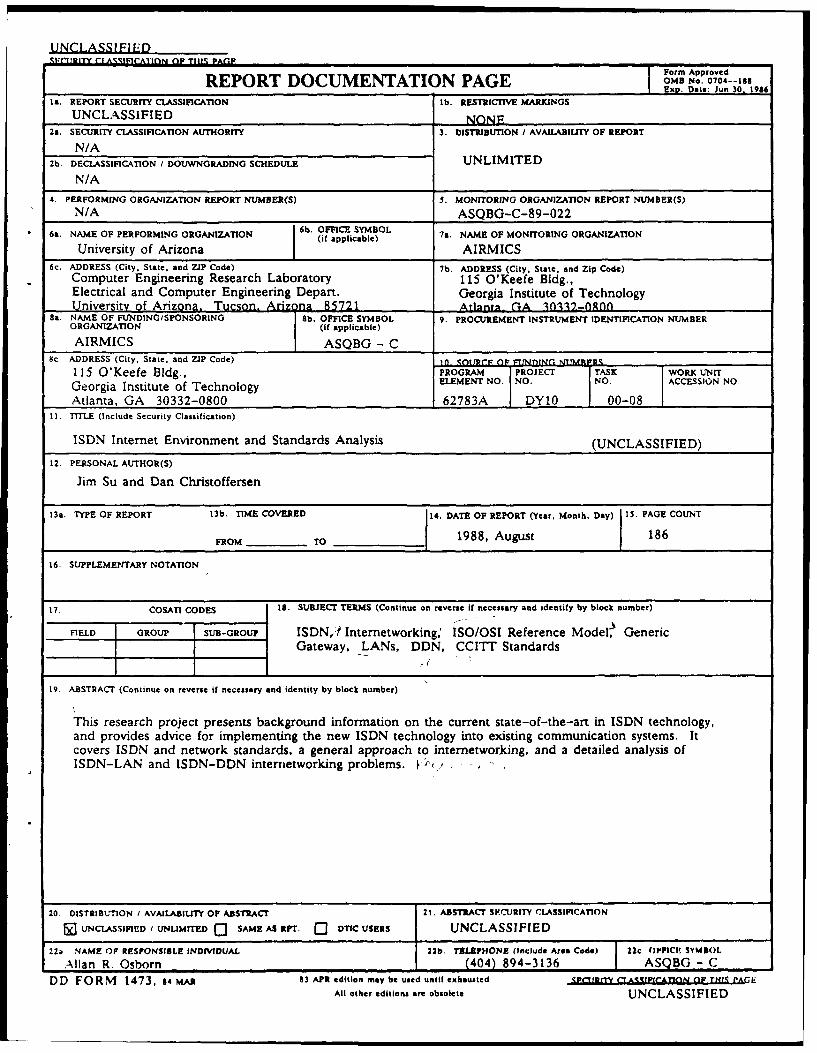
19. ABSTRACT (Continue on reverse if necessary and identity by block number)
This research project presents background information on the current state-of-the-art in ISDN technology,and provides advice for implementing the new ISDN technology into existing communication systems. Itcovers ISDN and network standards, a general approach to internetworking, and a detailed analysis ofISDN-LAN and ISDN-DDN interrnetworking problems.
DD FORM 1473. as MAR 83 APR edition may be used until exhausted PfflCTItAtAuO H '(I
All other editions are obsolete UNCLASSIFIED
FINAL REPORT
Contract No. B-I0-695-SIU.S. Army Institute for Research in ManagementInformation, Communications, and Computer Science
Georgia Institute of TechnologyAtlanta, GA 30332
ISDN INTERNET ENVIRONMENT AND STANDARDS ANALYSIS
by
Jim Su and Dan Christoffersen
Project Supervisors
Larry Schooley, Ph.D.
and
Ralph Martinez, Ph.D.
Computer Engineering Research LaboratoryElectrical and Computer Engineering Department
UNIVERSITY OF ARIZONA
Tucson, Arizona 85721
212t 2L CnORMta1. XNTrrOOuCTIou
2. 9ICGRAOND
2.1 ISO-qsI and CCITT Seven-Layer Reference Model
2.2 LAN Protocols& MAP and TOP
-- 2.3 ISDN Standard
3. ISDN-LAN INTZRNETIORKING
3.1 ISO-OSI Internetworking Model of End-Systems andSubnetworks
3.2 ISDN's Viewpoint of LAN
3.3 ISDNwLAN Gateway*
4. METHODOLOGY FOR COMPUTER N3T160RK IITERNETWORKING
4.1 General Considerations
4.2 Generic Gateway Functions
4.2.1 The Hardware and Software Interface Functions andProtocols Used by Networks A and B
4.2.2 Addressing, Naming, and Routing Functions
4.2.3 Packet Fragmentation and Reassembly Functions
4.2.4 Suffering Function
4.2.5 Flow Control Function
4.2.6 Congestion Control .n'ion
4.2.7 Error Handling Function
4.2.8 Access and Security Control Function
4.2.9 Billing and Charging Function ooession or
TIS MWA&4.2.10 Monitoring and Statistical Function TIC TAB 0
neanounoed 04.2.11 Protocol Conversion Function ,etif1lotin
4.3 Internetworking Approachest Practical Aspects , _I strlbutlIon/
4.3.1 Approach 1: Direct Connection of Network Avaribillt I
Interface Units Availability Caog. i Avall ador
Dist Spoial
Tabli f Contents continued
4.3.2 Approach 2: Interconnection through Computer Ports
4.3.3 Approach 3: Integrated Gateway
4.3.3.1 Step 1: Understand and Use Each ofthe Two Networks
4.3.3.2 Step 2: Start Internetworking fromApproach 1 and Approach 2
4.3.3.3 Step 3: Decide Which Layer GatewayIs Required
4.3.3.4 Step 4: Obtain the Required Informationfrom Network Vendors
4.3.3.5 Step 5: Decide What Kind of Chassis orComputer to Build the Gateway With
4.3.3.6 Step 6: Design the Translator Module-toInterface with the Two Half-GatewayModules
4.3.3.7 Step 7: Implement and Test theIntegrated Gateway
4.3.4 Approach 4: Gateway Design via a Neutral Network
4.4 Summary and Comparison of These lour Approaches
5. ISDN-LAN GATEWAY DESIGN
5.1 General Considerations
5.2 Implementation Plan of ISDN for U.S. Army
5.3 Layer-3 (Network Layer) ISDN-LAN Gateway
5.4 Step-i: Understand and Use Each of the Two Networks
5.4.1 The Lower Three Layer Protocols of ISDN
5.4.1.1 Layer 1 (Physical Layer) rf ISDN
5.4.1.2 Layer .2 _(Data Link Layer) of ISDN
5.4.1.3 Layer 3 (Network Layer) of ISDN
5.4.2 The Lower Three Layer Protocols of. TOP and MAP
5.4.2.1 Layer 1 (Physical Layer) of TOP and MAP
iii
Table of Contents continued
5.4.2.2 Layer 2 (Data Link Layer) of TOP and MAP
5.4.2.3 Layer 3 (Network Layer) of TOP and MAP
5.4.2.4 The Differences Between ISO IP and DoD IP
5.5 Step 2: Start Internetworking from Approach-i andApproach-2
5.6 Step 3: Decide Which Layer Gateway Is Required
5.7 Step 4: Obtain the Required Information from NetworkVendors
5.8 Step 5: Decide What Kind of Chassis or Computer toBuild the Gateway With
5.9 Step 6: Design the Translator Module to Interface withthe Two Half-Gateway Modules
5.10 Step 7: Implement and Test the Integrated Gateway
6. INTERNETWORKING DDN AND ISDN
6.0 General Considerations
6.1 Step 1: Understand the Characteristics of ISDN and DDN
6.2 Step 2: Start Internetworking from Approaches I and 2
6.3 Step 3: Decide Which Layer Gateway to Use
6.4 Step 4: Obtain Required Information About ISDN and DDN
6.4.1 ISDN Half-Gateway Module
6.4.1.1 ISDN Physical Layer
6.4.1.2 Data Link Layer for ISDN's D-channel
6.4.1.3 Network Layer for ISDN's D-channel
6.4.1.4 Data Link Layer for ISDN's B-channel
6.4.1.5 Network Layer for ISDN's B-channel
6.4.2 DDN Half-Gateway Module
6.4.2.1 Physical Layer of the DDN
6.4.2.2 Data Link Layer of the DDN
iv
Table of Contents continued
6.4.2.3 Network Layer of the DDN
6.4.2.4 Transport Layer of the DDN
6.5 Step 5i Decide Which Type of Chassis to Use
6.6 Step 6: Design Translator Module
6.6.1 Address Translation
6.6.2 Routing
6.6.3 Rate Adaption
6.6.4 Flow Control and Buffering
6.6.5 Congestion Control
6.6.6 Protocol Conversion
6.6.7 Real-Time Response
6.6.8 Performance Monitoring and Statistics
6.7 Step 7: Test the Integrated Gateway
6.8 Limitations of the DDN/ISDN Gateway
6.9 Summary
7. CONCLUSIONS AND RECOMMENDATIONS
8. REFERENCES
v
-- ii ii i I I i I • • ~ m IV
Table of Figures
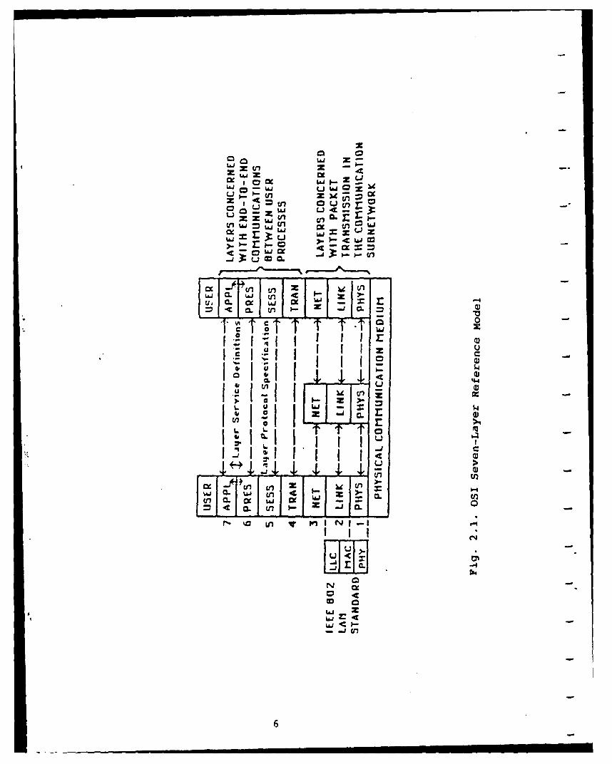
Fig. 2.1. OSI Seven-Layer Reference Model
Fig. 2.2. MAP Version 2.1 and TOP Version 1.0
Fig. 2.3. The Public Networks to ISDN Evolution
Fig. 2.4. User-Network Interfaces in ISDN
Fig. 3.1. ISO-OSI Internetworking Model of End-Systems andSubnetworks
Fig. 3.2. The Three-Sublayer Network-Layer Model
Fig. 3.3. The Scenario of Internetworking Based on theThree-Sublayer Network-Layer Model
Fig. 3.4. ISDN's Viewpoint of LAN
Fig. 3.5. The Logical Diagram of ISDN's Viewpoint of LAN
Fig. 3.6. The ISDN-LAN Internetworking via a Gateway
Fig. 3.7. The Scenario of Interconnecting Two RemotelyLocated LANs via ISDN
Fig. 3.8. The Scenario of Interconnection Between theISDN End-Systems and the LAN End-Systems
Fig. 4.1. The General Gateway Architecture forInternetworking Two Networks
Fig. 4.2. The Gateway Architecture Which Decomposes the Gatewayinto Two Half-Gateway Modules Linked bya Translator Module
Fig. 4.3. Some Addressing Spaces of Different Networks
Fig. 4.4. The Internetworking Scenario of Direct Connectionof Network Interface Units (NIUs)
Fig. 4.5. The Scenario of Internetworking Through Computer Ports
Fig. 4.6. The Scenario of Internetworking the Intel Ethernet LANwith the Sytek LocalNet-20 LAN
Fig. 4.7. One Example of Integrated Gateway Internetworking theSytek LocalNet-20 LAN with DoD Defense Data Network
Fig. 4.8. The Scenario of Choosing the Gateway Layer
Fig. 4.9. The Scenario of Internetworking via a Neutral Network
vi
Table of Figures continued
Fig. 4.10. The Architecture of Gateway Design via a NeutralNetwork
Fig. 5.1. The Relationships between the OSI Reference Model,OSI Service Definitions, OSI Protocol Specifications,and Implementations
Fig. 5.2. The Three X.25 Packet Switched Public Data Networks
Fig. 5.3. The DoD ISDN Organization
Fig. 5.4. The DoD DCA Proposed Mid-Term ISDN CONUS Architecture
Fig. 5.5. The DoD DCA Proposed Far-Term ISDN Architecture
Fig. 5.6. The Scenario of Technology-Independent Layers andTechnology-Dependent Layers in the OSI Seven LayerReference Model
Fig. 5.7. The Layered Protocol Structure at the ISDN User-NetworkInterface
Fig. 5.8. The Exchange Terminination (ET) Functional Elements ofISDN which separate and use B Channels and D Channel
Fig. 5.9. The Layer Structure of ISDN
Fig. 5.10. The Various Reference Points of ISDN
Fig. 5.11. The Physical Frames of ISDN Basic Access Rate
Fig. 5.12. The Physical Frames of ISDN Primary Access Rate
Fig. 5.13. Several Components of ISDN LAPD Frame
Fig. 5.14. The Control Field of ISDN LAPD
Fig. 5.15. The ISDN LAPD Control Field Types
Fig. 5.16. The Network Configuration and Protocols for theISDN Circuit Switching Scenario
Fig. 5.17. The Network Configuration and Protocols for PacketSwitching Using B Channel with Circuit-Switched Access
Fig. 5.18. The Network Configuration and Protocols for PacketSwitching Using D Channel
Fig. 5.19. The Terminologies Used in Figures 5.16, 5.17, and 5.18.
Fig. 5.20. The Protocol Layers at S and T Reference Points WhenD Channel Is Used in ISDN
vii
Table of Figures continued
Fig. 5.21. The Protocol Layers at S and T Reference Points WhenB Channel Is Used in ISDN
Fig. 5.22. The ISDN Q.931 Network Layer Message Format
Fig. 5.23. The Optional Information Elements of ISDN Q.931
Fig. 5.24. The Format of the Optional ISDN Q.931 InformationElements
Fig. 5.25. The Selected ISDN Q.931 Message Types
Fig. 5.26. MAP Version 2.1 and TOP Version"1.0
Fig. 5.27. The Frame Formats of IEEE 802.3 CSMA/CD andIEEE 802.4 Token Bus
Fig. 5.28. The IEEE 802.2 Logical Link Control (LLC) Frame Format
Fig. 5.29. The IEEE 802.2 LLC Control Field Format
Fig. 5.30. The IEEE 802.2 LLC Primitives for User-LLC Interface
Fig. 5.31. The Header Format of ISO Internet Protocol (IP)
Fig. 5.32. The Header Format of DoD Internet Protocol (IP)
Fig. 5.33. The Scenario of ISDN-LAN Internetworking throughLAN Network Interface Unit (NIU) and ISDN TerminalAdapter (TA)
Fig. 5.34. The Layer Structure of the Layer-3 ISDN-LAN Gateway
Fig. 5.35. The Available ISDN VLSI Chips from Several Companies
Fig. 5.36. The Scenario of ISDN-LAN Gateway Design Using theSpecific Bus of the ISDN-Compatible PABX
Fig. 5.37. The Scenario of ISDN-LAN (TOP or MAP) Gateway DesignUsing IBM-PC-386 Compatible Computers
Fig. 5.38. The Network Management Concept in the OSI Environment
Fig. 5.39. The Concept of Manager-Agent Protocol and the ExternalView of the Network Management Architecture
Fig. 6.1 Internetworking DDN and 3 networks with ISDN as a neutralnetwork
Fig. 6.2 Internetworking DDN and 3 networks without ISDN
viii
Table of Figures continued
Fig. 6.3 DDN protocol structure implementing X.25
Fig. 6.4 ISDN protocol structure
Fig. 6.5 ISDN user-network interface
Fig. 6.6 DDN/ISDN gateway configuration
Fig. 6.7 Gateway configuration showing end-to-end compatibility
Fig. 6.8 Funcitonal decompostion of ISDN half-gateway module
Fig. 6.9 Example of pseudo-ternary coding scheme
Fig. 6.10 Frame structure of the ISDN physical layer
Fig. 6.11 Frame structure of the LAP-D protocol
Fig. 6.12 LAP-D address field format
Fig. 6.13 D-channel data-link showing distinction between SAPIand TEI
Fig. 6.14 Control field format of the LAP-D protocol
Fig. 6.15 Structure of layer 3 message for ISDN's D-channel
Fig. 6.16 Channel identification information element structure
Fig. 6.17 Connected address information element structure
Fig. 6.18 X.25 protocol frame structure at the data link layer
Fig. 6.19 Data and control packets used on ISDN's B-channel
Fig. 6.20 Functional decomposition of DDN half-gateway module
Fig. 6.21 X.21 signal names and their functions
Fig. 6.22 Internet Protocol frame structure
Fig. 6.23 Transmission Control Protocol frame structure
Fig. 6.24 Gateway chassis and internal components
ix
1. INTRODUCTION
The following paper prepared by the IGIS Research Team at
the University of Arizona's Computer Engineering Research Lab is
the Final Report on the subject of ISDN-Internet Environment and
Standards Analysis. The intent of this report is to present
background information on the current state of the art in ISDN
technology, and to provide advice for implementing the new ISDN
technology into existing Army communication systems. This
information will be presented in Chapters two through six of this
report, beginning with general information about ISDN and
network standards, general approach to internetworking, and
finally discussing the specific cases of ISDN-LAN and ISDN-DDN
internetworking problems.
The term ISDN, Integrated Services Digital Network, refers
to a concept in communications technology rather than a
particular type of hardware. ISDN can be thought of as a world-
wide information system that uses international standards to
deliver a broad range of services (voice, data, video, etc.)
which are all integrated into a single end-to-end digital
network. The concept of an ISDN has been around for a couple of
decades, and now because of standardization and technological
advancements in digital communications this concept is becoming a
realization.
Development of standards for ISDN is the underlying key to
its success. A dedicated effort by CCITT, International
Telephone and Telegraph Consultative Committee, along with a
handful of other organizations, has resulted in a set of ISDN
ix
standards, CCITT Red Book, I-Series Recommendations. These
standards were first released in 1984 and a revised and expanded
version is expected to be released in 1988. The 1984 ISDN
standards were primarily directed toward the user-network
interface. This allowed many vendors to begin participating in
the development of ISDN equipment such as: switches, terminals,
as well as an assortment of VLSI chips for ISDN.
The evolution of ISDN technology is occurring at a rapid
pace. Throughout the world ISDN has undergone many trials, and
is actually in small scale operation in West Germany. Within the
next year several other countries are expected to make ISDN
services available to large customers. The United States is
lagging behind other nations in the implementation of ISDN
because unlike other countries, the U.S. does not have a
centralized provider of communications. The European countries
have government controlled Postal, Telephone, and Telegraph
companies (PTT's). Within the United States there is heavy
competition between companies (AT&T, GTE, Northern Telecom, etc.)
for the ISDN market and therefore these companies are unwilling
to take big financial risks during the early stages of ISDN
development. Despite this cautious approach taken by U.S.
companies, there are several field trials currently being
conducted across the U.S., and customers in the U.S. can expect
an operational ISDN within the next two or three years. The
initial ISDN customers will be large companies, and as ISDN
matures and becomes more economical the market will expand into
use by small companies and will eventually migrate into use by
ix
residential customers. The DoD, and specifically the U.S. Army,
will be one of the large customers of ISDN. This requires that
the U.S. Army be prepared for the coming of ISDN in order to put
this technology to use as soon and effectively as possible. This
report will present advice on how the power of ISDN can be tapped
to enhance existing Army communication systems.
The following is a brief overview of the succeeding chapters
in this report. Chapter 2 is a discussion of the necessary
background information regarding standardization, the ISO-OSI
Seven Layer Reference Model, and the correspondence of ISDN and
Internet protocols to those standards. Chapter 3 discusses the
ISO-OSI Internetworking Model. Chapter 3 also contains some
information relative to ISDN-LAN gateways. Chapter 4 is
"Methodology for Computer Network Internetworking." This chapter
provides information pertaining to the general case of
internetworking two networks. The topics discussed in Chapter 4
include: general gateway model, generic gateway functions, four
internetworking approaches, and a comparison between the four
approaches. The comparison of the four internetworking
approaches is made from a practical point of view taking into
consideration factors such as: time, cost, complexity, and
feasibility. Chapters 5 and 6 expand on the general
internetworking problem presented in Chapter 4 to the specific
internetworking problems of ISDN-LAN and ISDN-DDN respectively.
Chapter 5 is "ISDN-LAN (TOP or MAP) Gateway Design." The
approach to developing an ISDN-LAN (TOP or MAP) gateway is based
on the general principles and procedures of the Integrated
ix
Gateway Design discussed in Chapter 4. We also use the paper
"Army Implementation of ISDN" by Joseph J. Rudiger as the
guideline of the ISDN-LAN (TOP or MAP) gateway design. Because
TOP and MAP protocols as well as ISDN protocols are considered
standard, there will be several VLSI chips, communication adapter
cards, and software available to the gateway designer. The
vendor products can and should be used to make the gateway design
and implementation as simple as possible. We must assume that
the upper four layers are compatible between the ISDN side of the
gateway and the TOP or MAP side of the gateway. This implies
that the ISDN-(TOP or MAP) gateway is confined to the lower three
layers. Several of the generic gateway functions are related to
network management, and therefore applying ISO and CCITT
protocols and network management concepts to the more complex
internetworking environment is a good topic for future study.
Chapter 6 presents an approach to internetworking DDN with
an ISDN. The approach presented is to design and build an
integrated gateway. The general case of this approach is
contained in Section 4.3.3 of this report. The integrated
gateway will have a four-layer DDN side and a three-layer ISDN
side. Because DDN is a long-haul network, it is required that
the fourth layer, Transmission Control Protocol, be added in
order to handle connection control and to increase the
reliability of the integrated gateway. A complete discussion of
the implementation of generic gateway functions and procedures is
discussed in Chapter 6.
ix
2. BACKGROUND
2.1 ISO-OSI and CCITT Seven-Layer Reference Model
The International Organization for Standardization (ISO)
organized its Technical Committee 97 (TC-97) on Information
Processing Systems. The TC-97 established a SubCommittee 16 (SC-
16) on Open Systems Interconnection (OSI). SC-16's task was to
develop a reference model that would provide an architecture to
serve as a basis for all future development of standards for
world-wide distributed information systems. The International
Telegraph and Telephone Consultative Committee (CCITT) also
welcomed the ISO effort and appointed a special rapporteur to
maintain close liaison and to apply the OSI architecture to
CCITT applications.
In May 1983 the OSI Seven-Layer Reference Model (Figure 2.1)
finally resulted in the approval of ISO International Standard
7498 (ISO/IS 7498) and CCITT Recommendation X.200. The ISO also
defined standards at each of the OSI seven layers. According to
the status of standardization process, the ISO documents of
communication protocols can be: Draft Proposal (DP), Draft
International Standard (DIS), or International Standard (IS).
Both ISO and CCITT support the OSI direction of developing one
set of international standards as the best possible resolution of
incompatibilities. An example of this is the increasing
cooperation between ISO and CCITT through the mutual publication
of identical standards.
5
10 0 0XIA
x z. L& J vi cn -
C L
: H2 -C- iC10 -
usUIaIiiV czI ,
14 1'
N -n
N cx0 C
66
2.2 LAN Protocols: MAP and TOP
The protocols for Local Area Networks (LAN's) are very
confusing. A lot of LAN's use vendor's propriecary protocols
which are not ISO-OSI compatible. The IEEE 802 Committee
published LAN-802 standards: 802.2 Logical Link Control (LLC),
802.3 CSMA/CD, 802.4 Token Bus, 802.5 Token-Ring. However, the
IEEE 802 standards cover only the two lowest OSI layers: layer-2
Data Link layer and layer-l Physical layer.
During November 1980, General Motors (GM) formed the
Manufacturing Automation Protocol (MAP) task force to investigate
and identify common communications standards for factory systems.
The factory systems comprise: programmable controllers, numerical
controllers, robotic controllers, vision systems, and data
terminal equipment (including hosts, minicomputers, and
workstations). The Technical and Office Protocols (TOP) were
developed by the Boeing Co. to address the communications
problems for engineering and general office applications. Both
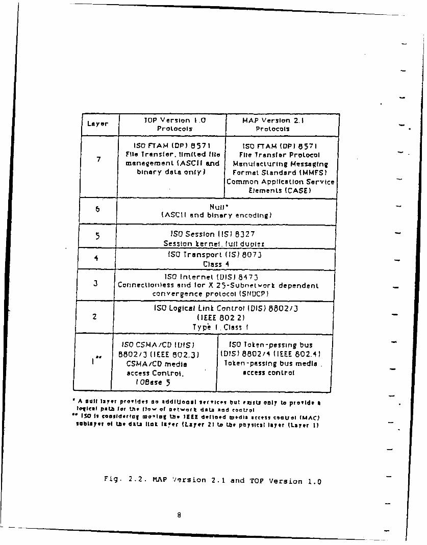
MAP and TOP are seven-layer protocols. The MAP Version 2.1 and
TOP Version 1.0 are shown in Figure 2.2. MAP and TOP choose the
protocols of each of the OSI seven layers from the ISO-OSI
standards. The major differences between TOP and MAP are at OSI
Layer-i and Layer-7. At Layer-i, TOP employs the IEEE 802.3
CSMA/CD baseband bus standard; and MAP employs the IEEE 802.4
Token Passing broadband bus. At Layer-7, TOP functions are for
the exchange of electronic-mail messages, editable text, and
graphics; but MAP functions are for exchange of information and
commands between factory programmable devices.
7
Layer TOP Version i 0 MAP Version 2.1Protocols Protocols
ISO FTAM (DP) 8571 ISO F-TAM (DPI 8571File Transfer. limited file File Transfer Protocol
7 management (ASCII end Manufacturing Messafingbinary data only) Format Standard (MMFS)
Common Application ServiceElements (CASE)
Null*(ASCII end binary encoding)
IS Session (IS) 8327
Session kernel, full duol.! .
4 ISO Transport (IS) 8073
Class 4
ISO Internet (DIS) 84733 Corinectlonless arid for X 25-Subiet work dependent
convergence protocol (StICP)
ISO Logical Link Control (DIS) 8802/32 (IEEE 8022)
Typi I. Class I
ISO CSMA/CD (VIS) ISO Token-passing bus6802/3 (IEEE 802.3) (DIS) 8802/4 (IEEE 802.4)
CSMA/CD media Token-passing bus mediaaccess Control. access control
1 Geese 5
A null Ia7.r providet no addlUoal 9ervicps but rjuLW 00l7 to provide aloilcal pAt1b l? th 0low of Detwort data hod eootrol
** ISO Is €oasldorlog motig tbe. lIEE defined tutdia scctlg couoL (MAC)lablayer of Lt diLs Hot Iaver (Layer 21 to .r physlcal liaer tLayer 1)
Fig. 2.2. MAP Version 2.1 arid TOP Version 1.0
---_ __ __ _ __ ___ 8
2.3 ISDN Standard
The ISDN (Integrated Services Digital Network) is coming of
age as a world-wide telecommunication revolution. This is
- evidenced in three areas: International standards, trials, and
equipment development. The CCITT 1984 Plenary approved the ISDN
standards which represent a major detailed technical advance
towards the realization of ISDN. The major telecommunication
providers have scheduled ISDN trials. The major telecommunication
equipment manufacturers have made a commitment to ISDN products.
IC chip manufacturers are working to build the underlying key to
economical and compatible ISDN implementation. The public
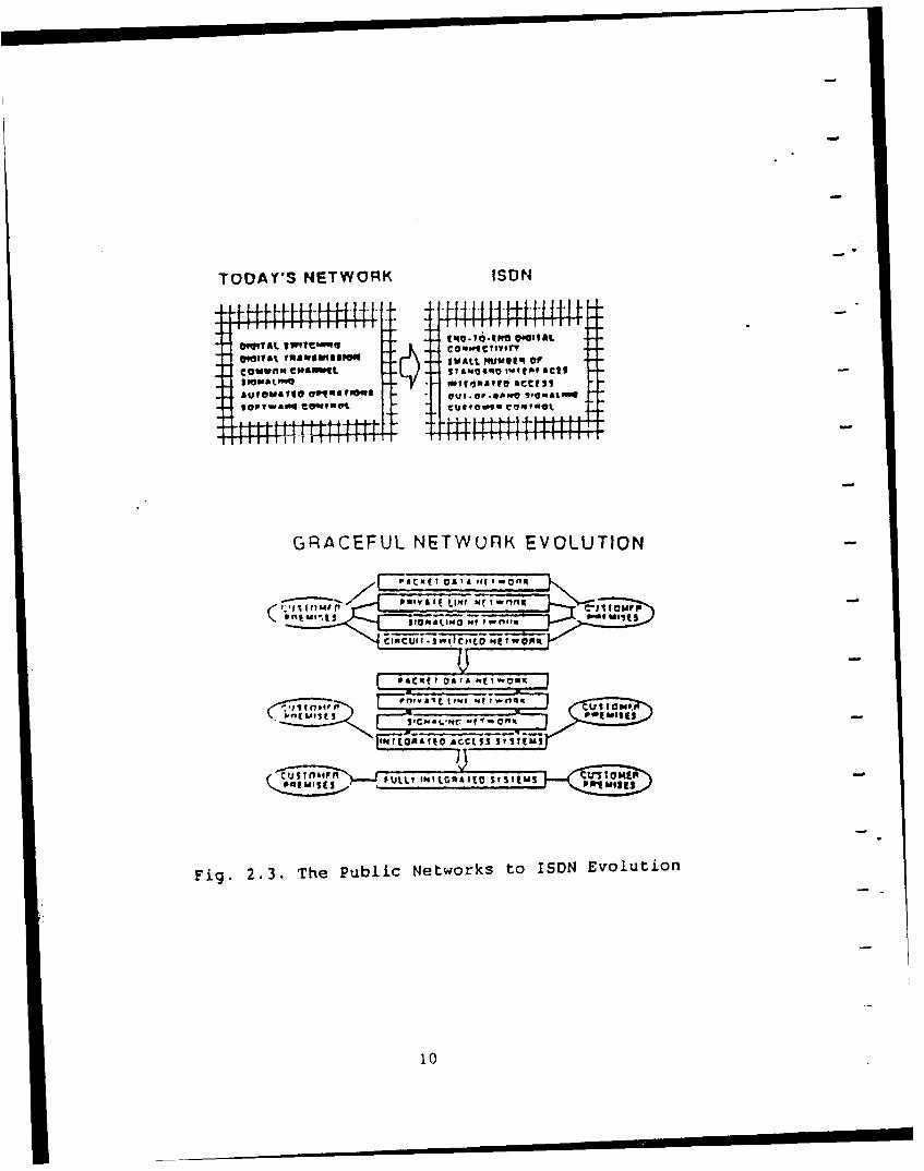
telephone networks world-wide are currently undergoing a rapid
phase of evolution from analog telephony networks to Integrated
Digital Networks (IDNs) and, in the future, to ISDN. Figure 2.3
shows the evolution from public networks to ISDN .
IEEE published several special issues on ISDN and related
technologies (6 -- 12]. The definition of Integrated Services
Digital Network (ISDN) can be viewed from two parts: Digital
Network and Integrated Services. The term "Digital Network" in
ISDN is defined as: digital switches, digital transmission,
digital telephones with coder/decoder (Codec), and end-to-end
digital connectivity. The term "Integrated Services" in ISDN is
defined as: services of voice, data, image; integrated access
with small number of standard user-network interfaces; out-of-
band signaling (D channel and Common Channel Signaling System #7
(CCSS #7)), narrowband ISDN (Basic Access Rate and Primary Access
Rate), and broadband ISDN (135 Mbit/s).
9
TODAY'S NET WORK ISDN
F97 a I I Iq Ia IwI I I I
cativirip c"ettEL L I 14061 1wa. lf acts
gVOuwqW& e0tam" que-q" xVNUCt-n 9a f-W4OI
GRACEFUL NETWORK EVOLUTION
F -1 aC to( 0 IA I" ~ofi
Fig. 2.3. The Pub i ietwok tom ISD Evoluti
10
The CCITT t984 ISDN I-SerLes Recommendations are:
1. 1-100 Series: ISDN Concept, Modeling, Evolution;2. 1-200 Series: ISDN Service Capabilities;3. 1-300 Series: ISDN Overall Network Aspects and Functions;4. 1-400 Series: ISDN User-Network Interfaces;5. 1-500 Series: ISDN Internetworking Interfaces;6. 1-600 Series: ISDN Maintenance Principles.
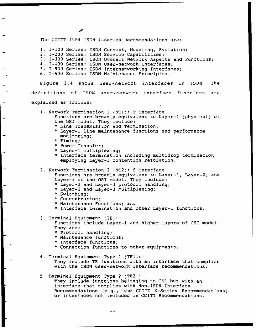
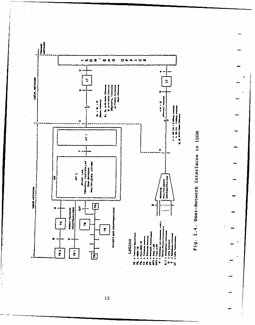
Figure 2.4 shows user-network interfaces in ISDN. The
definitions of ISDN user-network interface functions are
explained as follows:
1. Network Termination 1 (NTl): T interface.Functions are broadly equivalent to Layer-I (physical) ofthe OSI model. They include:* Line Transmission and Termination;* Layer-I line maintenance functions and performancemonitoring;
* Timing;* Power Transfer;* Layer-i multiplexing;* Interface termination including multidrop terminationemploying Layer-i contention resolution.
2. Network Termination 2 (NT2): S interfaceFunctions are broadly equivalent to Layer-i, Layer-2, andLayer-3 of the OSI model. They include:* Layer-2 and Layer-3 protocol handling;* Layer-2 and Layer-3 multiplexing;* Switching;* Concentration;* Maintenance Functions; and* Interface termination and other Layer-i functions.
3. Terminal Equipment (TE):Functions include Layer-i and higher layers of OSI model.They are:* Protocol handling;* Maintenance functions;* Interface functions;* Connection functions to other equipments.
4. Terminal Equipment Type 1 (TEl):They include TE functions with an interface that complieswith the ISDN user-network interface recommendations.
5. Terminal Equipment Type 2 (TE2):They include functions belonging to TEl but with aninterface that complies with Non-ISDN InterfaceRecommendations (e.g., the CCITT X-Series Recommendations)or interfaces not included in CCITT Recommendations.
11
II a
"" . ...... "
.................... ._ ..... ...................... !
L.#
#too$ ... . ...
12
I I / I1!
6. Terminal Adapter (TA): R interface.TA allows a TE2 terminal to be served by an ISDNUser-Network Interface.TA functions broadly belong to Layer-i and higher layersof the OSI model.
ISDN provides integrated voice, data, and image services in
one network. Because LANs are for high bandwidth transmission or
special purpose applications, e.g., MAP and TOP, ISDN and LANs
will coexist. We will discuss ISDN-LAN internetworking in the
following sections.
13
3. ISDN-LAN INTERNETWORKING
The CCITT and ISO both accepted the OSI Seven-Layer Reference
Model. The CCITT cooperates with ISO in developing communication
protocol standards and in the mutual publication of identical
standards. So the discussion of the "ISDN-LAN Internetworking"
will be based on the "ISO-OSI Internetworking Model of End-
Systems and Subnetworks."
3.1 ISO-OSI Internetworkina Model of End-Systems and Subnetworks
Ia a single network, the OSI Layer-4 Transport Layer provides
the "End-to-End" reliable transmission services; and the OSI
Layer-3 Network Layer provides the "intra-network routing
function" to route the packets from source node to destination
node. In the case of internetworking multiple subnetworks, the
OSI Layer-4 Transport Layer still provides the "End-to-End"
reliable transmission services; however, the OSI Layer-3 Network
Layer is subdivided into two sublayers 3L and 3H. The Sublayer-3L
provides the "intra-network routing function" within each of the
subnetworks; and the Sublayer-3H provides the "inter-network
routing function" to route the packets between subnetworks.
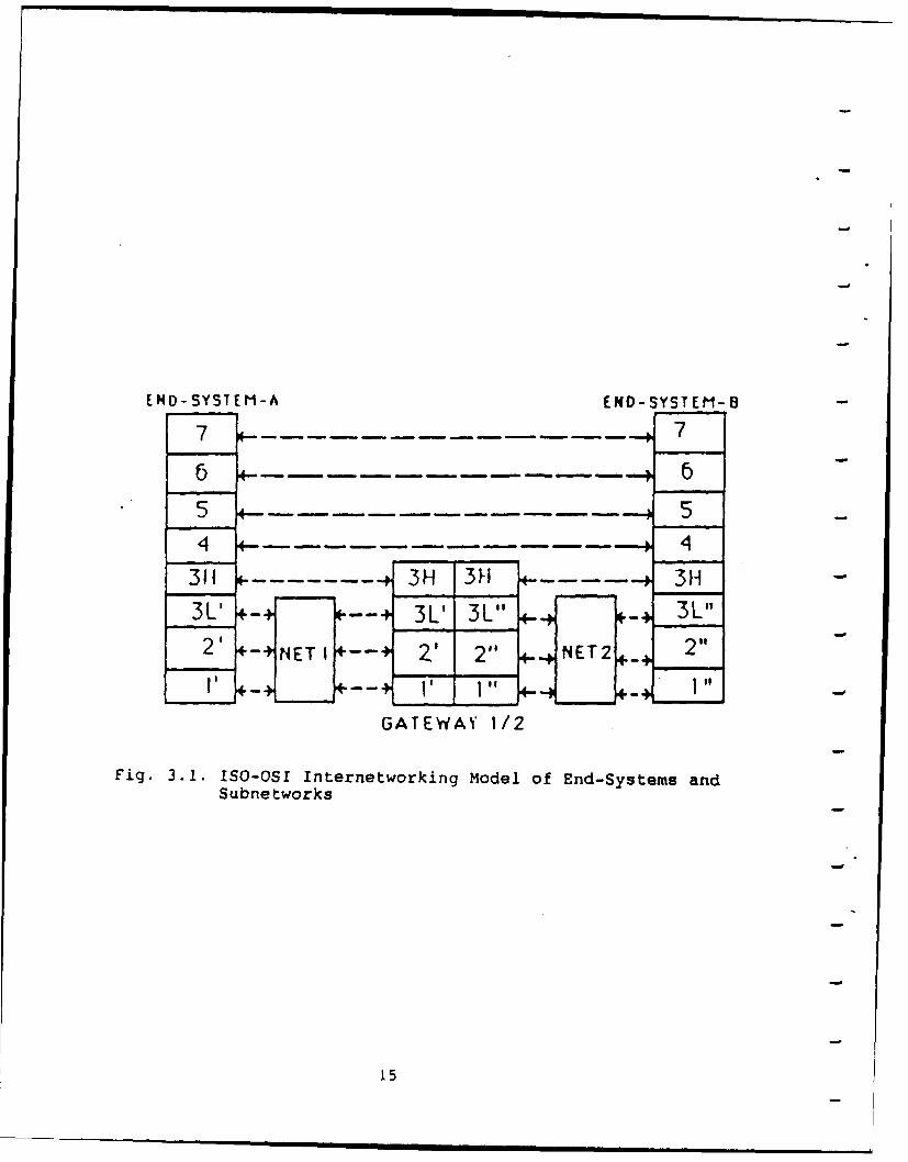
Figure 3.1 illustrates the ISO-OSI Internetworking Model of
End-Systems and Subnetworks. In this model, the assumptions are:
1. The communication protocols of End-Systems A and B are
compatible from layer-4 to layer-7. The layer-4 to layer-7 are
end-to-end layers.
14
END-SYSTEM-A END-SYSTEM-B
7 - - - - - - - - - -- -7
5 5.-- 5
4 - -.-. . .-.-.. 4
311 - - - 3H 3-I 311
3L' - L' 3L" R-21 +-+ M E T I, TO . NET2+
2+ -+tpv : - +
GATEWAY 1/2
Fig. 3.1. ISO-OSI Internetworking Model of End-Systems andSubne tworks
15
2. The intra-network routing function within each of the
subnetworks, e.g., Netl, Net2, is handled by the lower part of
the Network Layer (Sublayer-3L).
3. The inter-network routing function between different
subnetworks is handled by the upper part of Network Layer
(Sublayer-3H).
4. In this model, the Sublayer-3H can be: (i) ISO-IP or DDN-IP
for connectionless gateways; (ii) ISO-X.25 PLP for connection-
oriented gateways. The IP is Internet Protocol. The X.25 PLP is
X.25 Packet-Level Protocol.
Based on different technologies and topologies, the
subnetworks will be different in the lower three OSI layers. For
example, X.25 packet switched networks use X.21 in the physical
layer, LAPB in the data link layer, and X.25 Packet-Level
Protocol in network layer. The common bus LAN's, e.g., Ethernet
or Token Passing Bus LANs, use IEEE 802 protocols in physical
layer and data link layer. Because no routing function is needed
in the common bus topology, the network layer of common bus LANs
becomes a null layer. To resolve the differences of the lower
three OSI layers and to provide uniform OSI Network Layer
Services to the Layer-4 Transport Layer, the CCITT and ISO agreed
on a "Refined Network Layer Model" which comprises three
sublayers 3a, 3b, and 3c.
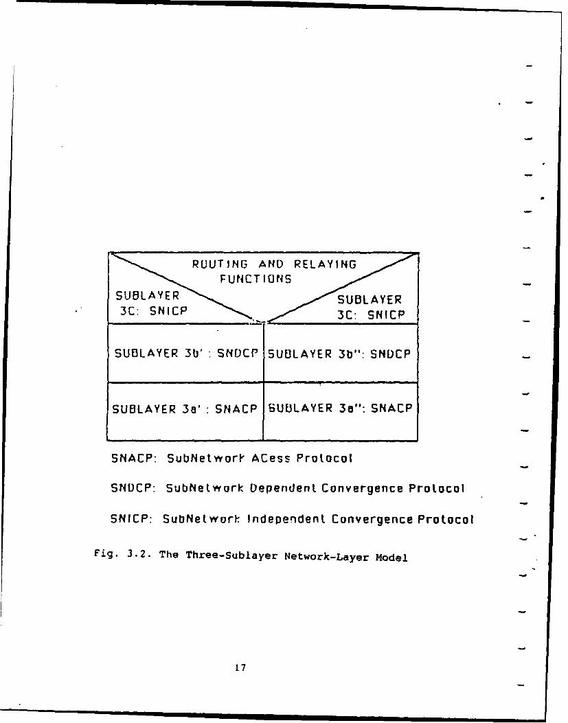
The Refined Network Layer Model is shown in Figure 3.2. The
three sublayers of the network layer are:
(i) Sublayer-3a: the SubNetwork ACcess Protocol (SNACP). The
SNACP protocol is the specific subnetwork's internal network
16
SU~LAY RUTN AND SRCESU LAYING":SDC
SUBLAYER 3'SAC ULYR3oSACPR
S3C: SN etwrl 3Ce: Protoco
SNDCP: SubNetwork Dependent Convergence Protocol
SNICP: Subbletwor Indepenident Convergence Protocol
Fig. 3.2. The Three-Sublayer Network-Layer Model
'7
layer protocol. It conveys the network layer functions needed to
meet the requirements of the specific -subnetwork such as X.25 or
LANs. It handles the intra-network routing function.
(ii) Sublayer-3b: the SubNetwork Dependent Convergence
Protocol (SNDCP). The SNDCP protocol is required to make up the
differences between the services provided by Sublayer-3a and
Sublayer-3c. It adjusts upward or downward the services provided
by the Sublayer-3a SNACP.
(iii) Sublayer-3c: the SubNetwork Independent Convergence
Protocol (SNICP). The SNICP protocol constitutes an internetwork
protocol and accomplishes the inter-network routing function. The
collective purpose of Sublayer-3b: SNDCP and Sublayer-3c: SNICP
protocols are, conceptually, to mask the peculiarity of each
constituent subnetwork in order to provide uniform OSI Network
Layer Services through the internetworking system of the
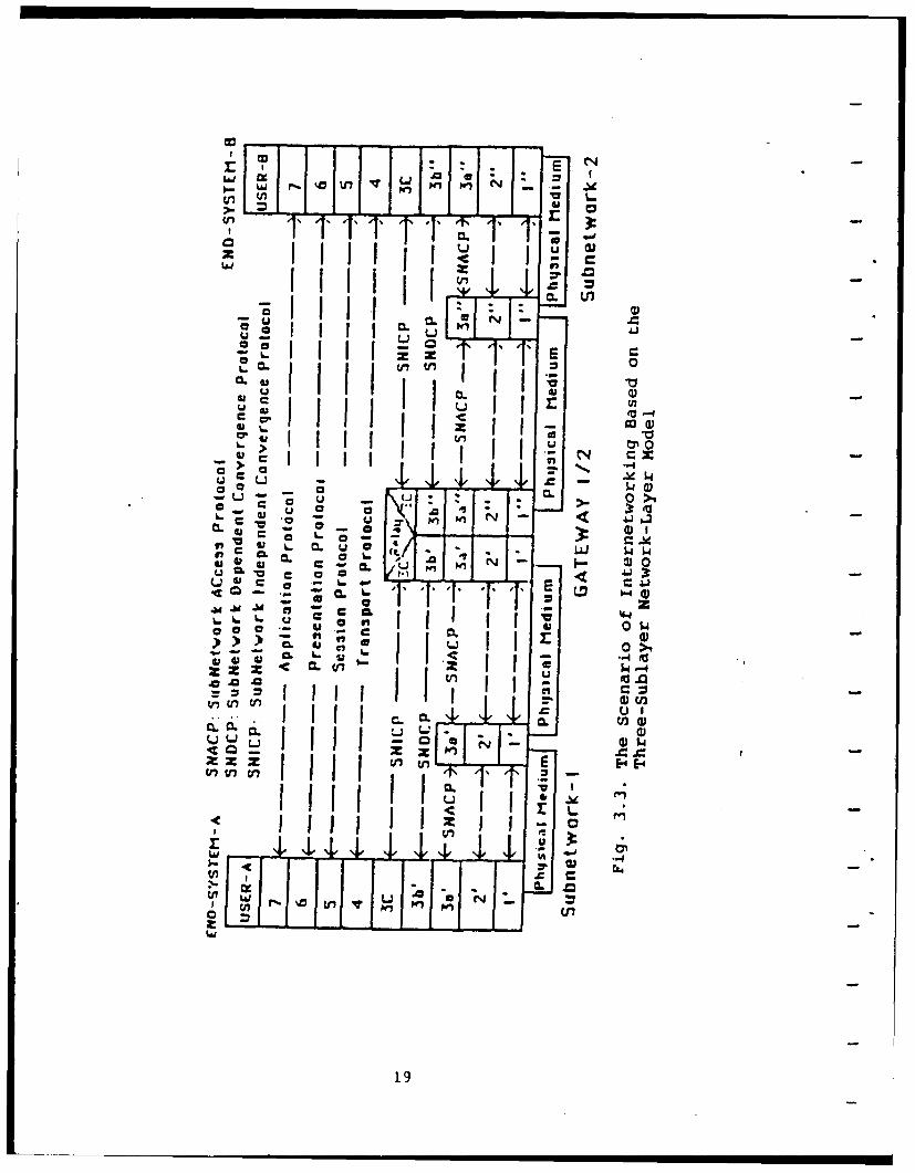
concatenated subnetworks. Figure 3.3 illustrates a scenario of
internetworking based on the three-sublayer Network Layer Model.
3.2 ISDN's viewpoint of LAN
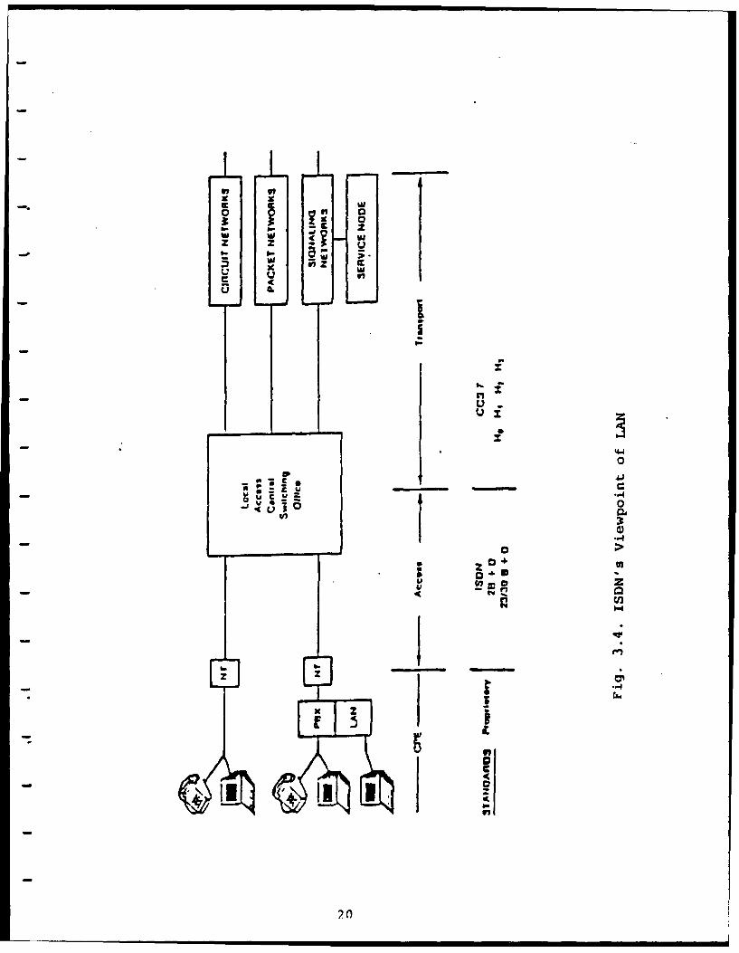
In Figure 2.4, from the ISDN point of view, the LAN is
included in the Network Termination 2 (NT2). Figure 3.4 shows the
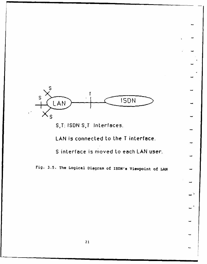
same scenario of ISDN's viewpoint of LAN. The logical diagram of
this viewpoint is shown in Figure 3.5. In Figure 3.5, the LAN is
- connected to the ISDN through the "T interface of ISDN" ; and the
LAN users will connect to the LAN via the "S interface of ISDN."
T provides an interface at the physical layer; and S covers the
network layer, the data-link layer , and the physical layer. In
this case (see Figure 3.5), the S interface will make any ISDN
18
cci
L JJ. W V
Z a
z Z ECL V
u cc
u~ 0 UU -1
E a- -WL
u ~ 00.1N 1c
j L 6 Lo 0 0
C, ',
19>
0 00
w wu,
U0 v0 .Y
U--
14
2.0
I iI LAN II I S D N
S
S,T: ISDN S,T Interfaces.
LAN is connected to the T interface.
S interface is moved to each LAN user.
Fig. 3.5. The Logical Diagram of ISDN's Viewpoint of LA
21
service available to all LAN users. However, providing the 'S
interface" to LAN users is not a simple task; and no existing
LANs can be used without large modifications. Gateways are
- needed to internetwork the existing LANs with an ISDN.
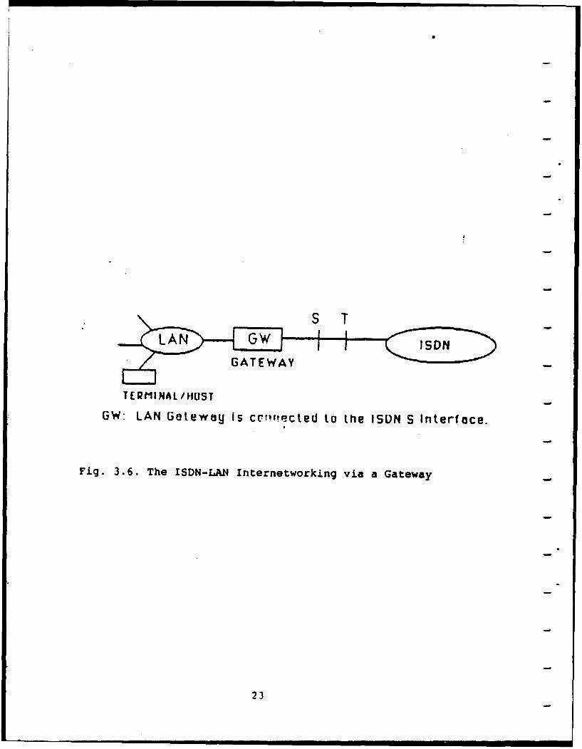
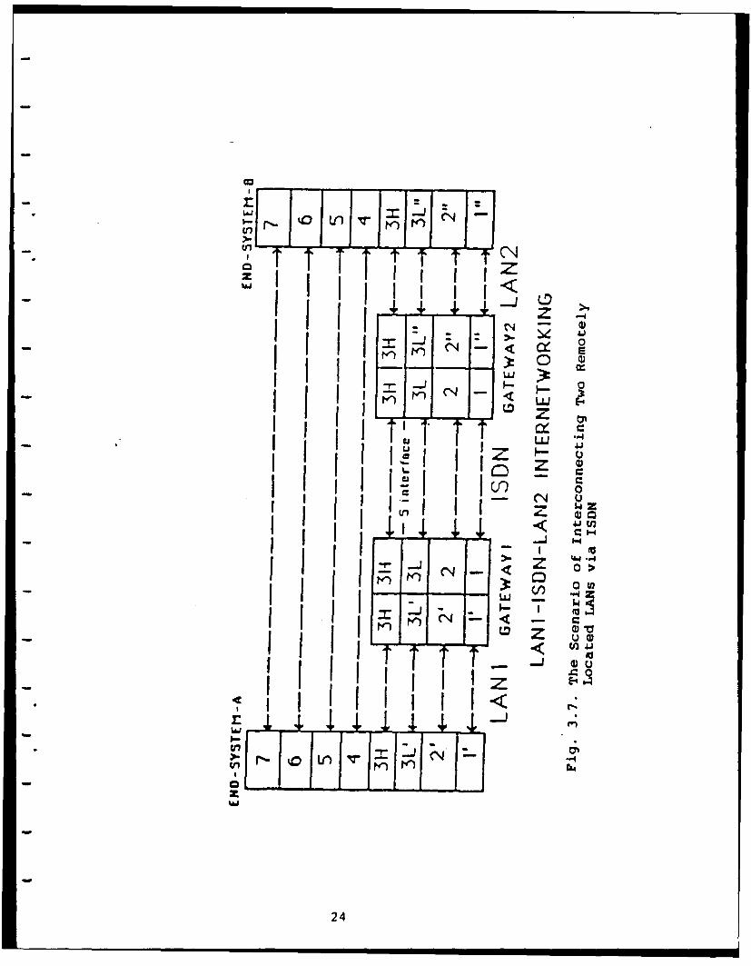
3.3 ISDN-LAN Gateways
The reasons for connecting LANs to ISDN are:
1. To interconnect LANs that are located at two remote sites;
2. To connect any ISDN terminal to the LANs;
3. To make any ISDN service available to all LAN users.
One approach of the ISDN-LAN internetworking is mentioned in
Section 3.2. The other approaches are through ISDN-LAN gateways.
Figure 3.6 shows the ISDN-LAN internetworking via gateway. This
interconnection is based on the ISO-OSI internetworking model of
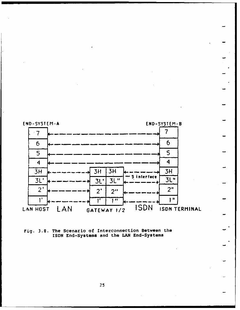
end-systems and subnetworks mentioned in Section 3.1. Figure 3.7
shows the scenario of interconnecting two remote site LANs via
ISDN. Figure 3.8 illustrates the scenario of interconnection
between the ISDN end-systems and the LAN end-systems. The issues
related to gateway design will be discussed in the following
sections.
22
TER MINA L/HUST-
GW: LAN Gateway is ctcr.Cled to the ISUN S Interface.
Fig. 3.6. The ISDN-LAN4 Internetworking via a Gateway-
23
z
0 Q)
I tn I eLO zTAi'AJ
u Z u -
Ic 0
- -4
5.4
24 4
END-SYSTEM-A END-SYSTEM-B
7 -........... - 76 - . . . . .- 65 ,-- -.-.-. . -. - .-. - 5
4 - . . . . - . . . . . .- 43H - - 3FH 3K - .... c 3H
3 . 3L' 3L" --. r 3L"2' 2 2" 2"I . " -.....o 1"
LAN HOST LAN GATEWAY 1/2 ISDN ISDN TERMINAL
Fig. 3.8. The Scenario of Interconnection Between theISDN End-Systems and the LAN End-Systems
25
4. METHODOLOGY FOR COMPUTER NETWORK INTERNETWORKING
4.1 General Considerations
The assumptions of the ISO-OSI Internetworking Model for End-
- Systems and Subnetworks mentioned in Section 3.1 are not always
true for some existing computer networks. For example, the
Assumption 1: the communication protocols of End-System A and
End-System B are compatible from Layer-4 to Layer-7; however, the
.layers 4-7 between different networks may not be compatible. The
- assumption that the Layer-3 Network Layer can be subdivided into
sublayers may also be incorrect. To add. the Internetwork
- Sublayers 3H or 3b and 3c into the existing networks requires
modification and redesign of hardware and software of the network
stations and nodes. Such an approach is usually opposed by
network vendors. For the design of future networks, the network
compatibility with the ISO and CCITT standards is of highest
priority; and the internetworking scenario should fit into the
"ISO-OSI Internetworking Model of End-Systems and Subnetworks."
However, to handle the internetworking problems of the existing
data communication and computer networks, we should consider the
more general gateway design approaches.
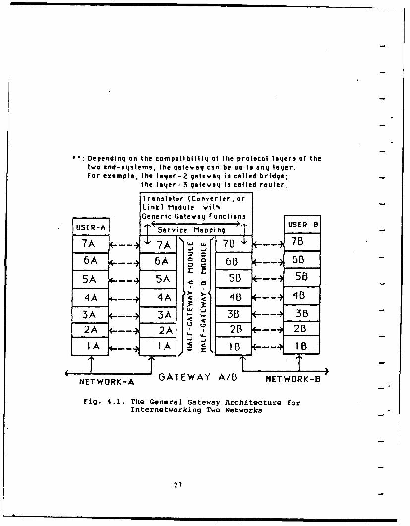
Figure 4.1 shows the general gateway architecture for
internetworking two networks. Figure 4.1 may mislead one to
- believe that the gateway design must cover all seven layers.
Depending on the level of compatibility between the two networks
the gateway design can be up to any layer. For example, if the
two networks are compatible from layers 3 to 7, then the layer-2
gateway (also called bridge) is possible. If the two networks are
26
''- Dependinq on the compatibility of the protocol laqers of thetwo end-systems, the gatevq can be up to any laIer.For example, the 1e4r-2 qateva is called bridqe;
the 1lyer- 3 gatevwa is called router.
Transltor (Converter. orLink) Module withGeneric Gateva Functions
USER-A Service Mappin. USER-O
7A 7__ A 7..__.7 B
5A -- 7A -- B
4A 4-- A C 4B ---. 23
1 ,A ,__ ,A Ib- b-L B ,513 *---4 5B2 A 2-'A 2B3 2- B
2 1A S 2cB 1 2BJ-
NETWORK-A GATEWAY A/B NETWORK-B
Fig. 4.1. The General Gateway Architecture forInternetworking Two Networks
27
compatible from layers 4 to 7, then the layer-3 gateway (also
called router) is possible.
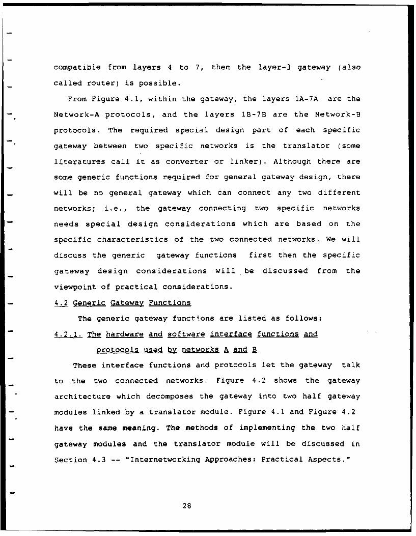
From Figure 4.1, within the gateway, the layers 1A-7A are the
Network-A protocols, and the layers 1B-7B are the Network-B
protocols. The required special design part of each specific
gateway between two specific networks is the translator (some
literatures call it as converter or linker). Although there are
some generic functions required for general gateway design, there
will be no general gateway which can connect any two different
networks; i.e., the gateway connecting two specific networks
needs special design considerations which are based on the
specific characteristics of the two connected networks. We will
discuss the generic gateway functions first then the specific
gateway design considerations will be discussed from the
viewpoint of practical considerations.
4.2 Generic Gateway Functions
The generic gateway functions are listed as follows:
4.2.1. The hardware and software interface functions and
protocols used by networks A and B
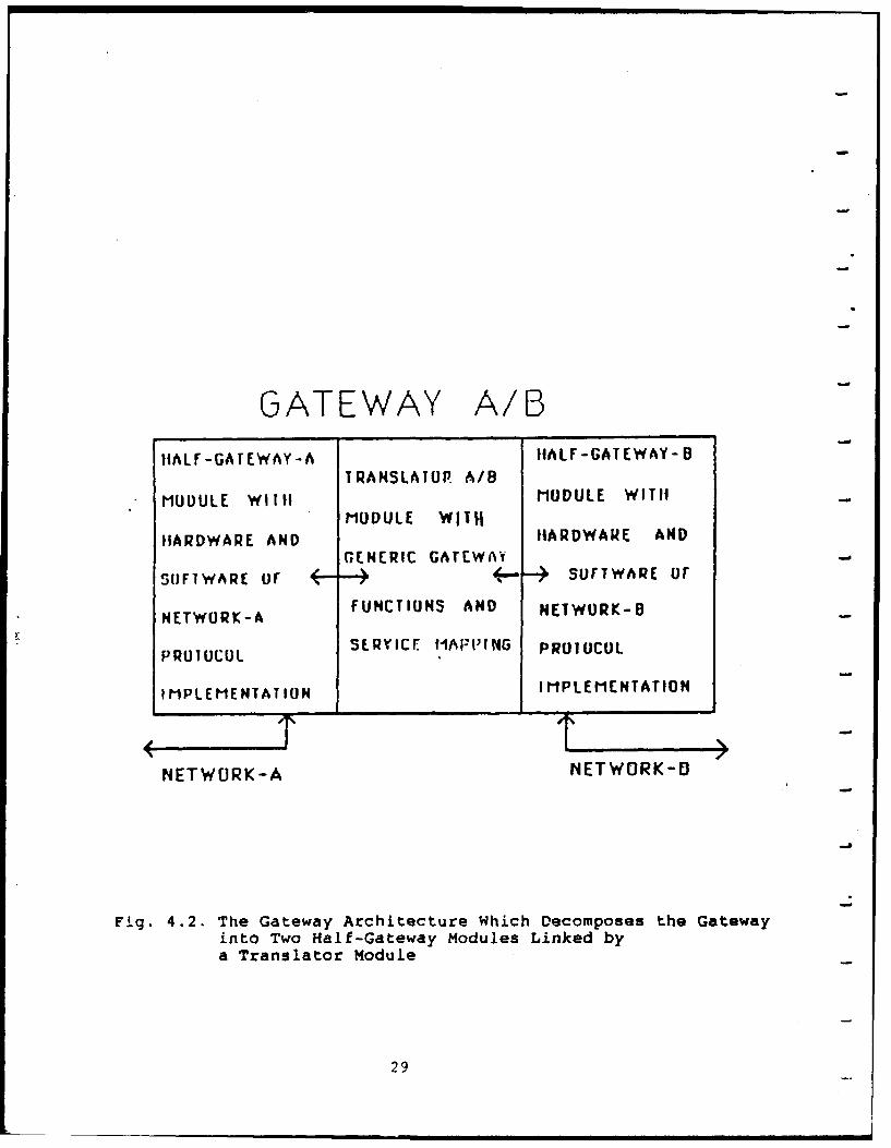
These interface functions and protocols let the gateway talk
to the two connected networks. Figure 4.2 shows the gateway
architecture which decomposes the gateway into two half gateway
modules linked by a translator module. Figure 4.1 and Figure 4.2
have the same meaning. The methods of implementing the two half
gateway modules and the translator module will be discussed in
Section 4.3 -- "Internetworking Approaches: Practical Aspects."
28
GATEWAY A/BIIALF-GATEWAY-A IIALF-GATEWAY- B
TRANSLATU A/B
MUOULE WITH MODULE WITIIMODULE W1l1I
IIARDWARE AND IIARDWARE ANDGENERIC GATEWA'Y
SFTWARE Of .--- SOFTWARE OF
FUNCTIONS AND NETWORK-BNETWORK-A
PRUIUCUL SERVICE I1AF:'tt4G PRO70COL
IMPLEMENTATION I MPLEMENTATION
NETWURK-A NETWORK-0
Fig. 4.2. The Gateway Architecture Which Decomposes the Gatewayinto Two Half-Gateway Modules Linked bya Translator Module
29
4.2.2. Addressing, Naming, and Routing Functions
A distinction is generally made among addresses, names, and
routes. A name specifies what an object is; an address specifies
where it is; and a route indicates how to get there. The names,
addresses, and routes can be "local" or "global" in the multiple
networks internetworking environment. "Local" means intra-
network; and "global" means inter-network. To translate "logical
name" into "physical address", the name server directory services
should be provided. The name server directory services can be
centralized or distributed and inside or outside the gateway. A
more important function of the gateway is the route selection
based on the address generated by the name server.
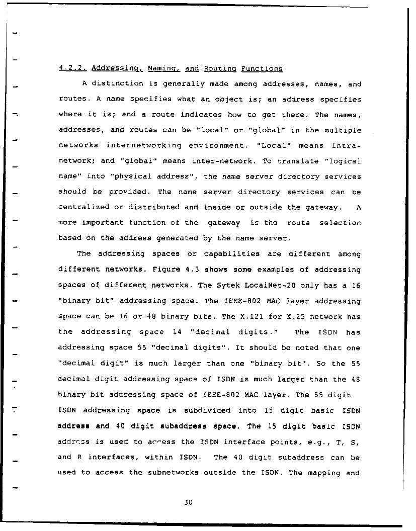
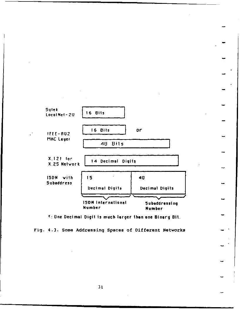
The addressing spaces or capabilities are different among
different networks. Figure 4.3 shows some examples of addressing
spaces of different networks. The Sytek LocalNet-20 only has a 16
"binary bit" addressing space. The IEEE-802 MAC layer addressing
space can be 16 or 48 binary bits. The X.121 for X.25 network has
the addressing space 14 "decimal digits." The ISDN has
addressing space 55 "decimal digits". It should be noted that one
"decimal digit" is much larger than one "binary bit". So the 55
decimal digit addressing space of ISDN is much larger than the 48
binary bit addressing space of IEEE-802 MAC layer. The 55 digit
ISDN addressing space is subdivided into 15 digit basic ISDN
address and 40 digit subaddress space. The 15 digit basic ISDN
addrr:zs is used to ac-ess the ISDN interface points, e.g., T, S,
and R interfaces, within ISDN. The 40 digit subaddress can be
used to access the subnetworks outside the ISDN. The mapping and
30
Sytek 16BtLocalNet-Z 162Ut
F-16 -0i ts or
MAC Layer40 Vits
X.121 for 14 Decimal Diqiti!X.25 Netvork . .......
ISDN vith 15 405ubeddress-
Decimal Digits Decimal Digits
ISDN International SubeddressingNumber Number
f: One Decimal Digit is much larger then one BinerY Bit.
Fig. 4.3. Some Addressing Spaces of Different Networks
31
interworking between different addressing spaces of different
networks is one important factor of gateway design
considerations.
The other gateway function related to addressing, naming, and
routing functions is the method used to establish and tear down
-- the end-to-end logical connections in the internetworking
environment. One design objective is to make a gateway as user-
friendly and transparent as possible. This means that the user
interaction when entering addresses should be simple but
flexible. When a user wishes to connect his terminal to a remote
computer on another network, it is undesirable to have to enter
long address strings to make up the call in separate hops, e.g.,
LAN-WAN-LAN. The ideal solution is to make the user unaware of
whether a resource is local or attached to a remote network. This
can only be achieved by name server directory services. The user
enters a single mnemonic name; and the name server translates the
name into a local LAN address, a WAN (Wide-Area-Network) address,
and a remote LAN address.
4.2.3 Packet Fragmentation and Reassembly Functions
The maximum allowed packet sizes of interconnected networks
are usually different. For packets sent from larger maximum
packet size via a gateway to a network with smaller maximum
packet size, the gateway should divide the larger packets into
smaller packets that can be managed by the second network. The
reassembly of these smaller packets can be performed by another
gateway or by the receiving end-system.
32
4.2.4 Buffering Function
The bandwidths (transmission capacities) of networks are
different. For example, the bandwidth of Ethernet is 10
Mbits/second; and ISDN provides basic access rate 2B+D (144
Kbps), primary access rate 23B+D (1.5 Mbit/s Ti), or future
Broadband ISDN rate (135.168) Mbps. To handle the interconnected
networks with different bandwidths, the gateway should provide
some type of buffering function.
4.2.5 Flow Control Function
Flow control is a procedure through which a pair of
communicating entities regulates traffic flowing from source to
destination. Such a mechanism is necessary at the gateway in
order to protect one network from being overloaded by the other.
Dissimilar flow control strategies used in each subnetwork will
further complicate the design of the gateway flow control
function.
4.2.6 Congestion Control Function
Congestion control is the ability to respond to an overloaded
condition within a network or a gateway. It is usually
accommodated by detecting a potential overload and cooperating
with flow control and routing functions to avoid the overload. If
the congestion control is insufficient, some packets are
discarded to free the resource. Sometime those discarded packets
cause more retransmission from the source; then that makes the
congestion condition worse. The discarding packet method is done
only as a last resort and should be an exception condition in
properly designed networks or gateways.
33
4.2.7 Error Handling Function
When a packet is discarded by gateway for some reasons, e.g.,
header error or gateway congestion, the gateway should try to
inform the packet source station. The gateways should report
their operating status among neighboring gateways to provide
better routing and error handling functions. Some kind of
gateway-to-gateway protocol is required for multiple network
internetworking environment.
4.2.8 Access and Security Control Function
Access and security control is needed to permit a gateway to
exercise control over the type and rate of traffic entering or
leaving networks. The control capability can monitor and bar some
specific traffic types. These functions are very important in the
gateways for military and banking networks.
4.2.9 Billing and Charging Function
The ISDN or Value-Added Networks (VAN's) charge users, and
LANs are usually free to users. The gateway needs mechanisms to
record the ISDN or public network billing, and provide the LAN
users procedures for verifying the public network billing.
4.2.10 Monitoring and Statistical Functions
The statistical information of traffic through a gateway
between specific source and destination networks should be
monitored and recorded for future gateway modification and
expansion. The number of damaged or discarded packets through
gateway should also be recorded for future modifications of
gateway flow control, congestion control, and error handling
functions. For these reasons, the gateway should have some non-
34
volatile storage devices to record the statistical data for
future investigation.
4.2.11 Protocol Conversion Function
The protocol conversion is the process of mapping of elements
of one protocol to another when the two protocols offer "similar
services", but are dissimilar in "protocol composition" or "the
set of atomic protocol functions." For example, the ISO
Transport Layer Protocol Class-4 (ISO TP-4) offers similar
functions as the DoD DDN Transmission Control Protocol (TCP)
does; however, the protocol compositions of TP-4 and TCP are
dissimilar. The Finite State Machine (FSM) concept of protocol is
very important in protocol conversion design and implementation.
The two famous papers about protocol conversion are:
Green, P.E. Jr., "Protocol Conversion", IEEE Trans. on Comms.,Vol. COM-34, No. 3, March 1986.
Groenbaek, I., "Conversion between the TCP and ISO TransportProtocols as a Method of Achieving Interoperability betweenData Communications Systems", IEEE J. Select. Areas Commun.,Vol. SAC-4, March 1986.
The other research area is the conversion between two
protocols offering "dissimilar services." For example, the
conversion between the connection-oriented protocol and
connectionless protocol. Actually, the ISO OSI Internetworking
Model of Sublayers 3a, 3b, 3c, of the Network Layer is also an
example of protocol conversion.
4.3 Internetworking Approaches: Practical Aspects
To tackle the internetworking problems, the approaches for
future new networks and those for existing networks are
different. For the future new networks, if the ISO and CCITT
35
communication protocol standards are implemented, then the
internetworking problems can be minimized. Especially, the ISO-
OSI Internetworking Model mentioned in Section 3.1 should be used
in End-Systems and all Subnetworks. The three Sublayers 3a, 3b,
3c of Layer-3 Network Layer will make the future gateway design
much easier.
However, in the real world there exist a lot of vendor's
proprietary networks which were designed and implemented before
the complete set of ISO-OSI and CCITT standards were available.
The internetworking or gateway design considerations must live
with this real-world situation. Therefore the internetworking
problems must be approached from hardware, software, and
political considerations.
The hardware considerations are:
1. What kind of communication components are available ?
For example, VLSI chips, communication interface boards, or
front-end stand-alone communication boxes.
2. What kind of interfaces or buses are available ?
For example, Int~l Multibus, Motorola VME-bus, DEC Q-bus,
RS-422, or RS-232-C interfaces.
3. Where is the gateway implemented ?
For example, stand-alone chassis, micro-computer,
or mini-computer.
The software considerations are:
1. Which layer is the gateway up to ?
This decision is dependent on the compatibility of layers
between the two connected networks.
36
2. Who provides the software of protocol implementation ?
Is the third-party software available?
Do the vendors of the two networks want to provide the
proprietary protocol software ?
3. Is the available protocol software portable ?
The available protocol software may run on the operating
system which is different from the operating system used by the
gateway. Sometimes, transferring the protocol implementation
from one operating system to another is very difficult, or
even impossible. We published a paper "A Case Study: The
TCP/IP/CMOS Kernel Conversion to iRMX Operating System" in the
IEEE Phoenix Conference on Computers and Communications,
1988. In that paper, we discussed some issues related to portable
communication protocol implementations.
4. Where and how is the translator module implemented ?
In Figure 4.1 and Figure 4.2, the translator module
connects the two half-gateway modules. To deal with the existing
networks interconnection, the most important thing to be kept in
mind is that we cannot ask the network vendors to change their
software and hardware of the existing networks. So for the
gateway design of existing networks, the implementation of the
translator module should be based on the characteristics of the
two interconnected networks.
In the following sections, we discuss four approaches for
network internetworking. In the discussion of the four
approaches, the questions related to the hardware and software
considerations of gateway design will be answered. The comparison
37
of the four approaches is also discussed.
4.3.1 Approach 1: Direct Connection of Network Interface Units
The RS-232-C is the most popular interface port for computers
and terminals. For several computer networks, especially LANs,
the vendors developed stand-alone, front-end communication boxes
with RS-232-C interface. Those communication boxes are also
called Network Interface Units (NIUs). The computers and
terminals connect the NIUs through RS-232-C interface to form the
computer network and to communicate with each other. For example,
the LAN vendor Sytek Inc. provides Packet Communication Unit
(PCU) boxes for its LocalNet-20 broadband CSMA/CD LAN. The
Concord Data Systems (CDS) Inc. provides Token/Net Interface
Module (TIM) boxes for its Token/Net broadband Token Passing Bus
LAN. To use a modem to access public telephone network, RS-232-C
is also a standard interface. Terminal Adapter (TA, see Figure
2.4) with RS-232-C in one end and ISDN S interface in the other
end can provide the ISDN access for equipment with an RS-232-C
interface.
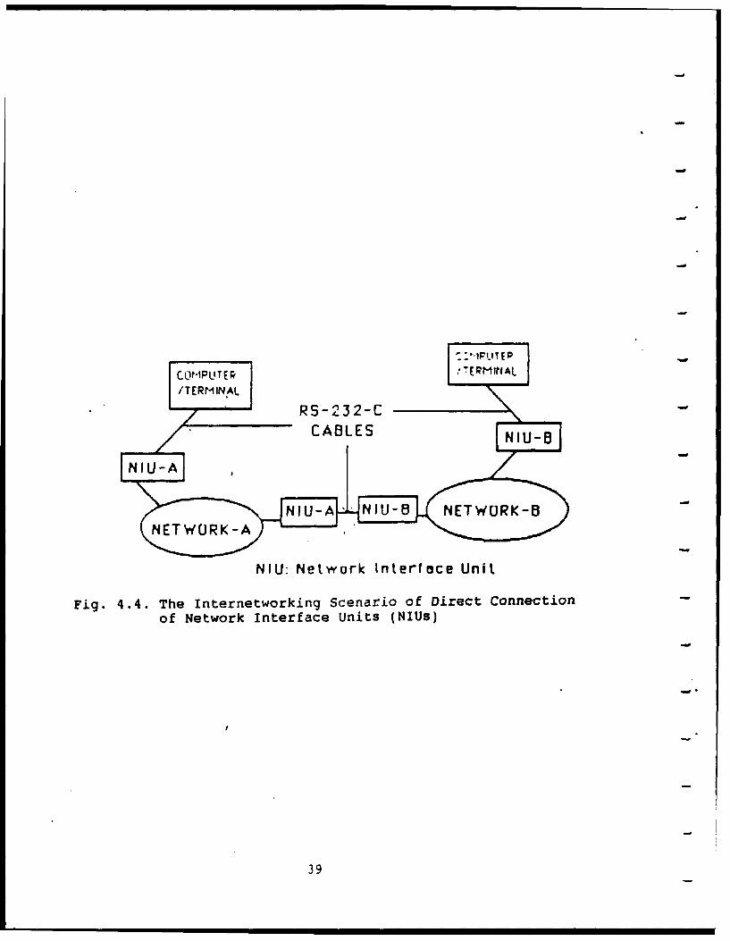
For those computer networks using stand-alone, front-end
Network Interface Units (NIUs) with RS-232-C interface, the
simplest internetworking approach is direct connection pairs of
NIUs via RS-232 cables. In our Computer Engineering Research
Laboratory (CERL), we connect Sytek LocalNet-20 PCU boxes with
CDS Token/Net TIM boxes via RS-232-C Null Modem cables. Users in
LocalNet-20 LAN can communicate with users in Token/Net LAN via
the direct connection of Network Interface Units. Figure 4.4
shows the internetworking scenario of direct connection of Wruit.
38
NIU:LTE NerTItro ERNA
Fig. 4.4. TeRINtentokn ceai fDrctCneto
of~IU Network Interf ace Units(I)
39
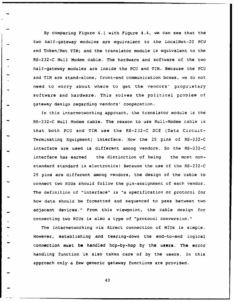
By comparing Figure 4.1 with Figure 4.4, we can see that the
two half-gateway modules are equivalent to the LocalNet-20 PCU
and Token/Net TIM; and the translator module is equivalent to the
RS-232-C Null Modem cable. The hardware and software of the two
half-gateway modules are inside the PCU and TIM. Because the PCU
and TIM are stand-alone, front-end communication boxes, we do not
need to worry about where to get the vendors' proprietary
software and hardware. This solves the political problem of
gateway design regarding vendors' cooperation.
In this internetworking approach, the translator module is the
RS-232-C Null Modem cable. The reason to use Null-Modem cable is
that both PCU and TIM use the RS-232-C DCE (Data Circuit-
Terminating Equipment) interface. How the 25 pins of RS-232-C
interface are used is different among vendors. So the RS-232-C
interface has earned the distinction of being the most non-
standard standard in electronics! Because the use of the RS-232-C
25 pins are different among vendors, the design of the cable to
connect two NIUs should follow the pin-assignment of each vendor.
The definition of "interface" is "a specification or protocol for
how data should be formatted and sequenced to pass between two
adjacent devices." From this viewpoint, the cable design for
connecting two NIUs is also a type of "protocol conversion."
-- The internetworking via direct connection of NIUs is simple.
However, establishing and tearing-down the end-to-end logical
connection must be handled hop-by-hop by the users. The error
handling function is also taken care of by the users. In this
approach only a few generic gateway functions are provided.
40
4.3.2 Aporoach 2: Interconnection through Computer Ports
One objective of gateway design is to make the gateway as
user-friendly and transparent as possible. From that point of
view, "Approach 1: Internetworking via Direct Connection of NIUs"
is not a good approach, although it is the simplest. To make the
gateway user-friendly and transparent, the translator module can
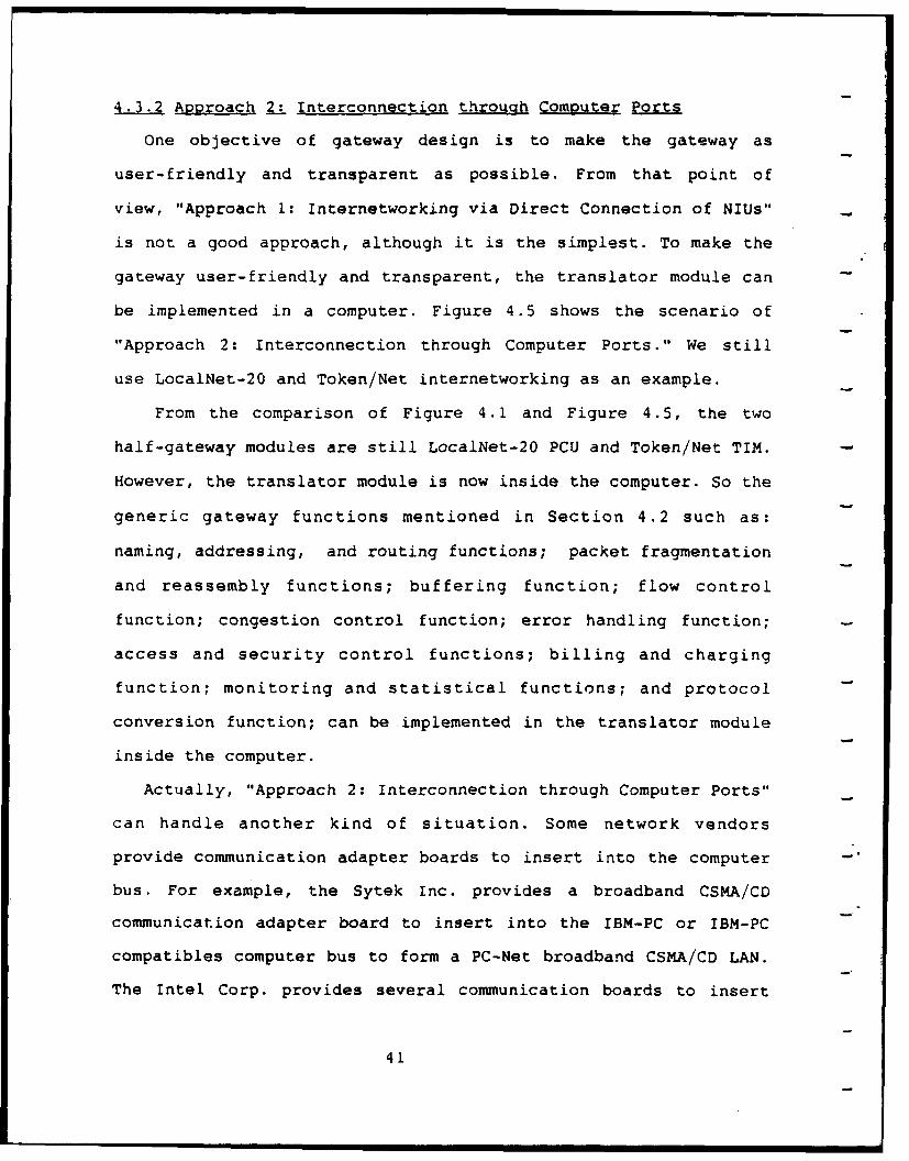
be implemented in a computer. Figure 4.5 shows the scenario of
"Approach 2: Interconnection through Computer Ports." We still
use LocalNet-20 and Token/Net internetworking as an example.
From the comparison of Figure 4.1 and Figure 4.5, the two
half-gateway modules are still LocalNet-20 PCU and Token/Net TIM.
However, the translator module is now inside the computer. So the
generic gateway functions mentioned in Section 4.2 such as:
naming, addressing, and routing functions; packet fragmentation
and reassembly functions; buffering function; flow control
function; congestion control function; error handling function;
access and security control functions; billing and charging
function; monitoring and statistical functions; and protocol
conversion function; can be implemented in the translator module
inside the computer.
Actually, "Approach 2: Interconnection through Computer Ports"
can handle another kind of situation. Some network vendors
provide communication adapter boards to insert into the computer -
bus. For example, the Sytek Inc. provides a broadband CSMA/CD
communication adapter board to insert into the IBM-PC or IBM-PC
compatibles computer bus to form a PC-Net broadband CSMA/CD LAN.
The Intel Corp. provides several communication boards to insert
41
C 1f-PlJ7EV AS
TPANSLATOR A/19 MOD'ULE COMPUJTERwj~w /TERMINAL
0ENEPIC GATE'wAY'
COMPUTER F UfIC T 'Of 1- /TERMINAL.
P5-Z 3 2-,ZNC-
CAeLES
Nls Neiwork Interface Unit
Fig. 4.5. The Scenario of Internetworking Through Computer Ports
42
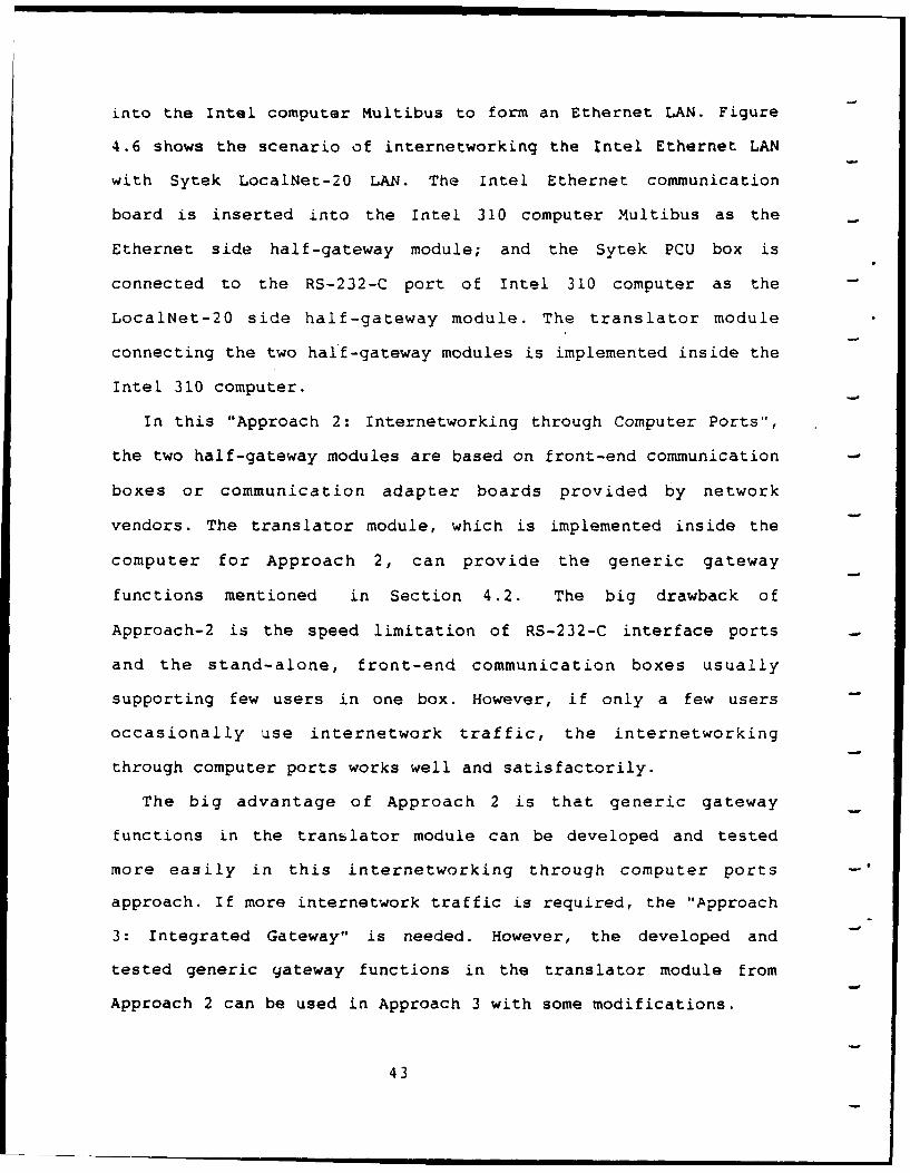
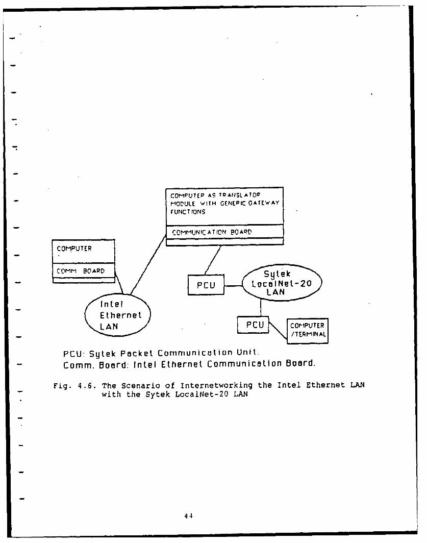
into the Intel computer Multibus to form an Ethernet LAN. Figure
4.6 shows the scenario of internetworking the Intel Ethernet LAN
with Sytek LocalNet-20 LAN. The Intel Ethernet communication
board is inserted into the Intel 310 computer Multibus as the
Ethernet side half-gateway module; and the Sytek PCU box is
connected to the RS-232-C port of Intel 310 computer as the
LocalNet-20 side half-gateway module. The translator module
connecting the two half-gateway modules is implemented inside the
Intel 310 computer.
In this "Approach 2: Internetworking through Computer Ports",
the two half-gateway modules are based on front-end communication
boxes or communication adapter boards provided by network
vendors. The translator module, which is implemented inside the
computer for Approach 2, can provide the generic gateway
functions mentioned in Section 4.2. The big drawback of
Approach-2 is the speed limitation of RS-232-C interface ports
and the stand-alone, front-end communication boxes usually
supporting few users in one box. However, if only a few users
occasionally use internetwork traffic, the internetworking
through computer ports works well and satisfactorily.
The big advantage of Approach 2 is that generic gateway
functions in the translator module can be developed and tested
more easily in this internetworking through computer ports
approach. If more internetwork traffic is required, the "Approach
3: Integrated Gateway" is needed. However, the developed and
tested generic gateway functions in the translator module from
Approach 2 can be used in Approach 3 with some modifications.
43
COMPUTEP As TRAtISLATOP
MOOULE WITH GENEPIC GATEWAY
FUNC T IONS
COMMUNICATION BOARtD
- COMPUTER
COMM BOARDStk
PCU LocalNet-20LAN
IntelEthernetLAN .PCU COMPUTER
PCU: Sytek Packet Communicat ion Unit.Comm. Board: Intel Ethernet Communication Board.
Fig. 4.6. The Scenario of Internetworking the Intel Ethernet LAN
with the Sytek LocalNet-20 LAN
44
4.3 Apo&roach ). Integrated Gateway
To support bigger bandwidth and multiple user sessions for
internetworking, Approach 3: Integrated Gateway, which is
more complicated than Approach 1 and Approach 2, should be taken.
The architecture of "Approach 3: Integrated Gateway" is the same
as Figure 4.1. The big difference between Approach 2 and Approach
3 is that the two half-gateway modules of Approach 3 are based on
the network vendors' proprietary internal design information of
hardware and software implementations. In Approach 1 and Approach
2, we use the stand-alone, front-end communication boxes (NIUs)
or communication adapter boards as the two half-gateway modules;
so the required information and cooperation from network vendors
is minimum. However, the "Approach 3: Integrated Gateway" needs
the network vendors' cooperation in providing the hardware and
software internal design and implementation information of the
two interconnected networks. To obtain the internal design and
implementation information from network vendors is the biggest
challenge in this integrated gateway approach.
The integrated gateway is a multi-processor system which
consists of several single board computers (SBC's). These SBC's
are inserted into a stand-alone chassis, or micro-computer bus,
or mini-computer bus. The computer interface bus may be: Intel
Multibus, Motorola VME-bus, DEC Q-bus, IBM-PC bus, etc. -
Basically, all of the hardware and software design principles of
multi-processor systems can be applied to the integrated gateway
design. Each of the two half-gateway modules and translator
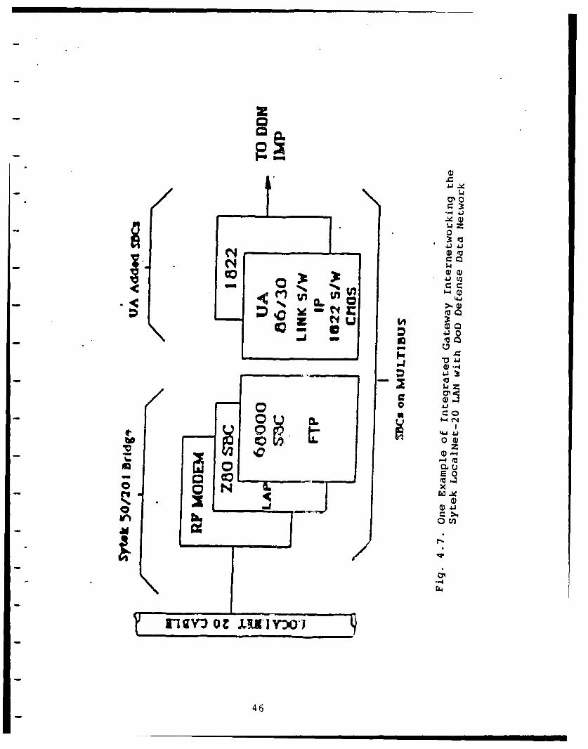
module can be implemented in one or more SBCs. Figure 4.7 shows
45
a)0
41 (
14 Q
4~ J
s0
0 tm
46J
one example of integrated gateway which interconnects Sytek
LocalNet-20 LAN and DoD Defense Data Network (DDN). This
integrated gateway was developed by our CERL gateway research
team. We describe the integrated gateway design steps as follows:
4.3.3.1 Step 1: Understand and Use Each of the Two Networks
The gateway designer should understand the hardware,
software, and protocols of each of the two interconnected
networks, especially, in the case of vendors using proprietary
non-standard protocols. If possible, the designer should also use
each of the two networks to understand the user-network
interface, the network access procedure, the session establishing
and terminating procedures, the error handling procedure, and the
characteristics of each network. In the case of internetworking
the existing network with the future new network, e.g., LAN-ISDN
Internetworking, an understanding of the protocols and
characteristics of the future new network is very important.
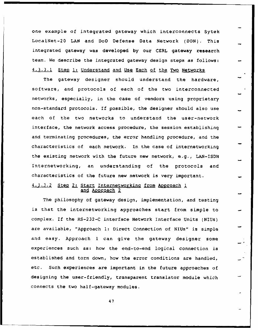
4.3.3.2 Ste 2:" Start Internetworkina from Approach 1and Approach 2
The philosophy of gateway design, implementation, and testing
is that the internetworking approaches start from simple to
complex. If the RS-232-C interface Network Interface Units (NIUs)
are available, "Approach 1: Direct Connection of NIUs" is simple
and easy. Approach 1 can give the gateway designer some
experiences such as: how the end-to-end logical connection is
established and torn down, how the error conditions are handled,
etc. Such experiences are important in the future approaches of
designing the user-friendly, transparent translator module which
connects the two half-gateway modules.
47
Based on the computer and available NIUs, the "Approach 2:
Interconnection through Computer Ports" can develop and test the
important gateway translator module in which the generic gateway
functions are implemented. The gateway translator module with
generic gateway functions developed in Approach 2 can be used in
-the "Approach 3: Integrated Gateway" with some modifications.
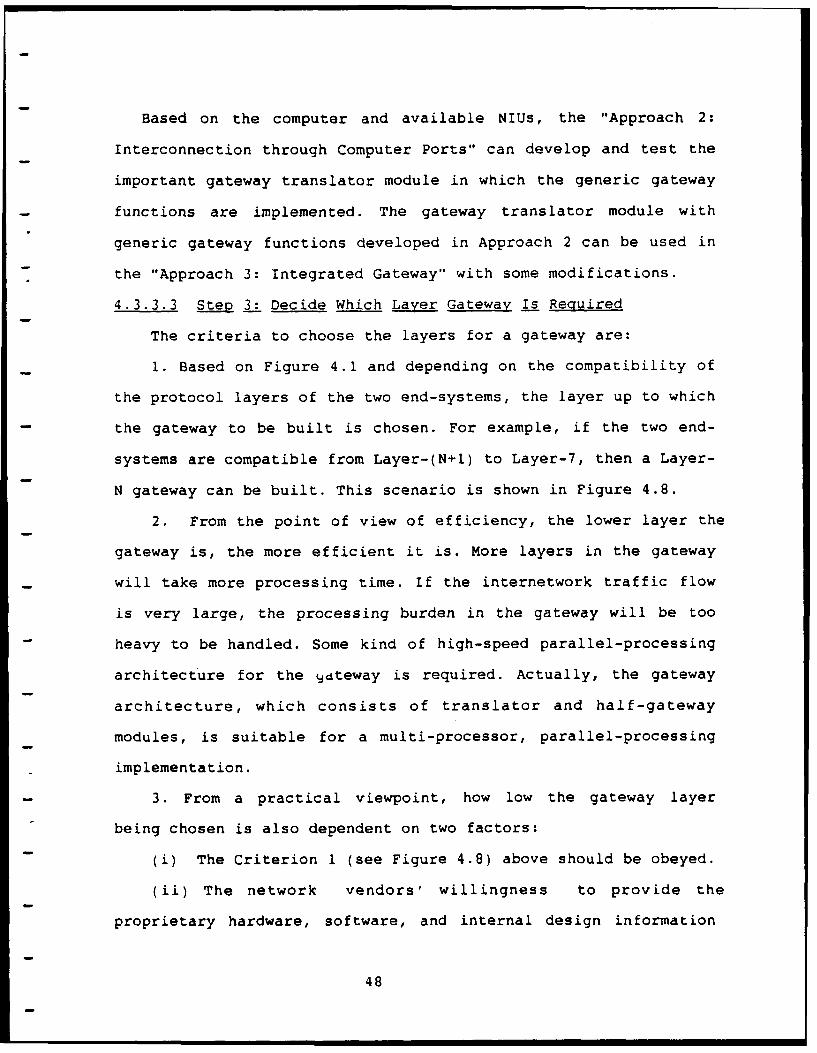
4.3.3.3 Ste, 3: Decide Which Laver Gateway Is Required
The criteria to choose the layers for a gateway are:
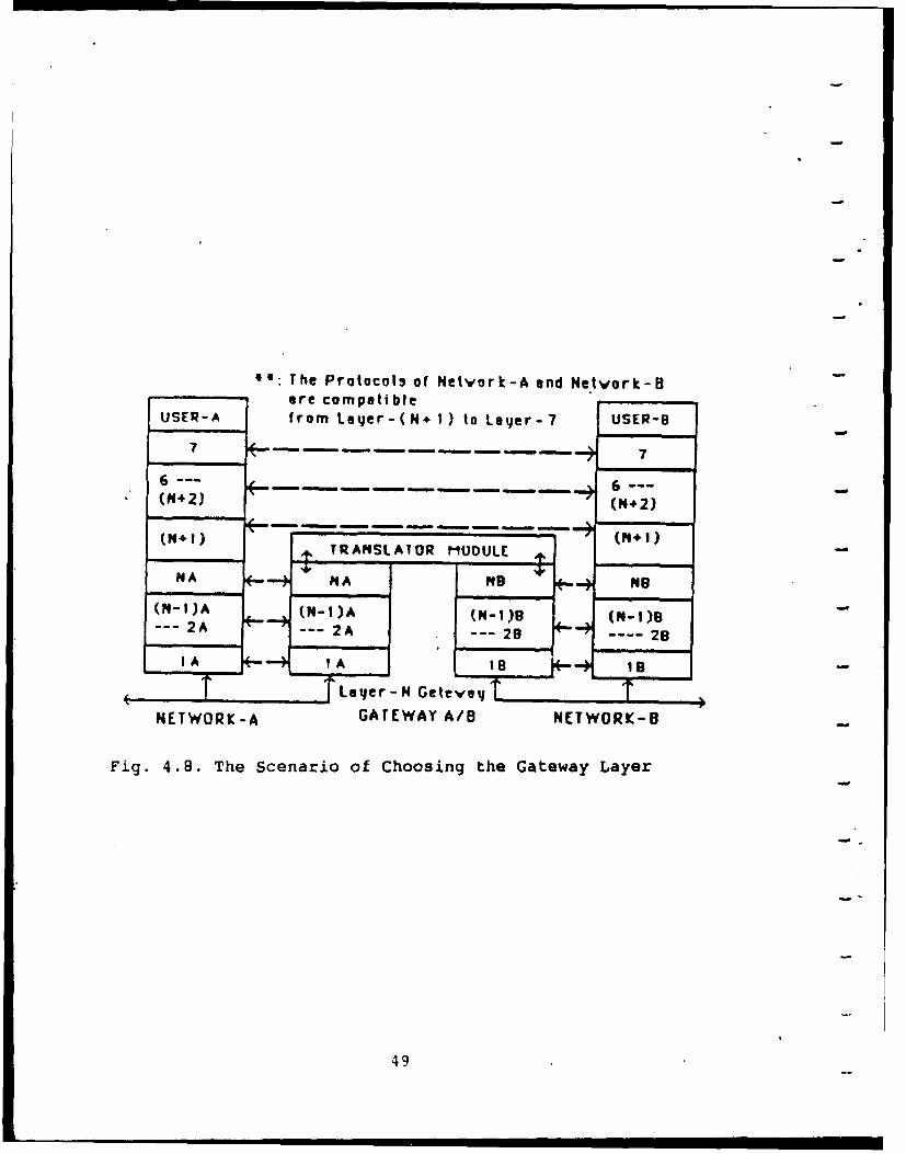
1. Based on Figure 4.1 and depending on the compatibility of
the protocol layers of the two end-systems, the layer up to which
the gateway to be built is chosen. For example, if the two end-
systems are compatible from Layer-(N+l) to Layer-7, then a Layer-
N gateway can be built. This scenario is shown in Figure 4.8.
2. From the point of view of efficiency, the lower layer the
gateway is, the more efficient it is. More layers in the gateway
will take more processing time. If the internetwork traffic flow
is very large, the processing burden in the gateway will be too
heavy to be handled. Some kind of high-speed parallel-processing
architecture for the qdteway is required. Actually, the gateway
architecture, which consists of translator and half-gateway
modules, is suitable for a multi-processor, parallel-processing
implementation.
3. From a practical viewpoint, how low the gateway layer
being chosen is also dependent on two factors:
(i) The Criterion 1 (see Figure 4.8) above should be obeyed.
(ii) The network vendors' willingness to provide the
proprietary hardware, software, and internal design information
48
00: The Protocols of Netvork-A and Netvork-8are compatible
USER-A from Lyer-(N* I) to Layer-7 USER-B
7 a a. 7
6-- Nnf . ---(M4 2) (N.+2)
(P,) TRANSLAOR MUOULE
NA NA N - NB
(N-I)A (N-1)A (N-1)1 (N-I)82A 2A --- 2 28
1 ---A 1,A 18e I--+ ,
S7 eTr-N GeteveT TNETWORK-A GATEWAY A/B NETWORK-B
Fig. 4.8. The Scenario of Choosing the Gateway Layer
49
becomes the most important factor in Integrated Gateway design.
For example, the end-systems are compatible from Layer-(N+l) to
Layer-7, i.e., a Layer-N gateway is possible; however, the
available hardware, software, and internal design information
from network vendors are in the Layer-M, where M is greater than
-N. In such case, the real Integrated-Gateway will be a Layer-M
gateway.
4.3.3.4 Step 4: Obtain the Required Information fromNetwork Vendors
Based on Steps 1, 2, and 3, the gateway designer lists all
the needed hardware, software, interface, and internal design
information which the two network vendors should provide. A lot
of political considerations are involved in this Step 4. Under
what conditions the network vendors agree to provide the needed
information, e.g., non-disclosure agreement, license fee, etc.
What kind hardware interface, e.g., Intel Multibus, Motorola VME-
bus, DEC Q-bus, IBM-PC bus, or some special buses, that vendors'
hardware can be inserted ? What kind of operating system can the
vendors' protocol implementation run ? Is there any interface
conflict between the software and hardware products from the two
network vendors ? Many such questions should be answered before
the Integrated Gateway design decision is made.
4.3.3.5 Step 5: Decide What Kind of Chassis or Computerto Build the Gateway
The Integrated Gateway is a multi-processor system which
comprises several Single Board Computers (SBCs). So the
Integrated Gateway should be in a stand-alone chassis with
interface bus or in a micro-computer or mini-computer with enough
50
interface slots on the backplane.
If the stand-alone chassis is chosen, then the software will
be in Read Only Memory (ROM) on SBCs; or the software is
developed on a host computer, then it is downloaded to the target
SBCs. Using the stand-alone chassis, the software development and
testing are on separate systems, i.e., developed on a host
computer and tested on SBCs. Such separation of development and
testing is not convenient. The name server, and monitoring and
statistical functions of generic gateway functions require some
kind of non-volatile storage devices such as floppy or hard disk
drives; however, the stand-alone chassis usually does not provide
non-volatile storage devices. For the two reasons above, a micro-
computer or a mini-computer with enough interface slots is the
preferable candidate for Integrated Gateway.
4.3.3.6 Steo 6: Design the Translator Module to Interfacewith the Two Half-Gateway Modules
We mentioned that the procurement of the network internal
design information, hardware, and software, i.e., the vendors'
proprietary protocol implementation, from the network vendors is
the biggest challenge in this Integrated Gateway approach. Now we
assume that we can get the necessary cooperation and support from
network vendors, i.e., the network vendors can provide the
hardware and software of the two half-gateway modules for the
Integrated Gateway approach. Then the next challenge is how to
implement the translator module, which provides most of the
generic gateway functions, to interface and connect the two half-
gateway modules.
Because every network has its own specific characteristics,
51
the design and implementation of each translator module will be
different among all integrated gateway cases. That is, although
the general principles are the same, the design and
implementation of each translator module should reflect the
special characteristics of the two interconnected networks.
Because the translator module in Approach 2 can be used in
Approach 3 with some modifications, and Approach 2 is much easier
in implementation and testing, we suggest that "Approach 2:
Internetworking through Computer Ports" should be taken before
"Approach 3: Integrated Gateway."
4.3.3.7 Step 7: Implementation and Testing of InteQrated Gateway
The integrated gateway is a complicated multi-processor,
parallel-processing system with hardware and software provided by
the two network vendors and the gateway designer. The
implementation and testing of the Integrated Gateway is a
tremendous task. All the design, implementation, and testing
principles of the multi-processor, parallel-processing systems
can be applied to the integrated gateway. The philosophy here is
that during the designing process, a method to test the gateway
should always be kept in mind; and the implementation and testing
should start from basic to advanced, from simple to complex.
For example, we cannot put all the generic gateway functions
mentioned in Section 4.2 into the integrated gateway in the
beginning. These generic gateway functions should be added into
the Integrated Gateway one by one, and tested one by one in
sequence. The first step of implementation is the simplest
translator module without any complex generic gateway function.
52
" " = " •------------|
The simplest translator module is not user-friendly or
transparent, it just interfaces and connects the two half-gateway
modules provided by the two network vendors. The purpose of this
first step is to make sure that the two half-gateway modules can
interwork together and can provide the internetworking end-to-end
connection via this simple gateway.
After the first step implementation and testing is passed, then
the generic gateway functions such as: protocol conversion
function; addressing, naming, and routing functions; packet
fragmentation and reassembly functions; buffering function; flow
control function; congestion control function; error handling
function; access and security control functions; billing and
charging functions; and monitoring and statistical functions can
be added into the translator module. The implementing and testing
these generic gateway functions should be one by one in sequence.
We emphasize here again that although the general principles of
these generic gateway functions are the same, the implementation
of them will be different among different integrated gateways
which connect pairs of different networks. That is, N(N-l)/2
different integrated gateways are needed for N different
networks.
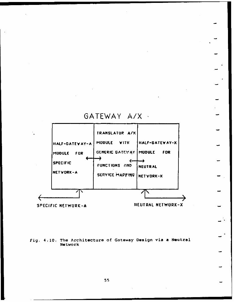
4.3.4 Approach 4: Gateway Design via a Neutral Network
Figure 4.9 shows the scenario of internetworking via a
neutral network. Figure 4.10 shows the architecture of Gateway
Design via a Neutral Network. The gateway architecture of this
Approach 4 is the same as that of Figure 4.1. The design,
implementation, and testing procedures )f this Approach 4 gateway
53
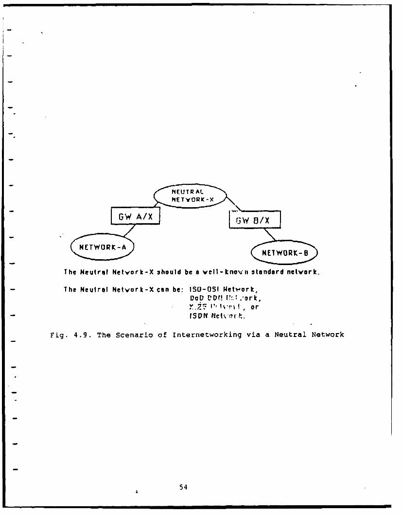
The Neutral Netvork-X should be a vell-knou'ii standard network.
The Neutral Network-X can be: I50-051 Wetw,.ork,Dot) VD(! V,., .ork,
ISDN 1zva .
Fig. 4.9. The Scenario of Internetworking via a Neutral Network
54
GATEWAY A/X
TRANSLATOR A/X
IHALF-GATEWVAY-A MODULE WITH HALF-GATEWAY-X
MODULE FUR GENERIC GATr.AY MODULE FOR
SPECIFIC(" +
FUNCTIONS AfND NEUTRAL
NETWORK-A SERVICE MAPFtyVl NETWORK-X
SPECIFIC NETWURK-A NEUTRAL NETWORK-X
Fig. 4.10. The Architecture of Gateway Design via a NeutralNetwork
55
are the same as in Approach 3: Integrated Gateway. However,
the difference in this Approach 4 gateway is that one half-
gateway module is implemented with well-known standard protocols
- such as: ISO-OSI protocols, DoD DDN (Defense Data Network)
protocols, CCITT X.25 protocols, or CCITT ISDN protocols. That
is, the Neutral Network can be ISO-OSI network, DoD DDN network,
X.25 network, or ISDN network. This "Approach 4: Gateway Design
via a Neutral Network" has some advantages and disadvantages. We
discuss them as follows:
The advantages of "Gateway Design via a Neutral Network" are:
i. In Approach 3: Integrated Gateway, N(N-1)/2 integrated
gateways are needed for N networks. In Approach 4: Gateway Design
via a Neutral Network, because any two networks can be
interconnected via the Neutral Network, there need only be N
gateways for N networks.
2. Because the chosen Neutral Network is a well-known
standard network such as X.25 network or ISDN, the protocol
implementation of the half-gateway module connecting the Neutral
Network is easier to implement it or to obtain it from third-
party organization.
3. We mentioned that the biggest challenge in Approach 3:
Integrated Gateway is the procurement of the necessary internal
design information of vendors' proprietary protocol
implementations from the two network vendors. In Approach 3, we
must handle such political considerations with two network
vendors. In Approach 4: Gateway Design via a Neutral Network, we
only require to handle such political considerations with one
56
network vendor, because of the Advantage 2 mentioned above.
4. If the gateway is designed by network vendor himself, then
the Approach 4: Gateway Design via a Neutral Network will be no
political considerations involved at all. For the half-gateway
module connecting the vendor's proprietary network, the vendor
has all the necessary internal design information. For the half-
gateway module connecting the Neutral Network, because the
Neutral Network is a well-known standard network, to obtain or to
implement the hardware and software of standard protocols is
easier. For this reason, the network vendors favor this "Approach
4: Gateway Design via a Neutral Network."
The only disadvantage of this "Approach 4: Gateway Design via
a Neutral Network" is the possible overhead and loss of
efficiency. We will consider two situations: Case 1: Connecting
two remotely located LANs via a Neutral Network; Case 2:
Connecting two LANs located at the same site via a Neutral
Network. For Case 1, the scenario in Figure 4.9 is essential and
justified, there are no overhead and no loss of efficiency. For
Case 2, because the two LANs are located at the same site, to
connect them via the Neutral Network means the Neutral Network
will be overhead. The packets from one LAN to the other LAN at
the same site still go through the extra Neutral Network. The
extra protocol processing delay in the extra Neutral Network
causes the loss of efficiency in Case 2.
57
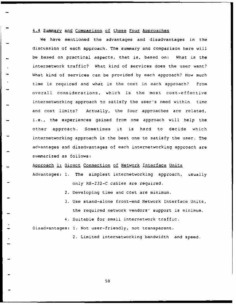
4.4 Summary and Comparison of these Four Approaches
We have mentioned the advantages and disadvantages in the
discussion of each approach. The summary and comparison here will
be based on practical aspects, that is, based on: What is the
internetwork traffic? What kind of services does the user want?
What kind of services can be provided by each approach? How much
time is required and what is the cost in each approach? From
overall considerations, which is the most cost-effective
internetworking approach to satisfy the user's need within time
and cost limits? Actually, the four approaches are related,
i.e., the experiences gained from one approach will help the
other approach. Sometimes it is hard to decide which
internetworking approach is the best one to satisfy the user. The
advantages and disadvantages of each internetworking approach are
summarized as follows:
Approach 1: Direct Connection of Network Interface Units
Advantages: 1. The simplest internetworking approach, usually
only RS-232-C cables are required.
2. Developing time and cost are minimum.
3. Use stand-alone front-end Network Interface Units,
the required network vendors' support is minimum.
4. Suitable for small internetwork traffic.
- Disadvantages: 1. Not user-friendly, not transparent.
2. Limited internetworking bandwidth and speed.
58
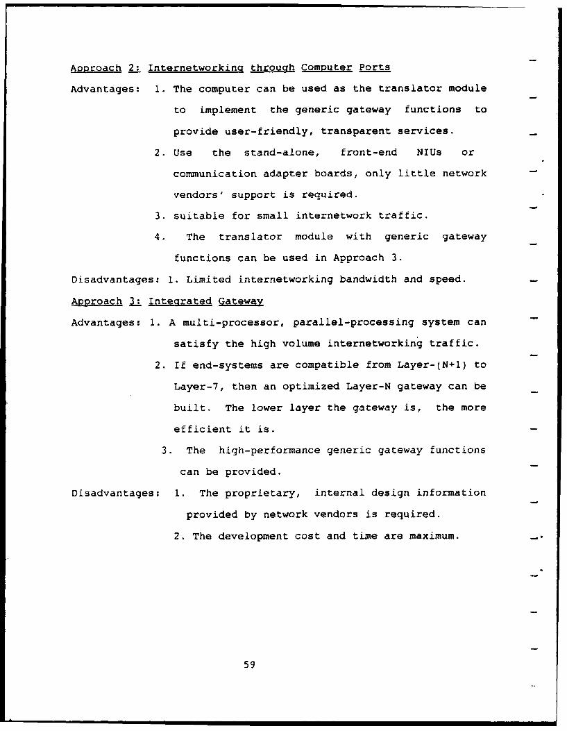
Approach 2: Internetworkinq through Computer Ports
Advantages: 1. The computer can be used as the translator module
to implement the generic gateway functions to
provide user-friendly, transparent services.
2. Use the stand-alone, front-end NIUs or
communication adapter boards, only little network
vendors' support is required.
3. suitable for small internetwork traffic.
4. The translator module with generic gateway
functions can be used in Approach 3.
Disadvantages: 1. Limited internetworking bandwidth and speed.
Approach 3: Integrated Gateway
Advantages: 1. A multi-processor, parallel-processing system can
satisfy the high volume internetworking traffic.
2. If end-systems are compatible from Layer-(N+1) to
Layer-7, then an optimized Layer-N gateway can be
built. The lower layer the gateway is, the more
efficient it is.
3. The high-performance generic gateway functions
can be provided.
Disadvantages: 1. The proprietary, internal design information
provided by network vendors is required.
2. The development cost and time are maximum.
59
Approach 4: Gateway Design via a Neutral Network
Advantages: 1. It is an integrated gateway, however, one half-
gateway module connects a well-known standard
network. The half-gateway module for standard
network is easier to implement.
2. Two remotely located LANs can be interconnected
via the Neutral Network.
3. If the gateway is designed by the network vendor,
he has all the proprietary internal design
information of one half-gateway module, and the
other half-gateway module is based on well-known
standard protocols. So the network vendors favor
Approach 4: Gateway Design via a Neutral Network.
Disadvantages: I. If the two LANs are located at the same site,
then the extra Neutral Network becomes an
overhead. It will cause extra protocol
processing delay and loss of efficiency.
Choosing the most cost-effective internetworking approach
should base on several factors: such as services wanted by users,
internetworking traffic, cost and time limitations, required
support and cooperation from network vendors, etc. We suggest
four internetworking approaches which include the simplest
-"Approach 1: Direct Connection of NIUs" and the complicated
multi-processor, parallel-processing gateway design in "Approach
3: Integrated Gateway." The "Approach 4: Gateway Design via a
Neutral Network" will become more important when the ISO-OSI
standard network and CCITT ISDN network become mature and popular
60
in the future. We emphasize here again that the internetworking
design, implementation, and testing should start from basic to
advanced, from simple to complex. Although the implementation of
each specific gateway, which interconnects two specific networks,
is different from one another, the general internetworking
principles are the same.
We have described the general internetworking principles in
this chapter. We will discuss the "ISDN -- LAN (TOP or MAP)
Gateway" in Chapter 5, and the "ISDN/DDN Gateway" in Chapter 6.
61
5. ISDN-LAN GATEWAY DESIGN
5.1. General Considerations
This ISDN-LAN gateway design will follow the general
- principles, guidelines, and methodology of internetworking
approaches which were described in Chapter 2, Chapter 3, and
Chapter 4. Before we go into the details of this specific ISDN-
LAN gateway design, we briefly review the general internetworking
approaches in Chapter 4.
In Chapter 4, we described the general gateway model (see Fig.
4.1 and Fig. 4.2). The generic gateway functions were discussed
in Section 4.2. We also proposed four internetworking approaches
in Sectioni 4.3. Based on some practical aspects and constraints,
those four internetworking approaches were compared in Section
4.4. The final goal of internetworking two different networks is
Approach-3: Integrated Gateway. The general procedures of
integrated gateway designs and implementations were described in
Section 4.3.3. Those general procedures are outlined again as
follows:
1. Understand and Use Each of the Two Networks (A&B).
2. Start Internetworking from Approach-i and Approach-2.
3. Decide Which Layer Gateway Is Required.
4. Obtain the Required Information from Network Vendors.
5. Decide What Kind of Chassis or Computer to use forimplementing the Gateway.
6. Design the Translator Module to Interface with the TwoHalf-Gateway Modules.
7. Implement and Test the Integrated Gateway.
62
The originality of internetworking problems comes from the
incompatibility of the two interconnected networks. Figure 5.1
shows the relationships between the OSI Reference Model
(Architecture), OS Service Definitions, OSI Protocol
Specifications, and Implementations. Usually, most people assume
that the incompatibility comes from the two interconnected
networks using different sets of protocols. However, two networks
using the same set of protocols may still be incompatible. The
problem is that there are different parameters and options to be
used by the protocol implementor even when using the same set of
protocols. One example of this type of incompatibility problem
is the implementations of CCITT X.25 protocol. X.25 covers the
lower three layers of the OSI Seven Layer Reference Model. Figure
5.2 shows the three X.25 packet switched public data networks
implemented by Transpac in France, PSS in United Kingdom, and DXX
in Japan. It can be seen that the X.25 parameters and options
used by those three X.25 networks were different (based on 1983
information) (24]. These three X.25 networks were incompatible,
even though they used X.25 standard protocol.
From the examples of X.25 networks, we emphasize again that
the gateway designer must study and understand the detailed
implementations, e.g., parameters and options, of the two
interconnected networks. That is, the real design and
implementation of a gateway to internetwork two networks should
be based on the detailed implementation and characteristics of
the two interconnected networks.
63
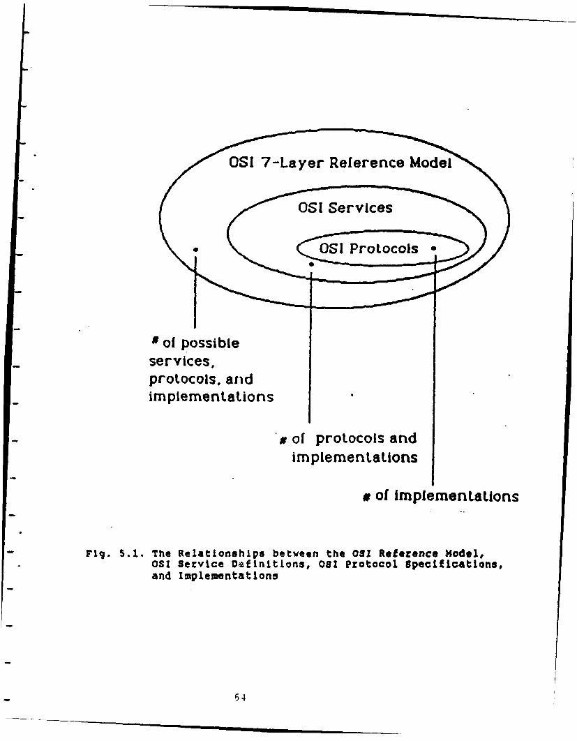
l I Sevie
OSI Protocols
of possibleservices,protocols, andimplementations
# of protocols andimplementations
a of implementations
Fig. 5.1. The Relationships between the 01 Reference Model,OSI Service Definitions, 081 Protocol Specifications,and Implementations
64
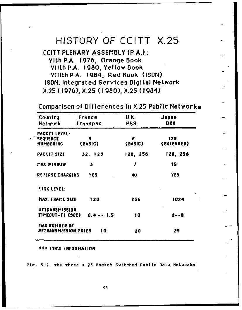
HISTORY OF CCITT X.25CCITT PLENARY ASSEMBLY (P.A.):
VILh P.A. 1976, Orange BookVllth P.A. 1980, Yellow BookVlllth P.A. 1984, Red Book (ISDN)
ISDN: Integrated Services Digital NetworkX.25 (1976), X.25 (1980), X.25 (1984)
Comparison of Differences in X.25 Public Networks
Country France U.K. JapanNetwork Transpac PSS DXX
PACKET LEVEL:SEQUENCE 8 a 128NUMBERING (BASIC) (BASIC) (EXTENDED)
PACK ET SIZE 32. 128 128, 256 128, 256
MAX WINDOW 3 7 15
RIPIERSE CHARGING YES NO YES
LINX LEYEL:
MAX. fRAME SIZE 128 256 1024
RETRANSMISSIONTIMEOUT-TI (SEC) 0.4-- 1.5 10 2--8
MAX NUMBER OFRETRANSMISSION TRIES tO 20 25
** 1963 INFORMATION
Fig. 5.2. The Three X.25 Packet Switched Public Data Networks
65
5.2 Implementation Plan of ISDN for the U.S. Army
The following information was obtained from the paper
published in the IEEE Communications Magazine, December 1987,
"Army Implementation of ISDN,"
by Joseph J. Rudigier, Chief of the Systems and Technology
Division of the Plans Directorate of the U.S. Army Information
Systems Command at Fort Huachuca, Arizona [25].
Figure 5.3 shows the Department of Defense (DoD) ISDN
organization. Figure 5.4 shows the DoD Defense Communications
Agency (DCA) proposed mid-term ISDN CONUS architecture. Figure
5.5 shows the DCA proposed far-term ISDN architecture. The plans
call for a mid-term ISDN Architecture that is based on the 1988
CCITT standards. Long-haul ISDN services in the CONtinental
United States (CONUS) will be obtained by DCA under a service
contract arrangement.
In the DCA proposed mid-term ISDN CONUS architecture, LAN's
,lo not interconnect the commercial ISDN switching node directly.
Instead, LAN's interconnect with ISDN PABX's, then the PABX's
access the commercial ISDN switching node. Thus our ISDN-LAN
gateway design will be based on internetworking a LAN and an
ISDN-compatible PBX.
* In the DCA proposed far-term ISDN architecture, the plans for
-- the 2005 time-frame call for the DoD ISDN switching and network
control to be fully integrated. The LAN's interconnect with the
WideBand (WB, Fiber Optic Cable) ISDN Network Termination (NT) to
access ISDN. Considering the high speed of many LAN's
(Mbits/sec), this kind of wideband fiber optic cable interface to
66
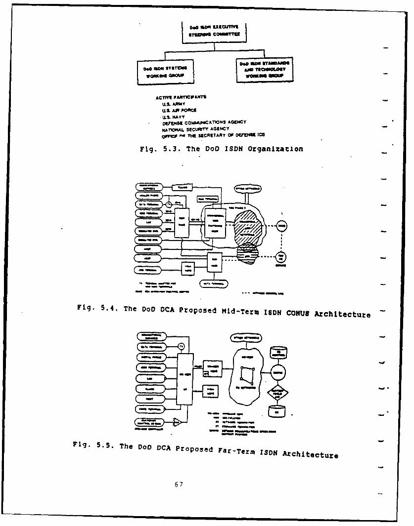
ACfVl[ PAAT1CPINTSkL. AAWY
kL& AI FORCEU.0. NAVYOVa" COWAIPOCATIONS AGENCYpdATIONAL 34CLMrY AOEHCY-
QOUlV e T ? 4 CAETAMY Of OuusM (CO
Fig. 5.3. The 00D ISDN Organization
Fig. 5.4. The DOD OCA proposed Mid-Term ISDN4 CONUS ArchiteCture
( law-a
F~~~~~ g .,w w 5 . . T e D D D A P r p s d F r T r I D f A c l e t r
6OW
wideband ISDN is more suitable for ISDN-LAN gateway design.
However, since the time-frame of wideband ISDN is after the year
2000 [26], we leave the fiber optic cable ISDN-LAN Gateway Design
- for future study.
The following paragraph is directly quoted from Ref [25]:
"While planning continues for the transition to ISDN, local area
networks (LANs) are being installed at many Army installations.
The Army policy is to use LANs that meet the IEEE 802.3 standard.
Generally it has been assumed that LANs will interface with ISDN
through terminal adapters (TAs) or gateways. However, new LAN
standards and technologies are becoming available, including
Fiber Data Distribution Interface (FDDI) which can operate at
rates up to 200Mb/s. Also, office automation needs are continuing
to expand, both in numbers and required bandwidth. As a result,
planning for ISDN is being reviewed continually to take these
factors into consideration. It is entirely possible that Army
installation information system architecture of the future may
have to change significantly."
From the quoted paragraph above, in the point of view of the
Army, the ISDN and LANs internetwork via TAs or gateways. The TA
Approach will be the same as Approach-l: Direct Connection of
Network Interface Units or Approach-2: Interconnection through
Computer Ports. The Gateway Approach will be the same as
Approach-3: Integrated Gateway or Approach-4: Gateway Design via
a Neutral Network in Chapter 4.
We will start the discussion of the ISDN-LAN gateway design
procedures using the seven steps listed in Section 5.1. The
68
discussion will follow the general guidelines in the paper "Army
Implementation of ISDN [251." We will describe the specific
ISDN-LAN gateway design step-by-step. However, a discussion of
"Step-3: Decide Which Layer Gateway Is Required" will be given
first. We want to give the reasons why we choose a Layer-3
(network layer) ISDN-LAN gateway in the beginning. Then we will
go back to start the discussion from Step i.
5.3 Layer 3 (Network Layer) ISDN-LAN Gateway
In Figure 2.1: ISO and CCITT OSI Seven-Layer Reference Model,
we mentioned that the seven layers are subdivided into two
groups. The lower group includes the physical layer, the data
link layer, and the network layer. These lower three layers are
concerned with packet transmission in the communication
subnetwork. The upper group includes the transport layer, the
session layer, the presentation layer, and the application layer.
These upper four layers handle the end-to-end communications
between user processes. "Figure 3.3: The Scenario of
Internetworking Based on the Three-Sublayer Network-Layer Model"
shows how the ISO and CCITT have tried to limit the
internetworking problems in the lower three layers of the OSI
reference model. The lower three layers will be different from
various networks using different technologies. The ISO and CCITT
assume that the higher four layers in the two communicating end-
systems will be compatible. Thus the Layer-3 (network layer)
gateways will be used in the world of ISO and CCITT.
69
Figure 5.6 shows the scenario of technology-independent upper
layers and technology-dependent lower layers in the OSI seven
layer reference model [27]. In Figure 5.6, the application layer
- is application-dependent; the presentation layer, session layer,
transport layer, and the upper part of the network layer are
- technology independent; and the lower part of the network layer,
the data link layer, and the physical layer are technology
dependent. That is, the higher three layers and upper part of the
network layer are software related; and the lower three layers
are both software and hardware related. For example, the
technologies used in the lower three layers include: CSMA/CD
Ethernet (IEEE 802.3), Token Bus (IEEE 802.4), Token Ring (IEEE
802.5), Fiber Optic Cable (FDDI: Fiber Distributed Data
Interface), X.25, and ISDN.
Figure 5.7 shows the layered protocol structure at the ISDN
user-network interface [28]. In Figure 5.7, the lower three
layers are ISDN protocols; however, the higher four layers are
CCITT-ISO OSI protocols. Figure 5.7 also supports our assumption
that the higher fou layers will be compatible if the two
interconnected networks both use the CCITT-ISO OSI protocols.
Thus our ISDN-LAN gateway design can be a Layer-3 (network layer)
integrated gateway.
-- For the LAN side, there are a lot of different vendor's
proprietary protocols. However, we believe that most LANs will
follow the ISO-OSI standard protocols in the future. Especially,
in the United States and worldwide eventually, the Manufacturing
Automation Protocol (MAP) will be used for factory automation,
70
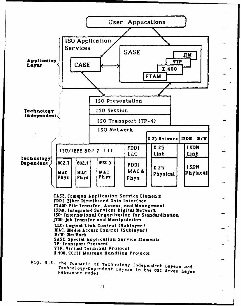
C_ User Applications
ISO Application
Application ServcesLayer CS T
ISO Presentation
TeehnoloXy ISO SessionIndependent
ISO Transport (TP-4)
ISO Network
125_ etvork SD Iv
ISO/IEEE 802 2 LIC C DLI 1.25 ISDN
Technology LLC Link Link
Dependent 802.3 e0.4 80.5 FDDI 125 ISDN
MAC MAC M AC MAC C&ph] b 1Z Py Physical Phiysical
CASE: Common Application Service ElementsEDDI: fiber Distributed Data InterfaceETAM: file Traasfer. Access, and ManagementISDN: Integrated Services Digital NetvorkISO: International Organization for StandardizationJTM: Job Transfer and ManipulationLLC: Logical Link Control (Sublarer)MAC: Media Access Control (Sublayer)I/V: Net YorkSASE: Special Application Service ElementsTP: Transport ProtocolVIP- Virtual Terminal Protocol1.400: CCITT Message Haendling Protocol
Fig. 5.6. The Scenario of Technology-Independent Layers andTechnology-Dependent Layers in the OS Seven LayerReference Model
71
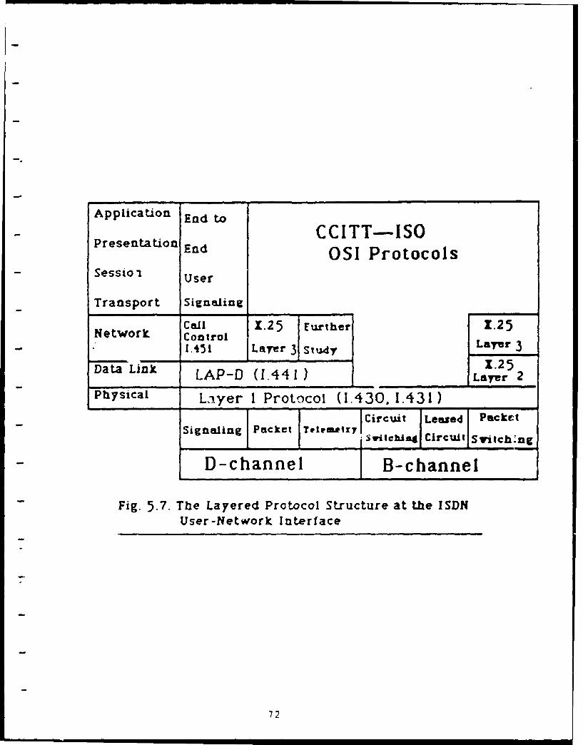
Application End to
CCITT-ISOPresentation End OS ProtocolsSessto ' User
Transport Signaling
Call 1.25 Further 1.25Network Control
1.451 Layer 3 Study Layer 3Da1.25
Data Link LAP-D (1.441) Layer 2
Physical Layer I Protocol (1.430. 1.431)
Circuit Leased PacketSignaling Packet Ye1,a~tzyif l
svitehliAt circuit Svitch-"ngD-channel B-channel
Fig. 5.7. The Layered Protocol Structure at the ISDNUser-Network Interface
72
I I I I 72
and the Technical and Office Protocols (TOP) will be used for
office automation. So we assume our LAN protocols in this ISDN-
LAN gqewy dOSL(ri will oither be MAP or TOP. From ChapLer 2
Figure 2.2, we can see that the MAP and TOP are subsets of ISO-
OSI standard protocols. This also matches our Layer-3 (network
layer) gateway design ASSUMPTION that the higher four layers in
the two end-systems should be compatible. The higher four layers
in the end-system of the ISDN side and those in end-system of
LAN side will use the same set of ISO-CCITT OSI standard
protocols. Someone may argue that the ISDN may use different
higher four layer protocols from that used by the MAP or TOP.
This may be true; however, the higher four layers are usually
software dependent. If the end-system is a computer, it can have
several different software packages for different sets of higher
four layer protocols to ensure the compatibility of the higher
four layers in the end-systems. The design procedures of the
ISDN-LAN gateway are discussed in the following sections.
5.4 Step-l: Understand and Use Each of the Two Networks
ISDN will provide the integrated services of voice, data, and
image to users through a small set of standard user-network
interfaces. LAN's, e.g., MAP or TOP in this report, usually only
provide data service to users. Because users in the LAN (MAP or
TOP) side do not have the digital telephones connected to the
LAN, the users in the LAN side cannot access the voice service of
ISDN, even there is a gateway to internetwork LAN and ISDN. This
is the limitation of ISDN-LAN gateway, because the services of
73
[SDN and those of LAN do not match. Thus in our ISDN-LAN gateway
design in this report, this ISDN-LAN gateway only provides the
data service for users between ISDN and LAN.
ISDN, TOP or MAP have seven layer protocols. As we mentioned
in Section 5.3, we assume that protocols of layer-4 to layer-7 in
the end-systems are compatible. So our ISDN-LAN gateway design is
a Layer-3 (network layer) gateway. We describe the lower three
layers of ISDN, TOP, and MAP in the following section.
5.4.1. The Lower Three Layer Protocols of ISDN
The ISDN channels at the user-network interfaces are: B, D,
HO, HI1, H12, H4 channels. The following information was obtained
from Refs. (28], (29], t30], (31].
The B, or Bearer, channel is a 64-Kbit/s bi-directional
digital voice-grade (high-quality) channel that does not carry
any signaling information. B channels will be the backbone of the
ISDN user-network interface. They will carry voice and data using
either circuit switching or packet switching.
The D channel handles both the transfer of user data and
signaling information. "Signaling" refers to the passing of
information for the establishment, maintenance, and clearing of
ISDN channels. Traditionally, the signaling information of
telephone network, such as ring, busy, and caller number, is
- passed along in-stream with the call (in-band signaling). The
ISDN user-network interface uses "out-of-band signaling" over the
O channel for more efficient transfer of data and overall use of
the B channels. Since signaling occurs in bursts and is not time-
consuming, the D channel will be idle for part or most of the
74
| | l i Ij
time. Therefore, the D channel can be used more efficiently by
passing low-speed packet data and telemetry information when not
in use by the signaling information for B channels. This gives a
user the choice of transmitting the packet-switched data over
either the B channel or the D channel. The transmission of
signaling information will have a higher priority on the D
channel than that of packet-switched data. Figure 5.8 shows how
the B channels and D channel are to be separated and used in ISDN
(25].
The H channels are formed out of multiple B channels. They
will generally rely on fiber optics to support multimegabit data
rates. The H channels will be used for fast facsimile, video,
high-speed data, high-quality audio, and packet switching.
The transmission rates of B, D, and H channels are:
1. Basic Access Rate: 2B + D; B channel: 64 Kb/s;D channel: 16 Kb/s.
2. Primary Access Rate: 23B + D or 30B + D;B channel: 64 Kb/s;D channel: 64 Kb/s.
3. The HO channel: 384 kbit/s.The HIl channel: 1.536 Mbit/s.The H12 channel: 1.920 Mbit/s.The H4 channel: approximately 135 Mbit/s.The H4 (135 Mbit/s) channel will have enough capacity toconnect to high-performance LANs.
Figure 5.9 shows the layer structure of ISDN. We explain the
lower three layer protocols of ISDN in the following sections.
Some information on ISDN is also discussed in "Chapter 6:
Internetworking DDN and ISDN."
75
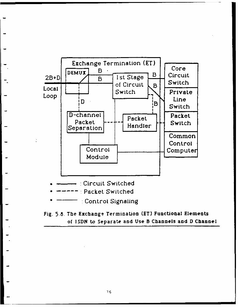
Exchange Termination (ET)
ConCool
2B D I3 st Stage ! B Circuit
Lq of Circuit SwitchLoopal Switch Private
'D IB LineI , Switch
D-channel Packet Packet
Packet Swite SwitchSeparationHnde
Common, Control
Control ComputerModule
• Circuit Switched
• ..... Packet Switched
• Control Signaling
Fig. 5.8. The Exchang. Termination (ET) Functional Elementsof ISDN to Separate and Use B Channels and D Channel
76
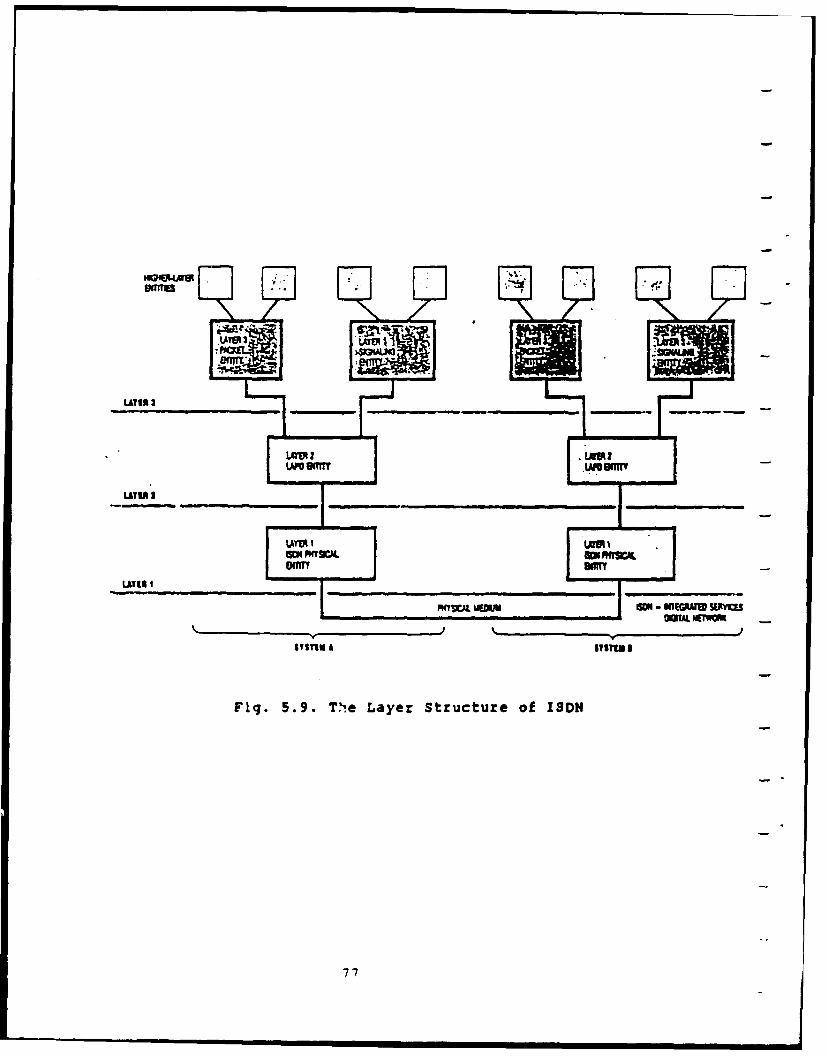
LATER 1
-AER -I II LYR I I
MWV~r MS
-y ME-N-XEGA EW
OWAL i~rWMs
SYSITM A lISTIngI
Fig. 5.9. T~ie Layer Structure of ISDN
77
5.4.1.1. Layer 1 (Physical Laver) of ISDN
Figure 5.10 shows the various reference points of ISDN. The
user-network interface is divided into Terminal Equipments (TEs)
and Network Terminations (NTs). The access rates discussed here
are: Basic Access Rate 2B + D, and Primary Access Rate 23B + D or
30B + D. Figure 5.11 shows the physical frames of ISDN Basic
Access Rate. Figure 5.12 shows the physical frames of ISDN
Primary Access Rate.
In Figure 5.11, although the basic-rate interface frames are
the same size (48 bits), the NT frames (frames transmitted from
the NT) have a different format than the TE frames (sent from the
TE). This is due to the different responsibilities of the NT and
the TE. In Figure 5.12, the 23B + D (1.544 Mbit/s) primary-rate
interface frame is used in North America and Japan, while the 30B
+ D (2.048 Mbit/s) frame is used in Europe. The unit of the small
rectangles in Figure 5.11 is bit, while that in Figure 5.12 is
byte. There are eight bits per byte in this application.
78
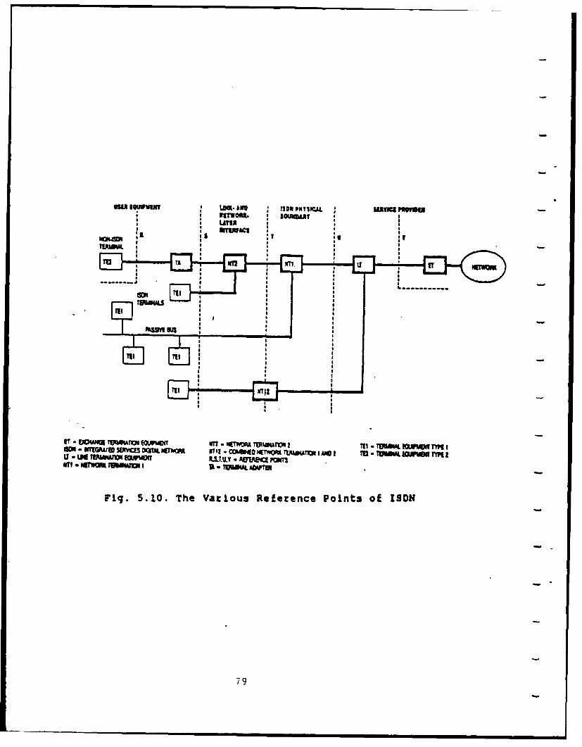
Ow SQw~ me 10 IMLUVC aaOrwo. l3umm
TA IILl
--------?Ut 'u s 11
ft M I
Ir - IM UB =Ia-W W w
Fig. 5.10. The Various Reference Points of ISDN
79
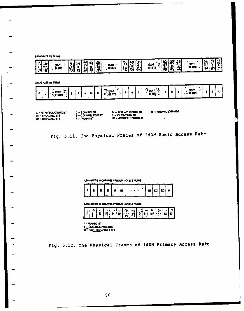
ff i j~ M*an
IAL IIIT IT Nnum-., wM OT X !I
L ]z;- Ilan, ; II oI. * .11_ 1111
-A - ACICMW~SI Wr 0 ow..a ffl I, - MJLAM A~Y .W4 IT i - TEaV4. SMAPTSe-@IOWeN&e. VS. 0ow. E Of L. C& M aCI
82 - UOeEWT CHP.I FIRMMEI NTf . WrK I'MAO
Fig. 5.11. The Physical Frames of ISDH Basic Access Rate
IJ44UOtTig &S.OW PRVALAY ACCM JIUA- I Ift-I i'- : I;1I'1UAI-UITTIS 94PAJINIM PwnAAI *ccz rum
j f I .. . . I j a, PJJ~II II
fOr ,,, eLe¢ "d
Fig. 5.12. The Physical Frames of ISDH Primary Access Rate
80
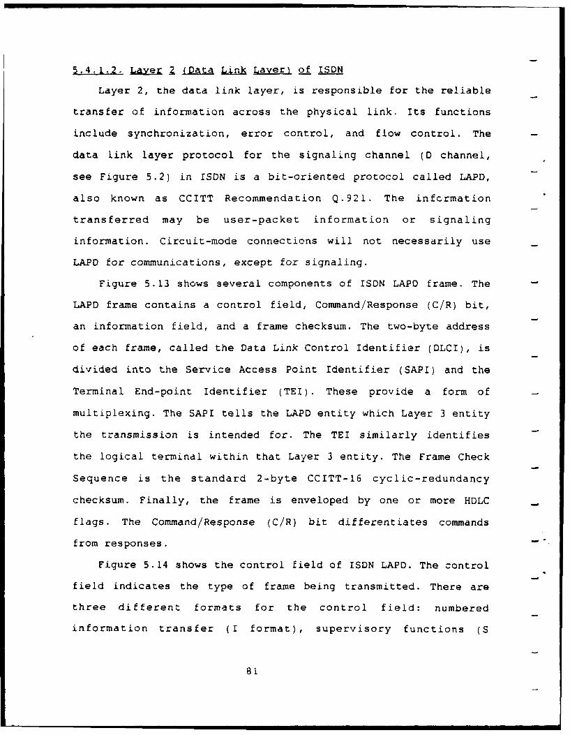
5.4.1.2. Laver Z (Data Link Laver) of ISDN
Layer 2, the data link layer, is responsible for the reliable
transfer of information across the physical link. Its functions
include synchronization, error control, and flow control. The
data link layer protocol for the signaling channel (D channel,
see Figure 5.2) in ISDN is a bit-oriented protocol called LAPD,
also known as CCITT Recommendation Q.921. The infcrmation
transferred may be user-packet information or signaling
information. Circuit-mode connections will not necessarily use
LAPD for communications, except for signaling.
Figure 5.13 shows several components of ISDN LAPD frame. The
LAPD frame contains a control field, Command/Response (C/R) bit,
an information field, and a frame checksum. The two-byte address
of each frame, called the Data Link Control Identifier (DLCI), is
divided into the Service Access Point Identifier (SAPI) and the
Terminal End-point Identifier (TEI). These provide a form of
multiplexing. The SAPI tells the LAPD entity which Layer 3 entity
the transmission is intended for. The TEI similarly identifies
the logical terminal within that Layer 3 entity. The Frame Check
Sequence is the standard 2-byte CCITT-16 cyclic-redundancy
checksum. Finally, the frame is enveloped by one or more HDLC
flags. The Command/Response (C/R) bit differentiates commands
from responses. -
Figure 5.14 shows the control field of ISDN LAPD. The control
field indicates the type of frame being transmitted. There are
three different formats for the control field: numbered
information transfer (I format), supervisory functions (S
81
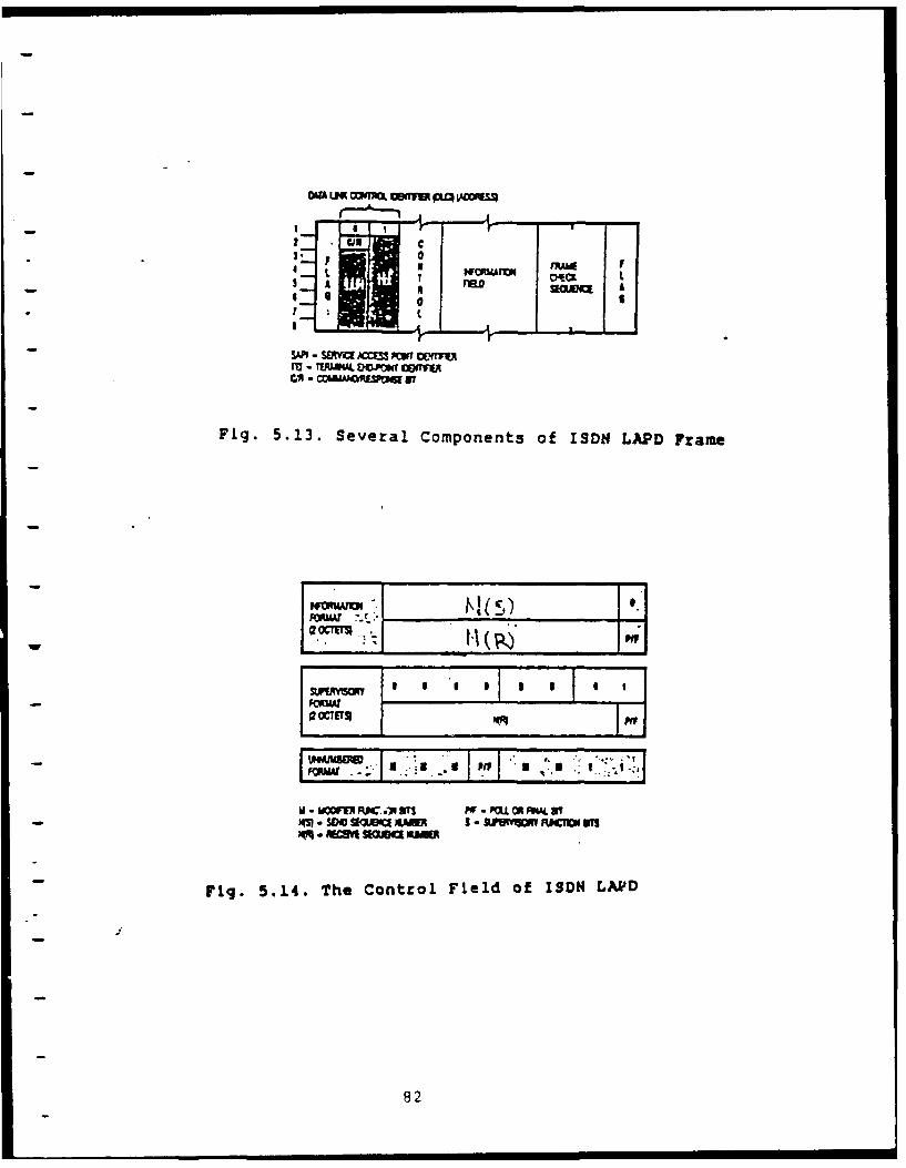
WA LM CMMA 09MnM VZOUp SS.
A FRO K BOM A
SAP, - SMYU A=SS PMT OEM"
lU*TIl4.D.Dr WjTE
Ml -rMKOim a
Fig. 5.13. Several Components of ISDN LAPD Frame
.--'
oA S I o Io I I I I
II . ~K**J2 =E/TSP vqI
I...
U O V, M W 13 Pff - KFLUJ 0R9 5C O Tf
Fig. 5.14. The Control Field of ISDN LAPD
82
format), and unnumbered information transfers and control
functions (U format). The I format helps transfer higher-layer
information. The S format handles flow control. The U format
helps maintain the data link connection. Figure 5.15 shows the
ISDN LAPD control field types. The supervisory function bits (S
bits in Figure 5.14) and modifier function bits (M bits in Figure
5.14) differentiate the LAPD frame types (listed in Figure 5.15)
from one another.
83
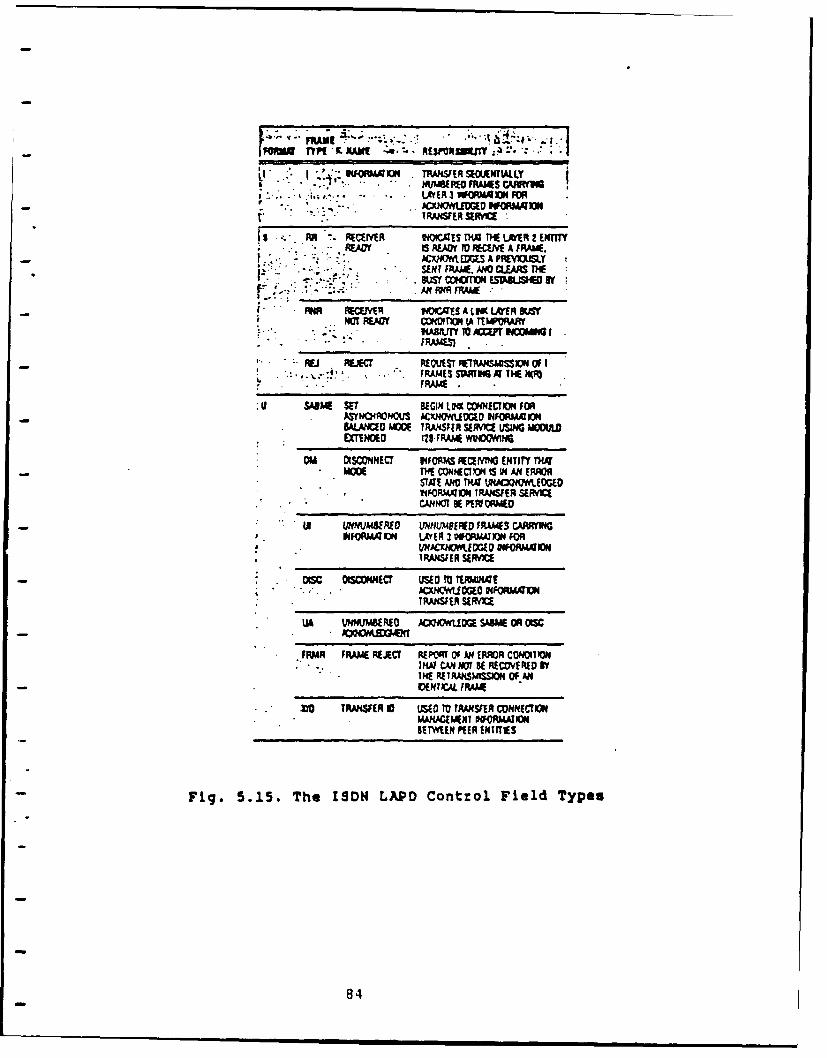
- FORM T ILN NAME-.. RESNPIVIIIM jA.
LI NKM 0 TPJJSER MNTAL LY*....*. * ~ . LAYER 3 NERMAJN FOR
TRANSFER SERAM
F3 R- REVEIVER tEOICqES TPA ThE Lh!R 2 ENTTTY**R-Qf 3 AM 1 RJW fA FRA&W.
ACXO MW A PREYlOUSY- - . . SENT FIRAME AND CLEARS THE
I-~A RR AW RAAXA~NA RECN'M IUrls AUs(IARewr
NOT 1fm CO T4IfO TEPOARY* .. 3ABIJy TO ACCEP INCOMM I
FRAMES)
REJ REAC REMSET RTANSMISSION OF I:i , FRAMES SWNGTHTE NM
FRAME.
Uv SAISME ME BEGIN LM CONNECTION FORASYN QNMu ACX.NVYUVO INORMXKON
- a-AMC AECE TRANSFER SERv1CE USING M1OCIAETENDED 128-FRAM1 WIDWNG
O M DISCONECT INFORMS RECEM ENTITY rTK~
STAT AND TK44 LWCW17*UOOWIlFQRMACH~ IRANSFER SME~v
- 5 UNMAWRED UNNLUUPE FR.AMES CARMMHINFO qA IO LAYER 3 90MAMN FOR
*UNJCXIOW.!O INFOAM1104IRAI4S[11SERVC
Otsc OI:C0NNECT USED TO T!ERAEKC~NQtVUOGEO INFORATINNIRAJISER SIRAMI
IA IMlMSEREO A00MUDGE SAISME OR DIC
FRMR FRAME REJECT REPOT OF AN ERROR CONOITIONI"D CAN HOT BE RECWV! RED By
*TH RSNSMISS2OOPIIDENIC-4 FRAME
** IG TRANSFER 0 USED TO TRANSFER CONNECTIONMAKWQEXT FUQRAI11BETWEEN PIER INF IES
Fig. 5.15. The ISDN LAPD Control Field Type.
84
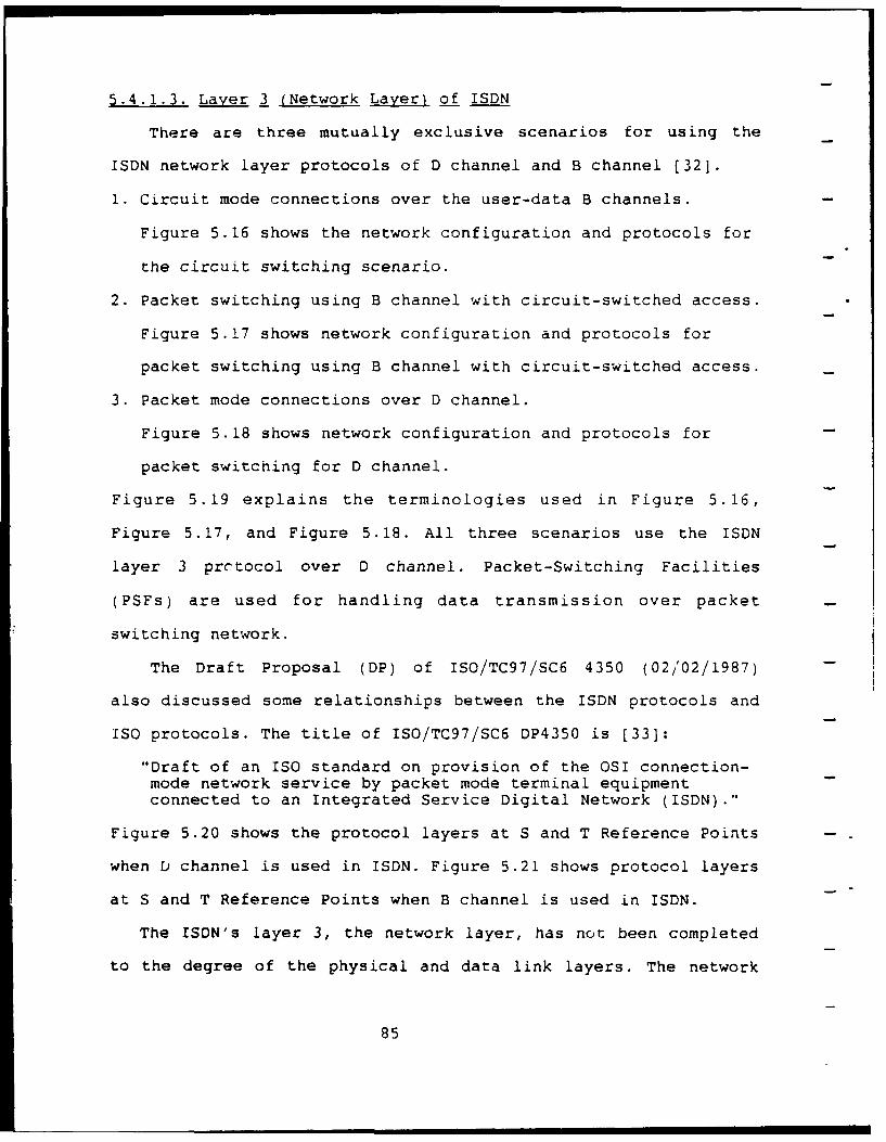
5.4.1.3. Layer 3 (Network Layer) of ISDN
There are three mutually exclusive scenarios for using the
ISDN network layer protocols of D channel and B channel [321.
1. Circuit mode connections over the user-data B channels.
Figure 5.16 shows the network configuration and protocols for
the circuit switching scenario.
2. Packet switching using B channel with circuit-switched access.
Figure 5.17 shows network configuration and protocols for
packet switching using B channel with circuit-switched access.
3. Packet mode connections over D channel.
Figure 5.18 shows network configuration and protocols for
packet switching for D channel.
Figure 5.19 explains the terminologies used in Figure 5.16,
Figure 5.17, and Figure 5.18. All three scenarios use the ISDN
layer 3 prctocol over D channel. Packet-Switching Facilities
(PSFs) are used for handling data transmission over packet
switching network.
The Draft Proposal (DP) of ISO/TC97/SC6 4350 (02/02/1987)
also discussed some relationships between the ISDN protocols and
ISO protocols. The title of ISO/TC97/SC6 DP4350 is [33]:
"Draft of an ISO standard on provision of the OSI connection-mode network service by packet mode terminal equipmentconnected to an Integrated Service Digital Network (ISDN)."
Figure 5.20 shows the protocol layers at S and T Reference Points
when b channel is used in ISDN. Figure 5.21 shows protocol layers
at S and T Reference Points when B channel is used in ISDN.
The ISDN's layer 3, the network layer, has not been completed
to the degree of the physical and data link layers. The network
85
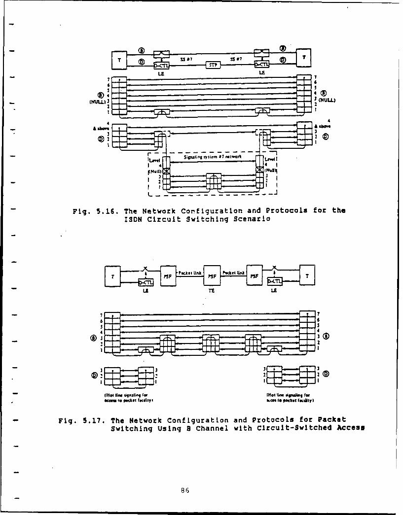
7 SS7 se
6 _ _6
(NULL) 3 3 (NULL)2 2
4 4& ~"____ ___ ____ ____ __A above
33
3 3272
1~
- Fig. 5.16. The Network Con~figuration and Protocols for theISDN Circuit Switching Scenario
7 17
S 6
22
3 3W W3
- (Hot lift Uignflih"f (fs Mot um ine A rmil (rnern to Packet faiiIs ken 10 packet f miluUI
Fig. 5.17. The Network Configuration and Protocols for PacketSwitching Using B Channel with Circuit-Switched Access
86
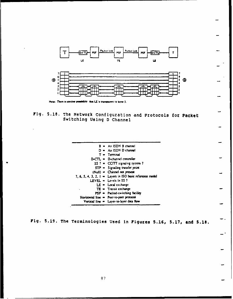
LE 11 1.1
7 7
433
N4ow: Then i £ aoUiw pownM*(i cat LE is awasmt to layw 3.
Fig, 5.10. The Network Configuration and Protocols for PacketSwitching Using D Channel
9 - An ISDN channelD - An ISDN D channelT - Terminal
D-CTL - 0-channel conuolIqrSS 7 m CCMT signaling system 7Si? - Signaling nnsfer point
(Nuil) - Cinnel W~ p=7, 6.5. 4. 3.2. 1 - LUyers in ISO basic referuncu model
LEVEL = Levels in SS 7LE - Local exchangeTE - Transit exchanige
PSF - Packed-switching facilityHorizontal line - Peer-to-pef protocol
Vertical line - Layer-to-tayer data low
Fig. 5.19. The- Terminologies Used in Figures 5.16, 5.17, and 5.18.
87
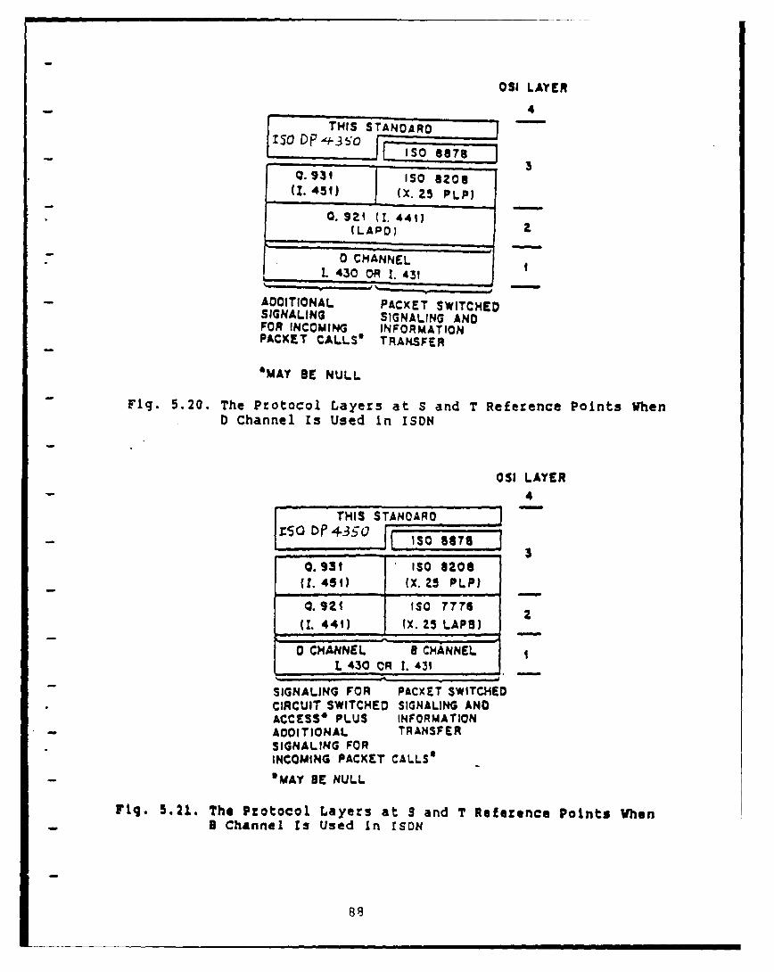
OSI LAYER
4
Q. 921 (1. 441)(LAPO) z
0 CHANNELL 430 OR . 431)
ADDITIONAL PACXET SWITCHEDSIGNALING SIGNALING ANDFOR INCOMING INFORMATIONPACKET CALLS* TRANSFER
'MAY BE NULL
Fig. 5.20. The Protocol Layers at S and T Reference Points WhenD Channel Is Used In ISON
OSI LAYER4
THIS STANDARD Dr5s3 D 43So | 130 GOT$3
0.931 ISO 6208(1. 459) (X. 25 PLP )
0. IV ISO 7776 2
(I. 441) (X. 25 LAPS)
0 CHANNEL a CHANNELL 430 OR 1. 431
SIGNALING FOR PACXET SWITCHEDCIRCUIT SWITCHED SIGNALING ANDACCESS* PLUS INFORMATIONADDITIONAL TRANSFERSIGNALING FORINCOMING PACXET CALLS''MAY BE NULL
Fig. 5.21. The Protocol Layers at S and T Reference Points Vhen8 Channel Is Used In ISDN
88
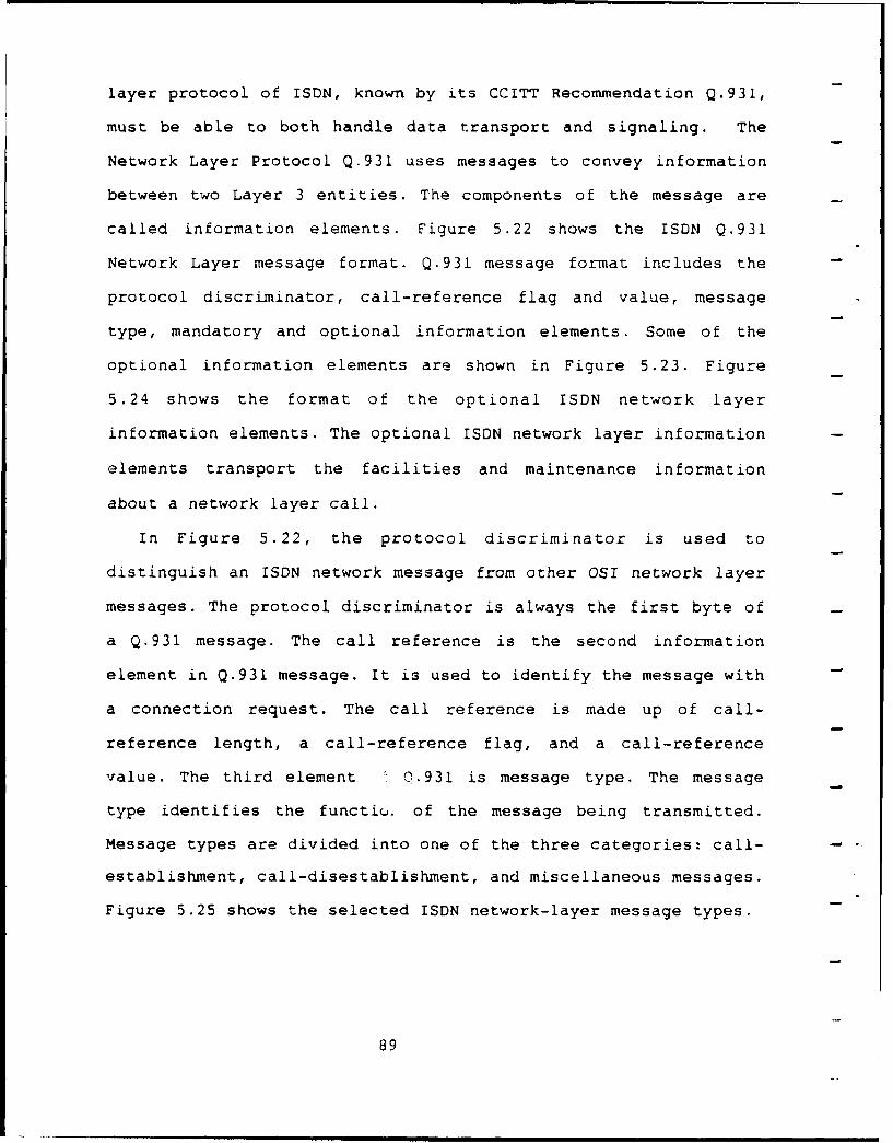
layer protocol of ISDN, known by its CCITT Recommendation Q.931,
must be able to both handle data transport and signaling. The
Network Layer Protocol Q.931 uses messages to convey information
between two Layer 3 entities. The components of the message are
called information elements. Figure 5.22 shows the ISDN Q.931
Network Layer message format. Q.931 message format includes the
protocol discriminator, call-reference flag and value, message
type, mandatory and optional information elements. Some of the
optional information elements are shown in Figure 5.23. Figure
5.24 shows the format of the optional ISDN network layer
information elements. The optional ISDN network layer information
elements transport the facilities and maintenance information
about a network layer call.
In Figure 5.22, the protocol discriminator is used to
distinguish an ISDN network message from other OSI network layer
messages. The protocol discriminator is always the first byte of
a Q.931 message. The call reference is the second information
element in Q.931 message. It is used to identify the message with
a connection request. The call reference is made up of call-
reference length, a call-reference flag, and a call-reference
value. The third element Q.931 is message type. The message
type identifies the functio. of the message being transmitted.
Message types are divided into one of the three categories: call-
establishment, call-disestablishment, and miscellaneous messages.
Figure 5.25 shows the selected ISDN network-layer message types.
89
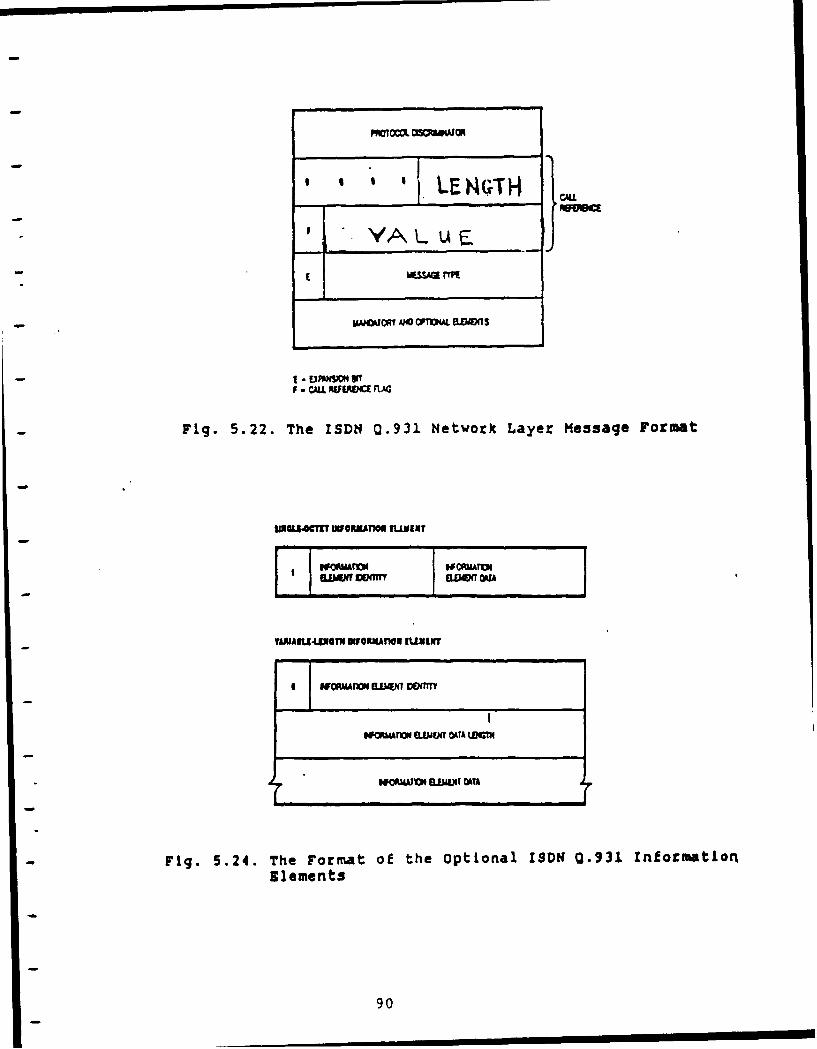
I LENG;TH Kc
- I4ESSAM 1WM
- ~MWoCA1 AMO TDWA 8..DOT
F - CALL AEUIRV" flJG
Fig. 5.22. The ISDN4 Q.931 Network Layer Message Format
$WELI4CTI INF@RMATMO EUMPIXT
NOORMAM B M ff UA
- Fig. 5.24. The Format of the optional ISDNE 0.931. InformationSl10ment s
90
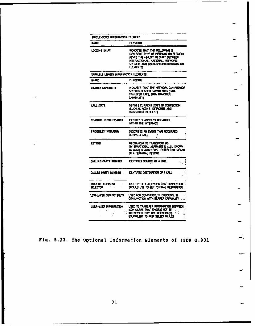
SrnCLE4CT INFORiLUIN (IUNENT
NAME FUNCTIKIN
Lfl9iN SHIFT MIV.#S T14. THE FOLUYE 6DIFFERENT TWI OF 16~10M ELEAWIIGiVES T! AMIJTY 10 SIFT BETWEENWCIEPIL1MAL, NXD4M.. NSAMSP(Mr- ANDJ uSMVwC HFCAmgI
VARJULIUGTM INFORMO ELEMENTS
NME FUNCMIN
1EAALFR CAPASJLIT iQUs T1W 11* IETKM CAN PFMESP*VFnc 8!ARR CAPRUJTES (0TRAHSFR FIA!. DQ TRAM
CALL RMN lFINES CURENT MWE OF CDNEC1O(WCH4 AS ATIVE. OE7IAOM ANO
CHIANNEL IDENTlFIt.UIN VNIIF Y CHANEfISUSCMOiELWITH4 flf p(TRFAE
PAMAJW INCN MSM3I! AN M E VEN 01WOCJMDMMG A CALL I
KEYPA kf~i H RMU M r~J lAGMPMMI ERHAO4A AL.P1* WIE ALSO KNOWNAS A00I 0LARACIEMS- BMOD of WEMOF A TEPPINAL KEYPAD
CALLING PARTY NUMIE Uffl MSC W OF A CALL
CALLED PART! NUNIER W4T1FIS OESTILU11ON1 OF A CALL I
ThANSIT NETWRK v~muIy 0F A mETwow 11w CONNECTIOSILACTM , 2io USE To GET 7v Fift OESr4U
WW4.YM VoupcZirLm UsEu FOR 02,.e4UvuT oexMG NCONRJNT1oN WIr M R CAA8JY .
UUAW PM~tq= LMD M T~44SR FF4qmo BETWEN
Fig. 5.23. The Optional information Elements of ISDN 0.931
9L
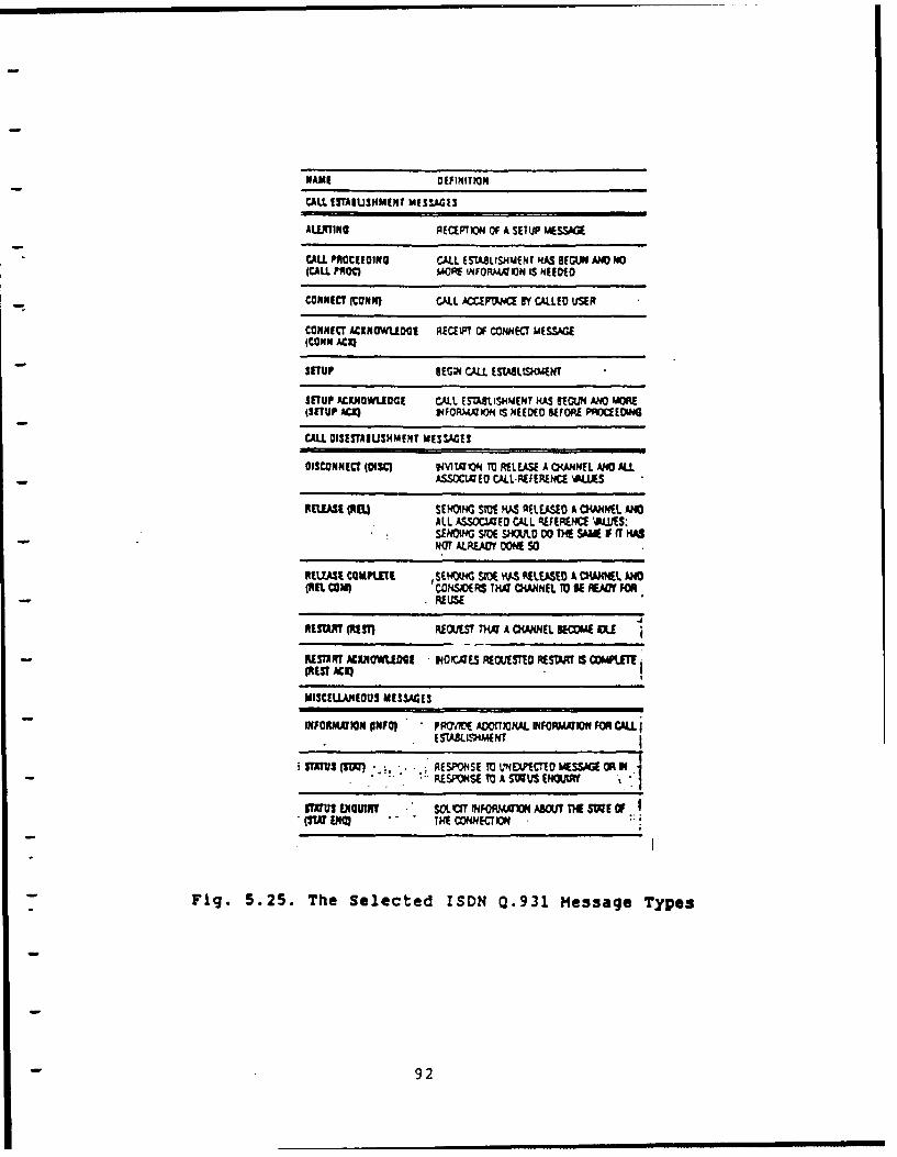
NAME O1fINITION
CALL 1STA1USIMENT MISSAGES
ALERTING AICEPTION OF A SETUP MESSAGE
CALL. PROCEEDING CALL (SJLISIUENt HAS BEGLX ND 4O(CALL. PAQd M001 INFORM410N IS NEEDED
CONNECT (CONNI CALL JCCIMOCE BY CALLED USER
CONNECT ACXNOWUlDGE RICELFT OF CONNEC MESSAGE(COHN ACXQ
- STUP IEGPI CALL. EnUALLS)4MENT
SETUP ACXJIOWUIOGI CALL ESUBLISHMENT KAS BEGUN AND3 MORE(SETUP ACE1) 14NVPJJA)ON IS NEEDED BEFORE P~CEOSNG
CALL DISITAIUISHMINT MESWSAE
DISCONNECT (OISC F IVt9 TO RELEASE A CKANEfL AMC ALL- ASSOCIZED CALL-AEFERENCE VIAS
RELEAE (NWE SEHG S?0E HAS AfEA SED A CK4NIEI AMALL ASSOC2AD CALL REFERENE "JJS.SENDING SPI D 00 THE SAUV IF I
- NOT ALREADY DONE 50
REUEASE CGIAKITE ISEHOtKG SIDE HAS VIEASED A CPWRIL MEG(BEL cam) CNHSIDERS TWi CKANNIL TO BE FAOt FOR
- .REUSE
"ESUR (NEST) RECAUT TKX A OWNEL BECME IE
- RESRT ACIIIOWUOGE 140"~E.S RECUESTID RESWIT IS COMPUTE(N EU AC K)
MISCELLANEOUS MESSACE3
INFORMATION (INFO) PRf7(" AOMfONAL INFOPMRVN FOR CALL
REPNETO V'4DPCTTD ?.(Swa OR IN
PSrU! ENQUIRY SOL VT ?NFORMXMO AWAU nfE SW E OFO(w ENO THE CONNECTION
Fig. 5.25. The Selected ISDN Q.931 Message Types
- 92
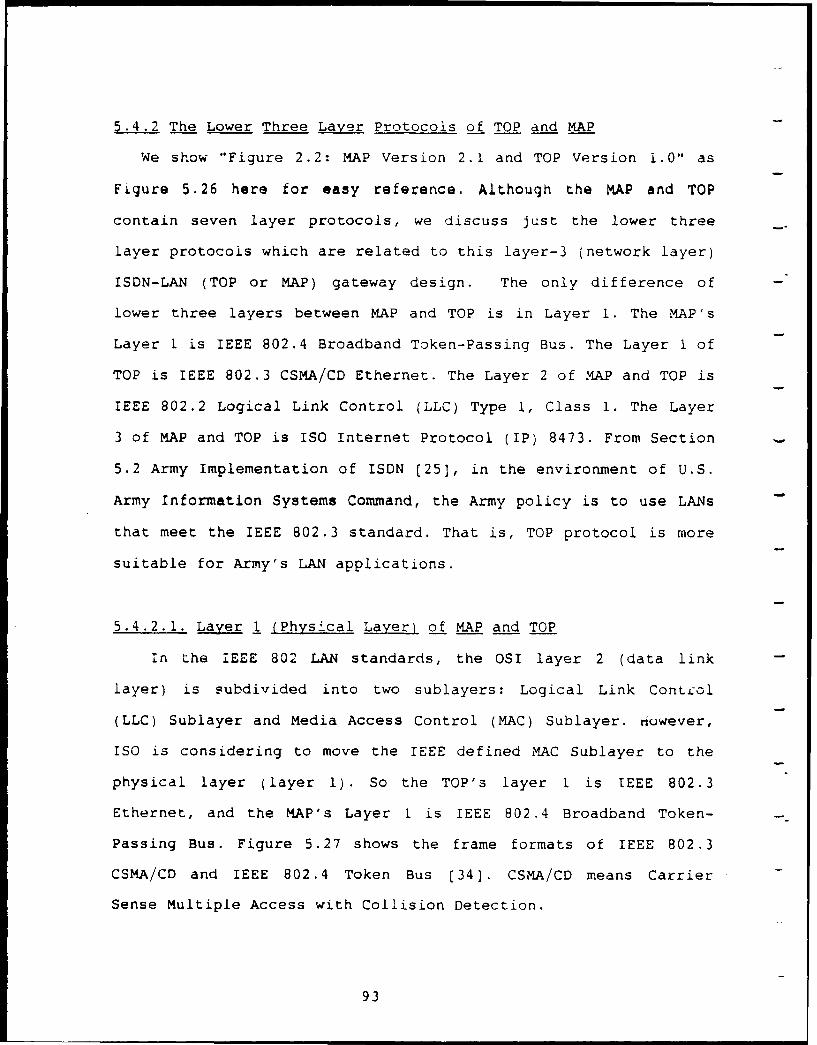
5.4.2 The Lower Three Layer Protocols of TOP and MAP
We show "Figure 2.2: MAP Version 2.1 and TOP Version i.0" as
Figure 5.26 here for easy reference. Although the MAP and TOP
contain seven layer protocols, we discuss just the lower three
layer protocols which are related to this layer-3 (network layer)
ISDN-LAN (TOP or MAP) gateway design. The only difference of
lower three layers between MAP and TOP is in Layer 1. The MAP's
Layer 1 is IEEE 802.4 Broadband Token-Passing Bus. The Layer 1 of
TOP is IEEE 802.3 CSMA/CD Ethernet. The Layer 2 of MAP and TOP is
IEEE 802.2 Logical Link Control (LLC) Type 1, Class 1. The Layer
3 of MAP and TOP is ISO Internet Protocol (IP) 8473. From Section
5.2 Army Implementation of ISDN [25], in the environment of U.S.
Army Information Systems Command, the Army policy is to use LANs
that meet the IEEE 802.3 standard. That is, TOP protocol is more
suitable for Army's LAN applications.
5.4.2.1. Layer 1 (Physical Layer) of MAP and TOP
in the iEEE 802 LAN standards, the OSI layer 2 (data link
layer) is subdivided into two sublayers: Logical Link ConU.ol
(LLC) Sublayer and Media Access Control (MAC) Sublayer. however,
ISO is considering to move the IEEE defined MAC Sublayer to the
physical layer (layer 1). So the TOP's layer 1 is IEEE 802.3
Ethernet, and the MAP's Layer 1 is IEEE 802.4 Broadband Token-
Passing Bus. Figure 5.27 shows the frame formats of IEEE 802.3
CSMA/CD and IEEE 802.4 Token Bus (34]. CSMA/CD means Carrier
Sense Multiple Access with Collision Detection.
93
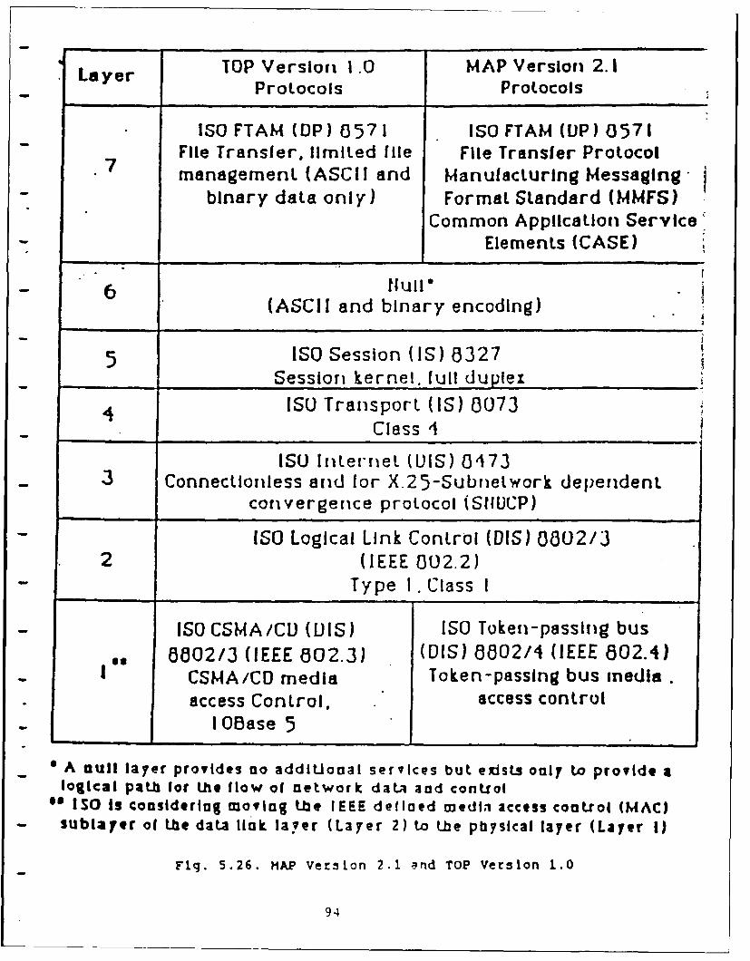
TOP Version 1 .0 MAP Version 2.1Layer Protocols Protocols
ISOFTAM (DP) 0571 ISOFTAM (UP) 0571File Transfer, limited file File Transfer Protocolmanagement (ASCII and Manufacturing Messaging
binary data only) Format Standard (MMFS)Common Application Service'
Elements (CASE)
6ull"(ASCII and binary encoding)
5 ISO Session (IS) 8327Session kernel, full duplex
4 ISO Transport (IS) a073Class 4
ISO InlerrieL UIS) 0473_ 3 Connectioiless and for X.25-Subrletwork depenidenl.
convergence protocol (SIIUCP)
- ISO Logical Link Control (DIS) 3302/32 (IEEE 002.2)
Type I .Class I
ISO CSMA/CD (IS) ISO Token-passing bus6802/3 (IEEE 602.3) (DIS) a802/4 (IEEE 802.4)CSMA/CD media Token-passing bus media.access Control. access controlI OBase 5
* A null layer provides no addiUonal services but e~isLs only to provide alogical path for Ihe flow of network data aod control
** ISO Is coasiderlag moving tbe IEEE defloed medl. access coatlrol (MAC)sublaYer of the data lInk laver (Layer 2) to the physical layer (Layer I)
F g. 5.26. HAP Version 2.1 and TOP Version 1.0
94
IEEE 802.3 CSMA/CD7 1 2,6 2.6 2 o-tioo 4 Bytes
Preamble SFD DA SA Length LLC PAD FCS
IEEE 802.4 Token Bus
>=I I 1 2, 6 2, 6 >=0 4 1 Bytes
Preamble~ SD FC~ DA SA LLC~ FCS EDJ
DA: Destination AddressED: Ending DelimiterFC: Frame ControlFCS: Frame Check SequenceLLC: Logical Link ControlSA: Source AddressSD: Starting Delimiter
Fig. 5.27. The Frame Formats of IEEE 802.3 CSMA/CDand IEEE 802.4 Token Bus
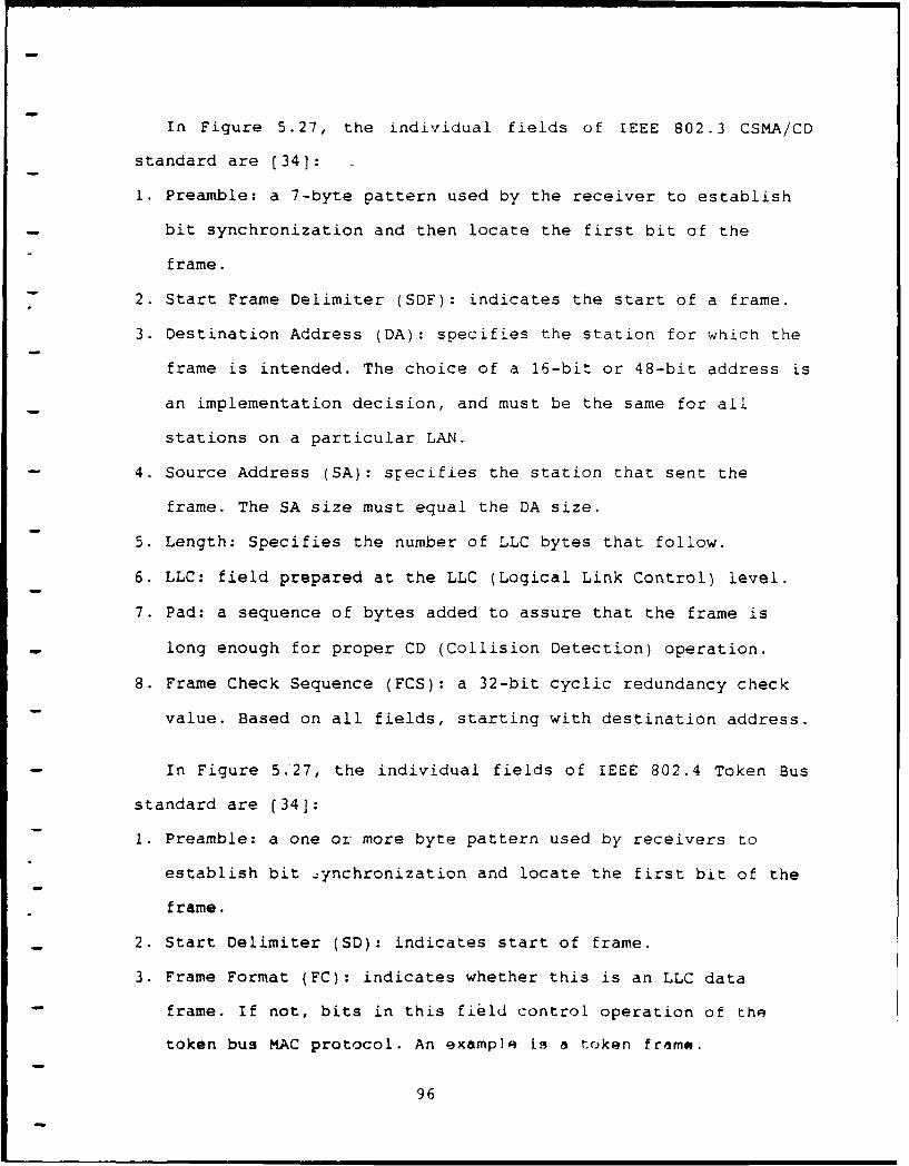
In Figure 5.27, the individual fields of IEEE 802.3 CSMA/CD
standard are (341:
I. Preamble: a 7-byte pattern used by the receiver to establish
bit synchronization and then locate the first bit of the
frame.
2. Start Frame Delimiter (SDF): indicates the start of a frame.
3. Destination Address (DA): specifies the station for which the
frame is intended. The choice of a 16-bit or 48-bit address is
an implementation decision, and must be the same for all
stations on a particular LAN.
4. Source Address (SA): specifies the station that sent the
frame. The SA size must equal the DA size.
5. Length: Specifies the number of LLC bytes that follow.
6. LLC: field prepared at the LLC (Logical Link Control) level.
7. Pad: a sequence of bytes added to assure that the frame is
long enough for proper CD (Collision Detection) operation.
8. Frame Check Sequence (FCS): a 32-bit cyclic redundancy check
value. Based on all fields, starting with destination address.
In Figure 5.27, the individual fields of IEEE 802.4 Token Bus
standard are (341:
1. Preamble: a one or more byte pattern used by receivers to
establish bit -,ynchronization and locate the first bit of the
frame.
2. Start Delimiter (SD): indicates start of frame.
3. Frame Format (FC): indicates whether this is an LLC data
frame. If not, bits in this field control operation of the
token bus MAC protocol. An example is a token frame.
96
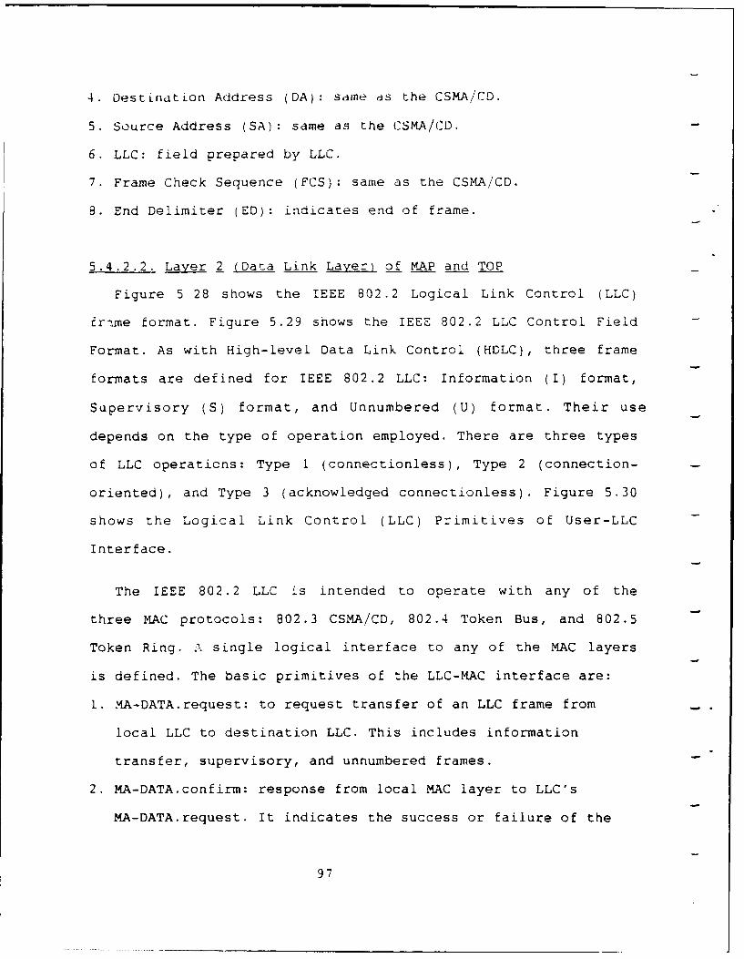
4. OestLnatLon Address (DA): same as the CSMA/CD.
5. Source Address (SA): same as the CSMA/CD.
6. LLC: field prepared by LLC.
7. Frame Check Sequence (FCS): same as the CSMA/CD.
8. End Delimiter (ED): indicates end of frame.
5.4.2.2. Laver 2 iData Link Laver) of MAP and TOP
Figure 5 28 shows the IEEE 802.2 Logical Link Control (LLC)
fr.me format. Figure 5.29 shows the IEEE 802.2 LLC Control Field
Format. As with High-level Data Link Control (HDLC), three frame
formats are defined for IEEE 802.2 LLC: Information (I) format,
Supervisory (S) format, and Unnumbered (U) format. Their use
depends on the type of operation employed. There are three types
of LLC operations: Type 1 (connectionless), Type 2 (connection-
oriented), and Type 3 (acknowledged connectionless). Figure 5.30
shows the Logical Link Control (LLC) Primitives of User-LLC
Interface.
The IEEE 802.2 LLC is intended to operate with any of the
three MAC protocols: 802.3 CSMA/CD, 802.4 Token Bus, and 802.5
Token Ring. A single logical interface to any of the MAC layers
is defined. The basic primitives of the LLC-MAC interface are:
1. MA-DATA.request: to request transfer of an LLC frame from
local LLC to destination LLC. This includes information
transfer, supervisory, and unnumbered frames.
2. MA-DATA.confirm: response from local MAC layer to LLC's
MA-DATA.request. It indicates the success or failure of the
97
request.
3. MA-DATA.indicate: to transfer incoming LLC frame from local
MAC to local LLC.
98
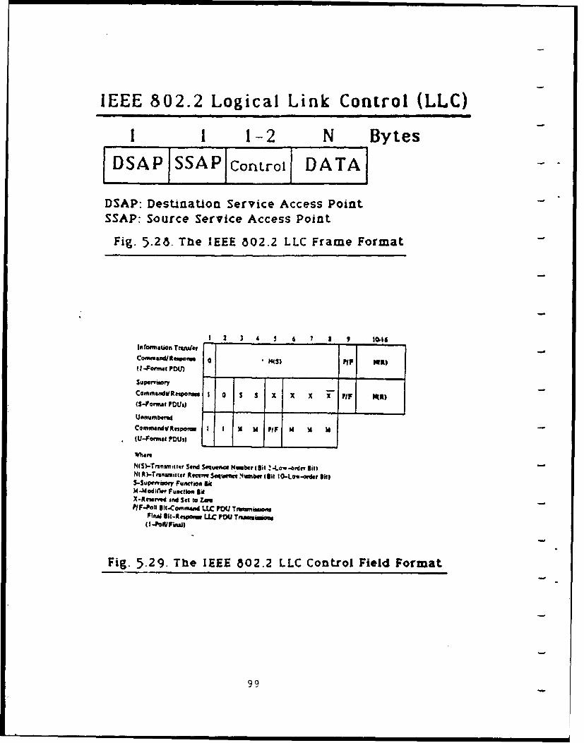
IEEE 802.2 Logical Link Control (LLC)
1 1 1-2 N Bytes
DSAPISSAP cotrol DATA~
DSAP: Destination Service Access PointSSAP: Source Service Access Point
Fig. 5.28. The IEEE 802.2 LLC Frame Format
I23 4 S 311
nOtMaWOn TrindetConmmand/Respawm G pip5 MI R)U 4-Ptal P041)
supenimaryComnmndilRespoftlet 1 0 S S x X X I P IRK)(S-PatMi PDOs
UORnffbemdcommandfIRespa,.. I I x 14 PIP Id V 1(U-Foinia POWI
N(S)-Trarnneitie Send Sequer~a N1011berI~ (St-Law-ardff BllNfR)-Trzmiier Rftvme $aq'w Numbe, ii I O-Low-andtieliiiS-Sueiaq Fuamcsia BiId-Mad ifie Fuacti" BiX-Iteuid 3nd Sit to Zn.
Final -AfmamaLLC P041Tnmmm
Fig. 5.29. The IEEE 802.2 LLC Control Field Format
99
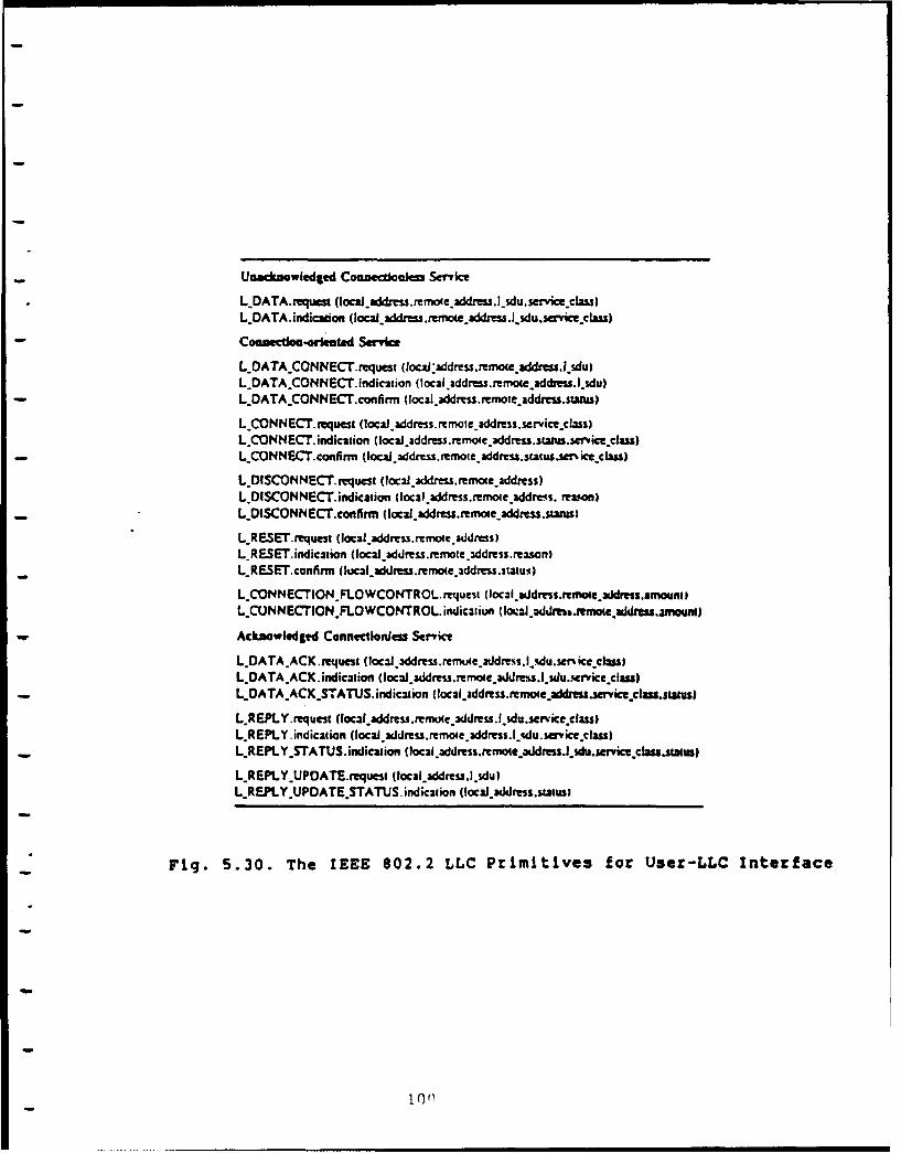
- ~Unacknowledged Counecioonesm Serylc
L..DATA.muest (locai-addrnsremoeaddres.jdu.srvice.cau)LDATA.indicadon (local_ dress .rreowddzessldu.srieciau)
- Counectiao-orked Ser-vic
L..DATACONNECT.tequest (loca:ades.renoe.addres .sdulL-DATA..CONNECI.indic-stion (local address.remoeaddess.~sdul
- LDATA.CONNECT.confirrn (loczladdmesjemoteaddess.status)
LCONNECT. rquest (Iocaladdress.rcmote.address.service-class)LCONNECT. indication (locaJiaddress.remoeaddress.stww.se'iccass)
-LCONNECT. confirm (lbca ~ds.momtedes.stauwet' icecls
L..DISCONNECT.requcst (I )J.ddress.remoteaddress)L-DlSCOMNECT. indicationt (local address.remoecaddres.s. feasgonl
- L..DISCONNECT.conlirm (locaiyaddress.remoteaddress.sasI
LRESET request (localaddress.mote.3ddness)L-RESET. indication (local address.rmte.3ddres.mawsnI
- LRESET.confirm (lucal address.remoe~ddress.stausI
L..CONNECrION.FLOWCONTROL.mrquest (local asJdms%.rmoae dwss,anMniL.CUNNECrION.FLOWCONTROL. indicaliwi(oa dmarmt druaaoat
Acknowledgied Cannecioniess Servce
L.DATA.ACK request (local.xddrss.revn4e-raddrs.l..sdu.scn iceclassIL.DATA-ACX. indication (locdmss.remoed ~s. du..evicelaaL.OATAACK.STATUS. indicviion (loca.addrss.remoeaSdess.sericecaus.swausl
LREPLY.request ((a f2(address.rm Jtc_3ddress.f~sdu.service.classIL.REPLY indication (local.3ddress.remo4eaddress.l-.du. sarice~classD
- LREPLY.STATUS. indication (local.address.rmowxtaddmss.lsdu.serice cLas.stattas
LREPLY..UPOATE.requesi (locaia3ddesa.lsdu)L.REPLY.UPOATE.STATUS. indicaion (loca.addres.suwuss
- Fig. 5.30. The IEEE 802.2 LLC Primitives for Usez-LLC Interface
Jon
5.4.2.3 Layer ) (Network Layer) o_ MAP and TOP
The layer 3 (i.etwork layer) of MAP and TOP is ISO IS 8473
Internet Protocol (IPN- The MAP uses Token-Passing Bus, and the
TOP uses CSMA/CD Ethernet. Both MAP and TOP use BUS topology. For
the bus topology, the Layer 3 (Network Layer) can be absent if we
do not consider internetworking with other networks. However, MAP
and TOP foresee the necessity of internetworking with other
networks. So both MAP and TOP use ISO Internet Protocol (IP) as
their Layer 3 protocol.
The ISO IP exhibits minor differences from DoD IP. Figure 5.31
shows the ISO IP Header format. Figure 5.32 shows the DoD IP
Header format. We discuss the ISO IP Header first. Then the
differences between ISO IP and DoD IP will be discussed.
In Figure 5.31, the ISO IP header is largely self-explanatory.
Some clarifying remarks are as follows:
1. Protocol Identifier: When the source and destination stations
are connected to the same network, an internet protocol is not
needed. In that case the internet layer is null and the header
consists of this single field of 8 bits.
2. PDU Lifetime: Expressed as a multiple of 500 ms. It is
determined and set by the source station. Each gateway that
the IP datagram visits decrements this field by I for each
500 ms of estimated delay for that hop. When the lifetime
value reaches 0, the datagram is discarded. This technique
prevents endlessly circulating datagrams.
3. Flags: The S/P flag indicates whether segmentation is
permitted. The M/S flag is the more flag. The E/P flag
101
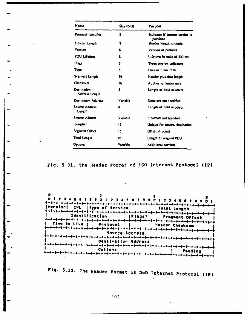
Name Sa MU) Pu Pon
Procol Identifier I Indicates if kam amnvke isprovided
Header Length I Header length in ac
Version I Version of protoc l
POU Lfetim uLtim inu=its of 5 Ms
Flags 3 Three one-bit indicatonType Data or Enor PDU
Segmment Lenot 16 Header plus data length
Checksum 16 Applies to header onlyDestination a Length of field in octts
Address Length
Destination Address Variable Structure not specifiedSource Address S Length of field in octets
Length
Source Address Variable Structure not specifiedIdentifier 16 Unique for source. destination
Segment Offset 16 Offset in octets
Total Length 16 Length of origina POUOptions Variable Additional services
Fig. 5.31. The Header Format of ISO Internet Protocol (IP)
0 2 20 1 2 3 4 5 6 7 1 9 0 I 2 3 4 1 07 3 I 0 1 2 3 4 5 6 7 3 0 a I
IVergionI 15L I t ype of Servicel Total Length- -- 4-4-- - -4- -4--+--+- -4--+4-- I.+ _+_.p
ldontification Iplaghl Fragment Offset
Time to L Ive Prot!o Heeder CheksumI~~ ~ ism 6g +_4_+_r4O
Source Address
Destiat ion Address
Options I Padding- + -.+..+ - ,..+++___ _ +_.+____ +_..4+++___
Fig. 5.32. The Header Format of DoD Internet Protocol (1P)
102
indicates whether an error report is desired by the source
station if a datagram is discarded.
4. Checksum: Computed at each gateway.
5. Addresses: Variable-length addresses are provided; the
structure of the addresses is not specified in the standard.
6. Options: The optional parameters that may be specified
include: Security, defined by the user; Source Routing, which
allows the source station to dictate the gateway routing;
Recording of Route, used to trace the route a datagram takes;
Priority; and Quality of Service, which specifies reliability
and delay parameters.
The ISO IP provides a connectionless data transfer service to
IP users, e.g., Transport Protocol (TP), in hosts attached to
networks of the internet. Three primitives are defined at the
user (TP)-IP interface. The DATA.request primitive is used to
request transmission of a data unit. DATA.indication is used by
IP to notify a user of the arrival of a data unit. An ERROR
primitive may be used to notify a user of failure to deliver a
datagram. For these primitives, the following parameters are
used: destination address, source address, options, and user
data.
5.4.2.4. The Differences Between ISO IP and DoD IP
By comparing Figure 5.31 ISO IP header with Figure 5.32 DoD IP
header, several differences between ISO IP and DoD IP can be
found. Those differences are:
1. Addresses: The DoD IP uses fixed 32-bit address length.
The ISO IP uses variable addresses. In ISO IP header, two
103
fields: address length (8-bit) and address (variable) are used
to specified the address of a station.
2. Lifetime of Datagram: The unit of lifetime in ISO IP is
500 ms. The unit of Time To Live of datagram in DoD IP is
second.
3. Error Reporting: In DoD IP, another protocol, Internet Control
Message Protocol (ICMP), is used for error reporting.
In ISO IP header, the field Type (5-bit) indicates Data or
Error Protocol Data Unit (PDU). That is, the ISO IP has the
error reporting capability in its header.
4. Flags: Both ISO IP and DoD IP have three flags. However, the
usage of flags is different between ISO IP and DoD IP.
The third bit flag is the E/P flag of ISO IP to indicate
whether an error report is desired by the source station
if a datagram is discarded.
In the DoD IP, the third bit flag is not used.
5. Header Length: In the DoD IP, the Internet Header Length
(IHL, 4-bit) indicates the length of header in 32-bit words.
In the ISO IP, the Header Length (8-bit) indicates the
length of IP header in bytes.
6. Version: The Version field of the DoD IP is 4-bit.
* The Version field of the ISO IP is 8-bit.
7. Protocol Identifier: The ISO IP uses this Protocol Identifier
to indicate whether the source station and the destination
station in the same network or in different-networks.
The DoD IP has Protocol field (8-bit) to indicate the next
higher layer protocol which is to receive the data field at
104
the destination.
8. Total Length: In DoD IP, the Total Length field (16-bit)
indicates total data unit length, including header, in bytes.
In ISO IP, there are two fields: Segment Length field (16-bit)
and Total Length field (16-bit). The Segment Length field
indicates the header plus data length of that segment.
The Total Length field of ISO IP indicates length of the
original PDU.
9. Segment Offset: In the DoD IP, the Fragment Offset field
(13-bit) indicates where in the datagram this fragment
belongs. It is measured in 64-bit units. This implies that
fragments (other than the last fragment) must contains a data
field that is a multiple of 64 bits long.
In the ISO IP, the Segment Offset field (16-bit) indicates
where in the datagram this segment belongs. It is measured in
bytes. That is, the segmentation in bytes of ISO IP is more
flexible than the fragmentation in 64-bit units of DoD IP.
105
5.5. Step 2. Start Internetworking from Approach-1 and Approach-2
In the Section 5.2 Army Implementation of ISDN, generally it
has been assumed that LANs will interface with ISDN through
Terminal Adapters (TAs) or gateways. The TA approach of ISDN-LAN
internetworking is basically the same as our "Approach-I: Direct
Connection of Network Interface Units," or "Approach-2:
Interconnection through Computer Ports." Figure 5.33 shows the
scenario of ISDN-LAN internetworking through LAN Network
Interface Unit (NIU) and ISDN Terminal Adapter (TA).
In the Integrated Services Digital Network (ISDN), the digital
equipments with ISDN interfaces can directly plug into ISDN
socket without Modem. However, existing digital equipments, such
as computers or terminals, usually uses non-ISDN interfaces,
e.g., RS-232C ports. The existing digital equipments with non-
ISDN interfaces cannot connect ISDN directly. They must connect
ISDN through Terminal Adapters (TAs). A TA for ISDN is a protocol
converter. One side of the TA provides ISDN S Reference Point
Interface, the other side of TA provides non-ISDN interface such
as RS-232C port. The TA performs: (i) bit rate adaption; (ii)
signaling conversion (mapping) between RS-232C and the Q.931 D-
-- channel procedures; (iii) ready for data alignment [35]. Some
reports predict that when ISDN becomes popular, a lot of
today's Modem manufacturers will become Terminal Adapter (TA)
manufacturers.
106
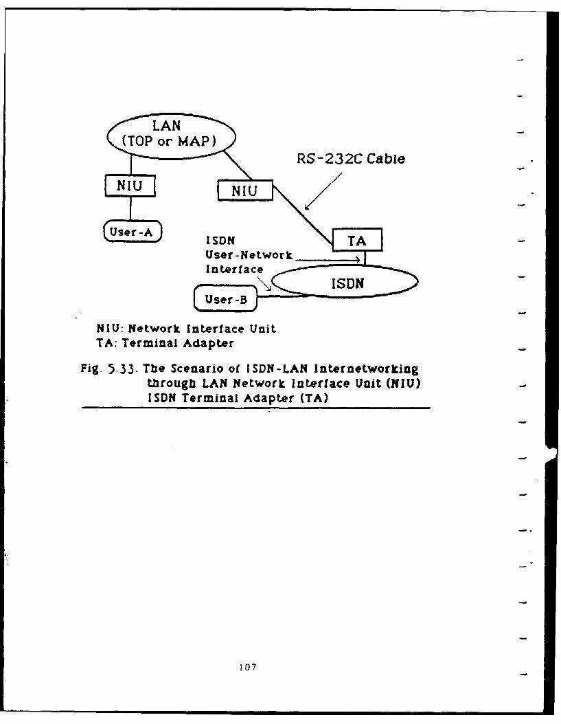
RS-232C Cable
NIU Network Interface UnitTA. Terminal Adapter
Fig. 5.33. The Scenario of ISDN-LAN Internetworkingthrough LAN Network Interface Unit (NIU)ISDN Terminal Adapter (TA)
107
5.6. Step 3: Decide Which Layer Gateway Is Required
We have given the reasons why we chose the Layer-3 (network
layer) ISDN-LAN gateway design in "Section 5.3: Layer-3 ISDN-LAN
Gateway." Thus we just show "Figure 5.34: the Layer Structure of
the Layer 3 ISDN-LAN Gateway" here. The lower three layer
protocols of ISDN, TOP, and MAP were discussed in "Section 5.4:
Understand and Use Each of the Two Networks."
5.7. Step 4: Obtain the Required Information from Network Vendors
We described the lower three layer protocols of ISDN, MAP,
and TOP in "Section 5.4: Understand and Use Each of the Two
Networks." Thus here "the required information from network
vendors" means the information of VLSI chips and the
communication adapter boards for ISDN, MAP, or TOP.
Figure 5.35 shows the available ISDN VLSI chips from several
companies [361. This information is based on "The Universal Data
Connection," IEEE Spectrum, July 1987. There should be more ISDN
VLSI chips available now than the information in Figure 5.35. For
the TOP LAN, Intel Corp. has IEEE 802.3 CSMA/CD VLSI chip and the
Ethernet communication adapter boards and software available. For
the MAP LAN, Motorola Co. has IEEE 802.4 Token Bus VLSI chip; and
several LAN vendors announced the MAP communication adapter
boards and software available. Actually, one big benefit of
standard protocols, such as ISDN, TOP, and MAP, is that more and
more companies will commit and produce products followed the
standard protocols. For this ISDN-LAN (TOP or MAP) gateway
design, there will be a lot of off-the-shelf software and
108
har'Iw4rts tor LSDN, rop, and MAP available. The commercial ISDN-
LAN (TOP or MAP) gateways may be available in the future, too.
109
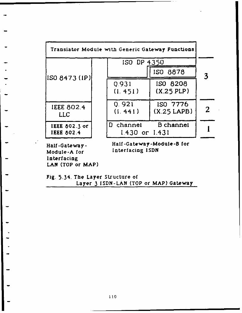
Translator Module with Generic Gateway Functions
- ISO DP 4350
ISO 8473 (P) 3Q.931 ISO 8208(1.451) (X.25 PLP)
IEEE 802.4 Q. 921 ISO 7776
LLC (1.441) (X.25 LAPB) 2
IEEE 802.3 or D channel B channelIEEE 802.4 1.430 or 1.431
Half-Gateway- Half-Gateway-Module-B for
Module-A for Interfacing ISDN
InterfacingLAN (TOP or MAP)
Fig. 5.34. The Layer Structure of
Layer 3 ISDN-LAN (TOP or MAP) Gateway
110
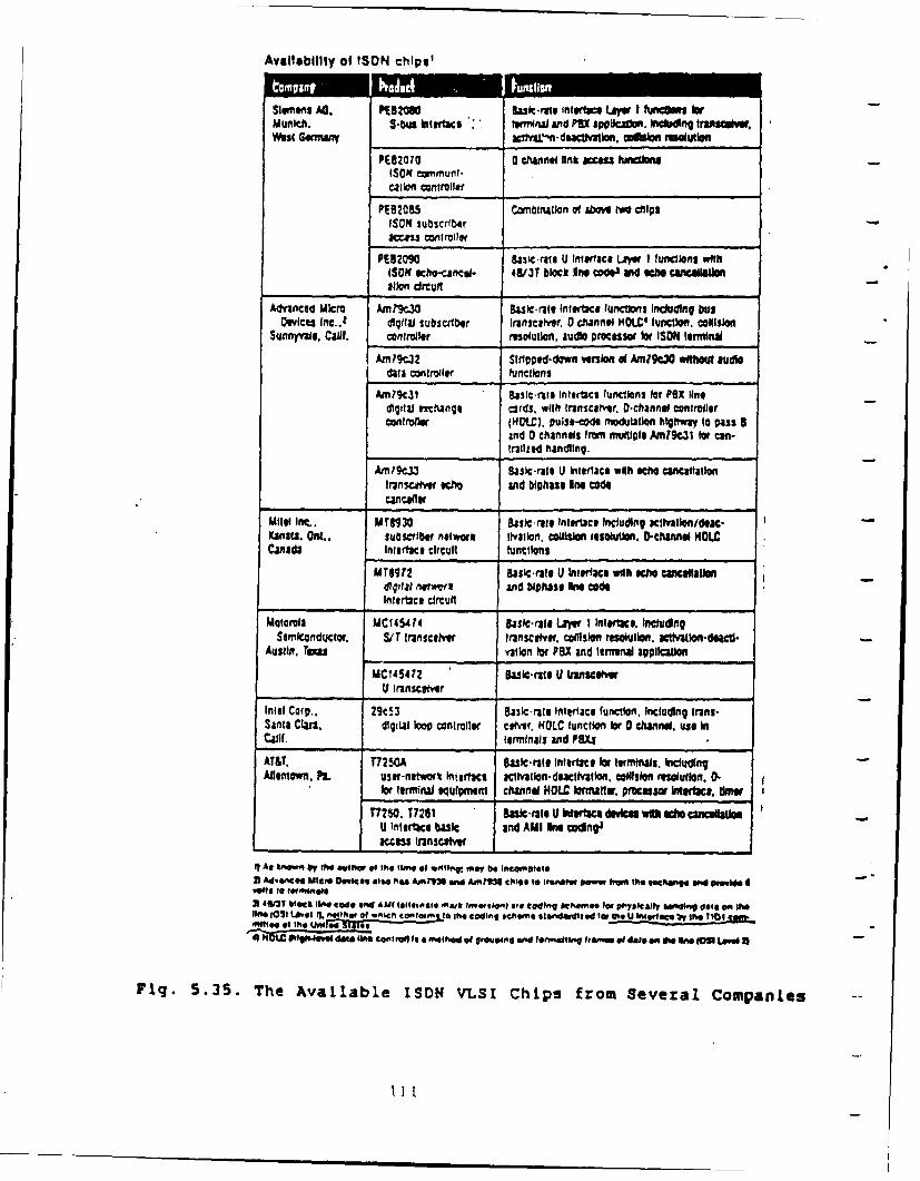
AvellablIty of ISDN chipi'
tnme An. P192VU@ asll-e Inte~ Lai I hotn wb
m u n i c . S .- n k1 I e r fa c6 I t e r" M a l a n d M U s ip p i c a d . I c l i n g:11 " t r a " a l e v
W edsi G mnnanv _ _ _ _ _ _ _ _ _ _ ~N~ d c "~ I" oo" U b A " O U 1111117PE82070 a CSAnno "nt acessfa~JnISOM cormunt.call"ion ntrole
PES2055 canbitlwationi of Above P" chipsISOM suliscrf.raccess controller
PE32eO 8as'crute U interface LaVW I functis witl$(SON echo-cgice- 4913T block in@ CWe Ind echi caniceaalioaflon cirtuit
Advanced Micro itMCM3 8aSlC-r3(8ettlrt2C# functions Inciuang busOevices fic-2. digital subscriber transcaiver, 0 channel HOLC' function. coillsio
Sunnyvale. Calif. controller resolution. judo proceswo lor ISDN terminal
AmW?9C02 Strtpoid-down versiof@ Am?9c3V withotd audlodata controller functions
Aml9l:31 Basic-nil interface funcionsi tor FOX l"nodigitaf nc'ange cards, with In'nsceirtr. O-channel controllerconflr4* (flOe). vuist-code mhodiatlon htrwa to p3ss S
Ind D channels fromr mulliple W WIc.~ Wo can-triledl handing.
Amn 8431atsl U Iturlace with echo ancefialloni(ransuer Ih and biphase one code
Mitl Inc.. MT"30 Basic-rats Interlace Including acinhalifflldew*Kanata. Oat.. subscriber nelwork tihon. collision resolutions. 0-channel NOLCCanada iertace circuit functions
Mrsqr2 asic-rale U Interlace Wilt1110111 camcellandigifal nqtworV and biphasse ne cedeIntertice circuit
Motorola MC145414 galle raie Lawe I Itrwc. IncldingSorikuctor. SIT transcelver transceiver. c*llsio resolto. ctato-daU
Austin. Teom ration 1wr PBX and tenenal application
MC145412 Sasi at U ftnscaligiVI fiascet'wr
Intel Corp.. 29053 Baic-ratit Intlace funciont. Including In~ns-Santa Clas. r digital Io controller cefver. KOIC functi o D channel. use InCalif. terminals and 11003AT&T, T7250A Suic-rate Intlace for trminals. IcludingAllentown. Pa. user-netiwk Ineftace cctaindatvt o llision resolutlon. D.
for terminal equipmrent channel HOWC lormaltar. pwocssor Weirta. teT7250, T7251 &&*~-rate Ukvwfterace deviee ub adis alsl
U Interface basic and AMI Ins codnge_____________ access trnsceive
11 As taw" by th rw at the mmm of. ,wiirr met,~ly be InC..ngee
3 deedMceOwiee. also nAls Ain"e mw £r=ise to~ I. ranal, oew tram Me secftionq meo praw I
3 4613T 1146C1 V1^* Code ad AMI (811en06fe "At fid iff e80 coding scheW for Phyically stnding dell on theline (Ctwll L . neite (.04 o Icomlnito* the coding schwne Slaa,did 1W, ~tSS.b he10 eofle f te Un4-IFIes ii4 hOtE OW-10-0 deja lin C40irai It 8 -11h01 .f W.0l1e41 and f~mt4111 h-n~ Of dal& en VW Sn. XOi lffw X
Fig. 5.35. The Available ISDN VLSI Chips from Several Companies
11I1I
5.8. Step 5: Decide What Kind of Chassis or Computer to Buildthe Gateway With
Based on "Figure 5.2: the DoD DCA proposed mid-term ISDN
-- CONUS Architecture [25]," the LANs will connect ISDN-compatible
PABX to access ISDN. So the chassis used for this ISDN-LAN
gateway design could be the specific bus of the PABX. That is,
this ISDN-LAN gateway design could be one or more 5oards which
will be plugged into the specific bus of the ISDN-Compatible PABX
(Private Automatic Branch Exchange). Figure 5.36 shows the
scenario of ISDN-LAN gateway design using the specific bus of the
ISDN-compatible PABX.
We can also choose a compute with two communication adapter
boards to build the ISDN-LAN (TOP or MAP) gateway. One
communication adapter board is for ±SDN interface, the other is
for LAN (TOP or MAP) interface. Considering the budget and the
availability of communication adapter boards for ISDN, TOP, or
MAP, the IBM-PC-386 compatible computers will be good candidates.
Figure 5.37 shows the scenario of ISDN-LAN (TOP or MAP) gateway
design using IBM-PC-386 compatible computer.
The reasons of choosing the IBM-PC-386 compatible computers for
this ISDN-LAN (TOP or MAP) gateway design are:
1. The IBM-PC is the de-facto personal computer industry
- standard. There will be more software and hardware, especially
communication adapter boards for ISDN, TOP, or MAP available
at reasonable prices for IBM-PC series than those for other
computers.
112
2. The IBM-PC-386 compatible computers use Intel 80386 CPU which
has enough processing capability at reasonable price for
gateway multi-tasking environment.
1
113
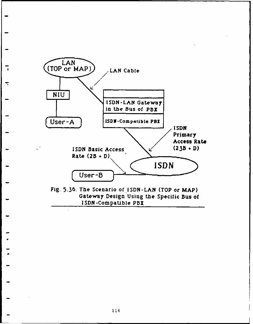
(TOP or MAP) ELAN Cable
ISDN-LAN Gatewayin the Bus of PBx
User -A ISD-Compatible P BXI D
Access Rate
GSN asica Dcesgsin (23B Spcii Bu)o
ISDN-Compatible PBX
114
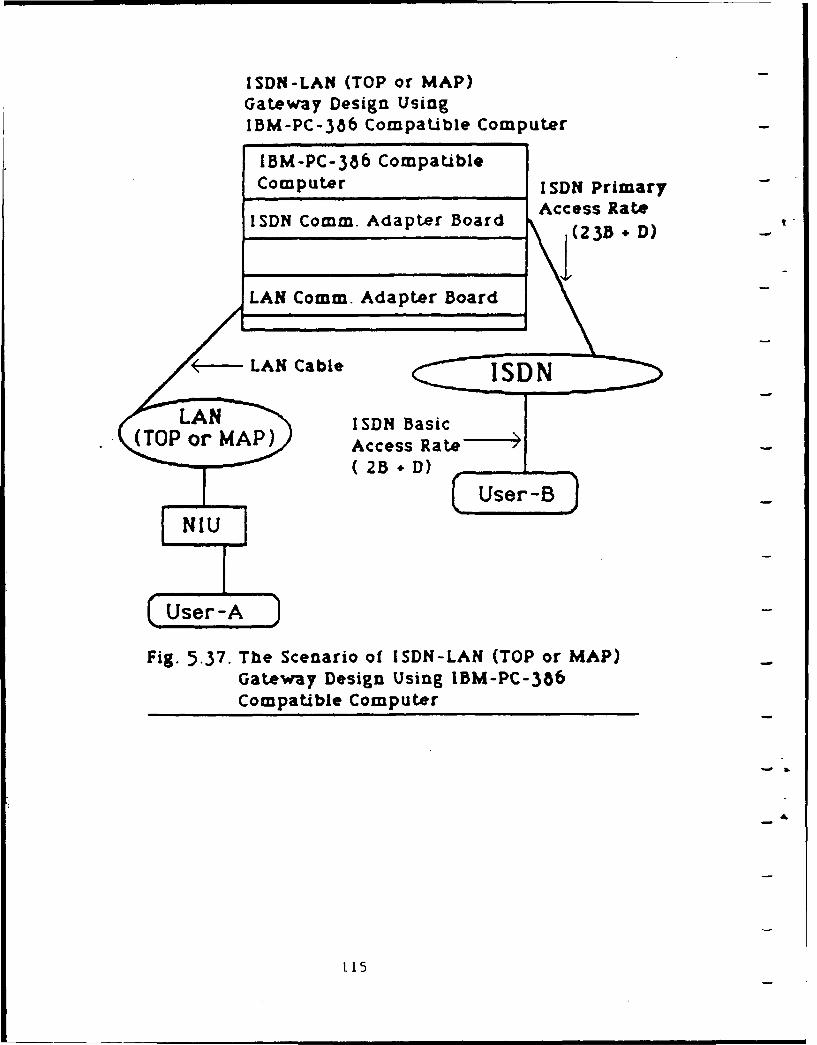
ISDN-LAN (TOP or MAP)Gateway Design UsingIBM-PC-386 Compatible Computer
IBM-PC-386 CompatibleComputer I SDN Primary
ISDN Comm. Adapter Board Access Rate
(23B +D)
LAN Comm. Adapter Board
(-LAN Cable -7 IDN
I SDN Basic(TOP or MAP) Access Rate"
(23 + D)
Fig. 5.37. The Scenario of ISDN-LAN (TOP or MAP)Gateway Design Using IBM-PC-306Compatible Computer
115
5.9. Step 6: Design the Translator Module to Interface with
the Two Half-Gateway Modules
In Figures 4.1, 4.2, and 4.8, the generic gateway model consists
of two half-gateway modules and one translator module. The
* generic gateway functions described in Section 4.2 are:
1. The Hardware and Software Functions of Network-A and
Network-B. That is, the functions of the two Half-Gateway
Modules.
2. Addressing, Naming, and Routing Functions.
3. Packet Fragmentation and Reassembly Functions.
4. Buffering and Flow Control Functions.
5. Congestion Control and Error Handling Functions.
6. Access and Security Control Functions.
7. Billing and Charging Functions.
8. Monitoring and Statistical Functions.
9. Management and Reconfiguration Functions.
10. Protocol Conversion Functions.
The generic gateway functions from 2 to 10 will be
implemented in the translator module. Because the ISDN, TOP, and
MAP are standard protocols, the implementation of these generic
gateway functions will be a little easier. However, the detailed
of the implementations of each of the generic gateway functions
should be based on the characteristics of the ISDN, TOP, or MAP.
The real implementation of the translator module of the ISDN-LAN
(TOP or MAP) gateway needs further study. The ISO Internet
Protocol (IP) is used by TOP and MAP. The ISO IP provides several
features of internetworking requirements, and they will ease the
implementation of generic gateway functions.
116
Several of the generic gateway functions are related to the
network management functions. Figure 5.38 shows the network
management concepts in the OSI environment. Figure 5.39 shows the
concept of manager-agent protocol and the external view of
network management architecture [37]. These network management
concepts, such as manager-agent protocol, fault management,
performance management, configuration and name management,
security management, accounting management, layer management
entity, distributed management information base, and so on, can
be extended to apply to the internetworking environments. The
extension of network management concepts to the implementation of
generic gateway functions needs further study.
117
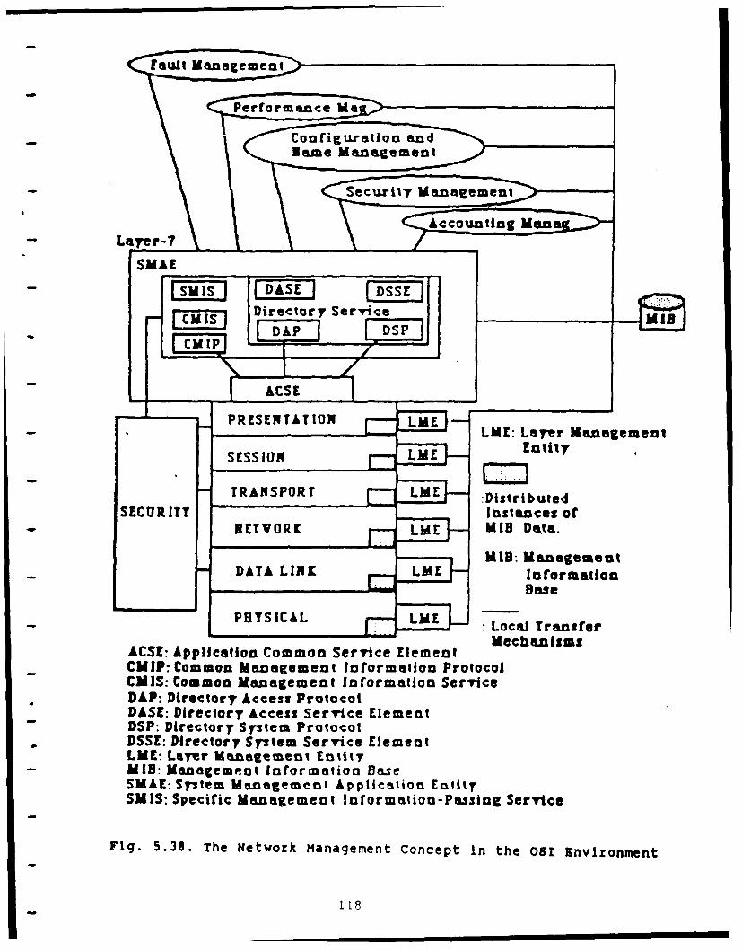
_____PeDreorynce I
-~~Nm LManLagemMentmen
ouEtntt
Lamyr-7 cco n t ane oEau" MI aa
MID: MIamn
PRSNTTO LoL Transfe
- ~ ~ ~ ~ ~ ~ ~ LE Layer ComoaMnneengemretntPrtoo
DASSSSIO Diecor AcentSrictEeyn
DSP DeTRASPOte T ProtocolteSSE:IT Dnrectory oftmSric lmn
DATA L11er LM nIBemeatagetetyMID: Mnagemeot Informationas
SMAE: Somten Management Anforation PrtylSM IS: SCmfoc Management Information-Servicg ervc
Fi.53.Th:wr ManagementCnet Infomto thB51wvromn
SMA , rstm anaem nt ppicaio119it
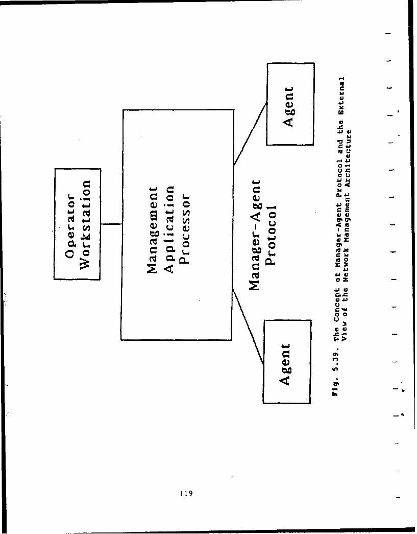
Aj4)
ul
0-
,kii
4..0 Ju7%
IV
4 V
Jug
0 0
a.))-4
119
5.10. Step 7: Implement and Test the Integrated Gateway
As we mentioned in Section 4.3.3.7 the implementation and
testing philosophy of an integrated gateway is as follows:
1. During the integrated gateway designing process, how to test
each of the implementation stages and the final product should
-always be kept in mind.
2. The implementation and testing should start from basic to
advanced, from simple to complex.
Based on the philosophy above, the ISDN-LAN (TOP or MAP)
gateway implementation and testing procedures are as follows:
i. Implement and test each of the two half-gateway modules (A&B).
First, test the Half-Gateway-Module-A which connects and
interfaces with the LAN (TOP or MAP). Make sure all the hardware
and software in the Half-Gateway-Module-A work properly and can
communicate with the LAN (TOP or MAP). Then, test the Half-
Gateway-Module-B which connects and interfaces with ISDN. Make
sure all the hardware and software in the Half-Gateway-Module-B
work properly and can communicate with ISDN.
2. Implement and test the simplified version of the translator
module. That is, just put the service mapping or protocol
conversion function (sometimes manually) in the translator
module. Make sure the simplified translator module can interface
with the two half-gateway-modules (A&B).
3. Add the generic gateway functions mentioned in Section 4.2 and
Section 5.9 to the translator module, one function at a
time. Make sure the function just added works properly, then add
next function and test it. Most of the implementations of the
120
generic gateway functions are software-dependent. Based on the
characteristics of ISDN and LAN (TOP or MAP), each of the generic
gateway functions should be implemented and tested one by one
before all functions being integrated together.
4. The final testing of the completed ISDN-LAN (TOP or MAP)
integrated gateway should be tested on the end-system-to-end-
system basis. We mentioned that the integrated gateway design
should consider the compatibility of the upper layer protocol in
the end-systems. In this ISDN-LAN (TOP or MAP) gateway design, we
assume the upper four layers in the end-systems are compatible.
The final testing should test this assumption is true or not. The
LAN provides the data service to end-systems connected to LAN,
and the ISDN provides the data, voice, image services to end-
systems connected to ISDN. Because no digital telephones are
connected to LAN, and the services provided by ISDN and that of
LAN are not the same, the ISDN-LAN (TOP or MAP) gateway can be
used for data service between ISDN and LAN only.
We emphasize here again that because the ISDN, TOP, and MAP
are standard protocols, the off-the-shelf software and hardware
products will make this ISDN-LAN (TOP or MAP) gateway design a
little easier. The off-the-shelf VLSI chips and communication
adapter boards for ISDN, TOP, or MAP can be used in this ISDN-LAN
gateway. However, caution must be taken to handle the parameters
and options used by each ISDN, TOP, or MAP products. Otherwise,
as the example of X.25 protocol implementations mentioned in
Section 5.1 (Figure 5.2), the use of the same set of protocols
cannot guarantee the compatibility of two products or two
121
a
networks. We can and should use the off-the-shelf products for
ISDN, TOP, or MAP for this ISDN-LAN (TOP or MAP) gateway design.
However, the final testing is the only way to quarantee the
proper use of the off-the-shelf products and successfully
internetworking ISDN with TOP or MAP by the ISDN-LAN (TOP or MAP)
gateway.
122
6.0 INTRODUCTION: INTERNTEWORKING DDN AND ISDN
The approach to internetworking the Defense Data Network
(DDN) and the Integrated Services Digital Network (ISDN) is to
design and build an integrated gateway. The general approach to
this internetworking problem was presented in Section 4.3.3 of
this report, Approach 3: Integrated Gateway. In this section
the general approach will be applied to the specific case of
internetworking DDN and ISDN.
The value of internetworking DDN and ISDN is manirested
by the many ways that ISDN services will enhance the DDN. In
addition to the wide range of services provided by ISDN, perhaps
the most significant benefit from internetworking DDN and ISDN is
the reduction of future internetworking problems. Part of the
intention behind the development of an ISDN is to create an
international standard that will endure the test of time and
adapt to changing technology. As ISDN matures, more and more
networks will have gateways that access ISDN. This will provide
the DDN with avenues to communicate with other networks that are
linked to ISDN. In this respect, ISDN can be regarded as a
neutral network providing the link between two end networks.
Figure 6.1 shows the scenario of internetworking DDN with three
other networks using ISDN as a neutral network. Figure 6.2 shows
the alternate scenario without ISDN. One can imagine the
complexity of this alternate internetworking method as the number
of networks is increased. When using ISDN as a neutral network,
only one gateway is required per network. The DDN/ISDN
internetworking problem is of special interest because of the
123
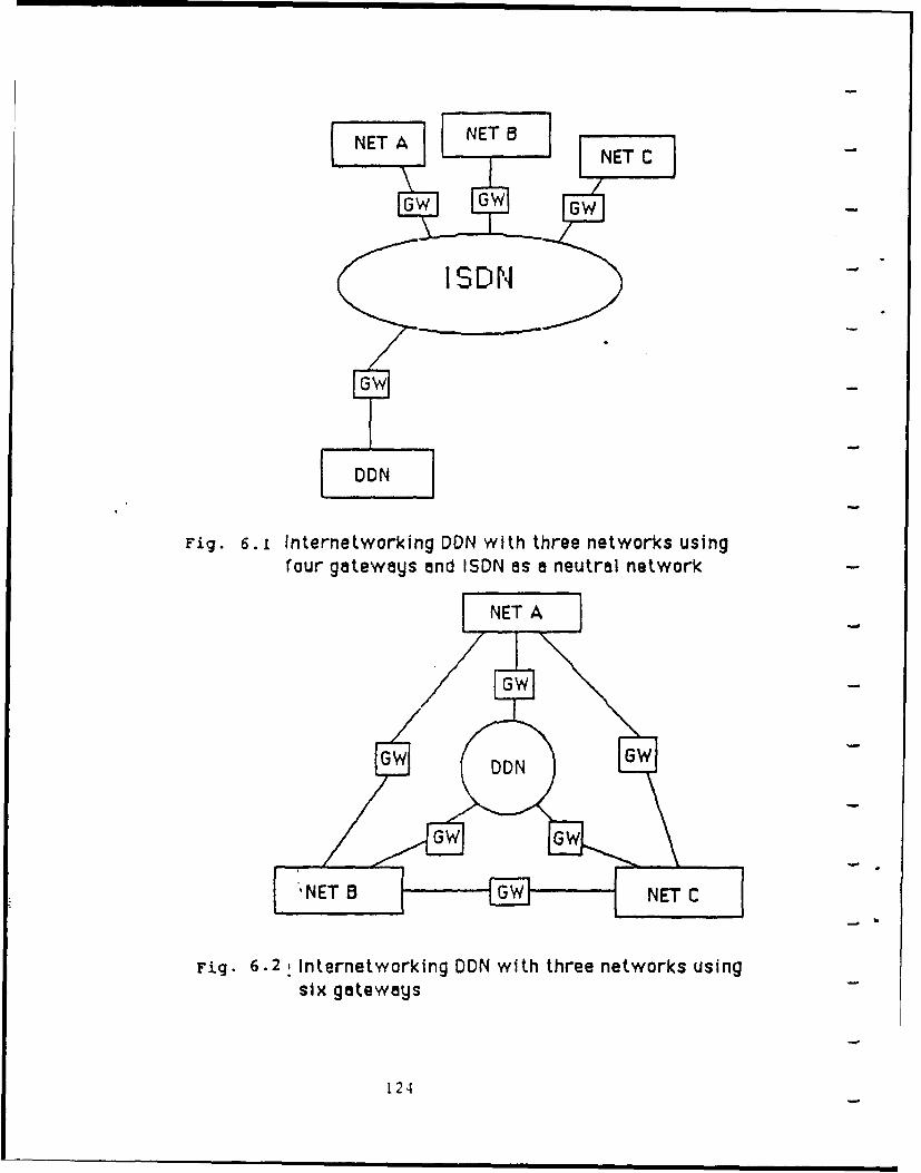
NDN 8
Fig. 6. 1 Internetworking DDN with three networks usingtour gateways and ISDN as a neutral network
Fig. 6.2 Internetworking DDN with three networks usingsix gateways
124
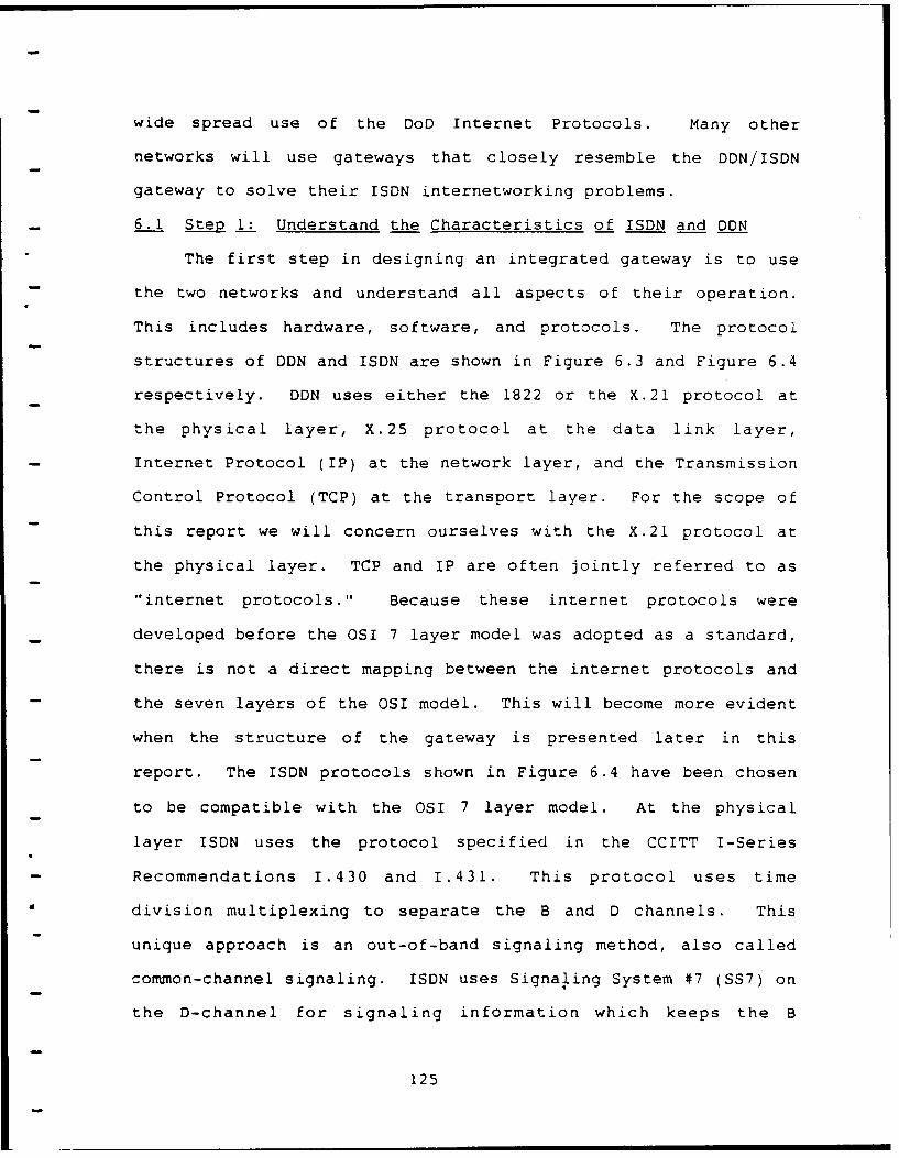
wide spread use of the DoD Internet Protocols. Many other
networks will use gateways that closely resemble the DDN/ISDN
gateway to solve their ISDN internetworking problems.
6.1 Step 1: Understand the Characteristics of ISDN and DDN
The first step in designing an integrated gateway is to use
the two networks and understand all aspects of their operation.
This includes hardware, software, and protocols. The protocol
structures of DDN and ISDN are shown in Figure 6.3 and Figure 6.4
respectively. DDN uses either the 1822 or the X.21 protocol at
the physical layer, X.25 protocol at the data link layer,
Internet Protocol (IP) at the network layer, and the Transmission
Control Protocol (TCP) at the transport layer. For the scope of
this report we will concern ourselves with the X.21 protocol at
the physical layer. TCP and IP are often jointly referred to as
"internet protocols." Because these internet protocols were
developed before the OSI 7 layer model was adopted as a standard,
there is not a direct mapping between the internet protocols and
the seven layers of the OSI model. This will become more evident
when the structure of the gateway is presented later in this
report. The ISDN protocols shown in Figure 6.4 have been chosen
to be compatible with the OSI 7 layer model. At the physical
layer ISDN uses the protocol specified in the CCITT I-Series
- Recommendations 1.430 and 1.431. This protocol uses time
division multiplexing to separate the B and D channels. This
unique approach is an out-of-band signaling method, also called
common-channel signaling. ISDN uses Signaling System #7 (SS7) on
the D-channel for signaling information which keeps the B
125
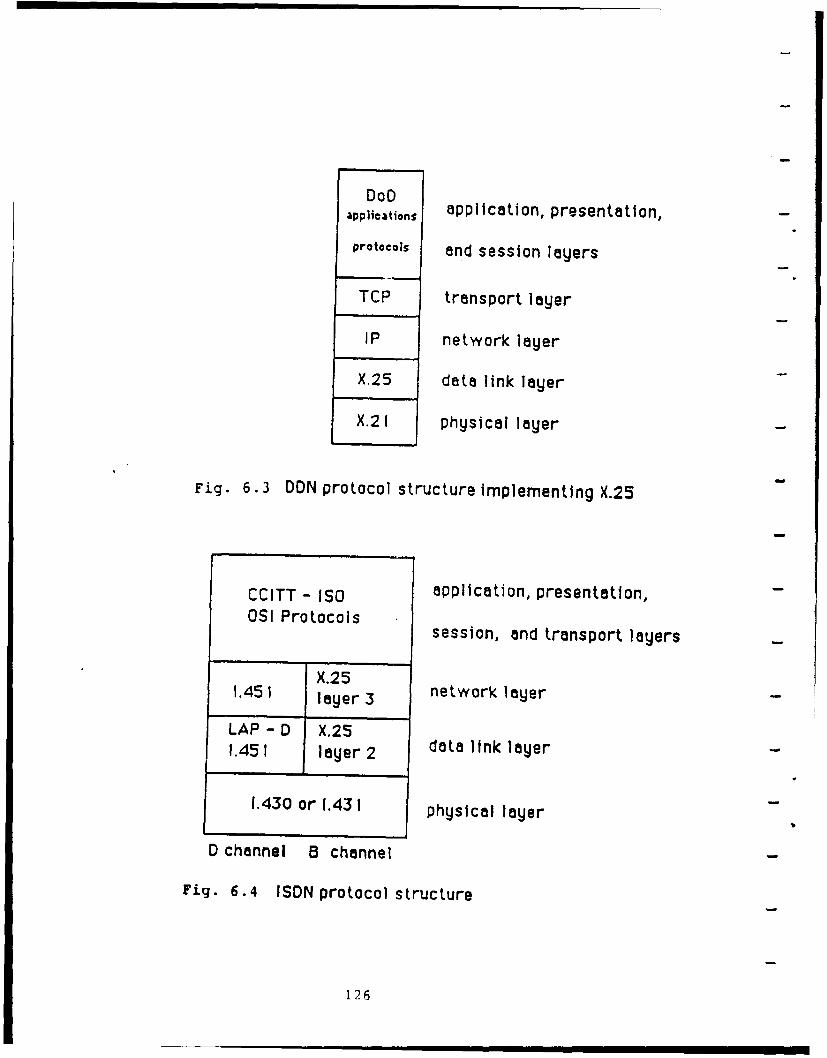
DoDDpplication application, presentation,
protocols and session layers
TCP transport layer
IP network layer
X.25 data link layer
X.2 I physical layer
Fig. 6.3 DDN protocol structure implementing X.25
CCITT - ISO application, presentation,OSI Protocols
session, and transport layers
X.251.451 layer3 network layer
LAP - D X.251.451 layer2 datalinklayer-
1.430 or 1.43 1 physical layer
D channel B channel
Fig. 6.4 ISDN protocol structure
126
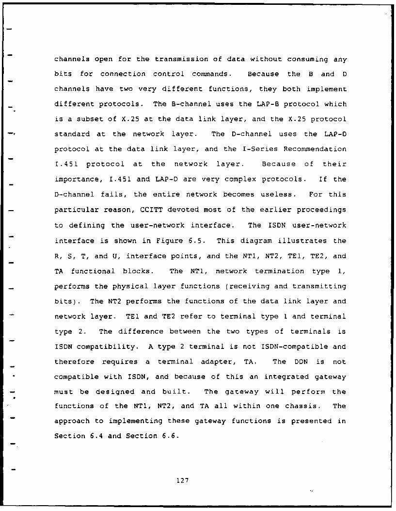
channels open for the transmission of data without consuming any
bits for connection control commands. Because the B and D
channels have two very different functions, they both implement
different protocols. The B-channel uses the LAP-B protocol which
is a subset of X.25 at the data link layer, and the X.25 protocol
- standard at the network layer. The D-channel uses the LAP-D
protocol at the data link layer, and the I-Series Recommendation
1.451 protocol at the network layer. Because of their
importance, 1.451 and LAP-D are very complex protocols. If the
D-channel fails, the entire network becomes useless. For this
particular reason, CCITT devoted most of the earlier proceedings
to defining the user-network interface. The ISDN user-network
interface is shown in Figure 6.5. This diagram illustrates the
R, S, T, and U, interface points, and the NTl, NT2, TEl, TE2, and
TA functional blocks. The NT1, network termination type 1,
performs the physical layer functions (receiving and transmitting
bits). The NT2 performs the functions of the data link layer and
network layer. TEl and TE2 refer to terminal type I and terminal
type 2. The difference between the two types of terminals is
ISDN compatibility. A type 2 terminal is not ISDN-compatible and
therefore requires a terminal adapter, TA. The DDN is not
" compatible with ISDN, and because of this an integrated gateway
- must be designed and built. The gateway will perform the
functions of the NTl, NT2, and TA all within one chassis. The
approach to implementing these gateway functions is presented in
Section 6.4 and Section 6.6.
127
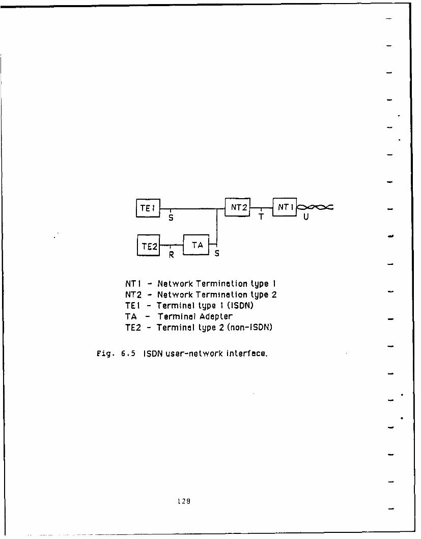
NT I - Network Termination type INT2 - Network Termination type 2-TE I - Terminal type I (ISDN)TA -Terminal Adapter-TE2 -Terminal type 2 (non-ISDN)
Fig. 6 .5 ISDN user-netwyork interface.
1.28
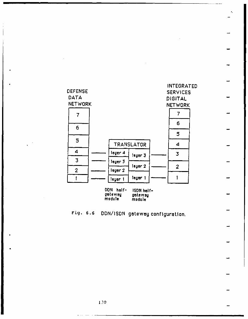
INTEGRATEDDEFENSE SERVICESDATA DIGITALNETWORK NETWORK
7 7
66
55 TRANSLATOR
44 laUer 4 lager 3 3
3 lauer3leer 2 2
2 laUer 2
lewer I lager 1 I
DON half- ISON half-gateweu getewaumodule module
Fig. 6.6 DON/ISDN gateway configuration.
130
protocols that exist in the DoD Internet Protocol Suite, an
assumption must be made that the two end systems are compatible
at the upper layers. Figure 6.7 depicts this end-to-end peer
layer compatibility. An example of an applications protocol is
electronic mail. The electronic mail facility within the DDN is
supported by the Simple Mail Transfer Protocol (SMTP) which is
built upon the services provided by TCP. The two end systems
must both use the SMTP or a compatible protocol in order to be
certain that no mismatches occur. A logical solution would be to
build a 7 layer gateway to alleviate the concern for
compatibility at the upper layers, but because there are so many
applications protocols in the internet environment it would be
virtually impossible to build a gateway that could handle such a
wide range of protocols effectively. Instead, we must make the
assumption that the upper layers are compatible in the two end
systems.
6.4 Step 4: Obtain the Required Information About DDN and ISDN
The information needed for the internal design of the
DDN/ISDN gateway is relatively easy to obtain. Both DDN and ISDN
are very common networks whose structures are both looked upon as
standards. A complete description of ISDN standards is available
. in CCITT's Red Book, I-Series Recommendations. The required
information about the DDN can be found in a variety of DoD RFC's.
These RFC's will be mentioned later in this section. This
section will explain in moderate detail the functions of the DDN
and ISDN half-gateway modules and provide the information needed
131
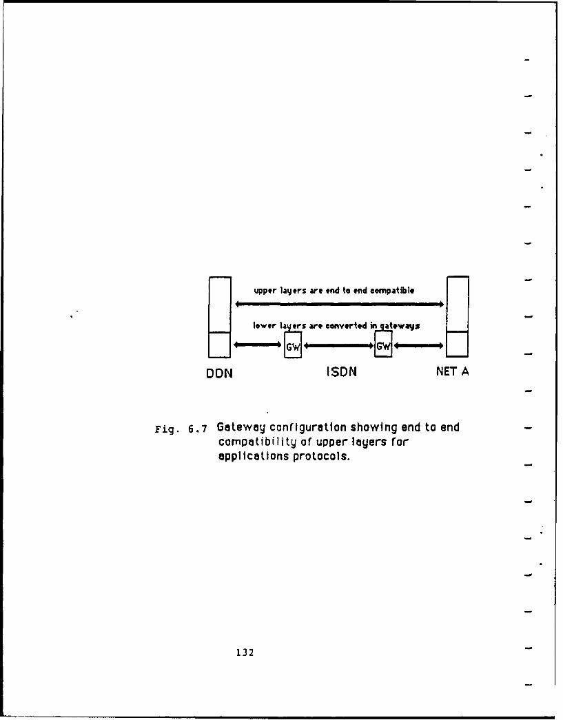
upper layers are end to end compatible
lower la rs are converted a*way] s
F]~~G 4- 1PG
DON ISDN NET A
Fig. 6.7 Gateway configuration showing end to endcompatibility of upper layers forapplications protocols.
132
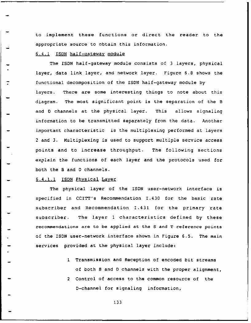
to implement these functions or direct the reader to the
appropriate source to obtain this information.
6.4.1 ISDN half-gateway module
- The ISDN half-gateway module consists of 3 layers, physical
layer, data link layer, and network layer. Figure 6.8 shows the
functional decomposition of the ISDN half-gateway module by
layers. There are some interesting things to note about this
diagram. The most significant point is the separation of the B
and D channels at the physical layer. This allows signaling
information to be transmitted separately from the data. Another
important characteristic is the multiplexing performed at layers
2 and 3. Multiplexing is used to support multiple service access
points and to increase throughput. The following sections
explain the functions of each layer and the protocols used for
both the B and D channels.
6.4.1.1 ISDN Physical Layer
The physical layer of the ISDN user-network interface is
specified in CCITT's Recommendation 1.430 for the basic rate
subscriber and Recommendation 1.431 for the primary rate
subscriber. The layer 1 characteristics defined by these
recommendations are to be applied at the S and T reference points
of the ISDN user-network interface shown in Figure 6.5. The main
- services provided at the physical layer include:
1 Transmission and Reception of encoded bit streams
of both B and D channels with the proper alignment,
2 Control of access to the common resource of the
D-channel for signaling information,
133
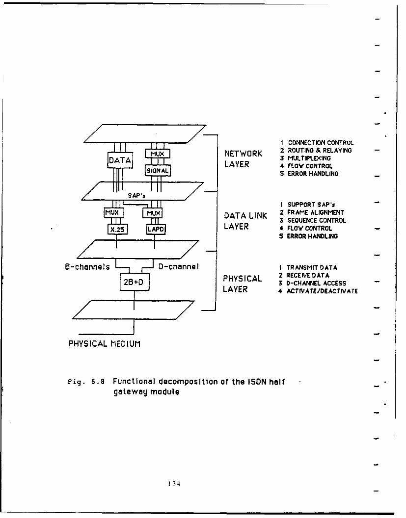
1 CONNECTION CONTROLM NETWORK 2 ROUTING & RELAYING
DATA 3 MULTIPLEXINGLAYER 4 FLOW CONTROL
5 ERROR HANDLING-
I SUPPORT SAP'sMuX LIXDATA LINK 2 FRAME ALIGNMENT
3 SEQUENCE CONTROL.2 A LAYER 4 FLOW' CONTROL
5 ERROR HANDLING
B5-channels LD-channel 1 TRANSMIT DATAPHYSICAL 2 RECEIVE DATA
28+D 3 D-CHANNEL ACCESSLAYER 4 ACTIVATE/DEACTIVATE
PHYSICAL MEDIUM
Fig. 6.8 Functional decomposition of the ISDN halfgateway module
134
3 Activation and Deactivation of terminals.
Other services provided by the physical layer include maintenance
functions, status indication to upper layers, and power feeding.
The information on the physical medium is coded using a pseudo-
ternary coding scheme. Figure 6.9 shows how this coding scheme
is implemented. Binary ones are represented with no line signal,
and binary zeroes are represented by alternating positive and
negative pulses. The first binary zero takes the same polarity
as the preceding framing balance bit. The bits within each frame
are separated into three channels, 2B + D, using time division
multiplexing. The layer 1 frame structure for the basic-rate
interface is shown in Figure 6.10. The frame structure is
dependent on the direction that the frame is being transmitted,
whether it be TE to NT, or NT to TE. In either case each frame
contains 48 bits which are transmitted in a time period of 250
microseconds. This corresponds to an aggregate data rate of 192
kilobits per second (Kbps). Frames being sent from TE to NT,
outgoing frames, are offset by two bits from the incoming frames,
NT to TE. Both types of frames contain 4 D-channel bits, 16 Bi-
channel bits, and 16 B2-channel bits. This makes the information
rates 16 Kbps for the D-channel and 64 Kbps for both of the B
channels. Each frame also contains framing bits and DC balance
-- bits. The incoming frames also contain D-channel echo bits, and
a terminal activation bit. The D-channel echo bit is set to the
value of the D-channel bit on the previous outgoing frame as
indicated by the diagram. This echo bit is monitored by
terminals that wish to gain access to the D-channel. The
135
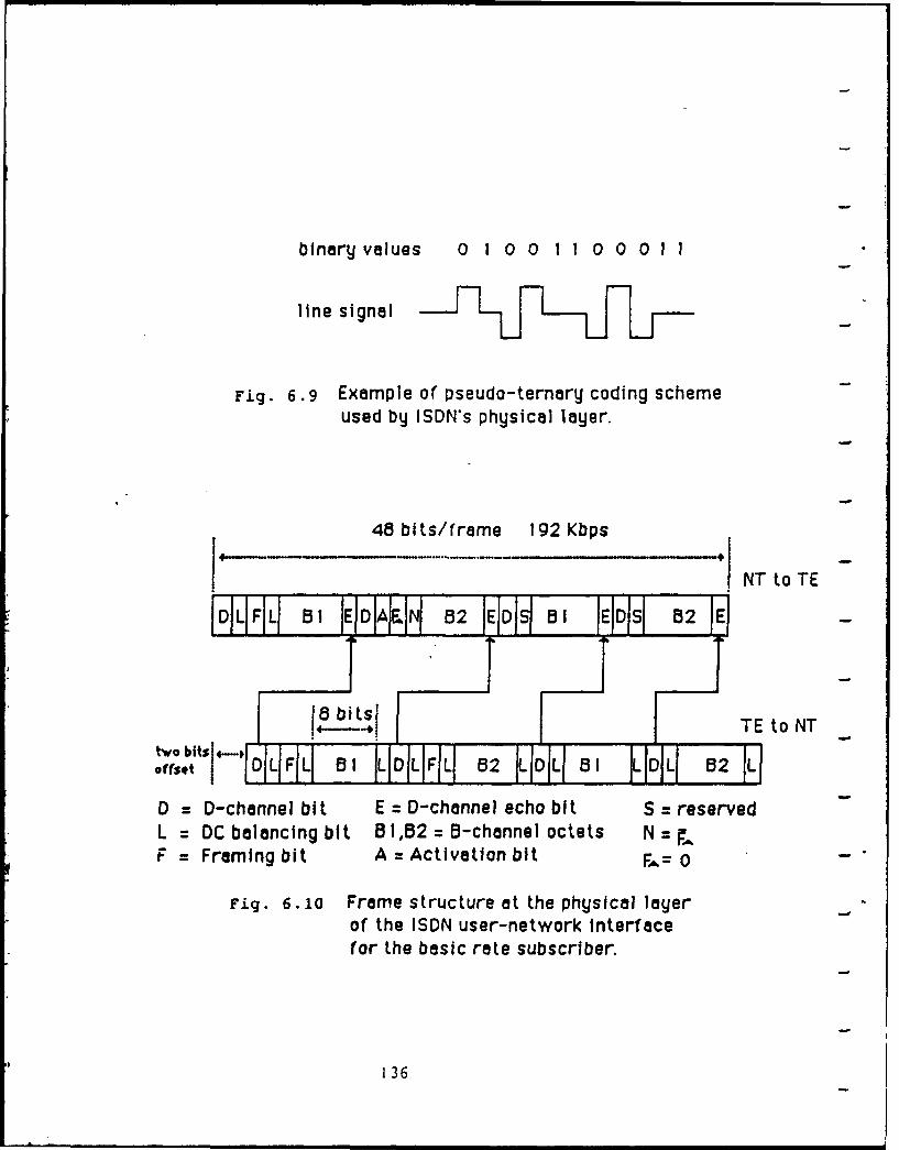
binary values 0 1 0 0 1 1 0 0 0 1 1
line signal j
Fig. 6.9 Example of pseudo-ternary coding schemeused by ISDN's physical layer.
48 bits/frame 192 Kbps]" "INTto TE
I DL F1Ll 01 E ID AENJ 02 E DS B01 EJDJS 02 JElI! IF F -TE to NTtrobits,14-
Offset I JOLFIL Bt ILDILIFL 532 LIDIL 81 LIL 0 B2L
D = D-channel bit E = D-channel echo bit S = reservedL = DC balancing bit B1,52 = B-channel octets N =F = Framing bit A = Activation bit 0 -
Fig. 6. i0 Frame structure at the physical layerof the ISDN user-network Interfacefor the basic rate subscriber.
136
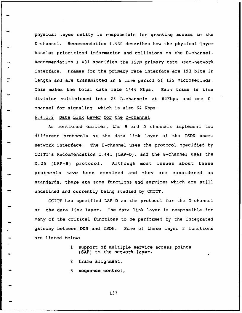
physical layer entity is responsible for granting access to the
D-channel. Recommendation 1.430 describes how the physical layer
handles prioritized information and collisions on the D-channel.
- Recommendation 1.431 specifies the ISDN primary rate user-network
interface. Frames for the primary rate interface are 193 bits in
length and are transmitted in a time period of 125 microseconds.
This makes the total data rate 1544 Kbps. Each frame is time
division multiplexed into 23 B-channels at 64Kbps and one D-
channel for signaling which is also 64 Kbps.
6.4.1.2 Data Link Layer for the D-channel
As mentioned earlier, the B and D channels implement two
different protocols at the data link layer of the ISDN user-
network interface. The D-channel uses the protocol specified by
CCITT's Recommendation 1.441 (LAP-D), and the B-channel uses the
X.25 (LAP-B) protocol. Although most issues about these
protocols have been resolved and they are considered as
standards, there are some functions and services which are still
undefined and currently being studied by CCITT.
CCITT has specified LAP-D as the protocol for the D-channel
at the data link layer. The data link layer is responsible for
many of the critical functions to be performed by the integrated
* gateway between DDN and ISDN. Some of these layer 2 functions
- are listed below:
1 support of multiple service access points(SAP) to the network layer,
2 frame alignment,
3 sequence control,
137
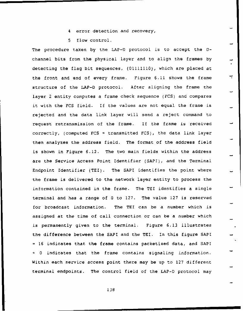
4 error detection and recovery,
5 flow control.
The procedure taken by the LAP-D protocol is to accept the D-
channel bits from the physical layer and to align the frames by
detecting the flag bit sequences, {01111110}, which are placed at
the front and end of every frame. Figure 6.11 shows the frame
structure of the LAP-D protocol. After aligning the frame the
layer 2 entity computes a frame check sequence (FCS) and compares
it with the FCS field. If the values are not equal the frame is
rejected and the data link layer will send a reject command to
request retransmission of the frame. If the frame is received
correctly, (computed FCS = transmitted FCS), the data link layer
then analyzes the address field. The format of the address field
is shown in Figure 6.12. The two main fields within the address
are the Service Access Point Identifier (SAPI), and the Terminal
Endpoint Identifier (TEI). The SAPI identifies the point where
the frame is delivered to the network layer entity to process the
information contained in the frame. The TEI identifies a single
terminal and has a range of 0 to 127. The value 127 is reserved
for broadcast information. The TEI can be a number which is
assigned at the time of call connection or can be a number which
is permanently given to the terminal. Figure 6.13 illustrates
the difference between the SAPI and the TEI. In this figure SAPI
= 16 indicates that the frame contains packetized data, and SAPI
= 0 indicates that the frame contains signaling information.
Within each service access point there may be up to 127 different
terminal endpoints. The control field of the LAP-D protocol may
138
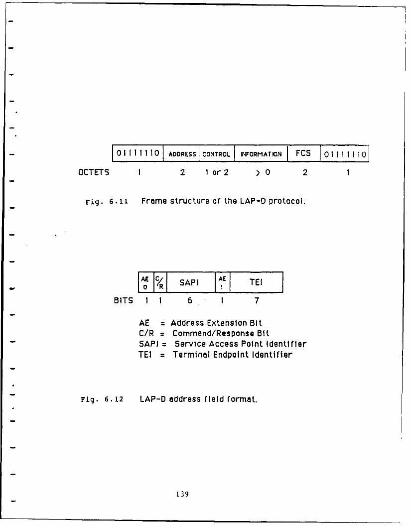
2
0 O1 1 1 1 10ADRESSCONTROLIINFORMATIONI FCS 0 111
OCTETS 1 2 1 or 2 > 0 2
Fig. 6.11 Frame structure of the LAP-D protocol.
w o R SAPI I E IBITS 1 1 6 1 7
AE = Address Extension BitC/R = Command/Response BitSAPI Service Access Point IdentifierTEl = Terminal Endpoint Identifier
Fig. 6.12 LAP-D address field format.
139
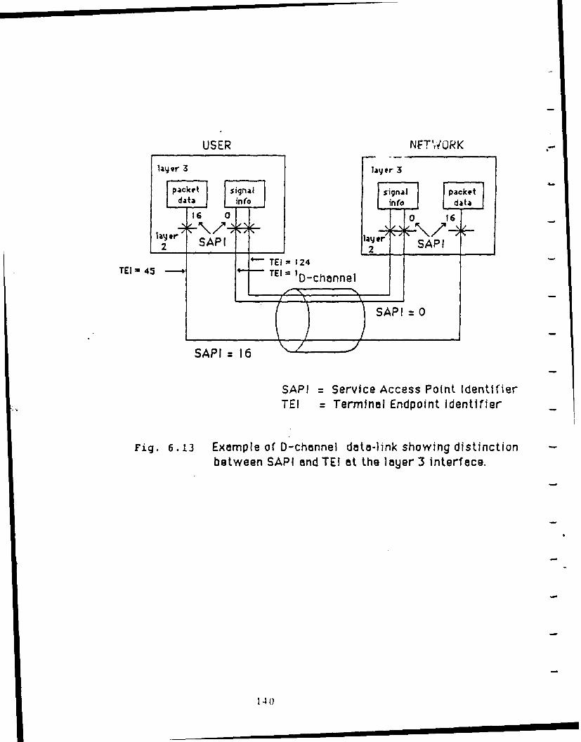
USER NIFTWOIRK
layjer 3 layer 3
packet signal signal packetdata intfo info data
16 0 0 1
SAP!ri(-% layer SP2 SAP I ~TEI 124 12r SP
TE 45 - TE =D-channel
SAPI Service Access Point IdentifierTEI Terminal Endpoint Identifier
Fig. 6.13 Example of D-'channel data-link showing distinction -
between SAPI and TEl at the layer 3 interface.
140
be one or two octets in length and is used to identify commands
and responses. There are three types of control field formats,
Information (I) frames, Supervisory (S) frames, and Unnumbered
- Information (U) frames. These formats are shown in Figure 6.14.
I frames are used to transmit intormation between layer three
entities. I frames contain sequence numbers, N(s) and N(r),
which are used to reorganize packets that may have gotten out of
order during transmission. U frames are used to transmit
unacknowledged information. S frames are used by the data link
layer to perform supervisory control functions. An example would
be requesting retransmission of an I frame that had an error.
The supervisory control frames are also used to implement the
flow control services provided by the data link layer.
6.4.1.3 Network Layer for ISDN's D-channel
The functions and protocol employed at the network layer,
layer 3, of the ISDN user-network interface are described in
CCITT's Recommendation 1.451. The D-channel network layer
protocol is a very complex protocol, and carries a great deal of
responsibility within the structure of the ISDN user-network
interface. Some of the duties of the D-channel network layer are
listed below:
I network connection control,
2 routing and relaying,
3 multiplexing and rate adaption,
4 flow control and sequencing,
5 error detection and recovery.
141
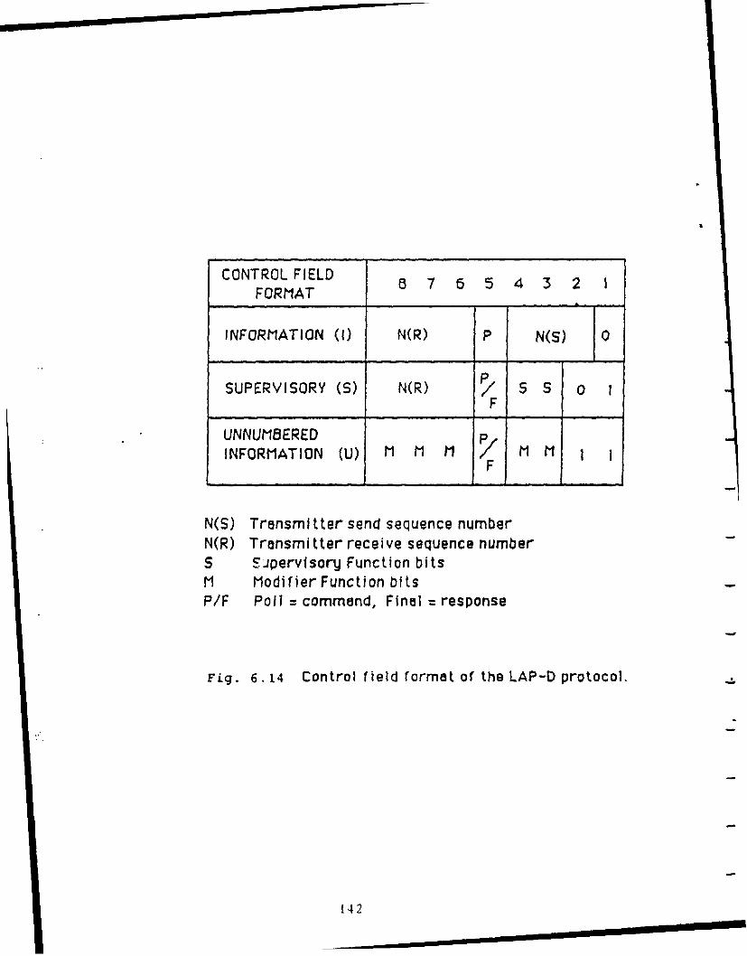
CONTROLFIELD 8 7 6 5 4 3 2 1FORMAT
INFORMATION (I) N(R) P N(S) 0
PSUPERVISORY (S) N(R) / S 0 1
FUNNUMBERED p M
INFORMATION (U) M M M M MF
N(S) Transmitter send sequence numberN(R) Transmitter receive sequence numberS ipervisory Function bitsM Modifier Function bitsP/F Poll command, Final =response
Fig. 6.14 Control field format of the LAP-D protocol.
142
The network layer receives assistance in implementing these
functions by using primitives to communicate with the data link
layer. The network layer also generates and interprets layer 3
-- messages for peer-level communication between the two end
systems. The messages sent between the peer-level network layers
and between the network and data link layers are always
transparent to the user. A complex set of network layer
primitives are used to control network connections. The
procedure for interpreting layer 3 messages to extract these
primitives will be explained later in this section. The routing
and relaying functions provided by the network layer are used to
determine the appropriate route to direct information between
layer 3 addresses. Multiplexing and rate adaption are very
important functions provided by the network layer to improve the
efficiency of packet-switched information flow on the B and D
channels. Flow control is achieved with the help of the data
link layer primitives which communicate ReceiveReady and
ReceiveNotReady indications to the network layer and vice
versa. Sequencing is used to ensure that data is reconstructed
in the same order that it was submitted by the user. Error
handling functions are also completed with the assistance of the
* data link layer. The data link layer is responsible for
detecting errors that occur during transmission, while the
network layer is responsible for detecting and recovering from
procedural errors. Network messages are contained in the data
link layer information field, and are passed to the network layer
via service access points. Network layer messages have the
143
format shown in Figure 6.15. After the network layer accepts a
message form the data link layer, it reads the protocol
discriminator. The protocol discriminator identifies the general
type of message whether it be for call control or some other type
of layer 3 function. A complete list of protocol discriminator
values can be found in the I-Series Recommendation 1.451. The
call reference value field is used to identify the call or
facility at the user-network interface to which the message
applies. The message type is analyzed to indicate the function
of the message. These functions are actually network layer
service primitives. This one octet of information is the heart
and soul of the network connection control. The eighth bit of
this octet is reserved for extension purposes. Additional
information is appended to the end of the message. This
additional information is usually specific to the type of message
that was sent. For some types of messages no additional
information is needed and therefore this field is optional. In
the event that additional information is appended to the message,
the first octet identifies the type of information and the second
octet specifies the length of the information field. Examples of
additional information are channel identification and connected
address identification. Channel identification is very important
when sub-channels are multiplexed into the same B-channel. When 7
several sub-channels of lower data rates are requesting use of
the B-channels, the network layer multiplexes them into the same
channel by assigning slot numbers (slots of time) to the
channels. The format of the channel identification information
t44

- bit a 7 6 5 4 3 2 1
PROTOCOL DISCRIMINATOR OCTET I
0 0 0 0 1 LENGTH OCTET 2
CALL REFERENCE VALUE OCTET 3
0 MESSAGE TYPE OCTET 4
ADDITIONAL INFORMATION ETC.
T T
Fig. 6.15 Structure of layer 3 message on ISDN's D-channel.
145
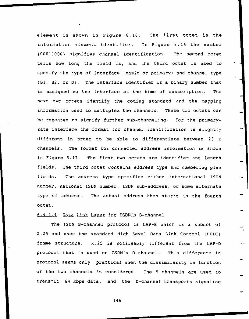
element is shown in Figure 6.16. The first octet is the
information element identifier. In Figure 6.16 the number
{O0011000} signifies channel identification. The second octet
tells how long the field is, and the third octet is used to
specify the type of interface (basic or primary) and channel type
(BI, B2, or D). The interface identifier is a binary number that
is assigned to the interface at the time of subscription. The
next two octets identify the coding standard and the mapping
information used to multiplex the channels. These two octets can
be repeated to signify further sub-channeling. For the primary-
rate interface the format for channel identification is slightly
different in order to be able to differentiate between 23 B
channels. The format for connected address information is shown
in Figure 6.17. The first two octets are identifier and length
fields. The third octet contains address type and numbering plan
fields. The address type specifies either international ISDN
number, national ISDN number, ISDN sub-address, or some alternate
type of address. The actual address then starts in the fourth
octet.
6.4.1.4 Data Link Layer for ISDN's B-channel
The ISDN B-channel protocol is LAP-B which is a subset of
X.25 and uses the standard High Level Data Link Control (HDLC)
frame structure. X.25 is noticeably different from the LAP-D -
protocol that is used on ISDN's D-chaiinel. This difference in
protocol seems only practical when the dissimilarity in function
of the two channels is considered. The B channels are used to
transmit 64 Kbps data, and the D-channel transports signaling
146
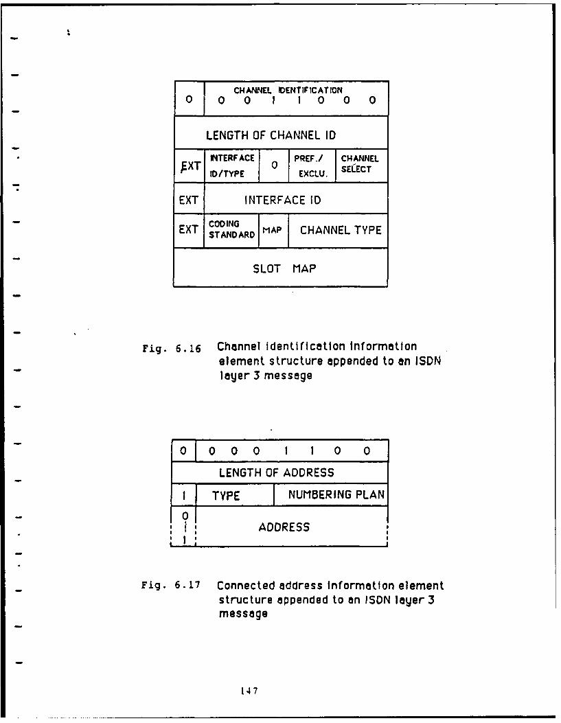
CHANNEL IDENTIFICATION0 0 0 1 1 0 0 0
LENGTH OF CHANNEL ID
- INTERFACE PREF./ CHANNELXT SEECT
E D/TYPE EXCLUE.
EXT INTERFACE ID
EXT CODINGSTANDARD MAP CHANNEL TYPE
SLOT MAP
Fig. 6.16 Channel identification informationelement structure appended to an ISDNlayer 3 message
O1 0 0 0 I 1 0 0
LENGTH OF ADDRESS
I TYPE NUMBERING PLAN
ADDRESS
Fig. 6.17 Connected address Information elementstructure appended to an ISDN layer 3message
147
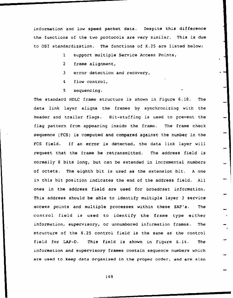
information and low speed packet data. Despite this difference
the functions of the two protocols are very similar. This is due
to OSI standardization. The functions of X.25 are listed below:
I support multiple Service Access Points,
2 frame alignment,
3 error detection and recovery,
4 flow control,
5 sequencing.
The standard HDLC frame structure is shown in Figure 6.18. The
data link layer aligns the frames by synchronizing with the
header and trailer flags. Bit-stuffing is used to prevent the
flag pattern from appearing inside the frame. The frame check
sequence (FCS) is computed and compared against the number in the
FCS field. If an error is detected, the data link layer will
request that the frame be retransmitted. The address field is
normally 8 bits long, but can be extended in incremental numbers
of octets. The eighth bit is used as the extension bit. A one
in this bit position indicates the end of the address field. All
ones in the address field are used for broadcast information.
This address should be able to identify multiple layer 3 service
access points and multiple processes within these SAP's. The
control field is used to identify the frame type either
information, supervisory, or unnumbered information frames. The
structure of the X.25 control field is the same as the control
field for LAP-D. This field is shown in Figure 6.14. The
information and supervisory frames contain sequence numbers which
are used to keep data organized in the proper order, and are also
148
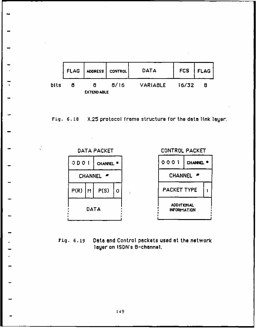
FLAG ADDRESS CONTROL DATA FCS IFLAG
I bits a a 8/16 VARIABLE 16/32 aEXTEND ABLE
Fig. 6. 18 X.25 protocol frame structure for the data link layer.
DATA PACKET CONTROL PACKET
ODO I cH N." 000 1 CHANNEL"
CHANNEL * CHANNEL
P(R) M P(S) 0 PACKET TYPE
ADDITIONAL
DATA INFORMATION
p I
Fig. 6.19 Data and Control packets used at the networklayer on ISDN's B-channel.
149
needed to implement flow control and error recovery functions.
The flow control function is implentanted using a sliding window.
This window will only accept frames with sequence numbers that
are between the limits of the window. Sequence numbers can vary
in length depending on the modulus being used either modulus 8 or
modulus 128. The modulus is set by sending an S frame containing
the proper set-mode command. When the modulus is set to 128 the
control field is extended to 16 bits to accommodate the larger
sequence numbers.
6.4.1.5 Network Layer for ISDN's B-channel
At the network layer ISDN's B-channel uses the X.25 layer 3
protocol standard. The functions performed at the network layer
are listed below:
1 multiplexing,
2 flow control,
3 sequencing,
4 error handling.
The network layer protocol uses two types of packets, data
packets and control packets. The format for these two packets
are shown in Figure 6.19. Bit position one of the third octet is
the delimiter that identifies the packet as either data or
control. Both packet types contain a 12 bit channel
identification field. This 12 bit identification will allow up
to 4095 channels to be multiplexed through the network layer.
The data packets contain send and receive sequence numbers in the
third octet followed by data st-rting in the fourth octet. The
first octet contains a D bit which is used to designate the
150
originating source of acknowledgments. With the D bit set to
zero, (D=O), acknowledgments will come from the gateway. If the
D bit is set to one, (D=I), then the acknowledgments must
originate at the remote network termination. The normal case is
for D=O, and the gateway sends acknowledgments. The M bit in the
-- third octet is used to indicate the final frame in a sequence.
Control packets are used to communicate commands and responses
between peer-level entities. Commands and responses are defined
by primitives which are coded into the packet-type field. These
primitives are the backbone of the management of the layer 3
entity which implements the error handling, flow control, and
sequencing functions. Just as it was with the 1.451 protocol for
the D-channel, most commands require additional information.
This additional information is appended to the packet immediately
following the packet-type identifier. A complete description of
the primitives and related information can be found in CCITT's
X.25 standards.
6.4.2 Step 4: DDN Half-Qateway Module
The DDN half-gateway module consists of four layers. The
protocols at these four layers do not correspond to the standard
OSI model layers. In an internet environment, protocols at
layers I and 2 are referred to as network protocols, the IP is
called a gateway protocol, and TCP is referred to as the host
protocol. Although these protocols do not conform to OSI
standards, for reasons of clarity reference will still be made to
the OSI layers: physical layer, data link layer, network layer,
and transport layer. The functional decomposition of the DDN
151
half-gateway module is shown in Figure 6.20. There is one very
distinct difference between the DDN half-gateway module and the
ISDN half-gateway module and that is in-band signaling versus
out-of-band signaling. The DDN protocols handle signaling
information that is inter-mingled with data, where as ISDN uses a
separate D-channel for signaling information. The following
sections will explain the functions of each layer and the
protocols implemented at each layer.
6.4.2.1 Physical Layer of the Defense Data Network
The Defense Data Network employs the X.21 standard at the
physical interface. X.21 specifies a connection similar to the
RS-232-C connection except X.21 has only 15 pins compared to 25
with the RS-232-C. Of these 15 pins only 8 are used and they are
shown in Figure 6.21. X.21 is a significant improvement over RS-
232-C because improved digital logic circuits have removed the
need for separate wires for every signal. X.21 is responsible
for controlling the transmission and reception of information
from the physical medium. The X.21 protocol must also
communicate with the data link layer protocol, X.25. X.21 and
X.25 cooperate to achieve the lower layer functions of the DDN.
6.4.2.2 Data Link Layer of the DDN
The data link layer protocol is the same for both DDN and
ISDN's B-channel. Although both ISDN and DDN implement X.25 at
the data link layer, the protocols are not identical. The X.25
protocol has several variables that could make DDN's
implementation of X.25 clearly different than the implementation
on ISDN's B-channel. Some of these differences might be in frame
152
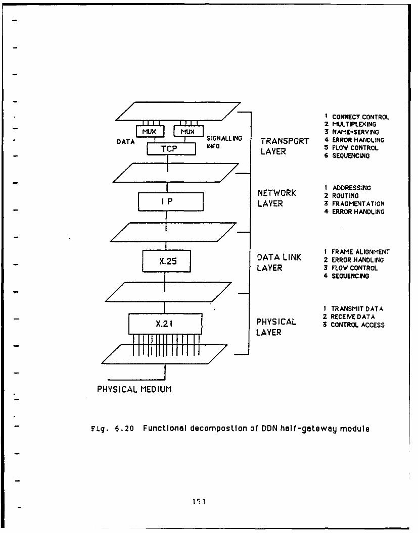
1 CONNECT CONTROL2 MULTIPLEXING
MUX MLIX3 NAME-SERVINGDATA SIGNALLING TRANSPORT 4 ERROR HANDLING
TCP INFO LAYER 5 FLOW CONTROL/ 6 SEQUENCING
I ADDRESSINGNETWORK 2 ROUTINGLAYER 3 FRAGMENTATION
4 ERROR HANDLING
I FRAME ALIGNMENTX.25 DATA LINK 2 ERROR HANDLING
LAYER 3 FLOW CONTROL4 SEQUENCING
I TRANSMIT DATA2 RECEIVE DATA
IPHYSICAL 3 CONTROL ACCESSLAYER
PHYSICAL MEDIUM
Fig. 6.20 Functional decompostion of DDN half-gateway module
151
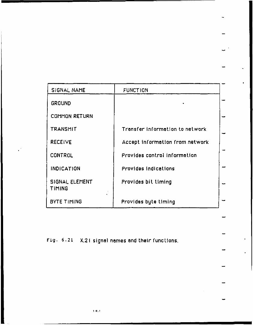
SIGNAL NAME FUNCTION
GROUND
COMMON RETURN
TRANSMIT Transfer information to network
RECEIVE Accept Information from network
CONTROL Provides control information
INDICATION Provides indications
SIGNAL ELEMENT Provides bit timingTIMING
BYTE TIMING Provides byte timing
Fig. 6.21 X.21 signal names and their functions.
I ;, A
length, timing functions, or windowing used for flow control. It
should be clear that these two implementations of X.25 are
different in the way that they communicate with the adjacent
layers. DDN's implementation of X.25 must communicate with X.21
at the physical layer and with the internet protocol (IP) at the
network layer. Similarly, ISDN's implementation of X.25 must
communicate with the 1.430 or 1.431 protocol at the physical
layer and with X.25 layer 3 at the network layer. Nevertheless,
for the scope of this report we can assume that the basic
functions are the same. The frame structure of the X.25 protocol
is shown in Figure 6.18 and its functions are discussed in
section 6.4.1.4.
6.4.2.3 Network Layer of the DDN
The Defense Data Network uses the internet protocol (1P) as
the network layer protocol. IP is defined in the DoD RFC 791.
As stated before, the internet protocols are not modeled
according to OSI standards. Because of this, IP will perform a
different set of functions than those described for the ISDN
layer 3 protocols. The main functions of IP are listed below:
1 addressing and routing,
2 fragmentation and reassembly,
3 error detection and recovery, (ICMP).
The first and most important function of the IP is to deliver
packetized data, commonly called datagrams, from a source to its
proper destination. The purpose of IP is to determine an
appropriate route through gateways and intermediate systems to
send the datagrams so they end up in the right place. Actually,
this route is determined one step at a time from gateway to
gateway. The IP checks the destination address of the datagram
which is part of the internet protocol header. This header is
shown in Figure 6.22. If IP is able to deliver the datagram
directly to its destination it does just that. Otherwise, IP
looks up the address in a routing table and then sends the
datagram to the appropriate gateway to forward the datagram. The
receiving gateway then performs a similar routing function to
direct the datagram. In the event that this destination address
is not in the routing table IP sends the datagram to a pre-
determined default gateway. For most practical purposes it can
be assumed that the DDN/ISDN gateway will be a default gateway.
Once the packet has reached ISDN, ISDN will implement its own
internal routing functions to deliver the datagrams to the proper
destination. Description of ISDN's routing function is beyond
the scope of this report. Currently most of the available ISDN
standards refer to the user-network interface. It is expected
that CCITT's 1988 version of ISDN standards will have more
information related to network operation. Figure 6.22 shows that
the inte.net header contains two 32 bit addresses, one source and
one destination. Internet addresses are separated into three
classes, A, B, and C according to the size of the network with
class A being the largest. The Arpanet is in class A and
therefore discussion in this report is limited to this class of
addresses. Class A addresses use 7 bits to identify the network
and 24 bits to identify the host on that network. Most of the
fields in the internet header are self-explanatory. If more
1I56
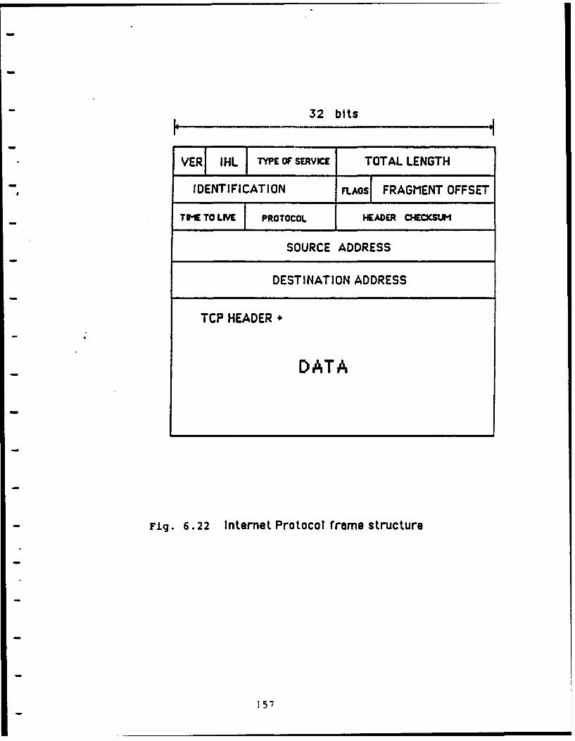
32 bits
VER IHL TYPE OF SERVICE TOTAL LENGTH
IDENTIFICATION n.AOS, FRAGMENT OFFSET
TE TO LIVEI PROTOCOL IHEADER CHECKSUH
SOURCE ADDRESS
DESTINATION ADDRESS
TCP HEADER +
DATA
Fig. 6.22 Internet Protocol frame structure
157
detail is desired, a thorough explanation of the header is given
in RFC 791. Some of the more significant fields which deserve
mentioning are the header checksum, identification, fragment
offset, and time to live fields. Every time an IP receives a
datagram it computes a very simple checksum on the information in
the header. This checksum is performed only on the IP header,
not on the data. This is done because the IP header changes each
time it is processed. The time to live field contains a number
that is decremented each time an IP processes the datagram. when
this number reaches zero the datagram is discarded. This is used
to prevent packets from being sent from gateway to gateway
without ever reaching the proper destination. The identification
and fragment offset fields are used in reassembling datagrams
that have been fragmented. Fragmentation is sometimes necessary
when one of the intermediate networks or gateways is unable to
handle large datagrams. This should not be a problem when
sending datagrams to ISDN, but is still a necessary function to
be performed by the integrated gateway. When IP detects an error
it calls upon the support of the Internet Control Message
Protocol (ICMP). ICMP is an error reporting protocol, but it
does not make IP reliable. The ICMP only reports those errors
that are detected by the IP such as: fragmentation needed, route
failure, or unreachable network. An example of route failure is
when the time to live has expired. ICMP sends notification that
the route taken was the wrong one and then IP will decide on an
alternative route.
158
6.4.2.4 Transport Laver of the DDN
The DDN uses the Transmission Control Protocol (TCP) as the
transport layer protocol. This protocol is defined in the DoD
RFC 793. TCP is designed to provide highly reliable end to end
data communications.. The functions performed by TCP are:
1 connection control,
2 multiplexing,
3 name serving,
4 error handling,
5 sequencing,
6 flow control,
7 precedence and security.
TCP is responsible for keeping track of multiple connections at
the same internet address. IP interprets the internet address
and delivers it to the host layer protocol, TCP. From this
point, TCP must be able to distinguish between many different
applications that all use the same internet address. TCP keeps
track of different applications by assigning port numbers to them
when a connection is established. TCP is then able to send
multiplexed datagrams from several applications to IP. IP is not
concerned with this port number, but instead is merely concerned
with delivering the datagram to the proper destination address.
TCP tells IP what the destination address is for every datagram.
Along with the datagram and destination address TCP includes its
own header that is placed at the front of the datagram. IP
treats the TCP header as if it were data. The TCP header is
shown in Figure 6.23. This header contains a source and
159
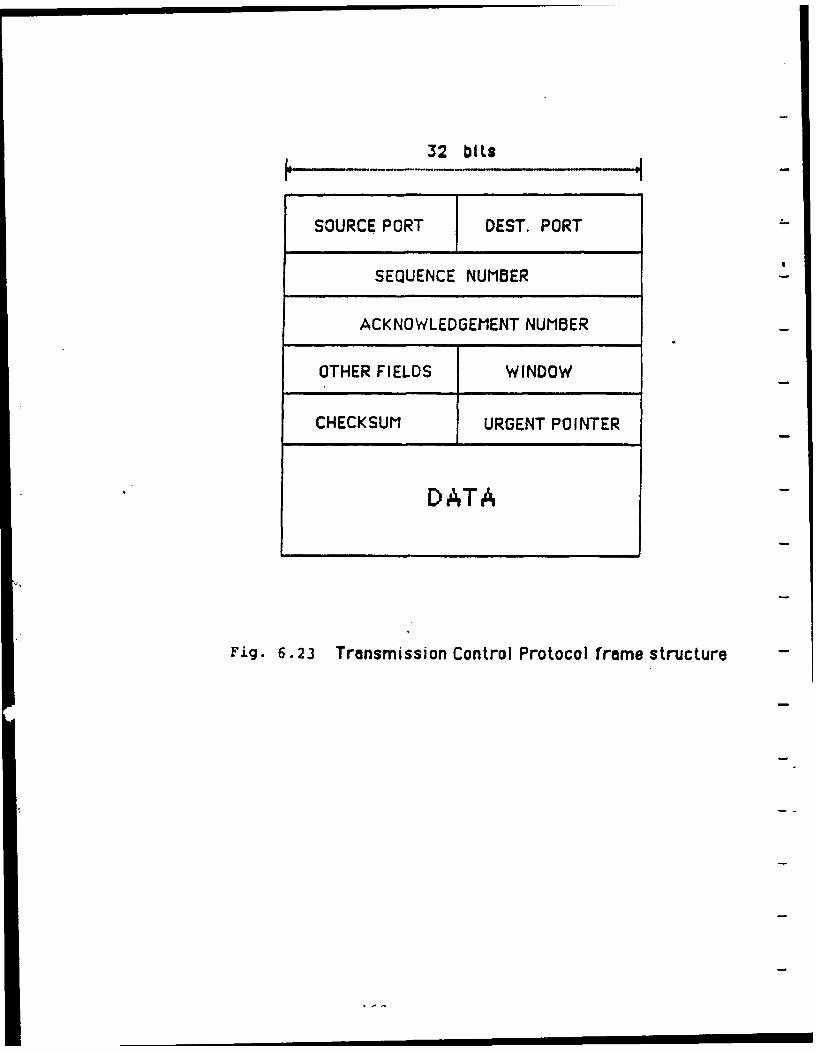
32 bits
SOURCE PORT DEST. PORT -
SEQUENCE NUMBER
ACKNOWLEDGEMENT NUMBER
OTHER FIELDS WINDOW
CHECKSUM URGENT POINTER
DATA
Fig. 6.23 Transmission Control Protocol frame structure
destination port number. When a user requests a service from a
remote host, TCP first takes on the responsibility of
establishing a connection. TCP will assign a local port number
for the application and send an open request to the remote host
with the port number of a "well-known socket" stored in the
destination port number field. This "well-known socket indicates
to the remote host what type of application is being requested.
For example the File Transfer Protocol is supported by socket
number 21. A list of "well-known socket numbers" for the
various applications protocols can be found in the DoD RFC 1010,
Assigned Numbers. After the remote host receives this open
request, the two ends swap port numbers and after some back and
forth signaling, the connection is established and is ready for
the transfer of data. TCP is also responsible for the sequencing
of data at the two ends. The TCP header contains a 32 bit
sequence number. Sequence numbers are assigned by octets, not by
framies as was the previous case with X.25. So if frames are
assembled with 500 octets, the sequence numbers would be 500,
100e, 1500, and etc. The acknowledgment number is used to
acknowledge to the sender the highest sequence numbered octet
that was received correctly. The window field is used to
indi.-ate the amount cf data that can still be accepted without
- waiting. This is how TCP implements the flow control function.
When the window field is set to zero, transmission is halted
until an acknowledgment is returned with a window value that is
greater than zero. The urgent field is used to tell the sender
to proceed to a higher numbered frame or octet. This prevents
161
retransmission of frames that were received correctly and helps
improve throughput. The TCP also performs a checksum on the data
and the addresses that it passes to IP. This checksum is what
makes TCP reliable. TCP not only verifies that the data is
correct, but also that the source and destination addresses it
assigns are correct too. The other fields in the TCP header are
beyond the scope of this report. A complete description of the
k. ,nd in RFC 793. TCP also makes use of the
over the next few years. It is expected that many vendors will
help meet this demand by supplying half-gateway modules as
single-board-computers (SBC's). These SBC's should be designed
to fit into the interface slots of a commonly used mini-computer
or micro-computer. This will undoubtedly save many gateway
design engineers time and headaches, but still there is the
decision of which micro-computer or mini-computer to use. There
are many factors to consider when making this choice such as:
What is the throughput capacity of the system? What type of
software, operating system, is needed? What type of software and
hardware is available for implementing the translator module?
How will this computer facilitate interfacing the two SBC half-
gateway modules? These questions will be easier to answer once
vendor participation is increased in the area of internetworking.
6.6 Step 6. Design the Translator Module
Once the DDN and ISDN half-gateway modules have been built
as described in section 6.4, a translator module must be designed
to interconnect the two half-gateway modules. The translator
module is needed to make the conversions between the different
network characteristics. The functions of the translator module
are as follows:
1 address translation,
2 routing,
3 flow control, buffering, and rate adaption
4 congestion control,
5 protocol conversion,
163
6 real-time response,
7 performance monitoring and statistics.
Figure 6.24 diagrams the entire DDN/ISDN gateway and shows the
function of each component. This diagram along with the
explanation of the translator module functions should clarify the
overall operation of the gateway.
6.6.1 Address Translation
The translator module must be able to translate the internet
address into an ISDN address and vice versa. These two addresses
are completely different. The internet address is a 32 bit
address and the ISDN address is a 55 decimal digit address. The
ISDN address is broken down into a 15 digit ISDN number and a 40
digit sub-address. The ISDN number is used to identify a
particular S or T reference point of the ISDN user-network
interface. The sub-address is transferred through the network
transparently to the network layer protocol. In addition to the
internet 32 bit address is a 12 bit channel identification which
is also essentially part of the address used to identify the user
application. It is the responsibility of the translator module
to be able to interpret one type of address and generate the
other. It is likely that this will be done by some type of large
scale name-server. One problem that has not been cleared up yet
is how the ISDN number will be abbreviated in the address fields
of the LAP-D and X.25 protocols. This is currently being studied
by CCITT and a solution should be presented in the 1988 version
of the I-Series Recommendations.
164
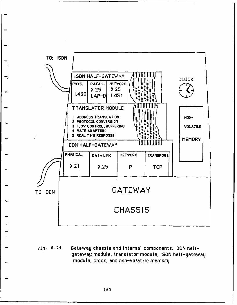
TO: ISON
-' ISDN HALF-GATEWAY CLOCKPHYS. DATA L.1 NETWORK
CLOCK
14X.25 X.251.430__ LAP-D1 1.45 1
TRANSLATOR MODULE
I ADDRESS TRANSLATION N ~I 111rON-2 PROTOCOL CONVERSION3 FLOW CONTROL, BUFFERING VOLATILE4 RATE ADAPTION5 REAL TIME RESPONSE - MEMORY
DON HALF-GATEWAY
PHYSICAL DATA LINK NETWORK TRANSPORT
X.2 1 X.25 IP TCP
TO: DON GATEWAY
CHASSIS
Fig. 6.24 Gateway chassis and internal components: DON half-gateway module, translator module, ISDN half-gatewaymodule, clock, and non-volatile memory
165
6.6.2 Routing
The gateway must be able to determine a proper route to
direct datagrams to their destinations. When packets are being
sent from DDN to ISDN routing is not a serious problem because -
the internal workings of ISDN will route the data to the right
destination node. On the other hand, when packets are being sent
from ISDN to DDN the gateway must route the data to the proper
network. In order to do this the gateway must maintain a routlng
table for IP to use in directing datagrams.
6.6.3 Flow Control , Buffering, and Rate Adaption
Flow control is an essential function of the gateway, and a
large part of this responsibility lies within the translator
module. Both half-gateway modules have their own flow control
mechanisms, but the translator module must also implement flow
control between the two half-gateway modules. To do this the
translator must communicate simultaneously with the flow control
mechanisms on both sides of the gateway. Because DDN and ISDN
have different data rates the translator module must buffer
information as it comes in and control the flow of data in order
to prevent the gateway or the DDN from being overloaded.
The translator module must be able to adapt the data rate of
DON to the data rate of ISDN and vice versa. The data rate used
on the DDN is 56 Kbps and the data rate used on ISDN's B-channel
is 64 Kbps. The procedure for adapting the data rates to comply
with ISDN's 64 Kbps is defined in Recommendation 1.460. The
reverse procedure is equally important. The translator must be
able to accept ISDN data at 64 Kbps and rate adapt this to 56
166
Kbps for transmission on the DDN. There exists the possibility
that the data coming from ISDN has been rate adapted at a remote
site. In this case the gateway must be able to distinguish which
- data is real and which data is not real. In order to do this the
gateway must perform the reverse of the mapping procedure used in
the original rate adaption. This process can be accomplished
cooperatively by the translator module and the network layer
protocols of the ISDN half-gateway module.
6.6.4 Congestion Control
In the event that the gateway becomes congested with too
much information, the gateway must indicate to neighboring
gateways that an alternate route should be taken if possible.
The gateway must also indicate when it is again ready to accept
more data.
6.6.5 Protocol Conversion
Protocol conversion is probably the single-most important
function of the translator module. This is also the most
complicated of The translator module functions. Protocol
conversion is a process of mapping states in one protocol to the
states in another protocol. The states of a protocol are
described by a Finite State Machine. These finite state machines
can become very complex. The conversion process in the DDN/ISDN
gateway is especially complex because the top layer protocols of
the gateway are dissimilar in both function and implementation.
This dissimilarity is acutely severe because ISDN implements two
separate protocols, X.25 on the B-channel, and 1.451 on the D-
channel. TCP, the top layer protocol in the DDN half-gateway
167
module, not only performs the functions that are jointly executed
by X.25 and 1.451, but also performs functions like name-serving
that are not supported by X.25 or 1.451. From this it is clear
to see that mapping the states between the two finite state
machines is a difficult task. It is likely that a perfect
mapping of states will not exist. This might bring dbout some
soft-mismatches, but hard-mismatches should be avoidable. Soft-
mismatches relate to errors that are acceptable and do not
prevent the gateway from operating. Hard-mismatches on the other
hand cause errors that can not be accepted and prevent the
gateway from operating.
6.6.6 Real-Time Response
The translator module must be able to handle packets in
real-time in order to prevent unacceptable delays in the
transmission of data. The translator module must be able to
handle the event timing functions of the DDN and ISDN. Both
networks have functions that require timed responses. The
translator module must be able to communicate with both networks
and give acknowledgments within the designated time frame to
prevent erroneous errors from occurring.
6.6.7 Performance Monitoring and Statistics
The translator module should record statistical information
about the traffic through the gateway. This information can be
used to improve the performance of the gateway through
modifications, but equally important this recorded information
can be used for billing purposes. Billing will be provided by
the vendor .who supplies the ISDN service, but this billing will
168
be for the entire interface or node. The gateway can record
information that will show which users accessed the ISDN service,
thus making it possible to bill each user accordingly.
6.7 Steo 7: Testing the Integrated Gateway
Testing the integrated gateway and bringing it up to an
operational level could be as difficult a task as designing it in
the first place. The functions of the gateway should be added in
slowly first starting out with basic transfer of data without any
additional functions. After the gateway is operational,
functions should be tested one at a time starting withi building
up and tearing down connections. Once all of the functions of
basic service are operating properly, the gateway can be
installed for limited use and further real-time testing.
Additional functions such as those contained within the quality
of service parameters can be tested an,' included later. ISDN is
expected to expand its range of sei ices once it becomes
established. When this happens, the gateway should be able to be
modified to take full advantage of the ISDN.
6.8 Limitations of the DDN/ISDN Gateway
There exists the possibility that the DDN/ISDN gateway might
impose noticeable delays in the transfer of data. This is not
something that is unique to the case of the DDN/ISDN gateway, but
is common to all gateways. These delays come about from extra
processing time, error recovery, and congestion within the
gateway. It is important that the translator module record
performance statistics so improvements can be made. The delays
caused by processing time are greater in this type of gateway as
169
opposed to a bridge. A bridge only covers the first two layers
while the DON/ISDN gateway covers four layers on the DDN side and
three layers on the ISDN side. Processing at these extra layers
is more expensive in terms of time, but increases reliability.
This extra processing time at the DDN/ISDN gateway may well be
worth not having to send data through a series of networks and
gateways, and in that respect response time may actually be
reduced. Of course, much of this depends upon the performance of
the ISDN itself.
6.9 Conclusions and Recommendations
There is a definite need to internetwork the Defense Data
Network and tle Integrated Services Digital Network. ISDN will
provide the DDN with access to networks world-wide without the
problems of communicating through multiple intermediate networks
and gateways. Internetworking DON and ISDN is achieved by
designing and building an integrated gateway. This report has
contributed a design of the functional architecture of such a
gateway. Critical design issues and unresolved problems have
also been identified. The detailed design of the gateway should
be done by a group of individuals who have expertise in data
network communications. Specifically, some individuals should be
deeply involved with the Defense Data Network and some should be
deeply involved with the Integrated Services Digital Network.
There should also be a mix of both hardware and software
engineers. As mentioned before, it is likely that vendor's will
supply the half-gateway modules which will greatly reduce the
difficulty of gateway design. At the present time there are not
170
enough ISDN standards to complete the design of an integrated
gateway. CCITT is expected to release a new version of ISDN
standards in 1988 that should shed light on all of the haziness
about ISDN. After these standards are released, ISDN should move
rapidly into its marketplace. The first !SON customers will be
large businesses, and after gateway technology is developed the
Department of Defense will enter into the market. The DDN/ISDN
gateway will be able to provide users with transparent, reliable,
end-to-end digital communications from one end of the world to
the other. The most significant limitation imposed by the
gateway is the requirement for protocol compatibility at the
upper layers on the two end systems. Although this may seem very
limiting, it is actually a very practical assumption. Given the
many advantages of internetworking DDN and ISDN, it is
recommended that research in the area of gateway development be
continued in order to stay abreast of the changiag technology of
data communications.
171
7.0 CONCLUSIONS AND RECOMMENDATIONS
ISDN has reached an evolutionary stage where it is essential
for the U.S. Army to begin taking steps to implement this new
communications technology. The global development of ISDN has
moved very rapidly during the past few years and can be expected
to move even faster during the 1988 to 1990 period. Throughout
this report we have discussed many of the unique aspects of an
ISDN, and the benefits brought about by coordinating this
technology with existing Army networks. Generalized as well as
detailed inspections of the approaches to internetworking with
ISDN have been developed and presented.
An Integrated Services Digital Network can be thought of as
a world-wide standard for modern communications that provides the
high reliability of end-to-end digital connectivity and
integrates all types of services into one network for efficient
use of bandwidth. Standards for ISDN are being developed by
CCITT and are structured around the Open Systems Interconnection
reference model. Current ISDN standards are available in the
1984 version of the I-Series Recommendations, CCITT Red Book.
These standards are designed to be able to cross international
boundaries without conflict, thus creating a unified global
communications standard. CCITT will publish another set of ISDN
standards in 1988. These standards should fill most of the gaps
that currently exist, and should also open new doors for the
expansion of ISDN research into areas such as Broadband ISDN and
the use of fiber-optics. Many years of research, testing, growth
and expansion are required in order to realize the full potential
172
of an ISDN. The development of an ISDN is without doubt an
evolutionary process. The early stages of ISDN are going to be
devoted to providing just the basic services to very large
customers. Over time, feedback from these first customers will
influence the evolutionary course of TSDN. Because the
Department of Defense will be one of ISDN's largest customers, it
is critical that the DoD take an active role in the development
of ISDN within the marketplace.
Throughout this report we emphasized how an ISDN can enhance
the existing Army communication networks. Many of the advantages
are clear when one considers the impact of ISDN on all types of
communications throughout the world: international
standardization, integrating services, highly reliable digital
connectivity, etc. Initially, the primary -ervice to be used by
the Army will be packetized data communication, and therefore
many of the services of ISDN will go unused, but as ISDN moves
forward, it may become practical for the Army to utilize other
ISDN services. Currently though, the primary advantage of
internetworking Army networks with ISDN is standardization. As
d- cussed in chapters 4, 5, and 6, the use of ISDN as a neutral
network eliminates the need to spend cime and noney for the
development of gateways for each and every connected network.
The short term expense of developing ISDN gateway technology will -
prove to be much less costly than the expense of waiting and
ignoring the fact that the future of data communications is
headed toward a global ISDN.
173
The generalized approach to internetworking two incompatible
networks is presented in chapter 4. Four approaches were
presented, each one depending on the level of incompatibility.
Essentially, Approach 3 is the most practical for real world
implementation, but also the most difficult. This approach is
-- to design and build an integrated gateway to implement the
functions necessary to bridge the gap between the incompatible
network protocols. This integrated gateway contains two half-
gateway modules and a translator module. The half-gateway
modules implement the lower layers of each network and the
translator is used to make necessary conversions to link the two
half-gateway modules. Approach 4 is just a special case of
Approach 3 and uses a network standard to implement one of the
two half-gateway modules. Chapters 5 and 6 expand on the
generalized approach presented in chapter 4 to the specific
problems of internetworking ISDN/LAN and ISDN/DDN. Several
current uncertainties which affect the specific design process
were identified. It is anticipated that most of these problems
will be resolved by the 1988 standards.
Although this repcrt might lead one to believe that
designing a gateway is a simple task of collecting information
and comparing incompatibilities, this is not the case. Gateway
design is very complicated, and the problem must be attacked by a
team of skilled and knowledgeable engineers. Gateway design
involves development of both hardware and software and by no
means is a trivial task. As mentioned earlier in this report,
vendor participdtion in the development of gateway technology
174
will be of tremendous help in the future as the need for this
technology becomes more widespread.
Over the next few years ISDN technology will change the
world of communications drastically. It is recommended that the
Army take an active role in developing the future of ISDN within
the U.S. and around the globe. Waiting for ISDN to mature -
without participation during the early stages and failure to plan
for the future could result in an ISDN that falls short of the
expectations of the Department of Defense.
175
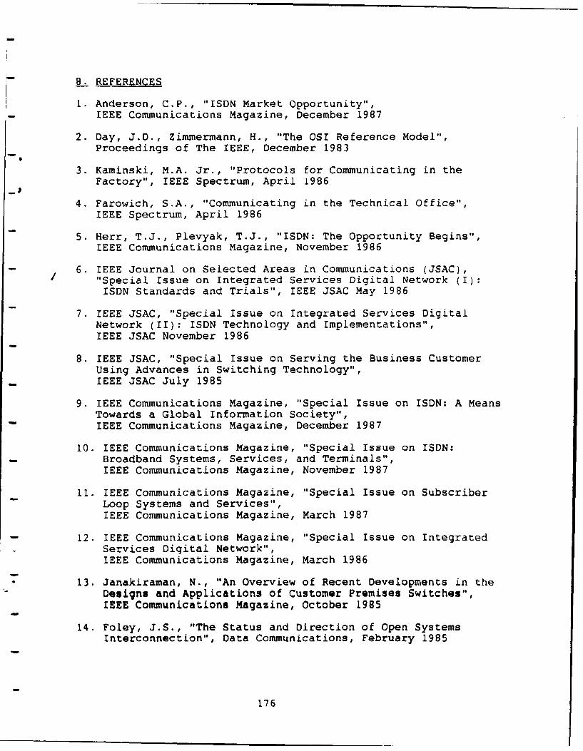
8. REFERENCES
1. Anderson, C.P., "ISDN Market Opportunity",IEEE Communications Magazine, December 1987
2. Day, J.D., Zimmermann, H., "The OSI Reference Model",Proceedings of The IEEE, December 1983
3. Kaminski, M.A. Jr., "Protocols for Communicating in theFactory", IEEE Spectrum, April 1986
4. Farowich, S.A., "Communicating in the Technical Office",IEEE Spectrum, April 1986
5. Herr, T.J., Plevyak, T.J., "ISDN: The Opportunity Begins",IEEE Communications Magazine, November 1986
6. IEEE Journal on Selected Areas in Communications (JSAC),"Special Issue on Integrated Services Digital Network (I):ISDN Standards and Trials", IEEE JSAC May 1986
7. IEEE JSAC, "Special Issue on Integrated Services DigitalNetwork (II): ISDN Technology and Implementations",IEEE JSAC November 1986
8. IEEE JSAC, "Special Issue on Serving the Business CustomerUsing Advances in Switching Technology",IEEE JSAC July 1985
9. IEEE Communications Magazine, "Special Issue on ISDN: A MeansTowards a Global Information Society",IEEE Communications Magazine, December 1987
10. IEEE Communications Magazine, "Special Issue on ISDN:Broadband Systems, Services, and Terminals",IEEE Communications Magazine, November 1987
11. IEEE Communications Magazine, "Special Issue on SubscriberLoop Systems and Services",IEEE Communications Magazine, March 1987
12. IEEE Communications Magazine, "Special Issue on IntegratedServices Digital Network",IEEE Communications Magazine, March 1986
* 13. Janakiraman, N., "An Overview of Recent Developments in theDesigns and Applications of Customer Premises Switches",IEEE Communications Magazine, October 1985
14. Foley, J.S., "The Status and Direction of Open SystemsInterconnection", Data Communications, February 1985
176
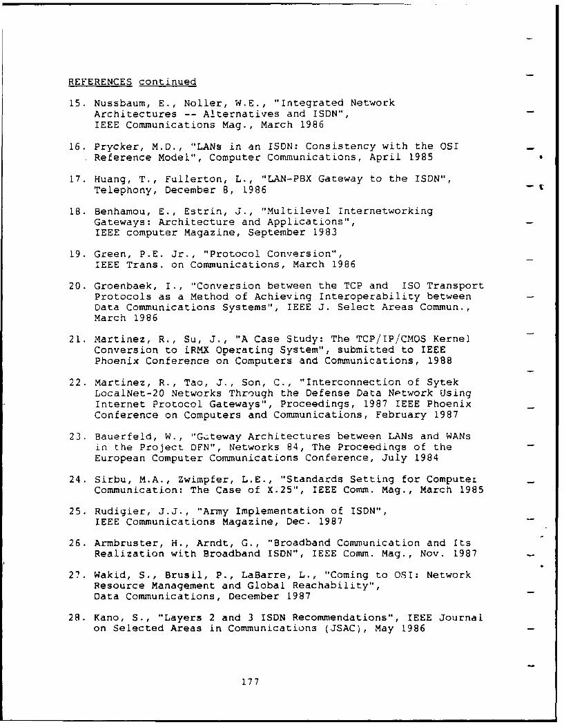
REFERENCES continued
15. Nussbaum, E., Noller, W.E., "Integrated NetworkArchitectures -- Alternatives and ISDN",IEEE Communications Mag., March 1986
16. Prycker, M.D., "LANs in an ISDN: Consistency with the OSIReference Model", Computer Communications, April 1985
17. Huang, T., Fullerton, L., "LAN-PBX Gateway to the ISDN",Telephony, December 8, 1986 -
18. Benhamou, E., Estrin, J., "Multilevel InternetworkingGateways: Architecture and Applications",IEEE computer Magazine, September 1983
19. Green, P.E. Jr., "Protocol Conversion",IEEE Trans. on Communications, March 1986
20. Groenbaek, I., "Conversion between the TCP and ISO TransportProtocols as a Method of Achieving Interoperability betweenData Communications Systems", IEEE J. Select Areas Commun.,March 1986
21. Martinez, R., Su, J., "A Case Study: The TCP/IP/CMOS KernelConversion to iRMX Operating System", submitted to IEEEPhoenix Conference on Computers and Communications, 1988
22. Martinez, R., Tao, J., Son, C., "Interconnection of SytekLocalNet-20 Networks Through the Defense Data Network UsingInternet Protocol Gateways", Proceedings, 1987 IEEE PhoenixConference on Computers and Communications, February 1987
23. Bauerfeld, W., "G..teway Architectures between LANs and WANsin the Project DFN", Networks 84, The Proceedings of theEuropean Computer Communications Conference, July 1984
24. Sirbu, M.A., Zwimpfer, L.E., "Standards Setting for ComputerCommunication: The Case of X.25", IEEE Comm. Mag., March 1985
25. Rudigier, J.J., "Army Implementation of ISDN",IEEE Communications Magazine, Dec. 1987
26. Armbruster, H., Arndt, G., "Broadband Communication and ItsRealization with Broadband ISDN", IEEE Comm. Mag., Nov. 1987
27. Wakid, S., Brusil, P., LaBarre, L., "Coming to OSI: NetworkResource Management and Global Reachability",Data Communications, December 1987
28. Kano, S., "Layers 2 and 3 ISDN Recommendations", IEEE Journalon Selected Areas in Communications (JSAC), May 1986
177
REFERENCES continued
29. Gifford, W.S., "ISDN User-Network Interfaces",
IEEE JSAC, May 1986
30. Julio, U., Pellegrini, G., "Layer 1 ISDN Recommendations",IEEE JSAC, May 1986
31. Falek, J.I., Johnston, M.A., "Standards Makers CementingISDN Subnetwork Layers", Data Communications, Oct. 1987
7
32. Stallings, W., "Data and Computer Communications",Macmillan Publishing Co., New York, 1985
33. ISO/TC97/SC6, "ISO Draft Proposal (DP) 4350", Feb. 02, 1987
34. Stallings, W., "Local Networks, An Introduction, 2nd Ed.",Macmillan Publishing Co., New York, 1987
35. Rumsey, D. C., "Support of Existing Data Interfaces by theISDN", IEEE JSAC, May 1986
37. Pandhi, S. N., "The Universal Data Connection",IEEE Spectrum, July 1987
38. MAP, "The MAP 2.1 Specification", Manufacturing Engineeringand Development, Attn: MAP Chairman, General Motors TechnicalCenter, Manufacturing Building, A/MD-39 30300 Mound Road,Warren, Mich. 48090-9040
39. I-Series Recommendations, CCITT, 1984.
40. X-Series Recommendations, CCITT, 1984.
41. Cole, Robert, ET. AL. "The DARPA Internet Protocol Suite,"IEEE Communications, vol. 23, March 1985.
42. Barberis, Guilio, ET. AL. "Handling packet services withinISDN," Computer Communications, vol 10, June 1987.
43. Hedrick, Charles, "Introduc-ion to the Internet Protocols,"
Rutgers University, July 1987.
- 44. Luetchford, John C., "CCITT Recommendations - Networko Aspects of the ISDN," IEEE Journal on Selected Areas in
Communications, vol sac4, May 1986.
45. DeJulio, Umberto, and Giorgio Pelligrini, "Layer 1 ISDNRecommendations," IEEE JSAC, vol sac4, May 1986.
46. Schlanger, Garry G., "An Overview of Signalling System No.7," IEEE JSAC, vol sac4, May 1986.
178
REFERENCES continued
47. Postel, John, "Internet Protocol - DARPA Internet ProgramProtocol Specification," RFC 791, USC/Information SciencesInstitute, September 1981.
48. Postel, John, "Internet Control Message Protocol - DARPAInternet Program Protocol Specification," RFC 792, USC/Information Sciences Institute, September 1981.
49. Postel, John, "Transmission Control Protocol - DARPAInternet Program Protocol Specification," RFC 793, USC/Information Sciences Institute, September 1981.
50. Postel, John, "Address Mappings," RFC 796, USC/InformationSciences Institute, September 1981.
179