Embed Size (px)
Citation preview
SUBCOURSE EDITION OD1006 6
US ARMY ORDNANCE CENTER AND SCHOOL
WHEELED VEHICLE DRIVE LINES, AXLES, AND SUSPENSION SYSTEMS
US ARMY LIGHT WHEEL VEHICLE MECHANIC MOS 63B SKILL LEVEL 3 COURSE
WHEELED VEHICLE DRIVE LINES, AXLES, AND SUSPENSION SYSTEMS
SUBCOURSE NO. OD 1006
US Army Ordnance Center and School
Five Credit Hours
GENERAL The Wheeled Vehicle Drive Lines, Axles, and Suspension Systems subcourse, part of the Light Wheel Vehicle Mechanic MOS 63B Skill Level 3 course, is designed to teach the knowledge necessary to develop the skills for servicing and maintaining drive lines, axles, and suspension systems. Information is provided on propeller shafts, axles, and suspension system components, to include springs, shock absorbers, frames, tires, and wheels. Information is also provided on inspection procedures for these systems. The subcourse is presented in three lessons, each lesson corresponding to a terminal objective as indicated below. Lesson 1: FUNDAMENTALS OF PROPELLER SHAFT ASSEMBLIES TASK: Describe the fundamentals of propeller shaft assemblies. CONDITIONS: Given information about the construction, operation, and maintenance of propeller shafts and universal joints. STANDARDS: Answer 70 percent of the multiple-choice test items covering fundamentals of propeller shaft assemblies. Lesson 2: FUNDAMENTALS OF AXLE ASSEMBLIES TASK: Describe the fundamentals of axle assemblies. CONDITIONS: Given information about the construction, operation, lubrication, and maintenance of axle assemblies; types and principles of axle shafts; and principles of bevel gear differentials. STANDARDS: Answer 70 percent of the multiple-choice items covering fundamentals of axle assemblies.
i
Lesson 3: FUNDAMENTALS OF SUSPENSION SYSTEMS TASK: Describe fundamentals of suspension systems. CONDITION: Given information about construction, operation, and maintenance of springs, shock absorbers, frames, bogie suspension systems, tires, and wheels. STANDARDS: Answer 70 percent of the multiple-choice items covering fundamentals of suspension systems. ii
TABLE OF CONTENTS Section Page TITLE PAGE ............................................................................................................................... i TABLE OF CONTENTS ............................................................................................................. iii ADMINISTRATIVE INSTRUCTIONS ..................................................................................... v GRADING AND CERTIFICATION INSTRUCTIONS ............................................................ v INTRODUCTION TO WHEELED VEHICLE DRIVE LINES, AXLES, AND SUSPENSION SYSTEM .................................................................................... vi Lesson 1: FUNDAMENTALS OF PROPELLER SHAFT ASSEMBLIES Learning Event: Describe the Construction, Operation, and Maintenance of Propeller Shafts and Universal Joints .............................................................................................. 2 Practice Exercise .............................................................................................................. 10 Answers to Practice Exercise ........................................................................................... 12 Lesson 2: FUNDAMENTALS OF AXLE ASSEMBLIES Learning Event 1: Describe the Types, Construction, and Purpose of Axle Assemblies ............................................................... 13 Learning Event 2: Describe the Construction and Operation of Live Axles and Differentials ................................................................ 19 Learning Event 3: Describe the Inspection Procedures for Axle Assemblies ...................................................................................... 44 Practice Exercise .............................................................................................................. 48 Answers to Practice Exercise ........................................................................................... 50
iii
Section Page Lesson 3: FUNDAMENTALS OF SUSPENSION SYSTEMS Learning Event 1: Describe the Types, Construction, and Operation of Frames, Springs, and Shock Absorbers ......................................................................................... 51 Learning Event 2: Describe the Types, Construction, and Inspection Procedures of Tires and Wheels ......................................................................................................... 61 Practice Exercise .............................................................................................................. 72 Answers to Practice Exercise ........................................................................................... 74
*** IMPORTANT NOTICE ***
THE PASSING SCORE FOR ALL ACCP MATERIAL IS NOW 70%.
PLEASE DISREGARD ALL REFERENCES TO THE 75% REQUIREMENT.
iv
INTRODUCTION TO WHEELED VEHICLE DRIVE LINES, AXLES, AND SUSPENSION SYSTEMS
Automotive drive lines and suspension systems have changed quite a bit since the first automobile was built. At first, automobile axles were attached directly to the main frame of the vehicle. This caused many problems. For example, the vehicle produced a very rough ride. Also, rigid construction did not work well on rough ground because sometimes one of the wheels would not touch the ground. If the wheel off the ground was a drive wheel, the vehicle lost traction and stopped. This problem proved a need for a more flexible vehicle. The problem was corrected by using springs between the axles and the frame. The early springs were the same type used on the horse-drawn buggy. They allowed the wheels and axles to move up and down separate from the body. The body moved very little compared to the wheels and axles, and the ride was much smoother. Allowing the axles to move separate from the body also kept the wheels on the ground over rough roads, but this caused a new problem. The old drive train between the engine and the axle would not work. The train had to be made to move more. This was done by adding movable joints in the drive shaft known as universal joints. Some early vehicles used only one universal joint on the drive shaft, while later vehicles used two universal joints on the drive shaft. Drive shafts are now usually called propeller shafts. Some long-wheel-base trucks now use as many as four propeller shafts between the transmission and the drive axle. These propeller shafts are connected by universal joints. Early automobiles were made up of a body, a power plant, and a running gear. The running gear was made up of the wheels, axles, springs, drive shaft, and transmission. The transmission was often mounted midway between the engine and rear axle. It was connected to the engine and the rear axle by drive shafts. The term "running gear" is not used any more. A new term, "chassis," is now used to identify the old running gear plus the power plant. In modern vehicles, the transmission is generally mounted on the engine and is part of the power plant. The chassis of modern military tactical vehicles, especially the frame, spring, and axles, must be very strong and yet quite flexible. You will learn how this is possible in this subcourse. vi
Lesson 1
LESSON 1 FUNDAMENTALS OF PROPELLER SHAFT ASSEMBLIES
TASK Describe the fundamentals of propeller shaft assemblies. CONDITIONS Given information about the construction, operation, and maintenance of propeller shafts and universal joints. STANDARDS Answer 70 percent of the multiple-choice test items covering fundamentals of propeller shaft assemblies. REFERENCES TM 9-8000
1
Lesson 1
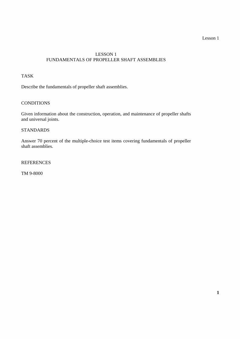
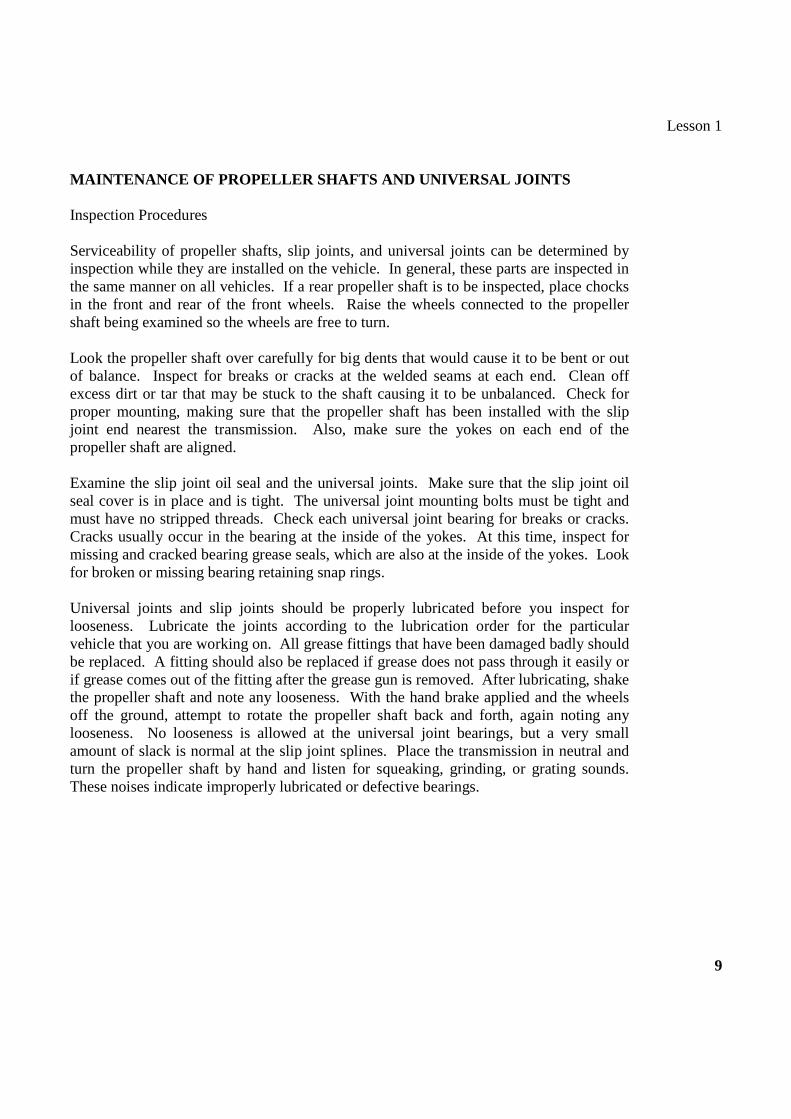
Learning Event: DESCRIBE THE CONSTRUCTION, OPERATION, AND MAINTENANCE OF PROPELLER SHAFTS AND UNIVERSAL JOINTS PROPELLER SHAFTS On vehicles equipped with a transfer case, power is transferred from the vehicle's transmission to the transfer case to the axle assemblies by propeller shafts.
FIGURE 1. PROPELLER SHAFTS.
A propeller shaft is also called a drive shaft. However, propeller shaft is the more common name, and some repairers shorten this to "prop shaft." The illustration shows the power transmission system, including the propeller shafts in one type of wheeled vehicle. Notice that four propeller shafts are used to drive the vehicle. One transmits torque from the transmission to the transfer case, one delivers rotary motion from the transfer case to the intermediate differential, another delivers rotary motion from the intermediate differential to the rear differential, and the fourth delivers torque to the front differential.
2
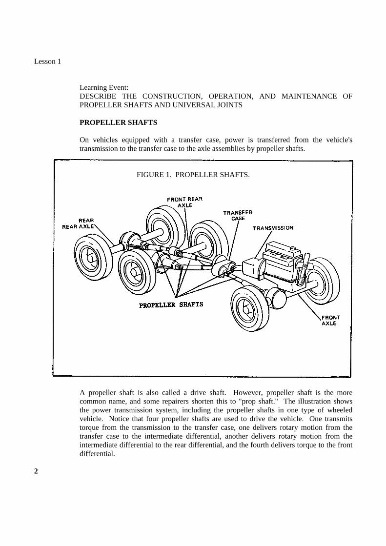
Lesson 1 Construction and Operation Propeller shafts are made in many different sizes, shapes, and strengths, depending on the needs of the different types of vehicles. One end of the shaft is built to house a universal joint. The other end is usually splined to a slip joint. The shafts may be made of solid steel or may be hollow (tubular). A hollow propeller shaft is usually preferred. The twisting force (torque) applied to one end of a shaft is transmitted through the shaft to its opposite end. The strain (stress) created within the shaft ranges from a minimum at the shaft's rotational center (axis) to a maximum at its outside surface. Since the center part of a shaft carries only a small portion of the load, tubular (hollow) propeller shafts are used whenever possible. A solid shaft is stronger than a tubular shaft of the same thickness (diameter). A tubular shaft, however, is much stronger than a solid shaft of the same weight and length.
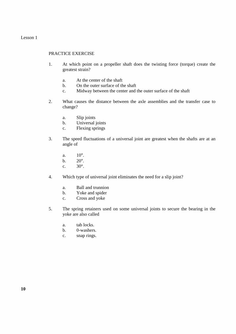
FIGURE 2. AXLE ASSEMBLY.
The power transmission system must be flexible because of the springs in the vehicle's suspension system. As the springs flex, the axle assemblies move backward and forward and up and down. This causes the angles and distance between the axle assemblies and the transfer case to constantly change. Slip joints and universal joints installed on propeller shafts provide flexibility and permit these changes in the power transmission system.
3
Lesson 1
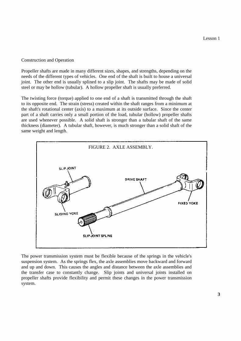
A slip joint at one end of the propeller shaft allows the propeller shaft to lengthen or shorten when the position of the axle changes. A typical slip Joint has a male and female spline. It usually contains a lubrication fitting and an oil seal. The male spline is a part of the propeller shaft, and the female spline is fixed to a universal joint. The slip joint is located at the power input end of a propeller shaft (the end nearest the transmission). It allows lengthwise freedom of movement of the propeller shaft and still transmits rotary motion. UNIVERSAL JOINTS Construction and Operation A universal joint is a flexible coupling between two shafts that permits one shaft to drive another at an angle. It will transmit power while the angle between the shafts is constantly changing.
FIGURE 3. UNIVERSAL-JOINT.
A simple universal joint consists of three basic parts: a journal and two yokes. The two yokes are set crosswise (at right angles) to each other, and their open ends are joined by the journal. This construction permits each yoke to turn (pivot) on the journal while transmitting rotary motion from one yoke to the other.
4
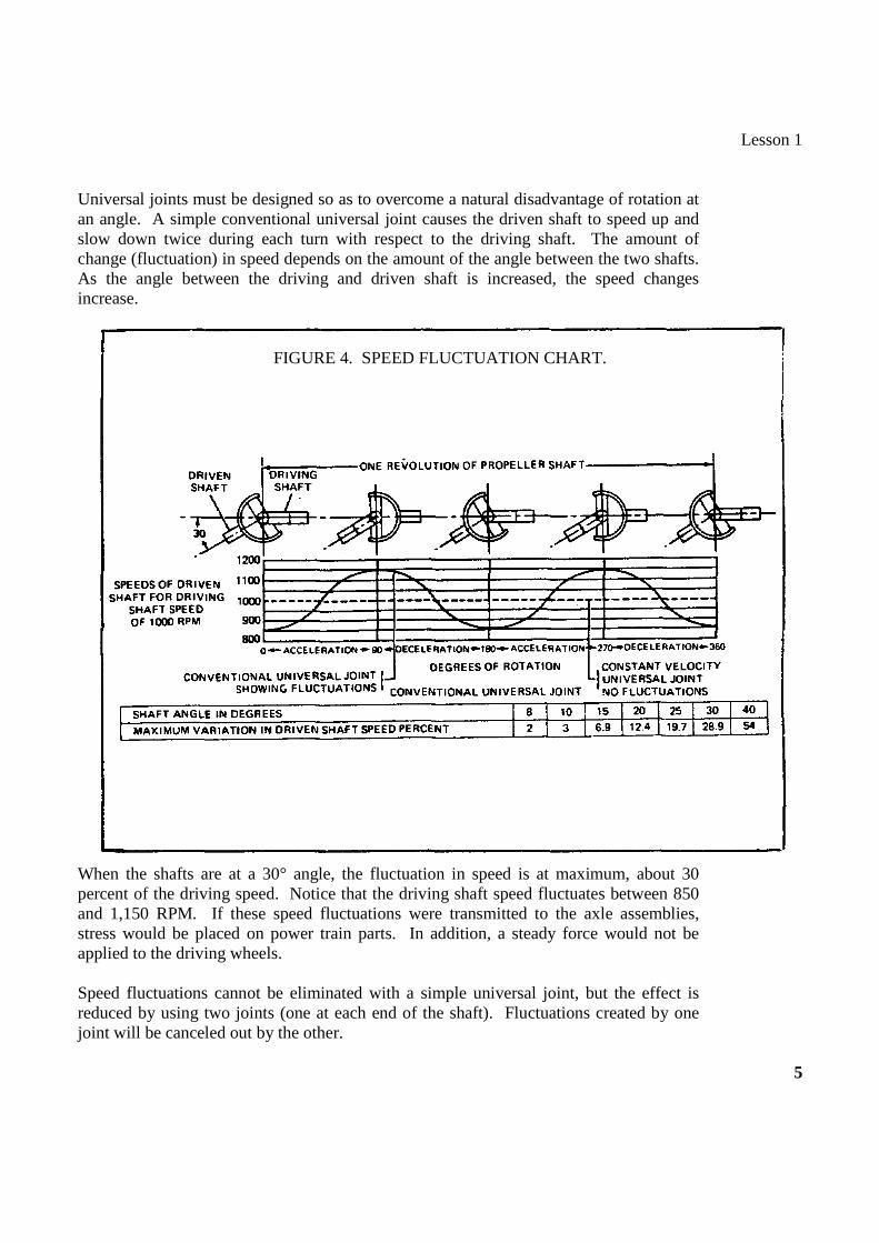
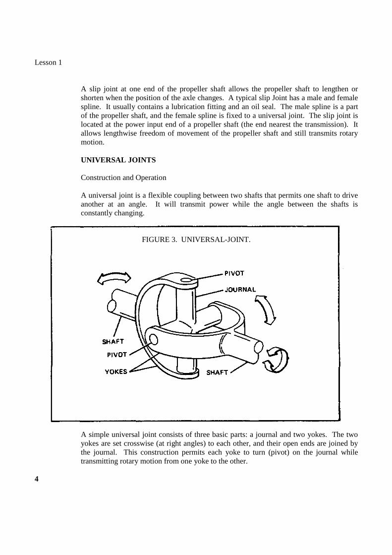
Lesson 1 Universal joints must be designed so as to overcome a natural disadvantage of rotation at an angle. A simple conventional universal joint causes the driven shaft to speed up and slow down twice during each turn with respect to the driving shaft. The amount of change (fluctuation) in speed depends on the amount of the angle between the two shafts. As the angle between the driving and driven shaft is increased, the speed changes increase.
FIGURE 4. SPEED FLUCTUATION CHART. When the shafts are at a 30° angle, the fluctuation in speed is at maximum, about 30 percent of the driving speed. Notice that the driving shaft speed fluctuates between 850 and 1,150 RPM. If these speed fluctuations were transmitted to the axle assemblies, stress would be placed on power train parts. In addition, a steady force would not be applied to the driving wheels. Speed fluctuations cannot be eliminated with a simple universal joint, but the effect is reduced by using two joints (one at each end of the shaft). Fluctuations created by one joint will be canceled out by the other.
5
Lesson 1
However, certain conditions must be met before cancellation will take place: The angle between the transmission output shaft and the propeller shaft must be the same as the angle between the propeller shaft and the axle assembly input shaft. In addition, the two yokes on the propeller shaft must be aligned with each other. With this arrangement, one joint turns at its greatest speed while the second joint turns at its slowest speed. This results in an almost constant output speed to the driving wheels. (The speed of the propeller shaft between the two joints, however, still fluctuates.) Types In a universal joint, bearings are included at the four points where the journal is attached to the yokes. There are several different kinds of journal-type universal joints. The main difference among them is the way the bearings are attached to the yokes.
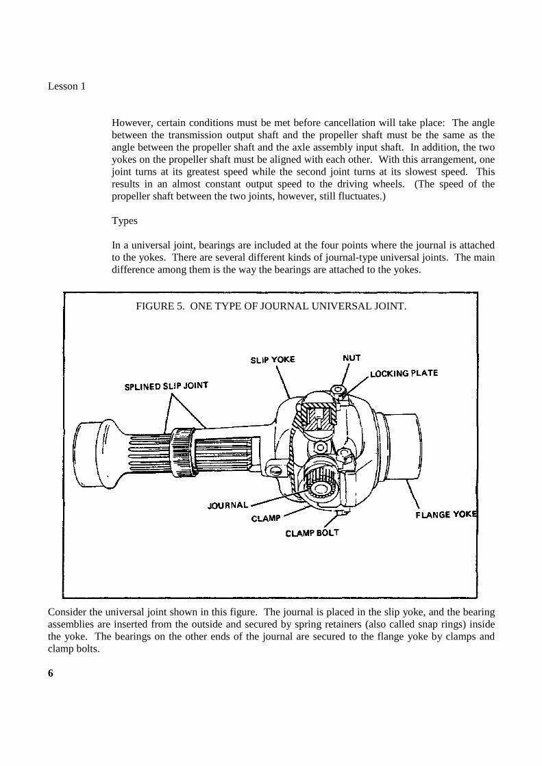
FIGURE 5. ONE TYPE OF JOURNAL UNIVERSAL JOINT. Consider the universal joint shown in this figure. The journal is placed in the slip yoke, and the bearing assemblies are inserted from the outside and secured by spring retainers (also called snap rings) inside the yoke. The bearings on the other ends of the journal are secured to the flange yoke by clamps and clamp bolts. 6
Lesson 1
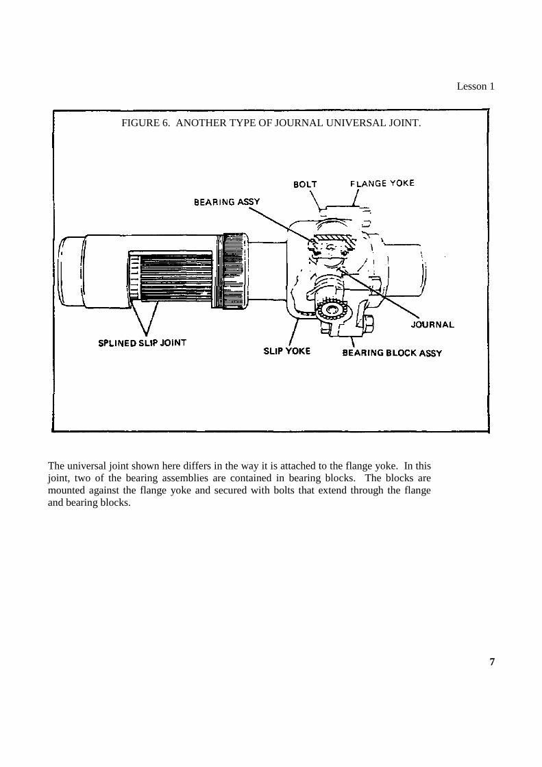
FIGURE 6. ANOTHER TYPE OF JOURNAL UNIVERSAL JOINT. The universal joint shown here differs in the way it is attached to the flange yoke. In this joint, two of the bearing assemblies are contained in bearing blocks. The blocks are mounted against the flange yoke and secured with bolts that extend through the flange and bearing blocks.
7
Lesson 1
FIGURE 7. BALL-AND-TRUNNION UNIVERSAL JOINT.
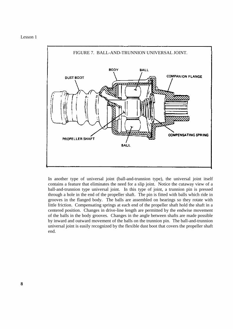
In another type of universal joint (ball-and-trunnion type), the universal joint itself contains a feature that eliminates the need for a slip joint. Notice the cutaway view of a ball-and-trunnion type universal joint. In this type of joint, a trunnion pin is pressed through a hole in the end of the propeller shaft. The pin is fitted with balls which ride in grooves in the flanged body. The balls are assembled on bearings so they rotate with little friction. Compensating springs at each end of the propeller shaft hold the shaft in a centered position. Changes in drive-line length are permitted by the endwise movement of the balls in the body grooves. Changes in the angle between shafts are made possible by inward and outward movement of the balls on the trunnion pin. The ball-and-trunnion universal joint is easily recognized by the flexible dust boot that covers the propeller shaft end.
8
Lesson 1 MAINTENANCE OF PROPELLER SHAFTS AND UNIVERSAL JOINTS Inspection Procedures Serviceability of propeller shafts, slip joints, and universal joints can be determined by inspection while they are installed on the vehicle. In general, these parts are inspected in the same manner on all vehicles. If a rear propeller shaft is to be inspected, place chocks in the front and rear of the front wheels. Raise the wheels connected to the propeller shaft being examined so the wheels are free to turn. Look the propeller shaft over carefully for big dents that would cause it to be bent or out of balance. Inspect for breaks or cracks at the welded seams at each end. Clean off excess dirt or tar that may be stuck to the shaft causing it to be unbalanced. Check for proper mounting, making sure that the propeller shaft has been installed with the slip joint end nearest the transmission. Also, make sure the yokes on each end of the propeller shaft are aligned. Examine the slip joint oil seal and the universal joints. Make sure that the slip joint oil seal cover is in place and is tight. The universal joint mounting bolts must be tight and must have no stripped threads. Check each universal joint bearing for breaks or cracks. Cracks usually occur in the bearing at the inside of the yokes. At this time, inspect for missing and cracked bearing grease seals, which are also at the inside of the yokes. Look for broken or missing bearing retaining snap rings. Universal joints and slip joints should be properly lubricated before you inspect for looseness. Lubricate the joints according to the lubrication order for the particular vehicle that you are working on. All grease fittings that have been damaged badly should be replaced. A fitting should also be replaced if grease does not pass through it easily or if grease comes out of the fitting after the grease gun is removed. After lubricating, shake the propeller shaft and note any looseness. With the hand brake applied and the wheels off the ground, attempt to rotate the propeller shaft back and forth, again noting any looseness. No looseness is allowed at the universal joint bearings, but a very small amount of slack is normal at the slip joint splines. Place the transmission in neutral and turn the propeller shaft by hand and listen for squeaking, grinding, or grating sounds. These noises indicate improperly lubricated or defective bearings.
9
Lesson 1
PRACTICE EXERCISE
1. At which point on a propeller shaft does the twisting force (torque) create the greatest strain?
a. At the center of the shaft b. On the outer surface of the shaft c. Midway between the center and the outer surface of the shaft 2. What causes the distance between the axle assemblies and the transfer case to
change? a. Slip joints b. Universal joints c. Flexing springs 3. The speed fluctuations of a universal joint are greatest when the shafts are at an
angle of a. 10°. b. 20°. c. 30°. 4. Which type of universal joint eliminates the need for a slip joint? a. Ball and trunnion b. Yoke and spider c. Cross and yoke 5. The spring retainers used on some universal joints to secure the bearing in the
yoke are also called a. tab locks. b. 0-washers. c. snap rings.
10

Lesson 1
This page intentionally left blank.
11
Lesson 1
ANSWERS TO PRACTICE EXERCISE 1. b (page 2) 2. c (page 3) 3. c (page 5) 4. a (page 8) 5. c (page 6)
12
Lesson 2/Learning Event 1
LESSON 2 FUNDAMENTALS OF AXLE ASSEMBLIES
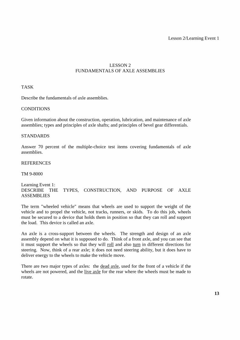
TASK Describe the fundamentals of axle assemblies. CONDITIONS Given information about the construction, operation, lubrication, and maintenance of axle assemblies; types and principles of axle shafts; and principles of bevel gear differentials. STANDARDS Answer 70 percent of the multiple-choice test items covering fundamentals of axle assemblies. REFERENCES TM 9-8000 Learning Event 1: DESCRIBE THE TYPES, CONSTRUCTION, AND PURPOSE OF AXLE ASSEMBLIES The term "wheeled vehicle" means that wheels are used to support the weight of the vehicle and to propel the vehicle, not tracks, runners, or skids. To do this job, wheels must be secured to a device that holds them in position so that they can roll and support the load. This device is called an axle. An axle is a cross-support between the wheels. The strength and design of an axle assembly depend on what it is supposed to do. Think of a front axle, and you can see that it must support the wheels so that they will roll and also turn in different directions for steering. Now, think of a rear axle; it does not need steering ability, but it does have to deliver energy to the wheels to make the vehicle move. There are two major types of axles: the dead axle, used for the front of a vehicle if the wheels are not powered, and the live axle for the rear where the wheels must be made to rotate.
13
Lesson 2/Learning Event 1
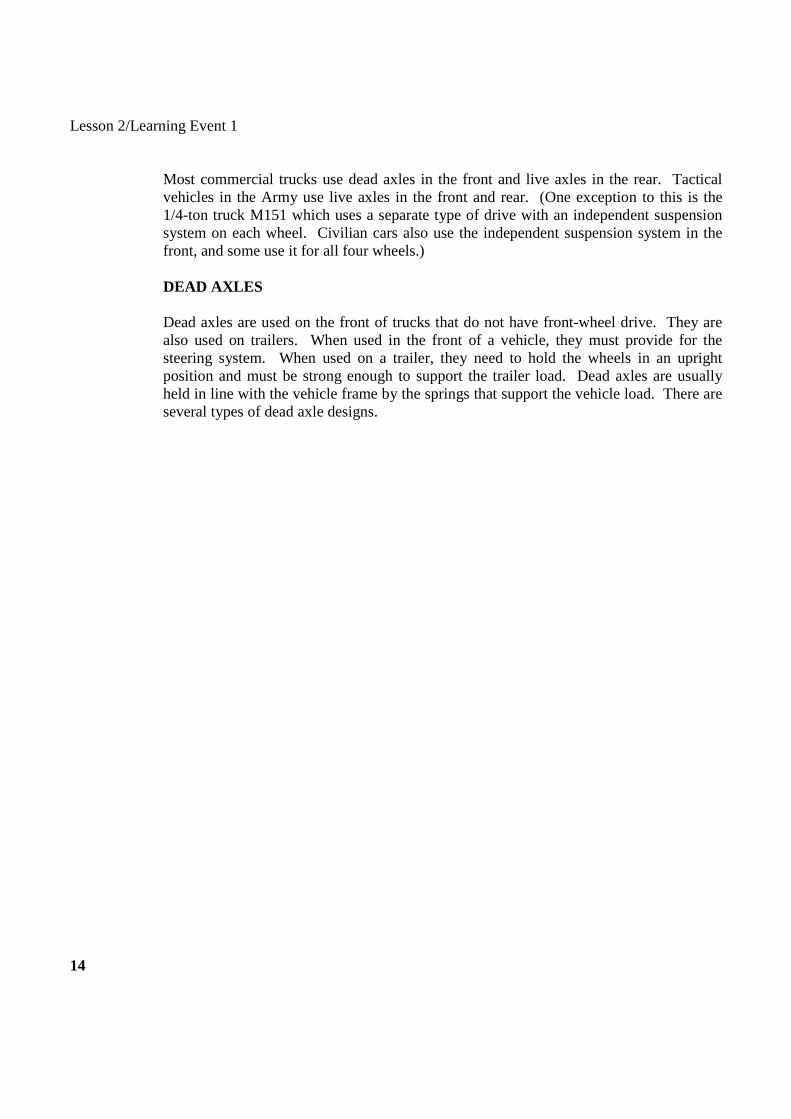
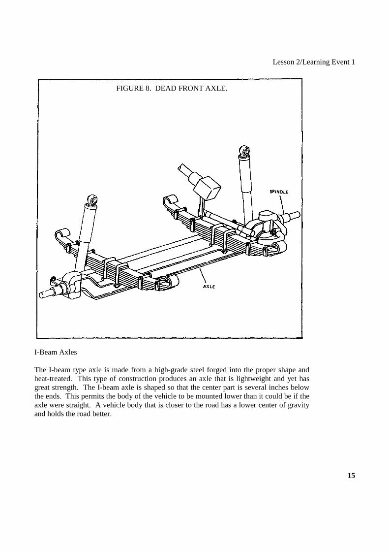
Most commercial trucks use dead axles in the front and live axles in the rear. Tactical vehicles in the Army use live axles in the front and rear. (One exception to this is the 1/4-ton truck M151 which uses a separate type of drive with an independent suspension system on each wheel. Civilian cars also use the independent suspension system in the front, and some use it for all four wheels.) DEAD AXLES Dead axles are used on the front of trucks that do not have front-wheel drive. They are also used on trailers. When used in the front of a vehicle, they must provide for the steering system. When used on a trailer, they need to hold the wheels in an upright position and must be strong enough to support the trailer load. Dead axles are usually held in line with the vehicle frame by the springs that support the vehicle load. There are several types of dead axle designs.
14
Lesson 2/Learning Event 1
FIGURE 8. DEAD FRONT AXLE. I-Beam Axles The I-beam type axle is made from a high-grade steel forged into the proper shape and heat-treated. This type of construction produces an axle that is lightweight and yet has great strength. The I-beam axle is shaped so that the center part is several inches below the ends. This permits the body of the vehicle to be mounted lower than it could be if the axle were straight. A vehicle body that is closer to the road has a lower center of gravity and holds the road better.
15
Lesson 2/Learning Event 1
On the top of the axle, the springs are mounted on flat, smooth surfaces or pads. The mounting surfaces are called spring seats and usually have five holes. The four holes on the outer edge of the mounting surface are for the U-bolts which hold the spring and axle together. The center hole provides an anchor point for the center bolt of the spring. The head of the center bolt, seated in the center hole in the mounting surface, ensures proper alignment of the axle with the vehicle frame. A hole is located in each end of the I-beam section. It is bored at a slight angle and provides a mounting point for the steering knuckle or kingpin. A small hole is drilled from front to rear at a right angle to the steering knuckle pinhole. It enters the larger kingpin hole very slightly. The kingpin retaining bolt is located in this hole and holds the kingpin in place in the axle. The steering knuckle is made with a yoke at one end and a spindle at the opposite end. Bronze bushings are pressed into the upper and lower arms of the yoke, through which the kingpin passes. These bushings provide replaceable bearing surfaces. A lubrication fitting and a drilled passage provide a method of forcing grease onto the bearing surfaces of the bronze bushings. The spindle is a highly machined, tapered, round shaft that has mounting surfaces for the inner and outer wheel bearings. The outer end of the spindle is threaded. These threads are used for installing a nut to secure the wheel bearings in position. A flange is located between the spindle and yoke. It has drilled holes around its outer edge. This flange provides a mounting surface for the brake drum backing plate and brake components. The kingpin acts like the pin of a door hinge as it connects the steering knuckles to the ends of the axle I-beam. The kingpin passes through the upper arm of the knuckle yoke, through the end of the I-beam and a thrust bearing, and then through the lower arm of the knuckle yoke. The kingpin retaining bolt locks the pin in position. The ball-type thrust bearing is installed between the I-beam and lower arm of the knuckle yoke so that the end of the I-beam rests upon the bearing. This provides a ball bearing for the knuckle to pivot on as it supports the vehicle's weight.
When the vehicle is not in motion, the only job that the axle has to do is hold the wheels in proper alignment and support part of the weight. When the vehicle goes into motion, the axle receives the twisting stresses of driving and braking. When the vehicle operator applies the brakes, the brake shoes are pressed against the moving wheel drum. This action tries to make the axle turn.
16
Lesson 2/Learning Event 1 When the brakes are applied suddenly, the axle twists against the springs and actually twists out of its normal upright position. In addition to twisting during braking, the front axle also moves up and down as the wheels move over rough surfaces. Steering controls and linkages provide the means of turning the steering knuckles to steer the vehicle. As the vehicle makes a turn while moving, a side thrust is received at the wheels and transferred to the axle and springs. These forces act on the axle from many different directions. You can see, therefore, that the axle has to be quite rugged to keep all parts in proper alignment. Trailer Axles The axles used on trailers are designed to mount the wheels and support the weight of the vehicle. Since trailer wheels are not powered, the axles used are all of the dead type. Larger trailer axles are equipped with service brakes to assist in stopping. Host smaller trailers use a single axle, while larger ones normally have two-axle assemblies. The size of trailers varies from the small 1/4-ton models to the large 50-ton transporters. The axle used on most military trailers is usually a straight, round, steel shaft or tube. Smooth, machined surfaces at the ends of the shaft provide mounting surfaces for the wheel bearings and the wheel bearing seals. The threads on the ends of the axle shaft hold the wheel bearing retaining nuts. A locking plate for the wheel bearing nuts fits into a keyway or slot to prevent the nuts from working loose. Two steel pads welded to the axle shaft provide seating surfaces to connect the axle to the leaf-type springs. A machined flange with holes located around the outer edge is located just inside the wheel bearing surfaces. It provides a mount for the brake backing plates. On semitrailers with tandem or two axles (one behind the other), the axles are not usually bolted directly to the leaf-type spring. The springs are mounted on a central trunnion shaft with spring seats so that they aid in holding the axle in line. The spring ends rest upon spring bearing plates welded to the axle shafts. The tip of the springs can slide forward and backward on the bearing plate. Torque rods are used to hold the axles in proper position.
17
Lesson 2/Learning Event 1
A trailer axle may support almost all or just part of the total vehicle weight. On small single-axle trailers, most of the weight is supported by the axle assembly. Large semitrailers are designed so that the towing vehicle (truck tractor) supports as much of the load as the trailer axles. On trailers with brakes controlled by the operator of the towing vehicle, the axle must withstand the twisting force of the wheels as the brakes are applied. While in motion, the axle will move up and down under the load of the trailer as the wheels follow the surface of the road. With only a few moving parts, the dead axle assembly does not require a large amount of lubrication. The wheel bearings are removed from the assembly and packed with automotive and artillery grease (GAA) at the intervals required by the lubrication order (LO). Steering knuckles and linkages on front axles are lubricated with automotive and artillery greases by means of lubricating fittings.
18
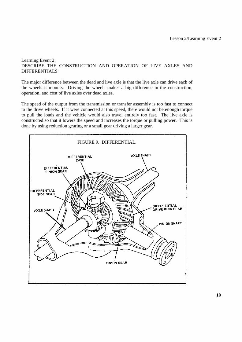
Lesson 2/Learning Event 2 Learning Event 2: DESCRIBE THE CONSTRUCTION AND OPERATION OF LIVE AXLES AND DIFFERENTIALS The major difference between the dead and live axle is that the live axle can drive each of the wheels it mounts. Driving the wheels makes a big difference in the construction, operation, and cost of live axles over dead axles. The speed of the output from the transmission or transfer assembly is too fast to connect to the drive wheels. If it were connected at this speed, there would not be enough torque to pull the loads and the vehicle would also travel entirely too fast. The live axle is constructed so that it lowers the speed and increases the torque or pulling power. This is done by using reduction gearing or a small gear driving a larger gear.
FIGURE 9. DIFFERENTIAL.
19
Lesson 2/Learning Event 2
Also, the axle is constructed so that the power flow can turn 90° in each direction (from the propeller shaft to the right and left wheels). This is needed to direct the power flow to the drive wheels on each side of the vehicle. This change of direction is done by the use of worm gears or bevel drive gears. Notice that the pinion gear is the smallest and the ring gear is the largest. These two gears provide a reduction in speed and change the direction of the power flow. As the vehicle moves around a turn, the wheels on opposite ends of the axle must turn at different speeds. The wheel on the outside of the turn travels a larger circle or path than the wheel on the inside of the turn. If both wheels were rigidly mounted to a solid shaft, the tires would slide on the road surface when the vehicle turned a corner. The live axle must, therefore, include some type of mechanism to prevent the wheels from sliding. This mechanism is called the differential. It permits one wheel to turn faster than the other one, while still driving both wheels. The output of the differential is transferred to the wheels by axle shafts. Types of Live Axles Live axles are grouped into four general types, based upon the way that the load is supported. An easy way to identify these axles is the manner in which the axle shafts are mounted. The four types are the plain, semifloating, three-quarter floating, and full-floating axles. Each rear live axle assembly consists of a gearbox or final drive in the center and axle shafts extending to the wheels on either side.
20
Lesson 2/Learning Event 2
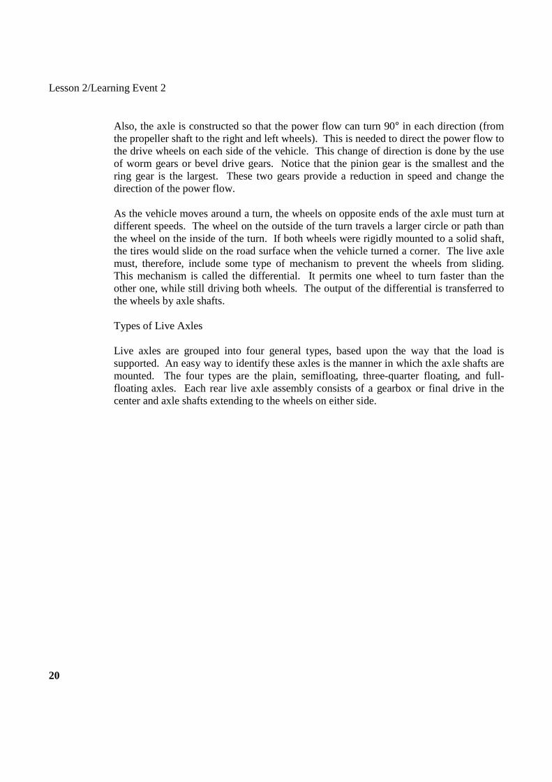
FIGURE 10. PLAIN REAR AXLE.
Early vehicles used a live axle known as the plain or nonfloating axle. This type of axle is not used on any modern wheeled vehicle. The axle resembled the semifloating axle (discussed in the next paragraph) on the outside. However, the axle shafts were supported by two roller bearings. One roller bearing was located just inside the outer end of the axle shaft housing. The other roller bearing was located at the center of the axle shaft and inside the axle shaft housing. The inner ends of the axles were connected to the differential side gears by keys and keyways. These axle shafts had to carry the weight of the differential assembly on the inner ends. The vehicle wheels were attached to the outer ends of the axle shafts. Therefore, the outer ends of the axle shafts carried the entire weight of the rear of the vehicle. End thrust on the axle shafts was absorbed, or taken up, by a ball-type bearing located on each side of the differential case and by a block between the inner ends of the axles.
21
Lesson 2/Learning Event 2
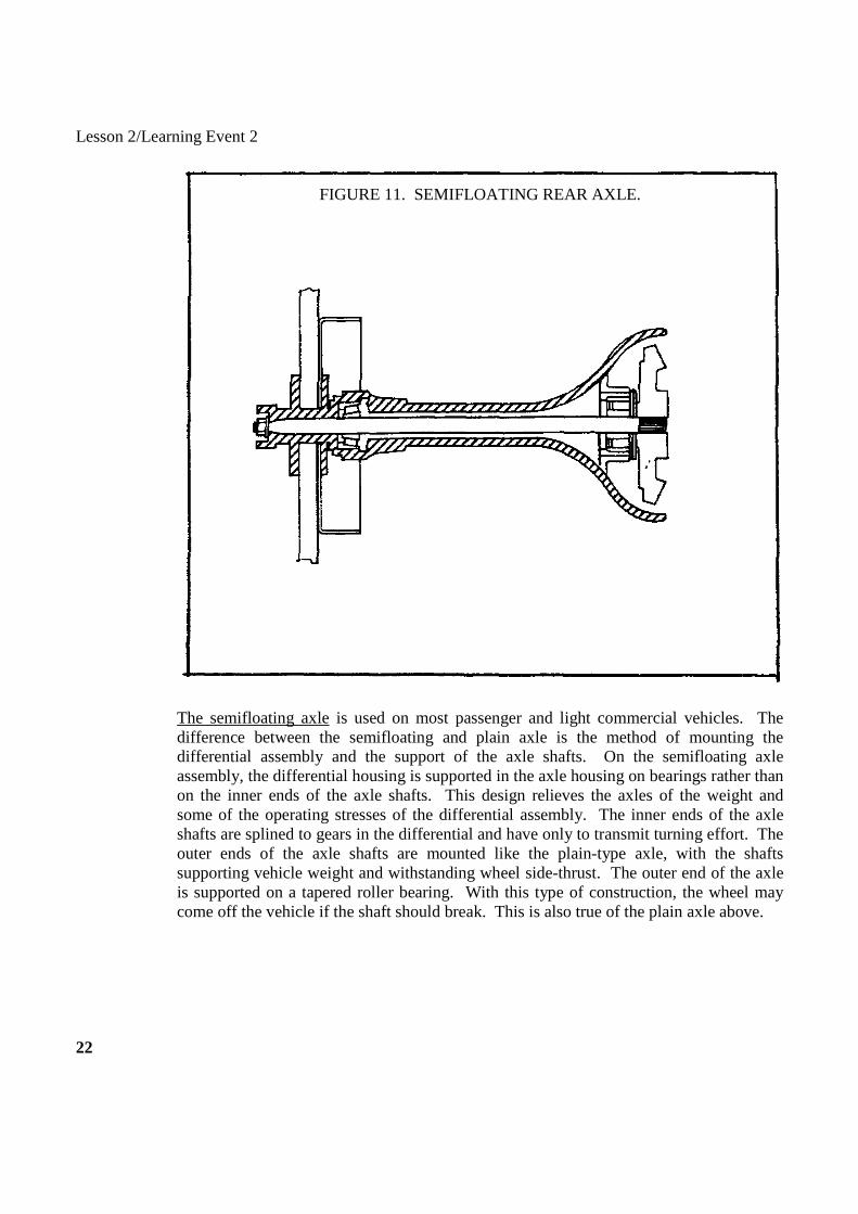
FIGURE 11. SEMIFLOATING REAR AXLE.
The semifloating axle is used on most passenger and light commercial vehicles. The difference between the semifloating and plain axle is the method of mounting the differential assembly and the support of the axle shafts. On the semifloating axle assembly, the differential housing is supported in the axle housing on bearings rather than on the inner ends of the axle shafts. This design relieves the axles of the weight and some of the operating stresses of the differential assembly. The inner ends of the axle shafts are splined to gears in the differential and have only to transmit turning effort. The outer ends of the axle shafts are mounted like the plain-type axle, with the shafts supporting vehicle weight and withstanding wheel side-thrust. The outer end of the axle is supported on a tapered roller bearing. With this type of construction, the wheel may come off the vehicle if the shaft should break. This is also true of the plain axle above.
22
Lesson 2/Learning Event 2
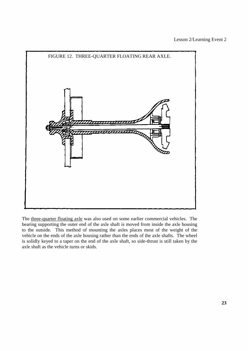
FIGURE 12. THREE-QUARTER FLOATING REAR AXLE.
The three-quarter floating axle was also used on some earlier commercial vehicles. The bearing supporting the outer end of the axle shaft is moved from inside the axle housing to the outside. This method of mounting the axles places most of the weight of the vehicle on the ends of the axle housing rather than the ends of the axle shafts. The wheel is solidly keyed to a taper on the end of the axle shaft, so side-thrust is still taken by the axle shaft as the vehicle turns or skids.
23
Lesson 2/Learning Event 2
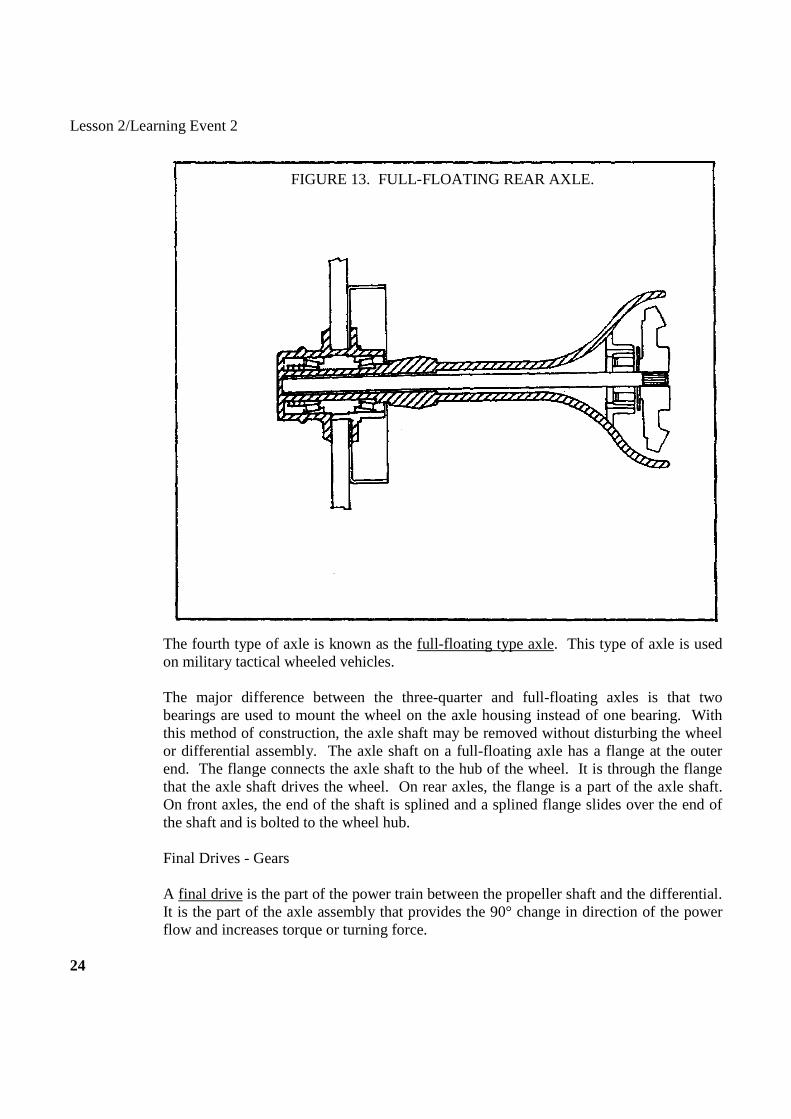
FIGURE 13. FULL-FLOATING REAR AXLE.
The fourth type of axle is known as the full-floating type axle. This type of axle is used on military tactical wheeled vehicles. The major difference between the three-quarter and full-floating axles is that two bearings are used to mount the wheel on the axle housing instead of one bearing. With this method of construction, the axle shaft may be removed without disturbing the wheel or differential assembly. The axle shaft on a full-floating axle has a flange at the outer end. The flange connects the axle shaft to the hub of the wheel. It is through the flange that the axle shaft drives the wheel. On rear axles, the flange is a part of the axle shaft. On front axles, the end of the shaft is splined and a splined flange slides over the end of the shaft and is bolted to the wheel hub. Final Drives - Gears A final drive is the part of the power train between the propeller shaft and the differential. It is the part of the axle assembly that provides the 90° change in direction of the power flow and increases torque or turning force.
24
Lesson 2/Learning Event 2 Final drives used in most military tactical vehicles are either single- or double-reduction units. Single-reduction axles are used on light wheeled vehicles and consist of one set of reduction gearing, and these same gears also change the direction of power flow. The double-reduction units have a second set of reduction gears. Double-reduction final drives are used on heavy wheeled vehicles where a large amount of reduction is needed.
FIGURE 14. WORM GEAR.
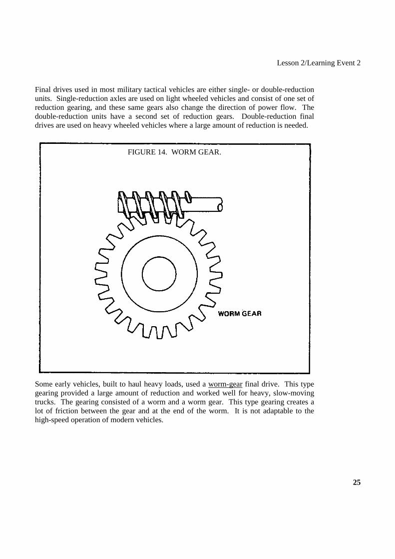
Some early vehicles, built to haul heavy loads, used a worm-gear final drive. This type gearing provided a large amount of reduction and worked well for heavy, slow-moving trucks. The gearing consisted of a worm and a worm gear. This type gearing creates a lot of friction between the gear and at the end of the worm. It is not adaptable to the high-speed operation of modern vehicles.
25
Lesson 2/Learning Event 2
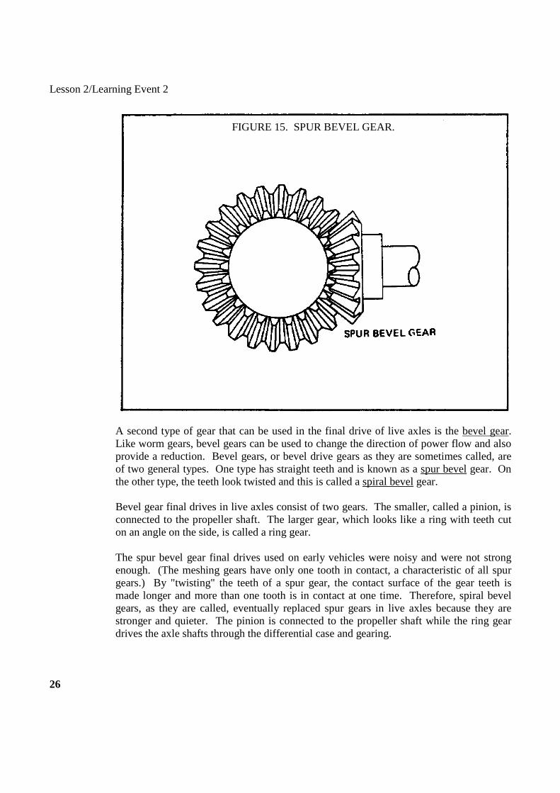
FIGURE 15. SPUR BEVEL GEAR.
A second type of gear that can be used in the final drive of live axles is the bevel gear. Like worm gears, bevel gears can be used to change the direction of power flow and also provide a reduction. Bevel gears, or bevel drive gears as they are sometimes called, are of two general types. One type has straight teeth and is known as a spur bevel gear. On the other type, the teeth look twisted and this is called a spiral bevel gear. Bevel gear final drives in live axles consist of two gears. The smaller, called a pinion, is connected to the propeller shaft. The larger gear, which looks like a ring with teeth cut on an angle on the side, is called a ring gear. The spur bevel gear final drives used on early vehicles were noisy and were not strong enough. (The meshing gears have only one tooth in contact, a characteristic of all spur gears.) By "twisting" the teeth of a spur gear, the contact surface of the gear teeth is made longer and more than one tooth is in contact at one time. Therefore, spiral bevel gears, as they are called, eventually replaced spur gears in live axles because they are stronger and quieter. The pinion is connected to the propeller shaft while the ring gear drives the axle shafts through the differential case and gearing.
26
Lesson 2/Learning Event 2
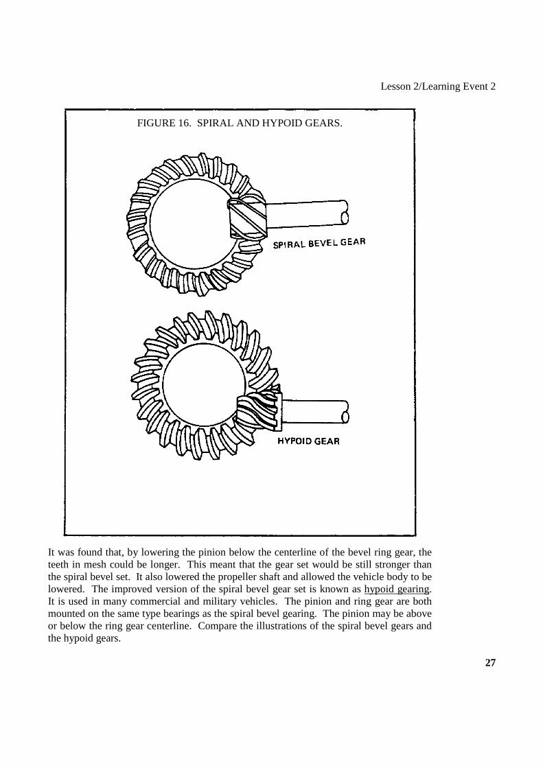
FIGURE 16. SPIRAL AND HYPOID GEARS.
It was found that, by lowering the pinion below the centerline of the bevel ring gear, the teeth in mesh could be longer. This meant that the gear set would be still stronger than the spiral bevel set. It also lowered the propeller shaft and allowed the vehicle body to be lowered. The improved version of the spiral bevel gear set is known as hypoid gearing. It is used in many commercial and military vehicles. The pinion and ring gear are both mounted on the same type bearings as the spiral bevel gearing. The pinion may be above or below the ring gear centerline. Compare the illustrations of the spiral bevel gears and the hypoid gears.
27
Lesson 2/Learning Event 2
Gear Ratios The size of the gears used in final drives depends on the needs of the vehicle. The relationship of the pinion and ring gear is known as the gear ratio. The ratio of gears is obtained by dividing the number of teeth on the pinion into the number of teeth on the ring gear. This will show how many revolutions the pinion makes when the ring gear makes one revolution. For example, if the pinion has 10 teeth and the ring gear has 50 teeth, the ring gear has five times as many teeth and the ratio is 5:1 (5 to 1). The ratio of automobile drive axles ranges from 2.5:1 to 5:1. Large trucks have gear ratios ranging from 5:1 to 15:1. Lighter vehicles that are not required to haul heavy loads can use a comparatively low-ratio set of gears. For example, a small commercial truck may have a gear set with a ratio of 5:1. This ratio can easily be obtained with one set of reduction gears. Larger trucks need gear ratios up to as much as 15:1. This would mean that if 10 teeth were on the pinion, there would have to be 150 teeth on the ring gear. A ring gear of that size would take up too much room. Instead, the ratio or total reduction is divided up between two sets of reduction gears. This type gear arrangement is known as the double-reduction drive. This way, if the bevel gears supply about a 3:1 reduction and the second reduction gearing a 5:1 reduction, the overall ratio would therefore be 15:1 and none of the gears would take up too much room.
The double-reduction axle should not be confused with the two-speed axle. Some commercial trucks use a drive axle that has two different ratios or reductions. The driver can select the ratio needed with controls that are located in the truck cab. This type axle has a "low" range and "high" range. The ranges are actually two different ratio reductions. Two-speed axles are known as dual ratio and double reduction-dual ratio axles. DIFFERENTIALS On live axles, one wheel must turn at a different speed than the other as the vehicle goes around a corner. Additional gearing is required to allow for the difference in the speed of the wheels. This gearing must also continue to drive both wheels at the same time. The gearing assembly designed to do this job is called a differential. The differential assembly is mounted in the axle housing and is bolted to, and driven by, the final drive ring gear.
28
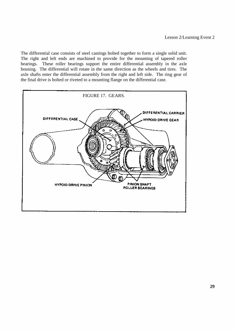
Lesson 2/Learning Event 2 The differential case consists of steel castings bolted together to form a single solid unit. The right and left ends are machined to provide for the mounting of tapered roller bearings. These roller bearings support the entire differential assembly in the axle housing. The differential will rotate in the same direction as the wheels and tires. The axle shafts enter the differential assembly from the right and left side. The ring gear of the final drive is bolted or riveted to a mounting flange on the differential case.
FIGURE 17. GEARS.
29
Lesson 2/Learning Event 2
FIGURE 18. DIFFERENTIAL.
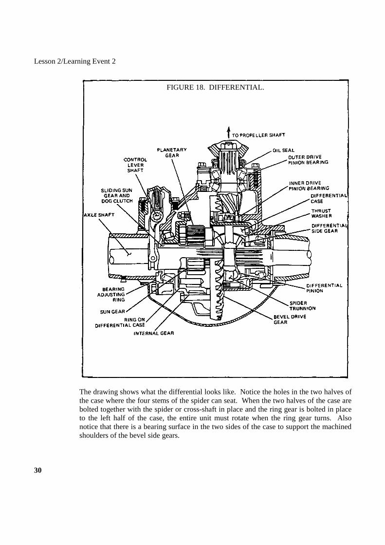
The drawing shows what the differential looks like. Notice the holes in the two halves of the case where the four stems of the spider can seat. When the two halves of the case are bolted together with the spider or cross-shaft in place and the ring gear is bolted in place to the left half of the case, the entire unit must rotate when the ring gear turns. Also notice that there is a bearing surface in the two sides of the case to support the machined shoulders of the bevel side gears.
30
Lesson 2/Learning Event 2 Some light vehicles use only two spider pinions in the differential. A straight shaft, instead of a four-fingered spider, supports the spider pinions. Something to remember is that the side gears are free to turn on their bearing surfaces of the case and the spider pinions are also free to turn on the spider cross-shaft.
FIGURE 19. SIDE GEARS.
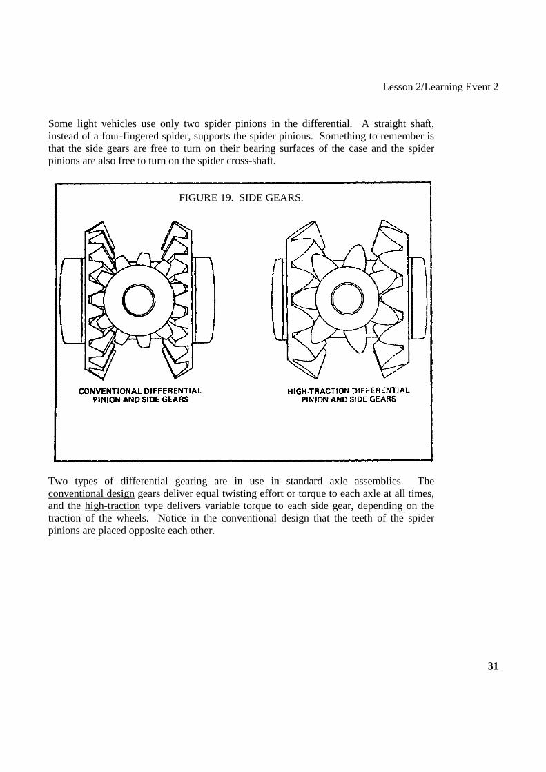
Two types of differential gearing are in use in standard axle assemblies. The conventional design gears deliver equal twisting effort or torque to each axle at all times, and the high-traction type delivers variable torque to each side gear, depending on the traction of the wheels. Notice in the conventional design that the teeth of the spider pinions are placed opposite each other.
31
Lesson 2/Learning Event 2
Also, the teeth have the normal spur gear tooth shape so that, as one tooth comes out of mesh on one side of the gear, the tooth on the opposite side does the same thing. Now, look at the shape of the teeth on the high-traction gears. If the ring gear was forcing the unit to rotate so the spider pinion was moving down, two teeth would be forcing the side gears, axle shafts, and wheels to rotate, also. However, look at the difference in the points of contact for the two teeth. The leverage from the center of the spider to the point of contact for one tooth is much longer than that for the other tooth. If you recall the principles of gears, you see that this arrangement will apply a greater force on the second tooth. High-traction type gearing works very well when only a small amount of wheel slippage is involved. However, if one wheel is on a large piece of ice and the other wheel has good traction, it will not provide enough change in torque to keep the one wheel from spinning. REAR AXLES Axle shafts must be strong enough to deliver the twisting force necessary to move the vehicle under all conditions. The full-floating axle shaft is splined on one end to fit the splines of the differential side gear. The other end contains a flange that can be bolted to the wheel hub, or it may be splined and require a splined flange that slides onto the shaft first and is then bolted to the hub. Semifloating axles are mounted a little differently. Remember, they support some of the weight of the vehicle, so the wheel end is tapered and the wheel hub is keyed to it and held in place with an axle nut.
The axle housing is usually a steel casting that varies in size according to the vehicle design and size. The housing mounts the wheels, axle shafts, final drive, and differential assembly. Seats or flat surfaces are provided either on the top or bottom of the housing for springs. On vehicles with more than one rear axle, torque rods are connected to arms located on the top and bottom of the housing. Like the tandem trailer axles, the torque rods and leaf springs keep the axles in position.
32
Lesson 2/Learning Event 2 More than one type of axle housing is used on wheeled vehicles. Some early vehicles used an axle housing that was made of two sections. These consisted of a right and left section that were joined in the center with bolts. Axles using this type of housing are called split type. The split construction requires that the axle be removed first and then completely disassembled for inspection or repair of the differential. A standard-type differential assembly is supported by tapered roller bearings in the right and left housings. The drive pinion and shaft are mounted in the front of either the right or left section. Most present-day vehicles use a banjo-type rear axle. With this type of construction, the differential and final drive assemblies are made as a single unit. The axle housing is a large single unit with a large opening in the center to receive the differential assembly. The differential and final drive are bolted into the front of the housing, and the axle shafts are installed from the right and left ends. It is possible to remove and repair the differential without complete disassembly of the axle assembly. Two different banjo-type axle housings are presently in use on military wheeled vehicles. One type mounts the final drive assembly in the front or rear of the housing. The second type of banjo axle mounts the final drive gearing on the top of the axle housing. This type axle assembly is used on most of the military tandem axle trucks. It is used as a front steering and drive axle as well as for both rear driving axles. On military vehicles, this type axle uses the double-reduction final drive gearing. OPERATION OF LIVE REAR AXLES As the vehicle operator engages the clutch, the rotating motion of the engine is transmitted through the transmission and transfer case to the axle by the propeller shafts. The propeller shaft is connected to the pinion shaft by means of a flange or yoke at the front of the axle and turns the pinion shaft and gear of the final drive. This forces the ring gear, which is in mesh with the pinion gear, to turn in the direction driven by the pinion. Since the ring gear has more teeth than the pinion, it will rotate more slowly. There is, therefore, a loss of speed and a gain in torque between the pinion and ring gear. The ring gear is solidly fastened to the differential case. Therefore, the entire differential assembly turns when the ring gear turns. The spider or differential pinion shafts that are mounted in the case are carried along at the same speed as the case.
33
Lesson 2/Learning Event 2
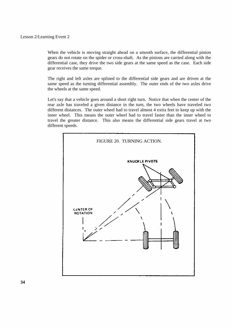
When the vehicle is moving straight ahead on a smooth surface, the differential pinion gears do not rotate on the spider or cross-shaft. As the pinions are carried along with the differential case, they drive the two side gears at the same speed as the case. Each side gear receives the same torque. The right and left axles are splined to the differential side gears and are driven at the same speed as the turning differential assembly. The outer ends of the two axles drive the wheels at the same speed. Let's say that a vehicle goes around a short right turn. Notice that when the center of the rear axle has traveled a given distance in the turn, the two wheels have traveled two different distances. The outer wheel had to travel almost 4 extra feet to keep up with the inner wheel. This means the outer wheel had to travel faster than the inner wheel to travel the greater distance. This also means the differential side gears travel at two different speeds.
FIGURE 20. TURNING ACTION. 34
Lesson 2/Learning Event 2 When the differential side gears rotate at two different speeds, they cause the pinions or spider gears to rotate on their shafts. The pinions walk around the slower side gear and force the other side gear to turn faster or speed up. The faster side gear must turn at the speed of the final drive ring gear plus whatever rotation is being caused by the rotating pinion. The pinion rotates as it travels between the two side gears. The pinions continue to rotate on their shafts as long as the side gears are at different speeds. If the vehicle turns in the opposite direction, the pinions will again rotate on their shafts but in the opposite direction. When the inner wheel slows down in a turn, the outer wheel speeds up the same amount. For example, let us say the ring gear and differential case are rotating at 100 revolutions per minute (RPM) as the vehicle makes a turn that causes the inside wheel to slow down to 70 RPM. This is 30 RPM slower than the ring gear. The outer wheel therefore has to be rotating 30 RPM faster than the ring gear, or 130 RPM. If torque is being applied to the rear axle, such as when going up a hill, the torque enters the rear axle through the pinion and is then increased as it passes through the ring gear. It is then transferred to the differential case and the differential pinion shaft and pinions. The pinions then apply equal torque to each axle side gear, and the torque is transferred to the wheels by the axle shafts. If the tire on one side of an axle with a conventional differential loses its grip on the road surface, the wheel will spin. With traction or grip on the road gone on one side, that wheel becomes very easy to turn. The opposite wheel that still has good traction is hard to turn. The power flow takes the path of least resistance and goes to the slipping wheel. (Because of the differential gearing, one of the side gears is hard to turn and the other very easy. The driving differential pinions walk around the hard-to-turn side gear and at the same time drive the easy-to-turn side gear faster than normal.) This is an undesirable feature, but it is not enough of a problem to cause a change to the types of axles used on military vehicles. A great amount of force is needed to move a heavy vehicle when it is stopped. When engine torque is applied to the rear axle, there are forces attempting to move in many directions. As the pinion gear tries to turn the ring gear, the two gears will tend to be forced apart. Keep in mind that as the engine tries to move the vehicle, the vehicle will resist and try to remain at rest. If the pinion gear is of the straight bevel type, the force being applied will try to push the driving pinion to the
35
Lesson 2/Learning Event 2
front of the vehicle and to the side away from the ring gear. A spiral bevel pinion may be pulled inward toward the differential as it tries to drive the ring gear. At the same time, the ring gear will try to move to the side away from the driving pinion. Some axle assemblies include a thrust pad mounted on the case to the rear of the ring gear to limit the amount the gear can move sideways. As the ring gear is forced away from the pinion, a twisting force is received by the differential carrier bearings. Also, as the ring gear drives the differential, the resistance from the wheels causes the assembly to drive against the mounting bearings. Inside the case, the differential gears try to push themselves apart as torque is applied. This causes both the pinions and side gears to press-against the thrust washers between the gear and the case. When a sudden heavy force is applied to the axle shafts, they tend to twist or wind up. The entire axle assembly tries to twist the mounting springs as it drives the wheels. The vehicle's springs or torque rods are designed to control the twisting effort of the axle assembly. CONSTRUCTION OF LIVE FRONT AXLES One of the requirements for tactical military vehicles is all-wheel drive. To provide this, the front axle must be similar to a live rear axle assembly. The main difference between the live front and live rear axles is that the front wheels must be able to pivot for steering purposes. This also means that the driving axle shafts must be able to deliver torque at an angle to the wheels when they are turned. There is very little difference in the final drive and differential assemblies of most front and rear live axles. On some models of vehicles, the differential assemblies are made the same in both the front and rear so that they may be interchanged. This section, therefore, will cover the construction of parts not found in the rear axle.
The axle housing is a large steel hollow casting that acts as the base or mount for all the other parts. On the front axle housing, the final drive and differential assembly are often mounted off-center. This is to allow the driving propeller shaft to bypass the engine oil pan. The axle housing extends all of the way across the front of the vehicle. Each end of the housing contains components for the steering mechanism. As with the dead axle, these are the parts of the axle that are hinged to turn and provide steering. On the live axle, the steering knuckle appears to be a large ball joint with each end of the axle housing shaped like a ball.
36
Lesson 2/Learning Event 2 The top and bottom of the round end of the housing contain mounting points for the spindle or knuckle bearing. Around the outside and partly covering most of the round ends of the axle housing are the steering knuckle housings. The steering knuckle housing is connected to the end of the axle housing by upper and lower knuckle bearings. On this type axle, a kingpin cannot be used to hold the bearings in position, because it cannot pass completely through the housing of a live axle. Two short kingpins are used on the top and bottom of each end of the axle to align the bearings. These kingpins may be mounted on the axle housing or on a plate that bolts to the top and bottom of the steering knuckle housing. Tapered roller bearings help support the vehicle and keep the steering knuckle in proper alignment. The bearings also provide a pivot or turning point for steering the wheels. Shims are used at the bearing mounting surfaces to ensure proper adjustment. An oil seal, mounted on the inner side of the steering knuckle housing, rides on the round surface at the ends of the axle housing. The spindle has a flange that bolts to the outside of the steering knuckle housing. The spindle also serves as a mounting point for the wheel hub and bearings. CONSTANT VELOCITY JOINTS (CV JOINTS) The axle shafts operate in the hollow tube sections on each end of the axle housing. The inner end of the axle shaft is splined to a side gear in the differential assembly. On most tactical military vehicles, the outer end of the axle shaft is splined to a flange. This flange is bolted to the wheel hub and provides the means of driving the front wheel. The front axle shafts must be able to pivot in the steering knuckle, and there must be a universal joint to transmit power at an angle. A single, conventional universal joint (the type used in the propeller shaft) does not meet military requirements for use on the front axle assembly. During steering, the axle shaft in the front live axle assembly must operate at angles up to 30° and has to drive the output the same as the input without speed changes. The type used on military vehicles is called a constant velocity (CV) joint. There are three types of CV joints used in military vehicles. These are the Rzeppa, Bendix-Weiss, and Tracta.
37
Lesson 2/Learning Event 2
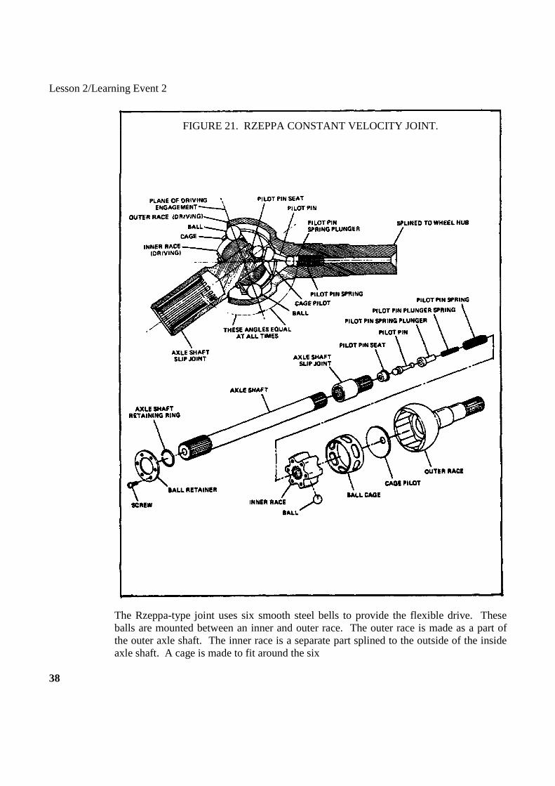
FIGURE 21. RZEPPA CONSTANT VELOCITY JOINT.
The Rzeppa-type joint uses six smooth steel bells to provide the flexible drive. These balls are mounted between an inner and outer race. The outer race is made as a part of the outer axle shaft. The inner race is a separate part splined to the outside of the inside axle shaft. A cage is made to fit around the six
38
Lesson 2/Learning Event 2 driving balls and hold them in the proper position during vehicle turns. A pilot, spring, and pin are mounted in the center of the outside axle at the CV joint to control the movement of the cage and balls.
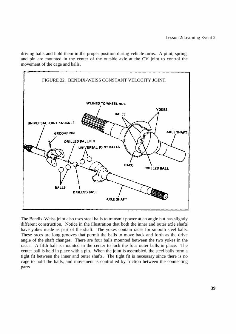
FIGURE 22. BENDIX-WEISS CONSTANT VELOCITY JOINT.
The Bendix-Weiss joint also uses steel balls to transmit power at an angle but has slightly different construction. Notice in the illustration that both the inner and outer axle shafts have yokes made as part of the shaft. The yokes contain races for smooth steel balls. These races are long grooves that permit the balls to move back and forth as the drive angle of the shaft changes. There are four balls mounted between the two yokes in the races. A fifth ball is mounted in the center to lock the four outer balls in place. The center ball is held in place with a pin. When the joint is assembled, the steel balls form a tight fit between the inner and outer shafts. The tight fit is necessary since there is no cage to hold the balls, and movement is controlled by friction between the connecting parts.
39
Lesson 2/Learning Event 2
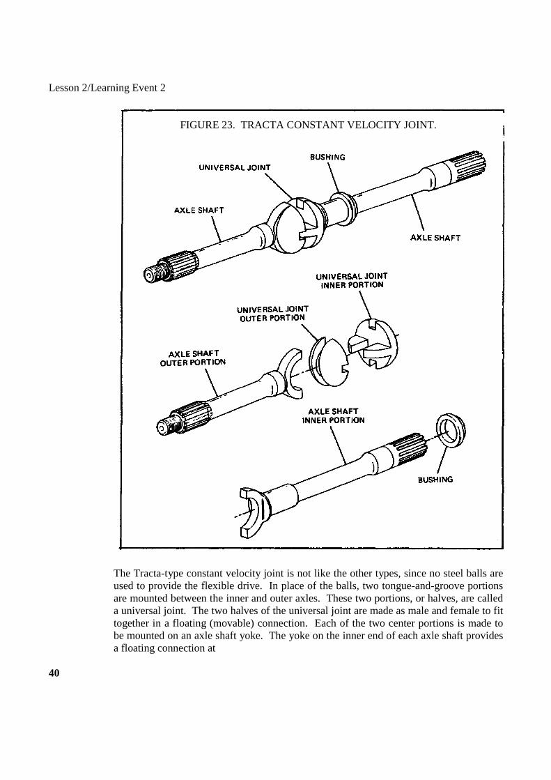
FIGURE 23. TRACTA CONSTANT VELOCITY JOINT.
The Tracta-type constant velocity joint is not like the other types, since no steel balls are used to provide the flexible drive. In place of the balls, two tongue-and-groove portions are mounted between the inner and outer axles. These two portions, or halves, are called a universal joint. The two halves of the universal joint are made as male and female to fit together in a floating (movable) connection. Each of the two center portions is made to be mounted on an axle shaft yoke. The yoke on the inner end of each axle shaft provides a floating connection at
40
Lesson 2/Learning Event 2 the constant velocity joint. When assembled, each of the two center portions is able to pivot (turn) between the other portion and the connecting axle. The axle shafts are supported in the housing by bushings on each side of the constant velocity joint. OPERATION OF LIVE FRONT AXLES The operation of the final drive and differential assemblies in the live front axle is the same as in a rear axle. Gear ratios to increase engine torque will be the same as those of the rear axles on the vehicle. None of the front axle assemblies used in wheeled vehicles are designed to be operated under power all of the time. Some vehicles have a control in the cab that permits the driver to engage the front axle when it is needed. Other vehicles have a device made into the transfer assembly to automatically engage the front-wheel drive when the rear tires lose traction and spin. When the vehicle is traveling straight ahead, both the inner and outer axle shafts are on the same line. If the front axle is engaged to the power train, the inner axle shaft will drive the CV joint. The CV joint will, in turn, drive the outer axle shafts which are splined to the wheel hubs. As steering arms and rods turn the knuckles, the axle shafts will flex at the CV joint. During turns, the CV joint will continue to deliver a smooth, steady flow of torque. The steering linkage moves both steering knuckles at the same time to the proper angle for the turn. LUBRICATION OF LIVE AXLES Whenever the vehicle is moving, the gears of the final drive and differential are turning. The lower part of the gearbox is filled with gear oil to a required level. The lower part of the gearing passes through a pool of oil each time the unit rotates and thereby lubricates all the working parts. On some types of axle assemblies, oil flows down each axle shaft housing to lubricate the bearings that support the outer ends of the axle shafts or wheel bearings. Lubrication of the CV joints is generally done by packing the joints with GAA (grease, automotive and artillery).
41
Lesson 2/Learning Event 2
Breather valves are installed in the axle assembly to allow excess pressure to escape. Pressure will build up in the gearbox as the unit heats up during operation. The breather valve must be able to perform this job without allowing dirt or water to enter from the outside. DRIVE AXLES OF HIGH MOBILITY MULTIPURPOSE WHEELED VEHICLES The 1 1/4-ton utility truck, M998-series, has a final drive that differs from other vehicles. Each truck of this model is equipped with individual (independent) wheel suspension. This means that each wheel has its own separate mounting and is not solidly connected to any of the other wheels. Each of the wheels may move up and down as the vehicle follows the road surface without affecting any of the other wheels. This type of construction does away with the solid axle that extends across the vehicle below the body and frame. The differential assembly is made as a separate unit. Both the front and rear differential assemblies are mounted to the frame of the vehicle rather than in an axle housing. The HMMWV uses axle drive shafts (half shafts) to accommodate the independent suspension system. The purpose of the half shafts is to transfer torque to the wheels from the differential through the geared hub. The unit is basically a one-piece assembly with boots on both the inboard (differential) and outboard (geared hub) ends. The inboard end is bolted to the differential side flange, and the outboard end is splined to the drive gear of the geared hub. The inboard boot encloses a tripot joint which accommodates the in-and-out and angular motion of the axle drive shaft with no change to either system. The outer boot encloses a constant velocity joint which transmits torque through various steering angles to the geared hub. The constant velocity joint end of the shaft assembly is held in place by the axle shaft retaining bolt located opposite the pipe plug in the geared hub. The tripot housing is held in place by both the differential output flange bolts and the caliper mounting brackets. The geared hub is a gearbox, located at the wheel ends, that serves as the front wheel spindle. It can be considered the final drive unit. It permits up to 16 inches of ground clearance.
42
Lesson 2/Learning Event 2 The geared hub includes a drive gear and a driven gear enclosed in a housing. The drive gear is turned by the differential-driven half shaft and powers the driven gear which turns the wheel spindle. The geared hub is joined to the upper and lower control arm by ball joints bolted to the outer end of each arm. The driven gear is splined to the wheel spindle, and the drive gear is turned by the differential-driven half shaft. The radius arm and cover (steering arm and cover) is connected to the center bar by the tie rod.
43
Lesson 2/Learning Event 3
Learning Event 3: DESCRIBE THE INSPECTION PROCEDURES FOR AXLE ASSEMBLIES Wheeled vehicle axles undergo rough treatment whenever the vehicle moves over an uneven surface. Military tactical vehicles often travel cross-country, and you will have to inspect axles quite often to find small troubles before they develop into big troubles. There are two major types of axles or axle arrangements you will work on: the independent suspension type and the solid-housing type. Inspection procedures for all solid types are about the same, but procedures for independent suspension types differ. Axles must be inspected and serviced properly if they are to do their job properly. Faults, such as loose bolts, cracked housings, leaking seals, and other minor troubles, will eventually lead to a major repair job if not corrected as soon as possible. If minor repairs are not made when first needed, a vehicle could very well have to be evacuated to higher levels of maintenance at a later date. This lesson will cover the maintenance procedures for inspecting front and rear axle assemblies and axle components on the M151-series, 1/4-ton trucks, and 2 1/2-ton, 6X6 trucks. INSPECTION PROCEDURES The first types of axle assemblies we will discuss are those used on the 2 1/2-ton truck M35A2. These trucks have one driving front axle assembly and two driving rear axles. All axles are of the top-mounted, double-reduction, single-speed type. The two rear axle assemblies are exactly alike. The front axle is similar but contains additional components to allow the front wheels to pivot to steer the truck. Rear Axle Inspection - M35A2 When you inspect the rear axle assembly of a 2 1/2-ton truck M35A2, use the following as a guide:
- Take a look at the axle assembly. Can you see anything that would make the
axle assembly unserviceable? - Use a lug wrench to check if all lug nuts are tight. - Check all other nuts, bolts, and screws to make sure they are present and tight.
44
Lesson 2/Learning Event 3
- Check the spring guide bracket, torque rods, and torque rod brackets for condition and secure mounting. Check the differential for leaking seals or gaskets.
- Check for plugged or leaking housing vents. - Check for loose or damaged companion flanges (where the propeller shaft is
attached to the differential). - Check the lube level in the differentials. - Check for broken axle shafts. First, block all wheels not being checked, and
then jack up the wheel that is driven by the shaft being checked. Put the transmission and transfer case in gear. Try to turn the wheel. If the wheel turns without turning the propeller shaft, the axle is broken or the differential is unserviceable.
- Check all areas of the axle assemblies for leaking brake fluid or lubricant. - Check wheel bearing adjustment. If the wheel bearings are adjusted properly,
only a slight amount of movement between the brake drum and the backing plate will be found. (The wheel must be jacked up for this check.)
- Check the entire axle assembly for excess dirt or damage that may be seen. - Road-test the vehicle. Listen for excessive or unusual noises in both the front
and rear axle assemblies. Front Axle Inspection - M35A2 To inspect the front axle assembly of a 2 1/2-ton truck M35A2, make all of the checks that you made on the rear axle, plus checks for the steering system. Check for bent or damaged steering components. Examine the tires for excessive wear due to misalignment of axle steering components. Before you make a toe-in check and adjustment, the wheel bearings must be properly adjusted and the tires must be inflated to correct pressure. The vehicle must be on a smooth, level surface, with the wheels in the straight-ahead position.
45
Lesson 2/Learning Event 3
There are two methods that can be used to check the toe-in of an M35A2 truck.
- Place a toe-in gage between the tires ahead of the axle with the ends of the gage against the tires' sidewalls. Both chains must be the same distance from the floor to make sure the gage is positioned properly on each wheel. Set the gage so the pointer measures zero. Move the truck forward until the chains are the same distance from the floor in the back of the axle as they were in front. The pointer will now show the amount the wheels are either toed-in or toed-out in the front. The correct setting is 1/16 to 3/16 inch closer in front than in back for vehicles using 9.00x20 tires.
- The second method consists of making a scribe mark in the center of the front
of each front tire at the same height from the floor as the center of the axle. Using a steel tape, measure the distance between the two marks. Then, roll the vehicle forward until the marks are the same distance from the floor as they were in front, and measure the distance between them. Make the necessary adjustments to the tie rod to bring the toe-in to the proper amount.
Inspection of M151-Series Truck Axles This vehicle has front and back drive assemblies bolted to the frame rails and swing axles to the wheels. To inspect these drive assemblies, use the following as a guide:
- Check the differential for insecure mounting, leaking seals and gaskets, and for damage to the drive and side gear flanges.
- Check the breather valve (located at the top of the differential). - Check the wheel drive shafts and universal joints for wear, damage, and
improper mounting. (The slip joint end should be connected to the differential.)
- Check the wheel drive flanges and the spindle hub for damage and insecure
mounting. - Road-test the vehicle, and listen for excessive or unusual noise in both the
front and rear drive assemblies. 46
Lesson 2/Learning Event 3 When you inspect the front drive assembly of the M151 truck, use the same procedures used on the rear. In addition, inspect the ball joints for serviceability and examine the tires for excessive wear due to misalignment of steering components. Use the same procedures for the 2 1/2-ton truck M35A2 to check the toe-in on the M151. The toe-in on the M151 should be centered with the steering wheel approximately 1 5/16 turns back from the stop. One spoke of the steering wheel should be in line with the center of the steering column. This is the straight-ahead position. The toe-in setting is 1/32 to 5/32 inch.
47
Lesson 2
PRACTICE EXERCISE 1. In which type of axle can the axle shaft be removed without removing the wheel? a. Semifloating b. Three-quarter floating c. Full-floating 2. Which type of universal joints is used in the front axles of most military vehicles? a. Ball and trunnion b. Mechanic's c. Constant velocity 3. An axle that delivers no power to the wheels is called a a. steering axle. b. dead axle. c. suspension axle. 4. Which components of a live front axle are packed with GAA? a. Differential gears b. Final drive gears c. Constant velocity joints 5. The HMMWV geared hub contains a a. drive gear and driven gear. b. constant velocity joint. c. live axle shaft.
48

Lesson 2
This page intentionally left blank.
49
Lesson 2
ANSWERS TO PRACTICE EXERCISE 1. c (page 24) 2. c (page 37) 3. b (page 17) 4. c (page 41) 5. a (page 43)
50
Lesson 3/Learning Event 1
LESSON 3 FUNDAMENTALS OF SUSPENSION SYSTEMS
TASK Describe the fundamentals of suspension systems. CONDITIONS Given information about the construction, operation, and maintenance of springs, shock absorbers, frames, bogie suspension systems, tires, and wheels. STANDARDS Answer 70 percent of the multiple-choice test items covering fundamentals of suspension systems. REFERENCES TM 9-8000 Learning Event 1: DESCRIBE THE TYPES, CONSTRUCTION, AND OPERATION OF FRAMES, SPRINGS, AND SOCK ABSORBERS The purpose of the vehicle suspension system is to support the weight of the vehicle. A perfect suspension system would give a smooth ride on rough roads while keeping the wheels pressed firmly to the ground for traction. It would allow the vehicle to carry small loads or very large loads without changing any of its other good features. Unfortunately, it is not practical to build all vehicles with "perfect" suspension. Instead, in each type of vehicle, the suspension system is built for a particular type of job. Because most military vehicles must travel over rough roads and carry heavy loads, their suspension systems are very strong and stiff. However, some vehicles used by the military have a more flexible suspension system. As a wheeled vehicle mechanic, you must have knowledge of both types. This lesson will cover suspension system components, to include frames, springs, bogie suspension systems, shock absorbers, wheels, and tires.
51
Lesson 3/Learning Event 1
FRAME CONSTRUCTION To provide a rigid foundation for the vehicle body, as well as a solid mounting for the suspension system, a frame of some sort is necessary. The plan and construction of a frame depends upon the type of vehicle and the service for which the vehicle is intended. Two major types of frames are in common use. They are the conventional frame and the integral frame. The conventional frame is made separately from the body, and the various vehicle parts are bolted to it. In the integral-type frame, the frame and body are made as a unit and welded together. Conventional frames for passenger cars and trucks are built of side rails, cross-members, and gussets. Gussets are angular pieces of metal used for strengthening points where the side rails and cross members join. These parts, when riveted together, look like some form of a letter, such as "A," "X," "Y," or "K." The assembled frame combines stiffness and strength with light weight. The conventional frame is usually not more than 30 inches wide in front so that the wheels will not rub on it when making a sharp turn. It may be widened to 48 inches at the rear for increased body stability. Kickups (humps) over the axles allow the vehicle body to be set closer to the ground. For large trucks, the frames are simply made of rugged channel iron. The side rails are usually set at standardized widths to permit the mounting of stock transmissions, transfer assemblies, axles, and so forth. Trucks used as wreckers or tractors have additional reinforcement of the side rails and rear cross-members. The frame members serve as supports to which suspension arms, radiators, transmissions, and the like may be attached. Additional brackets and supports are added for the mounting of running boards, springs, bumpers, engines, towing hooks, shock absorbers, gas tanks, and spare tires. Rubber insulator blocks are usually used between the frame and body attachment points to reduce vibrations and road noise. In the integral-type frame, various body sections are used as structural strength members. All these sections are welded together into what is usually referred to as the "unitized" body and frame.
52
Lesson 3/Learning Event 1 One example of an integral frame is the hull of a combat tank. A tank hull is an assembly of heavy armorplate. It serves not only as a frame but also houses and protects the crew and equipment. CONSTRUCTION OF SPRINGS AND SHACKLES
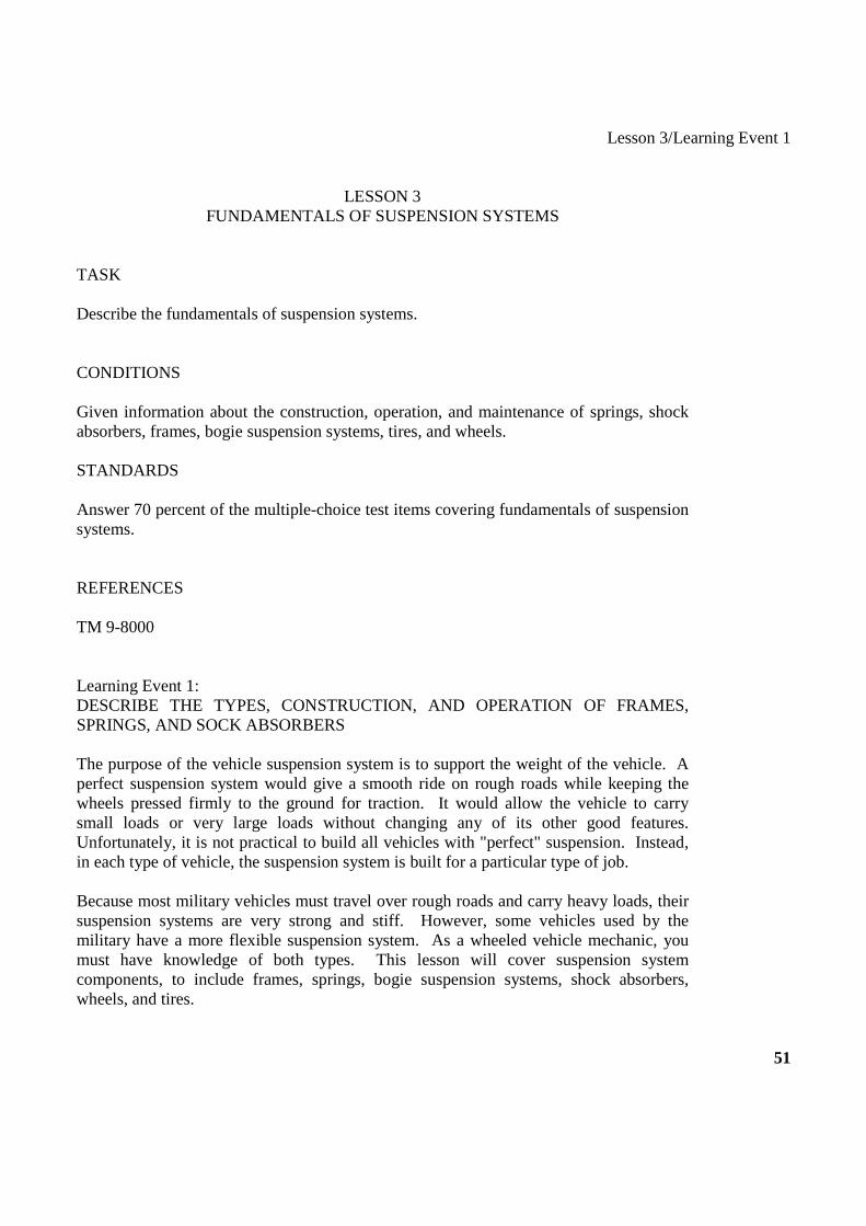
FIGURE 24. ELLIPTIC LEAF SPRING.
The key parts of the suspension system are the springs. One of the first types of springs to be used in suspension systems was the elliptic leaf spring. It is referred to as an elliptic spring because it has an oval shape, like a football or an egg.
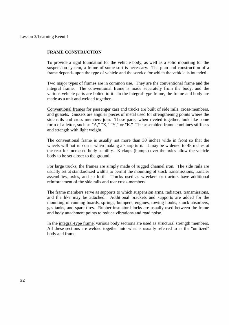
FIGURE 25. ELLIPTIC LAMINATED LEAF.
The spring is made stronger by adding more leaves. The spring then becomes known as an elliptic laminated leaf spring.
53
Lesson 3/Learning Event 1
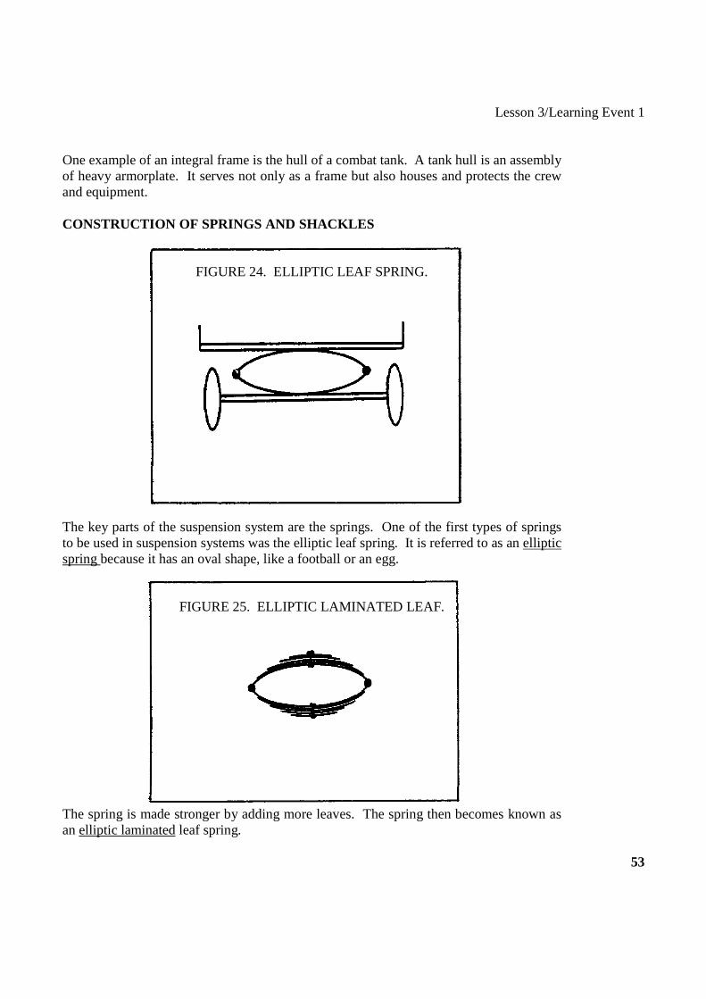
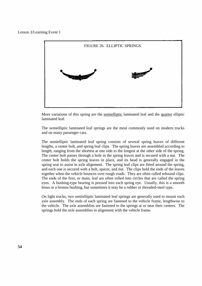
FIGURE 26. ELLIPTIC SPRINGS.
More variations of this spring are the semielliptic laminated leaf and the quarter elliptic laminated leaf. The semielliptic laminated leaf springs are the most commonly used on modern trucks and on many passenger cars. The semielliptic laminated leaf spring consists of several spring leaves of different lengths, a center bolt, and spring leaf clips. The spring leaves are assembled according to length, ranging from the shortest at one side to the longest at the other side of the spring. The center bolt passes through a hole in the spring leaves and is secured with a nut. The center bolt holds the spring leaves in place, and its head is generally engaged in the spring seat to assist in axle alignment. The spring leaf clips are fitted around the spring, and each one is secured with a bolt, spacer, and nut. The clips hold the ends of the leaves together when the vehicle bounces over rough roads. They are often called rebound clips. The ends of the first, or main, leaf are often rolled into circles that are called the spring eyes. A bushing-type bearing is pressed into each spring eye. Usually, this is a smooth brass or a bronze bushing, but sometimes it may be a rubber or threaded-steel type. On light trucks, two semielliptic laminated leaf springs are generally used to mount each axle assembly. The ends of each spring are fastened to the vehicle frame, lengthwise to the vehicle. The axle assemblies are fastened to the springs at or near their centers. The springs hold the axle assemblies in alignment with the vehicle frame.
54
Lesson 3/Learning Event 1 The shackle allows the springs to flex as the weight of the vehicle load is changed and as the vehicle travels over rough roads. Flexing of a spring causes its length to change. The flexing action of the laminated leaf-type spring is restricted by the friction of the leaves rubbing together. There are several different types of spring shackles. The bolt-type shackle has two flat sidepieces. The pins are made like bolts, with a head on one end and threads on the other end to receive a nut. It has a grease fitting and passages that permit lubrication to the center of the bearing. In the straight, threaded-type shackle, the bearings have internal threads. Threaded pins are then screwed into each bearing. The ends of the pins are fitted into holes in the shackle sidepieces. Bolts or small pins are placed in holes in the sidepieces, engaging grooves cut in the threaded pins. This holds the sidepieces on the threaded pins. The U-type shackle is a one-piece, U-shaped bolt that is threaded on both ends. The bearings are threaded both internally and externally. To assemble the U-type shackle, the shackle must first be placed inside the bearing bores of the spring and spring hanger. The threaded bearing is then screwed into the bearing bore and onto the shackle at the same time. The pin-and-bolt-type shackle usually has a one-piece shackle that resembles the letter "H." The shackle is fastened to the spring and spring hanger by straight pins. The pins are locked in place by bolts as on the straight, threaded-type shackle. The center-bolt-type shackle consists of two sidepieces, a center bolt, and two threaded pins tapered on their ends. The bearings are threaded on the inside to receive the threaded pins. The shackle sidepieces have tapered holes that fit over the tapered ends of the pins. The center bolt passes through the sidepieces and holds them tight on the tapers. In a variation of this shackle, the pins have a threaded portion extending beyond the tapers. Nuts and washers are then used to secure the sidepieces instead of the center bolt. The single-piece link shackle has a one-piece U-shaped shackle that forms both sidepieces. Bolt-type pins secure the shackle to the spring and spring hanger. The Y-shackle is a one-piece shackle that has the shape of the letter "Y." One of the bearings is contained in the shackle itself. 55
Lesson 3/Learning Event 1
TYPES OF SPRINGS For a number of years, passenger vehicles have used coil-type springs in their suspension systems. At first, they were used mainly in independent suspension of the front wheels. At present, coil springs are widely used on both the front and rear of passenger vehicles and some light trucks. One military vehicle that uses coil-spring suspension at both front and rear is the 1/4-ton truck M151. Coil springs have wide application because they cost less to make, they are compact, and they are effective. The main disadvantage is that excessive bouncing of the vehicle results from their frictionless action, making shock absorbers necessary. Coil springs are made of special steel rods, heated and wound in the shape of a spiral coil. One end contacts the vehicle frame, and the other end contacts the axle or the suspension device used. A rubber-like pad or insulator is used at the end of the spring that contacts the frame. The insulator prevents vibrations from transferring from the spring to the vehicle frame. Another type of suspension spring used in tracklaying vehicles is the torsion bar. The torsion bar is also being successfully used in some passenger cars and trucks. This suspension spring consists of a long spring-steel bar. One end of the bar is secured to a nonmovable mounting called an anchor. The other end is fastened to a suspension arm or lever. When the lever arm is moved up, it twists the long torsion bar. The bar resists the twisting and gives a spring action, always returning to its original position unless it is overloaded. Torsion bars are usually made to take stress in one direction only and often are marked by an arrow stamped into the metal to indicate the direction of stress. Large wheeled vehicles are built to carry both heavy and light loads. Several methods have been used to change the load rating of the spring suspension as the vehicle load is changed. Auxiliary springs, often called secondary springs, are commonly used in addition to the main springs for this purpose. The secondary spring is often secured to the frame at its center with its end free. When the vehicle load is increased to a certain amount, the main spring is compressed, bringing the free ends of the secondary spring against the axle. Both springs now support the load, and their load ratings are added. This arrangement permits the vehicle to carry heavy loads without compressing the main spring too much.
56
Lesson 3/Learning Event 1 Another variable-load suspension system provides a spring arrangement that increases the effective strength of the springs as the load is increased. The springs are made with flat ends which bear against curved bearing plates. With a light load, the spring ends make contact with the outer edges of the curved bearing plates (the part of the bearing plate that is farthest away from the center of the spring). As the load is increased, the spring compresses, causing the points of contact to move toward the inner edges of the bearing plates. This decreases the effective length of the spring, giving it a higher load rating. This method is referred to as a variable-load spring arrangement. Two rear axles are used on many heavy vehicles to reduce the load on each rear wheel. In addition, the use of two axles decreases effects of road shocks and increases traction. A typical rear end of a heavy vehicle consists of an axle mounted at each end of the rear springs. The load of the vehicle is applied at the center of the springs by means of a spring seat which is supported on the frame. The rear springs carry the same load as they do with a single rear axle. However, the load is divided between two axles instead of being applied to one. The drive is usually applied to both rear axles on military vehicles. Torque rods transmit the driving force to the frame and are arranged so that none of the turning force is applied to the springs. The rear suspension of a truck with two rear axles is usually called a bogie suspension unit. It consists of two axles joined by springs that pivot on bearing-mounted spring seats. The spring seat bearings fit around a trunnion axle which is rigidly attached at the frame through mounting pads. The ends of each spring rest on hardened-steel bearing plates on the two axle housings. Both springs are clamped to the spring seats by U-bolts. When the vehicle travels over uneven surfaces, the springs pivot on the tapered roller bearings. As a result, the weight remains divided between the four wheels even though one wheel may be on a lower or higher surface. This allows the vehicle to carry heavier loads without exceeding the safe tire load. Also, when one wheel hits a bump, the spring pivots on the seat bearings so that both ends of the spring absorb the shock. Thus, the effects of road shocks to the vehicle frame and body are reduced by one half. When only one axle is deflected up or down, the trunnion axle and the vehicle frame are raised or lowered only half the amount. In this manner, bogie axles reduce by half the shock impact not only to the vehicle frame but also to the tires.
57
Lesson 3/Learning Event 1
CONSTRUCTION AND OPERATION OF SHOCK ABSORBERS When a vehicle is traveling on a level road and the wheels strike a bump, the spring is compressed quickly. The compressed spring will attempt to return to its normal loaded length and, in so doing, will rebound past its normal height, causing the body to be lifted. The weight of the vehicle will then push the spring down below its normal loaded height. This, in turn, causes the spring to rebound again. This bouncing process is repeated over and over, a little less each time, until the up-and-down movement finally stops. If bouncing is allowed to go uncontrolled, it will not only cause an uncomfortable ride but will make handling of the vehicle very difficult. To overcome bouncing, assemblies called shock absorbers are used. The main function of a shock absorber is to control (regulate) the spring rebound. A shock absorber that checks (resists) only the spring rebound is single-acting. A shock absorber may also deaden (regulate) the compression of the spring by absorbing part of the energy as the spring is depressed. A shock absorber that regulates compression in addition to rebound is double-acting. Most shock absorbers used at the present time are double-acting, because they permit the use of more flexible springs and give a more comfortable ride. Many types of shock absorbers have been used. Some were operated by friction and spring tension. Those used at present are usually hydraulically operated. These depend upon the resistance of a liquid flowing through small openings to check the action of the spring.
A typical cam-operated (also known as indirect-acting) hydraulic shock absorber is attached to the frame of the vehicle and contains a lever that pivots in the housing. The lever is pinned to a link that is attached to the spring clamp assembly. Rubber grommets are used at both ends of the link to prevent metal-to-metal contact and to provide flexibility. Whenever the spring compresses and rebounds, the shock absorber lever is activated. One cam-operated shock absorber is made to check the rebound only (single-acting). The housing (body) contains an oil-filled reservoir and cylinder. A cam-operated piston is located in the cylinder. The cam is mounted on a shaft to which the shock absorber lever is connected. The piston is held against the cam by a coil spring in the cylinder. An intake/check valve, which permits oil to enter the cylinder from the outer reservoir, is located in the piston head.
58
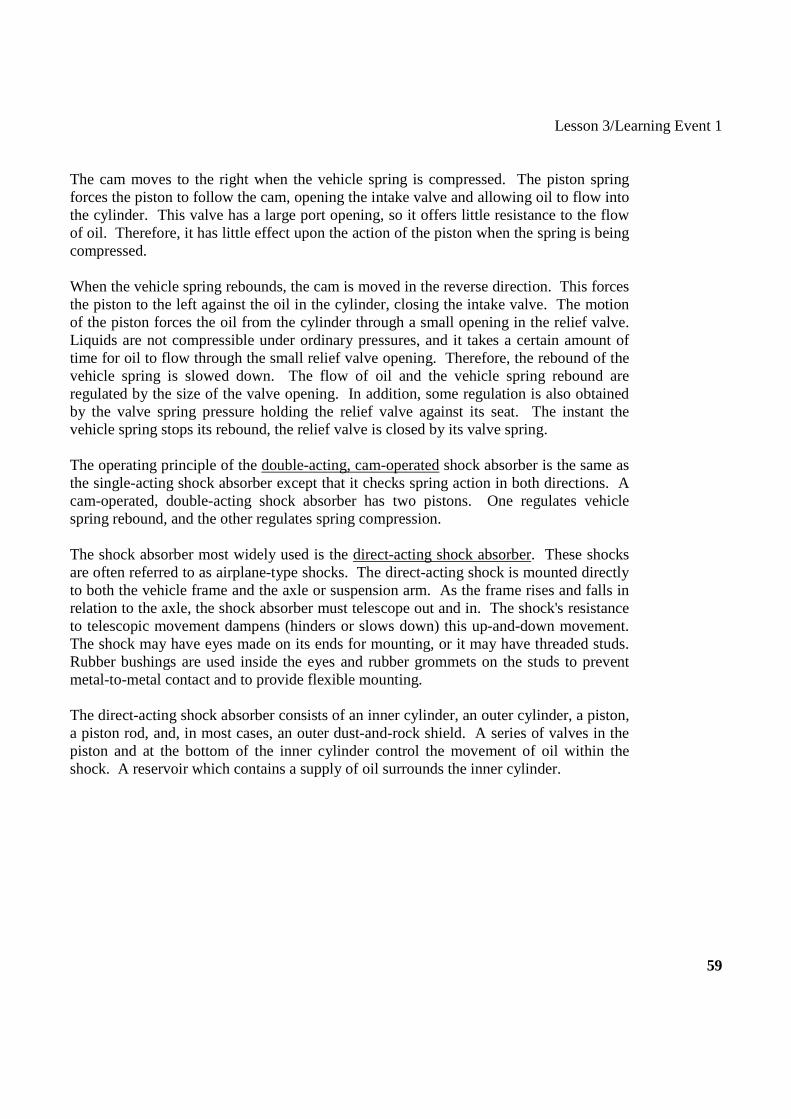
Lesson 3/Learning Event 1 The cam moves to the right when the vehicle spring is compressed. The piston spring forces the piston to follow the cam, opening the intake valve and allowing oil to flow into the cylinder. This valve has a large port opening, so it offers little resistance to the flow of oil. Therefore, it has little effect upon the action of the piston when the spring is being compressed. When the vehicle spring rebounds, the cam is moved in the reverse direction. This forces the piston to the left against the oil in the cylinder, closing the intake valve. The motion of the piston forces the oil from the cylinder through a small opening in the relief valve. Liquids are not compressible under ordinary pressures, and it takes a certain amount of time for oil to flow through the small relief valve opening. Therefore, the rebound of the vehicle spring is slowed down. The flow of oil and the vehicle spring rebound are regulated by the size of the valve opening. In addition, some regulation is also obtained by the valve spring pressure holding the relief valve against its seat. The instant the vehicle spring stops its rebound, the relief valve is closed by its valve spring. The operating principle of the double-acting, cam-operated shock absorber is the same as the single-acting shock absorber except that it checks spring action in both directions. A cam-operated, double-acting shock absorber has two pistons. One regulates vehicle spring rebound, and the other regulates spring compression. The shock absorber most widely used is the direct-acting shock absorber. These shocks are often referred to as airplane-type shocks. The direct-acting shock is mounted directly to both the vehicle frame and the axle or suspension arm. As the frame rises and falls in relation to the axle, the shock absorber must telescope out and in. The shock's resistance to telescopic movement dampens (hinders or slows down) this up-and-down movement. The shock may have eyes made on its ends for mounting, or it may have threaded studs. Rubber bushings are used inside the eyes and rubber grommets on the studs to prevent metal-to-metal contact and to provide flexible mounting. The direct-acting shock absorber consists of an inner cylinder, an outer cylinder, a piston, a piston rod, and, in most cases, an outer dust-and-rock shield. A series of valves in the piston and at the bottom of the inner cylinder control the movement of oil within the shock. A reservoir which contains a supply of oil surrounds the inner cylinder.
59

Lesson 3/Learning Event 1
The direct-acting shock absorber is double-acting. When the vehicle spring is compressed, the shock absorber telescopes in (gets shorter). This moves the piston down, putting pressure on the oil under the piston. For the piston to continue to move downward, it is necessary for the oil to pass through the compression valve. Oil flows through the compression valve into the upper section of the inner cylinder. Oil flow and spring compression are regulated by the size of the compression valve port holes and the spring. When the spring rebounds, the piston is moved up and down. The oil trapped above the piston must travel through the rebound valve. To make up for the reduced amount of rod that is now in the inner cylinder, additional fluid is pulled in from the reservoir through the intake valve. Oil flow and spring movement is regulated by the size of the rebound valve opening and its spring. Sometimes a series of valves is used to provide better regulation of the oil flow in the shock absorber to produce a smoother ride.
60
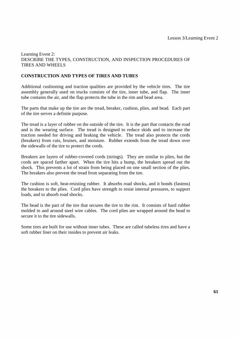
Lesson 3/Learning Event 2 Learning Event 2: DESCRIBE THE TYPES, CONSTRUCTION, AND INSPECTION PROCEDURES OF TIRES AND WHEELS CONSTRUCTION AND TYPES OF TIRES AND TUBES Additional cushioning and traction qualities are provided by the vehicle tires. The tire assembly generally used on trucks consists of the tire, inner tube, and flap. The inner tube contains the air, and the flap protects the tube in the rim and bead area. The parts that make up the tire are the tread, breaker, cushion, plies, and bead. Each part of the tire serves a definite purpose. The tread is a layer of rubber on the outside of the tire. It is the part that contacts the road and is the wearing surface. The tread is designed to reduce skids and to increase the traction needed for driving and braking the vehicle. The tread also protects the cords (breakers) from cuts, bruises, and moisture. Rubber extends from the tread down over the sidewalls of the tire to protect the cords. Breakers are layers of rubber-covered cords (strings). They are similar to plies, but the cords are spaced farther apart. When the tire hits a bump, the breakers spread out the shock. This prevents a lot of strain from being placed on one small section of the plies. The breakers also prevent the tread from separating from the tire. The cushion is soft, heat-resisting rubber. It absorbs road shocks, and it bonds (fastens) the breakers to the plies. Cord plies have strength to resist internal pressures, to support loads, and to absorb road shocks. The bead is the part of the tire that secures the tire to the rim. It consists of hard rubber molded in and around steel wire cables. The cord plies are wrapped around the bead to secure it to the tire sidewalls. Some tires are built for use without inner tubes. These are called tubeless tires and have a soft rubber liner on their insides to prevent air leaks.
61
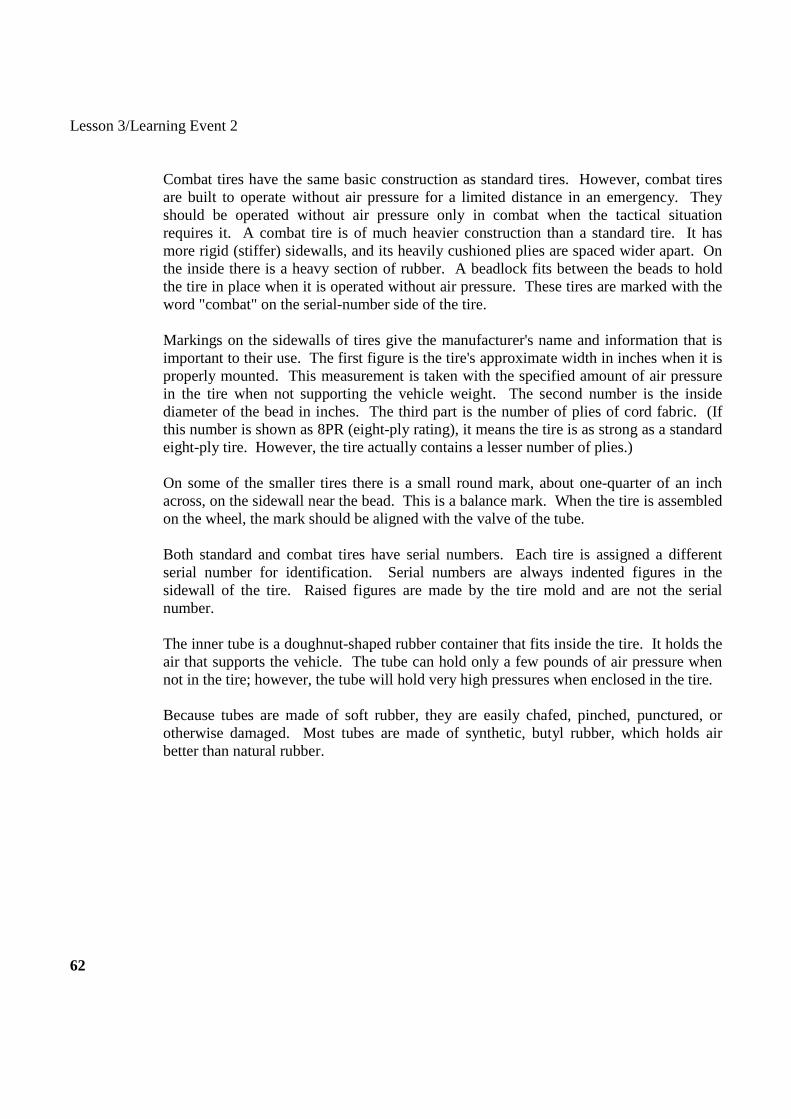
Lesson 3/Learning Event 2
Combat tires have the same basic construction as standard tires. However, combat tires are built to operate without air pressure for a limited distance in an emergency. They should be operated without air pressure only in combat when the tactical situation requires it. A combat tire is of much heavier construction than a standard tire. It has more rigid (stiffer) sidewalls, and its heavily cushioned plies are spaced wider apart. On the inside there is a heavy section of rubber. A beadlock fits between the beads to hold the tire in place when it is operated without air pressure. These tires are marked with the word "combat" on the serial-number side of the tire. Markings on the sidewalls of tires give the manufacturer's name and information that is important to their use. The first figure is the tire's approximate width in inches when it is properly mounted. This measurement is taken with the specified amount of air pressure in the tire when not supporting the vehicle weight. The second number is the inside diameter of the bead in inches. The third part is the number of plies of cord fabric. (If this number is shown as 8PR (eight-ply rating), it means the tire is as strong as a standard eight-ply tire. However, the tire actually contains a lesser number of plies.) On some of the smaller tires there is a small round mark, about one-quarter of an inch across, on the sidewall near the bead. This is a balance mark. When the tire is assembled on the wheel, the mark should be aligned with the valve of the tube. Both standard and combat tires have serial numbers. Each tire is assigned a different serial number for identification. Serial numbers are always indented figures in the sidewall of the tire. Raised figures are made by the tire mold and are not the serial number. The inner tube is a doughnut-shaped rubber container that fits inside the tire. It holds the air that supports the vehicle. The tube can hold only a few pounds of air pressure when not in the tire; however, the tube will hold very high pressures when enclosed in the tire. Because tubes are made of soft rubber, they are easily chafed, pinched, punctured, or otherwise damaged. Most tubes are made of synthetic, butyl rubber, which holds air better than natural rubber.
62
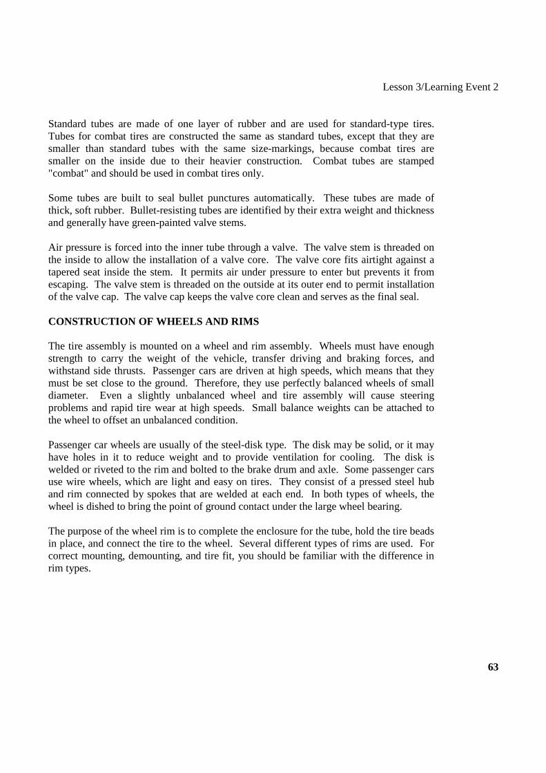
Lesson 3/Learning Event 2 Standard tubes are made of one layer of rubber and are used for standard-type tires. Tubes for combat tires are constructed the same as standard tubes, except that they are smaller than standard tubes with the same size-markings, because combat tires are smaller on the inside due to their heavier construction. Combat tubes are stamped "combat" and should be used in combat tires only. Some tubes are built to seal bullet punctures automatically. These tubes are made of thick, soft rubber. Bullet-resisting tubes are identified by their extra weight and thickness and generally have green-painted valve stems. Air pressure is forced into the inner tube through a valve. The valve stem is threaded on the inside to allow the installation of a valve core. The valve core fits airtight against a tapered seat inside the stem. It permits air under pressure to enter but prevents it from escaping. The valve stem is threaded on the outside at its outer end to permit installation of the valve cap. The valve cap keeps the valve core clean and serves as the final seal. CONSTRUCTION OF WHEELS AND RIMS The tire assembly is mounted on a wheel and rim assembly. Wheels must have enough strength to carry the weight of the vehicle, transfer driving and braking forces, and withstand side thrusts. Passenger cars are driven at high speeds, which means that they must be set close to the ground. Therefore, they use perfectly balanced wheels of small diameter. Even a slightly unbalanced wheel and tire assembly will cause steering problems and rapid tire wear at high speeds. Small balance weights can be attached to the wheel to offset an unbalanced condition. Passenger car wheels are usually of the steel-disk type. The disk may be solid, or it may have holes in it to reduce weight and to provide ventilation for cooling. The disk is welded or riveted to the rim and bolted to the brake drum and axle. Some passenger cars use wire wheels, which are light and easy on tires. They consist of a pressed steel hub and rim connected by spokes that are welded at each end. In both types of wheels, the wheel is dished to bring the point of ground contact under the large wheel bearing. The purpose of the wheel rim is to complete the enclosure for the tube, hold the tire beads in place, and connect the tire to the wheel. Several different types of rims are used. For correct mounting, demounting, and tire fit, you should be familiar with the difference in rim types.
63
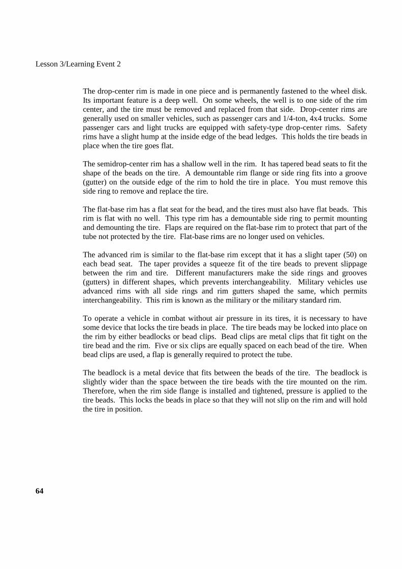
Lesson 3/Learning Event 2
The drop-center rim is made in one piece and is permanently fastened to the wheel disk. Its important feature is a deep well. On some wheels, the well is to one side of the rim center, and the tire must be removed and replaced from that side. Drop-center rims are generally used on smaller vehicles, such as passenger cars and 1/4-ton, 4x4 trucks. Some passenger cars and light trucks are equipped with safety-type drop-center rims. Safety rims have a slight hump at the inside edge of the bead ledges. This holds the tire beads in place when the tire goes flat. The semidrop-center rim has a shallow well in the rim. It has tapered bead seats to fit the shape of the beads on the tire. A demountable rim flange or side ring fits into a groove (gutter) on the outside edge of the rim to hold the tire in place. You must remove this side ring to remove and replace the tire. The flat-base rim has a flat seat for the bead, and the tires must also have flat beads. This rim is flat with no well. This type rim has a demountable side ring to permit mounting and demounting the tire. Flaps are required on the flat-base rim to protect that part of the tube not protected by the tire. Flat-base rims are no longer used on vehicles. The advanced rim is similar to the flat-base rim except that it has a slight taper (50) on each bead seat. The taper provides a squeeze fit of the tire beads to prevent slippage between the rim and tire. Different manufacturers make the side rings and grooves (gutters) in different shapes, which prevents interchangeability. Military vehicles use advanced rims with all side rings and rim gutters shaped the same, which permits interchangeability. This rim is known as the military or the military standard rim. To operate a vehicle in combat without air pressure in its tires, it is necessary to have some device that locks the tire beads in place. The tire beads may be locked into place on the rim by either beadlocks or bead clips. Bead clips are metal clips that fit tight on the tire bead and the rim. Five or six clips are equally spaced on each bead of the tire. When bead clips are used, a flap is generally required to protect the tube. The beadlock is a metal device that fits between the beads of the tire. The beadlock is slightly wider than the space between the tire beads with the tire mounted on the rim. Therefore, when the rim side flange is installed and tightened, pressure is applied to the tire beads. This locks the beads in place so that they will not slip on the rim and will hold the tire in position.
64
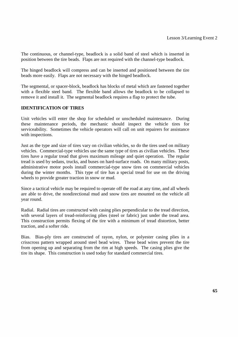
Lesson 3/Learning Event 2 The continuous, or channel-type, beadlock is a solid band of steel which is inserted in position between the tire beads. Flaps are not required with the channel-type beadlock. The hinged beadlock will compress and can be inserted and positioned between the tire beads more easily. Flaps are not necessary with the hinged beadlock. The segmental, or spacer-block, beadlock has blocks of metal which are fastened together with a flexible steel band. The flexible band allows the beadlock to be collapsed to remove it and install it. The segmental beadlock requires a flap to protect the tube. IDENTIFICATION OF TIRES Unit vehicles will enter the shop for scheduled or unscheduled maintenance. During these maintenance periods, the mechanic should inspect the vehicle tires for serviceability. Sometimes the vehicle operators will call on unit repairers for assistance with inspections. Just as the type and size of tires vary on civilian vehicles, so do the tires used on military vehicles. Commercial-type vehicles use the same type of tires as civilian vehicles. These tires have a regular tread that gives maximum mileage and quiet operation. The regular tread is used by sedans, trucks, and buses on hard-surface roads. On many military posts, administrative motor pools install commercial-type snow tires on commercial vehicles during the winter months. This type of tire has a special tread for use on the driving wheels to provide greater traction in snow or mud. Since a tactical vehicle may be required to operate off the road at any time, and all wheels are able to drive, the nondirectional mud and snow tires are mounted on the vehicle all year round. Radial. Radial tires are constructed with casing plies perpendicular to the tread direction, with several layers of tread-reinforcing plies (steel or fabric) just under the tread area. This construction permits flexing of the tire with a minimum of tread distortion, better traction, and a softer ride. Bias. Bias-ply tires are constructed of rayon, nylon, or polyester casing plies in a crisscross pattern wrapped around steel bead wires. These bead wires prevent the tire from opening up and separating from the rim at high speeds. The casing plies give the tire its shape. This construction is used today for standard commercial tires.
65
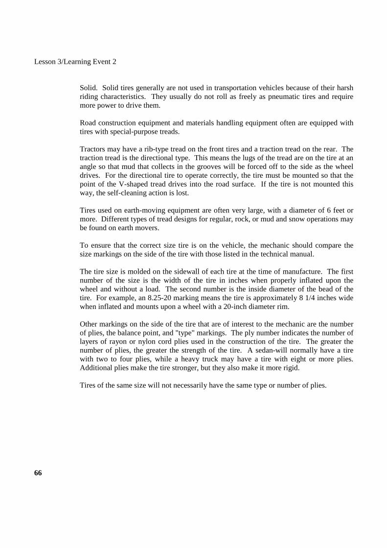
Lesson 3/Learning Event 2
Solid. Solid tires generally are not used in transportation vehicles because of their harsh riding characteristics. They usually do not roll as freely as pneumatic tires and require more power to drive them. Road construction equipment and materials handling equipment often are equipped with tires with special-purpose treads. Tractors may have a rib-type tread on the front tires and a traction tread on the rear. The traction tread is the directional type. This means the lugs of the tread are on the tire at an angle so that mud that collects in the grooves will be forced off to the side as the wheel drives. For the directional tire to operate correctly, the tire must be mounted so that the point of the V-shaped tread drives into the road surface. If the tire is not mounted this way, the self-cleaning action is lost. Tires used on earth-moving equipment are often very large, with a diameter of 6 feet or more. Different types of tread designs for regular, rock, or mud and snow operations may be found on earth movers. To ensure that the correct size tire is on the vehicle, the mechanic should compare the size markings on the side of the tire with those listed in the technical manual. The tire size is molded on the sidewall of each tire at the time of manufacture. The first number of the size is the width of the tire in inches when properly inflated upon the wheel and without a load. The second number is the inside diameter of the bead of the tire. For example, an 8.25-20 marking means the tire is approximately 8 1/4 inches wide when inflated and mounts upon a wheel with a 20-inch diameter rim. Other markings on the side of the tire that are of interest to the mechanic are the number of plies, the balance point, and "type" markings. The ply number indicates the number of layers of rayon or nylon cord plies used in the construction of the tire. The greater the number of plies, the greater the strength of the tire. A sedan-will normally have a tire with two to four plies, while a heavy truck may have a tire with eight or more plies. Additional plies make the tire stronger, but they also make it more rigid. Tires of the same size will not necessarily have the same type or number of plies.
66
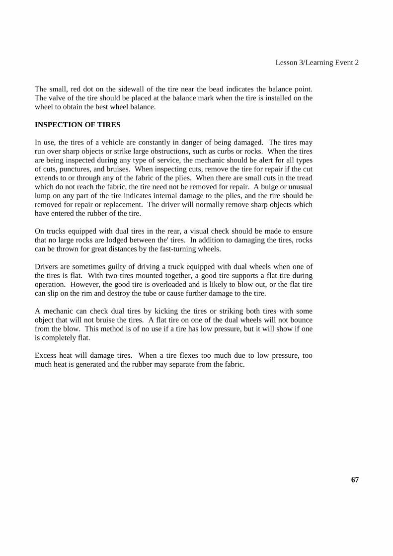
Lesson 3/Learning Event 2 The small, red dot on the sidewall of the tire near the bead indicates the balance point. The valve of the tire should be placed at the balance mark when the tire is installed on the wheel to obtain the best wheel balance. INSPECTION OF TIRES In use, the tires of a vehicle are constantly in danger of being damaged. The tires may run over sharp objects or strike large obstructions, such as curbs or rocks. When the tires are being inspected during any type of service, the mechanic should be alert for all types of cuts, punctures, and bruises. When inspecting cuts, remove the tire for repair if the cut extends to or through any of the fabric of the plies. When there are small cuts in the tread which do not reach the fabric, the tire need not be removed for repair. A bulge or unusual lump on any part of the tire indicates internal damage to the plies, and the tire should be removed for repair or replacement. The driver will normally remove sharp objects which have entered the rubber of the tire. On trucks equipped with dual tires in the rear, a visual check should be made to ensure that no large rocks are lodged between the' tires. In addition to damaging the tires, rocks can be thrown for great distances by the fast-turning wheels. Drivers are sometimes guilty of driving a truck equipped with dual wheels when one of the tires is flat. With two tires mounted together, a good tire supports a flat tire during operation. However, the good tire is overloaded and is likely to blow out, or the flat tire can slip on the rim and destroy the tube or cause further damage to the tire. A mechanic can check dual tires by kicking the tires or striking both tires with some object that will not bruise the tires. A flat tire on one of the dual wheels will not bounce from the blow. This method is of no use if a tire has low pressure, but it will show if one is completely flat. Excess heat will damage tires. When a tire flexes too much due to low pressure, too much heat is generated and the rubber may separate from the fabric.
67
Lesson 3/Learning Event 2
One of the decisions in tire inspection is when to remove the tire for recapping. Do not permit the tire to remain on the vehicle too long, or all of the rubber will be worn from the tire and the fabric will be exposed. When worn to the fabric, it is not practical to repair the tire or apply new tread. Yet, if the tire is removed too soon, rubber will be wasted since all of the possible use has not been attained from the tire. On the nondirectional mud and snow tires on tactical vehicles, the tires should be removed for recapping when the center of the tread is worn smooth. At this time the ridges formed by the grooves of the tread are worn off at the tire center. On commercial-type treads, the tread gage issued with the organizational tool set may be used to check depth. Normally, the tread should not be less than 1/16 inch. Some of the causes of rapid tire wear are misaligned wheels, excessive speed, improper loading, grabbing brakes, and improper vehicle operation. A tire will normally wear with a smooth surface, but when forced to slide or drag on the road, the surface becomes rough and scuffed. Operating a vehicle in front-wheel drive more than required can also increase tire wear. During the winter when tire chains are in use, improper installation or use of chains can chew pieces out of the tires. When installed on the wheel, sharp edges of tire chains should face away from the tire. If the tire has been driven on too long while not wearing evenly, it may be damaged beyond repair. Once the wear has extended into the fabric of the plies, it is unlikely the tire can be repaired. Uneven wear can be caused by improper air pressure, incorrect steering adjustments, faulty brakes, bad shock absorbers, loose wheel bearings, and poor driving by the operators. Front tires on a vehicle with too much toe-in will wear the outer edges at a fast rate. If the front tires toe-out when the vehicle is traveling straight ahead, the tires will wear rapidly on the inner edges. Improper toe-in or toe-out forces the tires to slide or drag sideways as they roll over the road surface. A sharp featheredge is left on the edges of the tire treads because of the sliding motion.
Too much free play in the steering linkages, loose wheel mountings, or loose wheel bearings can also cause uneven wear on the front tires. Brake shoes that grab on any of the wheels of a vehicle will cause the tire to slide and wear unevenly.
68
Lesson 3/Learning Event 2 Any hard-driving practices by the operator, such as moving through turns too fast and stopping and starting too quickly, will cause uneven wear on the tires. Also, it is the responsibility of the vehicle operator to ensure that the tires have the correct tire pressure. If the driver fails in this job, the tires wear unevenly or fail too early. When a tire is operated with too little air pressure, the center of the tire will buckle inward and the outer edges will carry the load. This causes the outer edges to wear very fast. Also, a tire without enough air pressure will flex more than it should and generate too much heat. If operated with too much tire pressure, the vehicle will ride on the crown or center of the over-expanded tire and, thus, wear the center of the tread too fast. The driver and the mechanic should make every effort to keep all the tires on a vehicle wearing at an even rate. One of the checks a mechanic will make is to measure the circumference or distance around the outside of the tires. This is done with the tape measure in the Organizational Maintenance Common Tool Set Number 2 (less power). The allowable tolerances for matching dual tires is determined by the outside diameter. Differences in the sizes of tires can cause increased wear on the tires and drive trains. Tires of different size on either side of the front of the vehicle can make steering and braking difficult. On any of the driving axles, unequal-size tires on opposite sides of the vehicle will force the differential to work more than necessary. When two unequal-size tires are mounted side by side on rear dual wheels, the tire with the most tread or larger diameter will be forced to carry more of the load. With one tire carrying the load of two, the working tire is much more likely to fail. On vehicles that have more than one driving axle, each axle will be driven at exactly the same speed. If the tires on the different axles have different diameters, some of the tires will be forced to slip to keep the wheel speeds matched, because the larger tire covers more ground during each revolution. Often the vehicle driver will be careless with the valve caps because they are not absolutely necessary to keep the vehicle running. The mechanic should check to see if the caps are present each time the tires are inspected, because they can prevent failure of the tires due to leaking valves. When the caps are not present, mud, dirt, or other foreign matter can enter the tire valve openings. This can prevent proper closing
69
Lesson 3/Learning Event 2
of the valve and allow dirt and moisture to be forced into the tire tube as it is inflated with air. Most valve caps contain a seal or gasket that provides a safeguard against a leaky valve. To function properly and to prevent small air leaks, the valve caps must be snug when installed. As the tire and tube are assembled, the mechanic must take care that the tire valve is properly installed. When inspecting a vehicle with dual rear wheels, note the position of the valves. To be correct, the two valves must be 180° apart (one valve directly opposite the other). This aids in the location of the valve stems under all conditions. The valves of the inner wheel will face the outside of the vehicle. If valves are not installed this way on the inner tire of the rear dual wheels, it will be very difficult to check air pressure or to inflate the tires. The lug nuts that retain the wheels may work loose during the operation of the vehicle. While inspecting, the mechanic should check all lug nuts by trying to tighten them with a wrench. When loose lug nuts are found, the nuts should be tightened to the specifications in the technical manual. Loose front-wheel bearings, which can cause excess tire wear, can be located by jacking the vehicle up and rocking the wheels back and forth. The free play can be felt at the wheel. This check may also reveal free play in kingpins, steering knuckles, or control arms. The mechanic should first determine exactly where the free play is located. If loose wheel bearings are found, they should be adjusted in accordance with the vehicle technical manual. If any other looseness is found, refer to the maintenance allocation chart (MAC) to determine who is responsible for the repair. Cracks in the outside rubber of the tire should be carefully inspected. Cracks usually spread out from the center of the tire and may extend all the way around the sidewall of the tire. The cracks are caused by the cord plies below the rubber becoming weak and spreading apart. This forces the rubber to crack open. Failure of the fabric of the tire is usually due to age and/or dry rot. As cracks open in the rubber, water will enter, and the complete failure of the fabric is speeded up. Once the fabric of the tire becomes weak, there is danger of a blowout any time a load is applied. When dry rot is suspected, the tire should be replaced. In all cases where there is doubt as to the service-ability of a tire, the mechanic should seek help from the maintenance supervisor.
70
Lesson 3/Learning Event 2 If the tire was carefully inspected prior to removal from the wheel, only those areas that could not be seen while mounted need to be inspected. If no inspection has been made, make all of the checks listed for a mounted tire. In addition, check the inside surfaces and beads. Check the bead for damage. Bead damage often occurs during installation and removal of the tire from the wheel. It is particularly important to check the outside of the bead on the tubeless tires since this area acts as a seal to retain the air. Check the inner surface of the tire for cuts, punctures, and bulges. If the cord plies have been pulled loose from the normally smooth inner surface, it indicates the tire has been operated while flat. INSPECTION OF WHEELS Inspect the wheel for cracks, dents, and oversized mounting holes. When a vehicle is operated with the wheel mounting nuts loose, the wheel will move against the studs and enlarge the mounting holes. In time, the holes will become so enlarged that it will be impossible to tighten the wheel properly. Cracks may develop in any part of the wheel, but the area around the mounting holes will usually be the first place they appear. Large dents are usually the result of an accident, such as a wheel striking a log, a curb, or another vehicle. A warped wheel is difficult to detect when off the vehicle. It is easier to detect a warped wheel while the vehicle is moving because of noticeable weaving in and out. If the vehicle is in the shop, the mechanic can raise the wheel off the floor and rotate the assembly. By looking at the tire from the front as it spins, or comparing it with a stationary object, a warped wheel can be detected. If the damage is enough to make the wheel unserviceable or unsafe, it should be replaced.
71
Lesson 3
PRACTICE EXERCISE 1. In the bogie suspension system, which item is mounted on tapered roller
bearings? a. Bearing plate b. Spring seat c. Mounting pad 2. Which type of spring causes excessive bouncing because of its frictionless action? a. Coil b. Leaf c. Torsion bar 3. If a tire size is 7.50 x 20, the figure 7.50 indicates the tire's approximate a. width. b. diameter. c. circumference. 4. Adding more plies to a tire will a. reduce tread wear. b. improve the ride. c. increase the strength. 5. What is the primary purpose of a shock absorber? a. Limit spring compression b. Regulate spring rebound c. Act as a helper spring
72

Lesson 3
This page intentionally left blank.
73
Lesson 3
ANSWERS TO PRACTICE EXERCISE 1. b (page 57) 2. a (page 56) 3. a (page 62) 4. c (page 62) 5. b (page 58)
����U.S. GOVERNMENT PRINTING OFFICE: 2000-528-075/20443 74