Embed Size (px)
Citation preview

U.S. Army Research, Development and
Engineering Command
INTELLIGENT POWER MANAGEMENT
DISTRIBUTION SYSTEMS (IPMDS)
April 2011
1.IPMDS Overview
2.Background
3.Automatic Load Balancing
4.IPMDS
5.Testing/Fielding Schedule
Outline
IPMDS Overview
Description • IPMDS – Intelligent Power Management Distribution
System
• Man portable, ruggedized power distribution system
• Automatic load balancing
• Electrical hazard warnings
• Use with Tactical Quiet Generators (TQGs), 15kW –
100kW
• 208 V, 3 phase, Wye configured, 50/60 Hz
IPMDS Overview
Benefits • Reduce burden on the warfighter during power grid
set up
• Increase power grid reliability
• Reduce injuries due to electrical hazards
• Near-term solution
• No increase in power distribution system footprint

Background
PDISE
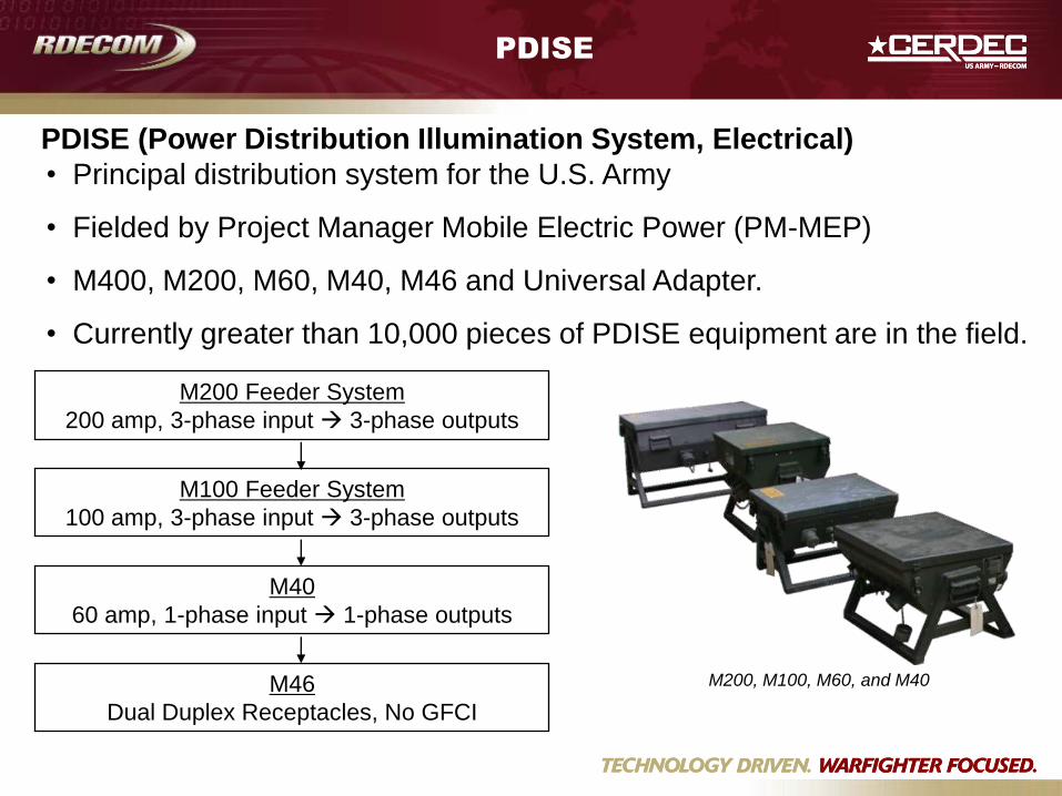
• Principal distribution system for the U.S. Army
• Fielded by Project Manager Mobile Electric Power (PM-MEP)
• M400, M200, M60, M40, M46 and Universal Adapter.
• Currently greater than 10,000 pieces of PDISE equipment are in the field.
PDISE (Power Distribution Illumination System, Electrical)
M100 Feeder System
100 amp, 3-phase input 3-phase outputs
M40
60 amp, 1-phase input 1-phase outputs
M46
Dual Duplex Receptacles, No GFCI
M200 Feeder System
200 amp, 3-phase input 3-phase outputs
M200, M100, M60, and M40
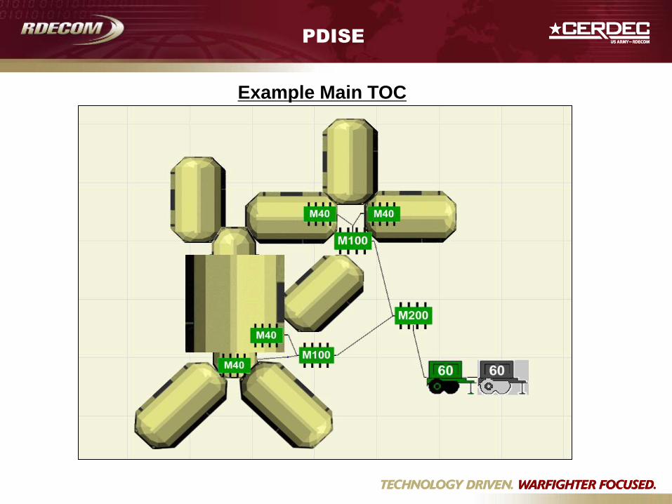
PDISE
Example Main TOC
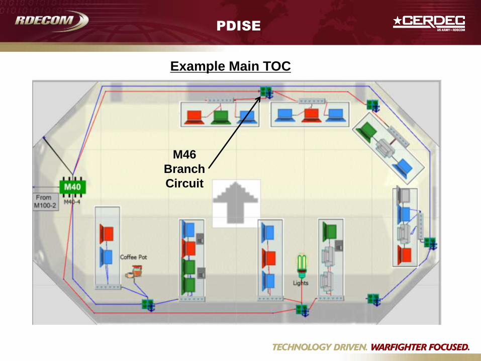
PDISE
Example Main TOC
M46
Branch
Circuit
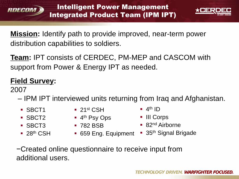
Intelligent Power Management
Integrated Product Team (IPM IPT)
Mission: Identify path to provide improved, near-term power
distribution capabilities to soldiers.
Team: IPT consists of CERDEC, PM-MEP and CASCOM with
support from Power & Energy IPT as needed.
Field Survey:
2007
– IPM IPT interviewed units returning from Iraq and Afghanistan.
SBCT1
SBCT2
SBCT3
28th CSH
21st CSH
4th Psy Ops
782 BSB
659 Eng. Equipment
4th ID
III Corps
82nd Airborne
35th Signal Brigade
−Created online questionnaire to receive input from
additional users.
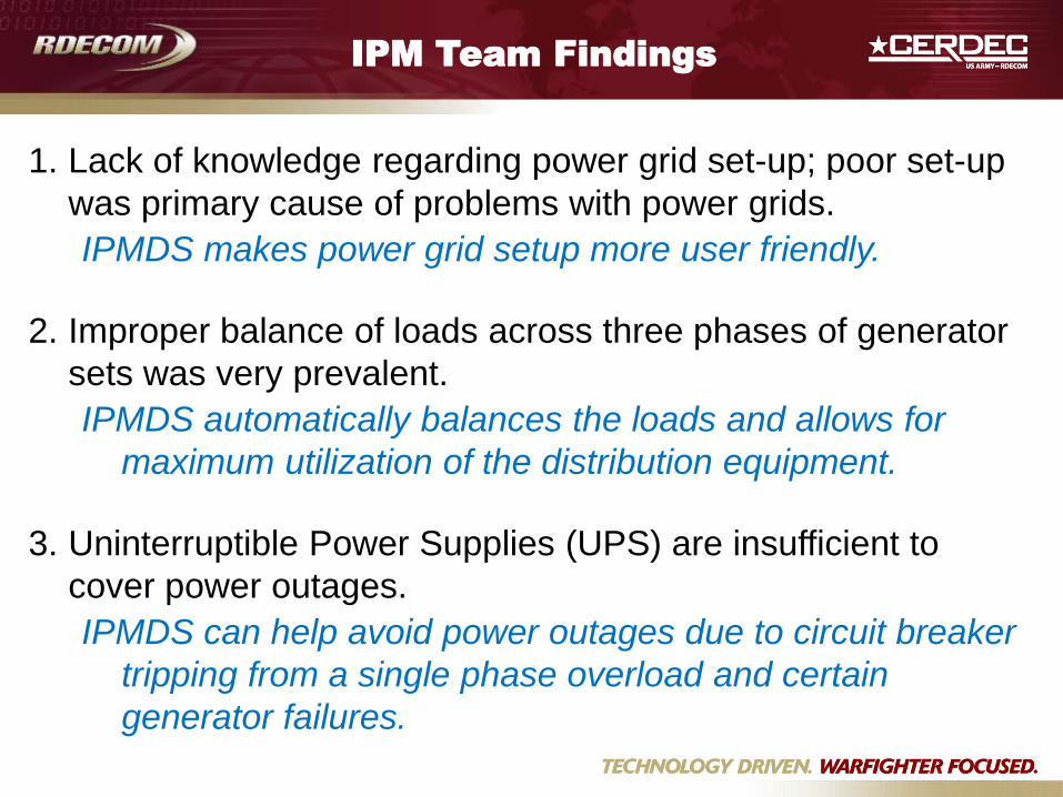
1. Lack of knowledge regarding power grid set-up; poor set-up
was primary cause of problems with power grids.
2. Improper balance of loads across three phases of generator
sets was very prevalent.
3. Uninterruptible Power Supplies (UPS) are insufficient to
cover power outages.
IPM Team Findings
IPMDS makes power grid setup more user friendly.
IPMDS automatically balances the loads and allows for
maximum utilization of the distribution equipment.
IPMDS can help avoid power outages due to circuit breaker
tripping from a single phase overload and certain
generator failures.
Automatic
Load Balancing
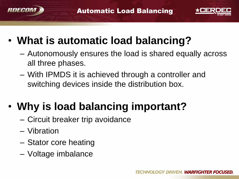
Automatic Load Balancing
• What is automatic load balancing? – Autonomously ensures the load is shared equally across
all three phases.
– With IPMDS it is achieved through a controller and
switching devices inside the distribution box.
• Why is load balancing important? – Circuit breaker trip avoidance
– Vibration
– Stator core heating
– Voltage imbalance
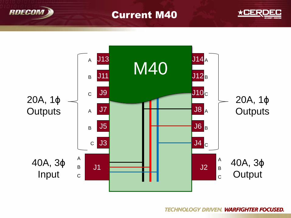
Current M40
C
B
A
B
A
C
B
A
C
B
A
A
B
C
20A, 1ϕ
Outputs
20A, 1ϕ
Outputs
40A, 3ϕ
Output
40A, 3ϕ
Input J2 J1
J14 J13
A
B
C
C
J12
J10
J8
J6
J4
J11
J9
J7
J5
J3
M40
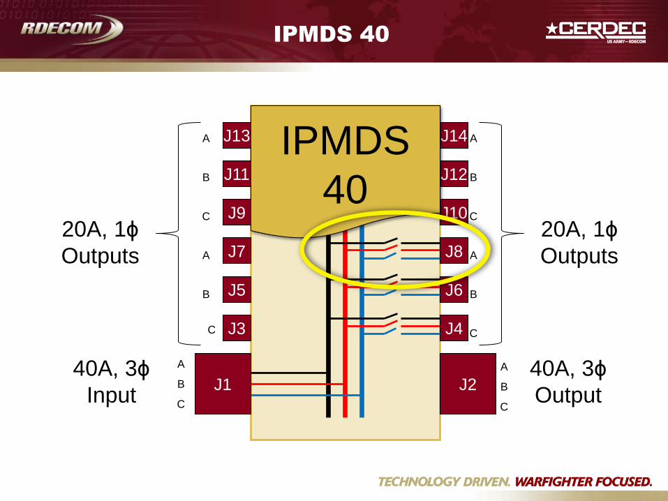
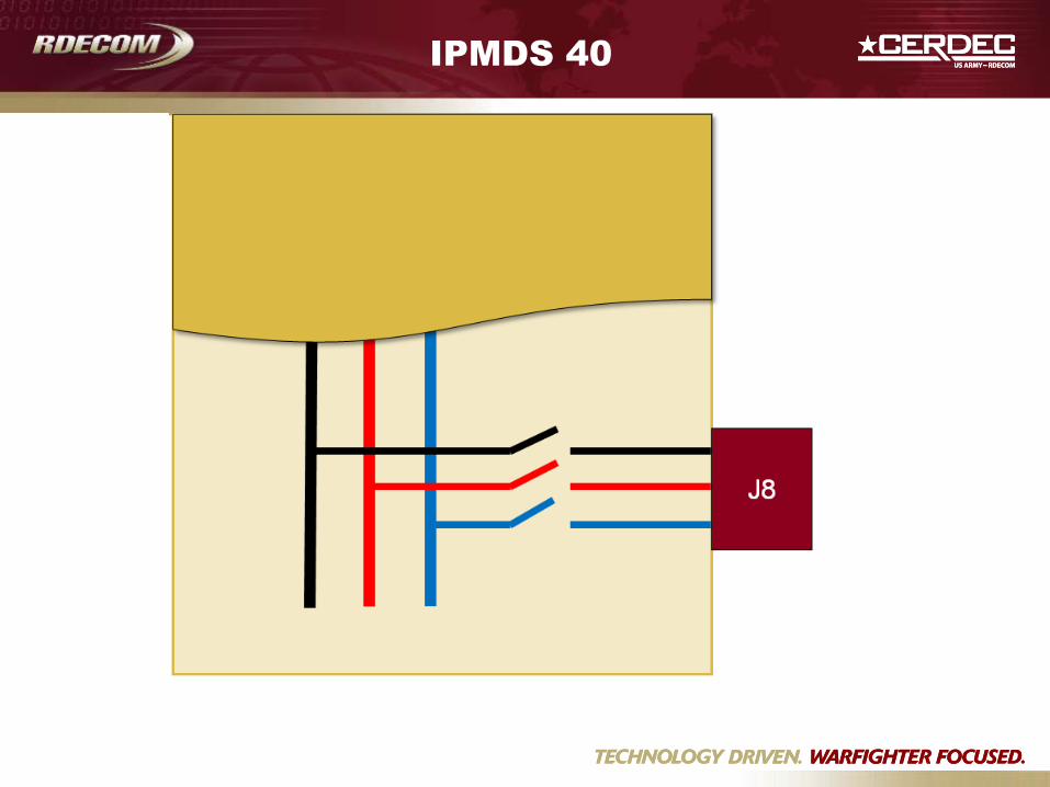
IPMDS 40
C
B
A
B
A
C
B
A
C
B
A
A
B
C
20A, 1ϕ
Outputs
20A, 1ϕ
Outputs
40A, 3ϕ
Output
40A, 3ϕ
Input J2 J1
J14 J13
A
B
C
C
J12
J10
J8
J6
J4
J11
J9
J7
J5
J3
IPMDS
40
IPMDS 40
J8 B A C
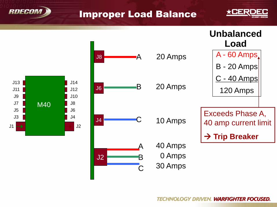
Unbalanced Load
A - 60 Amps
B - 20 Amps
C - 40 Amps
120 Amps
Exceeds Phase A,
40 amp current limit
Trip Breaker
Improper Load Balance
40 Amps
0 Amps
30 Amps
20 Amps
20 Amps
10 Amps
J1
J2
J8
A
B
C
A
J6
B
J4 C J1
J3
J5
J7 J8
J6
J4
J2
M40
J9
J11
J13
J10
J12
J14
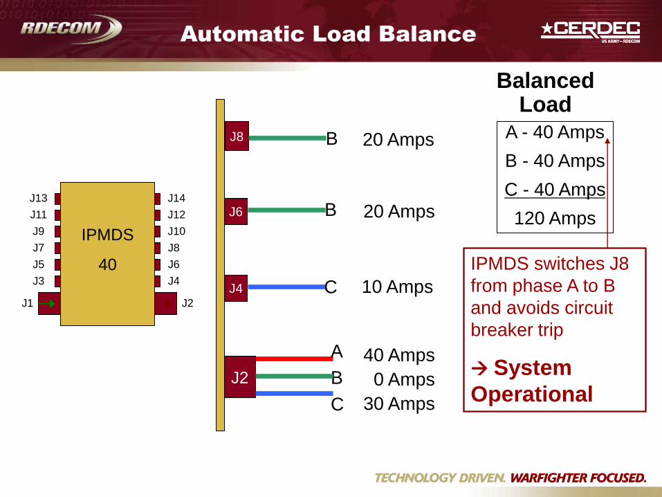
Balanced Load
A - 40 Amps
B - 40 Amps
C - 40 Amps
120 Amps
IPMDS switches J8
from phase A to B
and avoids circuit
breaker trip
System
Operational
Automatic Load Balance
40 Amps
0 Amps
30 Amps
20 Amps
20 Amps
10 Amps
J1
J2
J8
A
B
C
B
J6
B
J4 C J1
J3
J5
J7 J8
J6
J4
J2
IPMDS
40
J9
J11
J13
J10
J12
J14
IPMDS Program
IPMDS Development
• IPMDS programs, managed by CERDEC and
funded by PM-MEP and OSD
– 200A
– 100A and 40A
• Focus on IPMDS 40
– Greater potential to improve the load balance
– Less weight penalty
IPMDS Program
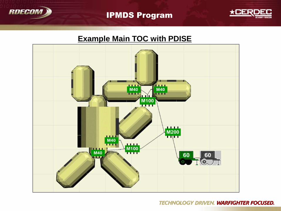
Example Main TOC with PDISE
IPMDS Program
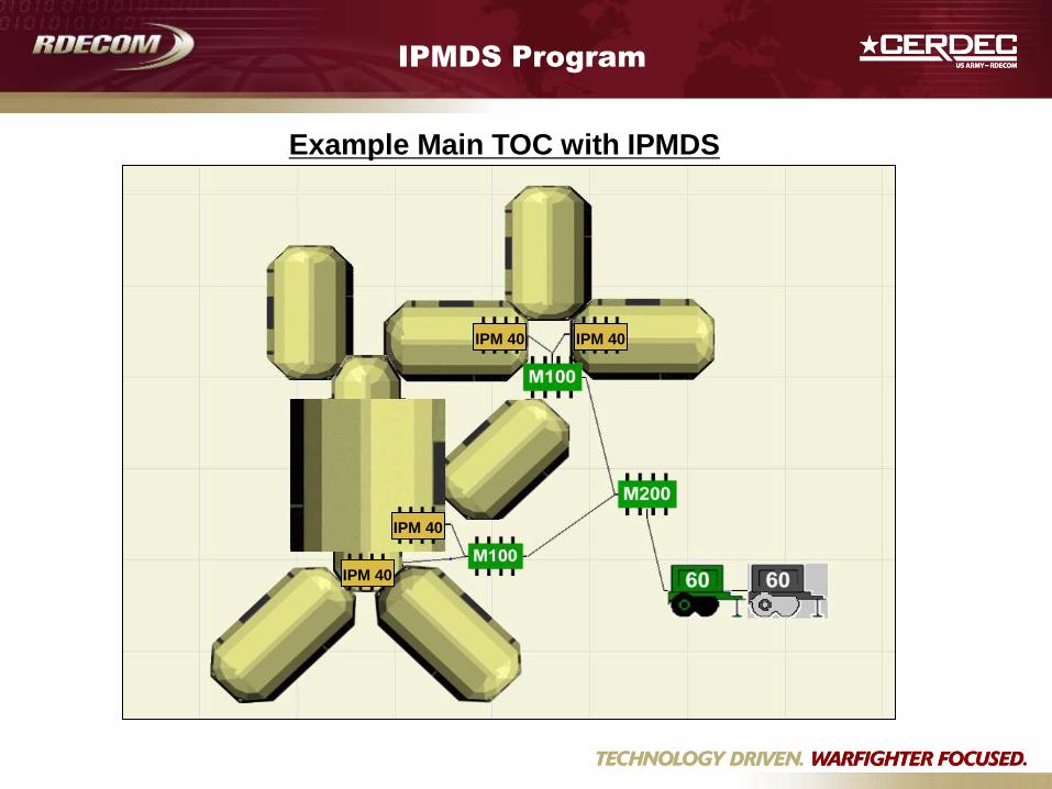
Example Main TOC with IPMDS
IPM 40 IPM 40
IPM 40
IPM 40
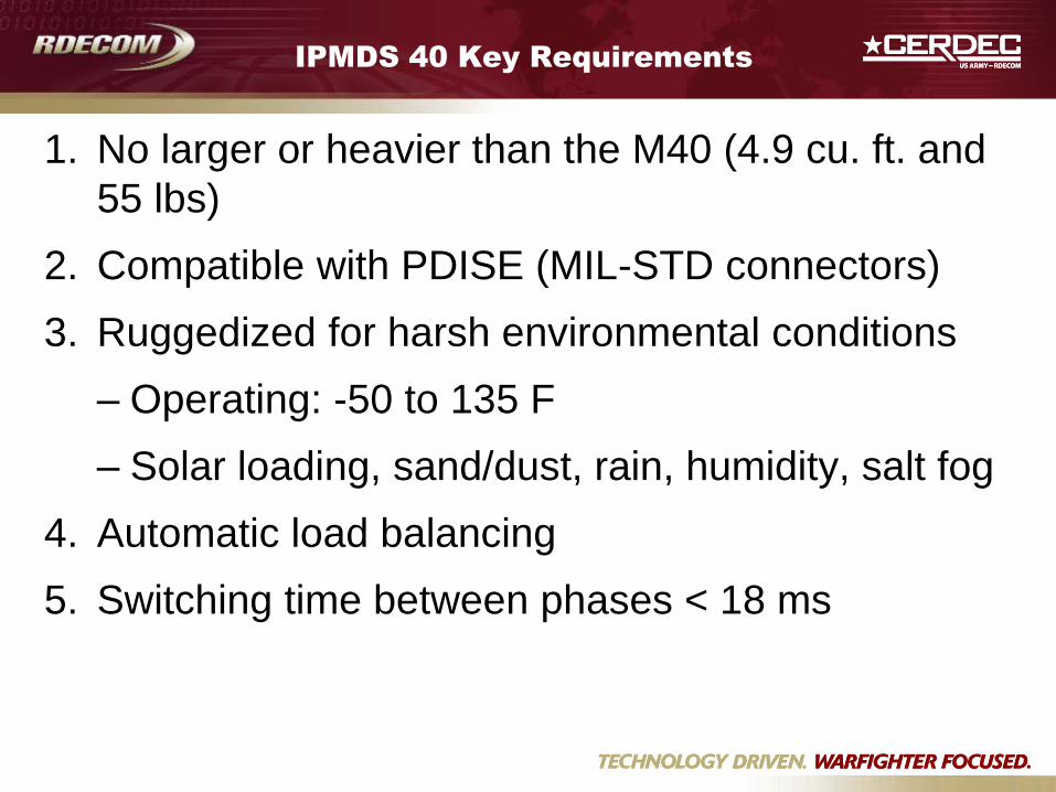
IPMDS 40 Key Requirements
1. No larger or heavier than the M40 (4.9 cu. ft. and
55 lbs)
2. Compatible with PDISE (MIL-STD connectors)
3. Ruggedized for harsh environmental conditions
– Operating: -50 to 135 F
– Solar loading, sand/dust, rain, humidity, salt fog
4. Automatic load balancing
5. Switching time between phases < 18 ms
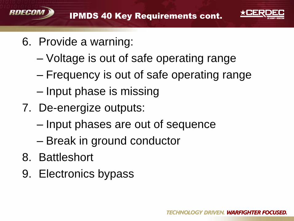
IPMDS 40 Key Requirements cont.
6. Provide a warning:
– Voltage is out of safe operating range
– Frequency is out of safe operating range
– Input phase is missing
7. De-energize outputs:
– Input phases are out of sequence
– Break in ground conductor
8. Battleshort
9. Electronics bypass
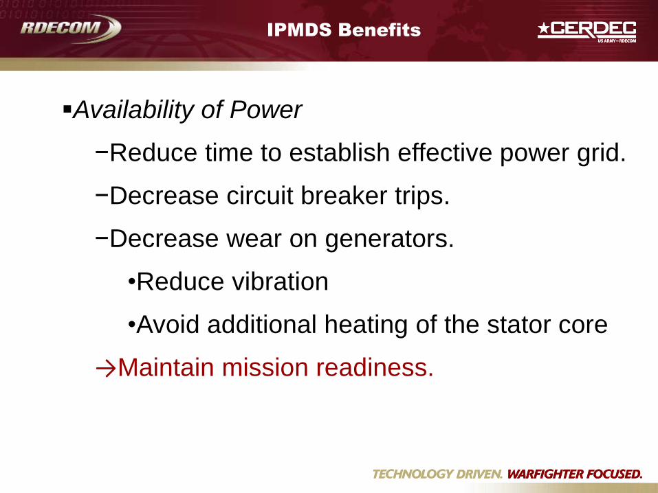
IPMDS Benefits
Availability of Power
−Reduce time to establish effective power grid.
−Decrease circuit breaker trips.
−Decrease wear on generators.
•Reduce vibration
•Avoid additional heating of the stator core
→Maintain mission readiness.
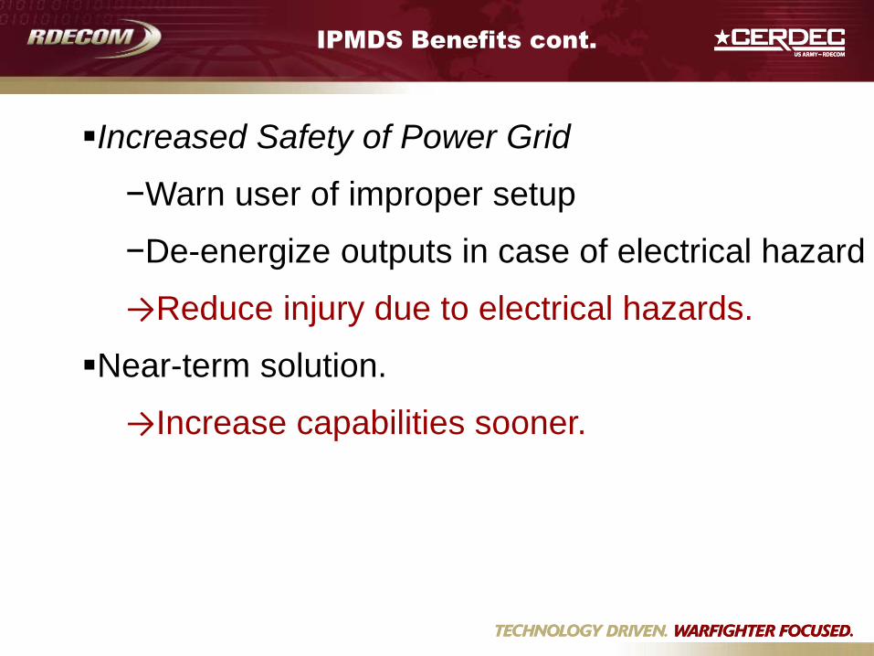
IPMDS Benefits cont.
Increased Safety of Power Grid
−Warn user of improper setup
−De-energize outputs in case of electrical hazard
→Reduce injury due to electrical hazards.
Near-term solution.
→Increase capabilities sooner.
Schedule
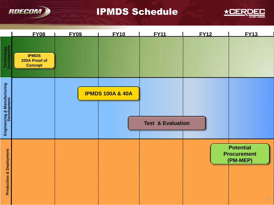
FY08 FY09 FY10 FY11 FY12
Tech
no
log
y
Dev
elo
pm
en
t
27
IPMDS
200A Proof of
Concept
IPMDS Schedule
En
gin
eeri
ng
& M
an
ufa
ctu
rin
g
Dev
elo
pm
en
t P
rod
ucti
on
& D
ep
loym
en
t
Test & Evaluation
IPMDS 100A & 40A
FY13
Potential
Procurement
(PM-MEP)