Embed Size (px)
Citation preview
Use of External Magnetic Fields To ReduceReaction Times in an Immunoassay UsingMicrometer-Sized Paramagnetic Particles asLabels (Magnetoimmunoassay)
Richard Luxton,† Jasvant Badesha,† Janice Kiely,‡ and Peter Hawkins*,†
Faculty of Applied Sciences, and Faculty of Computing, Engineering and Mathematical Sciences,University of the West of England, Bristol BS16 1QY, United Kingdom
The paper presents a rapid immunoassay system capableof quantifying analyte in complex biological and environ-mental media. Antibody-coated micrometer-sized para-magnetic particles are used as labels in an assay in whichthey bind quantitatively with an analyte and captureantibody molecules immobilized on a polyester disk toform a sandwich assay. The assay is performed in a simplereaction vessel, and reactions between labels, analyte, andantibodies are accelerated by positioning magnets alter-nately above and below the vessel. The bound paramag-netic particles are quantified using a simple flat, spiral,coil located just below the polyester disk. The electroniccircuitry associated with the coil uses components thatare inexpensive and readily available. The coil has beendesigned to respond only to particles bound on the diskand not to unbound particles still in the test solution.Unbound particles are pulled away from the disk by themagnet before readings are taken. The use of the reactionvessel with the cardiac markers CRP and CKMB isdescribed. No sample preparation or washing step is usedin the assays, and results can be obtained in less than 3min after introducing the sample into the vessel withsensitivities in the normal clinical range.
Immunoassays make use of the highly specific and sensitiveinteractions between antigens and their antibodies. Over the last30 years, they have found applications in many diverse areasincluding clinical chemistry1 and environmental monitoring.2 Thehigh specificity and sensitivity arises from the nature of theinteractions between the antigens, which are usually the analytemolecules, and their antibodies. With a few exceptions (such astechniques based on surface plasmon resonance,3 vibratingdevices,4 etc.), a label, reporter, or marker must be added if theinteractions between the antibodies and the antigens are to bequantified. Several different types of labels have been used in
immunoassays. Popular labels currently used include radioiso-topes, fluorescent and chemiluminescent molecules, enzymes,gold particles, and colored latex beads. Lateral flow or immuno-chromatographic assays are relatively simple immunoassay tech-niques using colored latex beads, an example of which is the verysuccessful Clear Blue one-step pregnancy test originally developedby Unilever. It is also an example of a device that with no samplepreparation can produce the result of an analysis in a few minuteswithout the intervention of a skilled operator. There is a require-ment for more such devices for use in the field in environmentalmonitoring or for rapid diagnostics such as point-of-care testing.However, simple lateral flow devices are restricted to applicationswhere it is only necessary to determine whether the concentrationof the analyte is above or below a threshold value. If morequantitative measurements are required, then elaborate measuringequipment has to be used, usually with different markers, andthis adds considerably to the complexity of the technique. Anexample of this is a lateral flow system for C-reactive protein(CRP),5 which uses a fluorescent label and a laser system to scanthe strips at the end of the assay. Other techniques, such as theenzyme-linked immunosorbent assay, cannot be readily adaptedinto rapid, portable, systems as they involve many time-consumingsteps (sample separation, washing, and incubation) and methodsusing luminescent labels need optically pure test solutions toreduce light absorption, scattering, and fluorescence quenchingeffects. Washing steps are necessary to remove excess, unreacted(free) label and other unwanted components in the sample (freeproteins, excess antibody, etc.) that are likely to interfere in thedetermination of the amount of bound label in the immunoassay.Coated paramagnetic particles (PMPs) are currently used in thepurification and isolation of antibodies, antigens, and other proteinsand more recently in immunoassays where they serve to isolatethe target antigen within the interacting molecules. PMPs areavailable in a range of different diameters (typically, 0.1-20 µm)from several different suppliers. They have a paramagnetic core(usually iron oxide) with a suitable coating to which captureantibody molecules are attached. In a typical automated system,6
an excess of the coated PMPs is introduced into a test solution
* Corresponding author. E-mail: [email protected]. Fax: ++44 117 3282904.
† Faculty of Applied Sciences.‡ Faculty of Computing, Engineering and Mathematical Sciences.
(1) Anderson, D. J.; Guo, B.; Xu, Y.; Ng L. M.; Kricka, L. J.; Skogerboe, K. J.;Hage, D. S.; Schoeff, L.; Wang, J.; Sokoll, L. J.; Chan, D. W.; Ward, K. M.;Davis, K. A. Anal. Chem. 1997, 69, 165R-229R.
(2) Richardson, S. D. Anal. Chem. 2003, 75, 2831-2857.(3) Mullett, W. M.; Lai, E. P. C.; Yeung, J. M. Methods 2000, 22, 77-91.
(4) Benes, E.; Groschl, M.; Burger, W.; Schmid, M. Sens. Actuators, A 1995,48, 1-21.
(5) Ahn, J. S.; Choi S.; Jang, S. H.; Chang, H. J.; Kim, J. H.; Nahm, K. B.; Oh,S. W.; Choi, E. Y. Clin. Chim. Acta 2003, 332, 51-59.
Anal. Chem. 2004, 76, 1715-1719
10.1021/ac034906+ CCC: $27.50 © 2004 American Chemical Society Analytical Chemistry, Vol. 76, No. 6, March 15, 2004 1715Published on Web 02/07/2004
containing a mixture of the target antigens (analyte) and otherspecies. Eventually, the antigens become attached to the antibod-ies on the PMPs. At this, or a later stage, an excess of theappropriately labeled secondary antibody (detecting antibody) isintroduced into the test solution, which then reacts with the targetantigen (analyte) on the PMPs. The PMPs with their attachmentscan be easily drawn to one side of the reaction vessel and heldthere by an external magnet while the remaining test solution isflushed away and replaced with clean buffer solution. The PMPsare resuspended in the buffer solution and the quantity of boundlabel determined using a technique appropriate for the label.Although the PMPs help to simplify the extraction and washingprocesses, several steps might still be required, which add to thetotal time for a complete assay. Another problem is that expensiveequipment is usually required to determine the amount of boundlabel (such as photon-counting equipment for luminescent labels,radiation-counting equipment for radioactive labels, etc.). Inprevious papers, we have described an immunoassay system thatuses the PMPs as the labels, so no additional label is required,7
and a simple magnetometer to determine the quantity of boundPMP labels.8 In this paper, this work is developed further and wedescribe a simple reaction vessel that uses two external magnetsto speed up the reactions between the antigens and the antibodiesgiving rise to a rapid measuring system requiring no samplepreparation or washing stages. The use of the system with theclinically important molecules, CRP and creatine kinase isoenzymeMB fraction (CKMB) is described.
METHODIn our earlier papers,7,8 we described a sandwich immunoassay
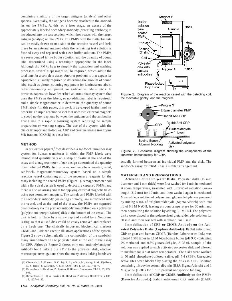
system for human transferrin in which the PMP labels wereimmobilized quantitatively on a strip of plastic at the end of theassay and a magnetometer of our design determined the quantityof immobilized PMPs. In this paper, we describe a one-step, rapid,sandwich, magnetoimmunoassay system based on a simplereaction vessel containing all of the necessary reagents for theassay including the coated PMPs (Figure 1). A magnetometer coilwith a flat spiral design is used to detect the captured PMPs, andthere is also an arrangement for applying external magnetic fieldsusing two permanent magnets. The sample and PMPs labeled withthe secondary antibody (detecting antibody) are introduced intothe vessel, and at the end of the assay, the PMPs are capturedquantitatively via the primary antibody immobilized on a polyester(poly(ethene terephthalate)) disk at the bottom of the vessel. Thedisk is held in place by a screw cap and sealed by a NeopreneO-ring so that a used disk could be easily removed and replacedby a fresh one. The clinically important biochemical markersCKMB and CRP are used to illustrate applications of the system.Figure 2 shows schematically the composition of the sandwichassay immobilized on the polyester disk at the end of the assayfor CRP. Although Figure 2 shows only one antibody/antigen/antibody bond linking the PMP to the polyester disk, electronmicroscope investigations show that many cross-linking bonds are
actually formed between an individual PMP and the disk. Thesandwich assay for CKMB has a similar arrangement.
MATERIALS AND PREPARATIONSActivation of the Polyester Disks. Polyester disks (15 mm
diameter and 1 mm thick) were first washed for 1 min in methanolat room temperature, irradiated with ultraviolet radiation (wave-length, 312 nm) for 10 min, and then washed again in methanol.Meanwhile, a solution of polymerized glutaraldehyde was preparedby mixing 5 mL of 5% glutaraldehyde (Sigma-Aldrich) with 500µL of 0.1 M NaOH, leaving at room temperature for 30 min, andthen neutralizing the solution by adding 0.1 M HCl. The polyesterdisks were placed in the polymerized glutaraldehyde solution for30 min and then washed with methanol for 1 min.
Immobilization of CRP or CKMB Antibody on the Acti-vated Polyester Disks (Capture Antibody). Rabbit anti-humanCRP or goat anti-human CKMB (Randox Laboratories Ltd.) wasdiluted 1:500 times in 0.1 M bicarbonate buffer (pH 9.7) containing2% methanol and 0.5% glutaraldehyde. A 35-µL sample of thesolution was applied to each activated polyester disk and allowedto incubate for 4 h at room temperature. The disks were washedin 50 mM phosphate-buffered saline, pH 7.4 (PBS). Unreactedactive sites were blocked by placing the disks in a PBS solutioncontaining 1% bovine serum albumin (BSA; Sigma-Aldrich) and 1M glycine (BDH) for 1 h to prevent nonspecific binding.
Immobilization of CRP or CKMB Antibody on the PMPs(Detector Antibody). Rabbit anti-human CRP antibody (DAKO
(6) Clements, J. A.; Forrest, G. C.; Jay, R. F.; Jeffery, M.; Kemp, P. M.; Kjeldsen,N. J.; Rattle, S. J.; Smith, A. Clin. Chem. 1992, 38, 1671-1677.
(7) Richardson, J.; Hawkins, P.; Luxton, R. Biosens. Bioelectron. 2001, 16, 989-993.
(8) Richardson, J.; Hill. A.; Luxton, R.; Hawkins, P. Biosens. Bioelectron. 2001,16, 1127-1132.
Figure 1. Diagram of the reaction vessel with the detecting coil,the moveable gantry, and the magnets.
Figure 2. Schematic diagram showing the components of thesandwich immunoassay for CRP.
1716 Analytical Chemistry, Vol. 76, No. 6, March 15, 2004
A/S) or monoclonal anti-human CKMB antibody (Randox Labo-ratories Ltd.) was diluted 1:1000 times in 0.1 M phosphate buffer(pH 8.1). A 10-µL sample of the PMPs (protein G-coated 2.8-µm-diameter Dynabead M-280 from Dynal UK Ltd.) was washed 3times in phosphate buffer. It was then mixed with 30 µL of theappropriate antibody solution and incubated for 10 min at roomtemperature in a slowly rotating sample mixer (Dynal UK Ltd.).The PMPs were washed 3 times in phosphate buffer before beingresuspended in 20 mM dimethyl pimelimidate (Sigma-Aldich) andincubated at room temperature with rotational mixing for 30 minto promote cross-linking. The reaction was stopped by suspendingthe PMPs in 50 mM tris(hydroxymethyl)aminoethane buffer (pH7.3). Unoccupied sites on the PMPs were blocked using PBS/BSA as described earlier.
Standards of CRP and CKMB in Serum. Standards wereprepared by diluting stock solutions of human CRP in serum (160µg/mL, DAKO A/S) and human CKMB in serum (10 µg/mL,Randox Laboratories Ltd.) in PBS/BSA to give a range of solutionswith known concentrations.
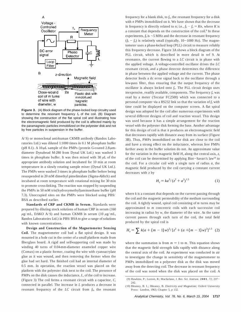
Design and Construction of the Magnetometer SensingCoil. The magnetometer coil had a flat spiral design. It wasmounted in a hole cut in the center of a small platform made fromfiberglass board. A rigid and self-supporting coil was made bywinding 40 turns of 0.04-mm-diameter enameled copper wire(Comax) on a plastic former, coating the wire with cyanoacrylateglue as it was wound, and then removing the former when theglue had set hard. The finished coil had an internal diameter of0.5 mm. In operation, the reaction vessel was placed on theplatform with the polyester disk next to the coil. The presence ofPMPs on the disk causes the inductance, L, of the coil to increase.(Figure 3) The coil forms a resonant circuit with a capacitor, C,connected in parallel. The increase in L produces a decrease inresonant frequency of the LC circuit from f0, the resonant
frequency for a blank disk, to fn, the resonant frequency for a diskwith n PMPs immobilized on it. We have shown that the decreasein frequency is directly related to n; i.e., f0 - fn ) Kn, where K isa constant that depends on the construction of the coil.9 In theseexperiments, f0 is ∼5 MHz and the decrease in resonant frequency(f0 - fn) is relatively small (typically, 10-1000 Hz). The magne-tometer uses a phase-locked loop (PLL) circuit to measure reliablythis frequency decrease. Figure 3A shows a block diagram of thePLL circuit, which is described in more detail in ref 9. Atresonance, the current flowing to a LC circuit is in phase withthe applied voltage. A voltage-controlled oscillator drives the LCresonant circuit, and a phase detector determines the differencein phase between the applied voltage and the current. The phasedetector feeds a dc error signal back to the oscillator through alow-pass filter, thus ensuring that the output frequency of theoscillator is always locked onto fn. The PLL circuit design usesinexpensive, readily available, components. The frequency fn wasread by a meter (Tecstar FC2500) which was connected to apersonal computer via a RS232 link so that the variation of fn withtime could be displayed on the computer screen. A flat spiraldesign was adopted for the coil after numerous experiments withseveral different designs of coil and reaction vessel. This designwas used because it has a simple arrangement for the reactionvessel with the polyester disk forming the base. Another advantagefor this design of coil is that it produces an electromagnetic fieldthat decreases rapidly with distance away from its surface (Figure3B). Thus, PMPs immobilized on the disk are close to the coiland have a strong effect on the inductance, whereas free PMPsfurther away in the buffer solution do not. An approximate valuefor the variation in the magnetic field Hz along the central axis, z,of the coil can be determined by applying Biot-Savart’s law10 tothe coil. For a circular coil with a single turn of radius a, themagnetic field produced by the coil carrying a constant currentdecreases with z by
where k is a constant that depends on the current passing throughthe coil and the magnetic permeability of the medium surroundingthe coil. A tightly wound, spiral coil consisting of m turns may beapproximated to m concentric coils with each successive coilincreasing in radius by w, the diameter of the wire. As the samecurrent passes through each turn of the coil, the total fieldproduced by the spiral coil is
where the summation is from m ) 1 to m. This equation showsthat the magnetic field strength falls rapidly with distance alongthe central axis of the coil. An experiment was conducted in airto investigate the change in sensitivity of the magnetometer toPMPs immobilized on a polyester disk as the disk was movedaway from the detecting coil. The decrease in resonant frequencyof the coil was noted when the disk was placed on the coil. A
(9) Hawkins, P.; Luxton, R.; Macfarlane, J. Rev. Sci. Instrum. 2001, 72, 237-242.
(10) Bleaney, B. I..; Bleaney, B. Electricity and Magnetism; Oxford UniversityPress: London, 1963; Chapter 5, p 132.
Figure 3. (A) Block diagram of the phase-locked loop circuitry usedto determine the resonant frequency fn of the coil. (B) Diagramshowing the construction of the flat spiral coil and illustrating howthe electromagnetic field produced by the coil is affected mainly bythe paramagnetic particles immobilized on the polyester disk and notby free particles in suspension in the buffer.
Hz ) ka2/(z2 + a2)1.5 (1)
Hz ) ∑ k(a + {m - 1}w)2/[z2 + (a +{m - 1}w)2]1.5 (2)
Analytical Chemistry, Vol. 76, No. 6, March 15, 2004 1717
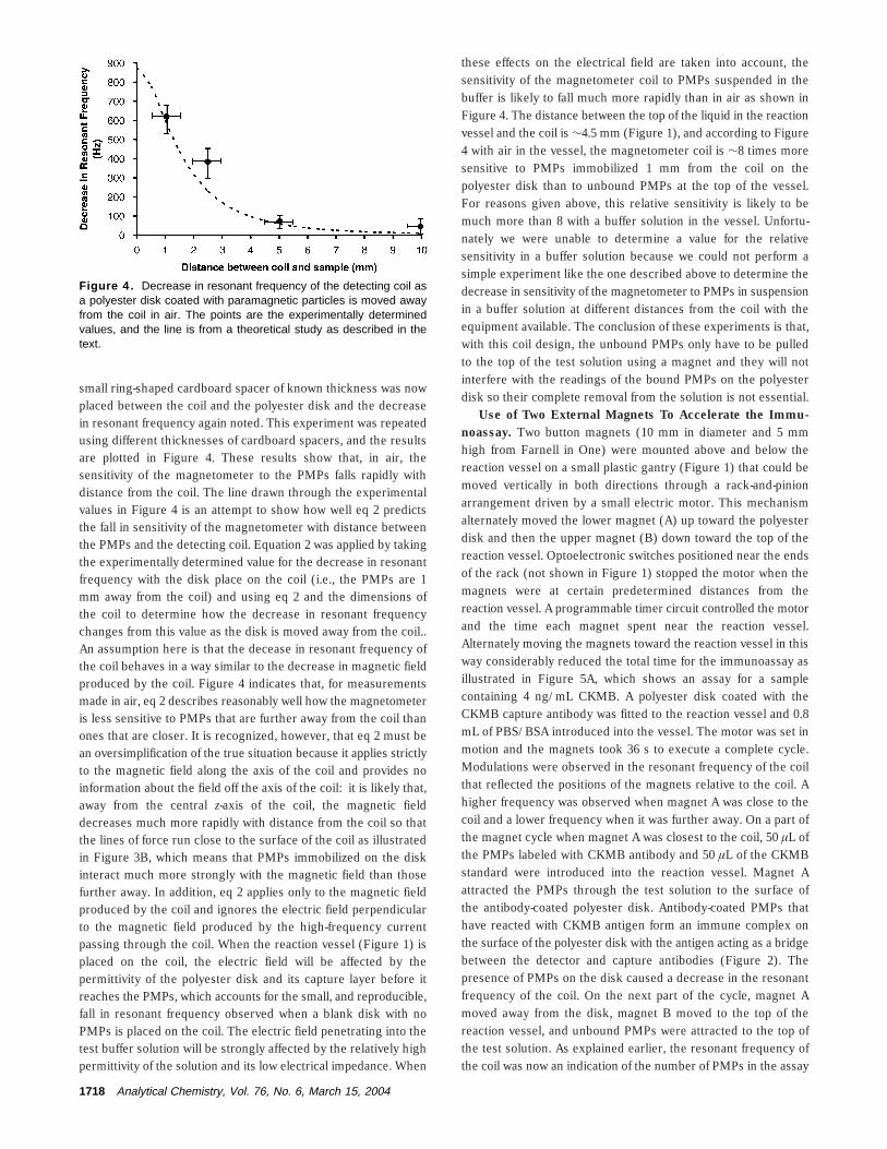
small ring-shaped cardboard spacer of known thickness was nowplaced between the coil and the polyester disk and the decreasein resonant frequency again noted. This experiment was repeatedusing different thicknesses of cardboard spacers, and the resultsare plotted in Figure 4. These results show that, in air, thesensitivity of the magnetometer to the PMPs falls rapidly withdistance from the coil. The line drawn through the experimentalvalues in Figure 4 is an attempt to show how well eq 2 predictsthe fall in sensitivity of the magnetometer with distance betweenthe PMPs and the detecting coil. Equation 2 was applied by takingthe experimentally determined value for the decrease in resonantfrequency with the disk place on the coil (i.e., the PMPs are 1mm away from the coil) and using eq 2 and the dimensions ofthe coil to determine how the decrease in resonant frequencychanges from this value as the disk is moved away from the coil..An assumption here is that the decease in resonant frequency ofthe coil behaves in a way similar to the decrease in magnetic fieldproduced by the coil. Figure 4 indicates that, for measurementsmade in air, eq 2 describes reasonably well how the magnetometeris less sensitive to PMPs that are further away from the coil thanones that are closer. It is recognized, however, that eq 2 must bean oversimplification of the true situation because it applies strictlyto the magnetic field along the axis of the coil and provides noinformation about the field off the axis of the coil: it is likely that,away from the central z-axis of the coil, the magnetic fielddecreases much more rapidly with distance from the coil so thatthe lines of force run close to the surface of the coil as illustratedin Figure 3B, which means that PMPs immobilized on the diskinteract much more strongly with the magnetic field than thosefurther away. In addition, eq 2 applies only to the magnetic fieldproduced by the coil and ignores the electric field perpendicularto the magnetic field produced by the high-frequency currentpassing through the coil. When the reaction vessel (Figure 1) isplaced on the coil, the electric field will be affected by thepermittivity of the polyester disk and its capture layer before itreaches the PMPs, which accounts for the small, and reproducible,fall in resonant frequency observed when a blank disk with noPMPs is placed on the coil. The electric field penetrating into thetest buffer solution will be strongly affected by the relatively highpermittivity of the solution and its low electrical impedance. When
these effects on the electrical field are taken into account, thesensitivity of the magnetometer coil to PMPs suspended in thebuffer is likely to fall much more rapidly than in air as shown inFigure 4. The distance between the top of the liquid in the reactionvessel and the coil is ∼4.5 mm (Figure 1), and according to Figure4 with air in the vessel, the magnetometer coil is ∼8 times moresensitive to PMPs immobilized 1 mm from the coil on thepolyester disk than to unbound PMPs at the top of the vessel.For reasons given above, this relative sensitivity is likely to bemuch more than 8 with a buffer solution in the vessel. Unfortu-nately we were unable to determine a value for the relativesensitivity in a buffer solution because we could not perform asimple experiment like the one described above to determine thedecrease in sensitivity of the magnetometer to PMPs in suspensionin a buffer solution at different distances from the coil with theequipment available. The conclusion of these experiments is that,with this coil design, the unbound PMPs only have to be pulledto the top of the test solution using a magnet and they will notinterfere with the readings of the bound PMPs on the polyesterdisk so their complete removal from the solution is not essential.
Use of Two External Magnets To Accelerate the Immu-noassay. Two button magnets (10 mm in diameter and 5 mmhigh from Farnell in One) were mounted above and below thereaction vessel on a small plastic gantry (Figure 1) that could bemoved vertically in both directions through a rack-and-pinionarrangement driven by a small electric motor. This mechanismalternately moved the lower magnet (A) up toward the polyesterdisk and then the upper magnet (B) down toward the top of thereaction vessel. Optoelectronic switches positioned near the endsof the rack (not shown in Figure 1) stopped the motor when themagnets were at certain predetermined distances from thereaction vessel. A programmable timer circuit controlled the motorand the time each magnet spent near the reaction vessel.Alternately moving the magnets toward the reaction vessel in thisway considerably reduced the total time for the immunoassay asillustrated in Figure 5A, which shows an assay for a samplecontaining 4 ng/mL CKMB. A polyester disk coated with theCKMB capture antibody was fitted to the reaction vessel and 0.8mL of PBS/BSA introduced into the vessel. The motor was set inmotion and the magnets took 36 s to execute a complete cycle.Modulations were observed in the resonant frequency of the coilthat reflected the positions of the magnets relative to the coil. Ahigher frequency was observed when magnet A was close to thecoil and a lower frequency when it was further away. On a part ofthe magnet cycle when magnet A was closest to the coil, 50 µL ofthe PMPs labeled with CKMB antibody and 50 µL of the CKMBstandard were introduced into the reaction vessel. Magnet Aattracted the PMPs through the test solution to the surface ofthe antibody-coated polyester disk. Antibody-coated PMPs thathave reacted with CKMB antigen form an immune complex onthe surface of the polyester disk with the antigen acting as a bridgebetween the detector and capture antibodies (Figure 2). Thepresence of PMPs on the disk caused a decrease in the resonantfrequency of the coil. On the next part of the cycle, magnet Amoved away from the disk, magnet B moved to the top of thereaction vessel, and unbound PMPs were attracted to the top ofthe test solution. As explained earlier, the resonant frequency ofthe coil was now an indication of the number of PMPs in the assay
Figure 4. Decrease in resonant frequency of the detecting coil asa polyester disk coated with paramagnetic particles is moved awayfrom the coil in air. The points are the experimentally determinedvalues, and the line is from a theoretical study as described in thetext.
1718 Analytical Chemistry, Vol. 76, No. 6, March 15, 2004
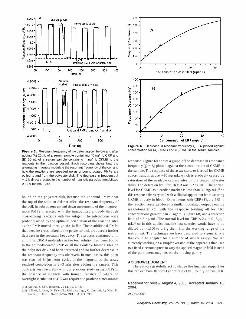
bound on the polyester disk, because the unbound PMPs nearthe top of the solution did not affect the resonant frequency ofthe coil. In subsequent up and down movements of the magnets,more PMPs interacted with the immobilized antibody throughcross-linking reactions with the antigen. The interactions wereprobably aided by the optimum orientation of the reacting sitesas the PMP moved through the buffer. These additional PMPsthat became cross-linked to the polyester disk produced a furtherdecrease in the resonant frequency. The process continued untilall of the CKMB molecules in the test solution had been boundto the antibody-coated PMP or all the available binding sites onthe polyester disk had been saturated and no further decrease inthe resonant frequency was observed. In most cases, this pointwas reached in just four cycles of the magnets, so the assayreached completion in 2-3 min after adding the sample. Thiscontrasts very favorably with our previous study using PMPs inthe absence of magnets with human transferrin,7 where anovernight incubation at 4°C was required to produce a measurable
response. Figure 6A shows a graph of the decrease in resonancefrequency (f0 - fn) plotted against the concentration of CKMB inthe sample. The response of the assay starts to level off for CKMBconcentrations above ∼10 ng/mL, which is probably caused bysaturation of the available capture sites on the coated polyesterdisks. The detection limit for CKMB was ∼2 ng/mL. The normallevel for CKMB as a cardiac marker is less than 3.5 ng/mL,11 sothis response fits very well with a clinical application for measuringCKMB directly in blood. Experiments with CRP (Figure 5B) inthe reaction vessel produced a similar modulated output from themagnetometer coil with the response leveling off for CRPconcentrations greater than 20 ng/mL (Figure 6B) and a detectionlimit of ∼3 ng/mL. The normal level for CRP is 2.4 ( 0.18 µg/mL,12 so in this application, the test samples would have to bediluted by ∼1:100 to bring them into the working range of theinstrument. The technique we have described is a generic onethat could be adapted for a number of similar assays. We arecurrently working on a simpler version of the apparatus that usestwo fixed electromagnets to vary the applied magnetic field insteadof the permanent magnets on the moving gantry.
ACKNOWLEDGMENTThe authors gratefully acknowledge the financial support for
this project from Randox Laboratories Ltd., County Antrim, U.K.
Received for review August 4, 2003. Accepted January 13,2004.
AC034906+
(11) Agewall, S. Clin. Biochem. 2003, 36, 27-30.(12) Golbasi, Z.; Ucar, O.; Keles, T.; Sahin, A.; Cagli, K.; Camsari, A.; Diker, E.;
Aydodu, S. Eur. J. Heart Failure 2003, 4, 593-595.
Figure 5. Resonant frequency of the detecting coil before and afteradding (A) 20 µL of a serum sample containing 40 ng/mL CRP and(B) 50 µL of a serum sample containing 4 ng/mL CKMB to thereagents in the reaction vessel. Each recording shows how thealternating magnets modulate the resonant frequency of the coil andhow the reactions are speeded up as unbound coated PMPs arepulled to and from the polyester disk. The decrease in frequency f0- fn is directly related to the number of magnetic particles immobilizedon the polymer disk.
Figure 6. Decrease in resonant frequency f0 - fn plotted againstconcentration for (A) CKMB and (B) CRP in the serum samples.
Analytical Chemistry, Vol. 76, No. 6, March 15, 2004 1719