Embed Size (px)
Citation preview
Autodesk Navisworks Freedom 2011
User Guide
March 2010
© 2010 Autodesk, Inc. All Rights Reserved. Except as otherwise permitted by Autodesk, Inc., this publication, or parts thereof, may not bereproduced in any form, by any method, for any purpose. Certain materials included in this publication are reprinted with the permission of the copyright holder. TrademarksThe following are registered trademarks or trademarks of Autodesk, Inc., and/or its subsidiaries and/or affiliates in the USA and other countries:3DEC (design/logo), 3December, 3December.com, 3ds Max, Algor, Alias, Alias (swirl design/logo), AliasStudio, Alias|Wavefront (design/logo),ATC, AUGI, AutoCAD, AutoCAD Learning Assistance, AutoCAD LT, AutoCAD Simulator, AutoCAD SQL Extension, AutoCAD SQL Interface,Autodesk, Autodesk Envision, Autodesk Intent, Autodesk Inventor, Autodesk Map, Autodesk MapGuide, Autodesk Streamline, AutoLISP, AutoSnap,AutoSketch, AutoTrack, Backburner, Backdraft, Built with ObjectARX (logo), Burn, Buzzsaw, CAiCE, Civil 3D, Cleaner, Cleaner Central, ClearScale,Colour Warper, Combustion, Communication Specification, Constructware, Content Explorer, Dancing Baby (image), DesignCenter, DesignDoctor, Designer's Toolkit, DesignKids, DesignProf, DesignServer, DesignStudio, Design Web Format, Discreet, DWF, DWG, DWG (logo), DWGExtreme, DWG TrueConvert, DWG TrueView, DXF, Ecotect, Exposure, Extending the Design Team, Face Robot, FBX, Fempro, Fire, Flame, Flare,Flint, FMDesktop, Freewheel, GDX Driver, Green Building Studio, Heads-up Design, Heidi, HumanIK, IDEA Server, i-drop, ImageModeler, iMOUT,Incinerator, Inferno, Inventor, Inventor LT, Kaydara, Kaydara (design/logo), Kynapse, Kynogon, LandXplorer, Lustre, MatchMover, Maya,Mechanical Desktop, Moldflow, Moonbox, MotionBuilder, Movimento, MPA, MPA (design/logo), Moldflow Plastics Advisers, MPI, MoldflowPlastics Insight, MPX, MPX (design/logo), Moldflow Plastics Xpert, Mudbox, Multi-Master Editing, Navisworks, ObjectARX, ObjectDBX, OpenReality, Opticore, Opticore Opus, Pipeplus, PolarSnap, PortfolioWall, Powered with Autodesk Technology, Productstream, ProjectPoint, ProMaterials,RasterDWG, RealDWG, Real-time Roto, Recognize, Render Queue, Retimer,Reveal, Revit, Showcase, ShowMotion, SketchBook, Smoke, Softimage,Softimage|XSI (design/logo), Sparks, SteeringWheels, Stitcher, Stone, StudioTools, ToolClip, Topobase, Toxik, TrustedDWG, ViewCube, Visual,Visual LISP, Volo, Vtour, Wire, Wiretap, WiretapCentral, XSI, and XSI (design/logo). LightWorks, the LightWorks logo, LWA and LWA-Enabled are registered trademarks of LightWork Design Ltd. The LWA-Enabled logo, InteractiveImage Regeneration, IIR, A-Cubed, Feature-Following Anti-Aliasing and FFAA are all trademarks of LightWork Design Ltd. All other trademarks,images and logos remain the property of their respective owners. Copyright of LightWork Design Ltd. 1990-2007, 2008.This software is based in part on the work of the Independent JPEG Group.Contains a modified version of Open CASCADE libraries. See the license file "OpenCascadeLicense.txt" in the Navisworks installation directory.Source code is available from download.autodesk.com/us/navisworks/OpenCascade.zip.DisclaimerTHIS PUBLICATION AND THE INFORMATION CONTAINED HEREIN IS MADE AVAILABLE BY AUTODESK, INC. "AS IS." AUTODESK, INC. DISCLAIMSALL WARRANTIES, EITHER EXPRESS OR IMPLIED, INCLUDING BUT NOT LIMITED TO ANY IMPLIED WARRANTIES OF MERCHANTABILITY ORFITNESS FOR A PARTICULAR PURPOSE REGARDING THESE MATERIALS. This User Guide was last updated on 12 February 2010.
Contents
Welcome to Autodesk Navisworks Freedom 2011 . . . . . . . . . . . . . . . . . . . . . 1
Chapter 1 What Is New in This Release? . . . . . . . . . . . . . . . . . . . . . . . . . . . . . . . . . . . . 3
Chapter 2 How to Get Assistance . . . . . . . . . . . . . . . . . . . . . . . . . . . . . . . . . . . . . . . . 5Finding Information Using the InfoCenter . . . . . . . . . . . . . . . . . . . . . . . . . . . . . . . . . . . 5
Overview of InfoCenter . . . . . . . . . . . . . . . . . . . . . . . . . . . . . . . . . . . . . . . . . . 5Search for Information . . . . . . . . . . . . . . . . . . . . . . . . . . . . . . . . . . . . . . . . . . 6Access Subscription Center . . . . . . . . . . . . . . . . . . . . . . . . . . . . . . . . . . . . . . . . 7Use Communication Center . . . . . . . . . . . . . . . . . . . . . . . . . . . . . . . . . . . . . . . . 8Save and Access Favorite Topics . . . . . . . . . . . . . . . . . . . . . . . . . . . . . . . . . . . . . . 9Use the Help System . . . . . . . . . . . . . . . . . . . . . . . . . . . . . . . . . . . . . . . . . . . 10Specify InfoCenter Settings . . . . . . . . . . . . . . . . . . . . . . . . . . . . . . . . . . . . . . . . 13
Get More Help . . . . . . . . . . . . . . . . . . . . . . . . . . . . . . . . . . . . . . . . . . . . . . . . . 15View the Product Readme . . . . . . . . . . . . . . . . . . . . . . . . . . . . . . . . . . . . . . . . . . . 16Join the Customer Involvement Program . . . . . . . . . . . . . . . . . . . . . . . . . . . . . . . . . . . 16
Chapter 3 Installation . . . . . . . . . . . . . . . . . . . . . . . . . . . . . . . . . . . . . . . . . . . . . 17Quick Start to Stand-Alone Installation . . . . . . . . . . . . . . . . . . . . . . . . . . . . . . . . . . . . 17
Prepare for Installation . . . . . . . . . . . . . . . . . . . . . . . . . . . . . . . . . . . . . . . . . . 17System Requirements for Stand-Alone Installation . . . . . . . . . . . . . . . . . . . . . . . . 17Understand Administrative Permission Requirements . . . . . . . . . . . . . . . . . . . . . . 19Avoid Data Loss During Installation . . . . . . . . . . . . . . . . . . . . . . . . . . . . . . . . 19Choose a Language . . . . . . . . . . . . . . . . . . . . . . . . . . . . . . . . . . . . . . . . . 19Configure Button . . . . . . . . . . . . . . . . . . . . . . . . . . . . . . . . . . . . . . . . . . 20Install Multiple or Bundled Products . . . . . . . . . . . . . . . . . . . . . . . . . . . . . . . 20
Install and Run Autodesk Navisworks Freedom 2011 . . . . . . . . . . . . . . . . . . . . . . . . . . 20Install Autodesk Navisworks . . . . . . . . . . . . . . . . . . . . . . . . . . . . . . . . . . . . 20Launch Autodesk Navisworks . . . . . . . . . . . . . . . . . . . . . . . . . . . . . . . . . . . 23How to Launch Autodesk Navisworks in Another Language . . . . . . . . . . . . . . . . . . . 23Repair Autodesk Navisworks Freedom 2011 . . . . . . . . . . . . . . . . . . . . . . . . . . . . 24Uninstall Autodesk Autodesk Navisworks Freedom 2011 . . . . . . . . . . . . . . . . . . . . . 24
Installation Troubleshooting . . . . . . . . . . . . . . . . . . . . . . . . . . . . . . . . . . . . . . . . . . 25General Installation Issues . . . . . . . . . . . . . . . . . . . . . . . . . . . . . . . . . . . . . . . . 25
How can I check my graphics card driver to see if it needs to be updated? . . . . . . . . . . . . 25When performing a Typical installation, what gets installed? . . . . . . . . . . . . . . . . . . 26Why should I specify the Project Folder and Site Folder? . . . . . . . . . . . . . . . . . . . . . 26How do I share the Autodesk Navisworks settings on a site and project basis? . . . . . . . . . . 26Where are my product manuals? . . . . . . . . . . . . . . . . . . . . . . . . . . . . . . . . . 27
Uninstall and Maintenance Issues . . . . . . . . . . . . . . . . . . . . . . . . . . . . . . . . . . . . 27
Contents | iii
When should I reinstall the product instead of a repair? . . . . . . . . . . . . . . . . . . . . . 27Do I need my original DVD to reinstall my software? . . . . . . . . . . . . . . . . . . . . . . . 27When I uninstall my software, what files are left on my system? . . . . . . . . . . . . . . . . . 28
Chapter 4 Quick Start . . . . . . . . . . . . . . . . . . . . . . . . . . . . . . . . . . . . . . . . . . . . . 29Start and Quit Autodesk Navisworks . . . . . . . . . . . . . . . . . . . . . . . . . . . . . . . . . . . . . . 29The User Interface . . . . . . . . . . . . . . . . . . . . . . . . . . . . . . . . . . . . . . . . . . . . . . . 29
Parts of Autodesk Navisworks Interface . . . . . . . . . . . . . . . . . . . . . . . . . . . . . . . . . 29Application Button and Menu . . . . . . . . . . . . . . . . . . . . . . . . . . . . . . . . . . . 30Quick Access Toolbar . . . . . . . . . . . . . . . . . . . . . . . . . . . . . . . . . . . . . . . . 33Ribbon . . . . . . . . . . . . . . . . . . . . . . . . . . . . . . . . . . . . . . . . . . . . . . . 34Tooltips . . . . . . . . . . . . . . . . . . . . . . . . . . . . . . . . . . . . . . . . . . . . . . . 37Keytips . . . . . . . . . . . . . . . . . . . . . . . . . . . . . . . . . . . . . . . . . . . . . . . 38Navigation Tools . . . . . . . . . . . . . . . . . . . . . . . . . . . . . . . . . . . . . . . . . . 38The Classic User Interface . . . . . . . . . . . . . . . . . . . . . . . . . . . . . . . . . . . . . 38Scene View . . . . . . . . . . . . . . . . . . . . . . . . . . . . . . . . . . . . . . . . . . . . . 45Dockable Windows . . . . . . . . . . . . . . . . . . . . . . . . . . . . . . . . . . . . . . . . . 47Status Bar . . . . . . . . . . . . . . . . . . . . . . . . . . . . . . . . . . . . . . . . . . . . . . 50
Undo/Redo Commands . . . . . . . . . . . . . . . . . . . . . . . . . . . . . . . . . . . . . . . . . 51Autodesk Navisworks Workspaces . . . . . . . . . . . . . . . . . . . . . . . . . . . . . . . . . . . . 51Default Keyboard Shortcuts . . . . . . . . . . . . . . . . . . . . . . . . . . . . . . . . . . . . . . . 52
Navigation with the Wheel Button . . . . . . . . . . . . . . . . . . . . . . . . . . . . . . . . . . . . . . 55Autodesk Navisworks Options . . . . . . . . . . . . . . . . . . . . . . . . . . . . . . . . . . . . . . . . . 56Location Options . . . . . . . . . . . . . . . . . . . . . . . . . . . . . . . . . . . . . . . . . . . . . . . . 59Display Units . . . . . . . . . . . . . . . . . . . . . . . . . . . . . . . . . . . . . . . . . . . . . . . . . . 60Profiles . . . . . . . . . . . . . . . . . . . . . . . . . . . . . . . . . . . . . . . . . . . . . . . . . . . . . 61Search Directories . . . . . . . . . . . . . . . . . . . . . . . . . . . . . . . . . . . . . . . . . . . . . . . . 62Gizmos . . . . . . . . . . . . . . . . . . . . . . . . . . . . . . . . . . . . . . . . . . . . . . . . . . . . . 62
Get a Whole-Project View . . . . . . . . . . . . . . . . . . . . . . . . . . . . . . . . . 65
Chapter 5 Work with Files . . . . . . . . . . . . . . . . . . . . . . . . . . . . . . . . . . . . . . . . . . . 67Use File Readers . . . . . . . . . . . . . . . . . . . . . . . . . . . . . . . . . . . . . . . . . . . . . . . . . 67
NWD Files . . . . . . . . . . . . . . . . . . . . . . . . . . . . . . . . . . . . . . . . . . . . . . . . 67DWF Files . . . . . . . . . . . . . . . . . . . . . . . . . . . . . . . . . . . . . . . . . . . . . . . . . 67
Use File Exporters . . . . . . . . . . . . . . . . . . . . . . . . . . . . . . . . . . . . . . . . . . . . . . . . 68MicroStation File Exporter . . . . . . . . . . . . . . . . . . . . . . . . . . . . . . . . . . . . . . . . 68
Manage Files . . . . . . . . . . . . . . . . . . . . . . . . . . . . . . . . . . . . . . . . . . . . . . . . . . 68Open Files . . . . . . . . . . . . . . . . . . . . . . . . . . . . . . . . . . . . . . . . . . . . . . . . 68Create Files . . . . . . . . . . . . . . . . . . . . . . . . . . . . . . . . . . . . . . . . . . . . . . . . 69
Chapter 6 Explore Your Model . . . . . . . . . . . . . . . . . . . . . . . . . . . . . . . . . . . . . . . . . 71Navigate a Scene . . . . . . . . . . . . . . . . . . . . . . . . . . . . . . . . . . . . . . . . . . . . . . . . 71
Orientation in 3D Space . . . . . . . . . . . . . . . . . . . . . . . . . . . . . . . . . . . . . . . . . 71Product-Specific Navigation Tools . . . . . . . . . . . . . . . . . . . . . . . . . . . . . . . . . . . . 72ViewCube . . . . . . . . . . . . . . . . . . . . . . . . . . . . . . . . . . . . . . . . . . . . . . . . . 93Navigation Bar . . . . . . . . . . . . . . . . . . . . . . . . . . . . . . . . . . . . . . . . . . . . . 100SteeringWheels . . . . . . . . . . . . . . . . . . . . . . . . . . . . . . . . . . . . . . . . . . . . . 102Camera . . . . . . . . . . . . . . . . . . . . . . . . . . . . . . . . . . . . . . . . . . . . . . . . . 108Navigation Aids . . . . . . . . . . . . . . . . . . . . . . . . . . . . . . . . . . . . . . . . . . . . . 111Focus . . . . . . . . . . . . . . . . . . . . . . . . . . . . . . . . . . . . . . . . . . . . . . . . . . 113Hold . . . . . . . . . . . . . . . . . . . . . . . . . . . . . . . . . . . . . . . . . . . . . . . . . . . 114
Control the Realism of Your Navigation . . . . . . . . . . . . . . . . . . . . . . . . . . . . . . . . . . . 114Gravity . . . . . . . . . . . . . . . . . . . . . . . . . . . . . . . . . . . . . . . . . . . . . . . . . 114Crouching . . . . . . . . . . . . . . . . . . . . . . . . . . . . . . . . . . . . . . . . . . . . . . . . 115Collision . . . . . . . . . . . . . . . . . . . . . . . . . . . . . . . . . . . . . . . . . . . . . . . . . 115Third Person View . . . . . . . . . . . . . . . . . . . . . . . . . . . . . . . . . . . . . . . . . . . . 116
Chapter 7 Control Model Appearance and Render Quality . . . . . . . . . . . . . . . . . . . . . . . . . 117Control Model Appearance . . . . . . . . . . . . . . . . . . . . . . . . . . . . . . . . . . . . . . . . . . 117
Select Render Mode . . . . . . . . . . . . . . . . . . . . . . . . . . . . . . . . . . . . . . . . . . . 117
iv | Contents
Add Lighting . . . . . . . . . . . . . . . . . . . . . . . . . . . . . . . . . . . . . . . . . . . . . . 118Select Background Effect . . . . . . . . . . . . . . . . . . . . . . . . . . . . . . . . . . . . . . . . 120Adjust Displaying of Primitives . . . . . . . . . . . . . . . . . . . . . . . . . . . . . . . . . . . . . 122
Control Render Quality . . . . . . . . . . . . . . . . . . . . . . . . . . . . . . . . . . . . . . . . . . . . 124Use Culling . . . . . . . . . . . . . . . . . . . . . . . . . . . . . . . . . . . . . . . . . . . . . . . 124Control Rendering of Objects . . . . . . . . . . . . . . . . . . . . . . . . . . . . . . . . . . . . . . 126Adjust Presenter Materials . . . . . . . . . . . . . . . . . . . . . . . . . . . . . . . . . . . . . . . 128
Chapter 8 Review Your Model . . . . . . . . . . . . . . . . . . . . . . . . . . . . . . . . . . . . . . . . 129Select Objects . . . . . . . . . . . . . . . . . . . . . . . . . . . . . . . . . . . . . . . . . . . . . . . . . 129
Interactive Geometry Selection . . . . . . . . . . . . . . . . . . . . . . . . . . . . . . . . . . . . . 129Set Highlighting Method . . . . . . . . . . . . . . . . . . . . . . . . . . . . . . . . . . . . . . . . 134Hide Objects . . . . . . . . . . . . . . . . . . . . . . . . . . . . . . . . . . . . . . . . . . . . . . . 135
Find Objects . . . . . . . . . . . . . . . . . . . . . . . . . . . . . . . . . . . . . . . . . . . . . . . . . . 136Quick Find . . . . . . . . . . . . . . . . . . . . . . . . . . . . . . . . . . . . . . . . . . . . . . . 136
Use Sets of Objects . . . . . . . . . . . . . . . . . . . . . . . . . . . . . . . . . . . . . . . . . . . . . . 136Object Properties . . . . . . . . . . . . . . . . . . . . . . . . . . . . . . . . . . . . . . . . . . . . . . . 137
Properties Window . . . . . . . . . . . . . . . . . . . . . . . . . . . . . . . . . . . . . . . . . . . 137Comments and Annotations . . . . . . . . . . . . . . . . . . . . . . . . . . . . . . . . . . . . . . . . . 137
View Comments and Annotations . . . . . . . . . . . . . . . . . . . . . . . . . . . . . . . . . . . 137Links . . . . . . . . . . . . . . . . . . . . . . . . . . . . . . . . . . . . . . . . . . . . . . . . . . . . . . 139
Link Categories . . . . . . . . . . . . . . . . . . . . . . . . . . . . . . . . . . . . . . . . . . . . . 139Display Links . . . . . . . . . . . . . . . . . . . . . . . . . . . . . . . . . . . . . . . . . . . . . . 140Customize Links . . . . . . . . . . . . . . . . . . . . . . . . . . . . . . . . . . . . . . . . . . . . . 141Follow Links . . . . . . . . . . . . . . . . . . . . . . . . . . . . . . . . . . . . . . . . . . . . . . . 142
Quick Properties . . . . . . . . . . . . . . . . . . . . . . . . . . . . . . . . . . . . . . . . . . . . . . . . 143
Chapter 9 Use Viewpoints and Sectioning Modes . . . . . . . . . . . . . . . . . . . . . . . . . . . . . . 145Modify Viewpoints . . . . . . . . . . . . . . . . . . . . . . . . . . . . . . . . . . . . . . . . . . . . . . 145
Saved Viewpoints Window . . . . . . . . . . . . . . . . . . . . . . . . . . . . . . . . . . . . . . . 145Recall Viewpoints . . . . . . . . . . . . . . . . . . . . . . . . . . . . . . . . . . . . . . . . . . . . 147Organize Viewpoints . . . . . . . . . . . . . . . . . . . . . . . . . . . . . . . . . . . . . . . . . . 147Edit Viewpoints . . . . . . . . . . . . . . . . . . . . . . . . . . . . . . . . . . . . . . . . . . . . . 148
Chapter 10 Play Back Animations . . . . . . . . . . . . . . . . . . . . . . . . . . . . . . . . . . . . . . . 151Play Animations and Scripts . . . . . . . . . . . . . . . . . . . . . . . . . . . . . . . . . . . . . . . . . 151
Chapter 11 Share Data . . . . . . . . . . . . . . . . . . . . . . . . . . . . . . . . . . . . . . . . . . . . . 153Print . . . . . . . . . . . . . . . . . . . . . . . . . . . . . . . . . . . . . . . . . . . . . . . . . . . . . . 153
Print Preview . . . . . . . . . . . . . . . . . . . . . . . . . . . . . . . . . . . . . . . . . . . . . . 153Print Setup . . . . . . . . . . . . . . . . . . . . . . . . . . . . . . . . . . . . . . . . . . . . . . . 153Print Current Viewpoint . . . . . . . . . . . . . . . . . . . . . . . . . . . . . . . . . . . . . . . . 154
Chapter 12 TimeLiner Playback . . . . . . . . . . . . . . . . . . . . . . . . . . . . . . . . . . . . . . . . 155Overview of TimeLiner Tool . . . . . . . . . . . . . . . . . . . . . . . . . . . . . . . . . . . . . . . . . 155
TimeLiner Playback Window . . . . . . . . . . . . . . . . . . . . . . . . . . . . . . . . . . . . . . 155Simulate Tab . . . . . . . . . . . . . . . . . . . . . . . . . . . . . . . . . . . . . . . . . . . 155
Play Simulations . . . . . . . . . . . . . . . . . . . . . . . . . . . . . . . . . . . . . . . . . . . . . . . . 157
Chapter 13 Autodesk Navisworks Reference . . . . . . . . . . . . . . . . . . . . . . . . . . . . . . . . . 159Background Settings Dialog Box . . . . . . . . . . . . . . . . . . . . . . . . . . . . . . . . . . . . . . . 159Collision Dialog Box . . . . . . . . . . . . . . . . . . . . . . . . . . . . . . . . . . . . . . . . . . . . . 159Default Collision Dialog Box . . . . . . . . . . . . . . . . . . . . . . . . . . . . . . . . . . . . . . . . . 160Edit Viewpoint Dialog Box . . . . . . . . . . . . . . . . . . . . . . . . . . . . . . . . . . . . . . . . . . 161File Options Dialog Box . . . . . . . . . . . . . . . . . . . . . . . . . . . . . . . . . . . . . . . . . . . . 162
Culling Tab . . . . . . . . . . . . . . . . . . . . . . . . . . . . . . . . . . . . . . . . . . . . . . . 162Orientation Tab . . . . . . . . . . . . . . . . . . . . . . . . . . . . . . . . . . . . . . . . . . . . . 163Speed Tab . . . . . . . . . . . . . . . . . . . . . . . . . . . . . . . . . . . . . . . . . . . . . . . . 163Head Light Tab . . . . . . . . . . . . . . . . . . . . . . . . . . . . . . . . . . . . . . . . . . . . . 163Scene Lights Tab . . . . . . . . . . . . . . . . . . . . . . . . . . . . . . . . . . . . . . . . . . . . . 164
InfoCenter Settings Dialog Box . . . . . . . . . . . . . . . . . . . . . . . . . . . . . . . . . . . . . . . . 164
Contents | v
General Node . . . . . . . . . . . . . . . . . . . . . . . . . . . . . . . . . . . . . . . . . . . . . . 164Search Locations Node . . . . . . . . . . . . . . . . . . . . . . . . . . . . . . . . . . . . . . . . . 164Communication Center Node . . . . . . . . . . . . . . . . . . . . . . . . . . . . . . . . . . . . . 164
Autodesk Channels Page . . . . . . . . . . . . . . . . . . . . . . . . . . . . . . . . . . . . . 165Balloon Notification Page . . . . . . . . . . . . . . . . . . . . . . . . . . . . . . . . . . . . . 165RSS Feeds Page . . . . . . . . . . . . . . . . . . . . . . . . . . . . . . . . . . . . . . . . . . 165
Options Editor Dialog Box . . . . . . . . . . . . . . . . . . . . . . . . . . . . . . . . . . . . . . . . . . 165General Node . . . . . . . . . . . . . . . . . . . . . . . . . . . . . . . . . . . . . . . . . . . . . . 166
Undo Page . . . . . . . . . . . . . . . . . . . . . . . . . . . . . . . . . . . . . . . . . . . . . 166Locations Page . . . . . . . . . . . . . . . . . . . . . . . . . . . . . . . . . . . . . . . . . . 166Environment Page . . . . . . . . . . . . . . . . . . . . . . . . . . . . . . . . . . . . . . . . 166
Interface Node . . . . . . . . . . . . . . . . . . . . . . . . . . . . . . . . . . . . . . . . . . . . . . 167Display Units Page . . . . . . . . . . . . . . . . . . . . . . . . . . . . . . . . . . . . . . . . 167Selection Page . . . . . . . . . . . . . . . . . . . . . . . . . . . . . . . . . . . . . . . . . . . 167Measure Page . . . . . . . . . . . . . . . . . . . . . . . . . . . . . . . . . . . . . . . . . . . 168Snapping Page . . . . . . . . . . . . . . . . . . . . . . . . . . . . . . . . . . . . . . . . . . . 168Viewpoint Defaults Page . . . . . . . . . . . . . . . . . . . . . . . . . . . . . . . . . . . . . 168Links Page . . . . . . . . . . . . . . . . . . . . . . . . . . . . . . . . . . . . . . . . . . . . . 169Quick Properties Page . . . . . . . . . . . . . . . . . . . . . . . . . . . . . . . . . . . . . . . 170Developer Page . . . . . . . . . . . . . . . . . . . . . . . . . . . . . . . . . . . . . . . . . . 171Display Page . . . . . . . . . . . . . . . . . . . . . . . . . . . . . . . . . . . . . . . . . . . . 171SpaceBall Page . . . . . . . . . . . . . . . . . . . . . . . . . . . . . . . . . . . . . . . . . . . 172Navigation Bar Page . . . . . . . . . . . . . . . . . . . . . . . . . . . . . . . . . . . . . . . . 172ViewCube Page . . . . . . . . . . . . . . . . . . . . . . . . . . . . . . . . . . . . . . . . . . 173SteeringWheels . . . . . . . . . . . . . . . . . . . . . . . . . . . . . . . . . . . . . . . . . . 174User Interface Page . . . . . . . . . . . . . . . . . . . . . . . . . . . . . . . . . . . . . . . . 175
Model Node . . . . . . . . . . . . . . . . . . . . . . . . . . . . . . . . . . . . . . . . . . . . . . . 176Performance Page . . . . . . . . . . . . . . . . . . . . . . . . . . . . . . . . . . . . . . . . . 176NWD Page . . . . . . . . . . . . . . . . . . . . . . . . . . . . . . . . . . . . . . . . . . . . . 177NWC Page . . . . . . . . . . . . . . . . . . . . . . . . . . . . . . . . . . . . . . . . . . . . . 177
File Readers Node . . . . . . . . . . . . . . . . . . . . . . . . . . . . . . . . . . . . . . . . . . . . 178DWF Page . . . . . . . . . . . . . . . . . . . . . . . . . . . . . . . . . . . . . . . . . . . . . 178
Tools Node . . . . . . . . . . . . . . . . . . . . . . . . . . . . . . . . . . . . . . . . . . . . . . . 178Presenter Page . . . . . . . . . . . . . . . . . . . . . . . . . . . . . . . . . . . . . . . . . . . 178Scripter Page . . . . . . . . . . . . . . . . . . . . . . . . . . . . . . . . . . . . . . . . . . . . 180Animator Page . . . . . . . . . . . . . . . . . . . . . . . . . . . . . . . . . . . . . . . . . . 180
Glossary . . . . . . . . . . . . . . . . . . . . . . . . . . . . . . . . . . . . . . . . . . . . . . 181
Index . . . . . . . . . . . . . . . . . . . . . . . . . . . . . . . . . . . . . . . . . . . . . . . . 183
vi | Contents
Welcome to AutodeskNavisworks Freedom 2011
Autodesk Navisworks Freedom 2011 software is the free viewer for NWD files.Autodesk Navisworks products can combine design data created with a variety ofdesign tools, and then publish the entire model to NWD format includingproperties, comments, viewpoints and 4D playback. Navisworks Freedom and thecompact, secure, and streamable NWD file format give all project stakeholdersaccess to the whole-project view. Quality is improved by enabling widespreadreal-time experience of entire design projects before they are real.
1

2 | Part 1 Welcome to Autodesk Navisworks Freedom 2011
What Is New in ThisRelease?
Autodesk Navisworks Freedom 2011 contains many new features andenhancements.
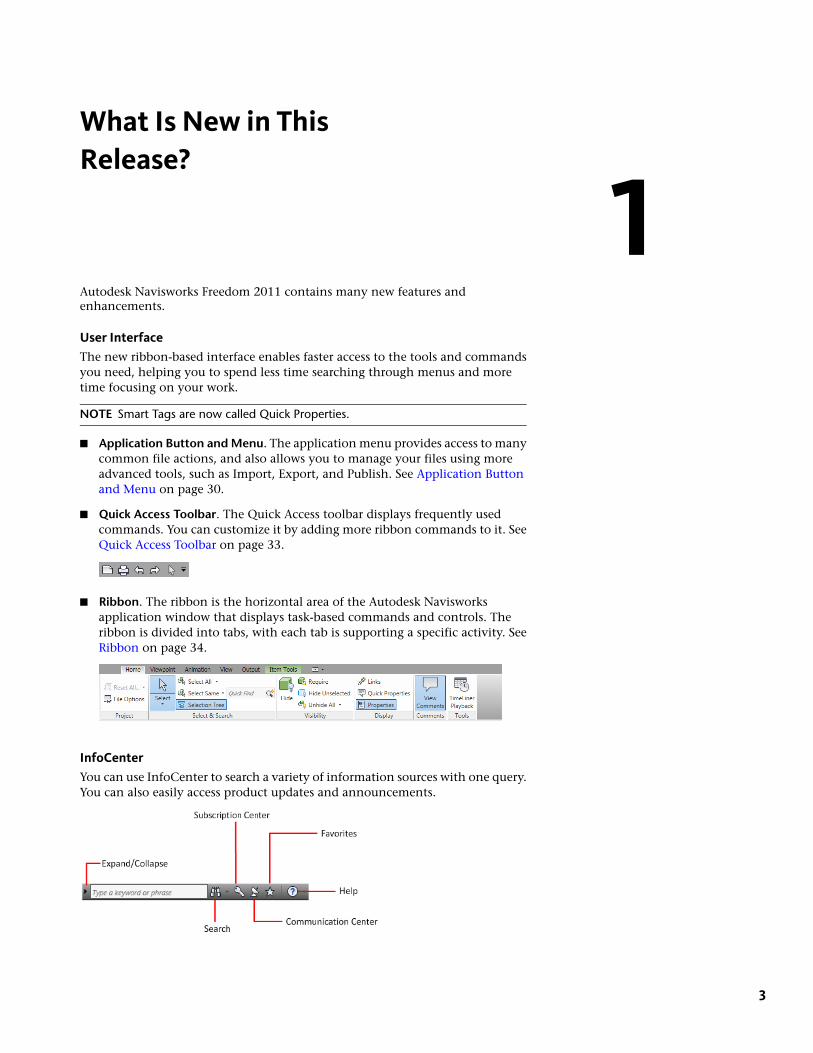
User InterfaceThe new ribbon-based interface enables faster access to the tools and commandsyou need, helping you to spend less time searching through menus and moretime focusing on your work.
NOTE Smart Tags are now called Quick Properties.
■ Application Button and Menu. The application menu provides access to manycommon file actions, and also allows you to manage your files using moreadvanced tools, such as Import, Export, and Publish. See Application Buttonand Menu on page 30.
■ Quick Access Toolbar. The Quick Access toolbar displays frequently usedcommands. You can customize it by adding more ribbon commands to it. SeeQuick Access Toolbar on page 33.
■ Ribbon. The ribbon is the horizontal area of the Autodesk Navisworksapplication window that displays task-based commands and controls. Theribbon is divided into tabs, with each tab is supporting a specific activity. SeeRibbon on page 34.
InfoCenterYou can use InfoCenter to search a variety of information sources with one query.You can also easily access product updates and announcements.
1
3

See “Finding Information Using the InfoCenter” on page 5.
New Features WorkshopThe New Features Workshop introduces you to what’s new in Autodesk Navisworks.
You can access the New Features Workshop from InfoCenter. On the InfoCenter toolbar, to the right of the Help button, clickthe drop-down arrow.
You can also access the New Features workshop from the Start menu. Click Start ➤ All Programs ➤ Autodesk ➤ NavisworksFreedom 2011 ➤ New Features Workshop.
4 | Chapter 1 What Is New in This Release?
How to Get Assistance
There are various ways to find information about how to use this program, andmultiple resources are available.
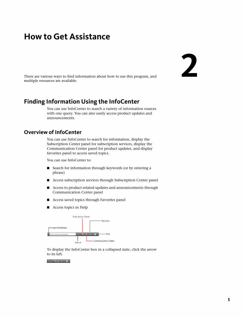
Finding Information Using the InfoCenterYou can use InfoCenter to search a variety of information sourceswith one query. You can also easily access product updates andannouncements.
Overview of InfoCenterYou can use InfoCenter to search for information, display theSubscription Center panel for subscription services, display theCommunication Center panel for product updates, and displayfavorites panel to access saved topics.
You can use InfoCenter to:
■ Search for information through keywords (or by entering aphrase)
■ Access subscription services through Subscription Center panel
■ Access to product-related updates and announcements throughCommunication Center panel
■ Access saved topics through Favorites panel
■ Access topics in Help
To display the InfoCenter box in a collapsed state, click the arrowto its left.
2
5
To browse search results
➤ On the panel for Search Results, Subscription Center, Communication Center, or Favorites, on the rightside of the category header, do one of the following:
■ Click the Next button.
■ Click the Previous button.
To rearrange the topics displayed on a panel
1 Display a panel by doing one of the following:
■ In the InfoCenter box, enter a keyword or phrase. Then press ENTER or click the Search button.
■ In the InfoCenter box, click the Communication Center button.
■ In the InfoCenter box, click the Favorites button.
2 Click and drag a category or group header to the desired position.
NOTE You can rearrange categories within a group, but you cannot move them into other groups.
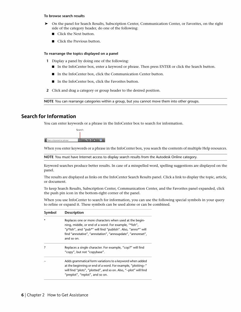
Search for InformationYou can enter keywords or a phrase in the InfoCenter box to search for information.
When you enter keywords or a phrase in the InfoCenter box, you search the contents of multiple Help resources.
NOTE You must have Internet access to display search results from the Autodesk Online category.
Keyword searches produce better results. In case of a misspelled word, spelling suggestions are displayed on thepanel.
The results are displayed as links on the InfoCenter Search Results panel. Click a link to display the topic, article,or document.
To keep Search Results, Subscription Center, Communication Center, and the Favorites panel expanded, clickthe push pin icon in the bottom-right corner of the panel.
When you use InfoCenter to search for information, you can use the following special symbols in your queryto refine or expand it. These symbols can be used alone or can be combined.
DescriptionSymbol
Replaces one or more characters when used at the begin-ning, middle, or end of a word. For example, “*lish”,
*
“p*lish”, and “pub*” will find “publish”. Also, “anno*” willfind “annotative”, “annotation”, “annoupdate”, “annoreset”,and so on.
Replaces a single character. For example, “cop?” will find“copy”, but not “copybase”.
?
Adds grammatical form variations to a keyword when addedat the beginning or end of a word. For example, “plotting~”
~
will find “plots”, “plotted”, and so on. Also, “~plot” will find“preplot”, “replot”, and so on.
6 | Chapter 2 How to Get Assistance
When performing the exact phrase search, use double quotation marks (" ") to enclose words that must appearnext to each other in the specified text string. For example, enter "specify units of measurement" to find onlytopics with all those words in that order. You can also use the previously mentioned symbols in a text stringthat is enclosed in double quotation marks.
To search multiple sources for information
1 In the InfoCenter box, enter a keyword or phrase.
2 Click the Search button.
The search results display in the Search Results panel.
To search a single location for information
1 In the InfoCenter box, enter a keyword or phrase.
2 Click the down arrow next to the Search button.
3 Select a location from the list to search.
The search results from that location display in the Search Results panel.
To add a location to search
1 In the InfoCenter box, click the down arrow next to the Search button.
2 Click Add Search Location.
3 In the Add Search Location dialog box, specify a document or a file location to search.
4 Click Add.
Access Subscription CenterSubscription Center displays links to information about subscription services such as product enhancements,personalized web support from Autodesk technical experts, and self-paced e-Learning.
If you are a subscription member, you can access subscription services by clicking the Communication Center
button in the InfoCenterbox, and then clicking a Subscription Center link. To learn more about Autodesksubscription membership, visit http://www.autodesk.com/subscriptioncenter.
About Subscription CenterWith Autodesk Subscription, you get the latest releases of Autodesk software, incremental product enhancements,personalized web support from Autodesk technical experts, and self paced e-Learning. Subscription services areavailable to subscription members only.
By clicking the Communication Center button in the InfoCenter box, members have access to the followingoptions (under Subscription Center):
■ Subscription status. Checks your subscription status.
■ Create support request. Provides direct one-to-one communication with Autodesk support technicians. Youreceive fast, complete answers to your installation, configuration, and troubleshooting questions.
■ View support requests. Tracks and manage your questions and responses through Autodesk's state-of-the-artsupport system.
■ Edit Subscription Center profile. Sets up and maintains your subscription account.
■ View e-Learning catalog. Features interactive lessons organized into product catalogs.
Access Subscription Center | 7
■ e-Learning Lessons. (For subscription members only.) Each lesson is 15-30 minutes and features hands-onexercises, with an option to use a simulation instead of the software application. You can use an onlineevaluation tool that identifies gaps in skills, determines what lessons will be most helpful, and gauges learningprogress.
Subscription Resources and PrivacySubscription resources provide interactive product features over the Internet. Each time you access subscriptionresources (such as e-Learning or Create Support Request) from Communication Center in an Autodesk product,product information (such as the serial number, version, language, and the subscription contract ID) is sent toAutodesk for verification that your product is on subscription.
Autodesk compiles statistics using the information sent to subscription resources to monitor how they are beingused and how they can be improved. Autodesk maintains the information provided by or collected from you inaccordance with Autodesk's published privacy policy, which is available at http://www.autodesk.com/privacy.
To open the Subscription Center
1 Click the Communication Center button in the InfoCenter box.
2 On the Communication Center panel, under Subscription Center, click the subscription resource you wantto access.
NOTE Subscription Center is not available to all product users. If subscription resources are not available in yourproduct, your product is not entitled to subscription benefits.
Manage Files with Autodesk VaultIf you are a subscription customer, you have access to Autodesk Vault, a file management tool that provides arepository where documents and files are stored and managed.
Autodesk Vault gives you more power to manage files and track changes. Versioned copies of master files aremaintained, allowing you to easily revert to earlier versions of files. You can check files out for editing and latercheck them back in. The master copy is never directly edited.
Autodesk Vault consists of two required components: the Autodesk Data Management Server and the VaultClient. Optionally, you can also install the Vault Office Add-in.
For information about using the Vault, refer to the Vault Help system.
TIP The main components for the Autodesk Vault can be downloaded from the Autodesk Subscription site.
Use Communication CenterCommunication Center provides up-to-date product information, software updates, product supportannouncements, and other product-related announcements.
Overview of Communication CenterYou can click the Communication Center button to display links to information about product updates andannouncements, and may include links to RSS feeds.
Whenever new information is available, Communication Center notifies you by displaying a balloon messagebelow the Communication Center button in the InfoCenter box.
Communication Center provides the following types of announcements:
■ Autodesk Channels: Receive support information, product updates, and other announcements (includingarticles and tips).
8 | Chapter 2 How to Get Assistance
■ RSS Feeds. Receive information from RSS feeds to which you subscribe. RSS feeds generally notify you whennew content is posted. You are automatically subscribed to several default RSS feeds when you install theprogram.
■ Product Support Information. Get breaking news from the Product Support team at Autodesk, includingwhen Live Update maintenance patches are released.
■ Subscription Announcements. Receive subscription announcements and subscription program news, as wellas links to e-Learning Lessons, if you are an Autodesk subscription member (available in countries/regionswhere Autodesk subscriptions are offered).
■ Articles and Tips. Be notified when new articles and tips are available on Autodesk websites.
■ Live Update Maintenance Patches. Receive automatic notifications whenever new maintenance patches arereleased from Autodesk.
■ Featured Technologies and Content. Learn more about third-party developer applications and content.
You can customize the items that display on the Communication Center panel. For more information, see“Specify InfoCenter Settings” on page 13.
Communication Center Online Policy
Communication Center is an interactive feature that must be connected to the Internet in order to deliver contentand information. Each time Communication Center is connected, it sends your information to Autodesk so thatyou receive the correct information. All information is sent anonymously to Autodesk to maintain your privacy.
Communication Center sends the following information to Autodesk:
■ Product name (in which you are using Communication Center)
■ Product release number
■ Product language
■ Country/region (specified in the Communication Center settings)
■ Your unique Customer Involvement Program (CIP) ID if you are participating in the CIP program
Autodesk compiles statistics using the information sent from Communication Center to monitor how it is beingused and how it can be improved. Autodesk maintains information provided by or collected from you inaccordance with the company's published privacy policy, which is available at http://www.autodesk.com/privacy.
To open Communication Center
■ In the InfoCenter box, click the Communication Center button.
To receive new information notifications
■ Click the link in the balloon message to open the article or announcement.
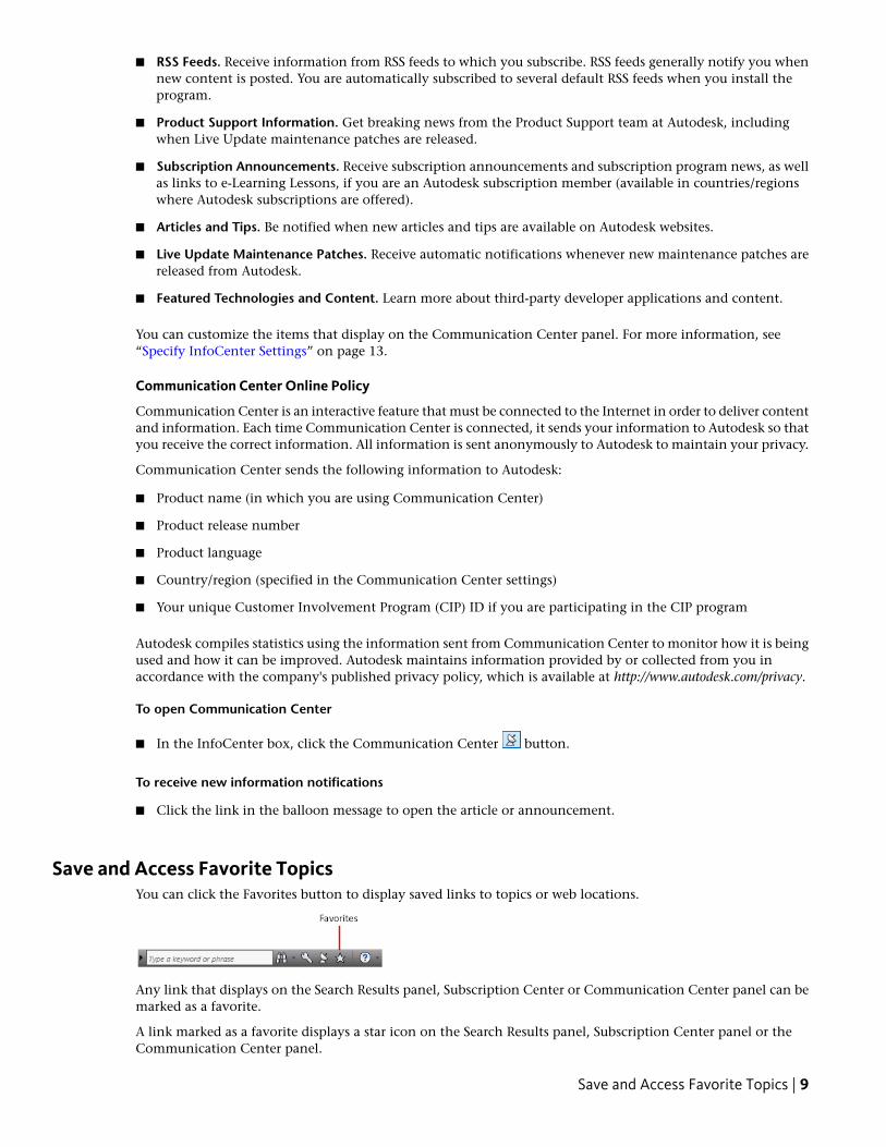
Save and Access Favorite TopicsYou can click the Favorites button to display saved links to topics or web locations.
Any link that displays on the Search Results panel, Subscription Center or Communication Center panel can bemarked as a favorite.
A link marked as a favorite displays a star icon on the Search Results panel, Subscription Center panel or theCommunication Center panel.
Save and Access Favorite Topics | 9
To display the InfoCenter Favorites panel
■ In the InfoCenter box, click the Favorites button.
NOTE The links displayed on the Favorites panel are organized into the same groups or categories from which theywere added.
To save a link in InfoCenter as a favorite
1 Display a panel by doing one of the following:
■ In the InfoCenter box, enter a keyword or phrase. Then press ENTER or click the Search button.
■ In the InfoCenter box, click the Subscription Center button.
■ In the InfoCenter box, click the Communication Center button.
2 Click the star icon that is displayed next to the link that you want to save as a favorite.
To remove a favorite link from the InfoCenter Favorites panel
1 In the InfoCenter box, click the Favorites button to display the Favorites panel.
2 Click the star icon that is displayed next to the link that you want to remove from the Favorites panel.
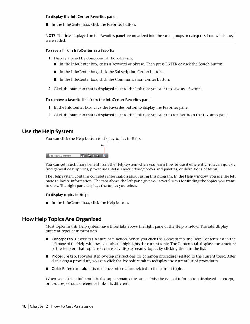
Use the Help SystemYou can click the Help button to display topics in Help.
You can get much more benefit from the Help system when you learn how to use it efficiently. You can quicklyfind general descriptions, procedures, details about dialog boxes and palettes, or definitions of terms.
The Help system contains complete information about using this program. In the Help window, you use the leftpane to locate information. The tabs above the left pane give you several ways for finding the topics you wantto view. The right pane displays the topics you select.
To display topics in Help
■ In the InfoCenter box, click the Help button.
How Help Topics Are OrganizedMost topics in this Help system have three tabs above the right pane of the Help window. The tabs displaydifferent types of information.
■ Concept tab. Describes a feature or function. When you click the Concept tab, the Help Contents list in theleft pane of the Help window expands and highlights the current topic. The Contents tab displays the structureof the Help on that topic. You can easily display nearby topics by clicking them in the list.
■ Procedure tab. Provides step-by-step instructions for common procedures related to the current topic. Afterdisplaying a procedure, you can click the Procedure tab to redisplay the current list of procedures.
■ Quick Reference tab. Lists reference information related to the current topic.
When you click a different tab, the topic remains the same. Only the type of information displayed—concept,procedures, or quick reference links—is different.
10 | Chapter 2 How to Get Assistance
Search in HelpUse the Help Search tab to find relevant topics based on keywords that you enter.
The basic search rules are as follows:
■ Type your keywords in uppercase or lowercase characters; searches are not case-sensitive.
■ Search for any combination of letters (a-z) and numbers (0-9).
■ Do not use punctuation marks such as a period, colon, semicolon, comma, hyphen, and single quotationmarks; they are ignored during a search.
■ Group the elements of your search using double quotation marks or parentheses to set each element apart.
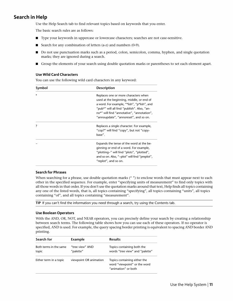
Use Wild Card CharactersYou can use the following wild card characters in any keyword:
DescriptionSymbol
Replaces one or more characters whenused at the beginning, middle, or end of
*
a word. For example, “*lish”, “p*lish”, and“pub*” will all find “publish”. Also, “an-no*” will find “annotative”, “annotation”,“annoupdate”, “annoreset”, and so on.
Replaces a single character. For example,“cop?” will find “copy”, but not “copy-base”.
?
Expands the tense of the word at the be-ginning or end of a word. For example,
~
“plotting~” will find “plots”, “plotted”,and so on. Also, “~plot” will find “preplot”,“replot”, and so on.
Search for PhrasesWhen searching for a phrase, use double quotation marks (“ ”) to enclose words that must appear next to eachother in the specified sequence. For example, enter “specifying units of measurement” to find only topics withall those words in that order. If you don’t use the quotation marks around that text, Help finds all topics containingany one of the listed words, that is, all topics containing “specifying”, all topics containing “units”, all topicscontaining “of”, and all topics containing “measurement”.
TIP If you can’t find the information you need through a search, try using the Contents tab.
Use Boolean OperatorsWith the AND, OR, NOT, and NEAR operators, you can precisely define your search by creating a relationshipbetween search terms. The following table shows how you can use each of these operators. If no operator isspecified, AND is used. For example, the query spacing border printing is equivalent to spacing AND border ANDprinting.
ResultsExampleSearch for
Topics containing both thewords “tree view” and “palette”
“tree view” AND“palette”
Both terms in the sametopic
Topics containing either theword “viewpoint” or the word“animation” or both
viewpoint OR animationEither term in a topic
Use the Help System | 11
ResultsExampleSearch for
Topics containing the word“NWD”, but not the word“NWC”
nwd NOT nwcThe first term withoutthe second term
Topics containing the word“user” within eight words of theword “menu”
user NEAR menuBoth terms in the sametopic, close together
NOTE The |, &, and ! characters do not work as Boolean operators. You must use AND (also +), OR, and NOT (also-).
Find Information in Help TopicsThe tabs on the left side of the Help window provide different methods for finding information.
Contents Tab
■ Presents an overview of the available documentation in a list of topics and subtopics.
■ Allows you to browse by selecting and expanding topics.
■ Provides a structure so you can always see where you are in Help and quickly jump to other topics.
Index Tab
■ Displays an alphabetical list of keywords related to the topics listed on the Contents tab.
■ Accesses information quickly when you already know the name of a feature, command, or operation, orwhen you know what action you want the program to perform.
Search Tab
■ Provides a keyword search of all the topics listed on the Contents tab.
■ Accepts the Boolean operators AND (+), OR, NOT (-), and NEAR.
■ Accepts the wild cards *, ?, and ~.
■ Allows you to perform a search for a phrase when the phrase is enclosed in double quotes.
■ Displays a ranked list of topics that contain the word or words entered in the keyword field.
■ Arranges the results alphabetically by title or by location if you click on the Title and Location columnheadings.
To find a specific word or phrase in the currently displayed Help topic
1 Click in the topic text and press CTRL+F.
2 In the Find text box, enter a keyword or phrase.
3 Click Next. If the keyword or phrase is located, the topic scrolls to display the result.
Print Help TopicsThe quickest way to print the current topic is to right-click within the topic and click Print.
The Print button on the Help toolbar provides these print options:
■ Print the selected topic (recommended)
■ Print the selected heading and all subtopics
12 | Chapter 2 How to Get Assistance
NOTE When you select the second option, you may get numerous printed pages, depending on how many subtopicsthe currently selected topic contains.
To print a Help topic
1 Display the topic you want to print.
2 Right-click in the topic pane. Click Print.
3 In the Print dialog box, click Print.
To print a selected heading and all subtopics
1 Display the topic you want to print and make sure that the Contents tab is displayed.
2 On the Help toolbar, click Print.
3 In the Print Topics dialog box, click Print the Selected Heading and All Subtopics.
4 Click OK.
Show and Hide the Contents PaneUse the Hide button on the Help toolbar to shrink the Help window to a compact size by hiding the pane thatcontains the Contents, Index, and Search tabs.
The compact window size is best for displaying procedures while you work.
Use the Show button to expand the Help window to display the pane that contains Contents, Index, and Searchtabs. The expanded window size is best for locating and displaying conceptual and reference information.
Specify InfoCenter SettingsYou can specify InfoCenter Search and Communication Center settings in the InfoCenter Settings dialog box.
In the InfoCenter Settings dialog box, you can specify the following settings:
■ General. Your current location, frequency for checking new online content and option to turn on or offanimated transition effects for the InfoCenter panels.
■ Search Locations. Locations (documents, web locations, and files) to search for information, as well as thename that displays for each location and the number of results to display for each. Also, you can add orremove search locations.The Web Locations check box provides access to important information on the Autodesk website, includingthe Knowledge Base and discussion groups. When you add document locations, you can specify files on yourlocal drive.
NOTE User-specified CHM (compiled help) files must be located on your local drive. InfoCenter cannot searchCHM files located on network drives.
■ Communication Center. Set the maximum age of the articles displayed on the Communication Center panel.
■ Autodesk Channels. Channels to display in the Communication Center panel as well as the number of articlesto display for each channel.
■ Balloon Notification. Notifications for new product information, software updates, and product supportannouncements. Also, you can customize the transparency and the display time of the balloon.
Specify InfoCenter Settings | 13
■ RSS Feeds. RSS feed subscriptions. You can add or remove RSS feeds. RSS feeds generally notify you whennew content is posted.
To specify locations to search for information
1 In the InfoCenter box, click the down arrow next to the Search button.
2 Click Search Settings.
3 In the InfoCenter Settings dialog box, Search Locations panel, in the right pane, select or clear the searchlocations you want to include or exclude when you search for information.
4 Click OK.
NOTE With the Search All Available Languages option, you can specify whether to search the default language or allavailable languages, including English, Japanese, and French. Select the check box if you want to search all availablelanguages.
To add a new location to search for information
1 In the InfoCenter box, click the down arrow next to the Search button.
2 Click Search Settings.
3 In the InfoCenter Settings dialog box, do one of the following:
■ On the Search Locations panel, in the right pane, click Add.
■ On the Search Locations panel, in the right pane, right-click anywhere in the pane. Click Add.
4 In the Add Search Location dialog box, specify a file location to search.
5 Click Add.
NOTE A warning message is displayed when you add a search location with a file size larger than 5 MB. Youcannot continue to work in the application until indexing is complete.
6 Click OK.
To remove a search location
1 In the InfoCenter box, click the down arrow next to the Search button.
2 Click Search Settings.
3 In the InfoCenter Settings dialog box, do one of the following:
■ Select a location to remove, and then click Remove.
■ Right-click a search location. Click Remove.
4 In the InfoCenter - Remove Search Location dialog box, click Yes.
5 Click OK.
To specify the channels to display in the Communication Center panel
1 In the InfoCenter box, click the down arrow next to the Search button.
2 Click Search Settings.
3 In the InfoCenter Settings dialog box, in the left pane, click Autodesk Channels.
4 In the right pane, select or clear the channels you want to display in the Communication Center panel.
5 Click OK.
14 | Chapter 2 How to Get Assistance
To specify InfoCenter balloon notification settings
1 In the InfoCenter box, click the down arrow next to the Search button.
2 Click Search Settings.
3 In the InfoCenter Settings dialog box, in the left pane, click Balloon Notification.
4 In the right pane, select or clear the options to turn balloon notification on or off.
5 Enter the number of seconds to set the length of time for balloon notifications to display.
6 Enter the transparency value of the balloon or set the value using the slider.
7 Click OK.
To add an RSS feed to Communication Center
1 In the InfoCenter box, click the down arrow next to the Search button.
2 Click Search Settings.
3 In the InfoCenter Settings dialog box, in the left pane, click RSS Feeds.
4 In the right pane, do one of the following:
■ Click Add.
■ Right-click anywhere in the right pane. Click Add.
5 In the Add RSS Feed dialog box, enter the location of the RSS feed you want to add. Click Add.
6 In the InfoCenter - RSS Feed Confirmation dialog box, click Close.
7 Click OK.
To remove an RSS feed from Communication Center
1 In the InfoCenter box, click the down arrow next to the Search button.
2 Click Search Settings.
3 In the InfoCenter Settings dialog box, in the left pane, click RSS Feeds.
4 In the right pane, do one of the following:
■ Click Remove.
■ Right-click an RSS feed. Click Remove.
5 In the InfoCenter - Remove RSS Feed dialog box, click Yes.
6 Click OK.
Get More HelpYou can access several additional sources of help.
■ Use Communication Center. Display the Communication Center panel for product updates andannouncements.
■ Press F1. Displays context-sensitive reference information.
■ Click the Help button in many dialog boxes. Displays reference information for the dialog box.
■ View the product Readme. Displays late-breaking information about this product.
Get More Help | 15
Other resources help you get information about Autodesk products and assistance with your questions aboutthis program.
■ Autodesk website. Access http://www.autodesk.com.
■ Local support. Check with your dealer or Autodesk country/region office.
View the Product ReadmeYou can find late-breaking information about this software in the Readme.
It is suggested that you read through the Autodesk Navisworks Readme for information about recommendedhardware, updated installation instructions, and known software problems. The Readme file is available fromthe product’s program group on the Windows Start menu.
Join the Customer Involvement ProgramYou are invited to help guide the direction of Autodesk design software.
If you participate in the Customer Involvement Program (CIP), specific information about how you use AutodeskNavisworks is forwarded to Autodesk. This information includes what features you use the most, problems thatyou encounter, and other information helpful to the future direction of the product.
See the following links for more information.
■ Learn more about the Autodesk Customer Involvement Program: http://www.autodesk.com/cip
■ Read the Autodesk Privacy Statement: http://www.autodesk.com/cipprivacy
When you join, you will be able to view reports that can help you optimize your use of Autodesk Navisworks.
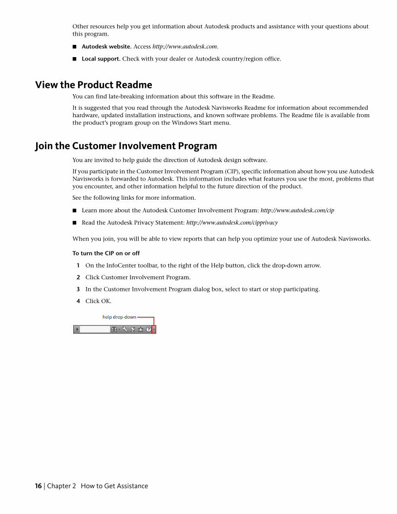
To turn the CIP on or off
1 On the InfoCenter toolbar, to the right of the Help button, click the drop-down arrow.
2 Click Customer Involvement Program.
3 In the Customer Involvement Program dialog box, select to start or stop participating.
4 Click OK.
16 | Chapter 2 How to Get Assistance
Installation
This chapter provides information about installing and activating AutodeskNavisworks on a workstation.
Quick Start to Stand-Alone InstallationThis section provides step-by-step instructions about how to prepare,and then install Autodesk Navisworks.
Prepare for InstallationTo prepare for installation, you should review the systemrequirements, understand administrative permission requirements,and close all running applications.
Complete these tasks, and you are ready to begin installing AutodeskNavisworks Freedom 2011.
System Requirements for Stand-Alone InstallationThe first task you need to complete is to make sure that yourcomputer meets the minimum system requirements. If your systemdoes not meet these requirements, problems can occur, both withinAutodesk Navisworks and at the operating system level.
Whether your Windows operating system is the 32-bit or the 64-bitversion, the version is automatically detected during installation.
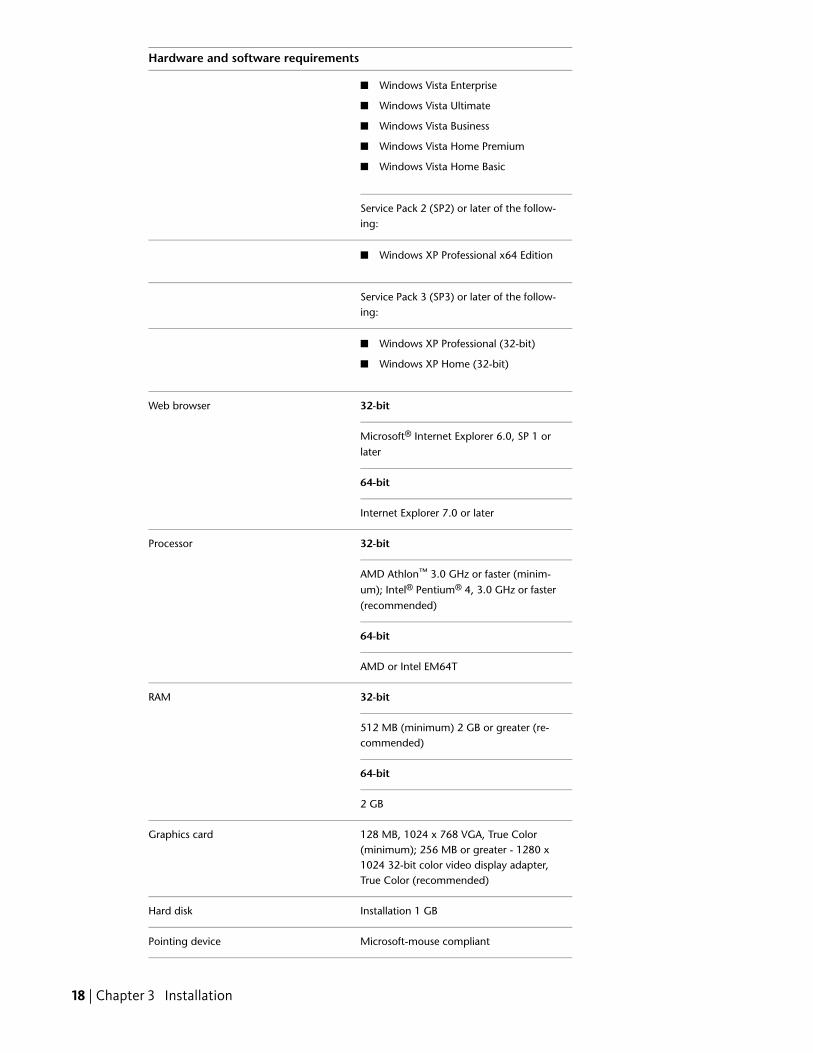
See the following table for hardware and software requirements.
Hardware and software requirements
RequirementHardware/Software
Operating system ■ Windows 7 Enterprise
■ Windows 7 Ultimate
■ Windows 7 Professional
■ Windows 7 Home Premium
■ Windows 7 Home Basic
Service Pack 2 (SP2) or later of the follow-ing:
3
17
Hardware and software requirements
■ Windows Vista Enterprise
■ Windows Vista Ultimate
■ Windows Vista Business
■ Windows Vista Home Premium
■ Windows Vista Home Basic
Service Pack 2 (SP2) or later of the follow-ing:
■ Windows XP Professional x64 Edition
Service Pack 3 (SP3) or later of the follow-ing:
■ Windows XP Professional (32-bit)
■ Windows XP Home (32-bit)
32-bitWeb browser
Microsoft® Internet Explorer 6.0, SP 1 orlater
64-bit
Internet Explorer 7.0 or later
32-bitProcessor
AMD Athlon™ 3.0 GHz or faster (minim-um); Intel® Pentium® 4, 3.0 GHz or faster(recommended)
64-bit
AMD or Intel EM64T
32-bitRAM
512 MB (minimum) 2 GB or greater (re-commended)
64-bit
2 GB
128 MB, 1024 x 768 VGA, True Color(minimum); 256 MB or greater - 1280 x
Graphics card
1024 32-bit color video display adapter,True Color (recommended)
Installation 1 GBHard disk
Microsoft-mouse compliantPointing device
18 | Chapter 3 Installation
Hardware and software requirements
Any speed (for installation only)DVD-ROM
Open GL©-compatible 3D video card;Printer or plotter; Modem or access to an
Optional hardware
Internet connection; Network interfacecard
Understand Administrative Permission RequirementsTo install Autodesk Navisworks, you must have administrator permissions.
You do not need to have domain administrative permissions. See your system administrator for informationabout administrative permissions.
To run Autodesk Navisworks, you do not need administrator permissions. You can run the program as a limiteduser.
Avoid Data Loss During InstallationThe Autodesk Navisworks installation process may stop if some applications (such as Microsoft® Outlook® orvirus-checking programs) are running.
Close all running applications to avoid possible data loss.
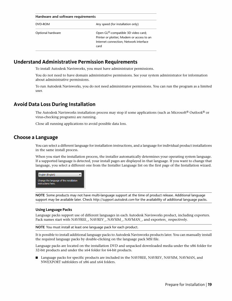
Choose a LanguageYou can select a different language for installation instructions, and a language for individual product installationsin the same install process.
When you start the installation process, the installer automatically determines your operating system language.If a supported language is detected, your install pages are displayed in that language. If you want to change thatlanguage, you select a different one from the Installer Language list on the first page of the Installation wizard.
NOTE Some products may not have multi-language support at the time of product release. Additional languagesupport may be available later. Check http://support.autodesk.com for the availability of additional language packs.
Using Language PacksLanguage packs support use of different languages in each Autodesk Navisworks product, including exporters.Pack names start with NAVFREE_, NAVREV_, NAVSIM_, NAVMAN_, and exporters_ respectively.
NOTE You must install at least one language pack for each product.
It is possible to install additional language packs to Autodesk Navisworks products later. You can manually installthe required language packs by double-clicking on the language pack MSI file.
Language packs are located on the installation DVD and unpacked downloaded media under the x86 folder for32-bit products and under the x64 folder for 64-bit products.
■ Language packs for specific products are included in the NAVFREE, NAVREV, NAVSIM, NAVMAN, andNWEXPORT subfolders of x86 and x64 folders.
Prepare for Installation | 19
■ Language packs for specific languages are included in the en-US (English), de-DE (German), es-ES (Spanish),fr-FR (French), it-IT (Italian), ja-JP (Japanese), ko-KR (Korean), pt-BR (Brazilian Portuguese), ru-RU (Russian)and zh-CN (Chinese PRC) subfolders of the product folders.
So, for example, to install the 32-bit French language pack for Autodesk Navisworks Freedom, double-clickx86/NAVFREE/fr-FR/NAVFREE_LP.msi.
Configure ButtonDuring the installation process, you choose either a typical installation (install the product with default settings),or a customized installation. If you choose to customize, you start that process in the Begin Installation page.Select the appropriate product from the drop-down list, and click Configure.
After you click Configure, the following dialog boxes and options are displayed:
■ Project and Site Folders. These settings can be shared across an entire project site, or across a specific projectgroup depending on the required level of granularity. Refer to “Why should I specify the Project Folder andSite Folder?” on page 26.
■ Select the Installation Location. Select the Product Install Path. Use the Browse button to select the drive andlocation where product will be installed.
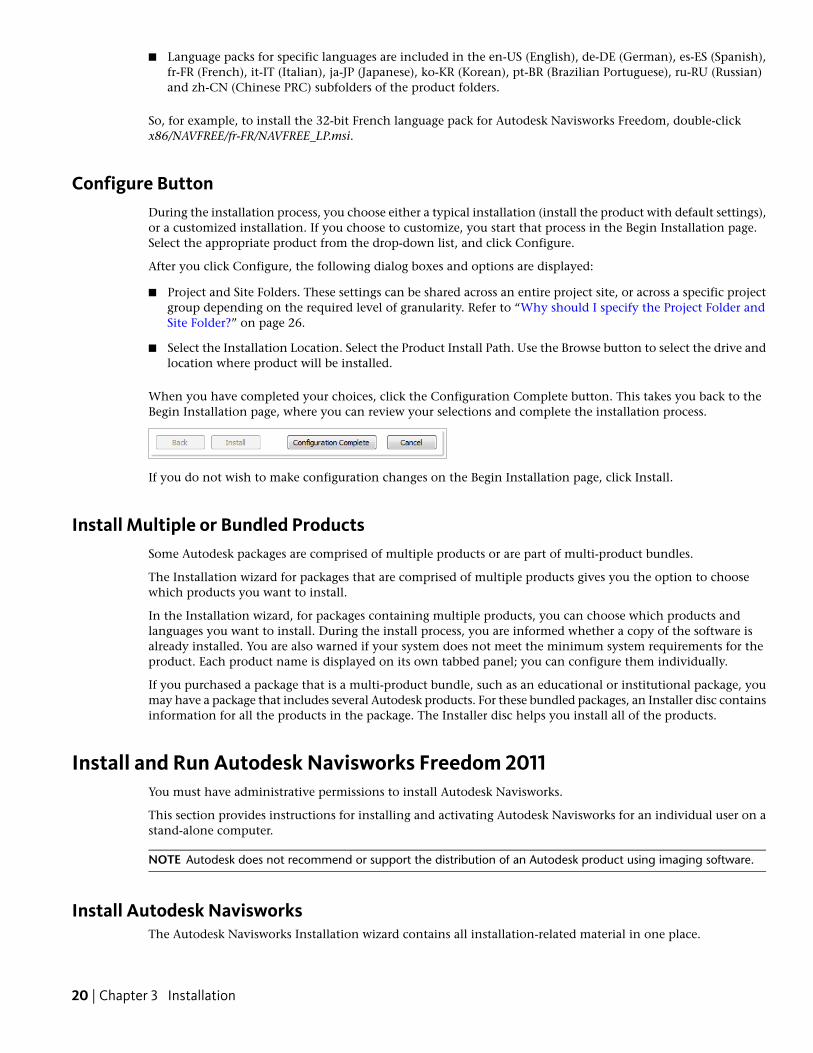
When you have completed your choices, click the Configuration Complete button. This takes you back to theBegin Installation page, where you can review your selections and complete the installation process.
If you do not wish to make configuration changes on the Begin Installation page, click Install.
Install Multiple or Bundled ProductsSome Autodesk packages are comprised of multiple products or are part of multi-product bundles.
The Installation wizard for packages that are comprised of multiple products gives you the option to choosewhich products you want to install.
In the Installation wizard, for packages containing multiple products, you can choose which products andlanguages you want to install. During the install process, you are informed whether a copy of the software isalready installed. You are also warned if your system does not meet the minimum system requirements for theproduct. Each product name is displayed on its own tabbed panel; you can configure them individually.
If you purchased a package that is a multi-product bundle, such as an educational or institutional package, youmay have a package that includes several Autodesk products. For these bundled packages, an Installer disc containsinformation for all the products in the package. The Installer disc helps you install all of the products.
Install and Run Autodesk Navisworks Freedom 2011You must have administrative permissions to install Autodesk Navisworks.
This section provides instructions for installing and activating Autodesk Navisworks for an individual user on astand-alone computer.
NOTE Autodesk does not recommend or support the distribution of an Autodesk product using imaging software.
Install Autodesk NavisworksThe Autodesk Navisworks Installation wizard contains all installation-related material in one place.
20 | Chapter 3 Installation
From the Installation wizard, you can access user documentation, change the installer language, select alanguage-specific product, install supplemental tools, view support solutions, and learn about deploying yourproduct on a network.
■ Review installation documentation before you install. It is recommended that you take the time to familiarizeyourself with the complete installation process before you install Autodesk Navisworks. You can access PDFversions of the licensing manuals and CHM versions of the installation manuals from the product's Installationwizard by selecting the Read the Documentation selection, or the Documentation link at the bottom, leftpane of the install pages.You can also access PDFs from the product disc. For late-breaking information, it is also recommended thatyou review the product Readme.
NOTE To view or print PDF (.pdf) files, Adobe® Reader must be installed on your computer. If you do not haveAdobe Reader, you can download the latest version at http://www.adobe.com.
■ Install Autodesk Navisworks Freedom 2011. From the Installation wizard, click Install Products. Follow theon-screen instructions to complete the installation.
Install Autodesk Navisworks Using Default ValuesThis is the fastest means of installing Autodesk Navisworks on your system.
Only default values are used which means it is a typical installation being installed to C:\ProgramFiles\Autodesk\Navisworks Freedom 2011.
To install Autodesk Navisworks using default values on a stand-alone computer
1 Insert the Autodesk Navisworks Freedom 2011 DVD into the DVD drive.
The Autodesk Navisworks Freedom 2011 Installation wizard launches in the language that best matches thesettings on your computer.
If the Installation wizard does not start automatically, double-click Setup.exe at the root of the AutodeskNavisworks DVD.
2 In the Installation wizard, change the language of the installation instructions or accept the default language.
Click Install Products.
3 Select the languages and the products you want to install.
Click Next.
4 Review the Autodesk software license agreement for your country or region. You must accept this agreementto proceed with the installation. Choose your country or region, click I Accept, and then click Next.
NOTE If you do not agree to the terms of the license and want to terminate the installation, click Cancel.
5 On the User Information page, enter your personal details and click Next.
IMPORTANT The information you enter here is permanent and is displayed in the Autodesk Navisworks Freedom2011 window (accessed in the InfoCenter box by clicking the down arrow next to the Help button ➤ AboutAutodesk Navisworks Freedom 2011). Because you can’t change this information later without uninstalling theproduct, make sure you enter the correct information now.
6 On the Begin Installation page, click Install.
Click Yes to continue installing using the default configuration.
Install and Run Autodesk Navisworks Freedom 2011 | 21

The wizard does the following:
■ Uses a Typical installation, which installs the most common application features. To see which featuresare included in a Typical installation, refer to “Typically Installed Features” on page 26.
■ Installs Autodesk Navisworks to the default install path of C:\Program Files\Autodesk\Navisworks
Freedom 2011.
■ Installs the products you selected in Step 3.
NOTE By default, the Installation wizard automatically enables the exporter plugins for all third-party productsalready installed on your computer.
7 On the Installation Complete page, choose:
■ View the Autodesk Navisworks Freedom 2011 Readme. Open the Readme file with the information thatwas not available when the Autodesk Navisworks Freedom 2011 documentation was prepared.
NOTE If you do not want to view the Readme file now, clear the check box.
8 Click Finish.
Install Autodesk Navisworks Using Configured ValuesWith this installation method, you can fine-tune exactly what gets installed by using the Configure option.
You can alter the installation type, the install path, the license type, and specify the location of the Project andSite folders.
To install Autodesk Navisworks using configured values on a stand-alone computer
1 Insert the Autodesk Navisworks Freedom 2011 DVD into the DVD drive.
The Autodesk Navisworks Freedom 2011 Installation wizard launches in the language that best matches thesettings on your computer.
If the Installation wizard does not start automatically, double-click Setup.exe at the root of the AutodeskNavisworks DVD.
2 In the Installation wizard, change the language of the installation instructions or accept the default language.Click Install Products.
3 Select the languages and the products you want to install.
Click Next.
4 Review the Autodesk software license agreement for your country or region. You must accept this agreementto proceed with the installation. Choose your country or region, click I Accept, and then click Next.
NOTE If you do not agree to the terms of the license and want to terminate the installation, click Cancel.
5 On the User Information page, enter your personal details and click Next.
IMPORTANT The information you enter here is permanent and is displayed in the Autodesk Navisworks Freedom2011 window (accessed in the InfoCenter box by clicking the down arrow next to the Help button ➤ AboutAutodesk Navisworks Freedom 2011). Because you can’t change this information later without uninstalling theproduct, make sure you enter the correct information now.
6 On the Begin Installation page, click Configure to make configuration changes. Each of the products youselected in Step 3 has its own tab.
NOTE At any time you can click Configuration Complete to return to the Begin Installation page.
22 | Chapter 3 Installation
7 You can make the following configuration changes:
➤ On the Project and Site Folders page, you can specify:
■ Project Folder. Use the Browse button to select the directory that contains the product settingsspecific to a project group.
■ Site Folder. Use the Browse button to select the directory that contains the product settings standardacross the entire project site.
Click Next.
8 On the Select the Installation Location page, you can make the following configuration change:
■ Product Install Path. Use the Browse button to select the drive and location where product will beinstalled. Click Next and then Configuration Complete to return to the Begin Installation page. Then,click Install.
NOTE If you want a copy of your configuration summary information, click Copy to Clipboard.
9 On the Installation Complete page, choose:
■ View the Autodesk Navisworks Freedom 2011 Readme. Open the Readme file with the information thatwas not available when the Autodesk Navisworks Freedom 2011 documentation was prepared.
NOTE If you do not want to view the Readme file now, clear the check box.
10 Click Finish.
Launch Autodesk NavisworksAssuming that you’ve followed all of the previous steps outlined in this Quick Start section, you can launchAutodesk Navisworks and start taking advantage of its new and updated features.
You can start Autodesk Navisworks in the following ways:
■ Desktop shortcut icon. When you install Autodesk Navisworks, a shortcut icon is placed on your desktop.Double-click the Autodesk Navisworks icon to start the program.
■ Start button. Click Start ➤ All Programs ➤ Autodesk ➤ Navisworks Freedom 2011 ➤ Autodesk NavisworksFreedom 2011.
■ Location where Autodesk Navisworks is installed. If you have administrative permissions, you can run AutodeskNavisworks in the location where you installed it. If you are a limited-rights user, you must run AutodeskNavisworks from the Start button or from the desktop shortcut icon. If you want to create a custom shortcut,make sure that the Start In directory for the shortcut points to a directory where you have write permissions.
NOTE When the product is started, by default, it uses the language that best matches the settings on your computer.You can also launch Autodesk Navisworks in another of the supported languages.
How to Launch Autodesk Navisworks in Another LanguageTo run Autodesk Navisworks in another of the installed languages, you need to add one of the language selectorarguments to the desktop shortcut.
To run Autodesk Navisworks in another language
1 Right-click the Autodesk Navisworks desktop shortcut, and click Properties on the shortcut menu to openthe Autodesk Navisworks Properties dialog box.
Install and Run Autodesk Navisworks Freedom 2011 | 23
2 On the Shortcut tab, enter a space in the Target field after ..\roamer.exe, and then enter one of the followingarguments:
-lang en-US for English localization
-lang de-DE for German localization
-lang es-ES for Spanish localization
-lang fr-FR for French localization
-lang it-IT for Italian localization
-lang ja-JP for Japanese localization
-lang ko-KR for Korean localization
-lang pt-BR for Brazilian Portuguese localization
-lang ru-RU for Russian localization
-lang zh-CN for Chinese (PRC) localization
3 Click OK to save the changes.
Repair Autodesk Navisworks Freedom 2011If you accidentally delete or alter files that are required by Autodesk Navisworks Freedom 2011, AutodeskNavisworks might not perform correctly, and you might receive error messages when you try to execute acommand or find a file. You can attempt to fix this problem by repairing Autodesk Navisworks Freedom 2011.
Repairing uses the features that were part of the installation type you chose when you initially installed theprogram.
To repair Autodesk Navisworks Freedom 2011
1 Do one of the following:
■ (Windows XP) Click Start ➤ Settings ➤ Control Panel ➤ Add or Remove Programs.
■ (Windows Vista and Windows 7) Click Start ➤ Control Panel ➤ Programs and Features.
2 From the list of programs, click Autodesk Navisworks Freedom 2011, and then click Change/Remove(Windows XP) or Uninstall/Change (Windows Vista and Windows 7).
The Autodesk Navisworks Freedom 2011 Installation wizard re-opens in Maintenance Mode.
3 Click Repair or Reinstall.
4 On the Select Repair or Reinstall page, click Repair My Autodesk Navisworks Freedom 2011 Installation.This option replaces all registry entries that Autodesk Navisworks initially installed and restores AutodeskNavisworks Freedom 2011 to its default state.one of the following, and then click Next.
NOTE Reinstall My Autodesk Navisworks Freedom 2011 Installation repairs the registry and reinstalls all files fromthe original installation. Use this option if the Repair My Autodesk Navisworks Freedom 2011 Installation optiondoes not solve the problem.
5 On the Repair Autodesk Navisworks Freedom 2011 page, click Next to start the process.
6 On the Repair Complete page, click Finish.
Uninstall Autodesk Autodesk Navisworks Freedom 2011When you uninstall Autodesk Navisworks Freedom 2011, all components are removed. This means that even ifyou've previously added or removed components, or if you've reinstalled or repaired Autodesk NavisworksFreedom 2011, the uninstall removes all Autodesk Navisworks installation files from your system.
24 | Chapter 3 Installation
To uninstall Autodesk Navisworks Freedom 2011
1 Do one of the following:
■ (Windows XP) Click Start ➤ Settings ➤ Control Panel ➤ Add or Remove Programs.
■ (Windows Vista and Windows 7) Click Start ➤ Control Panel ➤ Programs and Features.
2 From the list of programs, click Autodesk Navisworks Freedom 2011, and then click Change/Remove(Windows XP) or Uninstall/Change (Windows Vista and Windows 7).
The Autodesk Navisworks Freedom 2011 Installation wizard re-opens in Maintenance Mode.
3 Click Uninstall.
4 On the Autodesk Navisworks Freedom 2011 page, click Next to remove Autodesk Navisworks from thesystem.
5 When informed that the product has been successfully uninstalled, click Finish.
NOTE Even though Autodesk Navisworks Freedom 2011 is removed from your system, the software licenseremains. If you reinstall Autodesk Navisworks Freedom 2011 at some future time, you will not have to registerand re-activate the program.
Installation TroubleshootingThis section provides solutions to installation issues and answers to commonly asked questions that may arisewhile installing your products.
Additional troubleshooting information and support is also available at http://support.autodesk.com.
General Installation IssuesThis section provides solutions to installation issues and answers to commonly asked questions that may arisewhile installing your products.
How can I check my graphics card driver to see if it needs to be updated?It is recommended that you ensure your computer has the most current graphics card driver for the best possibledisplay performance.
To identify your graphics card driver
1 Start Autodesk Navisworks Freedom 2011.
2 In the InfoCenter box, click the down arrow next to the Help button ➤ System Info.
The Autodesk Navisworks Freedom 2011 information dialog box opens.
3 Review the information about your system including the graphics card driver and driver version, and clickOK to close the dialog.
To check the Web for an updated graphics card driver
■ Use Windows Update. If a more recent graphics card driver is available, select it to have Windows Updatedownload and install it.
■ Search the graphics card manufacturer’s website for the type of installed graphics card. If a more recentgraphics card driver is available, install it following the instructions provided by the manufacturer.
Installation Troubleshooting | 25
To install an updated graphics card driver
1 Check the Web for to see if an updated driver is available.
■ Use Windows Update.
■ Search the graphics card manufacturer’s website for the type of installed graphics card.
2 If a more recent graphics card driver is available, follow the instructions from the website to install downloadand install it.
When performing a Typical installation, what gets installed?A Typical installation includes the following features:
Contains full set of Autodesk NavisworksFreedom 2011 files
Autodesk Navisworks Freedom 2011
Contains the Component Object Modelinterface for customizing and extendingthe Autodesk Navisworks functionality
API
Contains several Rich Photorealistic Con-tent files for the Presenter tool
Sample RPCs
Contains various feature sample filesExample NWD files
Contains the Autodesk Navisworks Free-dom 2011 user guide in PDF format
PDF manual
Why should I specify the Project Folder and Site Folder?You can share global Autodesk Navisworks settings, workspaces, datatools, avatars, Clash Detective rules, Presenterarchives, custom Clash Detective tests, object animation scripts, and so on, with other users.
These settings can be shared across an entire project site, or across a specific project group depending on therequired level of granularity.
Autodesk Navisworks examines the current user profile and the all users profile on the local machine, and thenchecks the settings in the Project Directory and the Site Directory. The files in the Project Directory take precedence.
How do I share the Autodesk Navisworks settings on a site and project basis?Sharing Autodesk Navisworks settings requires you to export the desired settings as an XML file to the appropriateSite or Project directory’s global_options folder. The name of the XML file is not significant. However it must bestored in the global_options folder.
TIP When you configure global options, you can lock some of the options to prevent users from editing them lateron local machines. To create a locked global options file, run the stand-alone Options Editor from the command lineby typing “drive:pathname\OptionsEditor.exe” -l. The Options Editor opens with the locking facility.
To share settings on a site and project basis
1 Create appropriate Site and Project directories and subfolders in a central location to be accessed by otherNavisworks users.
26 | Chapter 3 Installation
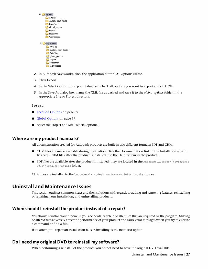
2 In Autodesk Navisworks, click the application button ➤ Options Editor.
3 Click Export.
4 In the Select Options to Export dialog box, check all options you want to export and click OK.
5 In the Save As dialog box, name the XML file as desired and save it to the global_options folder in theappropriate Site or Project directory.
See also:
■ Location Options on page 59
■ Global Options on page 57
■ Select the Project and Site Folders (optional)
Where are my product manuals?All documentation created for Autodesk products are built in two different formats: PDF and CHM.
■ CHM files are made available during installation; click the Documentation link in the Installation wizard.To access CHM files after the product is installed, use the Help system in the product.
■ PDF files are available after the product is installed; they are located in the Autodesk\Autodesk Navisworks
2011\<locale>\Manuals folder.
CHM files are installed to the \Autodesk\Autodesk Navisworks 2011\<locale> folder.
Uninstall and Maintenance IssuesThis section outlines common issues and their solutions with regards to adding and removing features, reinstallingor repairing your installation, and uninstalling products.
When should I reinstall the product instead of a repair?You should reinstall your product if you accidentally delete or alter files that are required by the program. Missingor altered files adversely affect the performance of your product and cause error messages when you try to executea command or find a file.
If an attempt to repair an installation fails, reinstalling is the next best option.
Do I need my original DVD to reinstall my software?When performing a reinstall of the product, you do not need to have the original DVD available.
Uninstall and Maintenance Issues | 27
Installation data is cached locally on your drive and that data is reused when reinstalling.
When I uninstall my software, what files are left on my system?If you uninstall the product, some files remain on your system such as files you created or edited.
Your license file also stays on your workstation when you uninstall your product. If you reinstall on the sameworkstation, the license information remains valid and you do not have to reactivate the product.
28 | Chapter 3 Installation
Quick Start
This chapter helps you get up-to-speed with the Autodesk Navisworks interface.
Start and Quit Autodesk NavisworksOnce you’ve installed Autodesk Navisworks Freedom 2011, you canstart it from the Windows desktop or from the command line.
To start Autodesk Navisworks, do one of the following from theWindows desktop:
■ Double-click the Autodesk Navisworks icon, or
■ Click Start ➤ All Programs ➤ Autodesk ➤ NavisworksFreedom 2011 ➤ Freedom 2011.
Autodesk Navisworks starts in the language that best matches thesettings on your computer. You can also start Autodesk Navisworksin another of the installed languages.
To quit Autodesk Navisworks, click the application button .At the bottom of the application menu, click Exit Navisworks.
The User InterfaceThe Autodesk Navisworks interface contains a number of traditionalWindows elements, such as the application menu, Quick Accesstoolbar, ribbon, dockable windows, dialog boxes and shortcut menusin which you complete tasks.
Parts of Autodesk Navisworks InterfaceThis section briefly describes the main components of the standardAutodesk Navisworks interface.
The Autodesk Navisworks interface is intuitive and easy to learnand use. You can adjust the application interface to match the wayyou work. For example, you can hide docking windows that yourarely use, so they do not clutter the interface. You can add andremove buttons from the ribbon and the Quick Access toolbar.
You can apply a different theme to the standard interface. You canalso switch back to the classic Autodesk Navisworks interface withold-style menu and toolbars.
4
29
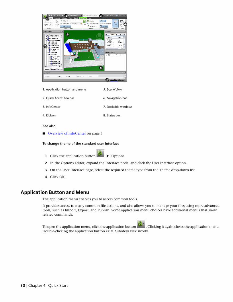
5. Scene View1. Application button and menu
6. Navigation bar2. Quick Access toolbar
7. Dockable windows3. InfoCenter
8. Status bar4. Ribbon
See also:
■ Overview of InfoCenter on page 5
To change theme of the standard user interface
1 Click the application button ➤ Options.
2 In the Options Editor, expand the Interface node, and click the User Interface option.
3 On the User Interface page, select the required theme type from the Theme drop-down list.
4 Click OK.
Application Button and MenuThe application menu enables you to access common tools.
It provides access to many common file actions, and also allows you to manage your files using more advancedtools, such as Import, Export, and Publish. Some application menu choices have additional menus that showrelated commands.
To open the application menu, click the application button . Clicking it again closes the application menu.Double-clicking the application button exits Autodesk Navisworks.
30 | Chapter 4 Quick Start
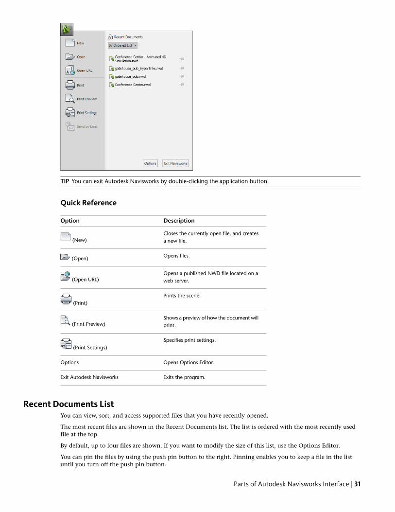
TIP You can exit Autodesk Navisworks by double-clicking the application button.
Quick Reference
DescriptionOption
Closes the currently open file, and createsa new file. (New)
Opens files. (Open)
Opens a published NWD file located on aweb server. (Open URL)
Prints the scene. (Print)
Shows a preview of how the document willprint. (Print Preview)
Specifies print settings. (Print Settings)
Opens Options Editor.Options
Exits the program.Exit Autodesk Navisworks
Recent Documents ListYou can view, sort, and access supported files that you have recently opened.
The most recent files are shown in the Recent Documents list. The list is ordered with the most recently usedfile at the top.
By default, up to four files are shown. If you want to modify the size of this list, use the Options Editor.
You can pin the files by using the push pin button to the right. Pinning enables you to keep a file in the listuntil you turn off the push pin button.
Parts of Autodesk Navisworks Interface | 31
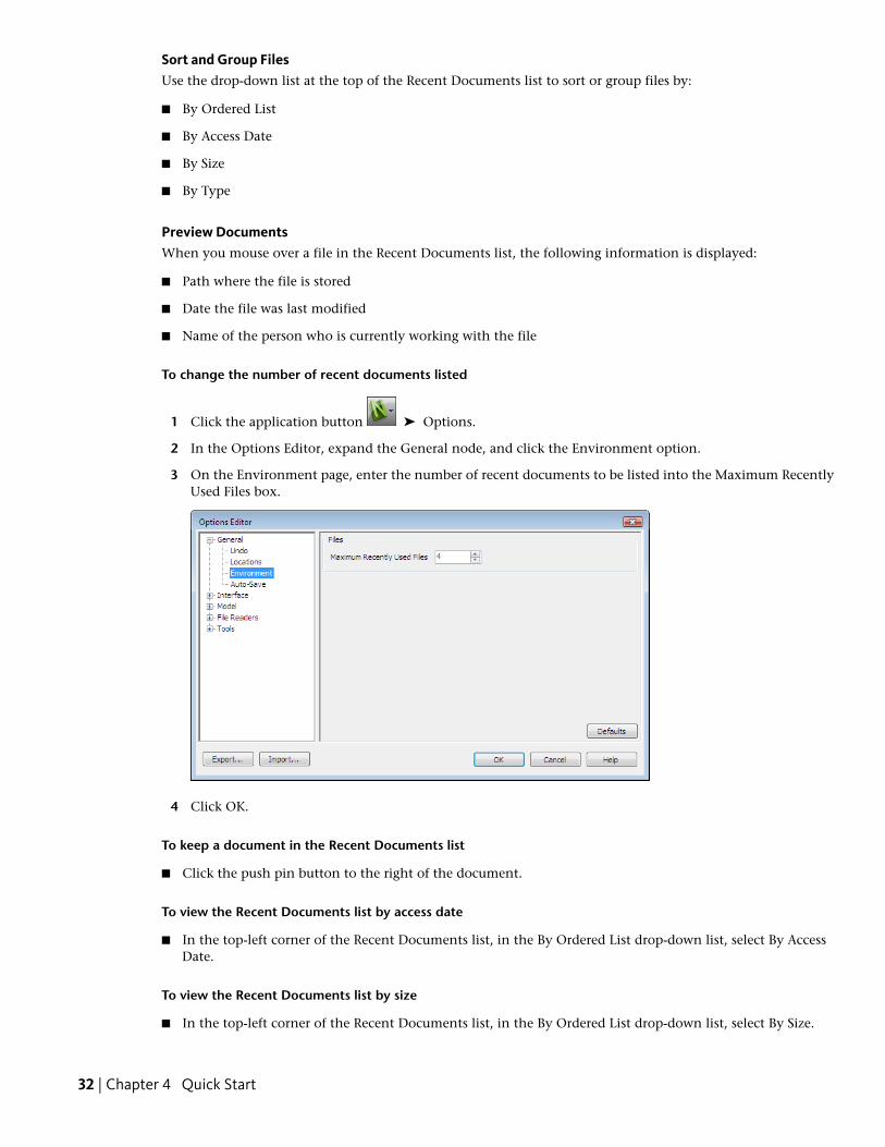
Sort and Group FilesUse the drop-down list at the top of the Recent Documents list to sort or group files by:
■ By Ordered List
■ By Access Date
■ By Size
■ By Type
Preview DocumentsWhen you mouse over a file in the Recent Documents list, the following information is displayed:
■ Path where the file is stored
■ Date the file was last modified
■ Name of the person who is currently working with the file
To change the number of recent documents listed
1 Click the application button ➤ Options.
2 In the Options Editor, expand the General node, and click the Environment option.
3 On the Environment page, enter the number of recent documents to be listed into the Maximum RecentlyUsed Files box.
4 Click OK.
To keep a document in the Recent Documents list
■ Click the push pin button to the right of the document.
To view the Recent Documents list by access date
■ In the top-left corner of the Recent Documents list, in the By Ordered List drop-down list, select By AccessDate.
To view the Recent Documents list by size
■ In the top-left corner of the Recent Documents list, in the By Ordered List drop-down list, select By Size.
32 | Chapter 4 Quick Start
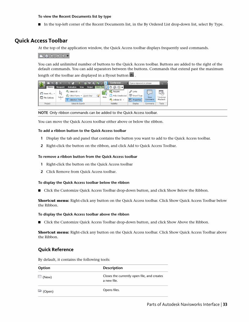
To view the Recent Documents list by type
■ In the top-left corner of the Recent Documents list, in the By Ordered List drop-down list, select By Type.
Quick Access ToolbarAt the top of the application window, the Quick Access toolbar displays frequently used commands.
You can add unlimited number of buttons to the Quick Access toolbar. Buttons are added to the right of thedefault commands. You can add separators between the buttons. Commands that extend past the maximum
length of the toolbar are displayed in a flyout button .
NOTE Only ribbon commands can be added to the Quick Access toolbar.
You can move the Quick Access toolbar either above or below the ribbon.
To add a ribbon button to the Quick Access toolbar
1 Display the tab and panel that contains the button you want to add to the Quick Access toolbar.
2 Right-click the button on the ribbon, and click Add to Quick Access Toolbar.
To remove a ribbon button from the Quick Access toolbar
1 Right-click the button on the Quick Access toolbar
2 Click Remove from Quick Access toolbar.
To display the Quick Access toolbar below the ribbon
■ Click the Customize Quick Access Toolbar drop-down button, and click Show Below the Ribbon.
Shortcut menu: Right-click any button on the Quick Access toolbar. Click Show Quick Access Toolbar belowthe Ribbon.
To display the Quick Access toolbar above the ribbon
■ Click the Customize Quick Access Toolbar drop-down button, and click Show Above the Ribbon.
Shortcut menu: Right-click any button on the Quick Access toolbar. Click Show Quick Access Toolbar abovethe Ribbon.
Quick Reference
By default, it contains the following tools:
DescriptionOption
Closes the currently open file, and createsa new file.
(New)
Opens files. (Open)
Parts of Autodesk Navisworks Interface | 33
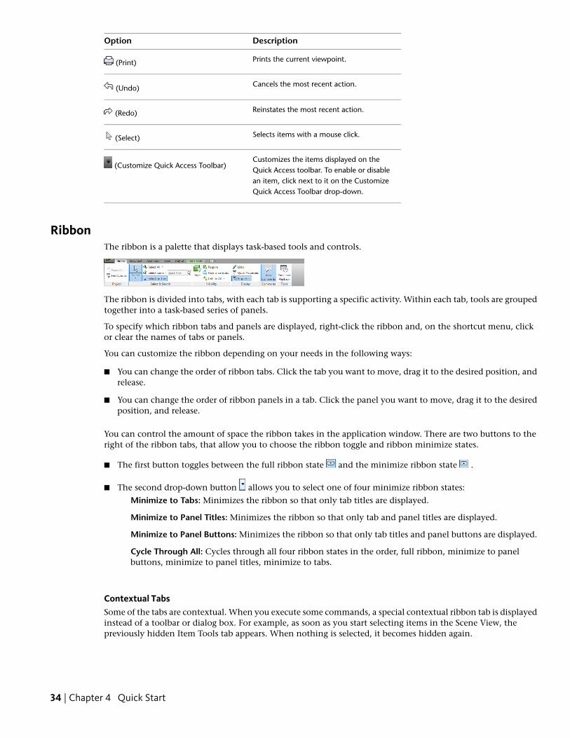
DescriptionOption
Prints the current viewpoint. (Print)
Cancels the most recent action. (Undo)
Reinstates the most recent action. (Redo)
Selects items with a mouse click. (Select)
Customizes the items displayed on theQuick Access toolbar. To enable or disable
(Customize Quick Access Toolbar)
an item, click next to it on the CustomizeQuick Access Toolbar drop-down.
RibbonThe ribbon is a palette that displays task-based tools and controls.
The ribbon is divided into tabs, with each tab is supporting a specific activity. Within each tab, tools are groupedtogether into a task-based series of panels.
To specify which ribbon tabs and panels are displayed, right-click the ribbon and, on the shortcut menu, clickor clear the names of tabs or panels.
You can customize the ribbon depending on your needs in the following ways:
■ You can change the order of ribbon tabs. Click the tab you want to move, drag it to the desired position, andrelease.
■ You can change the order of ribbon panels in a tab. Click the panel you want to move, drag it to the desiredposition, and release.
You can control the amount of space the ribbon takes in the application window. There are two buttons to theright of the ribbon tabs, that allow you to choose the ribbon toggle and ribbon minimize states.
■ The first button toggles between the full ribbon state and the minimize ribbon state .
■ The second drop-down button allows you to select one of four minimize ribbon states:
Minimize to Tabs: Minimizes the ribbon so that only tab titles are displayed.
Minimize to Panel Titles: Minimizes the ribbon so that only tab and panel titles are displayed.
Minimize to Panel Buttons: Minimizes the ribbon so that only tab titles and panel buttons are displayed.
Cycle Through All: Cycles through all four ribbon states in the order, full ribbon, minimize to panelbuttons, minimize to panel titles, minimize to tabs.
Contextual TabsSome of the tabs are contextual. When you execute some commands, a special contextual ribbon tab is displayedinstead of a toolbar or dialog box. For example, as soon as you start selecting items in the Scene View, thepreviously hidden Item Tools tab appears. When nothing is selected, it becomes hidden again.
34 | Chapter 4 Quick Start
Slideout PanelsA down arrow to the right of a panel title indicates that you can slide out the panel to display additional toolsand controls. By default, an expanded panel closes automatically when you click another panel. To keep a panel
expanded, click the push pin icon in the bottom-left corner of the slideout panel.
Floating PanelsIf you pull a panel off of a ribbon tab and into a different area in the application window or the desktop, thatpanel floats where you placed it. The floating panel remains open until you return it to the ribbon, even if youswitch ribbon tabs.
Tool Launcher
Some ribbon panels display a dialog box or a dockable window related to that panel. A tool launcher arrow in the lower-right corner of the panel indicates that you can display a related tool. Click the icon to display theassociated dialog box or dockable window.
Check BoxesCheck boxes allow you to toggle an option on or off.
SlidersWhen an option can be executed with varying intensity, the slider allows you to control the setting from lowerto higher, or reverse.
To display the ribbon
If you use the Classic user interface, you can switch back to the ribbon.
1 Click the application button ➤ Options.
2 In the Options Editor, expand the Interface node, and click the User Interface option.
3 On the User Interface page, select Standard from the User Interface drop-down list.
4 Click OK.
To hide or show a ribbon tab
1 Right-click anywhere inside the ribbon.
2 Under Tabs, click or clear the name of a tab.
To hide or show a ribbon panel
1 Click the ribbon tab that you want to organize.
2 Right-click the ribbon tab.
3 Under Panels, click or clear the name of a panel.
To show or hide text labels on ribbon panels
■ Right-click a ribbon tab, and click or clear Show Panel Titles.
To return a floating panel to the ribbon
■ Mouse over the right side of the floating panel and click the Return Panels to Ribbon icon.
To toggle the ribbon size
1 Click the drop-down arrow in the ribbon tab bar, and select the desired minimize ribbon state.
Parts of Autodesk Navisworks Interface | 35
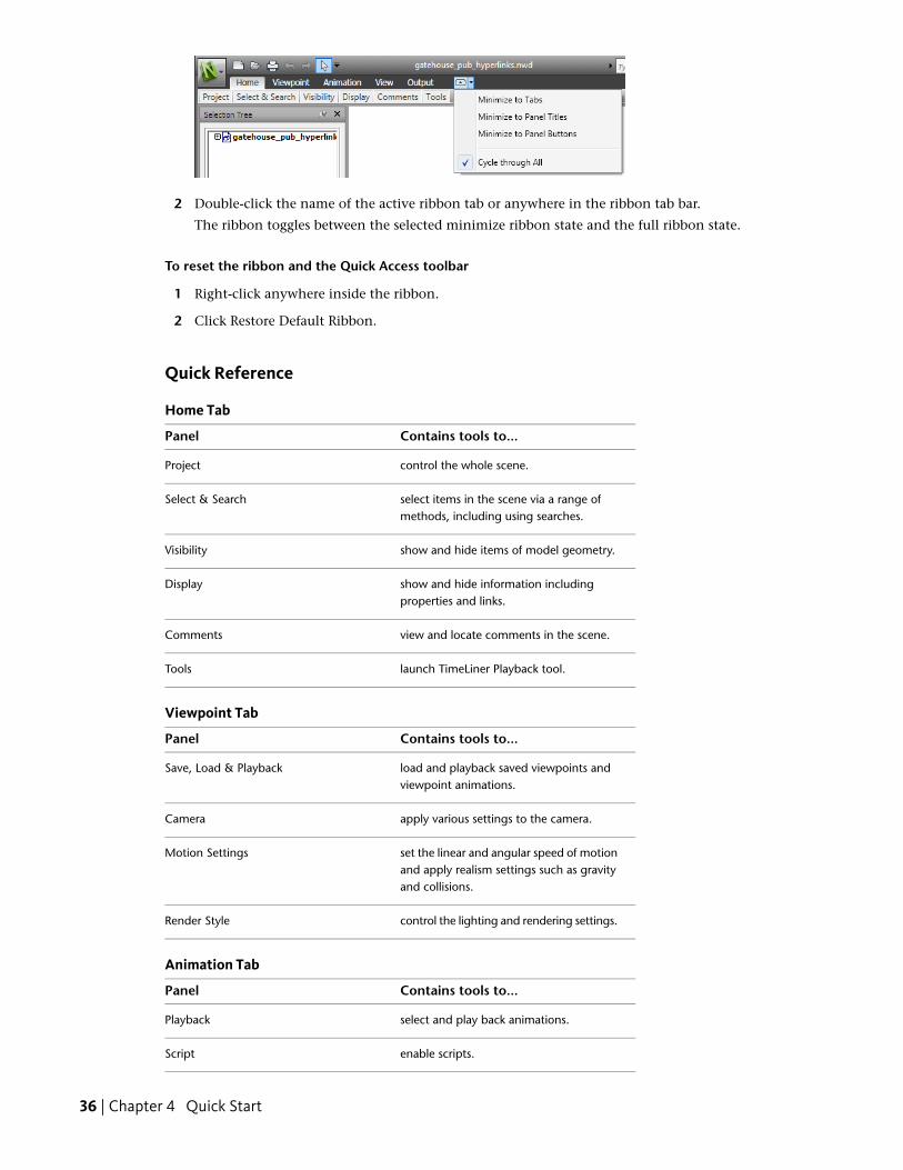
2 Double-click the name of the active ribbon tab or anywhere in the ribbon tab bar.
The ribbon toggles between the selected minimize ribbon state and the full ribbon state.
To reset the ribbon and the Quick Access toolbar
1 Right-click anywhere inside the ribbon.
2 Click Restore Default Ribbon.
Quick Reference
Home Tab
Contains tools to...Panel
control the whole scene.Project
select items in the scene via a range ofmethods, including using searches.
Select & Search
show and hide items of model geometry.Visibility
show and hide information includingproperties and links.
Display
view and locate comments in the scene.Comments
launch TimeLiner Playback tool.Tools
Viewpoint Tab
Contains tools to...Panel
load and playback saved viewpoints andviewpoint animations.
Save, Load & Playback
apply various settings to the camera.Camera
set the linear and angular speed of motionand apply realism settings such as gravityand collisions.
Motion Settings
control the lighting and rendering settings.Render Style
Animation Tab
Contains tools to...Panel
select and play back animations.Playback
enable scripts.Script
36 | Chapter 4 Quick Start
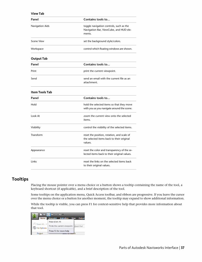
View Tab
Contains tools to...Panel
toggle navigation controls, such as theNavigation Bar, ViewCube, and HUD ele-ments.
Navigation Aids
set the background style/colors.Scene View
control which floating windows are shown.Workspace
Output Tab
Contains tools to...Panel
print the current viewpoint.Print
send an email with the current file as anattachment.
Send
Item Tools Tab
Contains tools to...Panel
hold the selected items so that they movewith you as you navigate around the scene.
Hold
zoom the current view onto the selecteditems.
Look At
control the visibility of the selected items.Visibility
reset the position, rotation, and scale ofthe selected items back to their originalvalues.
Transform
reset the color and transparency of the se-lected items back to their original values.
Appearance
reset the links on the selected items backto their original values.
Links
TooltipsPlacing the mouse pointer over a menu choice or a button shows a tooltip containing the name of the tool, akeyboard shortcut (if applicable), and a brief description of the tool.
Some tooltips on the application menu, Quick Access toolbar, and ribbon are progressive. If you leave the cursorover the menu choice or a button for another moment, the tooltip may expand to show additional information.
While the tooltip is visible, you can press F1 for context-sensitive help that provides more information aboutthat tool.
Parts of Autodesk Navisworks Interface | 37
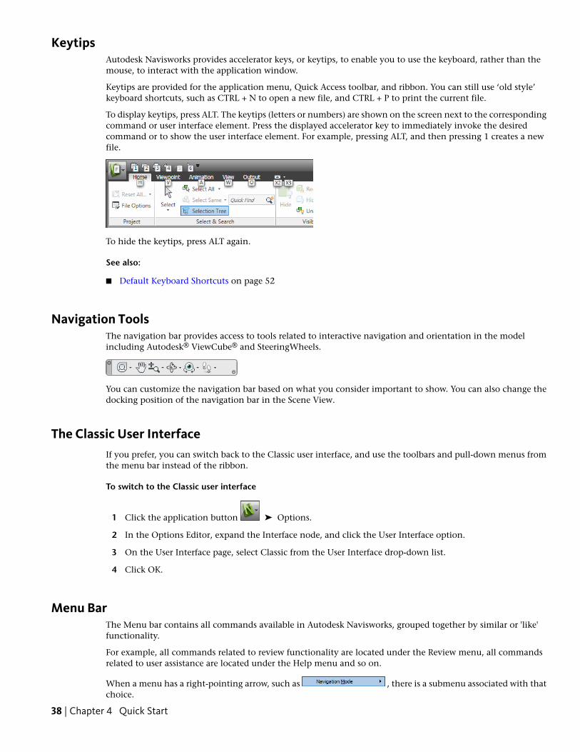
KeytipsAutodesk Navisworks provides accelerator keys, or keytips, to enable you to use the keyboard, rather than themouse, to interact with the application window.
Keytips are provided for the application menu, Quick Access toolbar, and ribbon. You can still use ‘old style’keyboard shortcuts, such as CTRL + N to open a new file, and CTRL + P to print the current file.
To display keytips, press ALT. The keytips (letters or numbers) are shown on the screen next to the correspondingcommand or user interface element. Press the displayed accelerator key to immediately invoke the desiredcommand or to show the user interface element. For example, pressing ALT, and then pressing 1 creates a newfile.
To hide the keytips, press ALT again.
See also:
■ Default Keyboard Shortcuts on page 52
Navigation ToolsThe navigation bar provides access to tools related to interactive navigation and orientation in the modelincluding Autodesk® ViewCube® and SteeringWheels.
You can customize the navigation bar based on what you consider important to show. You can also change thedocking position of the navigation bar in the Scene View.
The Classic User InterfaceIf you prefer, you can switch back to the Classic user interface, and use the toolbars and pull-down menus fromthe menu bar instead of the ribbon.
To switch to the Classic user interface
1 Click the application button ➤ Options.
2 In the Options Editor, expand the Interface node, and click the User Interface option.
3 On the User Interface page, select Classic from the User Interface drop-down list.
4 Click OK.
Menu BarThe Menu bar contains all commands available in Autodesk Navisworks, grouped together by similar or 'like'functionality.
For example, all commands related to review functionality are located under the Review menu, all commandsrelated to user assistance are located under the Help menu and so on.
When a menu has a right-pointing arrow, such as , there is a submenu associated with thatchoice.
38 | Chapter 4 Quick Start
When a menu item is followed by a series of dots, such as , there is a dialog box associatedwith that choice.
Quick Reference
File MenuThis menu contains commands for managing files.
DescriptionOption
Resets the program, and closes the cur-rently open Navisworks file.
New
Displays the Open dialog box.Open
Displays the Open URL dialog box.Open URL
Displays the Print dialog box.Print
Enables print preview mode.Print Preview
Displays the Print Setup dialog box.Print Settings
Send by Email
Displays shortcuts to the most recentlyopened files.
Recent Files
Exits the program.Exit
Edit MenuThis menu contains commands for locating, selecting and editing geometry in your model.
DescriptionOption
Reverses the last performed operation.Undo
Reverses the last operation performed bythe Undo command.
Redo
Gives you access to selection functionality.Select
Displays the Quick Find dialogbox.
Quick Find Next
Toggles hidden mode for selected items.Hidden
Toggles required mode for selected items.Required
Toggles hidden mode for unselected items.Hide Unselected
Reset Item
Enables you to reset all overridden itemsback to their original state.
Reset All
Parts of Autodesk Navisworks Interface | 39
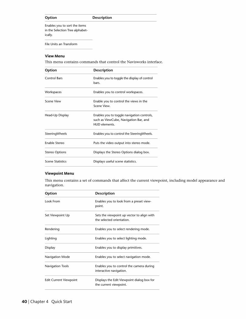
DescriptionOption
Enables you to sort the itemsin the Selection Tree alphabet-ically.
File Units an Transform
View MenuThis menu contains commands that control the Navisworks interface.
DescriptionOption
Enables you to toggle the display of controlbars.
Control Bars
Enables you to control workspaces.Workspaces
Enable you to control the views in theScene View.
Scene View
Enables you to toggle navigation controls,such as ViewCube, Navigation Bar, andHUD elements.
Head-Up Display
Enables you to control the SteeringWheels.SteeringWheels
Puts the video output into stereo mode.Enable Stereo
Displays the Stereo Options dialog box.Stereo Options
Displays useful scene statistics.Scene Statistics
Viewpoint Menu
This menu contains a set of commands that affect the current viewpoint, including model appearance andnavigation.
DescriptionOption
Enables you to look from a preset view-point.
Look From
Sets the viewpoint up vector to align withthe selected orientation.
Set Viewpoint Up
Enables you to select rendering mode.Rendering
Enables you to select lighting mode.Lighting
Enables you to display primitives.Display
Enables you to select navigation mode.Navigation Mode
Enables you to control the camera duringinteractive navigation.
Navigation Tools
Displays the Edit Viewpoint dialog box forthe current viewpoint.
Edit Current Viewpoint
40 | Chapter 4 Quick Start
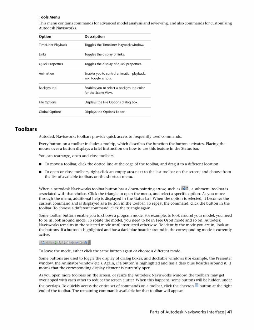
Tools MenuThis menu contains commands for advanced model analysis and reviewing, and also commands for customizingAutodesk Navisworks.
DescriptionOption
Toggles the TimeLiner Playback window.TimeLiner Playback
Toggles the display of links.Links
Toggles the display of quick properties.Quick Properties
Enables you to control animation playback,and toggle scripts.
Animation
Enables you to select a background colorfor the Scene View.
Background
Displays the File Options dialog box.File Options
Displays the Options Editor.Global Options
ToolbarsAutodesk Navisworks toolbars provide quick access to frequently used commands.
Every button on a toolbar includes a tooltip, which describes the function the button activates. Placing themouse over a button displays a brief instruction on how to use this feature in the Status bar.
You can rearrange, open and close toolbars:
■ To move a toolbar, click the dotted line at the edge of the toolbar, and drag it to a different location.
■ To open or close toolbars, right-click an empty area next to the last toolbar on the screen, and choose fromthe list of available toolbars on the shortcut menu.
When a Autodesk Navisworks toolbar button has a down-pointing arrow, such as , a submenu toolbar isassociated with that choice. Click the triangle to open the menu, and select a specific option. As you movethrough the menu, additional help is displayed in the Status bar. When the option is selected, it becomes thecurrent command and is displayed as a button in the toolbar. To repeat the command, click the button in thetoolbar. To choose a different command, click the triangle again.
Some toolbar buttons enable you to choose a program mode. For example, to look around your model, you needto be in look around mode. To rotate the model, you need to be in Free Orbit mode and so on. AutodeskNavisworks remains in the selected mode until instructed otherwise. To identify the mode you are in, look atthe buttons. If a button is highlighted and has a dark blue boarder around it, the corresponding mode is currentlyactive.
To leave the mode, either click the same button again or choose a different mode.
Some buttons are used to toggle the display of dialog boxes, and dockable windows (for example, the Presenterwindow, the Animator window etc.). Again, if a button is highlighted and has a dark blue boarder around it, itmeans that the corresponding display element is currently open.
As you open more toolbars on the screen, or resize the Autodesk Navisworks window, the toolbars may getoverlapped with each other to reduce the screen clutter. When this happens, some buttons will be hidden under
the overlaps. To quickly access the entire set of commands on a toolbar, click the chevron button at the rightend of the toolbar. The remaining commands available for that toolbar will appear.
Parts of Autodesk Navisworks Interface | 41
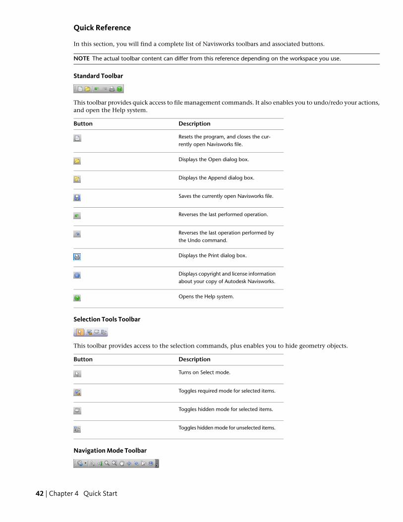
Quick Reference
In this section, you will find a complete list of Navisworks toolbars and associated buttons.
NOTE The actual toolbar content can differ from this reference depending on the workspace you use.
Standard Toolbar
This toolbar provides quick access to file management commands. It also enables you to undo/redo your actions,and open the Help system.
DescriptionButton
Resets the program, and closes the cur-rently open Navisworks file.
Displays the Open dialog box.
Displays the Append dialog box.
Saves the currently open Navisworks file.
Reverses the last performed operation.
Reverses the last operation performed bythe Undo command.
Displays the Print dialog box.
Displays copyright and license informationabout your copy of Autodesk Navisworks.
Opens the Help system.
Selection Tools Toolbar
This toolbar provides access to the selection commands, plus enables you to hide geometry objects.
DescriptionButton
Turns on Select mode.
Toggles required mode for selected items.
Toggles hidden mode for selected items.
Toggles hidden mode for unselected items.
Navigation Mode Toolbar
42 | Chapter 4 Quick Start
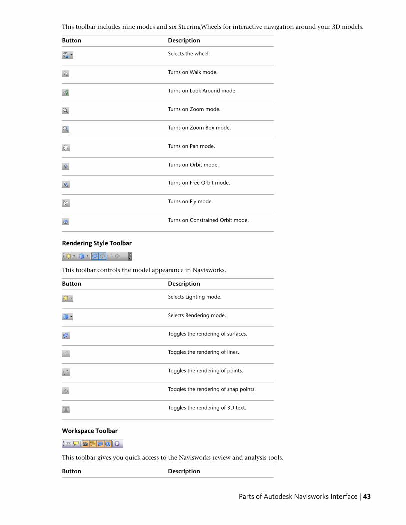
This toolbar includes nine modes and six SteeringWheels for interactive navigation around your 3D models.
DescriptionButton
Selects the wheel.
Turns on Walk mode.
Turns on Look Around mode.
Turns on Zoom mode.
Turns on Zoom Box mode.
Turns on Pan mode.
Turns on Orbit mode.
Turns on Free Orbit mode.
Turns on Fly mode.
Turns on Constrained Orbit mode.
Rendering Style Toolbar
This toolbar controls the model appearance in Navisworks.
DescriptionButton
Selects Lighting mode.
Selects Rendering mode.
Toggles the rendering of surfaces.
Toggles the rendering of lines.
Toggles the rendering of points.
Toggles the rendering of snap points.
Toggles the rendering of 3D text.
Workspace Toolbar
This toolbar gives you quick access to the Navisworks review and analysis tools.
DescriptionButton
Parts of Autodesk Navisworks Interface | 43
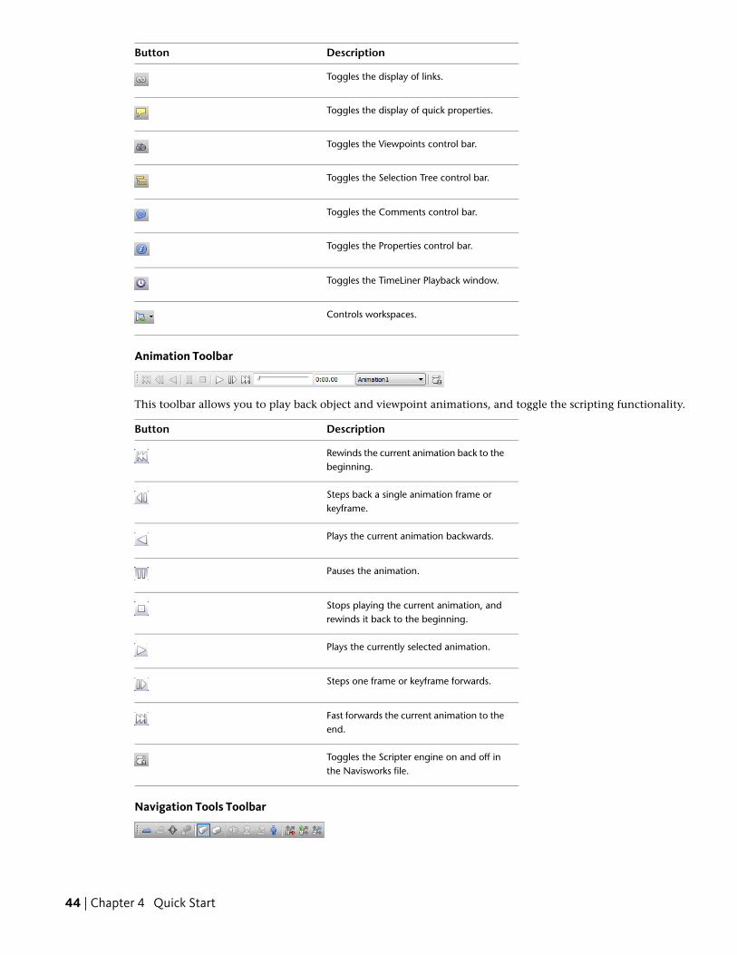
DescriptionButton
Toggles the display of links.
Toggles the display of quick properties.
Toggles the Viewpoints control bar.
Toggles the Selection Tree control bar.
Toggles the Comments control bar.
Toggles the Properties control bar.
Toggles the TimeLiner Playback window.
Controls workspaces.
Animation Toolbar
This toolbar allows you to play back object and viewpoint animations, and toggle the scripting functionality.
DescriptionButton
Rewinds the current animation back to thebeginning.
Steps back a single animation frame orkeyframe.
Plays the current animation backwards.
Pauses the animation.
Stops playing the current animation, andrewinds it back to the beginning.
Plays the currently selected animation.
Steps one frame or keyframe forwards.
Fast forwards the current animation to theend.
Toggles the Scripter engine on and off inthe Navisworks file.
Navigation Tools Toolbar
44 | Chapter 4 Quick Start
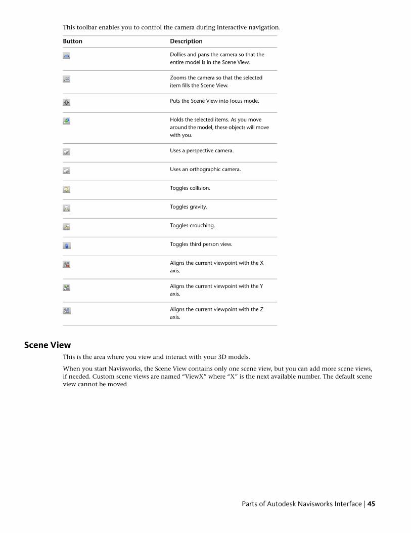
This toolbar enables you to control the camera during interactive navigation.
DescriptionButton
Dollies and pans the camera so that theentire model is in the Scene View.
Zooms the camera so that the selecteditem fills the Scene View.
Puts the Scene View into focus mode.
Holds the selected items. As you movearound the model, these objects will movewith you.
Uses a perspective camera.
Uses an orthographic camera.
Toggles collision.
Toggles gravity.
Toggles crouching.
Toggles third person view.
Aligns the current viewpoint with the Xaxis.
Aligns the current viewpoint with the Yaxis.
Aligns the current viewpoint with the Zaxis.
Scene ViewThis is the area where you view and interact with your 3D models.
When you start Navisworks, the Scene View contains only one scene view, but you can add more scene views,if needed. Custom scene views are named “ViewX” where “X” is the next available number. The default sceneview cannot be moved
Parts of Autodesk Navisworks Interface | 45
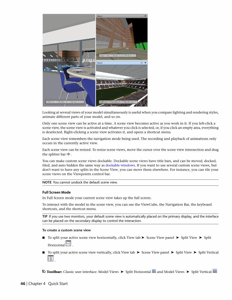
Looking at several views of your model simultaneously is useful when you compare lighting and rendering styles,animate different parts of your model, and so on.
Only one scene view can be active at a time. A scene view becomes active as you work in it. If you left-click ascene view, the scene view is activated and whatever you click is selected, or, if you click an empty area, everythingis deselected. Right-clicking a scene view activates it, and opens a shortcut menu.
Each scene view remembers the navigation mode being used. The recording and playback of animations onlyoccurs in the currently active view.
Each scene view can be resized. To resize scene views, move the cursor over the scene view intersection and dragthe splitter bar .
You can make custom scene views dockable. Dockable scene views have title bars, and can be moved, docked,tiled, and auto hidden the same way as dockable windows. If you want to use several custom scene views, butdon't want to have any splits in the Scene View, you can move them elsewhere. For instance, you can tile yourscene views on the Viewpoints control bar.
NOTE You cannot undock the default scene view.
Full Screen ModeIn Full Screen mode your current scene view takes up the full screen.
To interact with the model in the scene view, you can use the ViewCube, the Navigation Bar, the keyboardshortcuts, and the shortcut menu.
TIP If you use two monitors, your default scene view is automatically placed on the primary display, and the interfacecan be placed on the secondary display to control the interaction.
To create a custom scene view
■ To split your active scene view horizontally, click View tab ➤ Scene View panel ➤ Split View ➤ Split
Horizontal .
■ To split your active scene view vertically, click View tab ➤ Scene View panel ➤ Split View ➤ Split Vertical
.
Toolbar: Classic user interface: Model Views ➤ Split Horizontal and Model Views ➤ Split Vertical
46 | Chapter 4 Quick Start
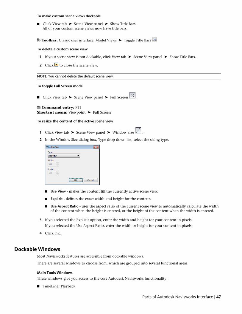
To make custom scene views dockable
■ Click View tab ➤ Scene View panel ➤ Show Title Bars.All of your custom scene views now have title bars.
Toolbar: Classic user interface: Model Views ➤ Toggle Title Bars
To delete a custom scene view
1 If your scene view is not dockable, click View tab ➤ Scene View panel ➤ Show Title Bars.
2 Click to close the scene view.
NOTE You cannot delete the default scene view.
To toggle Full Screen mode
■ Click View tab ➤ Scene View panel ➤ Full Screen .
Command entry: F11Shortcut menu: Viewpoint ➤ Full Screen
To resize the content of the active scene view
1 Click View tab ➤ Scene View panel ➤ Window Size .
2 In the Window Size dialog box, Type drop-down list, select the sizing type.
■ Use View - makes the content fill the currently active scene view.
■ Explicit - defines the exact width and height for the content.
■ Use Aspect Ratio - uses the aspect ratio of the current scene view to automatically calculate the widthof the content when the height is entered, or the height of the content when the width is entered.
3 If you selected the Explicit option, enter the width and height for your content in pixels.
If you selected the Use Aspect Ratio, enter the width or height for your content in pixels.
4 Click OK.
Dockable WindowsMost Navisworks features are accessible from dockable windows.
There are several windows to choose from, which are grouped into several functional areas:
Main Tools WindowsThese windows give you access to the core Autodesk Navisworks functionality:
■ TimeLiner Playback
Parts of Autodesk Navisworks Interface | 47
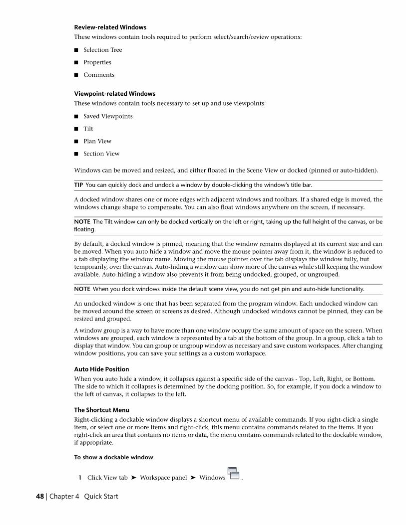
Review-related WindowsThese windows contain tools required to perform select/search/review operations:
■ Selection Tree
■ Properties
■ Comments
Viewpoint-related WindowsThese windows contain tools necessary to set up and use viewpoints:
■ Saved Viewpoints
■ Tilt
■ Plan View
■ Section View
Windows can be moved and resized, and either floated in the Scene View or docked (pinned or auto-hidden).
TIP You can quickly dock and undock a window by double-clicking the window’s title bar.
A docked window shares one or more edges with adjacent windows and toolbars. If a shared edge is moved, thewindows change shape to compensate. You can also float windows anywhere on the screen, if necessary.
NOTE The Tilt window can only be docked vertically on the left or right, taking up the full height of the canvas, or befloating.
By default, a docked window is pinned, meaning that the window remains displayed at its current size and canbe moved. When you auto hide a window and move the mouse pointer away from it, the window is reduced toa tab displaying the window name. Moving the mouse pointer over the tab displays the window fully, buttemporarily, over the canvas. Auto-hiding a window can show more of the canvas while still keeping the windowavailable. Auto-hiding a window also prevents it from being undocked, grouped, or ungrouped.
NOTE When you dock windows inside the default scene view, you do not get pin and auto-hide functionality.
An undocked window is one that has been separated from the program window. Each undocked window canbe moved around the screen or screens as desired. Although undocked windows cannot be pinned, they can beresized and grouped.
A window group is a way to have more than one window occupy the same amount of space on the screen. Whenwindows are grouped, each window is represented by a tab at the bottom of the group. In a group, click a tab todisplay that window. You can group or ungroup window as necessary and save custom workspaces. After changingwindow positions, you can save your settings as a custom workspace.
Auto Hide PositionWhen you auto hide a window, it collapses against a specific side of the canvas - Top, Left, Right, or Bottom.The side to which it collapses is determined by the docking position. So, for example, if you dock a window tothe left of canvas, it collapses to the left.
The Shortcut MenuRight-clicking a dockable window displays a shortcut menu of available commands. If you right-click a singleitem, or select one or more items and right-click, this menu contains commands related to the items. If youright-click an area that contains no items or data, the menu contains commands related to the dockable window,if appropriate.
To show a dockable window
1 Click View tab ➤ Workspace panel ➤ Windows .
48 | Chapter 4 Quick Start
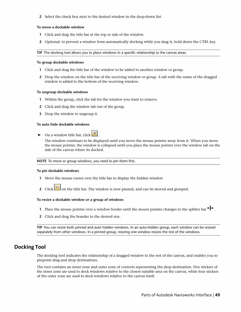
2 Select the check box next to the desired window in the drop-down list.
To move a dockable window
1 Click and drag the title bar at the top or side of the window.
2 Optional: to prevent a window from automatically docking while you drag it, hold down the CTRL key.
TIP The docking tool allows you to place windows in a specific relationship to the canvas areas.
To group dockable windows
1 Click and drag the title bar of the window to be added to another window or group.
2 Drop the window on the title bar of the receiving window or group. A tab with the name of the draggedwindow is added to the bottom of the receiving window.
To ungroup dockable windows
1 Within the group, click the tab for the window you want to remove.
2 Click and drag the window tab out of the group.
3 Drop the window to ungroup it.
To auto hide dockable windows
➤ On a window title bar, click .
The window continues to be displayed until you move the mouse pointer away from it. When you movethe mouse pointer, the window is collapsed until you place the mouse pointer over the window tab on theside of the canvas where its docked.
NOTE To move or group windows, you need to pin them first.
To pin dockable windows
1 Move the mouse cursor over the title bar to display the hidden window.
2 Click on the title bar. The window is now pinned, and can be moved and grouped.
To resize a dockable window or a group of windows
1 Place the mouse pointer over a window border until the mouse pointer changes to the splitter bar .
2 Click and drag the boarder to the desired size.
TIP You can resize both pinned and auto hidden windows. In an auto-hidden group, each window can be resizedseparately from other windows. In a pinned group, resizing one window resizes the rest of the windows.
Docking ToolThe docking tool indicates the relationship of a dragged window to the rest of the canvas, and enables you topinpoint drag and drop destinations.
The tool contains an inner zone and outer zone of controls representing the drop destination. Five stickers ofthe inner zone are used to dock windows relative to the closest suitable area on the canvas, while four stickersof the outer zone are used to dock windows relative to the canvas itself.
Parts of Autodesk Navisworks Interface | 49
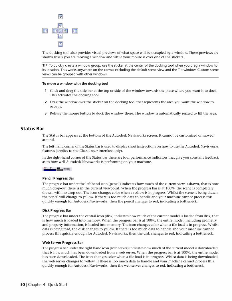
The docking tool also provides visual previews of what space will be occupied by a window. These previews areshown when you are moving a window and while your mouse is over one of the stickers.
TIP To quickly create a window group, use the sticker at the center of the docking tool when you drag a window toits location. This works anywhere on the canvas excluding the default scene view and the Tilt window. Custom sceneviews can be grouped with other windows.
To move a window with the docking tool
1 Click and drag the title bar at the top or side of the window towards the place where you want it to dock.This activates the docking tool.
2 Drag the window over the sticker on the docking tool that represents the area you want the window tooccupy.
3 Release the mouse button to dock the window there. The window is automatically resized to fill the area.
Status BarThe Status bar appears at the bottom of the Autodesk Navisworks screen. It cannot be customized or movedaround.
The left-hand corner of the Status bar is used to display short instructions on how to use the Autodesk Navisworksfeatures (applies to the Classic user interface only).
In the right-hand corner of the Status bar there are four performance indicators that give you constant feedbackas to how well Autodesk Navisworks is performing on your machine.
Pencil Progress BarThe progress bar under the left hand icon (pencil) indicates how much of the current view is drawn, that is howmuch drop-out there is in the current viewpoint. When the progress bar is at 100%, the scene is completelydrawn, with no drop-out. The icon changes color when a redraw is in progress. Whilst the scene is being drawn,the pencil will change to yellow. If there is too much data to handle and your machine cannot process thisquickly enough for Autodesk Navisworks, then the pencil changes to red, indicating a bottleneck.
Disk Progress BarThe progress bar under the central icon (disk) indicates how much of the current model is loaded from disk, thatis how much is loaded into memory. When the progress bar is at 100%, the entire model, including geometryand property information, is loaded into memory. The icon changes color when a file load is in progress. Whilstdata is being read, the disk changes to yellow. If there is too much data to handle and your machine cannotprocess this quickly enough for Autodesk Navisworks, then the disk changes to red, indicating a bottleneck.
Web Server Progress BarThe progress bar under the right hand icon (web server) indicates how much of the current model is downloaded,that is how much has been downloaded from a web server. When the progress bar is at 100%, the entire modelhas been downloaded. The icon changes color when a file load is in progress. Whilst data is being downloaded,the web server changes to yellow. If there is too much data to handle and your machine cannot process thisquickly enough for Autodesk Navisworks, then the web server changes to red, indicating a bottleneck.
50 | Chapter 4 Quick Start
Memory BarThe field to the right of the icons reports the amount of memory currently being used by Autodesk Navisworks.This is reported in Megabytes (MB).
Undo/Redo CommandsYou can undo or redo your actions in Autodesk Navisworks.
The default settings are adequate for regular Autodesk Navisworks usage, but you can adjust the amount of spaceallocated to the undo/redo buffer, if necessary.
To undo an action
■ Click Undo on the Quick Access toolbar.
Command entry: CTRL + Z
Toolbar: Classic user interface: Standard ➤ Undo
To redo an action
■ Click Redo on the Quick Access toolbar.
Command entry: CTRL + Y
Toolbar: Classic user interface: Standard ➤ Redo
Autodesk Navisworks WorkspacesWorkspaces retain information about which windows are open, their positions, and the size of the applicationwindow.
Workspaces do not retain changes made to the ribbon or the Quick Access toolbar.
NOTE In the Classic user interface mode (that is, the ribbon is turned off), workspaces retain information about thedockable windows and the toolbars.
The workspaces can be shared with other users. You could, for example, create separate workspaces for occasionaland power Navisworks users, or setup your own corporate standard.
Autodesk Navisworks comes with several pre-configured workspaces:
■ Safe Mode - selects the layout with the minimum features.
■ Navisworks Standard - selects the layout with commonly-used windows auto-hidden as tabs.
■ Navisworks Minimal - selects the layout giving the most space to the Scene View.
You can use these workspaces as-is or modify them in accordance to your requirements. When you first startNavisworks, the Navisworks Minimal workspace is used. You can choose a different workspace at any time by
clicking View tab ➤ Workspace panel ➤ Load Workspace , and then selecting the required workspace fromthe list.
Toolbar: Classic user interface: Workspace ➤ Workspaces
To save current layout to a new workspace
1 Set up your design review layout. For example, you can group together the Properties and Saved Viewpointswindows.
If you use the Classic user interface mode, for example, you can close all toolbars except the Standard,Selection Tools, Navigation Mode, and Workspace.
Undo/Redo Commands | 51
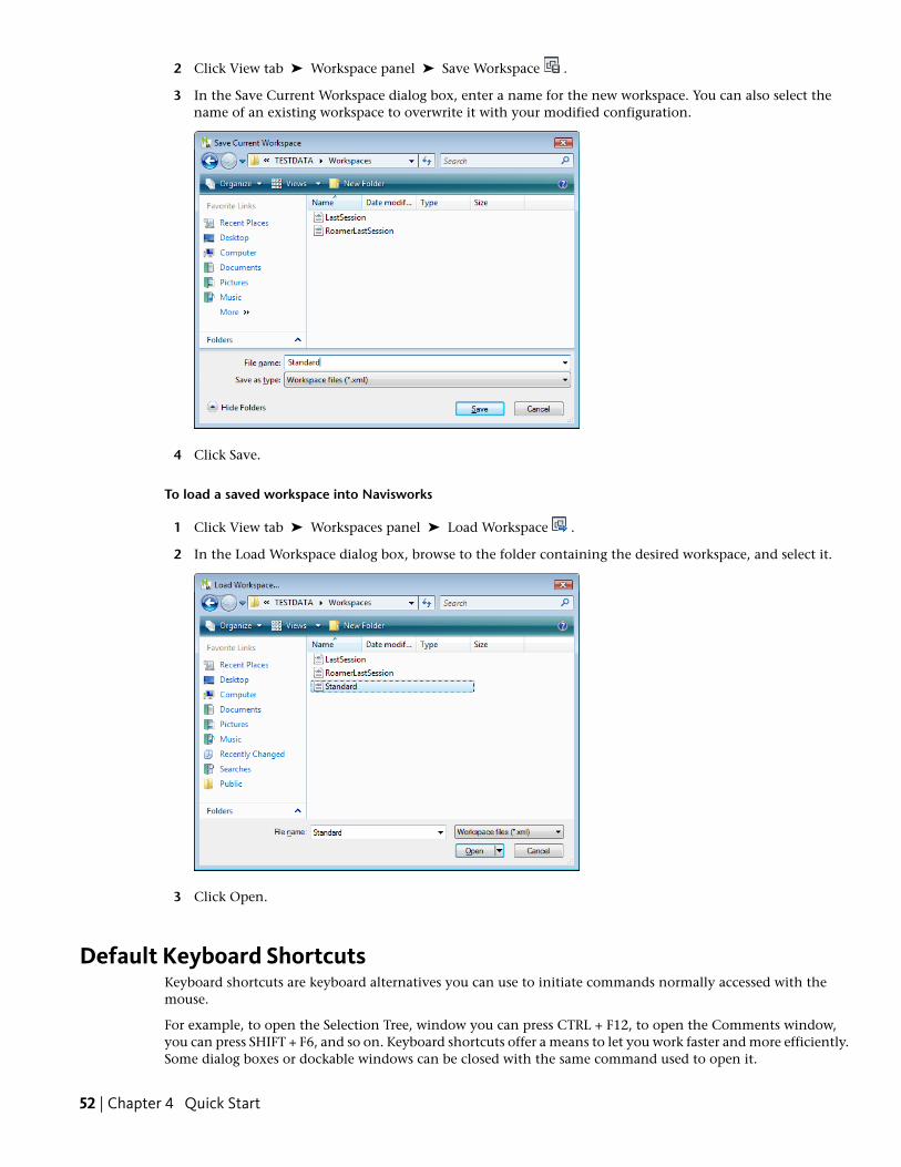
2 Click View tab ➤ Workspace panel ➤ Save Workspace .
3 In the Save Current Workspace dialog box, enter a name for the new workspace. You can also select thename of an existing workspace to overwrite it with your modified configuration.
4 Click Save.
To load a saved workspace into Navisworks
1 Click View tab ➤ Workspaces panel ➤ Load Workspace .
2 In the Load Workspace dialog box, browse to the folder containing the desired workspace, and select it.
3 Click Open.
Default Keyboard ShortcutsKeyboard shortcuts are keyboard alternatives you can use to initiate commands normally accessed with themouse.
For example, to open the Selection Tree, window you can press CTRL + F12, to open the Comments window,you can press SHIFT + F6, and so on. Keyboard shortcuts offer a means to let you work faster and more efficiently.Some dialog boxes or dockable windows can be closed with the same command used to open it.
52 | Chapter 4 Quick Start
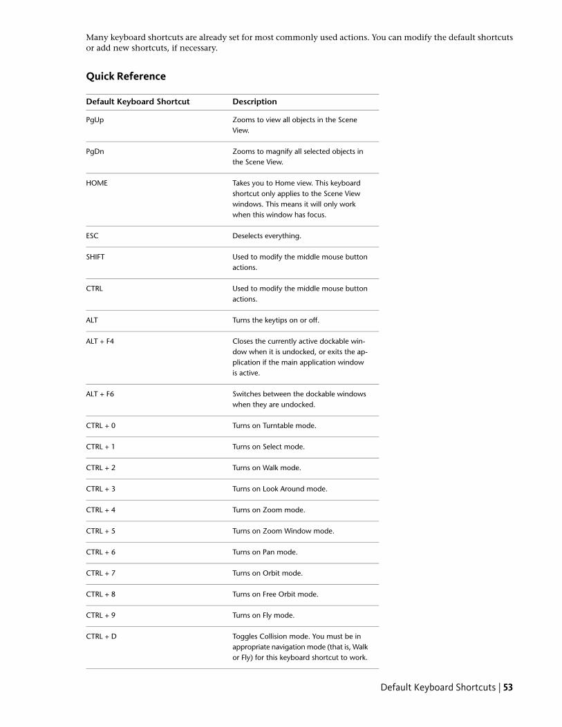
Many keyboard shortcuts are already set for most commonly used actions. You can modify the default shortcutsor add new shortcuts, if necessary.
Quick Reference
DescriptionDefault Keyboard Shortcut
Zooms to view all objects in the SceneView.
PgUp
Zooms to magnify all selected objects inthe Scene View.
PgDn
Takes you to Home view. This keyboardshortcut only applies to the Scene View
HOME
windows. This means it will only workwhen this window has focus.
Deselects everything.ESC
Used to modify the middle mouse buttonactions.
SHIFT
Used to modify the middle mouse buttonactions.
CTRL
Turns the keytips on or off.ALT
Closes the currently active dockable win-dow when it is undocked, or exits the ap-
ALT + F4
plication if the main application windowis active.
Switches between the dockable windowswhen they are undocked.
ALT + F6
Turns on Turntable mode.CTRL + 0
Turns on Select mode.CTRL + 1
Turns on Walk mode.CTRL + 2
Turns on Look Around mode.CTRL + 3
Turns on Zoom mode.CTRL + 4
Turns on Zoom Window mode.CTRL + 5
Turns on Pan mode.CTRL + 6
Turns on Orbit mode.CTRL + 7
Turns on Free Orbit mode.CTRL + 8
Turns on Fly mode.CTRL + 9
Toggles Collision mode. You must be inappropriate navigation mode (that is, Walkor Fly) for this keyboard shortcut to work.
CTRL + D
Default Keyboard Shortcuts | 53
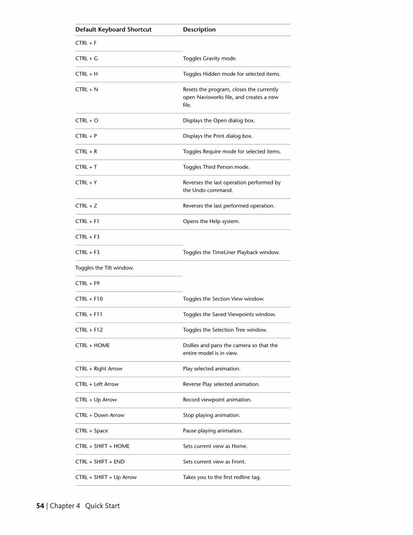
DescriptionDefault Keyboard Shortcut
CTRL + F
Toggles Gravity mode.CTRL + G
Toggles Hidden mode for selected items.CTRL + H
Resets the program, closes the currentlyopen Navisworks file, and creates a newfile.
CTRL + N
Displays the Open dialog box.CTRL + O
Displays the Print dialog box.CTRL + P
Toggles Require mode for selected items.CTRL + R
Toggles Third Person mode.CTRL + T
Reverses the last operation performed bythe Undo command.
CTRL + Y
Reverses the last performed operation.CTRL + Z
Opens the Help system.CTRL + F1
CTRL + F3
Toggles the TimeLiner Playback window.CTRL + F3
Toggles the Tilt window.
CTRL + F9
Toggles the Section View window.CTRL + F10
Toggles the Saved Viewpoints window.CTRL + F11
Toggles the Selection Tree window.CTRL + F12
Dollies and pans the camera so that theentire model is in view.
CTRL + HOME
Play selected animation.CTRL + Right Arrow
Reverse Play selected animation.CTRL + Left Arrow
Record viewpoint animation.CTRL + Up Arrow
Stop playing animation.CTRL + Down Arrow
Pause playing animation.CTRL + Space
Sets current view as Home.CTRL + SHIFT + HOME
Sets current view as Front.CTRL + SHIFT + END
Takes you to the first redline tag.CTRL + SHIFT + Up Arrow
54 | Chapter 4 Quick Start
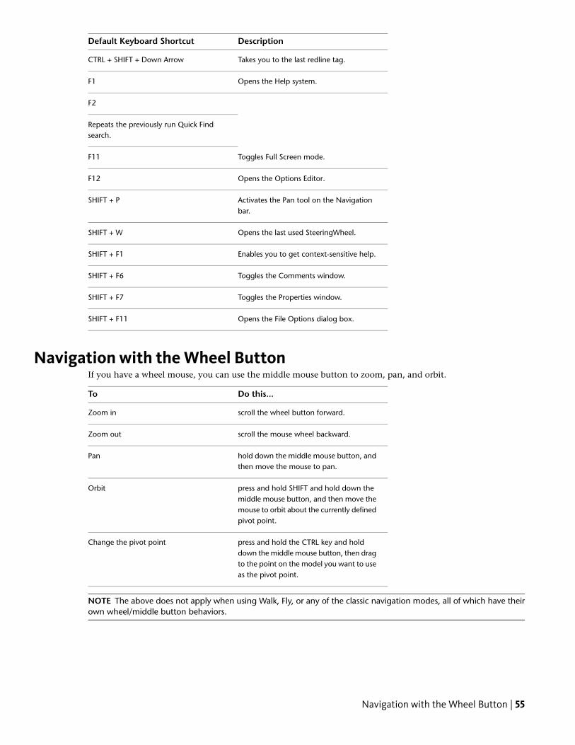
DescriptionDefault Keyboard Shortcut
Takes you to the last redline tag.CTRL + SHIFT + Down Arrow
Opens the Help system.F1
F2
Repeats the previously run Quick Findsearch.
Toggles Full Screen mode.F11
Opens the Options Editor.F12
Activates the Pan tool on the Navigationbar.
SHIFT + P
Opens the last used SteeringWheel.SHIFT + W
Enables you to get context-sensitive help.SHIFT + F1
Toggles the Comments window.SHIFT + F6
Toggles the Properties window.SHIFT + F7
Opens the File Options dialog box.SHIFT + F11
Navigation with the Wheel ButtonIf you have a wheel mouse, you can use the middle mouse button to zoom, pan, and orbit.
Do this...To
scroll the wheel button forward.Zoom in
scroll the mouse wheel backward.Zoom out
hold down the middle mouse button, andthen move the mouse to pan.
Pan
press and hold SHIFT and hold down themiddle mouse button, and then move the
Orbit
mouse to orbit about the currently definedpivot point.
press and hold the CTRL key and holddown the middle mouse button, then drag
Change the pivot point
to the point on the model you want to useas the pivot point.
NOTE The above does not apply when using Walk, Fly, or any of the classic navigation modes, all of which have theirown wheel/middle button behaviors.
Navigation with the Wheel Button | 55
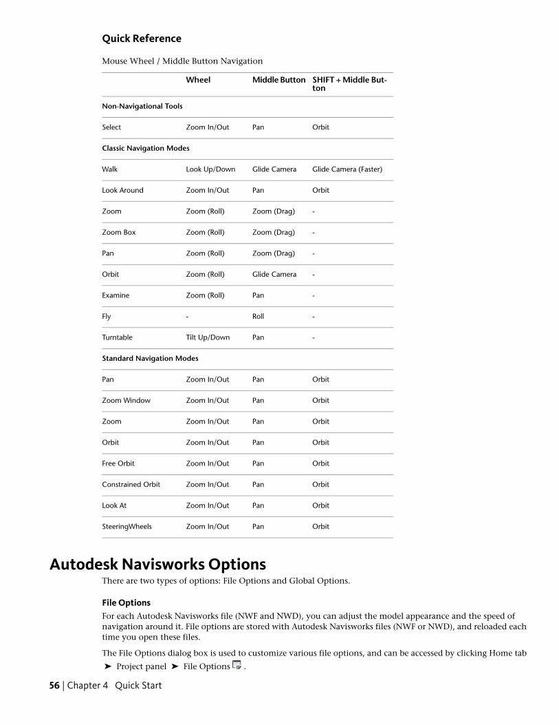
Quick Reference
Mouse Wheel / Middle Button Navigation
SHIFT + Middle But-ton
Middle ButtonWheel
Non-Navigational Tools
OrbitPanZoom In/OutSelect
Classic Navigation Modes
Glide Camera (Faster)Glide CameraLook Up/DownWalk
OrbitPanZoom In/OutLook Around
-Zoom (Drag)Zoom (Roll)Zoom
-Zoom (Drag)Zoom (Roll)Zoom Box
-Zoom (Drag)Zoom (Roll)Pan
-Glide CameraZoom (Roll)Orbit
-PanZoom (Roll)Examine
-Roll-Fly
-PanTilt Up/DownTurntable
Standard Navigation Modes
OrbitPanZoom In/OutPan
OrbitPanZoom In/OutZoom Window
OrbitPanZoom In/OutZoom
OrbitPanZoom In/OutOrbit
OrbitPanZoom In/OutFree Orbit
OrbitPanZoom In/OutConstrained Orbit
OrbitPanZoom In/OutLook At
OrbitPanZoom In/OutSteeringWheels
Autodesk Navisworks OptionsThere are two types of options: File Options and Global Options.
File OptionsFor each Autodesk Navisworks file (NWF and NWD), you can adjust the model appearance and the speed ofnavigation around it. File options are stored with Autodesk Navisworks files (NWF or NWD), and reloaded eachtime you open these files.
The File Options dialog box is used to customize various file options, and can be accessed by clicking Home tab
➤ Project panel ➤ File Options .
56 | Chapter 4 Quick Start
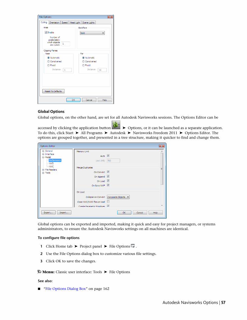
Global OptionsGlobal options, on the other hand, are set for all Autodesk Navisworks sessions. The Options Editor can be
accessed by clicking the application button ➤ Options, or it can be launched as a separate application.To do this, click Start ➤ All Programs ➤ Autodesk ➤ Navisworks Freedom 2011 ➤ Options Editor. Theoptions are grouped together, and presented in a tree structure, making it quicker to find and change them.
Global options can be exported and imported, making it quick and easy for project managers, or systemsadministrators, to ensure the Autodesk Navisworks settings on all machines are identical.
To configure file options
1 Click Home tab ➤ Project panel ➤ File Options .
2 Use the File Options dialog box to customize various file settings.
3 Click OK to save the changes.
Menu: Classic user interface: Tools ➤ File Options
See also:
■ “File Options Dialog Box” on page 162
Autodesk Navisworks Options | 57
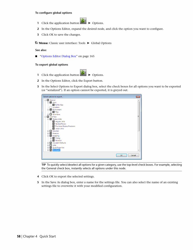
To configure global options
1 Click the application button ➤ Options.
2 In the Options Editor, expand the desired node, and click the option you want to configure.
3 Click OK to save the changes.
Menu: Classic user interface: Tools ➤ Global Options
See also:
■ “Options Editor Dialog Box” on page 165
To export global options
1 Click the application button ➤ Options.
2 In the Options Editor, click the Export button.
3 In the Select Options to Export dialog box, select the check boxes for all options you want to be exported(or “serialized”). If an option cannot be exported, it is greyed out.
TIP To quickly select/deselect all options for a given category, use the top-level check boxes. For example, selectingthe General check box, instantly selects all options under this node.
4 Click OK to export the selected settings.
5 In the Save As dialog box, enter a name for the settings file. You can also select the name of an existingsettings file to overwrite it with your modified configuration.
58 | Chapter 4 Quick Start
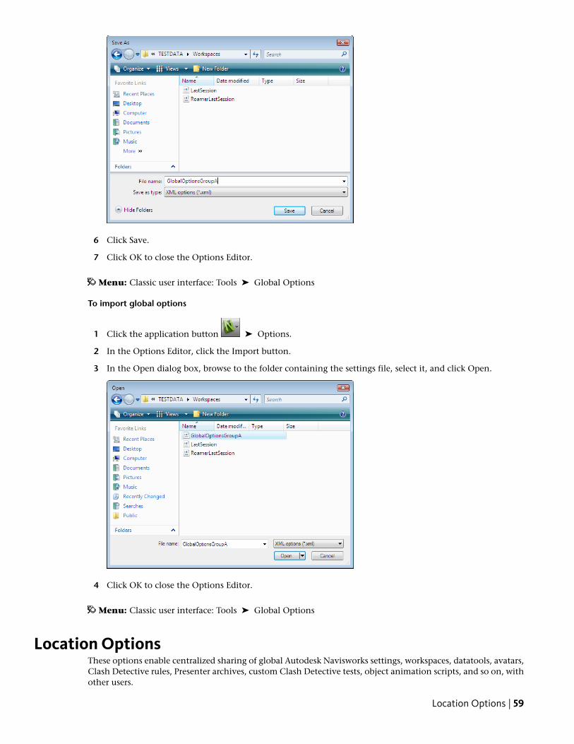
6 Click Save.
7 Click OK to close the Options Editor.
Menu: Classic user interface: Tools ➤ Global Options
To import global options
1 Click the application button ➤ Options.
2 In the Options Editor, click the Import button.
3 In the Open dialog box, browse to the folder containing the settings file, select it, and click Open.
4 Click OK to close the Options Editor.
Menu: Classic user interface: Tools ➤ Global Options
Location OptionsThese options enable centralized sharing of global Autodesk Navisworks settings, workspaces, datatools, avatars,Clash Detective rules, Presenter archives, custom Clash Detective tests, object animation scripts, and so on, withother users.
Location Options | 59
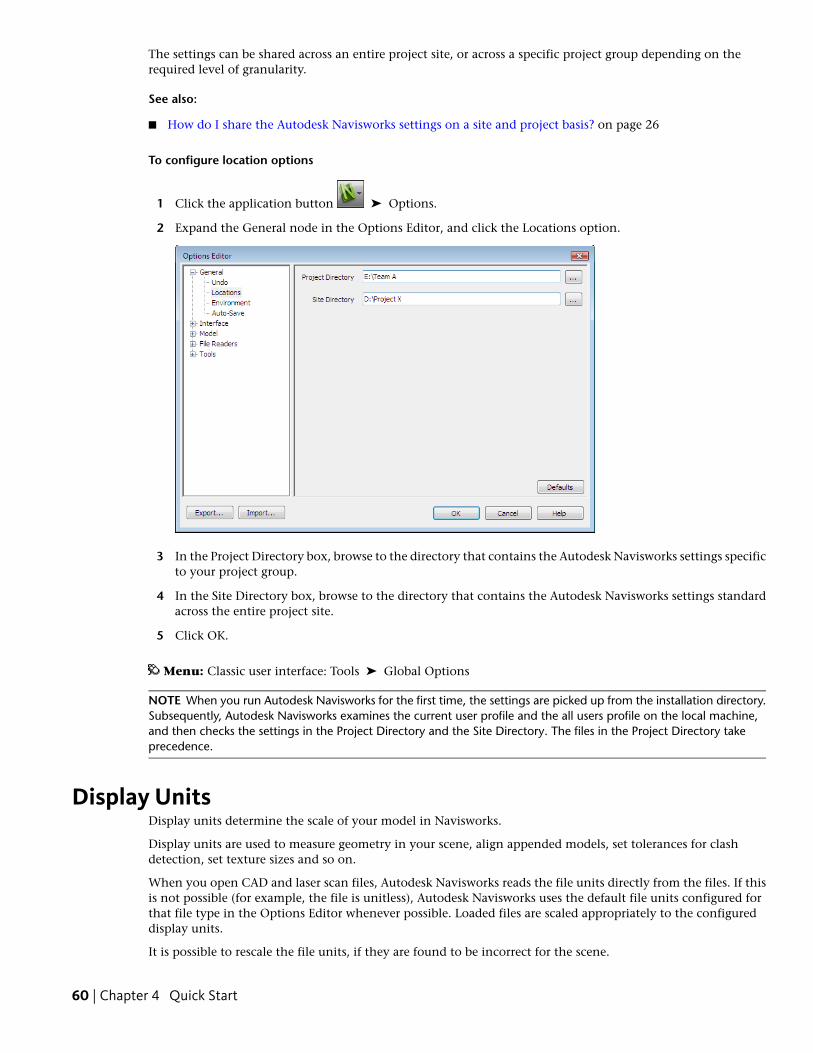
The settings can be shared across an entire project site, or across a specific project group depending on therequired level of granularity.
See also:
■ How do I share the Autodesk Navisworks settings on a site and project basis? on page 26
To configure location options
1 Click the application button ➤ Options.
2 Expand the General node in the Options Editor, and click the Locations option.
3 In the Project Directory box, browse to the directory that contains the Autodesk Navisworks settings specificto your project group.
4 In the Site Directory box, browse to the directory that contains the Autodesk Navisworks settings standardacross the entire project site.
5 Click OK.
Menu: Classic user interface: Tools ➤ Global Options
NOTE When you run Autodesk Navisworks for the first time, the settings are picked up from the installation directory.Subsequently, Autodesk Navisworks examines the current user profile and the all users profile on the local machine,and then checks the settings in the Project Directory and the Site Directory. The files in the Project Directory takeprecedence.
Display UnitsDisplay units determine the scale of your model in Navisworks.
Display units are used to measure geometry in your scene, align appended models, set tolerances for clashdetection, set texture sizes and so on.
When you open CAD and laser scan files, Autodesk Navisworks reads the file units directly from the files. If thisis not possible (for example, the file is unitless), Autodesk Navisworks uses the default file units configured forthat file type in the Options Editor whenever possible. Loaded files are scaled appropriately to the configureddisplay units.
It is possible to rescale the file units, if they are found to be incorrect for the scene.
60 | Chapter 4 Quick Start
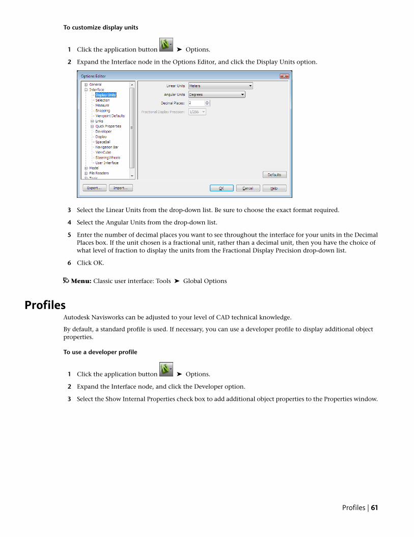
To customize display units
1 Click the application button ➤ Options.
2 Expand the Interface node in the Options Editor, and click the Display Units option.
3 Select the Linear Units from the drop-down list. Be sure to choose the exact format required.
4 Select the Angular Units from the drop-down list.
5 Enter the number of decimal places you want to see throughout the interface for your units in the DecimalPlaces box. If the unit chosen is a fractional unit, rather than a decimal unit, then you have the choice ofwhat level of fraction to display the units from the Fractional Display Precision drop-down list.
6 Click OK.
Menu: Classic user interface: Tools ➤ Global Options
ProfilesAutodesk Navisworks can be adjusted to your level of CAD technical knowledge.
By default, a standard profile is used. If necessary, you can use a developer profile to display additional objectproperties.
To use a developer profile
1 Click the application button ➤ Options.
2 Expand the Interface node, and click the Developer option.
3 Select the Show Internal Properties check box to add additional object properties to the Properties window.
Profiles | 61
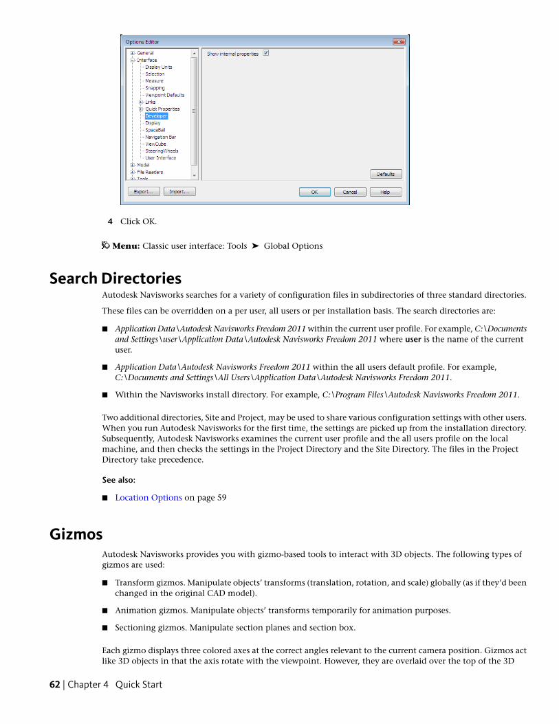
4 Click OK.
Menu: Classic user interface: Tools ➤ Global Options
Search DirectoriesAutodesk Navisworks searches for a variety of configuration files in subdirectories of three standard directories.
These files can be overridden on a per user, all users or per installation basis. The search directories are:
■ Application Data\Autodesk Navisworks Freedom 2011 within the current user profile. For example, C:\Documentsand Settings\user\Application Data\Autodesk Navisworks Freedom 2011 where user is the name of the currentuser.
■ Application Data\Autodesk Navisworks Freedom 2011 within the all users default profile. For example,C:\Documents and Settings\All Users\Application Data\Autodesk Navisworks Freedom 2011.
■ Within the Navisworks install directory. For example, C:\Program Files\Autodesk Navisworks Freedom 2011.
Two additional directories, Site and Project, may be used to share various configuration settings with other users.When you run Autodesk Navisworks for the first time, the settings are picked up from the installation directory.Subsequently, Autodesk Navisworks examines the current user profile and the all users profile on the localmachine, and then checks the settings in the Project Directory and the Site Directory. The files in the ProjectDirectory take precedence.
See also:
■ Location Options on page 59
GizmosAutodesk Navisworks provides you with gizmo-based tools to interact with 3D objects. The following types ofgizmos are used:
■ Transform gizmos. Manipulate objects’ transforms (translation, rotation, and scale) globally (as if they’d beenchanged in the original CAD model).
■ Animation gizmos. Manipulate objects’ transforms temporarily for animation purposes.
■ Sectioning gizmos. Manipulate section planes and section box.
Each gizmo displays three colored axes at the correct angles relevant to the current camera position. Gizmos actlike 3D objects in that the axis rotate with the viewpoint. However, they are overlaid over the top of the 3D
62 | Chapter 4 Quick Start
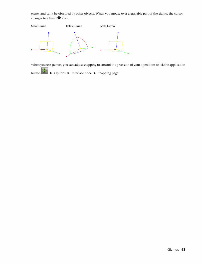
scene, and can’t be obscured by other objects. When you mouse over a grabable part of the gizmo, the cursor
changes to a hand icon.
Scale GizmoRotate GizmoMove Gizmo
When you use gizmos, you can adjust snapping to control the precision of your operations (click the application
button ➤ Options ➤ Interface node ➤ Snapping page.
Gizmos | 63

64 | Chapter 4 Quick Start

Get a Whole-Project View
65

66 | Part 2 Get a Whole-Project View
Work with Files
In Autodesk Navisworks you can open NWD files (published data), and DWF files.
Use File Readers
NWD FilesAn NWD file is a file created with Autodesk Navisworks publishertool, and contains all model geometry together with review markups.You can think of an NWD file as a snapshot of the current state ofthe model.
NWD files are very small, as they compress the CAD data by up to80% of the original size.
DWF FilesAutodesk DWF was specifically developed by Autodesk as a fileformat for architects, engineers, and GIS professionals to share designdata. The DWF file reader reads all 3D geometry, as well as texturesand properties.
Supported Entities
■ All 3D geometry
■ Texture maps
■ Texture coordinates
■ Colors (per-vertex, per-face)
■ Property fields
■ Categories
Unsupported Entities
■ 2D lines/plot sheets
■ Thumbnails
■ Marked-up sketches
■ More than one 3D sheet per file (any others are ignored)
5
67
■ NURBS surfaces
■ Cameras
See also:
■ “DWF File Reader Options” on page 178
Use File Exporters
MicroStation File Exporter
Manage Files
Open FilesTo open files in Autodesk Navisworks, you can either use a standard Open dialog box or drag and drop filesdirectly into the Selection Tree window.
NOTE If the chosen file is a CAD or laser scan file, Autodesk Navisworks automatically uses an appropriate file readerto open it, provided this file format is supported.
Autodesk Navisworks keeps a list of recently opened files (by default, up to 4 files are shown). You can open any
of these files by clicking the application button . If you want to modify the size of this list, use the OptionsEditor (General node ➤ Environment page).
You can use the SHIFT and CTRL keys to open several files at the same time. This automatically creates a new“Untitled” Navisworks file with the selected files appended together.
For NWD files, it is possible to publish them to a web server, and then open them directly from within Navisworks.You can start navigating the model even before the file has been fully downloaded. For this, 10 - 50% is usuallysufficient. The greater the hierarchical structure of the model, the closer to 50% download is required. Similarly,the lesser the hierarchical structure of the model, the sooner you can begin the navigation.
To open a file
1 Click the application button ➤ Open ➤ Open .
2 In the Open dialog box, use the Files of Type box to select the appropriate file type, and navigate to thefolder where your file is located.
3 Select the file, and click Open.
Toolbar: Classic user interface: Standard ➤ OpenCommand entry: CTRL + O
To open NWD files located on a web server
1 Click the application button ➤ Open URL .
2 Enter the file address, and click OK.
68 | Chapter 5 Work with Files
Create FilesWhen you start Autodesk Navisworks, a new “Untitled” Navisworks file is automatically created for you. Thenew file uses default settings defined in the Options Editor, and in the File Options dialog box. You can customizethese settings, as necessary.
If you have a Navisworks file already open, and want to close it and create another file, click New on theQuick Access toolbar.
Toolbar: Classic user interface: Standard ➤ New
Create Files | 69

70 | Chapter 5 Work with Files
Explore Your Model
Autodesk Navisworks Freedom 2011 enables you to walk through a scene in realtime.
Navigate a SceneIn Autodesk Navisworks, you have a variety of options for navigatingyour scene.
You can directly manipulate your position in 3D space withnavigation tools on the navigation bar. You can also useStreeringWheels® that travel with the cursor, and can save you timeby combining many of the common navigation tools into a singleinterface.
You can use the ViewCube®, a 3D navigational tool that enablesyou to reorient the view of a model by clicking predefined areas onthe cube. For example, clicking the front of the ViewCube turns theview until the camera is facing the front of the scene. You can alsoclick the ViewCube and drag it to rotate the view freely.
You can use the tools on the Viewpoint tab ➤ Motion Settingspanel to control the speed and realism of your navigation. So, forexample, you can walk down stairs or follow terrain, crouch underobjects, use an avatar to represent yourself within the 3D model.
Animating NavigationAs you navigate in Autodesk Navisworks, you can record viewpointanimations, and then play them back. For more information, see“Play Back Animations” on page 151.
Orientation in 3D SpaceAlthough Autodesk Navisworks uses the X, Y, Z coordinate system,there is no hard-and-fast rule as to which way each of these particularaxes actually “points”.
Autodesk Navisworks reads the data necessary to map which wayis “up” and which way is “north” directly from the files loaded intoyour scene. If this is not possible, by default, Z is treated as “up”and Y is treated as “north”.
It is possible to change the “up” and “north” directions for the entiremodel (world orientation), and the “up” direction for the currentviewpoint (viewpoint up vector).
6
71
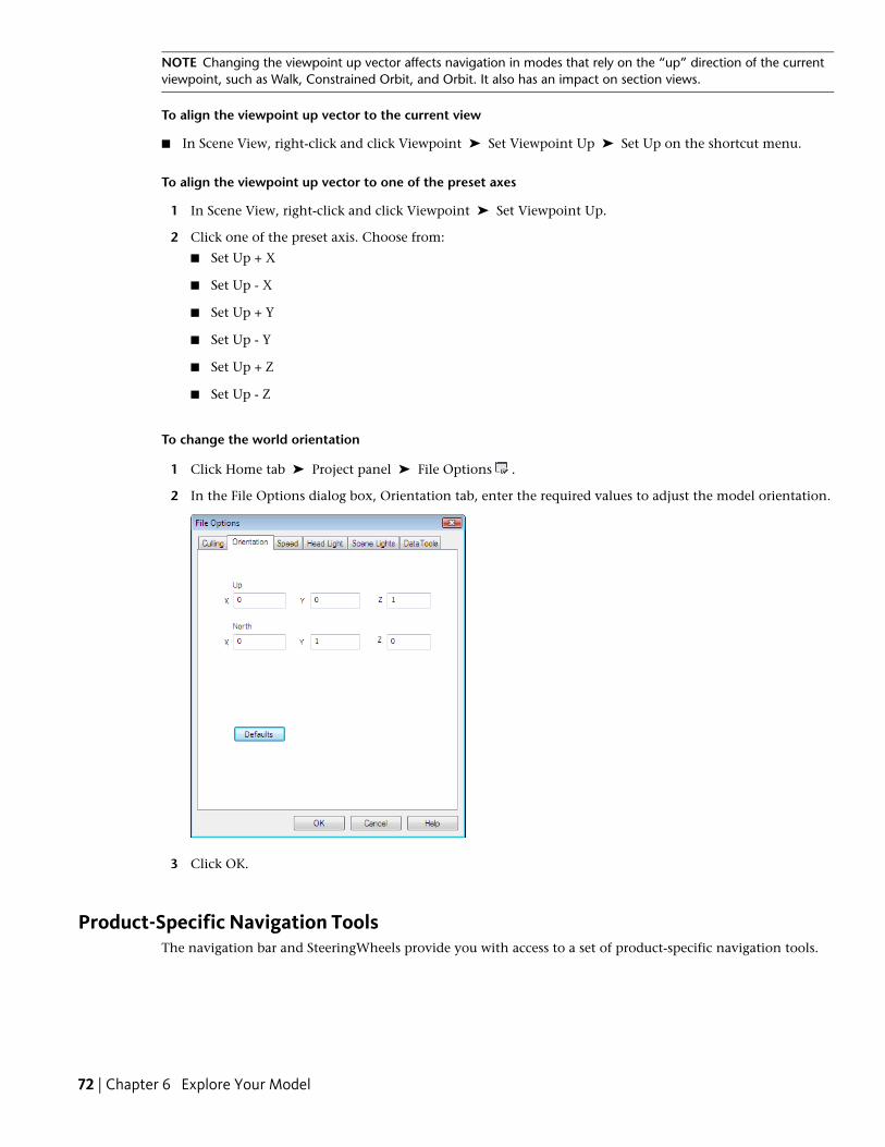
NOTE Changing the viewpoint up vector affects navigation in modes that rely on the “up” direction of the currentviewpoint, such as Walk, Constrained Orbit, and Orbit. It also has an impact on section views.
To align the viewpoint up vector to the current view
■ In Scene View, right-click and click Viewpoint ➤ Set Viewpoint Up ➤ Set Up on the shortcut menu.
To align the viewpoint up vector to one of the preset axes
1 In Scene View, right-click and click Viewpoint ➤ Set Viewpoint Up.
2 Click one of the preset axis. Choose from:
■ Set Up + X
■ Set Up - X
■ Set Up + Y
■ Set Up - Y
■ Set Up + Z
■ Set Up - Z
To change the world orientation
1 Click Home tab ➤ Project panel ➤ File Options .
2 In the File Options dialog box, Orientation tab, enter the required values to adjust the model orientation.
3 Click OK.
Product-Specific Navigation ToolsThe navigation bar and SteeringWheels provide you with access to a set of product-specific navigation tools.
72 | Chapter 6 Explore Your Model
In Autodesk Navisworks Freedom 2011, some classic navigation tools have been replaced with new navigationtools. See the table below for more details.
Can be switched back to clas-sic?
Replaced byClassic tool
NoPanPan
NoZoomZoom
NoZoom AllView All
NoZoom SelectedView Selected
NoZoom WindowZoom Box
YesOrbitOrbit
YesFree OrbitExamine
YesConstrained OrbitTurntable
NoLookLook Around
--Focus
YesWalkWalk
--Fly
Customizing Tools BehaviorFor the navigation bar, you can use Options Editor to toggle between standard and classic modes for Orbit andWalk tools.
Control Navigation RealismYou can use Collision, Gravity, Crouch, and Third Person View to enhance your navigation experience.
TIP Use a combination of Collision, Gravity, and Crouch with the Walk tool. This allows you, for example, to walk upand down stairs and walk under low objects.
Navigation Bar ToolsThe navigation bar contains a set of product-specific navigation tools.
Pan ToolThe pan tool moves the view parallel to the screen.
The tool is activated by clicking Pan on the navigation bar. Pan behaves the same way as the pan tool availableon the SteeringWheels.
Zoom ToolsSet of navigation tools for increasing or decreasing the magnification of the current view of the model.
The following zoom tools are available:
■ Zoom Window . Allows you to draw a box and zoom into that area.
Product-Specific Navigation Tools | 73
■ Zoom . Standard click/drag zoom.
■ Zoom Selected . Zooms in/out to show the selected geometry.
■ Zoom All . Zooms out to show the whole scene.
Zoom WindowThe tool is activated by clicking Zoom Window in the Zoom drop-down on the navigation bar. It behaves thesame way as the classic Zoom Box mode.
ZoomThe tool is activated by clicking Zoom in the Zoom drop-down on the navigation bar. It behaves the same wayas the Zoom tool available on the SteeringWheels.
Zoom SelectedThe tool is activated by clicking Zoom Selected in the Zoom drop-down on the navigation bar. Alternatively,
you can click Item Tools tab ➤ Look At panel ➤ Zoom on the ribbon. It behaves the same way as theclassic View Selected tool.
Zoom AllThe tool is activated by clicking Zoom All in the Zoom drop-down on the navigation bar. It behaves the sameway as the classic View All tool.
Orbit ToolsSet of navigation tools for rotating the model around a pivot point while the view remains fixed.
The following orbit tools are available:
■ Orbit . Moves the camera around the focal point of the model. The up direction is always maintained,and no camera rolling is possible.
■ Free Orbit . Rotates the model around the focal point in any direction.
■ Constrained Orbit . Spins the model around the up vector as though the model is sitting on a turntable.The up direction is always maintained.
OrbitThe tool is activated by clicking Orbit in the Orbit drop-down on the navigation bar. It behaves the same wayas the Orbit tool on the SteeringWheels. You can use the Options Editor to switch back to the classic Orbit mode.
Free OrbitThe tool is activated by clicking Free Orbit in the Orbit drop-down on the navigation bar. It behaves similarlyto the classic Examine mode. You can use the Options Editor to switch back to the classic Examine mode.
Constrained OrbitThe tool is activated by clicking Constrained Orbit in the Orbit drop-down on the navigation bar. It behavessimilarly to the classic Turntable mode. You can use the Options Editor to switch back to the classic Turntablemode.
To use the classic Orbit tool with the navigation bar
1 On the navigation bar, click Customize ➤ Navigation Bar Options.
74 | Chapter 6 Explore Your Model
2 In the Options Editor, the Navigation Bar page under the Interface node, select the Use Classic Orbit checkbox in the Orbit Tools area.
3 Click OK.
To use the classic Examine tool with the navigation bar
1 On the navigation bar, click Customize ➤ Navigation Bar Options.
2 In the Options Editor, the Navigation Bar page under the Interface node, select the Use Classic Free Orbit(Examine) check box in the Orbit Tools area.
3 Click OK.
To use the classic Turntable tool with the navigation bar
1 On the navigation bar, click Customize ➤ Navigation Bar Options.
2 In the Options Editor, the Navigation Bar page under the Interface node, select the Use Classic ConstrainedOrbit (Turntable) check box in the Orbit Tools area.
3 Click OK.
Look ToolsSet of navigation tools for rotating the current view vertically and horizontally.
The following look tools are available:
■ Look Around . Looks around the scene from the current camera location.
■ Look At . Looks at a particular point in the scene. The camera moves to align with that point.
■ Focus . Looks at a particular point in the scene. The camera stays where it is.
Look AroundThe tool is activated by clicking Look Around in the Look drop-down on the navigation bar. It behaves the sameway as the Look tool available on the SteeringWheels.
Look AtThe tool is activated by clicking Look At in the Look drop-down on the navigation bar. It behaves the same wayas the SteeringWheels Look tool when you press and hold the SHIFT key.
FocusThe tool is activated by clicking Focus in the Look drop-down on the navigation bar. See Focus on page 113 formore details.
Walk and Fly ToolsSet of navigation tools for moving around the model and controlling realism settings.
The following tools are available:
■ Walk . Moves through a model as if you were walking through it.
■ Fly . Moves through a model like in a flight simulator.
Product-Specific Navigation Tools | 75
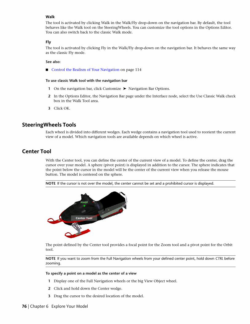
WalkThe tool is activated by clicking Walk in the Walk/Fly drop-down on the navigation bar. By default, the toolbehaves like the Walk tool on the SteeringWheels. You can customize the tool options in the Options Editor.You can also switch back to the classic Walk mode.
FlyThe tool is activated by clicking Fly in the Walk/Fly drop-down on the navigation bar. It behaves the same wayas the classic Fly mode.
See also:
■ Control the Realism of Your Navigation on page 114
To use classic Walk tool with the navigation bar
1 On the navigation bar, click Customize ➤ Navigation Bar Options.
2 In the Options Editor, the Navigation Bar page under the Interface node, select the Use Classic Walk checkbox in the Walk Tool area.
3 Click OK.
SteeringWheels ToolsEach wheel is divided into different wedges. Each wedge contains a navigation tool used to reorient the currentview of a model. Which navigation tools are available depends on which wheel is active.
Center ToolWith the Center tool, you can define the center of the current view of a model. To define the center, drag thecursor over your model. A sphere (pivot point) is displayed in addition to the cursor. The sphere indicates thatthe point below the cursor in the model will be the center of the current view when you release the mousebutton. The model is centered on the sphere.
NOTE If the cursor is not over the model, the center cannot be set and a prohibited cursor is displayed.
The point defined by the Center tool provides a focal point for the Zoom tool and a pivot point for the Orbittool.
NOTE If you want to zoom from the Full Navigation wheels from your defined center point, hold down CTRL beforezooming.
To specify a point on a model as the center of a view
1 Display one of the Full Navigation wheels or the big View Object wheel.
2 Click and hold down the Center wedge.
3 Drag the cursor to the desired location of the model.
76 | Chapter 6 Explore Your Model
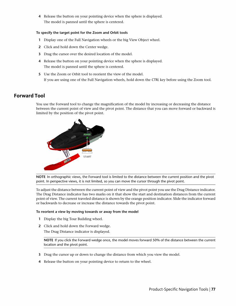
4 Release the button on your pointing device when the sphere is displayed.
The model is panned until the sphere is centered.
To specify the target point for the Zoom and Orbit tools
1 Display one of the Full Navigation wheels or the big View Object wheel.
2 Click and hold down the Center wedge.
3 Drag the cursor over the desired location of the model.
4 Release the button on your pointing device when the sphere is displayed.
The model is panned until the sphere is centered.
5 Use the Zoom or Orbit tool to reorient the view of the model.
If you are using one of the Full Navigation wheels, hold down the CTRL key before using the Zoom tool.
Forward ToolYou use the Forward tool to change the magnification of the model by increasing or decreasing the distancebetween the current point of view and the pivot point. The distance that you can move forward or backward islimited by the position of the pivot point.
NOTE In orthographic views, the Forward tool is limited to the distance between the current position and the pivotpoint. In perspective views, it is not limited, so you can move the cursor through the pivot point.
To adjust the distance between the current point of view and the pivot point you use the Drag Distance indicator.The Drag Distance indicator has two marks on it that show the start and destination distances from the currentpoint of view. The current traveled distance is shown by the orange position indicator. Slide the indicator forwardor backwards to decrease or increase the distance towards the pivot point.
To reorient a view by moving towards or away from the model
1 Display the big Tour Building wheel.
2 Click and hold down the Forward wedge.
The Drag Distance indicator is displayed.
NOTE If you click the Forward wedge once, the model moves forward 50% of the distance between the currentlocation and the pivot point.
3 Drag the cursor up or down to change the distance from which you view the model.
4 Release the button on your pointing device to return to the wheel.
Product-Specific Navigation Tools | 77
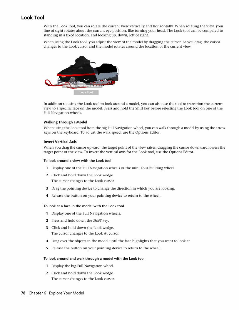
Look ToolWith the Look tool, you can rotate the current view vertically and horizontally. When rotating the view, yourline of sight rotates about the current eye position, like turning your head. The Look tool can be compared tostanding in a fixed location, and looking up, down, left or right.
When using the Look tool, you adjust the view of the model by dragging the cursor. As you drag, the cursorchanges to the Look cursor and the model rotates around the location of the current view.
In addition to using the Look tool to look around a model, you can also use the tool to transition the currentview to a specific face on the model. Press and hold the Shift key before selecting the Look tool on one of theFull Navigation wheels.
Walking Through a ModelWhen using the Look tool from the big Full Navigation wheel, you can walk through a model by using the arrowkeys on the keyboard. To adjust the walk speed, use the Options Editor.
Invert Vertical AxisWhen you drag the cursor upward, the target point of the view raises; dragging the cursor downward lowers thetarget point of the view. To invert the vertical axis for the Look tool, use the Options Editor.
To look around a view with the Look tool
1 Display one of the Full Navigation wheels or the mini Tour Building wheel.
2 Click and hold down the Look wedge.
The cursor changes to the Look cursor.
3 Drag the pointing device to change the direction in which you are looking.
4 Release the button on your pointing device to return to the wheel.
To look at a face in the model with the Look tool
1 Display one of the Full Navigation wheels.
2 Press and hold down the SHIFT key.
3 Click and hold down the Look wedge.
The cursor changes to the Look At cursor.
4 Drag over the objects in the model until the face highlights that you want to look at.
5 Release the button on your pointing device to return to the wheel.
To look around and walk through a model with the Look tool
1 Display the big Full Navigation wheel.
2 Click and hold down the Look wedge.
The cursor changes to the Look cursor.
78 | Chapter 6 Explore Your Model
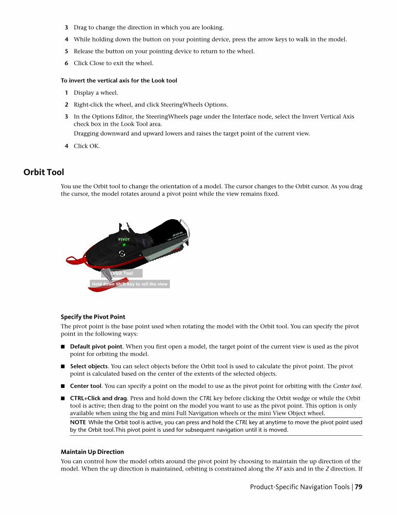
3 Drag to change the direction in which you are looking.
4 While holding down the button on your pointing device, press the arrow keys to walk in the model.
5 Release the button on your pointing device to return to the wheel.
6 Click Close to exit the wheel.
To invert the vertical axis for the Look tool
1 Display a wheel.
2 Right-click the wheel, and click SteeringWheels Options.
3 In the Options Editor, the SteeringWheels page under the Interface node, select the Invert Vertical Axischeck box in the Look Tool area.
Dragging downward and upward lowers and raises the target point of the current view.
4 Click OK.
Orbit ToolYou use the Orbit tool to change the orientation of a model. The cursor changes to the Orbit cursor. As you dragthe cursor, the model rotates around a pivot point while the view remains fixed.
Specify the Pivot PointThe pivot point is the base point used when rotating the model with the Orbit tool. You can specify the pivotpoint in the following ways:
■ Default pivot point. When you first open a model, the target point of the current view is used as the pivotpoint for orbiting the model.
■ Select objects. You can select objects before the Orbit tool is used to calculate the pivot point. The pivotpoint is calculated based on the center of the extents of the selected objects.
■ Center tool. You can specify a point on the model to use as the pivot point for orbiting with the Center tool.
■ CTRL+Click and drag. Press and hold down the CTRL key before clicking the Orbit wedge or while the Orbittool is active; then drag to the point on the model you want to use as the pivot point. This option is onlyavailable when using the big and mini Full Navigation wheels or the mini View Object wheel.
NOTE While the Orbit tool is active, you can press and hold the CTRL key at anytime to move the pivot point usedby the Orbit tool.This pivot point is used for subsequent navigation until it is moved.
Maintain Up DirectionYou can control how the model orbits around the pivot point by choosing to maintain the up direction of themodel. When the up direction is maintained, orbiting is constrained along the XY axis and in the Z direction. If
Product-Specific Navigation Tools | 79
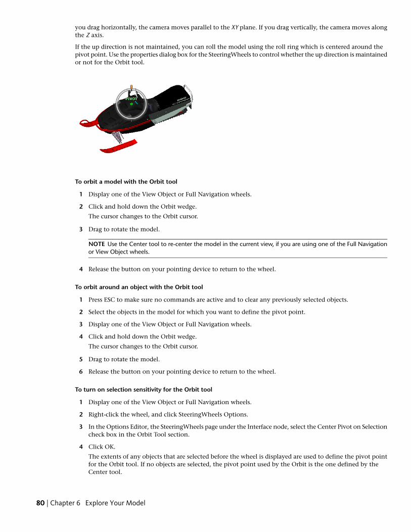
you drag horizontally, the camera moves parallel to the XY plane. If you drag vertically, the camera moves alongthe Z axis.
If the up direction is not maintained, you can roll the model using the roll ring which is centered around thepivot point. Use the properties dialog box for the SteeringWheels to control whether the up direction is maintainedor not for the Orbit tool.
To orbit a model with the Orbit tool
1 Display one of the View Object or Full Navigation wheels.
2 Click and hold down the Orbit wedge.
The cursor changes to the Orbit cursor.
3 Drag to rotate the model.
NOTE Use the Center tool to re-center the model in the current view, if you are using one of the Full Navigationor View Object wheels.
4 Release the button on your pointing device to return to the wheel.
To orbit around an object with the Orbit tool
1 Press ESC to make sure no commands are active and to clear any previously selected objects.
2 Select the objects in the model for which you want to define the pivot point.
3 Display one of the View Object or Full Navigation wheels.
4 Click and hold down the Orbit wedge.
The cursor changes to the Orbit cursor.
5 Drag to rotate the model.
6 Release the button on your pointing device to return to the wheel.
To turn on selection sensitivity for the Orbit tool
1 Display one of the View Object or Full Navigation wheels.
2 Right-click the wheel, and click SteeringWheels Options.
3 In the Options Editor, the SteeringWheels page under the Interface node, select the Center Pivot on Selectioncheck box in the Orbit Tool section.
4 Click OK.
The extents of any objects that are selected before the wheel is displayed are used to define the pivot pointfor the Orbit tool. If no objects are selected, the pivot point used by the Orbit is the one defined by theCenter tool.
80 | Chapter 6 Explore Your Model
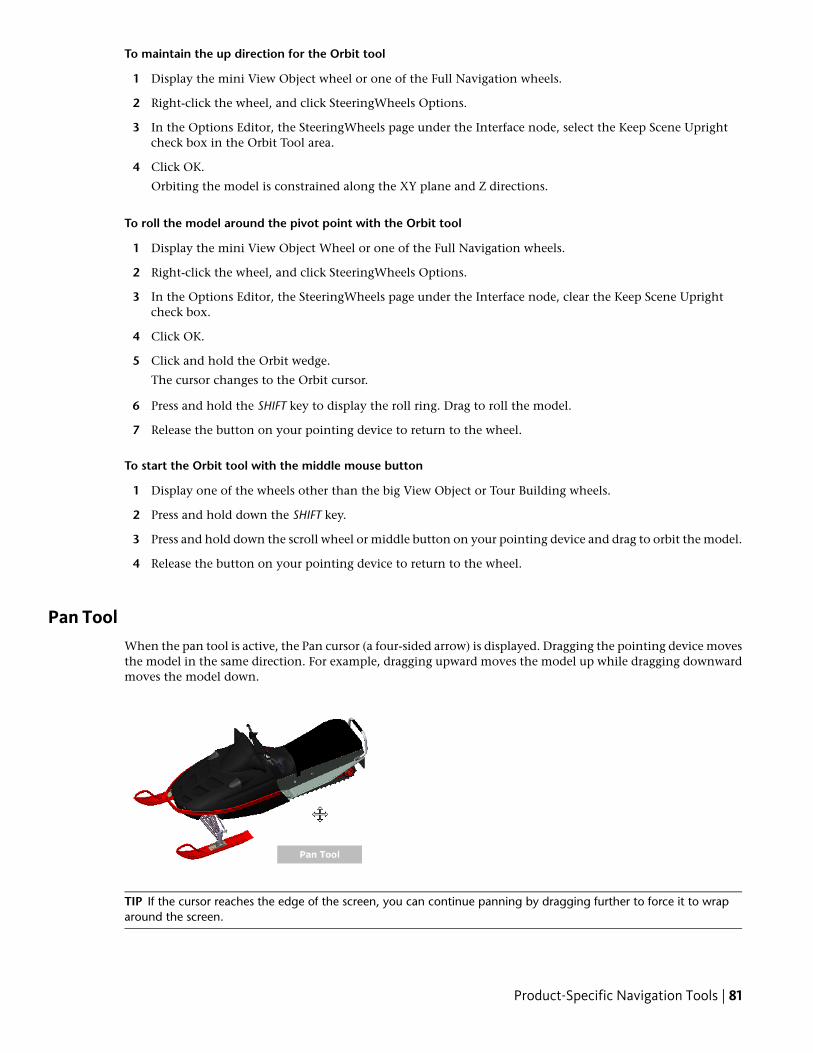
To maintain the up direction for the Orbit tool
1 Display the mini View Object wheel or one of the Full Navigation wheels.
2 Right-click the wheel, and click SteeringWheels Options.
3 In the Options Editor, the SteeringWheels page under the Interface node, select the Keep Scene Uprightcheck box in the Orbit Tool area.
4 Click OK.
Orbiting the model is constrained along the XY plane and Z directions.
To roll the model around the pivot point with the Orbit tool
1 Display the mini View Object Wheel or one of the Full Navigation wheels.
2 Right-click the wheel, and click SteeringWheels Options.
3 In the Options Editor, the SteeringWheels page under the Interface node, clear the Keep Scene Uprightcheck box.
4 Click OK.
5 Click and hold the Orbit wedge.
The cursor changes to the Orbit cursor.
6 Press and hold the SHIFT key to display the roll ring. Drag to roll the model.
7 Release the button on your pointing device to return to the wheel.
To start the Orbit tool with the middle mouse button
1 Display one of the wheels other than the big View Object or Tour Building wheels.
2 Press and hold down the SHIFT key.
3 Press and hold down the scroll wheel or middle button on your pointing device and drag to orbit the model.
4 Release the button on your pointing device to return to the wheel.
Pan ToolWhen the pan tool is active, the Pan cursor (a four-sided arrow) is displayed. Dragging the pointing device movesthe model in the same direction. For example, dragging upward moves the model up while dragging downwardmoves the model down.
TIP If the cursor reaches the edge of the screen, you can continue panning by dragging further to force it to wraparound the screen.
Product-Specific Navigation Tools | 81
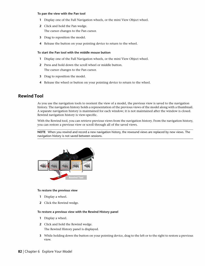
To pan the view with the Pan tool
1 Display one of the Full Navigation wheels, or the mini View Object wheel.
2 Click and hold the Pan wedge.
The cursor changes to the Pan cursor.
3 Drag to reposition the model.
4 Release the button on your pointing device to return to the wheel.
To start the Pan tool with the middle mouse button
1 Display one of the Full Navigation wheels, or the mini View Object wheel.
2 Press and hold down the scroll wheel or middle button.
The cursor changes to the Pan cursor.
3 Drag to reposition the model.
4 Release the wheel or button on your pointing device to return to the wheel.
Rewind ToolAs you use the navigation tools to reorient the view of a model, the previous view is saved to the navigationhistory. The navigation history holds a representation of the previous views of the model along with a thumbnail.A separate navigation history is maintained for each window; it is not maintained after the window is closed.Rewind navigation history is view-specific.
With the Rewind tool, you can retrieve previous views from the navigation history. From the navigation history,you can restore a previous view or scroll through all of the saved views.
NOTE When you rewind and record a new navigation history, the rewound views are replaced by new views. Thenavigation history is not saved between sessions.
To restore the previous view
1 Display a wheel.
2 Click the Rewind wedge.
To restore a previous view with the Rewind History panel
1 Display a wheel.
2 Click and hold the Rewind wedge.
The Rewind History panel is displayed.
3 While holding down the button on your pointing device, drag to the left or to the right to restore a previousview.
82 | Chapter 6 Explore Your Model
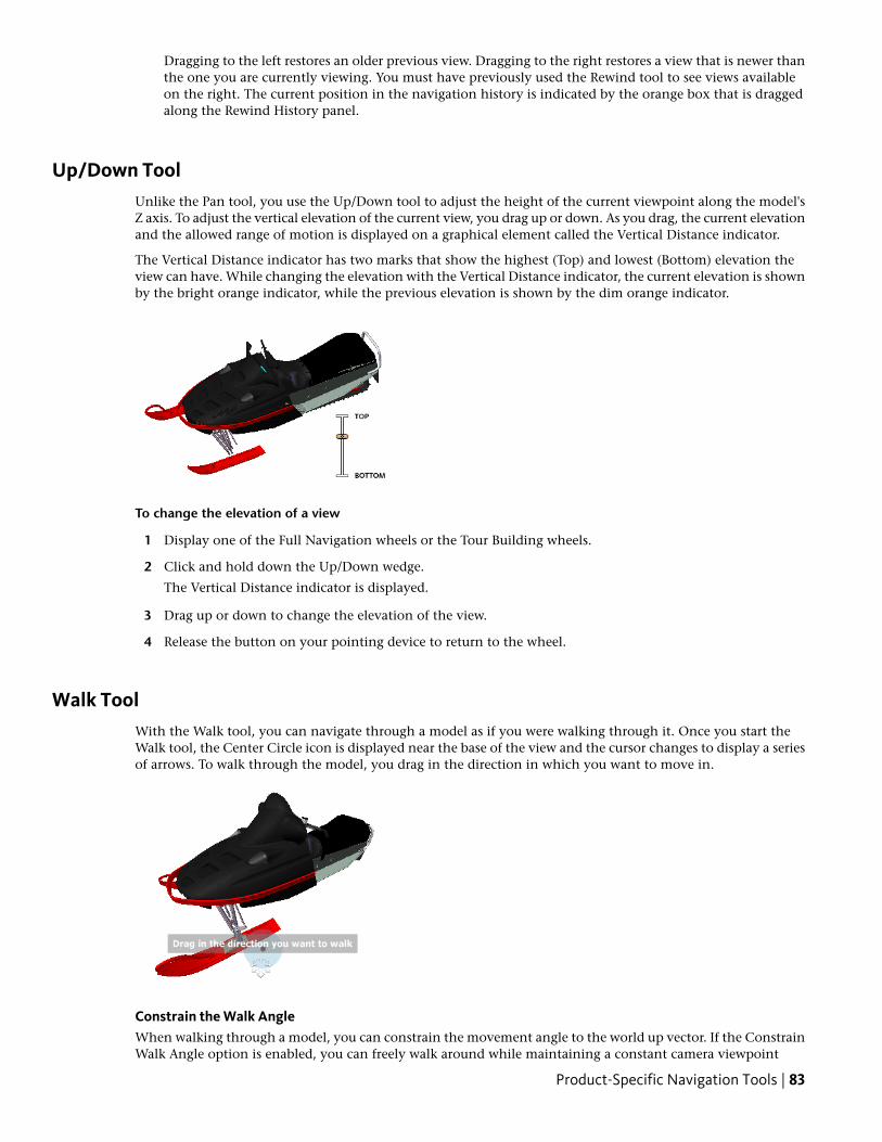
Dragging to the left restores an older previous view. Dragging to the right restores a view that is newer thanthe one you are currently viewing. You must have previously used the Rewind tool to see views availableon the right. The current position in the navigation history is indicated by the orange box that is draggedalong the Rewind History panel.
Up/Down ToolUnlike the Pan tool, you use the Up/Down tool to adjust the height of the current viewpoint along the model'sZ axis. To adjust the vertical elevation of the current view, you drag up or down. As you drag, the current elevationand the allowed range of motion is displayed on a graphical element called the Vertical Distance indicator.
The Vertical Distance indicator has two marks that show the highest (Top) and lowest (Bottom) elevation theview can have. While changing the elevation with the Vertical Distance indicator, the current elevation is shownby the bright orange indicator, while the previous elevation is shown by the dim orange indicator.
To change the elevation of a view
1 Display one of the Full Navigation wheels or the Tour Building wheels.
2 Click and hold down the Up/Down wedge.
The Vertical Distance indicator is displayed.
3 Drag up or down to change the elevation of the view.
4 Release the button on your pointing device to return to the wheel.
Walk ToolWith the Walk tool, you can navigate through a model as if you were walking through it. Once you start theWalk tool, the Center Circle icon is displayed near the base of the view and the cursor changes to display a seriesof arrows. To walk through the model, you drag in the direction in which you want to move in.
Constrain the Walk AngleWhen walking through a model, you can constrain the movement angle to the world up vector. If the ConstrainWalk Angle option is enabled, you can freely walk around while maintaining a constant camera viewpoint
Product-Specific Navigation Tools | 83
elevation; if the walk angle is not constrained, you will “fly” in the direction you are looking. Use the OptionsEditor to constrain the movement angle to the world up vector for the Walk tool.
Use Viewpoint Linear SpeedBy default, the linear navigation speed in viewpoints is directly related to the size of your model. You can set aspecific speed of motion for all viewpoints (Options Editor ➤ Interface ➤ Viewpoint Defaults) or for the currentviewpoint (Viewpoint tab ➤ Save, Load & Playback panel ➤ Edit Current Viewpoint). Use the Options Editorto make the Walk tool Use Viewpoint Linear Speed settings.
Movement SpeedAs you walk or “fly” through a model, you can control the movement speed. Movement speed is controlled bythe distance in which the cursor is moved from the Center Circle icon and the current movement speed setting.You can adjust the movement speed setting permanently and temporarily as you use the Walk tool. Topermanently adjust the movement speed, use the Options Editor or the < and > keys when the Walk tool isactive. To temporarily increase movement speed, press and hold the + (plus) key while using the Walk tool.
Change the ElevationAs you use the Walk tool, you can adjust the camera elevation by holding down the SHIFT key. This temporarilyactivates the Up/Down tool. With the Up/Down tool active, drag up or down to adjust the elevation of thecamera. You can also use the UP ARROW and DOWN ARROW keys as you walk to adjust the height of the view.
To use the Walk tool to move through the model
1 Display one of the Full Navigation wheels or the mini Tour Building wheel.
2 Click and hold down the Walk wedge.
The cursor changes to the Walk cursor and the Center Circle icon is displayed.
3 Drag in the direction you want to walk.
NOTE While walking, press and hold down the + (plus) key to temporarily increase your movement speed.
4 Release the button on your pointing device to return to the wheel.
To change the movement speed for the Walk tool
1 Display a wheel.
2 Right-click the wheel, and click SteeringWheels Options.
3 In the Options Editor, the SteeringWheels page under the Interface node, use the Walk Speed slider in theWalk Tool area.
Dragging the slider to the left decreases the walking speed; dragging the slider to the right increases thewalking speed.
4 Click OK.
To constraint the Walk tool to the world up vector
1 Display a wheel.
2 Right-click the wheel, and click SteeringWheels Options.
3 In the Options Editor, the SteeringWheels page under the Interface node, select the Constrain Walk Anglecheck box in the Walk Tool area.
4 Click OK.
Movement when walking is done parallel to the world up of the model.
To make the Walk tool use the viewpoint linear speed
1 Display a wheel.
84 | Chapter 6 Explore Your Model
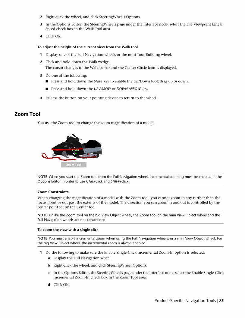
2 Right-click the wheel, and click SteeringWheels Options.
3 In the Options Editor, the SteeringWheels page under the Interface node, select the Use Viewpoint LinearSpeed check box in the Walk Tool area.
4 Click OK.
To adjust the height of the current view from the Walk tool
1 Display one of the Full Navigation wheels or the mini Tour Building wheel.
2 Click and hold down the Walk wedge.
The cursor changes to the Walk cursor and the Center Circle icon is displayed.
3 Do one of the following:
■ Press and hold down the SHIFT key to enable the Up/Down tool; drag up or down.
■ Press and hold down the UP ARROW or DOWN ARROW key.
4 Release the button on your pointing device to return to the wheel.
Zoom ToolYou use the Zoom tool to change the zoom magnification of a model.
NOTE When you start the Zoom tool from the Full Navigation wheel, incremental zooming must be enabled in theOptions Editor in order to use CTRL+click and SHIFT+click.
Zoom ConstraintsWhen changing the magnification of a model with the Zoom tool, you cannot zoom in any further than thefocus point or out past the extents of the model. The direction you can zoom in and out is controlled by thecenter point set by the Center tool.
NOTE Unlike the Zoom tool on the big View Object wheel, the Zoom tool on the mini View Object wheel and theFull Navigation wheels are not constrained.
To zoom the view with a single click
NOTE You must enable incremental zoom when using the Full Navigation wheels, or a mini View Object wheel. Forthe big View Object wheel, the incremental zoom is always enabled.
1 Do the following to make sure the Enable Single-Click Incremental Zoom-In option is selected:
a Display the Full Navigation wheel.
b Right-click the wheel, and click SteeringWheel Options.
c In the Options Editor, the SteeringWheels page under the Interface node, select the Enable Single-ClickIncremental Zoom-In check box in the Zoom Tool area.
d Click OK.
Product-Specific Navigation Tools | 85
2 Display a wheel that has the Zoom tool.
3 Click the Zoom wedge.
The magnification of the model is increased and you are zoomed in closer to the model. If you hold downthe SHIFT key while clicking the Zoom wedge, the model is zoomed out; you can hold down the CTRL keyto zoom in.
To zoom a view in and out by dragging
1 Display one of the Full Navigation wheels, or one of the View Object wheels.
2 Click and hold down the Zoom wedge.
The cursor changes to the Zoom cursor.
3 Drag vertically to zoom in or out.
4 Release the button on your pointing device to return to the wheel.
To zoom into an area of the model by specifying window
1 Display one of the Full Navigation wheels or the mini View Object wheel.
2 Press and hold down the SHIFT key.
3 Click and hold down the Zoom wedge.
The cursor changes to the Zoom cursor.
4 Drag the pointing device to define the opposite corner of the window that defines the area in which youwant to zoom.
NOTE Holding down the CTRL key while defining the second point of the window determines if the first pointof the window is used as the corner or center of the window being dragged. When the CTRL key is held down,the first point defines the center of the window.
5 Release the button on your pointing device to return to the wheel.
To zoom in and out by scrolling the mouse wheel when the SteeringWheels is displayed
1 Display one of the wheels other than the big Tour Building wheel.
2 Scroll the wheel forward or backward to zoom in or out.
3 Release the button on your pointing device to return to the wheel.
Quick Reference
You use the Zoom tool to change the zoom magnification of a model. The following mouse click and keycombinations are available to control how the Zoom tool behaves:
■ Click. If you click the Zoom tool on a wheel, the current view is zoomed in by a factor of 25 percent. If youare using the Full Navigation wheel, incremental zoom must be enabled in the Options Editor.
■ SHIFT+click. If you hold down the SHIFT key before you click the Zoom tool on a wheel, the current view iszoomed in by a factor of 25 percent. Zooming is performed from the current pivot point, and not the locationof the cursor.
■ CTRL+click. If you hold down the CTRL key before you click the Zoom tool on a wheel, the current view iszoomed in by a factor of 25 percent. Zooming is performed from the current pivot point, and not the locationof the cursor.
■ Click and drag. If you click the Zoom tool and hold down the button on your pointing device, you can adjustthe magnification of the model by dragging up and down.
86 | Chapter 6 Explore Your Model
■ CTRL+click and drag. When using the Full Navigation wheels or the mini View Object wheel, you can controlthe target point used by the Zoom tool. By holding down the CTRL key, the Zoom tool uses the location ofthe previous pivot point defined by the Zoom, Orbit, or Center tool.
■ SHIFT+click and drag. When using the Full Navigation wheels or the mini View Object wheel, you can zoomin to an area of the model by dragging a rectangular window around the area you want to fit in the window.Hold down the SHIFT key and then click and drag a window around the area in which you want to zoom.
NOTE If you hold down the CTRL key along with the SHIFT key, you can zoom in to an area of a model using acenter-based window instead of one defined by opposite corners.
■ Mouse wheel. When a wheel is displayed, scroll the mouse wheel up or down to zoom the view of the modelin or out.
NOTE When you use the Zoom tool from the Full Navigation wheel or the View Object wheel, the point in the viewwhere you click to zoom becomes the Center point for future Orbit operations until you either use the Zoom tool againor use the Center tool. If you press CTRL before you click the Zoom wedge, the Center point does not change.
Classic Navigation Modes and ToolsIn the Classic user interface, there are nine navigation modes available from the Navigation Mode toolbar tocontrol how you move around the Scene View: six camera-centric modes and three model-centric modes.
TIP You can use some of these classic navigation modes with the standard (ribbon) user interface. The Options Editorallows you to select between old and new modes.
In a camera-centric mode, the camera moves within the scene, whereas in a model-centric mode, model movesinside the scene. For example, orbit and examine modes essentially do the same thing, except that orbit modemoves the camera around the focal point and examine mode moves the model around the focal point.
NOTE Navigation modes and SteeringWheels are mutually exclusive, so activating navigation mode deactivates thecurrent SteeringWheel menu.
Movement in each mode is based on the keyboard arrow keys, the SHIFT and CTRL keys, and mouse drags. Themouse wheel is also supported, allowing quick and easy zooming or tilting, depending on the current navigationmode.
TIP Dragging with the left mouse button while holding down the CTRL key performs the same actions as draggingwith the middle mouse button, which is useful if you only have a two-button mouse.
The SHIFT and CONTROL keys modify the movement, for example holding down SHIFT in walk mode speedsup movement, and holding down CTRL in this mode, glides the camera left/right and up/down.
NOTE Gliding the camera is opposite to panning the model. Gliding is a camera-centric motion and panning is amodel-centric motion.
Quick Reference
DescriptionMode
Walk. Enables you to walk through themodel on a horizontal plane ensuring that“up” is always “up”.
Look Around. Enables you to look aroundthe model from the current camera posi-
Product-Specific Navigation Tools | 87
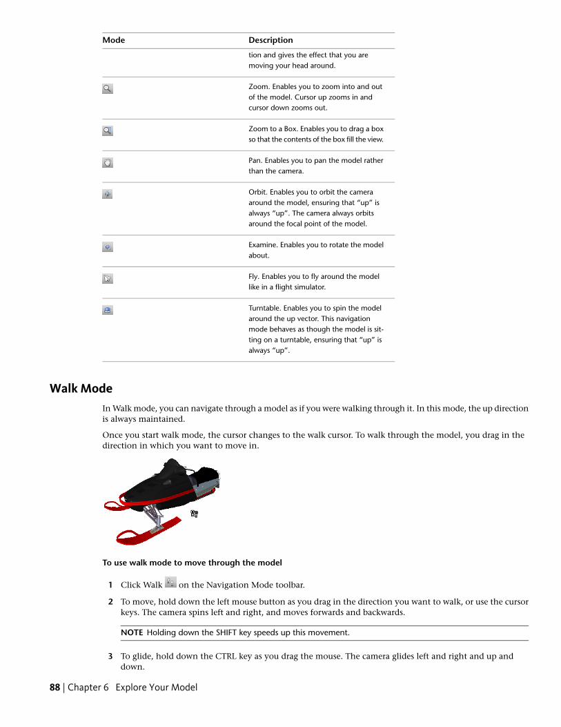
DescriptionMode
tion and gives the effect that you aremoving your head around.
Zoom. Enables you to zoom into and outof the model. Cursor up zooms in andcursor down zooms out.
Zoom to a Box. Enables you to drag a boxso that the contents of the box fill the view.
Pan. Enables you to pan the model ratherthan the camera.
Orbit. Enables you to orbit the cameraaround the model, ensuring that “up” isalways “up”. The camera always orbitsaround the focal point of the model.
Examine. Enables you to rotate the modelabout.
Fly. Enables you to fly around the modellike in a flight simulator.
Turntable. Enables you to spin the modelaround the up vector. This navigationmode behaves as though the model is sit-ting on a turntable, ensuring that “up” isalways “up”.
Walk ModeIn Walk mode, you can navigate through a model as if you were walking through it. In this mode, the up directionis always maintained.
Once you start walk mode, the cursor changes to the walk cursor. To walk through the model, you drag in thedirection in which you want to move in.
To use walk mode to move through the model
1 Click Walk on the Navigation Mode toolbar.
2 To move, hold down the left mouse button as you drag in the direction you want to walk, or use the cursorkeys. The camera spins left and right, and moves forwards and backwards.
NOTE Holding down the SHIFT key speeds up this movement.
3 To glide, hold down the CTRL key as you drag the mouse. The camera glides left and right and up anddown.
88 | Chapter 6 Explore Your Model
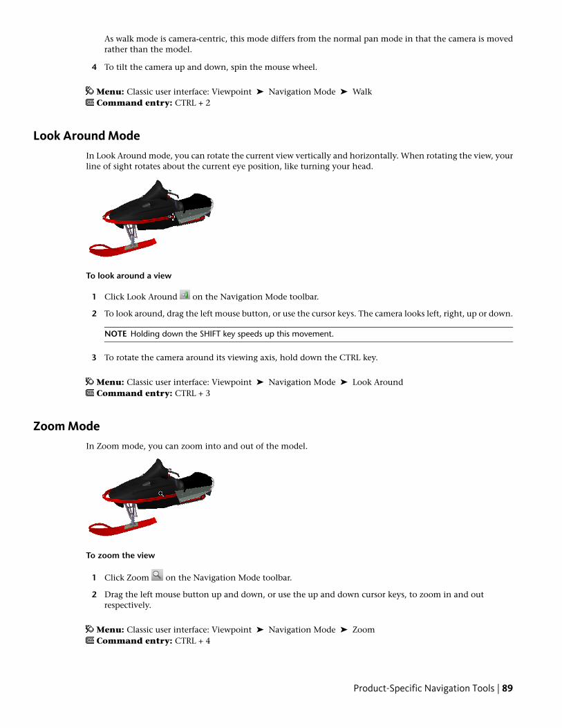
As walk mode is camera-centric, this mode differs from the normal pan mode in that the camera is movedrather than the model.
4 To tilt the camera up and down, spin the mouse wheel.
Menu: Classic user interface: Viewpoint ➤ Navigation Mode ➤ WalkCommand entry: CTRL + 2
Look Around ModeIn Look Around mode, you can rotate the current view vertically and horizontally. When rotating the view, yourline of sight rotates about the current eye position, like turning your head.
To look around a view
1 Click Look Around on the Navigation Mode toolbar.
2 To look around, drag the left mouse button, or use the cursor keys. The camera looks left, right, up or down.
NOTE Holding down the SHIFT key speeds up this movement.
3 To rotate the camera around its viewing axis, hold down the CTRL key.
Menu: Classic user interface: Viewpoint ➤ Navigation Mode ➤ Look AroundCommand entry: CTRL + 3
Zoom ModeIn Zoom mode, you can zoom into and out of the model.
To zoom the view
1 Click Zoom on the Navigation Mode toolbar.
2 Drag the left mouse button up and down, or use the up and down cursor keys, to zoom in and outrespectively.
Menu: Classic user interface: Viewpoint ➤ Navigation Mode ➤ ZoomCommand entry: CTRL + 4
Product-Specific Navigation Tools | 89
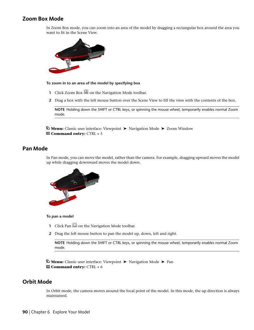
Zoom Box ModeIn Zoom Box mode, you can zoom into an area of the model by dragging a rectangular box around the area youwant to fit in the Scene View.
To zoom in to an area of the model by specifying box
1 Click Zoom Box on the Navigation Mode toolbar.
2 Drag a box with the left mouse button over the Scene View to fill the view with the contents of the box.
NOTE Holding down the SHIFT or CTRL keys, or spinning the mouse wheel, temporarily enables normal Zoommode.
Menu: Classic user interface: Viewpoint ➤ Navigation Mode ➤ Zoom WindowCommand entry: CTRL + 5
Pan ModeIn Pan mode, you can move the model, rather than the camera. For example, dragging upward moves the modelup while dragging downward moves the model down.
To pan a model
1 Click Pan on the Navigation Mode toolbar.
2 Drag the left mouse button to pan the model up, down, left and right.
NOTE Holding down the SHIFT or CTRL keys, or spinning the mouse wheel, temporarily enables normal Zoommode.
Menu: Classic user interface: Viewpoint ➤ Navigation Mode ➤ PanCommand entry: CTRL + 6
Orbit ModeIn Orbit mode, the camera moves around the focal point of the model. In this mode, the up direction is alwaysmaintained.
90 | Chapter 6 Explore Your Model
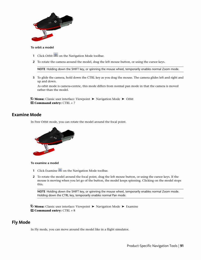
To orbit a model
1 Click Orbit on the Navigation Mode toolbar.
2 To rotate the camera around the model, drag the left mouse button, or using the cursor keys.
NOTE Holding down the SHIFT key, or spinning the mouse wheel, temporarily enables normal Zoom mode.
3 To glide the camera, hold down the CTRL key as you drag the mouse. The camera glides left and right andup and down.
As orbit mode is camera-centric, this mode differs from normal pan mode in that the camera is movedrather than the model.
Menu: Classic user interface: Viewpoint ➤ Navigation Mode ➤ OrbitCommand entry: CTRL + 7
Examine ModeIn Free Orbit mode, you can rotate the model around the focal point.
To examine a model
1 Click Examine on the Navigation Mode toolbar.
2 To rotate the model around the focal point, drag the left mouse button, or using the cursor keys. If themouse is moving when you let go of the button, the model keeps spinning. Clicking on the model stopsthis.
NOTE Holding down the SHIFT key, or spinning the mouse wheel, temporarily enables normal Zoom mode.Holding down the CTRL key, temporarily enables normal Pan mode.
Menu: Classic user interface: Viewpoint ➤ Navigation Mode ➤ ExamineCommand entry: CTRL + 8
Fly ModeIn Fly mode, you can move around the model like in a flight simulator.
Product-Specific Navigation Tools | 91
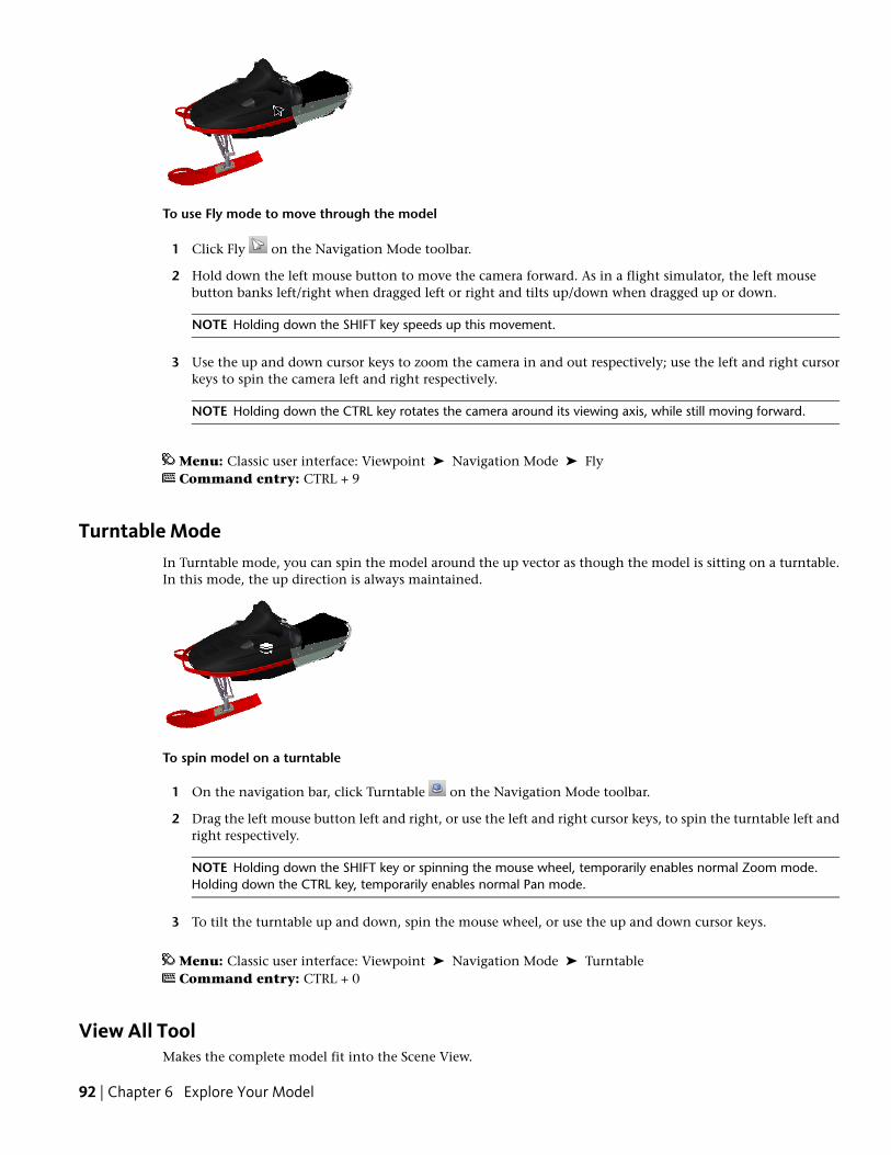
To use Fly mode to move through the model
1 Click Fly on the Navigation Mode toolbar.
2 Hold down the left mouse button to move the camera forward. As in a flight simulator, the left mousebutton banks left/right when dragged left or right and tilts up/down when dragged up or down.
NOTE Holding down the SHIFT key speeds up this movement.
3 Use the up and down cursor keys to zoom the camera in and out respectively; use the left and right cursorkeys to spin the camera left and right respectively.
NOTE Holding down the CTRL key rotates the camera around its viewing axis, while still moving forward.
Menu: Classic user interface: Viewpoint ➤ Navigation Mode ➤ FlyCommand entry: CTRL + 9
Turntable ModeIn Turntable mode, you can spin the model around the up vector as though the model is sitting on a turntable.In this mode, the up direction is always maintained.
To spin model on a turntable
1 On the navigation bar, click Turntable on the Navigation Mode toolbar.
2 Drag the left mouse button left and right, or use the left and right cursor keys, to spin the turntable left andright respectively.
NOTE Holding down the SHIFT key or spinning the mouse wheel, temporarily enables normal Zoom mode.Holding down the CTRL key, temporarily enables normal Pan mode.
3 To tilt the turntable up and down, spin the mouse wheel, or use the up and down cursor keys.
Menu: Classic user interface: Viewpoint ➤ Navigation Mode ➤ TurntableCommand entry: CTRL + 0
View All ToolMakes the complete model fit into the Scene View.
92 | Chapter 6 Explore Your Model
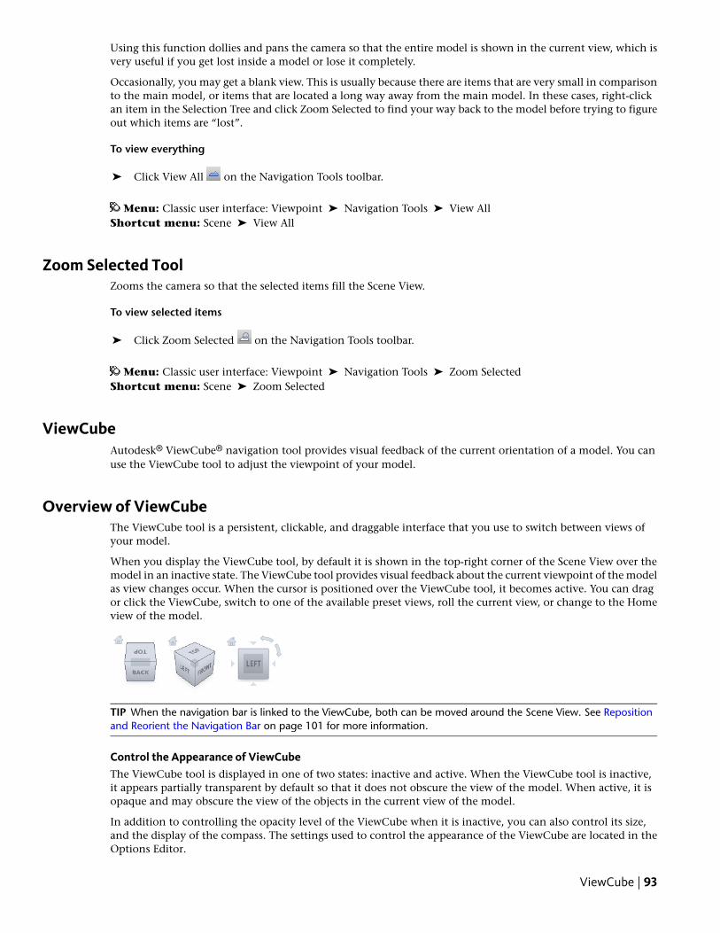
Using this function dollies and pans the camera so that the entire model is shown in the current view, which isvery useful if you get lost inside a model or lose it completely.
Occasionally, you may get a blank view. This is usually because there are items that are very small in comparisonto the main model, or items that are located a long way away from the main model. In these cases, right-clickan item in the Selection Tree and click Zoom Selected to find your way back to the model before trying to figureout which items are “lost”.
To view everything
➤ Click View All on the Navigation Tools toolbar.
Menu: Classic user interface: Viewpoint ➤ Navigation Tools ➤ View AllShortcut menu: Scene ➤ View All
Zoom Selected ToolZooms the camera so that the selected items fill the Scene View.
To view selected items
➤ Click Zoom Selected on the Navigation Tools toolbar.
Menu: Classic user interface: Viewpoint ➤ Navigation Tools ➤ Zoom SelectedShortcut menu: Scene ➤ Zoom Selected
ViewCubeAutodesk® ViewCube® navigation tool provides visual feedback of the current orientation of a model. You canuse the ViewCube tool to adjust the viewpoint of your model.
Overview of ViewCubeThe ViewCube tool is a persistent, clickable, and draggable interface that you use to switch between views ofyour model.
When you display the ViewCube tool, by default it is shown in the top-right corner of the Scene View over themodel in an inactive state. The ViewCube tool provides visual feedback about the current viewpoint of the modelas view changes occur. When the cursor is positioned over the ViewCube tool, it becomes active. You can dragor click the ViewCube, switch to one of the available preset views, roll the current view, or change to the Homeview of the model.
TIP When the navigation bar is linked to the ViewCube, both can be moved around the Scene View. See Repositionand Reorient the Navigation Bar on page 101 for more information.
Control the Appearance of ViewCubeThe ViewCube tool is displayed in one of two states: inactive and active. When the ViewCube tool is inactive,it appears partially transparent by default so that it does not obscure the view of the model. When active, it isopaque and may obscure the view of the objects in the current view of the model.
In addition to controlling the opacity level of the ViewCube when it is inactive, you can also control its size,and the display of the compass. The settings used to control the appearance of the ViewCube are located in theOptions Editor.
ViewCube | 93
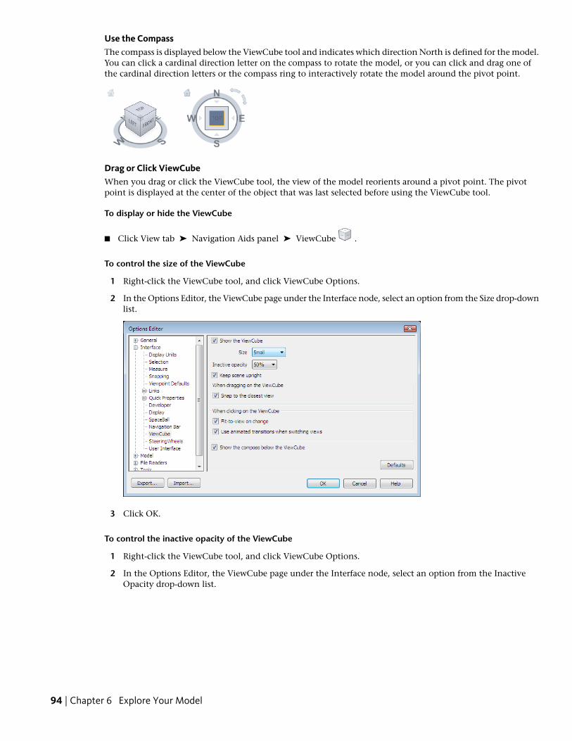
Use the CompassThe compass is displayed below the ViewCube tool and indicates which direction North is defined for the model.You can click a cardinal direction letter on the compass to rotate the model, or you can click and drag one ofthe cardinal direction letters or the compass ring to interactively rotate the model around the pivot point.
Drag or Click ViewCubeWhen you drag or click the ViewCube tool, the view of the model reorients around a pivot point. The pivotpoint is displayed at the center of the object that was last selected before using the ViewCube tool.
To display or hide the ViewCube
■ Click View tab ➤ Navigation Aids panel ➤ ViewCube .
To control the size of the ViewCube
1 Right-click the ViewCube tool, and click ViewCube Options.
2 In the Options Editor, the ViewCube page under the Interface node, select an option from the Size drop-downlist.
3 Click OK.
To control the inactive opacity of the ViewCube
1 Right-click the ViewCube tool, and click ViewCube Options.
2 In the Options Editor, the ViewCube page under the Interface node, select an option from the InactiveOpacity drop-down list.
94 | Chapter 6 Explore Your Model
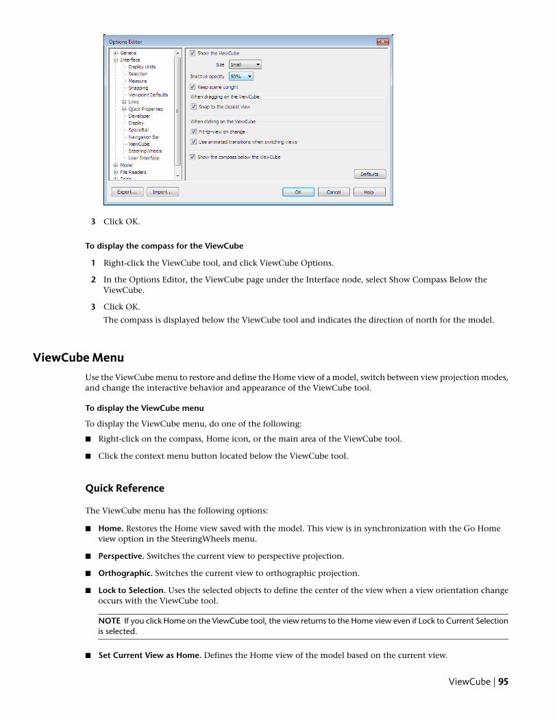
3 Click OK.
To display the compass for the ViewCube
1 Right-click the ViewCube tool, and click ViewCube Options.
2 In the Options Editor, the ViewCube page under the Interface node, select Show Compass Below theViewCube.
3 Click OK.
The compass is displayed below the ViewCube tool and indicates the direction of north for the model.
ViewCube MenuUse the ViewCube menu to restore and define the Home view of a model, switch between view projection modes,and change the interactive behavior and appearance of the ViewCube tool.
To display the ViewCube menu
To display the ViewCube menu, do one of the following:
■ Right-click on the compass, Home icon, or the main area of the ViewCube tool.
■ Click the context menu button located below the ViewCube tool.
Quick Reference
The ViewCube menu has the following options:
■ Home. Restores the Home view saved with the model. This view is in synchronization with the Go Homeview option in the SteeringWheels menu.
■ Perspective. Switches the current view to perspective projection.
■ Orthographic. Switches the current view to orthographic projection.
■ Lock to Selection. Uses the selected objects to define the center of the view when a view orientation changeoccurs with the ViewCube tool.
NOTE If you click Home on the ViewCube tool, the view returns to the Home view even if Lock to Current Selectionis selected.
■ Set Current View as Home. Defines the Home view of the model based on the current view.
ViewCube | 95
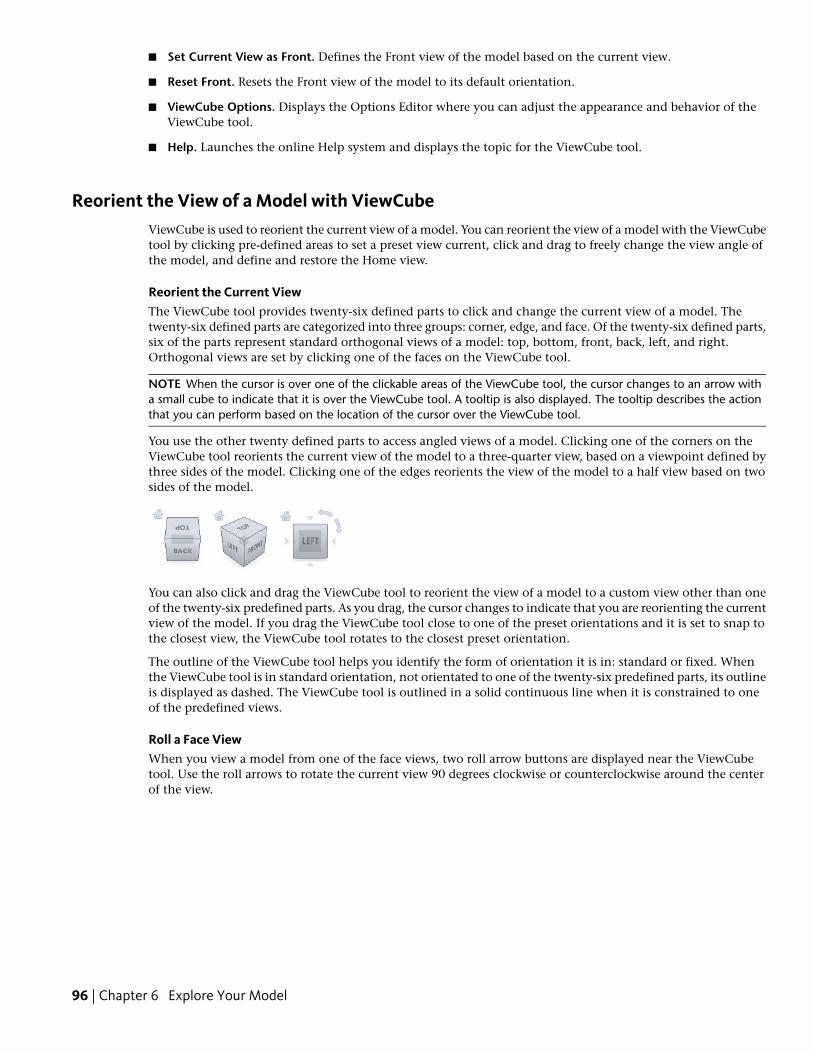
■ Set Current View as Front. Defines the Front view of the model based on the current view.
■ Reset Front. Resets the Front view of the model to its default orientation.
■ ViewCube Options. Displays the Options Editor where you can adjust the appearance and behavior of theViewCube tool.
■ Help. Launches the online Help system and displays the topic for the ViewCube tool.
Reorient the View of a Model with ViewCubeViewCube is used to reorient the current view of a model. You can reorient the view of a model with the ViewCubetool by clicking pre-defined areas to set a preset view current, click and drag to freely change the view angle ofthe model, and define and restore the Home view.
Reorient the Current ViewThe ViewCube tool provides twenty-six defined parts to click and change the current view of a model. Thetwenty-six defined parts are categorized into three groups: corner, edge, and face. Of the twenty-six defined parts,six of the parts represent standard orthogonal views of a model: top, bottom, front, back, left, and right.Orthogonal views are set by clicking one of the faces on the ViewCube tool.
NOTE When the cursor is over one of the clickable areas of the ViewCube tool, the cursor changes to an arrow witha small cube to indicate that it is over the ViewCube tool. A tooltip is also displayed. The tooltip describes the actionthat you can perform based on the location of the cursor over the ViewCube tool.
You use the other twenty defined parts to access angled views of a model. Clicking one of the corners on theViewCube tool reorients the current view of the model to a three-quarter view, based on a viewpoint defined bythree sides of the model. Clicking one of the edges reorients the view of the model to a half view based on twosides of the model.
You can also click and drag the ViewCube tool to reorient the view of a model to a custom view other than oneof the twenty-six predefined parts. As you drag, the cursor changes to indicate that you are reorienting the currentview of the model. If you drag the ViewCube tool close to one of the preset orientations and it is set to snap tothe closest view, the ViewCube tool rotates to the closest preset orientation.
The outline of the ViewCube tool helps you identify the form of orientation it is in: standard or fixed. Whenthe ViewCube tool is in standard orientation, not orientated to one of the twenty-six predefined parts, its outlineis displayed as dashed. The ViewCube tool is outlined in a solid continuous line when it is constrained to oneof the predefined views.
Roll a Face ViewWhen you view a model from one of the face views, two roll arrow buttons are displayed near the ViewCubetool. Use the roll arrows to rotate the current view 90 degrees clockwise or counterclockwise around the centerof the view.
96 | Chapter 6 Explore Your Model
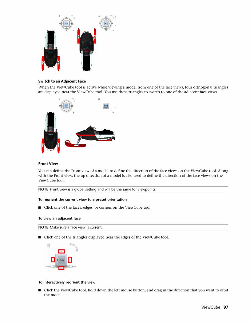
Switch to an Adjacent FaceWhen the ViewCube tool is active while viewing a model from one of the face views, four orthogonal trianglesare displayed near the ViewCube tool. You use these triangles to switch to one of the adjacent face views.
Front View
You can define the Front view of a model to define the direction of the face views on the ViewCube tool. Alongwith the Front view, the up direction of a model is also used to define the direction of the face views on theViewCube tool.
NOTE Front view is a global setting and will be the same for viewpoints.
To reorient the current view to a preset orientation
■ Click one of the faces, edges, or corners on the ViewCube tool.
To view an adjacent face
NOTE Make sure a face view is current.
■ Click one of the triangles displayed near the edges of the ViewCube tool.
To interactively reorient the view
■ Click the ViewCube tool, hold down the left mouse button, and drag in the direction that you want to orbitthe model.
ViewCube | 97
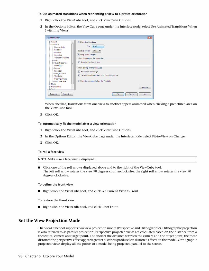
To use animated transitions when reorienting a view to a preset orientation
1 Right-click the ViewCube tool, and click ViewCube Options.
2 In the Options Editor, the ViewCube page under the Interface node, select Use Animated Transitions WhenSwitching Views.
When checked, transitions from one view to another appear animated when clicking a predefined area onthe ViewCube tool.
3 Click OK.
To automatically fit the model after a view orientation
1 Right-click the ViewCube tool, and click ViewCube Options.
2 In the Options Editor, the ViewCube page under the Interface node, select Fit-to-View on Change.
3 Click OK.
To roll a face view
NOTE Make sure a face view is displayed.
■ Click one of the roll arrows displayed above and to the right of the ViewCube tool.The left roll arrow rotates the view 90 degrees counterclockwise; the right roll arrow rotates the view 90degrees clockwise.
To define the front view
■ Right-click the ViewCube tool, and click Set Current View as Front.
To restore the Front view
■ Right-click the ViewCube tool, and click Reset Front.
Set the View Projection ModeThe ViewCube tool supports two view projection modes (Perspective and Orthographic). Orthographic projectionis also referred to as parallel projection. Perspective projected views are calculated based on the distance from atheoretical camera and target point. The shorter the distance between the camera and the target point, the moredistorted the perspective effect appears; greater distances produce less distorted affects on the model. Orthographicprojected views display all the points of a model being projected parallel to the screen.
98 | Chapter 6 Explore Your Model
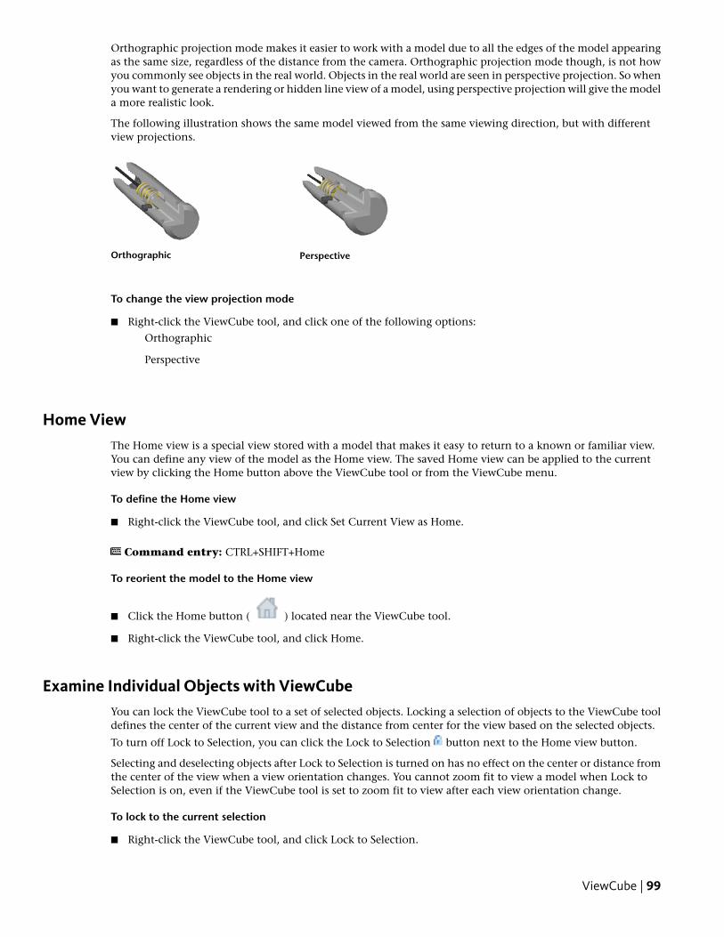
Orthographic projection mode makes it easier to work with a model due to all the edges of the model appearingas the same size, regardless of the distance from the camera. Orthographic projection mode though, is not howyou commonly see objects in the real world. Objects in the real world are seen in perspective projection. So whenyou want to generate a rendering or hidden line view of a model, using perspective projection will give the modela more realistic look.
The following illustration shows the same model viewed from the same viewing direction, but with differentview projections.
PerspectiveOrthographic
To change the view projection mode
■ Right-click the ViewCube tool, and click one of the following options:
Orthographic
Perspective
Home ViewThe Home view is a special view stored with a model that makes it easy to return to a known or familiar view.You can define any view of the model as the Home view. The saved Home view can be applied to the currentview by clicking the Home button above the ViewCube tool or from the ViewCube menu.
To define the Home view
■ Right-click the ViewCube tool, and click Set Current View as Home.
Command entry: CTRL+SHIFT+Home
To reorient the model to the Home view
■ Click the Home button ( ) located near the ViewCube tool.
■ Right-click the ViewCube tool, and click Home.
Examine Individual Objects with ViewCubeYou can lock the ViewCube tool to a set of selected objects. Locking a selection of objects to the ViewCube tooldefines the center of the current view and the distance from center for the view based on the selected objects.
To turn off Lock to Selection, you can click the Lock to Selection button next to the Home view button.
Selecting and deselecting objects after Lock to Selection is turned on has no effect on the center or distance fromthe center of the view when a view orientation changes. You cannot zoom fit to view a model when Lock toSelection is on, even if the ViewCube tool is set to zoom fit to view after each view orientation change.
To lock to the current selection
■ Right-click the ViewCube tool, and click Lock to Selection.
ViewCube | 99
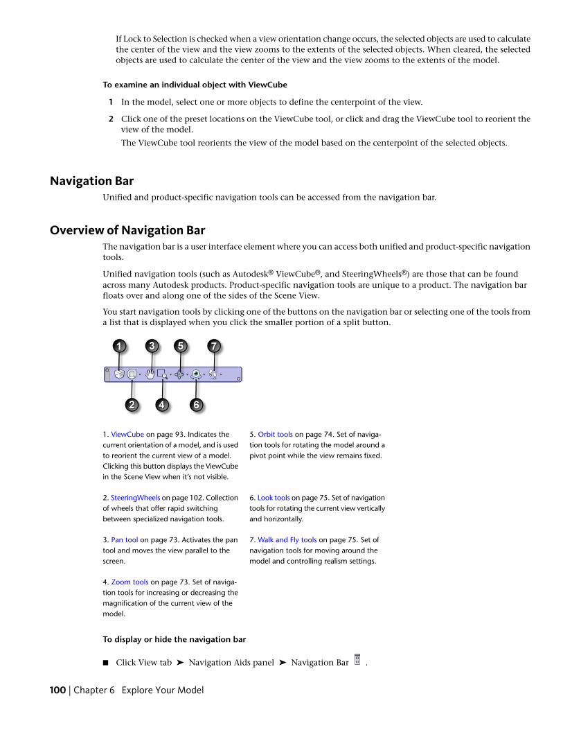
If Lock to Selection is checked when a view orientation change occurs, the selected objects are used to calculatethe center of the view and the view zooms to the extents of the selected objects. When cleared, the selectedobjects are used to calculate the center of the view and the view zooms to the extents of the model.
To examine an individual object with ViewCube
1 In the model, select one or more objects to define the centerpoint of the view.
2 Click one of the preset locations on the ViewCube tool, or click and drag the ViewCube tool to reorient theview of the model.
The ViewCube tool reorients the view of the model based on the centerpoint of the selected objects.
Navigation BarUnified and product-specific navigation tools can be accessed from the navigation bar.
Overview of Navigation BarThe navigation bar is a user interface element where you can access both unified and product-specific navigationtools.
Unified navigation tools (such as Autodesk® ViewCube®, and SteeringWheels®) are those that can be foundacross many Autodesk products. Product-specific navigation tools are unique to a product. The navigation barfloats over and along one of the sides of the Scene View.
You start navigation tools by clicking one of the buttons on the navigation bar or selecting one of the tools froma list that is displayed when you click the smaller portion of a split button.
5. Orbit tools on page 74. Set of naviga-tion tools for rotating the model around apivot point while the view remains fixed.
1. ViewCube on page 93. Indicates thecurrent orientation of a model, and is usedto reorient the current view of a model.Clicking this button displays the ViewCubein the Scene View when it’s not visible.
6. Look tools on page 75. Set of navigationtools for rotating the current view verticallyand horizontally.
2. SteeringWheels on page 102. Collectionof wheels that offer rapid switchingbetween specialized navigation tools.
7. Walk and Fly tools on page 75. Set ofnavigation tools for moving around themodel and controlling realism settings.
3. Pan tool on page 73. Activates the pantool and moves the view parallel to thescreen.
4. Zoom tools on page 73. Set of naviga-tion tools for increasing or decreasing themagnification of the current view of themodel.
To display or hide the navigation bar
■ Click View tab ➤ Navigation Aids panel ➤ Navigation Bar .
100 | Chapter 6 Explore Your Model
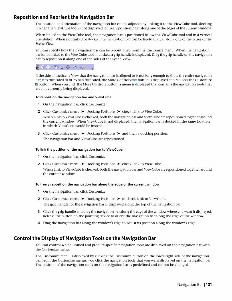
Reposition and Reorient the Navigation BarThe position and orientation of the navigation bar can be adjusted by linking it to the ViewCube tool, dockingit when the ViewCube tool is not displayed, or freely positioning it along one of the edges of the current window.
When linked to the ViewCube tool, the navigation bar is positioned below the ViewCube tool and in a verticalorientation. When not linked or docked, the navigation bar can be freely aligned along one of the edges of theScene View.
You can specify how the navigation bar can be repositioned from the Customize menu. When the navigationbar is not linked to the ViewCube tool or docked, a grip handle is displayed. Drag the grip handle on the navigationbar to reposition it along one of the sides of the Scene View.
If the side of the Scene View that the navigation bar is aligned to is not long enough to show the entire navigationbar, it is truncated to fit. When truncated, the More Controls button is displayed and replaces the Customize
button. When you click the More Controls button, a menu is displayed that contains the navigation tools thatare not currently being displayed.
To reposition the navigation bar and ViewCube
1 On the navigation bar, click Customize.
2 Click Customize menu ➤ Docking Positions ➤ check Link to ViewCube.
When Link to ViewCube is checked, both the navigation bar and ViewCube are repositioned together aroundthe current window. When ViewCube is not displayed, the navigation bar is docked in the same locationin which ViewCube would be instead.
3 Click Customize menu ➤ Docking Positions ➤ and then a docking position.
The navigation bar and ViewCube are repositioned.
To link the position of the navigation bar to ViewCube
1 On the navigation bar, click Customize.
2 Click Customize menu ➤ Docking Positions ➤ check Link to ViewCube.
When Link to ViewCube is checked, both the navigation bar and ViewCube are repositioned together aroundthe current window.
To freely reposition the navigation bar along the edge of the current window
1 On the navigation bar, click Customize.
2 Click Customize menu ➤ Docking Positions ➤ uncheck Link to ViewCube.
The grip handle for the navigation bar is displayed along the top of the navigation bar.
3 Click the grip handle and drag the navigation bar along the edge of the window where you want it displayed.Release the button on the pointing device to orient the navigation bar along the edge of the window.
4 Drag the navigation bar along the window’s edge to adjust its position along the window’s edge.
Control the Display of Navigation Tools on the Navigation BarYou can control which unified and product-specific navigation tools are displayed on the navigation bar withthe Customize menu.
The Customize menu is displayed by clicking the Customize button on the lower-right side of the navigationbar. From the Customize menus, you click the navigation tools that you want displayed on the navigation bar.The position of the navigation tools on the navigation bar is predefined and cannot be changed.
Navigation Bar | 101
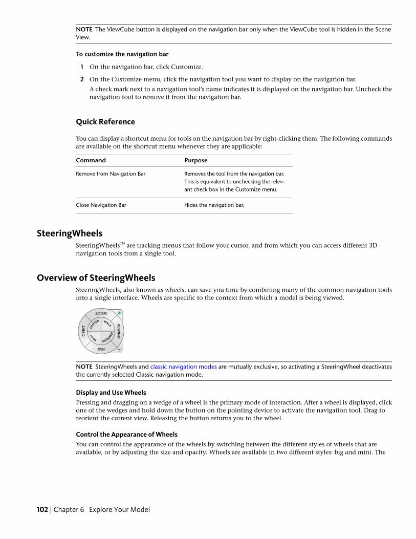
NOTE The ViewCube button is displayed on the navigation bar only when the ViewCube tool is hidden in the SceneView.
To customize the navigation bar
1 On the navigation bar, click Customize.
2 On the Customize menu, click the navigation tool you want to display on the navigation bar.
A check mark next to a navigation tool’s name indicates it is displayed on the navigation bar. Uncheck thenavigation tool to remove it from the navigation bar.
Quick Reference
You can display a shortcut menu for tools on the navigation bar by right-clicking them. The following commandsare available on the shortcut menu whenever they are applicable:
PurposeCommand
Removes the tool from the navigation bar.This is equivalent to unchecking the relev-ant check box in the Customize menu.
Remove from Navigation Bar
Hides the navigation bar.Close Navigation Bar
SteeringWheelsSteeringWheels™ are tracking menus that follow your cursor, and from which you can access different 3Dnavigation tools from a single tool.
Overview of SteeringWheelsSteeringWheels, also known as wheels, can save you time by combining many of the common navigation toolsinto a single interface. Wheels are specific to the context from which a model is being viewed.
NOTE SteeringWheels and classic navigation modes are mutually exclusive, so activating a SteeringWheel deactivatesthe currently selected Classic navigation mode.
Display and Use WheelsPressing and dragging on a wedge of a wheel is the primary mode of interaction. After a wheel is displayed, clickone of the wedges and hold down the button on the pointing device to activate the navigation tool. Drag toreorient the current view. Releasing the button returns you to the wheel.
Control the Appearance of WheelsYou can control the appearance of the wheels by switching between the different styles of wheels that areavailable, or by adjusting the size and opacity. Wheels are available in two different styles: big and mini. The
102 | Chapter 6 Explore Your Model
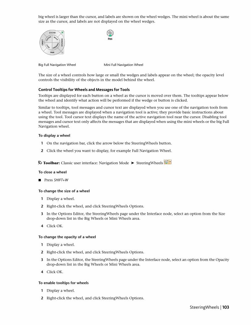
big wheel is larger than the cursor, and labels are shown on the wheel wedges. The mini wheel is about the samesize as the cursor, and labels are not displayed on the wheel wedges.
Mini Full Navigation WheelBig Full Navigation Wheel
The size of a wheel controls how large or small the wedges and labels appear on the wheel; the opacity levelcontrols the visibility of the objects in the model behind the wheel.
Control Tooltips for Wheels and Messages for ToolsTooltips are displayed for each button on a wheel as the cursor is moved over them. The tooltips appear belowthe wheel and identify what action will be performed if the wedge or button is clicked.
Similar to tooltips, tool messages and cursor text are displayed when you use one of the navigation tools froma wheel. Tool messages are displayed when a navigation tool is active; they provide basic instructions aboutusing the tool. Tool cursor text displays the name of the active navigation tool near the cursor. Disabling toolmessages and cursor text only affects the messages that are displayed when using the mini wheels or the big FullNavigation wheel.
To display a wheel
1 On the navigation bar, click the arrow below the SteeringWheels button.
2 Click the wheel you want to display, for example Full Navigation Wheel.
Toolbar: Classic user interface: Navigation Mode ➤ SteeringWheels
To close a wheel
■ Press SHIFT+W
To change the size of a wheel
1 Display a wheel.
2 Right-click the wheel, and click SteeringWheels Options.
3 In the Options Editor, the SteeringWheels page under the Interface node, select an option from the Sizedrop-down list in the Big Wheels or Mini Wheels area.
4 Click OK.
To change the opacity of a wheel
1 Display a wheel.
2 Right-click the wheel, and click SteeringWheels Options.
3 In the Options Editor, the SteeringWheels page under the Interface node, select an option from the Opacitydrop-down list in the Big Wheels or Mini Wheels area.
4 Click OK.
To enable tooltips for wheels
1 Display a wheel.
2 Right-click the wheel, and click SteeringWheels Options.
SteeringWheels | 103
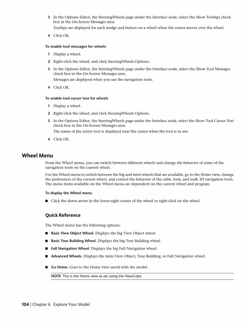
3 In the Options Editor, the SteeringWheels page under the Interface node, select the Show Tooltips checkbox in the On-Screen Messages area.
Tooltips are displayed for each wedge and button on a wheel when the cursor moves over the wheel.
4 Click OK.
To enable tool messages for wheels
1 Display a wheel.
2 Right-click the wheel, and click SteeringWheels Options.
3 In the Options Editor, the SteeringWheels page under the Interface node, select the Show Tool Messagescheck box in the On-Screen Messages area.
Messages are displayed when you use the navigation tools.
4 Click OK.
To enable tool cursor text for wheels
1 Display a wheel.
2 Right-click the wheel, and click SteeringWheels Options.
3 In the Options Editor, the SteeringWheels page under the Interface node, select the Show Tool Cursor Textcheck box in the On-Screen Messages area.
The name of the active tool is displayed near the cursor when the tool is in use.
4 Click OK.
Wheel MenuFrom the Wheel menu, you can switch between different wheels and change the behavior of some of thenavigation tools on the current wheel.
Use the Wheel menu to switch between the big and mini wheels that are available, go to the Home view, changethe preferences of the current wheel, and control the behavior of the orbit, look, and walk 3D navigation tools.The menu items available on the Wheel menu are dependent on the current wheel and program.
To display the Wheel menu
■ Click the down arrow in the lower-right corner of the wheel or right-click on the wheel.
Quick Reference
The Wheel menu has the following options:
■ Basic View Object Wheel. Displays the big View Object wheel.
■ Basic Tour Building Wheel. Displays the big Tour Building wheel.
■ Full Navigation Wheel. Displays the big Full Navigation wheel.
■ Advanced Wheels. Displays the mini View Object, Tour Building, or Full Navigation wheel.
■ Go Home. Goes to the Home view saved with the model.
NOTE This is the Home view as set using the ViewCube.
104 | Chapter 6 Explore Your Model
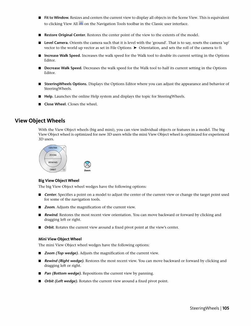
■ Fit to Window. Resizes and centers the current view to display all objects in the Scene View. This is equivalent
to clicking View All on the Navigation Tools toolbar in the Classic user interface.
■ Restore Original Center. Restores the center point of the view to the extents of the model.
■ Level Camera. Orients the camera such that it is level with the 'ground'. That is to say, resets the camera 'up'vector to the world up vector as set in File Options ➤ Orientation, and sets the roll of the camera to 0.
■ Increase Walk Speed. Increases the walk speed for the Walk tool to double its current setting in the OptionsEditor.
■ Decrease Walk Speed. Decreases the walk speed for the Walk tool to half its current setting in the OptionsEditor.
■ SteeringWheels Options. Displays the Options Editor where you can adjust the appearance and behavior ofSteeringWheels.
■ Help. Launches the online Help system and displays the topic for SteeringWheels.
■ Close Wheel. Closes the wheel.
View Object WheelsWith the View Object wheels (big and mini), you can view individual objects or features in a model. The bigView Object wheel is optimized for new 3D users while the mini View Object wheel is optimized for experienced3D users.
Big View Object WheelThe big View Object wheel wedges have the following options:
■ Center. Specifies a point on a model to adjust the center of the current view or change the target point usedfor some of the navigation tools.
■ Zoom. Adjusts the magnification of the current view.
■ Rewind. Restores the most recent view orientation. You can move backward or forward by clicking anddragging left or right.
■ Orbit. Rotates the current view around a fixed pivot point at the view’s center.
Mini View Object WheelThe mini View Object wheel wedges have the following options:
■ Zoom (Top wedge). Adjusts the magnification of the current view.
■ Rewind (Right wedge). Restores the most recent view. You can move backward or forward by clicking anddragging left or right.
■ Pan (Bottom wedge). Repositions the current view by panning.
■ Orbit (Left wedge). Rotates the current view around a fixed pivot point.
SteeringWheels | 105
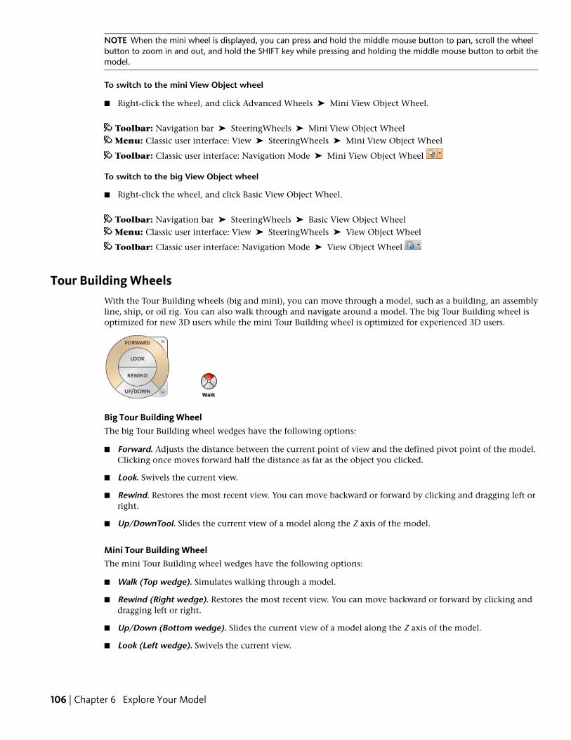
NOTE When the mini wheel is displayed, you can press and hold the middle mouse button to pan, scroll the wheelbutton to zoom in and out, and hold the SHIFT key while pressing and holding the middle mouse button to orbit themodel.
To switch to the mini View Object wheel
■ Right-click the wheel, and click Advanced Wheels ➤ Mini View Object Wheel.
Toolbar: Navigation bar ➤ SteeringWheels ➤ Mini View Object WheelMenu: Classic user interface: View ➤ SteeringWheels ➤ Mini View Object Wheel
Toolbar: Classic user interface: Navigation Mode ➤ Mini View Object Wheel
To switch to the big View Object wheel
■ Right-click the wheel, and click Basic View Object Wheel.
Toolbar: Navigation bar ➤ SteeringWheels ➤ Basic View Object WheelMenu: Classic user interface: View ➤ SteeringWheels ➤ View Object Wheel
Toolbar: Classic user interface: Navigation Mode ➤ View Object Wheel
Tour Building WheelsWith the Tour Building wheels (big and mini), you can move through a model, such as a building, an assemblyline, ship, or oil rig. You can also walk through and navigate around a model. The big Tour Building wheel isoptimized for new 3D users while the mini Tour Building wheel is optimized for experienced 3D users.
Big Tour Building WheelThe big Tour Building wheel wedges have the following options:
■ Forward. Adjusts the distance between the current point of view and the defined pivot point of the model.Clicking once moves forward half the distance as far as the object you clicked.
■ Look. Swivels the current view.
■ Rewind. Restores the most recent view. You can move backward or forward by clicking and dragging left orright.
■ Up/DownTool. Slides the current view of a model along the Z axis of the model.
Mini Tour Building WheelThe mini Tour Building wheel wedges have the following options:
■ Walk (Top wedge). Simulates walking through a model.
■ Rewind (Right wedge). Restores the most recent view. You can move backward or forward by clicking anddragging left or right.
■ Up/Down (Bottom wedge). Slides the current view of a model along the Z axis of the model.
■ Look (Left wedge). Swivels the current view.
106 | Chapter 6 Explore Your Model
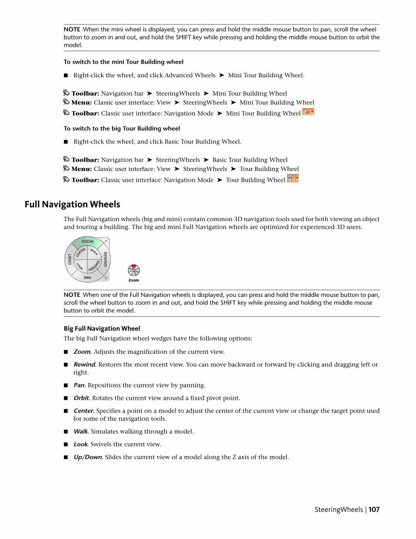
NOTE When the mini wheel is displayed, you can press and hold the middle mouse button to pan, scroll the wheelbutton to zoom in and out, and hold the SHIFT key while pressing and holding the middle mouse button to orbit themodel.
To switch to the mini Tour Building wheel
■ Right-click the wheel, and click Advanced Wheels ➤ Mini Tour Building Wheel.
Toolbar: Navigation bar ➤ SteeringWheels ➤ Mini Tour Building WheelMenu: Classic user interface: View ➤ SteeringWheels ➤ Mini Tour Building Wheel
Toolbar: Classic user interface: Navigation Mode ➤ Mini Tour Building Wheel
To switch to the big Tour Building wheel
■ Right-click the wheel, and click Basic Tour Building Wheel.
Toolbar: Navigation bar ➤ SteeringWheels ➤ Basic Tour Building WheelMenu: Classic user interface: View ➤ SteeringWheels ➤ Tour Building Wheel
Toolbar: Classic user interface: Navigation Mode ➤ Tour Building Wheel
Full Navigation WheelsThe Full Navigation wheels (big and mini) contain common 3D navigation tools used for both viewing an objectand touring a building. The big and mini Full Navigation wheels are optimized for experienced 3D users.
NOTE When one of the Full Navigation wheels is displayed, you can press and hold the middle mouse button to pan,scroll the wheel button to zoom in and out, and hold the SHIFT key while pressing and holding the middle mousebutton to orbit the model.
Big Full Navigation WheelThe big Full Navigation wheel wedges have the following options:
■ Zoom. Adjusts the magnification of the current view.
■ Rewind. Restores the most recent view. You can move backward or forward by clicking and dragging left orright.
■ Pan. Repositions the current view by panning.
■ Orbit. Rotates the current view around a fixed pivot point.
■ Center. Specifies a point on a model to adjust the center of the current view or change the target point usedfor some of the navigation tools.
■ Walk. Simulates walking through a model.
■ Look. Swivels the current view.
■ Up/Down. Slides the current view of a model along the Z axis of the model.
SteeringWheels | 107
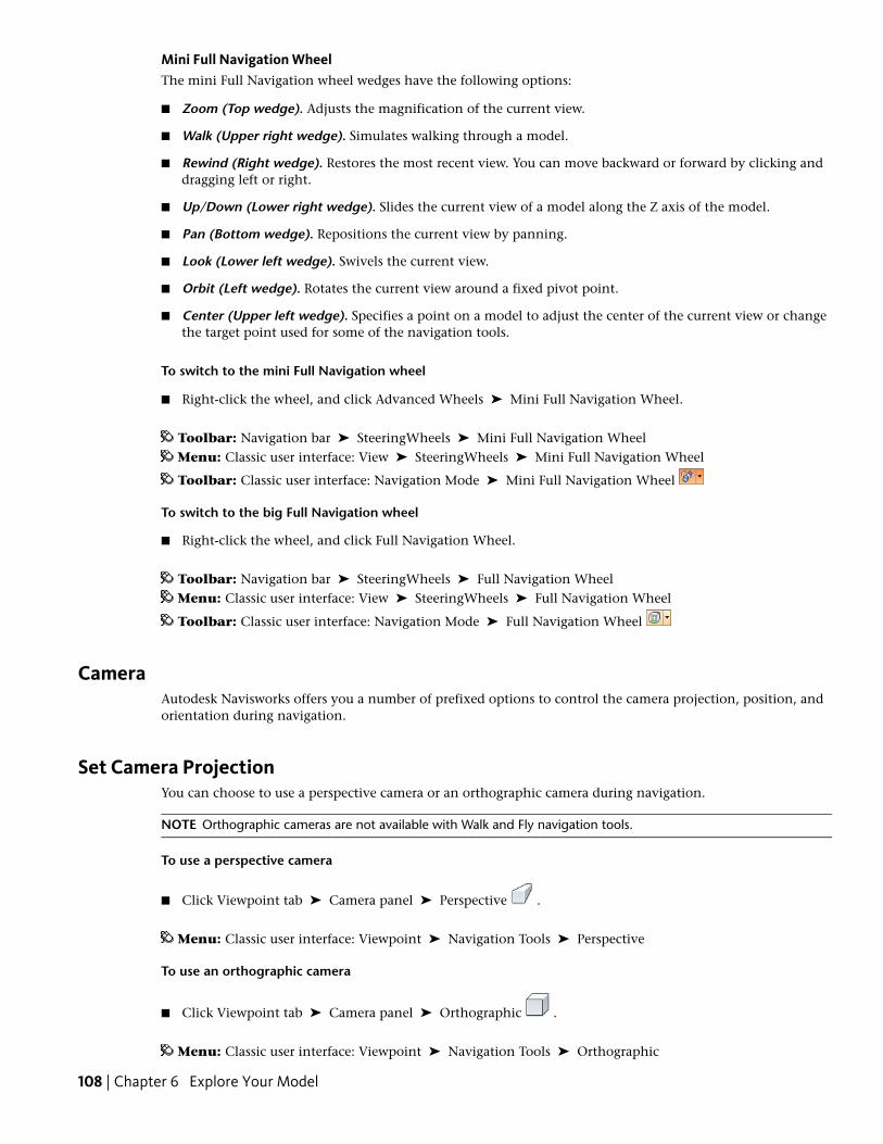
Mini Full Navigation WheelThe mini Full Navigation wheel wedges have the following options:
■ Zoom (Top wedge). Adjusts the magnification of the current view.
■ Walk (Upper right wedge). Simulates walking through a model.
■ Rewind (Right wedge). Restores the most recent view. You can move backward or forward by clicking anddragging left or right.
■ Up/Down (Lower right wedge). Slides the current view of a model along the Z axis of the model.
■ Pan (Bottom wedge). Repositions the current view by panning.
■ Look (Lower left wedge). Swivels the current view.
■ Orbit (Left wedge). Rotates the current view around a fixed pivot point.
■ Center (Upper left wedge). Specifies a point on a model to adjust the center of the current view or changethe target point used for some of the navigation tools.
To switch to the mini Full Navigation wheel
■ Right-click the wheel, and click Advanced Wheels ➤ Mini Full Navigation Wheel.
Toolbar: Navigation bar ➤ SteeringWheels ➤ Mini Full Navigation WheelMenu: Classic user interface: View ➤ SteeringWheels ➤ Mini Full Navigation Wheel
Toolbar: Classic user interface: Navigation Mode ➤ Mini Full Navigation Wheel
To switch to the big Full Navigation wheel
■ Right-click the wheel, and click Full Navigation Wheel.
Toolbar: Navigation bar ➤ SteeringWheels ➤ Full Navigation WheelMenu: Classic user interface: View ➤ SteeringWheels ➤ Full Navigation Wheel
Toolbar: Classic user interface: Navigation Mode ➤ Full Navigation Wheel
CameraAutodesk Navisworks offers you a number of prefixed options to control the camera projection, position, andorientation during navigation.
Set Camera ProjectionYou can choose to use a perspective camera or an orthographic camera during navigation.
NOTE Orthographic cameras are not available with Walk and Fly navigation tools.
To use a perspective camera
■ Click Viewpoint tab ➤ Camera panel ➤ Perspective .
Menu: Classic user interface: Viewpoint ➤ Navigation Tools ➤ Perspective
To use an orthographic camera
■ Click Viewpoint tab ➤ Camera panel ➤ Orthographic .
Menu: Classic user interface: Viewpoint ➤ Navigation Tools ➤ Orthographic
108 | Chapter 6 Explore Your Model
Control the Field of ViewYou can define the area of the scene that can be viewed through the camera.
For the current viewpoint, you can move the FOV slider on the ribbon to adjust the Horizontal Field of View.For previously saved viewpoints, you can use the Edit Viewpoint dialog box on page 161 to adjust the values forboth vertical and horizontal angles of view.
NOTE When you modify the Horizontal Field of View, the Vertical Field of View is automatically adjusted, and viceversa to match the aspect ratio in Autodesk Navisworks.
To control the horizontal field of view
■ Click Viewpoint tab ➤ Camera panel, and move the FOV slider to control the camera’s angle of view.Moving the slider to the right produces a wider angle of view, and moving the slider to the left produces anarrower, or more tightly focused, angle of view.
Position and Focus CameraYou can adjust the camera’s position and orientation in the scene.
Move CameraFor the current viewpoint, you can use the Position entry boxes on the ribbon to move the camera position. Forpreviously saved viewpoints, you can use the Edit Viewpoint dialog box on page 161 to adjust the camera values.
To move camera numerically
1 Click the Viewpoint tab, and slide out the Camera panel.
2 Type in numerical values into the Position entry boxes to move the camera by the amount entered.
Rotate CameraYou can adjust the angle of the camera during navigation.
For the current viewpoint, use the Tilt window to rotate the camera up/down, and the Roll entry box on theribbon to rotate the camera left/right. For saved viewpoints, you can use the Edit Viewpoint dialog box on page161 to adjust the camera values.
Tilt Window
Camera | 109
The tilt angle is indicated in the scene's units below (negative) or above (positive) horizontal (0) at the base ofthe window.
You can use the Tilt window with the Walk tool on the navigation bar to look up and down. If your mouse hasa wheel, you can use it to adjust the tilt angle.
To toggle the Tilt window
■ Click Viewpoint tab ➤ Camera panel ➤ Show Tilt Bar .
Command entry: CTRL + F7
To roll camera up/down
■ Drag the slider up or down on the Tilt window to roll the camera.You can also type values directly the entry box at the base of the Tilt window. A positive value rotates thecamera upwards, and a negative value rotates camera downwards. Typing 0 straightens the camera.
To roll camera left/right
■ Click the Viewpoint tab, and slide out the Camera panel.
■ Type in a value into the Roll entry box to rotate the camera around its front-to-back axis.A positive value rotates the camera counterclockwise, and a negative value rotates it clockwise.
NOTE This value is not editable when the viewpoint up vector stays upright (that is, when you use Walk, Orbitand Constrained Orbit navigation tools).
Move Focal PointYou can change the focal point for the camera. For the current viewpoint, use the Look At entry boxes on theribbon. For saved viewpoints, you can use the Edit Viewpoint dialog box on page 161 to adjust the camera values.
You can also put the Scene View into focus mode, which effectively swivels the camera so that the point clickedis in the center of the view. See Focus on page 113.
To move the camera focal point
1 Click the Viewpoint tab, and slide out the Camera panel.
2 Type in numerical values into the Look At entry boxes to move the camera focal point by the amountentered.
Straighten CameraYou can straighten the camera to align with the viewpoint up vector.
When the camera position is close to the viewpoint up vector (within 13 degrees), you can use this function tosnap the camera to the appropriate axis.
TIP The same effect can be achieved by typing 0 at the base of the Tilt window.
To straighten camera
■ Click Viewpoint tab ➤ Camera panel ➤ Align Camera drop-down ➤ Straighten .
Predefined Camera ViewsIn Autodesk Navisworks, you can align a camera to one of the axis, or select one of six predefined face views toinstantly change the camera’s position and orientation in the scene.
110 | Chapter 6 Explore Your Model
When you align the camera position along one of the axis:
■ Aligning with X axis toggles between front and back face views.
■ Aligning with Y axis toggles between left and right face views.
■ Aligning with Z axis toggles between top and bottom face views.
NOTE You can customize the location of the front face by using the ViewCube tool. This change is global, and affectsall viewpoints.
To align with X-axis
■ Click Viewpoint tab ➤ Camera panel ➤ Align Camera drop-down ➤ Align X .
Menu: Classic user interface: Viewpoint ➤ Navigation Tools ➤ Align X
To align with Y-axis
■ Click Viewpoint tab ➤ Camera panel ➤ Align Camera drop-down ➤ Align Y .
Menu: Classic user interface: Viewpoint ➤ Navigation Tools ➤ Align Y
To align with Z-axis
■ Click Viewpoint tab ➤ Camera panel ➤ Align Camera drop-down ➤ Align Z .
Menu: Classic user interface: Viewpoint ➤ Navigation Tools ➤ Align Z
To look from a preset face view
■ Right-click the Scene View, and click Viewpoint ➤ Look From.
■ Click one of the face views. Choose from:
■ Top
■ Bottom
■ Front
■ Back
■ Left
■ Right
Navigation Aids
Head-Up DisplayHead-up display elements are on-screen displays that provide information about your location and orientationin the 3D world.
In Autodesk Navisworks, you can use the following head-up display (HUD) elements:
■ XYZ Axes. Shows the X, Y, Z orientation of the camera (or the avatar’s eye if the avatar is visible). The XYZAxes indicator is located at the bottom-left of the Scene View.
Navigation Aids | 111
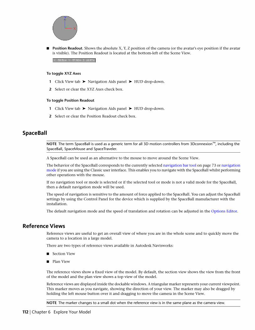
■ Position Readout. Shows the absolute X, Y, Z position of the camera (or the avatar's eye position if the avataris visible). The Position Readout is located at the bottom-left of the Scene View.
To toggle XYZ Axes
1 Click View tab ➤ Navigation Aids panel ➤ HUD drop-down.
2 Select or clear the XYZ Axes check box.
To toggle Position Readout
1 Click View tab ➤ Navigation Aids panel ➤ HUD drop-down.
2 Select or clear the Position Readout check box.
SpaceBall
NOTE The term SpaceBall is used as a generic term for all 3D motion controllers from 3Dconnexion™, including theSpaceBall, SpaceMouse and SpaceTraveler.
A SpaceBall can be used as an alternative to the mouse to move around the Scene View.
The behavior of the SpaceBall corresponds to the currently selected navigation bar tool on page 73 or navigationmode if you are using the Classic user interface. This enables you to navigate with the SpaceBall whilst performingother operations with the mouse.
If no navigation tool or mode is selected or if the selected tool or mode is not a valid mode for the SpaceBall,then a default navigation mode will be used.
The speed of navigation is sensitive to the amount of force applied to the SpaceBall. You can adjust the SpaceBallsettings by using the Control Panel for the device which is supplied by the SpaceBall manufacturer with theinstallation.
The default navigation mode and the speed of translation and rotation can be adjusted in the Options Editor.
Reference ViewsReference views are useful to get an overall view of where you are in the whole scene and to quickly move thecamera to a location in a large model.
There are two types of reference views available in Autodesk Navisworks:
■ Section View
■ Plan View
The reference views show a fixed view of the model. By default, the section view shows the view from the frontof the model and the plan view shows a top view of the model.
Reference views are displayed inside the dockable windows. A triangular marker represents your current viewpoint.This marker moves as you navigate, showing the direction of your view. The marker may also be dragged byholding the left mouse button over it and dragging to move the camera in the Scene View.
NOTE The marker changes to a small dot when the reference view is in the same plane as the camera view.
112 | Chapter 6 Explore Your Model
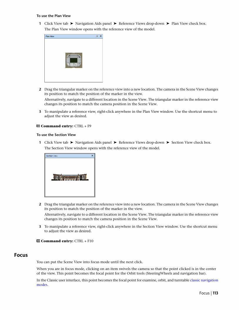
To use the Plan View
1 Click View tab ➤ Navigation Aids panel ➤ Reference Views drop-down ➤ Plan View check box.
The Plan View window opens with the reference view of the model.
2 Drag the triangular marker on the reference view into a new location. The camera in the Scene View changesits position to match the position of the marker in the view.
Alternatively, navigate to a different location in the Scene View. The triangular marker in the reference viewchanges its position to match the camera position in the Scene View.
3 To manipulate a reference view, right-click anywhere in the Plan View window. Use the shortcut menu toadjust the view as desired.
Command entry: CTRL + F9
To use the Section View
1 Click View tab ➤ Navigation Aids panel ➤ Reference Views drop-down ➤ Section View check box.
The Section View window opens with the reference view of the model.
2 Drag the triangular marker on the reference view into a new location. The camera in the Scene View changesits position to match the position of the marker in the view.
Alternatively, navigate to a different location in the Scene View. The triangular marker in the reference viewchanges its position to match the camera position in the Scene View.
3 To manipulate a reference view, right-click anywhere in the Section View window. Use the shortcut menuto adjust the view as desired.
Command entry: CTRL + F10
FocusYou can put the Scene View into focus mode until the next click.
When you are in focus mode, clicking on an item swivels the camera so that the point clicked is in the centerof the view. This point becomes the focal point for the Orbit tools (SteeringWheels and navigation bar).
In the Classic user interface, this point becomes the focal point for examine, orbit, and turntable classic navigationmodes.
Focus | 113
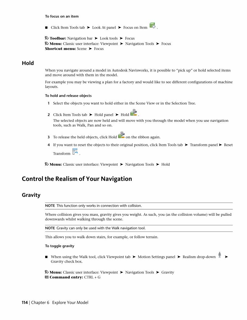
To focus on an item
■ Click Item Tools tab ➤ Look At panel ➤ Focus on Item .
Toolbar: Navigation bar ➤ Look tools ➤ FocusMenu: Classic user interface: Viewpoint ➤ Navigation Tools ➤ Focus
Shortcut menu: Scene ➤ Focus
HoldWhen you navigate around a model in Autodesk Navisworks, it is possible to “pick up” or hold selected itemsand move around with them in the model.
For example you may be viewing a plan for a factory and would like to see different configurations of machinelayouts.
To hold and release objects
1 Select the objects you want to hold either in the Scene View or in the Selection Tree.
2 Click Item Tools tab ➤ Hold panel ➤ Hold .
The selected objects are now held and will move with you through the model when you use navigationtools, such as Walk, Pan and so on.
3 To release the held objects, click Hold on the ribbon again.
4 If you want to reset the objects to their original position, click Item Tools tab ➤ Transform panel ➤ Reset
Transform .
Menu: Classic user interface: Viewpoint ➤ Navigation Tools ➤ Hold
Control the Realism of Your Navigation
Gravity
NOTE This function only works in connection with collision.
Where collision gives you mass, gravity gives you weight. As such, you (as the collision volume) will be pulleddownwards whilst walking through the scene.
NOTE Gravity can only be used with the Walk navigation tool.
This allows you to walk down stairs, for example, or follow terrain.
To toggle gravity
■ When using the Walk tool, click Viewpoint tab ➤ Motion Settings panel ➤ Realism drop-down ➤
Gravity check box.
Menu: Classic user interface: Viewpoint ➤ Navigation Tools ➤ GravityCommand entry: CTRL + G
114 | Chapter 6 Explore Your Model
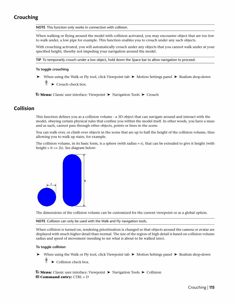
Crouching
NOTE This function only works in connection with collision.
When walking or flying around the model with collision activated, you may encounter object that are too lowto walk under, a low pipe for example. This function enables you to crouch under any such objects.
With crouching activated, you will automatically crouch under any objects that you cannot walk under at yourspecified height, thereby not impeding your navigation around the model.
TIP To temporarily crouch under a low object, hold down the Space bar to allow navigation to proceed.
To toggle crouching
➤ When using the Walk or Fly tool, click Viewpoint tab ➤ Motion Settings panel ➤ Realism drop-down
➤ Crouch check box.
Menu: Classic user interface: Viewpoint ➤ Navigation Tools ➤ Crouch
CollisionThis function defines you as a collision volume - a 3D object that can navigate around and interact with themodel, obeying certain physical rules that confine you within the model itself. In other words, you have a massand as such, cannot pass through other objects, points or lines in the scene.
You can walk over, or climb over objects in the scene that are up to half the height of the collision volume, thusallowing you to walk up stairs, for example.
The collision volume, in its basic form, is a sphere (with radius = r), that can be extruded to give it height (withheight = h >= 2r). See diagram below:
The dimensions of the collision volume can be customized for the current viewpoint or as a global option.
NOTE Collision can only be used with the Walk and Fly navigation tools.
When collision is turned on, rendering prioritization is changed so that objects around the camera or avatar aredisplayed with much higher detail than normal. The size of the region of high detail is based on collision volumeradius and speed of movement (needing to see what is about to be walked into).
To toggle collision
➤ When using the Walk or Fly tool, click Viewpoint tab ➤ Motion Settings panel ➤ Realism drop-down
➤ Collision check box.
Menu: Classic user interface: Viewpoint ➤ Navigation Tools ➤ CollisionCommand entry: CTRL + D
Crouching | 115
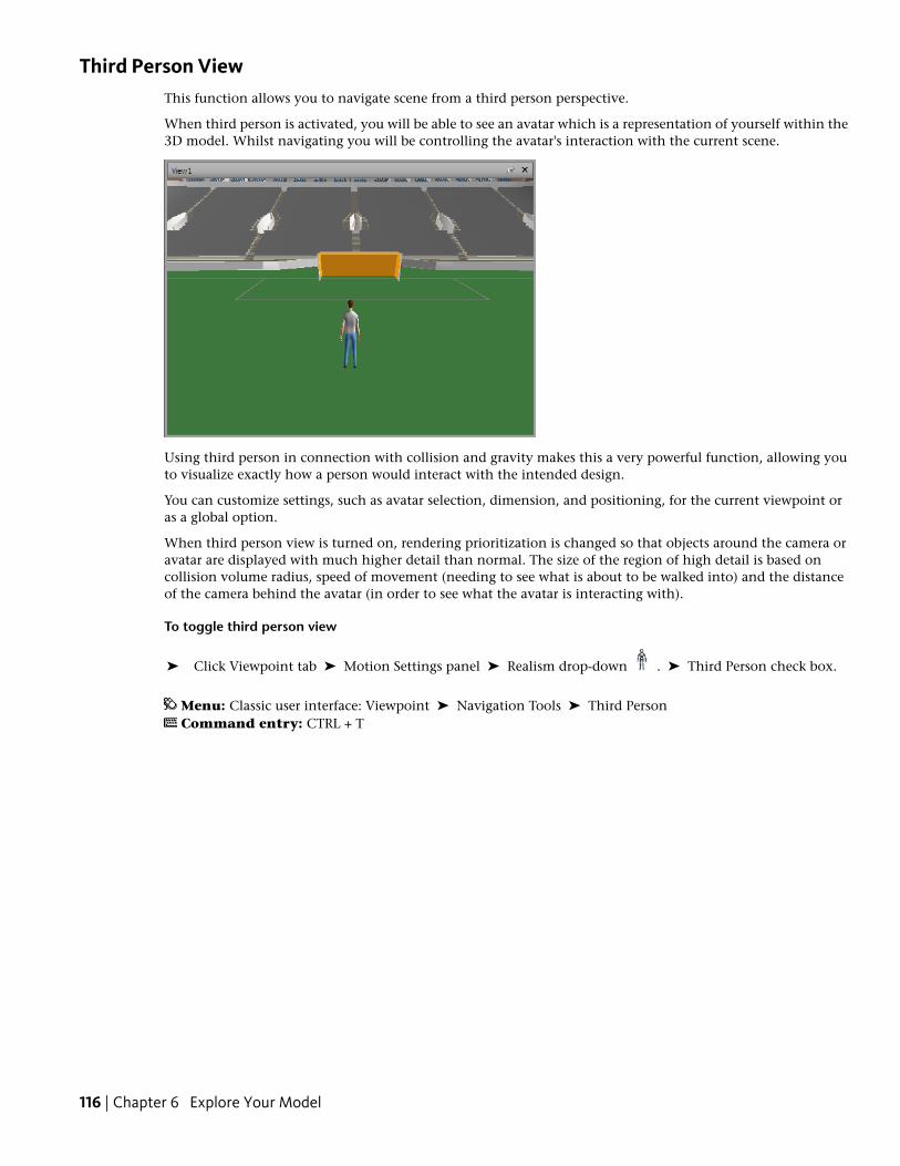
Third Person ViewThis function allows you to navigate scene from a third person perspective.
When third person is activated, you will be able to see an avatar which is a representation of yourself within the3D model. Whilst navigating you will be controlling the avatar's interaction with the current scene.
Using third person in connection with collision and gravity makes this a very powerful function, allowing youto visualize exactly how a person would interact with the intended design.
You can customize settings, such as avatar selection, dimension, and positioning, for the current viewpoint oras a global option.
When third person view is turned on, rendering prioritization is changed so that objects around the camera oravatar are displayed with much higher detail than normal. The size of the region of high detail is based oncollision volume radius, speed of movement (needing to see what is about to be walked into) and the distanceof the camera behind the avatar (in order to see what the avatar is interacting with).
To toggle third person view
➤ Click Viewpoint tab ➤ Motion Settings panel ➤ Realism drop-down . ➤ Third Person check box.
Menu: Classic user interface: Viewpoint ➤ Navigation Tools ➤ Third PersonCommand entry: CTRL + T
116 | Chapter 6 Explore Your Model
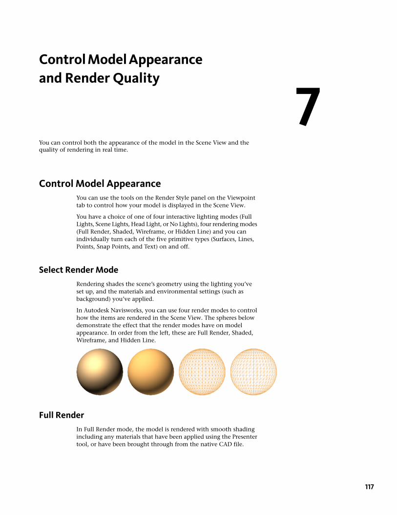
Control Model Appearanceand Render Quality
You can control both the appearance of the model in the Scene View and thequality of rendering in real time.
Control Model AppearanceYou can use the tools on the Render Style panel on the Viewpointtab to control how your model is displayed in the Scene View.
You have a choice of one of four interactive lighting modes (FullLights, Scene Lights, Head Light, or No Lights), four rendering modes(Full Render, Shaded, Wireframe, or Hidden Line) and you canindividually turn each of the five primitive types (Surfaces, Lines,Points, Snap Points, and Text) on and off.
Select Render ModeRendering shades the scene’s geometry using the lighting you’veset up, and the materials and environmental settings (such asbackground) you’ve applied.
In Autodesk Navisworks, you can use four render modes to controlhow the items are rendered in the Scene View. The spheres belowdemonstrate the effect that the render modes have on modelappearance. In order from the left, these are Full Render, Shaded,Wireframe, and Hidden Line.
Full RenderIn Full Render mode, the model is rendered with smooth shadingincluding any materials that have been applied using the Presentertool, or have been brought through from the native CAD file.
7
117
NOTE Autodesk Navisworks does not convert all native CAD file’s textures. For more details, see “Use File Readers”and “Use File Exporters” on page 68.
To select Full Render mode
■ Click Viewpoint tab ➤ Render Style panel ➤ Mode drop-down, and click Full Render .
Menu: Classic user interface: Viewpoint ➤ Rendering ➤ Full Render
ShadedIn Shaded mode, the model is rendered with smooth shading and without textures.
To select Shaded mode
■ Click Viewpoint tab ➤ Render Style panel ➤ Mode drop-down, and click Shaded .
Menu: Classic user interface: Viewpoint ➤ Rendering ➤ Shaded
WireframeIn Wireframe mode, the model is rendered in wireframe. As Autodesk Navisworks uses triangles to representsurfaces and solids, all triangle edges are visible in this mode.
To select Wireframe mode
■ Click Viewpoint tab ➤ Render Style panel ➤ Mode drop-down, and click Wireframe .
Menu: Classic user interface: Viewpoint ➤ Rendering ➤ Wireframe
Hidden LineIn Hidden Line mode, the model is rendered in wireframe, but only the outline and facet edges of surfaces thatare visible to the camera are displayed.
NOTE Unlike wireframe mode, where surfaces are rendered transparent, hidden line mode renders surfaces opaque.
To select Hidden Line mode
■ Click Viewpoint tab ➤ Render Style panel ➤ Mode drop-down, and click Hidden Line .
Menu: Classic user interface: Viewpoint ➤ Rendering ➤ Hidden Line
Add LightingIn Autodesk Navisworks, you can use four lighting modes to control how the 3D scene is lit.
The spheres below demonstrate the effect the lighting styles have on them. In order from the left, these are FullLights, Scene Lights, Head Light, and No Lights.
118 | Chapter 7 Control Model Appearance and Render Quality
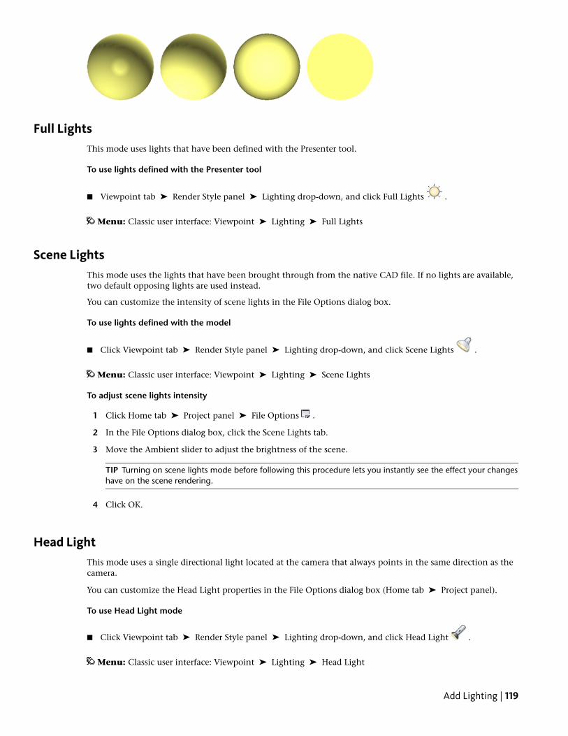
Full LightsThis mode uses lights that have been defined with the Presenter tool.
To use lights defined with the Presenter tool
■ Viewpoint tab ➤ Render Style panel ➤ Lighting drop-down, and click Full Lights .
Menu: Classic user interface: Viewpoint ➤ Lighting ➤ Full Lights
Scene LightsThis mode uses the lights that have been brought through from the native CAD file. If no lights are available,two default opposing lights are used instead.
You can customize the intensity of scene lights in the File Options dialog box.
To use lights defined with the model
■ Click Viewpoint tab ➤ Render Style panel ➤ Lighting drop-down, and click Scene Lights .
Menu: Classic user interface: Viewpoint ➤ Lighting ➤ Scene Lights
To adjust scene lights intensity
1 Click Home tab ➤ Project panel ➤ File Options .
2 In the File Options dialog box, click the Scene Lights tab.
3 Move the Ambient slider to adjust the brightness of the scene.
TIP Turning on scene lights mode before following this procedure lets you instantly see the effect your changeshave on the scene rendering.
4 Click OK.
Head LightThis mode uses a single directional light located at the camera that always points in the same direction as thecamera.
You can customize the Head Light properties in the File Options dialog box (Home tab ➤ Project panel).
To use Head Light mode
■ Click Viewpoint tab ➤ Render Style panel ➤ Lighting drop-down, and click Head Light .
Menu: Classic user interface: Viewpoint ➤ Lighting ➤ Head Light
Add Lighting | 119
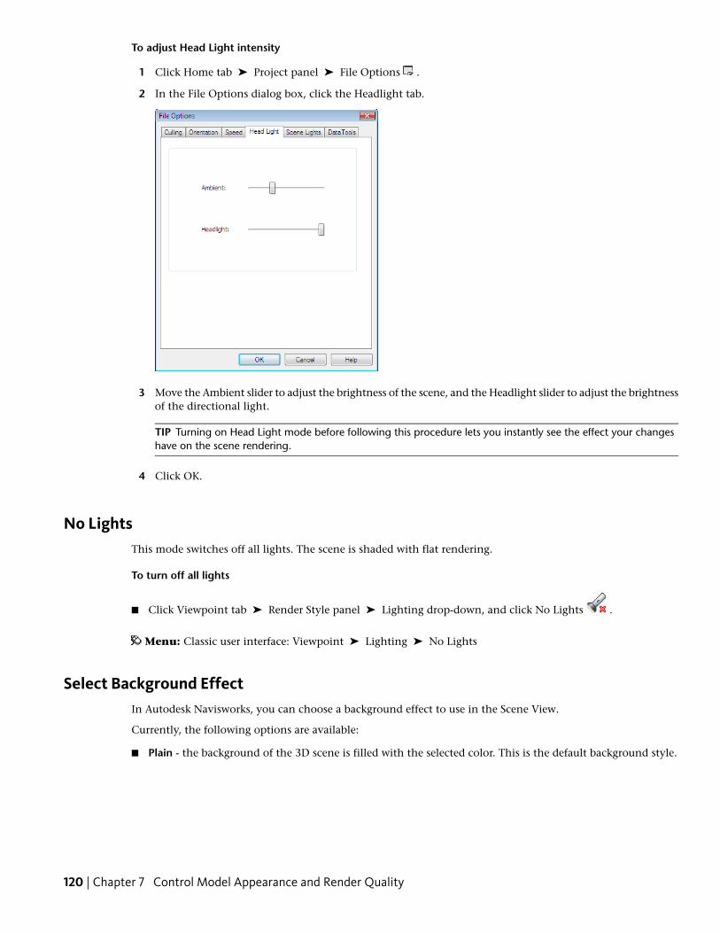
To adjust Head Light intensity
1 Click Home tab ➤ Project panel ➤ File Options .
2 In the File Options dialog box, click the Headlight tab.
3 Move the Ambient slider to adjust the brightness of the scene, and the Headlight slider to adjust the brightnessof the directional light.
TIP Turning on Head Light mode before following this procedure lets you instantly see the effect your changeshave on the scene rendering.
4 Click OK.
No LightsThis mode switches off all lights. The scene is shaded with flat rendering.
To turn off all lights
■ Click Viewpoint tab ➤ Render Style panel ➤ Lighting drop-down, and click No Lights .
Menu: Classic user interface: Viewpoint ➤ Lighting ➤ No Lights
Select Background EffectIn Autodesk Navisworks, you can choose a background effect to use in the Scene View.
Currently, the following options are available:
■ Plain - the background of the 3D scene is filled with the selected color. This is the default background style.
120 | Chapter 7 Control Model Appearance and Render Quality
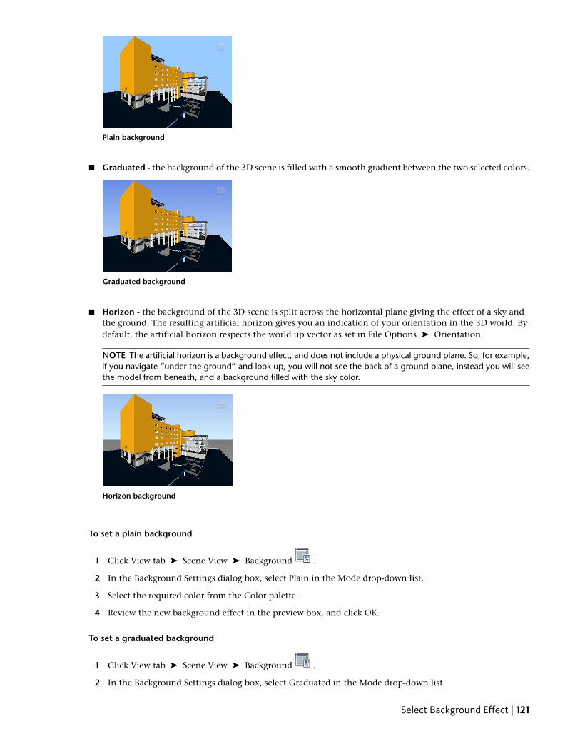
Plain background
■ Graduated - the background of the 3D scene is filled with a smooth gradient between the two selected colors.
Graduated background
■ Horizon - the background of the 3D scene is split across the horizontal plane giving the effect of a sky andthe ground. The resulting artificial horizon gives you an indication of your orientation in the 3D world. Bydefault, the artificial horizon respects the world up vector as set in File Options ➤ Orientation.
NOTE The artificial horizon is a background effect, and does not include a physical ground plane. So, for example,if you navigate “under the ground” and look up, you will not see the back of a ground plane, instead you will seethe model from beneath, and a background filled with the sky color.
Horizon background
To set a plain background
1 Click View tab ➤ Scene View ➤ Background .
2 In the Background Settings dialog box, select Plain in the Mode drop-down list.
3 Select the required color from the Color palette.
4 Review the new background effect in the preview box, and click OK.
To set a graduated background
1 Click View tab ➤ Scene View ➤ Background .
2 In the Background Settings dialog box, select Graduated in the Mode drop-down list.
Select Background Effect | 121
3 Select the first color from the Top Color palette.
4 Select the second color from the Bottom Color palette.
5 Review the new background effect in the preview box, and click OK.
To set an artificial horizon background
1 Click View tab ➤ Scene View ➤ Background .
2 In the Background Settings dialog box, select Horizon in the Mode drop-down list.
3 To set a graduated sky color, use the Sky Color and Horizon Sky Color palettes.
4 To set a graduated ground color, use the Horizon Ground Color and Ground Color palettes.
5 Review the new background effect in the preview box, and click OK.
Adjust Displaying of PrimitivesYou can enable and disable the drawing of Surfaces, Lines, Points, Snap Points, and 3D Text in the Scene View.
Points are “real” points in the model, whereas Snap Points mark locations on other primitives, for example thecenter of a circle, and are useful for snapping to when measuring.
SurfacesSurfaces are the triangles that make up the 2D and 3D items in the scene. You can toggle the rendering of surfacesin the model.
To toggle the rendering of surfaces
■ Click Viewpoint tab ➤ Render Style panel ➤ Mode drop-down, and click Surfaces .
Menu: Classic user interface: Viewpoint ➤ Display ➤ Surfaces
LinesYou can toggle the rendering of lines in the model. You can also change the width of the drawn lines by usingthe Options Editor.
To toggle the rendering of lines
■ Click Viewpoint tab ➤ Render Style panel ➤ Lines .
Menu: Classic user interface: Viewpoint ➤ Display ➤ Lines
To change the line width
1 Click the application button ➤ Options.
2 In the Options Editor, expand the Interface node, and click the Display options.
3 On the Display page, Primitives area, enter a number between 1 and 9 in the Line Size box.
This sets the width in pixels for lines drawn in the Scene View.
4 Click OK.
122 | Chapter 7 Control Model Appearance and Render Quality
PointsPoints are real points in the model, for example, the points in a point cloud in a laser scan file. You can togglethe rendering of points in the model. You can also change the size of drawn points by using the Options Editor.
To toggle the rendering of points
■ Click Viewpoint tab ➤ Render Style panel ➤ Points .
Menu: Classic user interface: Viewpoint ➤ Display ➤ Points
To change the size of points
1 Click the application button ➤ Options.
2 In the Options Editor, expand the Interface node, and click the Display option.
3 On the Display page, Primitives area, enter a number between 1 and 9 in the Point Size box.
This sets the size in pixels for points drawn in the Scene View.
4 Click OK.
Snap PointsSnap points are implied points in the model, for example, the center point of a sphere or end points of a pipe.You can toggle the rendering of snap point in the model. You can also change the size of the drawn snap pointsby using the Options Editor.
To toggle the rendering of snap points
■ Click Viewpoint tab ➤ Render Style panel ➤ Snap Points .
To change the size of snap points
1 Click the application button ➤ Options.
2 In the Options Editor, expand the Interface node, and click the Display option.
3 On the Display page, Primitives area, enter a number between 1 and 9 in the Snap Size box.
This sets the size in pixels of snap points drawn in the Scene View.
4 Click OK.
TextYou can toggle the rendering of 3D text in the model.
To toggle the rendering of 3D text
■ Click Viewpoint tab ➤ Render Style panel ➤ Text .
Menu: Classic user interface: Viewpoint ➤ Display ➤ Text
Adjust Displaying of Primitives | 123
Control Render Quality
Use CullingCulling lets you navigate and manipulate large and complex scenes at interactive rates by intelligently hidingless-important objects as you work.
In Autodesk Navisworks, you can use the following methods of culling objects:
■ Area - the objects’ size in pixels determines whether the objects are rendered or not. By default, any objectssmaller than 1x1 pixels in size are discarded.
■ Backface - by default, only the front face of every polygon is drawn in Autodesk Navisworks. Sometimes,during the conversion process the front and back face of polygons get mixed, in which case, you need toadjust the Backface option.
■ Near and Far Clipping Planes (frustum culling) - objects closer to the camera than the near clipping plane orbeyond the far clipping plane are not drawn. You can let Autodesk Navisworks automatically constrain thelocation of the clipping planes, or you can constrain their location manually.
To set area culling
1 Click Home tab ➤ Project panel ➤ File Options .
2 In the File Options dialog box, Culling tab, select the Enable check box in the Area section.
3 Enter a value for the screen area in pixels below which geometry objects are culled. For example, settingthis value to 100 pixels means that any object within the model that would be drawn less than 10x10 pixelsin size are discarded.
4 Click OK.
To turn on backface culling for all objects
1 Click Home tab ➤ Project panel ➤ File Options .
2 In the File Options dialog box, Culling tab, select On in the Backface area.
3 Click OK.
To turn off backface culling for all objects
1 Click Home tab ➤ Project panel ➤ File Options .
2 In the File Options dialog box, Culling tab, select Off in the Backface area.
3 Click OK.
To turn on backface culling only for solid objects
1 Click Home tab ➤ Project panel ➤ File Options .
2 In the File Options dialog box, Culling tab, select Solid in the Backface area.
3 Click OK.
To constrain the position of the clipping planes automatically
1 Click Home tab ➤ Project panel ➤ File Options .
2 In the File Options dialog box, click the Culling tab.
3 Select Automatic for the Near clipping plane.
124 | Chapter 7 Control Model Appearance and Render Quality
4 Select Automatic for the Far clipping plane.
5 Click OK.
Autodesk Navisworks automatically controls the position of near and far clipping planes to give you thebest view of the model.
To constrain the position of the clipping planes manually
1 Click Home tab ➤ Project panel ➤ File Options .
2 In the File Options dialog box, click the Culling tab.
3 Select Constrained for the Near clipping plane, and enter the desired value in the Distance box.
4 Select Constrained for the Far clipping plane, and enter the desired value in the Distance box.
5 Click OK.
Autodesk Navisworks uses the provided values unless doing so affects the system performance (for example,makes the whole model invisible), in which case it adjusts the position of the clipping planes as necessary.
To fix the position of the clipping planes
1 Click Home tab ➤ Project panel ➤ File Options .
2 In the File Options dialog box, click the Culling tab.
3 Select Fixed for the Near clipping plane, and enter the desired value in the Distance box.
4 Select Fixed for the Far clipping plane, and enter the desired value in the Distance box.
5 Click OK.
IMPORTANT Autodesk Navisworks uses the provided values even if doing so affects the system performance (forexample, makes the whole model invisible).
Make Objects RequiredAlthough Autodesk Navisworks intelligently prioritizes objects for culling in the scene, sometimes it drops outgeometry that needs to remain visible while navigating.
You can make sure the objects are always rendered during interactive navigation by making them required.
To make objects required
1 Select geometry items that you want to remain visible during navigation in the Selection Tree.
2 Click Home tab ➤ Visibility panel ➤ Require .
In the Selection Tree, the object appear red when required.
TIP Clicking Require again makes the selected objects unrequired.
Menu: Classic user interface: Edit ➤ RequiredCommand entry: CTRL + R
Ribbon: Item Tools tab ➤ Visibility panel ➤ Require
To make all objects unrequired
■ Click Home tab ➤ Visibility panel ➤ Unhide All drop-down ➤ Unrequire All .
Shortcut menu: Scene ➤ Reset All ➤ Unrequire All
Use Culling | 125
Control Rendering of Objects
Adjust Scene Rendering During NavigationYour models can range in size from small models to complex supermodels. As you navigate a scene in real time,Autodesk Navisworks automatically calculates which items to render first, based on the size of items, distancefrom the camera, and the specified frame rate. This customizable frame rate is guaranteed by default, but can beturned off, if necessary. Items that Autodesk Navisworks does not have time to render are dropped out. Thesedropped items are rendered when navigation stops.
The amount of drop-out depends on several factors, such as your hardware performance (graphics card anddriver), the size of the Scene View, and the size of the model. When working with truly large supermodels inAutodesk Navisworks, you will require a sufficient amount of RAM to load and review the data.
Autodesk Navisworks employs JetStream technology which optimizes the usage of the available RAM. Beforerunning out of memory, Autodesk Navisworks pages unnecessary data to the hard disk, freeing up space forloading to continue. JetStream technology also enables you to start navigating the supermodel, before it hasbeen completely loaded into memory. Autodesk Navisworks is large address aware, and utilizes any additionalmemory assignment following the 3GB switch available on Windows XP systems.
TIP You can reduce the amount of drop-out during navigation by reducing frame rate, or switching off the GuaranteeFrame Rate option.
To set the target frame rate
1 Click Home tab ➤ Project panel ➤ File Options .
2 In the File Options dialog box, Speed tab, select the number of frames per second to be applied to therendered display of the model.
3 Click OK.
To set the level of detail
1 Click the application button ➤ Options.
2 In the Options Editor, expand the Interface node, and click the Display option.
3 On the Display page, Detail area, select the Guarantee Frame Rate check box to maintain the target framerate during navigation. If this check box is clear, the complete model is rendered during navigation, nomatter how long it takes.
4 Select the Fill in Detail check box to render a complete model when navigation stops. If this check box isclear, the items dropped out during navigation are not filled in when it stops.
5 Select the Batch Fill check box if you want the dropped out items to be rendered in chunks rather thangradually.
NOTE This check box is clear by default, as gradual rendering gives better results for most video cards.
6 Click OK.
To render transparent items
NOTE If your video card supports hardware accelerated OpenGL, you can turn on the rendering of transparent itemsduring interactive navigation. By default, transparent items are only drawn when interaction has ceased to preventproblems with display performance.
1 Click the application button ➤ Options.
126 | Chapter 7 Control Model Appearance and Render Quality
2 In the Options Editor, expand the Interface node, and click the Display option.
3 On the Display page, Transparency area, select the Interactive Transparency check box.
4 Click OK.
To render parametric primitives
NOTE Modifying this option requires a restart of Autodesk Navisworks to take effect.
1 Click the application button ➤ Options.
2 In the Options Editor, expand the Interface node, and click the Display option.
3 On the Display page, Primitives area, select the Enable Parametric Primitives check box. The level of detailchanges during navigation depending on the distance from the camera.
If you want to use the default representations of primitives, clear this check box. The level of detail staysthe same during navigation.
Click OK.
Accelerate Display PerformanceIf your video card supports OpenGL, you can improve the graphical performance by turning on hardwareacceleration and occlusion culling.
Using the hardware acceleration usually gives you better and faster rendering. However, some graphics cardsmay not function well in this mode in which case switching this option off is recommended.
Occlusion culling can significantly improve performance in situations when much of the model is not visible.For example, when you walk down the corridor of a building, the walls occlude most geometry outside thecorridor. Other rooms are only visible through doorways or windows. Turning on occlusion culling dramaticallyreduces the rendering load in such cases.
To use hardware acceleration
NOTE If your video card does not support OpenGL hardware acceleration, this option is not available.
1 Click the application button ➤ Options.
2 In the Options Editor, expand the Interface node, and click the Display option.
3 On the Display page, Acceleration area, select the Hardware Acceleration check box. This allows AutodeskNavisworks to utilize any available OpenGL hardware acceleration on your video card.
NOTE If your video card drivers do not function well with Autodesk Navisworks, clear this check box.
4 Click OK.
To use occlusion culling
1 Click the application button ➤ Options.
2 In the Options Editor, expand the Interface node, and click the Display option.
3 On the Display page, Acceleration area, select the Occlusion Culling check box.
4 Click OK.
NOTE Occlusion culling can only be used on a machine with an OpenGL 1.5 compliant graphics card.
Control Rendering of Objects | 127
Adjust Presenter MaterialsYou can adjust the appearance of Presenter materials in the Scene View to get optimum performance from yourgraphics card when navigating around heavily textured scenes.
See also:
■ “Presenter Page” on page 178
128 | Chapter 7 Control Model Appearance and Render Quality
Review Your Model
Select ObjectsAutodesk Navisworks provides several methods to interactively selectitems.
Interactive Geometry SelectionIn Autodesk Navisworks, there is a concept of an active selectionset (the currently selected items, or the current selection) and savedselections sets. You cannot save any selection or search sets yourself,but you can use the selection or search sets saved in the model (theSets tab on the Selection Tree).
Selecting items makes them part of the current selection, so youcan hide them or override their colors.
You can use several methods to interactively select items into thecurrent selection. You can use the tabs in the Selection Tree, selectitems directly in the Scene View with the Select and Select Box tools,and you can select other items with similar properties to an existingselection using the selection commands.
NOTE Right-clicking any item in the Selection Tree or Scene View opensa shortcut menu.
You can also customize the level at which you select items (selectionresolution), and modify the highlighting method for the itemsselected in the Scene View.
Selection Tree WindowThe Selection Tree is a dockable window, which displays a varietyof hierarchical views of the structure of the model, as defined bythe CAD application in which the model was created.
8
129
Autodesk Navisworks uses this hierarchical structure to identify object-specific paths (from the file name downto a particular object).
By default there are four tabs:
■ Standard. Displays the default tree hierarchy, including all instancing.
■ Compact. Displays a simplified version of the hierarchy on the Standard tab, omitting various items. Youcan customize the level of complexity of this tree in the Options Editor.
■ Properties. Displays the hierarchy based on the items' properties. This enables simple manual searching ofthe model by item property.
■ Sets. Displays a list of selection and search sets. If no selection and search sets have been created, this tab isnot shown.
Naming of items reflects the names from the original CAD application, wherever possible. You can copy andpaste names from the Selection Tree. To do this, right-click an item in the Selection Tree, and click Copy Nameon the context menu. Alternatively, you can click an item in the Selection Tree, and press CTRL + C. The nameis now copied to the clipboard.
There are different tree icons representing the types of geometry making up the structure of the model. Each ofthese item types can be marked as hidden (gray), unhidden (dark blue) or required (red).
NOTE If a group is marked as hidden or required, then all instances of that group are marked as hidden or required.If you want to operate on a single occurrence of an item, then you should mark the instanced group (the level above,or the “parent”, in the hierarchy) hidden or required.
To toggle the Selection Tree
■ Click Home tab ➤ Select & Search panel ➤ Selection Tree .
Menu: Classic user interface: View ➤ Control Bars ➤ Selection TreeCommand entry: CTRL + F12
To use the Selection Tree to select objects
1 Open the Selection Tree, and click the Standard tab.
2 Click an object in the Selection tree to select the corresponding geometry in the Scene View.
NOTE When you select an item in the tree, individual geometry or a group of geometry is selected in the SceneView depending on chosen selection resolution.
3 To select several items at the same time, use the SHIFT and CTRL keys. CTRL allows multiple selection itemby item, and SHIFT allows multiple selection between the first and last items selected.
4 To remove selection from an object in the Selection Tree press ESC.
130 | Chapter 8 Review Your Model
To customize the contents of the Compact tab
1 Click the application button ➤ Options.
2 In the Options Editor, expand the Interface node, and click the Selection option.
3 On the Selection page, select the required level of detail in the Compact Tree box. Choose from the followingoptions:
■ Models - the tree is restricted to displaying model files only.
■ Layers - the tree can be expanded down to the layer level.
■ Objects - can be expanded down to the objects level, but without the levels of instancing shown on theStandard tab.
4 Click OK.
Quick Reference
DescriptionIcon
A model, such as a drawing file or designfile.
A layer or level.
A group, such as a block definition fromAutoCAD or cell definition from MicroSta-tion.
An instanced group, such as an insertedblock from AutoCAD or cell from MicroSta-tion. If in the imported file the instancewas unnamed, Autodesk Navisworks namesthe instance to match its child's name.
An item of geometry, such as a polygon.
An instanced item of geometry, such as aninstance from 3D Studio.
A composite object. A single CAD objectthat is represented in Autodesk Navisworksby a group of geometry items.
Saved selection set.
Saved search set.
Selection Tools
There are two selection tools (Select and Select Box ) available from Home tab ➤ Select & Search panelto control the way you select geometry.
Typically, using selection tools is mutually exclusive to using navigation tools (see Product-Specific NavigationTools, so that when you are selecting you cannot navigate and vice versa.
Interactive Geometry Selection | 131
NOTE When using a SpaceBall in conjunction with the standard mouse control, the SpaceBall can be configured fornavigation and the mouse for selecting. See “SpaceBall” on page 112 for more information.
Selecting geometry in the Scene View automatically selects the corresponding objects in the Selection Tree.
Holding the SHIFT key whilst selecting items in the Scene View cycles through the selection resolution, allowingyou to get more specific with your selections.
You can use the Options Editor to customize the distance from an item you have to be for it to be selected (pickradius). This is useful when you select lines and points.
Select ToolThe Select tool lets you select items in the Scene View with a mouse click. The tool is activated by clicking Home
tab ➤ Select & Search panel ➤ Select drop-down ➤ Select . Once a single item is selected, its propertiesare shown in the Properties window.
Select Box ToolIn select box mode, you can select multiple items in the model by dragging a rectangular box around the areayou want to make your current selection.
To select geometry with the Select tool
1 Click Home tab ➤ Select & Search panel ➤ Select drop-down ➤ Select .
2 Click an item in the Scene View to select it.
3 To select multiple geometry, press and hold down the CTRL key while clicking items in the scene.
4 To remove items from the current selection, hold down the CTRL key while clicking them again. Alternatively,press the ESC key to remove all items from the current selection.
Menu: Classic user interface: Edit ➤ Select ➤ SelectCommand entry: CTRL + 1
To select geometry with the Select Box tool
1 Click Home tab ➤ Select & Search panel ➤ Select drop-down ➤ Select Box .
2 Drag a box with the left mouse button over the Scene View to select all items within the box.
TIP Holding down the SHIFT key while dragging the box selects all items within and that intersect the box.
3 To select multiple geometry, press and hold down the CTRL key while dragging a box in the scene.
4 To remove items from the current selection, press the ESC key.
To set the pick radius
1 Click the application button ➤ Options.
2 In the Options Editor, expand the Interface node, and click the Selection option.
3 On the Selection page, enter the radius in pixels that an item has to be within in order to be selected. Thevalid values are between 1 and 9.
4 Click OK.
132 | Chapter 8 Review Your Model
Selection CommandsSelection commands enable you to quickly alter the current selection using logic. You can select multiple itemsbased on the currently selected items’ properties, or quickly invert the set, select everything or nothing.
To select all items within the model
■ Click Home tab ➤ Select & Search panel ➤ Select All drop-down ➤ Select All .
To deselect all items
■ Click Home tab ➤ Select & Search panel ➤ Select All drop-down ➤ Select None .
To invert your current selection
■ Click Home tab ➤ Select & Search panel ➤ Select All drop-down ➤ Invert Selection .Currently selected items become deselected, and currently deselected items become selected.
To select all instances of the selected geometry group
■ Click Home tab ➤ Select & Search panel ➤ Select Same drop-down ➤ Select Multiple Instances .
To select all items with the same name as the currently selected item
➤ Click Home tab ➤ Select & Search panel ➤ Select Same drop-down ➤ Same Name .
To select all items with the same type as the currently selected item
■ Click Home tab ➤ Select & Search panel ➤ Select Same drop-down ➤ Same Type .
To select all items with the same property as the currently selected item
■ Click Home tab ➤ Select & Search panel ➤ Select Same drop-down ➤ Same <Property>.
To use a saved selection or search set
■ Open the Selection Tree window, and click the Sets tab.
Quick Reference
The selection commands are as follows:
■ Select All. Selects all items contained within the model.
■ Select None. Deselects everything in the model.
■ Invert Selection. Currently selected items become deselected and vice versa.
■ Select Multiple Instances. Selects all instances (sometimes called insertions) of the currently selected geometrygroup that occur in the model.
■ Select Same Name. Selects all items in the model that have the same name as the currently selected item.
■ Select Same Type. Selects all items in the model that have the same type as the currently selected item.
■ Select Same <Property>. Selects all items with the same property as the currently selected item. This propertycan be any searchable property currently attached to the item, for example material or link.
Interactive Geometry Selection | 133
NOTE Using the Select Same <Property> command works by comparing items' properties. If you have multipleitems selected when you perform a selection command of same name or type and so on, all the types, names andproperties of the items in the current selection are compared with all items’ properties in the scene. The items withproperties matching any properties of the currently selected items are selected.
Set Highlighting MethodYou can use the Options Editor to customize color and method of highlighting geometry selected in the SceneView.
There are three types of highlighting:
■ Shaded
■ Wireframe
■ Tinted
To toggle highlighting of selected objects
1 Click the application button ➤ Options.
2 In the Options Editor, expand the Interface node, and click the Selection option.
3 On the Selection page, Highlight area, select the Enabled check box, if you want the selected items to behighlighted in the Scene View. Clear this check box, if you don’t want any highlighting.
4 Click OK.
134 | Chapter 8 Review Your Model
To customize the way objects are highlighted
1 Click the application button ➤ Options.
2 In the Options Editor, expand the Interface node, and click the Selection option.
3 Make sure the Enabled check box is selected.
4 Use the Method drop-down list to select the type of highlighting you want (Shaded, Wireframe or Tinted).
5 Click the Color palette to select the highlight color.
6 If you selected Tinted in the Method box, use the slider to adjust the Tint Level.
7 Click OK.
Hide ObjectsAutodesk Navisworks provides tools that can be used to hide and display objects or groups of objects. Hiddenobjects are not drawn in the Scene View.
Hide Selected ObjectsYou can hide the objects in the current selection so that they are not drawn in the Scene View. This is usefulwhen you want to remove specific parts of the model. For example, when you walk down the corridor of building,you may want to hide a wall that occlude your view of the next room.
Hide Unselected ObjectsYou can hide all items except those currently selected so that they are not drawn in the Scene View. This is usefulwhen you only want to see specific parts of the model.
NOTE In the Selection Tree, the items appear gray when marked as hidden.
To hide selected objects
1 In the Scene View, select all items you want to hide.
2 Click Home tab ➤ Visibility panel ➤ Hide .
The selected objects are now invisible.
TIP Clicking Hide again displays the invisible objects.
Menu: Classic user interface: Edit ➤ HiddenCommand entry: CTRL + H
Shortcut menu: Hide
To make unselected items hidden
1 In the Scene View, select all items you want to review.
2 Click Home tab ➤ Visibility panel ➤ Hide Unselected .
Only the selected geometry remains visible.
TIP Clicking Hide Unselected again displays the invisible objects.
Menu: Classic user interface: Edit ➤ Hide UnselectedShortcut menu: Hide Unselected
Hide Objects | 135
To reveal all hidden objects
■ Click Home tab ➤ Visibility panel ➤ Unhide All drop-down ➤ Unhide All .
Shortcut menu: Scene ➤ Reset All ➤ Unhide All
Find ObjectsYou can run simple manual searches of the model by item property. To do this:
■ On the Selection Tree, click the Properties tab, and click the saved property search in the list.The corresponding model geometry is selected in the Scene View.
Quick FindTo locate and select the objects quickly, use the Quick Find feature.
To quickly find items
1 Click Home tab ➤ Select & Search panel.
2 In the Quick Find text box, type in the string to search for in all item’s properties. This can be a word or afew words. The search is not case-sensitive.
3 Click Quick Find . Autodesk Navisworks finds and selects the first item in the Selection Tree that matchesthe entered text, selects it in the Scene View, and stops the search.
4 To find more items, click Quick Find again. If there are any more items that match the entered text,Autodesk Navisworks selects the next one in the Selection Tree, selects it in the Scene View, and stops thesearch. Subsequent clicks find next instances.
Command entry: To open the Quick Find dialog box: CTRL + F. To Find Next: F3
Use Sets of ObjectsIn Autodesk Navisworks, you cannot save any selection or search sets yourself, but you can use the selection orsearch sets saved in the model.
Selection sets store a group of items for later retrieval. There is no intelligence behind this set - if the modelchanges at all, the same items will be selected (assuming they are still available in the model) when recalling theselection set.
Search sets work in a similar way, except that they save search criteria instead of the results of a selection. So, ifthere are any search sets saved in the model, then you use them in Autodesk Navisworks to run the search andselect the resulting objects.
Selection and search sets can be named and contain comments. They can also be highlighted with icons in theScene View, so that when you click on one, the selection set is restored to the active set and all the items withinit are re-selected.
To select items from a selection or search set
1 Open the Selection Tree window, and click the Sets tab.
2 Click the saved selection or search set from the list.
On recalling a selection set, all the items that were selected when the set was saved are re-selected into thecurrent selection.
On recalling a search set, the search that was saved into the set is re-run and any items matching thespecification are selected into the current selection.
136 | Chapter 8 Review Your Model
Object Properties
Properties WindowThe Properties window is a dockable window, which has a dedicated tab for each property category associatedwith the currently selected object.
Internal file properties, such as transform and geometry properties, are not shown by default. The Options Editorenables you to switch this on.
To toggle the Properties window
■ Click View tab ➤ Workspace panel ➤ Windows drop-down, and select or clear the Properties check box.
Menu: Classic user interface: View ➤ Control Bars ➤ PropertiesCommand entry: SHIFT + F7
To examine object properties
1 Select the object of interest in the Selection Tree, or in the Scene View.
2 Open the Properties window, and use the tabs to navigate between the available property categories.
NOTE If more than one object is selected, the Properties window only shows the number of selected items, anddoesn’t show any property information.
To add tabs with internal properties to the Properties window
1 Click the application button ➤ Options.
2 In the Options Editor, expand the Interface node, and click the Developer option.
3 On the Developer page, select the Show Internal Properties check box.
4 Click OK.
Comments and Annotations
View Comments and AnnotationsYou cannot add any comments, redline annotations or tags in Autodesk Navisworks, but you can view comments,redlines, and tags attached to viewpoints.
Object Properties | 137
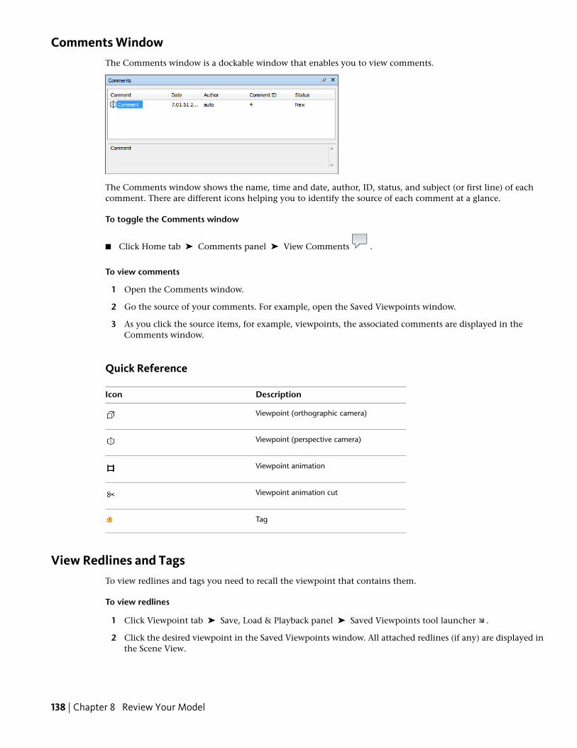
Comments WindowThe Comments window is a dockable window that enables you to view comments.
The Comments window shows the name, time and date, author, ID, status, and subject (or first line) of eachcomment. There are different icons helping you to identify the source of each comment at a glance.
To toggle the Comments window
■ Click Home tab ➤ Comments panel ➤ View Comments .
To view comments
1 Open the Comments window.
2 Go the source of your comments. For example, open the Saved Viewpoints window.
3 As you click the source items, for example, viewpoints, the associated comments are displayed in theComments window.
Quick Reference
DescriptionIcon
Viewpoint (orthographic camera)
Viewpoint (perspective camera)
Viewpoint animation
Viewpoint animation cut
Tag
View Redlines and TagsTo view redlines and tags you need to recall the viewpoint that contains them.
To view redlines
1 Click Viewpoint tab ➤ Save, Load & Playback panel ➤ Saved Viewpoints tool launcher .
2 Click the desired viewpoint in the Saved Viewpoints window. All attached redlines (if any) are displayed inthe Scene View.
138 | Chapter 8 Review Your Model
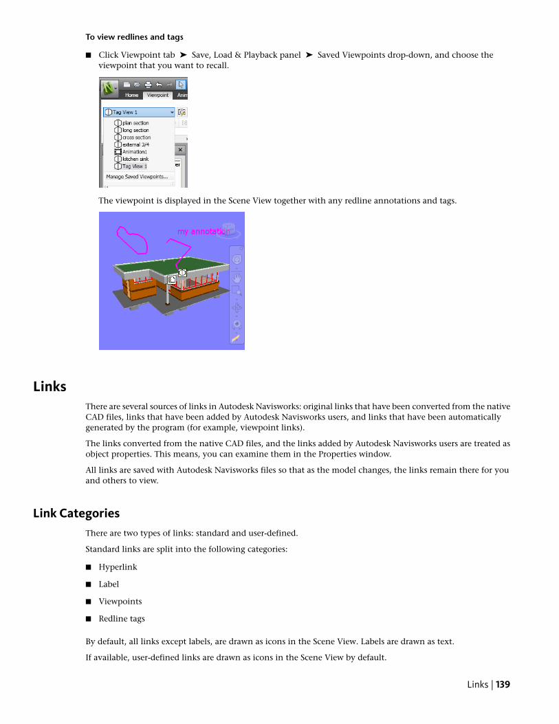
To view redlines and tags
■ Click Viewpoint tab ➤ Save, Load & Playback panel ➤ Saved Viewpoints drop-down, and choose theviewpoint that you want to recall.
The viewpoint is displayed in the Scene View together with any redline annotations and tags.
LinksThere are several sources of links in Autodesk Navisworks: original links that have been converted from the nativeCAD files, links that have been added by Autodesk Navisworks users, and links that have been automaticallygenerated by the program (for example, viewpoint links).
The links converted from the native CAD files, and the links added by Autodesk Navisworks users are treated asobject properties. This means, you can examine them in the Properties window.
All links are saved with Autodesk Navisworks files so that as the model changes, the links remain there for youand others to view.
Link CategoriesThere are two types of links: standard and user-defined.
Standard links are split into the following categories:
■ Hyperlink
■ Label
■ Viewpoints
■ Redline tags
By default, all links except labels, are drawn as icons in the Scene View. Labels are drawn as text.
If available, user-defined links are drawn as icons in the Scene View by default.
Links | 139
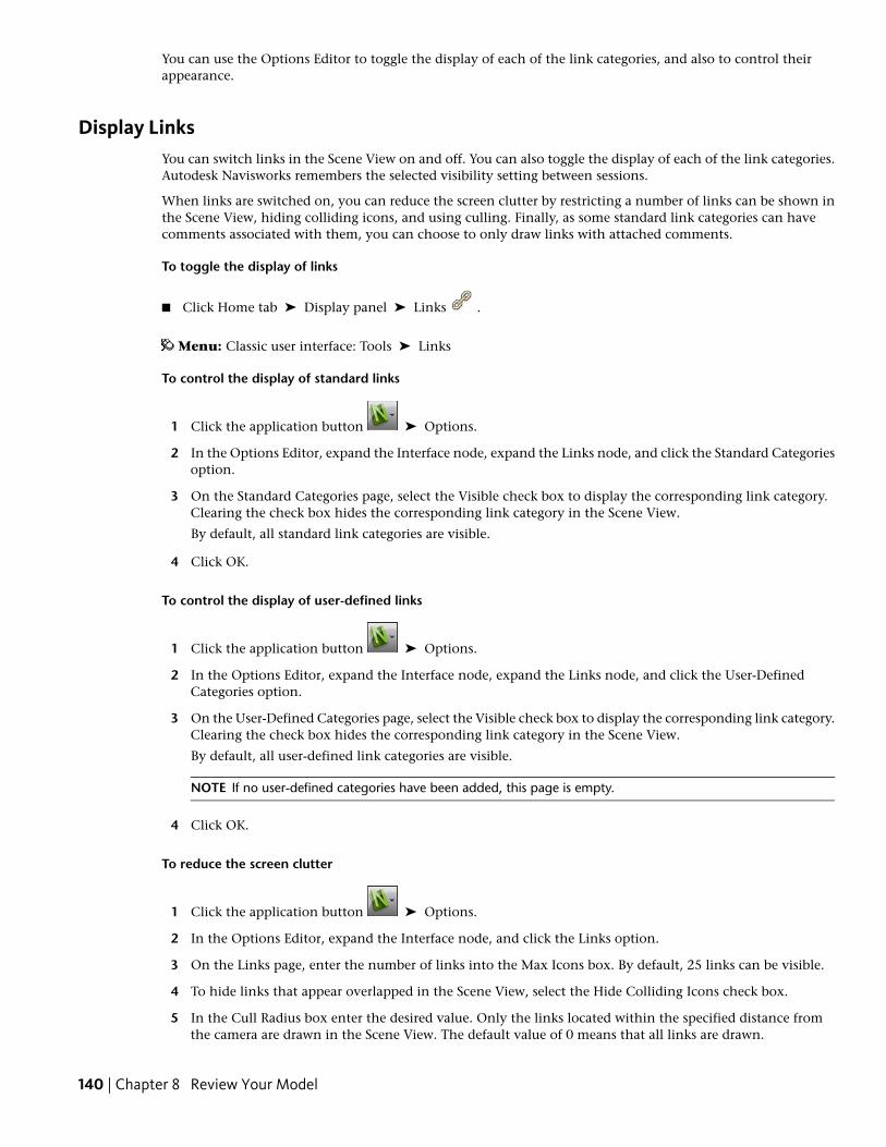
You can use the Options Editor to toggle the display of each of the link categories, and also to control theirappearance.
Display LinksYou can switch links in the Scene View on and off. You can also toggle the display of each of the link categories.Autodesk Navisworks remembers the selected visibility setting between sessions.
When links are switched on, you can reduce the screen clutter by restricting a number of links can be shown inthe Scene View, hiding colliding icons, and using culling. Finally, as some standard link categories can havecomments associated with them, you can choose to only draw links with attached comments.
To toggle the display of links
■ Click Home tab ➤ Display panel ➤ Links .
Menu: Classic user interface: Tools ➤ Links
To control the display of standard links
1 Click the application button ➤ Options.
2 In the Options Editor, expand the Interface node, expand the Links node, and click the Standard Categoriesoption.
3 On the Standard Categories page, select the Visible check box to display the corresponding link category.Clearing the check box hides the corresponding link category in the Scene View.
By default, all standard link categories are visible.
4 Click OK.
To control the display of user-defined links
1 Click the application button ➤ Options.
2 In the Options Editor, expand the Interface node, expand the Links node, and click the User-DefinedCategories option.
3 On the User-Defined Categories page, select the Visible check box to display the corresponding link category.Clearing the check box hides the corresponding link category in the Scene View.
By default, all user-defined link categories are visible.
NOTE If no user-defined categories have been added, this page is empty.
4 Click OK.
To reduce the screen clutter
1 Click the application button ➤ Options.
2 In the Options Editor, expand the Interface node, and click the Links option.
3 On the Links page, enter the number of links into the Max Icons box. By default, 25 links can be visible.
4 To hide links that appear overlapped in the Scene View, select the Hide Colliding Icons check box.
5 In the Cull Radius box enter the desired value. Only the links located within the specified distance fromthe camera are drawn in the Scene View. The default value of 0 means that all links are drawn.
140 | Chapter 8 Review Your Model
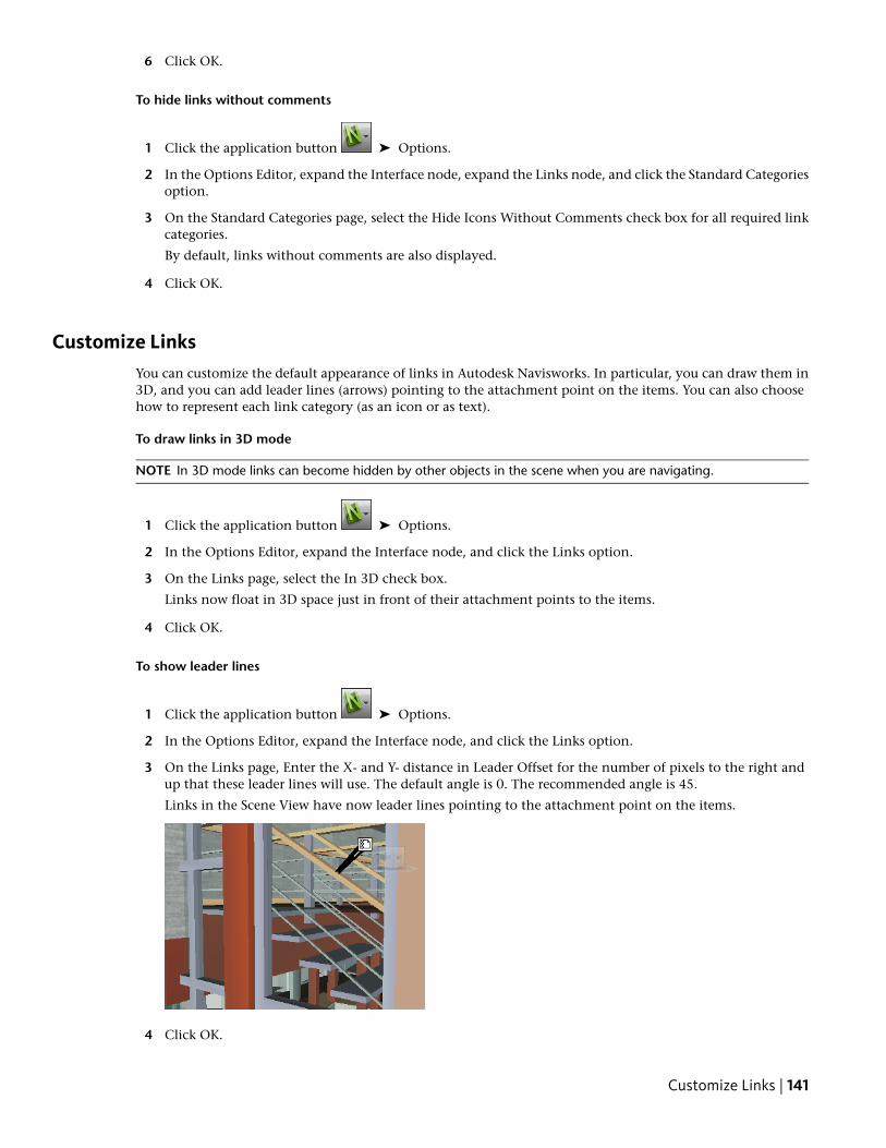
6 Click OK.
To hide links without comments
1 Click the application button ➤ Options.
2 In the Options Editor, expand the Interface node, expand the Links node, and click the Standard Categoriesoption.
3 On the Standard Categories page, select the Hide Icons Without Comments check box for all required linkcategories.
By default, links without comments are also displayed.
4 Click OK.
Customize LinksYou can customize the default appearance of links in Autodesk Navisworks. In particular, you can draw them in3D, and you can add leader lines (arrows) pointing to the attachment point on the items. You can also choosehow to represent each link category (as an icon or as text).
To draw links in 3D mode
NOTE In 3D mode links can become hidden by other objects in the scene when you are navigating.
1 Click the application button ➤ Options.
2 In the Options Editor, expand the Interface node, and click the Links option.
3 On the Links page, select the In 3D check box.
Links now float in 3D space just in front of their attachment points to the items.
4 Click OK.
To show leader lines
1 Click the application button ➤ Options.
2 In the Options Editor, expand the Interface node, and click the Links option.
3 On the Links page, Enter the X- and Y- distance in Leader Offset for the number of pixels to the right andup that these leader lines will use. The default angle is 0. The recommended angle is 45.
Links in the Scene View have now leader lines pointing to the attachment point on the items.
4 Click OK.
Customize Links | 141
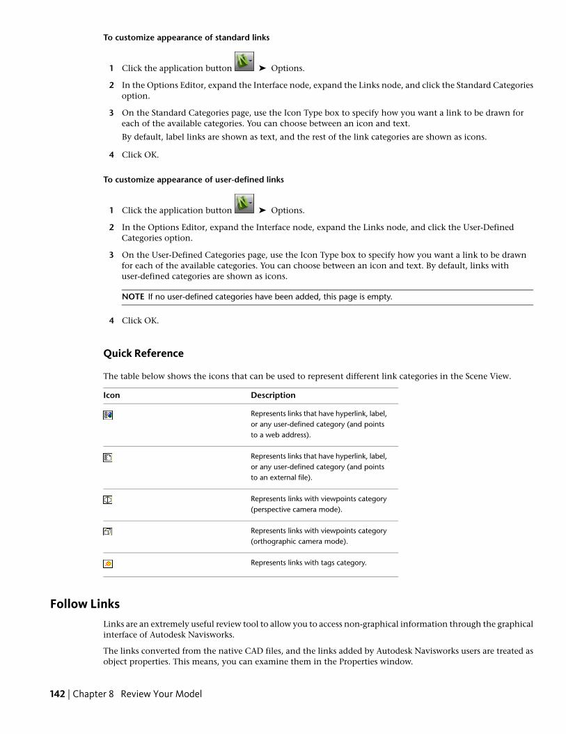
To customize appearance of standard links
1 Click the application button ➤ Options.
2 In the Options Editor, expand the Interface node, expand the Links node, and click the Standard Categoriesoption.
3 On the Standard Categories page, use the Icon Type box to specify how you want a link to be drawn foreach of the available categories. You can choose between an icon and text.
By default, label links are shown as text, and the rest of the link categories are shown as icons.
4 Click OK.
To customize appearance of user-defined links
1 Click the application button ➤ Options.
2 In the Options Editor, expand the Interface node, expand the Links node, and click the User-DefinedCategories option.
3 On the User-Defined Categories page, use the Icon Type box to specify how you want a link to be drawnfor each of the available categories. You can choose between an icon and text. By default, links withuser-defined categories are shown as icons.
NOTE If no user-defined categories have been added, this page is empty.
4 Click OK.
Quick Reference
The table below shows the icons that can be used to represent different link categories in the Scene View.
DescriptionIcon
Represents links that have hyperlink, label,or any user-defined category (and pointsto a web address).
Represents links that have hyperlink, label,or any user-defined category (and pointsto an external file).
Represents links with viewpoints category(perspective camera mode).
Represents links with viewpoints category(orthographic camera mode).
Represents links with tags category.
Follow LinksLinks are an extremely useful review tool to allow you to access non-graphical information through the graphicalinterface of Autodesk Navisworks.
The links converted from the native CAD files, and the links added by Autodesk Navisworks users are treated asobject properties. This means, you can examine them in the Properties window.
142 | Chapter 8 Review Your Model
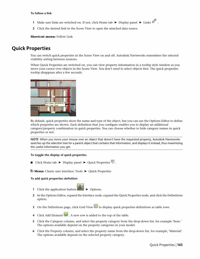
To follow a link
1 Make sure links are switched on. If not, click Home tab ➤ Display panel ➤ Links .
2 Click the desired link in the Scene View to open the attached data source.
Shortcut menu: Follow Link
Quick PropertiesYou can switch quick properties in the Scene View on and off. Autodesk Navisworks remembers the selectedvisibility setting between sessions.
When Quick Properties are switched on, you can view property information in a tooltip style window as youmove your cursor over objects in the Scene View. You don’t need to select objects first. The quick propertiestooltip disappears after a few seconds.
By default, quick properties show the name and type of the object, but you can use the Options Editor to definewhich properties are shown. Each definition that you configure enables you to display an additionalcategory/property combination in quick properties. You can choose whether to hide category names in quickproperties or not.
NOTE When you move your mouse over an object that doesn't have the requested property, Autodesk Navisworkssearches up the selection tree for a parent object that contains that information, and displays it instead, thus maximizingthe useful information you get.
To toggle the display of quick properties
■ Click Home tab ➤ Display panel ➤ Quick Properties .
Menu: Classic user interface: Tools ➤ Quick Properties
To add quick properties definition
1 Click the application button ➤ Options.
2 In the Options Editor, expand the Interface node, expand the Quick Properties node, and click the Definitionsoption.
3 On the Definitions page, click Grid View to display quick properties definitions as table rows.
4 Click Add Element . A new row is added to the top of the table.
5 Click the Category column, and select the property category from the drop-down list, for example ‘Item.’The options available depend on the property categories in your model.
6 Click the Property column, and select the property name from the drop-down list, for example, ‘Material’.The options available depend on the selected property category.
Quick Properties | 143
7 Click OK.
NOTE You can add as many definitions to your quick properties as you like.
To delete quick properties definition
1 Click the application button ➤ Options.
2 In the Options Editor, expand the Interface node, expand the Quick Properties node, and click the Definitionsoption.
3 On the Definitions page, click Grid View to display quick properties definitions as table rows.
4 Click the Category or Property for the definition that you want to delete.
5 Click Remove Element .
6 Click OK.
To hide category names
1 Click the application button ➤ Options.
2 In the Options Editor, expand the Interface node, and click the Quick Properties option.
3 Select the Hide Category check box.
4 Click OK.
144 | Chapter 8 Review Your Model
Use Viewpoints andSectioning Modes
Viewpoints are snapshots taken of the model as it is displayed in the Scene View.Viewpoints may include a variety of comments and redline tags, which have beenpreviously added to a viewpoint. You cannot create viewpoints in AutodeskNavisworks, but you can use any of the viewpoints and viewpoint animationssaved in the model. Viewpoint animation typically contains both the usermovement through the model and views of the model.
Modify Viewpoints
Saved Viewpoints WindowThe Saved Viewpoints window is a dockable window that enablesyou to jump to preset viewpoints without having to navigate eachtime to reach an item.
Viewpoint animations are also saved with the viewpoints, as theyare simply a list of viewpoints treated as keyframes.
Icons are used to represent different elements:
represents a folder which may contain all other elements(including other folders).
represents a viewpoint saved in orthographic mode.
9
145
represents a viewpoint saved in perspective mode.
represents a viewpoint animation clip.
represents a cut inserted into a viewpoint animation clip.
You can select more than one viewpoint by either holding down the CTRL key and left-clicking, or by left-clickingthe first item, and then clicking the last item while holding down the SHIFT key.
You can drag viewpoints around the Saved Viewpoints window, but you cannot save any changes.
There are no buttons on this window, and commands are invoked through shortcut menus.
To toggle the Saved Viewpoints window
■ Click Viewpoint tab ➤ Save, Load & Playback panel ➤ Saved Viewpoints tool launcher .
Menu: Classic user interface: View ➤ Control Bars ➤ Saved ViewpointsCommand entry: CTRL + F11
Quick Reference
You get a different shortcut menu, depending on what element you right-click in the Saved Viewpoints window.All shortcut menus share the Sort option, which sorts the contents of the window alphabetically, includingfolders and their contents.
IMPORTANT Any changes that you make cannot be saved, and will apply for the duration of your Autodesk Navisworkssession.
Blank SpaceSort Sorts the contents of the Saved Viewpoints window alphabetically.
Help Opens the Help system.
Saved ViewpointAdd Copy Creates a copy of the selected viewpoint in the Saved Viewpoints window. The copy is named thesame as the selected viewpoint, but includes the version number in brackets. For example, View1(1), View1(2)and so on.
Edit Opens the Edit Viewpoint dialog box, and enables you to manually edit the viewpoint’s attributes.
Update Makes the selected viewpoint the same as the current viewpoint in the Scene View.
Transform Opens the Transform dialog box. It enables you to transform the camera position.
Delete Deletes the selected viewpoint from the Saved Viewpoints window.
Rename Enables you to rename the selected viewpoint.
Copy Name Copies the name of the selected viewpoint to the Clipboard.
Sort Sorts the contents of the Saved Viewpoints window alphabetically.
Help Opens the Help system.
Viewpoint AnimationAdd Copy Creates a copy of the selected viewpoint animation in the Saved Viewpoints window. The copy isnamed the same as the selected viewpoint animation, but includes the version number in brackets. For example,View1(1), View1(2) and so on.
Edit Opens the Edit Animation dialog box, and enables you to set the duration of the selected viewpointanimation, the type of smoothing, and whether it loops or not.
146 | Chapter 9 Use Viewpoints and Sectioning Modes
NOTE Clicking Edit over an animation keyframe, opens the Edit Viewpoint dialog box; and clicking Edit over ananimation cut, opens the Edit Animation Cut dialog box.
Update Updates all keyframes in the viewpoint animation with the current render style, lighting, and navigationtool or mode.
NOTE Clicking Update over a single keyframe will only update that frame with the current modes.
Transform Opens the Transform dialog box. It enables you to transform the camera position.
Delete Deletes the selected viewpoint animation from the Saved Viewpoints window.
NOTE Clicking Delete over a keyframe or a cut, removes the keyframe or cut from the viewpoint animation.
Rename Enables you to rename the selected viewpoint animation, keyframe, or cut.
Copy Name Copies the name of the selected viewpoint animation, keyframe, or cut to the Clipboard.
Sort Sorts the contents of the Saved Viewpoints window alphabetically.
Help Opens the Help system.
FolderAdd Copy Creates a copy of the selected folder in the Saved Viewpoints window. The copy is named the sameas the selected folder, but includes the version number in brackets. For example, Folder1(1), Folder1(2) and soon.
Update Updates all viewpoints in the folder with the current render style, lighting and navigation tool or mode.Choosing Update for a single viewpoint will only update that viewpoint with the current modes.
Transform Opens the Transform dialog box. It enables you to transform the camera position.
Delete Removes the selected folder and all of its contents from the Saved Viewpoints window.
Rename Enables you to rename the selected folder.
Copy Name Copies the name of the selected folder to the Clipboard.
Sort Sorts the contents of the Saved Viewpoints window alphabetically.
Help Opens the Help system.
Recall ViewpointsYou can return to any of previously saved viewpoints. On recalling viewpoints the navigation mode that wasactive when the viewpoint was created will be re-selected. Any redlines and comments associated with theviewpoint will also be reinstated.
To recall a viewpoint from the Saved Viewpoints window
1 If the Saved Viewpoints window is not displayed, click Viewpoint tab ➤ Save, Load & Playback panel ➤
Saved Viewpoints tool launcher .
2 Click the desired viewpoint in the list. It is now displayed in the Scene View.
Organize ViewpointsViewpoints can be organized into folders, as necessary.
To organize viewpoints into folders
1 Click Viewpoint tab ➤ Save, Load & Playback panel ➤ Current Viewpoint drop-down ➤ Manage SavedViewpoints.
Recall Viewpoints | 147
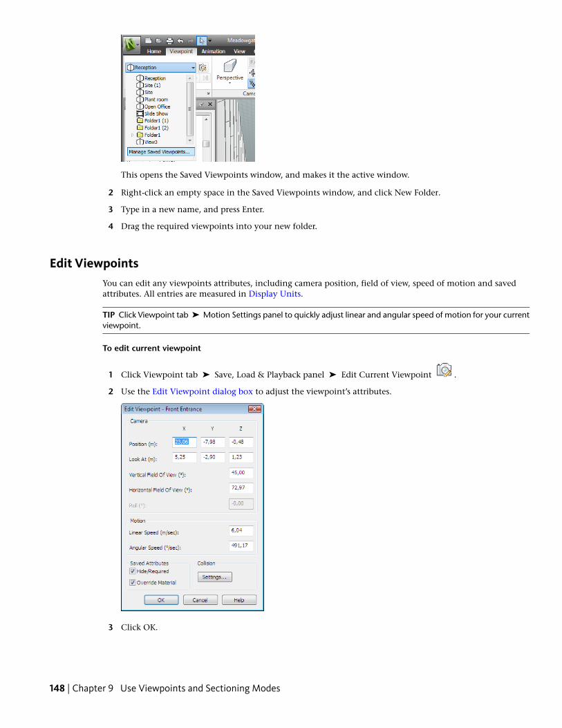
This opens the Saved Viewpoints window, and makes it the active window.
2 Right-click an empty space in the Saved Viewpoints window, and click New Folder.
3 Type in a new name, and press Enter.
4 Drag the required viewpoints into your new folder.
Edit ViewpointsYou can edit any viewpoints attributes, including camera position, field of view, speed of motion and savedattributes. All entries are measured in Display Units.
TIP Click Viewpoint tab ➤ Motion Settings panel to quickly adjust linear and angular speed of motion for your currentviewpoint.
To edit current viewpoint
1 Click Viewpoint tab ➤ Save, Load & Playback panel ➤ Edit Current Viewpoint .
2 Use the Edit Viewpoint dialog box to adjust the viewpoint’s attributes.
3 Click OK.
148 | Chapter 9 Use Viewpoints and Sectioning Modes
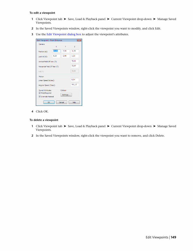
To edit a viewpoint
1 Click Viewpoint tab ➤ Save, Load & Playback panel ➤ Current Viewpoint drop-down ➤ Manage SavedViewpoints.
2 In the Saved Viewpoints window, right-click the viewpoint you want to modify, and click Edit.
3 Use the Edit Viewpoint dialog box to adjust the viewpoint’s attributes.
4 Click OK.
To delete a viewpoint
1 Click Viewpoint tab ➤ Save, Load & Playback panel ➤ Current Viewpoint drop-down ➤ Manage SavedViewpoints.
2 In the Saved Viewpoints window, right-click the viewpoint you want to remove, and click Delete.
Edit Viewpoints | 149

150 | Chapter 9 Use Viewpoints and Sectioning Modes
Play Back Animations
In Autodesk Navisworks there are two types of animation: viewpoint animationand object animation.
Viewpoint animation contains pre-recorded user and camera movements in themodel. Object animation contains pre-recorded object movements in the model.You cannot record any animation in Autodesk Navisworks, but you can play backanimations saved with the model. If there are any animation scripts, you canswitch them on and interact with animated objects.
Play Animations and ScriptsYou can play back both pre-recorded object animation and viewpointanimation in the Scene View.
The viewpoint animations play in real time; this means that theAutodesk Navisworks engine is still attempting to maintain theguaranteed frame rate so some drop-out may still occur, just as inreal-time navigation.
Quick Reference
PurposeControl
Rewinds the current animation backto the beginning.
Steps back a single animation frameor keyframe.
Plays the current animation back-wards.
Stops animation playback.
Pauses animation playback.
Plays the currently selected anima-tion.
Steps forwards one frame or keyframein the animation.
10
151
PurposeControl
Moves forward to the end of anima-tion.
The playback time slider.
The playback time spinner.
To play an animation
1 Click Animation tab ➤ Playback panel ➤ Available Animations drop-down list and select the animationyou want to play back.
2 On the Playback panel, click Play .
Use the VCR buttons on the Playback panel to control the animation. The Playback Position slider enablesyou to quickly move forward and backward through the animation. Full left is at the beginning and fullright is at the end.
To the right of the Playback Position slider, there are two animation progress indicators: percentage andtime (in seconds). You can type a number into either box to set the camera at a certain point.
3 For viewpoint animations, you may notice that the frame in the animation in the Saved Viewpoints window(click View tab ➤ Workspace panel ➤ Windows drop-down ➤ Saved Viewpoints) is highlighted whenthe animation is playing. Click any frame to set the camera to that point in time in the viewpoint animationand continue playing back from there.
To enable animation scripts
■ Click Animation tab ➤ Scripts panel ➤ Enable Scripts .You can now interact with your model. For example, if there is a script to open a door on pressing a specifickey on the keyboard, pressing this key will open the door.
152 | Chapter 10 Play Back Animations
Share Data
PrintYou can print a hard copy of the current viewpoint to any printeror plotter.
Print PreviewBefore you print out a copy of the model you are working on, youmay wish to see how it will appear.
To preview model before printing
1 Click Output tab ➤ Print panel ➤ Print Preview .
2 Use the Zoom In and Zoom Out buttons to do just that withthe preview image.
3 Click Print.
4 In the Print dialog box, click OK.
Print SetupThis option enables you to the set up paper size and orientationoptions.
To change the print setup
1 Click Output tab ➤ Print panel ➤ Print Settings .
2 In the Print Setup dialog box, make changes as required to thepaper and orientation.
3 Click the Properties button if you want to changeprinter-specific settings.
4 Return to the Print dialog box, and click OK to print the image.
11
153
Print Current ViewpointWhen the print option is selected, Autodesk Navisworks prints the current viewpoint scaled to fit and centeredon the page.
To print the current viewpoint
1 Click Output tab ➤ Print panel ➤ Print .
2 Check the printer settings are as required, and click OK.
NOTE The maximum image size is 2048x2048 pixels.
The Properties button controls printer-specific ink and paper settings.
Toolbar: Classic user interface: Standard ➤ Print
154 | Chapter 11 Share Data
TimeLiner Playback
TimeLiner Playback enables you to view a TimeLiner construction sequence. Inthis section, you will learn how to simulate your TimeLiner sequence throughoutthe duration of the project schedule.
Overview of TimeLiner ToolThe TimeLiner tool adds 4D schedule simulation to AutodeskNavisworks files.
In Autodesk Navisworks Freedom 2011, TimeLiner has aplayback-only option, allowing any externally created project datato be simulated, but no changes to be made to that data.
TimeLiner Playback WindowThe TimeLiner Playback dockable window enables you to set upand play simulations.
To toggle the TimeLiner Playback window
■ Click Home tab ➤ Tools panel ➤ TimeLiner Playback
Menu: Classic user interface: Tools ➤ TimeLiner Playback
Simulate TabIn the TimeLiner Playback window, the Simulate tab enables youto simulate your TimeLiner sequence throughout the duration ofthe project schedule.
12
155
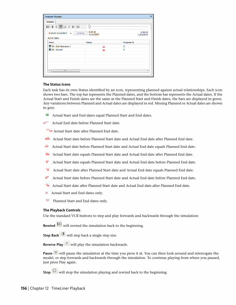
The Status IconsEach task has its own Status identified by an icon, representing planned against actual relationships. Each iconshows two bars. The top bar represents the Planned dates, and the bottom bar represents the Actual dates. If theActual Start and Finish dates are the same as the Planned Start and Finish dates, the bars are displayed in green.Any variations between Planned and Actual dates are displayed in red. Missing Planned or Actual dates are shownin grey.
Actual Start and End dates equal Planned Start and End dates.
Actual End date before Planned Start date.
Actual Start date after Planned End date.
Actual Start date before Planned Start date and Actual End date after Planned End date.
Actual Start date before Planned Start date and Actual End date equals Planned End date.
Actual Start date equals Planned Start date and Actual End date after Planned End date.
Actual Start date equals Planned Start date and Actual End date before Planned End date.
Actual Start date after Planned Start date and Actual End date equals Planned End date.
Actual Start date before Planned Start date and Actual End date before Planned End date.
Actual Start date after Planned Start date and Actual End date after Planned End date.
Actual Start and End dates only.
Planned Start and End dates only.
The Playback ControlsUse the standard VCR buttons to step and play forwards and backwards through the simulation:
Rewind will rewind the simulation back to the beginning.
Step Back will step back a single step size.
Reverse Play will play the simulation backwards.
Pause will pause the simulation at the time you press it at. You can then look around and interrogate themodel, or step forwards and backwards through the simulation. To continue playing from where you paused,just press Play again.
Stop will stop the simulation playing and rewind back to the beginning.
156 | Chapter 12 TimeLiner Playback
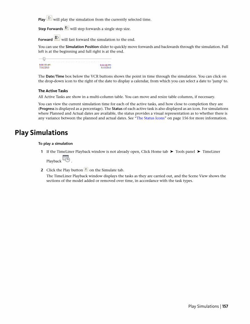
Play will play the simulation from the currently selected time.
Step Forwards will step forwards a single step size.
Forward will fast forward the simulation to the end.
You can use the Simulation Position slider to quickly move forwards and backwards through the simulation. Fullleft is at the beginning and full right is at the end.
The Date/Time box below the VCR buttons shows the point in time through the simulation. You can click onthe drop-down icon to the right of the date to display a calendar, from which you can select a date to 'jump' to.
The Active TasksAll Active Tasks are show in a multi-column table. You can move and resize table columns, if necessary.
You can view the current simulation time for each of the active tasks, and how close to completion they are(Progress is displayed as a percentage). The Status of each active task is also displayed as an icon. For simulationswhere Planned and Actual dates are available, the status provides a visual representation as to whether there isany variance between the planned and actual dates. See “The Status Icons” on page 156 for more information.
Play SimulationsTo play a simulation
1 If the TimeLiner Playback window is not already open, Click Home tab ➤ Tools panel ➤ TimeLiner
Playback .
2 Click the Play button on the Simulate tab.
The TimeLiner Playback window displays the tasks as they are carried out, and the Scene View shows thesections of the model added or removed over time, in accordance with the task types.
Play Simulations | 157

158 | Chapter 12 TimeLiner Playback
Autodesk NavisworksReference
Background Settings Dialog BoxUse this dialog box to choose a background effect to use in the SceneView.
Mode Selects the type of background effect. Choose from:
■ Plain
■ Graduated
■ Horizon
Color Sets the color for a plain background.
Top Color Sets the top color in a graduated background.
Bottom Color Sets the bottom color in the graduated background.
Sky Color Sets the sky color (top) in a horizon background.
Horizon Sky Color Sets the sky color (bottom) in a horizonbackground.
Horizon Ground Color Sets the ground color (top) in a horizonbackground.
Ground Color Sets the ground color (bottom) in a horizonbackground.
Ribbon: View tab ➤ Scene View panel ➤ BackgroundShortcut menu: Right-click a blank area in the scene, and clickBackground on the shortcut menu.
Menu: Classic user interface: Tools ➤ Background
Collision Dialog BoxUse this dialog box to adjust the collision settings for the selectedviewpoint.
By default, Collision, Gravity, Auto Crouch, and Third Person vieware switched off.
13
159
Collision Select this check box to define a viewer as a collision volume in Walk and Fly modes. As a result, aviewer acquires some mass, and cannot pass through other objects, points, or lines in the Scene View.
NOTE Selecting this check box changes the rendering prioritization so that objects around the viewer are displayedwith much higher detail than normal. The size of the region of high detail is based on collision volume radius andspeed of movement.
Gravity Select this check box to give a viewer some weight in Walk mode. This option works in conjunctionwith Collision.
Auto Crouch Select this check box to enable a viewer crouch under objects that are too low to pass under inWalk mode. This option works in conjunction with Collision.
ViewerRadius Specifies the radius of the collision volume.
Height Specifies the height of the collision volume.
Eye Offset Specifies the distance below the top of the collision volume, where the camera will focus upon ifAuto Zoom check box is selected.
Third PersonEnable Select this check box to use Third Person view. In Third Person view, an avatar is shown in the SceneView to represent the viewer.
Selecting this check box changes rendering prioritization so that objects around the avatar are displayed withmuch higher detail than normal. The size of the region of high detail is based on collision volume radius, speedof movement, and the distance of the camera behind the avatar.
Auto Zoom Select this check box to automatically switch from Third Person view to first person view wheneverthe line of vision becomes obscured by an item.
Avatar Specifies the avatar that is used in Third Person view.
Angle Specifies the angle at which the camera looks at the avatar.
For example, 0° positions the camera directly behind the avatar; 15° makes the camera look down on the avatarat a 15° angle.
Distance Specifies the distance between the camera and the avatar.
TIP If you want to restore the default values, click the Defaults button.
Pointing device: Edit Viewpoint dialog box ➤ Settings
Default Collision Dialog BoxUse this dialog box to specify and save your preferred collision settings.
By default, Collision, Gravity, Auto Crouch, and Third Person view are switched off. When you modify defaultcollision settings, your changes do not affect the currently opened Autodesk Navisworks file. They are used assoon as you open a new Autodesk Navisworks file, or start a new Autodesk Navisworks session.
Collision Select this check box to define a viewer as a collision volume in Walk and Fly modes. As a result, aviewer acquires some mass, and cannot pass through other objects, points, or lines in the Scene View.
NOTE Selecting this check box changes the rendering prioritization so that objects around the viewer are displayedwith much higher detail than normal. The size of the region of high detail is based on collision volume radius andspeed of movement.
Gravity Select this check box to give a viewer some weight in Walk mode. This option works in conjunctionwith Collision.
Auto Crouch Select this check box to enable a viewer crouch under objects that are too low to pass under inWalk mode. This option works in conjunction with Collision.
160 | Chapter 13 Autodesk Navisworks Reference
ViewerRadius Specifies the radius of the collision volume.
Height Specifies the height of the collision volume.
Eye Offset Specifies the distance below the top of the collision volume, where the camera will focus upon ifAuto Zoom check box is selected.
Third PersonEnable Select this check box to use Third Person view. In Third Person view, an avatar is shown in the SceneView to represent the viewer.
Selecting this check box changes rendering prioritization so that objects around the avatar are displayed withmuch higher detail than normal. The size of the region of high detail is based on collision volume radius, speedof movement, and the distance of the camera behind the avatar.
Auto Zoom Select this check box to automatically switch from Third Person view to first person view wheneverthe line of vision becomes obscured by an item.
Avatar Specifies the avatar that is used in Third Person view.
Angle Specifies the angle at which the camera looks at the avatar.
For example, 0° positions the camera directly behind the avatar; 15° makes the camera look down on the avatarat a 15° angle.
Distance Specifies the distance between the camera and the avatar.
TIP If you want to restore the default values, click the Defaults button.
Pointing device: Options Editor dialog box ➤ Interface node ➤ Viewpoint Defaults page ➤ Settings
Edit Viewpoint Dialog BoxUse this dialog box to edit viewpoint attributes.
CameraPosition Enter the X, Y, and Z coordinate values to move the camera into this position.
Look At Enter the X, Y, and Z coordinate values to change the focal point for the camera.
Vertical Field of View, Horizontal Field of View Defines the area of the scene that can be viewed through thecamera. You can adjust the values for both vertical and horizontal angles of view.
A larger value produces a wider angle of view and a smaller value produces a narrower, or more tightly focused,angle of view.
NOTE When you modify the Vertical Field of View, the Horizontal Field of View is automatically adjusted, and viceversa to match the aspect ratio in Autodesk Navisworks.
Roll Rotates the camera around its front-to-back axis. A positive value rotates the camera counterclockwise, anda negative value rotates it clockwise.
NOTE This value is not editable when the viewpoint up vector stays upright (that is, when you use Walk, Orbit andConstrained Orbit navigation tools).
MotionLinear Speed The speed of motion in a straight line for the viewpoint. The minimum value is 0 and the maximumis based on the size of the scene’s bounding box.
Angular Speed The speed at which the camera turns.
Saved AttributesThis area applies to saved viewpoints only. If you are editing a current viewpoint, this area is not greyed out.
Edit Viewpoint Dialog Box | 161
Hide/Required Select this check box to save hidden/required markup information about objects in your modelwith the viewpoint. When you use a viewpoint again, the hidden/required markups set when the viewpoint wassaved are reapplied.
NOTE Saving the state information with each viewpoint requires a relatively large amount of memory.
Override Material Select this check box to save material override information with the viewpoint. When youuse a viewpoint again, the material overrides set when the viewpoint was saved are reapplied.
NOTE Saving the state information with each viewpoint requires a relatively large amount of memory.
CollisionSettings Opens the Collision dialog box.
Ribbon: Viewpoint tab ➤ Save, Load & Playback panel ➤ Edit Current ViewpointMenu: Classic user interface: Viewpoint ➤ Edit Current Viewpoint
File Options Dialog BoxUse this dialog box to control the appearance of the model and the speed of navigation around it.
When you modify any of the options in this dialog box, your changes are saved in the currently opened AutodeskNavisworks file, and apply to this file only.
Ribbon: Home panel ➤ Project tab ➤ File OptionsMenu: Classic user interface: Tools ➤ File Options.
Culling TabUse this tab to adjust geometry culling in the opened Autodesk Navisworks file.
AreaEnable Specifies whether or not area culling is used.
Number of Pixels Below Which Objects Are Culled Specifies a value for the screen area in pixels below whichobjects are culled. For example, setting the value to 100 pixels means that any object within the model thatwould be drawn less than 10x10 pixels in size are discarded.
Clipping PlanesNearAutomatic Select this radio button to make Autodesk Navisworks automatically control the near clip planeposition to give you the best view of the model. The Distance box becomes unavailable.
Constrained Select this radio button to constrain the near clipping plane to the value set in the Distance box.
Autodesk Navisworks uses the provided value unless doing so affects performance (for example, makes the wholemodel invisible), in which case it adjusts the near clip plane position as necessary.
Fixed Select this radio button to set the near clipping plane to the value provided in the Distance box.
Distance Specifies the farthest distance between the camera and the near clipping plane position in constrainedmode.
Specifies the exact distance between the camera and the near clipping plane position in fixed mode.
NOTE Nothing is drawn between the camera and the near clipping plane; when you override automatic mode, makethis value small enough to display your data. Also, overriding automatic mode with values under 1 can produceunpredictable results.
FarAutomatic Select this radio button to make Autodesk Navisworks automatically control the far clipping planeposition to give you the best view of the model. The Distance box becomes unavailable.
Constrained Select this radio button to constrain the far clipping plane to the value set in the Distance box.
162 | Chapter 13 Autodesk Navisworks Reference
Autodesk Navisworks uses the provided value unless doing so affects performance (for example, makes the wholemodel invisible), in which case it adjusts the far clip plane position as necessary.
Fixed Select this radio button to set the far clipping plane to the value provided in the Distance box.
Distance Specifies the closest distance between the camera and the far clipping plane position in constrainedmode.
Specifies the exact distance between the camera and the far clipping plane position in fixed mode.
NOTE Nothing is drawn beyond this plane; when you override automatic mode, make this value large enough toinclude your data. Additionally, using the ratio of the far clipping plane to near clipping plane in excess of 10000 canproduce unwanted effects.
BackfaceTurns on backface culling for all objects. Select from the following options:
■ Off. Turns off backface culling.
■ Solid. Turns on backface culling for solid objects only. This is the default option.
■ On. Turns on backface culling for all objects.
TIP If you can see through some objects, or some object parts are missing, turn off backface culling.
TIP If you want to restore the default values, click the Reset to Defaults button.
Orientation TabUse this tab to adjust the real-world orientation of your model.
UpX, Y, Z Specify the X, Y, and Z coordinate values. By default, Autodesk Navisworks takes the positive Z-axis asUp.
NorthX, Y, Z Specify the X, Y, and Z coordinate values. By default, Autodesk Navisworks takes the positive Y-axis asNorth.
TIP If you want to restore the default values, click the Defaults button.
Speed TabUse this tab to adjust the frame rate speed to reduce the amount of drop-out during navigation.
TIP If this does not improve navigation, try switching off the Guarantee Frame Rate option.
Frame Rate Specifies the number of frames per second (FPS) that are rendered in the Scene View.
The default setting is 6. You can set the frame rate from 1 through 60 frames per second. Reducing the valuereduces drop-out, but can cause jerky movement during navigation. Increasing the value ensures a smoothernavigation, but increases drop-out.
TIP If you want to restore the default values, click the Defaults button.
Head Light TabUse this tab to change the intensity of the scene's ambient light and headlight for Head Light mode.
Ambient Use the slider to control the overall brightness of the scene.
Headlight Use the slider to control the brightness of the light located at the camera.
Orientation Tab | 163
NOTE To see the effect your changes have on the model in the Scene View, apply Head Light mode.
Scene Lights TabUse this tab to change the intensity of the scene’s ambient light for Scene Lights mode.
Ambient Use the slider to control the overall brightness of the scene.
NOTE To see the effect your changes have on the model in the Scene View, apply Scene Lights mode
InfoCenter Settings Dialog BoxUse this dialog box to specify InfoCenter Search and Communication Center settings.
ButtonsOK Saves changes and closes the InfoCenter Settings dialog box.
Cancel Discards changes and closes the InfoCenter Settings dialog box.
Help Displays the context-sensitive help.
Pointing device: In the InfoCenter box, click the down arrow next to the Search button ➤ Search Settings
General NodeUse the General node to select your current location, frequency for checking new online content and option toturn on or off animated transition effects for the InfoCenter panels.
Please Indicate the Country/Region Nearest to Your Current Location Set the country in which AutodeskNavisworks users work. This is used for tailoring location-specific Communication Center content.
Check for New Online Content Specifies how often Communication Center checks for new content.
Use Animated Transition Effects for Panels Check to animate panel transitions.
Pointing device: InfoCenter Settings dialog box ➤ General node
Search Locations NodeUse the Search Locations node to identify content (documents, Web locations, and files) to be searched, as wellas the name that displays for each location and the number of results to display for each.
Used by other Autodesk products, customizing search locations is not enabled in Autodesk Navisworks.
Pointing device: InfoCenter Settings dialog box ➤ Search Locations node
Communication Center NodeUse the Communication Center node to set the maximum age of the articles displayed on the CommunicationCenter panel.
Hide Results Which Are More Than X Days Old Select this check box to have InfoCenter hide search resultsolder than the numeric value you specify.
CAD Manager Channel Used by other Autodesk products to specify the RSS feeds published by a CAD manager,the CAD Manager Channel is not enabled in Navisworks.
Display Name Type the name to be displayed in the Search Results panel.
Pointing device: InfoCenter Settings dialog box ➤ Communication Center node
164 | Chapter 13 Autodesk Navisworks Reference
Autodesk Channels PageUse the settings on this page to adjust the settings for Communication Center.
By default, all available channels are selected. You cannot add or remove channels from the grid, and you cannotedit data in the grid.
Select Channels to Display in the Communication Center Panel Select the channels and the number of articlesyou want to display in the Communication Center panel.
Pointing device: InfoCenter Settings dialog box ➤ Communication Center node ➤ Autodesk Channelspage
Balloon Notification PageUse the settings on this page to adjust balloon notifications.
Enable Balloon Notification for These Sources Select this check box to enable balloon notifications in theproduct. Balloon notifications appear over the InfoCenter box when any new information is available from theselected sources.
Live Update Channel (New Software Updates) Select this check box to receive balloon notification of availablesoftware updates.
Product Support Information Channel Select this check box to receive balloon notification of new productinformation.
CAD Manager Channel The CAD Manager Channel is not enabled in Navisworks.
RSS Feeds Select this check box to receive balloon notification of new RSS feeds.
Number of Seconds Balloon Notification Displays Enter a numeric value to indicate the amount of time todisplay balloon notifications.
% Transparency of Balloon Notification Enter a numeric value to indicate the transparency of balloonnotifications.
Alternatively, drag the slider toward Opaque to decrease the balloon notification transparency percentage ortoward Transparent to increase the transparency percentage.
Pointing device: InfoCenter Settings dialog box ➤ Communication Center node ➤ Balloon Notificationpage
RSS Feeds PageUse the settings on this page to RSS feeds.
RSS Subscription Add. Specify the path for the RSS feed you want to add. After the RSS feed has been added tothe RSS Subscription list, under Items to Display enter a numeric value to indicate the number of items to display.
Remove. Remove a selected RSS feed from the RSS Subscription list.
Pointing device: InfoCenter Settings dialog box ➤ Communication Center node ➤ RSS Feeds page
Options Editor Dialog BoxUse the Options Editor to adjust program settings for Autodesk Navisworks sessions.
The settings that you set up in the Options Editor are persistent across all Autodesk Navisworks sessions. Youalso share the modified settings with other members of your team.
The options are presented in a hierarchical tree structure. Clicking expands the nodes, clicking collapses thenodes.
Ribbon: Application button ➤ OptionsMenu: Classic user interface: Tools ➤ Global Options
Options Editor Dialog Box | 165
ButtonsExport Displays the Select Options to Export dialog box, where you can select the global options you want toexport (or “serialize”). If an option cannot be exported, it is unavailable.
Import Displays the Open dialog box, where you can browse to the file with the required global option settings.
OK Saves the changes, and closes the Options Editor.
Cancel Discards the changes, and closes the Options Editor.
Help Displays the context-sensitive help.
General NodeUse the settings in this node to adjust the buffer size, file locations, number of recent file shortcuts you wantAutodesk Navisworks to store, and the auto-save options.
TIP If you want to restore the default values, click the Defaults button.
Pointing device: Options Editor dialog box ➤ General node
Undo PageUse the settings on this page to adjust the buffer size.
Pointing device: Options Editor dialog box ➤ General node ➤ Undo pageBuffer Size (KB) Specifies the amount of space Autodesk Navisworks allocates for saving undo/redo actions.
Locations PageUse the options on this page to share global Autodesk Navisworks settings, workspaces, datatools, avatars, ClashDetective rules, Presenter archives, custom Clash Detective tests, object animation scripts, and so on, with otherusers.
The settings can be shared across an entire project site, or across a specific project group depending on therequired level of granularity.
When you run Autodesk Navisworks for the first time, the settings are picked up from the installation directory.Subsequently, Autodesk Navisworks examines the current user profile and the all users profile on the localmachine, and then checks the settings in the Project Directory and the Site Directory. The files in the ProjectDirectory take precedence.
Project Directory Click to open the Browse for Folder dialog box, and locate the directory that contains theAutodesk Navisworks settings specific to a project group.
Site Directory Click to open the Browse for Folder dialog box, and locate the directory that contains theAutodesk Navisworks settings standard across the entire project site.
See also:
■ Location Options on page 59
■ How do I share the Autodesk Navisworks settings on a site and project basis? on page 26
Environment PageUse the settings on this page to adjust the number of recent file shortcuts stored by Autodesk Navisworks.
Maximum Recently Used Files Specifies how many file shortcuts Autodesk Navisworks can remember. Bydefault, shortcuts to the four most recently opened files can be displayed.
166 | Chapter 13 Autodesk Navisworks Reference
Interface NodeUse the settings in this node to customize Autodesk Navisworks interface.
TIP If you want to restore the default values, click the Defaults button.
Display Units PageUse this page to customize the units used by Autodesk Navisworks.
Linear Units Use the drop-down list to select the desired linear value. Meters are used by default.
Angular Units Use the drop-down list to select the desired angular value. Degrees are used by default.
Decimal Places Specifies the number of decimal places used by units.
Fractional Display Precision Specifies the level of fraction used by units. This box is enabled for fractional unitsonly.
Selection PageUse the options on this page to configure the way geometry objects are selected, and highlighted.
Pick Radius Specifies the radius, in pixels, that an item has to be within in order for it to be selected.
Resolution Specifies the level of selection used by default.
When you click in the Scene View, Autodesk Navisworks requires a starting point for the object path in theSelection Tree box to identify the selected item. You can choose one of the following options:
■ Model - the object path starts at the model node; as a result, all objects in the model are selected.
■ Layer - the object path starts at the layer node; as a result all objects within a layer are selected.
■ First Object - the object path starts at the highest level of objects below the layer node, if applicable.
■ Last Object - the object path starts at the lowest level of objects in the Selection Tree. Autodesk Navisworkslooks for composite objects first, and if none are found, the geometry level is used instead. This is the defaultoption.
■ Last Unique - the object path starts at the first unique level of objects (not multiple-instanced) in the SelectionTree.
■ Geometry - the object path starts from the geometry level in the Selection Tree.
Compact Tree Specifies the level of detail shown on the Compact tab of the Selection Tree.
Use one of the following options:
■ Models - the tree is restricted to displaying model files only.
■ Layers - the tree can be expanded down to the layer level.
■ Objects - can be expanded down to the objects level, but without the levels of instancing shown on theStandard tab.
HighlightEnabled Indicates whether Autodesk Navisworks highlights the selected items in the Scene View.
Clear this check box if you don’t want to highlight selected items.
Method Specifies how the objects are highlighted. Select one of the following options:
■ Shaded
■ Wireframe
■ Tinted
Interface Node | 167
Color Click to specify the highlight color.
Tint Level (%) Use the slider to adjust the tint level.
Measure PageUse the options on this page to adjust the appearance and style of the measure lines.
Line Thickness Specifies the thickness of the measure lines.
Color Click to specify the color of the measure lines.
In 3D Select this check box to draw the measure lines in 3D.
If the measure lines become obscured by other geometry, clear this check box to draw the lines in 2D over thetop of geometry.
Show Measurement Values in Scene View Select this check box if you want to display the dimension labels inthe Scene View.
Use Center Lines When this check box is selected, the shortest distance measurements snap to the center linesof parametric objects.
When this check box is clear, the surface of the parametric objects is used for the shortest distance measurementinstead.
NOTE Changing this option does not affect any measurement currently in place. To see any changes, clear themeasurement, and start again.
Snapping PageUse the options on this page to adjust the cursor snapping.
PickingSnap to Vertex Select this check box to snap the cursor to the nearest vertex.
Snap to Edge Select this check box to snap the cursor to the nearest triangle edge.
Snap to Line Vertex Select this check box to snap the cursor to the nearest line end.
Tolerance Defines the snapping tolerance. The smaller the value, the closer the cursor must be to a feature inthe model before it snaps to it.
RotationAngles Specifies the multiplier for the snapping angle.
Angle Sensitivity Defines the snapping tolerance. The value you enter here determines how close to the snappingangle the cursor must be for snap to take effect.
Viewpoint Defaults PageUse the options on this page to define attributes that are saved with viewpoints when you create them.
When you modify default viewpoint settings, your changes do not affect the currently opened AutodeskNavisworks file. They are used as soon as you open a new Autodesk Navisworks file, or start a new AutodeskNavisworks session.
Save Hide/Required Attributes Select this check box to save viewpoints with hidden/required markup informationabout objects in your model. When you use a viewpoint again, the hidden/required markups set when theviewpoint was saved are reapplied.
By default, this check box is clear, as saving the state information with each viewpoint requires a relatively largeamount of memory.
168 | Chapter 13 Autodesk Navisworks Reference
Override Material Select this check box to save viewpoints with material override information. When you usea viewpoint again, the material overrides set when the viewpoint was saved are reapplied.
By default, this check box is clear, as saving the state information with each viewpoint requires a relatively largeamount of memory.
Override Linear Speed By default, the linear navigation speed is directly related to the size of your model. Selectthis check box, if you want to set a specific navigation speed manually.
Default Linear Speed Specifies the default linear speed value.
Default Angular Speed Specifies the default speed at which the camera turns.
CollisionSettings Opens the Default Collision dialog box where you can adjust the collision, gravity, crouching and thirdperson view settings.
Links PageUse the options on this page to customize the way links are displayed in the Scene View.
TIP If you want to restore the default values, click the Defaults button.
Show Links Toggles the display of links in the Scene View.
In 3D Indicates whether the link icons are drawn in 3D in the Scene View.
Select this box if you want the links to float in 3D space just in front of their attachment points to the geometry.
If the links become obscured by other geometry, clear this check box to draw the link icons in 2D over the topof geometry.
Max Icons Specifies the maximum number of icons to draw in the Scene View.
Hide Colliding Icons Select this check box to hide the link icons that appear overlapped in the Scene View.
Cull Radius Specifies how close to the camera links have to be before they are drawn in the Scene View. Anylinks further away than this distance are not drawn. The default value of 0 means that all links are drawn.
X Leader Offset, Y Leader Offset Links can be drawn with leader lines (arrows) pointing to the attachmentpoint on the geometry that the link is attached to. Enter the X- and Y- values to specify the number of pixels tothe right and up that these leader lines use.
Standard Categories PageUse the settings on this page to switch the displaying of links based on their categories.
HyperlinkIcon Type Specifies how to display this link category.
Select one of the following options:
■ Icon - links are represented by default icons and in the Scene View.
■ Text - links are represented by text boxes with link descriptions in the Scene View.
Visible Select this check box to display this link category in the Scene View.
LabelIcon Type Specifies how to display this link category.
Select one of the following options:
■ Icon - links are represented by default icons and in the Scene View.
■ Text - links are represented by text boxes with link descriptions in the Scene View.
Interface Node | 169
Visible Select this check box to display this link category in the Scene View.
ViewpointsIcon Type Specifies how to display this link category.
Select one of the following options:
■ Icon - links are represented by default icons in the Scene View:
- links to viewpoints saved in perspective mode
- links to viewpoints saved in orthographic mode
■ Text - links are represented by text boxes with link descriptions in the Scene View.
Visible Select this check box to display this link category in the Scene View.
Hide Icons Without Comments Select this check box to display only the links that have comments in the SceneView.
Redline TagsIcon Type Specifies how to display this link category.
Select one of the following options:
■ Icon - links are represented by default icons in the Scene View.
■ Text - links are represented by text boxes with link descriptions in the Scene View.
Visible Select this check box to display this link category in the Scene View.
Hide Icons Without Comments Select this check box to display only the links that have comments in the SceneView.
User-Defined Categories PageUse this page to view custom link categories.
The padlock icon indicates that you cannot add or remove categories directly from here.
Buttons
Grid View Click to display custom link categories in a tabular format.
List View Click to display custom link categories in a list format (the same way as the standard link categoriesare shown).
Records View Click to display link categories as records.
Previous and Next Element Use and to navigate between link categories. If you clicked the Records Viewbutton, this is the only way to move between the records.
Visible Select this check box to display the corresponding link category in the Scene View.
Icon Type Select one of the following options:
■ Icon - links are represented by default icons and in the Scene View.
■ Text - links are represented by text boxes with link descriptions in the Scene View.
Quick Properties PageUse the options on this page to customize the way quick properties are displayed in the Scene View.
170 | Chapter 13 Autodesk Navisworks Reference
TIP If you want to restore the default values, click the Defaults button.
Show Quick Properties Toggles the display of quick properties in the Scene View.
Hide Category Clear this check box to include category names in the quick properties tooltips.
If you don’t want to see category names in the quick properties tooltips, select this check box.
Definitions PageUse the options on this page to set up the quick properties categories.
Buttons
Add Element Click to add quick properties definitions.
Remove Element Click to delete the selected quick properties definitions.
Grid View Click to display quick properties definitions in a tabular format.
List View Click to display quick properties definitions in a list format.
Records View Click to display quick properties definitions as records.
Previous and Next Element Use and to navigate between quick properties definitions.
If you clicked the Records View button, this is the only way to move between the records.
Category Specifies the property category that you want to customize.
Property Specifies the property that is displayed in the tooltips for the selected category.
Developer PageUse the options on this page to adjust the display of object properties.
Show Internal Properties Indicates whether additional object properties are displayed in Autodesk Navisworks.
Select this check box if you want to get access to the Geometry tab and the Transform tab in the Propertiescontrol bar.
Display PageUse the options on this page to adjust the display performance.
AccelerationHardware Acceleration Select this check box to utilize any available OpenGL hardware acceleration on yourvideo card.
If your video card drivers do not function well with Autodesk Navisworks, clear this check box.
NOTE If your video card does not support OpenGL hardware acceleration, this check box is not available.
Overlay Buffer Select the hardware overlay option from the drop-down list.
Occlusion Culling Select this check box to enable occlusion culling. This means that Autodesk Navisworks onlydraws visible objects and ignores any objects located behind other objects.
Selecting this check box improves the display performance when much of the model is not visible. For example,when you’re walking down the corridor of a building.
IMPORTANT Occlusion culling can only be used on a machine with an OpenGL 1.5 compliant graphics card.
Interface Node | 171
TransparencyInteractive Transparency Select this check box to render transparent items dynamically during interactivenavigation.
By default, this check box is clear, therefore, transparent items are only drawn when interaction has stopped.
NOTE If your video card does not support hardware accelerated OpenGL, selecting this check box can affect displayperformance.
DetailGuarantee Frame Rate Indicates whether the Autodesk Navisworks engine maintains the frame rate specifiedon the Speed tab of the File Options dialog box.
By default, this check box is selected, and the target rate is maintained while moving. When movement stopsthe complete model is rendered.
If this check box is clear, the complete model is always rendered during navigation, no matter how long it takes.
Fill In Detail Indicates whether Autodesk Navisworks fills in any discarded detail when navigation has stopped.
Batch Fill Select this check box to render detail in chunks (batches) rather than gradually.
NOTE This check box is clear by default, as gradual rendering gives better results for most video cards.
PrimitivesPoint Size Enter a number from 1 through 9 to set the size (in pixels) of points drawn in the Scene View.
Line Size Enter a number from 1 through 9 to set the width (in pixels) of lines drawn in the Scene View.
Snap Size Enter a number from 1 through 9 to set the size (in pixels) of snap points drawn in the Scene View.
Enable Parametric Primitives Indicates whether Autodesk Navisworks dynamically renders parametric primitivesduring interactive navigation.
Selecting this check box means the level of detail changes during navigation depending on the distance fromthe camera.
Clear this check box to use the default representations of primitives; the level of detail stays the same duringnavigation.
SpaceBall PageUse the options on this page to customize the SpaceBall behavior.
These options are offered in addition to the adjustments that can be made using the Control Panel for the devicewhich is supplied by the SpaceBall manufacturer with the installation.
Scale Translation By Enter the value that is used to adjust the speed of translation.
Scale Rotation By Enter the value that is used to adjust the speed of rotation.
Navigation Mode Use the drop-down list to specify a default navigation mode for the SpaceBall. It is used whenno valid navigation mode is currently selected.
Navigation Bar PageUse the options on this page to customize the behavior of tools on the navigation bar.
Orbit ToolsUse Classic Orbit Select this check box if you want to switch from the standard Orbit tool to the classic AutodeskNavisworks Orbit mode on the navigation bar.
Use Classic Free Orbit (Examine) Select this check box if you want to switch from the standard Free Orbit toolto the classic Autodesk Navisworks Examine mode on the navigation bar.
Use Classic Constrained Orbit (Turntable) Select this check box if you want to switch from the standardConstrained Orbit tool to the classic Autodesk Navisworks Turntable mode on the navigation bar.
172 | Chapter 13 Autodesk Navisworks Reference
Walk ToolUse Classic Walk Select this check box if you want to switch from the standard Walk tool to the classic AutodeskNavisworks Walk mode on the navigation bar.
Constrain Walk Angle When this check box is selected, the Walk tool will keep the camera upright whilenavigating. If this check box is clear, the tool will allow the camera to roll while navigating (resulting in behavioralmost like the Fly tool).
Use Viewpoint Linear Speed When this check box is selected, the Walk tool will respect the Viewpoint LinearSpeed setting. In this case, the Walk speed slider will act like a multiplier.
When this check box is clear, the Walk tool will work independently of the Viewpoint Linear Speed setting,using a fixed value set with the slider.
Walk Speed Sets the speed of the Walk tool from 0.1 (very slow) to 10 (very fast).
ViewCube PageUse the options on this page to customize the ViewCube behavior.
Show the ViewCube Indicates whether or not the ViewCube is displayed in the Scene View.
TIP You can also toggle the ViewCube by clicking View tab ➤ Navigation Aids panel ➤ ViewCube .
Size Specifies the size of the ViewCube. You can choose from the following options:
■ Automatic
■ Tiny
■ Small
■ Medium
■ Large
NOTE In automatic mode, the size of the ViewCube is relative to the size of the Scene View, and ranges betweenmedium and tiny.
Inactive Opacity When the ViewCube is inactive, that is your cursor is distant from the ViewCube, it appearstransparent. To control the opacity level, choose from the following options:
■ 0%
■ 25%
■ 50%
■ 75%
■ 100%
Keep Scene Upright Indicates whether the upside-down orientations of the scene is allowed when you use theViewCube.
When this check box is selected, dragging the ViewCube produces a turntable effect.
When Dragging on the ViewCubeWhile being dragged, the ViewCube and the scene rotate in an arcball like fashion, unless the Keep Scene Uprightcheck box is selected.
Snap to the Closest View Indicates whether the ViewCube snaps to one of the fixed views when it is angularlyclose to one of the fixed views.
Interface Node | 173
When Clicking on the ViewCubeFit-to-View on Change When this check box is selected, clicking the ViewCube rotates around the center ofthe scene and zooms out to fit the scene into the Scene View. When dragging the ViewCube, prior to the drag,the view changes to look at the scene center (but does not zoom) and continues to use that as the pivot pointwhile dragging.
If this check box is clear, clicking or dragging the ViewCube rotates around the current pivot point and does notzoom in or out.
Use Animated Transitions When Switching Views If this check box is selected, an animated transition displayswhen you click on a section of the ViewCube to help you visualize the spatial relationship between the currentviewpoint and the selected viewpoint.
NOTE When navigating about 3D scenes that contain vast amounts of geometry, the application frame rate may dropand make it difficult for the system to smoothly animate a viewpoint transition.
Show the Compass Below the ViewCube Indicates whether the compass is displayed below the ViewCube tool.
SteeringWheelsUse the options on this page to customize the SteeringWheels menus.
Big WheelsSize Specifies the size of big wheels. You can choose from the following options:
■ Small (64x64)
■ Normal (128x128)
■ Large (256x256).
Normal is the default option.
Opacity Controls the opacity level of big wheels. The default value is 50%. You can choose from the followingoptions:
■ 25% (mostly transparent)
■ 50%
■ 75%
■ 90% (mostly opaque)
Mini WheelsSize Specifies the size of mini wheels. You can choose from the following options:
■ Small (16x16)
■ Normal (32x32)
■ Large (64x64).
■ Extra Large (256x256)
Normal is the default option.
Opacity Controls the opacity level of mini wheels. The default value is 50%. You can choose from the followingoptions:
■ 25% (mostly transparent)
■ 50%
■ 75%
■ 90% (mostly opaque)
174 | Chapter 13 Autodesk Navisworks Reference
On-Screen MessagesShow Tool Messages Toggles the display of tooltips for navigation tools. When this check box is selected, thetooltips are shown below the cursor as you use the tools.
NOTE This setting is always on for View Object and Tour Building wheels, and cannot be turned off.
Show Tooltips Toggles the display of wheel tooltips. When this check box is selected, the tooltips are shownwhen you hover over wedges on the wheels.
NOTE This setting is always on for View Object and Tour Building wheels, and cannot be turned off.
Show Tool Cursor Text Toggles the display of tool label below the cursor.
NOTE This setting is always on for View Object and Tour Building wheels, and cannot be turned off.
Look ToolInvert Vertical Axis Selecting this check box swaps the up-down axis for the Look tool; that is pushing themouse forward looks down, and pulling the mouse backward looks up.
Walk ToolConstrain Walk Angle Selecting this check box makes the Walk Tool respect the world up vector (as set in FileOptions ➤ Orientation). As a result, using the Walk tool causes the camera to snap to the current up vector.
When this check box is clear, the Walk tool disregards the world up vector, and the camera is walked with itscurrent up orientation unaffected.
Use Viewpoint Linear Speed When this check box is selected, the Walk tool will respect the Viewpoint LinearSpeed setting. In this case, the Walk speed slider will act like a multiplier.
When this check box is clear, the Walk tool will work independently of the Viewpoint Linear Speed setting,using a fixed value set with the slider.
Walk Speed Sets the speed of the Walk tool from 0.1 (very slow) to 10 (very fast).
Zoom ToolEnable Single-Click Incremental Zoom In When this check box is selected, single clicking over the Zoomwedge increases the magnification of the model. When this check box is clear, nothing happens when you singleclick over the Zoom wedge.
Orbit ToolKeep Scene Upright When this check box is selected, the Orbit tool behaves similarly to the classic Orbit mode,with orbiting constrained along the XY axis and in the Z direction.
When this check box is clear, the Orbit tool behaves similarly to the classic Examine mode, and you can roll themodel around the pivot point.
Enable Selection Sensitivity When this check box is selected, the objects selected before the Orbit tool are usedto calculate the pivot point to use for orbiting. The pivot point is calculated based on the center of the extentsof the selected objects.
User Interface PageUse the options on this page to choose the user interface (standard or classic), and select the color theme.
User Interface Choose between the following options:
■ Classic. Switches over to the classic Autodesk Navisworks interface with old-style menu and toolbars.
■ Standard. Switches over to the new interface with a ribbon tool palette. This is the default option.
Theme Use the drop-down list to apply one of the preset interface themes.
Interface Node | 175
Model NodeUse the settings in this node to optimize Autodesk Navisworks performance, and customize parameters for NWDand NWC files.
TIP If you want to restore the default values, click the Defaults button.
Performance PageUse the options on this page to optimize Autodesk Navisworks performance.
Memory LimitAuto Indicates whether Autodesk Navisworks automatically determines the maximum memory that can be used.Selecting this check box sets the memory limit to the lowest of your available physical memory or address space,less that required for your operating system.
Limit (MB) Specifies the maximum memory that Autodesk Navisworks can use.
Merge DuplicatesThese options improve performance by multiply instancing matching items. Rather than storing every item inmemory, if any items are the same, Autodesk Navisworks can store one instance of them and 'copy' that instanceinto other positions. This is of particular benefit on larger models, where there are significant numbers of theseduplicate geometries.
On Convert Select this check box to merge duplicates when a CAD file is converted into the Autodesk Navisworksformat.
On Append Select this check box to merge duplicates when a new file is appended to the currently openedAutodesk Navisworks file.
On Load Select this check box to merge duplicates when a file is loaded into Autodesk Navisworks.
On Save NWF Select this check box to merge duplicates when the current scene is saved in the NWF file format.
On LoadCollapse on Convert Collapses the tree structure on the Selection Tree to the specified level when native CADfiles are converted into Autodesk Navisworks. Select from the following options:
■ None - the tree is fully expanded. Use this option to enable splitting polylines into individual segments whenimporting DWGs and DGNs to support multiple clash intersections. For DGN files, you also need to selectFile Readers ➤ DGN ➤ Split Lines check box, and deselect File Readers ➤ DGN ➤ Merge Lines and Arcscheck box. For DWG files, you also need to set File Readers ➤ DWG/DXF ➤ Line Processing drop-down toSeparate All Lines.
■ Composite Objects - the tree is collapsed up to the level of composite objects.
■ All Objects - the tree is collapsed up to the level of objects.
■ Layers - the tree is collapsed up to the level of layers.
■ Files - the tree is collapsed up to the level of files.
This enables performance to be prioritized over structure/properties and has the added benefit of improvingstreaming by cutting down the logical structure.
NOTE Although Autodesk Navisworks tries to collapse items to the fewest number possible, it may be necessary toprevent collapsing in some cases to preserve model fidelity. For example, if an item has properties or materials uniqueto itself, then collapsing would endanger this information, and therefore it will not be collapsed.
Close NWC/NWD files on Load Indicates whether NWC and NWD files are closed once they’ve been loadedinto memory.
176 | Chapter 13 Autodesk Navisworks Reference
When you open NWC/NWD files, Autodesk Navisworks locks them for editing. By selecting this check box, youinstruct Autodesk Navisworks to close NWC or NWD files as soon as they’ve been loaded into memory. Thismeans that the files can be opened and edited by other users while you are viewing them.
Create Parametric Primitives Select this check box to enable creation of parametric models (models describedby formulae not vertices).
Using this option allows you to get better looking visuals, faster rendering, smaller memory footprint (especially,when loading DGN and RVM files with significant amounts of parametric data that no longer need to be convertedinto vertices in Autodesk Navisworks).
NOTE Modifying this option takes effect when you next load or refresh file.
Create Presenter Materials Select this check box to enable creation of Presenter materials when NWC files areloaded.
Clearing this check box turns off creation of Presenter materials.
Temporary File LocationAuto Indicates whether Autodesk Navisworks automatically selects your user Temp folder.
Location Click to open the Browse for Folder dialog box, and select the desired Temp folder.
NWD PageUse the options on this page to enable and disable geometry compression and select whether the precision ofcertain options is reduced when saving or publishing NWD files.
Geometry CompressionEnable Select this check box to enable geometry compression when NWD files are saved.
Geometry compression results in less memory being required and therefore smaller NWD files.
Reduce PrecisionCoordinates Select this check box to reduce the precision of coordinates.
Precision Specifies the precision value for coordinates. The larger the value, the less precise coordinates are.
Normals Select this check box to reduce the precision of normals.
Colors Select this check box to reduce the precision of colors.
Texture Coordinates Select this check box to reduce the precision of texture coordinates.
NWC PageUse the options on this page to manage reading and writing of cache files (NWC).
By default, when Autodesk Navisworks opens a native CAD file (for example, AutoCAD or MicroStation), it firstchecks in the same directory whether there is a cache file present with the same name as the CAD file but withan .nwc extension. If there is, and this cache file is newer than the native CAD file, then Autodesk Navisworksopens this file instead as it has already been converted to Autodesk Navisworks format and, therefore, opensmuch quicker. If, however, there is no cache file present, or the cache file is older than the native CAD file, thenAutodesk Navisworks has to open the CAD file and convert it. By default, it writes a cache file in the samedirectory and with the same name as the CAD file, but with the .nwc extension, for speeding up the opening ofthis file in future.
CachingRead Cache Select this check box to use cache files when Autodesk Navisworks opens native CAD files.
Clear this check box if you don’t want to use cache files. This ensures that Autodesk Navisworks converts nativeCAD files each time they are opened.
Model Node | 177
Write Cache Select this check box to save cache files when native CAD files are converted. Generally, cache filesare much smaller than original CAD files, therefore, selecting this option does not take up too much disk space.
Clear this check box if you don’t want to save cache files.
Geometry CompressionEnable Select this check box to enable geometry compression when NWC files are saved.
Geometry compression results in less memory being required and therefore smaller NWC files.
Reduce PrecisionCoordinates Select this check box to reduce the precision of coordinates.
Precision Specifies the precision value for coordinates. The larger the value, the less precise coordinates are.
Normals Select this check box to reduce the precision of normals.
Colors Select this check box to reduce the precision of colors.
Texture Coordinates Select this check box to reduce the precision of texture coordinates.
File Readers Node
DWF PageUse this page to adjust the options for the DWF file reader.
Faceting Factor Enter the required value to control the level of faceting that takes place.
The faceting factor must be greater or equal to 0, where 0 results in the faceting factor being turned off. Thedefault value is 1. To get twice the number of facets, double the value. To get half as many facets, halve the value.Larger faceting factors result in more polygons to a model and larger Autodesk Navisworks files.
Max Facet Deviation This setting controls the greatest distance between the edge of a facet and the actualgeometry.
If this distance is greater than the Max Facet Deviation value, Autodesk Navisworks adds more facets.
If the Max Facet Deviation is set to 0, then this function is ignored.
Extract Textures Select this check box to extract textures and environment maps associated with the file.
NOTE Environment maps are not set in the scene by default, and must be configured in Presenter manually.
When this check box is clear, the file reader ignores maps and textures.
See also:
■ “DWF File Reader”
Tools NodeUse the settings in this node to adjust the options for Presenter, Scripter, and Animator.
Presenter PageUse this page to adjust the Presenter options.
Profile You can adjust Presenter to your level of knowledge.
Select from the following options:
■ Basic - gives you access to the basic Presenter features, with a limited editing functionality. This is the defaultoption.
178 | Chapter 13 Autodesk Navisworks Reference
■ Standard - gives you access to some of the advanced Presenter features.
■ Advanced - gives you access to the advanced Presenter features, such as extra materials, lights, render styles.
Smoothed Textures Select this check box if you want textures to look smooth; this takes longer to render.
When this check box is clear, the textures render faster, but appear pixelated.
Filtered Textures Select this check box to turn on mipmapping. Using this option improves the appearance oftextures in the distance.
Interactive Materials Indicates whether the applied Presenter materials are shown during navigation. By default,this check box is selected.
When this check box is clear, textures are not displayed during navigation. Using this option reduces the loadon graphics cards, and gives less drop-out in heavily textured scenes. The materials reappear automatically whennavigation stops, provided Autodesk Navisworks uses full render mode.
Interactive Lighting Indicates whether the applied Presenter lights are shown during navigation. By default,this check box is selected.
When this check box is clear, lights are not displayed during navigation. Using this option reduces the load ongraphics cards, and gives less drop-out in heavily lit scenes. The lights reappear automatically when navigationstops, provided Autodesk Navisworks uses full lights mode.
Max Texture Size This option affects the visual details of the textures applied to geometry. Enter the desiredvalue in pixels. For example, a value of 128 means the maximum texture size of 128 pixels x 128 pixels.
The higher the value, the higher the load on your graphics card, as more MB in memory is required to rendertextures.
Max Image Texture Size Specifies the maximum size for texture images in pixels. For example, a value of 256means the maximum texture size of 256 pixels x 256 pixels.
The higher the value, the higher the load on your graphics card, as more MB in memory is required to rendertextures.
Max Background Texture Specifies the maximum size for background textures in pixels. For example, a valueof 256 means the maximum texture size of 256 pixels x 256 pixels.
The higher the value, the higher the load on your graphics card, as more MB in memory is required to rendertextures.
Blend Transparent Textures Select this check box to use partially transparent objects. This option improvesoverall quality, but takes longer to render.
When this check box is clear, items with transparency of more than 50% are treated as completely transparent,and are not rendered.
Use Texture Anti-Aliasing Indicates whether anti-aliasing is used for procedural textures. Selecting this checkbox improves quality, but takes longer to render.
A procedural texture is a mathematically- generated image that represents natural elements such as wood, marble,granite, metal, stone, and so on. In Presenter, procedural textures have ball-style preview icons.
Hardware Shading Selects the hardware-accelerated shading.
NOTE This option can only be used on machines with OpenGL 1.5 compliant graphics cards.
Choose from the following options:
■ Off - turns off hardware-accelerated shading.
■ Lighting - only lights are shown.
■ Passive Shadows - both lights and shadows are turned off during navigation, and automatically reappearwhen navigation stops.
■ Interactive Shadows - both lights and shadows are shown during navigation.
Hardware Bump Maps Select this check box to display bump map textures during navigation. To use this option,enable Hardware Shading first.
Tools Node | 179
NOTE This option can only be used on machines with OpenGL 1.5 compliant graphics cards.
Hardware Marble Select this check box to display hardware-rendered marble materials during navigation. Touse this option, enable Hardware Shading first.
NOTE This option can only be used on machines with OpenGL 1.5 compliant graphics cards.
Scripter PageUse the settings in this node to customize the Scripter options.
Message Level Selects the contents of the message file.
Choose from the following options:
■ User - the message file only contains user messages (that is, messages generated by message actions in scripts).
■ Debug - the message file contains both user messages and debug messages (that is, messages generatedinternally by Scripter). Debugging enables you to see what is going on in more complex scripts.
Path to Message File Use this box to enter the location of the message file. If a message file doesn’t exist yet,Autodesk Navisworks attempts to create one for you.
NOTE You can’t use variables in the file path.
Animator PageUse the settings in this node to customize the Animator options.
Display Manual Entry Indicates whether the Manual Entry bar is shown in the Animator window. By default,this check box is selected.
180 | Chapter 13 Autodesk Navisworks Reference
Glossary
Glossary of technical terms relating to Autodesk Navisworks Freedom 2011.
Display Terminologyaverage frame rate This shows the current measured frame rate, averaged over the last second.
average frame time This shows the time taken to render the last frame.
average triangle rate This shows the rate at which triangles are being rendered and is a measure of how wellyour graphics card is working.
culling Culling is a process for determining items not to draw during the render of a scene. Autodesk Navisworksdoes a level of prioritized culling with the drop-out method of rendering interactive scenes, but you have acertain level of control over other aspects of culling such as backface, near and far planes.
drop-out In order to maintain interactivity and guarantee a user-defined frame rate, Autodesk Navisworks onlyrenders what it can in the fraction of a second it has. The remainder is “dropped out”, or not rendered.
Autodesk Navisworks prioritizes what is rendered and what is dropped out based on size of the item's boundingbox, distance from viewer and size on screen, so only the less significant items in the scene are dropped out.
Once navigation has ceased, the scene continues rendering until all items are visible.
frame rate The frame rate is the number of frames per second (FPS) that are rendered in the main navigationwindow. Autodesk Navisworks guarantees a user-defined frame rate in order to maintain interactivity.
File Terminologypublished data files (NWD) Published NWD files are useful when wanting to take a snapshot of the model ata certain time. All the geometry and review information is saved into the NWD file and cannot then be changed.Published NWD files can also contain information about the file, as well as being able to be password protectedand time-bombed for security. These files are also very small, compressing the CAD data by up to 80% of theoriginal size.
Published NWD files are useful when issuing models for viewing by others with the Autodesk Navisworks Freedom2011 free viewer, as well as being appendable themselves into Autodesk Navisworks to build up a larger scene.
Selection Terminology
These are terms specific to Autodesk Navisworks that are used in relation to selecting items.
composite objects A composite object is a group of geometry that is considered a single object in the selectiontree. For example, a window object might be made up of a frame and a pane. If a composite object, the windowobject would be both the frame and the pane and be selected all at once.
instances An instance is a single object, which is referred to several times within a model, for example a tree.This has the advantage of cutting down on file size by not unnecessarily repeating an object.
item name The original CAD or Autodesk Navisworks assigned identifier. Any item can have a name and thisname will usually come from the original CAD package that the model was created in.
181
item type Every item in Autodesk Navisworks has a type. Examples of types are reference files, layers, instances(sometimes called inserts), and groups. Every CAD package also has a number of geometry types, for example,polygons, 3D Solids, and so on.
selection resolution The selection resolution is the level in the selection tree you start selecting at. You cancycle through items in the tree by holding down the SHIFT key during a selection.
user name and internal name Each category and property name has two parts - a user visible string which islocalized and an internal string which isn’t and is mainly used by the API. By default when matching names inthe Smart Tags and Find Items dialog boxes, both parts must be the same, but you can use the flags to matchonly on one part. You might use Ignore User Name if you wanted to match something irrespective of whichlocalized version was being used.
Viewpoint Terminologyangular speed The speed that the camera moves when turning right and left in any navigation mode.
anti-aliasing Anti-aliasing improves image quality by softening the jagged edge appearance of sharp lines. 2xto 64x refers to the extra number of frames that are required for the anti-aliasing process. The greater the numberof frames, the finer the effect, (with the consequent increase in rendering time).
aspect ratio Aspect ratio is the proportion of X-axis to Y-axis size. For example, in exporting a bitmap of aviewpoint, maintaining the aspect ratio would keep the proportion of the view even if the number of pixels wasdifferent.
camera-centric Navigation modes in which the camera is moved around the model.
field of view The field of view of a camera is the angle that the camera can see. A large field of view will fit moreinto the view, but will look distorted and a small field of view will tend to make the view more flat, tendingtowards an orthographic view. There are two fields of view in Autodesk Navisworks - vertical and horizontal.Editing one will change the other and the two are related by the viewpoint’s aspect ratio.
focal point The focal point is the position in 3D space that the camera will rotate around or zoom into inexamine, orbit, turntable and zoom modes.
model centric Navigation modes in which the model is moved in front of the camera.
roll The roll of the camera is its angle around the viewing axis. This cannot be edited in a navigation modewhere the world up vector stays upright (walk, orbit and turntable).
saved attributes Each viewpoint can optionally save the state of its hidden and “required” items, as well as anymaterial (color and transparency) overrides. Then, on recalling the viewpoint, those same items are re-hidden,re-made required, and the materials reinstated. This can be useful in the creation of animations when draggingon viewpoints onto an empty animation.
tilt angle This is indicated in the scene’s units below (negative) or above (positive) horizontal (0) at the base ofthe Tilt window.
viewpoint up vector The direction that Autodesk Navisworks considers “up” is called the “viewpoint up vector”.This is maintained in the walk, orbit and turntable modes. This may be also referred to as “world up vector”.
182 | Glossary
Index
3D space 71
A
align viewpoint 71animation
enable scripts 151play 151
Animation toolbar 44Animator options 180annotations 137Autodesk Channels 13
B
background effects 120Background settings 159
C
cameras 108align 111orthographic 108perspective 108straighten 110tilt 110
Center tool 76CIP (Customer Involvement Program) 16close toolbars 41collision 115Collision 159
Auto Crouch 159Gravity 159Third Person 159Viewer 159
comments 137clash result 137search set 137selection set 137TimeLiner task 137view 137viewpoint 137viewpoint animation 137
Communication Center 8about 8receiving announcements 9settings 13Subscription Center 7
compass (ViewCube) 94configuration files 62constrained orbit 92create 69crouching 115culling 124
area 124backface 124near and far clipping planes 124require objects 125
Customer Involvement Program 16
customizingnavigation bar 101
D
Default Collision 160Auto Crouch 160Gravity 160Third Person 160Viewer 160
Developer options 171Display options 171Display Units 60Display Units options 167displaying
Help 10dockable windows 47DWF options 178
E
Edit menu 39Edit Viewpoint 161enable scripts 151enhancements 3Environment options 166exit 29
F
face views 96Favorites links (InfoCenter) 9File menu 39File Options 56, 162
Culling 162Head Light 163Orientation 163Scene Lights 164Speed 163
file readersDWF 67
find 136InfoCenter information 6links 142
findingInfoCenter information 13
fly 91focal point 91Forward tool 77Frame Rate 163Front view 97frustum culling 124Full Navigation wheels 107Full Navigation Wheels 102full screen mode 46
G
gizmos 62
Index | 183
Global Options 56Developer 61Display Units 60Environment 32export 57import 57Location 60
graduated background 120gravity 114
H
hardware accelearation 127head-up display 111Help
access more information 15concepts 10displaying 10print 12procedures 10quick reference 10search 11searching multiple Help sources 6
hide objects 135highlighting 134Home view 99horizon background 120HUD 111hyperlinks 139
I
InfoCenterabout 5favorite links 9searching 6settings 13Subscription Center 7
InfoCenter Settings 164Autodesk Channels 165Balloon Notifications 165Communication Center 164RSS Feeds 165
installation 17, 20general issues 25languages 19maintenance issues 27stand-alone 17troubleshooting 25
K
keyboard shortcuts 52
L
launch 29lighting 118
full lights 119head light 119no lights 120scene lights 119
links 139categories 139control display 140customize 141find 142follow 142standard 139user-defined 139
Links options 169Locations 60Locations options 166look around 89Look tool 78
M
markups 137Measure options 168Menu bar 38menus 38
Edit 39File 39Tools 41View 40Viewpoint 40
move toolbars 41
N
navigatingnavigation bar 100
navigation 71navigation bar 100Navigation Bar options 172Navigation Mode toolbar 43navigation modes 87
Constrained Orbit 92Fly 91Free Orbit 91Look Around 89Orbit 90Pan 90Turntable 92Walk 88Zoom 89Zoom Box 90
Navigation Tools toolbar 45new 69new features 3notifications 8NWC options 177NWD options 177
O
open 68open toolbars 41Options Editor 165
File Readers 178General 166Interface 167Model 176
orbit 90Orbit tool 79
184 | Index
orientation 71
P
pan 90Pan tool 81Performance options 176pick radius 131pivot points 79plain background 120Presenter materials 128Presenter options 178preview 153primitives 122
lines 122points 123snap points 123surfaces 122text 123
print 153current viewpoint 154preview 153setup 153
privacy 9product news 8product updates 8progress bar
disk 50memory 51pencil 50web server 50
Project Directory 60
Q
Quick Find 136quick properties 143
control display 143definition 143hide category name 143
Quick Properties options 170quit 29
R
Readme 16recently used files 31Redo 51reference views 112rendering 117
accelerate 127control 126full 117hidden line 118shaded 118wireframe 118
Rendering Style toolbar 43review 137Rewind tool 82ribbon
about 34displaying and organizing 34
RSS feeds 13
S
Scene Area 45scene views 45
resize 45Scripter options 180search
InfoCenter 6search directories 62searching
InfoCenter 13selection 129
commands 133pick radius 131
Selection options 167Selection Tools toolbar 42Selection Tree 129
sort 129share
print 153shortcuts 52Show Internal Properties 61Site Directory 60Snapping options 168SpaceBall 112SpaceBall options 172stand-alone installation 17Standard toolbar 42start 29Status bar 50SteeringWheels 102SteeringWheels options 174straighten 110Subscription Center 7system requirements
stand-alone installation 17
T
tilt 110TimeLiner
active tasks 157simulation playback 156
TimeLiner Playback 155simulate 155status 156
Toolbar Options 41toolbars 41
Animation 44Navigation Mode 43Navigation Tools 45Rendering Style 43Selection Tools 42Standard 42Workspace 43
Tools menu 41tooltips 102Tour Building wheels 106Tour Building Wheels 102turntable 92
U
UI 29
Index | 185
Undo 51Undo options 166unhide objects 135up direction 79Up/Down tool 83updates 8updating
Communication Center updates 8user interface 29User Interface options 175
V
viewfit model to Scene Area 93fit selection to Scene Area 93hold items 114set focal point 113third person perspective 116
View menu 40View Object wheels 105View Object Wheels 102ViewCube 93
appearance 93compass 93lock to selection 99
ViewCube options 173Viewpoint Defaults options 168Viewpoint menu 40viewpoints 145
delete 148edit 148folders 147organize 147
use 147views
ViewCube orientation 96
W
walk 88Walk tool 83wheels 102window
Comments 138Edit Viewpoint 148Properties 137Saved Viewpoints 145TimeLiner Playback 155
windowsauto-hide 47dock 47tile 47undock 47
Workspace toolbar 43workspaces 51
create 51load 51save 51shared 51
world orientation 71
Z
zoom 89zoom area 90Zoom tool 86
186 | Index