Embed Size (px)
Citation preview
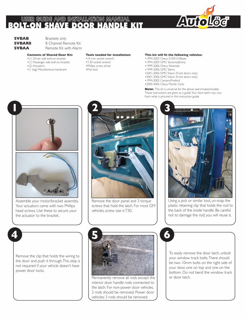
This kit will fit the following vehicles:�•1994-2003 Chevy S10/S10 Blazer�•1994-2003 GMC Sonoma/Jimmy�•1999-2006 Chevy Silverado�•1999-2006 GMC Sierra�•2001-2006 GMC Yukon (Front doors only)�•2001-2006 GMC Yukon (Front doors only)�•1994-2002 Camaro/Firebird�•2000-2006 Chevy Monte Carlo
Note: This kit is universal for the above years/makes/models. These instructions are given as a guide. Your door latch may vary from what is pictured in this instruction guide.
Contents of Shaved Door Kit:�•(1) Driver side bolt-on bracket�•(1) Passenger side bolt-on bracket�•(2) Actuators�•(1 bag) Miscellaneous hardware
Assemble your motor/bracket assembly. Your actuators came with two Phillips head screws. Use these to secure your the actuator to the bracket.
Remove the clip that holds the wiring to the door and push it through. This step is not required if your vehicle doesn�’t havepower door locks.
Permanently remove all rods except the interior door handle rods connected to the latch. For non-power door vehicles,2 rods should be removed. Power door vehicles: 3 rods should be removed.
Remove the door panel and 3 torque screws that hold the latch. For most GMvehicles, screw size is T30.
Using a pick or similar tool, un-snap the plastic retaining clip that holds the rod to the back of the inside handle. Be careful not to damage the rod; you will reuse it.
Tools needed for installation:�•10 mm socket wrench�•T-30 socket wrench�•Phillips screw driver�•Pick tool
WWW.AUTOLOC.COM
4
To easily remove the door latch, unboltyour window track bolts. There should be two 10mm bolts on the right side ofyour door, one on top and one on thebottom. Do not bend the window trackor door latch.
6
BOLT-ON SHAVE DOOR HANDLE KIT USER GUIDE AND INSTALLATION MANUAL
21 3
5
SVBAB Brackets onlySVBAR8 8 Channel Remote KitSVBAA Remote Kit with Alarm
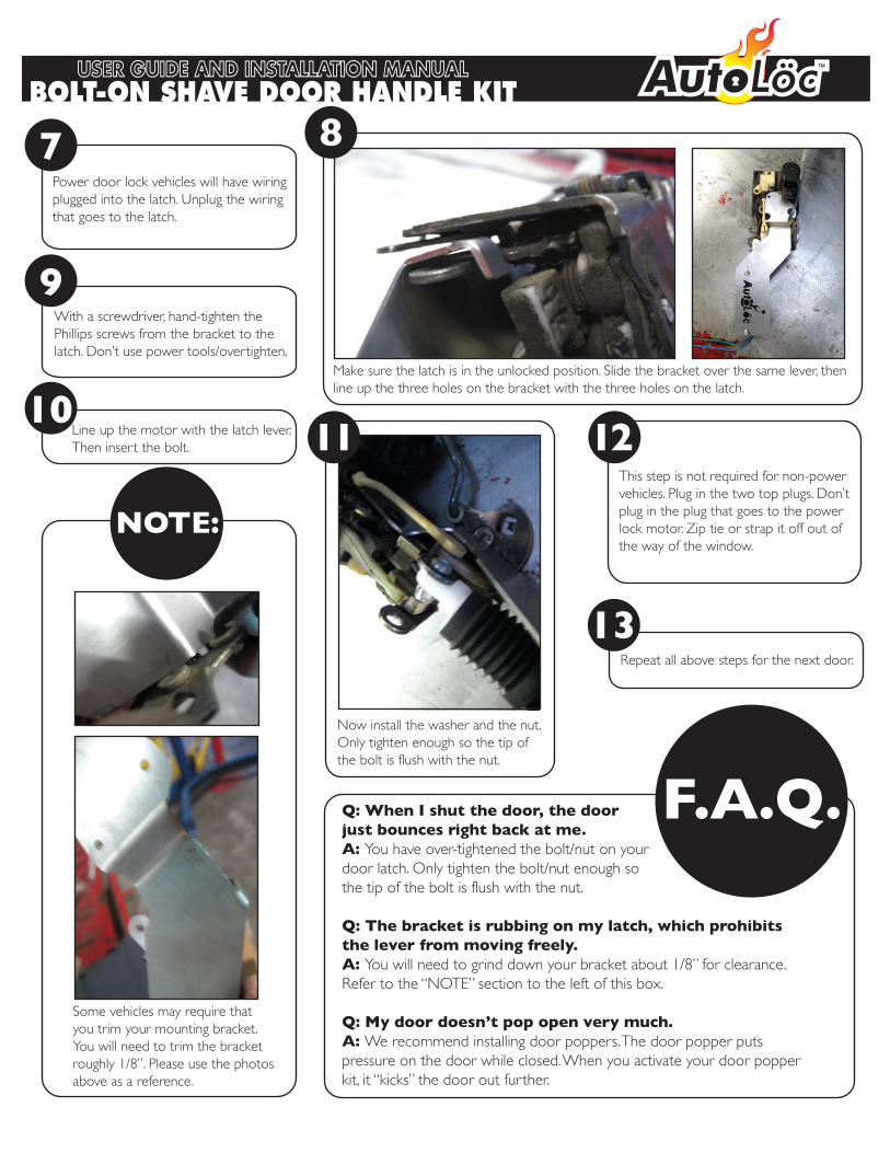
Power door lock vehicles will have wiringplugged into the latch. Unplug the wiringthat goes to the latch.
With a screwdriver, hand-tighten the Phillips screws from the bracket to thelatch. Don�’t use power tools/overtighten.
This step is not required for non-powervehicles. Plug in the two top plugs. Don�’tplug in the plug that goes to the power lock motor. Zip tie or strap it off out of the way of the window.
7
9
Now install the washer and the nut. Only tighten enough so the tip of the bolt is flush with the nut.
13Repeat all above steps for the next door.
10Line up the motor with the latch lever. Then insert the bolt.
Make sure the latch is in the unlocked position. Slide the bracket over the same lever, then line up the three holes on the bracket with the three holes on the latch.
NOTE:
Some vehicles may require that you trim your mounting bracket. You will need to trim the bracket roughly 1/8�”. Please use the photos above as a reference.
12
8
F.A.Q.Q: When I shut the door, the doorjust bounces right back at me.A: You have over-tightened the bolt/nut on yourdoor latch. Only tighten the bolt/nut enough so the tip of the bolt is flush with the nut.
Q: The bracket is rubbing on my latch, which prohibitsthe lever from moving freely.A: You will need to grind down your bracket about 1/8�” for clearance.Refer to the �“NOTE�” section to the left of this box.
Q: My door doesn�’t pop open very much.A: We recommend installing door poppers. The door popper puts pressure on the door while closed. When you activate your door popper kit, it �“kicks�” the door out further.
11
WWW.AUTOLOC.COMBOLT-ON SHAVE DOOR HANDLE KIT USER GUIDE AND INSTALLATION MANUAL
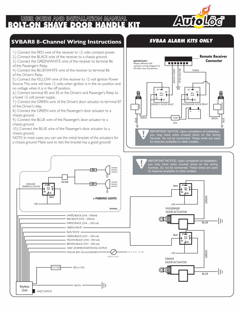
IMPORTANT NOTICE: Upon completion of installation, you may have extra unused wires on the wiring harness. Do not be concerned. These wires are used for features available on other models.
+12V
8787a
3086
85RELAY
DRIVERDOOR ACTUATOR
+12V
8787a
3086
85RELAY
PASSENGER DOOR ACTUATOR
+12V
15A FUSE
RELAY + PARKING LIGHTS
8787a
3086
85
OPTIONAL
(CH1 – 500 mA)
(CH2 – 500 mA)(CH3 – 500 mA)
(CH4 – 500 mA)
(STARTER/IGNITION KILL OUTPUT)
RED/BLACK (CH5 – 500mA)
VALET SWITCH
WHITE/BLACK (CH6 – 500mA)
KeylessUnit
SVBAA ALARM KITS ONLY
DRIVER’S DOOR RELAY PASSENGER DOOR RELAY
+ –
87
87a
3086
8587
87a
3086
85
FUSE
30A
Remote Receiver Connector
Please reference the receivers wiring diagram for all other wire connections.
IMPORTANT!E U
LB/
NW
ORB
PURPLEET
IH
W/NE
E RG
IMPORTANT NOTICE: Upon completion of installation, you may have extra unused wires on the wiring harness. Do not be concerned. These wires are used for features available on other models.
REV IRD
EG
NESS APR
SVBAR8 8-Channel Wiring Instructions
1.) Connect the RED wire of the receiver to 12 volts constant power.2.) Connect the BLACK wire of the receiver to a chassis ground.3.) Connect the GREEN/WHITE wire of the receiver to terminal 86 of the Passenger�’s Relay.4.) Connect the BLUE/WHITE wire of the receiver to terminal 86of the Driver�’s Relay.5.) Connect the YELLOW wire of the receiver to 12 volt Ignition Power Source. This wire will have 12 volts when ignition is in the on position andno voltage when it is in the off position.6.) Connect terminal 85 and 30 or the Driver�’s and Passenger�’s Relay to a fused 12 volt power supply.7.) Connect the GREEN wire of the Driver�’s door actuator to terminal 87of the Driver�’s relay.8.) Connect the GREEN wire of the Passenger�’s door actuator to a chassis ground.9.) Connect the BLUE wire of the Passenger�’s door actuator to a chassis ground.10.) Connect the BLUE wire of the Passenger�’s door actuator to a chassis ground. NOTE: In most cases you can use the metal bracket of the actuators fora chassis ground. Make sure to test the bracket has a good ground!
ignition switch
12 volts
GRE
ENG
REEN
BLUE
BLUEBL
UE
BLUE GREENGREEN
WWW.AUTOLOC.COMBOLT-ON SHAVE DOOR HANDLE KIT USER GUIDE AND INSTALLATION MANUAL
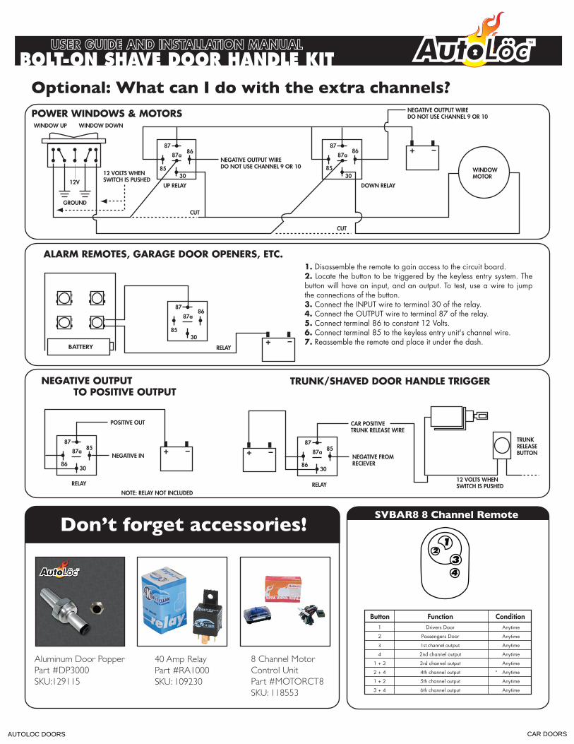
1 Drivers Door Anytime
2 Passengers Door Anytime
3 1st channel output Anytime
4 2nd channel output Anytime
1 + 3 3rd channel output Anytime
2 + 4 4th channel output Anytime
1 + 2 5th channel output Anytime
3 + 4 6th channel output Anytime
WINDOW DOWN
NEGATIVE OUTPUT WIREDO NOT USE CHANNEL 9 OR 10
NEGATIVE OUTPUT WIREDO NOT USE CHANNEL 9 OR 10
WINDOW UP
12V
GROUND
WINDOWMOTOR
UP RELAY DOWN RELAY
CUT
CUT
8787a
30
86
85
8787a
30
86
85
POWER WINDOWS & MOTORS
+ –
12 VOLTS WHENSWITCH IS PUSHED
NEGATIVE OUTPUT TO POSITIVE OUTPUT
POSITIVE OUT
NEGATIVE IN
RELAYNOTE: RELAY NOT INCLUDED
+ –87
87a
3086
8587
87a
3086
85
12 VOLTS WHENSWITCH IS PUSHED
TRUNKRELEASEBUTTON
TRUNK/SHAVED DOOR HANDLE TRIGGER
CAR POSITIVETRUNK RELEASE WIRE
NEGATIVE FROMRECIEVER
RELAY
+ –
ALARM REMOTES, GARAGE DOOR OPENERS, ETC.
RELAY+ –
8787a
30
86
85
1. Disassemble the remote to gain access to the circuit board.2. Locate the button to be triggered by the keyless entry system. The button will have an input, and an output. To test, use a wire to jump the connections of the button.3. Connect the INPUT wire to terminal 30 of the relay.4. Connect the OUTPUT wire to terminal 87 of the relay.5. Connect terminal 86 to constant 12 Volts.6. Connect terminal 85 to the keyless entry unit's channel wire.7. Reassemble the remote and place it under the dash.
BATTERY
Optional: What can I do with the extra channels?
Aluminum Door PopperPart #DP3000SKU:129115
40 Amp RelayPart #RA1000SKU: 109230
8 Channel Motor Control UnitPart #MOTORCT8SKU: 118553
Don�’t forget accessories!SVBAR8 8 Channel Remote
WWW.AUTOLOC.COMBOLT-ON SHAVE DOOR HANDLE KIT USER GUIDE AND INSTALLATION MANUAL
AUTOLOC DOORS CAR DOORS