Embed Size (px)
Citation preview
GAMATRONIC ELECTRONIC INDUSTRIES LTD. 17 Hartom St., P.O.B. 45029, Jerusalem 9777517, Israel
Tel: +972-2-588-8222 Fax: +972-2-582-8875 Email: [email protected] Website: www.gamatronic.com
2MUXGMAC5
GMAC5
USER GUIDE
Release 1.3, January 2016

ii GMAC5 User Guide
GAMATRONIC ELECTRONIC INDUSTRIES LTD. Har Hotzvim Industrial Park
17 Hartom St., PO Box 45029, Jerusalem 9777517 Israel Tel: +972-2-588-8222 Fax: +972-2-582-8875
Email: [email protected] Website: www.gamatronic.com
The equipment described in this document is not intended to be used in connection with any application requiring fail-safe performance, unless the application design includes appropriate redundancy. This exclusion includes, but is not limited to, the direct operation of any life support system or any other system whose failure could lead to serious injury, death, environmental damage or mass destruction.
Copyright 2016 by Gamatronic Electronic Industries Ltd. All rights reserved worldwide.
Any representations in this document concerning the performance of Gamatronic's product(s) are for informational purposes only and are not warranties of future performance, either express or implied. Gamatronic's standard limited Warranty, which accompanies its sales contract or order confirmation form, is the only warranty offered by Gamatronic Electronic Industries Ltd. in relation thereto.
Gamatronic Electronic Industries Ltd. ("Gamatronic") warrants the products it manufactures to be free from defect for a period of one calendar year from the date of invoice, including the date of invoice. Gamatronic's liability is limited to repairing or replacing any defective parts in the equipment under warranty. Gamatronic reserves the right to determine whether the repair work shall be performed at Gamatronic's factory, at the customer's premises, or at an alternate site. The customer must obtain authorization from Gamatronic before returning any parts or equipment to Gamatronic for repair or replacement. Any items returned to Gamatronic must be sent freight prepaid.
Gamatronic’s liability and warranty to the product are according and subject to the fulfillment and implementation by the customer of all the terms and instructions in connection with “preventive maintenance” and “service and repair” as further detailed in the user guide which is attached to the product and forms an integral part of it.”
Gamatronic is not responsible for any damage to the product due to unauthorized repair work, misuse or abuse of the product, or force majeure.
Gamatronic is not liable for and the Purchaser waives any right of action it has or may have against Gamatronic for any consequential or special damages arising out of any breach of warranty, and for any damages that the Purchaser may claim for damage to any property or injury or death to any person arising out of its purchase or the use, operation or maintenance of the subject product.
This warranty includes parts and labor; however, Gamatronic shall not be responsible for any labor subcontracted or performed by the Purchaser to prepare the warranted item for return to Gamatronic or Gamatronic's agent.
The information contained in this document is proprietary and is subject to all relevant copyright, patent and other laws protecting intellectual property, as well as any specific agreement protecting Gamatronic's rights in the aforesaid information. Neither this document nor the information contained herein may be published, reproduced or disclosed to third parties, in whole or in part, without the express, prior, written permission of Gamatronic. In addition, any use of this document or the information contained herein for any purposes other than those for which it was disclosed is strictly forbidden.
Gamatronic reserves the right, without prior notice or liability, to make changes in equipment design or specifications.
Information supplied by Gamatronic is believed to be accurate and reliable. However, no responsibility is assumed by Gamatronic for the use thereof nor for the rights of third parties which may be affected in any way by the use thereof.
This document may contain flaws, omissions or typesetting errors; no warranty is granted nor liability assumed in relation thereto unless specifically undertaken in Gamatronic Electronic Industries Ltd. standard limited Warranty. Information contained herein is periodically updated and changes will be incorporated into subsequent editions. If you have encountered an error, please notify Gamatronic Electronic Industries Ltd. All specifications are subject to change without prior notice.
GMAC5 may cause interference with radio communications if not installed and used according to the user guide and/or installation guide. GMAC5 is intended for use in a commercial or industrial setting. Operation of GMAC5 in a residential area may cause harmful interference, in which case the user will be required to correct the interference at his own expense.
GAMATRONIC ELECTRONIC INDUSTRIES LTD.
GMAC5 User Guide iii
TABLE OF CONTENTS
1. Introduction .............................................................................................................. 1 1.1 General ................................................................................................................................ 1
1.1.1 I/O............................................................................................................................ 1 1.2 Features ............................................................................................................................... 1 1.3 Technical specifications ....................................................................................................... 2 1.4 Package contents ................................................................................................................. 2 1.5 Physical description ............................................................................................................. 3
1.5.1 Front and rear panels .............................................................................................. 3 1.5.2 Restore GMAC5 factory settings ............................................................................ 4 1.5.3 Booting into bootloader mode ................................................................................. 4
2. Installation ................................................................................................................ 5 2.1 Physical setup ...................................................................................................................... 5 2.2 Access the web interface setup ........................................................................................... 5
3. User interface ............................................................................................................ 6 3.1 Dynamic updates ................................................................................................................. 6 3.2 Main screen .......................................................................................................................... 7
3.2.1 Monitoring a UPS or a power system ..................................................................... 8 3.2.2 Log ........................................................................................................................ 15 3.2.3 Configuration ......................................................................................................... 16
4. Additional features .................................................................................................. 17 4.1 Automated shutdown of computers ................................................................................... 17 4.2 The bootloader ................................................................................................................... 17
4.2.1 Using bootloader mode ......................................................................................... 17 4.2.2 Upgrades ............................................................................................................... 19 4.2.3 Saving system settings ......................................................................................... 19
5. Configuration ........................................................................................................... 20 Using Telnet to modify configuration parameters .............................................................. 20
5.1 Network configuration ........................................................................................................ 21 5.2 Date/Time configuration ..................................................................................................... 22 5.3 Configure a serial connection ............................................................................................ 23 5.4 Defining a Modbus connection ........................................................................................... 24 5.5 Defining an SNMP connection ........................................................................................... 25
5.5.1 Defining an SNMPv2 connection .......................................................................... 25 5.5.2 Defining an SNMPv3 connection .......................................................................... 26
5.6 Defining an email server .................................................................................................... 27 5.7 Define a shutdown target ................................................................................................... 28 5.8 Define a username and password ..................................................................................... 29
5.8.1 Restoring the factory default username and password ........................................ 29 5.9 Define a target for alarm notifications ................................................................................ 30 5.10 Define event properties ...................................................................................................... 31
5.10.1 Event severity ........................................................................................................ 31 5.10.2 Message Group ..................................................................................................... 31
5.11 Define message group names ........................................................................................... 32
GAMATRONIC ELECTRONIC INDUSTRIES LTD.
iv GMAC5 User Guide
6. Events and alarms .................................................................................................... 33 6.1 General events ................................................................................................................... 33 6.2 Product compatibility table ................................................................................................. 34 6.3 SEC protocol alarms .......................................................................................................... 34 6.4 Megatec protocol alarms .................................................................................................... 35 6.5 Power+ protocol alarms ..................................................................................................... 35 6.6 1UDC+ protocol alarms ...................................................................................................... 36 6.7 Modbus registers ................................................................................................................ 37
7. Preventive Maintenance .......................................................................................... 41
8. Service and repairs .................................................................................................. 42
LIST OF FIGURES
Figure 1: Front panel features .............................................................................................................. 3 Figure 2: Rear panel features ............................................................................................................... 3 Figure 3: Bootloader mode button ........................................................................................................ 4 Figure 4: The main web interface screen ............................................................................................. 5 Figure 5: Layout of the user interface screen ....................................................................................... 6 Figure 6: The main web interface screen ............................................................................................. 7 Figure 7: Display UPS nominal values and other information .............................................................. 8 Figure 8: UPS actual values ................................................................................................................. 9 Figure 9: Issuing commands to a UPS or other power system ............................................................ 9 Figure 10: Main screen for power system monitoring ........................................................................ 10 Figure 11: An example of a power system measurements screen .................................................... 11 Figure 12: The power systems Commands screen ............................................................................ 11 Figure 13: This screen displays the power system's nominal values ................................................. 12 Figure 14: Use this screen to set alarm thresholds ............................................................................ 13 Figure 15: Set power system automatic functions ............................................................................. 14 Figure 16: Define system characteristics ........................................................................................... 14 Figure 17: Log summary and download screen ................................................................................. 15 Figure 18: Log details ......................................................................................................................... 15 Figure 19: List of active alarms on the UPS or dc power system ....................................................... 16 Figure 20: Bootloader mode button .................................................................................................... 17 Figure 21: The bootloader login screen .............................................................................................. 18 Figure 22: Using the bootloader to update a file ................................................................................ 18 Figure 23: Configuration menu expanded .......................................................................................... 20 Figure 24: Network configuration screen ............................................................................................ 21 Figure 25: Setting the GMAC5’s internal clock with the current date and time .................................. 22 Figure 26: Defining a serial connection to a device to be monitored ................................................. 23 Figure 27: Conceptual diagram of a serial connection ....................................................................... 23 Figure 28: Defining an SNMPv2 connection ...................................................................................... 25 Figure 29: Defining an SNMPv3 connection ...................................................................................... 26 Figure 30: Defining an email recipient ................................................................................................ 27 Figure 31: Define a shutdown target .................................................................................................. 28 Figure 32: Define or update the username and password for access to GMAC5.............................. 29 Figure 33: This button does NOT restore the default username and password ................................ 29 Figure 34: Define a target for alarm notifications. ............................................................................... 30 Figure 35: The Events screen ............................................................................................................ 31 Figure 36: The Group screen, for defining message group names ................................................... 32
GAMATRONIC ELECTRONIC INDUSTRIES LTD.
GMAC5 User Guide 5
LIST OF TABLES
Table 1: Technical specifications ......................................................................................................... 2 Table 2: Key to Figure 1 ....................................................................................................................... 3 Table 3: Key to Figure 2 ....................................................................................................................... 3 Table 4: Key to Figure 28 ................................................................................................................... 25 Table 5: Key to Figure 29 ................................................................................................................... 26 Table 6: Key to Figure 30 ................................................................................................................... 27 Table 7: Key to Figure 31 ................................................................................................................... 28 Table 8: General events ..................................................................................................................... 33 Table 9: GMAC5 compatibility table ................................................................................................... 34 Table 10: SEC protocol alarms .......................................................................................................... 34 Table 11: Megatec protocol alarms .................................................................................................... 35 Table 12: PowerPlus protocol alarms ................................................................................................. 35 Table 13: 1UDC+ protocol alarms ...................................................................................................... 36 Table 14: Modbus registers ................................................................................................................ 37

GAMATRONIC ELECTRONIC INDUSTRIES LTD.
vi GMAC5 User Guide
This page left blank deliberately.
GAMATRONIC ELECTRONIC INDUSTRIES LTD.
GMAC5 User Guide 1
1. Introduction
1.1 General GMAC5 is a communication device for power system monitoring.
GMAC5 is accessed through a built-in web interface, and can be accessed remotely through a web browser. The interface is intuitive and simple, and configuration is straightforward.
GMAC5 enables the user to remotely monitor all current Gamatronic products.
1.1.1 I/O • Serial RS232 port: for monitoring a UPS or a dc power system.
1.2 Features • Up to 20 recipients for event and alarm notifications via email. • Eight user-configurable message groups for routing event notifications. • Remote computer shutdowns with shutdown agent software. • SNMP v2/v3 communication. • All UPS protocols are normalized to RFC 1628 (Standard UPS protocol). • Serial communication supports all Gamatronic UPS systems through SEC, PowerPlus and
Megatec protocols. • Modbus communication for building management systems (BMS). • Comprehensive event notification can be filtered by message severity. • Full featured log includes complete system snapshot saved for every event.
GAMATRONIC ELECTRONIC INDUSTRIES LTD.
2 GMAC5 User Guide
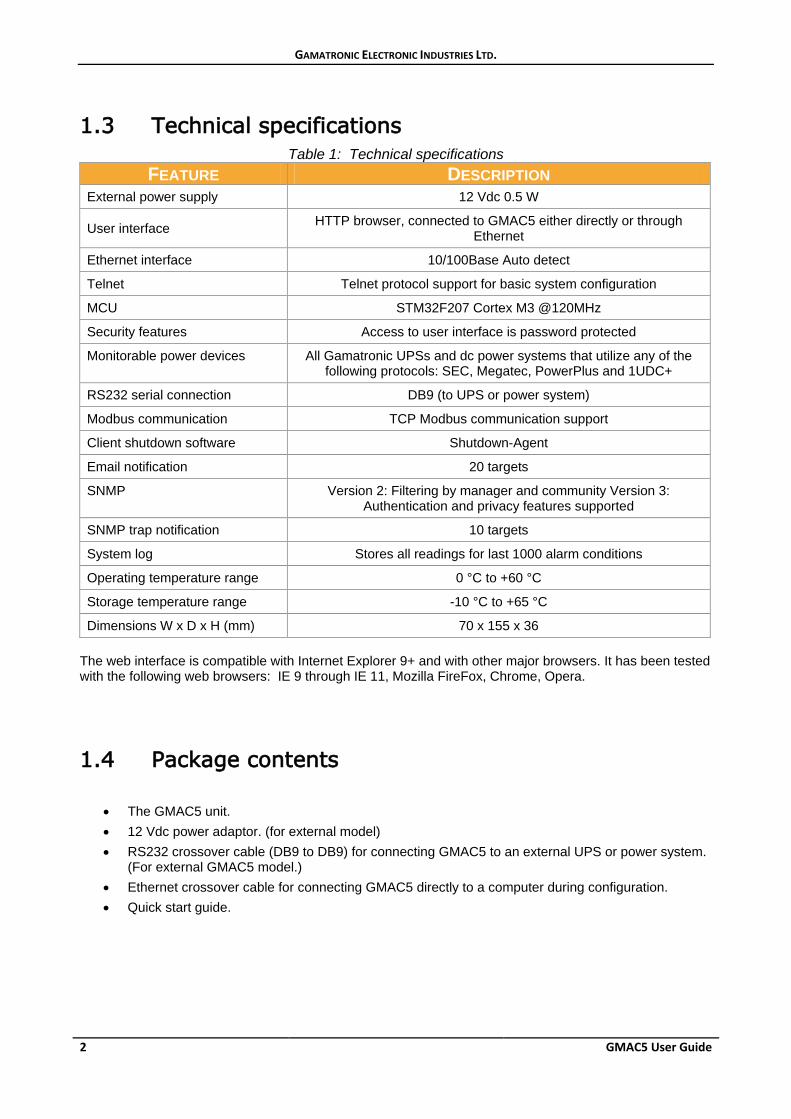
1.3 Technical specifications Table 1: Technical specifications
FEATURE DESCRIPTION External power supply 12 Vdc 0.5 W
User interface HTTP browser, connected to GMAC5 either directly or through Ethernet
Ethernet interface 10/100Base Auto detect
Telnet Telnet protocol support for basic system configuration
MCU STM32F207 Cortex M3 @120MHz
Security features Access to user interface is password protected
Monitorable power devices All Gamatronic UPSs and dc power systems that utilize any of the following protocols: SEC, Megatec, PowerPlus and 1UDC+
RS232 serial connection DB9 (to UPS or power system)
Modbus communication TCP Modbus communication support
Client shutdown software Shutdown-Agent
Email notification 20 targets
SNMP Version 2: Filtering by manager and community Version 3: Authentication and privacy features supported
SNMP trap notification 10 targets
System log Stores all readings for last 1000 alarm conditions
Operating temperature range 0 °C to +60 °C
Storage temperature range -10 °C to +65 °C
Dimensions W x D x H (mm) 70 x 155 x 36 The web interface is compatible with Internet Explorer 9+ and with other major browsers. It has been tested with the following web browsers: IE 9 through IE 11, Mozilla FireFox, Chrome, Opera.
1.4 Package contents
• The GMAC5 unit. • 12 Vdc power adaptor. (for external model) • RS232 crossover cable (DB9 to DB9) for connecting GMAC5 to an external UPS or power system.
(For external GMAC5 model.) • Ethernet crossover cable for connecting GMAC5 directly to a computer during configuration. • Quick start guide.
GAMATRONIC ELECTRONIC INDUSTRIES LTD.
GMAC5 User Guide 3
1.5 Physical description
1.5.1 Front and rear panels
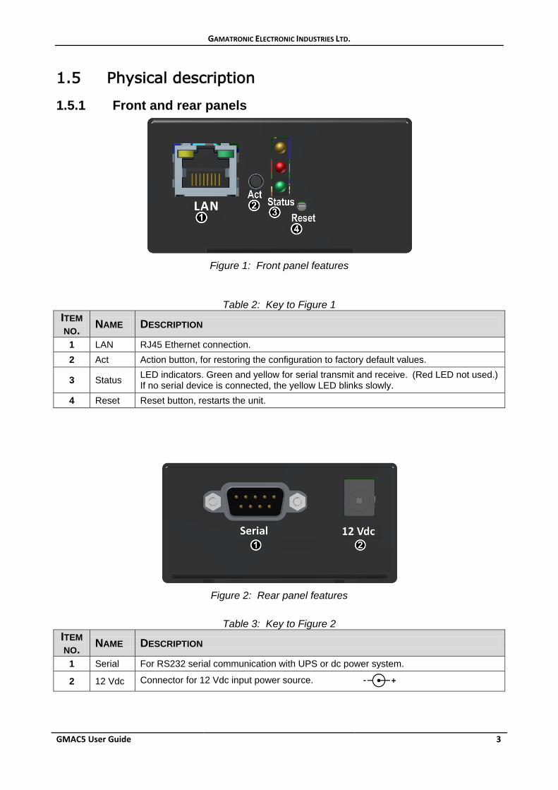
Figure 1: Front panel features
Table 2: Key to Figure 1 ITEM NO. NAME DESCRIPTION
1 LAN RJ45 Ethernet connection. 2 Act Action button, for restoring the configuration to factory default values.
3 Status LED indicators. Green and yellow for serial transmit and receive. (Red LED not used.) If no serial device is connected, the yellow LED blinks slowly.
4 Reset Reset button, restarts the unit.
Figure 2: Rear panel features
Table 3: Key to Figure 2 ITEM NO. NAME DESCRIPTION
1 Serial For RS232 serial communication with UPS or dc power system.
2 12 Vdc Connector for 12 Vdc input power source.
GAMATRONIC ELECTRONIC INDUSTRIES LTD.
4 GMAC5 User Guide
1.5.2 Restore GMAC5 factory settings If desired, you can clear GMAC5’s entire current configuration at any time and return the settings to the factory default values. To do this:
• Press and hold the Act button on the front panel for at least 20 seconds, until all three status LEDs are on. Then release the button. The unit will restart with factory settings.
• This procedure also returns the system user name and password to their original default values of “admin” and “admin”.
1.5.3 Booting into bootloader mode Bootloader mode allows you to perform system software upgrades and also to upload a previously saved configuration.
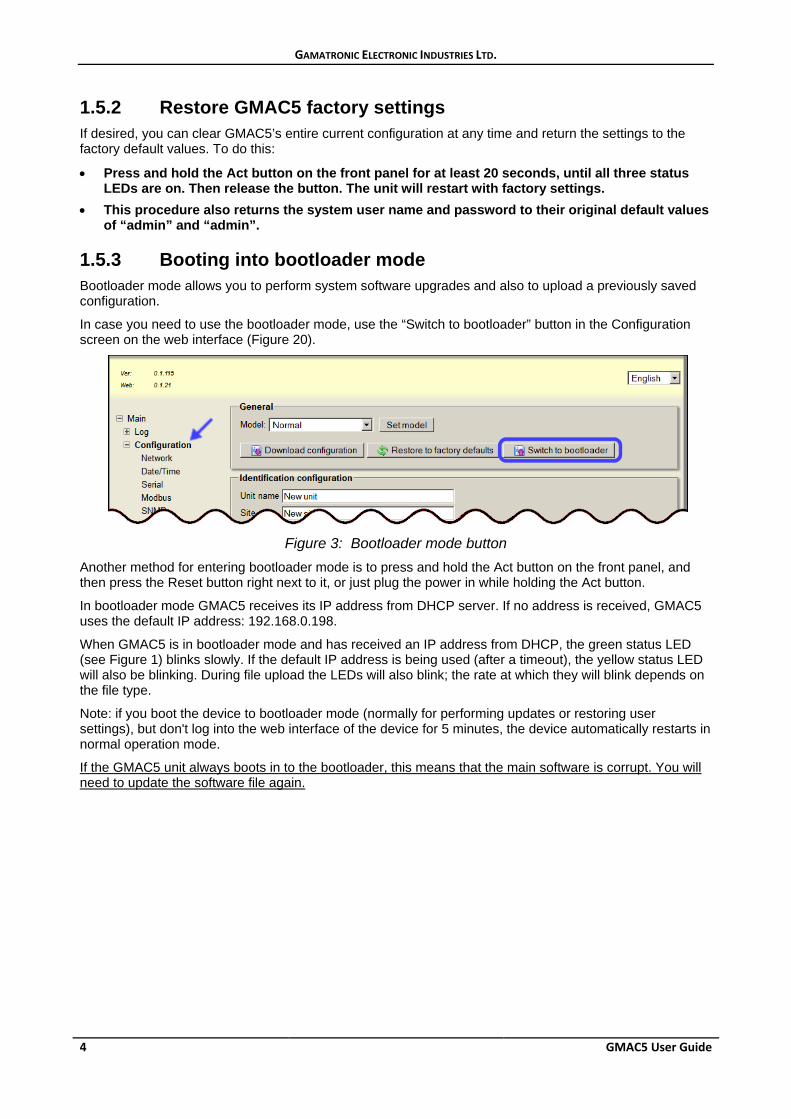
In case you need to use the bootloader mode, use the “Switch to bootloader” button in the Configuration screen on the web interface (Figure 20).
Figure 3: Bootloader mode button
Another method for entering bootloader mode is to press and hold the Act button on the front panel, and then press the Reset button right next to it, or just plug the power in while holding the Act button.
In bootloader mode GMAC5 receives its IP address from DHCP server. If no address is received, GMAC5 uses the default IP address: 192.168.0.198.
When GMAC5 is in bootloader mode and has received an IP address from DHCP, the green status LED (see Figure 1) blinks slowly. If the default IP address is being used (after a timeout), the yellow status LED will also be blinking. During file upload the LEDs will also blink; the rate at which they will blink depends on the file type.
Note: if you boot the device to bootloader mode (normally for performing updates or restoring user settings), but don't log into the web interface of the device for 5 minutes, the device automatically restarts in normal operation mode.
If the GMAC5 unit always boots in to the bootloader, this means that the main software is corrupt. You will need to update the software file again.
GAMATRONIC ELECTRONIC INDUSTRIES LTD.
GMAC5 User Guide 5
2. Installation The initial configuration of the device is fully performed through the web interface, and therefore the installation begins with connecting it to the local network.
2.1 Physical setup 1. Connect an Ethernet cable to the RJ45 connector marked LAN on the front panel. 2. Connect input power to the plug on the rear of the unit.
2.2 Access the web interface setup 1. When switched on for the first time, GMAC5 attempts to acquire an IP address
automatically from DHCP on the network. In the case that there is no DHCP server available in the network – for example, when you are connecting GMAC5 directly to a computer – or in any other case of failure to set the IP address automatically, the device falls back to the default address of 192.168.0.198, subnet class C. This process can take up to one minute.
2. When configuring the GMAC5 through a direct connection to a computer, the “network segment” (the first 3 nodes) of your computer’s IP address must match the network segment of G4’s default IP address. So, change your computer's IP address to 192.168.0.100 and subnet mask to 255.255.255.0.
Remember to return your computer to its original IP settings when you're done, otherwise this may cause issues on your LAN.
3. You can find GMAC5 on your computer network by running the Discover.NET software, which is compatible with Windows XP and later Windows releases. Discover.NET can be downloaded from “http://www.gamatronic.com/GMAC5.html”. The software is very easy to use, and it lists all Gamatronic devices in the current subnet.
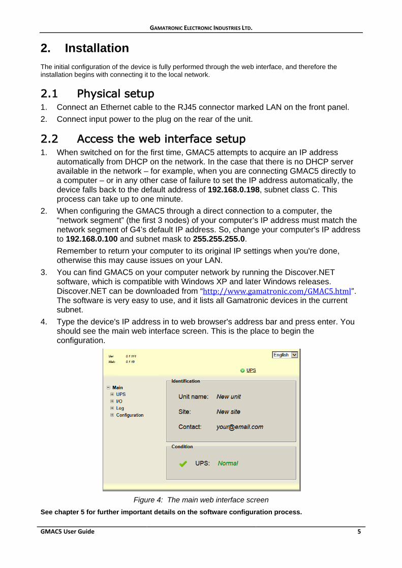
4. Type the device's IP address in to web browser's address bar and press enter. You should see the main web interface screen. This is the place to begin the configuration.
Figure 4: The main web interface screen
See chapter 5 for further important details on the software configuration process.
GAMATRONIC ELECTRONIC INDUSTRIES LTD.
6 GMAC5 User Guide
3. User interface
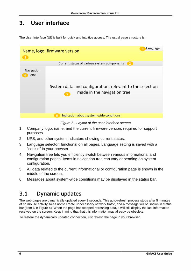
The User Interface (UI) is built for quick and intuitive access. The usual page structure is:
Figure 5: Layout of the user interface screen
1. Company logo, name, and the current firmware version, required for support purposes.
2. UPS, and other system indicators showing current status. 3. Language selector, functional on all pages. Language setting is saved with a
"cookie" in your browser. 4. Navigation tree lets you efficiently switch between various informational and
configuration pages. Items in navigation tree can vary depending on system configuration.
5. All data related to the current informational or configuration page is shown in the middle of the screen.
6. Messages about system-wide conditions may be displayed in the status bar.
3.1 Dynamic updates The web pages are dynamically updated every 3 seconds. This auto-refresh process stops after 5 minutes of no mouse activity so as not to create unnecessary network traffic, and a message will be shown in status bar (item 6 in Figure 4). When the page has stopped refreshing data, it will still display the last information received on the screen. Keep in mind that that this information may already be obsolete.
To restore the dynamically updated connection, just refresh the page in your browser.
GAMATRONIC ELECTRONIC INDUSTRIES LTD.
GMAC5 User Guide 7
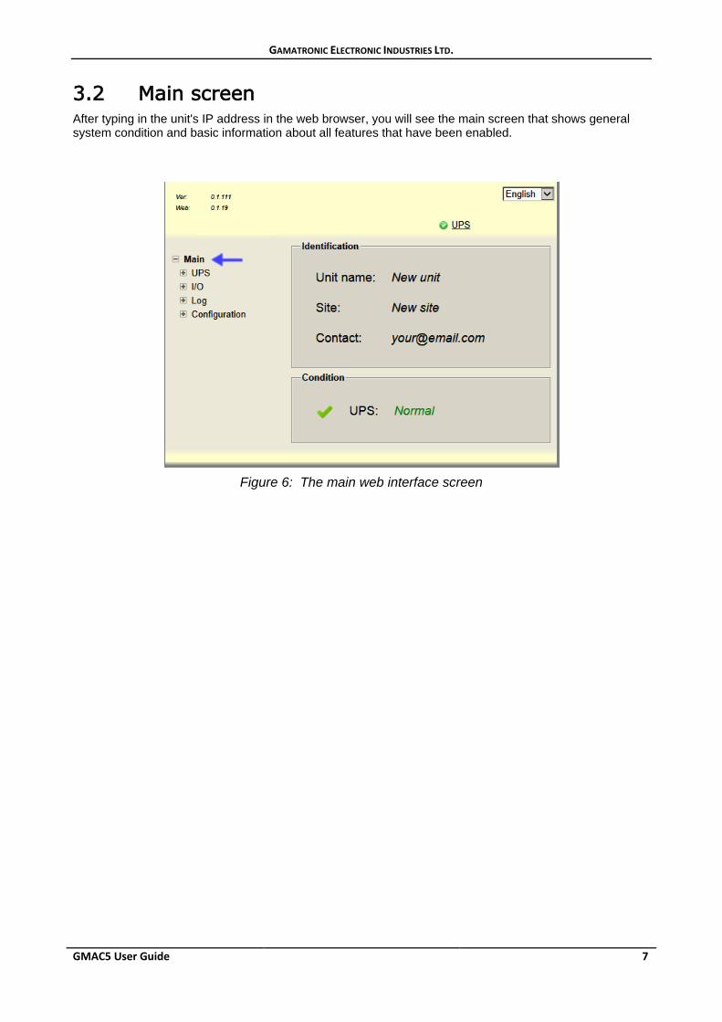
3.2 Main screen After typing in the unit's IP address in the web browser, you will see the main screen that shows general system condition and basic information about all features that have been enabled.
Figure 6: The main web interface screen
GAMATRONIC ELECTRONIC INDUSTRIES LTD.
8 GMAC5 User Guide
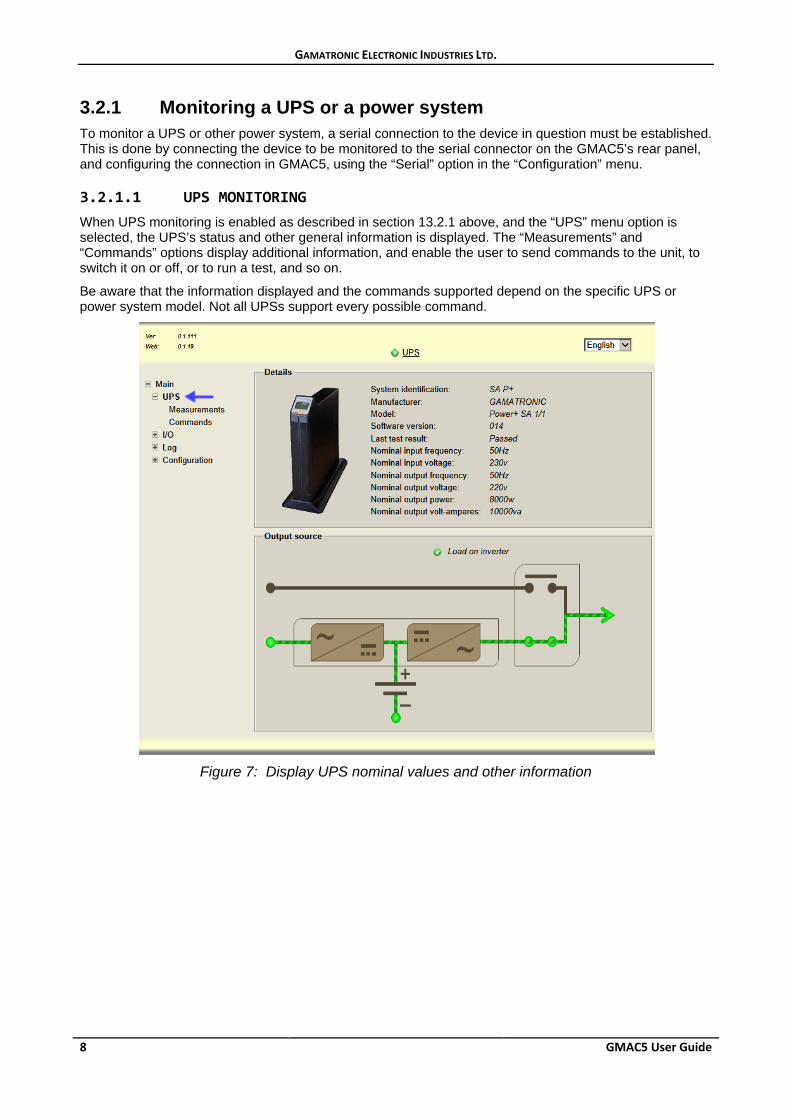
3.2.1 Monitoring a UPS or a power system To monitor a UPS or other power system, a serial connection to the device in question must be established. This is done by connecting the device to be monitored to the serial connector on the GMAC5’s rear panel, and configuring the connection in GMAC5, using the “Serial” option in the “Configuration” menu.
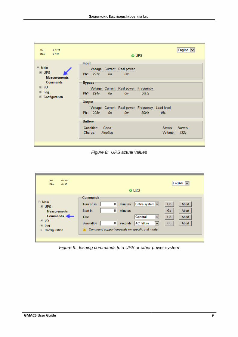
3.2.1.1 UPS MONITORING When UPS monitoring is enabled as described in section 1 3.2.1 above, and the “UPS” menu option is selected, the UPS’s status and other general information is displayed. The “Measurements” and “Commands” options display additional information, and enable the user to send commands to the unit, to switch it on or off, or to run a test, and so on.
Be aware that the information displayed and the commands supported depend on the specific UPS or power system model. Not all UPSs support every possible command.
Figure 7: Display UPS nominal values and other information
GAMATRONIC ELECTRONIC INDUSTRIES LTD.
GMAC5 User Guide 9
Figure 8: UPS actual values
Figure 9: Issuing commands to a UPS or other power system
GAMATRONIC ELECTRONIC INDUSTRIES LTD.
10 GMAC5 User Guide
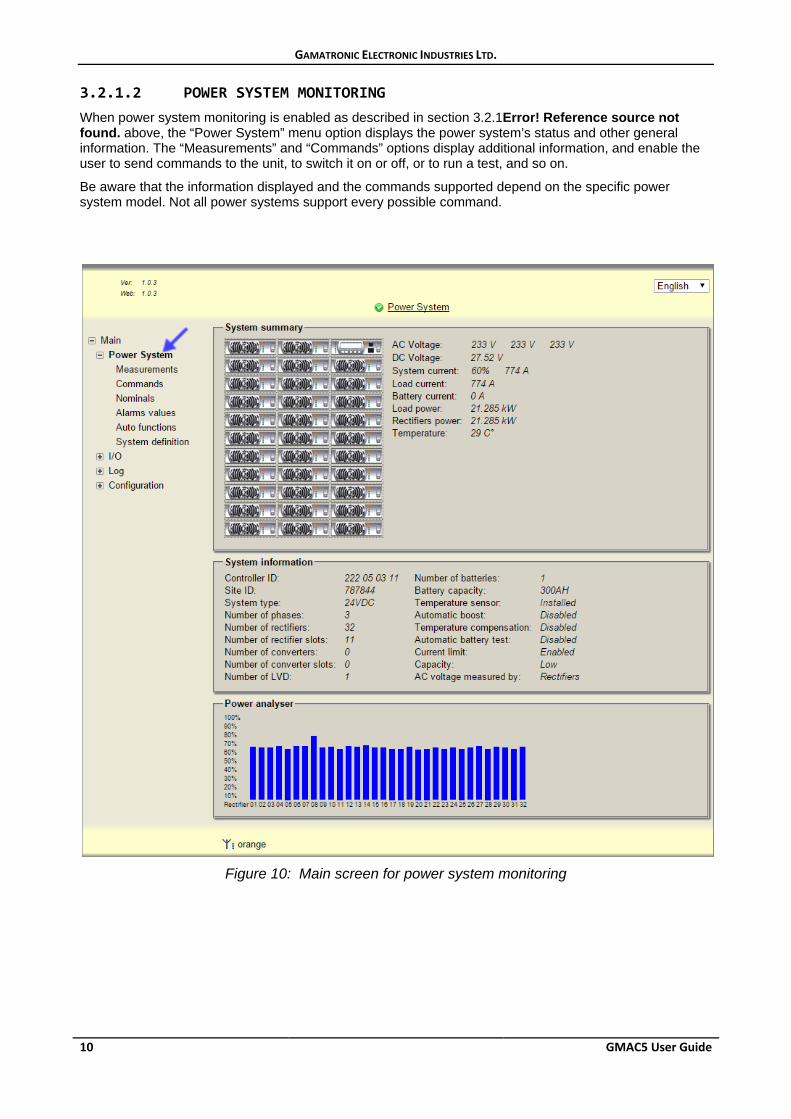
3.2.1.2 POWER SYSTEM MONITORING When power system monitoring is enabled as described in section 3.2.1Error! Reference source not found. above, the “Power System” menu option displays the power system’s status and other general information. The “Measurements” and “Commands” options display additional information, and enable the user to send commands to the unit, to switch it on or off, or to run a test, and so on.
Be aware that the information displayed and the commands supported depend on the specific power system model. Not all power systems support every possible command.
Figure 10: Main screen for power system monitoring
GAMATRONIC ELECTRONIC INDUSTRIES LTD.
GMAC5 User Guide 11
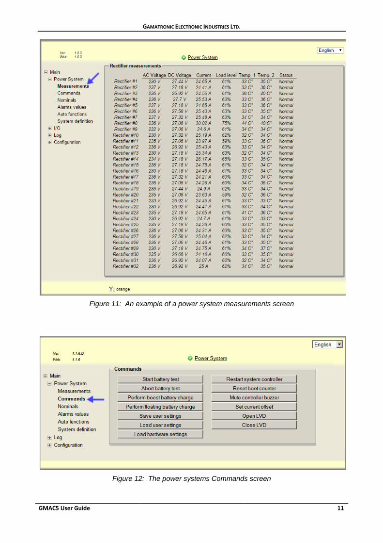
Figure 11: An example of a power system measurements screen
Figure 12: The power systems Commands screen
GAMATRONIC ELECTRONIC INDUSTRIES LTD.
12 GMAC5 User Guide
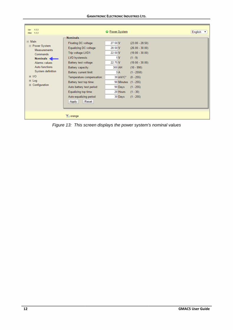
Figure 13: This screen displays the power system's nominal values
GAMATRONIC ELECTRONIC INDUSTRIES LTD.
GMAC5 User Guide 13
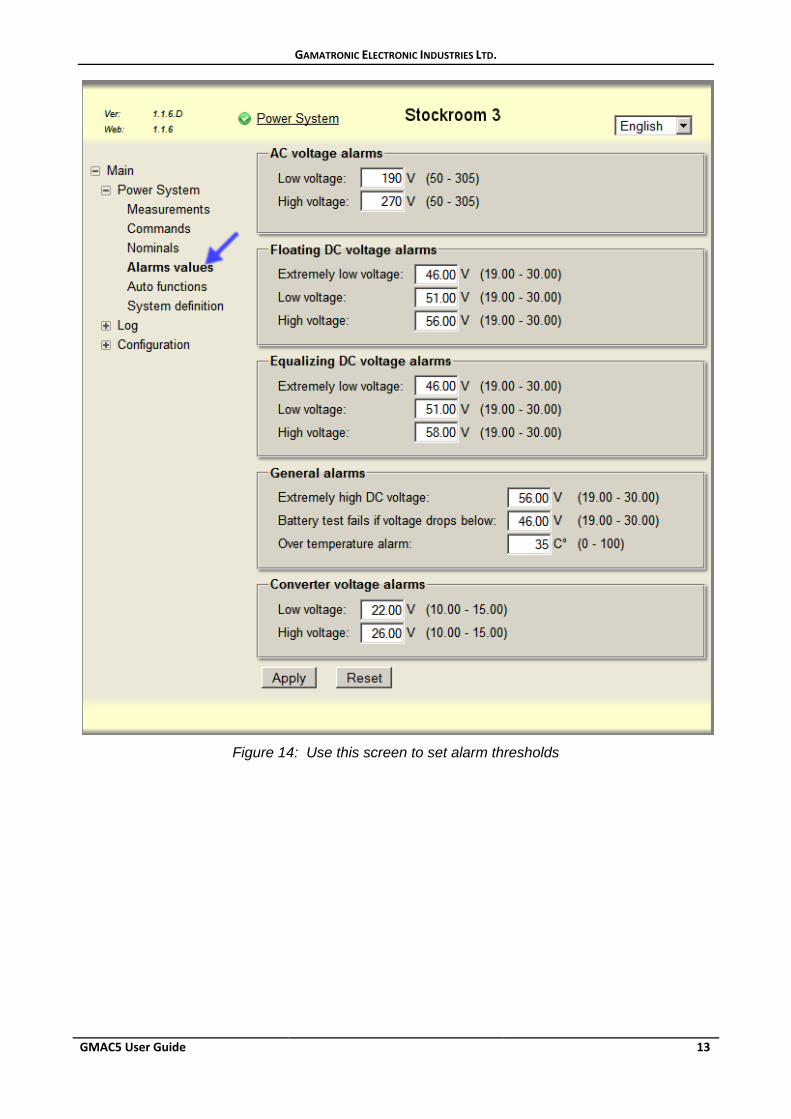
Figure 14: Use this screen to set alarm thresholds
GAMATRONIC ELECTRONIC INDUSTRIES LTD.
14 GMAC5 User Guide
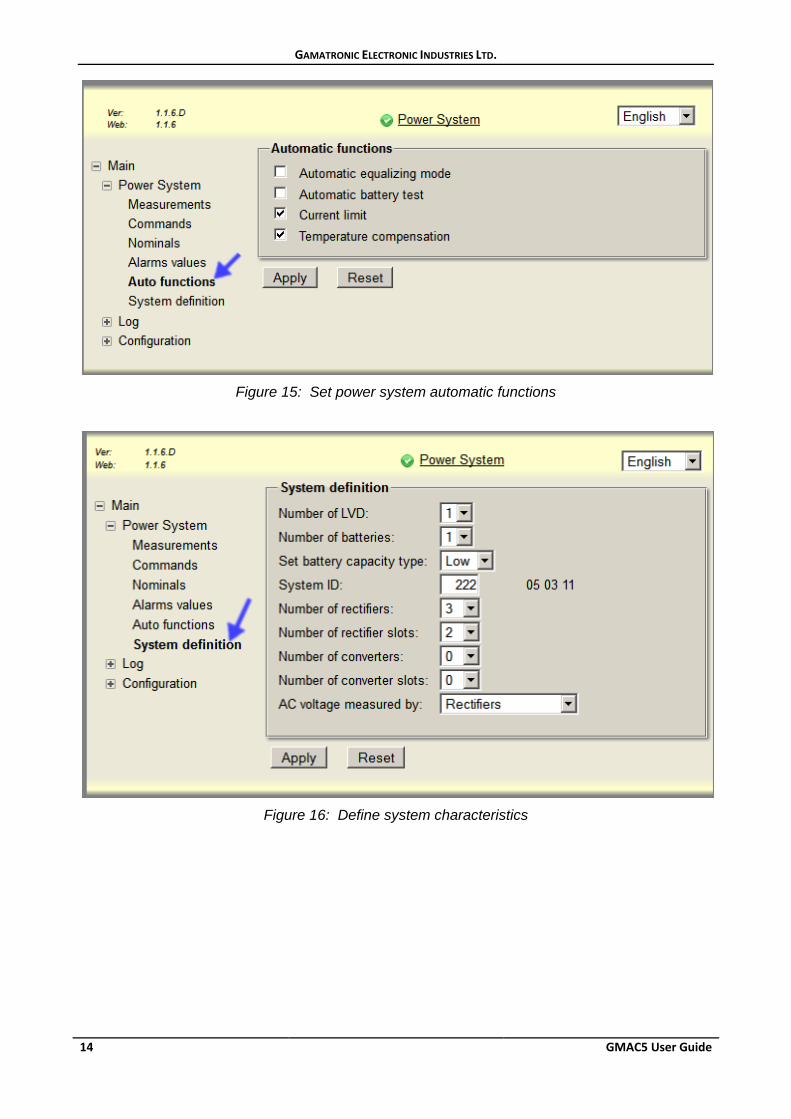
Figure 15: Set power system automatic functions
Figure 16: Define system characteristics
GAMATRONIC ELECTRONIC INDUSTRIES LTD.
GMAC5 User Guide 15
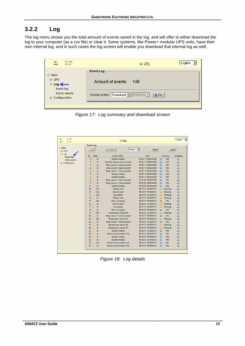
3.2.2 Log The log menu shows you the total amount of events saved in the log, and will offer to either download the log to your computer (as a csv file) or clear it. Some systems, like Power+ modular UPS units, have their own internal log, and in such cases the log screen will enable you download that internal log as well.
Figure 17: Log summary and download screen
Figure 18: Log details
GAMATRONIC ELECTRONIC INDUSTRIES LTD.
16 GMAC5 User Guide
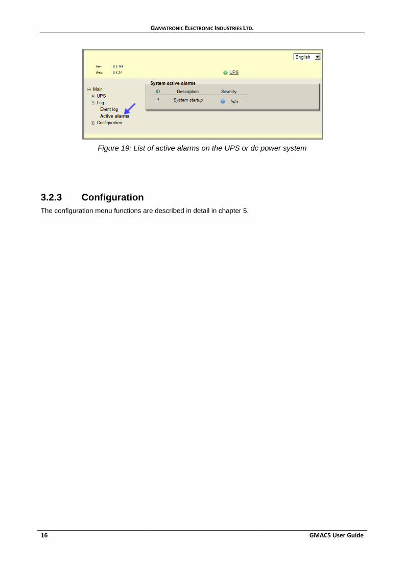
Figure 19: List of active alarms on the UPS or dc power system
3.2.3 Configuration The configuration menu functions are described in detail in chapter 5.
GAMATRONIC ELECTRONIC INDUSTRIES LTD.
GMAC5 User Guide 17
4. Additional features
4.1 Automated shutdown of computers If a UPS is being monitored by GMAC5, and that UPS is providing power to computers, you can instruct GMAC5 to shut down any of those computers in an orderly fashion in the event of a prolonged ac input failure, before the UPS’s battery is exhausted. To achieve that you must install Shutdown Agent software on the computers to be shut down. The Shutdown Agent can be downloaded through a link on the remote shutdown configuration webpage (see section 5.7), or can be obtained from your GMAC5 dealer. Use the same configuration webpage to configure remote shutdowns.
Remote computer shutdown can also be achieved through special dedicated software installed on one of the servers. Such software monitors the UPS through SNMP, and can be configured to send appropriate shutdown signals to specific servers in response to a specific alarm condition. Such software may provide more shutdown options.
4.2 The bootloader Bootloader mode is used to upgrade GMAC5’s system software, and to upload a previously saved GMAC5 configuration.
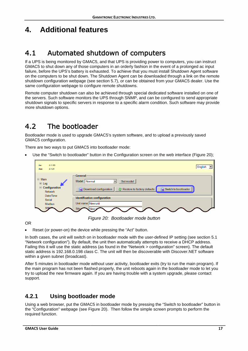
There are two ways to put GMAC5 into bootloader mode:
• Use the “Switch to bootloader” button in the Configuration screen on the web interface (Figure 20);
Figure 20: Bootloader mode button
OR • Reset (or power-on) the device while pressing the “Act” button.
In both cases, the unit will switch on in bootloader mode with the user-defined IP setting (see section 5.1 “Network configuration”). By default, the unit then automatically attempts to receive a DHCP address. Failing this it will use the static address (as found in the “Network > configuration” screen). The default static address is 192.168.0.198 class C. The unit will then be discoverable with Discover.NET software within a given subnet (broadcast).
After 5 minutes in bootloader mode without user activity, bootloader exits (try to run the main program). If the main program has not been flashed properly, the unit reboots again in the bootloader mode to let you try to upload the new firmware again. If you are having trouble with a system upgrade, please contact support.
4.2.1 Using bootloader mode Using a web browser, put the GMAC5 in bootloader mode by pressing the “Switch to bootloader” button in the "Configuration" webpage (see Figure 20). Then follow the simple screen prompts to perform the required function.
GAMATRONIC ELECTRONIC INDUSTRIES LTD.
18 GMAC5 User Guide
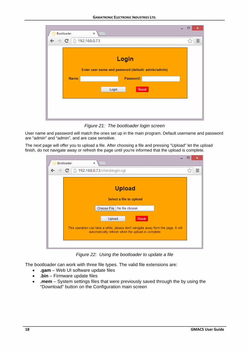
Figure 21: The bootloader login screen
User name and password will match the ones set up in the main program. Default username and password are "admin" and “admin”, and are case sensitive.
The next page will offer you to upload a file. After choosing a file and pressing "Upload" let the upload finish, do not navigate away or refresh the page until you're informed that the upload is complete.
Figure 22: Using the bootloader to update a file
The bootloader can work with three file types. The valid file extensions are:
• .gam – Web UI software update files • .bin – Firmware update files • .mem – System settings files that were previously saved through the by using the
“Download” button on the Configuration main screen
GAMATRONIC ELECTRONIC INDUSTRIES LTD.
GMAC5 User Guide 19
4.2.2 Upgrades You will not have to upgrade the software unless serious issues are reported and fixed. Your distributor will contact you if a critical update is required. Never try to upload any *.gam or *.bin files unless instructed to do so by an authorized distributor or the manufacturer.
Usually, the web user interface file version must exactly match the specific firmware file version, and therefore you will be asked to upload both .bin and .gam files for an upgrade. Do not change the names of the files you receive for upgrade. The bootloader will only accept English letters and numbers in the uploaded file name. The only valid file extensions are “.gam”, “.bin”, and “.mem”.
To perform an upgrade, just choose the relevant file (normally the .bin file goes first) in the upload page and press the "Upload" button. After you are informed that the upload is finished, choose to upload another file if required. After all files have been uploaded, press the "Reset" button to return to normal operation.
4.2.3 Saving system settings You can save the current system configuration values from the "Configuration" web page by selecting the “Download configuration” button. The configuration will be downloaded with the name “config.mem” to the location of your choosing. You can rename the file if you like, but use only Latin (English) letters and numbers in the file name, and do not change the “.mem” extension, otherwise you may have problems uploading it to the boot loader at a later stage.
When you need to restore the configuration, simply choose the file through the bootloader upload page and press the "Upload" button. After you are informed that the upload is finished, press the "Reset" button to return to normal operation.
GAMATRONIC ELECTRONIC INDUSTRIES LTD.
20 GMAC5 User Guide
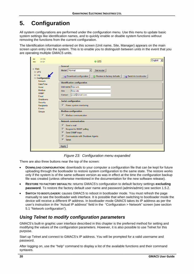
5. Configuration All system configurations are performed under the configuration menu. Use this menu to update basic system settings like identification names, and to quickly enable or disable system functions without removing the functions from the current configuration.
The Identification information entered on this screen (Unit name, Site, Manager) appears on the main screen upon entry into the system. This is to enable you to distinguish between units in the event that you are operating multiple GMAC5 units.
Figure 23: Configuration menu expanded
There are also three buttons near the top of the screen:
• DOWNLOAD CONFIGURATION: downloads to your computer a configuration file that can be kept for future uploading through the bootloader to restore system configuration to the same state. The restore works only if the system is of the same software version as was in effect at the time the configuration backup file was created (unless otherwise mentioned in the documentation for the new software release).
• RESTORE TO FACTORY DEFAULTS: returns GMAC5’s configuration to default factory settings excluding password. To restore the factory default user name and password (admin/admin) see section 1.5.2.
• SWITCH TO BOOTLOADER: causes GMAC5 to reboot in bootloader mode. You must refresh the page manually to see the bootloader web interface. It is possible that when switching to bootloader mode the device will receive a different IP address. In bootloader mode GMAC5 takes its IP address as per the user’s instruction in the “Actual IP address” field in the “Configuration > Network” screen (see section 5.1 “Network configuration”).
Using Telnet to modify configuration parameters GMAC5’s built-in graphic user interface described in this chapter is the preferred method for setting and modifying the values of the configuration parameters. However, it is also possible to use Telnet for this purpose.
Start up Telnet and connect to GMAC5’s IP address. You will be prompted for a valid username and password.
After logging on, use the “help” command to display a list of the available functions and their command syntaxes.
GAMATRONIC ELECTRONIC INDUSTRIES LTD.
GMAC5 User Guide 21
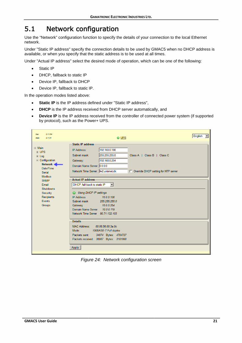
5.1 Network configuration Use the “Network” configuration function to specify the details of your connection to the local Ethernet network.
Under "Static IP address" specify the connection details to be used by GMAC5 when no DHCP address is available, or when you specify that the static address is to be used at all times.
Under "Actual IP address" select the desired mode of operation, which can be one of the following:
• Static IP • DHCP, fallback to static IP • Device IP, fallback to DHCP • Device IP, fallback to static IP.
In the operation modes listed above:
• Static IP is the IP address defined under "Static IP address", • DHCP is the IP address received from DHCP server automatically, and • Device IP is the IP address received from the controller of connected power system (if supported
by protocol), such as the Power+ UPS.
Figure 24: Network configuration screen
GAMATRONIC ELECTRONIC INDUSTRIES LTD.
22 GMAC5 User Guide
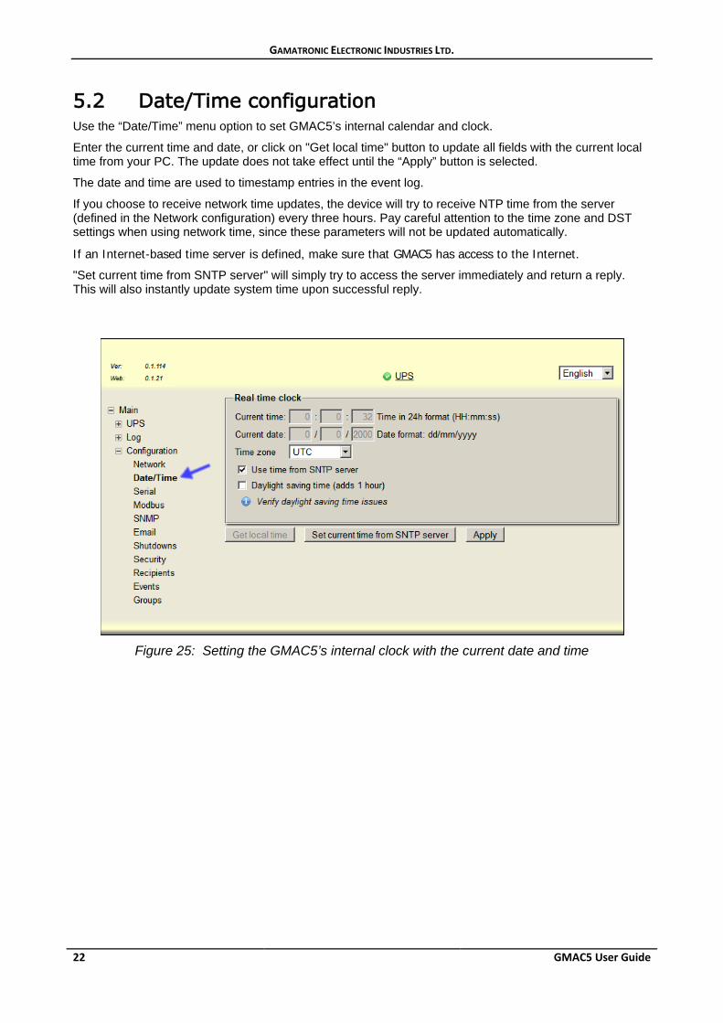
5.2 Date/Time configuration Use the “Date/Time” menu option to set GMAC5’s internal calendar and clock.
Enter the current time and date, or click on "Get local time" button to update all fields with the current local time from your PC. The update does not take effect until the “Apply” button is selected.
The date and time are used to timestamp entries in the event log.
If you choose to receive network time updates, the device will try to receive NTP time from the server (defined in the Network configuration) every three hours. Pay careful attention to the time zone and DST settings when using network time, since these parameters will not be updated automatically.
If an Internet-based time server is defined, make sure that GMAC5 has access to the Internet.
"Set current time from SNTP server" will simply try to access the server immediately and return a reply. This will also instantly update system time upon successful reply.
Figure 25: Setting the GMAC5’s internal clock with the current date and time
GAMATRONIC ELECTRONIC INDUSTRIES LTD.
GMAC5 User Guide 23
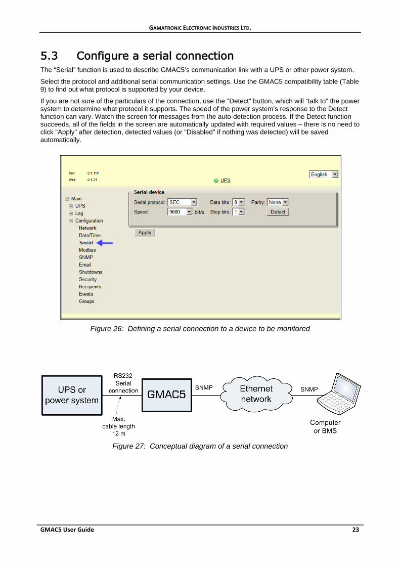
5.3 Configure a serial connection The “Serial” function is used to describe GMAC5’s communication link with a UPS or other power system.
Select the protocol and additional serial communication settings. Use the GMAC5 compatibility table (Table 9) to find out what protocol is supported by your device.
If you are not sure of the particulars of the connection, use the "Detect" button, which will “talk to” the power system to determine what protocol it supports. The speed of the power system’s response to the Detect function can vary. Watch the screen for messages from the auto-detection process. If the Detect function succeeds, all of the fields in the screen are automatically updated with required values – there is no need to click "Apply" after detection, detected values (or "Disabled" if nothing was detected) will be saved automatically.
Figure 26: Defining a serial connection to a device to be monitored
Figure 27: Conceptual diagram of a serial connection
GAMATRONIC ELECTRONIC INDUSTRIES LTD.
24 GMAC5 User Guide
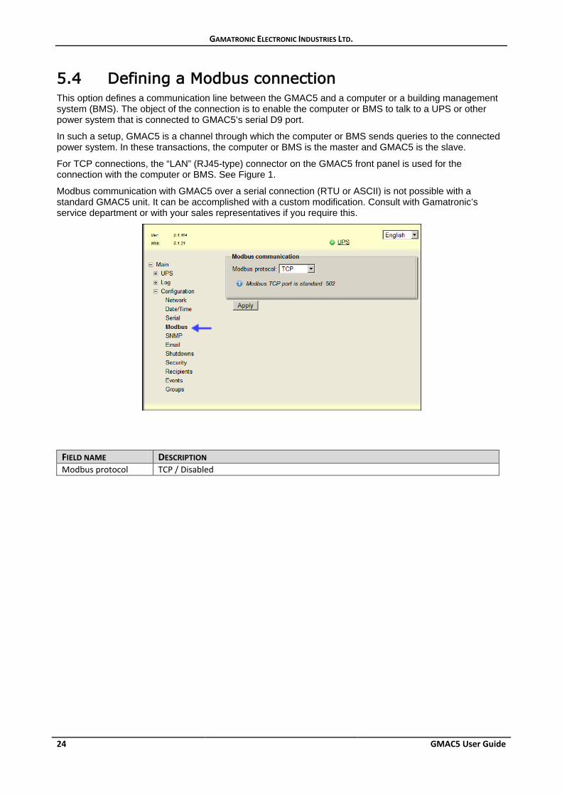
5.4 Defining a Modbus connection This option defines a communication line between the GMAC5 and a computer or a building management system (BMS). The object of the connection is to enable the computer or BMS to talk to a UPS or other power system that is connected to GMAC5’s serial D9 port.
In such a setup, GMAC5 is a channel through which the computer or BMS sends queries to the connected power system. In these transactions, the computer or BMS is the master and GMAC5 is the slave.
For TCP connections, the “LAN” (RJ45-type) connector on the GMAC5 front panel is used for the connection with the computer or BMS. See Figure 1.
Modbus communication with GMAC5 over a serial connection (RTU or ASCII) is not possible with a standard GMAC5 unit. It can be accomplished with a custom modification. Consult with Gamatronic’s service department or with your sales representatives if you require this.
FIELD NAME DESCRIPTION Modbus protocol TCP / Disabled
GAMATRONIC ELECTRONIC INDUSTRIES LTD.
GMAC5 User Guide 25
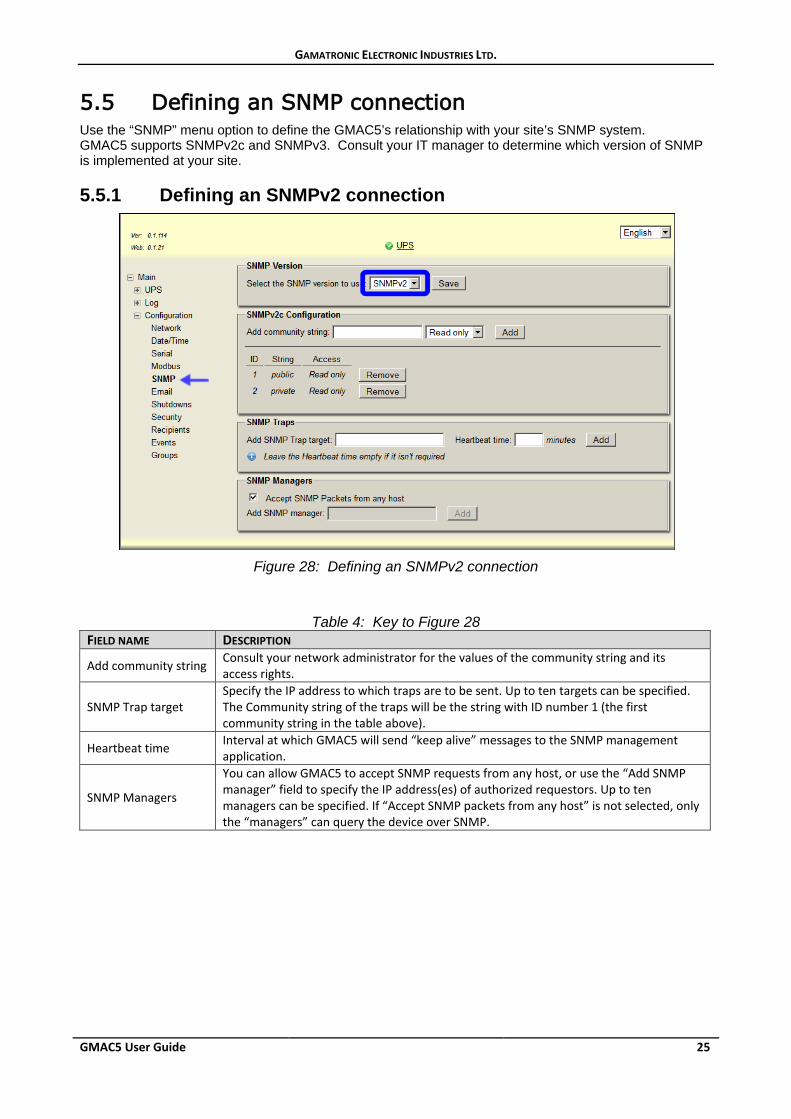
5.5 Defining an SNMP connection Use the “SNMP” menu option to define the GMAC5’s relationship with your site’s SNMP system. GMAC5 supports SNMPv2c and SNMPv3. Consult your IT manager to determine which version of SNMP is implemented at your site.
5.5.1 Defining an SNMPv2 connection
Figure 28: Defining an SNMPv2 connection
Table 4: Key to Figure 28 FIELD NAME DESCRIPTION
Add community string Consult your network administrator for the values of the community string and its access rights.
SNMP Trap target Specify the IP address to which traps are to be sent. Up to ten targets can be specified. The Community string of the traps will be the string with ID number 1 (the first community string in the table above).
Heartbeat time Interval at which GMAC5 will send “keep alive” messages to the SNMP management application.
SNMP Managers
You can allow GMAC5 to accept SNMP requests from any host, or use the “Add SNMP manager” field to specify the IP address(es) of authorized requestors. Up to ten managers can be specified. If “Accept SNMP packets from any host” is not selected, only the “managers” can query the device over SNMP.
GAMATRONIC ELECTRONIC INDUSTRIES LTD.
26 GMAC5 User Guide
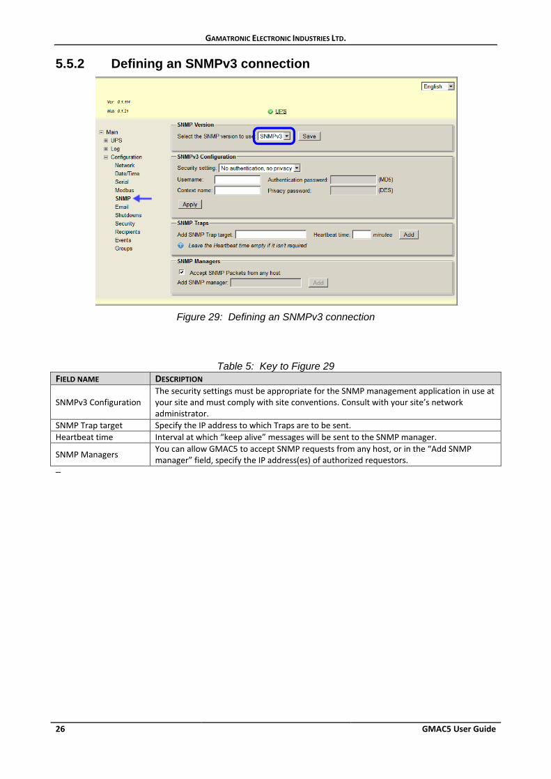
5.5.2 Defining an SNMPv3 connection
Figure 29: Defining an SNMPv3 connection
Table 5: Key to Figure 29 FIELD NAME DESCRIPTION
SNMPv3 Configuration The security settings must be appropriate for the SNMP management application in use at your site and must comply with site conventions. Consult with your site’s network administrator.
SNMP Trap target Specify the IP address to which Traps are to be sent. Heartbeat time Interval at which “keep alive” messages will be sent to the SNMP manager.
SNMP Managers You can allow GMAC5 to accept SNMP requests from any host, or in the “Add SNMP manager” field, specify the IP address(es) of authorized requestors.
–
GAMATRONIC ELECTRONIC INDUSTRIES LTD.
GMAC5 User Guide 27
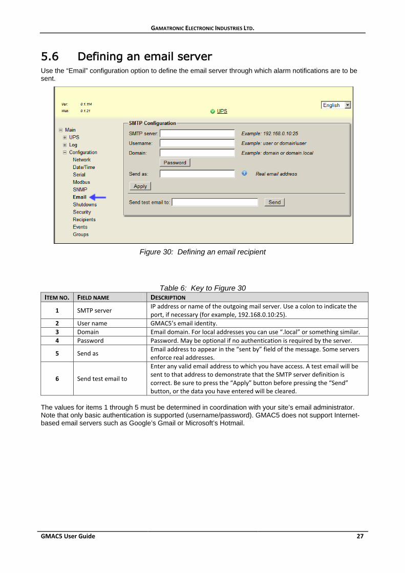
5.6 Defining an email server Use the “Email” configuration option to define the email server through which alarm notifications are to be sent.
Figure 30: Defining an email recipient
Table 6: Key to Figure 30 ITEM NO. FIELD NAME DESCRIPTION
1 SMTP server IP address or name of the outgoing mail server. Use a colon to indicate the port, if necessary (for example, 192.168.0.10:25).
2 User name GMAC5’s email identity. 3 Domain Email domain. For local addresses you can use “.local” or something similar. 4 Password Password. May be optional if no authentication is required by the server.
5 Send as Email address to appear in the “sent by” field of the message. Some servers enforce real addresses.
6 Send test email to
Enter any valid email address to which you have access. A test email will be sent to that address to demonstrate that the SMTP server definition is correct. Be sure to press the “Apply” button before pressing the “Send” button, or the data you have entered will be cleared.
The values for items 1 through 5 must be determined in coordination with your site’s email administrator. Note that only basic authentication is supported (username/password). GMAC5 does not support Internet-based email servers such as Google’s Gmail or Microsoft’s Hotmail.
GAMATRONIC ELECTRONIC INDUSTRIES LTD.
28 GMAC5 User Guide
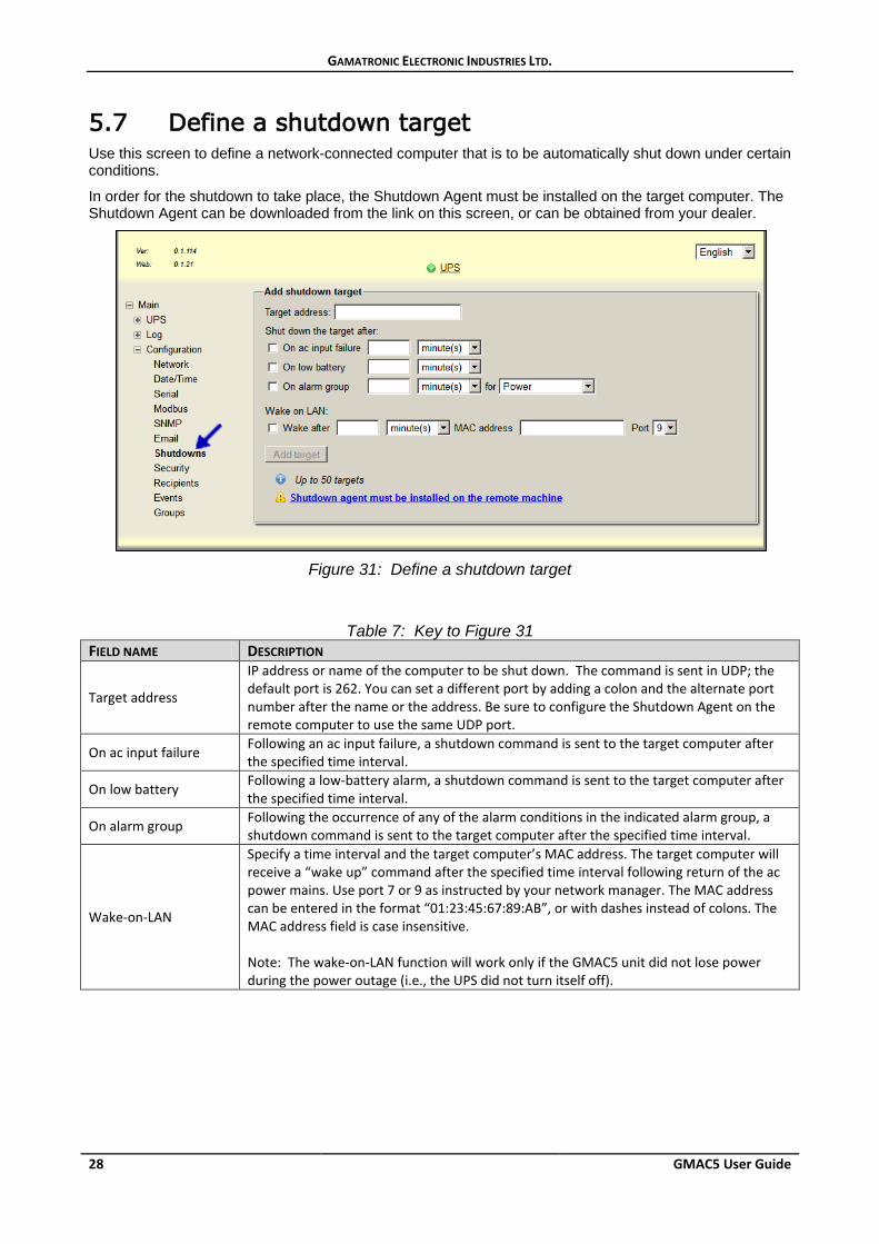
5.7 Define a shutdown target Use this screen to define a network-connected computer that is to be automatically shut down under certain conditions.
In order for the shutdown to take place, the Shutdown Agent must be installed on the target computer. The Shutdown Agent can be downloaded from the link on this screen, or can be obtained from your dealer.
Figure 31: Define a shutdown target
Table 7: Key to Figure 31 FIELD NAME DESCRIPTION
Target address
IP address or name of the computer to be shut down. The command is sent in UDP; the default port is 262. You can set a different port by adding a colon and the alternate port number after the name or the address. Be sure to configure the Shutdown Agent on the remote computer to use the same UDP port.
On ac input failure Following an ac input failure, a shutdown command is sent to the target computer after the specified time interval.
On low battery Following a low-battery alarm, a shutdown command is sent to the target computer after the specified time interval.
On alarm group Following the occurrence of any of the alarm conditions in the indicated alarm group, a shutdown command is sent to the target computer after the specified time interval.
Wake-on-LAN
Specify a time interval and the target computer’s MAC address. The target computer will receive a “wake up” command after the specified time interval following return of the ac power mains. Use port 7 or 9 as instructed by your network manager. The MAC address can be entered in the format “01:23:45:67:89:AB”, or with dashes instead of colons. The MAC address field is case insensitive. Note: The wake-on-LAN function will work only if the GMAC5 unit did not lose power during the power outage (i.e., the UPS did not turn itself off).
GAMATRONIC ELECTRONIC INDUSTRIES LTD.
GMAC5 User Guide 29
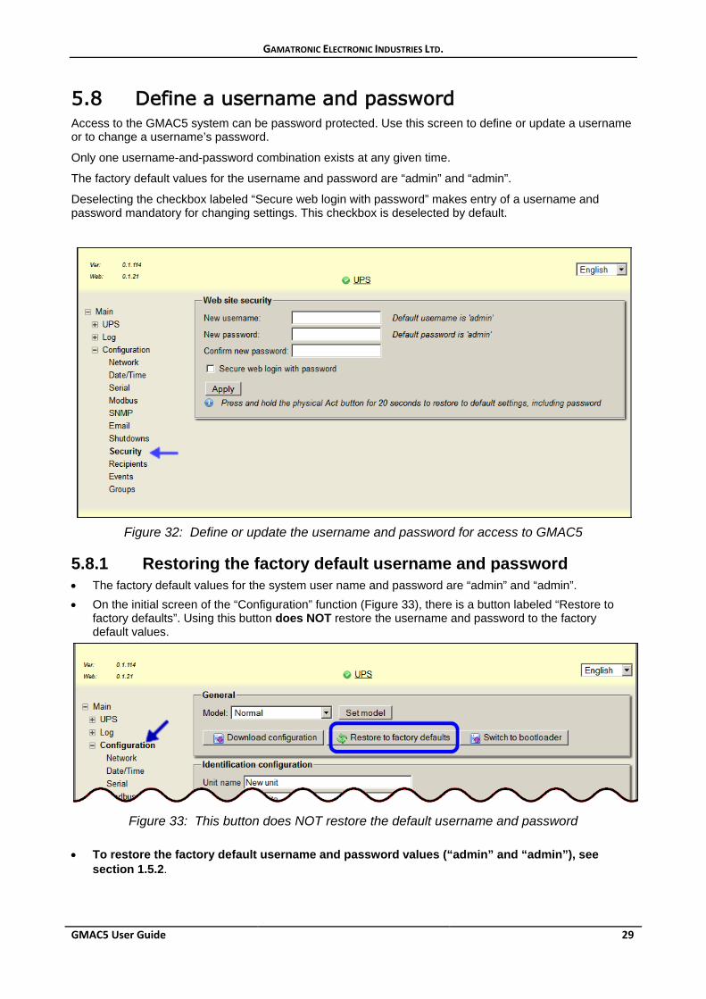
5.8 Define a username and password Access to the GMAC5 system can be password protected. Use this screen to define or update a username or to change a username’s password.
Only one username-and-password combination exists at any given time.
The factory default values for the username and password are “admin” and “admin”.
Deselecting the checkbox labeled “Secure web login with password” makes entry of a username and password mandatory for changing settings. This checkbox is deselected by default.
Figure 32: Define or update the username and password for access to GMAC5
5.8.1 Restoring the factory default username and password • The factory default values for the system user name and password are “admin” and “admin”. • On the initial screen of the “Configuration” function (Figure 33), there is a button labeled “Restore to
factory defaults”. Using this button does NOT restore the username and password to the factory default values.
Figure 33: This button does NOT restore the default username and password
• To restore the factory default username and password values (“admin” and “admin”), see
section 1.5.2.
GAMATRONIC ELECTRONIC INDUSTRIES LTD.
30 GMAC5 User Guide
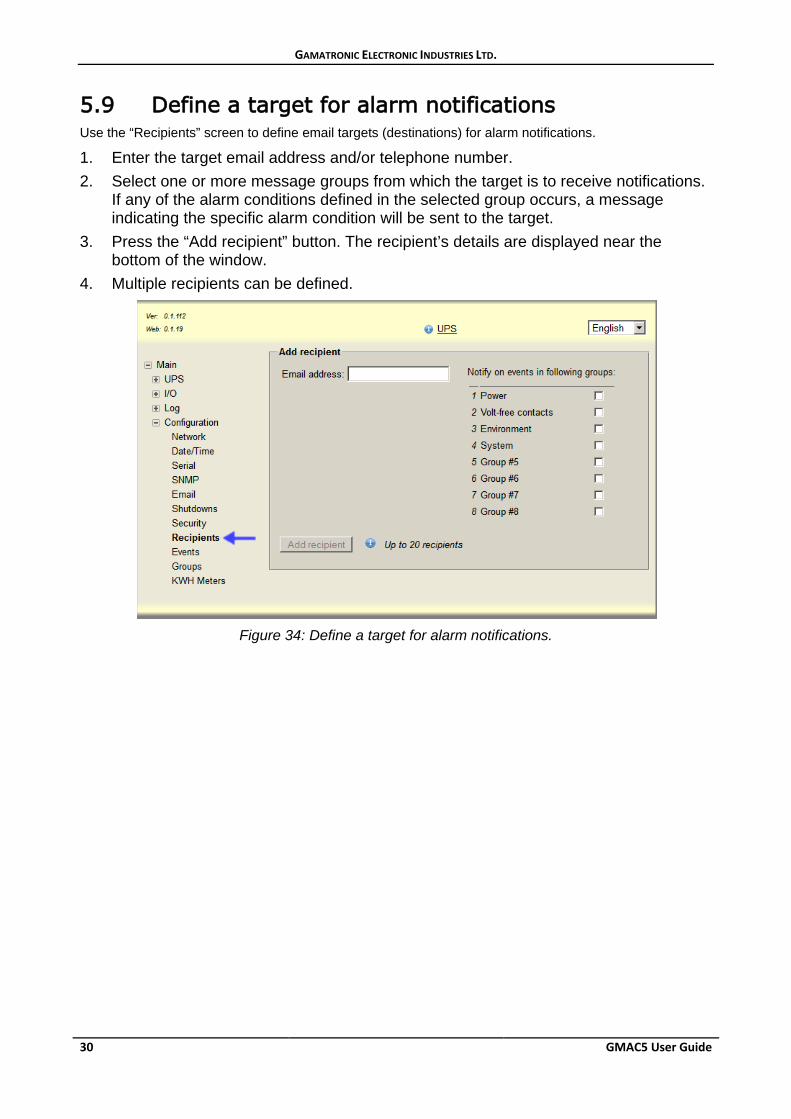
5.9 Define a target for alarm notifications Use the “Recipients” screen to define email targets (destinations) for alarm notifications.
1. Enter the target email address and/or telephone number. 2. Select one or more message groups from which the target is to receive notifications.
If any of the alarm conditions defined in the selected group occurs, a message indicating the specific alarm condition will be sent to the target.
3. Press the “Add recipient” button. The recipient’s details are displayed near the bottom of the window.
4. Multiple recipients can be defined.
Figure 34: Define a target for alarm notifications.
GAMATRONIC ELECTRONIC INDUSTRIES LTD.
GMAC5 User Guide 31
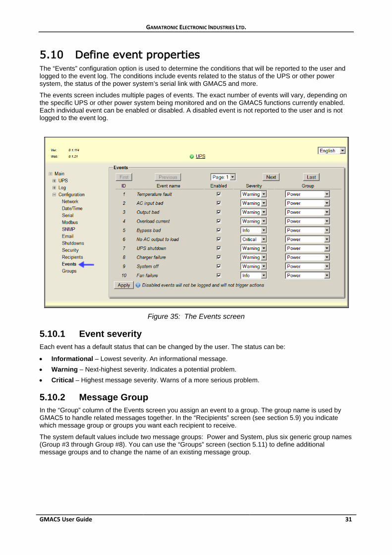
5.10 Define event properties The “Events” configuration option is used to determine the conditions that will be reported to the user and logged to the event log. The conditions include events related to the status of the UPS or other power system, the status of the power system’s serial link with GMAC5 and more.
The events screen includes multiple pages of events. The exact number of events will vary, depending on the specific UPS or other power system being monitored and on the GMAC5 functions currently enabled. Each individual event can be enabled or disabled. A disabled event is not reported to the user and is not logged to the event log.
Figure 35: The Events screen
5.10.1 Event severity Each event has a default status that can be changed by the user. The status can be:
• Informational – Lowest severity. An informational message. • Warning – Next-highest severity. Indicates a potential problem. • Critical – Highest message severity. Warns of a more serious problem.
5.10.2 Message Group In the “Group” column of the Events screen you assign an event to a group. The group name is used by GMAC5 to handle related messages together. In the “Recipients” screen (see section 5.9) you indicate which message group or groups you want each recipient to receive.
The system default values include two message groups: Power and System, plus six generic group names (Group #3 through Group #8). You can use the “Groups” screen (section 5.11) to define additional message groups and to change the name of an existing message group.
GAMATRONIC ELECTRONIC INDUSTRIES LTD.
32 GMAC5 User Guide
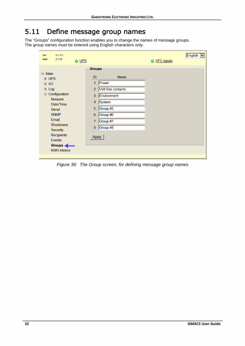
5.11 Define message group names The “Groups” configuration function enables you to change the names of message groups. The group names must be entered using English characters only.
Figure 36: The Group screen, for defining message group names
GAMATRONIC ELECTRONIC INDUSTRIES LTD.
GMAC5 User Guide 33
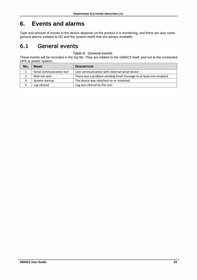
6. Events and alarms Type and amount of events in the device depends on the product it is monitoring, and there are also some general alarms (related to I/O and the system itself) that are always available.
6.1 General events Table 8: General events These events will be recorded in the log file. They are related to the GMAC5 itself, and not to the connected UPS or power system.
NO. NAME DESCRIPTION 1 Serial communication lost Lost communication with external serial device 2 Mail not sent There was a problem sending email message to at least one recipient 3 System startup The device was switched on or restarted 4 Log cleared Log was cleared by the user
GAMATRONIC ELECTRONIC INDUSTRIES LTD.
34 GMAC5 User Guide
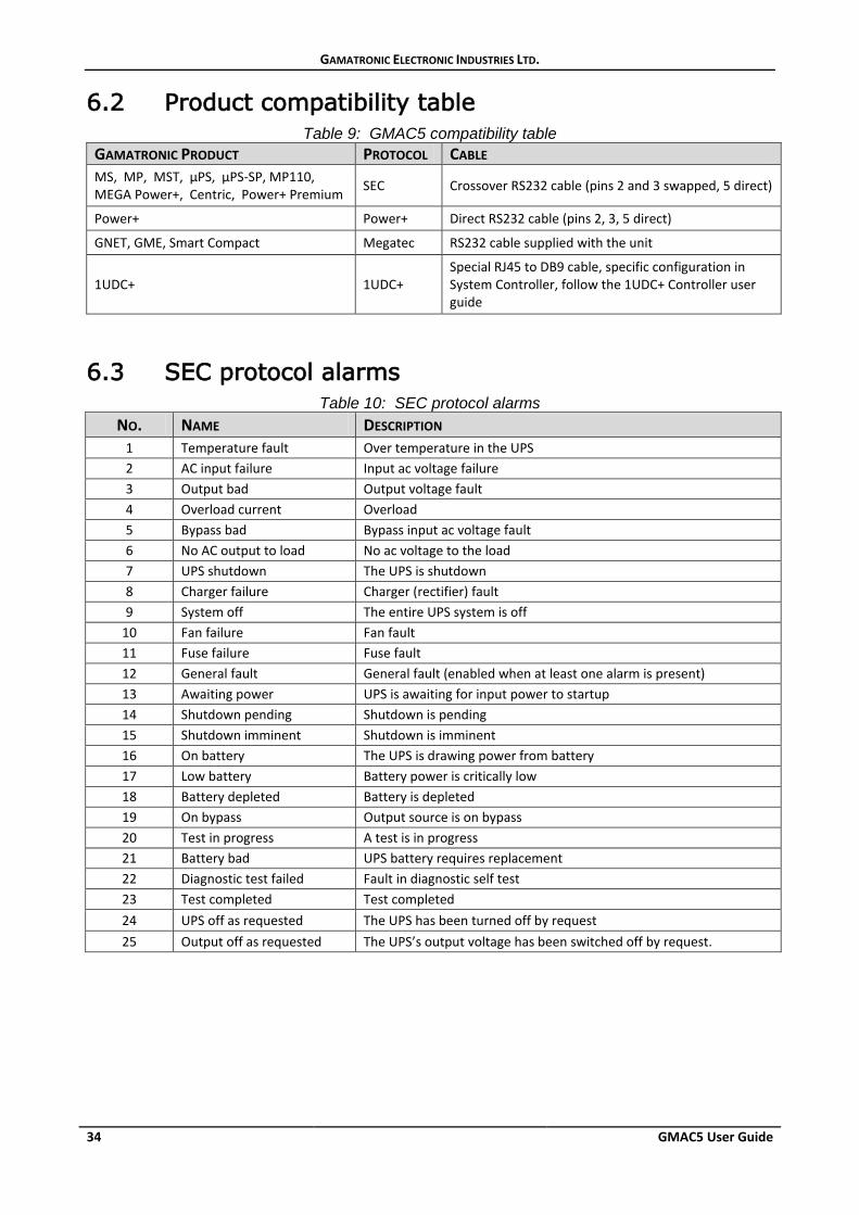
6.2 Product compatibility table Table 9: GMAC5 compatibility table
GAMATRONIC PRODUCT PROTOCOL CABLE MS, MP, MST, µPS, µPS-SP, MP110, MEGA Power+, Centric, Power+ Premium SEC Crossover RS232 cable (pins 2 and 3 swapped, 5 direct)
Power+ Power+ Direct RS232 cable (pins 2, 3, 5 direct)
GNET, GME, Smart Compact Megatec RS232 cable supplied with the unit
1UDC+ 1UDC+ Special RJ45 to DB9 cable, specific configuration in System Controller, follow the 1UDC+ Controller user guide
6.3 SEC protocol alarms Table 10: SEC protocol alarms
NO. NAME DESCRIPTION 1 Temperature fault Over temperature in the UPS 2 AC input failure Input ac voltage failure 3 Output bad Output voltage fault 4 Overload current Overload 5 Bypass bad Bypass input ac voltage fault 6 No AC output to load No ac voltage to the load 7 UPS shutdown The UPS is shutdown 8 Charger failure Charger (rectifier) fault 9 System off The entire UPS system is off
10 Fan failure Fan fault 11 Fuse failure Fuse fault 12 General fault General fault (enabled when at least one alarm is present) 13 Awaiting power UPS is awaiting for input power to startup 14 Shutdown pending Shutdown is pending 15 Shutdown imminent Shutdown is imminent 16 On battery The UPS is drawing power from battery 17 Low battery Battery power is critically low 18 Battery depleted Battery is depleted 19 On bypass Output source is on bypass 20 Test in progress A test is in progress 21 Battery bad UPS battery requires replacement 22 Diagnostic test failed Fault in diagnostic self test 23 Test completed Test completed 24 UPS off as requested The UPS has been turned off by request 25 Output off as requested The UPS’s output voltage has been switched off by request.
GAMATRONIC ELECTRONIC INDUSTRIES LTD.
GMAC5 User Guide 35
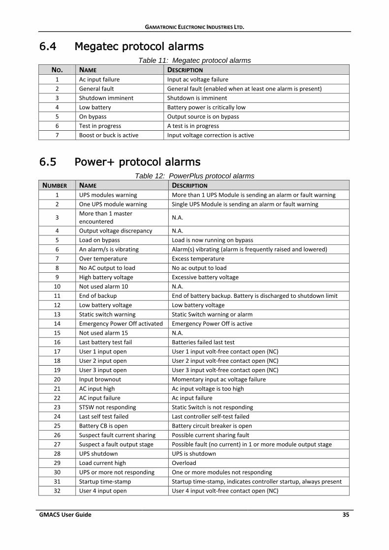
6.4 Megatec protocol alarms Table 11: Megatec protocol alarms
NO. NAME DESCRIPTION 1 Ac input failure Input ac voltage failure 2 General fault General fault (enabled when at least one alarm is present) 3 Shutdown imminent Shutdown is imminent 4 Low battery Battery power is critically low 5 On bypass Output source is on bypass 6 Test in progress A test is in progress 7 Boost or buck is active Input voltage correction is active
6.5 Power+ protocol alarms Table 12: PowerPlus protocol alarms
NUMBER NAME DESCRIPTION 1 UPS modules warning More than 1 UPS Module is sending an alarm or fault warning 2 One UPS module warning Single UPS Module is sending an alarm or fault warning
3 More than 1 master encountered N.A.
4 Output voltage discrepancy N.A. 5 Load on bypass Load is now running on bypass 6 An alarm/s is vibrating Alarm(s) vibrating (alarm is frequently raised and lowered) 7 Over temperature Excess temperature 8 No AC output to load No ac output to load 9 High battery voltage Excessive battery voltage
10 Not used alarm 10 N.A. 11 End of backup End of battery backup. Battery is discharged to shutdown limit 12 Low battery voltage Low battery voltage 13 Static switch warning Static Switch warning or alarm 14 Emergency Power Off activated Emergency Power Off is active 15 Not used alarm 15 N.A. 16 Last battery test fail Batteries failed last test 17 User 1 input open User 1 input volt-free contact open (NC) 18 User 2 input open User 2 input volt-free contact open (NC) 19 User 3 input open User 3 input volt-free contact open (NC) 20 Input brownout Momentary input ac voltage failure 21 AC input high Ac input voltage is too high 22 AC input failure Ac input failure 23 STSW not responding Static Switch is not responding 24 Last self test failed Last controller self-test failed 25 Battery CB is open Battery circuit breaker is open 26 Suspect fault current sharing Possible current sharing fault 27 Suspect a fault output stage Possible fault (no current) in 1 or more module output stage 28 UPS shutdown UPS is shutdown 29 Load current high Overload 30 UPS or more not responding One or more modules not responding 31 Startup time-stamp Startup time-stamp, indicates controller startup, always present 32 User 4 input open User 4 input volt-free contact open (NC)
GAMATRONIC ELECTRONIC INDUSTRIES LTD.
36 GMAC5 User Guide
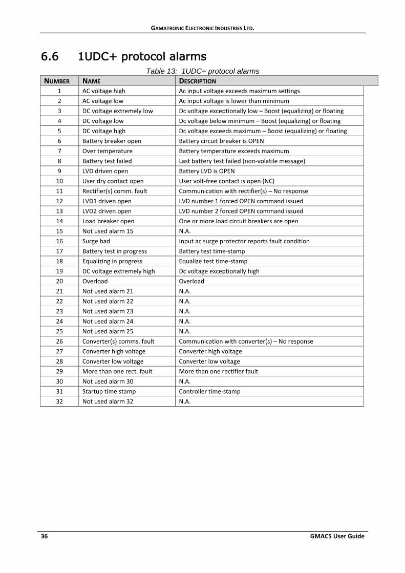
6.6 1UDC+ protocol alarms Table 13: 1UDC+ protocol alarms
NUMBER NAME DESCRIPTION 1 AC voltage high Ac input voltage exceeds maximum settings 2 AC voltage low Ac input voltage is lower than minimum 3 DC voltage extremely low Dc voltage exceptionally low – Boost (equalizing) or floating 4 DC voltage low Dc voltage below minimum – Boost (equalizing) or floating 5 DC voltage high Dc voltage exceeds maximum – Boost (equalizing) or floating 6 Battery breaker open Battery circuit breaker is OPEN 7 Over temperature Battery temperature exceeds maximum 8 Battery test failed Last battery test failed (non-volatile message) 9 LVD driven open Battery LVD is OPEN
10 User dry contact open User volt-free contact is open (NC) 11 Rectifier(s) comm. fault Communication with rectifier(s) – No response 12 LVD1 driven open LVD number 1 forced OPEN command issued 13 LVD2 driven open LVD number 2 forced OPEN command issued 14 Load breaker open One or more load circuit breakers are open 15 Not used alarm 15 N.A. 16 Surge bad Input ac surge protector reports fault condition 17 Battery test in progress Battery test time-stamp 18 Equalizing in progress Equalize test time-stamp 19 DC voltage extremely high Dc voltage exceptionally high 20 Overload Overload 21 Not used alarm 21 N.A. 22 Not used alarm 22 N.A. 23 Not used alarm 23 N.A. 24 Not used alarm 24 N.A. 25 Not used alarm 25 N.A. 26 Converter(s) comms. fault Communication with converter(s) – No response 27 Converter high voltage Converter high voltage 28 Converter low voltage Converter low voltage 29 More than one rect. fault More than one rectifier fault 30 Not used alarm 30 N.A. 31 Startup time stamp Controller time-stamp 32 Not used alarm 32 N.A.
GAMATRONIC ELECTRONIC INDUSTRIES LTD.
GMAC5 User Guide 37
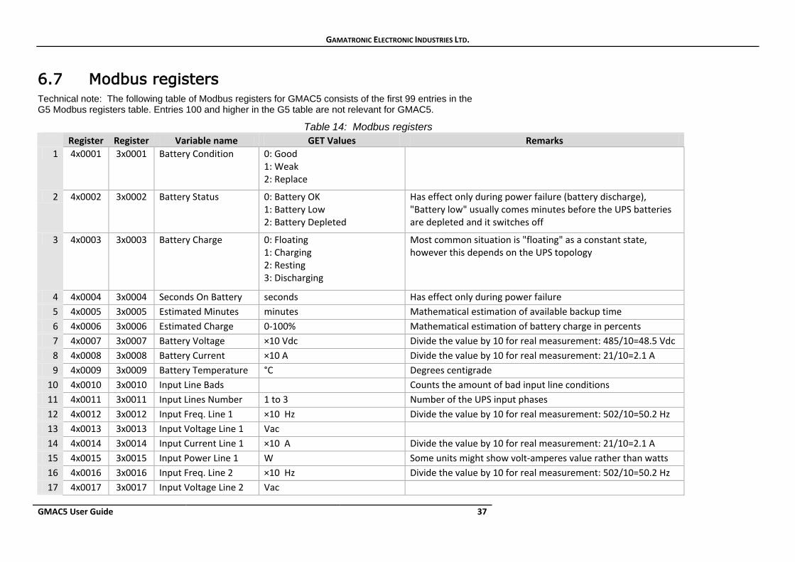
6.7 Modbus registers Technical note: The following table of Modbus registers for GMAC5 consists of the first 99 entries in the G5 Modbus registers table. Entries 100 and higher in the G5 table are not relevant for GMAC5.
Table 14: Modbus registers Register Register Variable name GET Values Remarks
1 4x0001 3x0001 Battery Condition 0: Good 1: Weak 2: Replace
2 4x0002 3x0002 Battery Status 0: Battery OK 1: Battery Low 2: Battery Depleted
Has effect only during power failure (battery discharge), "Battery low" usually comes minutes before the UPS batteries are depleted and it switches off
3 4x0003 3x0003 Battery Charge 0: Floating 1: Charging 2: Resting 3: Discharging
Most common situation is "floating" as a constant state, however this depends on the UPS topology
4 4x0004 3x0004 Seconds On Battery seconds Has effect only during power failure 5 4x0005 3x0005 Estimated Minutes minutes Mathematical estimation of available backup time 6 4x0006 3x0006 Estimated Charge 0-100% Mathematical estimation of battery charge in percents 7 4x0007 3x0007 Battery Voltage ×10 Vdc Divide the value by 10 for real measurement: 485/10=48.5 Vdc 8 4x0008 3x0008 Battery Current ×10 A Divide the value by 10 for real measurement: 21/10=2.1 A 9 4x0009 3x0009 Battery Temperature °C Degrees centigrade
10 4x0010 3x0010 Input Line Bads Counts the amount of bad input line conditions 11 4x0011 3x0011 Input Lines Number 1 to 3 Number of the UPS input phases 12 4x0012 3x0012 Input Freq. Line 1 ×10 Hz Divide the value by 10 for real measurement: 502/10=50.2 Hz 13 4x0013 3x0013 Input Voltage Line 1 Vac 14 4x0014 3x0014 Input Current Line 1 ×10 A Divide the value by 10 for real measurement: 21/10=2.1 A 15 4x0015 3x0015 Input Power Line 1 W Some units might show volt-amperes value rather than watts 16 4x0016 3x0016 Input Freq. Line 2 ×10 Hz Divide the value by 10 for real measurement: 502/10=50.2 Hz 17 4x0017 3x0017 Input Voltage Line 2 Vac
GAMATRONIC ELECTRONIC INDUSTRIES LTD.
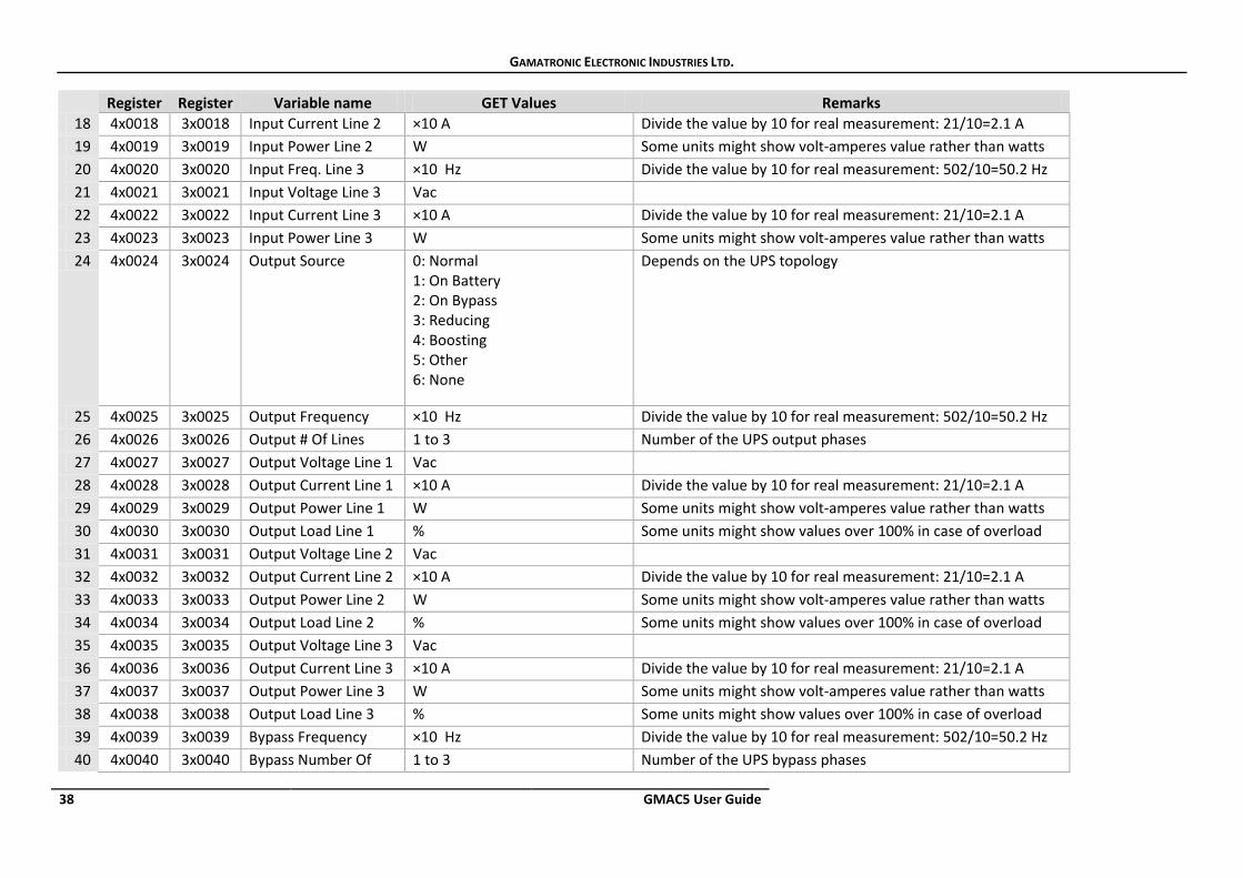
38 GMAC5 User Guide
Register Register Variable name GET Values Remarks 18 4x0018 3x0018 Input Current Line 2 ×10 A Divide the value by 10 for real measurement: 21/10=2.1 A 19 4x0019 3x0019 Input Power Line 2 W Some units might show volt-amperes value rather than watts 20 4x0020 3x0020 Input Freq. Line 3 ×10 Hz Divide the value by 10 for real measurement: 502/10=50.2 Hz 21 4x0021 3x0021 Input Voltage Line 3 Vac 22 4x0022 3x0022 Input Current Line 3 ×10 A Divide the value by 10 for real measurement: 21/10=2.1 A 23 4x0023 3x0023 Input Power Line 3 W Some units might show volt-amperes value rather than watts 24 4x0024 3x0024 Output Source 0: Normal
1: On Battery 2: On Bypass 3: Reducing 4: Boosting 5: Other 6: None
Depends on the UPS topology
25 4x0025 3x0025 Output Frequency ×10 Hz Divide the value by 10 for real measurement: 502/10=50.2 Hz 26 4x0026 3x0026 Output # Of Lines 1 to 3 Number of the UPS output phases 27 4x0027 3x0027 Output Voltage Line 1 Vac 28 4x0028 3x0028 Output Current Line 1 ×10 A Divide the value by 10 for real measurement: 21/10=2.1 A 29 4x0029 3x0029 Output Power Line 1 W Some units might show volt-amperes value rather than watts 30 4x0030 3x0030 Output Load Line 1 % Some units might show values over 100% in case of overload 31 4x0031 3x0031 Output Voltage Line 2 Vac 32 4x0032 3x0032 Output Current Line 2 ×10 A Divide the value by 10 for real measurement: 21/10=2.1 A 33 4x0033 3x0033 Output Power Line 2 W Some units might show volt-amperes value rather than watts 34 4x0034 3x0034 Output Load Line 2 % Some units might show values over 100% in case of overload 35 4x0035 3x0035 Output Voltage Line 3 Vac 36 4x0036 3x0036 Output Current Line 3 ×10 A Divide the value by 10 for real measurement: 21/10=2.1 A 37 4x0037 3x0037 Output Power Line 3 W Some units might show volt-amperes value rather than watts 38 4x0038 3x0038 Output Load Line 3 % Some units might show values over 100% in case of overload 39 4x0039 3x0039 Bypass Frequency ×10 Hz Divide the value by 10 for real measurement: 502/10=50.2 Hz 40 4x0040 3x0040 Bypass Number Of 1 to 3 Number of the UPS bypass phases
GAMATRONIC ELECTRONIC INDUSTRIES LTD.
GMAC5 User Guide 39
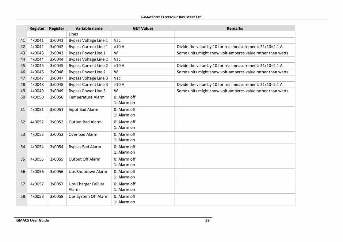
Register Register Variable name GET Values Remarks Lines
41 4x0041 3x0041 Bypass Voltage Line 1 Vac 42 4x0042 3x0042 Bypass Current Line 1 ×10 A Divide the value by 10 for real measurement: 21/10=2.1 A 43 4x0043 3x0043 Bypass Power Line 1 W Some units might show volt-amperes value rather than watts 44 4x0044 3x0044 Bypass Voltage Line 2 Vac 45 4x0045 3x0045 Bypass Current Line 2 ×10 A Divide the value by 10 for real measurement: 21/10=2.1 A 46 4x0046 3x0046 Bypass Power Line 2 W Some units might show volt-amperes value rather than watts 47 4x0047 3x0047 Bypass Voltage Line 3 Vac 48 4x0048 3x0048 Bypass Current Line 3 ×10 A Divide the value by 10 for real measurement: 21/10=2.1 A 49 4x0049 3x0049 Bypass Power Line 3 W Some units might show volt-amperes value rather than watts 50 4x0050 3x0050 Temperature Alarm 0: Alarm off
1: Alarm on
51 4x0051 3x0051 Input Bad Alarm 0: Alarm off 1: Alarm on
52 4x0052 3x0052 Output Bad Alarm 0: Alarm off 1: Alarm on
53 4x0053 3x0053 Overload Alarm 0: Alarm off 1: Alarm on
54 4x0054 3x0054 Bypass Bad Alarm 0: Alarm off 1: Alarm on
55 4x0055 3x0055 Output Off Alarm 0: Alarm off 1: Alarm on
56 4x0056 3x0056 Ups Shutdown Alarm 0: Alarm off 1: Alarm on
57 4x0057 3x0057 Ups Charger Failure Alarm
0: Alarm off 1: Alarm on
58 4x0058 3x0058 Ups System Off Alarm 0: Alarm off 1: Alarm on
GAMATRONIC ELECTRONIC INDUSTRIES LTD.
40 GMAC5 User Guide
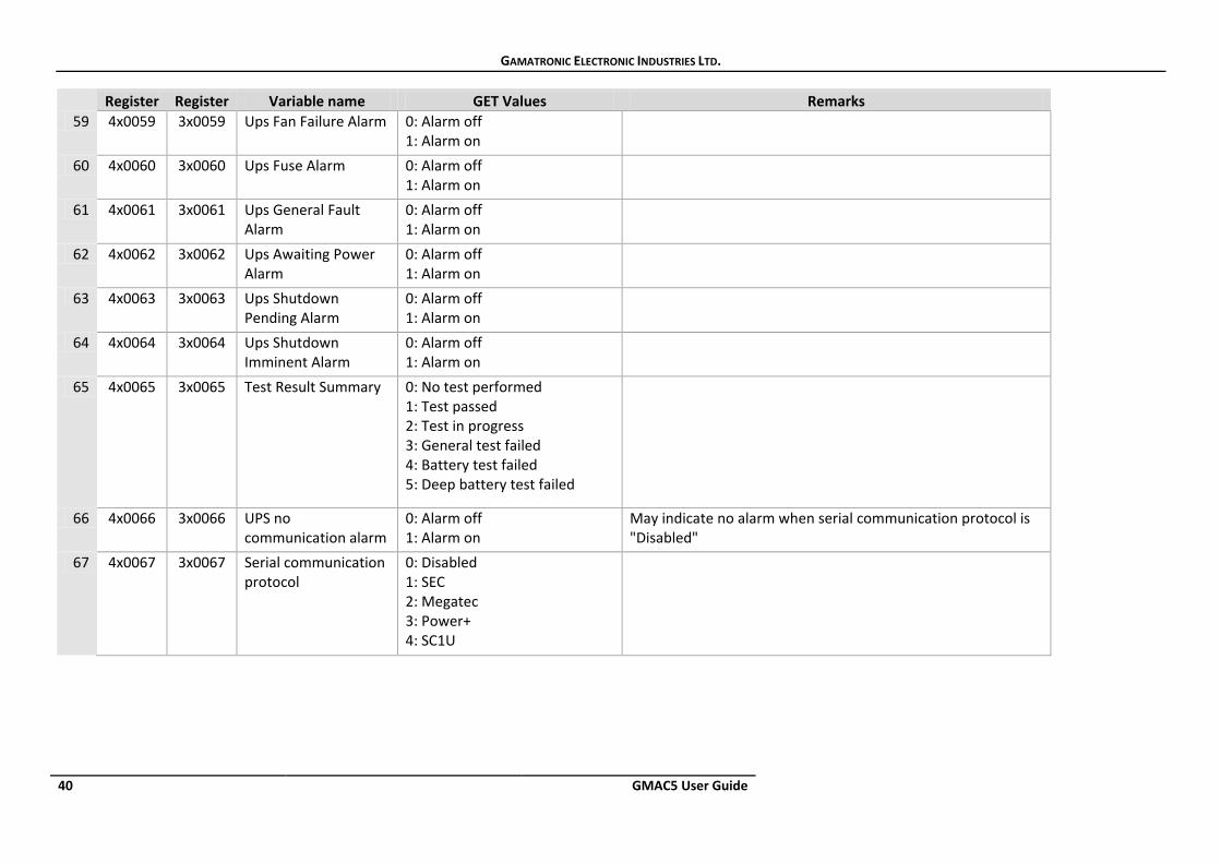
Register Register Variable name GET Values Remarks 59 4x0059 3x0059 Ups Fan Failure Alarm 0: Alarm off
1: Alarm on
60 4x0060 3x0060 Ups Fuse Alarm 0: Alarm off 1: Alarm on
61 4x0061 3x0061 Ups General Fault Alarm
0: Alarm off 1: Alarm on
62 4x0062 3x0062 Ups Awaiting Power Alarm
0: Alarm off 1: Alarm on
63 4x0063 3x0063 Ups Shutdown Pending Alarm
0: Alarm off 1: Alarm on
64 4x0064 3x0064 Ups Shutdown Imminent Alarm
0: Alarm off 1: Alarm on
65 4x0065 3x0065 Test Result Summary 0: No test performed 1: Test passed 2: Test in progress 3: General test failed 4: Battery test failed 5: Deep battery test failed
66 4x0066 3x0066 UPS no communication alarm
0: Alarm off 1: Alarm on
May indicate no alarm when serial communication protocol is "Disabled"
67 4x0067 3x0067 Serial communication protocol
0: Disabled 1: SEC 2: Megatec 3: Power+ 4: SC1U

GAMATRONIC ELECTRONIC INDUSTRIES LTD.
GMAC5 User Guide 41
7. Preventive Maintenance The GMAC5 product contains technologically advanced electronic systems. These electronic systems are sensitive to environmental conditions. It is important that the operating and storage environments of the power system be clean and dust-free, free of dampness and excess humidity.
GMAC5 requires periodic preventive maintenance inspections. At the least, these inspections should include a visual inspection of the GMAC5 and the tightening of any screws that have over time become loosened.
Gamatronic bears no liability for damage caused to the GMAC5 unit due to improper maintenance by third parties, in particular after the expiration of the warranty or service agreement.
It is the responsibility of GMAC5’s owner to uphold his responsibilities according to the warrantee or service agreement. This includes ensuring that GMAC5’s environment meets requirements.

GAMATRONIC ELECTRONIC INDUSTRIES LTD.
42 GMAC5 User Guide
8. Service and repairs Gamatronic maintains a team of service technicians, repair laboratories, and an ample inventory of spare parts, dedicated to the service and repair of our products. When service is required, it will be performed either at the customer's site or in one of our laboratories, according to the judgment of our technician and the specifics of the service agreement between the customer and Gamatronic.
In regards to service, oral agreements have no standing. Service shall be provided gratis during the warrantee period, on the condition that the GMAC5 unit has been properly maintained and a written record has been kept of any maintenance performed on the system.
The initial warrantee period can be extended by a written service agreement between Gamatronic and the customer. Without a written agreement, Gamatronic is under no obligation to provide service after expiration of the initial warrantee period.
Gamatronic will not be responsible for maintenance or changes to theGMAC5 unit that are performed by an agent without written authorization from Gamatronic.
GAMATRONIC ELECTRONIC INDUSTRIES LTD.
GMAC5 User Guide 43
For a full company profile, please visit our website at www.gamatronic.com.
Gamatronic’s product range: UPS Systems
Power systems for Telecom
Dc-to-Ac Inverters
Dc-to-Dc Converters
Frequency Changers
Battery Chargers
Power Management Solutions
Headquarters and Factory: 17 Hartom Street, POB 45029, Jerusalem 9777517, Israel
Gamatronic (UK) Ltd.: 15 Chester Road, Eaton Socon, St. Neots, Cambridgeshire PE19 8YT United Kingdom Tel: +44 (0)1480 479 889 Fax: +44 (0)1480 407 865 email: [email protected]
GAMATRONIC ELECTRONIC INDUSTRIES LTD.
44 GMAC5 User Guide
CHANGE LOG Release 1.0, March 2015 Release 1.1, December 2015 1 Changed trap targets to 10 (was 20). 2 The description for item “SNMP Trap target” in Table 4 was modified. 3 Added section 5.3 “Defining a Modbus connection”.
4 For a complete listing of updates, a Word-based comparison should be done between the latest version and the previous version.
Release 1.2, January 2016 1 Changed product name from “GMAC-5” to “GMAC5”. Release 1.3, January 2016 1 Updated Table 1 (Technical specifications).. 2 Added cat.no. to first page.


![User Guide...User. {{]}]} {}]}](https://img.pdfslide.net/doc/110x75/60918ca14327954d24291644/-user-guide-user-.jpg)