Embed Size (px)
Citation preview
M211840EN-D
User GuideVaisala Weather Transmitter
WXT530 Series

PUBLISHED BY
Vaisala Oyj Street address: Vanha Nurmijärventie 21, FI-01670 Vantaa, FinlandMailing address: P.O. Box 26, FI-00421 Helsinki, FinlandPhone: +358 9 8949 1Fax: +358 9 8949 2227
Visit our Internet pages at www.vaisala.com.
© Vaisala Oyj 2017
No part of this manual may be reproduced,published or publicly displayed in any formor by any means, electronic or mechanical(including photocopying), nor may itscontents be modified, translated, adapted,sold or disclosed to a third party withoutprior written permission of the copyrightholder. Translated manuals and translatedportions of multilingual documents arebased on the original English versions. Inambiguous cases, the English versions areapplicable, not the translations.
The contents of this manual are subject tochange without prior notice.
Local rules and regulations may vary andthey shall take precedence over theinformation contained in this manual.Vaisala makes no representations on thismanual’s compliance with the local rules
and regulations applicable at any giventime, and hereby disclaims any and allresponsibilities related thereto.
This manual does not create any legallybinding obligations for Vaisala towardscustomers or end users. All legally bindingobligations and agreements are includedexclusively in the applicable supplycontract or the General Conditions of Saleand General Conditions of Service ofVaisala.
This product contains software developedby Vaisala or third parties. Use of thesoftware is governed by license terms andconditions included in the applicablesupply contract or, in the absence ofseparate license terms and conditions, bythe General License Conditions of VaisalaGroup.
Table of Contents
1. About This Document........................................................................................91.1 Documentation Conventions................................................................................91.2 Trademarks............................................................................................................. 91.3 ESD Protection......................................................................................................101.4 Version Information............................................................................................. 10
2. Product Overview................................................................................................112.1 WXT530 Series Weather Transmitters................................................................ 11
2.1.1 WXT536...........................................................................................................132.1.2 WXT535 and WXT534................................................................................... 142.1.3 WXT533 and WXT532....................................................................................152.1.4 WXT531............................................................................................................16
2.2 Components.......................................................................................................... 172.3 Optional Features................................................................................................. 19
2.3.1 USB Cables.................................................................................................... 202.3.2 Mounting Kit....................................................................................................212.3.3 Surge Protector............................................................................................. 222.3.4 Bird Kit............................................................................................................232.3.5 Vaisala Configuration Tool........................................................................... 242.3.6 Sensor Heating.............................................................................................. 24
2.4 Backward Compatibility......................................................................................252.5 Regulatory Compliances.....................................................................................25
3. Functional Description.................................................................................... 273.1 Wind Measurement Principle............................................................................. 273.2 Precipitation Measurement Principle................................................................ 283.3 PTU Measurement Principle............................................................................... 293.4 Heating................................................................................................................. 303.5 Analog Input Interface......................................................................................... 313.6 Analog Output Interface......................................................................................31
4. Installation............................................................................................................334.1 Installing WXT530............................................................................................... 33
4.1.1 Maritime Installations....................................................................................334.2 Placing WXT530.................................................................................................. 334.3 Unpacking WXT530............................................................................................ 364.4 Mounting WXT530.............................................................................................. 38
4.4.1 Mounting WXT530 on Vertical Pole Mast without Mounting Kit............ 394.4.2 Mounting WXT530 on Vertical Pole Mast with Mounting Kit.................. 394.4.3 Mounting WXT530 on Sensor Support Arm..............................................43
4.5 Grounding.............................................................................................................454.5.1 Grounding with Bushing and Grounding Kit............................................. 45
4.6 Aligning WXT530................................................................................................464.6.1 Aligning WXT530 with Compass................................................................484.6.2 Configuring Wind Direction Offset.............................................................48
4.7 Installing Vaisala Configuration Tool.................................................................494.8 Installing USB Cable Driver..................................................................................51
Table of Contents
1

5. Wiring and Power Management..................................................................535.1 Power Supplies.....................................................................................................535.2 Power Management............................................................................................ 565.3 Wiring with 8-pin M12 Connector...................................................................... 58
5.3.1 External Wiring..............................................................................................585.3.2 Internal Wiring................................................................................................61
5.4 Wiring Using Screw Terminals........................................................................... 645.5 Data Communication Interfaces........................................................................ 67
6. Connection Options......................................................................................... 696.1 Communication Protocols..................................................................................696.2 Connection Cables.............................................................................................. 696.3 Connecting with Service Cable..........................................................................70
6.3.1 Connecting through M12 Bottom Connector or Screw Terminal..............716.4 Communication Setting Commands................................................................. 72
6.4.1 Checking Current Communication Settings (aXU)................................... 726.4.2 Settings Fields............................................................................................... 736.4.3 Changing the Communication Settings (aXU).......................................... 75
7. Retrieving Data Messages..............................................................................777.1 General Commands............................................................................................. 77
7.1.1 Reset (aXZ).................................................................................................... 777.1.2 Precipitation Counter Reset (aXZRU).........................................................787.1.3 Precipitation Intensity Reset (aXZRI)......................................................... 797.1.4 Measurement Reset (aXZM)........................................................................80
7.2 ASCII Protocol....................................................................................................... 817.2.1 Abbreviations and Units................................................................................817.2.2 Device Address (?)........................................................................................827.2.3 Acknowledge Active Command (a)............................................................837.2.4 Wind Data Message (aR1)............................................................................ 837.2.5 Pressure, Temperature and Humidity Data Message (aR2).....................847.2.6 Precipitation Data Message (aR3).............................................................. 857.2.7 Supervisor Data Message (aR5)..................................................................857.2.8 Combined Data Message (aR).....................................................................867.2.9 Composite Data Message Query (aR0)......................................................877.2.10 Polling with CRC............................................................................................877.2.11 Automatic Mode............................................................................................897.2.12 Automatic Composite Data Message (aR0)..............................................90
7.3 SDI-12 Protocol.................................................................................................... 907.3.1 Address Query Command (?).......................................................................917.3.2 Acknowledge Active Command (a).............................................................917.3.3 Change Address Command (aAb)..............................................................927.3.4 Send Identification Command (aI)..............................................................937.3.5 Start Measurement Command (aM)...........................................................947.3.6 Start Measurement Command with CRC (aMC)........................................957.3.7 Start Concurrent Measurement (aC).......................................................... 967.3.8 Start Concurrent Measurement with CRC (aCC).......................................97
WXT530 Series User Guide M211840EN-D
2
7.3.9 Send Data Command (aD)...........................................................................977.3.10 Examples of aM, aC and aD Commands.....................................................987.3.11 Continuous Measurement (aR)................................................................. 1007.3.12 Continuous Measurement with CRC (aRC).............................................. 102
7.4 NMEA 0183 v3.0 Protocol................................................................................. 1027.4.1 Device Address (?)...................................................................................... 1027.4.2 Acknowledge Active Command (a).......................................................... 1037.4.3 MWV Wind Speed and Direction Query...................................................1047.4.4 XDR Transducer Measurement Query.......................................................1057.4.5 TXT Text Transmission..................................................................................1137.4.6 Automatic Mode........................................................................................... 1147.4.7 Automatic Composite Data Message (aR0)..............................................115
8. Sensor and Data Message Settings........................................................... 1178.1 Sensor Configuration and Data Message Formatting.................................... 117
8.1.1 Wind Sensor.................................................................................................. 1178.1.2 Pressure, Temperature, and Humidity Sensors........................................ 1228.1.3 Precipitation Sensor.................................................................................... 1278.1.4 Supervisor Message.....................................................................................1328.1.5 Composite Data Message (aR0)................................................................ 1358.1.6 Analog Input.................................................................................................1368.1.7 Analog Output............................................................................................. 143
9. Maintenance....................................................................................................... 1479.1 Cleaning...............................................................................................................147
9.1.1 Cleaning the Radiation Shield.................................................................... 1479.2 Replacing PTU Module...................................................................................... 147
10. Troubleshooting.................................................................................................15110.1 Self-Diagnostics..................................................................................................153
10.1.1 Error Messaging/Text Messages................................................................ 15310.1.2 Rain and Wind Sensor Heating Control.................................................... 15410.1.3 Operating Voltage Control......................................................................... 15510.1.4 Missing Readings and Error Indication......................................................155
11. Technical Specifications................................................................................ 15711.1 Performance........................................................................................................15711.2 Inputs and Outputs............................................................................................ 15911.3 Environmental Conditions..................................................................................16111.4 Mechanical Specifications................................................................................. 16211.5 Options and Accessories................................................................................... 16311.6 Type Label...........................................................................................................16411.7 Dimensions (mm / inch)....................................................................................165
Appendix A: Networking....................................................................................... 171A.1 Connecting Several Transmitters on Same Bus............................................... 171A.2 SDI-12 Serial Interface......................................................................................... 171
A.2.1 Wiring SDI-12................................................................................................. 171A.2.2 SDI-12 Communication Protocol................................................................. 171
A.3 RS-485 Serial Interface...................................................................................... 172A.3.1 RS-485 Wiring.............................................................................................. 172A.3.2 RS-485 Communication Protocol.............................................................. 172A.3.3 ASCII, Polled................................................................................................. 172A.3.4 NMEA 0183 v3.0, Query.............................................................................. 173A.3.5 NMEA 0183 v3.0 Query with ASCII Query Commands............................175
Table of Contents
3
Appendix B: SDI-12 Protocol...............................................................................177B.1 SDI-12 Electrical Interface..................................................................................177
B.1.1 SDI-12 Communications Protocol...............................................................177B.1.2 SDI-12 Timing................................................................................................ 177
Appendix C: CRC-16 Computation................................................................... 179C.1 Encoding the CRC as ASCII Characters........................................................... 179C.2 NMEA 0183 v3.0 Checksum Computation......................................................180
Appendix D: Wind Measurement Averaging Method................................ 181
Appendix E: Factory Configurations............................................................... 183E.1 General Unit Settings.........................................................................................183E.2 Wind Configuration Settings............................................................................ 183E.3 PTU Configuration Settings.............................................................................. 184E.4 Rain Configuration Settings..............................................................................185E.5 Supervisor Settings............................................................................................185
Appendix F: Connecting External Sensors to WXT536...........................187F.1 Connecting Ultrasonic Level Sensor to WXT536............................................187F.2 Connecting Pyranometer to WXT536.............................................................190F.3 Connecting Resistance Temperature Sensor..................................................194F.4 Connecting Rain Gauge to WXT536................................................................ 197
Appendix G: Complete Set of Accessories...................................................199
Appendix H: Configuration Parameters........................................................203
Index............................................................................................................................... 211
Warranty.......................................................................................................................217
Recycling......................................................................................................................217
Technical Support.....................................................................................................217
WXT530 Series User Guide M211840EN-D
4
List of Figures
Figure 1 Vaisala Weather Transmitter WXT530 Series.............................................11Figure 2 WXT536............................................................................................................... 14Figure 3 WXT535 and WXT534......................................................................................15Figure 4 WXT533 and WXT532...................................................................................... 15Figure 5 WXT531.................................................................................................................16Figure 6 WXT536 Components...................................................................................... 17Figure 7 Cut-Away View of WXT536............................................................................ 18Figure 8 Bottom of WXT536........................................................................................... 19Figure 9 USB Cable...........................................................................................................20Figure 10 Mounting Kit........................................................................................................21Figure 11 Surge Protector................................................................................................. 22Figure 12 Bird Kit................................................................................................................. 23Figure 13 WXT536 with Bird Kit......................................................................................23Figure 14 Vaisala Configuration Tool............................................................................. 24Figure 15 Analog Inputs for External Sensors..............................................................31Figure 16 Recommended Mast Location in Open Area............................................34Figure 17 Recommended Mast Length on Top of Building......................................35Figure 18 Contents of Shipping Container................................................................... 36Figure 19 Installing with Protective Packaging........................................................... 37Figure 20 Mounting WXT531 on Vertical Pole Mast...................................................40Figure 21 WXT530 North Arrow..................................................................................... 47Figure 22 Sketch of Magnetic Declination....................................................................47Figure 23 Average Operational Current Consumption (with 4Hz
Wind Sensor Sampling)..................................................................................54Figure 24 Heating Instant Current and Power vs Vh (WXT536,
WXT535, WXT533, and WXT532)................................................................55Figure 25 Heating Instant Current and Power vs Vh (WXT531)..............................55Figure 26 Pins of 8-pin M12 Connector..........................................................................59Figure 27 Internal Wiring for RS-232, SDI-12, and RS-485...................................... 64Figure 28 Screw Terminal Block...................................................................................... 65Figure 29 Data Communication Interfaces...................................................................67Figure 30 Termination Jumper Positions...................................................................... 68Figure 31 Service Cable Connection.............................................................................. 70Figure 32 Analog Input Connector Pins....................................................................... 137Figure 33 Analog Input Settings in Vaisala Configuration Tool.............................138Figure 34 Type Label.........................................................................................................164Figure 35 WXT536 Dimensions in mm [in].................................................................165Figure 36 WXT535 and WXT534 Dimensions in mm [in]....................................... 166Figure 37 WXT533 and WXT532 Dimensions in mm [in]....................................... 167Figure 38 WXT531 Dimensions in mm [in].................................................................. 168Figure 39 WXT530 Series Mounting Kit (212792) Dimensions..............................169Figure 40 Mounting Accessory (WMSFIX60) for Connecting
Mounting Kit (212792) and 60 mm Tube.................................................. 170Figure 41 Timing Diagram............................................................................................... 178Figure 42 Wind Measurement Averaging Method.................................................... 182Figure 43 Connecting External Sensors to WXT536................................................ 187Figure 44 Connecting Ultrasonic Level Sensor to WXT536................................... 188Figure 45 Wiring Ultrasonic Level Sensor to WXT536.............................................189Figure 46 Connecting CMP3 to WXT536......................................................................191Figure 47 Peeling CMP3 Cable Sheath......................................................................... 192Figure 48 Wiring CMP3 to WXT53.................................................................................193Figure 49 Pt1000 Connected to WXT536 M12 Connector......................................194
List of Figures
5

Figure 50 Wiring Temperature Sensor Pt1000 to WXT536....................................195Figure 51 Wiring Temperature Sensor TM-Pt1000 to WXT536............................ 195Figure 52 TM-Pt1000 Connector................................................................................... 196Figure 53 Wiring RG13/RG13H to WXT536................................................................. 197Figure 54 Complete Set of Accessories....................................................................... 199Figure 55 WXT536 with Surge Protector WSP150................................................... 201Figure 56 WXT536 with Surge Protector WSP152...................................................202
WXT530 Series User Guide M211840EN-D
6
List of Tables
Table 1 Document Versions.............................................................................................10Table 2 Available Options.................................................................................................12Table 3 Heater Resistance...............................................................................................30Table 4 Standby Power Consumption......................................................................... 56Table 5 Economic Power Management....................................................................... 57Table 6 Pin-outs for WXT530 Series Serial Interfaces and Power Supplies......59Table 7 Screw Terminal Pin-outs................................................................................... 59Table 8 WXT532 mA Output Option Screw Terminal Pin-outs............................ 60Table 9 RS-232 Wiring...................................................................................................... 61Table 10 RS-485 Wiring.....................................................................................................62Table 11 SDI-12 Wiring....................................................................................................... 62Table 12 RS-422 Wiring..................................................................................................... 63Table 13 mA Output Wiring..............................................................................................63Table 14 Screw Terminal Pin-outs for Serial Interfaces and Power Supplies...... 65Table 15 Available Serial Communication Protocols................................................. 69Table 16 Connection Cable Options ..............................................................................70Table 17 Default Serial Communication Settings for M12/Screw
Terminal Connection...........................................................................................71Table 18 Abbreviations and Units.................................................................................... 81Table 19 Transducer IDs of Measurement Parameters.............................................107Table 20 Transducer Table.................................................................................................113Table 21 Wind Parameters Bits 1-8.................................................................................119Table 22 Wind Parameters Bits 9-16.............................................................................. 119Table 23 PTU Parameters Bits 1-8.................................................................................. 124Table 24 PTU Parameters Bits 9-16................................................................................124Table 25 Precipitation Parameters Bits 1-8..................................................................128Table 26 Precipitation Parameters Bits 9-16............................................................... 129Table 27 Supervisor Parameters Bits 1-8......................................................................133Table 28 Supervisor Parameters Bits 9-16................................................................... 134Table 29 Analog Input Signals........................................................................................ 137Table 30 Analog Input Setting Definitions.................................................................. 138Table 31 aIU Setting Fields [R]...................................................................................... 140Table 32 Analog Output Scaling.................................................................................... 144Table 33 aWU Setting Fields [R]................................................................................... 146Table 34 Data Validation....................................................................................................151Table 35 Communication Problems.............................................................................. 152Table 36 Error Messaging/Text Messages................................................................... 154Table 37 WXT530 Series Barometric Pressure Measuring Specifications.......... 157Table 38 WXT530 Series Air Temperature Measuring Specifications..................157Table 39 WXT530 Series Relative Humidity Measuring Specifications............... 157Table 40 WXT530 Series Precipitation Measuring Specifications........................ 158Table 41 WXT530 Series Wind Measuring Specifications...................................... 158Table 42 WXT530 Series Electrical Specifications....................................................159Table 43 WXT536 Analog Input Options.....................................................................160Table 44 WXT532 Analog mA Output Options......................................................... 160Table 45 WXT530 Series Environmental Specifications...........................................161Table 46 WXT530 Series Electromagnetic Compatibility........................................ 161Table 47 WXT530 Series Mechanical Specifications................................................ 162Table 48 Options and Accessories.................................................................................163Table 49 General Unit Settings....................................................................................... 183Table 50 Wind Configuration Settings......................................................................... 184Table 51 PTU Configuration Settings........................................................................... 184
List of Tables
7

Table 52 Rain Configuration Settings........................................................................... 185Table 53 General Unit Settings....................................................................................... 185Table 54 Ultrasonic Level Connections........................................................................ 190Table 55 Pyranometer Connections..............................................................................194Table 56 Temperature Sensor Connections................................................................ 196Table 57 Rain Gauge Connections.................................................................................198Table 58 General Parameters......................................................................................... 203Table 59 Pressure, Temperature and Humidity Parameters.................................. 205Table 60 Wind Parameters............................................................................................. 206Table 61 Precipitation Parameters............................................................................... 207Table 62 Auxiliary Sensor Parameters.........................................................................208Table 63 Analog mA Output Parameters................................................................... 209
WXT530 Series User Guide M211840EN-D
8
1. About This Document
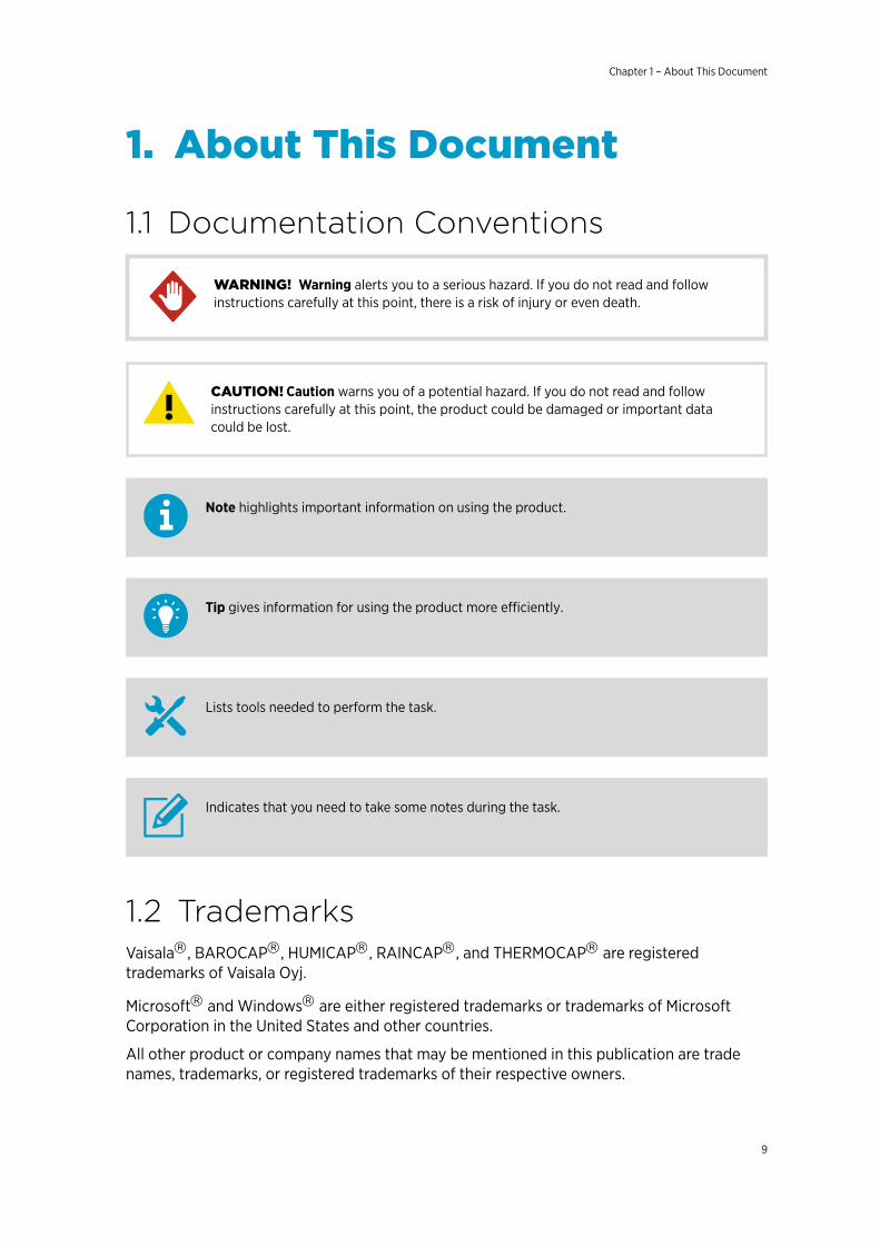
1.1 Documentation Conventions
Warning alerts you to a serious hazard. If you do not read and followinstructions carefully at this point, there is a risk of injury or even death.WARNING!
Caution warns you of a potential hazard. If you do not read and followinstructions carefully at this point, the product could be damaged or important datacould be lost.
CAUTION!
Note highlights important information on using the product.
Tip gives information for using the product more efficiently.
Lists tools needed to perform the task.
Indicates that you need to take some notes during the task.
1.2 TrademarksVaisalaâ, BAROCAPâ, HUMICAPâ, RAINCAPâ, and THERMOCAPâ are registeredtrademarks of Vaisala Oyj.
Microsoftâ and Windowsâ are either registered trademarks or trademarks of MicrosoftCorporation in the United States and other countries.
All other product or company names that may be mentioned in this publication are tradenames, trademarks, or registered trademarks of their respective owners.
Chapter 1 – About This Document
9

1.3 ESD ProtectionElectrostatic Discharge (ESD) can damage electronic circuits. Vaisala products areadequately protected against ESD for their intended use. However, it is possible to damagethe product by delivering electrostatic discharges when touching, removing, or inserting anyobjects in the equipment housing.
To avoid delivering high static voltages to the product:
• Handle ESD-sensitive components on a properly grounded and protected ESDworkbench or by grounding yourself to the equipment chassis with a wrist strap and aresistive connection cord.
• If you are unable to take either precaution, touch a conductive part of the equipmentchassis with your other hand before touching ESD-sensitive components.
• Hold component boards by the edges and avoid touching component contacts.
1.4 Version Information
Table 1 Document Versions
Document Code Date Description
M211840EN-D April 2017 Added information about external sensors. Updated technicaldrawings. Added grounding information. Added index.
M211840EN-C February 2016 Previous version
WXT530 Series User Guide M211840EN-D
10

2. Product Overview
2.1 WXT530 Series Weather TransmittersThe WXT530 product family consists of the following transmitters.
Figure 1 Vaisala Weather Transmitter WXT530 Series
The WXT530 series transmitters are suitable for several purposes, such as:
• Agro-meteorological applications• Building control systems• Cruisers• Energy applications• Environmental monitoring• Fire weather• Meteorological test beds• Noise monitoring• Researchers• Sport events• Weather stations
The product family offers a variety of weather parameters. The following table lists themeasurement combinations of each model.
Chapter 2 – Product Overview
11
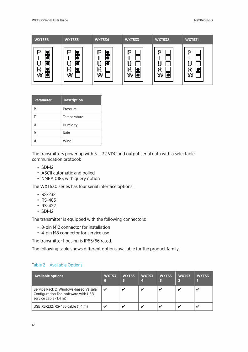
WXT536 WXT535 WXT534 WXT533 WXT532 WXT531
Parameter Description
P Pressure
T Temperature
U Humidity
R Rain
W Wind
The transmitters power up with 5 … 32 VDC and output serial data with a selectablecommunication protocol:
• SDI-12• ASCII automatic and polled• NMEA 0183 with query option
The WXT530 series has four serial interface options:
• RS-232• RS-485• RS-422• SDI-12
The transmitter is equipped with the following connectors:
• 8-pin M12 connector for installation• 4-pin M8 connector for service use
The transmitter housing is IP65/66 rated.
The following table shows different options available for the product family.
Table 2 Available Options
Available options WXT536
WXT535
WXT534
WXT533
WXT532
WXT531
Service Pack 2: Windows-based VaisalaConfiguration Tool software with USBservice cable (1.4 m)
✔ ✔ ✔ ✔ ✔ ✔
USB RS-232/RS-485 cable (1.4 m) ✔ ✔ ✔ ✔ ✔ ✔
WXT530 Series User Guide M211840EN-D
12
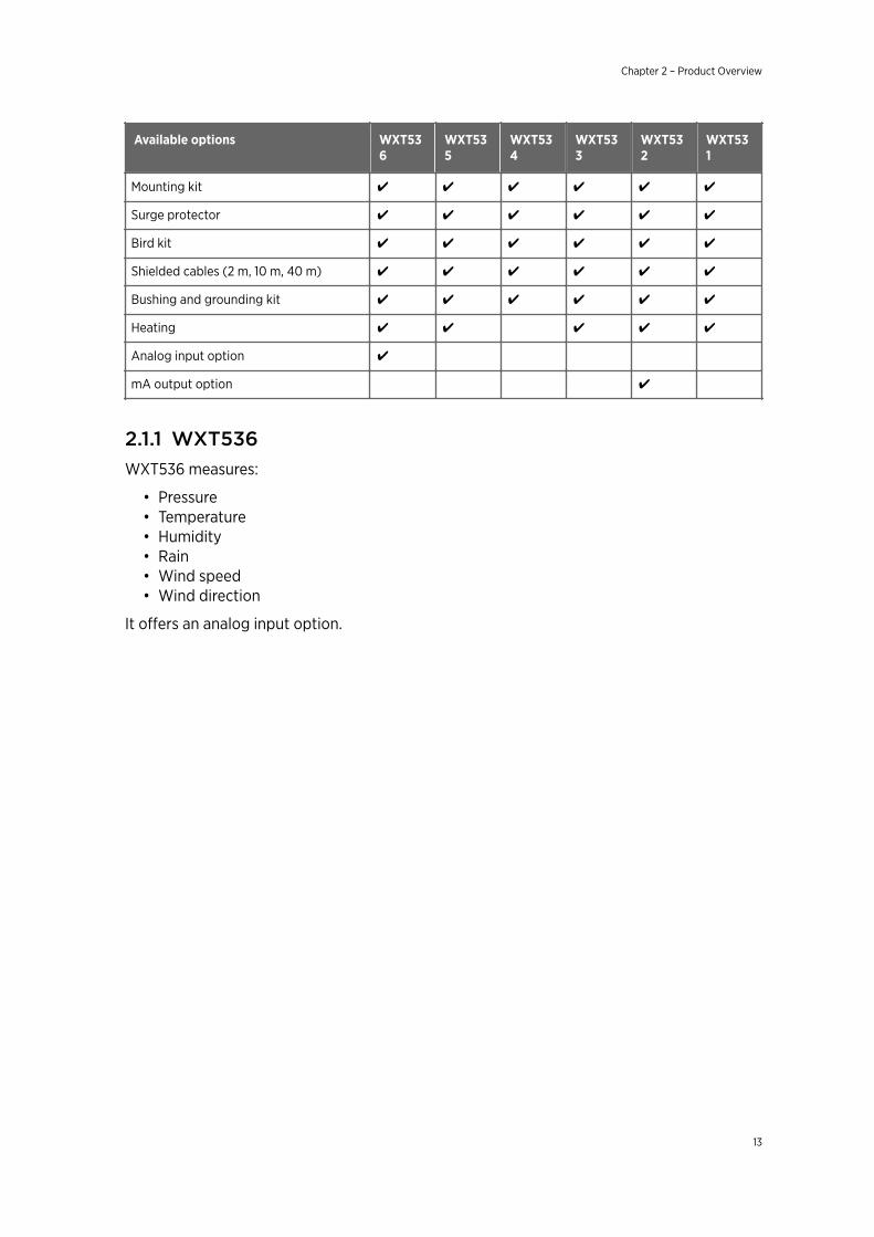
Available options WXT536
WXT535
WXT534
WXT533
WXT532
WXT531
Mounting kit ✔ ✔ ✔ ✔ ✔ ✔
Surge protector ✔ ✔ ✔ ✔ ✔ ✔
Bird kit ✔ ✔ ✔ ✔ ✔ ✔
Shielded cables (2 m, 10 m, 40 m) ✔ ✔ ✔ ✔ ✔ ✔
Bushing and grounding kit ✔ ✔ ✔ ✔ ✔ ✔
Heating ✔ ✔ ✔ ✔ ✔
Analog input option ✔
mA output option ✔
2.1.1 WXT536WXT536 measures:
• Pressure• Temperature• Humidity• Rain• Wind speed• Wind direction
It offers an analog input option.
Chapter 2 – Product Overview
13
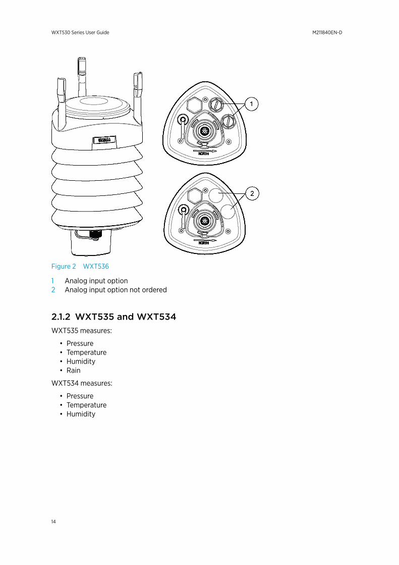
Figure 2 WXT536
1 Analog input option2 Analog input option not ordered
2.1.2 WXT535 and WXT534WXT535 measures:
• Pressure• Temperature• Humidity• Rain
WXT534 measures:
• Pressure• Temperature• Humidity
WXT530 Series User Guide M211840EN-D
14
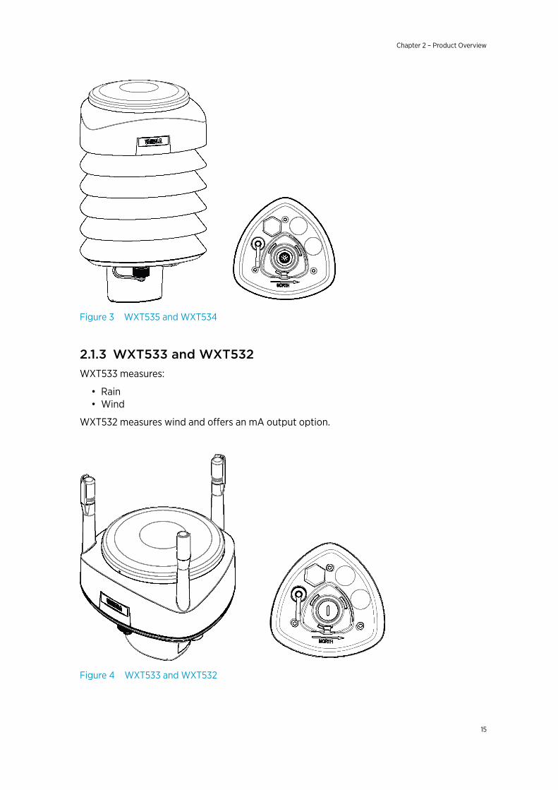
Figure 3 WXT535 and WXT534
2.1.3 WXT533 and WXT532WXT533 measures:
• Rain• Wind
WXT532 measures wind and offers an mA output option.
Figure 4 WXT533 and WXT532
Chapter 2 – Product Overview
15
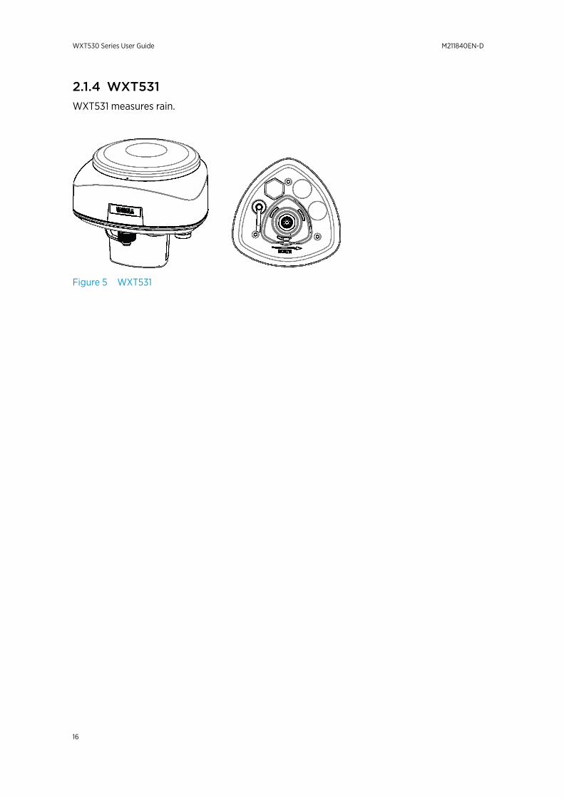
2.1.4 WXT531WXT531 measures rain.
Figure 5 WXT531
WXT530 Series User Guide M211840EN-D
16
2.2 Components
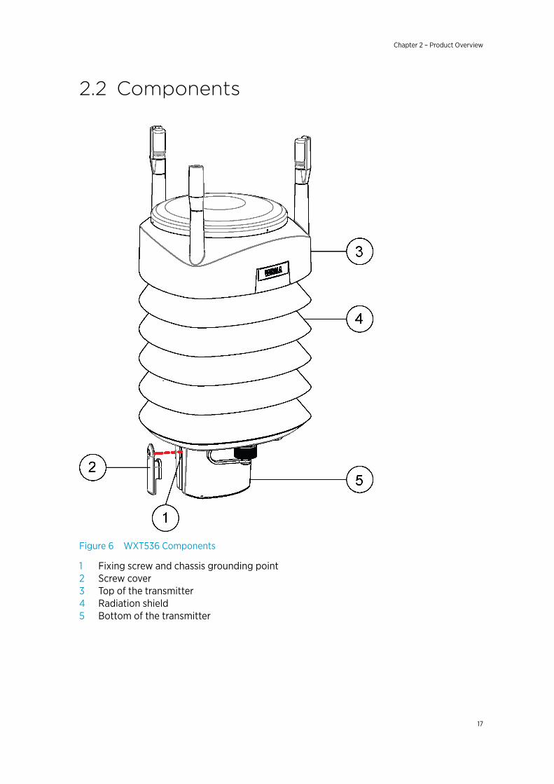
Figure 6 WXT536 Components
1 Fixing screw and chassis grounding point2 Screw cover3 Top of the transmitter4 Radiation shield5 Bottom of the transmitter
Chapter 2 – Product Overview
17
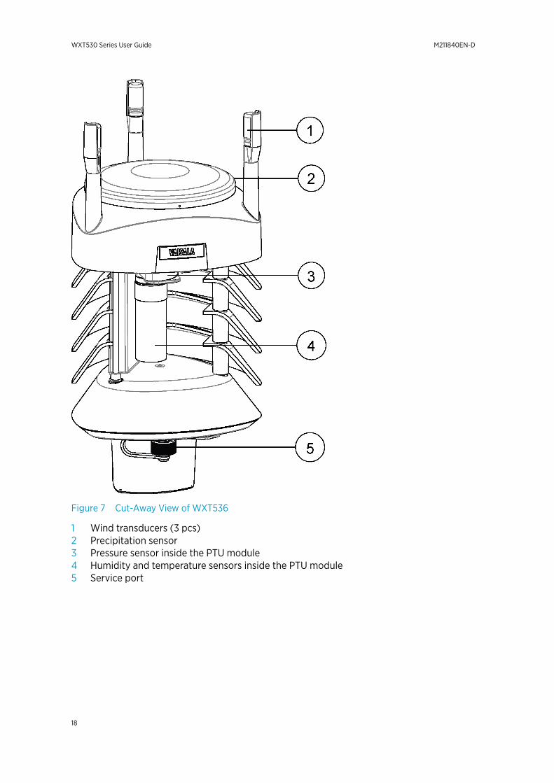
Figure 7 Cut-Away View of WXT536
1 Wind transducers (3 pcs)2 Precipitation sensor3 Pressure sensor inside the PTU module4 Humidity and temperature sensors inside the PTU module5 Service port
WXT530 Series User Guide M211840EN-D
18
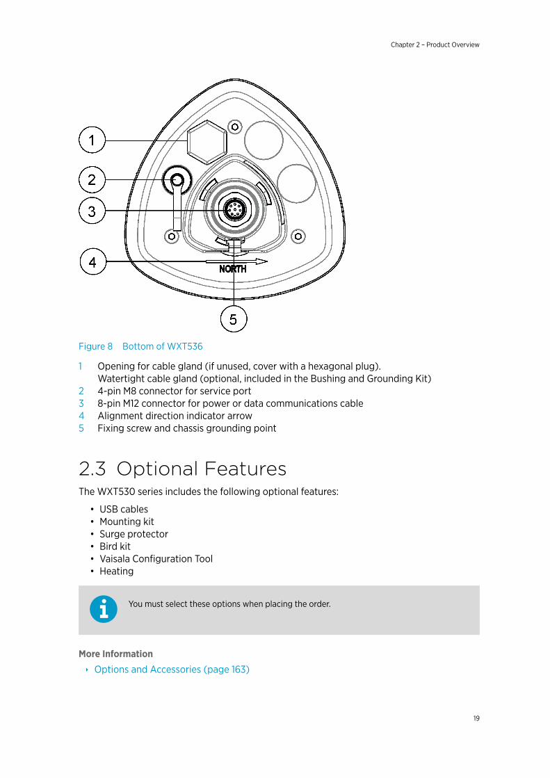
Figure 8 Bottom of WXT536
1 Opening for cable gland (if unused, cover with a hexagonal plug).Watertight cable gland (optional, included in the Bushing and Grounding Kit)
2 4-pin M8 connector for service port3 8-pin M12 connector for power or data communications cable4 Alignment direction indicator arrow5 Fixing screw and chassis grounding point
2.3 Optional FeaturesThe WXT530 series includes the following optional features:
• USB cables• Mounting kit• Surge protector• Bird kit• Vaisala Configuration Tool• Heating
You must select these options when placing the order.
More Information
‣ Options and Accessories (page 163)
Chapter 2 – Product Overview
19
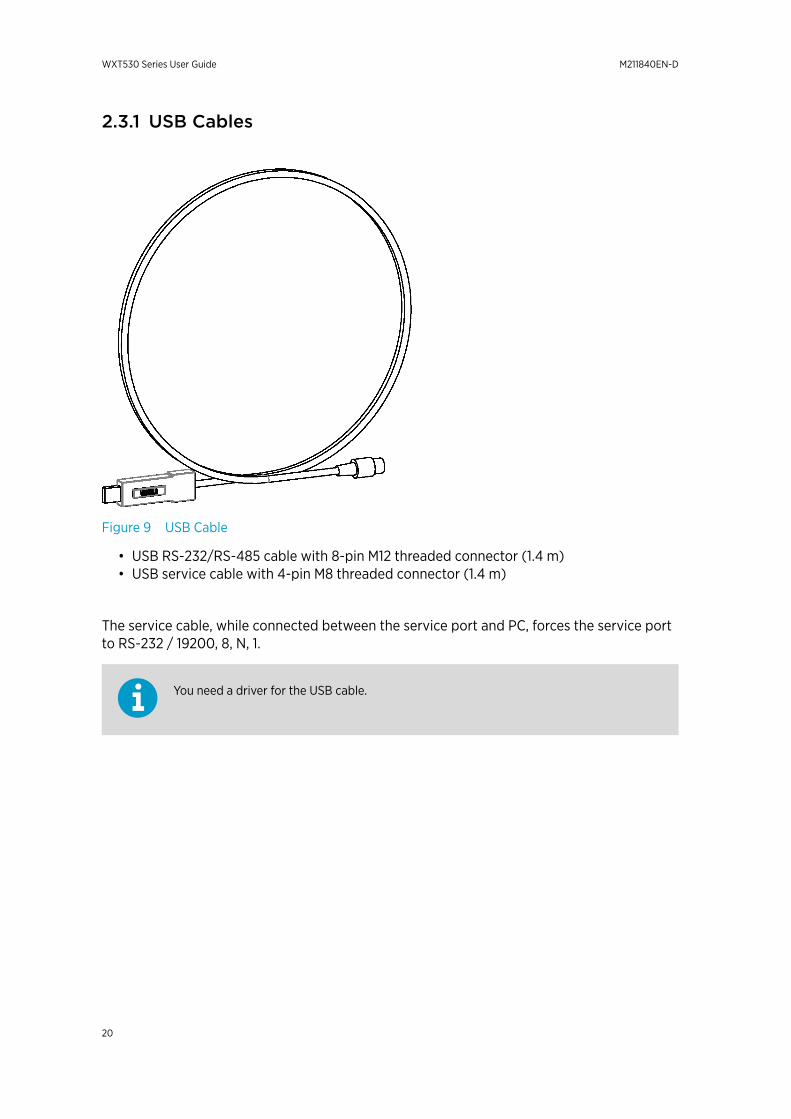
2.3.1 USB Cables
Figure 9 USB Cable
• USB RS-232/RS-485 cable with 8-pin M12 threaded connector (1.4 m)• USB service cable with 4-pin M8 threaded connector (1.4 m)
The service cable, while connected between the service port and PC, forces the service portto RS-232 / 19200, 8, N, 1.
You need a driver for the USB cable.
WXT530 Series User Guide M211840EN-D
20
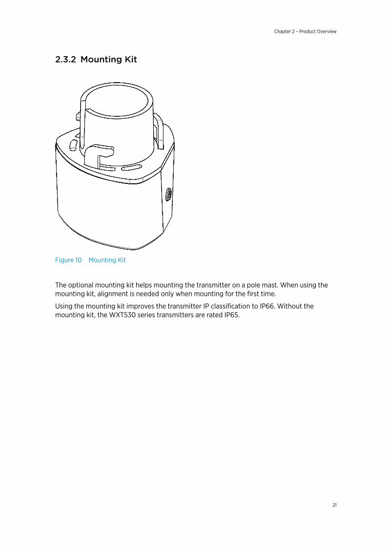
2.3.2 Mounting Kit
Figure 10 Mounting Kit
The optional mounting kit helps mounting the transmitter on a pole mast. When using themounting kit, alignment is needed only when mounting for the first time.
Using the mounting kit improves the transmitter IP classification to IP66. Without themounting kit, the WXT530 series transmitters are rated IP65.
Chapter 2 – Product Overview
21
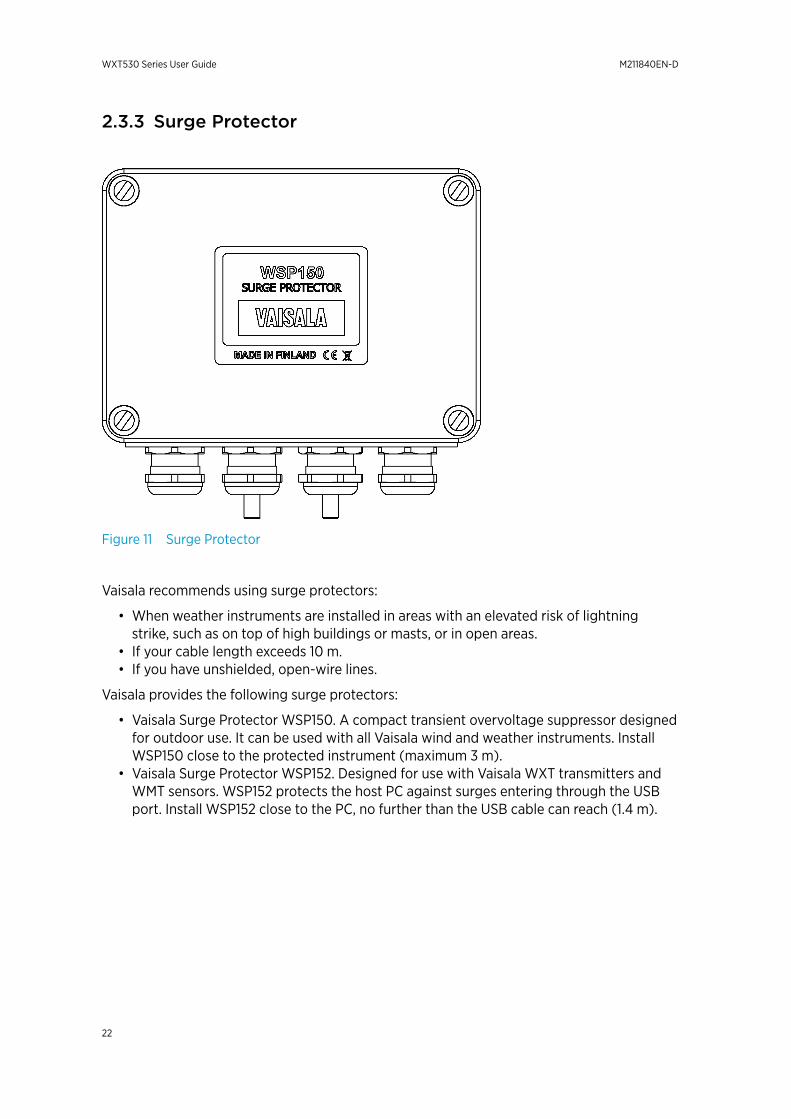
2.3.3 Surge Protector
Figure 11 Surge Protector
Vaisala recommends using surge protectors:
• When weather instruments are installed in areas with an elevated risk of lightningstrike, such as on top of high buildings or masts, or in open areas.
• If your cable length exceeds 10 m.• If you have unshielded, open-wire lines.
Vaisala provides the following surge protectors:
• Vaisala Surge Protector WSP150. A compact transient overvoltage suppressor designedfor outdoor use. It can be used with all Vaisala wind and weather instruments. InstallWSP150 close to the protected instrument (maximum 3 m).
• Vaisala Surge Protector WSP152. Designed for use with Vaisala WXT transmitters andWMT sensors. WSP152 protects the host PC against surges entering through the USBport. Install WSP152 close to the PC, no further than the USB cable can reach (1.4 m).
WXT530 Series User Guide M211840EN-D
22
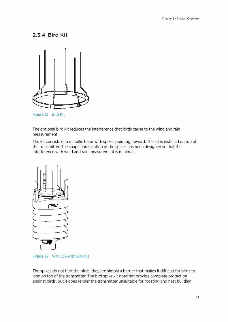
2.3.4 Bird Kit
Figure 12 Bird Kit
The optional bird kit reduces the interference that birds cause to the wind and rainmeasurement.
The kit consists of a metallic band with spikes pointing upward. The kit is installed on top ofthe transmitter. The shape and location of the spikes has been designed so that theinterference with wind and rain measurement is minimal.
Figure 13 WXT536 with Bird Kit
The spikes do not hurt the birds; they are simply a barrier that makes it difficult for birds toland on top of the transmitter. The bird spike kit does not provide complete protectionagainst birds, but it does render the transmitter unsuitable for roosting and nest building.
Chapter 2 – Product Overview
23

When the kit is in place, more snow can accumulate on the transmitter, and the snow canmelt away more slowly.
2.3.5 Vaisala Configuration ToolVaisala Configuration Tool is a Windows-based, user-friendly parameter setting software forWXT530 transmitters. It is also fully compatible with WMT52 and WXT520.
Figure 14 Vaisala Configuration Tool
2.3.6 Sensor HeatingHeating helps to improve the measurement accuracy.
More Information
‣ Heating (page 30)
WXT530 Series User Guide M211840EN-D
24

2.4 Backward Compatibility
Always use the latest version of WXT530 Configuration Tool.
The WXT530 series transmitters are fully compatible with WXT520 and WMT52. This appliesto mounting, cable options, and communication.
When you upgrade from WMT52 to WXT532 or from WXT520 to WXT536, you must use thesame profile and communication option as you had before. Regenerate the setup files (WXCfiles) for WXT530 with the latest version of WXT530 Configuration Tool .
Because the WXT530 series has several product variants, the old configuration code doesnot apply to the new WXT530 sensor. You must generate and apply a new order code for it.
More Information
‣ Vaisala Configuration Tool (page 24)
2.5 Regulatory CompliancesThe electromagnetic compatibility of the WXT530 series has been tested according to thefollowing product family standard:
• EN 61326-1 Electrical equipment for measurement, control and laboratory use - EMCrequirements - for use in industrial locations.
• The WXT530 series has been enhanced for marine use according to the appropriatesections of the IEC 60945 Maritime Navigation and Radiocommunication Equipmentand Systems - General requirements - Methods of testing.
• The WXT530 series is in conformance with the provisions of the RoHS directive of theEuropean Union:
• Directive on the Restriction of the Use of Certain Hazardous Substances in Electricaland Electronic Equipment (2002/95/EC)
Chapter 2 – Product Overview
25

WXT530 Series User Guide M211840EN-D
26
3. Functional Description
3.1 Wind Measurement Principle
WXT536 WXT535 WXT534 WXT533 WXT532 WXT531
✔ ✔ ✔
The transmitters use Vaisala WINDCAP sensor technology for wind measurement.
The wind sensor has an array of three equally spaced ultrasonic transducers on a horizontalplane. The unit determines wind speed and wind directions by measuring the time it takesthe ultrasound to travel from one transducer to the other two.
The wind sensor measures the transit time (in both directions) along the three pathsestablished by the array of transducers. The transit time depends on the wind speed alongthe ultrasonic path. For zero wind speed, both the forward and reverse transit times are thesame. With wind along the sound path, the up-wind direction transit time increases and thedown-wind transit time decreases.
The unit calculates wind speed from the measured transit times using the following formula:
Vw = 0.5 × L × (1/tf – 1/tr)
Vw Wind speed
L Distance between the two transducers
tf Transit time in forward direction
tr Transit time in reverse direction
Measuring the six transit times allows Vw to be computed for each of the three ultrasonicpaths. The computed wind speeds are independent of altitude, temperature, and humidity,which are cancelled out when the transit times are measured in both directions, althoughthe individual transit times depend on these parameters.
The Vw values of two array paths are enough to compute wind speed and wind direction. Asignal processing technique ensures that wind speed and wind direction are calculated fromthe two array paths with the best quality.
The wind speed is represented as a scalar speed in selected units (m/s, kt, mph, km/h). Thewind direction from which the wind comes is expressed in degrees (°). North is representedas 0°, East as 90°, South as 180°, and West as 270°.
Chapter 3 – Functional Description
27
The wind direction is not calculated when the wind speed drops below 0.05 m/s. In thiscase, the last calculated direction output remains until the wind speed increases to the levelof 0.05 m/s.
The average values of wind speed and direction are calculated as a scalar average of allsamples over the selected averaging time (1 ... 3600 s) with a selectable updating interval.The sample count depends on the selected sampling rate: 4 Hz (default), 2 Hz, or 1 Hz. Theminimum and maximum values of wind speed and direction represent the correspondingextremes during the selected averaging time.
You can select the computation of the wind speed extreme values in one of two ways:
• Traditional minimum/maximum calculation• 3-second gust & calm calculation recommended by the World Meteorological
Organization (WMO). In this case the highest and lowest 3-second average values(updated once a second) replace the maximum and minimum values in reporting ofwind speed, while the wind direction variance is returned in the traditional way.
The transmitter constantly monitors the wind measurement signal quality. If poor quality isdetected, the wind values are marked as invalid. If over half of the measurement values areconsidered invalid, the last valid wind values are returned as missing data. However, in theSDI-12 protocol, the invalid values are marked as zero (0).
More Information
‣ Wind Measurement Averaging Method (page 181)
3.2 Precipitation Measurement Principle
WXT536 WXT535 WXT534 WXT533 WXT532 WXT531
✔ ✔ ✔ ✔
The transmitter uses Vaisala RAINCAP Sensor 2-technology in precipitation measurement.
The precipitation sensor comprises of a steel cover and a piezoelectrical sensor mounted onthe bottom surface of the cover.
The precipitation sensor detects the impact of individual raindrops. The signals from theimpact are proportional to the volume of the drops. The signal of each drop can beconverted directly to accumulated rainfall. An advanced noise filtering technique filters outsignals originating from other sources than raindrops.
The measured parameters are:
• Accumulated rainfall• Rain current and peak intensity• Duration of a rain event
Detecting each drop enables the computing of rain amount and intensity with highresolution.
WXT530 Series User Guide M211840EN-D
28
Precipitation current intensity is internally updated every 10 seconds and represents theintensity during the one minute period before requesting/automatic precipitation messagesending (for fast reactions to a rain event, during the first minute of the rain event, theintensity is calculated over the period rain has lasted in 10-second steps instead of a fixedperiod of one minute). Precipitation peak intensity represents the maximum of thecalculated current intensity values since last precipitation intensity reset.
The sensor can also distinguish hail stones from raindrops. The measured hail parametersare the cumulative number of hail stones, current and peak hail intensity and the duration ofa hail shower.
The precipitation sensor operates in four modes:
• Precipitation Start/End mode:Transmitter automatically sends a precipitation message 10 seconds after therecognition of the first drop. The messages are sent continuously as the precipitationproceeds and stop when the precipitation ends.
• Tipping bucket mode:This mode emulates tipping bucket type precipitation sensors. Transmitter sendsautomatically a precipitation message when the counter detects one unit increment(0.1 mm/0.01 in).
• Time mode:Transmitter sends automatically a precipitation message in the update intervals definedby the user.
• Polled mode:Transmitter sends a precipitation message whenever requested by the user.
More Information
‣ Precipitation Sensor (page 127)
3.3 PTU Measurement Principle
WXT536 WXT535 WXT534 WXT533 WXT532 WXT531
✔ ✔ ✔
The PTU module contains separate sensors for pressure, temperature, and humiditymeasurement.
The measurement principle of the transmitter is based on an advanced RC oscillator and tworeference capacitors against which the capacitance of the sensors is continuously measured.The microprocessor of the transmitter performs compensation for the temperaturedependency of the pressure and humidity sensors.
The PTU module includes:
• Capacitive silicon BAROCAP sensor for pressure measurement,• Capacitive ceramic THERMOCAP sensor for air temperature measurement• Capacitive thin film polymer HUMICAP180 sensor for humidity measurement.
Chapter 3 – Functional Description
29
3.4 Heating
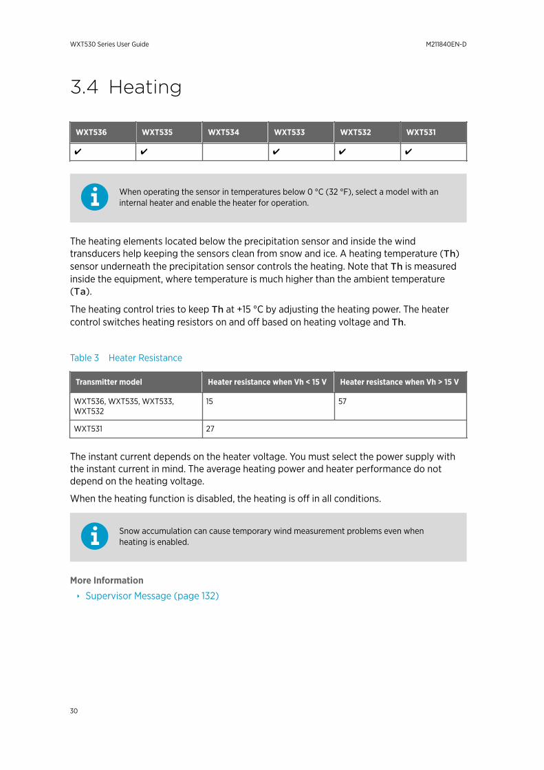
WXT536 WXT535 WXT534 WXT533 WXT532 WXT531
✔ ✔ ✔ ✔ ✔
When operating the sensor in temperatures below 0 °C (32 °F), select a model with aninternal heater and enable the heater for operation.
The heating elements located below the precipitation sensor and inside the windtransducers help keeping the sensors clean from snow and ice. A heating temperature (Th)sensor underneath the precipitation sensor controls the heating. Note that Th is measuredinside the equipment, where temperature is much higher than the ambient temperature(Ta).
The heating control tries to keep Th at +15 °C by adjusting the heating power. The heatercontrol switches heating resistors on and off based on heating voltage and Th.
Table 3 Heater Resistance
Transmitter model Heater resistance when Vh < 15 V Heater resistance when Vh > 15 V
WXT536, WXT535, WXT533,WXT532
15 57
WXT531 27
The instant current depends on the heater voltage. You must select the power supply withthe instant current in mind. The average heating power and heater performance do notdepend on the heating voltage.
When the heating function is disabled, the heating is off in all conditions.
Snow accumulation can cause temporary wind measurement problems even whenheating is enabled.
More Information
‣ Supervisor Message (page 132)
WXT530 Series User Guide M211840EN-D
30
3.5 Analog Input Interface
WXT536 WXT535 WXT534 WXT533 WXT532 WXT531
✔
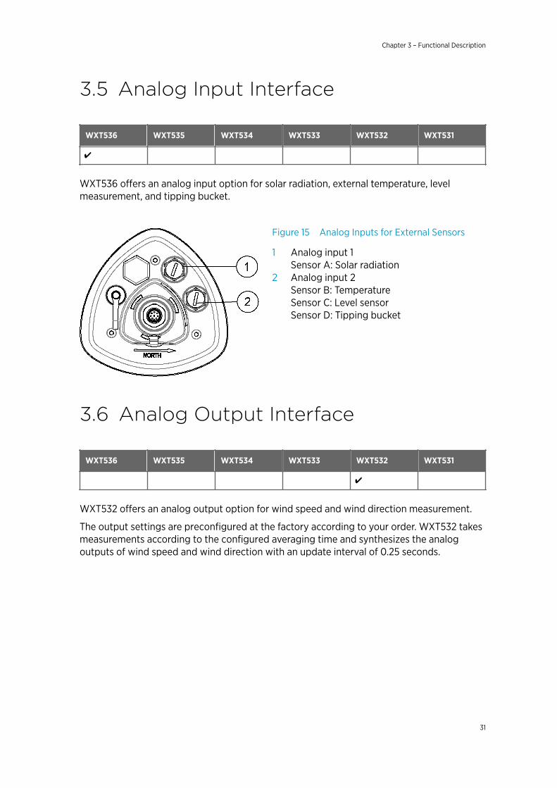
WXT536 offers an analog input option for solar radiation, external temperature, levelmeasurement, and tipping bucket.
Figure 15 Analog Inputs for External Sensors
1 Analog input 1Sensor A: Solar radiation
2 Analog input 2Sensor B: TemperatureSensor C: Level sensorSensor D: Tipping bucket
3.6 Analog Output Interface
WXT536 WXT535 WXT534 WXT533 WXT532 WXT531
✔
WXT532 offers an analog output option for wind speed and wind direction measurement.
The output settings are preconfigured at the factory according to your order. WXT532 takesmeasurements according to the configured averaging time and synthesizes the analogoutputs of wind speed and wind direction with an update interval of 0.25 seconds.
Chapter 3 – Functional Description
31

WXT530 Series User Guide M211840EN-D
32
4. InstallationDo not store the transmitter outdoors. Make sure you switch on the transmitter right afterinstallation.
4.1 Installing WXT530At the measurement site, you must mount, ground, align, and connect the transmitter to thedata logger and the power source.
You can install the instrument on top of a pole mast or on a sensor support arm.
For the most reliable measurements:
• Avoid trees or other objects nearby which could disturb wind flow.• Install the sensor to the height that best represents the prevailing wind conditions on
site.
To prevent equipment damage, install an air terminal so that the tip is ashigh above the instruments and sensors as possible.CAUTION!
To prevent corrosion and oxidation, use copper paste or equivalent on screws andconnector threads.
4.1.1 Maritime InstallationsIn maritime installations according to IEC 60945, the WXT530 series belongs to theinstallation category C, which means that it is exposed to weather. When making maritimeinstallations, pay attention to the following:
• Do not install WXT530 near a magnetic compass. The compass safe distance is 5 m. Thetransmitter must be installed in open space to avoid disturbance in measurements.
• Do not place WXT530 directly in front of a radar.• Do not install WXT530 next to a powerful RF-transmitter antenna.
4.2 Placing WXT530Select a site that represents the general area of interest to ensure representative ambientmeasurements. Make sure that the site that is free from turbulence caused by nearbyobjects, such as trees and buildings.
Chapter 4 – Installation
33
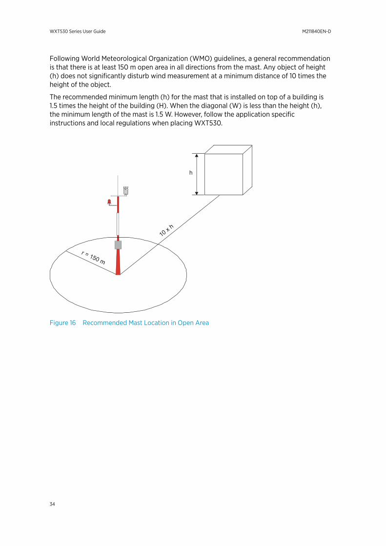
Following World Meteorological Organization (WMO) guidelines, a general recommendationis that there is at least 150 m open area in all directions from the mast. Any object of height(h) does not significantly disturb wind measurement at a minimum distance of 10 times theheight of the object.
The recommended minimum length (h) for the mast that is installed on top of a building is1.5 times the height of the building (H). When the diagonal (W) is less than the height (h),the minimum length of the mast is 1.5 W. However, follow the application specificinstructions and local regulations when placing WXT530.
Figure 16 Recommended Mast Location in Open Area
WXT530 Series User Guide M211840EN-D
34
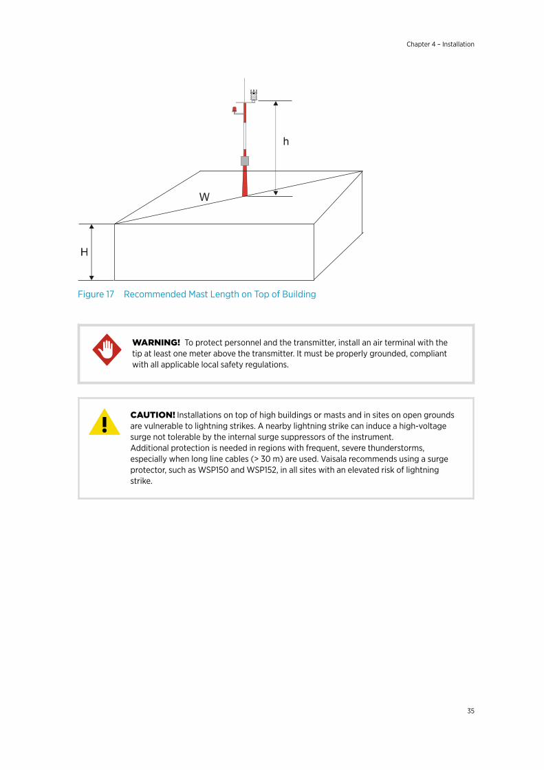
Figure 17 Recommended Mast Length on Top of Building
To protect personnel and the transmitter, install an air terminal with thetip at least one meter above the transmitter. It must be properly grounded, compliantwith all applicable local safety regulations.
WARNING!
Installations on top of high buildings or masts and in sites on open groundsare vulnerable to lightning strikes. A nearby lightning strike can induce a high-voltagesurge not tolerable by the internal surge suppressors of the instrument.Additional protection is needed in regions with frequent, severe thunderstorms,especially when long line cables (> 30 m) are used. Vaisala recommends using a surgeprotector, such as WSP150 and WSP152, in all sites with an elevated risk of lightningstrike.
CAUTION!
Chapter 4 – Installation
35
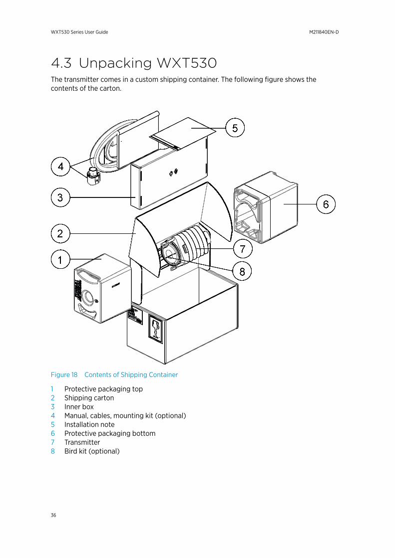
4.3 Unpacking WXT530The transmitter comes in a custom shipping container. The following figure shows thecontents of the carton.
Figure 18 Contents of Shipping Container
1 Protective packaging top2 Shipping carton3 Inner box4 Manual, cables, mounting kit (optional)5 Installation note6 Protective packaging bottom7 Transmitter8 Bird kit (optional)
WXT530 Series User Guide M211840EN-D
36
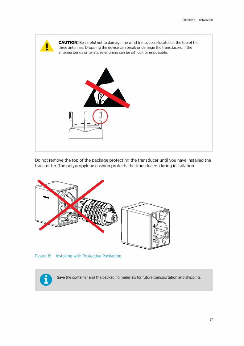
Be careful not to damage the wind transducers located at the top of thethree antennas. Dropping the device can break or damage the transducers. If theantenna bends or twists, re-aligning can be difficult or impossible.
CAUTION!
Do not remove the top of the package protecting the transducer until you have installed thetransmitter. The polypropylene cushion protects the transducers during installation.
Figure 19 Installing with Protective Packaging
Save the container and the packaging materials for future transportation and shipping.
Chapter 4 – Installation
37
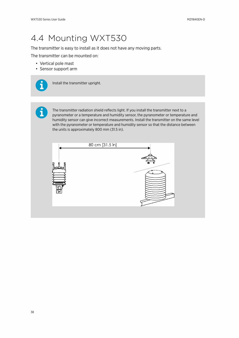
4.4 Mounting WXT530The transmitter is easy to install as it does not have any moving parts.
The transmitter can be mounted on:
• Vertical pole mast• Sensor support arm
Install the transmitter upright.
The transmitter radiation shield reflects light. If you install the transmitter next to apyranometer or a temperature and humidity sensor, the pyranometer or temperature andhumidity sensor can give incorrect measurements. Install the transmitter on the same levelwith the pyranometer or temperature and humidity sensor so that the distance betweenthe units is approximately 800 mm (31.5 in).
WXT530 Series User Guide M211840EN-D
38
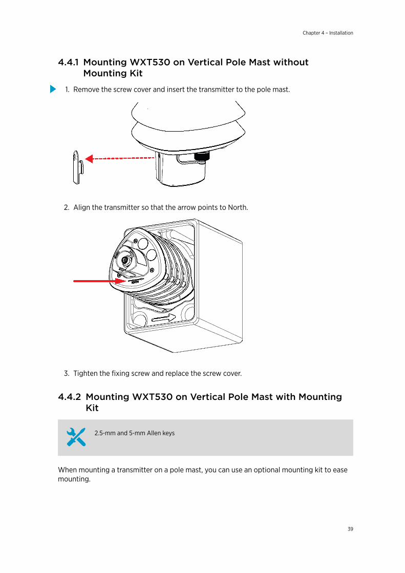
4.4.1 Mounting WXT530 on Vertical Pole Mast withoutMounting Kit
1. Remove the screw cover and insert the transmitter to the pole mast.
2. Align the transmitter so that the arrow points to North.
3. Tighten the fixing screw and replace the screw cover.
4.4.2 Mounting WXT530 on Vertical Pole Mast with MountingKit
2.5‑mm and 5‑mm Allen keys
When mounting a transmitter on a pole mast, you can use an optional mounting kit to easemounting.
Chapter 4 – Installation
39
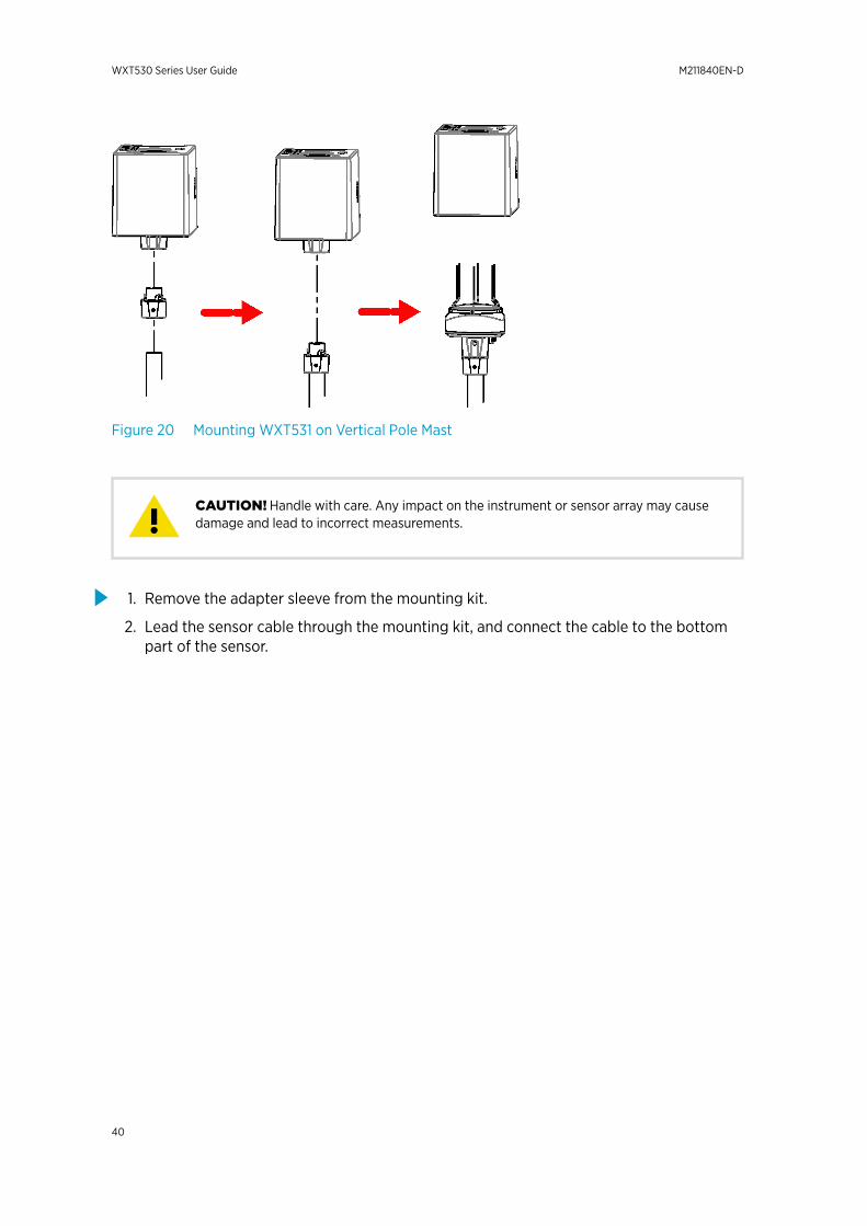
Figure 20 Mounting WXT531 on Vertical Pole Mast
Handle with care. Any impact on the instrument or sensor array may causedamage and lead to incorrect measurements.CAUTION!
1. Remove the adapter sleeve from the mounting kit.
2. Lead the sensor cable through the mounting kit, and connect the cable to the bottompart of the sensor.
WXT530 Series User Guide M211840EN-D
40
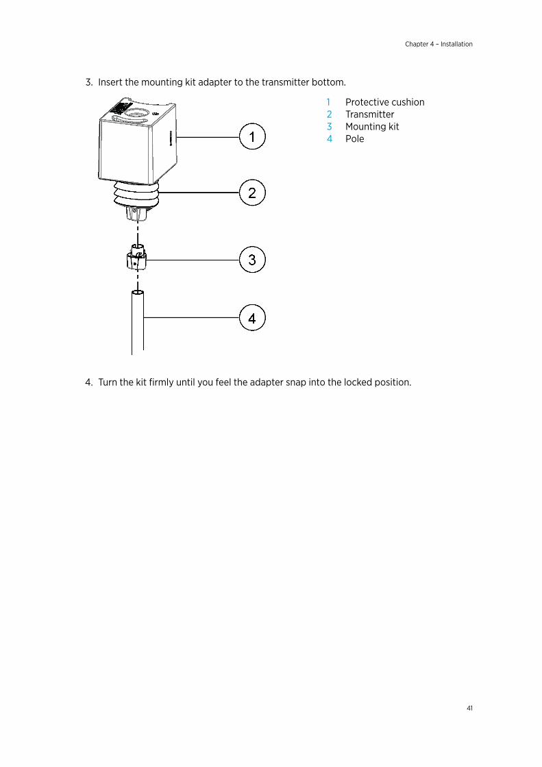
3. Insert the mounting kit adapter to the transmitter bottom.
1 Protective cushion2 Transmitter3 Mounting kit4 Pole
4. Turn the kit firmly until you feel the adapter snap into the locked position.
Chapter 4 – Installation
41
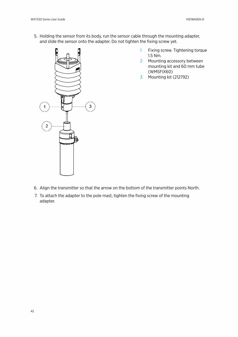
5. Holding the sensor from its body, run the sensor cable through the mounting adapter,and slide the sensor onto the adapter. Do not tighten the fixing screw yet.
1 Fixing screw. Tightening torque1.5 Nm.
2 Mounting accessory betweenmounting kit and 60 mm tube(WMSFIX60)
3 Mounting kit (212792)
6. Align the transmitter so that the arrow on the bottom of the transmitter points North.
7. To attach the adapter to the pole mast, tighten the fixing screw of the mountingadapter.
WXT530 Series User Guide M211840EN-D
42
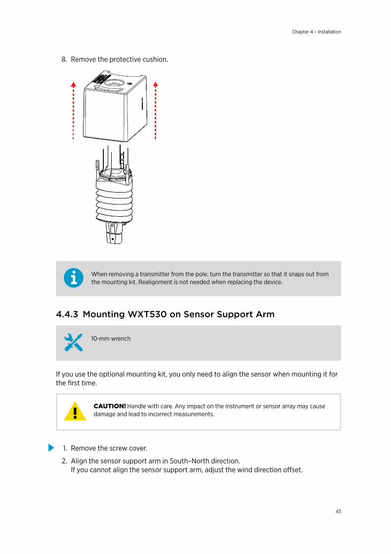
8. Remove the protective cushion.
When removing a transmitter from the pole, turn the transmitter so that it snaps out fromthe mounting kit. Realignment is not needed when replacing the device.
4.4.3 Mounting WXT530 on Sensor Support Arm
10‑mm wrench
If you use the optional mounting kit, you only need to align the sensor when mounting it forthe first time.
Handle with care. Any impact on the instrument or sensor array may causedamage and lead to incorrect measurements.CAUTION!
1. Remove the screw cover.
2. Align the sensor support arm in South–North direction. If you cannot align the sensor support arm, adjust the wind direction offset.
Chapter 4 – Installation
43
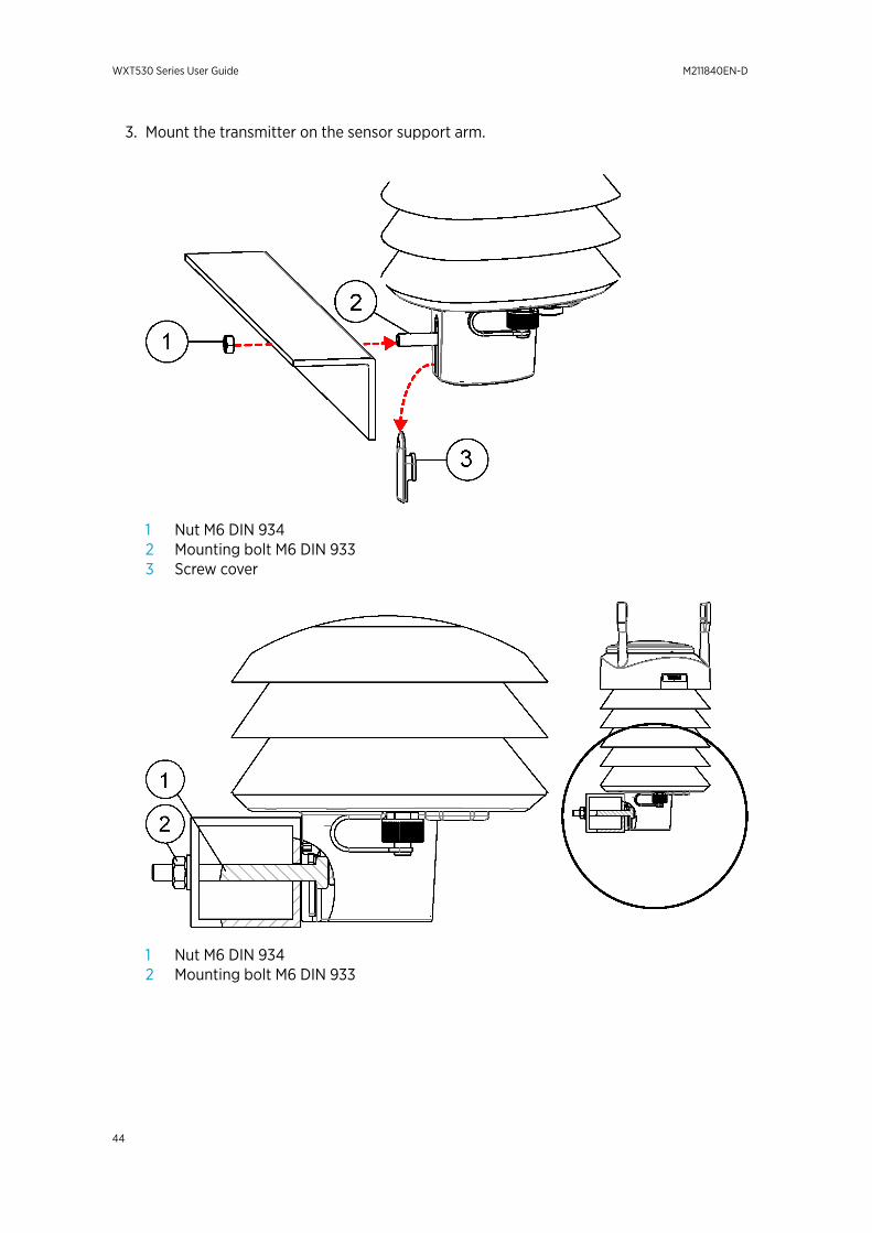
3. Mount the transmitter on the sensor support arm.
1 Nut M6 DIN 9342 Mounting bolt M6 DIN 9333 Screw cover
1 Nut M6 DIN 9342 Mounting bolt M6 DIN 933
WXT530 Series User Guide M211840EN-D
44
4.5 GroundingA transmitter is typically grounded by installing it on a mast or a cross arm that provides agood connection to earth ground.
As grounding is provided through the fixing screw (or mounting bolt), it is important that itmakes a good ground connection.
4.5.1 Grounding with Bushing and Grounding KitIf the surface of the mounting point is painted or has some other finishing that prevents agood electrical connection, consider using the Bushing and Grounding Kit (222109) and acable to ensure ground connection.
Use the Bushing and Grounding Kit to run a cable from the fixing screw to a groundingpoint. The kit does not include a grounding cable. The minimum grounding conductor size is4 mm2 (AWG 11).
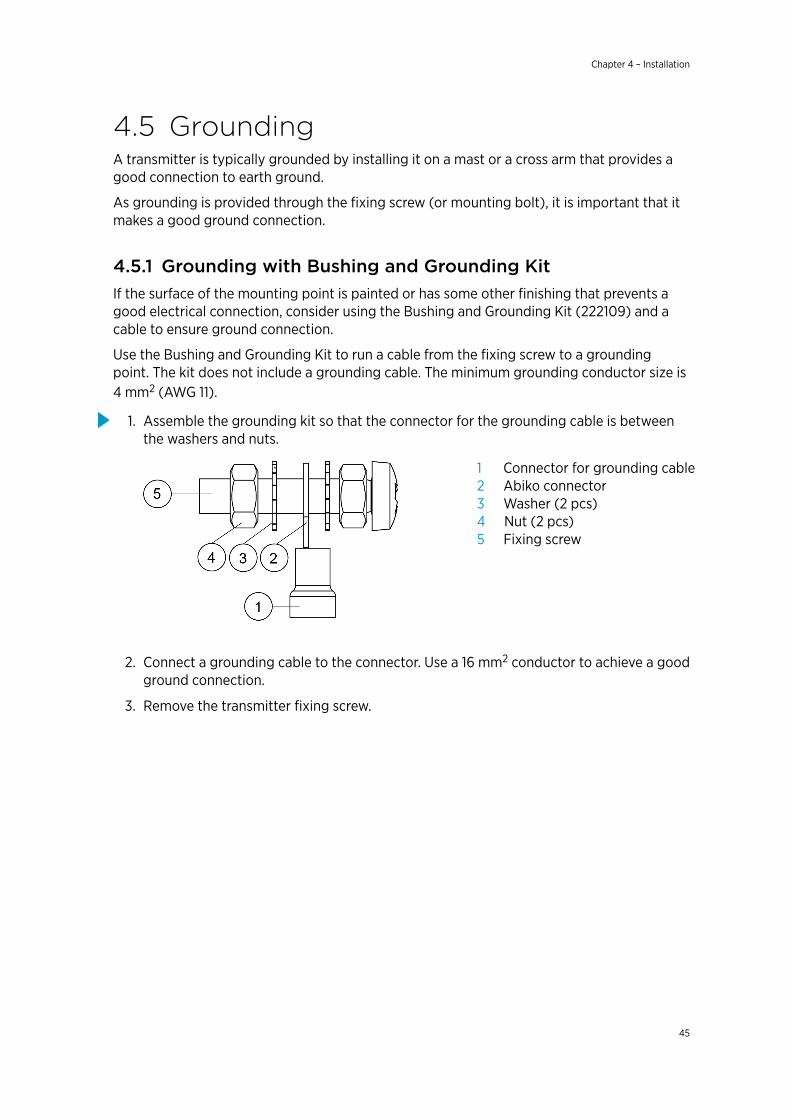
1. Assemble the grounding kit so that the connector for the grounding cable is betweenthe washers and nuts.
1 Connector for grounding cable2 Abiko connector3 Washer (2 pcs)4 Nut (2 pcs)5 Fixing screw
2. Connect a grounding cable to the connector. Use a 16 mm2 conductor to achieve a goodground connection.
3. Remove the transmitter fixing screw.
Chapter 4 – Installation
45
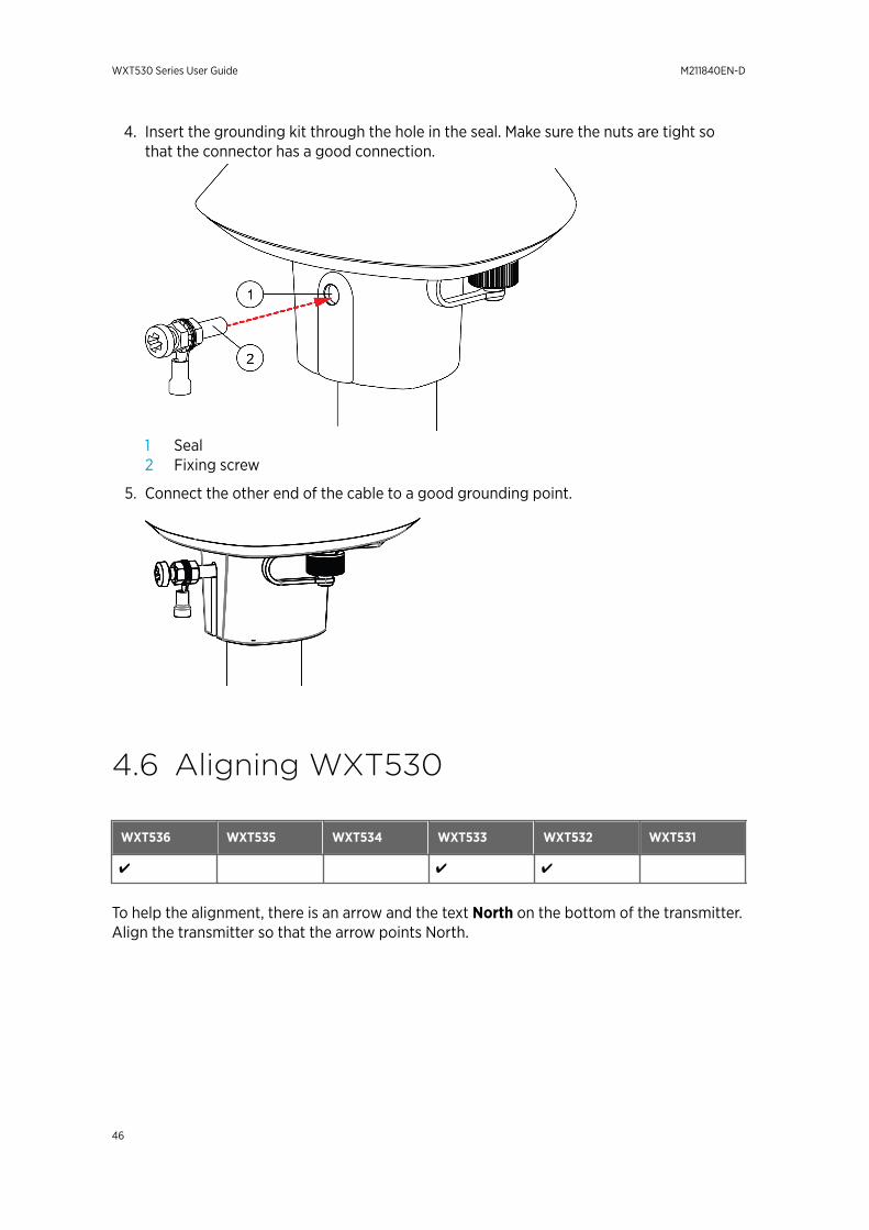
4. Insert the grounding kit through the hole in the seal. Make sure the nuts are tight sothat the connector has a good connection.
1 Seal2 Fixing screw
5. Connect the other end of the cable to a good grounding point.
4.6 Aligning WXT530
WXT536 WXT535 WXT534 WXT533 WXT532 WXT531
✔ ✔ ✔
To help the alignment, there is an arrow and the text North on the bottom of the transmitter.Align the transmitter so that the arrow points North.
WXT530 Series User Guide M211840EN-D
46
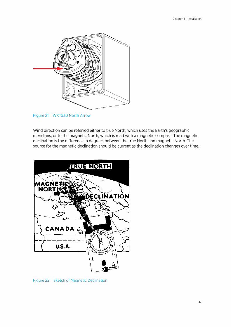
Figure 21 WXT530 North Arrow
Wind direction can be referred either to true North, which uses the Earth’s geographicmeridians, or to the magnetic North, which is read with a magnetic compass. The magneticdeclination is the difference in degrees between the true North and magnetic North. Thesource for the magnetic declination should be current as the declination changes over time.
Figure 22 Sketch of Magnetic Declination
Chapter 4 – Installation
47
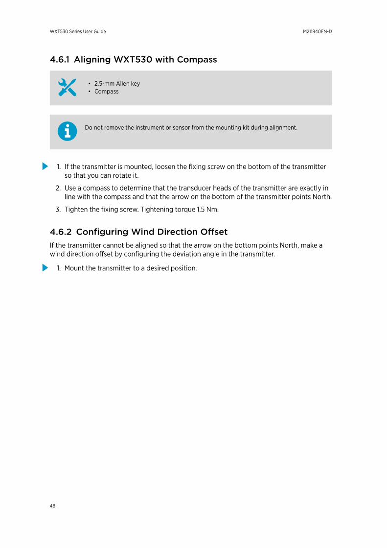
4.6.1 Aligning WXT530 with Compass
• 2.5‑mm Allen key• Compass
Do not remove the instrument or sensor from the mounting kit during alignment.
1. If the transmitter is mounted, loosen the fixing screw on the bottom of the transmitterso that you can rotate it.
2. Use a compass to determine that the transducer heads of the transmitter are exactly inline with the compass and that the arrow on the bottom of the transmitter points North.
3. Tighten the fixing screw. Tightening torque 1.5 Nm.
4.6.2 Configuring Wind Direction OffsetIf the transmitter cannot be aligned so that the arrow on the bottom points North, make awind direction offset by configuring the deviation angle in the transmitter.
1. Mount the transmitter to a desired position.
WXT530 Series User Guide M211840EN-D
48
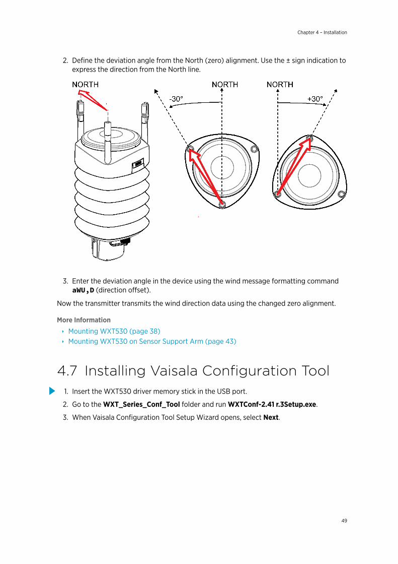
2. Define the deviation angle from the North (zero) alignment. Use the ± sign indication toexpress the direction from the North line.
3. Enter the deviation angle in the device using the wind message formatting commandaWU,D (direction offset).
Now the transmitter transmits the wind direction data using the changed zero alignment.
More Information
‣ Mounting WXT530 (page 38)‣ Mounting WXT530 on Sensor Support Arm (page 43)
4.7 Installing Vaisala Configuration Tool1. Insert the WXT530 driver memory stick in the USB port.
2. Go to the WXT_Series_Conf_Tool folder and run WXTConf-2.41 r.3Setup.exe.
3. When Vaisala Configuration Tool Setup Wizard opens, select Next.
Chapter 4 – Installation
49
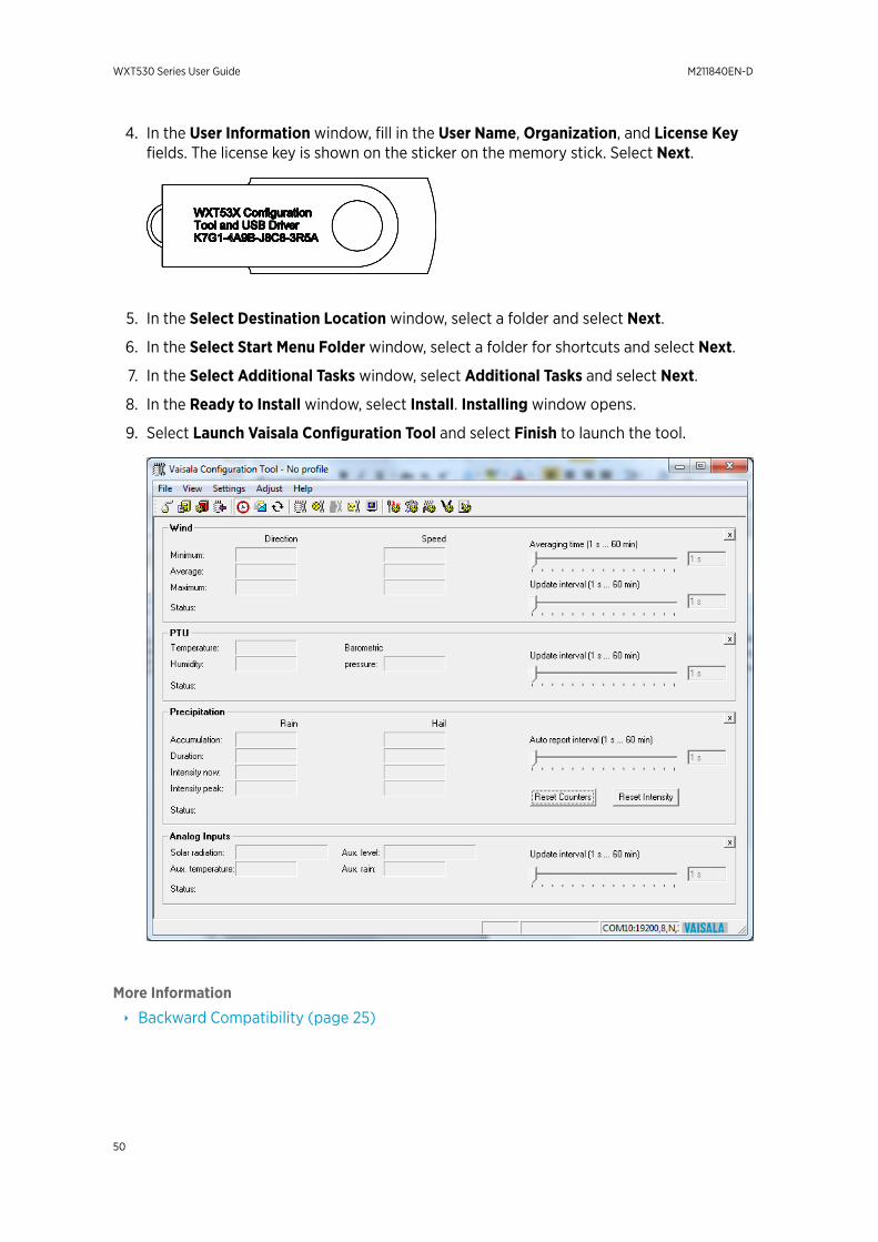
4. In the User Information window, fill in the User Name, Organization, and License Keyfields. The license key is shown on the sticker on the memory stick. Select Next.
5. In the Select Destination Location window, select a folder and select Next.
6. In the Select Start Menu Folder window, select a folder for shortcuts and select Next.
7. In the Select Additional Tasks window, select Additional Tasks and select Next.
8. In the Ready to Install window, select Install. Installing window opens.
9. Select Launch Vaisala Configuration Tool and select Finish to launch the tool.
More Information
‣ Backward Compatibility (page 25)
WXT530 Series User Guide M211840EN-D
50

4.8 Installing USB Cable DriverBefore taking the USB cable into use, you must install the USB cable driver on your PC. Thedriver is compatible with Windows 7, Windows 8, and Windows 10.
1. Make sure that the USB cable is not connected.
2. Insert the WXT530 driver memory stick in the USB port.
3. Go to the USB-driver folder and start installation by running setup.exe.
4. When Vaisala USB Device Driver Setup Wizard opens, select Next.
5. In the Select Additional Tasks window, select the tasks you want to perform and selectInstall.
Chapter 4 – Installation
51

6. Select Display Vaisala USB Device Finder > Finish. The driver is started.
7. Plug in the cable.
Remember to use the correct port in the settings of your terminal program. Windowsrecognizes each individual cable as a different device, and reserves a new COM port.
There is no reason to uninstall the driver for normal use. However, if you wish to remove thedriver files and all Vaisala USB cable devices, uninstall the entry for Vaisala USB InstrumentDriver from the program manager tool in the Windows Control Panel.
WXT530 Series User Guide M211840EN-D
52

5. Wiring and PowerManagement
This chapter describes how to connect the power supply and the serial interfaces and howto manage and estimate power consumption.
You can access the transmitter through the following serial interfaces:
• RS-232• RS-485• RS-422• SDI-12• mA output (WXT532)
You can wire them either through the internal screw terminal or the 8-pin M12 connector.You can use only one serial interface at a time.
The cable opening in the transmitter bottom assembly is covered withhexagonal rubber plugs. If you are not using the cable gland (included in the Bushingand Grounding Kit), keep the opening covered.
CAUTION!
More Information
‣ Wiring SDI-12 (page 171)
5.1 Power SuppliesThe minimum consumption graph is for SDI-12 standby mode.
Chapter 5 – Wiring and Power Management
53
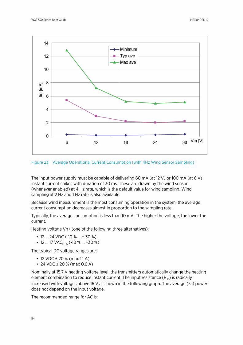
Figure 23 Average Operational Current Consumption (with 4Hz Wind Sensor Sampling)
The input power supply must be capable of delivering 60 mA (at 12 V) or 100 mA (at 6 V)instant current spikes with duration of 30 ms. These are drawn by the wind sensor(whenever enabled) at 4 Hz rate, which is the default value for wind sampling. Windsampling at 2 Hz and 1 Hz rate is also available.
Because wind measurement is the most consuming operation in the system, the averagecurrent consumption decreases almost in proportion to the sampling rate.
Typically, the average consumption is less than 10 mA. The higher the voltage, the lower thecurrent.
Heating voltage Vh+ (one of the following three alternatives):
• 12 … 24 VDC (-10 % … + 30 %)• 12 … 17 VACrms (-10 % … +30 %)
The typical DC voltage ranges are:
• 12 VDC ± 20 % (max 1.1 A)• 24 VDC ± 20 % (max 0.6 A)
Nominally at 15.7 V heating voltage level, the transmitters automatically change the heatingelement combination to reduce instant current. The input resistance (Rin) is radicallyincreased with voltages above 16 V as shown in the following graph. The average (5s) powerdoes not depend on the input voltage.
The recommended range for AC is:
WXT530 Series User Guide M211840EN-D
54
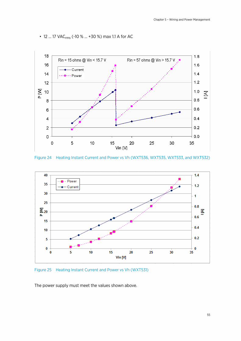
• 12 … 17 VACrms (-10 % … +30 %) max 1.1 A for AC
Figure 24 Heating Instant Current and Power vs Vh (WXT536, WXT535, WXT533, and WXT532)
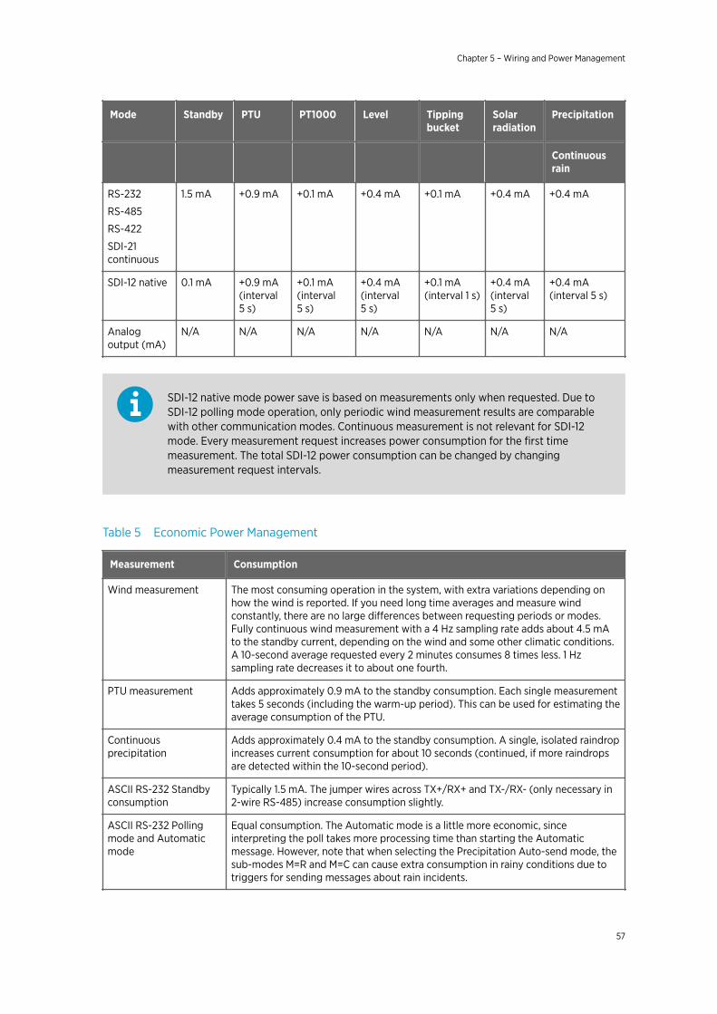
Figure 25 Heating Instant Current and Power vs Vh (WXT531)
The power supply must meet the values shown above.
Chapter 5 – Wiring and Power Management
55

Make sure that you connect only de-energized wires.WARNING!
To avoid exceeding the maximum ratings in any condition, the voltagesmust be checked with no load at the power supply output.CAUTION!
More Information
‣ Power Management (page 56)
5.2 Power ManagementThe power consumption varies significantly, depending on the selected operating mode orprotocol, the data interface type, the sensor configuration, and the measurement andreporting intervals.
Lowest consumption is achieved with the Native SDI-12 mode, typically about 1 mW instandby (0.1 mA at 12 V), while with ASCII RS-232 or Continuous SDI-12 modes it is about 3mW in standby. Any activated sensor measurement adds its own extra consumption to thestandby power.
Some hints for economic power management are given below. The consumption values areall defined for 12 V supply. For 6 V supply, multiply the values by 1.9. For 24 V supply,multiply the values by 0.65.
Table 4 Standby Power Consumption
Mode Standby Wind
4 Hz samplingrate
4 Hz samplingrate
1 Hz samplingrate
1 Hz samplingrate
Continuousmeasurement
10 s averageevery 2 min
Continuousmeasurement
10 s averageevery 2 min
RS-232
RS-485
RS-422
SDI-12continuous
1.5 mA +4.5 mA + 0.6 mA +1.3 mA +0.2 mA
SDI-12 native 0.1 mA N/A +1 mA N/A +0.7 mA
Analog output(mA)
N/A 16 … 90 mA 16 ... 90 mA 16 ... 90 mA 16 ... 90 mA
WXT530 Series User Guide M211840EN-D
56
Mode Standby PTU PT1000 Level Tippingbucket
Solarradiation
Precipitation
Continuousrain
RS-232
RS-485
RS-422
SDI-21continuous
1.5 mA +0.9 mA +0.1 mA +0.4 mA +0.1 mA +0.4 mA +0.4 mA
SDI-12 native 0.1 mA +0.9 mA(interval5 s)
+0.1 mA(interval5 s)
+0.4 mA(interval5 s)
+0.1 mA(interval 1 s)
+0.4 mA(interval5 s)
+0.4 mA(interval 5 s)
Analogoutput (mA)
N/A N/A N/A N/A N/A N/A N/A
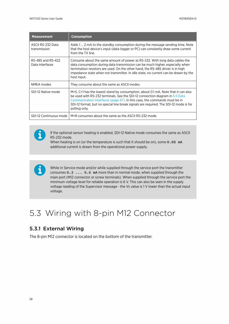
SDI-12 native mode power save is based on measurements only when requested. Due toSDI-12 polling mode operation, only periodic wind measurement results are comparablewith other communication modes. Continuous measurement is not relevant for SDI-12mode. Every measurement request increases power consumption for the first timemeasurement. The total SDI-12 power consumption can be changed by changingmeasurement request intervals.
Table 5 Economic Power Management
Measurement Consumption
Wind measurement The most consuming operation in the system, with extra variations depending onhow the wind is reported. If you need long time averages and measure windconstantly, there are no large differences between requesting periods or modes.Fully continuous wind measurement with a 4 Hz sampling rate adds about 4.5 mAto the standby current, depending on the wind and some other climatic conditions.A 10-second average requested every 2 minutes consumes 8 times less. 1 Hzsampling rate decreases it to about one fourth.
PTU measurement Adds approximately 0.9 mA to the standby consumption. Each single measurementtakes 5 seconds (including the warm-up period). This can be used for estimating theaverage consumption of the PTU.
Continuousprecipitation
Adds approximately 0.4 mA to the standby consumption. A single, isolated raindropincreases current consumption for about 10 seconds (continued, if more raindropsare detected within the 10-second period).
ASCII RS-232 Standbyconsumption
Typically 1.5 mA. The jumper wires across TX+/RX+ and TX-/RX- (only necessary in2-wire RS-485) increase consumption slightly.
ASCII RS-232 Pollingmode and Automaticmode
Equal consumption. The Automatic mode is a little more economic, sinceinterpreting the poll takes more processing time than starting the Automaticmessage. However, note that when selecting the Precipitation Auto-send mode, thesub-modes M=R and M=C can cause extra consumption in rainy conditions due totriggers for sending messages about rain incidents.
Chapter 5 – Wiring and Power Management
57
Measurement Consumption
ASCII RS-232 Datatransmission
Adds 1 ... 2 mA to the standby consumption during the message sending time. Notethat the host device's input (data logger or PC) can constantly draw some currentfrom the TX line.
RS-485 and RS-422Data interfaces
Consume about the same amount of power as RS-232. With long data cables thedata consumption during data transmission can be much higher, especially whentermination resistors are used. On the other hand, the RS-485 driver is in highimpedance state when not transmitter. In idle state, no current can be drawn by thehost input.
NMEA modes They consume about the same as ASCII modes.
SDI-12 Native mode M=S, C=1 has the lowest stand by consumption, about 0.1 mA. Note that it can alsobe used with RS-232 terminals. See the SDI-12 connection diagram in 5.5 DataCommunication Interfaces (page 67). In this case, the commands must be inSDI-12 format, but no special line break signals are required. The SDI-12 mode is forpolling only.
SDI-12 Continuous mode M=R consumes about the same as the ASCII RS-232 mode.
If the optional sensor heating is enabled, SDI-12 Native mode consumes the same as ASCIIRS-232 mode.When heating is on (or the temperature is such that it should be on), some 0.08 mAadditional current is drawn from the operational power supply.
While in Service mode and/or while supplied through the service port the transmitterconsumes 0.3 ... 0.6 mA more than in normal mode, when supplied through themain port (M12 connector or screw terminals). When supplied through the service port theminimum voltage level for reliable operation is 6 V. This can also be seen in the supplyvoltage reading of the Supervisor message - the Vs value is 1 V lower than the actual inputvoltage.
5.3 Wiring with 8-pin M12 Connector
5.3.1 External WiringThe 8-pin M12 connector is located on the bottom of the transmitter.
WXT530 Series User Guide M211840EN-D
58
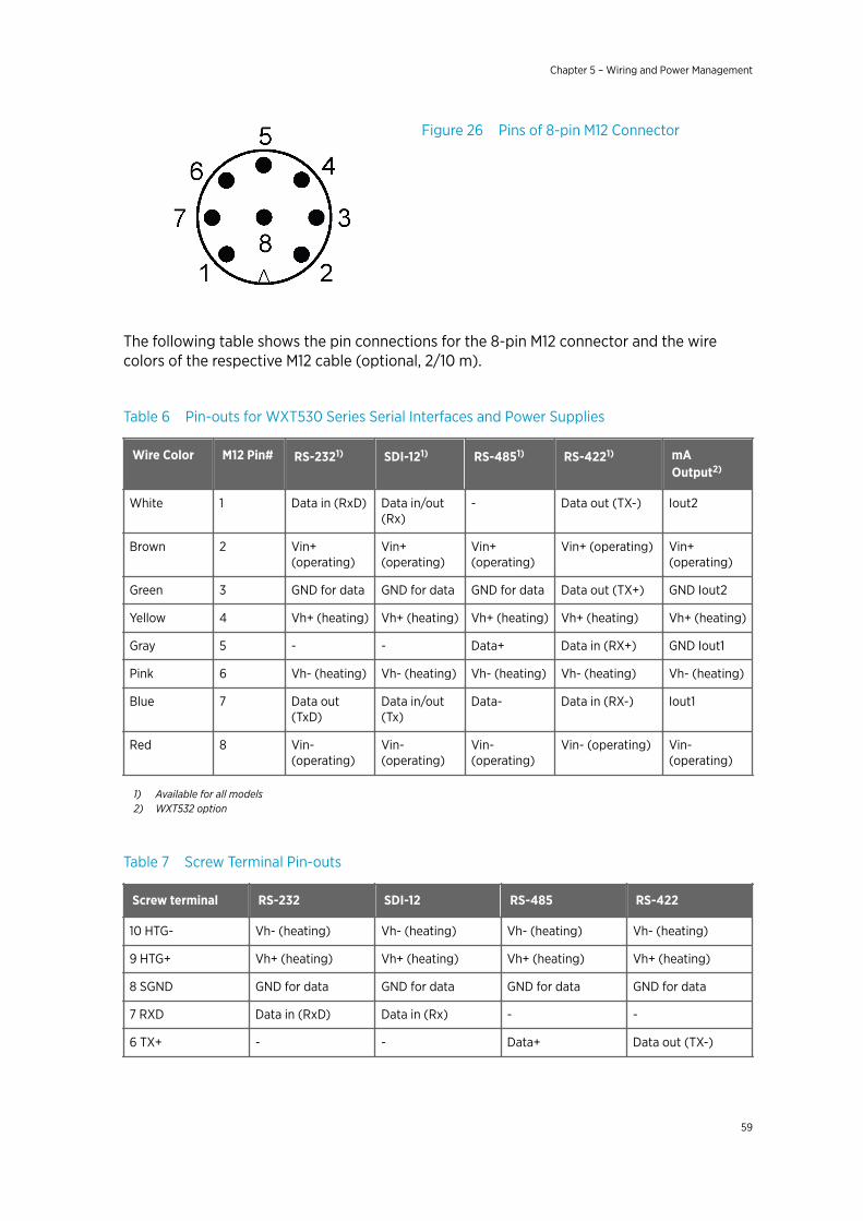
Figure 26 Pins of 8-pin M12 Connector
The following table shows the pin connections for the 8-pin M12 connector and the wirecolors of the respective M12 cable (optional, 2/10 m).
Table 6 Pin-outs for WXT530 Series Serial Interfaces and Power Supplies
Wire Color M12 Pin# RS-2321) SDI-121) RS-4851) RS-4221) mAOutput2)
White 1 Data in (RxD) Data in/out(Rx)
- Data out (TX-) Iout2
Brown 2 Vin+(operating)
Vin+(operating)
Vin+(operating)
Vin+ (operating) Vin+(operating)
Green 3 GND for data GND for data GND for data Data out (TX+) GND Iout2
Yellow 4 Vh+ (heating) Vh+ (heating) Vh+ (heating) Vh+ (heating) Vh+ (heating)
Gray 5 - - Data+ Data in (RX+) GND Iout1
Pink 6 Vh- (heating) Vh- (heating) Vh- (heating) Vh- (heating) Vh- (heating)
Blue 7 Data out(TxD)
Data in/out(Tx)
Data- Data in (RX-) Iout1
Red 8 Vin-(operating)
Vin-(operating)
Vin-(operating)
Vin- (operating) Vin-(operating)
1) Available for all models2) WXT532 option
Table 7 Screw Terminal Pin-outs
Screw terminal RS-232 SDI-12 RS-485 RS-422
10 HTG- Vh- (heating) Vh- (heating) Vh- (heating) Vh- (heating)
9 HTG+ Vh+ (heating) Vh+ (heating) Vh+ (heating) Vh+ (heating)
8 SGND GND for data GND for data GND for data GND for data
7 RXD Data in (RxD) Data in (Rx) - -
6 TX+ - - Data+ Data out (TX-)
Chapter 5 – Wiring and Power Management
59
Screw terminal RS-232 SDI-12 RS-485 RS-422
5 TX- Data out (TxD) Data out (Tx) Data - Data out (TX+)
4 RX+ - - - Data in (Rx+)
3 RX- - - - Data in (Rx-)
2 VIN- Vin- (operating) Vin- (operating) Vin- (operating) Vin- (operating)
1 VIN+ Vin+ (operating) Vin+ (operating) Vin+ (operating) Vin+ (operating)
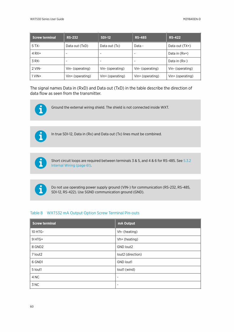
The signal names Data in (RxD) and Data out (TxD) in the table describe the direction ofdata flow as seen from the transmitter.
Ground the external wiring shield. The shield is not connected inside WXT.
In true SDI-12, Data in (Rx) and Data out (Tx) lines must be combined.
Short circuit loops are required between terminals 3 & 5, and 4 & 6 for RS-485. See 5.3.2Internal Wiring (page 61).
Do not use operating power supply ground (VIN-) for communication (RS-232, RS-485,SDI-12, RS-422). Use SGND communication ground (GND).
Table 8 WXT532 mA Output Option Screw Terminal Pin-outs
Screw terminal mA Output
10 HTG- Vh- (heating)
9 HTG+ Vh+ (heating)
8 GND2 GND Iout2
7 Iout2 Iout2 (direction)
6 GND1 GND Iout1
5 Iout1 Iout1 (wind)
4 NC -
3 NC -
WXT530 Series User Guide M211840EN-D
60
Screw terminal mA Output
2 VIN- Vin- (operating)
1 VIN+ Vin+ (operating)
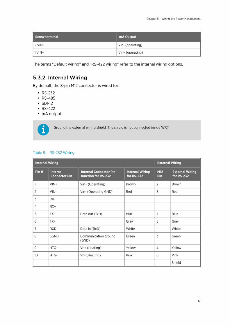
The terms "Default wiring" and "RS-422 wiring" refer to the internal wiring options.
5.3.2 Internal WiringBy default, the 8-pin M12 connector is wired for:
• RS-232• RS-485• SDI-12• RS-422• mA output
Ground the external wiring shield. The shield is not connected inside WXT.
Table 9 RS-232 Wiring
Internal Wiring External Wiring
Pin # InternalConnector Pin
Internal Connector Pinfunction for RS-232
Internal Wiringfor RS-232
M12Pin
External Wiringfor RS-232
1 VIN+ Vin+ (Operating) Brown 2 Brown
2 VIN- Vin- (Operating GND) Red 8 Red
3 RX-
4 RX+
5 TX- Data out (TxD) Blue 7 Blue
6 TX+ Gray 5 Gray
7 RXD Data in (RxD) White 1 White
8 SGND Communication ground(GND)
Green 3 Green
9 HTG+ Vh+ (Heating) Yellow 4 Yellow
10 HTG- Vh- (Heating) Pink 6 Pink
Shield
Chapter 5 – Wiring and Power Management
61
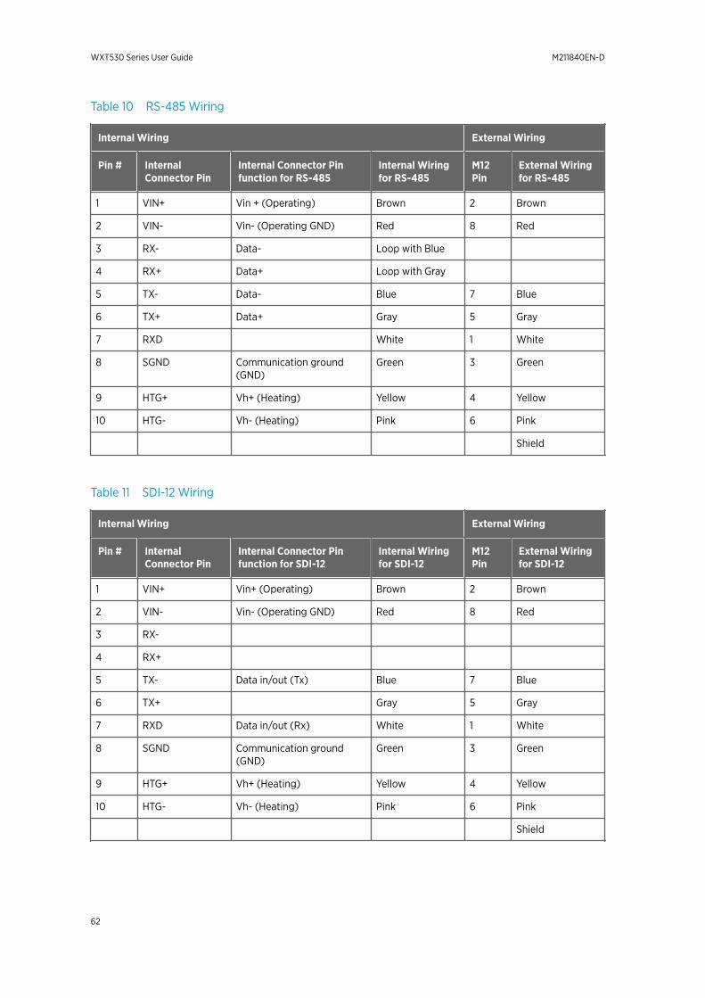
Table 10 RS-485 Wiring
Internal Wiring External Wiring
Pin # InternalConnector Pin
Internal Connector Pinfunction for RS-485
Internal Wiringfor RS-485
M12Pin
External Wiringfor RS-485
1 VIN+ Vin + (Operating) Brown 2 Brown
2 VIN- Vin- (Operating GND) Red 8 Red
3 RX- Data- Loop with Blue
4 RX+ Data+ Loop with Gray
5 TX- Data- Blue 7 Blue
6 TX+ Data+ Gray 5 Gray
7 RXD White 1 White
8 SGND Communication ground(GND)
Green 3 Green
9 HTG+ Vh+ (Heating) Yellow 4 Yellow
10 HTG- Vh- (Heating) Pink 6 Pink
Shield
Table 11 SDI-12 Wiring
Internal Wiring External Wiring
Pin # InternalConnector Pin
Internal Connector Pinfunction for SDI-12
Internal Wiringfor SDI-12
M12Pin
External Wiringfor SDI-12
1 VIN+ Vin+ (Operating) Brown 2 Brown
2 VIN- Vin- (Operating GND) Red 8 Red
3 RX-
4 RX+
5 TX- Data in/out (Tx) Blue 7 Blue
6 TX+ Gray 5 Gray
7 RXD Data in/out (Rx) White 1 White
8 SGND Communication ground(GND)
Green 3 Green
9 HTG+ Vh+ (Heating) Yellow 4 Yellow
10 HTG- Vh- (Heating) Pink 6 Pink
Shield
WXT530 Series User Guide M211840EN-D
62
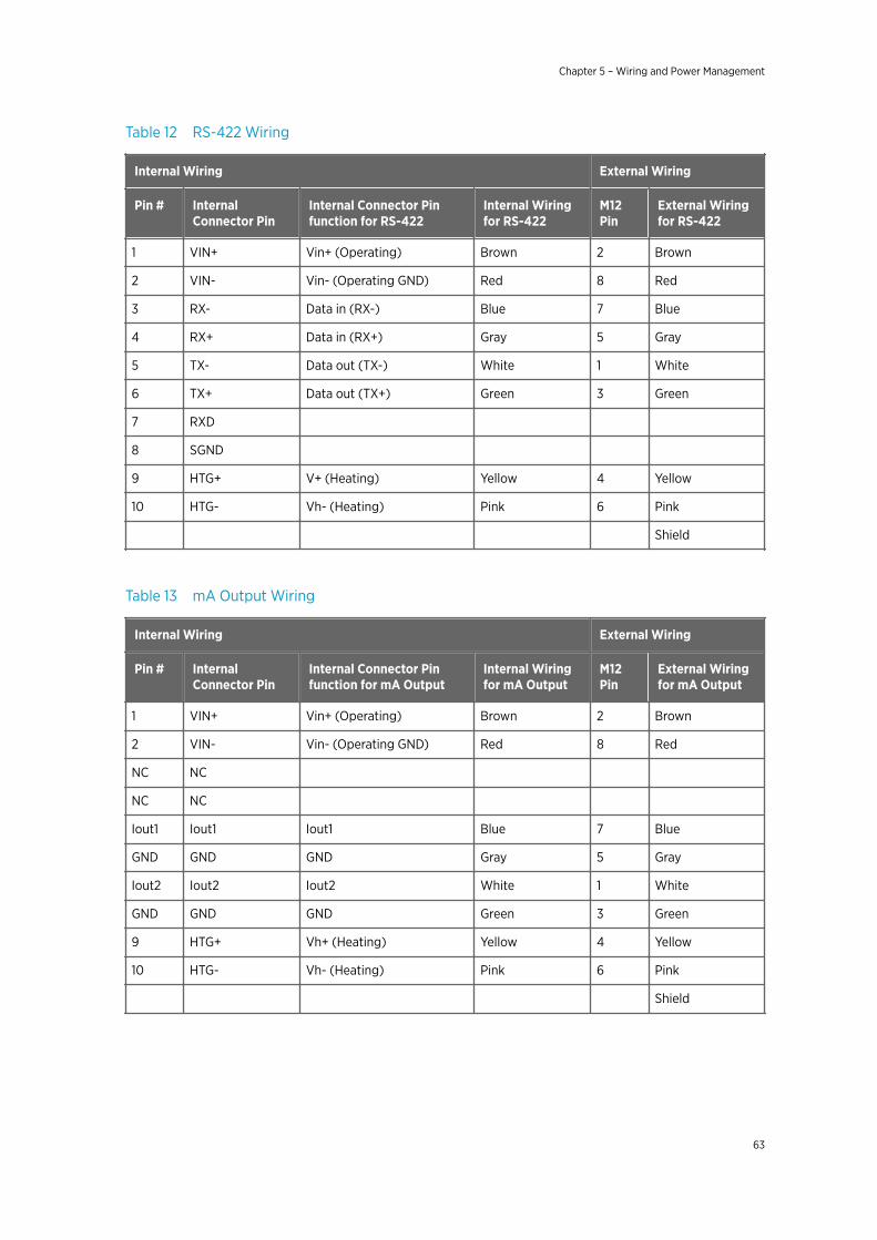
Table 12 RS-422 Wiring
Internal Wiring External Wiring
Pin # InternalConnector Pin
Internal Connector Pinfunction for RS-422
Internal Wiringfor RS-422
M12Pin
External Wiringfor RS-422
1 VIN+ Vin+ (Operating) Brown 2 Brown
2 VIN- Vin- (Operating GND) Red 8 Red
3 RX- Data in (RX-) Blue 7 Blue
4 RX+ Data in (RX+) Gray 5 Gray
5 TX- Data out (TX-) White 1 White
6 TX+ Data out (TX+) Green 3 Green
7 RXD
8 SGND
9 HTG+ V+ (Heating) Yellow 4 Yellow
10 HTG- Vh- (Heating) Pink 6 Pink
Shield
Table 13 mA Output Wiring
Internal Wiring External Wiring
Pin # InternalConnector Pin
Internal Connector Pinfunction for mA Output
Internal Wiringfor mA Output
M12Pin
External Wiringfor mA Output
1 VIN+ Vin+ (Operating) Brown 2 Brown
2 VIN- Vin- (Operating GND) Red 8 Red
NC NC
NC NC
Iout1 Iout1 Iout1 Blue 7 Blue
GND GND GND Gray 5 Gray
Iout2 Iout2 Iout2 White 1 White
GND GND GND Green 3 Green
9 HTG+ Vh+ (Heating) Yellow 4 Yellow
10 HTG- Vh- (Heating) Pink 6 Pink
Shield
Chapter 5 – Wiring and Power Management
63
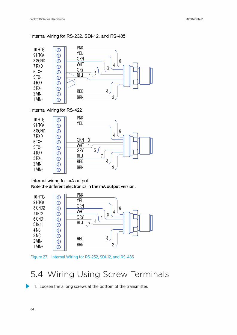
Figure 27 Internal Wiring for RS-232, SDI-12, and RS-485
5.4 Wiring Using Screw Terminals1. Loosen the 3 long screws at the bottom of the transmitter.
WXT530 Series User Guide M211840EN-D
64
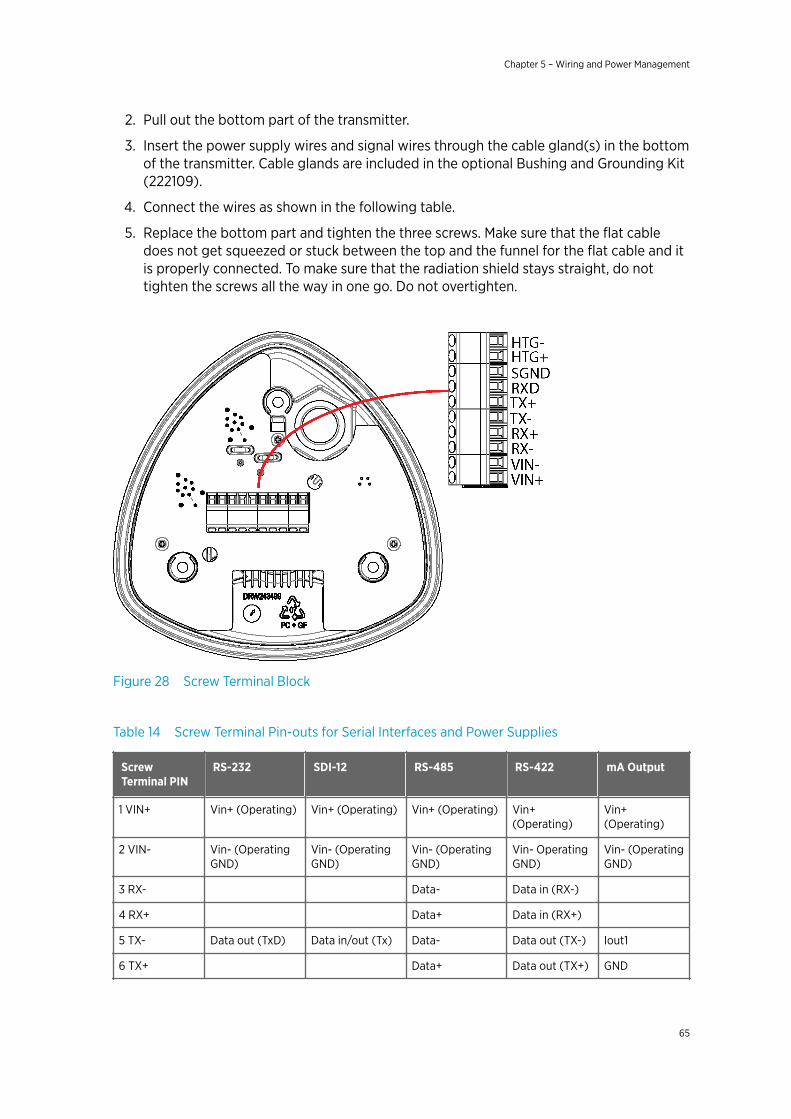
2. Pull out the bottom part of the transmitter.
3. Insert the power supply wires and signal wires through the cable gland(s) in the bottomof the transmitter. Cable glands are included in the optional Bushing and Grounding Kit(222109).
4. Connect the wires as shown in the following table.
5. Replace the bottom part and tighten the three screws. Make sure that the flat cabledoes not get squeezed or stuck between the top and the funnel for the flat cable and itis properly connected. To make sure that the radiation shield stays straight, do nottighten the screws all the way in one go. Do not overtighten.
Figure 28 Screw Terminal Block
Table 14 Screw Terminal Pin-outs for Serial Interfaces and Power Supplies
ScrewTerminal PIN
RS-232 SDI-12 RS-485 RS-422 mA Output
1 VIN+ Vin+ (Operating) Vin+ (Operating) Vin+ (Operating) Vin+(Operating)
Vin+(Operating)
2 VIN- Vin- (OperatingGND)
Vin- (OperatingGND)
Vin- (OperatingGND)
Vin- OperatingGND)
Vin- (OperatingGND)
3 RX- Data- Data in (RX-)
4 RX+ Data+ Data in (RX+)
5 TX- Data out (TxD) Data in/out (Tx) Data- Data out (TX-) Iout1
6 TX+ Data+ Data out (TX+) GND
Chapter 5 – Wiring and Power Management
65
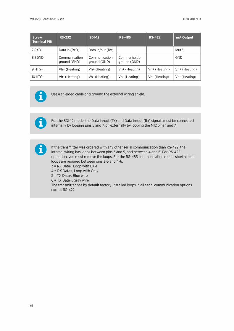
ScrewTerminal PIN
RS-232 SDI-12 RS-485 RS-422 mA Output
7 RXD Data in (RxD) Data in/out (Rx) Iout2
8 SGND Communicationground (GND)
Communicationground (GND)
Communicationground (GND)
GND
9 HTG+ Vh+ (Heating) Vh+ (Heating) Vh+ (Heating) Vh+ (Heating) Vh+ (Heating)
10 HTG- Vh- (Heating) Vh- (Heating) Vh- (Heating) Vh- (Heating) Vh- (Heating)
Use a shielded cable and ground the external wiring shield.
For the SDI-12 mode, the Data in/out (Tx) and Data in/out (Rx) signals must be connectedinternally by looping pins 5 and 7, or, externally by looping the M12 pins 1 and 7.
If the transmitter was ordered with any other serial communication than RS-422, theinternal wiring has loops between pins 3 and 5, and between 4 and 6. For RS-422operation, you must remove the loops. For the RS-485 communication mode, short-circuitloops are required between pins 3-5 and 4-6.3 = RX Data-, Loop with Blue4 = RX Data+, Loop with Gray5 = TX Data-, Blue wire6 = TX Data+, Gray wireThe transmitter has by default factory-installed loops in all serial communication optionsexcept RS-422.
WXT530 Series User Guide M211840EN-D
66
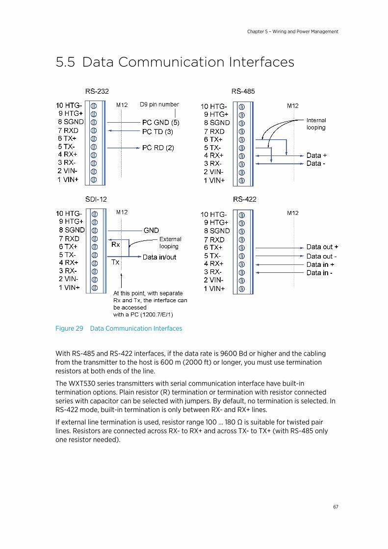
5.5 Data Communication Interfaces
Figure 29 Data Communication Interfaces
With RS-485 and RS-422 interfaces, if the data rate is 9600 Bd or higher and the cablingfrom the transmitter to the host is 600 m (2000 ft) or longer, you must use terminationresistors at both ends of the line.
The WXT530 series transmitters with serial communication interface have built-intermination options. Plain resistor (R) termination or termination with resistor connectedseries with capacitor can be selected with jumpers. By default, no termination is selected. InRS-422 mode, built-in termination is only between RX- and RX+ lines.
If external line termination is used, resistor range 100 … 180 Ω is suitable for twisted pairlines. Resistors are connected across RX- to RX+ and across TX- to TX+ (with RS-485 onlyone resistor needed).
Chapter 5 – Wiring and Power Management
67
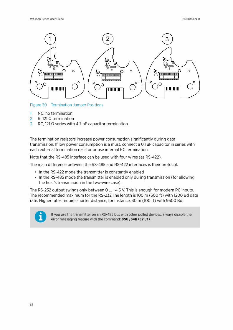
Figure 30 Termination Jumper Positions
1 NC, no termination2 R, 121 Ω termination3 RC, 121 Ω series with 4.7 nF capacitor termination
The termination resistors increase power consumption significantly during datatransmission. If low power consumption is a must, connect a 0.1 uF capacitor in series witheach external termination resistor or use internal RC termination.
Note that the RS-485 interface can be used with four wires (as RS-422).
The main difference between the RS-485 and RS-422 interfaces is their protocol:
• In the RS-422 mode the transmitter is constantly enabled• In the RS-485 mode the transmitter is enabled only during transmission (for allowing
the host’s transmission in the two-wire case).
The RS-232 output swings only between 0 ... +4.5 V. This is enough for modern PC inputs.The recommended maximum for the RS-232 line length is 100 m (300 ft) with 1200 Bd datarate. Higher rates require shorter distance, for instance, 30 m (100 ft) with 9600 Bd.
If you use the transmitter on an RS-485 bus with other polled devices, always disable theerror messaging feature with the command: 0SU,S=N<crlf>.
WXT530 Series User Guide M211840EN-D
68
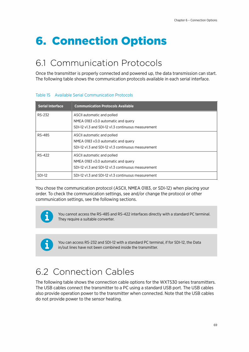
6. Connection Options
6.1 Communication ProtocolsOnce the transmitter is properly connected and powered up, the data transmission can start.The following table shows the communication protocols available in each serial interface.
Table 15 Available Serial Communication Protocols
Serial Interface Communication Protocols Available
RS-232 ASCII automatic and polled
NMEA 0183 v3.0 automatic and query
SDI-12 v1.3 and SDI-12 v1.3 continuous measurement
RS-485 ASCII automatic and polled
NMEA 0183 v3.0 automatic and query
SDI-12 v1.3 and SDI-12 v1.3 continuous measurement
RS-422 ASCII automatic and polled
NMEA 0183 v3.0 automatic and query
SDI-12 v1.3 and SDI-12 v1.3 continuous measurement
SDI-12 SDI-12 v1.3 and SDI-12 v1.3 continuous measurement
You chose the communication protocol (ASCII, NMEA 0183, or SDI-12) when placing yourorder. To check the communication settings, see and/or change the protocol or othercommunication settings, see the following sections.
You cannot access the RS-485 and RS-422 interfaces directly with a standard PC terminal.They require a suitable converter.
You can access RS-232 and SDI-12 with a standard PC terminal, if for SDI-12, the Datain/out lines have not been combined inside the transmitter.
6.2 Connection CablesThe following table shows the connection cable options for the WXT530 series transmitters.The USB cables connect the transmitter to a PC using a standard USB port. The USB cablesalso provide operation power to the transmitter when connected. Note that the USB cablesdo not provide power to the sensor heating.
Chapter 6 – Connection Options
69
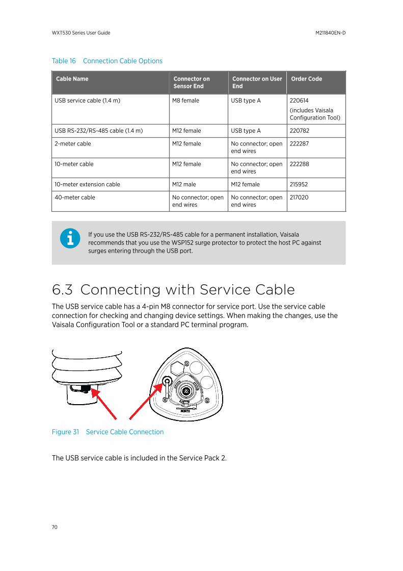
Table 16 Connection Cable Options
Cable Name Connector onSensor End
Connector on UserEnd
Order Code
USB service cable (1.4 m) M8 female USB type A 220614
(includes VaisalaConfiguration Tool)
USB RS-232/RS-485 cable (1.4 m) M12 female USB type A 220782
2-meter cable M12 female No connector; openend wires
222287
10-meter cable M12 female No connector; openend wires
222288
10-meter extension cable M12 male M12 female 215952
40-meter cable No connector; openend wires
No connector; openend wires
217020
If you use the USB RS-232/RS-485 cable for a permanent installation, Vaisalarecommends that you use the WSP152 surge protector to protect the host PC againstsurges entering through the USB port.
6.3 Connecting with Service CableThe USB service cable has a 4-pin M8 connector for service port. Use the service cableconnection for checking and changing device settings. When making the changes, use theVaisala Configuration Tool or a standard PC terminal program.
Figure 31 Service Cable Connection
The USB service cable is included in the Service Pack 2.
WXT530 Series User Guide M211840EN-D
70
When you connect the USB service cable between the service connector and PC USB port,the service port settings are forced automatically to RS-232 / 19200, 8, N, 1, and the mainserial port at the M12 connector at the screw terminals is disabled.
1. Use the USB service cable to establish a connection between the USB port of your PCand the M8 service port connector on the bottom plate of the transmitter.
2. Open the Vaisala Configuration Tool or a terminal program.
3. Select the COM port reserved for the USB cable and select the following defaultcommunication settings:
19200, 8, N, 1.
4. Use the Vaisala Configuration Tool or a terminal program to make the configurationchanges.
5. When removing the service cable, support the transmitter while pulling the 4-pin M8connector for service port. The connection is tight, and it is possible to change thealignment of the transmitter if you pull too hard.
Changes to the serial interface/communication protocol/baud settings take place whenyou disconnect the service cable or reset the transmitter.If these settings are not changed during the service connection session, the original mainport settings (at M12 and screw terminals) are returned when the service cable isdisconnected from either end.
More Information
‣ Communication Setting Commands (page 72)
6.3.1 Connecting through M12 Bottom Connector or ScrewTerminal
You can check and change the device settings through the 8-pin M12 bottom connector orscrew terminal.
To do this, you must know the device communication settings, have a suitable cablebetween the device and the host, and, if needed, use a converter (for example, RS-485/422to RS-232, if the host is a PC). The following table shows the factory default settings:
Table 17 Default Serial Communication Settings for M12/Screw Terminal Connection
Serial Interface Serial Settings
SDI-12 1200 baud, 7, E, 1
RS-232 ASCII 19200 baud, 8, N, 1
Chapter 6 – Connection Options
71
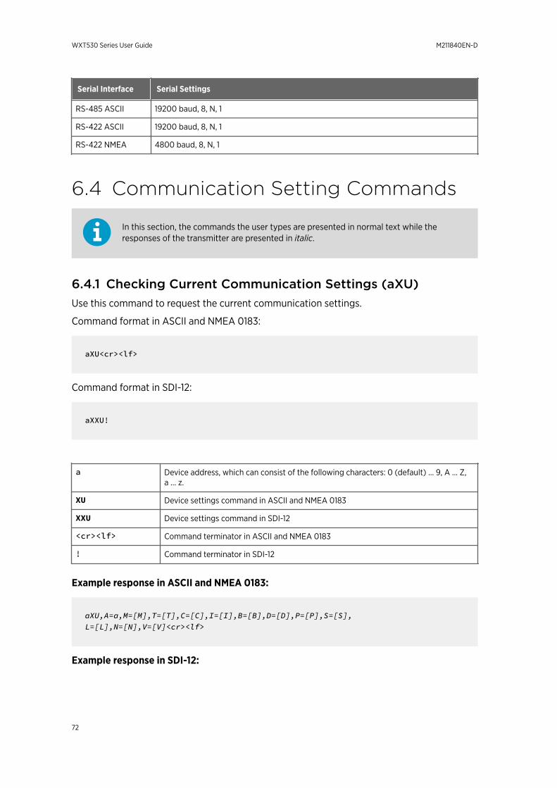
Serial Interface Serial Settings
RS-485 ASCII 19200 baud, 8, N, 1
RS-422 ASCII 19200 baud, 8, N, 1
RS-422 NMEA 4800 baud, 8, N, 1
6.4 Communication Setting Commands
In this section, the commands the user types are presented in normal text while theresponses of the transmitter are presented in italic.
6.4.1 Checking Current Communication Settings (aXU)Use this command to request the current communication settings.
Command format in ASCII and NMEA 0183:
aXU<cr><lf>
Command format in SDI-12:
aXXU!
a Device address, which can consist of the following characters: 0 (default) ... 9, A ... Z,a ... z.
XU Device settings command in ASCII and NMEA 0183
XXU Device settings command in SDI-12
<cr><lf> Command terminator in ASCII and NMEA 0183
! Command terminator in SDI-12
Example response in ASCII and NMEA 0183:
aXU,A=a,M=[M],T=[T],C=[C],I=[I],B=[B],D=[D],P=[P],S=[S], L=[L],N=[N],V=[V]<cr><lf>
Example response in SDI-12:
WXT530 Series User Guide M211840EN-D
72
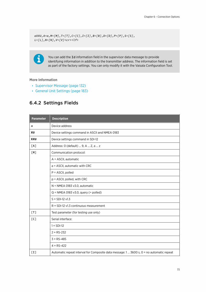
aXXU,A=a,M=[M],T=[T],C=[C],I=[I],B=[B],D=[D],P=[P],S=[S], L=[L],N=[N],V=[V]<cr><lf>
You can add the Id information field in the supervisor data message to provideidentifying information in addition to the transmitter address. The information field is setas part of the factory settings. You can only modify it with the Vaisala Configuration Tool.
More Information
‣ Supervisor Message (page 132)‣ General Unit Settings (page 183)
6.4.2 Settings Fields
Parameter Description
a Device address
XU Device settings command in ASCII and NMEA 0183
XXU Device settings command in SDI-12
[A] Address: 0 (default) … 9, A … Z, a … z
[M] Communication protocol:
A = ASCII, automatic
a = ASCII, automatic with CRC
P = ASCII, polled
p = ASCII, polled, with CRC
N = NMEA 0183 v3.0, automatic
Q = NMEA 0183 v3.0, query (= polled)
S = SDI-12 v1.3
R = SDI-12 v1.3 continuous measurement
[T] Test parameter (for testing use only)
[C] Serial interface:
1 = SDI-12
2 = RS-232
3 = RS-485
4 = RS-422
[I] Automatic repeat interval for Composite data message: 1 … 3600 s, 0 = no automatic repeat
Chapter 6 – Connection Options
73
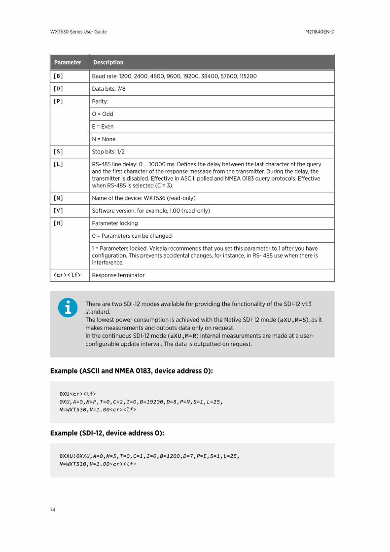
Parameter Description
[B] Baud rate: 1200, 2400, 4800, 9600, 19200, 38400, 57600, 115200
[D] Data bits: 7/8
[P] Parity:
O = Odd
E = Even
N = None
[S] Stop bits: 1/2
[L] RS-485 line delay: 0 … 10000 ms. Defines the delay between the last character of the queryand the first character of the response message from the transmitter. During the delay, thetransmitter is disabled. Effective in ASCII, polled and NMEA 0183 query protocols. Effectivewhen RS-485 is selected (C = 3).
[N] Name of the device: WXT536 (read-only)
[V] Software version: for example, 1.00 (read-only)
[H] Parameter locking
0 = Parameters can be changed
1 = Parameters locked. Vaisala recommends that you set this parameter to 1 after you haveconfiguration. This prevents accidental changes, for instance, in RS- 485 use when there isinterference.
<cr><lf> Response terminator
There are two SDI-12 modes available for providing the functionality of the SDI-12 v1.3standard.The lowest power consumption is achieved with the Native SDI-12 mode (aXU,M=S), as itmakes measurements and outputs data only on request.In the continuous SDI-12 mode (aXU,M=R) internal measurements are made at a user-configurable update interval. The data is outputted on request.
Example (ASCII and NMEA 0183, device address 0):
0XU<cr><lf>0XU,A=0,M=P,T=0,C=2,I=0,B=19200,D=8,P=N,S=1,L=25,N=WXT530,V=1.00<cr><lf>
Example (SDI-12, device address 0):
0XXU!0XXU,A=0,M=S,T=0,C=1,I=0,B=1200,D=7,P=E,S=1,L=25,N=WXT530,V=1.00<cr><lf>
WXT530 Series User Guide M211840EN-D
74
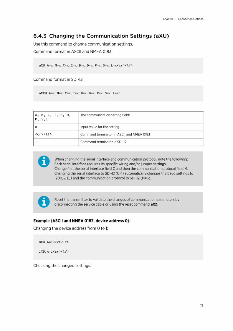
6.4.3 Changing the Communication Settings (aXU)Use this command to change communication settings.
Command format in ASCII and NMEA 0183:
aXU,A=x,M=x,C=x,I=x,B=x,D=x,P=x,S=x,L=x<cr><lf>
Command format in SDI-12:
aXXU,A=x,M=x,C=x,I=x,B=x,D=x,P=x,S=x,L=x!
A, M, C, I, B, D,P, S,L
The communication setting fields.
x Input value for the setting
<cr><lf> Command terminator in ASCII and NMEA 0183
! Command terminator in SDI-12
When changing the serial interface and communication protocol, note the following:Each serial interface requires its specific wiring and/or jumper settings.Change first the serial interface field C and then the communication protocol field M.Changing the serial interface to SDI-12 (C=1) automatically changes the baud settings to1200, 7, E, 1 and the communication protocol to SDI-12 (M=S).
Reset the transmitter to validate the changes of communication parameters bydisconnecting the service cable or using the reset command aXZ.
Example (ASCII and NMEA 0183, device address 0):
Changing the device address from 0 to 1:
0XU,A=1<cr><lf>
1XU,A=1<cr><lf>
Checking the changed settings:
Chapter 6 – Connection Options
75
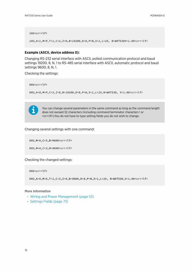
1XU<cr><lf>
1XU,A=1,M=P,T=1,C=2,I=0,B=19200,D=8,P=N,S=1,L=25, N=WXT530V=1.00<cr><lf>
Example (ASCII, device address 0):
Changing RS-232 serial interface with ASCII, polled communication protocol and baudsettings 19200, 8, N, 1 to RS-485 serial interface with ASCII, automatic protocol and baudsettings 9600, 8, N, 1.
Checking the settings:
0XU<cr><lf>
0XU,A=0,M=P,C=2,I=0,B=19200,D=8,P=N,S=1,L=25,N=WXT530, V=1.00<cr><lf>
You can change several parameters in the same command as long as the command lengthdoes not exceed 32 characters (including command terminator characters ! or<cr><lf>).You do not have to type setting fields you do not wish to change.
Changing several settings with one command:
0XU,M=A,C=3,B=9600<cr><lf>
0XU,M=A,C=3,B=9600<cr><lf>
Checking the changed settings:
0XU<cr><lf>
0XU,A=0,M=A,T=1,C=3,I=0,B=9600,D=8,P=N,S=1,L=25, N=WXT530,V=1.00<cr><lf>
More Information
‣ Wiring and Power Management (page 53)‣ Settings Fields (page 73)
WXT530 Series User Guide M211840EN-D
76
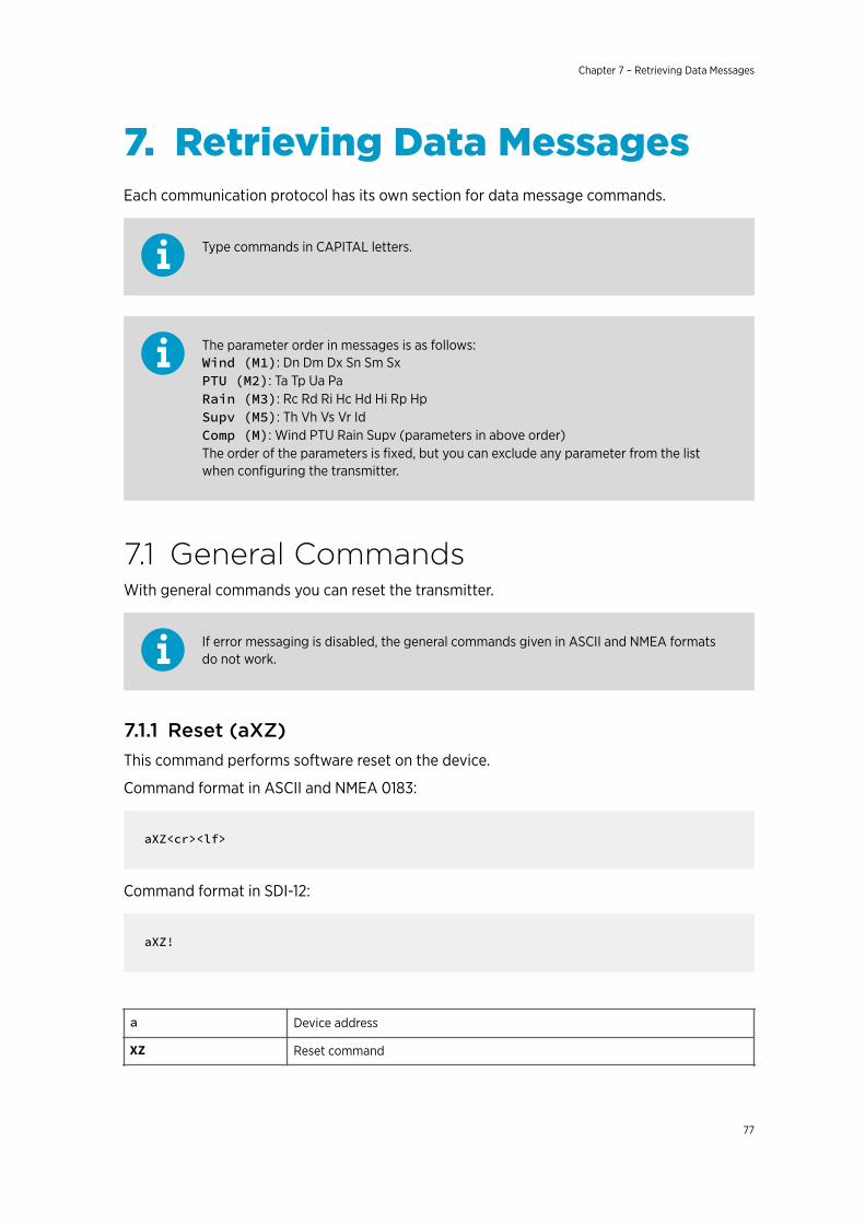
7. Retrieving Data MessagesEach communication protocol has its own section for data message commands.
Type commands in CAPITAL letters.
The parameter order in messages is as follows:Wind (M1): Dn Dm Dx Sn Sm SxPTU (M2): Ta Tp Ua PaRain (M3): Rc Rd Ri Hc Hd Hi Rp HpSupv (M5): Th Vh Vs Vr IdComp (M): Wind PTU Rain Supv (parameters in above order)The order of the parameters is fixed, but you can exclude any parameter from the listwhen configuring the transmitter.
7.1 General CommandsWith general commands you can reset the transmitter.
If error messaging is disabled, the general commands given in ASCII and NMEA formatsdo not work.
7.1.1 Reset (aXZ)This command performs software reset on the device.
Command format in ASCII and NMEA 0183:
aXZ<cr><lf>
Command format in SDI-12:
aXZ!
a Device address
XZ Reset command
Chapter 7 – Retrieving Data Messages
77
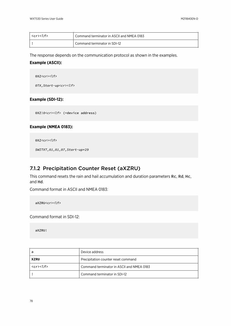
<cr><lf> Command terminator in ASCII and NMEA 0183
! Command terminator in SDI-12
The response depends on the communication protocol as shown in the examples.
Example (ASCII):
0XZ<cr><lf>
0TX,Start-up<cr><lf>
Example (SDI-12):
0XZ!0<cr><lf> (=device address)
Example (NMEA 0183):
0XZ<cr><lf>
$WITXT,01,01,07,Start-up*29
7.1.2 Precipitation Counter Reset (aXZRU)This command resets the rain and hail accumulation and duration parameters Rc, Rd, Hc,and Hd.
Command format in ASCII and NMEA 0183:
aXZRU<cr><lf>
Command format in SDI-12:
aXZRU!
a Device address
XZRU Precipitation counter reset command
<cr><lf> Command terminator in ASCII and NMEA 0183
! Command terminator in SDI-12
WXT530 Series User Guide M211840EN-D
78
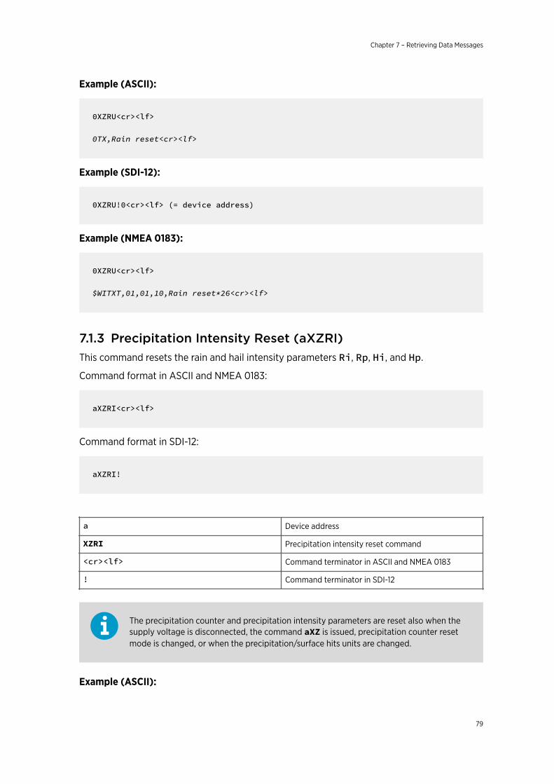
Example (ASCII):
0XZRU<cr><lf>
0TX,Rain reset<cr><lf>
Example (SDI-12):
0XZRU!0<cr><lf> (= device address)
Example (NMEA 0183):
0XZRU<cr><lf>
$WITXT,01,01,10,Rain reset*26<cr><lf>
7.1.3 Precipitation Intensity Reset (aXZRI)This command resets the rain and hail intensity parameters Ri, Rp, Hi, and Hp.
Command format in ASCII and NMEA 0183:
aXZRI<cr><lf>
Command format in SDI-12:
aXZRI!
a Device address
XZRI Precipitation intensity reset command
<cr><lf> Command terminator in ASCII and NMEA 0183
! Command terminator in SDI-12
The precipitation counter and precipitation intensity parameters are reset also when thesupply voltage is disconnected, the command aXZ is issued, precipitation counter resetmode is changed, or when the precipitation/surface hits units are changed.
Example (ASCII):
Chapter 7 – Retrieving Data Messages
79
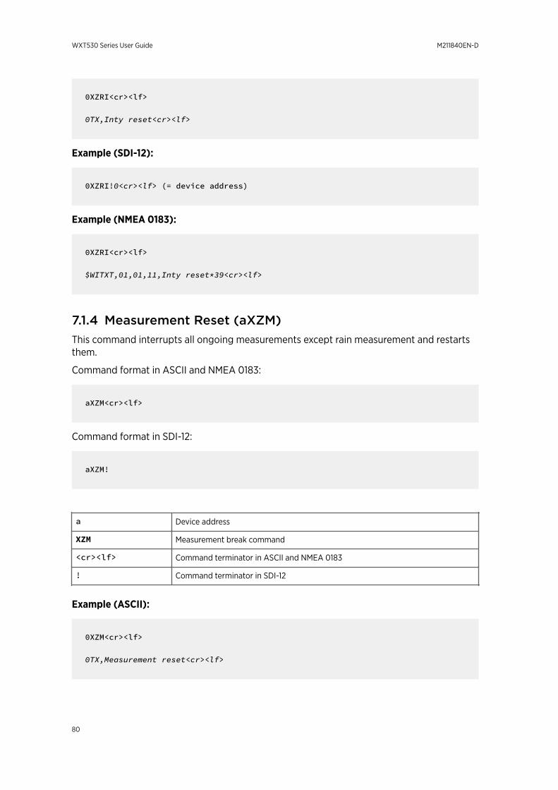
0XZRI<cr><lf>
0TX,Inty reset<cr><lf>
Example (SDI-12):
0XZRI!0<cr><lf> (= device address)
Example (NMEA 0183):
0XZRI<cr><lf>
$WITXT,01,01,11,Inty reset*39<cr><lf>
7.1.4 Measurement Reset (aXZM)This command interrupts all ongoing measurements except rain measurement and restartsthem.
Command format in ASCII and NMEA 0183:
aXZM<cr><lf>
Command format in SDI-12:
aXZM!
a Device address
XZM Measurement break command
<cr><lf> Command terminator in ASCII and NMEA 0183
! Command terminator in SDI-12
Example (ASCII):
0XZM<cr><lf>
0TX,Measurement reset<cr><lf>
WXT530 Series User Guide M211840EN-D
80
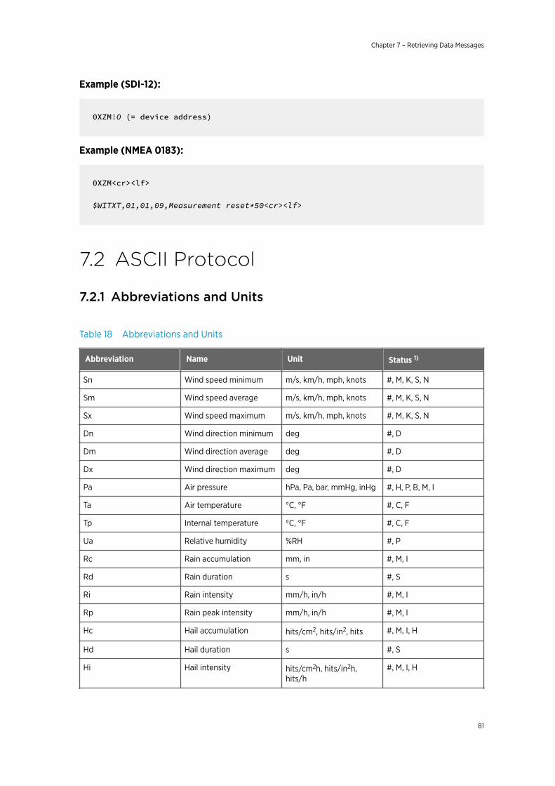
Example (SDI-12):
0XZM!0 (= device address)
Example (NMEA 0183):
0XZM<cr><lf>
$WITXT,01,01,09,Measurement reset*50<cr><lf>
7.2 ASCII Protocol
7.2.1 Abbreviations and Units
Table 18 Abbreviations and Units
Abbreviation Name Unit Status 1)
Sn Wind speed minimum m/s, km/h, mph, knots #, M, K, S, N
Sm Wind speed average m/s, km/h, mph, knots #, M, K, S, N
Sx Wind speed maximum m/s, km/h, mph, knots #, M, K, S, N
Dn Wind direction minimum deg #, D
Dm Wind direction average deg #, D
Dx Wind direction maximum deg #, D
Pa Air pressure hPa, Pa, bar, mmHg, inHg #, H, P, B, M, I
Ta Air temperature °C, °F #, C, F
Tp Internal temperature °C, °F #, C, F
Ua Relative humidity %RH #, P
Rc Rain accumulation mm, in #, M, I
Rd Rain duration s #, S
Ri Rain intensity mm/h, in/h #, M, I
Rp Rain peak intensity mm/h, in/h #, M, I
Hc Hail accumulation hits/cm2, hits/in2, hits #, M, I, H
Hd Hail duration s #, S
Hi Hail intensity hits/cm2h, hits/in2h,hits/h
#, M, I, H
Chapter 7 – Retrieving Data Messages
81
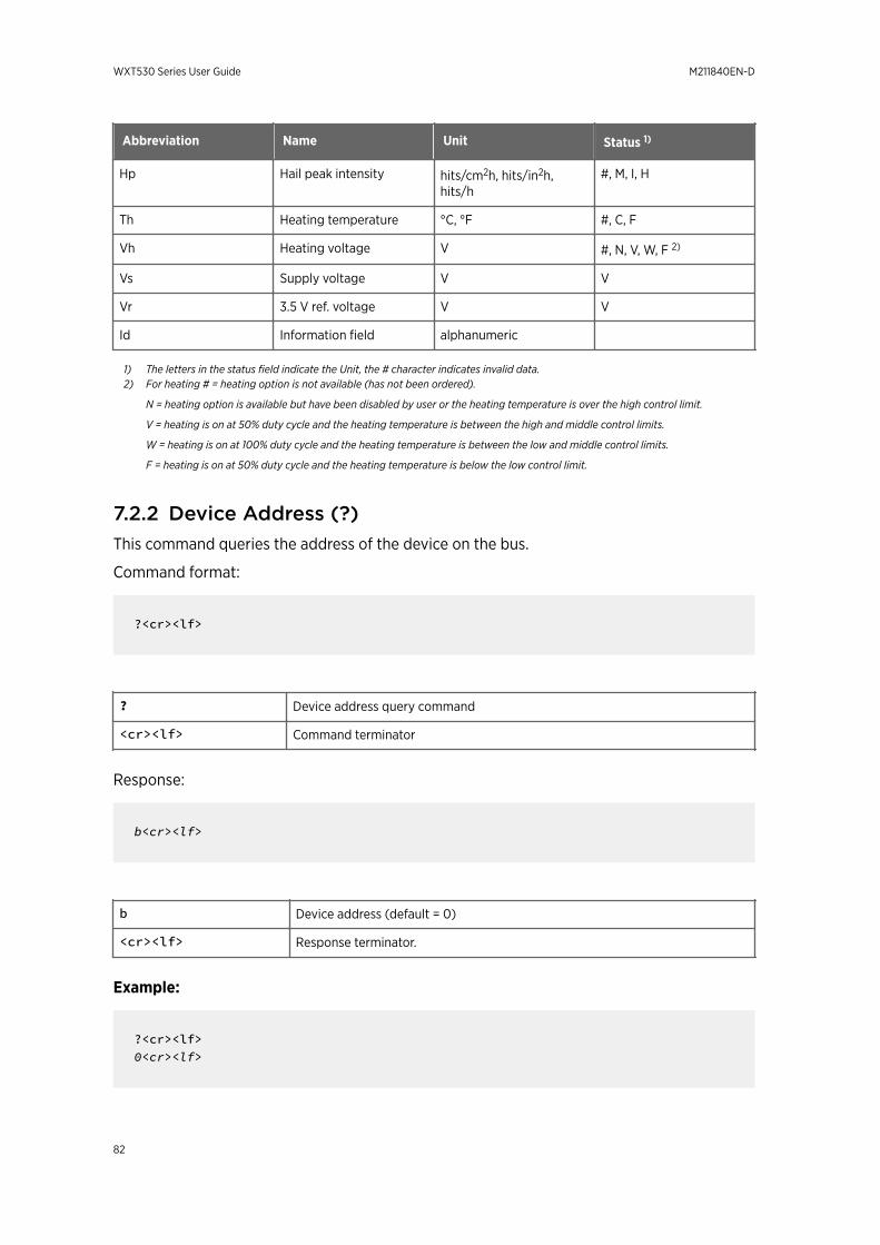
Abbreviation Name Unit Status 1)
Hp Hail peak intensity hits/cm2h, hits/in2h,hits/h
#, M, I, H
Th Heating temperature °C, °F #, C, F
Vh Heating voltage V #, N, V, W, F 2)
Vs Supply voltage V V
Vr 3.5 V ref. voltage V V
Id Information field alphanumeric
1) The letters in the status field indicate the Unit, the # character indicates invalid data.2) For heating # = heating option is not available (has not been ordered).
N = heating option is available but have been disabled by user or the heating temperature is over the high control limit.
V = heating is on at 50% duty cycle and the heating temperature is between the high and middle control limits.
W = heating is on at 100% duty cycle and the heating temperature is between the low and middle control limits.
F = heating is on at 50% duty cycle and the heating temperature is below the low control limit.
7.2.2 Device Address (?)This command queries the address of the device on the bus.
Command format:
?<cr><lf>
? Device address query command
<cr><lf> Command terminator
Response:
b<cr><lf>
b Device address (default = 0)
<cr><lf> Response terminator.
Example:
?<cr><lf>0<cr><lf>
WXT530 Series User Guide M211840EN-D
82
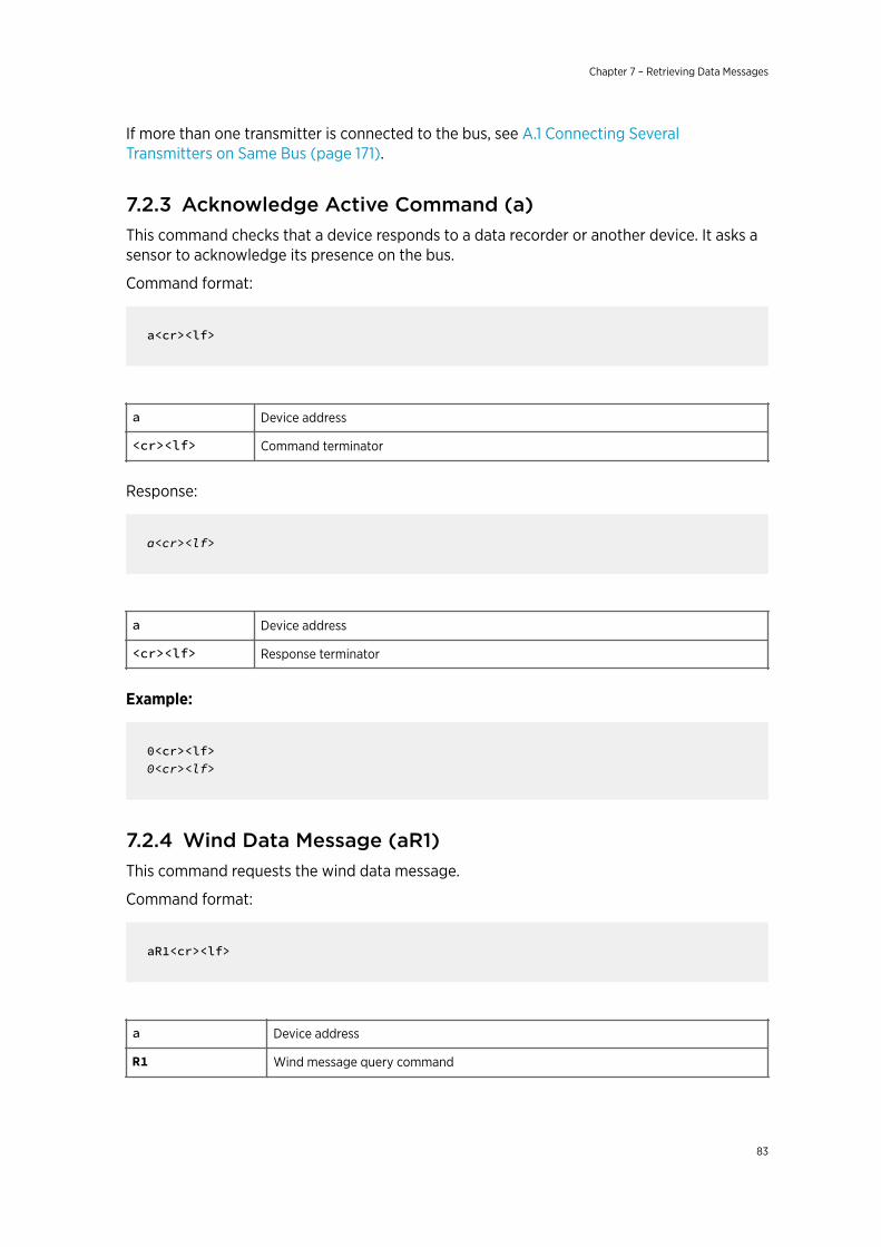
If more than one transmitter is connected to the bus, see A.1 Connecting SeveralTransmitters on Same Bus (page 171).
7.2.3 Acknowledge Active Command (a)This command checks that a device responds to a data recorder or another device. It asks asensor to acknowledge its presence on the bus.
Command format:
a<cr><lf>
a Device address
<cr><lf> Command terminator
Response:
a<cr><lf>
a Device address
<cr><lf> Response terminator
Example:
0<cr><lf>0<cr><lf>
7.2.4 Wind Data Message (aR1)This command requests the wind data message.
Command format:
aR1<cr><lf>
a Device address
R1 Wind message query command
Chapter 7 – Retrieving Data Messages
83
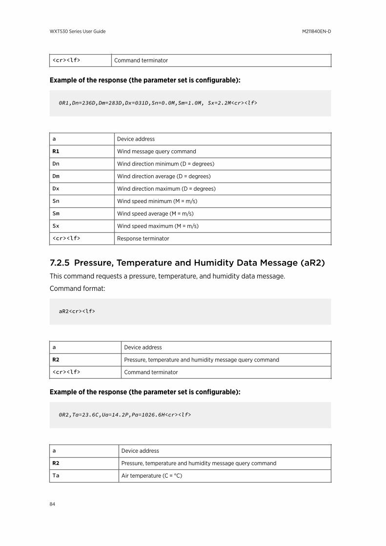
<cr><lf> Command terminator
Example of the response (the parameter set is configurable):
0R1,Dn=236D,Dm=283D,Dx=031D,Sn=0.0M,Sm=1.0M, Sx=2.2M<cr><lf>
a Device address
R1 Wind message query command
Dn Wind direction minimum (D = degrees)
Dm Wind direction average (D = degrees)
Dx Wind direction maximum (D = degrees)
Sn Wind speed minimum (M = m/s)
Sm Wind speed average (M = m/s)
Sx Wind speed maximum (M = m/s)
<cr><lf> Response terminator
7.2.5 Pressure, Temperature and Humidity Data Message (aR2)This command requests a pressure, temperature, and humidity data message.
Command format:
aR2<cr><lf>
a Device address
R2 Pressure, temperature and humidity message query command
<cr><lf> Command terminator
Example of the response (the parameter set is configurable):
0R2,Ta=23.6C,Ua=14.2P,Pa=1026.6H<cr><lf>
a Device address
R2 Pressure, temperature and humidity message query command
Ta Air temperature (C = °C)
WXT530 Series User Guide M211840EN-D
84
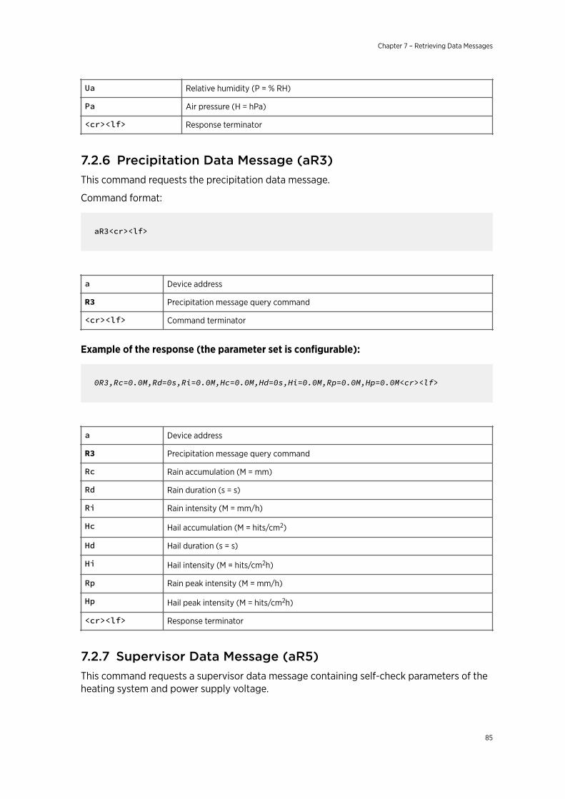
Ua Relative humidity (P = % RH)
Pa Air pressure (H = hPa)
<cr><lf> Response terminator
7.2.6 Precipitation Data Message (aR3)This command requests the precipitation data message.
Command format:
aR3<cr><lf>
a Device address
R3 Precipitation message query command
<cr><lf> Command terminator
Example of the response (the parameter set is configurable):
0R3,Rc=0.0M,Rd=0s,Ri=0.0M,Hc=0.0M,Hd=0s,Hi=0.0M,Rp=0.0M,Hp=0.0M<cr><lf>
a Device address
R3 Precipitation message query command
Rc Rain accumulation (M = mm)
Rd Rain duration (s = s)
Ri Rain intensity (M = mm/h)
Hc Hail accumulation (M = hits/cm2)
Hd Hail duration (s = s)
Hi Hail intensity (M = hits/cm2h)
Rp Rain peak intensity (M = mm/h)
Hp Hail peak intensity (M = hits/cm2h)
<cr><lf> Response terminator
7.2.7 Supervisor Data Message (aR5)This command requests a supervisor data message containing self-check parameters of theheating system and power supply voltage.
Chapter 7 – Retrieving Data Messages
85
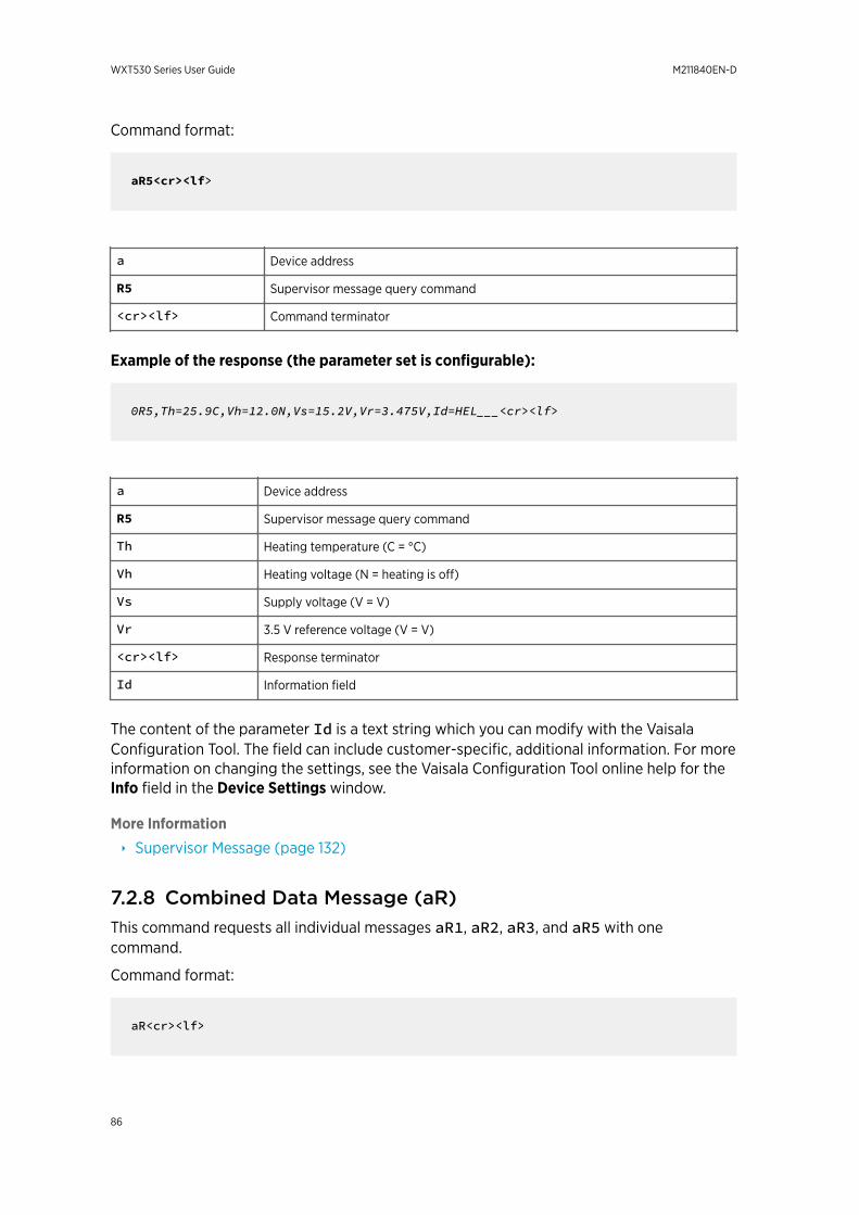
Command format:
aR5<cr><lf>
a Device address
R5 Supervisor message query command
<cr><lf> Command terminator
Example of the response (the parameter set is configurable):
0R5,Th=25.9C,Vh=12.0N,Vs=15.2V,Vr=3.475V,Id=HEL___<cr><lf>
a Device address
R5 Supervisor message query command
Th Heating temperature (C = °C)
Vh Heating voltage (N = heating is off)
Vs Supply voltage (V = V)
Vr 3.5 V reference voltage (V = V)
<cr><lf> Response terminator
Id Information field
The content of the parameter Id is a text string which you can modify with the VaisalaConfiguration Tool. The field can include customer-specific, additional information. For moreinformation on changing the settings, see the Vaisala Configuration Tool online help for theInfo field in the Device Settings window.
More Information
‣ Supervisor Message (page 132)
7.2.8 Combined Data Message (aR)This command requests all individual messages aR1, aR2, aR3, and aR5 with onecommand.
Command format:
aR<cr><lf>
WXT530 Series User Guide M211840EN-D
86
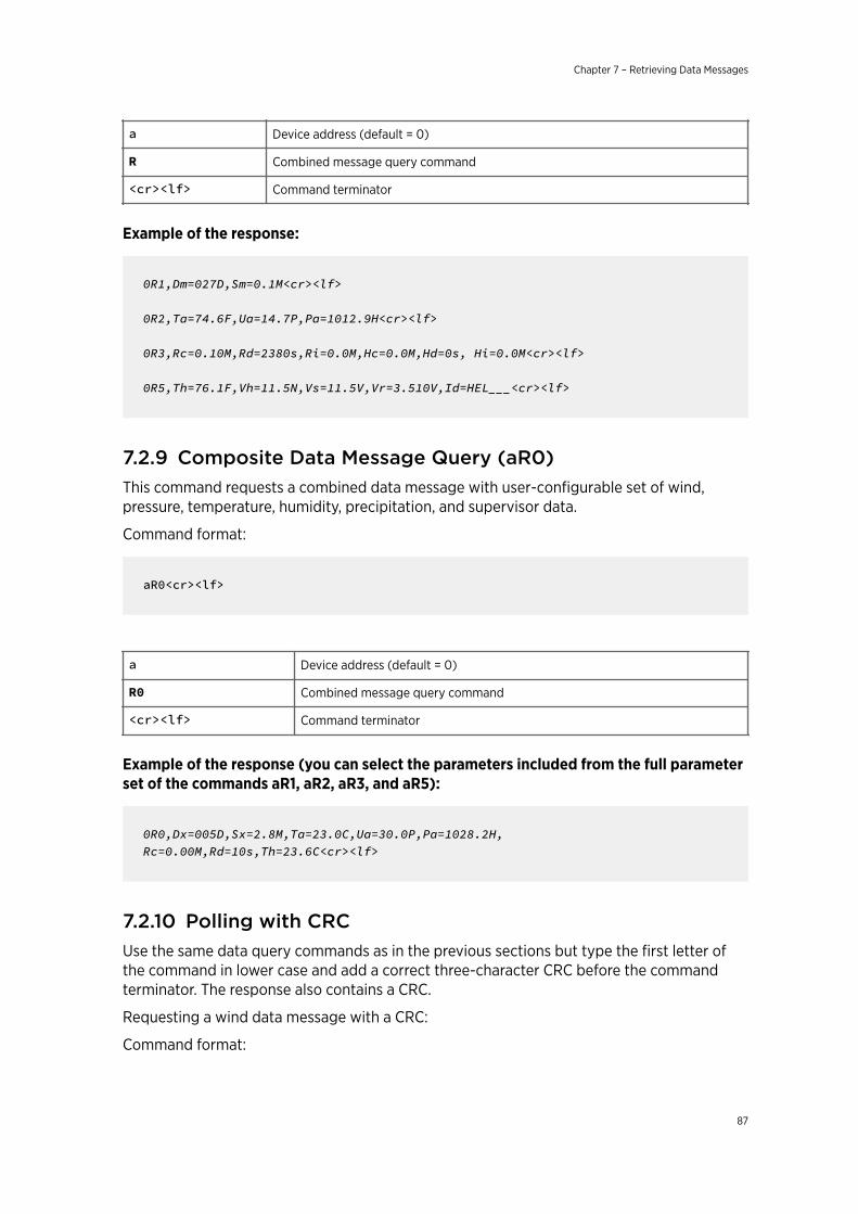
a Device address (default = 0)
R Combined message query command
<cr><lf> Command terminator
Example of the response:
0R1,Dm=027D,Sm=0.1M<cr><lf>
0R2,Ta=74.6F,Ua=14.7P,Pa=1012.9H<cr><lf>
0R3,Rc=0.10M,Rd=2380s,Ri=0.0M,Hc=0.0M,Hd=0s, Hi=0.0M<cr><lf>
0R5,Th=76.1F,Vh=11.5N,Vs=11.5V,Vr=3.510V,Id=HEL___<cr><lf>
7.2.9 Composite Data Message Query (aR0)This command requests a combined data message with user-configurable set of wind,pressure, temperature, humidity, precipitation, and supervisor data.
Command format:
aR0<cr><lf>
a Device address (default = 0)
R0 Combined message query command
<cr><lf> Command terminator
Example of the response (you can select the parameters included from the full parameterset of the commands aR1, aR2, aR3, and aR5):
0R0,Dx=005D,Sx=2.8M,Ta=23.0C,Ua=30.0P,Pa=1028.2H, Rc=0.00M,Rd=10s,Th=23.6C<cr><lf>
7.2.10 Polling with CRCUse the same data query commands as in the previous sections but type the first letter ofthe command in lower case and add a correct three-character CRC before the commandterminator. The response also contains a CRC.
Requesting a wind data message with a CRC:
Command format:
Chapter 7 – Retrieving Data Messages
87
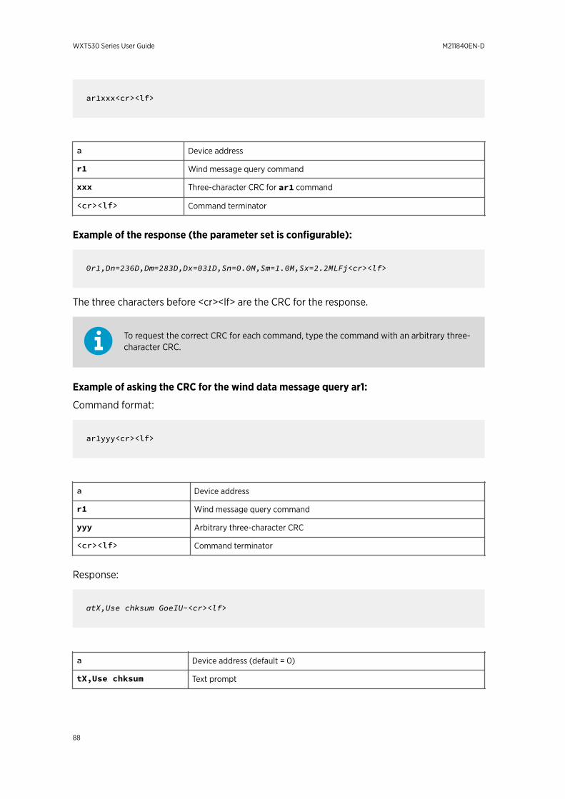
ar1xxx<cr><lf>
a Device address
r1 Wind message query command
xxx Three-character CRC for ar1 command
<cr><lf> Command terminator
Example of the response (the parameter set is configurable):
0r1,Dn=236D,Dm=283D,Dx=031D,Sn=0.0M,Sm=1.0M,Sx=2.2MLFj<cr><lf>
The three characters before <cr><lf> are the CRC for the response.
To request the correct CRC for each command, type the command with an arbitrary three-character CRC.
Example of asking the CRC for the wind data message query ar1:
Command format:
ar1yyy<cr><lf>
a Device address
r1 Wind message query command
yyy Arbitrary three-character CRC
<cr><lf> Command terminator
Response:
atX,Use chksum GoeIU~<cr><lf>
a Device address (default = 0)
tX,Use chksum Text prompt
WXT530 Series User Guide M211840EN-D
88
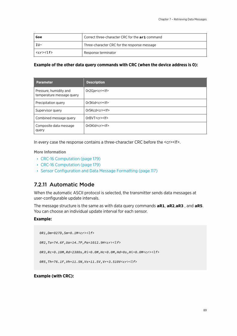
Goe Correct three-character CRC for the ar1 command
IU~ Three-character CRC for the response message
<cr><lf> Response terminator
Example of the other data query commands with CRC (when the device address is 0):
Parameter Description
Pressure, humidity andtemperature message query
0r2Gje<cr><lf>
Precipitation query 0r3Kid<cr><lf>
Supervisor query 0r5Kcd<cr><lf>
Combined message query 0rBVT<cr><lf>
Composite data messagequery
0r0Kld<cr><lf>
In every case the response contains a three-character CRC before the <cr><lf>.
More Information
‣ CRC-16 Computation (page 179)‣ CRC-16 Computation (page 179)‣ Sensor Configuration and Data Message Formatting (page 117)
7.2.11 Automatic ModeWhen the automatic ASCII protocol is selected, the transmitter sends data messages atuser-configurable update intervals.
The message structure is the same as with data query commands aR1, aR2,aR3 , and aR5.You can choose an individual update interval for each sensor.
Example:
0R1,Dm=027D,Sm=0.1M<cr><lf>
0R2,Ta=74.6F,Ua=14.7P,Pa=1012.9H<cr><lf>
0R3,Rc=0.10M,Rd=2380s,Ri=0.0M,Hc=0.0M,Hd=0s,Hi=0.0M<cr><lf>
0R5,Th=76.1F,Vh=11.5N,Vs=11.5V,Vr=3.510V<cr><lf>
Example (with CRC):
Chapter 7 – Retrieving Data Messages
89
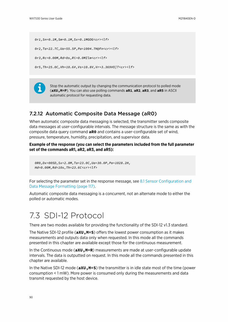
0r1,Sn=0.1M,Sm=0.1M,Sx=0.1MGOG<cr><lf>
0r2,Ta=22.7C,Ua=55.5P,Pa=1004.7H@Fn<cr><lf>
0r3,Rc=0.00M,Rd=0s,Ri=0.0MIlm<cr><lf>
0r5,Th=25.0C,Vh=10.6#,Vs=10.8V,Vr=3.369VO]T<cr><lf>
Stop the automatic output by changing the communication protocol to polled mode(aXU,M=P). You can also use polling commands aR1, aR2, aR3, and aR5 in ASCIIautomatic protocol for requesting data.
7.2.12 Automatic Composite Data Message (aR0)When automatic composite data messaging is selected, the transmitter sends compositedata messages at user-configurable intervals. The message structure is the same as with thecomposite data query command aR0 and contains a user-configurable set of wind,pressure, temperature, humidity, precipitation, and supervisor data.
Example of the response (you can select the parameters included from the full parameterset of the commands aR1, aR2, aR3, and aR5):
0R0,Dx=005D,Sx=2.8M,Ta=23.0C,Ua=30.0P,Pa=1028.2H,Hd=0.00M,Rd=10s,Th=23.6C<cr><lf>
For selecting the parameter set in the response message, see 8.1 Sensor Configuration andData Message Formatting (page 117).
Automatic composite data messaging is a concurrent, not an alternate mode to either thepolled or automatic modes.
7.3 SDI-12 ProtocolThere are two modes available for providing the functionality of the SDI-12 v1.3 standard.
The Native SDI-12 profile (aXU,M=S) offers the lowest power consumption as it makesmeasurements and outputs data only when requested. In this mode all the commandspresented in this chapter are available except those for the continuous measurement.
In the Continuous mode (aXU,M=R) measurements are made at user-configurable updateintervals. The data is outputted on request. In this mode all the commands presented in thischapter are available.
In the Native SDI-12 mode (aXU,M=S) the transmitter is in idle state most of the time (powerconsumption < 1 mW). More power is consumed only during the measurements and datatransmit requested by the host device.
WXT530 Series User Guide M211840EN-D
90
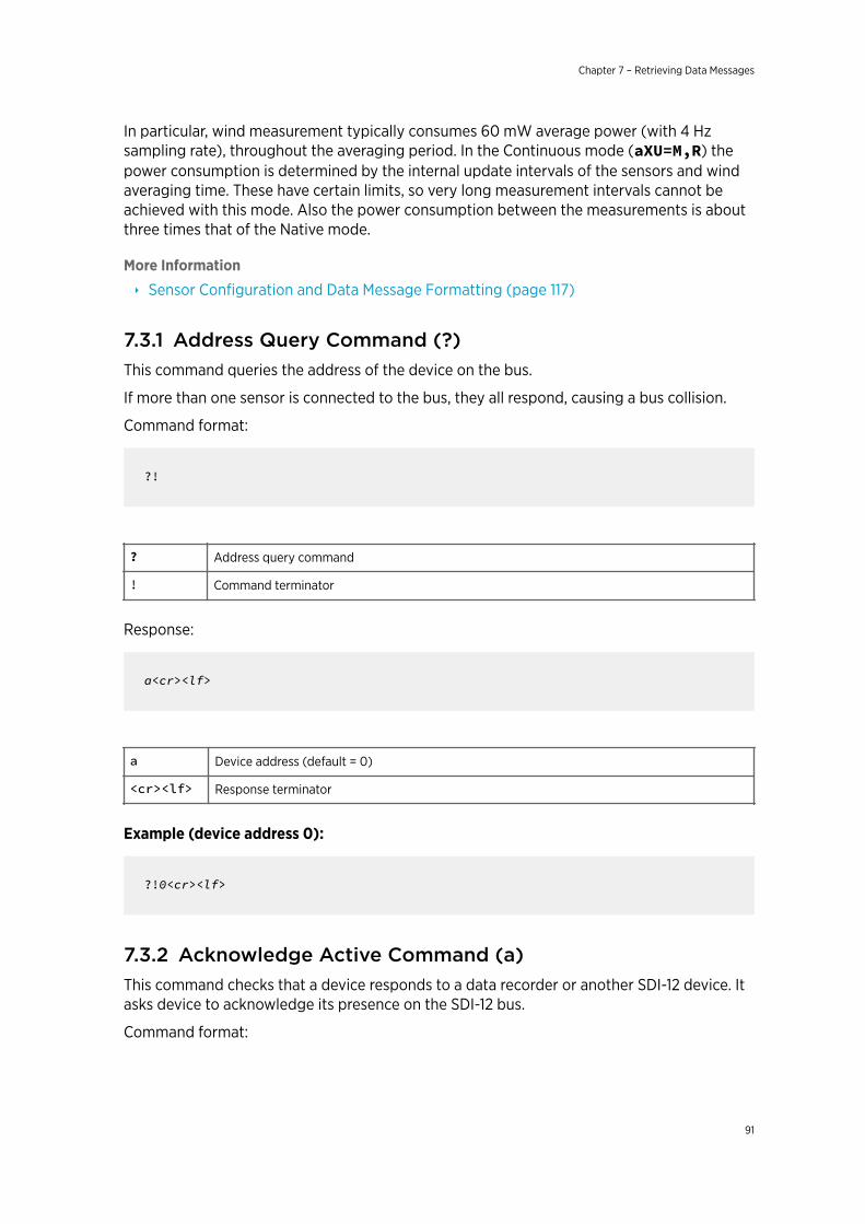
In particular, wind measurement typically consumes 60 mW average power (with 4 Hzsampling rate), throughout the averaging period. In the Continuous mode (aXU=M,R) thepower consumption is determined by the internal update intervals of the sensors and windaveraging time. These have certain limits, so very long measurement intervals cannot beachieved with this mode. Also the power consumption between the measurements is aboutthree times that of the Native mode.
More Information
‣ Sensor Configuration and Data Message Formatting (page 117)
7.3.1 Address Query Command (?)This command queries the address of the device on the bus.
If more than one sensor is connected to the bus, they all respond, causing a bus collision.
Command format:
?!
? Address query command
! Command terminator
Response:
a<cr><lf>
a Device address (default = 0)
<cr><lf> Response terminator
Example (device address 0):
?!0<cr><lf>
7.3.2 Acknowledge Active Command (a)This command checks that a device responds to a data recorder or another SDI-12 device. Itasks device to acknowledge its presence on the SDI-12 bus.
Command format:
Chapter 7 – Retrieving Data Messages
91
a!
a Device address
! Command terminator
Response:
a<cr><lf>
a Device address
<cr><lf> Response terminator
Example:
0!0<cr><lf>
7.3.3 Change Address Command (aAb)This command changes the device address. After the command has been issued andresponded to, the sensor is not required to respond to another command for one second toensure writing the new address to the non-volatile memory.
Command format:
aAb!
a Device address
A Change address command
b Address to change to
! Command terminator
Response:
b<cr><lf>
WXT530 Series User Guide M211840EN-D
92
b Device address = the new address (or the original address, if the device isunable to change it)
<cr><lf> Response terminator
Example (changing address from 0 to 3):
0A3!3<cr><lf>
7.3.4 Send Identification Command (aI)This command queries the device for the SDI-12 compatibility level, model number, firmwareversion, and serial number.
Command format:
aI!
a Device address
I Send identification command
! Command terminator
Response:
a13ccccccccmmmmmmvvvxxxxxxxx<cr><lf>
a Device address
13 The SDI-12 version number, indicating SDI-12 version compatibility; for example,version 1.3 is encoded as 13
cccccccc 8-character vendor identification Vaisala_
mmmmmm 6 characters specifying the sensor model number
vvv 3 characters specifying the firmware version
xxxxxxxx 8-character serial number
<cr><lf> Response terminator
Example:
Chapter 7 – Retrieving Data Messages
93
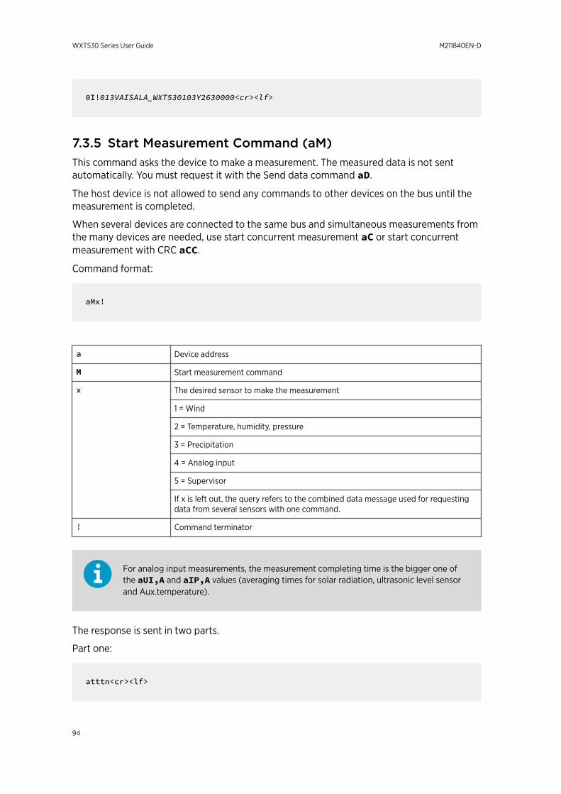
0I!013VAISALA_WXT530103Y2630000<cr><lf>
7.3.5 Start Measurement Command (aM)This command asks the device to make a measurement. The measured data is not sentautomatically. You must request it with the Send data command aD.
The host device is not allowed to send any commands to other devices on the bus until themeasurement is completed.
When several devices are connected to the same bus and simultaneous measurements fromthe many devices are needed, use start concurrent measurement aC or start concurrentmeasurement with CRC aCC.
Command format:
aMx!
a Device address
M Start measurement command
x The desired sensor to make the measurement
1 = Wind
2 = Temperature, humidity, pressure
3 = Precipitation
4 = Analog input
5 = Supervisor
If x is left out, the query refers to the combined data message used for requestingdata from several sensors with one command.
! Command terminator
For analog input measurements, the measurement completing time is the bigger one ofthe aUI,A and aIP,A values (averaging times for solar radiation, ultrasonic level sensorand Aux.temperature).
The response is sent in two parts.
Part one:
atttn<cr><lf>
WXT530 Series User Guide M211840EN-D
94
Part two (indicates that the data is ready to be requested):
a<cr><lf>
a Device address
ttt The measurement completing time in seconds
n The number of the measured parameters available (maximum number is 9)
<cr><lf> Response terminator
When the measurement takes less than one second, part two of the response is not sent.This is the case in the precipitation measurement aM3.
The maximum number of parameters that can be measured with aM and aMC commandsis nine. If more parameters must be measured, use Start concurrent measurementcommands aC and aCC (for which the maximum number of parameters to be measured is20).
More Information
‣ Examples of aM, aC and aD Commands (page 98)‣ Sensor Configuration and Data Message Formatting (page 117)‣ Start Concurrent Measurement (aC) (page 96)‣ Start Concurrent Measurement with CRC (aCC) (page 97)
7.3.6 Start Measurement Command with CRC (aMC)Command format:
aMCx!
This command asks the device to make a measurement and a three-character CRC is addedto the response data strings before <cr><lf>.
To request the measured data, use the Send data command aD.
More Information
‣ Send Data Command (aD) (page 97)
Chapter 7 – Retrieving Data Messages
95
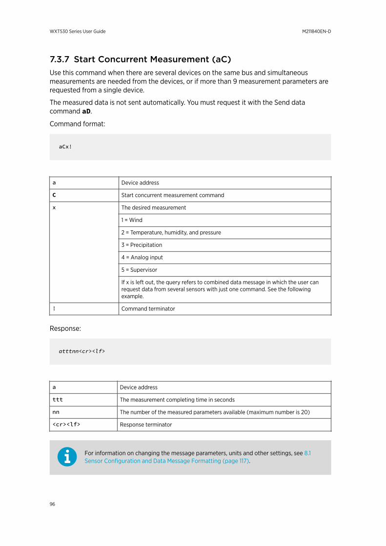
7.3.7 Start Concurrent Measurement (aC)Use this command when there are several devices on the same bus and simultaneousmeasurements are needed from the devices, or if more than 9 measurement parameters arerequested from a single device.
The measured data is not sent automatically. You must request it with the Send datacommand aD.
Command format:
aCx!
a Device address
C Start concurrent measurement command
x The desired measurement
1 = Wind
2 = Temperature, humidity, and pressure
3 = Precipitation
4 = Analog input
5 = Supervisor
If x is left out, the query refers to combined data message in which the user canrequest data from several sensors with just one command. See the followingexample.
! Command terminator
Response:
atttnn<cr><lf>
a Device address
ttt The measurement completing time in seconds
nn The number of the measured parameters available (maximum number is 20)
<cr><lf> Response terminator
For information on changing the message parameters, units and other settings, see 8.1Sensor Configuration and Data Message Formatting (page 117).
WXT530 Series User Guide M211840EN-D
96
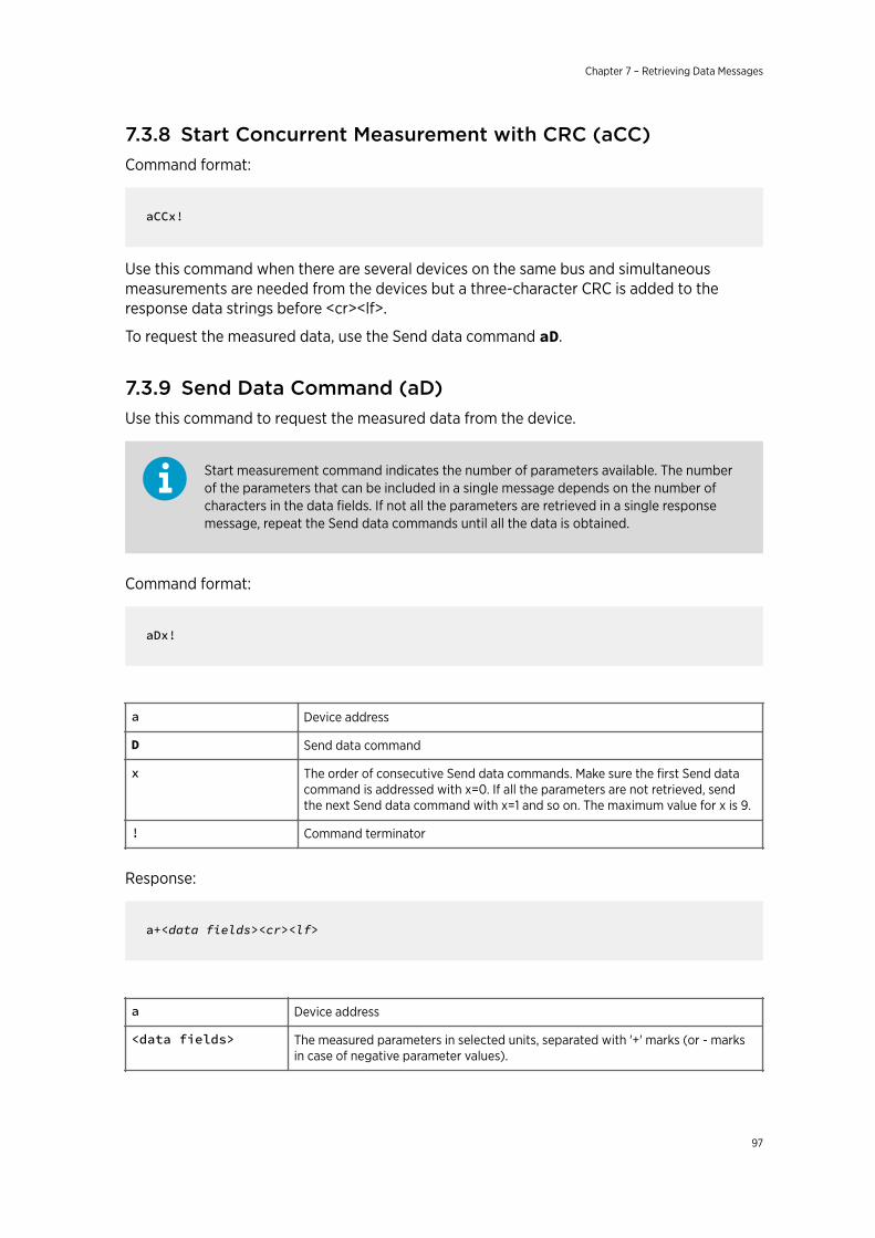
7.3.8 Start Concurrent Measurement with CRC (aCC)Command format:
aCCx!
Use this command when there are several devices on the same bus and simultaneousmeasurements are needed from the devices but a three-character CRC is added to theresponse data strings before <cr><lf>.
To request the measured data, use the Send data command aD.
7.3.9 Send Data Command (aD)Use this command to request the measured data from the device.
Start measurement command indicates the number of parameters available. The numberof the parameters that can be included in a single message depends on the number ofcharacters in the data fields. If not all the parameters are retrieved in a single responsemessage, repeat the Send data commands until all the data is obtained.
Command format:
aDx!
a Device address
D Send data command
x The order of consecutive Send data commands. Make sure the first Send datacommand is addressed with x=0. If all the parameters are not retrieved, sendthe next Send data command with x=1 and so on. The maximum value for x is 9.
! Command terminator
Response:
a+<data fields><cr><lf>
a Device address
<data fields> The measured parameters in selected units, separated with '+' marks (or - marksin case of negative parameter values).
Chapter 7 – Retrieving Data Messages
97
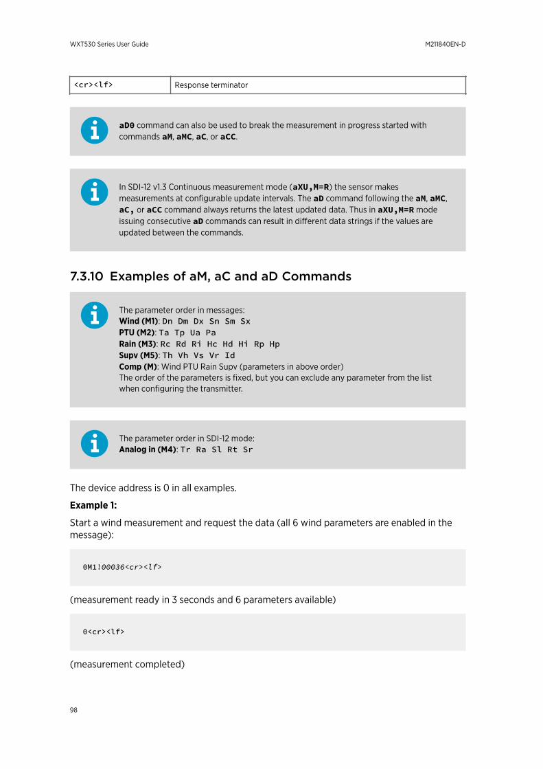
<cr><lf> Response terminator
aD0 command can also be used to break the measurement in progress started withcommands aM, aMC, aC, or aCC.
In SDI-12 v1.3 Continuous measurement mode (aXU,M=R) the sensor makesmeasurements at configurable update intervals. The aD command following the aM, aMC,aC, or aCC command always returns the latest updated data. Thus in aXU,M=R modeissuing consecutive aD commands can result in different data strings if the values areupdated between the commands.
7.3.10 Examples of aM, aC and aD Commands
The parameter order in messages:Wind (M1): Dn Dm Dx Sn Sm SxPTU (M2): Ta Tp Ua PaRain (M3): Rc Rd Ri Hc Hd Hi Rp HpSupv (M5): Th Vh Vs Vr IdComp (M): Wind PTU Rain Supv (parameters in above order)The order of the parameters is fixed, but you can exclude any parameter from the listwhen configuring the transmitter.
The parameter order in SDI-12 mode:Analog in (M4): Tr Ra Sl Rt Sr
The device address is 0 in all examples.
Example 1:
Start a wind measurement and request the data (all 6 wind parameters are enabled in themessage):
0M1!00036<cr><lf>
(measurement ready in 3 seconds and 6 parameters available)
0<cr><lf>
(measurement completed)
WXT530 Series User Guide M211840EN-D
98

0D0!0+339+018+030+0.1+0.1+0.1<cr><lf>
Example 2:
Start a concurrent pressure, humidity and temperature measurement and request the data:
0C2!000503<cr><lf>
(measurement ready in 5 seconds and 3 parameters available, for aC command deviceaddress not sent as a sign of a completed measurement)
0D0!0+23.6+29.5+1009.5<cr><lf>
Example 3:
Start a precipitation measurement and request the data:
0M3!00006<cr><lf>
(6 parameters available immediately, thus the device address is not sent)
0D0!0+0.15+20+0.0+0.0+0+0.0<cr><lf>
Example 4:
Start a supervisor measurement with CRC and request the data:
0MC5!00014<cr><lf>
(measurement ready in one second and 4 parameters available)
0<cr><lf>
(measurement completed)
0D0!0+34.3+10.5+10.7+3.366DpD<cr><lf>
Example 5:
Chapter 7 – Retrieving Data Messages
99
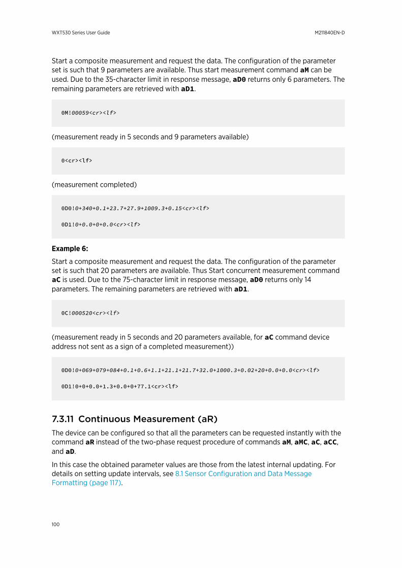
Start a composite measurement and request the data. The configuration of the parameterset is such that 9 parameters are available. Thus start measurement command aM can beused. Due to the 35-character limit in response message, aD0 returns only 6 parameters. Theremaining parameters are retrieved with aD1.
0M!00059<cr><lf>
(measurement ready in 5 seconds and 9 parameters available)
0<cr><lf>
(measurement completed)
0D0!0+340+0.1+23.7+27.9+1009.3+0.15<cr><lf>
0D1!0+0.0+0+0.0<cr><lf>
Example 6:
Start a composite measurement and request the data. The configuration of the parameterset is such that 20 parameters are available. Thus Start concurrent measurement commandaC is used. Due to the 75-character limit in response message, aD0 returns only 14parameters. The remaining parameters are retrieved with aD1.
0C!000520<cr><lf>
(measurement ready in 5 seconds and 20 parameters available, for aC command deviceaddress not sent as a sign of a completed measurement))
0D0!0+069+079+084+0.1+0.6+1.1+21.1+21.7+32.0+1000.3+0.02+20+0.0+0.0<cr><lf>
0D1!0+0+0.0+1.3+0.0+0+77.1<cr><lf>
7.3.11 Continuous Measurement (aR)The device can be configured so that all the parameters can be requested instantly with thecommand aR instead of the two-phase request procedure of commands aM, aMC, aC, aCC,and aD.
In this case the obtained parameter values are those from the latest internal updating. Fordetails on setting update intervals, see 8.1 Sensor Configuration and Data MessageFormatting (page 117).
WXT530 Series User Guide M211840EN-D
100
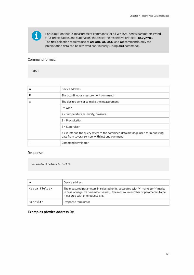
For using Continuous measurement commands for all WXT530 series parameters (wind,PTU, precipitation, and supervisor) the select the respective protocol (aXU,M=R).The M=S selection requires use of aM, aMC, aC, aCC, and aD commands, only theprecipitation data can be retrieved continuously (using aR3 command).
Command format:
aRx!
a Device address
R Start continuous measurement command:
x The desired sensor to make the measurement:
1 = Wind
2 = Temperature, humidity, pressure
3 = Precipitation
5 = Supervisor
If x is left out, the query refers to the combined data message used for requestingdata from several sensors with just one command.
! Command terminator
Response:
a+<data fields><cr><lf>
a Device address
<data fields> The measured parameters in selected units, separated with '+' marks (or '-' marksin case of negative parameter values). The maximum number of parameters to bemeasured with one request is 15.
<cr><lf> Response terminator
Examples (device address 0):
Chapter 7 – Retrieving Data Messages
101

0R1!0+323+331+351+0.0+0.4+3.0<cr><lf>
0R3!0+0.15+20+0.0+0.0+0+0.0+0.0+0.0<cr><lf>
0R!0+178+288+001+15.5+27.4+38.5+23.9+35.0+1002.1+0.00+0+0.0+23.8<cr><lf>
7.3.12 Continuous Measurement with CRC (aRC)Command format:
aRCx!
The device can be configured so that all the parameters can be requested instantly with thecommand aRC but a three-character CRC is added to the response data strings before<cr><lf>.
Example (device address 0):
0RC3!0+0.04+10+14.8+0.0+0+0.0INy
7.4 NMEA 0183 v3.0 ProtocolThis section lists the data query commands and data message formats for the NMEA 0183v3.0 query and automatic protocols.
A two-character checksum (CRC) field is transmitted in all data request sentences.
More Information
‣ Sensor Configuration and Data Message Formatting (page 117)‣ CRC-16 Computation (page 179)
7.4.1 Device Address (?)This command queries the address of the device on the bus.
Command format:
?<cr><lf>
? Device address query command
<cr><lf> Command terminator
WXT530 Series User Guide M211840EN-D
102
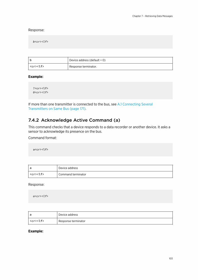
Response:
b<cr><lf>
b Device address (default = 0)
<cr><lf> Response terminator.
Example:
?<cr><lf>0<cr><lf>
If more than one transmitter is connected to the bus, see A.1 Connecting SeveralTransmitters on Same Bus (page 171).
7.4.2 Acknowledge Active Command (a)This command checks that a device responds to a data recorder or another device. It asks asensor to acknowledge its presence on the bus.
Command format:
a<cr><lf>
a Device address
<cr><lf> Command terminator
Response:
a<cr><lf>
a Device address
<cr><lf> Response terminator
Example:
Chapter 7 – Retrieving Data Messages
103
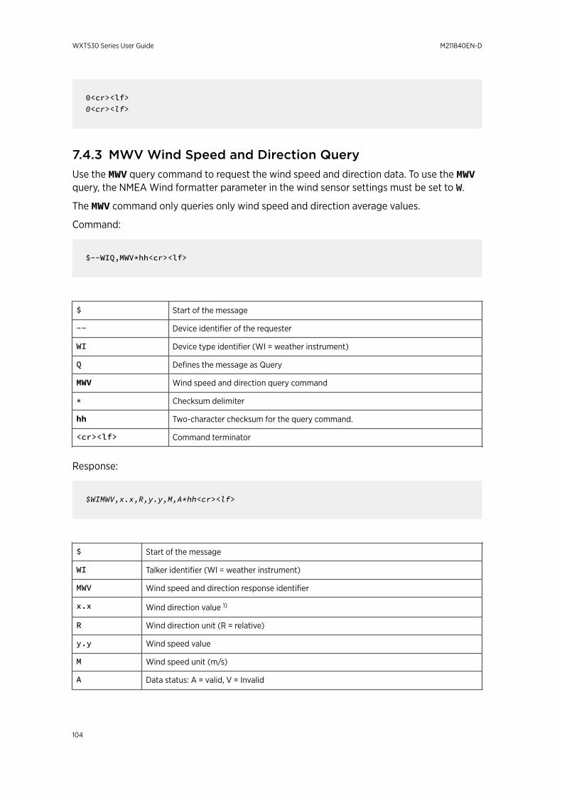
0<cr><lf>0<cr><lf>
7.4.3 MWV Wind Speed and Direction QueryUse the MWV query command to request the wind speed and direction data. To use the MWVquery, the NMEA Wind formatter parameter in the wind sensor settings must be set to W.
The MWV command only queries only wind speed and direction average values.
Command:
$--WIQ,MWV*hh<cr><lf>
$ Start of the message
-- Device identifier of the requester
WI Device type identifier (WI = weather instrument)
Q Defines the message as Query
MWV Wind speed and direction query command
* Checksum delimiter
hh Two-character checksum for the query command.
<cr><lf> Command terminator
Response:
$WIMWV,x.x,R,y.y,M,A*hh<cr><lf>
$ Start of the message
WI Talker identifier (WI = weather instrument)
MWV Wind speed and direction response identifier
x.x Wind direction value 1)
R Wind direction unit (R = relative)
y.y Wind speed value
M Wind speed unit (m/s)
A Data status: A = valid, V = Invalid
WXT530 Series User Guide M211840EN-D
104
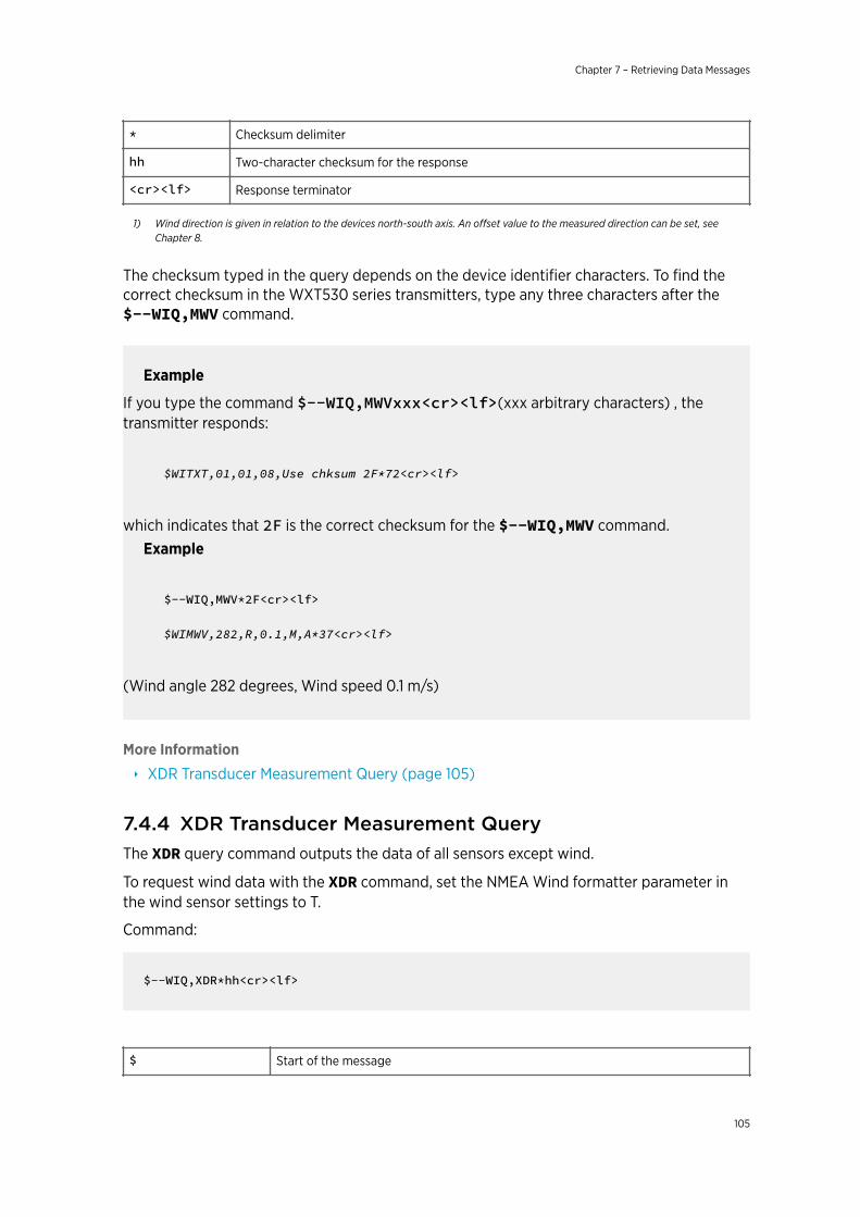
* Checksum delimiter
hh Two-character checksum for the response
<cr><lf> Response terminator
1) Wind direction is given in relation to the devices north-south axis. An offset value to the measured direction can be set, seeChapter 8.
The checksum typed in the query depends on the device identifier characters. To find thecorrect checksum in the WXT530 series transmitters, type any three characters after the$--WIQ,MWV command.
Example
If you type the command $--WIQ,MWVxxx<cr><lf>(xxx arbitrary characters) , thetransmitter responds:
$WITXT,01,01,08,Use chksum 2F*72<cr><lf>
which indicates that 2F is the correct checksum for the $--WIQ,MWV command.Example
$--WIQ,MWV*2F<cr><lf>
$WIMWV,282,R,0.1,M,A*37<cr><lf>
(Wind angle 282 degrees, Wind speed 0.1 m/s)
More Information
‣ XDR Transducer Measurement Query (page 105)
7.4.4 XDR Transducer Measurement QueryThe XDR query command outputs the data of all sensors except wind.
To request wind data with the XDR command, set the NMEA Wind formatter parameter inthe wind sensor settings to T.
Command:
$--WIQ,XDR*hh<cr><lf>
$ Start of the message
Chapter 7 – Retrieving Data Messages
105
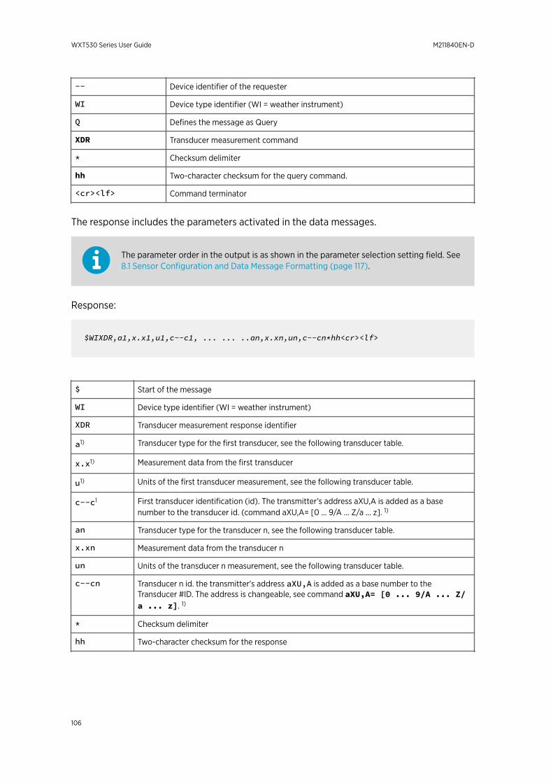
-- Device identifier of the requester
WI Device type identifier (WI = weather instrument)
Q Defines the message as Query
XDR Transducer measurement command
* Checksum delimiter
hh Two-character checksum for the query command.
<cr><lf> Command terminator
The response includes the parameters activated in the data messages.
The parameter order in the output is as shown in the parameter selection setting field. See8.1 Sensor Configuration and Data Message Formatting (page 117).
Response:
$WIXDR,a1,x.x1,u1,c--c1, ... ... ..an,x.xn,un,c--cn*hh<cr><lf>
$ Start of the message
WI Device type identifier (WI = weather instrument)
XDR Transducer measurement response identifier
a1) Transducer type for the first transducer, see the following transducer table.
x.x1) Measurement data from the first transducer
u1) Units of the first transducer measurement, see the following transducer table.
c--c1 First transducer identification (id). The transmitter’s address aXU,A is added as a basenumber to the transducer id. (command aXU,A= [0 ... 9/A ... Z/a ... z]. 1)
an Transducer type for the transducer n, see the following transducer table.
x.xn Measurement data from the transducer n
un Units of the transducer n measurement, see the following transducer table.
c--cn Transducer n id. the transmitter's address aXU,A is added as a base number to theTransducer #ID. The address is changeable, see command aXU,A= [0 ... 9/A ... Z/a ... z]. 1)
* Checksum delimiter
hh Two-character checksum for the response
WXT530 Series User Guide M211840EN-D
106
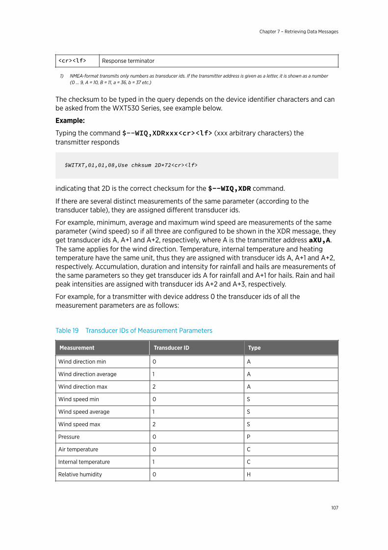
<cr><lf> Response terminator
1) NMEA-format transmits only numbers as transducer ids. If the transmitter address is given as a letter, it is shown as a number(0 ... 9, A = 10, B = 11, a = 36, b = 37 etc.)
The checksum to be typed in the query depends on the device identifier characters and canbe asked from the WXT530 Series, see example below.
Example:
Typing the command $--WIQ,XDRxxx<cr><lf> (xxx arbitrary characters) thetransmitter responds
$WITXT,01,01,08,Use chksum 2D*72<cr><lf>
indicating that 2D is the correct checksum for the $--WIQ,XDR command.
If there are several distinct measurements of the same parameter (according to thetransducer table), they are assigned different transducer ids.
For example, minimum, average and maximum wind speed are measurements of the sameparameter (wind speed) so if all three are configured to be shown in the XDR message, theyget transducer ids A, A+1 and A+2, respectively, where A is the transmitter address aXU,A.The same applies for the wind direction. Temperature, internal temperature and heatingtemperature have the same unit, thus they are assigned with transducer ids A, A+1 and A+2,respectively. Accumulation, duration and intensity for rainfall and hails are measurements ofthe same parameters so they get transducer ids A for rainfall and A+1 for hails. Rain and hailpeak intensities are assigned with transducer ids A+2 and A+3, respectively.
For example, for a transmitter with device address 0 the transducer ids of all themeasurement parameters are as follows:
Table 19 Transducer IDs of Measurement Parameters
Measurement Transducer ID Type
Wind direction min 0 A
Wind direction average 1 A
Wind direction max 2 A
Wind speed min 0 S
Wind speed average 1 S
Wind speed max 2 S
Pressure 0 P
Air temperature 0 C
Internal temperature 1 C
Relative humidity 0 H
Chapter 7 – Retrieving Data Messages
107
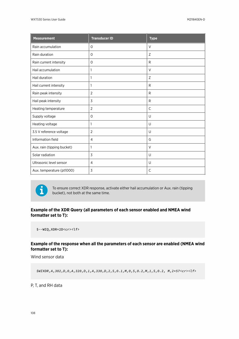
Measurement Transducer ID Type
Rain accumulation 0 V
Rain duration 0 Z
Rain current intensity 0 R
Hail accumulation 1 V
Hail duration 1 Z
Hail current intensity 1 R
Rain peak intensity 2 R
Hail peak intensity 3 R
Heating temperature 2 C
Supply voltage 0 U
Heating voltage 1 U
3.5 V reference voltage 2 U
Information field 4 G
Aux. rain (tipping bucket) 1 V
Solar radiation 3 U
Ultrasonic level sensor 4 U
Aux. temperature (pt1000) 3 C
To ensure correct XDR response, activate either hail accumulation or Aux. rain (tippingbucket), not both at the same time.
Example of the XDR Query (all parameters of each sensor enabled and NMEA windformatter set to T):
$--WIQ,XDR*2D<cr><lf>
Example of the response when all the parameters of each sensor are enabled (NMEA windformatter set to T):
Wind sensor data
$WIXDR,A,302,D,0,A,320,D,1,A,330,D,2,S,0.1,M,0,S,0.2,M,1,S,0.2, M,2*57<cr><lf>
P, T, and RH data
WXT530 Series User Guide M211840EN-D
108
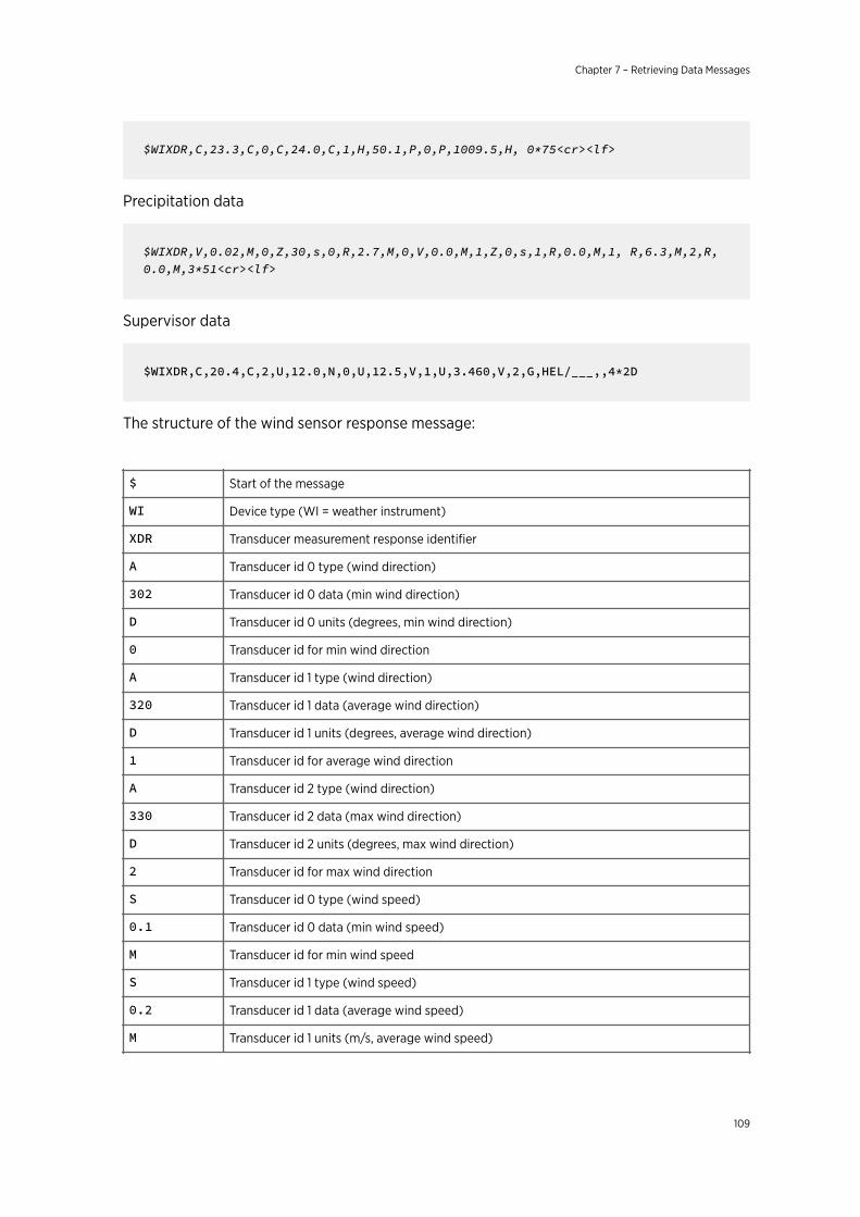
$WIXDR,C,23.3,C,0,C,24.0,C,1,H,50.1,P,0,P,1009.5,H, 0*75<cr><lf>
Precipitation data
$WIXDR,V,0.02,M,0,Z,30,s,0,R,2.7,M,0,V,0.0,M,1,Z,0,s,1,R,0.0,M,1, R,6.3,M,2,R,0.0,M,3*51<cr><lf>
Supervisor data
$WIXDR,C,20.4,C,2,U,12.0,N,0,U,12.5,V,1,U,3.460,V,2,G,HEL/___,,4*2D
The structure of the wind sensor response message:
$ Start of the message
WI Device type (WI = weather instrument)
XDR Transducer measurement response identifier
A Transducer id 0 type (wind direction)
302 Transducer id 0 data (min wind direction)
D Transducer id 0 units (degrees, min wind direction)
0 Transducer id for min wind direction
A Transducer id 1 type (wind direction)
320 Transducer id 1 data (average wind direction)
D Transducer id 1 units (degrees, average wind direction)
1 Transducer id for average wind direction
A Transducer id 2 type (wind direction)
330 Transducer id 2 data (max wind direction)
D Transducer id 2 units (degrees, max wind direction)
2 Transducer id for max wind direction
S Transducer id 0 type (wind speed)
0.1 Transducer id 0 data (min wind speed)
M Transducer id for min wind speed
S Transducer id 1 type (wind speed)
0.2 Transducer id 1 data (average wind speed)
M Transducer id 1 units (m/s, average wind speed)
Chapter 7 – Retrieving Data Messages
109
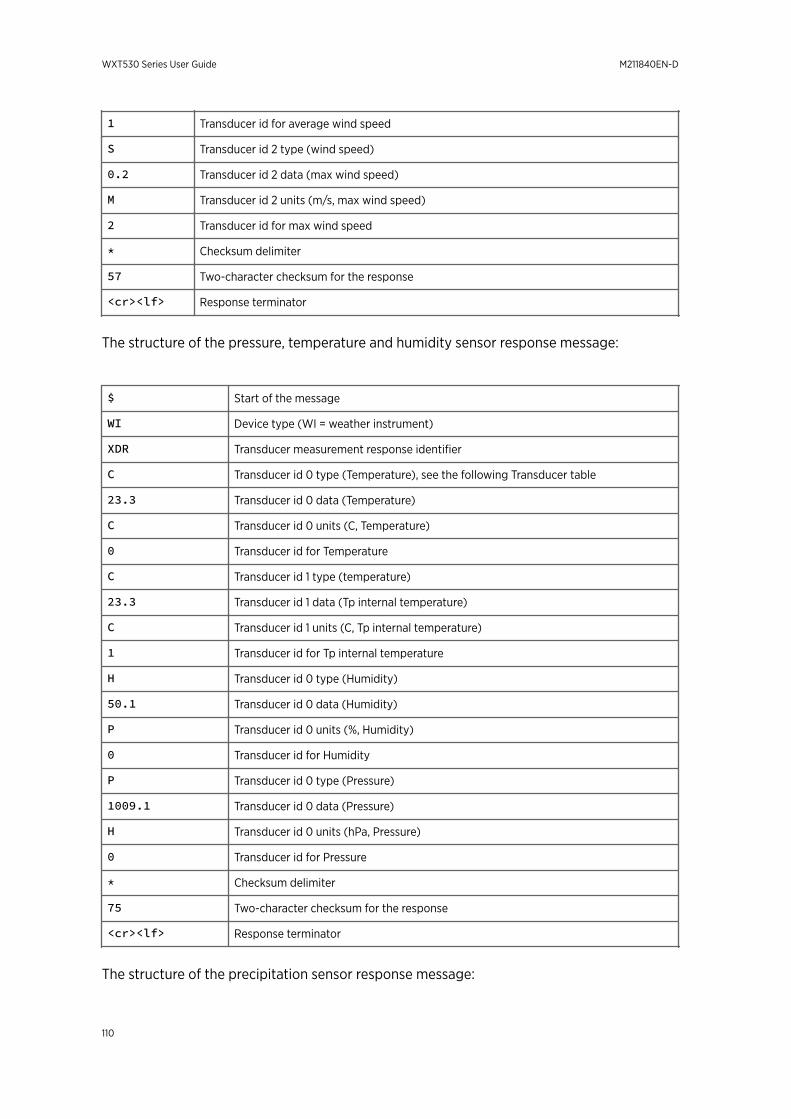
1 Transducer id for average wind speed
S Transducer id 2 type (wind speed)
0.2 Transducer id 2 data (max wind speed)
M Transducer id 2 units (m/s, max wind speed)
2 Transducer id for max wind speed
* Checksum delimiter
57 Two-character checksum for the response
<cr><lf> Response terminator
The structure of the pressure, temperature and humidity sensor response message:
$ Start of the message
WI Device type (WI = weather instrument)
XDR Transducer measurement response identifier
C Transducer id 0 type (Temperature), see the following Transducer table
23.3 Transducer id 0 data (Temperature)
C Transducer id 0 units (C, Temperature)
0 Transducer id for Temperature
C Transducer id 1 type (temperature)
23.3 Transducer id 1 data (Tp internal temperature)
C Transducer id 1 units (C, Tp internal temperature)
1 Transducer id for Tp internal temperature
H Transducer id 0 type (Humidity)
50.1 Transducer id 0 data (Humidity)
P Transducer id 0 units (%, Humidity)
0 Transducer id for Humidity
P Transducer id 0 type (Pressure)
1009.1 Transducer id 0 data (Pressure)
H Transducer id 0 units (hPa, Pressure)
0 Transducer id for Pressure
* Checksum delimiter
75 Two-character checksum for the response
<cr><lf> Response terminator
The structure of the precipitation sensor response message:
WXT530 Series User Guide M211840EN-D
110
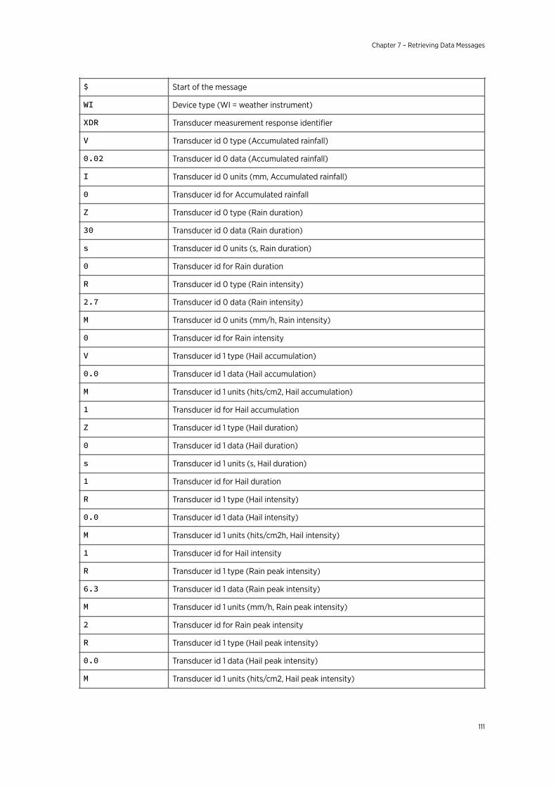
$ Start of the message
WI Device type (WI = weather instrument)
XDR Transducer measurement response identifier
V Transducer id 0 type (Accumulated rainfall)
0.02 Transducer id 0 data (Accumulated rainfall)
I Transducer id 0 units (mm, Accumulated rainfall)
0 Transducer id for Accumulated rainfall
Z Transducer id 0 type (Rain duration)
30 Transducer id 0 data (Rain duration)
s Transducer id 0 units (s, Rain duration)
0 Transducer id for Rain duration
R Transducer id 0 type (Rain intensity)
2.7 Transducer id 0 data (Rain intensity)
M Transducer id 0 units (mm/h, Rain intensity)
0 Transducer id for Rain intensity
V Transducer id 1 type (Hail accumulation)
0.0 Transducer id 1 data (Hail accumulation)
M Transducer id 1 units (hits/cm2, Hail accumulation)
1 Transducer id for Hail accumulation
Z Transducer id 1 type (Hail duration)
0 Transducer id 1 data (Hail duration)
s Transducer id 1 units (s, Hail duration)
1 Transducer id for Hail duration
R Transducer id 1 type (Hail intensity)
0.0 Transducer id 1 data (Hail intensity)
M Transducer id 1 units (hits/cm2h, Hail intensity)
1 Transducer id for Hail intensity
R Transducer id 1 type (Rain peak intensity)
6.3 Transducer id 1 data (Rain peak intensity)
M Transducer id 1 units (mm/h, Rain peak intensity)
2 Transducer id for Rain peak intensity
R Transducer id 1 type (Hail peak intensity)
0.0 Transducer id 1 data (Hail peak intensity)
M Transducer id 1 units (hits/cm2, Hail peak intensity)
Chapter 7 – Retrieving Data Messages
111
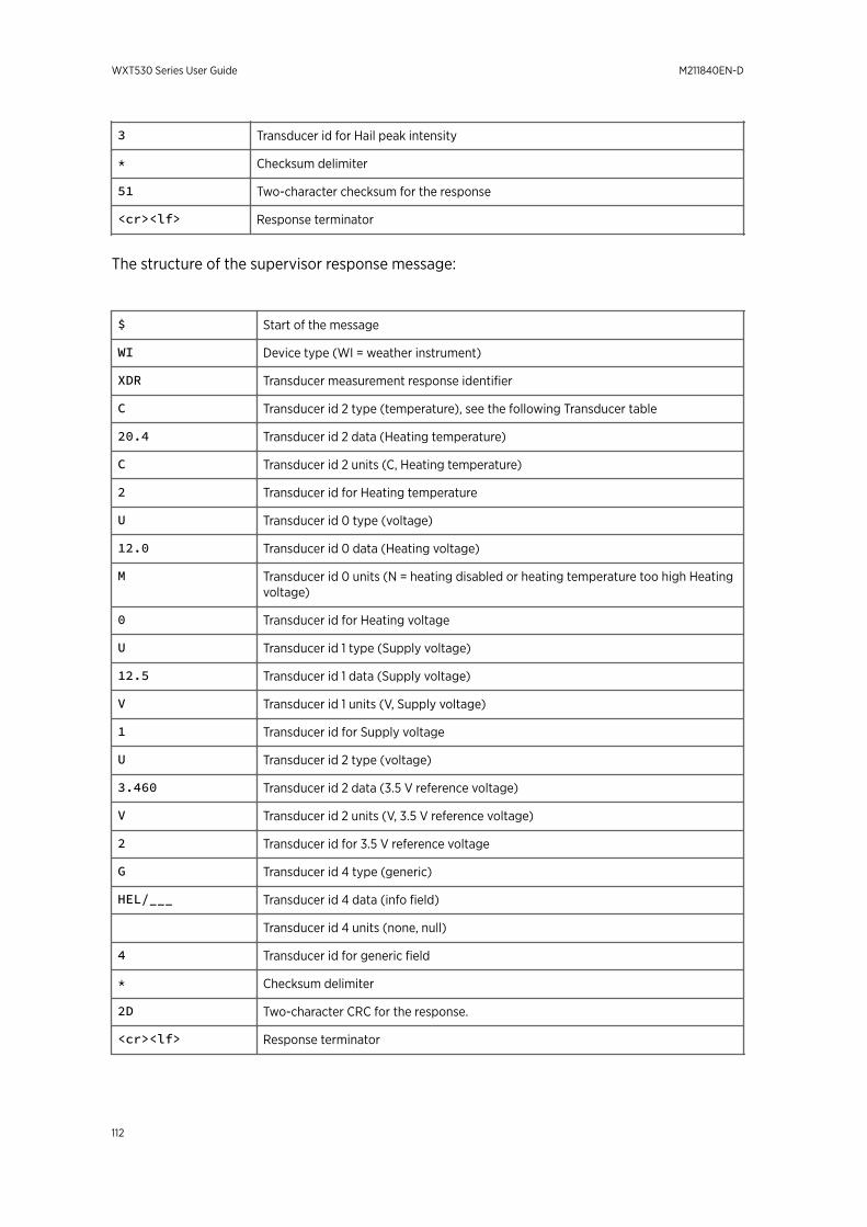
3 Transducer id for Hail peak intensity
* Checksum delimiter
51 Two-character checksum for the response
<cr><lf> Response terminator
The structure of the supervisor response message:
$ Start of the message
WI Device type (WI = weather instrument)
XDR Transducer measurement response identifier
C Transducer id 2 type (temperature), see the following Transducer table
20.4 Transducer id 2 data (Heating temperature)
C Transducer id 2 units (C, Heating temperature)
2 Transducer id for Heating temperature
U Transducer id 0 type (voltage)
12.0 Transducer id 0 data (Heating voltage)
M Transducer id 0 units (N = heating disabled or heating temperature too high Heatingvoltage)
0 Transducer id for Heating voltage
U Transducer id 1 type (Supply voltage)
12.5 Transducer id 1 data (Supply voltage)
V Transducer id 1 units (V, Supply voltage)
1 Transducer id for Supply voltage
U Transducer id 2 type (voltage)
3.460 Transducer id 2 data (3.5 V reference voltage)
V Transducer id 2 units (V, 3.5 V reference voltage)
2 Transducer id for 3.5 V reference voltage
G Transducer id 4 type (generic)
HEL/___ Transducer id 4 data (info field)
Transducer id 4 units (none, null)
4 Transducer id for generic field
* Checksum delimiter
2D Two-character CRC for the response.
<cr><lf> Response terminator
WXT530 Series User Guide M211840EN-D
112
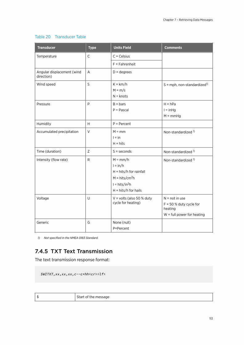
Table 20 Transducer Table
Transducer Type Units Field Comments
Temperature C C = Celsius
F = Fahrenheit
Angular displacement (winddirection)
A D = degrees
Wind speed S K = km/h
M = m/s
N = knots
S = mph, non-standardized1)
Pressure P B = bars
P = Pascal
H = hPa
I = inHg
M = mmHg
Humidity H P = Percent
Accumulated precipitation V M = mm
I = in
H = hits
Non-standardized 1)
Time (duration) Z S = seconds Non-standardized 1)
Intensity (flow rate) R M = mm/h
I = in/h
H = hits/h for rainfall
M = hits/cm2h
I = hits/in2h
H = hits/h for hails
Non-standardized 1)
Voltage U V = volts (also 50 % dutycycle for heating)
N = not in use
F = 50 % duty cycle forheating
W = full power for heating
Generic G None (null)
P=Percent
1) Not specified in the NMEA 0183 Standard.
7.4.5 TXT Text TransmissionThe text transmission response format:
$WITXT,xx,xx,xx,c--c*hh<cr><lf>
$ Start of the message
Chapter 7 – Retrieving Data Messages
113
WI Talker identifier (WI = weather instrument)
TXT Text transmission identifier.
xx Total number of messages, 01 to 99
xx Message number.
xx Text identifier (see text message table)
c---c Text message (see text message table)
* Checksum delimiter
hh Two-character checksum for the query command.
<cr><lf> Response terminator
Examples:
Wind data request when all the wind parameters were disabled from the wind message:
$WItXT,01,01,01,Unable to measure error*6D<cr><lf>
Unknown command 0XO!<cr><lf>:
$WITXT,01,01,03,Unknown cmd error*1F
Wrong checksum used in MWV query command:
$WITXT,01,01,08,Use chksum 2F*72
7.4.6 Automatic ModeWhen NMEA 0183 v3.0 automatic protocol is selected, the transmitter sends data messagesat user-configurable update intervals. The message format is the same as in the MWV andXDR data queries. The NMEA wind formatter parameter in the wind sensor settingsdetermines whether the wind messages are sent in MWV or XDR format.
You can use ASCII data query commands aR1, aR2, aR3, aR5, aR, aR0 and their CRC-versions ar1, ar2, ar3, ar5, ar and ar0 also in NMEA 0183 protocol. The responses tothese commands are in standard NMEA 0183 format.
More Information
‣ Sensor Configuration and Data Message Formatting (page 117)
WXT530 Series User Guide M211840EN-D
114

7.4.7 Automatic Composite Data Message (aR0)When automatic composite data messaging is selected, the transmitter sends compositedata messages at user-configurable intervals. The message structure is the same as with thecomposite data query command aR0 and contains a user configurable set of wind, pressure,temperature, humidity, precipitation, and supervisor data.
Example (the parameters included can be chosen from the full parameter set of thecommands aR1, aR2, aR3 and aR5):
$WIXDR,A,057,D,1,S,0.6,M,1,C,22.6,C,0,H,27.1,P,0,P,1013.6,H,0,V,0.003,I,0,U,12.0,N,0,U,12.4,V,1*67<cr><lf>
Example (rain and voltage parameters removed):
$WIXDR,A,054,D,1,S,0.4,M,1,C,22.5,C,0,H,26.3,P,0,P,1013.6,H,0*79<cr><lf>
For information on selecting the parameter set in the response message, see 8.1 SensorConfiguration and Data Message Formatting (page 117).
Automatic composite data messaging is in concurrent, not alternate mode to either thepolled or automatic modes.
Chapter 7 – Retrieving Data Messages
115

WXT530 Series User Guide M211840EN-D
116
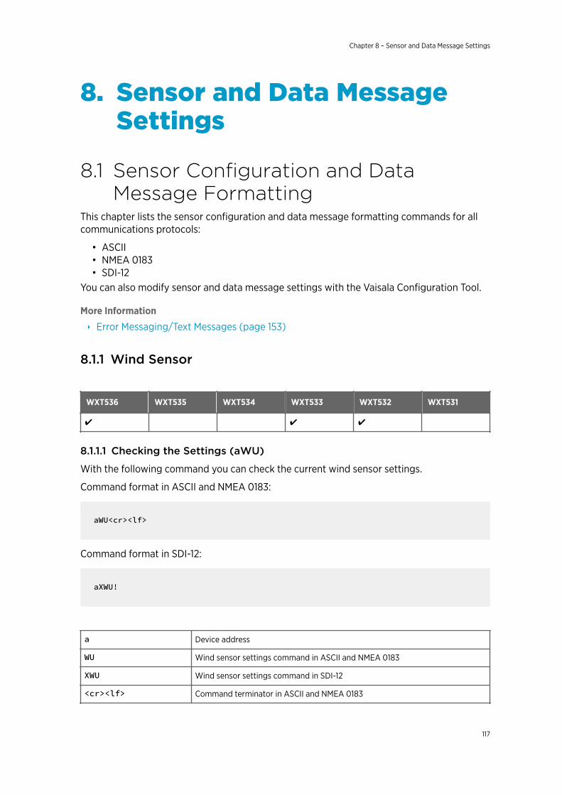
8. Sensor and Data MessageSettings
8.1 Sensor Configuration and DataMessage Formatting
This chapter lists the sensor configuration and data message formatting commands for allcommunications protocols:
• ASCII• NMEA 0183• SDI-12
You can also modify sensor and data message settings with the Vaisala Configuration Tool.
More Information
‣ Error Messaging/Text Messages (page 153)
8.1.1 Wind Sensor
WXT536 WXT535 WXT534 WXT533 WXT532 WXT531
✔ ✔ ✔
8.1.1.1 Checking the Settings (aWU)
With the following command you can check the current wind sensor settings.
Command format in ASCII and NMEA 0183:
aWU<cr><lf>
Command format in SDI-12:
aXWU!
a Device address
WU Wind sensor settings command in ASCII and NMEA 0183
XWU Wind sensor settings command in SDI-12
<cr><lf> Command terminator in ASCII and NMEA 0183
Chapter 8 – Sensor and Data Message Settings
117
! Command terminator in SDI-12
The response in ASCII and NMEA 0183:
aWU,R=[R],I=[I],A=[A],G=[G],U=[U],D=[D],N=[N],F=[F]<cr><lf>
The response in SDI-12:
aXWU,R=[R],I=[I],A=[A],G=[G],U=[U],D=[D],N=[N],F=[F]<cr><lf>
where [R][I][A][G][U][D][N] are the setting fields.
Example (ASCII and NMEA 0183, device address 0):
0WU<cr><lf>
0WU,R=01001000&00100100,I=60,A=10,G=1,U=N,D= -90,N=W,F=4<cr><lf>
Example (SDI-12, device address 0):
0XWU!0XWU,R=11111100&01001000,I=10,A=3,G=1,U=M,D=0,N=W,F=4<cr><lf>
More Information
‣ Configuring Wind Direction Offset (page 48)
8.1.1.2 Setting Fields
Parameter Description
[R] Parameter selection. This field consists of 16 bits defining the wind parametersincluded in the data messages. The bit value 0 disables and the bit value 1 enablesthe parameter.
Bits 1-8 determine the parameters in the data message obtained with the followingcommands:
• ASCII: aR1 and ar1• NMEA 0183: $--WIQ,XDR*hh• SDI-12: aM1, aMC1, aC1, and aCC1• SDI-12 continuous: aR1 and aRC1
WXT530 Series User Guide M211840EN-D
118
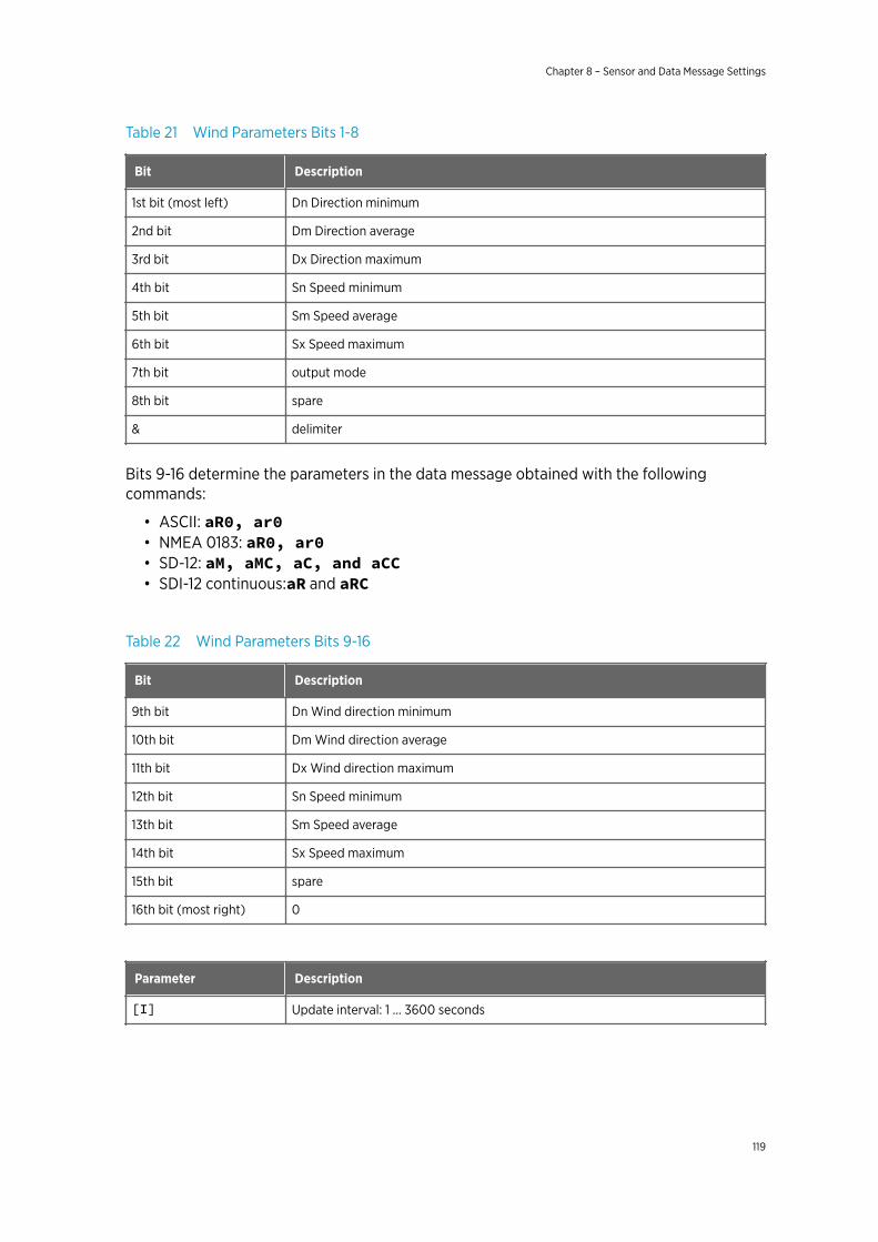
Table 21 Wind Parameters Bits 1-8
Bit Description
1st bit (most left) Dn Direction minimum
2nd bit Dm Direction average
3rd bit Dx Direction maximum
4th bit Sn Speed minimum
5th bit Sm Speed average
6th bit Sx Speed maximum
7th bit output mode
8th bit spare
& delimiter
Bits 9-16 determine the parameters in the data message obtained with the followingcommands:
• ASCII: aR0, ar0• NMEA 0183: aR0, ar0• SD-12: aM, aMC, aC, and aCC• SDI-12 continuous:aR and aRC
Table 22 Wind Parameters Bits 9-16
Bit Description
9th bit Dn Wind direction minimum
10th bit Dm Wind direction average
11th bit Dx Wind direction maximum
12th bit Sn Speed minimum
13th bit Sm Speed average
14th bit Sx Speed maximum
15th bit spare
16th bit (most right) 0
Parameter Description
[I] Update interval: 1 ... 3600 seconds
Chapter 8 – Sensor and Data Message Settings
119
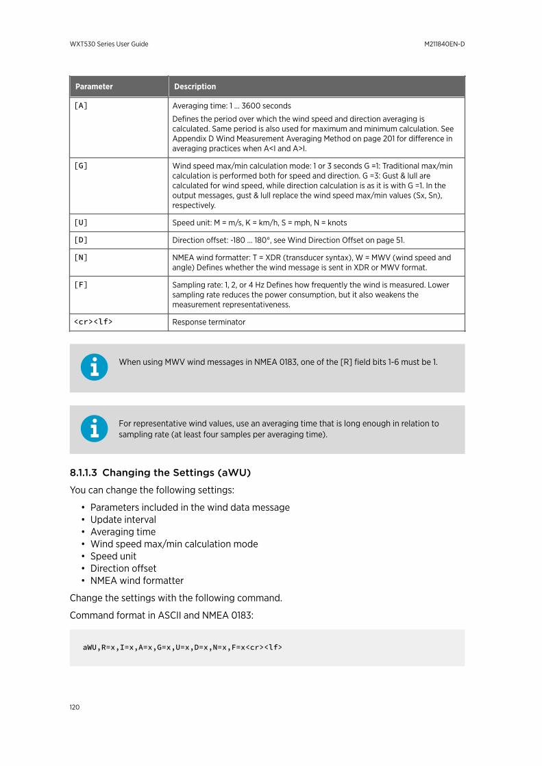
Parameter Description
[A] Averaging time: 1 ... 3600 seconds
Defines the period over which the wind speed and direction averaging iscalculated. Same period is also used for maximum and minimum calculation. SeeAppendix D Wind Measurement Averaging Method on page 201 for difference inaveraging practices when A<I and A>I.
[G] Wind speed max/min calculation mode: 1 or 3 seconds G =1: Traditional max/mincalculation is performed both for speed and direction. G =3: Gust & lull arecalculated for wind speed, while direction calculation is as it is with G =1. In theoutput messages, gust & lull replace the wind speed max/min values (Sx, Sn),respectively.
[U] Speed unit: M = m/s, K = km/h, S = mph, N = knots
[D] Direction offset: -180 ... 180°, see Wind Direction Offset on page 51.
[N] NMEA wind formatter: T = XDR (transducer syntax), W = MWV (wind speed andangle) Defines whether the wind message is sent in XDR or MWV format.
[F] Sampling rate: 1, 2, or 4 Hz Defines how frequently the wind is measured. Lowersampling rate reduces the power consumption, but it also weakens themeasurement representativeness.
<cr><lf> Response terminator
When using MWV wind messages in NMEA 0183, one of the [R] field bits 1-6 must be 1.
For representative wind values, use an averaging time that is long enough in relation tosampling rate (at least four samples per averaging time).
8.1.1.3 Changing the Settings (aWU)
You can change the following settings:
• Parameters included in the wind data message• Update interval• Averaging time• Wind speed max/min calculation mode• Speed unit• Direction offset• NMEA wind formatter
Change the settings with the following command.
Command format in ASCII and NMEA 0183:
aWU,R=x,I=x,A=x,G=x,U=x,D=x,N=x,F=x<cr><lf>
WXT530 Series User Guide M211840EN-D
120
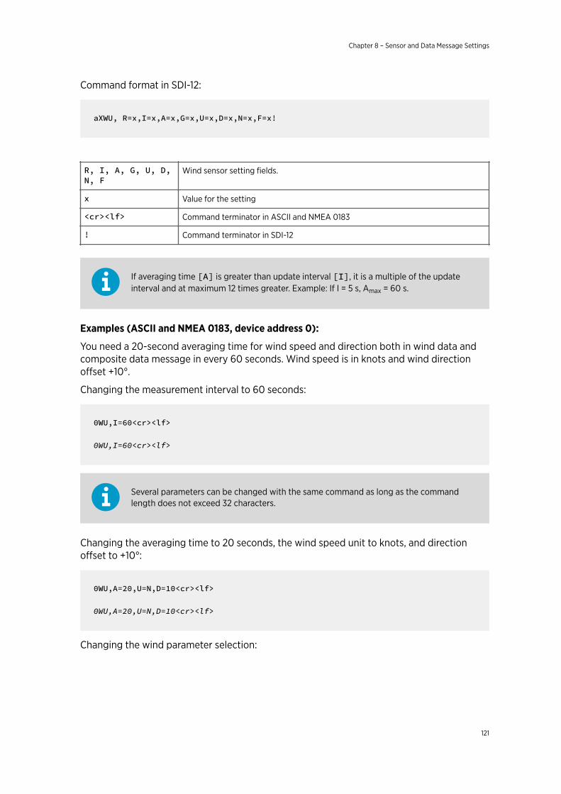
Command format in SDI-12:
aXWU, R=x,I=x,A=x,G=x,U=x,D=x,N=x,F=x!
R, I, A, G, U, D,N, F
Wind sensor setting fields.
x Value for the setting
<cr><lf> Command terminator in ASCII and NMEA 0183
! Command terminator in SDI-12
If averaging time [A] is greater than update interval [I], it is a multiple of the updateinterval and at maximum 12 times greater. Example: If I = 5 s, Amax = 60 s.
Examples (ASCII and NMEA 0183, device address 0):
You need a 20-second averaging time for wind speed and direction both in wind data andcomposite data message in every 60 seconds. Wind speed is in knots and wind directionoffset +10°.
Changing the measurement interval to 60 seconds:
0WU,I=60<cr><lf>
0WU,I=60<cr><lf>
Several parameters can be changed with the same command as long as the commandlength does not exceed 32 characters.
Changing the averaging time to 20 seconds, the wind speed unit to knots, and directionoffset to +10°:
0WU,A=20,U=N,D=10<cr><lf>
0WU,A=20,U=N,D=10<cr><lf>
Changing the wind parameter selection:
Chapter 8 – Sensor and Data Message Settings
121
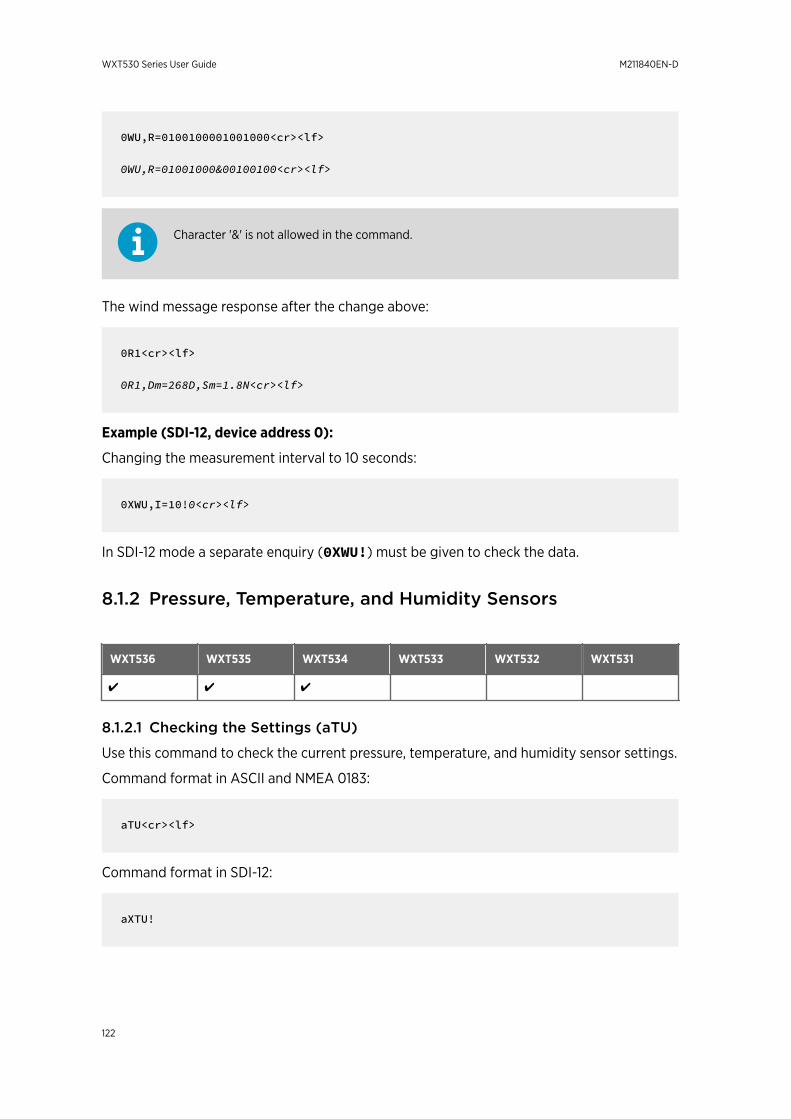
0WU,R=0100100001001000<cr><lf>
0WU,R=01001000&00100100<cr><lf>
Character '&' is not allowed in the command.
The wind message response after the change above:
0R1<cr><lf>
0R1,Dm=268D,Sm=1.8N<cr><lf>
Example (SDI-12, device address 0):
Changing the measurement interval to 10 seconds:
0XWU,I=10!0<cr><lf>
In SDI-12 mode a separate enquiry (0XWU!) must be given to check the data.
8.1.2 Pressure, Temperature, and Humidity Sensors
WXT536 WXT535 WXT534 WXT533 WXT532 WXT531
✔ ✔ ✔
8.1.2.1 Checking the Settings (aTU)
Use this command to check the current pressure, temperature, and humidity sensor settings.
Command format in ASCII and NMEA 0183:
aTU<cr><lf>
Command format in SDI-12:
aXTU!
WXT530 Series User Guide M211840EN-D
122
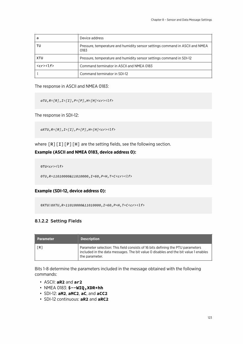
a Device address
TU Pressure, temperature and humidity sensor settings command in ASCII and NMEA0183
XTU Pressure, temperature and humidity sensor settings command in SDI-12
<cr><lf> Command terminator in ASCII and NMEA 0183
! Command terminator in SDI-12
The response in ASCII and NMEA 0183:
aTU,R=[R],I=[I],P=[P],H=[H]<cr><lf>
The response in SDI-12:
aXTU,R=[R],I=[I],P=[P],H=[H]<cr><lf>
where [R][I][P][H] are the setting fields, see the following section.
Example (ASCII and NMEA 0183, device address 0):
0TU<cr><lf>
0TU,R=11010000&11010000,I=60,P=H,T=C<cr><lf>
Example (SDI-12, device address 0):
0XTU!0XTU,R=11010000&11010000,I=60,P=H,T=C<cr><lf>
8.1.2.2 Setting Fields
Parameter Description
[R] Parameter selection: This field consists of 16 bits defining the PTU parametersincluded in the data messages. The bit value 0 disables and the bit value 1 enablesthe parameter.
Bits 1-8 determine the parameters included in the message obtained with the followingcommands:
• ASCII: aR2 and ar2• NMEA 0183: $--WIQ,XDR*hh• SDI-12: aM2, aMC2, aC, and aCC2• SDI-12 continuous: aR2 and aRC2
Chapter 8 – Sensor and Data Message Settings
123
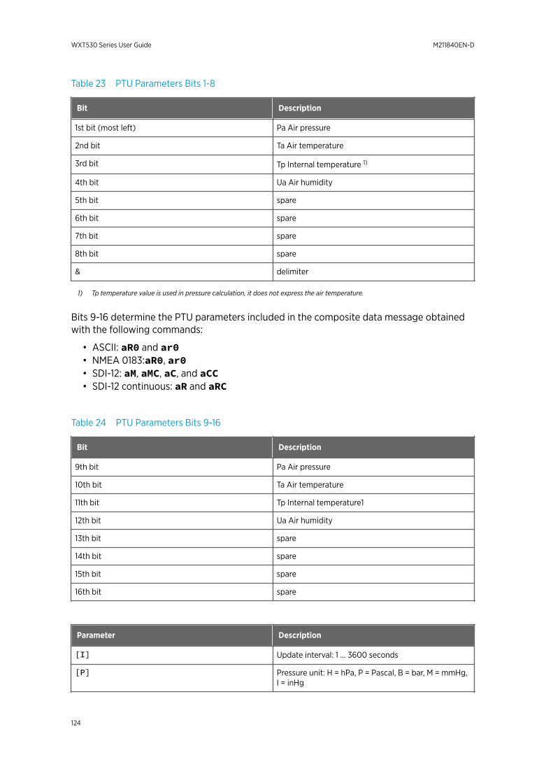
Table 23 PTU Parameters Bits 1-8
Bit Description
1st bit (most left) Pa Air pressure
2nd bit Ta Air temperature
3rd bit Tp Internal temperature 1)
4th bit Ua Air humidity
5th bit spare
6th bit spare
7th bit spare
8th bit spare
& delimiter
1) Tp temperature value is used in pressure calculation, it does not express the air temperature.
Bits 9-16 determine the PTU parameters included in the composite data message obtainedwith the following commands:
• ASCII: aR0 and ar0• NMEA 0183:aR0, ar0• SDI-12: aM, aMC, aC, and aCC• SDI-12 continuous: aR and aRC
Table 24 PTU Parameters Bits 9-16
Bit Description
9th bit Pa Air pressure
10th bit Ta Air temperature
11th bit Tp Internal temperature1
12th bit Ua Air humidity
13th bit spare
14th bit spare
15th bit spare
16th bit spare
Parameter Description
[I] Update interval: 1 … 3600 seconds
[P] Pressure unit: H = hPa, P = Pascal, B = bar, M = mmHg,I = inHg
WXT530 Series User Guide M211840EN-D
124
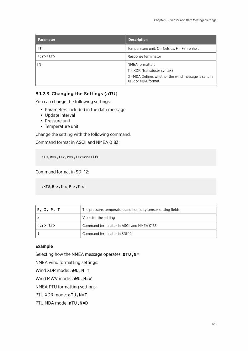
Parameter Description
[T] Temperature unit: C = Celsius, F = Fahrenheit
<cr><lf> Response terminator
[N] NMEA formatter:
T = XDR (transducer syntax)
D =MDA Defines whether the wind message is sent inXDR or MDA format.
8.1.2.3 Changing the Settings (aTU)
You can change the following settings:
• Parameters included in the data message• Update interval• Pressure unit• Temperature unit
Change the setting with the following command.
Command format in ASCII and NMEA 0183:
aTU,R=x,I=x,P=x,T=x<cr><lf>
Command format in SDI-12:
aXTU,R=x,I=x,P=x,T=x!
R, I, P, T The pressure, temperature and humidity sensor setting fields.
x Value for the setting
<cr><lf> Command terminator in ASCII and NMEA 0183
! Command terminator in SDI-12
Example
Selecting how the NMEA message operates: 0TU,N=NMEA wind formatting settings:
Wind XDR mode: aWU,N=TWind MWV mode: aWU,N=WNMEA PTU formatting settings:
PTU XDR mode: aTU,N=TPTU MDA mode: aTU,N=D
Chapter 8 – Sensor and Data Message Settings
125
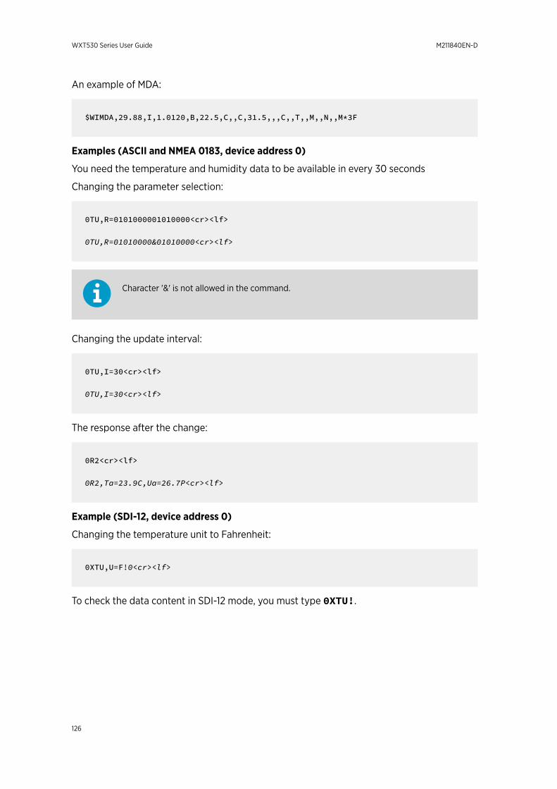
An example of MDA:
$WIMDA,29.88,I,1.0120,B,22.5,C,,C,31.5,,,C,,T,,M,,N,,M*3F
Examples (ASCII and NMEA 0183, device address 0)
You need the temperature and humidity data to be available in every 30 seconds
Changing the parameter selection:
0TU,R=0101000001010000<cr><lf>
0TU,R=01010000&01010000<cr><lf>
Character '&' is not allowed in the command.
Changing the update interval:
0TU,I=30<cr><lf>
0TU,I=30<cr><lf>
The response after the change:
0R2<cr><lf>
0R2,Ta=23.9C,Ua=26.7P<cr><lf>
Example (SDI-12, device address 0)
Changing the temperature unit to Fahrenheit:
0XTU,U=F!0<cr><lf>
To check the data content in SDI-12 mode, you must type 0XTU!.
WXT530 Series User Guide M211840EN-D
126
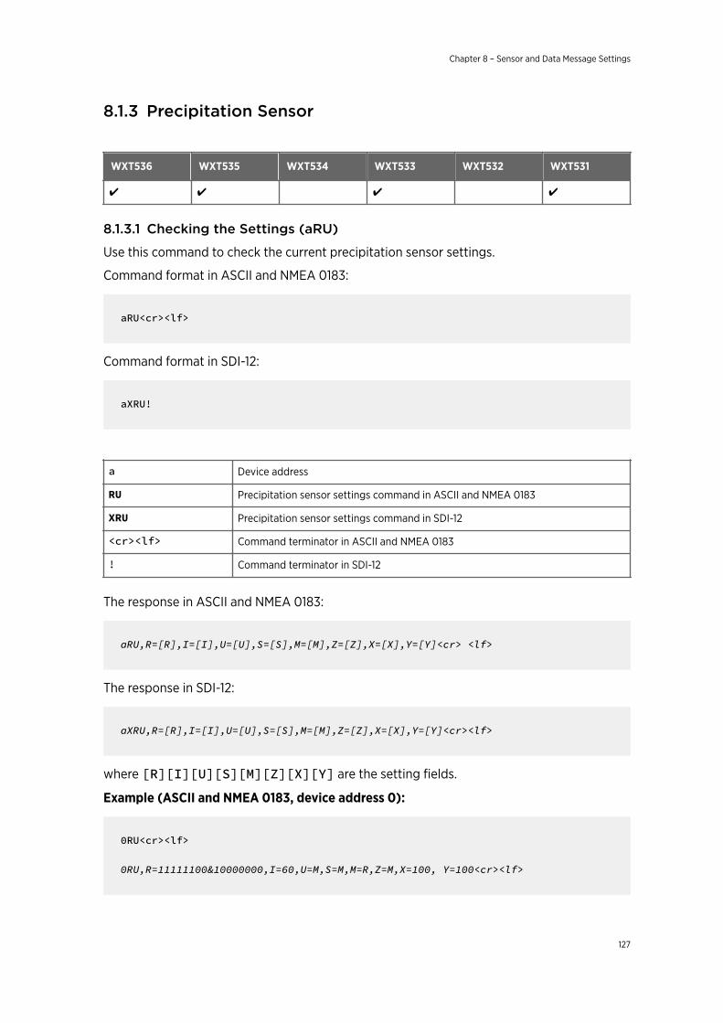
8.1.3 Precipitation Sensor
WXT536 WXT535 WXT534 WXT533 WXT532 WXT531
✔ ✔ ✔ ✔
8.1.3.1 Checking the Settings (aRU)
Use this command to check the current precipitation sensor settings.
Command format in ASCII and NMEA 0183:
aRU<cr><lf>
Command format in SDI-12:
aXRU!
a Device address
RU Precipitation sensor settings command in ASCII and NMEA 0183
XRU Precipitation sensor settings command in SDI-12
<cr><lf> Command terminator in ASCII and NMEA 0183
! Command terminator in SDI-12
The response in ASCII and NMEA 0183:
aRU,R=[R],I=[I],U=[U],S=[S],M=[M],Z=[Z],X=[X],Y=[Y]<cr> <lf>
The response in SDI-12:
aXRU,R=[R],I=[I],U=[U],S=[S],M=[M],Z=[Z],X=[X],Y=[Y]<cr><lf>
where [R][I][U][S][M][Z][X][Y] are the setting fields.
Example (ASCII and NMEA 0183, device address 0):
0RU<cr><lf>
0RU,R=11111100&10000000,I=60,U=M,S=M,M=R,Z=M,X=100, Y=100<cr><lf>
Chapter 8 – Sensor and Data Message Settings
127
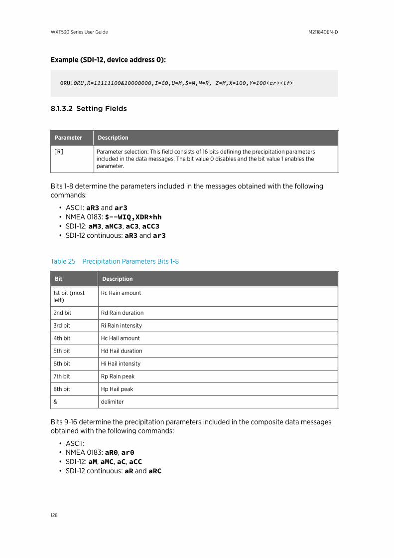
Example (SDI-12, device address 0):
0RU!0RU,R=11111100&10000000,I=60,U=M,S=M,M=R, Z=M,X=100,Y=100<cr><lf>
8.1.3.2 Setting Fields
Parameter Description
[R] Parameter selection: This field consists of 16 bits defining the precipitation parametersincluded in the data messages. The bit value 0 disables and the bit value 1 enables theparameter.
Bits 1-8 determine the parameters included in the messages obtained with the followingcommands:
• ASCII: aR3 and ar3• NMEA 0183: $--WIQ,XDR*hh• SDI-12: aM3, aMC3, aC3, aCC3• SDI-12 continuous: aR3 and ar3
Table 25 Precipitation Parameters Bits 1-8
Bit Description
1st bit (mostleft)
Rc Rain amount
2nd bit Rd Rain duration
3rd bit Ri Rain intensity
4th bit Hc Hail amount
5th bit Hd Hail duration
6th bit Hi Hail intensity
7th bit Rp Rain peak
8th bit Hp Hail peak
& delimiter
Bits 9-16 determine the precipitation parameters included in the composite data messagesobtained with the following commands:
• ASCII:• NMEA 0183: aR0, ar0• SDI-12: aM, aMC, aC, aCC• SDI-12 continuous: aR and aRC
WXT530 Series User Guide M211840EN-D
128
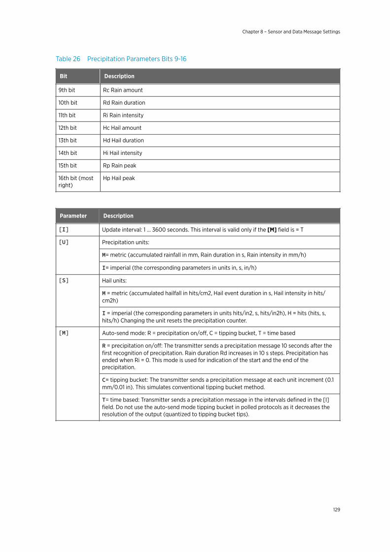
Table 26 Precipitation Parameters Bits 9-16
Bit Description
9th bit Rc Rain amount
10th bit Rd Rain duration
11th bit Ri Rain intensity
12th bit Hc Hail amount
13th bit Hd Hail duration
14th bit Hi Hail intensity
15th bit Rp Rain peak
16th bit (mostright)
Hp Hail peak
Parameter Description
[I] Update interval: 1 … 3600 seconds. This interval is valid only if the [M] field is = T
[U] Precipitation units:
M= metric (accumulated rainfall in mm, Rain duration in s, Rain intensity in mm/h)
I= imperial (the corresponding parameters in units in, s, in/h)
[S] Hail units:
M = metric (accumulated hailfall in hits/cm2, Hail event duration in s, Hail intensity in hits/cm2h)
I = imperial (the corresponding parameters in units hits/in2, s, hits/in2h), H = hits (hits, s,hits/h) Changing the unit resets the precipitation counter.
[M] Auto-send mode: R = precipitation on/off, C = tipping bucket, T = time based
R = precipitation on/off: The transmitter sends a precipitation message 10 seconds after thefirst recognition of precipitation. Rain duration Rd increases in 10 s steps. Precipitation hasended when Ri = 0. This mode is used for indication of the start and the end of theprecipitation.
C= tipping bucket: The transmitter sends a precipitation message at each unit increment (0.1mm/0.01 in). This simulates conventional tipping bucket method.
T= time based: Transmitter sends a precipitation message in the intervals defined in the [I]field. Do not use the auto-send mode tipping bucket in polled protocols as it decreases theresolution of the output (quantized to tipping bucket tips).
Chapter 8 – Sensor and Data Message Settings
129
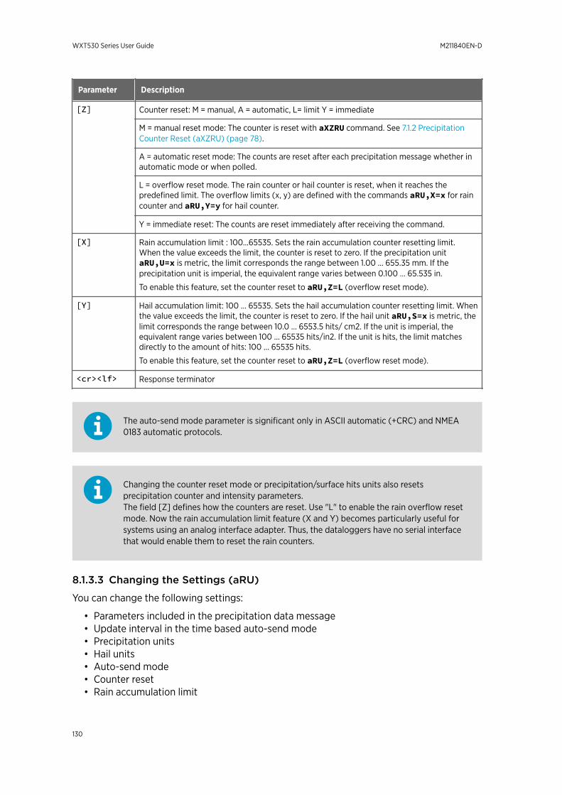
Parameter Description
[Z] Counter reset: M = manual, A = automatic, L= limit Y = immediate
M = manual reset mode: The counter is reset with aXZRU command. See 7.1.2 PrecipitationCounter Reset (aXZRU) (page 78).
A = automatic reset mode: The counts are reset after each precipitation message whether inautomatic mode or when polled.
L = overflow reset mode. The rain counter or hail counter is reset, when it reaches thepredefined limit. The overflow limits (x, y) are defined with the commands aRU,X=x for raincounter and aRU,Y=y for hail counter.
Y = immediate reset: The counts are reset immediately after receiving the command.
[X] Rain accumulation limit : 100...65535. Sets the rain accumulation counter resetting limit.When the value exceeds the limit, the counter is reset to zero. If the precipitation unitaRU,U=x is metric, the limit corresponds the range between 1.00 … 655.35 mm. If theprecipitation unit is imperial, the equivalent range varies between 0.100 … 65.535 in.
To enable this feature, set the counter reset to aRU,Z=L (overflow reset mode).
[Y] Hail accumulation limit: 100 … 65535. Sets the hail accumulation counter resetting limit. Whenthe value exceeds the limit, the counter is reset to zero. If the hail unit aRU,S=x is metric, thelimit corresponds the range between 10.0 … 6553.5 hits/ cm2. If the unit is imperial, theequivalent range varies between 100 … 65535 hits/in2. If the unit is hits, the limit matchesdirectly to the amount of hits: 100 … 65535 hits.
To enable this feature, set the counter reset to aRU,Z=L (overflow reset mode).
<cr><lf> Response terminator
The auto-send mode parameter is significant only in ASCII automatic (+CRC) and NMEA0183 automatic protocols.
Changing the counter reset mode or precipitation/surface hits units also resetsprecipitation counter and intensity parameters.The field [Z] defines how the counters are reset. Use "L" to enable the rain overflow resetmode. Now the rain accumulation limit feature (X and Y) becomes particularly useful forsystems using an analog interface adapter. Thus, the dataloggers have no serial interfacethat would enable them to reset the rain counters.
8.1.3.3 Changing the Settings (aRU)
You can change the following settings:
• Parameters included in the precipitation data message• Update interval in the time based auto-send mode• Precipitation units• Hail units• Auto-send mode• Counter reset• Rain accumulation limit
WXT530 Series User Guide M211840EN-D
130
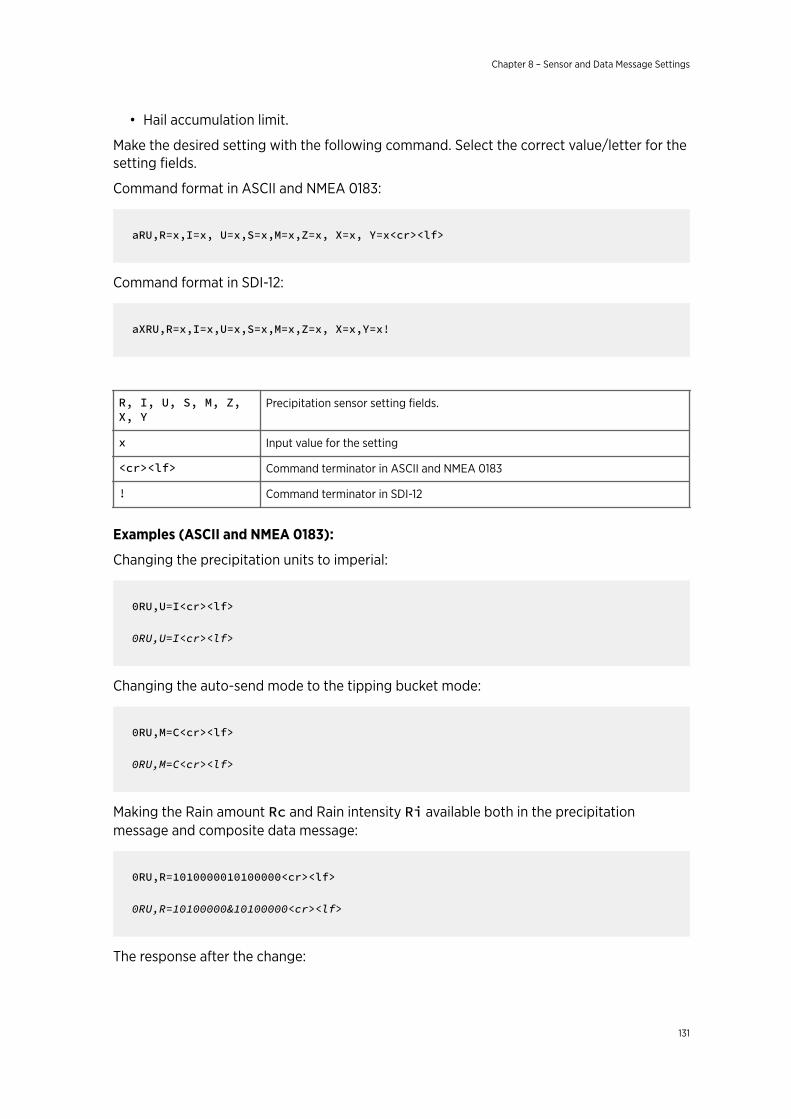
• Hail accumulation limit.
Make the desired setting with the following command. Select the correct value/letter for thesetting fields.
Command format in ASCII and NMEA 0183:
aRU,R=x,I=x, U=x,S=x,M=x,Z=x, X=x, Y=x<cr><lf>
Command format in SDI-12:
aXRU,R=x,I=x,U=x,S=x,M=x,Z=x, X=x,Y=x!
R, I, U, S, M, Z,X, Y
Precipitation sensor setting fields.
x Input value for the setting
<cr><lf> Command terminator in ASCII and NMEA 0183
! Command terminator in SDI-12
Examples (ASCII and NMEA 0183):
Changing the precipitation units to imperial:
0RU,U=I<cr><lf>
0RU,U=I<cr><lf>
Changing the auto-send mode to the tipping bucket mode:
0RU,M=C<cr><lf>
0RU,M=C<cr><lf>
Making the Rain amount Rc and Rain intensity Ri available both in the precipitationmessage and composite data message:
0RU,R=1010000010100000<cr><lf>
0RU,R=10100000&10100000<cr><lf>
The response after the change:
Chapter 8 – Sensor and Data Message Settings
131
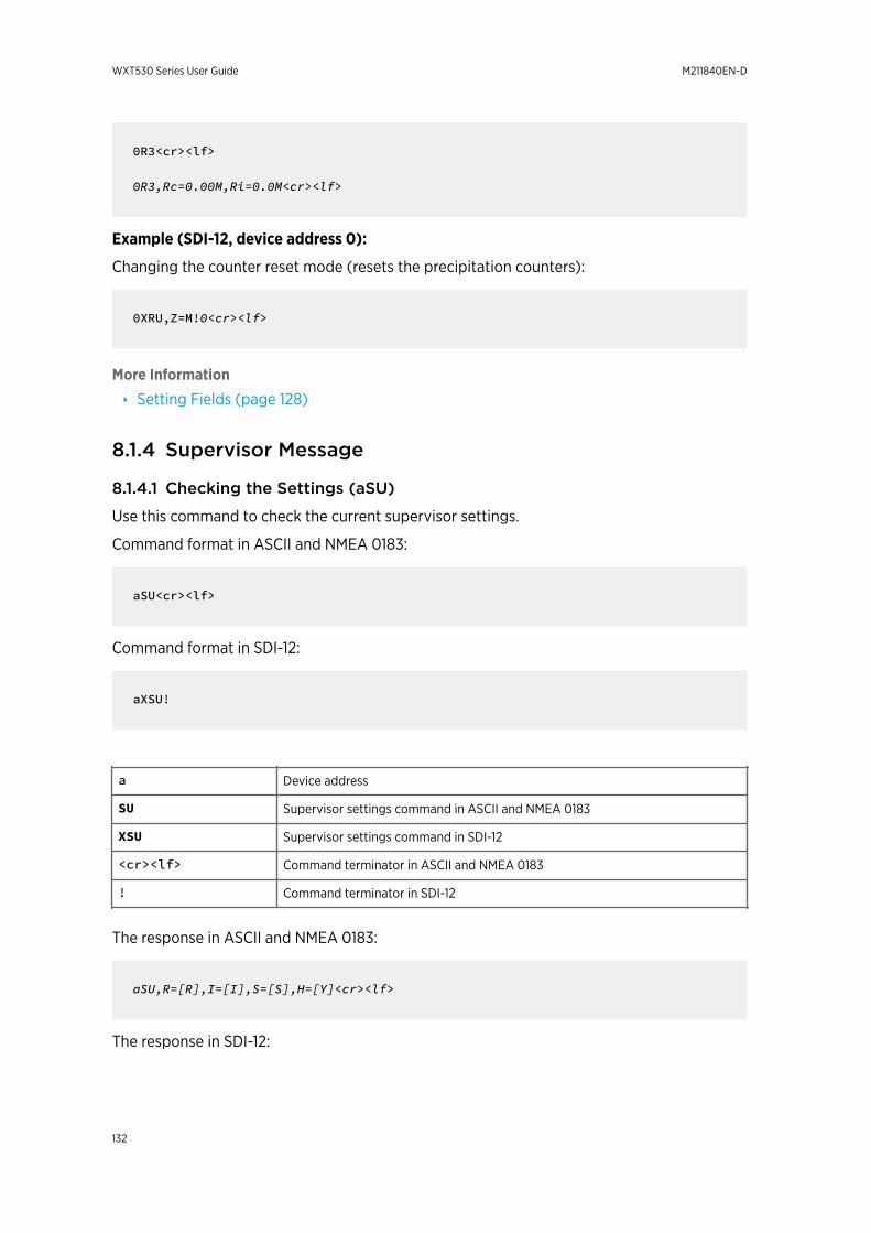
0R3<cr><lf>
0R3,Rc=0.00M,Ri=0.0M<cr><lf>
Example (SDI-12, device address 0):
Changing the counter reset mode (resets the precipitation counters):
0XRU,Z=M!0<cr><lf>
More Information
‣ Setting Fields (page 128)
8.1.4 Supervisor Message
8.1.4.1 Checking the Settings (aSU)
Use this command to check the current supervisor settings.
Command format in ASCII and NMEA 0183:
aSU<cr><lf>
Command format in SDI-12:
aXSU!
a Device address
SU Supervisor settings command in ASCII and NMEA 0183
XSU Supervisor settings command in SDI-12
<cr><lf> Command terminator in ASCII and NMEA 0183
! Command terminator in SDI-12
The response in ASCII and NMEA 0183:
aSU,R=[R],I=[I],S=[S],H=[Y]<cr><lf>
The response in SDI-12:
WXT530 Series User Guide M211840EN-D
132
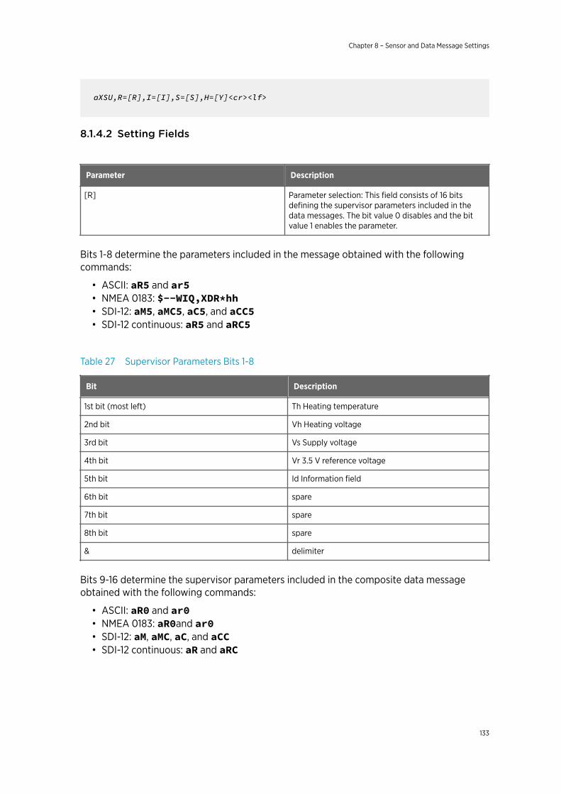
aXSU,R=[R],I=[I],S=[S],H=[Y]<cr><lf>
8.1.4.2 Setting Fields
Parameter Description
[R] Parameter selection: This field consists of 16 bitsdefining the supervisor parameters included in thedata messages. The bit value 0 disables and the bitvalue 1 enables the parameter.
Bits 1-8 determine the parameters included in the message obtained with the followingcommands:
• ASCII: aR5 and ar5• NMEA 0183: $--WIQ,XDR*hh• SDI-12: aM5, aMC5, aC5, and aCC5• SDI-12 continuous: aR5 and aRC5
Table 27 Supervisor Parameters Bits 1-8
Bit Description
1st bit (most left) Th Heating temperature
2nd bit Vh Heating voltage
3rd bit Vs Supply voltage
4th bit Vr 3.5 V reference voltage
5th bit Id Information field
6th bit spare
7th bit spare
8th bit spare
& delimiter
Bits 9-16 determine the supervisor parameters included in the composite data messageobtained with the following commands:
• ASCII: aR0 and ar0• NMEA 0183: aR0and ar0• SDI-12: aM, aMC, aC, and aCC• SDI-12 continuous: aR and aRC
Chapter 8 – Sensor and Data Message Settings
133
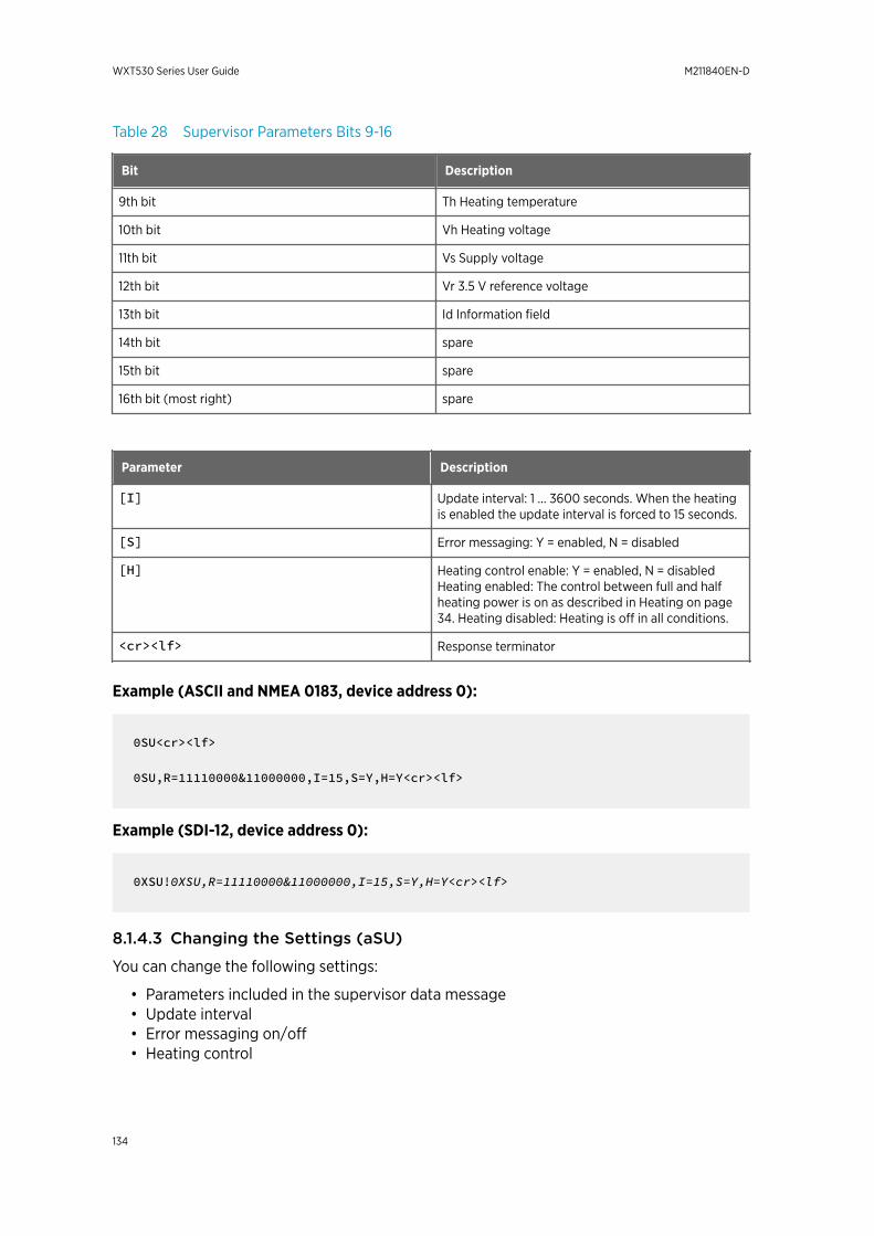
Table 28 Supervisor Parameters Bits 9-16
Bit Description
9th bit Th Heating temperature
10th bit Vh Heating voltage
11th bit Vs Supply voltage
12th bit Vr 3.5 V reference voltage
13th bit Id Information field
14th bit spare
15th bit spare
16th bit (most right) spare
Parameter Description
[I] Update interval: 1 … 3600 seconds. When the heatingis enabled the update interval is forced to 15 seconds.
[S] Error messaging: Y = enabled, N = disabled
[H] Heating control enable: Y = enabled, N = disabledHeating enabled: The control between full and halfheating power is on as described in Heating on page34. Heating disabled: Heating is off in all conditions.
<cr><lf> Response terminator
Example (ASCII and NMEA 0183, device address 0):
0SU<cr><lf>
0SU,R=11110000&11000000,I=15,S=Y,H=Y<cr><lf>
Example (SDI-12, device address 0):
0XSU!0XSU,R=11110000&11000000,I=15,S=Y,H=Y<cr><lf>
8.1.4.3 Changing the Settings (aSU)
You can change the following settings:
• Parameters included in the supervisor data message• Update interval• Error messaging on/off• Heating control
WXT530 Series User Guide M211840EN-D
134
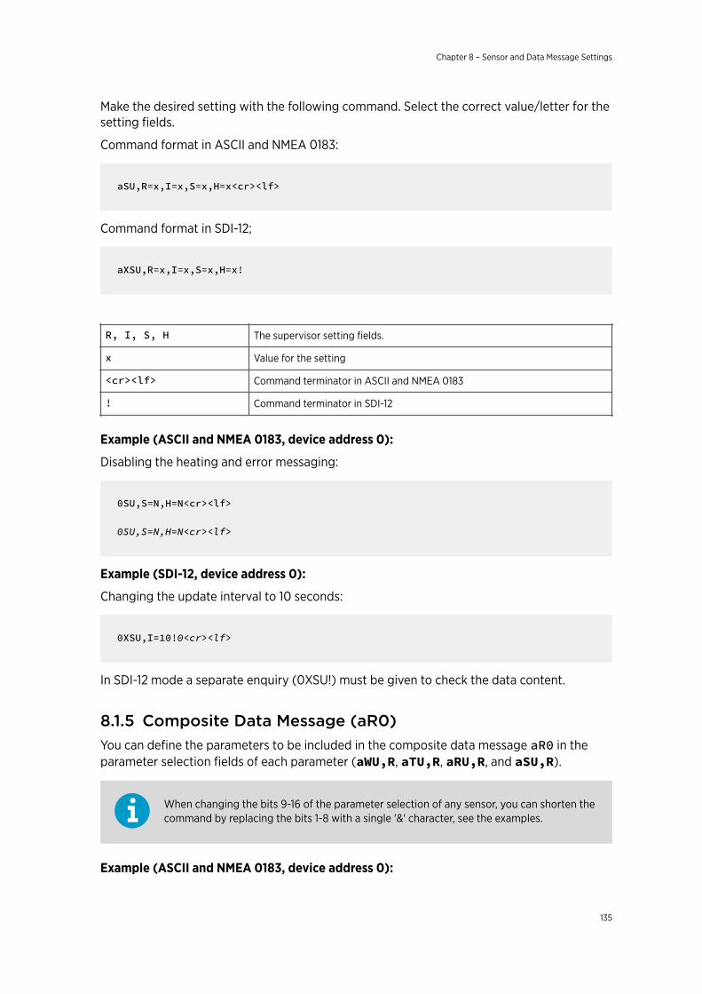
Make the desired setting with the following command. Select the correct value/letter for thesetting fields.
Command format in ASCII and NMEA 0183:
aSU,R=x,I=x,S=x,H=x<cr><lf>
Command format in SDI-12;
aXSU,R=x,I=x,S=x,H=x!
R, I, S, H The supervisor setting fields.
x Value for the setting
<cr><lf> Command terminator in ASCII and NMEA 0183
! Command terminator in SDI-12
Example (ASCII and NMEA 0183, device address 0):
Disabling the heating and error messaging:
0SU,S=N,H=N<cr><lf>
0SU,S=N,H=N<cr><lf>
Example (SDI-12, device address 0):
Changing the update interval to 10 seconds:
0XSU,I=10!0<cr><lf>
In SDI-12 mode a separate enquiry (0XSU!) must be given to check the data content.
8.1.5 Composite Data Message (aR0)You can define the parameters to be included in the composite data message aR0 in theparameter selection fields of each parameter (aWU,R, aTU,R, aRU,R, and aSU,R).
When changing the bits 9-16 of the parameter selection of any sensor, you can shorten thecommand by replacing the bits 1-8 with a single '&' character, see the examples.
Example (ASCII and NMEA 0183, device address 0):
Chapter 8 – Sensor and Data Message Settings
135

To format a composite data message with average wind direction, average wind speed,temperature, humidity and pressure data when the original composite data messagecontains following data: maximum wind direction, maximum wind speed, temperature,humidity, pressure, accumulated rainfall, supply voltage and heating voltage:
0R0<cr><lf>
0R0,Dx=009D,Sx=0.2M,Ta=23.3C,Ua=37.5P,Pa=996.8H, Rc=0.000I,Vs=12.0V,Vh=0.0N<cr><lf>
Replace the maximum wind direction (Dx) and speed (Sx) with average wind direction (Dm)and average wind speed (Sm):
0WU,R=&01001000<cr><lf>
0WU,R=11110000&01001000<cr><lf>
Remove the heating voltage (Vh) and temperature (Th) data from the composite datamessage, and include the information field (Id):
0SU,R=&00001000<cr><lf>
0SU,R=11110000&00001000<cr><lf>
Remove the accumulated rainfall (Rc) from the composite data message:
0RU,R=&00000000<cr><lf>
0RU,R=11111100&00000000<cr><lf>
The final composite data message query and response in ASCII:
0R0<cr><lf>
0R0,Dm=009D,Sm=0.2M,Ta=23.3C,Ua=37.5P, Pa=996.8H,Id=HEL___<cr><lf>
8.1.6 Analog InputThe following figure shows the pins of the analog input connectors.
WXT530 Series User Guide M211840EN-D
136
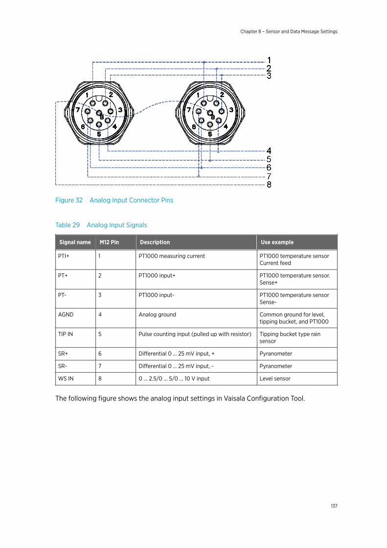
Figure 32 Analog Input Connector Pins
Table 29 Analog Input Signals
Signal name M12 Pin Description Use example
PTI+ 1 PT1000 measuring current PT1000 temperature sensorCurrent feed
PT+ 2 PT1000 input+ PT1000 temperature sensor.Sense+
PT- 3 PT1000 input- PT1000 temperature sensorSense-
AGND 4 Analog ground Common ground for level,tipping bucket, and PT1000
TIP IN 5 Pulse counting input (pulled up with resistor) Tipping bucket type rainsensor
SR+ 6 Differential 0 … 25 mV input, + Pyranometer
SR- 7 Differential 0 … 25 mV input, - Pyranometer
WS IN 8 0 … 2.5/0 … 5/0 … 10 V input Level sensor
The following figure shows the analog input settings in Vaisala Configuration Tool.
Chapter 8 – Sensor and Data Message Settings
137
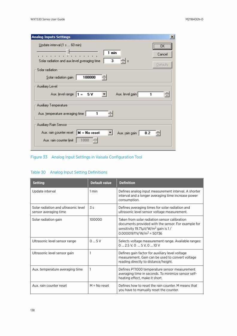
Figure 33 Analog Input Settings in Vaisala Configuration Tool
Table 30 Analog Input Setting Definitions
Setting Default value Definition
Update interval 1 min Defines analog input measurement interval. A shorterinterval and a longer averaging time increase powerconsumption.
Solar radiation and ultrasonic levelsensor averaging time
3 s Defines averaging times for solar radiation andultrasonic level sensor voltage measurement.
Solar radiation gain 100000 Taken from solar radiation sensor calibrationdocuments provided with the sensor. For example forsensitivity 19.71µV/W/m2 gain is 1 /0.00001971V/W/m2 = 50736
Ultrasonic level sensor range 0 … 5 V Selects voltage measurement range. Available ranges:0 … 2.5 V, 0 … 5 V, 0 … 10 V
Ultrasonic level sensor gain 1 Defines gain factor for auxiliary level voltagemeasurement. Gain can be used to convert voltagereading directly to distance/height.
Aux. temperature averaging time 1 Defines PT1000 temperature sensor measurementaveraging time in seconds. To minimize sensor self-heating effect, make it short.
Aux. rain counter reset M = No reset Defines how to reset the rain counter. M means thatyou have to manually reset the counter.
WXT530 Series User Guide M211840EN-D
138
Setting Default value Definition
Aux. rain gain 0.2 mm Comes from the rain sensor tipping bucket size. Itmeans pulses / user rain unit (for example, mm). If theaux. sensor has 5 pulses per mm of rain, and the usersets the gain to 0.2, the rain value reported by thetransmitter is in mm.
Aux. rain counter limit Used only when L = based on limit is selected. Resetsthe rain counter when it reaches this value. The sameunit as the gain G has.
• All measurement messages enabled• Update interval 60 s• Solar radiation and ultrasonic level sensor averaging time 3 s• Solar radiation gain 100 000• Ultrasonic level sensor range 5 V• Ultrasonic level sensor gain 1• Aux temperature average time 1 s• Aux rain counter reset: manual• Aux rain gain 0.2 (for 0.2 mm per tip)
WXT530 Series settings:
0IU,R=11111000&11111000,I=60,A=3.00IB,G=100000.00IS,M=1,G=1.00IP,A=1.00IA,M=M,G=0.2
8.1.6.1 Enabling and Disabling Analog Input
If the analog input option is selected for WXT536, all analog inputs are enabled by default.
You can enable and disable analog input with the aIU,R= command.
For example, PT1000 temperature enabled, all other disabled:
aIU,R=1000000010000000
You must reset the transmitter to apply the new setting. When analog input is in use, theserial port does not work. The service connector functions.
More Information
‣ Enabling or Disabling Analog Output (page 145)
Chapter 8 – Sensor and Data Message Settings
139
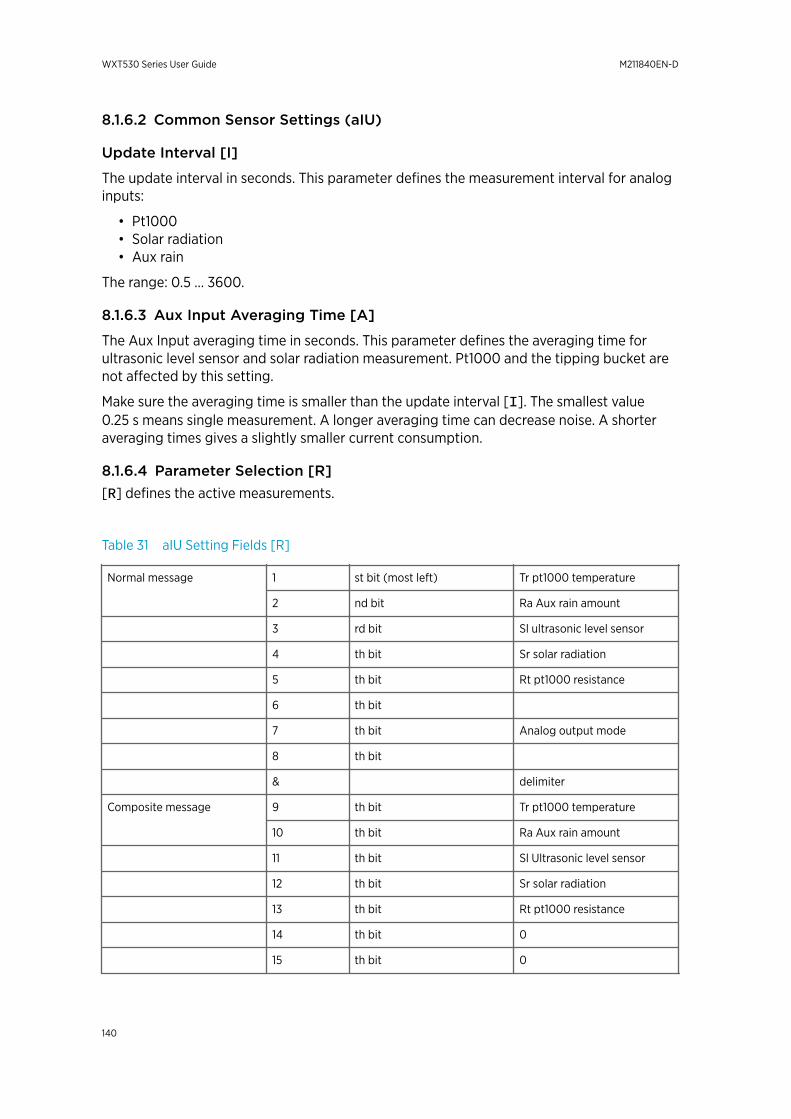
8.1.6.2 Common Sensor Settings (aIU)
Update Interval [I]
The update interval in seconds. This parameter defines the measurement interval for analoginputs:
• Pt1000• Solar radiation• Aux rain
The range: 0.5 … 3600.
8.1.6.3 Aux Input Averaging Time [A]
The Aux Input averaging time in seconds. This parameter defines the averaging time forultrasonic level sensor and solar radiation measurement. Pt1000 and the tipping bucket arenot affected by this setting.
Make sure the averaging time is smaller than the update interval [I]. The smallest value0.25 s means single measurement. A longer averaging time can decrease noise. A shorteraveraging times gives a slightly smaller current consumption.
8.1.6.4 Parameter Selection [R][R] defines the active measurements.
Table 31 aIU Setting Fields [R]
Normal message 1 st bit (most left) Tr pt1000 temperature
2 nd bit Ra Aux rain amount
3 rd bit Sl ultrasonic level sensor
4 th bit Sr solar radiation
5 th bit Rt pt1000 resistance
6 th bit
7 th bit Analog output mode
8 th bit
& delimiter
Composite message 9 th bit Tr pt1000 temperature
10 th bit Ra Aux rain amount
11 th bit Sl Ultrasonic level sensor
12 th bit Sr solar radiation
13 th bit Rt pt1000 resistance
14 th bit 0
15 th bit 0
WXT530 Series User Guide M211840EN-D
140
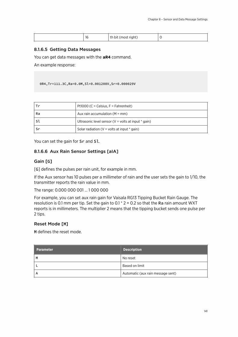
16 th bit (most right) 0
8.1.6.5 Getting Data Messages
You can get data messages with the aR4 command.
An example response:
0R4,Tr=111.3C,Ra=0.0M,Sl=0.001208V,Sr=0.000029V
Tr Pt1000 (C = Celsius, F = Fahrenheit)
Ra Aux rain accumulation (M = mm)
Sl Ultrasonic level sensor (V = volts at input * gain)
Sr Solar radiation (V = volts at input * gain)
You can set the gain for Sr and Sl.
8.1.6.6 Aux Rain Sensor Settings [aIA]
Gain [G]
[G] defines the pulses per rain unit, for example in mm.
If the Aux sensor has 10 pulses per a millimeter of rain and the user sets the gain to 1/10, thetransmitter reports the rain value in mm.
The range: 0.000 000 001 … 1 000 000
For example, you can set aux rain gain for Vaisala RG13 Tipping Bucket Rain Gauge. Theresolution is 0.1 mm per tip. Set the gain to 0.1 * 2 = 0.2 so that the Ra rain amount WXTreports is in millimeters. The multiplier 2 means that the tipping bucket sends one pulse per2 tips.
Reset Mode [M]
M defines the reset mode.
Parameter Description
M No reset
L Based on limit
A Automatic (aux rain message sent)
Chapter 8 – Sensor and Data Message Settings
141
The initial tip counter overflows if it reaches 65536 and it starts from 0. If the tipping bucketresolution is 0.2 mm per tip, the gain is 0.2, and the maximum rain amount before overflowis 65536 × 0.2 = 13107 mm.
Limit [L]
[L] defines the reset limit. The rain counter resets when it reaches this value. The unit is thesame as in gain [G].
The range: 0.000 000 001 … 1 000 000
Parameter Selection [aIU,R = bit 2 and bit 10]
Bits 7 and 14 enable normal and composite message for aux rain accumulation. You canselect the parameter with the aIU command. The maximum value for the rain counter is65535 * gain.
8.1.6.7 Solar Radiation Sensor Settings [aIB]
Gain
[G] defines the volts / user unit, for example, μV/W/m2. WXT reports the voltage at solarradiation input multiplied with gain [G].
For example, if the solar radiation sensor has sensitivity 5 μV/W/m2 and you set the gain [G]to 1/ μV = 200 000, the solar radiation value reported by WXT is in W/m2. WXT reports thevalue always with six decimals.
The range: 0.000 000 001 … 1 000 000
Parameter Selection [aIU,R= bit 3 and bit 11]
The bits enable normal and composite messages. You can select the parameters with theaIU command.
8.1.6.8 Ultrasonic Level Sensor Settings [aIS]
Gain [G]
[G] defines the volts / user unit, for example, V/m. WXT reports the voltage at inputmultiplied with the gain [G].
For example, if the sensor has gain 2 V/meter and the user sets the gain [G] to 0.5, the valuereported by WXT is in meters. WXT reports the value with 6 decimals.
The range: 0.000 000 001 … 1 000 000
Parameter Selection [aIU,R= (bit 3 and bit 11)]
The bits enable normal and composite messages. You can select the parameters with theaIU command.
8.1.6.9 Aux.temperature Sensor Settings [aIP]
You can set the temperature settings for the temperature unit with the aTU,U= command.
WXT530 Series User Guide M211840EN-D
142
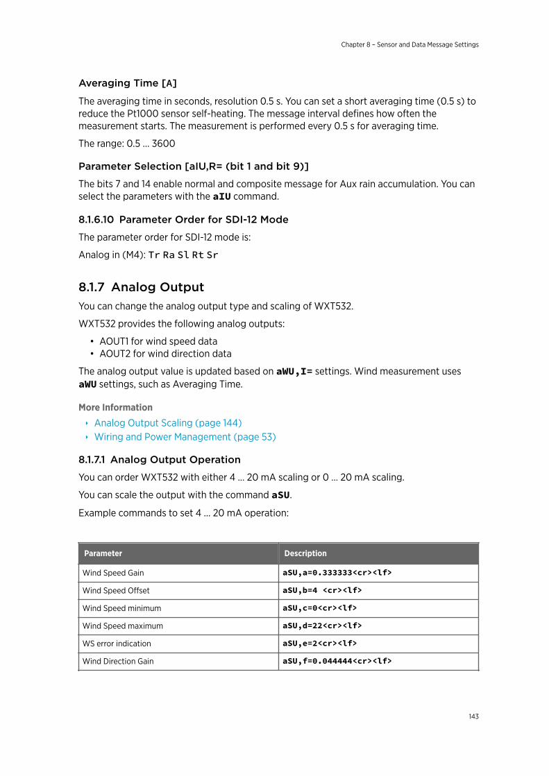
Averaging Time [A]
The averaging time in seconds, resolution 0.5 s. You can set a short averaging time (0.5 s) toreduce the Pt1000 sensor self-heating. The message interval defines how often themeasurement starts. The measurement is performed every 0.5 s for averaging time.
The range: 0.5 … 3600
Parameter Selection [aIU,R= (bit 1 and bit 9)]
The bits 7 and 14 enable normal and composite message for Aux rain accumulation. You canselect the parameters with the aIU command.
8.1.6.10 Parameter Order for SDI-12 Mode
The parameter order for SDI-12 mode is:
Analog in (M4): Tr Ra Sl Rt Sr
8.1.7 Analog OutputYou can change the analog output type and scaling of WXT532.
WXT532 provides the following analog outputs:
• AOUT1 for wind speed data• AOUT2 for wind direction data
The analog output value is updated based on aWU,I= settings. Wind measurement usesaWU settings, such as Averaging Time.
More Information
‣ Analog Output Scaling (page 144)‣ Wiring and Power Management (page 53)
8.1.7.1 Analog Output Operation
You can order WXT532 with either 4 … 20 mA scaling or 0 … 20 mA scaling.
You can scale the output with the command aSU.
Example commands to set 4 … 20 mA operation:
Parameter Description
Wind Speed Gain aSU,a=0.333333<cr><lf>
Wind Speed Offset aSU,b=4 <cr><lf>
Wind Speed minimum aSU,c=0<cr><lf>
Wind Speed maximum aSU,d=22<cr><lf>
WS error indication aSU,e=2<cr><lf>
Wind Direction Gain aSU,f=0.044444<cr><lf>
Chapter 8 – Sensor and Data Message Settings
143
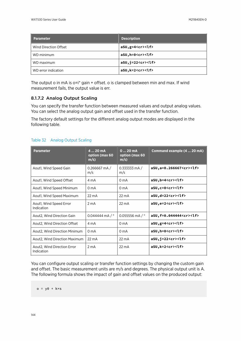
Parameter Description
Wind Direction Offset aSU,g=4<cr><lf>
WD minimum aSU,h=0<cr><lf>
WD maximum aSU,j=22<cr><lf>
WD error indication aSU,k=2<cr><lf>
The output o in mA is o=i* gain + offset. o is clamped between min and max. If windmeasurement fails, the output value is err.
8.1.7.2 Analog Output Scaling
You can specify the transfer function between measured values and output analog values.You can select the analog output gain and offset used in the transfer function.
The factory default settings for the different analog output modes are displayed in thefollowing table.
Table 32 Analog Output Scaling
Parameter 4 … 20 mAoption (max 60m/s)
0 … 20 mAoption (max 60m/s)
Command example (4 … 20 mA)
Aout1, Wind Speed Gain 0.266667 mA /m/s
0.333333 mA /m/s
aSU,a=0.266667<cr><lf>
Aout1, Wind Speed Offset 4 mA 0 mA aSU,b=4<cr><lf>
Aout1, Wind Speed Minimum 0 mA 0 mA aSU,c=0<cr><lf>
Aout1, Wind Speed Maximum 22 mA 22 mA aSU,d=22<cr><lf>
Aout1, Wind Speed ErrorIndication
2 mA 22 mA aSU,e=2<cr><lf>
Aout2, Wind Direction Gain 0.044444 mA / ° 0.055556 mA / ° aSU,f=0.044444<cr><lf>
Aout2, Wind Direction Offset 4 mA 0 mA aSU,g=4<cr><lf>
Aout2, Wind Direction Minimum 0 mA 0 mA aSU,h=0<cr><lf>
Aout2, Wind Direction Maximum 22 mA 22 mA aSU,j=22<cr><lf>
Aout2, Wind Direction ErrorIndication
2 mA 22 mA aSU,k=2<cr><lf>
You can configure output scaling or transfer function settings by changing the custom gainand offset. The basic measurement units are m/s and degrees. The physical output unit is A.The following formula shows the impact of gain and offset values on the produced output:
o = y0 + k×s
WXT530 Series User Guide M211840EN-D
144
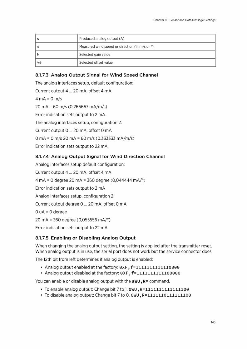
o Produced analog output (A)
s Measured wind speed or direction (in m/s or °)
k Selected gain value
y0 Selected offset value
8.1.7.3 Analog Output Signal for Wind Speed Channel
The analog interfaces setup, default configuration:
Current output 4 ... 20 mA, offset 4 mA
4 mA = 0 m/s
20 mA = 60 m/s (0,266667 mA/m/s)
Error indication sets output to 2 mA.
The analog interfaces setup, configuration 2:
Current output 0 … 20 mA, offset 0 mA
0 mA = 0 m/s 20 mA = 60 m/s (0.333333 mA/m/s)
Error indication sets output to 22 mA.
8.1.7.4 Analog Output Signal for Wind Direction Channel
Analog interfaces setup default configuration:
Current output 4 ... 20 mA, offset 4 mA
4 mA = 0 degree 20 mA = 360 degree (0,044444 mA/°)
Error indication sets output to 2 mA
Analog interfaces setup, configuration 2:
Current output degree 0 ... 20 mA, offset 0 mA
0 uA = 0 degree
20 mA = 360 degree (0,055556 mA/°)
Error indication sets output to 22 mA
8.1.7.5 Enabling or Disabling Analog Output
When changing the analog output setting, the setting is applied after the transmitter reset.When analog output is in use, the serial port does not work but the service connector does.
The 12th bit from left determines if analog output is enabled:
• Analog output enabled at the factory: 0XF,f=1111111111110000• Analog output disabled at the factory: 0XF,f=1111111111100000
You can enable or disable analog output with the aWU,R= command.
• To enable analog output: Change bit 7 to 1. 0WU,R=1111111111111100• To disable analog output: Change bit 7 to 0. 0WU,R=1111110111111100
Chapter 8 – Sensor and Data Message Settings
145
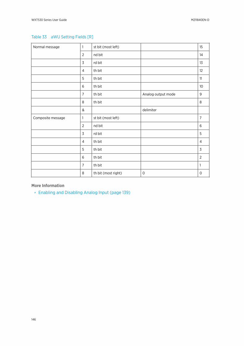
Table 33 aWU Setting Fields [R]
Normal message 1 st bit (most left) 15
2 nd bit 14
3 rd bit 13
4 th bit 12
5 th bit 11
6 th bit 10
7 th bit Analog output mode 9
8 th bit 8
& delimiter
Composite message 1 st bit (most left) 7
2 nd bit 6
3 rd bit 5
4 th bit 4
5 th bit 3
6 th bit 2
7 th bit 1
8 th bit (most right) 0 0
More Information
‣ Enabling and Disabling Analog Input (page 139)
WXT530 Series User Guide M211840EN-D
146
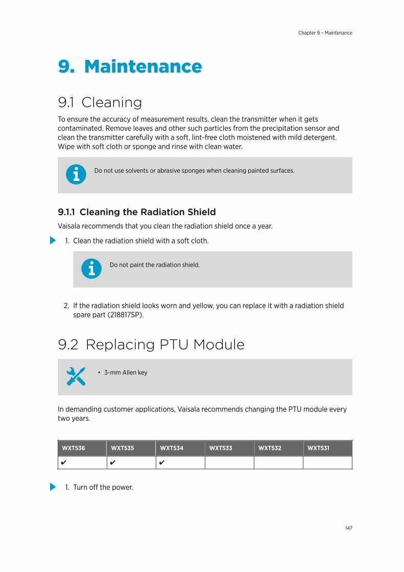
9. Maintenance
9.1 CleaningTo ensure the accuracy of measurement results, clean the transmitter when it getscontaminated. Remove leaves and other such particles from the precipitation sensor andclean the transmitter carefully with a soft, lint-free cloth moistened with mild detergent.Wipe with soft cloth or sponge and rinse with clean water.
Do not use solvents or abrasive sponges when cleaning painted surfaces.
9.1.1 Cleaning the Radiation ShieldVaisala recommends that you clean the radiation shield once a year.
1. Clean the radiation shield with a soft cloth.
Do not paint the radiation shield.
2. If the radiation shield looks worn and yellow, you can replace it with a radiation shieldspare part (218817SP).
9.2 Replacing PTU Module
• 3-mm Allen key
In demanding customer applications, Vaisala recommends changing the PTU module everytwo years.
WXT536 WXT535 WXT534 WXT533 WXT532 WXT531
✔ ✔ ✔
1. Turn off the power.
Chapter 9 – Maintenance
147
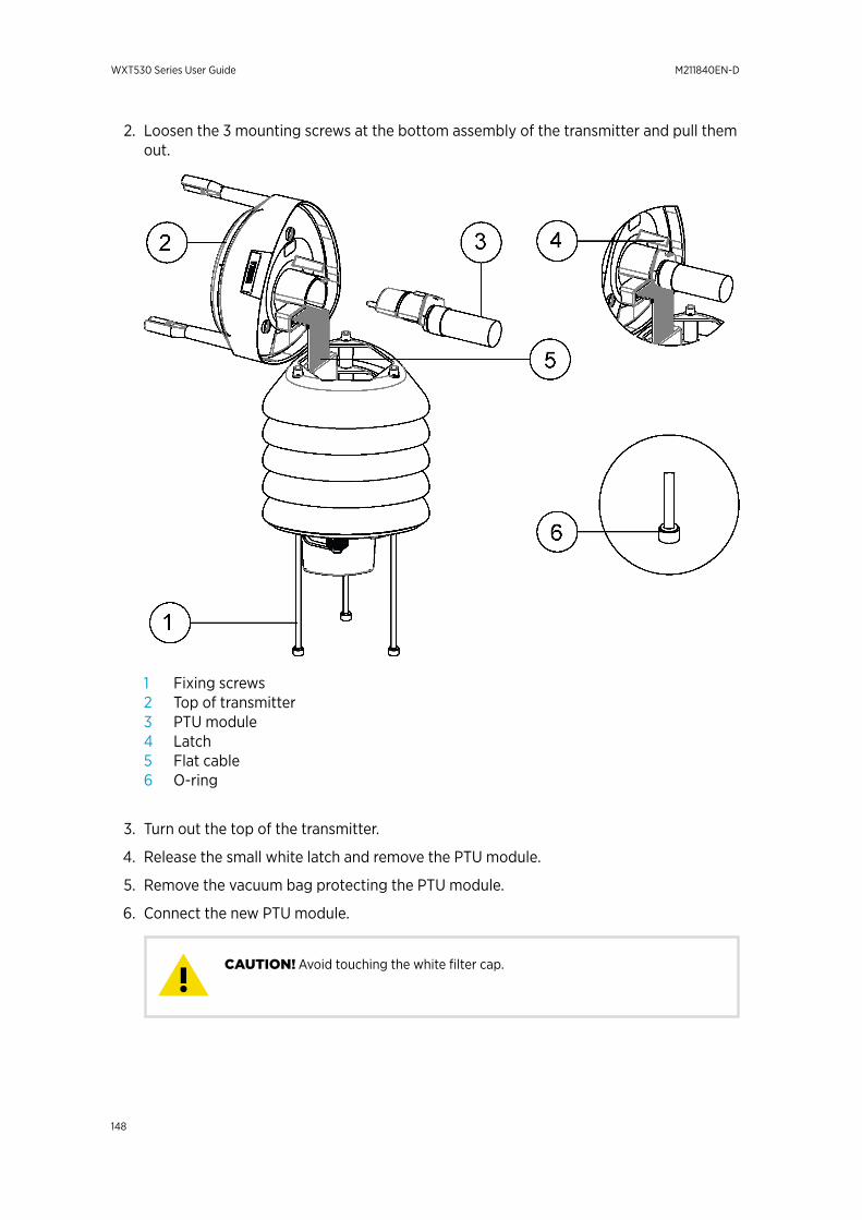
2. Loosen the 3 mounting screws at the bottom assembly of the transmitter and pull themout.
1 Fixing screws2 Top of transmitter3 PTU module4 Latch5 Flat cable6 O-ring
3. Turn out the top of the transmitter.
4. Release the small white latch and remove the PTU module.
5. Remove the vacuum bag protecting the PTU module.
6. Connect the new PTU module.
Avoid touching the white filter cap.CAUTION!
WXT530 Series User Guide M211840EN-D
148

7. Turn the top back in. Make sure the flat cable does not get stuck or squeezed betweenthe top and the funnel for the flat cable and it is properly connected.
8. If the O-rings are damaged, replace them with new ones.
9. Tighten the fixing screws.
To make sure that the radiation shield stays straight, do not tighten the screws all theway in one go. Do not overtighten.
Chapter 9 – Maintenance
149

WXT530 Series User Guide M211840EN-D
150
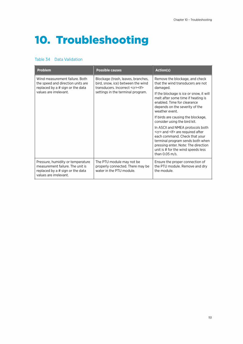
10. TroubleshootingTable 34 Data Validation
Problem Possible causes Action(s)
Wind measurement failure. Boththe speed and direction units arereplaced by a # sign or the datavalues are irrelevant.
Blockage (trash, leaves, branches,bird, snow, ice) between the windtransducers. Incorrect <cr><lf>settings in the terminal program.
Remove the blockage, and checkthat the wind transducers are notdamaged.
If the blockage is ice or snow, it willmelt after some time if heating isenabled. Time for clearancedepends on the severity of theweather event.
If birds are causing the blockage,consider using the bird kit.
In ASCII and NMEA protocols both<cr> and <lf> are required aftereach command. Check that yourterminal program sends both whenpressing enter. Note: The directionunit is # for the wind speeds lessthan 0.05 m/s.
Pressure, humidity or temperaturemeasurement failure. The unit isreplaced by a # sign or the datavalues are irrelevant.
The PTU module may not beproperly connected. There may bewater in the PTU module.
Ensure the proper connection ofthe PTU module. Remove and drythe module.
Chapter 10 – Troubleshooting
151
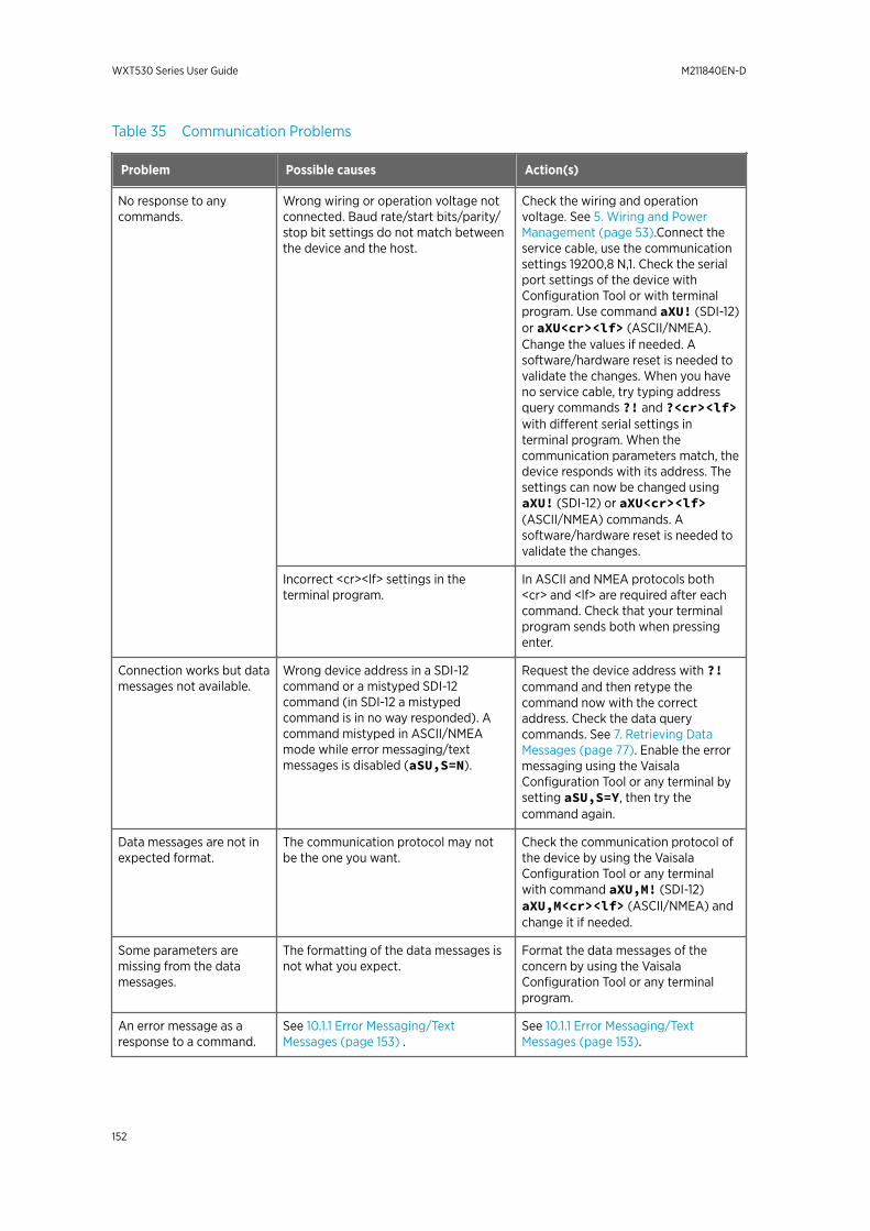
Table 35 Communication Problems
Problem Possible causes Action(s)
No response to anycommands.
Wrong wiring or operation voltage notconnected. Baud rate/start bits/parity/stop bit settings do not match betweenthe device and the host.
Check the wiring and operationvoltage. See 5. Wiring and PowerManagement (page 53).Connect theservice cable, use the communicationsettings 19200,8 N,1. Check the serialport settings of the device withConfiguration Tool or with terminalprogram. Use command aXU! (SDI-12)or aXU<cr><lf> (ASCII/NMEA).Change the values if needed. Asoftware/hardware reset is needed tovalidate the changes. When you haveno service cable, try typing addressquery commands ?! and ?<cr><lf>with different serial settings interminal program. When thecommunication parameters match, thedevice responds with its address. Thesettings can now be changed usingaXU! (SDI-12) or aXU<cr><lf>(ASCII/NMEA) commands. Asoftware/hardware reset is needed tovalidate the changes.
Incorrect <cr><lf> settings in theterminal program.
In ASCII and NMEA protocols both<cr> and <lf> are required after eachcommand. Check that your terminalprogram sends both when pressingenter.
Connection works but datamessages not available.
Wrong device address in a SDI-12command or a mistyped SDI-12command (in SDI-12 a mistypedcommand is in no way responded). Acommand mistyped in ASCII/NMEAmode while error messaging/textmessages is disabled (aSU,S=N).
Request the device address with ?!command and then retype thecommand now with the correctaddress. Check the data querycommands. See 7. Retrieving DataMessages (page 77). Enable the errormessaging using the VaisalaConfiguration Tool or any terminal bysetting aSU,S=Y, then try thecommand again.
Data messages are not inexpected format.
The communication protocol may notbe the one you want.
Check the communication protocol ofthe device by using the VaisalaConfiguration Tool or any terminalwith command aXU,M! (SDI-12)aXU,M<cr><lf> (ASCII/NMEA) andchange it if needed.
Some parameters aremissing from the datamessages.
The formatting of the data messages isnot what you expect.
Format the data messages of theconcern by using the VaisalaConfiguration Tool or any terminalprogram.
An error message as aresponse to a command.
See 10.1.1 Error Messaging/TextMessages (page 153) .
See 10.1.1 Error Messaging/TextMessages (page 153).
WXT530 Series User Guide M211840EN-D
152

Problem Possible causes Action(s)
The transmitter keepssending the message "TXSync/address error".
The polling address and the transmitteraddress do not match. The transmitter ison an RS-485 bus with other polleddevices and Error Messages areenabled.
Set correct address either for thetransmitter or to the polling request.Disable the Error Messages with thecommand aSU,S=N <cr><lf>.
mA messages cannot befound.
No mA output ordered. You must specify the mA option whenyou place the order.
Analog input messages aremissing.
Analog input messages are not enabled. Enable analog input messages. See8.1.7.5 Enabling or Disabling AnalogOutput (page 145).
Precipitation messagesmissing.
No precipitation measurement inmodels WXT534 and WXT532.
10.1 Self-Diagnostics
10.1.1 Error Messaging/Text MessagesThe transmitter sends a text message when certain type of errors occur. The function worksin all communication modes except in the SDI-12 mode. You can disable error messaging byusing the supervisor message aSU, S=N.
Examples:
0R1!0TX,Unable to measure error<cr><lf>
(request of wind data while all the wind parameters were disabled from the wind message)
1XU!0TX,Sync/address error<cr><lf>
(wrong device address. Ask the correct address with ? or ?! command.)
0XP!0TX,Unknown cmd error<cr><lf>
0xUabc!0TX,Use chksum CCb<cr><lf>
(wrong checksum applied to the 0xU command)
Chapter 10 – Troubleshooting
153
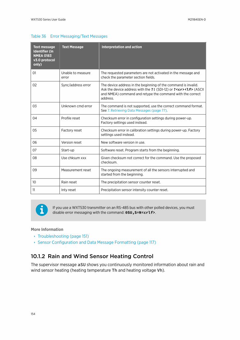
Table 36 Error Messaging/Text Messages
Text messageidentifier (inNMEA 0183v3.0 protocolonly)
Text Message Interpretation and action
01 Unable to measureerror
The requested parameters are not activated in the message andcheck the parameter section fields.
02 Sync/address error The device address in the beginning of the command is invalid.Ask the device address with the ?! (SDI-12) or ?<cr><lf> (ASCIIand NMEA) command and retype the command with the correctaddress.
03 Unknown cmd error The command is not supported, use the correct command format.See 7. Retrieving Data Messages (page 77).
04 Profile reset Checksum error in configuration settings during power-up.Factory settings used instead.
05 Factory reset Checksum error in calibration settings during power-up. Factorysettings used instead.
06 Version reset New software version in use.
07 Start-up Software reset. Program starts from the beginning.
08 Use chksum xxx Given checksum not correct for the command. Use the proposedchecksum.
09 Measurement reset The ongoing measurement of all the sensors interrupted andstarted from the beginning.
10 Rain reset The precipitation sensor counter reset.
11 Inty reset Precipitation sensor intensity counter reset.
If you use a WXT530 transmitter on an RS-485 bus with other polled devices, you mustdisable error messaging with the command: 0SU,S=N<crlf>.
More Information
‣ Troubleshooting (page 151)‣ Sensor Configuration and Data Message Formatting (page 117)
10.1.2 Rain and Wind Sensor Heating ControlThe supervisor message aSU shows you continuously monitored information about rain andwind sensor heating (heating temperature Th and heating voltage Vh).
WXT530 Series User Guide M211840EN-D
154
The heating temperature should stay above 0 °C when the heating is on (except inextremely cold conditions where the heating power is not sufficient). The heating voltageVh should correspond to the heating voltage supplied. If there is a remarkable deviation,check the wiring. Note that wire gauge should be large enough to avoid remarkable voltagedrop in the cable.
In case AC or full-wave rectified AC is used for the heating, the Vh measurement behavesas follows:While heating is off, Vh indicates the positive peak value (Vp) of the heating voltagewaveform.While heating is on, Vh indicates:
• 0.35 × Vp in case of AC voltage• 0.70 × Vp in case of full-wave rectified AC voltage
10.1.3 Operating Voltage ControlThe supervisor message aSU shows you continuously monitored supply voltage level (Vs). Incase of deviations between the supplied voltage and monitored voltage, check the wiringand the power supply.
10.1.4 Missing Readings and Error IndicationIf the transmitter is not able to measure the wind, it indicates a missing reading in theoutput. The most common reasons for measurement problems are foreign objects, such asice, birds, or other foreign objects, on the line of measurement, or sound reflections fromnearby objects, such as wind tunnel walls.
Chapter 10 – Troubleshooting
155

WXT530 Series User Guide M211840EN-D
156
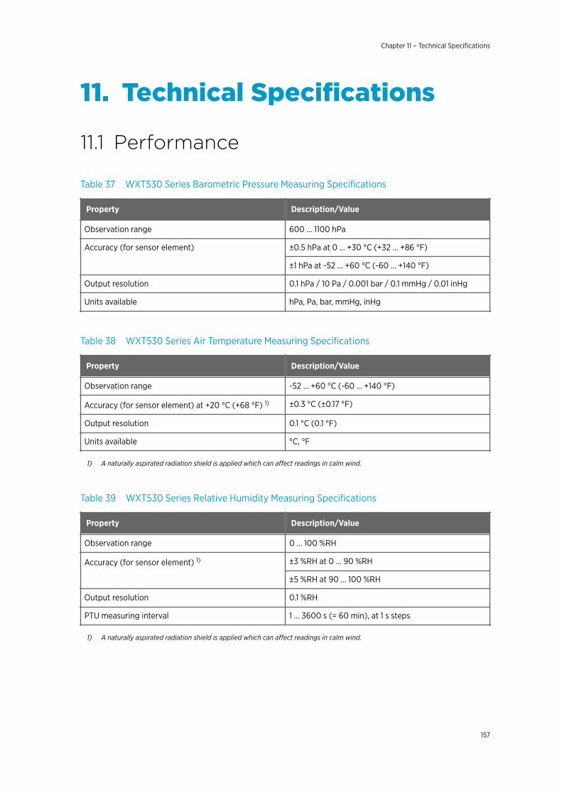
11. Technical Specifications
11.1 Performance
Table 37 WXT530 Series Barometric Pressure Measuring Specifications
Property Description/Value
Observation range 600 ... 1100 hPa
Accuracy (for sensor element) ±0.5 hPa at 0 … +30 °C (+32 … +86 °F)
±1 hPa at -52 … +60 °C (-60 … +140 °F)
Output resolution 0.1 hPa / 10 Pa / 0.001 bar / 0.1 mmHg / 0.01 inHg
Units available hPa, Pa, bar, mmHg, inHg
Table 38 WXT530 Series Air Temperature Measuring Specifications
Property Description/Value
Observation range -52 ... +60 °C (-60 ... +140 °F)
Accuracy (for sensor element) at +20 °C (+68 °F) 1) ±0.3 °C (±0.17 °F)
Output resolution 0.1 °C (0.1 °F)
Units available °C, °F
1) A naturally aspirated radiation shield is applied which can affect readings in calm wind.
Table 39 WXT530 Series Relative Humidity Measuring Specifications
Property Description/Value
Observation range 0 ... 100 %RH
Accuracy (for sensor element) 1) ±3 %RH at 0 ... 90 %RH
±5 %RH at 90 ... 100 %RH
Output resolution 0.1 %RH
PTU measuring interval 1 ... 3600 s (= 60 min), at 1 s steps
1) A naturally aspirated radiation shield is applied which can affect readings in calm wind.
Chapter 11 – Technical Specifications
157
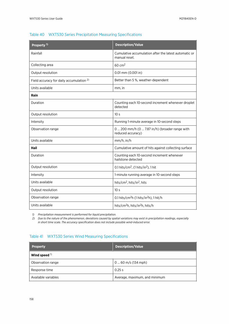
Table 40 WXT530 Series Precipitation Measuring Specifications
Property 1) Description/Value
Rainfall Cumulative accumulation after the latest automatic ormanual reset.
Collecting area 60 cm2
Output resolution 0.01 mm (0.001 in)
Field accuracy for daily accumulation 2) Better than 5 %, weather-dependent
Units available mm, in
Rain
Duration Counting each 10‑second increment whenever dropletdetected
Output resolution 10 s
Intensity Running 1‑minute average in 10‑second steps
Observation range 0 ... 200 mm/h (0 ... 7.87 in/h) (broader range withreduced accuracy)
Units available mm/h, in/h
Hail Cumulative amount of hits against collecting surface
Duration Counting each 10‑second increment wheneverhailstone detected
Output resolution 0.1 hits/cm2, (1 hits/in2), 1 hit
Intensity 1‑minute running average in 10‑second steps
Units available hits/cm2, hits/in2, hits
Output resolution 10 s
Observation range 0.1 hits/cm2h (1 hits/in2h), 1 hit/h
Units available hits/cm2h, hits/in2h, hits/h
1) Precipitation measurement is performed for liquid precipitation.2) Due to the nature of the phenomenon, deviations caused by spatial variations may exist in precipitation readings, especially
in short time scale. The accuracy specification does not include possible wind-induced error.
Table 41 WXT530 Series Wind Measuring Specifications
Property Description/Value
Wind speed 1)
Observation range 0 ... 60 m/s (134 mph)
Response time 0.25 s
Available variables Average, maximum, and minimum
WXT530 Series User Guide M211840EN-D
158
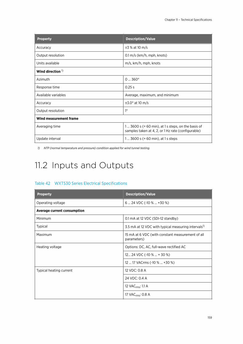
Property Description/Value
Accuracy ±3 % at 10 m/s
Output resolution 0.1 m/s (km/h, mph, knots)
Units available m/s, km/h, mph, knots
Wind direction 1)
Azimuth 0 ... 360°
Response time 0.25 s
Available variables Average, maximum, and minimum
Accuracy ±3.0° at 10 m/s
Output resolution 1°
Wind measurement frame
Averaging time 1 ... 3600 s (= 60 min), at 1 s steps, on the basis ofsamples taken at 4, 2, or 1 Hz rate (configurable)
Update interval 1 ... 3600 s (= 60 min), at 1 s steps
1) NTP (normal temperature and pressure) condition applied for wind tunnel testing.
11.2 Inputs and Outputs
Table 42 WXT530 Series Electrical Specifications
Property Description/Value
Operating voltage 6 ... 24 VDC (-10 % ... +30 %)
Average current consumption
Minimum 0.1 mA at 12 VDC (SDI-12 standby)
Typical 3.5 mA at 12 VDC with typical measuring intervals1)
Maximum 15 mA at 6 VDC (with constant measurement of allparameters)
Heating voltage Options: DC, AC, full-wave rectified AC
12... 24 VDC (-10 % ... + 30 %)
12 ... 17 VACrms (-10 % ... +30 %)
Typical heating current 12 VDC: 0.8 A
24 VDC: 0.4 A
12 VACrms: 1.1 A
17 VACrms: 0.8 A
Chapter 11 – Technical Specifications
159
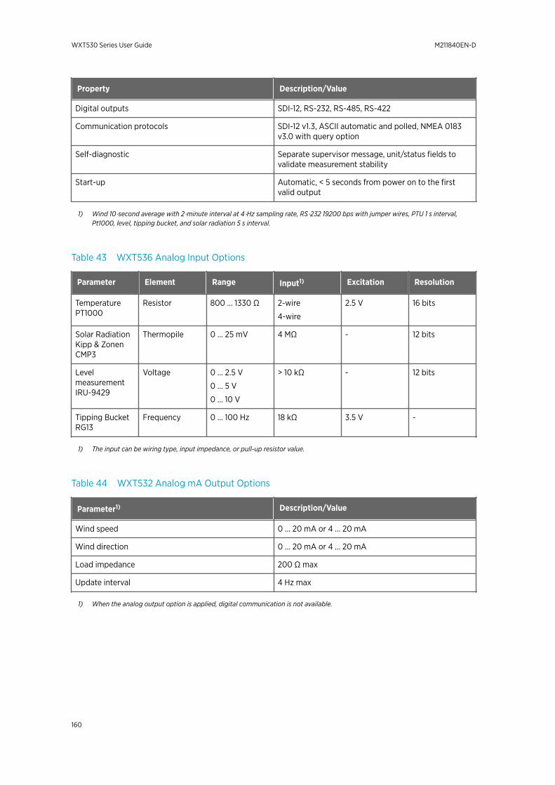
Property Description/Value
Digital outputs SDI-12, RS-232, RS-485, RS-422
Communication protocols SDI-12 v1.3, ASCII automatic and polled, NMEA 0183v3.0 with query option
Self-diagnostic Separate supervisor message, unit/status fields tovalidate measurement stability
Start-up Automatic, < 5 seconds from power on to the firstvalid output
1) Wind 10‑second average with 2‑minute interval at 4‑Hz sampling rate, RS‑232 19200 bps with jumper wires, PTU 1 s interval,Pt1000, level, tipping bucket, and solar radiation 5 s interval.
Table 43 WXT536 Analog Input Options
Parameter Element Range Input1) Excitation Resolution
TemperaturePT1000
Resistor 800 … 1330 Ω 2-wire
4-wire
2.5 V 16 bits
Solar RadiationKipp & ZonenCMP3
Thermopile 0 … 25 mV 4 MΩ - 12 bits
LevelmeasurementIRU-9429
Voltage 0 … 2.5 V
0 … 5 V
0 … 10 V
> 10 kΩ - 12 bits
Tipping BucketRG13
Frequency 0 … 100 Hz 18 kΩ 3.5 V -
1) The input can be wiring type, input impedance, or pull-up resistor value.
Table 44 WXT532 Analog mA Output Options
Parameter1) Description/Value
Wind speed 0 … 20 mA or 4 … 20 mA
Wind direction 0 … 20 mA or 4 … 20 mA
Load impedance 200 Ω max
Update interval 4 Hz max
1) When the analog output option is applied, digital communication is not available.
WXT530 Series User Guide M211840EN-D
160
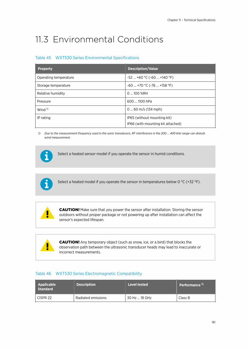
11.3 Environmental Conditions
Table 45 WXT530 Series Environmental Specifications
Property Description/Value
Operating temperature -52 ... +60 °C (-60 ... +140 °F)
Storage temperature -60 ... +70 °C (-76 ... +158 °F)
Relative humidity 0 ... 100 %RH
Pressure 600 ... 1100 hPa
Wind 1) 0 ... 60 m/s (134 mph)
IP rating IP65 (without mounting kit)
IP66 (with mounting kit attached)
1) Due to the measurement frequency used in the sonic transducers, RF interference in the 200 ... 400 kHz range can disturbwind measurement.
Select a heated sensor model if you operate the sensor in humid conditions.
Select a heated model if you operate the sensor in temperatures below 0 °C (+32 °F).
Make sure that you power the sensor after installation. Storing the sensoroutdoors without proper package or not powering up after installation can affect thesensor's expected lifespan.
CAUTION!
Any temporary object (such as snow, ice, or a bird) that blocks theobservation path between the ultrasonic transducer heads may lead to inaccurate orincorrect measurements.
CAUTION!
Table 46 WXT530 Series Electromagnetic Compatibility
ApplicableStandard
Description Level tested Performance 1)
CISPR 22 Radiated emissions 30 Hz ... 18 GHz Class B
Chapter 11 – Technical Specifications
161
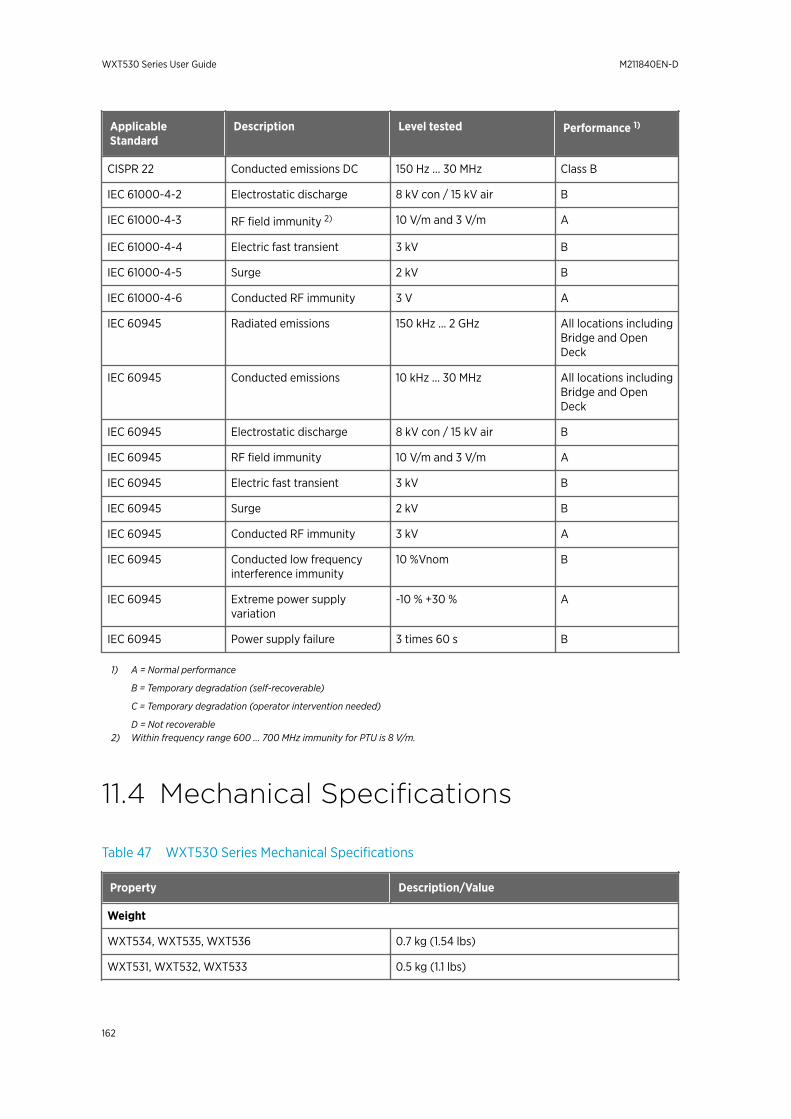
ApplicableStandard
Description Level tested Performance 1)
CISPR 22 Conducted emissions DC 150 Hz ... 30 MHz Class B
IEC 61000-4-2 Electrostatic discharge 8 kV con / 15 kV air B
IEC 61000-4-3 RF field immunity 2) 10 V/m and 3 V/m A
IEC 61000-4-4 Electric fast transient 3 kV B
IEC 61000-4-5 Surge 2 kV B
IEC 61000-4-6 Conducted RF immunity 3 V A
IEC 60945 Radiated emissions 150 kHz ... 2 GHz All locations includingBridge and OpenDeck
IEC 60945 Conducted emissions 10 kHz ... 30 MHz All locations includingBridge and OpenDeck
IEC 60945 Electrostatic discharge 8 kV con / 15 kV air B
IEC 60945 RF field immunity 10 V/m and 3 V/m A
IEC 60945 Electric fast transient 3 kV B
IEC 60945 Surge 2 kV B
IEC 60945 Conducted RF immunity 3 kV A
IEC 60945 Conducted low frequencyinterference immunity
10 %Vnom B
IEC 60945 Extreme power supplyvariation
-10 % +30 % A
IEC 60945 Power supply failure 3 times 60 s B
1) A = Normal performance
B = Temporary degradation (self-recoverable)
C = Temporary degradation (operator intervention needed)
D = Not recoverable2) Within frequency range 600 ... 700 MHz immunity for PTU is 8 V/m.
11.4 Mechanical Specifications
Table 47 WXT530 Series Mechanical Specifications
Property Description/Value
Weight
WXT534, WXT535, WXT536 0.7 kg (1.54 lbs)
WXT531, WXT532, WXT533 0.5 kg (1.1 lbs)
WXT530 Series User Guide M211840EN-D
162
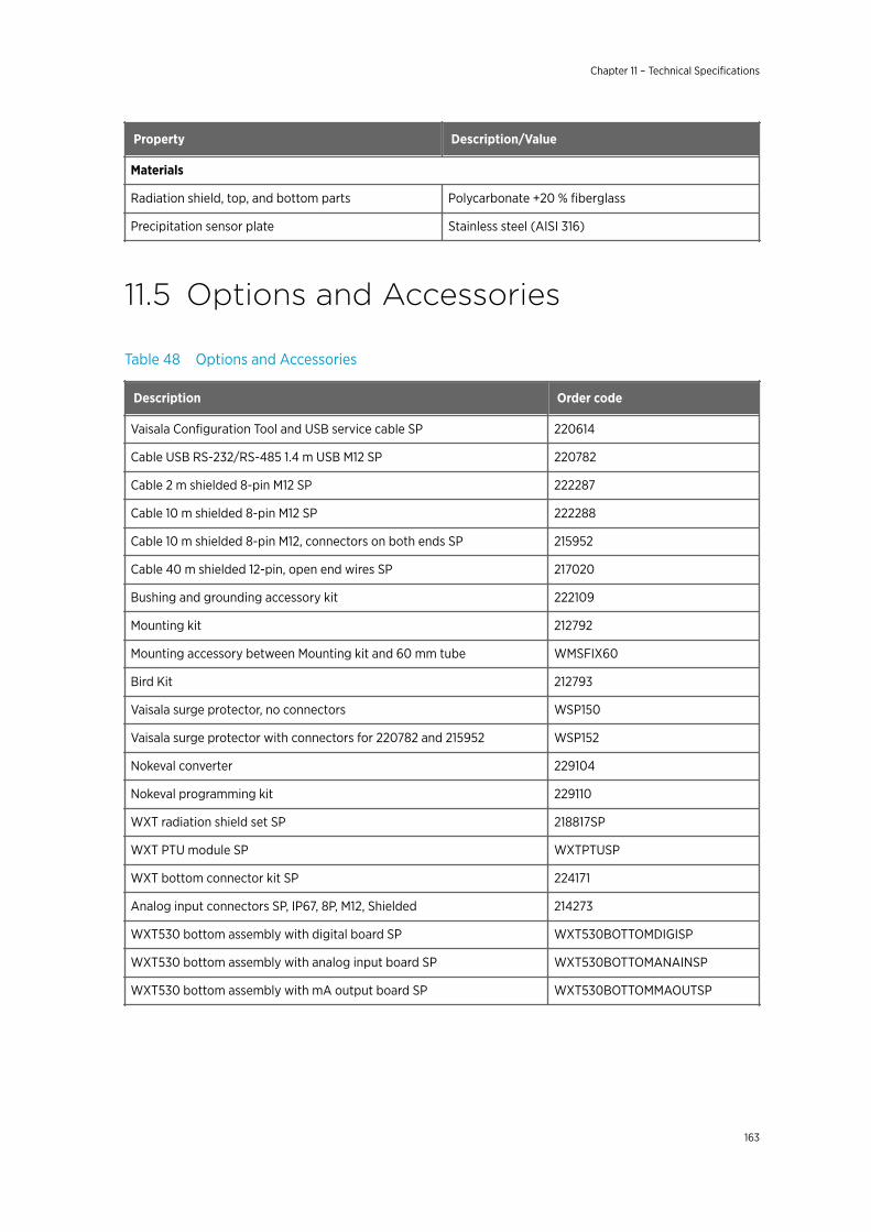
Property Description/Value
Materials
Radiation shield, top, and bottom parts Polycarbonate +20 % fiberglass
Precipitation sensor plate Stainless steel (AISI 316)
11.5 Options and Accessories
Table 48 Options and Accessories
Description Order code
Vaisala Configuration Tool and USB service cable SP 220614
Cable USB RS-232/RS-485 1.4 m USB M12 SP 220782
Cable 2 m shielded 8-pin M12 SP 222287
Cable 10 m shielded 8-pin M12 SP 222288
Cable 10 m shielded 8-pin M12, connectors on both ends SP 215952
Cable 40 m shielded 12-pin, open end wires SP 217020
Bushing and grounding accessory kit 222109
Mounting kit 212792
Mounting accessory between Mounting kit and 60 mm tube WMSFIX60
Bird Kit 212793
Vaisala surge protector, no connectors WSP150
Vaisala surge protector with connectors for 220782 and 215952 WSP152
Nokeval converter 229104
Nokeval programming kit 229110
WXT radiation shield set SP 218817SP
WXT PTU module SP WXTPTUSP
WXT bottom connector kit SP 224171
Analog input connectors SP, IP67, 8P, M12, Shielded 214273
WXT530 bottom assembly with digital board SP WXT530BOTTOMDIGISP
WXT530 bottom assembly with analog input board SP WXT530BOTTOMANAINSP
WXT530 bottom assembly with mA output board SP WXT530BOTTOMMAOUTSP
Chapter 11 – Technical Specifications
163
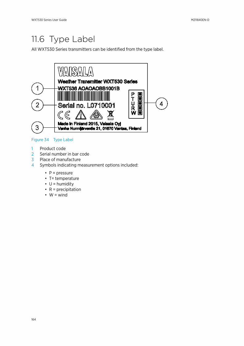
11.6 Type LabelAll WXT530 Series transmitters can be identified from the type label.
Figure 34 Type Label
1 Product code2 Serial number in bar code3 Place of manufacture4 Symbols indicating measurement options included:
• P = pressure• T= temperature• U = humidity• R = precipitation• W = wind
WXT530 Series User Guide M211840EN-D
164
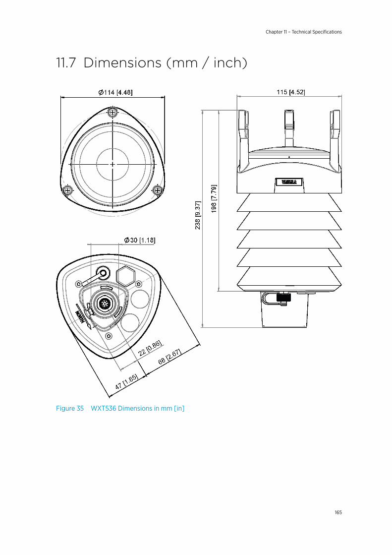
11.7 Dimensions (mm / inch)
Figure 35 WXT536 Dimensions in mm [in]
Chapter 11 – Technical Specifications
165
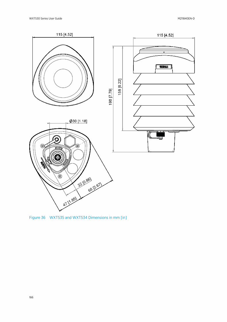
Figure 36 WXT535 and WXT534 Dimensions in mm [in]
WXT530 Series User Guide M211840EN-D
166
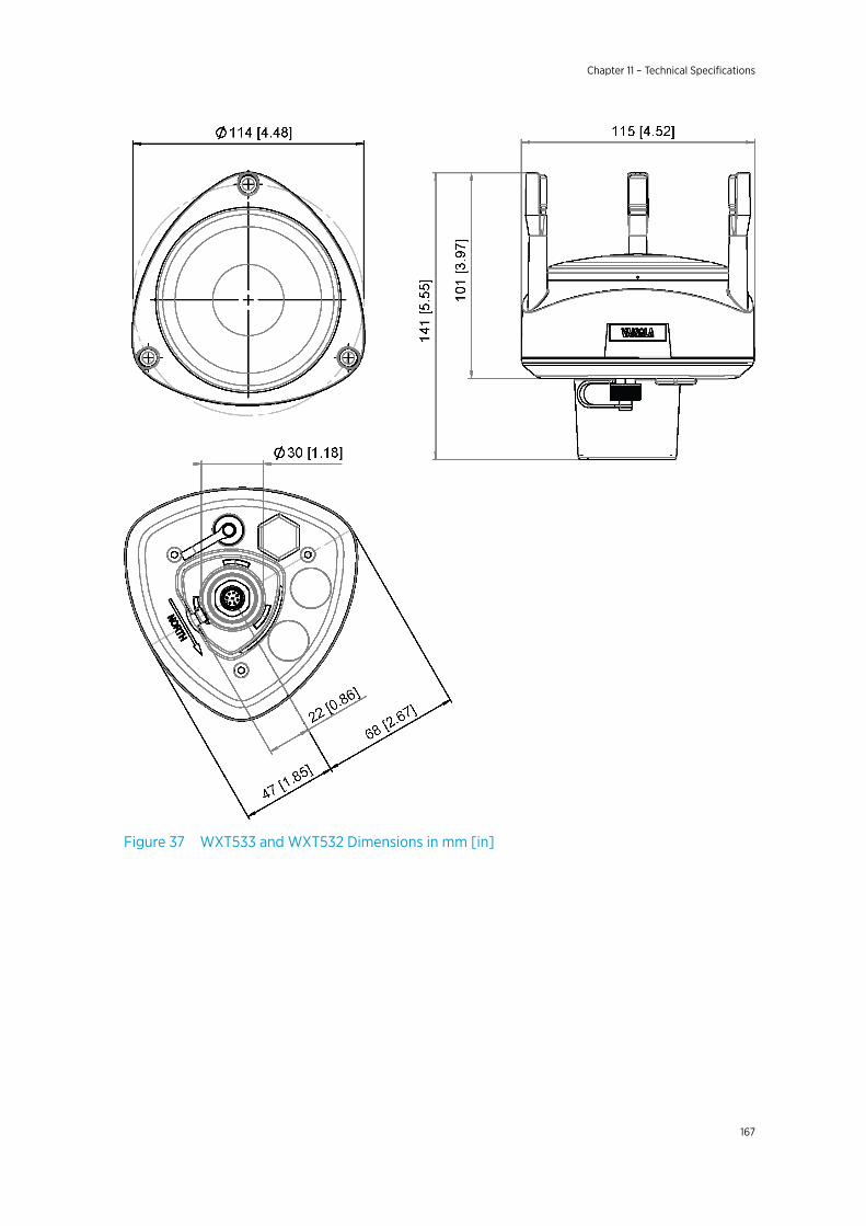
Figure 37 WXT533 and WXT532 Dimensions in mm [in]
Chapter 11 – Technical Specifications
167
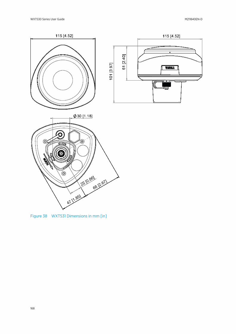
Figure 38 WXT531 Dimensions in mm [in]
WXT530 Series User Guide M211840EN-D
168
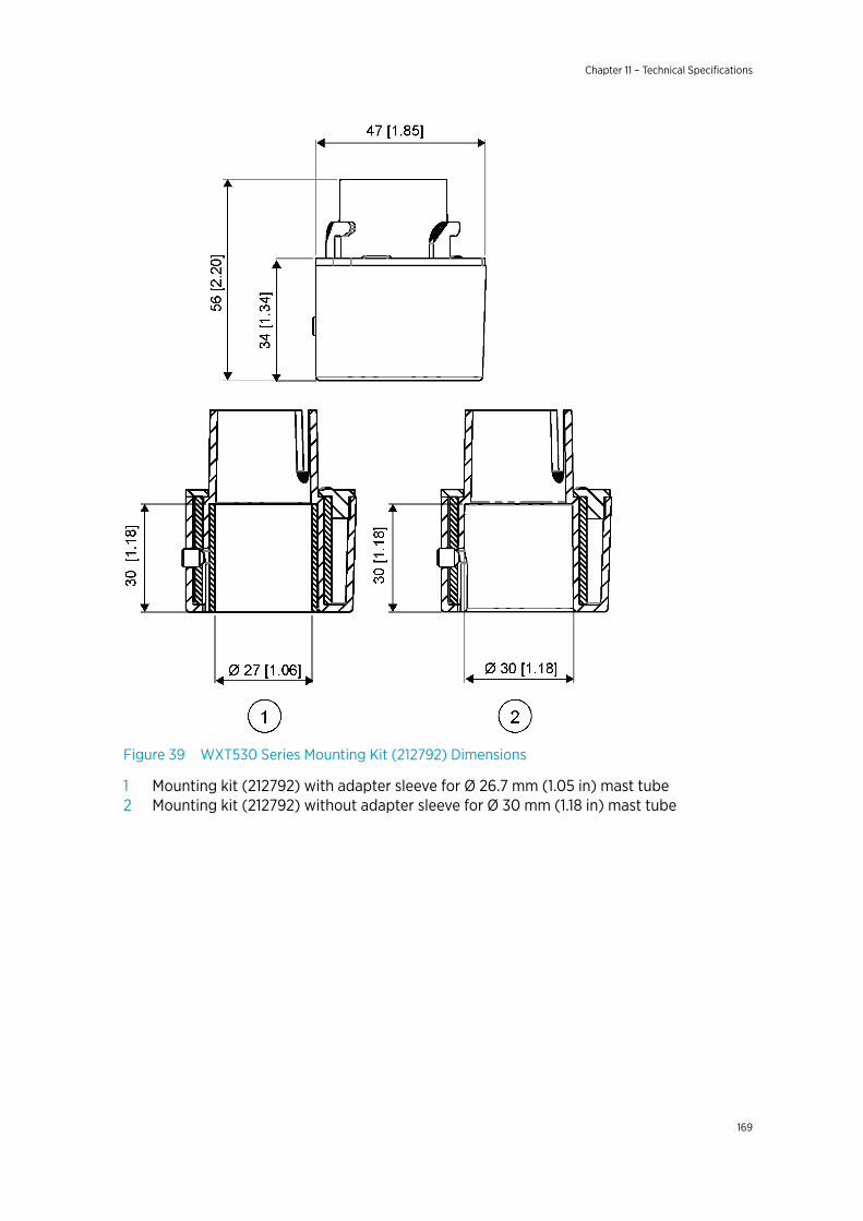
Figure 39 WXT530 Series Mounting Kit (212792) Dimensions
1 Mounting kit (212792) with adapter sleeve for Ø 26.7 mm (1.05 in) mast tube2 Mounting kit (212792) without adapter sleeve for Ø 30 mm (1.18 in) mast tube
Chapter 11 – Technical Specifications
169
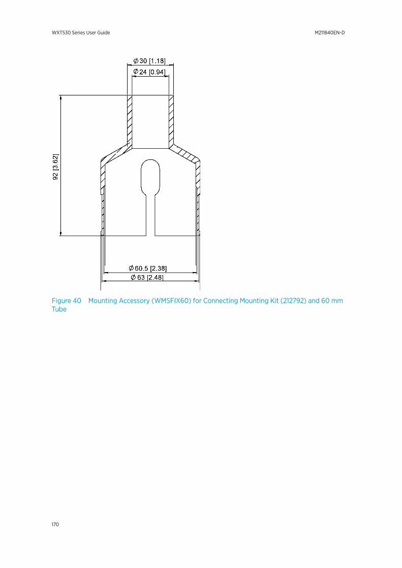
Figure 40 Mounting Accessory (WMSFIX60) for Connecting Mounting Kit (212792) and 60 mmTube
WXT530 Series User Guide M211840EN-D
170
Appendix A. Networking
A.1 Connecting Several Transmitters onSame Bus
There are two options for connecting several transmitters on the same bus:
• Using SDI-12 serial interface and communication protocol• Using RS-485 serial interface and one of the communication protocols: ASCII or NMEA
0183 v3.0.
A.2 SDI-12 Serial Interface
A.2.1 Wiring SDI-12
1. Perform SDI-12 wiring in the transmitter as described in 5. Wiring and PowerManagement (page 53). Make sure you combine the two "Data in/out" wires of eachtransmitter either in the internal screw terminal inside or outside the transmitter.
2. In the data logger end, combine the "GND for data" wires of each transmitter to thelogger "GND for data" wire. Connect the "Data in/out" wires of each transmitter to thelogger "Data" wire.
A.2.2 SDI-12 Communication ProtocolSet the communication protocol SDI-12 v 1.3 (aXU,C=1,M=S) or SDI- 12 v1.3 continuous(aXU,C=1,M=R).
Assign the transmitters on the bus with different addresses (forexample:aXU,A=0,1,2,...). After that, the transmitters on the bus do not respond to thecommands not assigned to them nor to the data messages sent by the other transmitters.
Example (A bus with three WXT530 Series transmitters):
WXT530 #1 communication settings:
0XXU,A=0,M=S,C=1,B=1200,D=7,P=E,S=1, L=25
WXT530 #2 communication settings:
1XXU,A=1,M=S,C=1,B=1200,D=7,P=E,S=1, L=25
WXT530 #3 communication settings:
Appendix A – Networking
171
2XXU,A=2,M=S,C=1,B=1200,D=7,P=E,S=1, L=25
If simultaneous measurements of the different units are needed, Start concurrentmeasurement commands aC and aCC must be used for all devices. If the measurements areto be performed consecutively for only one unit at a time, in addition to these also Startmeasurement commands aM and aMC can be used. Start continuous measurementcommands aR1, aR2, aR3, aR5, aR, aRC1, aRC2, aRC3, aRC5 and aRC available only inSDI-12 continuous protocol (aXU,M=R) can be used either for simultaneous measurementsof the units or consecutive measurements for one unit at time.
A.3 RS-485 Serial Interface
A.3.1 RS-485 Wiring
1. Make the RS-485 wiring of the transmitter. See 5. Wiring and Power Management(page 53).
2. In the data logger end, combine the "Data +" wires of each transmitter to the logger"Data +" wire. Connect the "Data-" wires of each transmitter to the logger "Data -" wire.
A.3.2 RS-485 Communication ProtocolSet the communication protocol to ASCII polled (with or without CRC) or NMEA query.When using NMEA query, the wind message must be set to XDR (aWU,N=T).
No matter which communication protocol, ASCII polled or NMEA query is chosen, theerror messaging parameter of the supervisor message must be inactivated with aSU,S=Nfor each transmitter on the bus to prevent the units responding to the commands notassigned to them.
A.3.3 ASCII, PolledAssign different addresses to the transmitters on the bus (for example, aXU,A=0,1,2, ...).
Example (a bus with three transmitters):
WXT530 #1 communication settings:
0XU,A=0,M=P,C=3,I=0,B=19200,D=8,P=N,S=1,L=25
WXT530 #2 communication settings:
WXT530 Series User Guide M211840EN-D
172
1XU,A=1,M=P,C=3,I=0,B=19200,D=8,P=N,S=1,L=25
WXT530 #3 communication settings:
2XU,A=2,M=P,C=3,I=0,B=19200,D=8,P=N,S=1,L=25
Example (composite data message queries to the sensors 1 and 3 are assigned asfollows):
0R0<cr><lf>
1R0<cr><lf>
2R0<cr><lf>
A.3.4 NMEA 0183 v3.0, QueryThe NMEA 0183 query messages do not contain device address information. Individualquery commands can thus not be directed to different transmitters. Instead, a specific timeslot method can be used for receiving data from several transmitters on the bus, just with asingle query command.
To generate different time slots, each transmitter is given an individual delay for its queryresponse, by using the RS-485 line delay parameter aXU,L. This parameter defines the time(in milliseconds) between the last character of the query and the first character of theresponse from the transmitter.
Example (a bus with three transmitters):
WXT530 #1 communication settings:
0XU,A=0,M=Q,C=3,I=0,B=4800,D=8,P=N,S=1,L=25
WXT530 #2 communication settings:
0XU,A=0,M=Q,C=3,I=0,B=4800,D=8,P=N,S=1,L=1000
WXT530 #3 communication settings:
0XU,A=0,M=Q,C=3,I=0,B=4800,D=8,P=N,S=1,L=2000
Appendix A – Networking
173
When the XDR query command $--WIQ,XDR*2D<cr><lf> is sent, WXT530 #1 respondsafter 25 ms, WXT530 #2 after 1000 ms, and WXT530 #3 responds after 2000 ms. Thesufficient delays depend on the maximum number of characters in the response messagesand the baud rate. Note that all the transmitters are assigned with the same address. Thedata logger, after sending the query, sorts out the response messages on the basis of theindividual response times.
To gain even more addressability transducer ID information provided in the XDR responsemessages can also be used. If WXT530 address is set to 0 (aXU,A=0) and all parameters arechosen except Rain peak intensity and Hail peak intensity in the precipitation message, theresponse to the XDR query $--WIQ,XDR*2D<cr><lf> is:
$WIXDR,A,316,D,0,A,326,D,1,A,330,D,2,S,0.1,M,0,S,0.1,M,1,S,0.1, M,2*57<cr><lf>
$WIXDR,C,24.0,C,0,C,25.2,C,1,H,47.4,P,0,P,1010.1,H, 0*54<cr><lf>
$WIXDR,V,0.000,I,0,Z,10,s,0,R,0.01,I,0,V,0.0,M,1,Z,0,s,1,R,0.0,M, 1*51<cr><lf>
$WIXDR,C,25.8,C,2,U,10.7,N,0,U,10.9,V,1,U,3.360,V,2*7D<cr><lf>
For the transducer IDs, see 7.4 NMEA 0183 v3.0 Protocol (page 102).
The maximum transducer ID is three when the transmitter address is 0. Assigning address 4for the second and address 8 for the third transmitter on the bus the following responses tothe XDR query $--WIQ,XDR*2D<cr><lf> will be obtained from these transmitters (samemessage parameter configuration):
The second transmitter (address 4):
$WIXDR,A,330,D,4,A,331,D,5,A,333,D,6,S,0.1,M,4,S,0.1,M,5,S,0.2, M,6*55<cr><lf>
$WIXDR,C,23.5,C,4,C,24.3,C,4,H,49.3,P,4,P,1010.1,H, 3*59<cr><lf>
$WIXDR,V,0.000,I,4,Z,0,s,4,R,0.00,I,4,V,0.0,M,5,Z,0,s,5,R,0.0,M, 5*67<cr><lf>
$WIXDR,C,25.8,C,6,U,10.6,N,4,U,10.9,V,5,U,3.362,V,6*78<cr><lf>
The third transmitter (address 8):
$WIXDR,A,341,D,8,A,347,D,9,A,357,D,10,S,0.1,M,8,S,0.2,M,9,S,0.2,M,10*53<cr><lf>
$WIXDR,C,23.5,C,8,C,24.3,C,9,H,49.3,P,8,P,1010.1,H, 8*5F<cr><lf>
$WIXDR,V,0.000,I,8,Z,0,s,8,R,0.00,I,8,V,0.0,M,9,Z,0,s,9,R,0.0,M, 9*61<cr><lf>
$WIXDR,C,25.8,C,10,U,10.6,N,8,U,10.9,V,9,U,3.360,V, 10*7C<cr><lf>
WXT530 Series User Guide M211840EN-D
174
Now the response messages of all three transmitters can be recognized and parsed by thedata logger.
The transmitter address may consist of letter characters but the transducer IDs in theNMEA XDR messages can only be numbers. The addresses given in letters show in thetransducer IDs in the following way: transmitter address = A => transducer ID = 10, B => 11,a => 36, b => 37, and so on.
A.3.5 NMEA 0183 v3.0 Query with ASCII Query CommandsYou can use ASCII query commands aR1, aR2, aR3, aR5, aR, aR0 and their CRC-versionsar1, ar2, ar3, ar5, ar, and ar0 also in NMEA 0183 protocol. The responses to thesecommands will be in standard NMEA 0183 format and the transmitters are assigned withdifferent addresses (for example: aXU,A=0,1,2,...). The RS-485 line delays are notneeded.
Example (a bus with three transmitters, data requests with combined data message querycommands; the same message parameter configuration as in the previous example):
WXT530 #1 communication settings:
0XU,A=0,M=Q,C=3,I=0,B=4800,D=8,P=N,S=1,L=25
WXT530 #2 communication settings:
0XU,A=1,M=Q,C=3,I=0,B=4800,D=8,P=N,S=1,L=25
WXT530 #3 communication settings:
0XU,A=2,M=Q,C=3,I=0,B=4800,D=8,P=N,S=1,L=25
The query for WXT530 #1 and the response:
0R<cr><lf>
$WIXDR,A,316,D,0,A,326,D,1,A,330,D,2,S,0.1,M,0,S,0.1,M,1,S,0.1, M,2*57<cr><lf>
$WIXDR,C,24.0,C,0,C,25.2,C,1,H,47.4,P,0,P,1010.1,H, 0*54<cr><lf>
$WIXDR,V,0.000,I,0,Z,10,s,0,R,0.01,I,0,V,0.0,M,1,Z,0,s,1,R,0.0,M, 1*51<cr><lf>
$WIXDR,C,25.8,C,2,U,10.7,N,0,U,10.9,V,1,U,3.360,V,2*7D<cr><lf>
The query for WXT530 #2 and the response:
Appendix A – Networking
175

1R<cr><lf>
$WIXDR,A,330,D,1,A,331,D,2,A,333,D,3,S,0.1,M,1,S,0.1,M,2,S,0.2, M,3*55<cr><lf>
$WIXDR,C,23.5,C,1,C,24.3,C,2,H,49.3,P,1,P,1010.1,H, 1*59<cr><lf>
$WIXDR,V,0.000,I,1,Z,0,s,1,R,0.00,I,1,V,0.0,M,2,Z,0,s,2,R,0.0,M, 2*67<cr><lf>
$WIXDR,C,25.8,C,3,U,10.6,N,1,U,10.9,V,1,U,3.362,V,2*78<cr><lf>
The query for WXT530 #3 and the response:
2R<cr><lf>
$WIXDR,A,341,D,2,A,347,D,3,A,357,D,4,S,0.1,M,2,S,0.2,M,3,S,0.2, M,4*53<cr><lf>
$WIXDR,C,23.5,C,2,C,24.3,C,3,H,49.3,P,2,P,1010.1,H, 2*5F<cr><lf>
$WIXDR,V,0.000,I,2,Z,0,s,2,R,0.00,I,2,V,0.0,M,3,Z,0,s,3,R,0.0,M, 3*61<cr><lf>
$WIXDR,C,25.8,C,4,U,10.6,N,2,U,10.9,V,2,U,3.360,V,3*7C<cr><lf>
If needed, for making the transducers IDs distinguishable, device addresses 0, 4, 8 can beused as described in the previous section.
WXT530 Series User Guide M211840EN-D
176

Appendix B. SDI-12 ProtocolSDI-12 is a standard for interfacing data recorders with microprocessor-based sensors. Thename stands for serial/digital interface at 1200 baud. More information of the completeSDI-12 standard text is available from the SDI-12 website: http://www.sdi-12.org.
B.1 SDI-12 Electrical InterfaceThe SDI-12 electrical interface uses the SDI-12 bus to transmit serial data between SDI-12data recorders and sensors. The SDI-12 bus is the cable that connects multiple SDI-12devices. The cable has three conductors:
• Serial data line• Ground line• 12 V line
The SDI-12 bus can have at least 10 sensors connected to it. The bus topology is a parallelconnection, where each of the three wires of different sensors are connected in parallel.
B.1.1 SDI-12 Communications ProtocolSDI-12 data recorders and sensors communicate by an exchange of ASCII characters on thedata line. The data recorder sends a break to wake up the sensors on the data line. A break iscontinuous spacing on the data line for at least 12 milliseconds. The data recorder then sendsa command. The sensor, in turn, returns the appropriate response. Each command is for aspecific sensor. The first character of each command is a unique sensor address thatspecifies with which sensor the recorder wants to communicate. Other sensors on the SDI-12bus ignore the command and return to low-power standby mode. When a data recorder tellsa sensor to start its measurement procedure, the recorder does not communicate with anyother sensor until the data collection from the first sensor is complete.
A typical recorder/sensor measurement sequence proceeds in the following order:
• The data recorder wakes all sensors on the SDI-12 bus with a break.• The recorder transmits a command to a specific, addressed sensor, instructing it to
make a measurement.• The addressed sensor responds within 15.0 ms returning the maximum time until the
measurement data is ready and the number of data values it returns.• If the measurement is immediately available, the recorder transmits a command to the
sensor instructing it to return the measurement(s). If the measurement is not ready, thedata recorder waits for the sensor to send a request to the recorder, which indicatesthat the data is ready. The recorder then transmits a command to get the data.
• The sensor responds, returning one or more measurements.
B.1.2 SDI-12 TimingThe following figure shows a timing diagram for a SDI-12 command and its response. Thetolerance for all SDI-12 timing is ±0.40 ms.
Appendix B – SDI-12 Protocol
177
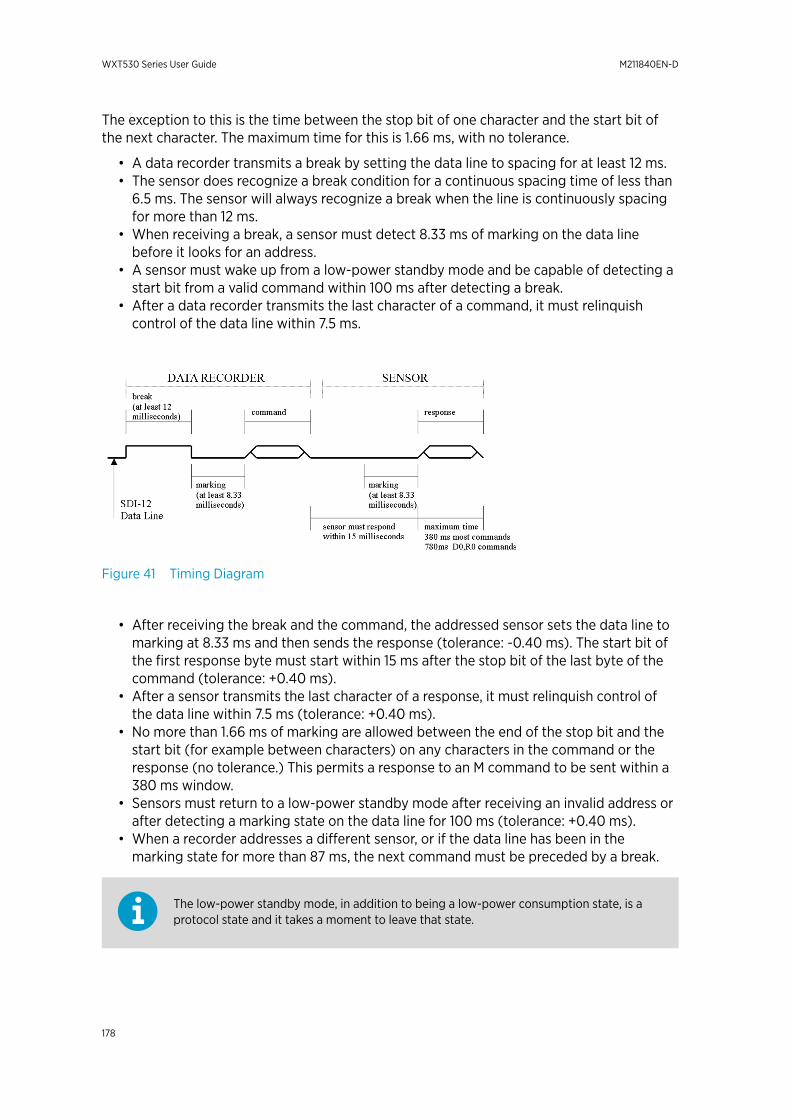
The exception to this is the time between the stop bit of one character and the start bit ofthe next character. The maximum time for this is 1.66 ms, with no tolerance.
• A data recorder transmits a break by setting the data line to spacing for at least 12 ms.• The sensor does recognize a break condition for a continuous spacing time of less than
6.5 ms. The sensor will always recognize a break when the line is continuously spacingfor more than 12 ms.
• When receiving a break, a sensor must detect 8.33 ms of marking on the data linebefore it looks for an address.
• A sensor must wake up from a low-power standby mode and be capable of detecting astart bit from a valid command within 100 ms after detecting a break.
• After a data recorder transmits the last character of a command, it must relinquishcontrol of the data line within 7.5 ms.
Figure 41 Timing Diagram
• After receiving the break and the command, the addressed sensor sets the data line tomarking at 8.33 ms and then sends the response (tolerance: -0.40 ms). The start bit ofthe first response byte must start within 15 ms after the stop bit of the last byte of thecommand (tolerance: +0.40 ms).
• After a sensor transmits the last character of a response, it must relinquish control ofthe data line within 7.5 ms (tolerance: +0.40 ms).
• No more than 1.66 ms of marking are allowed between the end of the stop bit and thestart bit (for example between characters) on any characters in the command or theresponse (no tolerance.) This permits a response to an M command to be sent within a380 ms window.
• Sensors must return to a low-power standby mode after receiving an invalid address orafter detecting a marking state on the data line for 100 ms (tolerance: +0.40 ms).
• When a recorder addresses a different sensor, or if the data line has been in themarking state for more than 87 ms, the next command must be preceded by a break.
The low-power standby mode, in addition to being a low-power consumption state, is aprotocol state and it takes a moment to leave that state.
WXT530 Series User Guide M211840EN-D
178

Appendix C. CRC-16ComputationThe computation of the CRC is performed on the data response before parity is added. Alloperations are assumed to be on 16-bit unsigned integers. The least significant bit is on theright. Numbers preceded by 0x are in hexadecimal. All shifts shift in a zero. The algorithm is:
Initialize the CRC to zero. For each character beginning with the address, up to but not including the carriage return (<cr>), do as follows:{ Set the CRC equal to the exclusive OR of the character and itself for count =1 to 8 { if the least significant bit of the CRC is one { right shift the CRC one bit set CRC equal to the exclusive OR of 0xA001 and itself } else { right shift the CRC one bit } }}
C.1 Encoding the CRC as ASCIICharacters
The 16-bit CRC is encoded to three ASCII characters by using the following algorithm:
1st character = 0x40 OR (CRC shifted right 12 bits)
2nd character = 0x40 OR ((CRC shifted right 6 bits) AND 0x3F)
3rd character = 0x40 OR (CRC AND 0x3F)
The three ASCII characters are placed between the data and <cr><lf>. Parity is applied to allthree characters, if selected for the character frame.
The CRC computation code is added to the end of the response, if the first letter of thecommand is sent by using lower case.
Appendix C – CRC-16 Computation
179

C.2 NMEA 0183 v3.0 ChecksumComputation
The checksum is the last field in the NMEA sentence and follows the checksum delimitercharacter "*". It is the 8-bit exclusive OR of all characters in the sentence, including "," and"^" delimiters, between but not including the "$" or "!" and the "*" delimiters. Thehexadecimal value of the most significant and least significant four bits of the result isconverted to two ASCII characters (0-9,A-F) for transmission. The most significant characteris transmitted first.
WXT530 Series User Guide M211840EN-D
180

Appendix D. WindMeasurement AveragingMethodThe following figures represent the wind measurement averaging for different selections ofcommunication protocol, wind measurement update interval (I) and averaging time (A).Scalar averaging is used for both wind speed and direction.
Grey boxes indicate that the measurement is in progress during the correspondingsecond.Update (= internal calculation) is always made in the end of the update interval.In the auto sending protocols (ASCII automatic (+ CRC) and NMEA automatic) outputtingthe data messages is synchronized to take place immediately after the update.In ASCII polled (+ CRC), NMEA query and SDI-12 continuous measurement protocolstrying to request data before the update interval is completed will result in getting thedata from the previous completed update interval.Wind measurement sampling rate (4, 2, or 1 Hz) does not have any effect on the averagingscheme. It determines from how many samples the one second values seen in the figuresare calculated.
Appendix D – Wind Measurement Averaging Method
181
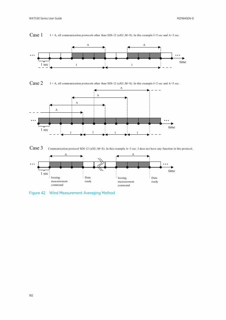
I I
A A
time1 sec
time1 sec
...
...
I > A, all communication p rotocols other than SDI-12 (aXU,M=S). In this example I=5 sec and A=3 sec.
I < A, all communication p rotocols other than SDI-12 (aXU,M=S). In this example I=2 sec and A=5 sec.
I I I I
...
...
A
A
A
A
A
time1 sec
...
Communication protocol SDI-12 (aXU,M=S). In this example A=3 sec. I does not have any function in this protocol.
Issuingmeasurementcommand
Dataready
A
Issuingmeasurementcommand
Dataready
...
Case 1
Case 2
Case 3
Figure 42 Wind Measurement Averaging Method
WXT530 Series User Guide M211840EN-D
182
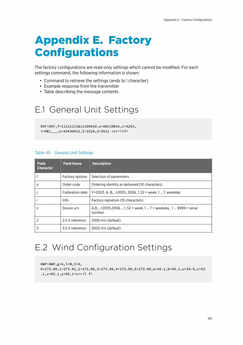
Appendix E. FactoryConfigurationsThe factory configurations are read-only settings which cannot be modified. For eachsettings command, the following information is shown:
• Command to retrieve the settings (ends to ! character)• Example response from the transmitter• Table describing the message contents
E.1 General Unit Settings
0XF!0XF,f=11111111&11100010,o=AAC1DB1A,c=A263, i=HEL___,n=A3430012,2=2528,3=3512 <cr><lf>
Table 49 General Unit Settings
FieldCharacter
Field Name Description
f Factory options Selection of parameters
o Order code Ordering identity as delivered (10 characters)
c Calibration date Y=2003, A, B,…=2005, 2006, 1..52 = week, 1 … 7, weekday
i Info Factory signature (10 characters)
n Device s/n A,B,...=2005,2006..., 1..52 = week, 1 … 7 = weekday , 1 … 9999 = serialnumber
2 2.5 V reference 2500 mV (default)
3 3.5 V reference 3500 mV (default)
E.2 Wind Configuration Settings
0WF!0WF,g=A,l=N,t=A,0=273.00,1=273.01,2=273.00,3=273.00,4=273.00,5=273.00,a=45.1,b=50.2,u=54.9,v=63.1,x=65.1,y=65.1<cr><l f>
Appendix E – Factory Configurations
183
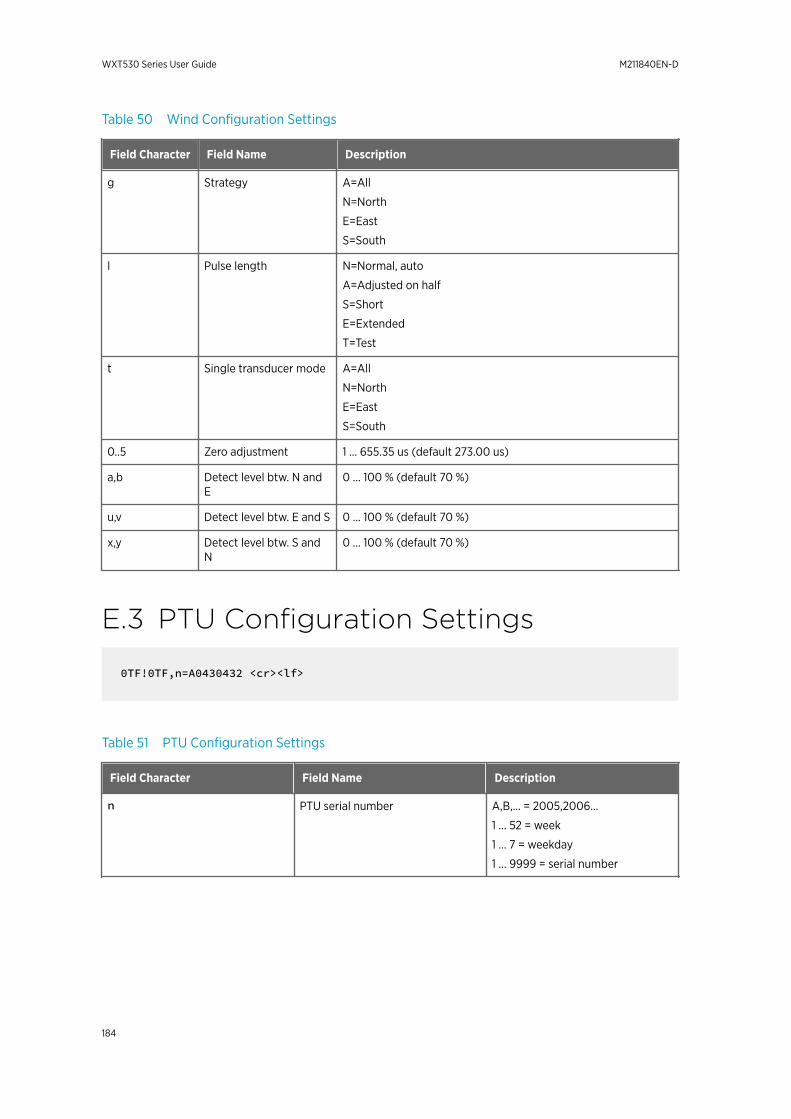
Table 50 Wind Configuration Settings
Field Character Field Name Description
g Strategy A=All
N=North
E=East
S=South
l Pulse length N=Normal, auto
A=Adjusted on half
S=Short
E=Extended
T=Test
t Single transducer mode A=All
N=North
E=East
S=South
0..5 Zero adjustment 1 … 655.35 us (default 273.00 us)
a,b Detect level btw. N andE
0 … 100 % (default 70 %)
u,v Detect level btw. E and S 0 … 100 % (default 70 %)
x,y Detect level btw. S andN
0 … 100 % (default 70 %)
E.3 PTU Configuration Settings
0TF!0TF,n=A0430432 <cr><lf>
Table 51 PTU Configuration Settings
Field Character Field Name Description
n PTU serial number A,B,… = 2005,2006…
1 ... 52 = week
1 ... 7 = weekday
1 ... 9999 = serial number
WXT530 Series User Guide M211840EN-D
184
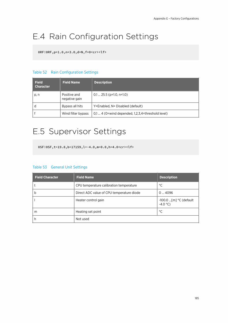
E.4 Rain Configuration Settings
0RF!0RF,p=1.0,n=3.0,d=N,f=0<cr><lf>
Table 52 Rain Configuration Settings
FieldCharacter
Field Name Description
p, n Positive andnegative gain
0.1 … 25.5 (p=1.0, n=1.0)
d Bypass all hits Y=Enabled, N= Disabled (default)
f Wind filter bypass 0,1 … 4 (0=wind depended, 1,2,3,4=threshold level)
E.5 Supervisor Settings
0SF!0SF,t=19.8,b=17159,l=-4.0,m=0.0,h=4.0<cr><lf>
Table 53 General Unit Settings
Field Character Field Name Description
t CPU temperature calibration temperature °C
b Direct ADC value of CPU temperature diode 0 … 4096
l Heater control gain -100.0 ...[m] °C (default-4.0 °C)
m Heating set point °C
h Not used
Appendix E – Factory Configurations
185

WXT530 Series User Guide M211840EN-D
186

Appendix F. ConnectingExternal Sensors to WXT536This section describes how to connect the following external sensors to WXT536:
• Ultrasonic level sensor• Pyranometer• Resistance temperature sensor• Rain gauge
Figure 43 Connecting External Sensors toWXT536
1 Ultrasonic level sensor IRU-94292 Pyranometer CMP33 Resistance temperature sensor Pt10004 Rain gauge RG13
F.1 Connecting Ultrasonic Level Sensor toWXT536
The following figure shows how to connect the ultrasonic level sensor IRU-9429 to WXT536.
IRU-9429 needs excitation voltage set to a 5 V level to get readings out to the WXT536input. You need a power box between WXT536 and IRU-9429.
Appendix F – Connecting External Sensors to WXT536
187
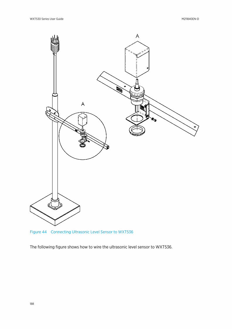
Figure 44 Connecting Ultrasonic Level Sensor to WXT536
The following figure shows how to wire the ultrasonic level sensor to WXT536.
WXT530 Series User Guide M211840EN-D
188
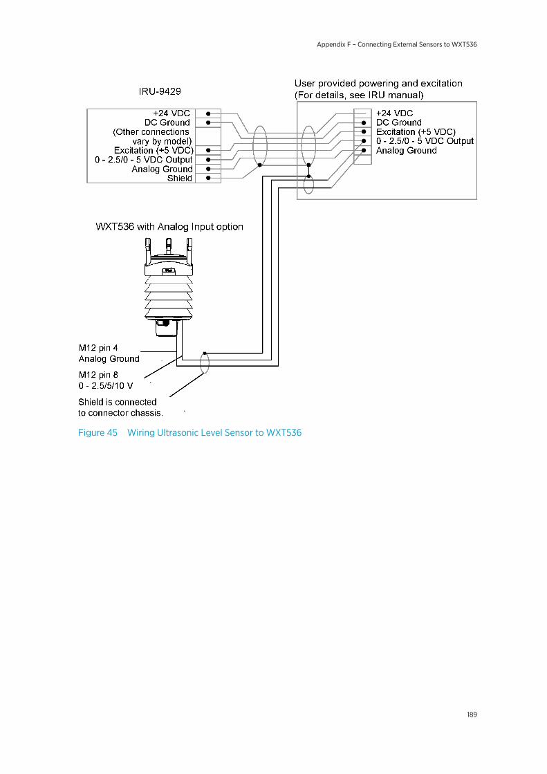
Figure 45 Wiring Ultrasonic Level Sensor to WXT536
Appendix F – Connecting External Sensors to WXT536
189

Table 54 Ultrasonic Level Connections
Level sensor connections IRU-9429
Pin Pin function Wire color Function
1 - - -
2 - - -
3 - - -
4 AGND
Common analog ground forPt, TIP, and WS
Green Analog ground
5 - - -
6 - - -
7 - - -
8 WSIN
Ultrasonic level sensor input+
AGND= -
0 ... 2.5 V
0 ... 5 V
0 ... 10 V
White 0 ... 2.5 VDC
F.2 Connecting Pyranometer to WXT536The following figure shows how to connect pyranometer CMP3 to WXT536.
WXT530 Series User Guide M211840EN-D
190
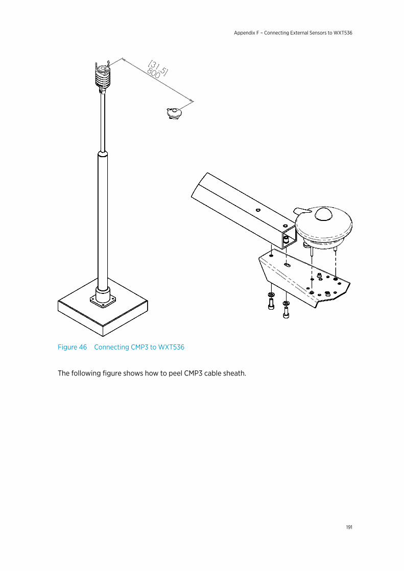
Figure 46 Connecting CMP3 to WXT536
The following figure shows how to peel CMP3 cable sheath.
Appendix F – Connecting External Sensors to WXT536
191

Figure 47 Peeling CMP3 Cable Sheath
1 Red cable2 Blue cable3 Cable sheath4 CMP3 cable
The following figure shows how to wire the pyranometer to WXT536.
WXT530 Series User Guide M211840EN-D
192
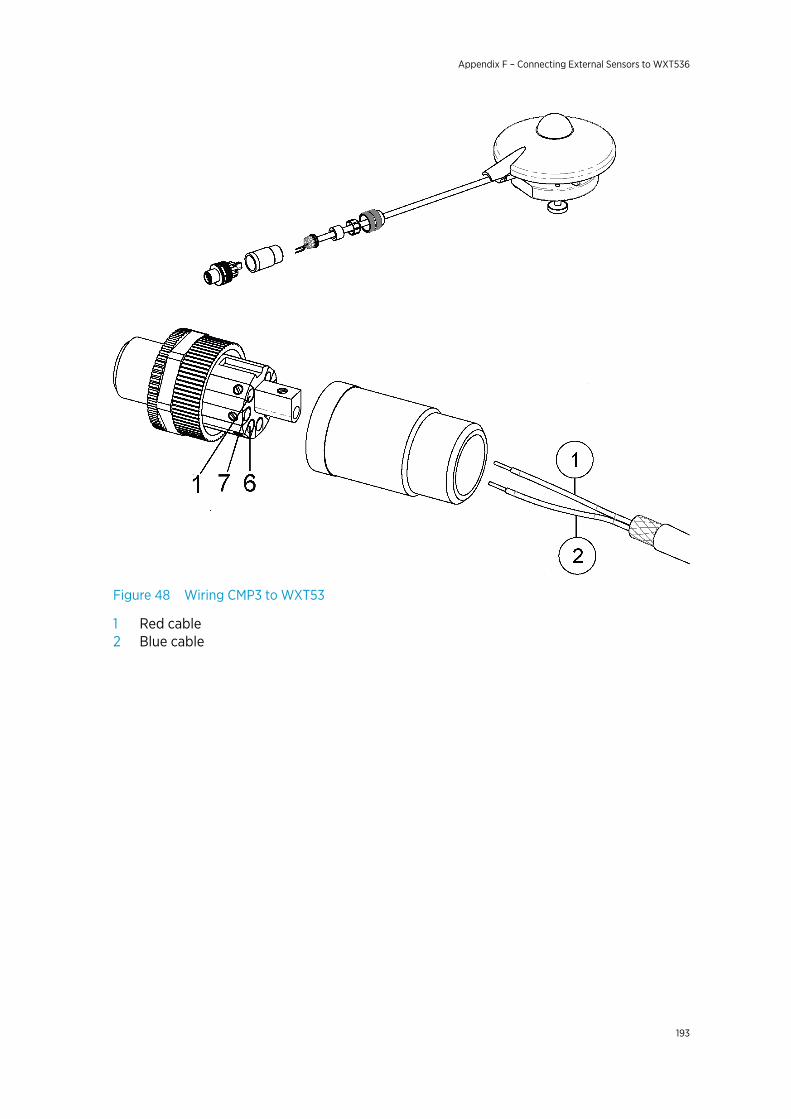
Figure 48 Wiring CMP3 to WXT53
1 Red cable2 Blue cable
Appendix F – Connecting External Sensors to WXT536
193

Table 55 Pyranometer Connections
Solar radiation connections CMP3
Pin Pin function Wire color Function
1 - - -
2 - - -
3 - - -
4 - - -
5 - - -
6 SR+
Solar radiation sensor input +
0 ... 25 mV
Red +
7 SR-
Solar radiation sensor input -
Blue -
8 - - -
F.3 Connecting Resistance TemperatureSensor
Connect the temperature sensor to the M12 connector of the transmitter.
Figure 49 Pt1000 Connected to WXT536 M12 Connector
The following figure shows how to wire a temperature sensor to the transmitter.
WXT530 Series User Guide M211840EN-D
194
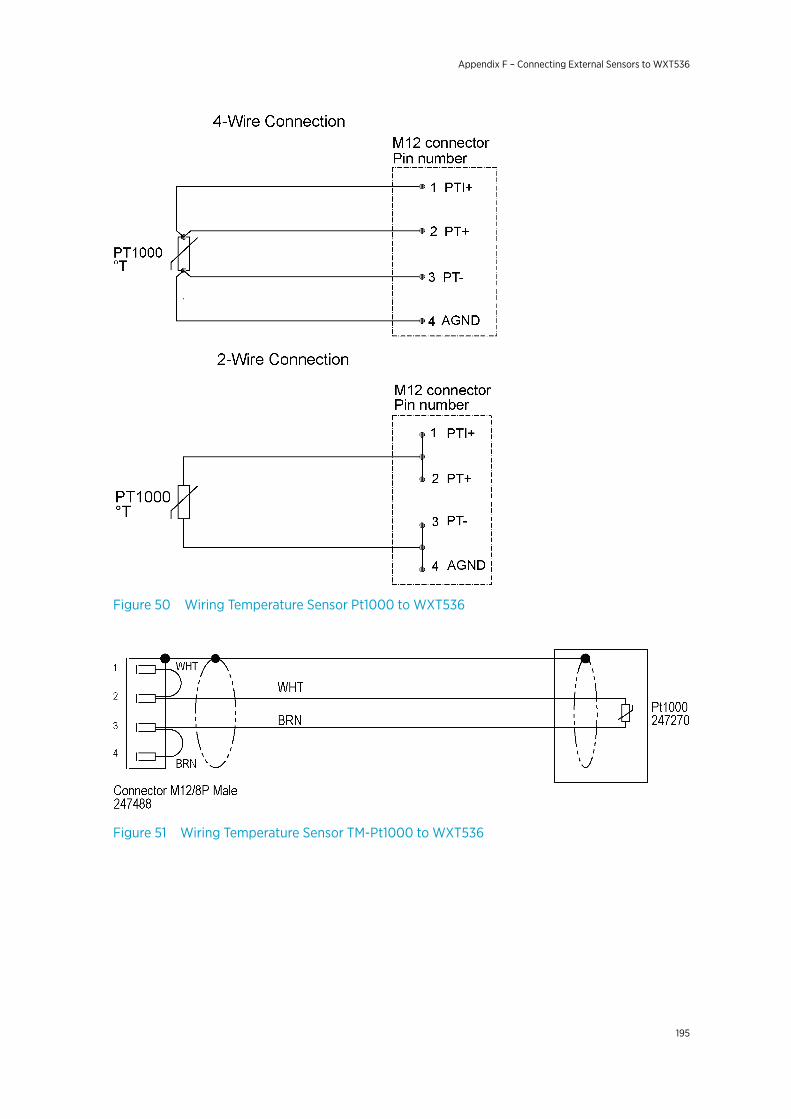
Figure 50 Wiring Temperature Sensor Pt1000 to WXT536
Figure 51 Wiring Temperature Sensor TM-Pt1000 to WXT536
Appendix F – Connecting External Sensors to WXT536
195
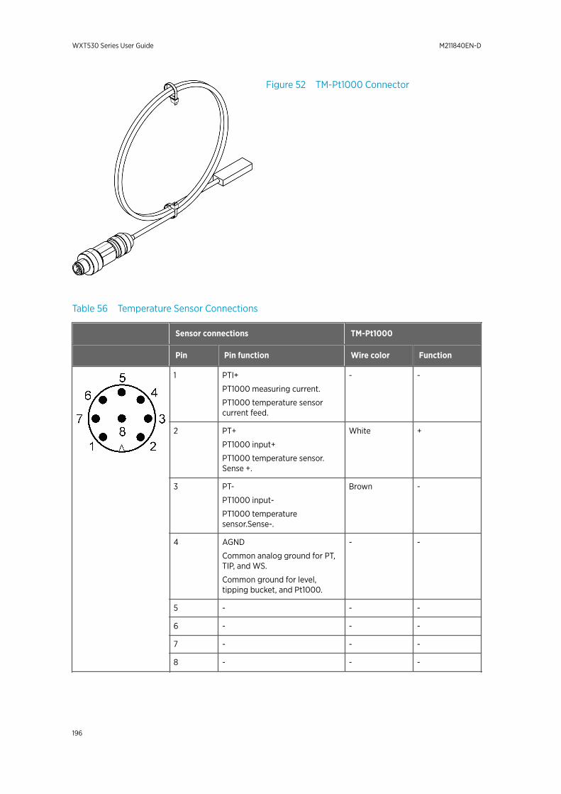
Figure 52 TM-Pt1000 Connector
Table 56 Temperature Sensor Connections
Sensor connections TM-Pt1000
Pin Pin function Wire color Function
1 PTI+
PT1000 measuring current.
PT1000 temperature sensorcurrent feed.
- -
2 PT+
PT1000 input+
PT1000 temperature sensor.Sense +.
White +
3 PT-
PT1000 input-
PT1000 temperaturesensor.Sense-.
Brown -
4 AGND
Common analog ground for PT,TIP, and WS.
Common ground for level,tipping bucket, and Pt1000.
- -
5 - - -
6 - - -
7 - - -
8 - - -
WXT530 Series User Guide M211840EN-D
196
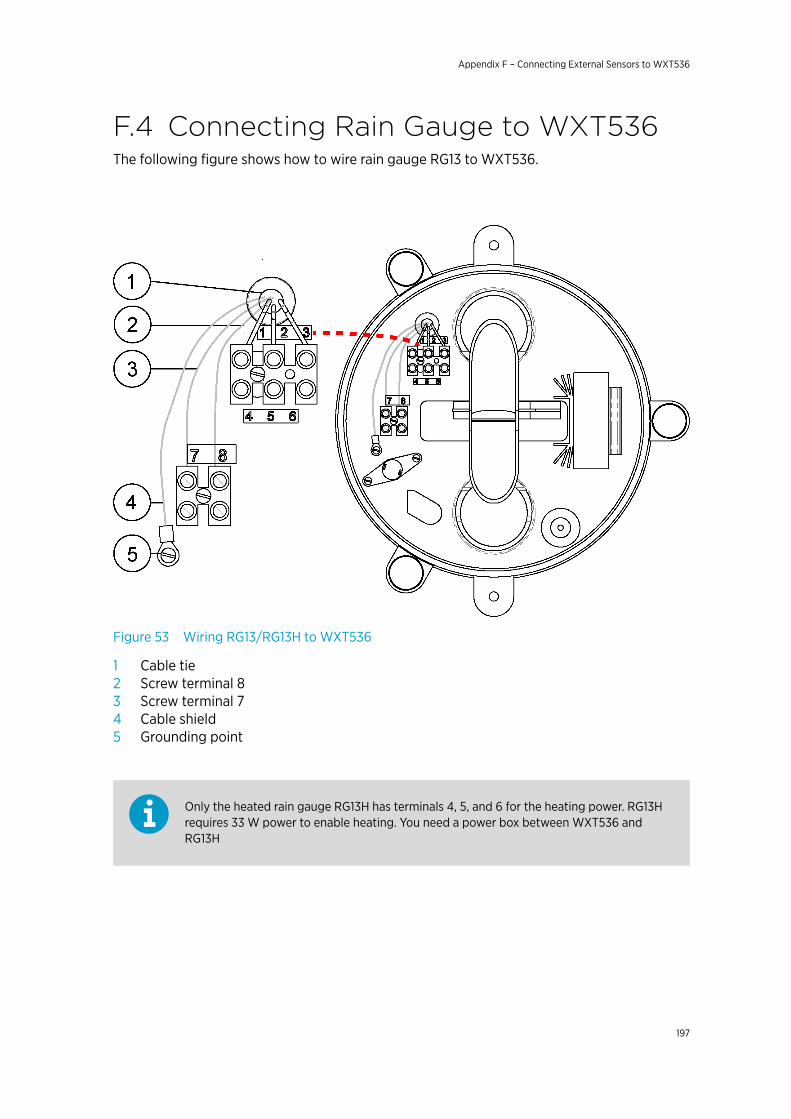
F.4 Connecting Rain Gauge to WXT536The following figure shows how to wire rain gauge RG13 to WXT536.
Figure 53 Wiring RG13/RG13H to WXT536
1 Cable tie2 Screw terminal 83 Screw terminal 74 Cable shield5 Grounding point
Only the heated rain gauge RG13H has terminals 4, 5, and 6 for the heating power. RG13Hrequires 33 W power to enable heating. You need a power box between WXT536 andRG13H
Appendix F – Connecting External Sensors to WXT536
197
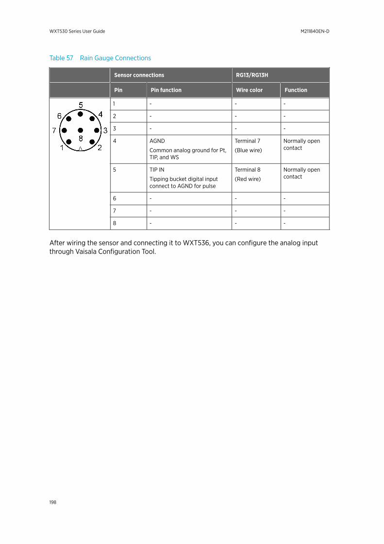
Table 57 Rain Gauge Connections
Sensor connections RG13/RG13H
Pin Pin function Wire color Function
1 - - -
2 - - -
3 - - -
4 AGND
Common analog ground for Pt,TIP, and WS
Terminal 7
(Blue wire)
Normally opencontact
5 TIP IN
Tipping bucket digital inputconnect to AGND for pulse
Terminal 8
(Red wire)
Normally opencontact
6 - - -
7 - - -
8 - - -
After wiring the sensor and connecting it to WXT536, you can configure the analog inputthrough Vaisala Configuration Tool.
WXT530 Series User Guide M211840EN-D
198
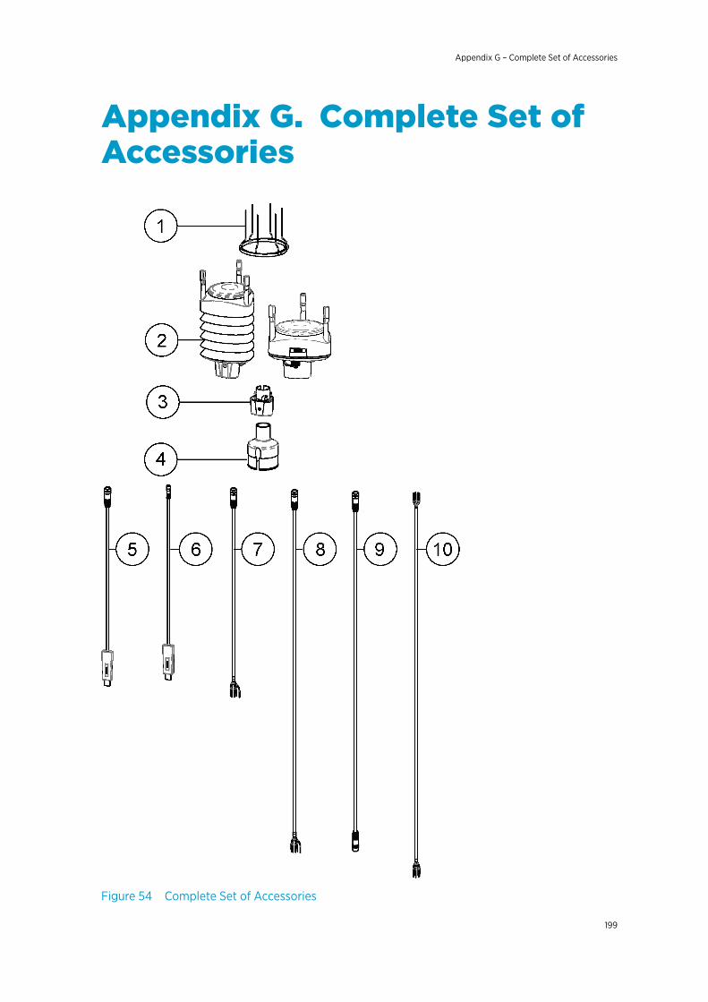
Appendix G. Complete Set ofAccessories
Figure 54 Complete Set of Accessories
Appendix G – Complete Set of Accessories
199

1 Bird kit 2127932 WXT530 Series transmitter3 Mounting kit 2127924 Mounting accessory between Mounting kit and 60 mm tube WMSFIX605 Cable USB RS-232/RS-485 1.4 m USB M12 SP 2207826 USB service cable delivered with the Vaisala Configuration Tool 2206147 Cable 2 m shielded 8-pin M12 SP 2222878 Cable 10 m shielded 8-pin M12 SP 2222889 Cable 10 m shielded 8-pin M12 SP, connectors on both ends SP 21595210 Cable 40 m shielded 12-pin, open end wires SP 217020
The following figure shows how to connect surge protector WSP150 to WXT536.
WXT530 Series User Guide M211840EN-D
200
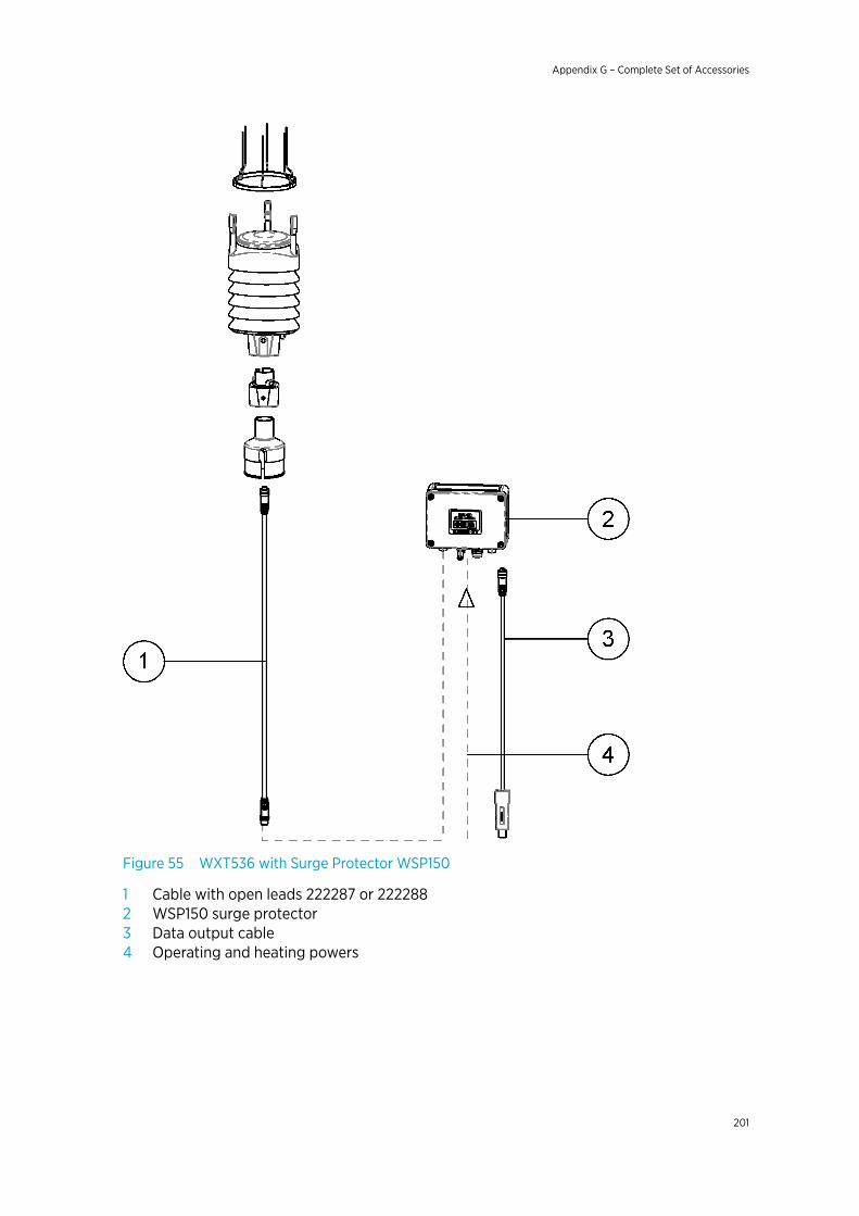
Figure 55 WXT536 with Surge Protector WSP150
1 Cable with open leads 222287 or 2222882 WSP150 surge protector3 Data output cable4 Operating and heating powers
Appendix G – Complete Set of Accessories
201
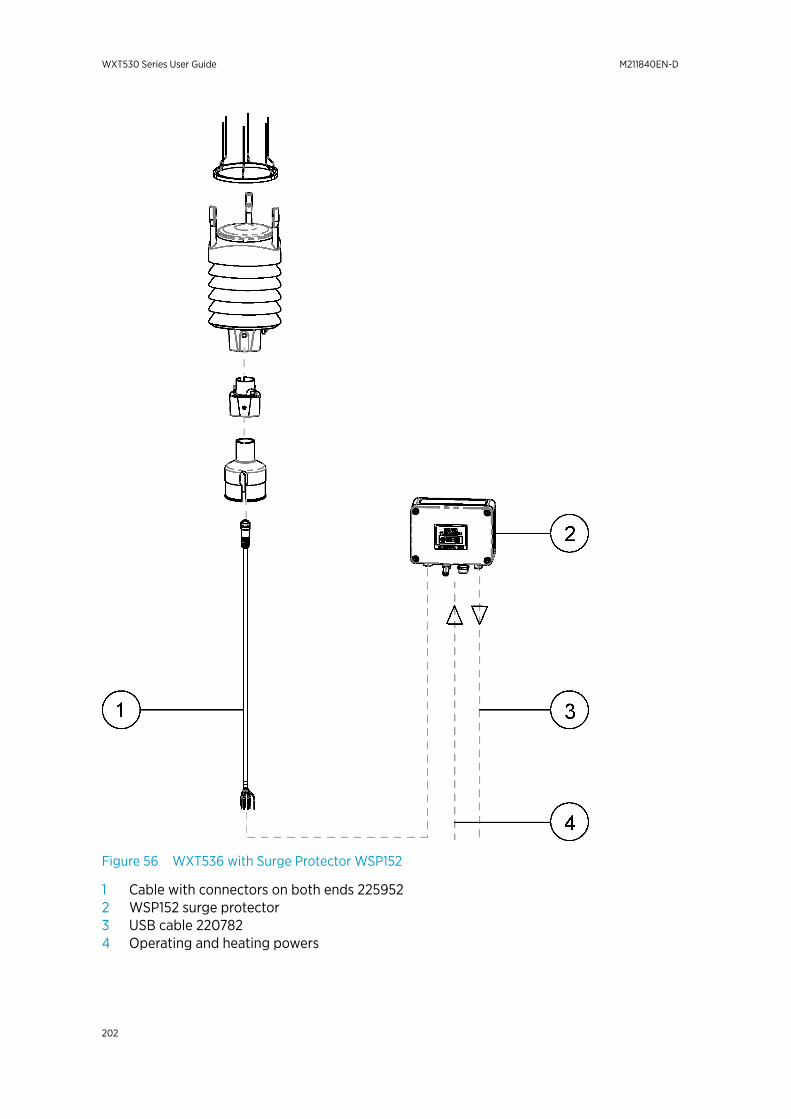
Figure 56 WXT536 with Surge Protector WSP152
1 Cable with connectors on both ends 2259522 WSP152 surge protector3 USB cable 2207824 Operating and heating powers
WXT530 Series User Guide M211840EN-D
202
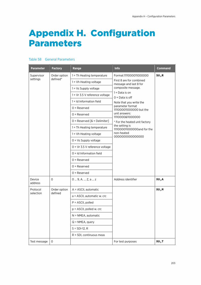
Appendix H. ConfigurationParametersTable 58 General Parameters
Parameter Factory Range Info Command
Supervisorsettings
Order optiondefined*
1 = Th Heating temperature Format:1111000011000000
First 8 are for combinedmessage and last 8 forcomposite message.
1 = Data is on
0 = Data is off
Note that you write theparameter format1111000011000000 but theunit answers:11110000&11000000
* For the heated unit factorythe setting is1111000011000000and for thenon-heated0000000000000000
SU,R
1 = Vh Heating voltage
1 = Vs Supply voltage
1 = Vr 3.5 V reference voltage
1 = Id Information field
0 = Reserved
0 = Reserved
0 = Reserved [& = Delimiter]
1 = Th Heating temperature
1 = Vh Heating voltage
0 = Vs Supply voltage
0 = Vr 3.5 V reference voltage
0 = Id Information field
0 = Reserved
0 = Reserved
0 = Reserved
Deviceaddress
0 0 … 9, A. … Z, a … z Address identifier XU,A
Protocolselection
Order optiondefined
A = ASCII, automatic XU,M
a = ASCII, automatic w. crc
P = ASCII, polled
p = ASCII, polled w. crc
N = NMEA, automatic
Q = NMEA, query
S = SDI-12, R
R = SDI, continuous meas
Test message 0 For test purposes XU,T
Appendix H – Configuration Parameters
203
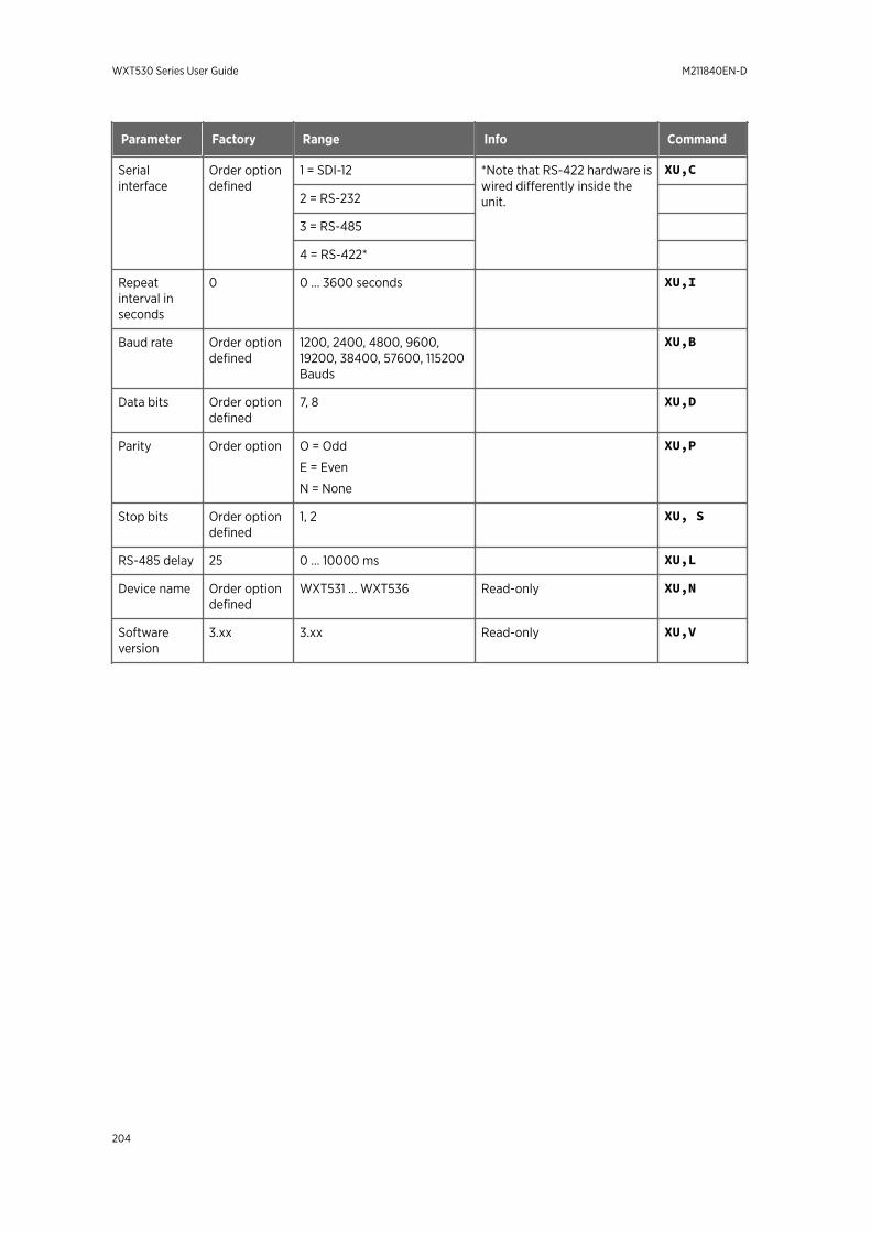
Parameter Factory Range Info Command
Serialinterface
Order optiondefined
1 = SDI-12 *Note that RS-422 hardware iswired differently inside theunit.
XU,C
2 = RS-232
3 = RS-485
4 = RS-422*
Repeatinterval inseconds
0 0 … 3600 seconds XU,I
Baud rate Order optiondefined
1200, 2400, 4800, 9600,19200, 38400, 57600, 115200Bauds
XU,B
Data bits Order optiondefined
7, 8 XU,D
Parity Order option O = Odd
E = Even
N = None
XU,P
Stop bits Order optiondefined
1, 2 XU, S
RS-485 delay 25 0 … 10000 ms XU,L
Device name Order optiondefined
WXT531 ... WXT536 Read-only XU,N
Softwareversion
3.xx 3.xx Read-only XU,V
WXT530 Series User Guide M211840EN-D
204
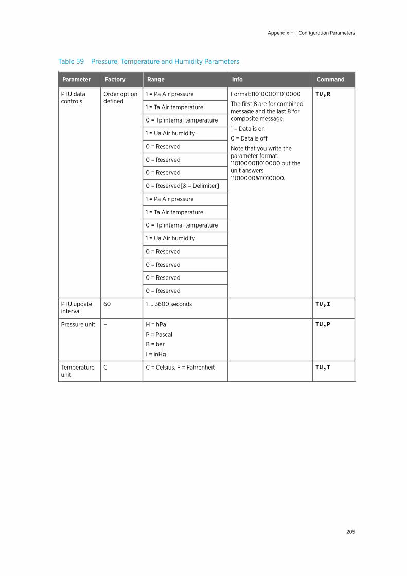
Table 59 Pressure, Temperature and Humidity Parameters
Parameter Factory Range Info Command
PTU datacontrols
Order optiondefined
1 = Pa Air pressure Format:1101000011010000
The first 8 are for combinedmessage and the last 8 forcomposite message.
1 = Data is on
0 = Data is off
Note that you write theparameter format:1101000011010000 but theunit answers11010000&11010000.
TU,R
1 = Ta Air temperature
0 = Tp internal temperature
1 = Ua Air humidity
0 = Reserved
0 = Reserved
0 = Reserved
0 = Reserved[& = Delimiter]
1 = Pa Air pressure
1 = Ta Air temperature
0 = Tp internal temperature
1 = Ua Air humidity
0 = Reserved
0 = Reserved
0 = Reserved
0 = Reserved
PTU updateinterval
60 1 ... 3600 seconds TU,I
Pressure unit H H = hPa
P = Pascal
B = bar
I = inHg
TU,P
Temperatureunit
C C = Celsius, F = Fahrenheit TU,T
Appendix H – Configuration Parameters
205
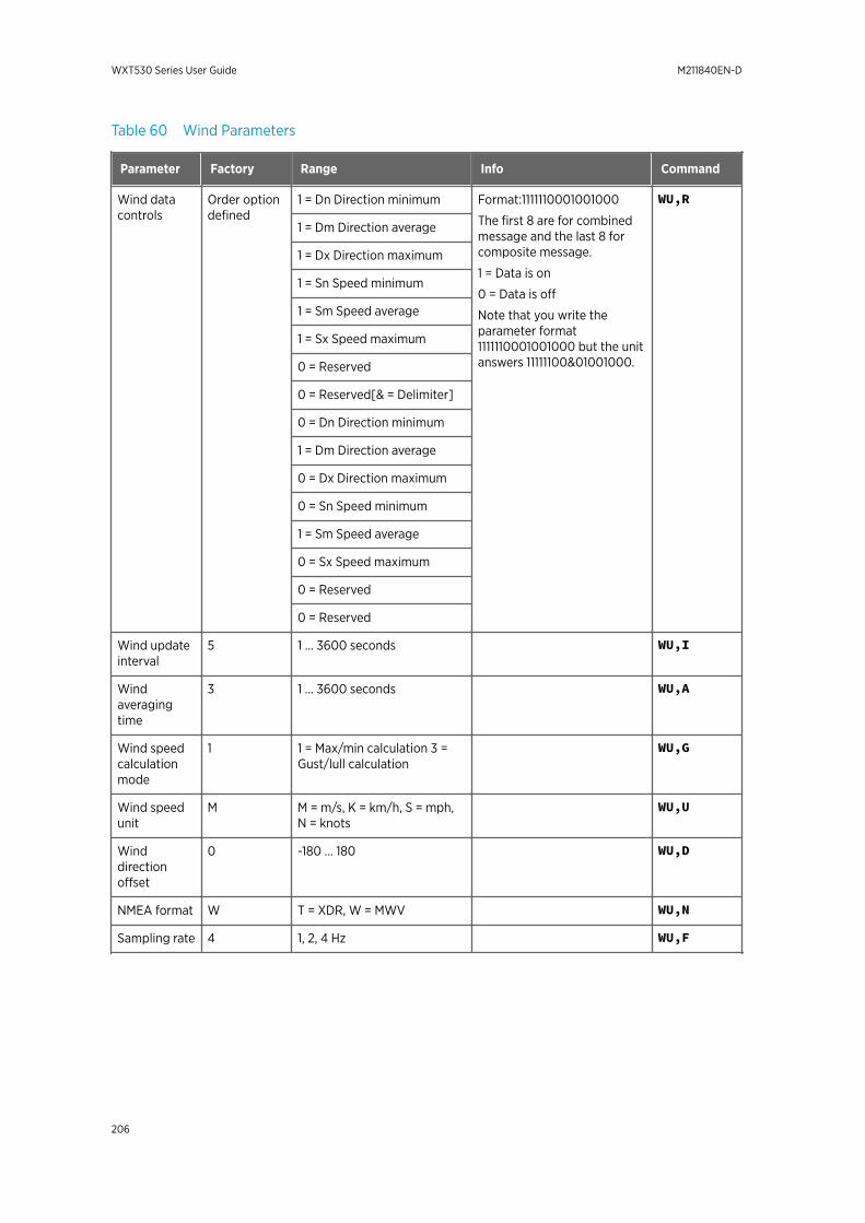
Table 60 Wind Parameters
Parameter Factory Range Info Command
Wind datacontrols
Order optiondefined
1 = Dn Direction minimum Format:1111110001001000
The first 8 are for combinedmessage and the last 8 forcomposite message.
1 = Data is on
0 = Data is off
Note that you write theparameter format1111110001001000 but the unitanswers 11111100&01001000.
WU,R
1 = Dm Direction average
1 = Dx Direction maximum
1 = Sn Speed minimum
1 = Sm Speed average
1 = Sx Speed maximum
0 = Reserved
0 = Reserved[& = Delimiter]
0 = Dn Direction minimum
1 = Dm Direction average
0 = Dx Direction maximum
0 = Sn Speed minimum
1 = Sm Speed average
0 = Sx Speed maximum
0 = Reserved
0 = Reserved
Wind updateinterval
5 1 … 3600 seconds WU,I
Windaveragingtime
3 1 … 3600 seconds WU,A
Wind speedcalculationmode
1 1 = Max/min calculation 3 =Gust/lull calculation
WU,G
Wind speedunit
M M = m/s, K = km/h, S = mph,N = knots
WU,U
Winddirectionoffset
0 -180 ... 180 WU,D
NMEA format W T = XDR, W = MWV WU,N
Sampling rate 4 1, 2, 4 Hz WU,F
WXT530 Series User Guide M211840EN-D
206
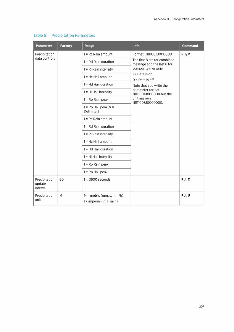
Table 61 Precipitation Parameters
Parameter Factory Range Info Command
Precipitationdata controls
1 = Rc Rain amount Format:1111110010000000
The first 8 are for combinedmessage and the last 8 forcomposite message.
1 = Data is on
0 = Data is off
Note that you write theparameter format1111110010000000 but theunit answers11111100&10000000.
RU,R
1 = Rd Rain duration
1 = Ri Rain intensity
1 = Hc Hail amount
1 = Hd Hail duration
1 = Hi Hail intensity
1 = Rp Rain peak
1 = Rp Hail peak[& =Delimiter]
1 = Rc Rain amount
1 = Rd Rain duration
1 = Ri Rain intensity
1 = Hc Hail amount
1 = Hd Hail duration
1 = Hi Hail intensity
1 = Rp Rain peak
1 = Rp Hail peak
Precipitationupdateinterval
60 1 … 3600 seconds RU,I
Precipitationunit
M M = metric (mm, s, mm/h)
I = imperial (in, s, in/h)
RU,U
Appendix H – Configuration Parameters
207
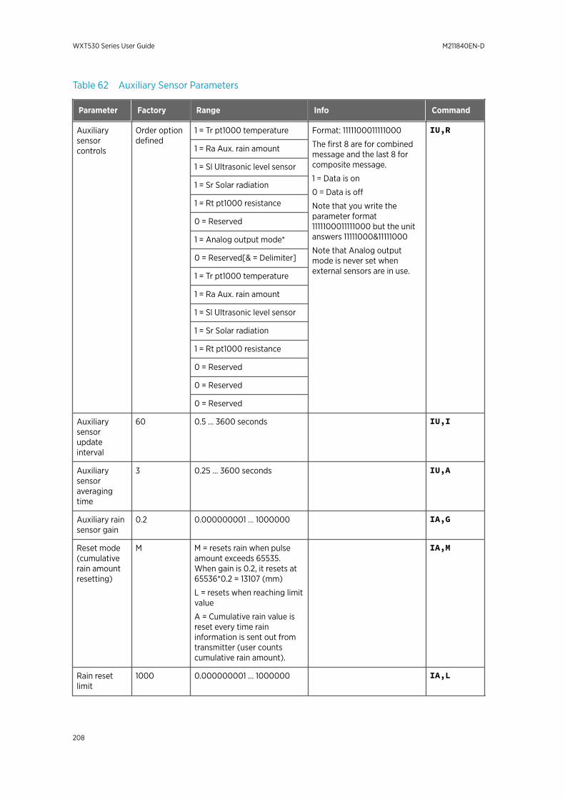
Table 62 Auxiliary Sensor Parameters
Parameter Factory Range Info Command
Auxiliarysensorcontrols
Order optiondefined
1 = Tr pt1000 temperature Format: 1111100011111000
The first 8 are for combinedmessage and the last 8 forcomposite message.
1 = Data is on
0 = Data is off
Note that you write theparameter format1111100011111000 but the unitanswers 11111000&11111000
Note that Analog outputmode is never set whenexternal sensors are in use.
IU,R
1 = Ra Aux. rain amount
1 = Sl Ultrasonic level sensor
1 = Sr Solar radiation
1 = Rt pt1000 resistance
0 = Reserved
1 = Analog output mode*
0 = Reserved[& = Delimiter]
1 = Tr pt1000 temperature
1 = Ra Aux. rain amount
1 = Sl Ultrasonic level sensor
1 = Sr Solar radiation
1 = Rt pt1000 resistance
0 = Reserved
0 = Reserved
0 = Reserved
Auxiliarysensorupdateinterval
60 0.5 … 3600 seconds IU,I
Auxiliarysensoraveragingtime
3 0.25 … 3600 seconds IU,A
Auxiliary rainsensor gain
0.2 0.000000001 … 1000000 IA,G
Reset mode(cumulativerain amountresetting)
M M = resets rain when pulseamount exceeds 65535.When gain is 0.2, it resets at65536*0.2 = 13107 (mm)
L = resets when reaching limitvalue
A = Cumulative rain value isreset every time raininformation is sent out fromtransmitter (user countscumulative rain amount).
IA,M
Rain resetlimit
1000 0.000000001 … 1000000 IA,L
WXT530 Series User Guide M211840EN-D
208
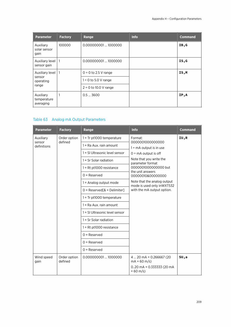
Parameter Factory Range Info Command
Auxiliarysolar sensorgain
100000 0.000000001 … 1000000 IB,G
Auxiliary levelsensor gain
1 0.000000001 … 1000000 IS,G
Auxiliary levelsensoroperatingrange
1 0 = 0 to 2.5 V range IS,M
1 = 0 to 5.0 V range
2 = 0 to 10.0 V range
Auxiliarytemperatureaveraging
1 0.5 … 3600 IP,A
Table 63 Analog mA Output Parameters
Parameter Factory Range Info Command
Auxiliarysensordefinitions
Order optiondefined
1 = Tr pt1000 temperature Format:0000001000000000
1 = mA output is in use
0 = mA output is off
Note that you write theparameter format0000001000000000 butthe unit answers00000010&00000000
Note that the analog outputmode is used only inWXT532with the mA output option.
IU,R
1 = Ra Aux. rain amount
1 = Sl Ultrasonic level sensor
1 = Sr Solar radiation
1 = Rt pt1000 resistance
0 = Reserved
1 = Analog output mode
0 = Reserved[& = Delimiter]
1 = Tr pt1000 temperature
1 = Ra Aux. rain amount
1 = Sl Ultrasonic level sensor
1 = Sr Solar radiation
1 = Rt pt1000 resistance
0 = Reserved
0 = Reserved
0 = Reserved
Wind speedgain
Order optiondefined
0.000000001 … 1000000 4 … 20 mA = 0.266667 (20mA = 60 m/s)
0..20 mA = 0.333333 (20 mA= 60 m/s)
SU,a
Appendix H – Configuration Parameters
209
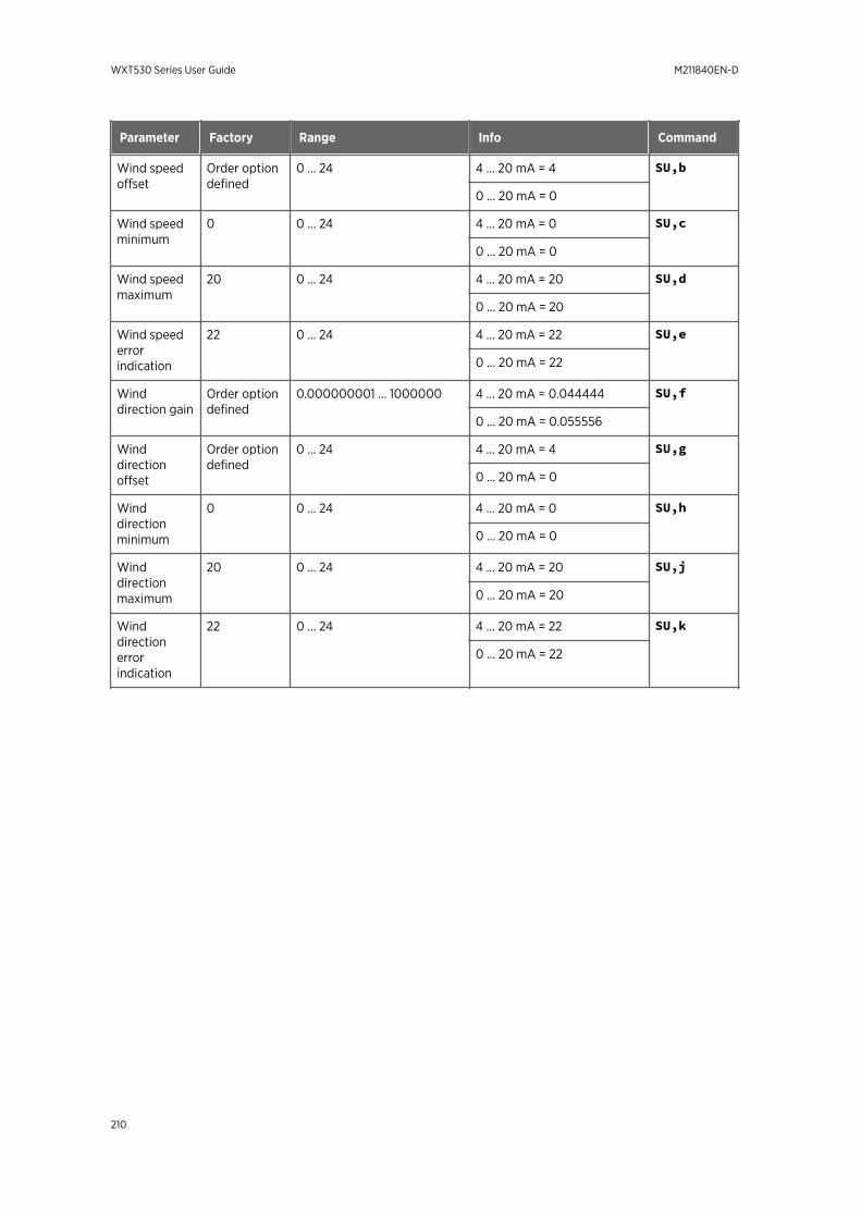
Parameter Factory Range Info Command
Wind speedoffset
Order optiondefined
0 … 24 4 … 20 mA = 4 SU,b
0 … 20 mA = 0
Wind speedminimum
0 0 … 24 4 … 20 mA = 0 SU,c
0 … 20 mA = 0
Wind speedmaximum
20 0 … 24 4 … 20 mA = 20 SU,d
0 … 20 mA = 20
Wind speederrorindication
22 0 … 24 4 … 20 mA = 22 SU,e
0 … 20 mA = 22
Winddirection gain
Order optiondefined
0.000000001 … 1000000 4 … 20 mA = 0.044444 SU,f
0 … 20 mA = 0.055556
Winddirectionoffset
Order optiondefined
0 … 24 4 … 20 mA = 4 SU,g
0 … 20 mA = 0
Winddirectionminimum
0 0 … 24 4 … 20 mA = 0 SU,h
0 … 20 mA = 0
Winddirectionmaximum
20 0 … 24 4 … 20 mA = 20 SU,j
0 … 20 mA = 20
Winddirectionerrorindication
22 0 … 24 4 … 20 mA = 22 SU,k
0 … 20 mA = 22
WXT530 Series User Guide M211840EN-D
210
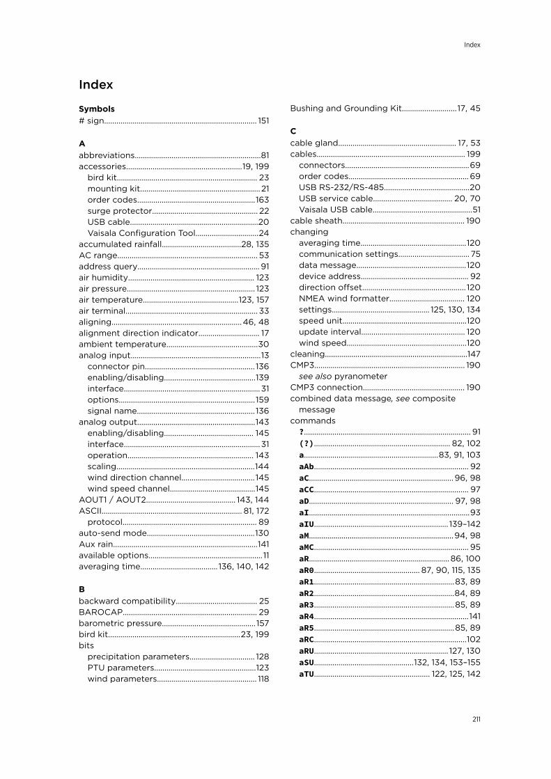
Index
Symbols# sign........................................................................... 151
Aabbreviations..............................................................81accessories.........................................................19, 199
bird kit..................................................................... 23mounting kit...........................................................21order codes..........................................................163surge protector.................................................... 22USB cable...............................................................20Vaisala Configuration Tool...............................24
accumulated rainfall.......................................28, 135AC range..................................................................... 53address query............................................................ 91air humidity.............................................................. 123air pressure............................................................... 123air temperature...............................................123, 157air terminal................................................................. 33aligning................................................................46, 48alignment direction indicator.............................. 17ambient temperature.............................................30analog input................................................................13
connector pin...................................................... 136enabling/disabling.............................................139interface...................................................................31options...................................................................159signal name.......................................................... 136
analog output..........................................................143enabling/disabling............................................ 145interface...................................................................31operation.............................................................. 143scaling....................................................................144wind direction channel.................................... 145wind speed channel..........................................145
AOUT1 / AOUT2............................................ 143, 144ASCII..................................................................... 81, 172
protocol.................................................................. 89auto-send mode.....................................................130Aux rain.......................................................................141available options........................................................ 11averaging time...................................... 136, 140, 142
Bbackward compatibility........................................ 25BAROCAP.................................................................. 29barometric pressure.............................................. 157bird kit.................................................................23, 199bits
precipitation parameters................................ 128PTU parameters..................................................123wind parameters................................................. 118
Bushing and Grounding Kit...........................17, 45
Ccable gland.......................................................... 17, 53cables......................................................................... 199
connectors.............................................................69order codes........................................................... 69USB RS-232/RS-485..........................................20USB service cable....................................... 20, 70Vaisala USB cable.................................................51
cable sheath............................................................ 190changing
averaging time....................................................120communication settings................................... 75data message......................................................120device address..................................................... 92direction offset................................................... 120NMEA wind formatter..................................... 120settings................................................ 125, 130, 134speed unit.............................................................120update interval................................................... 120wind speed...........................................................120
cleaning......................................................................147CMP3.......................................................................... 190
see also pyranometerCMP3 connection.................................................. 190combined data message, see composite
messagecommands?.................................................................................. 91(?)................................................................... 82, 102a..................................................................83, 91, 103aAb............................................................................ 92aC....................................................................... 96, 98aCC............................................................................ 97aD....................................................................... 97, 98aI...............................................................................93aIU.................................................................. 139–142aM.......................................................................94, 98aMC............................................................................ 95aR..................................................................... 86, 100aR0.................................................... 87, 90, 115, 135aR1.....................................................................83, 89aR2.....................................................................84, 89aR3.....................................................................85, 89aR4............................................................................141aR5.....................................................................85, 89aRC...........................................................................102aRU.................................................................. 127, 130aSU.................................................132, 134, 153–155aTU......................................................... 122, 125, 142
Index
211
aWU................................................................... 117, 145aXU..................................................................... 72, 75aXZ.............................................................................77aXZM......................................................................... 80MWV.......................................................................... 104XDR.......................................................................... 105XZRI..........................................................................79XZRU..........................................................................78
communication protocols........................... 117, 159RS-232.....................................................................69RS-422.....................................................................69RS-485............................................................69, 172SDI-12............................................................... 69, 171
communication settings................................ 72, 75compass, see aligningcompass safe distance.......................................... 33compatibility............................................................. 25compliance.................................................................25components................................................................17composite data message.................... 90, 115, 135concurrent measurement.....................................96concurrent measurement with CRC.................97configuration parameters..................................203configuration tool, see Vaisala Configuration
Toolconnecting
external sensors................................................. 187level sensor...........................................................187M12 connector....................................................... 71pyranometer........................................................190rain gauge.............................................................197resistance temperature sensor.....................194screw terminal....................................................... 71service cable.........................................................70several transmitters............................................171
connection cables...................................................69connectors.................................................................. 17
4-pin M8................................................................. 208-pin M12....................................53, 58, 61, 71, 194analog input.........................................................136TM-Pt1000........................................................... 194
continuous measurement......................... 100, 102corrosion protection...............................................33counter reset........................................................... 130CRC......................................................................87, 102
ASCII....................................................................... 179CRC-16 computation.............................................179current consumption............................................ 159
DData- / Data+...........................................................172data communication interfaces......................... 67data message.......................................................... 134
getting.................................................................... 141
precipitation..........................................................85retrieving................................................................ 77settings.................................................................. 125wind..........................................................................83
DC voltage range.....................................................53deviation angle.........................................................48device address.................................................82, 102digital outputs.........................................................159dimensions............................................................... 165document version.................................................... 10driver, see Vaisala USB Instrument Driver
Eearthing, see groundingeconomic power management.......................... 56electromagnetic compatibility................... 25, 161error............................................................ 151, 153, 155error messaging..................................................... 134ESD protection..........................................................10external sensors............................................... 31, 187
pyranometer........................................................190rain gauge.............................................................197resistance temperature sensor.....................194ultrasonic level sensor......................................187
external temperature.............................................. 31
Ffactory configuration............................................183failure........................................................................... 151fixing screw................................................................. 17
Ggain............................................................. 136, 141, 142grounding...................................................................45grounding point........................................................ 17
Hhail................................................................................128hail accumulation...................................................130hail intensity.............................................................. 28handling...................................................................... 36heated sensors.........................................................30heater resistance..................................................... 30heating........................................................ 24, 30, 154heating control...............................................133, 134heating instant current..........................................53heating temperature.............................30, 133, 135heating voltage.......................................53, 133, 135HUMICAP180............................................................. 29humidity......................................................................84humidity sensor................................................ 17, 122
Iingress protection...................................................161
WXT530 Series User Guide M211840EN-D
212
inputs.......................................................................... 159installation site..........................................................33installing
maritime..................................................................33pyranometer..........................................................38USB cable driver...................................................51Vaisala Configuration Tool.............................. 49WXT530..................................................................33
internal temperature............................................. 123IP classification.................................................. 21, 161IRU-9429................................................................... 187
Jjumper position........................................................ 67
Llevel measurement...................................................31level sensor............................................................... 187
see also IRU-9429level sensor settings............................................. 142license key..................................................................49lightning protection.........................................22, 33lightning rod, see air terminallocation........................................................................33
MmA...................................................................... 143, 144magnetic compass..................................................33magnetic North........................................................46manual.......................................................................... 10mA output................................................................ 159maritime installation...............................................33mast length................................................................33mast location.............................................................33material...................................................................... 162maximum wind direction.................................... 135maximum wind speed.......................................... 135measurement accuracy.........................................24measurement combination....................................11measurement failure.............................................. 151measurement interval.......................................... 140measuring
humidity..................................................................29precipitation..........................................................28pressure.................................................................. 29PTU........................................................................... 29temperature...........................................................29
memory stick............................................................ 49missing message..................................................... 151missing parameters................................................ 151missing reading.......................................................155models
WXT531............................................................... 11, 16WXT532.............................................................. 11, 15
WXT533.............................................................. 11, 15WXT534.................................................................... 11WXT535.................................................................... 11WXT536.............................................................. 11, 13
mountingpole mast.................................................................21sensor support arm.....................................38, 43vertical pole mast........................................ 38, 39with mounting kit................................................39
mounting kit...............................................21, 39, 199
Nnegative gain........................................................... 185NMEA 0183 v3.0.....................................................102
automatic mode..................................................114checksum computation.................................. 180query.............................................................. 173, 175
North.................................................................... 46, 48North arrow............................................................... 39
Ooperating voltage..........................................155, 159optional features.......................................................19options.................................................................19, 163order codes.............................................................. 163outputs.......................................................................159overvoltage, see surge protector
Ppackage.......................................................................36parameters.............................................................. 203
precipitation........................................................ 128PTU.......................................................................... 123supervisor............................................................. 133wind......................................................................... 118
parameter selection.....................................140, 142peak intensity............................................................28piezoelectrical sensor............................................28pin-outs
analog input.........................................................136screw terminal.............................................. 58, 64serial interfaces....................................................58
polling with CRC......................................................87positive gain.............................................................185power consumption........................................ 53, 56powering up.............................................................. 161power management............................................... 56power supply.............................................................53precipitation............................................................. 157precipitation counter reset.................................. 78precipitation intensity............................................79precipitation measurement................................. 28precipitation sensor........................................ 17, 127precipitation sensor modes.................................28
Index
213
precipitation unit................................................... 130pressure...............................................................84, 161pressure sensor.................................................17, 122pressure unit............................................................ 125problem.......................................................................151product code...........................................................164protocol, see communication protocolsPt1000...............................................................142, 194PTU.............................................................................. 122
configuration settings..................................... 184data message....................................................... 84measurement principle..................................... 29module............................................................29, 147
pulse length..............................................................183pulses per mm..........................................................141pyranometer................................................... 187, 190
see also CMP3
Rradiation shield.......................................... 17, 38, 147rain............................................................................... 128
see also precipitationrain accumulation.................................................. 130RAINCAP.................................................................... 28rain configuration.................................................. 185rain counter............................................................... 141rain current.................................................................28rain duration.............................................................. 28rain gauge.................................................. 31, 187, 197rain measurement....................................................28read-only setting....................................................183relative humidity............................................. 157, 161replacing PTU module..........................................147reset limit................................................................... 141reset mode................................................................ 141resetting hail accumulation................................. 78resetting rain accumulation.................................78resetting software................................................... 77resistance temperature sensor................ 187, 194retrieving data messages..................................... 77retrofit .........................................................................25RG13 connections...................................................197RS-485 wiring..........................................................172rubber plug................................................................ 53
Ssafety............................................................................ 10sampling rate.............................................................27screw cover..........................................................17, 39SDI-12...................................................................171, 177
continuous mode................................................90electrical interface............................................. 177native mode..........................................................90parameter order.................................................143
protocol......................................................... 90, 177timing..................................................................... 177wiring.......................................................................171
self-diagnostics.......................................................153sending data..............................................................97serial communication..............................................71serial connector........................................................53serial interfaces........................................................ 53serial number...........................................................164service cable ............................................................ 70
see also cablesService Pack 2.......................................................... 70service port......................................................... 17, 70setting fields.............................................................. 73settings
changing.................................... 120, 125, 130, 134checking................................................................ 122data message....................................................... 117PTU.......................................................................... 122rain configuration.............................................. 185sensor .....................................................................117temperature......................................................... 142
shipping container.................................................. 36single transducer mode.......................................183size, see dimensionssnow accumulation, see heatingsoftware, see Vaisala Configuration Toolsolar radiation..........................................31, 142, 190specifications
air temperature measurement...................... 157analog input.........................................................159analog mA output............................................. 159barometric pressure measurement.............157electrical................................................................159electromagnetic compatibility...................... 161environmental...................................................... 161mechanical........................................................... 162precipitation measurement............................157wind measurement............................................157
standards....................................................................161starting measurement....................................94, 95storage.........................................................................33strategy......................................................................183supervisor message.............................................. 132supervisor settings....................................... 132, 185supply voltage................................................ 133, 155surge protector................................................. 22, 33
Ttemperature...............................................................84
below zero, see heatingoperative................................................................ 161setting.................................................................... 142storage.................................................................... 161
WXT530 Series User Guide M211840EN-D
214
temperature sensor.........................................17, 122temperature unit.....................................................125terminal program.................................................... 70termination jumper................................................. 67termination resistor................................................ 67text message............................................................153text transmission..................................................... 113THERMOCAP............................................................ 29time slot..................................................................... 173tip counter................................................................. 141tipping bucket, see rain gaugeTM-Pt1000................................................................194trademark..................................................................... 9transducer............................................................ 17, 27transducer measurement query...................... 105transmitters on same bus.................................... 171troubleshooting....................................................... 151true North.................................................................. 46type label.................................................................. 164
Uultrasonic level sensor..........................................187units............................................................................... 81unit setting............................................................... 183unpacking...................................................................36update interval....................125, 130, 133, 134, 140USB cable driver................................................20, 51
VVaisala Configuration Tool...........49, 70, 117, 136Vaisala USB Instrument Driver............................ 51voltage range............................................................ 53volts / user unit.......................................................142
Wweight.........................................................................162wind............................................................................. 157WINDCAP ..................................................................27wind configuration................................................ 183wind direction................................................... 27, 118wind direction offset..............................................48wind direction query............................................104wind filter bypass...................................................185wind measurement................................................. 27wind measurement averaging method.......... 181wind sensor............................................................... 117wind speed......................................................... 27, 118wind speed query..................................................104wind speed range................................................... 161wiring........................................................................... 53
level sensor...........................................................187M12 connector...................................................... 58mA output...............................................................61pyranometer........................................................190
resistance temperature sensor.....................194RS-232...................................................................... 61RS-422......................................................................61RS-485............................................................. 61, 172screw terminals....................................................64SDI-12.................................................................61, 171
WMT52, see backward compatibilityWSP150/WSP152, see surge protectorWXT520, see backward compatibilityWXT531................................................................... 11, 16WXT532................................................... 11, 15, 31, 143WXT533.................................................................. 11, 15WXT534.................................................................. 11, 14WXT535.................................................................. 11, 14WXT536.................................................................. 11, 13
components............................................................17
XXDR..................................................................... 172, 173
Zzero adjustment......................................................183
Index
215

WXT530 Series User Guide M211840EN-D
216

WarrantyFor standard warranty terms and conditions, see www.vaisala.com/warranty.
Please observe that any such warranty may not be valid in case of damage due to normalwear and tear, exceptional operating conditions, negligent handling or installation, orunauthorized modifications. Please see the applicable supply contract or Conditions of Salefor details of the warranty for each product.
Recycling
Recycle all applicable material.
Follow the statutory regulations for disposing of the product and packaging.
Technical Support
Contact Vaisala technical support at [email protected]. Provide at least the followingsupporting information:
• Product name, model, and serial number• Name and location of the installation site• Name and contact information of a technical person who can provide further
information on the problem
For more information, see www.vaisala.com/support.
217

WXT530 Series User Guide M211840EN-D
218