Embed Size (px)
Citation preview
onlinec
omponen
ts.co
m
5003B
INTERBUS-SUser Manual for INTERBUS-S
Controller Board for Siemens SIMATIC S5
Type: IBS S5 DCB UM E
Revision: B
Order No.: 27 58 36 3
This user manual is valid for:
IBS S5 DCB/I-T Order No.: 27 58 15 6 Firmware ≥ 3.5IBS S5 DCB-T Hardware revision ≥CIBS S5 SWD Order No.: 28 06 22 8 Software ≥ 2.2IBS SYS SWT Order No.: 27 80 88 1 Software ≥ 2.3
Copyright by Phoenix Contact 04/1994

onlinec
omponen
ts.co
m
5003B
We are constantly attempting to improve the quality of our manuals.
Should you have any suggestions or recommendations for improvement of the contents andlayout of our manuals, we would appreciate it if you would send your recommendations to:
Phoenix Contact GmbH & Co.Abt. Applikation/Techn. Dokumentation
Flachsmarktstraße 8 – 28 ( *49-5235-55032825 Blomberg *49-5235-55-1200Germany
onlinec
omponen
ts.co
m
Please Read Completely
5003B
Please read completely before reading this manual !!
In order to guarantee that your use of this manual is as straightforward as possible and thathardware is used safely in the installation, operation and maintenance phases, we requestthat you carefully read and observe the following instructions:
Explanation of Symbols Used
The "pointer" hand gives you tips and advice on the efficient use of hardwareand on software optimization, to save you from performing extra work, forexample. In addition, text marked in this way informs you of system-relatedconditions that must absolutely be observed to achieve error-free operation.The hand is also found in front of clarifications of terms.
Statement of Legal Authority
This manual, including all illustrations contained herein, is copyright protected. Use of thismanual by any third party in departure from the copyright provision is forbidden.Reproduction, translation, or electronic or photographic archiving or alteration requires theexpress written consent of Phoenix Contact. Violations are liable for damages.
Phoenix Contact reserves the right to make any technical changes that serve for the purposeof technical progress. Phoenix Contact reserves all rights in the case of a patent award orlisting of a registered design. External products are always named without reference topatent rights. The existence of such rights shall not be excluded, however.
The use of products described in this manual is oriented exclusively to qualified electriciansor persons trained in the electrical field, who are entrusted with the applicable nationalstandards. Phoenix Contact assumes no liability for erroneous handling of or damage toPhoenix Contact or external products resulting from disregard or information contained inthis manual.
The "attention" symbol refers to erroneous handling, which could lead todamage to the hardware or software, or in indirect connection with dangerousprocess peripherals (e.g., unprotected shafts or motors with actuator functions)to light to severe personal injury. The symbol is always located to the left of thetagged text.
onlinec
omponen
ts.co
m
Supplementary Notes (February 1996)
15003BC04
Supplementary NotesIBS S5 DCB UM E, Order No.: 27 58 36 3, Revision BAlthough the manual was thoroughly checked, some additions became necessary after itspublication. Please observe the following notes.
Chapter 7.2, “Cable Installation”:InterBus was designed for industrial use.
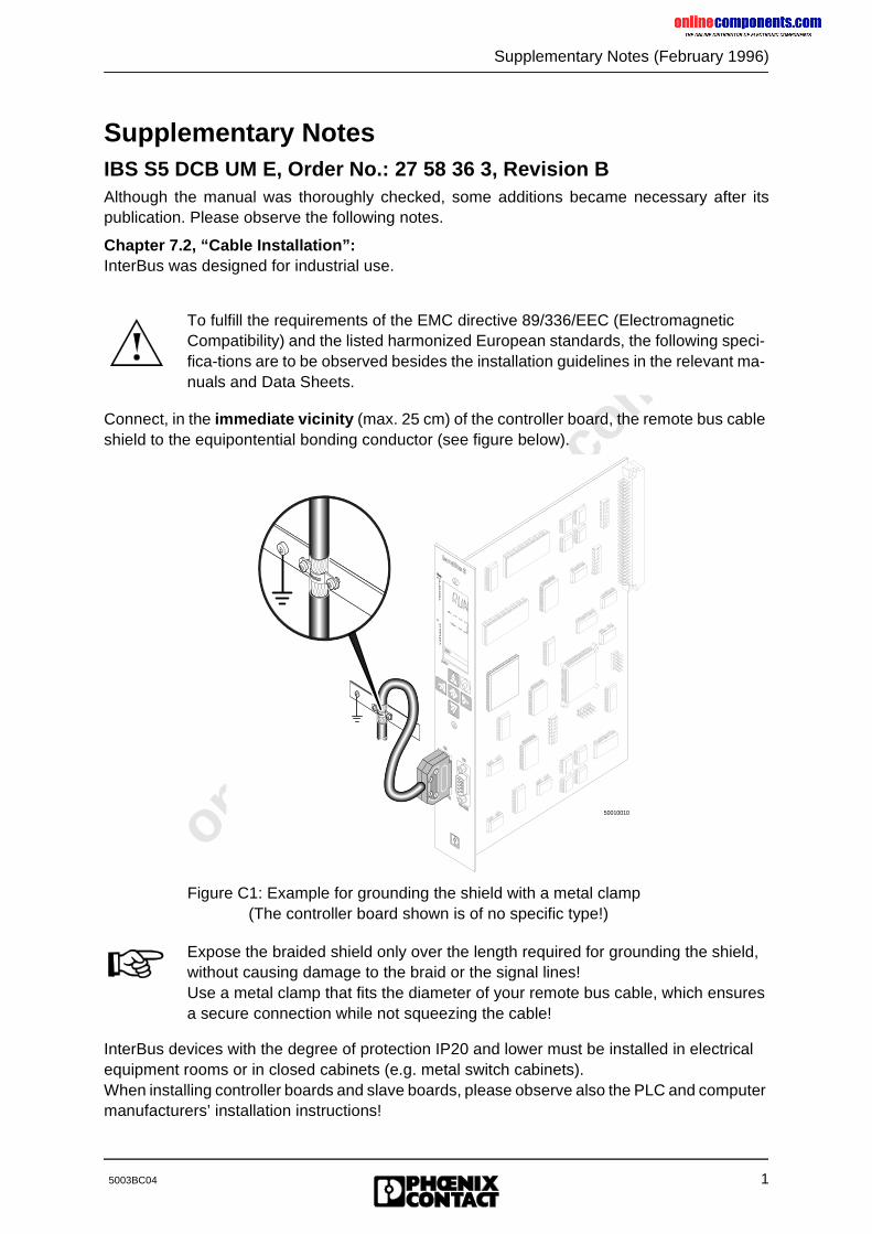
Connect, in the immediate vicinity (max. 25 cm) of the controller board, the remote bus cable shield to the equipontential bonding conductor (see figure below).
Figure C1: Example for grounding the shield with a metal clamp(The controller board shown is of no specific type!)
InterBus devices with the degree of protection IP20 and lower must be installed in electrical equipment rooms or in closed cabinets (e.g. metal switch cabinets). When installing controller boards and slave boards, please observe also the PLC and computer manufacturers’ installation instructions!
To fulfill the requirements of the EMC directive 89/336/EEC (Electromagnetic Compatibility) and the listed harmonized European standards, the following speci-fica-tions are to be observed besides the installation guidelines in the relevant ma-nuals and Data Sheets.
50010010
Expose the braided shield only over the length required for grounding the shield, without causing damage to the braid or the signal lines!Use a metal clamp that fits the diameter of your remote bus cable, which ensures a secure connection while not squeezing the cable!
onlinec
omponen
ts.co
m
2
Supplementary Notes (February 1996)
5003BC04
Chapter 6, “Startup”:
Replace the values as follows in the above text sections!
FEN3 : KF+200 -> FEN3 : KF +252
In accordance with this change, change the communication register addresses in the figures listed in the table below (200->252; 202->254):
Chapter 3.1, “ID Code of the Modules”, Page 3-4, Table 3-2
All register width details are given as number of bytes.
The numbers given for the IB ST 24 DO 8/3-2A module were mixed up by mistake for thecolumns "OUT-AR" and "Register width" (both numbers are given in bytes).Correct is: OUT-AR =1 and register width = 1The number"“81 *" for the IB ST 24 DO 8/3-2A module in the "Length code" column was givenin a hexadecimal format. The correct decimal value is "129".The number"“1**" is of no importance.The footnote text for both length specifications refers to firmware versions below version 3.5.
Page Section
6-10 c) Program example
6-15 d) Detailed program example with organization, function and data blocks
6-25 d) Detailed program example with organization, function and data blocks
6-28 FB210 listing
6-43 d) Detailed program example with organization, function and data blocks
6-57 d) Detailed program example with organization, function and data blocks
Page Section
6-9 Figure 6-6
6-12 Figure 6-8
6-22 Figure 6-9
6-26 Figure 6-10
6-40 Figure 6-11
6-54 Figure 6-12
The communication register base address settings documented in the manual do not match the program examples on the ISFP diskette.The following sections of the text (with page numbers) are affected:
onlinec
omponen
ts.co
m
Supplementary Notes (February 1996)
35003BC04
The numbers for the IBS IP CDI 1/24-F, IBS IP CDI 2/24-F, IBS IP CDO 1/24-F, IBS IP CDO 2/24-F, IB ST 24 DI 16/4 modules were given one byte too small in the “Register width” column. The register width is 2 bytes for the above modules.The numbers for the IB ST 24 DI 32/2 and IB ST 24 DO 32/2 modules were given two bytes too small in the “Register width” column (both in bytes). The register width for the above mo-dules is 4 bytes.
Chapter 3.1, “ID Code of the Modules”, Page 3-5, Table 3-3
The numbers for the InterBus-S module IBS 24 IP DIO BB1/E-T were given one byte too smallin the columns "OUT-AR" and "Register width" (both numbers in bytes). For this module theregister width is 4 bytes and the assigned output address area is 2 bytes.
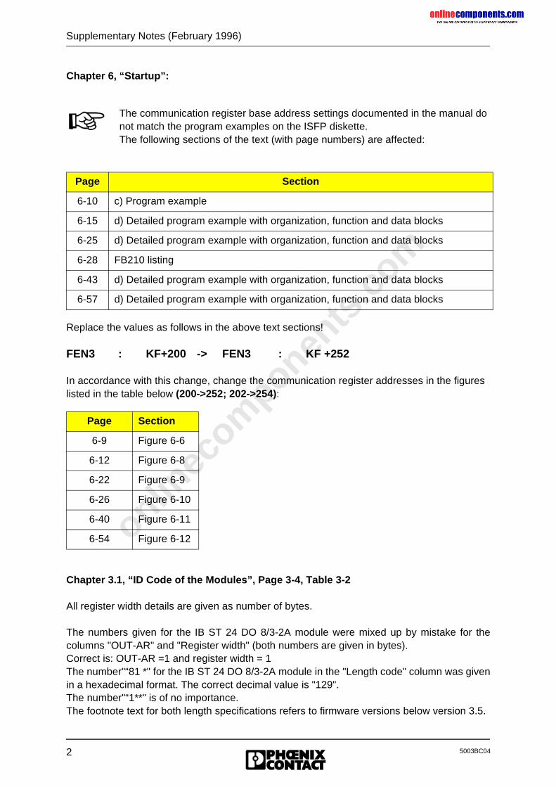
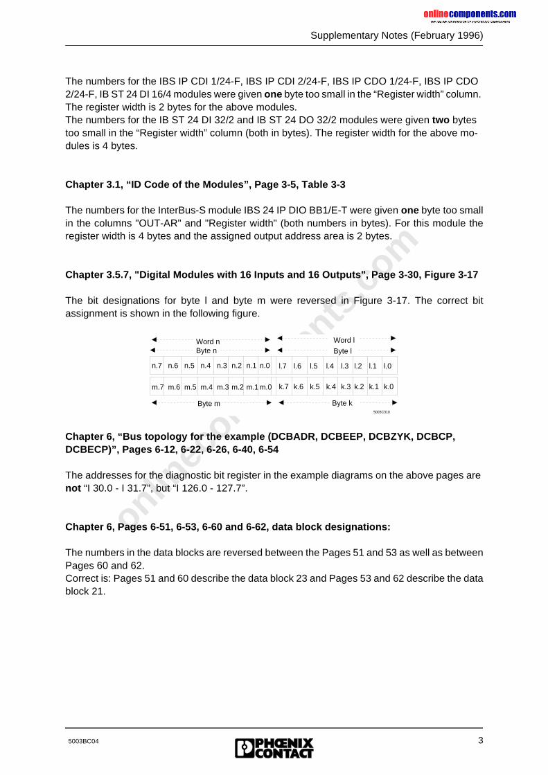
Chapter 3.5.7, "Digital Modules with 16 Inputs and 16 Outputs", Page 3-30, Figure 3-17
The bit designations for byte l and byte m were reversed in Figure 3-17. The correct bitassignment is shown in the following figure.
Chapter 6, “Bus topology for the example (DCBADR, DCBEEP, DCBZYK, DCBCP, DCBECP)”, Pages 6-12, 6-22, 6-26, 6-40, 6-54
The addresses for the diagnostic bit register in the example diagrams on the above pages are not “I 30.0 - I 31.7”, but “I 126.0 - 127.7”.
Chapter 6, Pages 6-51, 6-53, 6-60 and 6-62, data block designations:
The numbers in the data blocks are reversed between the Pages 51 and 53 as well as betweenPages 60 and 62.Correct is: Pages 51 and 60 describe the data block 23 and Pages 53 and 62 describe the datablock 21.
n.7 n.6 n.5 n.4 n.3 n.2 n.1 n.0 l.7 l.6 l.5 l.4 l.3 l.2 l.1 l.0
Byte n Byte lWord n
5003C310
m.7 m.6 m.5 m.4 m.3 m.2 m.1 m.0 k.7 k.6 k.5 k.4 k.3 k.2 k.1 k.0
Byte m Byte k
Word l
onlinec
omponen
ts.co
m
4
Supplementary Notes (February 1996)
5003BC04
New Firmware Revision V3.71 for the IBS S5 DCB (/I)-T Controller Board for SIMATIC S5 PLCs
Owing to functional extensions, technical improvements and corrections in the firmware, thereare some innovations for the IBS S5 DCB (/I)-T controller boards for SIMATIC S5 PLCs.
Controller boards and documentation concerned:
Hardware:IBS S5 DCB/I-T: Order No.: 27 58 15 6IBS S5 DCB-T: Order No.: 28 06 21 5
Firmware:- Previous version: 3.5x- Update version: 3.71
Upgrade:A hardware upgrade with the update version is possible with:- Hardware version: IBS GB S5 9166835 C- Plug-on board type: MA5
The firmware can be updated as of: - Firmware version: 3.3x
User manuals:German: IBS S5 DCB UM (Order No.: 28 06 23 1)English: IBS S5 DCB UM E (Order No.: 27 58 36 3)
onlinec
omponen
ts.co
m
Supplementary Notes (February 1996)
55003BC04
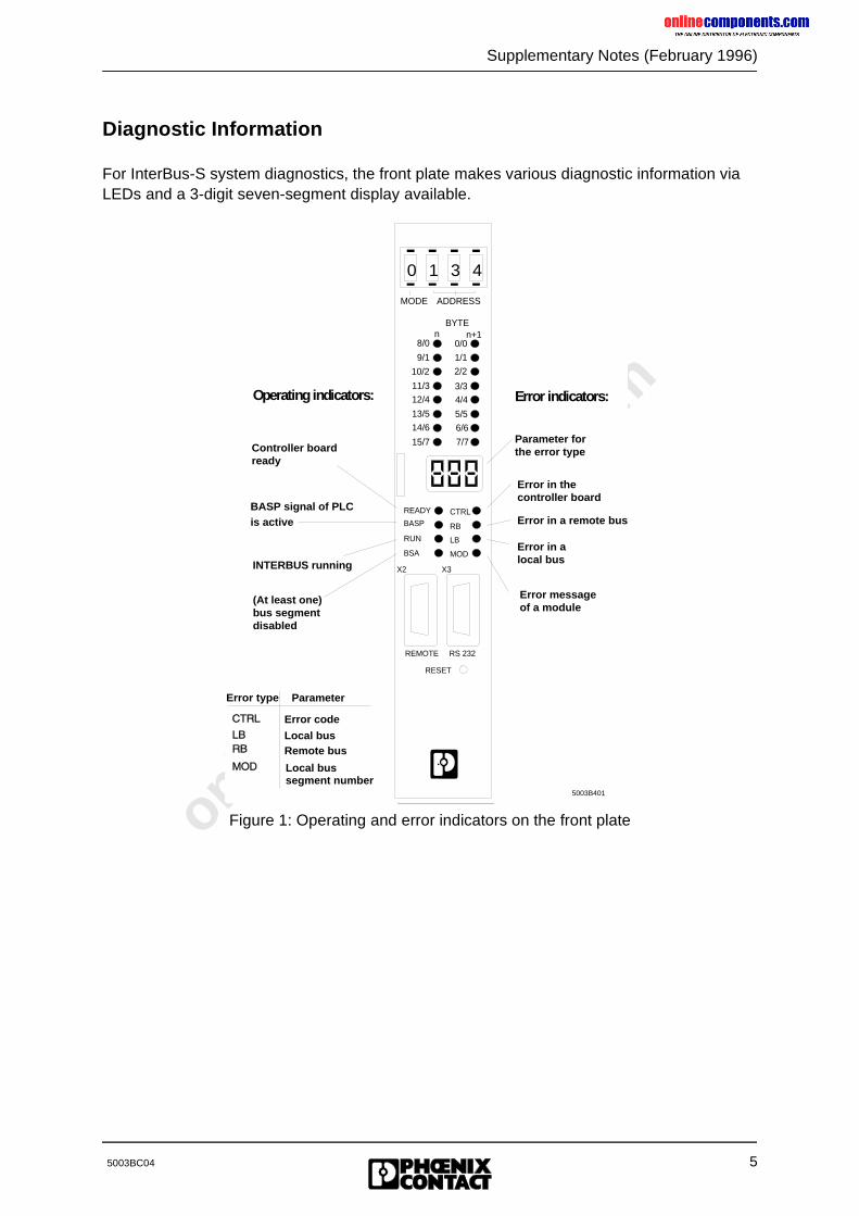
Diagnostic Information
For InterBus-S system diagnostics, the front plate makes various diagnostic information via LEDs and a 3-digit seven-segment display available.
Figure 1: Operating and error indicators on the front plate
X2 X3
REMOTE RS 232
RESET
BYTE
n n+1
MODE ADDRESS
CTRL
RB
LB
MOD
READY
BASP
RUN
BSA
10/2
8/0
9/1
11/3
12/4
13/5
14/6
15/7
0/0
1/1
2/2
3/3
4/4
5/5
6/6
7/7
0 1 3 4
5003B401
X2 X3
REMOTE RS 232
RESET
BYTEn n+1
MODE ADDRESS
CTRL
RB
LB
MOD
READY
BASP
RUN
BSA
10/2
8/0
9/1
11/3
12/4
13/5
14/6
15/7
0/0
1/1
2/2
3/3
4/4
5/5
6/6
7/7
0 1 3 4
5003B401
Controller boardready
BASP signal of PLCis active
INTERBUS running
Error type Parameter
Error code
Remote bus
Error messageof a module
Error in alocal bus
Error in a remote bus
Error in the controller board
Parameter forthe error type
Error indicators:Operating indicators:
(At least one)bus segmentdisabled
Local bus
Local bussegment number
onlinec
omponen
ts.co
m
6
Supplementary Notes (February 1996)
5003BC04
CTRL (Controller Error)LED description- Red LED- Parameterization error on the controller board or in the software parameterizationParameter- Hexadecimal value- Error description in the user manual
RB (Remote Bus Error)LED description- Red LED- Wrong remote bus segment consisting of a BK module and the preceding remote bus cableParameter- Decimal value- No. of the bus segment concerned
LB (Local Bus Error)LED description- Red LED- Wrong local bus segment consisting of the individual local bus modules and the connecting
bus cablesParameter- Decimal value- No. of the bus segment concerned
MOD (Module Error)LED description- Red LED- Defective module periphery- I/O voltage failure- Short-circuit at the output- Only for devices with status messageParameter- Decimal value- No. of the bus segment concerned
RB and LB (Indication of the error location by specifying an area)LED description- Red LEDParameter- Decimal value- The parameter specifies the base bus segment number of the area concerned.- Group error messages with the error codes E01, E02, E04, E05 and E06- The error was assigned to a bus area which may consist of several bus segments.
onlinec
omponen
ts.co
m
Supplementary Notes (February 1996)
75003BC04
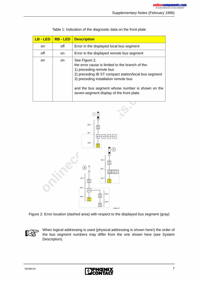
Table 1: Indication of the diagnostic data on the front plate
Figure 2: Error location (dashed area) with respect to the displayed bus segment (gray)
LB - LED RB - LED Description
on off Error in the displayed local bus segment
off on Error in the displayed remote bus segment
on on See Figure 2,the error cause is limited to the branch of the:1) preceding remote bus2) preceding IB ST compact station/local bus segment3) preceding installation remote bus
and the bus segment whose number is shown on theseven-segment display of the front plate.
When logical addressing is used (physical addressing is shown here!) the order ofthe bus segment numbers may differ from the one shown here (see SystemDescription).
onlinec
omponen
ts.co
m
8
Supplementary Notes (February 1996)
5003BC04
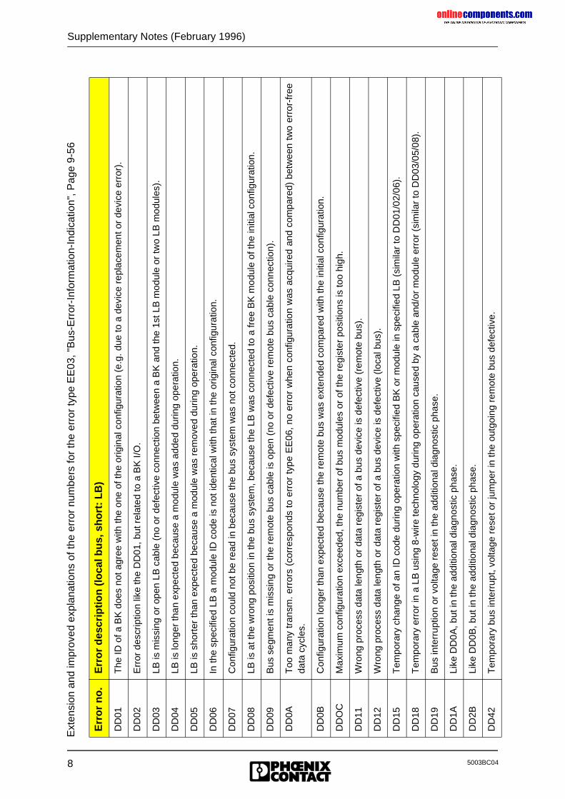
Ext
ensi
on a
nd im
prov
ed e
xpla
natio
ns o
f the
err
or n
umbe
rs fo
r th
e er
ror
type
EE
03, "
Bus
-Err
or-I
nfor
mat
ion-
Indi
catio
n", P
age
9-56
Err
or
no
.E
rro
r d
escr
ipti
on
(lo
cal b
us,
sh
ort
: L
B)
DD
01T
he ID
of a
BK
doe
s no
t agr
ee w
ith th
e on
e of
the
orig
inal
con
figur
atio
n (e
.g. d
ue to
a d
evic
e re
plac
emen
t or
devi
ce e
rror
).
DD
02E
rror
des
crip
tion
like
the
DD
01, b
ut r
elat
ed to
a B
K I/
O.
DD
03LB
is m
issi
ng o
r op
en L
B c
able
(no
or
defe
ctiv
e co
nnec
tion
betw
een
a B
K a
nd th
e 1s
t LB
mod
ule
or tw
o LB
mod
ules
).
DD
04LB
is lo
nger
than
exp
ecte
d be
caus
e a
mod
ule
was
add
ed d
urin
g op
erat
ion.
DD
05LB
is s
hort
er th
an e
xpec
ted
beca
use
a m
odul
e w
as r
emov
ed d
urin
g op
erat
ion.
DD
06In
the
spec
ified
LB
a m
odul
e ID
cod
e is
not
iden
tical
with
that
in th
e or
igin
al c
onfig
urat
ion.
DD
07C
onfig
urat
ion
coul
d no
t be
read
in b
ecau
se th
e bu
s sy
stem
was
not
con
nect
ed.
DD
08LB
is a
t the
wro
ng p
ositi
on in
the
bus
syst
em, b
ecau
se th
e LB
was
con
nect
ed to
a fr
ee B
K m
odul
e of
the
initi
al c
onfig
urat
ion.
DD
09B
us s
egm
ent i
s m
issi
ng o
r th
e re
mot
e bu
s ca
ble
is o
pen
(no
or d
efec
tive
rem
ote
bus
cabl
e co
nnec
tion)
.
DD
0AT
oo m
any
tran
sm. e
rror
s (c
orre
spon
ds to
err
or t
ype
EE
06, n
o er
ror
whe
n co
nfig
urat
ion
was
acq
uire
d an
d co
mpa
red)
bet
wee
n tw
o er
ror-
free
data
cyc
les.
DD
0BC
onfig
urat
ion
long
er th
an e
xpec
ted
beca
use
the
rem
ote
bus
was
ext
ende
d co
mpa
red
with
the
initi
al c
onfig
urat
ion.
DD
OC
Max
imum
con
figur
atio
n ex
ceed
ed, t
he n
umbe
r of
bus
mod
ules
or
of th
e re
gist
er p
ositi
ons
is to
o hi
gh.
DD
11W
rong
pro
cess
dat
a le
ngth
or
data
reg
iste
r of
a b
us d
evic
e is
def
ectiv
e (r
emot
e bu
s).
DD
12W
rong
pro
cess
dat
a le
ngth
or
data
reg
iste
r of
a b
us d
evic
e is
def
ectiv
e (lo
cal b
us).
DD
15T
empo
rary
cha
nge
of a
n ID
cod
e du
ring
oper
atio
n w
ith s
peci
fied
BK
or
mod
ule
in s
peci
fied
LB (
sim
ilar
to D
D01
/02/
06).
DD
18T
empo
rary
err
or in
a L
B u
sing
8-w
ire te
chno
logy
dur
ing
oper
atio
n ca
used
by
a ca
ble
and/
or m
odul
e er
ror
(sim
ilar
to D
D03
/05/
08).
DD
19B
us in
terr
uptio
n or
vol
tage
res
et in
the
addi
tiona
l dia
gnos
tic p
hase
.
DD
1ALi
ke D
D0A
, but
in th
e ad
ditio
nal d
iagn
ostic
pha
se.
DD
2BLi
ke D
D0B
, but
in th
e ad
ditio
nal d
iagn
ostic
pha
se.
DD
42T
empo
rary
bus
inte
rrup
t, vo
ltage
res
et o
r ju
mpe
r in
the
outg
oing
rem
ote
bus
defe
ctiv
e.
onlinec
omponen
ts.co
m
Supplementary Notes (February 1996)
95003BC04
Chapter 3.1, "ID Code of the Modules", Page 3-4, Table 3-2With the firmware update V3.71 the new IBS IP KES A/4 IN module is assigned to the ID code23 hex.This has the following consequences:
- The messages "battery" and "power fail" are not used for the motor relay module.- The I/O data is processed byte-by-byte.- The inputs and outputs of a bus terminal module can be switched off.As of firmware 3.71, IBS devices with a process data length of 26 words are supported. Thesedevices have a length code of 17dec in the more significant byte of the ID word.
Chapter 8.3.3, Function block EVENT (FB 76), Page 8-85, valid as of ISFP version 2.3:The following features were implemented for the event processing:- Comparison of an input with a given pattern- Counting of the occurred events in the associated event counters- Suppression of event indications- Readout of the event countersEvent processing is only possible with digital IBS modules.
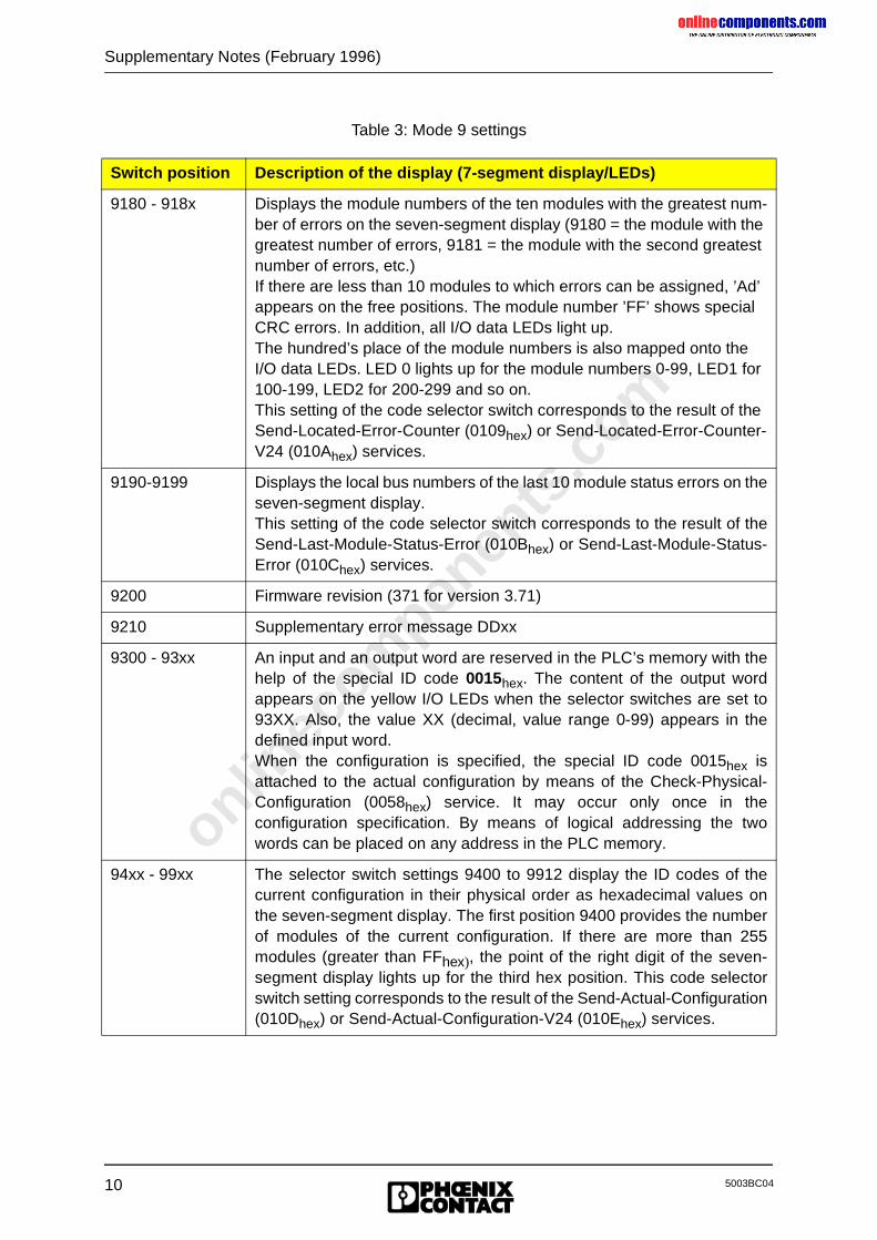
Chapter 2.3.1.1, "I/O Status Indicators", Page 2-5 ff., Mode 9 settingsBesides the familiar direct error indication with the red LEDs CTRL, RB, LB, MOD and theassociated parameters on the diagnostic front plate, firmware 3.71 includes further serviceinformation. This service information can be accessed with the switch setting MODE 9 and anassociated address. The associated data is displayed via the three-position diagnostic display. Note: MODE 9 must be used for service purposes only.
Table 3 summarizes the data shown on the front plate.
onlinec
omponen
ts.co
m
10
Supplementary Notes (February 1996)
5003BC04
Table 3: Mode 9 settings
Switch position Description of the display (7-segment display/LEDs)
9180 - 918x Displays the module numbers of the ten modules with the greatest num-ber of errors on the seven-segment display (9180 = the module with the greatest number of errors, 9181 = the module with the second greatest number of errors, etc.)If there are less than 10 modules to which errors can be assigned, ’Ad’ appears on the free positions. The module number ’FF’ shows special CRC errors. In addition, all I/O data LEDs light up.The hundred’s place of the module numbers is also mapped onto the I/O data LEDs. LED 0 lights up for the module numbers 0-99, LED1 for 100-199, LED2 for 200-299 and so on.This setting of the code selector switch corresponds to the result of the Send-Located-Error-Counter (0109hex) or Send-Located-Error-Counter-V24 (010Ahex) services.
9190-9199 Displays the local bus numbers of the last 10 module status errors on theseven-segment display.This setting of the code selector switch corresponds to the result of theSend-Last-Module-Status-Error (010Bhex) or Send-Last-Module-Status-Error (010Chex) services.
9200 Firmware revision (371 for version 3.71)
9210 Supplementary error message DDxx
9300 - 93xx An input and an output word are reserved in the PLC’s memory with thehelp of the special ID code 0015hex. The content of the output wordappears on the yellow I/O LEDs when the selector switches are set to93XX. Also, the value XX (decimal, value range 0-99) appears in thedefined input word.When the configuration is specified, the special ID code 0015hex isattached to the actual configuration by means of the Check-Physical-Configuration (0058hex) service. It may occur only once in theconfiguration specification. By means of logical addressing the twowords can be placed on any address in the PLC memory.
94xx - 99xx The selector switch settings 9400 to 9912 display the ID codes of thecurrent configuration in their physical order as hexadecimal values onthe seven-segment display. The first position 9400 provides the numberof modules of the current configuration. If there are more than 255modules (greater than FFhex), the point of the right digit of the seven-segment display lights up for the third hex position. This code selectorswitch setting corresponds to the result of the Send-Actual-Configuration(010Dhex) or Send-Actual-Configuration-V24 (010Ehex) services.
onlinec
omponen
ts.co
m
Supplementary Notes (February 1996)
115003BC04
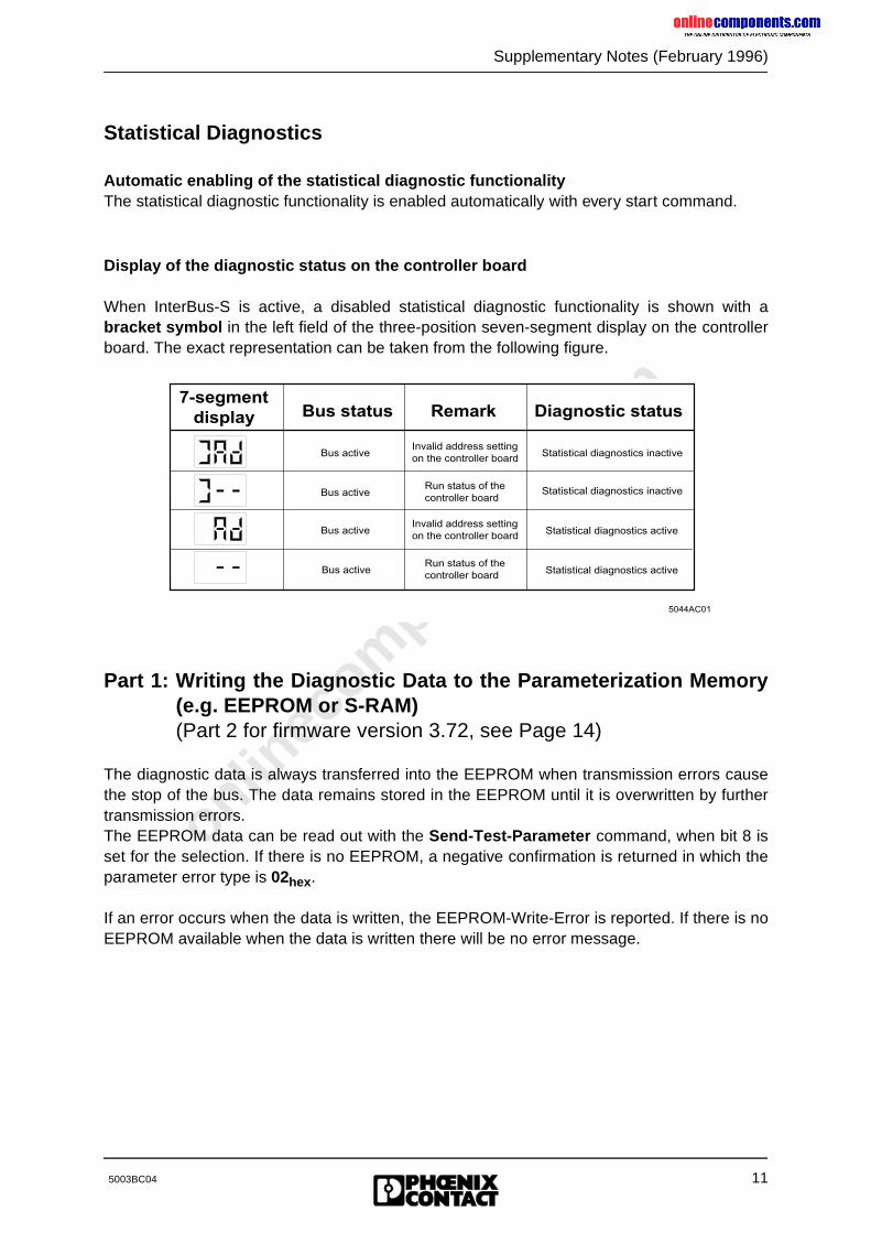
Statistical Diagnostics
Automatic enabling of the statistical diagnostic functionalityThe statistical diagnostic functionality is enabled automatically with every start command.
Display of the diagnostic status on the controller board
When InterBus-S is active, a disabled statistical diagnostic functionality is shown with abracket symbol in the left field of the three-position seven-segment display on the controllerboard. The exact representation can be taken from the following figure.
Part 1: Writing the Diagnostic Data to the Parameterization Memory(e.g. EEPROM or S-RAM)(Part 2 for firmware version 3.72, see Page 14)
The diagnostic data is always transferred into the EEPROM when transmission errors causethe stop of the bus. The data remains stored in the EEPROM until it is overwritten by furthertransmission errors.The EEPROM data can be read out with the Send-Test-Parameter command, when bit 8 isset for the selection. If there is no EEPROM, a negative confirmation is returned in which theparameter error type is 02hex.
If an error occurs when the data is written, the EEPROM-Write-Error is reported. If there is noEEPROM available when the data is written there will be no error message.
7-segmentdisplay Bus status Remark Diagnostic status
Bus active
Bus active
Bus active
Bus active
Invalid address settingon the controller board
Run status of the controller board
Invalid address settingon the controller board
Run status of the controller board
Statistical diagnostics inactive
Statistical diagnostics inactive
Statistical diagnostics active
Statistical diagnostics active
5044AC01
onlinec
omponen
ts.co
m
12
Supplementary Notes (February 1996)
5003BC04
New Firmware Revision V3.72 for the IBS S5 DCB (/I)-T Controller Board for SIMATIC S5 PLCs
Owing to functional extensions, technical improvements and corrections in the firmware, thereare some innovations for the IBS S5 DCB (/I)-T controller board for SIMATIC S5 PLCs.
Controller boards and documentation concerned:
Boards:IBS S5 DCB/I-T: Order No.: 27 58 15 6IBS S5 DCB-T: Order No.: 28 06 21 5
Firmware:- Previous version: 3.71- Update version: 3.72
Upgrade:A hardware upgrade with the update version is possible with:- Hardware version: IBS GB S5 9166835 C- Plug-on board type: MA5
The firmware can be updated as of: - Firmware version: 3.3x
User manuals:German: IBS S5 DCB UM (Order No.: 28 06 23 1)English: IBS S5 DCB UM E (Order No.: 27 58 36 3)
onlinec
omponen
ts.co
m
Supplementary Notes (February 1996)
135003BC04
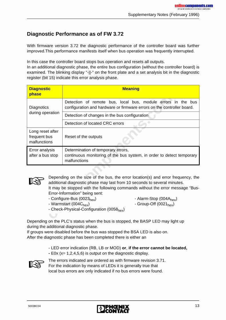
Diagnostic Performance as of FW 3.72
With firmware version 3.72 the diagnostic performance of the controller board was furtherimproved.This performance manifests itself when bus operation was frequently interrupted.
In this case the controller board stops bus operation and resets all outputs.In an additional diagnostic phase, the entire bus configuration (without the controller board) isexamined. The blinking display "-||-" on the front plate and a set analysis bit in the diagnosticregister (bit 15) indicate this error analysis phase.
Depending on the PLC’s status when the bus is stopped, the BASP LED may light up during the additional diagnostic phase.If groups were disabled before the bus was stopped the BSA LED is also on.After the diagnostic phase has been completed there is either an
- LED error indication (RB, LB or MOD) or, if the error cannot be located,- E0x (x= 1,2,4,5,6) is output on the diagnostic display.
Diagnosticphase
Meaning
Diagnotics during operation
Detection of remote bus, local bus, module errors in the busconfiguration and hardware or firmware errors on the controller board.
Detection of changes in the bus configuration
Detection of located CRC errors
Long reset after frequent bus malfunctions
Reset of the outputs
Error analysis after a bus stop
Determination of temporary errors, continuous monitoring of the bus system, in order to detect temporarymalfunctions
Depending on the size of the bus, the error location(s) and error frequency, theadditional diagnostic phase may last from 10 seconds to several minutes.It may be stopped with the following commands without the error message “Bus-Error-Information” being sent:- Configure-Bus (0023hex) - Alarm-Stop (004Ahex)- Warmstart (004Chex) - Group-Off (0021hex)- Check-Physical-Configuration (0058hex)
The errors indicated are ordered as with firmware revision 3.71.For the indication by means of LEDs it is generally true thatlocal bus errors are only indicated if no bus errors were found.
onlinec
omponen
ts.co
m
14
Supplementary Notes (February 1996)
5003BC04
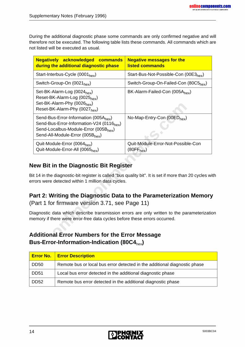
During the additional diagnostic phase some commands are only confirmed negative and willtherefore not be executed. The following table lists these commands. All commands which arenot listed will be executed as usual.
New Bit in the Diagnostic Bit Register
Bit 14 in the diagnostic-bit register is called "bus quality bit". It is set if more than 20 cycles witherrors were detected within 1 million data cycles.
Part 2: Writing the Diagnostic Data to the Parameterization Memory(Part 1 for firmware version 3.71, see Page 11)
Diagnostic data which describe transmission errors are only written to the parameterizationmemory if there were error-free data cycles before these errors occurred.
Additional Error Numbers for the Error MessageBus-Error-Information-Indication (80C4hex)
Negatively acknowledged commandsduring the additional diagnostic phase
Negative messages for the listed commands
Start-Interbus-Cycle (0001hex) Start-Bus-Not-Possible-Con (00E3hex)
Switch-Group-On (0021hex) Switch-Group-On-Failed-Con (80C5hex)
Set-BK-Alarm-Log (0024hex)Reset-BK-Alarm-Log (0025hex)Set-BK-Alarm-Phy (0026hex) Reset-BK-Alarm-Phy (0027hex)
BK-Alarm-Failed-Con (005Ahex)
Send-Bus-Error-Information (005Ahex)Send-Bus-Error-Information-V24 (0116hex)Send-Localbus-Module-Error (005Bhex)Send-All-Module-Error (005Bhex)
No-Map-Entry-Con (00EDhex)
Quit-Module-Error (0064hex)Quit-Module-Error-All (0065hex)
Quit-Module-Error-Not-Possible-Con(80FFhex)
Error No. Error Description
DD50 Remote bus or local bus error detected in the additional diagnostic phase
DD51 Local bus error detected in the additional diagnostic phase
DD52 Remote bus error detected in the additional diagnostic phase
onlinec
omponen
ts.co
m
Supplementary Notes (February 1996)
155003BC04
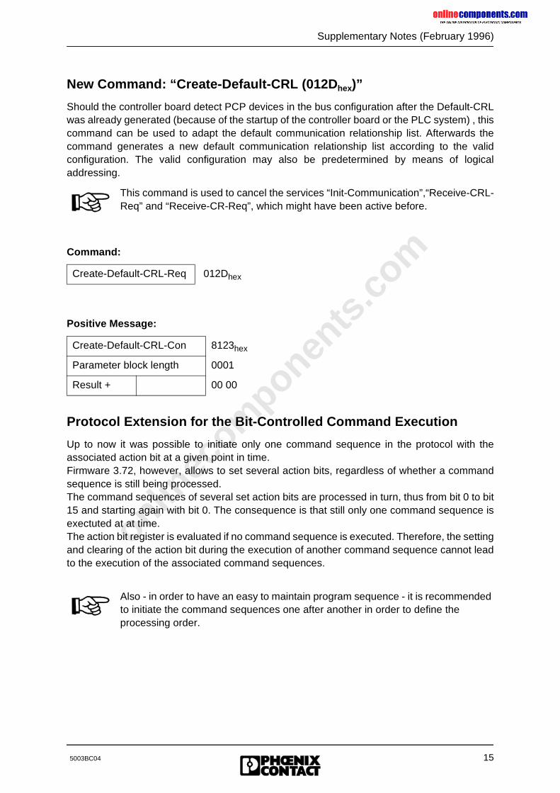
New Command: “Create-Default-CRL (012D hex)”
Should the controller board detect PCP devices in the bus configuration after the Default-CRLwas already generated (because of the startup of the controller board or the PLC system) , thiscommand can be used to adapt the default communication relationship list. Afterwards thecommand generates a new default communication relationship list according to the validconfiguration. The valid configuration may also be predetermined by means of logicaladdressing.
Protocol Extension for the Bit-Controlled Command Execution
Up to now it was possible to initiate only one command sequence in the protocol with theassociated action bit at a given point in time.Firmware 3.72, however, allows to set several action bits, regardless of whether a commandsequence is still being processed.The command sequences of several set action bits are processed in turn, thus from bit 0 to bit15 and starting again with bit 0. The consequence is that still only one command sequence isexectuted at at time.The action bit register is evaluated if no command sequence is executed. Therefore, the settingand clearing of the action bit during the execution of another command sequence cannot leadto the execution of the associated command sequences.
Command:
Create-Default-CRL-Req 012Dhex
Positive Message:
Create-Default-CRL-Con 8123hex
Parameter block length 0001
Result + 00 00
This command is used to cancel the services “Init-Communication”,“Receive-CRL-Req” and “Receive-CR-Req”, which might have been active before.
Also - in order to have an easy to maintain program sequence - it is recommended to initiate the command sequences one after another in order to define the processing order.
onlinec
omponen
ts.co
m
16
Supplementary Notes (February 1996)
5003BC04
New Firmware Revision V3.73 for the IBS S5 DCB (/I)-T Controller Board for SIMATIC S5 PLCs
Owing to functional extensions, technical improvements and corrections in the firmware, thereare some innovations for the IBS S5 DCB (/I)-T controller board for SIMATIC S5 PLCs.
Controller boards and documentation concerned:
Boards:IBS S5 DCB/I-T: Order No.: 27 58 15 6IBS S5 DCB-T: Order No.: 28 06 21 5
Firmware:- Previous version: 3.72- Update version: 3.73
Upgrade:A hardware upgrade with the update version is possible with:- Hardware version: IBS GB S5 9166835 C- Plug-on board type: MA5
The firmware can be updated as of: - Firmware version: 3.3x
User manuals:German: IBS S5 DCB UM (Order No.: 28 06 23 1)English: IBS S5 DCB UM E (Order No.: 27 58 36 3)
Changed Position of the Analysis Bit
When the firmware was updated to revision 3.73, the analysis bit in the diagnostic bit registerwas shifted from position 15 to position 13.
The request of analysis bit must be adapted in PLC programs that have previouslyused firmware 3.72 and this bit.
onlinec
omponen
ts.co
m
Supplementary Notes (February 1996)
175003BC04
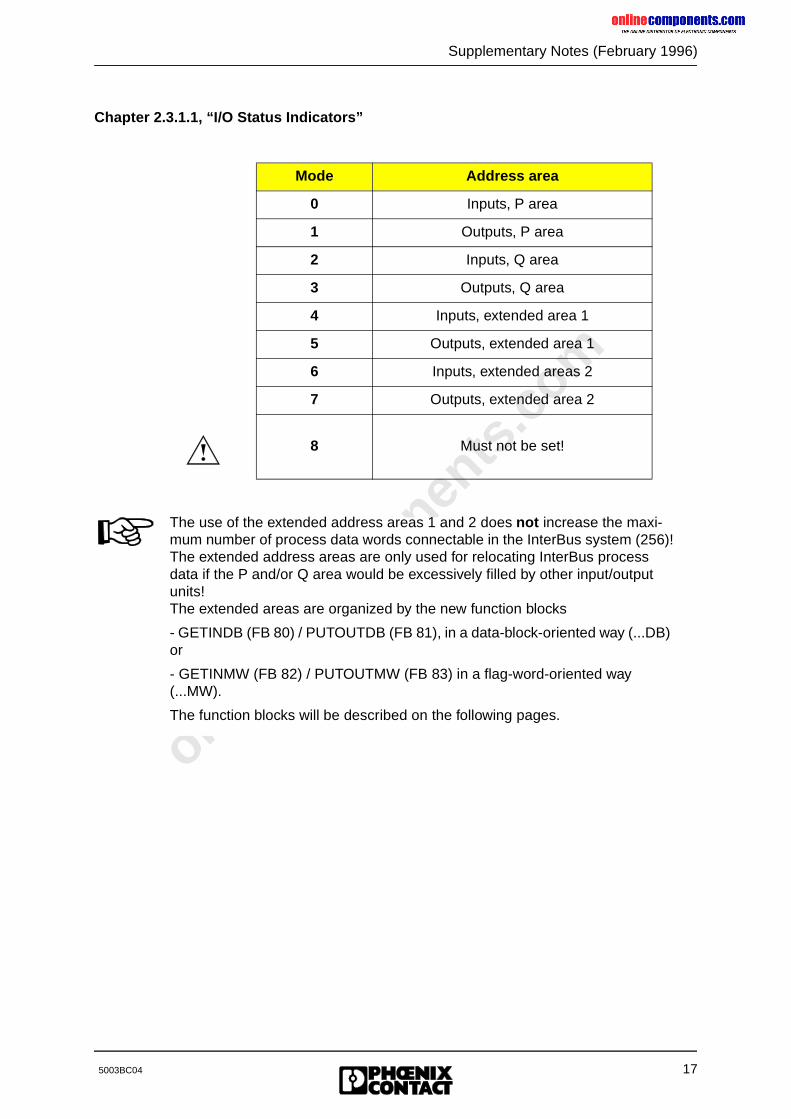
Chapter 2.3.1.1, “I/O Status Indicators”
Mode Address area
0 Inputs, P area
1 Outputs, P area
2 Inputs, Q area
3 Outputs, Q area
4 Inputs, extended area 1
5 Outputs, extended area 1
6 Inputs, extended areas 2
7 Outputs, extended area 2
8 Must not be set!
The use of the extended address areas 1 and 2 does not increase the maxi-mum number of process data words connectable in the InterBus system (256)!The extended address areas are only used for relocating InterBus process data if the P and/or Q area would be excessively filled by other input/output units!The extended areas are organized by the new function blocks
- GETINDB (FB 80) / PUTOUTDB (FB 81), in a data-block-oriented way (...DB) or
- GETINMW (FB 82) / PUTOUTMW (FB 83) in a flag-word-oriented way (...MW).
The function blocks will be described on the following pages.
onlinec
omponen
ts.co
m
18
Supplementary Notes (February 1996)
5003BC04
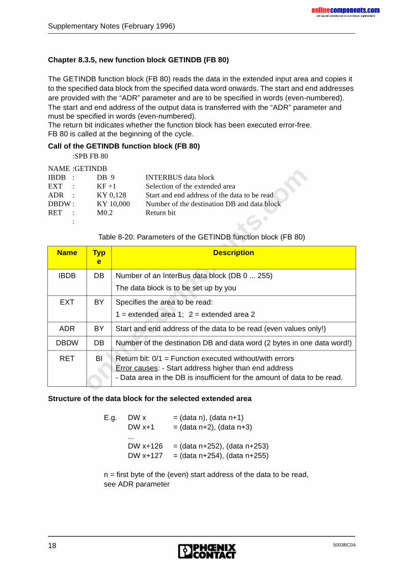
Chapter 8.3.5, new function block GETINDB (FB 80)
The GETINDB function block (FB 80) reads the data in the extended input area and copies it to the specified data block from the specified data word onwards. The start and end addresses are provided with the “ADR” parameter and are to be specified in words (even-numbered).The start and end address of the output data is transferred with the “ADR” parameter and must be specified in words (even-numbered).The return bit indicates whether the function block has been executed error-free.FB 80 is called at the beginning of the cycle.
Call of the GETINDB function block (FB 80):SPB FB 80
NAME :GETINDBIBDB : DB 9 INTERBUS data blockEXT : KF +1 Selection of the extended areaADR : KY 0,128 Start and end address of the data to be readDBDW : KY 10,000 Number of the destination DB and data blockRET : M0.2 Return bit
:
Structure of the data block for the selected extended area
E.g. DW x = (data n), (data n+1)DW x+1 = (data n+2), (data n+3)...DW x+126 = (data n+252), (data n+253)DW x+127 = (data n+254), (data n+255)
n = first byte of the (even) start address of the data to be read,see ADR parameter
Table 8-20: Parameters of the GETINDB function block (FB 80)
Name Type
Description
IBDB DB Number of an InterBus data block (DB 0 ... 255)
The data block is to be set up by you
EXT BY Specifies the area to be read:
1 = extended area 1; 2 = extended area 2
ADR BY Start and end address of the data to be read (even values only!)
DBDW DB Number of the destination DB and data word (2 bytes in one data word!)
RET BI Return bit: 0/1 = Function executed without/with errorsError causes: - Start address higher than end address- Data area in the DB is insufficient for the amount of data to be read.
onlinec
omponen
ts.co
m
Supplementary Notes (February 1996)
195003BC04
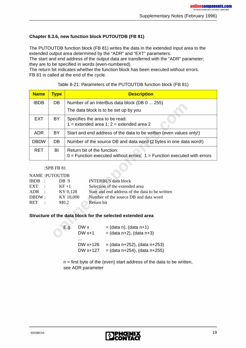
Chapter 8.3.6, new function block PUTOUTDB (FB 81)
The PUTOUTDB function block (FB 81) writes the data in the extended input area to the extended output area determined by the “ADR” and “EXT” parameters.The start and end address of the output data are transferred with the “ADR” parameter; they are to be specified in words (even-numbered).The return bit indicates whether the function block has been executed without errors.FB 81 is called at the end of the cycle.
:SPB FB 81
NAME :PUTOUTDBIBDB : DB 9 INTERBUS data blockEXT : KF +1 Selection of the extended areaADR : KY 0,128 Start and end address of the data to be writtenDBDW : KY 10,000 Number of the source DB and data wordRET : M0.2 Return bit
Structure of the data block for the selected extended area
E.g. DW x = (data n), (data n+1)DW x+1 = (data n+2), (data n+3)...DW x+126 = (data n+252), (data n+253)DW x+127 = (data n+254), (data n+255)
n = first byte of the (even) start address of the data to be written,see ADR parameter
Table 8-21: Parameters of the PUTOUTDB function block (FB 81)
Name Type Description
IBDB DB Number of an InterBus data block (DB 0 ... 255)
The data block is to be set up by you
EXT BY Specifies the area to be read:1 = extended area 1; 2 = extended area 2
ADR BY Start and end address of the data to be written (even values only!)
DBDW DB Number of the source DB and data word (2 bytes in one data word!)
RET BI Return bit of the function:0 = Function executed without errors; 1 = Function executed with errors
onlinec
omponen
ts.co
m
20
Supplementary Notes (February 1996)
5003BC04
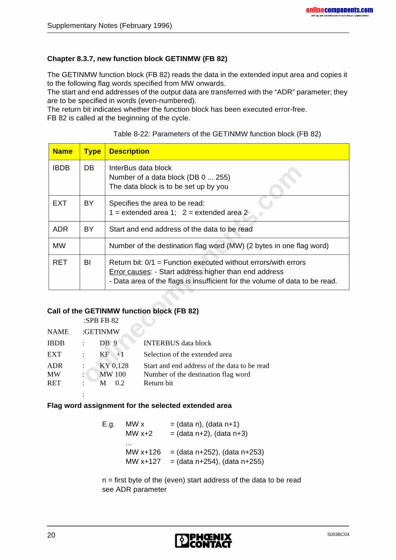
Chapter 8.3.7, new function block GETINMW (FB 82)
The GETINMW function block (FB 82) reads the data in the extended input area and copies it to the following flag words specified from MW onwards.The start and end addresses of the output data are transferred with the “ADR” parameter; they are to be specified in words (even-numbered).The return bit indicates whether the function block has been executed error-free.FB 82 is called at the beginning of the cycle.
Call of the GETINMW function block (FB 82):SPB FB 82
NAME :GETINMW
IBDB : DB 9 INTERBUS data block
EXT : KF +1 Selection of the extended area
ADR : KY 0,128 Start and end address of the data to be readMW : MW 100 Number of the destination flag word RET : M 0.2 Return bit
:
Flag word assignment for the selected extended area
E.g. MW x = (data n), (data n+1)MW x+2 = (data n+2), (data n+3)...MW x+126 = (data n+252), (data n+253)MW x+127 = (data n+254), (data n+255)
n = first byte of the (even) start address of the data to be readsee ADR parameter
Table 8-22: Parameters of the GETINMW function block (FB 82)
Name Type Description
IBDB DB InterBus data blockNumber of a data block (DB 0 ... 255)The data block is to be set up by you
EXT BY Specifies the area to be read:1 = extended area 1; 2 = extended area 2
ADR BY Start and end address of the data to be read
MW Number of the destination flag word (MW) (2 bytes in one flag word)
RET BI Return bit: 0/1 = Function executed without errors/with errorsError causes: - Start address higher than end address- Data area of the flags is insufficient for the volume of data to be read.
onlinec
omponen
ts.co
m
Supplementary Notes (February 1996)
215003BC04
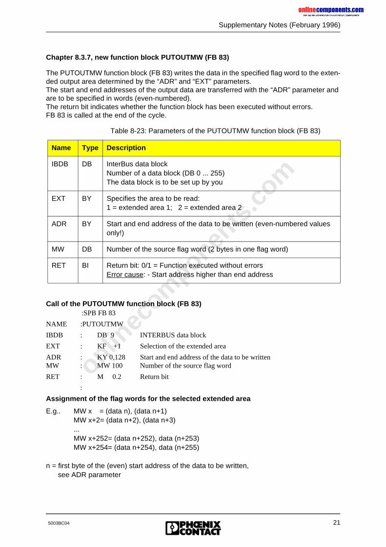
Chapter 8.3.7, new function block PUTOUTMW (FB 83)
The PUTOUTMW function block (FB 83) writes the data in the specified flag word to the exten-ded output area determined by the “ADR” and “EXT” parameters.The start and end addresses of the output data are transferred with the “ADR” parameter and are to be specified in words (even-numbered).The return bit indicates whether the function block has been executed without errors.FB 83 is called at the end of the cycle.
Call of the PUTOUTMW function block (FB 83):SPB FB 83
NAME :PUTOUTMW
IBDB : DB 9 INTERBUS data block
EXT : KF +1 Selection of the extended area
ADR : KY 0,128 Start and end address of the data to be writtenMW : MW 100 Number of the source flag word
RET : M 0.2 Return bit
:
Assignment of the flag words for the selected extended area
E.g.. MW x = (data n), (data n+1)MW x+2= (data n+2), (data n+3)...MW x+252= (data n+252), data (n+253)MW x+254= (data n+254), data (n+255)
n = first byte of the (even) start address of the data to be written,see ADR parameter
Table 8-23: Parameters of the PUTOUTMW function block (FB 83)
Name Type Description
IBDB DB InterBus data blockNumber of a data block (DB 0 ... 255)The data block is to be set up by you
EXT BY Specifies the area to be read:1 = extended area 1; 2 = extended area 2
ADR BY Start and end address of the data to be written (even-numbered values only!)
MW DB Number of the source flag word (2 bytes in one flag word)
RET BI Return bit: 0/1 = Function executed without errorsError cause: - Start address higher than end address
onlinec
omponen
ts.co
m
22
Supplementary Notes (February 1996)
5003BC04
New Firmware Revision V3.75 for the SIMATIC S5 Controller Board IBS S5 DCB (/I)-T
Owing to technical improvements of the hardware and the resulting adaptation of the firmware, a new firmware revision, V3.75, has been introduced for the SIMATIC S5 controller boards IBS S5 DCB (/I)-T.
Controller boards and documentation concerned:
Boards:IBS S5 DCB/I-T: Order No.: 27 58 15 6IBS S5 DCB-T: Order No.: 28 06 21 5
Firmware:- Previous version: 3.73- Update version: 3.75- Revision marking: 13/375 (sticker at the lower edge of the front plate)
onlinec
omponen
ts.co
m
Contents
5003B i
Table of Contents
1 System Overview ...............................................................................1-1
1.1 Networking with INTERBUS-S...................................................................... 1-1
1.2 INTERBUS-S Topology ................................................................................ 1-21.2.1 General Method of Operation ....................................................................... 1-31.2.2 Error Protection Mechanisms ....................................................................... 1-41.2.3 INTERBUS-S Protocol Sequence................................................................. 1-51.2.4 INTERBUS-S Scan Time Calculation ........................................................... 1-61.2.5 Basic System Specifications......................................................................... 1-10
1.3 System Components .................................................................................... 1-111.3.1 Host Controller Board................................................................................... 1-111.3.2 Remote Bus ................................................................................................. 1-121.3.3 Installation Remote Bus................................................................................ 1-131.3.4 Bus Terminal Module.................................................................................... 1-151.3.5 Local Bus ..................................................................................................... 1-161.3.6 INTERBUS-S I/O Modules ........................................................................... 1-181.3.6.1 Remote Bus and Installation Remote Bus Modules...................................... 1-181.3.6.2 Local Bus Modules ....................................................................................... 1-18
2 Technical Description........................................................................2-1
2.1 Host Controller Board Method of Operation.................................................. 2-1
2.2 Application Area of the Host Controller Board .............................................. 2-2
2.3 Overview ...................................................................................................... 2-32.3.1 Front Plate Components............................................................................... 2-42.3.1.1 I/O Status Indicators..................................................................................... 2-52.3.1.2 Operating Indicators ..................................................................................... 2-62.3.1.3 Error Indicators............................................................................................. 2-72.3.1.4 Interfaces ..................................................................................................... 2-72.3.2 Controller Board Components ...................................................................... 2-8
2.4 Host Controller Board Installation ................................................................. 2-92.4.1 Slot Allocation and Installation...................................................................... 2-9
2.5 Configuration of the Controller Board ........................................................... 2-112.5.1 PLC Address Area........................................................................................ 2-112.5.2 Hardware Term Definitions .......................................................................... 2-122.5.3 Configuring the Default Setting..................................................................... 2-13
onlinec
omponen
ts.co
m
Contents
ii 5003B
2.6 Hardware Settings........................................................................................ 2-192.6.1 Mounting Positions of the Jumpers............................................................... 2-192.6.2 Operation in the Central Controller and Controller Expansion Unit ............... 2-202.6.3 Startup and Operating Mode Selection......................................................... 2-212.6.3.1 INTERBUS-S in the PLC’s Address Area ..................................................... 2-252.6.3.2 Address Locations for Automatic Start in the DCB Mode.............................. 2-262.6.3.3 Address Locations for Controlled Start in the DCB Mode ............................. 2-272.6.3.4 Address Locations for Automatic Start in the DAB Mode.............................. 2-282.6.3.5 Address Locations for Controlled Start in the DAB Mode ............................. 2-292.6.4 Address Windows......................................................................................... 2-302.6.5 Interrupt Processing ..................................................................................... 2-362.6.5.1 Settings for Interrupt Processing .................................................................. 2-362.6.5.2 Different Interrupt Sources ........................................................................... 2-382.6.6 Acknowledgment Delay Message ................................................................ 2-382.6.7 Disconnecting the RESET Button................................................................. 2-39
2.7 Data Sheet ................................................................................................... 2-40
3 User Interfaces ...................................................................................3-1
3.1 ID Code of the Modules................................................................................ 3-3
3.2 Process Data Interface................................................................................. 3-83.2.1 Example Configuration .............................................................................. 3-93.2.2 Order of the Modules on the Bus ............................................................... 3-11
3.3 Physical Addressing (DCB Mode)................................................................. 3-123.3.1 Function..................................................................................................... 3-123.3.2 Addressing................................................................................................. 3-123.3.3 Address Orientation ................................................................................... 3-14
3.4 Logical Addressing (DCB Mode) .................................................................. 3-173.4.1 Function..................................................................................................... 3-173.4.2 Structure of an INTERBUS-S Address List ................................................ 3-183.4.3 Addressing................................................................................................. 3-19
3.5 Access to INTERBUS-S Modules................................................................. 3-233.5.1 Digital Modules with 16 Inputs ................................................................... 3-243.5.2 LC Modules with 16 Digital Inputs.............................................................. 3-253.5.3 Digital Modules with 32 Inputs ................................................................... 3-263.5.4 Digital Modules with 16 Outputs................................................................. 3-273.5.5 LC Modules with 16 Digital Outputs ........................................................... 3-283.5.6 Digital Modules with 32 Outputs................................................................. 3-293.5.7 Digital Modules with 16 Inputs and 16 Outputs .......................................... 3-303.5.8 Four-Channel Analog-Input Module with Programmable Gain ................... 3-313.5.9 Four-Channel Analog-Output Modules....................................................... 3-343.5.10 Relais Modules .......................................................................................... 3-363.5.11 Communication Interface Boards............................................................... 3-373.5.12 Modules for Thermocouples ...................................................................... 3-38
onlinec
omponen
ts.co
m
Contents
5003B iii
4 Diagnostic Interfaces.........................................................................4-1
4.1 Diagnostics on the Controller Board’s Front Plate ........................................ 4-24.1.1 Operating Indicators .................................................................................. 4-44.1.2 Error Indication .......................................................................................... 4-54.1.3 Error Codes for Controller Errors (CTRL) .................................................. 4-8
4.2 Notes on Error Diagnostics........................................................................... 4-114.2.1 Indication of Errors on the Front Plate ....................................................... 4-124.2.2 Example of a System Documentation ........................................................ 4-19
4.3 Diagnostic Registers .................................................................................... 4-234.3.1 Diagnostic Bit Register .............................................................................. 4-234.3.2 Diagnostic Parameter Register .................................................................. 4-234.3.3 Diagnostic Register Locations ................................................................... 4-24
4.4 I/O Status Indicators..................................................................................... 4-26
4.5 Startup and Acknowledgment Displays ........................................................ 4-284.5.1 Host Controller Board Startup.................................................................... 4-284.5.2 Acknowledgment after an Error ................................................................. 4-29
4.6 Diagnostics on the Modules.......................................................................... 4-304.6.1 Diagnostic Functions on I/O Modules ........................................................ 4-314.6.2 Diagnostic Functions on Bus Terminal Modules ........................................ 4-324.6.3 Diagnostics on Third-Party Devices ........................................................... 4-32
4.7 Using the Hand Held Monitor........................................................................ 4-33
4.8 Using the Monitor Program for INTERBUS-S on the PC .............................. 4-34
4.9 CTRL Error Displays..................................................................................... 4-354.9.1 List of Errors .............................................................................................. 4-36
5 System Interfaces ..............................................................................5-1
5.1 Interface Description .................................................................................... 5-15.1.1 Interface Function......................................................................................... 5-25.1.2 Interface Classification ................................................................................. 5-3
5.2 Command and Message Structure ............................................................... 5-45.2.1 Structure of Commands and Messages ....................................................... 5-4
5.3 Interface Description .................................................................................... 5-55.3.1 ISFP ............................................................................................................. 5-55.3.1.1 Program Structure ........................................................................................ 5-65.3.1.2 INTERBUS-S System Control ...................................................................... 5-85.3.1.3 Function Overview........................................................................................ 5-105.3.2 Bit-Controlled Command Execution.............................................................. 5-135.3.2.1 Description ................................................................................................... 5-135.3.2.2 Access to the Bit-Controlled Command Sequences ..................................... 5-135.3.3 IBS SYS SWT .............................................................................................. 5-165.3.3.1 Description ................................................................................................... 5-165.3.3.2 Commands................................................................................................... 5-18
onlinec
omponen
ts.co
m
Contents
iv 5003B
6 Startup ................................................................................................6-1
6.1 Introduction .................................................................................................. 6-16.1.1 General Information About Physical Addressing........................................... 6-16.1.2 General Information About Logical Addressing ............................................ 6-26.1.3 Modes of Operation...................................................................................... 6-26.1.4 Startup Behavior........................................................................................... 6-36.1.5 Acknowledgment Behavior ........................................................................... 6-4
6.2 Hardware Setting.......................................................................................... 6-5
6.3 Software Setting ........................................................................................... 6-6
7 Installation..........................................................................................7-1
7.1 Slots for the Controller Board ....................................................................... 7-1
7.2 Cable Installation.......................................................................................... 7-2
7.3 Pin Assignment of the Hardware Interfaces.................................................. 7-37.3.1 System Connector........................................................................................ 7-47.3.2 Remote Bus Interface................................................................................... 7-57.3.3 Serial Interface (V.24/RS-232) ................................................................... 7-67.3.4 Ordering Information .................................................................................... 7-8
8 ISFP.....................................................................................................8-1
8.1 Interface Description .................................................................................... 8-18.1.1 Program Structure ..................................................................................... 8-28.1.2 Inclusion of the Interface Drivers ............................................................... 8-58.1.2.1 INITIB (FB 60) .......................................................................................... 8-68.1.2.2 CON/IND .................................................................................................. 8-108.1.2.3 REQ/RES ................................................................................................. 8-128.1.2.4 INTERBUS Data Block (IBDB).................................................................. 8-148.1.3 INTERBUS-S System Control.................................................................... 8-168.1.3.1 Structure of the Functions......................................................................... 8-188.1.3.2 Overview of Functions .............................................................................. 8-20
8.2 Command Functions .................................................................................... 8-248.2.1 CONTROL (FB 68) .................................................................................... 8-248.2.1.1 Configure INTERBUS-S (FKT 0)............................................................... 8-268.2.1.2 Start INTERBUS-S Cycle (FKT 1)............................................................. 8-268.2.1.3 Stop InterBus-S Cycle (FKT 2) ................................................................. 8-268.2.1.4 Alarm Stop (FKT 3)................................................................................... 8-268.2.1.5 Clear Display (FKT 4) ............................................................................... 8-268.2.1.6 Disable All Messages (FKT 5)................................................................... 8-278.2.1.7 Implement All Logical Address Map (FKT 6)............................................. 8-278.2.1.8 Init Communication (FKT 7) ...................................................................... 8-278.2.1.9 INTERBUS-S Delay (FKT 8) ..................................................................... 8-278.2.1.10 Quit Module Error All (FKT 9) ................................................................... 8-27
onlinec
omponen
ts.co
m
Contents
5003B v
8.2.2 DEFINE (FB 69) ........................................................................................ 8-288.2.2.1 Physical Configuration Map (FKT 0) ......................................................... 8-308.2.2.2 Logical Local Bus Address Map (FKT 1)................................................... 8-318.2.2.3 Logical IN Address Map (FKT 2)............................................................... 8-328.2.2.4 Logical OUT Address Map (FKT 3)........................................................... 8-338.2.2.5 Communication Reference (FKT 4) .......................................................... 8-348.2.2.6 Event Map (FKT 5) ................................................................................... 8-358.2.2.7 Group Numbers (FKT 6) ........................................................................... 8-378.2.2.8 Parameter Timeout Constant (FKT 7) ....................................................... 8-388.2.2.9 Receive KBL (FKT 8)................................................................................ 8-398.2.2.10 Receive Bit Manipulation (FKT 9) ............................................................. 8-418.2.2.11 Group Error Characteristics (FKT 10) ....................................................... 8-508.2.2.12 Quit Module Error (FKT 11) ...................................................................... 8-528.2.3 SYSINFO (FB 70) ...................................................................................... 8-538.2.3.1 Physical Configuration Map (FKT 0) ......................................................... 8-558.2.3.2 Software Revision (FKT 1)........................................................................ 8-558.2.3.3 Switch Information (FKT 2) ....................................................................... 8-568.2.3.4 INTERBUS-S Cycle Counter (FKT 3)........................................................ 8-568.2.3.5 Logical Address Error (FKT 4) .................................................................. 8-578.2.4 ON/OFF (FB 71) ........................................................................................ 8-588.2.4.1 Group ON (FKT 0) .................................................................................... 8-608.2.4.2 Group OFF (FKT 1) .................................................................................. 8-608.2.4.3 BK-Alarm ON (FKT 2)............................................................................... 8-608.2.4.4 BK-Alarm OFF (FKT 3) ............................................................................. 8-618.2.4.5 Event ON (FKT 4) ..................................................................................... 8-618.2.4.6 Event OFF (FKT 5) ................................................................................... 8-618.2.5 ADDRESS (FB 72) .................................................................................... 8-628.2.5.1 ID Code List.............................................................................................. 8-668.2.5.2 Bus Segment Address List........................................................................ 8-678.2.5.3 IN Address List ......................................................................................... 8-688.2.5.4 OUT Address List ..................................................................................... 8-698.2.5.5 Group No. List .......................................................................................... 8-708.2.5.6 Group Error Characteristics ...................................................................... 8-728.2.5.7 Communication Reference List ................................................................. 8-738.2.6 ERRINFO (FB 74)...................................................................................... 8-748.2.6.1 Controller Error Code (FKT 0)................................................................... 8-768.2.6.2 Bus Information (FKT 1) ........................................................................... 8-768.2.6.3 Defective Group (FKT 2)........................................................................... 8-778.2.6.4 Module Error (FKT 3)................................................................................ 8-788.2.6.5 Local Bus Module Error (FKT 4) ............................................................... 8-79
8.3 Message Functions ...................................................................................... 8-808.3.1 SYSERROR (FB 73).................................................................................. 8-808.3.2 RECONFIG (FB 75)................................................................................... 8-828.3.3 EVENT (FB 76).......................................................................................... 8-83
8.4 Working with Communication ....................................................................... 8-848.4.1 Introduction................................................................................................ 8-848.4.1.1 Control During Communication................................................................. 8-868.4.1.2 Call Structure of the Function Blocks ........................................................ 8-868.4.1.3 Initialization/Addressing ............................................................................ 8-878.4.1.4 Service Structure ...................................................................................... 8-898.4.1.5 Service Execution ..................................................................................... 8-908.4.1.6 Activation Flag Service ............................................................................. 8-908.4.1.7 Message Flag Service .............................................................................. 8-92
onlinec
omponen
ts.co
m
Contents
vi 5003B
8.4.1.8 Principal Service Sequence ...................................................................... 8-948.4.1.9 Example of a Service................................................................................ 8-968.4.2 Request/Confirmation ................................................................................ 8-978.4.2.1 Read Request........................................................................................... 8-1008.4.2.2 Write Request........................................................................................... 8-1008.4.2.3 Start Request............................................................................................ 8-1008.4.2.4 Stop Request............................................................................................ 8-1008.4.2.5 Information Report Request...................................................................... 8-1018.4.2.6 Status Request ......................................................................................... 8-1018.4.2.7 Identify Request........................................................................................ 8-1018.4.2.8 Initiate Request......................................................................................... 8-1018.4.2.9 Abort Request........................................................................................... 8-1028.4.2.10 Read Confirmation.................................................................................... 8-1028.4.2.11 Write Confirmation .................................................................................... 8-1028.4.2.12 Start Confirmation..................................................................................... 8-1038.4.2.13 Stop Confirmation ..................................................................................... 8-1038.4.2.14 Status Confirmation .................................................................................. 8-1038.4.2.15 Identify Confirmation................................................................................. 8-1048.4.2.16 Initiate Confirmation.................................................................................. 8-1048.4.2.17 Initiate Error Confirmation......................................................................... 8-1048.4.3 Response/Indication .................................................................................. 8-1068.4.3.1 Abort Indication......................................................................................... 8-1068.4.3.2 Reject Indication ....................................................................................... 8-1068.4.3.3 Start Indication.......................................................................................... 8-1068.4.3.4 Stop Indication.......................................................................................... 8-1068.4.3.5 Information Report Indication.................................................................... 8-1078.4.3.6 Read Indication......................................................................................... 8-1078.4.3.7 Write Indication......................................................................................... 8-1078.4.3.8 Initiate Indication....................................................................................... 8-1088.4.3.9 Read Response........................................................................................ 8-1088.4.3.10 Write Response ........................................................................................ 8-1088.4.3.11 Start Response......................................................................................... 8-1098.4.3.12 Stop Response ......................................................................................... 8-1098.4.4 Application of Communication ................................................................... 8-1108.4.5 Communication Error Messages................................................................ 8-1138.4.5.1 Error Messages for a Connection Abort .................................................... 8-1138.4.5.2 Error Messages for the Reject Service ..................................................... 8-1158.4.5.3 Additional Error Messages........................................................................ 8-1168.4.5.4 Description of the Service-Specific Error Messages ................................. 8-116
9 Commands and Messages................................................................9-1
9.1 Controller Board Commands ....................................................................... 9-59.1.1 Commands for Bus Operation ................................................................... 9-69.1.2 Commands for Configuration ..................................................................... 9-99.1.3 Commands for Error Recovery .................................................................. 9-189.1.4 Commands for System Control.................................................................. 9-249.1.5 Commands for Addressing ........................................................................ 9-259.1.6 Commands for Process Data Linkage ....................................................... 9-279.1.7 Commands for Event Processing .............................................................. 9-349.1.8 Commands for Communication ................................................................. 9-389.1.9 Commands for the EEPROM Management ............................................... 9-38
onlinec
omponen
ts.co
m
Contents
5003B vii
9.2 Controller Board Messages ......................................................................... 9-409.2.1 Messages of the User Interface ................................................................. 9-419.2.2 Messages for Bus Operation ..................................................................... 9-419.2.3 Messages for Configuration ....................................................................... 9-439.2.4 Messages for Error Recovery .................................................................... 9-499.2.5 Messages for System Control.................................................................... 9-609.2.6 Messages for Addressing .......................................................................... 9-619.2.7 Messages for Process Data Linkage ......................................................... 9-639.2.8 Messages for Event Processing ................................................................ 9-659.2.9 Messages for Communication ................................................................... 9-669.2.10 Messages for the EEPROM Management ................................................. 9-67
10 Appendix.........................................................................................................10-1
10.1 Overview of the DCB Revisions.............................................................................. 10-1
10.2 Technical Data........................................................................................................ 10-5
10.3 Contents of the Data Diskette ................................................................................. 10-6
Figures
Tables
Index
onlinec
omponen
ts.co
m
5003B
Chapter 1
System OverviewThis chapter provides information on
- the INTERBUS-S system and its components- the basic INTERBUS-S system specifications- the specific terms of the INTERBUS-S system
1 System Overview ...............................................................................1-1
1.1 Networking with INTERBUS-S...................................................................... 1-1
1.2 INTERBUS-S Topology ................................................................................ 1-21.2.1 General Method of Operation ....................................................................... 1-31.2.2 Error Protection Mechanisms ....................................................................... 1-41.2.3 INTERBUS-S Protocol Sequence................................................................. 1-51.2.4 INTERBUS-S Scan Time Calculation ........................................................... 1-61.2.5 Basic System Specifications......................................................................... 1-10
1.3 System Components .................................................................................... 1-111.3.1 Host Controller Board................................................................................... 1-111.3.2 Remote Bus ................................................................................................. 1-121.3.3 Installation Remote Bus................................................................................ 1-131.3.4 Bus Terminal Module.................................................................................... 1-151.3.5 Local Bus ..................................................................................................... 1-161.3.6 INTERBUS-S I/O Modules ........................................................................... 1-181.3.6.1 Remote Bus and Installation Remote Bus Modules...................................... 1-181.3.6.2 Local Bus Modules ....................................................................................... 1-18
onlinec
omponen
ts.co
m
1 System Overview
5003B 1-1
1 System Overview
INTERBUS-S, the high-speed and universal sensor/actuator bus system.
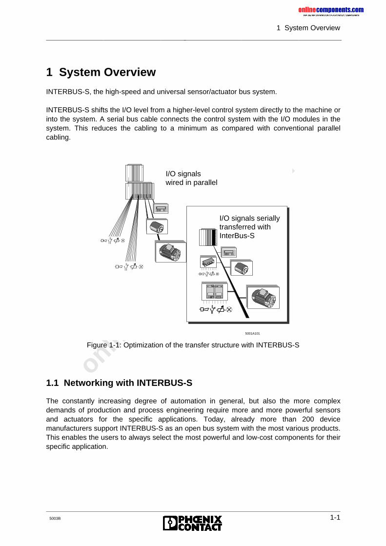
INTERBUS-S shifts the I/O level from a higher-level control system directly to the machine orinto the system. A serial bus cable connects the control system with the I/O modules in thesystem. This reduces the cabling to a minimum as compared with conventional parallelcabling.
Figure 1-1: Optimization of the transfer structure with INTERBUS-S
1.1 Networking with INTERBUS-S
The constantly increasing degree of automation in general, but also the more complexdemands of production and process engineering require more and more powerful sensorsand actuators for the specific applications. Today, already more than 200 devicemanufacturers support INTERBUS-S as an open bus system with the most various products.This enables the users to always select the most powerful and low-cost components for theirspecific application.
5001A101
IN
TE
RB
US
-S
I/O signalswired in parallel
I/O signals seriallytransferred withInterBus-S
onlinec
omponen
ts.co
m
1 System Overview
1-2 5003B
Overview of INTERBUS-S-compatible devices
- Host controller boards/interface boards forprogrammable logic controllers (PLC)industrial computers and/or PCs
- I/O units fordigital inputs/outputsanalog inputs/outputsdegrees of protection - IP 20 - IP 65
- High-tech control systems forautomatic wrenchingpositioningrobots
- DrivesDRIVECOM standardgeneral motion control
- Pneumatic valve terminals
- Encoders
- Identification systems
- Operator and display units
- Further devices with INTERBUS-S interface are in preparation.
1.2 INTERBUS-S Topology
INTERBUS-S is installed in the system as a compact single circuit line following onedirection. Starting at the host controller board, the bus system connects the respectivecontrol or computer systems with the distributed I/O modules (INTERBUS-S modules).
The main line that is led through the plant is called remote bus and covers the distancesbetween the distributed substations.
Local branches (spur lines) are possible from the remote bus. Depending on the type, theyare either called installations remote bus or local bus.
onlinec
omponen
ts.co
m
1 System Overview
5003B 1-3
The installation remote bus corresponds - according to its structure - to the remote bus.However, it provides the option to carry along a voltage supply for the sensors in the buscable (hybrid cable design).At the beginning of the installation remote bus there is always a CBK module. Theinstallation remote bus may be set up with CDI, CDO, DIO and all remote bus modules.The installation remote bus has been designed to install distributed sub-stations with adirect connection of sensors and actuators. This results in an optimally short and low-costsensor/actuator connection.
The local bus has been designed for the cost-effective and flexible installation ofdecentralized cabinets and terminal boxes. It interconnects the various local bus modulesand also establishes the connection to the bus terminal module (BK).
The bus terminal module (BK) connects the local bus to the remote bus.
1.2.1 General Method of Operation
The INTERBUS-S system is a data ring with a central master-slave access method. It hasthe structure of a spatially distributed shift register. Every module forms with its registers apart of this shift register, through which the master, i.e. the host controller board, clocks thedata serially.With the ring structure it is possible to send and receive data synchronously (full duplex).To simplify system installation, the ring system is implemented in one cable line.Because of this, the system appears like a bus system with branching spur lines (simplifiedtree structure).Every station in the INTERBUS-S system has an ID register (IDentification register) whichincludes information such as module type, number of I/O registers, as well as statuses anderror states. The I/O modules also have I/O registers for the process data transmission.
There are two types of cycles in an INTERBUS-S system:
- The ID cycle which is run upon request or to initialize the INTERBUS-S system. When thehost controller board is in the ID cycle it reads out the ID registers of all modules and usesthis information to generate the process image.
- The data cycle is the actual operating cycle which controls the data transfer. In the datacycle, input data of all modules is read out of the registers and output data is shifted from thehost controller board to the modules.
Special test methods ensure a correct data transmission after every cycle.
- If no errors occurred during the data transmission the host controller board accepts thedata and/or outputs the data on the modules.
- If an error occurred, the data of the erroneous cycle is rejected because a new cycle iscompleted faster than the correction of corrupted data.
onlinec
omponen
ts.co
m
1 System Overview
1-4 5003B
1.2.2 Error Protection Mechanisms
As a sensor/actuator bus the INTERBUS-S system has been designed for the use inindustrial environments.In order to ensure a secure data transmission under the most various conditions of anindustrial field of application, the INTERBUS-S system features extensive protectionmechanisms.The following precautionary measures ensure a safe data transmission:
Differential signal transfer in accordance with RS-485The transfer in accordance with RS-485 uses a twisted-wire pair. User data is sent over bothlines of a pair as differential signals. This transfer method can be strongly affected byinfluences from the outside and is used on the remote bus line and the installation remotebus.
Remote bus checkThe individual remote bus segments are checked by exchanging special status information.An interrupt of the line or a connector which is not fitted properly causes a remote bus errorRB ERR and the ’RC’ LED on the remote bus module goes out.
Loopback wordThe controller board clocks this word ahead of the data through the ring (bus). Thus, theloopback word is transferred directly between the input and output data through allINTERBUS-S system modules and after the input data back to the controller board. The timerequired for the loopback word to make a complete cycle is known to and monitored by thecontroller board. The special bit sequence of the loopback word detects errors on thetransmission path or in the modules.
CRCEvery transmission path between two modules in the INTERBUS-S system is checked bymeans of a CRC (Cyclic Redundancy Check).For this purpose, a CRC word is calculated both in the output direction as well as in the inputdirection in every module and in the controller board itself. At the end of every transmissioncycle it is checked at the beginning and at the end of a transmission path if the values of thecheck words match. If the values do not match, this will be reported to the controller boardthrough all following modules and a new cycle is started with current data.A Hamming distance of 4 is reached with this check.
Test routinesIn order to detect hardware faults on the INTERBUS-S host controller board, various testroutines are executed after a RESET or a voltage recovery.These special routines check:
- the CPU of the INTERBUS-S protocol chip,- the EPROM and RAM,- the logic circuitries and functions of the various components.
onlinec
omponen
ts.co
m
1 System Overview
5003B 1-5
After error-free execution of the test routines, the green LED READY lights up.Furthermore, the connected INTERBUS-S system is initialized and its functions are checked.To this end, the controller board activates one bus segment after another and tests thefunctioning of each.First, the connection between the host controller board and the first bus terminal module orthe first remote bus module is enabled. When no errors occur, a local bus or installationremote bus which is connected to the bus terminal is initialized. Afterwards, the connectionto the next remote bus station is enabled. In this way all segments of an INTERBUS-Ssystem are put into operation sequentially and bit by bit. After this configuration phase thehost controller board knows the connected INTERBUS-S system and can operate it.This configuration algorithm is also used to locate the error if a malfunction occurs in thecourse of normal data traffic.
1.2.3 INTERBUS-S Protocol Sequence
- Starting with a loopback word, the controller board clocks the output data in the outputdirection into the data ring of the INTERBUS-S system. At the same time the controllerboard receives in the input direction the input data which has previously been stored in thedata ring by the INTERBUS-S modules.
- The loopback word is transferred between the output and input data through the entire dataring, which is formed by all system modules. When the controller board receives theloopback word, all output data is in the ring and all input data is in the controller board.
- The checksums calculated by the CRC generators are transferred to the next modulewhere they are checked.
- When the loopback word is read back correctly and the comparison of the checksumsresulted in an error-free transfer on all bus lines, the output data becomes valid and themodules put the data to their outputs. The controller board also passes the read input datato the PLC for processing.
- Afterwards the controller board causes the modules to store all new input data in the ring,before it clocks a new loopback word and new output data into the data ring.
- Due to the cyclic run of the INTERBUS-S protocol all I/O data is constantly updated.
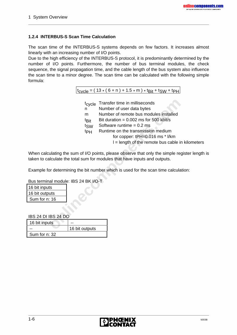
onlinec
omponen
ts.co
m
1 System Overview
1-6 5003B
1.2.4 INTERBUS-S Scan Time Calculation
The scan time of the INTERBUS-S systems depends on few factors. It increases almostlinearly with an increasing number of I/O points.Due to the high efficiency of the INTERBUS-S protocol, it is predominantly determined by thenumber of I/O points. Furthermore, the number of bus terminal modules, the checksequence, the signal propagation time, and the cable length of the bus system also influencethe scan time to a minor degree. The scan time can be calculated with the following simpleformula:
tcycle Transfer time in millisecondsn Number of user data bytesm Number of remote bus modules installedtBit Bit duration = 0.002 ms for 500 kbit/stSW Software runtime = 0.2 mstPH Runtime on the transmission medium
for copper: tPH=0.016 ms * l/kml = length of the remote bus cable in kilometers
When calculating the sum of I/O points, please observe that only the simple register length istaken to calculate the total sum for modules that have inputs and outputs.
Example for determining the bit number which is used for the scan time calculation:
Bus terminal module: IBS 24 BK I/O-T16 bit inputs16 bit outputs Sum for n: 16
IBS 24 DI IBS 24 DO 16 bit inputs -- -- 16 bit outputs Sum for n: 32
tcycle = ( 13 * ( 6 + n ) + 1.5 * m ) * tBit + tSW + tPH
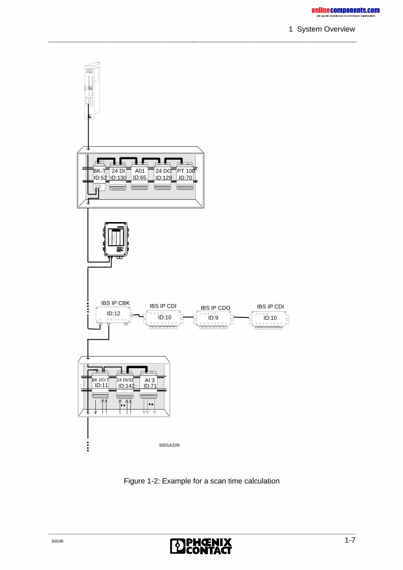
onlinec
omponen
ts.co
m
1 System Overview
5003B 1-7
Figure 1-2: Example for a scan time calculation
5001A1085001A109
BK-T 24 DIID:52 ID:130
A01ID:65
24 DOID:129
PT 100ID:70
IBS IP CBK IBS IP CDI IBS IP CDO IBS IP CDIID:12
ID:9
BK I/O-T 24 DI/32 AI 3ID:11 ID:142 ID:71
X2 X3
ID:10 ID:10
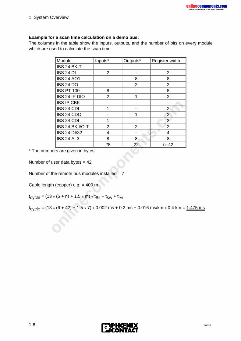
onlinec
omponen
ts.co
m
1 System Overview
1-8 5003B
Example for a scan time calculation on a demo bus:The columns in the table show the inputs, outputs, and the number of bits on every modulewhich are used to calculate the scan time.
* The numbers are given in bytes.
Number of user data bytes = 42
Number of the remote bus modules installed = 7
Cable length (copper) e.g. = 400 m
tcycle = (13 * (6 + n) + 1.5 * m) * tBit + tsw + tPH
tcycle = (13 * (6 + 42) + 1.5 * 7) * 0.002 ms + 0.2 ms + 0.016 ms/km * 0.4 km = 1.475 ms
Module Inputs* Outputs* Register widthIBS 24 BK-T - - -IBS 24 DI 2 - 2IBS 24 AO1 - 8 8IBS 24 DO - 2 2IBS PT 100 8 -- 8IBS 24 IP DIO 2 1 2IBS IP CBK - -- -IBS 24 CDI 1 -- 2IBS 24 CDO - 1 2IBS 24 CDI 1 -- 2IBS 24 BK I/O-T 2 2 2IBS 24 DI/32 4 -- 4IBS 24 AI 3 8 8 8
28 22 n=42

onlinec
omponen
ts.co
m
1 System Overview
5003B 1-9
Figure 1-3: INTERBUS-S topology with the various bus types
Local bus
Remote bus
Bus terminal IP 20
Bus terminal IP 65
Bus terminal IP 20
PLC
Host controllerboard
5001A1085001A108
Installation remote bus
Local bus
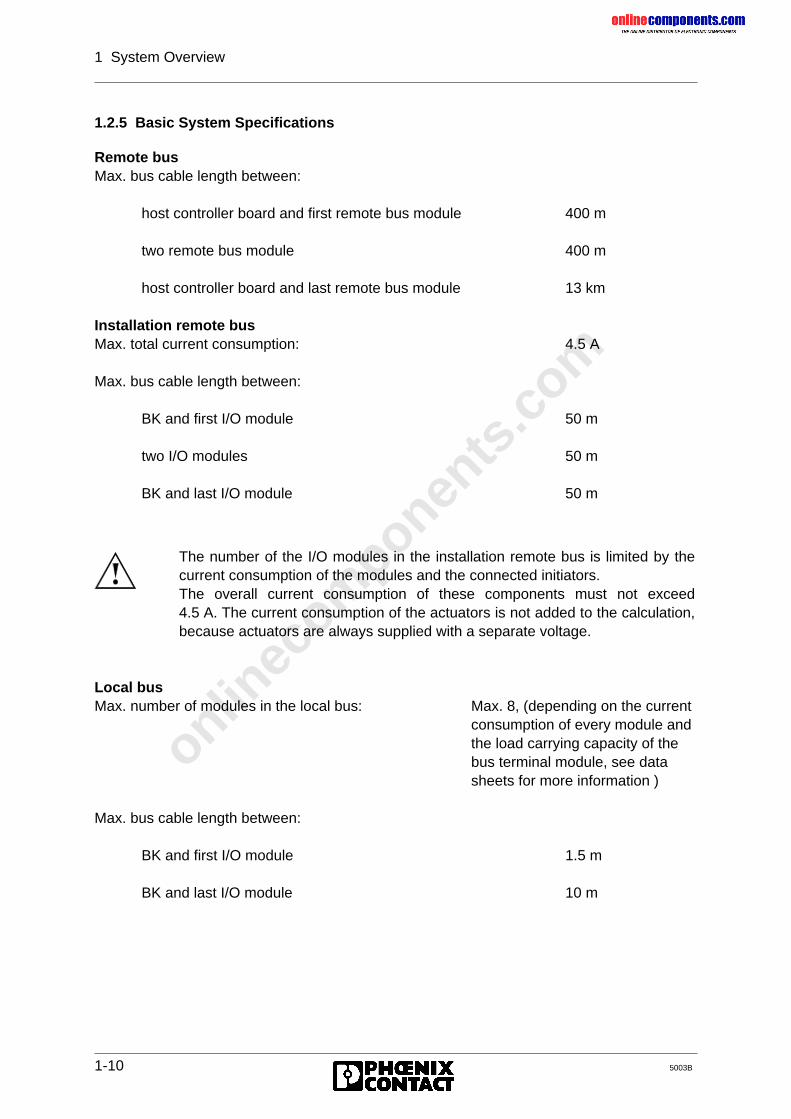
onlinec
omponen
ts.co
m
1 System Overview
1-10 5003B
1.2.5 Basic System Specifications
Remote busMax. bus cable length between:
host controller board and first remote bus module 400 m
two remote bus module 400 m
host controller board and last remote bus module 13 km
Installation remote busMax. total current consumption: 4.5 A
Max. bus cable length between:
BK and first I/O module 50 m
two I/O modules 50 m
BK and last I/O module 50 m
Local busMax. number of modules in the local bus: Max. 8, (depending on the current
consumption of every module andthe load carrying capacity of thebus terminal module, see datasheets for more information )
Max. bus cable length between:
BK and first I/O module 1.5 m
BK and last I/O module 10 m
The number of the I/O modules in the installation remote bus is limited by thecurrent consumption of the modules and the connected initiators.The overall current consumption of these components must not exceed4.5 A. The current consumption of the actuators is not added to the calculation,because actuators are always supplied with a separate voltage.
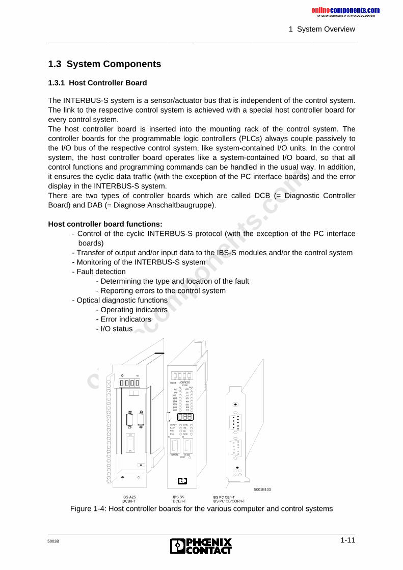
onlinec
omponen
ts.co
m
1 System Overview
5003B 1-11
1.3 System Components
1.3.1 Host Controller Board
The INTERBUS-S system is a sensor/actuator bus that is independent of the control system.The link to the respective control system is achieved with a special host controller board forevery control system.The host controller board is inserted into the mounting rack of the control system. Thecontroller boards for the programmable logic controllers (PLCs) always couple passively tothe I/O bus of the respective control system, like system-contained I/O units. In the controlsystem, the host controller board operates like a system-contained I/O board, so that allcontrol functions and programming commands can be handled in the usual way. In addition,it ensures the cyclic data traffic (with the exception of the PC interface boards) and the errordisplay in the INTERBUS-S system.There are two types of controller boards which are called DCB (= Diagnostic ControllerBoard) and DAB (= Diagnose Anschaltbaugruppe).
Host controller board functions:- Control of the cyclic INTERBUS-S protocol (with the exception of the PC interface boards)- Transfer of output and/or input data to the IBS-S modules and/or the control system- Monitoring of the INTERBUS-S system- Fault detection
- Determining the type and location of the fault- Reporting errors to the control system
- Optical diagnostic functions- Operating indicators- Error indicators- I/O status
BYTEn n+1
MODE ADDRESS
READY
BASP
RUN
BSA
X2 X3
REMOTE RS 232RESET
10/2
8/09/1
11/312/413/5
14/615/7
0/0
1/12/23/3
4/4
5/56/67/7
5001B103
IBS A25DCB/I-T
IBS S5DCB/I-T
CTRL
RB
LB
MOD
IBS PC CB/I-TIBS PC CB/COP/I-T
Figure 1-4: Host controller boards for the various computer and control systems
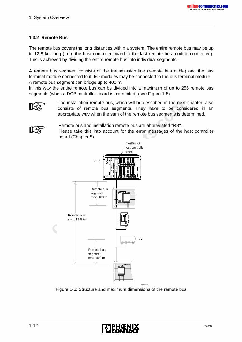
onlinec
omponen
ts.co
m
1 System Overview
1-12 5003B
1.3.2 Remote Bus
The remote bus covers the long distances within a system. The entire remote bus may be upto 12.8 km long (from the host controller board to the last remote bus module connected).This is achieved by dividing the entire remote bus into individual segments.
A remote bus segment consists of the transmission line (remote bus cable) and the busterminal module connected to it. I/O modules may be connected to the bus terminal module.A remote bus segment can bridge up to 400 m.In this way the entire remote bus can be divided into a maximum of up to 256 remote bussegments (when a DCB controller board is connected) (see Figure 1-5).
Figure 1-5: Structure and maximum dimensions of the remote bus
The installation remote bus, which will be described in the next chapter, alsoconsists of remote bus segments. They have to be considered in anappropriate way when the sum of the remote bus segments is determined.
Remote bus and installation remote bus are abbreviated "RB".Please take this into account for the error messages of the host controllerboard (Chapter 5).
Remote busmax. 12.8 km
Remote bussegmentmax. 400 m
Remote bussegmentmax. 400 m
5001A102
PLC
host controllerboard
InterBus-S
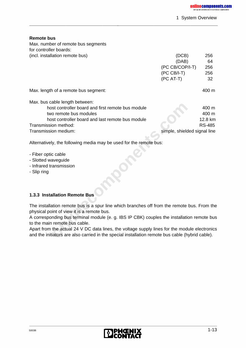
onlinec
omponen
ts.co
m
1 System Overview
5003B 1-13
Remote busMax. number of remote bus segmentsfor controller boards:(incl. installation remote bus) (DCB) 256
(DAB) 64(PC CB/COP/I-T) 256(PC CB/I-T) 256(PC AT-T) 32
Max. length of a remote bus segment: 400 m
Max. bus cable length between:host controller board and first remote bus module 400 mtwo remote bus modules 400 mhost controller board and last remote bus module 12.8 km
Transmission method: RS-485Transmission medium: simple, shielded signal line
Alternatively, the following media may be used for the remote bus:
- Fiber optic cable- Slotted waveguide- Infrared transmission- Slip ring
1.3.3 Installation Remote Bus
The installation remote bus is a spur line which branches off from the remote bus. From thephysical point of view it is a remote bus.A corresponding bus terminal module (e. g. IBS IP CBK) couples the installation remote busto the main remote bus cable.Apart from the actual 24 V DC data lines, the voltage supply lines for the module electronicsand the initiators are also carried in the special installation remote bus cable (hybrid cable).
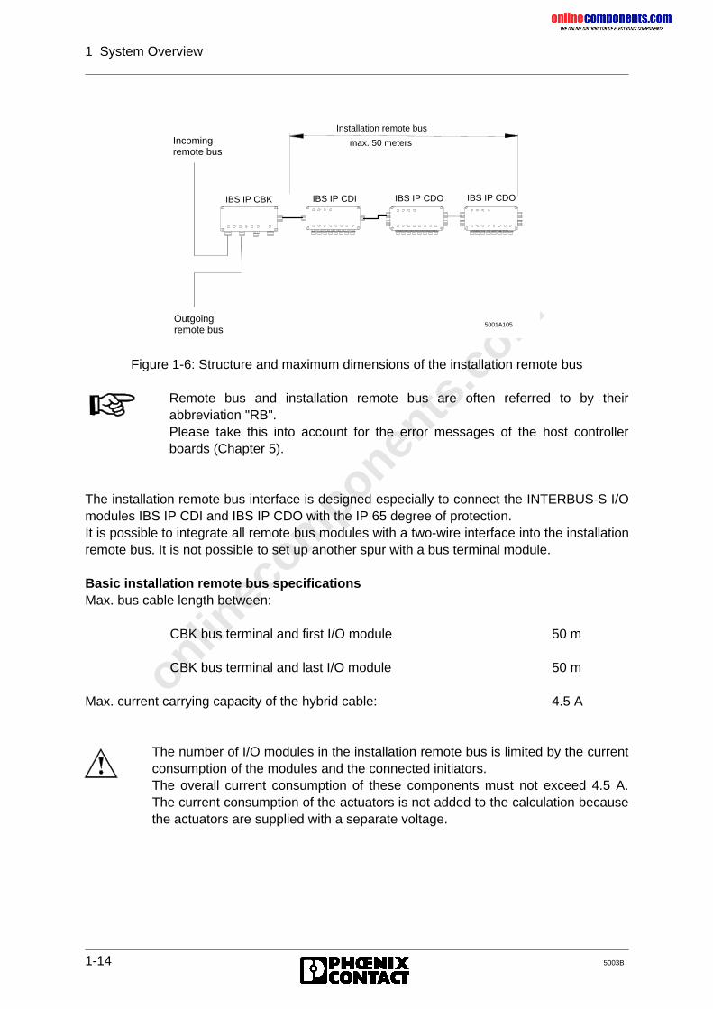
onlinec
omponen
ts.co
m
1 System Overview
1-14 5003B
Figure 1-6: Structure and maximum dimensions of the installation remote bus
The installation remote bus interface is designed especially to connect the INTERBUS-S I/Omodules IBS IP CDI and IBS IP CDO with the IP 65 degree of protection.It is possible to integrate all remote bus modules with a two-wire interface into the installationremote bus. It is not possible to set up another spur with a bus terminal module.
Basic installation remote bus specificationsMax. bus cable length between:
CBK bus terminal and first I/O module 50 m
CBK bus terminal and last I/O module 50 m
Max. current carrying capacity of the hybrid cable: 4.5 A
IBS IP CBK IBS IP CDI
Installation remote bus
max. 50 metersIncomingremote bus
Outgoingremote bus
IBS IP CDO
5001A105
IBS IP CDO
Remote bus and installation remote bus are often referred to by theirabbreviation "RB".Please take this into account for the error messages of the host controllerboards (Chapter 5).
The number of I/O modules in the installation remote bus is limited by the currentconsumption of the modules and the connected initiators.The overall current consumption of these components must not exceed 4.5 A.The current consumption of the actuators is not added to the calculation becausethe actuators are supplied with a separate voltage.
onlinec
omponen
ts.co
m
1 System Overview
5003B 1-15
Calculation example for determining the number of modules in the installation remotebus:
Let us assume that the following components are used in an installation remote bus. (Theinformation on the current consumption of the I/O modules and initiators is taken from theappropriate data sheets).
Table 1-1: Example for testing the load capacity of an installation remote bus
Bus operation is ensured in this example!
1.3.4 Bus Terminal Module
A bus terminal module belongs to the remote bus. It connects a local bus (cf. Chapter 1.3.5)and/or installation remote bus to the remote bus (cf. Chapter 1.3.2). The supply voltage of abus terminal module must be maintained even when parts of the system are disconnected.Only then can it be guaranteed that the remaining part of the bus system can continueoperation.Bus terminal modules may be identified by the designation BK (IBS IP CBK 1/24-F, IBS 24BK I/O-T, IBS BK-T, IBS 24 BK/LC 2, IBS 24 BK-I/O, IBS 230 BK, IBS 24 BK, IBS 24BK/LC). There are also bus terminal modules with additional I/O functions (I/O is included inthe name).
Bus terminal functions:- Coupling an installation remote bus and/or local bus to the remote bus- Supplying the I/O modules with the operating voltage for the bus electronics- Regenerating data in the remote bus- Electrical isolation between remote bus segments- Switching on or off the local bus, installation remote bus, and the outgoing remote bus- Indicating errors via a floating alarm output- For the IBS 24 BK/LC 2: reconfiguration by means of an external pushbutton
Current consumption by the module electronics ofa CDO or CDI module:
100 mA
Current consumption of a typical initiator: 25 mANumber of CDO modules: 4Number of CDI modules: 8Number of the connected initiators: 27Total current consumption: 4* 100mA + 8*100 mA + 27*25 mA
= 1.875 A
If the supply voltage at a bus terminal module fails, the controller board stops thesystem and generates an error message for the remote bus segment concerned.
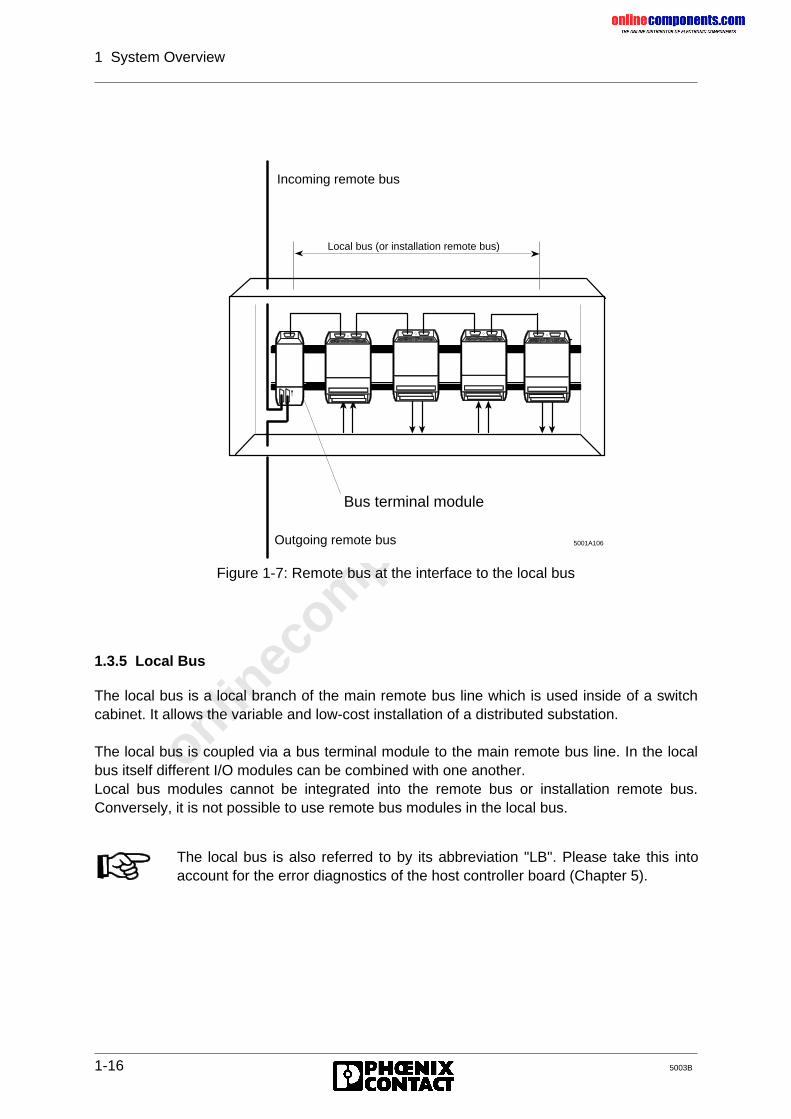
onlinec
omponen
ts.co
m
1 System Overview
1-16 5003B
Figure 1-7: Remote bus at the interface to the local bus
1.3.5 Local Bus
The local bus is a local branch of the main remote bus line which is used inside of a switchcabinet. It allows the variable and low-cost installation of a distributed substation.
The local bus is coupled via a bus terminal module to the main remote bus line. In the localbus itself different I/O modules can be combined with one another.Local bus modules cannot be integrated into the remote bus or installation remote bus.Conversely, it is not possible to use remote bus modules in the local bus.
Outgoing remote bus
Incoming remote bus
Local bus (or installation remote bus)
Bus terminal module
5001A106
The local bus is also referred to by its abbreviation "LB". Please take this intoaccount for the error diagnostics of the host controller board (Chapter 5).
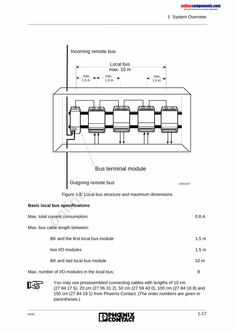
onlinec
omponen
ts.co
m
1 System Overview
5003B 1-17
Figure 1-8: Local bus structure and maximum dimensions
Basic local bus specifications
Max. total current consumption: 0.8 A
Max. bus cable length between:
BK and the first local bus module 1.5 m
two I/O modules 1.5 m
BK and last local bus module 10 m
Max. number of I/O modules in the local bus: 8
Local bus max. 10 m
max.1.5 m
max.1.5 m
max.1.5 m
Outgoing remote bus
Incoming remote bus
Bus terminal module
5001A107
You may use preassembled connecting cables with lengths of 10 cm(27 84 17 5), 20 cm (27 06 31 2), 50 cm (27 59 43 0), 100 cm (27 84 18 8) and150 cm (27 84 19 1) from Phoenix Contact. (The order numbers are given inparentheses.)
onlinec
omponen
ts.co
m
1 System Overview
1-18 5003B
1.3.6 INTERBUS-S I/O Modules
The I/O modules link the sensors and actuators to the INTERBUS-S system. Here, adistinction is to be made between I/O modules in the remote bus and/or installation remotebus and the I/O modules in the local bus.
1.3.6.1 Remote Bus and Installation Remote Bus Modules
Besides I/O modules for digital and analog signals there are I/O modules withbus terminal functionality, such as IBS 24 BK I/O-T, and operator terminals,valve terminals, DRIVECOM devices, ENCOM devices, etc.
If the supply voltage U (CDO, CDI UL) fails in a remote bus or installationremote bus module, the INTERBUS-S system is stopped and an errormessage for the respective remote bus segment is output.
For the INTERBUS-S system operation it is necessary that the bus logic of allmodules is supplied with voltage.The voltage (U) for supplying the bus logic is for- remote and local bus modules directly connected to every I/O module andevery BK.- installation remote bus modules provided via the special installation remotebus cable.The voltage is supplied through the BK, which is coupled to the main line inthe respective installation remote bus.
1.3.6.2 Local Bus Modules
Local bus modules are I/O modules for the variable and cost-effective installation in adecentralized switch cabinet.In a local bus the modules can be combined with regard to their respective control andmonitoring tasks.The local bus modules of a local bus are coupled through a bus terminal module to the mainremote bus line. The bus terminal module features an integrated power pack. It supplies theBK electronics and, via the local bus cable, the bus logic of the connected I/O modules.The voltage supplied at the respective I/O module serves to supply the peripheral side whichis electrically isolated from the bus logic.If the voltage fails in the bus terminal module, the INTERBUS-S system stops and thecontroller board reports an error for the remote bus segment concerned.When calculating the sum of the I/O points, please observe that for modules with inputs andoutputs only the simple register width is taken for calculating the total sum.
onlinec
omponen
ts.co
m
5003B
Chapter 2
Technical DescriptionThis chapter provides information on
- the functions of the operating and display elements of the controller board- the project planning of the controller board- the hardware settings in order to get different modes of operation- the technical data
2 Technical Description........................................................................2-1
2.1 Host Controller Board Method of Operation.................................................. 2-1
2.2 Application Area of the Host Controller Board .............................................. 2-2
2.3 Overview ...................................................................................................... 2-32.3.1 Front Plate Components............................................................................... 2-42.3.1.1 I/O Status Indicators..................................................................................... 2-52.3.1.2 Operating Indicators ..................................................................................... 2-62.3.1.3 Error Indicators............................................................................................. 2-72.3.1.4 Interfaces ..................................................................................................... 2-72.3.2 Controller Board Components ...................................................................... 2-8
2.4 Host Controller Board Installation ................................................................. 2-92.4.1 Slot Allocation and Installation...................................................................... 2-9
2.5 Configuration of the Controller Board ........................................................... 2-112.5.1 PLC Address Area........................................................................................ 2-112.5.2 Hardware Term Definitions .......................................................................... 2-122.5.3 Configuring the Default Setting..................................................................... 2-13
2.6 Hardware Settings........................................................................................ 2-192.6.1 Mounting Positions of the Jumpers............................................................... 2-192.6.2 Operation in the Central Controller and Controller Expansion Unit ............... 2-202.6.3 Startup and Operating Mode Selection......................................................... 2-212.6.3.1 INTERBUS-S in the PLC’s Address Area ..................................................... 2-252.6.3.2 Address Locations for Automatic Start in the DCB Mode.............................. 2-262.6.3.3 Address Locations for Controlled Start in the DCB Mode ............................. 2-272.6.3.4 Address Locations for Automatic Start in the DAB Mode.............................. 2-282.6.3.5 Address Locations for Controlled Start in the DAB Mode ............................. 2-292.6.4 Address Windows......................................................................................... 2-302.6.5 Interrupt Processing ..................................................................................... 2-362.6.5.1 Settings for Interrupt Processing .................................................................. 2-362.6.5.2 Different Interrupt Sources ........................................................................... 2-382.6.6 Acknowledgment Delay Message ................................................................ 2-382.6.7 Disconnecting the RESET Button................................................................. 2-39
2.7 Data Sheet ................................................................................................... 2-40
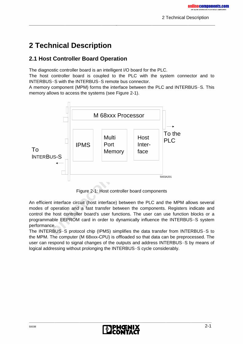
onlinec
omponen
ts.co
m
2 Technical Description
5003B 2-1
2 Technical Description
2.1 Host Controller Board Operation
The diagnostic controller board is an intelligent I/O board for the PLC.The host controller board is coupled to the PLC with the system connector and toINTERBUS-S with the INTERBUS-S remote bus connector.A memory component (MPM) forms the interface between the PLC and INTERBUS-S. Thismemory allows to access the systems (see Figure 2-1).
Figure 2-1: Host controller board components
An efficient interface circuit (host interface) between the PLC and the MPM allows severalmodes of operation and a fast transfer between the components. Registers indicate andcontrol the host controller board’s user functions. The user can use function blocks or aprogrammable EEPROM card in order to dynamically influence the INTERBUS-S systemperformance.The INTERBUS-S protocol chip (IPMS) simplifies the data transfer from INTERBUS-S tothe MPM. The computer (M 68xxx-CPU) is offloaded so that data can be preprocessed. Theuser can respond to signal changes of the outputs and address INTERBUS-S by means oflogical addressing without prolonging the INTERBUS-S cycle considerably.
5003A201
M 68xxx Processor
IPMSMultiPortMemory
HostInter-face
To the PLC
To INTERBUS-S
onlinec
omponen
ts.co
m
2 Technical Description
2-2 5003B
2.2 Application Area of the Host Controller Board
The INTERBUS S5 host controller board ensures asynchronous communication between theprogrammable controllers and the INTERBUS-S I/O system.The host controller board includes operating and diagnostic indicators, which provideinformation about the board’s status and the connected INTERBUS-S system.A software package and a memory block constitute the interface between the controlprogram and the controller board. Diagnostic, command and special user functions can becalled through this interface.
The host controller board may be used in the following SIMATIC S5 PLCs:
S5 115 U S5 135 U S5 130 WB S5 150 S S5 150 U S5 155 U
Other Siemens or compatible PLCs upon request.
When coupled to the S5 backplane bus, the controller board can be used with all Siemensmodules.The two-wire INTERBUS-S system is connected through the remote bus connector. A bussystem with the following expansion can be set up:
• max. 256 local bus segments and/or remote bus modules• max. 320 modules• max. 256 INTERBUS-S words• max. 62 PCP stations.
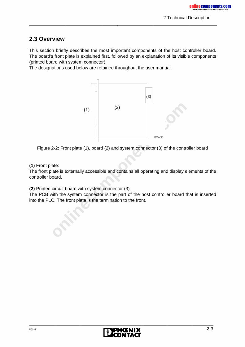
onlinec
omponen
ts.co
m
2 Technical Description
5003B 2-3
2.3 Overview
This section briefly describes the most important components of the host controller board.The board’s front plate is explained first, followed by an explanation of its visible components(printed board with system connector).The designations used below are retained throughout the user manual.
Figure 2-2: Front plate (1), board (2) and system connector (3) of the controller board
(1) Front plate:The front plate is externally accessible and contains all operating and display elements of thecontroller board.
(2) Printed circuit board with system connector (3):The PCB with the system connector is the part of the host controller board that is insertedinto the PLC. The front plate is the termination to the front.
5003A202
(2)(1)
(3)
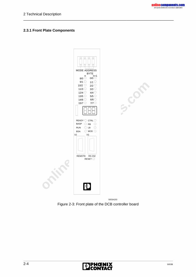
onlinec
omponen
ts.co
m
2 Technical Description
2-4 5003B
2.3.1 Front Plate Components
Figure 2-3: Front plate of the DCB controller board
BYTEn n+1
MODE ADDRESS
8/09/1
11/3
12/413/514/615/7
10/2
0/0
1/12/23/3
4/45/56/67/7
CTRL
RB
LB
MOD
READY
BASP
RUN
BSA
X2 X3
REMOTE RS 232RESET
5003A203
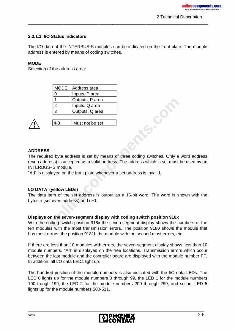
onlinec
omponen
ts.co
m
2 Technical Description
5003B 2-5
2.3.1.1 I/O Status Indicators
The I/O data of the INTERBUS-S modules can be indicated on the front plate. The moduleaddress is entered by means of coding switches.
MODESelection of the address area:
ADDRESSThe required byte address is set by means of three coding switches. Only a word address(even address) is accepted as a valid address. The address which is set must be used by anINTERBUS-S module."Ad" is displayed on the front plate whenever a set address is invalid.
I/O DATA (yellow LEDs)The data item of the set address is output as a 16-bit word. The word is shown with thebytes n (set even address) and n+1.
Displays on the seven-segment display with coding switch position 918xWith the coding switch position 918x the seven-segment display shows the numbers of theten modules with the most transmission errors. The position 9180 shows the module thathas most errors, the position 9181h the module with the second most errors, etc.
If there are less than 10 modules with errors, the seven-segment display shows less than 10module numbers. "Ad" is displayed on the free locations. Transmission errors which occurbetween the last module and the controller board are displayed with the module number FF.In addition, all I/O data LEDs light up.
The hundred position of the module numbers is also indicated with the I/O data LEDs. TheLED 0 lights up for the module numbers 0 through 99, the LED 1 for the module numbers100 trough 199, the LED 2 for the module numbers 200 through 299, and so on. LED 5lights up for the module numbers 500-511.
MODE Address area0 Inputs, P area1 Outputs, P area2 Inputs, Q area3 Outputs, Q area
4-8 Must not be set
onlinec
omponen
ts.co
m
2 Technical Description
2-6 5003B
Displays on the seven-segment display with the coding switch position 919xWhen the coding switches are in position 9190, the seven-segment display shows thenumber of the local bus station in which the last module status error occurred. The position9191 indicates the number of the local bus station of the last but one module status errorand so on.
Displays on the seven-segment display with the coding switch position 94xx to 99xxWhen the coding switches are in position 9400, the seven-segment display shows thenumber of modules in the current configuration.When the coding switches are in position 9401 through 9912, the seven-segment displayshows the ID codes (hexadecimal) of the current physical configuration ("9401" shows the IDcodes of the first bus station, "9402" shows the ID codes of the second bus station, etc.).The register length of the modules is given in the first digit of the three-digit display.
Display of the firmware revisionThe coding switch position 9200 shows the implemented firmware revision on the seven-segment display.
DIAGNOSTICS (seven-segment display)The three-position seven-segment display shows parameters during operation an whenerrors occur.
-��- Controller board stop -- Run status of the controller board Ad Invalid address set with the coding switch
A parameter is output in case of an error (an error LED is active).
2.3.1.2 Operating Indicators
Various LEDs indicate the operating state of INTERBUS-S and the PLC. The seven-segment display provides more detailed information.
READYThe controller board has completed the self-test without discovering any errors and is readyfor operation.
BASPThe PLC has activated the BASP (Befehls Ausgabe SPerren = disable command output)signal and is in the STOP state. In this operating state, INTERBUS-S resets all outputs.
RUNThe RUN LED is active when a data cycle runs on INTERBUS-S.
BSAThe BSA signal (Bus Segment Abgeschaltet = bus segment disabled) indicates that one orseveral bus segments is/are disabled. The remaining bus configuration runs properly.
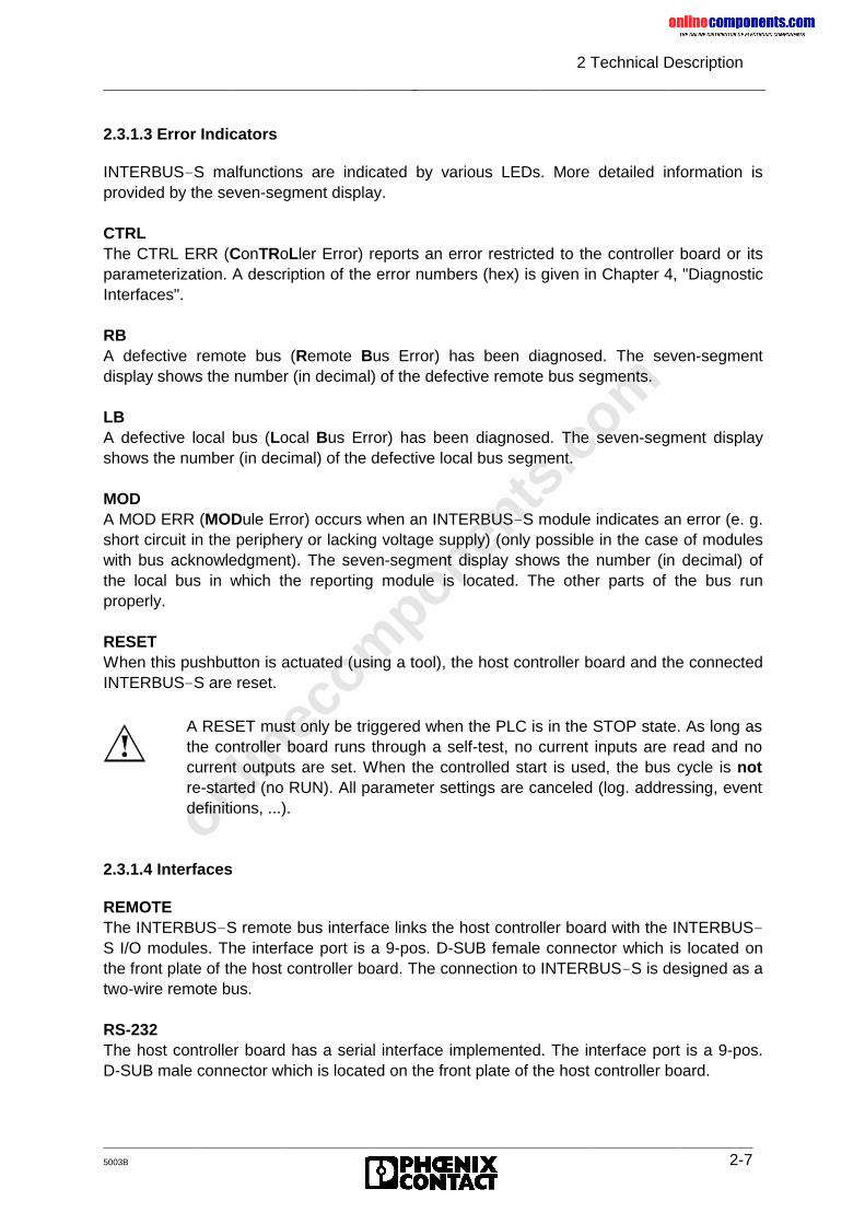
onlinec
omponen
ts.co
m
2 Technical Description
5003B 2-7
2.3.1.3 Error Indicators
INTERBUS-S malfunctions are indicated by various LEDs. More detailed information isprovided by the seven-segment display.
CTRLThe CTRL ERR (ConTRoLler Error) reports an error restricted to the controller board or itsparameterization. A description of the error numbers (hex) is given in Chapter 4, "DiagnosticInterfaces".
RBA defective remote bus (Remote Bus Error) has been diagnosed. The seven-segmentdisplay shows the number (in decimal) of the defective remote bus segments.
LBA defective local bus (Local Bus Error) has been diagnosed. The seven-segment displayshows the number (in decimal) of the defective local bus segment.
MODA MOD ERR (MODule Error) occurs when an INTERBUS-S module indicates an error (e. g.short circuit in the periphery or lacking voltage supply) (only possible in the case of moduleswith bus acknowledgment). The seven-segment display shows the number (in decimal) ofthe local bus in which the reporting module is located. The other parts of the bus runproperly.
RESETWhen this pushbutton is actuated (using a tool), the host controller board and the connectedINTERBUS-S are reset.
2.3.1.4 Interfaces
REMOTEThe INTERBUS-S remote bus interface links the host controller board with the INTERBUS-S I/O modules. The interface port is a 9-pos. D-SUB female connector which is located onthe front plate of the host controller board. The connection to INTERBUS-S is designed as atwo-wire remote bus.
RS-232The host controller board has a serial interface implemented. The interface port is a 9-pos.D-SUB male connector which is located on the front plate of the host controller board.
A RESET must only be triggered when the PLC is in the STOP state. As long asthe controller board runs through a self-test, no current inputs are read and nocurrent outputs are set. When the controlled start is used, the bus cycle is notre-started (no RUN). All parameter settings are canceled (log. addressing, eventdefinitions, ...).

onlinec
omponen
ts.co
m
2 Technical Description
2-8 5003B
The connector pinouts can be found in the section where the interface is described.
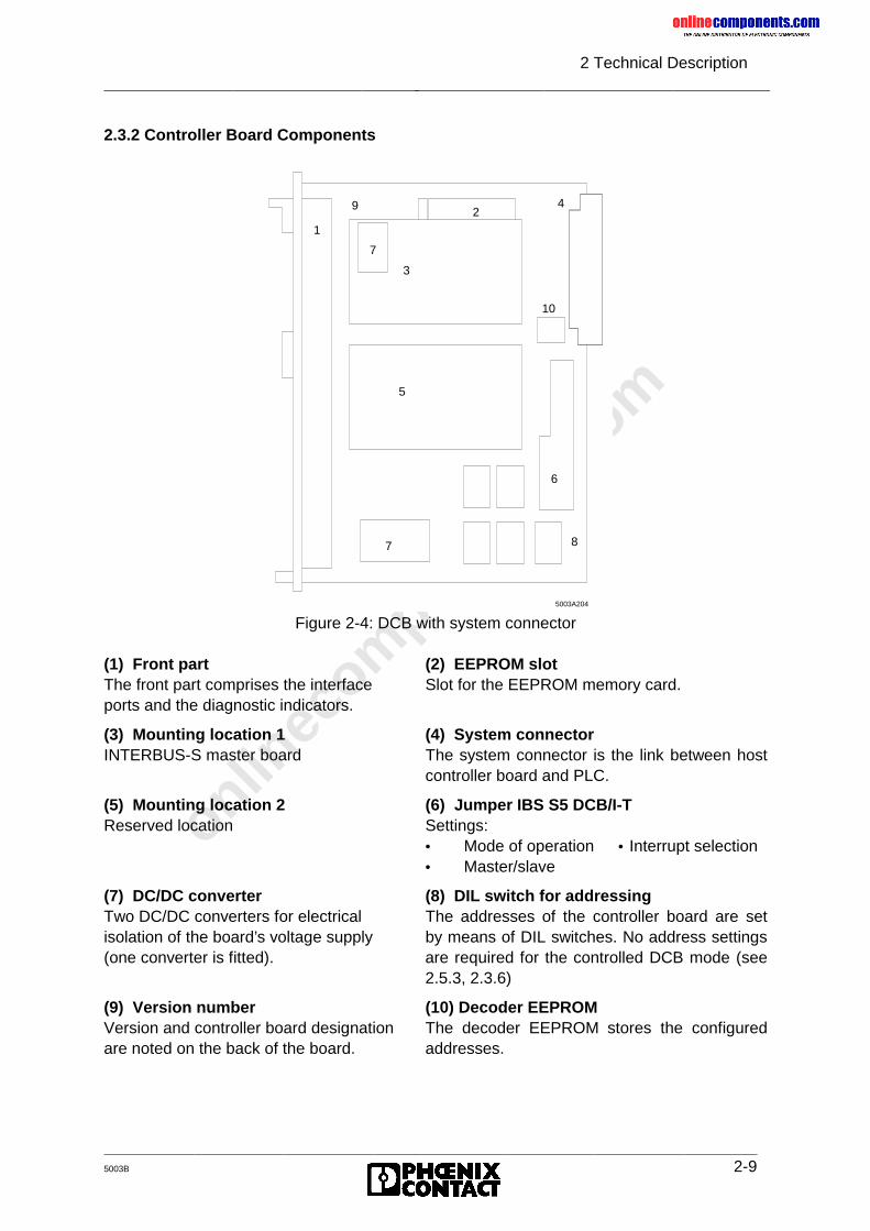
onlinec
omponen
ts.co
m
2 Technical Description
5003B 2-9
2.3.2 Controller Board Components
Figure 2-4: DCB with system connector
(1) Front part (2) EEPROM slotThe front part comprises the interface Slot for the EEPROM memory card.ports and the diagnostic indicators.
(3) Mounting location 1 (4) System connectorINTERBUS-S master board The system connector is the link between host
controller board and PLC.
(5) Mounting location 2 (6) Jumper IBS S5 DCB/I-TReserved location Settings:
• Mode of operation • Interrupt selection• Master/slave
(7) DC/DC converter (8) DIL switch for addressingTwo DC/DC converters for electrical The addresses of the controller board are setisolation of the board’s voltage supply by means of DIL switches. No address settings(one converter is fitted). are required for the controlled DCB mode (see
2.5.3, 2.3.6)
(9) Version number (10) Decoder EEPROMVersion and controller board designation The decoder EEPROM stores the configuredare noted on the back of the board. addresses.
1
29
3
5
7
7
6
4
10
8
5003A204
onlinec
omponen
ts.co
m
2 Technical Description
2-10 5003B
2.4 Host Controller Board Installation
2.4.1 Slot Allocation and Installation
The DCB consists of a printed board in the double Euroformat. The front plate covers twoslots for printed circuit boards. In SIMATIC PLCs of the type 130 U (and larger), thecontroller board can be directly inserted. In SIMATIC 115 U PLCs, an adaptation casingmust be used.A standard EEPROM memory card stores the non-volatile configuration data (e.g. logicaladdressing). On the host controller board the memory card is located below the mountinglocation 1 (see Figure 2-4 (3)). The memory card sits in a holding support with an ejectionmechanism and can only be replaced when the board is not plugged in.
Slots:Installation options of the DCB in SIMATIC PLCs of types S5-155U, -150 U, -135 U,-130 WB and -115 U.
Live insertion or removal of the controller board causes damage.
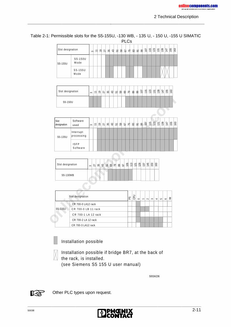
onlinec
omponen
ts.co
m
2 Technical Description
5003B 2-11
Table 2-1: Permissible slots for the S5-155U, -130 WB, - 135 U, - 150 U, -155 U SIMATICPLCs
S5-155U
S 5 -1 5 0 U M o d e
S 5 - 1 5 5 U M o d e
Slot designation
3 11 19 27 35 43 51 59 67 75 83 91 99 107
115
123
131
139
147
155
163
S lot des ignat ion 3 11 19 27 35 43 51 59 69 79 89 99 107
115
123
131
139
147
155
163
S5-150U
S5-135U
In te rru p t p ro ce s s in g
IS F P S o f tw a r e
Slot designation 3 11 19 27 35 43 51 59 67 75 83 91 99 10
7
115
123
131
139
147
155
163Software
used
Slot designation 3 27 35 43 51 69 79 89 97 105
113
121
129
137
145
153
163
S5-130WB
S5-115U
CR 700-0 LA12 rack
Slot designation
PS CPU
0 1 2 3 4 5 6 IM
C R 7 0 0 - 0 L B 1 1 r a c k
C R 7 0 0 -1 L A 1 2 ra c k
CR 700-2 LA 12 rack
CR 700-3 LA12 rack
Instal lation possible
Installation possible if bridge BR7, at the back of the rack, is installed. (see Siemens S5 155 U user manual)
5003A236
Other PLC types upon request.
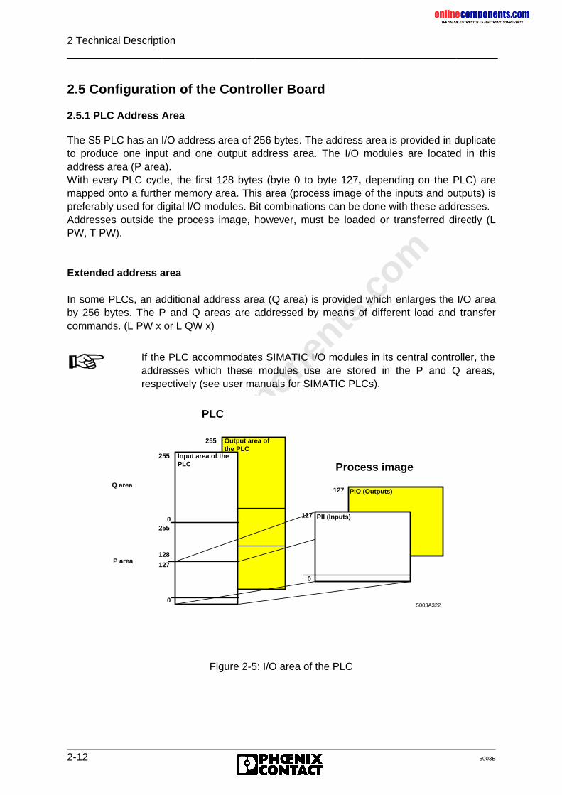
onlinec
omponen
ts.co
m
2 Technical Description
2-12 5003B
2.5 Configuration of the Controller Board
2.5.1 PLC Address Area
The S5 PLC has an I/O address area of 256 bytes. The address area is provided in duplicateto produce one input and one output address area. The I/O modules are located in thisaddress area (P area).With every PLC cycle, the first 128 bytes (byte 0 to byte 127, depending on the PLC) aremapped onto a further memory area. This area (process image of the inputs and outputs) ispreferably used for digital I/O modules. Bit combinations can be done with these addresses.Addresses outside the process image, however, must be loaded or transferred directly (LPW, T PW).
Extended address area
In some PLCs, an additional address area (Q area) is provided which enlarges the I/O areaby 256 bytes. The P and Q areas are addressed by means of different load and transfercommands. (L PW x or L QW x)
Figure 2-5: I/O area of the PLC
If the PLC accommodates SIMATIC I/O modules in its central controller, theaddresses which these modules use are stored in the P and Q areas,respectively (see user manuals for SIMATIC PLCs).
Q area
P area
PIO (Outputs)
Output area ofthe PLC
255
0255
128
127
0
Input area of the PLC
255
0255
128
127
0
0
127
127
PII (Inputs)
Process image
5003A322
PLC
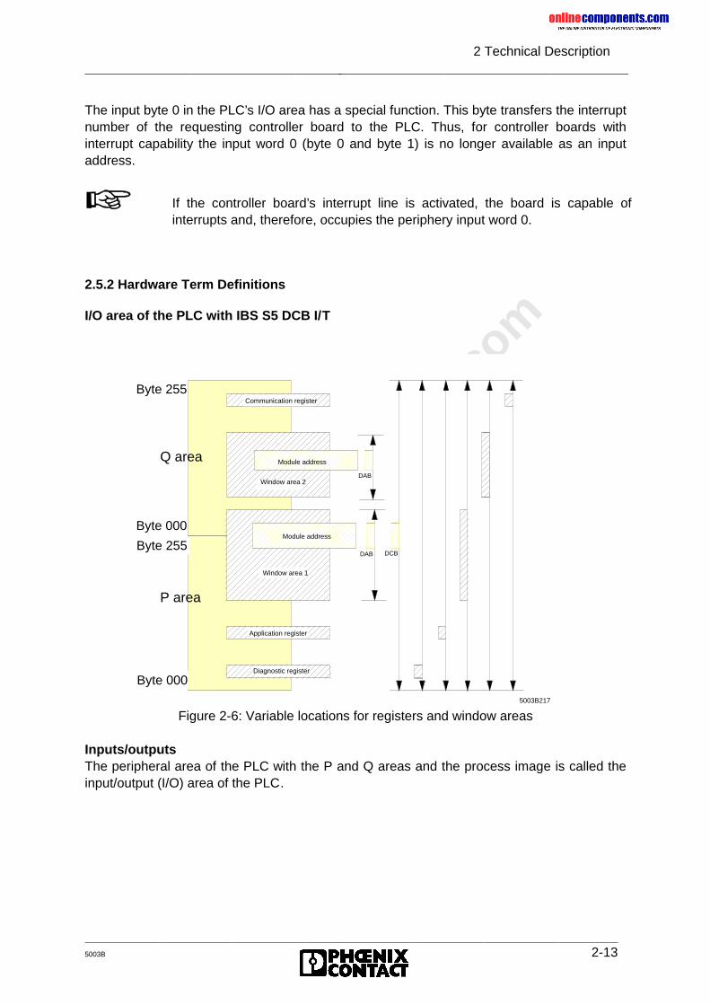
onlinec
omponen
ts.co
m
2 Technical Description
5003B 2-13
The input byte 0 in the PLC’s I/O area has a special function. This byte transfers the interruptnumber of the requesting controller board to the PLC. Thus, for controller boards withinterrupt capability the input word 0 (byte 0 and byte 1) is no longer available as an inputaddress.
2.5.2 Hardware Term Definitions
I/O area of the PLC with IBS S5 DCB I/T
Figure 2-6: Variable locations for registers and window areas
Inputs/outputsThe peripheral area of the PLC with the P and Q areas and the process image is called theinput/output (I/O) area of the PLC.
If the controller board’s interrupt line is activated, the board is capable ofinterrupts and, therefore, occupies the periphery input word 0.
Byte 255
5003B217
P area
Q area
Byte 255
Byte 000
Byte 000
Communication register
DAB DCB
Module address
Window area 2
Window area 1
Application register
Diagnostic register
DAB
Module address
onlinec
omponen
ts.co
m
2 Technical Description
2-14 5003B
Window areasWindow areas are address areas in the PLC which are occupied through the host controllerboard. They are set with DIP switches on the host controller board and can occupy inputs oroutputs, depending on the board’s mode of operation.
Module addressesModule addresses are the I/O addresses in the PLC which are used by an input or outputmodule. The application program accesses these addresses in order to link inputs and to setoutputs. Depending on the mode of operation, these addresses can be within or outside thewindow areas.
Diagnostic registersThe host controller board automatically monitors the entire bus system and diagnoses errorsif they occur. The diagnostic result is displayed on the front plate. This data can also becalled by the application program via the diagnostic registers (diagnostic bit register,diagnostic parameter register).
Application registersDifferent I/O words are used to perform functions on the controller board and the bus system(bit-controlled command register, bit manipulation register).
Communication registersThese registers are always active in the PLC. They are addressed by means of the includedfunction (driver) blocks (FBs). Using these blocks, control commands and/or messages canbe exchanged between the PLC and the controller board.
2.5.3 Configuring the Default Setting
In order to configure the available addresses, jumpers and DIP switches on the controllerboard, the following information will be of importance:
Definition of I/O addressesDepending on the number of inputs or outputs, every module occupies 8, 16, 32 or more bitsin the PLC. In the PLC, every module is accessible through the controller board. The hostcontroller board displays every input and output data item word by word (as the smallestunit). Here, the base address of the module is decisive. The host controller board allows twodifferent types of addressing. The address area which the host controller board occupies isvariable.
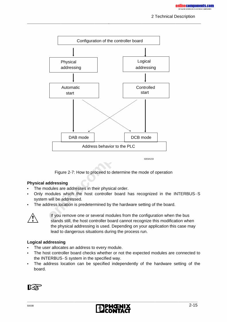
onlinec
omponen
ts.co
m
2 Technical Description
5003B 2-15
Figure 2-7: How to proceed to determine the mode of operation
Physical addressing• The modules are addresses in their physical order.• Only modules which the host controller board has recognized in the INTERBUS-S
system will be addressed.• The address location is predetermined by the hardware setting of the board.
Logical addressing• The user allocates an address to every module.• The host controller board checks whether or not the expected modules are connected to
the INTERBUS-S system in the specified way.• The address location can be specified independently of the hardware setting of the
board.
Configuration of the controller board
Address behavior to the PLC
start
DCB mode
Logical
addressing
Controlled Automatic
DAB mode
start
Physical addressing
5003A233
If you remove one or several modules from the configuration when the busstands still, the host controller board cannot recognize this modification whenthe physical addressing is used. Depending on your application this case maylead to dangerous situations during the process run.
onlinec
omponen
ts.co
m
2 Technical Description
2-16 5003B
Please note that the addressing modes are described in the Chapter "UserInterfaces".Chapter 2.6.3 "Startup and Operating Mode Selection" describes the differentDAB/DCB modes.
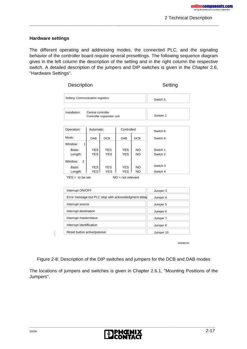
onlinec
omponen
ts.co
m
2 Technical Description
5003B 2-17
Hardware settings
The different operating and addressing modes, the connected PLC, and the signalingbehavior of the controller board require several presettings. The following sequence diagramgives in the left column the description of the setting and in the right column the respectiveswitch. A detailed description of the jumpers and DIP switches is given in the Chapter 2.6,"Hardware Settings".
Figure 2-8: Description of the DIP switches and jumpers for the DCB and DAB modes
The locations of jumpers and switches is given in Chapter 2.6.1, "Mounting Positions of theJumpers".
5003B232
SettingDescription
Switch 2
Switch 3
Switch 4
Switch 1
Switch 6
Switch 6
YES = to be set
Length:
Window:
Base:Length:
2
Base:YES
YESYES
YES
YES YES
NO = not relevant
NO
NONO
NOYESYES
YESYES
Automatic
DCB
Window:
Operation:
Mode:
1
DAB
Controlled
DCBDAB
YES
YES
Switch 5Setting: Communication registers
Jumper 1Central controllerController expansion unit
Installation:
Jumper 7
Jumper 8
Jumper 5
Jumper 6
Jumper 10
Interrupt master/slave
Reset button active/passive
Interrupt source
Interrupt destination
Interrupt identification
Jumper 3Interrupt ON/OFF
Jumper 4Error message but PLC stop with acknowledgment delay
onlinec
omponen
ts.co
m
2 Technical Description
2-18 5003B
Software requirements
There are different ways to program the startup:
• Automatically by means of the host controller board• Controlled programming by means of the PLC (function blocks) or via the EEPROM card
In both cases the PLC monitors the startup in order to achieve a synchronism between thePLC and the controller board. The application program is kept in its startup blocks untilINTERBUS-S provides I/O data.
Program packages
For the PLC: ISFP Version: ≥ 2.0InterBus-S Functions for the PLC
For the EEPROM card: IBS S5 SWD-T Version: ≥ 1.0
The different programming methods are described in Chapter 5, "SystemInterfaces".
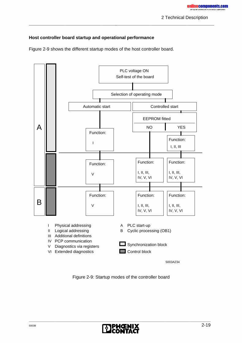
onlinec
omponen
ts.co
m
2 Technical Description
5003B 2-19
Host controller board startup and operational performance
Figure 2-9 shows the different startup modes of the host controller board.
Figure 2-9: Startup modes of the controller board
PLC voltage ON
Self-test of the board
Selection of operating mode
PLC start-upCyclic processing (OB1)
IV, V, VI
IV, V, VI
Controlled start
EEPROM fitted
Synchronization block
Control block
AFunction:
Additional definitions
Physical addressingLogical addressing
Extended diagnosticsDiagnostics via registers
Function:
Function:
PCP communicationIIIIV
VI
III
V
B
AB
V
Function:
I, II, III,
V
I
Function:
I, II, III,
NO
Automatic start
IV, V, VI
Function:
I, II, III,
IV, V, VI
Function:
I, II, III,
Function:
I, II, III
YES
5003A234
onlinec
omponen
ts.co
m
2 Technical Description
2-20 5003B
Host controller board diagnostics
The controller board diagnostics is subdivided into three areas:
1) Detection of an operating or error state
• Automatic diagnostics
This includes the complete error detection and processing. As soon as a bus error(RB, LB), a controller board error (CTRL), or a module error (MOD) is detected, theerror location or error parameter is determined and displayed.
2) Display of diagnostic data
• Front plate (error group with LEDs and error parameters with seven-segment display)
• Diagnostic registers
Using two input words, the status and error indicators (LEDs) and the parameters(seven-segment display) are overlaid in the PLC’s input area.
• Acknowledgment delay
By setting a jumper it can be determined whether or not an acknowledgment delay isto occur in the PLC in the event of an error.
3) Other diagnostic functions
• ISFP software program
Function blocks, which are included in the delivery, allow to get additional errorinformation. (e.g. which module in the case of a MOD error)
• V.24 (RS-232) interface
In the case of servicing, a PC program can be used to call diagnostic functions.
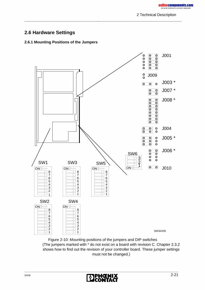
onlinec
omponen
ts.co
m
2 Technical Description
5003B 2-21
2.6 Hardware Settings
2.6.1 Mounting Positions of the Jumpers
Figure 2-10: Mounting positions of the jumpers and DIP switches(The jumpers marked with * do not exist on a board with revision C. Chapter 2.3.2shows how to find out the revision of your controller board. These jumper settings
must not be changed.)
22
4321
SW2ON
765
1
8
4321
65
78
1
ON
SW4
43
SW1ON
65
78
43
65
78
ON
SW3
21
43
65
78
ON
SW5 21
ON
3SW6
J006 *
J010
J005 *
J004
J008 *
J007 *
J003 *
J009
J001
5003A205
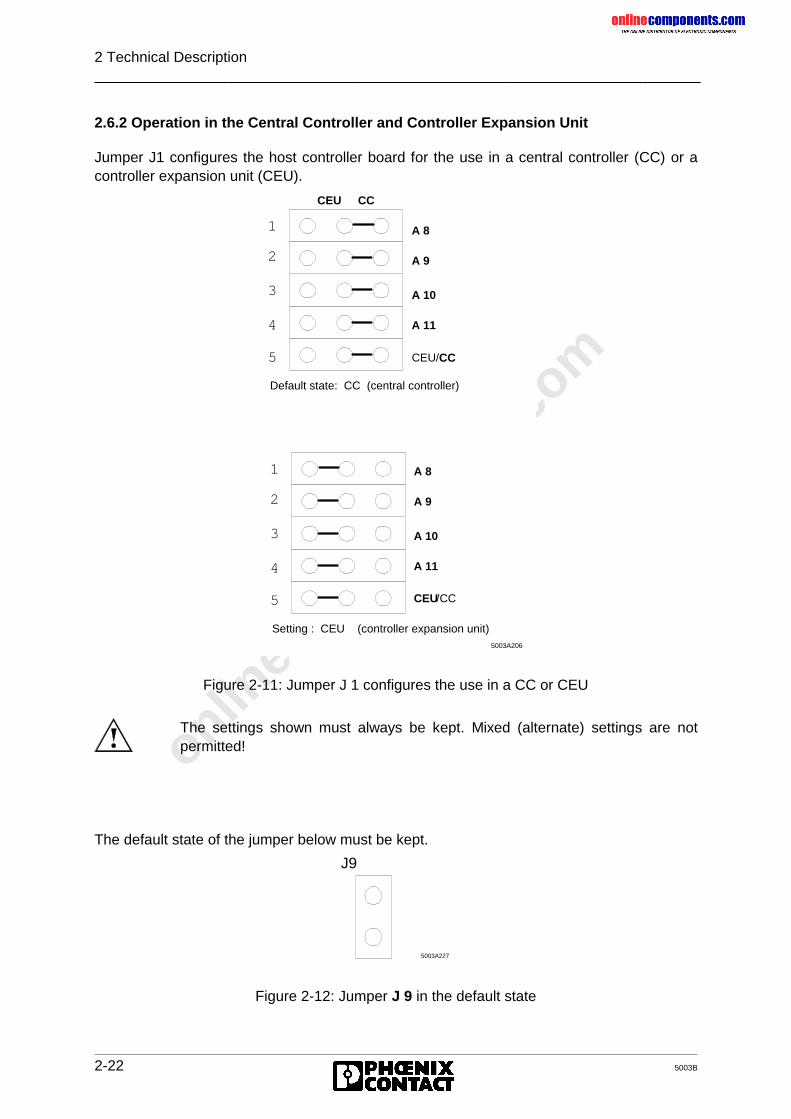
onlinec
omponen
ts.co
m
2 Technical Description
2-22 5003B
2.6.2 Operation in the Central Controller and Controller Expansion Unit
Jumper J1 configures the host controller board for the use in a central controller (CC) or acontroller expansion unit (CEU).
Figure 2-11: Jumper J 1 configures the use in a CC or CEU
The default state of the jumper below must be kept.
Figure 2-12: Jumper J 9 in the default state
3
2
1
4
5
Default state: CC (central controller)
5003A206
3
2
1
4
5
Setting : CEU (controller expansion unit)
A 8
A 9
A 10
A 11
CEU/CC
CEU CC
A 8
A 9
A 10
A 11
CEU/CC
The settings shown must always be kept. Mixed (alternate) settings are notpermitted!
5003A227
J9
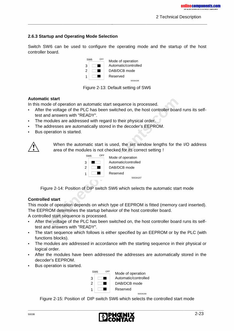
onlinec
omponen
ts.co
m
2 Technical Description
5003B 2-23
2.6.3 Startup and Operating Mode Selection
Switch SW6 can be used to configure the operating mode and the startup of the hostcontroller board.
Figure 2-13: Default setting of SW6
Automatic startIn this mode of operation an automatic start sequence is processed.• After the voltage of the PLC has been switched on, the host controller board runs its self-
test and answers with "READY".• The modules are addressed with regard to their physical order.• The addresses are automatically stored in the decoder’s EEPROM.• Bus operation is started.
Figure 2-14: Position of DIP switch SW6 which selects the automatic start mode
Controlled startThis mode of operation depends on which type of EEPROM is fitted (memory card inserted).The EEPROM determines the startup behavior of the host controller board.A controlled start sequence is processed.• After the voltage of the PLC has been switched on, the host controller board runs its self-
test and answers with "READY".• The start sequence which follows is either specified by an EEPROM or by the PLC (with
functions blocks).• The modules are addressed in accordance with the starting sequence in their physical or
logical order.• After the modules have been addressed the addresses are automatically stored in the
decoder’s EEPROM.• Bus operation is started.
Figure 2-15: Position of DIP switch SW6 which selects the controlled start mode
OFF
1
SW6
23
DAB/DCB mode
Reserved5003A208
Mode of operationAutomatic/controlled
When the automatic start is used, the set window lengths for the I/O addressarea of the modules is not checked for its correct setting !
OFF
1
SW6
23
DAB/DCB mode
Reserved5003A207
Mode of operationAutomatic/controlled
OFF
1
SW6
23
DAB/DCB mode
Reserved5003A208
Mode of operationAutomatic/controlled
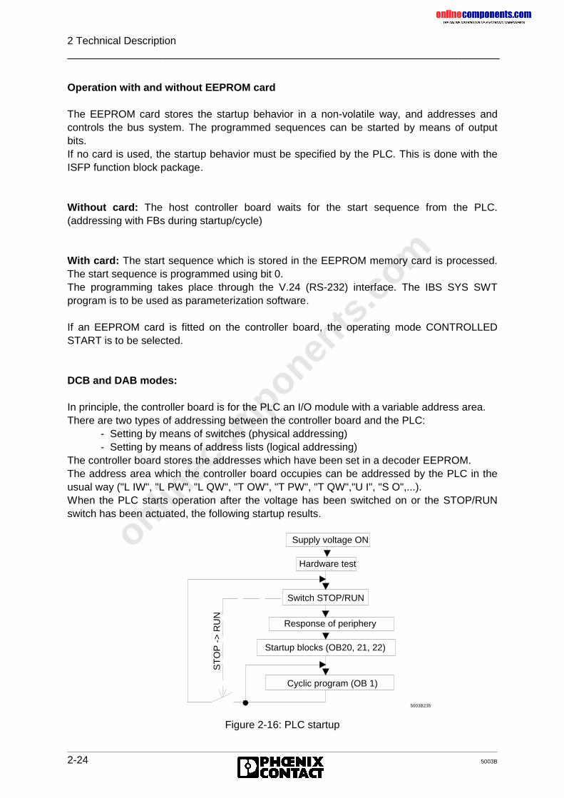
onlinec
omponen
ts.co
m
2 Technical Description
2-24 5003B
Operation with and without EEPROM card
The EEPROM card stores the startup behavior in a non-volatile way, and addresses andcontrols the bus system. The programmed sequences can be started by means of outputbits.If no card is used, the startup behavior must be specified by the PLC. This is done with theISFP function block package.
Without card: The host controller board waits for the start sequence from the PLC.(addressing with FBs during startup/cycle)
With card: The start sequence which is stored in the EEPROM memory card is processed.The start sequence is programmed using bit 0.The programming takes place through the V.24 (RS-232) interface. The IBS SYS SWTprogram is to be used as parameterization software.
If an EEPROM card is fitted on the controller board, the operating mode CONTROLLEDSTART is to be selected.
DCB and DAB modes:
In principle, the controller board is for the PLC an I/O module with a variable address area.There are two types of addressing between the controller board and the PLC:
- Setting by means of switches (physical addressing)- Setting by means of address lists (logical addressing)
The controller board stores the addresses which have been set in a decoder EEPROM.The address area which the controller board occupies can be addressed by the PLC in theusual way ("L IW", "L PW", "L QW", "T OW", "T PW", "T QW","U I", "S O",...).When the PLC starts operation after the voltage has been switched on or the STOP/RUNswitch has been actuated, the following startup results.
Figure 2-16: PLC startup
Supply voltage ON
Hardware test
Switch STOP/RUN
Response of periphery
Startup blocks (OB20, 21, 22)
Cyclic program (OB 1)
5003B235
ST
OP
->
RU
N
onlinec
omponen
ts.co
m
2 Technical Description
5003B 2-25
Under the menu item "Addressing the Periphery" the correctly connected I/O modulesindicate their readiness and the PLC recognizes the addresses stored in the decoderEEPROM. They are entered in the PLC as existing I/O modules.
Special case a):When the PLC starts again, it recognizes first the old addresses in the decoder EEPROM(addressing the I/O modules).Then, the controller board updates the contents of the decoder EEPROM by adding the newaddresses.
Remedy for case a) : Press the STOP/RUN switch of the PLC again. Then the PLC iscommunicated the new addresses and the application program can recognize them.
Special case b):When you set the communication register (=window 3, 4 bytes inputs, 4 bytes outputs) toaddresses which have previously been occupied by other modules, the ADDRESS andINITIB function blocks of the ISFP software (software to simplify INTERBUS-S operation,see Chapter 8) cannot address the controller board.
Remedies for case b):1) Switch off the voltage2) Set the controller board to the automatic start mode (hardware switch SW6, switch 3 to ON, switch 2 to OFF, see Figure 2-17)3) Set the base addresses of window 1 and window 2 to valid addresses (hardware switches SW1 and SW3)4) Change the PLC to the STOP mode and switch on the voltage (indication on the board: the READY, BASP and RUN LEDs light up)5) Switch off the voltage6) Parameterize the controller board and, for logical addressing, the address lists7) Switch on the voltage and change switch from STOP to RUN mode (cold restart)
Please observe, that there are two special cases when the addresses arechanged in the bus system (for example by removing or adding bus stations) andthe application program thus calls address which it did not recognize duringstartup.
The PLC cannot recognize these address changes in the decoder EEPROManymore. This results in an acknowledgment delay or the non-recognition ofthe changed addresses!
This may also occur during the first startup, because each controller board hasbeen tested at the factory so that the decoder EEPROM contains valid addresses.
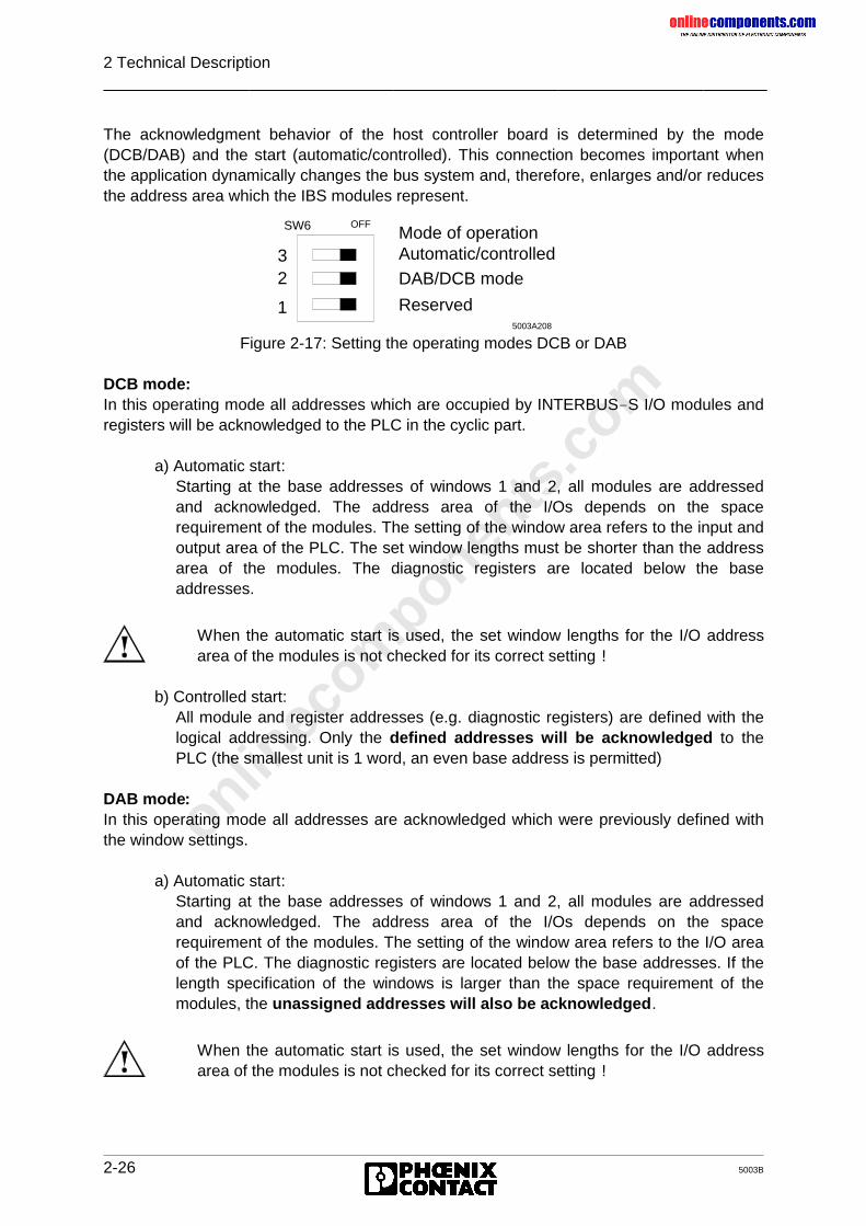
onlinec
omponen
ts.co
m
2 Technical Description
2-26 5003B
The acknowledgment behavior of the host controller board is determined by the mode(DCB/DAB) and the start (automatic/controlled). This connection becomes important whenthe application dynamically changes the bus system and, therefore, enlarges and/or reducesthe address area which the IBS modules represent.
Figure 2-17: Setting the operating modes DCB or DAB
DCB mode:In this operating mode all addresses which are occupied by INTERBUS-S I/O modules andregisters will be acknowledged to the PLC in the cyclic part.
a) Automatic start:Starting at the base addresses of windows 1 and 2, all modules are addressedand acknowledged. The address area of the I/Os depends on the spacerequirement of the modules. The setting of the window area refers to the input andoutput area of the PLC. The set window lengths must be shorter than the addressarea of the modules. The diagnostic registers are located below the baseaddresses.
b) Controlled start:All module and register addresses (e.g. diagnostic registers) are defined with thelogical addressing. Only the defined addresses will be acknowledged to thePLC (the smallest unit is 1 word, an even base address is permitted)
DAB mode:In this operating mode all addresses are acknowledged which were previously defined withthe window settings.
a) Automatic start:Starting at the base addresses of windows 1 and 2, all modules are addressedand acknowledged. The address area of the I/Os depends on the spacerequirement of the modules. The setting of the window area refers to the I/O areaof the PLC. The diagnostic registers are located below the base addresses. If thelength specification of the windows is larger than the space requirement of themodules, the unassigned addresses will also be acknowledged.
OFF
1
SW6
23
DAB/DCB mode
Reserved5003A208
Mode of operationAutomatic/controlled
When the automatic start is used, the set window lengths for the I/O addressarea of the modules is not checked for its correct setting !
When the automatic start is used, the set window lengths for the I/O addressarea of the modules is not checked for its correct setting !
onlinec
omponen
ts.co
m
2 Technical Description
5003B 2-27
b) Controlled start:All module and register addresses (e.g. diagnostic registers) must be definedwithin the window area by means of logical addressing. All window addressesare acknowledged.
2.6.3.1 INTERBUS-S in the PLC’s Address Area
INTERBUS-S occupies one part of the PLC’s I/O address area. The size of the addressarea which is occupied depends on the INTERBUS-S configuration. This address area canbe accessed in the same way ("L IW", "T OW", "U I", "S O", "L PW", "T PW", "L QW", "TQW") as system-contained boards. For the INTERBUS-S system the address area requiredfor the I/O modules is addressed centrally on the host controller board. The setting of therequired addresses depends on the operating mode of the controller board (SW 6).
Automatic start/ DCB modeIn this operating mode the host controller board automatically puts the addresses of theINTERBUS-S modules into the specified address windows after the voltage has beenswitched on. The set window lengths must be shorter than the address area of the modules.Moreover, registers for bus system diagnostics will be overlaid at fixed positions in the PLC’sinput area.
Controlled start/ DCB modeIn this mode of operation, the host controller board runs through an initialization phase inorder to address INTERBUS-S modules after the voltage has been switched on. Theprogrammer can freely assign the addresses of the modules as well as the diagnosticregisters in the PLC’s address area. The programming is done either during the PLC startup,by means of a software package or on the host controller board by means of a programmedEEPROM.
Automatic and controlled start/ DAB modeIn this mode of operation the host controller board puts the addresses of the INTERBUS-Smodules automatically and/or by means of logical addressing into the specified addresswindows after the voltage has been switched on. In the controlled start mode, the registers(e.g. diagnostic registers) must be addressed in the address windows.Besides the setting of the I/O addresses of the INTERBUS-S system a register (window 3)is put in the I/O area of the PLC. Via these registers, INTERBUS-S is controlled andsynchronized with the PLC. The input word 0 of the PLC is an alarm message word.
The communication registers (window 3) must be set independently of the start(automatic/controlled) and mode setting (DAB/DCB).
When the automatic start is used, the set window lengths for the I/O addressarea of the modules is not checked for its correct setting !
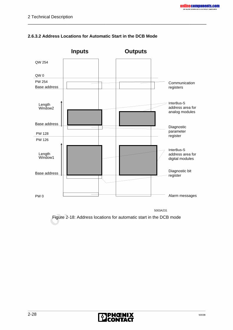
onlinec
omponen
ts.co
m
2 Technical Description
2-28 5003B
2.6.3.2 Address Locations for Automatic Start in the DCB Mode
Figure 2-18: Address locations for automatic start in the DCB mode
Window2
Base address
PW 0
PW 126
LengthWindow1
Base address
PW 128
Base addressPW 254
QW 0
Length
QW 254
Inputs Outputs
Alarm messages
registerDiagnostic bit
InterBus-Saddress area fordigital modules
InterBus-Saddress area foranalog modules
Diagnostic parameterregister
Communication registers
5003A231
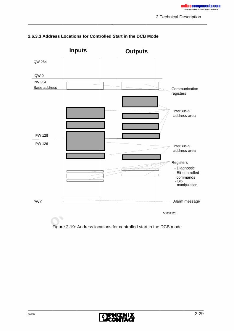
onlinec
omponen
ts.co
m
2 Technical Description
5003B 2-29
2.6.3.3 Address Locations for Controlled Start in the DCB Mode
Figure 2-19: Address locations for controlled start in the DCB mode
PW 0
PW 126
PW 128
Base address
PW 254
QW 0
QW 254
Inputs Outputs
commands
manipulation - Bit-
Alarm message
- Bit-controlled - Diagnostic
Registers
InterBus-Saddress area
InterBus-Saddress area
Communication registers
5003A228
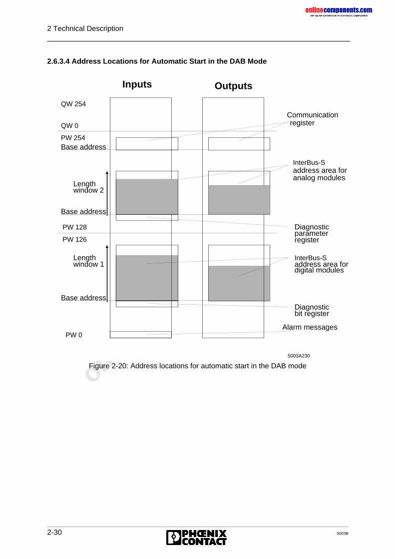
onlinec
omponen
ts.co
m
2 Technical Description
2-30 5003B
2.6.3.4 Address Locations for Automatic Start in the DAB Mode
Figure 2-20: Address locations for automatic start in the DAB mode
Length
Base address
PW 0
PW 126
Lengthwindow 1
Base address
PW 128
window 2
Base addressPW 254
QW 0
QW 254
Inputs Outputs
Diagnosticbit register
Alarm messages
register
InterBus-Saddress area fordigital modules
Diagnostic parameter
Communication register
InterBus-Saddress area foranalog modules
5003A230
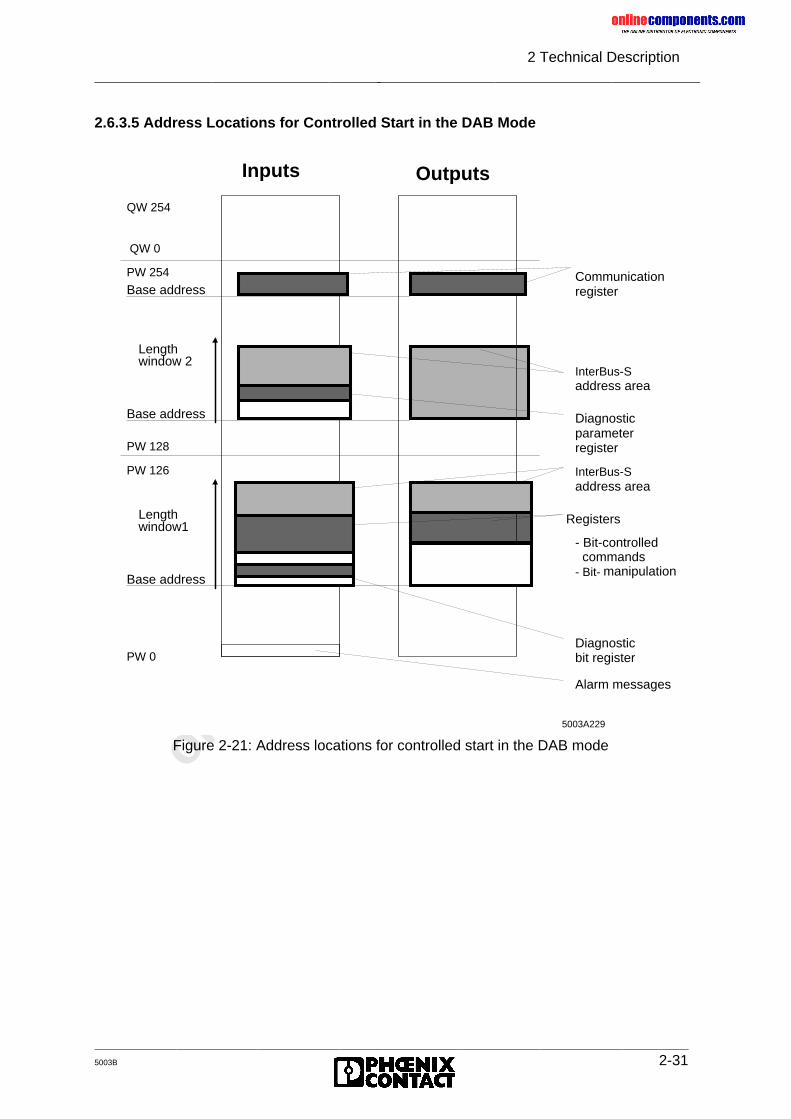
onlinec
omponen
ts.co
m
2 Technical Description
5003B 2-31
2.6.3.5 Address Locations for Controlled Start in the DAB Mode
window 2
Base address
PW 0
PW 126
Lengthwindow1
Base address
PW 128
Base addressPW 254
QW 0
Length
QW 254
Inputs Outputs
manipulation
Alarm messages
- Bit-
Diagnosticbit register
- Bit-controlled
InterBus-Saddress area
commands
Registers
InterBus-Saddress area
Diagnostic parameter register
Communicationregister
5003A229
Figure 2-21: Address locations for controlled start in the DAB mode
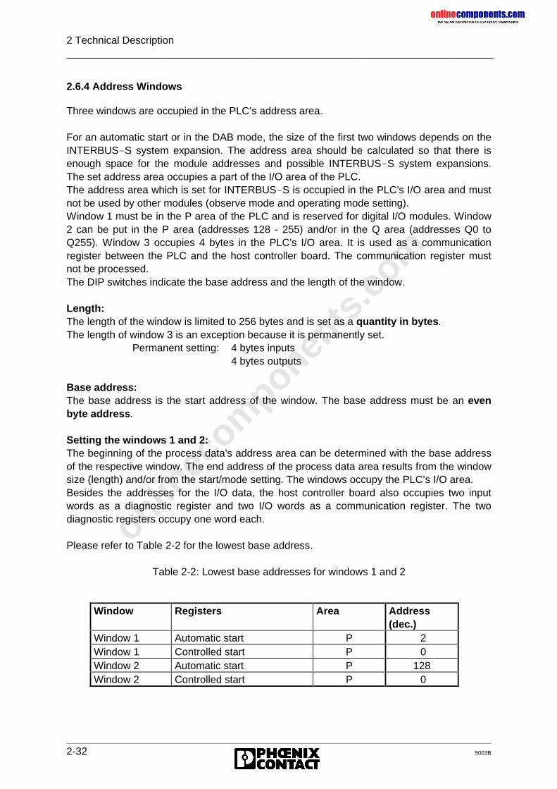
onlinec
omponen
ts.co
m
2 Technical Description
2-32 5003B
2.6.4 Address Windows
Three windows are occupied in the PLC’s address area.
For an automatic start or in the DAB mode, the size of the first two windows depends on theINTERBUS-S system expansion. The address area should be calculated so that there isenough space for the module addresses and possible INTERBUS-S system expansions.The set address area occupies a part of the I/O area of the PLC.The address area which is set for INTERBUS-S is occupied in the PLC’s I/O area and mustnot be used by other modules (observe mode and operating mode setting).Window 1 must be in the P area of the PLC and is reserved for digital I/O modules. Window2 can be put in the P area (addresses 128 - 255) and/or in the Q area (addresses Q0 toQ255). Window 3 occupies 4 bytes in the PLC’s I/O area. It is used as a communicationregister between the PLC and the host controller board. The communication register mustnot be processed.The DIP switches indicate the base address and the length of the window.
Length:The length of the window is limited to 256 bytes and is set as a quantity in bytes.The length of window 3 is an exception because it is permanently set.
Permanent setting: 4 bytes inputs4 bytes outputs
Base address:The base address is the start address of the window. The base address must be an evenbyte address.
Setting the windows 1 and 2:The beginning of the process data’s address area can be determined with the base addressof the respective window. The end address of the process data area results from the windowsize (length) and/or from the start/mode setting. The windows occupy the PLC’s I/O area.Besides the addresses for the I/O data, the host controller board also occupies two inputwords as a diagnostic register and two I/O words as a communication register. The twodiagnostic registers occupy one word each.
Please refer to Table 2-2 for the lowest base address.
Table 2-2: Lowest base addresses for windows 1 and 2
Window Registers Area Address(dec.)
Window 1 Automatic start P 2Window 1 Controlled start P 0Window 2 Automatic start P 128Window 2 Controlled start P 0
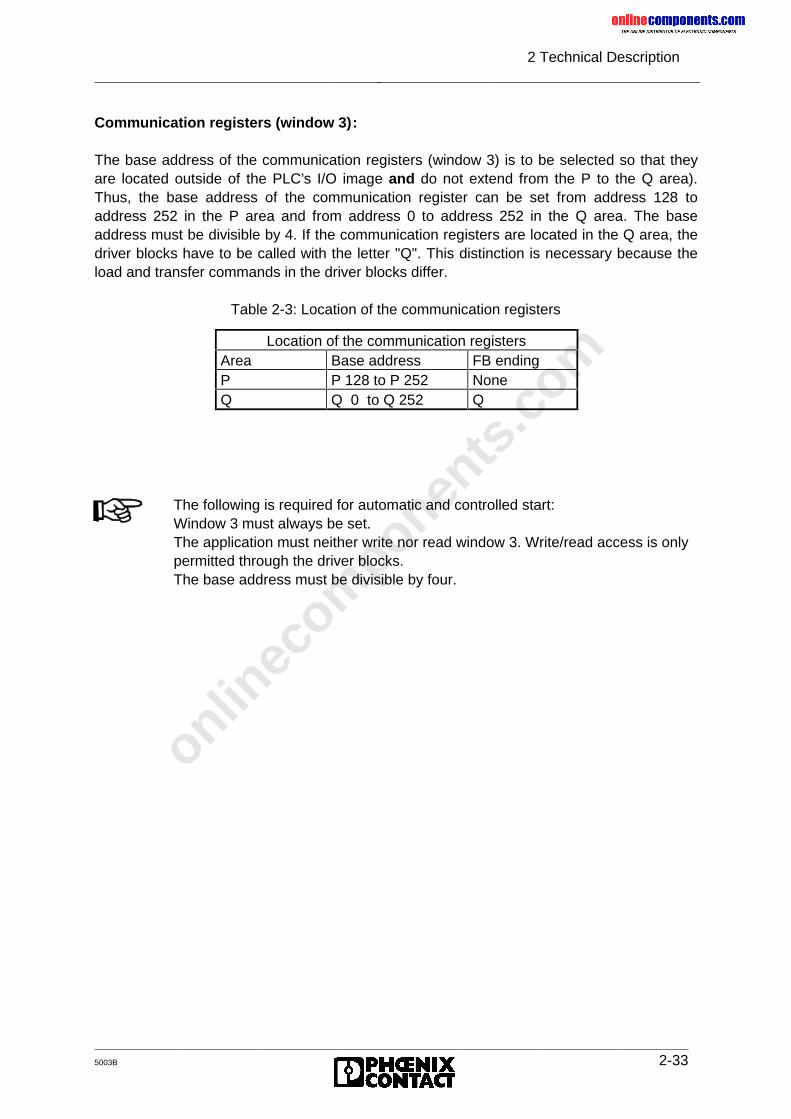
onlinec
omponen
ts.co
m
2 Technical Description
5003B 2-33
Communication registers (window 3):
The base address of the communication registers (window 3) is to be selected so that theyare located outside of the PLC’s I/O image and do not extend from the P to the Q area).Thus, the base address of the communication register can be set from address 128 toaddress 252 in the P area and from address 0 to address 252 in the Q area. The baseaddress must be divisible by 4. If the communication registers are located in the Q area, thedriver blocks have to be called with the letter "Q". This distinction is necessary because theload and transfer commands in the driver blocks differ.
Table 2-3: Location of the communication registers
Location of the communication registersArea Base address FB endingP P 128 to P 252 NoneQ Q 0 to Q 252 Q
The following is required for automatic and controlled start:Window 3 must always be set.The application must neither write nor read window 3. Write/read access is onlypermitted through the driver blocks.The base address must be divisible by four.
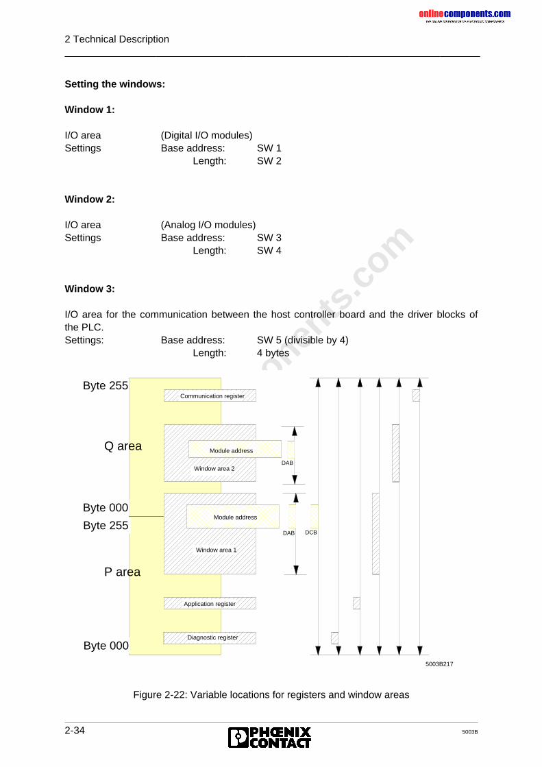
onlinec
omponen
ts.co
m
2 Technical Description
2-34 5003B
Setting the windows:
Window 1:
I/O area (Digital I/O modules)Settings Base address: SW 1
Length: SW 2
Window 2:
I/O area (Analog I/O modules)Settings Base address: SW 3
Length: SW 4
Window 3:
I/O area for the communication between the host controller board and the driver blocks ofthe PLC.Settings: Base address: SW 5 (divisible by 4)
Length: 4 bytes
Figure 2-22: Variable locations for registers and window areas
Byte 255
5003B217
P area
Q area
Byte 255
Byte 000
Byte 000
Communication register
DAB DCB
Module address
Window area 2
Window area 1
Application register
Diagnostic register
DAB
Module address
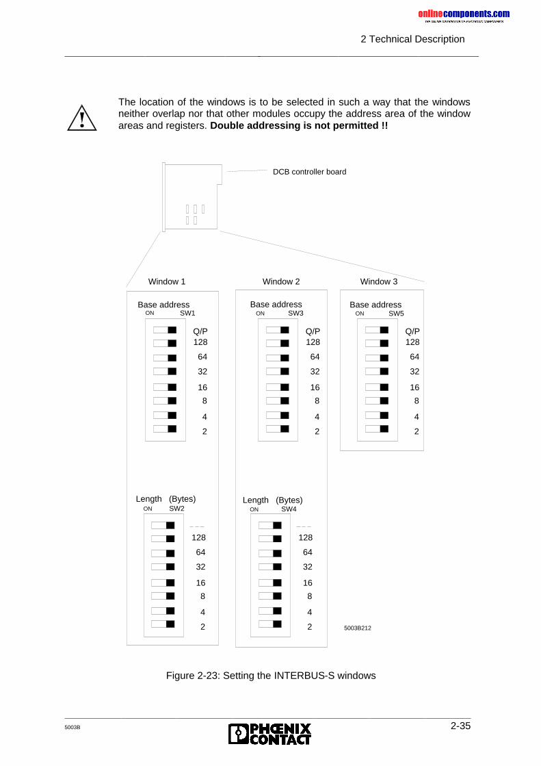
onlinec
omponen
ts.co
m
2 Technical Description
5003B 2-35
5003B212
DCB controller board
Base address
Window 2
ON
Q/P128
64
32
16
8
4
2
SW3
Length (Bytes)ON
128
64
32
16
8
4
2
SW4Length (Bytes)
ON
128
64
32
16
8
4
2
SW2
Base address
Window 1
ON
Q/P128
64
32
16
8
4
2
SW1Base address
Window 3
ON
Q/P128
64
32
16
8
4
SW5
2
Figure 2-23: Setting the INTERBUS-S windows
The location of the windows is to be selected in such a way that the windowsneither overlap nor that other modules occupy the address area of the windowareas and registers. Double addressing is not permitted !!
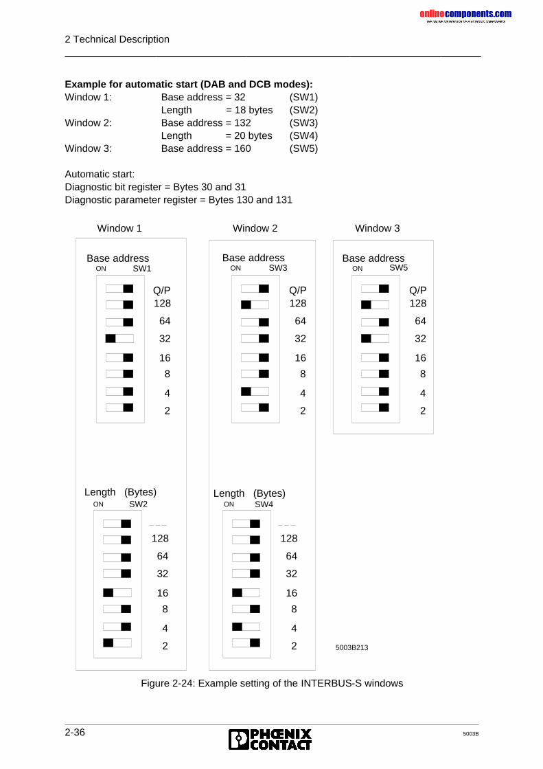
onlinec
omponen
ts.co
m
2 Technical Description
2-36 5003B
Example for automatic start (DAB and DCB modes):Window 1: Base address = 32 (SW1)
Length = 18 bytes (SW2)Window 2: Base address = 132 (SW3)
Length = 20 bytes (SW4)Window 3: Base address = 160 (SW5)
Automatic start:Diagnostic bit register = Bytes 30 and 31Diagnostic parameter register = Bytes 130 and 131
Figure 2-24: Example setting of the INTERBUS-S windows
5003B213
Length (Bytes)ON
128
64
32
16
8
4
2
SW2
Base address
Window 1
ON
Q/P128
64
32
16
8
4
2
SW1Base address
Window 2
ON
Q/P128
64
32
16
8
4
2
SW3
Length (Bytes)ON
128
64
32
16
8
4
2
SW4
Base address
Window 3
ON
Q/P128
64
32
16
8
4
SW5
2
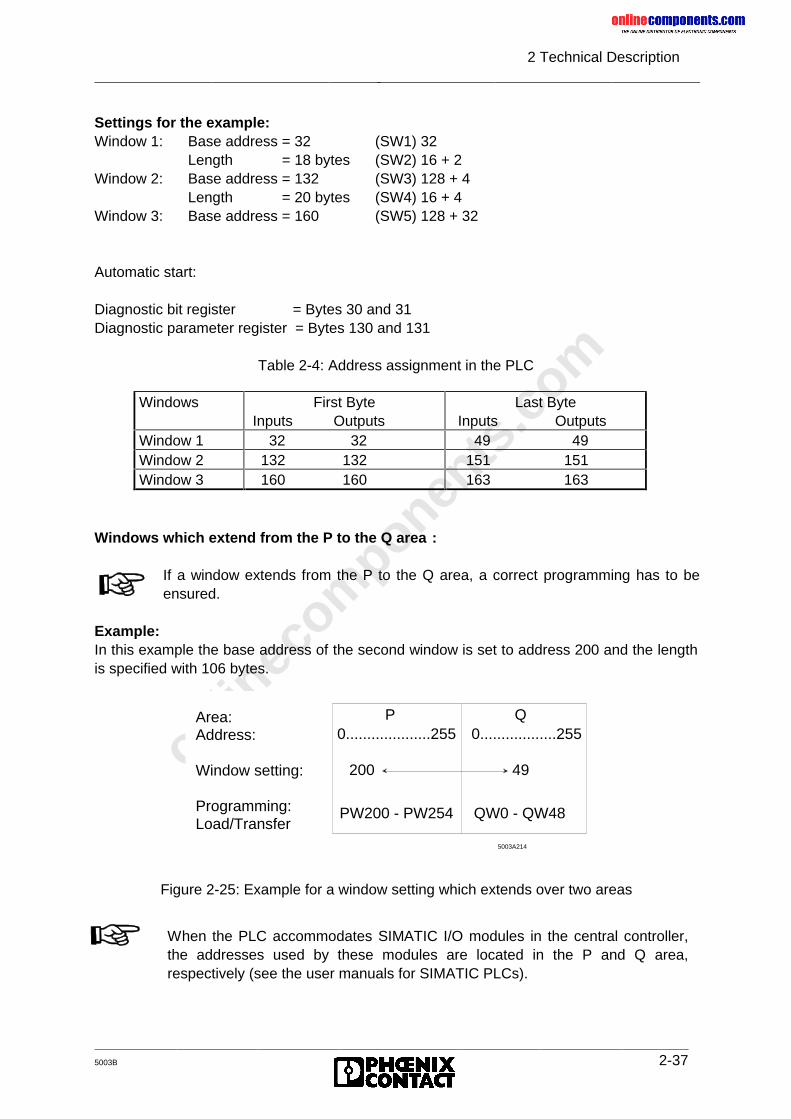
onlinec
omponen
ts.co
m
2 Technical Description
5003B 2-37
Settings for the example:Window 1: Base address = 32 (SW1) 32
Length = 18 bytes (SW2) 16 + 2Window 2: Base address = 132 (SW3) 128 + 4
Length = 20 bytes (SW4) 16 + 4Window 3: Base address = 160 (SW5) 128 + 32
Automatic start:
Diagnostic bit register = Bytes 30 and 31Diagnostic parameter register = Bytes 130 and 131
Table 2-4: Address assignment in the PLC
Windows which extend from the P to the Q area :
Example:In this example the base address of the second window is set to address 200 and the lengthis specified with 106 bytes.
Figure 2-25: Example for a window setting which extends over two areas
Windows First Byte Inputs Outputs
Last Byte Inputs Outputs
Window 1 32 32 49 49Window 2 132 132 151 151Window 3 160 160 163 163
If a window extends from the P to the Q area, a correct programming has to beensured.
P Q0....................255 0..................255
200 49
PW200 - PW254 QW0 - QW48
Area:Address:
Window setting:
Programming:Load/Transfer
5003A214
When the PLC accommodates SIMATIC I/O modules in the central controller,the addresses used by these modules are located in the P and Q area,respectively (see the user manuals for SIMATIC PLCs).
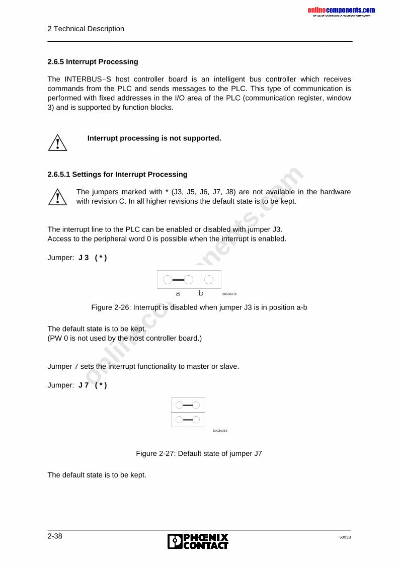
onlinec
omponen
ts.co
m
2 Technical Description
2-38 5003B
2.6.5 Interrupt Processing
The INTERBUS-S host controller board is an intelligent bus controller which receivescommands from the PLC and sends messages to the PLC. This type of communication isperformed with fixed addresses in the I/O area of the PLC (communication register, window3) and is supported by function blocks.
2.6.5.1 Settings for Interrupt Processing
The interrupt line to the PLC can be enabled or disabled with jumper J3.Access to the peripheral word 0 is possible when the interrupt is enabled.
Jumper: J 3 ( * )
Figure 2-26: Interrupt is disabled when jumper J3 is in position a-b
The default state is to be kept.(PW 0 is not used by the host controller board.)
Jumper 7 sets the interrupt functionality to master or slave.
Jumper: J 7 ( * )
Figure 2-27: Default state of jumper J7
The default state is to be kept.
Interrupt processing is not supported.
The jumpers marked with * (J3, J5, J6, J7, J8) are not available in the hardwarewith revision C. In all higher revisions the default state is to be kept.
a b 5003A215
5003A216
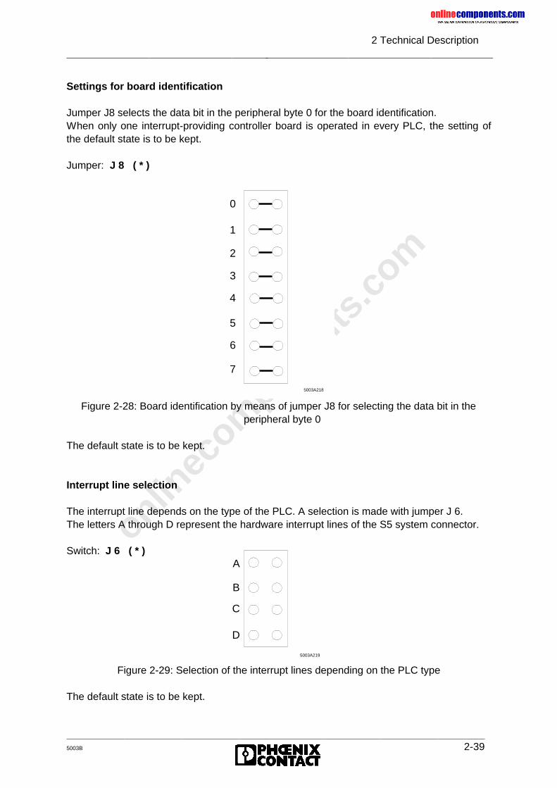
onlinec
omponen
ts.co
m
2 Technical Description
5003B 2-39
Settings for board identification
Jumper J8 selects the data bit in the peripheral byte 0 for the board identification.When only one interrupt-providing controller board is operated in every PLC, the setting ofthe default state is to be kept.
Jumper: J 8 ( * )
Figure 2-28: Board identification by means of jumper J8 for selecting the data bit in theperipheral byte 0
The default state is to be kept.
Interrupt line selection
The interrupt line depends on the type of the PLC. A selection is made with jumper J 6.The letters A through D represent the hardware interrupt lines of the S5 system connector.
Figure 2-29: Selection of the interrupt lines depending on the PLC type
The default state is to be kept.
5003A218
7
6
5
4
3
2
1
0
5003A219
D
C
B
ASwitch: J 6 ( * )
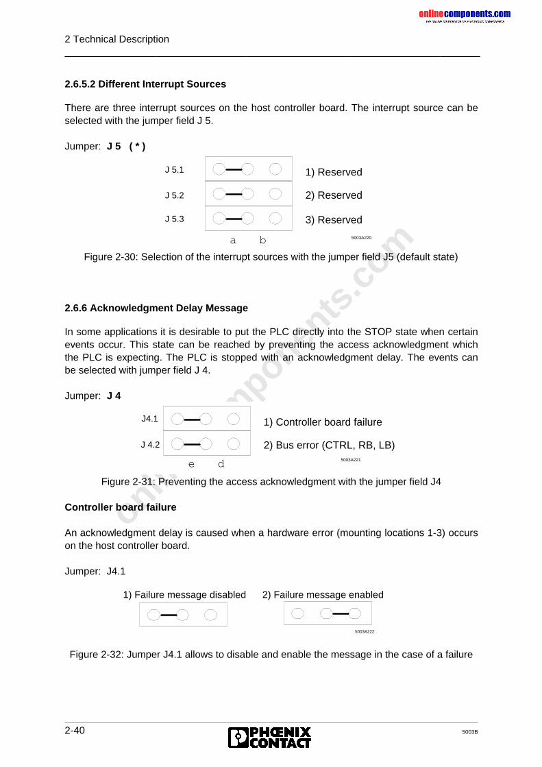
onlinec
omponen
ts.co
m
2 Technical Description
2-40 5003B
2.6.5.2 Different Interrupt Sources
There are three interrupt sources on the host controller board. The interrupt source can beselected with the jumper field J 5.
Jumper: J 5 ( * )
Figure 2-30: Selection of the interrupt sources with the jumper field J5 (default state)
2.6.6 Acknowledgment Delay Message
In some applications it is desirable to put the PLC directly into the STOP state when certainevents occur. This state can be reached by preventing the access acknowledgment whichthe PLC is expecting. The PLC is stopped with an acknowledgment delay. The events canbe selected with jumper field J 4.
Jumper: J 4
Figure 2-31: Preventing the access acknowledgment with the jumper field J4
Controller board failure
An acknowledgment delay is caused when a hardware error (mounting locations 1-3) occurson the host controller board.
Jumper: J4.1
Figure 2-32: Jumper J4.1 allows to disable and enable the message in the case of a failure
a b 5003A220
1) Reserved
2) Reserved
3) Reserved
J 5.1
J 5.2
J 5.3
e d 5003A221
1) Controller board failure
2) Bus error (CTRL, RB, LB)
J4.1
J 4.2
5003A222
1) Failure message disabled
2) Failure message enabled
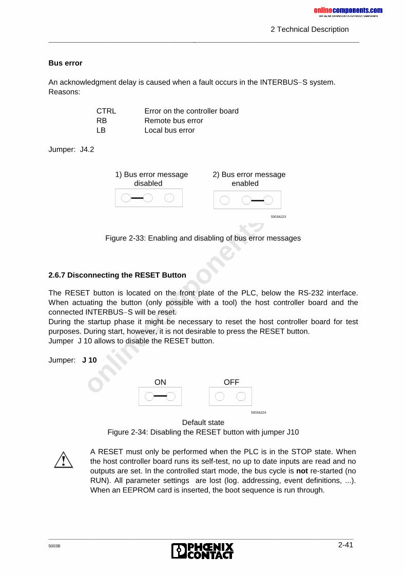
onlinec
omponen
ts.co
m
2 Technical Description
5003B 2-41
Bus error
An acknowledgment delay is caused when a fault occurs in the INTERBUS-S system.Reasons:
CTRL Error on the controller boardRB Remote bus errorLB Local bus error
Jumper: J4.2
Figure 2-33: Enabling and disabling of bus error messages
2.6.7 Disconnecting the RESET Button
The RESET button is located on the front plate of the PLC, below the RS-232 interface.When actuating the button (only possible with a tool) the host controller board and theconnected INTERBUS-S will be reset.During the startup phase it might be necessary to reset the host controller board for testpurposes. During start, however, it is not desirable to press the RESET button.Jumper J 10 allows to disable the RESET button.
Jumper: J 10
Default stateFigure 2-34: Disabling the RESET button with jumper J10
5003A223
1) Bus error message disabled
2) Bus error message enabled
5003A224
ON OFF
A RESET must only be performed when the PLC is in the STOP state. Whenthe host controller board runs its self-test, no up to date inputs are read and nooutputs are set. In the controlled start mode, the bus cycle is not re-started (noRUN). All parameter settings are lost (log. addressing, event definitions, ...).When an EEPROM card is inserted, the boot sequence is run through.
onlinec
omponen
ts.co
m
2 Technical Description
2-42 5003B
2.7 Data Sheet
Designation: IBS S5 DCB/I-T
Basic specifications
Control system: SIMATIC S5 PLCsTypes: S5 115 U S5 130 WB
S5 135 U S5 150 U, 150 SS5 155 UOthers upon request
Bus system
Sensor/actuator: INTERBUS-SBus: INTERBUS-S compatible modules
Types: Different I/O modulesManufacturer: Phoenix ContactThird-party: Inquiries to
INTERBUS-S-Club
Expansion:Max. 256 local busses(incl. bus terminal modules with I/O functionand installation remote bus modules)Max. 320 modules (incl. BKs and PCP stations)Max. 256 INTERBUS-S wordsMax. 62 PCP stations
Diagnostics: Overall system diagnostics by means of- front plate diagnostics- diagnostic registers - software-diagnostics via
the PLCRS-232 and PC monitor
Interfaces:Two-wire remote bus connection
9-pos. D-SUB female connectorRS-232 connection
9-pos. D-SUB male connector
HardwareSize: The controller board occupies two narrow slots
115 U with adaptation casing 130 U - 155 U directly pluggable
onlinec
omponen
ts.co
m
2 Technical Description
5003B 2-43
Address area: P areaQ area
Multiprocessor operation: Yes
Interrupt operation: No
Current consumption: 1.3 A typ. at +5 voltsmax. 2.5 A
Temperature Operation: 0 °C to 60 °CStorage: -25 °C to 80 °C
Humidity Operation: 70 %Storage: 95 %
EEPROM: 16 - 64 kbytes (memory card format)
onlinec
omponen
ts.co
m
5003B
Chapter 3
User InterfacesThis chapter provides information on
- how the INTERBUS-S controller board and the PLC exchange process data- the identification of modules in the bus configuration- the two basic method of addressing the I/O modules- the input and output, as well as the allocation of digital and analog I/O data
3 User Interfaces ...................................................................................3-1
3.1 ID Code of the Modules................................................................................ 3-3
3.2 Process Data Interface................................................................................. 3-83.2.1 Example Configuration .............................................................................. 3-93.2.2 Order of the Modules on the Bus ............................................................... 3-11
3.3 Physical Addressing (DCB Mode)................................................................. 3-123.3.1 Function..................................................................................................... 3-123.3.2 Addressing................................................................................................. 3-123.3.3 Address Orientation ................................................................................... 3-14
3.4 Logical Addressing (DCB Mode) .................................................................. 3-173.4.1 Function..................................................................................................... 3-173.4.2 Structure of an INTERBUS-S Address List ................................................ 3-183.4.3 Addressing................................................................................................. 3-19
3.5 Access to INTERBUS-S Modules................................................................. 3-233.5.1 Digital Modules with 16 Inputs ................................................................... 3-243.5.2 LC Modules with 16 Digital Inputs.............................................................. 3-253.5.3 Digital Modules with 32 Inputs ................................................................... 3-263.5.4 Digital Modules with 16 Outputs................................................................. 3-273.5.5 LC Modules with 16 Digital Outputs ........................................................... 3-283.5.6 Digital Modules with 32 Outputs................................................................. 3-293.5.7 Digital Modules with 16 Inputs and 16 Outputs .......................................... 3-303.5.8 Four-Channel Analog-Input Module with Programmable Gain ................... 3-313.5.9 Four-Channel Analog-Output Modules....................................................... 3-343.5.10 Relais Modules .......................................................................................... 3-363.5.11 Communication Interface Boards............................................................... 3-373.5.12 Modules for Thermocouples ...................................................................... 3-38
onlinec
omponen
ts.co
m
3 User Interfaces
5003B 3-1
3 User Interfaces
The following intelligent host controller boards are available for Siemens S5 PLCs: the IBSS5 DCB/I-T (with electrical isolation) and the IBS S5 DCB-T (without electrical isolation)boards. Both types have three software interfaces which are accessible from the PLC side.They can be used by the user without additional tools.
Process data interface:
This interface• can be used in the two operating modes: AUTOMATIC START and CONTROLLED
START,• consists of the INTERBUS-S window 1 and the INTERBUS-S window 2, and• allows to access in real-time the states of sensors and actuators of the connected
processes.
Communication Interface:
The standard function blocks of the INTERBUS-S use the communication interface:• for initializing the controller board and the connected INTERBUS-S system• for controling the INTERBUS-S system during operation• for evaluating the error states• for addressing communication stations through a PMS connection (PMS = Peripherals
Message Specification). The associated protocol is called Peripherals CommunicationProtocol (PCP). Therefore, INTERBUS-S modules which can be addressed in this wayare called PCP stations.
• as an extended communication interface. When a PC is used, system and PCPcommunication can be used through this RS-232 interface.
Diagnostic interface:
• It is always activated in the AUTOMATIC START and optionally in the CONTROLLEDSTART mode.
• It allows to evaluate the controller board indicators for the operating mode and the errortype by means of software.
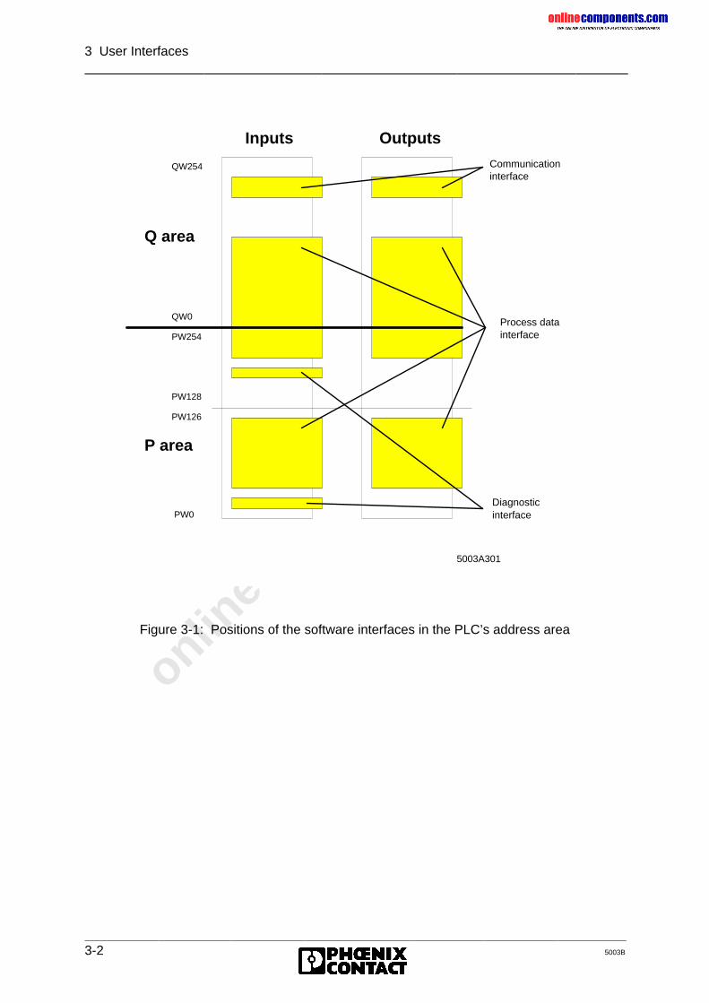
onlinec
omponen
ts.co
m
3 User Interfaces
3-2 5003B
Figure 3-1: Positions of the software interfaces in the PLC’s address area
PW0
PW126
PW128
QW0
PW254
QW254
5003A301
Process data interface
Communication interface
Diagnosticinterface
P area
Q area
Inputs Outputs
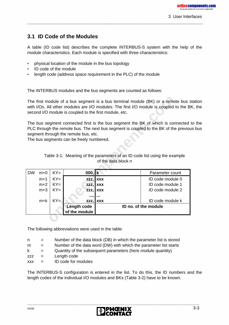
onlinec
omponen
ts.co
m
3 User Interfaces
5003B 3-3
3.1 ID Code of the Modules
A table (ID code list) describes the complete INTERBUS-S system with the help of themodule characteristics. Each module is specified with three characteristics:
• physical location of the module in the bus topology• ID code of the module• length code (address space requirement in the PLC) of the module
The INTERBUS modules and the bus segments are counted as follows:
The first module of a bus segment is a bus terminal module (BK) or a remote bus stationwith I/Os. All other modules are I/O modules. The first I/O module is coupled to the BK, thesecond I/O module is coupled to the first module, etc.
The bus segment connected first is the bus segment the BK of which is connected to thePLC through the remote bus. The next bus segment is coupled to the BK of the previous bussegment through the remote bus, etc.The bus segments can be freely numbered.
Table 3-1: Meaning of the parameters of an ID code list using the exampleof the data block n
DW m+0 KY= 000, k Parameter count
m+1 KY= zzz, xxx ID code module 0m+2 KY= zzz, xxx ID code module 1m+3 KY= zzz, xxx ID code module 2
..., ...m+k KY= zzz, xxx ID code module k
Length codeof the module
ID no. of the module
The following abbreviations were used in the table:
n = Number of the data block (DB) in which the parameter list is storedm = Number of the data word (DW) with which the parameter list startsk = Quantity of the subsequent parameters (here module quantity)zzz = Length codexxx = ID code for modules
The INTERBUS-S configuration is entered in the list. To do this, the ID numbers and thelength codes of the individual I/O modules and BKs (Table 3-2) have to be known.
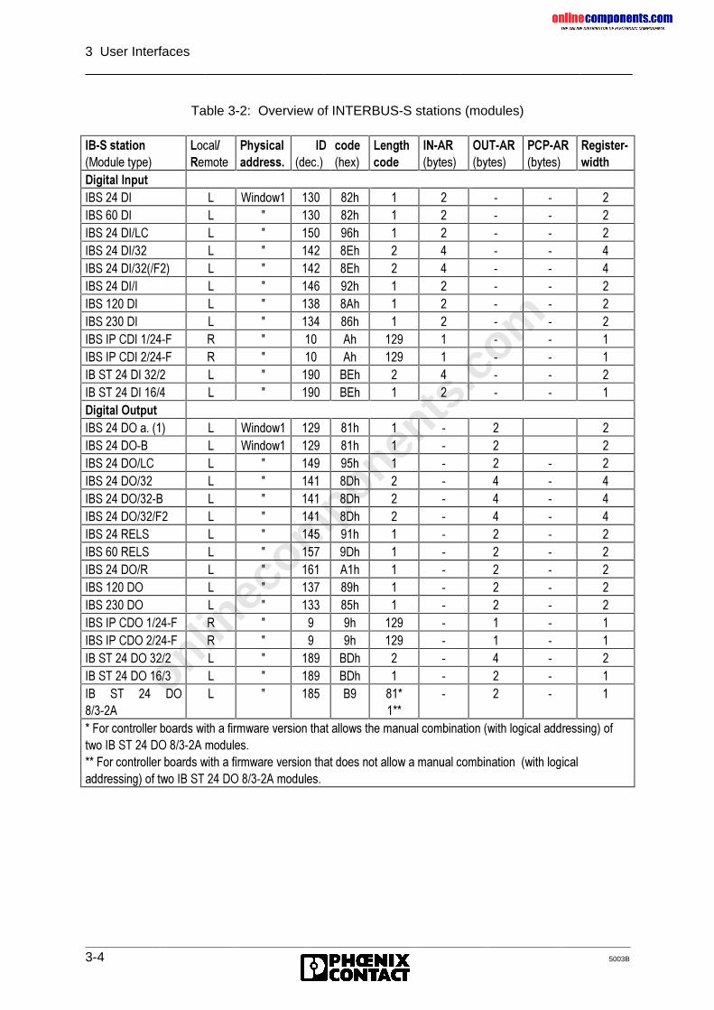
onlinec
omponen
ts.co
m
3 User Interfaces
3-4 5003B
Table 3-2: Overview of INTERBUS-S stations (modules)
,%�6�VWDWLRQ�0RGXOH�W\SH�
/RFDO�5HPRWH
3K\VLFDODGGUHVV�
,'�GHF��
FRGH�KH[�
/HQJWKFRGH
,1�$5�E\WHV�
287�$5�E\WHV�
3&3�$5�E\WHV�
5HJLVWHU�ZLGWK
'LJLWDO�,QSXW,%6����', / :LQGRZ� ��� ��K � � � � �,%6����', / � ��� ��K � � � � �,%6����',�/& / � ��� ��K � � � � �,%6����',��� / � ��� �(K � � � � �,%6����',�����)�� / � ��� �(K � � � � �,%6����',�, / � ��� ��K � � � � �,%6�����', / � ��� �$K � � � � �,%6�����', / � ��� ��K � � � � �,%6�,3�&',������) 5 � �� $K ��� � � � �,%6�,3�&',������) 5 � �� $K ��� � � � �,%�67����',����� / � ��� %(K � � � � �,%�67����',����� / � ��� %(K � � � � �'LJLWDO�2XWSXW,%6����'2�D����� / :LQGRZ� ��� ��K � � � �,%6����'2�% / :LQGRZ� ��� ��K � � � �,%6����'2�/& / � ��� ��K � � � � �,%6����'2��� / � ��� �'K � � � � �,%6����'2����% / � ��� �'K � � � � �,%6����'2����)� / � ��� �'K � � � � �,%6����5(/6 / � ��� ��K � � � � �,%6����5(/6 / � ��� �'K � � � � �,%6����'2�5 / � ��� $�K � � � � �,%6�����'2 / � ��� ��K � � � � �,%6�����'2 / � ��� ��K � � � � �,%6�,3�&'2������) 5 � � �K ��� � � � �,%6�,3�&'2������) 5 � � �K ��� � � � �,%�67����'2����� / � ��� %'K � � � � �,%�67����'2����� / � ��� %'K � � � � �,%� 67� ��� '2�����$
/ � ��� %� �� �
� � � �
�)RU�FRQWUROOHU�ERDUGV�ZLWK�D�ILUPZDUH�YHUVLRQ�WKDW�DOORZV�WKH�PDQXDO�FRPELQDWLRQ��ZLWK�ORJLFDO�DGGUHVVLQJ��RIWZR�,%�67����'2������$�PRGXOHV� �)RU�FRQWUROOHU�ERDUGV�ZLWK�D�ILUPZDUH�YHUVLRQ�WKDW�GRHV�QRW�DOORZ�D�PDQXDO�FRPELQDWLRQ���ZLWK�ORJLFDODGGUHVVLQJ��RI�WZR�,%�67����'2������$�PRGXOHV�
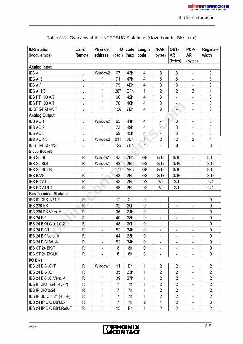
onlinec
omponen
ts.co
m
3 User Interfaces
5003B 3-5
Table 3-3: Overview of the INTERBUS-S stations (slave boards, BKs, etc.)
,%�6�VWDWLRQ�0RGXOH�W\SH�
/RFDO�5HPRWH
3K\VLFDODGGUHVV�
,'�GHF��
FRGH�KH[�
/HQJWKFRGH
,1�$5�E\WHV�
287�$5�E\WHV�
3&3�$5�E\WHV�
5HJLVWHU�ZLGWK
$QDORJ�,QSXW,%6�$, / :LQGRZ� �� ��K � � � � �,%6�$,�� / � �� ��K � � � � �,%6�$,�, / � �� �%K � � � � �,%6�$,���� / � ��� &)K � � � � �,%6�37�����$�� / � �� ��K � � � � �,%6�37�����$�� / � �� ��K � � � � �,%�67����$,���6) / � ��� �(K � � � � �$QDORJ�2XWSXW,%6�$2�� / :LQGRZ� �� ��K � � � � �,%6�$2�� / � �� ��K � � � � �,%6�$2�� / � �� ��K � � � � �,%6�$2���� / :LQGRZ� ��� �'K � � � � �,%�67����$2���6) / � ��� �'K � � � � �6ODYH�%RDUGV,%6�6��6/ 5 :LQGRZ� �� �%K ��� ���� ���� � ����,%6�6��6/�, 5 :LQGRZ� �� �%K ��� ���� ���� � ����,%6�6��6/�/% / � ��� $%K ��� ���� ���� � ����,%6�%$�6/ 5 � �� �%K ��� ���� ���� � ����,%6�3&�$7�7 5 � �� �%K ��� ��� ��� � ���,%6�3&�$7�,�7 5 � �� �%K ��� ��� ��� � ���%XV�7HUPLQDO�0RGXOHV,%6�,3�&%.������) 5 � �� &K � � � � �,%6�����%. 5 � �� ��K � � � � �,%6�����%.�9HUV��$ 5 � �� ��K � � � � �,%6����%. 5 � �� ��K � � � � �,%6����%.�/&�D��/&�� 5 � �� ��K � � � � �,%6����%.�7 5 � �� ��K � � � � �,%6����%.�9HUV��$ 5 � �� ��K � � � � �,%6����%.�/:/�. 5 � �� ��K � � � � �,%6�67����%.�7 5 � � �K � � � � �,%6�67����%.�/. 5 � � �K � � � � �,�2�%.V,%6����%.�,�2�7 5 :LQGRZ� �� %K � � � � �,%6����%.�,�2 5 � �� ��K � � � � �,%6����%.�,�2�9HUV��$ 5 � �� ��K � � � � �,%6�,3�',2��������)���3� 5 � � �K � � � � �,%6�,3�',2������� 5 � � �K � � � � �,%6�,3�%',2��������)���3� 5 � � �K � � � � �,%6����,3�',2�%%��(�7 5 � � �K � � � � �,%6����,3�',2�%%��5HOV�7 5 � �� )K � � � � �
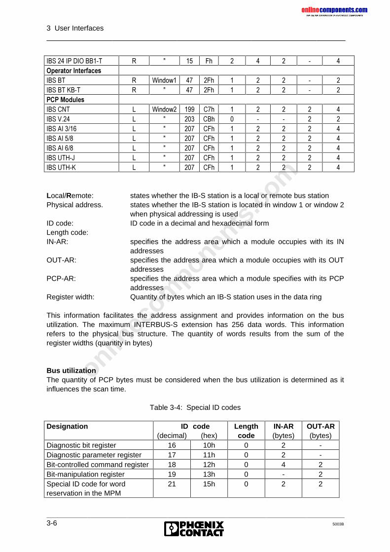
onlinec
omponen
ts.co
m
3 User Interfaces
3-6 5003B
,%6����,3�',2�%%��7 5 � �� )K � � � � �2SHUDWRU�,QWHUIDFHV,%6�%7 5 :LQGRZ� �� �)K � � � � �,%6�%7�.%�7 5 � �� �)K � � � � �3&3�0RGXOHV,%6�&17 / :LQGRZ� ��� &�K � � � � �,%6�9��� / � ��� &%K � � � � �,%6�$,����� / � ��� &)K � � � � �,%6�$,���� / � ��� &)K � � � � �,%6�$,���� / � ��� &)K � � � � �,%6�87+�- / � ��� &)K � � � � �,%6�87+�. / � ��� &)K � � � � �
Local/Remote: states whether the IB-S station is a local or remote bus stationPhysical address. states whether the IB-S station is located in window 1 or window 2
when physical addressing is usedID code: ID code in a decimal and hexadecimal formLength code:IN-AR: specifies the address area which a module occupies with its IN
addressesOUT-AR: specifies the address area which a module occupies with its OUT
addressesPCP-AR: specifies the address area which a module specifies with its PCP
addressesRegister width: Quantity of bytes which an IB-S station uses in the data ring
This information facilitates the address assignment and provides information on the busutilization. The maximum INTERBUS-S extension has 256 data words. This informationrefers to the physical bus structure. The quantity of words results from the sum of theregister widths (quantity in bytes)
Bus utilizationThe quantity of PCP bytes must be considered when the bus utilization is determined as itinfluences the scan time.
Table 3-4: Special ID codes
Designation ID(decimal)
code(hex)
Lengthcode
IN-AR(bytes)
OUT-AR(bytes)
Diagnostic bit register 16 10h 0 2 -Diagnostic parameter register 17 11h 0 2 -Bit-controlled command register 18 12h 0 4 2Bit-manipulation register 19 13h 0 - 2Special ID code for wordreservation in the MPM
21 15h 0 2 2
onlinec
omponen
ts.co
m
3 User Interfaces
5003B 3-7
INTERBUS-S devices from third party manufacturers
Apart from this module overview, the INTERBUS-S User Groups DRIVECOM, ENCOM andother manufacturers of INTERBUS-S-compatible devices offer a wide range of remote andlocal bus stations.
A description of these bus stations can be obtained from the respective manufacturer.Please have the following information at hand:• ID code• Length code• PCP byte quantity
The special ID codes are appended to the ID code list. The ID codes for the bitmanipulation registers can be assigned several times.
With the help of the special ID codes 0015h an output and input word isreserved in the MPM. The contents of the output word output on the yellowLEDs by means of the coding switch position 93xx. The value xx (decimal,value range 0-99) is written into the input word. When the configuration isinput the special ID code is appended to the actual configuration by means ofthe Check-Physical-Configuration (0058h) service. It must occur only once inthe configuration. You may use the logical addressing to place the two wordsat any address in the MPM.
onlinec
omponen
ts.co
m
3 User Interfaces
3-8 5003B
3.2 Process Data Interface
The INTERBUS-S system occupies a certain portion of the PLC’s I/O address area. The sizeof this address area depends on the bus topology. This INTERBUS-S address area can beaccessed with the same commands ("L IW", "T OW", "U I", "S O", "L PW", "T PW", "L QW","T QW" etc.) as for system-internal boards.
The address area which is required for the I/O modules of the INTERBUS-S system is set onthe controller board. The setting of the required addresses depends on the mode ofoperation of the controller board (switch SW 6).
Two types of addressing are possible.
PHYSICAL ADDRESSINGIn this mode of operation the host controller board puts the addresses of the INTERBUS-Smodules, in accordance with the physical order of the modules in the bus topology,automatically into the set address windows after the voltage has been switched on.Additionally, registers for bus system diagnostics are overlaid at fixed locations in the PLC’sinput area.
LOGICAL ADDRESSINGFor this mode of operation, the programmer can freely assign the addresses of the modulesand of the diagnostic registers in the address area of the PLC. After power on, the controllerboard addresses the INTERBUS-S modules in the way that was programmed in the softwarepackage or EEPROM before.
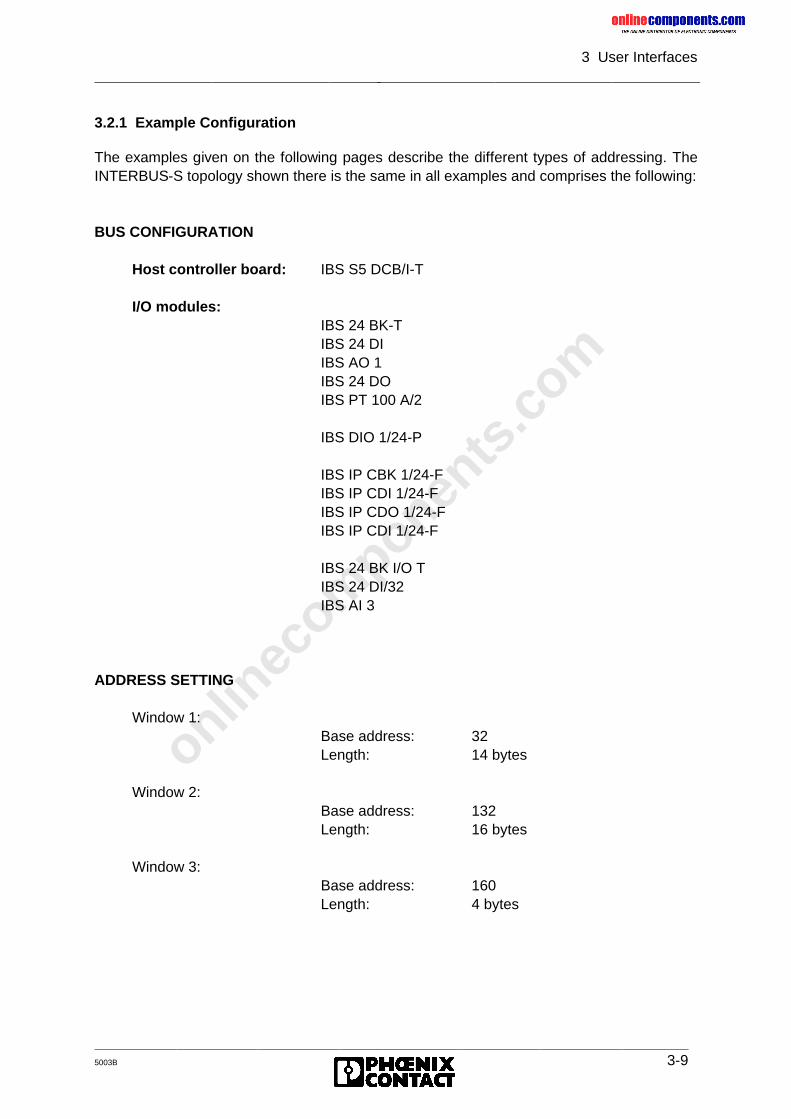
onlinec
omponen
ts.co
m
3 User Interfaces
5003B 3-9
3.2.1 Example Configuration
The examples given on the following pages describe the different types of addressing. TheINTERBUS-S topology shown there is the same in all examples and comprises the following:
BUS CONFIGURATION
Host controller board: IBS S5 DCB/I-T
I/O modules:IBS 24 BK-TIBS 24 DIIBS AO 1IBS 24 DOIBS PT 100 A/2
IBS DIO 1/24-P
IBS IP CBK 1/24-FIBS IP CDI 1/24-FIBS IP CDO 1/24-FIBS IP CDI 1/24-F
IBS 24 BK I/O TIBS 24 DI/32IBS AI 3
ADDRESS SETTING
Window 1:Base address: 32Length: 14 bytes
Window 2:Base address: 132Length: 16 bytes
Window 3:Base address: 160Length: 4 bytes
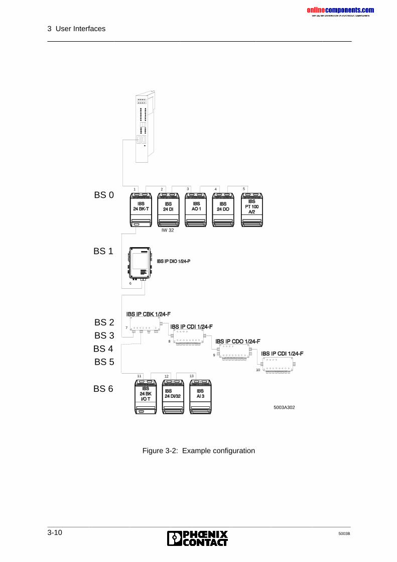
onlinec
omponen
ts.co
m
3 User Interfaces
3-10 5003B
Figure 3-2: Example configuration
IW 32
5003A302
7
8
9
10
11 12 13
1 2 3 4 5
6
ID 7
BS 6
BS 1
BS 0
BS 2BS 3BS 4BS 5
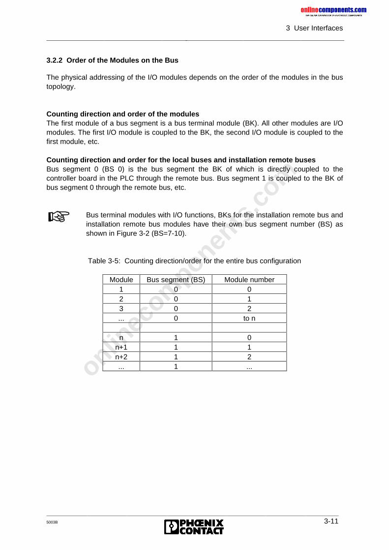
onlinec
omponen
ts.co
m
3 User Interfaces
5003B 3-11
3.2.2 Order of the Modules on the Bus
The physical addressing of the I/O modules depends on the order of the modules in the bustopology.
Counting direction and order of the modulesThe first module of a bus segment is a bus terminal module (BK). All other modules are I/Omodules. The first I/O module is coupled to the BK, the second I/O module is coupled to thefirst module, etc.
Counting direction and order for the local buses and installation remote busesBus segment 0 (BS 0) is the bus segment the BK of which is directly coupled to thecontroller board in the PLC through the remote bus. Bus segment 1 is coupled to the BK ofbus segment 0 through the remote bus, etc.
Table 3-5: Counting direction/order for the entire bus configuration
Bus terminal modules with I/O functions, BKs for the installation remote bus andinstallation remote bus modules have their own bus segment number (BS) asshown in Figure 3-2 (BS=7-10).
Module Bus segment (BS) Module number1 0 02 0 13 0 2... 0 to n
n 1 0n+1 1 1n+2 1 2... 1 ...
onlinec
omponen
ts.co
m
3 User Interfaces
3-12 5003B
3.3 Physical Addressing (DCB Mode)
The bus topology in the example for the PHYSICAL ADDRESSING is identical withFigure 3-2.
3.3.1 Function
The controller board starts automatically in the startup of the PLC. To ensure that theINTERBUS-S system is ready for operation when the cyclic program is started, theINTERBUS-S standard block INIT_IB must be called in the startup organization blocks of thePLC.
When the PHYSICAL ADDRESSING is used, the addresses of the INTERBUS-S I/Omodules result from the physical structure of the system.
When the addresses are assigned for the INTERBUS-S I/O modules, the digital inputs, thedigital outputs, the analog inputs, and the analog outputs have to be considered separately.
The digital inputs and outputs occupy the first window and the analog I/O the second windowin the PLC’s address area.
In the PLC address area, the module addresses are put into the window starting at the baseaddress. The size of the address area which every module occupies depends on themodule.
3.3.2 Addressing
Addressing digital inputs:The first word of the first I/O module with digital inputs in the INTERBUS-S system isassigned the base address (even word address) set in the controller board of the firstwindow. The next I/O module with digital inputs on the bus is given the next availableaddress (even word or byte address; observe address orientation), etc.
In the ID code list, the parameter WINDOW specifies in which window therespective module appears.
If one or several stations are removed from the bus configuration when the busis stopped, the controller board does not recognize this modification when thephysical addressing is used. Depending on the application, this may causedangerous situations in the process run.
onlinec
omponen
ts.co
m
3 User Interfaces
5003B 3-13
Addressing digital outputs:The same is true for the digital outputs. The first word of the first I/O module with digitaloutputs in the INTERBUS-S system is assigned the base address set in the controller board(even word address) of the first window. The next I/O module with digital outputs whichoccurs on the bus is given the next available address (even word or byte address; observeaddress orientation), etc.
Addressing analog inputs:The first word of the first I/O module with analog inputs in INTERBUS-S system is assignedthe base address set on the controller board (even word address) of the second window.The next I/O module with analog inputs on the bus is given the available free address (evenword address), etc.
Addressing analog outputs:The first word of the first I/O module with analog outputs in the INTERBUS-S system isassigned the base address set on the controller board of the second window. The next I/Omodule with analog outputs on the bus is given the next available address (even wordaddress) etc.
The IBS AI analog input module, for instance, occupies• four words in the input field (one word for each analog input channel)• four words in the output field (one word per channel for the gain).
Possible addresses would be, e.g. input: PW 132 output PW 140
Some modules have input and output addresses.
onlinec
omponen
ts.co
m
3 User Interfaces
3-14 5003B
3.3.3 Address Orientation
Word-oriented addressingAssign an even byte address to modules whose the address areas contain complete words.
Table 3-6: Example for word-oriented addressingModule number Address area E.g. address
n Input: 1 word IB 30n+1 Input: 1 word IB 32n+3 Output: 4 words OB 30n+4 Input: 1 word IB 34n+5 Output: 1 word OB 38
Byte-oriented addressingModules the address area of which contain an odd number of bytes are assigned an evenbyte address, if:
• the previous module is a word-oriented module,• the previous module is located in another I/O area,
e.g. the module is an input module, the previous module is an output module.
Table 3-7: Example for byte-oriented addressing with even byte addressesModule number Address area E.g. address
n Input: 1 word IB 30n+1 Input: 1 byte IB 32n+3 Output: 1 byte OB 30n+4 Input: 1 byte IB 34n+5 Output: 1 byte OB 32n+6 Input: 1 byte IB 36
Modules the address area of which contains an odd number of bytes are assigned an oddbyte address if:
• the previous module is a byte-oriented module with the same area and has an even baseaddress (filling up the words).
Table 3-8: Example for byte-oriented addressing with odd byte addressesModule number Address area E.g. address
n Input: 1 word IB 30n+1 Input: 1 byte IB 32n+2 Input: 1 byte IB 33n+4 Input: 1 byte IB 34n+5 Output: 1 byte OB 32n+6 Output: 1 byte OB 33
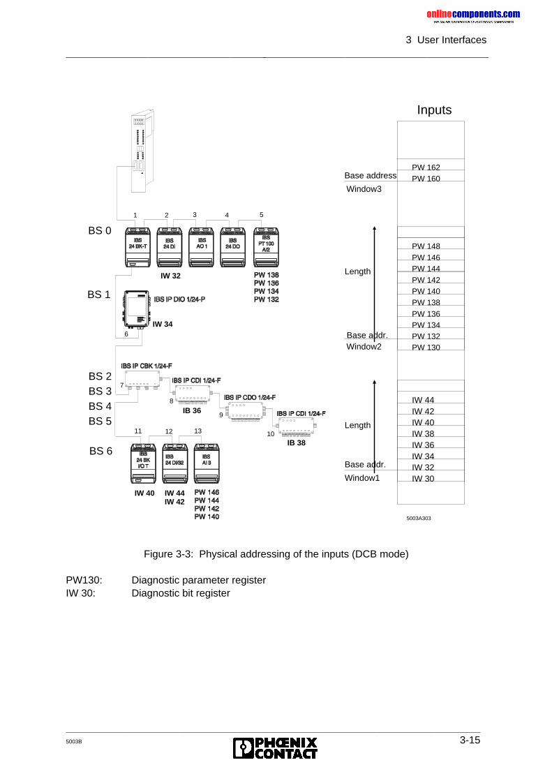
onlinec
omponen
ts.co
m
3 User Interfaces
5003B 3-15
Figure 3-3: Physical addressing of the inputs (DCB mode)
PW130: Diagnostic parameter registerIW 30: Diagnostic bit register
Inputs
PW 160PW 162
IW 32IW 34IW 36IW 38IW 40IW 42IW 44
PW 132PW 134PW 136PW 138PW 140PW 142PW 144PW 146PW 148
PW 130
IW 30
Base addr.
Window1
Length
Base addr.
Length
Window2
Base address
Window3
5003A303
BS 6
7
8
9
10 11 12 13
1 2 3 4 5
6
ID 7
BS 1
BS 0
BS 2BS 3BS 4BS 5
IW 40 IW 44IW 42
IW 32
IW 34
IB 36
IB 38
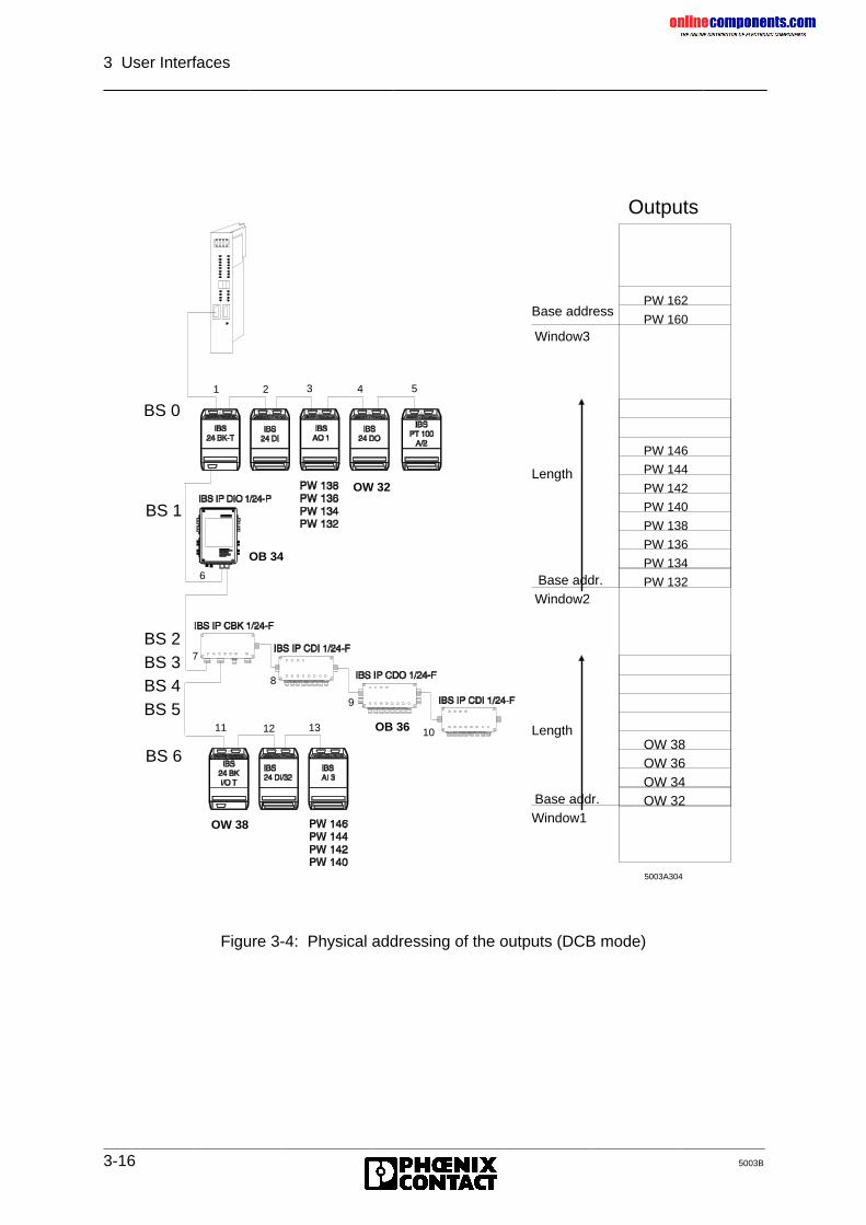
onlinec
omponen
ts.co
m
3 User Interfaces
3-16 5003B
Figure 3-4: Physical addressing of the outputs (DCB mode)
PW 160
PW 162
PW 132
PW 134
PW 136
PW 138
PW 140
PW 142
PW 144
PW 146
OW 32OW 34OW 36OW 38
Outputs
Base addr.Window1
Length
Base addr.
Length
Window2
Base address
Window3
5003A304
7
8
9
10 11 12 13
1 2 3 4 5
6
ID 7
BS 6
BS 1
BS 0
BS 2BS 3BS 4BS 5
OW 38
OB 36
OB 34
OW 32
onlinec
omponen
ts.co
m
3 User Interfaces
5003B 3-17
3.4 Logical Addressing (DCB Mode)
The bus topology in this example for the LOGICAL ADDRESSING is identical with Figure 3-2.
3.4.1 Function
In contrast to the PHYSICAL ADDRESSING, the addresses for the INTERBUS-S modulesare assigned independently of the two windows when LOGICAL ADDRESSING is used.
The addresses of the individual I/O modules can be freely selected when logical addressingis used. The address area in the PLC for the modules must not be used by other devices.
The free selection of the addresses facilitates the insertion and removal of modules, as themodules keep their addresses and the addresses are not shifted.
Address list link the physical and the logical address configurations. The address lists arestored as data blocks in the PLC or as an address list in the EEPROM memory card. Whenthe PLC or the controller board are started, the address lists address the I/O modules in thePLC’s I/O area. With the help of a programmer (under MS DOS) you may enter constants forthe address lists in the data blocks or the EEPROM card.
When the LOGICAL ADDRESSING is used, the addresses of the modules are notdetermined by the bus topology, but the user can freely assign them for every module. Thelink of the digital modules to window 1 and the analog modules to window 2 is removed forthe LOGICAL ADDRESSING. All addresses which have been entered in the following listsshould be regarded as examples and can certainly be assigned in a different order.
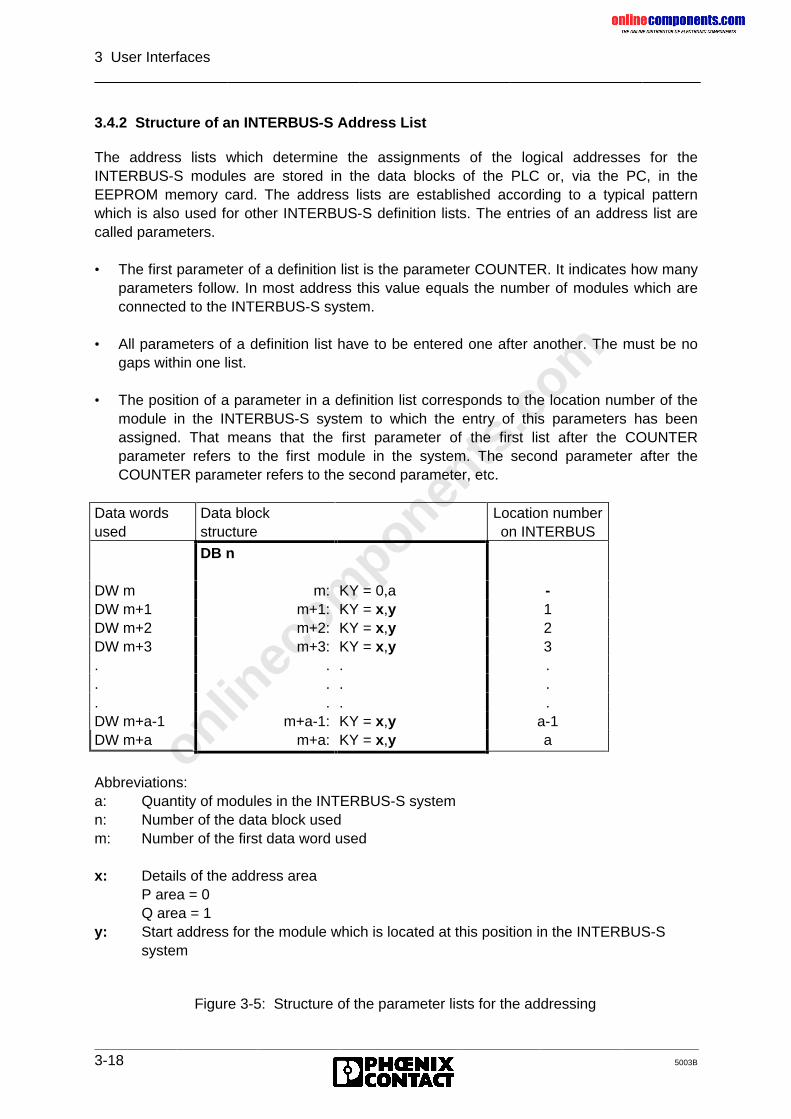
onlinec
omponen
ts.co
m
3 User Interfaces
3-18 5003B
3.4.2 Structure of an INTERBUS-S Address List
The address lists which determine the assignments of the logical addresses for theINTERBUS-S modules are stored in the data blocks of the PLC or, via the PC, in theEEPROM memory card. The address lists are established according to a typical patternwhich is also used for other INTERBUS-S definition lists. The entries of an address list arecalled parameters.
• The first parameter of a definition list is the parameter COUNTER. It indicates how manyparameters follow. In most address this value equals the number of modules which areconnected to the INTERBUS-S system.
• All parameters of a definition list have to be entered one after another. The must be nogaps within one list.
• The position of a parameter in a definition list corresponds to the location number of themodule in the INTERBUS-S system to which the entry of this parameters has beenassigned. That means that the first parameter of the first list after the COUNTERparameter refers to the first module in the system. The second parameter after theCOUNTER parameter refers to the second parameter, etc.
Data wordsused
Data blockstructure
Location numberon INTERBUS
DB n
DW m m: KY = 0,a -DW m+1 m+1: KY = x,y 1DW m+2 m+2: KY = x,y 2DW m+3 m+3: KY = x,y 3. . . .. . . .. . . .DW m+a-1 m+a-1: KY = x,y a-1DW m+a m+a: KY = x,y a
Abbreviations:a: Quantity of modules in the INTERBUS-S systemn: Number of the data block usedm: Number of the first data word used
x: Details of the address areaP area = 0Q area = 1
y: Start address for the module which is located at this position in the INTERBUS-Ssystem
Figure 3-5: Structure of the parameter lists for the addressing
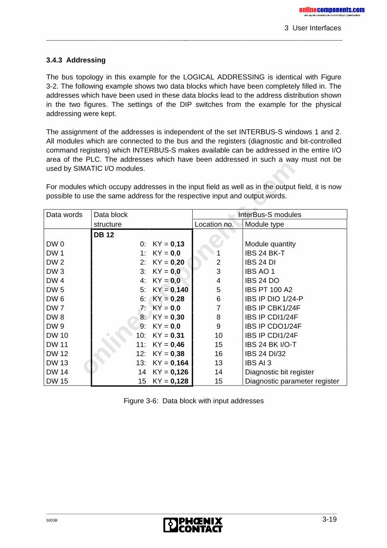
onlinec
omponen
ts.co
m
3 User Interfaces
5003B 3-19
3.4.3 Addressing
The bus topology in this example for the LOGICAL ADDRESSING is identical with Figure3-2. The following example shows two data blocks which have been completely filled in. Theaddresses which have been used in these data blocks lead to the address distribution shownin the two figures. The settings of the DIP switches from the example for the physicaladdressing were kept.
The assignment of the addresses is independent of the set INTERBUS-S windows 1 and 2.All modules which are connected to the bus and the registers (diagnostic and bit-controlledcommand registers) which INTERBUS-S makes available can be addressed in the entire I/Oarea of the PLC. The addresses which have been addressed in such a way must not beused by SIMATIC I/O modules.
For modules which occupy addresses in the input field as well as in the output field, it is nowpossible to use the same address for the respective input and output words.
Data words Data block InterBus-S modulesstructure Location no. Module type
DB 12DW 0 0: KY = 0,13 Module quantityDW 1 1: KY = 0,0 1 IBS 24 BK-TDW 2 2: KY = 0,20 2 IBS 24 DIDW 3 3: KY = 0,0 3 IBS AO 1DW 4 4: KY = 0,0 4 IBS 24 DODW 5 5: KY = 0,140 5 IBS PT 100 A2DW 6 6: KY = 0,28 6 IBS IP DIO 1/24-PDW 7 7: KY = 0,0 7 IBS IP CBK1/24FDW 8 8: KY = 0,30 8 IBS IP CDI1/24FDW 9 9: KY = 0,0 9 IBS IP CDO1/24FDW 10 10: KY = 0,31 10 IBS IP CDI1/24FDW 11 11: KY = 0,46 15 IBS 24 BK I/O-TDW 12 12: KY = 0,38 16 IBS 24 DI/32DW 13 13: KY = 0,164 13 IBS AI 3DW 14 14 KY = 0,126 14 Diagnostic bit registerDW 15 15 KY = 0,128 15 Diagnostic parameter register
Figure 3-6: Data block with input addresses
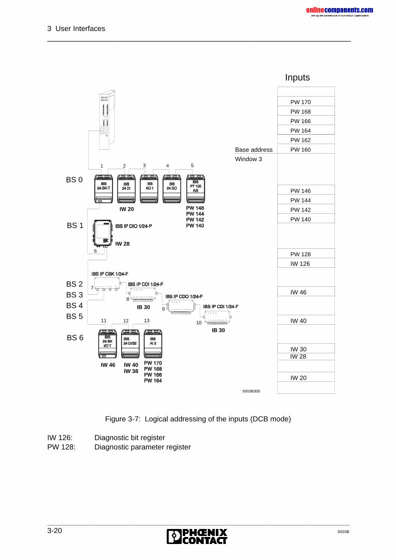
onlinec
omponen
ts.co
m
3 User Interfaces
3-20 5003B
Figure 3-7: Logical addressing of the inputs (DCB mode)
IW 126: Diagnostic bit registerPW 128: Diagnostic parameter register
7
8
9
10 11 12 13
1 2 3 4 5
6
ID 7
Inputs
IW 20
IW 30
IW 40
IW 46
PW 164
PW 166
PW 168
PW 170
PW 160
PW 162
PW 140
PW 142
PW 144
PW 146
IW 126
PW 128
Base address
Window 3
IW 28
5003B305
BS 6
BS 1
BS 0
BS 2BS 3BS 4BS 5
IW 28
IW 20
IB 30
IB 30
IW 46 IW 40IW 38
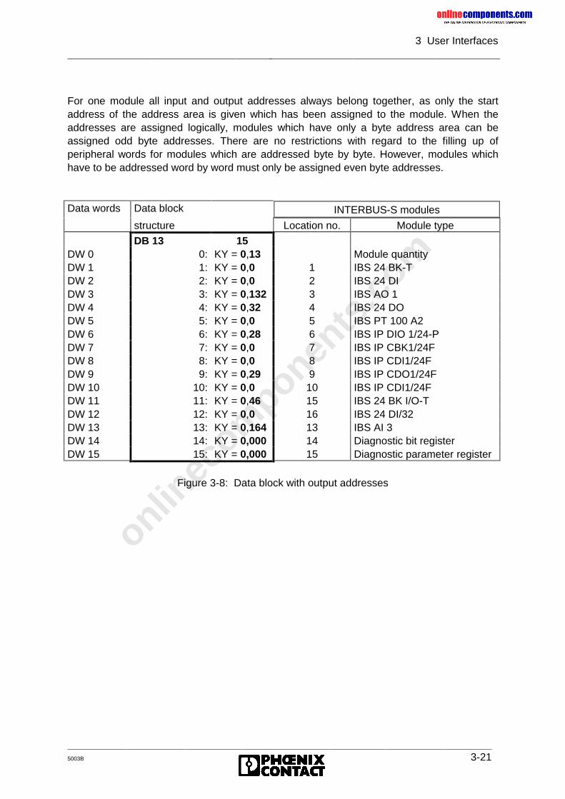
onlinec
omponen
ts.co
m
3 User Interfaces
5003B 3-21
For one module all input and output addresses always belong together, as only the startaddress of the address area is given which has been assigned to the module. When theaddresses are assigned logically, modules which have only a byte address area can beassigned odd byte addresses. There are no restrictions with regard to the filling up ofperipheral words for modules which are addressed byte by byte. However, modules whichhave to be addressed word by word must only be assigned even byte addresses.
Data words Data block INTERBUS-S modules
structure Location no. Module type
DB 13 15DW 0 0: KY = 0,13 Module quantityDW 1 1: KY = 0,0 1 IBS 24 BK-TDW 2 2: KY = 0,0 2 IBS 24 DIDW 3 3: KY = 0,132 3 IBS AO 1DW 4 4: KY = 0,32 4 IBS 24 DODW 5 5: KY = 0,0 5 IBS PT 100 A2DW 6 6: KY = 0,28 6 IBS IP DIO 1/24-PDW 7 7: KY = 0,0 7 IBS IP CBK1/24FDW 8 8: KY = 0,0 8 IBS IP CDI1/24FDW 9 9: KY = 0,29 9 IBS IP CDO1/24FDW 10 10: KY = 0,0 10 IBS IP CDI1/24FDW 11 11: KY = 0,46 15 IBS 24 BK I/O-TDW 12 12: KY = 0,0 16 IBS 24 DI/32DW 13 13: KY = 0,164 13 IBS AI 3DW 14 14: KY = 0,000 14 Diagnostic bit registerDW 15 15: KY = 0,000 15 Diagnostic parameter register
Figure 3-8: Data block with output addresses
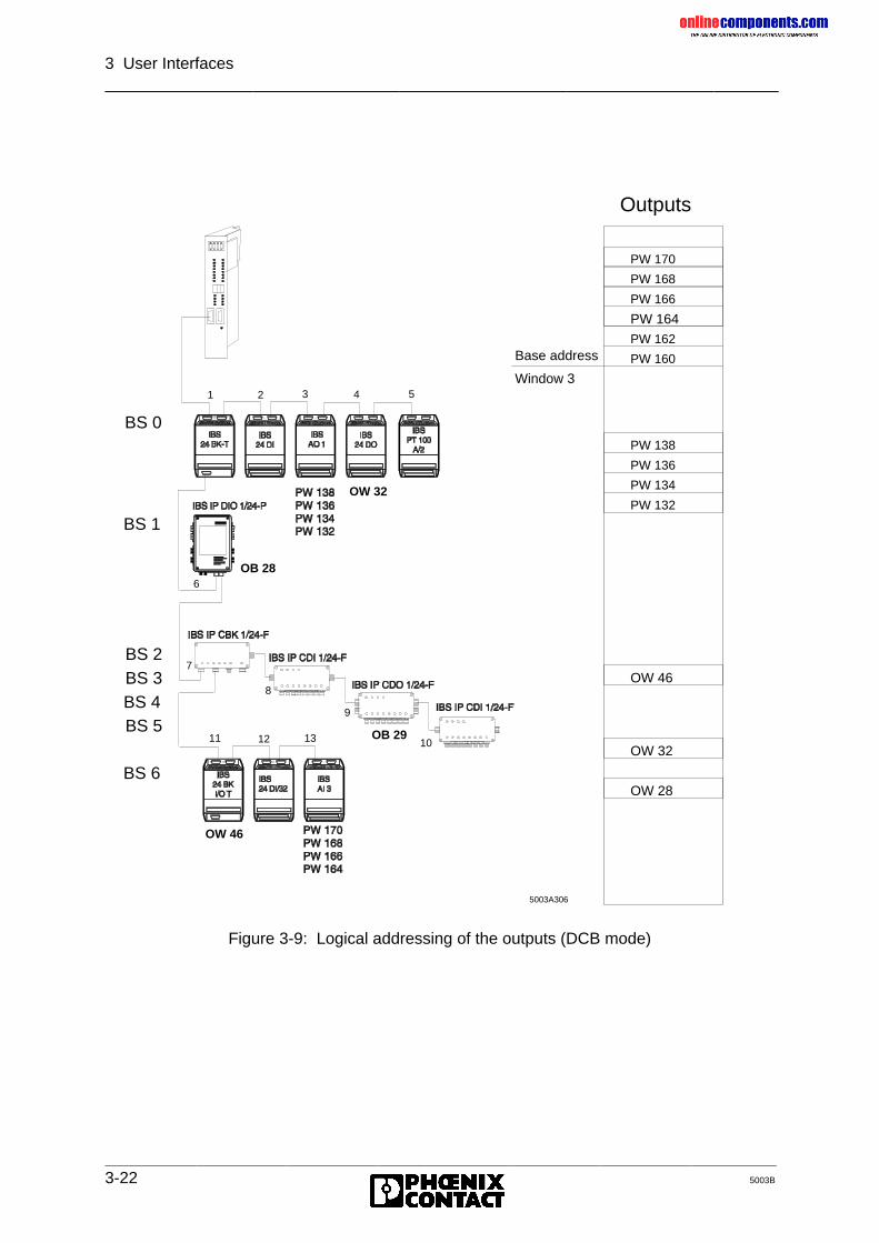
onlinec
omponen
ts.co
m
3 User Interfaces
3-22 5003B
Figure 3-9: Logical addressing of the outputs (DCB mode)
7
8
9
10 11 12 13
1 2 3 4 5
6
ID 7
PW 164
PW 166
PW 168
PW 170
PW 160
PW 162
Outputs
PW 132
PW 134
PW 136
PW 138
OW 32
OW 28
OW 46
Base address
Window 3
5003A306
BS 6
BS 1
BS 0
BS 2BS 3BS 4BS 5
OW 32
OB 28
OW 46
OB 29
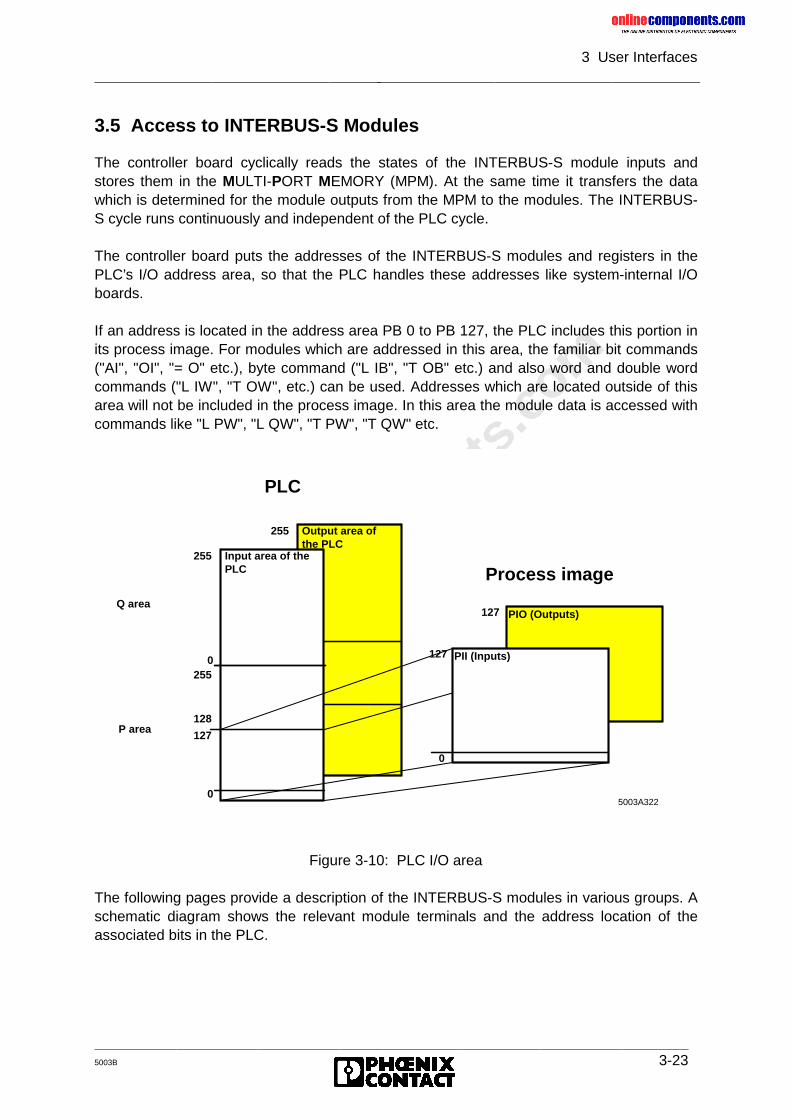
onlinec
omponen
ts.co
m
3 User Interfaces
5003B 3-23
3.5 Access to INTERBUS-S Modules
The controller board cyclically reads the states of the INTERBUS-S module inputs andstores them in the MULTI-PORT MEMORY (MPM). At the same time it transfers the datawhich is determined for the module outputs from the MPM to the modules. The INTERBUS-S cycle runs continuously and independent of the PLC cycle.
The controller board puts the addresses of the INTERBUS-S modules and registers in thePLC’s I/O address area, so that the PLC handles these addresses like system-internal I/Oboards.
If an address is located in the address area PB 0 to PB 127, the PLC includes this portion inits process image. For modules which are addressed in this area, the familiar bit commands("AI", "OI", "= O" etc.), byte command ("L IB", "T OB" etc.) and also word and double wordcommands ("L IW", "T OW", etc.) can be used. Addresses which are located outside of thisarea will not be included in the process image. In this area the module data is accessed withcommands like "L PW", "L QW", "T PW", "T QW" etc.
Figure 3-10: PLC I/O area
The following pages provide a description of the INTERBUS-S modules in various groups. Aschematic diagram shows the relevant module terminals and the address location of theassociated bits in the PLC.
Q area
P area
PIO (Outputs)
Output area ofthe PLC
255
0255
128
127
0
Input area of the PLC
255
0255
128
127
0
0
127
127
PII (Inputs)
Process image
5003A322
PLC
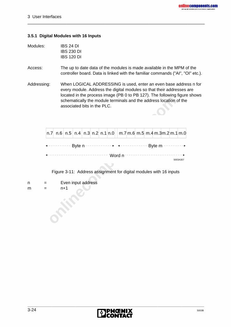
onlinec
omponen
ts.co
m
3 User Interfaces
3-24 5003B
3.5.1 Digital Modules with 16 Inputs
Modules: IBS 24 DIIBS 230 DIIBS 120 DI
Access: The up to date data of the modules is made available in the MPM of thecontroller board. Data is linked with the familiar commands ("AI", "OI" etc.).
Addressing: When LOGICAL ADDRESSING is used, enter an even base address n forevery module. Address the digital modules so that their addresses arelocated in the process image (PB 0 to PB 127). The following figure showsschematically the module terminals and the address location of theassociated bits in the PLC.
Figure 3-11: Address assignment for digital modules with 16 inputs
n = Even input addressm = n+1
n.7 n.6 n.5 n.4 n.3 n.2 n.1 n.0 m.7 m.6 m.5 m.4 m.3m.2 m.1 m.0
Byte n Byte m
Word n5003A307
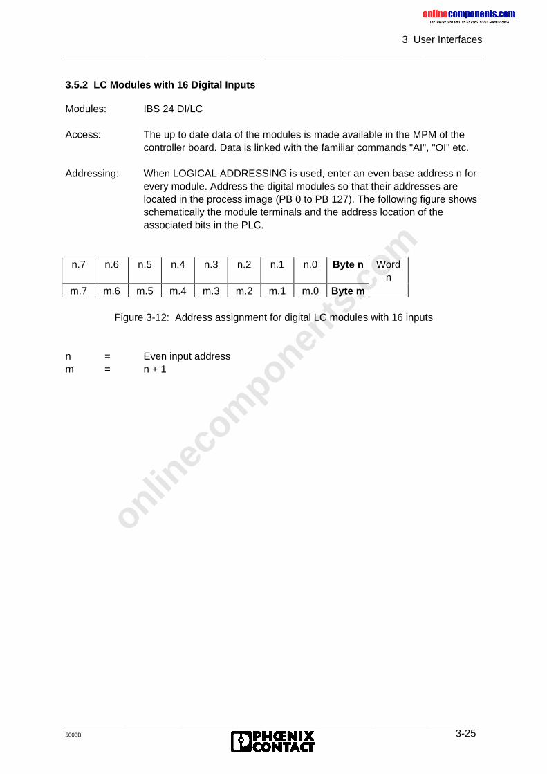
onlinec
omponen
ts.co
m
3 User Interfaces
5003B 3-25
3.5.2 LC Modules with 16 Digital Inputs
Modules: IBS 24 DI/LC
Access: The up to date data of the modules is made available in the MPM of thecontroller board. Data is linked with the familiar commands "AI", "OI" etc.
Addressing: When LOGICAL ADDRESSING is used, enter an even base address n forevery module. Address the digital modules so that their addresses arelocated in the process image (PB 0 to PB 127). The following figure showsschematically the module terminals and the address location of theassociated bits in the PLC.
n.7 n.6 n.5 n.4 n.3 n.2 n.1 n.0 Byte n Wordn
m.7 m.6 m.5 m.4 m.3 m.2 m.1 m.0 Byte m
Figure 3-12: Address assignment for digital LC modules with 16 inputs
n = Even input addressm = n + 1
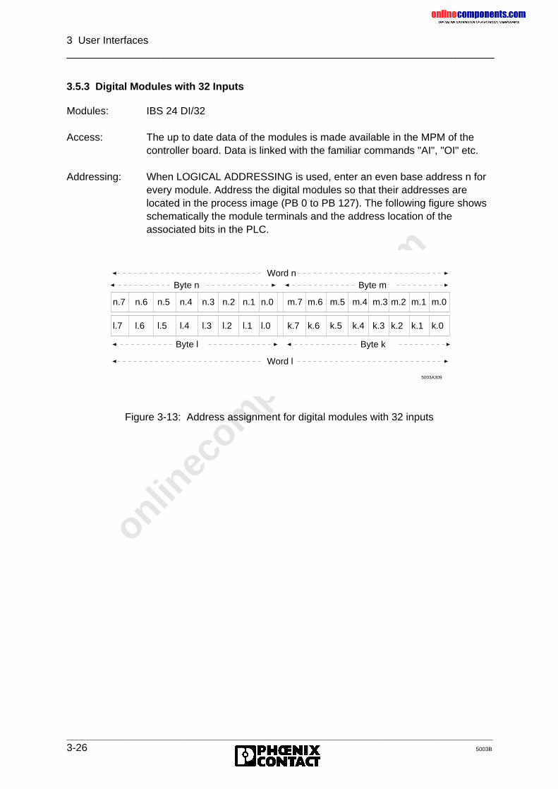
onlinec
omponen
ts.co
m
3 User Interfaces
3-26 5003B
3.5.3 Digital Modules with 32 Inputs
Modules: IBS 24 DI/32
Access: The up to date data of the modules is made available in the MPM of thecontroller board. Data is linked with the familiar commands "AI", "OI" etc.
Addressing: When LOGICAL ADDRESSING is used, enter an even base address n forevery module. Address the digital modules so that their addresses arelocated in the process image (PB 0 to PB 127). The following figure showsschematically the module terminals and the address location of theassociated bits in the PLC.
Figure 3-13: Address assignment for digital modules with 32 inputs
n.7 n.6 n.5 n.4 n.3 n.2 n.1 n.0 m.7 m.6 m.5 m.4 m.3 m.2 m.1 m.0
Byte n Byte mWord n
5003A309
l.7 l.6 l.5 l.4 l.3 l.2 l.1 l.0 k.7 k.6 k.5 k.4 k.3 k.2 k.1 k.0
Byte l Byte k
Word l
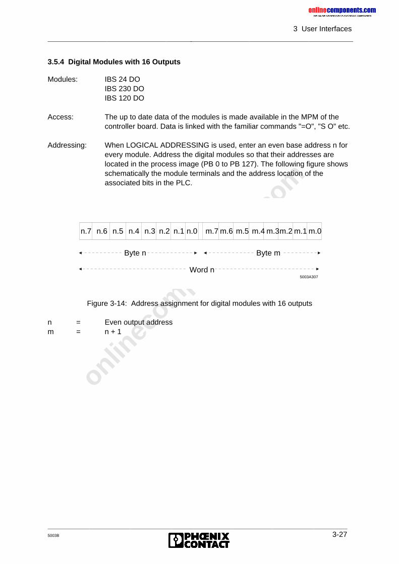
onlinec
omponen
ts.co
m
3 User Interfaces
5003B 3-27
3.5.4 Digital Modules with 16 Outputs
Modules: IBS 24 DOIBS 230 DOIBS 120 DO
Access: The up to date data of the modules is made available in the MPM of thecontroller board. Data is linked with the familiar commands "=O", "S O" etc.
Addressing: When LOGICAL ADDRESSING is used, enter an even base address n forevery module. Address the digital modules so that their addresses arelocated in the process image (PB 0 to PB 127). The following figure showsschematically the module terminals and the address location of theassociated bits in the PLC.
Figure 3-14: Address assignment for digital modules with 16 outputs
n = Even output addressm = n + 1
n.7 n.6 n.5 n.4 n.3 n.2 n.1 n.0 m.7 m.6 m.5 m.4 m.3m.2 m.1 m.0
Byte n Byte m
Word n5003A307
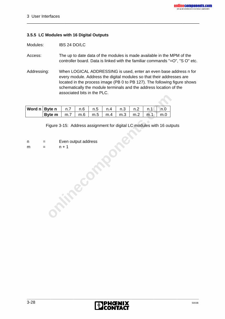
onlinec
omponen
ts.co
m
3 User Interfaces
3-28 5003B
3.5.5 LC Modules with 16 Digital Outputs
Modules: IBS 24 DO/LC
Access: The up to date data of the modules is made available in the MPM of thecontroller board. Data is linked with the familiar commands "=O", "S O" etc.
Addressing: When LOGICAL ADDRESSING is used, enter an even base address n forevery module. Address the digital modules so that their addresses arelocated in the process image (PB 0 to PB 127). The following figure showsschematically the module terminals and the address location of theassociated bits in the PLC.
Word n Byte n n.7 n.6 n.5 n.4 n.3 n.2 n.1 n.0Byte m m.7 m.6 m.5 m.4 m.3 m.2 m.1 m.0
Figure 3-15: Address assignment for digital LC modules with 16 outputs
n = Even output addressm = n + 1
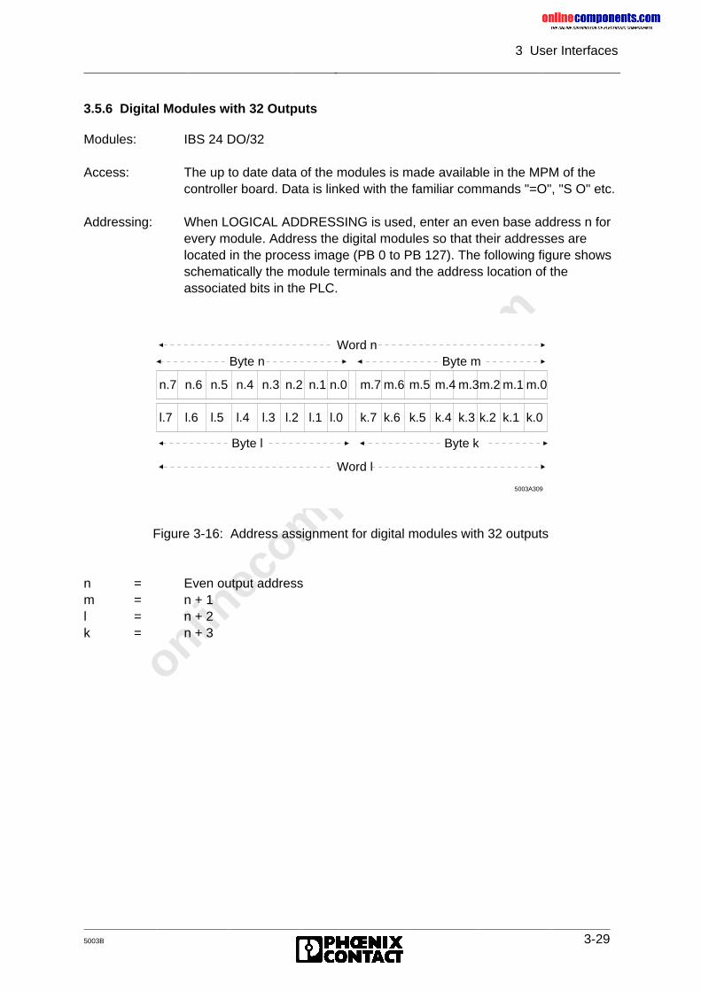
onlinec
omponen
ts.co
m
3 User Interfaces
5003B 3-29
3.5.6 Digital Modules with 32 Outputs
Modules: IBS 24 DO/32
Access: The up to date data of the modules is made available in the MPM of thecontroller board. Data is linked with the familiar commands "=O", "S O" etc.
Addressing: When LOGICAL ADDRESSING is used, enter an even base address n forevery module. Address the digital modules so that their addresses arelocated in the process image (PB 0 to PB 127). The following figure showsschematically the module terminals and the address location of theassociated bits in the PLC.
Figure 3-16: Address assignment for digital modules with 32 outputs
n = Even output addressm = n + 1l = n + 2k = n + 3
n.7 n.6 n.5 n.4 n.3 n.2 n.1 n.0 m.7 m.6 m.5 m.4 m.3m.2 m.1 m.0
Byte n Byte mWord n
5003A309
l.7 l.6 l.5 l.4 l.3 l.2 l.1 l.0 k.7 k.6 k.5 k.4 k.3 k.2 k.1 k.0
Byte l Byte k
Word l
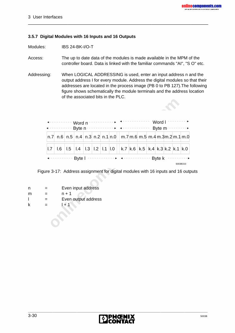
onlinec
omponen
ts.co
m
3 User Interfaces
3-30 5003B
3.5.7 Digital Modules with 16 Inputs and 16 Outputs
Modules: IBS 24-BK-I/O-T
Access: The up to date data of the modules is made available in the MPM of thecontroller board. Data is linked with the familiar commands "AI", "S O" etc.
Addressing: When LOGICAL ADDRESSING is used, enter an input address n and theoutput address I for every module. Address the digital modules so that theiraddresses are located in the process image (PB 0 to PB 127).The followingfigure shows schematically the module terminals and the address locationof the associated bits in the PLC.
Figure 3-17: Address assignment for digital modules with 16 inputs and 16 outputs
n = Even input addressm = n + 1l = Even output addressk = l + 1
n.7 n.6 n.5 n.4 n.3 n.2 n.1 n.0 m.7 m.6 m.5 m.4 m.3m.2 m.1 m.0
Byte n Byte mWord n
5003B310
l.7 l.6 l.5 l.4 l.3 l.2 l.1 l.0 k.7 k.6 k.5 k.4 k.3 k.2 k.1 k.0
Byte l Byte k
Word l
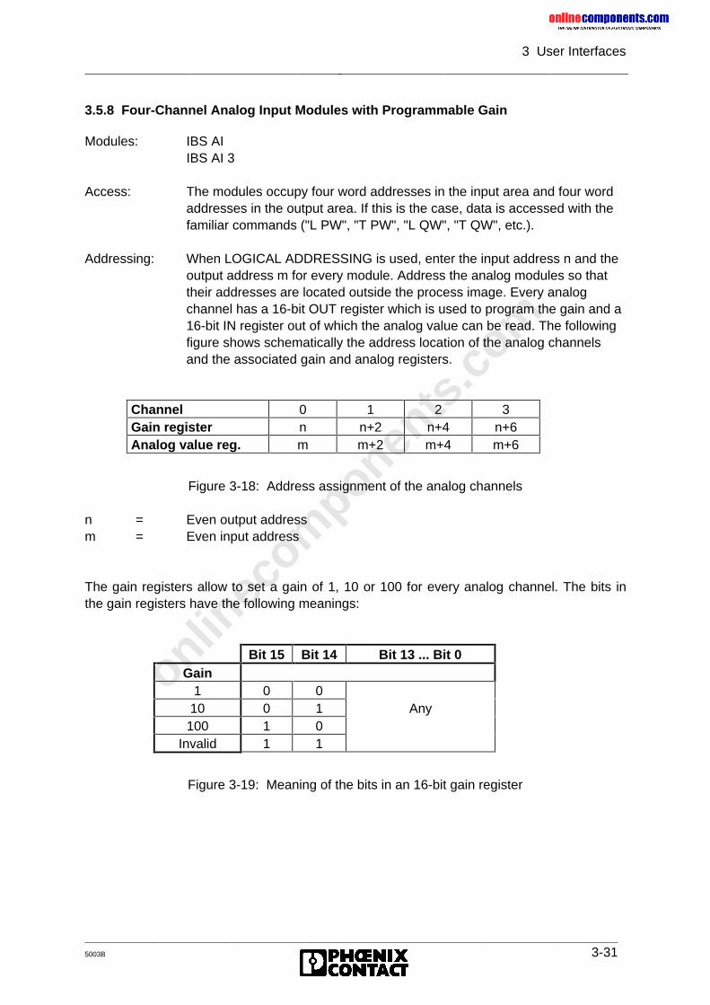
onlinec
omponen
ts.co
m
3 User Interfaces
5003B 3-31
3.5.8 Four-Channel Analog Input Modules with Programmable Gain
Modules: IBS AIIBS AI 3
Access: The modules occupy four word addresses in the input area and four wordaddresses in the output area. If this is the case, data is accessed with thefamiliar commands ("L PW", "T PW", "L QW", "T QW", etc.).
Addressing: When LOGICAL ADDRESSING is used, enter the input address n and theoutput address m for every module. Address the analog modules so thattheir addresses are located outside the process image. Every analogchannel has a 16-bit OUT register which is used to program the gain and a16-bit IN register out of which the analog value can be read. The followingfigure shows schematically the address location of the analog channelsand the associated gain and analog registers.
Figure 3-18: Address assignment of the analog channels
n = Even output addressm = Even input address
The gain registers allow to set a gain of 1, 10 or 100 for every analog channel. The bits inthe gain registers have the following meanings:
Figure 3-19: Meaning of the bits in an 16-bit gain register
Channel 0 1 2 3Gain register n n+2 n+4 n+6Analog value reg. m m+2 m+4 m+6
Bit 15 Bit 14 Bit 13 ... Bit 0Gain
1 0 010 0 1 Any100 1 0
Invalid 1 1
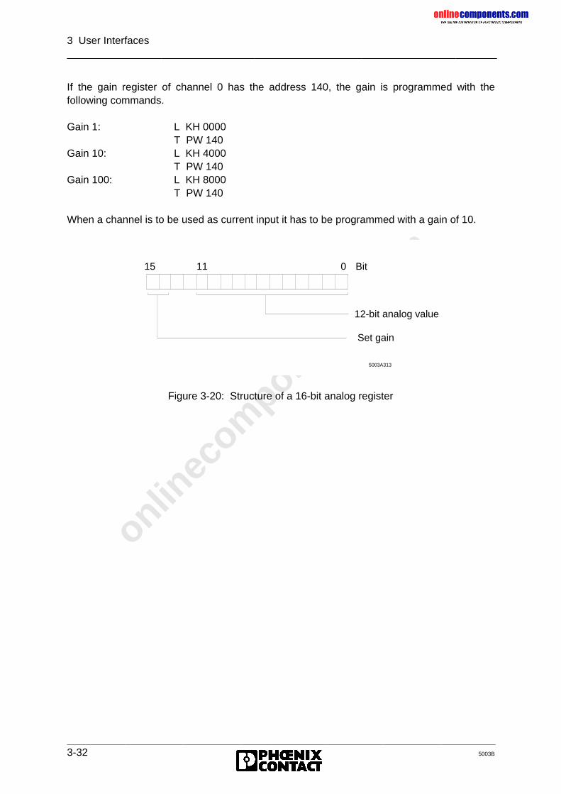
onlinec
omponen
ts.co
m
3 User Interfaces
3-32 5003B
If the gain register of channel 0 has the address 140, the gain is programmed with thefollowing commands.
Gain 1: L KH 0000T PW 140
Gain 10: L KH 4000T PW 140
Gain 100: L KH 8000T PW 140
When a channel is to be used as current input it has to be programmed with a gain of 10.
Figure 3-20: Structure of a 16-bit analog register
5003A313
15
Set gain
11 0
12-bit analog value
Bit
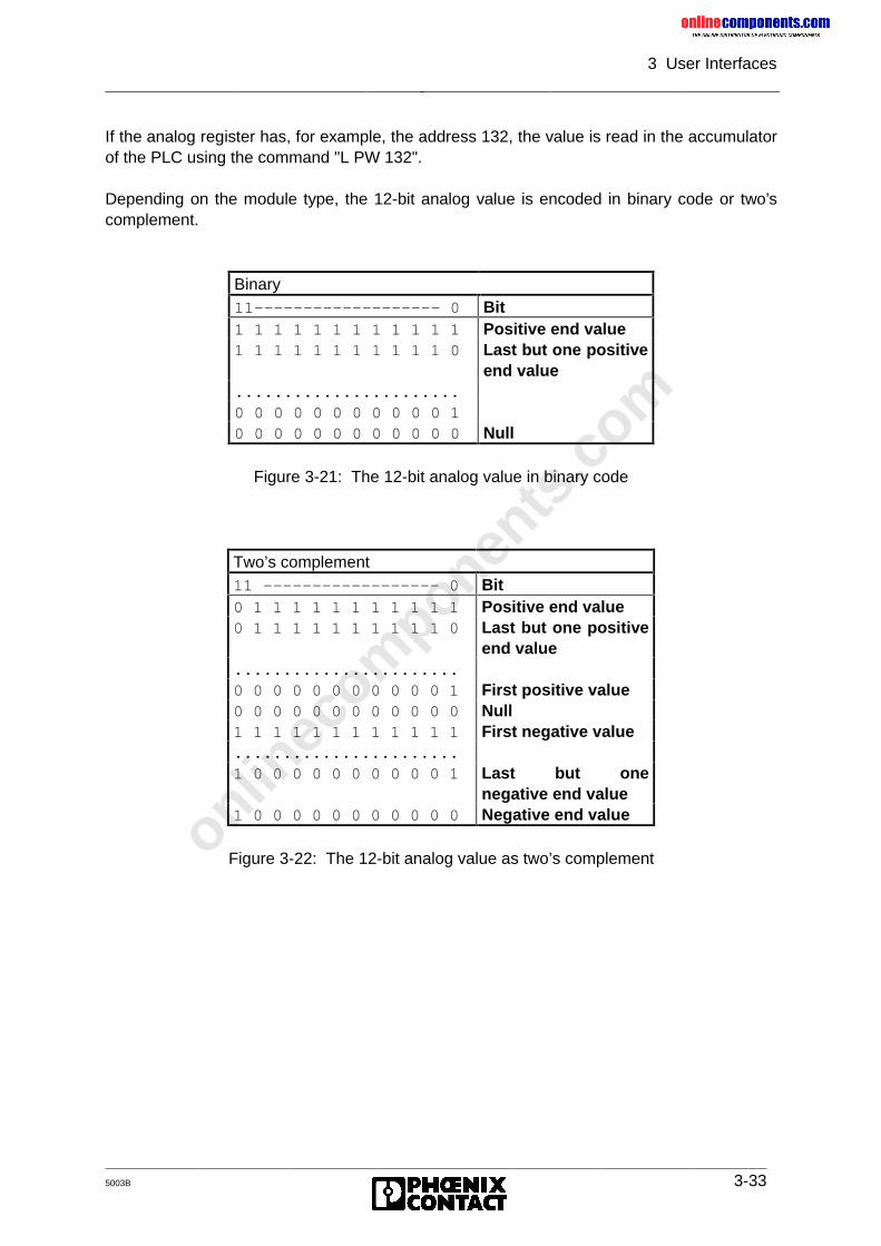
onlinec
omponen
ts.co
m
3 User Interfaces
5003B 3-33
If the analog register has, for example, the address 132, the value is read in the accumulatorof the PLC using the command "L PW 132".
Depending on the module type, the 12-bit analog value is encoded in binary code or two’scomplement.
Figure 3-21: The 12-bit analog value in binary code
Figure 3-22: The 12-bit analog value as two’s complement
Binary11------------------- 0 Bit1 1 1 1 1 1 1 1 1 1 1 1 Positive end value1 1 1 1 1 1 1 1 1 1 1 0 Last but one positive
end value.......................0 0 0 0 0 0 0 0 0 0 0 10 0 0 0 0 0 0 0 0 0 0 0 Null
Two’s complement11 ------------------ 0 Bit0 1 1 1 1 1 1 1 1 1 1 1 Positive end value0 1 1 1 1 1 1 1 1 1 1 0 Last but one positive
end value.......................0 0 0 0 0 0 0 0 0 0 0 1 First positive value0 0 0 0 0 0 0 0 0 0 0 0 Null1 1 1 1 1 1 1 1 1 1 1 1 First negative value.......................1 0 0 0 0 0 0 0 0 0 0 1 Last but one
negative end value1 0 0 0 0 0 0 0 0 0 0 0 Negative end value
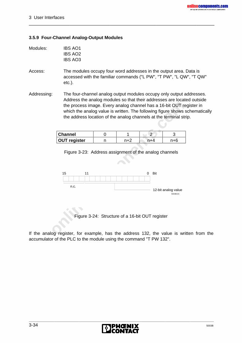
onlinec
omponen
ts.co
m
3 User Interfaces
3-34 5003B
3.5.9 Four-Channel Analog-Output Modules
Modules: IBS AO1IBS AO2IBS AO3
Access: The modules occupy four word addresses in the output area. Data isaccessed with the familiar commands ("L PW", "T PW", "L QW", "T QW"etc.).
Addressing: The four-channel analog output modules occupy only output addresses.Address the analog modules so that their addresses are located outsidethe process image. Every analog channel has a 16-bit OUT register inwhich the analog value is written. The following figure shows schematicallythe address location of the analog channels at the terminal strip.
Figure 3-23: Address assignment of the analog channels
Figure 3-24: Structure of a 16-bit OUT register
If the analog register, for example, has the address 132, the value is written from theaccumulator of the PLC to the module using the command "T PW 132".
Channel 0 1 2 3OUT register n n+2 n+4 n+6
5003B315
15 11 0
12-bit analog value
Bit
n.c.
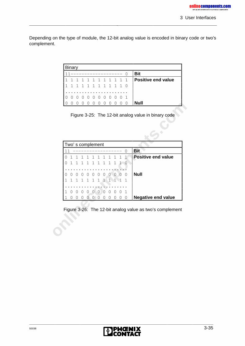
onlinec
omponen
ts.co
m
3 User Interfaces
5003B 3-35
Depending on the type of module, the 12-bit analog value is encoded in binary code or two’scomplement.
Figure 3-25: The 12-bit analog value in binary code
Figure 3-26: The 12-bit analog value as two’s complement
Binary11------------------- 0 Bit1 1 1 1 1 1 1 1 1 1 1 1 Positive end value1 1 1 1 1 1 1 1 1 1 1 0.......................0 0 0 0 0 0 0 0 0 0 0 10 0 0 0 0 0 0 0 0 0 0 0 Null
Two’ s complement11 ------------------ 0 Bit0 1 1 1 1 1 1 1 1 1 1 1 Positive end value0 1 1 1 1 1 1 1 1 1 1 0.......................0 0 0 0 0 0 0 0 0 0 0 0 Null1 1 1 1 1 1 1 1 1 1 1 1.......................1 0 0 0 0 0 0 0 0 0 0 11 0 0 0 0 0 0 0 0 0 0 0 Negative end value
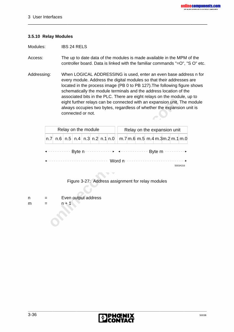
onlinec
omponen
ts.co
m
3 User Interfaces
3-36 5003B
3.5.10 Relay Modules
Modules: IBS 24 RELS
Access: The up to date data of the modules is made available in the MPM of thecontroller board. Data is linked with the familiar commands "=O", "S O" etc.
Addressing: When LOGICAL ADDRESSING is used, enter an even base address n forevery module. Address the digital modules so that their addresses arelocated in the process image (PB 0 to PB 127).The following figure showsschematically the module terminals and the address location of theassociated bits in the PLC. There are eight relays on the module, up toeight further relays can be connected with an expansion unit. The modulealways occupies two bytes, regardless of whether the expansion unit isconnected or not.
Figure 3-27: Address assignment for relay modules
n = Even output addressm = n + 1
n.7 n.6 n.5 n.4 n.3 n.2 n.1 n.0 m.7 m.6 m.5 m.4 m.3m.2 m.1 m.0
Byte n Byte m
Word n5003A316
Relay on the module Relay on the expansion unit
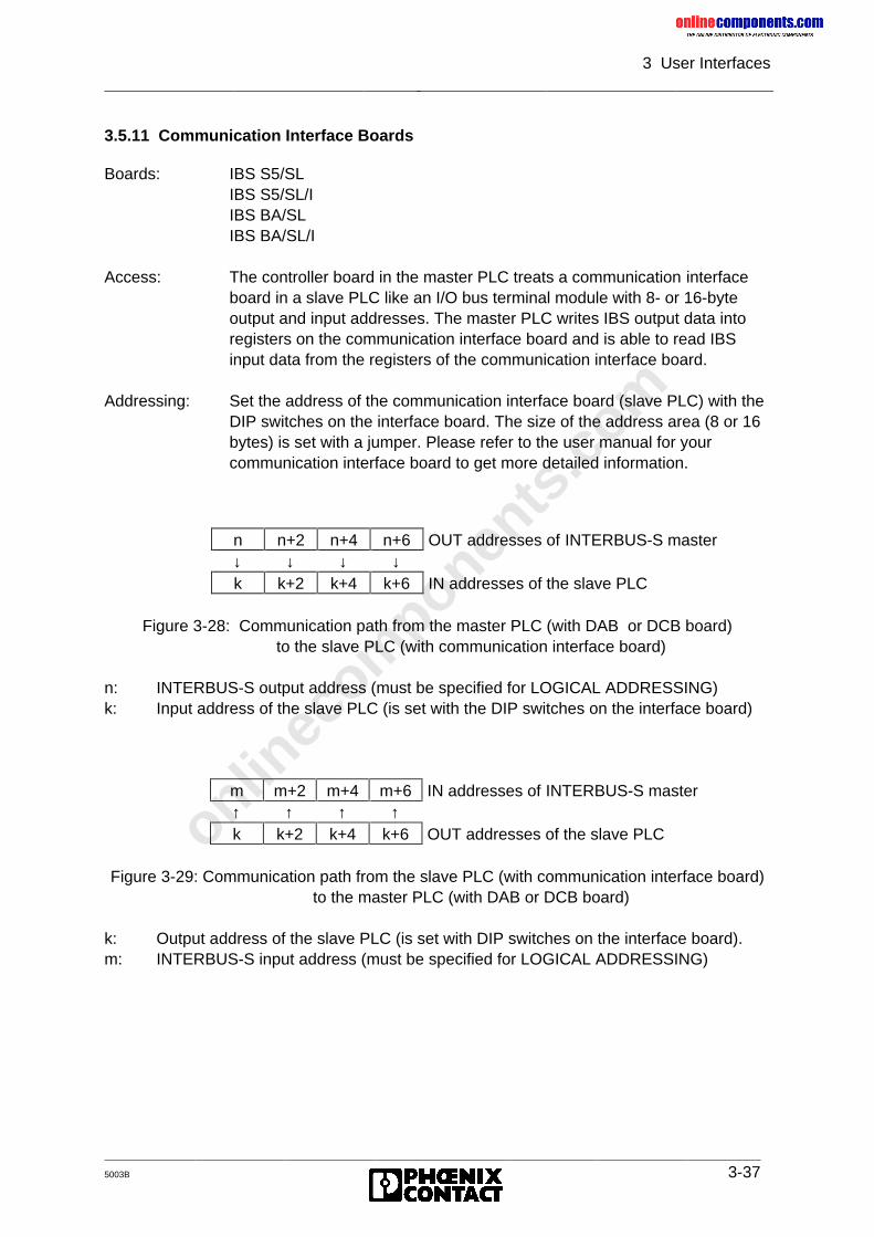
onlinec
omponen
ts.co
m
3 User Interfaces
5003B 3-37
3.5.11 Communication Interface Boards
Boards: IBS S5/SLIBS S5/SL/IIBS BA/SLIBS BA/SL/I
Access: The controller board in the master PLC treats a communication interfaceboard in a slave PLC like an I/O bus terminal module with 8- or 16-byteoutput and input addresses. The master PLC writes IBS output data intoregisters on the communication interface board and is able to read IBSinput data from the registers of the communication interface board.
Addressing: Set the address of the communication interface board (slave PLC) with theDIP switches on the interface board. The size of the address area (8 or 16bytes) is set with a jumper. Please refer to the user manual for yourcommunication interface board to get more detailed information.
Figure 3-28: Communication path from the master PLC (with DAB or DCB board) to the slave PLC (with communication interface board)
n: INTERBUS-S output address (must be specified for LOGICAL ADDRESSING)k: Input address of the slave PLC (is set with the DIP switches on the interface board)
Figure 3-29: Communication path from the slave PLC (with communication interface board) to the master PLC (with DAB or DCB board)
k: Output address of the slave PLC (is set with DIP switches on the interface board).m: INTERBUS-S input address (must be specified for LOGICAL ADDRESSING)
n n+2 n+4 n+6 OUT addresses of INTERBUS-S master↓ ↓ ↓ ↓k k+2 k+4 k+6 IN addresses of the slave PLC
m m+2 m+4 m+6 IN addresses of INTERBUS-S master↑ ↑ ↑ ↑k k+2 k+4 k+6 OUT addresses of the slave PLC
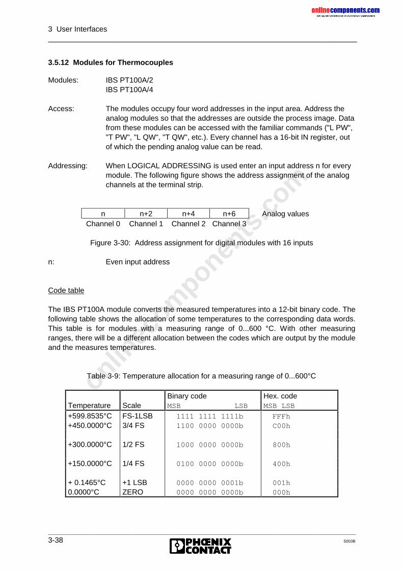
onlinec
omponen
ts.co
m
3 User Interfaces
3-38 5003B
3.5.12 Modules for Thermocouples
Modules: IBS PT100A/2IBS PT100A/4
Access: The modules occupy four word addresses in the input area. Address theanalog modules so that the addresses are outside the process image. Datafrom these modules can be accessed with the familiar commands ("L PW","T PW", "L QW", "T QW", etc.). Every channel has a 16-bit IN register, outof which the pending analog value can be read.
Addressing: When LOGICAL ADDRESSING is used enter an input address n for everymodule. The following figure shows the address assignment of the analogchannels at the terminal strip.
Figure 3-30: Address assignment for digital modules with 16 inputs
n: Even input address
Code table
The IBS PT100A module converts the measured temperatures into a 12-bit binary code. Thefollowing table shows the allocation of some temperatures to the corresponding data words.This table is for modules with a measuring range of 0...600 °C. With other measuringranges, there will be a different allocation between the codes which are output by the moduleand the measures temperatures.
Table 3-9: Temperature allocation for a measuring range of 0...600°C
n n+2 n+4 n+6 Analog valuesChannel 0 Channel 1 Channel 2 Channel 3
Binary code Hex. codeTemperature Scale MSB LSB MSB LSB
+599.8535°C FS-1LSB 1111 1111 1111b FFFh+450.0000°C 3/4 FS 1100 0000 0000b C00h
+300.0000°C 1/2 FS 1000 0000 0000b 800h
+150.0000°C 1/4 FS 0100 0000 0000b 400h
+ 0.1465°C +1 LSB 0000 0000 0001b 001h0.0000°C ZERO 0000 0000 0000b 000h
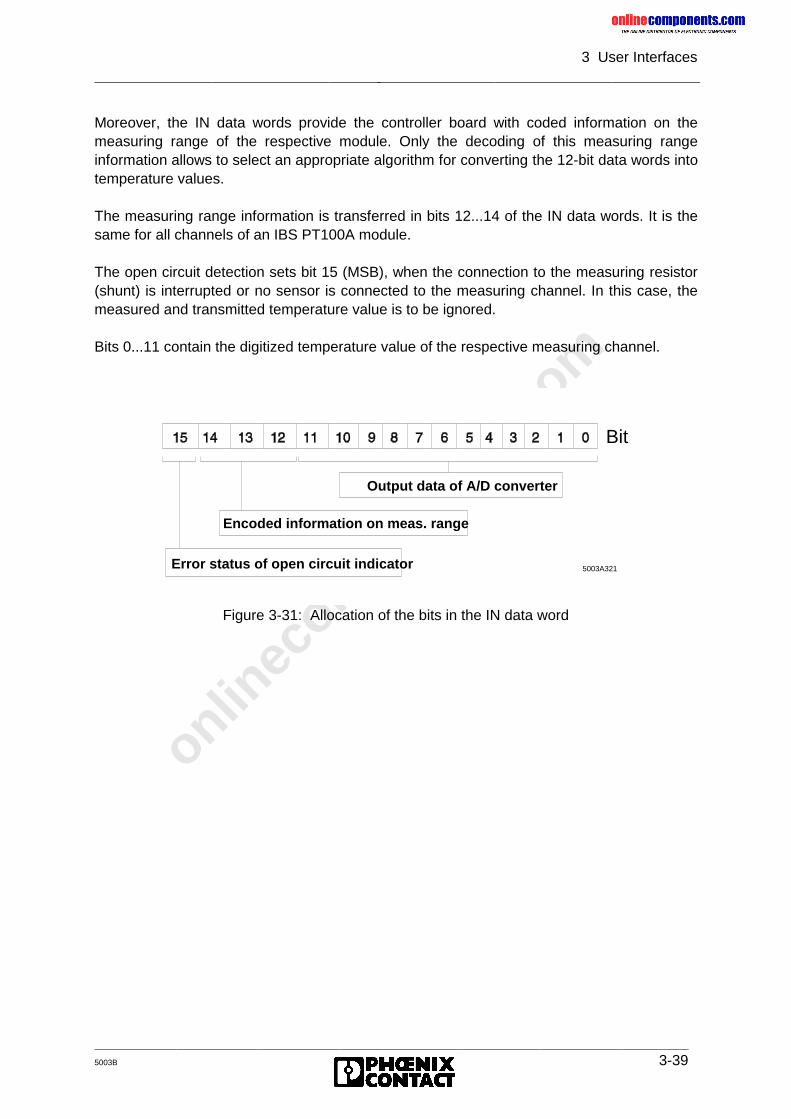
onlinec
omponen
ts.co
m
3 User Interfaces
5003B 3-39
Moreover, the IN data words provide the controller board with coded information on themeasuring range of the respective module. Only the decoding of this measuring rangeinformation allows to select an appropriate algorithm for converting the 12-bit data words intotemperature values.
The measuring range information is transferred in bits 12...14 of the IN data words. It is thesame for all channels of an IBS PT100A module.
The open circuit detection sets bit 15 (MSB), when the connection to the measuring resistor(shunt) is interrupted or no sensor is connected to the measuring channel. In this case, themeasured and transmitted temperature value is to be ignored.
Bits 0...11 contain the digitized temperature value of the respective measuring channel.
Figure 3-31: Allocation of the bits in the IN data word
5003A321
Bit
Output data of A/D converter
Encoded information on meas. range
Error status of open circuit indicator
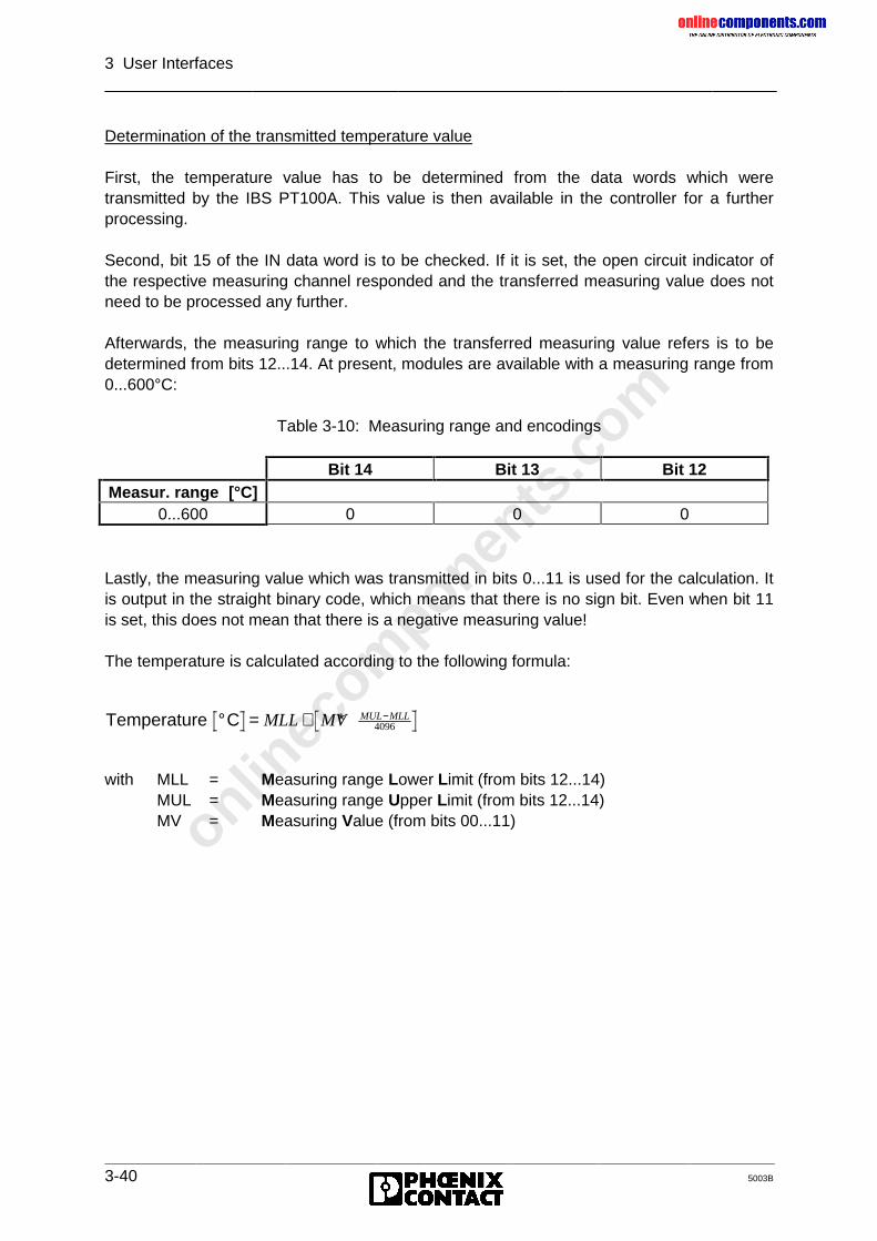
onlinec
omponen
ts.co
m
3 User Interfaces
3-40 5003B
Determination of the transmitted temperature value
First, the temperature value has to be determined from the data words which weretransmitted by the IBS PT100A. This value is then available in the controller for a furtherprocessing.
Second, bit 15 of the IN data word is to be checked. If it is set, the open circuit indicator ofthe respective measuring channel responded and the transferred measuring value does notneed to be processed any further.
Afterwards, the measuring range to which the transferred measuring value refers is to bedetermined from bits 12...14. At present, modules are available with a measuring range from0...600°C:
Table 3-10: Measuring range and encodings
Bit 14 Bit 13 Bit 12Measur. range [°C]
0...600 0 0 0
Lastly, the measuring value which was transmitted in bits 0...11 is used for the calculation. Itis output in the straight binary code, which means that there is no sign bit. Even when bit 11is set, this does not mean that there is a negative measuring value!
The temperature is calculated according to the following formula:
Temperature C° = + ∗ −MLL MV MUL MLL4096
with MLL = Measuring range Lower Limit (from bits 12...14)MUL = Measuring range Upper Limit (from bits 12...14)MV = Measuring Value (from bits 00...11)
onlinec
omponen
ts.co
m
5003B
Chapter 4
Diagnostic InterfacesThis chapter provides information on
- the possibilities for hard- and software-supported diagnostics on the controller board- the I/O status indications in the connected bus system- the diagnostic functions on modules and bus terminal modules- the use of the Hand Held Monitor and the monitor program
for diagnostic support
4 Diagnostic Interfaces.........................................................................4-1
4.1 Diagnostics on the Controller Board’s Front Plate ........................................ 4-24.1.1 Operating Indicators .................................................................................. 4-44.1.2 Error Indication .......................................................................................... 4-54.1.3 Error Codes for Controller Errors (CTRL) .................................................. 4-8
4.2 Notes on Error Diagnostics........................................................................... 4-114.2.1 Indication of Errors on the Front Plate ....................................................... 4-124.2.2 Example of a System Documentation ........................................................ 4-19
4.3 Diagnostic Registers .................................................................................... 4-234.3.1 Diagnostic Bit Register .............................................................................. 4-234.3.2 Diagnostic Parameter Register .................................................................. 4-234.3.3 Diagnostic Register Locations ................................................................... 4-24
4.4 I/O Status Indicators..................................................................................... 4-26
4.5 Startup and Acknowledgment Displays ........................................................ 4-284.5.1 Host Controller Board Startup.................................................................... 4-284.5.2 Acknowledgment after an Error ................................................................. 4-29
4.6 Diagnostics on the Modules.......................................................................... 4-304.6.1 Diagnostic Functions on I/O Modules ........................................................ 4-314.6.2 Diagnostic Functions on Bus Terminal Modules ........................................ 4-324.6.3 Diagnostics on Third-Party Devices ........................................................... 4-32
4.7 Using the Hand Held Monitor........................................................................ 4-33
4.8 Using the Monitor Program for INTERBUS-S on the PC .............................. 4-34
4.9 CTRL Error Displays..................................................................................... 4-354.9.1 List of Errors .............................................................................................. 4-36
onlinec
omponen
ts.co
m
4 Diagnostic Interfaces
5003B 4-1
4 Diagnostic Interfaces
This chapter describes the different diagnostic options of the IBS DCB controller board.
1. Diagnostics on the controller board’s front plate
2. Software diagnosticsDiagnostic bit registerDiagnose parameter register
3. Diagnostics on the I/O modules
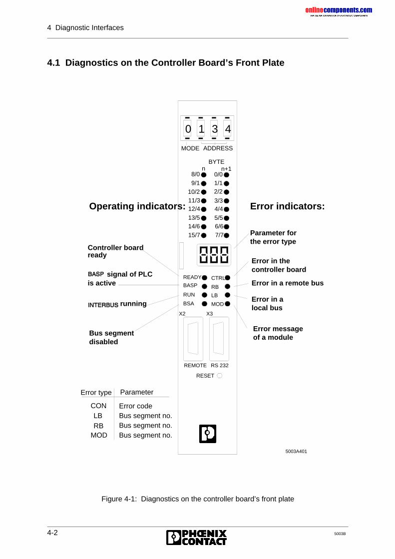
onlinec
omponen
ts.co
m
4 Diagnostic Interfaces
4-2 5003B
4.1 Diagnostics on the Controller Board’s Front Plate
Figure 4-1: Diagnostics on the controller board’s front plate
X2 X3
REMOTE RS 232
RESET
Error type
Error codeBus segment no.Bus segment no.Bus segment no.
BYTEn n+1
MODE ADDRESS
CTRL
RB
LB
MOD
READY
BASP
RUN
BSA
10/2
8/0
9/1
11/312/413/514/6
15/7
0/01/12/2
3/34/4
5/56/67/7
0 1 3 4
5003A401
CON
RBLB
MOD
Parameter
Controller boardready
signal of PLCis active
running
Bus segmentdisabled
Error messageof a module
Error in alocal bus
Error in a remote bus
Error in the controller board
Parameter forthe error type
Operating indicators: Error indicators:
onlinec
omponen
ts.co
m
4 Diagnostic Interfaces
5003B 4-3
Diagnostics on the controller board’s front plate is subdivided into:
• Operating indicators and• Error indicators.
The various LEDs indicate the operating status of the INTERBUS-S systems. The currentstatus is shown in a coded form on a three-digit seven-segment display.
The display shows the following characters and parameters:
-| |- STOP of the controller board - - Run state of the controller boardAd Invalid address settingXXX A parameter is output in case of an error
Software diagnostics:The diagnostic registers contain an image of the operating and error indicators (LEDs) aswell as the error parameters (display) on the front plate.
Further information can be recalled by means of the SYSERROR (FB 73) and ERRINFO (FB74) functions blocks during the PLC cycle or with a PC which is connected to the V.24 (RS-232) interface.
onlinec
omponen
ts.co
m
4 Diagnostic Interfaces
4-4 5003B
4.1.1 Operating Indicators
Four LEDs indicate the operating state of INTERBUS-S and the PLC. The LEDs aredesignated READY, BASP, RUN and BSA. Further information is indicated on the display.
READYThe controller board has completed the self-test without errors occurring and is ready foroperation.
BASPThe PLC has activated the BASP signal (Befehls Ausgabe SPerren = disable commandoutput) and is in the STOP state. In this operating state, INTERBUS-S resets all outputs.
RUNWhen INTERBUS-S is active, the RUN LED lights up.
BSAThe BSA signal (Bus Segment Abgeschaltet = bus segment disabled) indicates that one orseveral bus segments is/are disabled. The remaining bus configuration is running properly.
This signal is activated by the PLC. All outputs of the INTERBUS-S systemare reset.
The I/O data of disabled local buses does not correspond to the up to datesignal states. There must be no access to the bus addresses concerned.
onlinec
omponen
ts.co
m
4 Diagnostic Interfaces
5003B 4-5
4.1.2 Error Indication
Four red LEDs indicate INTERBUS-S and PLC malfunctions. The LEDs are designatedCTRL, LB ERROR, RB ERROR and MOD ERROR. Further information is indicated on thedisplay.
LB ERRA defective local bus (Local Bus Error) has been diagnosed. The display and the diagnosticparameter register indicate the number of the defective local bus segment.
Remedies: Error in the indicated local bus- check I/O stations- too many or not enough stations on the local bus- check the cabling
RB ERRA defective remote bus (Remote Bus Error) or a defective installation remote bus modulehas been diagnosed. The seven-segment display and/or the diagnostic parameter registerindicate the number of the defective remote bus segment or installation remote bus module.
Remedies: Error in the indicated remote bus segment- check bus terminal module- check the voltage supply- check the remote bus cable coming from the controller board- too many stations in the remote bus
This error leads to the stopping of the bus. The I/O data does not correspondto the up to date status of the signal states. There must be no access to thebus addresses concerned.
The error leads to the stopping of the bus. The I/O data does not correspondto the up to date signal states. There must be no access to the bus addressesconcerned.
The RB ERR LED indicates additional group error messages (messages: E1,E2, E4, E5, E6). The following table lists the possible error causes.
onlinec
omponen
ts.co
m
4 Diagnostic Interfaces
4-6 5003B
7-segmentdisplay on the
front panel
Meaning Error cause Remedy
FW state 3.5
E1 After the error hasoccurred, no error wasdetected when theconfiguration wasacquired and compared.
Cabling error;shielding error
- Check remote andlocal bus cabling- Check voltagesupply- Tool: IBS SYSSWT
E2 The maximum possibleconfiguration has beenexceeded.
The number ofstations or theregister locations istoo large.
- Check theaddressing lists andthe configuration(Observe: max. 320stations and max.256 register words)
E4 The configuration couldnot be detected.
The station does notrespond.
Check voltage supplyfor failures
E5 All groups have beenswitched off
Error in theapplication program
Check applicationprogram
E6 No error has beendetected when theconfiguration wasacquired and compared,but no data cycle ispossible
Module error - Tool: IBS SYSSWT- Please inform thetechnical support atPhoenix Contact.
Information about IBS SYS SWT: The IBS SYS SWT program package offers acomprehensive diagnostic environment. For the error detection it uses an additionaldiagnostic function on the controller board which monitors the system while the bus isrunning. A PC evaluates the data and displays them.
MOD ERRThe MOD ERR (Module Error) occurs in the event of an error in an INTERBUS-S module.The display and/or the diagnostic parameter register indicate the number of the bus segmentin which the reporting module is located. The error is indicated only for modules with a busacknowledgment. The error does not lead to the stopping of the bus.
The I/O data of the reporting local bus module does not correspond to the upto data signal states. There must be no access to the bus addressesconcerned.
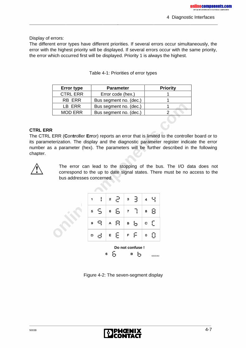
onlinec
omponen
ts.co
m
4 Diagnostic Interfaces
5003B 4-7
Display of errors:The different error types have different priorities. If several errors occur simultaneously, theerror with the highest priority will be displayed. If several errors occur with the same priority,the error which occurred first will be displayed. Priority 1 is always the highest.
Table 4-1: Priorities of error types
CTRL ERRThe CTRL ERR (Controller Error) reports an error that is limited to the controller board or toits parameterization. The display and the diagnostic parameter register indicate the errornumber as a parameter (hex). The parameters will be further described in the followingchapter.
Figure 4-2: The seven-segment display
Error type Parameter PriorityCTRL ERR Error code (hex.) 1RB ERR Bus segment no. (dec.) 1LB ERR Bus segment no. (dec.) 1
MOD ERR Bus segment no. (dec.) 2
The error can lead to the stopping of the bus. The I/O data does notcorrespond to the up to date signal states. There must be no access to thebus addresses concerned.
5003A402
Do not confuse !
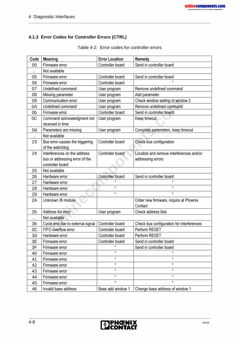
onlinec
omponen
ts.co
m
4 Diagnostic Interfaces
4-8 5003B
4.1.3 Error Codes for Controller Errors (CTRL)
Table 4-2: Error codes for controller errors
&RGH 0HDQLQJ (UURU�/RFDWLRQ 5HPHG\00 )LUPZDUH�HUURU &RQWUROOHU�ERDUG 6HQG�LQ�FRQWUROOHU�ERDUG.. 1RW�DYDLODEOH05 )LUPZDUH�HUURU &RQWUROOHU�ERDUG 6HQG�LQ�FRQWUROOHU�ERDUG06 )LUPZDUH�HUURU &RQWUROOHU�ERDUG �07 8QGHILQHG�FRPPDQG 8VHU�SURJUDP 5HPRYH�XQGHILQHG�FRPPDQG08 0LVVLQJ�SDUDPHWHU 8VHU�SURJUDP $GG�SDUDPHWHU09 &RPPXQLFDWLRQ�HUURU 8VHU�SURJUDP &KHFN�ZLQGRZ�VHWWLQJ�RI�ZLQGRZ��0A 8QGHILQHG�FRPPDQG 8VHU�SURJUDP 5HPRYH�XQGHILQHG�FRPPDQG0b )LUPZDUH�HUURU &RQWUROOHU�ERDUG 6HQG�LQ�FRQWUROOHU�ERDUG0C &RPPDQG�DFNQRZOHGJPHQW�QRW
UHFHLYHG�LQ�WLPH8VHU�SURJUDP .HHS�WLPHRXW
0d 3DUDPHWHUV�DUH�PLVVLQJ 8VHU�SURJUDP &RPSOHWH�SDUDPHWHUV��NHHS�WLPHRXW.. 1RW�DYDLODEOH23 %XV�HUURU�FDXVHV�WKH�WULJJHULQJ
RI�WKH�ZDWFKGRJ&RQWUROOHU�ERDUG &KHFN�EXV�FRQILJXUDWLRQ
24 ,QWHUIHUHQFHV�RQ�WKH�DGGUHVVEXV�RU�DGGUHVVLQJ�HUURU�RI�WKHFRQWUROOHU�ERDUG
&RQWUROOHU�ERDUG /RFDOL]H�DQG�UHPRYH�LQWHUIHUHQFHV�DQG�RUDGGUHVVLQJ�HUURUV
25 1RW�DYDLODEOH26 +DUGZDUH�HUURU &RQWUROOHU�ERDUG 6HQG�LQ�FRQWUROOHU�ERDUG27 +DUGZDUH�HUURU � �28 +DUGZDUH�HUURU � �29 +DUGZDUH�HUURU � �2A 8QNQRZQ�,%�PRGXOH 2UGHU�QHZ�ILUPZDUH��LQTXLUH�DW�3KRHQL[
&RQWDFW2b $GGUHVV�OLVW�HUURU 8VHU�SURJUDP &KHFN�DGGUHVV�OLVWV.. 1RW�DYDLODEOH3b &\FOH�HQG�GXH�WR�H[WHUQDO�VLJQDO &RQWUROOHU�ERDUG &KHFN�EXV�FRQILJXUDWLRQ�IRU�LQWHUIHUHQFHV3C ),)2�RYHUIORZ�HUURU &RQWUROOHU�ERDUG 3HUIRUP�5(6(73d +DUGZDUH�HUURU &RQWUROOHU�ERDUG 3HUIRUP�5(6(73E )LUPZDUH�HUURU &RQWUROOHU�ERDUG 6HQG�LQ�FRQWUROOHU�ERDUG3F )LUPZDUH�HUURU � 6HQG�LQ�FRQWUROOHU�ERDUG40 )LUPZDUH�HUURU � �41 )LUPZDUH�HUURU � �42 )LUPZDUH�HUURU � �43 )LUPZDUH�HUURU � �44 )LUPZDUH�HUURU � �45 )LUPZDUH�HUURU � �46 ,QYDOLG�EDVH�DGGUHVV %DVH�DGG�ZLQGRZ�� &KDQJH�EDVH�DGGUHVV�RI�ZLQGRZ��
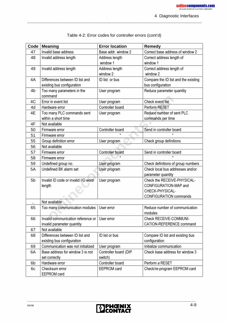
onlinec
omponen
ts.co
m
4 Diagnostic Interfaces
5003B 4-9
Table 4-2: Error codes for controller errors (cont’d)
Code Meaning Error location Remedy47 ,QYDOLG�EDVH�DGGUHVV %DVH�DGGU��ZLQGRZ�� &RUUHFW�EDVH�DGGUHVV�RI�ZLQGRZ��48 ,QYDOLG�DGGUHVV�OHQJWK $GGUHVV�OHQJWK
�ZLQGRZ��&RUUHFW�DGGUHVV�OHQJWK�RIZLQGRZ��
49 ,QYDOLG�DGGUHVV�OHQJWK $GGUHVV�OHQJWKZLQGRZ��
&RUUHFW�DGGUHVV�OHQJWK�RI�ZLQGRZ��
4A 'LIIHUHQFHV�EHWZHHQ�,'�OLVW�DQGH[LVWLQJ�EXV�FRQILJXUDWLRQ
,'�OLVW��RU�EXV &RPSDUH�WKH�,'�OLVW�DQG�WKH�H[LVWLQJEXV�FRQILJXUDWLRQ
4b 7RR�PDQ\�SDUDPHWHUV�LQ�WKHFRPPDQG
8VHU�SURJUDP 5HGXFH�SDUDPHWHU�TXDQWLW\
4C (UURU�LQ�HYHQW�OLVW 8VHU�SURJUDP &KHFN�HYHQW�OLVW4d +DUGZDUH�HUURU &RQWUROOHU�ERDUG 3HUIRUP�5(6(74E 7RR�PDQ\�3/&�FRPPDQGV�VHQW
ZLWKLQ�D�VKRUW�WLPH8VHU�SURJUDP 5HGXFH�QXPEHU�RI�VHQW�3/&
FRPPDQGV�SHU�WLPH4F 1RW�DYDLODEOH50 )LUPZDUH�HUURU &RQWUROOHU�ERDUG 6HQG�LQ�FRQWUROOHU�ERDUG51 )LUPZDUH�HUURU � �55 *URXS�GHILQLWLRQ�HUURU 8VHU�SURJUDP &KHFN�JURXS�GHILQLWLRQV56 1RW�DYDLODEOH57 )LUPZDUH�HUURU &RQWUROOHU�ERDUG 6HQG�LQ�FRQWUROOHU�ERDUG58 )LUPZDUH�HUURU � �59 8QGHILQHG�JURXS�QR� 8VHU�SURJUDP &KHFN�GHILQLWLRQV�RI�JURXS�QXPEHUV5A 8QGHILQHG�%.�DODUP�VHW 8VHU�SURJUDP &KHFN�ORFDO�EXV�DGGUHVVHV�DQG�RU
SDUDPHWHU�TXDQWLW\5b ,QYDOLG�,'�FRGH�RU�LQYDOLG�,�2�ZRUG
OHQJWK8VHU�SURJUDP &KHFN�WKH�5(&(,9(�3+<6,&$/�
&21),*85$7,21�0$3�DQG&+(&.�3+<6,&$/�&21),*85$7,21�FRPPDQGV
.. 1RW�DYDLODEOH65 7RR�PDQ\�FRPPXQLFDWLRQ�PRGXOHV 8VHU�HUURU 5HGXFH�QXPEHU�RI�FRPPXQLFDWLRQ
PRGXOHV66 ,QYDOLG�FRPPXQLFDWLRQ�UHIHUHQFH�RU
LQYDOLG�SDUDPHWHU�TXDQWLW\8VHU�HUURU &KHFN�5(&(,9(�&20081,�
&$7,21�5()(5(1&(�FRPPDQG67 1RW�DYDLODEOH68 'LIIHUHQFHV�EHWZHHQ�,'�OLVW�DQG
H[LVWLQJ�EXV�FRQILJXUDWLRQ,'�OLVW�RU�EXV &RPSDUH�,'�OLVW�DQG�H[LVWLQJ�EXV
FRQILJXUDWLRQ69 &RPPXQLFDWLRQ�ZDV�QRW�LQLWLDOL]HG 8VHU�SURJUDP ,QLWLDOL]H�FRPPXQLFDWLRQ6A %DVH�DGGUHVV�IRU�ZLQGRZ���LV�QRW
VHW�FRUUHFWO\&RQWUROOHU�ERDUG �',3VZLWFK�
&KHFN�EDVH�DGGUHVV�IRU�ZLQGRZ��
6b +DUGZDUH�HUURU &RQWUROOHU�ERDUG 3HUIRUP�D�5(6(76c &KHFNVXP�HUURU
((3520�FDUG((3520�FDUG &KHFN�UH�SURJUDP�((3520�FDUG
onlinec
omponen
ts.co
m
4 Diagnostic Interfaces
4-10 5003B
All errors described here are only valid when the CTRL LED is active. Theerror codes are described in further detail at the end of this chapter. The errorcodes E01 and E02 were previously described in the "RB ERR" section.
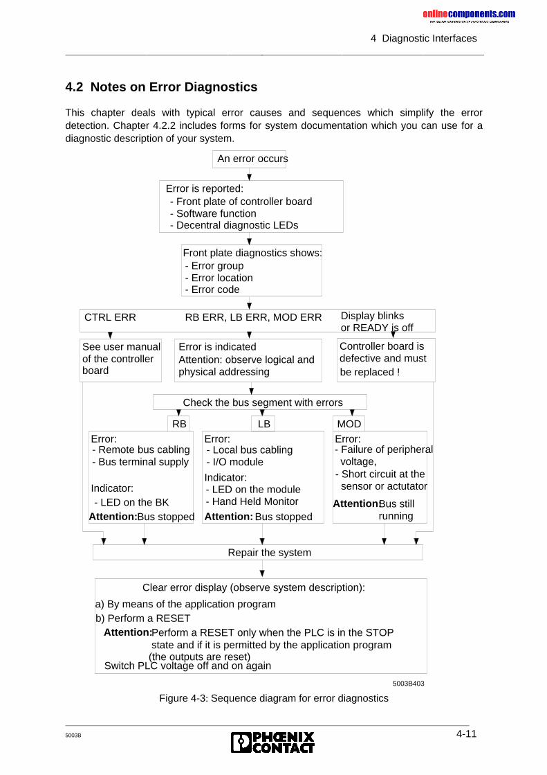
onlinec
omponen
ts.co
m
4 Diagnostic Interfaces
5003B 4-11
4.2 Notes on Error Diagnostics
This chapter deals with typical error causes and sequences which simplify the errordetection. Chapter 4.2.2 includes forms for system documentation which you can use for adiagnostic description of your system.
Figure 4-3: Sequence diagram for error diagnostics
An error occurs
Check the bus segment with errors
RB MOD
Repair the system
a) By means of the application program
Switch PLC voltage off and on again
Bus stillrunning
5003B403
LB
Error is indicatedAttention: observe logical and physical addressing
Error is reported:- Front plate of controller board- Software function- Decentral diagnostic LEDs
Front plate diagnostics shows:- Error group- Error location- Error code
See user manualof the controllerboard
Controller board is defective and must be replaced !
- Failure of peripheral voltage,- Short circuit at the sensor or actutator
- Local bus cabling- I/O module
- LED on the module- Hand Held Monitor
Bus stopped
- Remote bus cabling- Bus terminal supply
- LED on the BK
Clear error display (observe system description):
b) Perform a RESET Perform a RESET only when the PLC is in the STOP state and if it is permitted by the application program (the outputs are reset)
CTRL ERR RB ERR, LB ERR, MOD ERR Display blinksor READY is off
Bus stopped
Error:
Indicator:
Error:
Indicator:
Error:
Attention: Attention:Attention:
Attention:
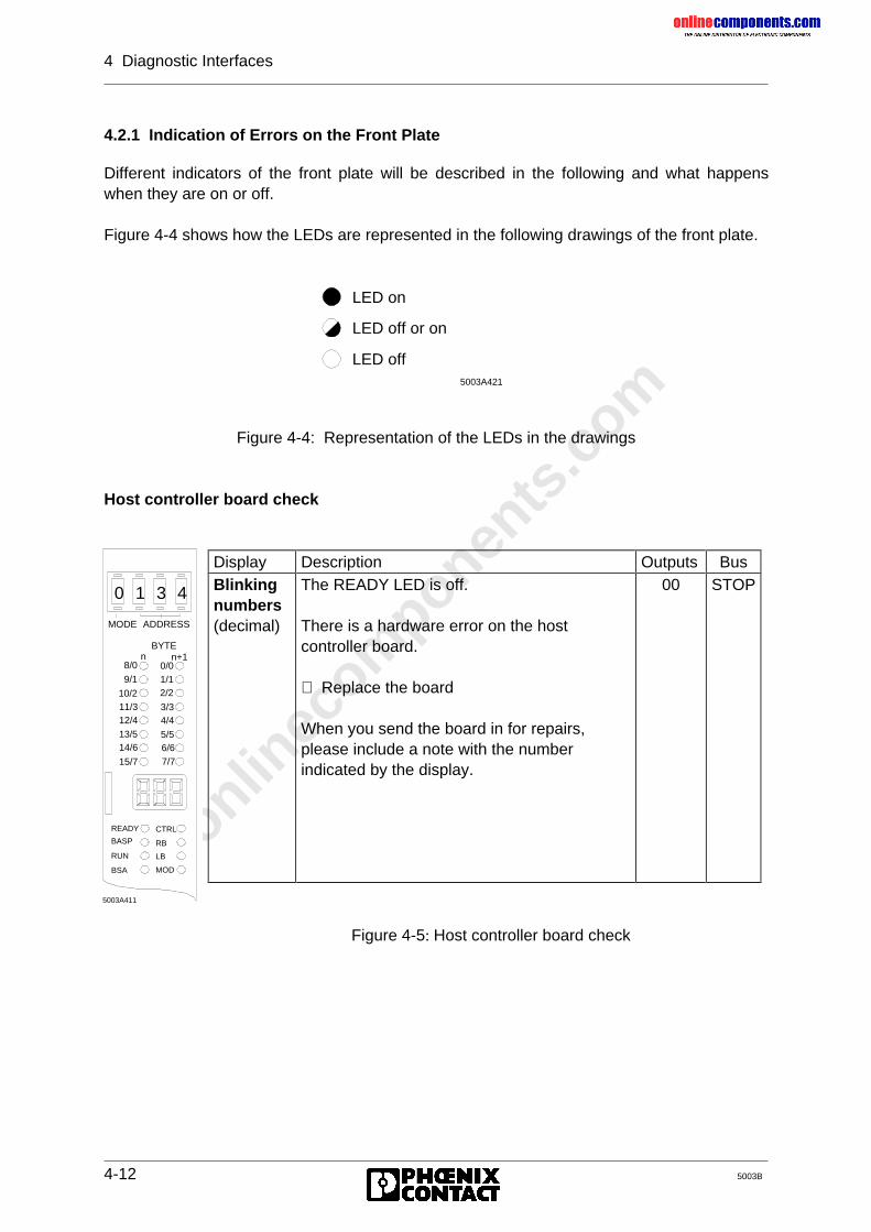
onlinec
omponen
ts.co
m
4 Diagnostic Interfaces
4-12 5003B
4.2.1 Indication of Errors on the Front Plate
Different indicators of the front plate will be described in the following and what happenswhen they are on or off.
Figure 4-4 shows how the LEDs are represented in the following drawings of the front plate.
Figure 4-4: Representation of the LEDs in the drawings
Host controller board check
Display Description Outputs BusBlinkingnumbers(decimal)
The READY LED is off.
There is a hardware error on the hostcontroller board.
⇒ Replace the board
When you send the board in for repairs,please include a note with the numberindicated by the display.
00 STOP
Figure 4-5: Host controller board check
5003A421
LED on
LED off or on
LED off
BYTEn n+1
MODE ADDRESS
CTRL
RB
LB
MOD
READY
BASP
RUN
BSA
10/2
8/0
9/1
11/312/413/514/6
15/7
0/01/12/2
3/34/4
5/56/67/7
0 1 3 4
5003A411
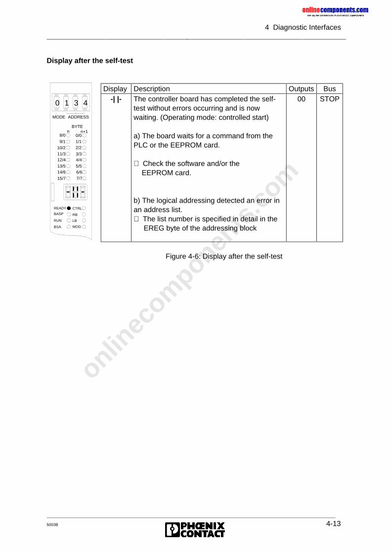
onlinec
omponen
ts.co
m
4 Diagnostic Interfaces
5003B 4-13
Display after the self-test
Display Description Outputs Bus-| |- The controller board has completed the self-
test without errors occurring and is nowwaiting. (Operating mode: controlled start)
a) The board waits for a command from thePLC or the EEPROM card.
⇒ Check the software and/or the EEPROM card.
b) The logical addressing detected an error inan address list.⇒ The list number is specified in detail in the EREG byte of the addressing block
00 STOP
Figure 4-6: Display after the self-test
BYTEn n+1
MODE ADDRESS
CTRL
RB
LB
MOD
READY
BASP
RUN
BSA
10/2
8/0
9/1
11/312/4
13/514/6
15/7
0/01/12/2
3/34/4
5/56/67/7
0 1 3 4
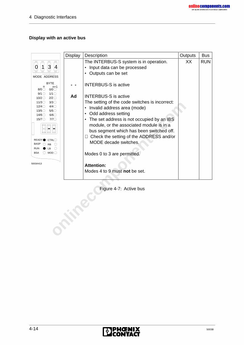
onlinec
omponen
ts.co
m
4 Diagnostic Interfaces
4-14 5003B
Display with an active bus
Display Description Outputs Bus
- -
Ad
The INTERBUS-S system is in operation.• Input data can be processed• Outputs can be set
INTERBUS-S is active
INTERBUS-S is activeThe setting of the code switches is incorrect:• Invalid address area (mode)• Odd address setting• The set address is not occupied by an IBS
module, or the associated module is in abus segment which has been switched off.
⇒ Check the setting of the ADDRESS and/or MODE decade switches.
Modes 0 to 3 are permitted.
Attention:Modes 4 to 9 must not be set.
XX RUN
Figure 4-7: Active bus
BYTEn n+1
MODE ADDRESS
CTRL
RB
LB
MOD
READY
BASP
RUN
BSA
10/2
8/0
9/1
11/312/413/514/6
15/7
0/01/12/2
3/34/4
5/56/6
7/7
0 1 3 4
5003A413
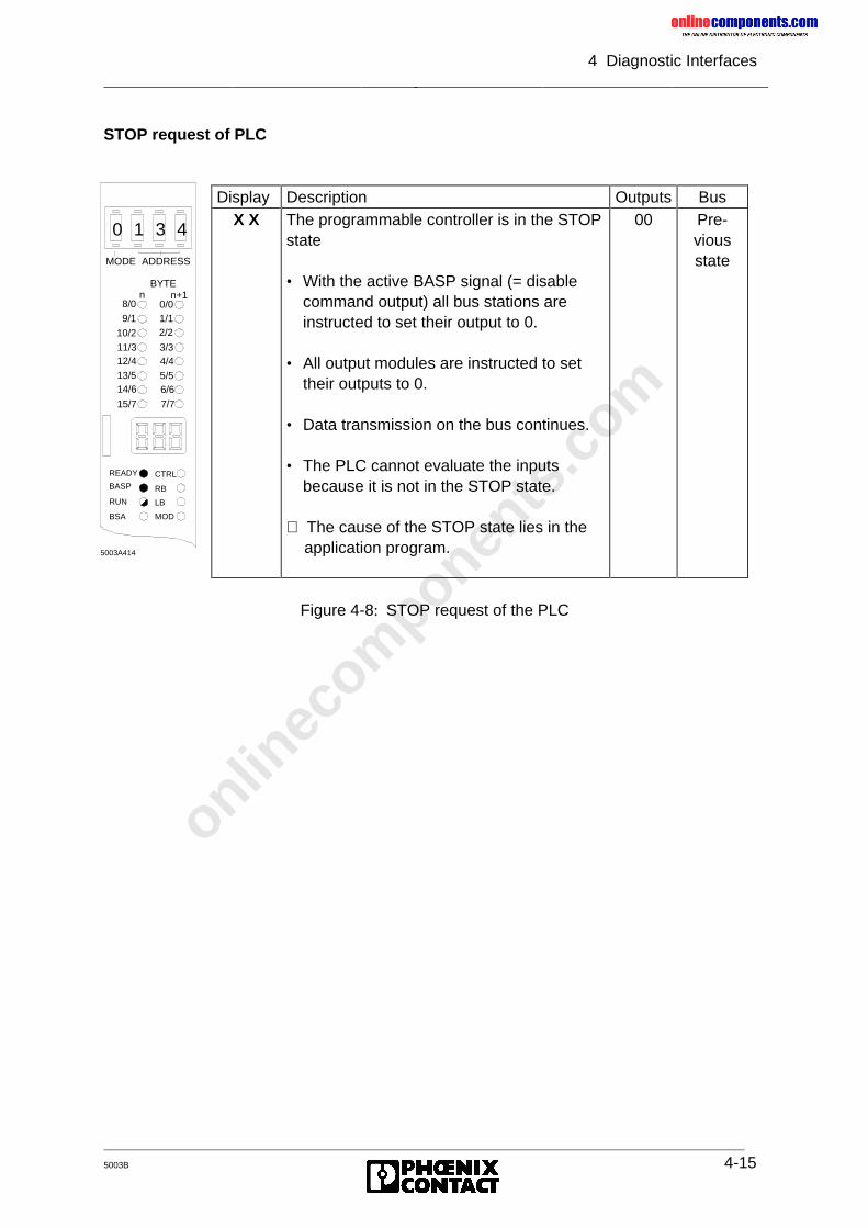
onlinec
omponen
ts.co
m
4 Diagnostic Interfaces
5003B 4-15
STOP request of PLC
Display Description Outputs BusX X The programmable controller is in the STOP
state
• With the active BASP signal (= disablecommand output) all bus stations areinstructed to set their output to 0.
• All output modules are instructed to settheir outputs to 0.
• Data transmission on the bus continues.
• The PLC cannot evaluate the inputsbecause it is not in the STOP state.
⇒ The cause of the STOP state lies in the application program.
00 Pre-viousstate
Figure 4-8: STOP request of the PLC
BYTEn n+1
MODE ADDRESS
CTRL
RB
LB
MOD
READY
BASP
RUN
BSA
10/2
8/0
9/1
11/312/413/514/6
15/7
0/01/12/2
3/34/45/56/6
7/7
0 1 3 4
5003A414
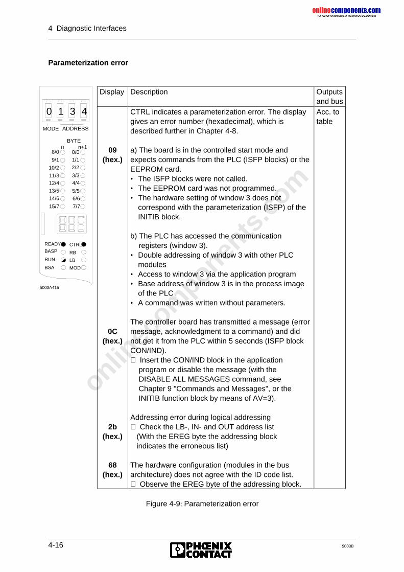
onlinec
omponen
ts.co
m
4 Diagnostic Interfaces
4-16 5003B
Parameterization error
Display Description Outputsand bus
09(hex.)
0C(hex.)
2b(hex.)
68(hex.)
CTRL indicates a parameterization error. The displaygives an error number (hexadecimal), which isdescribed further in Chapter 4-8.
a) The board is in the controlled start mode andexpects commands from the PLC (ISFP blocks) or theEEPROM card.• The ISFP blocks were not called.• The EEPROM card was not programmed.• The hardware setting of window 3 does not
correspond with the parameterization (ISFP) of theINITIB block.
b) The PLC has accessed the communication registers (window 3).• Double addressing of window 3 with other PLC
modules• Access to window 3 via the application program• Base address of window 3 is in the process image
of the PLC• A command was written without parameters.
The controller board has transmitted a message (errormessage, acknowledgment to a command) and didnot get it from the PLC within 5 seconds (ISFP blockCON/IND).⇒ Insert the CON/IND block in the application program or disable the message (with the DISABLE ALL MESSAGES command, see Chapter 9 "Commands and Messages", or the INITIB function block by means of AV=3).
Addressing error during logical addressing⇒ Check the LB-, IN- and OUT address list (With the EREG byte the addressing block indicates the erroneous list)
The hardware configuration (modules in the busarchitecture) does not agree with the ID code list.⇒ Observe the EREG byte of the addressing block.
Acc. totable
Figure 4-9: Parameterization error
BYTEn n+1
MODE ADDRESS
CTRL
RB
LB
MOD
READY
BASP
RUN
BSA
10/2
8/0
9/1
11/312/4
13/5
14/6
15/7
0/01/1
2/2
3/34/4
5/56/6
7/7
0 1 3 4
5003A415
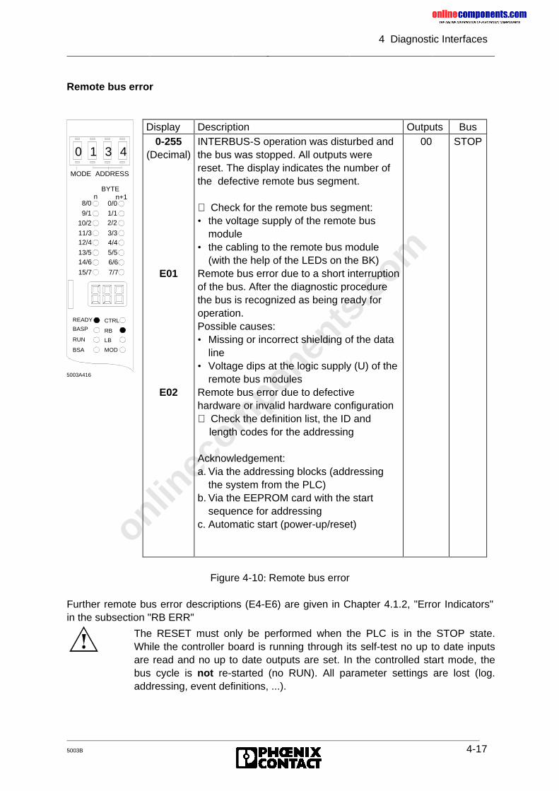
onlinec
omponen
ts.co
m
4 Diagnostic Interfaces
5003B 4-17
Remote bus error
Display Description Outputs Bus0-255
(Decimal)
E01
E02
INTERBUS-S operation was disturbed andthe bus was stopped. All outputs werereset. The display indicates the number ofthe defective remote bus segment.
⇒ Check for the remote bus segment:• the voltage supply of the remote bus
module• the cabling to the remote bus module
(with the help of the LEDs on the BK)Remote bus error due to a short interruptionof the bus. After the diagnostic procedurethe bus is recognized as being ready foroperation.Possible causes:• Missing or incorrect shielding of the data
line• Voltage dips at the logic supply (U) of the
remote bus modulesRemote bus error due to defectivehardware or invalid hardware configuration⇒ Check the definition list, the ID and length codes for the addressing
Acknowledgement:a. Via the addressing blocks (addressing
the system from the PLC)b. Via the EEPROM card with the start
sequence for addressingc. Automatic start (power-up/reset)
00 STOP
Figure 4-10: Remote bus error
Further remote bus error descriptions (E4-E6) are given in Chapter 4.1.2, "Error Indicators"in the subsection "RB ERR"
BYTEn n+1
MODE ADDRESS
CTRL
RB
LB
MOD
READY
BASP
RUN
BSA
10/2
8/0
9/1
11/312/4
13/514/6
15/7
0/01/12/2
3/34/45/56/6
7/7
0 1 3 4
5003A416
The RESET must only be performed when the PLC is in the STOP state.While the controller board is running through its self-test no up to date inputsare read and no up to date outputs are set. In the controlled start mode, thebus cycle is not re-started (no RUN). All parameter settings are lost (log.addressing, event definitions, ...).
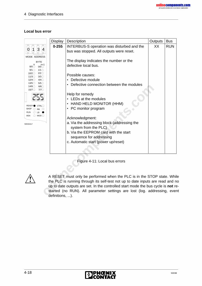
onlinec
omponen
ts.co
m
4 Diagnostic Interfaces
4-18 5003B
Local bus error
Display Description Outputs Bus0-255 INTERBUS-S operation was disturbed and the
bus was stopped. All outputs were reset.
The display indicates the number or thedefective local bus.
Possible causes:• Defective module• Defective connection between the modules
Help for remedy• LEDs at the modules• HAND HELD MONITOR (HHM)• PC monitor program
Acknowledgment:a. Via the addressing block (addressing the
system from the PLC)b. Via the EEPROM card with the start
sequence for addressingc. Automatic start (power up/reset)
XX RUN
Figure 4-11: Local bus errors
BYTEn n+1
MODE ADDRESS
CTRL
RB
LB
MOD
READY
BASP
RUN
BSA
10/2
8/0
9/1
11/312/413/514/6
15/7
0/01/12/2
3/34/4
5/56/6
7/7
0 1 3 4
5003A417
A RESET must only be performed when the PLC is in the STOP state. Whilethe PLC is running through its self-test not up to date inputs are read and noup to date outputs are set. In the controlled start mode the bus cycle is not re-started (no RUN). All parameter settings are lost (log. addressing, eventdefinitions, ...).
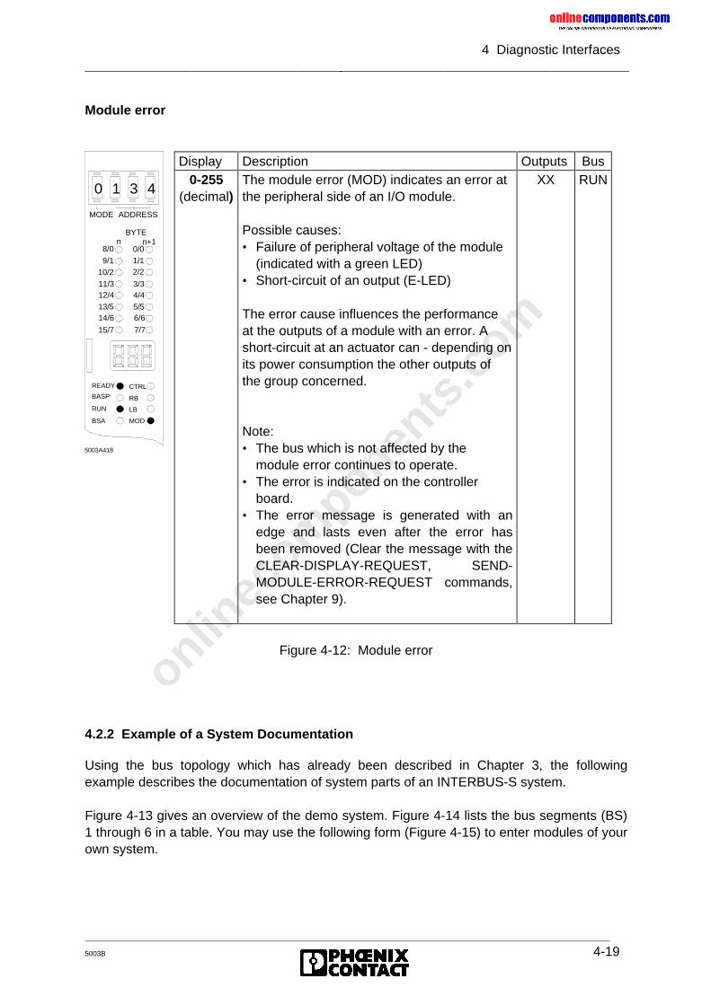
onlinec
omponen
ts.co
m
4 Diagnostic Interfaces
5003B 4-19
Module error
Display Description Outputs Bus0-255
(decimal)The module error (MOD) indicates an error atthe peripheral side of an I/O module.
Possible causes:• Failure of peripheral voltage of the module
(indicated with a green LED)• Short-circuit of an output (E-LED)
The error cause influences the performanceat the outputs of a module with an error. Ashort-circuit at an actuator can - depending onits power consumption the other outputs ofthe group concerned.
Note:• The bus which is not affected by the
module error continues to operate.• The error is indicated on the controller
board.• The error message is generated with an
edge and lasts even after the error hasbeen removed (Clear the message with theCLEAR-DISPLAY-REQUEST, SEND-MODULE-ERROR-REQUEST commands,see Chapter 9).
XX RUN
Figure 4-12: Module error
4.2.2 Example of a System Documentation
Using the bus topology which has already been described in Chapter 3, the followingexample describes the documentation of system parts of an INTERBUS-S system.
Figure 4-13 gives an overview of the demo system. Figure 4-14 lists the bus segments (BS)1 through 6 in a table. You may use the following form (Figure 4-15) to enter modules of yourown system.
BYTEn n+1
MODE ADDRESS
CTRL
RB
LB
MOD
READY
BASP
RUN
BSA
10/2
8/0
9/1
11/312/413/514/6
15/7
0/01/12/2
3/34/45/56/6
7/7
0 1 3 4
5003A418
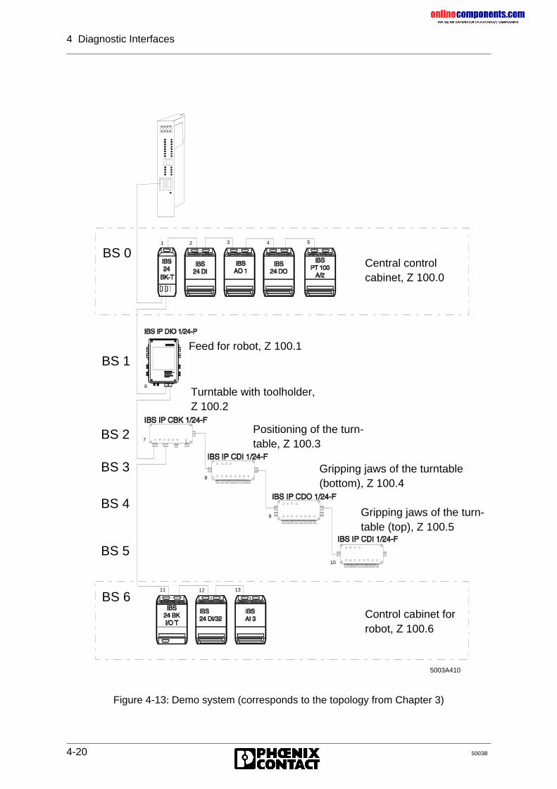
onlinec
omponen
ts.co
m
4 Diagnostic Interfaces
4-20 5003B
Figure 4-13: Demo system (corresponds to the topology from Chapter 3)
5003A410
7
8
9
10
11 12 13
1 2 3 4 5
6
ID 7
Central controlcabinet, Z 100.0
Feed for robot, Z 100.1
Turntable with toolholder,Z 100.2
Positioning of the turn-table, Z 100.3
Gripping jaws of the turntable(bottom), Z 100.4
Gripping jaws of the turn-table (top), Z 100.5
Control cabinet for robot, Z 100.6
BS 6
BS 1
BS 0
BS 2
BS 3
BS 4
BS 5
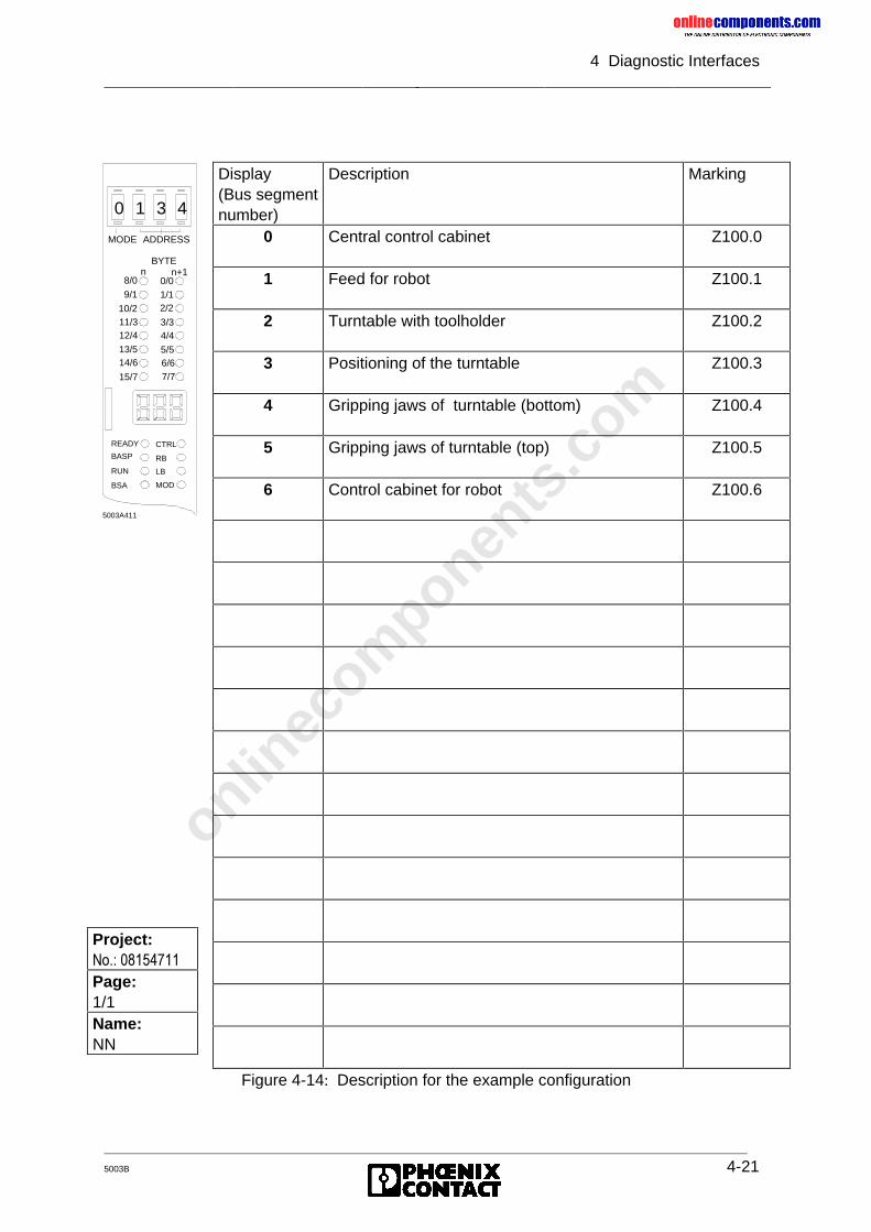
onlinec
omponen
ts.co
m
4 Diagnostic Interfaces
5003B 4-21
Figure 4-14: Description for the example configuration
BYTEn n+1
MODE ADDRESS
CTRL
RB
LB
MOD
READY
BASP
RUN
BSA
10/2
8/0
9/1
11/312/413/514/6
15/7
0/01/12/2
3/34/4
5/56/67/7
0 1 3 4
5003A411
Project:1R�����������Page:1/1Name:NN
Display(Bus segmentnumber)
Description Marking
0 Central control cabinet Z100.0
1 Feed for robot Z100.1
2 Turntable with toolholder Z100.2
3 Positioning of the turntable Z100.3
4 Gripping jaws of turntable (bottom) Z100.4
5 Gripping jaws of turntable (top) Z100.5
6 Control cabinet for robot Z100.6
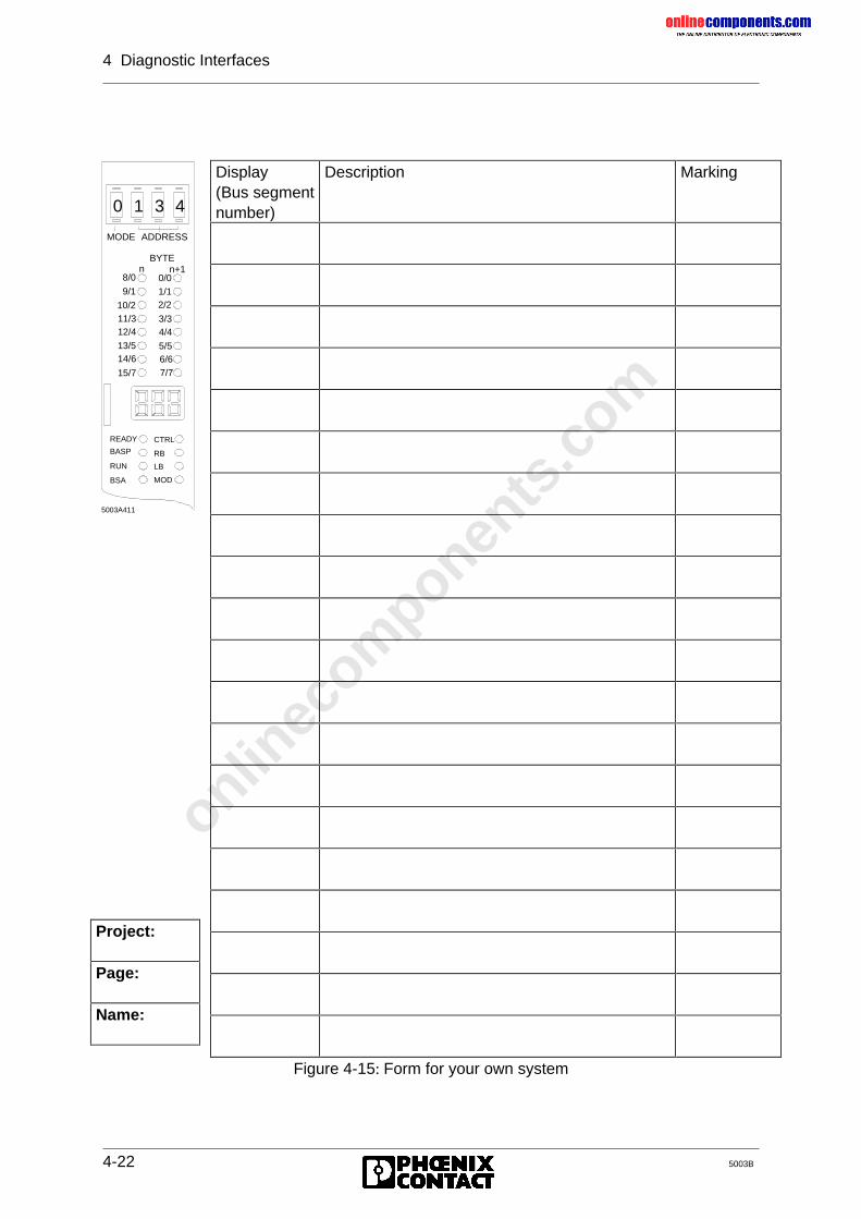
onlinec
omponen
ts.co
m
4 Diagnostic Interfaces
4-22 5003B
Figure 4-15: Form for your own system
BYTEn n+1
MODE ADDRESS
CTRL
RB
LB
MOD
READY
BASP
RUN
BSA
10/2
8/0
9/1
11/312/413/514/6
15/7
0/01/12/2
3/34/4
5/56/67/7
0 1 3 4
5003A411
Project:
Page:
Name:
Display(Bus segmentnumber)
Description Marking
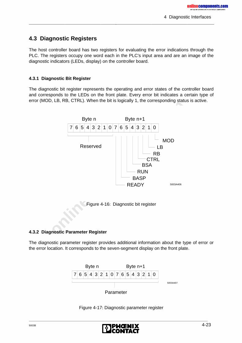
onlinec
omponen
ts.co
m
4 Diagnostic Interfaces
5003B 4-23
4.3 Diagnostic Registers
The host controller board has two registers for evaluating the error indications through thePLC. The registers occupy one word each in the PLC’s input area and are an image of thediagnostic indicators (LEDs, display) on the controller board.
4.3.1 Diagnostic Bit Register
The diagnostic bit register represents the operating and error states of the controller boardand corresponds to the LEDs on the front plate. Every error bit indicates a certain type oferror (MOD, LB, RB, CTRL). When the bit is logically 1, the corresponding status is active.
Figure 4-16: Diagnostic bit register
4.3.2 Diagnostic Parameter Register
The diagnostic parameter register provides additional information about the type of error orthe error location. It corresponds to the seven-segment display on the front plate.
Figure 4-17: Diagnostic parameter register
7 6 5 4 3 2 1 0 7 6 5 4 3 2 1 0
Byte n Byte n+1
ReservedMOD
LBRB
CTRLBSA
RUNBASP
READY 5003A406
7 6 5 4 3 2 1 0 7 6 5 4 3 2 1 0
Byte n Byte n+1
5003A407
Parameter
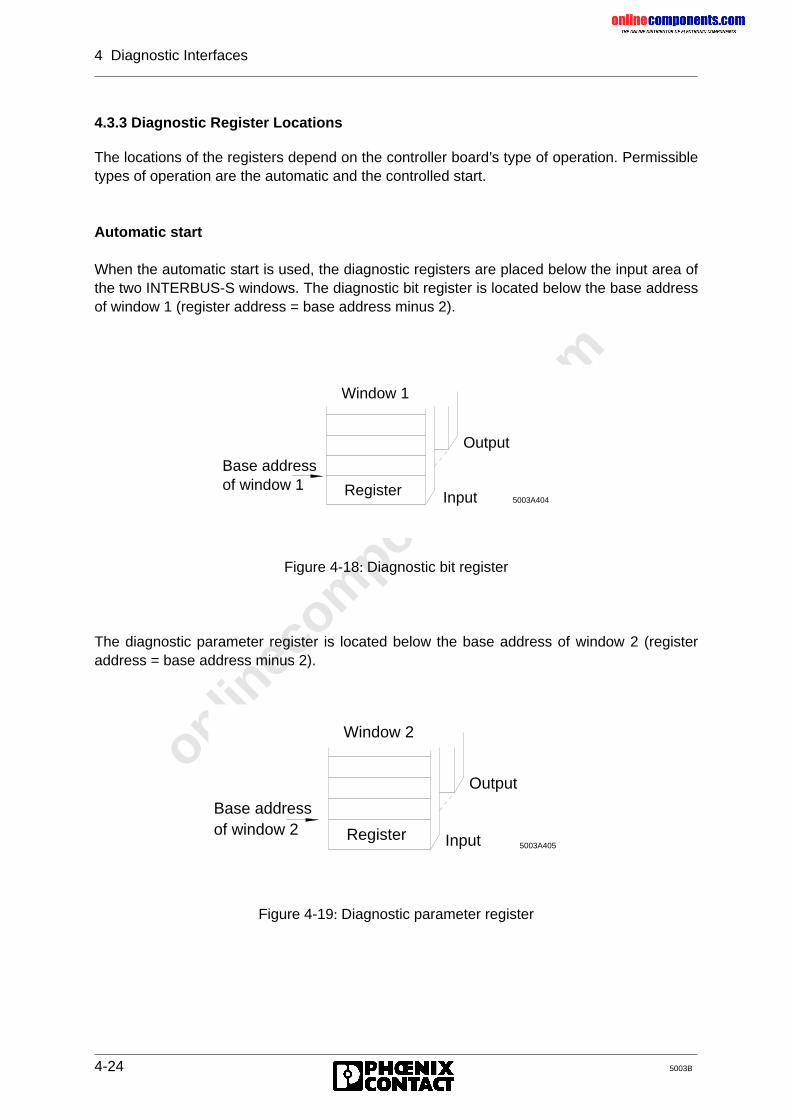
onlinec
omponen
ts.co
m
4 Diagnostic Interfaces
4-24 5003B
4.3.3 Diagnostic Register Locations
The locations of the registers depend on the controller board’s type of operation. Permissibletypes of operation are the automatic and the controlled start.
Automatic start
When the automatic start is used, the diagnostic registers are placed below the input area ofthe two INTERBUS-S windows. The diagnostic bit register is located below the base addressof window 1 (register address = base address minus 2).
Figure 4-18: Diagnostic bit register
The diagnostic parameter register is located below the base address of window 2 (registeraddress = base address minus 2).
Figure 4-19: Diagnostic parameter register
Window 1
Output
Register Input 5003A404
Base addressof window 1
Window 2
Output
Register Input 5003A405
Base addressof window 2
onlinec
omponen
ts.co
m
4 Diagnostic Interfaces
5003B 4-25
Controlled start
When the controlled start is used, the diagnostic registers in the input area of the twoINTERBUS-S windows can be freely assigned. The addresses are assigned by means of anID code in the logical addressing.
ID code:
• Diagnostic bit register: ID = 16• Diagnostic parameter register: ID = 17
The logical addressing assigns an address to the ID code at which the correspondingregister is located.
Example:
ID List IN Address ListKY = 000,016 KY = 000.032KY = 000,017 KY = 000.034
Diagnostic bit register: IW 32Diagnostic parameter register: IW 34
Enter ID codes for the diagnostic registers at the end of the ID code list.
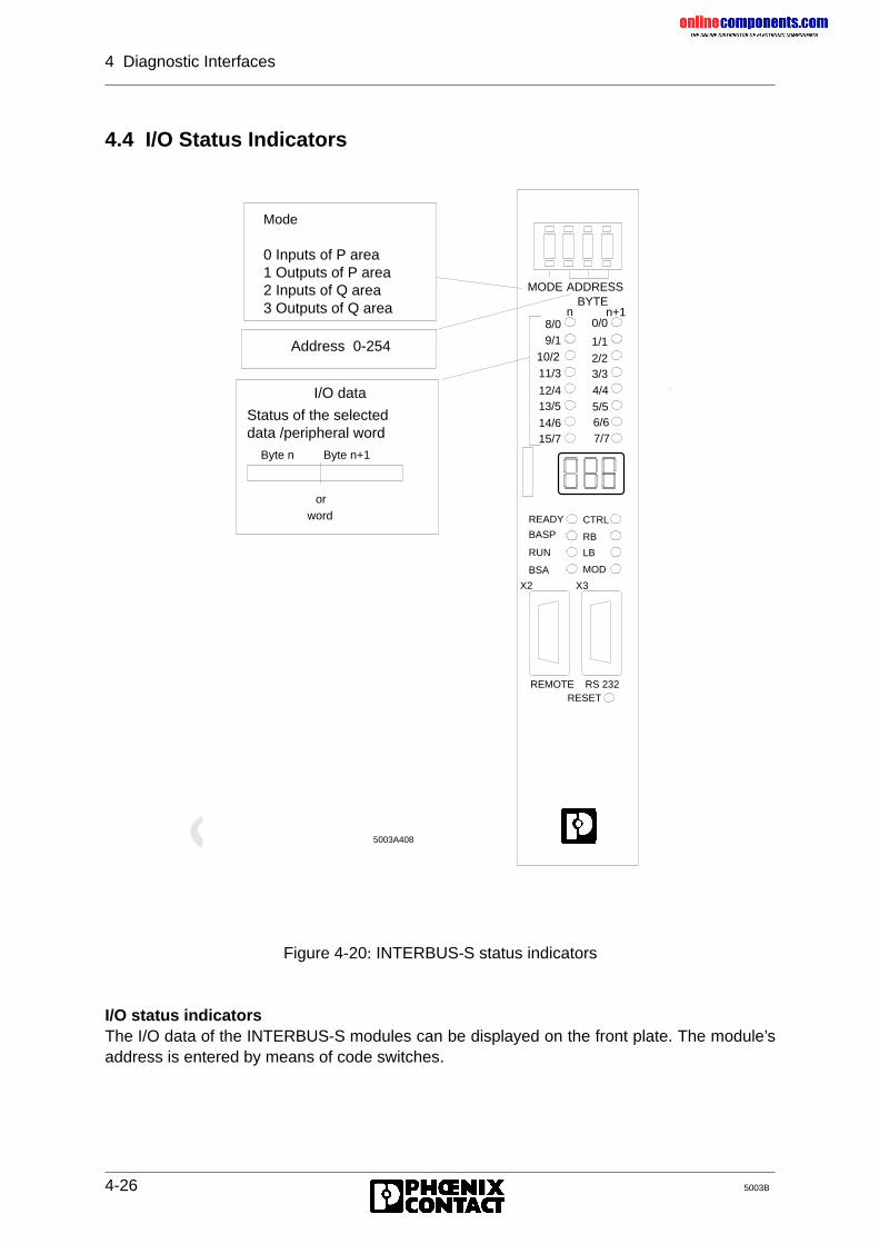
onlinec
omponen
ts.co
m
4 Diagnostic Interfaces
4-26 5003B
4.4 I/O Status Indicators
Figure 4-20: INTERBUS-S status indicators
I/O status indicatorsThe I/O data of the INTERBUS-S modules can be displayed on the front plate. The module’saddress is entered by means of code switches.
BYTEn n+1
MODE ADDRESS
8/09/1
11/3
12/413/5
14/615/7
10/2
0/0
1/1
2/23/3
4/45/56/67/7
CTRL
RB
LB
MOD
READY
BASP
RUN
BSA
X2 X3
REMOTE RS 232RESET
Mode
0 Inputs of P area1 Outputs of P area2 Inputs of Q area3 Outputs of Q area
Address 0-254
I/O data
Status of the selected data /peripheral word
Byte n Byte n+1
orword
5003A408
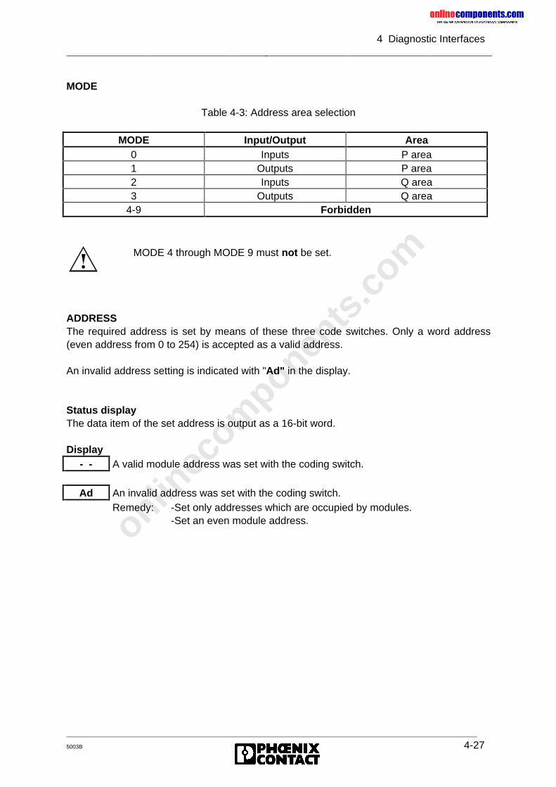
onlinec
omponen
ts.co
m
4 Diagnostic Interfaces
5003B 4-27
MODE
Table 4-3: Address area selection
MODE Input/Output Area0 Inputs P area1 Outputs P area2 Inputs Q area3 Outputs Q area
4-9 Forbidden
ADDRESSThe required address is set by means of these three code switches. Only a word address(even address from 0 to 254) is accepted as a valid address.
An invalid address setting is indicated with "Ad" in the display.
Status displayThe data item of the set address is output as a 16-bit word.
Display- - A valid module address was set with the coding switch.
Ad An invalid address was set with the coding switch.Remedy: -Set only addresses which are occupied by modules.
-Set an even module address.
MODE 4 through MODE 9 must not be set.
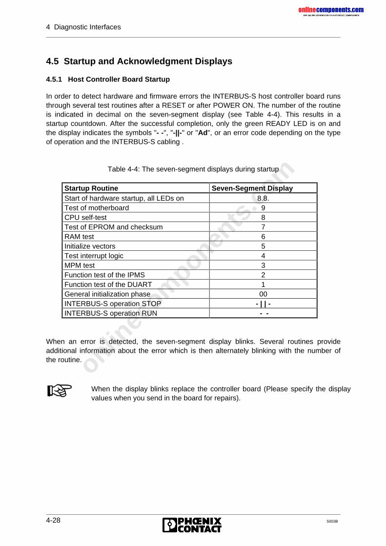
onlinec
omponen
ts.co
m
4 Diagnostic Interfaces
4-28 5003B
4.5 Startup and Acknowledgment Displays
4.5.1 Host Controller Board Startup
In order to detect hardware and firmware errors the INTERBUS-S host controller board runsthrough several test routines after a RESET or after POWER ON. The number of the routineis indicated in decimal on the seven-segment display (see Table 4-4). This results in astartup countdown. After the successful completion, only the green READY LED is on andthe display indicates the symbols "- -", "-||-" or "Ad", or an error code depending on the typeof operation and the INTERBUS-S cabling .
Table 4-4: The seven-segment displays during startup
Startup Routine Seven-Segment DisplayStart of hardware startup, all LEDs on 8.8.Test of motherboard 9CPU self-test 8Test of EPROM and checksum 7RAM test 6Initialize vectors 5Test interrupt logic 4MPM test 3Function test of the IPMS 2Function test of the DUART 1General initialization phase 00INTERBUS-S operation STOP - | | -INTERBUS-S operation RUN - -
When an error is detected, the seven-segment display blinks. Several routines provideadditional information about the error which is then alternately blinking with the number ofthe routine.
When the display blinks replace the controller board (Please specify the displayvalues when you send in the board for repairs).
onlinec
omponen
ts.co
m
4 Diagnostic Interfaces
5003B 4-29
4.5.2 Acknowledgment after an Error
The diagnostic indicators on the front plate of the controller board indicate errors of theINTERBUS-S system. The red LEDs indicate the type of error. The seven-segment displayfurther classifies the error. Except for the module error (MOD), INTERBUS-S is alwaysstopped after an error occurred (RUN LED is off).
After the error has been removed INTERBUS-S can be started again. The start behaviordepends on the selected mode and the error cause.
Clearing the error display and automatic startIn the automatic start mode INTERBUS-S can either be started by applying the PLC’s supplyvoltage (power up) or by pushing the RESET button.
Clearing the error display and controlled startIn the controlled start mode INTERBUS-S can be started by means of the ADDRESS startupblock or by means of the EEPROM card.
Clearing the display of a module error (MOD) while the system is runningAfter a module error the application program or the EEPROM card can clear the display withthe following commands.
• CLEAR-DISPLAY (CONTROL block, function 4) or• MODULE-ERROR (ERRINFO block, function 3)
If the bus is in the STOP state the I/O data does not correspond to the up todate signal states. There must be no access to the bus address.
A RESET must only be performed when the PLC is in the STOP state. Whilethe controller board performs its self-test no up to date inputs are read and noup to date outputs are set. In the controlled start mode, the bus cycle is notre-started (no RUN). All parameter settings (logical addressing, eventdefinitions, ...) are lost.
The I/O data of disabled local buses does not correspond to the up to datesignal states. There must be no access to the bus addresses concerned.
As long as the controller board does the addressing no up to date inputs are readand no up to date outputs are set.
onlinec
omponen
ts.co
m
4 Diagnostic Interfaces
4-30 5003B
4.6 Diagnostics on the Modules
In order to allow fast "local" diagnostics the modules feature status and diagnostic LEDs.The error indicators provide information about the type and location of an error. Other LEDsindicate the I/O states.
Indicators on the I/O modules:
• Supply voltage• Output overload/short circuit (group by group, single DI/DO)• Status LED for each I/O channel
Indicators on the bus terminal modules:
• Supply voltage• Remote bus monitoring• Local bus monitoring• Operating indication for INTERBUS-S
On some bus terminal modules, there is an additional pushbutton (Reconfiguration) thattriggers a message to the controller board (re-initialization of the bus system). This ispossible when operation continues, e.g. after the repair of a local bus.
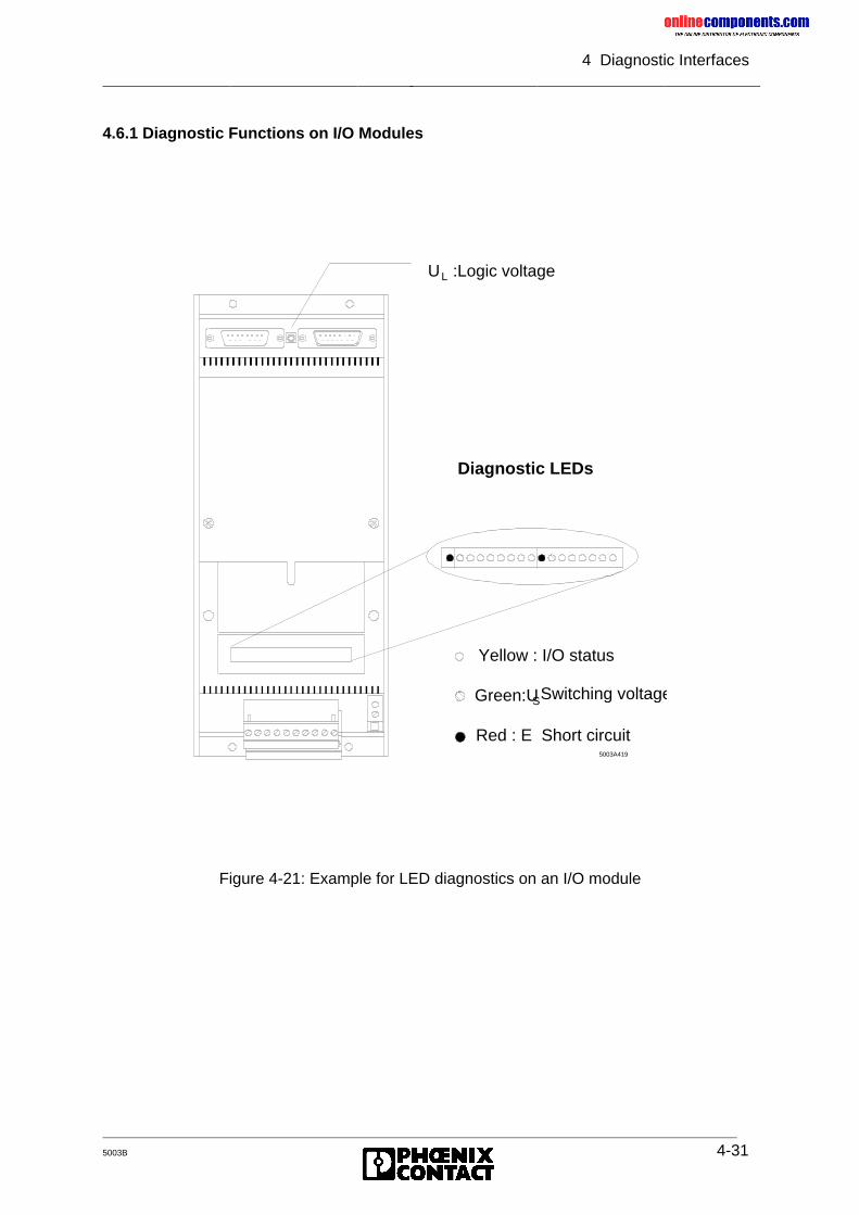
onlinec
omponen
ts.co
m
4 Diagnostic Interfaces
5003B 4-31
4.6.1 Diagnostic Functions on I/O Modules
Figure 4-21: Example for LED diagnostics on an I/O module
Diagnostic LEDs
Yellow : I/O status
Green:U SSwitching voltage
Red : E Short circuit5003A419
U :Logic voltageL
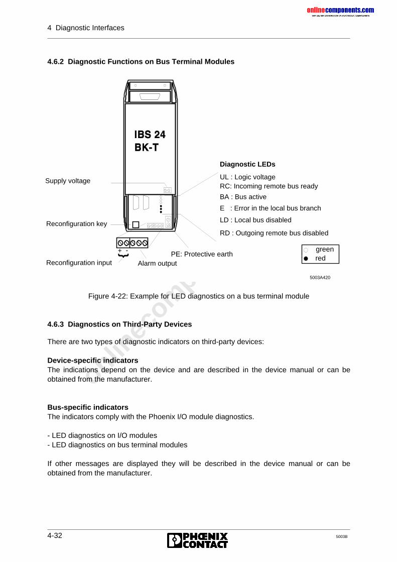
onlinec
omponen
ts.co
m
4 Diagnostic Interfaces
4-32 5003B
4.6.2 Diagnostic Functions on Bus Terminal Modules
Figure 4-22: Example for LED diagnostics on a bus terminal module
4.6.3 Diagnostics on Third-Party Devices
There are two types of diagnostic indicators on third-party devices:
Device-specific indicatorsThe indications depend on the device and are described in the device manual or can beobtained from the manufacturer.
Bus-specific indicatorsThe indicators comply with the Phoenix I/O module diagnostics.
- LED diagnostics on I/O modules- LED diagnostics on bus terminal modules
If other messages are displayed they will be described in the device manual or can beobtained from the manufacturer.
5003A420
Diagnostic LEDs
UL : Logic voltageRC: Incoming remote bus ready
BA : Bus active
E : Error in the local bus branch
LD : Local bus disabled
RD : Outgoing remote bus disabled
Supply voltage
PE: Protective earthAlarm output
-+
Reconfiguration input
Reconfiguration key
} greenred
onlinec
omponen
ts.co
m
4 Diagnostic Interfaces
5003B 4-33
4.7 Using the Hand Held Monitor
For startup or servicing, the Hand Held Monitor (HHM) facilitates the checking of individualbus stations in relation to their functions and correct connection to the periphery.
The monitor is accommodated in a handy and sturdy plastic housing. The connection toINTERBUS-S is established through the local bus interface. The connecting cable is pluggedbetween the bus terminal connector and the outgoing local bus cable. Therefore, the monitordoes not require an external power supply because it obtains its operating voltage throughthe connected bus terminal module. A clearly arranged key pad allows user-friendly handlingof the diagnostic unit in conjunction with the four-line alphanumeric liquid crystal display(LCD). The menu-prompted interface allows the user to read inputs and to set the outputsdirectly on the spot and without communication with the PLC. Connected in this way, theHHM is the master for the local bus. This guarantees a large number of diagnostic functionswhich are indicated in clear text on the LCD.
After the monitor has been started, operation of one single bus segment can be started toenable a gradual and error-free startup.
Starting individual modules:
• Test of the I/O modules• Test of the sensor/actuators cabling• Test of the sensors and actuators themselves
Troubleshooting in individual modules:
• Local bus cable errors• Module errors• Cabling faults (short or open circuit)• Failure of sensors and actuators
With the Hand Held Monitor, the PLC and service technician has a mobile measuringinstrument for checking machine and system cabling.
onlinec
omponen
ts.co
m
4 Diagnostic Interfaces
4-34 5003B
4.8 Using the Monitor Program for INTERBUS-S on the PC
If INTERBUS-S is controlled by a PC, the IBS-MONI monitor program offers acomprehensive test environment, It can be used to check installation of the INTERBUS-Smodules, the bus cabling, as well as the wiring of sensors and actuators. In contrast to theHand Held Monitor, these functions are called from a central location (PC).
The menu-driven program offers the following utilities:
• Starting an INTERBUS-S system on the PC.• Testing an INTERBUS-S system on the PC.• Checking the connected configuration.• Setting digital and analog outputs.• Displaying the statuses of digital and analog inputs.• Resetting the INTERBUS-S system (outputs = 0).
Using the cursor keys, each module connected on the bus can be selected through its I/Oaddress. The local bus number, the module number, the selected channel and the moduletype are specified (in clear text) for each module. Another field specifies the physical addressof the module on the bus. The IN data of the selected module is indicated in binary orhexadecimal code. Just like the IN data, the OUT data can be entered and edited in twonumber formats. Changes are acknowledged by pressing the ENTER key and are acceptedby the bus. INTERBUS-S can be reset with a function key. The resetting sets all outputs tothe value zero.
Use of the IBS-MONI program supports a structured startup and simplifies troubleshooting.
onlinec
omponen
ts.co
m
4 Diagnostic Interfaces
5003B 4-35
4.9 CTRL Error Displays
The following information is given for the errors listed below:
Error name (Error code)The code is given in a hexadecimal form. The letters A to F arerepresented as capital or small letters in accordance with the display.
Error type: User, hardware or firmware error
Error LED: Indicates which of the red error LEDs is active on the host controllerboard.
IB data cycle: Indicates whether the INTERBUS-S data cycle is running (RUN LEDon) or has been stopped (RUN LED off).
IB reset: Indicates whether a reset has been triggered on INTERBUS-S or not.
Further errors: Indicates any follow-up errors.
Cause: Describes the cause of the error in more detail.
Remedy: Gives information on how to remove the error cause and the error.
onlinec
omponen
ts.co
m
4 Diagnostic Interfaces
4-36 5003B
4.9.1 List of Errors
No-Command-Code (0007)
Error type: User errorError LED: Controller errorIB data cycle: OnIB reset: -Further error: -
Cause: An undefined command code has been sent to the controller board.
Remedy: Check the application program (e.g. PCP commands)
Command-Write (0008)
Error type: User errorError LED: Controller errorIB data cycle: OnIB reset: -Further error: -
Cause: Instead of a parameter still expected, a command has been sent tothe host controller board.
Remedy: Check the application program (e.g. PCP commands)
onlinec
omponen
ts.co
m
4 Diagnostic Interfaces
5003B 4-37
Parameter-Write (0009)
Error type: User errorError LED: Controller errorIB data cycle: OnIB reset: -Further error: -
Causes: 1. No program has been loaded into the PLC.2. Communication registers are overwritten.3. Pointer in the ADDRESS function block points to incorrect data
words.4. A command with parameters has been sent and the parameter
count was 0.5. A parameter without command has been sent to the controller
board.6. The host sends one parameter, although no parameter is
expected, because, for example, the command does not requireany parameters.
Remedies: 1. Load a program.2. Check the setting of window 3 on the hardware (DIP switches) and
on the software (FB INITIB) side. The lowest permissible baseaddress is PW 128.
3.-6. Check the parameters.
No-Command-Parameter (000A)
Error type: User errorError LED: Controller errorIB data cycle: OnIB reset: -Further error: -
Cause: An undefined command has been sent.
Remedy: Check the application program (e.g. PCP commands).
During the PLC startup every I/O address is addressed (case 4-6). At thebeginning of the addressing, the display must be cleared either by means ofthe INITIB function block or the EEPROM card.
onlinec
omponen
ts.co
m
4 Diagnostic Interfaces
4-38 5003B
No-Error-Code (000b)
Error type: Firmware errorError LED: Controller errorIB data cycle: OffIB reset: RESETFurther error: -
Cause: The error management on the controller board has been addressedwith an unknown error code.
Remedy: Please contact Phoenix Contact.
Controller-Parameter-Timeout (000C)
Error type: User errorError LED: Controller errorIB data cycle: OnIB reset: -Further error: -
Causes: The error message is triggered, when:• the PLC has not enabled the message communication handshake
for the controller board within the preset time (5 sec).• the controller board has sent one further message to the host,
although the last pending message has not yet been fetched.
Remedies: Check whether the CON/IND message driver is called in the cycle.The application program can disable messages (CONTROL functionblock, function 5, DISABLE ALL MESSAGES command).
The error message is written regardless of the handshake. If this error messageinterrupts receipt of another message, the message which has already beenpartly received is no longer valid because it is overwritten by the error message.
onlinec
omponen
ts.co
m
4 Diagnostic Interfaces
5003B 4-39
Host-Parameter-Timeout (000d)
Error type: User errorError LED: Controller errorIB data cycle: OnIB reset: -Further error: -
Cause: The host controller board is still expecting parameters that were notsent within the specified time of 5 s.
Remedy: Check the application program (e.g. PCP services). The PLC is in theSTOP state. A command which has just been written has not yetbeen transferred completely.
Bus-Error (0023)
Error type: Hardware errorError LED: Controller errorIB data cycle: OffIB reset: RESETFurther error: -
Cause: Triggering of the watchdog
Remedy: Please contact Phoenix Contact.
The timeout can be set with the SET-PARAMETER-TIMEOUT-CONSTANTcommand. It has been specified to 7.88 s. If required, the time can be set to ahigher or lower value.
The error message is written regardless of the handshake. If this error messageinterrupts receipt of another message, the message which has already beenpartly received is no longer valid because it is overwritten by the error message.
onlinec
omponen
ts.co
m
4 Diagnostic Interfaces
4-40 5003B
Add-Error (0024)
Error type: Hardware errorError LED: Controller errorIB data cycle: OffIB reset: RESETFurther error: -
Causes: Addressing error on the host controller board or interferences on theaddress bus of the controller board.
Remedies: Check the addressing list on the controller board.In the case of interferences please contact Phoenix Contact.
CHK-Zerodiv-Error (0026)
Error type: Hardware errorError LED: Controller errorIB data cycle: OffIB reset: RESETFurther error: -
Cause: A division by zero took place. The processor is outside of the addressarea which was defined by the CHK command.
Remedy: Please contact Phoenix Contact.
Bad-Exception-Error (0027)
Error type: Hardware errorError LED: Controller errorIB data cycle: OffIB reset: RESETFurther error: -
Remedy: Please contact Phoenix Contact.
Perform a RESET before using the controller board again.
Perform a RESET before using the controller board again.
onlinec
omponen
ts.co
m
4 Diagnostic Interfaces
5003B 4-41
Not-IMP-Error (0028)
Error type: Hardware errorError LED: Controller errorIB data cycle: OffIB reset: RESETFurther error: -
Cause: The CPU of the controller board has triggered an interrupt which hasnot been used.
Remedy: Please contact Phoenix Contact.
ILL-Error (0029)
Error type: Hardware/firmware errorError LED: Controller errorIB data cycle: OffIB reset: RESETFurther error: -
Cause: The CPU received a machine instruction which has not yet beenimplemented.
Remedy: Please contact Phoenix Contact.
Perform a RESET before using the controller board again.
Perform a RESET before using the controller board again.
onlinec
omponen
ts.co
m
4 Diagnostic Interfaces
4-42 5003B
Logical-Address-Error (002b)
Error type: User errorError LED: Controller errorIB data cycle: OffIB reset: -Further error: -
Cause: During checking, an error has been detected in the logical addressinglists sent to the controller board (for example, the consistency for amodule is incorrect).
Remedy: Check the logical addressing lists.• The EREG register of the addressing block indicates the
erroneous list.• In the addressing sequence (EEPROM) an error is output which
can be fetched by the parameterization software (via theV.24/RS-232 interface).
INTERBUS-S-System-Error (0038)
Error type: INTERBUS-S errorError LED -IB data cycle: OnIB reset: -Further error: -
Cause: An error has occurred in the INTERBUS-S system that leads to asituation in which a system is no longer executable with the lastconfiguration. This error is reported immediately by the controllerboard. A test routine is then running to localize the error in thesystem. The LBERR LED or RBERR LED becomes active.
The bus changes without RESET to the STOP state. The outputs are notreset.
The erroneous parameter can be displayed with the SEND-LOGICAL-ADDRESS-ERROR command.
The error is only sent as a message. The diagnostics indicates an LB or RBerror found after the routine was executed. While the error is located the busdoes not run a data cycle.
onlinec
omponen
ts.co
m
4 Diagnostic Interfaces
5003B 4-43
IPMS-Extern-Error (003b)
Error type: Hardware errorError LED: Controller errorIB data cycle: OffIB reset: RESETFurther error: -
Causes: The IPMS protocol chip has detected an external error or theINTERBUS-S cycle has been terminated by an external signal.
Remedies: Please contact Phoenix Contact.
IPMS-FIFO-Error (003C)
Error type:: Hardware errorError LED: Controller error in the event of multiple errorsIB data cycle: On (Off in the event of multiple errors)IB reset: Only in the event of multiple errorsFurther error: -
Cause: The IPMS protocol chip has detected a FIFO overflow error.
Remedy: Please contact Phoenix Contact.
IPMS-Undefined-Error (003d)
Error type: Hardware errorError LED: Controller errorIB data cycle: OffIB reset: RESETFurther error: -
Cause: The IPMS protocol chip has sent an undefined error.
Remedy: Please contact Phoenix Contact.
Perform a RESET before using the controller board again.
Perform a RESET before using the controller board again.
Perform a RESET before using the controller board again.
onlinec
omponen
ts.co
m
4 Diagnostic Interfaces
5003B 4-45
Invalid-DCF-Condition-Error (003E)
Error type: Firmware errorError LED: Controller errorIB data cycle: OffIB reset: RESETFurther error: -
Remedy: Please contact Phoenix Contact.
Invalid-DCF-State-Error (003F)
Error type: Firmware errorError LED: Controller errorIB data cycle: OffIB reset: RESETFurther error: -
Remedy: Please contact Phoenix Contact.
Impossible-MC-Condition-Error (0040)
Error type: Firmware errorError LED: Controller errorIB data cycle: OffIB reset: RESETFurther error: -
Remedy: Please contact Phoenix Contact.
Perform a RESET before using the controller board again.
Perform a RESET before using the controller board again.
Perform a RESET before using the controller board again.
onlinec
omponen
ts.co
m
4 Diagnostic Interfaces
4-46 5003B
Invalid-MC-State-Error (0041)
Error type: Firmware errorError LED: Controller errorIB data cycle: OffIB reset: RESETFurther error: -
Remedy: Please contact Phoenix Contact.
Invalid-UC-State-Error (0042)
Error type: Firmware errorError LED: Controller errorIB data cycle: OffIB reset: RESETFurther error: -
Remedy: Please contact Phoenix Contact.
Wrong-Base-Address-Window1 (0046)
Error type: User errorError LED: Controller errorIB data cycle: OffIB reset: RESETFurther error: -
Cause: The user has not set the start address for window 1 correctly.
Remedy: Check the base address of window 1.
Perform a RESET before using the controller board again.
Perform a RESET before using the controller board again.
onlinec
omponen
ts.co
m
4 Diagnostic Interfaces
5003B 4-47
Wrong-Base-Address-Window2 (0047)
Error type: User errorError LED: Controller ErrorIB data cycle; OffIB reset: RESETFurther error: -
Cause: The user has not set the start address for window 2 correctly.
Remedy: Check the base address of window 2.
Wrong-Length-Window1 (0048)
Error type: User errorError LED: Controller errorIB data cycle: OffIB reset: RESETFurther error: -
Cause: The user has not set the correct area length of window 1.
Remedy: Check the length setting of window 1 for• sufficient lengths for all modules and• address overlaps with window 2 or window 3.
Wrong-Length-Window2 (0049)
Error type: User errorError LED: Controller errorIB data cycle: OffIB reset: RESETFurther error: -
Cause: The user has not set the correct area length of window 2.
Remedy: Check the length setting of window 2 for• sufficient length of all modules and• address overlaps with window 1 or window 3.
onlinec
omponen
ts.co
m
4 Diagnostic Interfaces
4-48 5003B
No-Executable-Configuration-Error (004A)
Error type: User errorError LED: Controller errorIB data cycle: OnIB reset: -Further error: -
Cause: A non-existent INTERBUS-S configuration was sent to the hostcontroller board.
Remedy: Check the connection of the INTERBUS-S cable at the controllerboard and restart the board.
Command-Parameter-Error (004b)
Error type: User errorError LED: Controller errorIB data cycle: OnIB reset: -Further error -
Cause: The quantity of parameters lies outside the quantity range defined forthe command.
Remedy: Check the parameterization list which was sent last for an incorrectnumber of parameters.
Event-Error (004C)
Error type: User errorError LED: Controller errorIB data cycle: OnIB reset: -Further error: -
Cause: An error has been detected when the parameter for programming theevents was checked.
Remedy: Check the event parameterization list which was sent last for anincorrect number of parameters and non-existent event definitions.
Execution of commands is aborted.
onlinec
omponen
ts.co
m
4 Diagnostic Interfaces
5003B 4-49
IPMS-No-Error (004D)
Error type: Hardware/INTERBUS-S errorError LED: Controller error in the event of multiple errorsIB data cycle: On (Off in the event of multiple errors)IB reset: Only for multiple errorsFurther error: -
Remedy: Please contact Phoenix Contact.
Cause: The IPMS protocol chip has detected a BUS error, however, no bitwas set in the IPMS error register.
Communication-Invalid (004E)
Error type: User errorError LED: Controller errorIB data cycle: OnIB reset: -Further error: -
Cause: The controller board uses a limited memory space for processingcommands. This error message is generated if the resources areexhausted. This may be the case, for instance, if the PLC sends alarge number of commands in a short time, but the controller board isnot capable of processing them fast enough.
Remedy: Check the application program.
Invalid-D-State (0050)
Error type: Firmware errorError LED: Controller errorIB data cycle: OffIB reset: RESETFurther error: -
Remedy: Please contact Phoenix Contact.
Perform a RESET before using the controller board again.
Perform a RESET before using the controller board again.
onlinec
omponen
ts.co
m
4 Diagnostic Interfaces
4-50 5003B
Invalid-D-Condition (0051)
Error type: Firmware errorError LED: Controller errorIB data cycle: OffIB reset: RESETFurther error: -
Remedy: Please contact Phoenix Contact.
Receive-Group-Number-Failed (0055)
Error type: User errorError LED: Controller errorIB data cycle: OnIB reset: -Further error: -
Causes: The list which was transferred with the RECEIVE-GROUP-NUMBERS-REQUEST (code 0049) command contains erroneousentries.Error causes may be:• Invalid local bus numbers.• Multiple assignment of local bus numbers.• Invalid group number.• Combining several modules with bus terminal functionality to one
group by using modules with bus terminal functionality withoutoutgoing interfaces (local bus, remote bus etc.).
• Incorrect number of parameters
Remedy: Check the definition lists of the group definitions.
Invalid-EC-State (0057)
Error type: Firmware errorError LED: Controller errorIB data cycle: OffIB reset: RESETFurther error: -
Remedy: Please contact Phoenix Contact.
Perform a RESET before using the controller board again.
Perform a RESET before using the controller board again.
onlinec
omponen
ts.co
m
4 Diagnostic Interfaces
4-52 5003B
Invalid-EC-State (0058)
Error type: Firmware errorError LED: Controller errorIB data cycle: OffIB reset: RESETFurther error: -
Remedy: Please contact Phoenix Contact.
Unexpected-Group-Number (0059)
Error type: User errorError LED: Controller errorIB data cycle: OnIB reset: -Further error: -
Causes:• When a group is enabled or disabled, a group number was
specified that had not been defined beforehand.• The transferred group number is outside of the permissible area.• It is attempted to disable a module with process data and remote
bus connection which cannot be disabled .
Remedy: Check the application program for non-existent group numbers andincorrect numbers of parameters.
Perform a RESET before using the controller board again.
This error is only reported and does not influence the further response of thecontroller board.
onlinec
omponen
ts.co
m
4 Diagnostic Interfaces
5003B 4-53
BK-Alarm-Failed (005A)
Error type: User errorError LED: Controller errorIB data cycle: OnIB reset: -Further error: -Causes: One of the following command was not executed successfully:
• SET-BK-ALARM-LOGICAL (0024)• RESET-BK-ALARM-LOGICAL (0025)• SET-BK-ALARM-PHYSICAL (0026)• RESET-BK-ALARM-PHYSICAL (0027)
Errors which cause this message are:• no parameter, or more than one parameter specified.• non-existent local bus addresses.
Remedy: Check the application program for non-existing local bus addressesand incorrect numbers of parameters.
Unknown-INTERBUS-S-Module (005b)
Error type: User errorError LED: Controller errorIB data cycle: OnIB reset: -Further error: -Causes: • Unknown ID numbers were used in the RECEIVE-PHYSICAL-
CONFIGURATION-MAP command.• An invalid I/O word length has been specified in the CHECK-
PHYSICAL-CONFIGURATION (code 0058) command.• An invalid number of process data has been specified.• The first module does not have bus terminal functionality.
Remedies: Check the parameterization lists of the ID numbers for non-existentlength codes and the numbers of process data.
The bus changes without RESET to the stop state. Output data is not reset.The data cycle of the bus can only be re-initialized with the WARMSTARTcommand or the RESET button.
onlinec
omponen
ts.co
m
4 Diagnostic Interfaces
4-54 5003B
Too-Many-K-Modules (0065)
Error type: User errorError LED: Controller errorIB data cycle: OnIB reset: -Further error: -
Cause: The maximum number of communication modules has beenexceeded.
Remedy: Check the parameterization lists of the communication references(KR) for permitted KR (2 to 62). A continuous ascending order is tobe kept (2, 3, 4, ...).
Receive-CR-Error (0066)
Error type: User errorError LED: Controller errorIB data cycle: OnIB reset: -Further error: -
Cause: When the RECEIVE-COMMUNICATION-REFERENCE command ischecked, this error is sent when• an invalid communication reference has been used• too many parameters were sent• too few parameters were sent.
Remedy: Check the parameterization lists of the communication references(KR) for permitted KR (2 to 62). A continuous ascending order is tobe kept (2, 3, 4, ...). The first parameter indicates the number ofdefinitions.
The surplus communication modules are not served.
onlinec
omponen
ts.co
m
4 Diagnostic Interfaces
5003B 4-55
Check-Configuration-Error (0068)
Error type: User errorError LED: Controller errorIB data cycle: OnIB reset: -Further error: -
Cause: This error is reported if the sent and existing configurations do notagree after the CHECK-PHYSICAL-CONFIGURATION (ID code list)command has been used.
Remedy: Check the ID list for:• the number of parameters,• sequence of ID numbers and the modules as well as• the locations of registers and special ID codes.
Communication-Not-Ready (0069)
Error type: User errorError LED: Controller errorIB data cycle: OnIB reset: -Further error: -
Cause: A request or response command has been sent althoughcommunication is not yet initialized.
Remedy: Initialize communication by:• specifying the KR addressing list with the FB address in the
PLC or• sending the INIT-COMMUNICATION command with the help of
the EEPROM card.
onlinec
omponen
ts.co
m
4 Diagnostic Interfaces
4-56 5003B
Wrong-Base-Address-Window (006A)
Error type: User errorError LED: Controller errorIB data cycle: OffIB reset: RESETFurther error: -
Cause: The user did not set the start address for window 3 correctly. TheREADY LED is off when this error occurs.
Remedy: Check the base address for window 3. The lowest permissible baseaddress is PW 128.
Defective-Address-Decoder (006b)
Error type: Hardware errorError LED: Controller errorIB data cycle: OffIB reset: RESETFurther error: -
Cause: Hardware error of address decoding.
Remedy: Please contact Phoenix Contact.
Defective-EEPROM (006c)
Error type: Hardware or software errorError LED: Controller errorIB data cycle: OffIB reset: RESETFurther error: -
Cause: Checksum error due to a falsified or missing checksum.
Remedy: Please contact Phoenix Contact.
Perform a RESET before using the controller board again.
onlinec
omponen
ts.co
m
5003B
Chapter 5
System Interfaces
This chapter provides information on
- the different hardware and software interfaces which change the controller board’sfunctionality
- the structure and the functions of the ISFP and IBS SYS SWT software
5 System Interfaces ..............................................................................5-1
5.1 Interface Description .................................................................................... 5-15.1.1 Interface Function......................................................................................... 5-25.1.2 Interface Classification ................................................................................. 5-3
5.2 Command and Message Structure ............................................................... 5-45.2.1 Structure of Commands and Messages ....................................................... 5-4
5.3 Interface Description .................................................................................... 5-55.3.1 ISFP ............................................................................................................. 5-55.3.1.1 Program Structure ........................................................................................ 5-65.3.1.2 INTERBUS-S System Control ...................................................................... 5-85.3.1.3 Function Overview........................................................................................ 5-105.3.2 Bit-Controlled Command Execution.............................................................. 5-135.3.2.1 Description ................................................................................................... 5-135.3.2.2 Access to the Bit-Controlled Command Sequences ..................................... 5-135.3.3 IBS SYS SWT .............................................................................................. 5-165.3.3.1 Description ................................................................................................... 5-165.3.3.2 Commands................................................................................................... 5-18
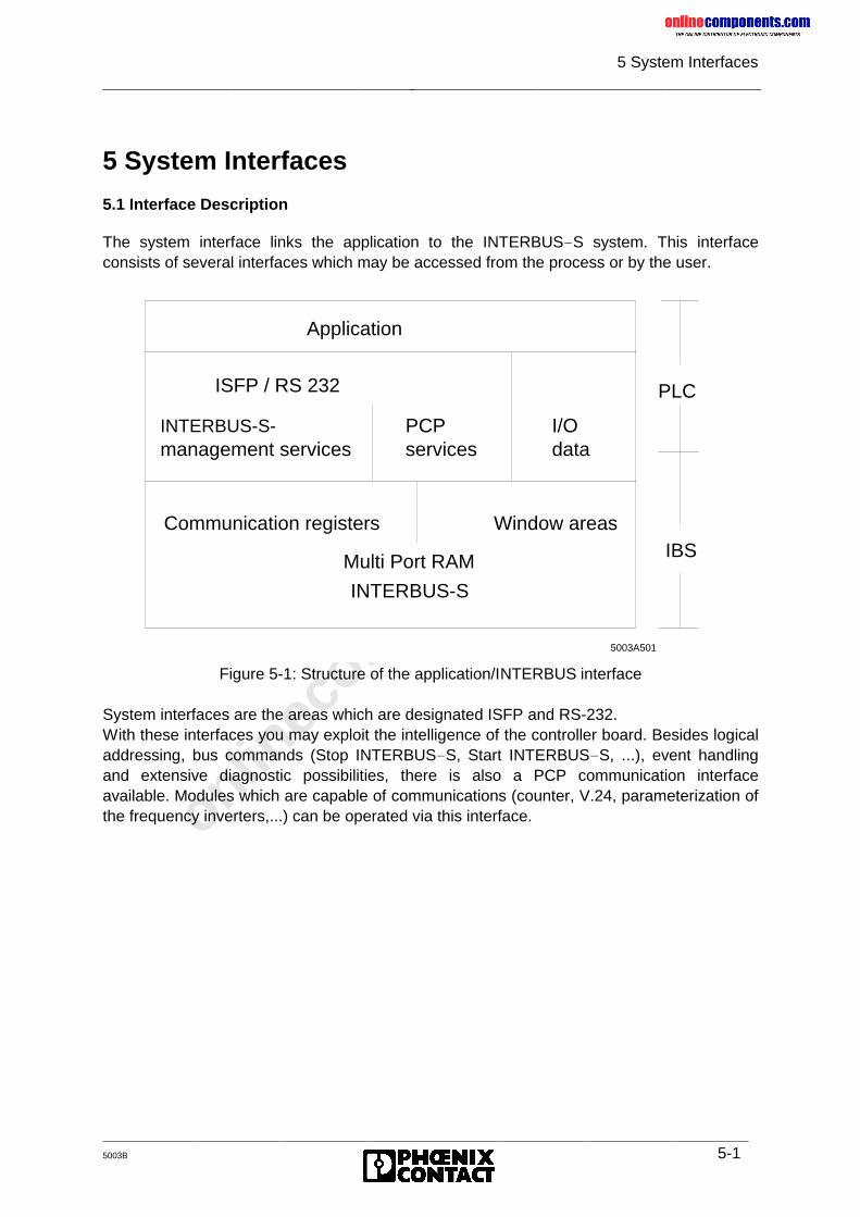
onlinec
omponen
ts.co
m
5 System Interfaces
5003B 5-1
5 System Interfaces
5.1 Interface Description
The system interface links the application to the INTERBUS-S system. This interfaceconsists of several interfaces which may be accessed from the process or by the user.
Figure 5-1: Structure of the application/INTERBUS interface
System interfaces are the areas which are designated ISFP and RS-232.With these interfaces you may exploit the intelligence of the controller board. Besides logicaladdressing, bus commands (Stop INTERBUS-S, Start INTERBUS-S, ...), event handlingand extensive diagnostic possibilities, there is also a PCP communication interfaceavailable. Modules which are capable of communications (counter, V.24, parameterization ofthe frequency inverters,...) can be operated via this interface.
Application
ISFP / RS 232
Communication registers Window areas
INTERBUS-S
PLC
IBS
5003A501
INTERBUS-S-management services
I/O data
PCP services
Multi Port RAM
onlinec
omponen
ts.co
m
5 System Interfaces
5-2 5003B
5.1.1 Interface Function
Commands and messages can be exchanged between the host controller board and thePLC.An application-oriented programming interface ensures simple operation. The ’INTERBUS-SSystem Functions for the PLC’ (abbreviated ISFP below) interface represents anINTERBUS-S operating system for the user. The ISFP interface allows to trigger andexecute complex functions (e.g. logical addressing) by means of a signal edge.Besides this interface which allows a parameterization by means of the PLC, the user candirectly influence the controller board’s functions via a serial interface. This can be done witha RS-232 connection to the PC or to a programming unit. A monitor software allows to sendcommands (similar to ISFP) to the controller board. Messages are received and processedin a way that is suitable for the screen.In addition, programming sequences such as logical addressing or clearing of the diagnosticdisplay can be created with the PC and stored on the controller board in a non-volatile way(in the EEPROM card). The individual sequences can be started by means of an output bit inthe PLC (bit-controlled command register).Thus, the INTERBUS-S system can be configured and controlled in different ways. Thischapter describes the programming interfaces and explains how they are used together.The previous general description of the interrelations will be clarified with the help of anexample.Example: Logical addressing
For the logical addressing it is useful to program the start sequence (allocation of addresslists and start of INTERBUS-S) via the EEPROM. The programming can be done so that theprogram executes the bus system start once during start-up (start sequence no. 0 andinitialization block) of the PLC and additionally also in the PLC’s cycle (with bit-controlledcommand execution). During operation, messages (e.g. error messages) are received in thecycle (with ISFP) to evaluate them with the application program.
onlinec
omponen
ts.co
m
5 System Interfaces
5003B 5-3
5.1.2 Interface Classification
The term "system interface" stands for hardware such as the communication registers, theregisters for the bit-controlled command execution and the RS-232 interface (link to the PC).This hardware helps to control the INTERBUS-S system in the start phase and duringoperation.
1) Communication registers
Window 3 of the controller board is called communication register. The application programis not allowed to read or write the register areas. Access is exclusively done via standardfunction blocks. The function blocks are included in a software package called ISFP. Thesoftware includes two driver blocks which send commands to the controller board (FB:REQ/RES) and receive messages (such as error and control messages) from the board (FB:CON/IND). These components ensure simple operation of the communication registers.
2) Bit-controlled command register
Input and output words are defined as registers for bit-controlled commands. The registerareas which are addressed by means of an ID code are divided into two input words and oneoutput word. Every bit (0-15) represents a program sequence (e.g. logical addressing) whichhas been stored in the EEPROM card. The program sequence can be started with an outputbit (so-called activation bit) and the execution can be monitored with two input bits (BUSYand RETURN). These registers allow simple operation of complex program sequencesduring startup or in the PLC cycle.
3) Serial interface RS-232
This interface can be used to couple a programming interface to the controller board. A 9-pos. D-SUB connector is provided on the controller board’s front plate for this.
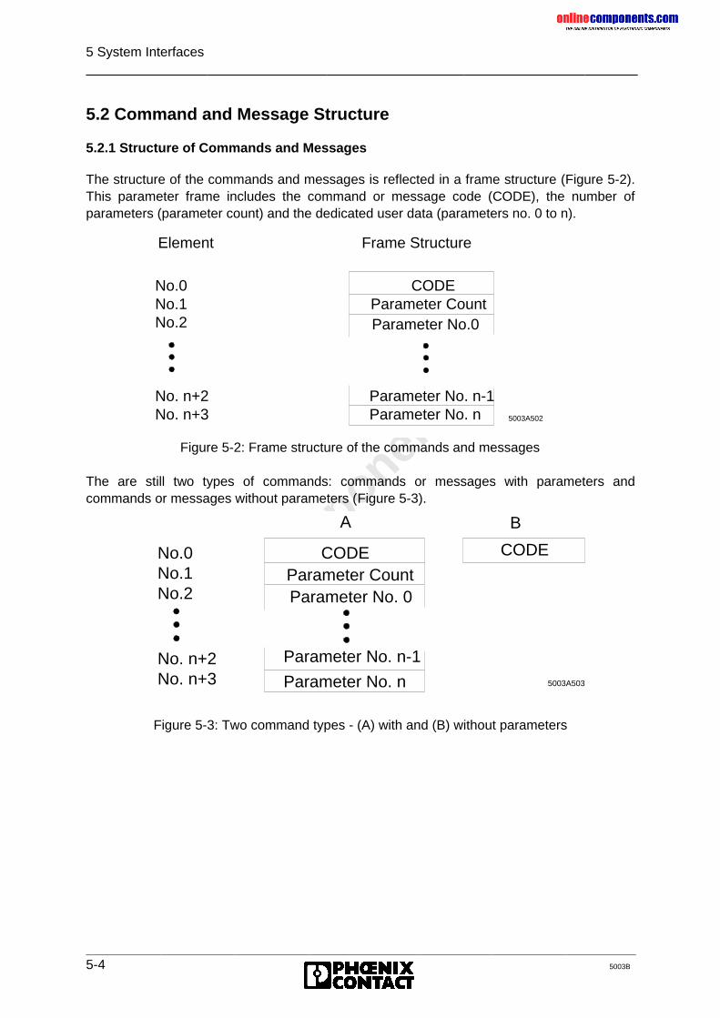
onlinec
omponen
ts.co
m
5 System Interfaces
5-4 5003B
5.2 Command and Message Structure
5.2.1 Structure of Commands and Messages
The structure of the commands and messages is reflected in a frame structure (Figure 5-2).This parameter frame includes the command or message code (CODE), the number ofparameters (parameter count) and the dedicated user data (parameters no. 0 to n).
Figure 5-2: Frame structure of the commands and messages
The are still two types of commands: commands or messages with parameters andcommands or messages without parameters (Figure 5-3).
Figure 5-3: Two command types - (A) with and (B) without parameters
Element Frame Structure
5003A502
No.0 CODENo.1No.2
No. n+2 Parameter No. n-1No. n+3 Parameter No. n
Parameter CountParameter No.0
5003A503
No.0No.1No.2
No. n+2No. n+3
A B
CODE CODE
Parameter CountParameter No. 0
Parameter No. n-1
Parameter No. n
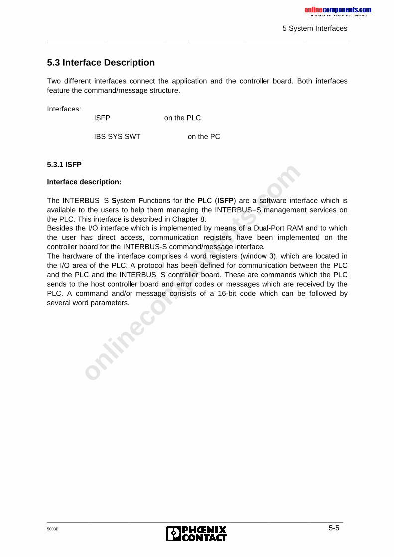
onlinec
omponen
ts.co
m
5 System Interfaces
5003B 5-5
5.3 Interface Description
Two different interfaces connect the application and the controller board. Both interfacesfeature the command/message structure.
Interfaces:ISFP on the PLC
IBS SYS SWT on the PC
5.3.1 ISFP
Interface description:
The INTERBUS-S System Functions for the PLC (ISFP) are a software interface which isavailable to the users to help them managing the INTERBUS-S management services onthe PLC. This interface is described in Chapter 8.Besides the I/O interface which is implemented by means of a Dual-Port RAM and to whichthe user has direct access, communication registers have been implemented on thecontroller board for the INTERBUS-S command/message interface.The hardware of the interface comprises 4 word registers (window 3), which are located inthe I/O area of the PLC. A protocol has been defined for communication between the PLCand the PLC and the INTERBUS-S controller board. These are commands which the PLCsends to the host controller board and error codes or messages which are received by thePLC. A command and/or message consists of a 16-bit code which can be followed byseveral word parameters.
onlinec
omponen
ts.co
m
5 System Interfaces
5-6 5003B
5.3.1.1 Program Structure
In order to avoid larger cycle times the INTERBUS-S system functions for the PLC (ISFP)are specifically tailored to the respective PLC and the program has been optimized andstructured. Operation of the ISFP interface (by setting single bits) was kept simple to reducethe programming expense for the user. The interface consists of three types of functionblocks. The blocks are available as standard function blocks.
Block types:
• Initialization block• Receive/send blocks
(interface driver)• Function blocks
Apart from an initialization block, which must only be called during the PLC’s startup, thereare two function blocks which are permanently addressed.These blocks are called receive and send block. They form the link between the PLC (ISFPinterface) and the controller board. The blocks (interface drivers) become only active whencommands are sent or messages are received. The third group of blocks is related to theapplication. That means that only the function blocks which are currently required are called(e.g. for addressing, system information, event handling...).
A description of the flag bits, times and data blocks used by the functionblocks is given in the Appendix.
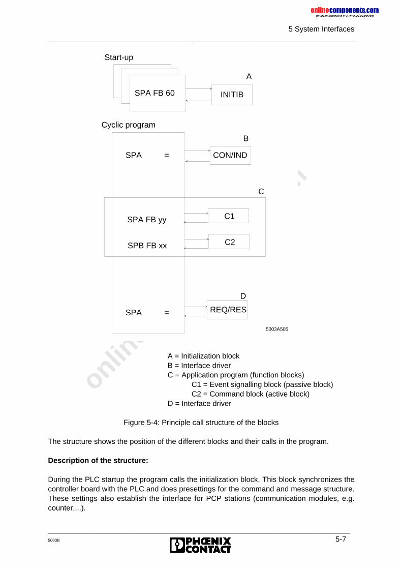
onlinec
omponen
ts.co
m
5 System Interfaces
5003B 5-7
A = Initialization blockB = Interface driverC = Application program (function blocks)
C1 = Event signalling block (passive block)C2 = Command block (active block)
D = Interface driver
Figure 5-4: Principle call structure of the blocks
The structure shows the position of the different blocks and their calls in the program.
Description of the structure:
During the PLC startup the program calls the initialization block. This block synchronizes thecontroller board with the PLC and does presettings for the command and message structure.These settings also establish the interface for PCP stations (communication modules, e.g.counter,...).
Start-up
SPA FB 60 INITIB
A
CON/IND
B
Cyclic program
SPA =
SPB FB xx
C
REQ/RES
D
5003A505
SPA =
C2
SPA FB yy C1
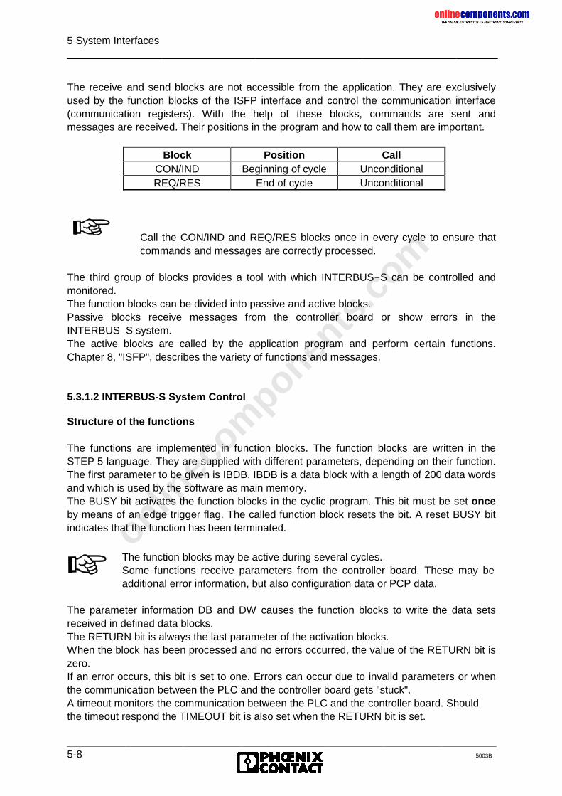
onlinec
omponen
ts.co
m
5 System Interfaces
5-8 5003B
The receive and send blocks are not accessible from the application. They are exclusivelyused by the function blocks of the ISFP interface and control the communication interface(communication registers). With the help of these blocks, commands are sent andmessages are received. Their positions in the program and how to call them are important.
The third group of blocks provides a tool with which INTERBUS-S can be controlled andmonitored.The function blocks can be divided into passive and active blocks.Passive blocks receive messages from the controller board or show errors in theINTERBUS-S system.The active blocks are called by the application program and perform certain functions.Chapter 8, "ISFP", describes the variety of functions and messages.
5.3.1.2 INTERBUS-S System Control
Structure of the functions
The functions are implemented in function blocks. The function blocks are written in theSTEP 5 language. They are supplied with different parameters, depending on their function.The first parameter to be given is IBDB. IBDB is a data block with a length of 200 data wordsand which is used by the software as main memory.The BUSY bit activates the function blocks in the cyclic program. This bit must be set onceby means of an edge trigger flag. The called function block resets the bit. A reset BUSY bitindicates that the function has been terminated.
The parameter information DB and DW causes the function blocks to write the data setsreceived in defined data blocks.The RETURN bit is always the last parameter of the activation blocks.When the block has been processed and no errors occurred, the value of the RETURN bit iszero.If an error occurs, this bit is set to one. Errors can occur due to invalid parameters or whenthe communication between the PLC and the controller board gets "stuck".A timeout monitors the communication between the PLC and the controller board. Shouldthe timeout respond the TIMEOUT bit is also set when the RETURN bit is set.
Block Position CallCON/IND Beginning of cycle UnconditionalREQ/RES End of cycle Unconditional
Call the CON/IND and REQ/RES blocks once in every cycle to ensure thatcommands and messages are correctly processed.
The function blocks may be active during several cycles.Some functions receive parameters from the controller board. These may beadditional error information, but also configuration data or PCP data.
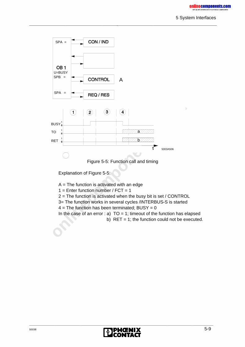
onlinec
omponen
ts.co
m
5 System Interfaces
5003B 5-9
Figure 5-5: Function call and timing
Explanation of Figure 5-5:
A = The function is activated with an edge1 = Enter function number / FCT = 12 = The function is activated when the busy bit is set / CONTROL3= The function works in several cycles /INTERBUS-S is started4 = The function has been terminated; BUSY = 0In the case of an error : a) TO = 1; timeout of the function has elapsed
b) RET = 1; the function could not be executed.
5003A506
A
SPA =
U=BUSYSPB =
SPA =
BUSY
TO
RET
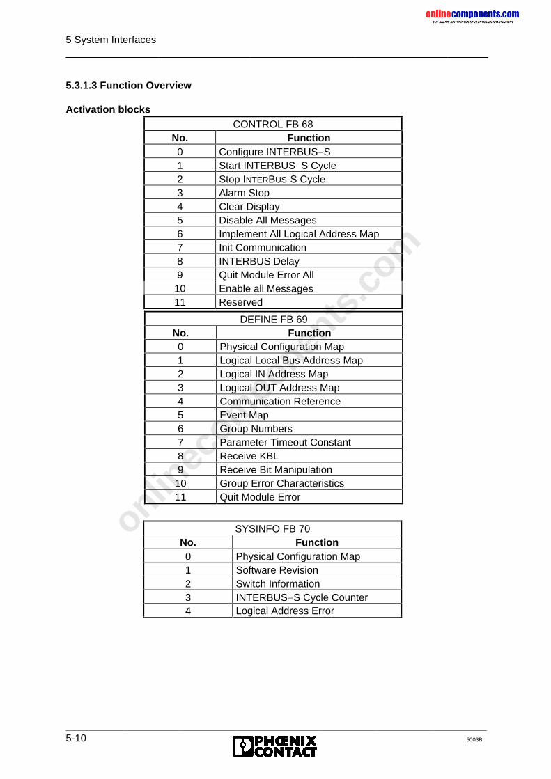
onlinec
omponen
ts.co
m
5 System Interfaces
5-10 5003B
5.3.1.3 Function Overview
Activation blocksCONTROL FB 68
No. Function0 Configure INTERBUS-S1 Start INTERBUS-S Cycle2 Stop INTERBUS-S Cycle3 Alarm Stop4 Clear Display5 Disable All Messages6 Implement All Logical Address Map7 Init Communication8 INTERBUS Delay9 Quit Module Error All
10 Enable all Messages11 Reserved
DEFINE FB 69No. Function0 Physical Configuration Map1 Logical Local Bus Address Map2 Logical IN Address Map3 Logical OUT Address Map4 Communication Reference5 Event Map6 Group Numbers7 Parameter Timeout Constant8 Receive KBL9 Receive Bit Manipulation10 Group Error Characteristics11 Quit Module Error
SYSINFO FB 70No. Function0 Physical Configuration Map1 Software Revision2 Switch Information3 INTERBUS-S Cycle Counter4 Logical Address Error
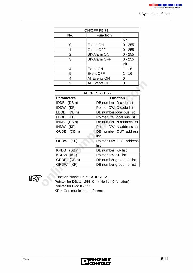
onlinec
omponen
ts.co
m
5 System Interfaces
5003B 5-11
ADDRESS FB 72Parameters FunctionIDDB (DB n) DB number ID code listIDDW (KF) Pointer DW ID code listLBDB (DB n) DB number local bus listLBDB (KF) Pointer DW local bus listINDB (DB n) DB number IN address listINDW (KF) Pointer DW IN address listOUDB (DB n) DB number OUT address
listOUDW (KF) Pointer DW OUT address
listKRDB (DB n) DB number KR listKRDW (KF) Pointer DW KR listGRDB (DB n) DB number group no. listGRDW (KF) DB number group no. list
ON/OFF FB 71No. Function
No.0 Group ON 0 - 2551 Group OFF 0 - 2552 BK-Alarm ON 0 - 2553 BK-Alarm OFF 0 - 255
Bit4 Event ON 1 - 165 Event OFF 1 - 164 All Events ON 05 All Events OFF 0
Function block: FB 72 ’ADDRESS’Pointer for DB: 1 - 255, 0 => No list (0 function)Pointer for DW: 0 - 255KR = Communication reference
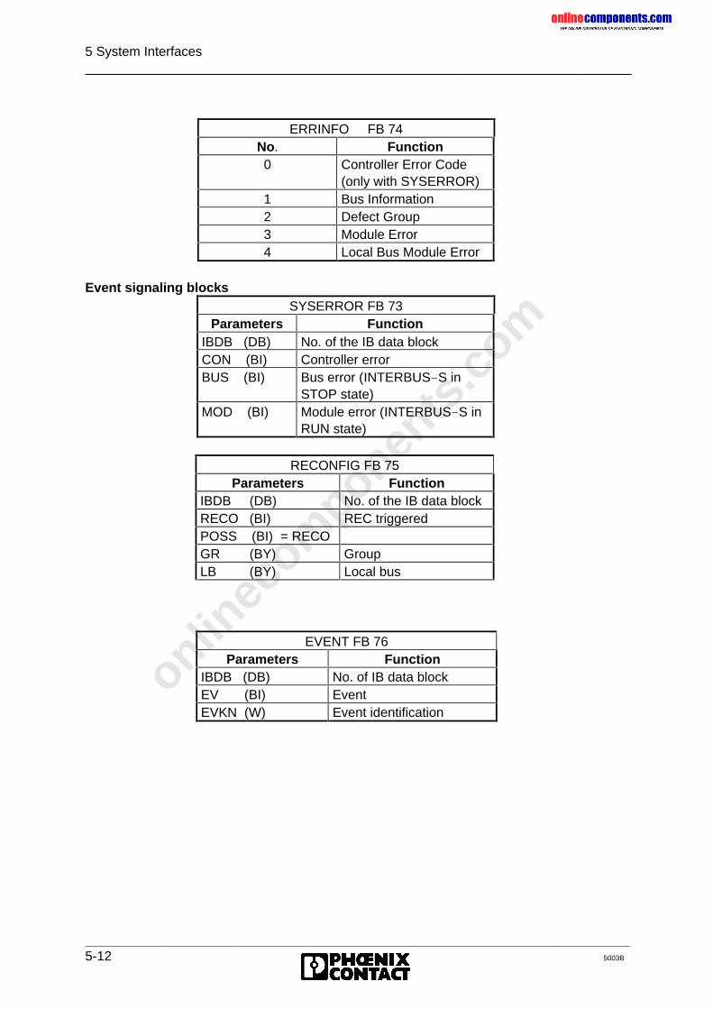
onlinec
omponen
ts.co
m
5 System Interfaces
5-12 5003B
ERRINFO FB 74No. Function0 Controller Error Code
(only with SYSERROR)1 Bus Information2 Defect Group3 Module Error4 Local Bus Module Error
Event signaling blocksSYSERROR FB 73
Parameters FunctionIBDB (DB) No. of the IB data blockCON (BI) Controller errorBUS (BI) Bus error (INTERBUS-S in
STOP state)MOD (BI) Module error (INTERBUS-S in
RUN state)
RECONFIG FB 75Parameters Function
IBDB (DB) No. of the IB data blockRECO (BI) REC triggeredPOSS (BI) = RECOGR (BY) GroupLB (BY) Local bus
EVENT FB 76Parameters Function
IBDB (DB) No. of IB data blockEV (BI) EventEVKN (W) Event identification
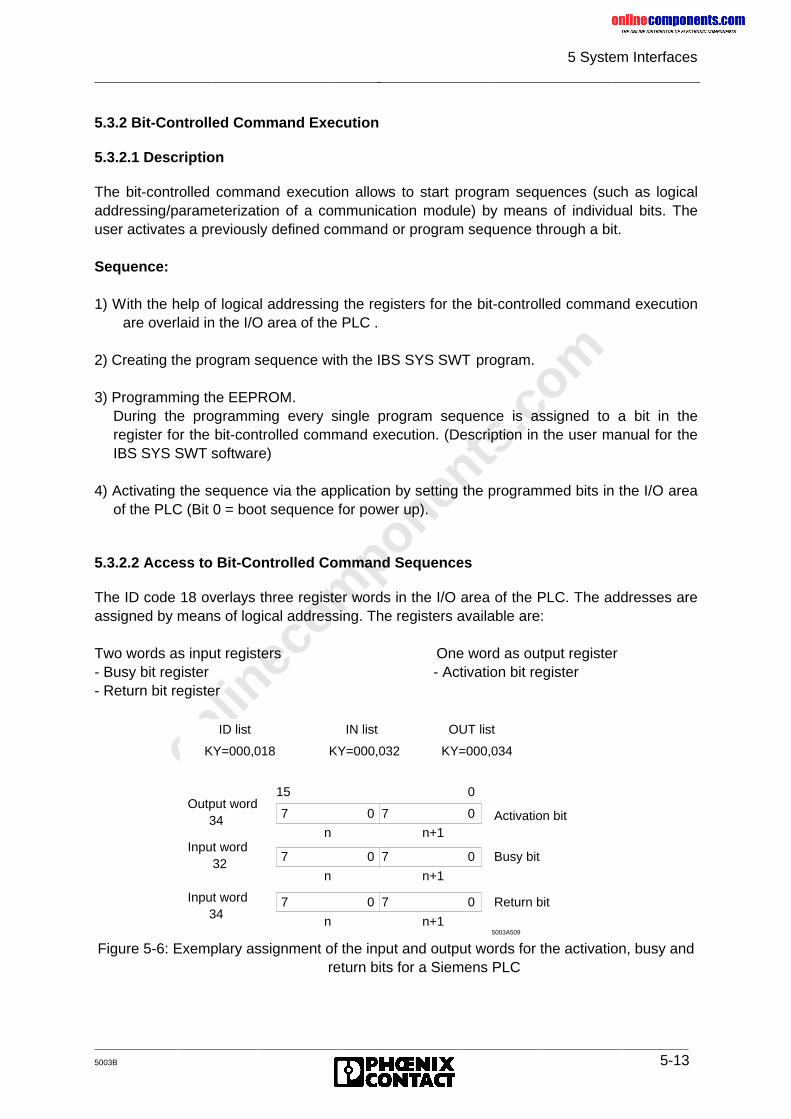
onlinec
omponen
ts.co
m
5 System Interfaces
5003B 5-13
5.3.2 Bit-Controlled Command Execution
5.3.2.1 Description
The bit-controlled command execution allows to start program sequences (such as logicaladdressing/parameterization of a communication module) by means of individual bits. Theuser activates a previously defined command or program sequence through a bit.
Sequence:
1) With the help of logical addressing the registers for the bit-controlled command executionare overlaid in the I/O area of the PLC .
2) Creating the program sequence with the IBS SYS SWT program.
3) Programming the EEPROM.During the programming every single program sequence is assigned to a bit in theregister for the bit-controlled command execution. (Description in the user manual for theIBS SYS SWT software)
4) Activating the sequence via the application by setting the programmed bits in the I/O areaof the PLC (Bit 0 = boot sequence for power up).
5.3.2.2 Access to Bit-Controlled Command Sequences
The ID code 18 overlays three register words in the I/O area of the PLC. The addresses areassigned by means of logical addressing. The registers available are:
Two words as input registers One word as output register- Busy bit register - Activation bit register- Return bit register
Figure 5-6: Exemplary assignment of the input and output words for the activation, busy andreturn bits for a Siemens PLC
ID list IN list OUT list
KY=000,018 KY=000,032 KY=000,034
15 0
7 0 07
n n+1
7 0 07
n n+1
7 0 07
n n+1
Output word 34
Input word 32
Input word 34
Activation bit
Busy bit
Return bit
5003A509
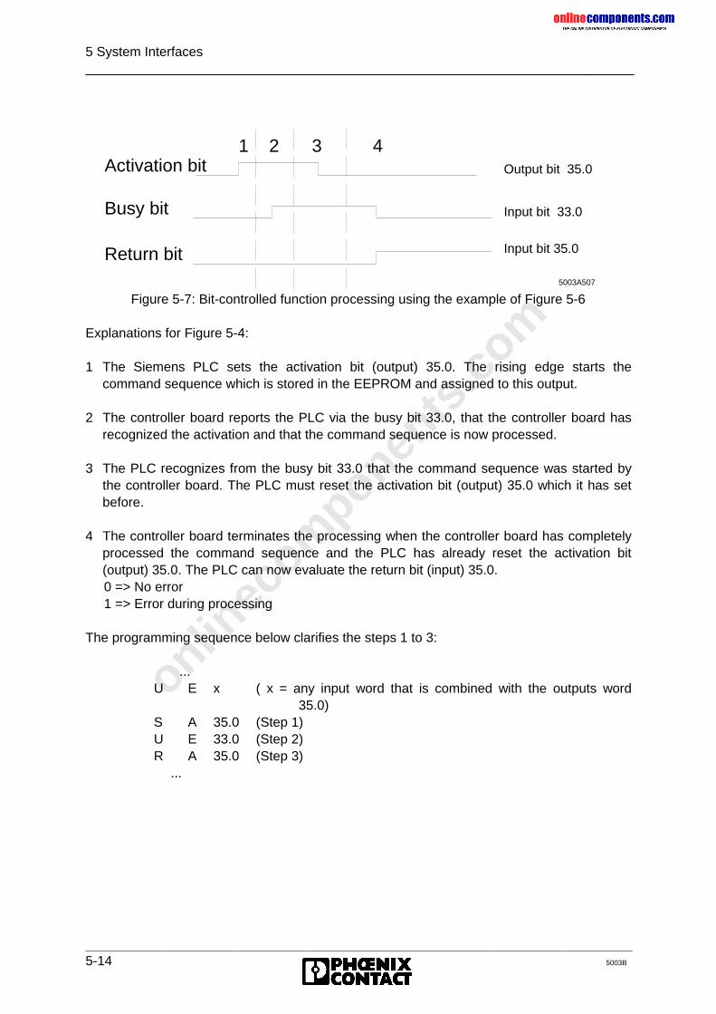
onlinec
omponen
ts.co
m
5 System Interfaces
5-14 5003B
Figure 5-7: Bit-controlled function processing using the example of Figure 5-6
Explanations for Figure 5-4:
1 The Siemens PLC sets the activation bit (output) 35.0. The rising edge starts thecommand sequence which is stored in the EEPROM and assigned to this output.
2 The controller board reports the PLC via the busy bit 33.0, that the controller board hasrecognized the activation and that the command sequence is now processed.
3 The PLC recognizes from the busy bit 33.0 that the command sequence was started bythe controller board. The PLC must reset the activation bit (output) 35.0 which it has setbefore.
4 The controller board terminates the processing when the controller board has completelyprocessed the command sequence and the PLC has already reset the activation bit(output) 35.0. The PLC can now evaluate the return bit (input) 35.0.
0 => No error 1 => Error during processing
The programming sequence below clarifies the steps 1 to 3:
...U E x ( x = any input word that is combined with the outputs word
35.0)S A 35.0 (Step 1)U E 33.0 (Step 2)R A 35.0 (Step 3)
...
Output bit 35.0
Input bit 33.0
Input bit 35.0
Activation bit
Return bit
1 2 3 4
Busy bit
5003A507
onlinec
omponen
ts.co
m
5 System Interfaces
5003B 5-15
Structure of the initial configuration
Command sequence
Stored programming
Bit 0Quit_ErrorConfigure_INTERBUS-SStart_INTERBUS-S_Cycle
Bit 1Alarm_Stop
Bit 2Clear_Display
Bit 3Send_All_Module_Error
Bit 4 to 15 are not programmed
The command sequence "0" is at the same time the power on or start sequence.The controller board starts this sequence automatically after every voltagerecovery or a reset.
onlinec
omponen
ts.co
m
5 System Interfaces
5-16 5003B
5.3.3 IBS SYS SWT
5.3.3.1 Description
IBS SYS SWT provides the user interface of the controller board on the PC. With thisprogram the functions of the INTERBUS-S controller board and the modules connected toINTERBUS-S can be used without programming expense.The PC is coupled to the controller board via the serial interface (RS-232) of the twodevices.
The program functions in detail:
• Transfer of INTERBUS-S commands to the INTERBUS-S controller board.• Receipt of INTERBUS-S messages from the INTERBUS-S controller board.• Logging of the messages received and the command transferred.• Storing of the INTERBUS-S commands and transfer of the stored commands to the
controller board.• Programming of the EEPROM (and/or the memory card) of the controller board.• Diagnostics and evaluation of bus operation
Serial interface
The serial interface of the controller board is used to send commands to the controller boardand to receive messages from it. The commands or the modules connected to the busgenerate messages. The messages are displayed immediately after they have beenreceived, provided that the display has not been explicitly switched off (menu: option).Whether the controller board accepts transferred command and processes them at alldepends on two conditions:
• Commands which are not available on the host controller board will be rejected.• The controller board is preset in such a way that it receives the commands after a reset
or power-up via the serial interface only until the PLC sends a command to the controllerboard.
This process is described symbolically in Figure 5-5 on the next page.
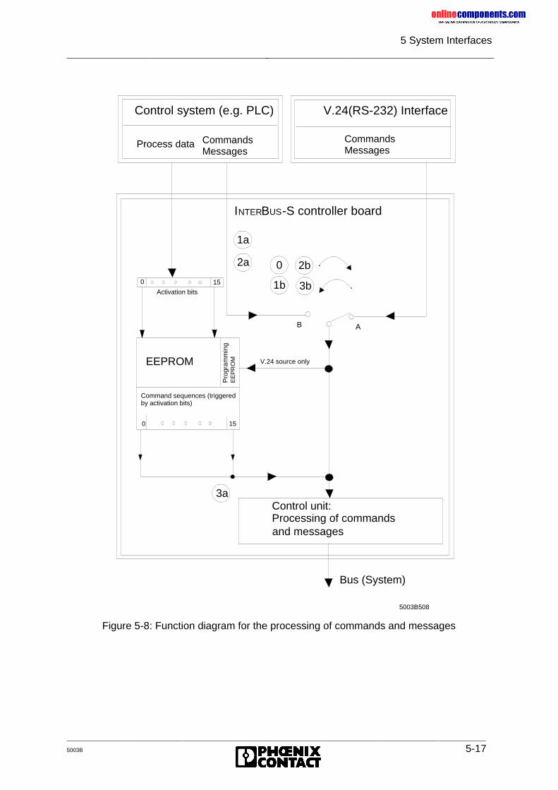
onlinec
omponen
ts.co
m
5 System Interfaces
5003B 5-17
Figure 5-8: Function diagram for the processing of commands and messages
and messages
AB
5003B508
Control unit:Processing of commands
V.24(RS-232) Interface
0 15
Activation bits
EEPROM
0 15
V.24 source only
3a
1a
2a
1b
2b
3b
0
Bus (System)
Control system (e.g. PLC)
Process data CommandsMessages
CommandsMessages
Pro
gram
min
gE
EP
RO
M
Command sequences (triggeredby activation bits)
INTERBUS-S controller board
onlinec
omponen
ts.co
m
5 System Interfaces
5-18 5003B
0 : After power-up the "switch" returns to the initial position A and provides theconnection between the control unit and the V.24 (RS-232) interface.1a: The first command which the PLC sends sets the switch permanently toposition B (process 1b)2a: The "Disable All Messages" command resets the switch to position A(process 2b)3a: The "Enable All Messages" command (activated by the EEPROM card via acorresponding activation bit) sets the switch in position B (process 3b); this isnecessary if no commands are to be sent with ISFP but messages are to bereceived .
5.3.3.2 Commands
The commands are described in Chapter 9, "Commands and Messages".A short description is available in the IBS SYS SWT monitor program.
onlinec
omponen
ts.co
m
5003B
Chapter 6
StartupThis chapter provides information on
- the possibilities of automatic and controlled start- how to do the logical and physical addressing- the address area assignment and the address orientation
6 Startup ................................................................................................6-1
6.1 Introduction .................................................................................................. 6-16.1.1 General Information About Physical Addressing........................................... 6-16.1.2 General Information About Logical Addressing ............................................ 6-26.1.3 Modes of Operation...................................................................................... 6-26.1.4 Startup Behavior........................................................................................... 6-36.1.5 Acknowledgment Behavior ........................................................................... 6-4
6.2 Hardware Setting.......................................................................................... 6-5
6.3 Software Setting ........................................................................................... 6-6
onlinec
omponen
ts.co
m
6 Startup
_______________________________________________5003B 6-1
6 Startup
6.1 Introduction
6.1.1 General Information About Physical Addressing
For the physical addressing, the assignment of the addresses for the I/O modules dependson the order of the modules in the bus topology. Thus, the counting direction and the orderof modules, local buses and installation remote buses have to be observed.
The local buses and INTERBUS modules are counted as follows:
The first module of a local bus is a bus terminal module (BK). All other modules are I/Omodules. The first I/O module is coupled to the BK, the second I/O module is coupled to thefirst I/O module, etc.
Local bus 0 (LB 0) is the local bus the BK of which is connected to the PLC by means of theremote bus. Local bus 1 is coupled to the bus terminal of local bus 0 through the remote bus,etc.
When addresses are allocated to the modules a difference is to be made between digitaland analog I/Os.
Digital I/Os occupy the first window in the PLC’s address area and analog I/O the secondwindow.
Starting with the base address, the module addresses are stored in the respective window inthe PLC’s address area. The size of the address area which every module occupiesdepends on the module.
If one or several modules area removed from the bus topology and physicaladdressing is used the controller board cannot recognize this modification.Depending on your application this may lead to dangerous situations.
BKs with I/O functions, BKs for the installation remote bus and installationremote bus modules have their own remote bus segment number (RBS).
In the ID code list the WINDOW parameter specifies in which window therespective module appears (see Tables 3-2 and 3-3).
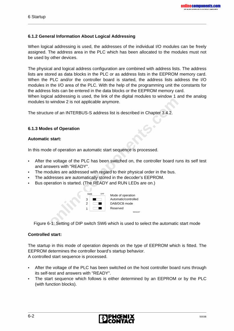
onlinec
omponen
ts.co
m
6 Startup
6-2 5003B
6.1.2 General Information About Logical Addressing
When logical addressing is used, the addresses of the individual I/O modules can be freelyassigned. The address area in the PLC which has been allocated to the modules must notbe used by other devices.
The physical and logical address configuration are combined with address lists. The addresslists are stored as data blocks in the PLC or as address lists in the EEPROM memory card.When the PLC and/or the controller board is started, the address lists address the I/Omodules in the I/O area of the PLC. With the help of the programming unit the constants forthe address lists can be entered in the data blocks or the EEPROM memory card.When logical addressing is used, the link of the digital modules to window 1 and the analogmodules to window 2 is not applicable anymore.
The structure of an INTERBUS-S address list is described in Chapter 3.4.2.
6.1.3 Modes of Operation
Automatic start:
In this mode of operation an automatic start sequence is processed.
• After the voltage of the PLC has been switched on, the controller board runs its self testand answers with "READY".
• The modules are addressed with regard to their physical order in the bus.• The addresses are automatically stored in the decoder’s EEPROM.• Bus operation is started. (The READY and RUN LEDs are on.)
Figure 6-1: Setting of DIP switch SW6 which is used to select the automatic start mode
Controlled start:
The startup in this mode of operation depends on the type of EEPROM which is fitted. TheEEPROM determines the controller board’s startup behavior.A controlled start sequence is processed.
• After the voltage of the PLC has been switched on the host controller board runs throughits self-test and answers with "READY".
• The start sequence which follows is either determined by an EEPROM or by the PLC(with function blocks).
OFF
1
SW6
23
DAB/DCB mode
Reserved5003A207
Mode of operationAutomatic/controlled
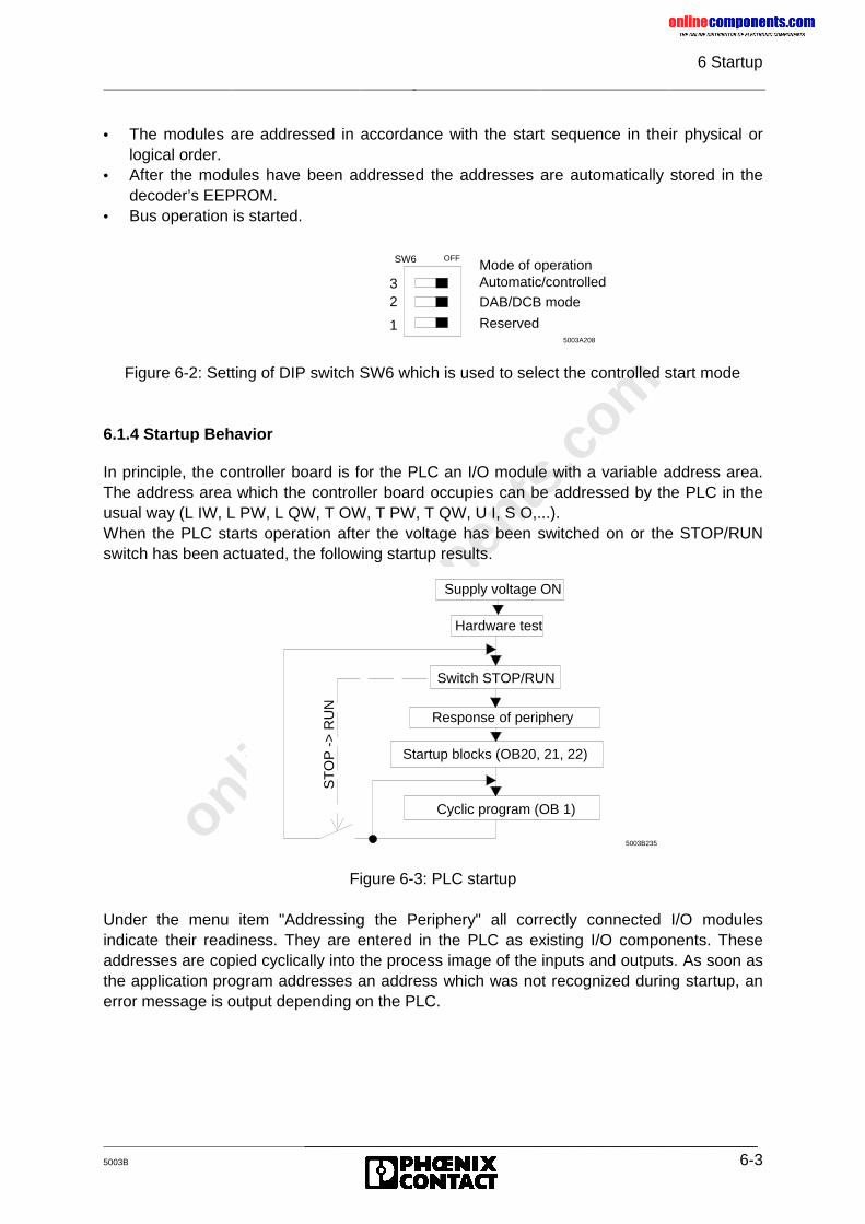
onlinec
omponen
ts.co
m
6 Startup
_______________________________________________5003B 6-3
• The modules are addressed in accordance with the start sequence in their physical orlogical order.
• After the modules have been addressed the addresses are automatically stored in thedecoder’s EEPROM.
• Bus operation is started.
Figure 6-2: Setting of DIP switch SW6 which is used to select the controlled start mode
6.1.4 Startup Behavior
In principle, the controller board is for the PLC an I/O module with a variable address area.The address area which the controller board occupies can be addressed by the PLC in theusual way (L IW, L PW, L QW, T OW, T PW, T QW, U I, S O,...).When the PLC starts operation after the voltage has been switched on or the STOP/RUNswitch has been actuated, the following startup results.
Figure 6-3: PLC startup
Under the menu item "Addressing the Periphery" all correctly connected I/O modulesindicate their readiness. They are entered in the PLC as existing I/O components. Theseaddresses are copied cyclically into the process image of the inputs and outputs. As soon asthe application program addresses an address which was not recognized during startup, anerror message is output depending on the PLC.
OFF
1
SW6
23
DAB/DCB mode
Reserved5003A208
Mode of operationAutomatic/controlled
Supply voltage ON
Hardware test
Switch STOP/RUN
Response of periphery
Startup blocks (OB20, 21, 22)
Cyclic program (OB 1)
5003B235
ST
OP
->
RU
N

onlinec
omponen
ts.co
m
6 Startup
6-4 5003B
6.1.5 Acknowledgment Behavior
The acknowledgement behavior of the controller board is determined by the mode (DCB orDAB) and the start (automatic/controlled). This connection becomes important when theapplication dynamically changes the bus system and, therefore, enlarges and/or reduces theaddress area which the IBS modules represent.
Figure 6-4: Setting of the operating modes DCB or DAB
Free addressing (DCB mode):In this mode of operation all addresses which are occupied by INTERBUS-S I/O modulesand registers will be acknowledged to the PLC in the cyclic part.
a) Automatic start:Starting at the base addresses of the windows 1 and 2 all modules are addressedand acknowledged. The length specification depends on the space requirement ofthe modules. The setting of the window area refers to the I/O area of the PLC. Thediagnostic registers are located below the base addresses. The set window lengthsmust not be shorter than the address area of the modules. If the length specificationof the windows is larger than the space requirement of the modules, the unassignedaddresses will not be acknowledged.
b) Controlled start:All module and register addresses (e.g. diagnostic registers) are defined by means oflogical addressing. Only the defined addresses will be acknowledged to the PLC(smallest unit 1 word, an even base address is permitted).
Addressing with fixed area (DAB mode):In this mode of operation all addresses are acknowledged which were defined with thewindow settings before.
a) Automatic start:Starting at the base addresses of the windows 1 and 2, all modules are addressedand acknowledged. The length specification depends on the space requirement ofthe modules. The setting of the window area refers to the I/O area of the PLC. Thediagnostic registers are located below the base addresses. The set window lengthsmust not be shorter than the address area of the modules. If the length setting of thewindows is larger than the space requirement of the modules, the unassignedaddresses will also be acknowledged.
b) Controlled start:All module and register addresses (e.g. diagnostic registers) must be defined withinthe window area by means of logical addressing. All window addresses areacknowledged.
OFF
1
SW6
23
DAB/DCB mode
Reserved5003A208
Mode of operationAutomatic/controlled

onlinec
omponen
ts.co
m
6 Startup
_______________________________________________5003B 6-5
The communication registers (window 3) must be set independently of the start(automatic/controlled) and mode setting (DAB/DCB) They always occupy twowords in the I/O area of the PLC.
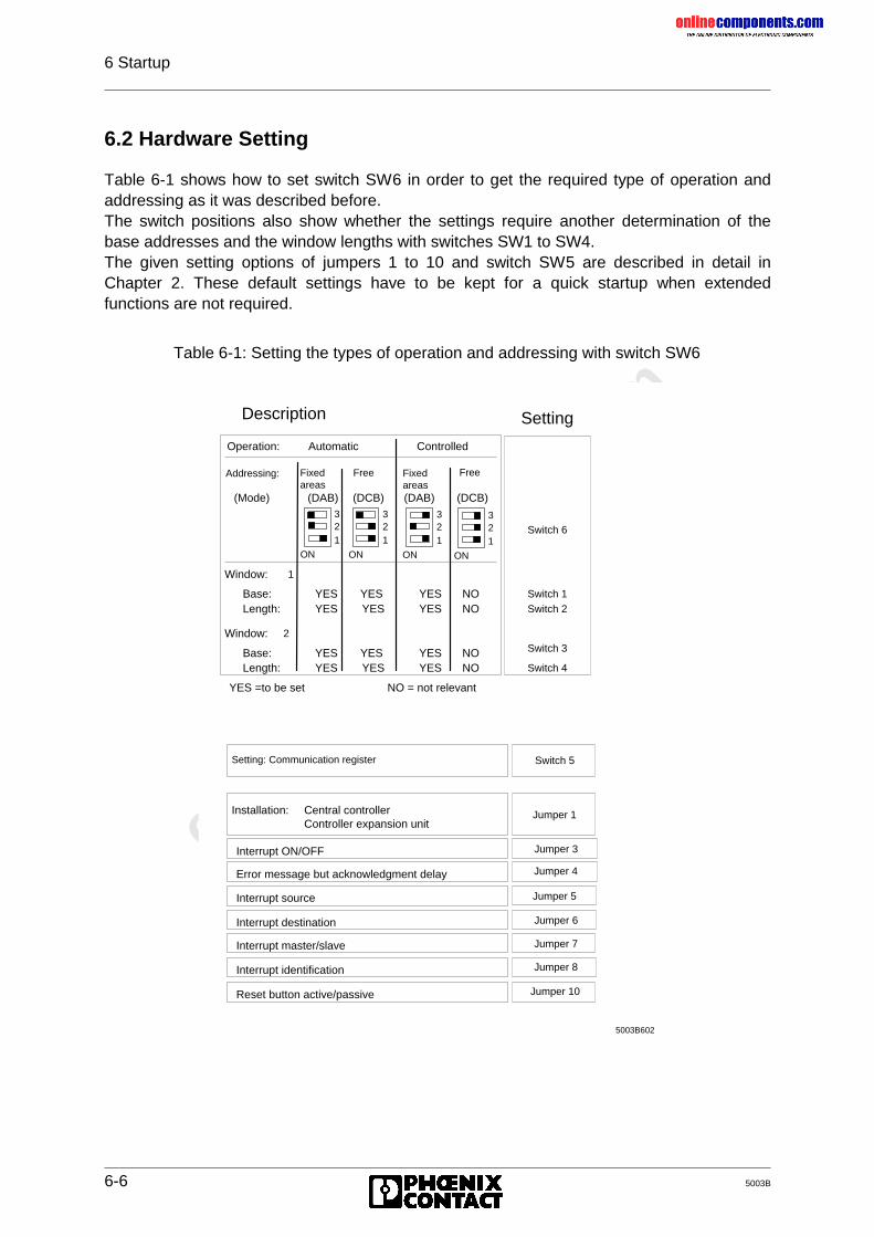
onlinec
omponen
ts.co
m
6 Startup
6-6 5003B
6.2 Hardware Setting
Table 6-1 shows how to set switch SW6 in order to get the required type of operation andaddressing as it was described before.The switch positions also show whether the settings require another determination of thebase addresses and the window lengths with switches SW1 to SW4.The given setting options of jumpers 1 to 10 and switch SW5 are described in detail inChapter 2. These default settings have to be kept for a quick startup when extendedfunctions are not required.
Table 6-1: Setting the types of operation and addressing with switch SW6
5003B602
SettingDescription
Switch 2
Switch 3
Switch 4
Switch 1
Switch 6
YES =to be set
Length:
Window:
Base:Length:
2
Base:YES
YESYES
YES
YES YES
NO = not relevant
NO
NONO
NOYESYES
YESYES
Automatic
(DCB)
Window:
Operation:
(Mode)
1
(DAB)
Controlled
(DAB)
YES
YES
Jumper 7
Jumper 8
Jumper 5
Jumper 6
Jumper 10
Interrupt master/slave
Reset button active/passive
Interrupt source
Interrupt destination
Interrupt identification
Jumper 3Interrupt ON/OFF
Jumper 4Error message but acknowledgment delay
Switch 5Setting: Communication register
Jumper 1Central controllerController expansion unit
Installation:
Addressing: Fixedareas
Free Fixedareas
Free
321
ON
321
ON
321
ON
321
ON
(DCB)
onlinec
omponen
ts.co
m
6 Startup
_______________________________________________5003B 6-7
6.3 Software Setting
When the setting of switch SW6 has determined a certain type of operation and addressingthe software may be set afterwards. This setting depends on the different operationalrequirements made on the bus system.
These requirements are:
1) The startup behavior of the controller board (has already been determined in thehardware setting): either automatic or controlled start.
2) The start characteristics of the bus system in the PLC: a difference is made between thestart of the INTERBUS-S system during PLC startup and in the cyclic program part. Theinitial start during startup is coordinated and monitored with the startup OBs 20, 21 and22.
3) The necessity to do switching operations through the application program. This includesthe enabling and disabling of bus segments in the cyclic program, the demand ofdiagnostic data, and the parameterization of modules which are capable of PCPcommunications (PCP= Peripherals Communication Protocol).
4) The request to program the bus system. This is either possible with the help of the PLCand function blocks or the EEPROM card and the controller board.
The following pages show example bus structures (topology, ID code and I/O addressassignment) and the program sequences belonging to them. They are based on an overviewtable which lists on the next page the possible combinations of the above-mentionedrequirements and the hardware settings which you have already done.
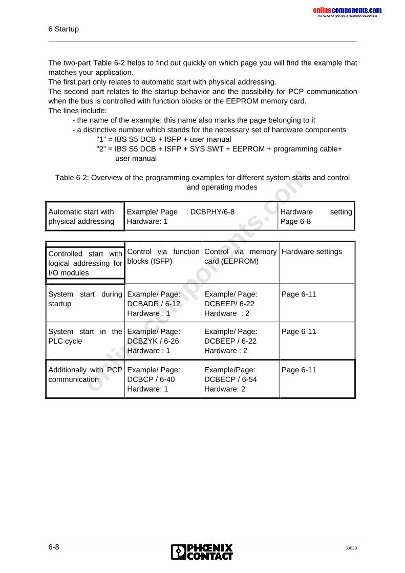
onlinec
omponen
ts.co
m
6 Startup
6-8 5003B
The two-part Table 6-2 helps to find out quickly on which page you will find the example thatmatches your application.The first part only relates to automatic start with physical addressing.The second part relates to the startup behavior and the possibility for PCP communicationwhen the bus is controlled with function blocks or the EEPROM memory card.The lines include:
- the name of the example; this name also marks the page belonging to it- a distinctive number which stands for the necessary set of hardware components
"1" = IBS S5 DCB + ISFP + user manual"2" = IBS S5 DCB + ISFP + SYS SWT + EEPROM + programming cable+ user manual
Table 6-2: Overview of the programming examples for different system starts and controland operating modes
Automatic start withphysical addressing
Example/ Page : DCBPHY/6-8Hardware: 1
Hardware settingPage 6-8
Controlled start withlogical addressing forI/O modules
Control via functionblocks (ISFP)
Control via memorycard (EEPROM)
Hardware settings
System start duringstartup
Example/ Page:DCBADR / 6-12Hardware : 1
Example/ Page:DCBEEP/ 6-22Hardware : 2
Page 6-11
System start in thePLC cycle
Example/ Page:DCBZYK / 6-26Hardware : 1
Example/ Page:DCBEEP / 6-22Hardware : 2
Page 6-11
Additionally with PCPcommunication
Example/ Page:DCBCP / 6-40Hardware: 1
Example/Page:DCBECP / 6-54Hardware: 2
Page 6-11
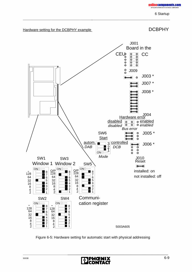
onlinec
omponen
ts.co
m
6 Startup
_______________________________________________5003B 6-9
Hardware setting for the DCBPHY example DCBPHY
4321
SW2ON
765
8
4321
65
78
ON
SW4
21
ON
3
SW6
J006 *
J010
J005 *
J004
J008 *
J007 *
J003 *J009
J001Board in the
CEU CC
disabled enableddisabled enabled
Reset
installed: onnot installed: off
-643216842
128-643216842
128
Startautom. controlled
Mode
DAB DCB
Hardware error
Bus error
21
43
SW1
ON
65
78-
128643216842
Window 1
21
43
65
78
ON
SW3
128643216842
Q/P
Window 2
Communi-cation register
21
43
65
78
ON
SW5
128643216842
Q/P
5003A605
Figure 6-5: Hardware setting for automatic start with physical addressing
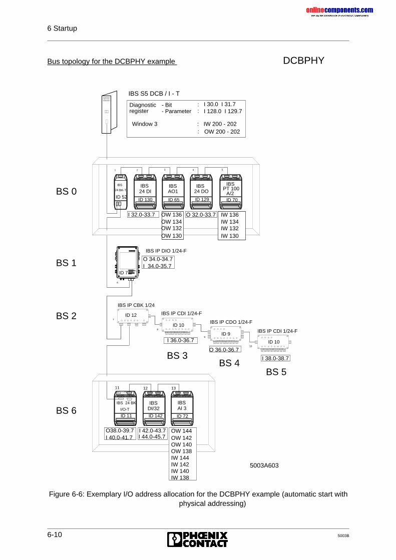
onlinec
omponen
ts.co
m
6 Startup
6-10 5003B
Bus topology for the DCBPHY example DCBPHY
Figure 6-6: Exemplary I/O address allocation for the DCBPHY example (automatic start withphysical addressing)
IBS S5 DCB / I - T
11
7
8
9
10
6
ID 7
1 2 3 4 5
24 DI 24 DOAO1 PT 100A/2
IBS IBS IBS IBS
IBS IBSDI/32 AI 3
IBS
24 BK-T
IBS
I/O-T
IBS IP CBK 1/24
IBS IP CDI 1/24-F
IBS IP CDO 1/24-F
IBS IP CDI 1/24-F
IBS IP DIO 1/24-F
12 13
Diagnosticregister
- Bit- Parameter
::
I 30.0 I 31.7I 128.0 I 129.7
24 BK
I 32.0-33.7 O 32.0-33.7
O 34.0-34.7I 34.0-35.7
I 36.0-36.7
O 36.0-36.7
I 38.0-38.7
O38.0-39.7I 40.0-41.7
I 42.0-43.7 OW 144OW 142OW 140OW 138IW 144IW 142IW 140IW 138
Window 3 : IW 200 - 202OW 200 - 202:
BS 0ID 52 ID 130 ID 65 ID 129 ID 70
OW 136OW 134OW 132OW 130
IW 136IW 134IW 132IW 130
ID 7
BS 1
BS 2
BS 6
ID 12
ID 10
ID 9
ID 10
BS 3BS 4
BS 5
ID 11 ID 142 ID 72
I 44.0-45.7
5003A603
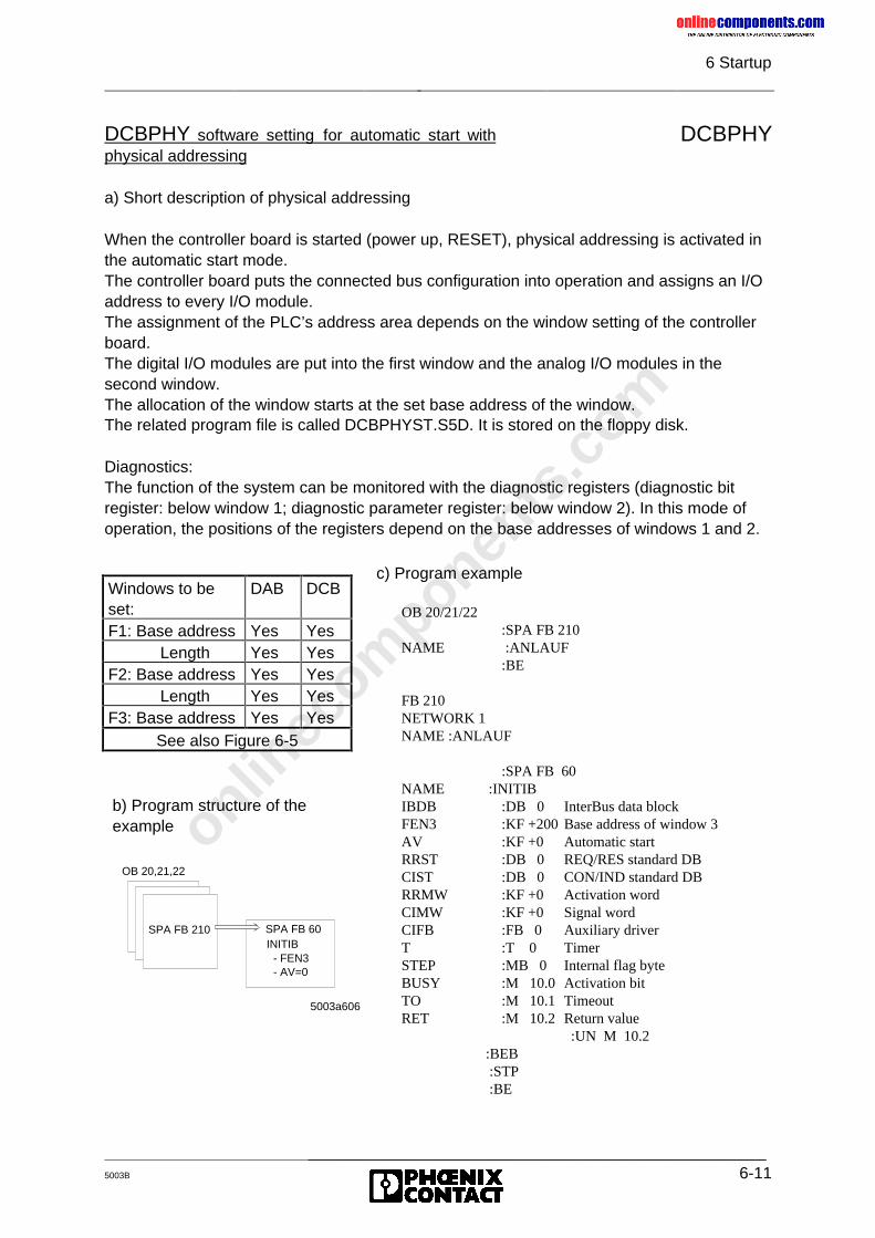
onlinec
omponen
ts.co
m
6 Startup
_______________________________________________5003B 6-11
DCBPHY
a) Short description of physical addressing
When the controller board is started (power up, RESET), physical addressing is activated inthe automatic start mode.The controller board puts the connected bus configuration into operation and assigns an I/Oaddress to every I/O module.The assignment of the PLC’s address area depends on the window setting of the controllerboard.The digital I/O modules are put into the first window and the analog I/O modules in thesecond window.The allocation of the window starts at the set base address of the window.The related program file is called DCBPHYST.S5D. It is stored on the floppy disk.
Diagnostics:The function of the system can be monitored with the diagnostic registers (diagnostic bitregister: below window 1; diagnostic parameter register: below window 2). In this mode ofoperation, the positions of the registers depend on the base addresses of windows 1 and 2.
DCBPHY software setting for automatic start withphysical addressing
OB 20,21,22
SPA FB 210 SPA FB 60INITIB
- FEN3- AV=0
5003a606
c) Program example
OB 20/21/22:SPA FB 210
NAME :ANLAUF:BE
FB 210NETWORK 1NAME :ANLAUF
:SPA FB 60NAME :INITIBIBDB :DB 0 InterBus data blockFEN3 :KF +200 Base address of window 3AV :KF +0 Automatic startRRST :DB 0 REQ/RES standard DBCIST :DB 0 CON/IND standard DBRRMW :KF +0 Activation wordCIMW :KF +0 Signal wordCIFB :FB 0 Auxiliary driverT :T 0 TimerSTEP :MB 0 Internal flag byteBUSY :M 10.0 Activation bitTO :M 10.1 TimeoutRET :M 10.2 Return value :UN M 10.2 :BEB :STP :BE
b) Program structure of theexample
Windows to beset:
DAB DCB
F1: Base address Yes YesLength Yes Yes
F2: Base address Yes YesLength Yes Yes
F3: Base address Yes YesSee also Figure 6-5
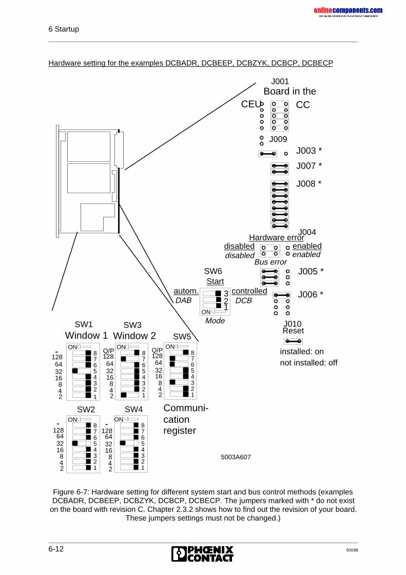
onlinec
omponen
ts.co
m
6 Startup
6-12 5003B
Hardware setting for the examples DCBADR, DCBEEP, DCBZYK, DCBCP, DCBECP
Figure 6-7: Hardware setting for different system start and bus control methods (examplesDCBADR, DCBEEP, DCBZYK, DCBCP, DCBECP. The jumpers marked with * do not exist
on the board with revision C. Chapter 2.3.2 shows how to find out the revision of your board.These jumpers settings must not be changed.)
4321
SW2ON
765
8
4321
65
78
ON
SW4
21
ON
3
SW6
J006 *
J010
J005 *
J004
J008 *
J007 *
J003 *J009
J001Board in the
CEU CC
disabled enableddisabled enabled
Reset
installed: onnot installed: off
-643216842
128-643216842
128
Startautom. controlled
Mode
DAB DCB
Hardware error
Bus error
21
43
SW1
ON
65
78-
128643216842
Window 1
21
43
65
78
ON
SW3
128643216842
Q/P
Window 2
Communi-cationregister
21
43
65
78
ON
SW5
128643216842
Q/P
5003A607
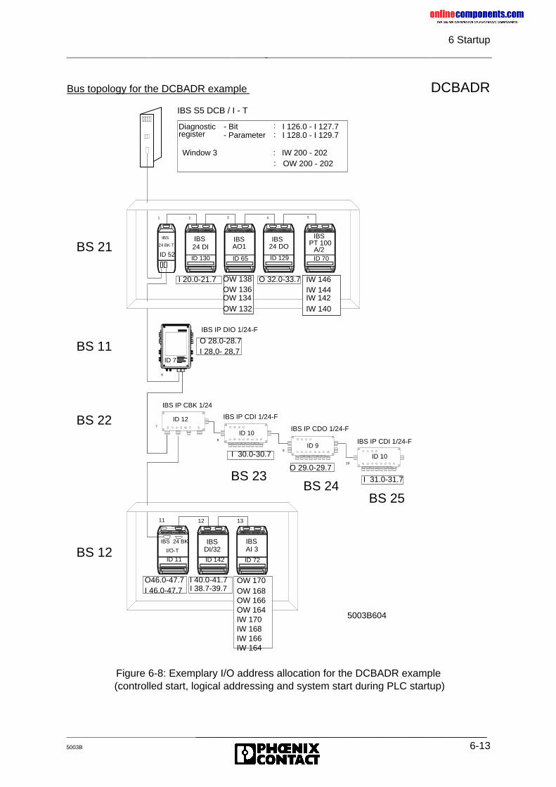
onlinec
omponen
ts.co
m
6 Startup
_______________________________________________5003B 6-13
Bus topology for the DCBADR example DCBADR
Figure 6-8: Exemplary I/O address allocation for the DCBADR example (controlled start, logical addressing and system start during PLC startup)
IBS S5 DCB / I - T
11
7
8
9
10
6
ID 7
1 2 3 4 5
24 DI 24 DOAO1 PT 100A/2
IBS IBS IBS IBS
IBS IBSDI/32 AI 3
IBS
24 BK-T
IBS
I/O-T
IBS IP CBK 1/24
IBS IP CDI 1/24-F
IBS IP CDO 1/24-F
IBS IP CDI 1/24-F
IBS IP DIO 1/24-F
12 13
Diagnosticregister
- Bit- Parameter
::
I 126.0 - I 127.7I 128.0 - I 129.7
24 BK
I 20.0-21.7 O 32.0-33.7
O 28.0-28.7I 28,0- 28,7
I 30.0-30.7
O 29.0-29.7
I 31.0-31.7
O46.0-47.7I 46.0-47.7
I 40.0-41.7 OW 170OW 168OW 166OW 164IW 170IW 168IW 166IW 164
Window 3 : IW 200 - 202OW 200 - 202:
BS 21ID 52
ID 130 ID 65 ID 129 ID 70
OW 138OW 136OW 134OW 132
IW 146IW 144IW 142IW 140
ID 7
BS 11
BS 22
BS 12
ID 12
ID 10
ID 9
ID 10
BS 23BS 24
BS 25
ID 11 ID 142 ID 72
I 38.7-39.7
5003B604
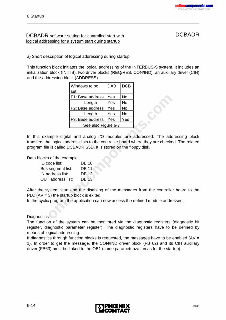
onlinec
omponen
ts.co
m
6 Startup
6-14 5003B
DCBADR
a) Short description of logical addressing during startup
This function block initiates the logical addressing of the INTERBUS-S system. It includes aninitialization block (INITIB), two driver blocks (REQ/RES, CON/IND), an auxiliary driver (CIH)and the addressing block (ADDRESS).
In this example digital and analog I/O modules are addressed. The addressing blocktransfers the logical address lists to the controller board where they are checked. The relatedprogram file is called DCBADR.S5D. It is stored on the floppy disk.
Data blocks of the example:ID code list: DB 10Bus segment list: DB 11IN address list: DB 12OUT address list: DB 13
After the system start and the disabling of the messages from the controller board to thePLC (AV = 3) the startup block is exited.In the cyclic program the application can now access the defined module addresses.
Diagnostics:The function of the system can be monitored via the diagnostic registers (diagnostic bitregister, diagnostic parameter register). The diagnostic registers have to be defined bymeans of logical addressing.If diagnostics through function blocks is requested, the messages have to be enabled (AV =1). In order to get the message, the CON/IND driver block (FB 62) and its CIH auxiliarydriver (FB63) must be linked to the OB1 (same parameterization as for the startup).
DCBADR software setting for controlled start withlogical addressing for a system start during startup
Windows to beset:
DAB DCB
F1: Base address Yes NoLength Yes No
F2: Base address Yes NoLength Yes No
F3: Base address Yes YesSee also Figure 6-7
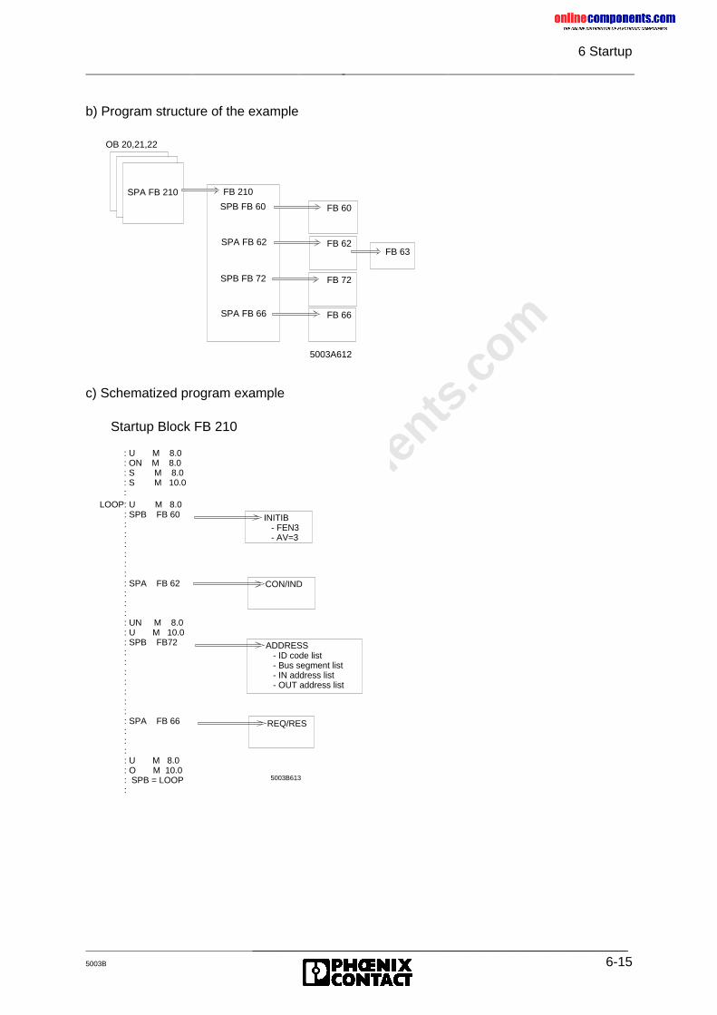
onlinec
omponen
ts.co
m
6 Startup
_______________________________________________5003B 6-15
b) Program structure of the example
c) Schematized program example
OB 20,21,22
SPA FB 210 FB 210
5003A612
SPA FB 62 FB 62
SPB FB 72 FB 72
SPA FB 66 FB 66
SPB FB 60 FB 60
FB 63
5003B613
CON/IND
ADDRESS - ID code list - Bus segment list - IN address list - OUT address list
REQ/RES
INITIB - FEN3 - AV=3
Startup Block FB 210
: U M 8.0: ON M 8.0: S M 8.0: S M 10.0:
LOOP: U M 8.0 : SPB FB 60 : : : : : : : SPA FB 62 : : : : UN M 8.0 : U M 10.0 : SPB FB72 : : : : : : : : SPA FB 66 : : : : U M 8.0 : O M 10.0 : SPB = LOOP :
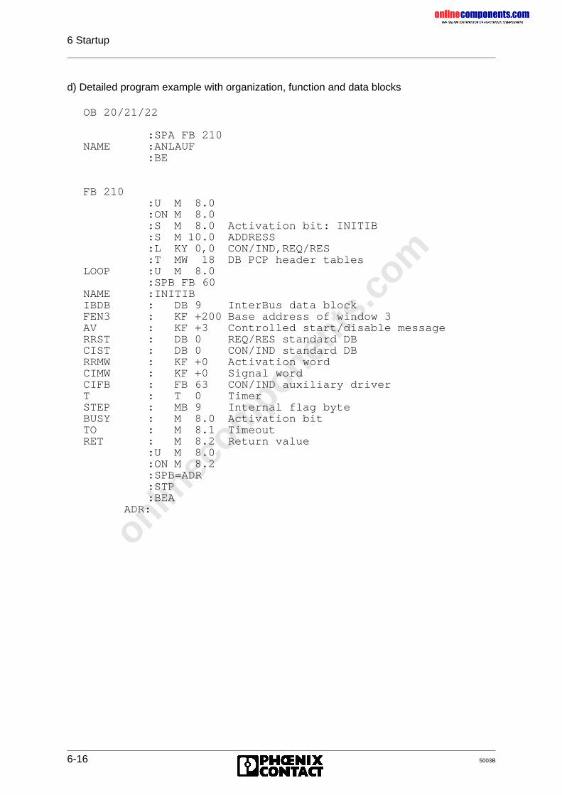
onlinec
omponen
ts.co
m
6 Startup
6-16 5003B
d) Detailed program example with organization, function and data blocks
OB 20/21/22
:SPA FB 210NAME :ANLAUF
:BE
FB 210:U M 8.0:ON M 8.0:S M 8.0 Activation bit: INITIB:S M 10.0 ADDRESS:L KY 0,0 CON/IND,REQ/RES:T MW 18 DB PCP header tables
LOOP :U M 8.0:SPB FB 60
NAME :INITIBIBDB : DB 9 InterBus data blockFEN3 : KF +200 Base address of window 3AV : KF +3 Controlled start/disable messageRRST : DB 0 REQ/RES standard DBCIST : DB 0 CON/IND standard DBRRMW : KF +0 Activation wordCIMW : KF +0 Signal wordCIFB : FB 63 CON/IND auxiliary driverT : T 0 TimerSTEP : MB 9 Internal flag byteBUSY : M 8.0 Activation bitTO : M 8.1 TimeoutRET : M 8.2 Return value
:U M 8.0:ON M 8.2:SPB=ADR:STP:BEA
ADR:
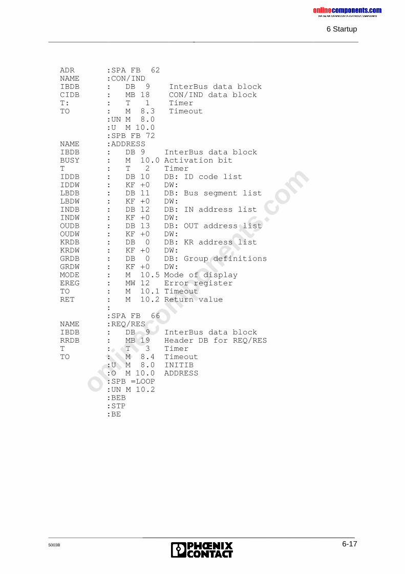
onlinec
omponen
ts.co
m
6 Startup
_______________________________________________5003B 6-17
ADR :SPA FB 62NAME :CON/INDIBDB : DB 9 InterBus data blockCIDB : MB 18 CON/IND data blockT: : T 1 TimerTO : M 8.3 Timeout
:UN M 8.0:U M 10.0:SPB FB 72
NAME :ADDRESSIBDB : DB 9 InterBus data blockBUSY : M 10.0 Activation bitT : T 2 TimerIDDB : DB 10 DB: ID code listIDDW : KF +0 DW:LBDB : DB 11 DB: Bus segment listLBDW : KF +0 DW:INDB : DB 12 DB: IN address listINDW : KF +0 DW:OUDB : DB 13 DB: OUT address listOUDW : KF +0 DW:KRDB : DB 0 DB: KR address listKRDW : KF +0 DW:GRDB : DB 0 DB: Group definitionsGRDW : KF +0 DW:MODE : M 10.5 Mode of displayEREG : MW 12 Error registerTO : M 10.1 TimeoutRET : M 10.2 Return value
::SPA FB 66
NAME :REQ/RESIBDB : DB 9 InterBus data blockRRDB : MB 19 Header DB for REQ/REST : T 3 TimerTO : M 8.4 Timeout
:U M 8.0 INITIB:O M 10.0 ADDRESS:SPB =LOOP:UN M 10.2:BEB:STP:BE
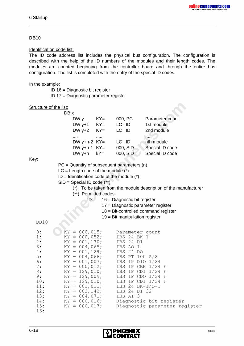
onlinec
omponen
ts.co
m
6 Startup
6-18 5003B
DB10
Identification code list:The ID code address list includes the physical bus configuration. The configuration isdescribed with the help of the ID numbers of the modules and their length codes. Themodules are counted beginning from the controller board and through the entire busconfiguration. The list is completed with the entry of the special ID codes.
In the example: ID 16 = Diagnostic bit register ID 17 = Diagnostic parameter register
Structure of the list:DB x
DW y KY= 000, PC Parameter countDW y+1 KY= LC , ID 1st moduleDW y+2 KY= LC , ID 2nd module.... ...... .....DW y+n-2 KY= LC , ID nth moduleDW y+n-1 KY= 000, SID Special ID codeDW y+n kY= 000, SID Special ID code
Key:PC = Quantity of subsequent parameters (n)LC = Length code of the module (*)ID = Identification code of the module (*)SID = Special ID code (**)
(*) To be taken from the module description of the manufacturer(**) Permitted codes:
ID: 16 = Diagnostic bit register17 = Diagnostic parameter register18 = Bit-controlled command register19 = Bit manipulation register
DB10
0: KY = 000,015; Parameter count1: KY = 000,052; IBS 24 BK-T2: KY = 001,130; IBS 24 DI3: KY = 004,065; IBS AO 14: KY = 001,129; IBS 24 DO5: KY = 004,066; IBS PT 100 A/26: KY = 001,007; IBS IP DIO 1/247: KY = 000,012; IBS IP CBK 1/24 F8: KY = 129,010; IBS IP CDI 1/24 F9: KY = 129,009; IBS IP CDO 1/24 F10: KY = 129,010; IBS IP CDI 1/24 F11: KY = 001,011; IBS 24 BK-I/O-T12: KY = 002,142; IBS 24 DI 3213: KY = 004,071; IBS AI 314: KY = 000,016; Diagnostic bit register15: KY = 000,017; Diagnostic parameter register16:
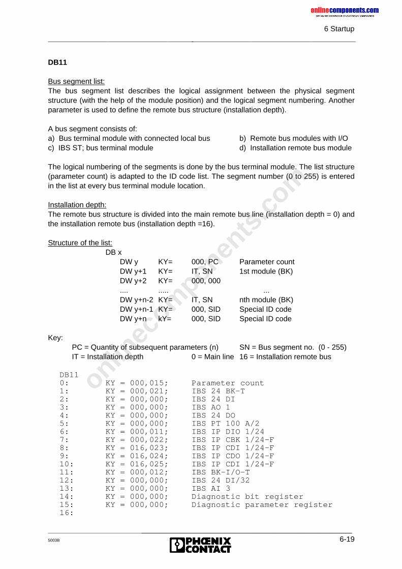
onlinec
omponen
ts.co
m
6 Startup
_______________________________________________5003B 6-19
DB11
Bus segment list:The bus segment list describes the logical assignment between the physical segmentstructure (with the help of the module position) and the logical segment numbering. Anotherparameter is used to define the remote bus structure (installation depth).
A bus segment consists of:a) Bus terminal module with connected local bus b) Remote bus modules with I/Oc) IBS ST; bus terminal module d) Installation remote bus module
The logical numbering of the segments is done by the bus terminal module. The list structure(parameter count) is adapted to the ID code list. The segment number (0 to 255) is enteredin the list at every bus terminal module location.
Installation depth:The remote bus structure is divided into the main remote bus line (installation depth = 0) andthe installation remote bus (installation depth =16).
Structure of the list:DB x
DW y KY= 000, PC Parameter countDW y+1 KY= IT, SN 1st module (BK)DW y+2 KY= 000, 000.... ..... ...DW y+n-2 KY= IT, SN nth module (BK)DW y+n-1 KY= 000, SID Special ID codeDW y+n kY= 000, SID Special ID code
Key:PC = Quantity of subsequent parameters (n) SN = Bus segment no. (0 - 255)IT = Installation depth 0 = Main line 16 = Installation remote bus
DB110: KY = 000,015; Parameter count1: KY = 000,021; IBS 24 BK-T2: KY = 000,000; IBS 24 DI3: KY = 000,000; IBS AO 14: KY = 000,000; IBS 24 DO5: KY = 000,000; IBS PT 100 A/26: KY = 000,011; IBS IP DIO 1/247: KY = 000,022; IBS IP CBK 1/24-F8: KY = 016,023; IBS IP CDI 1/24-F9: KY = 016,024; IBS IP CDO 1/24-F10: KY = 016,025; IBS IP CDI 1/24-F11: KY = 000,012; IBS BK-I/O-T12: KY = 000,000; IBS 24 DI/3213: KY = 000,000; IBS AI 314: KY = 000,000; Diagnostic bit register15: KY = 000,000; Diagnostic parameter register16:
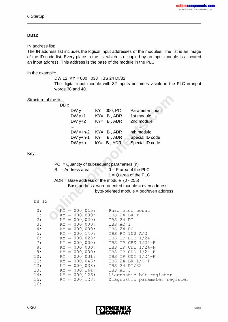
onlinec
omponen
ts.co
m
6 Startup
6-20 5003B
DB12
IN address list:The IN address list includes the logical input addresses of the modules. The list is an imageof the ID code list. Every place in the list which is occupied by an input module is allocatedan input address. This address is the base of the module in the PLC.
In the example:DW 12 KY = 000 , 038 IBS 24 DI/32The digital input module with 32 inputs becomes visible in the PLC in inputwords 38 and 40.
Structure of the list:DB x
DW y KY= 000, PC Parameter countDW y+1 KY= B , ADR 1st moduleDW y+2 KY= B , ADR 2nd module.... ... ...DW y+n-2 KY= B , ADR nth moduleDW y+n-1 KY= B , ADR Special ID codeDW y+n kY= B , ADR Special ID code
Key:
PC = Quantity of subsequent parameters (n)B = Address area 0 = P area of the PLC
1 = Q area of the PLCADR = Base address of the module (0 - 255)
Base address: word-oriented module = even addressbyte-oriented module = odd/even address
DB 12
0: KY = 000,015; Parameter count 1: KY = 000,000; IBS 24 BK-T 2: KY = 000,020; IBS 24 DI 3: KY = 000,000; IBS AO 1 4: KY = 000,000; IBS 24 DO 5: KY = 000,140; IBS PT 100 A/2 6: KY = 000,028; IBS IP DIO 1/24 7: KY = 000,000; IBS IP CBK 1/24-F 8: KY = 000,030; IBS IP CDI 1/24-F 9: KY = 000,000; IBS IP CDO 1/24-F10: KY = 000,031; IBS IP CDI 1/24-F11: KY = 000,046; IBS 24 BK-I/O-T12: KY = 000,038; IBS 24 DI/3213: KY = 000,164; IBS AI 314: KY = 000,126; Diagnostic bit register15: KY = 000,128; Diagnostic parameter register16:
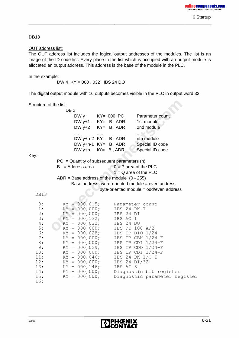
onlinec
omponen
ts.co
m
6 Startup
_______________________________________________5003B 6-21
DB13
OUT address list:The OUT address list includes the logical output addresses of the modules. The list is animage of the ID code list. Every place in the list which is occupied with an output module isallocated an output address. This address is the base of the module in the PLC.
In the example:DW 4 KY = 000 , 032 IBS 24 DO
The digital output module with 16 outputs becomes visible in the PLC in output word 32.
Structure of the list:DB x
DW y KY= 000, PC Parameter countDW y+1 KY= B , ADR 1st moduleDW y+2 KY= B , ADR 2nd module.... ..... ...DW y+n-2 KY= B , ADR nth moduleDW y+n-1 KY= B , ADR Special ID codeDW y+n kY= B , ADR Special ID code
Key:PC = Quantity of subsequent parameters (n)B = Address area 0 = P area of the PLC
1 = Q area of the PLCADR = Base address of the module (0 - 255)
Base address: word-oriented module = even address byte-oriented module = odd/even address
DB13
0: KY = 000,015; Parameter count 1: KY = 000,000; IBS 24 BK-T 2: KY = 000,000; IBS 24 DI 3: KY = 000,132; IBS AO 1 4: KY = 000,032; IBS 24 DO 5: KY = 000,000; IBS PT 100 A/2 6: KY = 000,028; IBS IP DIO 1/24 7: KY = 000,000; IBS IP CBK 1/24-F 8: KY = 000,000; IBS IP CDI 1/24-F 9: KY = 000,029; IBS IP CDO 1/24-F10: KY = 000,000; IBS IP CDI 1/24-F11: KY = 000,046; IBS 24 BK-I/O-T12: KY = 000,000; IBS 24 DI/3213: KY = 000,146; IBS AI 314: KY = 000,000; Diagnostic bit register15: KY = 000,000; Diagnostic parameter register16:

onlinec
omponen
ts.co
m
6 Startup
6-22 5003B
The DCBEEP example is given on the next page in order to avoid having to turn overbetween the pages "Bus topology...." and "Software setting..."

onlinec
omponen
ts.co
m
6 Startup
_______________________________________________5003B 6-23
Bus topology for the DCBEEP example DCBEEP
Figure 6-9: Exemplary I/O address allocation for the DCBEEP example(controlled start, logical addressing, system start during PLC startup or program, control via
memory card)
IBS S5 DCB / I - T
11
7
8
9
10
6
ID 7
1 2 3 4 5
24 DI 24 DOAO1 PT 100A/2
IBS IBS IBS IBS
IBS IBSDI/32 AI 3
IBS
24 BK-T
IBS
I/O-T
IBS IP CBK 1/24
IBS IP CDI 1/24-F
IBS IP CDO 1/24-F
IBS IP CDI 1/24-F
IBS IP DIO 1/24-F
12 13
Diagnosticregister
- Bit- Parameter
::
I 126.0 - I 127.7I 128.0 - I 129.7
24 BK
I 20.0-21.7 O 32.0-33.7
O 28.0-28.7I 28.0- 28.7
I 30.0-30.7
O 29.0-29.7
I 31.0-31.7
O46.0-47.7I 46.0-47.7
I 40.0-41.7 OW 170OW 168OW 166OW 164IW 170IW 168IW 166IW 164
Window 3 : IW 200 - 202OW 200 - 202:
BS 21ID 52 ID 130 ID 65 ID 129 ID 70
OW 138OW 136OW 134OW 132
IW 146IW 144IW 142
IW 140
ID 7
BS 11
BS 22
BS 12
ID 12
ID 10
ID 9
ID 10
BS 23BS 24
BS 25
ID 11 ID 142 ID 72
I 38.7-39.7
5003B608
Functions Active bits: O 60.0 - 61.7Busy bits: I 62.0 - 63.7Return bits: I 62.0 - 63.7
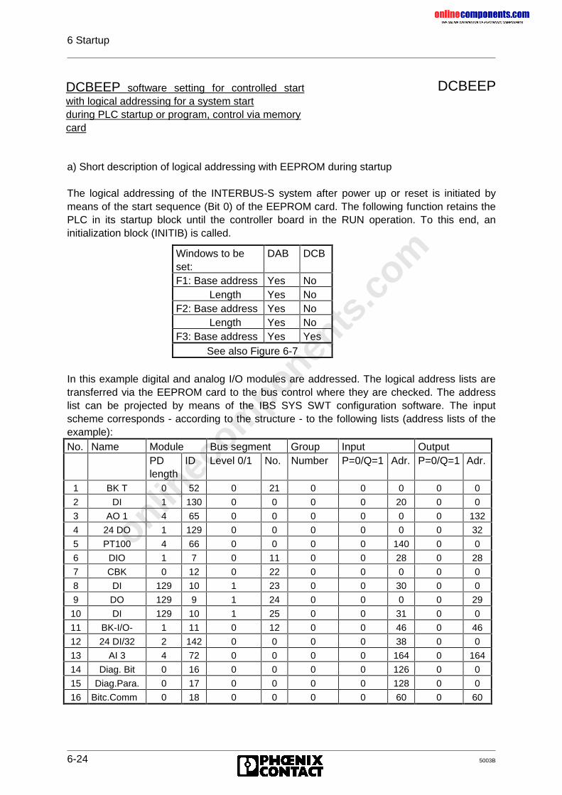
onlinec
omponen
ts.co
m
6 Startup
6-24 5003B
DCBEEP
a) Short description of logical addressing with EEPROM during startup
The logical addressing of the INTERBUS-S system after power up or reset is initiated bymeans of the start sequence (Bit 0) of the EEPROM card. The following function retains thePLC in its startup block until the controller board in the RUN operation. To this end, aninitialization block (INITIB) is called.
In this example digital and analog I/O modules are addressed. The logical address lists aretransferred via the EEPROM card to the bus control where they are checked. The addresslist can be projected by means of the IBS SYS SWT configuration software. The inputscheme corresponds - according to the structure - to the following lists (address lists of theexample):No. Name Module Bus segment Group Input Output
PDlength
ID Level 0/1 No. Number P=0/Q=1 Adr. P=0/Q=1 Adr.
1 BK T 0 52 0 21 0 0 0 0 0
2 DI 1 130 0 0 0 0 20 0 0
3 AO 1 4 65 0 0 0 0 0 0 132
4 24 DO 1 129 0 0 0 0 0 0 32
5 PT100 4 66 0 0 0 0 140 0 0
6 DIO 1 7 0 11 0 0 28 0 28
7 CBK 0 12 0 22 0 0 0 0 0
8 DI 129 10 1 23 0 0 30 0 0
9 DO 129 9 1 24 0 0 0 0 29
10 DI 129 10 1 25 0 0 31 0 0
11 BK-I/O- 1 11 0 12 0 0 46 0 46
12 24 DI/32 2 142 0 0 0 0 38 0 0
13 AI 3 4 72 0 0 0 0 164 0 164
14 Diag. Bit 0 16 0 0 0 0 126 0 0
15 Diag.Para. 0 17 0 0 0 0 128 0 0
16 Bitc.Comm 0 18 0 0 0 0 60 0 60
DCBEEP software setting for controlled startwith logical addressing for a system startduring PLC startup or program, control via memorycard
Windows to beset:
DAB DCB
F1: Base address Yes NoLength Yes No
F2: Base address Yes NoLength Yes No
F3: Base address Yes YesSee also Figure 6-7
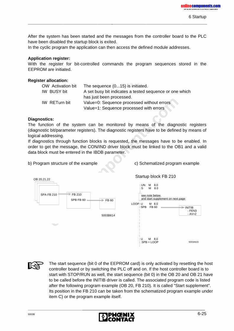
onlinec
omponen
ts.co
m
6 Startup
_______________________________________________5003B 6-25
After the system has been started and the messages from the controller board to the PLChave been disabled the startup block is exited.In the cyclic program the application can then access the defined module addresses.
Application register:With the register for bit-controlled commands the program sequences stored in theEEPROM are initiated.
Register allocation:OW Activation bit The sequence (0...15) is initiated.IW BUSY bit A set busy bit indicates a tested sequence or one which
has just been processed.IW RETurn bit Value=0: Sequence processed without errors
Value=1: Sequence processed with errors
Diagnostics:The function of the system can be monitored by means of the diagnostic registers(diagnostic bit/parameter registers). The diagnostic registers have to be defined by means oflogical addressing.If diagnostics through function blocks is requested, the messages have to be enabled. Inorder to get the message, the CON/IND driver block must be linked to the OB1 and a validdata block must be entered in the IBDB parameter.
b) Program structure of the example c) Schematized program example
INITIB - FEN3 - AV=2
Startup block FB 210
: UN M 8.0: S M 8.0:
LOOP: U M 8.0 : SPB FB 60 : : : : : : : : : : U M 8.0 : SPB = LOOP :
5003A615
see note below and start supplement on next page
OB 20,21,22
SPA FB 210 FB 210
5003B614
SPB FB 60 FB 60
The start sequence (bit 0 of the EEPROM card) is only activated by resetting the hostcontroller board or by switching the PLC off and on. If the host controller board is tostart with STOP/RUN as well, the start sequence (bit 0) in the OB 20 and OB 21 haveto be called before the INITIB driver is called. The associated program code is listedafter the following program example (OB 20, FB 210). It is called "Start supplement".Its position in the FB 210 can be taken from the schematized program example underitem C) or the program example itself.
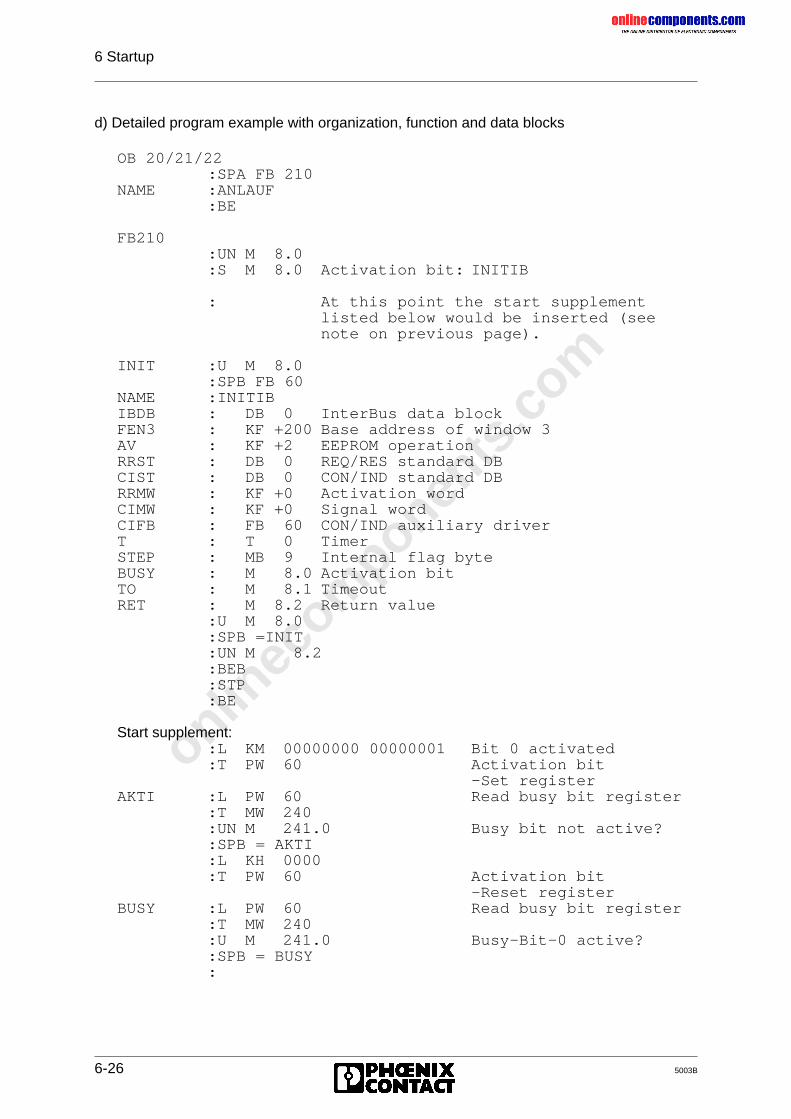
onlinec
omponen
ts.co
m
6 Startup
6-26 5003B
d) Detailed program example with organization, function and data blocks
OB 20/21/22:SPA FB 210
NAME :ANLAUF:BE
FB210:UN M 8.0:S M 8.0 Activation bit: INITIB
: At this point the start supplementlisted below would be inserted (seenote on previous page).
INIT :U M 8.0:SPB FB 60
NAME :INITIBIBDB : DB 0 InterBus data blockFEN3 : KF +200 Base address of window 3AV : KF +2 EEPROM operationRRST : DB 0 REQ/RES standard DBCIST : DB 0 CON/IND standard DBRRMW : KF +0 Activation wordCIMW : KF +0 Signal wordCIFB : FB 60 CON/IND auxiliary driverT : T 0 TimerSTEP : MB 9 Internal flag byteBUSY : M 8.0 Activation bitTO : M 8.1 TimeoutRET : M 8.2 Return value
:U M 8.0:SPB =INIT:UN M 8.2:BEB:STP:BE
Start supplement::L KM 00000000 00000001 Bit 0 activated:T PW 60 Activation bit
-Set registerAKTI :L PW 60 Read busy bit register
:T MW 240:UN M 241.0 Busy bit not active?:SPB = AKTI:L KH 0000:T PW 60 Activation bit
-Reset registerBUSY :L PW 60 Read busy bit register
:T MW 240:U M 241.0 Busy-Bit-0 active?:SPB = BUSY:
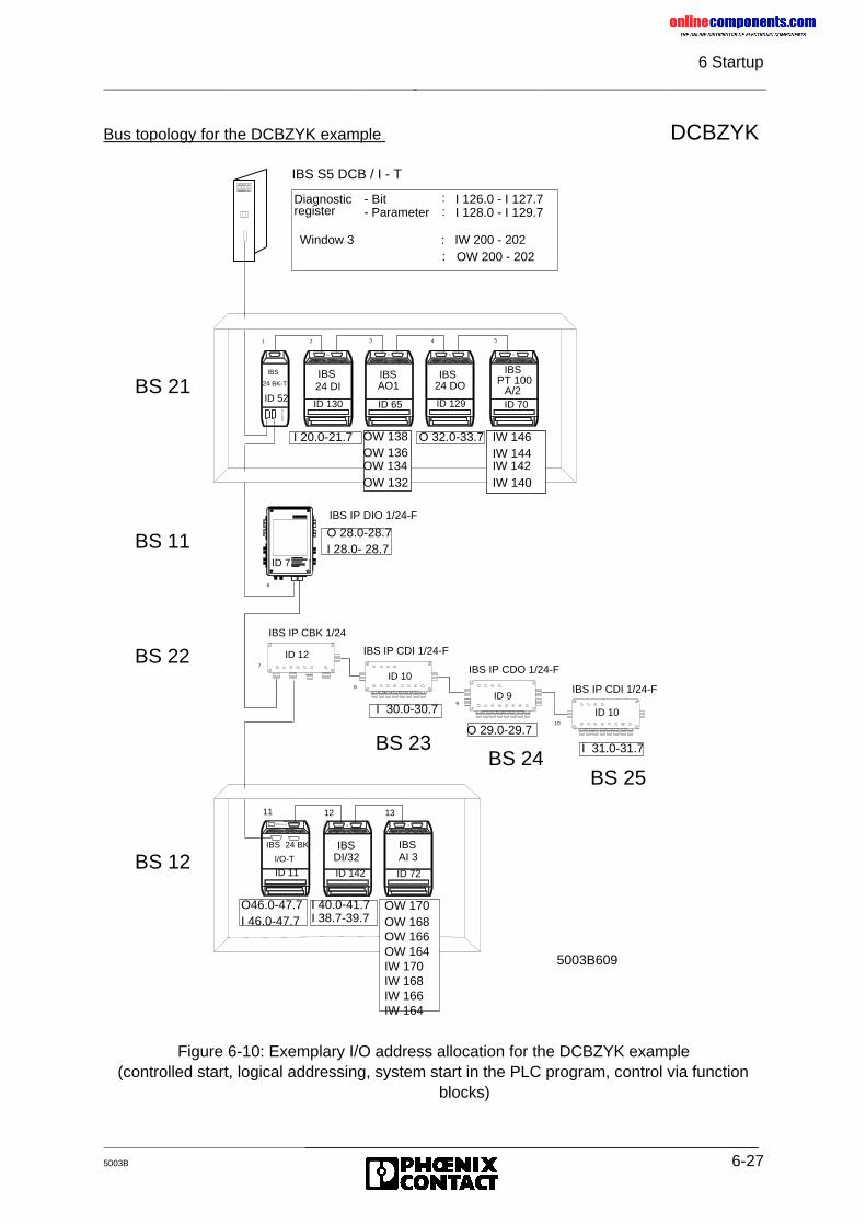
onlinec
omponen
ts.co
m
6 Startup
_______________________________________________5003B 6-27
Bus topology for the DCBZYK example DCBZYK
Figure 6-10: Exemplary I/O address allocation for the DCBZYK example(controlled start, logical addressing, system start in the PLC program, control via function
blocks)
IBS S5 DCB / I - T
11
7
8
9
10
6
ID 7
1 2 3 4 5
24 DI 24 DOAO1 PT 100A/2
IBS IBS IBS IBS
IBS IBSDI/32 AI 3
IBS
24 BK-T
IBS
I/O-T
IBS IP CBK 1/24
IBS IP CDI 1/24-F
IBS IP CDO 1/24-F
IBS IP CDI 1/24-F
IBS IP DIO 1/24-F
12 13
Diagnosticregister
- Bit- Parameter
::
I 126.0 - I 127.7I 128.0 - I 129.7
24 BK
I 20.0-21.7 O 32.0-33.7
O 28.0-28.7I 28.0- 28.7
I 30.0-30.7
O 29.0-29.7
I 31.0-31.7
O46.0-47.7I 46.0-47.7
I 40.0-41.7 OW 170OW 168OW 166OW 164IW 170IW 168IW 166IW 164
Window 3 : IW 200 - 202OW 200 - 202:
BS 21ID 52
ID 130 ID 65 ID 129 ID 70
OW 138OW 136OW 134OW 132
IW 146IW 144IW 142IW 140
ID 7
BS 11
BS 22
BS 12
ID 12
ID 10
ID 9
ID 10
BS 23BS 24
BS 25
ID 11 ID 142 ID 72
I 38.7-39.7
5003B609
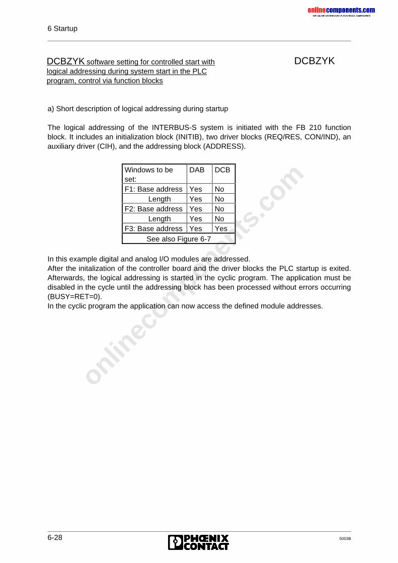
onlinec
omponen
ts.co
m
6 Startup
6-28 5003B
DCBZYK
a) Short description of logical addressing during startup
The logical addressing of the INTERBUS-S system is initiated with the FB 210 functionblock. It includes an initialization block (INITIB), two driver blocks (REQ/RES, CON/IND), anauxiliary driver (CIH), and the addressing block (ADDRESS).
In this example digital and analog I/O modules are addressed.After the initalization of the controller board and the driver blocks the PLC startup is exited.Afterwards, the logical addressing is started in the cyclic program. The application must bedisabled in the cycle until the addressing block has been processed without errors occurring(BUSY=RET=0).In the cyclic program the application can now access the defined module addresses.
DCBZYK software setting for controlled start withlogical addressing during system start in the PLCprogram, control via function blocks
Windows to beset:
DAB DCB
F1: Base address Yes NoLength Yes No
F2: Base address Yes NoLength Yes No
F3: Base address Yes YesSee also Figure 6-7
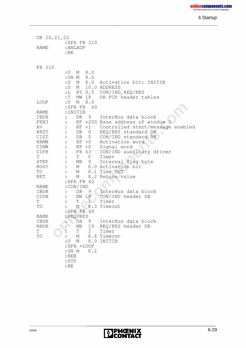
onlinec
omponen
ts.co
m
6 Startup
_______________________________________________5003B 6-29
OB 20,21,22:SPA FB 210
NAME :ANLAUF:BE
FB 210:U M 8.0:ON M 8.0:S M 8.0 Activation bit: INITIB:S M 10.0 ADDRESS:L KY 0,0 CON/IND,REQ/RES:T MW 18 DB PCP header tables
LOOP :U M 8.0:SPB FB 60
NAME :INITIBIBDB : DB 9 InterBus data blockFEN3 : KF +200 Base address of window 3AV : KF +1 Controlled start/message enabledRRST : DB 0 REQ/RES standard DBCIST : DB 0 CON/IND standard DBRRMW : KF +0 Activation wordCIMW : KF +0 Signal wordCIFB : FB 63 CON/IND auxiliary driverT : T 0 TimerSTEP : MB 9 Internal flag byteBUSY : M 8.0 Activation bitTO : M 8.1 Time OUTRET : M 8.2 Return value
:SPA FB 62NAME :CON/INDIBDB : DB 9 InterBus data blockCIDB : MB 18 CON/IND header DBT : T 1 TimerTO : M 8.3 Timeout
:SPA FB 66NAME :REQ/RESIBDB : DB 9 InterBus data blockRRDB : MB 19 REQ/RES header DBT : T 3 TimerTO : M 8.4 Timeout
:U M 8.0 INITIB:SPB =LOOP:UN M 8.2:BEB:STP:BE
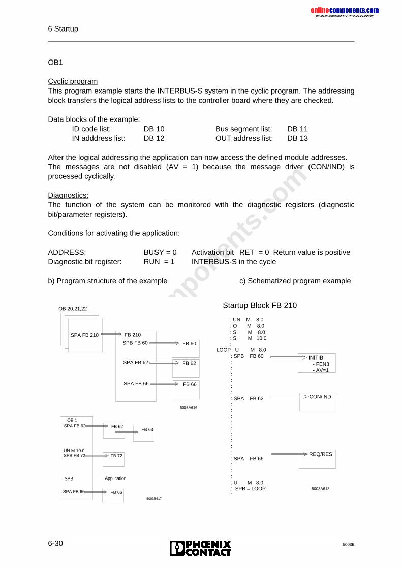
onlinec
omponen
ts.co
m
6 Startup
6-30 5003B
OB1
Cyclic programThis program example starts the INTERBUS-S system in the cyclic program. The addressingblock transfers the logical address lists to the controller board where they are checked.
Data blocks of the example:ID code list: DB 10 Bus segment list: DB 11IN adddress list: DB 12 OUT address list: DB 13
After the logical addressing the application can now access the defined module addresses.The messages are not disabled (AV = 1) because the message driver (CON/IND) isprocessed cyclically.
Diagnostics:The function of the system can be monitored with the diagnostic registers (diagnosticbit/parameter registers).
Conditions for activating the application:
ADDRESS: BUSY = 0 Activation bit RET = 0 Return value is positiveDiagnostic bit register: RUN = 1 INTERBUS-S in the cycle
b) Program structure of the example c) Schematized program example
OB 20,21,22
SPA FB 210 FB 210
5003A616
SPA FB 62 FB 62
SPA FB 66 FB 66
SPB FB 60 FB 60
5003A618
CON/IND
REQ/RES
INITIB - FEN3 - AV=1
Startup Block FB 210
: UN M 8.0: O M 8.0: S M 8.0: S M 10.0:
LOOP : U M 8.0 : SPB FB 60 : : : : : : : SPA FB 62 : : : : : : : : : : SPA FB 66 : : : : U M 8.0 : SPB = LOOP :
OB 1
5003B617
SPA FB 62 FB 62
SPA FB 66 FB 66
FB 63
UN M 10.0SPB FB 72 FB 72
SPB Application
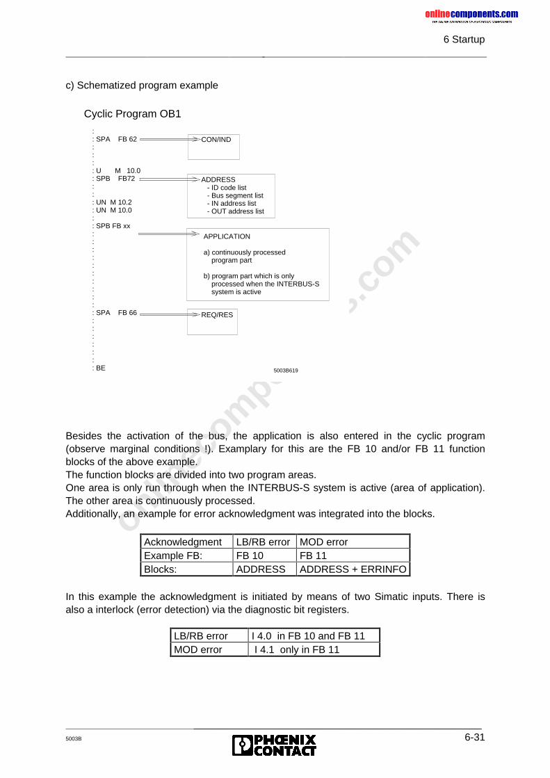
onlinec
omponen
ts.co
m
6 Startup
_______________________________________________5003B 6-31
c) Schematized program example
Besides the activation of the bus, the application is also entered in the cyclic program(observe marginal conditions !). Examplary for this are the FB 10 and/or FB 11 functionblocks of the above example.The function blocks are divided into two program areas.One area is only run through when the INTERBUS-S system is active (area of application).The other area is continuously processed.Additionally, an example for error acknowledgment was integrated into the blocks.
In this example the acknowledgment is initiated by means of two Simatic inputs. There isalso a interlock (error detection) via the diagnostic bit registers.
5003B619
CON/IND
ADDRESS - ID code list - Bus segment list - IN address list - OUT address list
REQ/RES
Cyclic Program OB1
: : SPA FB 62 : : : : U M 10.0 : SPB FB72 : : : UN M 10.2 : UN M 10.0 : : SPB FB xx : : : : : : : : : : : SPA FB 66 : : : : : : : BE
APPLICATION
a) continuously processed program part
b) program part which is only processed when the INTERBUS-S system is active
Acknowledgment LB/RB error MOD errorExample FB: FB 10 FB 11Blocks: ADDRESS ADDRESS + ERRINFO
LB/RB error I 4.0 in FB 10 and FB 11MOD error I 4.1 only in FB 11
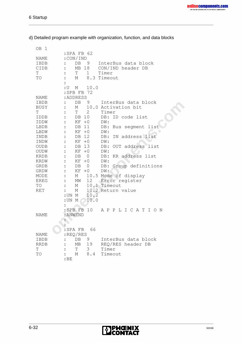
onlinec
omponen
ts.co
m
6 Startup
6-32 5003B
d) Detailed program example with organization, function, and data blocks
OB 1:SPA FB 62
NAME :CON/INDIBDB : DB 9 InterBus data blockCIDB : MB 18 CON/IND header DBT : T 1 TimerTO : M 8.3 Timeout
::U M 10.0:SPB FB 72
NAME :ADDRESSIBDB : DB 9 InterBus data blockBUSY : M 10.0 Activation bitT : T 2 TimerIDDB : DB 10 DB: ID code listIDDW : KF +0 DW:LBDB : DB 11 DB: Bus segment listLBDW : KF +0 DW:INDB : DB 12 DB: IN address listINDW : KF +0 DW:OUDB : DB 13 DB: OUT address listOUDW : KF +0 DW:KRDB : DB 0 DB: KR address listKRDW : KF +0 DW:GRDB : DB 0 DB: Group definitionsGRDW : KF +0 DW:MODE : M 10.5 Mode of displayEREG : MW 12 Error registerTO : M 10.1 TimeoutRET : M 10.2 Return value
:UN M 10.2:UN M 10.0::SPB FB 10 A P P L I C A T I O N
NAME :ANWEND:::SPA FB 66
NAME :REQ/RESIBDB : DB 9 InterBus data blockRRDB : MB 19 REQ/RES header DBT : T 3 TimerTO : M 8.4 Timeout
:BE
onlinec
omponen
ts.co
m
6 Startup
_______________________________________________5003B 6-33
e) Description of the function blocks FB 10 and/or FB 11 as example applications:
Both function blocks are exemplary for the application. FB 11 differs from FB 10 only in thefact that when a module error occurs it updates the front plate displays and the registers aswell as enters the list of the reported local bus segments. (This additional feature is markedin bold face in the example listing.)
Structure:The function of the block is divided into two areas.
1) Always activeThis area of the block is also run through when the INTERBUS-S system has stopped. In theexample error states such as RB and LB errors are acknowledged.Entry condition: None
2) Active, when IBS is OKThis area of the block is only run though when the INTERBUS-S system is in the RUN state.Entry condition: ADDRESS block has been completed BUSY = 0
RET = 0INTERBUS-S system is in the RUN stateDiagnostic bit register RUN = 1
Diagnostics:With the diagnostic register the application can recognize the current bus status andrespond to it.
Diagnostic registers of the example:- Diagnostic bit register IW 126- Diagnostic parameter register PW 128
Further functions:When a bus error occurs (RB-/LB error = STOP of the system), INTERBUS-S can be startedwith an input edge (Example: SIMATIC I 4.0) which activates the addressing block.
I 4.0 => BUSY ADDRESSa) No bus error has occurred.
- The front plate and the diagnostic registers are cleared.- The INTERBUS-S system is active.
b) A bus error has occurred.- The front plate and the diagnostic registers are updated.- The INTERBUS-S system is in the STOP state.- The outputs are reset (OUT = 0).
onlinec
omponen
ts.co
m
6 Startup
6-34 5003B
Supplement to FB11:When a module error occurs (peripheral voltage failure or a short circuit in a module;only for modules with bus acknowledgment), the display can be updated via an inputedge (Example: SIMATIC I 4.1).
I 4.1 => BUSY ADDRESS
a) No module error message is active- The front plate and the diagnostic registers are cleared
b) A module error message is active- The front plate and the diagnostic registers are updated- The list of the reported local bus segments is entered in a data block.
Structure of the list:
DB DW n KY = 000, PCDW n+1 KY = 000, BSDW n+2 KY = 000, BS...DW n+PC KY = 000, BS
Key:PC = Quantity of subsequent parametersDB = Data block of the messagen = First data word of the message
Parameter ExampleData block: DB DB 9First data word of the list: DW DW 200
onlinec
omponen
ts.co
m
6 Startup
_______________________________________________5003B 6-35
f) Detailed program example with organization, function, and data blocks
FB10 and/or FB 11 (supplement printed in bold face)
: ===== Always active =====:: ----- IBS acknowledgment -----: - RB error: - LB error::U E 4.0 Acknowledgment button RB/LB error:UN M 4.0 Edge trigger flag:UN E 127.5 RUN bit diagnostic register:S M 4.0:S M 10.0 BUSY bit of addressing:UN E 4.0:R M 4.0 ----------------------------:::O M 10.0 ADDRESS: BUSY bit:O M 10.2 RET bit:ON E 127.5 Diagnostic bit register: RUN bit:BEB: ===== Active when IBS OK =====::U E 4.1 Acknowledgment button MOD error:UN M 4.1 Edge trigger flag:S M 4.1:S M 50.0 BUSY bit of the ERRINFO:UN E 4.1:R M 4.1::L KB 200 Pointer: DW of the message:T MB 54:L KB 3 Function: module error:T MB 51:L KB 0 Parameter no.: none:T MB 52::U M 50.0:SPB FB 74
NAME :ERRINFOIBDB : DB 9 InterBus data blockT : T 2 Timer usedFKT : MB 51 Function no.NR : MB 52 Parameter no.DB : DB 9 DB of the messageDW : MB 54 First DW of the messageBUSY : M 50.0 Activation bitTO : M 50.1 Return valueRET : M 50.2 Timeout
:::::BE
onlinec
omponen
ts.co
m
6 Startup
6-36 5003B
DB10
Identification code list:The ID code address list includes the physical bus structure.The structure is described with the help of the ID numbers and their length codes. Themodules are counted starting from the controller board and through the entire bus structure.The list is completed with the special ID code entries .
In the example: ID 16 = Diagnostic bit register ID 17 = Diagnostic parameter register
Structure of the list:DB x
DW y KY= 000, PC Parameter countDW y+1 KY= LC , ID 1st moduleDW y+2 KY= LC , ID 2nd module... ... ...DW y+n-2 KY= LC , ID nth moduleDW y+n-1 KY= 000, SID Special ID codeDW y+n KY= 000, SID Special ID code
Key:PC = Quantity of the subsequent parameters (n)LC = Length code of the module (*)ID = Identification code of the module (*)SID = Special ID code (**)
(*) To be taken from the module description of the manufacturer(**) Permitted codes:ID: 16 = Diagnostic bit register
17 = Diagnostic parameter register18 = Bit-controlled command register19 = Bit manipulation register
DB100: KY = 000,015; Parameter count1: KY = 000,052; IBS 24 BK-T2: KY = 001,130; IBS 24 DI3: KY = 004,065; IBS AO 14: KY = 001,129; IBS 24 DO5: KY = 004,066; IBS PT 100 A/26: KY = 001,007; IBS IP DIO 1/247: KY = 000,012; IBS IP CBK 1/24 F8: KY = 129,010; IBS IP CDI 1/24 F9: KY = 129,009; IBS IP CDO 1/24 F10: KY = 129,010; IBS IP CDI 1/24 F11: KY = 001,011; IBS 24 BK-I/O-T12: KY = 002,142; IBS 24 DI 3213: KY = 004,071; IBS AI 314: KY = 000,016; Diagnostic bit register15: KY = 000,017; Diagnostic parameter regist.16:
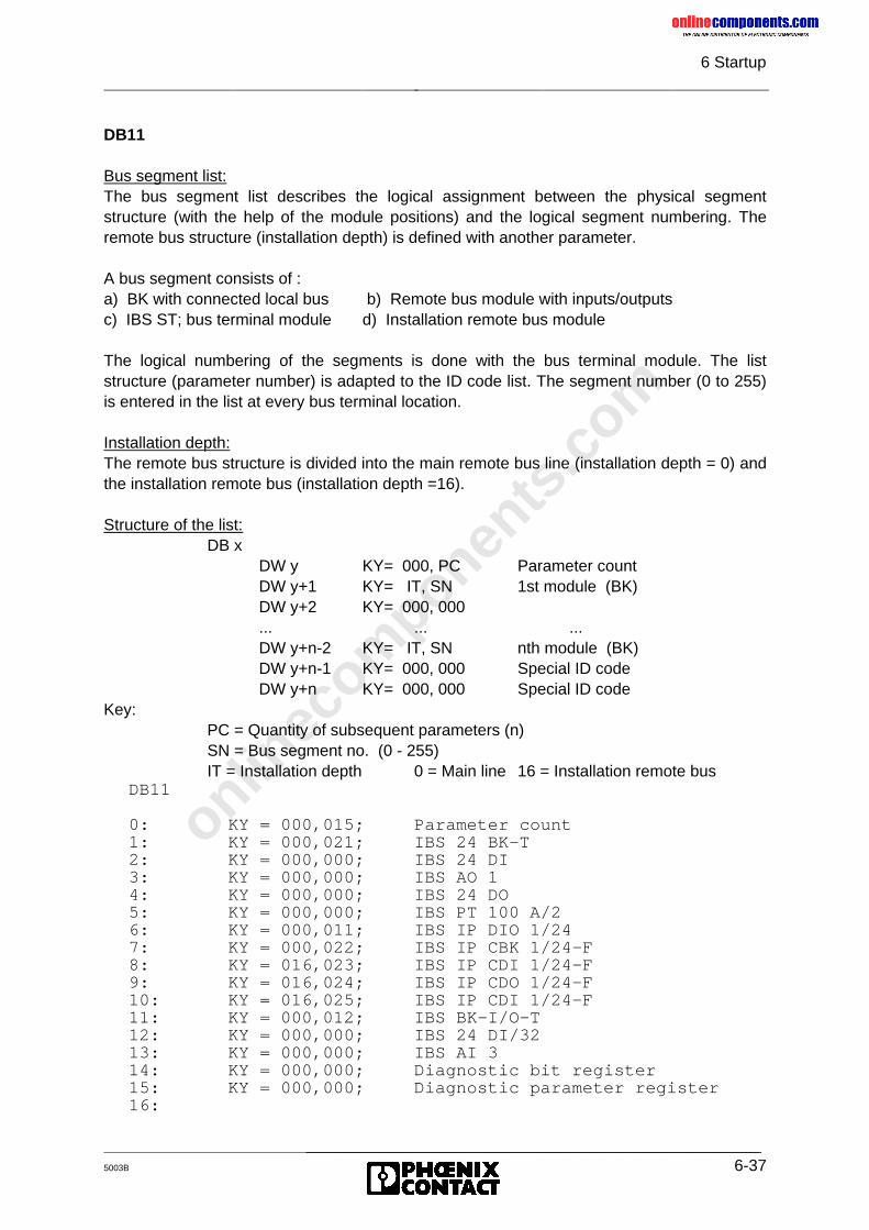
onlinec
omponen
ts.co
m
6 Startup
_______________________________________________5003B 6-37
DB11
Bus segment list:The bus segment list describes the logical assignment between the physical segmentstructure (with the help of the module positions) and the logical segment numbering. Theremote bus structure (installation depth) is defined with another parameter.
A bus segment consists of :a) BK with connected local bus b) Remote bus module with inputs/outputsc) IBS ST; bus terminal module d) Installation remote bus module
The logical numbering of the segments is done with the bus terminal module. The liststructure (parameter number) is adapted to the ID code list. The segment number (0 to 255)is entered in the list at every bus terminal location.
Installation depth:The remote bus structure is divided into the main remote bus line (installation depth = 0) andthe installation remote bus (installation depth =16).
Structure of the list:DB x
DW y KY= 000, PC Parameter countDW y+1 KY= IT, SN 1st module (BK)DW y+2 KY= 000, 000... ... ...DW y+n-2 KY= IT, SN nth module (BK)DW y+n-1 KY= 000, 000 Special ID codeDW y+n KY= 000, 000 Special ID code
Key:PC = Quantity of subsequent parameters (n)SN = Bus segment no. (0 - 255)IT = Installation depth 0 = Main line 16 = Installation remote bus
DB11
0: KY = 000,015; Parameter count1: KY = 000,021; IBS 24 BK-T2: KY = 000,000; IBS 24 DI3: KY = 000,000; IBS AO 14: KY = 000,000; IBS 24 DO5: KY = 000,000; IBS PT 100 A/26: KY = 000,011; IBS IP DIO 1/247: KY = 000,022; IBS IP CBK 1/24-F8: KY = 016,023; IBS IP CDI 1/24-F9: KY = 016,024; IBS IP CDO 1/24-F10: KY = 016,025; IBS IP CDI 1/24-F11: KY = 000,012; IBS BK-I/O-T12: KY = 000,000; IBS 24 DI/3213: KY = 000,000; IBS AI 314: KY = 000,000; Diagnostic bit register15: KY = 000,000; Diagnostic parameter register16:
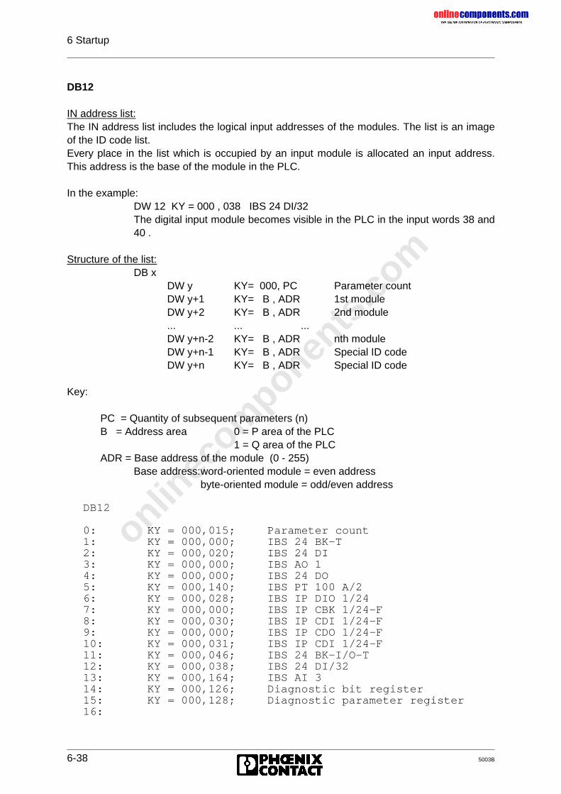
onlinec
omponen
ts.co
m
6 Startup
6-38 5003B
DB12
IN address list:The IN address list includes the logical input addresses of the modules. The list is an imageof the ID code list.Every place in the list which is occupied by an input module is allocated an input address.This address is the base of the module in the PLC.
In the example:DW 12 KY = 000 , 038 IBS 24 DI/32The digital input module becomes visible in the PLC in the input words 38 and40 .
Structure of the list:DB x
DW y KY= 000, PC Parameter countDW y+1 KY= B , ADR 1st moduleDW y+2 KY= B , ADR 2nd module... ... ...DW y+n-2 KY= B , ADR nth moduleDW y+n-1 KY= B , ADR Special ID codeDW y+n KY= B , ADR Special ID code
Key:
PC = Quantity of subsequent parameters (n)B = Address area 0 = P area of the PLC
1 = Q area of the PLCADR = Base address of the module (0 - 255)
Base address:word-oriented module = even addressbyte-oriented module = odd/even address
DB12
0: KY = 000,015; Parameter count1: KY = 000,000; IBS 24 BK-T2: KY = 000,020; IBS 24 DI3: KY = 000,000; IBS AO 14: KY = 000,000; IBS 24 DO5: KY = 000,140; IBS PT 100 A/26: KY = 000,028; IBS IP DIO 1/247: KY = 000,000; IBS IP CBK 1/24-F8: KY = 000,030; IBS IP CDI 1/24-F9: KY = 000,000; IBS IP CDO 1/24-F10: KY = 000,031; IBS IP CDI 1/24-F11: KY = 000,046; IBS 24 BK-I/O-T12: KY = 000,038; IBS 24 DI/3213: KY = 000,164; IBS AI 314: KY = 000,126; Diagnostic bit register15: KY = 000,128; Diagnostic parameter register16:
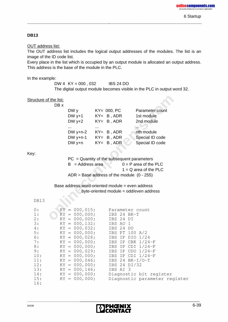
onlinec
omponen
ts.co
m
6 Startup
_______________________________________________5003B 6-39
DB13
OUT address list:The OUT address list includes the logical output addresses of the modules. The list is animage of the ID code list.Every place in the list which is occupied by an output module is allocated an output address.This address is the base of the module in the PLC.
In the example:DW 4 KY = 000 , 032 IBS 24 DOThe digital output module becomes visible in the PLC in output word 32.
Structure of the list:DB x
DW y KY= 000, PC Parameter countDW y+1 KY= B , ADR 1st moduleDW y+2 KY= B , ADR 2nd module... ... ...DW y+n-2 KY= B , ADR nth moduleDW y+n-1 KY= B , ADR Special ID codeDW y+n KY= B , ADR Special ID code
Key:PC = Quantity of the subsequent parametersB = Address area 0 = P area of the PLC
1 = Q area of the PLCADR = Base address of the module (0 - 255)
Base address:word-oriented module = even addressbyte-oriented module = odd/even address
DB13
0: KY = 000,015; Parameter count1: KY = 000,000; IBS 24 BK-T2: KY = 000,000; IBS 24 DI3: KY = 000,132; IBS AO 14: KY = 000,032; IBS 24 DO5: KY = 000,000; IBS PT 100 A/26: KY = 000,028; IBS IP DIO 1/247: KY = 000,000; IBS IP CBK 1/24-F8: KY = 000,000; IBS IP CDI 1/24-F9: KY = 000,029; IBS IP CDO 1/24-F10: KY = 000,000; IBS IP CDI 1/24-F11: KY = 000,046; IBS 24 BK-I/O-T12: KY = 000,000; IBS 24 DI/3213: KY = 000,146; IBS AI 314: KY = 000,000; Diagnostic bit register15: KY = 000,000; Diagnostic parameter register16:

onlinec
omponen
ts.co
m
6 Startup
6-40 5003B
The DCBCP example is given on the next page in order to avoid having to turn over betweenthe pages "Bus topology...." and "Software setting..."
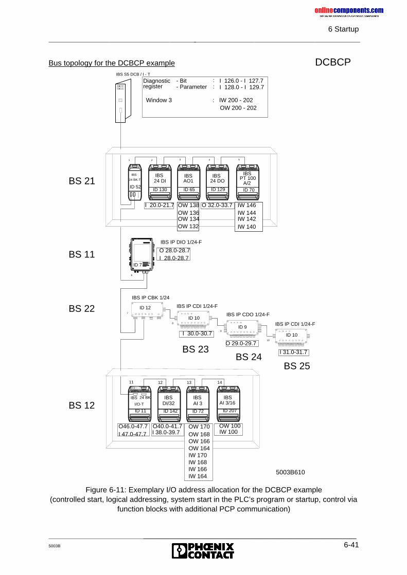
onlinec
omponen
ts.co
m
6 Startup
_______________________________________________5003B 6-41
Bus topology for the DCBCP example DCBCP
Figure 6-11: Exemplary I/O address allocation for the DCBCP example(controlled start, logical addressing, system start in the PLC’s program or startup, control via
function blocks with additional PCP communication)
IBS S5 DCB / I - T
11
7
8
9
10
6
ID 7
1 2 3 4 5
24 DI 24 DOAO1 PT 100A/2
IBS IBS IBS IBS
IBS IBSDI/32 AI 3
IBS
24 BK-T
IBS
I/O-T
IBS IP CBK 1/24
IBS IP CDI 1/24-F
IBS IP CDO 1/24-F
IBS IP CDI 1/24-F
IBS IP DIO 1/24-F
12 13
Diagnosticregister
- Bit- Parameter
::
I 126.0 - I 127.7I 128.0 - I 129.7
24 BK
I 20.0-21.7 O 32.0-33.7
O 28.0-28.7I 28.0-28.7
I 30.0-30.7
O 29.0-29.7
I 31.0-31.7
O46.0-47.7I 47.0-47.7
O40.0-41.7 OW 170OW 168OW 166OW 164IW 170IW 168IW 166IW 164
Window 3 : IW 200 - 202OW 200 - 202
BS 21ID 52
ID 130 ID 65 ID 129 ID 70
OW 138OW 136OW 134OW 132
IW 146IW 144IW 142IW 140
ID 7
BS 11
BS 22
BS 12
ID 12
ID 10
ID 9
ID 10
BS 23BS 24
BS 25
ID 11 ID 142 ID 72
I 38.0-39.7
IBSAI 3/16
14
OW 100
ID 207
IW 100
5003B610
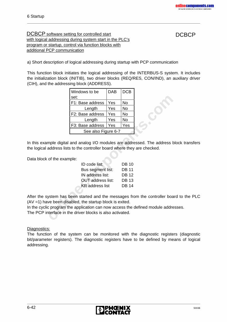
onlinec
omponen
ts.co
m
6 Startup
6-42 5003B
DCBCP
a) Short description of logical addressing during startup with PCP communication
This function block initiates the logical addressing of the INTERBUS-S system. It includesthe initialization block (INITIB), two driver blocks (REQ/RES, CON/IND), an auxiliary driver(CIH), and the addressing block (ADDRESS).
In this example digital and analog I/O modules are addressed. The address block transfersthe logical address lists to the controller board where they are checked.
Data block of the example:ID code list: DB 10Bus segment list: DB 11IN address list: DB 12OUT address list: DB 13KR address list DB 14
After the system has been started and the messages from the controller board to the PLC(AV =1) have been disabled, the startup block is exited.In the cyclic program the application can now access the defined module addresses.The PCP interface in the driver blocks is also activated.
Diagnostics:The function of the system can be monitored with the diagnostic registers (diagnosticbit/parameter registers). The diagnostic registers have to be defined by means of logicaladdressing.
DCBCP software setting for controlled startwith logical addressing during system start in the PLC’sprogram or startup, control via function blocks withadditional PCP communication
Windows to beset:
DAB DCB
F1: Base address Yes NoLength Yes No
F2: Base address Yes NoLength Yes No
F3: Base address Yes YesSee also Figure 6-7
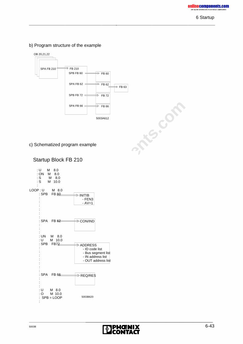
onlinec
omponen
ts.co
m
6 Startup
_______________________________________________5003B 6-43
c) Schematized program example
b) Program structure of the example
OB 20,21,22
SPA FB 210 FB 210
5003A612
SPA FB 62 FB 62
SPB FB 72 FB 72
SPA FB 66 FB 66
SPB FB 60 FB 60
FB 63
5003B620
CON/IND
ADDRESS - ID code list - Bus segment list - IN address list - OUT address list
REQ/RES
INITIB - FEN3 - AV=1
Startup Block FB 210
: U M 8.0: ON M 8.0: S M 8.0: S M 10.0:
LOOP : U M 8.0 : SPB FB 60 : : : : : : : SPA FB 62 : : : : UN M 8.0 : U M 10.0 : SPB FB72 : : : : : : : : SPA FB 66 : : : : U M 8.0 : O M 10.0 : SPB = LOOP :
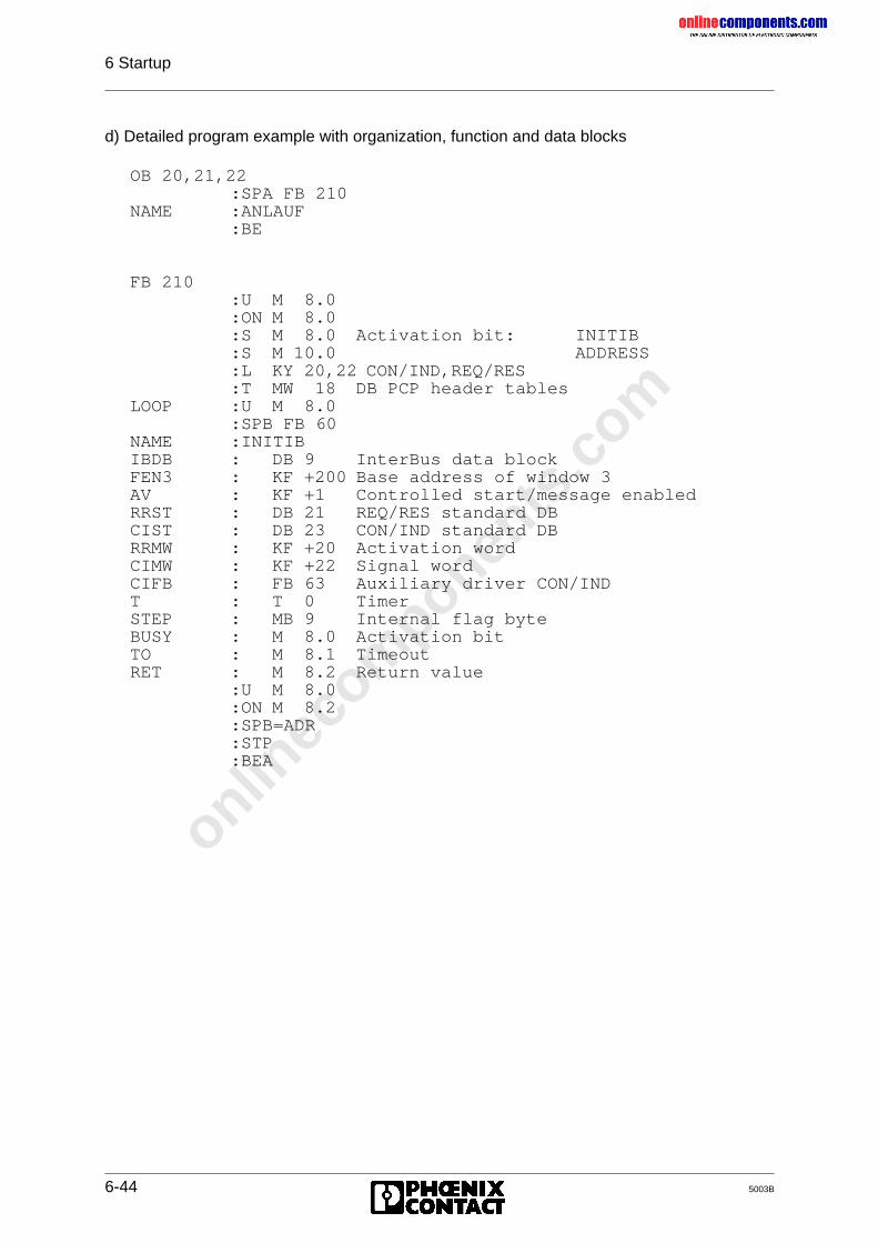
onlinec
omponen
ts.co
m
6 Startup
6-44 5003B
d) Detailed program example with organization, function and data blocks
OB 20,21,22:SPA FB 210
NAME :ANLAUF:BE
FB 210:U M 8.0:ON M 8.0:S M 8.0 Activation bit: INITIB:S M 10.0 ADDRESS:L KY 20,22 CON/IND,REQ/RES:T MW 18 DB PCP header tables
LOOP :U M 8.0:SPB FB 60
NAME :INITIBIBDB : DB 9 InterBus data blockFEN3 : KF +200 Base address of window 3AV : KF +1 Controlled start/message enabledRRST : DB 21 REQ/RES standard DBCIST : DB 23 CON/IND standard DBRRMW : KF +20 Activation wordCIMW : KF +22 Signal wordCIFB : FB 63 Auxiliary driver CON/INDT : T 0 TimerSTEP : MB 9 Internal flag byteBUSY : M 8.0 Activation bitTO : M 8.1 TimeoutRET : M 8.2 Return value
:U M 8.0:ON M 8.2:SPB=ADR:STP:BEA
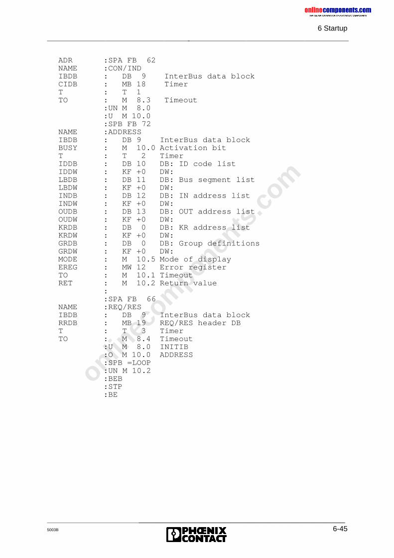
onlinec
omponen
ts.co
m
6 Startup
_______________________________________________5003B 6-45
ADR :SPA FB 62NAME :CON/INDIBDB : DB 9 InterBus data blockCIDB : MB 18 TimerT : T 1TO : M 8.3 Timeout
:UN M 8.0:U M 10.0:SPB FB 72
NAME :ADDRESSIBDB : DB 9 InterBus data blockBUSY : M 10.0 Activation bitT : T 2 TimerIDDB : DB 10 DB: ID code listIDDW : KF +0 DW:LBDB : DB 11 DB: Bus segment listLBDW : KF +0 DW:INDB : DB 12 DB: IN address listINDW : KF +0 DW:OUDB : DB 13 DB: OUT address listOUDW : KF +0 DW:KRDB : DB 0 DB: KR address listKRDW : KF +0 DW:GRDB : DB 0 DB: Group definitionsGRDW : KF +0 DW:MODE : M 10.5 Mode of displayEREG : MW 12 Error registerTO : M 10.1 TimeoutRET : M 10.2 Return value
::SPA FB 66
NAME :REQ/RESIBDB : DB 9 InterBus data blockRRDB : MB 19 REQ/RES header DBT : T 3 TimerTO : M 8.4 Timeout
:U M 8.0 INITIB:O M 10.0 ADDRESS:SPB =LOOP:UN M 10.2:BEB:STP:BE
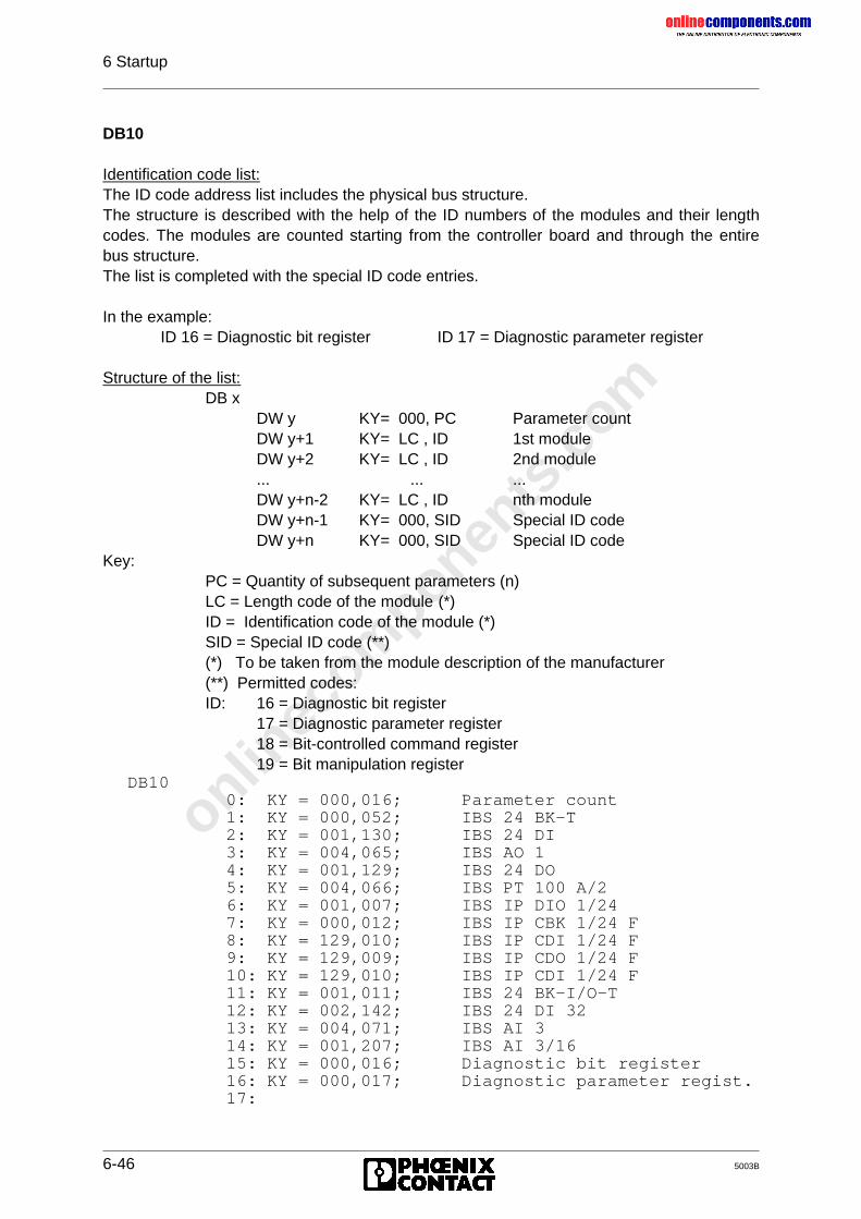
onlinec
omponen
ts.co
m
6 Startup
6-46 5003B
DB10
Identification code list:The ID code address list includes the physical bus structure.The structure is described with the help of the ID numbers of the modules and their lengthcodes. The modules are counted starting from the controller board and through the entirebus structure.The list is completed with the special ID code entries.
In the example: ID 16 = Diagnostic bit register ID 17 = Diagnostic parameter register
Structure of the list:DB x
DW y KY= 000, PC Parameter countDW y+1 KY= LC , ID 1st moduleDW y+2 KY= LC , ID 2nd module... ... ...DW y+n-2 KY= LC , ID nth moduleDW y+n-1 KY= 000, SID Special ID codeDW y+n KY= 000, SID Special ID code
Key:PC = Quantity of subsequent parameters (n)LC = Length code of the module (*)ID = Identification code of the module (*)SID = Special ID code (**)(*) To be taken from the module description of the manufacturer(**) Permitted codes:ID: 16 = Diagnostic bit register
17 = Diagnostic parameter register18 = Bit-controlled command register19 = Bit manipulation register
DB100: KY = 000,016; Parameter count1: KY = 000,052; IBS 24 BK-T2: KY = 001,130; IBS 24 DI3: KY = 004,065; IBS AO 14: KY = 001,129; IBS 24 DO5: KY = 004,066; IBS PT 100 A/26: KY = 001,007; IBS IP DIO 1/247: KY = 000,012; IBS IP CBK 1/24 F8: KY = 129,010; IBS IP CDI 1/24 F9: KY = 129,009; IBS IP CDO 1/24 F10: KY = 129,010; IBS IP CDI 1/24 F11: KY = 001,011; IBS 24 BK-I/O-T12: KY = 002,142; IBS 24 DI 3213: KY = 004,071; IBS AI 314: KY = 001,207; IBS AI 3/1615: KY = 000,016; Diagnostic bit register16: KY = 000,017; Diagnostic parameter regist.17:
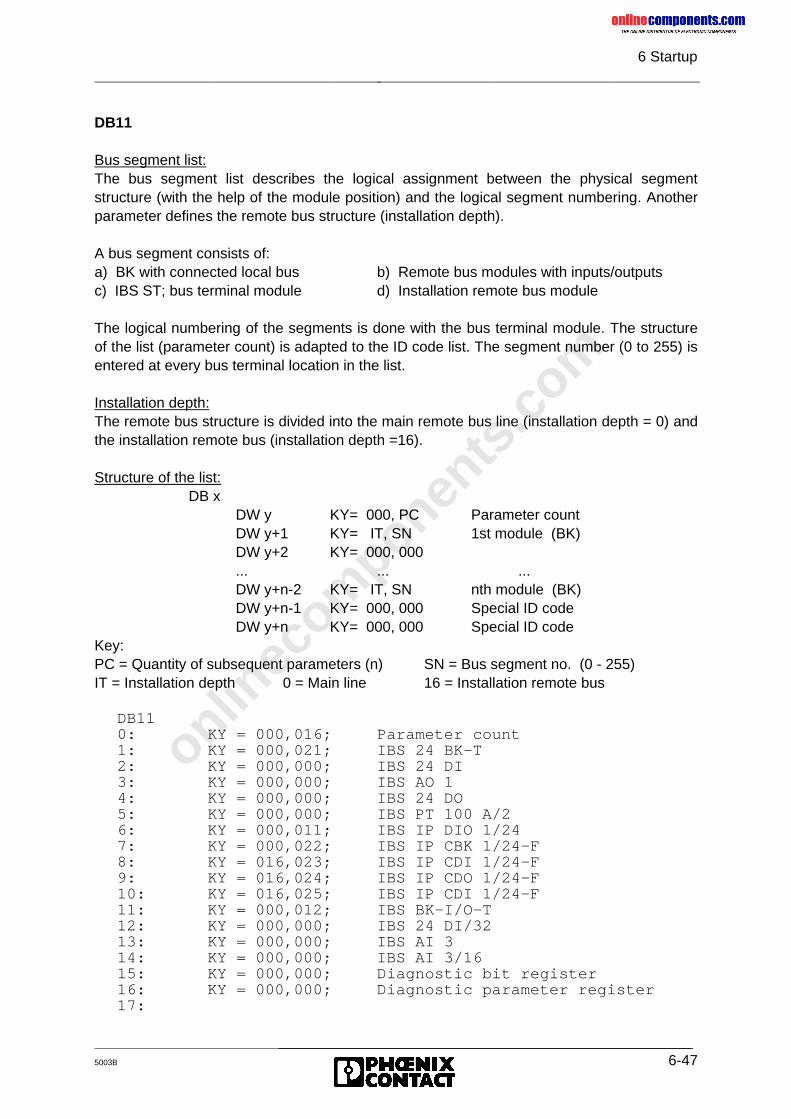
onlinec
omponen
ts.co
m
6 Startup
_______________________________________________5003B 6-47
DB11
Bus segment list:The bus segment list describes the logical assignment between the physical segmentstructure (with the help of the module position) and the logical segment numbering. Anotherparameter defines the remote bus structure (installation depth).
A bus segment consists of:a) BK with connected local bus b) Remote bus modules with inputs/outputsc) IBS ST; bus terminal module d) Installation remote bus module
The logical numbering of the segments is done with the bus terminal module. The structureof the list (parameter count) is adapted to the ID code list. The segment number (0 to 255) isentered at every bus terminal location in the list.
Installation depth:The remote bus structure is divided into the main remote bus line (installation depth = 0) andthe installation remote bus (installation depth =16).
Structure of the list:DB x
DW y KY= 000, PC Parameter countDW y+1 KY= IT, SN 1st module (BK)DW y+2 KY= 000, 000... ... ...DW y+n-2 KY= IT, SN nth module (BK)DW y+n-1 KY= 000, 000 Special ID codeDW y+n KY= 000, 000 Special ID code
Key:PC = Quantity of subsequent parameters (n) SN = Bus segment no. (0 - 255)IT = Installation depth 0 = Main line 16 = Installation remote bus
DB110: KY = 000,016; Parameter count1: KY = 000,021; IBS 24 BK-T2: KY = 000,000; IBS 24 DI3: KY = 000,000; IBS AO 14: KY = 000,000; IBS 24 DO5: KY = 000,000; IBS PT 100 A/26: KY = 000,011; IBS IP DIO 1/247: KY = 000,022; IBS IP CBK 1/24-F8: KY = 016,023; IBS IP CDI 1/24-F9: KY = 016,024; IBS IP CDO 1/24-F10: KY = 016,025; IBS IP CDI 1/24-F11: KY = 000,012; IBS BK-I/O-T12: KY = 000,000; IBS 24 DI/3213: KY = 000,000; IBS AI 314: KY = 000,000; IBS AI 3/1615: KY = 000,000; Diagnostic bit register16: KY = 000,000; Diagnostic parameter register17:
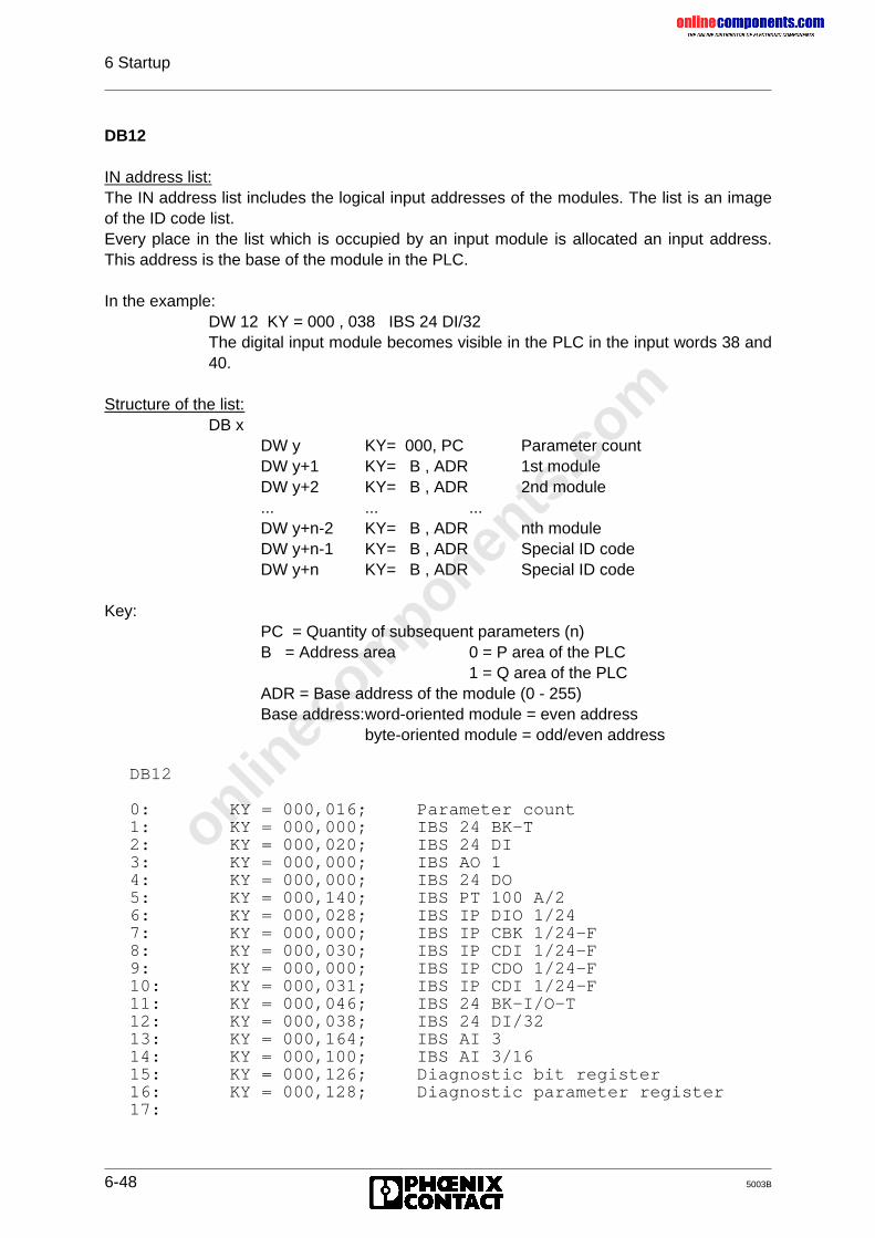
onlinec
omponen
ts.co
m
6 Startup
6-48 5003B
DB12
IN address list:The IN address list includes the logical input addresses of the modules. The list is an imageof the ID code list.Every place in the list which is occupied by an input module is allocated an input address.This address is the base of the module in the PLC.
In the example:DW 12 KY = 000 , 038 IBS 24 DI/32The digital input module becomes visible in the PLC in the input words 38 and
40.
Structure of the list:DB x
DW y KY= 000, PC Parameter countDW y+1 KY= B , ADR 1st moduleDW y+2 KY= B , ADR 2nd module... ... ...DW y+n-2 KY= B , ADR nth moduleDW y+n-1 KY= B , ADR Special ID codeDW y+n KY= B , ADR Special ID code
Key:PC = Quantity of subsequent parameters (n)B = Address area 0 = P area of the PLC
1 = Q area of the PLCADR = Base address of the module (0 - 255)Base address:word-oriented module = even address
byte-oriented module = odd/even address
DB12
0: KY = 000,016; Parameter count1: KY = 000,000; IBS 24 BK-T2: KY = 000,020; IBS 24 DI3: KY = 000,000; IBS AO 14: KY = 000,000; IBS 24 DO5: KY = 000,140; IBS PT 100 A/26: KY = 000,028; IBS IP DIO 1/247: KY = 000,000; IBS IP CBK 1/24-F8: KY = 000,030; IBS IP CDI 1/24-F9: KY = 000,000; IBS IP CDO 1/24-F10: KY = 000,031; IBS IP CDI 1/24-F11: KY = 000,046; IBS 24 BK-I/O-T12: KY = 000,038; IBS 24 DI/3213: KY = 000,164; IBS AI 314: KY = 000,100; IBS AI 3/1615: KY = 000,126; Diagnostic bit register16: KY = 000,128; Diagnostic parameter register17:
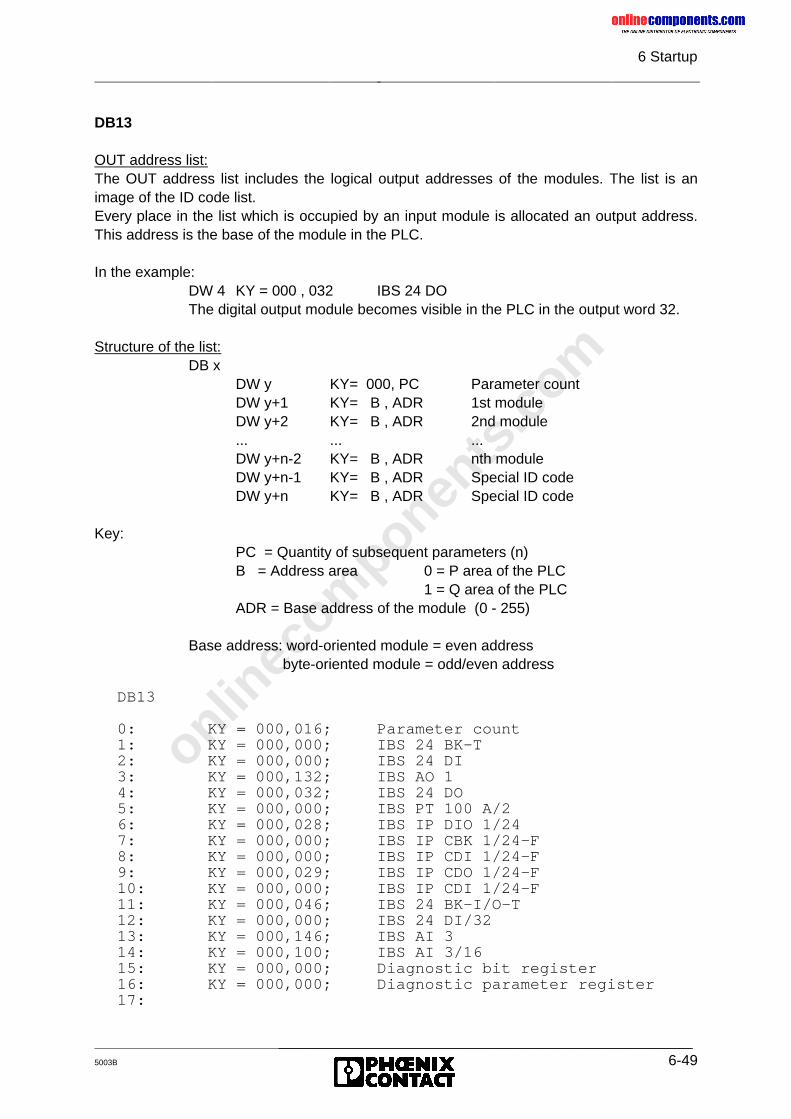
onlinec
omponen
ts.co
m
6 Startup
_______________________________________________5003B 6-49
DB13
OUT address list:The OUT address list includes the logical output addresses of the modules. The list is animage of the ID code list.Every place in the list which is occupied by an input module is allocated an output address.This address is the base of the module in the PLC.
In the example:DW 4 KY = 000 , 032 IBS 24 DOThe digital output module becomes visible in the PLC in the output word 32.
Structure of the list:DB x
DW y KY= 000, PC Parameter countDW y+1 KY= B , ADR 1st moduleDW y+2 KY= B , ADR 2nd module... ... ...DW y+n-2 KY= B , ADR nth moduleDW y+n-1 KY= B , ADR Special ID codeDW y+n KY= B , ADR Special ID code
Key:PC = Quantity of subsequent parameters (n)B = Address area 0 = P area of the PLC
1 = Q area of the PLCADR = Base address of the module (0 - 255)
Base address: word-oriented module = even addressbyte-oriented module = odd/even address
DB13
0: KY = 000,016; Parameter count1: KY = 000,000; IBS 24 BK-T2: KY = 000,000; IBS 24 DI3: KY = 000,132; IBS AO 14: KY = 000,032; IBS 24 DO5: KY = 000,000; IBS PT 100 A/26: KY = 000,028; IBS IP DIO 1/247: KY = 000,000; IBS IP CBK 1/24-F8: KY = 000,000; IBS IP CDI 1/24-F9: KY = 000,029; IBS IP CDO 1/24-F10: KY = 000,000; IBS IP CDI 1/24-F11: KY = 000,046; IBS 24 BK-I/O-T12: KY = 000,000; IBS 24 DI/3213: KY = 000,146; IBS AI 314: KY = 000,100; IBS AI 3/1615: KY = 000,000; Diagnostic bit register16: KY = 000,000; Diagnostic parameter register17:
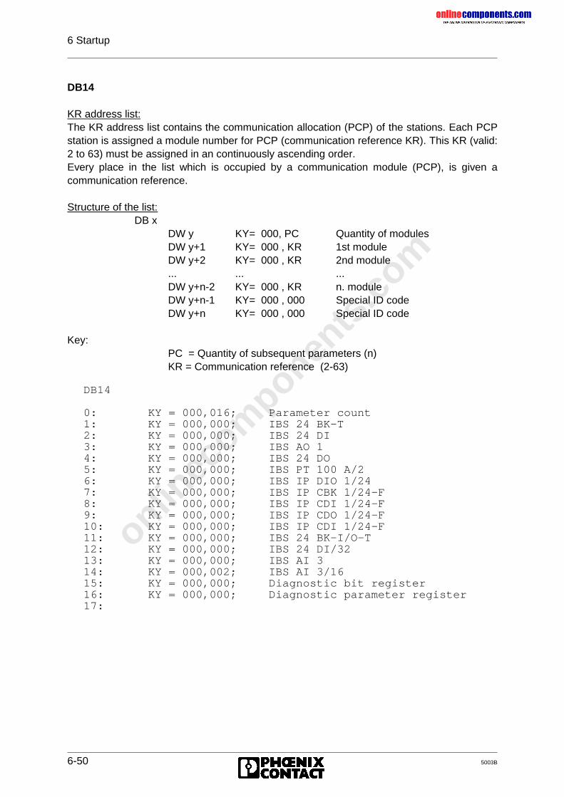
onlinec
omponen
ts.co
m
6 Startup
6-50 5003B
DB14
KR address list:The KR address list contains the communication allocation (PCP) of the stations. Each PCPstation is assigned a module number for PCP (communication reference KR). This KR (valid:2 to 63) must be assigned in an continuously ascending order.Every place in the list which is occupied by a communication module (PCP), is given acommunication reference.
Structure of the list:DB x
DW y KY= 000, PC Quantity of modulesDW y+1 KY= 000 , KR 1st moduleDW y+2 KY= 000 , KR 2nd module... ... ...DW y+n-2 KY= 000 , KR n. moduleDW y+n-1 KY= 000 , 000 Special ID codeDW y+n KY= 000 , 000 Special ID code
Key:PC = Quantity of subsequent parameters (n)KR = Communication reference (2-63)
DB14
0: KY = 000,016; Parameter count1: KY = 000,000; IBS 24 BK-T2: KY = 000,000; IBS 24 DI3: KY = 000,000; IBS AO 14: KY = 000,000; IBS 24 DO5: KY = 000,000; IBS PT 100 A/26: KY = 000,000; IBS IP DIO 1/247: KY = 000,000; IBS IP CBK 1/24-F8: KY = 000,000; IBS IP CDI 1/24-F9: KY = 000,000; IBS IP CDO 1/24-F10: KY = 000,000; IBS IP CDI 1/24-F11: KY = 000,000; IBS 24 BK-I/O-T12: KY = 000,000; IBS 24 DI/3213: KY = 000,000; IBS AI 314: KY = 000,002; IBS AI 3/1615: KY = 000,000; Diagnostic bit register16: KY = 000,000; Diagnostic parameter register17:
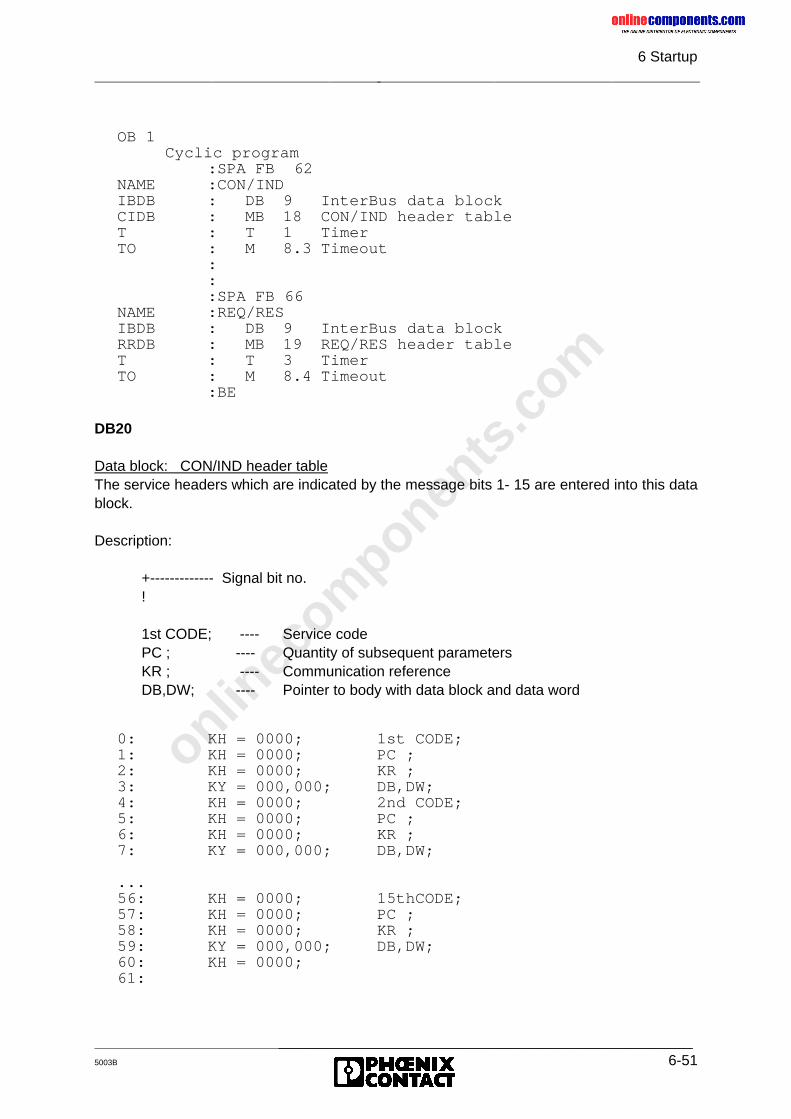
onlinec
omponen
ts.co
m
6 Startup
_______________________________________________5003B 6-51
OB 1 Cyclic program
:SPA FB 62NAME :CON/INDIBDB : DB 9 InterBus data blockCIDB : MB 18 CON/IND header tableT : T 1 TimerTO : M 8.3 Timeout
:::SPA FB 66
NAME :REQ/RESIBDB : DB 9 InterBus data blockRRDB : MB 19 REQ/RES header tableT : T 3 TimerTO : M 8.4 Timeout
:BE
DB20
Data block: CON/IND header tableThe service headers which are indicated by the message bits 1- 15 are entered into this datablock.
Description:
+------------- Signal bit no.!
1st CODE; ---- Service codePC ; ---- Quantity of subsequent parametersKR ; ---- Communication referenceDB,DW; ---- Pointer to body with data block and data word
0: KH = 0000; 1st CODE;1: KH = 0000; PC ;2: KH = 0000; KR ;3: KY = 000,000; DB,DW;4: KH = 0000; 2nd CODE;5: KH = 0000; PC ;6: KH = 0000; KR ;7: KY = 000,000; DB,DW;
...56: KH = 0000; 15thCODE;57: KH = 0000; PC ;58: KH = 0000; KR ;59: KY = 000,000; DB,DW;60: KH = 0000;61:
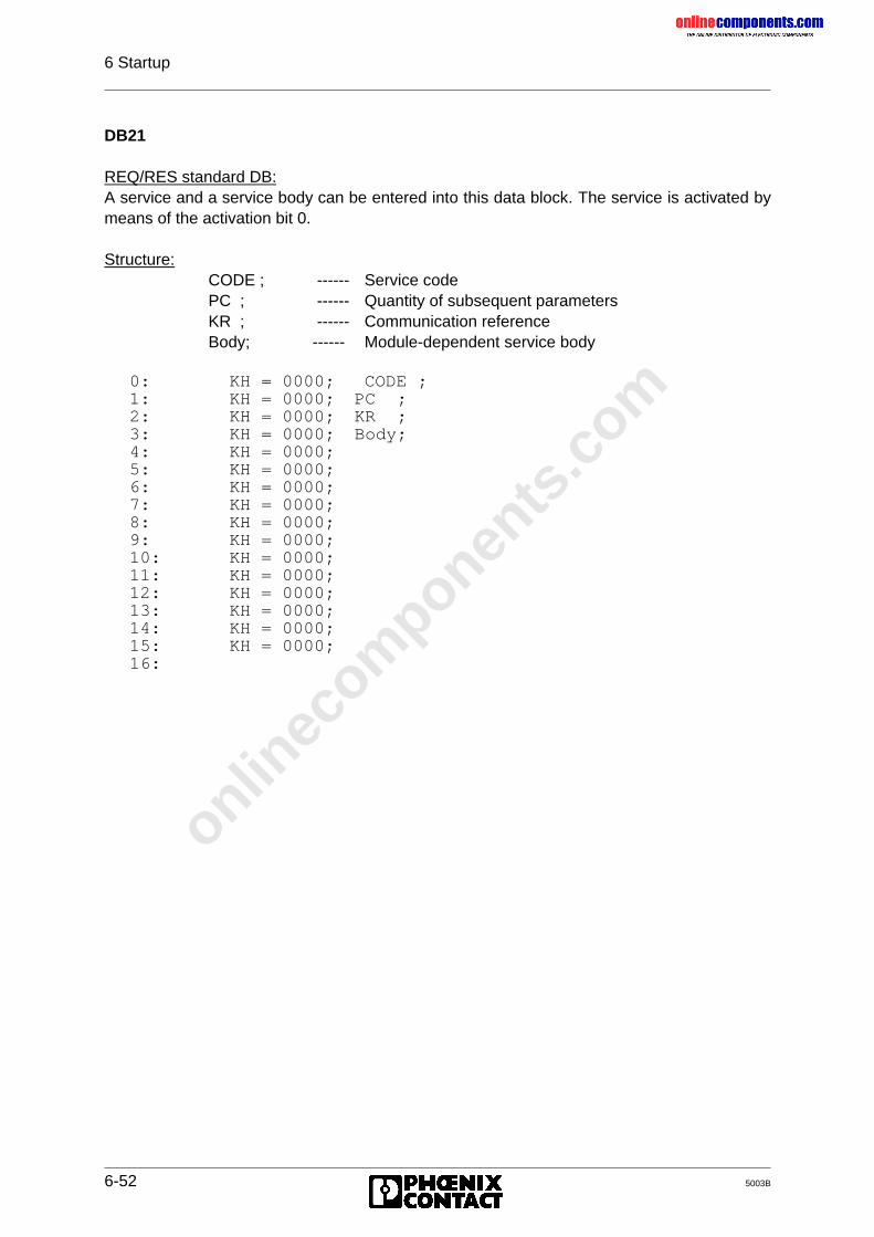
onlinec
omponen
ts.co
m
6 Startup
6-52 5003B
DB21
REQ/RES standard DB:A service and a service body can be entered into this data block. The service is activated bymeans of the activation bit 0.
Structure:CODE ; ------ Service codePC ; ------ Quantity of subsequent parametersKR ; ------ Communication referenceBody; ------ Module-dependent service body
0: KH = 0000; CODE ;1: KH = 0000; PC ;2: KH = 0000; KR ;3: KH = 0000; Body;4: KH = 0000;5: KH = 0000;6: KH = 0000;7: KH = 0000;8: KH = 0000;9: KH = 0000;10: KH = 0000;11: KH = 0000;12: KH = 0000;13: KH = 0000;14: KH = 0000;15: KH = 0000;16:
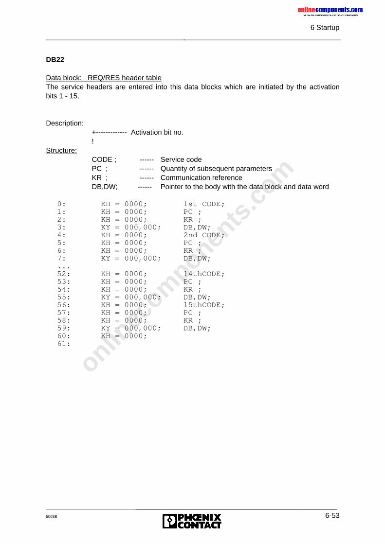
onlinec
omponen
ts.co
m
6 Startup
_______________________________________________5003B 6-53
DB22
Data block: REQ/RES header tableThe service headers are entered into this data blocks which are initiated by the activationbits 1 - 15.
Description: +------------- Activation bit no. !Structure:
CODE ; ------ Service codePC ; ------ Quantity of subsequent parametersKR ; ------ Communication referenceDB,DW; ------ Pointer to the body with the data block and data word
0: KH = 0000; 1st CODE;1: KH = 0000; PC ;2: KH = 0000; KR ;3: KY = 000,000; DB,DW;4: KH = 0000; 2nd CODE;5: KH = 0000; PC ;6: KH = 0000; KR ;7: KY = 000,000; DB,DW;...52: KH = 0000; 14thCODE;53: KH = 0000; PC ;54: KH = 0000; KR ;55: KY = 000,000; DB,DW;56: KH = 0000; 15thCODE;57: KH = 0000; PC ;58: KH = 0000; KR ;59: KY = 000,000; DB,DW;60: KH = 0000;61:
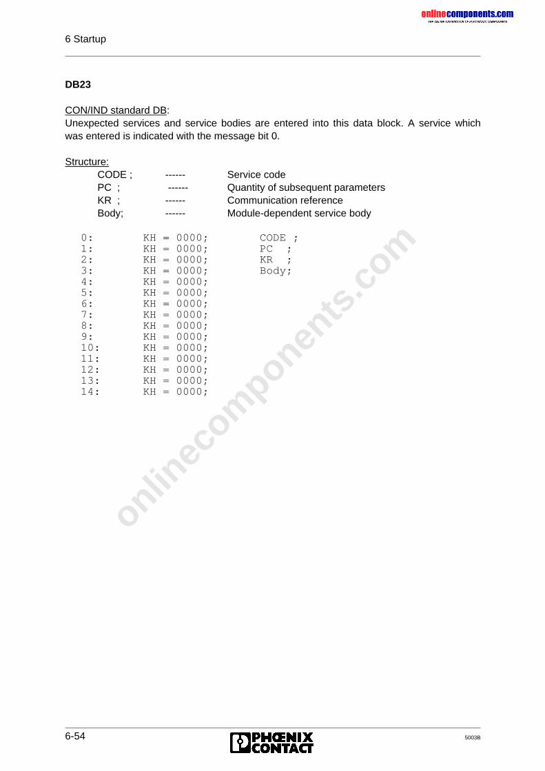
onlinec
omponen
ts.co
m
6 Startup
6-54 5003B
DB23
CON/IND standard DB:Unexpected services and service bodies are entered into this data block. A service whichwas entered is indicated with the message bit 0.
Structure:CODE ; ------ Service codePC ; ------ Quantity of subsequent parametersKR ; ------ Communication referenceBody; ------ Module-dependent service body
0: KH = 0000; CODE ;1: KH = 0000; PC ;2: KH = 0000; KR ;3: KH = 0000; Body;4: KH = 0000;5: KH = 0000;6: KH = 0000;7: KH = 0000;8: KH = 0000;9: KH = 0000;10: KH = 0000;11: KH = 0000;12: KH = 0000;13: KH = 0000;14: KH = 0000;
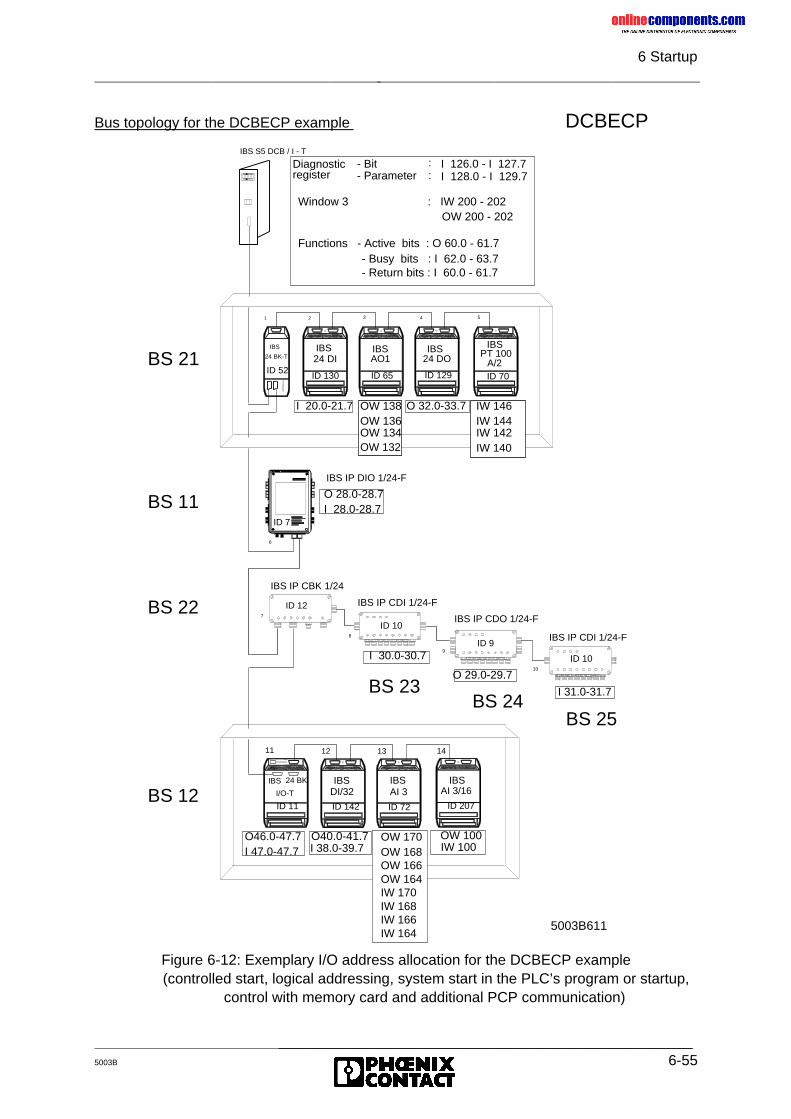
onlinec
omponen
ts.co
m
6 Startup
_______________________________________________5003B 6-55
Bus topology for the DCBECP example DCBECP
Figure 6-12: Exemplary I/O address allocation for the DCBECP example (controlled start, logical addressing, system start in the PLC’s program or startup,
control with memory card and additional PCP communication)
IBS S5 DCB / I - T
11
7
8
9
10
6
ID 7
1 2 3 4 5
24 DI 24 DOAO1 PT 100A/2
IBS IBS IBS IBS
IBS IBSDI/32 AI 3
IBS
24 BK-T
IBS
I/O-T
IBS IP CBK 1/24
IBS IP CDI 1/24-F
IBS IP CDO 1/24-F
IBS IP CDI 1/24-F
IBS IP DIO 1/24-F
12 13
Diagnosticregister
- Bit- Parameter
::
I 126.0 - I 127.7I 128.0 - I 129.7
24 BK
I 20.0-21.7 O 32.0-33.7
O 28.0-28.7I 28.0-28.7
I 30.0-30.7
O 29.0-29.7
I 31.0-31.7
O46.0-47.7I 47.0-47.7
O40.0-41.7 OW 170OW 168OW 166OW 164IW 170IW 168IW 166IW 164
Window 3 : IW 200 - 202OW 200 - 202
BS 21ID 52
ID 130 ID 65 ID 129 ID 70
OW 138OW 136OW 134OW 132
IW 146IW 144IW 142IW 140
ID 7
BS 11
BS 22
BS 12
ID 12
ID 10
ID 9
ID 10
BS 23BS 24
BS 25
ID 11 ID 142 ID 72
I 38.0-39.7
Functions - Active bits : O 60.0 - 61.7 - Busy bits : I 62.0 - 63.7 - Return bits : I 60.0 - 61.7
IBSAI 3/16
14
OW 100
ID 207
IW 100
5003B611
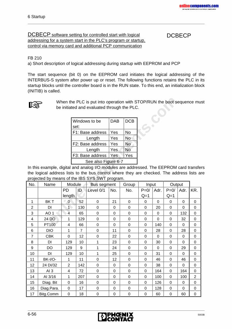
onlinec
omponen
ts.co
m
6 Startup
6-56 5003B
DCBECP
FB 210a) Short description of logical addressing during startup with EEPROM and PCP
The start sequence (bit 0) on the EEPROM card initiates the logical addressing of theINTERBUS-S system after power up or reset. The following functions retains the PLC in itsstartup blocks until the controller board is in the RUN state. To this end, an initialization block(INITIB) is called.
In this example, digital and analog I/O modules are addressed. The EEPROM card transfersthe logical address lists to the bus control where they are checked. The address lists areprojected by means of the IBS SYS SWT program.No. Name Module Bus segment Group Input Output
PDlength
ID Level 0/1 No. No. P=0/Q=1
Adr. P=0/Q=1
Adr. KR.
1 BK T 0 52 0 21 0 0 0 0 0 0
2 DI 1 130 0 0 0 0 20 0 0 0
3 AO 1 4 65 0 0 0 0 0 0 132 0
4 24 DO 1 129 0 0 0 0 0 0 32 0
5 PT100 4 66 0 0 0 0 140 0 0 0
6 DIO 1 7 0 11 0 0 28 0 28 0
7 CBK 0 12 0 22 0 0 0 0 0 0
8 DI 129 10 1 23 0 0 30 0 0 0
9 DO 129 9 1 24 0 0 0 0 29 0
10 DI 129 10 1 25 0 0 31 0 0 0
11 BK-I/O- 1 11 0 12 0 0 46 0 46 0
12 24 DI/32 2 142 0 0 0 0 38 0 0 0
13 AI 3 4 72 0 0 0 0 164 0 164 0
14 AI 3/16 1 207 0 0 0 0 100 0 100 2
15 Diag. Bit 0 16 0 0 0 0 126 0 0 0
16 Diag.Para. 0 17 0 0 0 0 128 0 0 0
17 Bitg.Comm 0 18 0 0 0 0 60 0 60 0
DCBECP software setting for controlled start with logicaladdressing for a system start in the PLC’s program or startup,control via memory card and additional PCP communication
When the PLC is put into operation with STOP/RUN the boot sequence mustbe initiated and evaluated through the PLC.
Windows to beset:
DAB DCB
F1: Base address Yes NoLength Yes No
F2: Base address Yes NoLength Yes No
F3: Base address Yes YesSee also Figure 6-7
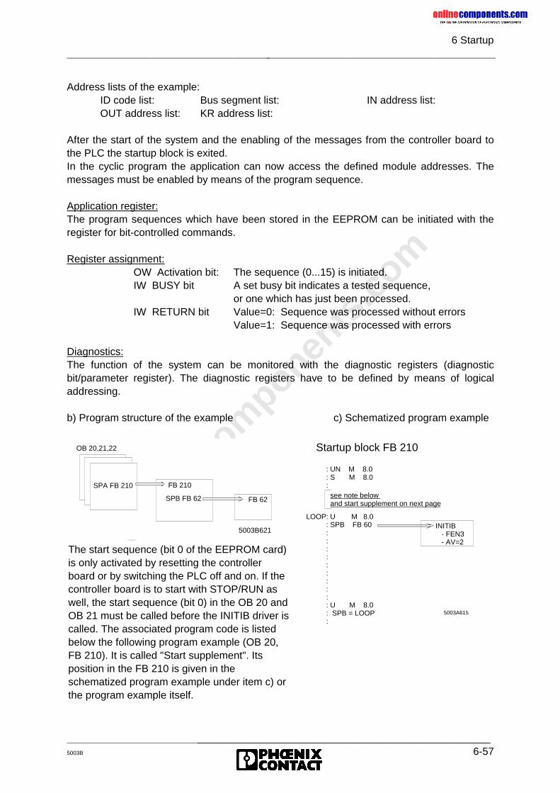
onlinec
omponen
ts.co
m
6 Startup
_______________________________________________5003B 6-57
Address lists of the example:ID code list: Bus segment list: IN address list:OUT address list: KR address list:
After the start of the system and the enabling of the messages from the controller board tothe PLC the startup block is exited.In the cyclic program the application can now access the defined module addresses. Themessages must be enabled by means of the program sequence.
Application register:The program sequences which have been stored in the EEPROM can be initiated with theregister for bit-controlled commands.
Register assignment:OW Activation bit: The sequence (0...15) is initiated.IW BUSY bit A set busy bit indicates a tested sequence,
or one which has just been processed.IW RETURN bit Value=0: Sequence was processed without errors
Value=1: Sequence was processed with errors
Diagnostics:The function of the system can be monitored with the diagnostic registers (diagnosticbit/parameter register). The diagnostic registers have to be defined by means of logicaladdressing.
b) Program structure of the example c) Schematized program example
INITIB - FEN3 - AV=2
Startup block FB 210
: UN M 8.0: S M 8.0:
LOOP: U M 8.0 : SPB FB 60 : : : : : : : : : : U M 8.0 : SPB = LOOP :
5003A615
see note below and start supplement on next page
The start sequence (bit 0 of the EEPROM card)is only activated by resetting the controllerboard or by switching the PLC off and on. If thecontroller board is to start with STOP/RUN aswell, the start sequence (bit 0) in the OB 20 andOB 21 must be called before the INITIB driver iscalled. The associated program code is listedbelow the following program example (OB 20,FB 210). It is called "Start supplement". Itsposition in the FB 210 is given in theschematized program example under item c) orthe program example itself.
OB 20,21,22
SPA FB 210 FB 210
5003B621
SPB FB 62 FB 62
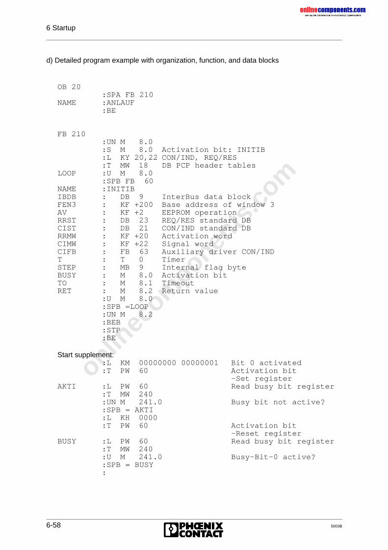
onlinec
omponen
ts.co
m
6 Startup
6-58 5003B
d) Detailed program example with organization, function, and data blocks
OB 20:SPA FB 210
NAME :ANLAUF:BE
FB 210:UN M 8.0:S M 8.0 Activation bit: INITIB:L KY 20,22 CON/IND, REQ/RES:T MW 18 DB PCP header tables
LOOP :U M 8.0:SPB FB 60
NAME :INITIBIBDB : DB 9 InterBus data blockFEN3 : KF +200 Base address of window 3AV : KF +2 EEPROM operationRRST : DB 23 REQ/RES standard DBCIST : DB 21 CON/IND standard DBRRMW : KF +20 Activation wordCIMW : KF +22 Signal wordCIFB : FB 63 Auxiliary driver CON/INDT : T 0 TimerSTEP : MB 9 Internal flag byteBUSY : M 8.0 Activation bitTO : M 8.1 TimeoutRET : M 8.2 Return value
:U M 8.0:SPB =LOOP:UN M 8.2:BEB:STP:BE
Start supplement::L KM 00000000 00000001 Bit 0 activated:T PW 60 Activation bit
-Set registerAKTI :L PW 60 Read busy bit register
:T MW 240:UN M 241.0 Busy bit not active?:SPB = AKTI:L KH 0000:T PW 60 Activation bit
-Reset registerBUSY :L PW 60 Read busy bit register
:T MW 240:U M 241.0 Busy-Bit-0 active?:SPB = BUSY:
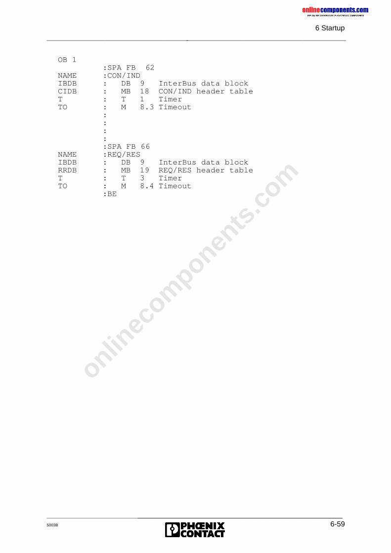
onlinec
omponen
ts.co
m
6 Startup
_______________________________________________5003B 6-59
OB 1:SPA FB 62
NAME :CON/INDIBDB : DB 9 InterBus data blockCIDB : MB 18 CON/IND header tableT : T 1 TimerTO : M 8.3 Timeout
:::::SPA FB 66
NAME :REQ/RESIBDB : DB 9 InterBus data blockRRDB : MB 19 REQ/RES header tableT : T 3 TimerTO : M 8.4 Timeout
:BE
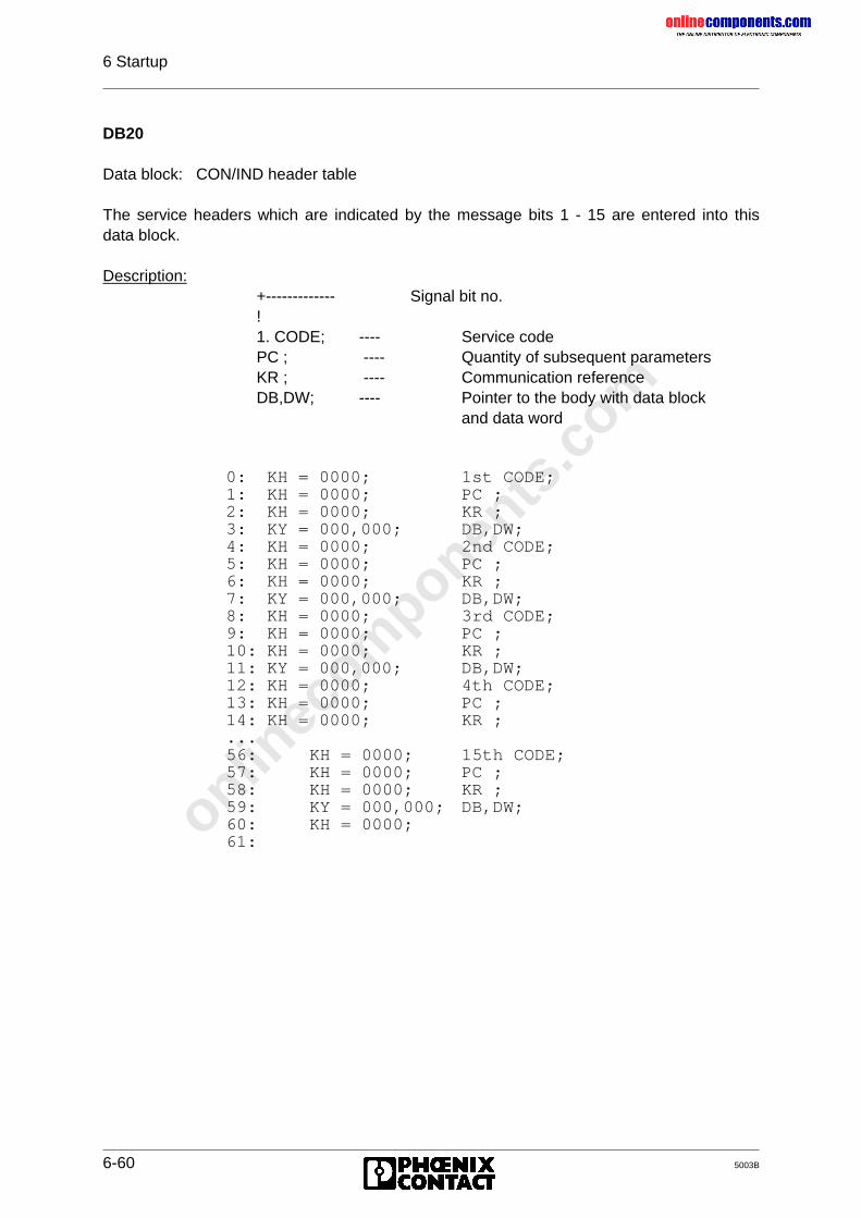
onlinec
omponen
ts.co
m
6 Startup
6-60 5003B
DB20
Data block: CON/IND header table
The service headers which are indicated by the message bits 1 - 15 are entered into thisdata block.
Description:+------------- Signal bit no.!1. CODE; ---- Service codePC ; ---- Quantity of subsequent parametersKR ; ---- Communication referenceDB,DW; ---- Pointer to the body with data block
and data word
0: KH = 0000; 1st CODE;1: KH = 0000; PC ;2: KH = 0000; KR ;3: KY = 000,000; DB,DW;4: KH = 0000; 2nd CODE;5: KH = 0000; PC ;6: KH = 0000; KR ;7: KY = 000,000; DB,DW;8: KH = 0000; 3rd CODE;9: KH = 0000; PC ;10: KH = 0000; KR ;11: KY = 000,000; DB,DW;12: KH = 0000; 4th CODE;13: KH = 0000; PC ;14: KH = 0000; KR ;...56: KH = 0000; 15th CODE;57: KH = 0000; PC ;58: KH = 0000; KR ;59: KY = 000,000; DB,DW;60: KH = 0000;61:
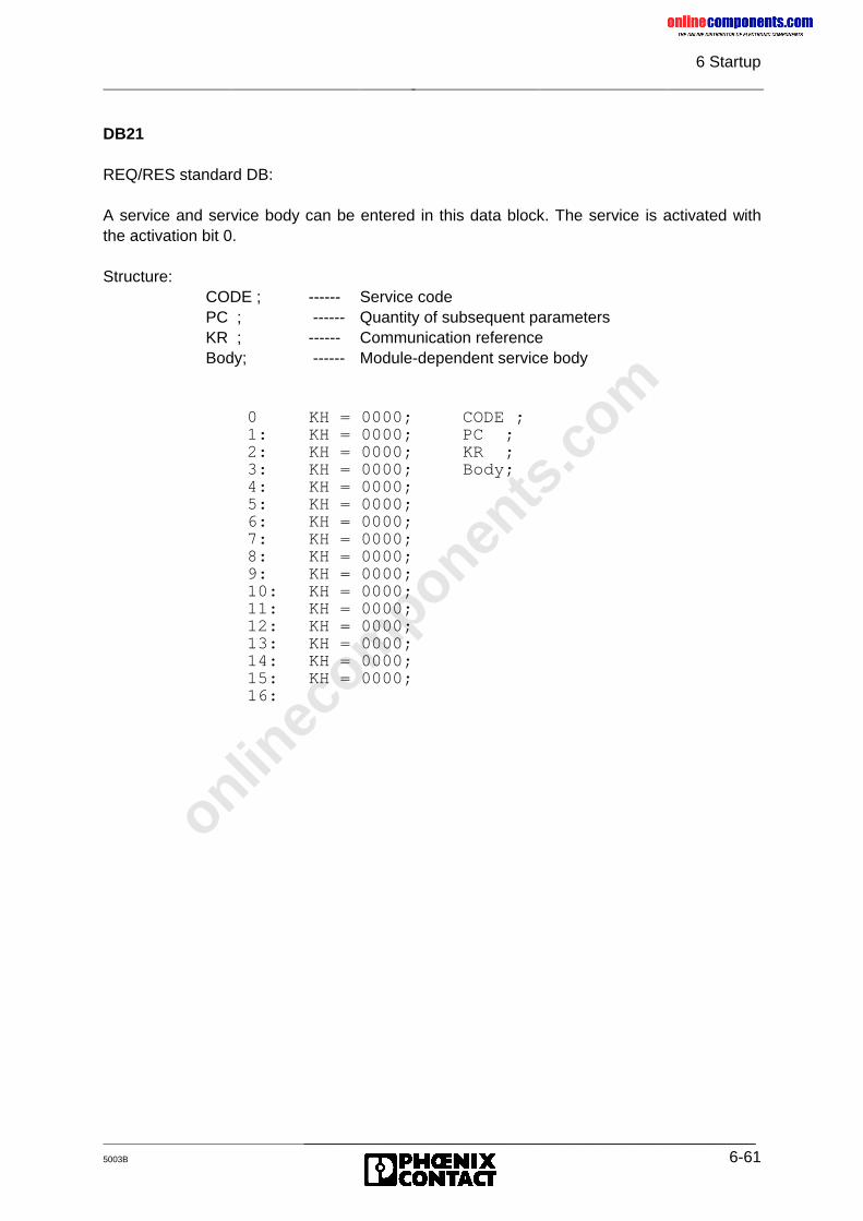
onlinec
omponen
ts.co
m
6 Startup
_______________________________________________5003B 6-61
DB21
REQ/RES standard DB:
A service and service body can be entered in this data block. The service is activated withthe activation bit 0.
Structure:CODE ; ------ Service codePC ; ------ Quantity of subsequent parametersKR ; ------ Communication referenceBody; ------ Module-dependent service body
0 KH = 0000; CODE ;1: KH = 0000; PC ;2: KH = 0000; KR ;3: KH = 0000; Body;4: KH = 0000;5: KH = 0000;6: KH = 0000;7: KH = 0000;8: KH = 0000;9: KH = 0000;10: KH = 0000;11: KH = 0000;12: KH = 0000;13: KH = 0000;14: KH = 0000;15: KH = 0000;16:
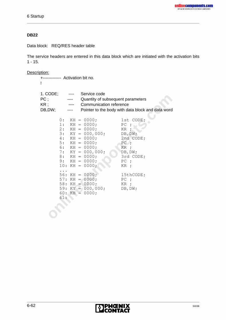
onlinec
omponen
ts.co
m
6 Startup
6-62 5003B
DB22
Data block: REQ/RES header table
The service headers are entered in this data block which are initiated with the activation bits1 - 15.
Description:+------------- Activation bit no.!
1. CODE; ---- Service codePC ; ---- Quantity of subsequent parametersKR ; ---- Communication referenceDB,DW; ---- Pointer to the body with data block and data word
0: KH = 0000; 1st CODE;1: KH = 0000; PC ;2: KH = 0000; KR ;3: KY = 000,000; DB,DW;4: KH = 0000; 2nd CODE;5: KH = 0000; PC ;6: KH = 0000; KR ;7: KY = 000,000; DB,DW;8: KH = 0000; 3rd CODE;9: KH = 0000; PC ;10: KH = 0000; KR ;...56: KH = 0000; 15thCODE;57: KH = 0000; PC ;58: KH = 0000; KR ;59: KY = 000,000; DB,DW;60: KH = 0000;61:
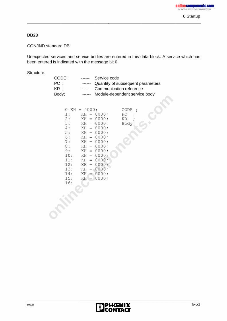
onlinec
omponen
ts.co
m
6 Startup
_______________________________________________5003B 6-63
DB23
CON/IND standard DB:
Unexpected services and service bodies are entered in this data block. A service which hasbeen entered is indicated with the message bit 0.
Structure:CODE ; ------ Service codePC ; ------ Quantity of subsequent parametersKR ; ------ Communication referenceBody; ------ Module-dependent service body
0 KH = 0000; CODE ;1: KH = 0000; PC ;2: KH = 0000; KR ;3: KH = 0000; Body;4: KH = 0000;5: KH = 0000;6: KH = 0000;7: KH = 0000;8: KH = 0000;9: KH = 0000;10: KH = 0000;11: KH = 0000;12: KH = 0000;13: KH = 0000;14: KH = 0000;15: KH = 0000;16:
onlinec
omponen
ts.co
m
5003B
Chapter 7
InstallationThis chapter provides information on
- the possible slots and the correct connection of the controller board to the various SiemensPLCs
- the correct connection of the host controller board to the remote bus cable- the V.24 (RS-232) connection of the controller board to a Siemens programming unit by
means of an adapter cable
7 Installation..........................................................................................7-1
7.1 Slots for the Controller Board ....................................................................... 7-1
7.2 Cable Installation.......................................................................................... 7-2
7.3 Pin Assignment of the Hardware Interfaces.................................................. 7-37.3.1 System Connector........................................................................................ 7-47.3.2 Remote Bus Interface................................................................................... 7-57.3.3 Serial Interface (V.24/RS-232) ................................................................... 7-67.3.4 Ordering Information .................................................................................... 7-8
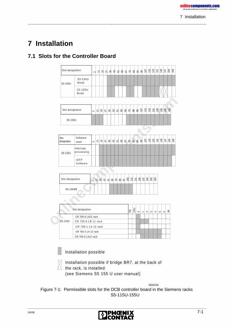
onlinec
omponen
ts.co
m
7 Installation
5003B 7-1
7 Installation
7.1 Slots for the Controller Board
Figure 7-1: Permissible slots for the DCB controller board in the Siemens racksS5-115U-155U
S5-155U
S 5 -1 5 0 U M o d e
S 5 - 1 5 5 U M o d e
Slot designation
3 11 19 27 35 43 51 59 67 75 83 91 99 107
115
123
131
139
147
155
163
S lot des ignat ion 3 11 19 27 35 43 51 59 69 79 89 99 107
115
123
131
139
147
155
163
S5-150U
S5-135U
In te rru p t p ro ce s s in g
IS F P S o f tw a r e
Slot designation 3 11 19 27 35 43 51 59 67 75 83 91 99 10
7
115
123
131
139
147
155
163Software
used
Slot designation 3 27 35 43 51 69 79 89 97 105
113
121
129
137
145
153
163
S5-130WB
S5-115U
CR 700-0 LA12 rack
Slot designation
PS CPU
0 1 2 3 4 5 6 IM
C R 7 0 0 - 0 L B 1 1 r a c k
C R 7 0 0 -1 L A 1 2 ra c k
CR 700-2 LA 12 rack
CR 700-3 LA12 rack
Instal lation possible
Installation possible if bridge BR7, at the back of the rack, is installed. (see Siemens S5 155 U user manual)
5003A236
onlinec
omponen
ts.co
m
7 Installation
7-2 5003B
7.2 Cable Installation
There are two ways to connect the DCB controller board to the following components of theINTERBUS-S system.You may either select one of the preassembled cables from Phoenix Contact (see catalog)or you can assemble the required cables by yourself.
For the correct cable laying in the plant the guidelines given in VDE 0100 are authoritative.
For information concerning the installation please refer to the installation user manual. Thismanual also describes measures for shielding the INTERBUS-S connections.The Chapter "Recommended Cabling" in the installation user manual provides furtherinstructions for the INTERBUS-S system installation, in particular for the potentialequalization and lightning protection of the plant.The manual also includes explanations of the voltage supply for the INTERBUS-S system.
Depending on the components to be connected, there are different types ofcables available. For further information, please refer to the installation usermanual (Order number: 27 54 80 4).
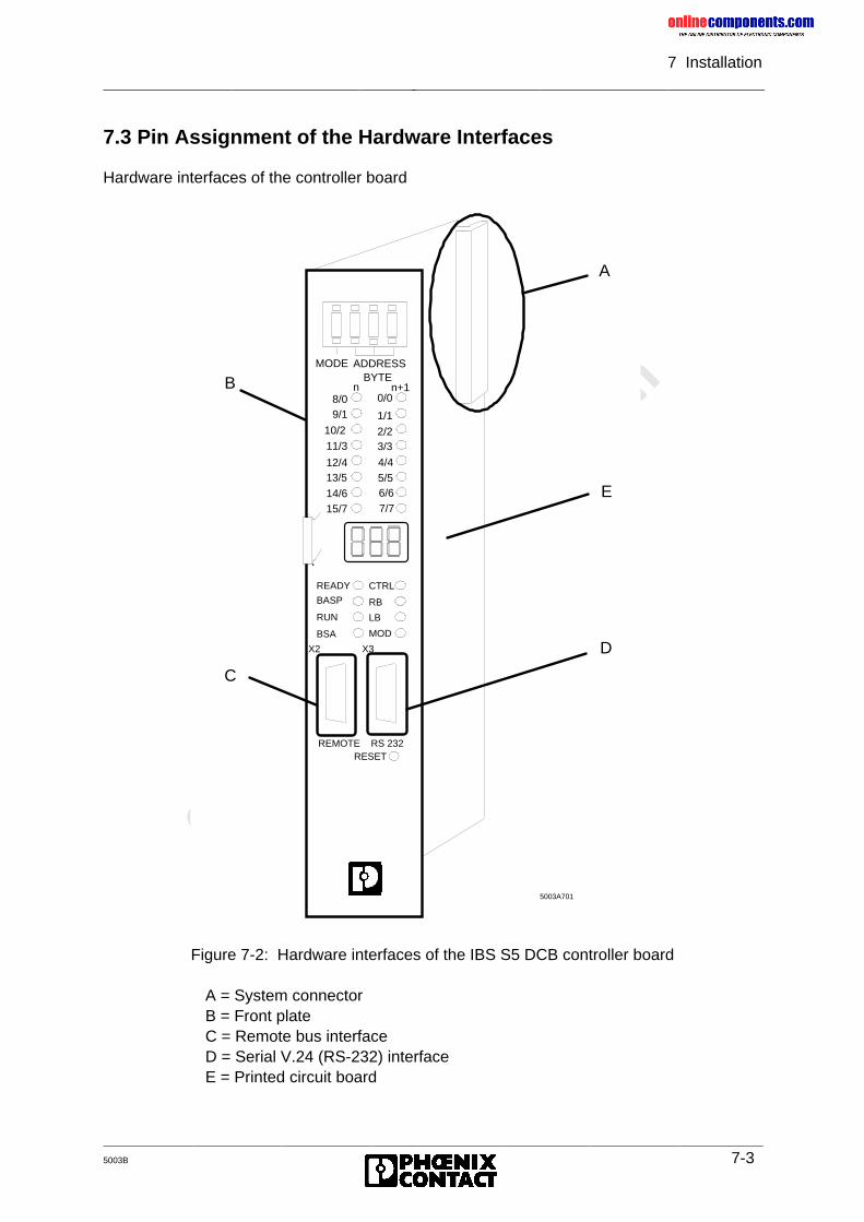
onlinec
omponen
ts.co
m
7 Installation
5003B 7-3
7.3 Pin Assignment of the Hardware Interfaces
Hardware interfaces of the controller board
Figure 7-2: Hardware interfaces of the IBS S5 DCB controller board
A = System connectorB = Front plateC = Remote bus interfaceD = Serial V.24 (RS-232) interfaceE = Printed circuit board
BYTEn n+1
MODE ADDRESS
8/09/1
11/3
12/413/5
14/615/7
10/2
0/0
1/1
2/23/3
4/45/56/67/7
CTRL
RB
LB
MOD
READY
BASP
RUN
BSA
X2 X3
REMOTE RS 232RESET
A
C
B
D
E
5003A701
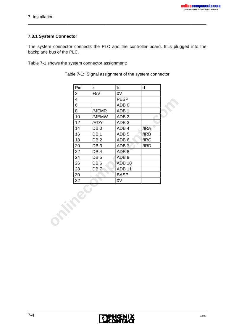
onlinec
omponen
ts.co
m
7 Installation
7-4 5003B
7.3.1 System Connector
The system connector connects the PLC and the controller board. It is plugged into thebackplane bus of the PLC.
Table 7-1 shows the system connector assignment:
Table 7-1: Signal assignment of the system connector
Pin z b d2 +5V 0V4 PESP6 ADB 08 /MEMR ADB 110 /MEMW ADB 212 /RDY ADB 314 DB 0 ADB 4 /IRA16 DB 1 ADB 5 /IRB18 DB 2 ADB 6 /IRC20 DB 3 ADB 7 /IRD22 DB 4 ADB 824 DB 5 ADB 926 DB 6 ADB 1028 DB 7 ADB 1130 BASP32 0V
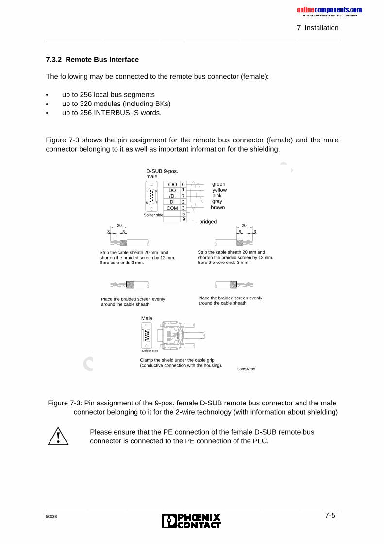
onlinec
omponen
ts.co
m
7 Installation
5003B 7-5
7.3.2 Remote Bus Interface
The following may be connected to the remote bus connector (female):
• up to 256 local bus segments• up to 320 modules (including BKs)• up to 256 INTERBUS-S words.
Figure 7-3 shows the pin assignment for the remote bus connector (female) and the maleconnector belonging to it as well as important information for the shielding.
Figure 7-3: Pin assignment of the 9-pos. female D-SUB remote bus connector and the maleconnector belonging to it for the 2-wire technology (with information about shielding)
D-SUB 9-pos.male
1
23
6
7
COM
DO
DI/DI
/DO
Solder side
1
5
9
9
6
5
bridged
Place the braided screen evenlyaround the cable sheath.
Strip the cable sheath 20 mm andshorten the braided screen by 12 mm.Bare core ends 3 mm.
Solder side
1
20
3 8
Strip the cable sheath 20 mm andshorten the braided screen by 12 mm. Bare the core ends 3 mm .
Place the braided screen evenlyaround the cable sheath
Male
5003A703
20
38
Clamp the shield under the cable grip(conductive connection with the housing).
yellow
graybrown
green
pink
Please ensure that the PE connection of the female D-SUB remote busconnector is connected to the PE connection of the PLC.
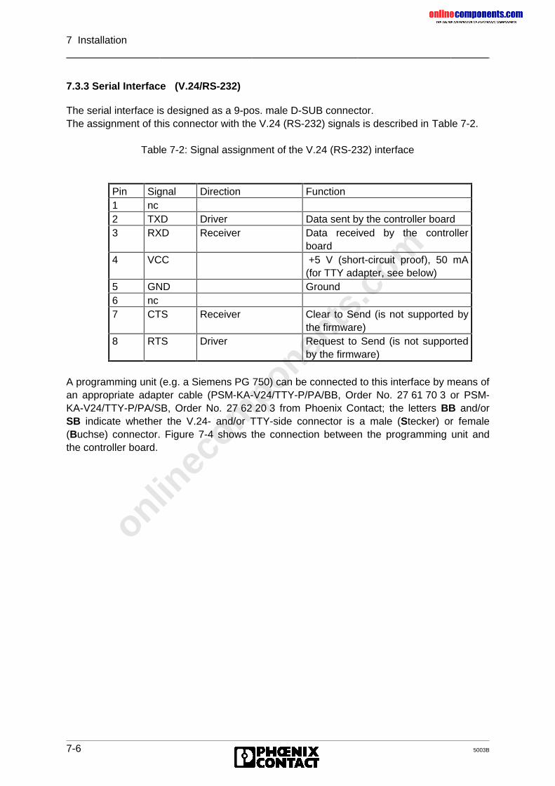
onlinec
omponen
ts.co
m
7 Installation
7-6 5003B
7.3.3 Serial Interface (V.24/RS-232)
The serial interface is designed as a 9-pos. male D-SUB connector.The assignment of this connector with the V.24 (RS-232) signals is described in Table 7-2.
Table 7-2: Signal assignment of the V.24 (RS-232) interface
A programming unit (e.g. a Siemens PG 750) can be connected to this interface by means ofan appropriate adapter cable (PSM-KA-V24/TTY-P/PA/BB, Order No. 27 61 70 3 or PSM-KA-V24/TTY-P/PA/SB, Order No. 27 62 20 3 from Phoenix Contact; the letters BB and/orSB indicate whether the V.24- and/or TTY-side connector is a male (Stecker) or female(Buchse) connector. Figure 7-4 shows the connection between the programming unit andthe controller board.
Pin Signal Direction Function1 nc2 TXD Driver Data sent by the controller board3 RXD Receiver Data received by the controller
board4 VCC +5 V (short-circuit proof), 50 mA
(for TTY adapter, see below)5 GND Ground6 nc7 CTS Receiver Clear to Send (is not supported by
the firmware)8 RTS Driver Request to Send (is not supported
by the firmware)
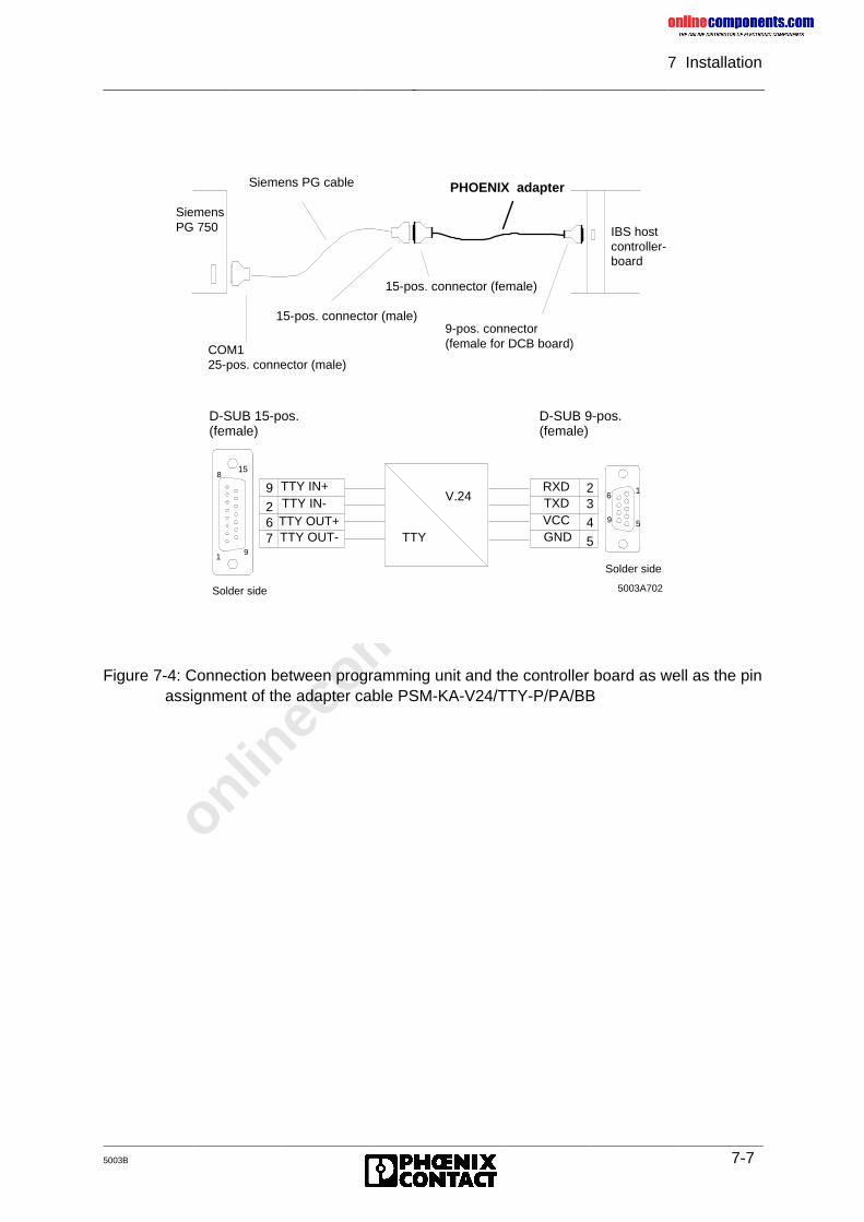
onlinec
omponen
ts.co
m
7 Installation
5003B 7-7
Figure 7-4: Connection between programming unit and the controller board as well as the pinassignment of the adapter cable PSM-KA-V24/TTY-P/PA/BB
SiemensPG 750
Siemens PG cable PHOENIX adapter
COM125-pos. connector (male)
15-pos. connector (male)
15-pos. connector (female)
9-pos. connector (female for DCB board)
IBS hostcontroller-board
1
158
9
V.24
TTY
1
5
6
9
RXDTXDVCCGND
5003A702
23
4
5
TTY IN+TTY IN-
TTY OUT-TTY OUT+
9
267
D-SUB 15-pos.(female)
D-SUB 9-pos.(female)
Solder side
Solder side
onlinec
omponen
ts.co
m
7 Installation
7-8 5003B
7.3.4 Ordering Information
This chapter provides an overview of other available INTERBUS-S products in connectionwith the DCB controller board.These products serve for a more convenient diagnostics of the DCB controller board usedand they also allow a complete use of the capabilities of the controller board.(The respective item designations and order numbers are given in parentheses)You may get a basic or advanced package assembled from the individual products:
Basic package• DCB controller board: IBS S5 DCB-T, (28 06 21 5)
IBS S5 DCB/I-T, (27 58 15 6)• ISFP software: IBS S5 SWD, (28 06 22 8)With this package INTERBUS-S is exclusively operated via the connected PLC.
Advanced package• Basic package and• EEPROM memory in credit-card format, IBS MC 64k (27 58 96 5 )• IBS SYS SWT software (27 80 88 1)• Connecting cable for direct connection of a PC to the DCB controller board,
IBS PRG CAB (28 06 86 2)This package allows the operation of INTERBUS on the PLC and PC side. In the case ofoperation on the PC-side, the parameterization data can be stored in the EEPROM memory.
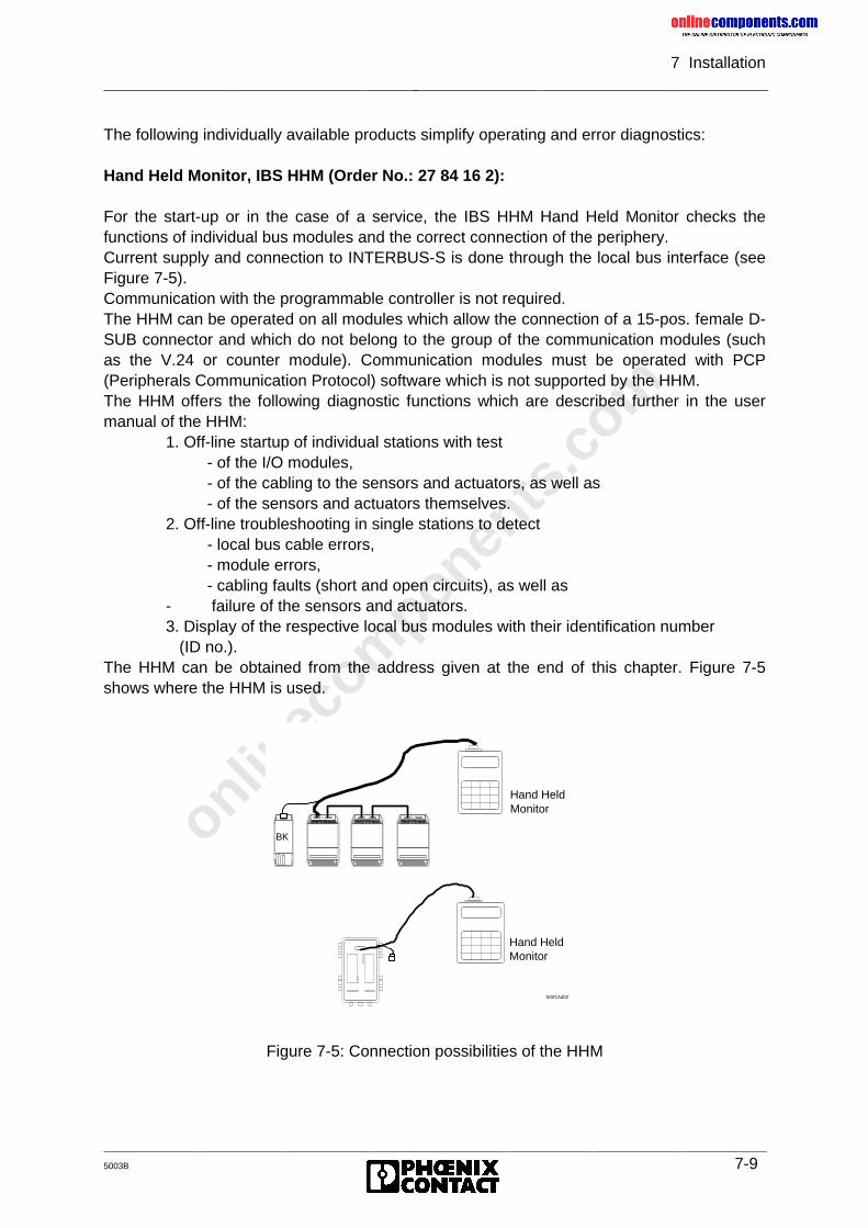
onlinec
omponen
ts.co
m
7 Installation
5003B 7-9
The following individually available products simplify operating and error diagnostics:
Hand Held Monitor, IBS HHM (Order No.: 27 84 16 2):
For the start-up or in the case of a service, the IBS HHM Hand Held Monitor checks thefunctions of individual bus modules and the correct connection of the periphery.Current supply and connection to INTERBUS-S is done through the local bus interface (seeFigure 7-5).Communication with the programmable controller is not required.The HHM can be operated on all modules which allow the connection of a 15-pos. female D-SUB connector and which do not belong to the group of the communication modules (suchas the V.24 or counter module). Communication modules must be operated with PCP(Peripherals Communication Protocol) software which is not supported by the HHM.The HHM offers the following diagnostic functions which are described further in the usermanual of the HHM:
1. Off-line startup of individual stations with test- of the I/O modules,- of the cabling to the sensors and actuators, as well as- of the sensors and actuators themselves.
2. Off-line troubleshooting in single stations to detect- local bus cable errors,- module errors,- cabling faults (short and open circuits), as well as
- failure of the sensors and actuators.3. Display of the respective local bus modules with their identification number (ID no.).
The HHM can be obtained from the address given at the end of this chapter. Figure 7-5shows where the HHM is used.
Figure 7-5: Connection possibilities of the HHM
Hand HeldMonitor
5001A402
Hand Held Monitor
BK
onlinec
omponen
ts.co
m
7 Installation
7-10 5003B
PC boardsIBS PC AT-T (27 58 05 9)IBS PC AT/I-T (27 58 06 2)IBS PC CB/COP/I-T (27 54 51 6)IBS PC CB/I-T (27 80 84 9)with monitor program of the suitable driver softwareIBS TS CC for Microsoft C (27 67 07 9)IBS TS TP for Borland Turbo Pascal (27 84 80 3)
The respective monitor software provides the following services:• Start-up of an INTERBUS-S system on the PC• Test of an INTERBUS-S system on the PC• Control of the connected configuration• Address assignment of the I/O words• Setting of outputs (binary)• Setting of output words (hex)• Displaying the input statuses (binary and hex)• Resetting the INTERBUS-S system
c) IBS SYS SWT (27 80 88 1) and the connecting cable IBS PRG CAB (28 06 86 2)IBS SYS SWT provides the user interface of the controller board on the PC. This allows touse the functions of the INTERBUS-S controller board and the modules connected toINTERBUS without any additional programming expense.The PC is coupled to the controller board through the serial interfaces of both devices.
The program functions in detail:
• Transferring the INTERBUS-S commands to the INTERBUS-S controller board• Receiving the INTERBUS-S messages from the INTERBUS-S controller board• Listing the received messages and the transferred commands• Storing the INTERBUS-S commands and transferring the stored commands to the
controller board• Programming the controller board’s EEPROM
onlinec
omponen
ts.co
m
5003B
Chapter 8
ISFP – INTERBUS-S System Functions for the PLCThis chapter provides information on
– the software interface for INTERBUS-S system control via the PLC– the PCP services (command and message functions)– the use of communications (PCP services for INTERBUS-S control)– the error messages
8 ISFP.....................................................................................................8-1
8.1 Interface Description .................................................................................... 8-18.1.1 Program Structure ..................................................................................... 8-28.1.2 Inclusion of the Interface Drivers ............................................................... 8-58.1.2.1 INITIB (FB 60) .......................................................................................... 8-68.1.2.2 CON/IND .................................................................................................. 8-108.1.2.3 REQ/RES ................................................................................................. 8-128.1.2.4 INTERBUS Data Block (IBDB).................................................................. 8-148.1.3 INTERBUS-S System Control.................................................................... 8-168.1.3.1 Structure of the Functions......................................................................... 8-188.1.3.2 Overview of Functions .............................................................................. 8-20
8.2 Command Functions .................................................................................... 8-248.2.1 CONTROL (FB 68) .................................................................................... 8-248.2.1.1 Configure INTERBUS-S (FKT 0)............................................................... 8-268.2.1.2 Start INTERBUS-S Cycle (FKT 1)............................................................. 8-268.2.1.3 Stop InterBus-S Cycle (FKT 2) ................................................................. 8-268.2.1.4 Alarm Stop (FKT 3)................................................................................... 8-268.2.1.5 Clear Display (FKT 4) ............................................................................... 8-268.2.1.6 Disable All Messages (FKT 5)................................................................... 8-278.2.1.7 Implement All Logical Address Map (FKT 6)............................................. 8-278.2.1.8 Init Communication (FKT 7) ...................................................................... 8-278.2.1.9 INTERBUS-S Delay (FKT 8) ..................................................................... 8-278.2.1.10 Quit Module Error All (FKT 9) ................................................................... 8-278.2.2 DEFINE (FB 69) ........................................................................................ 8-288.2.2.1 Physical Configuration Map (FKT 0) ......................................................... 8-308.2.2.2 Logical Local Bus Address Map (FKT 1)................................................... 8-318.2.2.3 Logical IN Address Map (FKT 2)............................................................... 8-328.2.2.4 Logical OUT Address Map (FKT 3)........................................................... 8-338.2.2.5 Communication Reference (FKT 4) .......................................................... 8-348.2.2.6 Event Map (FKT 5) ................................................................................... 8-358.2.2.7 Group Numbers (FKT 6) ........................................................................... 8-378.2.2.8 Parameter Timeout Constant (FKT 7) ....................................................... 8-388.2.2.9 Receive KBL (FKT 8)................................................................................ 8-398.2.2.10 Receive Bit Manipulation (FKT 9) ............................................................. 8-418.2.2.11 Group Error Characteristics (FKT 10) ....................................................... 8-508.2.2.12 Quit Module Error (FKT 11) ...................................................................... 8-52
onlinec
omponen
ts.co
m
5003B
8.2.3 SYSINFO (FB 70) ...................................................................................... 8-538.2.3.1 Physical Configuration Map (FKT 0) ......................................................... 8-558.2.3.2 Software Revision (FKT 1)........................................................................ 8-558.2.3.3 Switch Information (FKT 2) ....................................................................... 8-568.2.3.4 INTERBUS-S Cycle Counter (FKT 3)........................................................ 8-568.2.3.5 Logical Address Error (FKT 4) .................................................................. 8-578.2.4 ON/OFF (FB 71) ........................................................................................ 8-588.2.4.1 Group ON (FKT 0) .................................................................................... 8-608.2.4.2 Group OFF (FKT 1) .................................................................................. 8-608.2.4.3 BK-Alarm ON (FKT 2)............................................................................... 8-608.2.4.4 BK-Alarm OFF (FKT 3) ............................................................................. 8-618.2.4.5 Event ON (FKT 4) ..................................................................................... 8-618.2.4.6 Event OFF (FKT 5) ................................................................................... 8-618.2.5 ADDRESS (FB 72) .................................................................................... 8-628.2.5.1 ID Code List.............................................................................................. 8-668.2.5.2 Bus Segment Address List........................................................................ 8-678.2.5.3 IN Address List ......................................................................................... 8-688.2.5.4 OUT Address List ..................................................................................... 8-698.2.5.5 Group No. List .......................................................................................... 8-708.2.5.6 Group Error Characteristics ...................................................................... 8-728.2.5.7 Communication Reference List ................................................................. 8-738.2.6 ERRINFO (FB 74)...................................................................................... 8-748.2.6.1 Controller Error Code (FKT 0)................................................................... 8-768.2.6.2 Bus Information (FKT 1) ........................................................................... 8-768.2.6.3 Defective Group (FKT 2)........................................................................... 8-778.2.6.4 Module Error (FKT 3)................................................................................ 8-788.2.6.5 Local Bus Module Error (FKT 4) ............................................................... 8-79
8.3 Message Functions ...................................................................................... 8-808.3.1 SYSERROR (FB 73).................................................................................. 8-808.3.2 RECONFIG (FB 75)................................................................................... 8-828.3.3 EVENT (FB 76).......................................................................................... 8-83
8.4 Working with Communication ....................................................................... 8-848.4.1 Introduction................................................................................................ 8-848.4.1.1 Control During Communication................................................................. 8-868.4.1.2 Call Structure of the Function Blocks ........................................................ 8-868.4.1.3 Initialization/Addressing ............................................................................ 8-878.4.1.4 Service Structure ...................................................................................... 8-898.4.1.5 Service Execution ..................................................................................... 8-908.4.1.6 Activation Flag Service ............................................................................. 8-908.4.1.7 Message Flag Service .............................................................................. 8-928.4.1.8 Principal Service Sequence ...................................................................... 8-948.4.1.9 Example of a Service................................................................................ 8-968.4.2 Request/Confirmation ................................................................................ 8-978.4.2.1 Read Request........................................................................................... 8-1008.4.2.2 Write Request........................................................................................... 8-1008.4.2.3 Start Request............................................................................................ 8-1008.4.2.4 Stop Request............................................................................................ 8-1008.4.2.5 Information Report Request...................................................................... 8-1018.4.2.6 Status Request ......................................................................................... 8-1018.4.2.7 Identify Request........................................................................................ 8-1018.4.2.8 Initiate Request......................................................................................... 8-1018.4.2.9 Abort Request........................................................................................... 8-102
onlinec
omponen
ts.co
m
5003B
8.4.2.10 Read Confirmation.................................................................................... 8-1028.4.2.11 Write Confirmation .................................................................................... 8-1028.4.2.12 Start Confirmation..................................................................................... 8-1038.4.2.13 Stop Confirmation ..................................................................................... 8-1038.4.2.14 Status Confirmation .................................................................................. 8-1038.4.2.15 Identify Confirmation................................................................................. 8-1048.4.2.16 Initiate Confirmation.................................................................................. 8-1048.4.2.17 Initiate Error Confirmation ......................................................................... 8-1048.4.3 Response/Indication .................................................................................. 8-1068.4.3.1 Abort Indication......................................................................................... 8-1068.4.3.2 Reject Indication ....................................................................................... 8-1068.4.3.3 Start Indication.......................................................................................... 8-1068.4.3.4 Stop Indication.......................................................................................... 8-1068.4.3.5 Information Report Indication.................................................................... 8-1078.4.3.6 Read Indication......................................................................................... 8-1078.4.3.7 Write Indication......................................................................................... 8-1078.4.3.8 Initiate Indication....................................................................................... 8-1088.4.3.9 Read Response........................................................................................ 8-1088.4.3.10 Write Response ........................................................................................ 8-1088.4.3.11 Start Response......................................................................................... 8-1098.4.3.12 Stop Response ......................................................................................... 8-1098.4.4 Application of Communication ................................................................... 8-1108.4.5 Communication Error Messages................................................................ 8-1138.4.5.1 Error Messages for a Connection Abort .................................................... 8-1138.4.5.2 Error Messages for the Reject Service ..................................................... 8-1158.4.5.3 Additional Error Messages........................................................................ 8-1168.4.5.4 Description of the Service-Specific Error Messages ................................. 8-116
onlinec
omponen
ts.co
m
8 ISFP
5003B 8-1
8 ISFP
8.1 Interface Description
The INTERBUS-S System Functions for the PLC (ISFP) are a software interface, which ismade available to the users to allow them to control INTERBUS-S via the PLC. Along withthe I/O interface which is implemented with an MPM (Multi-Port Memory) and to which theuser has direct access, a communication register is also implemented on the controllerboard for the INTERBUS-S command/message interface. The hardware of this interfaceconsists of four word registers which are located in the I/O area of the PLC. A protocol wasdefined to link the PLC and the INTERBUS-S controller board. This protocol comprisescommands which the PLC sends to the controller board and messages which the PLCreceives.
The INTERBUS-S system functions are based on the command/message interface and offerthe user self-contained functions as INTERBUS-S management services.
INTERBUS-S management functions, for instance, are:
• re-configuration,
• switching groups off,
• error recovery,
• re-addressing,
• clearing of the display,
• starting,
• stopping, etc.
Besides the system services, the PCP (Peripherals Communication Protocol) services alsouse the communication registers as an interface to the controller board. This is the reasonwhy the use of the PCP services is integrated into the interface.
onlinec
omponen
ts.co
m
8 ISFP
8-2 5003B
8.1.1 Program Structure
An interface, which includes extensive functions, is represented by software which consistsof different components.
To avoid longer scan times, the INTERBUS-S System Functions for the PLC (ISFP) havebeen tailored specifically to the respective PLC and optimized and structured from the pointof view of the program. Operation of the ISFP interface (by setting individual bits) is keptsimple to reduce the programming effort on the part of the user.
The interface consists of three types of function blocks:
• Initialization block
• Receive/send blocks (interface drivers)
• Function blocks
These blocks are available as standard function blocks and have to be ordered in addition tothe respective controller board.
Besides an initialization block which is only called when the PLC is started, there are twofunction blocks which are addressed continuously. These are the receive and the sendblock, which establish the link between the PLC (ISFP interface) and the controller board.The blocks (interface drivers) only ever become active when commands are sent ormessages are received.
The third type of blocks is related to the application and must be integrated by the user. Thatis to say: Only those function blocks are called that are currently needed (e.g. for:addressing, system information, event handling...).
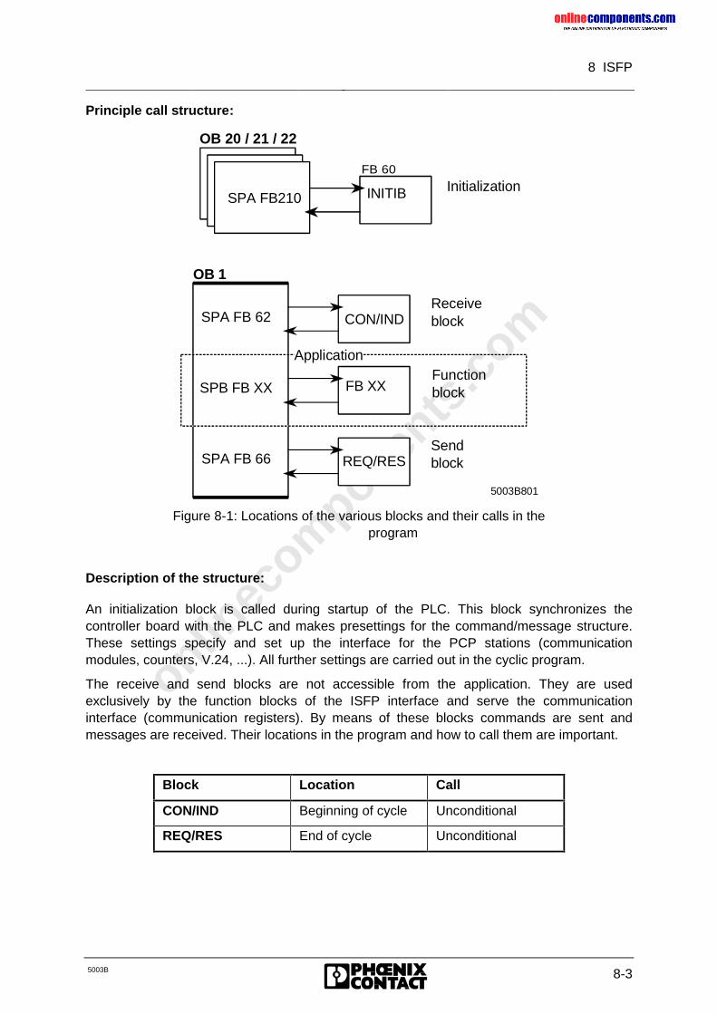
onlinec
omponen
ts.co
m
8 ISFP
5003B 8-3
Principle call structure:
OB 20 / 21 / 22
SPA FB210Initialization
OB 1
Receiveblock
Function block
Sendblock
Application
REQ/RES
CON/INDSPA FB 62
SPB FB XX
SPA FB 66
5003B801
INITIB
FB XX
FB 60
Figure 8-1: Locations of the various blocks and their calls in theprogram
Description of the structure:
An initialization block is called during startup of the PLC. This block synchronizes thecontroller board with the PLC and makes presettings for the command/message structure.These settings specify and set up the interface for the PCP stations (communicationmodules, counters, V.24, ...). All further settings are carried out in the cyclic program.
The receive and send blocks are not accessible from the application. They are usedexclusively by the function blocks of the ISFP interface and serve the communicationinterface (communication registers). By means of these blocks commands are sent andmessages are received. Their locations in the program and how to call them are important.
Block Location Call
CON/IND Beginning of cycle Unconditional
REQ/RES End of cycle Unconditional
onlinec
omponen
ts.co
m
8 ISFP
8-4 5003B
The CON/IND and REQ/RES blocks must be called once in every cycle toensure a correct processing of commands and messages.
A detailed description of the CON/IND and REQ/RES function blocks is given inChapter 8.1.2.2, "CON/IND“ (Page 10ff)
The third type of blocks provides the users with a tool with which they can control andmonitor INTERBUS-S. The function blocks are subdivided into passive and active functionblocks.
Passive blocks receive messages from the controller board or indicate errors in theINTERBUS-S system.
The active blocks are initiated by the user program and execute specific functions.
The variety of functions and messages is described in Chapter 8.1.3"INTERBUS-S System Control“ (Page 16ff).
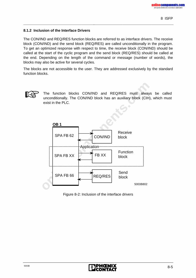
onlinec
omponen
ts.co
m
8 ISFP
5003B 8-5
8.1.2 Inclusion of the Interface Drivers
The CON/IND and REQ/RES function blocks are referred to as interface drivers. The receiveblock (CON/IND) and the send block (REQ/RES) are called unconditionally in the program.To get an optimized response with respect to time, the receive block (CON/IND) should becalled at the start of the cyclic program and the send block (REQ/RES) should be called atthe end. Depending on the length of the command or message (number of words), theblocks may also be active for several cycles.
The blocks are not accessible to the user. They are addressed exclusively by the standardfunction blocks.
The function blocks CON/IND and REQ/RES must always be calledunconditionally. The CON/IND block has an auxiliary block (CIH), which mustexist in the PLC.
OB 1
Receiveblock
Functionblock
Send block
Application
REQ/RES
CON/INDSPA FB 62
SPA FB XX
SPA FB 66
5003B802
FB XX
Figure 8-2: Inclusion of the interface drivers
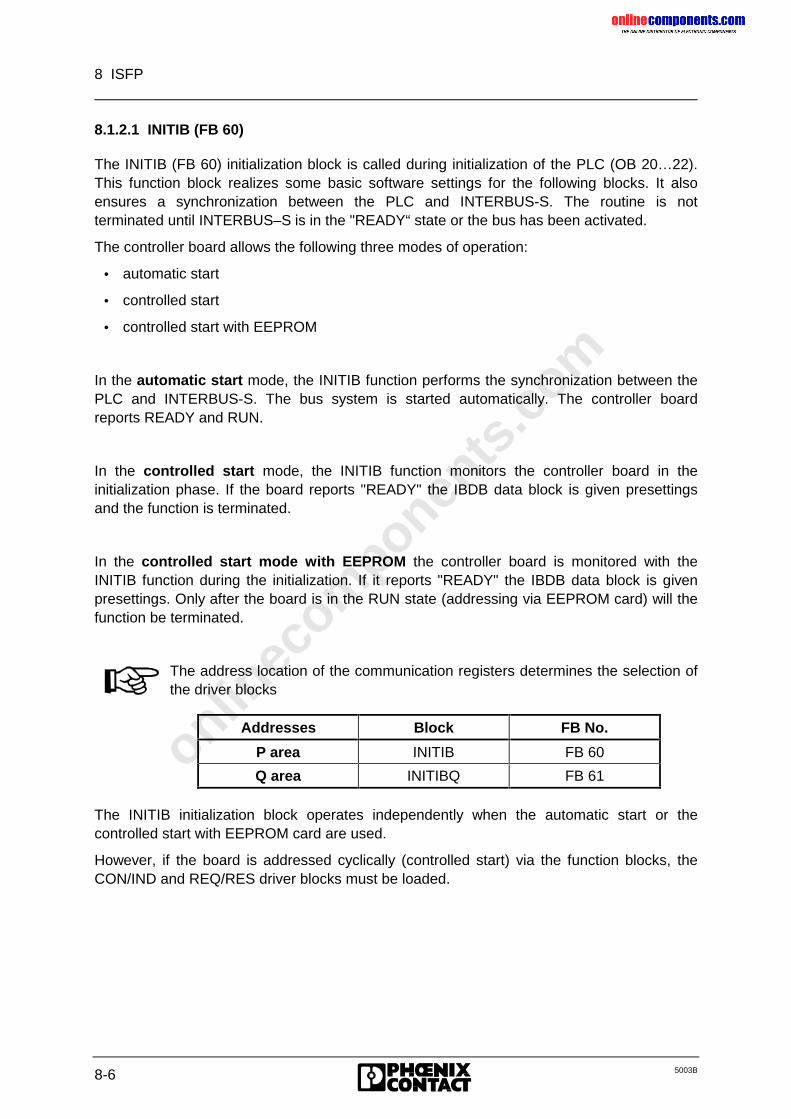
onlinec
omponen
ts.co
m
8 ISFP
8-6 5003B
8.1.2.1 INITIB (FB 60)
The INITIB (FB 60) initialization block is called during initialization of the PLC (OB 20…22).This function block realizes some basic software settings for the following blocks. It alsoensures a synchronization between the PLC and INTERBUS-S. The routine is notterminated until INTERBUS–S is in the "READY“ state or the bus has been activated.
The controller board allows the following three modes of operation:
• automatic start
• controlled start
• controlled start with EEPROM
In the automatic start mode, the INITIB function performs the synchronization between thePLC and INTERBUS-S. The bus system is started automatically. The controller boardreports READY and RUN.
In the controlled start mode, the INITIB function monitors the controller board in theinitialization phase. If the board reports "READY" the IBDB data block is given presettingsand the function is terminated.
In the controlled start mode with EEPROM the controller board is monitored with theINITIB function during the initialization. If it reports "READY" the IBDB data block is givenpresettings. Only after the board is in the RUN state (addressing via EEPROM card) will thefunction be terminated.
The address location of the communication registers determines the selection ofthe driver blocks
Addresses Block FB No.
P area INITIB FB 60
Q area INITIBQ FB 61
The INITIB initialization block operates independently when the automatic start or thecontrolled start with EEPROM card are used.
However, if the board is addressed cyclically (controlled start) via the function blocks, theCON/IND and REQ/RES driver blocks must be loaded.
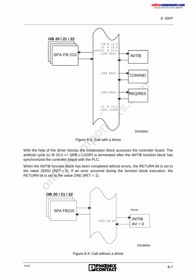
onlinec
omponen
ts.co
m
8 ISFP
5003B 8-7
5003B803
:U M 10.0 :SPB =LOOP :
:SPA FB66
:SPA FB62
:UN M 10.0 :S M 10.0LOOP:U M 10.0 :SPB FB60
INITIB
CON/IND
REQ/RES
SPA FB 210
OB 20 / 21 / 22
Figure 8-3: Call with a driver
With the help of the driver blocks, the initialization block accesses the controller board. Theartificial cycle (U M 10.0 => SPB = LOOP) is terminated after the INITIB function block hassynchronized the controller board with the PLC.
When the INITIB function block has been completed without errors, the RETURN bit is set tothe value ZERO (RET = 0). If an error occurred during the function block execution, theRETURN bit is set to the value ONE (RET = 1).
OB 20 / 21 / 22
SPA FB210
INITIB
5003B804
:SPA FB 60AV = 0
FB 60
Figure 8-4: Call without a driver
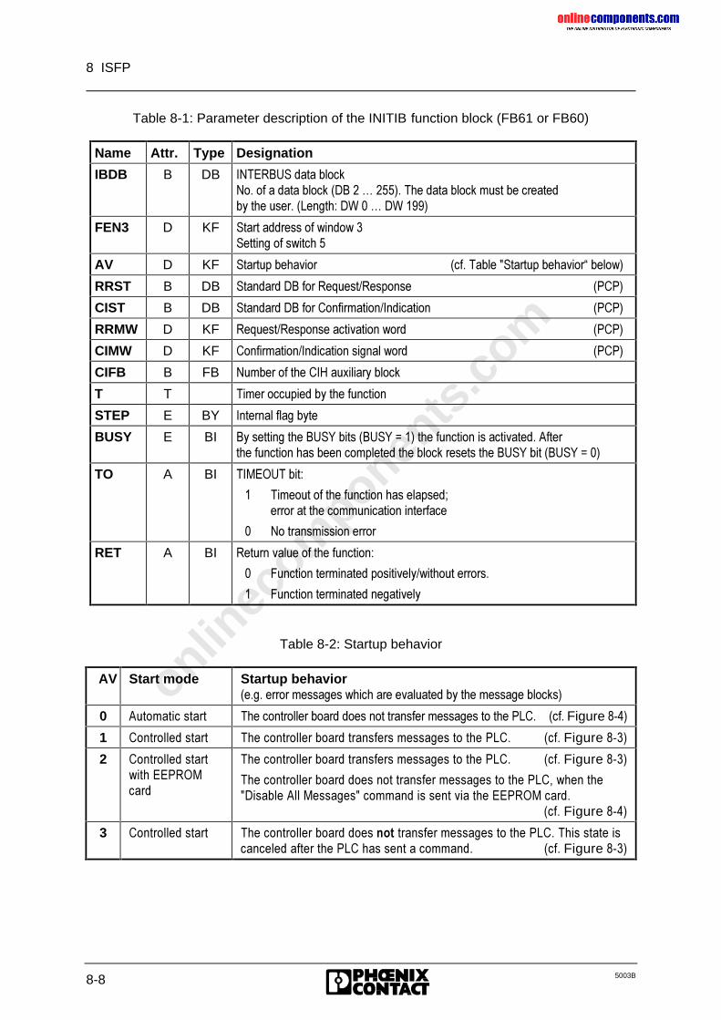
onlinec
omponen
ts.co
m
8 ISFP
8-8 5003B
Table 8-1: Parameter description of the INITIB function block (FB61 or FB60)
Name Attr. Type Designation
IBDB B DB ,17(5%86�GDWD�EORFN1R��RI�D�GDWD�EORFN��'%���«�������7KH�GDWD�EORFN�PXVW�EH�FUHDWHGE\�WKH�XVHU���/HQJWK��':���«�':�����
FEN3 D KF 6WDUW�DGGUHVV�RI�ZLQGRZ��6HWWLQJ�RI�VZLWFK��
AV D KF 6WDUWXS�EHKDYLRU �FI��7DEOH��6WDUWXS�EHKDYLRU´�EHORZ�
RRST B DB 6WDQGDUG�'%�IRU�5HTXHVW�5HVSRQVH �3&3�
CIST B DB 6WDQGDUG�'%�IRU�&RQILUPDWLRQ�,QGLFDWLRQ �3&3�
RRMW D KF 5HTXHVW�5HVSRQVH�DFWLYDWLRQ�ZRUG �3&3�
CIMW D KF &RQILUPDWLRQ�,QGLFDWLRQ�VLJQDO�ZRUG �3&3�
CIFB B FB 1XPEHU�RI�WKH�&,+�DX[LOLDU\�EORFN
T T 7LPHU�RFFXSLHG�E\�WKH�IXQFWLRQ
STEP E BY ,QWHUQDO�IODJ�E\WH
BUSY E BI %\�VHWWLQJ�WKH�%86<�ELWV��%86<� ����WKH�IXQFWLRQ�LV�DFWLYDWHG��$IWHUWKH�IXQFWLRQ�KDV�EHHQ�FRPSOHWHG�WKH�EORFN�UHVHWV�WKH�%86<�ELW��%86<� ���
TO A BI 7,0(287�ELW�
� 7LPHRXW�RI�WKH�IXQFWLRQ�KDV�HODSVHG�HUURU�DW�WKH�FRPPXQLFDWLRQ�LQWHUIDFH
� 1R�WUDQVPLVVLRQ�HUURU
RET A BI 5HWXUQ�YDOXH�RI�WKH�IXQFWLRQ�
� )XQFWLRQ�WHUPLQDWHG�SRVLWLYHO\�ZLWKRXW�HUURUV�
� )XQFWLRQ�WHUPLQDWHG�QHJDWLYHO\
Table 8-2: Startup behavior
AV Start mode Startup behavior�H�J��HUURU�PHVVDJHV�ZKLFK�DUH�HYDOXDWHG�E\�WKH�PHVVDJH�EORFNV�
0 $XWRPDWLF�VWDUW 7KH�FRQWUROOHU�ERDUG�GRHV�QRW�WUDQVIHU�PHVVDJHV�WR�WKH�3/&�� �FI��Figure�����
1 &RQWUROOHG�VWDUW 7KH�FRQWUROOHU�ERDUG�WUDQVIHUV�PHVVDJHV�WR�WKH�3/&�� �FI��Figure�����
2 &RQWUROOHG�VWDUWZLWK�((3520FDUG
7KH�FRQWUROOHU�ERDUG�WUDQVIHUV�PHVVDJHV�WR�WKH�3/&�� �FI��Figure�����
7KH�FRQWUROOHU�ERDUG�GRHV�QRW�WUDQVIHU�PHVVDJHV�WR�WKH�3/&��ZKHQ�WKH�'LVDEOH�$OO�0HVVDJHV��FRPPDQG�LV�VHQW�YLD�WKH�((3520�FDUG�
�FI��Figure�����
3 &RQWUROOHG�VWDUW 7KH�FRQWUROOHU�ERDUG�GRHV�QRW�WUDQVIHU�PHVVDJHV�WR�WKH�3/&��7KLV�VWDWH�LVFDQFHOHG�DIWHU�WKH�3/&�KDV�VHQW�D�FRPPDQG� �FI��Figure�����
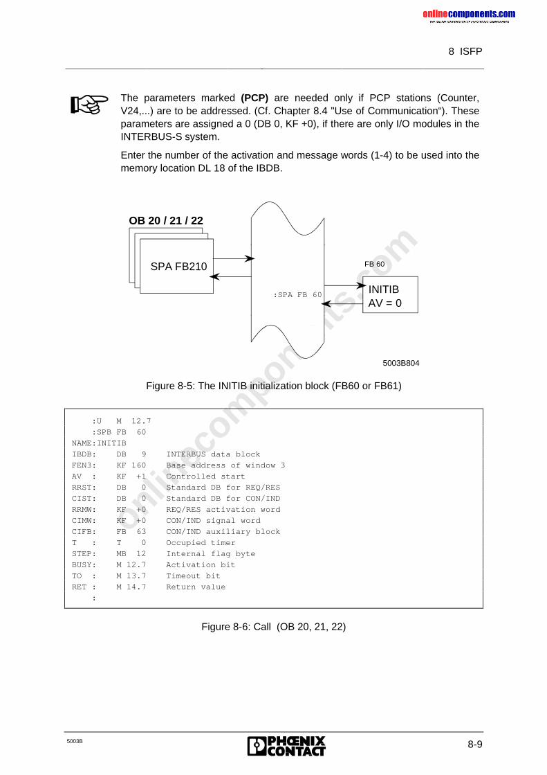
onlinec
omponen
ts.co
m
8 ISFP
5003B 8-9
The parameters marked (PCP) are needed only if PCP stations (Counter,V24,...) are to be addressed. (Cf. Chapter 8.4 "Use of Communication“). Theseparameters are assigned a 0 (DB 0, KF +0), if there are only I/O modules in theINTERBUS-S system.
Enter the number of the activation and message words (1-4) to be used into thememory location DL 18 of the IBDB.
OB 20 / 21 / 22
SPA FB210
INITIB
5003B804
:SPA FB 60AV = 0
FB 60
Figure 8-5: The INITIB initialization block (FB60 or FB61)
:U M 12.7
:SPB FB 60
NAME:INITIB
IBDB: DB 9 INTERBUS data block
FEN3: KF 160 Base address of window 3
AV : KF +1 Controlled start
RRST: DB 0 Standard DB for REQ/RES
CIST: DB 0 Standard DB for CON/IND
RRMW: KF +0 REQ/RES activation word
CIMW: KF +0 CON/IND signal word
CIFB: FB 63 CON/IND auxiliary block
T : T 0 Occupied timer
STEP: MB 12 Internal flag byte
BUSY: M 12.7 Activation bit
TO : M 13.7 Timeout bit
RET : M 14.7 Return value
:
Figure 8-6: Call (OB 20, 21, 22)
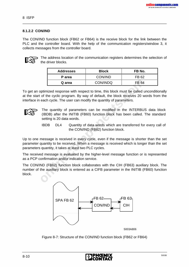
onlinec
omponen
ts.co
m
8 ISFP
8-10 5003B
8.1.2.2 CON/IND
The CON/IND function block (FB62 or FB64) is the receive block for the link between thePLC and the controller board. With the help of the communication registers/window 3, itcollects messages from the controller board.
The address location of the communication registers determines the selection ofthe driver blocks.
Addresses Block FB No.
P area CON/IND FB 62
Q area CON/INDQ FB 64
To get an optimized response with respect to time, this block must be called unconditionallyat the start of the cyclic program. By way of default, the block receives 20 words from theinterface in each cycle. The user can modify the quantity of parameters.
The quantity of parameters can be modified in the INTERBUS data block(IBDB) after the INITIB (FB60) function block has been called. The standardsetting is 20 data words.
IBDB DL4 Quantity of data words which are transferred for every call ofthe CON/IND (FB62) function block.
Up to one message is received in every cycle, even if the message is shorter than the setparameter quantity to be received. When a message is received which is longer than the setparameters quantity, it takes at least two PLC cycles.
The received message is evaluated by the higher-level message function or is representedas a PCP confirmation and/or indication service.
The CON/IND (FB62) function block collaborates with the CIH (FB63) auxiliary block. Thenumber of the auxiliary block is entered as a CIFB parameter in the INITIB (FB60) functionblock.
CON/IND
5003A806
CIH
FB 62 FB 63SPA FB 62
Figure 8-7: Structure of the CON/IND function block (FB62 or FB64)
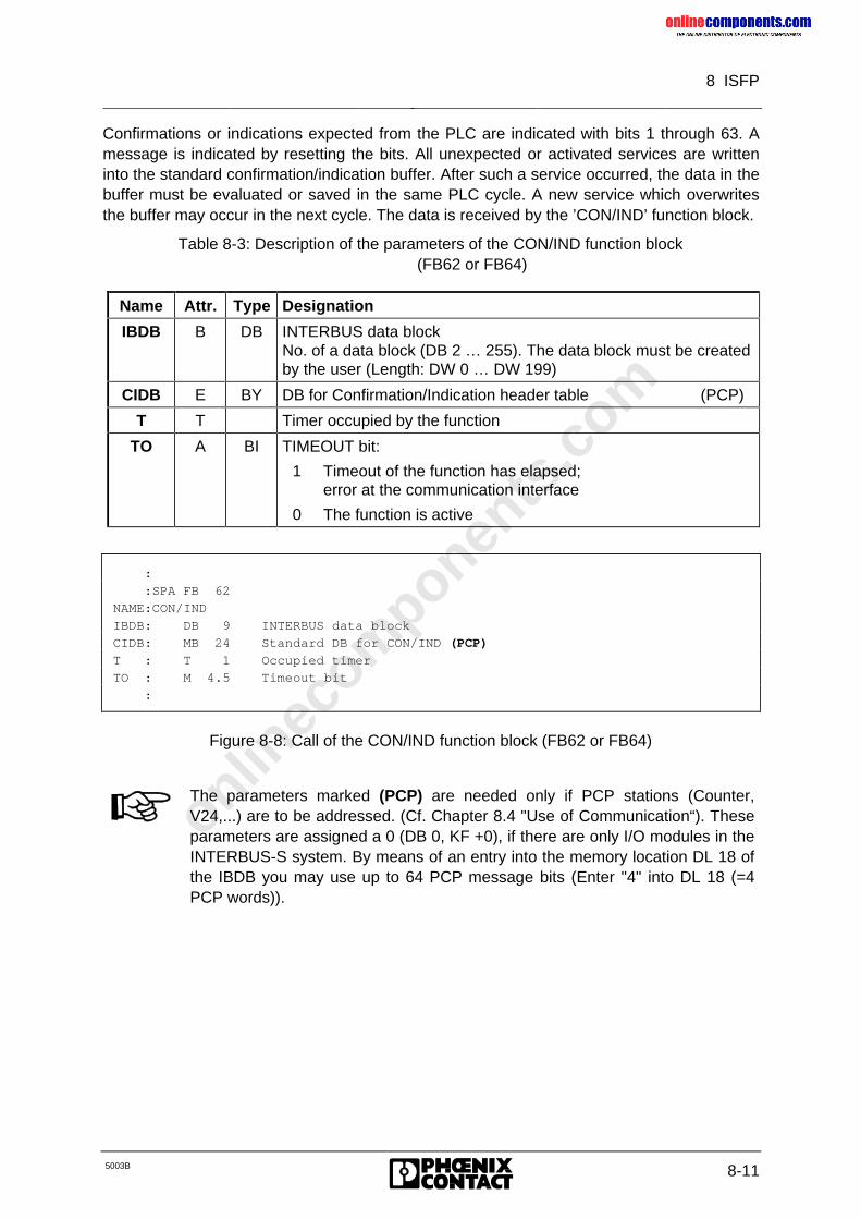
onlinec
omponen
ts.co
m
8 ISFP
5003B 8-11
Confirmations or indications expected from the PLC are indicated with bits 1 through 63. Amessage is indicated by resetting the bits. All unexpected or activated services are writteninto the standard confirmation/indication buffer. After such a service occurred, the data in thebuffer must be evaluated or saved in the same PLC cycle. A new service which overwritesthe buffer may occur in the next cycle. The data is received by the ’CON/IND’ function block.
Table 8-3: Description of the parameters of the CON/IND function block(FB62 or FB64)
Name Attr. Type Designation
IBDB B DB INTERBUS data blockNo. of a data block (DB 2 … 255). The data block must be createdby the user (Length: DW 0 … DW 199)
CIDB E BY DB for Confirmation/Indication header table (PCP)
T T Timer occupied by the function
TO A BI TIMEOUT bit:
1 Timeout of the function has elapsed;error at the communication interface
0 The function is active
:
:SPA FB 62
NAME:CON/IND
IBDB: DB 9 INTERBUS data block
CIDB: MB 24 Standard DB for CON/IND (PCP)
T : T 1 Occupied timer
TO : M 4.5 Timeout bit
:
Figure 8-8: Call of the CON/IND function block (FB62 or FB64)
The parameters marked (PCP) are needed only if PCP stations (Counter,V24,...) are to be addressed. (Cf. Chapter 8.4 "Use of Communication“). Theseparameters are assigned a 0 (DB 0, KF +0), if there are only I/O modules in theINTERBUS-S system. By means of an entry into the memory location DL 18 ofthe IBDB you may use up to 64 PCP message bits (Enter "4" into DL 18 (=4PCP words)).
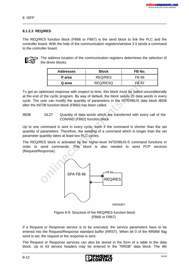
onlinec
omponen
ts.co
m
8 ISFP
8-12 5003B
8.1.2.3 REQ/RES
The REQ/RES function block (FB66 or FB67) is the send block to link the PLC and thecontroller board. With the help of the communication registers/window 3 it sends a commandto the controller board.
The address location of the communication registers determines the selection ofthe driver blocks.
Addresses Block FB No.
P area REQ/RES FB 66
Q area REQ/RESQ FB 67
To get an optimized response with respect to time, this block must be called unconditionallyat the end of the cyclic program. By way of default, the block sends 20 data words in everycycle. The user can modify the quantity of parameters in the INTERBUS data block IBDBafter the INITIB function block (FB60) has been called.
IBDB DL27 Quantity of data words which are transferred with every call of theCON/IND (FB62) function block.
Up to one command is sent in every cycle, even if the command is shorter than the setquantity of parameters. Therefore, the sending of a command which is longer than the setparameter quantity takes at least two PLC cycles.
The REQ/RES block is activated by the higher-level INTERBUS-S command functions inorder to send commands. This block is also needed to send PCP services(Request/Response).
REQ/RES
5003A807
FB 66SPA FB 66
Figure 8-9: Structure of the REQ/RES function block(FB66 or FB67)
If a Request or Response service is to be executed, the service parameters have to beentered into the Request/Response standard buffer (RRST). When bit 0 of the RRMW flagword is set, the request or the response is sent.
The Request or Response services can also be stored in the form of a table in the datablock. Up to 63 service headers may be entered in the "RRDB" data block. The 4th
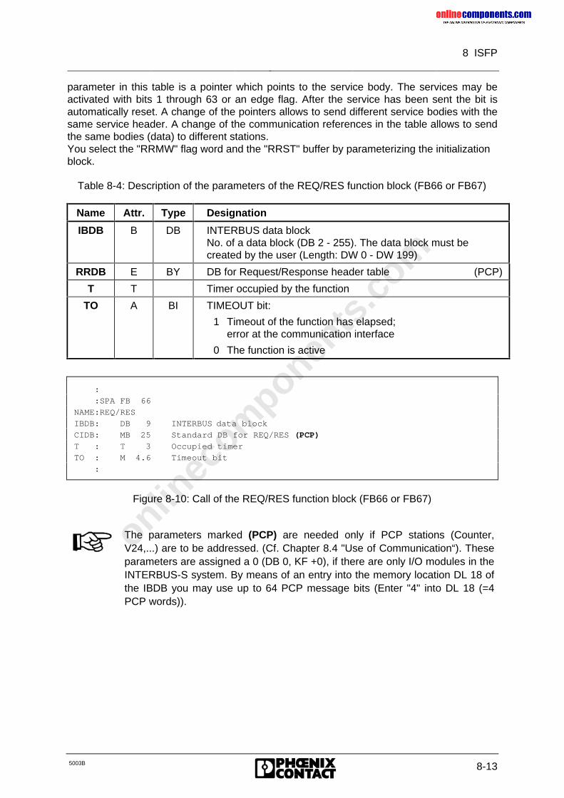
onlinec
omponen
ts.co
m
8 ISFP
5003B 8-13
parameter in this table is a pointer which points to the service body. The services may beactivated with bits 1 through 63 or an edge flag. After the service has been sent the bit isautomatically reset. A change of the pointers allows to send different service bodies with thesame service header. A change of the communication references in the table allows to sendthe same bodies (data) to different stations.You select the "RRMW" flag word and the "RRST" buffer by parameterizing the initializationblock.
Table 8-4: Description of the parameters of the REQ/RES function block (FB66 or FB67)
Name Attr. Type Designation
IBDB B DB INTERBUS data blockNo. of a data block (DB 2 - 255). The data block must becreated by the user (Length: DW 0 - DW 199)
RRDB E BY DB for Request/Response header table (PCP)
T T Timer occupied by the function
TO A BI TIMEOUT bit:
1 Timeout of the function has elapsed;error at the communication interface
0 The function is active
:
:SPA FB 66
NAME:REQ/RES
IBDB: DB 9 INTERBUS data block
CIDB: MB 25 Standard DB for REQ/RES (PCP)
T : T 3 Occupied timer
TO : M 4.6 Timeout bit
:
Figure 8-10: Call of the REQ/RES function block (FB66 or FB67)
The parameters marked (PCP) are needed only if PCP stations (Counter,V24,...) are to be addressed. (Cf. Chapter 8.4 "Use of Communication“). Theseparameters are assigned a 0 (DB 0, KF +0), if there are only I/O modules in theINTERBUS-S system. By means of an entry into the memory location DL 18 ofthe IBDB you may use up to 64 PCP message bits (Enter "4" into DL 18 (=4PCP words)).
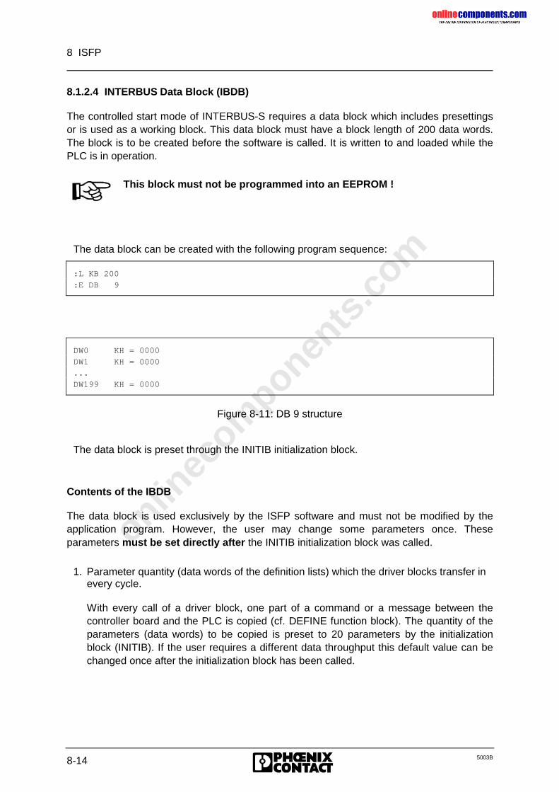
onlinec
omponen
ts.co
m
8 ISFP
8-14 5003B
8.1.2.4 INTERBUS Data Block (IBDB)
The controlled start mode of INTERBUS-S requires a data block which includes presettingsor is used as a working block. This data block must have a block length of 200 data words.The block is to be created before the software is called. It is written to and loaded while thePLC is in operation.
This block must not be programmed into an EEPROM !
The data block can be created with the following program sequence:
:L KB 200
:E DB 9
DW0 KH = 0000
DW1 KH = 0000
...
DW199 KH = 0000
Figure 8-11: DB 9 structure
The data block is preset through the INITIB initialization block.
Contents of the IBDB
The data block is used exclusively by the ISFP software and must not be modified by theapplication program. However, the user may change some parameters once. Theseparameters must be set directly after the INITIB initialization block was called.
1. Parameter quantity (data words of the definition lists) which the driver blocks transfer inevery cycle.
With every call of a driver block, one part of a command or a message between thecontroller board and the PLC is copied (cf. DEFINE function block). The quantity of theparameters (data words) to be copied is preset to 20 parameters by the initializationblock (INITIB). If the user requires a different data throughput this default value can bechanged once after the initialization block has been called.
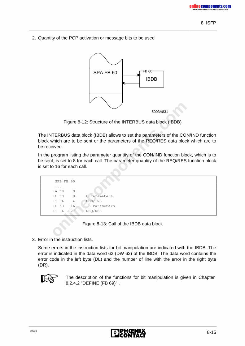
onlinec
omponen
ts.co
m
8 ISFP
5003B 8-15
2. Quantity of the PCP activation or message bits to be used
IBDB
5003A831
FB 60SPA FB 60
Figure 8-12: Structure of the INTERBUS data block (IBDB)
The INTERBUS data block (IBDB) allows to set the parameters of the CON/IND functionblock which are to be sent or the parameters of the REQ/RES data block which are tobe received.
In the program listing the parameter quantity of the CON/IND function block, which is tobe sent, is set to 8 for each call. The parameter quantity of the REQ/RES function blockis set to 16 for each call.
SPB FB 60
...
:A DB 9
:L KB 8 8 Parameters
:T DL 4 CON/IND
:L KB 16 16 Parameters
:T DL 27 REQ/RES
Figure 8-13: Call of the IBDB data block
3. Error in the instruction lists.
Some errors in the instruction lists for bit manipulation are indicated with the IBDB. Theerror is indicated in the data word 62 (DW 62) of the IBDB. The data word contains theerror code in the left byte (DL) and the number of line with the error in the right byte(DR).
The description of the functions for bit manipulation is given in Chapter8.2.4.2 "DEFINE (FB 69)" .
onlinec
omponen
ts.co
m
8 ISFP
8-16 5003B
8.1.3 INTERBUS-S System Control
The INTERBUS-S functions consist of function blocks. They are called by the user at startupand in the cyclic program by means of conditional or unconditional jumps. The functionblocks are written in STEP 5.
The INITIB initialization block is called at startup of the PLC (OB 20 - 22). Some basicsoftware settings are carried out with the INITIB function block (FB60). It also performssynchronization between the PLC and INTERBUS-S. The routine is not terminated untilINTERBUS-S is in the "READY" state, i.e. is ready for operation.
In the cyclic program, the receive and send blocks are called unconditionally. To get anoptimized response with respect to time, the receive block (CON/IND) should be called at thestart of the cyclic program and the send block (REQ/RES) should be called at the end.Depending on the length of the command or message (quantity of data words), the blocksmay also be active for several cycles.
The function blocks for the system messages are called after the receive block. Thecommand functions are called at the end of the cyclic program before the send block. Thecommand and message functions are activated by flag bits. Each function may only becalled up in one position of the program.
A function is started by setting its parameters and activation bit (BUSY bit). If a function is tobe used in several parts of the user program, the parameters and the activation bit have tobe set.
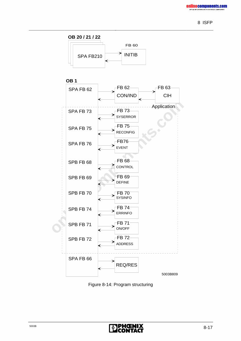
onlinec
omponen
ts.co
m
8 ISFP
5003B 8-17
OB 20 / 21 / 22
SPA FB210
OB 1
CON/INDSPA FB 62
SPA FB 66
5003B809
INITIB
CIH
REQ/RES
SPB FB 71
SPB FB 74
SPB FB 70
SPB FB 69
SPB FB 68
SPA FB 76
SPA FB 75
SPA FB 73
FB 62 FB 63
FB 73
FB 75
FB76
FB 68
FB 69
FB 70
FB 74
FB 71
Application
FB 72SPB FB 72
SYSERROR
RECONFIG
EVENT
CONTROL
DEFINE
SYSINFO
ERRINFO
ON/OFF
ADDRESS
FB 60
Figure 8-14: Program structuring
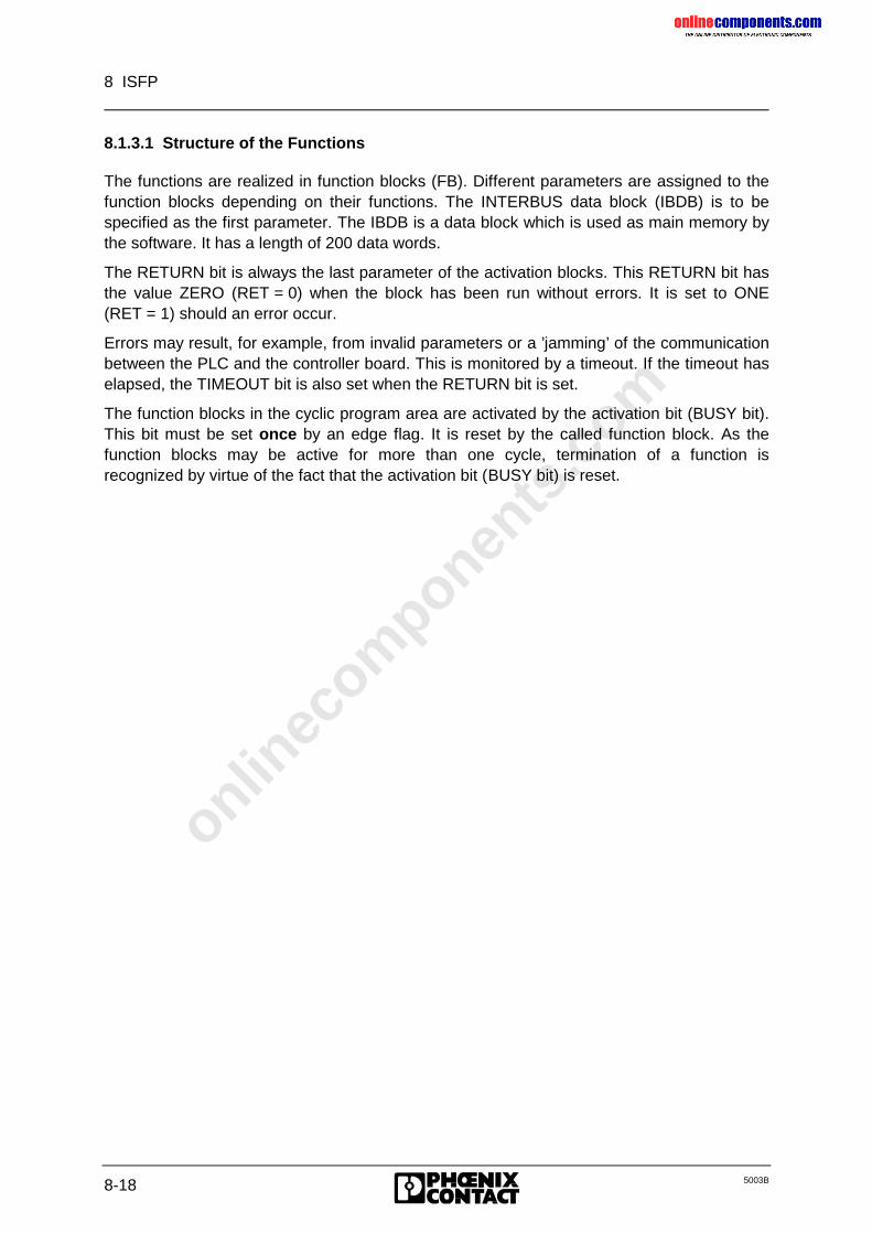
onlinec
omponen
ts.co
m
8 ISFP
8-18 5003B
8.1.3.1 Structure of the Functions
The functions are realized in function blocks (FB). Different parameters are assigned to thefunction blocks depending on their functions. The INTERBUS data block (IBDB) is to bespecified as the first parameter. The IBDB is a data block which is used as main memory bythe software. It has a length of 200 data words.
The RETURN bit is always the last parameter of the activation blocks. This RETURN bit hasthe value ZERO (RET = 0) when the block has been run without errors. It is set to ONE(RET = 1) should an error occur.
Errors may result, for example, from invalid parameters or a ’jamming’ of the communicationbetween the PLC and the controller board. This is monitored by a timeout. If the timeout haselapsed, the TIMEOUT bit is also set when the RETURN bit is set.
The function blocks in the cyclic program area are activated by the activation bit (BUSY bit).This bit must be set once by an edge flag. It is reset by the called function block. As thefunction blocks may be active for more than one cycle, termination of a function isrecognized by virtue of the fact that the activation bit (BUSY bit) is reset.
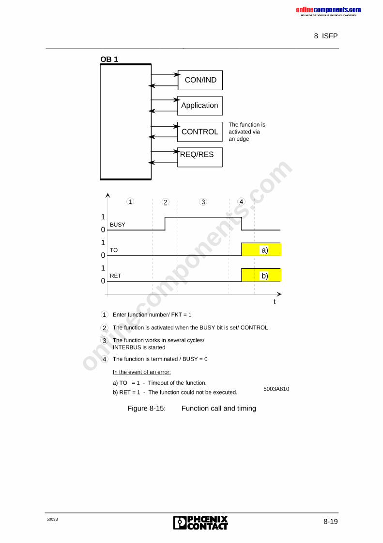
onlinec
omponen
ts.co
m
8 ISFP
5003B 8-19
OB 1
Application
REQ/RES
CON/IND
5003A810
CONTROLThe function is activated viaan edge
b)
a)
0
1
0
1
0
1
BUSY
TO
RET
t
1 2 3 4
1
2
3
4
Enter function number/ FKT = 1
The function is activated when the BUSY bit is set/ CONTROL
The function works in several cycles/INTERBUS is started
The function is terminated / BUSY = 0
In the event of an error:
a) TO = 1 - Timeout of the function.
b) RET = 1 - The function could not be executed.
Figure 8-15: Function call and timing
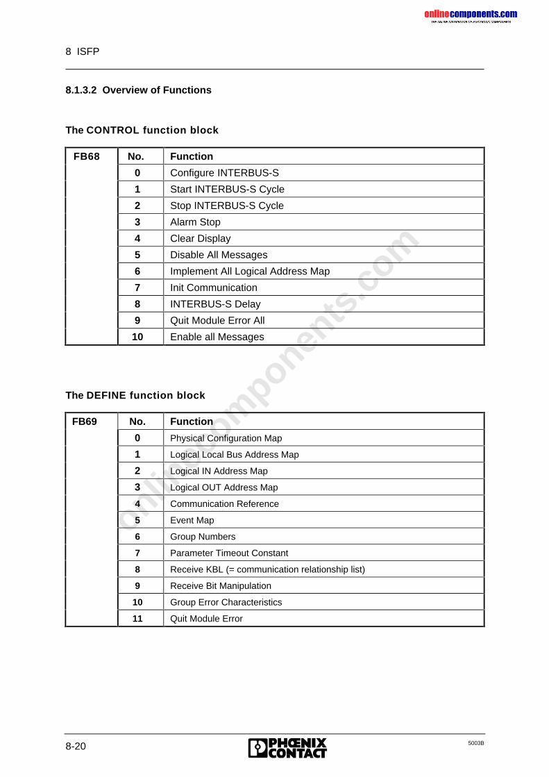
onlinec
omponen
ts.co
m
8 ISFP
8-20 5003B
8.1.3.2 Overview of Functions
The CONTROL function block
FB68 No. Function
0 Configure INTERBUS-S
1 Start INTERBUS-S Cycle
2 Stop INTERBUS-S Cycle
3 Alarm Stop
4 Clear Display
5 Disable All Messages
6 Implement All Logical Address Map
7 Init Communication
8 INTERBUS-S Delay
9 Quit Module Error All
10 Enable all Messages
The DEFINE function block
FB69 No. Function
0 Physical Configuration Map
1 Logical Local Bus Address Map
2 Logical IN Address Map
3 Logical OUT Address Map
4 Communication Reference
5 Event Map
6 Group Numbers
7 Parameter Timeout Constant
8 Receive KBL (= communication relationship list)
9 Receive Bit Manipulation
10 Group Error Characteristics
11 Quit Module Error
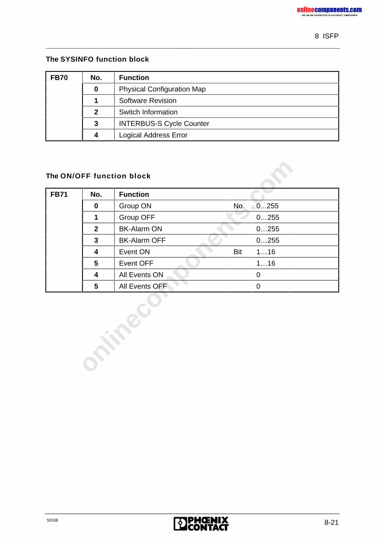
onlinec
omponen
ts.co
m
8 ISFP
5003B 8-21
The SYSINFO function block
FB70 No. Function
0 Physical Configuration Map
1 Software Revision
2 Switch Information
3 INTERBUS-S Cycle Counter
4 Logical Address Error
The ON/OFF function block
FB71 No. Function
0 Group ON No. 0…255
1 Group OFF 0…255
2 BK-Alarm ON 0…255
3 BK-Alarm OFF 0…255
4 Event ON Bit 1…16
5 Event OFF 1…16
4 All Events ON 0
5 All Events OFF 0
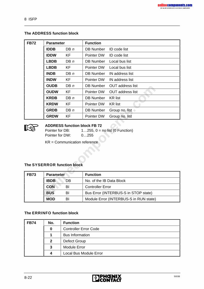
onlinec
omponen
ts.co
m
8 ISFP
8-22 5003B
The ADDRESS function block
FB72 Parameter Function
IDDB DB n DB Number ID code list
IDDW KF Pointer DW ID code list
LBDB DB n DB Number Local bus list
LBDB KF Pointer DW Local bus list
INDB DB n DB Number IN address list
INDW KF Pointer DW IN address list
OUDB DB n DB Number OUT address list
OUDW KF Pointer DW OUT address list
KRDB DB n DB Number KR list
KRDW KF Pointer DW KR list
GRDB DB n DB Number Group no. list
GRDW KF Pointer DW Group no. list
ADDRESS function block FB 72Pointer for DB: 1…255, 0 = no list (0 Function)Pointer for DW: 0…255
KR = Communication reference
The SYSERROR function block
FB73 Parameter Function
IBDB DB No. of the IB Data Block
CON BI Controller Error
BUS BI Bus Error (INTERBUS-S in STOP state)
MOD BI Module Error (INTERBUS-S in RUN state)
The ERRINFO function block
FB74 No. Function
0 Controller Error Code
1 Bus Information
2 Defect Group
3 Module Error
4 Local Bus Module Error
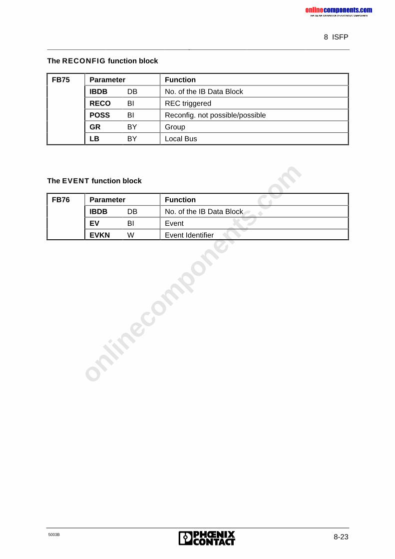
onlinec
omponen
ts.co
m
8 ISFP
5003B 8-23
The RECONFIG function block
FB75 Parameter Function
IBDB DB No. of the IB Data Block
RECO BI REC triggered
POSS BI Reconfig. not possible/possible
GR BY Group
LB BY Local Bus
The EVENT function block
FB76 Parameter Function
IBDB DB No. of the IB Data Block
EV BI Event
EVKN W Event Identifier
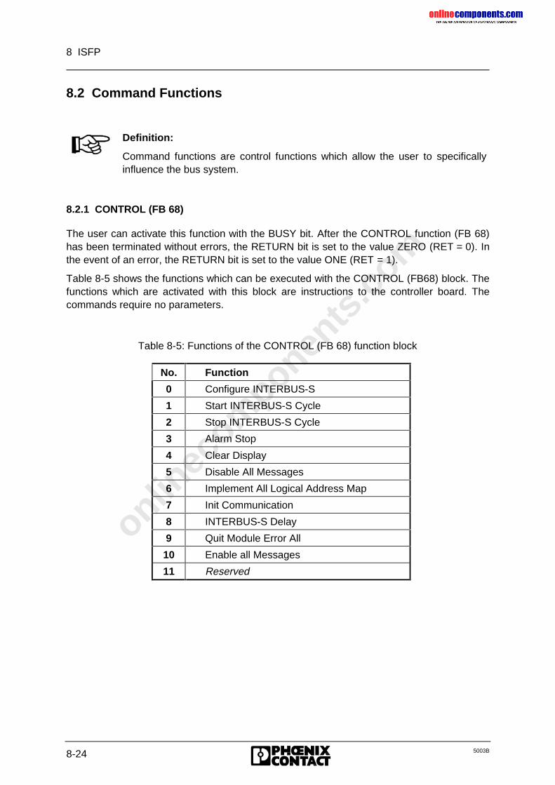
onlinec
omponen
ts.co
m
8 ISFP
8-24 5003B
8.2 Command Functions
Definition:
Command functions are control functions which allow the user to specificallyinfluence the bus system.
8.2.1 CONTROL (FB 68)
The user can activate this function with the BUSY bit. After the CONTROL function (FB 68)has been terminated without errors, the RETURN bit is set to the value ZERO (RET = 0). Inthe event of an error, the RETURN bit is set to the value ONE (RET = 1).
Table 8-5 shows the functions which can be executed with the CONTROL (FB68) block. Thefunctions which are activated with this block are instructions to the controller board. Thecommands require no parameters.
Table 8-5: Functions of the CONTROL (FB 68) function block
No. Function
0 Configure INTERBUS-S
1 Start INTERBUS-S Cycle
2 Stop INTERBUS-S Cycle
3 Alarm Stop
4 Clear Display
5 Disable All Messages
6 Implement All Logical Address Map
7 Init Communication
8 INTERBUS-S Delay
9 Quit Module Error All
10 Enable all Messages
11 Reserved
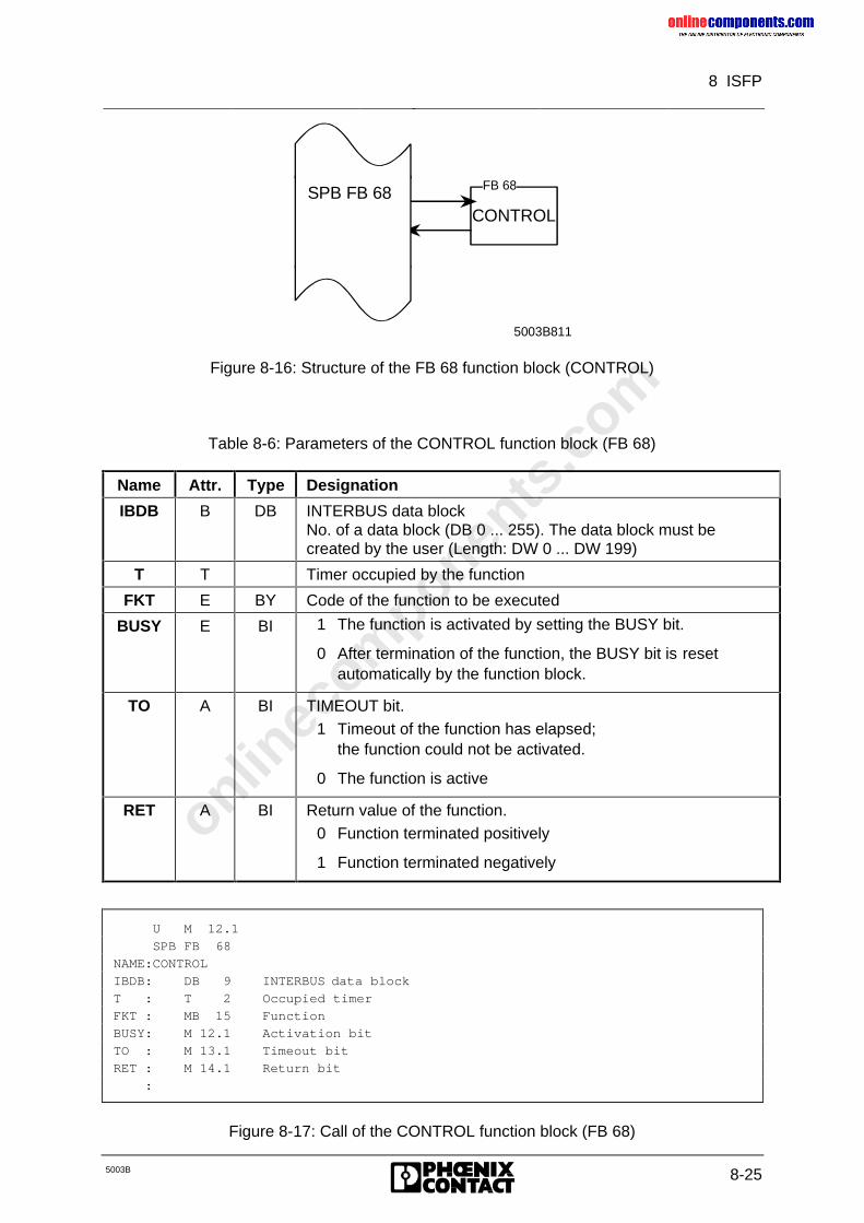
onlinec
omponen
ts.co
m
8 ISFP
5003B 8-25
CONTROL
5003B811
FB 68SPB FB 68
Figure 8-16: Structure of the FB 68 function block (CONTROL)
Table 8-6: Parameters of the CONTROL function block (FB 68)
Name Attr. Type Designation
IBDB B DB INTERBUS data blockNo. of a data block (DB 0 ... 255). The data block must becreated by the user (Length: DW 0 ... DW 199)
T T Timer occupied by the function
FKT E BY Code of the function to be executed
BUSY E BI 1 The function is activated by setting the BUSY bit.
0 After termination of the function, the BUSY bit is resetautomatically by the function block.
TO A BI TIMEOUT bit.1 Timeout of the function has elapsed;
the function could not be activated.
0 The function is active
RET A BI Return value of the function.0 Function terminated positively
1 Function terminated negatively
U M 12.1
SPB FB 68
NAME:CONTROL
IBDB: DB 9 INTERBUS data block
T : T 2 Occupied timer
FKT : MB 15 Function
BUSY: M 12.1 Activation bit
TO : M 13.1 Timeout bit
RET : M 14.1 Return bit
:
Figure 8-17: Call of the CONTROL function block (FB 68)
onlinec
omponen
ts.co
m
8 ISFP
8-26 5003B
8.2.1.1 Configure INTERBUS-S (FKT 0)
The controller board is caused to configure the connected INTERBUS-S system. Thisconfiguration is declared to be the "initial" configuration. Previously sent group definitions,logical address lists or event definitions are no longer valid.
8.2.1.2 Start INTERBUS-S Cycle (FKT 1)
The INTERBUS-S cycle is started when a permissible bus configuration is connected. Fromthis time on, the controller board stores a cyclic data image of the INTERBUS-S system inthe DPM.
INTERBUS-S will not be started if it is not allowed after an error (e.g. a hardware error), or ifall groups are deactivated.
The yellow "BSA" LED is activated when a bus segment has been deactivated.
8.2.1.3 Stop INTERBUS-S Cycle (FKT 2)
The ’Stop INTERBUS-S Cycle’ function stops the running of INTERBUS-S cycles. TheIBRUN LED is switched off.
The last statuses of the outputs remain unchanged. The ALARM STOP (FKT 3)command must be used if the outputs of the OUT module are to be set to zero.
8.2.1.4 Alarm Stop (FKT 3)
The ’Alarm Stop’ function triggers a reset on INTERBUS-S. This sets all module outputs tozero and the INTERBUS-S cycle is stopped.
If the bus is then to be restarted, it must be configured beforehand by a reset or with the’Configure INTERBUS-S’ function (FKT 0).
8.2.1.5 Clear Display (FKT 4)
The ’Clear Display’ function acknowledges an error message of the controller board. Thisfunction clears simultaneously the red error LEDs and resets the seven-segment display.Only then can new errors be reported on the seven-segment display.
The error source is still available after the clearing !
onlinec
omponen
ts.co
m
8 ISFP
5003B 8-27
8.2.1.6 Disable All Messages (FKT 5)
The ’Disable All Messages’ function disables all messages from the controller board.
The disabling of messages is canceled by calling any other function.
8.2.1.7 Implement All Logical Address Map (FKT 6)
With the ’Implement All Logical Address Map’ function, logical address lists become validwhich were previously sent to the PLC. From then on, they are used to address theINTERBUS-S modules.
This function must only be sent when the bus is in the stop state as no RESETwill be triggered on the bus if an error should occur. Otherwise, the pendingoutput data on the modules would not be cleared in the event of an error.
The error location in the previously sent address list can be obtained with the’Logical Address Error’ (FB 70, FKT 4) function.
8.2.1.8 Init Communication (FKT 7)
The ’Init Communication’ function initializes the communication layers and enablescommunication.
The bus must be started before this command.(cf. Chapter 8.2.1.1, "Start INTERBUS-S Cycle")
Error causes: The ’Init Communication’ function reports an error, if ...
• the bus was not started,
• the KBL (communication relationship list) contains an invalid communication reference,
• an invalid remote bus address was specified in the KBL (e.g.: double allocation)
8.2.1.9 INTERBUS-S Delay (FKT 8)
With the ’INTERBUS-S Delay’ function, the delay time during operation with communicationcan be deactivated. The time is set after switching on the voltage.
8.2.1.10 Quit Module Error All (FKT 9)
With the ’Quit Module Error All’ function, the module errors of the currently accessibleconfiguration are acknowledged.
This command function is effective for all modules with a stored module error.
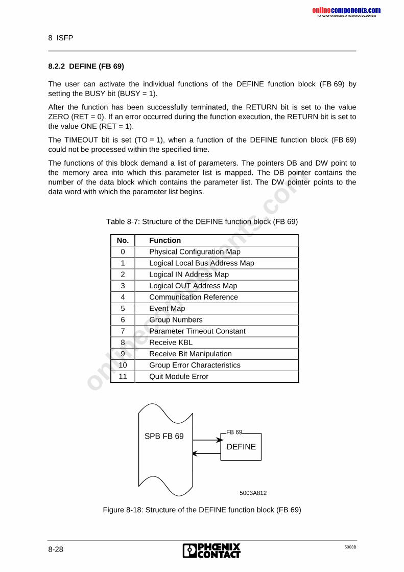
onlinec
omponen
ts.co
m
8 ISFP
8-28 5003B
8.2.2 DEFINE (FB 69)
The user can activate the individual functions of the DEFINE function block (FB 69) bysetting the BUSY bit (BUSY = 1).
After the function has been successfully terminated, the RETURN bit is set to the valueZERO (RET = 0). If an error occurred during the function execution, the RETURN bit is set tothe value ONE (RET = 1).
The TIMEOUT bit is set (TO = 1), when a function of the DEFINE function block (FB 69)could not be processed within the specified time.
The functions of this block demand a list of parameters. The pointers DB and DW point tothe memory area into which this parameter list is mapped. The DB pointer contains thenumber of the data block which contains the parameter list. The DW pointer points to thedata word with which the parameter list begins.
Table 8-7: Structure of the DEFINE function block (FB 69)
No. Function
0 Physical Configuration Map
1 Logical Local Bus Address Map
2 Logical IN Address Map
3 Logical OUT Address Map
4 Communication Reference
5 Event Map
6 Group Numbers
7 Parameter Timeout Constant
8 Receive KBL
9 Receive Bit Manipulation
10 Group Error Characteristics
11 Quit Module Error
DEFINE
5003A812
FB 69SPB FB 69
Figure 8-18: Structure of the DEFINE function block (FB 69)
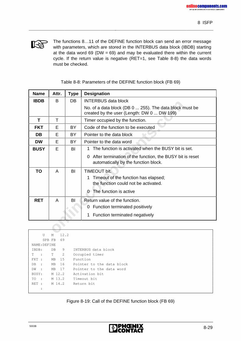
onlinec
omponen
ts.co
m
8 ISFP
5003B 8-29
The functions 8…11 of the DEFINE function block can send an error messagewith parameters, which are stored in the INTERBUS data block (IBDB) startingat the data word 69 (DW = 69) and may be evaluated there within the currentcycle. If the return value is negative (RET=1, see Table 8-8) the data wordsmust be checked.
Table 8-8: Parameters of the DEFINE function block (FB 69)
Name Attr. Type Designation
IBDB B DB INTERBUS data block
No. of a data block (DB 0 ... 255). The data block must becreated by the user (Length: DW 0 ... DW 199)
T T Timer occupied by the function.
FKT E BY Code of the function to be executed
DB E BY Pointer to the data block
DW E BY Pointer to the data word
BUSY E BI 1 The function is activated when the BUSY bit is set.
0 After termination of the function, the BUSY bit is resetautomatically by the function block.
TO A BI TIMEOUT bit.1 Timeout of the function has elapsed;
the function could not be activated.
0 The function is active
RET A BI Return value of the function.0 Function terminated positively
1 Function terminated negatively
U M 12.2
SPB FB 69
NAME:DEFINE
IBDB: DB 9 INTERBUS data block
T : T 2 Occupied timer
FKT : MB 15 Function
DB : MB 16 Pointer to the data block
DW : MB 17 Pointer to the data word
BUSY: M 12.2 Activation bit
TO : M 13.2 Timeout bit
RET : M 14.2 Return bit
:
Figure 8-19: Call of the DEFINE function block (FB 69)
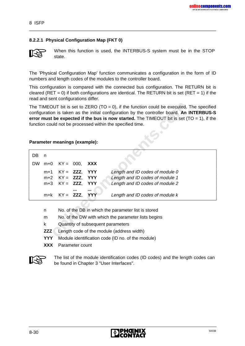
onlinec
omponen
ts.co
m
8 ISFP
8-30 5003B
8.2.2.1 Physical Configuration Map (FKT 0)
When this function is used, the INTERBUS-S system must be in the STOPstate.
The ’Physical Configuration Map’ function communicates a configuration in the form of IDnumbers and length codes of the modules to the controller board.
This configuration is compared with the connected bus configuration. The RETURN bit iscleared (RET = 0) if both configurations are identical. The RETURN bit is set (RET = 1) if theread and sent configurations differ.
The TIMEOUT bit is set to ZERO (TO = 0), if the function could be executed. The specifiedconfiguration is taken as the initial configuration by the controller board. An INTERBUS-Serror must be expected if the bus is now started. The TIMEOUT bit is set (TO = 1), if thefunction could not be processed within the specified time.
Parameter meanings (example):
DB n
DW m+0 KY = 000, XXX
m+1 KY = ZZZ, YYY Length and ID codes of module 0m+2 KY = ZZZ, YYY Length and ID codes of module 1m+3 KY = ZZZ, YYY Length and ID codes of module 2
... ...m+k KY = ZZZ, YYY Length and ID codes of module k
n No. of the DB in which the parameter list is stored
m No. of the DW with which the parameter lists begins
k Quantity of subsequent parameters
ZZZ Length code of the module (address width)
YYY Module identification code (ID no. of the module)
XXX Parameter count
The list of the module identification codes (ID codes) and the length codes canbe found in Chapter 3 "User Interfaces".
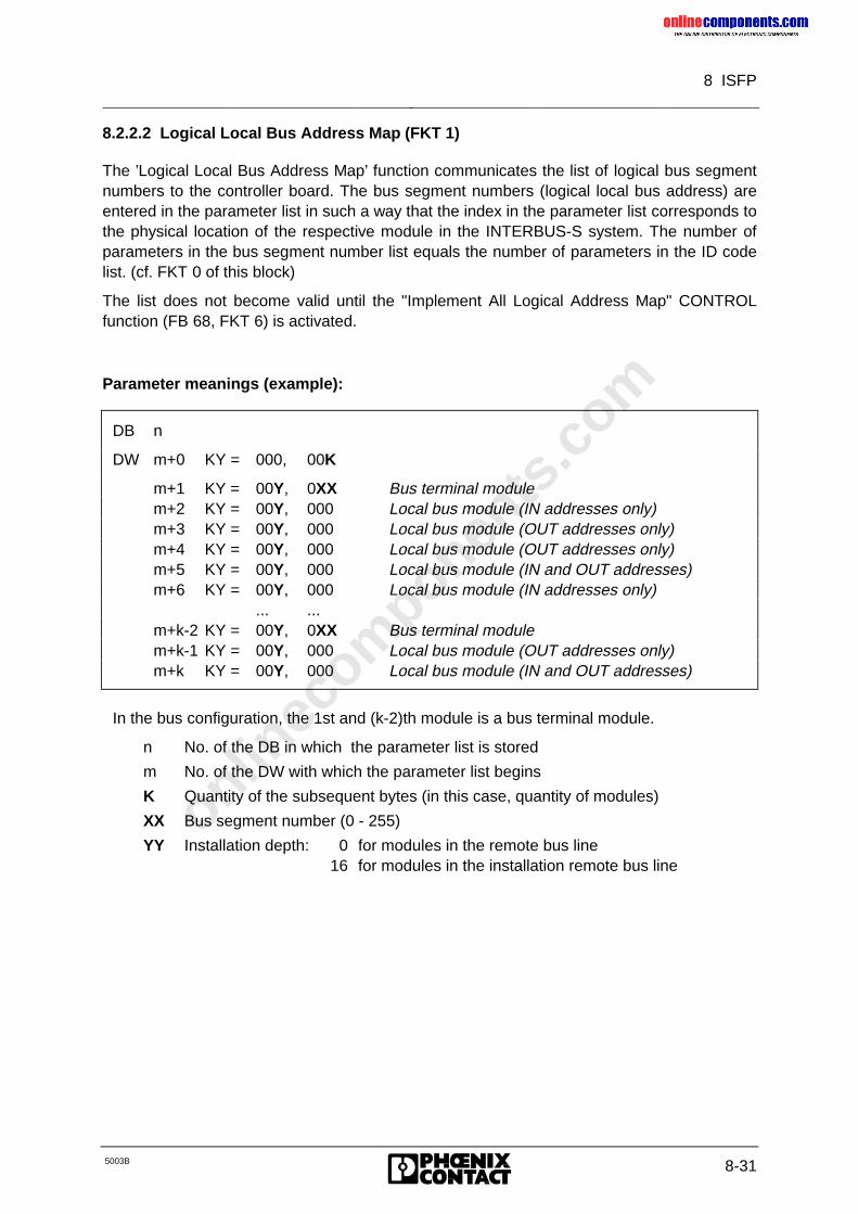
onlinec
omponen
ts.co
m
8 ISFP
5003B 8-31
8.2.2.2 Logical Local Bus Address Map (FKT 1)
The ’Logical Local Bus Address Map’ function communicates the list of logical bus segmentnumbers to the controller board. The bus segment numbers (logical local bus address) areentered in the parameter list in such a way that the index in the parameter list corresponds tothe physical location of the respective module in the INTERBUS-S system. The number ofparameters in the bus segment number list equals the number of parameters in the ID codelist. (cf. FKT 0 of this block)
The list does not become valid until the "Implement All Logical Address Map" CONTROLfunction (FB 68, FKT 6) is activated.
Parameter meanings (example):
DB n
DW m+0 KY = 000, 00K
m+1 KY = 00Y, 0XX Bus terminal modulem+2 KY = 00Y, 000 Local bus module (IN addresses only)m+3 KY = 00Y, 000 Local bus module (OUT addresses only)m+4 KY = 00Y, 000 Local bus module (OUT addresses only)m+5 KY = 00Y, 000 Local bus module (IN and OUT addresses)m+6 KY = 00Y, 000 Local bus module (IN addresses only)
... ...m+k-2 KY = 00Y, 0XX Bus terminal modulem+k-1 KY = 00Y, 000 Local bus module (OUT addresses only)m+k KY = 00Y, 000 Local bus module (IN and OUT addresses)
In the bus configuration, the 1st and (k-2)th module is a bus terminal module.
n No. of the DB in which the parameter list is stored
m No. of the DW with which the parameter list begins
K Quantity of the subsequent bytes (in this case, quantity of modules)
XX Bus segment number (0 - 255)
YY Installation depth: 0 for modules in the remote bus line16 for modules in the installation remote bus line
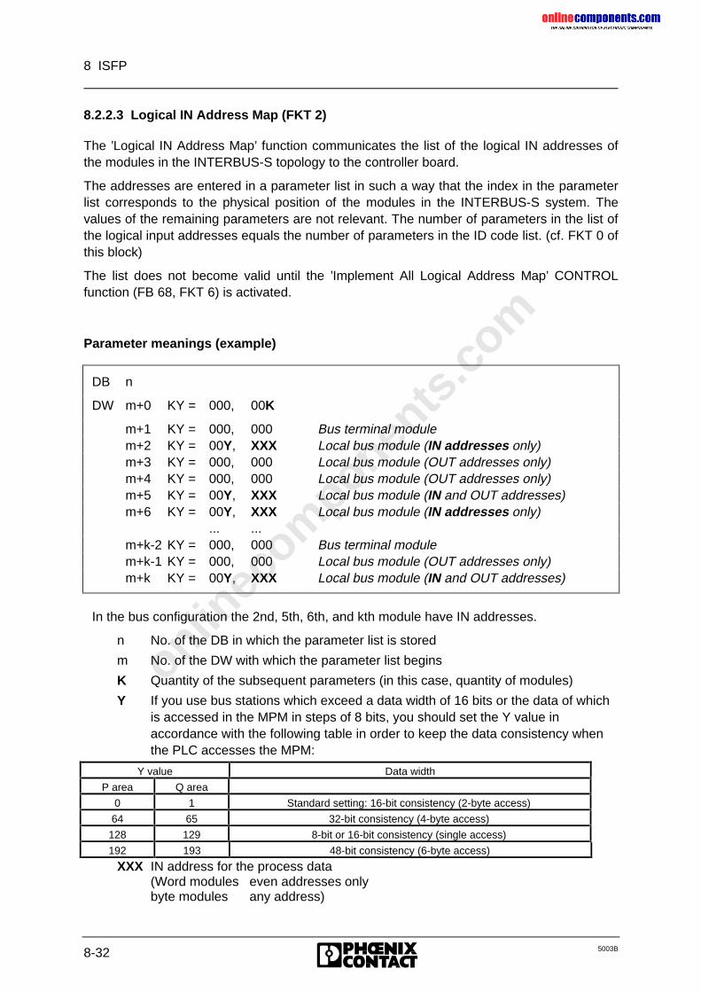
onlinec
omponen
ts.co
m
8 ISFP
8-32 5003B
8.2.2.3 Logical IN Address Map (FKT 2)
The ’Logical IN Address Map’ function communicates the list of the logical IN addresses ofthe modules in the INTERBUS-S topology to the controller board.
The addresses are entered in a parameter list in such a way that the index in the parameterlist corresponds to the physical position of the modules in the INTERBUS-S system. Thevalues of the remaining parameters are not relevant. The number of parameters in the list ofthe logical input addresses equals the number of parameters in the ID code list. (cf. FKT 0 ofthis block)
The list does not become valid until the ’Implement All Logical Address Map’ CONTROLfunction (FB 68, FKT 6) is activated.
Parameter meanings (example)
DB n
DW m+0 KY = 000, 00K
m+1 KY = 000, 000 Bus terminal modulem+2 KY = 00Y, XXX Local bus module (IN addresses only)m+3 KY = 000, 000 Local bus module (OUT addresses only)m+4 KY = 000, 000 Local bus module (OUT addresses only)m+5 KY = 00Y, XXX Local bus module (IN and OUT addresses)m+6 KY = 00Y, XXX Local bus module (IN addresses only)
... ...m+k-2 KY = 000, 000 Bus terminal modulem+k-1 KY = 000, 000 Local bus module (OUT addresses only)m+k KY = 00Y, XXX Local bus module (IN and OUT addresses)
In the bus configuration the 2nd, 5th, 6th, and kth module have IN addresses.
n No. of the DB in which the parameter list is stored
m No. of the DW with which the parameter list begins
K Quantity of the subsequent parameters (in this case, quantity of modules)
Y If you use bus stations which exceed a data width of 16 bits or the data of whichis accessed in the MPM in steps of 8 bits, you should set the Y value inaccordance with the following table in order to keep the data consistency whenthe PLC accesses the MPM:
Y value Data width
P area Q area
0 1 Standard setting: 16-bit consistency (2-byte access)
64 65 32-bit consistency (4-byte access)
128 129 8-bit or 16-bit consistency (single access)
192 193 48-bit consistency (6-byte access)
XXX IN address for the process data(Word modules even addresses onlybyte modules any address)
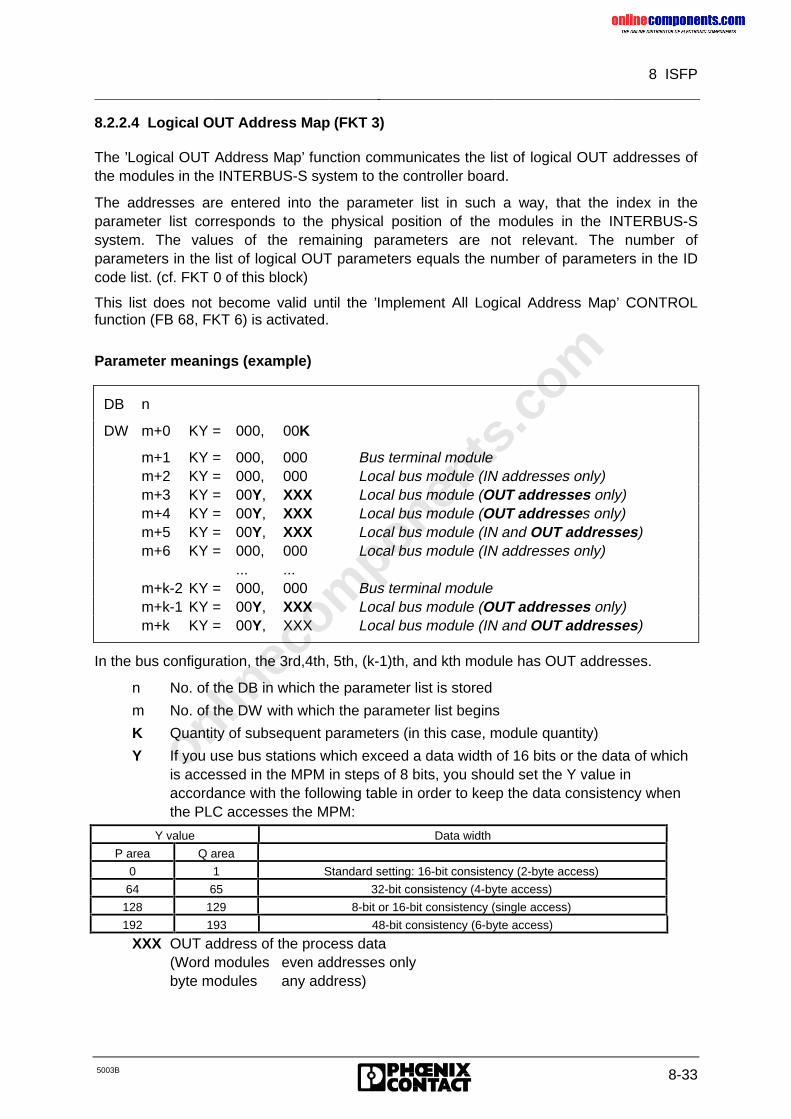
onlinec
omponen
ts.co
m
8 ISFP
5003B 8-33
8.2.2.4 Logical OUT Address Map (FKT 3)
The ’Logical OUT Address Map’ function communicates the list of logical OUT addresses ofthe modules in the INTERBUS-S system to the controller board.
The addresses are entered into the parameter list in such a way, that the index in theparameter list corresponds to the physical position of the modules in the INTERBUS-Ssystem. The values of the remaining parameters are not relevant. The number ofparameters in the list of logical OUT parameters equals the number of parameters in the IDcode list. (cf. FKT 0 of this block)
This list does not become valid until the ’Implement All Logical Address Map’ CONTROLfunction (FB 68, FKT 6) is activated.
Parameter meanings (example)
DB n
DW m+0 KY = 000, 00K
m+1 KY = 000, 000 Bus terminal modulem+2 KY = 000, 000 Local bus module (IN addresses only)m+3 KY = 00Y, XXX Local bus module (OUT addresses only)m+4 KY = 00Y, XXX Local bus module (OUT addresses only)m+5 KY = 00Y, XXX Local bus module (IN and OUT addresses)m+6 KY = 000, 000 Local bus module (IN addresses only)
... ...m+k-2 KY = 000, 000 Bus terminal modulem+k-1 KY = 00Y, XXX Local bus module (OUT addresses only)m+k KY = 00Y, XXX Local bus module (IN and OUT addresses)
In the bus configuration, the 3rd,4th, 5th, (k-1)th, and kth module has OUT addresses.
n No. of the DB in which the parameter list is stored
m No. of the DW with which the parameter list begins
K Quantity of subsequent parameters (in this case, module quantity)
Y If you use bus stations which exceed a data width of 16 bits or the data of whichis accessed in the MPM in steps of 8 bits, you should set the Y value inaccordance with the following table in order to keep the data consistency whenthe PLC accesses the MPM:
Y value Data width
P area Q area
0 1 Standard setting: 16-bit consistency (2-byte access)
64 65 32-bit consistency (4-byte access)
128 129 8-bit or 16-bit consistency (single access)
192 193 48-bit consistency (6-byte access)
XXX OUT address of the process data(Word modules even addresses onlybyte modules any address)
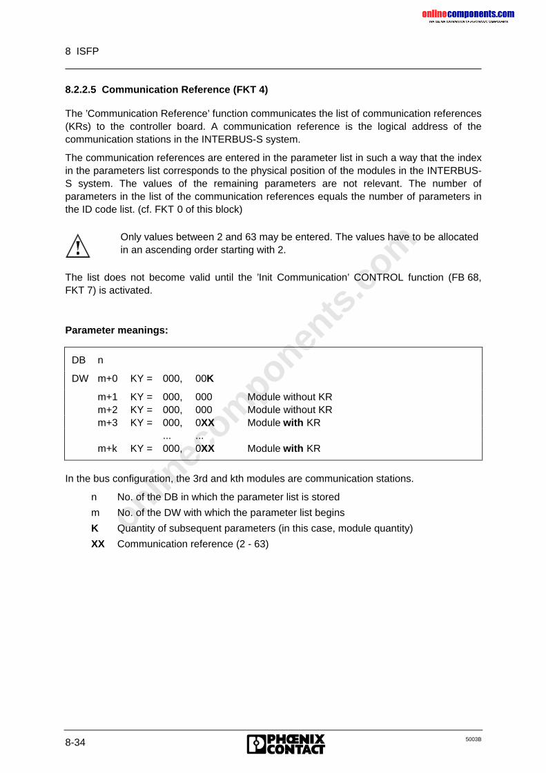
onlinec
omponen
ts.co
m
8 ISFP
8-34 5003B
8.2.2.5 Communication Reference (FKT 4)
The ’Communication Reference’ function communicates the list of communication references(KRs) to the controller board. A communication reference is the logical address of thecommunication stations in the INTERBUS-S system.
The communication references are entered in the parameter list in such a way that the indexin the parameters list corresponds to the physical position of the modules in the INTERBUS-S system. The values of the remaining parameters are not relevant. The number ofparameters in the list of the communication references equals the number of parameters inthe ID code list. (cf. FKT 0 of this block)
Only values between 2 and 63 may be entered. The values have to be allocatedin an ascending order starting with 2.
The list does not become valid until the ’Init Communication’ CONTROL function (FB 68,FKT 7) is activated.
Parameter meanings:
DB n
DW m+0 KY = 000, 00K
m+1 KY = 000, 000 Module without KRm+2 KY = 000, 000 Module without KRm+3 KY = 000, 0XX Module with KR
... ...m+k KY = 000, 0XX Module with KR
In the bus configuration, the 3rd and kth modules are communication stations.
n No. of the DB in which the parameter list is stored
m No. of the DW with which the parameter list begins
K Quantity of subsequent parameters (in this case, module quantity)
XX Communication reference (2 - 63)
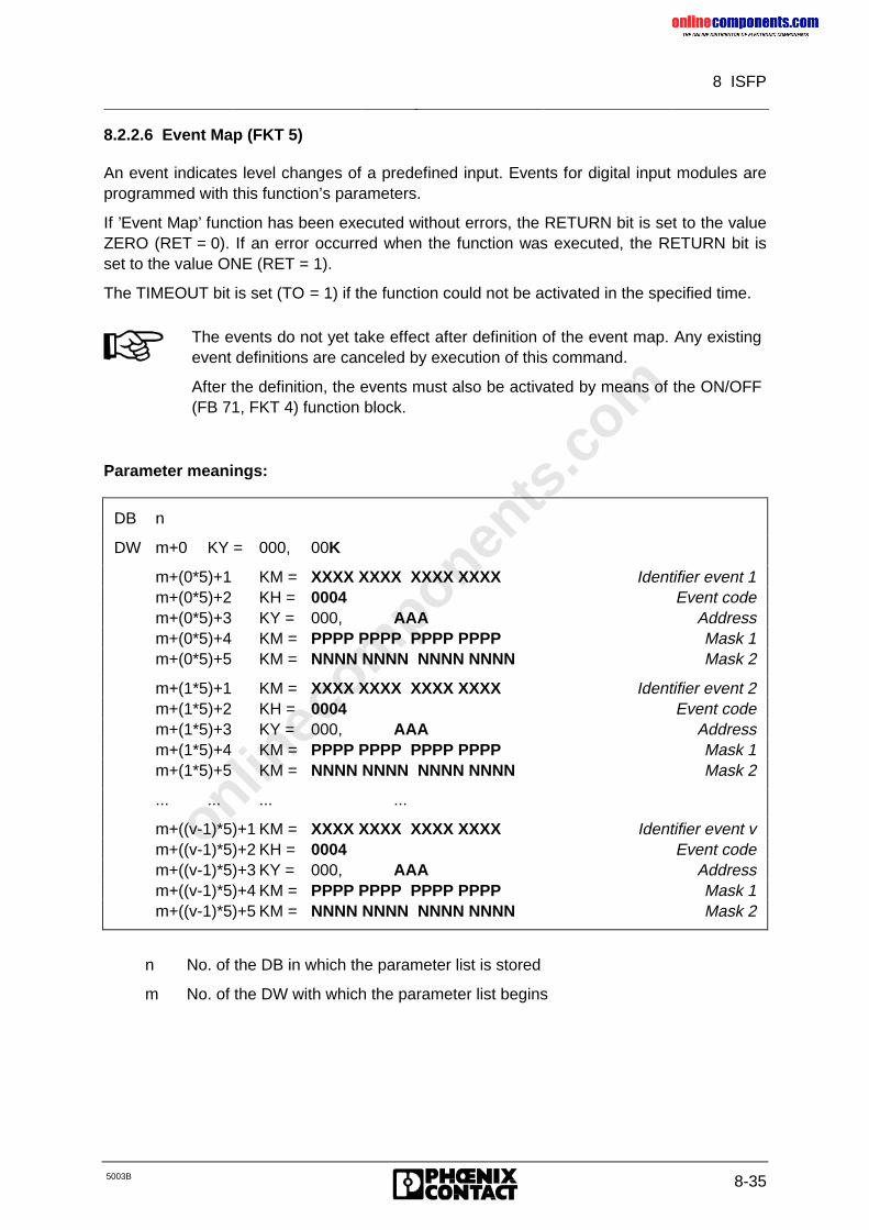
onlinec
omponen
ts.co
m
8 ISFP
5003B 8-35
8.2.2.6 Event Map (FKT 5)
An event indicates level changes of a predefined input. Events for digital input modules areprogrammed with this function’s parameters.
If ’Event Map’ function has been executed without errors, the RETURN bit is set to the valueZERO (RET = 0). If an error occurred when the function was executed, the RETURN bit isset to the value ONE (RET = 1).
The TIMEOUT bit is set (TO = 1) if the function could not be activated in the specified time.
The events do not yet take effect after definition of the event map. Any existingevent definitions are canceled by execution of this command.
After the definition, the events must also be activated by means of the ON/OFF(FB 71, FKT 4) function block.
Parameter meanings:
DB n
DW m+0 KY = 000, 00K
m+(0*5)+1 KM = XXXX XXXX XXXX XXXX Identifier event 1m+(0*5)+2 KH = 0004 Event codem+(0*5)+3 KY = 000, AAA Addressm+(0*5)+4 KM = PPPP PPPP PPPP PPPP Mask 1m+(0*5)+5 KM = NNNN NNNN NNNN NNNN Mask 2
m+(1*5)+1 KM = XXXX XXXX XXXX XXXX Identifier event 2m+(1*5)+2 KH = 0004 Event codem+(1*5)+3 KY = 000, AAA Addressm+(1*5)+4 KM = PPPP PPPP PPPP PPPP Mask 1m+(1*5)+5 KM = NNNN NNNN NNNN NNNN Mask 2
... ... ... ...
m+((v-1)*5)+1 KM = XXXX XXXX XXXX XXXX Identifier event vm+((v-1)*5)+2 KH = 0004 Event codem+((v-1)*5)+3 KY = 000, AAA Addressm+((v-1)*5)+4 KM = PPPP PPPP PPPP PPPP Mask 1m+((v-1)*5)+5 KM = NNNN NNNN NNNN NNNN Mask 2
n No. of the DB in which the parameter list is stored
m No. of the DW with which the parameter list begins
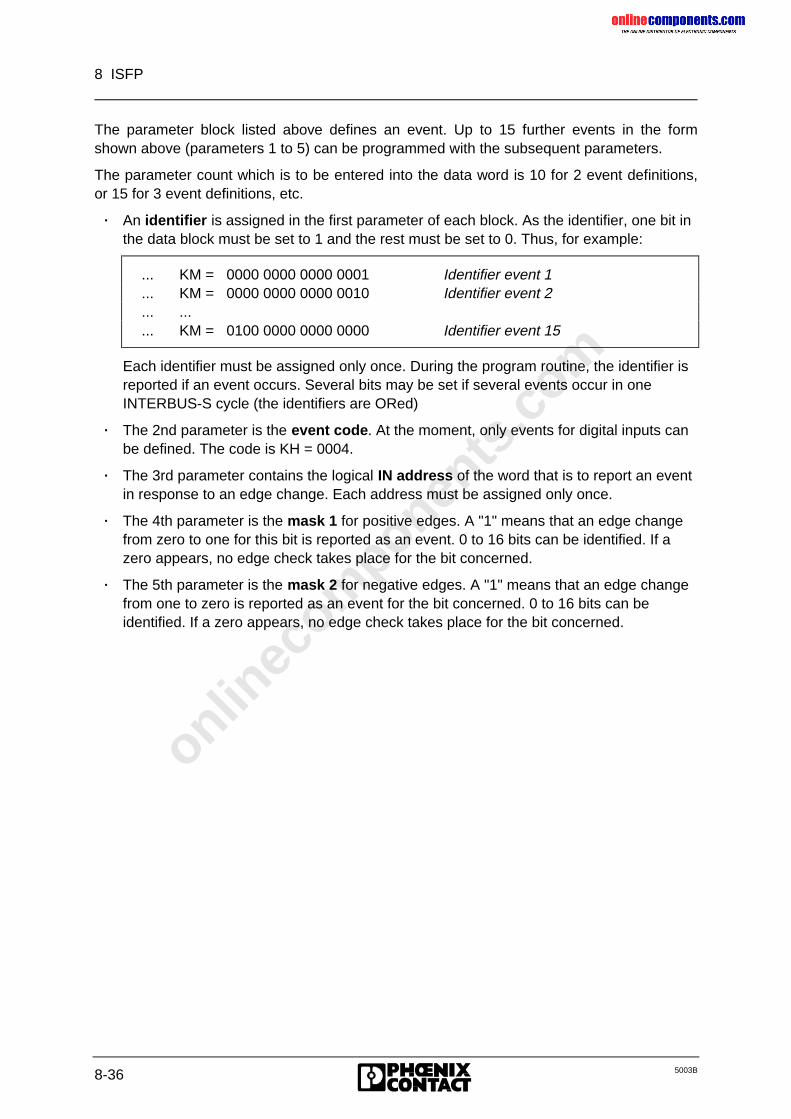
onlinec
omponen
ts.co
m
8 ISFP
8-36 5003B
The parameter block listed above defines an event. Up to 15 further events in the formshown above (parameters 1 to 5) can be programmed with the subsequent parameters.
The parameter count which is to be entered into the data word is 10 for 2 event definitions,or 15 for 3 event definitions, etc.
� An identifier is assigned in the first parameter of each block. As the identifier, one bit inthe data block must be set to 1 and the rest must be set to 0. Thus, for example:
... KM = 0000 0000 0000 0001 Identifier event 1
... KM = 0000 0000 0000 0010 Identifier event 2
... ...
... KM = 0100 0000 0000 0000 Identifier event 15
Each identifier must be assigned only once. During the program routine, the identifier isreported if an event occurs. Several bits may be set if several events occur in oneINTERBUS-S cycle (the identifiers are ORed)
� The 2nd parameter is the event code. At the moment, only events for digital inputs canbe defined. The code is KH = 0004.
� The 3rd parameter contains the logical IN address of the word that is to report an eventin response to an edge change. Each address must be assigned only once.
� The 4th parameter is the mask 1 for positive edges. A "1" means that an edge changefrom zero to one for this bit is reported as an event. 0 to 16 bits can be identified. If azero appears, no edge check takes place for the bit concerned.
� The 5th parameter is the mask 2 for negative edges. A "1" means that an edge changefrom one to zero is reported as an event for the bit concerned. 0 to 16 bits can beidentified. If a zero appears, no edge check takes place for the bit concerned.
onlinec
omponen
ts.co
m
8 ISFP
5003B 8-37
8.2.2.7 Group Numbers (FKT 6)
Several local buses can be combined to one group. If no groups have been defined, all localbuses belong to one group. To be able to deactivate a single local bus or installation remotebus, this bus must be assigned a group of its own. The group’s number can be freely chosenbetween 0 and 255. Equally, several installation remote buses can be combined in onegroup.
Bus stations which have only one remote bus connection, such as the IBS IP ...modules, can only form a group of their own. (This does not apply to busstations of the type IBS BK I/O T and IBS BB1 ...)
The ’Group Numbers’ function communicates the list of group definitions to the controllerboard. The controller board does not accept the list until after a test.
This test checks whether
• the addresses are valid,
• the addresses do not occur several times,
• the group numbers are within the range from 0 to 255,
• I/O BKs or similar modules are only defined singly in one group.
If the ’Group Numbers’ function has been executed without errors, the RETURN bit is set tothe value ZERO (RET = 0). If an error occurred during the function execution, the RETURNbit is set to the value ONE (RET = 1).
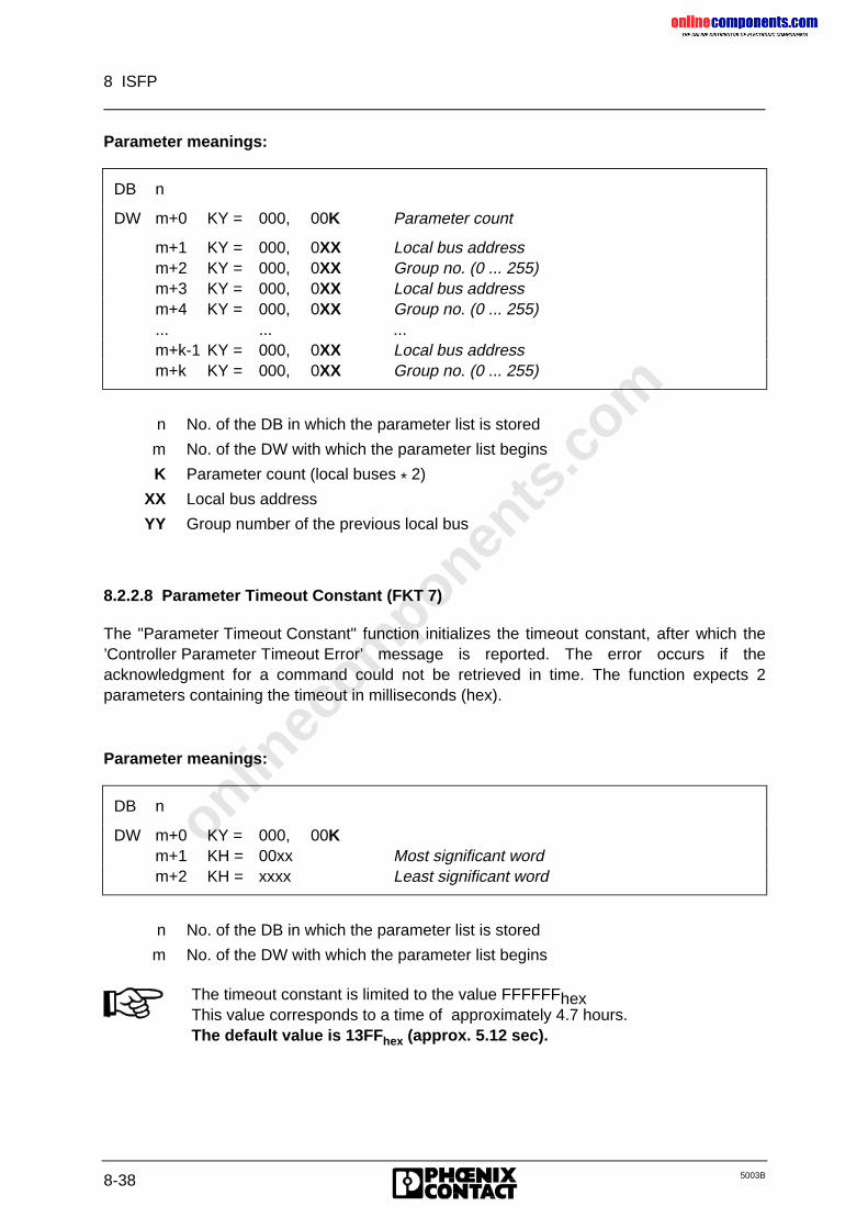
onlinec
omponen
ts.co
m
8 ISFP
8-38 5003B
Parameter meanings:
DB n
DW m+0 KY = 000, 00K Parameter count
m+1 KY = 000, 0XX Local bus addressm+2 KY = 000, 0XX Group no. (0 ... 255)m+3 KY = 000, 0XX Local bus addressm+4 KY = 000, 0XX Group no. (0 ... 255)... ... ...m+k-1 KY = 000, 0XX Local bus addressm+k KY = 000, 0XX Group no. (0 ... 255)
n No. of the DB in which the parameter list is stored
m No. of the DW with which the parameter list begins
K Parameter count (local buses * 2)
XX Local bus address
YY Group number of the previous local bus
8.2.2.8 Parameter Timeout Constant (FKT 7)
The "Parameter Timeout Constant" function initializes the timeout constant, after which the’Controller Parameter Timeout Error’ message is reported. The error occurs if theacknowledgment for a command could not be retrieved in time. The function expects 2parameters containing the timeout in milliseconds (hex).
Parameter meanings:
DB n
DW m+0 KY = 000, 00Km+1 KH = 00xx Most significant wordm+2 KH = xxxx Least significant word
n No. of the DB in which the parameter list is stored
m No. of the DW with which the parameter list begins
The timeout constant is limited to the value FFFFFFhexThis value corresponds to a time of approximately 4.7 hours.The default value is 13FFhex (approx. 5.12 sec).
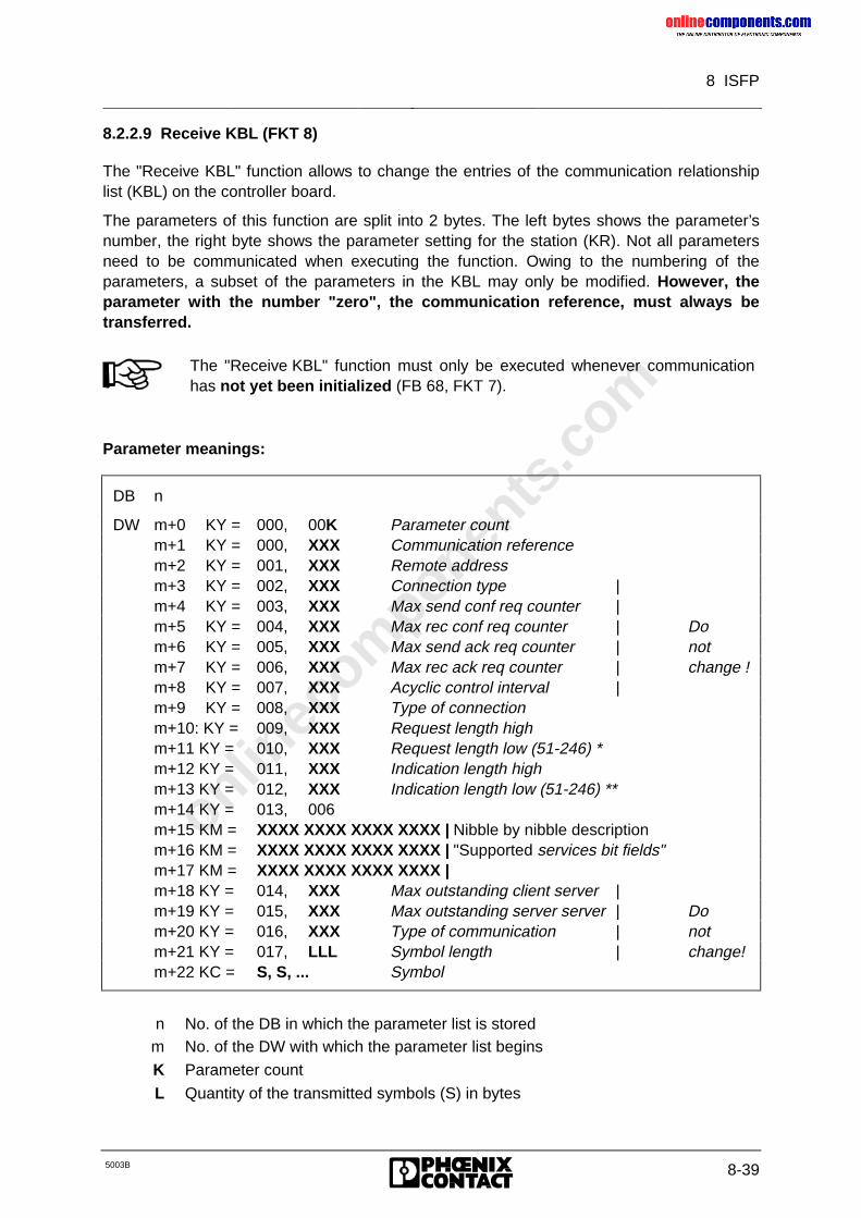
onlinec
omponen
ts.co
m
8 ISFP
5003B 8-39
8.2.2.9 Receive KBL (FKT 8)
The "Receive KBL" function allows to change the entries of the communication relationshiplist (KBL) on the controller board.
The parameters of this function are split into 2 bytes. The left bytes shows the parameter’snumber, the right byte shows the parameter setting for the station (KR). Not all parametersneed to be communicated when executing the function. Owing to the numbering of theparameters, a subset of the parameters in the KBL may only be modified. However, theparameter with the number "zero", the communication reference, must always betransferred.
The "Receive KBL" function must only be executed whenever communicationhas not yet been initialized (FB 68, FKT 7).
Parameter meanings:
DB n
DW m+0 KY = 000, 00K Parameter countm+1 KY = 000, XXX Communication referencem+2 KY = 001, XXX Remote addressm+3 KY = 002, XXX Connection type |m+4 KY = 003, XXX Max send conf req counter |m+5 KY = 004, XXX Max rec conf req counter | Dom+6 KY = 005, XXX Max send ack req counter | notm+7 KY = 006, XXX Max rec ack req counter | change !m+8 KY = 007, XXX Acyclic control interval |m+9 KY = 008, XXX Type of connectionm+10: KY = 009, XXX Request length highm+11 KY = 010, XXX Request length low (51-246) *m+12 KY = 011, XXX Indication length highm+13 KY = 012, XXX Indication length low (51-246) **m+14 KY = 013, 006m+15 KM = XXXX XXXX XXXX XXXX | Nibble by nibble descriptionm+16 KM = XXXX XXXX XXXX XXXX | "Supported services bit fields"m+17 KM = XXXX XXXX XXXX XXXX |m+18 KY = 014, XXX Max outstanding client server |m+19 KY = 015, XXX Max outstanding server server | Dom+20 KY = 016, XXX Type of communication | notm+21 KY = 017, LLL Symbol length | change!m+22 KC = S, S, ... Symbol
n No. of the DB in which the parameter list is storedm No. of the DW with which the parameter list begins
K Parameter count
L Quantity of the transmitted symbols (S) in bytes
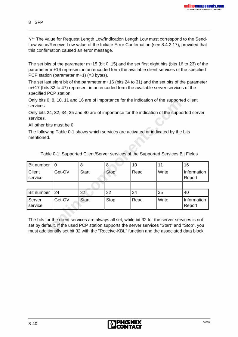
onlinec
omponen
ts.co
m
8 ISFP
8-40 5003B
*/** The value for Request Length Low/Indication Length Low must correspond to the Send-Low value/Receive Low value of the Initiate Error Confirmation (see 8.4.2.17), provided thatthis confirmation caused an error message.
The set bits of the parameter m+15 (bit 0..15) and the set first eight bits (bits 16 to 23) of theparameter m+16 represent in an encoded form the available client services of the specifiedPCP station (parameter m+1) (=3 bytes).
The set last eight bit of the parameter m+16 (bits 24 to 31) and the set bits of the parameterm+17 (bits 32 to 47) represent in an encoded form the available server services of thespecified PCP station.
Only bits 0, 8, 10, 11 and 16 are of importance for the indication of the supported clientservices.
Only bits 24, 32, 34, 35 and 40 are of importance for the indication of the supported serverservices.
All other bits must be 0.
The following Table 0-1 shows which services are activated or indicated by the bitsmentioned.
Table 0-1: Supported Client/Server services of the Supported Services Bit Fields
Bit number 0 8 8 10 11 16
Clientservice
Get-OV Start Stop Read Write InformationReport
Bit number 24 32 32 34 35 40
Serverservice
Get-OV Start Stop Read Write InformationReport
The bits for the client services are always all set, while bit 32 for the server services is notset by default. If the used PCP station supports the server services "Start" and "Stop", youmust additionally set bit 32 with the "Receive-KBL" function and the associated data block.
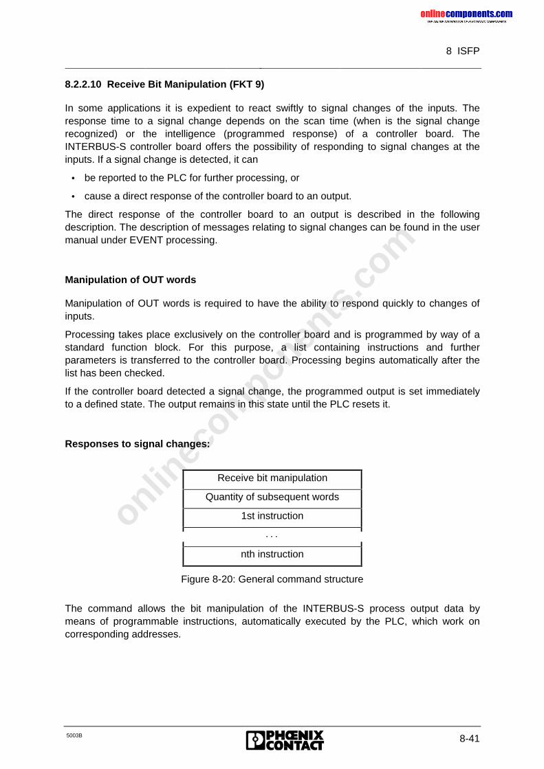
onlinec
omponen
ts.co
m
8 ISFP
5003B 8-41
8.2.2.10 Receive Bit Manipulation (FKT 9)
In some applications it is expedient to react swiftly to signal changes of the inputs. Theresponse time to a signal change depends on the scan time (when is the signal changerecognized) or the intelligence (programmed response) of a controller board. TheINTERBUS-S controller board offers the possibility of responding to signal changes at theinputs. If a signal change is detected, it can
• be reported to the PLC for further processing, or
• cause a direct response of the controller board to an output.
The direct response of the controller board to an output is described in the followingdescription. The description of messages relating to signal changes can be found in the usermanual under EVENT processing.
Manipulation of OUT words
Manipulation of OUT words is required to have the ability to respond quickly to changes ofinputs.
Processing takes place exclusively on the controller board and is programmed by way of astandard function block. For this purpose, a list containing instructions and furtherparameters is transferred to the controller board. Processing begins automatically after thelist has been checked.
If the controller board detected a signal change, the programmed output is set immediatelyto a defined state. The output remains in this state until the PLC resets it.
Responses to signal changes:
Receive bit manipulation
Quantity of subsequent words
1st instruction
· · ·
nth instruction
Figure 8-20: General command structure
The command allows the bit manipulation of the INTERBUS-S process output data bymeans of programmable instructions, automatically executed by the PLC, which work oncorresponding addresses.
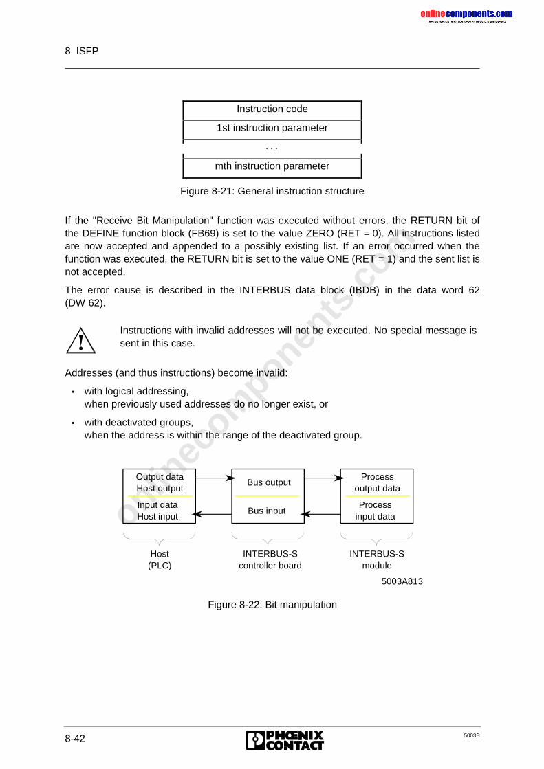
onlinec
omponen
ts.co
m
8 ISFP
8-42 5003B
Instruction code
1st instruction parameter
· · ·
mth instruction parameter
Figure 8-21: General instruction structure
If the "Receive Bit Manipulation" function was executed without errors, the RETURN bit ofthe DEFINE function block (FB69) is set to the value ZERO (RET = 0). All instructions listedare now accepted and appended to a possibly existing list. If an error occurred when thefunction was executed, the RETURN bit is set to the value ONE (RET = 1) and the sent list isnot accepted.
The error cause is described in the INTERBUS data block (IBDB) in the data word 62(DW 62).
Instructions with invalid addresses will not be executed. No special message issent in this case.
Addresses (and thus instructions) become invalid:
• with logical addressing,when previously used addresses do no longer exist, or
• with deactivated groups,when the address is within the range of the deactivated group.
Output dataHost output
Input dataHost input
Bus output
Bus input
Processoutput data
Process input data
Host(PLC)
INTERBUS-Scontroller board
INTERBUS-Smodule
5003A813
Figure 8-22: Bit manipulation
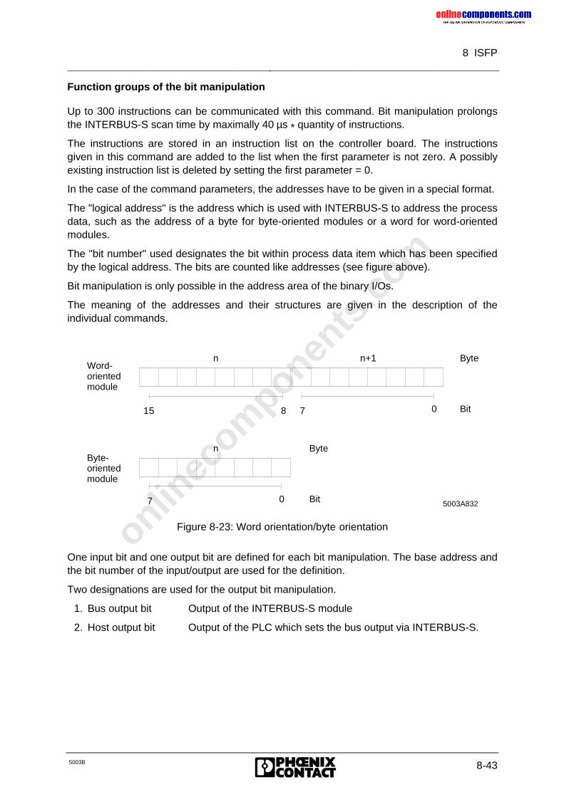
onlinec
omponen
ts.co
m
8 ISFP
5003B 8-43
Function groups of the bit manipulation
Up to 300 instructions can be communicated with this command. Bit manipulation prolongsthe INTERBUS-S scan time by maximally 40 µs * quantity of instructions.
The instructions are stored in an instruction list on the controller board. The instructionsgiven in this command are added to the list when the first parameter is not zero. A possiblyexisting instruction list is deleted by setting the first parameter = 0.
In the case of the command parameters, the addresses have to be given in a special format.
The "logical address" is the address which is used with INTERBUS-S to address the processdata, such as the address of a byte for byte-oriented modules or a word for word-orientedmodules.
The "bit number" used designates the bit within process data item which has been specifiedby the logical address. The bits are counted like addresses (see figure above).
Bit manipulation is only possible in the address area of the binary I/Os.
The meaning of the addresses and their structures are given in the description of theindividual commands.
15 078
n n+1
07
n
Byte
Bit
Byte
Bit
Word- orientedmodule
Byte-orientedmodule
5003A832
Figure 8-23: Word orientation/byte orientation
One input bit and one output bit are defined for each bit manipulation. The base address andthe bit number of the input/output are used for the definition.
Two designations are used for the output bit manipulation.
1. Bus output bit Output of the INTERBUS-S module
2. Host output bit Output of the PLC which sets the bus output via INTERBUS-S.
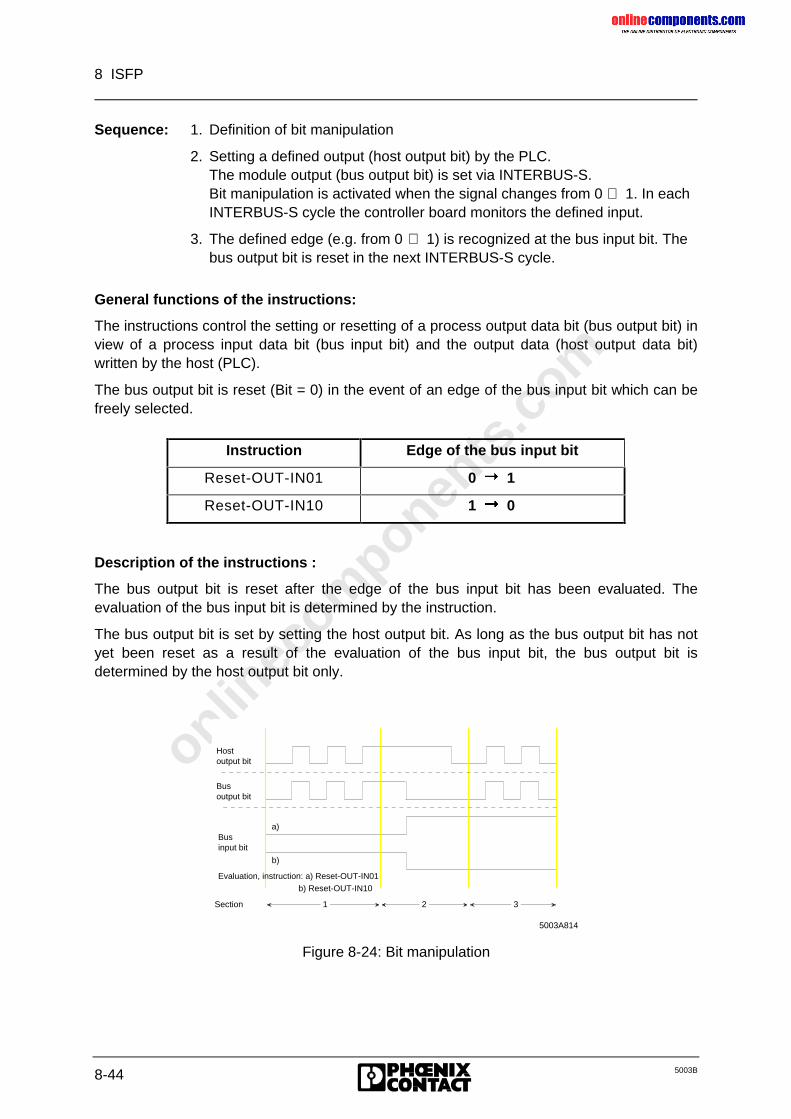
onlinec
omponen
ts.co
m
8 ISFP
8-44 5003B
Sequence: 1. Definition of bit manipulation
2. Setting a defined output (host output bit) by the PLC.The module output (bus output bit) is set via INTERBUS-S.Bit manipulation is activated when the signal changes from 0 ⇒ 1. In eachINTERBUS-S cycle the controller board monitors the defined input.
3. The defined edge (e.g. from 0 ⇒ 1) is recognized at the bus input bit. Thebus output bit is reset in the next INTERBUS-S cycle.
General functions of the instructions:
The instructions control the setting or resetting of a process output data bit (bus output bit) inview of a process input data bit (bus input bit) and the output data (host output data bit)written by the host (PLC).
The bus output bit is reset (Bit = 0) in the event of an edge of the bus input bit which can befreely selected.
Instruction Edge of the bus input bit
Reset-OUT-IN01 0 Þ 1
Reset-OUT-IN10 1 Þ 0
Description of the instructions :
The bus output bit is reset after the edge of the bus input bit has been evaluated. Theevaluation of the bus input bit is determined by the instruction.
The bus output bit is set by setting the host output bit. As long as the bus output bit has notyet been reset as a result of the evaluation of the bus input bit, the bus output bit isdetermined by the host output bit only.
Figure 8-24: Bit manipulation
1 2
3
Businput bit
Evaluation, instruction: a) Reset-OUT-IN01
a)
b)
b) Reset-OUT-IN10
5003A814
Section
Hostoutput bit
Bus output bit
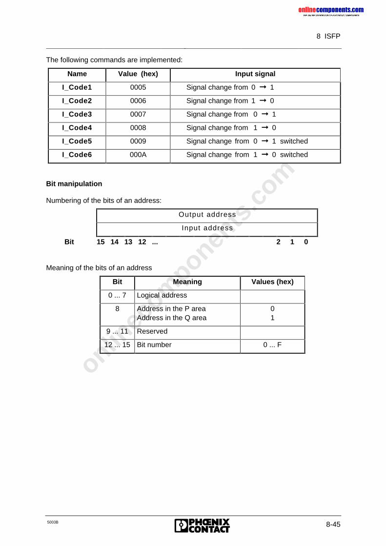
onlinec
omponen
ts.co
m
8 ISFP
5003B 8-45
The following commands are implemented:
Name Value (hex) Input signal
I_Code1 0005 Signal change from 0 ➞ 1
I_Code2 0006 Signal change from 1 ➞ 0
I_Code3 0007 Signal change from 0 ➞ 1
I_Code4 0008 Signal change from 1 ➞ 0
I_Code5 0009 Signal change from 0 ➞ 1 switched
I_Code6 000A Signal change from 1 ➞ 0 switched
Bit manipulation
Numbering of the bits of an address:
Output address
Input address
Bit 15 14 13 12 ... 2 1 0
Meaning of the bits of an address
Bit Meaning Values (hex)
0 ... 7 Logical address
8 Address in the P areaAddress in the Q area
01
9 ... 11 Reserved
12 ... 15 Bit number 0 ... F
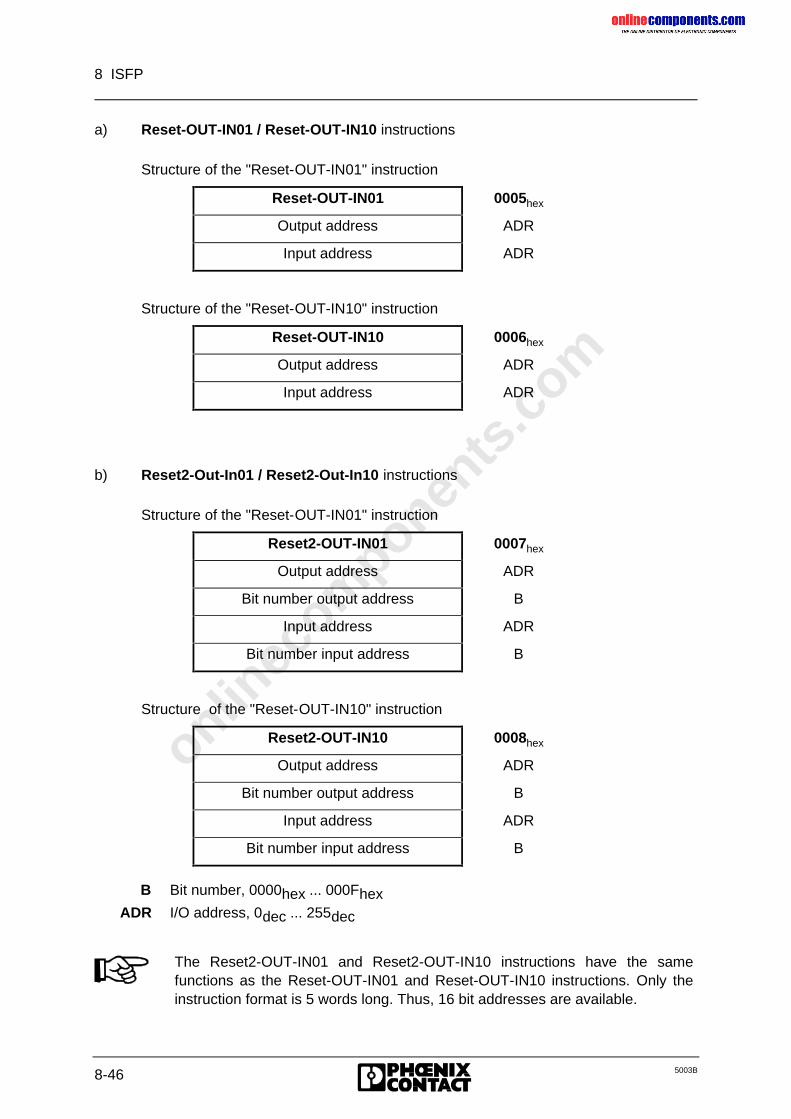
onlinec
omponen
ts.co
m
8 ISFP
8-46 5003B
a) Reset-OUT-IN01 / Reset-OUT-IN10 instructions
Structure of the "Reset-OUT-IN01" instruction
Reset-OUT-IN01 0005hex
Output address ADR
Input address ADR
Structure of the "Reset-OUT-IN10" instruction
Reset-OUT-IN10 0006hex
Output address ADR
Input address ADR
b) Reset2-Out-In01 / Reset2-Out-In10 instructions
Structure of the "Reset-OUT-IN01" instruction
Reset2-OUT-IN01 0007hex
Output address ADR
Bit number output address B
Input address ADR
Bit number input address B
Structure of the "Reset-OUT-IN10" instruction
Reset2-OUT-IN10 0008hex
Output address ADR
Bit number output address B
Input address ADR
Bit number input address B
B Bit number, 0000hex ... 000FhexADR I/O address, 0dec ... 255dec
The Reset2-OUT-IN01 and Reset2-OUT-IN10 instructions have the samefunctions as the Reset-OUT-IN01 and Reset-OUT-IN10 instructions. Only theinstruction format is 5 words long. Thus, 16 bit addresses are available.
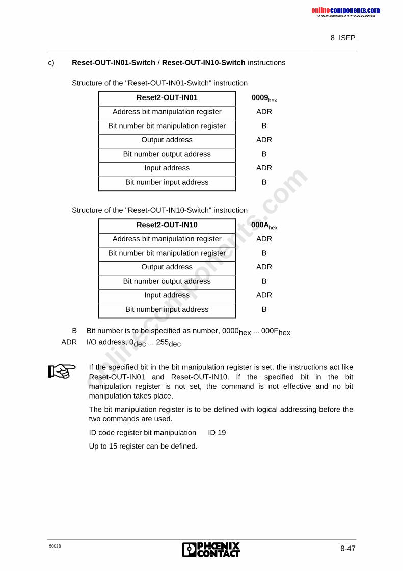
onlinec
omponen
ts.co
m
8 ISFP
5003B 8-47
c) Reset-OUT-IN01-Switch / Reset-OUT-IN10-Switch instructions
Structure of the "Reset-OUT-IN01-Switch" instruction
Reset2-OUT-IN01 0009hex
Address bit manipulation register ADR
Bit number bit manipulation register B
Output address ADR
Bit number output address B
Input address ADR
Bit number input address B
Structure of the "Reset-OUT-IN10-Switch" instruction
Reset2-OUT-IN10 000Ahex
Address bit manipulation register ADR
Bit number bit manipulation register B
Output address ADR
Bit number output address B
Input address ADR
Bit number input address B
B Bit number is to be specified as number, 0000hex ... 000FhexADR I/O address, 0dec ... 255dec
If the specified bit in the bit manipulation register is set, the instructions act likeReset-OUT-IN01 and Reset-OUT-IN10. If the specified bit in the bitmanipulation register is not set, the command is not effective and no bitmanipulation takes place.
The bit manipulation register is to be defined with logical addressing before thetwo commands are used.
ID code register bit manipulation ID 19
Up to 15 register can be defined.
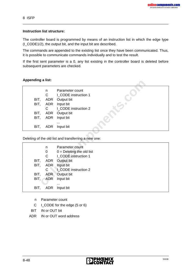
onlinec
omponen
ts.co
m
8 ISFP
8-48 5003B
Instruction list structure:
The controller board is programmed by means of an instruction list in which the edge type(I_CODE1/2), the output bit, and the input bit are described.
The commands are appended to the existing list once they have been communicated. Thus,it is possible to communicate commands individually and to test the result.
If the first sent parameter is a 0, any list existing in the controller board is deleted beforesubsequent parameters are checked.
Appending a list:
n Parameter countC I_CODE instruction 1
BIT, ADR Output bitBIT, ADR Input bit
C I_CODE instruction 2BIT, ADR Output bitBIT, ADR Input bit
...BIT, ADR Input bit
Deleting of the old list and transferring a new one:
n Parameter count0 0 = Deleting the old listC I_CODE instruction 1
BIT, ADR Output bitBIT, ADR Input bit
C I_CODE instruction 2BIT, ADR Output bitBIT, ADR Input bit
...BIT, ADR Input bit
n Parameter count
C I_CODE for the edge (5 or 6)
BIT IN or OUT bit
ADR IN or OUT word address
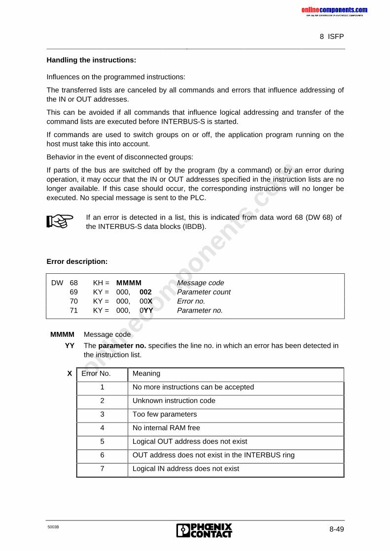
onlinec
omponen
ts.co
m
8 ISFP
5003B 8-49
Handling the instructions:
Influences on the programmed instructions:
The transferred lists are canceled by all commands and errors that influence addressing ofthe IN or OUT addresses.
This can be avoided if all commands that influence logical addressing and transfer of thecommand lists are executed before INTERBUS-S is started.
If commands are used to switch groups on or off, the application program running on thehost must take this into account.
Behavior in the event of disconnected groups:
If parts of the bus are switched off by the program (by a command) or by an error duringoperation, it may occur that the IN or OUT addresses specified in the instruction lists are nolonger available. If this case should occur, the corresponding instructions will no longer beexecuted. No special message is sent to the PLC.
If an error is detected in a list, this is indicated from data word 68 (DW 68) ofthe INTERBUS-S data blocks (IBDB).
Error description:
DW 68 KH = MMMM Message code69 KY = 000, 002 Parameter count70 KY = 000, 00X Error no.71 KY = 000, 0YY Parameter no.
MMMM Message code
YY The parameter no. specifies the line no. in which an error has been detected inthe instruction list.
X Error No. Meaning
1 No more instructions can be accepted
2 Unknown instruction code
3 Too few parameters
4 No internal RAM free
5 Logical OUT address does not exist
6 OUT address does not exist in the INTERBUS ring
7 Logical IN address does not exist
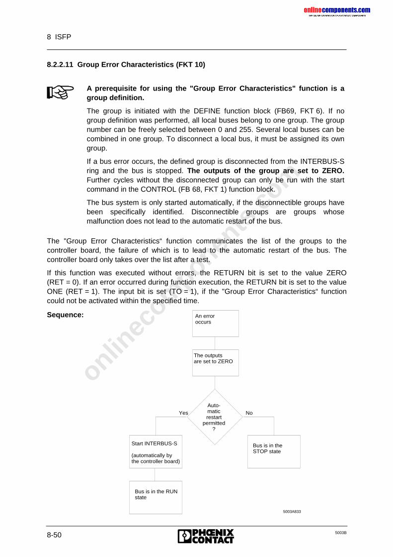
onlinec
omponen
ts.co
m
8 ISFP
8-50 5003B
8.2.2.11 Group Error Characteristics (FKT 10)
A prerequisite for using the "Group Error Characteristics" function is agroup definition.
The group is initiated with the DEFINE function block (FB69, FKT 6). If nogroup definition was performed, all local buses belong to one group. The groupnumber can be freely selected between 0 and 255. Several local buses can becombined in one group. To disconnect a local bus, it must be assigned its owngroup.
If a bus error occurs, the defined group is disconnected from the INTERBUS-Sring and the bus is stopped. The outputs of the group are set to ZERO.Further cycles without the disconnected group can only be run with the startcommand in the CONTROL (FB 68, FKT 1) function block.
The bus system is only started automatically, if the disconnectible groups havebeen specifically identified. Disconnectible groups are groups whosemalfunction does not lead to the automatic restart of the bus.
The "Group Error Characteristics“ function communicates the list of the groups to thecontroller board, the failure of which is to lead to the automatic restart of the bus. Thecontroller board only takes over the list after a test.
If this function was executed without errors, the RETURN bit is set to the value ZERO(RET = 0). If an error occurred during function execution, the RETURN bit is set to the valueONE (RET = 1). The input bit is set (TO = 1), if the "Group Error Characteristics“ functioncould not be activated within the specified time.
Sequence:
Yes No
Start INTERBUS-S
(automatically bythe controller board)
Bus is in the RUNstate
Bus is in the STOP state
5003A833
An error occurs
The outputsare set to ZERO
Auto-maticrestart
permitted?
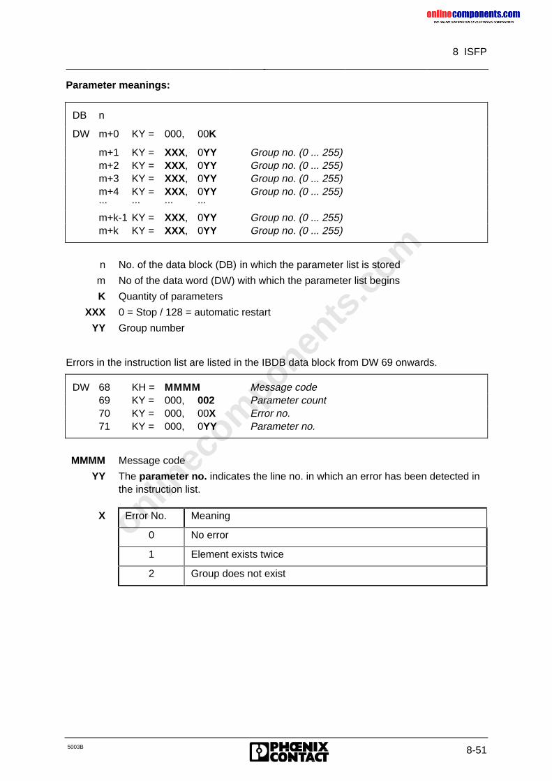
onlinec
omponen
ts.co
m
8 ISFP
5003B 8-51
Parameter meanings:
DB n
DW m+0 KY = 000, 00K
m+1 KY = XXX, 0YY Group no. (0 ... 255)m+2 KY = XXX, 0YY Group no. (0 ... 255)m+3 KY = XXX, 0YY Group no. (0 ... 255)m+4 KY = XXX, 0YY Group no. (0 ... 255)... ... ... ...
m+k-1 KY = XXX, 0YY Group no. (0 ... 255)m+k KY = XXX, 0YY Group no. (0 ... 255)
n No. of the data block (DB) in which the parameter list is stored
m No of the data word (DW) with which the parameter list begins
K Quantity of parameters
XXX 0 = Stop / 128 = automatic restart
YY Group number
Errors in the instruction list are listed in the IBDB data block from DW 69 onwards.
DW 68 KH = MMMM Message code69 KY = 000, 002 Parameter count70 KY = 000, 00X Error no.71 KY = 000, 0YY Parameter no.
MMMM Message code
YY The parameter no. indicates the line no. in which an error has been detected inthe instruction list.
X Error No. Meaning
0 No error
1 Element exists twice
2 Group does not exist
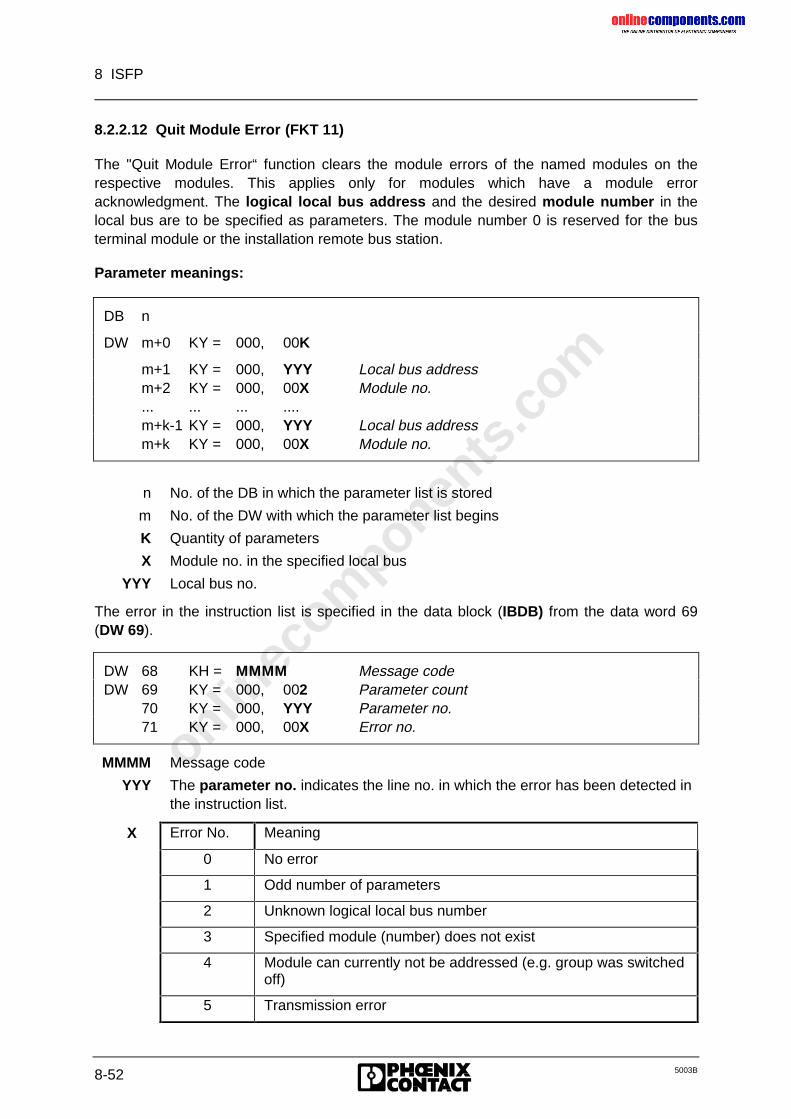
onlinec
omponen
ts.co
m
8 ISFP
8-52 5003B
8.2.2.12 Quit Module Error (FKT 11)
The "Quit Module Error“ function clears the module errors of the named modules on therespective modules. This applies only for modules which have a module erroracknowledgment. The logical local bus address and the desired module number in thelocal bus are to be specified as parameters. The module number 0 is reserved for the busterminal module or the installation remote bus station.
Parameter meanings:
DB n
DW m+0 KY = 000, 00K
m+1 KY = 000, YYY Local bus addressm+2 KY = 000, 00X Module no.... ... ... ....m+k-1 KY = 000, YYY Local bus addressm+k KY = 000, 00X Module no.
n No. of the DB in which the parameter list is stored
m No. of the DW with which the parameter list begins
K Quantity of parameters
X Module no. in the specified local bus
YYY Local bus no.
The error in the instruction list is specified in the data block (IBDB) from the data word 69(DW 69).
DW 68 KH = MMMM Message codeDW 69 KY = 000, 002 Parameter count
70 KY = 000, YYY Parameter no.71 KY = 000, 00X Error no.
MMMM Message code
YYY The parameter no. indicates the line no. in which the error has been detected inthe instruction list.
X Error No. Meaning
0 No error
1 Odd number of parameters
2 Unknown logical local bus number
3 Specified module (number) does not exist
4 Module can currently not be addressed (e.g. group was switchedoff)
5 Transmission error
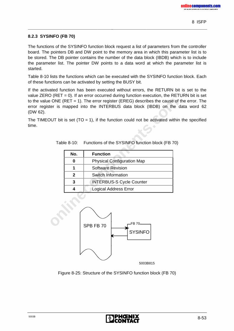
onlinec
omponen
ts.co
m
8 ISFP
5003B 8-53
8.2.3 SYSINFO (FB 70)
The functions of the SYSINFO function block request a list of parameters from the controllerboard. The pointers DB and DW point to the memory area in which this parameter list is tobe stored. The DB pointer contains the number of the data block (IBDB) which is to includethe parameter list. The pointer DW points to a data word at which the parameter list isstarted.
Table 8-10 lists the functions which can be executed with the SYSINFO function block. Eachof these functions can be activated by setting the BUSY bit.
If the activated function has been executed without errors, the RETURN bit is set to thevalue ZERO (RET = 0). If an error occurred during function execution, the RETURN bit is setto the value ONE (RET = 1). The error register (EREG) describes the cause of the error. Theerror register is mapped into the INTERBUS data block (IBDB) on the data word 62(DW 62).
The TIMEOUT bit is set (TO = 1), if the function could not be activated within the specifiedtime.
Table 8-10: Functions of the SYSINFO function block (FB 70)
No. Function
0 Physical Configuration Map
1 Software Revision
2 Switch Information
3 INTERBUS-S Cycle Counter
4 Logical Address Error
SYSINFO
5003B815
FB 70SPB FB 70
Figure 8-25: Structure of the SYSINFO function block (FB 70)
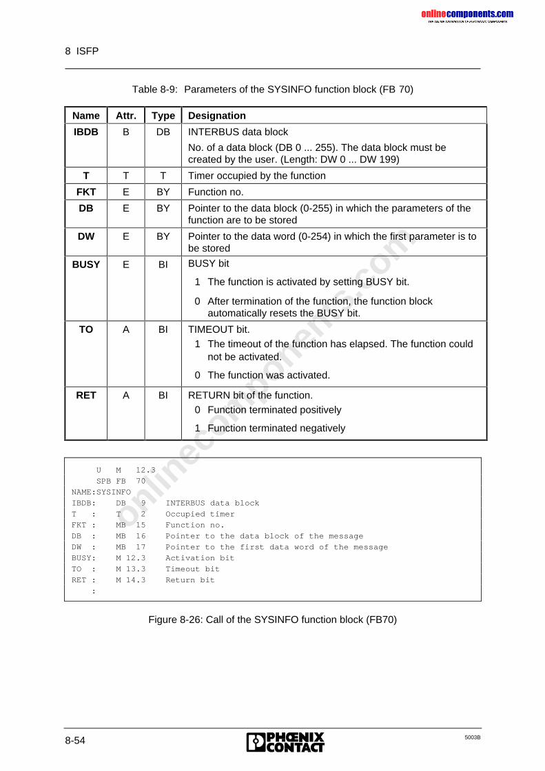
onlinec
omponen
ts.co
m
8 ISFP
8-54 5003B
Table 8-9: Parameters of the SYSINFO function block (FB 70)
Name Attr. Type Designation
IBDB B DB INTERBUS data block
No. of a data block (DB 0 ... 255). The data block must becreated by the user. (Length: DW 0 ... DW 199)
T T T Timer occupied by the function
FKT E BY Function no.
DB E BY Pointer to the data block (0-255) in which the parameters of thefunction are to be stored
DW E BY Pointer to the data word (0-254) in which the first parameter is tobe stored
BUSY E BI BUSY bit
1 The function is activated by setting BUSY bit.
0 After termination of the function, the function blockautomatically resets the BUSY bit.
TO A BI TIMEOUT bit.1 The timeout of the function has elapsed. The function could
not be activated.
0 The function was activated.
RET A BI RETURN bit of the function.0 Function terminated positively
1 Function terminated negatively
U M 12.3
SPB FB 70
NAME:SYSINFO
IBDB: DB 9 INTERBUS data block
T : T 2 Occupied timer
FKT : MB 15 Function no.
DB : MB 16 Pointer to the data block of the message
DW : MB 17 Pointer to the first data word of the message
BUSY: M 12.3 Activation bit
TO : M 13.3 Timeout bit
RET : M 14.3 Return bit
:
Figure 8-26: Call of the SYSINFO function block (FB70)
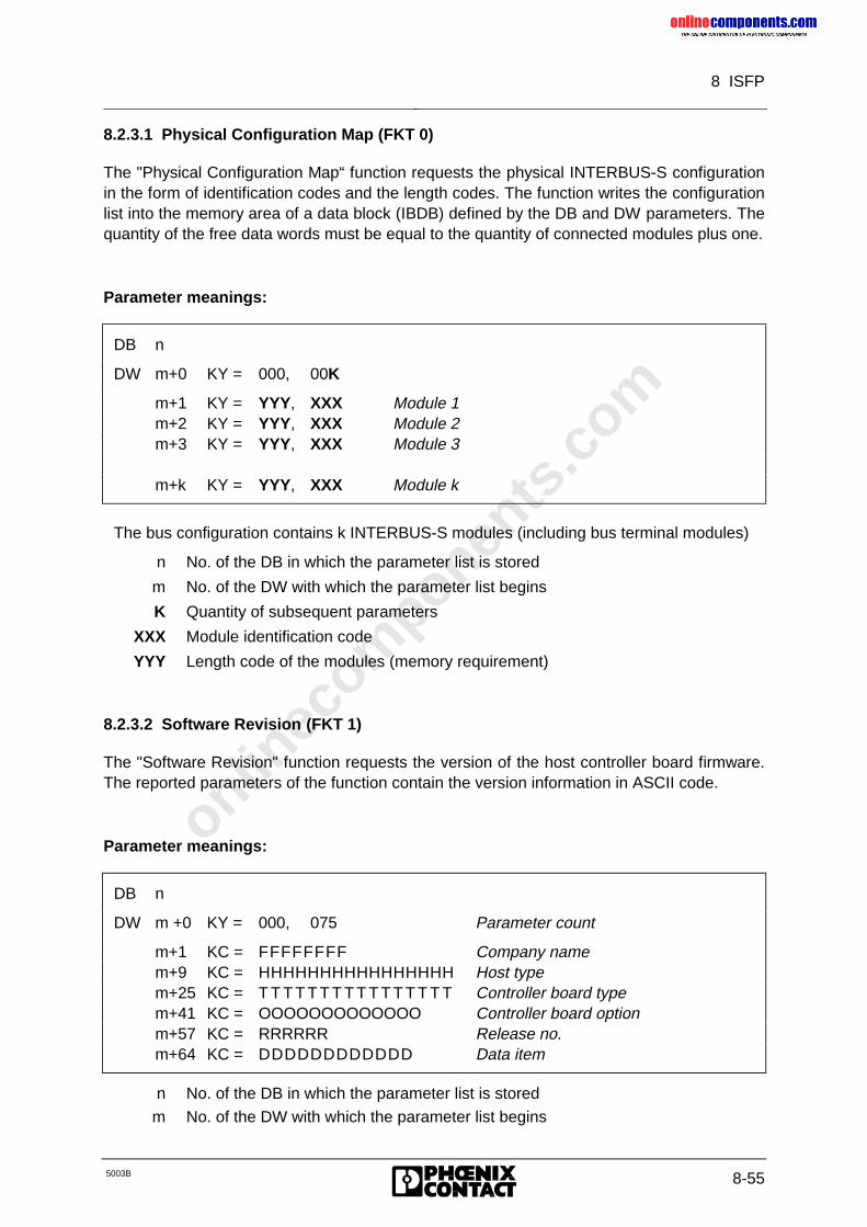
onlinec
omponen
ts.co
m
8 ISFP
5003B 8-55
8.2.3.1 Physical Configuration Map (FKT 0)
The "Physical Configuration Map“ function requests the physical INTERBUS-S configurationin the form of identification codes and the length codes. The function writes the configurationlist into the memory area of a data block (IBDB) defined by the DB and DW parameters. Thequantity of the free data words must be equal to the quantity of connected modules plus one.
Parameter meanings:
DB n
DW m+0 KY = 000, 00K
m+1 KY = YYY, XXX Module 1m+2 KY = YYY, XXX Module 2m+3 KY = YYY, XXX Module 3
m+k KY = YYY, XXX Module k
The bus configuration contains k INTERBUS-S modules (including bus terminal modules)
n No. of the DB in which the parameter list is stored
m No. of the DW with which the parameter list begins
K Quantity of subsequent parameters
XXX Module identification code
YYY Length code of the modules (memory requirement)
8.2.3.2 Software Revision (FKT 1)
The "Software Revision" function requests the version of the host controller board firmware.The reported parameters of the function contain the version information in ASCII code.
Parameter meanings:
DB n
DW m +0 KY = 000, 075 Parameter count
m+1 KC = FFFFFFFF Company namem+9 KC = HHHHHHHHHHHHHHHH Host typem+25 KC = T T T T T T T T T T T T T T T T Controller board typem+41 KC = OOOOOOOOOOOOO Controller board optionm+57 KC = RRRRRR Release no.m+64 KC = DDDDDDDDDDDD Data item
n No. of the DB in which the parameter list is stored
m No. of the DW with which the parameter list begins
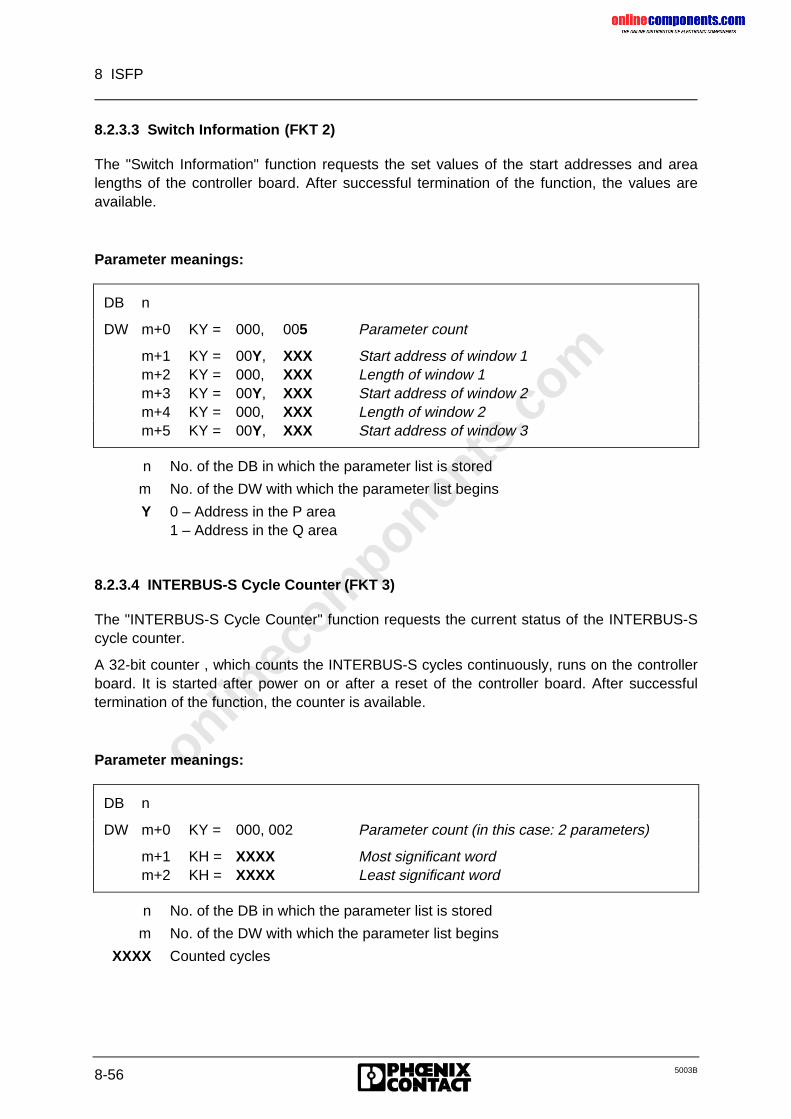
onlinec
omponen
ts.co
m
8 ISFP
8-56 5003B
8.2.3.3 Switch Information (FKT 2)
The "Switch Information" function requests the set values of the start addresses and arealengths of the controller board. After successful termination of the function, the values areavailable.
Parameter meanings:
DB n
DW m+0 KY = 000, 005 Parameter count
m+1 KY = 00Y, XXX Start address of window 1m+2 KY = 000, XXX Length of window 1m+3 KY = 00Y, XXX Start address of window 2m+4 KY = 000, XXX Length of window 2m+5 KY = 00Y, XXX Start address of window 3
n No. of the DB in which the parameter list is stored
m No. of the DW with which the parameter list begins
Y 0 – Address in the P area1 – Address in the Q area
8.2.3.4 INTERBUS-S Cycle Counter (FKT 3)
The "INTERBUS-S Cycle Counter" function requests the current status of the INTERBUS-Scycle counter.
A 32-bit counter , which counts the INTERBUS-S cycles continuously, runs on the controllerboard. It is started after power on or after a reset of the controller board. After successfultermination of the function, the counter is available.
Parameter meanings:
DB n
DW m+0 KY = 000, 002 Parameter count (in this case: 2 parameters)
m+1 KH = XXXX Most significant wordm+2 KH = XXXX Least significant word
n No. of the DB in which the parameter list is stored
m No. of the DW with which the parameter list begins
XXXX Counted cycles
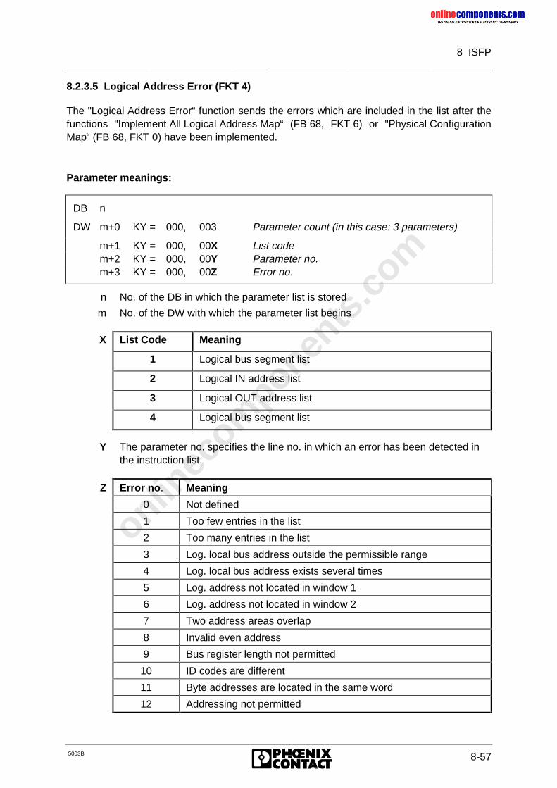
onlinec
omponen
ts.co
m
8 ISFP
5003B 8-57
8.2.3.5 Logical Address Error (FKT 4)
The "Logical Address Error“ function sends the errors which are included in the list after thefunctions "Implement All Logical Address Map“ (FB 68, FKT 6) or "Physical ConfigurationMap“ (FB 68, FKT 0) have been implemented.
Parameter meanings:
DB n
DW m+0 KY = 000, 003 Parameter count (in this case: 3 parameters)
m+1 KY = 000, 00X List codem+2 KY = 000, 00Y Parameter no.m+3 KY = 000, 00Z Error no.
n No. of the DB in which the parameter list is stored
m No. of the DW with which the parameter list begins
X List Code Meaning
1 Logical bus segment list
2 Logical IN address list
3 Logical OUT address list
4 Logical bus segment list
Y The parameter no. specifies the line no. in which an error has been detected inthe instruction list.
Z Error no. Meaning
0 Not defined
1 Too few entries in the list
2 Too many entries in the list
3 Log. local bus address outside the permissible range
4 Log. local bus address exists several times
5 Log. address not located in window 1
6 Log. address not located in window 2
7 Two address areas overlap
8 Invalid even address
9 Bus register length not permitted
10 ID codes are different
11 Byte addresses are located in the same word
12 Addressing not permitted
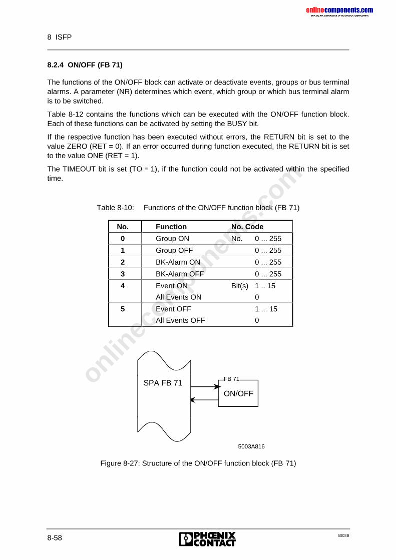
onlinec
omponen
ts.co
m
8 ISFP
8-58 5003B
8.2.4 ON/OFF (FB 71)
The functions of the ON/OFF block can activate or deactivate events, groups or bus terminalalarms. A parameter (NR) determines which event, which group or which bus terminal alarmis to be switched.
Table 8-12 contains the functions which can be executed with the ON/OFF function block.Each of these functions can be activated by setting the BUSY bit.
If the respective function has been executed without errors, the RETURN bit is set to thevalue ZERO (RET = 0). If an error occurred during function executed, the RETURN bit is setto the value ONE (RET = 1).
The TIMEOUT bit is set (TO = 1), if the function could not be activated within the specifiedtime.
Table 8-10: Functions of the ON/OFF function block (FB 71)
No. Function No. Code
0 Group ON No. 0 ... 255
1 Group OFF 0 ... 255
2 BK-Alarm ON 0 ... 255
3 BK-Alarm OFF 0 ... 255
4 Event ON Bit(s) 1 .. 15
All Events ON 0
5 Event OFF 1 ... 15
All Events OFF 0
ON/OFF
5003A816
FB 71SPA FB 71
Figure 8-27: Structure of the ON/OFF function block (FB 71)
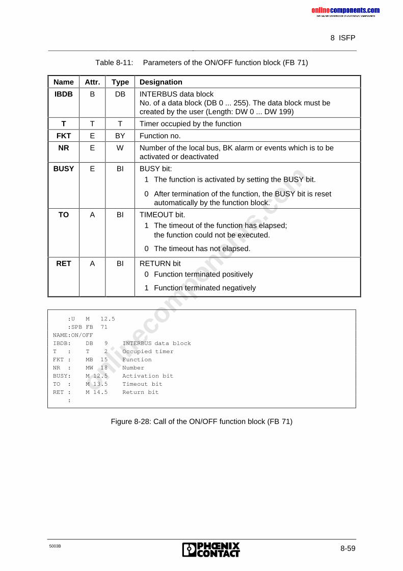
onlinec
omponen
ts.co
m
8 ISFP
5003B 8-59
Table 8-11: Parameters of the ON/OFF function block (FB 71)
Name Attr. Type Designation
IBDB B DB INTERBUS data blockNo. of a data block (DB 0 ... 255). The data block must becreated by the user (Length: DW 0 ... DW 199)
T T T Timer occupied by the function
FKT E BY Function no.
NR E W Number of the local bus, BK alarm or events which is to beactivated or deactivated
BUSY E BI BUSY bit:1 The function is activated by setting the BUSY bit.
0 After termination of the function, the BUSY bit is resetautomatically by the function block.
TO A BI TIMEOUT bit.1 The timeout of the function has elapsed;
the function could not be executed.
0 The timeout has not elapsed.
RET A BI RETURN bit0 Function terminated positively
1 Function terminated negatively
:U M 12.5
:SPB FB 71
NAME:ON/OFF
IBDB: DB 9 INTERBUS data block
T : T 2 Occupied timer
FKT : MB 15 Function
NR : MW 18 Number
BUSY: M 12.5 Activation bit
TO : M 13.5 Timeout bit
RET : M 14.5 Return bit
:
Figure 8-28: Call of the ON/OFF function block (FB 71)
onlinec
omponen
ts.co
m
8 ISFP
8-60 5003B
8.2.4.1 Group ON (FKT 0)
The "Group ON" function allows to activate a previously defined group of local buses (FB 72/FB 69, FKT 6). The number of the group is to be passed to this function as a parameter.
If the "Group ON" function has been executed without errors, the RETURN bit is set to thevalue ZERO (RET = 0). If an error occurred during the function execution, the RETURN bit isset to the value ONE (RET = 1).
Common error causes are:
• the use of an unknown group number,
• the use of a group number which is not within the permissible range (0 to 255).
Result:
The bus is stopped and the outputs are reset. The "Start INTERBUS-S Cycle" function fromthe CONTROL function block (FB 68, FKT 1) can be used to restart the bus.
The TIMEOUT bit is set (TO = 1), if the function could not be activated within the specifiedtimeout.
8.2.4.2 Group OFF (FKT 1)
The "Group OFF" function allows to deactivate a group of local buses which has beendefined before (FB 72/FB 69, FKT 6). The number of this group is to be passed to thefunction as a parameter.
If the "Group OFF" function has been executed without errors, the RETURN bit is set to thevalue ZERO (RET = 0). The group is put into operation and can be addressed via theapplication program.
When an error occurred during function execution, the RETURN bit is set to the value ONE(RET = 1).
Common error causes are:
• the use of an unknown group number, or
• the use of a group number which lies not within the permissible range (0 to 255).
The TIMEOUT bit is set (TO = 1), if the function could not been activated within the set time.
8.2.4.3 BK-Alarm ON (FKT 2)
The "BK-Alarm ON" function sets the bus terminal alarm output. The bus segment number ofthe local bus in which the bus terminal module is located is specified as a parameter.
If the function has been executed without errors, the RETURN bit is set to the value ZERO(RET = 0). If an error occurred during function execution, the RETURN bit is set to the valueONE (RET = 1).
Possible error causes are the use of an unknown bus segment number, or an address whichdoes not lie in the permissible range (0 to 255).
The TIMEOUT bit is set (TO = 1), if the function could not be forwarded to the controllerboard.
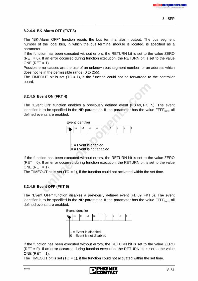
onlinec
omponen
ts.co
m
8 ISFP
5003B 8-61
8.2.4.4 BK-Alarm OFF (FKT 3)
The "BK-Alarm OFF" function resets the bus terminal alarm output. The bus segmentnumber of the local bus, in which the bus terminal module is located, is specified as aparameter.If the function has been executed without errors, the RETURN bit is set to the value ZERO(RET = 0). If an error occurred during function execution, the RETURN bit is set to the valueONE (RET = 1).Possible error causes are the use of an unknown bus segment number, or an address whichdoes not lie in the permissible range (0 to 255).The TIMEOUT bit is set (TO = 1), if the function could not be forwarded to the controllerboard.
8.2.4.5 Event ON (FKT 4)
The "Event ON" function enables a previously defined event (FB 69, FKT 5). The eventidentifier is to be specified in the NR parameter. If the parameter has the value FFFFhex, alldefined events are enabled.
Event identifier
16 15 14 13 12 4 3 2 1
1 = Event is enabled0 = Event is not enabled
If the function has been executed without errors, the RETURN bit is set to the value ZERO(RET = 0). If an error occurred during function execution, the RETURN bit is set to the valueONE (RET = 1).The TIMEOUT bit is set (TO = 1), if the function could not activated within the set time.
8.2.4.6 Event OFF (FKT 5)
The "Event OFF" function disables a previously defined event (FB 69, FKT 5). The eventidentifier is to be specified in the NR parameter. If the parameter has the value FFFFhex, alldefined events are enabled.
Event identifier
16 15 14 13 12 4 3 2 1
1 = Event is disabled0 = Event is not disabled
If the function has been executed without errors, the RETURN bit is set to the value ZERO(RET = 0). If an error occurred during function execution, the RETURN bit is set to the valueONE (RET = 1).The TIMEOUT bit is set (TO = 1), if the function could not activated within the set time.
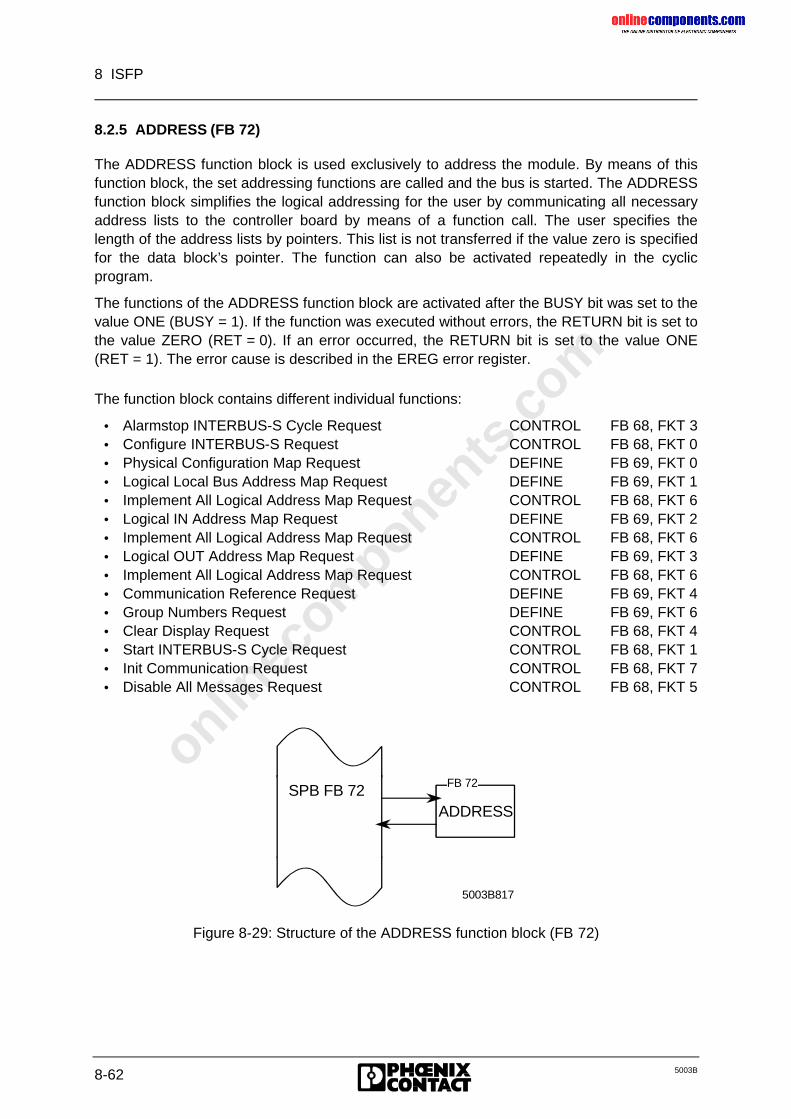
onlinec
omponen
ts.co
m
8 ISFP
8-62 5003B
8.2.5 ADDRESS (FB 72)
The ADDRESS function block is used exclusively to address the module. By means of thisfunction block, the set addressing functions are called and the bus is started. The ADDRESSfunction block simplifies the logical addressing for the user by communicating all necessaryaddress lists to the controller board by means of a function call. The user specifies thelength of the address lists by pointers. This list is not transferred if the value zero is specifiedfor the data block’s pointer. The function can also be activated repeatedly in the cyclicprogram.
The functions of the ADDRESS function block are activated after the BUSY bit was set to thevalue ONE (BUSY = 1). If the function was executed without errors, the RETURN bit is set tothe value ZERO (RET = 0). If an error occurred, the RETURN bit is set to the value ONE(RET = 1). The error cause is described in the EREG error register.
The function block contains different individual functions:
• Alarmstop INTERBUS-S Cycle Request CONTROL FB 68, FKT 3• Configure INTERBUS-S Request CONTROL FB 68, FKT 0• Physical Configuration Map Request DEFINE FB 69, FKT 0• Logical Local Bus Address Map Request DEFINE FB 69, FKT 1• Implement All Logical Address Map Request CONTROL FB 68, FKT 6• Logical IN Address Map Request DEFINE FB 69, FKT 2• Implement All Logical Address Map Request CONTROL FB 68, FKT 6• Logical OUT Address Map Request DEFINE FB 69, FKT 3• Implement All Logical Address Map Request CONTROL FB 68, FKT 6• Communication Reference Request DEFINE FB 69, FKT 4• Group Numbers Request DEFINE FB 69, FKT 6• Clear Display Request CONTROL FB 68, FKT 4• Start INTERBUS-S Cycle Request CONTROL FB 68, FKT 1• Init Communication Request CONTROL FB 68, FKT 7• Disable All Messages Request CONTROL FB 68, FKT 5
ADDRESS
5003B817
FB 72SPB FB 72
Figure 8-29: Structure of the ADDRESS function block (FB 72)
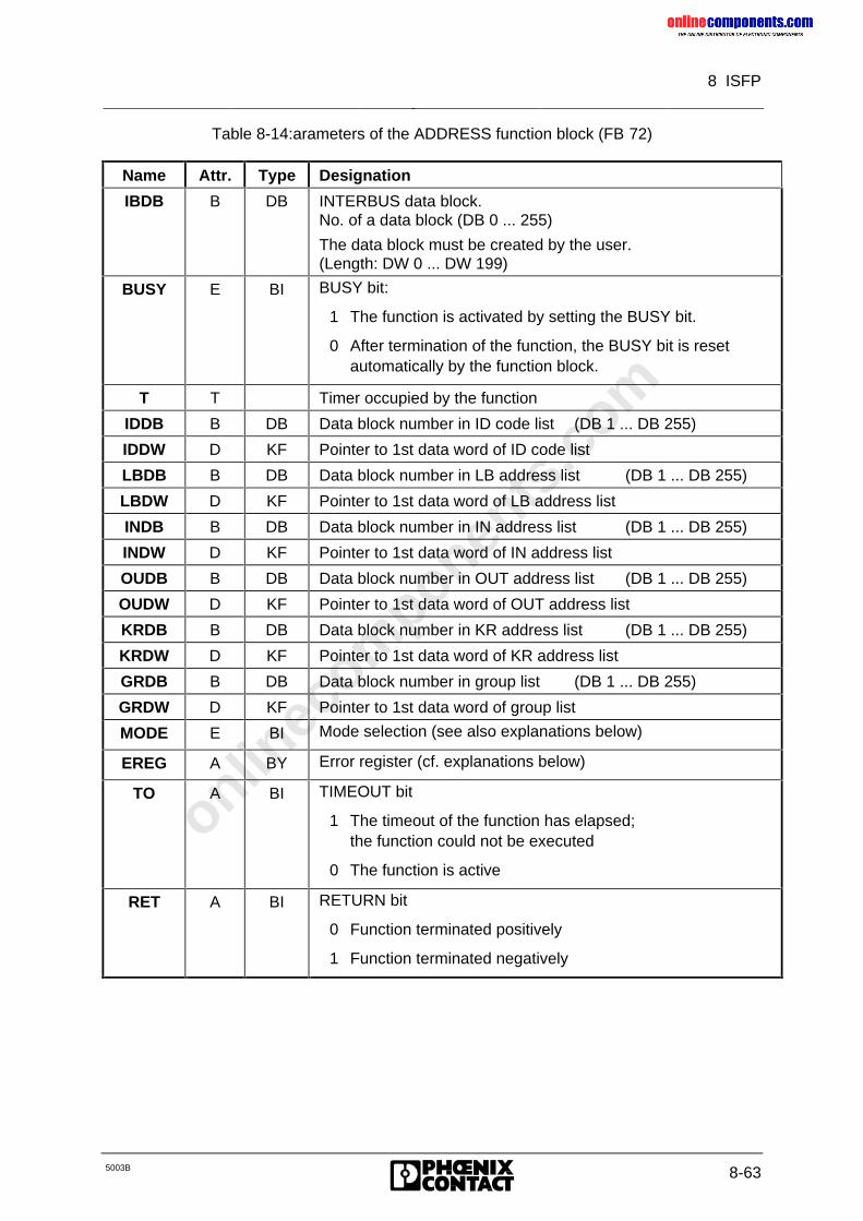
onlinec
omponen
ts.co
m
8 ISFP
5003B 8-63
Table 8-14:arameters of the ADDRESS function block (FB 72)
Name Attr. Type Designation
IBDB B DB INTERBUS data block.No. of a data block (DB 0 ... 255)
The data block must be created by the user.(Length: DW 0 ... DW 199)
BUSY E BI BUSY bit:
1 The function is activated by setting the BUSY bit.
0 After termination of the function, the BUSY bit is resetautomatically by the function block.
T T Timer occupied by the function
IDDB B DB Data block number in ID code list (DB 1 ... DB 255)
IDDW D KF Pointer to 1st data word of ID code list
LBDB B DB Data block number in LB address list (DB 1 ... DB 255)
LBDW D KF Pointer to 1st data word of LB address list
INDB B DB Data block number in IN address list (DB 1 ... DB 255)
INDW D KF Pointer to 1st data word of IN address list
OUDB B DB Data block number in OUT address list (DB 1 ... DB 255)
OUDW D KF Pointer to 1st data word of OUT address list
KRDB B DB Data block number in KR address list (DB 1 ... DB 255)
KRDW D KF Pointer to 1st data word of KR address list
GRDB B DB Data block number in group list (DB 1 ... DB 255)
GRDW D KF Pointer to 1st data word of group list
MODE E BI Mode selection (see also explanations below)
EREG A BY Error register (cf. explanations below)
TO A BI TIMEOUT bit
1 The timeout of the function has elapsed;the function could not be executed
0 The function is active
RET A BI RETURN bit
0 Function terminated positively
1 Function terminated negatively
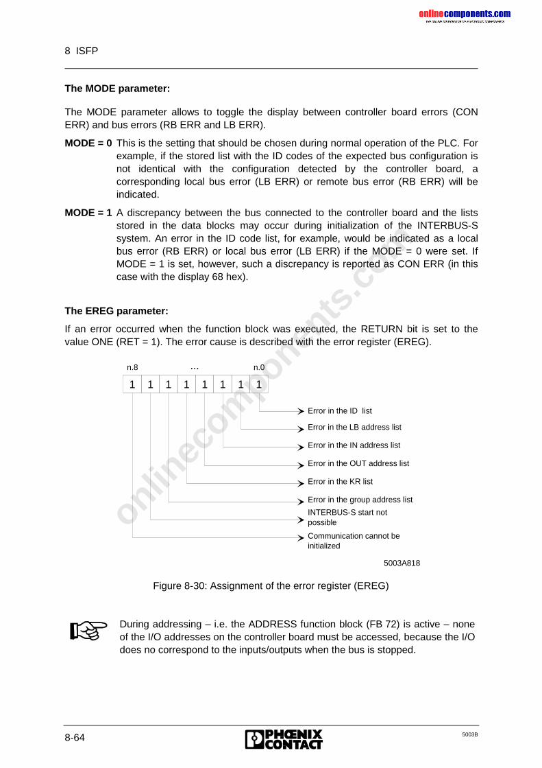
onlinec
omponen
ts.co
m
8 ISFP
8-64 5003B
The MODE parameter:
The MODE parameter allows to toggle the display between controller board errors (CONERR) and bus errors (RB ERR and LB ERR).
MODE = 0 This is the setting that should be chosen during normal operation of the PLC. Forexample, if the stored list with the ID codes of the expected bus configuration isnot identical with the configuration detected by the controller board, acorresponding local bus error (LB ERR) or remote bus error (RB ERR) will beindicated.
MODE = 1 A discrepancy between the bus connected to the controller board and the listsstored in the data blocks may occur during initialization of the INTERBUS-Ssystem. An error in the ID code list, for example, would be indicated as a localbus error (RB ERR) or local bus error (LB ERR) if the MODE = 0 were set. IfMODE = 1 is set, however, such a discrepancy is reported as CON ERR (in thiscase with the display 68 hex).
The EREG parameter:
If an error occurred when the function block was executed, the RETURN bit is set to thevalue ONE (RET = 1). The error cause is described with the error register (EREG).
Communication cannot be initialized
Error in the OUT address list
Error in the group address list
INTERBUS-S start not possible
5003A818
1 1 1 1 1 1 1 1
n.8 n.0...
Error in the ID list
Error in the LB address list
Error in the IN address list
Error in the KR list
Figure 8-30: Assignment of the error register (EREG)
During addressing – i.e. the ADDRESS function block (FB 72) is active – noneof the I/O addresses on the controller board must be accessed, because the I/Odoes no correspond to the inputs/outputs when the bus is stopped.
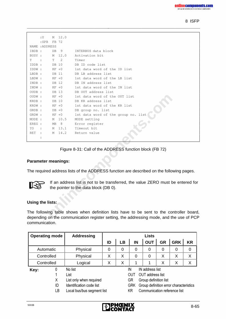
onlinec
omponen
ts.co
m
8 ISFP
5003B 8-65
:U M 12.0
:SPB FB 72
NAME :ADDRESS
IBDB : DB 9 INTERBUS data block
BUSY : M 12.0 Activation bit
T : T 2 Timer
IDDB : DB 10 DB ID code list
IDDW : KF +0 1st data word of the ID list
LBDB : DB 11 DB LB address list
LBDW : KF +0 1st data word of the LB list
INDB : DB 12 DB IN address list
INDW : KF +0 1st data word of the IN list
OUDB : DB 13 DB OUT address list
OUDW : KF +0 1st data word of the OUT list
KRDB : DB 10 DB KR address list
KRDW : KF +0 1st data word of the KR list
GRDB : DB +0 DB group no. list
GRDW : KF +0 1st data word of the group no. list
MODE : M 10.5 MODE setting
EREG : MB 8 Error register
TO : M 13.1 Timeout bit
RET : M 14.2 Return value
:
Figure 8-31: Call of the ADDRESS function block (FB 72)
Parameter meanings:
The required address lists of the ADDRESS function are described on the following pages.
If an address list is not to be transferred, the value ZERO must be entered forthe pointer to the data block (DB 0).
Using the lists:
The following table shows when definition lists have to be sent to the controller board,depending on the communication register setting, the addressing mode, and the use of PCPcommunication.
Operating mode Addressing Lists
ID LB IN OUT GR GRK KR
Automatic Physical 0 0 0 0 0 0 0
Controlled Physical X X 0 0 X X X
Controlled Logical X X 1 1 X X X
Key: � 1R�OLVW� /LVW; /LVW�RQO\�ZKHQ�UHTXLUHG,' ,GHQWLILFDWLRQ�FRGH�OLVW/% /RFDO�EXV�EXV�VHJPHQW�OLVW
,1 ,1�DGGUHVV�OLVW287 287�DGGUHVV�OLVW*5 *URXS�GHILQLWLRQ�OLVW*5. *URXS�GHILQLWLRQ�HUURU�FKDUDFWHULVWLFV.5 &RPPXQLFDWLRQ�UHIHUHQFH�OLVW
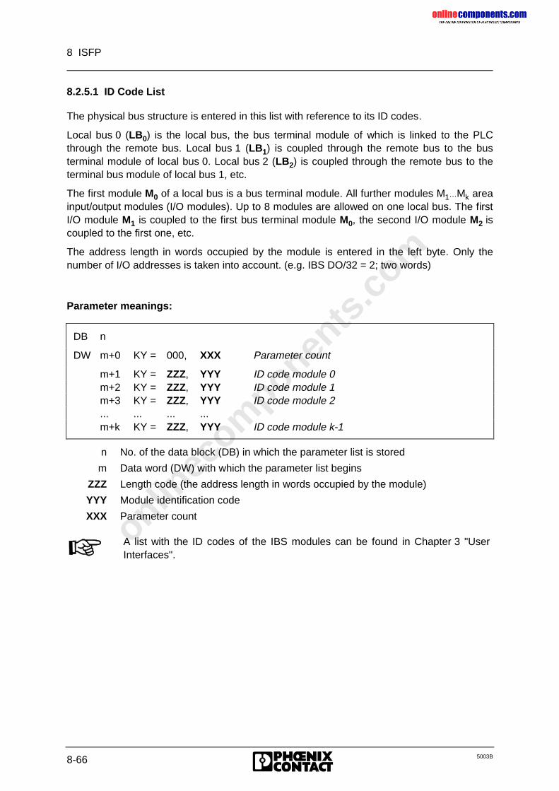
onlinec
omponen
ts.co
m
8 ISFP
8-66 5003B
8.2.5.1 ID Code List
The physical bus structure is entered in this list with reference to its ID codes.
Local bus 0 (LB0) is the local bus, the bus terminal module of which is linked to the PLCthrough the remote bus. Local bus 1 (LB1) is coupled through the remote bus to the busterminal module of local bus 0. Local bus 2 (LB2) is coupled through the remote bus to theterminal bus module of local bus 1, etc.
The first module M0 of a local bus is a bus terminal module. All further modules M1…Mk areainput/output modules (I/O modules). Up to 8 modules are allowed on one local bus. The firstI/O module M1 is coupled to the first bus terminal module M0, the second I/O module M2 iscoupled to the first one, etc.
The address length in words occupied by the module is entered in the left byte. Only thenumber of I/O addresses is taken into account. (e.g. IBS DO/32 = 2; two words)
Parameter meanings:
DB n
DW m+0 KY = 000, XXX Parameter count
m+1 KY = ZZZ, YYY ID code module 0m+2 KY = ZZZ, YYY ID code module 1m+3 KY = ZZZ, YYY ID code module 2... ... ... ...m+k KY = ZZZ, YYY ID code module k-1
n No. of the data block (DB) in which the parameter list is stored
m Data word (DW) with which the parameter list begins
ZZZ Length code (the address length in words occupied by the module)
YYY Module identification code
XXX Parameter count
A list with the ID codes of the IBS modules can be found in Chapter 3 "UserInterfaces".
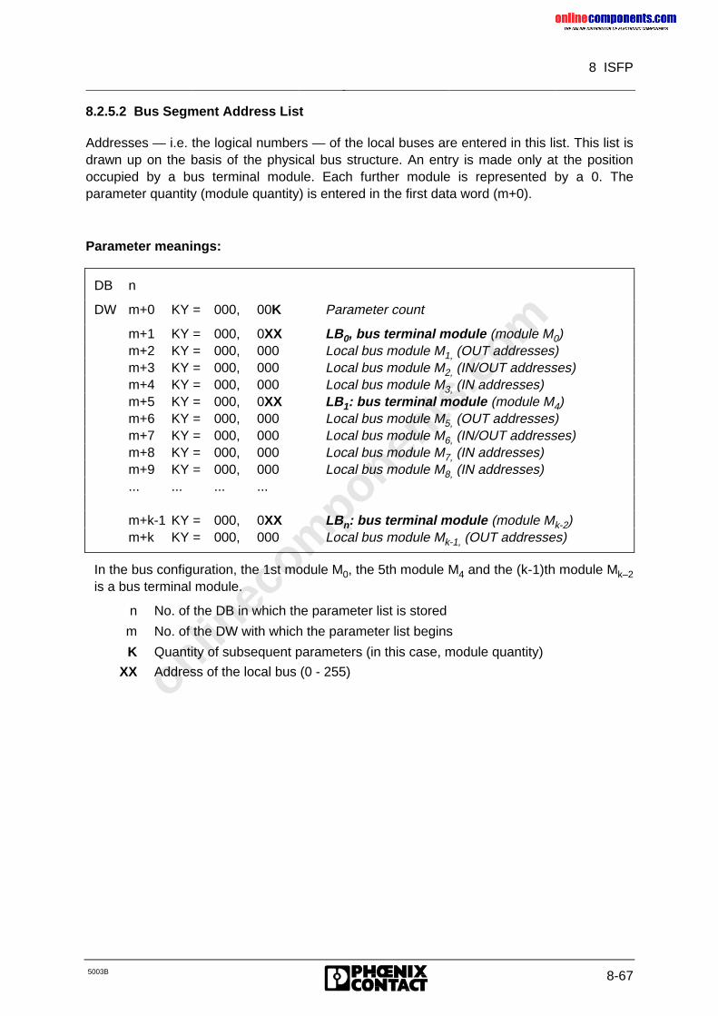
onlinec
omponen
ts.co
m
8 ISFP
5003B 8-67
8.2.5.2 Bus Segment Address List
Addresses — i.e. the logical numbers — of the local buses are entered in this list. This list isdrawn up on the basis of the physical bus structure. An entry is made only at the positionoccupied by a bus terminal module. Each further module is represented by a 0. Theparameter quantity (module quantity) is entered in the first data word (m+0).
Parameter meanings:
DB n
DW m+0 KY = 000, 00K Parameter count
m+1 KY = 000, 0XX LB0, bus terminal module (module M0)m+2 KY = 000, 000 Local bus module M1, (OUT addresses)m+3 KY = 000, 000 Local bus module M2, (IN/OUT addresses)m+4 KY = 000, 000 Local bus module M3, (IN addresses)m+5 KY = 000, 0XX LB1: bus terminal module (module M4)m+6 KY = 000, 000 Local bus module M5, (OUT addresses)m+7 KY = 000, 000 Local bus module M6, (IN/OUT addresses)m+8 KY = 000, 000 Local bus module M7, (IN addresses)m+9 KY = 000, 000 Local bus module M8, (IN addresses)... ... ... ...
m+k-1 KY = 000, 0XX LBn: bus terminal module (module Mk-2)m+k KY = 000, 000 Local bus module Mk-1, (OUT addresses)
In the bus configuration, the 1st module M0, the 5th module M4 and the (k-1)th module Mk–2is a bus terminal module.
n No. of the DB in which the parameter list is stored
m No. of the DW with which the parameter list begins
K Quantity of subsequent parameters (in this case, module quantity)
XX Address of the local bus (0 - 255)
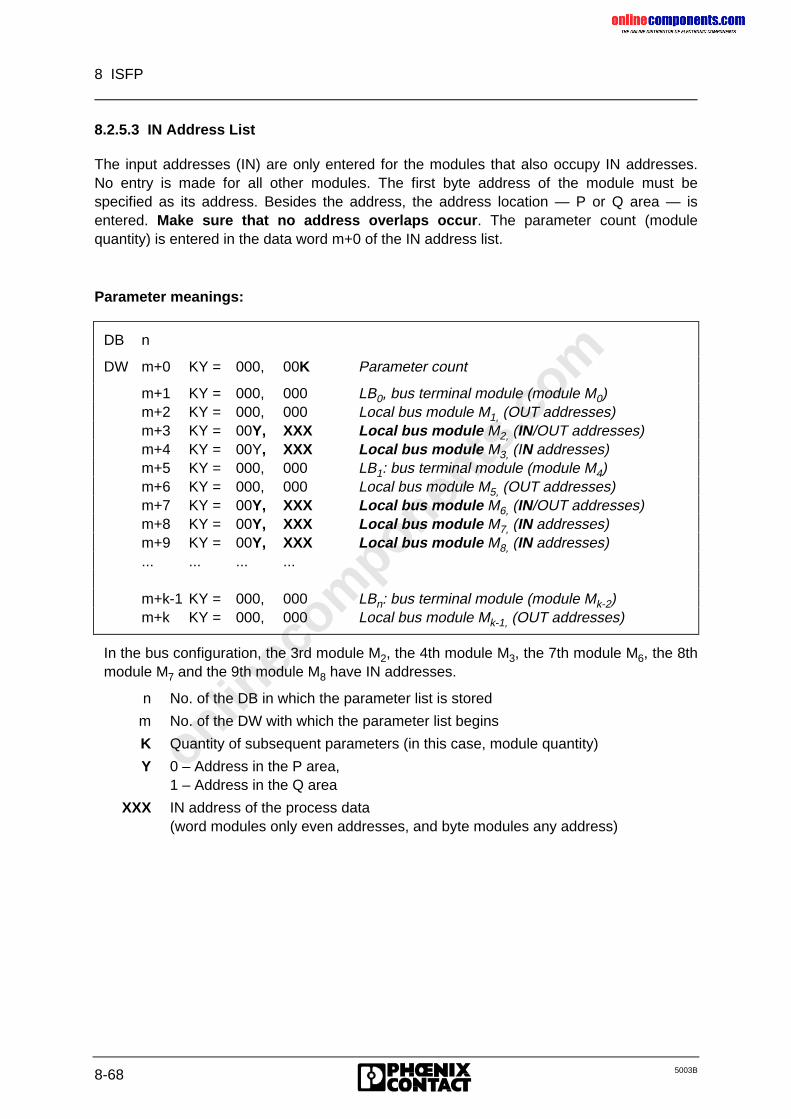
onlinec
omponen
ts.co
m
8 ISFP
8-68 5003B
8.2.5.3 IN Address List
The input addresses (IN) are only entered for the modules that also occupy IN addresses.No entry is made for all other modules. The first byte address of the module must bespecified as its address. Besides the address, the address location — P or Q area — isentered. Make sure that no address overlaps occur. The parameter count (modulequantity) is entered in the data word m+0 of the IN address list.
Parameter meanings:
DB n
DW m+0 KY = 000, 00K Parameter count
m+1 KY = 000, 000 LB0, bus terminal module (module M0)m+2 KY = 000, 000 Local bus module M1, (OUT addresses)m+3 KY = 00Y, XXX Local bus module M2, (IN/OUT addresses)m+4 KY = 00Y, XXX Local bus module M3, (IN addresses)m+5 KY = 000, 000 LB1: bus terminal module (module M4)m+6 KY = 000, 000 Local bus module M5, (OUT addresses)m+7 KY = 00Y, XXX Local bus module M6, (IN/OUT addresses)m+8 KY = 00Y, XXX Local bus module M7, (IN addresses)m+9 KY = 00Y, XXX Local bus module M8, (IN addresses)... ... ... ...
m+k-1 KY = 000, 000 LBn: bus terminal module (module Mk-2)m+k KY = 000, 000 Local bus module Mk-1, (OUT addresses)
In the bus configuration, the 3rd module M2, the 4th module M3, the 7th module M6, the 8thmodule M7 and the 9th module M8 have IN addresses.
n No. of the DB in which the parameter list is stored
m No. of the DW with which the parameter list begins
K Quantity of subsequent parameters (in this case, module quantity)
Y 0 – Address in the P area,1 – Address in the Q area
XXX IN address of the process data(word modules only even addresses, and byte modules any address)
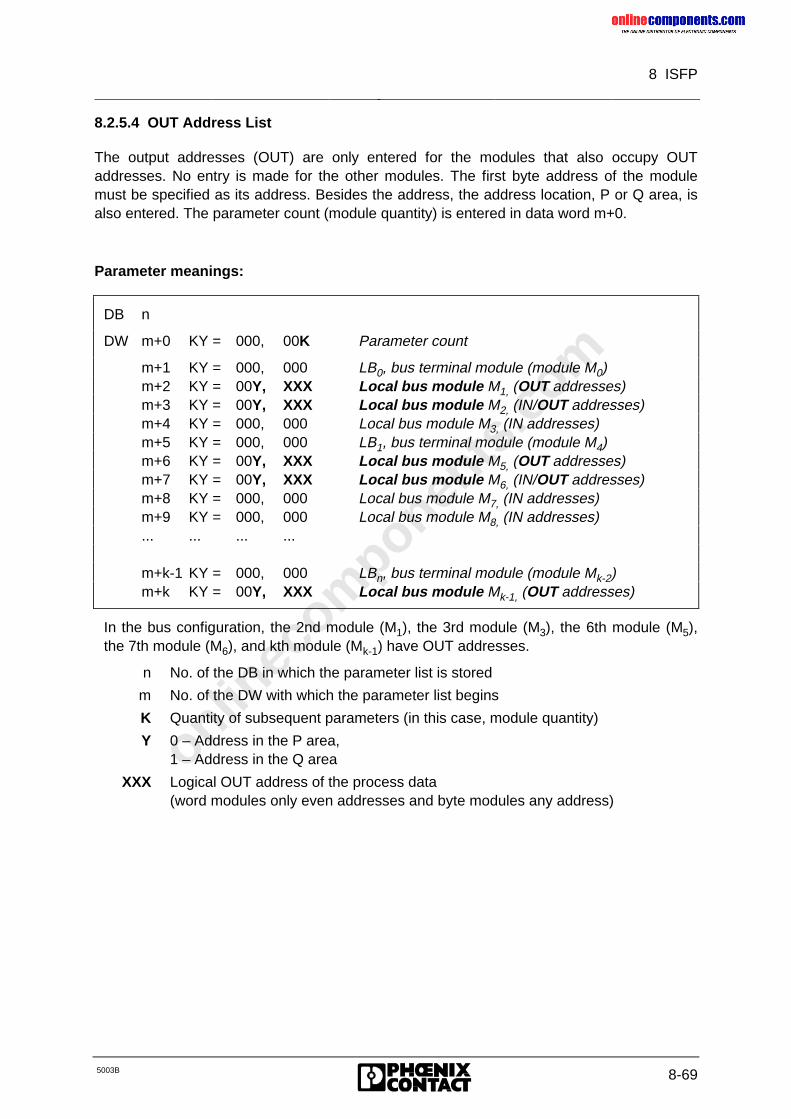
onlinec
omponen
ts.co
m
8 ISFP
5003B 8-69
8.2.5.4 OUT Address List
The output addresses (OUT) are only entered for the modules that also occupy OUTaddresses. No entry is made for the other modules. The first byte address of the modulemust be specified as its address. Besides the address, the address location, P or Q area, isalso entered. The parameter count (module quantity) is entered in data word m+0.
Parameter meanings:
DB n
DW m+0 KY = 000, 00K Parameter count
m+1 KY = 000, 000 LB0, bus terminal module (module M0)m+2 KY = 00Y, XXX Local bus module M1, (OUT addresses)m+3 KY = 00Y, XXX Local bus module M2, (IN/OUT addresses)m+4 KY = 000, 000 Local bus module M3, (IN addresses)m+5 KY = 000, 000 LB1, bus terminal module (module M4)m+6 KY = 00Y, XXX Local bus module M5, (OUT addresses)m+7 KY = 00Y, XXX Local bus module M6, (IN/OUT addresses)m+8 KY = 000, 000 Local bus module M7, (IN addresses)m+9 KY = 000, 000 Local bus module M8, (IN addresses)... ... ... ...
m+k-1 KY = 000, 000 LBn, bus terminal module (module Mk-2)m+k KY = 00Y, XXX Local bus module Mk-1, (OUT addresses)
In the bus configuration, the 2nd module (M1), the 3rd module (M3), the 6th module (M5),the 7th module (M6), and kth module (Mk-1) have OUT addresses.
n No. of the DB in which the parameter list is stored
m No. of the DW with which the parameter list begins
K Quantity of subsequent parameters (in this case, module quantity)
Y 0 – Address in the P area,1 – Address in the Q area
XXX Logical OUT address of the process data(word modules only even addresses and byte modules any address)
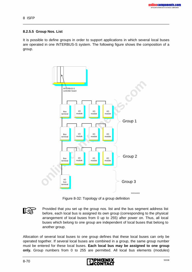
onlinec
omponen
ts.co
m
8 ISFP
8-70 5003B
8.2.5.5 Group Nos. List
It is possible to define groups in order to support applications in which several local busesare operated in one INTERBUS-S system. The following figure shows the composition of agroup.
5003A830
INTERBUS-Scontroller board
Busterminal
I/O module
I/O module
I/O module
Bus terminal
I/Omodule
I/Omodule
I/O module
Busterminal
I/Omodule
I/Omodule
I/Omodule
I/Obus
terminal Group 3
Group 2
Group 1
Figure 8-32: Topology of a group definition
Provided that you set up the group nos. list and the bus segment address listbefore, each local bus is assigned its own group (corresponding to the physicalarrangement of local buses from 0 up to 255) after power on. Thus, all localbuses which belong to one group are independent of local buses that belong toanother group.
Allocation of several local buses to one group defines that these local buses can only beoperated together. If several local buses are combined in a group, the same group numbermust be entered for these local buses. Each local bus may be assigned to one grouponly. Group numbers from 0 to 255 are permitted. All local bus elements (modules)
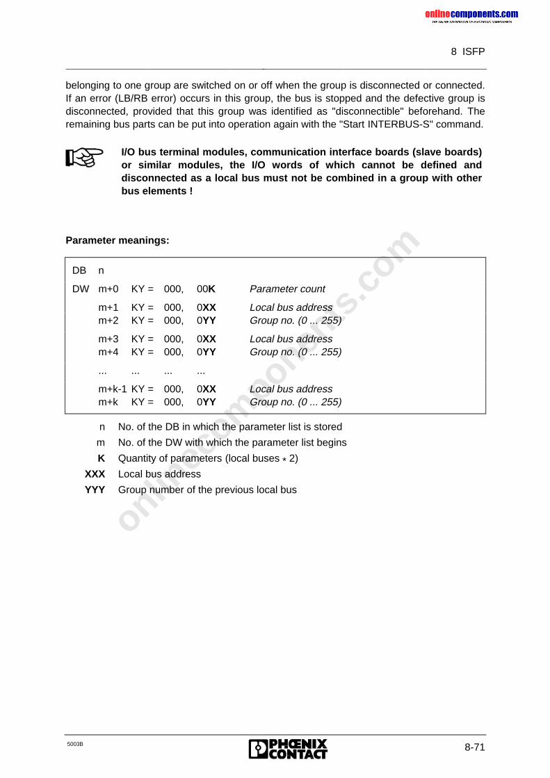
onlinec
omponen
ts.co
m
8 ISFP
5003B 8-71
belonging to one group are switched on or off when the group is disconnected or connected.If an error (LB/RB error) occurs in this group, the bus is stopped and the defective group isdisconnected, provided that this group was identified as "disconnectible" beforehand. Theremaining bus parts can be put into operation again with the "Start INTERBUS-S" command.
I/O bus terminal modules, communication interface boards (slave boards)or similar modules, the I/O words of which cannot be defined anddisconnected as a local bus must not be combined in a group with otherbus elements !
Parameter meanings:
DB n
DW m+0 KY = 000, 00K Parameter count
m+1 KY = 000, 0XX Local bus addressm+2 KY = 000, 0YY Group no. (0 ... 255)
m+3 KY = 000, 0XX Local bus addressm+4 KY = 000, 0YY Group no. (0 ... 255)
... ... ... ...
m+k-1 KY = 000, 0XX Local bus addressm+k KY = 000, 0YY Group no. (0 ... 255)
n No. of the DB in which the parameter list is stored
m No. of the DW with which the parameter list begins
K Quantity of parameters (local buses * 2)
XXX Local bus address
YYY Group number of the previous local bus
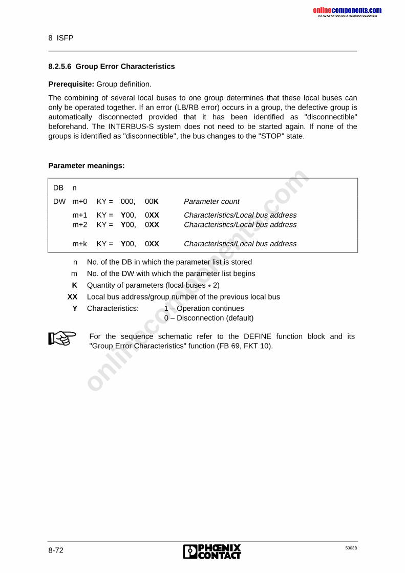
onlinec
omponen
ts.co
m
8 ISFP
8-72 5003B
8.2.5.6 Group Error Characteristics
Prerequisite: Group definition.
The combining of several local buses to one group determines that these local buses canonly be operated together. If an error (LB/RB error) occurs in a group, the defective group isautomatically disconnected provided that it has been identified as "disconnectible"beforehand. The INTERBUS-S system does not need to be started again. If none of thegroups is identified as "disconnectible", the bus changes to the "STOP" state.
Parameter meanings:
DB n
DW m+0 KY = 000, 00K Parameter count
m+1 KY = Y00, 0XX Characteristics/Local bus addressm+2 KY = Y00, 0XX Characteristics/Local bus address
m+k KY = Y00, 0XX Characteristics/Local bus address
n No. of the DB in which the parameter list is stored
m No. of the DW with which the parameter list begins
K Quantity of parameters (local buses * 2)
XX Local bus address/group number of the previous local bus
Y Characteristics: 1 – Operation continues0 – Disconnection (default)
For the sequence schematic refer to the DEFINE function block and its"Group Error Characteristics" function (FB 69, FKT 10).
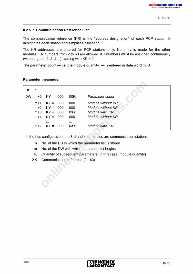
onlinec
omponen
ts.co
m
8 ISFP
5003B 8-73
8.2.5.7 Communication Reference List
The communication reference (KR) is the "address designation“ of each PCP station. Itdesignates each station and simplifies allocation.
The KR addresses are entered for PCP stations only. No entry is made for the othermodules. KR numbers from 2 to 63 are allowed. KR numbers must be assigned continuously(without gaps; 2, 3, 4,...) starting with KR = 2.
The parameter count — i.e. the module quantity — is entered in data word m+0.
Parameter meanings:
DB n
DW m+0 KY = 000, 00K Parameter count
m+1 KY = 000, 000 Module without KRm+2 KY = 000, 000 Module without KRm+3 KY = 000, 0XX Module with KRm+4 KY = 000, 000 Module without KR... ... ... ...m+k KY = 000, 0XX Module with KR
In the bus configuration, the 3rd and kth modules are communication stations
n No. of the DB in which the parameter list is stored
m No. of the DW with which parameter list begins
K Quantity of subsequent parameters (in this case; module quantity)
XX Communication reference (2 - 63)
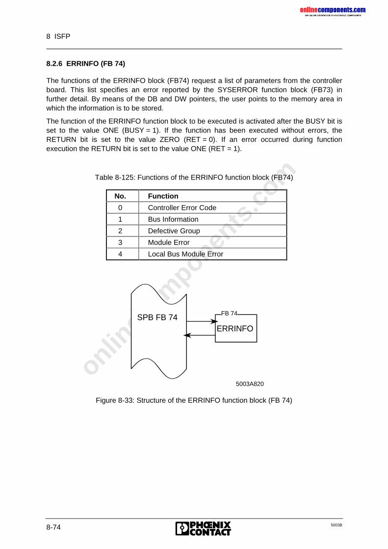
onlinec
omponen
ts.co
m
8 ISFP
8-74 5003B
8.2.6 ERRINFO (FB 74)
The functions of the ERRINFO block (FB74) request a list of parameters from the controllerboard. This list specifies an error reported by the SYSERROR function block (FB73) infurther detail. By means of the DB and DW pointers, the user points to the memory area inwhich the information is to be stored.
The function of the ERRINFO function block to be executed is activated after the BUSY bit isset to the value ONE (BUSY = 1). If the function has been executed without errors, theRETURN bit is set to the value ZERO (RET = 0). If an error occurred during functionexecution the RETURN bit is set to the value ONE (RET = 1).
Table 8-125: Functions of the ERRINFO function block (FB74)
No. Function
0 Controller Error Code
1 Bus Information
2 Defective Group
3 Module Error
4 Local Bus Module Error
ERRINFO
5003A820
FB 74SPB FB 74
Figure 8-33: Structure of the ERRINFO function block (FB 74)
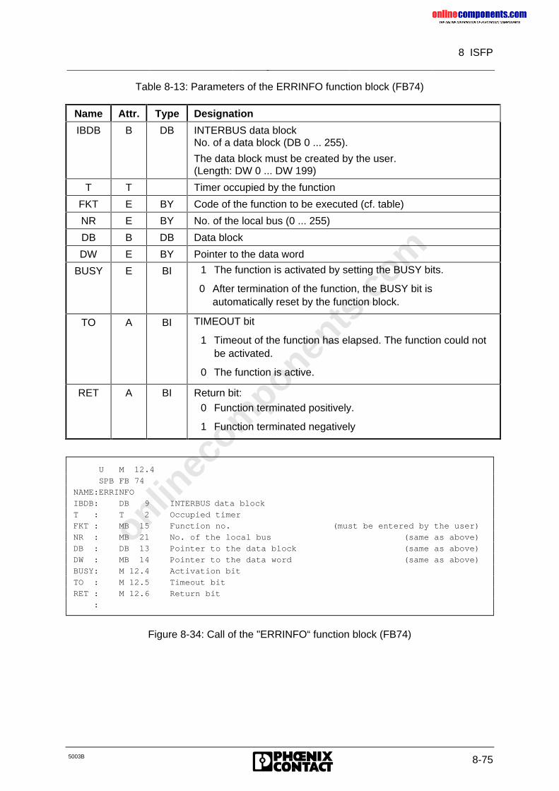
onlinec
omponen
ts.co
m
8 ISFP
5003B 8-75
Table 8-13: Parameters of the ERRINFO function block (FB74)
Name Attr. Type Designation
IBDB B DB INTERBUS data blockNo. of a data block (DB 0 ... 255).
The data block must be created by the user.(Length: DW 0 ... DW 199)
T T Timer occupied by the function
FKT E BY Code of the function to be executed (cf. table)
NR E BY No. of the local bus (0 ... 255)
DB B DB Data block
DW E BY Pointer to the data word
BUSY E BI 1 The function is activated by setting the BUSY bits.
0 After termination of the function, the BUSY bit isautomatically reset by the function block.
TO A BI TIMEOUT bit
1 Timeout of the function has elapsed. The function could notbe activated.
0 The function is active.
RET A BI Return bit:0 Function terminated positively.
1 Function terminated negatively
U M 12.4
SPB FB 74
NAME:ERRINFO
IBDB: DB 9 INTERBUS data block
T : T 2 Occupied timer
FKT : MB 15 Function no. (must be entered by the user)
NR : MB 21 No. of the local bus (same as above)
DB : DB 13 Pointer to the data block (same as above)
DW : MB 14 Pointer to the data word (same as above)
BUSY: M 12.4 Activation bit
TO : M 12.5 Timeout bit
RET : M 12.6 Return bit
:
Figure 8-34: Call of the "ERRINFO“ function block (FB74)
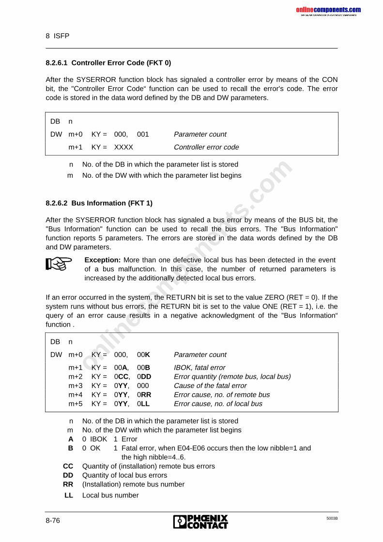
onlinec
omponen
ts.co
m
8 ISFP
8-76 5003B
8.2.6.1 Controller Error Code (FKT 0)
After the SYSERROR function block has signaled a controller error by means of the CONbit, the "Controller Error Code“ function can be used to recall the error's code. The errorcode is stored in the data word defined by the DB and DW parameters.
DB n
DW m+0 KY = 000, 001 Parameter count
m+1 KY = XXXX Controller error code
n No. of the DB in which the parameter list is stored
m No. of the DW with which the parameter list begins
8.2.6.2 Bus Information (FKT 1)
After the SYSERROR function block has signaled a bus error by means of the BUS bit, the"Bus Information" function can be used to recall the bus errors. The "Bus Information"function reports 5 parameters. The errors are stored in the data words defined by the DBand DW parameters.
Exception: More than one defective local bus has been detected in the eventof a bus malfunction. In this case, the number of returned parameters isincreased by the additionally detected local bus errors.
If an error occurred in the system, the RETURN bit is set to the value ZERO (RET = 0). If thesystem runs without bus errors, the RETURN bit is set to the value ONE (RET = 1), i.e. thequery of an error cause results in a negative acknowledgment of the "Bus Information“function .
DB n
DW m+0 KY = 000, 00K Parameter count
m+1 KY = 00A, 00B IBOK, fatal errorm+2 KY = 0CC, 0DD Error quantity (remote bus, local bus)m+3 KY = 0YY, 000 Cause of the fatal errorm+4 KY = 0YY, 0RR Error cause, no. of remote busm+5 KY = 0YY, 0LL Error cause, no. of local bus
n No. of the DB in which the parameter list is storedm No. of the DW with which the parameter list beginsA 0 IBOK 1 ErrorB 0 OK 1 Fatal error, when E04-E06 occurs then the low nibble=1 and
the high nibble=4..6.CC Quantity of (installation) remote bus errorsDD Quantity of local bus errorsRR (Installation) remote bus number
LL Local bus number
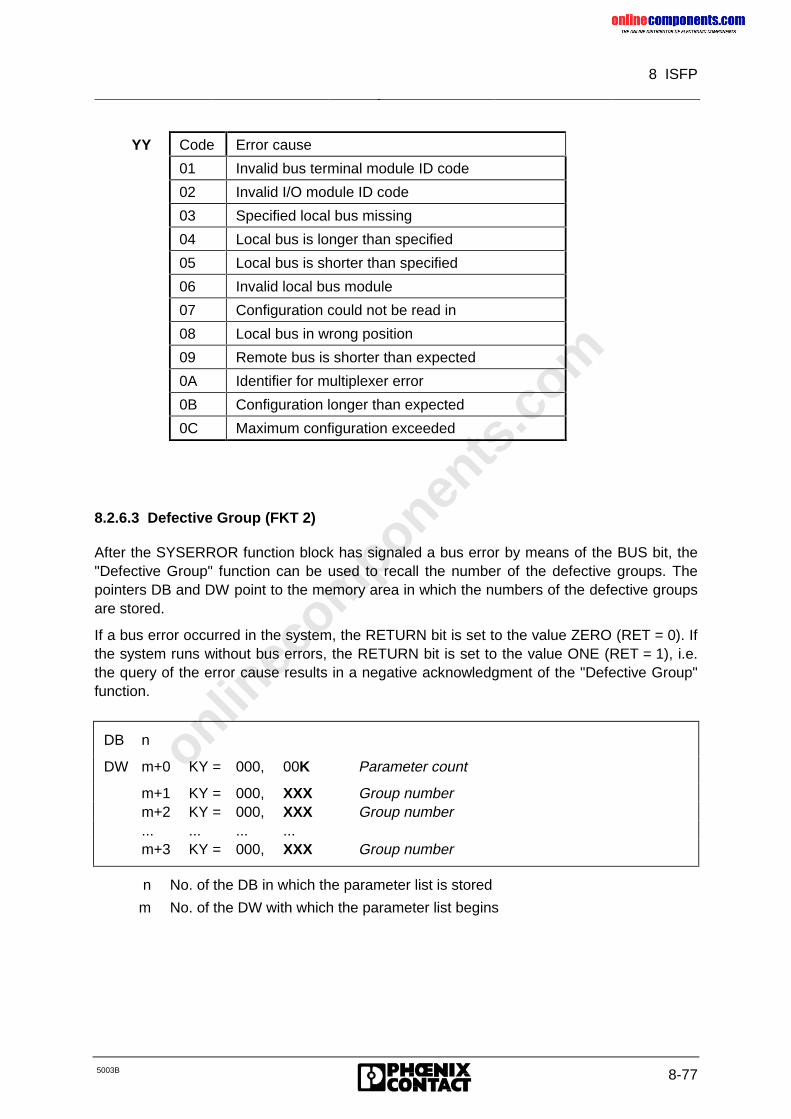
onlinec
omponen
ts.co
m
8 ISFP
5003B 8-77
YY Code Error cause
01 Invalid bus terminal module ID code
02 Invalid I/O module ID code
03 Specified local bus missing
04 Local bus is longer than specified
05 Local bus is shorter than specified
06 Invalid local bus module
07 Configuration could not be read in
08 Local bus in wrong position
09 Remote bus is shorter than expected
0A Identifier for multiplexer error
0B Configuration longer than expected
0C Maximum configuration exceeded
8.2.6.3 Defective Group (FKT 2)
After the SYSERROR function block has signaled a bus error by means of the BUS bit, the"Defective Group" function can be used to recall the number of the defective groups. Thepointers DB and DW point to the memory area in which the numbers of the defective groupsare stored.
If a bus error occurred in the system, the RETURN bit is set to the value ZERO (RET = 0). Ifthe system runs without bus errors, the RETURN bit is set to the value ONE (RET = 1), i.e.the query of the error cause results in a negative acknowledgment of the "Defective Group"function.
DB n
DW m+0 KY = 000, 00K Parameter count
m+1 KY = 000, XXX Group numberm+2 KY = 000, XXX Group number... ... ... ...m+3 KY = 000, XXX Group number
n No. of the DB in which the parameter list is stored
m No. of the DW with which the parameter list begins
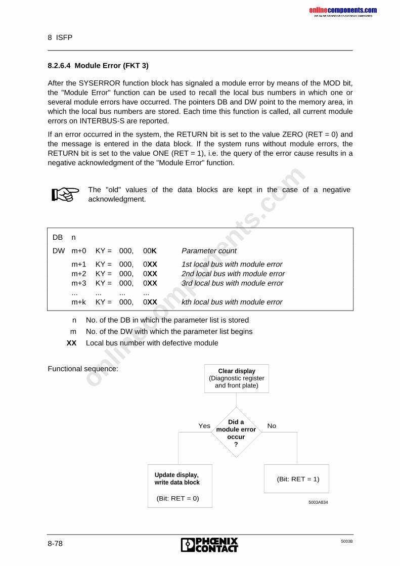
onlinec
omponen
ts.co
m
8 ISFP
8-78 5003B
8.2.6.4 Module Error (FKT 3)
After the SYSERROR function block has signaled a module error by means of the MOD bit,the "Module Error" function can be used to recall the local bus numbers in which one orseveral module errors have occurred. The pointers DB and DW point to the memory area, inwhich the local bus numbers are stored. Each time this function is called, all current moduleerrors on INTERBUS-S are reported.
If an error occurred in the system, the RETURN bit is set to the value ZERO (RET = 0) andthe message is entered in the data block. If the system runs without module errors, theRETURN bit is set to the value ONE (RET = 1), i.e. the query of the error cause results in anegative acknowledgment of the "Module Error" function.
The "old" values of the data blocks are kept in the case of a negativeacknowledgment.
DB n
DW m+0 KY = 000, 00K Parameter count
m+1 KY = 000, 0XX 1st local bus with module errorm+2 KY = 000, 0XX 2nd local bus with module errorm+3 KY = 000, 0XX 3rd local bus with module error... ... ... ...m+k KY = 000, 0XX kth local bus with module error
n No. of the DB in which the parameter list is stored
m No. of the DW with which the parameter list begins
XX Local bus number with defective module
Functional sequence: Clear display(Diagnostic register
and front plate)
Did a module error
occur?
Yes No
Update display,write data block
(Bit: RET = 0)
(Bit: RET = 1)
5003A834
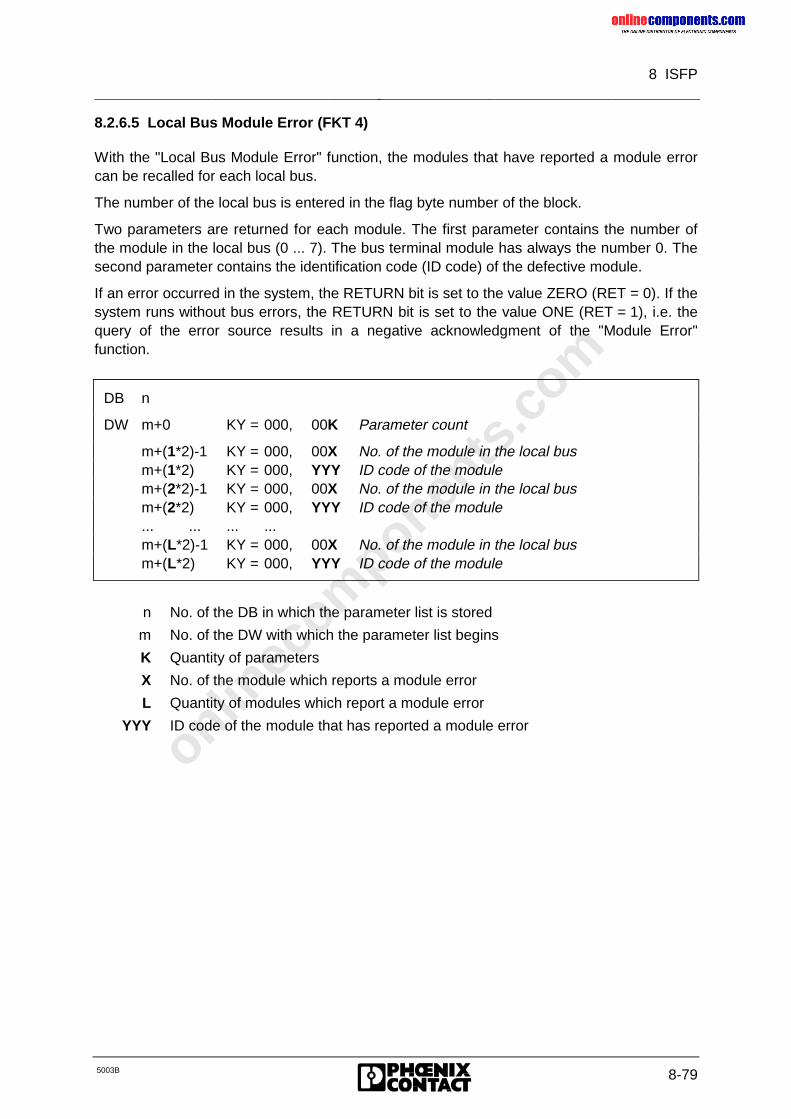
onlinec
omponen
ts.co
m
8 ISFP
5003B 8-79
8.2.6.5 Local Bus Module Error (FKT 4)
With the "Local Bus Module Error" function, the modules that have reported a module errorcan be recalled for each local bus.
The number of the local bus is entered in the flag byte number of the block.
Two parameters are returned for each module. The first parameter contains the number ofthe module in the local bus (0 ... 7). The bus terminal module has always the number 0. Thesecond parameter contains the identification code (ID code) of the defective module.
If an error occurred in the system, the RETURN bit is set to the value ZERO (RET = 0). If thesystem runs without bus errors, the RETURN bit is set to the value ONE (RET = 1), i.e. thequery of the error source results in a negative acknowledgment of the "Module Error"function.
DB n
DW m+0 KY = 000, 00K Parameter count
m+(1*2)-1 KY = 000, 00X No. of the module in the local busm+(1*2) KY = 000, YYY ID code of the modulem+(2*2)-1 KY = 000, 00X No. of the module in the local busm+(2*2) KY = 000, YYY ID code of the module... ... ... ...m+(L*2)-1 KY = 000, 00X No. of the module in the local busm+(L*2) KY = 000, YYY ID code of the module
n No. of the DB in which the parameter list is stored
m No. of the DW with which the parameter list begins
K Quantity of parameters
X No. of the module which reports a module error
L Quantity of modules which report a module error
YYY ID code of the module that has reported a module error
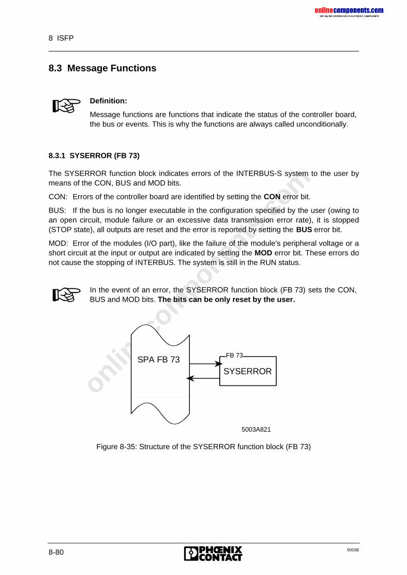
onlinec
omponen
ts.co
m
8 ISFP
8-80 5003B
8.3 Message Functions
Definition:
Message functions are functions that indicate the status of the controller board,the bus or events. This is why the functions are always called unconditionally.
8.3.1 SYSERROR (FB 73)
The SYSERROR function block indicates errors of the INTERBUS-S system to the user bymeans of the CON, BUS and MOD bits.
CON: Errors of the controller board are identified by setting the CON error bit.
BUS: If the bus is no longer executable in the configuration specified by the user (owing toan open circuit, module failure or an excessive data transmission error rate), it is stopped(STOP state), all outputs are reset and the error is reported by setting the BUS error bit.
MOD: Error of the modules (I/O part), like the failure of the module’s peripheral voltage or ashort circuit at the input or output are indicated by setting the MOD error bit. These errors donot cause the stopping of INTERBUS. The system is still in the RUN status.
In the event of an error, the SYSERROR function block (FB 73) sets the CON,BUS and MOD bits. The bits can be only reset by the user.
SYSERROR
5003A821
FB 73SPA FB 73
Figure 8-35: Structure of the SYSERROR function block (FB 73)
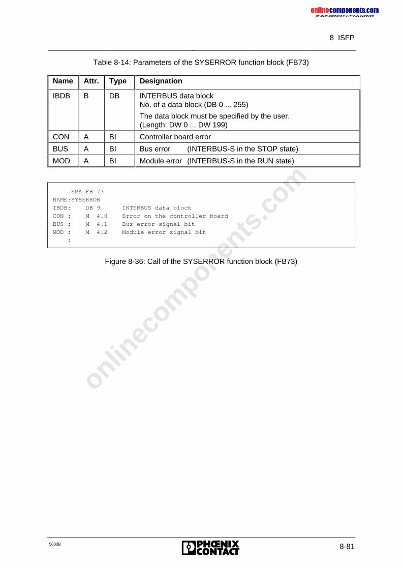
onlinec
omponen
ts.co
m
8 ISFP
5003B 8-81
Table 8-14: Parameters of the SYSERROR function block (FB73)
Name Attr. Type Designation
IBDB B DB INTERBUS data blockNo. of a data block (DB 0 ... 255)
The data block must be specified by the user.(Length: DW 0 ... DW 199)
CON A BI Controller board error
BUS A BI Bus error (INTERBUS-S in the STOP state)
MOD A BI Module error (INTERBUS-S in the RUN state)
SPA FB 73
NAME:SYSERROR
IBDB: DB 9 INTERBUS data block
CON : M 4.0 Error on the controller board
BUS : M 4.1 Bus error signal bit
MOD : M 4.2 Module error signal bit
:
Figure 8-36: Call of the SYSERROR function block (FB73)
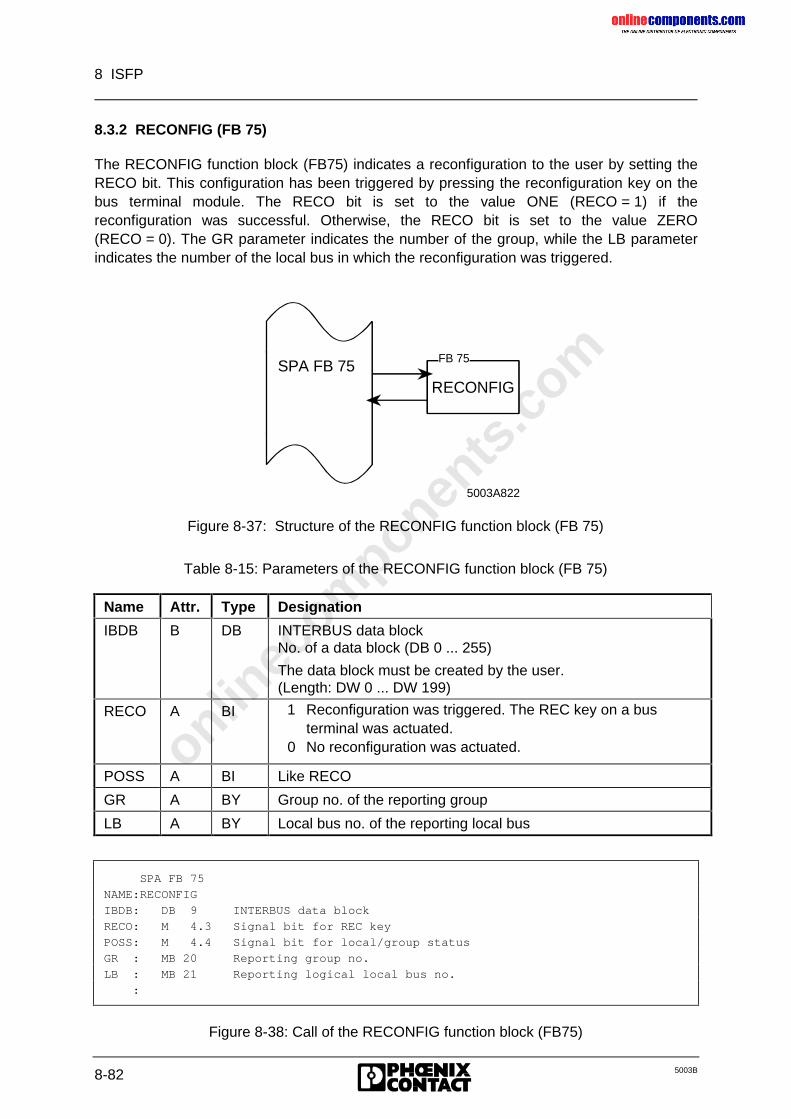
onlinec
omponen
ts.co
m
8 ISFP
8-82 5003B
8.3.2 RECONFIG (FB 75)
The RECONFIG function block (FB75) indicates a reconfiguration to the user by setting theRECO bit. This configuration has been triggered by pressing the reconfiguration key on thebus terminal module. The RECO bit is set to the value ONE (RECO = 1) if thereconfiguration was successful. Otherwise, the RECO bit is set to the value ZERO(RECO = 0). The GR parameter indicates the number of the group, while the LB parameterindicates the number of the local bus in which the reconfiguration was triggered.
RECONFIG
5003A822
FB 75SPA FB 75
Figure 8-37: Structure of the RECONFIG function block (FB 75)
Table 8-15: Parameters of the RECONFIG function block (FB 75)
Name Attr. Type Designation
IBDB B DB INTERBUS data blockNo. of a data block (DB 0 ... 255)
The data block must be created by the user.(Length: DW 0 ... DW 199)
RECO A BI 1 Reconfiguration was triggered. The REC key on a busterminal was actuated.
0 No reconfiguration was actuated.
POSS A BI Like RECO
GR A BY Group no. of the reporting group
LB A BY Local bus no. of the reporting local bus
SPA FB 75
NAME:RECONFIG
IBDB: DB 9 INTERBUS data block
RECO: M 4.3 Signal bit for REC key
POSS: M 4.4 Signal bit for local/group status
GR : MB 20 Reporting group no.
LB : MB 21 Reporting logical local bus no.
:
Figure 8-38: Call of the RECONFIG function block (FB75)
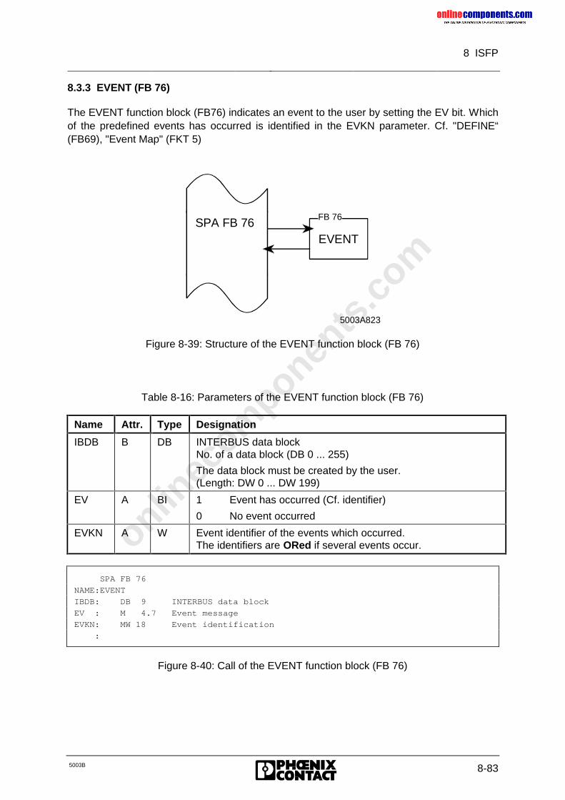
onlinec
omponen
ts.co
m
8 ISFP
5003B 8-83
8.3.3 EVENT (FB 76)
The EVENT function block (FB76) indicates an event to the user by setting the EV bit. Whichof the predefined events has occurred is identified in the EVKN parameter. Cf. "DEFINE“(FB69), "Event Map" (FKT 5)
EVENT
5003A823
FB 76SPA FB 76
Figure 8-39: Structure of the EVENT function block (FB 76)
Table 8-16: Parameters of the EVENT function block (FB 76)
Name Attr. Type Designation
IBDB B DB INTERBUS data blockNo. of a data block (DB 0 ... 255)
The data block must be created by the user.(Length: DW 0 ... DW 199)
EV A BI 1 Event has occurred (Cf. identifier)
0 No event occurred
EVKN A W Event identifier of the events which occurred.The identifiers are ORed if several events occur.
SPA FB 76
NAME:EVENT
IBDB: DB 9 INTERBUS data block
EV : M 4.7 Event message
EVKN: MW 18 Event identification
:
Figure 8-40: Call of the EVENT function block (FB 76)
onlinec
omponen
ts.co
m
8 ISFP
8-84 5003B
8.4 Working with Communication
8.4.1 Introduction
Communication is a term used to describe the fact of ’being able to talk to each other andunderstand each other’. A prerequisite is that both partners speak the same language andare able to contact each other. Besides dedicated communication, its ’direction’ is alsodefined in order to perform a specific task.
The sequence can be described as follows:
• Two partners are always required for successful communication. On the one side,orders are issued and on the other side, they are executed.
• An order is not issued until it is certain that the entity entrusted with the order is alsocapable of executing it.
• After execution of the order, its success or failure is reported back to the one whoordered.
• In an equivalent relationship, both partners can order.
When transferring the sequence to the communication protocol, the following is understoodto constitute communication:
• Being able to talk to each other ...
– Establishment of a communication relationship
– Definition of a communication channel
• ... and understanding each other:
– The recipient of a message should also be capable of translating it.
Communication
As far as communication is concerned, a distinction is made between client and server.Within the meaning of communication, a client is a user process that issues orders. Theserver is the user process executing the order. In principle, a user process can be both aserver and a client.
In the client, the issuing of an order is described by the Request service primitive and theacceptance of the service’s order acknowledgment is described by Confirmation serviceprimitive. In the server, the arrival of the order is represented by the Indication serviceprimitive and the issuing of the order confirmation is represented by the Response serviceprimitive.
As a rule the application program on the PLC works as a client. From firmware3.5 onwards the PLC can also support a server functionality with the help of adefault object dictionary (e.g. for a V.24 client).
Taking the fields of application into account, the PCP communication system provides theuser with some services for use of open communication. The following services are availableto the user:
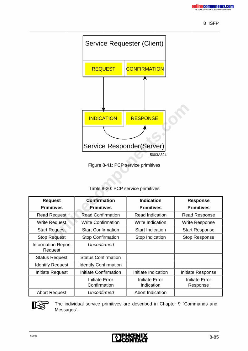
onlinec
omponen
ts.co
m
8 ISFP
5003B 8-85
REQUEST CONFIRMATION
Service Requester (Client)
RESPONSEINDICATION
Service Responder(Server)5003A824
Figure 8-41: PCP service primitives
Table 8-20: PCP service primitives
Request
Primitives
Confirmation
Primitives
Indication
Primitives
Response
Primitives
Read Request Read Confirmation Read Indication Read Response
Write Request Write Confirmation Write Indication Write Response
Start Request Start Confirmation Start Indication Start Response
Stop Request Stop Confirmation Stop Indication Stop Response
Information ReportRequest
Unconfirmed
Status Request Status Confirmation
Identify Request Identify Confirmation
Initiate Request Initiate Confirmation Initiate Indication Initiate Response
Initiate ErrorConfirmation
Initiate ErrorIndication
Initiate ErrorResponse
Abort Request Unconfirmed Abort Indication
The individual service primitives are described in Chapter 9 "Commands andMessages“.
onlinec
omponen
ts.co
m
8 ISFP
8-86 5003B
8.4.1.1 Control During Communication
Process data
When using the INTERBUS-S system, the process data occupies part of the PLC’s I/Oaddress area. The size of the address area occupied by INTERBUS-S depends on theINTERBUS-S system’s capacity. This address area is treated by the PLC as if S5 moduleswere plugged into it.
For the INTERBUS-S system, the address area required by the process data is reservedcentrally on the controller board.
Communication data
Unlike the process data, the communication data of the PCP stations is not mapped into thePLC’s I/O address area. It is kept in the data blocks of the PLC. The data is exchangedbetween the PLC and the controller board. The communication registers serve as thehardware interface for this purpose. The registers occupy 4 bytes in the PLC’s I/O addressarea. The addresses are located above the process data’s window 2. In the PLC, handling ofcommunication between the PLC and the controller board is realized by function blockswhich are integrated into the user program.
8.4.1.2 Call Structure of the Function Blocks
The interface between the application and PCP consists of function blocks. These functionblocks serve the communication registers.
The user calls them during startup and in the cyclic program by means of conditional jumps.The function blocks were written for the SIMATIC S5 in STEP 5.
The INITIB initialization block (FB 60) is called during startup of the PLC (OB 20…22). Thisfunction block carries out some basic software settings. It also controls the synchronizationbetween the PLC and INTERBUS-S. The routine is not terminated until INTERBUS-S is inthe READY state, or the bus was activated.
A receive block (FB66) and a send block (FB62 or FB 64) are called in the cyclic program.To arrive at an optimized response with respect to time, the receive block (CON/IND) shouldbe called at the start of the cyclic program and the send block (REQ/RES) at the end.
The ADDRESS addressing block must be processed before the application is started in thecyclic program. This block addresses the INTERBUS-S stations, performs PCP initialization,and starts the bus afterwards.
The application can be started once the addressing block has ended. For PCPcommunication, the receive and send block are activated from the application program bymeans of flag bits.
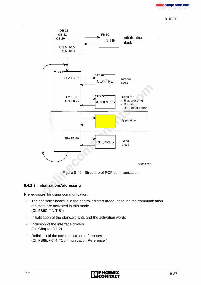
onlinec
omponen
ts.co
m
8 ISFP
5003B 8-87
Initialization -block
OB 1
Receive block
Send block
REQ/RES
CON/INDSPA FB 62
5003A825
INITIB
OB 22 FB 60 OB 21
OB 20
UN M 10.0 S M 10.0
FB 62
ADDRESS
FB 72 U M 10.0SPB FB 72
Block for- IB addressing- IB start- PCP initialization
SPA FB 60
Application
Figure 8-42: Structure of PCP communication
8.4.1.3 Initialization/Addressing
Prerequisites for using communication:
• The controller board is in the controlled start mode, because the communicationregisters are activated in this mode.(Cf. FB60, "INITIB“)
• Initialization of the standard DBs and the activation words
• Inclusion of the interface drivers(Cf. Chapter 8.1.2)
• Definition of the communication references(Cf. FB69/FKT4, "Communication Reference")
onlinec
omponen
ts.co
m
8 ISFP
8-88 5003B
Initialization
With the communication registers activated, the controller board is initialized during startupof the PLC. Besides defining the IBDB (INTERBUS data block), this initialization also definestwo further blocks and two flag words.
Data blocks
RRST Request/Responsestandard data block
The service request or response isentered in this data block.
CIST Confirmation/Indicationstandard data block
The service confirmation or indication isentered in this data block.
Flag words
RRMW Request/Responseflag word
The services are activated by way of thisflag word.
CIMW Confirmation/Indicationflag word
This flag word indicates execution of theorder.
Interface drivers
The two function blocks CON/IND (FB62) and REQ/RES (FB66) are referred to as interfacedrivers. Commands are sent to the controller board and messages are fetched from it bymeans of these function blocks.
To achieve an optimized behavior with respect to time, their locations in the cyclic programare important.
Placing the blocks:
• The CON/IND function block is called conditionally at the start of the cycle.
• The REQ/RES function block is called conditionally at the end of the cycle.
The communication services are also operated by way of these driver blocks. The ISFPinterface (INTERBUS-S Functions for the PLC) was developed to provide the user with thepossibility of using the services easily for open communication. Part of this interface consistsof two data blocks which must be specified by way of parameters of the interface drivers.
RRDB REQ/RES header blocks
CIDB CON/IND header blocks
Addressing/Communication reference
The communication references (KR) are transferred by the ADDRESS function block(FB 72). Each module which is capable of communication is assigned one KR. Allcommunication stations are unambiguously identified with this communication reference.The communication references of the modules are entered in a communication referencelist.
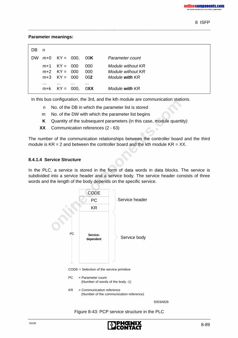
onlinec
omponen
ts.co
m
8 ISFP
5003B 8-89
Parameter meanings:
DB n
DW m+0 KY = 000, 00K Parameter count
m+1 KY = 000 000 Module without KRm+2 KY = 000 000 Module without KRm+3 KY = 000 002 Module with KR... ... ... ...m+k KY = 000, 0XX Module with KR
In this bus configuration, the 3rd, and the kth module are communication stations.
n No. of the DB in which the parameter list is stored
m No. of the DW with which the parameter list begins
K Quantity of the subsequent parameters (in this case, module quantity)
XX Communication references (2 - 63)
The number of the communication relationships between the controller board and the thirdmodule is KR = 2 and between the controller board and the kth module KR = XX.
8.4.1.4 Service Structure
In the PLC, a service is stored in the form of data words in data blocks. The service issubdivided into a service header and a service body. The service header consists of threewords and the length of the body depends on the specific service.
Service-dependent
CODE
PC
KR
Service header
Service bodyPC
CODE = Selection of the service primitive
PC = Parameter count (Number of words of the body -1)
KR = Communication reference (Number of the communication reference)
5003A826
Figure 8-43: PCP service structure in the PLC
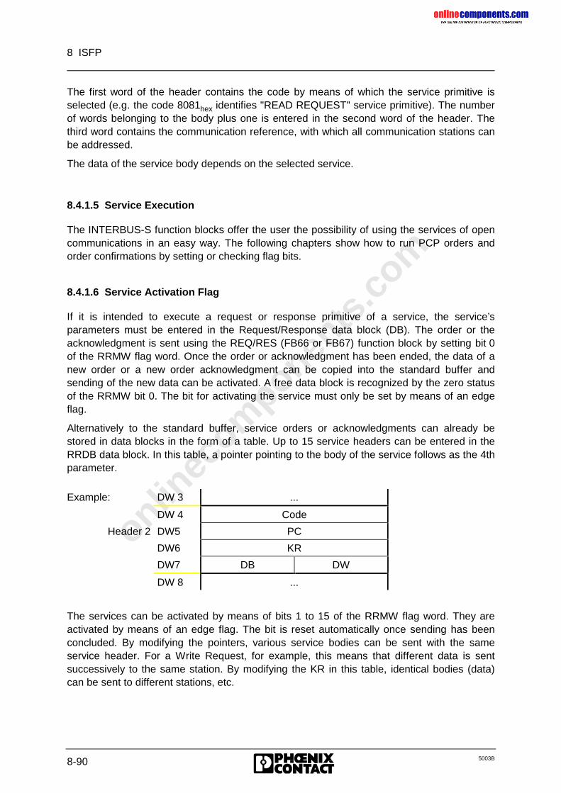
onlinec
omponen
ts.co
m
8 ISFP
8-90 5003B
The first word of the header contains the code by means of which the service primitive isselected (e.g. the code 8081hex identifies "READ REQUEST" service primitive). The numberof words belonging to the body plus one is entered in the second word of the header. Thethird word contains the communication reference, with which all communication stations canbe addressed.
The data of the service body depends on the selected service.
8.4.1.5 Service Execution
The INTERBUS-S function blocks offer the user the possibility of using the services of opencommunications in an easy way. The following chapters show how to run PCP orders andorder confirmations by setting or checking flag bits.
8.4.1.6 Service Activation Flag
If it is intended to execute a request or response primitive of a service, the service’sparameters must be entered in the Request/Response data block (DB). The order or theacknowledgment is sent using the REQ/RES (FB66 or FB67) function block by setting bit 0of the RRMW flag word. Once the order or acknowledgment has been ended, the data of anew order or a new order acknowledgment can be copied into the standard buffer andsending of the new data can be activated. A free data block is recognized by the zero statusof the RRMW bit 0. The bit for activating the service must only be set by means of an edgeflag.
Alternatively to the standard buffer, service orders or acknowledgments can already bestored in data blocks in the form of a table. Up to 15 service headers can be entered in theRRDB data block. In this table, a pointer pointing to the body of the service follows as the 4thparameter.
Example: DW 3 ...
DW 4 Code
Header 2 DW5 PC
DW6 KR
DW7 DB DW
DW 8 ...
The services can be activated by means of bits 1 to 15 of the RRMW flag word. They areactivated by means of an edge flag. The bit is reset automatically once sending has beenconcluded. By modifying the pointers, various service bodies can be sent with the sameservice header. For a Write Request, for example, this means that different data is sentsuccessively to the same station. By modifying the KR in this table, identical bodies (data)can be sent to different stations, etc.
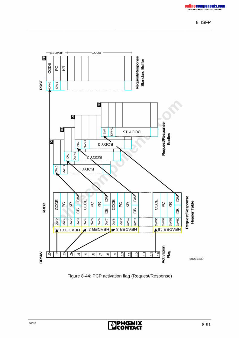
onlinec
omponen
ts.co
m
8 ISFP
5003B 8-91
RR
DB
DW
+1 BODY 1
HEADER 15DW
56
DW
57
DW
58
DW
59
CO
DE
PC
KR
DB
DW
HEADER 3D
W 8
DW
9
DW
10
DW
11
CO
DE
PC
KR
DB
DW
HEADER 2
DW
4
DW
5
DW
6
DW
7
CO
DE
PC
KR
DB
DW
HEADER 1
DW
0
DW
1
DW
2
DW
3
CO
DE
PC
KR
DB
DW
DW
DW
+1 RUMPF 1
DW
DW
+1 RUMPF 1
DW
DW
+1 RUMPF 1
CO
DE
PC
KR
DB
DW
DW
0
DW
1
BODY HEADER
RR
MW
RR
ST
DB
DB
DB
DB
DB
BODY 2
BODY 3
BODY 15
Req
ues
t/R
esponse
Bodie
s
Req
ues
t/R
esponse
Sta
ndar
d B
uff
er
Act
ivat
ion
Fla
g
Req
ues
t/R
esponse
Hea
der
Tab
le
5003B827
.0 .1 .2 .3 .4 .5 .6 .7 .8 .9 .10
.11
.12
.13
.14
.15
DW
0
Figure 8-44: PCP activation flag (Request/Response)
onlinec
omponen
ts.co
m
8 ISFP
8-92 5003B
8.4.1.7 Service Message Flag
Confirmations or indications are reported by way of the bits belonging to the CIMW flagword. If bits 1 to 15 have the value zero, all services are written into the standardconfirmation/indication buffer. Once such as service has arrived, the user must evaluate orsave the data in the buffer within the same PLC cycle. In the next cycle, a new service mayarrive that will overwrite the buffer. The data is received by the CON/IND function block(FB62 or FB64).
By means of a pointer to the entries of the service headers belonging to expected services inthe CIDB data block, it is possible to specify the data area into which the service bodiesshould be written. For an expected service, the application activates the flag bit belonging toa data header for this purpose. If a data with the code entered in the table and theassociated KR is received by the CON/IND receive block, the service body is written into thedata area identified by the pointer. Reception of data is indicated to the application byresetting of the flag bit. Thus, the data requested by a Read Request, for example, istransferred directly to its destination by the entry in the table and not indirectly through thestandard buffer.
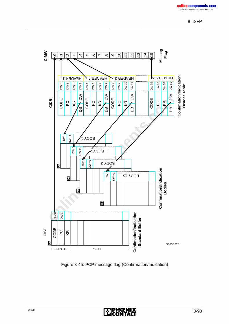
onlinec
omponen
ts.co
m
8 ISFP
5003B 8-93
CIS
TC
IMW
Co
nfi
mat
ion
/Ind
icat
ion
Bo
die
s
Co
nfi
mat
ion
/Ind
icat
ion
Sta
nd
ard
Bu
ffer
Mes
sag
Flag
Co
nfi
mat
ion
/Ind
icat
ion
Hea
der
Tab
le
5003B828HEADER 15
DW
56
DW
57
DW
58
DW
59
CO
DE
PC
KR
DB
DW
HEADER 3
DW
8
DW
9
DW
10
DW
11
CO
DE
PC
KR
DB
DW
HEADER 2
DW
4
DW
5
DW
6
DW
7
CO
DE
PC
KR
DB
DW
HEADER 1
DW
0
DW
1
DW
2
DW
3
CO
DE
PC
KR
DB
DW
CO
DE
PC
KR
DB
DW
DW
0
DW
1
BODY HEADER
DB
.0 .1 .2 .3 .4 .5 .6 .7 .8 .9 .10
.11
.12
.13
.14
.15
DW
DW
+1 BODY 1
DW
DW
+1 RUMPF 1
DW
DW
+1 RUMPF 1
DW
DW
+1 RUMPF 1
DB
DB
DB
DB
BODY 15
BODY 3
BODY 2
CID
B
Figure 8-45: PCP message flag (Confirmation/Indication)
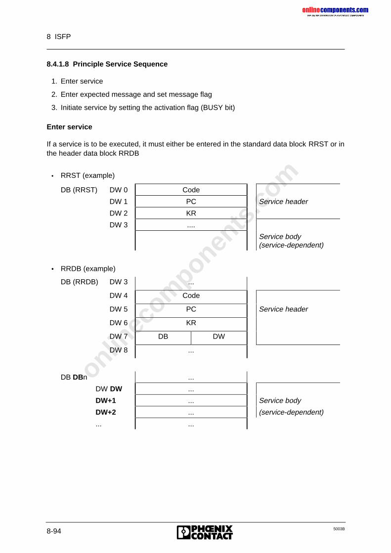
onlinec
omponen
ts.co
m
8 ISFP
8-94 5003B
8.4.1.8 Principle Service Sequence
1. Enter service
2. Enter expected message and set message flag
3. Initiate service by setting the activation flag (BUSY bit)
Enter service
If a service is to be executed, it must either be entered in the standard data block RRST or inthe header data block RRDB
• RRST (example)
DB (RRST) DW 0 Code
DW 1 PC Service header
DW 2 KR
DW 3 ....
Service body(service-dependent)
• RRDB (example)
DB (RRDB) DW 3 ...
DW 4 Code
DW 5 PC Service header
DW 6 KR
DW 7 DB DW
DW 8 ...
DB DBn ...
DW DW ...
DW+1 ... Service body
DW+2 ... (service-dependent)
... ...
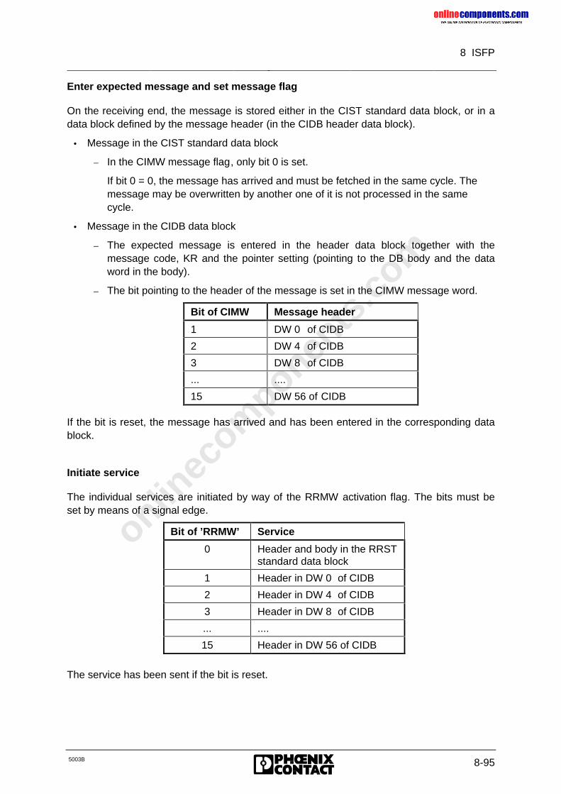
onlinec
omponen
ts.co
m
8 ISFP
5003B 8-95
Enter expected message and set message flag
On the receiving end, the message is stored either in the CIST standard data block, or in adata block defined by the message header (in the CIDB header data block).
• Message in the CIST standard data block
– In the CIMW message flag, only bit 0 is set.
If bit 0 = 0, the message has arrived and must be fetched in the same cycle. Themessage may be overwritten by another one of it is not processed in the samecycle.
• Message in the CIDB data block
– The expected message is entered in the header data block together with themessage code, KR and the pointer setting (pointing to the DB body and the dataword in the body).
– The bit pointing to the header of the message is set in the CIMW message word.
Bit of CIMW Message header
1 DW 0 of CIDB
2 DW 4 of CIDB
3 DW 8 of CIDB
... ....
15 DW 56 of CIDB
If the bit is reset, the message has arrived and has been entered in the corresponding datablock.
Initiate service
The individual services are initiated by way of the RRMW activation flag. The bits must beset by means of a signal edge.
Bit of ’RRMW’ Service
0 Header and body in the RRSTstandard data block
1 Header in DW 0 of CIDB
2 Header in DW 4 of CIDB
3 Header in DW 8 of CIDB
... ....
15 Header in DW 56 of CIDB
The service has been sent if the bit is reset.
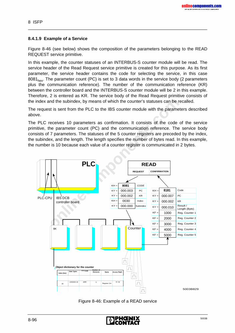
onlinec
omponen
ts.co
m
8 ISFP
8-96 5003B
8.4.1.9 Example of a Service
Figure 8-46 (see below) shows the composition of the parameters belonging to the READREQUEST service primitive.
In this example, the counter statuses of an INTERBUS-S counter module will be read. Theservice header of the Read Request service primitive is created for this purpose. As its firstparameter, the service header contains the code for selecting the service, in this case8081hex. The parameter count (PC) is set to 3 data words in the service body (2 parametersplus the communication reference). The number of the communication reference (KR)between the controller board and the INTERBUS-S counter module will be 2 in this example.Therefore, 2 is entered as KR. The service body of the Read Request primitive consists ofthe index and the subindex, by means of which the counter’s statuses can be recalled.
The request is sent from the PLC to the IBS counter module with the parameters describedabove.
The PLC receives 10 parameters as confirmation. It consists of the code of the serviceprimitive, the parameter count (PC) and the communication reference. The service bodyconsists of 7 parameters. The statuses of the 5 counter registers are preceded by the index,the subindex, and the length. The length specifies the number of bytes read. In this example,the number is 10 because each value of a counter register is communicated in 2 bytes.
KY =
KF =
KF =
KF =
KF =
KF =
1000
2000
3000
4000
5000
000.010 Result /Length (Byte)
Reg. Counter 1
Reg. Counter 2
Reg. Counter 3
Reg. Counter 4
Reg. Counter 5
KH =
KY =
KY = 000.002
000.007
8181 Code
PC
KR
PLC
PLC-CPU IBS DCBcontroller board
Object dictionary for the counter
READ REQUEST CONFIRMATION
5003B829
BK BK BK BKCounterBK
Index (hex)Data Types ??? Code Number of
Elements Name Access Right
30UNSIGN 16 ARR 5
Register CntR / W
KH =
KH =
KY =
KY =
KY =
CODE
PC
KR
Index
Subindex
8081
000.003
000.002
0030
000.000
Figure 8-46: Example of a READ service
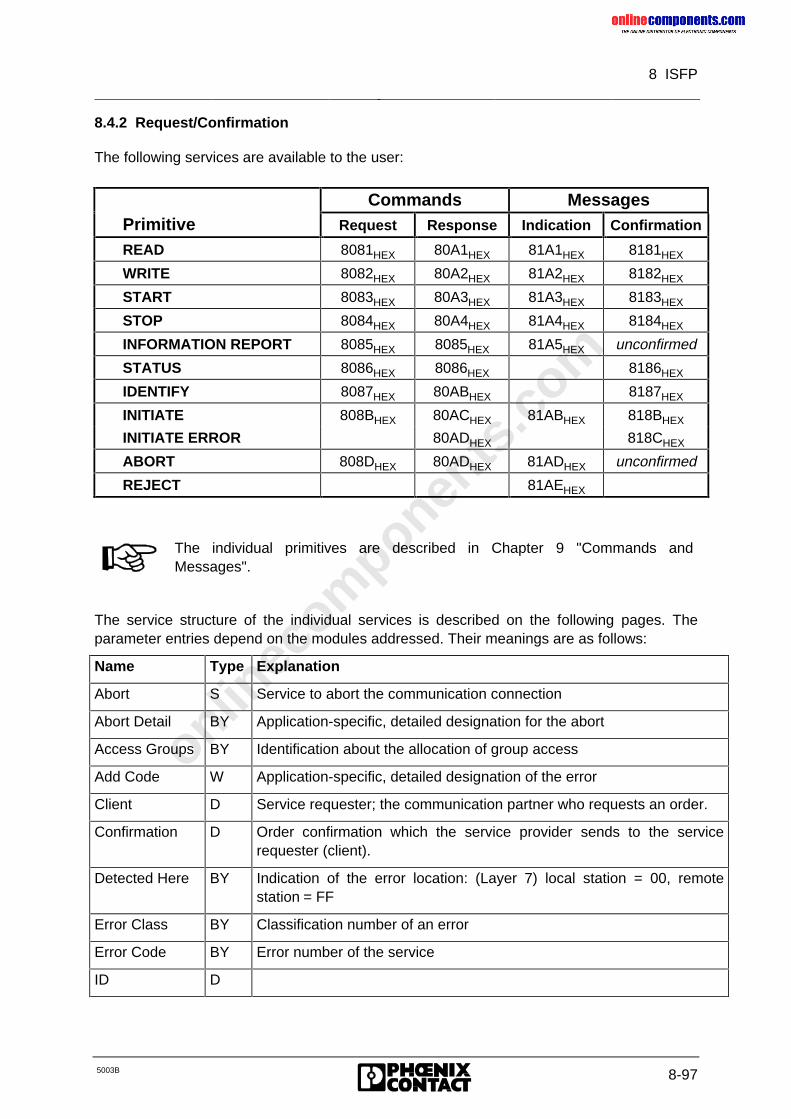
onlinec
omponen
ts.co
m
8 ISFP
5003B 8-97
8.4.2 Request/Confirmation
The following services are available to the user:
Commands MessagesPrimitive Request Response Indication Confirmation
READ 8081HEX 80A1HEX 81A1HEX 8181HEX
WRITE 8082HEX 80A2HEX 81A2HEX 8182HEX
START 8083HEX 80A3HEX 81A3HEX 8183HEX
STOP 8084HEX 80A4HEX 81A4HEX 8184HEX
INFORMATION REPORT 8085HEX 8085HEX 81A5HEX unconfirmed
STATUS 8086HEX 8086HEX 8186HEX
IDENTIFY 8087HEX 80ABHEX 8187HEX
INITIATE 808BHEX 80ACHEX 81ABHEX 818BHEX
INITIATE ERROR 80ADHEX 818CHEX
ABORT 808DHEX 80ADHEX 81ADHEX unconfirmed
REJECT 81AEHEX
The individual primitives are described in Chapter 9 "Commands andMessages".
The service structure of the individual services is described on the following pages. Theparameter entries depend on the modules addressed. Their meanings are as follows:
Name Type Explanation
Abort S Service to abort the communication connection
Abort Detail BY Application-specific, detailed designation for the abort
Access Groups BY Identification about the allocation of group access
Add Code W Application-specific, detailed designation of the error
Client D Service requester; the communication partner who requests an order.
Confirmation D Order confirmation which the service provider sends to the servicerequester (client).
Detected Here BY Indication of the error location: (Layer 7) local station = 00, remotestation = FF
Error Class BY Classification number of an error
Error Code BY Error number of the service
ID D
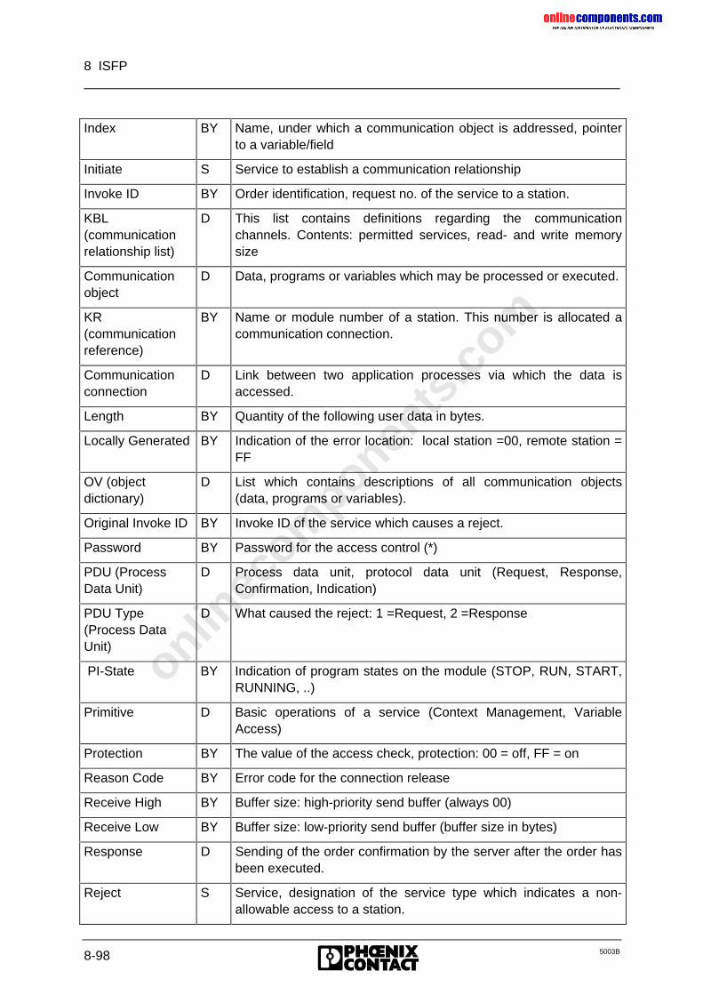
onlinec
omponen
ts.co
m
8 ISFP
8-98 5003B
Index BY Name, under which a communication object is addressed, pointerto a variable/field
Initiate S Service to establish a communication relationship
Invoke ID BY Order identification, request no. of the service to a station.
KBL(communicationrelationship list)
D This list contains definitions regarding the communicationchannels. Contents: permitted services, read- and write memorysize
Communicationobject
D Data, programs or variables which may be processed or executed.
KR(communicationreference)
BY Name or module number of a station. This number is allocated acommunication connection.
Communicationconnection
D Link between two application processes via which the data isaccessed.
Length BY Quantity of the following user data in bytes.
Locally Generated BY Indication of the error location: local station =00, remote station =FF
OV (objectdictionary)
D List which contains descriptions of all communication objects(data, programs or variables).
Original Invoke ID BY Invoke ID of the service which causes a reject.
Password BY Password for the access control (*)
PDU (ProcessData Unit)
D Process data unit, protocol data unit (Request, Response,Confirmation, Indication)
PDU Type(Process DataUnit)
D What caused the reject: 1 =Request, 2 =Response
PI-State BY Indication of program states on the module (STOP, RUN, START,RUNNING, ..)
Primitive D Basic operations of a service (Context Management, VariableAccess)
Protection BY The value of the access check, protection: 00 = off, FF = on
Reason Code BY Error code for the connection release
Receive High BY Buffer size: high-priority send buffer (always 00)
Receive Low BY Buffer size: low-priority send buffer (buffer size in bytes)
Response D Sending of the order confirmation by the server after the order hasbeen executed.
Reject S Service, designation of the service type which indicates a non-allowable access to a station.
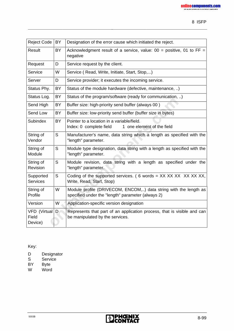
onlinec
omponen
ts.co
m
8 ISFP
5003B 8-99
Reject Code BY Designation of the error cause which initiated the reject.
Result BY Acknowledgment result of a service, value: 00 = positive, 01 to FF =negative
Request D Service request by the client.
Service W Service ( Read, Write, Initiate, Start, Stop,...)
Server D Service provider; it executes the incoming service.
Status Phy. BY Status of the module hardware (defective, maintenance, ..)
Status Log. BY Status of the program/software (ready for communication, ..)
Send High BY Buffer size: high-priority send buffer (always 00 )
Send Low BY Buffer size: low-priority send buffer (buffer size in bytes)
Subindex BY Pointer to a location in a variable/field.Index: 0 complete field 1 one element of the field
String ofVendor
S Manufacturer’s name, data string which a length as specified with the"length" parameter.
String ofModule
S Module type designation, data string with a length as specified with the"length" parameter.
String ofRevision
S Module revision, data string with a length as specified under the"length" parameter.
SupportedServices
S Coding of the supported services. ( 6 words = XX XX XX XX XX XX,Write, Read, Start, Stop)
String ofProfile
W Module profile (DRIVECOM, ENCOM,..) data string with the length asspecified under the "length" parameter (always 2)
Version W Application-specific version designation
VFD (VirtualFieldDevice)
D Represents that part of an application process, that is visible and canbe manipulated by the services.
Key:
D DesignatorS ServiceBY ByteW Word
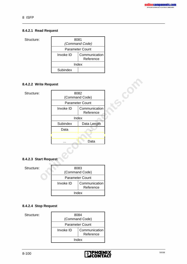
onlinec
omponen
ts.co
m
8 ISFP
8-100 5003B
8.4.2.1 Read Request
Structure: 8081(Command Code)
Parameter Count
Invoke ID CommunicationReference
Index
Subindex
8.4.2.2 Write Request
Structure: 8082(Command Code)
Parameter Count
Invoke ID CommunicationReference
Index
Subindex Data Length
Data ...
... Data
8.4.2.3 Start Request
Structure: 8083(Command Code)
Parameter Count
Invoke ID CommunicationReference
Index
8.4.2.4 Stop Request
Structure: 8084(Command Code)
Parameter Count
Invoke ID CommunicationReference
Index
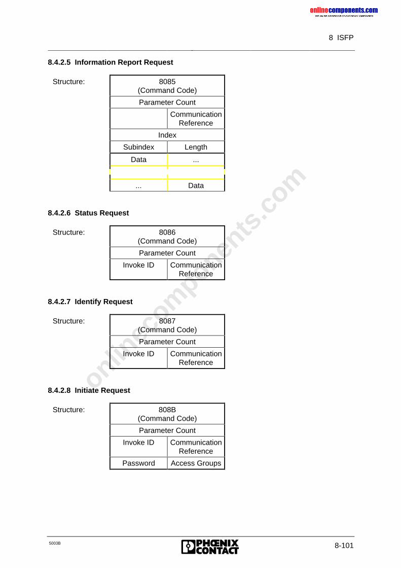
onlinec
omponen
ts.co
m
8 ISFP
5003B 8-101
8.4.2.5 Information Report Request
Structure: 8085(Command Code)
Parameter Count
CommunicationReference
Index
Subindex Length
Data ...
... Data
8.4.2.6 Status Request
Structure: 8086(Command Code)
Parameter Count
Invoke ID CommunicationReference
8.4.2.7 Identify Request
Structure: 8087(Command Code)
Parameter Count
Invoke ID CommunicationReference
8.4.2.8 Initiate Request
Structure: 808B(Command Code)
Parameter Count
Invoke ID CommunicationReference
Password Access Groups
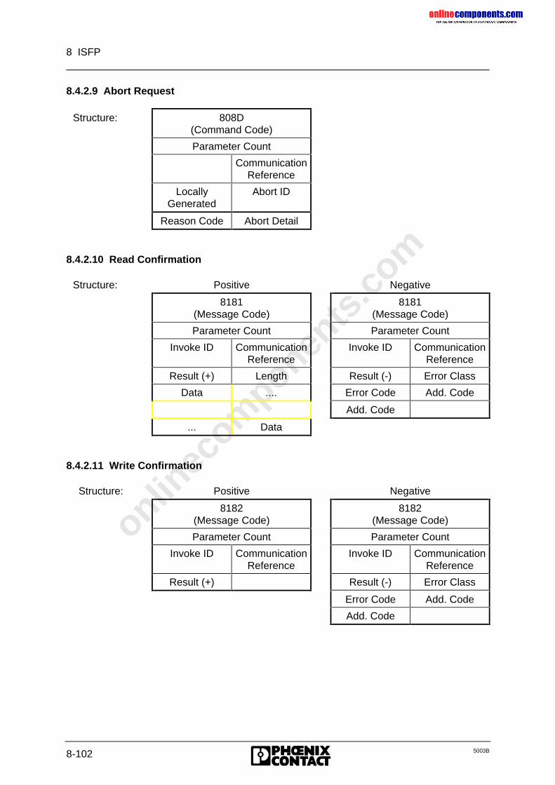
onlinec
omponen
ts.co
m
8 ISFP
8-102 5003B
8.4.2.9 Abort Request
Structure: 808D(Command Code)
Parameter Count
CommunicationReference
LocallyGenerated
Abort ID
Reason Code Abort Detail
8.4.2.10 Read Confirmation
Structure: Positive Negative
8181(Message Code)
8181(Message Code)
Parameter Count Parameter Count
Invoke ID CommunicationReference
Invoke ID CommunicationReference
Result (+) Length Result (-) Error Class
Data .... Error Code Add. Code
Add. Code
... Data
8.4.2.11 Write Confirmation
Structure: Positive Negative
8182(Message Code)
8182(Message Code)
Parameter Count Parameter Count
Invoke ID CommunicationReference
Invoke ID CommunicationReference
Result (+) Result (-) Error Class
Error Code Add. Code
Add. Code
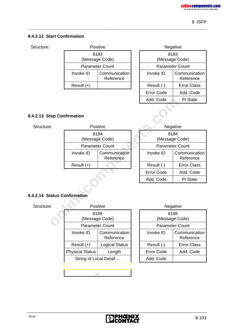
onlinec
omponen
ts.co
m
8 ISFP
5003B 8-103
8.4.2.12 Start Confirmation
Structure: Positive Negative
8183(Message Code)
8183(Message Code)
Parameter Count Parameter Count
Invoke ID CommunicationReference
Invoke ID CommunicationReference
Result (+) Result (-) Error Class
Error Code Add. Code
Add. Code PI State
8.4.2.13 Stop Confirmation
Structure: Positive Negative
8184(Message Code)
8184(Message Code)
Parameter Count Parameter Count
Invoke ID CommunicationReference
Invoke ID CommunicationReference
Result (+) Result (-) Error Class
Error Code Add. Code
Add. Code PI State
8.4.2.14 Status Confirmation
Structure: Positive Negative
8186(Message Code)
8186(Message Code)
Parameter Count Parameter Count
Invoke ID CommunicationReference
Invoke ID CommunicationReference
Result (+) Logical Status Result (-) Error Class
Physical Status Length Error Code Add. Code
String of Local Detail ... Add. Code
...
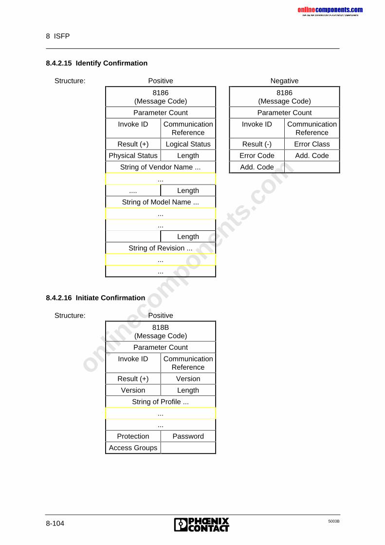
onlinec
omponen
ts.co
m
8 ISFP
8-104 5003B
8.4.2.15 Identify Confirmation
Structure: Positive Negative
8186(Message Code)
8186(Message Code)
Parameter Count Parameter Count
Invoke ID CommunicationReference
Invoke ID CommunicationReference
Result (+) Logical Status Result (-) Error Class
Physical Status Length Error Code Add. Code
String of Vendor Name ... Add. Code
...
.... Length
String of Model Name ...
...
...
Length
String of Revision ...
...
...
8.4.2.16 Initiate Confirmation
Structure: Positive
818B(Message Code)
Parameter Count
Invoke ID CommunicationReference
Result (+) Version
Version Length
String of Profile ...
...
...
Protection Password
Access Groups
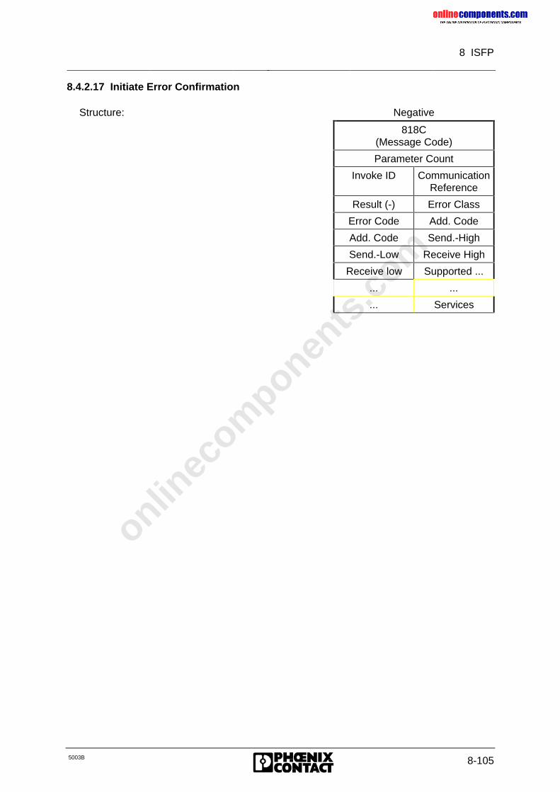
onlinec
omponen
ts.co
m
8 ISFP
5003B 8-105
8.4.2.17 Initiate Error Confirmation
Structure: Negative
818C(Message Code)
Parameter Count
Invoke ID CommunicationReference
Result (-) Error Class
Error Code Add. Code
Add. Code Send.-High
Send.-Low Receive High
Receive low Supported ...
... ...
... Services
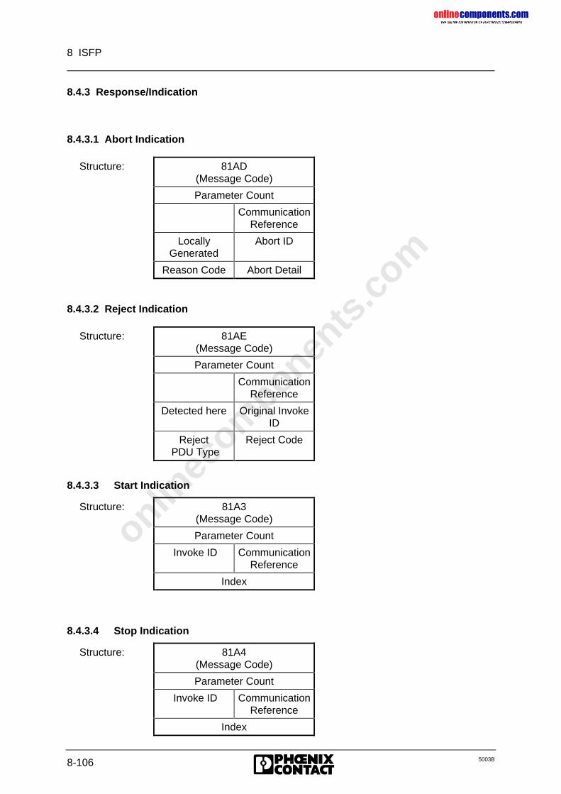
onlinec
omponen
ts.co
m
8 ISFP
8-106 5003B
8.4.3 Response/Indication
8.4.3.1 Abort Indication
Structure: 81AD(Message Code)
Parameter Count
CommunicationReference
LocallyGenerated
Abort ID
Reason Code Abort Detail
8.4.3.2 Reject Indication
Structure: 81AE(Message Code)
Parameter Count
CommunicationReference
Detected here Original InvokeID
Reject PDU Type
Reject Code
8.4.3.3 Start Indication
Structure: 81A3(Message Code)
Parameter Count
Invoke ID CommunicationReference
Index
8.4.3.4 Stop Indication
Structure: 81A4(Message Code)
Parameter Count
Invoke ID CommunicationReference
Index
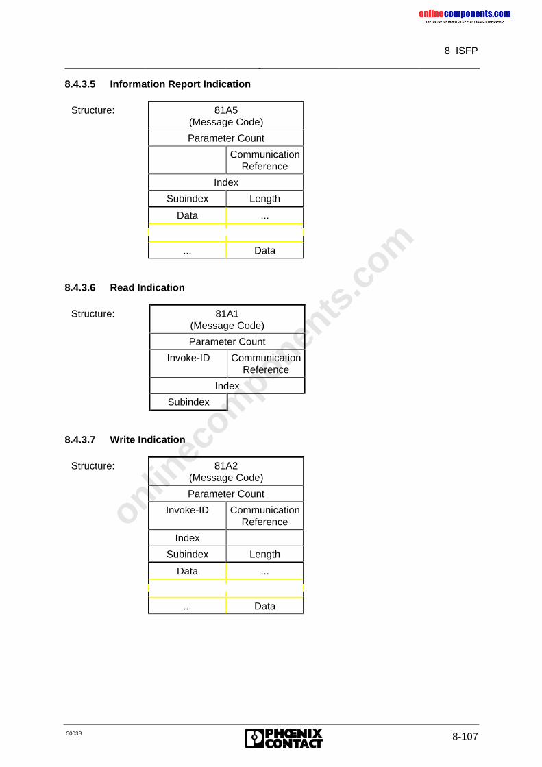
onlinec
omponen
ts.co
m
8 ISFP
5003B 8-107
8.4.3.5 Information Report Indication
Structure: 81A5(Message Code)
Parameter Count
CommunicationReference
Index
Subindex Length
Data ...
... Data
8.4.3.6 Read Indication
Structure: 81A1(Message Code)
Parameter Count
Invoke-ID CommunicationReference
Index
Subindex
8.4.3.7 Write Indication
Structure: 81A2(Message Code)
Parameter Count
Invoke-ID CommunicationReference
Index
Subindex Length
Data ...
... Data
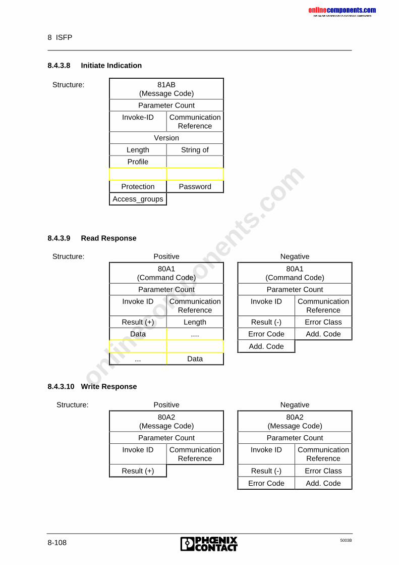
onlinec
omponen
ts.co
m
8 ISFP
8-108 5003B
8.4.3.8 Initiate Indication
Structure: 81AB(Message Code)
Parameter Count
Invoke-ID CommunicationReference
Version
Length String of
Profile
Protection Password
Access_groups
8.4.3.9 Read Response
Structure: Positive Negative
80A1(Command Code)
80A1(Command Code)
Parameter Count Parameter Count
Invoke ID CommunicationReference
Invoke ID CommunicationReference
Result (+) Length Result (-) Error Class
Data .... Error Code Add. Code
Add. Code
... Data
8.4.3.10 Write Response
Structure: Positive Negative
80A2(Message Code)
80A2(Message Code)
Parameter Count Parameter Count
Invoke ID CommunicationReference
Invoke ID CommunicationReference
Result (+) Result (-) Error Class
Error Code Add. Code
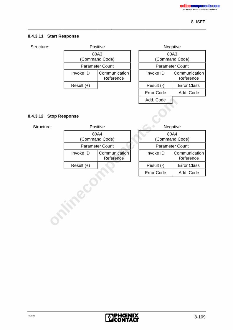
onlinec
omponen
ts.co
m
8 ISFP
5003B 8-109
8.4.3.11 Start Response
Structure: Positive Negative
80A3(Command Code)
80A3(Command Code)
Parameter Count Parameter Count
Invoke ID CommunicationReference
Invoke ID CommunicationReference
Result (+) Result (-) Error Class
Error Code Add. Code
Add. Code
8.4.3.12 Stop Response
Structure: Positive Negative
80A4(Command Code)
80A4(Command Code)
Parameter Count Parameter Count
Invoke ID CommunicationReference
Invoke ID CommunicationReference
Result (+) Result (-) Error Class
Error Code Add. Code
onlinec
omponen
ts.co
m
8 ISFP
8-110 5003B
8.4.4 Use of Communication
Prerequisites:
• Mode of operation: controlled start
• Software: ISFP (CON/IND and REQ/RES blocks in the cyclic program)
Initialization:
• Startup
– The INITIB function block must be called during startup. It performs initialization forall further standard function blocks.
– The standard data blocks RRST, CIST and the flag words RRMW and CIMW mustbe specified in the INITIB function block.
• Interface drivers
– The two interface drivers must be called conditionally in the cyclic program.
CON/IND is called at the start of the organization block (OB) 1.
REQ/RES is called at the end of the organization block (OB) 1.
• Addressing
– Addressing is initiated by way of the ADDRESS function block.
– One KR is assigned to each module that is capable of communication. Countingbegins with KR = 2, in the direction of the physical bus structure, up to a maximum ofKR = 63.
– Communication is initialized once all lists have been transferred by the ADDRESSfunction block. Once all commands have been acknowledged positively, the bus iscapable of communication and is in the RUN mode.
Application
Further communication commands depend on the connected hardware. Not every module iscapable of processing all commands. The parameters belonging to the command differ.
The commands are sent to the controller board by means of the REQ/RES function block.The controller board then receives the expected message by means of the CON/INDfunction block.
The structure of the commands and messages have been described in the previouschapters. Refer to the module descriptions for details of the individual commands’parameters.
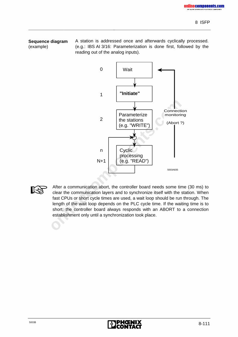
onlinec
omponen
ts.co
m
8 ISFP
5003B 8-111
Sequence diagram(example)
A station is addressed once and afterwards cyclically processed.(e.g.: IBS AI 3/16: Parameterization is done first, followed by thereading out of the analog inputs).
"Initiate"
Wait
Parameterizethe stations(e.g. "WRITE")
Cyclic processing(e.g. "READ")
5003A835
Connectionmonitoring
(Abort ?)
0
1
2
n
N+1
After a communication abort, the controller board needs some time (30 ms) toclear the communication layers and to synchronize itself with the station. Whenfast CPUs or short cycle times are used, a wait loop should be run through. Thelength of the wait loop depends on the PLC cycle time. If the waiting time is toshort, the controller board always responds with an ABORT to a connectionestablishment only until a synchronization took place.
onlinec
omponen
ts.co
m
8 ISFP
8-112 5003B
Example:
Addressing a communication module:
• Connection establishment.Connection is established with the Initiate Request service primitive
• Program-dependent service requests (Request/Response).The commands used depend on the specific module and application.
• Connection abortConnection is aborted with the ABORT Request service primitive.
Every connection established requires a certain amount of administration on the PLC. Tominimize this work, unnecessary connections should be avoided.
It is expedient to abort a connection whenever a PCP station is addressed seldom. Forexample, when a frequency inverter is parameterized once, it is not necessary to maintainthe connection any longer.
It is not expedient to abort connections of highly frequented PCP stations because renewedestablishment of a connection takes an unnecessarily long time.
Examples will elucidate the sequence of communication and the program structure needed.The programs created for this purpose are included with the standard software.
• Example for a Count: File: IBSCNTST.S5D
• Example for a V.24 module: File: IBSV24ST.S5D
The connection has to be monitored during the entire program run. After theconnection has been aborted (ABORT) the station cannot be addressed untilthe connection has been established again (INITIATE).
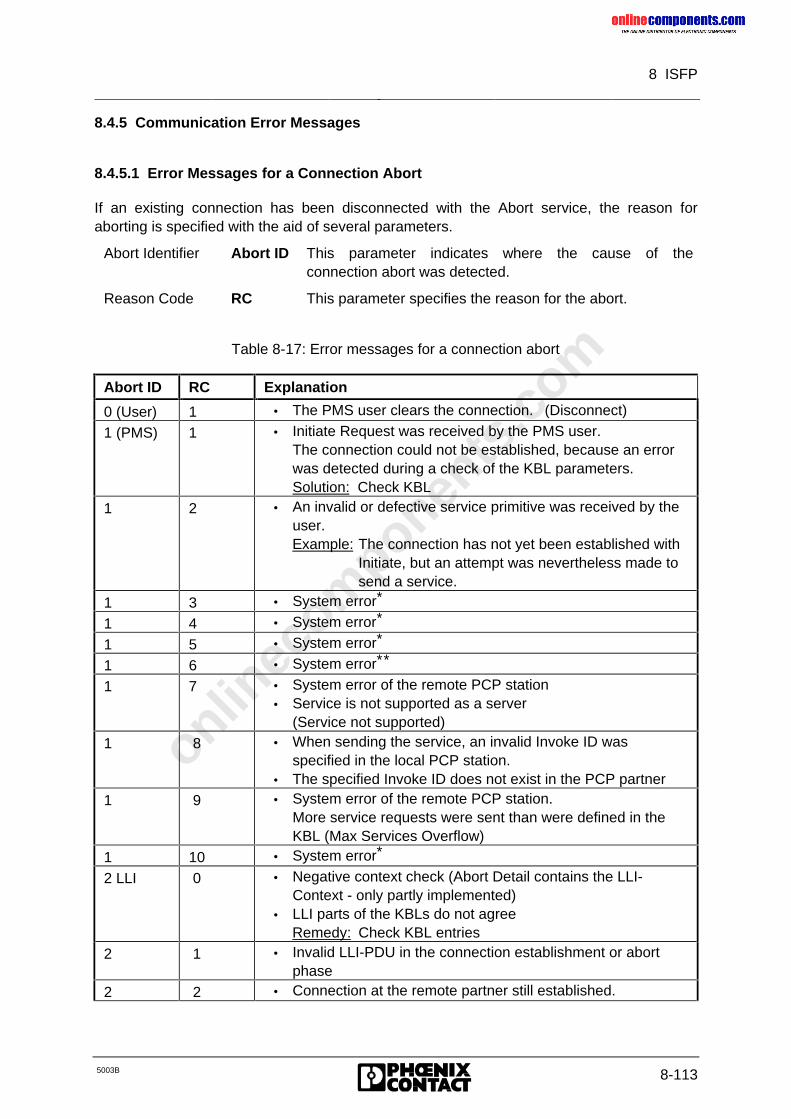
onlinec
omponen
ts.co
m
8 ISFP
5003B 8-113
8.4.5 Communication Error Messages
8.4.5.1 Error Messages for a Connection Abort
If an existing connection has been disconnected with the Abort service, the reason foraborting is specified with the aid of several parameters.
Abort Identifier Abort ID This parameter indicates where the cause of theconnection abort was detected.
Reason Code RC This parameter specifies the reason for the abort.
Table 8-17: Error messages for a connection abort
Abort ID RC Explanation
0 (User) 1 • The PMS user clears the connection. (Disconnect)
1 (PMS) 1 • Initiate Request was received by the PMS user.The connection could not be established, because an errorwas detected during a check of the KBL parameters.Solution: Check KBL
1 2 • An invalid or defective service primitive was received by theuser.Example: The connection has not yet been established with
Initiate, but an attempt was nevertheless made tosend a service.
1 3 • System error*
1 4 • System error*
1 5 • System error*
1 6 • System error**
1 7 • System error of the remote PCP station• Service is not supported as a server
(Service not supported)
1 8 • When sending the service, an invalid Invoke ID wasspecified in the local PCP station.
• The specified Invoke ID does not exist in the PCP partner
1 9 • System error of the remote PCP station.More service requests were sent than were defined in theKBL (Max Services Overflow)
1 10 • System error*
2 LLI 0 • Negative context check (Abort Detail contains the LLI-Context - only partly implemented)
• LLI parts of the KBLs do not agreeRemedy: Check KBL entries
2 1 • Invalid LLI-PDU in the connection establishment or abortphase
2 2 • Connection at the remote partner still established.
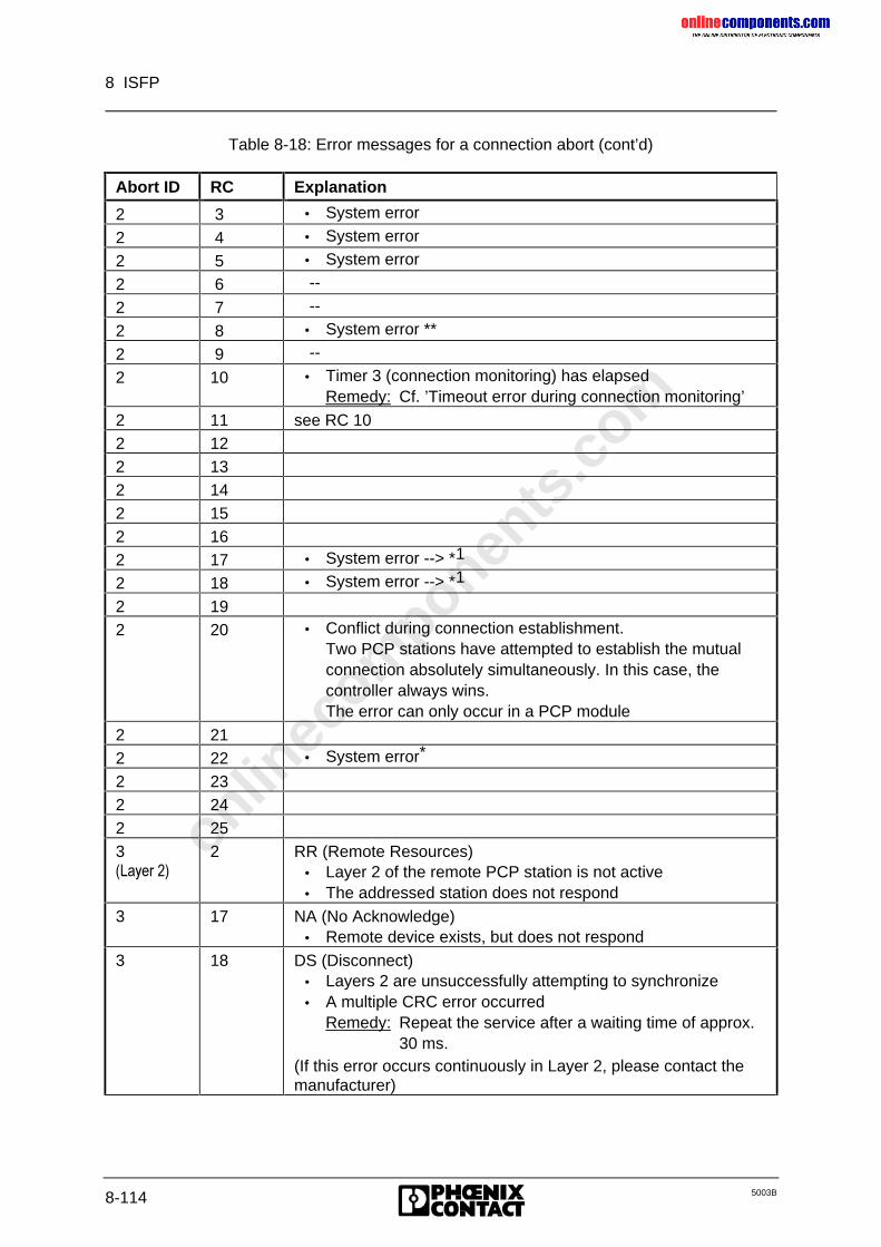
onlinec
omponen
ts.co
m
8 ISFP
8-114 5003B
Table 8-18: Error messages for a connection abort (cont’d)
Abort ID RC Explanation
2 3 • System error
2 4 • System error
2 5 • System error
2 6 --
2 7 --
2 8 • System error **
2 9 --
2 10 • Timer 3 (connection monitoring) has elapsedRemedy: Cf. ’Timeout error during connection monitoring’
2 11 see RC 102 122 132 142 152 162 17 • System error --> *1
2 18 • System error --> *1
2 192 20 • Conflict during connection establishment.
Two PCP stations have attempted to establish the mutualconnection absolutely simultaneously. In this case, thecontroller always wins.The error can only occur in a PCP module
2 212 22 • System error*
2 232 242 253�/D\HU���
2 RR (Remote Resources)• Layer 2 of the remote PCP station is not active• The addressed station does not respond
3 17 NA (No Acknowledge)• Remote device exists, but does not respond
3 18 DS (Disconnect)• Layers 2 are unsuccessfully attempting to synchronize• A multiple CRC error occurred
Remedy: Repeat the service after a waiting time of approx.30 ms.
(If this error occurs continuously in Layer 2, please contact themanufacturer)
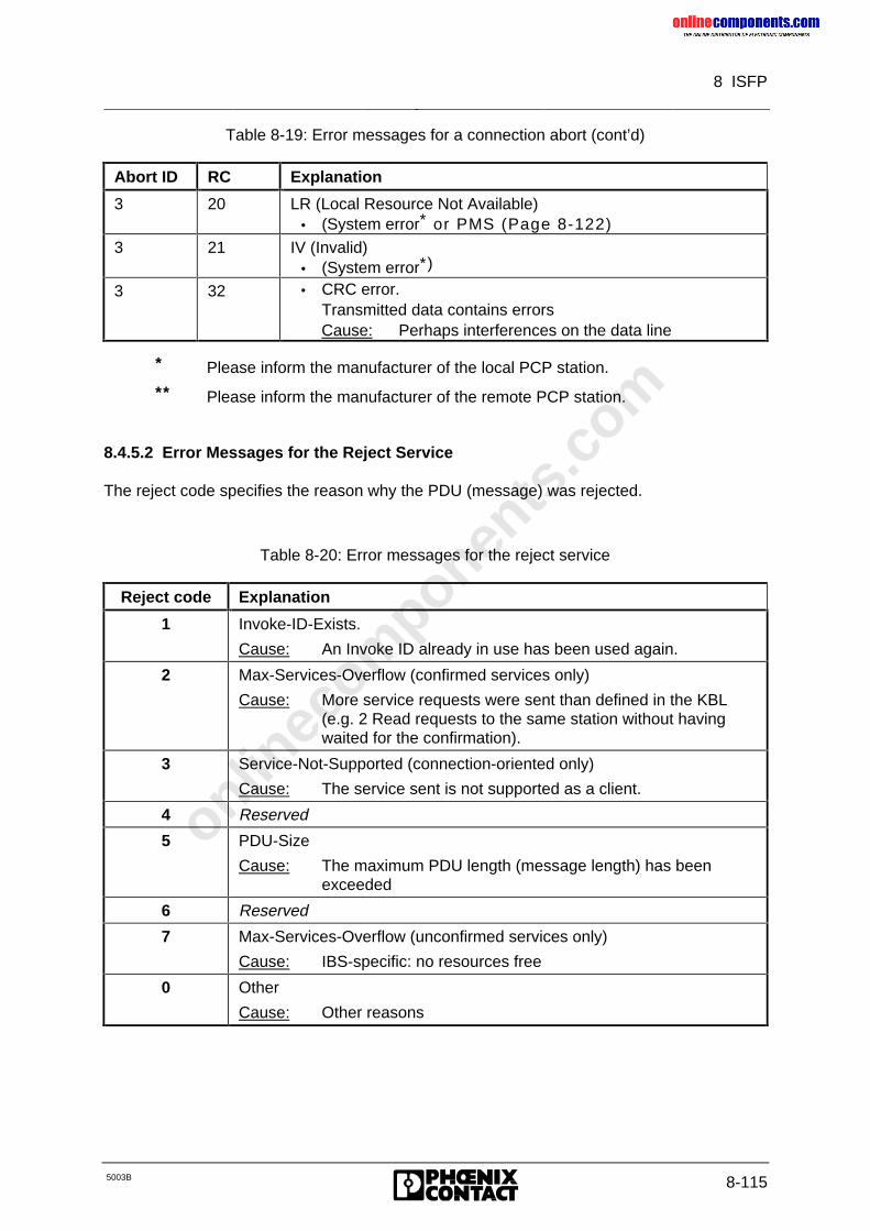
onlinec
omponen
ts.co
m
8 ISFP
5003B 8-115
Table 8-19: Error messages for a connection abort (cont’d)
Abort ID RC Explanation
3 20 LR (Local Resource Not Available)• (System error* or PMS (Page 8-122)
3 21 IV (Invalid)• (System error*)
3 32 • CRC error.Transmitted data contains errorsCause: Perhaps interferences on the data line
* Please inform the manufacturer of the local PCP station.
** Please inform the manufacturer of the remote PCP station.
8.4.5.2 Error Messages for the Reject Service
The reject code specifies the reason why the PDU (message) was rejected.
Table 8-20: Error messages for the reject service
Reject code Explanation
1 Invoke-ID-Exists.
Cause: An Invoke ID already in use has been used again.
2 Max-Services-Overflow (confirmed services only)
Cause: More service requests were sent than defined in the KBL(e.g. 2 Read requests to the same station without havingwaited for the confirmation).
3 Service-Not-Supported (connection-oriented only)
Cause: The service sent is not supported as a client.
4 Reserved
5 PDU-Size
Cause: The maximum PDU length (message length) has beenexceeded
6 Reserved
7 Max-Services-Overflow (unconfirmed services only)
Cause: IBS-specific: no resources free
0 Other
Cause: Other reasons
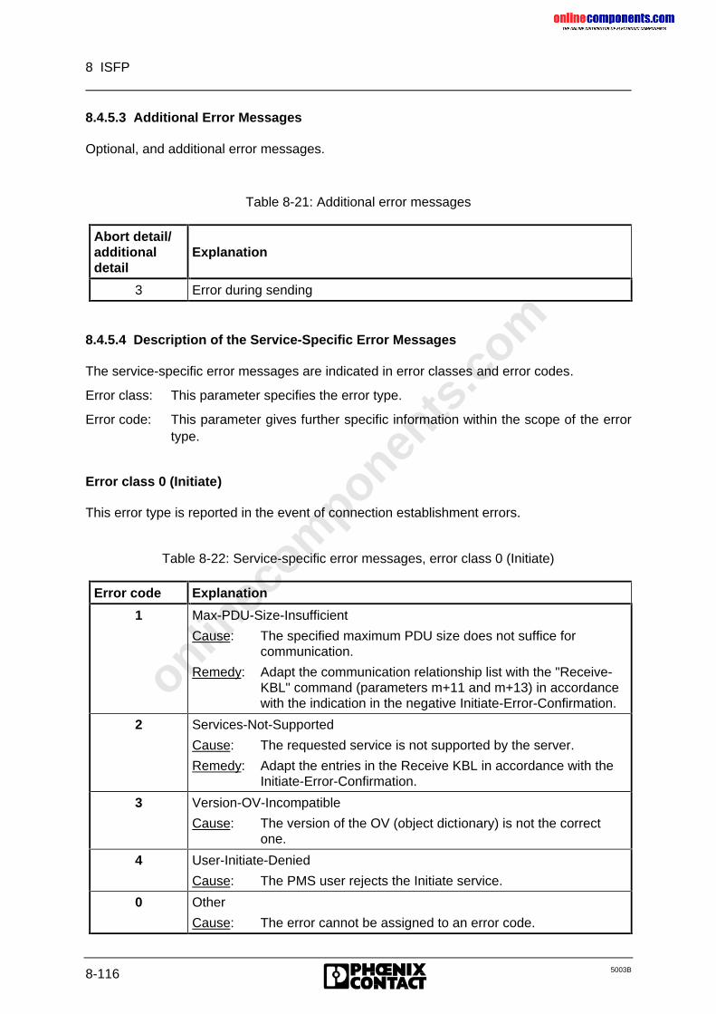
onlinec
omponen
ts.co
m
8 ISFP
8-116 5003B
8.4.5.3 Additional Error Messages
Optional, and additional error messages.
Table 8-21: Additional error messages
Abort detail/additionaldetail
Explanation
3 Error during sending
8.4.5.4 Description of the Service-Specific Error Messages
The service-specific error messages are indicated in error classes and error codes.
Error class: This parameter specifies the error type.
Error code: This parameter gives further specific information within the scope of the errortype.
Error class 0 (Initiate)
This error type is reported in the event of connection establishment errors.
Table 8-22: Service-specific error messages, error class 0 (Initiate)
Error code Explanation
1 Max-PDU-Size-Insufficient
Cause: The specified maximum PDU size does not suffice forcommunication.
Remedy: Adapt the communication relationship list with the "Receive-KBL" command (parameters m+11 and m+13) in accordancewith the indication in the negative Initiate-Error-Confirmation.
2 Services-Not-Supported
Cause: The requested service is not supported by the server.
Remedy: Adapt the entries in the Receive KBL in accordance with theInitiate-Error-Confirmation.
3 Version-OV-Incompatible
Cause: The version of the OV (object dictionary) is not the correctone.
4 User-Initiate-Denied
Cause: The PMS user rejects the Initiate service.
0 Other
Cause: The error cannot be assigned to an error code.
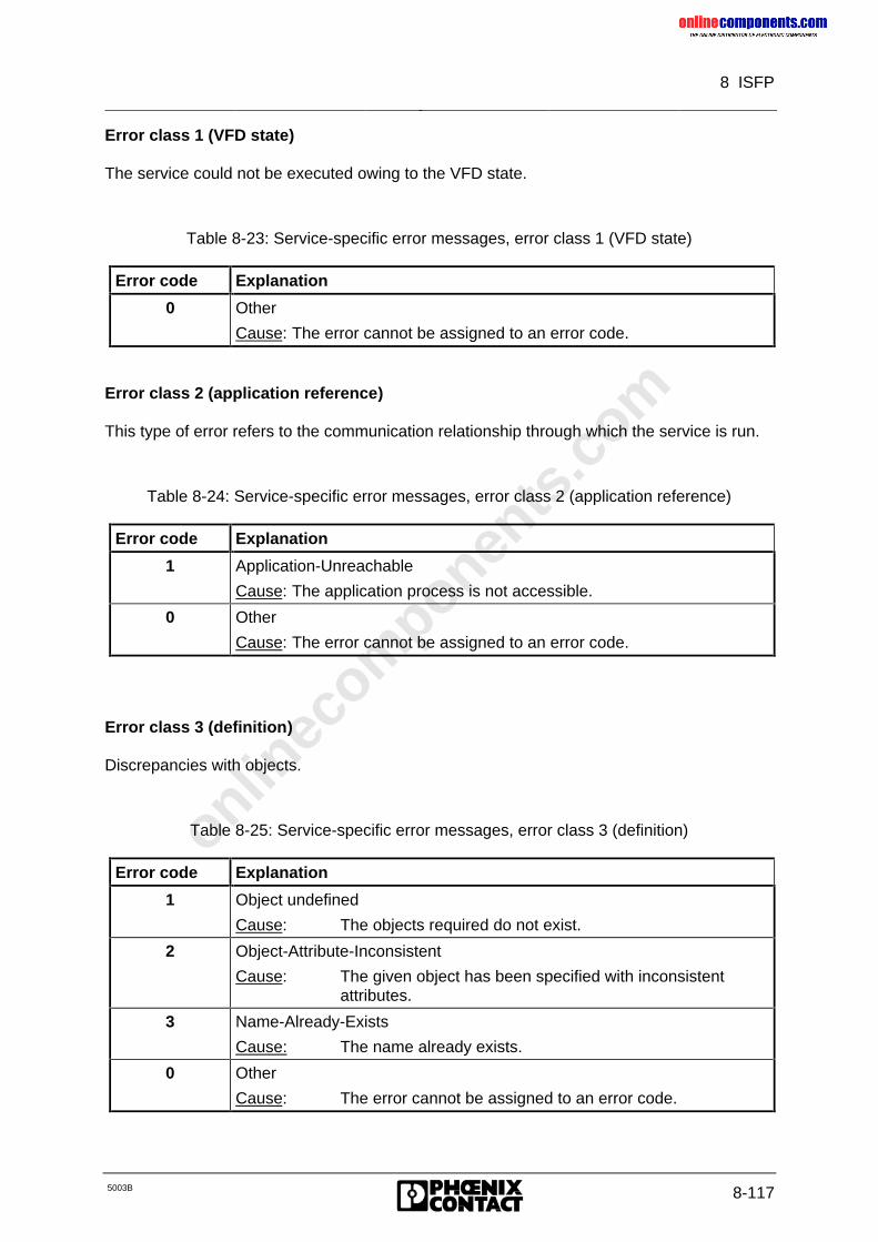
onlinec
omponen
ts.co
m
8 ISFP
5003B 8-117
Error class 1 (VFD state)
The service could not be executed owing to the VFD state.
Table 8-23: Service-specific error messages, error class 1 (VFD state)
Error code Explanation
0 Other
Cause: The error cannot be assigned to an error code.
Error class 2 (application reference)
This type of error refers to the communication relationship through which the service is run.
Table 8-24: Service-specific error messages, error class 2 (application reference)
Error code Explanation
1 Application-Unreachable
Cause: The application process is not accessible.
0 Other
Cause: The error cannot be assigned to an error code.
Error class 3 (definition)
Discrepancies with objects.
Table 8-25: Service-specific error messages, error class 3 (definition)
Error code Explanation
1 Object undefined
Cause: The objects required do not exist.
2 Object-Attribute-Inconsistent
Cause: The given object has been specified with inconsistentattributes.
3 Name-Already-Exists
Cause: The name already exists.
0 Other
Cause: The error cannot be assigned to an error code.
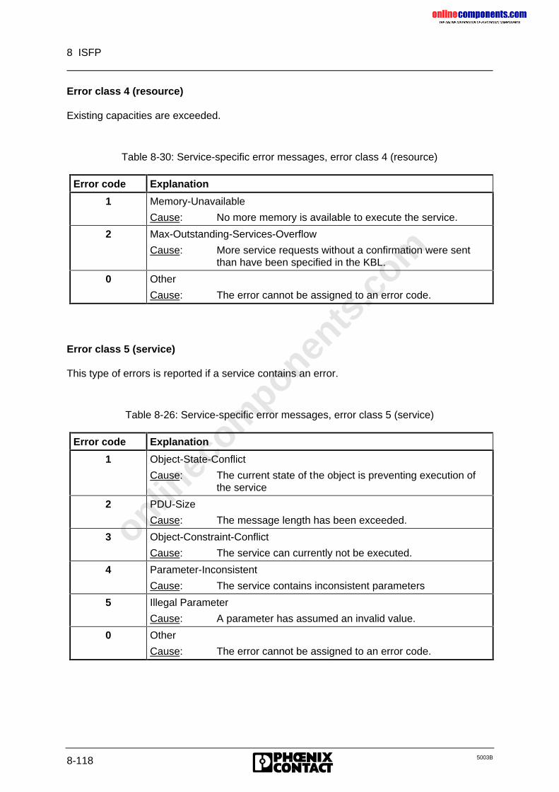
onlinec
omponen
ts.co
m
8 ISFP
8-118 5003B
Error class 4 (resource)
Existing capacities are exceeded.
Table 8-30: Service-specific error messages, error class 4 (resource)
Error code Explanation
1 Memory-Unavailable
Cause: No more memory is available to execute the service.
2 Max-Outstanding-Services-Overflow
Cause: More service requests without a confirmation were sentthan have been specified in the KBL.
0 Other
Cause: The error cannot be assigned to an error code.
Error class 5 (service)
This type of errors is reported if a service contains an error.
Table 8-26: Service-specific error messages, error class 5 (service)
Error code Explanation
1 Object-State-Conflict
Cause: The current state of the object is preventing execution ofthe service
2 PDU-Size
Cause: The message length has been exceeded.
3 Object-Constraint-Conflict
Cause: The service can currently not be executed.
4 Parameter-Inconsistent
Cause: The service contains inconsistent parameters
5 Illegal Parameter
Cause: A parameter has assumed an invalid value.
0 Other
Cause: The error cannot be assigned to an error code.
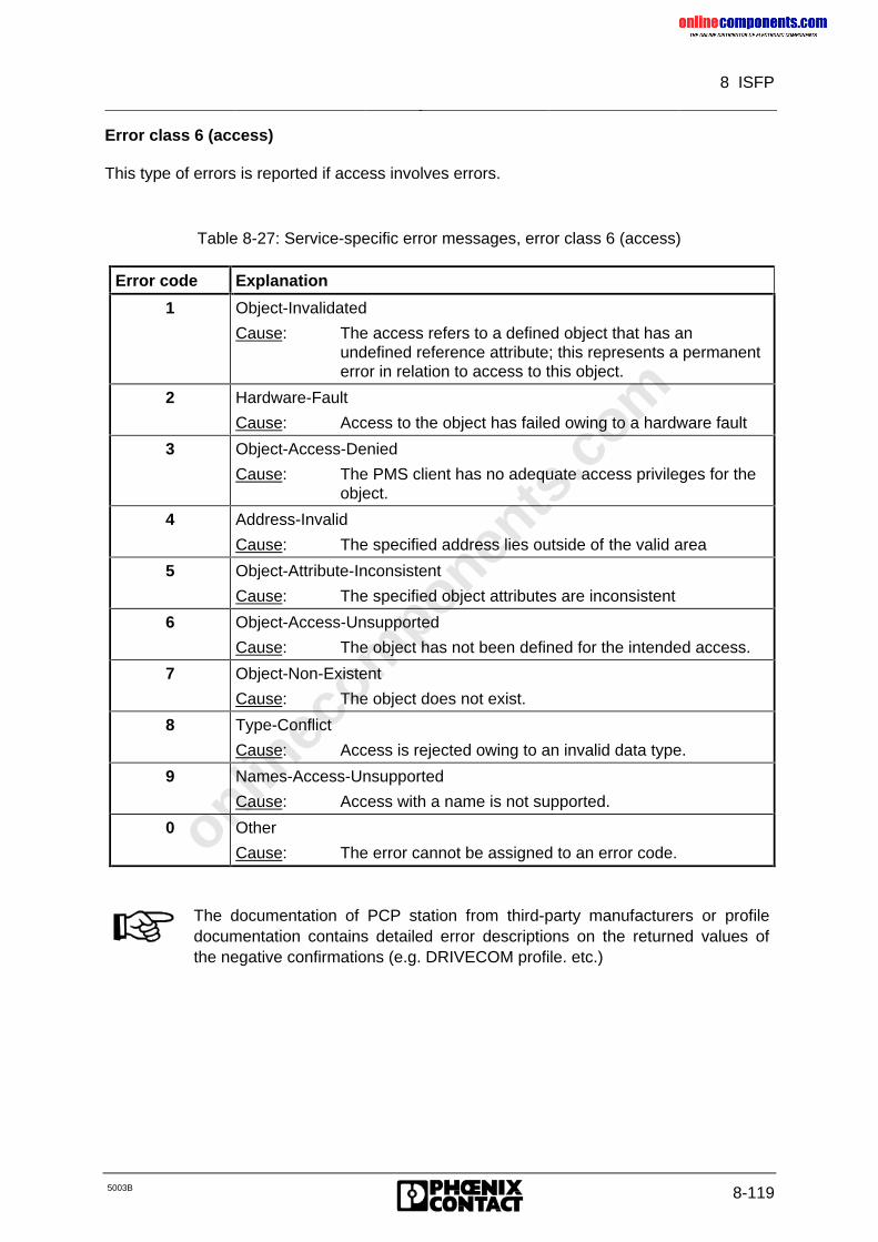
onlinec
omponen
ts.co
m
8 ISFP
5003B 8-119
Error class 6 (access)
This type of errors is reported if access involves errors.
Table 8-27: Service-specific error messages, error class 6 (access)
Error code Explanation
1 Object-Invalidated
Cause: The access refers to a defined object that has anundefined reference attribute; this represents a permanenterror in relation to access to this object.
2 Hardware-Fault
Cause: Access to the object has failed owing to a hardware fault
3 Object-Access-Denied
Cause: The PMS client has no adequate access privileges for theobject.
4 Address-Invalid
Cause: The specified address lies outside of the valid area
5 Object-Attribute-Inconsistent
Cause: The specified object attributes are inconsistent
6 Object-Access-Unsupported
Cause: The object has not been defined for the intended access.
7 Object-Non-Existent
Cause: The object does not exist.
8 Type-Conflict
Cause: Access is rejected owing to an invalid data type.
9 Names-Access-Unsupported
Cause: Access with a name is not supported.
0 Other
Cause: The error cannot be assigned to an error code.
The documentation of PCP station from third-party manufacturers or profiledocumentation contains detailed error descriptions on the returned values ofthe negative confirmations (e.g. DRIVECOM profile. etc.)
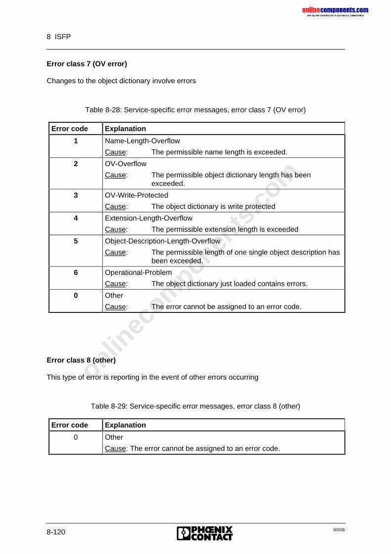
onlinec
omponen
ts.co
m
8 ISFP
8-120 5003B
Error class 7 (OV error)
Changes to the object dictionary involve errors
Table 8-28: Service-specific error messages, error class 7 (OV error)
Error code Explanation
1 Name-Length-Overflow
Cause: The permissible name length is exceeded.
2 OV-Overflow
Cause: The permissible object dictionary length has beenexceeded.
3 OV-Write-Protected
Cause: The object dictionary is write protected
4 Extension-Length-Overflow
Cause: The permissible extension length is exceeded
5 Object-Description-Length-Overflow
Cause: The permissible length of one single object description hasbeen exceeded.
6 Operational-Problem
Cause: The object dictionary just loaded contains errors.
0 Other
Cause: The error cannot be assigned to an error code.
Error class 8 (other)
This type of error is reporting in the event of other errors occurring
Table 8-29: Service-specific error messages, error class 8 (other)
Error code Explanation
0 Other
Cause: The error cannot be assigned to an error code.
onlinec
omponen
ts.co
m
A
5003B 8-121
A
ABORT, 8-120Abort ID, 8-122Abort Identifier, 8-122Abort Indication, 8-118Abort Request, 8-113ABORT-Request, 8-121Access, 8-129Activation flag, 8-103; 8-108Additional error messages, 8-125ADDRESS, 8-23; 8-69; 8-98; 8-101; 8-119Address length, 8-74Addressing, 8-100; 8-101; 8-119Addressing block, 8-98Alarm Stop, 8-29Application reference, 8-127Automatic start, 8-6Auxiliary block, 8-5
BBitMOD, 8-88
Bit manipulation, 8-46Bit manipulation register, 8-50Bit number, 8-46BK-Alarm OFF, 8-67BK-Alarm ON, 8-67BUS bit, 8-85; 8-87; 8-91Bus Information, 8-85Bus output bit, 8-46Bus segment address list, 8-75Bus segment number, 8-67Bus segment numbers, 8-35Bus structure (physical), 8-74Bus terminal alarm output, 8-67BUSY bit, 8-17Busy bit, 8-19Byte orientation, 8-46
CCall structure, 8-3CIDB, 101; 8-108CIDB (data block), 8-105CIH, 8-5; 8-10CIMW, 8-105; 8-108; 8-119CIST, 8-108; 8-119Clear Display, 8-29Client, 8-96Command functions, 8-25Command list, 8-51Communication, 8-96; 8-98; 8-119
Communication abort, 8-120Communication data, 8-98Communication Reference, 8-38Communication reference, 8-101;8-102; 8-109Communication reference list, 8-81Communication references, 8-38Communication registers, 8-98Communication relation ship list,8-43Communication stations, 8-102CON bit, 8-84; 8-91CON/IND, 8-4; 8-10; 8-15; 8-17; 8-98; 8-100; 8-105; 8-119CON/IND header blocks, 8-101Configure InterBus-S, 8-28Confirmation service primitive, 8-96Confirmations, 8-105Connection abort, 8-121Connection establishment, 8-121CONTROL, 8-26Control, 8-17; 8-21; 8-98Controlled start, 8-6Controlled start with EEPROM, 8-6Controller Error Code, 8-84Controller Parameter Timeout Error, 8-42Counter, 8-62
DData block
header data block, 8-107; 8-108standard data block, 8-107; 8-108
Defective Group, 8-87DEFINE, 8-21; 8-32; 8-53Definition, 8-127Disable All Messages, 8-29disconnectible, 8-80Driver blocks, 8-101
EEREG, 8-71ERRINFO, 8-24; 8-82Error classes, 8-126Error codes, 8-126Error messages, 8-122EVENT, 8-24; 8-95Event code, 8-40Event identifier, 8-40; 8-68Event Map, 8-39Event OFF, 8-68
onlinec
omponen
ts.co
m
A
8-122 5003B
Event ON, 8-68
FFunction block, 8-2Function blocks, 8-98
GGroup definition, 8-78Group Error Characteristics, 8-53;8-80Group nos. list, 8-78Group Numbers, 8-41Group OFF, 8-66Group ON, 8-66
HHilfsfunktionsbaustein, 8-10Host output bit, 8-46
II/O address area, 8-98IBDB, 8-10; 8-14; 8-15; 8-19; 8-52; 8-56; 8-71ID code, 8-74ID code list, 8-74ID numbers, 8-34Identification codes, 8-59Identify Confirmation, 8-116Identify Request, 8-113Implement All Logical AddressMap, 8-30; 8-35; 8-36; 8-37; 8-63IN address, 8-40IN address list, 8-76Indication service primitive, 8-96Indications, 8-105Information Report Request, 8-112Init Communication, 8-30; 8-38Initialization, 100; 8-119Initialization block, 8-2; 8-98Initiate, 8-126Initiate Confirmation, 8-116Initiate Error Confirmation, 8-117Initiate Request, 8-113Initiate.Request, 8-121INITIB, 8-6; 8-8; 8-98; 8-119Input addresses, 8-76Input bit, 8-46Installation remote bus station, 8-56INTERBUS data block, 8-19; 8-52
InterBus data block, 8-10INTERBUS-S Cycle Counter, 8-62InterBus-S Delay, 8-31InterBus-S managementfunctions, 8-1Interface drivers, 8-119ISFP interface, 8-101
LLB ERR, 8-71Length codes, 8-34; 8-59Local bus, 8-78Local Bus Module Error, 8-89Local buses, 8-41Logical Address Error, 8-63Logical IN Address Map, 8-36Logical IN addresses, 8-36Logical local bus address, 8-56Logical Local Bus Address Map,8-35logical numbers, 8-75Logical OUT Address Map, 8-37Logical OUT addresses, 8-37
MManipulation of OUT words, 8-44Mask 1, 8-40Mask 2, 8-40Message flag, 8-108Message functions, 8-90Message header, 8-108MOD bit, 8-91MODE, 8-71Module Error, 8-88Module identification code, 8-34Module number, 8-56
OON/OFF, 8-22; 8-64Organization block, 8-119Other, 8-130OUT address list, 8-77Output addresses, 8-77Output bit, 8-46OV-Error, 8-130
PParameter Timeout Constant, 8-42PCP activation flag, 8-104PCP communication system, 8-96
onlinec
omponen
ts.co
m
A
5003B 8-123
PCP message flag, 8-106PCP services, 8-110PCP stations, 8-98Physical Configuration Map, 8-34;8-59Physical Configuration Map, 8-63Process data, 8-98
QQuit Module Error, 8-56Quit Module Error All, 8-31
RRB ERR, 8-71RC, 8-122Read Confirmation, 8-114Read Request, 8-111READ service (Exmp.), 8-109Reason Code, 8-122Receive Bit Manipulation, 8-44Receive block, 8-2; 8-98Receive KBL, 8-43RECO bit, 8-93RECONFIG, 8-24; 8-93Reject Indication, 8-118Reject Service, 8-125REQ/RES, 8-4; 8-12; 8-15; 8-17;8-98; 8-100; 8-119REQ/RES header blocks, 8-101Request service primitive, 8-96Reset-Out-In01, 8-49Reset-Out-In01-Switch, 8-50Reset-Out-In10, 8-49Reset-Out-In10-Switch, 8-50Reset2-Out-In01, 8-49Reset2-Out-In10, 8-49Resource, 8-128Response service primitive, 8-96Restart (automatic), 8-53Return bit, 8-19RRDB, 8-101; 8-103; 8-107RRMW, 8-103; 8-108; 8-119RRST, 8-107; 8-108; 8-119
SSend block, 8-2; 8-98Server, 8-96Service, 8-128Service execution, 8-102Service Message Flag, 8-105
Service primitive, 8-102Confirmation, 8-105; 8-109Indication, 8-105
Service request, 8-121Service Structure, 8-102
Service primitiveRequest, 8-109
Service-specific error messages,8-126Signal changes, 8-44Simatic S5, 8-98Software Revision, 8-60Start Confirmation, 8-114Start InterBus-S Cycle, 8-28Start Request, 8-111Startup, 8-119Status Confirmation, 8-115Status Request, 8-112Stop Confirmation, 8-115Stop InterBus-S Cycle,8-28Stop Request, 8-112Switch Information, 8-61Synchronization, 8-98SYSERROR, 8-23; 8-82; 8-91SYSINFO, 8-22; 8-57
TTIMEOUT bit, 8-19
UUse, 8-119User process, 8-96
VVFD-State, 8-126
WWrite Confirmation, 8-114Write Request, 8-111
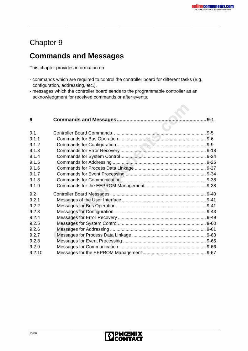
onlinec
omponen
ts.co
m
5003B
Chapter 9
Commands and MessagesThis chapter provides information on
- commands which are required to control the controller board for different tasks (e.g.configuration, addressing, etc.).
- messages which the controller board sends to the programmable controller as anacknowledgment for received commands or after events.
9 Commands and Messages................................................................9-1
9.1 Controller Board Commands ....................................................................... 9-59.1.1 Commands for Bus Operation ................................................................... 9-69.1.2 Commands for Configuration ..................................................................... 9-99.1.3 Commands for Error Recovery .................................................................. 9-189.1.4 Commands for System Control.................................................................. 9-249.1.5 Commands for Addressing ........................................................................ 9-259.1.6 Commands for Process Data Linkage ....................................................... 9-279.1.7 Commands for Event Processing .............................................................. 9-349.1.8 Commands for Communication ................................................................. 9-389.1.9 Commands for the EEPROM Management ............................................... 9-38
9.2 Controller Board Messages ......................................................................... 9-409.2.1 Messages of the User Interface ................................................................. 9-419.2.2 Messages for Bus Operation ..................................................................... 9-419.2.3 Messages for Configuration ....................................................................... 9-439.2.4 Messages for Error Recovery .................................................................... 9-499.2.5 Messages for System Control.................................................................... 9-609.2.6 Messages for Addressing .......................................................................... 9-619.2.7 Messages for Process Data Linkage ......................................................... 9-639.2.8 Messages for Event Processing ................................................................ 9-659.2.9 Messages for Communication ................................................................... 9-669.2.10 Messages for the EEPROM Management ................................................. 9-67
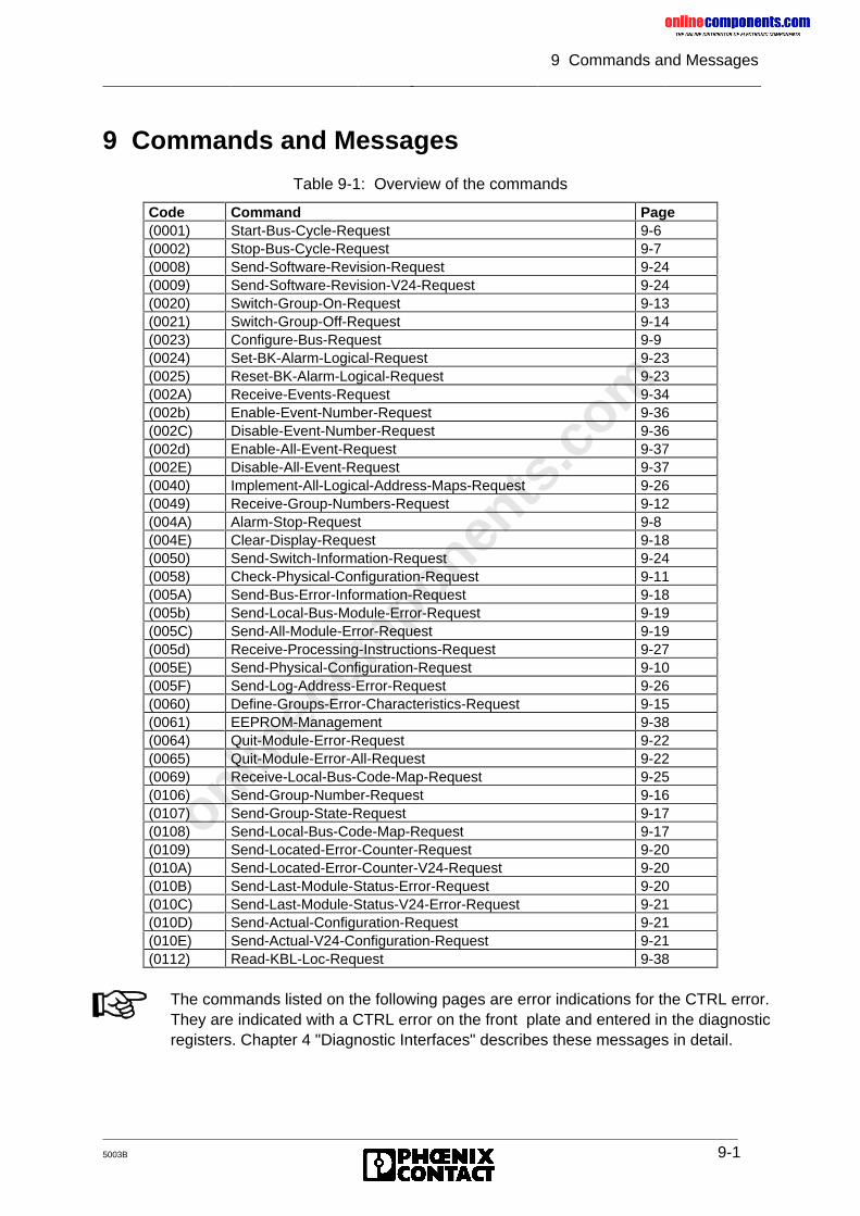
onlinec
omponen
ts.co
m
9 Commands and Messages
5003B 9-1
9 Commands and Messages
Table 9-1: Overview of the commands
Code Command Page(0001) Start-Bus-Cycle-Request 9-6(0002) Stop-Bus-Cycle-Request 9-7(0008) Send-Software-Revision-Request 9-24(0009) Send-Software-Revision-V24-Request 9-24(0020) Switch-Group-On-Request 9-13(0021) Switch-Group-Off-Request 9-14(0023) Configure-Bus-Request 9-9(0024) Set-BK-Alarm-Logical-Request 9-23(0025) Reset-BK-Alarm-Logical-Request 9-23(002A) Receive-Events-Request 9-34(002b) Enable-Event-Number-Request 9-36(002C) Disable-Event-Number-Request 9-36(002d) Enable-All-Event-Request 9-37(002E) Disable-All-Event-Request 9-37(0040) Implement-All-Logical-Address-Maps-Request 9-26(0049) Receive-Group-Numbers-Request 9-12(004A) Alarm-Stop-Request 9-8(004E) Clear-Display-Request 9-18(0050) Send-Switch-Information-Request 9-24(0058) Check-Physical-Configuration-Request 9-11(005A) Send-Bus-Error-Information-Request 9-18(005b) Send-Local-Bus-Module-Error-Request 9-19(005C) Send-All-Module-Error-Request 9-19(005d) Receive-Processing-Instructions-Request 9-27(005E) Send-Physical-Configuration-Request 9-10(005F) Send-Log-Address-Error-Request 9-26(0060) Define-Groups-Error-Characteristics-Request 9-15(0061) EEPROM-Management 9-38(0064) Quit-Module-Error-Request 9-22(0065) Quit-Module-Error-All-Request 9-22(0069) Receive-Local-Bus-Code-Map-Request 9-25(0106) Send-Group-Number-Request 9-16(0107) Send-Group-State-Request 9-17(0108) Send-Local-Bus-Code-Map-Request 9-17(0109) Send-Located-Error-Counter-Request 9-20(010A) Send-Located-Error-Counter-V24-Request 9-20(010B) Send-Last-Module-Status-Error-Request 9-20(010C) Send-Last-Module-Status-V24-Error-Request 9-21(010D) Send-Actual-Configuration-Request 9-21(010E) Send-Actual-V24-Configuration-Request 9-21(0112) Read-KBL-Loc-Request 9-38
The commands listed on the following pages are error indications for the CTRL error.They are indicated with a CTRL error on the front plate and entered in the diagnosticregisters. Chapter 4 "Diagnostic Interfaces" describes these messages in detail.
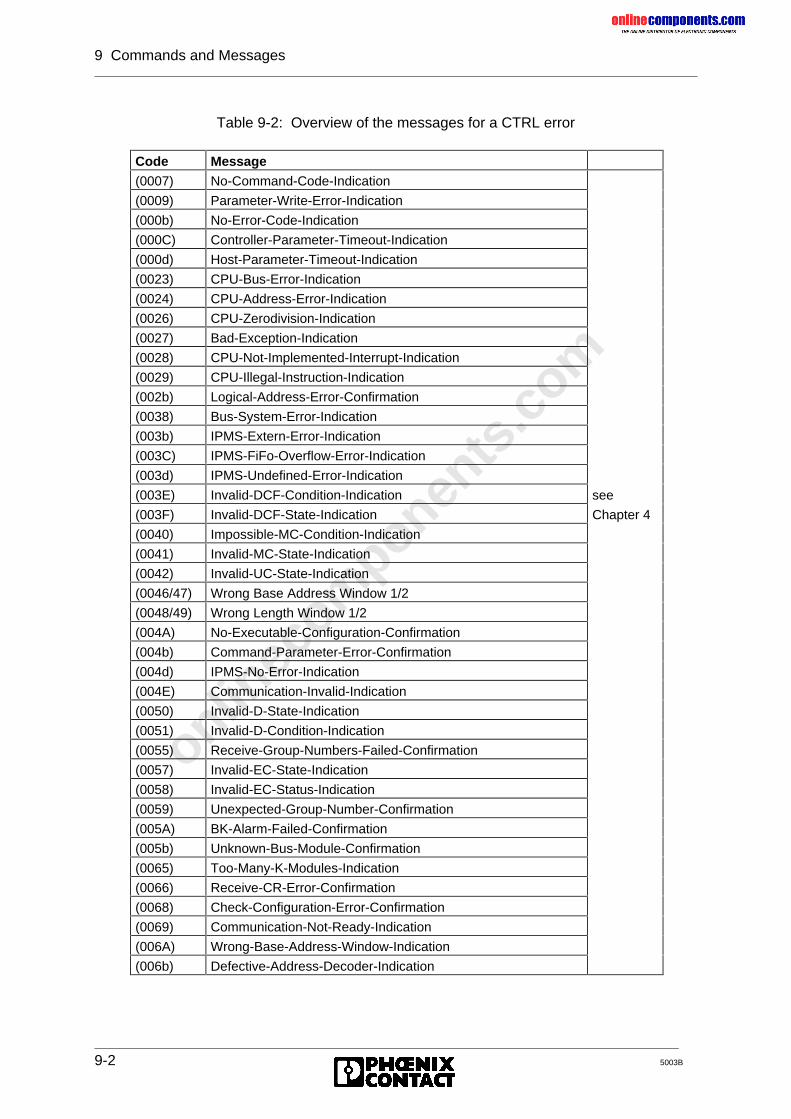
onlinec
omponen
ts.co
m
9 Commands and Messages
9-2 5003B
Table 9-2: Overview of the messages for a CTRL error
Code Message(0007) No-Command-Code-Indication
(0009) Parameter-Write-Error-Indication
(000b) No-Error-Code-Indication
(000C) Controller-Parameter-Timeout-Indication
(000d) Host-Parameter-Timeout-Indication
(0023) CPU-Bus-Error-Indication
(0024) CPU-Address-Error-Indication
(0026) CPU-Zerodivision-Indication
(0027) Bad-Exception-Indication
(0028) CPU-Not-Implemented-Interrupt-Indication
(0029) CPU-Illegal-Instruction-Indication
(002b) Logical-Address-Error-Confirmation
(0038) Bus-System-Error-Indication
(003b) IPMS-Extern-Error-Indication
(003C) IPMS-FiFo-Overflow-Error-Indication
(003d) IPMS-Undefined-Error-Indication
(003E) Invalid-DCF-Condition-Indication see
(003F) Invalid-DCF-State-Indication Chapter 4
(0040) Impossible-MC-Condition-Indication
(0041) Invalid-MC-State-Indication
(0042) Invalid-UC-State-Indication
(0046/47) Wrong Base Address Window 1/2
(0048/49) Wrong Length Window 1/2
(004A) No-Executable-Configuration-Confirmation
(004b) Command-Parameter-Error-Confirmation
(004d) IPMS-No-Error-Indication
(004E) Communication-Invalid-Indication
(0050) Invalid-D-State-Indication
(0051) Invalid-D-Condition-Indication
(0055) Receive-Group-Numbers-Failed-Confirmation
(0057) Invalid-EC-State-Indication
(0058) Invalid-EC-Status-Indication
(0059) Unexpected-Group-Number-Confirmation
(005A) BK-Alarm-Failed-Confirmation
(005b) Unknown-Bus-Module-Confirmation
(0065) Too-Many-K-Modules-Indication
(0066) Receive-CR-Error-Confirmation
(0068) Check-Configuration-Error-Confirmation
(0069) Communication-Not-Ready-Indication
(006A) Wrong-Base-Address-Window-Indication
(006b) Defective-Address-Decoder-Indication
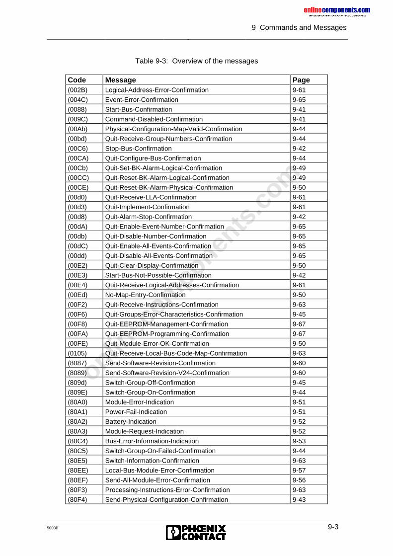
onlinec
omponen
ts.co
m
9 Commands and Messages
5003B 9-3
Table 9-3: Overview of the messages
Code Message Page(002B) Logical-Address-Error-Confirmation 9-61
(004C) Event-Error-Confirmation 9-65
(0088) Start-Bus-Confirmation 9-41
(009C) Command-Disabled-Confirmation 9-41
(00Ab) Physical-Configuration-Map-Valid-Confirmation 9-44
(00bd) Quit-Receive-Group-Numbers-Confirmation 9-44
(00C6) Stop-Bus-Confirmation 9-42
(00CA) Quit-Configure-Bus-Confirmation 9-44
(00Cb) Quit-Set-BK-Alarm-Logical-Confirmation 9-49
(00CC) Quit-Reset-BK-Alarm-Logical-Confirmation 9-49
(00CE) Quit-Reset-BK-Alarm-Physical-Confirmation 9-50
(00d0) Quit-Receive-LLA-Confirmation 9-61
(00d3) Quit-Implement-Confirmation 9-61
(00d8) Quit-Alarm-Stop-Confirmation 9-42
(00dA) Quit-Enable-Event-Number-Confirmation 9-65
(00db) Quit-Disable-Number-Confirmation 9-65
(00dC) Quit-Enable-All-Events-Confirmation 9-65
(00dd) Quit-Disable-All-Events-Confirmation 9-65
(00E2) Quit-Clear-Display-Confirmation 9-50
(00E3) Start-Bus-Not-Possible-Confirmation 9-42
(00E4) Quit-Receive-Logical-Addresses-Confirmation 9-61
(00Ed) No-Map-Entry-Confirmation 9-50
(00F2) Quit-Receive-Instructions-Confirmation 9-63
(00F6) Quit-Groups-Error-Characteristics-Confirmation 9-45
(00F8) Quit-EEPROM-Management-Confirmation 9-67
(00FA) Quit-EEPROM-Programming-Confirmation 9-67
(00FE) Quit-Module-Error-OK-Confirmation 9-50
(0105) Quit-Receive-Local-Bus-Code-Map-Confirmation 9-63
(8087) Send-Software-Revision-Confirmation 9-60
(8089) Send-Software-Revision-V24-Confirmation 9-60
(809d) Switch-Group-Off-Confirmation 9-45
(809E) Switch-Group-On-Confirmation 9-44
(80A0) Module-Error-Indication 9-51
(80A1) Power-Fail-Indication 9-51
(80A2) Battery-Indication 9-52
(80A3) Module-Request-Indication 9-52
(80C4) Bus-Error-Information-Indication 9-53
(80C5) Switch-Group-On-Failed-Confirmation 9-44
(80E5) Switch-Information-Confirmation 9-63
(80EE) Local-Bus-Module-Error-Confirmation 9-57
(80EF) Send-All-Module-Error-Confirmation 9-56
(80F3) Processing-Instructions-Error-Confirmation 9-63
(80F4) Send-Physical-Configuration-Confirmation 9-43
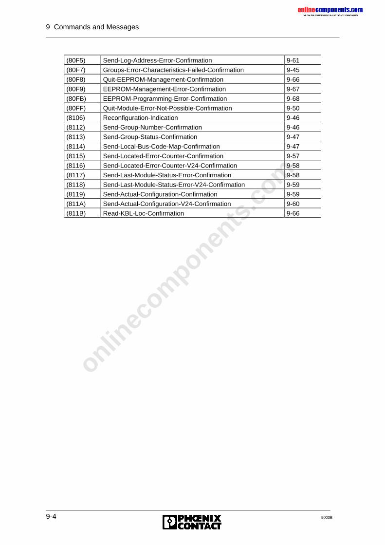
onlinec
omponen
ts.co
m
9 Commands and Messages
9-4 5003B
(80F5) Send-Log-Address-Error-Confirmation 9-61
(80F7) Groups-Error-Characteristics-Failed-Confirmation 9-45
(80F8) Quit-EEPROM-Management-Confirmation 9-66
(80F9) EEPROM-Management-Error-Confirmation 9-67
(80FB) EEPROM-Programming-Error-Confirmation 9-68
(80FF) Quit-Module-Error-Not-Possible-Confirmation 9-50
(8106) Reconfiguration-Indication 9-46
(8112) Send-Group-Number-Confirmation 9-46
(8113) Send-Group-Status-Confirmation 9-47
(8114) Send-Local-Bus-Code-Map-Confirmation 9-47
(8115) Send-Located-Error-Counter-Confirmation 9-57
(8116) Send-Located-Error-Counter-V24-Confirmation 9-58
(8117) Send-Last-Module-Status-Error-Confirmation 9-58
(8118) Send-Last-Module-Status-Error-V24-Confirmation 9-59
(8119) Send-Actual-Configuration-Confirmation 9-59
(811A) Send-Actual-Configuration-V24-Confirmation 9-60
(811B) Read-KBL-Loc-Confirmation 9-66
onlinec
omponen
ts.co
m
9 Commands and Messages
5003B 9-5
9.1 Controller Board Commands
Chapter 9.1 describes the commands for the controller board. The descriptions follow theschematic below. The command code is given in a hexadecimal form. The letters A throughF are shown as upper or lower case letters like they are displayed on the seven-segmentdisplay.
Name of the command (Code)
Function: Describes the task of the command.
Requirement: All requirements which must be met before a command is called to allow itssuccessful processing.
Messages: Positiveacknowledgement:
Message which confirms a positive execution of thecommand.
Meaning: Explanation of the message.Remark: Further information on the message.
Negativeacknowledgment:
Message which indicates that an error occurred whilethe command was executed.
Meaning: Explanation of the error reason.Remark: Further information on the message.
The syntax of a command with parameters is as follows:
Syntax: Name of the command CodeStructureof the
command
The key explains the parameters which have been used for the syntax description.
Key: Dummyvariable
Description of the parameter
The syntax of a command without parameters is described as follows.
Syntax: Name of the command Code
onlinec
omponen
ts.co
m
9 Commands and Messages
9-6 5003B
9.1.1 Commands for Bus Operation
Start-Bus-Cycle-Request (0001)
Function: The command activates the cyclic data traffic on the bus. Depending on thepreviously loaded definitions (e.g. logical addressing, group definitions) thecontroller board puts the bus configuration into operation and makes theI/O addresses available to the PLC.
Prerequisite: Logical addressing of local bus error for group definition
Messages: Positiveacknowledgment: Start-Bus-Confirmation (0088)Remark: The IB RUN LED is illuminatedMeaning: The system could be started. The controller board
starts the cyclic reading and setting of inputs andoutputs.
Negativeacknowledgment: Start-Bus-Not-Possible-Confirmation (00E3)Remark: The IB RUN LED is not illuminatedMeaning: • all groups are switched off
• the maximum possible bus configuration hasbeen exceeded
• hardware error of the controller board
Negativeacknowledgment: Bus-System-Error-Indication (0038)Meaning: An error has occurred which does not permit further
bus operation.Remark: The general message Bus-Error-Information-
Indication (80C4) provides a detailed errordescription.
Further details: The data traffic is not stopped in the event of the Module-Error-Indication(80A0) error message which may occur after a positive or negativeacknowledgment.
The BSA LED is illuminated when the bus is started after a local bus orinstallation remote bus error. A prerequisite for this is the group definition.
onlinec
omponen
ts.co
m
9 Commands and Messages
5003B 9-7
Stop-Bus-Cycle-Request (0002)
Function: The command stops the cyclic data traffic on the bus.
Prerequisite: None
Effects: Process datachannel:
• The cyclic data traffic is stopped. The existingprocess data image of the modules connected tothe bus is statically kept and not renewed.
• The command does not switch the processoutput data in the safe state (reset of theoutputs). This is only possible with the Alarm-Stop-Request (004A) command.
PCP channel: • The Peripherals Communication Protocol (PCP)is not used further.
• The established connections are notautomatically aborted. Services which arepossibly to be expected are processed furtherafter the data traffic has started again.
Messages: Positiveacknowledgment: Stop-Bus-Confirmation (00C6)Meaning: The process data channel and the possibly used
(PCP) channel are no longer used.Remark: • The IB RUN LED goes off.
• The parameter list is not deleted.
Syntax: Stop-Bus-Cycle-Request 0002
onlinec
omponen
ts.co
m
9 Commands and Messages
9-8 5003B
Alarm-Stop-Request (004A)
Function: The command causes a RESET on the bus. The data traffic on the bus isstopped. Modules with process data set their output values to 0. Thecommand is executed immediately after the running data cycle has beencompleted.
Effects: Process datachannel:
• The cyclic data traffic on the bus is stopped. Theexisting process data image of the modulesconnected to the bus is kept statically and is notrenewed.
• The command switches the process output datato a safe state (reset of the outputs).
PCP channel: • The Peripherals Communication Protocol (PCP)is not used further.
• The established connections are notautomatically aborted. Services which arepossibly to be expected are processed furtherafter the data traffic has started again.
Further operation: The following definitions are deleted:• Logical address lists• Group definition• Bit manipulation• Event definition
Messages: Positiveacknowledgment: Quit-Alarm-Stop-Confirmation (00d8)Meaning: The data traffic on the bus is stopped.Remark: The parameter list is deleted.
Syntax: Alarm-Stop-Request 004A
onlinec
omponen
ts.co
m
9 Commands and Messages
5003B 9-9
9.1.2 Commands for Configuration
Configure-Bus-Request (0023)
Function: This command causes the controller board to reject all previously defineddefinitions and to read in the up to date bus configuration. Thisconfiguration is valid from now on and is declared as "initial configuration".
Effects: The following definitions are deleted:• Logical address lists• Group definition• Bit manipulation• Event definition
Prerequisite: When this command is used, the INTERBUS-S cycle must have beenstopped.
Further operation: Further bus operation is initiated with logical addressing.
Messages: Positiveacknowledgment: Quit-Configure-Bus-Confirmation (00CA)
Error: Defective bus parts are reported as errors (LEDs, messages) in the orderof the physical bus structure or are indicated on the diagnostics display.
Syntax: Configure-Bus-Request 0023
onlinec
omponen
ts.co
m
9 Commands and Messages
9-10 5003B
Send-Physical-Configuration-Request (005E)
Function: The command reads out the bus configuration, which has been stored asvalid configuration on the controller board in the form of ID codes andlength codes.
Prerequisite: If the up to date bus configuration is to be read out, the followingcommands must be executed before the Send-Physical-Configuration-Request command is called:- Configure-Bus-Request (command code 0023)- Warmstart-Request (command code 004c)
If the "initial" bus configuration is to be read out, the Check-Physical-Configuration-Request must be executed before the Send-Physical-Configuration-Request command is called.
Messages: Positiveacknowledgment: Send-Physical-Configuration-Confirmation (80F4)Meaning: The acknowledgment transmits the physical bus
configuration including the number of registers whichare used for the process data (bus register).
Negativeacknowledgment: No-Executable-Configuration-Confirmation (004A)Meaning: No bus system was connected during hardware
startup.
onlinec
omponen
ts.co
m
9 Commands and Messages
5003B 9-11
Check-Physical-Configuration-Request (0058)
Function: The command transmits the bus configuration which is demanded foroperation in the form of ID codes and length codes. The requested busconfiguration is first compared with the connected bus configuration and, ifpossible, stored as "initial configuration".
Remark: If there are one or several installation remote buses, the location of themodule in the bus system (installation depth) must be declared with theReceive-Local-Bus-Code-Map-Request (0069) and Implement-All-Logical-Address-Maps-Request (0040) commands. Only then is the configurationcomplete.
Prerequisite: When this command is used, the INTERBUS-S cycle must have beenstopped.
Messages: Positiveacknowledgment:
Physical-Configuration-Map-Valid-Confirmation(00Ab)
Meaning: The requested bus configuration agrees with theconnected one and was stored on the controllerboard as "initial configuration".
Negativeacknowledgment: Check-Configuration-Error-Confirmation (0068)Meaning: Requested and connected bus configuration are not
identical.Remark: Nevertheless, the controller board attempts to store
the requested configuration as "initial configuration".If this is possible, the board returns the messageCheck-Configuration-Error-Confirmation 0068.
Neg.acknowledg.: Unknown-Bus-Module-Confirmation (005b)Meaning: • The first module in the bus configuration is not a
bus terminal module.• A number of process data words was specified
which is not permitted.Remark: Only in this case is the requested configuration not
stored as "initial configuration".
Syntax: Check-Physical-Configuration-Request 0058Quantity of subsequent words PC
1 1st module ppii...
n nth module:Number of process data/ID code
ppii
Key: PC: Parameter count (Quantity of subsequent words,corresponds to the quantity of modules)
pp: Current number of the module’s process data.ii: ID code (is printed on the modules)
onlinec
omponen
ts.co
m
9 Commands and Messages
9-12 5003B
Receive-Group-Numbers-Request (0049)
Function: The segmentation of the bus structure in groups allows to switch on or offthe bus segments (local bus, installation remote bus) which branch off fromthe main bus line (commands: Switch-Group-Off-Request or Switch-Group-On-Request). A group may consist of one or several bus segments.Assign all bus segments, except for the segments in installation remotebuses, to one group! In the initial state (after the voltage has been switchedon, after the RESET button has been used or Configure-INTERBUS-Request has been called), all bus segments are combined in group 0.
Prerequisite: When this command is used, the INTERBUS-S cycle must have beenstopped.
Messages: Positiveacknowledgment: Quit-Receive-Group-Numbers-Confirmation (00bd)Meaning: The group definition was accepted and is validNegativeacknowledgment: Receive-Group-Numbers-Failed-Confirmation (0055)Meaning: An error was detected when the list was checked.
Syntax: Receive-Group-Numbers-Request 0049Quantity of subsequent words PC
1 Logical bus segment address 1 00xx2 Group number for BS 1 00xx
...2∗n-1 Logical bus segment address n 00xx2∗n Group number for BS n 00xx
Key: PC: Parameter count = 2 ∗ n, where n is the quantity of localbuses.
xx: 00 ≤ xx ≤ FF (hex), corresponds to 000 - 255 (decimal)
Remote bus stations which cannot be disconnected (e.g. bus terminalmodules with I/O functions) must be assigned their own group number.
• Depending on the selected type of addressing, enter the logical or physicaladdress in the LOGICAL BUS SEGMENT ADDRESS parameter.
• All bus segments (BS), except for the segments in the installation remotebuses, are to be assigned to groups.
• BS addresses must only exist once!• Group numbers may be assigned several times.
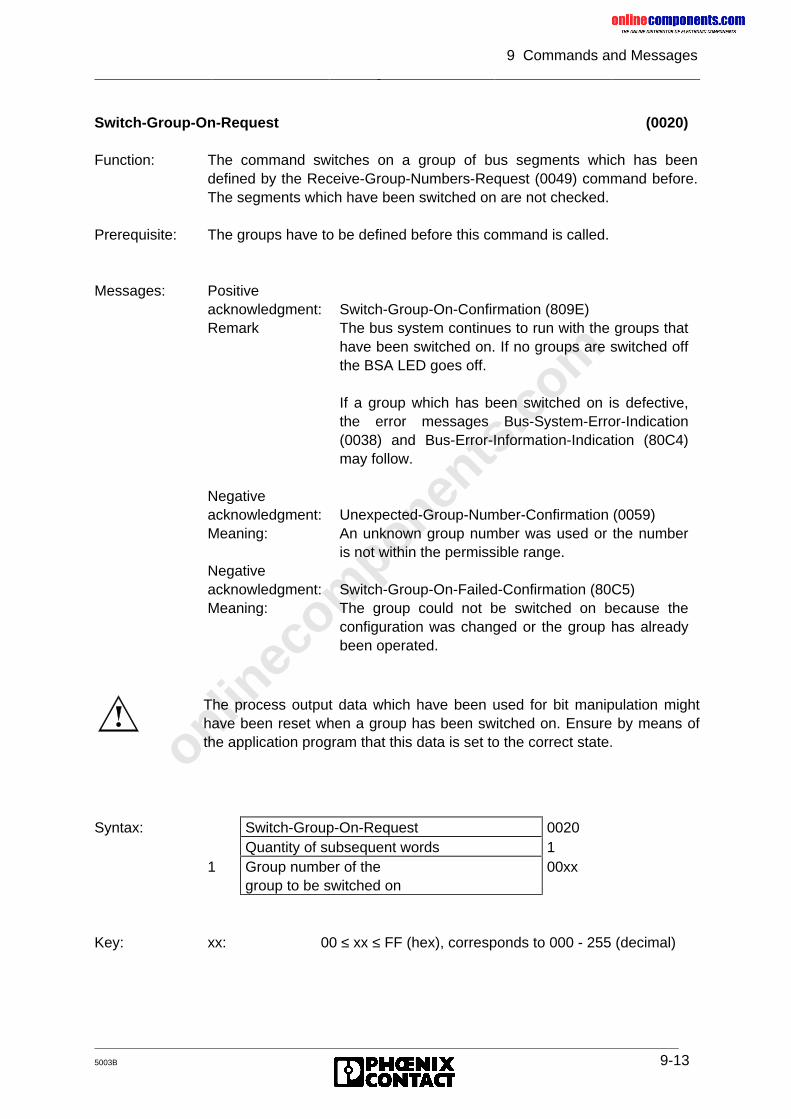
onlinec
omponen
ts.co
m
9 Commands and Messages
5003B 9-13
Switch-Group-On-Request (0020)
Function: The command switches on a group of bus segments which has beendefined by the Receive-Group-Numbers-Request (0049) command before.The segments which have been switched on are not checked.
Prerequisite: The groups have to be defined before this command is called.
Messages: Positiveacknowledgment: Switch-Group-On-Confirmation (809E)Remark The bus system continues to run with the groups that
have been switched on. If no groups are switched offthe BSA LED goes off.
If a group which has been switched on is defective,the error messages Bus-System-Error-Indication(0038) and Bus-Error-Information-Indication (80C4)may follow.
Negativeacknowledgment: Unexpected-Group-Number-Confirmation (0059)Meaning: An unknown group number was used or the number
is not within the permissible range.Negativeacknowledgment: Switch-Group-On-Failed-Confirmation (80C5)Meaning: The group could not be switched on because the
configuration was changed or the group has alreadybeen operated.
Syntax: Switch-Group-On-Request 0020Quantity of subsequent words 1
1 Group number of thegroup to be switched on
00xx
Key: xx: 00 ≤ xx ≤ FF (hex), corresponds to 000 - 255 (decimal)
The process output data which have been used for bit manipulation mighthave been reset when a group has been switched on. Ensure by means ofthe application program that this data is set to the correct state.
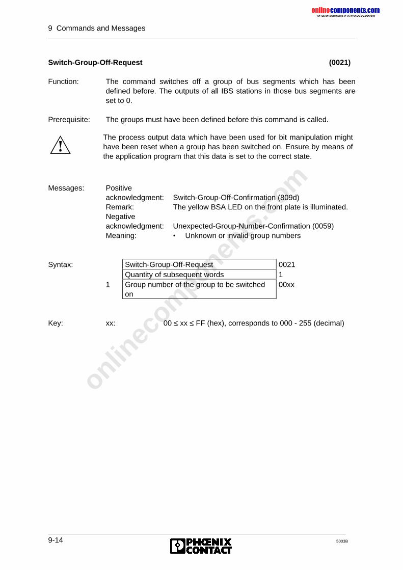
onlinec
omponen
ts.co
m
9 Commands and Messages
9-14 5003B
Switch-Group-Off-Request (0021)
Function: The command switches off a group of bus segments which has beendefined before. The outputs of all IBS stations in those bus segments areset to 0.
Prerequisite: The groups must have been defined before this command is called.
Messages: Positiveacknowledgment: Switch-Group-Off-Confirmation (809d)Remark: The yellow BSA LED on the front plate is illuminated.Negativeacknowledgment: Unexpected-Group-Number-Confirmation (0059)Meaning: • Unknown or invalid group numbers
Syntax: Switch-Group-Off-Request 0021Quantity of subsequent words 1
1 Group number of the group to be switchedon
00xx
Key: xx: 00 ≤ xx ≤ FF (hex), corresponds to 000 - 255 (decimal)
The process output data which have been used for bit manipulation mighthave been reset when a group has been switched on. Ensure by means ofthe application program that this data is set to the correct state.
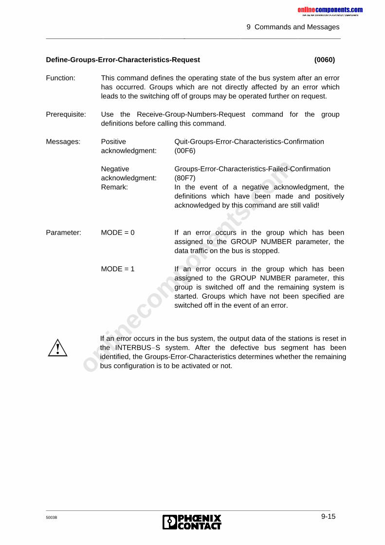
onlinec
omponen
ts.co
m
9 Commands and Messages
5003B 9-15
Define-Groups-Error-Characteristics-Request (0060)
Function: This command defines the operating state of the bus system after an errorhas occurred. Groups which are not directly affected by an error whichleads to the switching off of groups may be operated further on request.
Prerequisite: Use the Receive-Group-Numbers-Request command for the groupdefinitions before calling this command.
Messages: Positiveacknowledgment:
Quit-Groups-Error-Characteristics-Confirmation(00F6)
Negativeacknowledgment:
Groups-Error-Characteristics-Failed-Confirmation(80F7)
Remark: In the event of a negative acknowledgment, thedefinitions which have been made and positivelyacknowledged by this command are still valid!
Parameter: MODE = 0 If an error occurs in the group which has beenassigned to the GROUP NUMBER parameter, thedata traffic on the bus is stopped.
MODE = 1 If an error occurs in the group which has beenassigned to the GROUP NUMBER parameter, thisgroup is switched off and the remaining system isstarted. Groups which have not been specified areswitched off in the event of an error.
If an error occurs in the bus system, the output data of the stations is reset inthe INTERBUS-S system. After the defective bus segment has beenidentified, the Groups-Error-Characteristics determines whether the remainingbus configuration is to be activated or not.
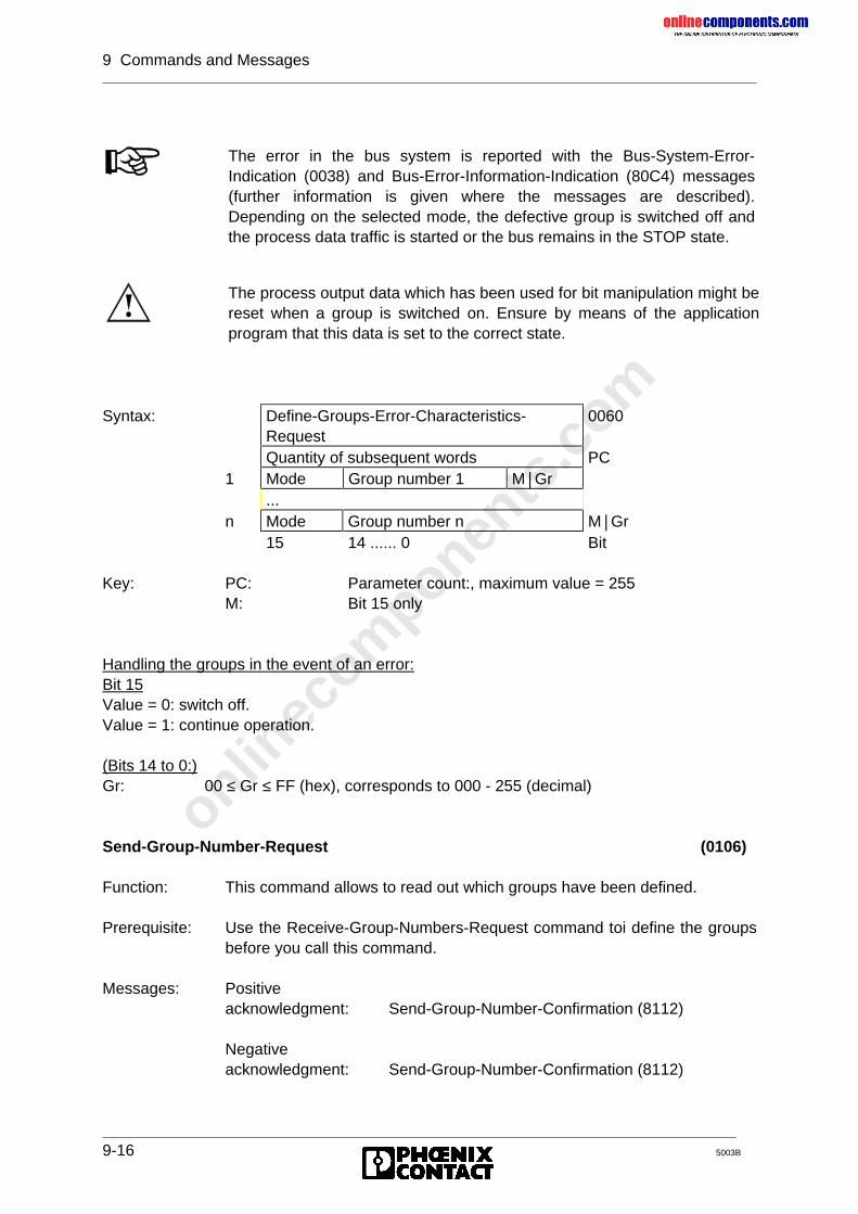
onlinec
omponen
ts.co
m
9 Commands and Messages
9-16 5003B
Syntax: Define-Groups-Error-Characteristics-Request
0060
Quantity of subsequent words PC1 Mode Group number 1 M�Gr
...n Mode Group number n M�Gr
15 14 ...... 0 Bit
Key: PC: Parameter count:, maximum value = 255M: Bit 15 only
Handling the groups in the event of an error:Bit 15Value = 0: switch off.Value = 1: continue operation.
(Bits 14 to 0:)Gr: 00 ≤ Gr ≤ FF (hex), corresponds to 000 - 255 (decimal)
Send-Group-Number-Request (0106)
Function: This command allows to read out which groups have been defined.
Prerequisite: Use the Receive-Group-Numbers-Request command toi define the groupsbefore you call this command.
Messages: Positiveacknowledgment: Send-Group-Number-Confirmation (8112)
Negativeacknowledgment: Send-Group-Number-Confirmation (8112)
The error in the bus system is reported with the Bus-System-Error-Indication (0038) and Bus-Error-Information-Indication (80C4) messages(further information is given where the messages are described).Depending on the selected mode, the defective group is switched off andthe process data traffic is started or the bus remains in the STOP state.
The process output data which has been used for bit manipulation might bereset when a group is switched on. Ensure by means of the applicationprogram that this data is set to the correct state.
onlinec
omponen
ts.co
m
9 Commands and Messages
5003B 9-17
Send-Group-State-Request (0107)
Function: This command allows to read out which groups are switched on or off.
Prerequisite: Use the Receive-Group-Numbers-Request command to define the groupsbefore this command is called.
Messages: Positiveacknowledgment: Send-Group-State-Confirmation (8113)
Negativeacknowledgment: Send-Group-State-Confirmation (8113)
Send-Local-Bus-Code-Request (0108)
Function: This command reads out the local bus addresses (with information on theinstallation depth) from the controller board.
Prerequisite: Use the Receive-Local-Bus-Code-Map-Request command before callingthis command.
Remark: If the Send-Local-Bus-Code-Request command has not yet been usedafter power on or a Configure-Bus-Request (0023), the presettings of thecontroller are used.
Messages: Positiveacknowledgment: Send-Local-Bus-Code-Map-Confirmation (8114)
Negativeacknowledgment: Send-Local-Bus-Code-Map-Confirmation (8114)
onlinec
omponen
ts.co
m
9 Commands and Messages
9-18 5003B
9.1.3 Commands for Error Recovery
Clear-Display-Request (004E)
Function: This command causes the error LEDs of the front plate to go off. Thediagnostic code which belongs to the error indication is also cleared fromthe display. Since the diagnostic bit parameter and the diagnosticparameter reflect the front plate indicators, all entries are reset here aswell.
Prerequisite: None
Messages: Positiveacknowledgment: Quit-Clear-Display-Confirmation (00E2).
Syntax: Clear-Display-Request 004E
Send-Bus-Error-Information-Request (005A)
Function: The last bus error message is sent with the Bus-Error-Information-Indication (80C4) message to the controller board.
Prerequisite: This command should only be used after the Bus-Data-Error (0038) errormessage occurred. It is not checked if the error status of the bus haschanged or if the contents of the last Bus-Error-Information-Map messageis still up to date.
Messages: Positiveacknowledgment: Bus-Error-Information-Indication (80C4)
Negativeacknowledgment: No-Map-Entry-Confirmation (00Ed)Meaning: There are no entries.
Syntax: Send-Bus-Error Information-Request 005A
onlinec
omponen
ts.co
m
9 Commands and Messages
5003B 9-19
Send-Local-Bus-Module-Error-Request (005b)
Function: The local bus with the specified local bus address is searched for moduleswith a module error.
Prerequisite: The module error message with the specification of the local bus (Send-All-Module-Error Request) was received
Messages: Positiveacknowledgment: Local-Bus-Module-Error-Confirmation (80EE)Meaning: A list with the module numbers and the ID codes of
all modules, in which a module error occurred, is sentto the controller board.
Negativeacknowledgment: No-Map-Entry-Confirmation (00Ed)Meaning: No module errors were detected.
Syntax: Send-Local-Bus-Module-Error-Request 005bQuantity of subsequent words 1
1 Logical local bus address 00xx
Send-All-Module-Error-Request (005C)
Function: This command first clears the diagnostic display on the front plate.Afterwards, while the bus system is active, it checks all modules for errormessages and updates the module error indications.
Prerequisite: Module error
Messages: Positiveacknowledgment: Send-All-Module-Error-Confirmation (80EF)Meaning: This acknowledgment transmits a list of all local
buses with module errors.
Negativeacknowledgment: No-Map-Entry-Confirmation (00Ed)Meaning: There are no module errors. The error indications on
the front plate and at the diagnostic interface arereset.
Syntax: Send-All-Module-Error-Request 005C
onlinec
omponen
ts.co
m
9 Commands and Messages
9-20 5003B
Send-Located-Error-Counter-Request (0109)
Function: This command determines the 10 module to which the most transmissionerrors can be assigned. After every configuration, the data is automaticallyreset, newly determined and can be scanned with the command call.
Remark: The error indication includes malfunction in the periphery and on thetransmission path. Bus cycles with errors as a result of malfunctions in theperiphery are also counted as transmission errors.The module numbers of the ten modules with the most errors can bedisplayed one after another on the seven-segment display with the codingswitch position 918x (beginning with the module with the most errors).
Messages: Positiveacknowledgment: Send-Located-Error-Counter-Confirmation (8115)
Syntax: Send-Located-Error-Counter-Request 0109
Send-Located-Error-Counter-V24-Request (010A)
Function: This function corresponds to the Send-Located-Error-Counter-Request.The only difference is the data is exclusively transmitted via the V.24 (RS-232) interface.
Remark: See remark on Send-Located-Error-Counter-Request
Messages: Positiveacknowledgment:
Send-Located-Error-Counter-V24-Confirmation(8116)
Syntax: Send-Located-Error-Counter-V24-Request 010A
Send-Last-Module-Status-Error-Request (010B)
Function: This command returns the local bus numbers of the ten module whichreported the last ten module status errors.
Remark: The local bus numbers can be displayed one after another on the seven-segment display (coding switch setting 919x).
Messages: Positiveacknowledgment: Send-Last-Module-Status-Error-Confirmation (8117)
Syntax: Send-Last-Module-Error-Request 010B
onlinec
omponen
ts.co
m
9 Commands and Messages
5003B 9-21
Send-Last-Module-Status-Error-V24-Request (010C)
Function: This function corresponds to the Send-Last-Module-Status-Error-Requestcommand. The only difference is that the data is exclusively transmitted viathe V.24 (RS-232) interface.
Remark: See remark on Send-Last-Module-Status-Error-Request
Messages: Positiveacknowledgment:
Send-Last-Module-Status-Error-V24-Confirmation(8118)
Syntax: Send-Last-Module-Status-Error-Request 010C
Send-Actual-Configuration-Request (010D)
Function: This command request the current configuration in the form of an ID codelist. In contrast to the Send-Physical-Configuration-Request (005E) service,the currently connected configuration is indicated and not the "initialconfiguration".
Remark: If the bus is in the STOP mode, this command cannot detect later changesto the configuration. These changes are only taken into consideration afterthe bus has been started again or the system has been configured again(with Configure-Bus-Request, 0023 or Check-Physical-Configuration-Request, 0058).However, if the bus changes from the RUN state to the STOP state as aresult of a configuration change, Send-Actual-Configuration-Request canshow the new (and incorrect) configuration.The current configuration can also be displayed on the seven-segmentdisplay (coding switch positions 94xx-99xx).
Messages: Positive acknowl.: Send-Actual-Configuration-Confirmation (8119)
Syntax: Send-Actual-Configuration-Request 010D
Send-Actual-Configuration-V24-Request (010E)
Function: The function corresponds to the Send-Actual-Configuration-Requestcommand. The only difference is that the data is transmitted exclusively viathe V.24 (RS-232) interface.
Remark: See remark on Send-Actual-Configuration-Request
Messages: Positive acknowl.: Send-Actual-Configuration-V24-Confirmation (811A)
Syntax: Send-Actual-Configuration-V24-Request 010E
onlinec
omponen
ts.co
m
9 Commands and Messages
9-22 5003B
Quit-Module-Error-Request (0064)
Function: Modules with a storage display continue to indicate the error even if theerror has been removed. Therefore, the error message must beacknowledged. This command acknowledges the module errors of thespecified modules. The logical local bus address and the requested modulenumber are specified in pairs as parameters.
Prerequisite: Module error on a module with a storage display.
Remark: Even error LEDs on the module go out.
Messages: Positiveacknowledgment: Quit-Module-Error-OK-Confirmation (00FE)Negativeacknowledgment: Quit-Module-Error-Not-Possible-Confirmation (80FF)
Syntax: Quit-Module-Error-Request 0064Quantity of subsequent words PC
1 1st logical local bus address2 1st module number
...2∗n-1 nth logical local bus number2∗n nth module number
Key: PC: Parameter count (module quantity multiplied with 2)
Quit-Module-Error-All-Request (0065)
Function: This command acknowledges the message of the module errors of allmodules with storage display in the currently accessible bus configuration.
Prerequisite: Module error on module with storage display
Remark: Even error LEDs on the module go out.
Messages: Positiveacknowledgment: Quit-Module-Error-OK-Confirmation (00FE)
Negativeacknowledgment: Quit-Module-Error-Not-Possible-Confirmation (80FF)Remark: The PARAMETER NUMBER and ERROR NUMBER
parameters are passed on.
Syntax: Quit-Module-Error-All-Request 0065
onlinec
omponen
ts.co
m
9 Commands and Messages
5003B 9-23
Set-BK-Alarm-Logical-Request (0024)
Function: The command sets the alarm output of a bus terminal module (BK).
Prerequisite: There must be an alarm output on the addressed BK.
Messages: Positiveacknowledgment: Quit-Set-BK-Alarm-Logical-Confirmation (00cb)Remark: Parameter 1 identifies the BK whose output is set.
Negativeacknowledgment: BK-Alarm-Failed-Confirmation (005A)Meaning: Invalid local bus address.
Syntax: Set-BK-Alarm-Logical-Request 0024Quantity of subsequent words 1
1 Logical local bus address 00xx
Key: xx: 00 ≤ xx ≤ FF (hex), corresponds to 000 - 255 (decimal)
Reset-BK-Alarm-Logical-Request (0025)
Function: The command resets the alarm output of a BK.
Prerequisite: The alarm output of the addressed BK must have been activated.
Messages: Positiveacknowledgment: Quit-Reset-BK-Alarm-Logical-Confirmation (00CC)Remark: Parameter 1 identifies the BK whose alarm output is
to be reset.
Negativeacknowledgment: BK-Alarm-Failed-Confirmation (005A)Meaning: Invalid local bus address
Syntax: Reset-BK-Alarm-Logical-Request 0025Quantity of subsequent words 1
1 Logical local bus address 00xx
Key: xx: 00 ≤ xx ≤ FF (hex), corresponds to 000 - 255 (decimal)
If the addressed module does not have an alarm output, the positiveacknowledgment is generated!
onlinec
omponen
ts.co
m
9 Commands and Messages
9-24 5003B
9.1.4 Commands for System Control
Send-Software-Revision-Request (0008)
Function: The command requests the firmware version of the controller board.
Prerequisite: None
Messages: Positiveacknowledgment: Send-Software-Revision-Confirmation (8087)
Syntax: Send-Software-Revision-Request 0008
Send-Software-Revision-V24-Request (0009)
Function: This function corresponds to the Send-Software-Revision-Requestcommand. The only difference is that the data is transmitted exclusively viathe V.24 (RS-232) interface.
Prerequisites: None
Messages: Positiveacknowledgment: Send-Software-Revision-V24-Confirmation (8089)
Syntax: Send-Software-Revision-V24-Request 0009
Send-Switch-Information-Request (0050)
Function: The command reads the values of the switches which are needed for theaddress setting.
Messages: Positiveacknowledgment: Switch-Information-Confirmation (80E5)Meaning: The result is given with this message (see Chapter
9.2).
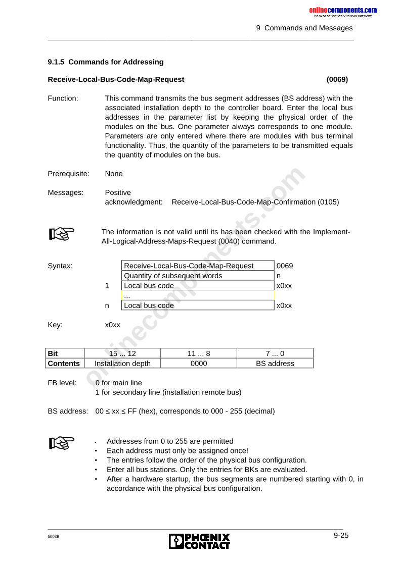
onlinec
omponen
ts.co
m
9 Commands and Messages
5003B 9-25
9.1.5 Commands for Addressing
Receive-Local-Bus-Code-Map-Request (0069)
Function: This command transmits the bus segment addresses (BS address) with theassociated installation depth to the controller board. Enter the local busaddresses in the parameter list by keeping the physical order of themodules on the bus. One parameter always corresponds to one module.Parameters are only entered where there are modules with bus terminalfunctionality. Thus, the quantity of the parameters to be transmitted equalsthe quantity of modules on the bus.
Prerequisite: None
Messages: Positiveacknowledgment: Receive-Local-Bus-Code-Map-Confirmation (0105)
Syntax: Receive-Local-Bus-Code-Map-Request 0069Quantity of subsequent words n
1 Local bus code x0xx...
n Local bus code x0xx
Key: x0xx
Bit 15 ... 12 11 ... 8 7 ... 0Contents Installation depth 0000 BS address
FB level: 0 for main line1 for secondary line (installation remote bus)
BS address: 00 ≤ xx ≤ FF (hex), corresponds to 000 - 255 (decimal)
The information is not valid until its has been checked with the Implement-All-Logical-Address-Maps-Request (0040) command.
• Addresses from 0 to 255 are permitted• Each address must only be assigned once!• The entries follow the order of the physical bus configuration.• Enter all bus stations. Only the entries for BKs are evaluated.• After a hardware startup, the bus segments are numbered starting with 0, in
accordance with the physical bus configuration.
onlinec
omponen
ts.co
m
9 Commands and Messages
9-26 5003B
Implement-All-Logical-Address-Maps-Request (0040)
Function:
Messages: Positiveacknowledgment: Quit-Implement-Confirmation (00d3)Meaning: The addresses are valid and have been accepted.Negativeacknowledgment: Logical-Address-Error-Confirmation (002b)Meaning: There are incorrect values in the lists to be
implemented (logical addresses). The data traffic onthe bus is stopped. The process output data is notswitched to a defined, safe state!
Send-Log-Address-Error-Request (005F)
Function: Request of the result of a command which has been executed before:• Implement-All-Logical-Address-Maps-Request (0040)• Check-Physical-Configuration-Request (0058)
Messages: Positiveacknowledgment: Send-Log-Address-Error-Confirmation (80F5)Meaning: The result is given with this message (see
Chapter 9.2).
The command may only be used when there are no data cycles on the bus!The lists with the addresses of the process data which have been sentbefore are checked and accepted if they are correct.
onlinec
omponen
ts.co
m
9 Commands and Messages
5003B 9-27
9.1.6 Commands for Process Data Linkage
Receive-Processing-Instructions-Request (005d)
Function: This command allows the bit manipulation of the process output dataconnected to the bus by means of programmable instructions which areautomatically executed by the controller board.
Messages: Positiveacknowledgment: Quit-Receive-Instructions-Confirmation (00F2)Meaning: There are no errors in the parameters. All listed
instructions have been accepted and are appendedto a possibly existing list.
Negativeacknowledgment: Processing-Instructions-Error-Confirmation (80F3)Meaning: There are errors in the parameters. The sent list must
not be accepted.
A memory of 1,000 entries is available for the instructions, because the instructions canhave a different number of entries. Up to
• 332 instructions with the instruction code 5 or 6,• 199 instructions with the instruction code 7 or 8
are possible.
Transfer the command lists before the INTERBUS-S system is started and -ifused- after the Implement-All-Logical-Address-Maps-Request command. Thebit manipulation must not be re-defined during operation and must not be usedin connection with the group definitions, because the process output data usedfor the bit manipulation might by reset.
Commands with invalid addresses are not executed. There will be no specialmessage for this case.Addresses (and therefore instructions) become invalid with• logical addressing, if previously used addresses do no longer exist, or• switched off groups, if the address is in the area of the disconnected
group.
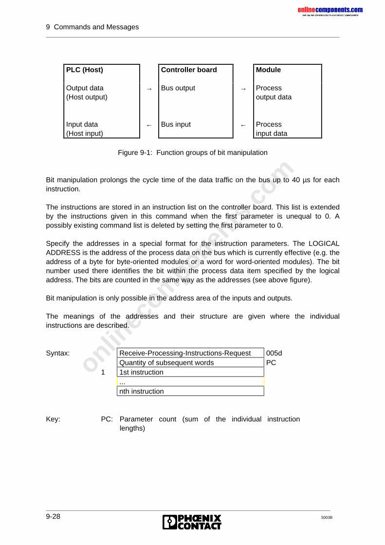
onlinec
omponen
ts.co
m
9 Commands and Messages
9-28 5003B
Figure 9-1: Function groups of bit manipulation
Bit manipulation prolongs the cycle time of the data traffic on the bus up to 40 µs for eachinstruction.
The instructions are stored in an instruction list on the controller board. This list is extendedby the instructions given in this command when the first parameter is unequal to 0. Apossibly existing command list is deleted by setting the first parameter to 0.
Specify the addresses in a special format for the instruction parameters. The LOGICALADDRESS is the address of the process data on the bus which is currently effective (e.g. theaddress of a byte for byte-oriented modules or a word for word-oriented modules). The bitnumber used there identifies the bit within the process data item specified by the logicaladdress. The bits are counted in the same way as the addresses (see above figure).
Bit manipulation is only possible in the address area of the inputs and outputs.
The meanings of the addresses and their structure are given where the individualinstructions are described.
Syntax: Receive-Processing-Instructions-Request 005dQuantity of subsequent words PC
1 1st instruction...nth instruction
Key: PC: Parameter count (sum of the individual instructionlengths)
PLC (Host) Controller board Module
Output data(Host output)
Input data(Host input)
→
←
Bus output
Bus input
→
←
Processoutput data
Processinput data
onlinec
omponen
ts.co
m
9 Commands and Messages
5003B 9-29
General structure of an instruction
Syntax: 1 Instruction code2 1st instruction parameter
...m mth instruction parameter
General function of all instructions
The instructions control determinable bits of the process output data (bus output bit) takinginto account determinable bits of the process input data (bus input bit) and output data (hostoutput data) written by the PLC (host).
Specify the address of the bus output bit in the OUTPUT ADDRESS parameter and theaddress of the bus input parameter in the INPUT ADDRESS parameter. Depending on afreely selectable edge of the bus input bit, the bus output bit 0 is reset.
General function of the RESET instructions:
The bus output bit is reset after the edge of the bus input bit has been reset (section 2 in thefigure). The command determines the evaluation of the bus input bit. The bus output bit isset by setting the host output bit (sections 1 and 3 in the figure). As long as the bus outputbit is not reset upon evaluation of the bus input bit, the bus output bit is only determined bythe host output bit (sections 1 and 3 in the figure).
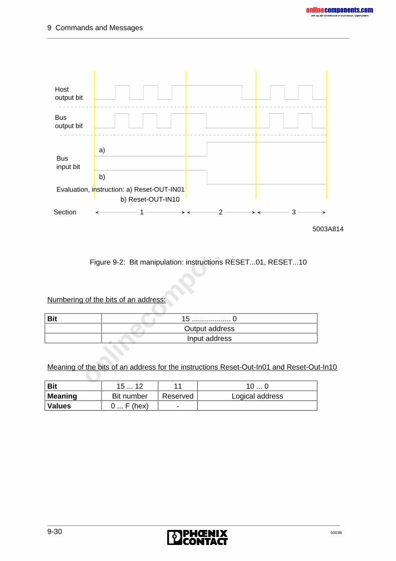
onlinec
omponen
ts.co
m
9 Commands and Messages
9-30 5003B
Figure 9-2: Bit manipulation: instructions RESET...01, RESET...10
Numbering of the bits of an address:
Bit 15 ................... 0Output addressInput address
Meaning of the bits of an address for the instructions Reset-Out-In01 and Reset-Out-In10
Bit 15 ... 12 11 10 ... 0Meaning Bit number Reserved Logical addressValues 0 ... F (hex) -
1 2
3
Businput bit
Evaluation, instruction: a) Reset-OUT-IN01
a)
b)
b) Reset-OUT-IN10
5003A814
Section
Hostoutput bit
Bus output bit
onlinec
omponen
ts.co
m
9 Commands and Messages
5003B 9-31
Structure of the Reset-Out-In01 instruction
Syntax: 1 Reset-Out-In01 00052 Output address3 Input address
Structure of the Reset-Out-In10 instruction
Syntax: 1 Reset-Out-In10 00062 Output address3 Input address
Structure of the Reset 2-Out-In01 instruction
Syntax: 1 Reset2-Out-In01 00072 Output address3 Bit number for the output address B4 Input address5 Bit number for the input address B
Key: B: Bit number, 0000 hex to 000F hex
Structure of the Reset2-Out-In10 instruction
Syntax: 1 Reset2-Out-In10 00082 Output address3 Bit number for the output address B4 Input address5 Bit number for the input address B
Key: B: Bit number, 0000 hex to 000F hex
Function of the Reset 2-Out-In10 and Reset 2-Out-In 01 instructions
The instructions Reset 2-Out-In01 and Reset 2-Out-In10 have the same functions as theinstructions Reset-Out-In01 and Reset-Out-In10. The instruction format is 5 words long sothat 16 bit addresses are available.
onlinec
omponen
ts.co
m
9 Commands and Messages
9-32 5003B
Structure of the Reset-Out-In01-Switch (0009) instruction
Syntax: 1 Reset-Out-In01-Switch 00092 Address of the bit manipulation register3 Bit number of the bit manipulation register B4 Output address5 Bit number for the output address B6 Input address7 Bit number for the input address B
Key: B: Bit number, 0000 hex to 000F hex
Structure of the Reset-Out-In10-Switch (000A) instruction
Syntax: 1 Reset-Out-In10-Switch 000A2 Address of the bit manipulation register3 Bit number of the bit manipulation register B4 Output address5 Bit number for the output address B6 Input address7 Bit number for the input address B
Key: B: Bit number, 0000 hex to 000F hex
Function of the Reset-Out-In01-Switch and Reset-Out-In10-Switch instructions
The instructions Reset-Out-In01-Switch and Reset-Out-In10-Switch have the same functionas the previous instructions, however with the difference that the specified bit of the bitmanipulation register is additionally tested. If this bit is 0, the respective instruction is noteffective.Several bit manipulation registers may be defined. Bit manipulation registers are addressedby defining a "pseudo module" (ID code 0013h) as the last module of the configuration usingthe "Check-Physical-Configuration-Request" service. Afterwards this module is assigned theaddress of the bit manipulation register using the logical addressing.
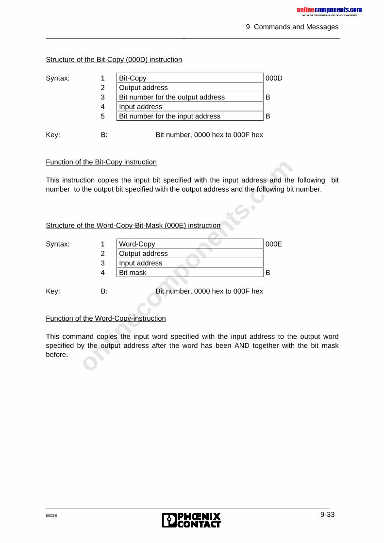
onlinec
omponen
ts.co
m
9 Commands and Messages
5003B 9-33
Structure of the Bit-Copy (000D) instruction
Syntax: 1 Bit-Copy 000D2 Output address3 Bit number for the output address B4 Input address5 Bit number for the input address B
Key: B: Bit number, 0000 hex to 000F hex
Function of the Bit-Copy instruction
This instruction copies the input bit specified with the input address and the following bitnumber to the output bit specified with the output address and the following bit number.
Structure of the Word-Copy-Bit-Mask (000E) instruction
Syntax: 1 Word-Copy 000E2 Output address3 Input address4 Bit mask B
Key: B: Bit number, 0000 hex to 000F hex
Function of the Word-Copy-instruction
This command copies the input word specified with the input address to the output wordspecified by the output address after the word has been AND together with the bit maskbefore.
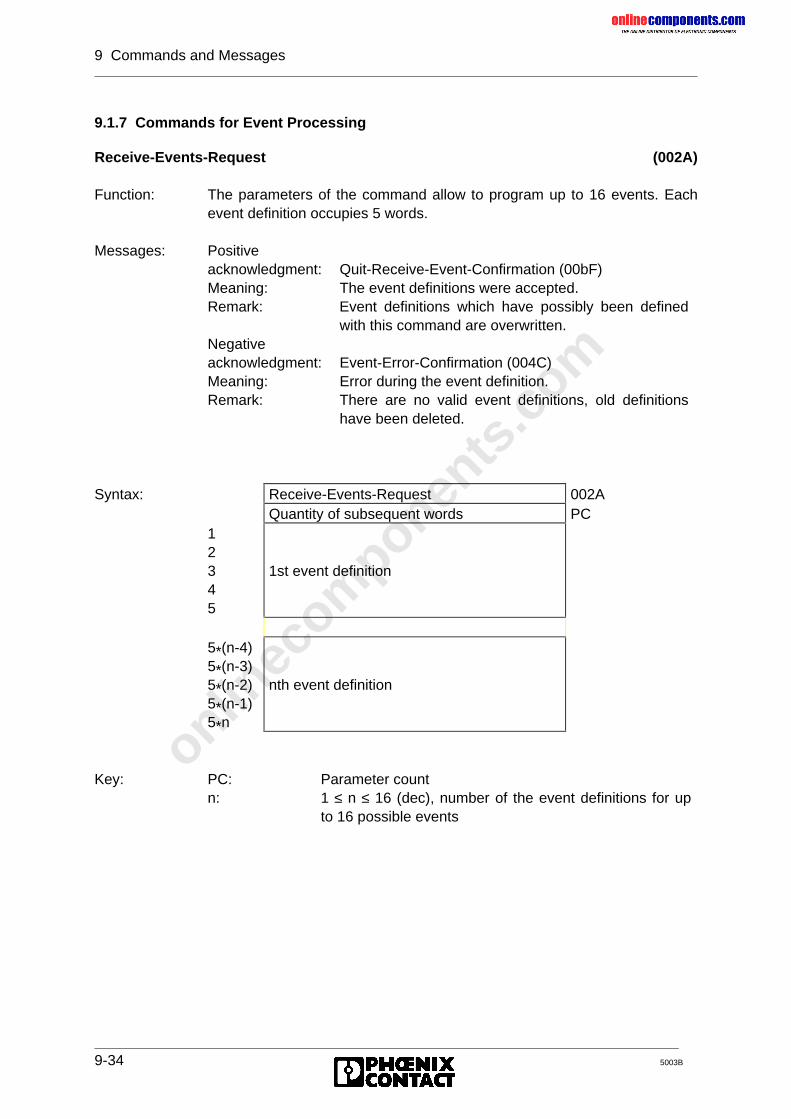
onlinec
omponen
ts.co
m
9 Commands and Messages
9-34 5003B
9.1.7 Commands for Event Processing
Receive-Events-Request (002A)
Function: The parameters of the command allow to program up to 16 events. Eachevent definition occupies 5 words.
Messages: Positiveacknowledgment: Quit-Receive-Event-Confirmation (00bF)Meaning: The event definitions were accepted.Remark: Event definitions which have possibly been defined
with this command are overwritten.Negativeacknowledgment: Event-Error-Confirmation (004C)Meaning: Error during the event definition.Remark: There are no valid event definitions, old definitions
have been deleted.
Syntax: Receive-Events-Request 002AQuantity of subsequent words PC
12345
1st event definition
5*(n-4)5*(n-3)5*(n-2)5*(n-1)5*n
nth event definition
Key: PC:n:
Parameter count1 ≤ n ≤ 16 (dec), number of the event definitions for upto 16 possible events
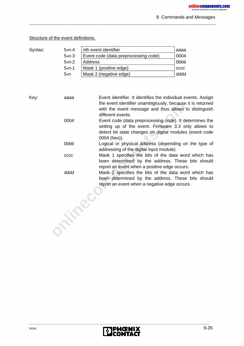
onlinec
omponen
ts.co
m
9 Commands and Messages
5003B 9-35
Structure of the event definitions:
Syntax: 5*n-4 nth event identifier aaaa5*n-3 Event code (data preprocessing code) 00045*n-2 Address 0bbb5*n-1 Mask 1 (positive edge) cccc5*n Mask 2 (negative edge) dddd
Key: aaaa Event identifier. It identifies the individual events. Assignthe event identifier unambigiously, because it is returnedwith the event message and thus allows to distinguishdifferent events.
0004 Event code (data preprocessing code). It determines thesetting up of the event. Firmware 3.3 only allows todetect bit state changes on digital modules (event code0004 (hex)).
0bbb Logical or physical address (depending on the type ofaddressing of the digital input module)
cccc Mask 1 specifies the bits of the data word which hasbeen determined by the address. These bits shouldreport an event when a positive edge occurs.
dddd Mask 2 specifies the bits of the data word which hasbeen determined by the address. These bits shouldreport an event when a negative edge occurs.
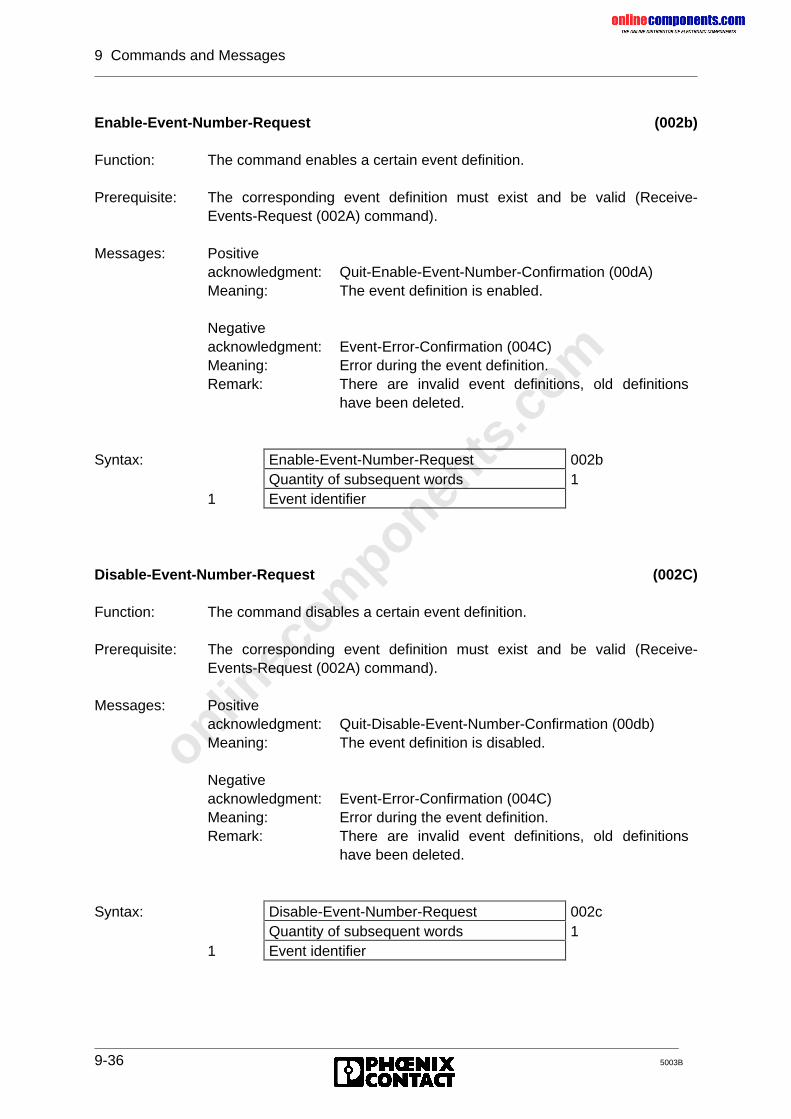
onlinec
omponen
ts.co
m
9 Commands and Messages
9-36 5003B
Enable-Event-Number-Request (002b)
Function: The command enables a certain event definition.
Prerequisite: The corresponding event definition must exist and be valid (Receive-Events-Request (002A) command).
Messages: Positiveacknowledgment: Quit-Enable-Event-Number-Confirmation (00dA)Meaning: The event definition is enabled.
Negativeacknowledgment: Event-Error-Confirmation (004C)Meaning: Error during the event definition.Remark: There are invalid event definitions, old definitions
have been deleted.
Syntax: Enable-Event-Number-Request 002bQuantity of subsequent words 1
1 Event identifier
Disable-Event-Number-Request (002C)
Function: The command disables a certain event definition.
Prerequisite: The corresponding event definition must exist and be valid (Receive-Events-Request (002A) command).
Messages: Positiveacknowledgment: Quit-Disable-Event-Number-Confirmation (00db)Meaning: The event definition is disabled.
Negativeacknowledgment: Event-Error-Confirmation (004C)Meaning: Error during the event definition.Remark: There are invalid event definitions, old definitions
have been deleted.
Syntax: Disable-Event-Number-Request 002cQuantity of subsequent words 1
1 Event identifier
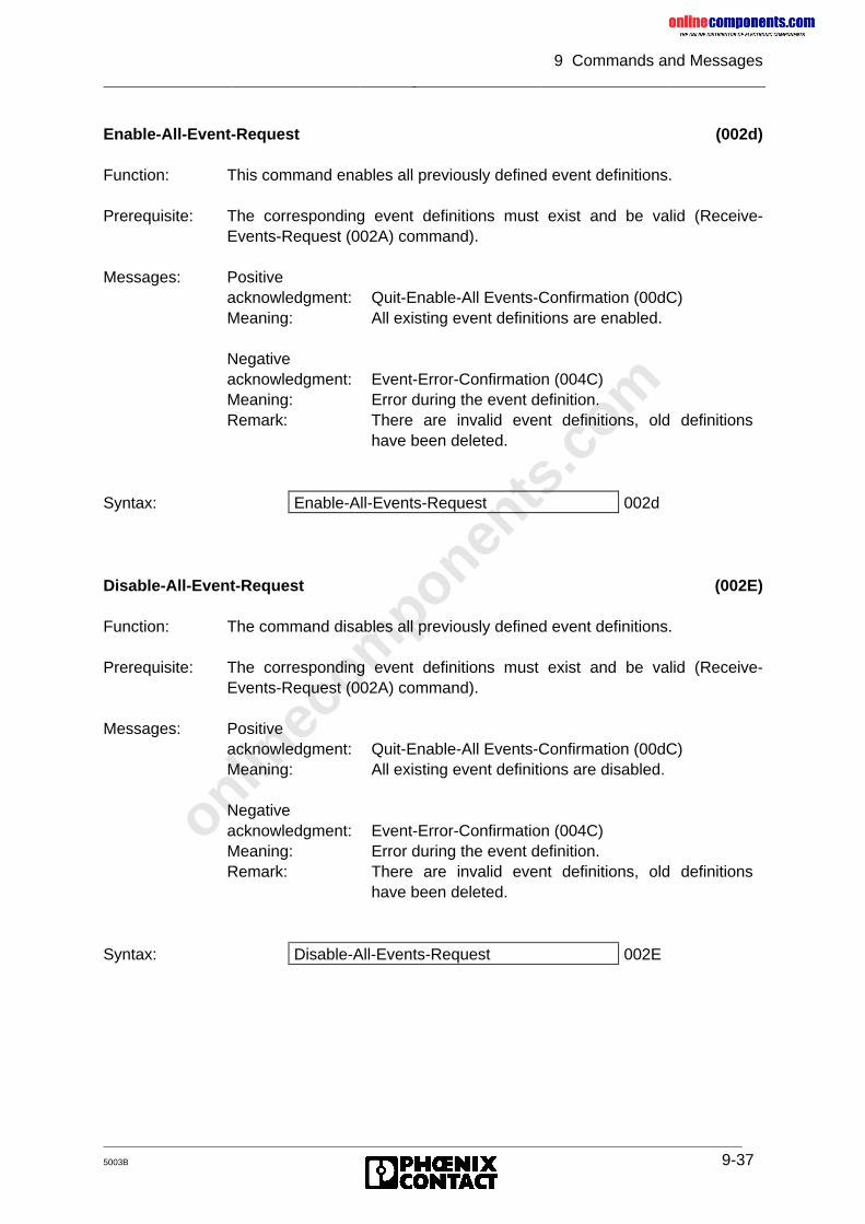
onlinec
omponen
ts.co
m
9 Commands and Messages
5003B 9-37
Enable-All-Event-Request (002d)
Function: This command enables all previously defined event definitions.
Prerequisite: The corresponding event definitions must exist and be valid (Receive-Events-Request (002A) command).
Messages: Positiveacknowledgment: Quit-Enable-All Events-Confirmation (00dC)Meaning: All existing event definitions are enabled.
Negativeacknowledgment: Event-Error-Confirmation (004C)Meaning: Error during the event definition.Remark: There are invalid event definitions, old definitions
have been deleted.
Syntax: Enable-All-Events-Request 002d
Disable-All-Event-Request (002E)
Function: The command disables all previously defined event definitions.
Prerequisite: The corresponding event definitions must exist and be valid (Receive-Events-Request (002A) command).
Messages: Positiveacknowledgment: Quit-Enable-All Events-Confirmation (00dC)Meaning: All existing event definitions are disabled.
Negativeacknowledgment: Event-Error-Confirmation (004C)Meaning: Error during the event definition.Remark: There are invalid event definitions, old definitions
have been deleted.
Syntax: Disable-All-Events-Request 002E
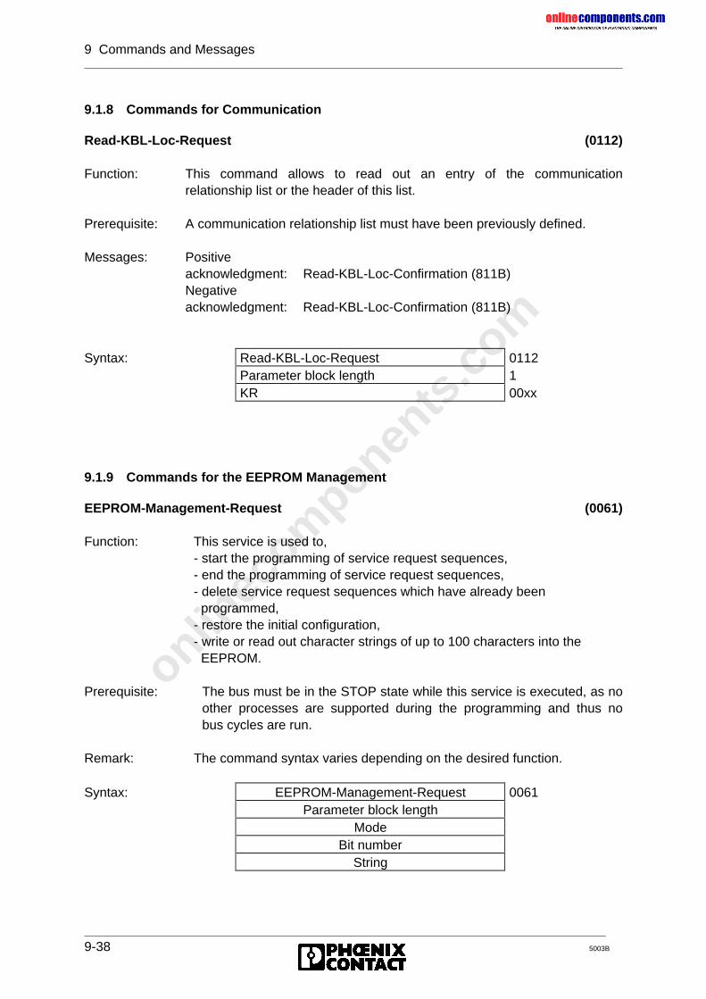
onlinec
omponen
ts.co
m
9 Commands and Messages
9-38 5003B
9.1.8 Commands for Communication
Read-KBL-Loc-Request (0112)
Function: This command allows to read out an entry of the communicationrelationship list or the header of this list.
Prerequisite: A communication relationship list must have been previously defined.
Messages: Positiveacknowledgment: Read-KBL-Loc-Confirmation (811B)Negativeacknowledgment: Read-KBL-Loc-Confirmation (811B)
Syntax: Read-KBL-Loc-Request 0112Parameter block length 1KR 00xx
9.1.9 Commands for the EEPROM Management
EEPROM-Management-Request (0061)
Function: This service is used to,- start the programming of service request sequences,- end the programming of service request sequences,- delete service request sequences which have already been programmed,- restore the initial configuration,- write or read out character strings of up to 100 characters into the EEPROM.
Prerequisite: The bus must be in the STOP state while this service is executed, as noother processes are supported during the programming and thus nobus cycles are run.
Remark: The command syntax varies depending on the desired function.
Syntax: EEPROM-Management-Request 0061Parameter block length
ModeBit number
String
onlinec
omponen
ts.co
m
9 Commands and Messages
5003B 9-39
Parameter description:Mode: This parameter controls the programming.
Possible modes are:1 - Start programming2 - End programming3 - Delete programmed service request sequences4 - Establish default state5 - Write character string6 - Read out character string
Bit number: This parameter is only relevant for mode 1. It indicates with which bit numberthe service sequence to be programmed can be activated. Value range: 0-15
String: In the service request primitive, this parameter is only relevant for mode 5 . Itincludes the character string to be written with the maximum length of 100.Characters which are not used are filled up internally with zeros.In the service confirmation primitive this parameter is only relevant for mode6.It includes the read out character string of the maximum length of 100.
Remark: The character string stored in the EEPROM cannot be cleared with mode 3.
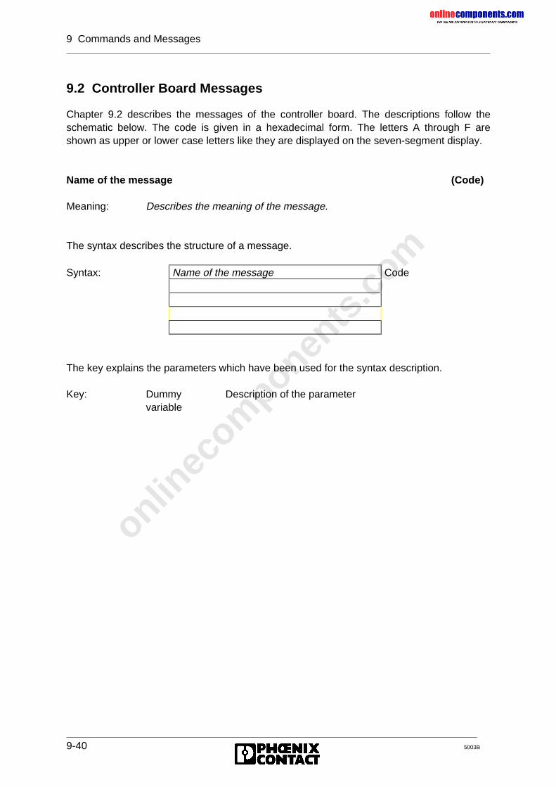
onlinec
omponen
ts.co
m
9 Commands and Messages
9-40 5003B
9.2 Controller Board Messages
Chapter 9.2 describes the messages of the controller board. The descriptions follow theschematic below. The code is given in a hexadecimal form. The letters A through F areshown as upper or lower case letters like they are displayed on the seven-segment display.
Name of the message (Code)
Meaning: Describes the meaning of the message.
The syntax describes the structure of a message.
Syntax: Name of the message Code
The key explains the parameters which have been used for the syntax description.
Key: Dummyvariable
Description of the parameter
onlinec
omponen
ts.co
m
9 Commands and Messages
5003B 9-41
9.2.1 Messages of the User Interface
Command-Disabled-Confirmation (009C)
Meaning: The previously sent command has not been enabled.
A description of the following messages is given in Chapter 4.
No-Command-Code-Indication (0007)
Parameter-Write-Error-Indication (0009)
Controller-Parameter-Timeout-Indication (000C)
Host-Parameter-Timeout-Indication (000d)
Command-Parameter-Error (004b)
9.2.2 Messages for Bus Operation
Start-Bus-Confirmation (0088)
Meaning: The data cycle of the bus has been started. From this point in time, thecontroller board operates the process data channel and the PCP channel, ifnecessary.
Process data: Cyclic preparation of the process input data image of the modules for thePLC. Cyclic transfer process output data from the PLC to the modulesconnected to the bus.
PCP channel: Operation of the Peripherals Communication Protocol for modules withintegrated PCP.
These messages are displayed with a CTRL error on the front plate andentered in the diagnostic registers.
For group definitions and defective local bus or installation remote bussegments the bus is run without the defective and switched off segment.The BSA LED is then illuminated.
onlinec
omponen
ts.co
m
9 Commands and Messages
9-42 5003B
Stop-Bus-Confirmation (00C6)
Meaning: The process data and the possibly used PCP channel are not operated anylonger.
Process data: • The cyclic data traffic on the bus is stopped. The existing process dataimage of the modules connected to the bus is statically kept and is notrenewed.
• The process output data can only be changed to the safe state bymeans of the Alarm-Stop-Request (004A) command (resetting of theoutputs).
PCP channel: • The Peripherals Communication Protocol (PCP) is not used further.• The established connections are not automatically aborted. Possibly
pending services are not processed until the data traffic is startedagain.
Quit-Alarm-Stop-Confirmation (00d8)
Meaning: The Alarm-Stop-Request (004A) command was successfully executed.
Start-Bus-Not-Possible-Confirmation (00E3)
Meaning: This is a negative acknowledgment of the Start-Bus-Cycle-Request (0001)command. It is sent if no data traffic operation is possible.
Cause: • Hardware error on the controller board.• All groups are switched off.• Configuration change in the remote bus.
onlinec
omponen
ts.co
m
9 Commands and Messages
5003B 9-43
9.2.3 Messages for Configuration
Send-Physical-Configuration-Confirmation (80F4)
Meaning: Positive acknowledgment of the Send-Physical-Configuration-Request(005E).
Syntax: Send-Physical-Configuration-Request 80F4Quantity of subsequent words PC
1 Bus register ID code rrii...
n Bus register ID code rrii15 0
Key: PC:rrii:ID code
Parameter count (quantity of the connected modules)Number of registers 0 ≤ rr ≤ 127.0 ≤ ii ≤ FF (hex), corresponds to 000 - 255 (decimal)
The parameters 1 to n provide information on the physical bus configuration.
The BUS REGISTER parameter gives the number of registers (bus registers) used for theprocess data on the bus. The number is always given in accordance with the data type of theregisters. With byte-oriented modules bit 15 is set to 1.
The ID NUMBER parameter gives the identification code of the connected modules in theorder of the module installation.
Example: A byte-oriented module with 2 bytes has two bus registers. A module withtwo words has also two registers.
Syntax: 80F4 hex0003 hex
(1) 01 dec (01 hex) 129 dec (81 hex)(2) 04 hex (04 hex) 67 dec (43 hex)(3) 01 hex (01 hex) 207 dec (CF hex)
1 IBS 24 DO, 1 data word2 IBS AI, 4 data words3 IBS AI 3/16, 1 data word4 IBS IP CDO 1 data byte
The bus register number of communication modules only includes the number of the processdata words.
onlinec
omponen
ts.co
m
9 Commands and Messages
9-44 5003B
Quit-Configure-Bus-Confirmation (00CA)
Meaning: The Configure-Bus-Request (0023) command was executed.
Physical-Configuration-Map-Valid-Confirmation (00Ab)
Meaning: The bus configuration which has been communicated to the controllerboard by means of the Receive-Physical-Configuration-Map-Requestcommand are not identical with the connected configuration.
Quit-Receive-Group-Numbers-Confirmation (00bd)
Meaning: The Receive-Group-Numbers-Request (0049) command was successfullyexecuted.
Switch-Group-On-Confirmation (809E)
Meaning: A group of bus segments was switched on. The number of group whichwas switched on is given as a parameter.
Syntax: Switch-Group-On-Confirmation 809EQuantity of subsequent words 1
1 Group number of the switched on group
Switch-Group-On-Failed-Confirmation (80C5)
Meaning: The attempt to switch on a group was not successful. The group number isgiven as a parameter.
Syntax: Switch-Group-On-Failed-Confirmation 80C5Quantity of subsequent words 1
1 Group number
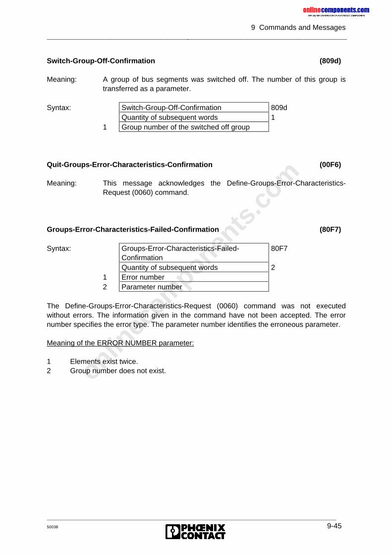
onlinec
omponen
ts.co
m
9 Commands and Messages
5003B 9-45
Switch-Group-Off-Confirmation (809d)
Meaning: A group of bus segments was switched off. The number of this group istransferred as a parameter.
Syntax: Switch-Group-Off-Confirmation 809dQuantity of subsequent words 1
1 Group number of the switched off group
Quit-Groups-Error-Characteristics-Confirmation (00F6)
Meaning: This message acknowledges the Define-Groups-Error-Characteristics-Request (0060) command.
Groups-Error-Characteristics-Failed-Confirmation (80F7)
Syntax: Groups-Error-Characteristics-Failed-Confirmation
80F7
Quantity of subsequent words 21 Error number2 Parameter number
The Define-Groups-Error-Characteristics-Request (0060) command was not executedwithout errors. The information given in the command have not been accepted. The errornumber specifies the error type. The parameter number identifies the erroneous parameter.
Meaning of the ERROR NUMBER parameter:
1 Elements exist twice.2 Group number does not exist.
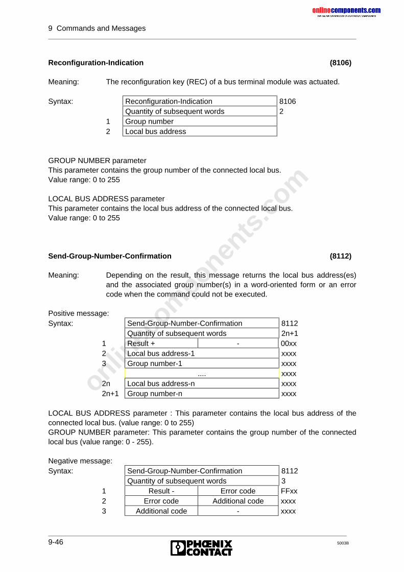
onlinec
omponen
ts.co
m
9 Commands and Messages
9-46 5003B
Reconfiguration-Indication (8106)
Meaning: The reconfiguration key (REC) of a bus terminal module was actuated.
Syntax: Reconfiguration-Indication 8106Quantity of subsequent words 2
1 Group number2 Local bus address
GROUP NUMBER parameterThis parameter contains the group number of the connected local bus.Value range: 0 to 255
LOCAL BUS ADDRESS parameterThis parameter contains the local bus address of the connected local bus.Value range: 0 to 255
Send-Group-Number-Confirmation (8112)
Meaning: Depending on the result, this message returns the local bus address(es)and the associated group number(s) in a word-oriented form or an errorcode when the command could not be executed.
Positive message:Syntax: Send-Group-Number-Confirmation 8112
Quantity of subsequent words 2n+11 Result + - 00xx2 Local bus address-1 xxxx3 Group number-1 xxxx
.... xxxx2n Local bus address-n xxxx2n+1 Group number-n xxxx
LOCAL BUS ADDRESS parameter : This parameter contains the local bus address of theconnected local bus. (value range: 0 to 255)GROUP NUMBER parameter: This parameter contains the group number of the connectedlocal bus (value range: 0 - 255).
Negative message:Syntax: Send-Group-Number-Confirmation 8112
Quantity of subsequent words 31 Result - Error code FFxx2 Error code Additional code xxxx3 Additional code - xxxx
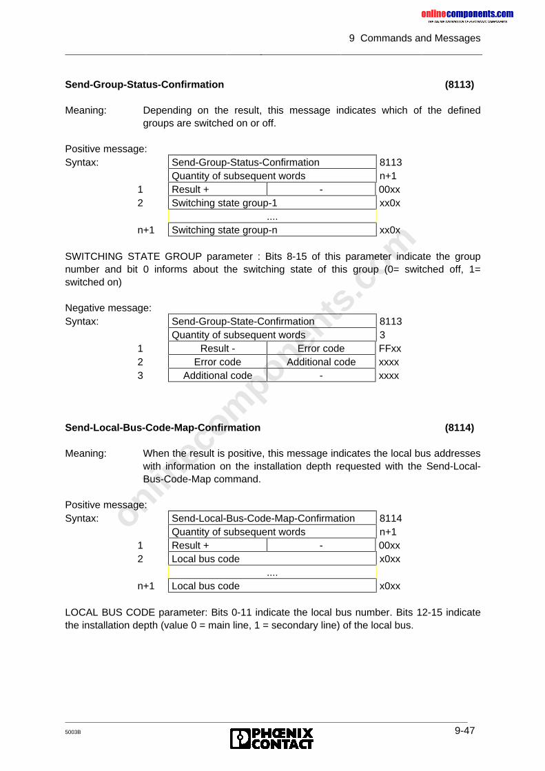
onlinec
omponen
ts.co
m
9 Commands and Messages
5003B 9-47
Send-Group-Status-Confirmation (8113)
Meaning: Depending on the result, this message indicates which of the definedgroups are switched on or off.
Positive message:Syntax: Send-Group-Status-Confirmation 8113
Quantity of subsequent words n+11 Result + - 00xx2 Switching state group-1 xx0x
....n+1 Switching state group-n xx0x
SWITCHING STATE GROUP parameter : Bits 8-15 of this parameter indicate the groupnumber and bit 0 informs about the switching state of this group (0= switched off, 1=switched on)
Negative message:Syntax: Send-Group-State-Confirmation 8113
Quantity of subsequent words 31 Result - Error code FFxx2 Error code Additional code xxxx3 Additional code - xxxx
Send-Local-Bus-Code-Map-Confirmation (8114)
Meaning: When the result is positive, this message indicates the local bus addresseswith information on the installation depth requested with the Send-Local-Bus-Code-Map command.
Positive message:Syntax: Send-Local-Bus-Code-Map-Confirmation 8114
Quantity of subsequent words n+11 Result + - 00xx2 Local bus code x0xx
....n+1 Local bus code x0xx
LOCAL BUS CODE parameter: Bits 0-11 indicate the local bus number. Bits 12-15 indicatethe installation depth (value 0 = main line, 1 = secondary line) of the local bus.
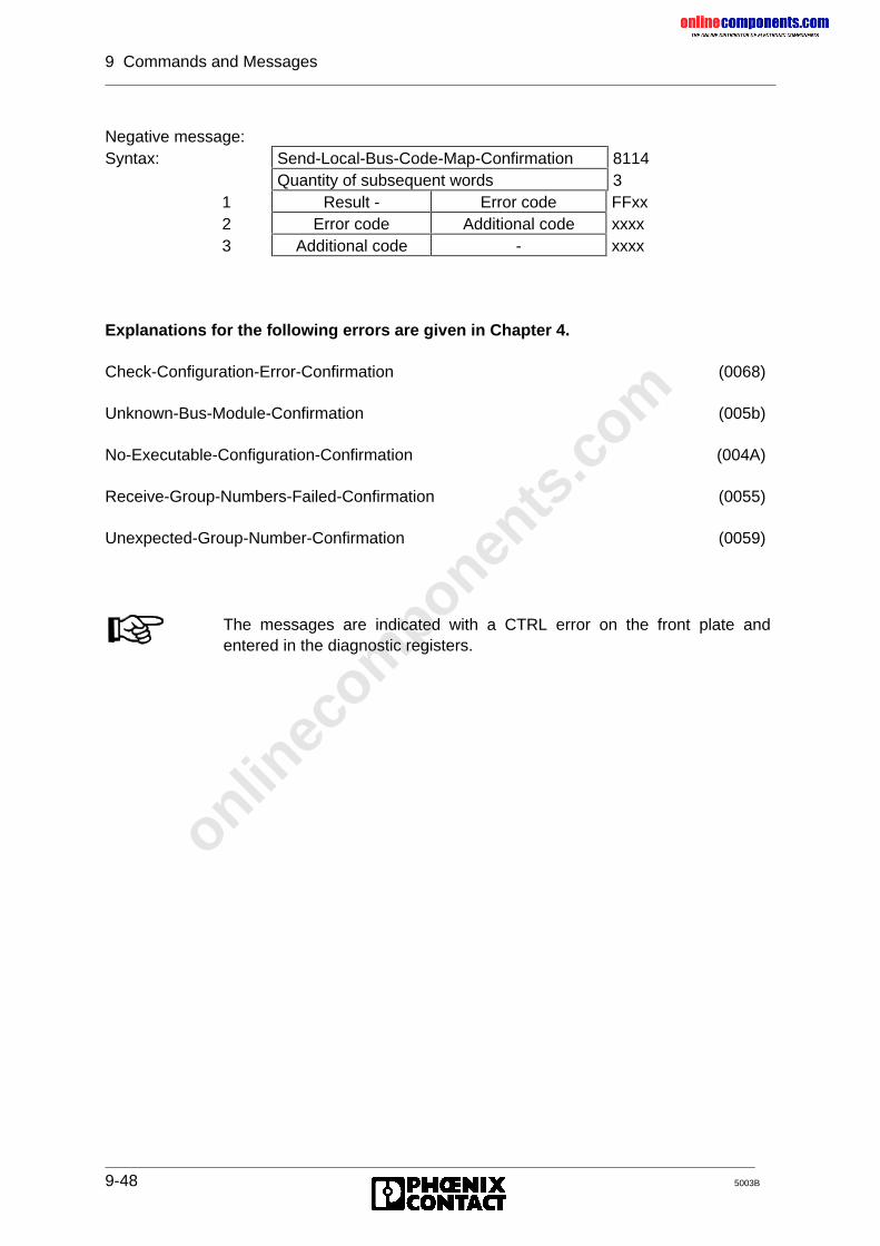
onlinec
omponen
ts.co
m
9 Commands and Messages
9-48 5003B
Negative message:Syntax: Send-Local-Bus-Code-Map-Confirmation 8114
Quantity of subsequent words 31 Result - Error code FFxx2 Error code Additional code xxxx3 Additional code - xxxx
Explanations for the following errors are given in Chapter 4.
Check-Configuration-Error-Confirmation (0068)
Unknown-Bus-Module-Confirmation (005b)
No-Executable-Configuration-Confirmation (004A)
Receive-Group-Numbers-Failed-Confirmation (0055)
Unexpected-Group-Number-Confirmation (0059)
The messages are indicated with a CTRL error on the front plate andentered in the diagnostic registers.
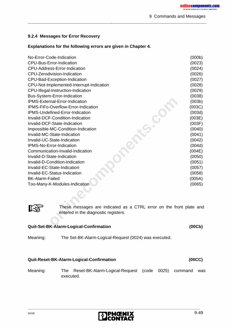
onlinec
omponen
ts.co
m
9 Commands and Messages
5003B 9-49
9.2.4 Messages for Error Recovery
Explanations for the following errors are given in Chapter 4.
No-Error-Code-Indication (000b)CPU-Bus-Error-Indication (0023)CPU-Address-Error-Indication (0024)CPU-Zerodivision-Indication (0026)CPU-Bad-Exception-Indication (0027)CPU-Not-Implemented-Interrupt-Indication (0028)CPU-Illegal-Instruction-Indication (0029)Bus-System-Error-Indication (0038)IPMS-External-Error-Indication (003b)IPMS-FiFo-Overflow-Error-Indication (003C)IPMS-Undefined-Error-Indication (003d)Invalid-DCF-Condition-Indication (003E)Invalid-DCF-State-Indication (003F)Impossible-MC-Condition-Indication (0040)Invalid-MC-State-Indication (0041)Invalid-UC-State-Indication (0042)IPMS-No-Error-Indication (004d)Communication-Invalid-Indication (004E)Invalid-D-State-Indication (0050)Invalid-D-Condition-Indication (0051)Invalid-EC-State-Indication (0057)Invalid-EC-Status-Indication (0058)BK-Alarm-Failed (005A)Too-Many-K-Modules-Indication (0065)
Quit-Set-BK-Alarm-Logical-Confirmation (00Cb)
Meaning: The Set-BK-Alarm-Logical-Request (0024) was executed.
Quit-Reset-BK-Alarm-Logical-Confirmation (00CC)
Meaning: The Reset-BK-Alarm-Logical-Request (code 0025) command wasexecuted.
These messages are indicated as a CTRL error on the front plate andentered in the diagnostic registers.
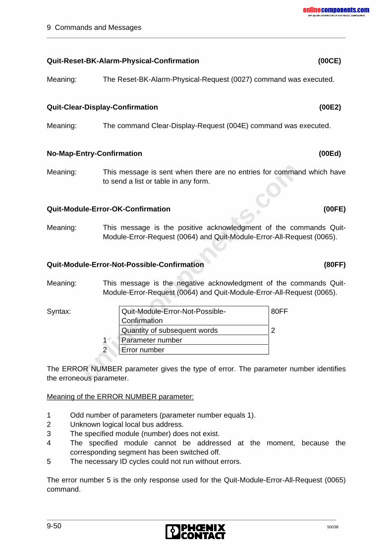
onlinec
omponen
ts.co
m
9 Commands and Messages
9-50 5003B
Quit-Reset-BK-Alarm-Physical-Confirmation (00CE)
Meaning: The Reset-BK-Alarm-Physical-Request (0027) command was executed.
Quit-Clear-Display-Confirmation (00E2)
Meaning: The command Clear-Display-Request (004E) command was executed.
No-Map-Entry-Confirmation (00Ed)
Meaning: This message is sent when there are no entries for command which haveto send a list or table in any form.
Quit-Module-Error-OK-Confirmation (00FE)
Meaning: This message is the positive acknowledgment of the commands Quit-Module-Error-Request (0064) and Quit-Module-Error-All-Request (0065).
Quit-Module-Error-Not-Possible-Confirmation (80FF)
Meaning: This message is the negative acknowledgment of the commands Quit-Module-Error-Request (0064) and Quit-Module-Error-All-Request (0065).
Syntax: Quit-Module-Error-Not-Possible-Confirmation
80FF
Quantity of subsequent words 21 Parameter number2 Error number
The ERROR NUMBER parameter gives the type of error. The parameter number identifiesthe erroneous parameter.
Meaning of the ERROR NUMBER parameter:
1 Odd number of parameters (parameter number equals 1).2 Unknown logical local bus address.3 The specified module (number) does not exist.4 The specified module cannot be addressed at the moment, because the
corresponding segment has been switched off.5 The necessary ID cycles could not run without errors.
The error number 5 is the only response used for the Quit-Module-Error-All-Request (0065)command.
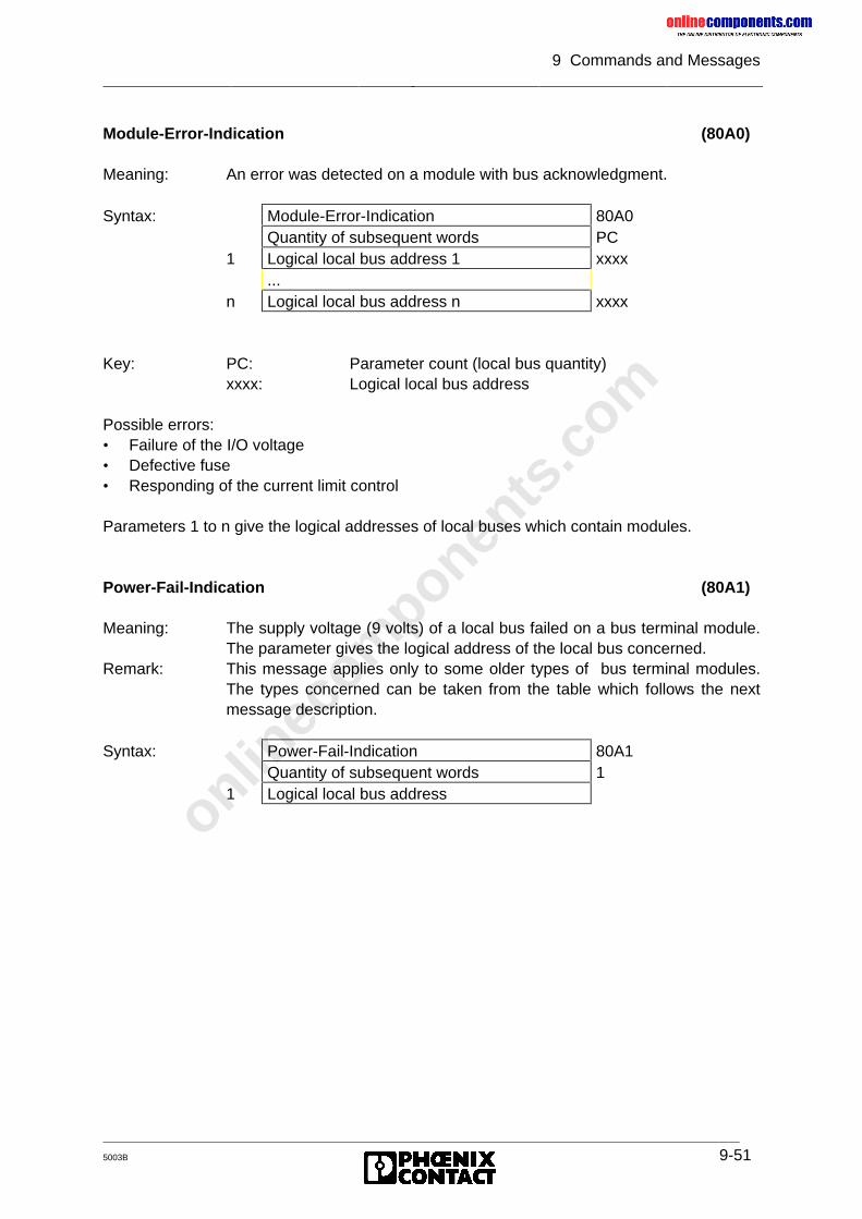
onlinec
omponen
ts.co
m
9 Commands and Messages
5003B 9-51
Module-Error-Indication (80A0)
Meaning: An error was detected on a module with bus acknowledgment.
Syntax: Module-Error-Indication 80A0Quantity of subsequent words PC
1 Logical local bus address 1 xxxx...
n Logical local bus address n xxxx
Key: PC: Parameter count (local bus quantity)xxxx: Logical local bus address
Possible errors:• Failure of the I/O voltage• Defective fuse• Responding of the current limit control
Parameters 1 to n give the logical addresses of local buses which contain modules.
Power-Fail-Indication (80A1)
Meaning: The supply voltage (9 volts) of a local bus failed on a bus terminal module.The parameter gives the logical address of the local bus concerned.
Remark: This message applies only to some older types of bus terminal modules.The types concerned can be taken from the table which follows the nextmessage description.
Syntax: Power-Fail-Indication 80A1Quantity of subsequent words 1
1 Logical local bus address
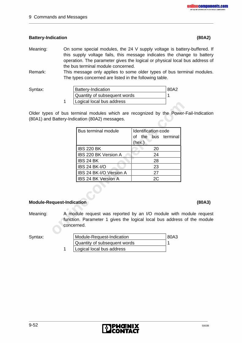
onlinec
omponen
ts.co
m
9 Commands and Messages
9-52 5003B
Battery-Indication (80A2)
Meaning: On some special modules, the 24 V supply voltage is battery-buffered. Ifthis supply voltage fails, this message indicates the change to batteryoperation. The parameter gives the logical or physical local bus address ofthe bus terminal module concerned.
Remark: This message only applies to some older types of bus terminal modules.The types concerned are listed in the following table.
Syntax: Battery-Indication 80A2Quantity of subsequent words 1
1 Logical local bus address
Older types of bus terminal modules which are recognized by the Power-Fail-Indication(80A1) and Battery-Indication (80A2) messages.
Bus terminal module Identification codeof the bus terminal(hex.)
IBS 220 BK 20IBS 220 BK Version A 24IBS 24 BK 28IBS 24 BK-I/O 23IBS 24 BK-I/O Version A 27IBS 24 BK Version A 2C
Module-Request-Indication (80A3)
Meaning: A module request was reported by an I/O module with module requestfunction. Parameter 1 gives the logical local bus address of the moduleconcerned.
Syntax: Module-Request-Indication 80A3Quantity of subsequent words 1
1 Logical local bus address
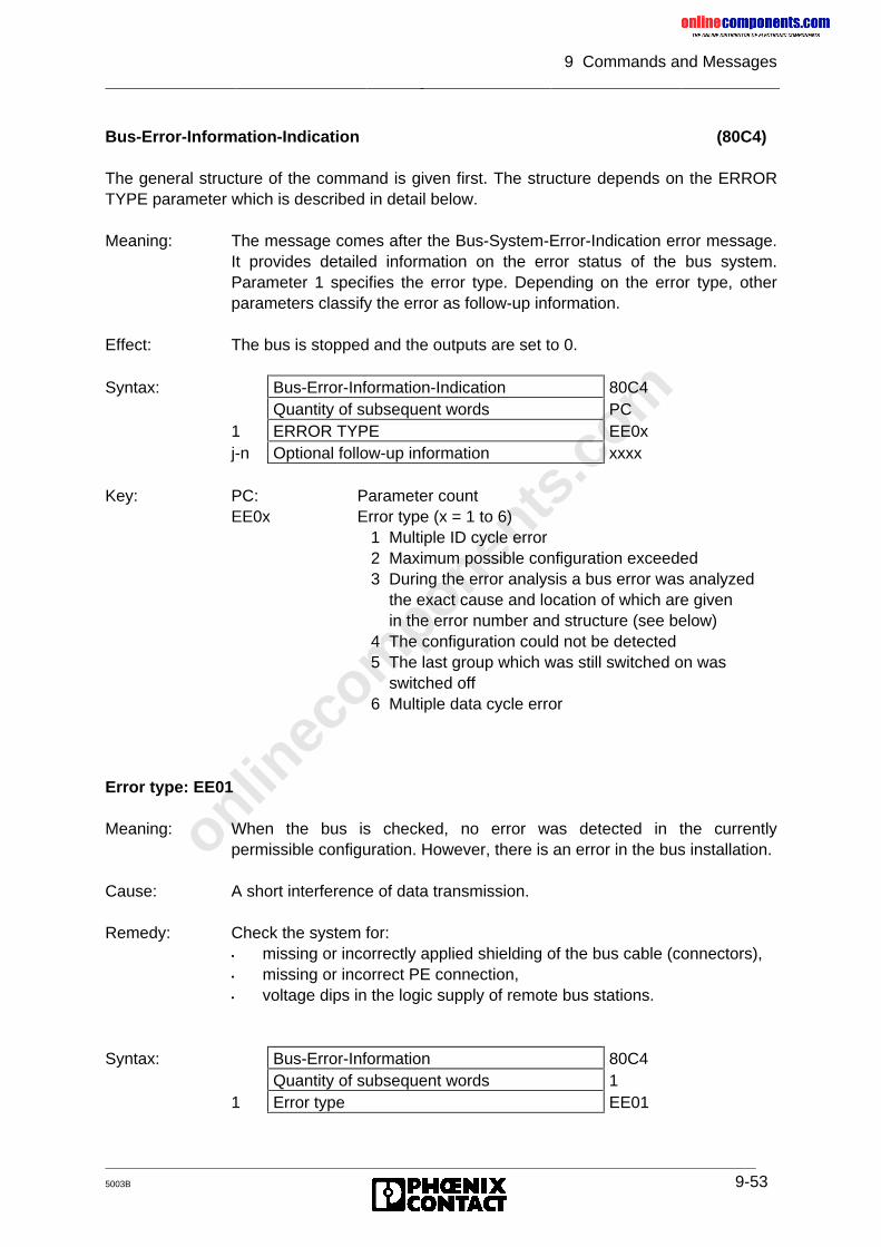
onlinec
omponen
ts.co
m
9 Commands and Messages
5003B 9-53
Bus-Error-Information-Indication (80C4)
The general structure of the command is given first. The structure depends on the ERRORTYPE parameter which is described in detail below.
Meaning: The message comes after the Bus-System-Error-Indication error message.It provides detailed information on the error status of the bus system.Parameter 1 specifies the error type. Depending on the error type, otherparameters classify the error as follow-up information.
Effect: The bus is stopped and the outputs are set to 0.
Syntax: Bus-Error-Information-Indication 80C4Quantity of subsequent words PC
1 ERROR TYPE EE0xj-n Optional follow-up information xxxx
Key: PC: Parameter countEE0x Error type (x = 1 to 6)
1 Multiple ID cycle error 2 Maximum possible configuration exceeded 3 During the error analysis a bus error was analyzed the exact cause and location of which are given in the error number and structure (see below) 4 The configuration could not be detected 5 The last group which was still switched on was switched off 6 Multiple data cycle error
Error type: EE01
Meaning: When the bus is checked, no error was detected in the currentlypermissible configuration. However, there is an error in the bus installation.
Cause: A short interference of data transmission.
Remedy: Check the system for:• missing or incorrectly applied shielding of the bus cable (connectors),• missing or incorrect PE connection,• voltage dips in the logic supply of remote bus stations.
Syntax: Bus-Error-Information 80C4Quantity of subsequent words 1
1 Error type EE01
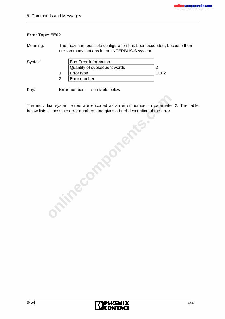
onlinec
omponen
ts.co
m
9 Commands and Messages
9-54 5003B
Error Type: EE02
Meaning: The maximum possible configuration has been exceeded, because thereare too many stations in the INTERBUS-S system.
Syntax: Bus-Error-InformationQuantity of subsequent words 2
1 Error type EE022 Error number
Key: Error number: see table below
The individual system errors are encoded as an error number in parameter 2. The tablebelow lists all possible error numbers and gives a brief description of the error.
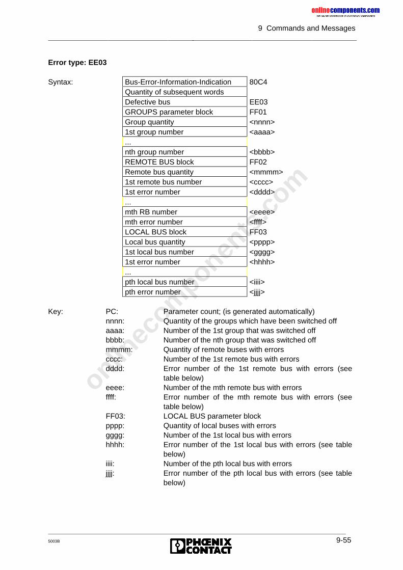
onlinec
omponen
ts.co
m
9 Commands and Messages
5003B 9-55
Error type: EE03
Syntax: Bus-Error-Information-Indication 80C4Quantity of subsequent wordsDefective bus EE03GROUPS parameter block FF01Group quantity <nnnn>1st group number <aaaa>...nth group number <bbbb>REMOTE BUS block FF02Remote bus quantity <mmmm>1st remote bus number <cccc>1st error number <dddd>...mth RB number <eeee>mth error number <ffff>LOCAL BUS block FF03Local bus quantity <pppp>1st local bus number <gggg>1st error number <hhhh>...pth local bus number <iiii>pth error number <jjjj>
Key: PC: Parameter count; (is generated automatically)nnnn: Quantity of the groups which have been switched offaaaa: Number of the 1st group that was switched offbbbb: Number of the nth group that was switched offmmmm: Quantity of remote buses with errorscccc: Number of the 1st remote bus with errorsdddd: Error number of the 1st remote bus with errors (see
table below)eeee: Number of the mth remote bus with errorsffff: Error number of the mth remote bus with errors (see
table below)FF03: LOCAL BUS parameter blockpppp: Quantity of local buses with errorsgggg: Number of the 1st local bus with errorshhhh: Error number of the 1st local bus with errors (see table
below)iiii: Number of the pth local bus with errorsjjjj: Error number of the pth local bus with errors (see table
below)
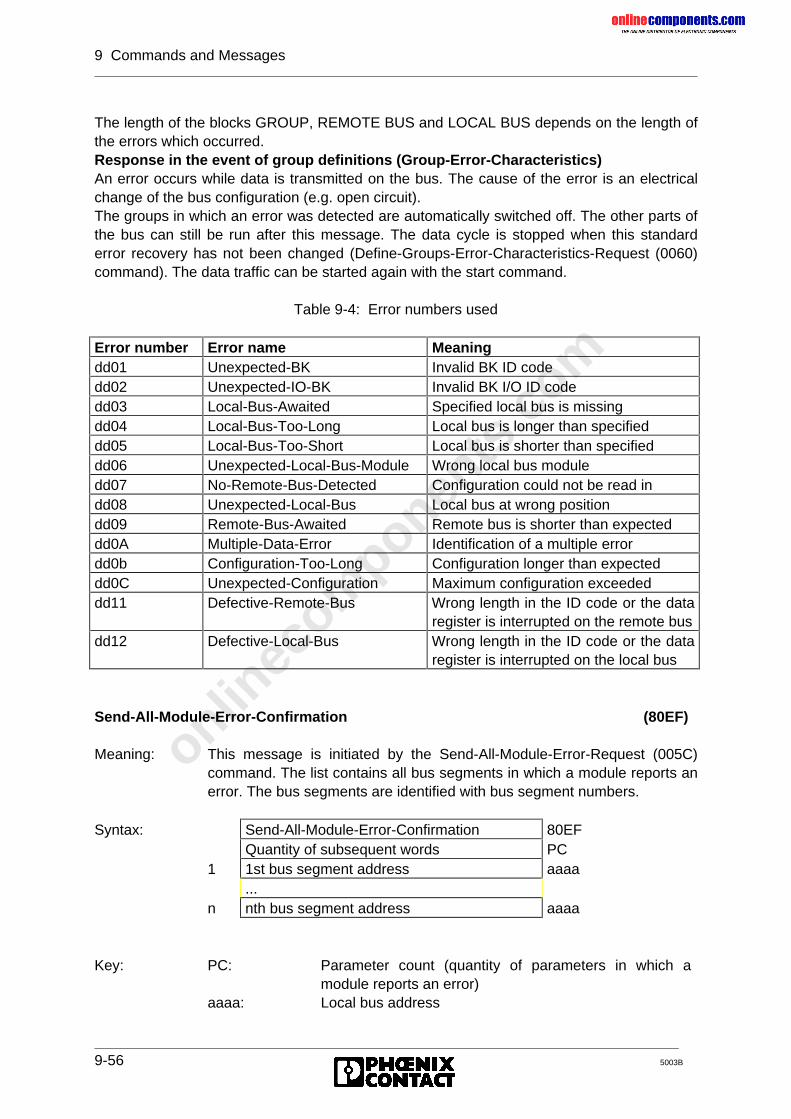
onlinec
omponen
ts.co
m
9 Commands and Messages
9-56 5003B
The length of the blocks GROUP, REMOTE BUS and LOCAL BUS depends on the length ofthe errors which occurred.Response in the event of group definitions (Group-Error-Characteristics)An error occurs while data is transmitted on the bus. The cause of the error is an electricalchange of the bus configuration (e.g. open circuit).The groups in which an error was detected are automatically switched off. The other parts ofthe bus can still be run after this message. The data cycle is stopped when this standarderror recovery has not been changed (Define-Groups-Error-Characteristics-Request (0060)command). The data traffic can be started again with the start command.
Table 9-4: Error numbers used
Error number Error name Meaningdd01 Unexpected-BK Invalid BK ID codedd02 Unexpected-IO-BK Invalid BK I/O ID codedd03 Local-Bus-Awaited Specified local bus is missingdd04 Local-Bus-Too-Long Local bus is longer than specifieddd05 Local-Bus-Too-Short Local bus is shorter than specifieddd06 Unexpected-Local-Bus-Module Wrong local bus moduledd07 No-Remote-Bus-Detected Configuration could not be read indd08 Unexpected-Local-Bus Local bus at wrong positiondd09 Remote-Bus-Awaited Remote bus is shorter than expecteddd0A Multiple-Data-Error Identification of a multiple errordd0b Configuration-Too-Long Configuration longer than expecteddd0C Unexpected-Configuration Maximum configuration exceededdd11 Defective-Remote-Bus Wrong length in the ID code or the data
register is interrupted on the remote busdd12 Defective-Local-Bus Wrong length in the ID code or the data
register is interrupted on the local bus
Send-All-Module-Error-Confirmation (80EF)
Meaning: This message is initiated by the Send-All-Module-Error-Request (005C)command. The list contains all bus segments in which a module reports anerror. The bus segments are identified with bus segment numbers.
Syntax: Send-All-Module-Error-Confirmation 80EFQuantity of subsequent words PC
1 1st bus segment address aaaa...
n nth bus segment address aaaa
Key: PC: Parameter count (quantity of parameters in which amodule reports an error)
aaaa: Local bus address
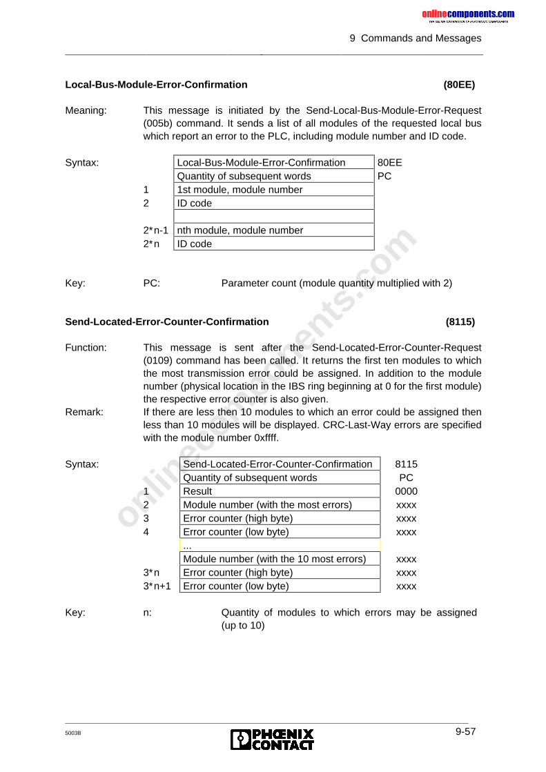
onlinec
omponen
ts.co
m
9 Commands and Messages
5003B 9-57
Local-Bus-Module-Error-Confirmation (80EE)
Meaning: This message is initiated by the Send-Local-Bus-Module-Error-Request(005b) command. It sends a list of all modules of the requested local buswhich report an error to the PLC, including module number and ID code.
Syntax: Local-Bus-Module-Error-Confirmation 80EEQuantity of subsequent words PC
1 1st module, module number2 ID code
2∗n-1 nth module, module number2∗n ID code
Key: PC: Parameter count (module quantity multiplied with 2)
Send-Located-Error-Counter-Confirmation (8115)
Function: This message is sent after the Send-Located-Error-Counter-Request(0109) command has been called. It returns the first ten modules to whichthe most transmission error could be assigned. In addition to the modulenumber (physical location in the IBS ring beginning at 0 for the first module)the respective error counter is also given.
Remark: If there are less then 10 modules to which an error could be assigned thenless than 10 modules will be displayed. CRC-Last-Way errors are specifiedwith the module number 0xffff.
Syntax: Send-Located-Error-Counter-Confirmation 8115Quantity of subsequent words PC
1 Result 00002 Module number (with the most errors) xxxx3 Error counter (high byte) xxxx4 Error counter (low byte) xxxx
...Module number (with the 10 most errors) xxxx
3∗n Error counter (high byte) xxxx3∗n+1 Error counter (low byte) xxxx
Key: n: Quantity of modules to which errors may be assigned(up to 10)
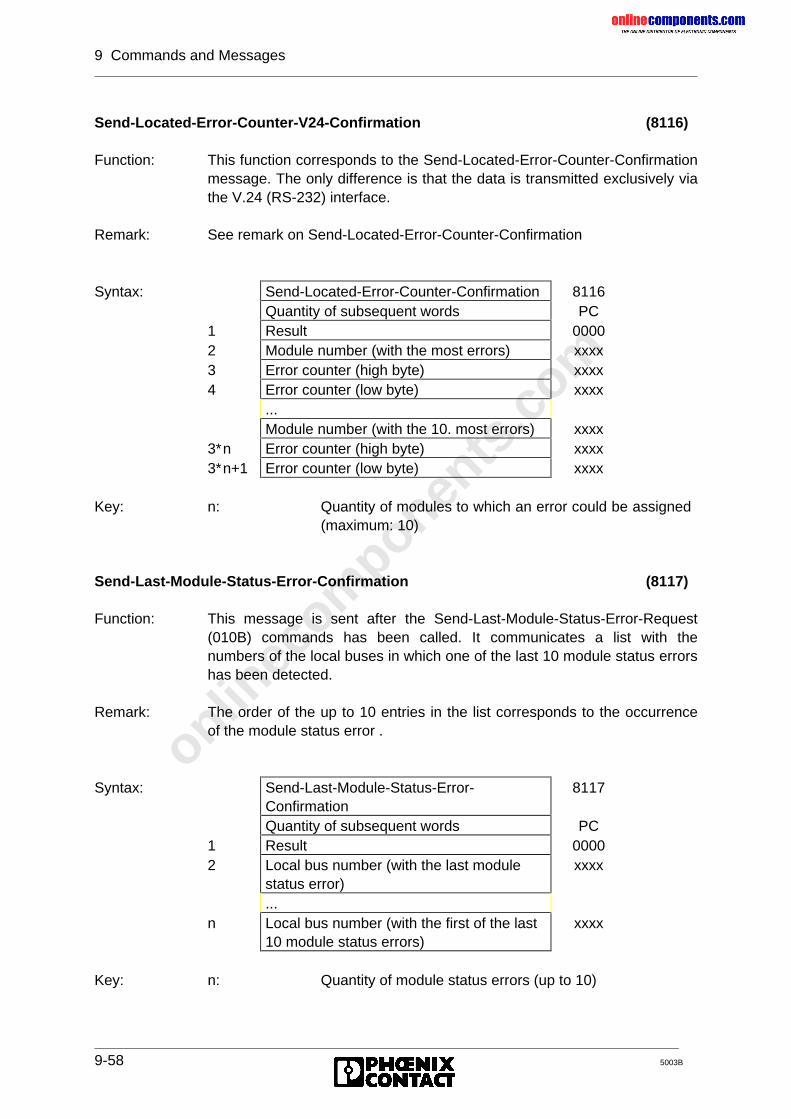
onlinec
omponen
ts.co
m
9 Commands and Messages
9-58 5003B
Send-Located-Error-Counter-V24-Confirmation (8116)
Function: This function corresponds to the Send-Located-Error-Counter-Confirmationmessage. The only difference is that the data is transmitted exclusively viathe V.24 (RS-232) interface.
Remark: See remark on Send-Located-Error-Counter-Confirmation
Syntax: Send-Located-Error-Counter-Confirmation 8116Quantity of subsequent words PC
1 Result 00002 Module number (with the most errors) xxxx3 Error counter (high byte) xxxx4 Error counter (low byte) xxxx
...Module number (with the 10. most errors) xxxx
3∗n Error counter (high byte) xxxx3∗n+1 Error counter (low byte) xxxx
Key: n: Quantity of modules to which an error could be assigned(maximum: 10)
Send-Last-Module-Status-Error-Confirmation (8117)
Function: This message is sent after the Send-Last-Module-Status-Error-Request(010B) commands has been called. It communicates a list with thenumbers of the local buses in which one of the last 10 module status errorshas been detected.
Remark: The order of the up to 10 entries in the list corresponds to the occurrenceof the module status error .
Syntax: Send-Last-Module-Status-Error-Confirmation
8117
Quantity of subsequent words PC1 Result 00002 Local bus number (with the last module
status error)xxxx
...n Local bus number (with the first of the last
10 module status errors)xxxx
Key: n: Quantity of module status errors (up to 10)
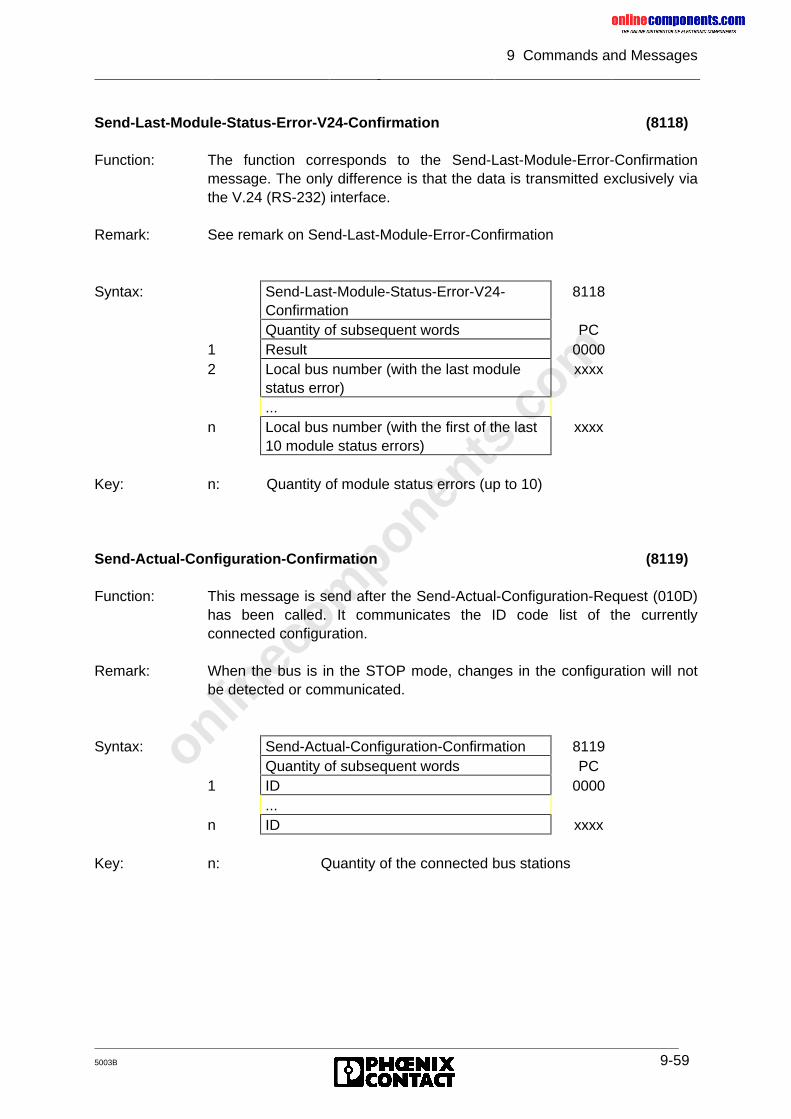
onlinec
omponen
ts.co
m
9 Commands and Messages
5003B 9-59
Send-Last-Module-Status-Error-V24-Confirmation (8118)
Function: The function corresponds to the Send-Last-Module-Error-Confirmationmessage. The only difference is that the data is transmitted exclusively viathe V.24 (RS-232) interface.
Remark: See remark on Send-Last-Module-Error-Confirmation
Syntax: Send-Last-Module-Status-Error-V24-Confirmation
8118
Quantity of subsequent words PC1 Result 00002 Local bus number (with the last module
status error)xxxx
...n Local bus number (with the first of the last
10 module status errors)xxxx
Key: n: Quantity of module status errors (up to 10)
Send-Actual-Configuration-Confirmation (8119)
Function: This message is send after the Send-Actual-Configuration-Request (010D)has been called. It communicates the ID code list of the currentlyconnected configuration.
Remark: When the bus is in the STOP mode, changes in the configuration will notbe detected or communicated.
Syntax: Send-Actual-Configuration-Confirmation 8119Quantity of subsequent words PC
1 ID 0000...
n ID xxxx
Key: n: Quantity of the connected bus stations
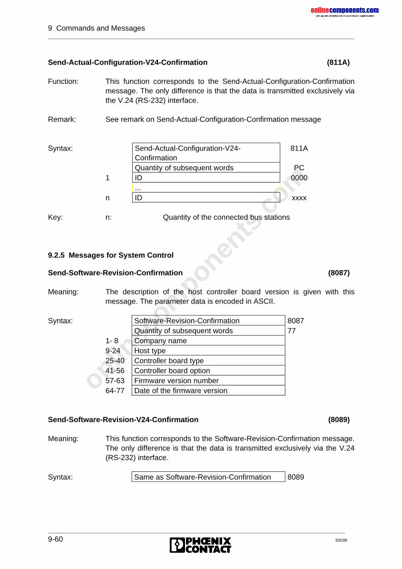
onlinec
omponen
ts.co
m
9 Commands and Messages
9-60 5003B
Send-Actual-Configuration-V24-Confirmation (811A)
Function: This function corresponds to the Send-Actual-Configuration-Confirmationmessage. The only difference is that the data is transmitted exclusively viathe V.24 (RS-232) interface.
Remark: See remark on Send-Actual-Configuration-Confirmation message
Syntax: Send-Actual-Configuration-V24-Confirmation
811A
Quantity of subsequent words PC1 ID 0000
...n ID xxxx
Key: n: Quantity of the connected bus stations
9.2.5 Messages for System Control
Send-Software-Revision-Confirmation (8087)
Meaning: The description of the host controller board version is given with thismessage. The parameter data is encoded in ASCII.
Syntax: Software-Revision-Confirmation 8087Quantity of subsequent words 77
1- 8 Company name9-24 Host type25-40 Controller board type41-56 Controller board option57-63 Firmware version number64-77 Date of the firmware version
Send-Software-Revision-V24-Confirmation (8089)
Meaning: This function corresponds to the Software-Revision-Confirmation message.The only difference is that the data is transmitted exclusively via the V.24(RS-232) interface.
Syntax: Same as Software-Revision-Confirmation 8089
onlinec
omponen
ts.co
m
9 Commands and Messages
5003B 9-61
9.2.6 Messages for Addressing
Logical-Address-Error-Confirmation (002b)
See Chapter 4.
Quit-Receive-LLA-Confirmation (00d0)
Meaning: The Receive-Logical-Local-Bus-Address-Map-Request (0039) commandwas executed.
Quit-Implement-Confirmation (00d3)
Meaning: The Implement-All-Logical-Address-Maps-Request (0040) command wasexecuted. The previously defined address list is now valid.
Quit-Receive-Logical-Addresses-Confirmation (00E4)
Meaning: The Receive-Logical-Addresses-Request (004F) command was executed.
Send-Log-Address-Error-Confirmation (80F5)
Meaning: The positive acknowledgment of the Send-Log-Address-Error-Request(005F) command communicates the error which was found last during thelogical addressing. All parameters are 0, if no addressing error has beendetected.
Syntax: Send-Log-Address-Error-Confirmation 80F5Quantity of subsequent words 3
1 List2 Parameter number3 Error number
The LIST parameter names the list with errors.The PARAMETER NUMBER parameter identifies the parameter with errors.The error number names the error type.
The messages are indicated with a CTRL error on the front plate andentered in the diagnostic registers.
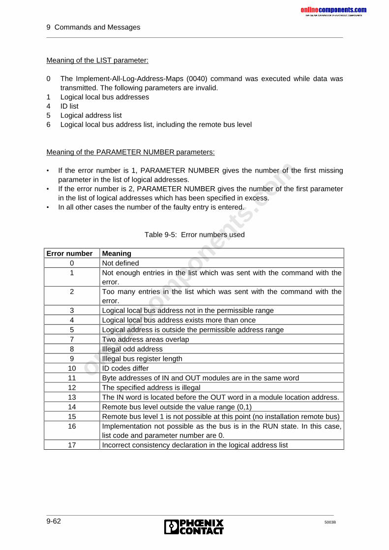
onlinec
omponen
ts.co
m
9 Commands and Messages
9-62 5003B
Meaning of the LIST parameter:
0 The Implement-All-Log-Address-Maps (0040) command was executed while data wastransmitted. The following parameters are invalid.
1 Logical local bus addresses4 ID list5 Logical address list6 Logical local bus address list, including the remote bus level
Meaning of the PARAMETER NUMBER parameters:
• If the error number is 1, PARAMETER NUMBER gives the number of the first missingparameter in the list of logical addresses.
• If the error number is 2, PARAMETER NUMBER gives the number of the first parameterin the list of logical addresses which has been specified in excess.
• In all other cases the number of the faulty entry is entered.
Table 9-5: Error numbers used
Error number Meaning0 Not defined1 Not enough entries in the list which was sent with the command with the
error.2 Too many entries in the list which was sent with the command with the
error.3 Logical local bus address not in the permissible range4 Logical local bus address exists more than once5 Logical address is outside the permissible address range7 Two address areas overlap8 Illegal odd address9 Illegal bus register length10 ID codes differ11 Byte addresses of IN and OUT modules are in the same word12 The specified address is illegal13 The IN word is located before the OUT word in a module location address.14 Remote bus level outside the value range (0,1)15 Remote bus level 1 is not possible at this point (no installation remote bus)16 Implementation not possible as the bus is in the RUN state. In this case,
list code and parameter number are 0.17 Incorrect consistency declaration in the logical address list
onlinec
omponen
ts.co
m
9 Commands and Messages
5003B 9-63
Switch-Information-Confirmation (80E5)
Meaning: The set base node address and the number of the following nodes is sentto the host upon request of the Send-Switch-Information-Request (0050)command.
Syntax: Switch-Information-Confirmation 80E5Quantity of subsequent words 2
1 Base address of window 1 BE, ADR2 Length of window 1 00, LE3 Base address of window 2 BE, ADR4 Length of window 2 00, LE5 Base address of window 3 BE, ADR
Key: BE: Area (P = 0, Q = 1)ADR: Base address (SW1,SW3, SW5)LE: Window length in bytes
Quit-Receive-Local-Bus-Code-Map-Confirmation (0105)
Meaning: The Receive-Local-Bus-Code-Map-Request (0069) command wasexecuted.
9.2.7 Messages for Process Data Linkage
Quit-Receive-Instructions-Confirmation (00F2)
Meaning: Positive acknowledgment of the Receive-Processing-Instructions-Request(005d) command.
Processing-Instructions-Error-Confirmation (80F3)
Meaning: Negative acknowledgment of the Receive-Processing-Instructions-Request(005d) command.
Syntax: Processing-Instructions-Error-Confirmation
80F3
Quantity of subsequent words 21 Error number xxaa2 Parameter number xxbb
Key: xxaa: Error number acc. to tablexxbb: Parameter number,
00 ≤ bb ≤ FF (hex), corresponds to 000 - 255 (decimal)
onlinec
omponen
ts.co
m
9 Commands and Messages
9-64 5003B
The error number gives the error type.The parameter number identifies the parameter with the error.
Meaning of the error number:
1 All memory occupied, no instructions can be accepted, parameter number = 02 Unknown instruction code3 Not enough parameters in the last instruction, parameter number = 04 No internal RAM free5 Reserved6 Logical output address does not exist7 Logical input address does not exist8 Invalid bit number. A bit number larger than 15 (for words) or larger than 7 (for bytes)
was specified.
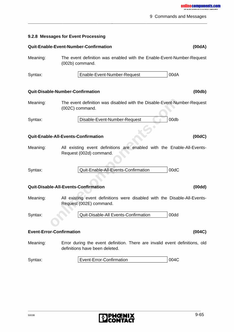
onlinec
omponen
ts.co
m
9 Commands and Messages
5003B 9-65
9.2.8 Messages for Event Processing
Quit-Enable-Event-Number-Confirmation (00dA)
Meaning: The event definition was enabled with the Enable-Event-Number-Request(002b) command.
Syntax: Enable-Event-Number-Request 00dA
Quit-Disable-Number-Confirmation (00db)
Meaning: The event definition was disabled with the Disable-Event-Number-Request(002C) command.
Syntax: Disable-Event-Number-Request 00db
Quit-Enable-All-Events-Confirmation (00dC)
Meaning: All existing event definitions are enabled with the Enable-All-Events-Request (002d) command.
Syntax: Quit-Enable-All-Events-Confirmation 00dC
Quit-Disable-All-Events-Confirmation (00dd)
Meaning: All existing event definitions were disabled with the Disable-All-Events-Request (002E) command.
Syntax: Quit-Disable-All Events-Confirmation 00dd
Event-Error-Confirmation (004C)
Meaning: Error during the event definition. There are invalid event definitions, olddefinitions have been deleted.
Syntax: Event-Error-Confirmation 004C
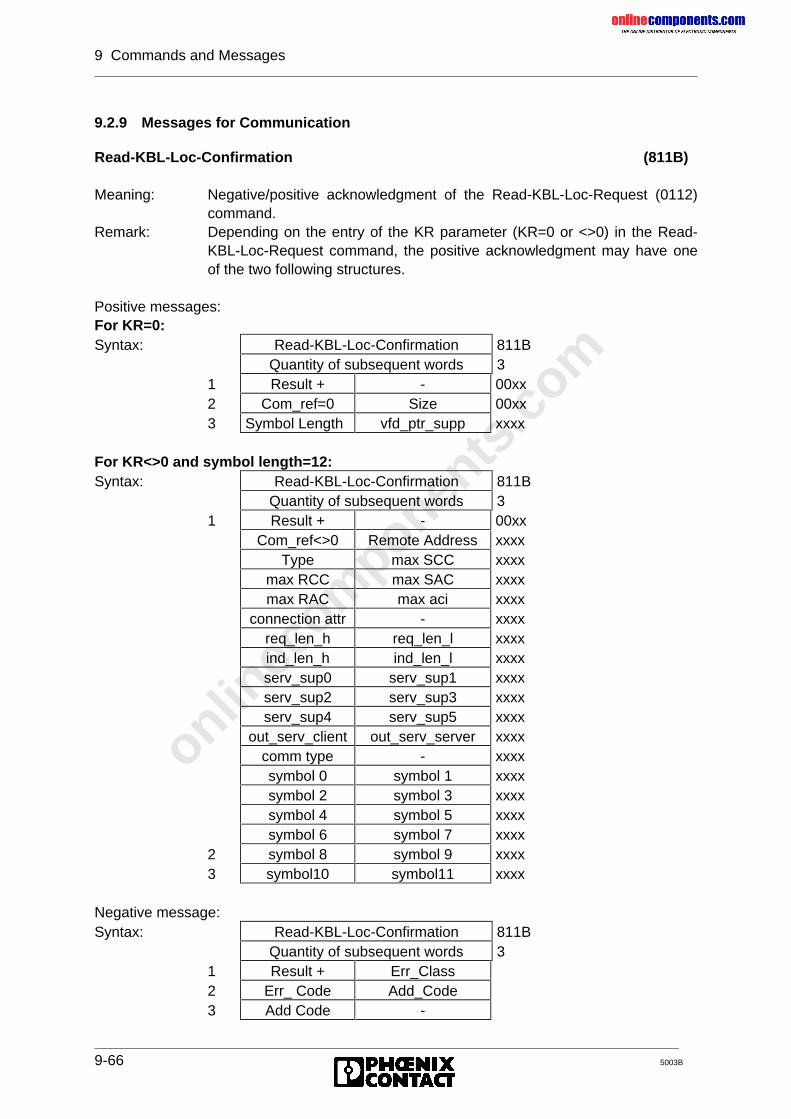
onlinec
omponen
ts.co
m
9 Commands and Messages
9-66 5003B
9.2.9 Messages for Communication
Read-KBL-Loc-Confirmation (811B)
Meaning: Negative/positive acknowledgment of the Read-KBL-Loc-Request (0112)command.
Remark: Depending on the entry of the KR parameter (KR=0 or <>0) in the Read-KBL-Loc-Request command, the positive acknowledgment may have oneof the two following structures.
Positive messages:For KR=0:Syntax: Read-KBL-Loc-Confirmation 811B
Quantity of subsequent words 31 Result + - 00xx2 Com_ref=0 Size 00xx3 Symbol Length vfd_ptr_supp xxxx
For KR<>0 and symbol length=12:Syntax: Read-KBL-Loc-Confirmation 811B
Quantity of subsequent words 31 Result + - 00xx
Com_ref<>0 Remote Address xxxxType max SCC xxxx
max RCC max SAC xxxxmax RAC max aci xxxx
connection attr - xxxxreq_len_h req_len_l xxxxind_len_h ind_len_l xxxxserv_sup0 serv_sup1 xxxxserv_sup2 serv_sup3 xxxxserv_sup4 serv_sup5 xxxx
out_serv_client out_serv_server xxxxcomm type - xxxxsymbol 0 symbol 1 xxxxsymbol 2 symbol 3 xxxxsymbol 4 symbol 5 xxxxsymbol 6 symbol 7 xxxx
2 symbol 8 symbol 9 xxxx3 symbol10 symbol11 xxxx
Negative message:Syntax: Read-KBL-Loc-Confirmation 811B
Quantity of subsequent words 31 Result + Err_Class2 Err_ Code Add_Code3 Add Code -
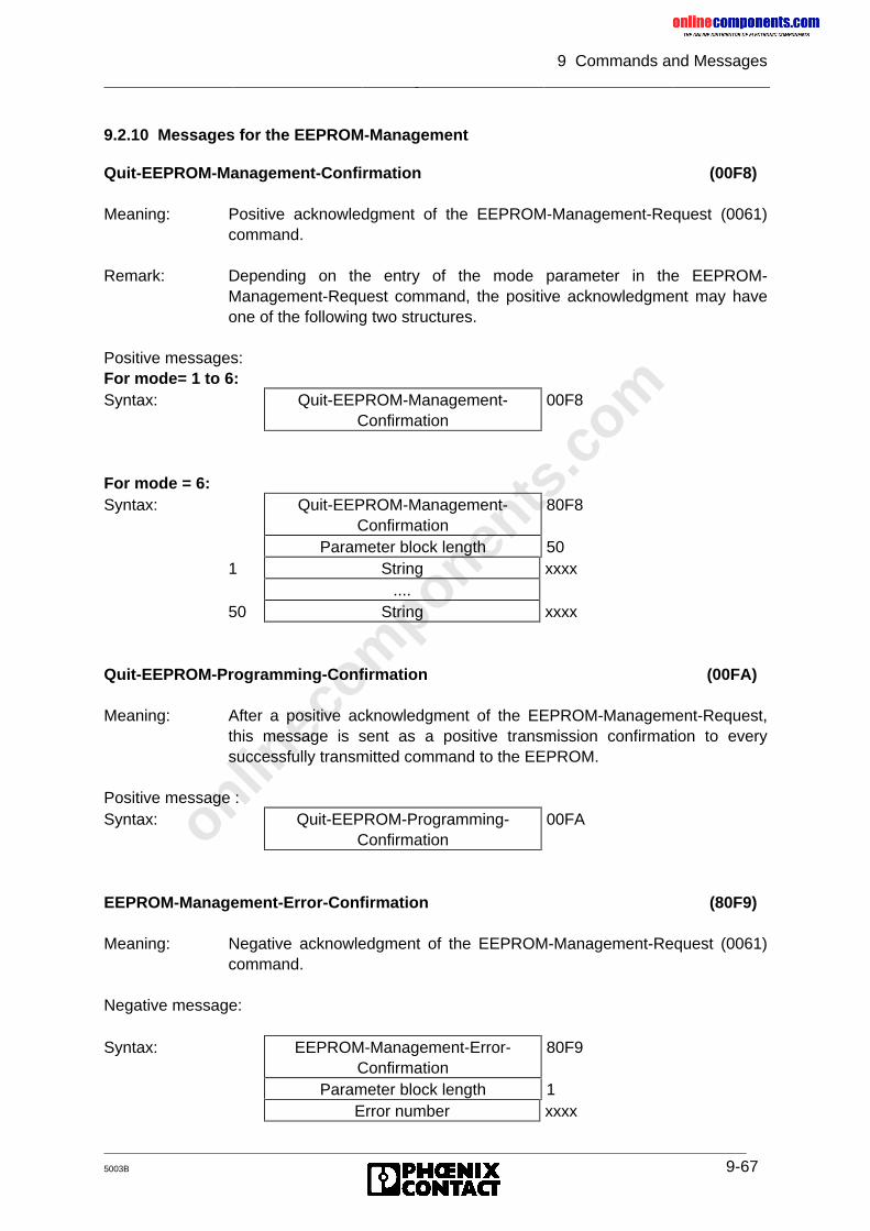
onlinec
omponen
ts.co
m
9 Commands and Messages
5003B 9-67
9.2.10 Messages for the EEPROM-Management
Quit-EEPROM-Management-Confirmation (00F8)
Meaning: Positive acknowledgment of the EEPROM-Management-Request (0061)command.
Remark: Depending on the entry of the mode parameter in the EEPROM-Management-Request command, the positive acknowledgment may haveone of the following two structures.
Positive messages:For mode= 1 to 6:Syntax: Quit-EEPROM-Management-
Confirmation00F8
For mode = 6:Syntax: Quit-EEPROM-Management-
Confirmation80F8
Parameter block length 501 String xxxx
....50 String xxxx
Quit-EEPROM-Programming-Confirmation (00FA)
Meaning: After a positive acknowledgment of the EEPROM-Management-Request,this message is sent as a positive transmission confirmation to everysuccessfully transmitted command to the EEPROM.
Positive message :Syntax: Quit-EEPROM-Programming-
Confirmation00FA
EEPROM-Management-Error-Confirmation (80F9)
Meaning: Negative acknowledgment of the EEPROM-Management-Request (0061)command.
Negative message:
Syntax: EEPROM-Management-Error-Confirmation
80F9
Parameter block length 1Error number xxxx
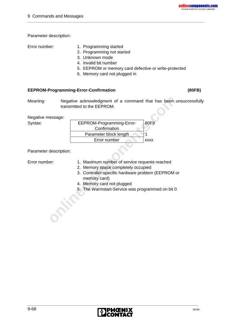
onlinec
omponen
ts.co
m
9 Commands and Messages
9-68 5003B
Parameter description:
Error number: 1. Programming started2. Programming not started3. Unknown mode4. Invalid bit number5. EEPROM or memory card defective or write-protected6. Memory card not plugged in
EEPROM-Programming-Error-Confirmation (80FB)
Meaning: Negative acknowledgment of a command that has been unsuccessfullytransmitted to the EEPROM.
Negative message:Syntax: EEPROM-Programming-Error-
Confirmation80F9
Parameter block length 1Error number xxxx
Parameter description:
Error number: 1. Maximum number of service requests reached2. Memory space completely occupied3. Controller-specific hardware problem (EEPROM or memory card)4. Memory card not plugged5. The Warmstart-Service was programmed on bit 0
onlinec
omponen
ts.co
m
5003B
Chapter 10
AppendixThis chapter provides information on
- the marking of different revisions on the controller boards- the technical data of the controller board- the contents of the data diskette
10 Appendix.........................................................................................................10-1
10.1 Overview of the DCB Revisions.............................................................................. 10-1
10.2 Technical Data........................................................................................................ 10-5
10.3 Contents of the Data Diskette ................................................................................. 10-6
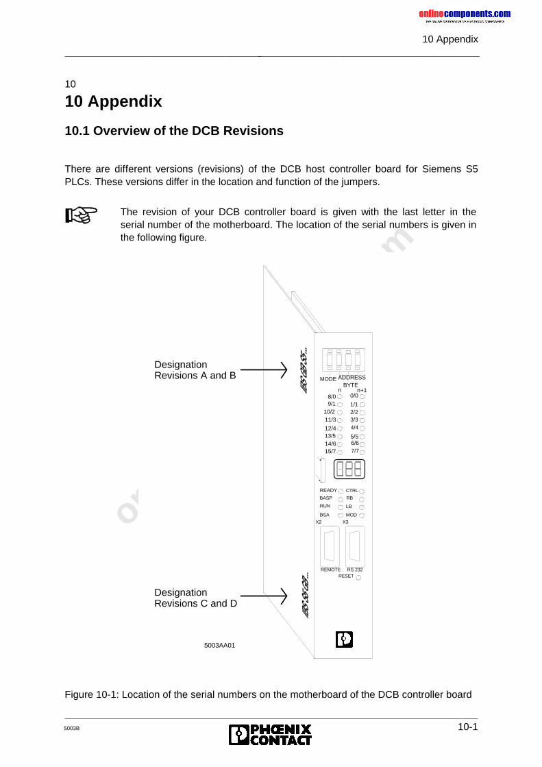
onlinec
omponen
ts.co
m
10 Appendix
5003B 10-1
10
10 Appendix
10.1 Overview of the DCB Revisions
There are different versions (revisions) of the DCB host controller board for Siemens S5PLCs. These versions differ in the location and function of the jumpers.
Figure 10-1: Location of the serial numbers on the motherboard of the DCB controller board
The revision of your DCB controller board is given with the last letter in theserial number of the motherboard. The location of the serial numbers is given inthe following figure.
BYTEn n+1
MODE ADDRESS
READY
BASP
RUN
BSA
X2 X3
REMOTE RS 232RESET
10/2
8/09/1
11/3
12/413/5
14/615/7
0/0
1/12/23/34/4
5/56/67/7
CTRL
RB
LB
MOD
DesignationRevisions A and B
DesignationRevisions C and D
5003AA01
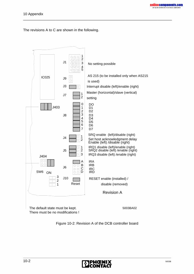
onlinec
omponen
ts.co
m
10 Appendix
10-2 5003B
The revisions A to C are shown in the following.
Figure 10-2: Revision A of the DCB controller board
4
SW6 ON
J10
J6
J5
J4
J8
J7
J3
J9
J1
321
0
123
5
67
12
4
123
5
12
123
ABCD
Reset
IC025
No setting possible
AS 215 (to be installed only when AS215
is used)
Interrupt disable (left)/enable (right)
Master (horizontal)/slave (vertical)
setting
DOD1D2D3D4D5D6D7
SRQ enable (left)/disable (right)
IRQ1 disable (left)/enable (right)SRQ2 disable (left) /enable (right)IRQ3 disable (left) /enable (right)
IRAIRBIRCIRD
RESET enable (installed) /
disable (removed)
Revision A
Set host acknowledgment delayEnable (left) /disable (right)
J403
J404
The default state must be kept.There must be no modifications !
5003BA02
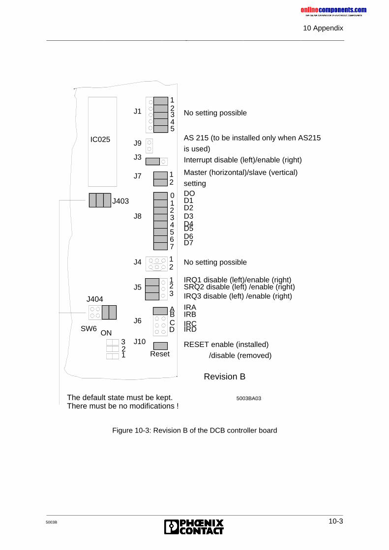
onlinec
omponen
ts.co
m
10 Appendix
5003B 10-3
Figure 10-3: Revision B of the DCB controller board
4
SW6ON
J10
J6
J5
J4
J8
J7
J3
J9
J1
321
0
123
5
67
12
4
123
5
12
123
ABCD
Reset
IC025
No setting possible
DOD1D2D3D4D5D6D7
IRAIRBIRCIRD
Revision B
No setting possible
AS 215 (to be installed only when AS215
is used)
Interrupt disable (left)/enable (right)
Master (horizontal)/slave (vertical)
setting
IRQ1 disable (left)/enable (right)SRQ2 disable (left) /enable (right)IRQ3 disable (left) /enable (right)
RESET enable (installed)
/disable (removed)
J403
J404
The default state must be kept.There must be no modifications !
5003BA03
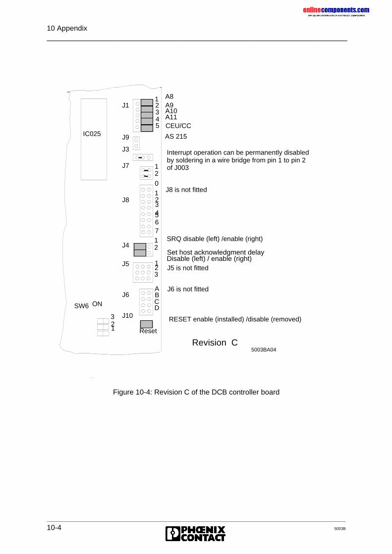
onlinec
omponen
ts.co
m
10 Appendix
10-4 5003B
Figure 10-4: Revision C of the DCB controller board
4
SW6 ON
J10
J6
J5
J4
J8
J7
J3
J9
J1
321
0
123
5
67
12
4
123
5
12
123
ABCD
Reset
IC025 AS 215
Interrupt operation can be permanently disabledby soldering in a wire bridge from pin 1 to pin 2 of J003
RESET enable (installed) /disable (removed)
Revision C
A8A9A10A11CEU/CC
J8 is not fitted
SRQ disable (left) /enable (right)
J5 is not fitted
J6 is not fitted
Set host acknowledgment delay Disable (left) / enable (right)
5003BA04
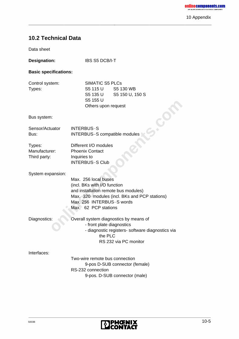
onlinec
omponen
ts.co
m
10 Appendix
5003B 10-5
10.2 Technical Data
Data sheet
Designation: IBS S5 DCB/I-T
Basic specifications:
Control system: SIMATIC S5 PLCsTypes: S5 115 U S5 130 WB
S5 135 U S5 150 U, 150 SS5 155 UOthers upon request
Bus system:
Sensor/Actuator INTERBUS-SBus: INTERBUS-S compatible modules
Types: Different I/O modulesManufacturer: Phoenix ContactThird party: Inquiries to
INTERBUS-S Club
System expansion:Max. 256 local buses(incl. BKs with I/O functionand installation remote bus modules)Max. 320 modules (incl. BKs and PCP stations)Max. 256 INTERBUS-S wordsMax. 62 PCP stations
Diagnostics: Overall system diagnostics by means of- front plate diagnostics- diagnostic registers- software diagnostics via
the PLCRS 232 via PC monitor
Interfaces:Two-wire remote bus connection
9-pos D-SUB connector (female)RS-232 connection
9-pos. D-SUB connector (male)
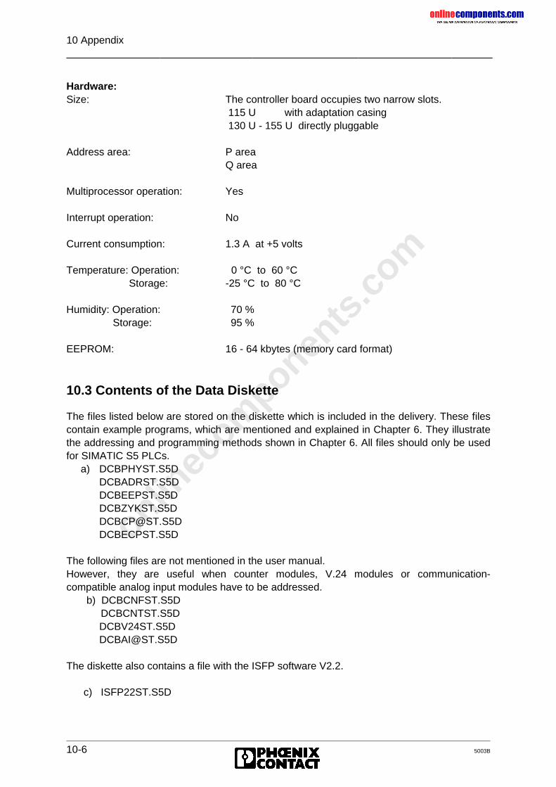
onlinec
omponen
ts.co
m
10 Appendix
10-6 5003B
Hardware:Size: The controller board occupies two narrow slots.
115 U with adaptation casing 130 U - 155 U directly pluggable
Address area: P areaQ area
Multiprocessor operation: Yes
Interrupt operation: No
Current consumption: 1.3 A at +5 volts
Temperature: Operation: 0 °C to 60 °C Storage: -25 °C to 80 °C
Humidity: Operation: 70 %Storage: 95 %
EEPROM: 16 - 64 kbytes (memory card format)
10.3 Contents of the Data Diskette
The files listed below are stored on the diskette which is included in the delivery. These filescontain example programs, which are mentioned and explained in Chapter 6. They illustratethe addressing and programming methods shown in Chapter 6. All files should only be usedfor SIMATIC S5 PLCs. a) DCBPHYST.S5D
The following files are not mentioned in the user manual.However, they are useful when counter modules, V.24 modules or communication-compatible analog input modules have to be addressed. b) DCBCNFST.S5D DCBCNTST.S5D
The diskette also contains a file with the ISFP software V2.2.
c) ISFP22ST.S5D
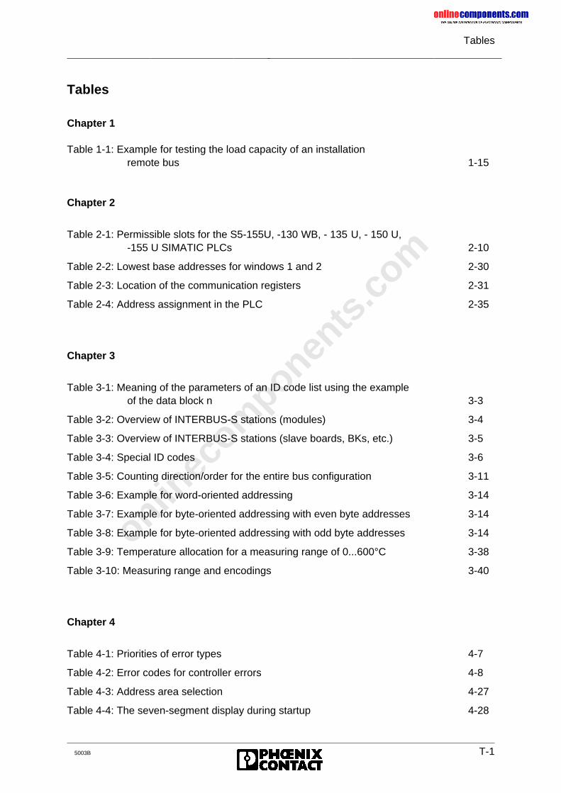
onlinec
omponen
ts.co
m
Tables
5003B T-1
Tables
Chapter 1
Table 1-1: Example for testing the load capacity of an installationremote bus 1-15
Chapter 2
Table 2-1: Permissible slots for the S5-155U, -130 WB, - 135 U, - 150 U,-155 U SIMATIC PLCs 2-10
Table 2-2: Lowest base addresses for windows 1 and 2 2-30
Table 2-3: Location of the communication registers 2-31
Table 2-4: Address assignment in the PLC 2-35
Chapter 3
Table 3-1: Meaning of the parameters of an ID code list using the exampleof the data block n 3-3
Table 3-2: Overview of INTERBUS-S stations (modules) 3-4
Table 3-3: Overview of INTERBUS-S stations (slave boards, BKs, etc.) 3-5
Table 3-4: Special ID codes 3-6
Table 3-5: Counting direction/order for the entire bus configuration 3-11
Table 3-6: Example for word-oriented addressing 3-14
Table 3-7: Example for byte-oriented addressing with even byte addresses 3-14
Table 3-8: Example for byte-oriented addressing with odd byte addresses 3-14
Table 3-9: Temperature allocation for a measuring range of 0...600°C 3-38
Table 3-10: Measuring range and encodings 3-40
Chapter 4
Table 4-1: Priorities of error types 4-7
Table 4-2: Error codes for controller errors 4-8
Table 4-3: Address area selection 4-27
Table 4-4: The seven-segment display during startup 4-28
onlinec
omponen
ts.co
m
Tables
T-2 5003B
Chapter 6
Table 6-1: Setting the types of operation and addressing with switch SW6 6-5
Table 6-2: Overview of the programming examples for different system starts and control and operating modes 6-7
Chapter 7
Table 7-1: Signal assignment of the system connector 7-4
Table 7-2: Signal assignment of the V.24 interface 7-6
Chapter 8
Table 8-1: Parameter description of the INITIB function block (FB61 or FB60) 8-8
Table 8-2: Startup behavior 8-8
Table 8-3: Description of the parameters of the CON/IND function block(FB62 or FB64) 8-11
Table 8-4: Description of the parameters of the REQ/RES function block(FB66 or FB67) 8-13
Table 8-5: Functions of the CONTROL (FB 68) function block 8-24
Table 8-6: Parameters of the CONTROL function block (FB 68) 8-25
Table 8-7: Structure of the DEFINE function block (FB 69) 8-28
Table 8-8: Parameters of the DEFINE function block (FB 69) 8-29
Table 8-9: Supported Client/Server services of the Supported Services Bit Fields 8-40
Table 8-10: Functions of the SYSINFO function block (FB 70) 8-53
Table 8-11: Parameters of the SYSINFO function block (FB 70) 8-54
Table 8-12: Functions of the ON/OFF function block (FB 71) 8-58
Table 8-13: Parameters of the ON/OFF function block (FB 71) 8-59
Table 8-14: Parameters of the ADDRESS function block (FB 72) 8-63
Table 8-15: Functions of the ERRINFO function block (FB74) 8-75
Table 8-16: Parameters of the ERRINFO function block (FB74) 8-75
Table 8-17: Parameters of the SYSERROR function block (FB73) 8-81
Table 8-18: Parameters of the RECONFIG function block (FB 75) 8-82
Table 8-19: Parameters of the EVENT function block (FB 76) 8-83
onlinec
omponen
ts.co
m
Tables
5003B T-3
Table 8-20: PCP service primitives 8-85
Table 8-21: Error messages for a connection abort 8-113
Table 8-22: Error messages for a connection abort (cont’d) 8-114
Table 8-23: Error messages for a connection abort (cont’d) 8-115
Table 8-24: Error messages for the reject service 8-115
Table 8-25: Additional error messages 8-116
Table 8-26: Service-specific error messages, error class 0 (initiate) 8-116
Table 8-27: Service-specific error messages, error class 1 (VFD state) 8-117
Table 8-28: Service-specific error messages, error class 2(application reference) 8-117
Table 8-29: Service-specific error messages, error class 3 (definition) 8-117
Table 8-30: Service-specific error messages, error class 4 (resource) 8-118
Table 8-31: Service-specific error messages, error class 5 (service) 8-118
Table 8-32: Service-specific error messages, error class 6 (access) 8-119
Table 8-33: Service-specific error messages, error class 7 (OV error) 8-120
Table 8-34: Service-specific error messages, error class 8 (other) 8-120
Chapter 9
Table 9-1: Overview of the commands 9-1
Table 9-2: Overview of the messages for a CTRL error 9-2
Table 9-3: Overview of the messages 9-3
Table 9-4: Error numbers used 9-56
Table 9-5: Error numbers used 9-62
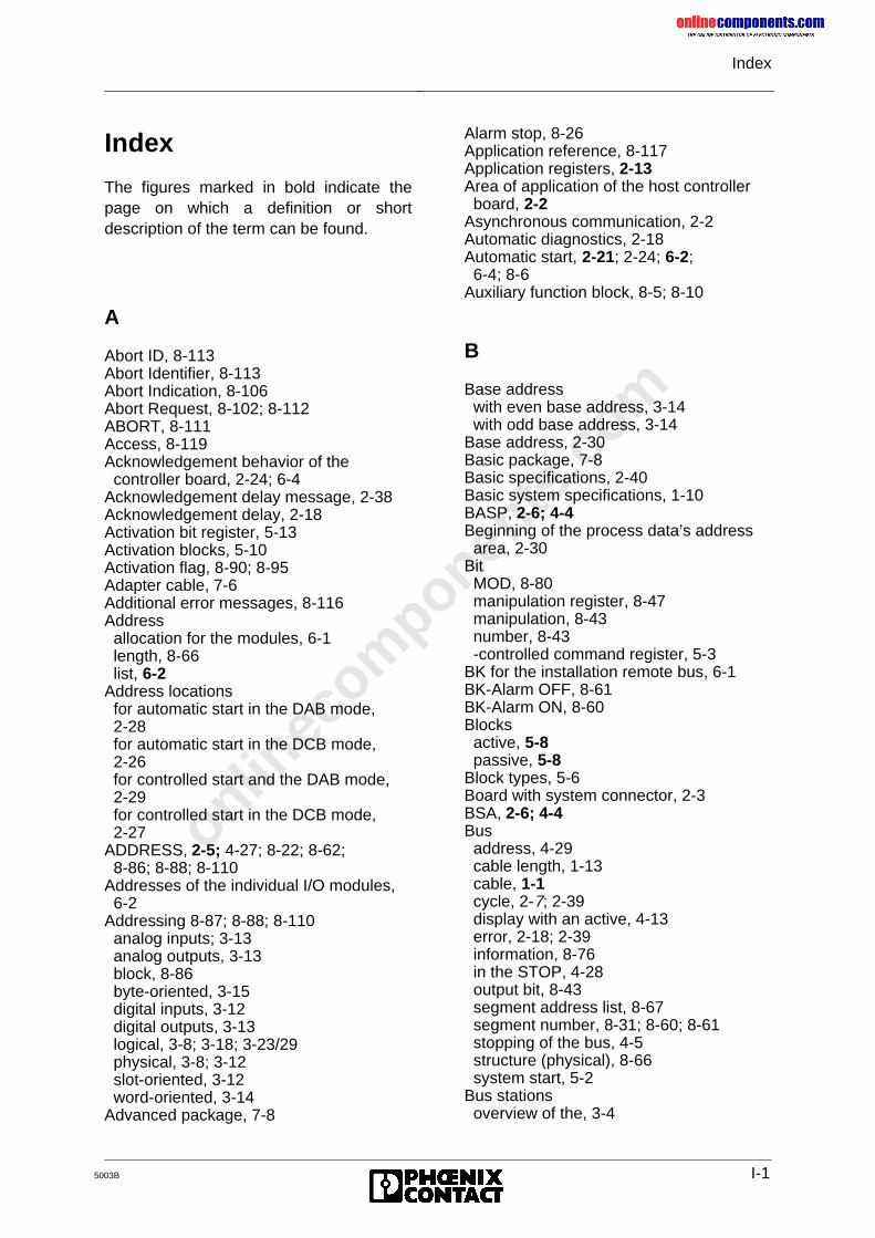
onlinec
omponen
ts.co
m
Index
5003B I-1
Index
The figures marked in bold indicate thepage on which a definition or shortdescription of the term can be found.
A
Abort ID, 8-113Abort Identifier, 8-113Abort Indication, 8-106Abort Request, 8-102; 8-112ABORT, 8-111Access, 8-119Acknowledgement behavior of the controller board, 2-24; 6-4Acknowledgement delay message, 2-38Acknowledgement delay, 2-18Activation bit register, 5-13Activation blocks, 5-10Activation flag, 8-90; 8-95Adapter cable, 7-6Additional error messages, 8-116Address allocation for the modules, 6-1 length, 8-66 list, 6-2Address locations for automatic start in the DAB mode, 2-28 for automatic start in the DCB mode, 2-26 for controlled start and the DAB mode, 2-29 for controlled start in the DCB mode, 2-27ADDRESS, 2-5; 4-27; 8-22; 8-62; 8-86; 8-88; 8-110Addresses of the individual I/O modules, 6-2Addressing 8-87; 8-88; 8-110 analog inputs; 3-13 analog outputs, 3-13 block, 8-86 byte-oriented, 3-15 digital inputs, 3-12 digital outputs, 3-13 logical, 3-8; 3-18; 3-23/29 physical, 3-8; 3-12 slot-oriented, 3-12 word-oriented, 3-14Advanced package, 7-8
Alarm stop, 8-26Application reference, 8-117Application registers, 2-13Area of application of the host controller board, 2-2Asynchronous communication, 2-2Automatic diagnostics, 2-18Automatic start, 2-21; 2-24; 6-2; 6-4; 8-6Auxiliary function block, 8-5; 8-10
B
Base address with even base address, 3-14 with odd base address, 3-14Base address, 2-30Basic package, 7-8Basic specifications, 2-40Basic system specifications, 1-10BASP, 2-6; 4-4Beginning of the process data’s address area, 2-30Bit MOD, 8-80 manipulation register, 8-47 manipulation, 8-43 number, 8-43 -controlled command register, 5-3BK for the installation remote bus, 6-1BK-Alarm OFF, 8-61BK-Alarm ON, 8-60Blocks active, 5-8 passive, 5-8Block types, 5-6Board with system connector, 2-3BSA, 2-6; 4-4Bus address, 4-29 cable length, 1-13 cable, 1-1 cycle, 2-7; 2-39 display with an active, 4-13 error, 2-18; 2-39 information, 8-76 in the STOP, 4-28 output bit, 8-43 segment address list, 8-67 segment number, 8-31; 8-60; 8-61 stopping of the bus, 4-5 structure (physical), 8-66 system start, 5-2Bus stations overview of the, 3-4
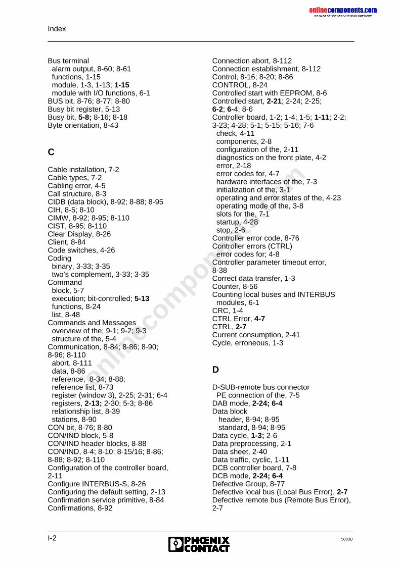
onlinec
omponen
ts.co
m
Index
I-2 5003B
Bus terminal alarm output, 8-60; 8-61 functions, 1-15 module, 1-3, 1-13; 1-15 module with I/O functions, 6-1BUS bit, 8-76; 8-77; 8-80Busy bit register, 5-13Busy bit, 5-8; 8-16; 8-18Byte orientation, 8-43
C
Cable installation, 7-2Cable types, 7-2Cabling error, 4-5Call structure, 8-3CIDB (data block), 8-92; 8-88; 8-95CIH, 8-5; 8-10CIMW, 8-92; 8-95; 8-110CIST, 8-95; 8-110Clear Display, 8-26Client, 8-84Code switches, 4-26Coding binary, 3-33; 3-35 two’s complement, 3-33; 3-35Command block, 5-7 execution; bit-controlled; 5-13 functions, 8-24 list, 8-48Commands and Messages overview of the; 9-1; 9-2; 9-3 structure of the, 5-4Communication, 8-84; 8-86; 8-90;8-96; 8-110 abort, 8-111 data, 8-86 reference, 8-34; 8-88; reference list, 8-73 register (window 3), 2-25; 2-31; 6-4 registers, 2-13; 2-30; 5-3; 8-86 relationship list, 8-39 stations, 8-90CON bit, 8-76; 8-80CON/IND block, 5-8CON/IND header blocks, 8-88CON/IND, 8-4; 8-10; 8-15/16; 8-86;8-88; 8-92; 8-110Configuration of the controller board,2-11Configure INTERBUS-S, 8-26Configuring the default setting, 2-13Confirmation service primitive, 8-84Confirmations, 8-92
Connection abort, 8-112Connection establishment, 8-112Control, 8-16; 8-20; 8-86CONTROL, 8-24Controlled start with EEPROM, 8-6Controlled start, 2-21; 2-24; 2-25;6-2; 6-4; 8-6Controller board, 1-2; 1-4; 1-5; 1-11; 2-2;3-23; 4-28; 5-1; 5-15; 5-16; 7-6 check, 4-11 components, 2-8 configuration of the, 2-11 diagnostics on the front plate, 4-2 error, 2-18 error codes for, 4-7 hardware interfaces of the, 7-3 initialization of the, 3-1 operating and error states of the, 4-23 operating mode of the, 3-8 slots for the, 7-1 startup, 4-28 stop, 2-6Controller error code, 8-76Controller errors (CTRL) error codes for; 4-8Controller parameter timeout error,8-38Correct data transfer, 1-3Counter, 8-56Counting local buses and INTERBUS modules, 6-1CRC, 1-4CTRL Error, 4-7CTRL, 2-7Current consumption, 2-41Cycle, erroneous, 1-3
D
D-SUB-remote bus connector PE connection of the, 7-5DAB mode, 2-24; 6-4Data block header, 8-94; 8-95 standard, 8-94; 8-95Data cycle, 1-3; 2-6Data preprocessing, 2-1Data sheet, 2-40Data traffic, cyclic, 1-11DCB controller board, 7-8DCB mode, 2-24; 6-4Defective Group, 8-77Defective local bus (Local Bus Error), 2-7Defective remote bus (Remote Bus Error),2-7
onlinec
omponen
ts.co
m
Index
5003B I-3
DEFINE, 8-20; 8-28; 8-50Definition of I/O addresses, 2-13Definition, 8-117Detection of an operating or error status,2-18Diagnostic functions on bus terminal modules, 4-32 functions on I/O modules, 4-31 interface, 3-1 possibilities, 5-1 registers locations, 4-24 registers, 2-13; 2-18; 2-30; 4-23Diagnostics on third-party devices, 4-32DIAGNOSTICS, 2-6Different interrupt sources, 2-38Differential signal transfer (RS 485), 1-4DIP switches, 2-30Disable All Messages, 8-27Disconnecting the RESET button, 2-39Display of diagnostic data, 2-18Double addressing, 2-33Driver blocks, 8-88Dual Port RAM, 5-5
E
EEPROM memory card, 2-1; 2-22; 6-2EEPROM, 2-41; 5-2; 5-13EREG, 8-64ERRINFO, 8-22; 8-74Error classes, 8-116 code, 4-35; 8-116 detection, 1-11 diagnostics, notes on, 4-10 displays, 4-35 free-data transmission, 1-3 indication, 2-7; 4-5 in local bus, 4-18 in remote bus, 4-17 in the module, 4-19 LED, 4-35 list of, 4-36 messages, 8-113 protection mechanisms, 1-4 type, 4-35Errors display of, 4-6Event code, 8-36 handling, 5-1 identifier, 8-36; 8-61 map, 8-35Event OFF, 8-61
Event ON, 8-61Event signaling blocks, 5-12EVENT, 8-23; 8-83Extended address area, 2-11
F
Front plate components, 2-4Front plate, 2-3Function block, 2-1; 8-2; 8-86
G
Gain register, 3-31General method of operation, 1-3Group definition, 8-70Group Error Characteristics, 8-50;8-72Group Nos. List, 8-70Group Numbers, 8-37Group OFF, 8-60Group ON, 8-60Guidelines of VDE 0100, 7-2
H
Hand Held Monitor, 7-9 using the, 4-33Hardware interfaces pin assignments of the, 7-3Hardware settings, 2-15; 2-19Host controller board, 1-2; 1-4; 1-5; 1-11;2-2 diagnostics, 2-18 functions, 1-11 installation, 2-9 operation, 2-1 startup, 2-17Host output bit, 8-43Humidity, 2-41
I
I/O address area, 2-11; 8-86I/O area of the PLC with IBS S5 DCB I/,2-12I/O data of disabled local buses, 4-4I/O DATA, 2-5I/O status Indicator, 2-5; 4-26IB data cycle, 4-35IB reset, 4-35
onlinec
omponen
ts.co
m
Index
I-4 5003B
IBDB, 8-10; 8-14; 8-18; 8-49; 8-52IBS 24 RELS, 3-36IBS BA/SL, 3-37IBS PT 100, 3-38 measuring range of the, 3-38 temperature calculation for the,3-40IBS SYS SWT, 2-22; 5-13; 5-16; 7-10ID code, 4-25; 5-18; 5-13; 8-66ID code list, 6-1, 8-66ID cycle, 1-3ID numbers, 8-30Identification codes, 8-55Identify Confirmation, 8-104Identify Request, 8-101Implement All Logical Address Map,8-27; 8-31; 8-32; 8-33; 8-57IN address list, 8-68IN address, 8-36Indication service primitive, 8-84Indications, 8-92 for operating mode and error type,3-1Indicators bus-specific, 4-32 device-specific, 4-32Information Report Request, 8-101;8-107; 8-108Init Communication, 8-27; 8-34Initial configuration structure of the, 5-16Initialization block, 5-6; 5-7; 8-2;8-86Initialization, 8-87; 8-88; 8-110Initiate Confirmation, 8-104Initiate Error Confirmation, 8-105Initiate Request, 8-101Initiate, 8-116Initiate.Request, 8-112INITIB, 8-6; 8-8; 8-86; 8-110Input addresses, 8-68Input and output area of the PLC, 2-12Input bit, 8-43Input byte 0 in the PLC’s I/O area, 2-12Installation remote bus, 1-3, 1-10/13/14/16 cable, 1-13 modules, 6-1 number of I/O modules in the, 1-14 station, 8-52Installation user manual, 7-2Installation, 2-9; 7-1INTERBUS data block, 8-10; 8-18;8-49INTERBUS-S diagnostics, 4-29 address list, structure of a, 3-19 cycle counter, 8-56
delay, 8-27 I/O modules, 1-18 in the PLC’s address area, 2-25 management functions, 8-1 protocol chip (IPMS), 2-1 protocol sequence, 1-5 remote bus connector, 2-1 scan time calculation, 1-6 system, voltage supply of the, 7-2 system control, 5-8 system expansion, 2-30 system functions for the PLC, 5-2; 5-5 systems installation, 7-2Interface description, 5-1Interface driver, 5-6, 5-7; 8-110Interfaces, 2-7; 2-40Interrupt line of the controller board, 2-12Interrupt line selection, 2-37Interrupt operation, 2-41Interrupt processing, 2-36Invalid address set with the coding switch,2-6ISFP, 5-1; 5-3; 5-5 function block package, 2-22 interface, 8-88 software program, 2-18
L
LB ERR, 8-64LB error, 4-5LB, 2-7Length codes, 8-30; 8-55Local bus, 1-3; 1-10; 1-16; 1-17; 8-37; 8-70 module error, 8-79 modules, 1-18Location of windows, 2-33Logical address error, 8-57Logical addressing, 2-1; 2-14Logical IN addresses, 8-32Logical IN address map, 8-32Logical local bus address map, 8-31Logical local bus address, 8-52logical numbers, 8-67Logical OUT address map, 8-33Logical OUT addresses, 8-33Loopback word, 1-4
M
Manipulation of OUT words, 8-41Mask 1, 8-36Mask 2, 8-36
onlinec
omponen
ts.co
m
Index
5003B I-5
Master PLC, 3-37Master-slave access method, 1-3Maximum INTERBUS-S expansion, 3-7Memory component (MPM), 2-1Message flag, 8-95Message functions, 8-80Message header, 8-95Messages overview of the, 9-1; 9-2; 9-3MOD, 2-7MOD bit, 8-80MOD ERR (MODule Error), 2-7; 4-6MODE, 2-5; 4-27; 8-64MODE 4 to 9, 4-27Module addresses, 2-13 error, 2-18; 8-78 identification code, 8-30 number, 8-52Modules byte-oriented, 3-14 capable of communication, 5-1 with bus acknowledgement, 4-6 word-oriented, 3-14Monitor software, 5-2Mounting positions of the jumpers, 2-19Multiprocessor operation, 2-41
O
ON/OFF, 8-21; 8-58Operating and diagnostic indicators, 2-2Operating indicators, 2-6; 4-4Operating mode of the controller board,2-25Operating/addressing modes, 2-15Operation in the central controller and controller expansion unit, 2-20Operation with and without EEPROM card, 2-22Ordering information, 7-8Organization block, 8-110Other, 8-120OUT address list, 8-69Output addresses, 8-69Output bit, 8-43OV-Error, 8-120Overview of commands and messages, 9-1; 9-2; 9-3
P
Parameter counter, 3-18
list, 3-3 frame, 5-4 settings, 2-7; 2-39 timeout constant, 8-38Parameterization software, 2-22Parameterization of the host controller board, 2-7PC board, 7-10PCP activation flag, 8-91 communication interface, 5-1 communication system, 8-84 message flag, 8-93 services, 8-97 stations, 5-7 stations, 8-86Peripherals Message Specification3-1Physical addressing, 2-14 of the input/output modules, 3-11Physical configuration map, 8-30;8-55, 8-57PLC, 2-15 address area, 2-11 startup of the, 3-8, 4-36 STOP request of, 4-14 STOP state of the, 4-15, 4-17, 4-28Process data, 8-86Process data interface, 3-1; 3-8Process image of the inputs and outputs,2-11Program packages, 2-16Programming unit, 7-6
Q
Quit Module Error All, 8-27Quit Module Error, 8-52
R
RB error, 4-5RB ERR, 8-64RB, 2-7RC, 8-113Read Confirmation, 8-102; 8-108Read Request, 8-100READ service (Exmp.), 8-96READY, 2-6; 4-4Reason code, 8-113Receive bit manipulation, 8-41Receive block, 5-6; 5-8; 8-2; 8-86Receive KBL, 8-39RECO bit, 8-82
onlinec
omponen
ts.co
m
Index
I-6 5003B
RECONFIG, 8-23; 8-82Reject Indication, 8-106Reject service, 8-115Remote bus, 1-2; 1-10; 1-12; 1-16 check, 1-4 connector, 2-2 error ’RB ERR’, 1-4 interface, 7-5 module with two-wire interface, 1-14 segment: error message for the, 1-15REMOTE, 2-7Representation "Ad", 2-5REQ/RES header blocks, 8-88REQ/RES, 5-8; 8-4; 8-12; 8-15;8-16; 8-86; 8-88; 8-110Request service primitive, 8-84
Request, 8-96RESET, 1-4RESET, 2-7; 2-39; 4-17; 4-18; 4-28/29;4-40-45; 4-48ff; 4-54Reset-Out-In01, 8-46Reset-Out-In01-Switch, 8-47Reset-Out-In10, 8-46Reset-Out-In10-Switch, 8-47Reset2-Out-In01, 8-46Reset2-Out-In10, 8-46Resource, 8-118Response service primitive, 8-84Restart (automatic), 8-50Return bit register, 5-13RETURN bit, 5-8Return bit, 8-18RRDB, 8-88; 8-90; 8-94RRMW, 8-90; 8-95; 8-110RRST, 8-94; 8-95; 8-110RS 232, 2-7-, 5-1Run status of the controller board, 2-6RUN, 2-6; 4-4
S
Scan time, 1-6Secondary diagnostic functions, 2-18Segment, 1-12Selection of the address area, 2-5Self-test, 2-6 display after the, 4-13Send block, 5-6; 5-8; 8-2; 8-86Serial interface RS-232, 5-3Serial interface, 2-7; 5-2; 5-16; 7-6Server, 8-84Service, 8-118 execution, 8-90 message flag, 8-92 primitive, 8-90
request, 8-112 structure, 8-89Service-specific error messages,8-116Settings for board identification, 2-37Settings for central controller and controller expansion unit, 2-20; 2-21;2-24; 2-25Seven-segment display, 2-6; 2-7Signal changes, 8-41Signal states up to date, 4-5; 4-29Signaling behavior of the host controllerboard, 2-15Signaling block, 5-7SIMATIC S5, 8-86Slave PLC, 3-37Slot allocation, 2-9Slots, 2-9Software interfaces, 3-1 requirements, 2-16 revision, 8-55 runtime, 1-6Standard data block, 8-94, 8-95Standard function blocks, 5-3Start automatic, 3-1, 4-24; 4-29 behavior, 4-29 confirmation, 8-103; 8-109 controlled, 3-1; 4-25; 4-29 INTERBUS-S Cycle, 8-26 request, 8-100Startup, 8-110 and operating mode selection, 2-21 behavior, 6-3 organization blocks, 3-12 performance, 2-16; 2-22 with physical addressing, 6-1Status Confirmation, 8-103Status display, 4-27Status Request, 8-101Stop Confirmation, 8-103; 8-109Stop INTERBUS-S Cycle, 8-26Stop Request, 8-100STOP state, 2-6; 2-7Supply voltage failure of the, 1-18Switch Information, 8-56Switch SW6, 2-21Synchronization, 8-86SYSERROR, 8-22; 8-74; 8-80SYSINFO, 8-21; 8-53System connector, 2-1, 7-4System interface, 5-1; 5-3
onlinec
omponen
ts.co
m
Index
5003B I-7
T
Temperature, 2-41Test routines, 1-4TIMEOUT bit, 5-8Timeout bit, 8-18Transfer method, 1-13Transfer time, 1-6Transmission cycle, 1-4Transmission medium, 1-13Two-wire INTERBUS-S system, 2-2Two-wire remote bus, 2-7Types of addressing, 2-13
U
Use, 8-110User process, 8-84
V
V.24 interface, 2-18VFD-State, 8-117
W
Window 3, 2-31Window areas, 2-13Windows which extend from the P to the Q area, 2-35Write Confirmation, 8-102; 8-108Write Request, 8-100