Embed Size (px)
Citation preview
User’s Guide (Ver. 3.0)
Analog DVR: N-0440MH, N-0840MH, N-1640MH
HD-SDI DVR: HD-0405M, HD-0810M
High Definition H.264 Digital Video Recorder
About This User’s Guide Before operating the unit, please read this user’s guide thoroughly and retain it for future reference.
2 | P a g e
Cautions
Explanation of Graphical Symbols
WARNING
To reduce a risk of fire or electric shock, do not expose this product to rain or moisture.
CAUTION
Changes or modifications not approved by the manufacture will void the warranty of the product.
Using an incompatible battery may increase the risk of fire or explosion.
Replace only with the same or equivalent type battery recommended by the manufacture.
Discard used batteries according to manufacturer’s instructions.
This symbol indicates the presence of important operating and maintenance
(servicing) instructions in the literature accompanying the product.
This symbol indicates the presence of “dangerous voltage” within the product’s
enclosure that may be of sufficient magnitude to constitute a risk of electric
shock, property damage, personal injury, or death.
3 | P a g e
These precautions must be followed for safety reasons.
Warning
Do not use if the unit emits smoke.
Do not disassemble the unit.
Do not place any heavy or sharp objects on the unit.
Do not place on uneven surface.
Do not expose to shock or vibration.
Do not move the unit when the unit is powered on.
Do not block, and allow dust to accumulate in the air vents.
Do not restrict airflow of the unit; doing so can damage the unit.
Installation and servicing should be performed only by qualified and experienced
personnel.
Turn off the power of the DVR when connecting Cameras, Audio or Sensor Cables.
The manufacture is not responsible for any damage caused by improper use of the
product or failure to follow instructions for the product.
The manufacture is not responsible for any problems caused by or resulting from the
user physically opening the DVR for examination or attempting to repair the unit.
The manufacture may not be held liable for any issues with the unit if the warranty
seal is removed.
4 | P a g e
Table of Contents
Product Components ............................................................................................... 7
Features ................................................................................................................... 8
Specifications: N-0440MH, N-0840MH, N-1640MH ................................................ 11
Specifications: HD-0405M, HD-0810M .................................................................. 13
1. Name, Function and Connection ..................................................................... 15
1-1. Front Panel ....................................................................................................................... 15
1-2. Rear Panel ....................................................................................................................... 17
1-2-1. N-0440MH ..................................................................................................................... 17
1-2-2. N-0840MH ..................................................................................................................... 17
1-2-3. N-1640MH ..................................................................................................................... 18
1-2-4. HD-0405M ..................................................................................................................... 18
1-2-5. HD-0810M ..................................................................................................................... 19
1-3. Remote Control ................................................................................................................ 19
2. Preparation ...................................................................................................... 21
2-1. DVD-RW Installation ........................................................................................................ 21
2-2. Hard Drive Installation ...................................................................................................... 22
2-3. Compatible HDD Models .................................................................................................. 23
2-4. Storage Estimation ........................................................................................................... 24
2-5. Booting the DVR and Basic Time Setting ......................................................................... 25
2-6. Setting Daylight Saving Time ........................................................................................... 26
2-7. Setting NTP (Network Time Protocol) ............................................................................... 27
3. Setting up the DVR .......................................................................................... 30
3-1. Setup – Main screen and Menu Tree ............................................................................... 30
3-2. Setup – Display Mode ...................................................................................................... 34
3-3. Setup – Record Mode ...................................................................................................... 36
3-3-1. Recording Schedules .................................................................................................... 37
3-4. Setup – Device Mode ....................................................................................................... 39
3-4-1. ALARM-OUT ................................................................................................................. 40
3-4-2 SPOT-OUT Setup .......................................................................................................... 40
3-4-3CONTROLLER & PTZ Setup .......................................................................................... 41
3-4-4. Motion Zone Setup ........................................................................................................ 42
3-5. Setup – Storage Mode ...................................................................................................... 43
3-6. Setup – System Mode ...................................................................................................... 44
3-7. Setup – Security Mode ..................................................................................................... 47
3-8. Setup – Network Mode ..................................................................................................... 49
3-8-1. DDNS ............................................................................................................................ 50
3-8-2. Network Ports ................................................................................................................ 51
3-8-3. Network Stream............................................................................................................. 51
5 | P a g e
3-9. Setup - CONFIG Mode ..................................................................................................... 52
3-10. Quick Setup .................................................................................................................... 54
4. Live, Search and Playback .............................................................................. 55
4-1. Live Viewing Screen ......................................................................................................... 55
4-2. SEARCH Screen .............................................................................................................. 57
4-2-1. TIME-LINE Search ........................................................................................................ 58
4-2-2. Event Search................................................................................................................. 59
4-2-3. Go To First Time ............................................................................................................ 59
4-2-4. Go To Last Time ............................................................................................................ 59
4-2-5. Go To Specific Time ...................................................................................................... 60
4-2-6. Archive Search .............................................................................................................. 60
4-2-7. Log Search .................................................................................................................... 61
4-3. Play Mode ........................................................................................................................ 62
5. PTZ Control ..................................................................................................... 63
6. Back Up ............................................................................................................. 64
6-1. Still Image Backup onto USB Flash Drive ........................................................................ 64
6-2. Video Backup onto USB Flash Drive ................................................................................ 64
6-3. Transferring Still Images or Video from the ARCHIVE List ............................................... 65
6-4. Playback of Backup Video ................................................................................................ 66
7. Network Access Using the Single Site Network Viewer ..................................... 67
7-1. PC Requirements ............................................................................................................. 67
7-2. Installing the Network Viewer ........................................................................................... 68
7-3. Live Monitoring Mode and Functions. ............................................................................... 69
7-4. Bi-directional Audio........................................................................................................... 71
7-5. Remote Search Mode and Functions ............................................................................... 71
7-6. PC System Configuration ................................................................................................. 75
8. Network Access Using the Multi-Sites Network Viewer ...................................... 78
8-1. Overview .......................................................................................................................... 78
8-2. Minimum PC Requirements ............................................................................................. 78
8-3. Installation of the Program ............................................................................................... 78
8-4. Live Window ..................................................................................................................... 80
8-4-1. Main User Interface ....................................................................................................... 80
8-4-2. Control Buttons ............................................................................................................. 80
8-5. Search and Playback Window .......................................................................................... 81
8-5-1. Main User Interface ....................................................................................................... 81
8-5-2. Main Control Panel ........................................................................................................ 82
8-6. Setup of UMS Multi Client ................................................................................................ 84
8-6-1. General ......................................................................................................................... 84
8-6-2. Event ............................................................................................................................. 85
8-6-3. Record .......................................................................................................................... 86
8-6-4. OSD .............................................................................................................................. 87
6 | P a g e
8-6-5. Language ...................................................................................................................... 88
8-7. Remote Setup .................................................................................................................. 89
8-7-1. Setting the Display ........................................................................................................ 89
8-7-2. Record .......................................................................................................................... 89
8-7-3. Storage .......................................................................................................................... 90
8-7-4. Device ........................................................................................................................... 90
8-7-5.Upgrade ......................................................................................................................... 90
8-7-6. System .......................................................................................................................... 91
8-7-7.Network .......................................................................................................................... 91
8-8. Operation ......................................................................................................................... 92
8-8-1. Addition, Delete, and Modify of DVR Sites .................................................................... 92
8-8-2. Connect and Disconnect ............................................................................................... 94
8-8-4. Recording Video on Local PC during Live ..................................................................... 96
8-8-5. Local Playback and Remote Playback .......................................................................... 98
9-8-6. AVI Backup During Playback ....................................................................................... 100
9. Network – By a Web-Browser Viewer .............................................................. 102
10. Network Access Using the Mobile Viewer .................................................... 105
10-1. Installing the Viewer ..................................................................................................... 105
10-2. iUMS for Android Live Monitoring and PTZ Control ...................................................... 105
10-2-1. Live ........................................................................................................................... 105
10-2-2.PTZ Control ................................................................................................................ 106
10-3. iUMS for Apple iPhone ................................................................................................. 107
10-3-1. Live ........................................................................................................................... 107
10-3-2.PTZ Control ................................................................................................................ 107
10-3-3. Playback ................................................................................................................... 108
APPENDIX: How to Connect the Network ........................................................... 109
A. How to set the IP address of the DVR and open TCP port of the router? ....................... 109
B. How to access DVR from a Remote PC? ....................................................................... 112
LAN Connection – Using a Switching Hub ............................................................................ 112
Internet Connection Using DDNS .......................................................................................... 114
7 | P a g e
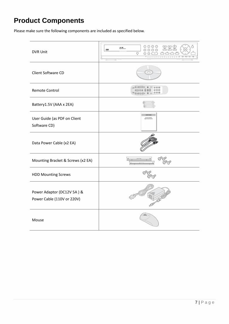
Product Components
Please make sure the following components are included as specified below.
DVR Unit
Client Software CD
Remote Control
Battery1.5V (AAA x 2EA)
User Guide (as PDF on Client
Software CD)
Data Power Cable (x2 EA)
Mounting Bracket & Screws (x2 EA)
HDD Mounting Screws
Power Adaptor (DC12V 5A ) &
Power Cable (110V or 220V)
Mouse
8 | P a g e
Features
H.264 Video compression
HDcctv/HD-SDI Compatible (HD-0405M / HD-0810M Model only)
HDMI 1080P Video Output
Reliable File System
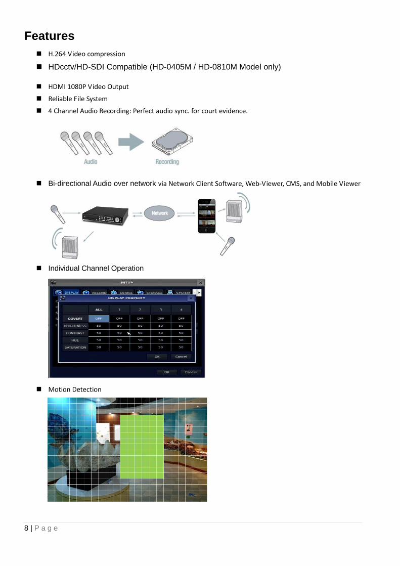
4 Channel Audio Recording: Perfect audio sync. for court evidence.
Bi-directional Audio over network via Network Client Software, Web-Viewer, CMS, and Mobile Viewer
Individual Channel Operation
Motion Detection
9 | P a g e
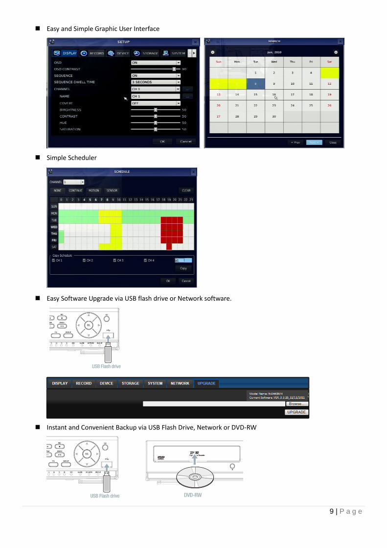
Easy and Simple Graphic User Interface
Simple Scheduler
Easy Software Upgrade via USB flash drive or Network software.
Instant and Convenient Backup via USB Flash Drive, Network or DVD-RW
10 | P a g e
Exclusive File Format and AVI Backup
Time stamp over AVI backup data for court evidence
S.M.A.R.T. (Self-Monitoring, Analysis, and Reporting Technology for HDD)
Automatic Video Input and Video Loss Detection
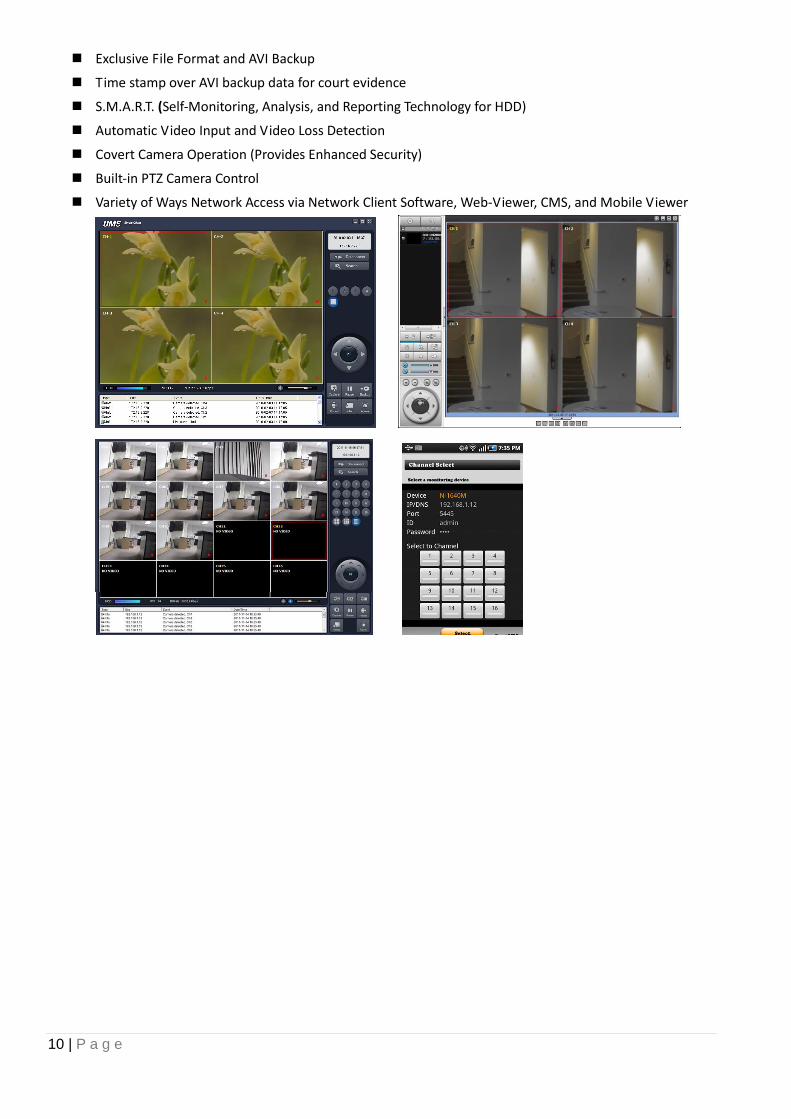
Covert Camera Operation (Provides Enhanced Security)
Built-in PTZ Camera Control
Variety of Ways Network Access via Network Client Software, Web-Viewer, CMS, and Mobile Viewer
11 | P a g e
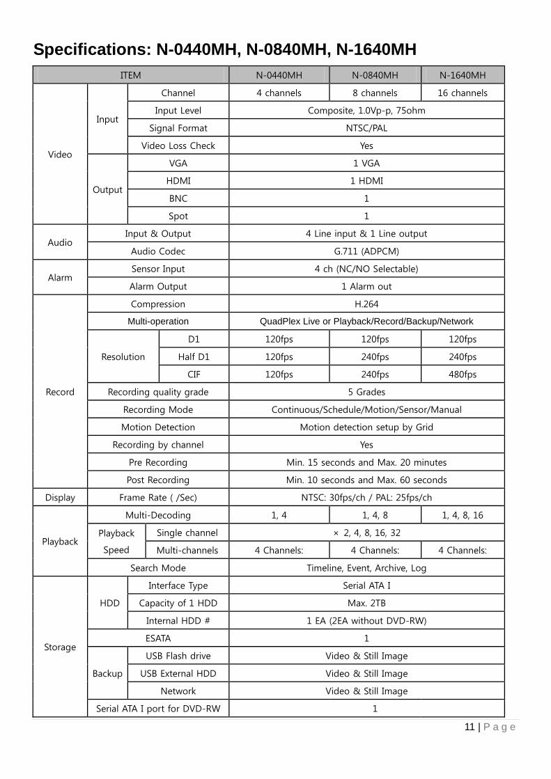
Specifications: N-0440MH, N-0840MH, N-1640MH
ITEM N-0440MH N-0840MH N-1640MH
Video
Input
Channel 4 channels 8 channels 16 channels
Input Level Composite, 1.0Vp-p, 75ohm
Signal Format NTSC/PAL
Video Loss Check Yes
Output
VGA 1 VGA
HDMI 1 HDMI
BNC 1
Spot 1
Audio Input & Output 4 Line input & 1 Line output
Audio Codec G.711 (ADPCM)
Alarm Sensor Input 4 ch (NC/NO Selectable)
Alarm Output 1 Alarm out
Record
Compression H.264
Multi-operation QuadPlex Live or Playback/Record/Backup/Network
Resolution
D1 120fps 120fps 120fps
Half D1 120fps 240fps 240fps
CIF 120fps 240fps 480fps
Recording quality grade 5 Grades
Recording Mode Continuous/Schedule/Motion/Sensor/Manual
Motion Detection Motion detection setup by Grid
Recording by channel Yes
Pre Recording Min. 15 seconds and Max. 20 minutes
Post Recording Min. 10 seconds and Max. 60 seconds
Display Frame Rate ( /Sec) NTSC: 30fps/ch / PAL: 25fps/ch
Playback
Multi-Decoding 1, 4 1, 4, 8 1, 4, 8, 16
Playback
Speed
Single channel × 2, 4, 8, 16, 32
Multi-channels 4 Channels: 4 Channels: 4 Channels:
Search Mode Timeline, Event, Archive, Log
Storage
HDD
Interface Type Serial ATA I
Capacity of 1 HDD Max. 2TB
Internal HDD # 1 EA (2EA without DVD-RW)
ESATA 1
Backup
USB Flash drive Video & Still Image
USB External HDD Video & Still Image
Network Video & Still Image
Serial ATA I port for DVD-RW 1
12 | P a g e
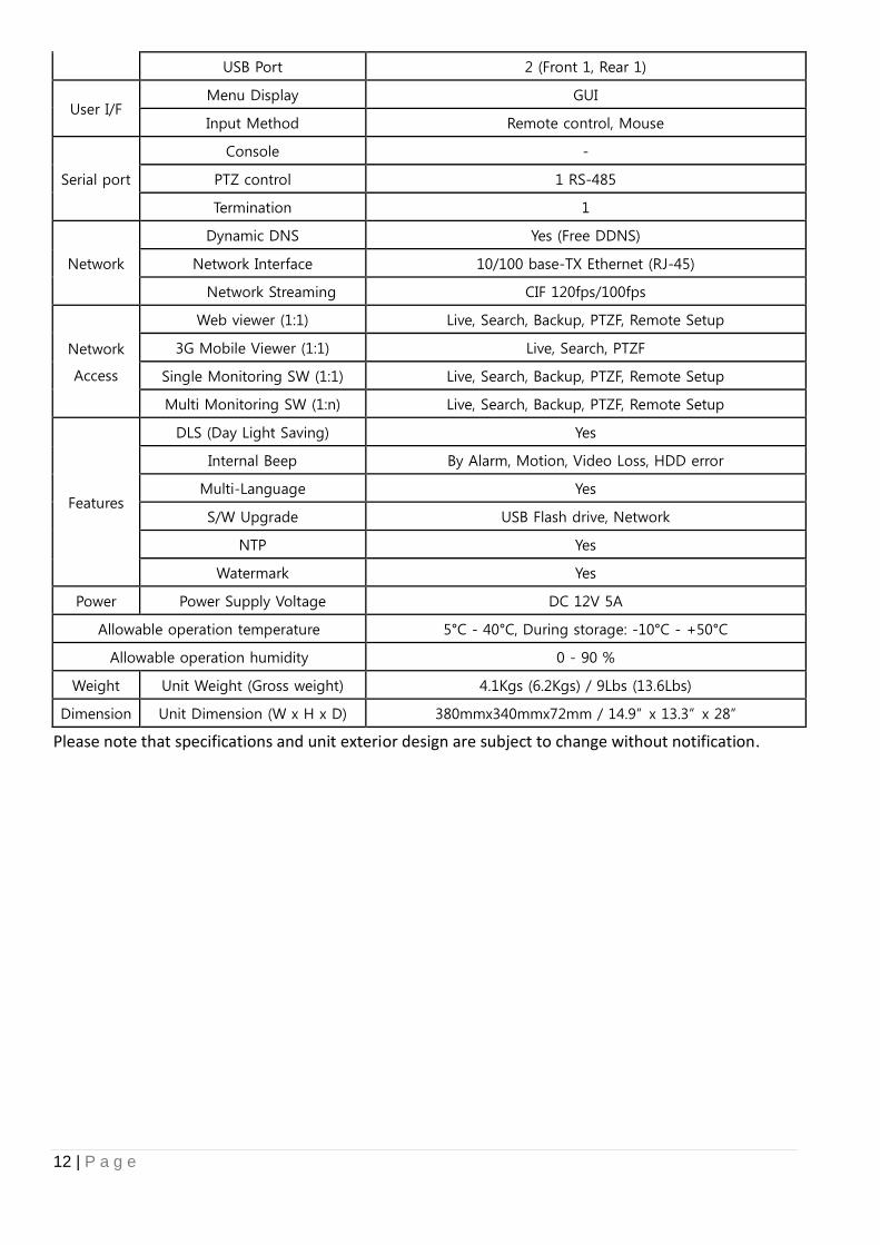
USB Port 2 (Front 1, Rear 1)
User I/F Menu Display GUI
Input Method Remote control, Mouse
Serial port
Console -
PTZ control 1 RS-485
Termination 1
Network
Dynamic DNS Yes (Free DDNS)
Network Interface 10/100 base-TX Ethernet (RJ-45)
Network Streaming CIF 120fps/100fps
Network
Access
Web viewer (1:1) Live, Search, Backup, PTZF, Remote Setup
3G Mobile Viewer (1:1) Live, Search, PTZF
Single Monitoring SW (1:1) Live, Search, Backup, PTZF, Remote Setup
Multi Monitoring SW (1:n) Live, Search, Backup, PTZF, Remote Setup
Features
DLS (Day Light Saving) Yes
Internal Beep By Alarm, Motion, Video Loss, HDD error
Multi-Language Yes
S/W Upgrade USB Flash drive, Network
NTP Yes
Watermark Yes
Power Power Supply Voltage DC 12V 5A
Allowable operation temperature 5°C - 40°C, During storage: -10°C - +50°C
Allowable operation humidity 0 - 90 %
Weight Unit Weight (Gross weight) 4.1Kgs (6.2Kgs) / 9Lbs (13.6Lbs)
Dimension Unit Dimension (W x H x D) 380mmx340mmx72mm / 14.9” x 13.3” x 28”
Please note that specifications and unit exterior design are subject to change without notification.
13 | P a g e
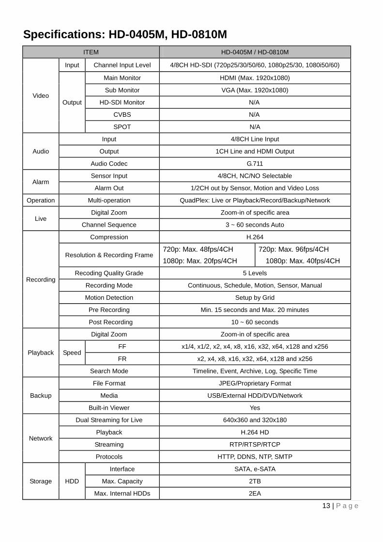
Specifications: HD-0405M, HD-0810M
ITEM HD-0405M / HD-0810M
Video
Input Channel Input Level 4/8CH HD-SDI (720p25/30/50/60, 1080p25/30, 1080i50/60)
Output
Main Monitor HDMI (Max. 1920x1080)
Sub Monitor VGA (Max. 1920x1080)
HD-SDI Monitor N/A
CVBS N/A
SPOT N/A
Audio
Input 4/8CH Line Input
Output 1CH Line and HDMI Output
Audio Codec G.711
Alarm Sensor Input 4/8CH, NC/NO Selectable
Alarm Out 1/2CH out by Sensor, Motion and Video Loss
Operation Multi-operation QuadPlex: Live or Playback/Record/Backup/Network
Live Digital Zoom Zoom-in of specific area
Channel Sequence 3 ~ 60 seconds Auto
Recording
Compression H.264
Resolution & Recording Frame 720p: Max. 48fps/4CH
1080p: Max. 20fps/4CH
720p: Max. 96fps/4CH
1080p: Max. 40fps/4CH
Recoding Quality Grade 5 Levels
Recording Mode Continuous, Schedule, Motion, Sensor, Manual
Motion Detection Setup by Grid
Pre Recording Min. 15 seconds and Max. 20 minutes
Post Recording 10 ~ 60 seconds
Playback
Digital Zoom Zoom-in of specific area
Speed FF x1/4, x1/2, x2, x4, x8, x16, x32, x64, x128 and x256
FR x2, x4, x8, x16, x32, x64, x128 and x256
Search Mode Timeline, Event, Archive, Log, Specific Time
Backup
File Format JPEG/Proprietary Format
Media USB/External HDD/DVD/Network
Built-in Viewer Yes
Network
Dual Streaming for Live 640x360 and 320x180
Playback H.264 HD
Streaming RTP/RTSP/RTCP
Protocols HTTP, DDNS, NTP, SMTP
Storage HDD
Interface SATA, e-SATA
Max. Capacity 2TB
Max. Internal HDDs 2EA
14 | P a g e
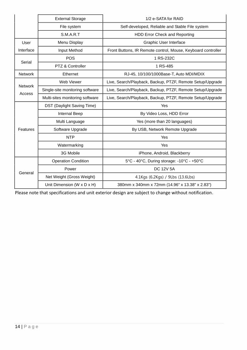
External Storage 1/2 e-SATA for RAID
File system Self-developed, Reliable and Stable File system
S.M.A.R.T HDD Error Check and Reporting
User
Interface
Menu Display Graphic User Interface
Input Method Front Buttons, IR Remote control, Mouse, Keyboard controller
Serial POS 1 RS-232C
PTZ & Controller 1 RS-485
Network Ethernet RJ-45, 10/100/1000Base-T, Auto MDI/MDIX
Network
Access
Web Viewer Live, Search/Playback, Backup, PTZF, Remote Setup/Upgrade
Single-site monitoring software Live, Search/Playback, Backup, PTZF, Remote Setup/Upgrade
Multi-sites monitoring software Live, Search/Playback, Backup, PTZF, Remote Setup/Upgrade
Features
DST (Daylight Saving Time) Yes
Internal Beep By Video Loss, HDD Error
Multi Language Yes (more than 20 languages)
Software Upgrade By USB, Network Remote Upgrade
NTP Yes
Watermarking Yes
3G Mobile iPhone, Android, Blackberry
General
Operation Condition 5°C - 40°C, During storage: -10°C - +50°C
Power DC 12V 5A
Net Weight (Gross Weight) 4.1Kgs (6.2Kgs) / 9Lbs (13.6Lbs)
Unit Dimension (W x D x H) 380mm x 340mm x 72mm (14.96" x 13.38" x 2.83")
Please note that specifications and unit exterior design are subject to change without notification.
15 | P a g e
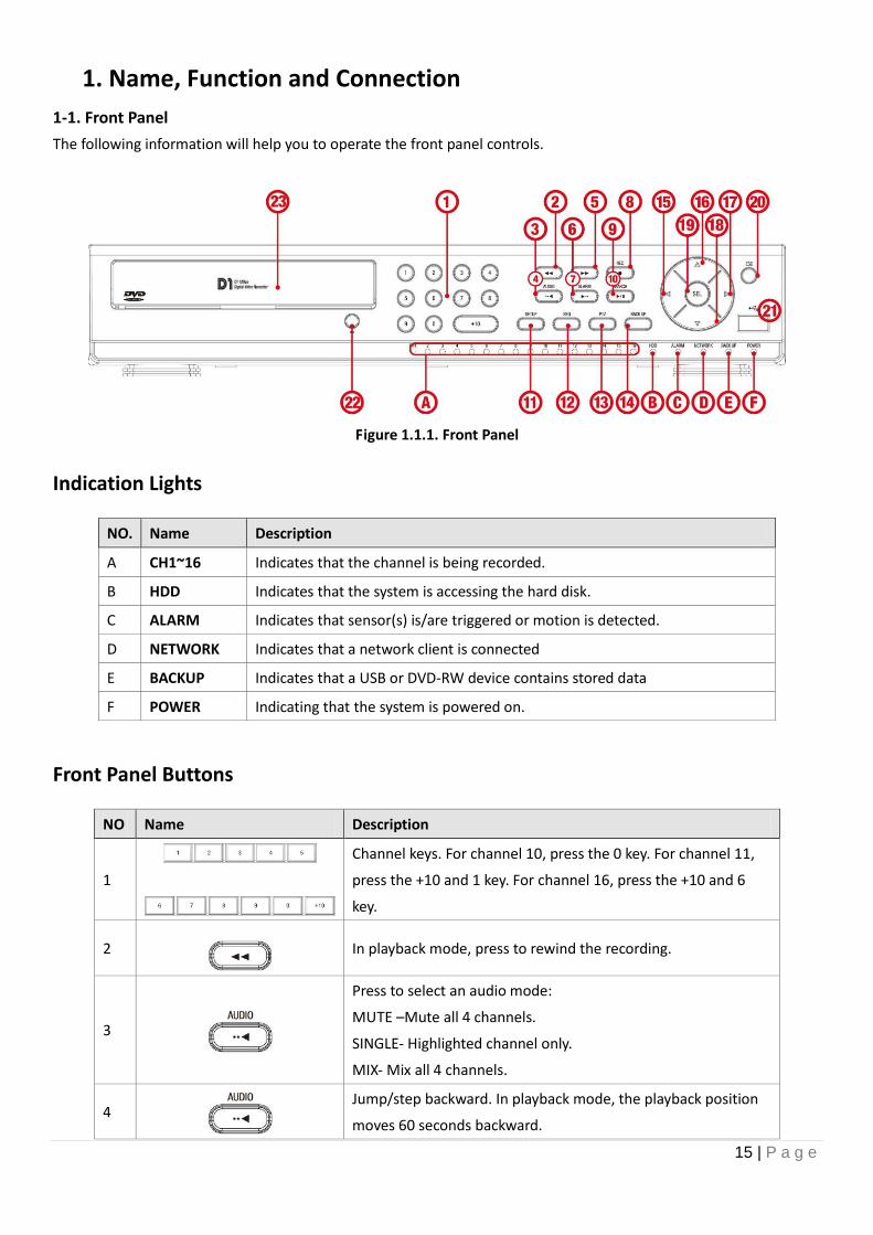
1. Name, Function and Connection
1-1. Front Panel
The following information will help you to operate the front panel controls.
Figure 1.1.1. Front Panel
Indication Lights
NO. Name Description
A CH1~16 Indicates that the channel is being recorded.
B HDD Indicates that the system is accessing the hard disk.
C ALARM Indicates that sensor(s) is/are triggered or motion is detected.
D NETWORK Indicates that a network client is connected
E BACKUP Indicates that a USB or DVD-RW device contains stored data
F POWER Indicating that the system is powered on.
Front Panel Buttons
NO Name Description
1
Channel keys. For channel 10, press the 0 key. For channel 11,
press the +10 and 1 key. For channel 16, press the +10 and 6
key.
2
In playback mode, press to rewind the recording.
3
Press to select an audio mode:
MUTE –Mute all 4 channels.
SINGLE- Highlighted channel only.
MIX- Mix all 4 channels.
4
Jump/step backward. In playback mode, the playback position
moves 60 seconds backward.
16 | P a g e
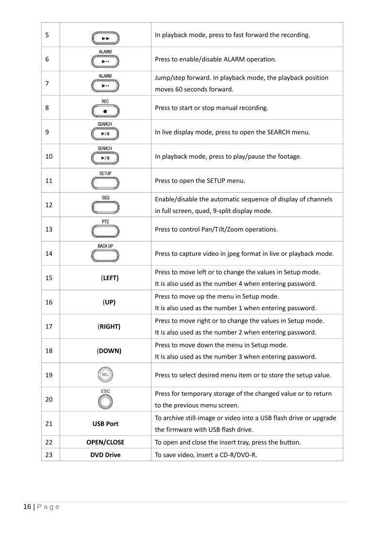
5
In playback mode, press to fast forward the recording.
6
Press to enable/disable ALARM operation.
7
Jump/step forward. In playback mode, the playback position
moves 60 seconds forward.
8
Press to start or stop manual recording.
9
In live display mode, press to open the SEARCH menu.
10
In playback mode, press to play/pause the footage.
11
Press to open the SETUP menu.
12
Enable/disable the automatic sequence of display of channels
in full screen, quad, 9-split display mode.
13
Press to control Pan/Tilt/Zoom operations.
14
Press to capture video in jpeg format in live or playback mode.
15 (LEFT) Press to move left or to change the values in Setup mode.
It is also used as the number 4 when entering password.
16 (UP) Press to move up the menu in Setup mode.
It is also used as the number 1 when entering password.
17 (RIGHT) Press to move right or to change the values in Setup mode.
It is also used as the number 2 when entering password.
18 (DOWN) Press to move down the menu in Setup mode.
It is also used as the number 3 when entering password.
19
Press to select desired menu item or to store the setup value.
20
Press for temporary storage of the changed value or to return
to the previous menu screen.
21 USB Port To archive still-image or video into a USB flash drive or upgrade
the firmware with USB flash drive.
22 OPEN/CLOSE To open and close the insert tray, press the button.
23 DVD Drive To save video, insert a CD-R/DVD-R.
17 | P a g e
1-2. Rear Panel
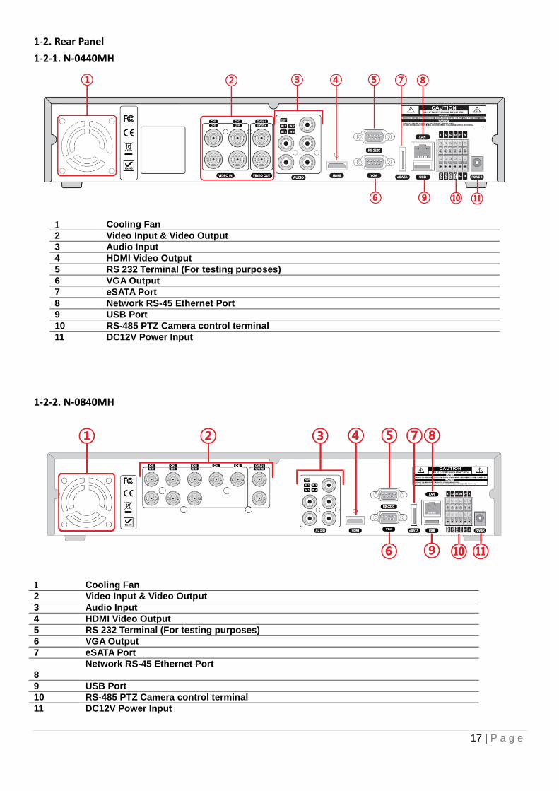
1-2-1. N-0440MH
1 Cooling Fan
2 Video Input & Video Output
3 Audio Input
4 HDMI Video Output
5 RS 232 Terminal (For testing purposes)
6 VGA Output
7 eSATA Port
8 Network RS-45 Ethernet Port
9 USB Port
10 RS-485 PTZ Camera control terminal
11 DC12V Power Input
1-2-2. N-0840MH
1 Cooling Fan
2 Video Input & Video Output
3 Audio Input
4 HDMI Video Output
5 RS 232 Terminal (For testing purposes)
6 VGA Output
7 eSATA Port
8
Network RS-45 Ethernet Port
9 USB Port
10 RS-485 PTZ Camera control terminal
11 DC12V Power Input
18 | P a g e
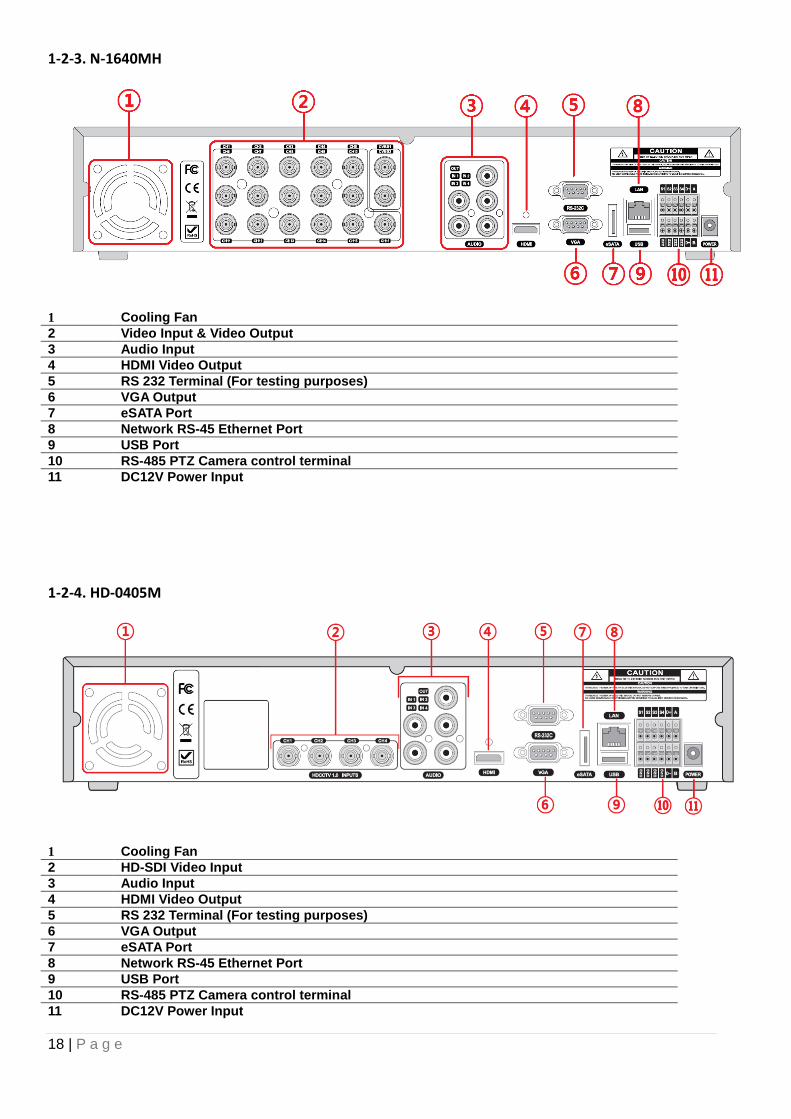
1-2-3. N-1640MH
1 Cooling Fan
2 Video Input & Video Output
3 Audio Input
4 HDMI Video Output
5 RS 232 Terminal (For testing purposes)
6 VGA Output
7 eSATA Port
8 Network RS-45 Ethernet Port
9 USB Port
10 RS-485 PTZ Camera control terminal
11 DC12V Power Input
1-2-4. HD-0405M
1 Cooling Fan
2 HD-SDI Video Input
3 Audio Input
4 HDMI Video Output
5 RS 232 Terminal (For testing purposes)
6 VGA Output
7 eSATA Port
8 Network RS-45 Ethernet Port
9 USB Port
10 RS-485 PTZ Camera control terminal
11 DC12V Power Input
19 | P a g e
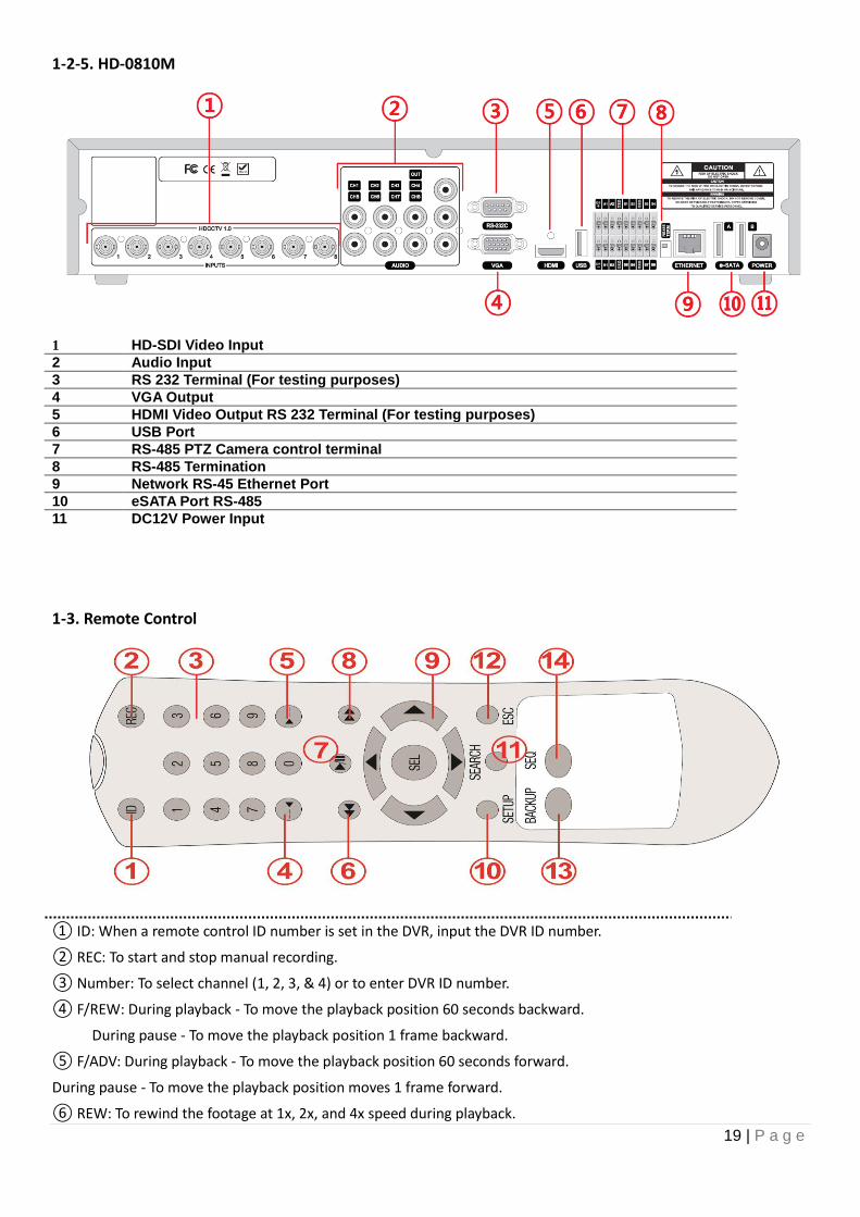
1-2-5. HD-0810M
1 HD-SDI Video Input
2 Audio Input
3 RS 232 Terminal (For testing purposes)
4 VGA Output
5 HDMI Video Output RS 232 Terminal (For testing purposes)
6 USB Port
7 RS-485 PTZ Camera control terminal
8 RS-485 Termination
9 Network RS-45 Ethernet Port
10 eSATA Port RS-485
11 DC12V Power Input
1-3. Remote Control
① ID: When a remote control ID number is set in the DVR, input the DVR ID number.
② REC: To start and stop manual recording.
③ Number: To select channel (1, 2, 3, & 4) or to enter DVR ID number.
④ F/REW: During playback - To move the playback position 60 seconds backward.
During pause - To move the playback position 1 frame backward.
⑤ F/ADV: During playback - To move the playback position 60 seconds forward.
During pause - To move the playback position moves 1 frame forward.
⑥ REW: To rewind the footage at 1x, 2x, and 4x speed during playback.

20 | P a g e
⑦ PLAY/PAUSE: To play or to pause the footage in playback mode.
⑧ FF: To fast forward the footage at 1x, 2x, and 4x speeds during playback.
⑨ Control button: Press to move the menu items or select channel.
⑩ SETUP: To launch SETUP menu.
⑪ SEARCH: To go to the search menu.
⑫ ESC: During setting - To return to previous menu screen.
During playback - To exit from playback
System Lock – To lock a system when pressing ESC button for 5 seconds.
System Unlock – To unlock a system when pressing ESC button for 5 seconds.
⑬ BACKUP: To start operations of backup in live or playback mode. (The same function button as CAPTURE on the
front panel of DVR)
⑭ SEQ: To start auto sequencing of the screen in full screen mode. (Toggle)
21 | P a g e
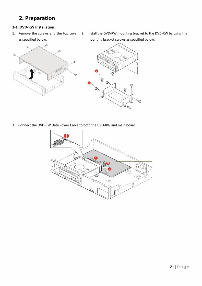
2. Preparation
2-1. DVD-RW Installation
1. Remove the screws and the top cover
as specified below.
2. Install the DVD-RW mounting bracket to the DVD-RW by using the
mounting bracket screws as specified below.
3. Connect the DVD-RW Data Power Cable to both the DVD-RW and main board.
22 | P a g e
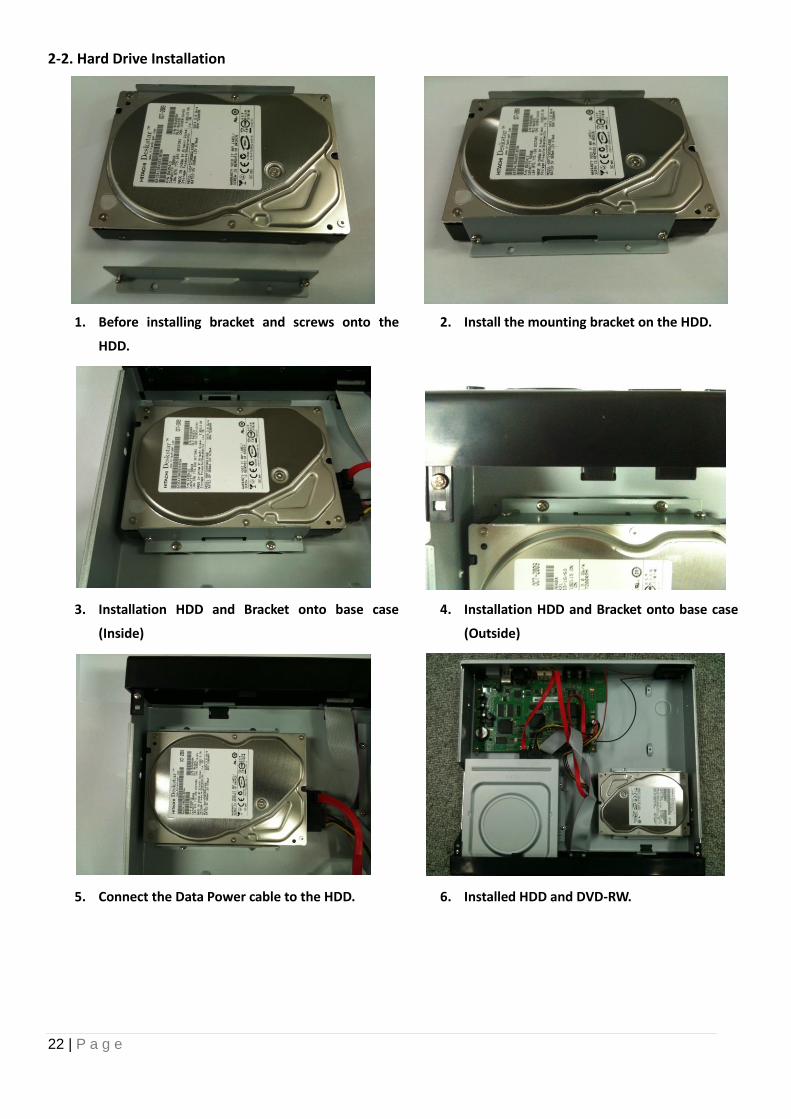
2-2. Hard Drive Installation
1. Before installing bracket and screws onto the
HDD.
2. Install the mounting bracket on the HDD.
3. Installation HDD and Bracket onto base case
(Inside)
4. Installation HDD and Bracket onto base case
(Outside)
5. Connect the Data Power cable to the HDD. 6. Installed HDD and DVD-RW.
23 | P a g e
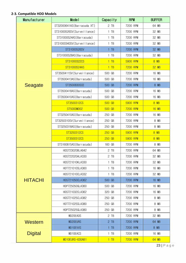
2-3. Compatible HDD Models
Manufacturer Model Capacity RPM BUFFER
Seagate
ST32000641AS(Barracuda XT) 2 TB 7200 RPM 64 MB
ST31000526SV(Surveillance) 1 TB 7200 RPM 32 MB
ST31000524AS(Barracuda) 1 TB 7200 RPM 32 MB
ST31000340SV(Surveillance) 1 TB 7200 RPM 32 MB
ST31000526SV 1 TB 7200 RPM 32 MB
ST31000528AS(Barracuda) 1 TB 7200 RPM 32 MB
ST31000322CS 1 TB 5900 RPM 8 MB
ST31000524AS 1 TB 7200 RPM 32 MB
ST3500411SV(Surveillance) 500 GB 7200 RPM 16 MB
ST3500413AS(Barracuda) 500 GB 7200 RPM 16 MB
ST3500830SCE 500 GB 7200 RPM 8 MB
ST3500418AS(Barracuda) 500 GB 7200 RPM 16 MB
ST3500410AS(Barracuda) 500 GB 7200 RPM 16 MB
ST3500312CS 500 GB 5900 RPM 8 MB
ST500DM002 500 GB 7200 RPM 16 MB
ST3250410AS(Barracuda) 250 GB 7200 RPM 16 MB
ST3250310SV(Surveillance) 250 GB 7200 RPM 8 MB
ST3250318AS(Barracuda) 250 GB 7200 RPM 8 MB
ST3250312CS 250 GB 5900 RPM 8 MB
ST3500312CS 250 GB 5900 RPM 8 MB
ST3160815AS(Barracuda) 160 GB 7200 RPM 8 MB
HITACHI
HDS723020BLA642 2 TB 7200 RPM 64 MB
HDS722020ALA330 2 TB 7200 RPM 32 MB
HDS721010KLA330 1 TB 7200 RPM 32 MB
HDT721010SLA360 1 TB 7200 RPM 16 MB
HDS721010CLA332 1 TB 7200 RPM 32 MB
HDS721050CLA362 500 GB 7200 RPM 16 MB
HDP725050GLA360 500 GB 7200 RPM 16 MB
HDS721032CLA362 320 GB 7200 RPM 16 MB
HDS721025CLA382 250 GB 7200 RPM 8 MB
HDT721025SLA380 250 GB 7200 RPM 8 MB
HDP725025GLA380 250 GB 7200 RPM 8 MB
Western
Digital
WD20EADS 2 TB 7200 RPM 32 MB
WD20EURS 2 TB 7200 RPM 64 MB
WD10EVVS 1 TB 7200 RPM 8 MB
WD10EACS 1 TB 7200 RPM 16 MB
WD10EURS-630AB1 1 TB 7200 RPM 64 MB
24 | P a g e
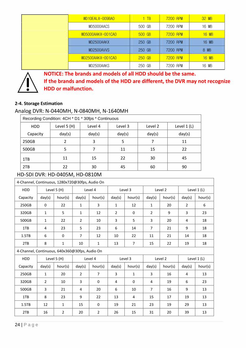
WD10EALX-009BA0 1 TB 7200 RPM 32 MB
WD5000AACS 500 GB 7200 RPM 16 MB
WD5000AAKX-001CA0 500 GB 7200 RPM 16 MB
WD2500AAKX 250 GB 7200 RPM 16 MB
WD2500AVVS 250 GB 7200 RPM 8 MB
WD2500AAKX-001CA0 250 GB 7200 RPM 16 MB
WD2500AAKS 250 GB 7200 RPM 16 MB
NOTICE: The brands and models of all HDD should be the same.
If the brands and models of the HDD are different, the DVR may not recognize
HDD or malfunction.
2-4. Storage Estimation
Analog DVR: N-0440MH, N-0840MH, N-1640MH Recording Condition: 4CH * D1 * 30fps * Continuous
HDD
Capacity
Level 5 (H) Level 4 Level 3 Level 2 Level 1 (L)
day(s) day(s) day(s) day(s) day(s)
250GB 2 3 5 7 11
500GB 5 7 11 15 22
1TB 11 15 22 30 45
2TB 22 30 45 60 90
HD-SDI DVR: HD-0405M, HD-0810M 4-Channel, Continuous, 1280x720@30fps, Audio On
HDD Level 5 (H) Level 4 Level 3 Level 2 Level 1 (L)
Capacity day(s) hour(s) day(s) hour(s) day(s) hour(s) day(s) hour(s) day(s) hour(s)
250GB 0 22 1 3 1 12 1 20 2 6
320GB 1 5 1 12 2 0 2 9 3 23
500GB 1 22 2 10 3 5 3 20 4 18
1TB 4 23 5 23 6 14 7 21 9 18
1.5TB 6 0 7 12 10 22 11 21 14 18
2TB 8 1 10 1 13 7 15 22 19 18
4-Channel, Continuous, 640x360@30fps, Audio On
HDD Level 5 (H) Level 4 Level 3 Level 2 Level 1 (L)
Capacity day(s) hour(s) day(s) hour(s) day(s) hour(s) day(s) hour(s) day(s) hour(s)
250GB 1 20 2 7 3 1 3 16 4 13
320GB 2 10 3 0 4 0 4 19 6 23
500GB 3 21 4 20 6 10 7 16 9 13
1TB 8 23 9 22 13 4 15 17 19 13
1.5TB 12 1 15 0 19 21 23 19 29 13
2TB 16 2 20 2 26 15 31 20 39 13
25 | P a g e
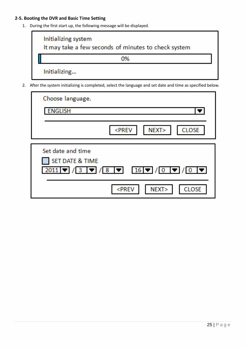
2-5. Booting the DVR and Basic Time Setting
1. During the first start up, the following message will be displayed.
2. After the system initializing is completed, select the language and set date and time as specified below.
26 | P a g e
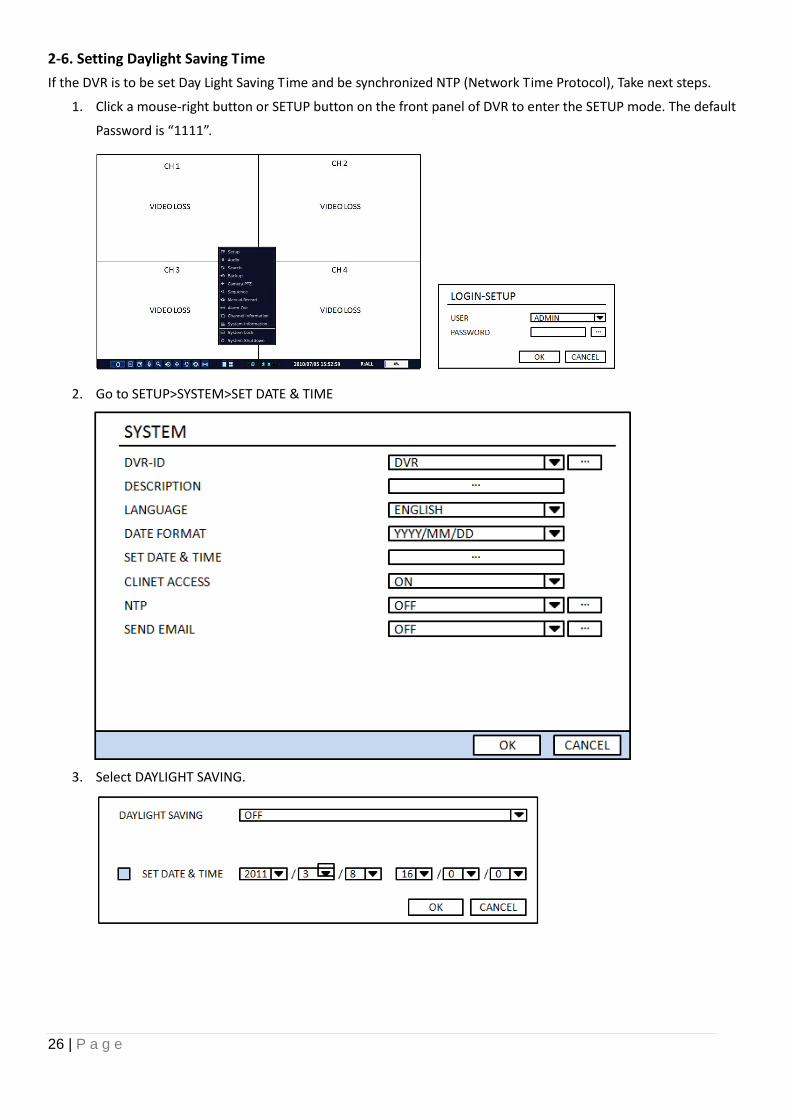
2-6. Setting Daylight Saving Time
If the DVR is to be set Day Light Saving Time and be synchronized NTP (Network Time Protocol), Take next steps.
1. Click a mouse-right button or SETUP button on the front panel of DVR to enter the SETUP mode. The default
Password is “1111”.
2. Go to SETUP>SYSTEM>SET DATE & TIME
3. Select DAYLIGHT SAVING.
27 | P a g e
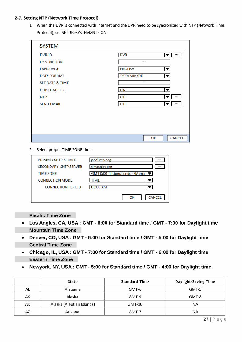
2-7. Setting NTP (Network Time Protocol)
1. When the DVR is connected with internet and the DVR need to be syncronized with NTP (Network Time
Protocol), set SETUP>SYSTEM>NTP ON.
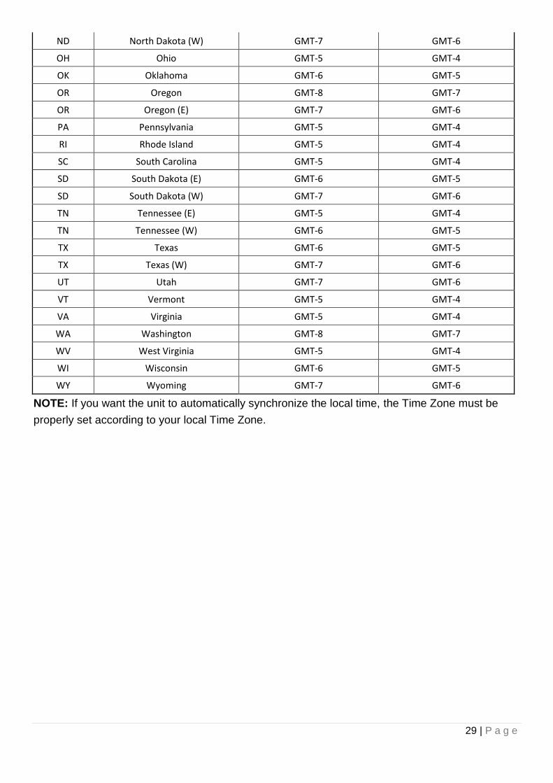
2. Select proper TIME ZONE time.
Pacific Time Zone
Los Angles, CA, USA : GMT - 8:00 for Standard time / GMT - 7:00 for Daylight time
Mountain Time Zone
Denver, CO, USA : GMT - 6:00 for Standard time / GMT - 5:00 for Daylight time
Central Time Zone
Chicago, IL, USA : GMT - 7:00 for Standard time / GMT - 6:00 for Daylight time
Eastern Time Zone
Newyork, NY, USA : GMT - 5:00 for Standard time / GMT - 4:00 for Daylight time
State Standard Time Daylight-Saving Time
AL Alabama GMT-6 GMT-5
AK Alaska GMT-9 GMT-8
AK Alaska (Aleutian Islands) GMT-10 NA
AZ Arizona GMT-7 NA
28 | P a g e
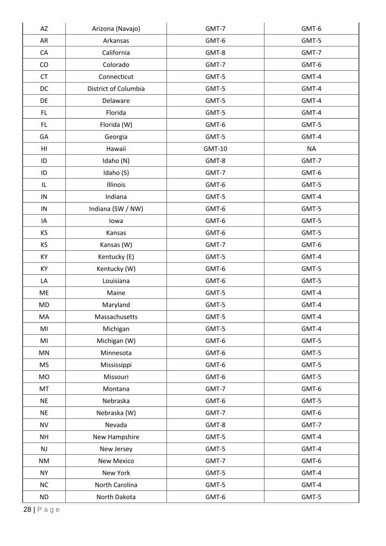
AZ Arizona (Navajo) GMT-7 GMT-6
AR Arkansas GMT-6 GMT-5
CA California GMT-8 GMT-7
CO Colorado GMT-7 GMT-6
CT Connecticut GMT-5 GMT-4
DC District of Columbia GMT-5 GMT-4
DE Delaware GMT-5 GMT-4
FL Florida GMT-5 GMT-4
FL Florida (W) GMT-6 GMT-5
GA Georgia GMT-5 GMT-4
HI Hawaii GMT-10 NA
ID Idaho (N) GMT-8 GMT-7
ID Idaho (S) GMT-7 GMT-6
IL Illinois GMT-6 GMT-5
IN Indiana GMT-5 GMT-4
IN Indiana (SW / NW) GMT-6 GMT-5
IA Iowa GMT-6 GMT-5
KS Kansas GMT-6 GMT-5
KS Kansas (W) GMT-7 GMT-6
KY Kentucky (E) GMT-5 GMT-4
KY Kentucky (W) GMT-6 GMT-5
LA Louisiana GMT-6 GMT-5
ME Maine GMT-5 GMT-4
MD Maryland GMT-5 GMT-4
MA Massachusetts GMT-5 GMT-4
MI Michigan GMT-5 GMT-4
MI Michigan (W) GMT-6 GMT-5
MN Minnesota GMT-6 GMT-5
MS Mississippi GMT-6 GMT-5
MO Missouri GMT-6 GMT-5
MT Montana GMT-7 GMT-6
NE Nebraska GMT-6 GMT-5
NE Nebraska (W) GMT-7 GMT-6
NV Nevada GMT-8 GMT-7
NH New Hampshire GMT-5 GMT-4
NJ New Jersey GMT-5 GMT-4
NM New Mexico GMT-7 GMT-6
NY New York GMT-5 GMT-4
NC North Carolina GMT-5 GMT-4
ND North Dakota GMT-6 GMT-5
29 | P a g e
ND North Dakota (W) GMT-7 GMT-6
OH Ohio GMT-5 GMT-4
OK Oklahoma GMT-6 GMT-5
OR Oregon GMT-8 GMT-7
OR Oregon (E) GMT-7 GMT-6
PA Pennsylvania GMT-5 GMT-4
RI Rhode Island GMT-5 GMT-4
SC South Carolina GMT-5 GMT-4
SD South Dakota (E) GMT-6 GMT-5
SD South Dakota (W) GMT-7 GMT-6
TN Tennessee (E) GMT-5 GMT-4
TN Tennessee (W) GMT-6 GMT-5
TX Texas GMT-6 GMT-5
TX Texas (W) GMT-7 GMT-6
UT Utah GMT-7 GMT-6
VT Vermont GMT-5 GMT-4
VA Virginia GMT-5 GMT-4
WA Washington GMT-8 GMT-7
WV West Virginia GMT-5 GMT-4
WI Wisconsin GMT-6 GMT-5
WY Wyoming GMT-7 GMT-6
NOTE: If you want the unit to automatically synchronize the local time, the Time Zone must be
properly set according to your local Time Zone.
30 | P a g e
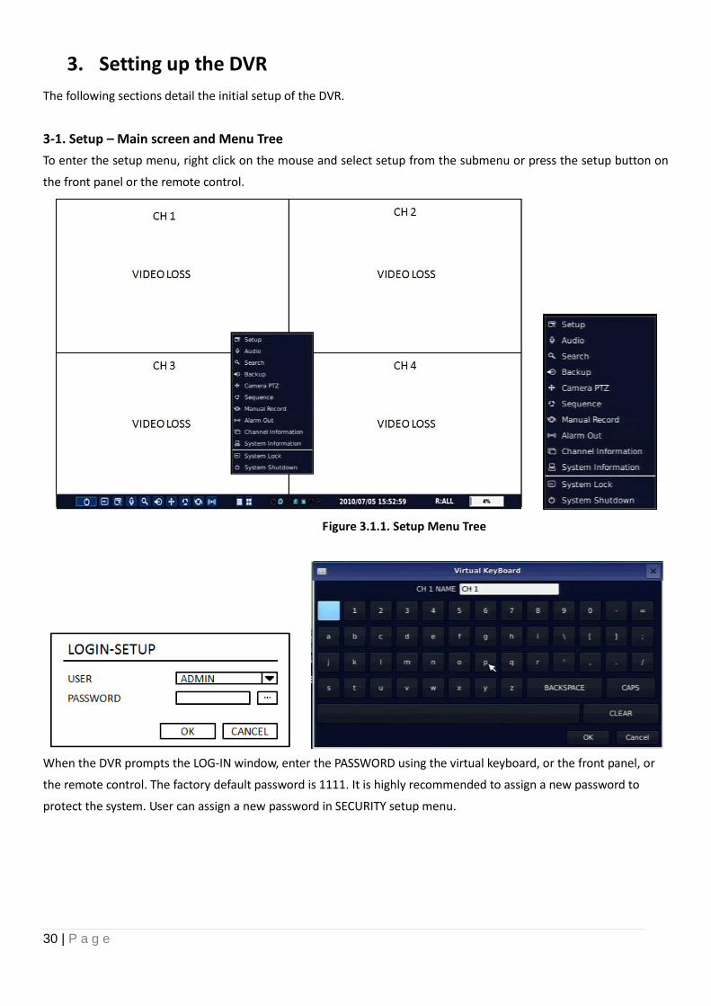
3. Setting up the DVR
The following sections detail the initial setup of the DVR.
3-1. Setup – Main screen and Menu Tree
To enter the setup menu, right click on the mouse and select setup from the submenu or press the setup button on
the front panel or the remote control.
Figure 3.1.1. Setup Menu Tree
When the DVR prompts the LOG-IN window, enter the PASSWORD using the virtual keyboard, or the front panel, or
the remote control. The factory default password is 1111. It is highly recommended to assign a new password to
protect the system. User can assign a new password in SECURITY setup menu.
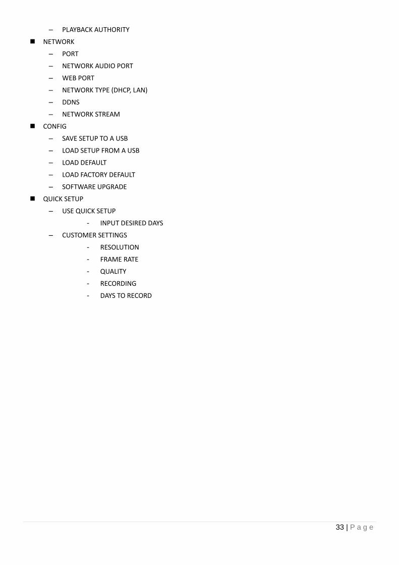
31 | P a g e
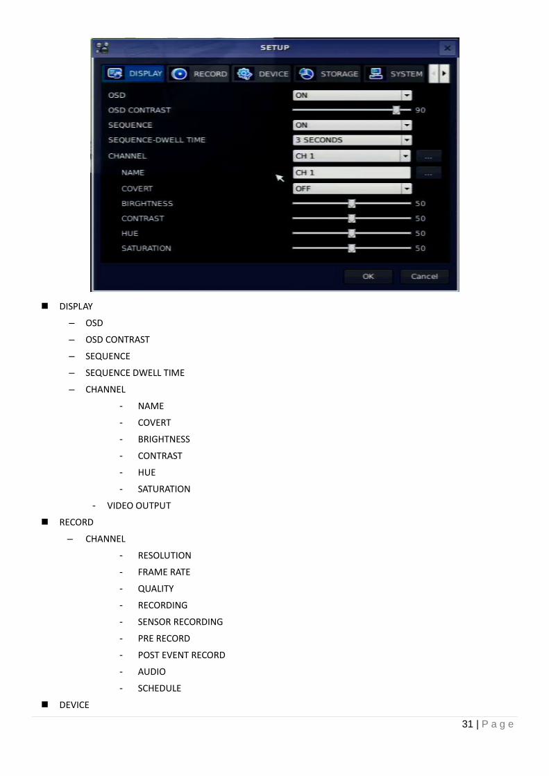
DISPLAY
– OSD
– OSD CONTRAST
– SEQUENCE
– SEQUENCE DWELL TIME
– CHANNEL
- NAME
- COVERT
- BRIGHTNESS
- CONTRAST
- HUE
- SATURATION
- VIDEO OUTPUT
RECORD
– CHANNEL
- RESOLUTION
- FRAME RATE
- QUALITY
- RECORDING
- SENSOR RECORDING
- PRE RECORD
- POST EVENT RECORD
- AUDIO
- SCHEDULE
DEVICE
32 | P a g e
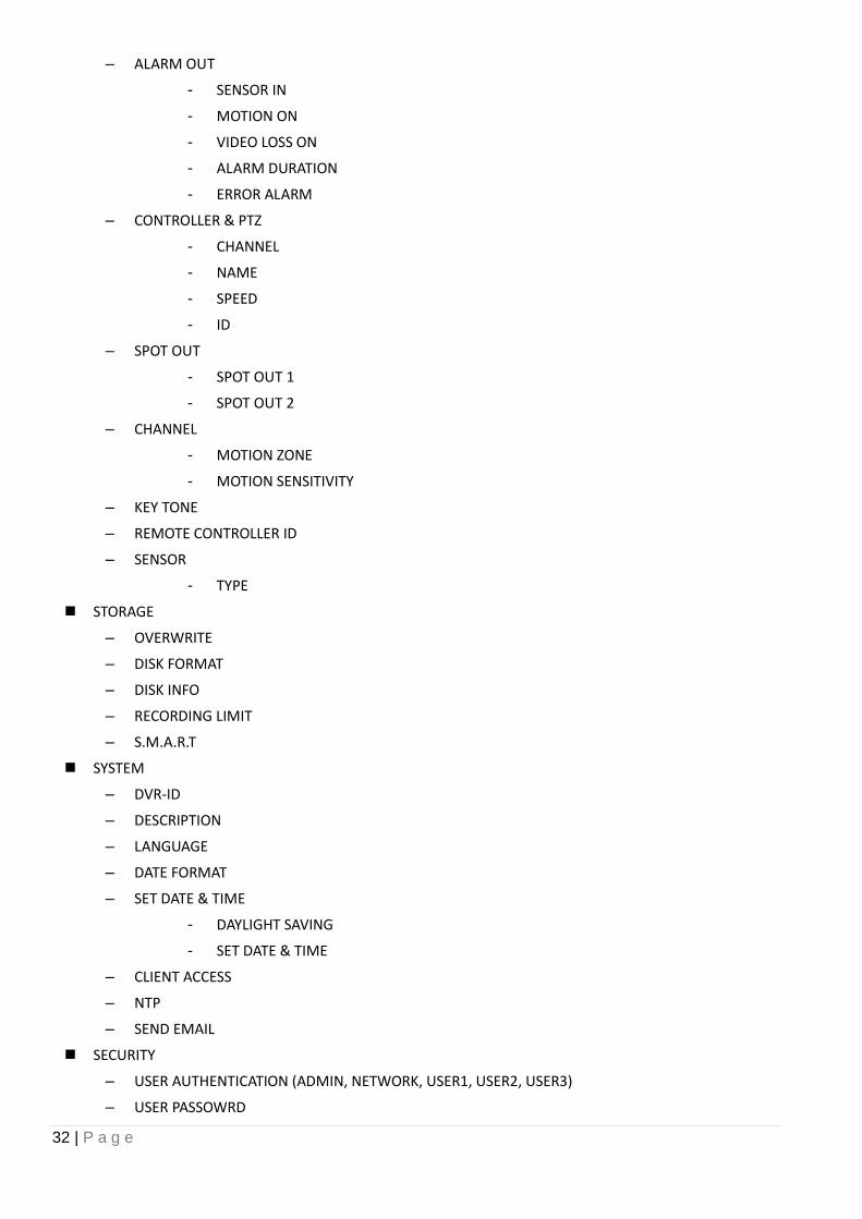
– ALARM OUT
- SENSOR IN
- MOTION ON
- VIDEO LOSS ON
- ALARM DURATION
- ERROR ALARM
– CONTROLLER & PTZ
- CHANNEL
- NAME
- SPEED
- ID
– SPOT OUT
- SPOT OUT 1
- SPOT OUT 2
– CHANNEL
- MOTION ZONE
- MOTION SENSITIVITY
– KEY TONE
– REMOTE CONTROLLER ID
– SENSOR
- TYPE
STORAGE
– OVERWRITE
– DISK FORMAT
– DISK INFO
– RECORDING LIMIT
– S.M.A.R.T
SYSTEM
– DVR-ID
– DESCRIPTION
– LANGUAGE
– DATE FORMAT
– SET DATE & TIME
- DAYLIGHT SAVING
- SET DATE & TIME
– CLIENT ACCESS
– NTP
– SEND EMAIL
SECURITY
– USER AUTHENTICATION (ADMIN, NETWORK, USER1, USER2, USER3)
– USER PASSOWRD
33 | P a g e
– PLAYBACK AUTHORITY
NETWORK
– PORT
– NETWORK AUDIO PORT
– WEB PORT
– NETWORK TYPE (DHCP, LAN)
– DDNS
– NETWORK STREAM
CONFIG
– SAVE SETUP TO A USB
– LOAD SETUP FROM A USB
– LOAD DEFAULT
– LOAD FACTORY DEFAULT
– SOFTWARE UPGRADE
QUICK SETUP
– USE QUICK SETUP
- INPUT DESIRED DAYS
– CUSTOMER SETTINGS
- RESOLUTION
- FRAME RATE
- QUALITY
- RECORDING
- DAYS TO RECORD
34 | P a g e
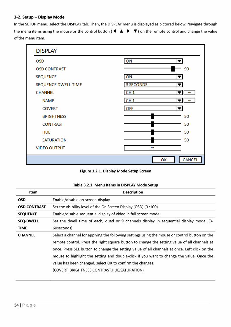
3-2. Setup – Display Mode
In the SETUP menu, select the DISPLAY tab. Then, the DISPLAY menu is displayed as pictured below. Navigate through
the menu items using the mouse or the control button (◀ ▲ ▶ ▼) on the remote control and change the value
of the menu item.
Figure 3.2.1. Display Mode Setup Screen
Table 3.2.1. Menu Items in DISPLAY Mode Setup
Item Description
OSD Enable/disable on-screen-display.
OSD CONTRAST Set the visibility level of the On Screen Display (OSD) (0~100)
SEQUENCE Enable/disable sequential display of video in full screen mode.
SEQ-DWELL
TIME
Set the dwell time of each, quad or 9 channels display in sequential display mode. (3-
60seconds)
CHANNEL Select a channel for applying the following settings using the mouse or control button on the
remote control. Press the right square button to change the setting value of all channels at
once. Press SEL button to change the setting value of all channels at once. Left click on the
mouse to highlight the setting and double-click if you want to change the value. Once the
value has been changed, select OK to confirm the changes.
(COVERT, BRIGHTNESS,CONTRAST,HUE,SATURATION)
35 | P a g e
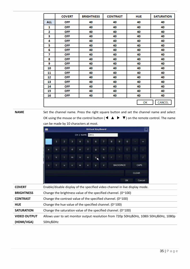
NAME Set the channel name. Press the right square button and set the channel name and select
OK using the mouse or the control button (◀ ▲ ▶ ▼) on the remote control. The name
can be made by 10 characters at most.
COVERT Enable/disable display of the specified video channel in live display mode.
BRIGHTNESS Change the brightness value of the specified channel. (0~100)
CONTRAST Change the contrast value of the specified channel. (0~100)
HUE Change the hue value of the specified channel. (0~100)
SATURATION Change the saturation value of the specified channel. (0~100)
VIDEO OUTPUT
(HDMI/VGA)
Allows user to set monitor output resolution from 720p 50Hz/60Hz, 1080i 50Hz/60Hz, 1080p
50Hz/60Hz
36 | P a g e
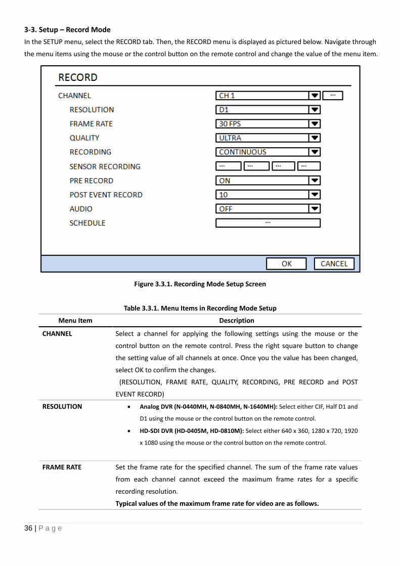
3-3. Setup – Record Mode
In the SETUP menu, select the RECORD tab. Then, the RECORD menu is displayed as pictured below. Navigate through
the menu items using the mouse or the control button on the remote control and change the value of the menu item.
Figure 3.3.1. Recording Mode Setup Screen
Table 3.3.1. Menu Items in Recording Mode Setup
Menu Item Description
CHANNEL Select a channel for applying the following settings using the mouse or the
control button on the remote control. Press the right square button to change
the setting value of all channels at once. Once you the value has been changed,
select OK to confirm the changes.
(RESOLUTION, FRAME RATE, QUALITY, RECORDING, PRE RECORD and POST
EVENT RECORD)
RESOLUTION Analog DVR (N-0440MH, N-0840MH, N-1640MH): Select either CIF, Half D1 and
D1 using the mouse or the control button on the remote control.
HD-SDI DVR (HD-0405M, HD-0810M): Select either 640 x 360, 1280 x 720, 1920
x 1080 using the mouse or the control button on the remote control.
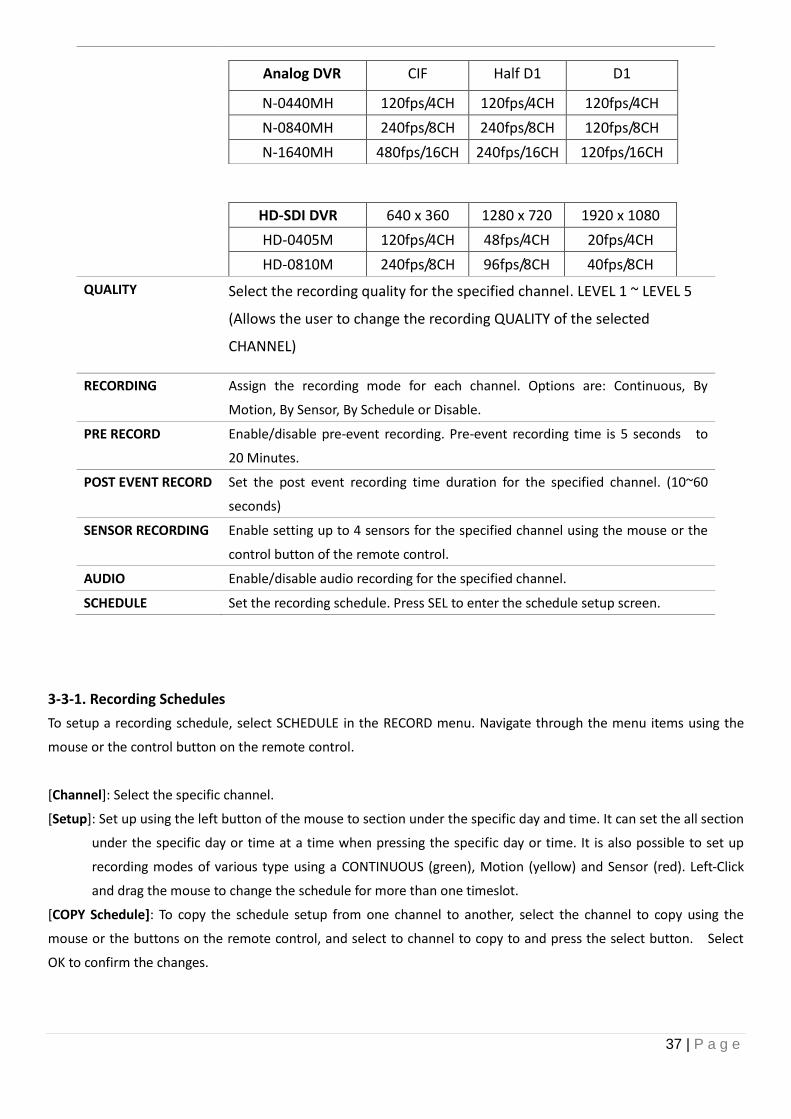
FRAME RATE Set the frame rate for the specified channel. The sum of the frame rate values
from each channel cannot exceed the maximum frame rates for a specific
recording resolution.
Typical values of the maximum frame rate for video are as follows.
37 | P a g e
Analog DVR CIF Half D1 D1
N-0440MH 120fps/4CH 120fps/4CH 120fps/4CH
N-0840MH 240fps/8CH 240fps/8CH 120fps/8CH
N-1640MH 480fps/16CH 240fps/16CH 120fps/16CH
HD-SDI DVR 640 x 360 1280 x 720 1920 x 1080
HD-0405M 120fps/4CH 48fps/4CH 20fps/4CH
HD-0810M 240fps/8CH 96fps/8CH 40fps/8CH
QUALITY Select the recording quality for the specified channel. LEVEL 1 ~ LEVEL 5
(Allows the user to change the recording QUALITY of the selected
CHANNEL)
RECORDING Assign the recording mode for each channel. Options are: Continuous, By
Motion, By Sensor, By Schedule or Disable.
PRE RECORD Enable/disable pre-event recording. Pre-event recording time is 5 seconds to
20 Minutes.
POST EVENT RECORD Set the post event recording time duration for the specified channel. (10~60
seconds)
SENSOR RECORDING Enable setting up to 4 sensors for the specified channel using the mouse or the
control button of the remote control.
AUDIO Enable/disable audio recording for the specified channel.
SCHEDULE Set the recording schedule. Press SEL to enter the schedule setup screen.
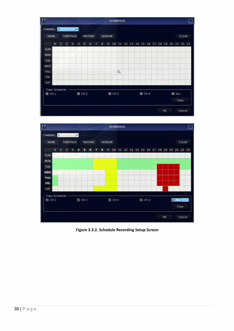
3-3-1. Recording Schedules
To setup a recording schedule, select SCHEDULE in the RECORD menu. Navigate through the menu items using the
mouse or the control button on the remote control.
[Channel]: Select the specific channel.
[Setup]: Set up using the left button of the mouse to section under the specific day and time. It can set the all section
under the specific day or time at a time when pressing the specific day or time. It is also possible to set up
recording modes of various type using a CONTINUOUS (green), Motion (yellow) and Sensor (red). Left-Click
and drag the mouse to change the schedule for more than one timeslot.
[COPY Schedule]: To copy the schedule setup from one channel to another, select the channel to copy using the
mouse or the buttons on the remote control, and select to channel to copy to and press the select button. Select
OK to confirm the changes.
38 | P a g e
Figure 3.3.2. Schedule Recording Setup Screen
39 | P a g e
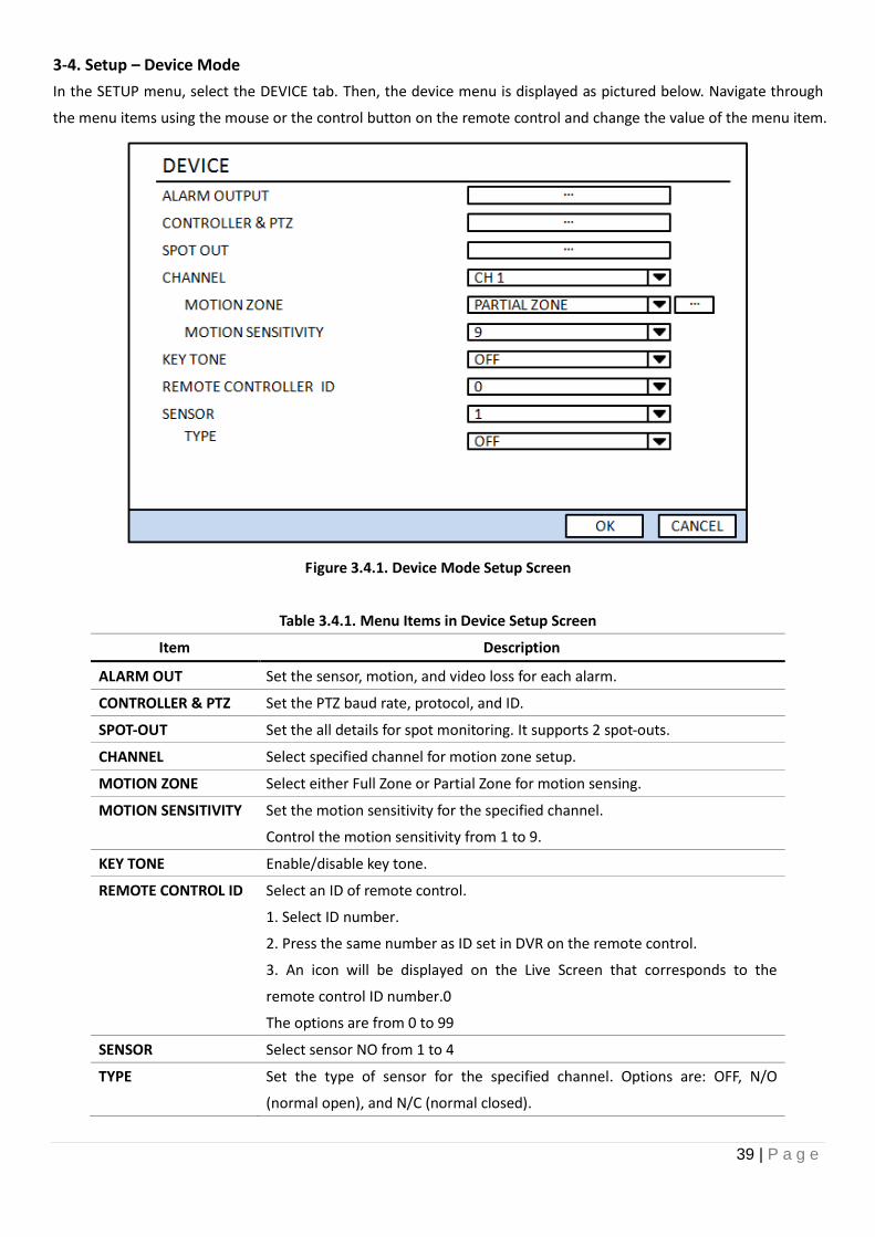
3-4. Setup – Device Mode
In the SETUP menu, select the DEVICE tab. Then, the device menu is displayed as pictured below. Navigate through
the menu items using the mouse or the control button on the remote control and change the value of the menu item.
Figure 3.4.1. Device Mode Setup Screen
Table 3.4.1. Menu Items in Device Setup Screen
Item Description
ALARM OUT Set the sensor, motion, and video loss for each alarm.
CONTROLLER & PTZ Set the PTZ baud rate, protocol, and ID.
SPOT-OUT Set the all details for spot monitoring. It supports 2 spot-outs.
CHANNEL Select specified channel for motion zone setup.
MOTION ZONE Select either Full Zone or Partial Zone for motion sensing.
MOTION SENSITIVITY Set the motion sensitivity for the specified channel.
Control the motion sensitivity from 1 to 9.
KEY TONE Enable/disable key tone.
REMOTE CONTROL ID Select an ID of remote control.
1. Select ID number.
2. Press the same number as ID set in DVR on the remote control.
3. An icon will be displayed on the Live Screen that corresponds to the
remote control ID number.0
The options are from 0 to 99
SENSOR Select sensor NO from 1 to 4
TYPE Set the type of sensor for the specified channel. Options are: OFF, N/O
(normal open), and N/C (normal closed).
40 | P a g e
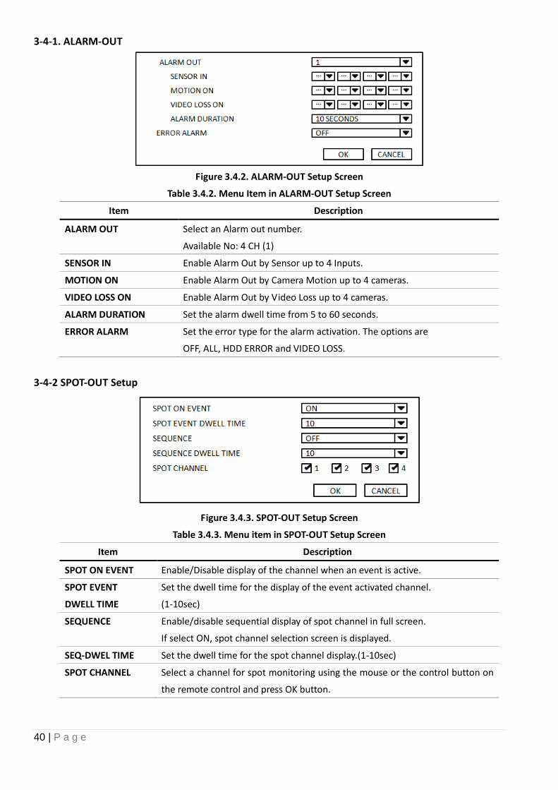
3-4-1. ALARM-OUT
Figure 3.4.2. ALARM-OUT Setup Screen
Table 3.4.2. Menu Item in ALARM-OUT Setup Screen
Item Description
ALARM OUT Select an Alarm out number.
Available No: 4 CH (1)
SENSOR IN Enable Alarm Out by Sensor up to 4 Inputs.
MOTION ON Enable Alarm Out by Camera Motion up to 4 cameras.
VIDEO LOSS ON Enable Alarm Out by Video Loss up to 4 cameras.
ALARM DURATION Set the alarm dwell time from 5 to 60 seconds.
ERROR ALARM Set the error type for the alarm activation. The options are
OFF, ALL, HDD ERROR and VIDEO LOSS.
3-4-2 SPOT-OUT Setup
Figure 3.4.3. SPOT-OUT Setup Screen
Table 3.4.3. Menu item in SPOT-OUT Setup Screen
Item Description
SPOT ON EVENT Enable/Disable display of the channel when an event is active.
SPOT EVENT
DWELL TIME
Set the dwell time for the display of the event activated channel.
(1-10sec)
SEQUENCE Enable/disable sequential display of spot channel in full screen.
If select ON, spot channel selection screen is displayed.
SEQ-DWEL TIME Set the dwell time for the spot channel display.(1-10sec)
SPOT CHANNEL Select a channel for spot monitoring using the mouse or the control button on
the remote control and press OK button.
41 | P a g e
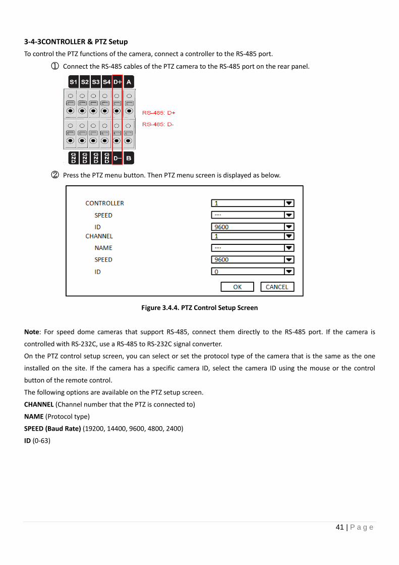
3-4-3CONTROLLER & PTZ Setup
To control the PTZ functions of the camera, connect a controller to the RS-485 port.
① Connect the RS-485 cables of the PTZ camera to the RS-485 port on the rear panel.
② Press the PTZ menu button. Then PTZ menu screen is displayed as below.
Figure 3.4.4. PTZ Control Setup Screen
Note: For speed dome cameras that support RS-485, connect them directly to the RS-485 port. If the camera is
controlled with RS-232C, use a RS-485 to RS-232C signal converter.
On the PTZ control setup screen, you can select or set the protocol type of the camera that is the same as the one
installed on the site. If the camera has a specific camera ID, select the camera ID using the mouse or the control
button of the remote control.
The following options are available on the PTZ setup screen.
CHANNEL (Channel number that the PTZ is connected to)
NAME (Protocol type)
SPEED (Baud Rate) (19200, 14400, 9600, 4800, 2400)
ID (0-63)
42 | P a g e
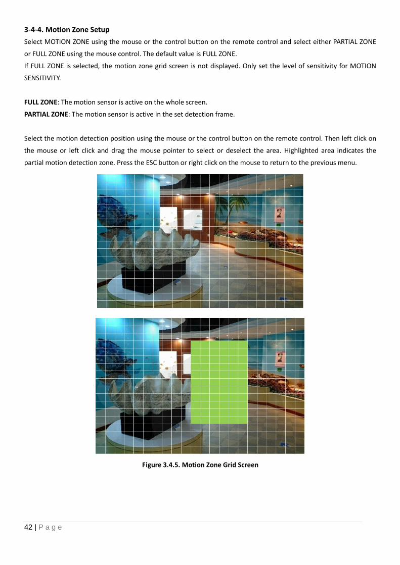
3-4-4. Motion Zone Setup
Select MOTION ZONE using the mouse or the control button on the remote control and select either PARTIAL ZONE
or FULL ZONE using the mouse control. The default value is FULL ZONE.
If FULL ZONE is selected, the motion zone grid screen is not displayed. Only set the level of sensitivity for MOTION
SENSITIVITY.
FULL ZONE: The motion sensor is active on the whole screen.
PARTIAL ZONE: The motion sensor is active in the set detection frame.
Select the motion detection position using the mouse or the control button on the remote control. Then left click on
the mouse or left click and drag the mouse pointer to select or deselect the area. Highlighted area indicates the
partial motion detection zone. Press the ESC button or right click on the mouse to return to the previous menu.
Figure 3.4.5. Motion Zone Grid Screen
43 | P a g e
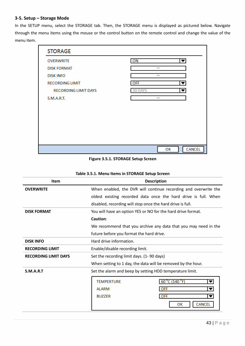
3-5. Setup – Storage Mode
In the SETUP menu, select the STORAGE tab. Then, the STORAGE menu is displayed as pictured below. Navigate
through the menu items using the mouse or the control button on the remote control and change the value of the
menu item.
Figure 3.5.1. STORAGE Setup Screen
Table 3.5.1. Menu Items in STORAGE Setup Screen
Item Description
OVERWRITE When enabled, the DVR will continue recording and overwrite the
oldest existing recorded data once the hard drive is full. When
disabled, recording will stop once the hard drive is full.
DISK FORMAT You will have an option YES or NO for the hard drive format.
Caution:
We recommend that you archive any data that you may need in the
future before you format the hard drive.
DISK INFO Hard drive information.
RECORDING LIMIT Enable/disable recording limit.
RECORDING LIMIT DAYS Set the recording limit days. (1- 90 days)
When setting to 1 day, the data will be removed by the hour.
S.M.A.R.T Set the alarm and beep by setting HDD temperature limit.
44 | P a g e
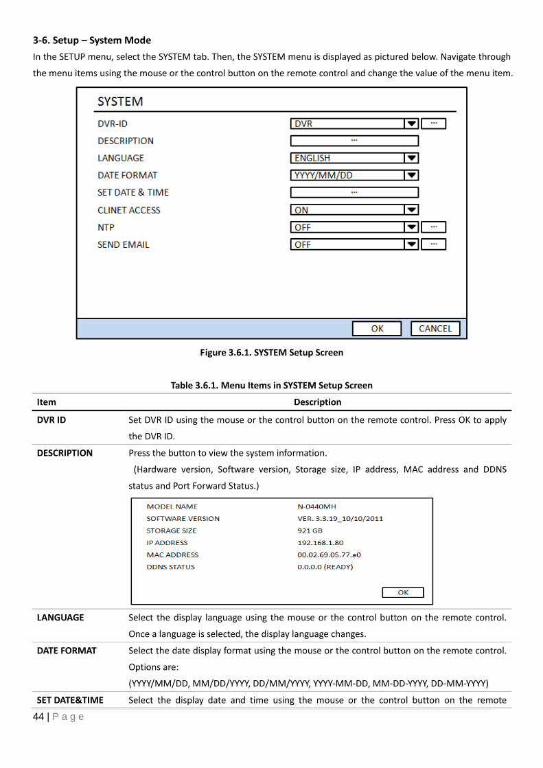
3-6. Setup – System Mode
In the SETUP menu, select the SYSTEM tab. Then, the SYSTEM menu is displayed as pictured below. Navigate through
the menu items using the mouse or the control button on the remote control and change the value of the menu item.
Figure 3.6.1. SYSTEM Setup Screen
Table 3.6.1. Menu Items in SYSTEM Setup Screen
Item Description
DVR ID Set DVR ID using the mouse or the control button on the remote control. Press OK to apply
the DVR ID.
DESCRIPTION Press the button to view the system information.
(Hardware version, Software version, Storage size, IP address, MAC address and DDNS
status and Port Forward Status.)
LANGUAGE Select the display language using the mouse or the control button on the remote control.
Once a language is selected, the display language changes.
DATE FORMAT Select the date display format using the mouse or the control button on the remote control.
Options are:
(YYYY/MM/DD, MM/DD/YYYY, DD/MM/YYYY, YYYY-MM-DD, MM-DD-YYYY, DD-MM-YYYY)
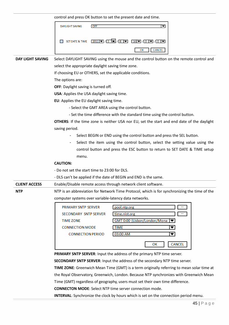
SET DATE&TIME Select the display date and time using the mouse or the control button on the remote
45 | P a g e
control and press OK button to set the present date and time.
DAY LIGHT SAVING
Select DAYLIGHT SAVING using the mouse and the control button on the remote control and
select the appropriate daylight saving time zone.
If choosing EU or OTHERS, set the applicable conditions.
The options are:
OFF: Daylight saving is turned off.
USA: Applies the USA daylight saving time.
EU: Applies the EU daylight saving time.
- Select the GMT AREA using the control button.
- Set the time difference with the standard time using the control button.
OTHERS: If the time zone is neither USA nor EU, set the start and end date of the daylight
saving period.
- Select BEGIN or END using the control button and press the SEL button.
- Select the item using the control button, select the setting value using the
control button and press the ESC button to return to SET DATE & TIME setup
menu.
CAUTION:
- Do not set the start time to 23:00 for DLS.
- DLS can’t be applied if the date of BEGIN and END is the same.
CLIENT ACCESS Enable/Disable remote access through network client software.
NTP NTP is an abbreviation for Network Time Protocol, which is for synchronizing the time of the
computer systems over variable-latency data networks.
PRIMARY SNTP SERVER: Input the address of the primary NTP time server.
SECONDARY SNTP SERVER: Input the address of the secondary NTP time server.
TIME ZONE: Greenwich Mean Time (GMT) is a term originally referring to mean solar time at
the Royal Observatory, Greenwich, London. Because NTP synchronizes with Greenwich Mean
Time (GMT) regardless of geography, users must set their own time difference.
CONNECTON MODE: Select NTP time server connection mode.
INTERVAL: Synchronize the clock by hours which is set on the connection period menu.
46 | P a g e
TIME: Synchronize the clock at the time daily which is set on the connection period menu.
CONNECTION PERIOD: 1~24
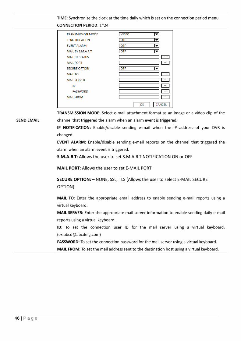
SEND EMAIL
TRANSMISSION MODE: Select e-mail attachment format as an image or a video clip of the
channel that triggered the alarm when an alarm event is triggered.
IP NOTIFICATION: Enable/disable sending e-mail when the IP address of your DVR is
changed.
EVENT ALARM: Enable/disable sending e-mail reports on the channel that triggered the
alarm when an alarm event is triggered.
S.M.A.R.T: Allows the user to set S.M.A.R.T NOTIFICATION ON or OFF
MAIL PORT: Allows the user to set E-MAIL PORT
SECURE OPTION: – NONE, SSL, TLS (Allows the user to select E-MAIL SECURE
OPTION)
MAIL TO: Enter the appropriate email address to enable sending e-mail reports using a
virtual keyboard.
MAIL SERVER: Enter the appropriate mail server information to enable sending daily e-mail
reports using a virtual keyboard.
ID: To set the connection user ID for the mail server using a virtual keyboard.
PASSWORD: To set the connection password for the mail server using a virtual keyboard.
MAIL FROM: To set the mail address sent to the destination host using a virtual keyboard.
47 | P a g e
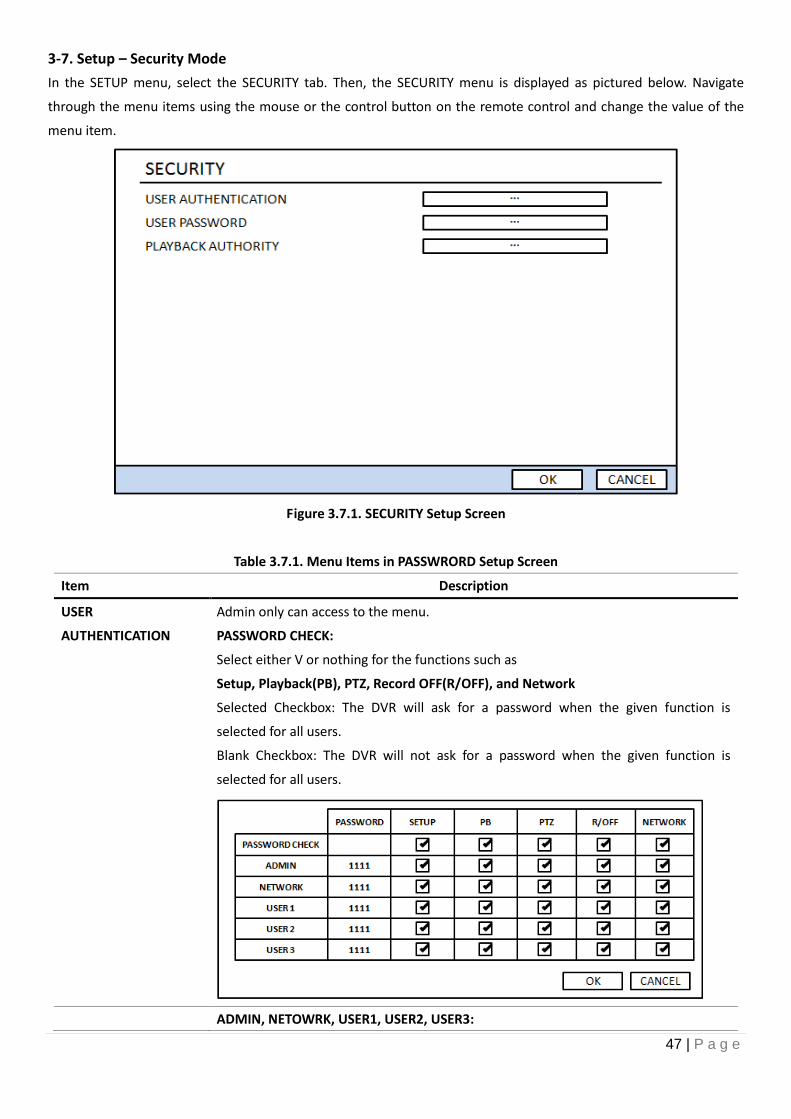
3-7. Setup – Security Mode
In the SETUP menu, select the SECURITY tab. Then, the SECURITY menu is displayed as pictured below. Navigate
through the menu items using the mouse or the control button on the remote control and change the value of the
menu item.
Figure 3.7.1. SECURITY Setup Screen
Table 3.7.1. Menu Items in PASSWRORD Setup Screen
Item Description
USER
AUTHENTICATION
Admin only can access to the menu.
PASSWORD CHECK:
Select either V or nothing for the functions such as
Setup, Playback(PB), PTZ, Record OFF(R/OFF), and Network
Selected Checkbox: The DVR will ask for a password when the given function is
selected for all users.
Blank Checkbox: The DVR will not ask for a password when the given function is
selected for all users.
ADMIN, NETOWRK, USER1, USER2, USER3:
48 | P a g e
Selected Checkbox: The user can access to the function.
Blank Checkbox: The user can not access to the function.
USER PASSWORD Options are ADMIN, NETWORK, USER1, USER2 and USER3.
Select USER PASSWORD using the mouse or the control button on the remote control
and press SEL button. Select user type and enter the current password. And, enter a
new password, enter the same password again to confirm and select OK. Then the
message “PASSWORD CHANGED” is displayed.
The factory default password is 1111.
PLAYBACK AUTHORITY Allows specific users AUTHORITY OF PLAYBACK per CHANNEL
When the user set this function, the login window will appear. Then, the user can select one of user types (ADMIN,
USER1, USER2, USER3) using the mouse or the control button on the remote control. The user can select a password
using the mouse or the control button on the remote control. The factory default password is 1111. It is highly
recommended to assign a new password to protect the system. User can assign a new password in the SECURITY
setup menu.
49 | P a g e
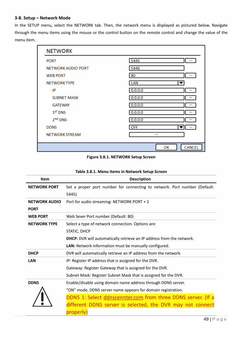
3-8. Setup – Network Mode
In the SETUP menu, select the NETWORK tab. Then, the network menu is displayed as pictured below. Navigate
through the menu items using the mouse or the control button on the remote control and change the value of the
menu item.
Figure 3.8.1. NETWORK Setup Screen
Table 3.8.1. Menu Items in Network Setup Screen
Item Description
NETWORK PORT Set a proper port number for connecting to network. Port number (Default:
5445)
NETWORK AUDIO
PORT
Port for audio streaming: NETWORK PORT + 1
WEB PORT Web Sever Port number (Default: 80)
NETWORK TYPE Select a type of network connection. Options are:
STATIC, DHCP
DHCP: DVR will automatically retrieve an IP address from the network.
LAN: Network information must be manually configured.
DHCP DVR will automatically retrieve an IP address from the network.
LAN IP: Register IP address that is assigned for the DVR.
Gateway: Register Gateway that is assigned for the DVR.
Subnet Mask: Register Subnet Mask that is assigned for the DVR.
DDNS Enable/disable using domain name address through DDNS server.
“ON” mode, DDNS server name appears for domain registration.
DDNS 1: Select ddnscennter.com from three DDNS server. (If a
different DDNS server is selected, the DVR may not connect
properly)
50 | P a g e
DDNS 2: Select this type when wants to use other general-purpose DDNS Server.
DDNS INTERVAL: Set the connection interval (5-60 minutes)
NETWORK
STREAM
Set the value for network streaming.
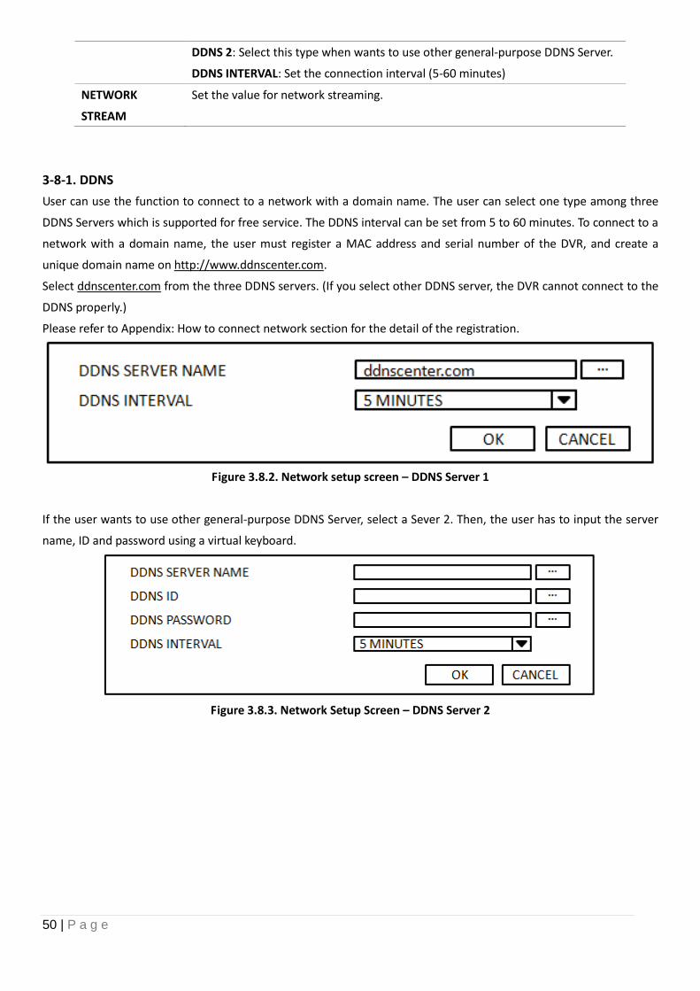
3-8-1. DDNS
User can use the function to connect to a network with a domain name. The user can select one type among three
DDNS Servers which is supported for free service. The DDNS interval can be set from 5 to 60 minutes. To connect to a
network with a domain name, the user must register a MAC address and serial number of the DVR, and create a
unique domain name on http://www.ddnscenter.com.
Select ddnscenter.com from the three DDNS servers. (If you select other DDNS server, the DVR cannot connect to the
DDNS properly.)
Please refer to Appendix: How to connect network section for the detail of the registration.
Figure 3.8.2. Network setup screen – DDNS Server 1
If the user wants to use other general-purpose DDNS Server, select a Sever 2. Then, the user has to input the server
name, ID and password using a virtual keyboard.
Figure 3.8.3. Network Setup Screen – DDNS Server 2
51 | P a g e
3-8-2. Network Ports
When you connect one or more DVRs to a network through an IP sharing device, each device must have a unique TCP
port number for access to each unit from outside the LAN. The IP sharing device must be configured to forward the
assigned port to the specific DVR.
Note: This port number is listed next to the Port menu option in the Network Setup screen. If you plan to access the
DVR units only from within the same LAN, the TCP port does not have to be changed.
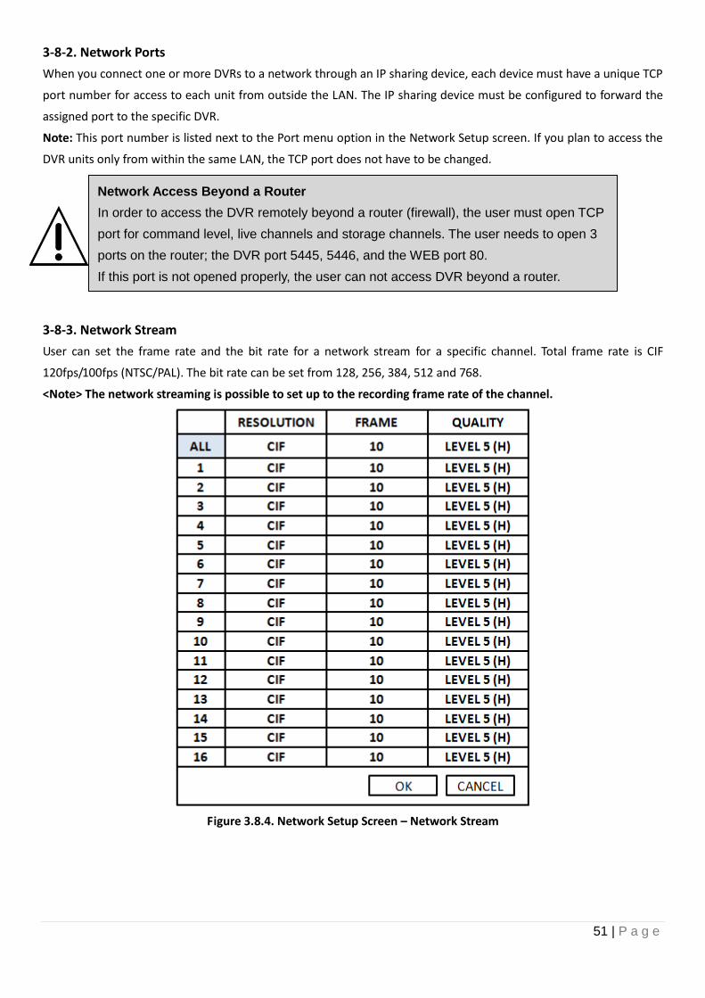
3-8-3. Network Stream
User can set the frame rate and the bit rate for a network stream for a specific channel. Total frame rate is CIF
120fps/100fps (NTSC/PAL). The bit rate can be set from 128, 256, 384, 512 and 768.
<Note> The network streaming is possible to set up to the recording frame rate of the channel.
Figure 3.8.4. Network Setup Screen – Network Stream
Network Access Beyond a Router
In order to access the DVR remotely beyond a router (firewall), the user must open TCP
port for command level, live channels and storage channels. The user needs to open 3
ports on the router; the DVR port 5445, 5446, and the WEB port 80.
If this port is not opened properly, the user can not access DVR beyond a router.
52 | P a g e
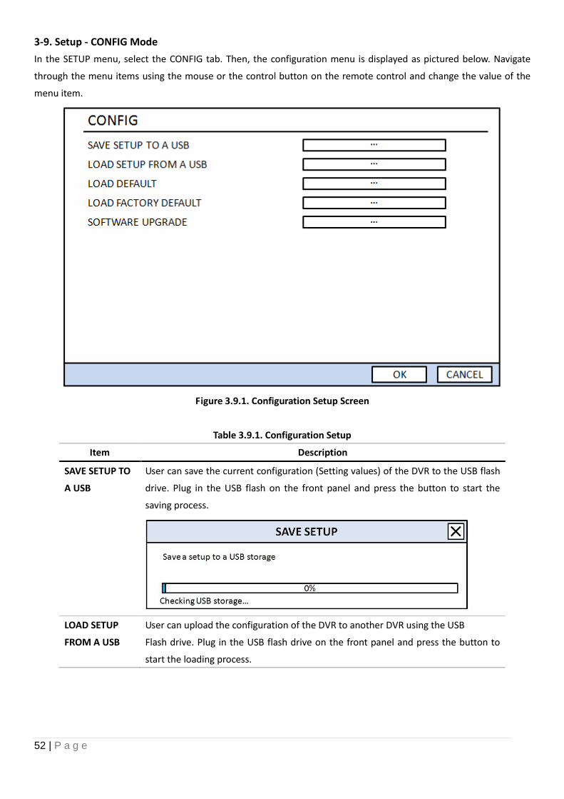
3-9. Setup - CONFIG Mode
In the SETUP menu, select the CONFIG tab. Then, the configuration menu is displayed as pictured below. Navigate
through the menu items using the mouse or the control button on the remote control and change the value of the
menu item.
Figure 3.9.1. Configuration Setup Screen
Table 3.9.1. Configuration Setup
Item Description
SAVE SETUP TO
A USB
User can save the current configuration (Setting values) of the DVR to the USB flash
drive. Plug in the USB flash on the front panel and press the button to start the
saving process.
LOAD SETUP
FROM A USB
User can upload the configuration of the DVR to another DVR using the USB
Flash drive. Plug in the USB flash drive on the front panel and press the button to
start the loading process.
53 | P a g e
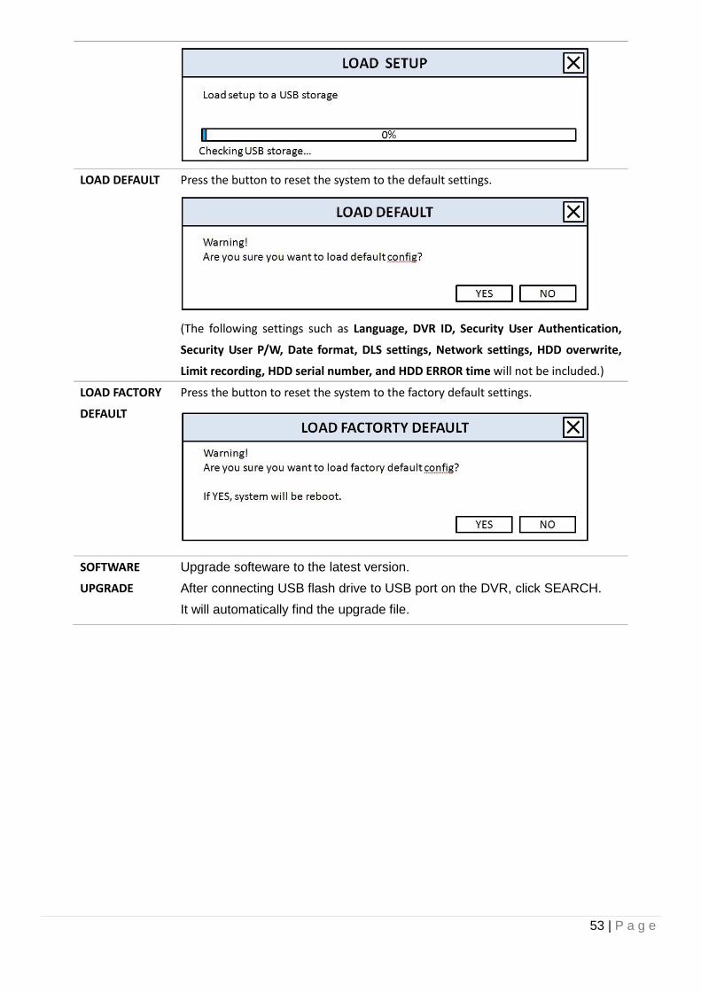
LOAD DEFAULT Press the button to reset the system to the default settings.
(The following settings such as Language, DVR ID, Security User Authentication,
Security User P/W, Date format, DLS settings, Network settings, HDD overwrite,
Limit recording, HDD serial number, and HDD ERROR time will not be included.)
LOAD FACTORY
DEFAULT
Press the button to reset the system to the factory default settings.
SOFTWARE
UPGRADE
Upgrade softeware to the latest version.
After connecting USB flash drive to USB port on the DVR, click SEARCH.
It will automatically find the upgrade file.
54 | P a g e
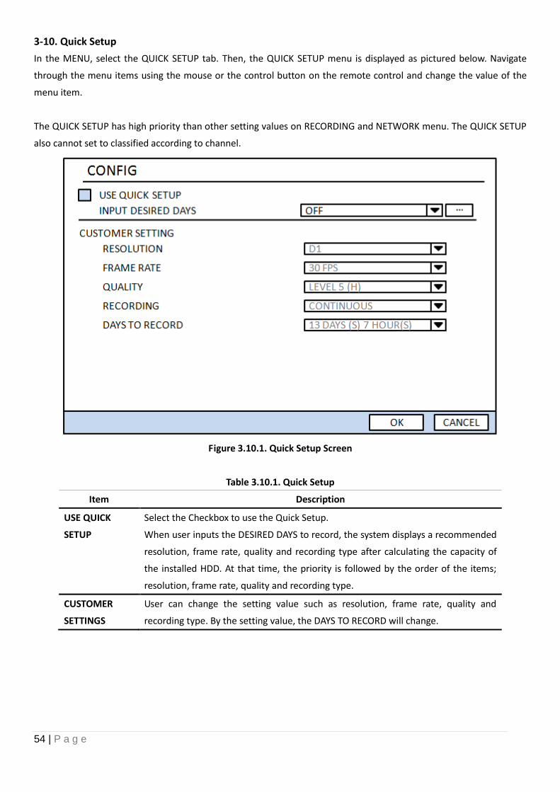
3-10. Quick Setup
In the MENU, select the QUICK SETUP tab. Then, the QUICK SETUP menu is displayed as pictured below. Navigate
through the menu items using the mouse or the control button on the remote control and change the value of the
menu item.
The QUICK SETUP has high priority than other setting values on RECORDING and NETWORK menu. The QUICK SETUP
also cannot set to classified according to channel.
Figure 3.10.1. Quick Setup Screen
Table 3.10.1. Quick Setup
Item Description
USE QUICK
SETUP
Select the Checkbox to use the Quick Setup.
When user inputs the DESIRED DAYS to record, the system displays a recommended
resolution, frame rate, quality and recording type after calculating the capacity of
the installed HDD. At that time, the priority is followed by the order of the items;
resolution, frame rate, quality and recording type.
CUSTOMER
SETTINGS
User can change the setting value such as resolution, frame rate, quality and
recording type. By the setting value, the DAYS TO RECORD will change.
55 | P a g e
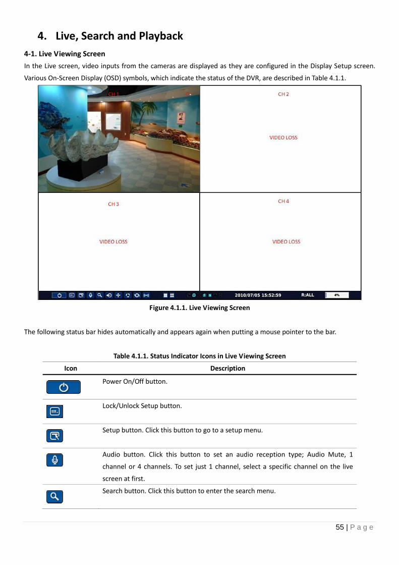
4. Live, Search and Playback
4-1. Live Viewing Screen
In the Live screen, video inputs from the cameras are displayed as they are configured in the Display Setup screen.
Various On-Screen Display (OSD) symbols, which indicate the status of the DVR, are described in Table 4.1.1.
Figure 4.1.1. Live Viewing Screen
The following status bar hides automatically and appears again when putting a mouse pointer to the bar.
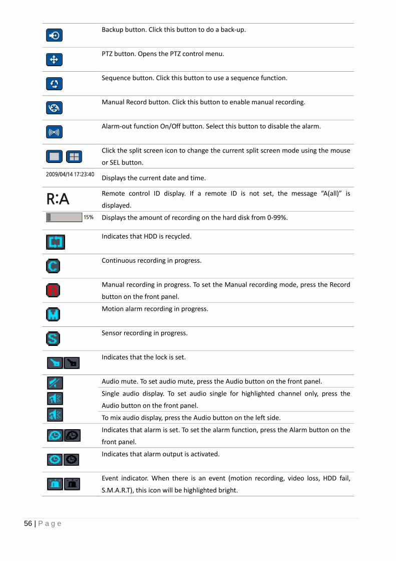
Table 4.1.1. Status Indicator Icons in Live Viewing Screen
Icon Description
Power On/Off button.
Lock/Unlock Setup button.
Setup button. Click this button to go to a setup menu.
Audio button. Click this button to set an audio reception type; Audio Mute, 1
channel or 4 channels. To set just 1 channel, select a specific channel on the live
screen at first.
Search button. Click this button to enter the search menu.
56 | P a g e
Backup button. Click this button to do a back-up.
PTZ button. Opens the PTZ control menu.
Sequence button. Click this button to use a sequence function.
Manual Record button. Click this button to enable manual recording.
Alarm-out function On/Off button. Select this button to disable the alarm.
Click the split screen icon to change the current split screen mode using the mouse
or SEL button.
Displays the current date and time.
Remote control ID display. If a remote ID is not set, the message “A(all)” is
displayed.
Displays the amount of recording on the hard disk from 0-99%.
Indicates that HDD is recycled.
Continuous recording in progress.
Manual recording in progress. To set the Manual recording mode, press the Record
button on the front panel.
Motion alarm recording in progress.
Sensor recording in progress.
Indicates that the lock is set.
Audio mute. To set audio mute, press the Audio button on the front panel.
Single audio display. To set audio single for highlighted channel only, press the
Audio button on the front panel.
To mix audio display, press the Audio button on the left side.
Indicates that alarm is set. To set the alarm function, press the Alarm button on the
front panel.
Indicates that alarm output is activated.
Event indicator. When there is an event (motion recording, video loss, HDD fail,
S.M.A.R.T), this icon will be highlighted bright.
57 | P a g e
Indicates that a network client is connected to the DVR.
Indicates that sequencing mode is enabled.
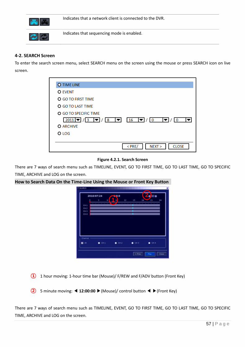
4-2. SEARCH Screen
To enter the search screen menu, select SEARCH menu on the screen using the mouse or press SEARCH icon on live
screen.
Figure 4.2.1. Search Screen
There are 7 ways of search menu such as TIMELINE, EVENT, GO TO FIRST TIME, GO TO LAST TIME, GO TO SPECIFIC
TIME, ARCHIVE and LOG on the screen.
How to Search Data On the Time-Line Using the Mouse or Front Key Button
① 1 hour moving: 1-hour time bar (Mouse)/ F/REW and F/ADV button (Front Key)
② 5 minute moving: ◀ 12:00:00 ▶(Mouse)/ control button ◀ ▶(Front Key)
There are 7 ways of search menu such as TIMELINE, EVENT, GO TO FIRST TIME, GO TO LAST TIME, GO TO SPECIFIC
TIME, ARCHIVE and LOG on the screen.
1 1 1
1 1 2
58 | P a g e
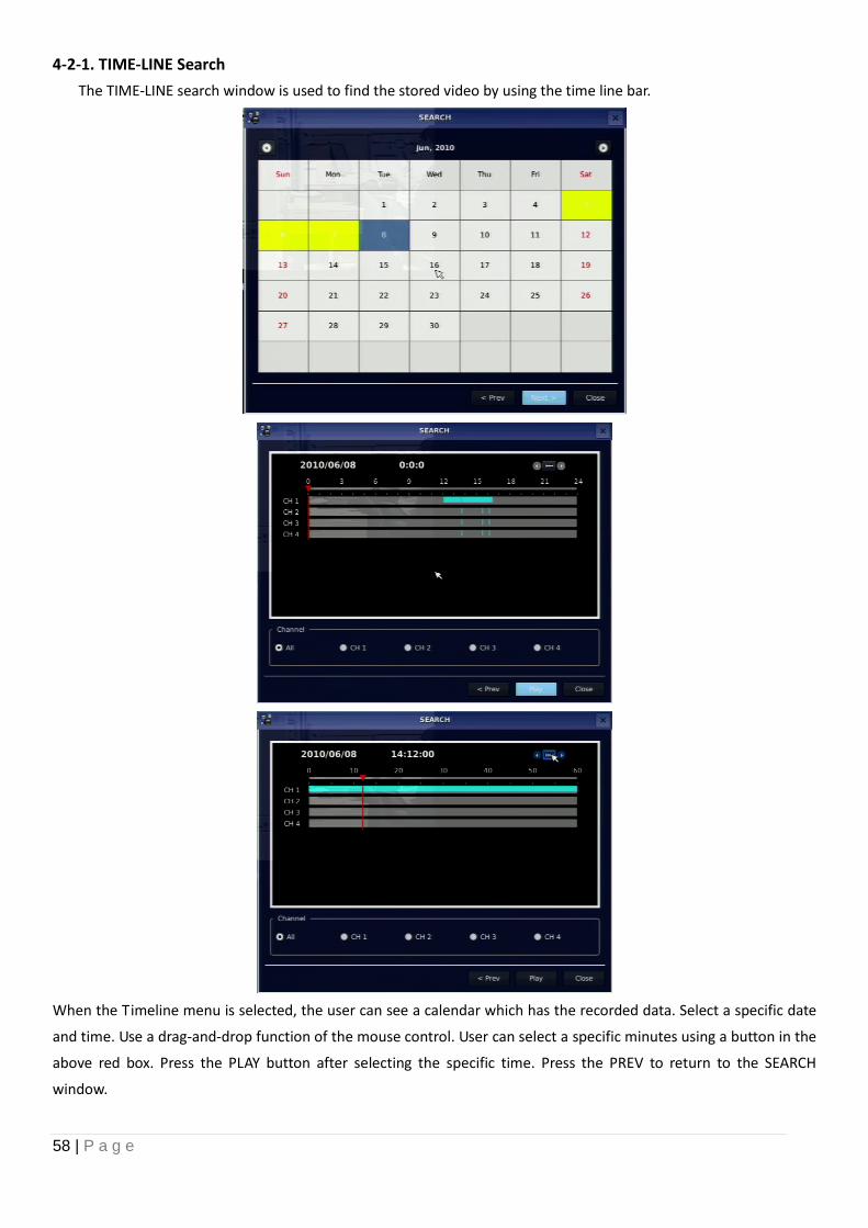
4-2-1. TIME-LINE Search
The TIME-LINE search window is used to find the stored video by using the time line bar.
When the Timeline menu is selected, the user can see a calendar which has the recorded data. Select a specific date
and time. Use a drag-and-drop function of the mouse control. User can select a specific minutes using a button in the
above red box. Press the PLAY button after selecting the specific time. Press the PREV to return to the SEARCH
window.
59 | P a g e
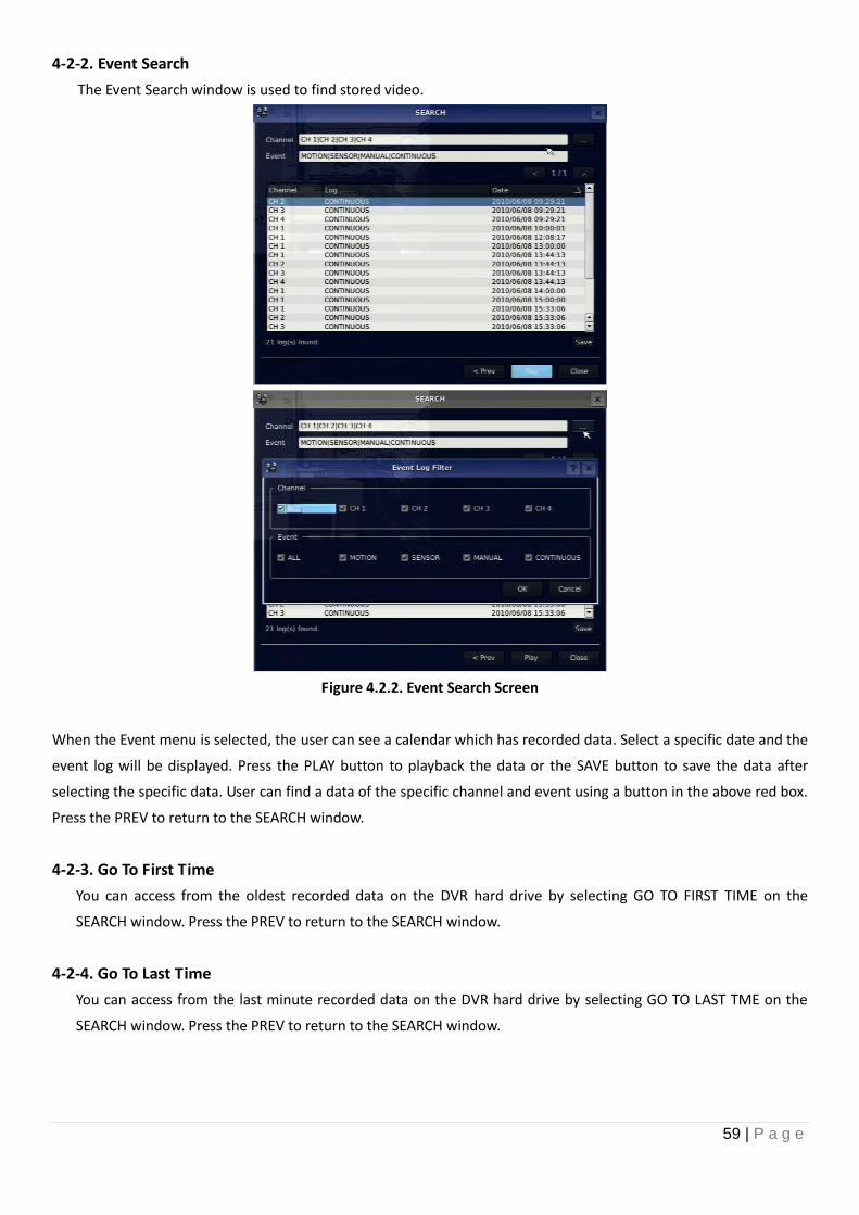
4-2-2. Event Search
The Event Search window is used to find stored video.
Figure 4.2.2. Event Search Screen
When the Event menu is selected, the user can see a calendar which has recorded data. Select a specific date and the
event log will be displayed. Press the PLAY button to playback the data or the SAVE button to save the data after
selecting the specific data. User can find a data of the specific channel and event using a button in the above red box.
Press the PREV to return to the SEARCH window.
4-2-3. Go To First Time
You can access from the oldest recorded data on the DVR hard drive by selecting GO TO FIRST TIME on the
SEARCH window. Press the PREV to return to the SEARCH window.
4-2-4. Go To Last Time
You can access from the last minute recorded data on the DVR hard drive by selecting GO TO LAST TME on the
SEARCH window. Press the PREV to return to the SEARCH window.
60 | P a g e
4-2-5. Go To Specific Time
Figure 4.2.3. Go To Specific Time
User can search for video data from a specific instance by setting the date and time in the Go To Specific Time
menu. Use the mouse or the control button on the remote control to change the date and time value and press
the PLAY button after setting. If there are not video data in the set date and time, No Data Exist message displays.
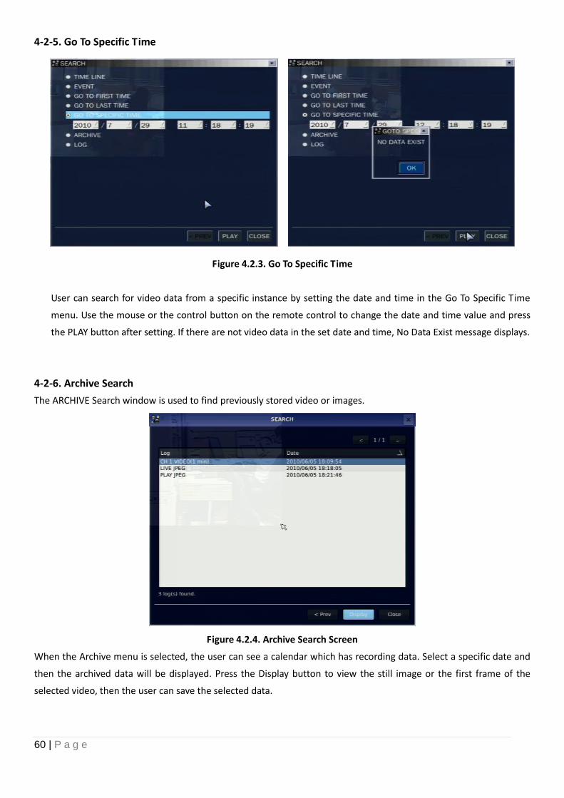
4-2-6. Archive Search
The ARCHIVE Search window is used to find previously stored video or images.
Figure 4.2.4. Archive Search Screen
When the Archive menu is selected, the user can see a calendar which has recording data. Select a specific date and
then the archived data will be displayed. Press the Display button to view the still image or the first frame of the
selected video, then the user can save the selected data.
61 | P a g e
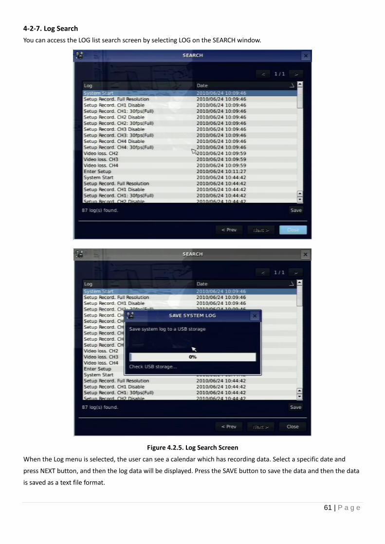
4-2-7. Log Search
You can access the LOG list search screen by selecting LOG on the SEARCH window.
Figure 4.2.5. Log Search Screen
When the Log menu is selected, the user can see a calendar which has recording data. Select a specific date and
press NEXT button, and then the log data will be displayed. Press the SAVE button to save the data and then the data
is saved as a text file format.
62 | P a g e
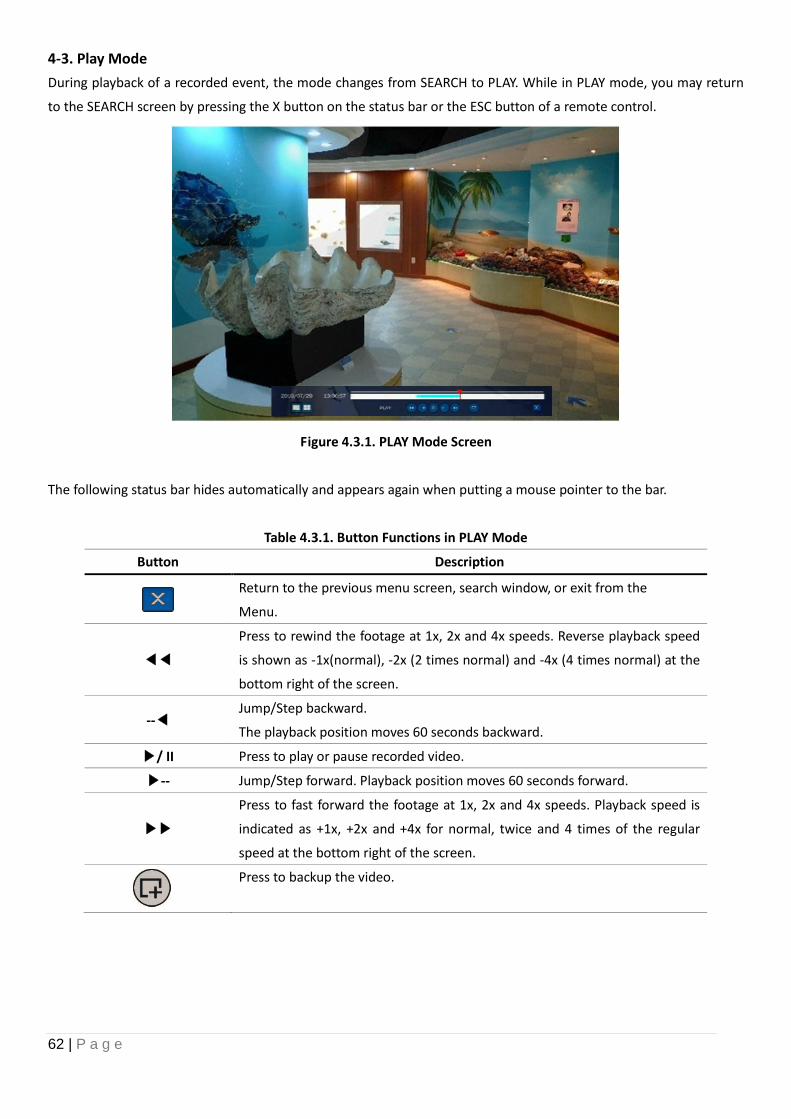
4-3. Play Mode
During playback of a recorded event, the mode changes from SEARCH to PLAY. While in PLAY mode, you may return
to the SEARCH screen by pressing the X button on the status bar or the ESC button of a remote control.
Figure 4.3.1. PLAY Mode Screen
The following status bar hides automatically and appears again when putting a mouse pointer to the bar.
Table 4.3.1. Button Functions in PLAY Mode
Button Description
Return to the previous menu screen, search window, or exit from the
Menu.
◀◀
Press to rewind the footage at 1x, 2x and 4x speeds. Reverse playback speed
is shown as -1x(normal), -2x (2 times normal) and -4x (4 times normal) at the
bottom right of the screen.
--◀ Jump/Step backward.
The playback position moves 60 seconds backward.
▶/ II Press to play or pause recorded video.
▶-- Jump/Step forward. Playback position moves 60 seconds forward.
▶▶
Press to fast forward the footage at 1x, 2x and 4x speeds. Playback speed is
indicated as +1x, +2x and +4x for normal, twice and 4 times of the regular
speed at the bottom right of the screen.
Press to backup the video.
63 | P a g e
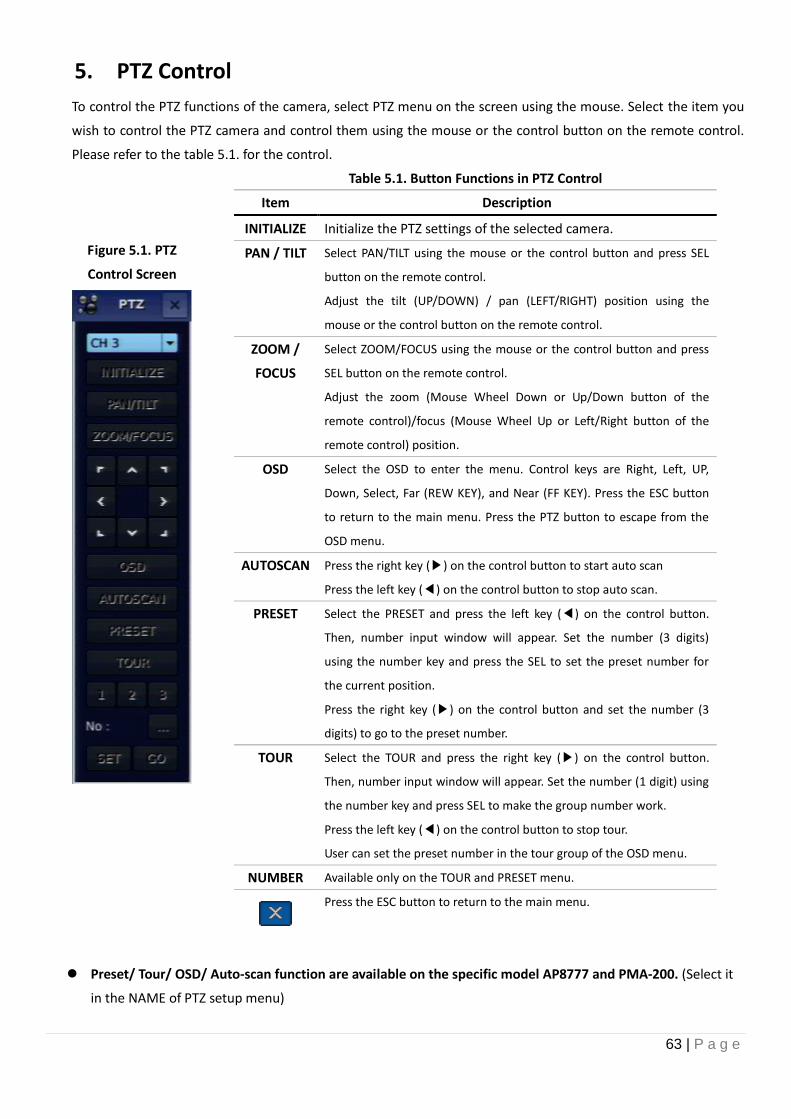
5. PTZ Control
To control the PTZ functions of the camera, select PTZ menu on the screen using the mouse. Select the item you
wish to control the PTZ camera and control them using the mouse or the control button on the remote control.
Please refer to the table 5.1. for the control.
Figure 5.1. PTZ
Control Screen
Table 5.1. Button Functions in PTZ Control
Item Description
INITIALIZE Initialize the PTZ settings of the selected camera.
PAN / TILT Select PAN/TILT using the mouse or the control button and press SEL
button on the remote control.
Adjust the tilt (UP/DOWN) / pan (LEFT/RIGHT) position using the
mouse or the control button on the remote control.
ZOOM /
FOCUS
Select ZOOM/FOCUS using the mouse or the control button and press
SEL button on the remote control.
Adjust the zoom (Mouse Wheel Down or Up/Down button of the
remote control)/focus (Mouse Wheel Up or Left/Right button of the
remote control) position.
OSD Select the OSD to enter the menu. Control keys are Right, Left, UP,
Down, Select, Far (REW KEY), and Near (FF KEY). Press the ESC button
to return to the main menu. Press the PTZ button to escape from the
OSD menu.
AUTOSCAN Press the right key (▶) on the control button to start auto scan
Press the left key (◀) on the control button to stop auto scan.
PRESET Select the PRESET and press the left key (◀) on the control button.
Then, number input window will appear. Set the number (3 digits)
using the number key and press the SEL to set the preset number for
the current position.
Press the right key (▶) on the control button and set the number (3
digits) to go to the preset number.
TOUR Select the TOUR and press the right key (▶) on the control button.
Then, number input window will appear. Set the number (1 digit) using
the number key and press SEL to make the group number work.
Press the left key (◀) on the control button to stop tour.
User can set the preset number in the tour group of the OSD menu.
NUMBER Available only on the TOUR and PRESET menu.
Press the ESC button to return to the main menu.
Preset/ Tour/ OSD/ Auto-scan function are available on the specific model AP8777 and PMA-200. (Select it
in the NAME of PTZ setup menu)
64 | P a g e
6. Back Up
6-1. Still Image Backup onto USB Flash Drive
Still images can be captured and archived onto a USB flash drive or a hard drive in live mode or while playing back
recorded video. In the live mode, press the BACKUP button to launch the archive function or select BACK UP menu on
the screen using the mouse.
1. Select a specific channel which wants to backup on live screen.
2. When you press BACKUP button, the archiving screen will display as Figure 6.1.1.
3. Once you press Backup button, the system will start to archive the data to the selected media.
Figure 6.1.1. Still Image Archiving and Backup Screen
NOTICE For a backup using a USB Flash Drive, the file format of the USB flash drive has to be FAT32.
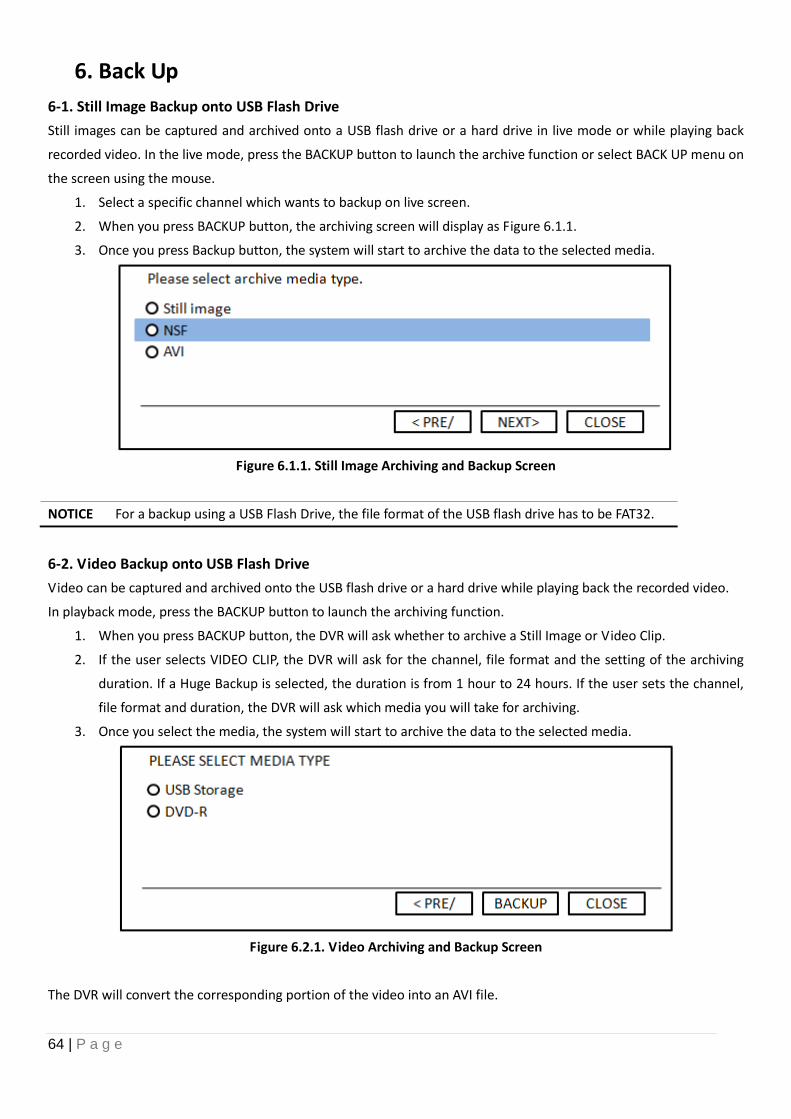
6-2. Video Backup onto USB Flash Drive
Video can be captured and archived onto the USB flash drive or a hard drive while playing back the recorded video.
In playback mode, press the BACKUP button to launch the archiving function.
1. When you press BACKUP button, the DVR will ask whether to archive a Still Image or Video Clip.
2. If the user selects VIDEO CLIP, the DVR will ask for the channel, file format and the setting of the archiving
duration. If a Huge Backup is selected, the duration is from 1 hour to 24 hours. If the user sets the channel,
file format and duration, the DVR will ask which media you will take for archiving.
3. Once you select the media, the system will start to archive the data to the selected media.
Figure 6.2.1. Video Archiving and Backup Screen
The DVR will convert the corresponding portion of the video into an AVI file.
65 | P a g e
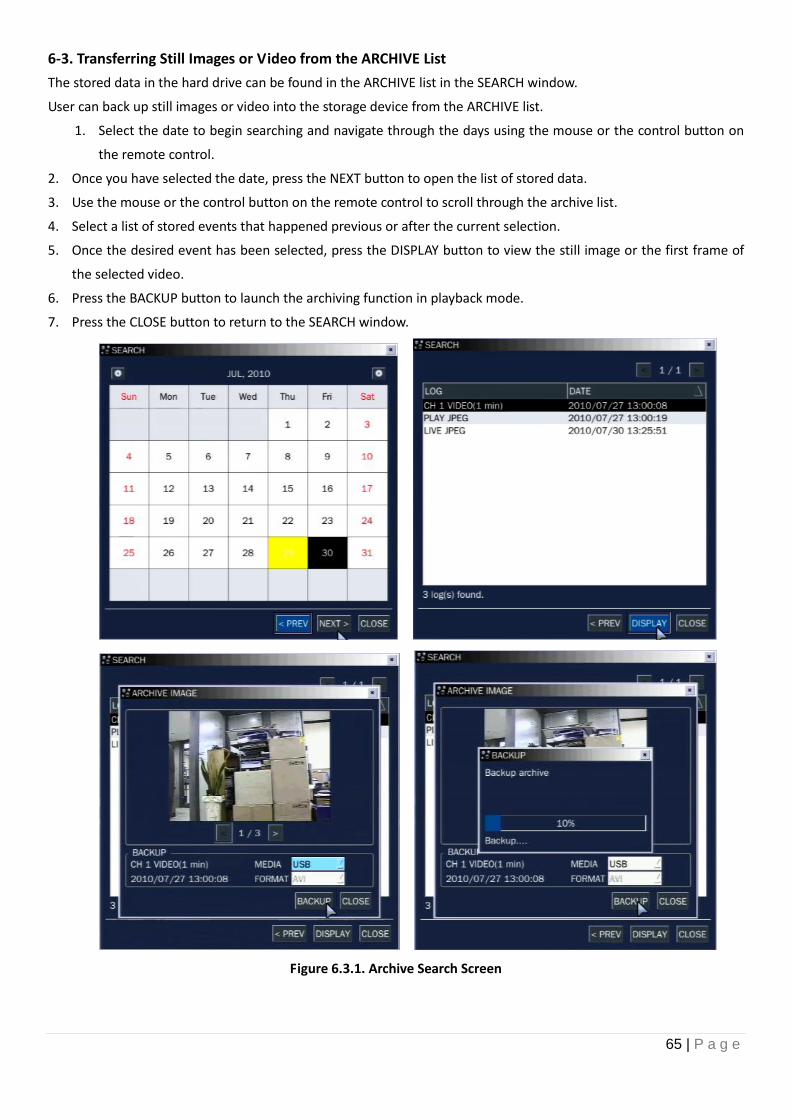
6-3. Transferring Still Images or Video from the ARCHIVE List
The stored data in the hard drive can be found in the ARCHIVE list in the SEARCH window.
User can back up still images or video into the storage device from the ARCHIVE list.
1. Select the date to begin searching and navigate through the days using the mouse or the control button on
the remote control.
2. Once you have selected the date, press the NEXT button to open the list of stored data.
3. Use the mouse or the control button on the remote control to scroll through the archive list.
4. Select a list of stored events that happened previous or after the current selection.
5. Once the desired event has been selected, press the DISPLAY button to view the still image or the first frame of
the selected video.
6. Press the BACKUP button to launch the archiving function in playback mode.
7. Press the CLOSE button to return to the SEARCH window.
Figure 6.3.1. Archive Search Screen
66 | P a g e
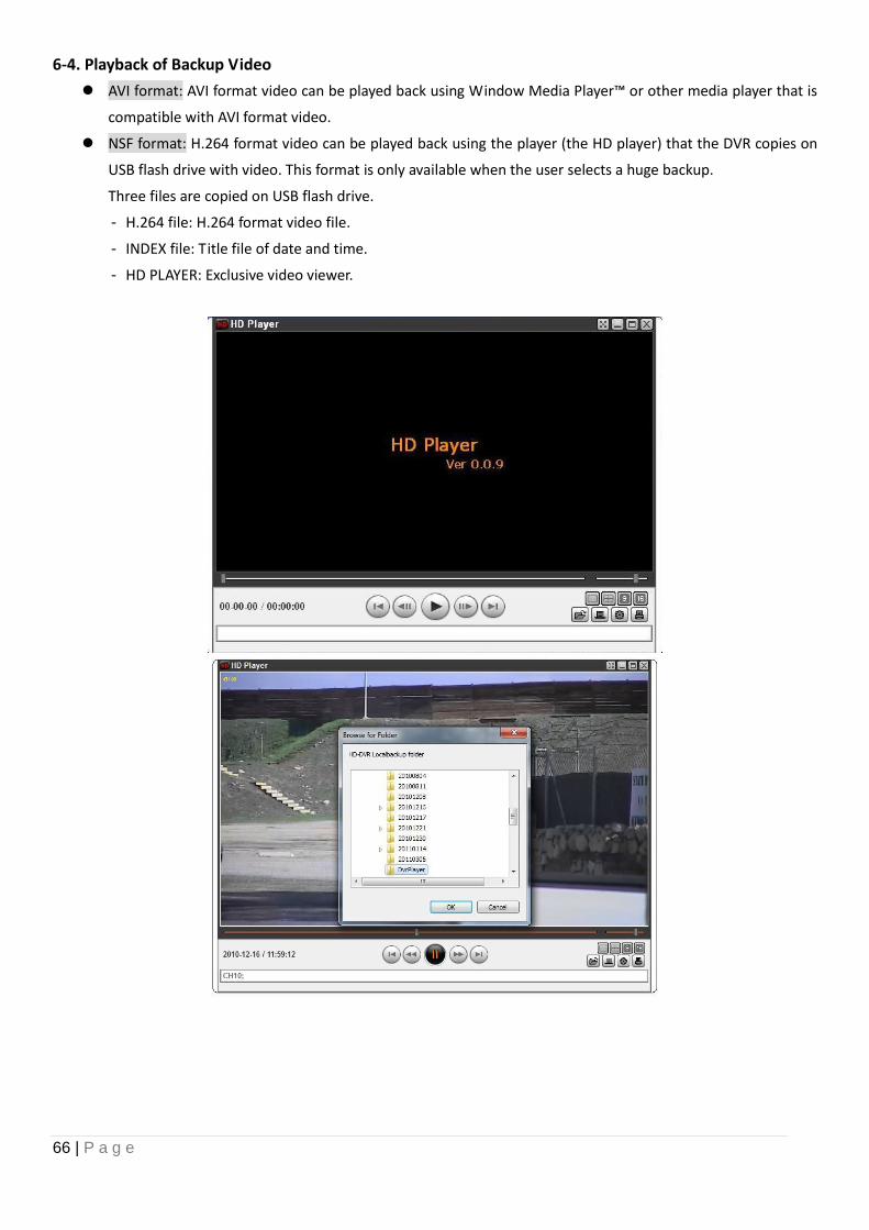
6-4. Playback of Backup Video
AVI format: AVI format video can be played back using Window Media Player™ or other media player that is
compatible with AVI format video.
NSF format: H.264 format video can be played back using the player (the HD player) that the DVR copies on
USB flash drive with video. This format is only available when the user selects a huge backup.
Three files are copied on USB flash drive.
- H.264 file: H.264 format video file.
- INDEX file: Title file of date and time.
- HD PLAYER: Exclusive video viewer.
67 | P a g e
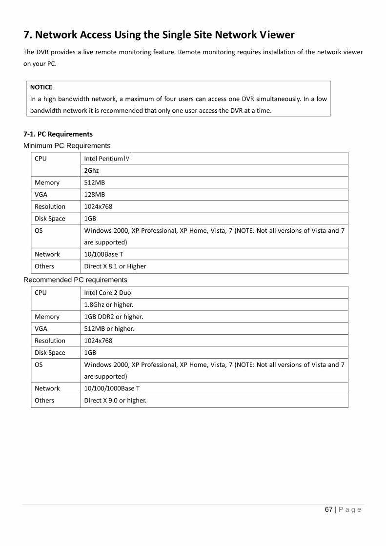
7. Network Access Using the Single Site Network Viewer
The DVR provides a live remote monitoring feature. Remote monitoring requires installation of the network viewer
on your PC.
NOTICE
In a high bandwidth network, a maximum of four users can access one DVR simultaneously. In a low
bandwidth network it is recommended that only one user access the DVR at a time.
7-1. PC Requirements
Minimum PC Requirements
Recommended PC requirements
CPU Intel PentiumⅣ
2Ghz
Memory 512MB
VGA 128MB
Resolution 1024x768
Disk Space 1GB
OS Windows 2000, XP Professional, XP Home, Vista, 7 (NOTE: Not all versions of Vista and 7
are supported)
Network 10/100Base T
Others Direct X 8.1 or Higher
CPU Intel Core 2 Duo
1.8Ghz or higher.
Memory 1GB DDR2 or higher.
VGA 512MB or higher.
Resolution 1024x768
Disk Space 1GB
OS Windows 2000, XP Professional, XP Home, Vista, 7 (NOTE: Not all versions of Vista and 7
are supported)
Network 10/100/1000Base T
Others Direct X 9.0 or higher.
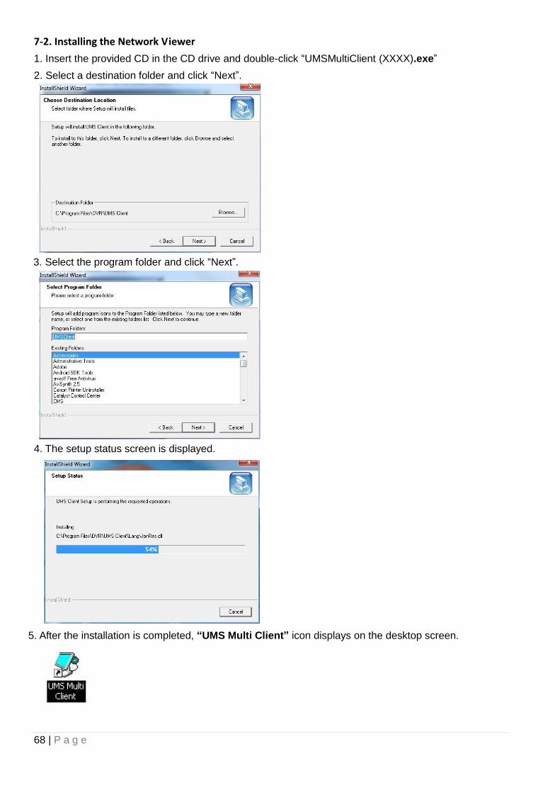
68 | P a g e
7-2. Installing the Network Viewer
1. Insert the provided CD in the CD drive and double-click “UMSMultiClient (XXXX).exe”
2. Select a destination folder and click “Next”.
3. Select the program folder and click “Next”.
4. The setup status screen is displayed.
5. After the installation is completed, “UMS Multi Client” icon displays on the desktop screen.
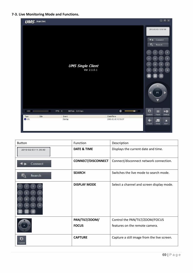
69 | P a g e
7-3. Live Monitoring Mode and Functions.
Button Function Description
DATE & TIME Displays the current date and time.
CONNECT/DISCONNECT Connect/disconnect network connection.
SEARCH Switches the live mode to search mode.
DISPLAY MODE Select a channel and screen display mode.
PAN/TILT/ZOOM/
FOCUS
Control the PAN/TILT/ZOOM/FOCUS
features on the remote camera.
CAPTURE Capture a still image from the live screen.
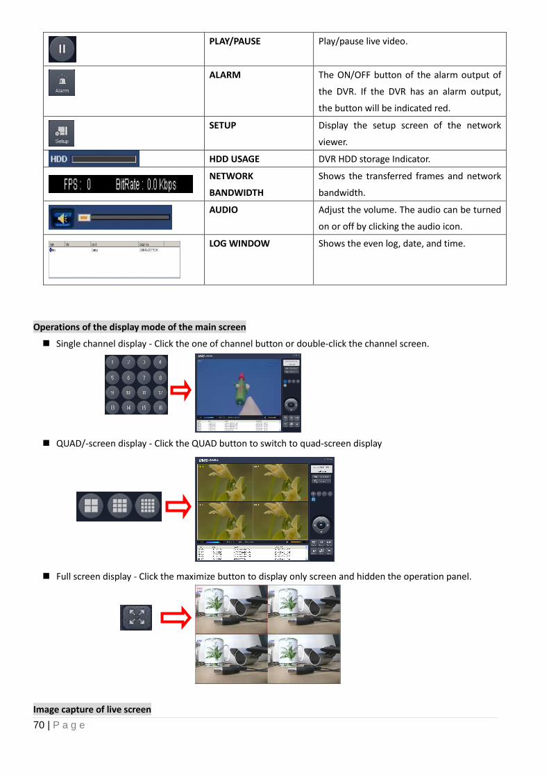
70 | P a g e
PLAY/PAUSE Play/pause live video.
ALARM The ON/OFF button of the alarm output of
the DVR. If the DVR has an alarm output,
the button will be indicated red.
SETUP Display the setup screen of the network
viewer.
HDD USAGE DVR HDD storage Indicator.
NETWORK
BANDWIDTH
Shows the transferred frames and network
bandwidth.
AUDIO Adjust the volume. The audio can be turned
on or off by clicking the audio icon.
LOG WINDOW Shows the even log, date, and time.
Operations of the display mode of the main screen
Single channel display - Click the one of channel button or double-click the channel screen.
QUAD/-screen display - Click the QUAD button to switch to quad-screen display
Full screen display - Click the maximize button to display only screen and hidden the operation panel.
Image capture of live screen
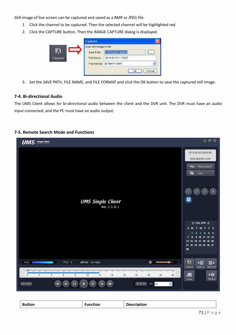
71 | P a g e
Still-image of live screen can be captured and saved as a BMP or JPEG file.
1. Click the channel to be captured. Then the selected channel will be highlighted red.
2. Click the CAPTURE button. Then the IMAGE CAPTURE dialog is displayed.
3. Set the SAVE PATH, FILE NAME, and FILE FORMAT and click the OK button to save the captured still image.
7-4. Bi-directional Audio
The UMS Client allows for bi-directional audio between the client and the DVR unit. The DVR must have an audio
input connected, and the PC must have an audio output.
7-5. Remote Search Mode and Functions
Button Function Description
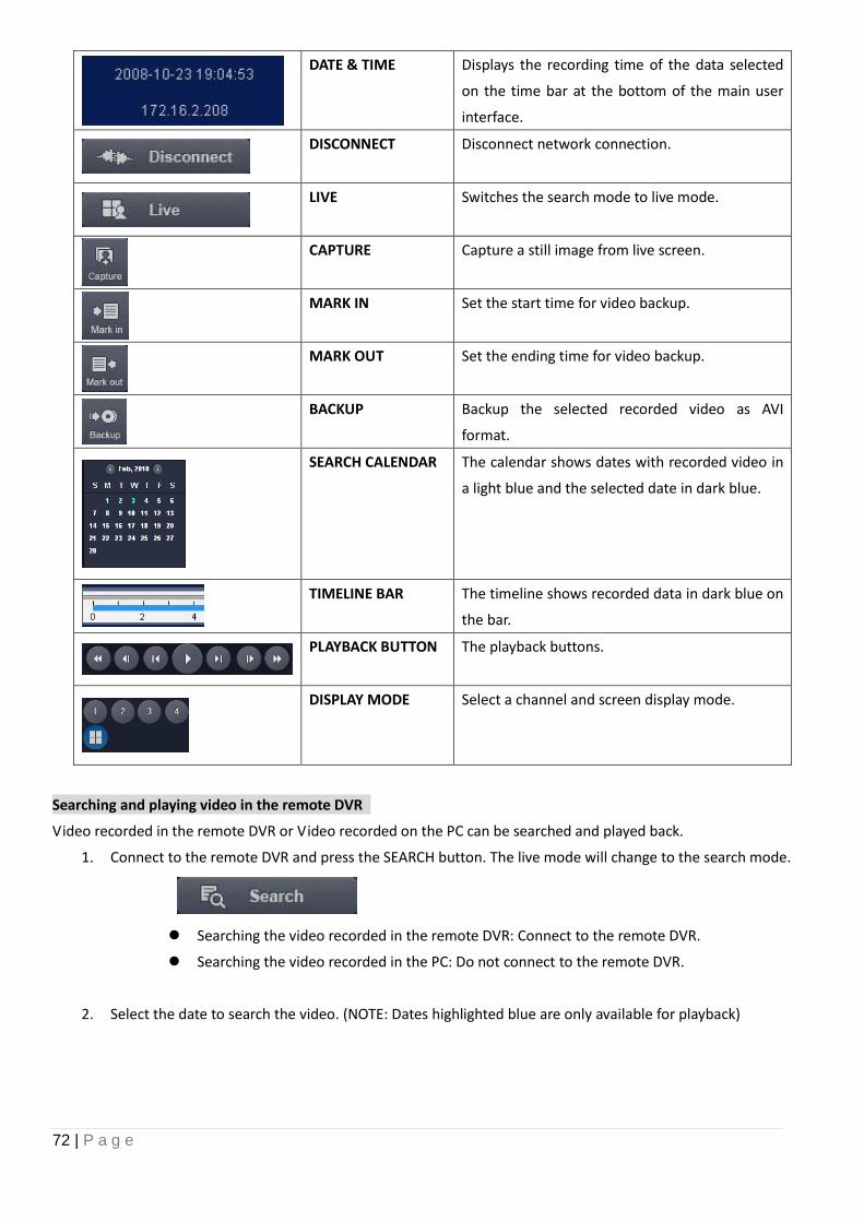
72 | P a g e
DATE & TIME Displays the recording time of the data selected
on the time bar at the bottom of the main user
interface.
DISCONNECT Disconnect network connection.
LIVE Switches the search mode to live mode.
CAPTURE Capture a still image from live screen.
MARK IN Set the start time for video backup.
MARK OUT Set the ending time for video backup.
BACKUP Backup the selected recorded video as AVI
format.
SEARCH CALENDAR The calendar shows dates with recorded video in
a light blue and the selected date in dark blue.
TIMELINE BAR The timeline shows recorded data in dark blue on
the bar.
PLAYBACK BUTTON The playback buttons.
DISPLAY MODE Select a channel and screen display mode.
Searching and playing video in the remote DVR
Video recorded in the remote DVR or Video recorded on the PC can be searched and played back.
1. Connect to the remote DVR and press the SEARCH button. The live mode will change to the search mode.
Searching the video recorded in the remote DVR: Connect to the remote DVR.
Searching the video recorded in the PC: Do not connect to the remote DVR.
2. Select the date to search the video. (NOTE: Dates highlighted blue are only available for playback)
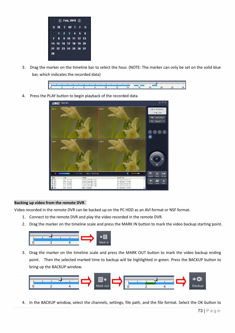
73 | P a g e
3. Drag the marker on the timeline bar to select the hour. (NOTE: The marker can only be set on the solid blue
bar, which indicates the recorded data)
4. Press the PLAY button to begin playback of the recorded data.
Backing up video from the remote DVR
Video recorded in the remote DVR can be backed up on the PC HDD as an AVI format or NSF format.
1. Connect to the remote DVR and play the video recorded in the remote DVR.
2. Drag the marker on the timeline scale and press the MARK IN button to mark the video backup starting point.
3. Drag the marker on the timeline scale and press the MARK OUT button to mark the video backup ending
point. Then the selected marked time to backup will be highlighted in green. Press the BACKUP button to
bring up the BACKUP window.
4. In the BACKUP window, select the channels, settings, file path, and the file format. Select the OK button to
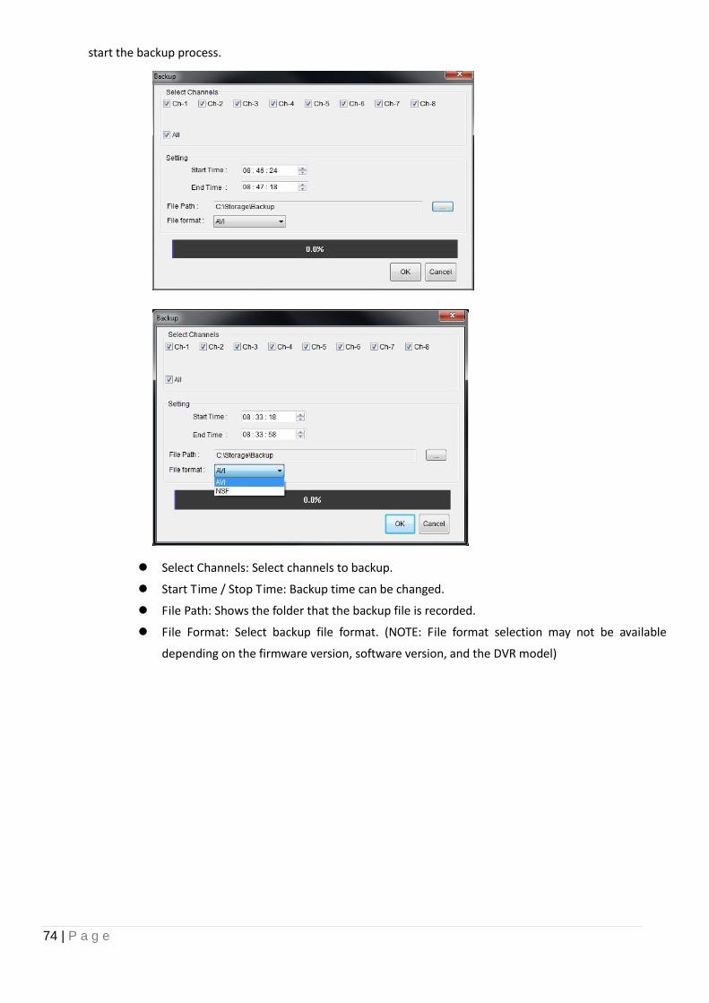
74 | P a g e
start the backup process.
Select Channels: Select channels to backup.
Start Time / Stop Time: Backup time can be changed.
File Path: Shows the folder that the backup file is recorded.
File Format: Select backup file format. (NOTE: File format selection may not be available
depending on the firmware version, software version, and the DVR model)
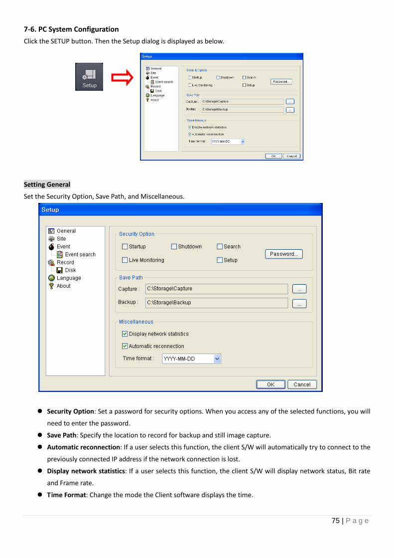
75 | P a g e
7-6. PC System Configuration
Click the SETUP button. Then the Setup dialog is displayed as below.
Setting General
Set the Security Option, Save Path, and Miscellaneous.
Security Option: Set a password for security options. When you access any of the selected functions, you will
need to enter the password.
Save Path: Specify the location to record for backup and still image capture.
Automatic reconnection: If a user selects this function, the client S/W will automatically try to connect to the
previously connected IP address if the network connection is lost.
Display network statistics: If a user selects this function, the client S/W will display network status, Bit rate
and Frame rate.
Time Format: Change the mode the Client software displays the time.
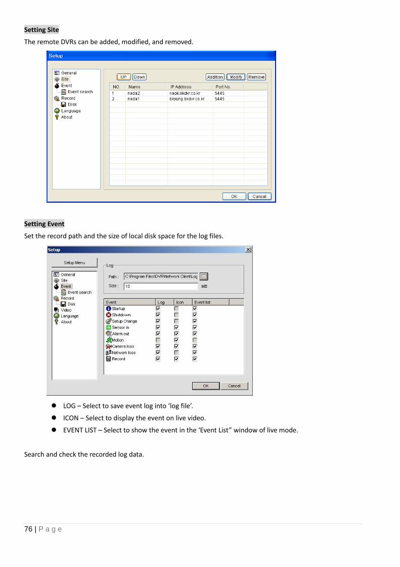
76 | P a g e
Setting Site
The remote DVRs can be added, modified, and removed.
Setting Event
Set the record path and the size of local disk space for the log files.
LOG – Select to save event log into ‘log file’.
ICON – Select to display the event on live video.
EVENT LIST – Select to show the event in the ‘Event List” window of live mode.
Search and check the recorded log data.
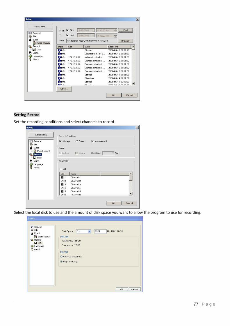
77 | P a g e
Setting Record
Set the recording conditions and select channels to record.
Select the local disk to use and the amount of disk space you want to allow the program to use for recording.
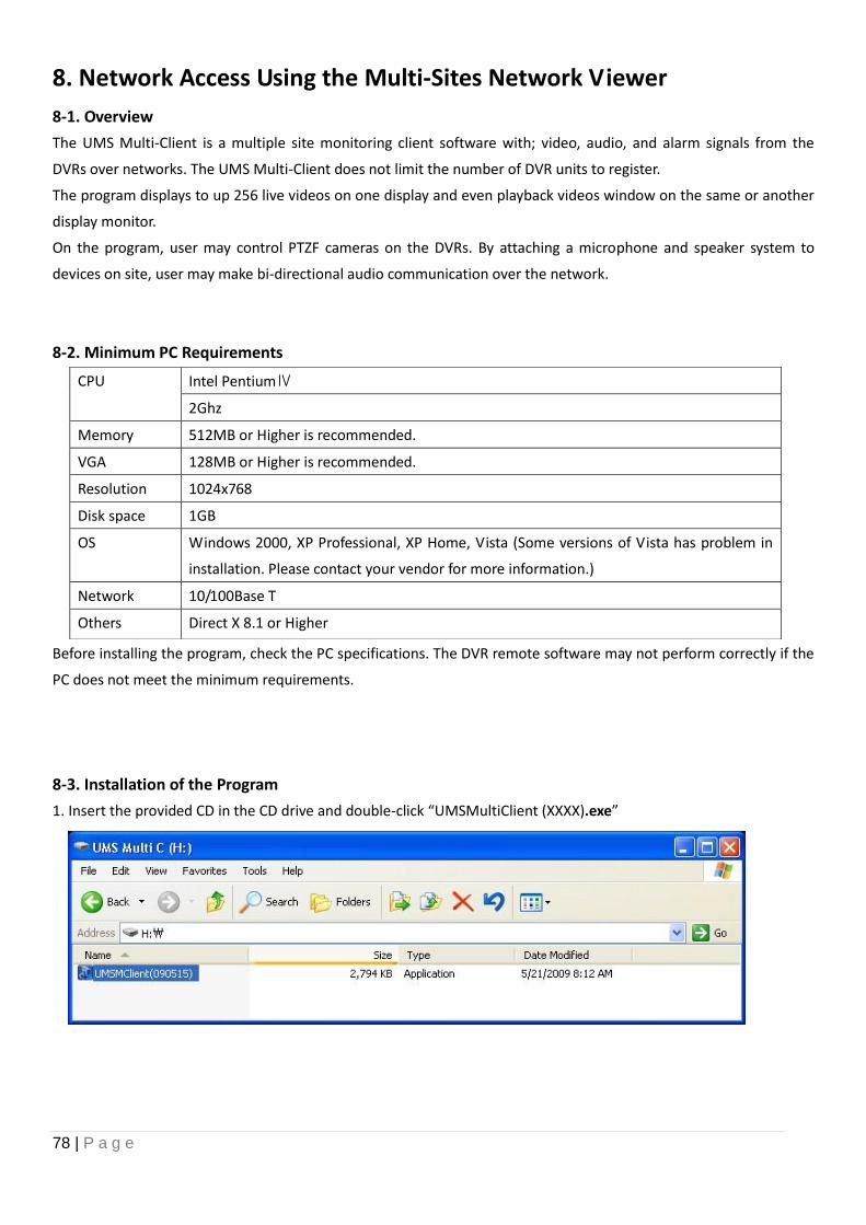
78 | P a g e
8. Network Access Using the Multi-Sites Network Viewer
8-1. Overview
The UMS Multi-Client is a multiple site monitoring client software with; video, audio, and alarm signals from the
DVRs over networks. The UMS Multi-Client does not limit the number of DVR units to register.
The program displays to up 256 live videos on one display and even playback videos window on the same or another
display monitor.
On the program, user may control PTZF cameras on the DVRs. By attaching a microphone and speaker system to
devices on site, user may make bi-directional audio communication over the network.
8-2. Minimum PC Requirements
Before installing the program, check the PC specifications. The DVR remote software may not perform correctly if the
PC does not meet the minimum requirements.
8-3. Installation of the Program
1. Insert the provided CD in the CD drive and double-click “UMSMultiClient (XXXX).exe”
CPU Intel PentiumⅣ
2Ghz
Memory 512MB or Higher is recommended.
VGA 128MB or Higher is recommended.
Resolution 1024x768
Disk space 1GB
OS Windows 2000, XP Professional, XP Home, Vista (Some versions of Vista has problem in
installation. Please contact your vendor for more information.)
Network 10/100Base T
Others Direct X 8.1 or Higher
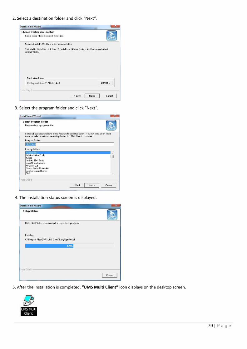
79 | P a g e
2. Select a destination folder and click “Next”.
3. Select the program folder and click “Next”.
4. The installation status screen is displayed.
5. After the installation is completed, “UMS Multi Client” icon displays on the desktop screen.
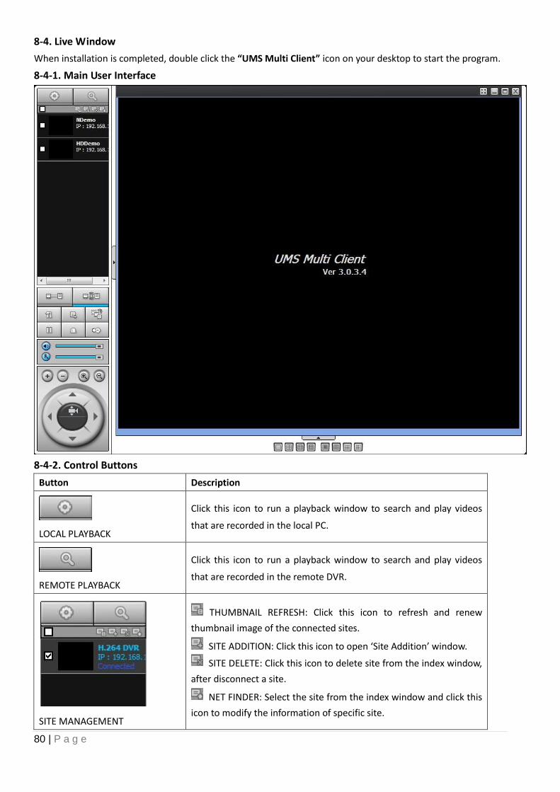
80 | P a g e
8-4. Live Window
When installation is completed, double click the “UMS Multi Client” icon on your desktop to start the program.
8-4-1. Main User Interface
8-4-2. Control Buttons
Button Description
LOCAL PLAYBACK
Click this icon to run a playback window to search and play videos
that are recorded in the local PC.
REMOTE PLAYBACK
Click this icon to run a playback window to search and play videos
that are recorded in the remote DVR.
SITE MANAGEMENT
THUMBNAIL REFRESH: Click this icon to refresh and renew
thumbnail image of the connected sites.
SITE ADDITION: Click this icon to open ‘Site Addition’ window.
SITE DELETE: Click this icon to delete site from the index window,
after disconnect a site.
NET FINDER: Select the site from the index window and click this
icon to modify the information of specific site.
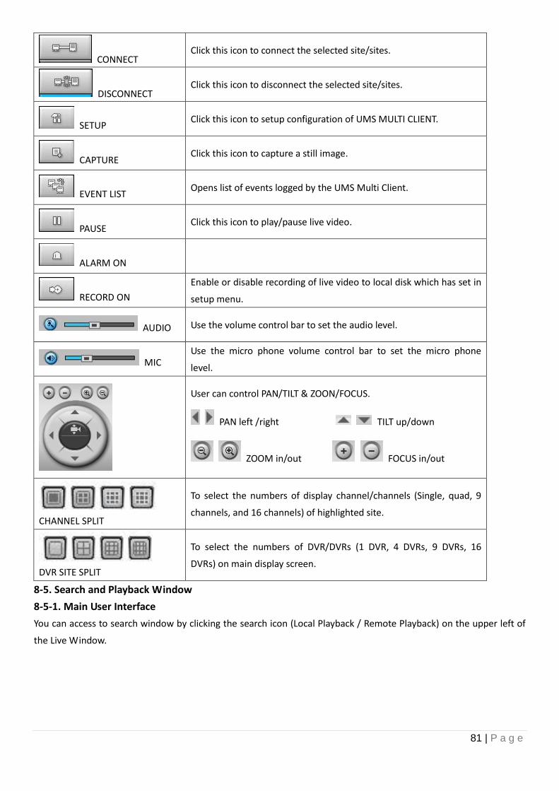
81 | P a g e
CONNECT Click this icon to connect the selected site/sites.
DISCONNECT Click this icon to disconnect the selected site/sites.
SETUP Click this icon to setup configuration of UMS MULTI CLIENT.
CAPTURE Click this icon to capture a still image.
EVENT LIST Opens list of events logged by the UMS Multi Client.
PAUSE Click this icon to play/pause live video.
ALARM ON
RECORD ON
Enable or disable recording of live video to local disk which has set in
setup menu.
AUDIO Use the volume control bar to set the audio level.
MIC Use the micro phone volume control bar to set the micro phone
level.
User can control PAN/TILT & ZOON/FOCUS.
PAN left /right TILT up/down
ZOOM in/out FOCUS in/out
CHANNEL SPLIT
To select the numbers of display channel/channels (Single, quad, 9
channels, and 16 channels) of highlighted site.
DVR SITE SPLIT
To select the numbers of DVR/DVRs (1 DVR, 4 DVRs, 9 DVRs, 16
DVRs) on main display screen.
8-5. Search and Playback Window
8-5-1. Main User Interface
You can access to search window by clicking the search icon (Local Playback / Remote Playback) on the upper left of
the Live Window.
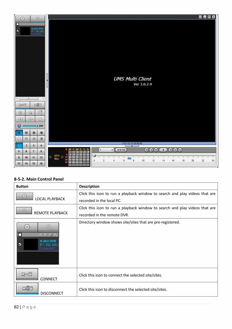
82 | P a g e
8-5-2. Main Control Panel
Button Description
LOCAL PLAYBACK Click this icon to run a playback window to search and play videos that are
recorded in the local PC.
REMOTE PLAYBACK Click this icon to run a playback window to search and play videos that are
recorded in the remote DVR.
Directory window shows site/sites that are pre-registered.
CONNECT Click this icon to connect the selected site/sites.
DISCONNECT Click this icon to disconnect the selected site/sites.
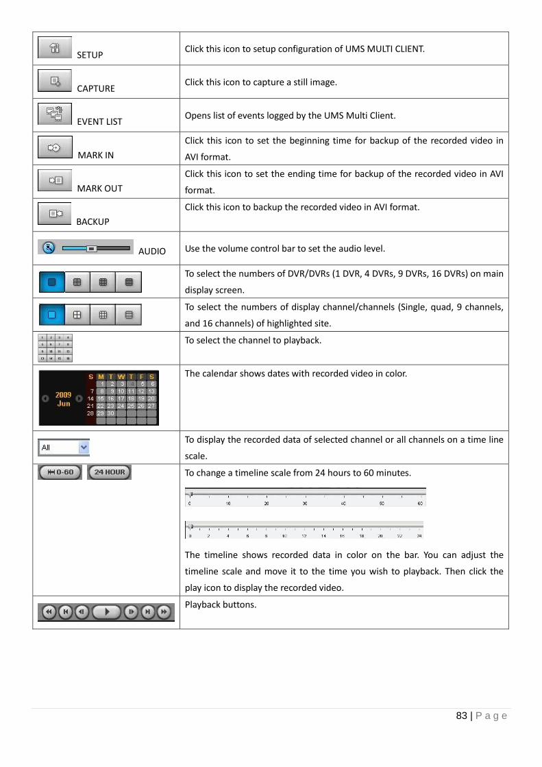
83 | P a g e
SETUP Click this icon to setup configuration of UMS MULTI CLIENT.
CAPTURE Click this icon to capture a still image.
EVENT LIST Opens list of events logged by the UMS Multi Client.
MARK IN
Click this icon to set the beginning time for backup of the recorded video in
AVI format.
MARK OUT
Click this icon to set the ending time for backup of the recorded video in AVI
format.
BACKUP
Click this icon to backup the recorded video in AVI format.
AUDIO Use the volume control bar to set the audio level.
To select the numbers of DVR/DVRs (1 DVR, 4 DVRs, 9 DVRs, 16 DVRs) on main
display screen.
To select the numbers of display channel/channels (Single, quad, 9 channels,
and 16 channels) of highlighted site.
To select the channel to playback.
The calendar shows dates with recorded video in color.
To display the recorded data of selected channel or all channels on a time line
scale.
To change a timeline scale from 24 hours to 60 minutes.
The timeline shows recorded data in color on the bar. You can adjust the
timeline scale and move it to the time you wish to playback. Then click the
play icon to display the recorded video.
Playback buttons.
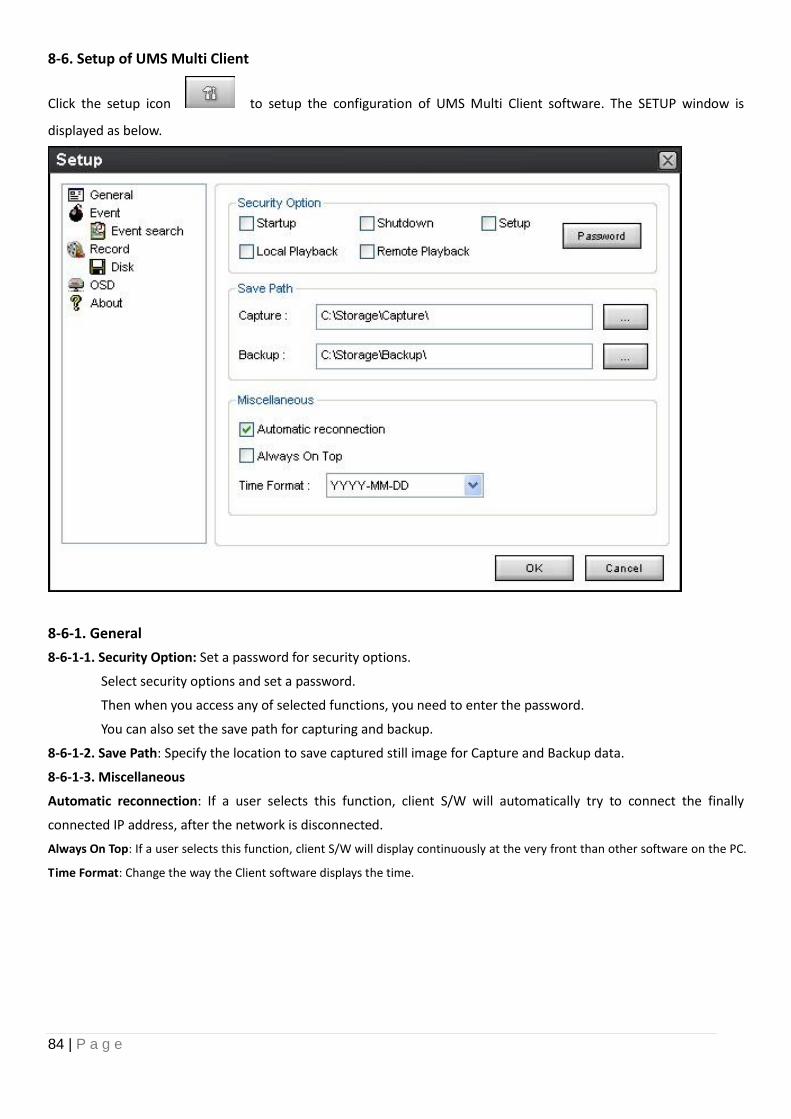
84 | P a g e
8-6. Setup of UMS Multi Client
Click the setup icon to setup the configuration of UMS Multi Client software. The SETUP window is
displayed as below.
8-6-1. General
8-6-1-1. Security Option: Set a password for security options.
Select security options and set a password.
Then when you access any of selected functions, you need to enter the password.
You can also set the save path for capturing and backup.
8-6-1-2. Save Path: Specify the location to save captured still image for Capture and Backup data.
8-6-1-3. Miscellaneous
Automatic reconnection: If a user selects this function, client S/W will automatically try to connect the finally
connected IP address, after the network is disconnected.
Always On Top: If a user selects this function, client S/W will display continuously at the very front than other software on the PC.
Time Format: Change the way the Client software displays the time.
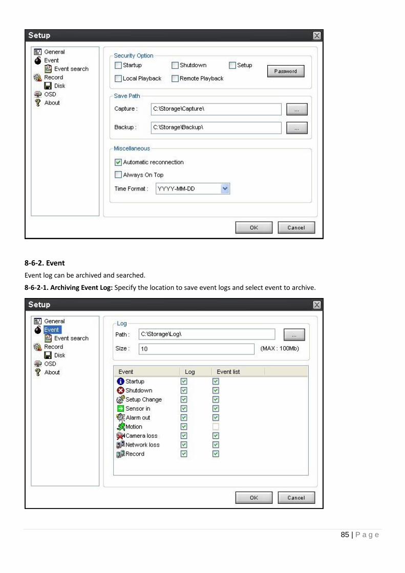
85 | P a g e
8-6-2. Event
Event log can be archived and searched.
8-6-2-1. Archiving Event Log: Specify the location to save event logs and select event to archive.
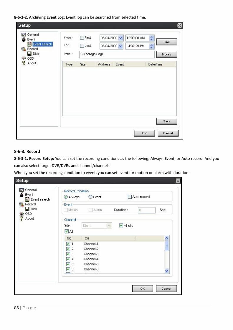
86 | P a g e
8-6-2-2. Archiving Event Log: Event log can be searched from selected time.
8-6-3. Record
8-6-3-1. Record Setup: You can set the recording conditions as the following; Always, Event, or Auto record. And you
can also select target DVR/DVRs and channel/channels.
When you set the recording condition to event, you can set event for motion or alarm with duration.
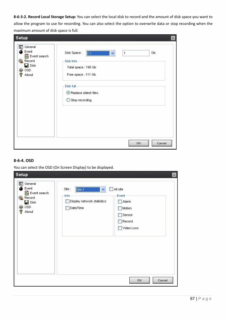
87 | P a g e
8-6-3-2. Record Local Storage Setup: You can select the local disk to record and the amount of disk space you want to
allow the program to use for recording. You can also select the option to overwrite data or stop recording when the
maximum amount of disk space is full.
8-6-4. OSD
You can select the OSD (On Screen Display) to be displayed.
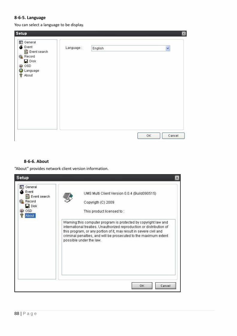
88 | P a g e
8-6-5. Language
You can select a language to be display.
8-6-6. About
“About” provides network client version information.
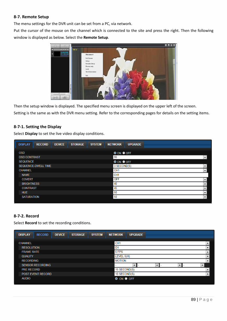
89 | P a g e
8-7. Remote Setup
The menu settings for the DVR unit can be set from a PC, via network.
Put the cursor of the mouse on the channel which is connected to the site and press the right. Then the following
window is displayed as below. Select the Remote Setup.
Then the setup window is displayed. The specified menu screen is displayed on the upper left of the screen.
Setting is the same as with the DVR menu setting. Refer to the corresponding pages for details on the setting items.
8-7-1. Setting the Display
Select Display to set the live video display conditions.
8-7-2. Record
Select Record to set the recording conditions.
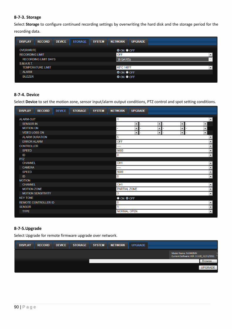
90 | P a g e
8-7-3. Storage
Select Storage to configure continued recording settings by overwriting the hard disk and the storage period for the
recording data.
8-7-4. Device
Select Device to set the motion zone, sensor input/alarm output conditions, PTZ control and spot setting conditions.
8-7-5.Upgrade
Select Upgrade for remote firmware upgrade over network.
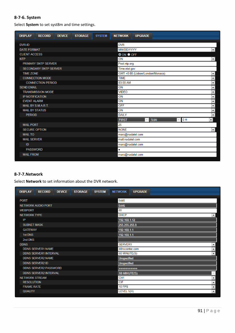
91 | P a g e
8-7-6. System
Select System to set syst8m and time settings.
8-7-7.Network
Select Network to set information about the DVR network.
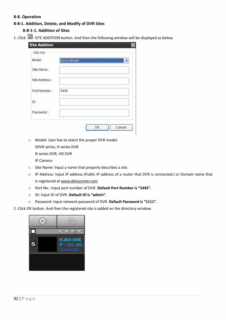
92 | P a g e
8-8. Operation
8-8-1. Addition, Delete, and Modify of DVR Sites
8-8-1-1. Addition of Sites
1. Click SITE ADDITION button. And then the following window will be displayed as below.
o Model: User has to select the proper DVR model.
SDVR series, H series DVR
N series DVR, HD DVR
IP Camera
o Site Name: Input a name that properly describes a site.
o IP Address: Input IP address (Public IP address of a router that DVR is connected.) or Domain name that
is registered at www.ddnscenter.com
o Port No.: Input port number of DVR. Default Port Number is “5445”.
o ID: Input ID of DVR. Default ID is “admin”.
o Password: Input network password of DVR. Default Password is “1111”.
2. Click OK button. And then the registered site is added on the directory window.
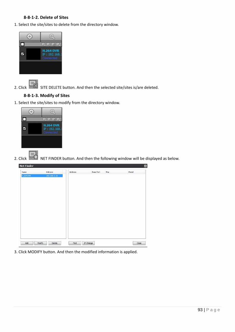
93 | P a g e
8-8-1-2. Delete of Sites
1. Select the site/sites to delete from the directory window.
2. Click SITE DELETE button. And then the selected site/sites is/are deleted.
8-8-1-3. Modify of Sites
1. Select the site/sites to modify from the directory window.
2. Click NET FINDER button. And then the following window will be displayed as below.
3. Click MODIFY button. And then the modified information is applied.
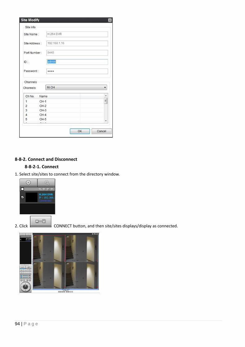
94 | P a g e
8-8-2. Connect and Disconnect
8-8-2-1. Connect
1. Select site/sites to connect from the directory window.
2. Click CONNECT button, and then site/sites displays/display as connected.
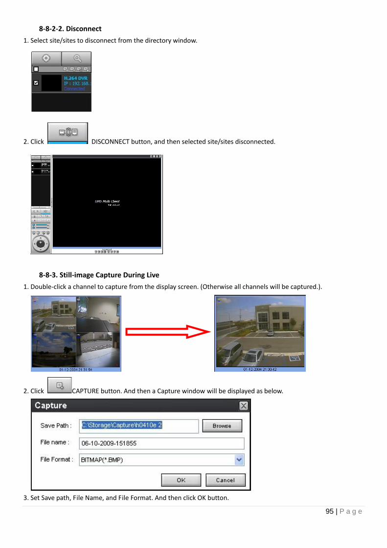
95 | P a g e
8-8-2-2. Disconnect
1. Select site/sites to disconnect from the directory window.
2. Click DISCONNECT button, and then selected site/sites disconnected.
8-8-3. Still-image Capture During Live
1. Double-click a channel to capture from the display screen. (Otherwise all channels will be captured.).
2. Click CAPTURE button. And then a Capture window will be displayed as below.
3. Set Save path, File Name, and File Format. And then click OK button.
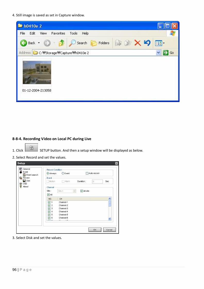
96 | P a g e
4. Still image is saved as set in Capture window.
8-8-4. Recording Video on Local PC during Live
1. Click SETUP button. And then a setup window will be displayed as below.
2. Select Record and set the values.
3. Select Disk and set the values.
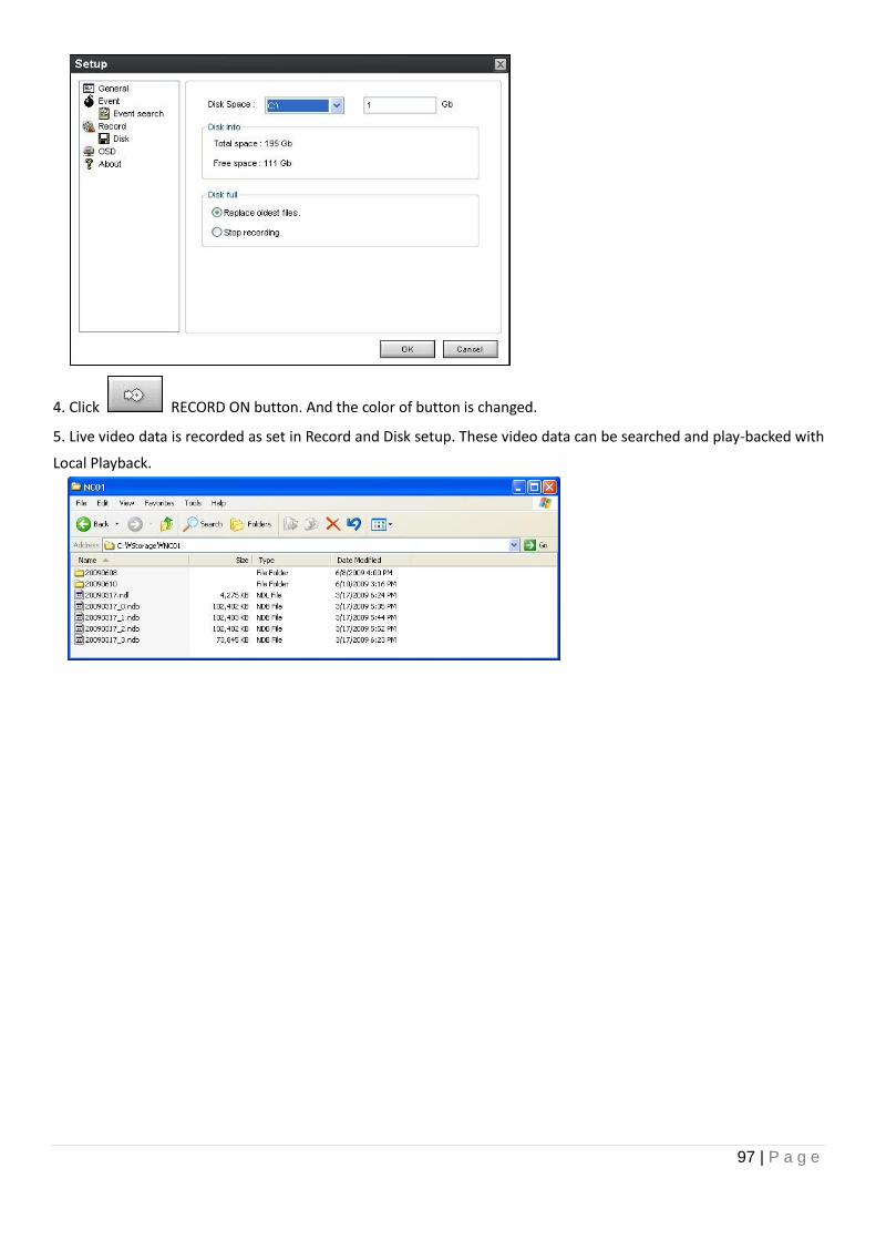
97 | P a g e
4. Click RECORD ON button. And the color of button is changed.
5. Live video data is recorded as set in Record and Disk setup. These video data can be searched and play-backed with
Local Playback.
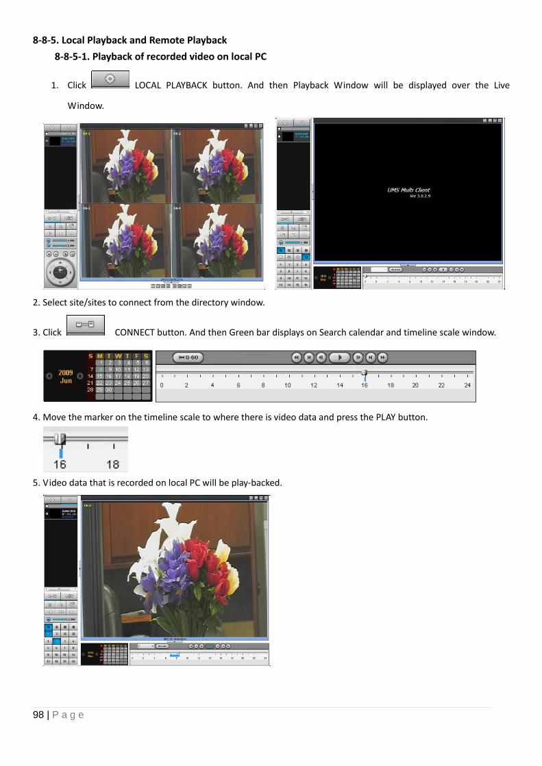
98 | P a g e
8-8-5. Local Playback and Remote Playback
8-8-5-1. Playback of recorded video on local PC
1. Click LOCAL PLAYBACK button. And then Playback Window will be displayed over the Live
Window.
2. Select site/sites to connect from the directory window.
3. Click CONNECT button. And then Green bar displays on Search calendar and timeline scale window.
4. Move the marker on the timeline scale to where there is video data and press the PLAY button.
5. Video data that is recorded on local PC will be play-backed.
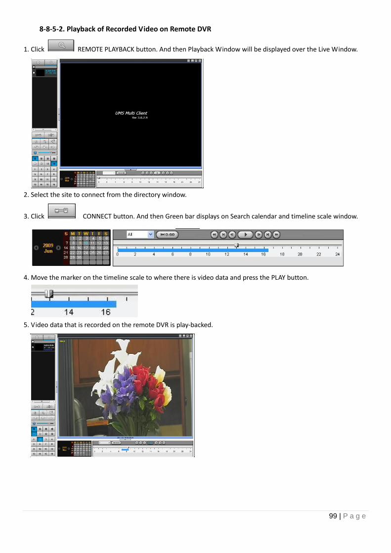
99 | P a g e
8-8-5-2. Playback of Recorded Video on Remote DVR
1. Click REMOTE PLAYBACK button. And then Playback Window will be displayed over the Live Window.
2. Select the site to connect from the directory window.
3. Click CONNECT button. And then Green bar displays on Search calendar and timeline scale window.
4. Move the marker on the timeline scale to where there is video data and press the PLAY button.
5. Video data that is recorded on the remote DVR is play-backed.
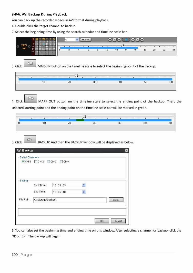
100 | P a g e
9-8-6. AVI Backup During Playback
You can back up the recorded videos in AVI format during playback.
1. Double-click the target channel to backup.
2. Select the beginning time by using the search calendar and timeline scale bar.
3. Click MARK IN button on the timeline scale to select the beginning point of the backup.
4. Click MARK OUT button on the timeline scale to select the ending point of the backup. Then, the
selected starting point and the ending point on the timeline scale bar will be marked in green.
5. Click BACKUP. And then the BACKUP window will be displayed as below.
6. You can also set the beginning time and ending time on this window. After selecting a channel for backup, click the
OK button. The backup will begin.
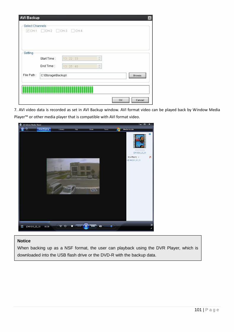
101 | P a g e
7. AVI video data is recorded as set in AVI Backup window. AVI format video can be played back by Window Media
Player™ or other media player that is compatible with AVI format video.
Notice
When backing up as a NSF format, the user can playback using the DVR Player, which is
downloaded into the USB flash drive or the DVD-R with the backup data.
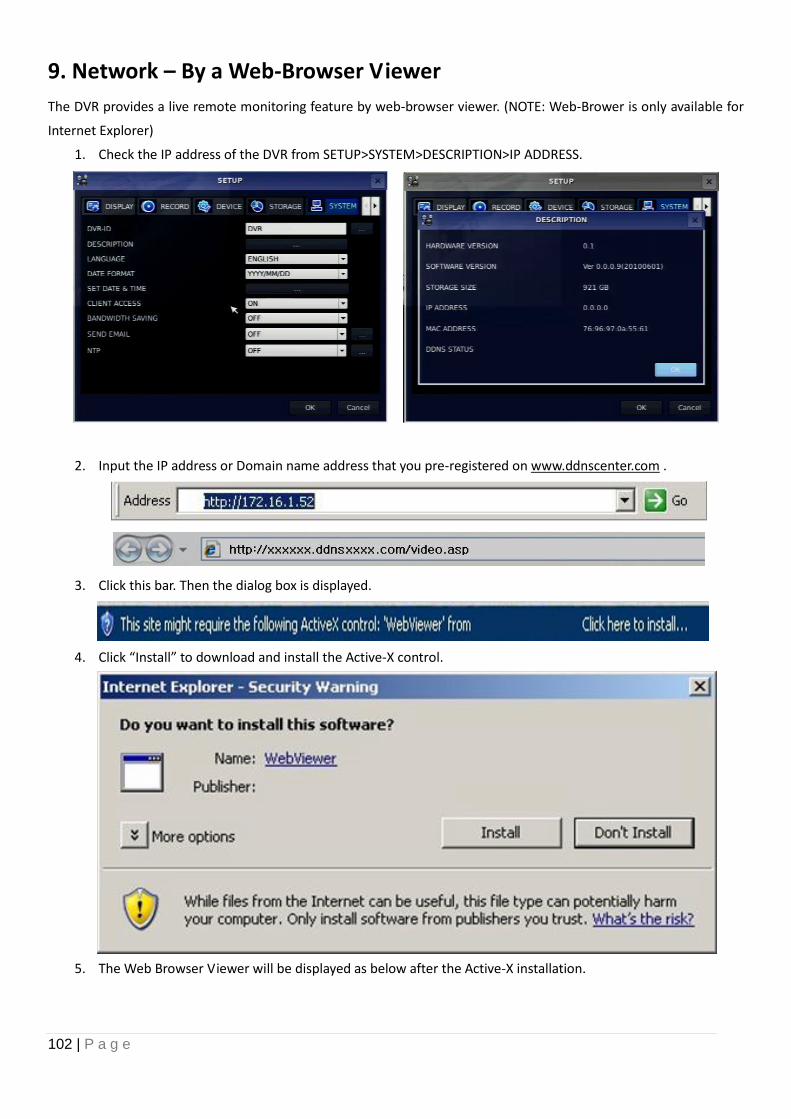
102 | P a g e
9. Network – By a Web-Browser Viewer
The DVR provides a live remote monitoring feature by web-browser viewer. (NOTE: Web-Brower is only available for
Internet Explorer)
1. Check the IP address of the DVR from SETUP>SYSTEM>DESCRIPTION>IP ADDRESS.
2. Input the IP address or Domain name address that you pre-registered on www.ddnscenter.com .
3. Click this bar. Then the dialog box is displayed.
4. Click “Install” to download and install the Active-X control.
5. The Web Browser Viewer will be displayed as below after the Active-X installation.
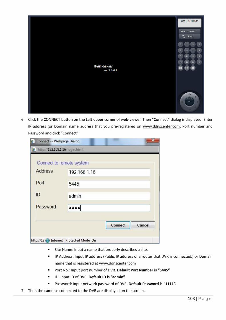
103 | P a g e
6. Click the CONNECT button on the Left upper corner of web-viewer. Then “Connect” dialog is displayed. Enter
IP address (or Domain name address that you pre-registered on www.ddnscenter.com, Port number and
Password and click “Connect”
Site Name: Input a name that properly describes a site.
IP Address: Input IP address (Public IP address of a router that DVR is connected.) or Domain
name that is registered at www.ddnscenter.com
Port No.: Input port number of DVR. Default Port Number is “5445”.
ID: Input ID of DVR. Default ID is “admin”.
Password: Input network password of DVR. Default Password is “1111”.
7. Then the cameras connected to the DVR are displayed on the screen.
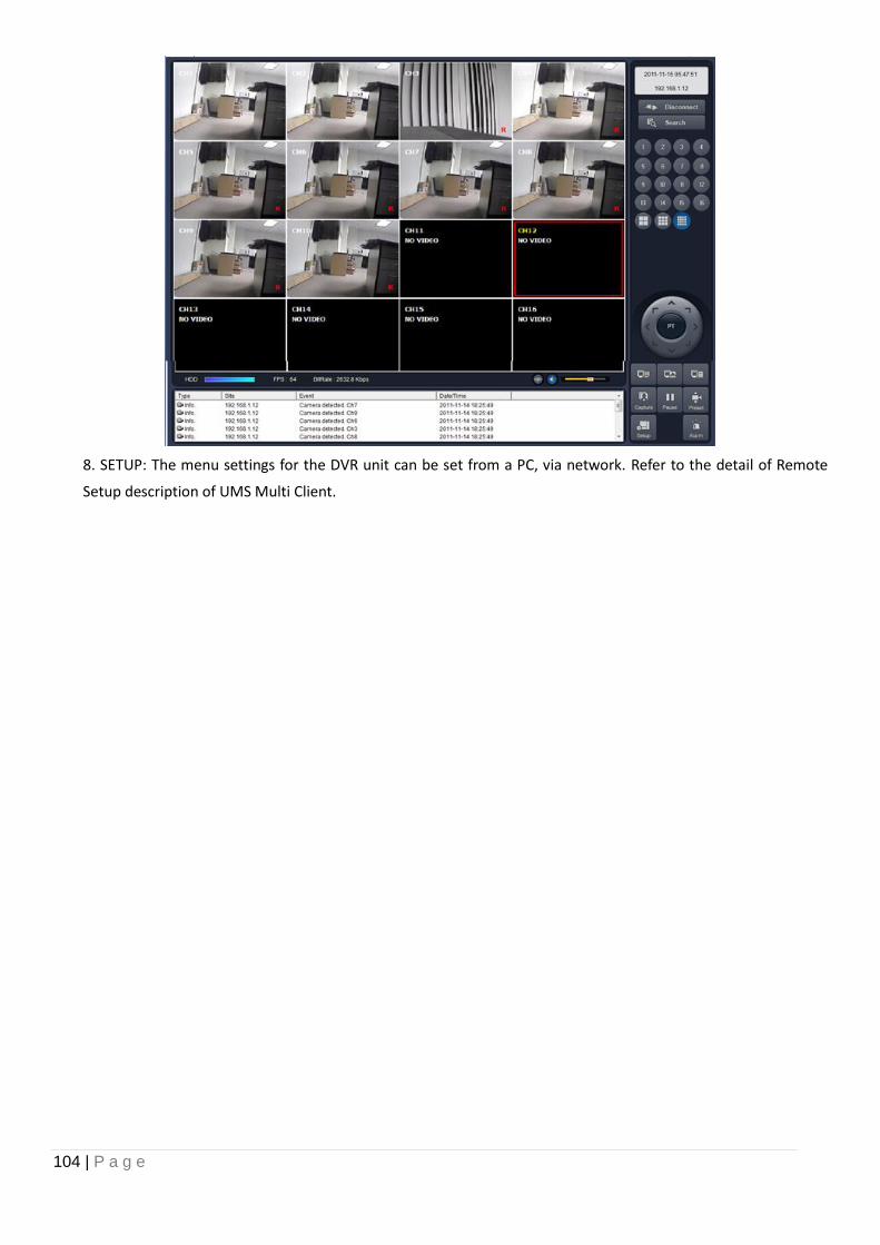
104 | P a g e
8. SETUP: The menu settings for the DVR unit can be set from a PC, via network. Refer to the detail of Remote
Setup description of UMS Multi Client.
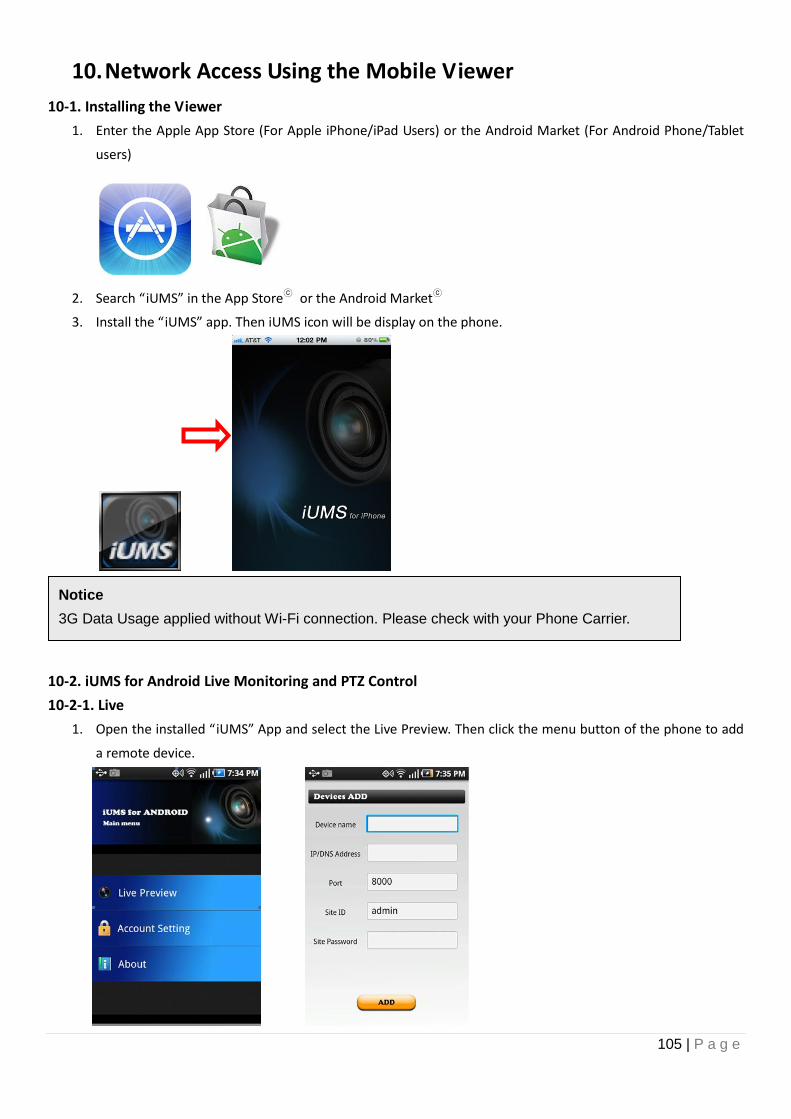
105 | P a g e
10. Network Access Using the Mobile Viewer
10-1. Installing the Viewer
1. Enter the Apple App Store (For Apple iPhone/iPad Users) or the Android Market (For Android Phone/Tablet
users)
2. Search “iUMS” in the App Storeⓒ or the Android Marketⓒ
3. Install the “iUMS” app. Then iUMS icon will be display on the phone.
10-2. iUMS for Android Live Monitoring and PTZ Control
10-2-1. Live
1. Open the installed “iUMS” App and select the Live Preview. Then click the menu button of the phone to add
a remote device.
Notice
3G Data Usage applied without Wi-Fi connection. Please check with your Phone Carrier.
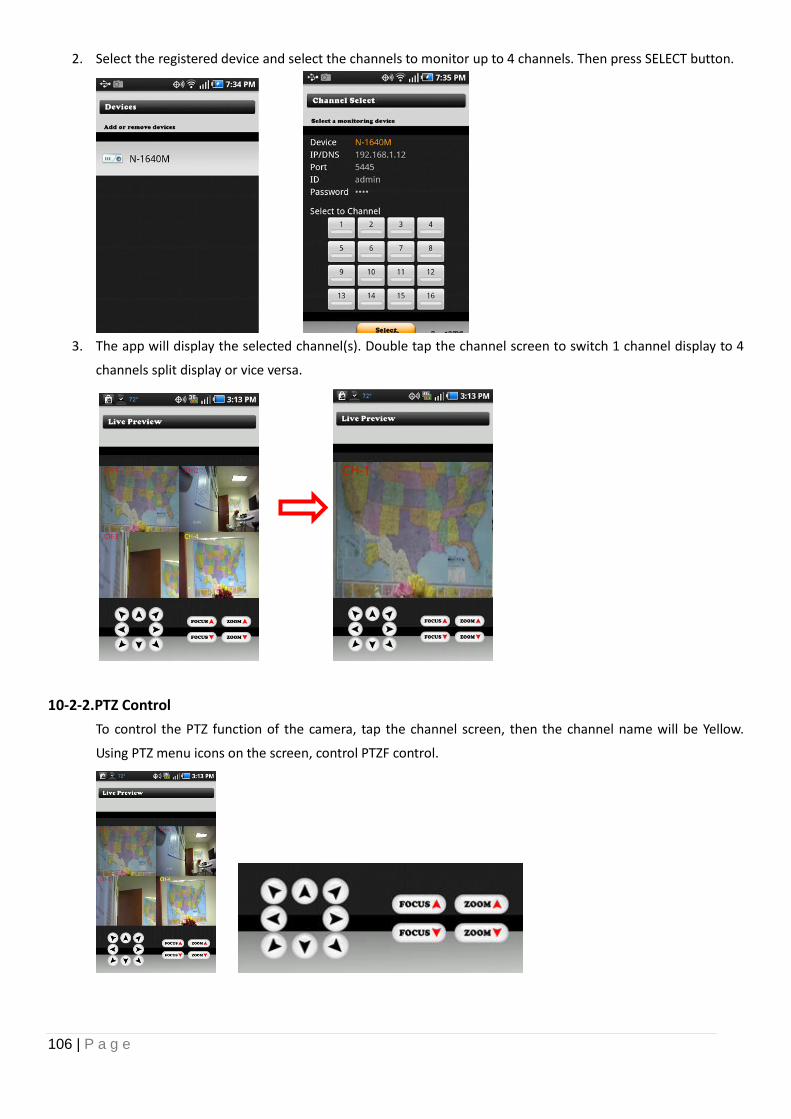
106 | P a g e
2. Select the registered device and select the channels to monitor up to 4 channels. Then press SELECT button.
3. The app will display the selected channel(s). Double tap the channel screen to switch 1 channel display to 4
channels split display or vice versa.
10-2-2.PTZ Control
To control the PTZ function of the camera, tap the channel screen, then the channel name will be Yellow.
Using PTZ menu icons on the screen, control PTZF control.
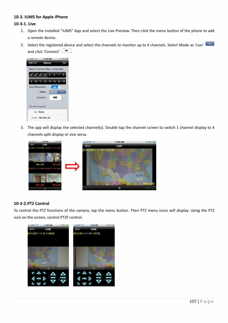
107 | P a g e
10-3. iUMS for Apple iPhone
10-3-1. Live
1. Open the installed “iUMS” App and select the Live Preview. Then click the menu button of the phone to add
a remote device.
2. Select the registered device and select the channels to monitor up to 4 channels. Select Mode as ‘Live’
and click ‘Connect’ .
3. The app will display the selected channel(s). Double tap the channel screen to switch 1 channel display to 4
channels split display or vice versa.
10-3-2.PTZ Control
To control the PTZ functions of the camera, tap the menu button. Then PTZ menu icons will display. Using the PTZ
icon on the screen, control PTZF control.
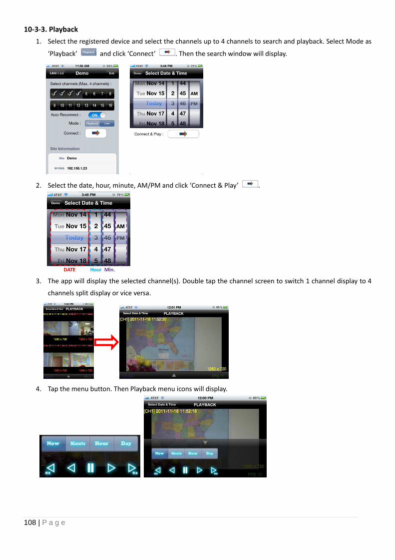
108 | P a g e
10-3-3. Playback
1. Select the registered device and select the channels up to 4 channels to search and playback. Select Mode as
‘Playback’ and click ‘Connect’ . Then the search window will display.
2. Select the date, hour, minute, AM/PM and click ‘Connect & Play’ .
3. The app will display the selected channel(s). Double tap the channel screen to switch 1 channel display to 4
channels split display or vice versa.
4. Tap the menu button. Then Playback menu icons will display.
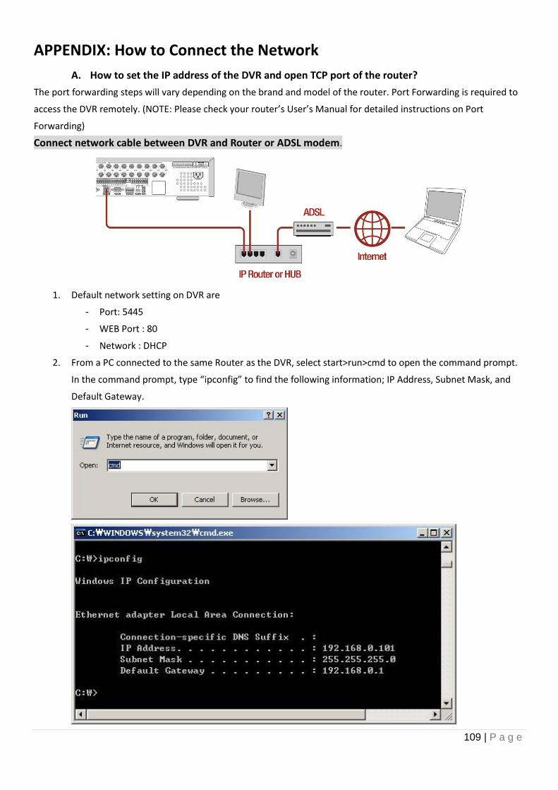
109 | P a g e
APPENDIX: How to Connect the Network
A. How to set the IP address of the DVR and open TCP port of the router?
The port forwarding steps will vary depending on the brand and model of the router. Port Forwarding is required to
access the DVR remotely. (NOTE: Please check your router’s User’s Manual for detailed instructions on Port
Forwarding)
Connect network cable between DVR and Router or ADSL modem.
1. Default network setting on DVR are
- Port: 5445
- WEB Port : 80
- Network : DHCP
2. From a PC connected to the same Router as the DVR, select start>run>cmd to open the command prompt.
In the command prompt, type “ipconfig” to find the following information; IP Address, Subnet Mask, and
Default Gateway.
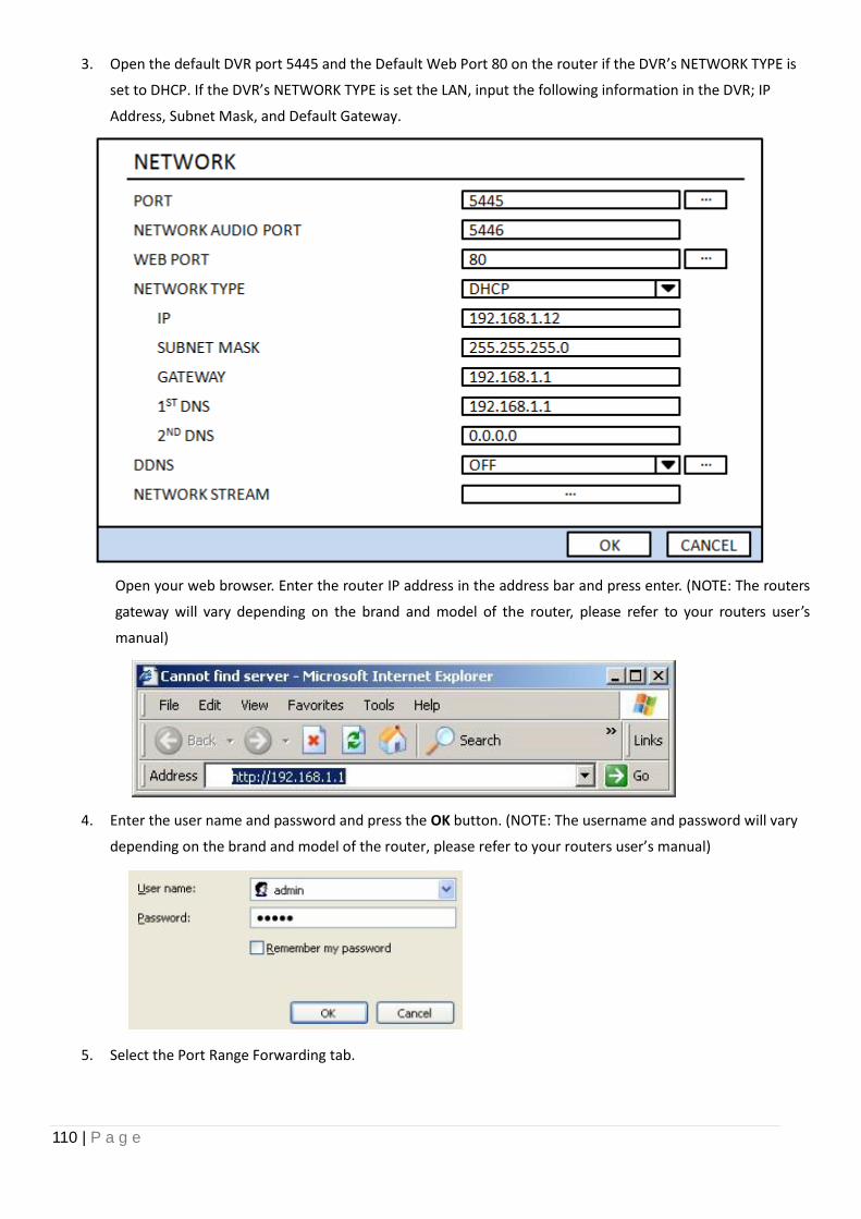
110 | P a g e
3. Open the default DVR port 5445 and the Default Web Port 80 on the router if the DVR’s NETWORK TYPE is
set to DHCP. If the DVR’s NETWORK TYPE is set the LAN, input the following information in the DVR; IP
Address, Subnet Mask, and Default Gateway.
Open your web browser. Enter the router IP address in the address bar and press enter. (NOTE: The routers
gateway will vary depending on the brand and model of the router, please refer to your routers user’s
manual)
4. Enter the user name and password and press the OK button. (NOTE: The username and password will vary
depending on the brand and model of the router, please refer to your routers user’s manual)
5. Select the Port Range Forwarding tab.
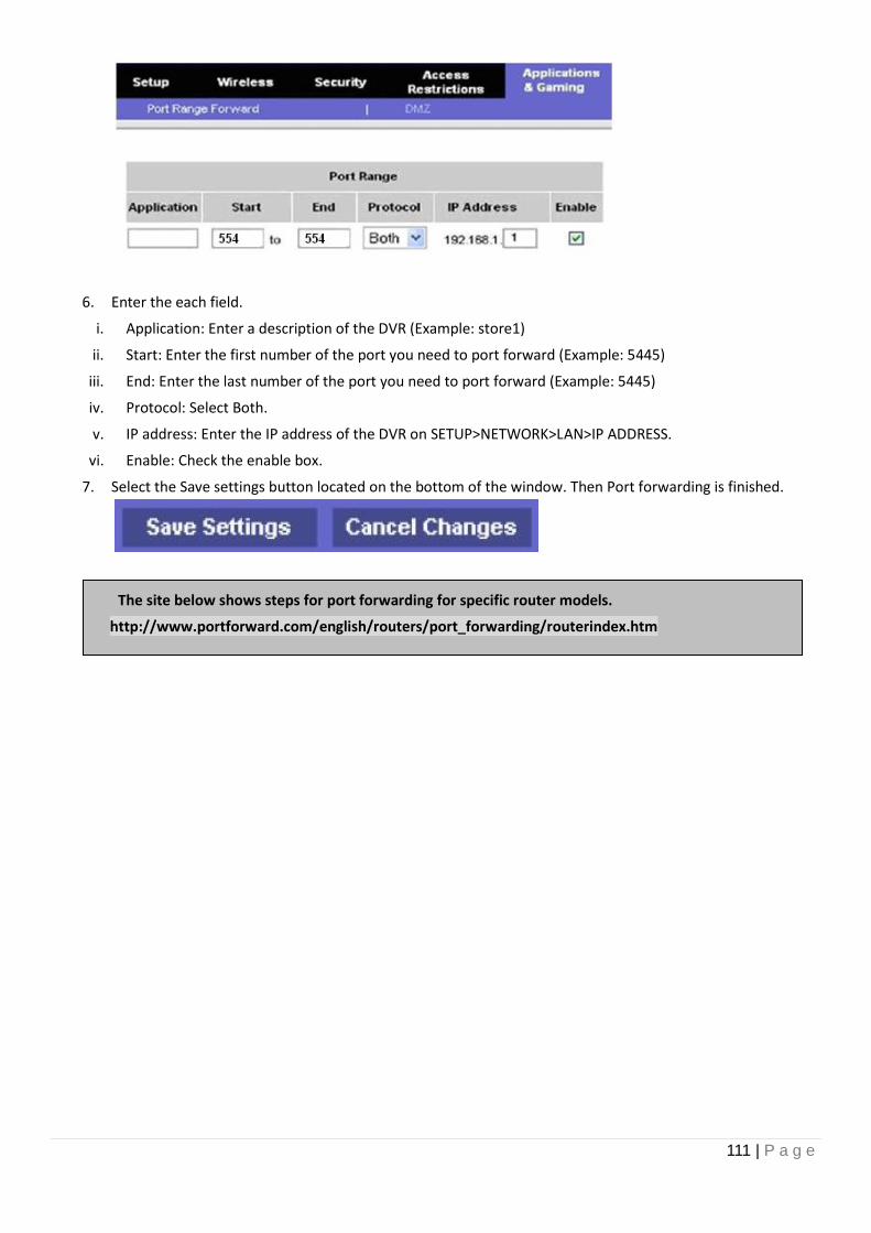
111 | P a g e
6. Enter the each field.
i. Application: Enter a description of the DVR (Example: store1)
ii. Start: Enter the first number of the port you need to port forward (Example: 5445)
iii. End: Enter the last number of the port you need to port forward (Example: 5445)
iv. Protocol: Select Both.
v. IP address: Enter the IP address of the DVR on SETUP>NETWORK>LAN>IP ADDRESS.
vi. Enable: Check the enable box.
7. Select the Save settings button located on the bottom of the window. Then Port forwarding is finished.
The site below shows steps for port forwarding for specific router models.
http://www.portforward.com/english/routers/port_forwarding/routerindex.htm
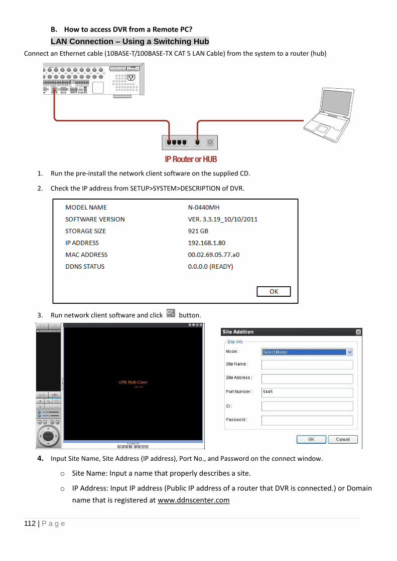
112 | P a g e
B. How to access DVR from a Remote PC?
LAN Connection – Using a Switching Hub
Connect an Ethernet cable (10BASE-T/100BASE-TX CAT 5 LAN Cable) from the system to a router (hub)
1. Run the pre-install the network client software on the supplied CD.
2. Check the IP address from SETUP>SYSTEM>DESCRIPTION of DVR.
3. Run network client software and click button.
4. Input Site Name, Site Address (IP address), Port No., and Password on the connect window.
o Site Name: Input a name that properly describes a site.
o IP Address: Input IP address (Public IP address of a router that DVR is connected.) or Domain
name that is registered at www.ddnscenter.com
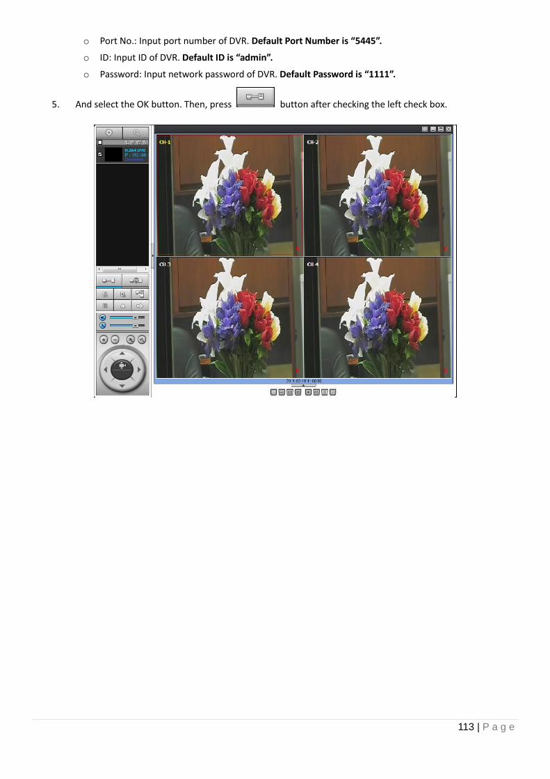
113 | P a g e
o Port No.: Input port number of DVR. Default Port Number is “5445”.
o ID: Input ID of DVR. Default ID is “admin”.
o Password: Input network password of DVR. Default Password is “1111”.
5. And select the OK button. Then, press button after checking the left check box.
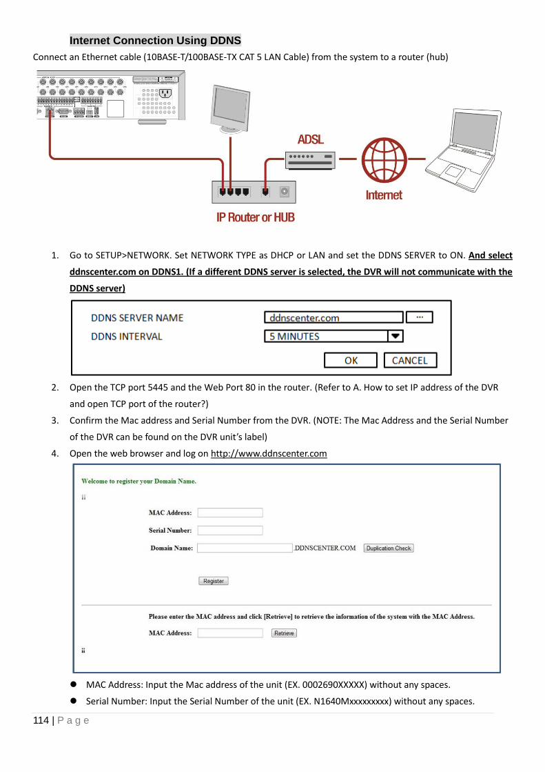
114 | P a g e
Internet Connection Using DDNS
Connect an Ethernet cable (10BASE-T/100BASE-TX CAT 5 LAN Cable) from the system to a router (hub)
1. Go to SETUP>NETWORK. Set NETWORK TYPE as DHCP or LAN and set the DDNS SERVER to ON. And select
ddnscenter.com on DDNS1. (If a different DDNS server is selected, the DVR will not communicate with the
DDNS server)
2. Open the TCP port 5445 and the Web Port 80 in the router. (Refer to A. How to set IP address of the DVR
and open TCP port of the router?)
3. Confirm the Mac address and Serial Number from the DVR. (NOTE: The Mac Address and the Serial Number
of the DVR can be found on the DVR unit’s label)
4. Open the web browser and log on http://www.ddnscenter.com
MAC Address: Input the Mac address of the unit (EX. 0002690XXXXX) without any spaces.
Serial Number: Input the Serial Number of the unit (EX. N1640Mxxxxxxxxx) without any spaces.
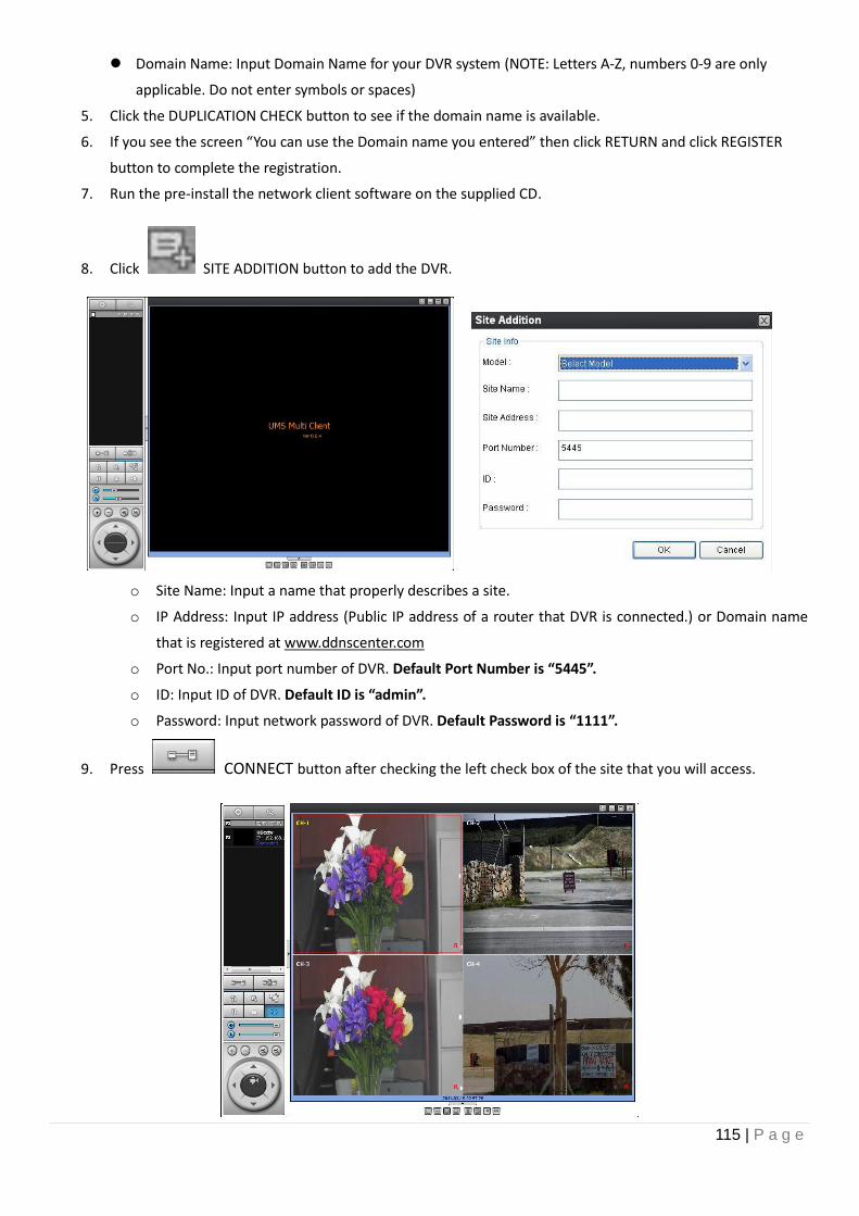
115 | P a g e
Domain Name: Input Domain Name for your DVR system (NOTE: Letters A-Z, numbers 0-9 are only
applicable. Do not enter symbols or spaces)
5. Click the DUPLICATION CHECK button to see if the domain name is available.
6. If you see the screen “You can use the Domain name you entered” then click RETURN and click REGISTER
button to complete the registration.
7. Run the pre-install the network client software on the supplied CD.
8. Click SITE ADDITION button to add the DVR.
o Site Name: Input a name that properly describes a site.
o IP Address: Input IP address (Public IP address of a router that DVR is connected.) or Domain name
that is registered at www.ddnscenter.com
o Port No.: Input port number of DVR. Default Port Number is “5445”.
o ID: Input ID of DVR. Default ID is “admin”.
o Password: Input network password of DVR. Default Password is “1111”.
9. Press CONNECT button after checking the left check box of the site that you will access.