Embed Size (px)
Citation preview
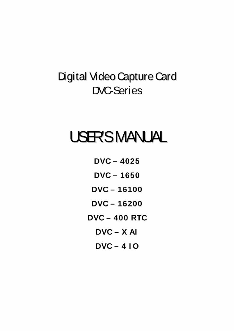
DDiiggiittaall VViiddeeoo CCaappttuurree CCaarrdd DVC-Series
UUSSEERR’’SS MMAANNUUAALL
DVC – 4025
DVC – 1650
DVC – 16100
DVC – 16200
DVC – 400 RTC
DVC – X AI
DVC – 4 IO
2
DVC-Manual_en.doc Stand 10.2005 Seite 2 von 80
Copyright © by MONACOR INTERNATIONAL GmbH & CO. KG , Bremen. All rights reserved.
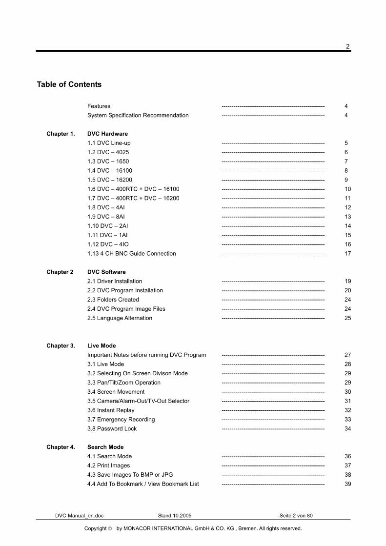
Table of Contents
Features ----------------------------------------------------- 4 System Specification Recommendation ----------------------------------------------------- 4 Chapter 1. DVC Hardware 1.1 DVC Line-up ----------------------------------------------------- 5 1.2 DVC – 4025 ----------------------------------------------------- 6 1.3 DVC – 1650 ----------------------------------------------------- 7 1.4 DVC – 16100 ----------------------------------------------------- 8 1.5 DVC – 16200 ----------------------------------------------------- 9 1.6 DVC – 400RTC + DVC – 16100 ----------------------------------------------------- 10 1.7 DVC – 400RTC + DVC – 16200 ----------------------------------------------------- 11 1.8 DVC – 4AI ----------------------------------------------------- 12 1.9 DVC – 8AI ----------------------------------------------------- 13 1.10 DVC – 2AI ----------------------------------------------------- 14 1.11 DVC – 1AI ----------------------------------------------------- 15 1.12 DVC – 4IO ----------------------------------------------------- 16 1.13 4 CH BNC Guide Connection ----------------------------------------------------- 17 Chapter 2 DVC Software 2.1 Driver Installation ----------------------------------------------------- 19 2.2 DVC Program Installation ----------------------------------------------------- 20 2.3 Folders Created ----------------------------------------------------- 24 2.4 DVC Program Image Files ----------------------------------------------------- 24 2.5 Language Alternation ----------------------------------------------------- 25 Chapter 3. Live Mode Important Notes before running DVC Program ----------------------------------------------------- 27 3.1 Live Mode ----------------------------------------------------- 28 3.2 Selecting On Screen Divison Mode ----------------------------------------------------- 29 3.3 Pan/Tilt/Zoom Operation ----------------------------------------------------- 29 3.4 Screen Movement ----------------------------------------------------- 30 3.5 Camera/Alarm-Out/TV-Out Selector ----------------------------------------------------- 31 3.6 Instant Replay ----------------------------------------------------- 32 3.7 Emergency Recording ----------------------------------------------------- 33 3.8 Password Lock ----------------------------------------------------- 34 Chapter 4. Search Mode 4.1 Search Mode ----------------------------------------------------- 36 4.2 Print Images ----------------------------------------------------- 37 4.3 Save Images To BMP or JPG ----------------------------------------------------- 38 4.4 Add To Bookmark / View Bookmark List ----------------------------------------------------- 39
3
DVC-Manual_en.doc Stand 10.2005 Seite 3 von 80
Copyright © by MONACOR INTERNATIONAL GmbH & CO. KG , Bremen. All rights reserved.
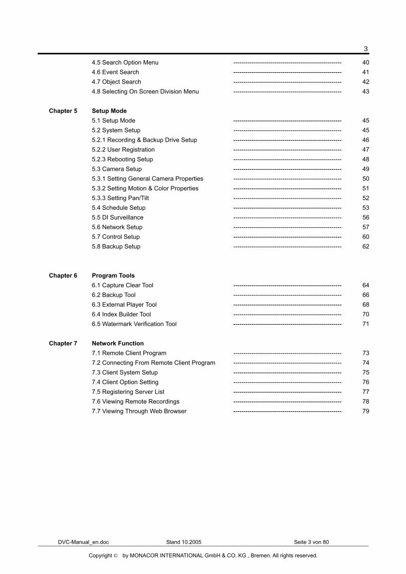
4.5 Search Option Menu ----------------------------------------------------- 40 4.6 Event Search ----------------------------------------------------- 41 4.7 Object Search ----------------------------------------------------- 42 4.8 Selecting On Screen Division Menu ----------------------------------------------------- 43 Chapter 5 Setup Mode 5.1 Setup Mode ----------------------------------------------------- 45 5.2 System Setup ----------------------------------------------------- 45 5.2.1 Recording & Backup Drive Setup ----------------------------------------------------- 46 5.2.2 User Registration ----------------------------------------------------- 47 5.2.3 Rebooting Setup ----------------------------------------------------- 48 5.3 Camera Setup ----------------------------------------------------- 49 5.3.1 Setting General Camera Properties ----------------------------------------------------- 50 5.3.2 Setting Motion & Color Properties ----------------------------------------------------- 51 5.3.3 Setting Pan/Tilt ----------------------------------------------------- 52 5.4 Schedule Setup ----------------------------------------------------- 53 5.5 DI Surveillance ----------------------------------------------------- 56 5.6 Network Setup ----------------------------------------------------- 57 5.7 Control Setup ----------------------------------------------------- 60 5.8 Backup Setup ----------------------------------------------------- 62 Chapter 6 Program Tools 6.1 Capture Clear Tool ----------------------------------------------------- 64 6.2 Backup Tool ----------------------------------------------------- 66 6.3 External Player Tool ----------------------------------------------------- 68 6.4 Index Builder Tool ----------------------------------------------------- 70 6.5 Watermark Verification Tool ----------------------------------------------------- 71 Chapter 7 Network Function 7.1 Remote Client Program ----------------------------------------------------- 73 7.2 Connecting From Remote Client Program ----------------------------------------------------- 74 7.3 Client System Setup ----------------------------------------------------- 75 7.4 Client Option Setting ----------------------------------------------------- 76 7.5 Registering Server List ----------------------------------------------------- 77 7.6 Viewing Remote Recordings ----------------------------------------------------- 78 7.7 Viewing Through Web Browser ----------------------------------------------------- 79
4
DVC-Manual_en.doc Stand 10.2005 Seite 4 von 80
Copyright © by MONACOR INTERNATIONAL GmbH & CO. KG , Bremen. All rights reserved.
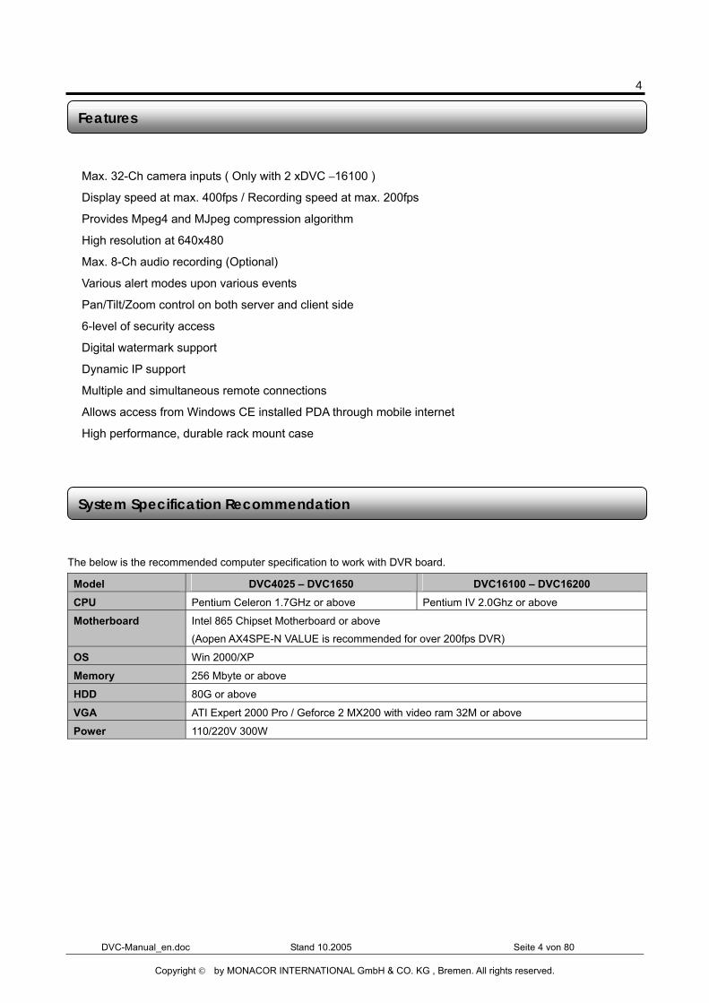
� Max. 32-Ch camera inputs ( Only with 2 xDVC –16100 )
� Display speed at max. 400fps / Recording speed at max. 200fps
� Provides Mpeg4 and MJpeg compression algorithm
� High resolution at 640x480
� Max. 8-Ch audio recording (Optional)
� Various alert modes upon various events
� Pan/Tilt/Zoom control on both server and client side
� 6-level of security access
� Digital watermark support
� Dynamic IP support
� Multiple and simultaneous remote connections
� Allows access from Windows CE installed PDA through mobile internet
� High performance, durable rack mount case
The below is the recommended computer specification to work with DVR board.
Model DVC4025 – DVC1650 DVC16100 – DVC16200 CPU Pentium Celeron 1.7GHz or above Pentium IV 2.0Ghz or above
Motherboard Intel 865 Chipset Motherboard or above
(Aopen AX4SPE-N VALUE is recommended for over 200fps DVR)
OS Win 2000/XP
Memory 256 Mbyte or above
HDD 80G or above
VGA ATI Expert 2000 Pro / Geforce 2 MX200 with video ram 32M or above
Power 110/220V 300W
System Specification Recommendation
Features
5
DVC-Manual_en.doc Stand 10.2005 Seite 5 von 80
Copyright © by MONACOR INTERNATIONAL GmbH & CO. KG , Bremen. All rights reserved.
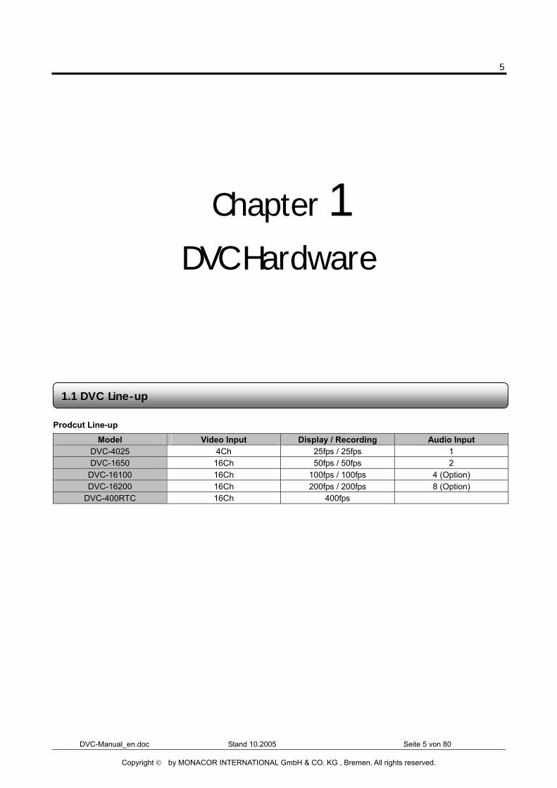
Chapter 1 DVC Hardware
Prodcut Line-up
Model Video Input Display / Recording Audio Input DVC-4025 4Ch 25fps / 25fps 1 DVC-1650 16Ch 50fps / 50fps 2
DVC-16100 16Ch 100fps / 100fps 4 (Option) DVC-16200 16Ch 200fps / 200fps 8 (Option)
DVC-400RTC 16Ch 400fps
1.1 DVC Line-up
6
DVC-Manual_en.doc Stand 10.2005 Seite 6 von 80
Copyright © by MONACOR INTERNATIONAL GmbH & CO. KG , Bremen. All rights reserved.
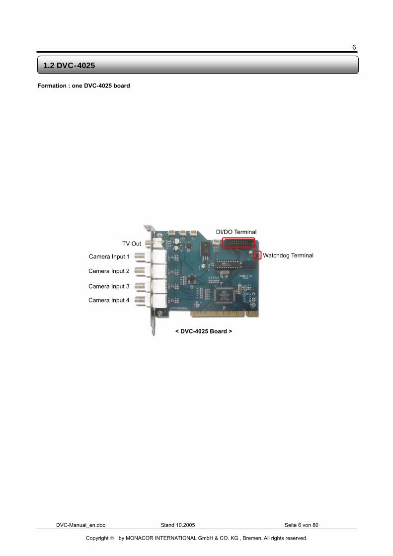
Formation : one DVC-4025 board
1.2 DVC-4025
DI/DO Terminal
Watchdog Terminal
< DVC-4025 Board >
Camera Input 1
Camera Input 2
Camera Input 4
TV Out
Camera Input 3
7
DVC-Manual_en.doc Stand 10.2005 Seite 7 von 80
Copyright © by MONACOR INTERNATIONAL GmbH & CO. KG , Bremen. All rights reserved.
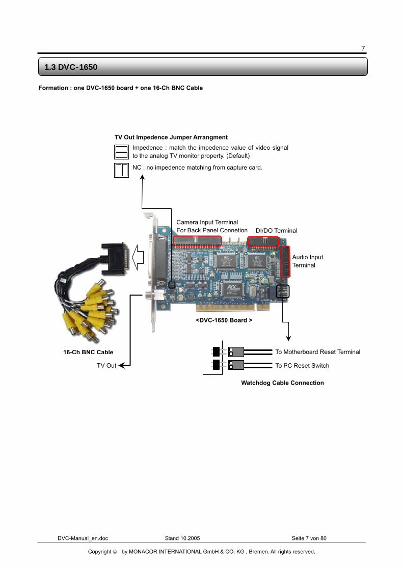
Formation : one DVC-1650 board + one 16-Ch BNC Cable
1.3 DVC-1650
16-Ch BNC Cable
Camera Input Terminal For Back Panel Connetion DI/DO Terminal
TV Out Impedence Jumper Arrangment
NC : no impedence matching from capture card.
Impedence : match the impedence value of video signalto the analog TV monitor property. (Default)
TV Out
<DVC-1650 Board >
Audio Input Terminal
To Motherboard Reset Terminal
To PC Reset Switch
Watchdog Cable Connection
8
DVC-Manual_en.doc Stand 10.2005 Seite 8 von 80
Copyright © by MONACOR INTERNATIONAL GmbH & CO. KG , Bremen. All rights reserved.
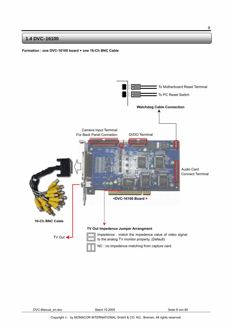
Formation : one DVC-16100 board + one 16-Ch BNC Cable
1.4 DVC-16100
TV Out
Camera Input TerminalFor Back Panel Connetion DI/DO Terminal
Audio Card Connect Terminal
<DVC-16100 Board >
16-Ch BNC Cable
To Motherboard Reset Terminal
To PC Reset Switch
Watchdog Cable Connection
TV Out Impedence Jumper Arrangment
NC : no impedence matching from capture card.
Impedence : match the impedence value of video signalto the analog TV monitor property. (Default)
9
DVC-Manual_en.doc Stand 10.2005 Seite 9 von 80
Copyright © by MONACOR INTERNATIONAL GmbH & CO. KG , Bremen. All rights reserved.
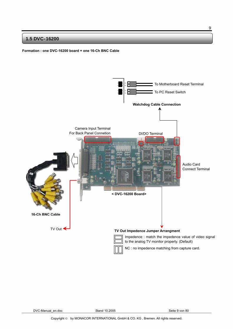
Formation : one DVC-16200 board + one 16-Ch BNC Cable
1.5 DVC-16200
TV Out
DI/DO Terminal
Audio Card Connect Terminal
< DVC-16200 Board>
16-Ch BNC Cable
To Motherboard Reset Terminal
To PC Reset Switch
Watchdog Cable Connection
TV Out Impedence Jumper Arrangment
NC : no impedence matching from capture card.
Impedence : match the impedence value of video signalto the analog TV monitor property. (Default)
Camera Input TerminalFor Back Panel Connetion
10
DVC-Manual_en.doc Stand 10.2005 Seite 10 von 80
Copyright © by MONACOR INTERNATIONAL GmbH & CO. KG , Bremen. All rights reserved.
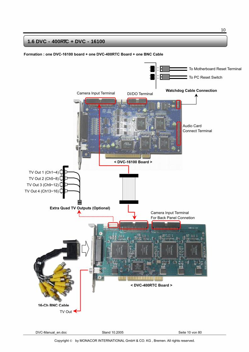
Formation : one DVC-16100 board + one DVC-400RTC Board + one BNC Cable
1.6 DVC - 400RTC + DVC - 16100
Camera Input Terminal DI/DO Terminal
Audio Card Connect Terminal
< DVC-16100 Board >
< DVC-400RTC Board >
To Motherboard Reset Terminal
To PC Reset Switch
Watchdog Cable Connection
TV Out
16-Ch BNC Cable
Camera Input Terminal For Back Panel Connetion
TV Out 1 (Ch1~4)
TV Out 2 (Ch5~8)
TV Out 3 (Ch9~12)
TV Out 4 (Ch13~16)
Extra Quad TV Outputs (Optional)
11
DVC-Manual_en.doc Stand 10.2005 Seite 11 von 80
Copyright © by MONACOR INTERNATIONAL GmbH & CO. KG , Bremen. All rights reserved.
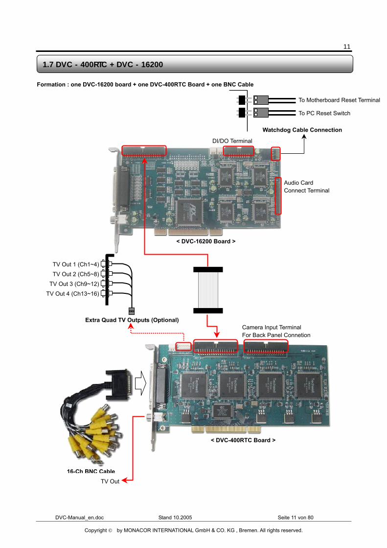
Formation : one DVC-16200 board + one DVC-400RTC Board + one BNC Cable
1.7 DVC - 400RTC + DVC - 16200
DI/DO Terminal
Audio Card Connect Terminal
To Motherboard Reset Terminal
To PC Reset Switch
Watchdog Cable Connection
< DVC-16200 Board >
< DVC-400RTC Board >
TV Out
16-Ch BNC Cable
Camera Input Terminal For Back Panel Connetion
TV Out 1 (Ch1~4)
TV Out 2 (Ch5~8)
TV Out 3 (Ch9~12)
TV Out 4 (Ch13~16)
Extra Quad TV Outputs (Optional)
12
DVC-Manual_en.doc Stand 10.2005 Seite 12 von 80
Copyright © by MONACOR INTERNATIONAL GmbH & CO. KG , Bremen. All rights reserved.
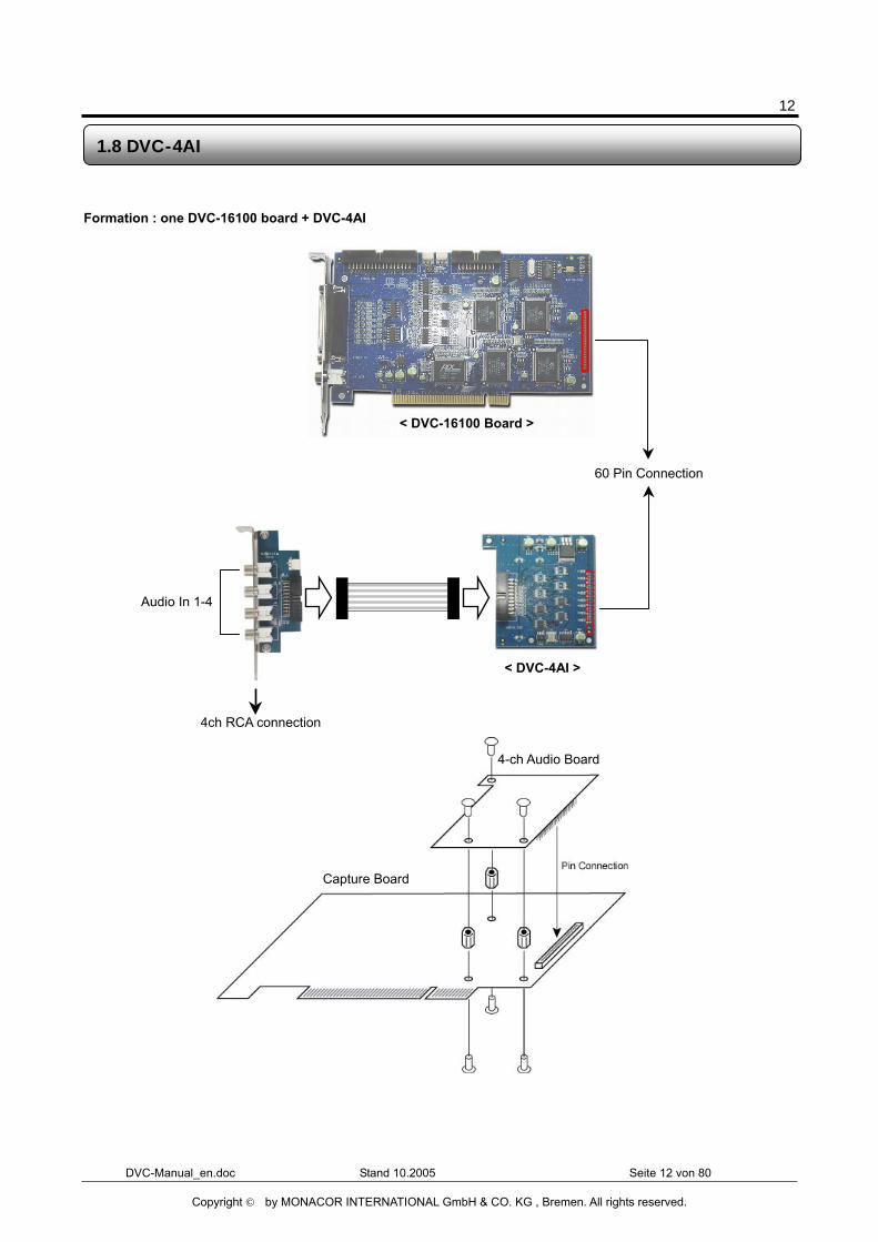
Formation : one DVC-16100 board + DVC-4AI
1.8 DVC-4AI
60 Pin Connection
Audio In 1-4
4ch RCA connection
< DVC-4AI >
< DVC-16100 Board >
Capture Board
4-ch Audio Board
13
DVC-Manual_en.doc Stand 10.2005 Seite 13 von 80
Copyright © by MONACOR INTERNATIONAL GmbH & CO. KG , Bremen. All rights reserved.
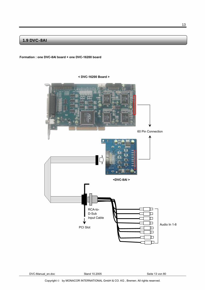
Formation : one DVC-8AI board + one DVC-16200 board
1.9 DVC-8AI
60 Pin Connection
Audio In 1-8
RCA-to- D-Sub Input Cable
PCI Slot
<DVC-8AI >
< DVC-16200 Board >
14
DVC-Manual_en.doc Stand 10.2005 Seite 14 von 80
Copyright © by MONACOR INTERNATIONAL GmbH & CO. KG , Bremen. All rights reserved.
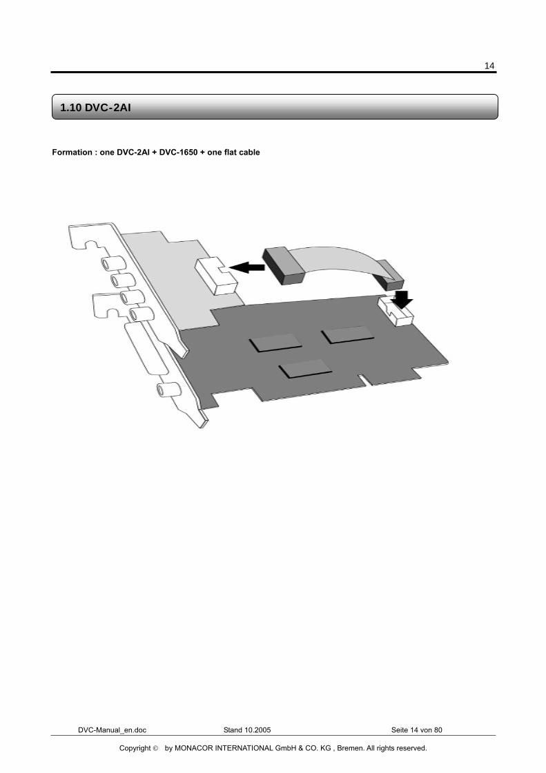
Formation : one DVC-2AI + DVC-1650 + one flat cable
1.10 DVC-2AI
15
DVC-Manual_en.doc Stand 10.2005 Seite 15 von 80
Copyright © by MONACOR INTERNATIONAL GmbH & CO. KG , Bremen. All rights reserved.
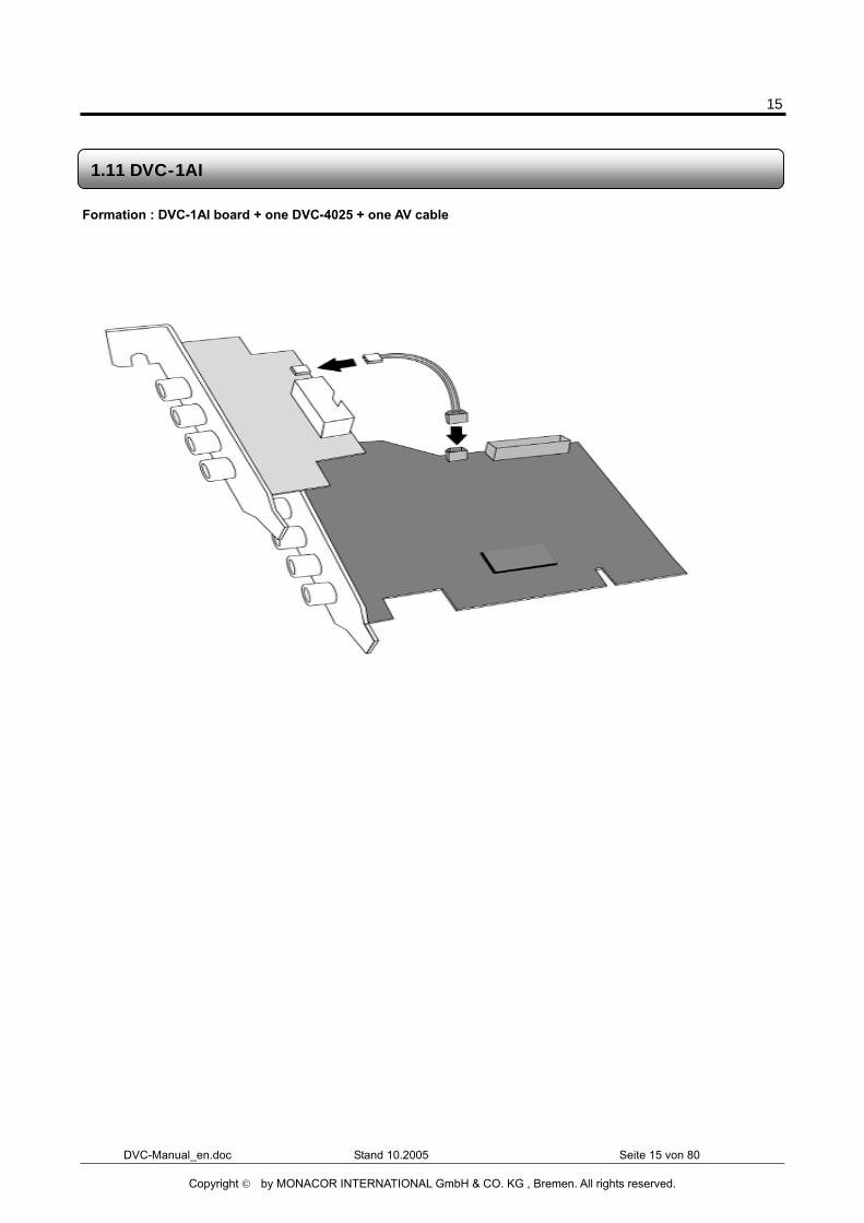
Formation : DVC-1AI board + one DVC-4025 + one AV cable
1.11 DVC-1AI
16
DVC-Manual_en.doc Stand 10.2005 Seite 16 von 80
Copyright © by MONACOR INTERNATIONAL GmbH & CO. KG , Bremen. All rights reserved.
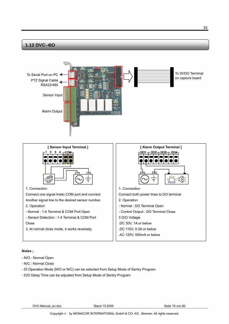
Notes ;
- N/O : Normal Open
- N/C : Normal Close
- DI Operation Mode (N/O or N/C) can be selected from Setup Mode of Sentry Program
- D/O Delay Time can be adjusted from Setup Mode of Sentry Program
To Serial Port on PC
1.12 DVC-4IO
[ Sensor Input Terminal ]
1. Connection
Connect one signal lineto COM port and connect
Another signal line to the desired sensor number.
2. Operation
- Normal : 1-4 Terminal & COM Port Open
- Sensor Detection : 1-4 Terminal & COM Port
Close 3. At normal close mode, it works reversely.
[ Alarm Output Terminal ]
1. Connection
Connect both power lines to DO terminal
2. Operation
- Normal : DO Terminal Open
- Control Output : DO Terminal Close
3 D/O Voltage
.DC 30V, 1A or below
.DC 110V, 0.3A or below
.AC 125V, 500mA or below
To DI/DO Terminal on capture board
Sensor Input
Alarm Output
PTZ Signal CableRS422/485
17
DVC-Manual_en.doc Stand 10.2005 Seite 17 von 80
Copyright © by MONACOR INTERNATIONAL GmbH & CO. KG , Bremen. All rights reserved.
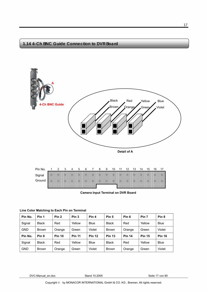
1 2 3 4 5 6 7 8 9 10 11 12 13 14 15 16 17
○ ○ ○ ○ ○ ○ ○ ○ ○ ○ ○ ○ ○ ○ ○ ○ ○
○ ○ ○ ○ ○ ○ ○ ○ ○ ○ ○ ○ ○ ○ ○ ○ ○
Line Color Matching to Each Pin on Terminal
Pin No. Pin 1 Pin 2 Pin 3 Pin 4 Pin 5 Pin 6 Pin 7 Pin 8
Signal Black Red Yellow Blue Black Red Yellow Blue
GND Brown Orange Green Violet Brown Orange Green Violet
Pin No. Pin 9 Pin 10 Pin 11 Pin 12 Pin 13 Pin 14 Pin 15 Pin 16
Signal Black Red Yellow Blue Black Red Yellow Blue
GND Brown Orange Green Violet Brown Orange Green Violet
1.14 4-Ch BNC Guide Connection to DVR Board
4-Ch BNC Guide
A
Signal Ground
Detail of A
Black
Brown
Red
Orange
Yellow
Green
Blue
Violet
Camera Input Terminal on DVR Board
Pin No.
18
DVC-Manual_en.doc Stand 10.2005 Seite 18 von 80
Copyright © by MONACOR INTERNATIONAL GmbH & CO. KG , Bremen. All rights reserved.
In case of using over two pcs of 4-Ch BNC Guides, you can connect to Pin 5 ~ Pin 16.
Chapter 2 DVC Software
19
DVC-Manual_en.doc Stand 10.2005 Seite 19 von 80
Copyright © by MONACOR INTERNATIONAL GmbH & CO. KG , Bremen. All rights reserved.
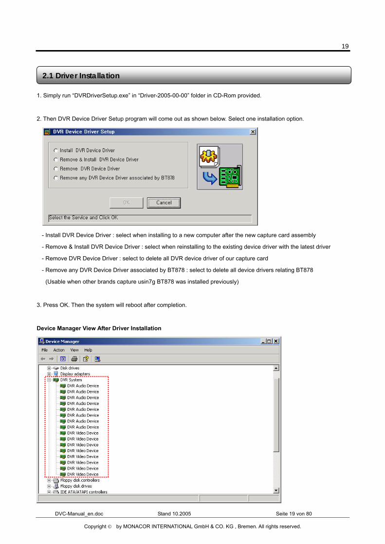
1. Simply run “DVRDriverSetup.exe” in “Driver-2005-00-00” folder in CD-Rom provided.
2. Then DVR Device Driver Setup program will come out as shown below. Select one installation option.
- Install DVR Device Driver : select when installing to a new computer after the new capture card assembly
- Remove & Install DVR Device Driver : select when reinstalling to the existing device driver with the latest driver
- Remove DVR Device Driver : select to delete all DVR device driver of our capture card
- Remove any DVR Device Driver associated by BT878 : select to delete all device drivers relating BT878
(Usable when other brands capture usin7g BT878 was installed previously)
3. Press OK. Then the system will reboot after completion.
Device Manager View After Driver Installation
2.1 Driver Installation
20
DVC-Manual_en.doc Stand 10.2005 Seite 20 von 80
Copyright © by MONACOR INTERNATIONAL GmbH & CO. KG , Bremen. All rights reserved.
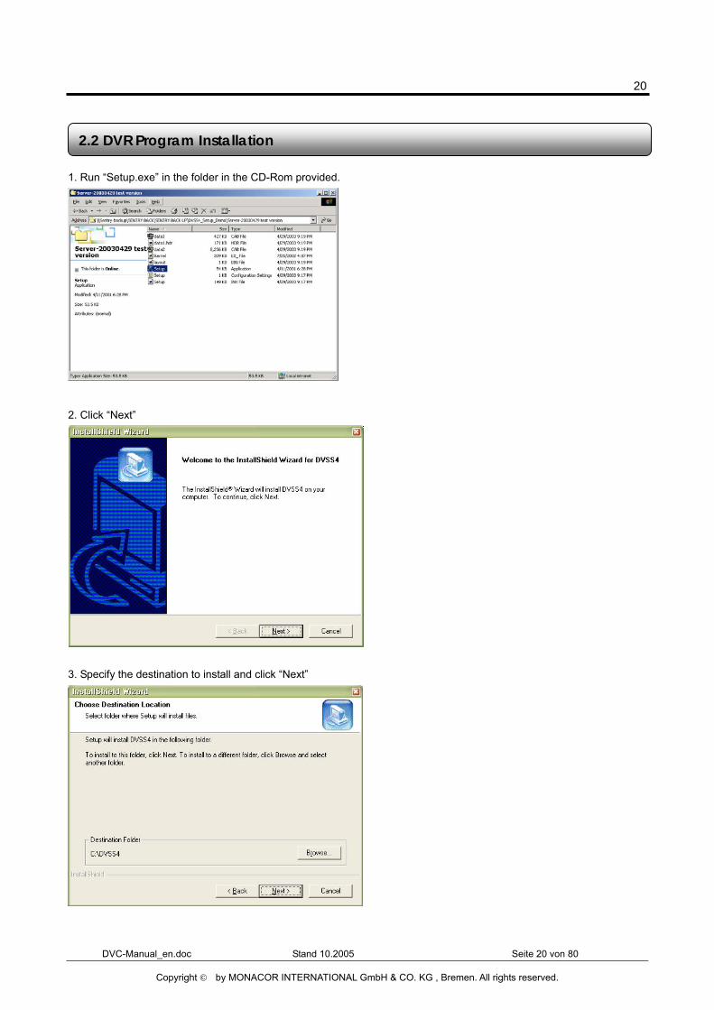
1. Run “Setup.exe” in the folder in the CD-Rom provided.
2. Click “Next”
3. Specify the destination to install and click “Next”
2.2 DVR Program Installation
21
DVC-Manual_en.doc Stand 10.2005 Seite 21 von 80
Copyright © by MONACOR INTERNATIONAL GmbH & CO. KG , Bremen. All rights reserved.
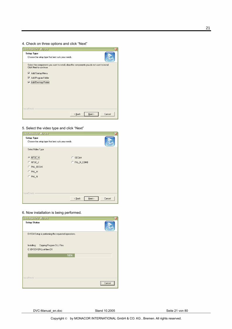
4. Check on three options and click “Next”
5. Select the video type and click “Next”
6. Now installation is being performed.
22
DVC-Manual_en.doc Stand 10.2005 Seite 22 von 80
Copyright © by MONACOR INTERNATIONAL GmbH & CO. KG , Bremen. All rights reserved.
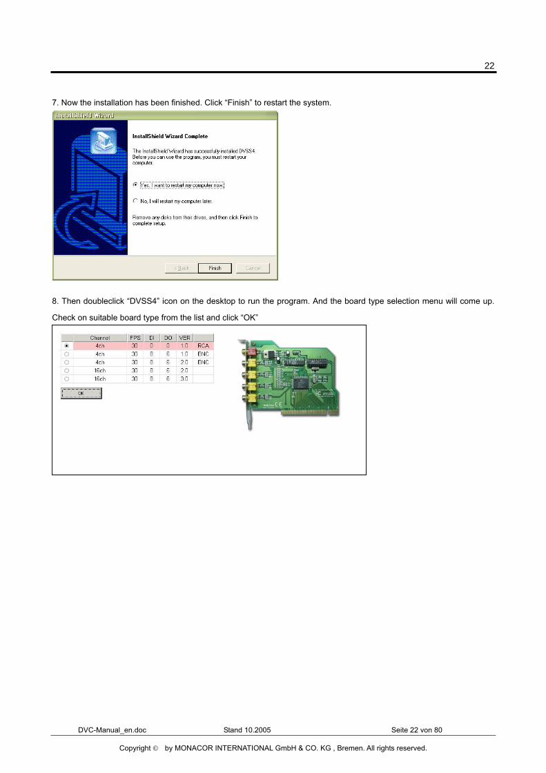
7. Now the installation has been finished. Click “Finish” to restart the system.
8. Then doubleclick “DVSS4” icon on the desktop to run the program. And the board type selection menu will come up.
Check on suitable board type from the list and click “OK”
23
DVC-Manual_en.doc Stand 10.2005 Seite 23 von 80
Copyright © by MONACOR INTERNATIONAL GmbH & CO. KG , Bremen. All rights reserved.
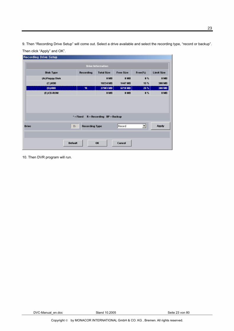
9. Then “Recording Drive Setup” will come out. Select a drive available and select the recording type, “record or backup”.
Then click “Apply” and OK”.
10. Then DVR program will run.
24
DVC-Manual_en.doc Stand 10.2005 Seite 24 von 80
Copyright © by MONACOR INTERNATIONAL GmbH & CO. KG , Bremen. All rights reserved.
The below folders are created after DVR Program installation.
Folder Name Description
Language Language files exist
LogFile System Log files exist
PanTilt PTZ Driver files exist
Skin GUI skin file exists
Sound Sound files (*.wav) used in DVR program exist
Tools Utilities exist (Backup, Backup Player & CaptureClear)
Update Temp folder for download when real-tim update
WebPages Web files for web service exists
There are a few image files used in DVR Program. The files can be replaced with the ones that the users desire to have.
File Name Description Size Format Path
Logo.bmp Shown on blank channel where no camera input exists from main GUI
320 X 240 BMP C:/DVSS4/Image
MiniLogo.bmp Shown on main GUI to display supplier’s logo
98 X 50 BMP C:/DVSS4/Image
Splash.bmp Shown when loading Sentry DVR Program 500 X 200 BMP C:/DVSS4/Image
DVSS4WallPaper.bmp Wallpaper when used on DVR mode 1024 X 768 BMP C:/DVSS4/Image
Playbacklogo.bmp Shown on blank channel where no camera input exists from playback GUI
320 X 240 BMP C:/DVSS4/Image
Disconnect.bmp Shown when no video signal 320 X 240 BMP C:/DVSS4/Image
Note - You can make image files and copy them to image folder. - In order to apply customized images from install stage, you can make image folder in installation folder (ex ; Server-2003XXXX) and copy the image files to the folder.
2.3 Folders Created After DVR Program Installation
2.4 DVR Program Image Files
25
DVC-Manual_en.doc Stand 10.2005 Seite 25 von 80
Copyright © by MONACOR INTERNATIONAL GmbH & CO. KG , Bremen. All rights reserved.
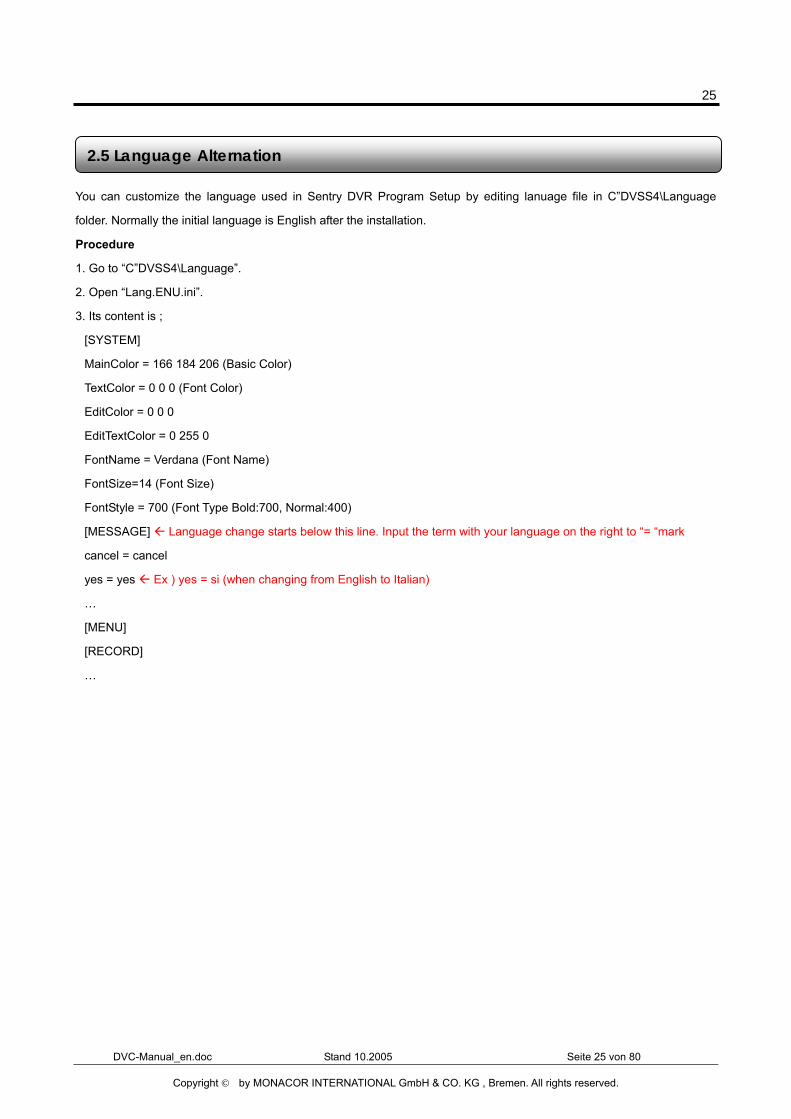
You can customize the language used in Sentry DVR Program Setup by editing lanuage file in C”DVSS4\Language
folder. Normally the initial language is English after the installation.
Procedure
1. Go to “C”DVSS4\Language”.
2. Open “Lang.ENU.ini”.
3. Its content is ;
[SYSTEM]
MainColor = 166 184 206 (Basic Color)
TextColor = 0 0 0 (Font Color)
EditColor = 0 0 0
EditTextColor = 0 255 0
FontName = Verdana (Font Name)
FontSize=14 (Font Size)
FontStyle = 700 (Font Type Bold:700, Normal:400)
[MESSAGE] Language change starts below this line. Input the term with your language on the right to “= “mark
cancel = cancel
yes = yes Ex ) yes = si (when changing from English to Italian)
…
[MENU]
[RECORD]
…
2.5 Language Alternation
26
DVC-Manual_en.doc Stand 10.2005 Seite 26 von 80
Copyright © by MONACOR INTERNATIONAL GmbH & CO. KG , Bremen. All rights reserved.
Chapter 3 Live Mode
27
DVC-Manual_en.doc Stand 10.2005 Seite 27 von 80
Copyright © by MONACOR INTERNATIONAL GmbH & CO. KG , Bremen. All rights reserved.
Before Operating DVR Program
1) Recycle Bin Setup
Check on the box “Do not move files to the Recycle Bin. Remove files immediately when deleted.” in the property of
Recycle Bin.
2) Display Setup
- Set resolution at 1024x768 and High Color 16bit.
- Set “System Standby”, “Turn off monitor” and “Turn off hard disk” at “Never” in Display Properties\Power Management
Properties\Power Schemes.
3) Rebooting Setup
We highly recommend you to set automatic daily rebooting in idle time for most stable system operation.
4) Operating System
As Sentry Software was bulit on Windows 2000 platform, it operates most stable on Windows 2000 platform.
You can use Windows XP as well.
5) DirectX
DirectX Verison 8.1b or above
Important Notes Before Running DVR Program
28
DVC-Manual_en.doc Stand 10.2005 Seite 28 von 80
Copyright © by MONACOR INTERNATIONAL GmbH & CO. KG , Bremen. All rights reserved.
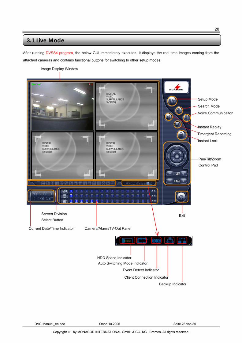
After running DVSS4 program, the below GUI immediately executes. It displays the real-time images coming from the
attached cameras and contains functional buttons for switching to other setup modes.
3.1 Live Mode
Pan/Tilt/Zoom Control Pad
Exit Screen Division
Select Button
Image Display Window
Current Date/Time Indicator
HDD Space Indicator Auto Switching Mode Indicator
Event Detect Indicator
Client Connection Indicator
Camera/Alarm/TV-Out Panel
Backup Indicator
Setup Mode
Search Mode
Voice Communicaiton
Instant Replay
Emergent Recording
Instant Lock
29
DVC-Manual_en.doc Stand 10.2005 Seite 29 von 80
Copyright © by MONACOR INTERNATIONAL GmbH & CO. KG , Bremen. All rights reserved.
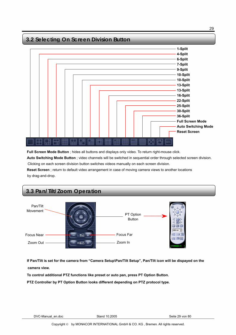
� Full Screen Mode Button ; hides all buttons and displays only video. To return right-mouse click. � Auto Switching Mode Button ; video channels will be switched in sequential order through selected screen division. Clicking on each screen division button switches videos manually on each screen division.
� Reset Screen ; return to default video arrangement in case of moving camera views to another locations
by drag-and-drop.
� If Pan/Tilt is set for the camera from “Camera Setup\Pan/Tilt Setup”, Pan/Tilt icon will be dispayed on the
camera view.
� To control additional PTZ functions like preset or auto pan, press PT Option Button.
� PTZ Controller by PT Option Button looks different depending on PTZ protocol type.
3.2 Selecting On Screen Division Button
3.3 Pan/Tilt/Zoom Operation
Zoom In Zoom Out
Focus Near Focus Far
Pan/TiltMovement
PT OptionButton
1-Split 4-Split 6-Split 7-Split 9-Split 10-Split 10-Split 13-Split 13-Split 16-Split 22-Split 25-Split 30-Split 36-Split Full Screen Mode Auto Switching Mode Reset Screen
30
DVC-Manual_en.doc Stand 10.2005 Seite 30 von 80
Copyright © by MONACOR INTERNATIONAL GmbH & CO. KG , Bremen. All rights reserved.
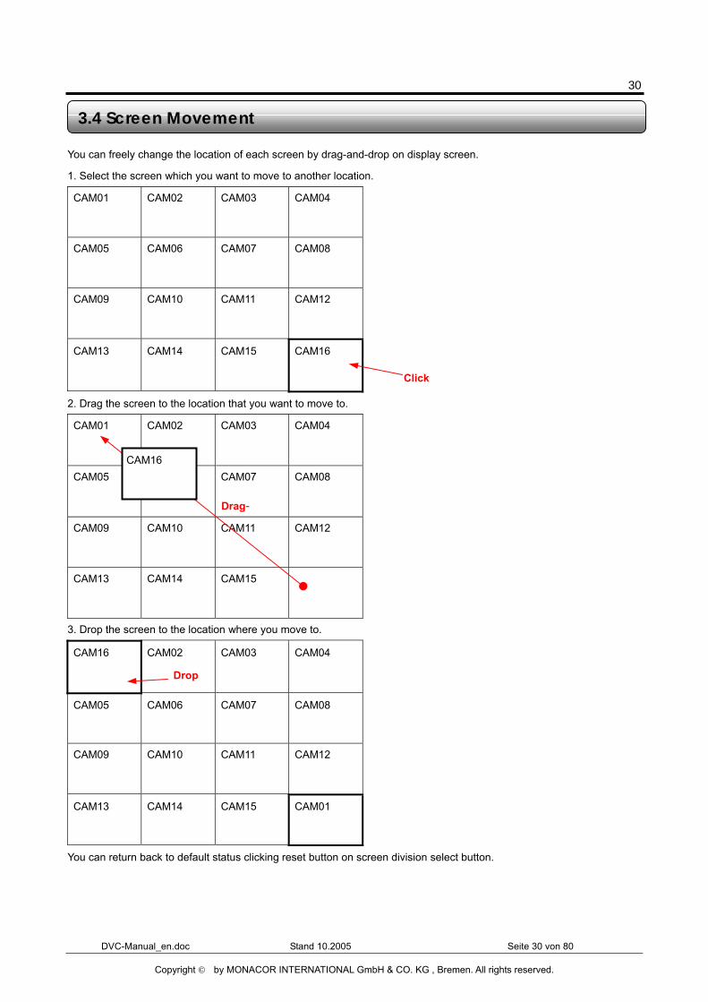
You can freely change the location of each screen by drag-and-drop on display screen.
1. Select the screen which you want to move to another location.
CAM01 CAM02 CAM03 CAM04
CAM05 CAM06 CAM07 CAM08
CAM09 CAM10 CAM11 CAM12
CAM13 CAM14 CAM15 CAM16
2. Drag the screen to the location that you want to move to.
CAM01 CAM02 CAM03 CAM04
CAM05 CAM06 CAM07 CAM08
CAM09 CAM10 CAM11 CAM12
CAM13 CAM14 CAM15
3. Drop the screen to the location where you move to.
CAM16 CAM02 CAM03 CAM04
CAM05 CAM06 CAM07 CAM08
CAM09 CAM10 CAM11 CAM12
CAM13 CAM14 CAM15 CAM01
You can return back to default status clicking reset button on screen division select button.
3.4 Screen Movement
Drag-
Click
CAM16
Drop
31
DVC-Manual_en.doc Stand 10.2005 Seite 31 von 80
Copyright © by MONACOR INTERNATIONAL GmbH & CO. KG , Bremen. All rights reserved.
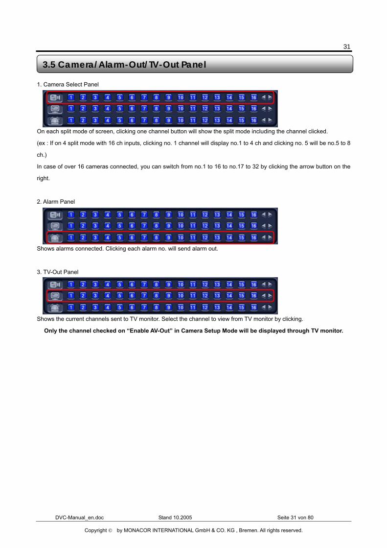
1. Camera Select Panel
On each split mode of screen, clicking one channel button will show the split mode including the channel clicked.
(ex : If on 4 split mode with 16 ch inputs, clicking no. 1 channel will display no.1 to 4 ch and clicking no. 5 will be no.5 to 8
ch.)
In case of over 16 cameras connected, you can switch from no.1 to 16 to no.17 to 32 by clicking the arrow button on the
right.
2. Alarm Panel
Shows alarms connected. Clicking each alarm no. will send alarm out.
3. TV-Out Panel
Shows the current channels sent to TV monitor. Select the channel to view from TV monitor by clicking.
� Only the channel checked on “Enable AV-Out” in Camera Setup Mode will be displayed through TV monitor.
3.5 Camera/Alarm-Out/TV-Out Panel
32
DVC-Manual_en.doc Stand 10.2005 Seite 32 von 80
Copyright © by MONACOR INTERNATIONAL GmbH & CO. KG , Bremen. All rights reserved.
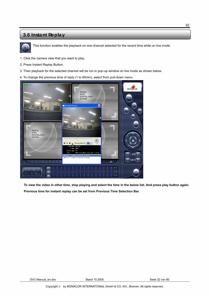
This function enables the playback on one channel selected for the recent time while on live mode.
1. Click the camera view that you want to play.
2. Press Instant Replay Button.
3. Then playback for the selected channel will be run in pop-up window on live mode as shown below.
4. To change the previous time of reply (1 to 60min), select from pull-down menu.
� To view the video in other time, stop playing and select the time in the below list. And press play button again.
� Previous time for instant replay can be set from Previous Time Selection Bar.
3.6 Instant Replay
33
DVC-Manual_en.doc Stand 10.2005 Seite 33 von 80
Copyright © by MONACOR INTERNATIONAL GmbH & CO. KG , Bremen. All rights reserved.
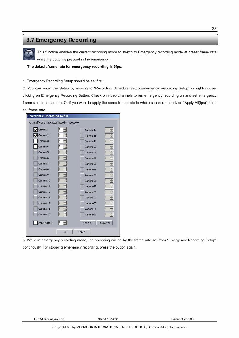
This function enables the current recording mode to switch to Emergency recording mode at preset frame rate
while the button is pressed in the emergency.
� The default frame rate for emergency recording is 5fps.
1. Emergency Recording Setup should be set first..
2. You can enter the Setup by moving to “Recording Schedule Setup\Emergency Recording Setup” or right-mouse-
clicking on Emergency Recording Button. Check on video channels to run emergency recording on and set emergency
frame rate each camera. Or if you want to apply the same frame rate to whole channels, check on “Apply All(fps)”, then
set frame rate.
3. While in emergency recording mode, the recording will be by the frame rate set from “Emergency Recording Setup”
continously. For stopping emergency recording, press the button again.
3.7 Emergency Recording
34
DVC-Manual_en.doc Stand 10.2005 Seite 34 von 80
Copyright © by MONACOR INTERNATIONAL GmbH & CO. KG , Bremen. All rights reserved.
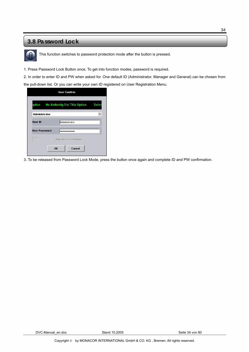
This function switches to password protection mode after the button is pressed.
1. Press Password Lock Button once. To get into function modes, password is required.
2. In order to enter ID and PW when asked for. One default ID (Administrator, Manager and General) can be chosen from
the pull-down list. Or you can write your own ID registered on User Registration Menu.
3. To be released from Password Lock Mode, press the button once again and complete ID and PW confirmation.
3.8 Password Lock

35
DVC-Manual_en.doc Stand 10.2005 Seite 35 von 80
Copyright © by MONACOR INTERNATIONAL GmbH & CO. KG , Bremen. All rights reserved.
Chapter 4 Search Mode
36
DVC-Manual_en.doc Stand 10.2005 Seite 36 von 80
Copyright © by MONACOR INTERNATIONAL GmbH & CO. KG , Bremen. All rights reserved.
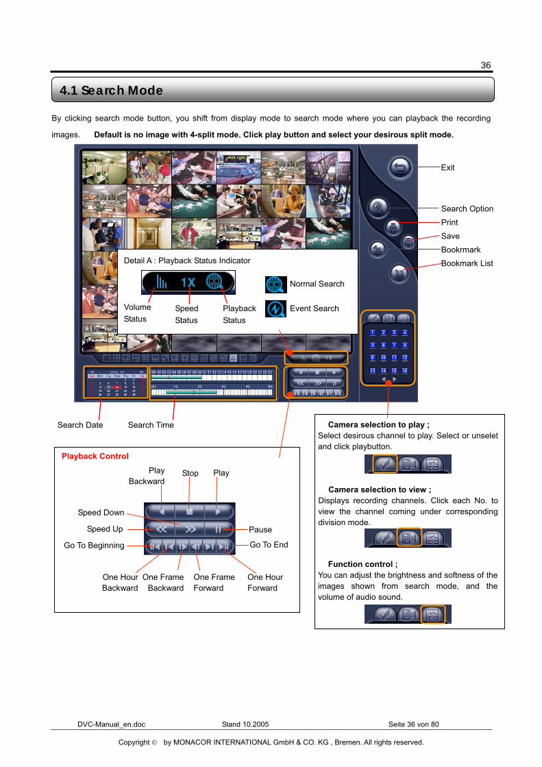
By clicking search mode button, you shift from display mode to search mode where you can playback the recording
images. � Default is no image with 4-split mode. Click play button and select your desirous split mode.
4.1 Search Mode
Search Date Search Time
Exit
Volume Status
Speed Status
Playback Status
Detail A : Playback Status Indicator
Normal Search
Event Search
� Camera selection to view ; Displays recording channels. Click each No. toview the channel coming under correspondingdivision mode.
Playback Control
� Function control ; You can adjust the brightness and softness of theimages shown from search mode, and thevolume of audio sound.
� Camera selection to play ; Select desirous channel to play. Select or unseletand click playbutton.
Search Option
Save
Bookrmark Bookmark List
Go To End
Pause
PlayPlay Backward
One FrameBackward
Stop
One Frame Forward
Go To Beginning
One HourBackward
One Hour Forward
Speed Up
Speed Down
37
DVC-Manual_en.doc Stand 10.2005 Seite 37 von 80
Copyright © by MONACOR INTERNATIONAL GmbH & CO. KG , Bremen. All rights reserved.
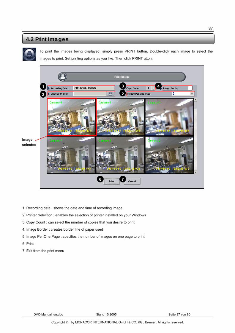
To print the images being displayed, simply press PRINT button. Double-click each image to select the
images to print. Set printing options as you like. Then click PRINT utton.
1. Recording date : shows the date and time of recording image
2. Printer Selection : enables the selection of printer installed on your Windows
3. Copy Count : can select the number of copies that you desire to print
4. Image Border : creates border line of paper used
5. Image Per One Page : specifies the number of images on one page to print
6. Print
7. Exit from the print menu
4.2 Print Images
Image selected
1
2
3 4
5
6 7
38
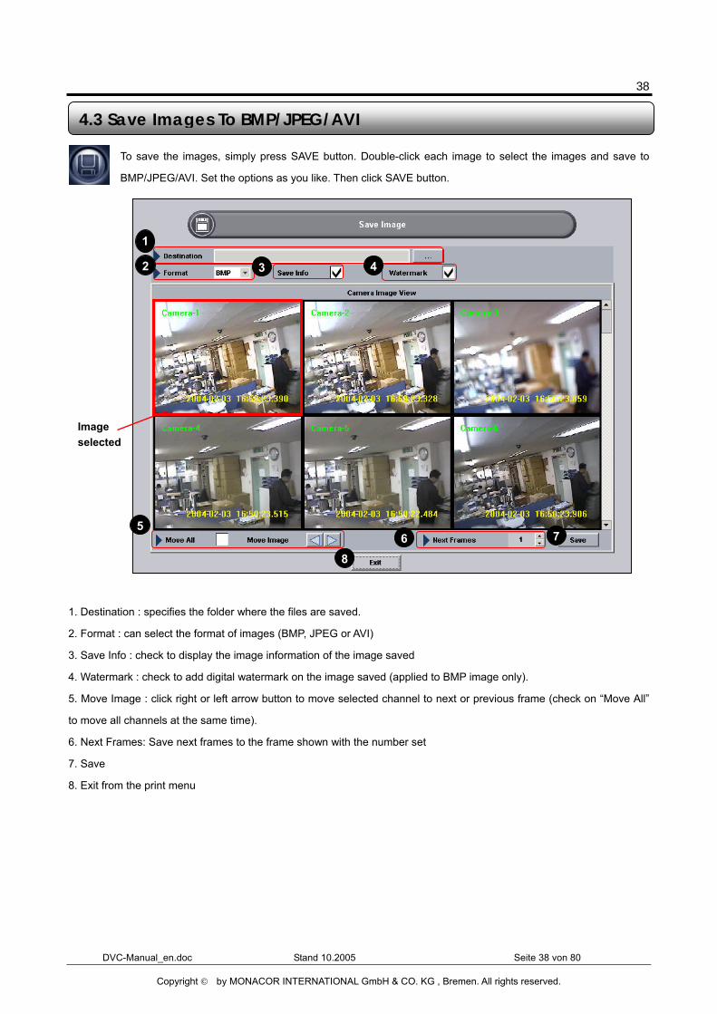
DVC-Manual_en.doc Stand 10.2005 Seite 38 von 80
Copyright © by MONACOR INTERNATIONAL GmbH & CO. KG , Bremen. All rights reserved.
To save the images, simply press SAVE button. Double-click each image to select the images and save to
BMP/JPEG/AVI. Set the options as you like. Then click SAVE button.
1. Destination : specifies the folder where the files are saved.
2. Format : can select the format of images (BMP, JPEG or AVI)
3. Save Info : check to display the image information of the image saved
4. Watermark : check to add digital watermark on the image saved (applied to BMP image only).
5. Move Image : click right or left arrow button to move selected channel to next or previous frame (check on “Move All”
to move all channels at the same time).
6. Next Frames: Save next frames to the frame shown with the number set
7. Save
8. Exit from the print menu
4.3 Save Images To BMP/JPEG/AVI
Image selected
1
2 3 4
5 6 7
8
39
DVC-Manual_en.doc Stand 10.2005 Seite 39 von 80
Copyright © by MONACOR INTERNATIONAL GmbH & CO. KG , Bremen. All rights reserved.
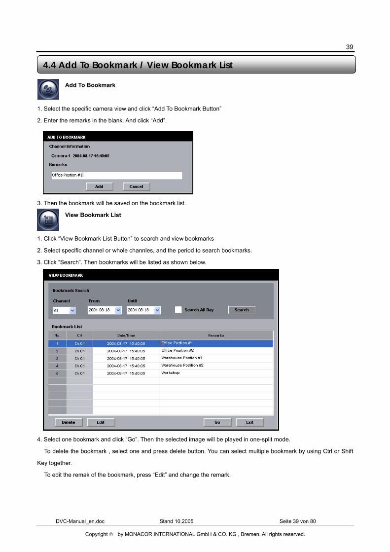
Add To Bookmark
1. Select the specific camera view and click “Add To Bookmark Button”
2. Enter the remarks in the blank. And click “Add”.
3. Then the bookmark will be saved on the bookmark list.
View Bookmark List
1. Click “View Bookmark List Button” to search and view bookmarks
2. Select specific channel or whole channles, and the period to search bookmarks.
3. Click “Search”. Then bookmarks will be listed as shown below.
4. Select one bookmark and click “Go”. Then the selected image will be played in one-split mode.
� To delete the bookmark , select one and press delete button. You can select multiple bookmark by using Ctrl or Shift
Key together.
� To edit the remak of the bookmark, press “Edit” and change the remark.
4.4 Add To Bookmark / View Bookmark List
40
DVC-Manual_en.doc Stand 10.2005 Seite 40 von 80
Copyright © by MONACOR INTERNATIONAL GmbH & CO. KG , Bremen. All rights reserved.
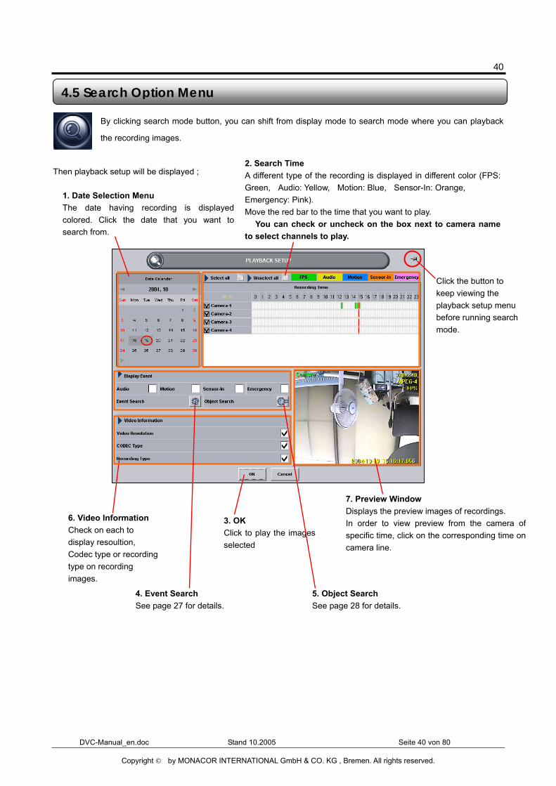
By clicking search mode button, you can shift from display mode to search mode where you can playback
the recording images.
Then playback setup will be displayed ;
4.5 Search Option Menu
1. Date Selection Menu The date having recording is displayedcolored. Click the date that you want tosearch from.
2. Search Time A different type of the recording is displayed in different color (FPS:Green, Audio: Yellow, Motion: Blue, Sensor-In: Orange, Emergency: Pink). Move the red bar to the time that you want to play. � You can check or uncheck on the box next to camera nameto select channels to play.
7. Preview Window Displays the preview images of recordings. In order to view preview from the camera ofspecific time, click on the corresponding time oncamera line.
3. OK Click to play the imagesselected
4. Event Search See page 27 for details.
6. Video Information Check on each to display resoultion, Codec type or recording type on recording images.
Click the button to keep viewing the playback setup menu before running search mode.
5. Object Search See page 28 for details.
41
DVC-Manual_en.doc Stand 10.2005 Seite 41 von 80
Copyright © by MONACOR INTERNATIONAL GmbH & CO. KG , Bremen. All rights reserved.
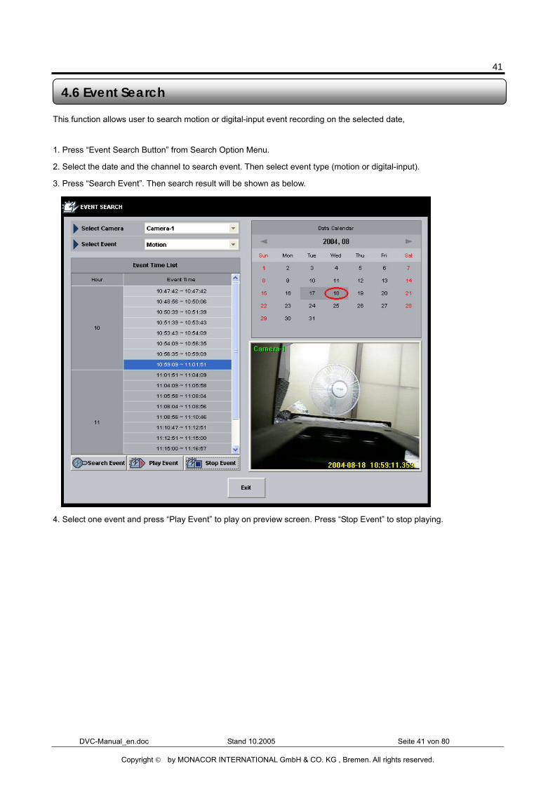
This function allows user to search motion or digital-input event recording on the selected date,
1. Press “Event Search Button” from Search Option Menu.
2. Select the date and the channel to search event. Then select event type (motion or digital-input).
3. Press “Search Event”. Then search result will be shown as below.
4. Select one event and press “Play Event” to play on preview screen. Press “Stop Event” to stop playing.
4.6 Event Search
42
DVC-Manual_en.doc Stand 10.2005 Seite 42 von 80
Copyright © by MONACOR INTERNATIONAL GmbH & CO. KG , Bremen. All rights reserved.
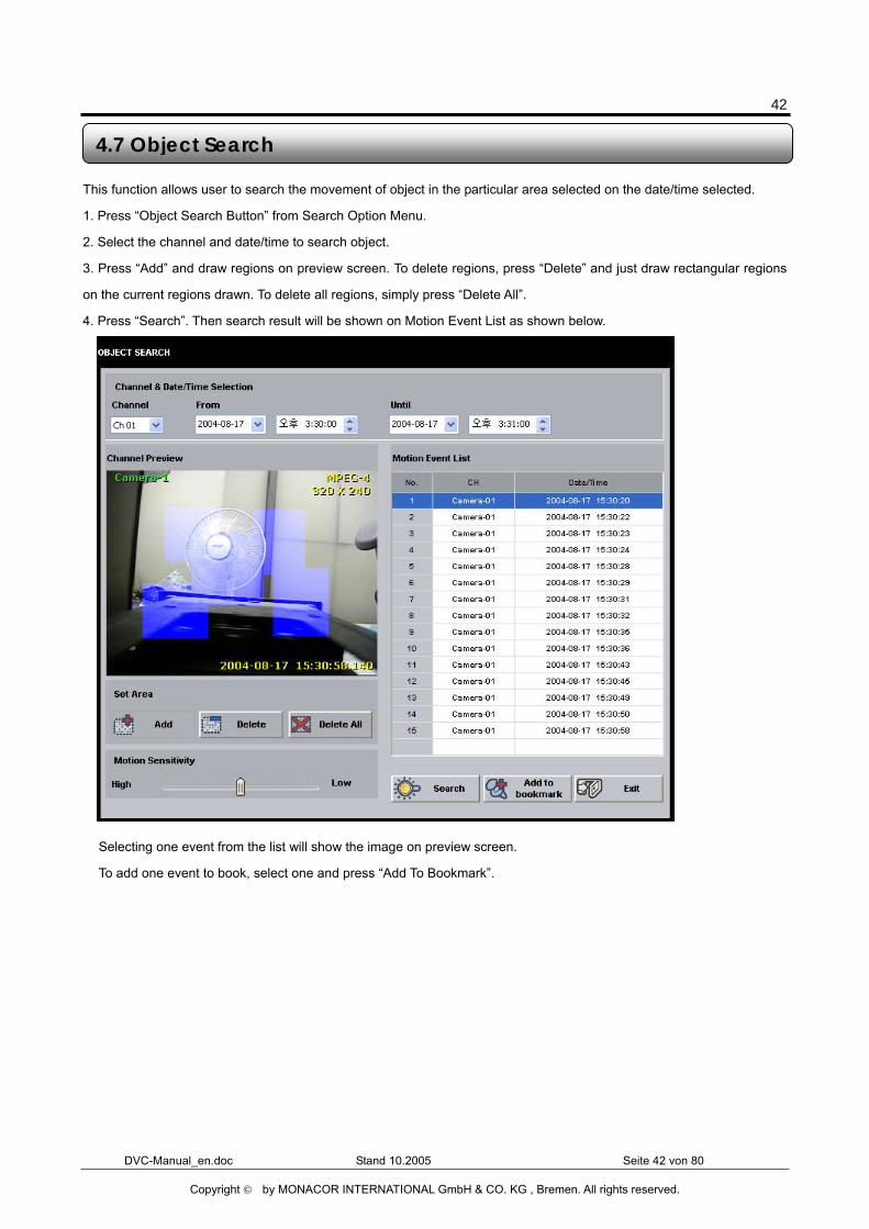
This function allows user to search the movement of object in the particular area selected on the date/time selected.
1. Press “Object Search Button” from Search Option Menu.
2. Select the channel and date/time to search object.
3. Press “Add” and draw regions on preview screen. To delete regions, press “Delete” and just draw rectangular regions
on the current regions drawn. To delete all regions, simply press “Delete All”.
4. Press “Search”. Then search result will be shown on Motion Event List as shown below.
� Selecting one event from the list will show the image on preview screen.
� To add one event to book, select one and press “Add To Bookmark”.
4.7 Object Search
43
DVC-Manual_en.doc Stand 10.2005 Seite 43 von 80
Copyright © by MONACOR INTERNATIONAL GmbH & CO. KG , Bremen. All rights reserved.
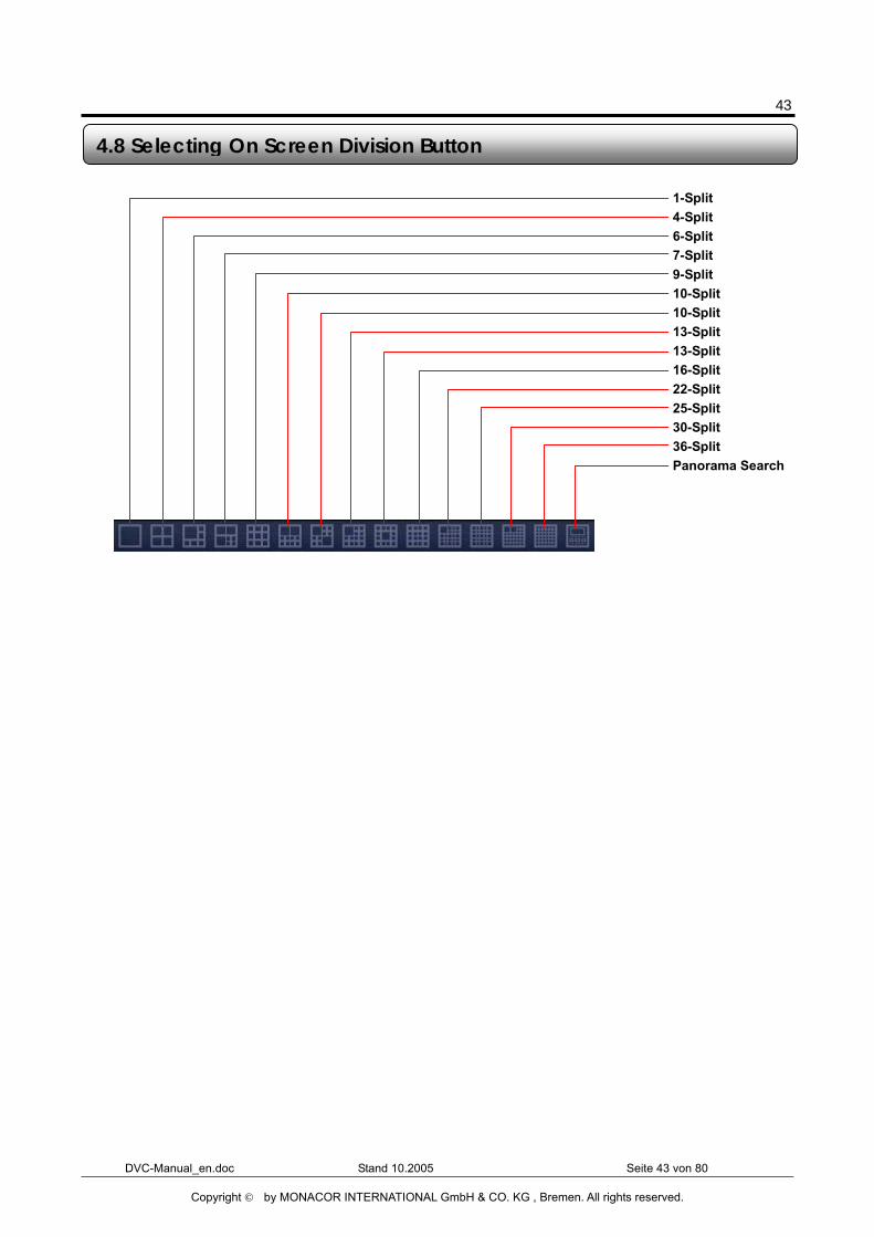
4.8 Selecting On Screen Division Button
1-Split 4-Split 6-Split 7-Split 9-Split 10-Split 10-Split 13-Split 13-Split 16-Split 22-Split 25-Split 30-Split 36-Split Panorama Search
44
DVC-Manual_en.doc Stand 10.2005 Seite 44 von 80
Copyright © by MONACOR INTERNATIONAL GmbH & CO. KG , Bremen. All rights reserved.
Chapter 5 Setup Mode
45
DVC-Manual_en.doc Stand 10.2005 Seite 45 von 80
Copyright © by MONACOR INTERNATIONAL GmbH & CO. KG , Bremen. All rights reserved.
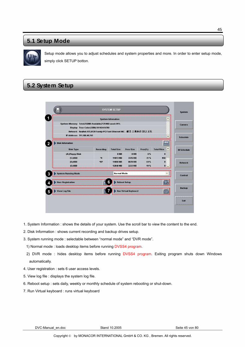
Setup mode allows you to adjust schedules and system properties and more. In order to enter setup mode,
simply click SETUP botton.
1. System Information : shows the details of your system. Use the scroll bar to view the content to the end.
2. Disk Information : shows current recording and backup drives setup.
3. System running mode : selectable between “normal mode” and “DVR mode”.
1) Normal mode : loads desktop items before running DVSS4 program.
2) DVR mode : hides desktop items before running DVSS4 program. Exiting program shuts down Windows
automatically.
4. User registration : sets 6 user access levels.
5. View log file : displays the system log file.
6. Reboot setup : sets daily, weekly or monthly schedule of system rebooting or shut-down.
7. Run Virtual keyboard : runs virtual keyboard
5.1 Setup Mode
5.2 System Setup
1
2
3
4
5
6
7
46
DVC-Manual_en.doc Stand 10.2005 Seite 46 von 80
Copyright © by MONACOR INTERNATIONAL GmbH & CO. KG , Bremen. All rights reserved.
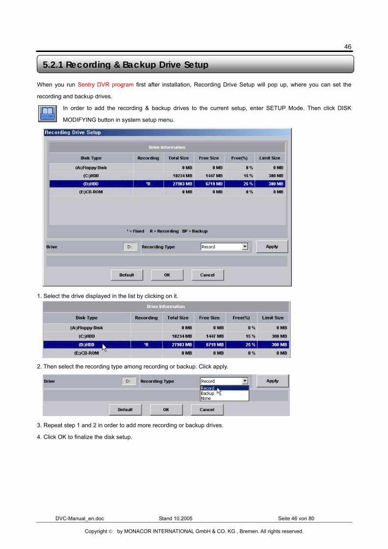
When you run Sentry DVR program first after installation, Recording Drive Setup will pop up, where you can set the
recording and backup drives.
In order to add the recording & backup drives to the current setup, enter SETUP Mode. Then click DISK
MODIFYING button in system setup menu.
1. Select the drive displayed in the list by clicking on it.
2. Then select the recording type among recording or backup. Click apply.
3. Repeat step 1 and 2 in order to add more recording or backup drives.
4. Click OK to finalize the disk setup.
5.2.1 Recording & Backup Drive Setup
47
DVC-Manual_en.doc Stand 10.2005 Seite 47 von 80
Copyright © by MONACOR INTERNATIONAL GmbH & CO. KG , Bremen. All rights reserved.
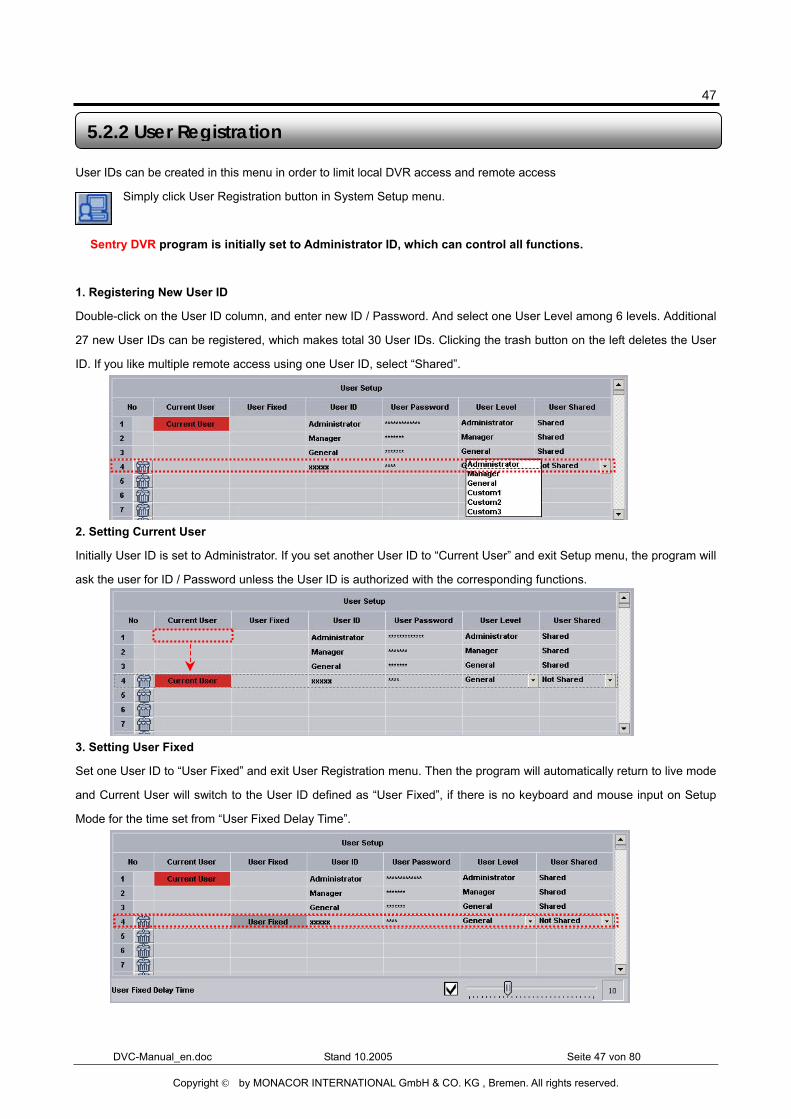
User IDs can be created in this menu in order to limit local DVR access and remote access
Simply click User Registration button in System Setup menu.
� Sentry DVR program is initially set to Administrator ID, which can control all functions.
1. Registering New User ID
Double-click on the User ID column, and enter new ID / Password. And select one User Level among 6 levels. Additional
27 new User IDs can be registered, which makes total 30 User IDs. Clicking the trash button on the left deletes the User
ID. If you like multiple remote access using one User ID, select “Shared”.
2. Setting Current User
Initially User ID is set to Administrator. If you set another User ID to “Current User” and exit Setup menu, the program will
ask the user for ID / Password unless the User ID is authorized with the corresponding functions.
3. Setting User Fixed
Set one User ID to “User Fixed” and exit User Registration menu. Then the program will automatically return to live mode
and Current User will switch to the User ID defined as “User Fixed”, if there is no keyboard and mouse input on Setup
Mode for the time set from “User Fixed Delay Time”.
5.2.2 User Registration
User Share
48
DVC-Manual_en.doc Stand 10.2005 Seite 48 von 80
Copyright © by MONACOR INTERNATIONAL GmbH & CO. KG , Bremen. All rights reserved.
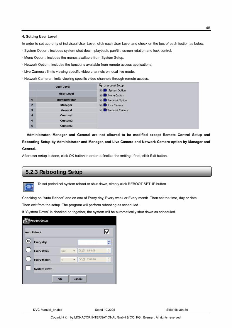
4. Setting User Level
In order to set authority of indivisual User Level, click each User Level and check on the box of each fuction as below.
- System Option : includes system shut-down, playback, pan/tilt, screen rotation and lock control.
- Menu Option : includes the menus available from System Setup.
- Network Option : includes the functions available from remote access applications.
- Live Camera : limits viewing specific video channels on local live mode.
- Network Camera : limits viewing specific video channels through remote access.
� Administrator, Manager and General are not allowed to be modified except Remote Control Setup and
Rebooting Setup by Administrator and Manager, and Live Camera and Network Camera option by Manager and
General.
After user setup is done, click OK button in order to finalize the setting. If not, click Exit button.
To set periodical system reboot or shut-down, simply click REBOOT SETUP button.
Checking on “Auto Reboot” and on one of Every day, Every week or Every month. Then set the time, day or date.
Then exit from the setup. The program will perform rebooting as scheduled.
If “System Down” is checked on together, the system will be automatically shut down as scheduled.
5.2.3 Rebooting Setup
49
DVC-Manual_en.doc Stand 10.2005 Seite 49 von 80
Copyright © by MONACOR INTERNATIONAL GmbH & CO. KG , Bremen. All rights reserved.
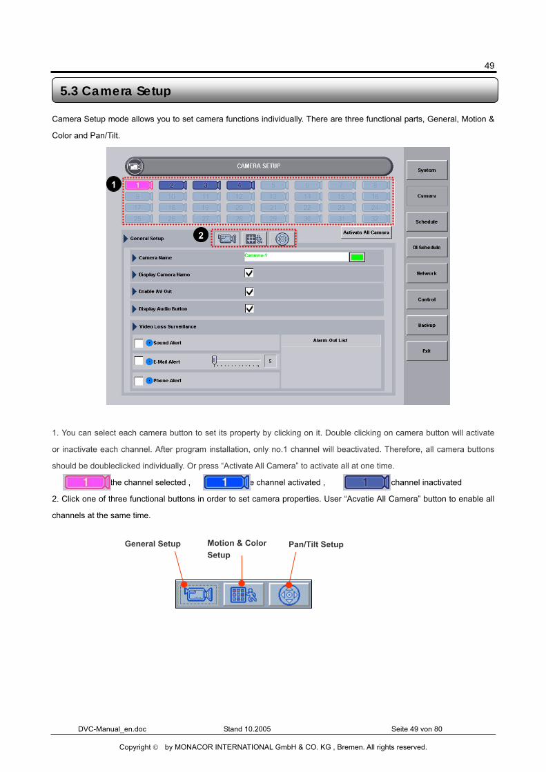
Camera Setup mode allows you to set camera functions individually. There are three functional parts, General, Motion &
Color and Pan/Tilt.
1. You can select each camera button to set its property by clicking on it. Double clicking on camera button will activate
or inactivate each channel. After program installation, only no.1 channel will beactivated. Therefore, all camera buttons
should be doubleclicked individually. Or press “Activate All Camera” to activate all at one time.
� : the channel selected , : the channel activated , : the channel inactivated
2. Click one of three functional buttons in order to set camera properties. User “Acvatie All Camera” button to enable all
channels at the same time.
5.3 Camera Setup
General Setup Motion & Color Setup
Pan/Tilt Setup
1
2
50
DVC-Manual_en.doc Stand 10.2005 Seite 50 von 80
Copyright © by MONACOR INTERNATIONAL GmbH & CO. KG , Bremen. All rights reserved.
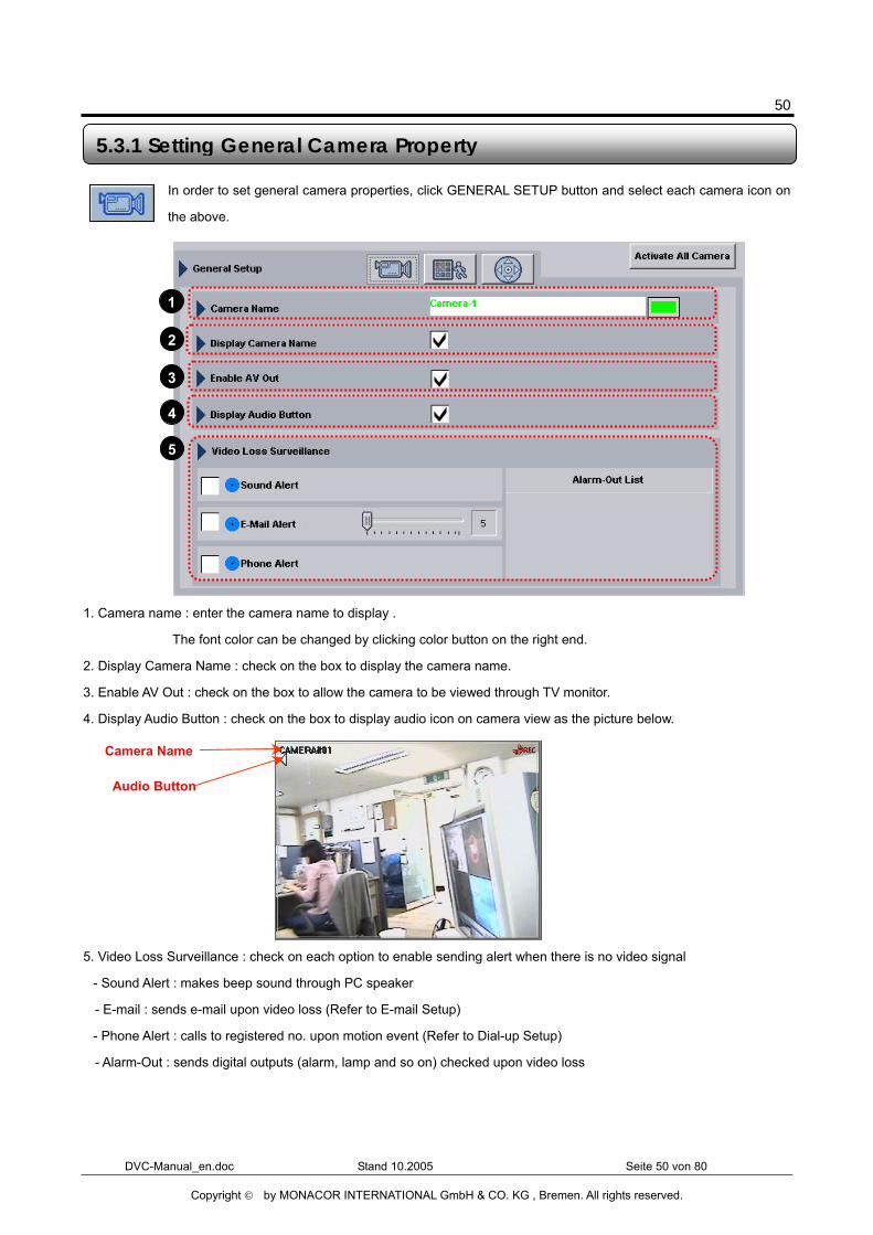
In order to set general camera properties, click GENERAL SETUP button and select each camera icon on
the above.
1. Camera name : enter the camera name to display .
The font color can be changed by clicking color button on the right end.
2. Display Camera Name : check on the box to display the camera name.
3. Enable AV Out : check on the box to allow the camera to be viewed through TV monitor.
4. Display Audio Button : check on the box to display audio icon on camera view as the picture below.
5. Video Loss Surveillance : check on each option to enable sending alert when there is no video signal
- Sound Alert : makes beep sound through PC speaker
- E-mail : sends e-mail upon video loss (Refer to E-mail Setup)
- Phone Alert : calls to registered no. upon motion event (Refer to Dial-up Setup)
- Alarm-Out : sends digital outputs (alarm, lamp and so on) checked upon video loss
5.3.1 Setting General Camera Property
Audio Button
Camera Name
1
2
3
4
5
51
DVC-Manual_en.doc Stand 10.2005 Seite 51 von 80
Copyright © by MONACOR INTERNATIONAL GmbH & CO. KG , Bremen. All rights reserved.
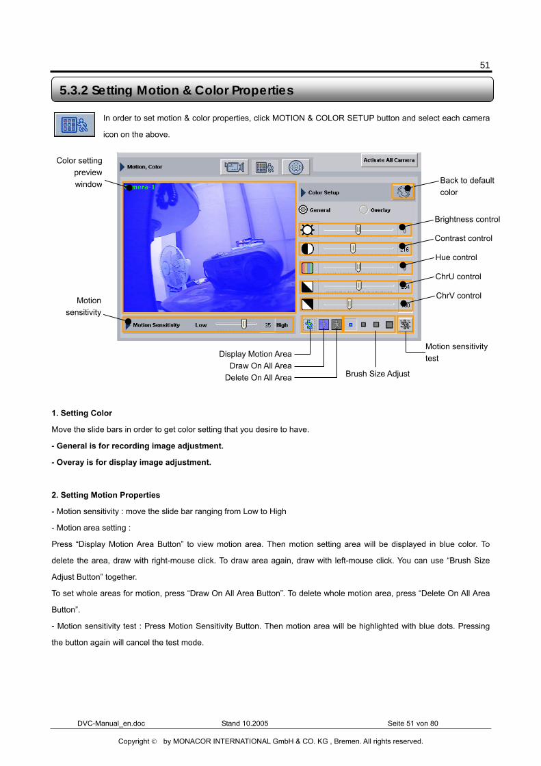
In order to set motion & color properties, click MOTION & COLOR SETUP button and select each camera
icon on the above.
1. Setting Color
Move the slide bars in order to get color setting that you desire to have.
- General is for recording image adjustment.
- Overay is for display image adjustment.
2. Setting Motion Properties
- Motion sensitivity : move the slide bar ranging from Low to High
- Motion area setting :
Press “Display Motion Area Button” to view motion area. Then motion setting area will be displayed in blue color. To
delete the area, draw with right-mouse click. To draw area again, draw with left-mouse click. You can use “Brush Size
Adjust Button” together.
To set whole areas for motion, press “Draw On All Area Button”. To delete whole motion area, press “Delete On All Area
Button”.
- Motion sensitivity test : Press Motion Sensitivity Button. Then motion area will be highlighted with blue dots. Pressing
the button again will cancel the test mode.
5.3.2 Setting Motion & Color Properties
Brightness control
Color settingpreviewwindow Back to default
color
Contrast control
Hue control
ChrU control
ChrV control Motionsensitivity
Display Motion AreaDraw On All Area
Delete On All Area Brush Size Adjust
Motion sensitivity test
52
DVC-Manual_en.doc Stand 10.2005 Seite 52 von 80
Copyright © by MONACOR INTERNATIONAL GmbH & CO. KG , Bremen. All rights reserved.
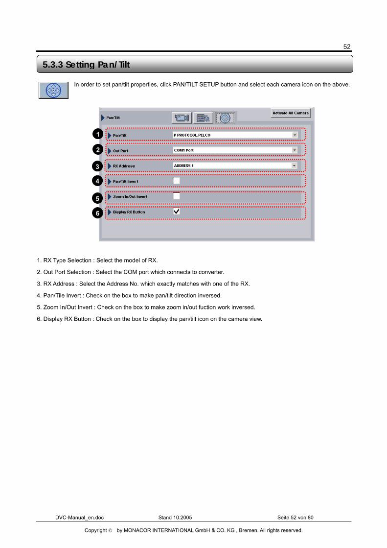
In order to set pan/tilt properties, click PAN/TILT SETUP button and select each camera icon on the above.
1. RX Type Selection : Select the model of RX.
2. Out Port Selection : Select the COM port which connects to converter.
3. RX Address : Select the Address No. which exactly matches with one of the RX.
4. Pan/Tile Invert : Check on the box to make pan/tilt direction inversed.
5. Zoom In/Out Invert : Check on the box to make zoom in/out fuction work inversed.
6. Display RX Button : Check on the box to display the pan/tilt icon on the camera view.
5.3.3 Setting Pan/Tilt
1
2
3
4
5
6
53
DVC-Manual_en.doc Stand 10.2005 Seite 53 von 80
Copyright © by MONACOR INTERNATIONAL GmbH & CO. KG , Bremen. All rights reserved.
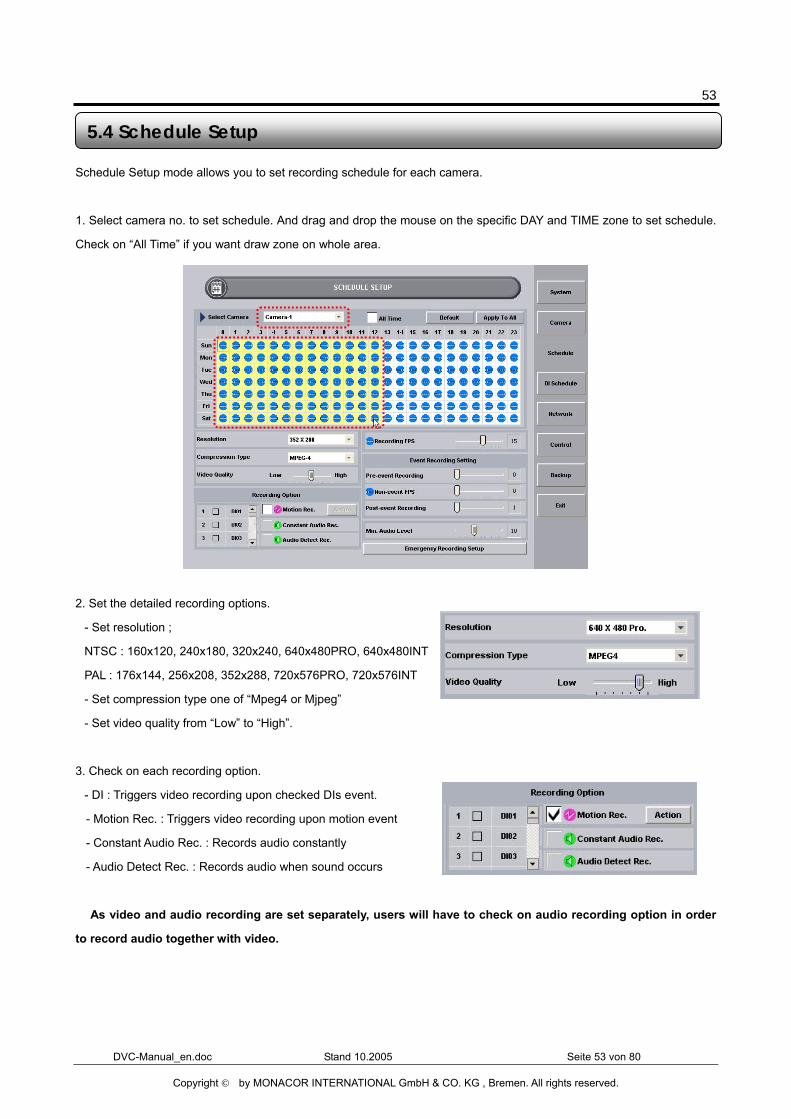
Schedule Setup mode allows you to set recording schedule for each camera.
1. Select camera no. to set schedule. And drag and drop the mouse on the specific DAY and TIME zone to set schedule.
Check on “All Time” if you want draw zone on whole area.
2. Set the detailed recording options.
- Set resolution ;
NTSC : 160x120, 240x180, 320x240, 640x480PRO, 640x480INT
PAL : 176x144, 256x208, 352x288, 720x576PRO, 720x576INT
- Set compression type one of “Mpeg4 or Mjpeg”
- Set video quality from “Low” to “High”.
3. Check on each recording option.
- DI : Triggers video recording upon checked DIs event.
- Motion Rec. : Triggers video recording upon motion event
- Constant Audio Rec. : Records audio constantly
- Audio Detect Rec. : Records audio when sound occurs
� As video and audio recording are set separately, users will have to check on audio recording option in order
to record audio together with video.
5.4 Schedule Setup
54
DVC-Manual_en.doc Stand 10.2005 Seite 54 von 80
Copyright © by MONACOR INTERNATIONAL GmbH & CO. KG , Bremen. All rights reserved.
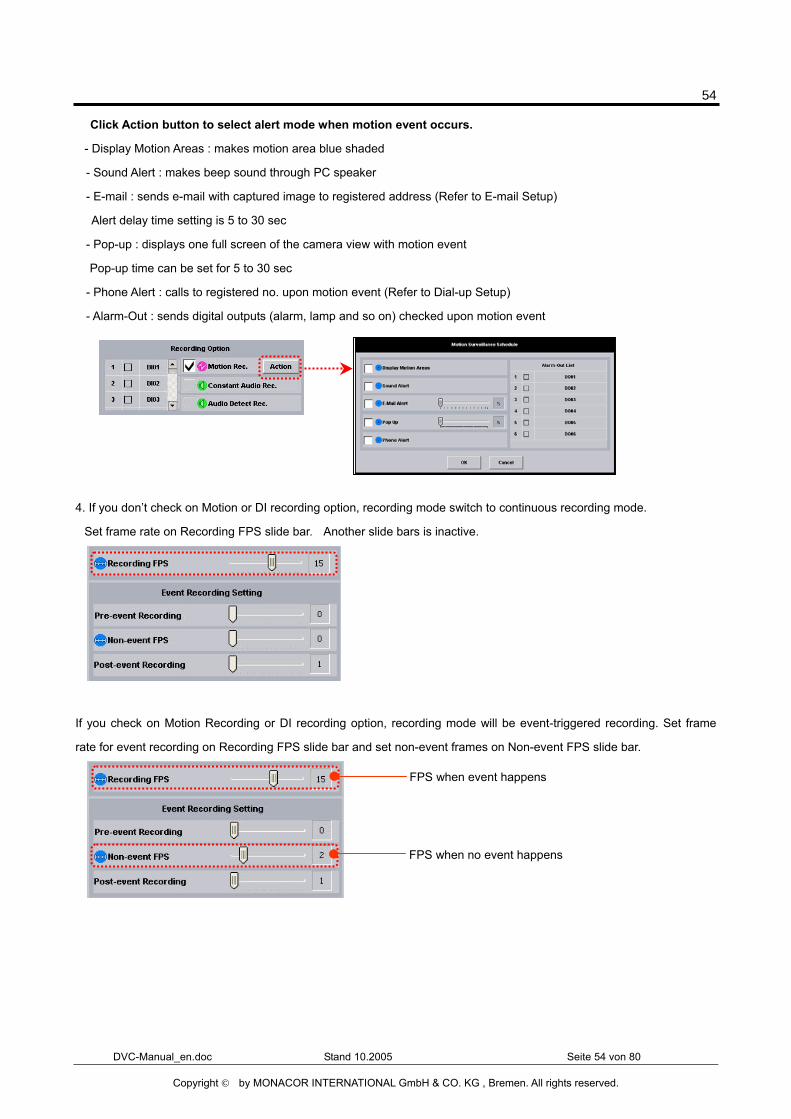
� Click Action button to select alert mode when motion event occurs.
- Display Motion Areas : makes motion area blue shaded
- Sound Alert : makes beep sound through PC speaker
- E-mail : sends e-mail with captured image to registered address (Refer to E-mail Setup)
Alert delay time setting is 5 to 30 sec
- Pop-up : displays one full screen of the camera view with motion event
Pop-up time can be set for 5 to 30 sec
- Phone Alert : calls to registered no. upon motion event (Refer to Dial-up Setup)
- Alarm-Out : sends digital outputs (alarm, lamp and so on) checked upon motion event
4. If you don’t check on Motion or DI recording option, recording mode switch to continuous recording mode.
Set frame rate on Recording FPS slide bar. Another slide bars is inactive.
If you check on Motion Recording or DI recording option, recording mode will be event-triggered recording. Set frame
rate for event recording on Recording FPS slide bar and set non-event frames on Non-event FPS slide bar.
FPS when no event happens
FPS when event happens
55
DVC-Manual_en.doc Stand 10.2005 Seite 55 von 80
Copyright © by MONACOR INTERNATIONAL GmbH & CO. KG , Bremen. All rights reserved.
Pre-event Recording : Record more key frames specified (0-2 key frames) ahead of the frame with event.
Post-event Recoring : Record more seconds specificed (1-10 seconds) after the frame with event.
Min. Audio Level : 0 to 25
� You can repeat the step 1 to 4 in order to set schedule on multiple DAY and TIME zones.
5. Click Exit button to save and exit.
56
DVC-Manual_en.doc Stand 10.2005 Seite 56 von 80
Copyright © by MONACOR INTERNATIONAL GmbH & CO. KG , Bremen. All rights reserved.
DI Surveillance Setup mode allows you to set DI surveillance schedule for each DI.
1. Select DI no. to set schedule. And drag and drop the mouse on the specific DAY and TIME zone to set schedule.
2. Check on alert option in order to send alert upon motion event.
- Sound Alert : makes beep sound through PC speaker
- E-mail : sends e-mail to registered address (Refer to E-mail Setup)
Alert delay time setting is 5 to 30 sec
- Phone Alert : calls to registered no. upon motion event (Refer to Dial-up Setup)
- Pop-up : displays one full screen of the camera view with motion event
Pop-up time can be set for 5 to 30 sec
- Alarm-Out : sends digital outputs (alarm, lamp and so on) checked upon DI event
3. Click Exit button to save and exit.
� You can repeat the above steps in order to set schedule on multiple DAY and TIME zones.
5.5 DI Surveillance
57
DVC-Manual_en.doc Stand 10.2005 Seite 57 von 80
Copyright © by MONACOR INTERNATIONAL GmbH & CO. KG , Bremen. All rights reserved.
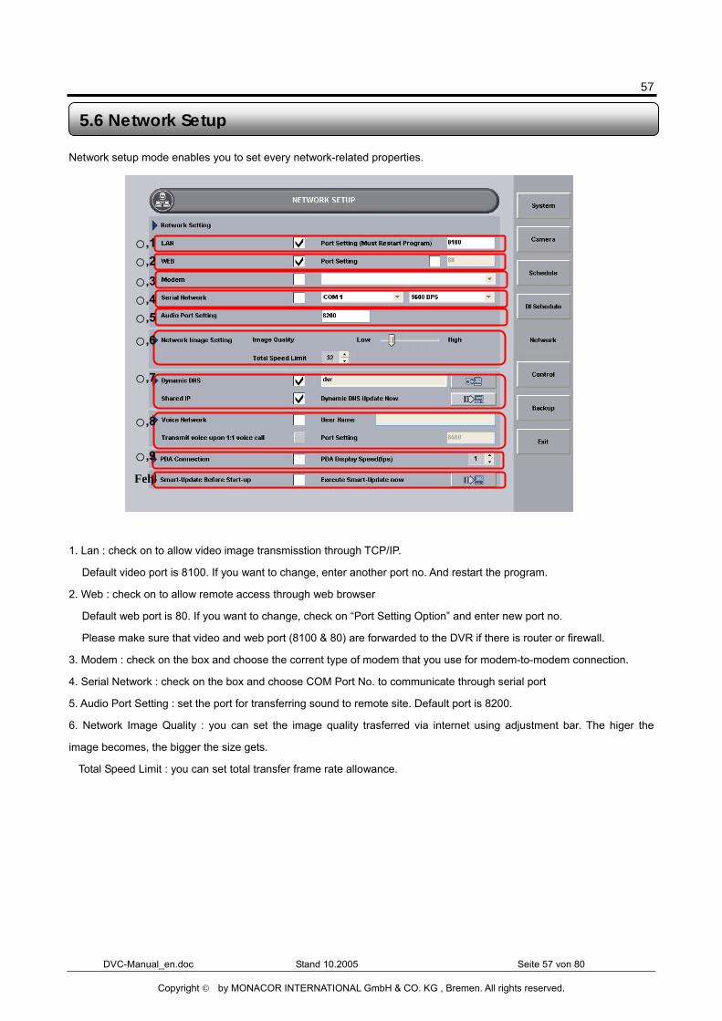
Network setup mode enables you to set every network-related properties.
1. Lan : check on to allow video image transmisstion through TCP/IP.
� Default video port is 8100. If you want to change, enter another port no. And restart the program.
2. Web : check on to allow remote access through web browser
� Default web port is 80. If you want to change, check on “Port Setting Option” and enter new port no.
� Please make sure that video and web port (8100 & 80) are forwarded to the DVR if there is router or firewall.
3. Modem : check on the box and choose the corrent type of modem that you use for modem-to-modem connection.
4. Serial Network : check on the box and choose COM Port No. to communicate through serial port
5. Audio Port Setting : set the port for transferring sound to remote site. Default port is 8200.
6. Network Image Quality : you can set the image quality trasferred via internet using adjustment bar. The higer the
image becomes, the bigger the size gets.
Total Speed Limit : you can set total transfer frame rate allowance.
5.6 Network Setup
○,1 ○,2
○,3 ○,4 ○,5
○,6
○,7
○,8
○,9
Fehl
58
DVC-Manual_en.doc Stand 10.2005 Seite 58 von 80
Copyright © by MONACOR INTERNATIONAL GmbH & CO. KG , Bremen. All rights reserved.
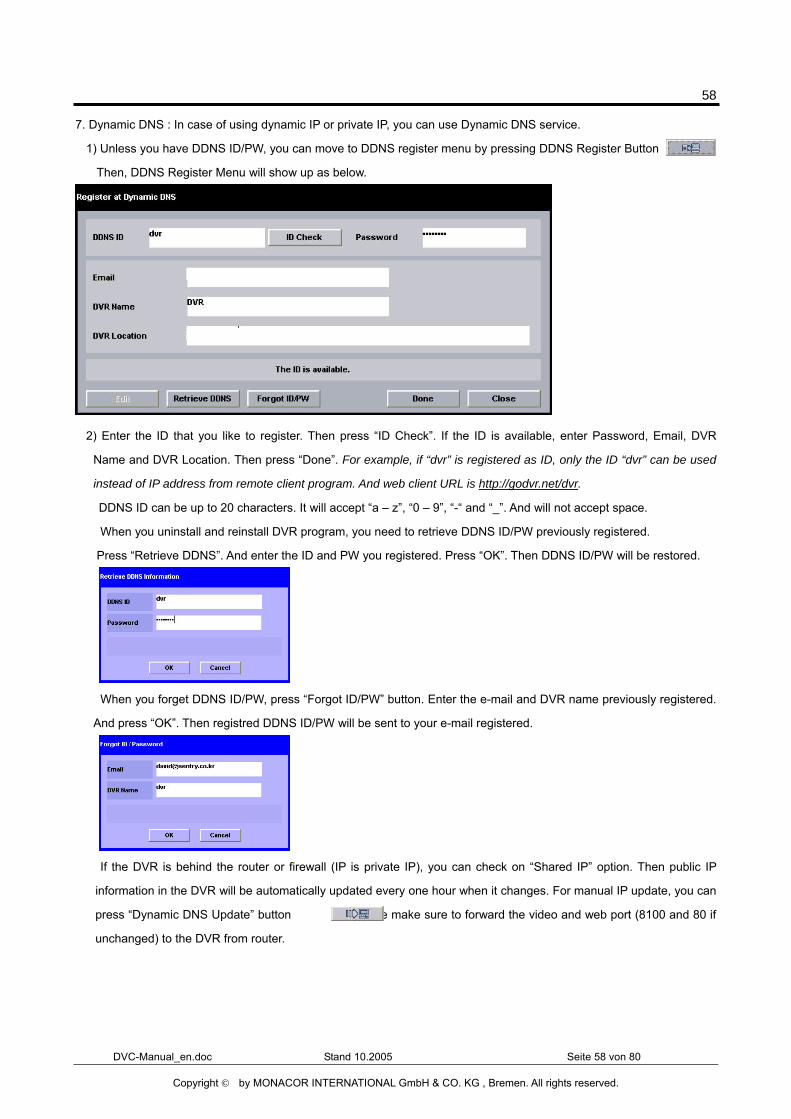
7. Dynamic DNS : In case of using dynamic IP or private IP, you can use Dynamic DNS service.
1) Unless you have DDNS ID/PW, you can move to DDNS register menu by pressing DDNS Register Button .
Then, DDNS Register Menu will show up as below.
2) Enter the ID that you like to register. Then press “ID Check”. If the ID is available, enter Password, Email, DVR
Name and DVR Location. Then press “Done”. For example, if “dvr” is registered as ID, only the ID “dvr” can be used
instead of IP address from remote client program. And web client URL is http://godvr.net/dvr.
� DDNS ID can be up to 20 characters. It will accept “a – z”, “0 – 9”, “-“ and “_”. And will not accept space.
� When you uninstall and reinstall DVR program, you need to retrieve DDNS ID/PW previously registered.
Press “Retrieve DDNS”. And enter the ID and PW you registered. Press “OK”. Then DDNS ID/PW will be restored.
� When you forget DDNS ID/PW, press “Forgot ID/PW” button. Enter the e-mail and DVR name previously registered.
And press “OK”. Then registred DDNS ID/PW will be sent to your e-mail registered.
� If the DVR is behind the router or firewall (IP is private IP), you can check on “Shared IP” option. Then public IP
information in the DVR will be automatically updated every one hour when it changes. For manual IP update, you can
press “Dynamic DNS Update” button . Please make sure to forward the video and web port (8100 and 80 if
unchanged) to the DVR from router.
59
DVC-Manual_en.doc Stand 10.2005 Seite 59 von 80
Copyright © by MONACOR INTERNATIONAL GmbH & CO. KG , Bremen. All rights reserved.
8. Voice Netwok : check on the box for two-way voice communication and enter the name desired.
Transmit voice upon 1:1 voice call : enables allowing 1: 1 voice talk only with client’s call.
Port Setting : set the port used for transferring voice. Default is TCP8500/UDP8500.
9. PDA Connection : check on to enable access from PDA client
10. Smart-Update Before Start-up : check on to use Smart Update function before running the program.
Execute Smart-Upgrade Now : click the button to run instant Smart Updated right now.
60
DVC-Manual_en.doc Stand 10.2005 Seite 60 von 80
Copyright © by MONACOR INTERNATIONAL GmbH & CO. KG , Bremen. All rights reserved.
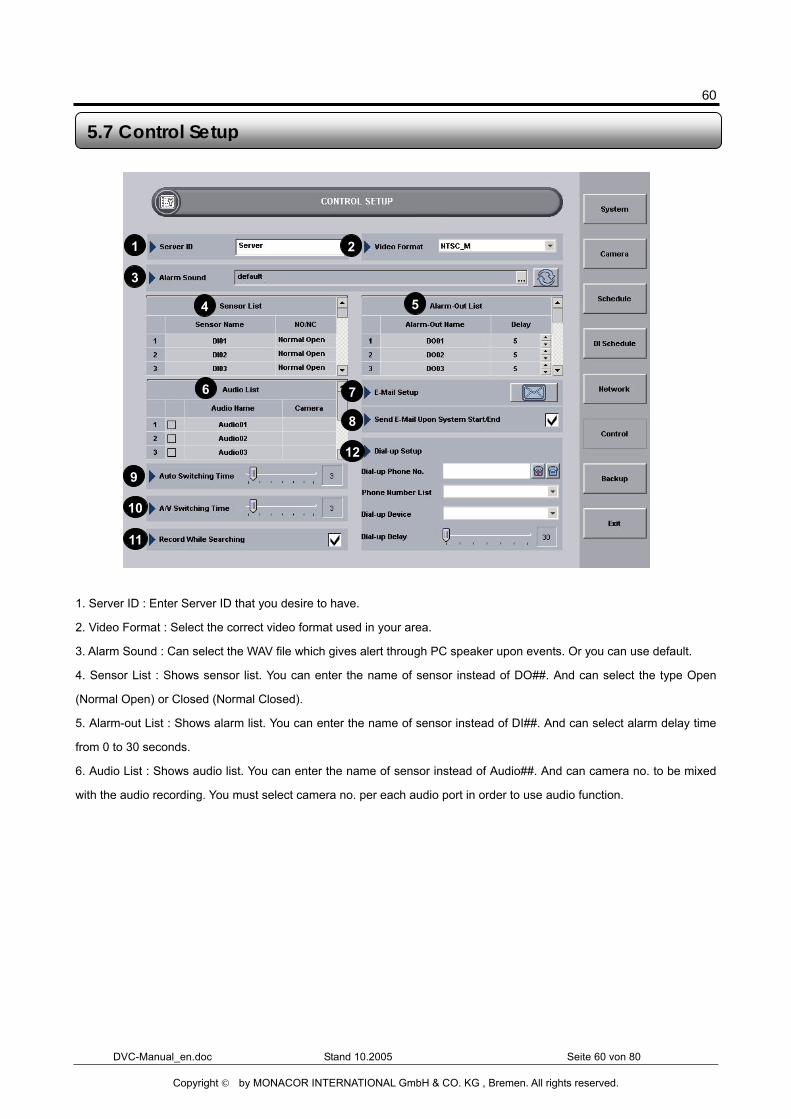
1. Server ID : Enter Server ID that you desire to have.
2. Video Format : Select the correct video format used in your area.
3. Alarm Sound : Can select the WAV file which gives alert through PC speaker upon events. Or you can use default.
4. Sensor List : Shows sensor list. You can enter the name of sensor instead of DO##. And can select the type Open
(Normal Open) or Closed (Normal Closed).
5. Alarm-out List : Shows alarm list. You can enter the name of sensor instead of DI##. And can select alarm delay time
from 0 to 30 seconds.
6. Audio List : Shows audio list. You can enter the name of sensor instead of Audio##. And can camera no. to be mixed
with the audio recording. You must select camera no. per each audio port in order to use audio function.
5.7 Control Setup
1 2
3
4 5
6 7
8
9
10
11
12
61
DVC-Manual_en.doc Stand 10.2005 Seite 61 von 80
Copyright © by MONACOR INTERNATIONAL GmbH & CO. KG , Bremen. All rights reserved.
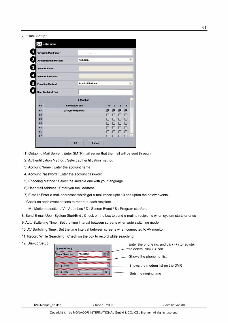
7. E-mail Setup :
1) Outgoing Mail Server : Enter SMTP mail server that the mail will be sent through
2) Authentification Method : Select authentification method
3) Account Name : Enter the account name
4) Account Password : Enter the account password
5) Encoding Method : Select the suitable one with your language
6) User Mail Address : Enter you mail address
7) E-mail : Enter e-mail addresses which get e-mail report upto 10 nos upton the below events.
Check on each event options to report to each recipient.
- M : Motion detection / V : Video Los / D : Sensor Event / S : Program start/end
8. Send E-mail Upon System Start/End : Check on the box to send e-mail to recipients when system starts or ends
9. Auto Switching Time : Set the time interval between screens when auto switching mode
10. AV Switching Time : Set the time interval between screens when connected to AV monitor
11. Record While Searching : Check on the box to record while searching
12. Dial-up Setup
1
2
3
4
5
6
7
Enter the phone no. and click (+) to register To delete, click (-) icon.
Shows the phone no. list
Shows the modem list on the DVR
Sets the ringing time
62
DVC-Manual_en.doc Stand 10.2005 Seite 62 von 80
Copyright © by MONACOR INTERNATIONAL GmbH & CO. KG , Bremen. All rights reserved.
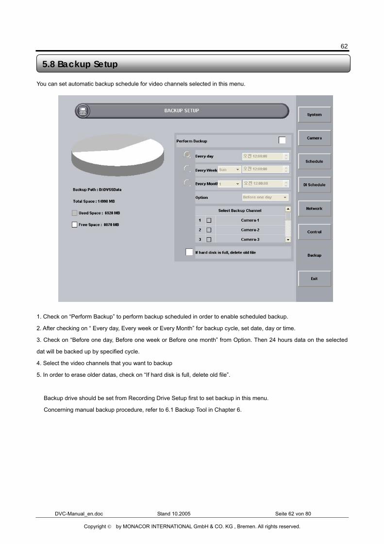
You can set automatic backup schedule for video channels selected in this menu.
1. Check on “Perform Backup” to perform backup scheduled in order to enable scheduled backup.
2. After checking on “ Every day, Every week or Every Month” for backup cycle, set date, day or time.
3. Check on “Before one day, Before one week or Before one month” from Option. Then 24 hours data on the selected
dat will be backed up by specified cycle.
4. Select the video channels that you want to backup
5. In order to erase older datas, check on “If hard disk is full, delete old file”.
� Backup drive should be set from Recording Drive Setup first to set backup in this menu.
� Concerning manual backup procedure, refer to 6.1 Backup Tool in Chapter 6.
5.8 Backup Setup
63
DVC-Manual_en.doc Stand 10.2005 Seite 63 von 80
Copyright © by MONACOR INTERNATIONAL GmbH & CO. KG , Bremen. All rights reserved.
Chapter 6 Program Tools
64
DVC-Manual_en.doc Stand 10.2005 Seite 64 von 80
Copyright © by MONACOR INTERNATIONAL GmbH & CO. KG , Bremen. All rights reserved.
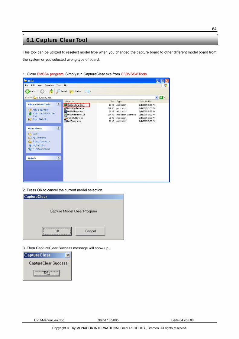
This tool can be utilized to reselect model type when you changed the capture board to other different model board from
the system or you selected wrong type of board.
1. Close DVSS4 program. Simply run CaptureClear.exe from C:\DVSS4\Tools.
2. Press OK to cancel the current model selection.
3. Then CaptureClear Success message will show up.
6.1 Capture Clear Tool
65
DVC-Manual_en.doc Stand 10.2005 Seite 65 von 80
Copyright © by MONACOR INTERNATIONAL GmbH & CO. KG , Bremen. All rights reserved.
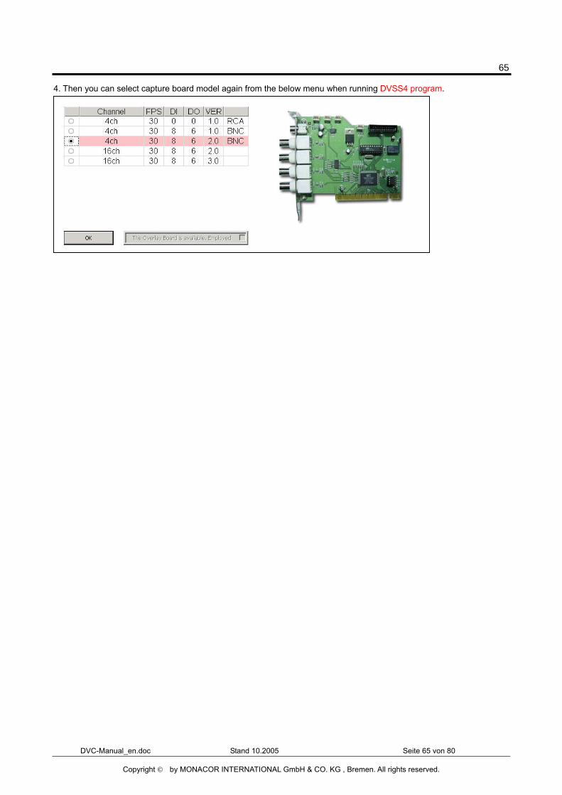
4. Then you can select capture board model again from the below menu when running DVSS4 program.
66
DVC-Manual_en.doc Stand 10.2005 Seite 66 von 80
Copyright © by MONACOR INTERNATIONAL GmbH & CO. KG , Bremen. All rights reserved.
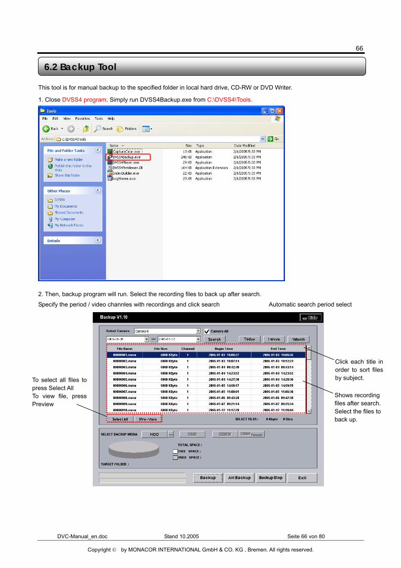
This tool is for manual backup to the specified folder in local hard drive, CD-RW or DVD Writer. 1. Close DVSS4 program. Simply run DVSS4Backup.exe from C:\DVSS4\Tools.
2. Then, backup program will run. Select the recording files to back up after search.
6.2 Backup Tool
Specify the period / video channles with recordings and click search Automatic search period select
Shows recording files after search. Select the files to back up.
Click each title inorder to sort filesby subject. To select all files to
press Select All To view file, pressPreview
67
DVC-Manual_en.doc Stand 10.2005 Seite 67 von 80
Copyright © by MONACOR INTERNATIONAL GmbH & CO. KG , Bremen. All rights reserved.
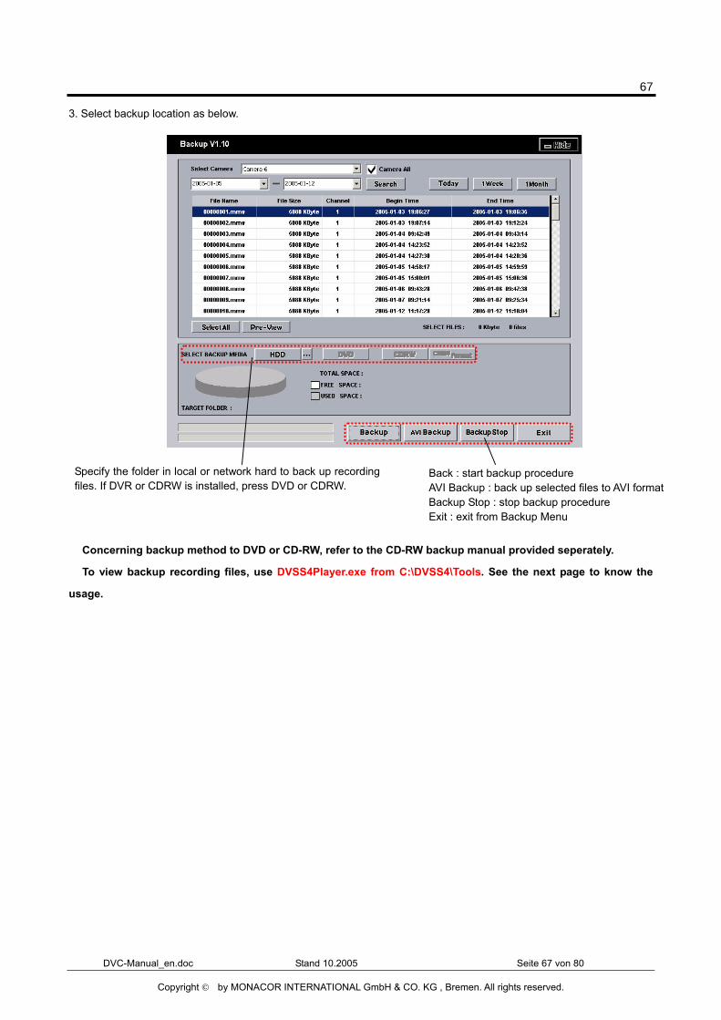
3. Select backup location as below.
� Concerning backup method to DVD or CD-RW, refer to the CD-RW backup manual provided seperately.
� To view backup recording files, use DVSS4Player.exe from C:\DVSS4\Tools. See the next page to know the
usage.
Specify the folder in local or network hard to back up recordingfiles. If DVR or CDRW is installed, press DVD or CDRW.
Back : start backup procedure AVI Backup : back up selected files to AVI format Backup Stop : stop backup procedure Exit : exit from Backup Menu
68
DVC-Manual_en.doc Stand 10.2005 Seite 68 von 80
Copyright © by MONACOR INTERNATIONAL GmbH & CO. KG , Bremen. All rights reserved.
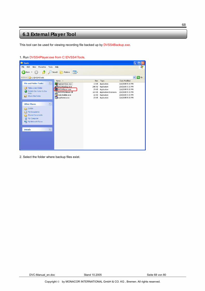
This tool can be used for viewing recording file backed up by DVSS4Backup.exe.
1. Run DVSS4Player.exe from C:\DVSS4\Tools.
2. Select the folder where backup files exist.
6.3 External Player Tool
69
DVC-Manual_en.doc Stand 10.2005 Seite 69 von 80
Copyright © by MONACOR INTERNATIONAL GmbH & CO. KG , Bremen. All rights reserved.
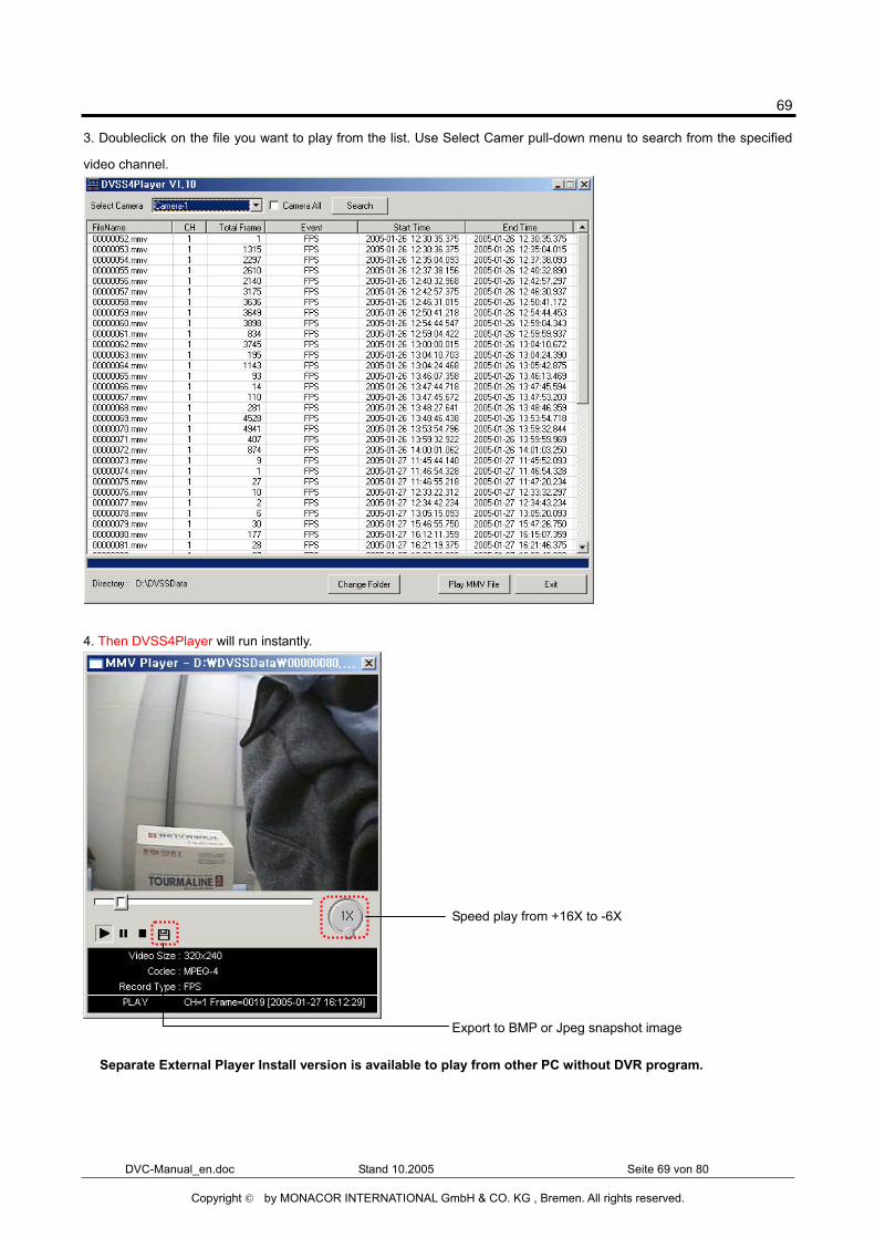
3. Doubleclick on the file you want to play from the list. Use Select Camer pull-down menu to search from the specified
video channel.
4. Then DVSS4Player will run instantly.
� Separate External Player Install version is available to play from other PC without DVR program.
Speed play from +16X to -6X
Export to BMP or Jpeg snapshot image
70
DVC-Manual_en.doc Stand 10.2005 Seite 70 von 80
Copyright © by MONACOR INTERNATIONAL GmbH & CO. KG , Bremen. All rights reserved.
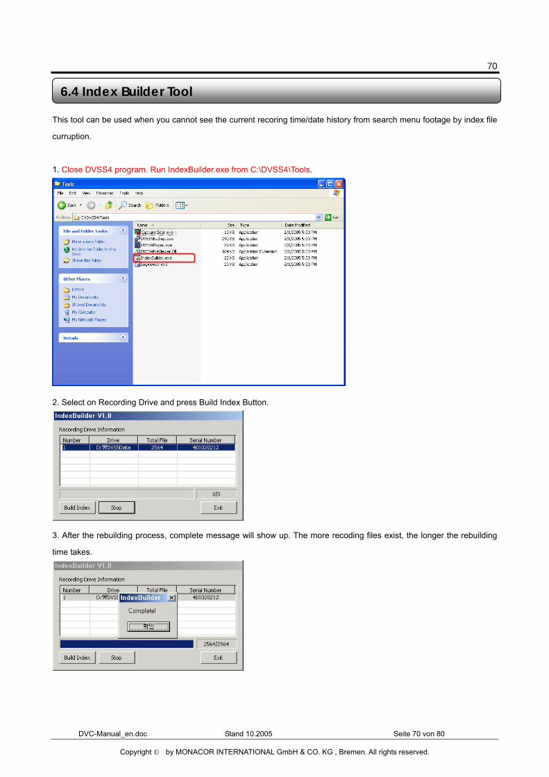
This tool can be used when you cannot see the current recoring time/date history from search menu footage by index file
curruption.
1. Close DVSS4 program. Run IndexBuilder.exe from C:\DVSS4\Tools.
2. Select on Recording Drive and press Build Index Button.
3. After the rebuilding process, complete message will show up. The more recoding files exist, the longer the rebuilding
time takes.
6.4 Index Builder Tool
71
DVC-Manual_en.doc Stand 10.2005 Seite 71 von 80
Copyright © by MONACOR INTERNATIONAL GmbH & CO. KG , Bremen. All rights reserved.
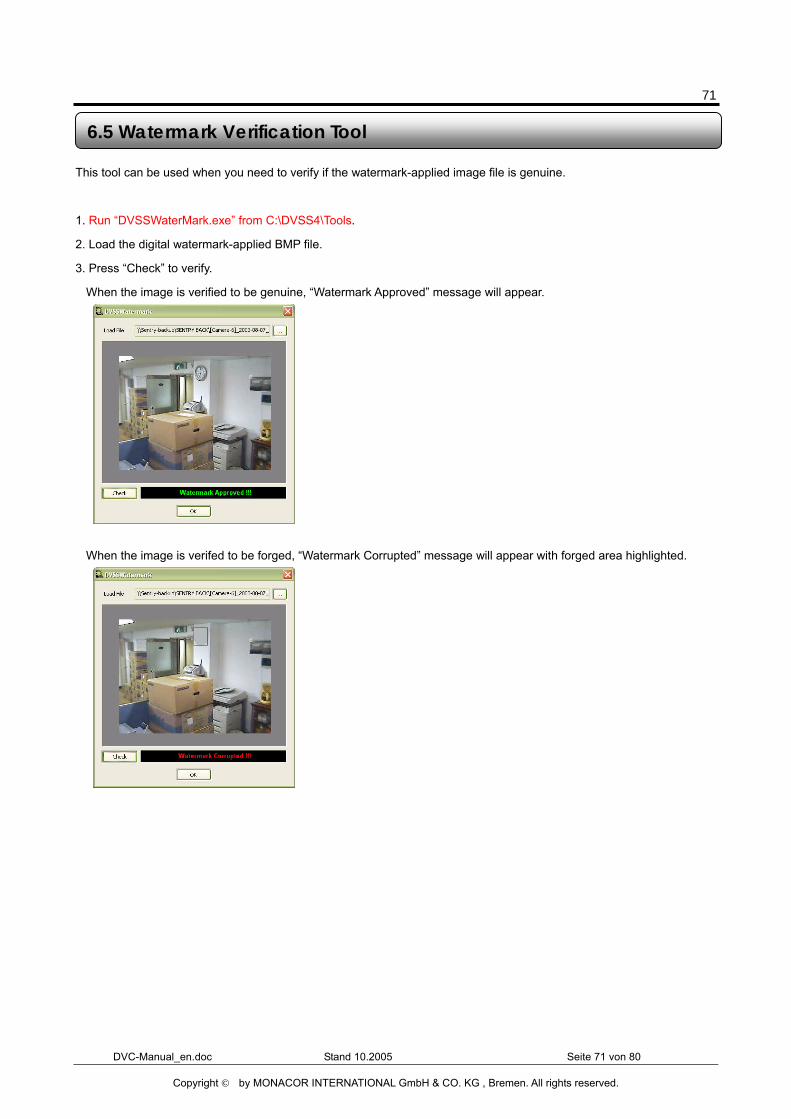
This tool can be used when you need to verify if the watermark-applied image file is genuine.
1. Run “DVSSWaterMark.exe” from C:\DVSS4\Tools.
2. Load the digital watermark-applied BMP file.
3. Press “Check” to verify.
When the image is verified to be genuine, “Watermark Approved” message will appear.
When the image is verifed to be forged, “Watermark Corrupted” message will appear with forged area highlighted.
6.5 Watermark Verification Tool
72
DVC-Manual_en.doc Stand 10.2005 Seite 72 von 80
Copyright © by MONACOR INTERNATIONAL GmbH & CO. KG , Bremen. All rights reserved.
Chapter 7 Network Function
73
DVC-Manual_en.doc Stand 10.2005 Seite 73 von 80
Copyright © by MONACOR INTERNATIONAL GmbH & CO. KG , Bremen. All rights reserved.
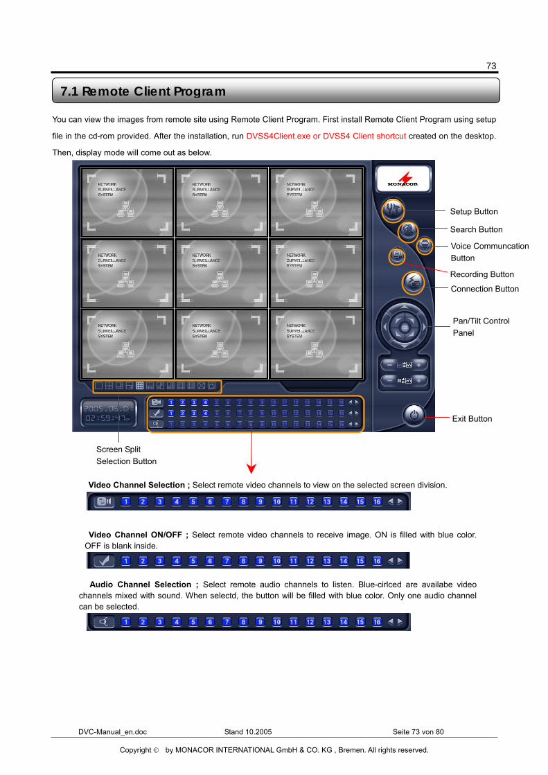
You can view the images from remote site using Remote Client Program. First install Remote Client Program using setup
file in the cd-rom provided. After the installation, run DVSS4Client.exe or DVSS4 Client shortcut created on the desktop.
Then, display mode will come out as below.
7.1 Remote Client Program
� Video Channel ON/OFF ; Select remote video channels to receive image. ON is filled with blue color.OFF is blank inside.
� Video Channel Selection ; Select remote video channels to view on the selected screen division.
� Audio Channel Selection ; Select remote audio channels to listen. Blue-cirlced are availabe videochannels mixed with sound. When selectd, the button will be filled with blue color. Only one audio channelcan be selected.
Setup Button
Search Button
Voice Communcation Button
Recording Button
Connection Button
Exit Button
Pan/Tilt Control Panel
Screen Split Selection Button
74
DVC-Manual_en.doc Stand 10.2005 Seite 74 von 80
Copyright © by MONACOR INTERNATIONAL GmbH & CO. KG , Bremen. All rights reserved.
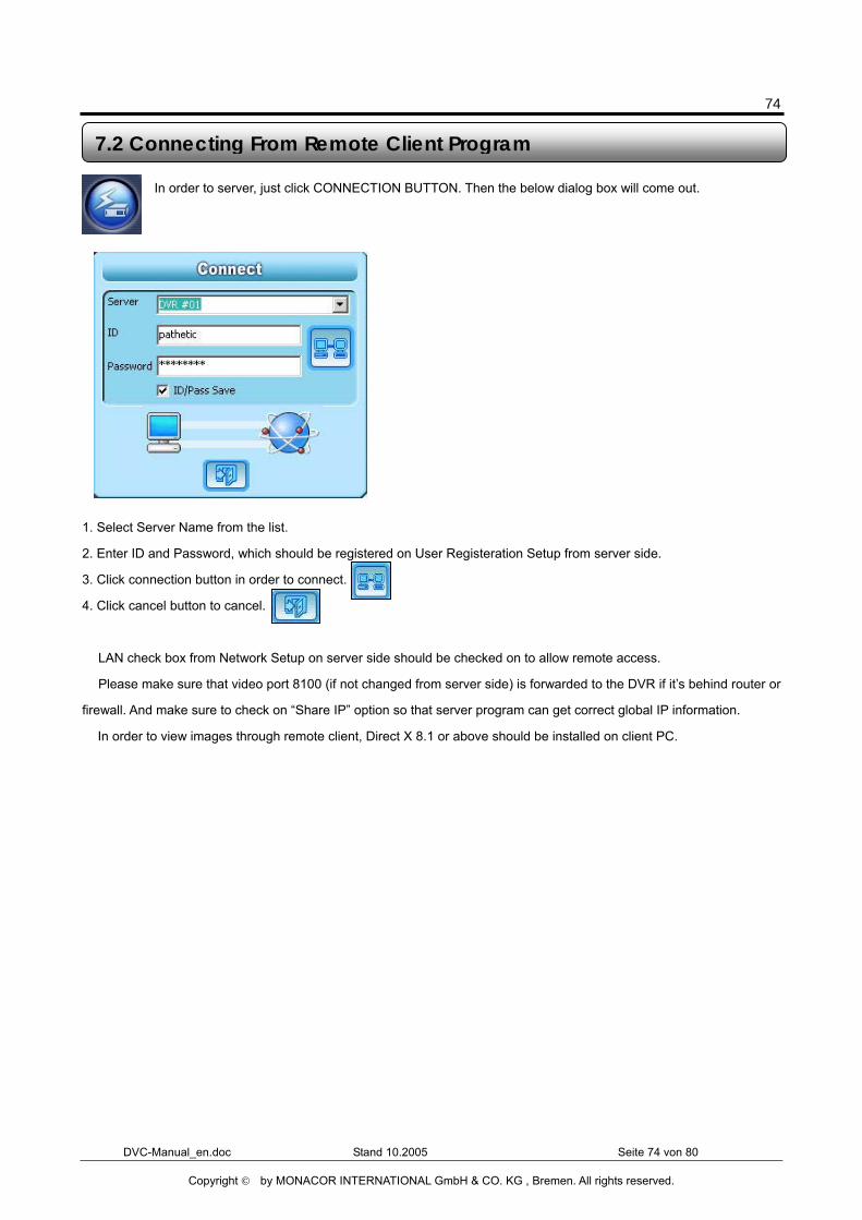
In order to server, just click CONNECTION BUTTON. Then the below dialog box will come out.
1. Select Server Name from the list.
2. Enter ID and Password, which should be registered on User Registeration Setup from server side.
3. Click connection button in order to connect.
4. Click cancel button to cancel.
� LAN check box from Network Setup on server side should be checked on to allow remote access.
� Please make sure that video port 8100 (if not changed from server side) is forwarded to the DVR if it’s behind router or
firewall. And make sure to check on “Share IP” option so that server program can get correct global IP information.
� In order to view images through remote client, Direct X 8.1 or above should be installed on client PC.
7.2 Connecting From Remote Client Program
75
DVC-Manual_en.doc Stand 10.2005 Seite 75 von 80
Copyright © by MONACOR INTERNATIONAL GmbH & CO. KG , Bremen. All rights reserved.
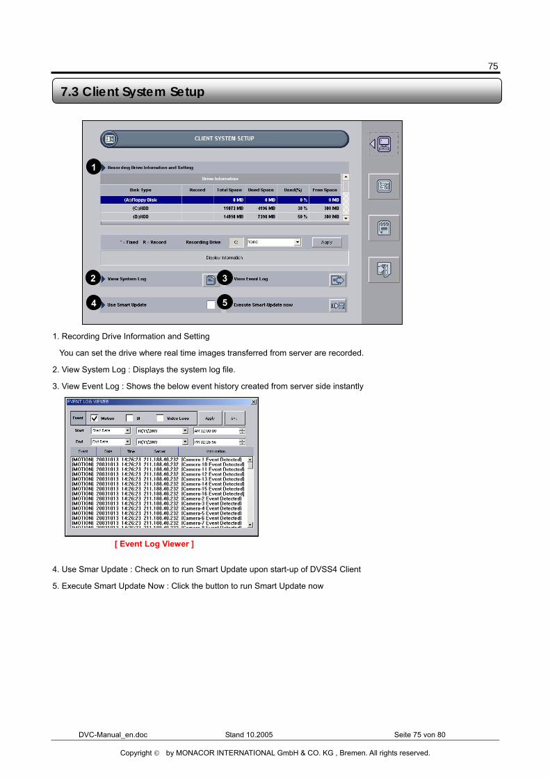
1. Recording Drive Information and Setting
You can set the drive where real time images transferred from server are recorded.
2. View System Log : Displays the system log file.
3. View Event Log : Shows the below event history created from server side instantly
4. Use Smar Update : Check on to run Smart Update upon start-up of DVSS4 Client
5. Execute Smart Update Now : Click the button to run Smart Update now
7.3 Client System Setup
1
2 3
4 5
[ Event Log Viewer ]
76
DVC-Manual_en.doc Stand 10.2005 Seite 76 von 80
Copyright © by MONACOR INTERNATIONAL GmbH & CO. KG , Bremen. All rights reserved.
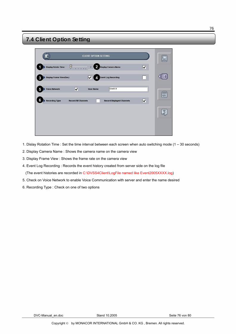
1. Dislay Rotation Time : Set the time interval between each screen when auto switching mode (1 – 30 seconds)
2. Display Camera Name : Shows the camera name on the camera view
3. Display Frame View : Shows the frame rate on the camera view
4. Event Log Recording : Records the event history created from server side on the log file
(The event histories are recorded in C:\DVSS4Client\LogFile named like Event2005XXXX.log)
5. Check on Voice Network to enable Voice Communication with server and enter the name desired
6. Recording Type : Check on one of two options
7.4 Client Option Setting
1 2
3 4
5
6
77
DVC-Manual_en.doc Stand 10.2005 Seite 77 von 80
Copyright © by MONACOR INTERNATIONAL GmbH & CO. KG , Bremen. All rights reserved.
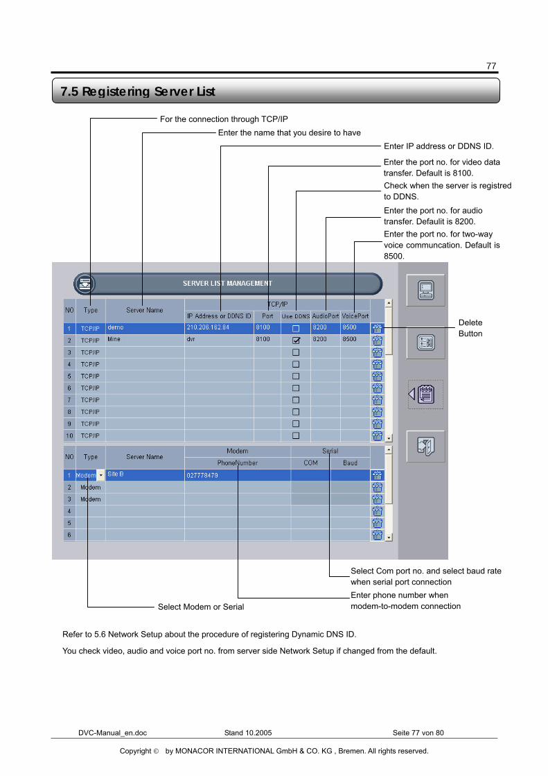
� Refer to 5.6 Network Setup about the procedure of registering Dynamic DNS ID.
� You check video, audio and voice port no. from server side Network Setup if changed from the default.
7.5 Registering Server List
For the connection through TCP/IP Enter the name that you desire to have
Enter the port no. for audio transfer. Defaulit is 8200.
Check when the server is registred to DDNS.
Enter the port no. for video data transfer. Default is 8100.
Enter IP address or DDNS ID.
Select Modem or Serial Enter phone number when modem-to-modem connection
Select Com port no. and select baud rate when serial port connection
Enter the port no. for two-way voice communcation. Default is8500.
Delete Button
78
DVC-Manual_en.doc Stand 10.2005 Seite 78 von 80
Copyright © by MONACOR INTERNATIONAL GmbH & CO. KG , Bremen. All rights reserved.
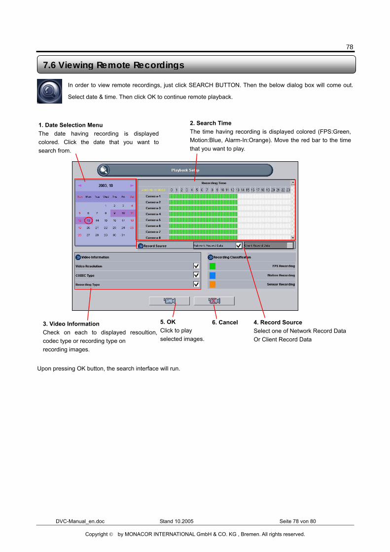
In order to view remote recordings, just click SEARCH BUTTON. Then the below dialog box will come out.
Select date & time. Then click OK to continue remote playback.
Upon pressing OK button, the search interface will run.
1. Date Selection Menu The date having recording is displayedcolored. Click the date that you want tosearch from.
2. Search Time The time having recording is displayed colored (FPS:Green,Motion:Blue, Alarm-In:Orange). Move the red bar to the timethat you want to play.
5. OK Click to play selected images.
6. Cancel 3. Video Information Check on each to displayed resoultion,codec type or recording type on recording images.
4. Record Source Select one of Network Record Data Or Client Record Data
7.6 Viewing Remote Recordings
79
DVC-Manual_en.doc Stand 10.2005 Seite 79 von 80
Copyright © by MONACOR INTERNATIONAL GmbH & CO. KG , Bremen. All rights reserved.
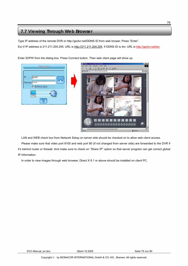
Type IP address of the remote DVR or http://godvr.net/DDNS ID from web brower. Press “Enter”.
Ex) If IP address is 211.211.204.205, URL is http://211.211.204.205. If DDNS ID is dvr, URL is http://godvr.net/dvr.
Enter ID/PW from the dialog box. Press Connect button. Then web client page will show up.
� LAN and WEB check box from Network Setup on server side should be checked on to allow web client access.
� Please make sure that video port 8100 and web port 80 (if not changed from server side) are forwarded to the DVR if
it’s behind router or firewall. And make sure to check on “Share IP” option so that server program can get correct global
IP information.
� In order to view images through web browser, Direct X 8.1 or above should be installed on client PC.
7.7 Viewing Through Web Browser
80
DVC-Manual_en.doc Stand 10.2005 Seite 80 von 80
Copyright © by MONACOR INTERNATIONAL GmbH & CO. KG , Bremen. All rights reserved.
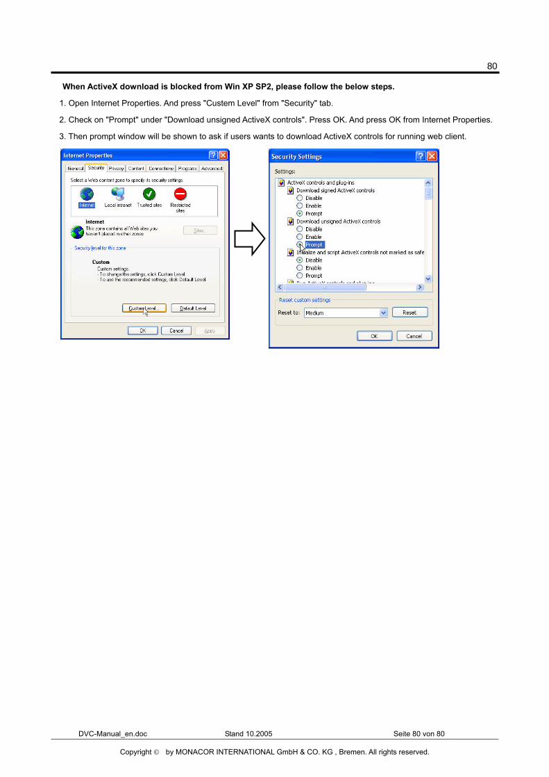
� When ActiveX download is blocked from Win XP SP2, please follow the below steps.
1. Open Internet Properties. And press "Custem Level" from "Security" tab.
2. Check on "Prompt" under "Download unsigned ActiveX controls". Press OK. And press OK from Internet Properties.
3. Then prompt window will be shown to ask if users wants to download ActiveX controls for running web client.