Embed Size (px)
DESCRIPTION
Citation preview
TeleWell WLAN 54Mbps
Cardbus Adapter
User’s Manual
Version: 1.2
High-Speed Wireless Cardbus Adapter Version: 1.2
Page 2 of 30
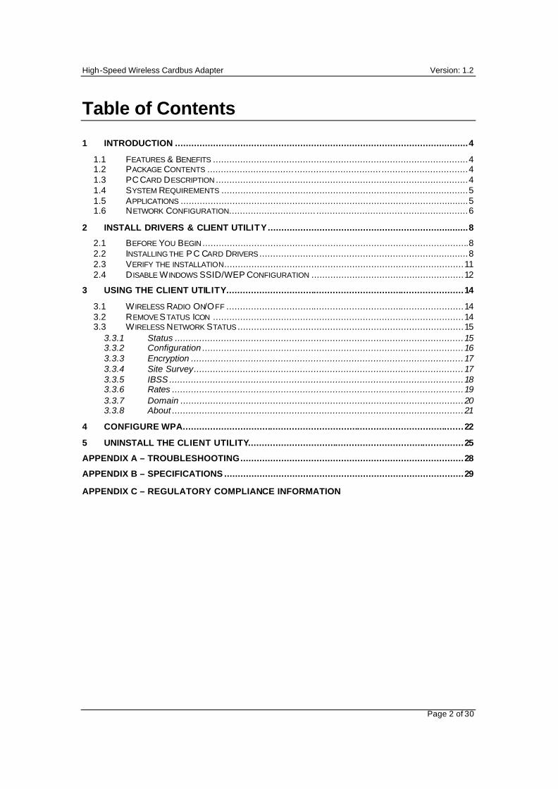
Table of Contents 1 INTRODUCTION ............................................................................................................4
1.1 FEATURES & BENEFITS ..............................................................................................4 1.2 PACKAGE CONTENTS ................................ ................................ ................................4 1.3 PC CARD DESCRIPTION .............................................................................................4 1.4 SYSTEM REQUIREMENTS ...........................................................................................5 1.5 APPLICATIONS ..........................................................................................................5 1.6 NETWORK CONFIGURATION................................ ................................ ........................6
2 INSTALL DRIVERS & CLIENT UTILITY..........................................................................8
2.1 BEFORE YOU BEGIN ..................................................................................................8 2.2 INSTALLING THE P C CARD DRIVERS .............................................................................8 2.3 VERIFY THE INSTALLATION........................................................................................11 2.4 D ISABLE W INDOWS SSID/WEP CONFIGURATION ........................................................12
3 USING THE CLIENT UTILITY.......................................................................................14
3.1 W IRELESS RADIO ON/OFF .......................................................................................14 3.2 REMOVE STATUS ICON ............................................................................................14 3.3 W IRELESS NETWORK STATUS ...................................................................................15
3.3.1 Status ..........................................................................................................15 3.3.2 Configuration ................................................................................................16 3.3.3 Encryption ....................................................................................................17 3.3.4 Site Survey...................................................................................................17 3.3.5 IBSS ............................................................................................................18 3.3.6 Rates ...........................................................................................................19 3.3.7 Domain ........................................................................................................20 3.3.8 About ...........................................................................................................21
4 CONFIGURE WPA.......................................................................................................22
5 UNINSTALL THE CLIENT UTILITY...............................................................................25
APPENDIX A – TROUBLESHOOTING..................................................................................28
APPENDIX B – SPECIFICATIONS ........................................................................................29
APPENDIX C – REGULATORY COMPLIANCE INFORMATION

High-Speed Wireless Cardbus Adapter Version: 1.2
Page 3 of 30
Revision History Version Date Notes 1.0 September 8, 2003 Initial Version 1.1 October 2, 2003 Updated Screens 1.2 October 29, 2003 Add WPA configuration
High-Speed Wireless Cardbus Adapter Version: 1.2
Page 4 of 30
1 Introduction This chapter describes the features & benefits, package contents, PC card description, system requirements, applications, and network configuration.
1.1 Features & Benefits
Features Benefits High-speed data rate up to 54 Mbps
Capable of handling heavy data payloads such as MPEG video streaming.
Up to 152-bit WEP data encryption and TKIP
Powerful data security.
IEEE 802.1x client support (optional)
Enhances authentication and security.
Multi-country roaming (802.11d) support
Automatically adjusts regulatory domain to operate in different countries.
Advanced power management Low power consumption in power saving mode.
1.2 Package Contents
� One PC Card � One Installation CD � One Quick Installation Guide
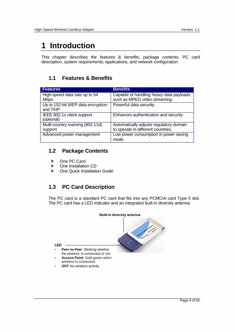
1.3 PC Card Description
The PC card is a standard PC card that fits into any PCMCIA card Type II slot. The PC card has a LED indicator and an integrated built-in diversity antenna
Built-in diversity antenna
LED: • Peer-to-Peer: Blinking whether
the wireless is connected or not. • Access Point: Sold green when
wireless is connected. • OFF: No wireless activity.
High-Speed Wireless Cardbus Adapter Version: 1.2
Page 5 of 30
1.4 System Requirements
The following are the minimum system requirements in order to use the PC card. • PC/AT compatible computer with a PCMCIA Type II slot. • Windows 98/ME/ /2000/XP operating system. • 1.3 MB of free disk space for installing the PC Card driver and utility
program.
1.5 Applications
The wireless LAN products are easy to install and highly efficient. The following list describes some of the many applications made possible through the power and flexibility of wireless LANs:
a) Difficult-to-wire environments There are many situations where wires cannot be laid easily. Historic buildings, older buildings, open areas and across busy streets make the installation of LANs either impossible or very expensive.
b) Temporary workgroups Consider situations in parks, athletic arenas, exhibition centers, disaster-recovery, temporary offices and construction sites where one wants a temporary WLAN established and removed.
c) The ability to access real-time information Doctors/nurses, point-of-sale employees, and warehouse workers can access real-time information while dealing with patients, serving customers and processing information.
d) Frequently changed environments Show rooms, meeting rooms, retail stores, and manufacturing sites where frequently rearrange the workplace.
e) Small Office and Home Office (SOHO) networks SOHO users need a cost-effective, easy and quick installation of a small network.
f) Wireless extensions to Ethernet networks Network managers in dynamic environments can minimize the overhead caused by moves, extensions to networks, and other changes with wireless LANs.
g) Wired LAN backup Network managers implement wireless LANs to provide backup for mission-critical applications running on wired networks.
h) Training/Educational facilities Training sites at corporations and students at universities use wireless connectivity to ease access to information, information exchanges, and learning.
High-Speed Wireless Cardbus Adapter Version: 1.2
Page 6 of 30
1.6 Network Configuration
To better understand how the wireless LAN products work together to create a wireless network, it might be helpful to depict a few of the possible wireless LAN PC card network configurations. The wireless LAN products can be configured as:
a) Ad-hoc (or peer-to-peer) for departmental or SOHO LANs. b) Infrastructure for enterprise LANs.
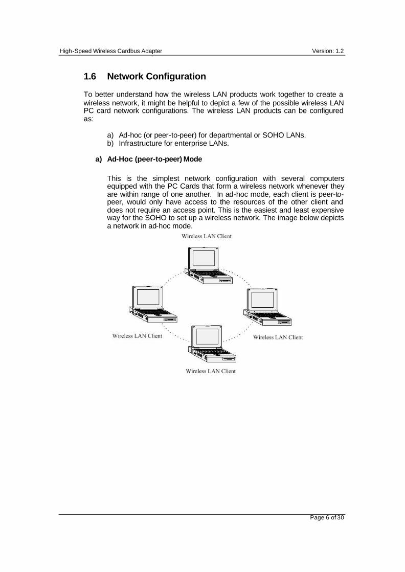
a) Ad-Hoc (peer-to-peer) Mode
This is the simplest network configuration with several computers equipped with the PC Cards that form a wireless network whenever they are within range of one another. In ad-hoc mode, each client is peer-to-peer, would only have access to the resources of the other client and does not require an access point. This is the easiest and least expensive way for the SOHO to set up a wireless network. The image below depicts a network in ad-hoc mode.
High-Speed Wireless Cardbus Adapter Version: 1.2
Page 7 of 30
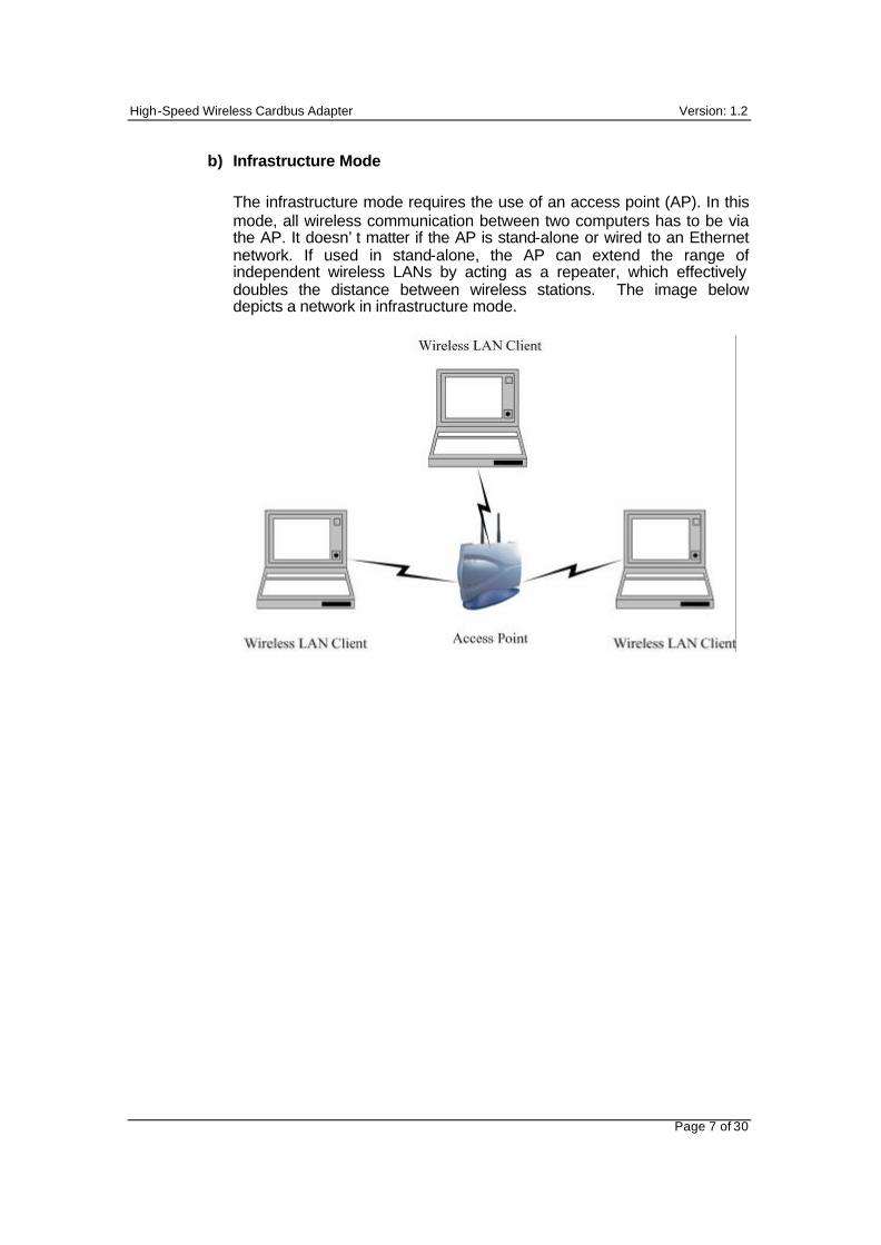
b) Infrastructure Mode
The infrastructure mode requires the use of an access point (AP). In this mode, all wireless communication between two computers has to be via the AP. It doesn’t matter if the AP is stand-alone or wired to an Ethernet network. If used in stand-alone, the AP can extend the range of independent wireless LANs by acting as a repeater, which effectively doubles the distance between wireless stations. The image below depicts a network in infrastructure mode.
High-Speed Wireless Cardbus Adapter Version: 1.2
Page 8 of 30
2 Install Drivers & Client Utility
This chapter describes how to install the drivers and client utility in Windows 98/ME/2000/XP.
2.1 Before You Begin
Before installing the new drivers into your PC, you need to remove all of the Wireless LAN PC card drivers that you have installed.
During the installation, Windows 98/ME/2000/XP may need to copy systems files from its installation CD. Therefore, you may need a copy of the Windows installation CD at hand before installing the drivers. On many systems, instead of a CD, the necessary installation files are archived on the hard disk in C:\WINDOWS \OPTIONS\CABS directory.
2.2 Installing the PC Card Drivers
Follow the steps below in order to install the PC card drivers:
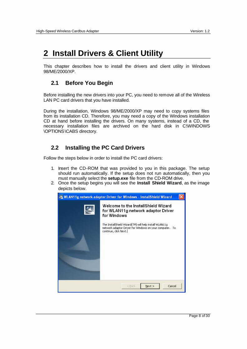
1. Insert the CD-ROM that was provided to you in this package. The setup should run automatically. If the setup does not run automatically, then you must manually select the setup.exe file from the CD-ROM drive.
2. Once the setup begins you will see the Install Shield Wizard, as the image depicts below.
High-Speed Wireless Cardbus Adapter Version: 1.2
Page 9 of 30
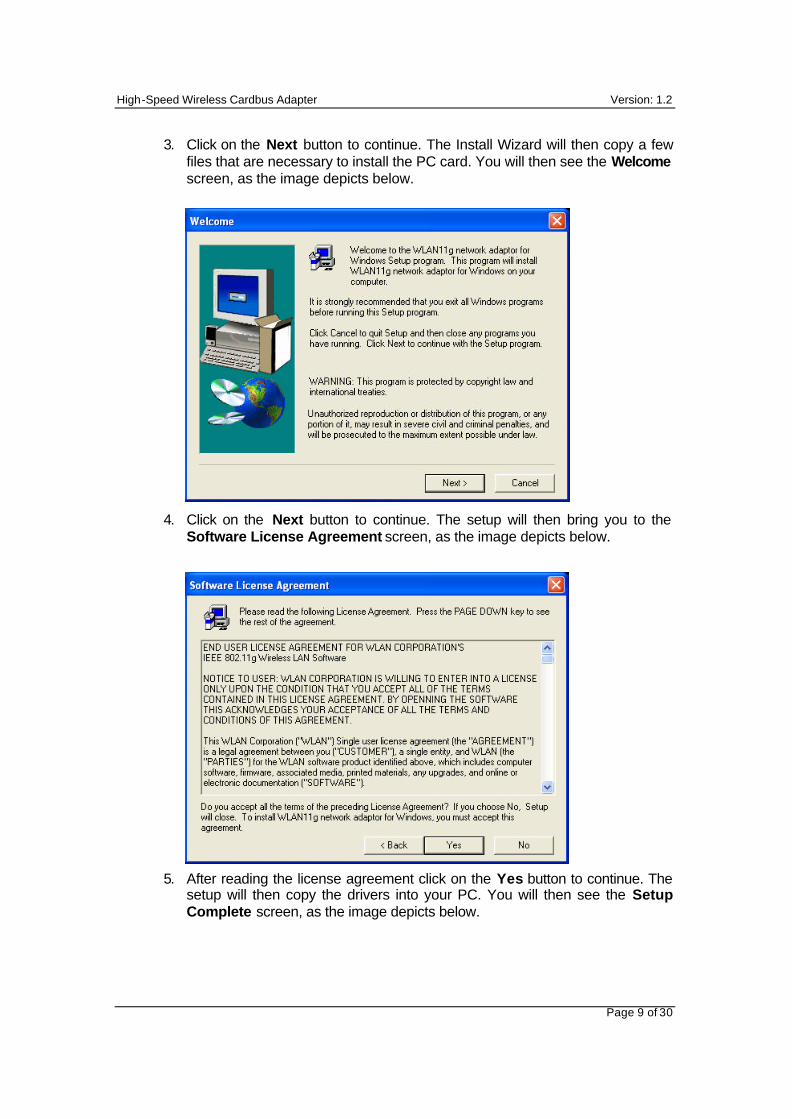
3. Click on the Next button to continue. The Install Wizard will then copy a few files that are necessary to install the PC card. You will then see the Welcome screen, as the image depicts below.
4. Click on the Next button to continue. The setup will then bring you to the
Software License Agreement screen, as the image depicts below. 5. After reading the license agreement click on the Yes button to continue. The
setup will then copy the drivers into your PC. You will then see the Setup Complete screen, as the image depicts below.
High-Speed Wireless Cardbus Adapter Version: 1.2
Page 10 of 30
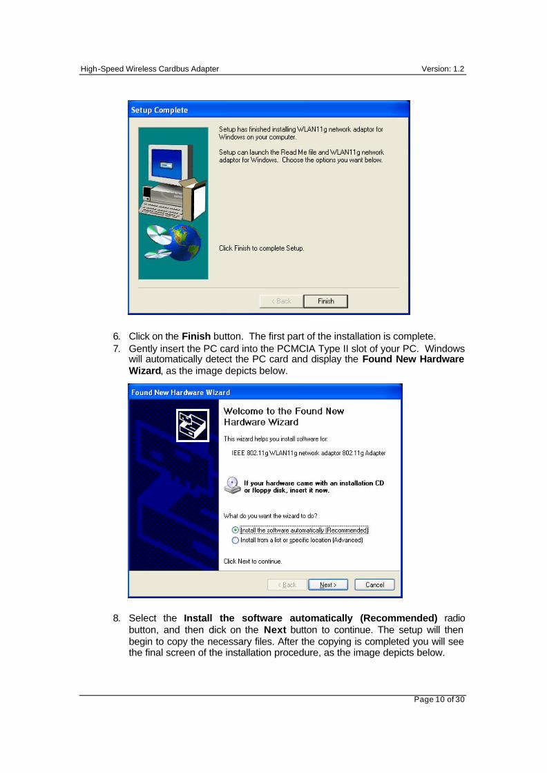
6. Click on the Finish button. The first part of the installation is complete. 7. Gently insert the PC card into the PCMCIA Type II slot of your PC. Windows
will automatically detect the PC card and display the Found New Hardware Wizard, as the image depicts below.
8. Select the Install the software automatically (Recommended) radio button, and then click on the Next button to continue. The setup will then begin to copy the necessary files. After the copying is completed you will see the final screen of the installation procedure, as the image depicts below.
High-Speed Wireless Cardbus Adapter Version: 1.2
Page 11 of 30
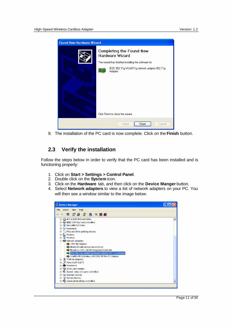
9. The installation of the PC card is now complete. Click on the Finish button.
2.3 Verify the installation
Follow the steps below in order to verify that the PC card has been installed and is functioning properly:
1. Click on Start > Settings > Control Panel. 2. Double click on the System icon. 3. Click on the Hardware tab, and then click on the Device Manger button. 4. Select Network adapters to view a list of network adapters on your PC. You
will then see a window similar to the image below.
High-Speed Wireless Cardbus Adapter Version: 1.2
Page 12 of 30
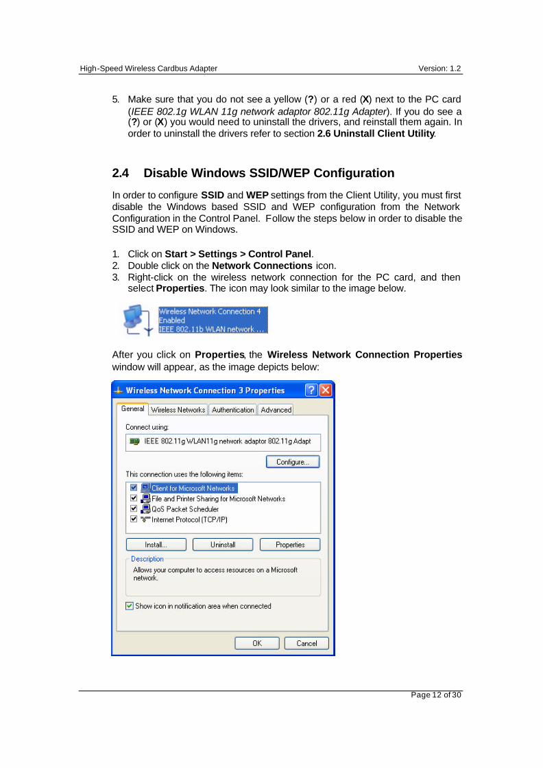
5. Make sure that you do not see a yellow (?) or a red (X) next to the PC card (IEEE 802.1g WLAN 11g network adaptor 802.11g Adapter). If you do see a (?) or (X) you would need to uninstall the drivers, and reinstall them again. In order to uninstall the drivers refer to section 2.6 Uninstall Client Utility.
2.4 Disable Windows SSID/WEP Configuration
In order to configure SSID and WEP settings from the Client Utility, you must first disable the Windows based SSID and WEP configuration from the Network Configuration in the Control Panel. Follow the steps below in order to disable the SSID and WEP on Windows.
1. Click on Start > Settings > Control Panel. 2. Double click on the Network Connections icon. 3. Right-click on the wireless network connection for the PC card, and then
select Properties. The icon may look similar to the image below.
After you click on Properties, the Wireless Network Connection Properties window will appear, as the image depicts below:
High-Speed Wireless Cardbus Adapter Version: 1.2
Page 13 of 30
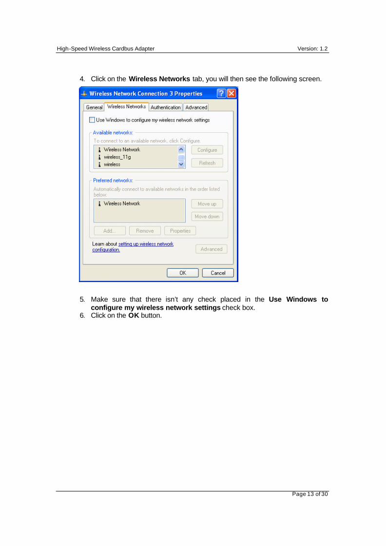
4. Click on the Wireless Networks tab, you will then see the following screen.
5. Make sure that there isn’t any check placed in the Use Windows to configure my wireless network settings check box.
6. Click on the OK button.
High-Speed Wireless Cardbus Adapter Version: 1.2
Page 14 of 30
3 Using the Client Utility
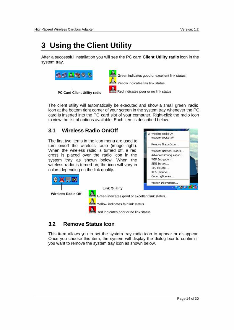
After a successful installation you will see the PC card Client Utility radio icon in the system tray.
The client utility will automatically be executed and show a small green radio icon at the bottom right corner of your screen in the system tray whenever the PC card is inserted into the PC card slot of your computer. Right-click the radio icon to view the list of options available. Each item is described below. 3.1 Wireless Radio On/Off
The first two items in the icon menu are used to turn on/off the wireless radio (image right). When the wireless radio is turned off, a red cross is placed over the radio icon in the system tray as shown below. When the wireless radio is turned on, the icon will vary in colors depending on the link quality.
3.2 Remove Status Icon
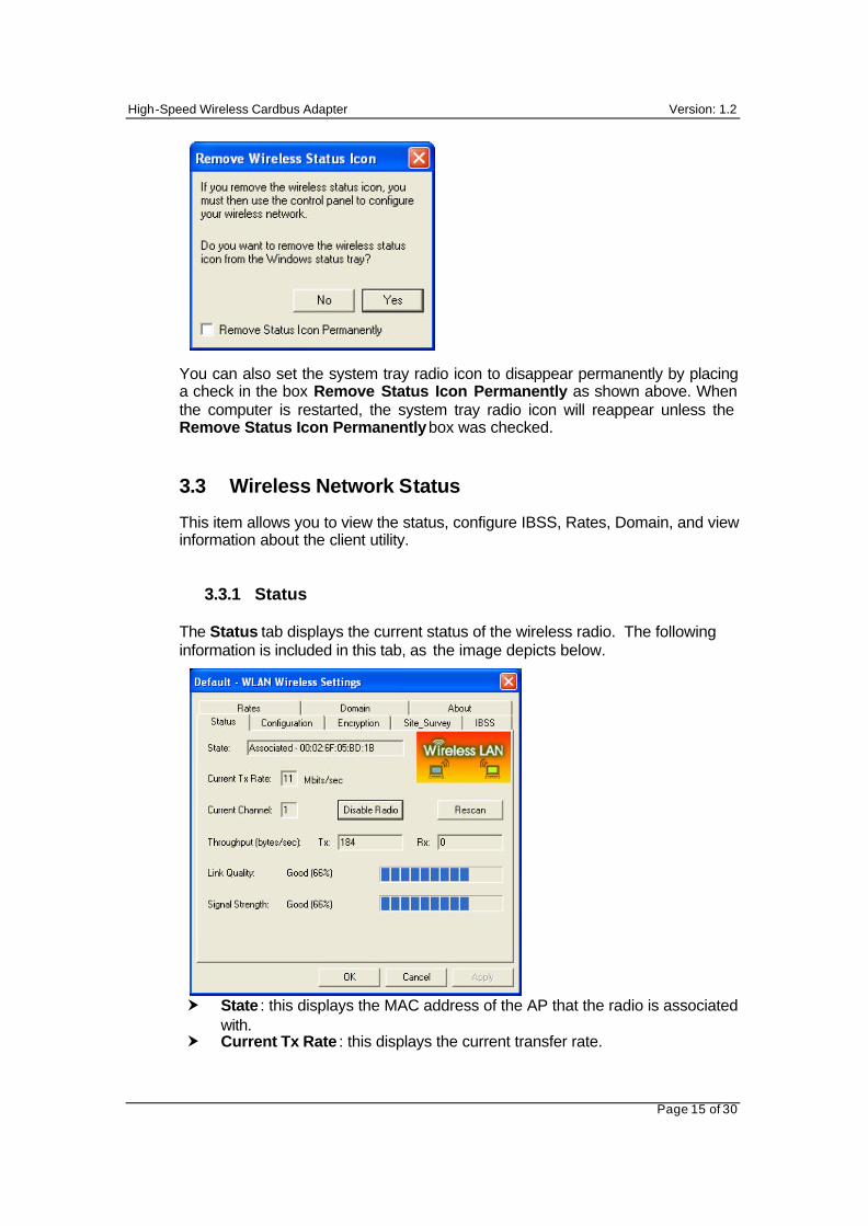
This item allows you to set the system tray radio icon to appear or disappear. Once you choose this item, the system will display the dialog box to confirm if you want to remove the system tray icon as shown below.
PC Card Client Utility radio
Green indicates good or excellent link status.
Yellow indicates fair link status.
Red indicates poor or no link status.
Link Quality
Green indicates good or excellent link status.
Yellow indicates fair link status.
Red indicates poor or no link status.
Wireless Radio Off
High-Speed Wireless Cardbus Adapter Version: 1.2
Page 15 of 30
You can also set the system tray radio icon to disappear permanently by placing a check in the box Remove Status Icon Permanently as shown above. When the computer is restarted, the system tray radio icon will reappear unless the Remove Status Icon Permanently box was checked. 3.3 Wireless Network Status
This item allows you to view the status, configure IBSS, Rates, Domain, and view information about the client utility.
3.3.1 Status The Status tab displays the current status of the wireless radio. The following information is included in this tab, as the image depicts below. � State : this displays the MAC address of the AP that the radio is associated
with. � Current Tx Rate : this displays the current transfer rate.
High-Speed Wireless Cardbus Adapter Version: 1.2
Page 16 of 30
� Disable Radio: click on this button to turn the radio off. � Rescan: click on this button if you would like the radio to scan for a
different channel. � Current Channel: this displays the current channel that the radio is using. � Throughput (bytes/sec): this displays the transmitting (Tx) and receiving
(Rx) bytes per second. � Link Quality: this displays the quality of the link from the radio to the AP. � Signal Strength: this displays the strength of the signal from the radio to
the AP. � Click on the Apply or OK button if you have made any changes.
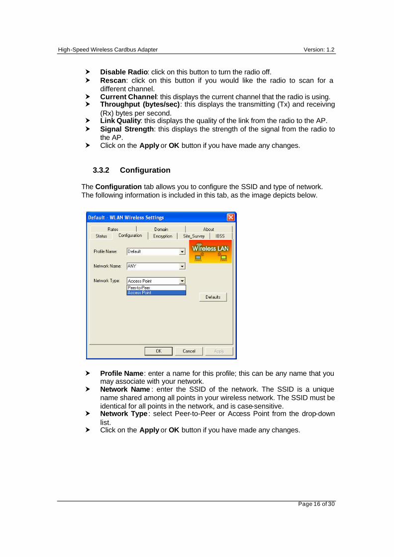
3.3.2 Configuration The Configuration tab allows you to configure the SSID and type of network. The following information is included in this tab, as the image depicts below. � Profile Name: enter a name for this profile; this can be any name that you
may associate with your network. � Network Name : enter the SSID of the network. The SSID is a unique
name shared among all points in your wireless network. The SSID must be identical for all points in the network, and is case-sensitive.
� Network Type : select Peer-to-Peer or Access Point from the drop-down list.
� Click on the Apply or OK button if you have made any changes.
High-Speed Wireless Cardbus Adapter Version: 1.2
Page 17 of 30
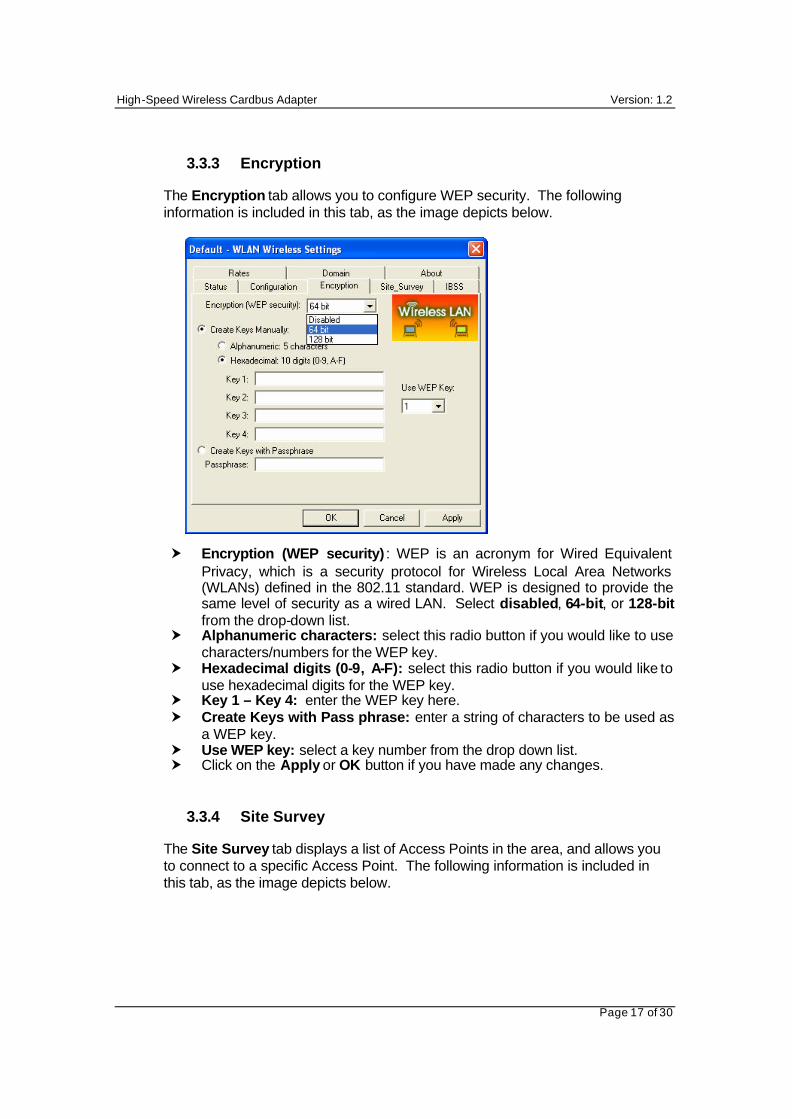
3.3.3 Encryption
The Encryption tab allows you to configure WEP security. The following information is included in this tab, as the image depicts below. � Encryption (WEP security) : WEP is an acronym for Wired Equivalent
Privacy, which is a security protocol for Wireless Local Area Networks (WLANs) defined in the 802.11 standard. WEP is designed to provide the same level of security as a wired LAN. Select disabled, 64-bit, or 128-bit from the drop-down list.
� Alphanumeric characters: select this radio button if you would like to use characters/numbers for the WEP key.
� Hexadecimal digits (0-9, A-F): select this radio button if you would like to use hexadecimal digits for the WEP key.
� Key 1 – Key 4: enter the WEP key here. � Create Keys with Pass phrase: enter a string of characters to be used as
a WEP key. � Use WEP key: select a key number from the drop down list. � Click on the Apply or OK button if you have made any changes.
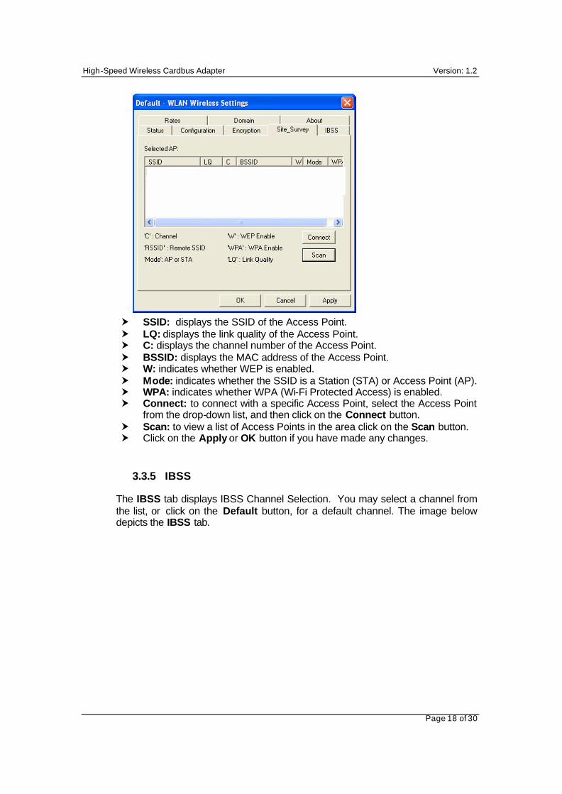
3.3.4 Site Survey
The Site Survey tab displays a list of Access Points in the area, and allows you to connect to a specific Access Point. The following information is included in this tab, as the image depicts below.
High-Speed Wireless Cardbus Adapter Version: 1.2
Page 18 of 30
� SSID: displays the SSID of the Access Point. � LQ: displays the link quality of the Access Point. � C: displays the channel number of the Access Point. � BSSID: displays the MAC address of the Access Point. � W: indicates whether WEP is enabled. � Mode: indicates whether the SSID is a Station (STA) or Access Point (AP). � WPA: indicates whether WPA (Wi-Fi Protected Access) is enabled. � Connect: to connect with a specific Access Point, select the Access Point
from the drop-down list, and then click on the Connect button. � Scan: to view a list of Access Points in the area click on the Scan button. � Click on the Apply or OK button if you have made any changes.
3.3.5 IBSS The IBSS tab displays IBSS Channel Selection. You may select a channel from the list, or click on the Default button, for a default channel. The image below depicts the IBSS tab.

High-Speed Wireless Cardbus Adapter Version: 1.2
Page 19 of 30
� Click on the Apply or OK button if you have made any changes.
3.3.6 Rates The Rates tab displays the data rate. You may select a data rate from the list, or click on the Default button, for a default data rate (Fully Automatic). The image below depicts the Rates tab.
� Click on the Apply or OK button if you have made any changes.
High-Speed Wireless Cardbus Adapter Version: 1.2
Page 20 of 30
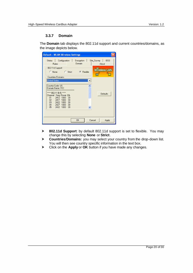
3.3.7 Domain The Domain tab displays the 802.11d support and current countries/domains, as the image depicts below. � 802.11d Support: by default 802.11d support is set to flexible. You may
change this by selecting None or Strict. � Countries/Domains: you may select your country from the drop-down list.
You will then see country specific information in the text box. � Click on the Apply or OK button if you have made any changes.
High-Speed Wireless Cardbus Adapter Version: 1.2
Page 21 of 30
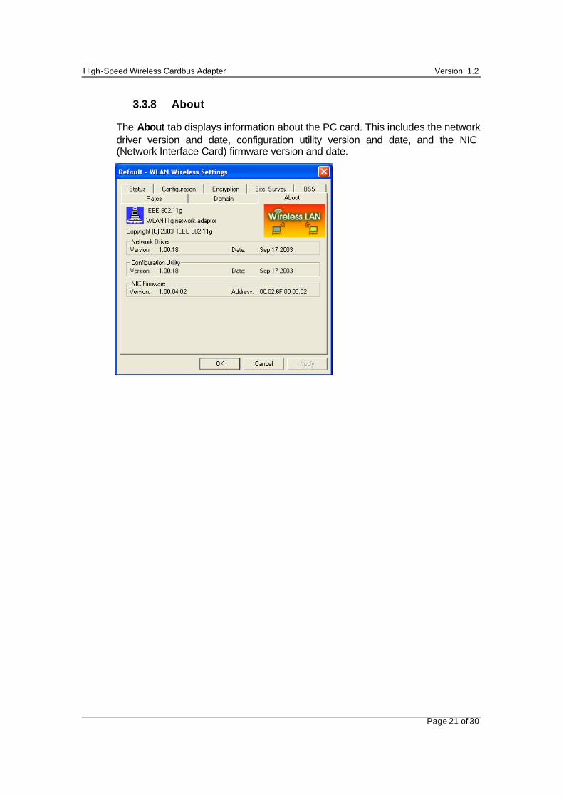
3.3.8 About The About tab displays information about the PC card. This includes the network driver version and date, configuration utility version and date, and the NIC (Network Interface Card) firmware version and date.
High-Speed Wireless Cardbus Adapter Version: 1.2
Page 22 of 30
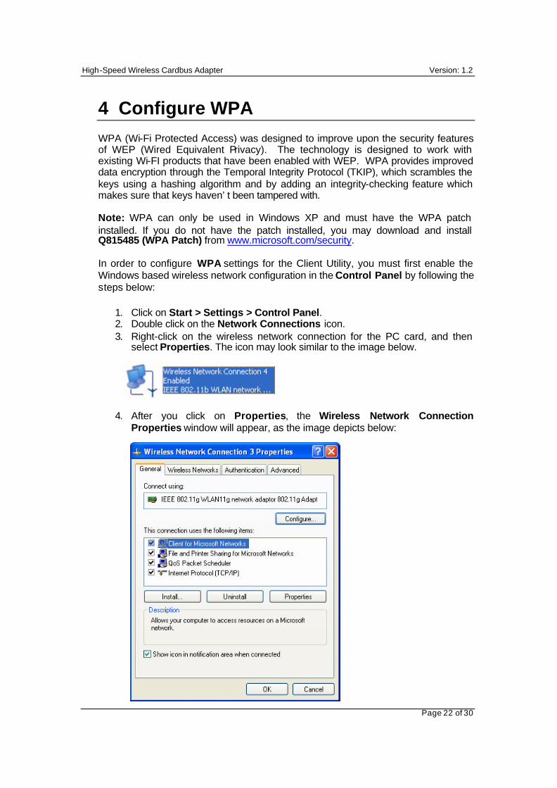
4 Configure WPA
WPA (Wi-Fi Protected Access) was designed to improve upon the security features of WEP (Wired Equivalent Privacy). The technology is designed to work with existing Wi-FI products that have been enabled with WEP. WPA provides improved data encryption through the Temporal Integrity Protocol (TKIP), which scrambles the keys using a hashing algorithm and by adding an integrity-checking feature which makes sure that keys haven’t been tampered with. Note: WPA can only be used in Windows XP and must have the WPA patch installed. If you do not have the patch installed, you may download and install Q815485 (WPA Patch) from www.microsoft.com/security. In order to configure WPA settings for the Client Utility, you must first enable the Windows based wireless network configuration in the Control Panel by following the steps below:
1. Click on Start > Settings > Control Panel. 2. Double click on the Network Connections icon. 3. Right-click on the wireless network connection for the PC card, and then
select Properties. The icon may look similar to the image below.
4. After you click on Properties, the Wireless Network Connection Properties window will appear, as the image depicts below:
High-Speed Wireless Cardbus Adapter Version: 1.2
Page 23 of 30
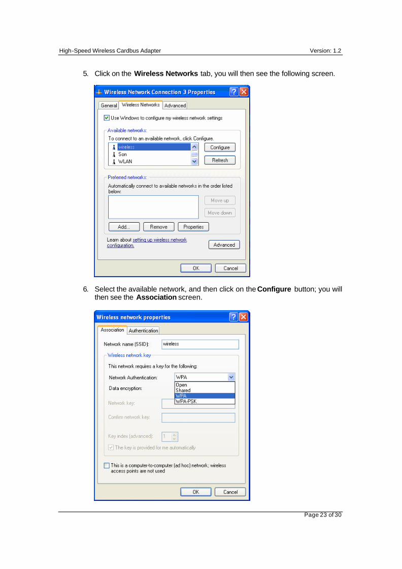
5. Click on the Wireless Networks tab, you will then see the following screen. 6. Select the available network, and then click on the Configure button; you will
then see the Association screen.
High-Speed Wireless Cardbus Adapter Version: 1.2
Page 24 of 30
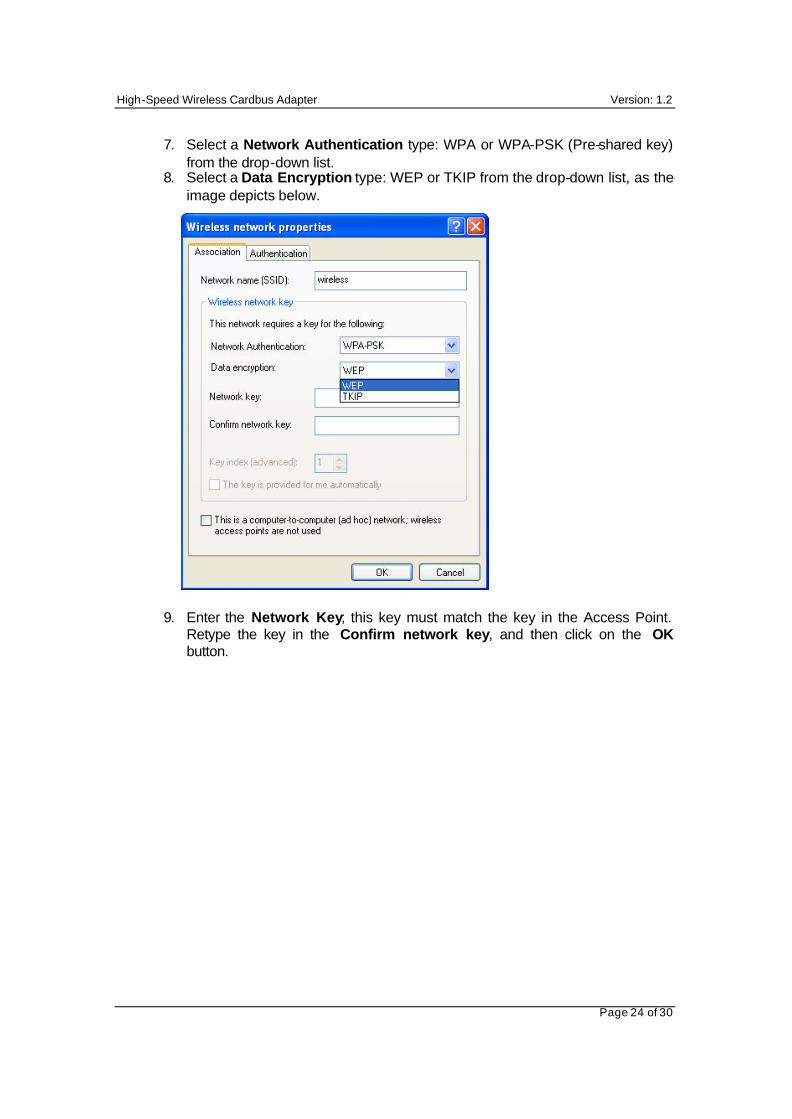
7. Select a Network Authentication type: WPA or WPA-PSK (Pre-shared key) from the drop-down list.
8. Select a Data Encryption type: WEP or TKIP from the drop-down list, as the image depicts below.
9. Enter the Network Key; this key must match the key in the Access Point. Retype the key in the Confirm network key, and then click on the OK button.
High-Speed Wireless Cardbus Adapter Version: 1.2
Page 25 of 30
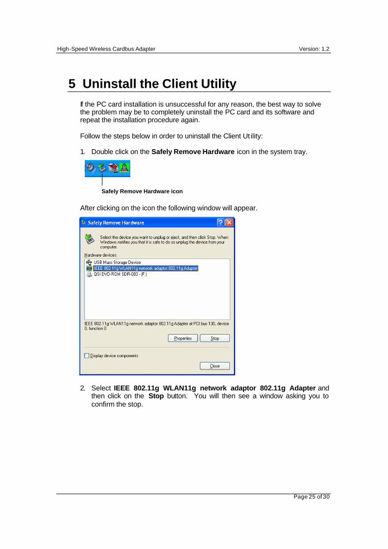
5 Uninstall the Client Utility
If the PC card installation is unsuccessful for any reason, the best way to solve the problem may be to completely uninstall the PC card and its software and repeat the installation procedure again. Follow the steps below in order to uninstall the Client Ut ility: 1. Double click on the Safely Remove Hardware icon in the system tray.
After clicking on the icon the following window will appear.
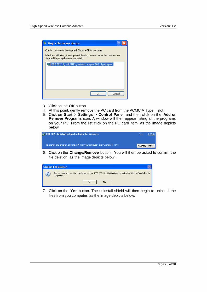
2. Select IEEE 802.11g WLAN11g network adaptor 802.11g Adapter and then click on the Stop button. You will then see a window asking you to confirm the stop.
Safely Remove Hardware icon
High-Speed Wireless Cardbus Adapter Version: 1.2
Page 26 of 30
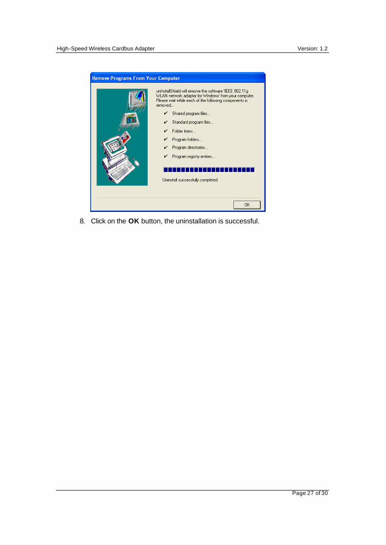
3. Click on the OK button. 4. At this point, gently remove the PC card from the PCMCIA Type II slot. 5. Click on Start > Settings > Control Panel, and then click on the Add or
Remove Programs icon. A window will then appear listing all the programs on your PC. From the list click on the PC card item, as the image depicts below.
6. Click on the Change/Remove button. You will then be asked to confirm the file deletion, as the image depicts below.
7. Click on the Yes button. The uninstall shield will then begin to uninstall the files from you computer, as the image depicts below.
High-Speed Wireless Cardbus Adapter Version: 1.2
Page 27 of 30
8. Click on the OK button, the uninstallation is successful.
High-Speed Wireless Cardbus Adapter Version: 1.2
Page 28 of 30
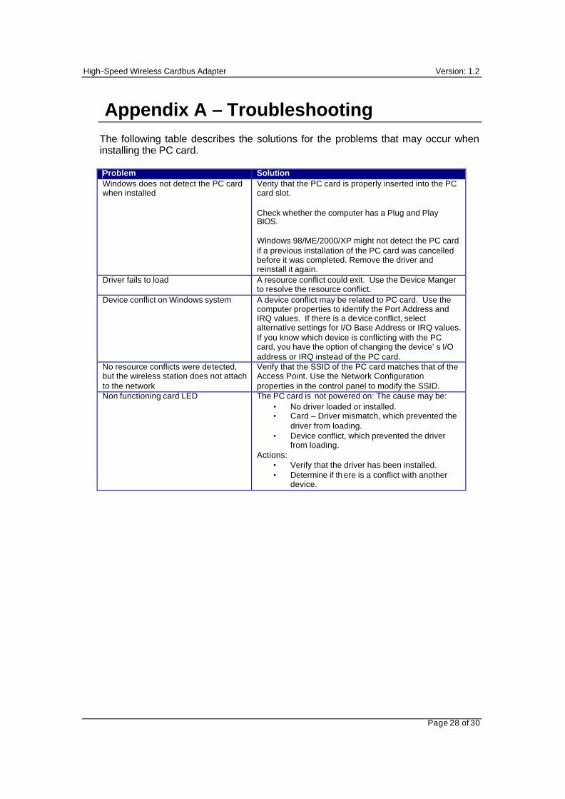
Appendix A – Troubleshooting
The following table describes the solutions for the problems that may occur when installing the PC card.
Problem Solution Windows does not detect the PC card when installed
Verity that the PC card is properly inserted into the PC card slot. Check whether the computer has a Plug and Play BIOS. Windows 98/ME/2000/XP might not detect the PC card if a previous installation of the PC card was cancelled before it was completed. Remove the driver and reinstall it again.
Driver fails to load A resource conflict could exit. Use the Device Manger to resolve the resource conflict.
Device conflict on Windows system A device conflict may be related to PC card. Use the computer properties to identify the Port Address and IRQ values. If there is a device conflict, select alternative settings for I/O Base Address or IRQ values. If you know which device is conflicting with the PC card, you have the option of changing the device’s I/O address or IRQ instead of the PC card.
No resource conflicts were detected, but the wireless station does not attach to the network
Verify that the SSID of the PC card matches that of the Access Point. Use the Network Configuration properties in the control panel to modify the SSID.
Non functioning card LED The PC card is not powered on: The cause may be: • No driver loaded or installed. • Card – Driver mismatch, which prevented the
driver from loading. • Device conflict, which prevented the driver
from loading. Actions:
• Verify that the driver has been installed. • Determine if th ere is a conflict with another
device.
High-Speed Wireless Cardbus Adapter Version: 1.2
Page 29 of 30
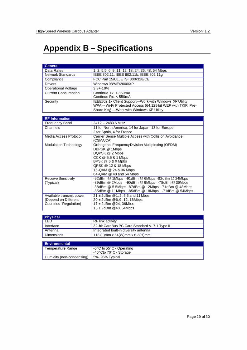
Appendix B – Specifications
General Data Rates 1, 2, 5.5, 6, 9, 11, 12, 18, 24, 36, 48, 54 Mbps Network Standards IEEE 802.11, IEEE 802.11b, IEEE 802.11g Compliance FCC Part 15/UL, ETSI 300/328/CE Drivers Windows 98/ME/2000/XP Operational Voltage 3.3+-10% Current Consumption Continue Tx: < 850mA
Continue Rx: < 550mA Security IEEE802.1x Client Support— Work with Windows XP Utility
WPA -- Wi-Fi Protected Access (64,128-bit WEP with TKIP, Pre-Share Key) — Work with Windows XP Utility
RF Information Frequency Band 2412 – 2483.5 MHz Channels 11 for North America, 14 for Japan, 13 for Europe,
2 for Spain, 4 for France Media Access Protocol Carrier Sense Multiple Access with Collision Avoidance
(CSMA/CA) Modulation Technology Orthogonal Frequency Division Multiplexing (OFDM)
DBPSK @ 1Mbps DQPSK @ 2 Mbps CCK @ 5.5 & 1 Mbps BPSK @ 6 & 9 Mpbs QPSK @ 12 & 18 Mbps 16-QAM @ 24 & 36 Mbps 64-QAM @ 48 and 54 Mbps
Receive Sensitivity (Typical)
-92dBm @ 1Mbps -91dBm @ 6Mbps -82dBm @ 24Mbps -89dBm @ 2Mbps -90dBm @ 9Mbps -78dBm @ 36Mbps -88dBm @ 5.5Mbps -87dBm @ 12Mbps -71dBm @ 48Mbps -85dBm @ 11Mbps -85dBm @ 18Mbps -71dBm @ 54Mbps
Available transmit power (Depend on Different Countries ’ Regulation)
21 ± 2dBm @1, 2, 5.5 and 11Mbps 20 ± 2dBm @6, 9, 12, 18Mbps 17 ± 2dBm @24, 36Mbps 16 ± 2dBm @48, 54Mbps
Physical LED RF link activity Interface 32-bit CardBus PC Card Standard V. 7.1 Type II Antenna Integrated built-in diversity antenna Dimensions 118 (L)mm x 54(W)mm x 6.3(H)mm
Environmental Temperature Range -0°C to 55°C - Operating
-40°Cto 70°C - Storage Humidity (non-condensing) 5%~95% Typical
High-Speed Wireless Cardbus Adapter Version: 1.2
Page 30 of 30
Appendix C – Regulatory Compliance Information Federal Communication Commission Interference Statement This equipment has been tested and found to comply with the limits for a Class B digital device, pursuant to Part 15 of the FCC Rules. These limits are designed to provide reasonable protection against harmful interference in a residential installation. This equipment generates, uses and can radiate radio frequency energy and, if not installed and used in accordance with the instructions, may cause harmful interference to radio communications. However, there is no guarantee that interference will not occur in a particular installation. If this equipment does cause harmful interference to radio or television reception, which can be determined by turning the equipment off and on, the user is encouraged to try to correct the interference by one of the following measures:
• Reorient or relocate the receiving antenna. • Increase the separation between the equipment and receiver. • Connect the equipment into an outlet on a circuit different from that to which the receiver
is connected. • Consult the dealer or an experienced radio/TV technician for help.
FCC Caution: Any changes or modifications not expressly approved by the party responsible for compliance could void the user's authority to operate this equipment.
This device complies with Part 15 of the FCC Rules. Operation is subject to the following two conditions: (1) This device may not cause harmful interference, and (2) this device must accept any interference received, including interference that may cause undesired operation.
IMPORTANT NOTE: FCC Radiation Exposure Statement:
This equipment complies with FCC radiation exposure limits set forth for an uncontrolled environment. This device complies with FCC RF Exposure limits set forth for an uncontrolled environment, under 47 CFR 2.1093 paragraph (d)(2). This transmitter must not be co-located or operating in conjunction with any other antenna or transmitter.