Embed Size (px)
Citation preview
User’sManual
DPharpHART 5/7 Communication Type(EJXA, EJAE)
IM 01C25T01-06EN
IM 01C25T01-06EN3rd Edition
i
IM 01C25T01-06EN
DPharpHART 5/7 Communication Type(EJXA, EJAE)
IM 01C25T01-06EN 3rd Edition
3rd Edition: June 2012 (KP)All Rights Reserved, Copyright © 2010, Yokogawa Electric Corporation
Contents1. Introduction ............................................................................................... 1-1
Regarding This Manual ....................................................................................1-11.1 Safe Use of This Product .................................................................................1-21.2 Warranty .............................................................................................................1-21.3 ATEX Documentation .......................................................................................1-3
2. Connection ................................................................................................ 2-12.1 Integral Indicator Display When Powering On .............................................. 2-12.2 HART Protocol Revision ..................................................................................2-12.3 Device Description (DD) on a Configuration Tool and
Transmitter Device Revision............................................................................2-22.4 Set the parameters using DTM ........................................................................2-32.5 Interconnection Between DPharp and the HART Configuration Tool ........ 2-42.6 Power Supply Voltage and Load Resistance ................................................. 2-4
3. Parameter Setting ..................................................................................... 3-13.1 Menu Tree ..........................................................................................................3-1
3.1.1 For DD (HART 5/HART 7) and DTM (HART 7/EJA series: HART 5) ..................................................3-1
3.1.2 For DTM (EJX series: HART 5) .........................................................3-8
3.2 Basic Setup ......................................................................................................3-123.2.1 Tag and Device Information .............................................................3-12
3.2.2 Unit ...................................................................................................3-12
3.2.3 Range Change .................................................................................3-13
3.2.4 Output Mode ....................................................................................3-13
3.2.5 Damping Time Constant Setup ........................................................3-13
3.2.6 Output Signal Low Cut Mode Setup ................................................3-14
3.2.7 Impulse Line Connection Orientation Setup ....................................3-14
3.2.8 Static Pressure Setup ......................................................................3-15
3.3 Detailed Setup .................................................................................................3-153.3.1 Bi-directional Flow Measurement ....................................................3-15
3.3.2 Analog Output Signal Adjustable Range .........................................3-16
3.3.3 Integral Indicator Display Mode .......................................................3-16
3.3.4 Integral Indicator Scale Setup ..........................................................3-16
3.3.5 Unit for Displayed Temperature .......................................................3-18
ii
IM 01C25T01-06EN
3.3.6 Sensor Trim ......................................................................................3-18
3.3.7 Trim Analog Output ..........................................................................3-20
3.3.8 External Switch Mode ......................................................................3-20
3.3.9 CPU Failure Burnout Direction and Hardware Write Protect ..........3-21
3.3.10 Software Write Protection ................................................................3-21
3.3.11 Signal Characterizer ........................................................................3-22
3.3.12 Alarm ................................................................................................3-22
3.3.13 Status Output (only for EJX series: option code AL) .......................3-23
3.3.14 Capillary Fill Fluid Density Compensation ......................................3-24
3.3.15 Test Output, Simulation, and Squawk ..............................................3-25
3.3.16 Burst Mode .......................................................................................3-27
3.3.16.1 In the case of using HART 5 ...........................................3-27
3.3.16.2 In the case of using HART 7 ...........................................3-27
3.3.17 Multidrop Mode ................................................................................3-32
3.3.17.1 In the case of using HART 5 ...........................................3-32
3.3.17.2 In the case of using HART 7 ...........................................3-33
3.3.18 Switching HART Protocol Revision .................................................3-33
4. Diagnostics ............................................................................................... 4-14.1 Self-Diagnostics ................................................................................................4-1
4.1.1 Identify Problems by Using the HART Configuration Tool ................. 4-1
4.1.2 Checking with Integral Indicator .........................................................4-2
4.1.3 Status information available for HART 7 ............................................ 4-2
4.2 Advanced Diagnostics (Only for EJX series) ................................................ 4-34.2.1 Multi-sensing Process Monitoring ......................................................4-3
4.2.2 Impulse Line Blockage Detection (ILBD) ........................................... 4-3
4.2.2.1 Blockage Detection ...........................................................4-6
4.2.2.2 Combination of Reference Result and Blockage Detection ...........................................................4-8
4.2.2.3 Operation Parameters ......................................................4-9
4.2.2.4 Operating Procedure ...................................................... 4-11
4.2.2.5 Alarm and Alert Setting ...................................................4-12
4.2.2.6 Condition Check .............................................................4-14
4.2.2.7 Obtain Reference Values ................................................4-15
4.2.2.8 Capability Test of Blockage Detection Operation ...........4-16
4.2.2.9 Start ILBD Operation ......................................................4-16
4.2.2.10 Tuning .............................................................................4-17
4.2.2.11 Reset of Reference Value ...............................................4-18
4.2.2.12 ILBD Parameter List .......................................................4-19
4.2.3 Heat Trace Monitoring......................................................................4-21
4.2.3.1 Flg Temp Coef Setting ....................................................4-21
4.2.3.2 Out of Temperature Measurement Range ......................4-22
4.2.3.3 Parameter Lists for Heat Trace Monitoring .....................4-23
4.3 Alarms and Countermeasures ......................................................................4-24
iii
IM 01C25T01-06EN
5. Parameter Summary ................................................................................ 5-1Appendix 1. Safety Instrumented Systems Installation ............................A1-1
A1.1 Scope and Purpose ....................................................................................... A1-1A1.2 Using the transmitter for an SIS Application .............................................. A1-1
A1.2.1 Safety Accuracy ...............................................................................A1-1
A1.2.2 Diagnostic Response Time ..............................................................A1-1
A1.2.3 Setup ................................................................................................A1-1
A1.2.4 Required Parameter Settings ..........................................................A1-1
A1.2.5 Proof Testing ....................................................................................A1-1
A1.2.6 Repair and Replacement .................................................................A1-2
A1.2.7 Startup Time .....................................................................................A1-2
A1.2.8 Firmware Update .............................................................................A1-2
A1.2.9 Reliability Data .................................................................................A1-2
A1.2.10 Lifetime Limits ..................................................................................A1-2
A1.2.11 Environmental Limits .......................................................................A1-2
A1.2.12 Application Limits .............................................................................A1-2
A1.3 Definitions and Abbreviations ...................................................................... A1-3A1.3.1 Definitions ........................................................................................A1-3
A1.3.2 Abbreviations ...................................................................................A1-3
Appendix 2. ILBD Check List ........................................................................A2-1Revision Information ...............................................................................................i
<1. Introduction> 1-1
IM 01C25T01-06EN
1. IntroductionThank you for purchasing the DPharp EJX series pressure transmitter/EJA series pressure transmitter(“transmitter”).
The transmitters are precisely calibrated at the factory before shipment.To ensure both safety and efficiency, please read this manual carefully before operating the instrument.This manual describes the HART protocol communication functions of the transmitter and explains how to set the parameters for the transmitters using the HART configuration tool.For information on the installation, wiring, and maintenance of the transmitters, please refer to the user’s manual of each model.
WARNING
When using the transmitter in a Safety Instrumented Systems (SIS) application, refer to Appendix 1 in this manual. The instructions and procedures in the appendix must be strictly followed in order to maintain the designed safety integrity of the transmitter.
Regarding This Manual• This manual should be provided to the end
user.
• The contents of this manual are subject to change without prior notice.
• All rights reserved. No part of this manual may be reproduced in any form without Yokogawa’s written permission.
• Yokogawa makes no warranty of any kind with regard to this manual, including, but not limited to, implied warranty of merchantability and fitness for a particular purpose.
• If any question arises or errors are found, or if any information is missing from this manual, please inform the nearest Yokogawa sales office.
• The specifications covered by this manual are limited to those for the standard type under the specified model number break-down and do not cover custom-made instruments.
• Please note that changes in the specifications, construction, or component parts of the instrument may not immediately be reflected in this manual at the time of change, provided that postponement of revisions will not cause difficulty to the user from a functional or performance standpoint.
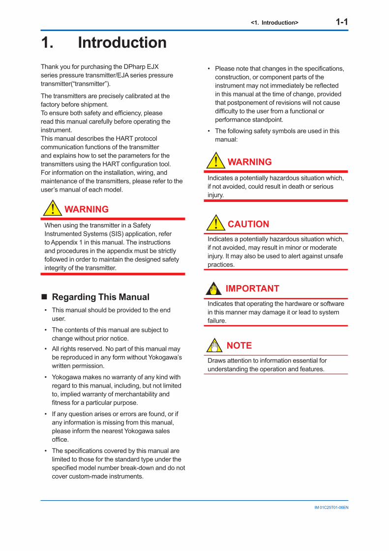
• The following safety symbols are used in this manual:
WARNING
Indicates a potentially hazardous situation which, if not avoided, could result in death or serious injury.
CAUTIONIndicates a potentially hazardous situation which, if not avoided, may result in minor or moderate injury. It may also be used to alert against unsafe practices.
IMPORTANTIndicates that operating the hardware or software in this manner may damage it or lead to system failure.
NOTEDraws attention to information essential for understanding the operation and features.
<1. Introduction> 1-2
IM 01C25T01-06EN
1.1 Safe Use of This Product For the safety of the operator and to protect the instrument and the system, please be sure to follow this manual’s safety instructions when handling this instrument. If these instructions are not heeded, the protection provided by this instrument may be impaired. In this case, Yokogawa cannot guarantee that the instrument can be safely operated. Please pay special attention to the following points:
(a) Installation• This instrument may only be installed by an
engineer or technician who has an expert knowledge of this device. Operators are not allowed to carry out installation unless they meet this condition.
• With high process temperatures, care must be taken not to burn yourself by touching the instrument or its casing.
• Never loosen the process connector nuts when the instrument is installed in a process. This can lead to a sudden, explosive release of process fluids.
• When draining condensate from the pressure detector section, take appropriate precautions to prevent the inhalation of harmful vapors and the contact of toxic process fluids with the skin or eyes.
• When removing the instrument from a hazardous process, avoid contact with the process fluid and the interior of the meter.
• All installation shall comply with local installation requirements and the local electrical code.
(b) Wiring• The instrument must be installed by an engineer
or technician who has an expert knowledge of this instrument. Operators are not permitted to carry out wiring unless they meet this condition.
• Before connecting the power cables, please confirm that there is no current flowing through the cables and that the power supply to the instrument is switched off.
(c) Operation• Wait 10 min. after the power is turned off before
opening the covers.
(d) Maintenance• Please carry out only the maintenance
procedures described in this manual. If you require further assistance, please contact the nearest Yokogawa office.
• Care should be taken to prevent the build up of dust or other materials on the display glass and the name plate. To clean these surfaces, use a soft, dry cloth.
(e) Modification• Yokogawa will not be liable for malfunctions or
damage resulting from any modification made to this instrument by the customer.
1.2 Warranty• The warranty shall cover the period noted on
the quotation presented to the purchaser at the time of purchase. Problems occurring during the warranty period shall basically be repaired free of charge.
• If any problems are experienced with this instrument, the customer should contact the Yokogawa representative from which this instrument was purchased or the nearest Yokogawa office.
• If a problem arises with this instrument, please inform us of the nature of the problem and the circumstances under which it developed, including the model specification and serial number. Any diagrams, data and other information you can include in your communication will also be helpful.
• The party responsible for the cost of fixing the problem shall be determined by Yokogawa following an investigation conducted by Yokogawa.
• The purchaser shall bear the responsibility for repair costs, even during the warranty period, if the malfunction is due to:
- Improper and/or inadequate maintenance by the purchaser.
- Malfunction or damage due to a failure to handle, use, or store the instrument in accordance with the design specifications.
- Use of the product in question in a location not conforming to the standards specified by Yokogawa, or due to improper maintenance of the installation location.
- Failure or damage due to modification or repair by any party except Yokogawa or an approved representative of Yokogawa.
- Malfunction or damage from improper relocation of the product in question after delivery.
- Reason of force majeure such as fires, earthquakes, storms/floods, thunder/lightening, or other natural disasters, or disturbances, riots, warfare, or radioactive contamination.
<1. Introduction> 1-3
IM 01C25T01-06EN
1.3 ATEX DocumentationThis is only applicable to the countries in European Union.
GB
DK
I
E
NL
SF
P
F
D
S
LT
LV
PL
EST
SLO
H
BG
RO
M
CZ
SK
GR
<2. Connection> 2-1
IM 01C25T01-06EN
2. Connection2.1 Integral Indicator Display
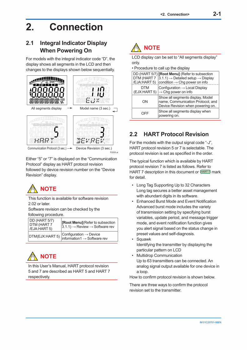
When Powering OnFor models with the integral indicator code “D”, the display shows all segments in the LCD and then changes to the displays shown below sequentially.
All segments display Model name (3 sec.)
Communication Protocol (3 sec.) Device Revision (3 sec.) F0200.ai
Either “5” or “7” is displayed on the “Communication Protocol” display as HART protocol revision followed by device revision number on the “Device Revision” display.
NOTEThis function is available for software revision 2.02 or later.Software revision can be checked by the following procedure.DD (HART 5/7)DTM (HART 7 /EJA:HART 5)
[Root Menu](Refer to subsection 3.1.1) → Review → Software rev
DTM(EJX:HART 5) Configuration → Device information1 → Software rev
NOTEIn this User’s Manual, HART protocol revision 5 and 7 are described as HART 5 and HART 7 respectively.
NOTELCD display can be set to “All segments display” only.• Procedure to call up the display DD (HART 5/7)DTM (HART 7 /EJA:HART 5)
[Root Menu] (Refer to subsection 3.1.1) → Detailed setup → Display condition → Chg power on info
DTM (EJX:HART 5)
Configuration → Local Display → Chg power on info
ONShow all segments display, Model name, Communication Protocol, and Device Revision when powering on.
OFF Show all segments display when powering on.
2.2 HART Protocol RevisionFor the models with the output signal code “-J”, HART protocol revision 5 or 7 is selectable. The protocol revision is set as specified in the order.
The typical function which is available by HART protocol revision 7 is listed as follows. Refer to HART 7 description in this document or HART 7 mark for detail.
• Long Tag Supporting Up to 32 Characters Long tag secures a better asset management
with abundant digits in its software.• Enhanced Burst Mode and Event Notification Advanced burst mode includes the variety
of transmission setting by specifying burst variables, update period, and message trigger mode, and event notification function gives you alert signal based on the status change in preset values and self-diagnosis.
• Squawk Identifying the transmitter by displaying the
particular pattern on LCD• Multidrop Communication Up to 63 transmitters can be connected. An
analog signal output available for one device in a loop.
How to confirm protocol revision is shown below.
There are three ways to confirm the protocol revision set to the transmitter.
<2. Connection> 2-2
IM 01C25T01-06EN
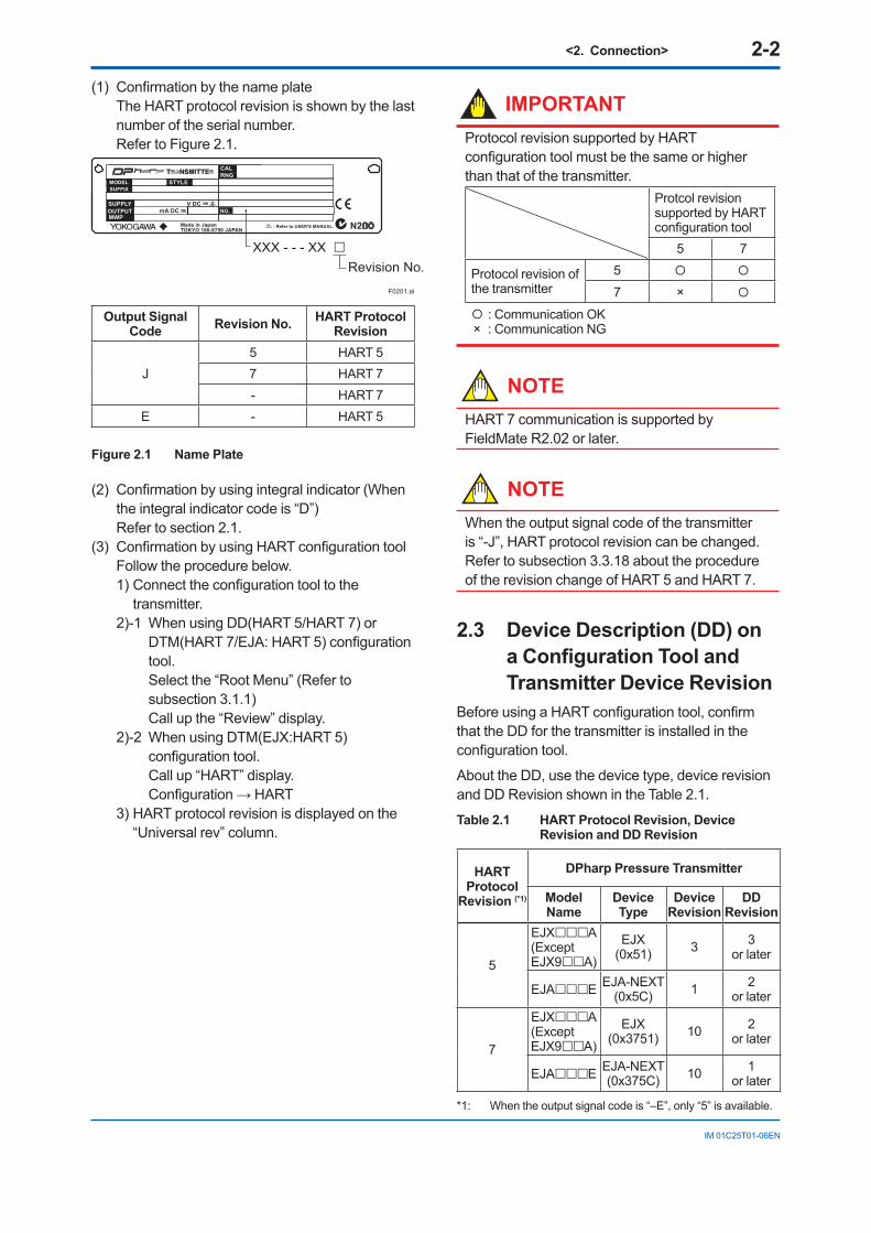
(1) Confirmation by the name plate The HART protocol revision is shown by the last
number of the serial number. Refer to Figure 2.1.
F0201.ai
: Refer to USER'S MANUAL.Made in JapanTOKYO 180-8750 JAPAN
MODELSUFFIX
SUPPLYOUTPUTMWP
mA DCV DC
STYLE
CALRNG
NO.
XXX - - - XX Revision No.
Output Signal Code Revision No. HART Protocol
Revision
J5 HART 57 HART 7- HART 7
E - HART 5
Figure 2.1 Name Plate
(2) Confirmation by using integral indicator (When the integral indicator code is “D”)
Refer to section 2.1.(3) Confirmation by using HART configuration tool Follow the procedure below.
1) Connect the configuration tool to the transmitter.
2)-1 When using DD(HART 5/HART 7) or DTM(HART 7/EJA: HART 5) configuration tool. Select the “Root Menu” (Refer to subsection 3.1.1) Call up the “Review” display.
2)-2 When using DTM(EJX:HART 5) configuration tool. Call up “HART” display. Configuration → HART
3) HART protocol revision is displayed on the “Universal rev” column.
IMPORTANTProtocol revision supported by HART configuration tool must be the same or higher than that of the transmitter.
Protcol revision supported by HART configuration tool
5 7
Protocol revision of the transmitter
5
7 ×
: Communication OK×: Communication NG
NOTEHART 7 communication is supported by FieldMate R2.02 or later.
NOTEWhen the output signal code of the transmitter is “-J”, HART protocol revision can be changed. Refer to subsection 3.3.18 about the procedure of the revision change of HART 5 and HART 7.
2.3 Device Description (DD) on a Configuration Tool and Transmitter Device Revision
Before using a HART configuration tool, confirm that the DD for the transmitter is installed in the configuration tool.
About the DD, use the device type, device revision and DD Revision shown in the Table 2.1.
Table 2.1 HART Protocol Revision, Device Revision and DD Revision
HART Protocol
Revision (*1)
DPharp Pressure Transmitter
Model Name
Device Type
Device Revision
DDRevision
5
EJXA(Except EJX9A)
EJX(0x51) 3 3
or later
EJAE EJA-NEXT(0x5C) 1 2
or later
7
EJXA(Except EJX9A)
EJX(0x3751) 10 2
or later
EJAE EJA-NEXT(0x375C) 10 1
or later
*1: When the output signal code is “–E”, only “5” is available.
<2. Connection> 2-3
IM 01C25T01-06EN
The device revision of the transmitter and DD can be confirmed as shown below.
If the correct DD is not installed in the configuration tool, download it from the official web site of HART Communication Foundation.
(1) Confirming the device revision of the transmitter Confirmation by using integral indicator
(When the integral indicator code is “D”) Refer to the section 2.1 Confirmation by using HART configuration
tool Follow the procedure below.
1) Connect the configuration tool to the transmitter.
2) Select the “Root Menu” (Refer to subsection 3.1.1) Call up the “Review” display.
3) The device revision is displayed on the “Fld dev rev” column.
(2) Confirming the device revision of the configuration tool
Confirm the device revision from the installed DD file name according to the procedure provided for the configuration tool.
The first two digits indicate the device revision and the next two digits indicate the DD revision.
0 a 0 2. X X XDD revisionDevice revision
NOTEDevice revision of DD file is given in hexadecimal
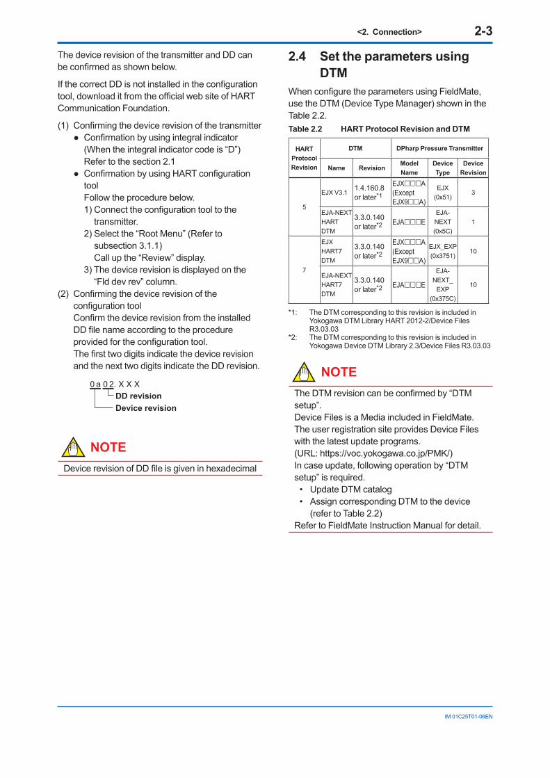
2.4 Set the parameters using DTM
When configure the parameters using FieldMate, use the DTM (Device Type Manager) shown in the Table 2.2. Table 2.2 HART Protocol Revision and DTM
HART ProtocolRevision
DTM DPharp Pressure Transmitter
Name RevisionModel Name
Device Type
Device Revision
5
EJX V3.1 1.4.160.8 or later*1
EJXA(Except EJX9A)
EJX(0x51)
3
EJA-NEXT HART DTM
3.3.0.140 or later*2 EJAE
EJA-NEXT(0x5C)
1
7
EJX HART7 DTM
3.3.0.140 or later*2
EJXA(Except EJX9A)
EJX_EXP(0x3751)
10
EJA-NEXT HART7 DTM
3.3.0.140 or later*2 EJAE
EJA-NEXT_
EXP(0x375C)
10
*1: The DTM corresponding to this revision is included in Yokogawa DTM Library HART 2012-2/Device Files R3.03.03
*2: The DTM corresponding to this revision is included in Yokogawa Device DTM Library 2.3/Device Files R3.03.03
NOTEThe DTM revision can be confirmed by “DTM setup”.Device Files is a Media included in FieldMate. The user registration site provides Device Files with the latest update programs. (URL: https://voc.yokogawa.co.jp/PMK/) In case update, following operation by “DTM setup” is required.
• Update DTM catalog• Assign corresponding DTM to the device
(refer to Table 2.2) Refer to FieldMate Instruction Manual for detail.
<2. Connection> 2-4
IM 01C25T01-06EN
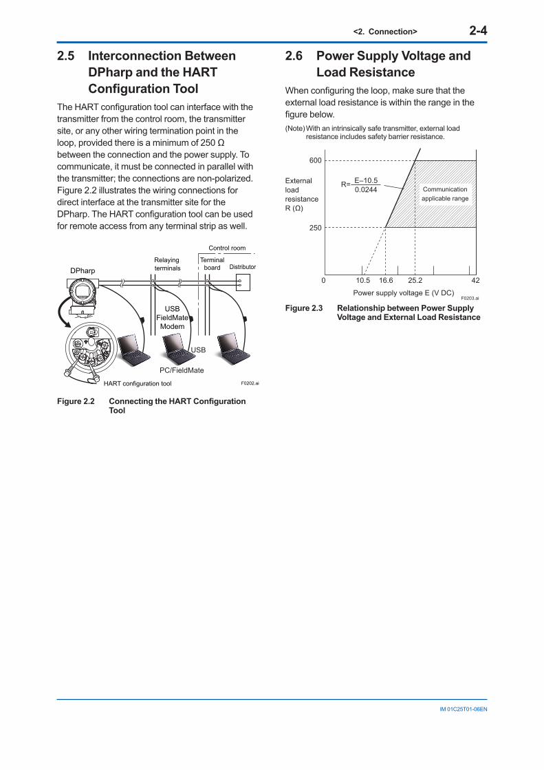
2.5 Interconnection Between DPharp and the HART Configuration Tool
The HART configuration tool can interface with the transmitter from the control room, the transmitter site, or any other wiring termination point in the loop, provided there is a minimum of 250 Ω between the connection and the power supply. To communicate, it must be connected in parallel with the transmitter; the connections are non-polarized. Figure 2.2 illustrates the wiring connections for direct interface at the transmitter site for the DPharp. The HART configuration tool can be used for remote access from any terminal strip as well.
USBFieldMateModem
Relaying terminals Distributor
Control room
Terminalboard
F0202.ai
USB
PC/FieldMate
HART configuration tool
DPharp
SUPPLY
PULS
E
CHECKALARM
Figure 2.2 Connecting the HART Configuration Tool
2.6 Power Supply Voltage and Load Resistance
When configuring the loop, make sure that the external load resistance is within the range in the figure below.(Note) With an intrinsically safe transmitter, external load
resistance includes safety barrier resistance.
600
250
0 10.5 16.6 25.2 42
External load resistanceR (Ω)
Power supply voltage E (V DC)F0203.ai
Communication applicable range
R= E–10.50.0244
Figure 2.3 Relationship between Power Supply Voltage and External Load Resistance
<3. Parameter Setting> 3-1
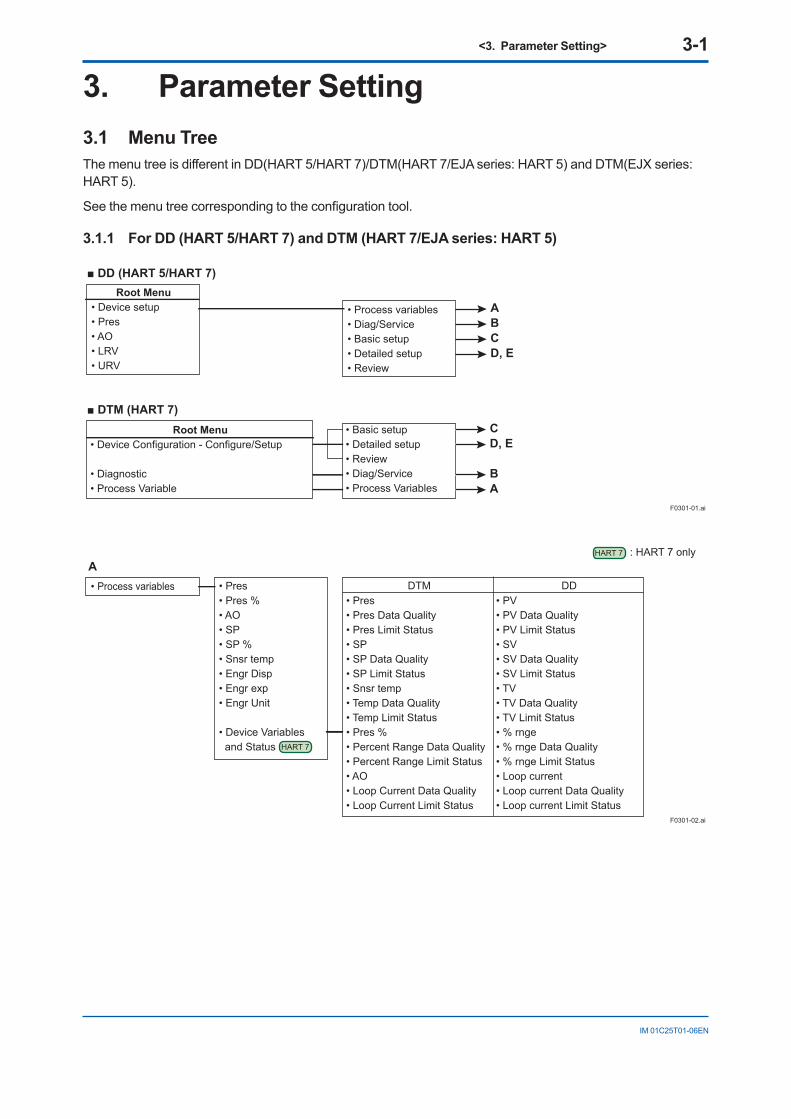
IM 01C25T01-06EN
3.1 Menu TreeThe menu tree is different in DD(HART 5/HART 7)/DTM(HART 7/EJA series: HART 5) and DTM(EJX series: HART 5).
See the menu tree corresponding to the configuration tool.
3.1.1 For DD (HART 5/HART 7) and DTM (HART 7/EJA series: HART 5)
3. Parameter Setting
ABCD, E
F0301-01.ai
• Process variables• Diag/Service• Basic setup• Detailed setup• Review
DD (HART 5/HART 7)
DTM (HART 7)• Basic setup• Detailed setup• Review• Diag/Service• Process Variables
Root Menu• Device setup• Pres• AO• LRV• URV
Root Menu• Device Configuration - Configure/Setup
• Diagnostic • Process Variable
CD, E
BA
A
F0301-02.ai
• Process variables • Pres• Pres % • AO• SP• SP %• Snsr temp• Engr Disp• Engr exp• Engr Unit
• Device Variables and Status
• Pres• Pres Data Quality• Pres Limit Status• SP• SP Data Quality• SP Limit Status• Snsr temp• Temp Data Quality• Temp Limit Status• Pres %• Percent Range Data Quality• Percent Range Limit Status• AO• Loop Current Data Quality• Loop Current Limit Status
• PV• PV Data Quality• PV Limit Status• SV• SV Data Quality• SV Limit Status• TV• TV Data Quality• TV Limit Status• % rnge• % rnge Data Quality• % rnge Limit Status• Loop current• Loop current Data Quality• Loop current Limit Status
DTM DD
HART 7
: HART 7 onlyHART 7
<3. Parameter Setting> 3-2
IM 01C25T01-06EN
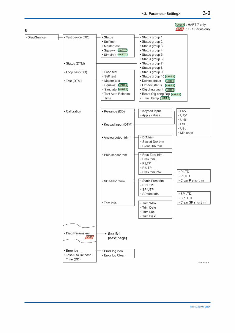
B
F0301-03.ai
: HART 7 only: EJX Series only
• Diag/Service • Test device (DD)
• Status (DTM)
• Loop Test (DD)
• Test (DTM)
• Calibration
• Diag Parameters
• Error log• Test Auto Release
Time (DD)
• Status group 1• Status group 2• Status group 3• Status group 4• Status group 5• Status group 6• Status group 7• Status group 8• Status group 9• Status group 10• Device status• Ext dev status• Cfg chng count• Reset Cfg chng flag• Time Stamp
• Loop test• Self test• Master test• Squawk• Simulate• Test Auto Release
Time
• LRV• URV• Unit• LSL• USL• Min span
• D/A trim• Scaled D/A trim• Clear D/A trim
• Keypad input• Apply values
• Pres Zero trim• Pres trim• P LTP• P UTP• Pres trim info.
• Static Pres trim• SP LTP• SP UTP• SP trim info. • SP LTD
• SP UTD• Clear SP snsr trim
• P LTD• P UTD• Clear P snsr trim
• Trim Who• Trim Date• Trim Loc• Trim Desc
• Re-range (DD)
• Keypad input (DTM)
• Analog output trim
• Pres sensor trim
• SP sensor trim
• Trim info.
• Status• Self test• Master test• Squawk• Simulate
• Error log view• Error log Clear
See B1(next page)
HART 7
HART 7
HART 7
HART 7
HART 7
HART 7
HART 7HART 7
EJX
EJX
HART 7
HART 7
HART 7
<3. Parameter Setting> 3-3
IM 01C25T01-06EN
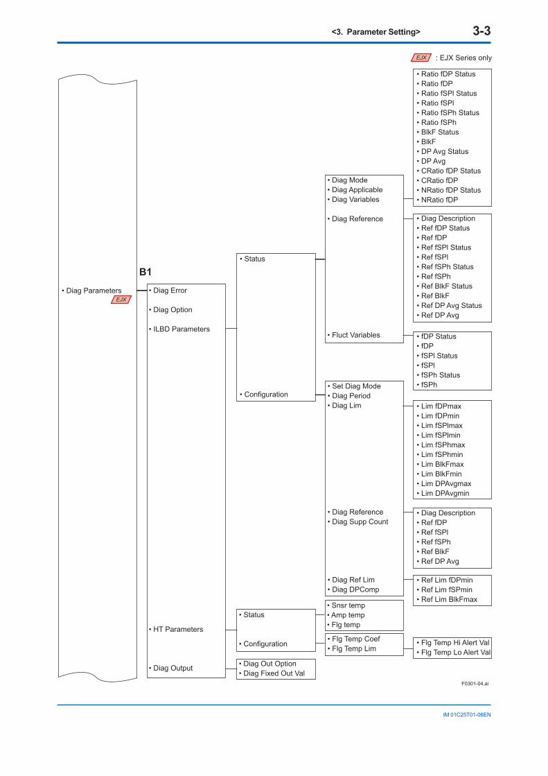
B1
• Diag Parameters
F0301-04.ai
• Ratio fDP Status• Ratio fDP• Ratio fSPl Status• Ratio fSPl• Ratio fSPh Status• Ratio fSPh• BlkF Status• BlkF• DP Avg Status• DP Avg• CRatio fDP Status• CRatio fDP• NRatio fDP Status• NRatio fDP
• Diag Description• Ref fDP Status• Ref fDP• Ref fSPl Status• Ref fSPl• Ref fSPh Status• Ref fSPh• Ref BlkF Status• Ref BlkF• Ref DP Avg Status• Ref DP Avg
• fDP Status• fDP• fSPl Status• fSPl• fSPh Status• fSPh
• Lim fDPmax• Lim fDPmin• Lim fSPlmax• Lim fSPlmin• Lim fSPhmax• Lim fSPhmin• Lim BlkFmax• Lim BlkFmin• Lim DPAvgmax• Lim DPAvgmin
• Diag Description• Ref fDP• Ref fSPl• Ref fSPh• Ref BlkF• Ref DP Avg
• Ref Lim fDPmin• Ref Lim fSPmin• Ref Lim BlkFmax
• Flg Temp Hi Alert Val• Flg Temp Lo Alert Val
• Flg Temp Coef• Flg Temp Lim
• Snsr temp• Amp temp• Flg temp
• Set Diag Mode• Diag Period• Diag Lim
• Diag Reference• Diag Supp Count
• Diag Ref Lim• Diag DPComp
• Diag Mode• Diag Applicable• Diag Variables
• Diag Reference
• Fluct Variables
• Status
• Configuration
• Status
• Configuration
• Diag Out Option• Diag Fixed Out Val
• Diag Error
• Diag Option
• ILBD Parameters
• HT Parameters
• Diag Output
: EJX Series only
EJX
EJX
<3. Parameter Setting> 3-4
IM 01C25T01-06EN
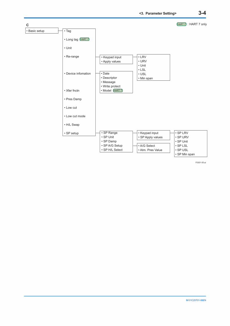
• Basic setup • Tag
• Long tag
• Unit
• Re-range
• Device infomation
• Xfer fnctn
• Pres Damp
• Low cut
• Low cut mode
• H/L Swap
• SP setup
C
• LRV• URV• Unit• LSL• USL• Min span
• Keypad input• SP Apply values
• SP LRV• SP URV• SP Unit• SP LSL• SP USL• SP Min span
• A/G Select• Atm. Pres Value
F0301-05.ai
• Keypad input• Apply values
• Date• Descriptor• Message• Write protect• Model
• SP Range• SP Unit• SP Damp• SP A/G Setup• SP H/L Select
: HART 7 onlyHART 7
HART 7
HART 7
<3. Parameter Setting> 3-5
IM 01C25T01-06EN
See E
See D1(next page)
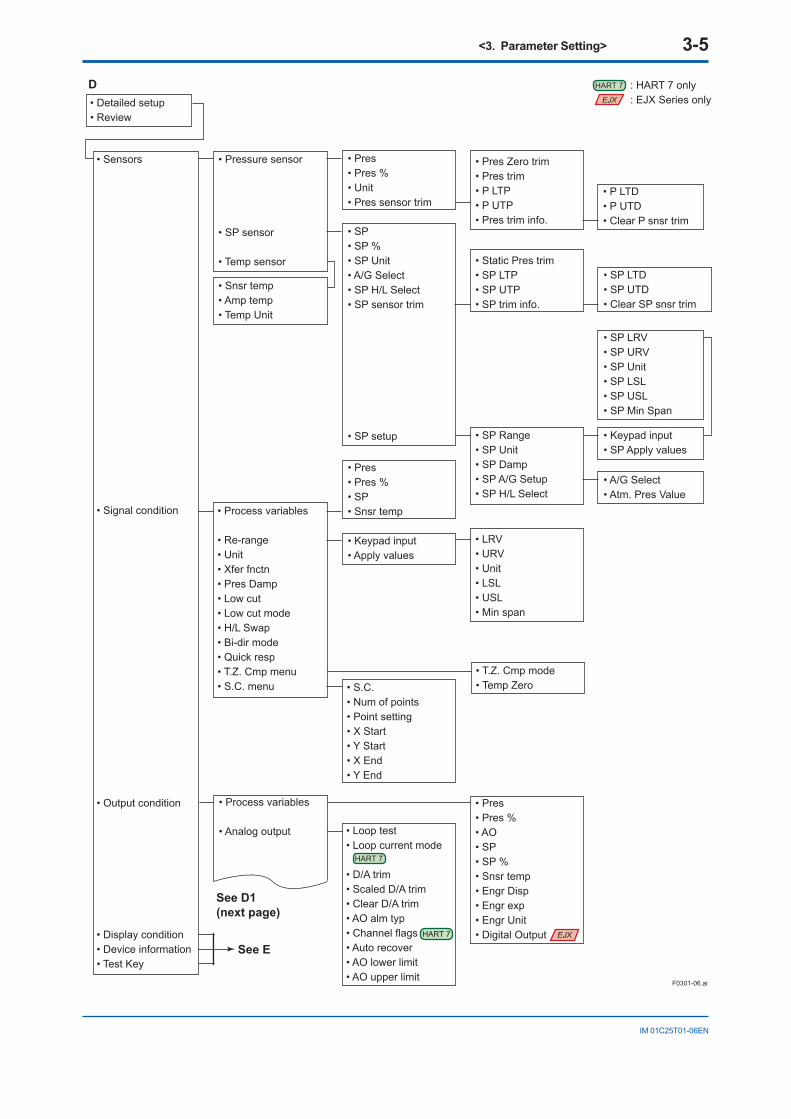
• Detailed setup• Review
• Sensors
• Signal condition
• Output condition
• Display condition• Device information• Test Key
D
• Pressure sensor
• SP sensor
• Temp sensor
• Snsr temp• Amp temp• Temp Unit
• Process variables
• Re-range• Unit• Xfer fnctn• Pres Damp• Low cut• Low cut mode• H/L Swap• Bi-dir mode• Quick resp• T.Z. Cmp menu• S.C. menu
• Pres• Pres %• SP• Snsr temp
• Pres• Pres %• Unit• Pres sensor trim
• SP• SP %• SP Unit• A/G Select• SP H/L Select• SP sensor trim
• SP setup
• Keypad input• Apply values
F0301-06.ai
• Process variables
• Analog output
• T.Z. Cmp mode• Temp Zero• S.C.
• Num of points• Point setting• X Start• Y Start• X End• Y End
• Loop test• Loop current mode
• D/A trim• Scaled D/A trim• Clear D/A trim• AO alm typ• Channel flags• Auto recover• AO lower limit• AO upper limit
• Pres• Pres %• AO• SP• SP %• Snsr temp• Engr Disp• Engr exp• Engr Unit• Digital Output
: HART 7 only: EJX Series only
• LRV• URV• Unit• LSL• USL• Min span
• Pres Zero trim• Pres trim• P LTP• P UTP• Pres trim info.
• P LTD• P UTD• Clear P snsr trim
• Static Pres trim• SP LTP• SP UTP• SP trim info.
• SP Range• SP Unit• SP Damp• SP A/G Setup• SP H/L Select
• SP LTD• SP UTD• Clear SP snsr trim
• SP LRV• SP URV• SP Unit• SP LSL• SP USL• SP Min Span
• Keypad input• SP Apply values
• A/G Select• Atm. Pres Value
HART 7
HART 7
HART 7
EJX
EJX
<3. Parameter Setting> 3-6
IM 01C25T01-06EN
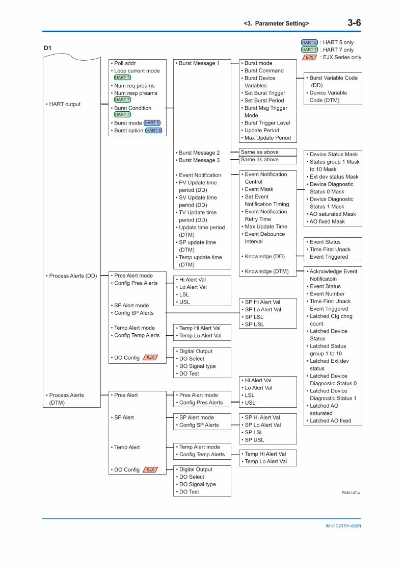
D1
F0301-07.ai
: HART 5 only: HART 7 only: EJX Series only
Same as aboveSame as above
• Burst Variable Code (DD)
• Device Variable Code (DTM)
• HART output
• Process Alerts (DD)
• Process Alerts (DTM)
• Poll addr• Loop current mode
• Num req preams• Num resp preams
• Burst Condition
• Burst mode• Burst option
• Pres Alert mode• Config Pres Alerts
• SP Alert mode• Config SP Alerts
• Temp Alert mode• Config Temp Alerts
• Hi Alert Val• Lo Alert Val• LSL• USL
• SP Hi Alert Val• SP Lo Alert Val• SP LSL• SP USL
• Temp Hi Alert Val• Temp Lo Alert Val
• Digital Output• DO Select• DO Signal type• DO Test
• Pres Alert
• SP Alert
• Temp Alert
• DO Config
• Hi Alert Val• Lo Alert Val• LSL• USL • SP Hi Alert Val
• SP Lo Alert Val• SP LSL• SP USL
• Temp Hi Alert Val• Temp Lo Alert Val
• Digital Output• DO Select• DO Signal type• DO Test
• Pres Alert mode• Config Pres Alerts
• SP Alert mode• Config SP Alerts
• Temp Alert mode• Config Temp Alerts
• DO Config
• Acknowledge Event Notificatoin
• Event Status• Event Number• Time First Unack
Event Triggered• Latched Cfg chng
count• Latched Device
Status• Latched Status
group 1 to 10• Latched Ext dev
status• Latched Device
Diagnostic Status 0• Latched Device
Diagnostic Status 1• Latched AO
saturated• Latched AO fixed
• Device Status Mask• Status group 1 Mask
to 10 Mask• Ext dev status Mask• Device Diagnostic
Status 0 Mask• Device Diagnostic
Status 1 Mask• AO saturated Mask• AO fixed Mask
• Event Status• Time First Unack
Event Triggered
• Burst mode• Burst Command• Burst Device
Variables• Set Burst Trigger• Set Burst Period• Burst Msg Trigger
Mode• Burst Trigger Level• Update Period• Max Update Period
• Event Notification Control
• Event Mask• Set Event
Notification Timing• Event Notification
Retry Time• Max Update Time• Event Debounce
Interval
• Knowledge (DD)
• Knowledge (DTM)
• Burst Message 1
• Burst Message 2• Burst Message 3
• Event Notification• PV Update time
period (DD)• SV Update time
period (DD)• TV Update time
period (DD)• Update time period
(DTM)• SP update time
(DTM) • Temp update time
(DTM)
HART 5
HART 7
HART 5
HART 7
HART 5
HART 7
HART 7
EJX
EJX
EJX
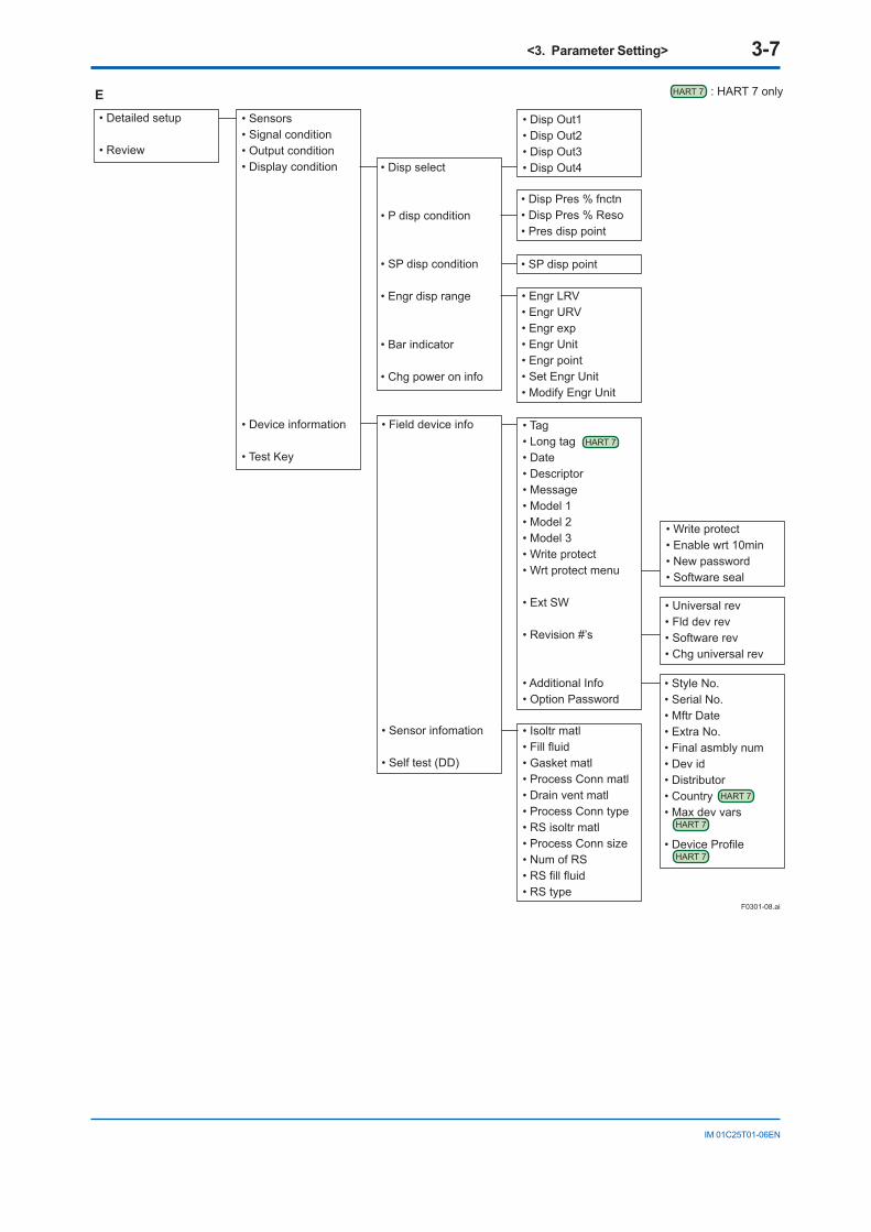
<3. Parameter Setting> 3-7
IM 01C25T01-06EN
• Detailed setup
• Review
• Sensors• Signal condition• Output condition• Display condition
• Device information
• Test Key
E
• Disp select
• P disp condition
• SP disp condition
• Engr disp range
• Bar indicator
• Chg power on info
• Disp Out1• Disp Out2• Disp Out3• Disp Out4
F0301-08.ai
• Field device info
• Sensor infomation
• Self test (DD)
• Style No.• Serial No.• Mftr Date• Extra No.• Final asmbly num• Dev id• Distributor• Country• Max dev vars
• Device Profile
• Tag• Long tag• Date• Descriptor• Message• Model 1• Model 2• Model 3• Write protect• Wrt protect menu
• Ext SW
• Revision #’s
• Additional Info• Option Password
• Isoltr matl• Fill fluid• Gasket matl• Process Conn matl• Drain vent matl• Process Conn type• RS isoltr matl• Process Conn size• Num of RS• RS fill fluid• RS type
• Universal rev• Fld dev rev• Software rev• Chg universal rev
• Write protect• Enable wrt 10min• New password• Software seal
• Engr LRV• Engr URV• Engr exp• Engr Unit• Engr point• Set Engr Unit• Modify Engr Unit
• Disp Pres % fnctn• Disp Pres % Reso• Pres disp point
• SP disp point
: HART 7 onlyHART 7
HART 7
HART 7
HART 7
HART 7
<3. Parameter Setting> 3-8
IM 01C25T01-06EN
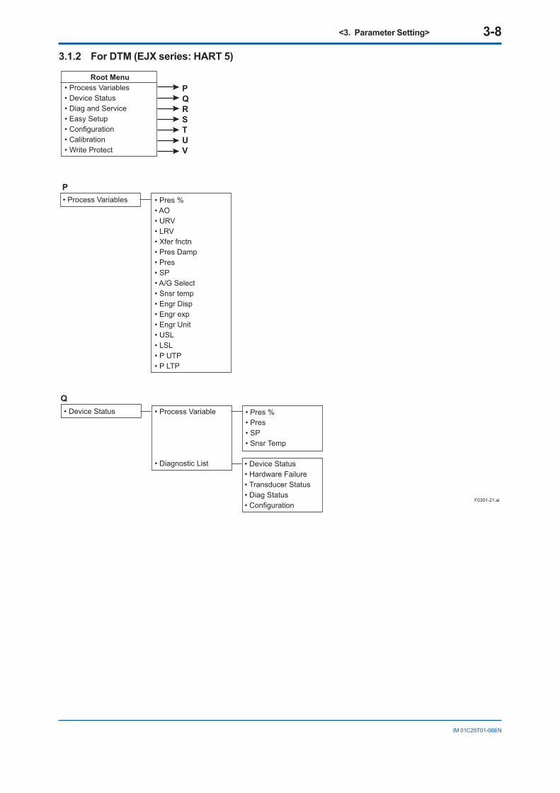
3.1.2 For DTM (EJX series: HART 5)
F0301-21.ai
Root Menu• Process Variables• Device Status• Diag and Service• Easy Setup• Configuration• Calibration• Write Protect
• Process Variables • Pres %• AO• URV• LRV• Xfer fnctn• Pres Damp• Pres• SP• A/G Select• Snsr temp• Engr Disp• Engr exp• Engr Unit• USL• LSL• P UTP• P LTP
• Device Status • Process Variable
• Diagnostic List
• Pres %• Pres• SP• Snsr Temp
• Device Status• Hardware Failure• Transducer Status• Diag Status• Configuration
PQRSTUV
P
Q
<3. Parameter Setting> 3-9
IM 01C25T01-06EN
F0301-22.ai
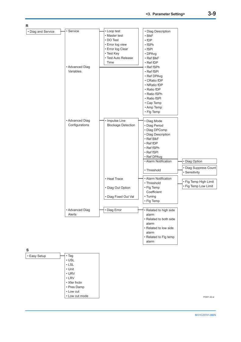
• Diag and Service • Service
• Advanced Diag Variables
• Advanced Diag Configurations
• Advanced Diag Alerts
• Loop test• Master test• DO Test• Error log view• Error log Clear• Test Key• Test Auto Release
Time
• Diag Description• BlkF• fDP• fSPh• fSPl• DPAvg• Ref BlkF• Ref fDP• Ref fSPh• Ref fSPl• Ref DPAvg• CRatio fDP• NRatio fDP• Ratio fDP• Ratio fSPh• Ratio fSPl• Cap Temp• Amp Temp• Flg Temp
• Impulse Line Blockage Detection
• Heat Trace
• Diag Out Option
• Diag Fixed Out Val
• Diag Error
• Diag Mode• Diag Period• Diag DPComp• Diag Description• Ref BlkF• Ref fDP• Ref fSPh• Ref fSPl• Ref DPAvg• Alarm Notification
• Threshold
• Alarm Notification • Threshold• Flg Temp
Coefficient• Tuning• Flg Temp
• Related to high side alarm
• Related to both side alarm
• Related to low side alarm
• Related to Flg temp alarm
• Diag Suppress Count• Sensitivity
• Fig Temp High Limit• Fig Temp Low Limit
• Diag Option
R
• Easy Setup • Tag• USL• LSL• Unit• URV• LRV• Xfer fnctn• Pres Damp• Low cut• Low cut mode
S
<3. Parameter Setting> 3-10
IM 01C25T01-06EN
F0301-23.ai
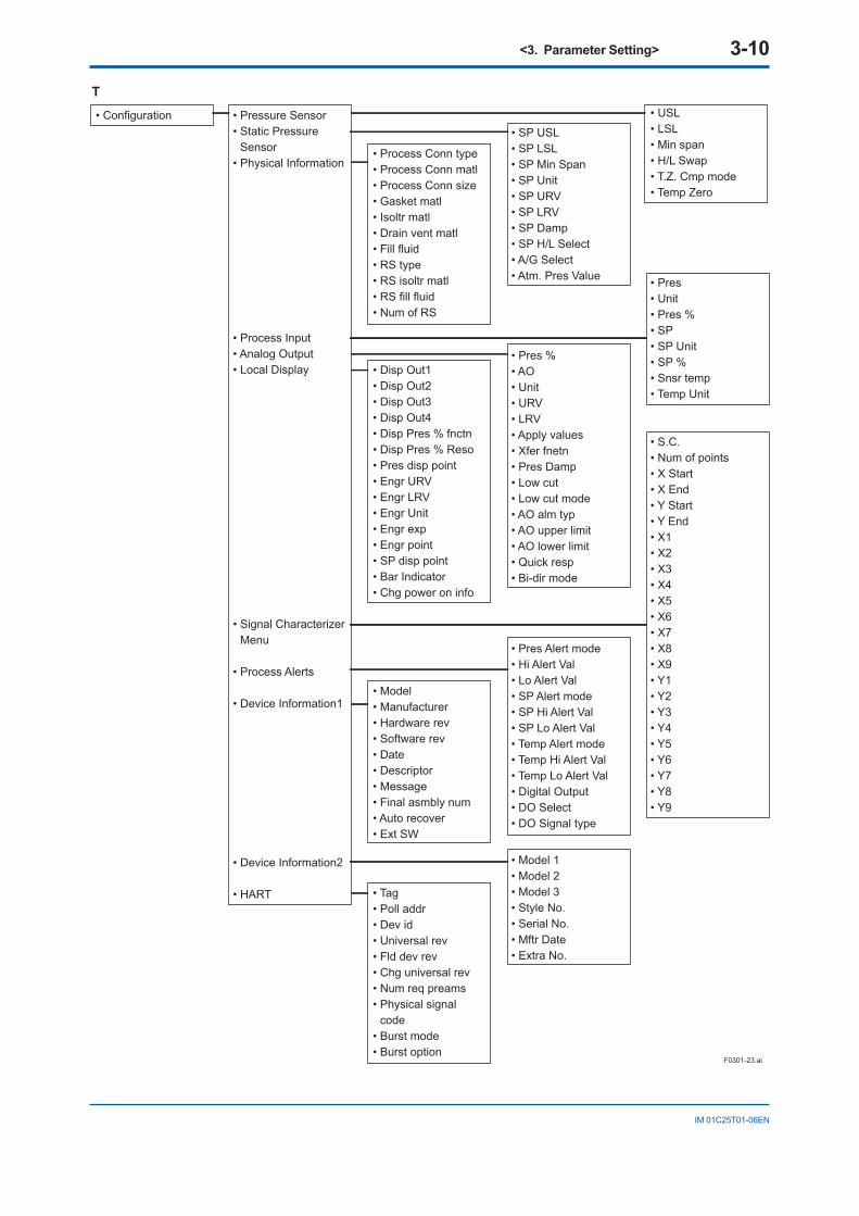
• Configuration
T
• Pressure Sensor• Static Pressure
Sensor• Physical Information
• Process Input• Analog Output• Local Display
• Signal Characterizer Menu
• Process Alerts
• Device Information1
• Device Information2
• HART
• USL• LSL• Min span• H/L Swap• T.Z. Cmp mode• Temp Zero
• SP USL• SP LSL• SP Min Span• SP Unit• SP URV• SP LRV• SP Damp• SP H/L Select• A/G Select• Atm. Pres Value
• Process Conn type• Process Conn matl• Process Conn size• Gasket matl• Isoltr matl• Drain vent matl• Fill fluid• RS type• RS isoltr matl• RS fill fluid• Num of RS
• Disp Out1• Disp Out2• Disp Out3• Disp Out4• Disp Pres % fnctn• Disp Pres % Reso• Pres disp point• Engr URV• Engr LRV• Engr Unit• Engr exp• Engr point• SP disp point• Bar Indicator• Chg power on info
• Pres• Unit• Pres %• SP• SP Unit• SP %• Snsr temp• Temp Unit
• S.C.• Num of points• X Start• X End • Y Start• Y End• X1• X2• X3• X4• X5• X6• X7• X8• X9• Y1• Y2• Y3• Y4• Y5• Y6• Y7• Y8• Y9
• Model 1• Model 2• Model 3• Style No.• Serial No.• Mftr Date• Extra No.
• Pres %• AO• Unit• URV• LRV• Apply values• Xfer fnetn• Pres Damp• Low cut• Low cut mode• AO alm typ• AO upper limit• AO lower limit• Quick resp• Bi-dir mode
• Model• Manufacturer• Hardware rev• Software rev• Date• Descriptor• Message• Final asmbly num• Auto recover• Ext SW
• Tag• Poll addr• Dev id• Universal rev• Fld dev rev• Chg universal rev• Num req preams• Physical signal
code• Burst mode• Burst option
• Pres Alert mode• Hi Alert Val• Lo Alert Val• SP Alert mode• SP Hi Alert Val• SP Lo Alert Val• Temp Alert mode• Temp Hi Alert Val• Temp Lo Alert Val• Digital Output• DO Select• DO Signal type
<3. Parameter Setting> 3-11
IM 01C25T01-06EN
F0301-24.ai
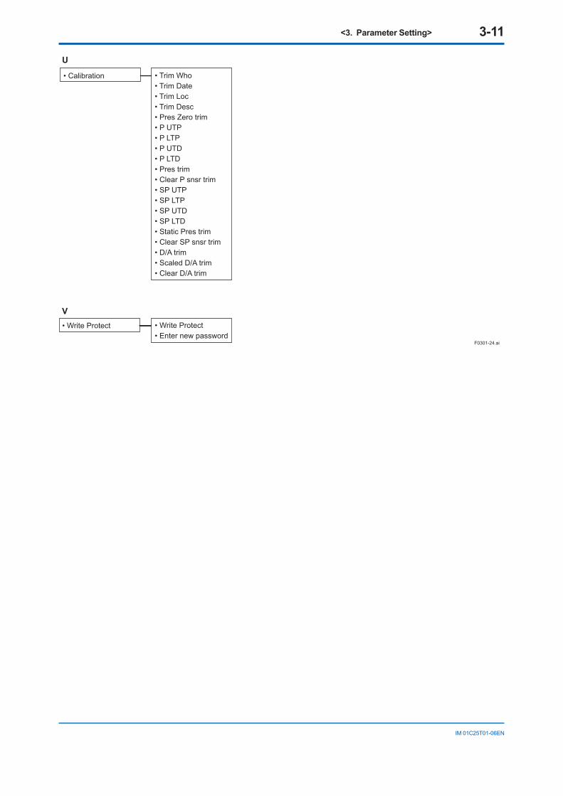
• Trim Who• Trim Date• Trim Loc• Trim Desc• Pres Zero trim• P UTP• P LTP• P UTD• P LTD• Pres trim• Clear P snsr trim• SP UTP• SP LTP• SP UTD• SP LTD• Static Pres trim• Clear SP snsr trim• D/A trim• Scaled D/A trim• Clear D/A trim
• Write Protect• Enter new password
• Write Protect
• Calibration
U
V
<3. Parameter Setting> 3-12
IM 01C25T01-06EN
3.2 Basic Setup
IMPORTANTAfter setting and sending data with the HART configuration tool, wait 30 seconds before turning off the transmitter. If it is turned off too soon, the settings will not be stored in the transmitter.
3.2.1 Tag and Device InformationIf there are specified when ordering, the desired Tag No. and device information are set and shipped. Tag No. and device information can be checked as follows.
• Procedure to call up the display using DD (HART 5/HART 7) and DTM (HART 7/EJA: HART 5)Item Procedure
Tag [Root Menu] → Basic setup → TagLong tag(HART 7 only)
[Root Menu] → Basic setup → Long Tag
Descriptor [Root Menu] → Basic setup → Device information → Descriptor
Message [Root Menu] → Basic setup → Device information → Message
Date [Root Menu] → Basic setup → Device information → Date
• Procedure to call up the display using DTM (EJX: HART 5)Item Procedure
Tag Easy Setup → Tagor Configuration → HART → Tag
Descriptor Configuration → Device information 1 → Descriptor
Message Configuration → Device information 1 → Message
Date Configuration → Device information 1 → Date
When the Tag No. and device information are changed, input them based on the following limitations.
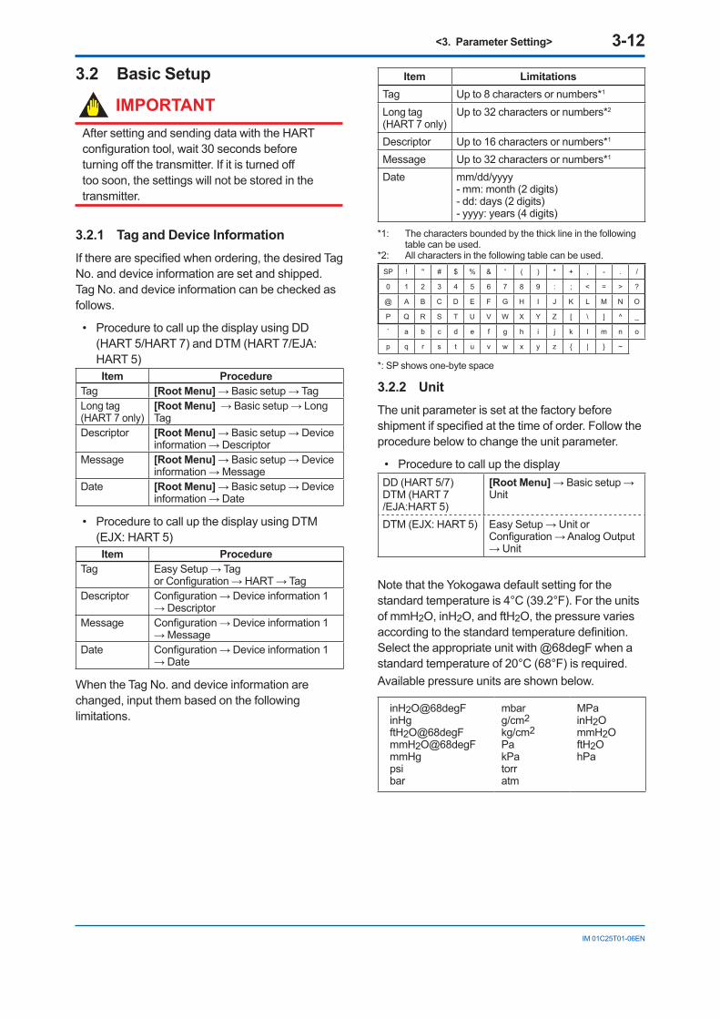
Item LimitationsTag Up to 8 characters or numbers*1
Long tag(HART 7 only)
Up to 32 characters or numbers*2
Descriptor Up to 16 characters or numbers*1
Message Up to 32 characters or numbers*1
Date mm/dd/yyyy - mm: month (2 digits)- dd: days (2 digits)- yyyy: years (4 digits)
*1: The characters bounded by the thick line in the following table can be used.
*2: All characters in the following table can be used.SP ! " # $ % & ' ( ) * + , - . /
0 1 2 3 4 5 6 7 8 9 : ; < = > ?
@ A B C D E F G H I J K L M N O
P Q R S T U V W X Y Z [ \ ] ^ _
` a b c d e f g h i j k l m n o
p q r s t u v w x y z | ~
*: SP shows one-byte space
3.2.2 UnitThe unit parameter is set at the factory before shipment if specified at the time of order. Follow the procedure below to change the unit parameter.
• Procedure to call up the displayDD (HART 5/7)DTM (HART 7 /EJA:HART 5)
[Root Menu] → Basic setup → Unit
DTM (EJX: HART 5) Easy Setup → Unit or Configuration → Analog Output → Unit
Note that the Yokogawa default setting for the standard temperature is 4°C (39.2°F). For the units of mmH2O, inH2O, and ftH2O, the pressure varies according to the standard temperature definition. Select the appropriate unit with @68degF when a standard temperature of 20°C (68°F) is required.Available pressure units are shown below.
inH2O@68degFinHgftH2O@68degFmmH2O@68degFmmHgpsibar
mbarg/cm2kg/cm2PakPatorratm
MPainH2OmmH2OftH2OhPa
<3. Parameter Setting> 3-13
IM 01C25T01-06EN
3.2.3 Range ChangeThe range values are factory-set as specified by the customer. To change the range, follow the steps below.
(1) Keypad input — LRV and URV
The measurement span is determined by the upper and lower range values. In this method, the upper and lower range values can be set independently, and the span changes according to the range limit values sent to the transmitter.
• Procedure to call up the displayDD (HART 5/7)DTM (HART 7 /EJA:HART 5)
[Root Menu] → Basic setup → Re-range → Keypad input
DTM (EJX: HART 5) Easy Setup → or Configuration → Analog Output →
→ LRV Lower range value → URV Upper range value
NOTEThe calibration range can be set as LRV > URV under the following conditions, reversing the 4 to 20 mA output signal. When using the integral indicator, change the user set scale values accordingly.
Conditions: LSL ≤ LRV ≤ USL LSL ≤ URV ≤ USL |URV – LRV| ≥ Min Span
LSL: Lower sensor limit of range settingUSL: Upper sensor limit of range setting
(2) Apply values — changing the ranges while applying an actual Input
This feature allows the lower and upper range values to be setup automatically with the actual input applied. If the upper and lower range values are set, URV and LRV are changed at the same time.
• Procedure to call up the displayDD (HART 5/7)DTM (HART 7 /EJA:HART 5)
[Root Menu] → Basic setup → Re-range → Apply values →
DTM (EJX: HART 5) Configuration → Analog Output → Apply values →
The measurement span is determined by the upper and lower range values. Changing the lower range value causes the upper range value to change automatically, keeping the span constant. If a change in the lower range value causes the upper range value to exceed the measuring limit of the transmitter, an error message appears and the transmitter holds the output signal right before the error occurred. Enter the correct values within the range of the sensor limits.Note that changing the upper range value does not cause the lower range value to change. Thus, changing the upper range value also changes the span.
3.2.4 Output ModeThe mode setting for the output signal and the integral indicator can be performed independently.
The output mode for the output signal is set as specified in the order when the instrument is shipped. Follow the procedure below to change the mode.
• Procedure to call up the displayDD (HART 5/7)DTM (HART 7 /EJA:HART 5)
[Root Menu] → Basic setup →
DTM (EJX: HART 5) Easy Setup → or Configuration → Analog Output →
→ Xfer fnctn Select “Linear” or “Sq root”
3.2.5 Damping Time Constant SetupThe damping time constant is set as specified in the order when the instrument is shipped. Follow the procedure below to change the damping time constant. The damping time constant for the amplifier assembly can be set here. The damping time constant for the entire transmitter is the sum of the values for the amplifier assembly and the capsule assembly.
Any number from 0.00 to 100.00 can be set for the damping time constant. Note that setting the quick response parameter ON enables you to set the time constant between 0.00 and 0.49 seconds.
• Procedure to call up the Pres Damp displayDD (HART 5/7)DTM (HART 7 /EJA:HART 5)
[Root Menu] → Basic setup → Pres Damp
DTM (EJX: HART 5) Easy Setup → Pres Damp or Configuration → Analog Output → Pres Damp
<3. Parameter Setting> 3-14
IM 01C25T01-06EN
• Procedure to call up the Quick resp displayDD (HART 5/7)DTM (HART 7 /EJA:HART 5)
[Root Menu] → Detailed setup → Signal condition → Quick resp →
DTM (EJX: HART 5) Configuration → Analog Output → Quick resp →
→ Off Set from 0.50 to 100.00→ On Set from 0.00 to 100.00
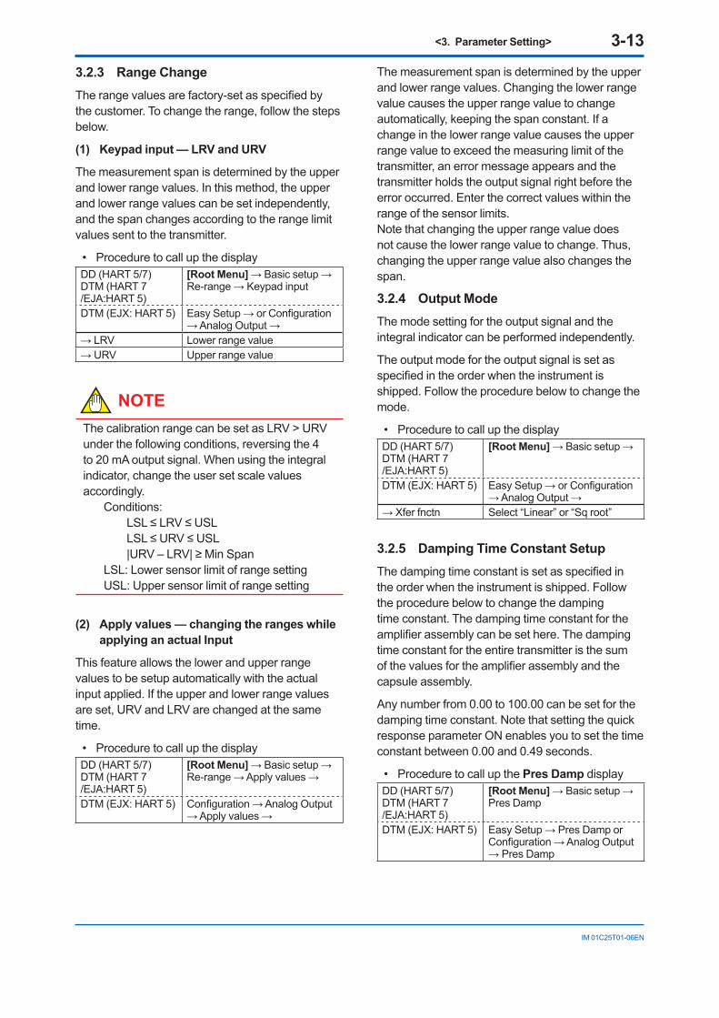
3.2.6 Output Signal Low Cut Mode SetupLow cut mode can be used to stabilize the output signal near the zero point.
The low cut point can be set in a range from 0 to 20%, the direct ratio corresponding to the output signal of 4 to 20 mA. (Hysteresis for the cut point: ±10% of the cut point)
Either “Linear” or “Zero” can be selected as the low cut mode. Unless otherwise specified, the cut mode is set to “Linear” at the factory.
The default value of Low cut is set according to the combination of the Output mode (Xfer fnctn) and Integral indicator display mode (Disp Pres % fnctn). See below table.
Relationship of default value of Low cut and Low cut point
Combination of output mode and
display modeDefault value of Low cut
Low cut point for
the output signal/ display# Output
modeDisplay mode
1) Linear Linear 10% 10% / 10%2) Sq Root Sq Root 10% 10% / 10%3) Linear Sq Root 1%* 1% / 10%4) Sq Root Linear 10% 10% / NA
*: It is applied for software revision 2.02 or later. For previous software version, it is set in 10%.
In the case 3) above, Low cut point for the display is square root of Low cut value.
(Example: Low cut value; 2%, Low cut point; 14%)
Note that when the output modes of the output signal and the display are selected as “Sq root” and “Linear” accordingly, the low cut function is not available for the display value.
(%)50
(%)50
0 50(%)
50(%)
Out
put
Out
put
For low cut in linear mode
Input
2020
0
For low cut in zero mode
Input
F0302.ai
Example: Low cut at 20%
Figure 3.1 Low Cut Mode
• Procedure to call up the displayDD (HART 5/7)DTM (HART 7 /EJA:HART 5)
[Root Menu] → Basic setup →
DTM (EJX: HART 5) Easy Setup → or Configuration → Analog Output →
→ Low cut Set from 0 to 20% of output→ Low cut mode Select “Linear” or “Zero”
The low cut point has hysteresis so that the output around the point is behaved as below figure.
<Example>Output mode: Linear Low cut mode: Zero Low cut: 20.00%
F0303.ai
Setting range: 0 to 20%
2% 2%4mA
Output Low cut point
Input
Hysteresis fixed at 10%of the cut point
7.2mA(20%)
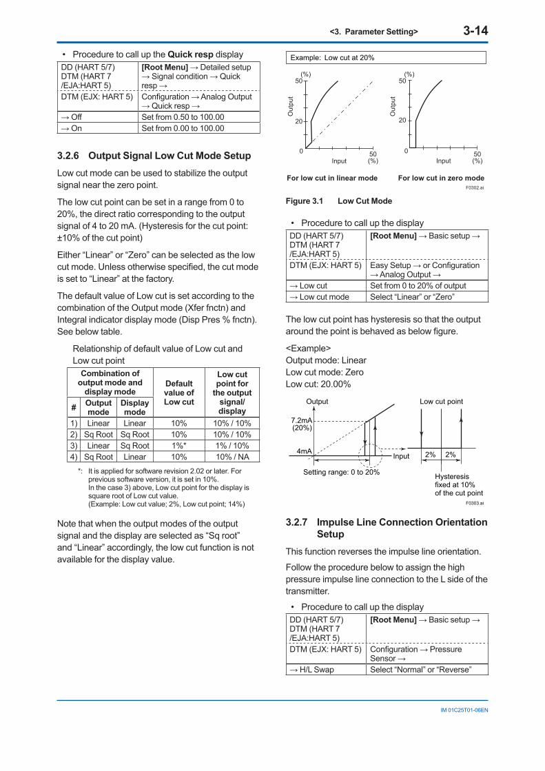
3.2.7 Impulse Line Connection Orientation Setup
This function reverses the impulse line orientation.
Follow the procedure below to assign the high pressure impulse line connection to the L side of the transmitter.
• Procedure to call up the displayDD (HART 5/7)DTM (HART 7 /EJA:HART 5)
[Root Menu] → Basic setup →
DTM (EJX: HART 5) Configuration → Pressure Sensor →
→ H/L Swap Select “Normal” or “Reverse”

<3. Parameter Setting> 3-15
IM 01C25T01-06EN
3.2.8 Static Pressure SetupThe differential pressure transmitter can display the static pressure also.
(1) Setting of the unit for static pressure
Follow the procedure below to change the static pressure unit.
• Procedure to call up the displayDD (HART 5/7)DTM (HART 7 /EJA:HART 5)
[Root Menu] → Basic setup → SP setup →
DTM (EJX: HART 5) Configuration → Process Input (or Static Pressure Sensor) →
→ SP Unit Select the unit for static pressure (Refer to subsection 3.2.2 Unit)
(2) Setting of the measuring range for static pressure
Follow the procedure below to change the lower range value (LRV) and upper range value (URV).
• Procedure to call up the displayDD (HART 5/7)DTM (HART 7 /EJA:HART 5)
[Root Menu] → Basic setup → SP setup → SP Range → Keypad input →
DTM (EJX: HART 5) Configuration → Static Pressure Sensor →
→ SP LRV Set the lower range value (0 %) of static pressure
→ SP URV Set the upper range value (100 %) of static pressure
(3) Selection of Gauge pressure and Absolute pressure
Either the gauge pressure or absolute pressure can be selected to display on the LCD display.
Absolute pressure is selected when the transmitter is shipped.
• Procedure to call up the displayDD (HART 5/7)DTM (HART 7 /EJA:HART 5)
[Root Menu] → Basic setup → SP setup → SP A/G Setup →
DTM (EJX: HART 5) Configuration → Static Pressure Sensor →
→ A/G Select Select “Gauge” or “Absolute”
→ Atm. Pres Value 0.1013 MPa when the transmitter is shipped
(4) Selection of pressure side
Either the high or low pressure side of capsule can be selected to monitor the static pressure.
High pressure side is selected when the transmitter is shipped.
• Procedure to call up the displayDD (HART 5/7)DTM (HART 7 /EJA:HART 5)
[Root Menu] → Basic setup → SP setup →
DTM (EJX: HART 5) Configuration → Static Pressure Sensor →
→ SP H/L Select Select “High” or “Low”
3.3 Detailed Setup3.3.1 Bi-directional Flow Measurement(a) Bi-dir mode enables selection of 50% output at
an input of 0 mmH2O.
• Procedure to call up the displayDD (HART 5/7)DTM (HART 7 /EJA:HART 5)
[Root Menu] → Detailed setup → Signal condition →
DTM (EJX: HART 5) Configuration → Analog output →
→ Bi-dir mode Select “On” or “Off”
(b) Combining Bi-dir mode with Xfer fnctn provides a square root output computed independently for 0% to 50% output and for 50% to 100% output.
20 mA (100% display)
4 mA (−100% display)
Output mode “LINEAR”
LRV HRV
F0304.ai
20 mA (100% display)
Low Cut
4 mA (−100% display)
Output mode “SQUARE ROOT”
LRV HRV
<3. Parameter Setting> 3-16
IM 01C25T01-06EN
3.3.2 Analog Output Signal Adjustable Range
Output signal adjustable range at normal operating condition are set as shown below at the factory when the instrument is shipped, and output signal are limited by these value.
Lower limit Upper limitStandardOption code /C1 3.6 mA 21.6 mA
Option code /C2 and /C3 3.8 mA 20.5 mA
Output signal range can be changed between 3.6mA and 21.6mA to match it to the equipment on the receiving side.Lower value is set at AO lower limit and upper value is set at AO upper limit respectively.Follow the procedure below to change the upper and lower values.
• Procedure to call up the displayDD (HART 5/7)DTM (HART 7 /EJA:HART 5)
[Root Menu] → Detailed setup → Output condition → Analog output →
DTM (EJX: HART 5) Configuration → Analog output →
→ AO lower limit Set the lower value (mA)→ AO upper limit Set the upper value (mA)
Set the values as below.Lower value < Upper value
3.3.3 Integral Indicator Display ModeThe mode setting for the output signal and the integral indicator can be performed independently.
The output mode for the integral indicator is set as specified in the order when the instrument is shipped. Follow the procedure below to change the mode.
• Procedure to call up the displayDD (HART 5/7)DTM (HART 7 /EJA:HART 5)
[Root Menu] → Detailed setup → Display condition → P disp condition →
DTM (EJX: HART 5) Configuration → Local Display →
→ Disp Pres % fnctn Select “Linear” or “Sq root”
If the instrument is equipped with an integral indicator and the transfer function is sq root, “ ” is displayed on the integral indicator.
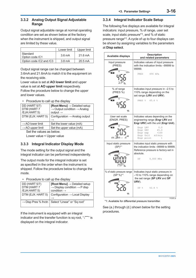
3.3.4 Integral Indicator Scale SetupThe following five displays are available for integral indicators: input pressure, % of range, user set scale, input static pressure*1, and % of static pressure range*1. A cycle of up to four displays can be shown by assigning variables to the parameters at Disp select.
F0305.ai
Available displays
Input pressure(PRES)
% of range(PRES %)
User set scale(ENGR. PRES)
Input static pressure(SP)*1
% of static pressure range(SP %)*1
Indicates values of input pressurewith the indication limits –99999 to 99999.
Indicates input pressure in –2.5 to 110% range depending on the set range (LRV and URV).
Indicates values depending on the engineering range (Engr LRV and Engr URV) with the unit (Engr Unit).
Indicates input static pressure with the indication limits –99999 to 99999.Reference pressure is factory-set in absolute.
Indicates input static pressure in –10 to 110% range depending on the set range (SP LRV and SP URV).
PRES 456 kPa
Descriptionand related parameters
PRES % 45.6 %
SP 4.000 MPa
SP % 52.6 %
Engr LRV 0.0Engr URV 45.0Engr exp ×100Engr Unit m3/minEngr point 1
*1: Available for differential pressure transmitter.
See (a.) through (d.) shown below for the setting procedures.
<3. Parameter Setting> 3-17
IM 01C25T01-06EN
a. Display SelectionAt Disp select, select the variable that the parameter Disp Out 1 will display on the integral indicator.
• Procedure to call up the displayDD (HART 5/7)DTM (HART 7 /EJA:HART 5)
[Root Menu] → Detailed setup → Display condition → Disp select →
DTM (EJX: HART 5) Configuration → Local Display →
→ Disp Out 1 to 4 Select desired display from five kinds of display shown above.
Set Disp Out 2, Disp Out 3 and Disp Out 4 in the same way if necessary.In addition to the above item, “Not used” is also displayed as a selection item.
b. Cyclic Display
Up to four displays can be displayed cyclically in the order of the parameter number.
c. Display Resolution
User can change the position of decimal point which is shown on the integral indicator.
• Procedure to call up the display for PV %DD (HART 5/7)DTM (HART 7 /EJA:HART 5)
[Root Menu] → Detailed setup → Display condition → P disp condition →
DTM (EJX: HART 5) Configuration → Local Display →
→ Disp Pres % Reso
Select the decimal point position of pressureNormal: Display one digit below the decimal pointHigh Resolution: Display two digits below the decimal point
• Procedure to call up the display for Pres and SPDD (HART 5/7)DTM (HART 7 /EJA:HART 5)
[Root Menu] → Detailed setup → Display condition →
DTM (EJX: HART 5) Configuration → Local Display →
(→ P disp condition) → Pres disp point
Select the decimal point position of differential pressure (0, 1, 2, 3 or 4)
(→ SP disp condition) → SP disp point
Select the decimal point position of static pressure (0, 1, 2, 3 or 4)
d. User Setting of Engineering Unit and Scale
[For DD (HART 5/7) and DTM (HART 7/EJA: HART 5)]Engr disp range parameters allow the engineering unit and scale to be displayed. At Set Engr Unit, the following engineering units can be selected from a list.
• Procedure to call up the displayDD (HART 5/7)DTM (HART 7 /EJA:HART 5)
[Root Menu] → Detailed setup → Display condition → Engr disp range
→ Set Engr Unit
Select the engineering unit
→ Engr LRV Lower range value→ Engr URV Upper range value→ Engr exp Exponents for user scale display→ Engr point Decimal point position for user scale
display (0, 1, 2, 3 or 4)
Select the engineering unit from the list. Available units are shown below
kPaMPambarbarpsipsiammH2OmmHgmmHgAmmAqmmWGTorrinH2OinHginHgA
ftH2Ogf/cm2kgf/cm2kg/cm2Gkg/cm2Aatmkg/ht/hm3/hm3/minl/hl/minkl/hkl/minNl/h
Nl/minNm3/hNm3/minACFHACFMSCFHSCFMGPHGPMmmminftkg/m3g/cm3
At Modify Engr Unit parameter, user can set your own unit also. Up to eight alphanumeric characters, spaces or one slashe (/) can be input at Modify Engr Unit; only the first six are displayed on the integral indicator.
• Procedure to call up the displayDD (HART 5/7)DTM (HART 7 /EJA:HART 5)
[Root Menu] → Detailed setup → Display condition → Engr disp range →
→ Modify Engr Unit
Set your own unit
Note that following symbols are not available:
# % & < > . * : + - , ’ ( )
The integral indicator shows “-- -- -- -- -- --” when these symbols or more than two slashes are entered.
[For DTM (EJX:HART 5)]User can input the desired unit at Engr Unit.
• Procedure to call up the displayDTM (HART 5) Configuration →Local Display →→ Engr Unit Set the engineering unit→ Engr LRV Lower range value→ Engr URV Upper range value→ Engr exp Exponents for user scale display→ Engr point Decimal point position for user scale
displayAvailable characters and symbols for Engr Unit are the same as for Modify Engr Unit shown above.
<3. Parameter Setting> 3-18
IM 01C25T01-06EN
3.3.5 Unit for Displayed TemperatureWhen the instrument is shipped, the temperature units are set to “deg C” (Centigrade). Follow the procedure below to change this setting.
When this parameter is set, it also changes the temperature unit for Snsr temp at Process variables and Amp temp at Temp sensor.
• Procedure to call up the displayDD (HART 5/7)DTM (HART 7 /EJA:HART 5)
[Root Menu] → Detailed setup → Sensors → Temp sensor →
DTM (EJX: HART 5) Configuration → Process Input →
→ Temp Unit Select the temperature unit(deg C, deg F, Kelvin(K))
3.3.6 Sensor TrimThe transmitter is factory characterized. Factory characterization is the process of comparing a known pressure input with the output of each transmitter sensor module over the entire pressure and temperature operating range. During the characterization process, this comparison information is stored in the transmitter EEPROM. In operation, the transmitter uses this factory-stored curve to produce a process variable output (PV), in engineering units, dependent on the pressure input.
The sensor trim procedure allows you to adjust for local conditions, changing how the transmitter calculates process variables. There are two ways to trim the sensor: a zero trim and a full sensor trim. A zero trim is a one-point adjustment typically used to compensate for mounting position effects or zero shifts caused by static pressure. A full sensor trim is a two-point process, in which two accurate end-point pressures are applied (equal to or greater than the range values), and all output is linearized between them.
(1) Zero Trim
a. Zeroing—Pres Zero trim
Pres Zero trim carries out the zero adjustment and automatically sets the applied “0” input values to the output value of “0”, keeping the span constant. Use this setting when the LRV is known to be 0 mmH2O.
• Procedure to call up the displayDD (HART 5/7)DTM (HART 7 /EJA:HART 5)
[Root Menu] → Diag/Service → Calibration → Pres Sensor trim →
DTM (EJX: HART 5) Calibration →
→ Pres Zero trim Adjust the lower point
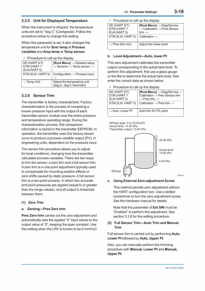
b. Level Adjustment—Auto, lower Pt
This zero adjustment calibrates the transmitter output corresponding to the actual tank level. To perform this adjustment, first use a glass gauge or the like to determine the actual tank level, then enter the correct data as shown below.
• Procedure to call up the displayDD (HART 5/7)DTM (HART 7 /EJA:HART 5)
[Root Menu] → Diag/Service → Calibration → Pres Sensor trim → Pres trim →
DTM (EJX: HART 5) Calibration → Pres trim →
→ Auto, Lower Pt Auto trim for 0% point
F0306.ai
25.00 kPa
0.00 kPa
Actual level13.50 kPa
DPharp span: 0 to 25.00 kPaActual level: 13.50 kPaTransmitter output: 13.83 kPa
DPharp
c. Using External Zero-adjustment Screw
This method permits zero adjustment without the HART configuration tool. Use a slotted screwdriver to turn the zero-adjustment screw. See the hardware manual for details.
Note that the parameter of Ext SW must be “Enabled” to perform this adjustment. See section 3.3.8 for the setting procedure.
(2) Full Sensor Trim—Auto Trim and Manual Trim
Full sensor trim is carried out by performing Auto, Lower Pt followed by Auto, Upper Pt.
Also, you can manually perform the trimming procedure with Manual, Lower Pt and Manual, Upper Pt.
<3. Parameter Setting> 3-19
IM 01C25T01-06EN
The full sensor trim is a two-point adjustment, and the lower point adjustment should always be performed before the upper point adjustment in order to maintain the pitch between the zero and 100% points within the calibration range.
In the manual method, the reference pressure should also be applied to the transmitter at both the lower and upper points. Without the reference pressure, Manual, Lower Pt and Manual, Upper Pt may not represent the correct value for each adjustment point.
a. Auto Sensor TrimApplying reference pressure of 0% and 100% of the measurement range to the transmitter, adjust the lower and upper points automatically.
• Procedure to call up the displayDD (HART 5/7)DTM (HART 7 /EJA:HART 5)
[Root Menu] → Diag/Service → Calibration → Pres sensor trim → Pres trim →
DTM (EJX: HART 5) Calibration → Pres trim →→ Auto, Lower Pt Auto trim for 0% point→ Auto, Upper Pt Auto trim for 100% point
b. Manual Sensor TrimUsing the example below, follow the steps to perform the full sensor trim by manually. The Pres LTD (Manual, Lower Pt) and Pres UTD (Manual, Upper Pt) represent the previously adjusted values.
Example: For the range of 1000 to 3000 mmH2OPres LTD (Manual, Lower Pt) = −4.0 mmH2OPres UTD (Manual, Upper Pt) = −3.0 mmH2O
<1> Call up the Manual, Lower Pt.
• Procedure to call up the displayDD (HART 5/7)DTM (HART 7 /EJA:HART 5)
[Root Menu] → Diag/Service → Calibration → Pres sensor trim → Pres trim →
DTM (EJX: HART 5) Calibration → Pres trim →→ Manual, Lower Pt Manual trim for 0% point→ Manual, Upper Pt Manual trim for 100% point
<2> Suppose that a standard pressure of 1000 mmH2O is applied and the value of the “Pres for trim” is 994.0. Correct for this output error of 6 mmH2O by adding 6 mmH2O to Pres LTD (Manual, Lower Pt).
−4.0+6.0=+2.0
<3> Enter the correction value of “2” to the Pres LTD (Manual, Lower Pt).
<4> Call up the Pres UTD (Manual, Upper Pt).
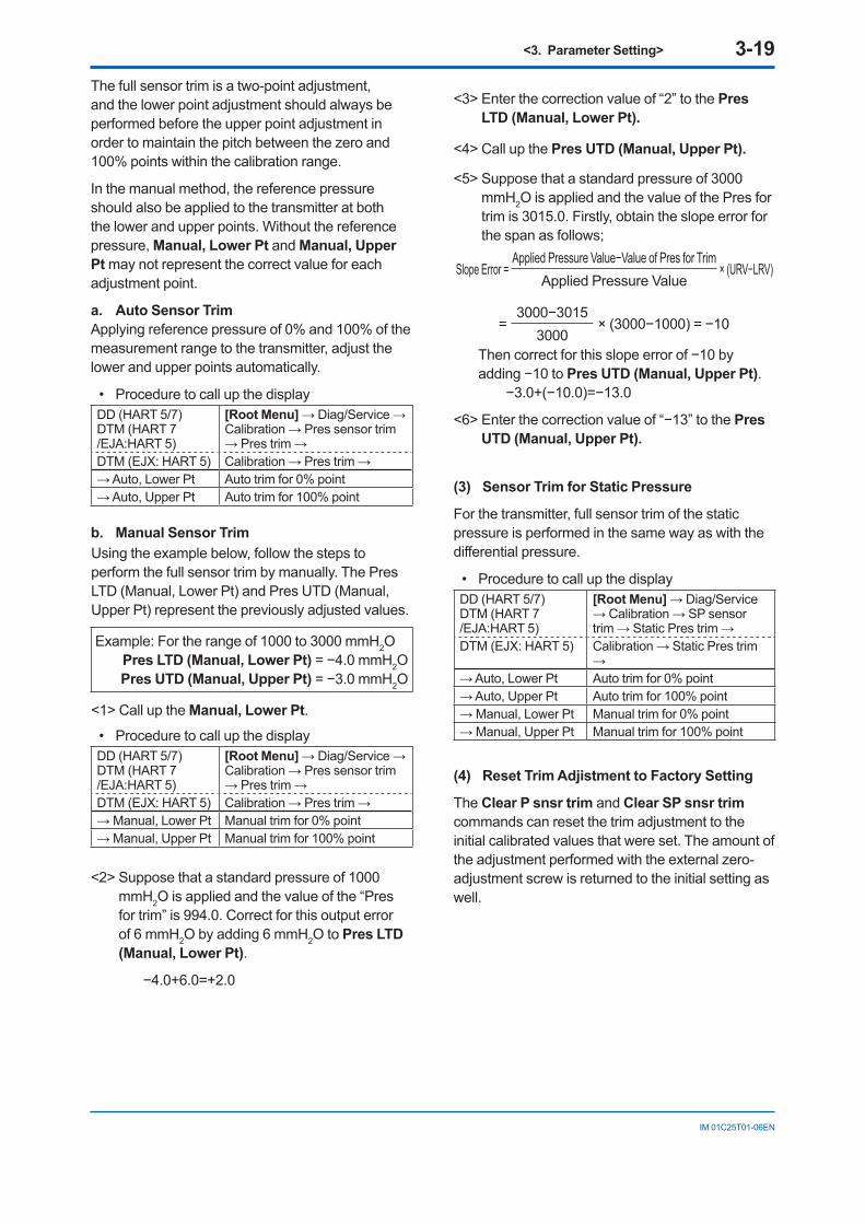
<5> Suppose that a standard pressure of 3000 mmH2O is applied and the value of the Pres for trim is 3015.0. Firstly, obtain the slope error for the span as follows;
Slope Error =Applied Pressure Value−Value of Pres for Trim
× (URV−LRV)Applied Pressure Value
=3000−3015
× (3000−1000) = −103000
Then correct for this slope error of −10 by adding −10 to Pres UTD (Manual, Upper Pt).
−3.0+(−10.0)=−13.0
<6> Enter the correction value of “−13” to the Pres UTD (Manual, Upper Pt).
(3) Sensor Trim for Static Pressure
For the transmitter, full sensor trim of the static pressure is performed in the same way as with the differential pressure.
• Procedure to call up the display DD (HART 5/7)DTM (HART 7 /EJA:HART 5)
[Root Menu] → Diag/Service → Calibration → SP sensor trim → Static Pres trim →
DTM (EJX: HART 5) Calibration → Static Pres trim →
→ Auto, Lower Pt Auto trim for 0% point→ Auto, Upper Pt Auto trim for 100% point→ Manual, Lower Pt Manual trim for 0% point→ Manual, Upper Pt Manual trim for 100% point
(4) Reset Trim Adjistment to Factory Setting
The Clear P snsr trim and Clear SP snsr trim commands can reset the trim adjustment to the initial calibrated values that were set. The amount of the adjustment performed with the external zero-adjustment screw is returned to the initial setting as well.
<3. Parameter Setting> 3-20
IM 01C25T01-06EN
• Procedure to call up the display for pressureDD (HART 5/7)DTM (HART 7 /EJA:HART 5)
[Root Menu] → Diag/Service → Calibration → Pres sensor trim → Pres trim info. → Clear P snsr trim
DTM (EJX: HART 5) Calibration → Clear P snsr trim
• Procedure to call up the display for static pressure
DD (HART 5/7)DTM (HART 7 /EJA:HART 5)
[Root Menu] → Diag/Service → Calibration → SP sensor trim → SP trim info. → Clear SP snsr trim
DTM (EJX: HART 5) Calibration → Clear SP snsr trim
3.3.7 Trim Analog OutputFine current output adjustment is carried out with D/A trim or Scaled D/A trim.
(1) D/A Trim
D/A trim is to be carried out if the calibration digital ammeter does not exactly read 4.000 mA and 20.000 mA with an output signal of 0% and 100%.
• Procedure to call up the D/A trim displayDD (HART 5/7)DTM (HART 7 /EJA:HART 5)
[Root Menu] → Diag/Service → Calibration→ Analog output trim → D/A trim
DTM (EJX: HART 5) Calibration → D/A trim
(2) Scaled D/A Trim
Scaled D/A trim is to be carried out if the output is adjusted using a voltmeter or a meter whose scale is 0 to 100%.
• Procedure to call up the Scaled D/A trim display
DD (HART 5/7)DTM (HART 7 /EJA:HART 5)
[Root Menu] → Diag/Service → Calibration→ Analog output trim →Scaled D/A trim
DTM (EJX: HART 5) Calibration → Scaled D/A trim
<Example>Adjustment using a volt meter. (4mA → 1V, 20mA → 5V)1) Select “Change”.
2) Enter the value read on the voltmeter when the out-
put signal is 4mA.
In this case, enter the value of the voltage across a
250Ω resistor (1V).
3) Enter the value read on the meter when the output
signal is 20mA (5V).
4) Select “Proceed”.
5) Connect the voltmeter.
6) Output the 0% output signal and read the output
value.
7) Enter the reading of the voltmeter to the configuration
tool. (The output of the transmitter changes).
8) Confirm the voltmeter reading is 1.000.
9) If the reading on the voltmeter is 1.000, select “Yes”.
If the reading is not 1.000, select “No” and repeat
steps 6 and 7 until the voltmeter reads 1.000V.
10) Output the 100% output signal and read the output
value.
11) Enter the reading of the voltmeter.
12) Confirm the voltmeter reading is 5.000.
13) If the reading of the voltmeter is 5.000, select “Yes”.
If the reading on the voltmeter is not 5.000, select
“No” and repeat steps 10 and 11 until the voltmeter
reads 5.000V.
3.3.8 External Switch ModeFollow the procedure below to enable or inhibit zero point adjustment by means of the zero-adjustment screw on the transmitter.
This is set to “Enabled” when the instrument is shipped.
To change the mode, follow the procedure below.
• Procedure to call up the displayDD (HART 5/7)DTM (HART 7 /EJA:HART 5)
[Root Menu] → Detailed setup → Device information → Field device info → Ext SW
DTM (EJX: HART 5) Configuration → Device information1 → Ext SW
Enabled Enable the external zero point adjustment
Disabled Disable the external zero point adjustment
<3. Parameter Setting> 3-21
IM 01C25T01-06EN
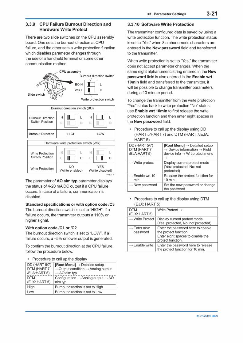
3.3.9 CPU Failure Burnout Direction and Hardware Write Protect
There are two slide switches on the CPU assembly board. One sets the burnout direction at CPU failure, and the other sets a write protection function which disables parameter changes through the use of a handheld terminal or some other communication method.
HIGH LOW
CPU assembly
Slide switch
Burnout direction switch
Write protection switch
Write ProtectionSwitch Position
Burnout DirectionSwitch Position
BO H L
WR E D
H L
E D
H L
E D
H L H L
Hardware write protection switch (WR)
Burnout direction switch (BO)
Burnout Direction
Write Protection YES(Write disabled)
NO(Write enabled)
F0307.ai
The parameter of AO alm typ parameter displays the status of 4-20 mA DC output if a CPU failure occurs. In case of a failure, communication is disabled.
Standard specifications or with option code /C3The burnout direction switch is set to “HIGH”. If a failure occurs, the transmitter outputs a 110% or higher signal.
With option code /C1 or /C2The burnout direction switch is set to “LOW”. If a failure occurs, a –5% or lower output is generated.
To confirm the burnout direction at the CPU failure, follow the procedure below.
• Procedure to call up the displayDD (HART 5/7)DTM (HART 7 /EJA:HART 5)
[Root Menu] → Detailed setup →Output condition → Analog output → AO alm typ
DTM (EJX: HART 5)
Configuration → Analog output → AO alm typ
High Burnout direction is set to HighLow Burnout direction is set to Low
3.3.10 Software Write ProtectionThe transmitter configured data is saved by using a write protection function. The write protection status is set to “Yes” when 8 alphanumeric characters are entered in the New password field and transferred to the transmitter.
When write protection is set to ”Yes,” the transmitter does not accept parameter changes. When the same eight alphanumeric string entered in the New password field is also entered in the Enable wrt 10min field and transferred to the transmitter, it will be possible to change transmitter parameters during a 10 minute period.
To change the transmitter from the write protection ”Yes” status back to write protection ”No” status, use Enable wrt 10min to first release the write protection function and then enter eight spaces in the New password field.
• Procedure to call up the display using DD (HART 5/HART 7) and DTM (HART 7/EJA: HART 5)
DD (HART 5/7)DTM (HART 7 /EJA:HART 5)
[Root Menu] → Detailed setup → Device information → Field device info → Wrt protect menu →
→ Write protect Display current protect mode (Yes: protected, No: not protected)
→ Enable wrt 10 min
Release the protect function for 10 min.
→ New password Set the new password or change the password
• Procedure to call up the display using DTM (EJX: HART 5)
DTM (EJX: HART 5)
Write Protect →
→ Write Protect Display current protect mode (Yes: protected, No: not protected)
→ Enter new password
Enter the password here to enable the protect function.Enter eight spaces to disable the protect function.
→ Enable write Enter the password here to release the protect function for 10 min.
<3. Parameter Setting> 3-22
IM 01C25T01-06EN
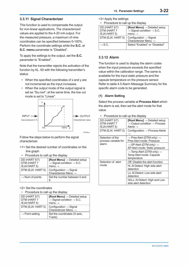
3.3.11 Signal CharacterizerThis function is used to compensate the output for non-linear applications. The characterized values are applied to the 4-20 mA output. For the measured pressure, a maximum of nine coordinates can be specified between 0-100%. Perform the coordinate settings while the S.C. at S.C. menu parameter is “Disabled”.
To apply the settings to the output, set the S.C. parameter to “Enabled”.
Note that the transmitter rejects the activation of the function by AL. 60 with the following transmitter’s status:
• When the specified coordinates of x and y are not incremental as the input increases.
• When the output mode of the output signal is set as “Sq root”; at the same time, the low cut mode is set to “Linear”.
F0308.ai
Y
X100%0%
100%
INPUT OUTPUTInput pressure in % Characterized value
Follow the steps below to perform the signal characterizer.
<1> Set the desired number of coordinates on the line graph
• Procedure to call up the displayDD (HART 5/7)DTM (HART 7 /EJA:HART 5)
[Root Menu] → Detailed setup → Signal condition → S.C. menu →
DTM (EJX: HART 5) Configuration → Signal Characterizer Menu →
→ Num of points Set the number between 0 and 9
<2> Set the coordinates• Procedure to call up the displayDD (HART 5/7)DTM (HART 7 /EJA:HART 5)
[Root Menu] → Detailed setup → Signal condition → S.C. menu →
DTM (EJX: HART 5) Configuration → Signal Characterizer Menu →
→ Point setting Set the coordinates (X-axis, Y-axis)
<3> Apply the settings• Procedure to call up the displayDD (HART 5/7)DTM (HART 7 /EJA:HART 5)
[Root Menu] → Detailed setup → Signal condition → S.C. menu →
DTM (EJX: HART 5) Configuration → Signal Characterizer Menu →
→ S.C. Select “Enabled” or “Disabled”
3.3.12 AlarmThe function is used to display the alarm codes when the input pressure exceeds the specified value within the calibration range. The same is available for the input static pressure and the capsule temperature on the pressure sensor. Refer to table 4.5 Alarm Message Summary for the specific alarm code to be generated.
(1) Alarm Setting
Select the process variable at Process Alert which the alarm is set, then set the alert mode for that value.
• Procedure to call up the displayDD (HART 5/7)DTM (HART 7 /EJA:HART 5)
[Root Menu] → Detailed setup → Output condition → Process Alerts →
DTM (EJX: HART 5) Configuration → Process Alerts →
Selection of the process variable for alarm
→ Pres Alert (DTM only) → Pres Alert mode: Pressure→ SP Alert (DTM only) → SP Alert mode: Static pressure→ Temp Alert (DTM only) → Temp Alert mode: Capsule temperature
Selection of alert mode
Off: Disable the alert functionHi. Al Detect: High side alert detectionLo. Al Detect: Low side alert detectionHi/Lo. Al Detect: High and Low side alert detection
<3. Parameter Setting> 3-23
IM 01C25T01-06EN
(2) Threshold Level Setting
Set the threshold of high and low alert value for alarm generation.
• Procedure to call up the display For DD (HART 5/7) and DTM (HART 7/EJA:
HART 5)DD (HART 5/7)DTM (HART 7 /EJA:HART 5)
[Root Menu] → Detailed setup→ Output condition → Process Alerts → Pres Alert (DTM only) → Config Pres Alerts →
→ Hi Alert Val Set the threshold value of upper side for pressure
→ Lo Alert Val Set the threshold value of lower side for pressure
DD (HART 5/7)DTM (HART 7 /EJA:HART 5)
[Root Menu] → Detailed setup→ Output condition → Process Alerts → SP Alert (DTM only) → Config SP Alerts →
→ SP Hi Alert Val Set the threshold value of upper side for static pressure
→ SP Lo Alert Val Set the threshold value of lower side for static pressure
DD (HART 5/7)DTM (HART 7 /EJA:HART 5)
[Root Menu] → Detailed setup→ Output condition → Process Alerts → Temp Alert (DTM only) → Config Temp Alerts →
→ Temp Hi Alert Val Set the threshold value of upper side for capsule temperature
→ Temp Lo Alert Val Set the threshold value of lower side for capsule temperature
• Procedure to call up the display For DTM ( EJX:HART 5)DTM (EJX: HART 5) Configuration → Process Alerts
→ → Hi Alert Val Set the threshold value of upper
side for pressure→ Lo Alert Val Set the threshold value of lower
side for pressure→ SP Hi Alert Val Set the threshold value of upper
side for static pressure→ SP Lo Alert Val Set the threshold value of lower
side for static pressure→ Temp Hi Alert Val Set the threshold value of upper
side for capsule temperature→ Temp Lo Alert Val Set the threshold value of lower
side for capsule temperature
NOTEWhen option code /DG6 is specified, Diag can be also assigned to Status. The Hi Alert Val or Lo Alert Val for Diag is defined by the following parameters.
[Impulse Line Blockage Detection]Limit meters to detect the blockage and Condition error for ILBD operation is defined. Refer to 4.2.2.1.
[Heat Trace Monitoring]Flg temp Hi Alert Val and Flg temp Lo Alert Val parameters are used as the upper and lower threshold for Status output. Refer to 4.2.3.2.
3.3.13 Status Output (only for EJX series: option code AL)
The transmitter has a contact output.Select the type of output, status output, and set the unit, value etc.
(1) Setting of status output
This feature is used for a transistor output (open collector) of an on/off signal according to the status of high and low alarm limits, which are user-configurable values as shown in subsection 3.3.12 Alarm. The status output can be assigned as any combination of the high or low limits of the input pressure, input static pressure, or capsule temperature.
• Procedure to call up the displayDD (HART 5/7)DTM (HART 7)
[Root Menu] → Detailed setup →Output condition → Process Alerts → DO config → DO Select
DTM (HART 5) Configuration → Process Alerts → DO Select
Display Item Contents (Select a output variable from the list below)
Off –Pres Differential pressureSP Static pressureTemp TemperaturePres/SP Pressure and static pressurePres/Temp Pressure and temperatureSP/Temp Static pressure and temperaturePres/SP/Temp Pressure, static pressure and
temperatureDiag Alarm Alarm for advanced diagnostics
(Refer to subsection 4.2.2.5)All Alarm for pressure, static pressure,
temperature, and advanced diagnostics
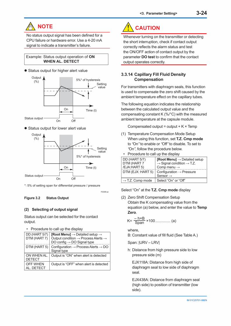
<3. Parameter Setting> 3-24
IM 01C25T01-06EN
NOTENo status output signal has been defined for a CPU failure or hardware error. Use a 4-20 mA signal to indicate a transmitter’s failure.
Status output for higher alert value
Status output for lower alert value
F0309.ai
Output(%)
Status output
Status output
*: 5% of setting span for differential pressure / pressure
Time (t)
Time (t)
Settingvalue
Settingvalue
5%* of hysteresis
Output(%)
5%* of hysteresis
On Off
On
On
On
Off
Example: Status output operation of ON WHEN AL. DETECT
Figure 3.2 Status Output
(2) Selecting of output signal
Status output can be selected for the contact output.
• Procedure to call up the displayDD (HART 5/7)DTM (HART 7)
[Root Menu] → Detailed setup →Output condition → Process Alerts → DO config → DO Signal type
DTM (HART 5) Configuration → Process Alerts → DO Signal type
ON WHEN AL. DETECT
Output is “ON” when alert is detected
OFF WHEN AL. DETECT
Output is “OFF” when alert is detected
CAUTIONWhenever turning on the transmitter or detecting the short interruption, check if contact output correctly reflects the alarm status and test the ON/OFF action of contact output by the parameter DO test to confirm that the contact output operates correctly.
3.3.14 Capillary Fill Fluid Density Compensation
For transmitters with diaphragm seals, this function is used to compensate the zero shift caused by the ambient temperature effect on the capillary tubes.
The following equation indicates the relationship between the calculated output value and the compensating constant K (%/°C) with the measured ambient temperature at the capsule module.
Compensated output = output + K × Temp
(1) Temperature Compensation Mode Setup When using this function, set T.Z. Cmp mode to “On” to enable or “Off” to disable. To set to “On”, follow the procedure below.
• Procedure to call up the displayDD (HART 5/7)DTM (HART 7 /EJA:HART 5)
[Root Menu] → Detailed setup → Signal condition → T.Z. Comp menu →
DTM (EJX: HART 5) Configuration → Pressure Sensor →
→ T.Z. Comp mode Select “On” or “Off”
Select “On” at the T.Z. Cmp mode display
(2) Zero Shift Compensation Setup Obtain the K compensating value from the equation (a) below, and enter the value to Temp Zero.
K= ×100.............. (a)– h×BSpan
where,B: Constant value of fill fluid (See Table A.)
Span: |URV – LRV|
h: Distance from high pressure side to low pressure side (m)
EJX118A: Distance from high side of diaphragm seal to low side of diaphragm seal.
EJX438A: Distance from diaphragm seal (high side) to position of transmitter (low side).
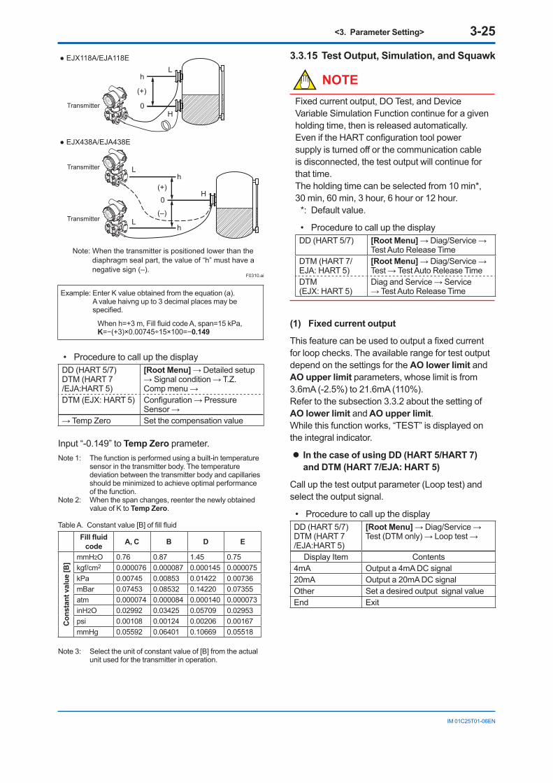
<3. Parameter Setting> 3-25
IM 01C25T01-06EN
Transmitter
Lh
0H
(+)
EJX118A/EJA118E
F0310.ai
h
hL
L
H
Transmitter
Transmitter
0
(+)
(–)
EJX438A/EJA438E
Note: When the transmitter is positioned lower than the diaphragm seal part, the value of “h” must have a negative sign (–).
Example: Enter K value obtained from the equation (a). A value haivng up to 3 decimal places may be specified.
When h=+3 m, Fill fluid code A, span=15 kPa,K=−(+3)×0.00745÷15×100=−0.149
• Procedure to call up the displayDD (HART 5/7)DTM (HART 7 /EJA:HART 5)
[Root Menu] → Detailed setup → Signal condition → T.Z. Comp menu →
DTM (EJX: HART 5) Configuration → Pressure Sensor →
→ Temp Zero Set the compensation value
Input “-0.149” to Temp Zero prameter.Note 1: The function is performed using a built-in temperature
sensor in the transmitter body. The temperature deviation between the transmitter body and capillaries should be minimized to achieve optimal performance of the function.
Note 2: When the span changes, reenter the newly obtained value of K to Temp Zero.
Table A. Constant value [B] of fill fluidFill fluid
code A, C B D E
Con
stan
t val
ue [B
]
mmH2O 0.76 0.87 1.45 0.75kgf/cm2 0.000076 0.000087 0.000145 0.000075kPa 0.00745 0.00853 0.01422 0.00736mBar 0.07453 0.08532 0.14220 0.07355atm 0.000074 0.000084 0.000140 0.000073inH2O 0.02992 0.03425 0.05709 0.02953psi 0.00108 0.00124 0.00206 0.00167mmHg 0.05592 0.06401 0.10669 0.05518
Note 3: Select the unit of constant value of [B] from the actual unit used for the transmitter in operation.
3.3.15 Test Output, Simulation, and Squawk
NOTEFixed current output, DO Test, and Device Variable Simulation Function continue for a given holding time, then is released automatically. Even if the HART configuration tool power supply is turned off or the communication cable is disconnected, the test output will continue for that time. The holding time can be selected from 10 min*, 30 min, 60 min, 3 hour, 6 hour or 12 hour.
*: Default value.
• Procedure to call up the displayDD (HART 5/7) [Root Menu] → Diag/Service →
Test Auto Release TimeDTM (HART 7/EJA: HART 5)
[Root Menu] → Diag/Service → Test → Test Auto Release Time
DTM (EJX: HART 5)
Diag and Service → Service → Test Auto Release Time
(1) Fixed current output
This feature can be used to output a fixed current for loop checks. The available range for test output depend on the settings for the AO lower limit and AO upper limit parameters, whose limit is from 3.6mA (-2.5%) to 21.6mA (110%).Refer to the subsection 3.3.2 about the setting of AO lower limit and AO upper limit.While this function works, “TEST” is displayed on the integral indicator.
In the case of using DD (HART 5/HART 7) and DTM (HART 7/EJA: HART 5)
Call up the test output parameter (Loop test) and select the output signal.
• Procedure to call up the displayDD (HART 5/7)DTM (HART 7 /EJA:HART 5)
[Root Menu] → Diag/Service → Test (DTM only) → Loop test →
Display Item Contents4mA Output a 4mA DC signal 20mA Output a 20mA DC signalOther Set a desired output signal valueEnd Exit
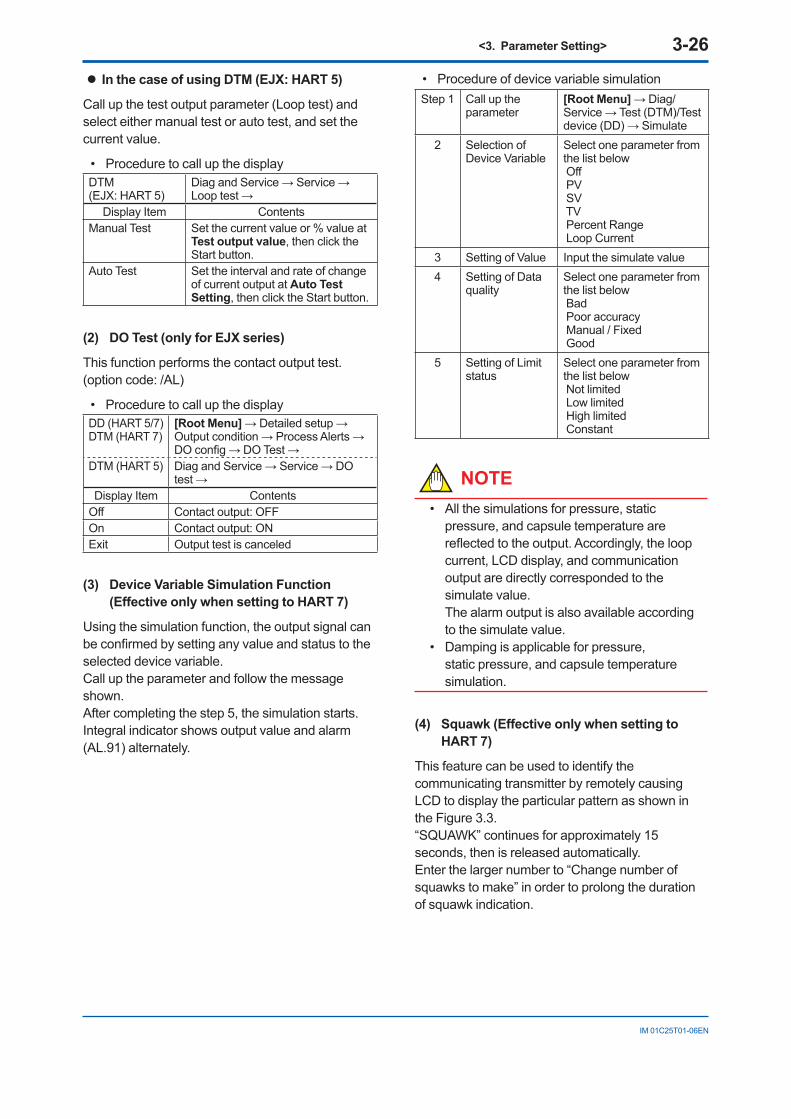
<3. Parameter Setting> 3-26
IM 01C25T01-06EN
In the case of using DTM (EJX: HART 5)
Call up the test output parameter (Loop test) and select either manual test or auto test, and set the current value.
• Procedure to call up the displayDTM (EJX: HART 5)
Diag and Service → Service → Loop test →
Display Item ContentsManual Test Set the current value or % value at
Test output value, then click the Start button.
Auto Test Set the interval and rate of change of current output at Auto Test Setting, then click the Start button.
(2) DO Test (only for EJX series)
This function performs the contact output test. (option code: /AL)
• Procedure to call up the displayDD (HART 5/7)DTM (HART 7)
[Root Menu] → Detailed setup →Output condition → Process Alerts → DO config → DO Test →
DTM (HART 5) Diag and Service → Service → DO test →
Display Item ContentsOff Contact output: OFFOn Contact output: ONExit Output test is canceled
(3) Device Variable Simulation Function (Effective only when setting to HART 7)
Using the simulation function, the output signal can be confirmed by setting any value and status to the selected device variable.Call up the parameter and follow the message shown.After completing the step 5, the simulation starts.Integral indicator shows output value and alarm (AL.91) alternately.
• Procedure of device variable simulationStep 1 Call up the
parameter [Root Menu] → Diag/Service → Test (DTM)/Test device (DD) → Simulate
2 Selection of Device Variable
Select one parameter from the list below Off PV SV TV Percent Range Loop Current
3 Setting of Value Input the simulate value4 Setting of Data
qualitySelect one parameter from the list below Bad Poor accuracy Manual / Fixed Good
5 Setting of Limit status
Select one parameter from the list below Not limited Low limited High limited Constant
NOTE• All the simulations for pressure, static
pressure, and capsule temperature are reflected to the output. Accordingly, the loop current, LCD display, and communication output are directly corresponded to the simulate value. The alarm output is also available according to the simulate value.
• Damping is applicable for pressure, static pressure, and capsule temperature simulation.
(4) Squawk (Effective only when setting to HART 7)
This feature can be used to identify the communicating transmitter by remotely causing LCD to display the particular pattern as shown in the Figure 3.3.“SQUAWK” continues for approximately 15 seconds, then is released automatically.Enter the larger number to “Change number of squawks to make” in order to prolong the duration of squawk indication.
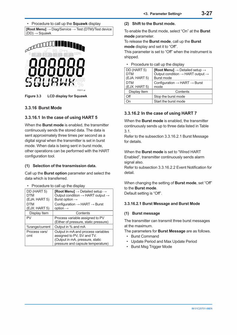
<3. Parameter Setting> 3-27
IM 01C25T01-06EN
• Procedure to call up the Squawk display[Root Menu] → Diag/Service → Test (DTM)/Test device (DD) → Squawk
P SP T F
F0311.ai
Figure 3.3 LCD display for Squawk
3.3.16 Burst Mode
3.3.16.1 In the case of using HART 5When the Burst mode is enabled, the transmitter continuously sends the stored data. The data is sent approximately three times per second as a digital signal when the transmitter is set in burst mode. When data is being sent in burst mode, other operations can be performed with the HART configuration tool.
(1) Selection of the transmission data.
Call up the Burst option parameter and select the data which is transferred.
• Procedure to call up the displayDD (HART 5)DTM (EJA: HART 5)
[Root Menu] → Detailed setup → Output condition → HART output → Burst option →
DTM (EJX: HART 5)
Configuration → HART → Burst option →
Display Item ContentsPV Process variable assigned to PV
(Either of pressure, static pressure)%range/current Output in % and mAProcess vars/crnt
Output in mA and process variables assigned to PV, SV and TV.(Output in mA, pressure, static pressure and capsule temperature)
(2) Shift to the Burst mode.
To enable the Burst mode, select “On” at the Burst mode parameter.To release the Burst mode, call up the Burst mode display and set it to “Off”. This parameter is set to “Off” when the instrument is shipped.
• Procedure to call up the displayDD (HART 5)DTM (EJA: HART 5)
[Root Menu] → Detailed setup → Output condition → HART output → Burst mode
DTM (EJX: HART 5)
Configuration → HART → Burst mode
Display Item ContentsOff Stop the burst modeOn Start the burst mode
3.3.16.2 In the case of using HART 7When the Burst mode is enabled, the transmitter continuously sends up to three data listed in Table 3.1.Refer to the subsection 3.3.16.2.1 Burst Message for details.
When the Burst mode is set to “Wired HART Enabled”, transmitter continuously sends alarm signal also.Refer to subsection 3.3.16.2.2 Event Notification for detail.
When changing the setting of Burst mode, set “Off” to the Burst mode.Default setting is “Off”.
3.3.16.2.1 Burst Message and Burst Mode
(1) Burst message
The transmitter can transmit three burst messages at the maximum.The parameters for Burst Message are as follows.
• Burst Command• Update Period and Max Update Period• Burst Msg Trigger Mode
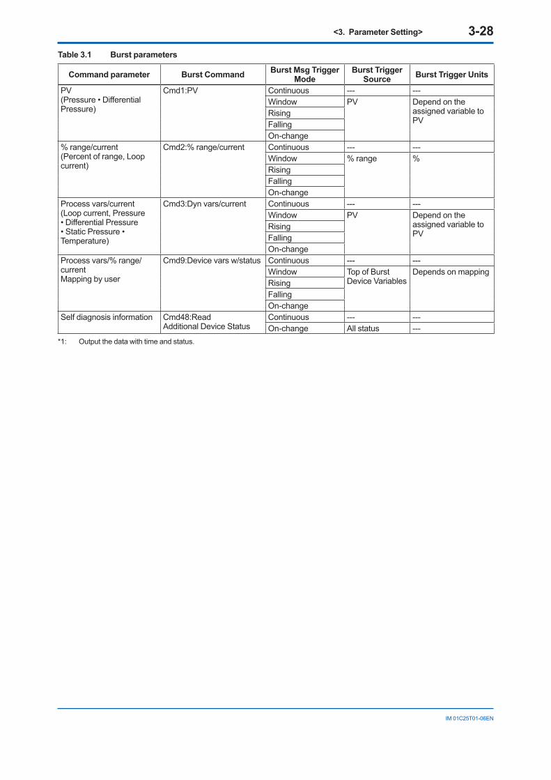
<3. Parameter Setting> 3-28
IM 01C25T01-06EN
Table 3.1 Burst parameters
Command parameter Burst Command Burst Msg Trigger Mode
Burst Trigger Source Burst Trigger Units
PV(Pressure • Differential Pressure)
Cmd1:PV Continuous --- ---Window PV Depend on the
assigned variable to PV
RisingFallingOn-change
% range/current(Percent of range, Loop current)
Cmd2:% range/current Continuous --- ---Window % range %RisingFallingOn-change
Process vars/current(Loop current, Pressure • Differential Pressure • Static Pressure • Temperature)
Cmd3:Dyn vars/current Continuous --- ---Window PV Depend on the
assigned variable to PV
RisingFallingOn-change
Process vars/% range/currentMapping by user
Cmd9:Device vars w/status Continuous --- ---Window Top of Burst
Device VariablesDepends on mapping
RisingFallingOn-change
Self diagnosis information Cmd48:Read Additional Device Status
Continuous --- ---On-change All status ---
*1: Output the data with time and status.
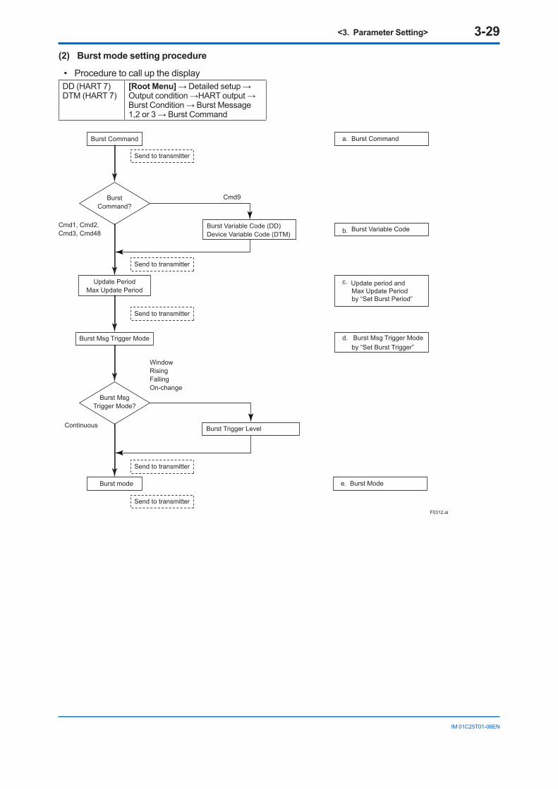
<3. Parameter Setting> 3-29
IM 01C25T01-06EN
(2) Burst mode setting procedure
• Procedure to call up the displayDD (HART 7)DTM (HART 7)
[Root Menu] → Detailed setup → Output condition →HART output → Burst Condition → Burst Message 1,2 or 3 → Burst Command
BurstCommand?
Burst MsgTrigger Mode?
Update PeriodMax Update Period
Burst Command
Burst mode
Burst Msg Trigger Mode
Continuous
Window Rising Falling On-change
Send to transmitter
Cmd9
a. Burst Command
b. Burst Variable Code
c. Update period and Max Update Period by “Set Burst Period”
d. Burst Msg Trigger Mode by “Set Burst Trigger”
F0312.ai
e. Burst Mode
Cmd1, Cmd2, Cmd3, Cmd48
Burst Variable Code (DD)Device Variable Code (DTM)
Burst Trigger Level
Send to transmitter
Send to transmitter
Send to transmitter
Send to transmitter
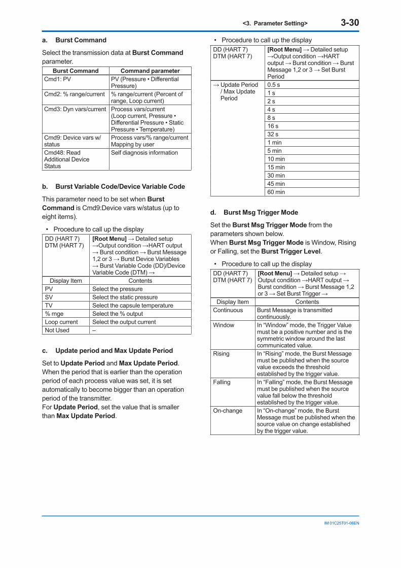
<3. Parameter Setting> 3-30
IM 01C25T01-06EN
a. Burst Command
Select the transmission data at Burst Command parameter.
Burst Command Command parameterCmd1: PV PV (Pressure • Differential
Pressure)Cmd2: % range/current % range/current (Percent of
range, Loop current)Cmd3: Dyn vars/current Process vars/current
(Loop current, Pressure • Differential Pressure • Static Pressure • Temperature)
Cmd9: Device vars w/status
Process vars/% range/current Mapping by user
Cmd48: Read Additional Device Status
Self diagnosis information
b. Burst Variable Code/Device Variable Code
This parameter need to be set when Burst Command is Cmd9:Device vars w/status (up to eight items).
• Procedure to call up the displayDD (HART 7)DTM (HART 7)
[Root Menu] → Detailed setup →Output condition →HART output → Burst condition → Burst Message 1,2 or 3 → Burst Device Variables → Burst Variable Code (DD)/Device Variable Code (DTM) →
Display Item ContentsPV Select the pressureSV Select the static pressureTV Select the capsule temperature% rnge Select the % outputLoop current Select the output currentNot Used –
c. Update period and Max Update Period
Set to Update Period and Max Update Period.When the period that is earlier than the operation period of each process value was set, it is set automatically to become bigger than an operation period of the transmitter.For Update Period, set the value that is smaller than Max Update Period.
• Procedure to call up the displayDD (HART 7)DTM (HART 7)
[Root Menu] → Detailed setup →Output condition →HART output → Burst condition → Burst Message 1,2 or 3 → Set Burst Period
→ Update Period / Max Update Period
0.5 s1 s2 s4 s8 s16 s32 s1 min5 min10 min15 min30 min45 min60 min
d. Burst Msg Trigger Mode
Set the Burst Msg Trigger Mode from the parameters shown below.When Burst Msg Trigger Mode is Window, Rising or Falling, set the Burst Trigger Level.
• Procedure to call up the displayDD (HART 7)DTM (HART 7)
[Root Menu] → Detailed setup →Output condition →HART output → Burst condition → Burst Message 1,2 or 3 → Set Burst Trigger →
Display Item ContentsContinuous Burst Message is transmitted
continuously.Window In “Window” mode, the Trigger Value
must be a positive number and is the symmetric window around the last communicated value.
Rising In “Rising” mode, the Burst Message must be published when the source value exceeds the threshold established by the trigger value.
Falling In “Falling” mode, the Burst Message must be published when the source value fall below the threshold established by the trigger value.
On-change In “On-change” mode, the Burst Message must be published when the source value on change established by the trigger value.
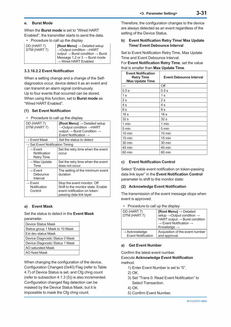
<3. Parameter Setting> 3-31
IM 01C25T01-06EN
e. Burst Mode
When the Burst mode is set to “Wired HART Enabled”, the transmitter starts to send the data.
• Procedure to call up the displayDD (HART 7)DTM (HART 7)
[Root Menu] → Detailed setup →Output condition →HART output → Burst condition → Burst Message 1,2 or 3 → Burst mode → Wired HART Enabled
3.3.16.2.2 Event Notification
When a setting change and a change of the Self-diagnostics occur, device detect it as an event and can transmit an alarm signal continuously.Up to four events that occurred can be stored.When using this function, set to Burst mode as “Wired HART Enabled”.
(1) Set Event Notification
• Procedure to call up the displayDD (HART 7)DTM (HART 7)
[Root Menu] → Detailed setup →Output condition →HART output → Burst Condition → Event Notification →
→ Event Mask Set the status to detect → Set Event Notification Timing
→ Event Notification Retry Time
Set the retry time when the event occur.
→ Max Update Time
Set the retry time when the event does not occur.
→ Event Debounce Interval
The setting of the minimum event duration
→ Event Notification Control
Stop the event monitor: OffShift to the monitor state: Enable event notification on token-passing data link layer
a) Event Mask
Set the status to detect in the Event Mask parameter.Device Status MaskStatus group 1 Mask to 10 MaskExt dev status MaskDevice Diagnostic Status 0 MaskDevice Diagnostic Status 1 MaskAO saturated MaskAO fixed Mask
When changing the configuration of the device, Configuration Changed (0x40) Flag (refer to Table 4.7) of Device Status is set, and Cfg chng count (refer to subsection 4.1.3 (5)) is also incremented.Configuration changed flag detection can be masked by the Device Status Mask, but it is impossible to mask the Cfg chng count.
Therefore, the configuration changes to the device are always detected as an event regardless of the setting of the Device Status.
b) Event Notification Retry Time/ Max Update Time/ Event Debounce Interval
Set to Event Notification Retry Time, Max Update Time and Event Debounce Interval.For Event Notification Retry Time, set the value that is smaller than Max Update Time.
Event Notification Retry Time
/Max Update Time Event Debounce Interval
--- Off0.5 s 0.5 s1 s 1 s2 s 2 s4 s 4 s8 s 8 s16 s 16 s32 s 32 s1 min 1 min5 min 5 min10 min 10 min15 min 15 min30 min 30 min45 min 45 min60 min 60 min
c) Event Notification Control
Select “Enable event notification on token-passing data link layer” in the Event Notification Control parameter to shift to the monitor state:
(2) Acknowledge Event Notification
The transmission of the event message stops when event is approved.
• Procedure to call up the displayDD (HART 7)DTM (HART 7)
[Root Menu] → Detailed setup →Output condition →HART output → Burst condition → Event Notification → Knowledge →
→ Acknowledge Event Notification
Acquisition of the event number and approval.
a) Get Event Number
Confirm the latest event number.Execute Acknowledge Event Notification method.
1) Enter Event Number is set to “0”.2) OK.3) Set “Trans 0: Read Event Notificaiton” to
Select Transaction.4) OK.5) Confirm Event Number.
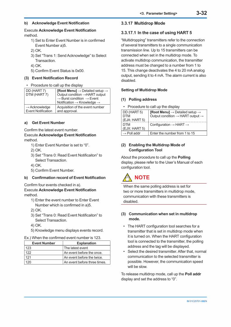
<3. Parameter Setting> 3-32
IM 01C25T01-06EN
b) Acknowledge Event Notification
Execute Acknowledge Event Notification method.
1) Set to Enter Event Number is in confirmed Event Number a)5.
2) OK.3) Set “Trans 1: Send Acknowledge” to Select
Transaction.4) OK.5) Confirm Event Status is 0x00.
(3) Event Notification Record
• Procedure to call up the displayDD (HART 7)DTM (HART 7)
[Root Menu] → Detailed setup →Output condition →HART output → Burst condition → Event Notification → Knowledge →
→ Acknowledge Event Notification
Acquisition of the event number and approval.
a) Get Event Number
Confirm the latest event number.Execute Acknowledge Event Notification method.
1) Enter Event Number is set to “0”.2) OK.3) Set “Trans 0: Read Event Notificaiton” to
Select Transaction.4) OK.5) Confirm Event Number.
b) Confirmation record of Event Notification
Confirm four events checked in a).Execute Acknowledge Event Notification method.
1) Enter the event number to Enter Event Number which is confirmed in a)5.
2) OK.3) Set “Trans 0: Read Event Notificaiton” to
Select Transaction.4) OK.5) Knowledge menu displays events record.
Ex.) When the confirmed event number is 123.Event Number Explanation
123 The latest event122 An event before the once. 121 An event before the twice. 120 An event before three times.
3.3.17 Multidrop Mode
3.3.17.1 In the case of using HART 5“Multidropping” transmitters refer to the connection of several transmitters to a single communication transmission line. Up to 15 transmitters can be connected when set in the multidrop mode. To activate multidrop communication, the transmitter address must be changed to a number from 1 to 15. This change deactivates the 4 to 20 mA analog output, sending it to 4 mA. The alarm current is also disabled.
Setting of Multidrop Mode
(1) Polling address
• Procedure to call up the displayDD (HART 5)DTM (EJA: HART 5)
[Root Menu] → Detailed setup → Output condition → HART output →
DTM (EJX: HART 5)
Configuration → HART →
→ Poll addr Enter the number from 1 to 15
(2) Enabling the Multidrop Mode of Configuration Tool
About the procedure to call up the Polling display, please refer to the User’s Manual of each configuration tool.
NOTEWhen the same polling address is set for two or more transmitters in multidrop mode, communication with these transmitters is disabled.
(3) Communication when set in multidrop mode.
• The HART configuration tool searches for a transmitter that is set in multidrop mode when it is turned on. When the HART configuration tool is connected to the transmitter, the polling address and the tag will be displayed.
• Select the desired transmitter. After that, normal communication to the selected transmitter is possible. However, the communication speed will be slow.
To release multidrop mode, call up the Poll addr display and set the address to “0”.
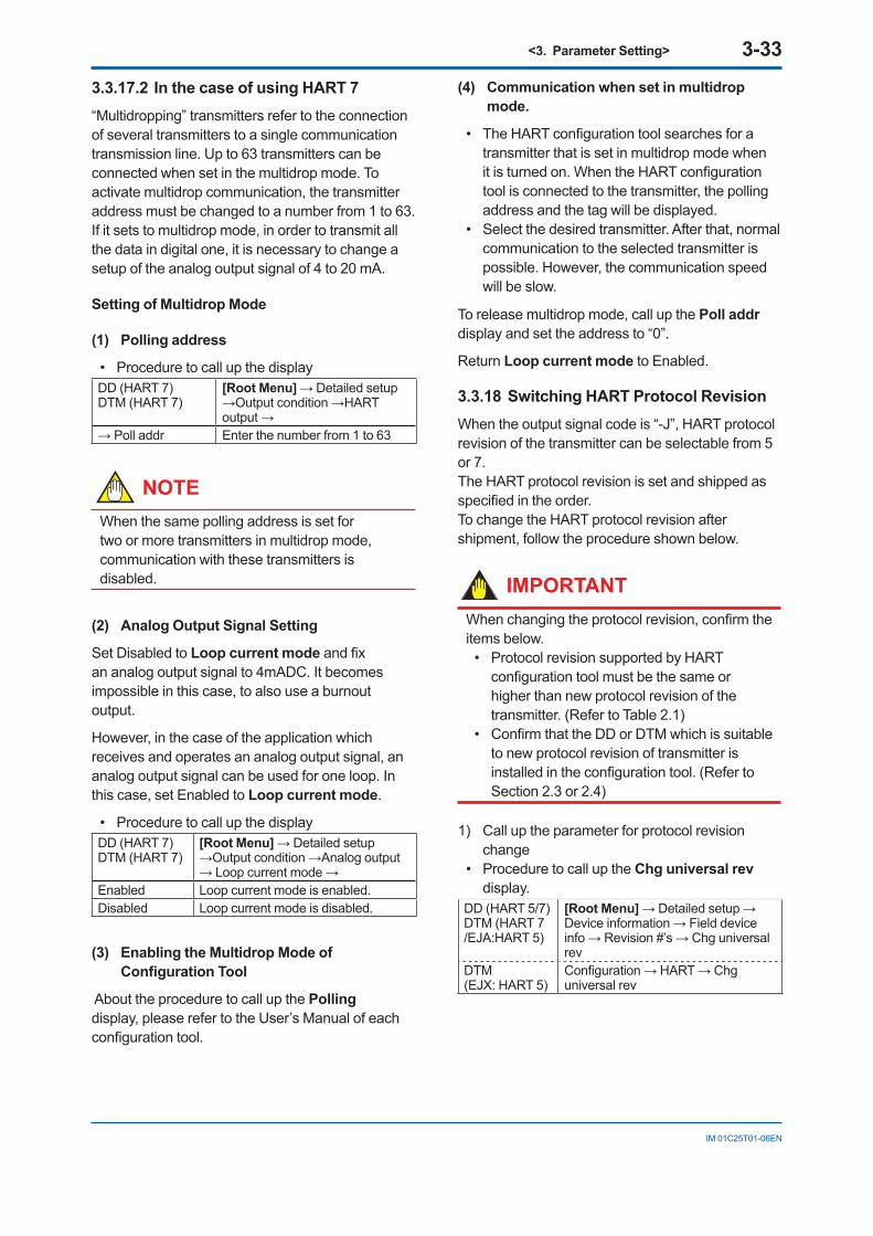
<3. Parameter Setting> 3-33
IM 01C25T01-06EN
3.3.17.2 In the case of using HART 7“Multidropping” transmitters refer to the connection of several transmitters to a single communication transmission line. Up to 63 transmitters can be connected when set in the multidrop mode. To activate multidrop communication, the transmitter address must be changed to a number from 1 to 63. If it sets to multidrop mode, in order to transmit all the data in digital one, it is necessary to change a setup of the analog output signal of 4 to 20 mA.
Setting of Multidrop Mode
(1) Polling address
• Procedure to call up the displayDD (HART 7)DTM (HART 7)
[Root Menu] → Detailed setup →Output condition →HART output →
→ Poll addr Enter the number from 1 to 63
NOTEWhen the same polling address is set for two or more transmitters in multidrop mode, communication with these transmitters is disabled.
(2) Analog Output Signal Setting
Set Disabled to Loop current mode and fix an analog output signal to 4mADC. It becomes impossible in this case, to also use a burnout output.
However, in the case of the application which receives and operates an analog output signal, an analog output signal can be used for one loop. In this case, set Enabled to Loop current mode.
• Procedure to call up the displayDD (HART 7)DTM (HART 7)
[Root Menu] → Detailed setup →Output condition →Analog output → Loop current mode →
Enabled Loop current mode is enabled.Disabled Loop current mode is disabled.
(3) Enabling the Multidrop Mode of Configuration Tool
About the procedure to call up the Polling display, please refer to the User’s Manual of each configuration tool.
(4) Communication when set in multidrop mode.
• The HART configuration tool searches for a transmitter that is set in multidrop mode when it is turned on. When the HART configuration tool is connected to the transmitter, the polling address and the tag will be displayed.
• Select the desired transmitter. After that, normal communication to the selected transmitter is possible. However, the communication speed will be slow.
To release multidrop mode, call up the Poll addr display and set the address to “0”.
Return Loop current mode to Enabled.
3.3.18 Switching HART Protocol RevisionWhen the output signal code is “-J”, HART protocol revision of the transmitter can be selectable from 5 or 7.The HART protocol revision is set and shipped as specified in the order.To change the HART protocol revision after shipment, follow the procedure shown below.
IMPORTANTWhen changing the protocol revision, confirm the items below.
• Protocol revision supported by HART configuration tool must be the same or higher than new protocol revision of the transmitter. (Refer to Table 2.1)
• Confirm that the DD or DTM which is suitable to new protocol revision of transmitter is installed in the configuration tool. (Refer to Section 2.3 or 2.4)
1) Call up the parameter for protocol revision change
• Procedure to call up the Chg universal rev display.
DD (HART 5/7)DTM (HART 7 /EJA:HART 5)
[Root Menu] → Detailed setup → Device information → Field device info → Revision #’s → Chg universal rev
DTM (EJX: HART 5)
Configuration → HART → Chg universal rev
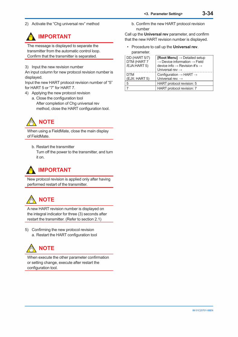
<3. Parameter Setting> 3-34
IM 01C25T01-06EN
2) Activate the “Chg universal rev” method
IMPORTANTThe message is displayed to separate the transmitter from the automatic control loop.Confirm that the transmitter is separated.
3) Input the new revision numberAn input column for new protocol revision number is displayed.Input the new HART protocol revision number of “5” for HART 5 or “7” for HART 7. 4) Applying the new protocol revision
a. Close the configuration tool After completion of Chg universal rev method, close the HART configuration tool.
NOTEWhen using a FieldMate, close the main display of FieldMate.
b. Restart the transmitter Turn off the power to the transmitter, and turn it on.
IMPORTANTNew protocol revision is applied only after having performed restart of the transmitter.
NOTEA new HART revision number is displayed on the integral indicator for three (3) seconds after restart the transmitter. (Refer to section 2.1)
5) Confirming the new protocol revisiona. Restart the HART configuration tool
NOTEWhen execute the other parameter confirmation or setting change, execute after restart the configuration tool.
b. Confirm the new HART protocol revision number
Call up the Universal rev parameter, and confirm that the new HART revision number is displayed.
• Procedure to call up the Universal rev. parameter.
DD (HART 5/7)DTM (HART 7 /EJA:HART 5)
[Root Menu] → Detailed setup → Device information → Field device info → Revision #’s → Universal rev →
DTM (EJX: HART 5)
Configuration → HART → Universal rev. →
5 HART protocol revision: 57 HART protocol revision: 7
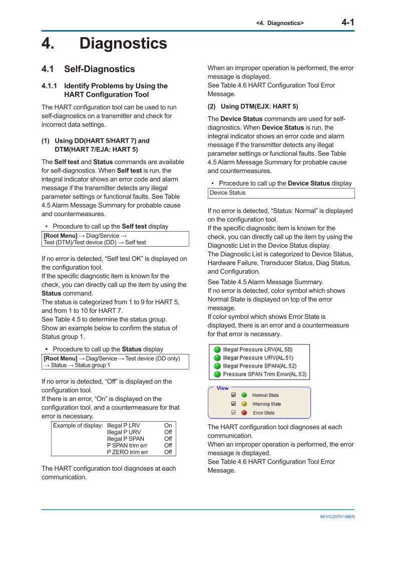
<4. Diagnostics> 4-1
IM 01C25T01-06EN
4. Diagnostics4.1 Self-Diagnostics4.1.1 Identify Problems by Using the
HART Configuration ToolThe HART configuration tool can be used to run self-diagnostics on a transmitter and check for incorrect data settings.
(1) Using DD(HART 5/HART 7) and DTM(HART 7/EJA: HART 5)
The Self test and Status commands are available for self-diagnostics. When Self test is run, the integral indicator shows an error code and alarm message if the transmitter detects any illegal parameter settings or functional faults. See Table 4.5 Alarm Message Summary for probable cause and countermeasures.
• Procedure to call up the Self test display [Root Menu] → Diag/Service → Test (DTM)/Test device (DD) → Self test
If no error is detected, “Self test OK” is displayed on the configuration tool.If the specific diagnostic item is known for the check, you can directly call up the item by using the Status command. The status is categorized from 1 to 9 for HART 5, and from 1 to 10 for HART 7.See Table 4.5 to determine the status group.Show an example below to confirm the status of Status group 1.
• Procedure to call up the Status display[Root Menu] → Diag/Service → Test device (DD only) → Status → Status group 1
If no error is detected, “Off” is displayed on the configuration tool.If there is an error, “On” is displayed on the configuration tool, and a countermeasure for that error is necessary.
Example of display: Illegal P LRV On Illegal P URV Off Illegal P SPAN Off P SPAN trim err Off P ZERO trim err Off
The HART configuration tool diagnoses at each communication.
When an improper operation is performed, the error message is displayed.See Table 4.6 HART Configuration Tool Error Message.
(2) Using DTM(EJX: HART 5)
The Device Status commands are used for self-diagnostics. When Device Status is run, the integral indicator shows an error code and alarm message if the transmitter detects any illegal parameter settings or functional faults. See Table 4.5 Alarm Message Summary for probable cause and countermeasures.
• Procedure to call up the Device Status display Device Status
If no error is detected, “Status: Normal” is displayed on the configuration tool.If the specific diagnostic item is known for the check, you can directly call up the item by using the Diagnostic List in the Device Status display.The Diagnostic List is categorized to Device Status, Hardware Failure, Transducer Status, Diag Status, and Configuration.See Table 4.5 Alarm Message Summary.If no error is detected, color symbol which shows Normal State is displayed on top of the error message.If color symbol which shows Error State is displayed, there is an error and a countermeasure for that error is necessary.
The HART configuration tool diagnoses at each communication. When an improper operation is performed, the error message is displayed.See Table 4.6 HART Configuration Tool Error Message.
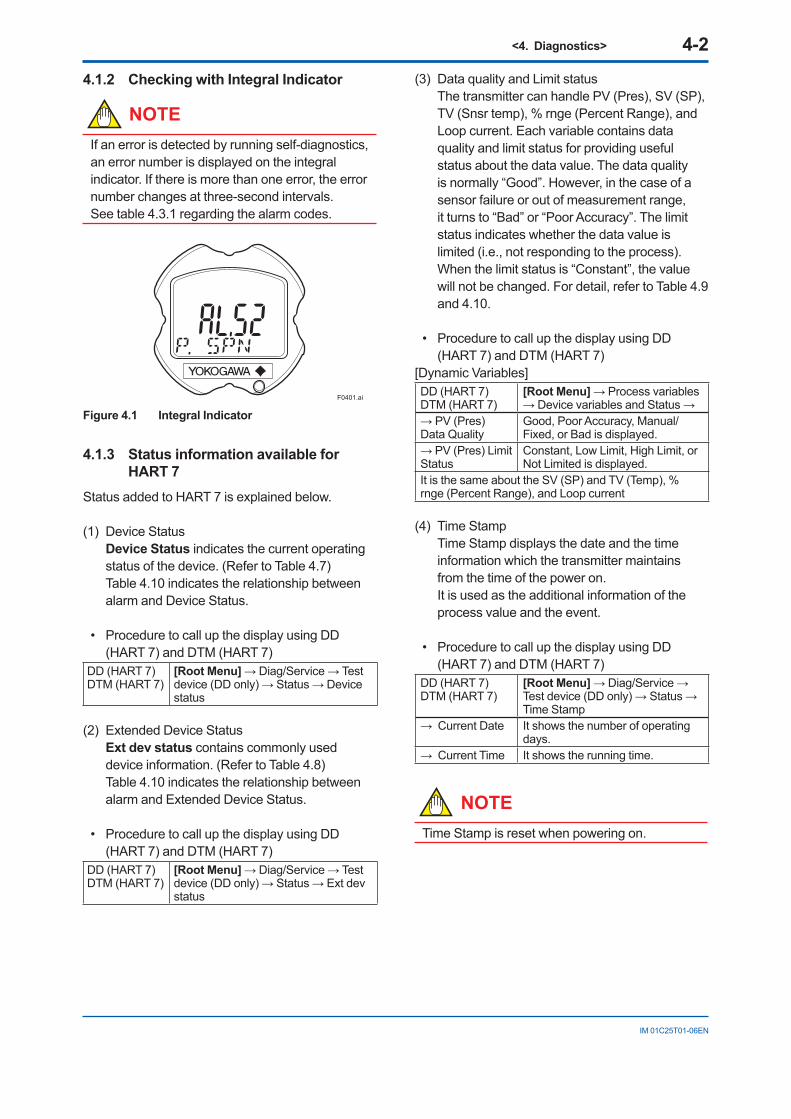
<4. Diagnostics> 4-2
IM 01C25T01-06EN
4.1.2 Checking with Integral Indicator
NOTEIf an error is detected by running self-diagnostics, an error number is displayed on the integral indicator. If there is more than one error, the error number changes at three-second intervals.See table 4.3.1 regarding the alarm codes.
F0401.ai
Figure 4.1 Integral Indicator
4.1.3 Status information available for HART 7
Status added to HART 7 is explained below.
(1) Device StatusDevice Status indicates the current operating status of the device. (Refer to Table 4.7) Table 4.10 indicates the relationship between alarm and Device Status.
• Procedure to call up the display using DD (HART 7) and DTM (HART 7)
DD (HART 7)DTM (HART 7)
[Root Menu] → Diag/Service → Test device (DD only) → Status → Device status
(2) Extended Device StatusExt dev status contains commonly used device information. (Refer to Table 4.8) Table 4.10 indicates the relationship between alarm and Extended Device Status.
• Procedure to call up the display using DD (HART 7) and DTM (HART 7)
DD (HART 7)DTM (HART 7)
[Root Menu] → Diag/Service → Test device (DD only) → Status → Ext dev status
(3) Data quality and Limit statusThe transmitter can handle PV (Pres), SV (SP), TV (Snsr temp), % rnge (Percent Range), and Loop current. Each variable contains data quality and limit status for providing useful status about the data value. The data quality is normally “Good”. However, in the case of a sensor failure or out of measurement range, it turns to “Bad” or “Poor Accuracy”. The limit status indicates whether the data value is limited (i.e., not responding to the process). When the limit status is “Constant”, the value will not be changed. For detail, refer to Table 4.9 and 4.10.
• Procedure to call up the display using DD (HART 7) and DTM (HART 7)
[Dynamic Variables]DD (HART 7)DTM (HART 7)
[Root Menu] → Process variables → Device variables and Status →
→ PV (Pres) Data Quality
Good, Poor Accuracy, Manual/Fixed, or Bad is displayed.
→ PV (Pres) Limit Status
Constant, Low Limit, High Limit, or Not Limited is displayed.
It is the same about the SV (SP) and TV (Temp), % rnge (Percent Range), and Loop current
(4) Time StampTime Stamp displays the date and the time information which the transmitter maintains from the time of the power on.It is used as the additional information of the process value and the event.
• Procedure to call up the display using DD (HART 7) and DTM (HART 7)
DD (HART 7)DTM (HART 7)
[Root Menu] → Diag/Service → Test device (DD only) → Status → Time Stamp
→ Current Date It shows the number of operating days.
→ Current Time It shows the running time.
NOTETime Stamp is reset when powering on.
<4. Diagnostics> 4-3
IM 01C25T01-06EN
(5) Configuration Change CounterThe Configuration Change Counter is incremented once for every user action that changes the device’s configuration or calibration. This value is never reset or written and maintained even if power is removed from the device.
• Procedure to call up the display using DD (HART 7) and DTM (HART 7)
DD (HART 7)DTM (HART 7)
[Root Menu] → Diag/Service → Test device (DD only) → Status →
→ Cfg chng count
The configuration change times are counted. The counted value cannot be reset.
(6) Reset Configuration Changed FlagConfiguration Changed Flag can be reset by this method.
NOTERefer to Configuration Changed (0x40) in the Table 4.7.
• Procedure to call up the display using DD (HART 7) and DTM (HART 7)
DD (HART 7)DTM (HART 7)
[Root Menu] → Diag/Service → Test device (DD only) → Status → Reset Cfg Chng flag
4.2 Advanced Diagnostics (Only for EJX series)
4.2.1 Multi-sensing Process MonitoringMulti-sensing process monitoring function (option code: /DG6) provides the advanced diagnostics to detect the abnormal conditions in process environment such as an impulse line etc. by using the EJX multisensing technology and its unique algorithm. There are following two functions.
Impulse Line Blockage Detection (ILBD)The fluctuation change of differential pressure and static pressure is monitored by a silicone resonant sensor and detects a potential blockage condition. The differential pressure transmitter gives also a result of which pressure-side was plugged.
Heat Trace MonitoringThe two temperature sensors built in the transmitter calculate the flange temperature, the change of which enables to detect the heat trace breakage or the abnormal temperature due to the failure.
4.2.2 Impulse Line Blockage Detection (ILBD)
ILBD is carried out by using statistical analysis based on the measured values of process fluctuations that exist in a fluid. An alarm on the transmitter LCD display or an analog alert is generated if blockage reaches a certain level. The transmitter provides the following results as blockage detection.
(1) A Blocking and B BlockingThese are blockage detections based on the fluctuation value change of differential pressure/pressure. With a differential pressure transmitter, each result indicates that both or single side is plugged.
(2) L Side BlockingIt is a low-pressure side blockage detection based on the change of BlkF or low-pressure-side fluctuation value.
(3) H Side BlockingIt is a high-pressure side blockage detection based on the change of BlkF or high-pressure-side fluctuation value.
*: BlkF indicates blockage degree characterized by a comparison of the high- and low-pressure-side fluctuation values. For the details, refer to Figure 4.2.2.
IMPORTANT• The pressure fluctuation amplitude in fluids
must be sufficiently large for blockages to be detected.
• If the pressure fluctuation amplitude is too low for a reference value to be obtained, blockages detection operation cannot be performed with an alarm that the reference value is invalid.
• The pressure fluctuation amplitude may decrease due to other causes unrelated with a blockage according to process condition. In above case, a false alarm of an impulse line blockage may be generated. Before taking action in response to a blockage alarm, consider the plant operating conditions.
<4. Diagnostics> 4-4
IM 01C25T01-06EN
Notes for Pressure or Level Measurement
With pressure or level measurement, the pressure fluctuation amplitude may reduce especially for the following cases.
Pressure Measurement
• Operational pressure is near outside of diagnostic range.
• Even though pressure is constant, the flow decreases than that under normal condition.
• A source of pressure fluctuation (pump, compressor, blower, etc.) is shut down. As a result, the pressure fluctuation amplitude decreases.
Level Measurement
• A transmitter is used to measure tank level and the flow of fluid into or out of the tank comes to a stop.
• The agitator in the tank is shut down.• A source of pressure variation (a compressor,
etc.) that controls the internal pressure of a sealed (closed) tank is shut down.
Before taking action in response to a blockage alarm, consider the plant operating conditions.
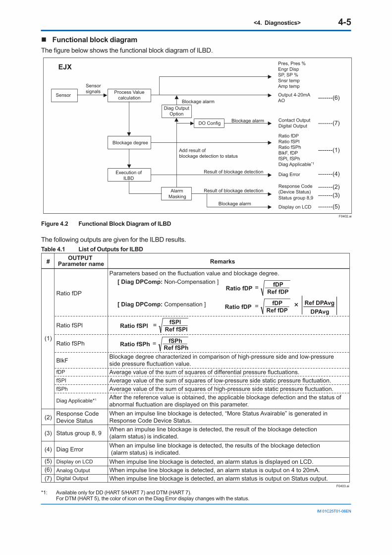
<4. Diagnostics> 4-5
IM 01C25T01-06EN
Functional block diagramThe figure below shows the functional block diagram of ILBD.
EJX
Sensor Process Valuecalculation
Blockage degree
AlarmMasking
Response Code(Device Status)Status group 8,9
Display on LCD
Contact OutputDigital Output
Sensorsignals
DO Config
Ratio fDPRatio fSPlRatio fSPhBlkF, fDPfSPl, fSPhDiag Applicable*1
Diag Error
Add result ofblockage detection to status
Pres, Pres %Engr DispSP, SP %Snsr tempAmp temp
Output 4-20mAAO
Execution ofILBD
Result of blockage detection
Blockage alarm
Blockage alarmDiag Output
OptionBlockage alarm
Result of blockage detection
-------(6)
F0402.ai
-------(7)
-------(1)
-------(4)
-------(2)-------(3)
-------(5)
Figure 4.2 Functional Block Diagram of ILBD
The following outputs are given for the ILBD results.Table 4.1 List of Outputs for ILBD
OUTPUT Parameter name
Parameters based on the fluctuation value and blockage degree.[ Diag DPComp: Non-Compensation ]:
[ Diag DPComp: Compensation ]:
Blockage degree characterized in comparison of high-pressure side and low-pressure side pressure fluctuation value.Average value of the sum of squares of differential pressure fluctuations.Average value of the sum of squares of low-pressure side static pressure fluctuation.Average value of the sum of squares of high-pressure side static pressure fluctuation.After the reference value is obtained, the applicable blockage defection and the status of abnormal fluctuation are displayed on this parameter.When an impulse line blockage is detected, “More Status Avairable” is generated in Response Code Device Status.
Response CodeDevice Status
When an impulse line blockage is detected, the result of the blockage detection (alarm status) is indicated.When an impulse line blockage is detected, the results of the blockage detection (alarm status) is indicated.When impulse line blockage is detected, an alarm status is displayed on LCD.When impulse line blockage is detected, an alarm status is output on 4 to 20mA.When impulse line blockage is detected, an alarm status is output on Status output.
#
(1)
(3)
(4)
Status group 8, 9
Diag Error
Ratio fDP
Ratio fSPl
Ratio fSPh
BlkF
(2)
=Ratio fDP Ref fDPfDP
×DPAvg
Ref DPAvg=Ratio fDP Ref fDPfDP
=Ratio fSPl Ref fSPlfSPl
=Ratio fSPh Ref fSPhfSPh
Remarks
(5)(6)(7)
Display on LCD
Analog OutputDigital Output
fDPfSPIfSPh
Diag Applicable*1
F0403.ai
*1: Available only for DD (HART 5/HART 7) and DTM (HART 7). For DTM (HART 5), the color of icon on the Diag Error display changes with the status.
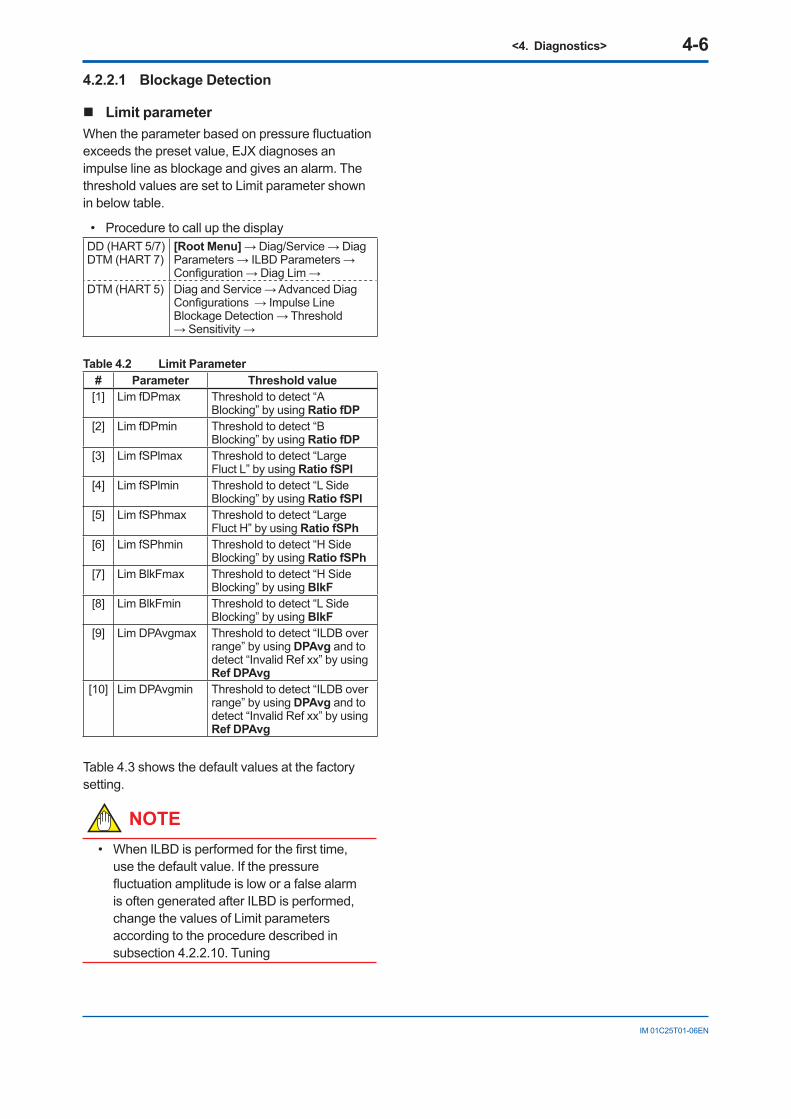
<4. Diagnostics> 4-6
IM 01C25T01-06EN
4.2.2.1 Blockage Detection
Limit parameterWhen the parameter based on pressure fluctuation exceeds the preset value, EJX diagnoses an impulse line as blockage and gives an alarm. The threshold values are set to Limit parameter shown in below table.
• Procedure to call up the displayDD (HART 5/7)DTM (HART 7)
[Root Menu] → Diag/Service → Diag Parameters → ILBD Parameters → Configuration → Diag Lim →
DTM (HART 5) Diag and Service → Advanced Diag Configurations → Impulse Line Blockage Detection → Threshold → Sensitivity →
Table 4.2 Limit Parameter# Parameter Threshold value[1] Lim fDPmax Threshold to detect “A
Blocking” by using Ratio fDP[2] Lim fDPmin Threshold to detect “B
Blocking” by using Ratio fDP[3] Lim fSPlmax Threshold to detect “Large
Fluct L” by using Ratio fSPl[4] Lim fSPlmin Threshold to detect “L Side
Blocking” by using Ratio fSPl[5] Lim fSPhmax Threshold to detect “Large
Fluct H” by using Ratio fSPh[6] Lim fSPhmin Threshold to detect “H Side
Blocking” by using Ratio fSPh[7] Lim BlkFmax Threshold to detect “H Side
Blocking” by using BlkF[8] Lim BlkFmin Threshold to detect “L Side
Blocking” by using BlkF[9] Lim DPAvgmax Threshold to detect “ILDB over
range” by using DPAvg and to detect “Invalid Ref xx” by using Ref DPAvg
[10] Lim DPAvgmin Threshold to detect “ILDB over range” by using DPAvg and to detect “Invalid Ref xx” by using Ref DPAvg
Table 4.3 shows the default values at the factory setting.
NOTE• When ILBD is performed for the first time,
use the default value. If the pressure fluctuation amplitude is low or a false alarm is often generated after ILBD is performed, change the values of Limit parameters according to the procedure described in subsection 4.2.2.10. Tuning
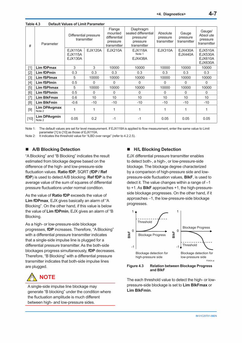
<4. Diagnostics> 4-7
IM 01C25T01-06EN
Table 4.3 Default Values of Limit Parameter
# Parameter
Differential pressure transmitter
Flange mounted
differential pressure
transmitter
Diaphragm sealed differential
pressure/pressure
transmitter
Absolute pressure
transmitter
Gauge pressure
transmitter
Gauge/Absol ute pressure
transmitter
EJX110AEJX115AEJX130A
EJX120A EJX210A EJX118ANote 1
EJX438A
EJX310A EJX430AEJX440A
EJX510AEJX530AEJX610AEJX630A
[1] Lim fDPmax 3 3 10000 10000 10000 10000 10000[2] Lim fDPmin 0.3 0.3 0.3 0.3 0.3 0.3 0.3[3] Lim fSPlmax 5 10000 10000 10000 10000 10000 10000[4] Lim fSPlmin 0.5 0 0 0 0 0 0[5] Lim fSPhmax 5 10000 10000 10000 10000 10000 10000[6] Lim fSPhmin 0.5 0 0 0 0 0 0[7] Lim BlkFmax 0.6 10 10 10 10 10 10[8] Lim BlkFmin -0.6 -10 -10 -10 -10 -10 -10
[9] Lim DPAvgmaxNote 2 1 1 1 1 1 1 1
[10] Lim DPAvgminNote 2 0.05 0.2 -1 -1 0.05 0.05 0.05
Note 1: The default values are set for level measurement. If EJX118A is applied to flow measurement, enter the same value to Limit parameter [1] to [10] as those of EJX110A.
Note 2: It indicates the threshold value for “ILBD over range” (refer to 4.2.2.5).
H/L Blocking DetectionEJX differential pressure transmitter enables to detect both-, a high-, or low-pressure-side blockage. The blockage degree characterized by a comparison of high-pressure side and low-pressure-side fluctuation values, BlkF, is used to detect it. The value changes within a range of –1 to +1. As BlkF approaches +1, the high-pressure-side blockage progresses. On the other hand, if it approaches –1, the low-pressure-side blockage progresses.
1
0
1
0
F0404.ai
BlkF
Blockage detection forhigh-pressure side
Threshold
Blockage Progress
BlkF
Blockage detection forlow-pressure side
Threshold
Blockage Progress
-1-1
Figure 4.3 Relation between Blockage Progress and BlkF
The each threshold value to detect the high- or low-pressure-side blockage is set to Lim BlkFmax or Lim BlkFmin.
A/B Blocking Detection“A Blocking” and “B Blocking” indicates the result estimated from blockage degree based on the difference of the high- and low-pressure-side fluctuation values. Ratio fDP, SQRT (fDP / Ref fDP) is used to detect A/B blocking. Ref fDP is the average value of the sum of squares of differential pressure fluctuations under normal condition.
As the value of Ratio fDP exceeds the value of Lim fDPmax, EJX gives basically an alarm of “A Blocking”. On the other hand, if this value is below the value of Lim fDPmin, EJX gives an alarm of “B Blocking.
As a high- or low-pressure-side blockage progresses, fDP increases. Therefore, “A Blocking” with a differential pressure transmitter indicates that a single-side impulse line is plugged for a differential pressure transmitter. As the both-side blockages progress simultaneously, fDP decreases. Therefore, “B Blocking” with a differential pressure transmitter indicates that both-side impulse lines are plugged.
NOTEA single-side impulse line blockage may generate “B blocking” under the condition where the fluctuation amplitude is much different between high- and low-pressure sides.
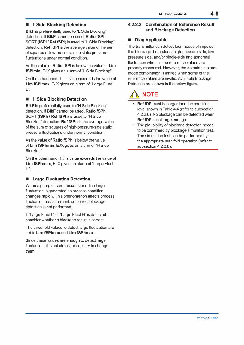
<4. Diagnostics> 4-8
IM 01C25T01-06EN
4.2.2.2 Combination of Reference Result and Blockage Detection
Diag ApplicableThe transmitter can detect four modes of impulse line blockage: both-sides, high-pressure side, low-pressure side, and/or single-side and abnormal fluctuation when all the reference values are properly measured. However, the detectable alarm mode combination is limited when some of the reference values are invalid. Available Blockage Detection are shown in the below figure.
NOTE• Ref fDP must be larger than the specified
level shown in Table 4.4 (refer to subsection 4.2.2.6). No blockage can be detected when Ref fDP is not large enough.
• The plausibility of blockage detection needs to be confirmed by blockage simulation test. The simulation test can be performed by the appropriate manifold operation (refer to subsection 4.2.2.8).
L Side Blocking DetectionBlkF is preferentially used to "L Side Blocking" detection. If BlkF cannot be used, Ratio fSPl, SQRT (fSPl / Ref fSPl) is used to "L Side Blocking" detection. Ref fSPl is the average value of the sum of squares of low-pressure-side static pressure fluctuations under normal condition.
As the value of Ratio fSPl is below the value of Lim fSPlmin, EJX gives an alarm of "L Side Blocking".
On the other hand, if this value exceeds the value of Lim fSPlmax, EJX gives an alarm of “Large Fluct L”.
H Side Blocking DetectionBlkF is preferentially used to "H Side Blocking" detection. If BlkF cannot be used, Ratio fSPh, SQRT (fSPh / Ref fSPh) is used to "H Side Blocking" detection. Ref fSPh is the average value of the sum of squares of high-pressure-side static pressure fluctuations under normal condition.
As the value of Ratio fSPh is below the value of Lim fSPhmin, EJX gives an alarm of "H Side Blocking".
On the other hand, if this value exceeds the value of Lim fSPhmax, EJX gives an alarm of “Large Fluct H”.
Large Fluctuation DetectionWhen a pump or compressor starts, the large fluctuation is generated as process condition changes rapidly. This phenomenon affects process fluctuation measurement; so correct blockage detection is not performed.
If “Large Fluct L” or “Large Fluct H” is detected, consider whether a blockage result is correct.
The threshold values to detect large fluctuation are set to Lim fSPlmax and Lim fSPhmax.
Since these values are enough to detect large fluctuation, it is not almost necessary to change them.
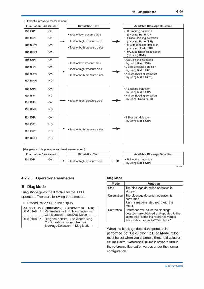
<4. Diagnostics> 4-9
IM 01C25T01-06EN
Ref fDP: OK
Ref fSPI: OK
Ref fSPh: OK
Ref BlkF: OK
Fluctuation Parameters
• Test for low-pressure side • Test for high-pressure side • Test for both-pressure sides
Simulation Test
• B Blocking detection (by using Ratio fDP)• L Side Blocking detection (by using Ratio fSPI)• H Side Blocking detection (by using Ratio fSPh)• H/L Side Blocking detection (by using BlkF)
Ref fDP: OK
Ref fSPI: OK
Ref fSPh: OK
Ref BlkF: NG
• Test for low-pressure side • Test for high-pressure side • Test for both-pressure sides
• A/B Blocking detection (by using Ratio fDP)• L Side Blocking detection (by using Ratio fSPl)• H Side Blocking detection (by using Ratio fSPh)
Ref fDP: OK
Ref fSPI: NG
Ref fSPh: OK
Ref BlkF: NG
• Test for high-pressure side
• A Blocking detection (by using Ratio fDP)• H Side Blocking detection (by using Ratio fSPh)
Ref fDP: OK
Ref fSPI: NG
Ref fSPh: NG
Ref BlkF: NG
• Test for both-pressure sides
• B Blocking detection (by using Ratio fDP)
Available Blockage Detection
[Differential pressure measurement]
[Gauge/absolute pressure and level measurement]
Ref fDP: OK
Fluctuation Parameters Simulation Test
• Test for high-pressure side • B Blocking detection (by using Ratio fDP)
Available Blockage Detection
F0405.ai
4.2.2.3 Operation Parameters
Diag ModeDiag Mode gives the directive for the ILBD operation. There are following three modes.
• Procedure to call up the displayDD (HART 5/7)DTM (HART 7)
[Root Menu] → Diag/Service → Diag Parameters → ILBD Parameters → Configuration → Set Diag Mode →
DTM (HART 5) Diag and Service → Advanced Diag Configurations → Impulse Line Blockage Detection → Diag Mode →
Diag Mode
Mode FunctionStop The blockage detection operation is
stopped.Calculation The blockage detection operation is
performed.Alarms are generated along with the result.
Reference Reference values for the blockage detection are obtained and updated to the latest. After sampling reference values, this mode changes to "Calculation".
When the blockage detection operation is performed, set “Calculation” to Diag Mode. “Stop” must be set when you change a threshold value or set an alarm. “Reference” is set in order to obtain the reference fluctuation values under the normal configuration.
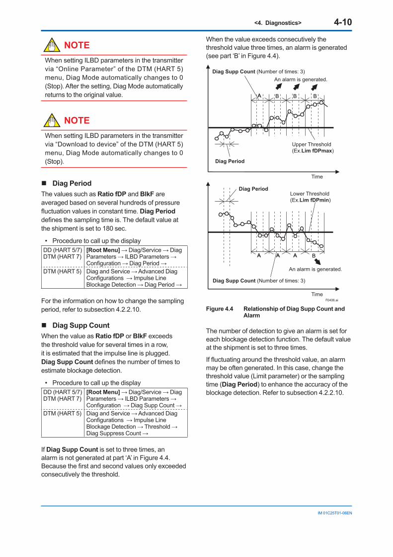
<4. Diagnostics> 4-10
IM 01C25T01-06EN
NOTEWhen setting ILBD parameters in the transmitter via “Online Parameter” of the DTM (HART 5) menu, Diag Mode automatically changes to 0 (Stop). After the setting, Diag Mode automatically returns to the original value.
NOTEWhen setting ILBD parameters in the transmitter via “Download to device” of the DTM (HART 5) menu, Diag Mode automatically changes to 0 (Stop).
Diag PeriodThe values such as Ratio fDP and BlkF are averaged based on several hundreds of pressure fluctuation values in constant time. Diag Period defines the sampling time is. The default value at the shipment is set to 180 sec.
• Procedure to call up the displayDD (HART 5/7)DTM (HART 7)
[Root Menu] → Diag/Service → Diag Parameters → ILBD Parameters → Configuration → Diag Period →
DTM (HART 5) Diag and Service → Advanced Diag Configurations → Impulse Line Blockage Detection → Diag Period →
For the information on how to change the sampling period, refer to subsection 4.2.2.10.
Diag Supp CountWhen the value as Ratio fDP or BlkF exceeds the threshold value for several times in a row, it is estimated that the impulse line is plugged. Diag Supp Count defines the number of times to estimate blockage detection.
• Procedure to call up the displayDD (HART 5/7)DTM (HART 7)
[Root Menu] → Diag/Service → Diag Parameters → ILBD Parameters → Configuration → Diag Supp Count →
DTM (HART 5) Diag and Service → Advanced Diag Configurations → Impulse Line Blockage Detection → Threshold → Diag Suppress Count →
If Diag Supp Count is set to three times, an alarm is not generated at part ‘A’ in Figure 4.4. Because the first and second values only exceeded consecutively the threshold.
When the value exceeds consecutively the threshold value three times, an alarm is generated (see part ‘B’ in Figure 4.4).
BA A A
B BBA
F0406.ai
Diag Supp Count (Number of times: 3)
Diag Supp Count (Number of times: 3)
Diag Period
Diag Period
Upper Threshold(Ex.Lim fDPmax)
Lower Threshold(Ex.Lim fDPmin)
An alarm is generated.
An alarm is generated.
Time
Time
Figure 4.4 Relationship of Diag Supp Count and Alarm
The number of detection to give an alarm is set for each blockage detection function. The default value at the shipment is set to three times.
If fluctuating around the threshold value, an alarm may be often generated. In this case, change the threshold value (Limit parameter) or the sampling time (Diag Period) to enhance the accuracy of the blockage detection. Refer to subsection 4.2.2.10.
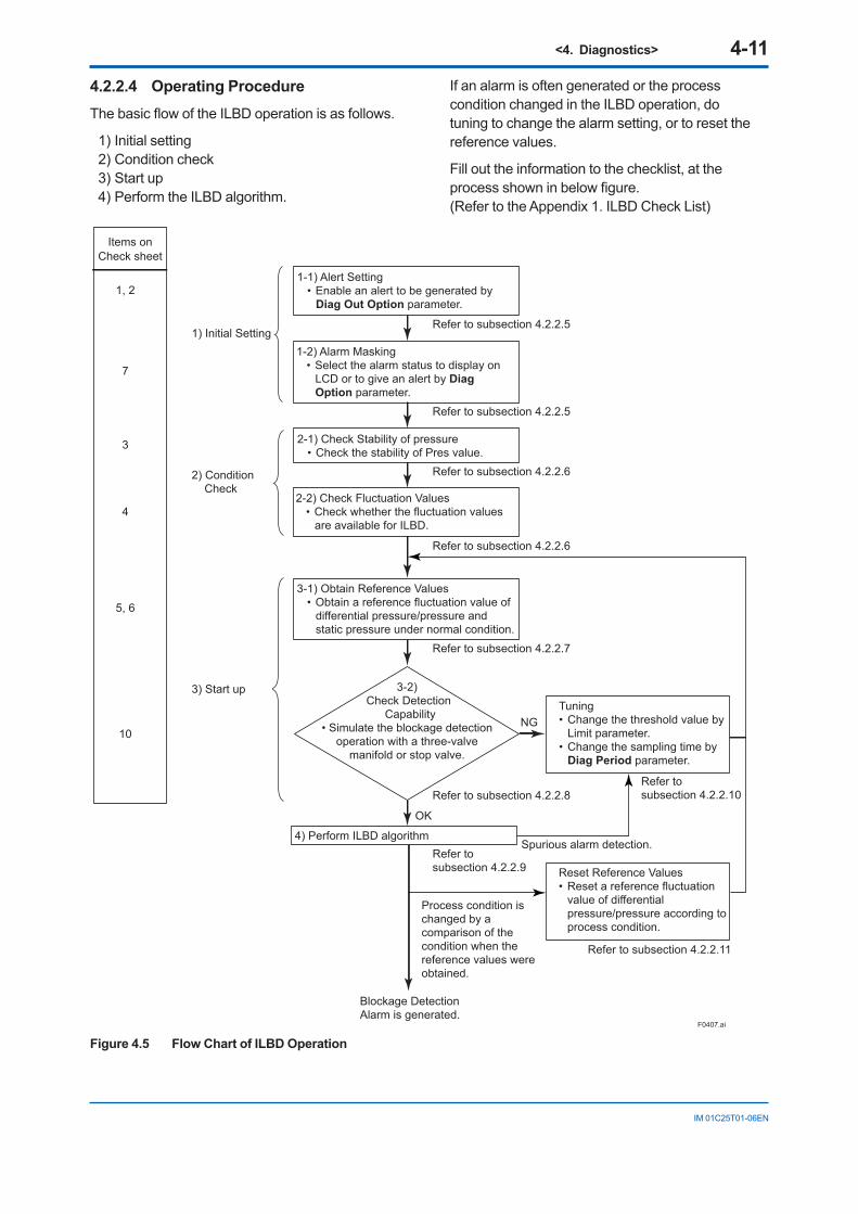
<4. Diagnostics> 4-11
IM 01C25T01-06EN
4.2.2.4 Operating ProcedureThe basic flow of the ILBD operation is as follows.
1) Initial setting2) Condition check3) Start up4) Perform the ILBD algorithm.
If an alarm is often generated or the process condition changed in the ILBD operation, do tuning to change the alarm setting, or to reset the reference values.
Fill out the information to the checklist, at the process shown in below figure. (Refer to the Appendix 1. ILBD Check List)
F0407.ai
NG
1, 2
7
3
4
5, 6
10
1-1) Alert Setting• Enable an alert to be generated by
Diag Out Option parameter.
1-2) Alarm Masking• Select the alarm status to display on
LCD or to give an alert by Diag Option parameter.
2-1) Check Stability of pressure• Check the stability of Pres value.
2-2) Check Fluctuation Values• Check whether the fluctuation values
are available for ILBD.
3-1) Obtain Reference Values• Obtain a reference fluctuation value of
differential pressure/pressure and static pressure under normal condition.
3-2) Check Detection
Capability• Simulate the blockage detection
operation with a three-valve manifold or stop valve.
Tuning• Change the threshold value by
Limit parameter.• Change the sampling time by
Diag Period parameter.
Reset Reference Values• Reset a reference fluctuation
value of differential pressure/pressure according to process condition.
4) Perform ILBD algorithm
Refer to subsection 4.2.2.11
Refer to subsection 4.2.2.10
Process condition is changed by a comparison of the condition when the reference values were obtained.
Blockage DetectionAlarm is generated.
Refer to subsection 4.2.2.9
Spurious alarm detection.
Refer to subsection 4.2.2.8
Refer to subsection 4.2.2.7
Refer to subsection 4.2.2.6
Refer to subsection 4.2.2.6
Refer to subsection 4.2.2.5
Refer to subsection 4.2.2.51) Initial Setting
2) Condition Check
3) Start up
Items onCheck sheet
OK
Figure 4.5 Flow Chart of ILBD Operation
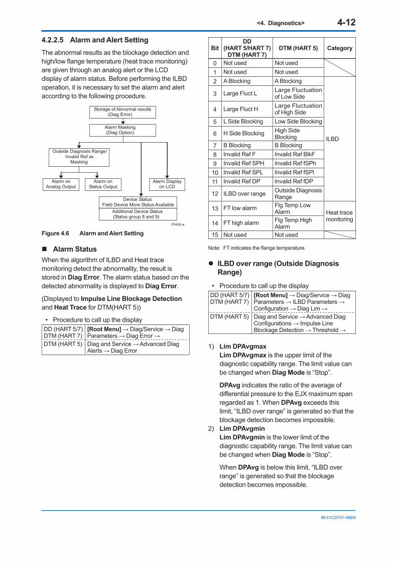
<4. Diagnostics> 4-12
IM 01C25T01-06EN
BitDD
(HART 5/HART 7) DTM (HART 7)
DTM (HART 5) Category
0 Not used Not used1 Not used Not used2 A Blocking A Blocking
ILBD
3 Large Fluct L Large Fluctuation of Low Side
4 Large Fluct H Large Fluctuation of High Side
5 L Side Blocking Low Side Blocking
6 H Side Blocking High Side Blocking
7 B Blocking B Blocking8 Invalid Ref F Invalid Ref BlkF9 Invalid Ref SPH Invalid Ref fSPh10 Invalid Ref SPL Invalid Ref fSPl11 Invalid Ref DP Invalid Ref fDP
12 ILBD over range Outside Diagnosis Range
13 FT low alarm Flg Temp Low Alarm Heat trace
monitoring14 FT high alarm Flg Temp High
Alarm15 Not used Not used
Note: FT indicates the flange temperature.
ILBD over range (Outside Diagnosis Range)
• Procedure to call up the displayDD (HART 5/7)DTM (HART 7)
[Root Menu] → Diag/Service → Diag Parameters → ILBD Parameters → Configuration → Diag Lim →
DTM (HART 5) Diag and Service → Advanced Diag Configurations → Impulse Line Blockage Detection → Threshold →
1) Lim DPAvgmaxLim DPAvgmax is the upper limit of the diagnostic capability range. The limit value can be changed when Diag Mode is “Stop”.
DPAvg indicates the ratio of the average of differential pressure to the EJX maximum span regarded as 1. When DPAvg exceeds this limit, “ILBD over range” is generated so that the blockage detection becomes impossible.
2) Lim DPAvgminLim DPAvgmin is the lower limit of the diagnostic capability range. The limit value can be changed when Diag Mode is “Stop”.
When DPAvg is below this limit, “ILBD over range” is generated so that the blockage detection becomes impossible.
4.2.2.5 Alarm and Alert SettingThe abnormal results as the blockage detection and high/low flange temperature (heat trace monitoring) are given through an analog alert or the LCD display of alarm status. Before performing the ILBD operation, it is necessary to set the alarm and alert according to the following procedure.
Storage of Abnormal results (Diag Error)
Alarm Masking (Diag Option)
Outside Diagnosis Range/ Invalid Ref xx
Masking
Alarm on Analog Output
Alarm on Status Output
Device Status Field Device More Status Available
Additional Device Status (Status group 8 and 9)
Alarm Displayon LCD
F0408.ai
Figure 4.6 Alarm and Alert Setting
Alarm StatusWhen the algorithm of ILBD and Heat trace monitoring detect the abnormality, the result is stored in Diag Error. The alarm status based on the detected abnormality is displayed to Diag Error.
(Displayed to Impulse Line Blockage Detection and Heat Trace for DTM(HART 5))
• Procedure to call up the displayDD (HART 5/7)DTM (HART 7)
[Root Menu] → Diag/Service → Diag Parameters → Diag Error →
DTM (HART 5) Diag and Service → Advanced Diag Alerts → Diag Error
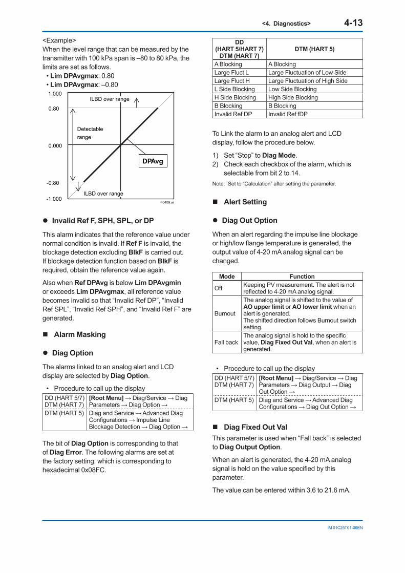
<4. Diagnostics> 4-13
IM 01C25T01-06EN
<Example>When the level range that can be measured by the transmitter with 100 kPa span is –80 to 80 kPa, the limits are set as follows.
• Lim DPAvgmax: 0.80• Lim DPAvgmax: –0.801.000
0.000
0.80
-0.80
-1.000
Detectable range
DPAvg
ILBD over range
ILBD over range F0409.ai
Invalid Ref F, SPH, SPL, or DP
This alarm indicates that the reference value under normal condition is invalid. If Ref F is invalid, the blockage detection excluding BlkF is carried out. If blockage detection function based on BlkF is required, obtain the reference value again.
Also when Ref DPAvg is below Lim DPAvgmin or exceeds Lim DPAvgmax, all reference value becomes invalid so that “Invalid Ref DP”, “Invalid Ref SPL”, “Invalid Ref SPH”, and “Invalid Ref F” are generated.
Alarm Masking
Diag Option
The alarms linked to an analog alert and LCD display are selected by Diag Option.
• Procedure to call up the displayDD (HART 5/7)DTM (HART 7)
[Root Menu] → Diag/Service → Diag Parameters → Diag Option →
DTM (HART 5) Diag and Service → Advanced Diag Configurations → Impulse Line Blockage Detection → Diag Option →
The bit of Diag Option is corresponding to that of Diag Error. The following alarms are set at the factory setting, which is corresponding to hexadecimal 0x08FC.
DD (HART 5/HART 7)
DTM (HART 7)DTM (HART 5)
A Blocking A BlockingLarge Fluct L Large Fluctuation of Low SideLarge Fluct H Large Fluctuation of High SideL Side Blocking Low Side BlockingH Side Blocking High Side BlockingB Blocking B BlockingInvalid Ref DP Invalid Ref fDP
To Link the alarm to an analog alert and LCD display, follow the procedure below.
1) Set “Stop” to Diag Mode.2) Check each checkbox of the alarm, which is
selectable from bit 2 to 14.Note: Set to “Calculation” after setting the parameter.
Alert Setting
Diag Out Option
When an alert regarding the impulse line blockage or high/low flange temperature is generated, the output value of 4-20 mA analog signal can be changed.
Mode Function
Off Keeping PV measurement. The alert is not reflected to 4-20 mA analog signal.
Burnout
The analog signal is shifted to the value of AO upper limit or AO lower limit when an alert is generated. The shifted direction follows Burnout switch setting.
Fall backThe analog signal is hold to the specific value, Diag Fixed Out Val, when an alert is generated.
• Procedure to call up the displayDD (HART 5/7)DTM (HART 7)
[Root Menu] → Diag/Service → Diag Parameters → Diag Output → Diag Out Option →
DTM (HART 5) Diag and Service → Advanced Diag Configurations → Diag Out Option →
Diag Fixed Out ValThis parameter is used when “Fall back” is selected to Diag Output Option.
When an alert is generated, the 4-20 mA analog signal is held on the value specified by this parameter.
The value can be entered within 3.6 to 21.6 mA.
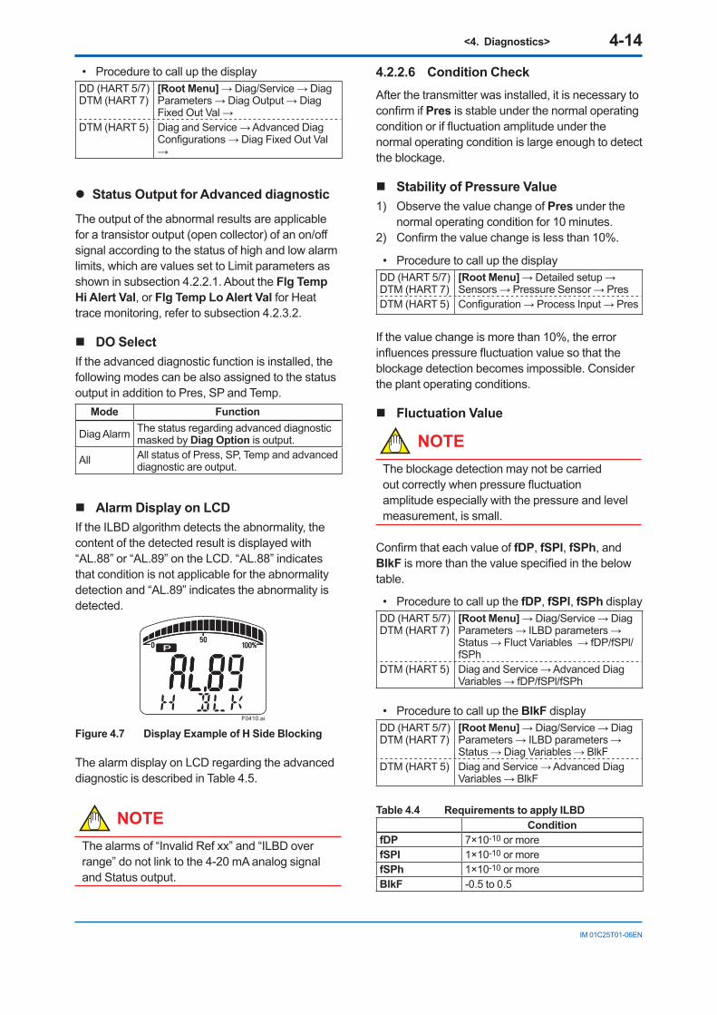
<4. Diagnostics> 4-14
IM 01C25T01-06EN
• Procedure to call up the displayDD (HART 5/7)DTM (HART 7)
[Root Menu] → Diag/Service → Diag Parameters → Diag Output → Diag Fixed Out Val →
DTM (HART 5) Diag and Service → Advanced Diag Configurations → Diag Fixed Out Val →
Status Output for Advanced diagnostic
The output of the abnormal results are applicable for a transistor output (open collector) of an on/off signal according to the status of high and low alarm limits, which are values set to Limit parameters as shown in subsection 4.2.2.1. About the Flg Temp Hi Alert Val, or Flg Temp Lo Alert Val for Heat trace monitoring, refer to subsection 4.2.3.2.
DO SelectIf the advanced diagnostic function is installed, the following modes can be also assigned to the status output in addition to Pres, SP and Temp.
Mode Function
Diag Alarm The status regarding advanced diagnostic masked by Diag Option is output.
All All status of Press, SP, Temp and advanced diagnostic are output.
Alarm Display on LCDIf the ILBD algorithm detects the abnormality, the content of the detected result is displayed with “AL.88” or “AL.89” on the LCD. “AL.88” indicates that condition is not applicable for the abnormality detection and “AL.89” indicates the abnormality is detected.
F0410.ai
Figure 4.7 Display Example of H Side Blocking
The alarm display on LCD regarding the advanced diagnostic is described in Table 4.5.
NOTEThe alarms of “Invalid Ref xx” and “ILBD over range” do not link to the 4-20 mA analog signal and Status output.
4.2.2.6 Condition CheckAfter the transmitter was installed, it is necessary to confirm if Pres is stable under the normal operating condition or if fluctuation amplitude under the normal operating condition is large enough to detect the blockage.
Stability of Pressure Value1) Observe the value change of Pres under the
normal operating condition for 10 minutes.2) Confirm the value change is less than 10%.
• Procedure to call up the displayDD (HART 5/7)DTM (HART 7)
[Root Menu] → Detailed setup → Sensors → Pressure Sensor → Pres
DTM (HART 5) Configuration → Process Input → Pres
If the value change is more than 10%, the error influences pressure fluctuation value so that the blockage detection becomes impossible. Consider the plant operating conditions.
Fluctuation Value
NOTEThe blockage detection may not be carried out correctly when pressure fluctuation amplitude especially with the pressure and level measurement, is small.
Confirm that each value of fDP, fSPl, fSPh, and BlkF is more than the value specified in the below table.
• Procedure to call up the fDP, fSPl, fSPh displayDD (HART 5/7)DTM (HART 7)
[Root Menu] → Diag/Service → Diag Parameters → ILBD parameters → Status → Fluct Variables → fDP/fSPl/fSPh
DTM (HART 5) Diag and Service → Advanced Diag Variables → fDP/fSPl/fSPh
• Procedure to call up the BlkF displayDD (HART 5/7)DTM (HART 7)
[Root Menu] → Diag/Service → Diag Parameters → ILBD parameters → Status → Diag Variables → BlkF
DTM (HART 5) Diag and Service → Advanced Diag Variables → BlkF
Table 4.4 Requirements to apply ILBDCondition
fDP 7×10⁻¹⁰ or morefSPI 1×10⁻¹⁰ or morefSPh 1×10⁻¹⁰ or moreBlkF -0.5 to 0.5
<4. Diagnostics> 4-15
IM 01C25T01-06EN
fDP is not enough.
No blockage can be detected if fDP is not larger than the specified value.
Only fDP is enough.
“A Blocking” or “B Blocking” can be detected if fSPl and fSPh are not larger than specified values.
fDP and fSPl are enough.
“H Side Blocking” and “Large Fluct H” can not be detected if fSPh is not larger than specified value.
fDP and fSPh are enough.
“L Side Blocking” and “Large Fluct L” can not be detected if fSPl is not larger than specified value.
fDP, fSPl and fSPh are enough.
All alarm modes can be detected even if BlkF is not within the specified values.
4.2.2.7 Obtain Reference ValuesThe pressure fluctuation values are reduced when the impulse line is plugged. Therefore, the reference value is required to determine the degree of reduction.
IMPORTANT• If the impulse line is about to be plugged at
the time when a reference value is obtained, blockages cannot be detected accurately. The impulse lines on both the high-pressure and low-pressure sides need to be cleaned before a reference value is obtained.
• All air bubbles need to be adequately purged before a reference value is obtained.
• Reference values must be obtained under operating condition.
Start of SamplingThe sampling of reference value is carried out for 180 sec, which is the default value set to Diag Period.
1) Confirm that the sampling period (Diag Period) is set to 180 sec.
2) Set “Reference” to Diag Mode.The sampling starts soon after the setting.
IMPORTANT• For the each parameter, the one value is
given. If Reference is set to Diag Mode again, the value is updated and overwritten.
• If the power supply is shut down during the sampling, Diag Mode becomes “Stop”. Set “Reference” to Diag Mode in order to carry out the sampling again.
End of SamplingAfter about 180 sec, the sampling automatically finishes. The “Reference” setting of Diag Mode moves automatically to “Calculation”.
Confirm that the setting of Diag Mode moves to “Calculation”.
Reference ValuesConfirm the latest values are obtained into the following parameters.
• Ref fDP• Ref fSPl• Ref fSPh• Ref BlkF• Ref DPAvg
• Procedure to call up the displayDD (HART 5/7)DTM (HART 7)
[Root Menu] → Diag/Service → Diag Parameters → ILBD parameters → Status → Diag Reference → Ref fDP/Ref fSPl/Ref fSPh/Ref BlkF/Ref DPAvg
DTM (HART 5) Diag and Service → Advanced Diag Configuration → Impulse Line Blockage Detection → Ref fDP/Ref fSPl/Ref fSPh/Ref BlkF/Ref DPAvg
<4. Diagnostics> 4-16
IM 01C25T01-06EN
Invalid Ref F, SPH, SPL, or DPWhen the enough reference fluctuation value is not obtained, an alarm of invalid reference value for each parameter is generated and also the ILBD operation is not carried out.
Confirm the alarm of Invalid Ref F, SPH, SPL, or DP is not displayed in Diag Error.
If an alarm of Invalid Ref F, SPH, SPL, or DP is generated, consider the process condition or obtain the reference fluctuation values again.
NOTEEven if an alarm of Invalid Ref F, SPH, SPL, or DP is generated, “Calculation” in Diag Mode is kept.
4.2.2.8 Capability Test of Blockage Detection Operation
Before performing the ILBD operation, check the capability of the blockage detection operation. The simulation test is performed by closing motion of a three-valve manifold or stop valve. When simulated blockage occurs, confirm that an alarm is generated.
NOTEThe fluctuation amplitude of atmospheric pressure is nearly zero with pressure or level measurement. In such case, simulate the blockage detection by closing the valve where the fluctuation existed.
Simulation of High-pressure Side Blockage1) Close the high-pressure-side valve.2) Confirm the value of Pres is stable. If not,
open the valve a little.3) Set “Calculation” to Diag Mode so as to start
blockage detection operation.4) Check that an alarm of “H Side Blocking” is
generated after the time that consists of Diag Period and Diag Supp Count passed.
5) Check also the operation of the analog alert if an analog alert is set.
6) Open the valve completely and check that there are no alarms.
Simulation of Low-pressure Side Blockage1) Close the low-pressure-side valve.2) Confirm the value of Pres is stable. If not,
open the valve a little.3) Set “Calculation” to Diag Mode so as to start
blockage detection operation.4) Check that an alarm of “L Side Blocking” is
generated after the time that consists of Diag Period and Diag Supp Count passed.
5) Check also the operation of the analog alert if an analog alert is set.
6) Open the valve completely and check that there are no alarms.
Simulation of Both-pressure Side Blockage1) Close the both-pressure-side valves.2) Confirm the value of Pres is stable. If not,
open the valve a little.3) Set “Calculation” to Diag Mode so as to start
blockage detection operation.4) Check that an alarm of “B Blocking” is
generated in the Diag Error after the time that consists of Diag Period and Diag Supp Count passed.
5) Check also the operation of the analog alert if an analog alert is set.
6) Open the valve completely and check that there are no alarms.
4.2.2.9 Start ILBD OperationIf process condition and capability to detect a blockage are confirmed, you can start the ILBD operation according to the following procedure.
1) Check the value of sampling period (Diag Period).
2) Check the number of times that detect the blockage consecutively in order to give an alarm (Diag Supp Count). The default value at the shipment is set to 3 times.
3) Set “Calculation” to Diag Mode. If the reference value has not yet been
obtained, set “Reference” to Diag Mode. After obtained the reference values, the ILBD starts automatically. At the same time, Diag Mode changes automatically from “Reference” to “Calculation”.
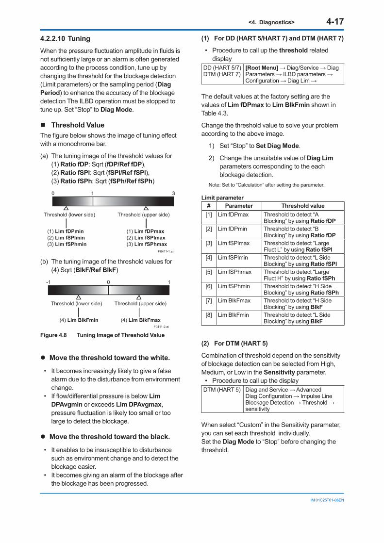
<4. Diagnostics> 4-17
IM 01C25T01-06EN
4.2.2.10 TuningWhen the pressure fluctuation amplitude in fluids is not sufficiently large or an alarm is often generated according to the process condition, tune up by changing the threshold for the blockage detection (Limit parameters) or the sampling period (Diag Period) to enhance the accuracy of the blockage detection The ILBD operation must be stopped to tune up. Set “Stop” to Diag Mode.
Threshold ValueThe figure below shows the image of tuning effect with a monochrome bar.
(a) The tuning image of the threshold values for(1) Ratio fDP: Sqrt (fDP/Ref fDP),(2) Ratio fSPl: Sqrt (fSPl/Ref fSPl),(3) Ratio fSPh: Sqrt (fSPh/Ref fSPh)
F0411-1.ai
0 1 3
Threshold (lower side) Threshold (upper side)
(1) Lim fDPmin(2) Lim fSPlmin(3) Lim fSPhmin
(1) Lim fDPmax(2) Lim fSPlmax(3) Lim fSPhmax
(b) The tuning image of the threshold values for(4) Sqrt (BlkF/Ref BlkF)
F0411-2.ai
0-1 1
Threshold (lower side) Threshold (upper side)
(4) Lim BlkFmin (4) Lim BlkFmax
Figure 4.8 Tuning Image of Threshold Value
Move the threshold toward the white.
• It becomes increasingly likely to give a false alarm due to the disturbance from environment change.
• If flow/differential pressure is below Lim DPAvgmin or exceeds Lim DPAvgmax, pressure fluctuation is likely too small or too large to detect the blockage.
Move the threshold toward the black.
• It enables to be insusceptible to disturbance such as environment change and to detect the blockage easier.
• It becomes giving an alarm of the blockage after the blockage has been progressed.
(1) For DD (HART 5/HART 7) and DTM (HART 7)
• Procedure to call up the threshold related display
DD (HART 5/7)DTM (HART 7)
[Root Menu] → Diag/Service → Diag Parameters → ILBD parameters → Configuration → Diag Lim →
The default values at the factory setting are the values of Lim fDPmax to Lim BlkFmin shown in Table 4.3.
Change the threshold value to solve your problem according to the above image.
1) Set “Stop” to Set Diag Mode.
2) Change the unsuitable value of Diag Lim parameters corresponding to the each blockage detection.
Note: Set to “Calculation” after setting the parameter.
Limit parameter# Parameter Threshold value[1] Lim fDPmax Threshold to detect “A
Blocking” by using Ratio fDP[2] Lim fDPmin Threshold to detect “B
Blocking” by using Ratio fDP[3] Lim fSPlmax Threshold to detect “Large
Fluct L” by using Ratio fSPl[4] Lim fSPlmin Threshold to detect “L Side
Blocking” by using Ratio fSPl[5] Lim fSPhmax Threshold to detect “Large
Fluct H” by using Ratio fSPh[6] Lim fSPhmin Threshold to detect “H Side
Blocking” by using Ratio fSPh[7] Lim BlkFmax Threshold to detect “H Side
Blocking” by using BlkF[8] Lim BlkFmin Threshold to detect “L Side
Blocking” by using BlkF
(2) For DTM (HART 5)
Combination of threshold depend on the sensitivity of blockage detection can be selected from High, Medium, or Low in the Sensitivity parameter.
• Procedure to call up the displayDTM (HART 5) Diag and Service → Advanced
Diag Configuration → Impulse Line Blockage Detection → Threshold → sensitivity
When select “Custom” in the Sensitivity parameter, you can set each threshold individually.Set the Diag Mode to “Stop” before changing the threshold.
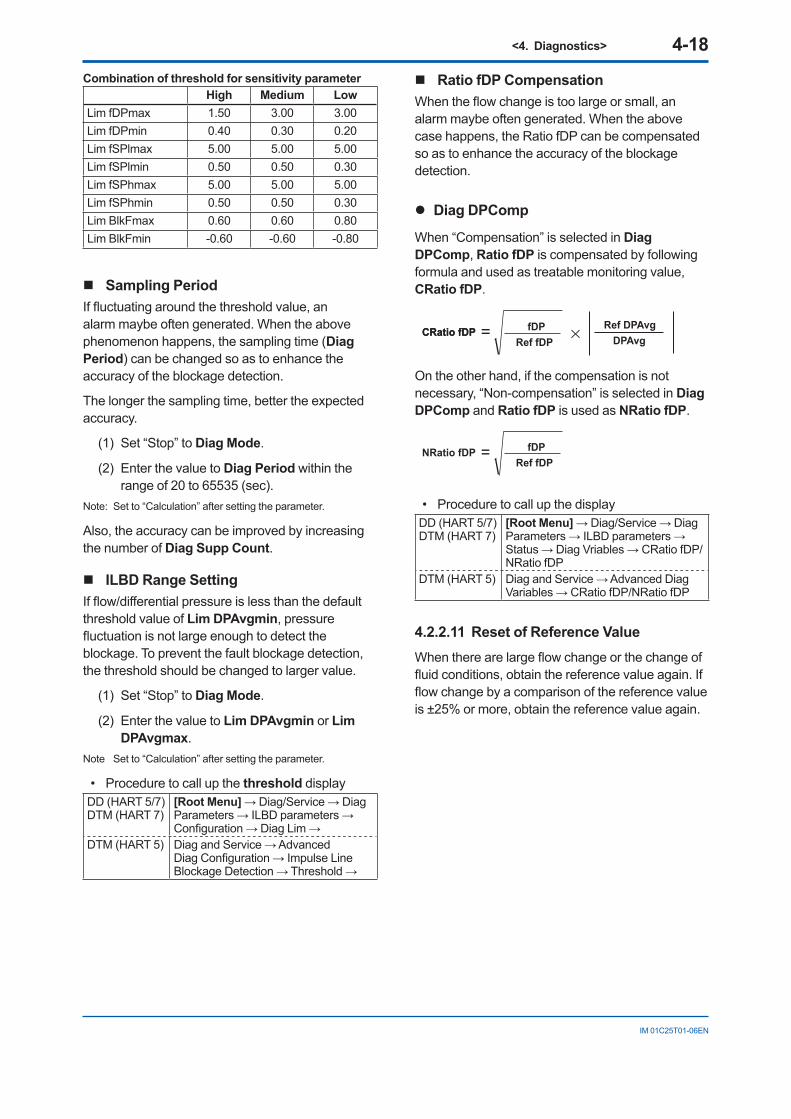
<4. Diagnostics> 4-18
IM 01C25T01-06EN
Combination of threshold for sensitivity parameterHigh Medium Low
Lim fDPmax 1.50 3.00 3.00Lim fDPmin 0.40 0.30 0.20Lim fSPlmax 5.00 5.00 5.00Lim fSPlmin 0.50 0.50 0.30Lim fSPhmax 5.00 5.00 5.00Lim fSPhmin 0.50 0.50 0.30Lim BlkFmax 0.60 0.60 0.80Lim BlkFmin -0.60 -0.60 -0.80
Sampling PeriodIf fluctuating around the threshold value, an alarm maybe often generated. When the above phenomenon happens, the sampling time (Diag Period) can be changed so as to enhance the accuracy of the blockage detection.
The longer the sampling time, better the expected accuracy.
(1) Set “Stop” to Diag Mode.
(2) Enter the value to Diag Period within the range of 20 to 65535 (sec).
Note: Set to “Calculation” after setting the parameter.
Also, the accuracy can be improved by increasing the number of Diag Supp Count.
ILBD Range SettingIf flow/differential pressure is less than the default threshold value of Lim DPAvgmin, pressure fluctuation is not large enough to detect the blockage. To prevent the fault blockage detection, the threshold should be changed to larger value.
(1) Set “Stop” to Diag Mode.
(2) Enter the value to Lim DPAvgmin or Lim DPAvgmax.
Note Set to “Calculation” after setting the parameter.
• Procedure to call up the threshold displayDD (HART 5/7)DTM (HART 7)
[Root Menu] → Diag/Service → Diag Parameters → ILBD parameters → Configuration → Diag Lim →
DTM (HART 5) Diag and Service → Advanced Diag Configuration → Impulse Line Blockage Detection → Threshold →
Ratio fDP CompensationWhen the flow change is too large or small, an alarm maybe often generated. When the above case happens, the Ratio fDP can be compensated so as to enhance the accuracy of the blockage detection.
Diag DPComp
When “Compensation” is selected in Diag DPComp, Ratio fDP is compensated by following formula and used as treatable monitoring value, CRatio fDP.
=CRatio fDPCRatio fDPRef fDP
fDPDPAvg
Ref DPAvg
On the other hand, if the compensation is not necessary, “Non-compensation” is selected in Diag DPComp and Ratio fDP is used as NRatio fDP.
=NRatio fDPRef fDP
fDP
• Procedure to call up the displayDD (HART 5/7)DTM (HART 7)
[Root Menu] → Diag/Service → Diag Parameters → ILBD parameters → Status → Diag Vriables → CRatio fDP/NRatio fDP
DTM (HART 5) Diag and Service → Advanced Diag Variables → CRatio fDP/NRatio fDP
4.2.2.11 Reset of Reference ValueWhen there are large flow change or the change of fluid conditions, obtain the reference value again. If flow change by a comparison of the reference value is ±25% or more, obtain the reference value again.
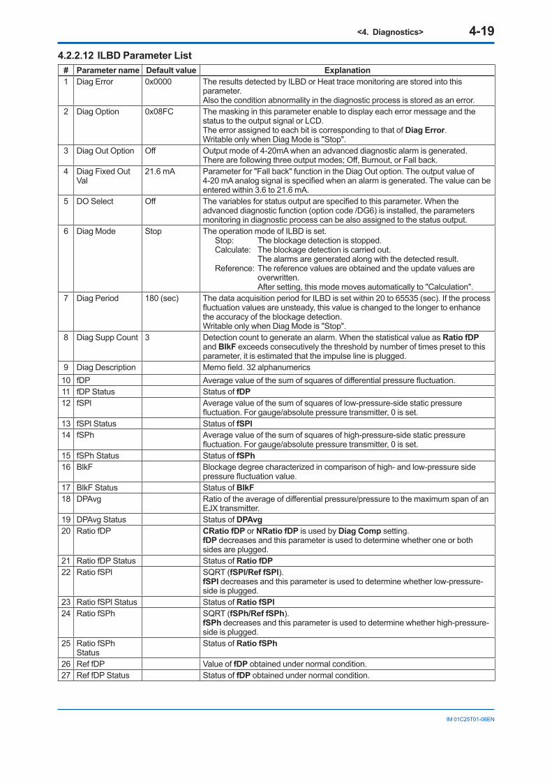
<4. Diagnostics> 4-19
IM 01C25T01-06EN
4.2.2.12 ILBD Parameter List# Parameter name Default value Explanation1 Diag Error 0x0000 The results detected by ILBD or Heat trace monitoring are stored into this
parameter.Also the condition abnormality in the diagnostic process is stored as an error.
2 Diag Option 0x08FC The masking in this parameter enable to display each error message and the status to the output signal or LCD. The error assigned to each bit is corresponding to that of Diag Error.Writable only when Diag Mode is "Stop".
3 Diag Out Option Off Output mode of 4-20mA when an advanced diagnostic alarm is generated.There are following three output modes; Off, Burnout, or Fall back.
4 Diag Fixed Out Val
21.6 mA Parameter for "Fall back" function in the Diag Out option. The output value of 4-20 mA analog signal is specified when an alarm is generated. The value can be entered within 3.6 to 21.6 mA.
5 DO Select Off The variables for status output are specified to this parameter. When the advanced diagnostic function (option code /DG6) is installed, the parameters monitoring in diagnostic process can be also assigned to the status output.
6 Diag Mode Stop The operation mode of ILBD is set.Stop: The blockage detection is stopped.Calculate: The blockage detection is carried out. The alarms are generated along with the detected result.Reference: The reference values are obtained and the update values are
overwritten. After setting, this mode moves automatically to "Calculation".
7 Diag Period 180 (sec) The data acquisition period for ILBD is set within 20 to 65535 (sec). If the process fluctuation values are unsteady, this value is changed to the longer to enhance the accuracy of the blockage detection.Writable only when Diag Mode is "Stop".
8 Diag Supp Count 3 Detection count to generate an alarm. When the statistical value as Ratio fDP and BlkF exceeds consecutively the threshold by number of times preset to this parameter, it is estimated that the impulse line is plugged.
9 Diag Description Memo field. 32 alphanumerics10 fDP Average value of the sum of squares of differential pressure fluctuation.11 fDP Status Status of fDP12 fSPl Average value of the sum of squares of low-pressure-side static pressure
fluctuation. For gauge/absolute pressure transmitter, 0 is set.13 fSPl Status Status of fSPl14 fSPh Average value of the sum of squares of high-pressure-side static pressure
fluctuation. For gauge/absolute pressure transmitter, 0 is set.15 fSPh Status Status of fSPh16 BlkF Blockage degree characterized in comparison of high- and low-pressure side
pressure fluctuation value.17 BlkF Status Status of BlkF18 DPAvg Ratio of the average of differential pressure/pressure to the maximum span of an
EJX transmitter.19 DPAvg Status Status of DPAvg20 Ratio fDP CRatio fDP or NRatio fDP is used by Diag Comp setting.
fDP decreases and this parameter is used to determine whether one or both sides are plugged.
21 Ratio fDP Status Status of Ratio fDP22 Ratio fSPl SQRT (fSPl/Ref fSPl).
fSPl decreases and this parameter is used to determine whether low-pressure-side is plugged.
23 Ratio fSPl Status Status of Ratio fSPl24 Ratio fSPh SQRT (fSPh/Ref fSPh).
fSPh decreases and this parameter is used to determine whether high-pressure-side is plugged.
25 Ratio fSPh Status
Status of Ratio fSPh
26 Ref fDP Value of fDP obtained under normal condition.27 Ref fDP Status Status of fDP obtained under normal condition.
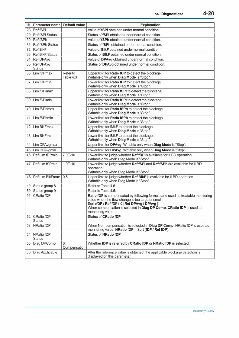
<4. Diagnostics> 4-20
IM 01C25T01-06EN
# Parameter name Default value Explanation28 Ref fSPl Value of fSPl obtained under normal condition.29 Ref fSPl Status Status of fSPl obtained under normal condition.30 Ref fSPh Value of fSPh obtained under normal condition.31 Ref fSPh Status Status of fSPh obtained under normal condition.32 Ref BlkF Value of BlkF obtained under normal condition.33 Ref BlkF Status Status of BlkF obtained under normal condition.34 Ref DPAvg Value of DPAvg obtained under normal condition.35 Ref DPAvg
StatusStatus of DPAvg obtained under normal condition.
36 Lim fDPmax Refer to Table 4.3
Upper limit for Ratio fDP to detect the blockage. Writable only when Diag Mode is "Stop".
37 Lim fDPmin Lower limit for Ratio fDP to detect the blockage. Writable only when Diag Mode is "Stop".
38 Lim fSPlmax Upper limit for Ratio fSPl to detect the blockage. Writable only when Diag Mode is "Stop".
39 Lim fSPlmin Lower limit for Ratio fSPl to detect the blockage. Writable only when Diag Mode is "Stop".
40 Lim fSPhmax Upper limit for Ratio fSPh to detect the blockage. Writable only when Diag Mode is "Stop".
41 Lim fSPhmin Lower limit for Ratio fSPh to detect the blockage. Writable only when Diag Mode is "Stop".
42 Lim BlkFmax Upper limit for BlkF to detect the blockage. Writable only when Diag Mode is "Stop".
43 Lim BlkFmin Lower limit for BlkF to detect the blockage. Writable only when Diag Mode is "Stop".
44 Lim DPAvgmax Upper limit for DPAvg. Writable only when Diag Mode is "Stop".45 Lim DPAvgmin Lower limit for DPAvg. Writable only when Diag Mode is "Stop".46 Ref Lim fDPmin 7.0E-10 Lower limit to judge whether Ref fDP is available for ILBD operation.
Writable only when Diag Mode is "Stop".47 Ref Lim fSPmin 1.0E-10 Lower limit to judge whether Ref fSPl and Ref fSPh are available for ILBD
operation.Writable only when Diag Mode is "Stop".
48 Ref Lim BlkFmax 0.5 Upper limit to judge whether Ref BlkF is available for ILBD operation.Writable only when Diag Mode is "Stop".
49 Status group 8 Refer to Table 4.5.50 Status group 9 Refer to Table 4.5.51 CRatio fDP Ratio fDP is compensated by following formula and used as treatable monitoring
value when the flow change is too large or small.Sqrt (fDP / Ref fDP) X | Ref DPAvg / DPAvg |When compensation is selected in Diag DP Comp, CRatio fDP is used as monitoring value.
52 CRatio fDP Status
Status of CRatio fDP
53 NRatio fDP When Non-compensation is selected in Diag DP Comp, NRatio fDP is used as monitoring value. NRatio fDP = Sqrt (fDP / Ref fDP)
54 NRatio fDP Status
Status of NRatio fDP
55 Diag DPComp 0:Compensation
Whether fDP is referred by CRatio fDP or NRatio fDP is selected.
56 Diag Applicable After the reference value is obtained, the applicable blockage detection is displayed on this parameter.
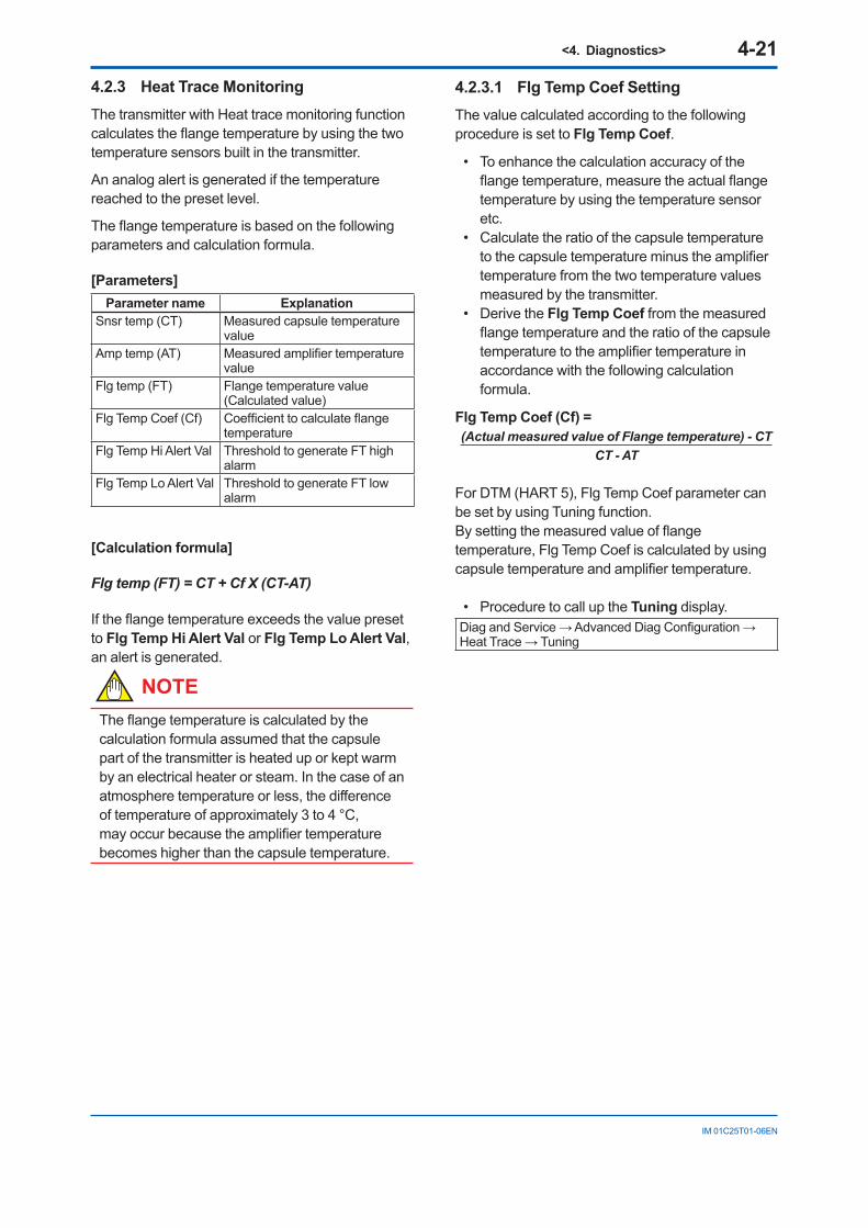
<4. Diagnostics> 4-21
IM 01C25T01-06EN
4.2.3 Heat Trace MonitoringThe transmitter with Heat trace monitoring function calculates the flange temperature by using the two temperature sensors built in the transmitter.
An analog alert is generated if the temperature reached to the preset level.
The flange temperature is based on the following parameters and calculation formula.
[Parameters]Parameter name Explanation
Snsr temp (CT) Measured capsule temperature value
Amp temp (AT) Measured amplifier temperature value
Flg temp (FT) Flange temperature value (Calculated value)
Flg Temp Coef (Cf) Coefficient to calculate flange temperature
Flg Temp Hi Alert Val Threshold to generate FT high alarm
Flg Temp Lo Alert Val Threshold to generate FT low alarm
[Calculation formula]
Flg temp (FT) = CT + Cf X (CT-AT)
If the flange temperature exceeds the value preset to Flg Temp Hi Alert Val or Flg Temp Lo Alert Val, an alert is generated.
NOTEThe flange temperature is calculated by the calculation formula assumed that the capsule part of the transmitter is heated up or kept warm by an electrical heater or steam. In the case of an atmosphere temperature or less, the difference of temperature of approximately 3 to 4 °C, may occur because the amplifier temperature becomes higher than the capsule temperature.
4.2.3.1 Flg Temp Coef SettingThe value calculated according to the following procedure is set to Flg Temp Coef.
• To enhance the calculation accuracy of the flange temperature, measure the actual flange temperature by using the temperature sensor etc.
• Calculate the ratio of the capsule temperature to the capsule temperature minus the amplifier temperature from the two temperature values measured by the transmitter.
• Derive the Flg Temp Coef from the measured flange temperature and the ratio of the capsule temperature to the amplifier temperature in accordance with the following calculation formula.
Flg Temp Coef (Cf) =(Actual measured value of Flange temperature) - CT
CT - AT
For DTM (HART 5), Flg Temp Coef parameter can be set by using Tuning function. By setting the measured value of flange temperature, Flg Temp Coef is calculated by using capsule temperature and amplifier temperature.
• Procedure to call up the Tuning display.Diag and Service → Advanced Diag Configuration → Heat Trace → Tuning
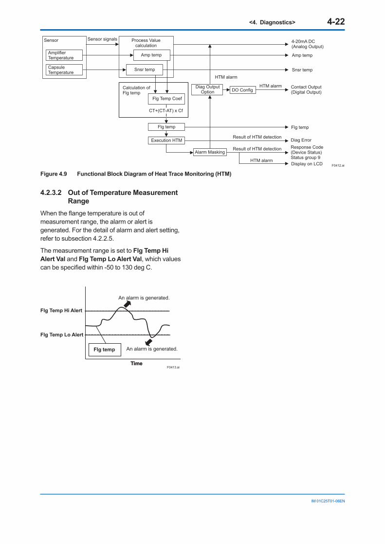
<4. Diagnostics> 4-22
IM 01C25T01-06EN
Amplifier Temperature
Capsule Temperature
Amp temp
Snsr temp
Flg Temp Coef
Flg temp
Execution HTM
CT+(CT-AT) x Cf
Calculation of Flg temp
Snsr temp
Flg temp
Diag Error
Display on LCD
Response Code(Device Status)Status group 9
Contact Output(Digital Output)
4-20mA DC(Analog Output)
Amp temp
Sensor signalsSensor Process Valuecalculation
Alarm MaskingResult of HTM detection
HTM alarm
Result of HTM detection
DO Config
HTM alarm
HTM alarmDiag OutputOption
F0412.ai
Figure 4.9 Functional Block Diagram of Heat Trace Monitoring (HTM)
4.2.3.2 Out of Temperature Measurement Range
When the flange temperature is out of measurement range, the alarm or alert is generated. For the detail of alarm and alert setting, refer to subsection 4.2.2.5.
The measurement range is set to Flg Temp Hi Alert Val and Flg Temp Lo Alert Val, which values can be specified within -50 to 130 deg C.
FlgtempFlg temp
F0413.aiTimeTime
An alarm is generated.
An alarm is generated.
Flg Temp Hi Alert
Flg Temp Lo Alert
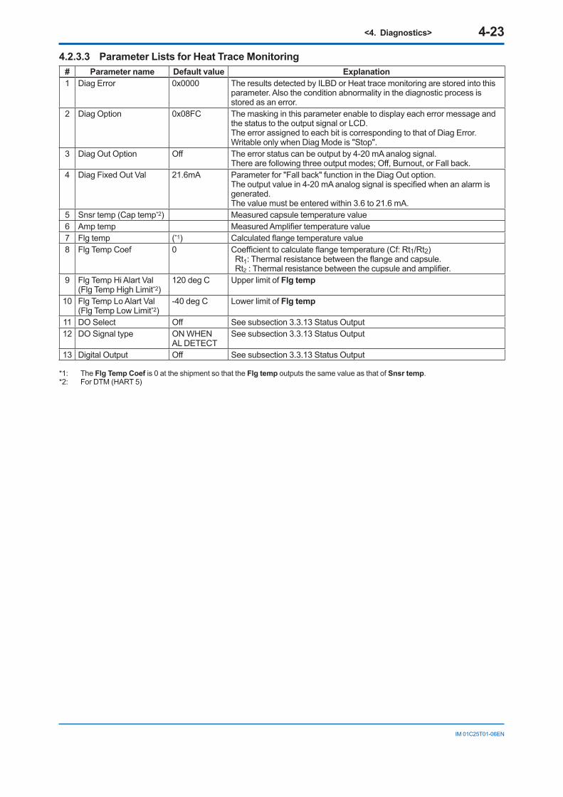
<4. Diagnostics> 4-23
IM 01C25T01-06EN
4.2.3.3 Parameter Lists for Heat Trace Monitoring# Parameter name Default value Explanation1 Diag Error 0x0000 The results detected by ILBD or Heat trace monitoring are stored into this
parameter. Also the condition abnormality in the diagnostic process is stored as an error.
2 Diag Option 0x08FC The masking in this parameter enable to display each error message and the status to the output signal or LCD.The error assigned to each bit is corresponding to that of Diag Error. Writable only when Diag Mode is "Stop".
3 Diag Out Option Off The error status can be output by 4-20 mA analog signal.There are following three output modes; Off, Burnout, or Fall back.
4 Diag Fixed Out Val 21.6mA Parameter for "Fall back" function in the Diag Out option.The output value in 4-20 mA analog signal is specified when an alarm is generated.The value must be entered within 3.6 to 21.6 mA.
5 Snsr temp (Cap temp*2) Measured capsule temperature value6 Amp temp Measured Amplifier temperature value7 Flg temp (*1) Calculated flange temperature value8 Flg Temp Coef 0 Coefficient to calculate flange temperature (Cf: Rt1/Rt2)
Rt1: Thermal resistance between the flange and capsule.Rt2 : Thermal resistance between the cupsule and amplifier.
9 Flg Temp Hi Alart Val(Flg Temp High Limit*2)
120 deg C Upper limit of Flg temp
10 Flg Temp Lo Alart Val(Flg Temp Low Limit*2)
-40 deg C Lower limit of Flg temp
11 DO Select Off See subsection 3.3.13 Status Output12 DO Signal type ON WHEN
AL DETECTSee subsection 3.3.13 Status Output
13 Digital Output Off See subsection 3.3.13 Status Output
*1: The Flg Temp Coef is 0 at the shipment so that the Flg temp outputs the same value as that of Snsr temp.*2: For DTM (HART 5)
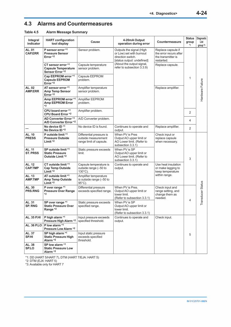
<4. Diagnostics> 4-24
IM 01C25T01-06EN
4.3 Alarms and CountermeasuresTable 4.5 Alarm Message Summary
Integral indicator
HART configuration tool display Cause 4-20mA Output
operation during error Countermeasure Status group
*1
Diagnostic List
group *2
AL. 01 CAP.ERR
P sensor error *1
Pressure Sensor Error *2
Sensor problem. Outputs the signal (High or Low) set with burnout direction switch. [status output: undefined] (About the output signal, refer to subsection 3.3.9)
Replace capsule if the error recurs after the transmitter is restarted.
1
Har
dwar
e Fa
ilure
CT sensor error *1
Capsule Temperature Sensor Error *2
Capsule temperature sensor problem.
Replace capsule.
Cap EEPROM error *1
Capsule EEPROM Error *2
Capsule EEPROM problem.
AL. 02 AMP.ERR
AT sensor error *1
Amp Temp Sensor Error *2
Amplifier temperature sensor problem.
Replace amplifier.
Amp EEPROM error *1
Amp EEPROM Error *2
Amplifier EEPROM problem.
CPU board error *1
CPU Board Error *2Amplifier problem. 2
AD Converter Error *1
A/D Converter Error *2A/D Converter problem. 4
— No device ID *1
No Device ID *2No device ID is found. Continues to operate and
output. Replace amplifier. 2
AL. 10 PRESS
P outside limit *1
Pressure Outside Limit *2
Differential pressure is outside measurement range limit of capsule.
When PV is Pres Output AO upper limit or AO Lower limit. (Refer to subsection 3.3.1)
Check input or replace capsule when necessary.
3
Tran
sduc
er S
tatu
s
AL. 11 ST. PRSS
SP outside limit *1
Static Pressure Outside Limit *2
Static pressure exceeds limit.
When PV is SP Output AO upper limit or AO Lower limit. (Refer to subsection 3.3.1)
AL. 12 CAP.TMP
CT outside limit *1
Cap Temp Outside Limit *2
Capsule temperature is outside range (–50 to 130°C).
Continues to operate and output.
Use heat insulation or make lagging to keep temperature within range. AL. 13
AMP.TMP AT outside limit *1
Amp Temp Outside Limit *2
Amplifier temperature is outside range (–50 to 95°C).
AL. 30 PRS.RNG
P over range *1
Pressure Over Range *2
Differential pressure exceeds specified range.
When PV is Pres. Output AO upper limit or lower limit.(Refer to subsection 3.3.1)
Check input and range setting, and change them as needed.
4AL. 31 SP. RNG
SP over range *1
Static Pressure Over Range *2
Static pressure exceeds specified range.
When PV is SP Output AO upper limit or lower limit.(Refer to subsection 3.3.1)
AL. 35 P.HI P high alarm *1
Pressure High Alarm *2Input pressure exceeds specified threshold.
Continues to operate and output.
Check input.
5
AL. 36 P.LO P low alarm *1
Pressure Low Alarm *2
AL. 37 SP.HI
SP high alarm *1
Static Pressure High Alarm *2
Input static pressure exceeds specified threshold.
AL. 38 SP.LO
SP low alarm *1
Static Pressure Low Alarm *2
*1: DD (HART 5/HART 7), DTM (HART 7/EJA: HART 5)*2: DTM (EJX: HART 5)*3: Available only for HART 7
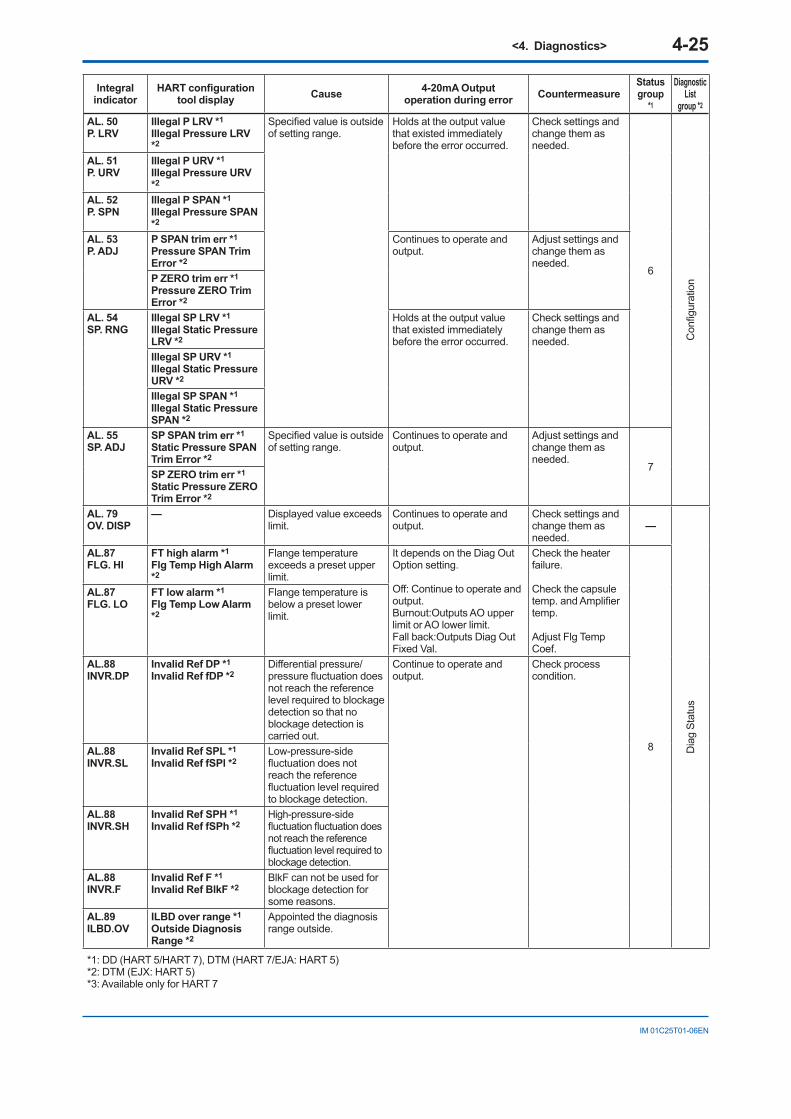
<4. Diagnostics> 4-25
IM 01C25T01-06EN
Integral indicator
HART configuration tool display Cause 4-20mA Output
operation during error Countermeasure Status group
*1
Diagnostic List
group *2
AL. 50 P. LRV
Illegal P LRV *1
Illegal Pressure LRV *2
Specified value is outside of setting range.
Holds at the output value that existed immediately before the error occurred.
Check settings and change them as needed.
6
Con
figur
atio
n
AL. 51 P. URV
Illegal P URV *1
Illegal Pressure URV *2
AL. 52 P. SPN
Illegal P SPAN *1
Illegal Pressure SPAN *2
AL. 53 P. ADJ
P SPAN trim err *1
Pressure SPAN Trim Error *2
Continues to operate and output.
Adjust settings and change them as needed.
P ZERO trim err *1
Pressure ZERO Trim Error *2
AL. 54 SP. RNG
Illegal SP LRV *1
Illegal Static Pressure LRV *2
Holds at the output value that existed immediately before the error occurred.
Check settings and change them as needed.
Illegal SP URV *1
Illegal Static Pressure URV *2
Illegal SP SPAN *1
Illegal Static Pressure SPAN *2
AL. 55 SP. ADJ
SP SPAN trim err *1
Static Pressure SPAN Trim Error *2
Specified value is outside of setting range.
Continues to operate and output.
Adjust settings and change them as needed.
7 SP ZERO trim err *1
Static Pressure ZERO Trim Error *2
AL. 79 OV. DISP
— Displayed value exceeds limit.
Continues to operate and output.
Check settings and change them as needed.
—
Dia
g St
atus
AL.87FLG. HI
FT high alarm *1
Flg Temp High Alarm *2
Flange temperature exceeds a preset upper limit.
It depends on the Diag Out Option setting.
Off: Continue to operate and output.Burnout:Outputs AO upper limit or AO lower limit.Fall back:Outputs Diag Out Fixed Val.
Check the heater failure.
Check the capsule temp. and Amplifier temp.
Adjust Flg Temp Coef.
8
AL.87FLG. LO
FT low alarm *1
Flg Temp Low Alarm *2
Flange temperature is below a preset lower limit.
AL.88INVR.DP
Invalid Ref DP *1
Invalid Ref fDP *2Differential pressure/pressure fluctuation does not reach the reference level required to blockage detection so that no blockage detection is carried out.
Continue to operate and output.
Check process condition.
AL.88INVR.SL
Invalid Ref SPL *1
Invalid Ref fSPl *2Low-pressure-side fluctuation does not reach the reference fluctuation level required to blockage detection.
AL.88INVR.SH
Invalid Ref SPH *1
Invalid Ref fSPh *2High-pressure-side fluctuation fluctuation does not reach the reference fluctuation level required to blockage detection.
AL.88INVR.F
Invalid Ref F *1
Invalid Ref BlkF *2BlkF can not be used for blockage detection for some reasons.
AL.89ILBD.OV
ILBD over range *1
Outside Diagnosis Range *2
Appointed the diagnosis range outside.
*1: DD (HART 5/HART 7), DTM (HART 7/EJA: HART 5)*2: DTM (EJX: HART 5)*3: Available only for HART 7
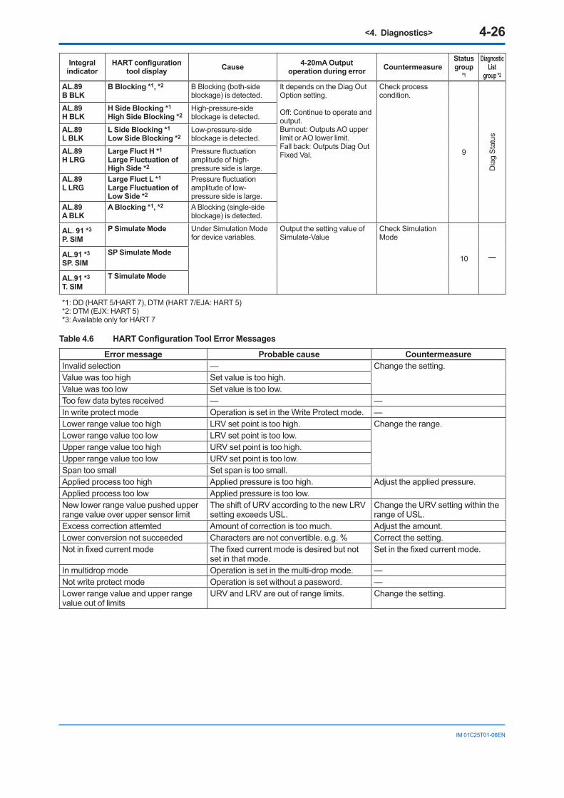
<4. Diagnostics> 4-26
IM 01C25T01-06EN
Integral indicator
HART configuration tool display Cause 4-20mA Output
operation during error Countermeasure Status group
*1
Diagnostic List
group *2
AL.89B BLK
B Blocking *1, *2 B Blocking (both-side blockage) is detected.
It depends on the Diag Out Option setting.
Off: Continue to operate and output.Burnout: Outputs AO upper limit or AO lower limit.Fall back: Outputs Diag Out Fixed Val.
Check process condition.
9
Dia
g St
atus
AL.89H BLK
H Side Blocking *1
High Side Blocking *2High-pressure-side blockage is detected.
AL.89L BLK
L Side Blocking *1
Low Side Blocking *2Low-pressure-side blockage is detected.
AL.89H LRG
Large Fluct H *1
Large Fluctuation of High Side *2
Pressure fluctuation amplitude of high-pressure side is large.
AL.89L LRG
Large Fluct L *1
Large Fluctuation of Low Side *2
Pressure fluctuation amplitude of low-pressure side is large.
AL.89A BLK
A Blocking *1, *2 A Blocking (single-side blockage) is detected.
AL. 91 *3
P. SIMP Simulate Mode Under Simulation Mode
for device variables.Output the setting value of Simulate-Value
Check Simulation Mode
10
—AL.91 *3
SP. SIMSP Simulate Mode
AL.91 *3
T. SIMT Simulate Mode
*1: DD (HART 5/HART 7), DTM (HART 7/EJA: HART 5)*2: DTM (EJX: HART 5)*3: Available only for HART 7
Table 4.6 HART Configuration Tool Error Messages
Error message Probable cause Countermeasure Invalid selection — Change the setting.Value was too high Set value is too high.Value was too low Set value is too low.Too few data bytes received — —In write protect mode Operation is set in the Write Protect mode. —Lower range value too high LRV set point is too high. Change the range.Lower range value too low LRV set point is too low.Upper range value too high URV set point is too high.Upper range value too low URV set point is too low.Span too small Set span is too small.Applied process too high Applied pressure is too high. Adjust the applied pressure.Applied process too low Applied pressure is too low.New lower range value pushed upper range value over upper sensor limit
The shift of URV according to the new LRV setting exceeds USL.
Change the URV setting within the range of USL.
Excess correction attemted Amount of correction is too much. Adjust the amount.Lower conversion not succeeded Characters are not convertible. e.g. % Correct the setting.Not in fixed current mode The fixed current mode is desired but not
set in that mode.Set in the fixed current mode.
In multidrop mode Operation is set in the multi-drop mode. —Not write protect mode Operation is set without a password. —Lower range value and upper range value out of limits
URV and LRV are out of range limits. Change the setting.
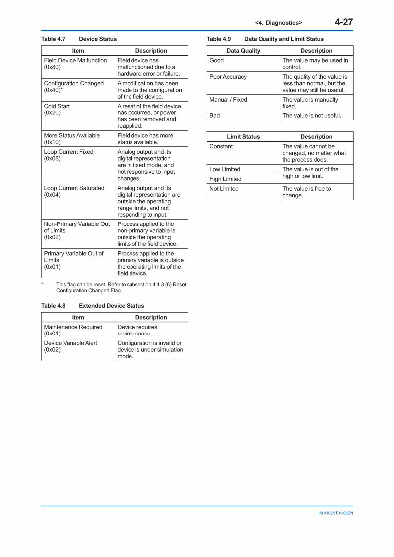
<4. Diagnostics> 4-27
IM 01C25T01-06EN
Table 4.7 Device Status
Item DescriptionField Device Malfunction(0x80)
Field device has malfunctioned due to a hardware error or failure.
Configuration Changed(0x40)*
A modification has been made to the configuration of the field device.
Cold Start(0x20)
A reset of the field device has occurred, or power has been removed and reapplied.
More Status Available(0x10)
Field device has more status available.
Loop Current Fixed(0x08)
Analog output and its digital representation are in fixed mode, and not responsive to input changes.
Loop Current Saturated(0x04)
Analog output and its digital representation are outside the operating range limits, and not responding to input.
Non-Primary Variable Out of Limits(0x02)
Process applied to the non-primary variable is outside the operating limits of the field device.
Primary Variable Out of Limits(0x01)
Process applied to the primary variable is outside the operating limits of the field device.
*: This flag can be reset. Refer to subsection 4.1.3 (6) Reset Configuration Changed Flag
Table 4.8 Extended Device Status
Item DescriptionMaintenance Required(0x01)
Device requires maintenance.
Device Variable Alert(0x02)
Configuration is invalid or device is under simulation mode.
Table 4.9 Data Quality and Limit Status
Data Quality DescriptionGood The value may be used in
control.Poor Accuracy The quality of the value is
less than normal, but the value may still be useful.
Manual / Fixed The value is manually fixed.
Bad The value is not useful.
Limit Status DescriptionConstant The value cannot be
changed, no matter what the process does.
Low Limited The value is out of the high or low limit.High Limited
Not Limited The value is free to change.
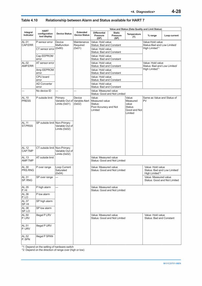
<4. Diagnostics> 4-28
IM 01C25T01-06EN
Table 4.10 Relationship between Alarm and Status available for HART 7
Integral Indicator
HART configuration tool display
Device Status Extended Device Status
Value and Status (Data Quality and Limit Status)Differential Pressure
(DP)
Static Pressure
(SP)Temperature
(T) % range Loop current
AL.01 CAP.ERR
P sensor error Device Malfunction(0x80)
Maintenance Required(0x01)
Value: Hold value Status: Bad and Constant
Value:Hold value Status:Bad and Low Limited/High Limited*1CT sensor error Value: Hold value
Status: Bad and ConstantCap EEPROM error
Value: Hold value Status: Bad and Constant
AL.02 AMP.ERR
AT sensor error Value: Hold value Status: Bad and Constant
Value: Hold value Status: Bad and Low Limited/High Limited*1Amp EEPROM
errorValue: Hold value Status: Bad and Constant
CPU board error
Value: Hold value Status: Bad and Constant
AD Converter error
Value: Hold value Status: Bad and Constant
--- No device ID --- --- Value: Measured value Status: Good and Not Limited
AL.10 PRESS
P outside limit Primary Variable Out of Limits (0x01)
Device Variable Alert(0x02)
Value: Measured value Status: Poor Accuracy and Not Limited
Value: Measured value Status: Good and Not Limited
Same as Value and Status of PV
AL.11 ST.PRSS
SP outside limit Non-Primary Variable Out of Limits (0x02)
AL.12 CAP.TMP
CT outside limit Non-Primary Variable Out of Limits (0x02)
AL.13 AMP.TMP
AT outside limit Value: Measured value Status: Good and Not Limited
AL.30 PRS.RNG
P over range Loop Current Saturated(0x04)
Value: Measured value Status: Good and Not Limited
Value: Hold value Status: Bad and Low Limited/High Limited*2
AL.31 SP. RNG
SP over range --- Value: Measured value Status: Good and Not Limited
AL.35 P. HI
P high alarm --- Value: Measured value Status: Good and Not Limited
AL.36 P. LO
P low alarm
AL.37 SP. HI
SP high alarm
AL.38 SP. LO
SP low alarm
AL.50 P. LRV
Illegal P LRV Value: Measured value Status: Good and Not Limited
Value: Hold value Status: Bad and Constant
AL.51 P. URV
Illegal P URV
AL.52 P. SPN
Illegal P SPAN
*1: Depend on the setting of hardware switch*2: Depend on the direction of range over (high or low)

<4. Diagnostics> 4-29
IM 01C25T01-06EN
Integral Indicator
HART configuration tool display
Device Status Extended Device Status
Value and Status (Data Quality and Limit Status)Differential Pressure
(DP)
Static Pressure
(SP)Temperature
(T) % range Loop current
AL.53 P. ADJ
P SPAN trim err --- Device Variable Alert(0x02)
Value: Measured value Status: Poor Accuracy and Not Limited
Value: Measured value Status: Good and Not Limited
Value: Measured value Status: Poor Accuracy and Not Limited
P ZERO trim err
AL.54 SP. RNG
Illegal SP LRV Value: Measured value Status: Good and Not Limited
Value: Measured value Status: Good and Not Limited
Illegal SP URV
Illegal SP SPAN
AL.55 SP. ADJ
SP SPAN trim err
Value: Measured value Status: Good and Not Limited
Value: Measured value Status: Poor Accuracy and Not Limited
Value: Measured value Status: Good and Not Limited
Value: Measured value Status: Good and Not Limited
SP ZERO trim err
AL.79 OV.DISP
(None) --- --- Value: Measured value Status: Good and Not Limited
AL.87 FLG. HI
FT high alarm --- Maintenance Required(0x01)
Value: Measured value Status: Good and Not Limited
In the case “Off” is set to Diag Out OptionValue: Measured value Status: Good and Not Limited
In the case “Burnout” is set to Diag Out Option Value: Low Limited/High Limited Status: Bad and Low Limited/High Limited*1
In the case “Fall back” is set to Diag Out OptionValue: Fixed value Status: Bad and Constant
AL.87 FLG. LO
FT low alarm
AL.88 INVR.DP
Invalid Ref DP Value: Measured value Status: Good and Not Limited
AL.88 INVR.SL
Invalid Ref SPL
AL.88 INVR.SH
Invalid Ref SPH
AL.88 INVR.F
Invalid Ref F
*1: Depend on the setting of hardware switch*2: Depend on the direction of range over (high or low)
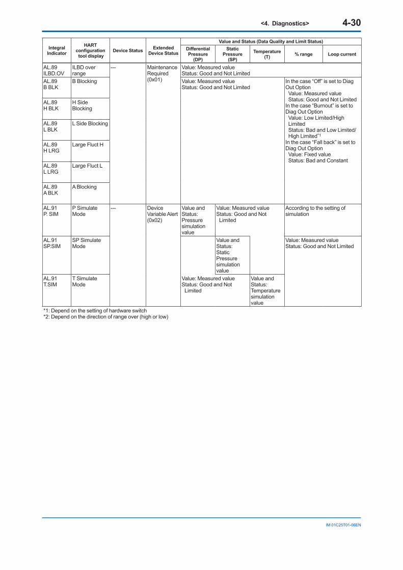
<4. Diagnostics> 4-30
IM 01C25T01-06EN
Integral Indicator
HART configuration tool display
Device Status Extended Device Status
Value and Status (Data Quality and Limit Status)Differential Pressure
(DP)
Static Pressure
(SP)Temperature
(T) % range Loop current
AL.89 ILBD.OV
ILBD over range
--- Maintenance Required(0x01)
Value: Measured value Status: Good and Not Limited
AL.89 B BLK
B Blocking Value: Measured value Status: Good and Not Limited
In the case “Off” is set to Diag Out OptionValue: Measured value Status: Good and Not Limited
In the case “Burnout” is set to Diag Out OptionValue: Low Limited/High Limited Status: Bad and Low Limited/High Limited*1
In the case “Fall back” is set to Diag Out Option Value: Fixed value Status: Bad and Constant
AL.89 H BLK
H Side Blocking
AL.89 L BLK
L Side Blocking
AL.89 H LRG
Large Fluct H
AL.89 L LRG
Large Fluct L
AL.89 A BLK
A Blocking
AL.91 P. SIM
P Simulate Mode
--- Device Variable Alert(0x02)
Value and Status: Pressure simulation value
Value: Measured valueStatus: Good and Not Limited
According to the setting of simulation
AL.91 SP.SIM
SP Simulate Mode
Value and Status: Static Pressure simulation value
Value: Measured valueStatus: Good and Not Limited
AL.91 T.SIM
T Simulate Mode
Value: Measured valueStatus: Good and Not Limited
Value and Status: Temperature simulation value
*1: Depend on the setting of hardware switch*2: Depend on the direction of range over (high or low)
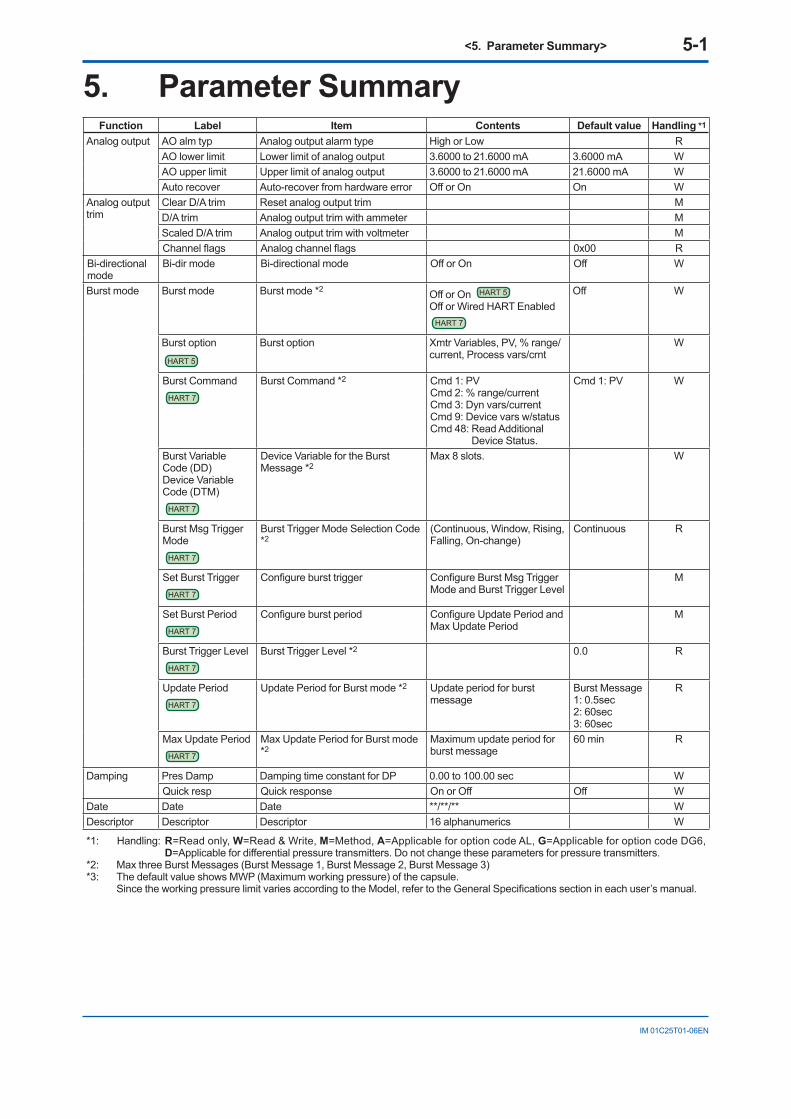
<5. Parameter Summary> 5-1
IM 01C25T01-06EN
5. Parameter SummaryFunction Label Item Contents Default value Handling *1
Analog output AO alm typ Analog output alarm type High or Low RAO lower limit Lower limit of analog output 3.6000 to 21.6000 mA 3.6000 mA WAO upper limit Upper limit of analog output 3.6000 to 21.6000 mA 21.6000 mA WAuto recover Auto-recover from hardware error Off or On On W
Analog output trim
Clear D/A trim Reset analog output trim MD/A trim Analog output trim with ammeter MScaled D/A trim Analog output trim with voltmeter MChannel flags Analog channel flags 0x00 R
Bi-directional mode
Bi-dir mode Bi-directional mode Off or On Off W
Burst mode Burst mode Burst mode *2 Off or On HART 5
Off or Wired HART Enabled HART 7
Off W
Burst optionHART 5
Burst option Xmtr Variables, PV, % range/current, Process vars/crnt
W
Burst CommandHART 7
Burst Command *2 Cmd 1: PVCmd 2: % range/currentCmd 3: Dyn vars/currentCmd 9: Device vars w/statusCmd 48: Read Additional
Device Status.
Cmd 1: PV W
Burst Variable Code (DD)Device Variable Code (DTM)
HART 7
Device Variable for the Burst Message *2
Max 8 slots. W
Burst Msg Trigger Mode
HART 7
Burst Trigger Mode Selection Code *2
(Continuous, Window, Rising, Falling, On-change)
Continuous R
Set Burst TriggerHART 7
Configure burst trigger Configure Burst Msg Trigger Mode and Burst Trigger Level
M
Set Burst PeriodHART 7
Configure burst period Configure Update Period and Max Update Period
M
Burst Trigger LevelHART 7
Burst Trigger Level *2 0.0 R
Update PeriodHART 7
Update Period for Burst mode *2 Update period for burst message
Burst Message1: 0.5sec2: 60sec3: 60sec
R
Max Update PeriodHART 7
Max Update Period for Burst mode *2
Maximum update period for burst message
60 min R
Damping Pres Damp Damping time constant for DP 0.00 to 100.00 sec WQuick resp Quick response On or Off Off W
Date Date Date **/**/** WDescriptor Descriptor Descriptor 16 alphanumerics W
*1: Handling: R=Read only, W=Read & Write, M=Method, A=Applicable for option code AL, G=Applicable for option code DG6, D=Applicable for differential pressure transmitters. Do not change these parameters for pressure transmitters.
*2: Max three Burst Messages (Burst Message 1, Burst Message 2, Burst Message 3)*3: The default value shows MWP (Maximum working pressure) of the capsule. Since the working pressure limit varies according to the Model, refer to the General Specifications section in each user’s manual.
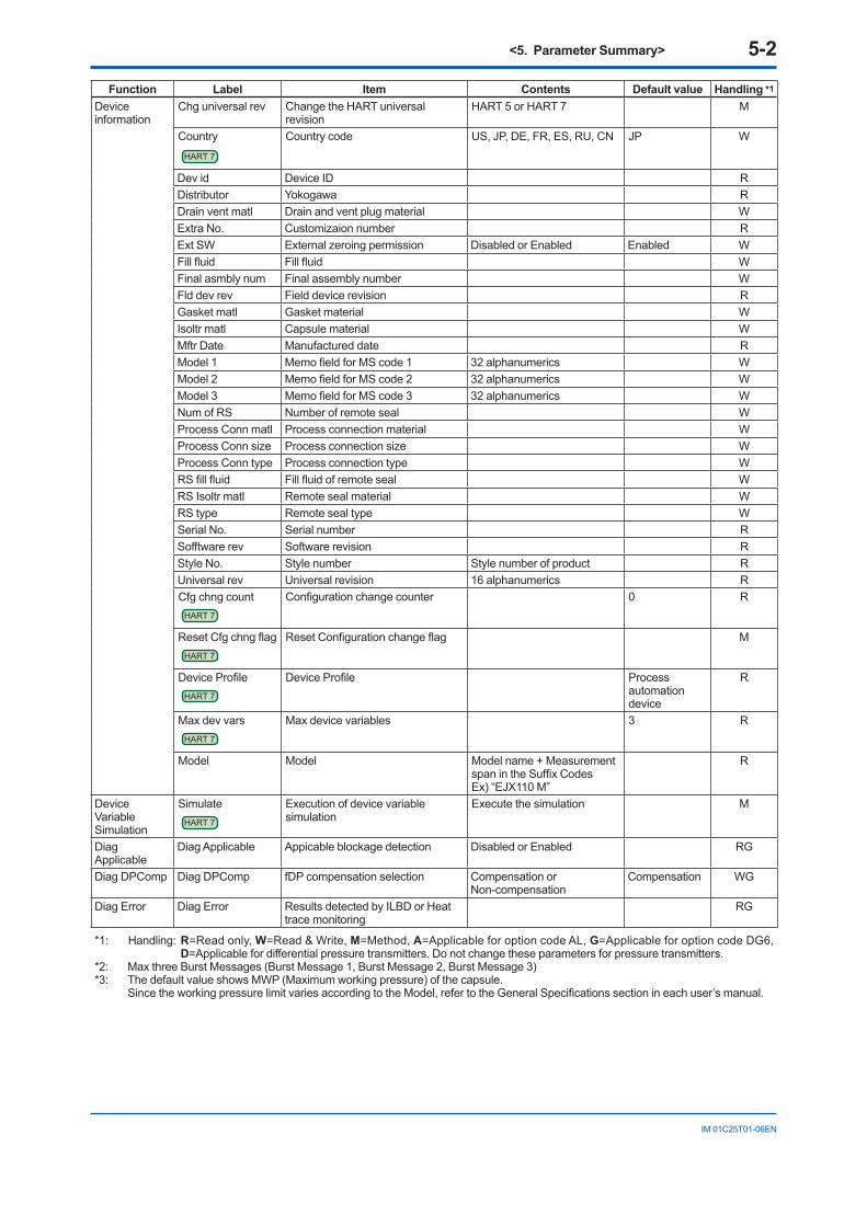
<5. Parameter Summary> 5-2
IM 01C25T01-06EN
Function Label Item Contents Default value Handling *1
Device information
Chg universal rev Change the HART universal revision
HART 5 or HART 7 M
CountryHART 7
Country code US, JP, DE, FR, ES, RU, CN JP W
Dev id Device ID RDistributor Yokogawa RDrain vent matl Drain and vent plug material WExtra No. Customizaion number RExt SW External zeroing permission Disabled or Enabled Enabled WFill fluid Fill fluid WFinal asmbly num Final assembly number WFld dev rev Field device revision RGasket matl Gasket material WIsoltr matl Capsule material WMftr Date Manufactured date RModel 1 Memo field for MS code 1 32 alphanumerics WModel 2 Memo field for MS code 2 32 alphanumerics WModel 3 Memo field for MS code 3 32 alphanumerics WNum of RS Number of remote seal WProcess Conn matl Process connection material WProcess Conn size Process connection size WProcess Conn type Process connection type WRS fill fluid Fill fluid of remote seal WRS Isoltr matl Remote seal material WRS type Remote seal type WSerial No. Serial number RSofftware rev Software revision RStyle No. Style number Style number of product RUniversal rev Universal revision 16 alphanumerics RCfg chng count
HART 7
Configuration change counter 0 R
Reset Cfg chng flagHART 7
Reset Configuration change flag M
Device ProfileHART 7
Device Profile Process automation device
R
Max dev varsHART 7
Max device variables 3 R
Model Model Model name + Measurement span in the Suffix CodesEx) “EJX110 M”
R
Device Variable Simulation
SimulateHART 7
Execution of device variable simulation
Execute the simulation M
Diag Applicable
Diag Applicable Appicable blockage detection Disabled or Enabled RG
Diag DPComp Diag DPComp fDP compensation selection Compensation or Non-compensation
Compensation WG
Diag Error Diag Error Results detected by ILBD or Heat trace monitoring
RG
*1: Handling: R=Read only, W=Read & Write, M=Method, A=Applicable for option code AL, G=Applicable for option code DG6, D=Applicable for differential pressure transmitters. Do not change these parameters for pressure transmitters.
*2: Max three Burst Messages (Burst Message 1, Burst Message 2, Burst Message 3)*3: The default value shows MWP (Maximum working pressure) of the capsule. Since the working pressure limit varies according to the Model, refer to the General Specifications section in each user’s manual.

<5. Parameter Summary> 5-3
IM 01C25T01-06EN
Function Label Item Contents Default value Handling *1
Diag Lim Lim fDPmax Upper limit for Ratio fDP Refer to Table 4.2.3 WGLim fDPmin Lower limit for Ratio fDP Refer to Table 4.2.3 WGLim fSPlmax Upper limit for Ratio fSPl Refer to Table 4.2.3 WGLim fSPlmin Lower limit for Ratio fSPl Refer to Table 4.2.3 WGLim fSPhmax Upper limit for Ratio fSPh Refer to Table 4.2.3 WGLim fSPhmin Lower limit for Ratio fSPh Refer to Table 4.2.3 WGLim BlkFmax Upper limit for BlkF Refer to Table 4.2.3 WGLim BlkFmin Lower limit for BlkF Refer to Table 4.2.3 WGLim DPAvgmax Upper limit for DPAvg Refer to Table 4.2.3 WGLim DPAvgmin Lower limit for DPAvg Refer to Table 4.2.3 WG
Diag Mode Diag Mode ILBD operation mode Stop, Calculation, or Reference
WG
Diag Option Diag Option Alarm masking WGDiag Output Diag Out Option Output mode of 4-20mA when
an advanced diagnostic alarm is generated
Off, Burnout, or Fall back Off WG
Diag Fixed Out Val 4-20 mA output when an advanced diagnostic alarm is generated
3.6000 to 21.6000 mA 21.6 mA WG
Diag Period Diag Period Sampling period per one Diag count 180 sec WGDiag Reference
Diag Description Memo field 32 alphanumerics WGRef fDP Reference value of fDP WGRef fDP Status Status of Reference fDP RGRef fSPl Reference value of fSPl WGRef fSPl Status Status of Reference fSPl RGRef fSPh Reference value of fSPh WGRef fSPh Status Status of Reference fSPh RGRef BlkF Reference value of BlkF WGRef BlkF Status Status of Reference BlkF RGRef DPAvg Reference value of DPAvg WGRef DPAvg Status Status of Reference DPAvg RG
Diag Ref Lim Ref Lim fDPmin Lower limit of fDP 7.0E-10 WGRef Lim fSPmin Lower limit of fSPl and fSPh 1.0E-10 WGRef Lim BlkFmax Upper limit of BlkF 0.5 WG
Diag Supp Count
Diag Supp Count Detection count to generate an alarm
WG
Diag Variables Ratio fDP SQRT (fDP/Ref fDP). RGRatio fDP Status Status of Ratio fDP RGRatio fSPl SQRT (fSPl/Ref fSPl). RGRatio fSPl Status Status of Ratio fSPl RGRatio fSPh SQRT (fSPh/Ref fSPh). RGRatio fSPh Status Status of Ratio fSPh RGBlkF Blockage degree characterized in
comparison of high-pressure side and low-pressure side pressure fluctuation values
RG
BlkF Status Status of BlkF RGDPAvg Ratio of the average of differential
pressure/pressure to the maximum span of an EJX transmitter.
RG
DPAvg Status Status of DPAvg RGCRatio fDP Compensated fDP RGCRatio fDP Status Status of CRatio fDP RGNRatio fDP Non-compensated fDP RGNRatio fDP Status Status of NRatio fDP RG
*1: Handling: R=Read only, W=Read & Write, M=Method, A=Applicable for option code AL, G=Applicable for option code DG6, D=Applicable for differential pressure transmitters. Do not change these parameters for pressure transmitters.
*2: Max three Burst Messages (Burst Message 1, Burst Message 2, Burst Message 3)*3: The default value shows MWP (Maximum working pressure) of the capsule. Since the working pressure limit varies according to the Model, refer to the General Specifications section in each user’s manual.
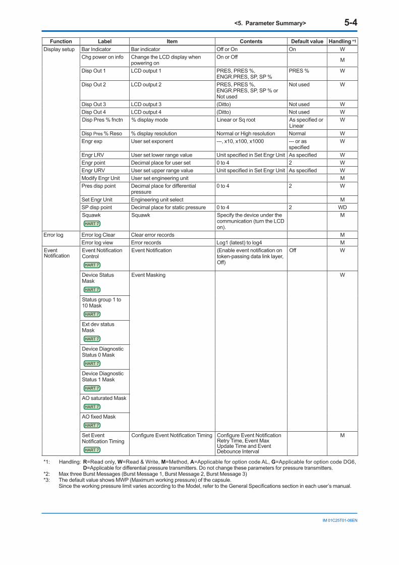
<5. Parameter Summary> 5-4
IM 01C25T01-06EN
Function Label Item Contents Default value Handling *1
Display setup Bar Indicator Bar indicator Off or On On WChg power on info Change the LCD display when
powering onOn or Off M
Disp Out 1 LCD output 1 PRES, PRES %, ENGR.PRES, SP, SP %
PRES % W
Disp Out 2 LCD output 2 PRES, PRES %, ENGR.PRES, SP, SP % or Not used
Not used W
Disp Out 3 LCD output 3 (Ditto) Not used WDisp Out 4 LCD output 4 (Ditto) Not used WDisp Pres % fnctn % display mode Linear or Sq root As specified or
LinearW
Disp Pres % Reso % display resolution Normal or High resolution Normal WEngr exp User set exponent ---, x10, x100, x1000 --- or as
specifiedW
Engr LRV User set lower range value Unit specified in Set Engr Unit As specified WEngr point Decimal place for user set 0 to 4 2 WEngr URV User set upper range value Unit specified in Set Engr Unit As specified WModify Engr Unit User set engineering unit MPres disp point Decimal place for differential
pressure0 to 4 2 W
Set Engr Unit Engineering unit select MSP disp point Decimal place for static pressure 0 to 4 2 WDSquawk
HART 7
Squawk Specify the device under the communication (turn the LCD on).
M
Error log Error log Clear Clear error records MError log view Error records Log1 (latest) to log4 M
Event Notification
Event Notification Control
HART 7
Event Notification (Enable event notification on token-passing data link layer, Off)
Off W
Device Status Mask
HART 7
Event Masking W
Status group 1 to 10 Mask
HART 7
Ext dev status Mask
HART 7
Device Diagnostic Status 0 Mask
HART 7
Device Diagnostic Status 1 Mask
HART 7
AO saturated MaskHART 7
AO fixed MaskHART 7
Set Event Notification Timing
HART 7
Configure Event Notification Timing Configure Event Notification Retry Time, Event Max Update Time and Event Debounce Interval
M
*1: Handling: R=Read only, W=Read & Write, M=Method, A=Applicable for option code AL, G=Applicable for option code DG6, D=Applicable for differential pressure transmitters. Do not change these parameters for pressure transmitters.
*2: Max three Burst Messages (Burst Message 1, Burst Message 2, Burst Message 3)*3: The default value shows MWP (Maximum working pressure) of the capsule. Since the working pressure limit varies according to the Model, refer to the General Specifications section in each user’s manual.
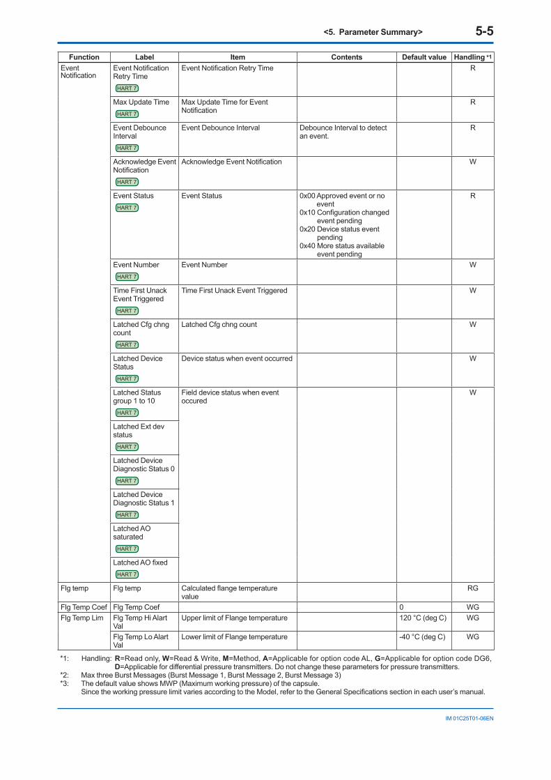
<5. Parameter Summary> 5-5
IM 01C25T01-06EN
Function Label Item Contents Default value Handling *1
Event Notification
Event Notification Retry Time
HART 7
Event Notification Retry Time R
Max Update TimeHART 7
Max Update Time for Event Notification
R
Event Debounce Interval
HART 7
Event Debounce Interval Debounce Interval to detect an event.
R
Acknowledge Event Notification
HART 7
Acknowledge Event Notification W
Event StatusHART 7
Event Status 0x00 Approved event or no event
0x10 Configuration changed event pending
0x20 Device status event pending
0x40 More status available event pending
R
Event NumberHART 7
Event Number W
Time First Unack Event Triggered
HART 7
Time First Unack Event Triggered W
Latched Cfg chng count
HART 7
Latched Cfg chng count W
Latched Device Status
HART 7
Device status when event occurred W
Latched Status group 1 to 10
HART 7
Field device status when event occured
W
Latched Ext dev status
HART 7
Latched Device Diagnostic Status 0
HART 7
Latched Device Diagnostic Status 1
HART 7
Latched AO saturated
HART 7
Latched AO fixedHART 7
Flg temp Flg temp Calculated flange temperature value
RG
Flg Temp Coef Flg Temp Coef 0 WGFlg Temp Lim Flg Temp Hi Alart
ValUpper limit of Flange temperature 120 °C (deg C) WG
Flg Temp Lo Alart Val
Lower limit of Flange temperature -40 °C (deg C) WG
*1: Handling: R=Read only, W=Read & Write, M=Method, A=Applicable for option code AL, G=Applicable for option code DG6, D=Applicable for differential pressure transmitters. Do not change these parameters for pressure transmitters.
*2: Max three Burst Messages (Burst Message 1, Burst Message 2, Burst Message 3)*3: The default value shows MWP (Maximum working pressure) of the capsule. Since the working pressure limit varies according to the Model, refer to the General Specifications section in each user’s manual.
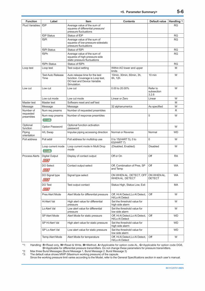
<5. Parameter Summary> 5-6
IM 01C25T01-06EN
Function Label Item Contents Default value Handling *1
Fluct Variables fDP Average value of the sum of squares of differential pressure/pressure fluctuations
RG
fDP Status Status of fDP RGfSPl Average value of the sum of
squares of low-pressure-sidestatic pressure fluctuations
RG
fSPl Status Status of fSPl RGfSPh Average value of the sum of
squares of high-pressure-side static pressure fluctuations
RG
fSPh Status Status of fSPh RGLoop test Loop test Test output setting Within AO lower and upper
limitsM
Test Auto Release Time
Auto release time for the test function. Coverage is Loop test, DO test and Device Variable Simulation.
10min, 30min, 60min, 3h, 6h, 12h
10 min W
Low cut Low cut Low cut 0.00 to 20.00% Refer to subsection 3.2.6
W
Low cut mode Low cut mode Linear or Zero Linear WMaster test Master test Software reset and self test MMessage Message Message 32 alphanumerics As specified WNumber of requested preambles
Num req preams Number of requested preambles R
Num resp preamsHART 7
Number of response preambles 5 W
Optional function Option Password Optional function activation
password W
Piping orientation
H/L Swap Impulse piping accessing direction Normal or Reverse Normal WD
Poll address Poll addr Poll address for multidrop use 0 to 15(HART 5), 0 to 63(HART 7)
0 W
Loop current modeHART 7
Loop current mode in Multi Drop mode
(Disabled, Enabled) Disabled W
Process Alerts Digital OutputEJX
Display of contact output Off or On Off RA
DO Select EJX
Contact output select Off, Combination of Pres, SP and Temp
Off WA
DO Signal typeEJX
Signal type select ON WHEN AL. DETECT, OFF WHEN AL. DETECT
ON WHEN AL. DETECT
WA
DO Test EJX
Test output contact Status High, Status Low, Exit MA
Pres Alert Mode Alert Mode for differential pressure Off, Hi Al Detect,Lo Al Detect, Hi/Lo Al Detect
Off W
Hi Alert Val High alert value for differential pressure
Set the threshold value for high side alarm
W
Lo Alert Val Low alert value for differential pressure
Set the threshold value for low side alarm
W
SP Alert Mode Alert Mode for static pressure Off, Hi Al Detect,Lo Al Detect, Hi/Lo Al Detect
Off WD
SP Hi Alert Val High alert value for static pressure Set the threshold value for high side alarm
WD
SP Lo Alert Val Low alert value for static pressure Set the threshold value for low side alarm
WD
Temp Alert Mode Alert Mode for temperature Off, Hi Al Detect,Lo Al Detect, Hi/Lo Al Detect
Off W
*1: Handling: R=Read only, W=Read & Write, M=Method, A=Applicable for option code AL, G=Applicable for option code DG6, D=Applicable for differential pressure transmitters. Do not change these parameters for pressure transmitters.
*2: Max three Burst Messages (Burst Message 1, Burst Message 2, Burst Message 3)*3: The default value shows MWP (Maximum working pressure) of the capsule. Since the working pressure limit varies according to the Model, refer to the General Specifications section in each user’s manual.
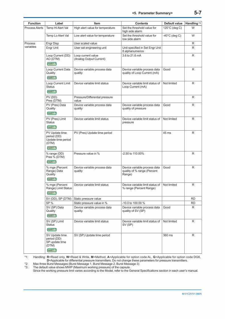
<5. Parameter Summary> 5-7
IM 01C25T01-06EN
Function Label Item Contents Default value Handling *1
Process Alerts Temp Hi Alert Val High alert value for temperature Set the threshold value for high side alarm
120°C (deg C) W
Temp Lo Alert Val Low alert value for temperature Set the threshold value for low side alarm
-40°C (deg C) W
Process variables
Engr Disp User scaled value REngr Unit User set engineering unit Unit specified in Set Engr Unit
8 alphanumericsR
Loop Current (DD)AO (DTM)
HART 7
Loop current value(Analog Output Current)
3.6 to 21.6 mA R
Loop Current Data Quality
HART 7
Device variable process data quality
Device variable process data quality of Loop Current (mA)
Good R
Loop Current Limit Status
HART 7
Device variable limit status Device variable limit status of Loop Current (mA)
Not limited R
PV (DD)Pres (DTM)
Pressure/Differential pressure value
R
PV (Pres) Data Quality
HART 7
Device variable process data quality
Device variable process data quality of pressure
Good R
PV (Pres) Limit Status
HART 7
Device variable limit status Device variable limit status of pressure
Not limited R
PV Update time period (DD)Update time period (DTM)
HART 7
PV (Pres) Update time period 45 ms R
% range (DD)Pres % (DTM)
HART 7
Pressure value in % -2.50 to 110.00% R
% rnge (Percent Range) Data Quality
HART 7
Device variable process data quality
Device variable process data quality of % range (Percent Range)
Good R
% rnge (Percent Range) Limit Status
HART 7
Device variable limit status Device variable limit status of % range (Percent Range)
Not limited R
SV (DD), SP (DTM) Static pressure value RDSP % Static pressure value in % -10.0 to 100.00 % RDSV (SP) Data Quality
HART 7
Device variable process data quality
Device variable process data quality of SV (SP)
Good R
SV (SP) Limit Status
HART 7
Device variable limit status Device variable limit status of SV (SP)
Not limited R
SV Update time period (DD)SP update time (DTM)
HART 7
SV (SP) Update time period 360 ms R
*1: Handling: R=Read only, W=Read & Write, M=Method, A=Applicable for option code AL, G=Applicable for option code DG6, D=Applicable for differential pressure transmitters. Do not change these parameters for pressure transmitters.
*2: Max three Burst Messages (Burst Message 1, Burst Message 2, Burst Message 3)*3: The default value shows MWP (Maximum working pressure) of the capsule. Since the working pressure limit varies according to the Model, refer to the General Specifications section in each user’s manual.
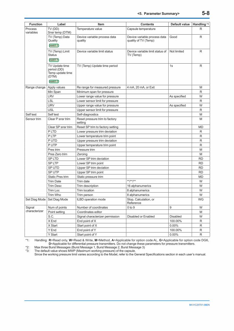
<5. Parameter Summary> 5-8
IM 01C25T01-06EN
Function Label Item Contents Default value Handling *1
Process variables
TV (DD)Snsr temp (DTM)
Temperature value Capsule temperature R
TV (Temp) Data Quality
HART 7
Device variable process data quality
Device variable process data quality of TV (Temp)
Good R
TV (Temp) Limit Status
HART 7
Device variable limit status Device variable limit status of TV (Temp)
Not limited R
TV Update time period (DD)Temp update time (DTM)
HART 7
TV (Temp) Update time period 1s R
Range change Apply values Re range for measured pressure 4 mA, 20 mA, or Exit MMin Span Minimum span for pressure RLRV Lower range value for pressure As specified WLSL Lower sensor limit for pressure RURV Upper range value for pressure As specified WUSL Upper sensor limit for pressure R
Self test Self test Self-diagnostics MSensor trim Clear P snsr trim Reset pressure trim to factory
settingM
Clear SP snsr trim Reset SP trim to factory setting MDP LTD Lower pressure trim deviation RP LTP Lower temperature trim point RP UTD Upper pressure trim deviation RP UTP Upper temperature trim point RPres trim Pressure trim MPres Zero trim Zeroing MSP LTD Lower SP trim deviation RDSP LTP Lower SP trim point RDSP UTD Upper SP trim deviation RDSP UTP Upper SP trim point RDStatic Pres trim Static pressure trim MDTrim Date Trim date **/**/** WTrim Desc Trim description 16 alphanumerics WTrim Loc Trim location 8 alphanumerics WTrim Who Trim person 8 alphanumerics W
Set Diag Mode Set Diag Mode ILBD operation mode Stop, Calculation, or Reference
WG
Signal characterizer
Num of points Number of coordinates 0 to 9 9 WPoint setting Coordinates editor MS.C. Signal characterizer permission Disabled or Enabled Disabled WX End End point of X 100.00% RX Start Start point of X 0.00% RY End End point of Y 100.00% RY Start Start point of Y 0.00% R
*1: Handling: R=Read only, W=Read & Write, M=Method, A=Applicable for option code AL, G=Applicable for option code DG6, D=Applicable for differential pressure transmitters. Do not change these parameters for pressure transmitters.
*2: Max three Burst Messages (Burst Message 1, Burst Message 2, Burst Message 3)*3: The default value shows MWP (Maximum working pressure) of the capsule. Since the working pressure limit varies according to the Model, refer to the General Specifications section in each user’s manual.
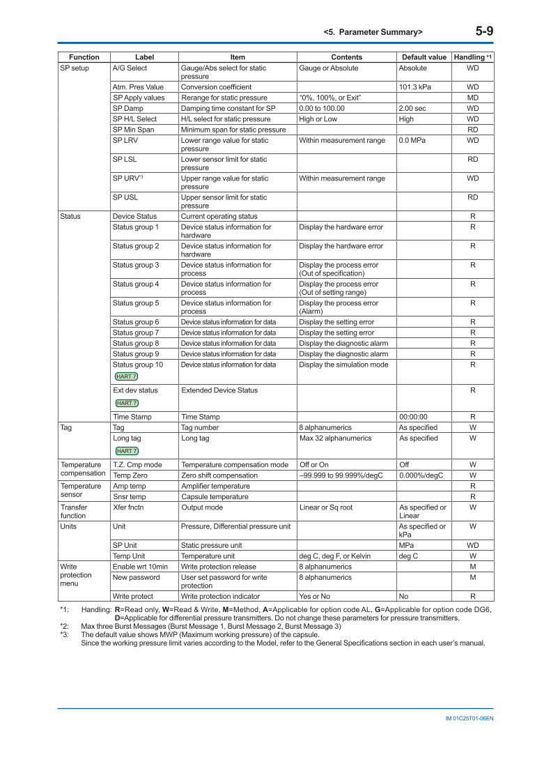
<5. Parameter Summary> 5-9
IM 01C25T01-06EN
Function Label Item Contents Default value Handling *1
SP setup A/G Select Gauge/Abs select for static pressure
Gauge or Absolute Absolute WD
Atm. Pres Value Conversion coefficient 101.3 kPa WDSP Apply values Rerange for static pressure “0%, 100%, or Exit” MDSP Damp Damping time constant for SP 0.00 to 100.00 2.00 sec WDSP H/L Select H/L select for static pressure High or Low High WDSP Min Span Minimum span for static pressure RDSP LRV Lower range value for static
pressureWithin measurement range 0.0 MPa WD
SP LSL Lower sensor limit for static pressure
RD
SP URV*3 Upper range value for static pressure
Within measurement range WD
SP USL Upper sensor limit for static pressure
RD
Status Device Status Current operating status RStatus group 1 Device status information for
hardwareDisplay the hardware error R
Status group 2 Device status information for hardware
Display the hardware error R
Status group 3 Device status information for process
Display the process error(Out of specification)
R
Status group 4 Device status information for process
Display the process error(Out of setting range)
R
Status group 5 Device status information for process
Display the process error(Alarm)
R
Status group 6 Device status information for data Display the setting error RStatus group 7 Device status information for data Display the setting error RStatus group 8 Device status information for data Display the diagnostic alarm RStatus group 9 Device status information for data Display the diagnostic alarm RStatus group 10
HART 7
Device status information for data Display the simulation mode R
Ext dev status
HART 7
Extended Device Status R
Time Stamp Time Stamp 00:00:00 RTag Tag Tag number 8 alphanumerics As specified W
Long tagHART 7
Long tag Max 32 alphanumerics As specified W
Temperature compensation
T.Z. Cmp mode Temperature compensation mode Off or On Off WTemp Zero Zero shift compensation –99.999 to 99.999%/degC 0.000%/degC W
Temperaturesensor
Amp temp Amplifier temperature RSnsr temp Capsule temperature R
Transfer function
Xfer fnctn Output mode Linear or Sq root As specified or Linear
W
Units Unit Pressure, Differential pressure unit As specified or kPa
W
SP Unit Static pressure unit MPa WDTemp Unit Temperature unit deg C, deg F, or Kelvin deg C W
Write protection menu
Enable wrt 10min Write protection release 8 alphanumerics MNew password User set password for write
protection8 alphanumerics M
Write protect Write protection indicator Yes or No No R
*1: Handling: R=Read only, W=Read & Write, M=Method, A=Applicable for option code AL, G=Applicable for option code DG6, D=Applicable for differential pressure transmitters. Do not change these parameters for pressure transmitters.
*2: Max three Burst Messages (Burst Message 1, Burst Message 2, Burst Message 3)*3: The default value shows MWP (Maximum working pressure) of the capsule. Since the working pressure limit varies according to the Model, refer to the General Specifications section in each user’s manual.
<Appendix1. Safety Instrumented Systems Installation> A1-1
IM 01C25T01-06EN
Appendix 1. Safety Instrumented Systems Installation
WARNING
The contents of this appendix are cited from exida.com safety manual on the transmitters specifically observed for the safety transmitter purpose. When using the transmitter for Safety Instrumented Systems (SIS) application, the instructions and procedures in this section must be strictly followed in order to preserve the transmitter for that safety level.
A1.1 Scope and PurposeThis section provides an overview of the user responsibilities for installation and operation of the transmitter in order to maintain the designed safety level for Safety Instrumented Systems (SIS) applications. Items that will be addressed are proof testing, repair and replacement of the transmitter, reliability data, lifetime, environmental and application limits, and parameter settings.
A1.2 Using the transmitter for an SIS Application
A1.2.1 Safety AccuracyThe transmitter has a specified safety accuracy of 2%. This means that the internal component failures are listed in the device failure rate if they will cause an error of 2% or greater.
A1.2.2 Diagnostic Response TimeThe transmitter will report an internal failure within 5 seconds of the fault occurrence.
A1.2.3 SetupDuring installation the transmitter must be setup with engineering units parameters. This is typically done with a handheld terminal. These parameters must be verified during the installation to insure that the correct parameters are in the transmitter. Engineering range parameters can be verified by reading these parameters from the optional local display or by checking actual calibration of the transmitter.
The calibration of the transmitter must be performed after parameters are set.
A1.2.4 Required Parameter SettingsThe following parameters need to be set in order to maintain the designed safety integrity.
Table A1.1 Required Parameter Settings
Item DescriptionBurnout direction switch
To specify if the output should go 21.6 mA or higher or 3.6 mA or lower upon detection of an internal failure.
Write protection switch
The write function should be disabled.
A1.2.5 Proof TestingThe objective of proof testing is to detect failures within the transmitter that are not detected by the diagnostics of the transmitter. Of main concern are undetected failures that prevent the safety instrumented function from performing its intended function. See table A1.2 for proof testing method.
The frequency of the proof tests (or the proof test interval) is to be determined in the reliability calculations for the safety instrumented functions for which the transmitter is applied. The actual proof tests must be performed more frequently or as frequently as specified in the calculation in order to maintain required safety integrity of the safety instrumented function.
The following tests need to be specifically executed when a proof test is performed. The results of the proof test need to be documented and this documentation should be part of a plant safety management system. Failures that are detected should be reported to Yokogawa.
The personnel performing the proof test of the transmitter should be trained in SIS operations including bypass procedures, transmitter maintenance, and company management of change procedures.
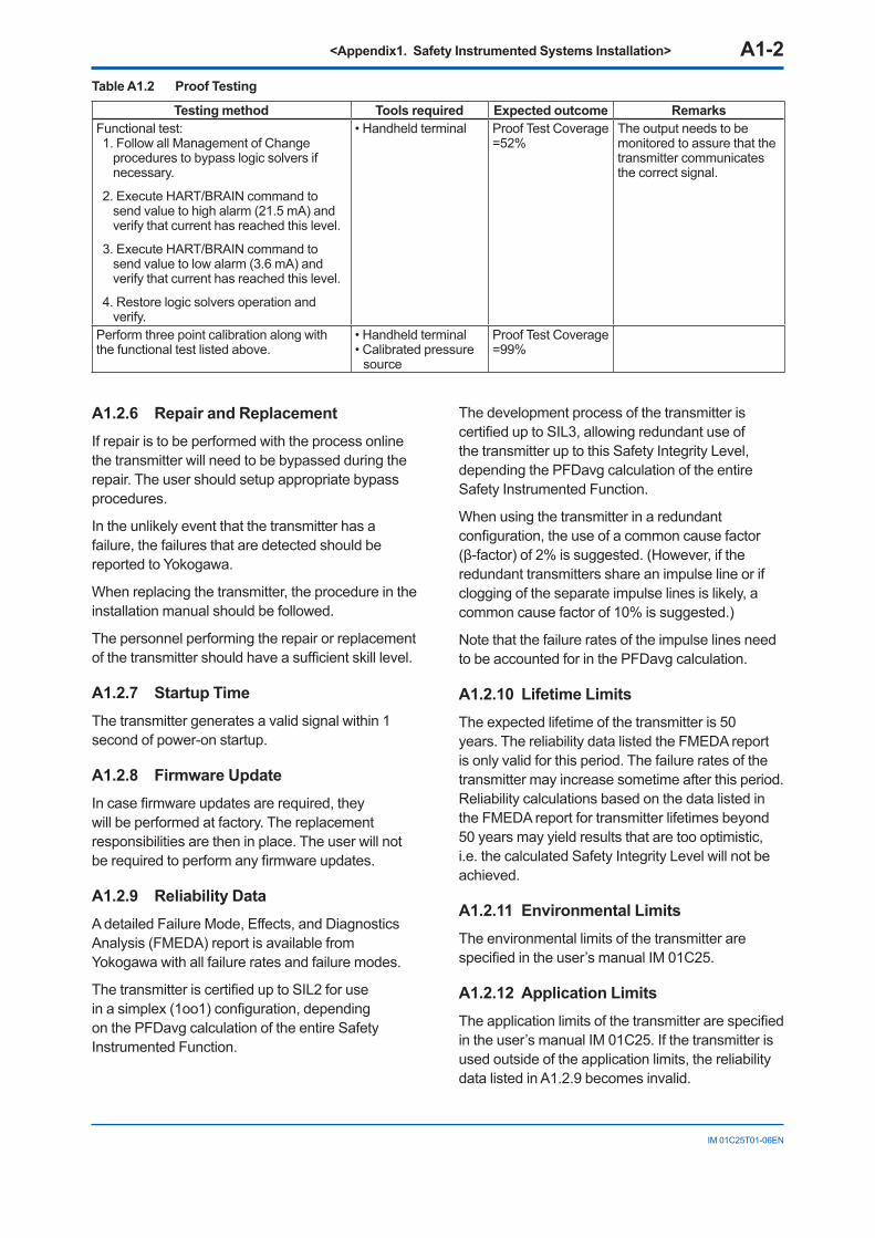
<Appendix1. Safety Instrumented Systems Installation> A1-2
IM 01C25T01-06EN
Table A1.2 Proof Testing
Testing method Tools required Expected outcome RemarksFunctional test:1. Follow all Management of Change
procedures to bypass logic solvers if necessary.
2. Execute HART/BRAIN command to send value to high alarm (21.5 mA) and verify that current has reached this level.
3. Execute HART/BRAIN command to send value to low alarm (3.6 mA) and verify that current has reached this level.
4. Restore logic solvers operation and verify.
• Handheld terminal Proof Test Coverage =52%
The output needs to be monitored to assure that the transmitter communicates the correct signal.
Perform three point calibration along with the functional test listed above.
• Handheld terminal • Calibrated pressure
source
Proof Test Coverage =99%
A1.2.6 Repair and ReplacementIf repair is to be performed with the process online the transmitter will need to be bypassed during the repair. The user should setup appropriate bypass procedures.
In the unlikely event that the transmitter has a failure, the failures that are detected should be reported to Yokogawa.
When replacing the transmitter, the procedure in the installation manual should be followed.
The personnel performing the repair or replacement of the transmitter should have a sufficient skill level.
A1.2.7 Startup TimeThe transmitter generates a valid signal within 1 second of power-on startup.
A1.2.8 Firmware UpdateIn case firmware updates are required, they will be performed at factory. The replacement responsibilities are then in place. The user will not be required to perform any firmware updates.
A1.2.9 Reliability DataA detailed Failure Mode, Effects, and Diagnostics Analysis (FMEDA) report is available from Yokogawa with all failure rates and failure modes.
The transmitter is certified up to SIL2 for use in a simplex (1oo1) configuration, depending on the PFDavg calculation of the entire Safety Instrumented Function.
The development process of the transmitter is certified up to SIL3, allowing redundant use of the transmitter up to this Safety Integrity Level, depending the PFDavg calculation of the entire Safety Instrumented Function.
When using the transmitter in a redundant configuration, the use of a common cause factor (β-factor) of 2% is suggested. (However, if the redundant transmitters share an impulse line or if clogging of the separate impulse lines is likely, a common cause factor of 10% is suggested.)
Note that the failure rates of the impulse lines need to be accounted for in the PFDavg calculation.
A1.2.10 Lifetime LimitsThe expected lifetime of the transmitter is 50 years. The reliability data listed the FMEDA report is only valid for this period. The failure rates of the transmitter may increase sometime after this period. Reliability calculations based on the data listed in the FMEDA report for transmitter lifetimes beyond 50 years may yield results that are too optimistic, i.e. the calculated Safety Integrity Level will not be achieved.
A1.2.11 Environmental LimitsThe environmental limits of the transmitter are specified in the user’s manual IM 01C25.
A1.2.12 Application LimitsThe application limits of the transmitter are specified in the user’s manual IM 01C25. If the transmitter is used outside of the application limits, the reliability data listed in A1.2.9 becomes invalid.
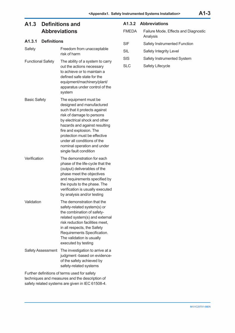
<Appendix1. Safety Instrumented Systems Installation> A1-3
IM 01C25T01-06EN
A1.3 Definitions and Abbreviations
A1.3.1 DefinitionsSafety Freedom from unacceptable
risk of harm
Functional Safety The ability of a system to carry out the actions necessary to achieve or to maintain a defined safe state for the equipment/machinery/plant/apparatus under control of the system
Basic Safety The equipment must be designed and manufactured such that it protects against risk of damage to persons by electrical shock and other hazards and against resulting fire and explosion. The protection must be effective under all conditions of the nominal operation and under single fault condition
Verification The demonstration for each phase of the life-cycle that the (output) deliverables of the phase meet the objectives and requirements specified by the inputs to the phase. The verification is usually executed by analysis and/or testing
Validation The demonstration that the safety-related system(s) or the combination of safety-related system(s) and external risk reduction facilities meet, in all respects, the Safety Requirements Specification. The validation is usually executed by testing
Safety Assessment The investigation to arrive at a judgment -based on evidence- of the safety achieved by safety-related systems
Further definitions of terms used for safety techniques and measures and the description of safety related systems are given in IEC 61508-4.
A1.3.2 AbbreviationsFMEDA Failure Mode, Effects and Diagnostic
Analysis
SIF Safety Instrumented Function
SIL Safety Integrity Level
SIS Safety Instrumented System
SLC Safety Lifecycle
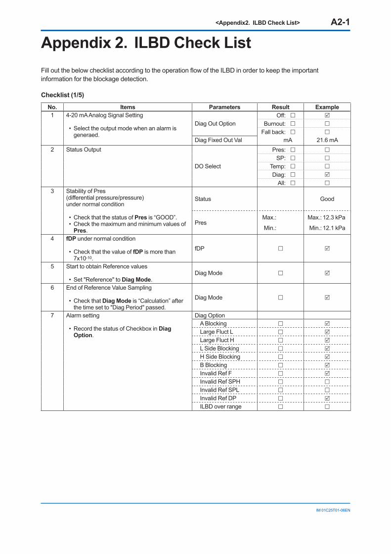
<Appendix2. ILBD Check List> A2-1
IM 01C25T01-06EN
Appendix 2. ILBD Check ListFill out the below checklist according to the operation flow of the ILBD in order to keep the important information for the blockage detection.
Checklist (1/5)
No. Items Parameters Result Example1 4-20 mA Analog Signal Setting
• Select the output mode when an alarm is generaed.
Diag Out Option Off:
Burnout:
Fall back:
Diag Fixed Out Val mA 21.6 mA2 Status Output
DO Select
Pres:
SP:
Temp:
Diag:
All:
3 Stability of Pres(differential pressure/pressure)under normal condition
• Check that the status of Pres is “GOOD”.• Check the maximum and minimum values of
Pres.
Status Good
Pres Max.:
Min.:
Max.: 12.3 kPa
Min.: 12.1 kPa
4 fDP under normal condition
• Check that the value of fDP is more than 7x10⁻¹⁰.
fDP
5 Start to obtain Reference values
• Set "Reference" to Diag Mode.Diag Mode
6 End of Reference Value Sampling
• Check that Diag Mode is “Calculation” after the time set to "Diag Period" passed.
Diag Mode
7 Alarm setting
• Record the status of Checkbox in Diag Option.
Diag OptionA Blocking
Large Fluct L
Large Fluct H
L Side Blocking
H Side Blocking
B Blocking
Invalid Ref F
Invalid Ref SPH
Invalid Ref SPL
Invalid Ref DP
ILBD over range
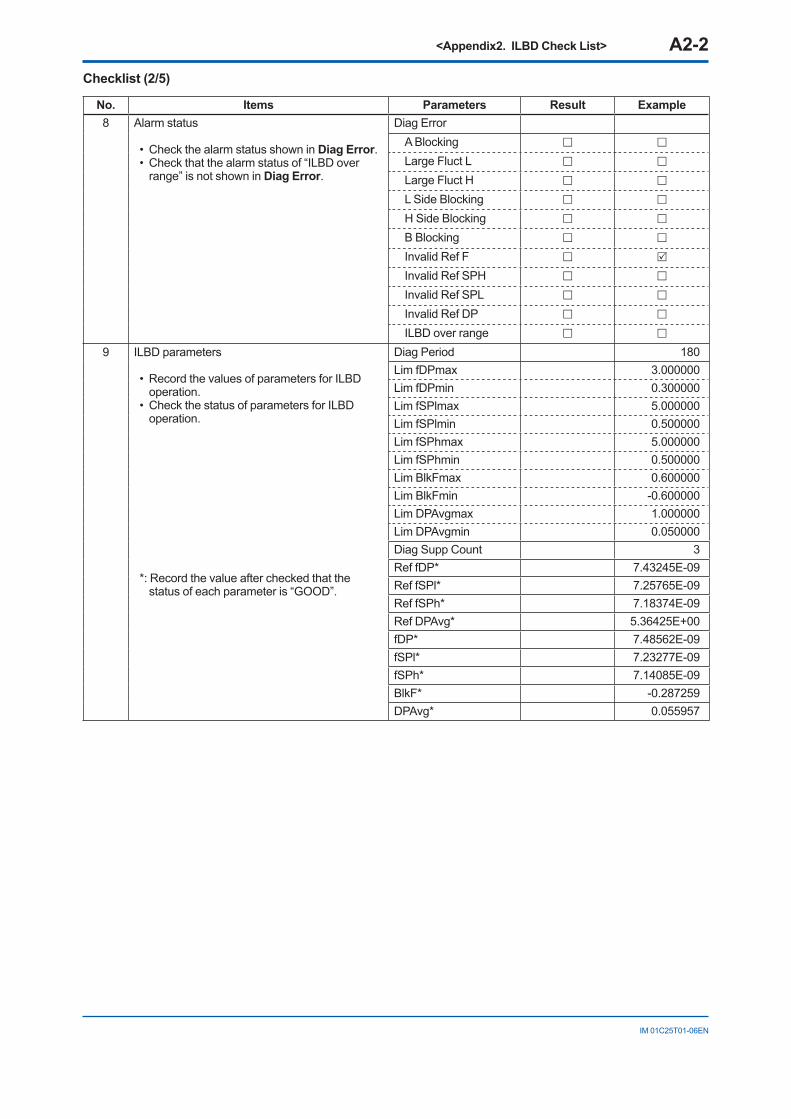
<Appendix2. ILBD Check List> A2-2
IM 01C25T01-06EN
Checklist (2/5)
No. Items Parameters Result Example8 Alarm status
• Check the alarm status shown in Diag Error.• Check that the alarm status of “ILBD over
range” is not shown in Diag Error.
Diag ErrorA Blocking
Large Fluct L
Large Fluct H
L Side Blocking
H Side Blocking
B Blocking
Invalid Ref F
Invalid Ref SPH
Invalid Ref SPL
Invalid Ref DP
ILBD over range
9 ILBD parameters
• Record the values of parameters for ILBD operation.
• Check the status of parameters for ILBD operation.
*: Record the value after checked that the status of each parameter is “GOOD”.
Diag Period 180Lim fDPmax 3.000000Lim fDPmin 0.300000Lim fSPlmax 5.000000Lim fSPlmin 0.500000Lim fSPhmax 5.000000Lim fSPhmin 0.500000Lim BlkFmax 0.600000Lim BlkFmin -0.600000Lim DPAvgmax 1.000000Lim DPAvgmin 0.050000Diag Supp Count 3Ref fDP* 7.43245E-09Ref fSPl* 7.25765E-09Ref fSPh* 7.18374E-09Ref DPAvg* 5.36425E+00fDP* 7.48562E-09fSPl* 7.23277E-09fSPh* 7.14085E-09BlkF* -0.287259DPAvg* 0.055957
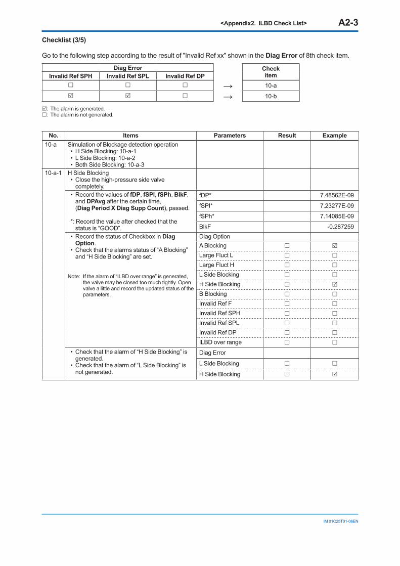
<Appendix2. ILBD Check List> A2-3
IM 01C25T01-06EN
Checklist (3/5)
Go to the following step according to the result of "Invalid Ref xx" shown in the Diag Error of 8th check item.
Diag Error CheckitemInvalid Ref SPH Invalid Ref SPL Invalid Ref DP
→ 10-a
→ 10-b
: The alarm is generated.: The alarm is not generated.
No. Items Parameters Result Example10-a Simulation of Blockage detection operation
• H Side Blocking: 10-a-1• L Side Blocking: 10-a-2• Both Side Blocking: 10-a-3
10-a-1 H Side Blocking• Close the high-pressure side valve
completely.• Record the values of fDP, fSPl, fSPh, BlkF,
and DPAvg after the certain time, (Diag Period X Diag Supp Count), passed.
*: Record the value after checked that the status is “GOOD”.
fDP* 7.48562E-09
fSPI* 7.23277E-09
fSPh* 7.14085E-09
BlkF -0.287259• Record the status of Checkbox in Diag
Option.• Check that the alarms status of “A Blocking”
and “H Side Blocking” are set.
Note: If the alarm of “ILBD over range” is generated, the valve may be closed too much tightly. Open valve a little and record the updated status of the parameters.
Diag OptionA Blocking
Large Fluct L
Large Fluct H
L Side Blocking
H Side Blocking
B Blocking
Invalid Ref F
Invalid Ref SPH
Invalid Ref SPL
Invalid Ref DP
ILBD over range
• Check that the alarm of “H Side Blocking” is generated.
• Check that the alarm of “L Side Blocking” is not generated.
Diag Error
L Side Blocking
H Side Blocking
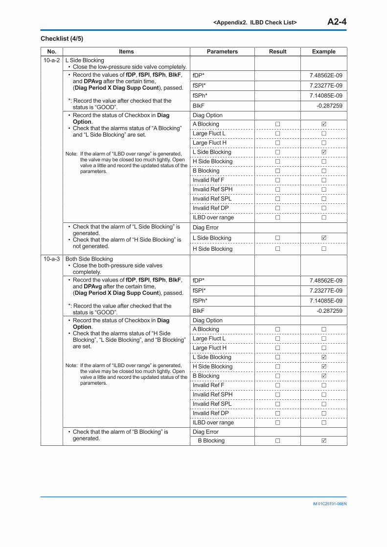
<Appendix2. ILBD Check List> A2-4
IM 01C25T01-06EN
Checklist (4/5)
No. Items Parameters Result Example10-a-2 L Side Blocking
• Close the low-pressure side valve completely.• Record the values of fDP, fSPl, fSPh, BlkF,
and DPAvg after the certain time, (Diag Period X Diag Supp Count), passed.
*: Record the value after checked that the status is “GOOD”.
fDP* 7.48562E-09
fSPI* 7.23277E-09
fSPh* 7.14085E-09
BIkF -0.287259• Record the status of Checkbox in Diag
Option.• Check that the alarms status of “A Blocking”
and “L Side Blocking” are set.
Note: If the alarm of “ILBD over range” is generated, the valve may be closed too much tightly. Open valve a little and record the updated status of the parameters.
Diag OptionA Blocking
Large Fluct L
Large Fluct H
L Side Blocking
H Side Blocking
B Blocking
Invalid Ref F
Invalid Ref SPH
Invalid Ref SPL
Invalid Ref DP
ILBD over range
• Check that the alarm of “L Side Blocking” is generated.
• Check that the alarm of “H Side Blocking” is not generated.
Diag Error
L Side Blocking
H Side Blocking
10-a-3 Both Side Blocking• Close the both-pressure side valves
completely.• Record the values of fDP, fSPl, fSPh, BlkF,
and DPAvg after the certain time, (Diag Period X Diag Supp Count), passed.
*: Record the value after checked that the status is “GOOD”.
fDP* 7.48562E-09
fSPI* 7.23277E-09
fSPh* 7.14085E-09
BIkF -0.287259• Record the status of Checkbox in Diag
Option.• Check that the alarms status of “H Side
Blocking”, “L Side Blocking”, and “B Blocking” are set.
Note: If the alarm of “ILBD over range” is generated, the valve may be closed too much tightly. Open valve a little and record the updated status of the parameters.
Diag OptionA Blocking
Large Fluct L
Large Fluct H
L Side Blocking
H Side Blocking
B Blocking
Invalid Ref F
Invalid Ref SPH
Invalid Ref SPL
Invalid Ref DP
ILBD over range
• Check that the alarm of “B Blocking” is generated.
Diag ErrorB Blocking
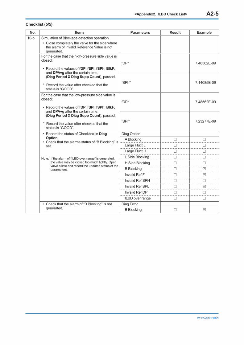
<Appendix2. ILBD Check List> A2-5
IM 01C25T01-06EN
Checklist (5/5)
No. Items Parameters Result Example10-b Simulation of Blockage detection operation
• Close completely the valve for the side where the alarm of Invalid Reference Value is not generated.
For the case that the high-pressure side value is closed;
• Record the values of fDP, fSPl, fSPh, BlkF, and DPAvg after the certain time, (Diag Period X Diag Supp Count), passed.
*: Record the value after checked that the status is “GOOD”.
fDP* 7.48562E-09
fSPh* 7.14085E-09
For the case that the low-pressure side value is closed;
• Record the values of fDP, fSPl, fSPh, BlkF, and DPAvg after the certain time, (Diag Period X Diag Supp Count), passed.
*: Record the value after checked that the status is “GOOD”.
fDP* 7.48562E-09
fSPI* 7.23277E-09
• Record the status of Checkbox in Diag Option.
• Check that the alarms status of “B Blocking” is set.
Note: If the alarm of “ILBD over range” is generated, the valve may be closed too much tightly. Open valve a little and record the updated status of the parameters.
Diag OptionA Blocking
Large Fluct L
Large Fluct H
L Side Blocking
H Side Blocking
B Blocking
Invalid Ref F
Invalid Ref SPH
Invalid Ref SPL
Invalid Ref DP
ILBD over range
• Check that the alarm of “B Blocking” is not generated.
Diag ErrorB Blocking
i
IM 01C25T01-06EN
Revision Information Title : DPharp HART 5/7 Communication Type (EJXA, EJAE) Manual No. : IM 01C25T01-06EN
Edition Date Page Revised Item1st June 2010 — New publication
2nd Apr. 2012 —2-13-34
Re-edit to a common User’s Manual of HART 5 and HART 7.2.1 Add integral indicator display when powering on.3.3.18 Add switching procedure for HART protocol revision
(HART 5/HART 7)
3rd June 2012 — Add EJA series


![User’s Manual EJX and EJA-E Series Differential Pressure ... · [EJX series Communication Manual] Models Document No. Style DPharp HART 5/HART 7 Communication Type IM 01C25T01-06EN](https://img.pdfslide.net/doc/110x75/5eda7023b3745412b5715724/useras-manual-ejx-and-eja-e-series-differential-pressure-ejx-series-communication.jpg)