Embed Size (px)
Citation preview

USER'S MANUAL
for
CLCI2000 SERIES
1 to 4 AXIS COMPUTER INDEXERS
Anaheim Automation(714) 992-6990
(714) 992-0471 fax
May 6, 2002 #L010018
COPYRIGHT
Copyright 1993 by Anaheim Automation. All rights reserved. No part of this publication may be reproduced, transmitted,transcribed, stored in a retrieval system, or translated into any language, in any form or by any means, electronic,mechanical, magnetic, optical, chemical, manual, or otherwise, without the prior written permission of AnaheimAutomation, 910 E. Orangefair Lane, Anaheim, CA 92801. The only exception to this would be use of the programexamples in this manual.
DISCLAIMER
Though every effort has been made to supply complete and accurate information in this manual, the contents are subjectto change without notice or obligation to inform the buyer. In no event will Anaheim Automation be liable for direct,indirect, special, incidental, or consequential damages arising out of the use or inability to use the product ordocumentation.
LIMITED WARRANTY
All Anaheim Automation products are warranted against defects in workmanship, materials and construction, when usedunder Normal Operating Conditions and when used in accordance with specifications. This warranty shall be in effectfor a period of twelve months from the date of purchase or eighteen months from the date of manufacture, whichevercomes first. Warranty provisions may be voided if the products are subjected to physical damage or abuse.
Anaheim Automation will repair or replace at its option, any of its products which have been found to be defective andare within the warranty period, provided that the item is shipped freight prepaid, with RMA (return material authorization),to Anaheim Automation's plant in Anaheim, California.
TRADEMARKS
Control Link and Driver Pack are registered trademarks of Anaheim Automation.IBM PC is a registered trademark of International Business Machines, Inc.
TABLE OF CONTENTS
DESCRIPTION . . . . . . . . . . . . . . . . . . . . . . . . . . . . . . . . . . . . . . . . . . . . . . . . . . . . . . . . . . . . 1General Description . . . . . . . . . . . . . . . . . . . . . . . . . . . . . . . . . . . . . . . . . . . . . . . . . . . . 1Main Features . . . . . . . . . . . . . . . . . . . . . . . . . . . . . . . . . . . . . . . . . . . . . . . . . . . . . . . . 1Packing Information . . . . . . . . . . . . . . . . . . . . . . . . . . . . . . . . . . . . . . . . . . . . . . . . . . . . 1Ordering Information . . . . . . . . . . . . . . . . . . . . . . . . . . . . . . . . . . . . . . . . . . . . . . . . . . . 2
SPECIFICATIONS . . . . . . . . . . . . . . . . . . . . . . . . . . . . . . . . . . . . . . . . . . . . . . . . . . . . . . . . . . 4
INSTALLATION . . . . . . . . . . . . . . . . . . . . . . . . . . . . . . . . . . . . . . . . . . . . . . . . . . . . . . . . . . . . 5Installing the Board . . . . . . . . . . . . . . . . . . . . . . . . . . . . . . . . . . . . . . . . . . . . . . . . . . . . 5Wiring to the CLCI2000 . . . . . . . . . . . . . . . . . . . . . . . . . . . . . . . . . . . . . . . . . . . . . . . . . 5Address Settings . . . . . . . . . . . . . . . . . . . . . . . . . . . . . . . . . . . . . . . . . . . . . . . . . . . . . . 5
QUICKSTART WITH QUICKBASIC . . . . . . . . . . . . . . . . . . . . . . . . . . . . . . . . . . . . . . . . . . . . . 6
CONNECTOR DESCRIPTIONS . . . . . . . . . . . . . . . . . . . . . . . . . . . . . . . . . . . . . . . . . . . . . . . . 7
PROGRAMMING WITH ANAHEIM AUTOMATION LIBRARIES . . . . . . . . . . . . . . . . . . . . . . 10Programming with QuickBASIC or VisualBasic for DOS . . . . . . . . . . . . . . . . . . . . . . . 10Speed Considerations . . . . . . . . . . . . . . . . . . . . . . . . . . . . . . . . . . . . . . . . . . . . . . . . . 10
CLCISUB1.BAS LIBRARY . . . . . . . . . . . . . . . . . . . . . . . . . . . . . . . . . . . . . . . . . . . . . . . . . . . 11Sample Program #1 . . . . . . . . . . . . . . . . . . . . . . . . . . . . . . . . . . . . . . . . . . . . . . . . . . . 15Sample Program #2 . . . . . . . . . . . . . . . . . . . . . . . . . . . . . . . . . . . . . . . . . . . . . . . . . . . 16
CLCISUBS.CPP PROGRAM FUNCTION DEFINITIONS . . . . . . . . . . . . . . . . . . . . . . . . . . . . 17Sample Program #3 . . . . . . . . . . . . . . . . . . . . . . . . . . . . . . . . . . . . . . . . . . . . . . . . . . . 19
PROGRAMMING IN WINDOWS . . . . . . . . . . . . . . . . . . . . . . . . . . . . . . . . . . . . . . . . . . . . . . 20WIN2000.BAS Program Listing . . . . . . . . . . . . . . . . . . . . . . . . . . . . . . . . . . . . . . . . . . 21
CLCI2004 PROGRAM GENERATOR . . . . . . . . . . . . . . . . . . . . . . . . . . . . . . . . . . . . . . . . . . 22
CLCI2004 PROGRAM GENERATOR COMMAND DICTIONARY . . . . . . . . . . . . . . . . . . . . . 26
ADVANCED PROGRAMMING . . . . . . . . . . . . . . . . . . . . . . . . . . . . . . . . . . . . . . . . . . . . . . . . 30
1
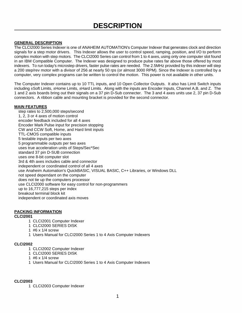
DESCRIPTION
GENERAL DESCRIPTIONThe CLCI2000 Series Indexer is one of ANAHEIM AUTOMATION's Computer Indexer that generates clock and directionsignals for a step motor drivers. This Indexer allows the user to control speed, ramping, position, and I/O to performcomplex motion with step motors. The CLCI2000 Series can control from 1 to 4 axes, using only one computer slot foundin an IBM Compatible Computer. The Indexer was designed to produce pulse rates far above those offered by mostindexers. To run today's microstep drivers, faster pulse rates are needed. The 2.5MHz provided by this indexer will stepa 200 step/rev motor with a divisor of 256 at nearly 50 rps (or almost 3000 RPM). Since the Indexer is controlled by acomputer, very complex programs can be written to control the motion. This power is not available in other units.
The Computer Indexer contains up to 10 TTL inputs, and 10 Open Collector Outputs. It also has Limit Switch inputsincluding ±Soft Limits, ±Home Limits, ±Hard Limits. Along with the inputs are Encoder Inputs, Channel A,B, and Z. The1 and 2 axis boards bring out their signals on a 37 pin D-Sub connecter. The 3 and 4 axes units use 2, 37 pin D-Subconnectors. A ribbon cable and mounting bracket is provided for the second connector.
MAIN FEATURESë step rates to 2,500,000 steps/secondë 1, 2, 3 or 4 axes of motion controlë encoder feedback included for all 4 axesë Encoder Mark Pulse input for precision stoppingë CW and CCW Soft, Home, and Hard limit inputsë TTL-CMOS compatible inputsë 5 testable inputs per two axesë 5 programmable outputs per two axesë uses true acceleration units of Steps/Sec*Secë standard 37 pin D-SUB connectionë uses one 8-bit computer slotë 3rd & 4th axes includes cable and connectorë independent or coordinated control of all 4 axesë use Anaheim Automation's QuickBASIC, VISUAL BASIC, C++ Libraries, or Windows DLLë not speed dependant on the computerë does not tie up the computers processorë use CLCI2000 software for easy control for non-programmersë up to 16,777,215 steps per indexë breakout terminal block kitë independent or coordinated axis moves
PACKING INFORMATIONCLCI2001
1 CLCI2001 Computer Indexer1 CLCI2000 SERIES DISK1 #6 x 1/4 screw1 Users Manual for CLCI2000 Series 1 to 4 Axis Computer Indexers
CLCI20021 CLCI2002 Computer Indexer1 CLCI2000 SERIES DISK1 #6 x 1/4 screw1 Users Manual for CLCI2000 Series 1 to 4 Axis Computer Indexers
CLCI20031 CLCI2003 Computer Indexer
2
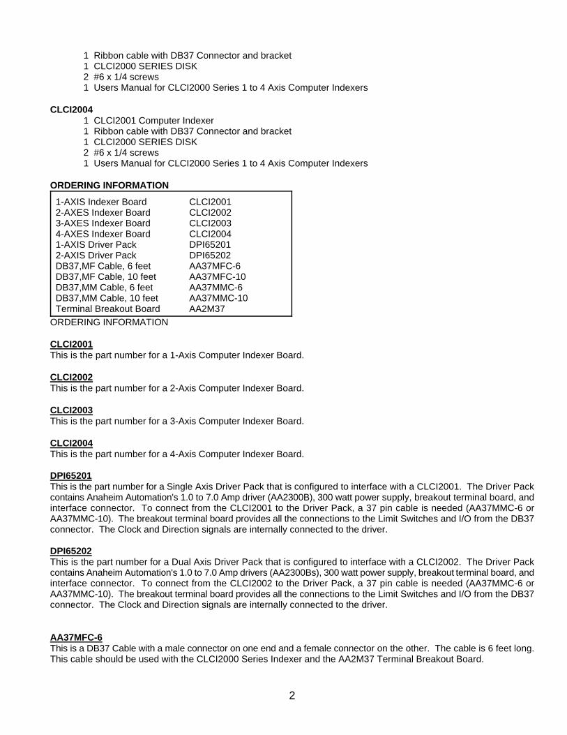
1 Ribbon cable with DB37 Connector and bracket1 CLCI2000 SERIES DISK2 #6 x 1/4 screws1 Users Manual for CLCI2000 Series 1 to 4 Axis Computer Indexers
CLCI20041 CLCI2001 Computer Indexer1 Ribbon cable with DB37 Connector and bracket1 CLCI2000 SERIES DISK2 #6 x 1/4 screws1 Users Manual for CLCI2000 Series 1 to 4 Axis Computer Indexers
ORDERING INFORMATION
1-AXIS Indexer Board CLCI20012-AXES Indexer Board CLCI20023-AXES Indexer Board CLCI20034-AXES Indexer Board CLCI20041-AXIS Driver Pack DPI652012-AXIS Driver Pack DPI65202DB37,MF Cable, 6 feet AA37MFC-6 DB37,MF Cable, 10 feet AA37MFC-10DB37,MM Cable, 6 feet AA37MMC-6DB37,MM Cable, 10 feet AA37MMC-10Terminal Breakout Board AA2M37
ORDERING INFORMATION
CLCI2001This is the part number for a 1-Axis Computer Indexer Board.
CLCI2002This is the part number for a 2-Axis Computer Indexer Board.
CLCI2003This is the part number for a 3-Axis Computer Indexer Board.
CLCI2004This is the part number for a 4-Axis Computer Indexer Board.
DPI65201This is the part number for a Single Axis Driver Pack that is configured to interface with a CLCI2001. The Driver Packcontains Anaheim Automation's 1.0 to 7.0 Amp driver (AA2300B), 300 watt power supply, breakout terminal board, andinterface connector. To connect from the CLCI2001 to the Driver Pack, a 37 pin cable is needed (AA37MMC-6 orAA37MMC-10). The breakout terminal board provides all the connections to the Limit Switches and I/O from the DB37connector. The Clock and Direction signals are internally connected to the driver.
DPI65202This is the part number for a Dual Axis Driver Pack that is configured to interface with a CLCI2002. The Driver Packcontains Anaheim Automation's 1.0 to 7.0 Amp drivers (AA2300Bs), 300 watt power supply, breakout terminal board, andinterface connector. To connect from the CLCI2002 to the Driver Pack, a 37 pin cable is needed (AA37MMC-6 orAA37MMC-10). The breakout terminal board provides all the connections to the Limit Switches and I/O from the DB37connector. The Clock and Direction signals are internally connected to the driver.
AA37MFC-6This is a DB37 Cable with a male connector on one end and a female connector on the other. The cable is 6 feet long.This cable should be used with the CLCI2000 Series Indexer and the AA2M37 Terminal Breakout Board.

3
AA37MFC-10This is a DB37 Cable with a male connector on one end and a female connector on the other. The cable is 10 feet long.This cable should be used with the CLCI2000 Series Indexer and the AA2M37 Terminal Breakout Board.
AA37MMC-6This is a DB37 Cable with a male connector on both ends. The cable is 6 feet long. This cable should be used with theCLCI2000 Series Indexer and the DPI65200 Series Driver Packs.
AA37MMC-10This is a DB37 Cable with a male connector on both ends. The cable is 10 feet long. This cable should be used withthe CLCI2000 Series Indexer and the DPI65200 Series Driver Packs.
AA2M37This is a DB37 Breakout Board. This board contains a DB37 Male Connector, and screw terminal blocks to aid in wiringto the CLCI2000 Series Indexers. The cable needed to interface between the Indexer and this module is the AA37MFC-6or AA37MFC-10.
4
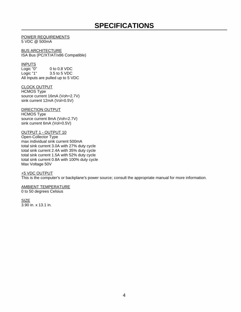
SPECIFICATIONS
POWER REQUIREMENTS5 VDC @ 500mA
BUS ARCHITECTUREISA Bus (PC/XT/AT/x86 Compatible)
INPUTSLogic "0" 0 to 0.8 VDCLogic "1" 3.5 to 5 VDCAll Inputs are pulled up to 5 VDC
CLOCK OUTPUTHCMOS Typesource current 16mA (Voh=2.7V)sink current 12mA (Vol=0.5V)
DIRECTION OUTPUTHCMOS Typesource current 8mA (Voh=2.7V)sink current 6mA (Vol=0.5V)
OUTPUT 1 - OUTPUT 10Open-Collector Typemax individual sink current 500mAtotal sink current 3.0A with 27% duty cycletotal sink current 2.4A with 35% duty cycletotal sink current 1.5A with 52% duty cycletotal sink current 0.8A with 100% duty cycleMax Voltage 50V
+5 VDC OUTPUTThis is the computer's or backplane's power source; consult the appropriate manual for more information.
AMBIENT TEMPERATURE0 to 50 degrees Celsius
SIZE3.90 in. x 13.1 in.
5
INSTALLATION
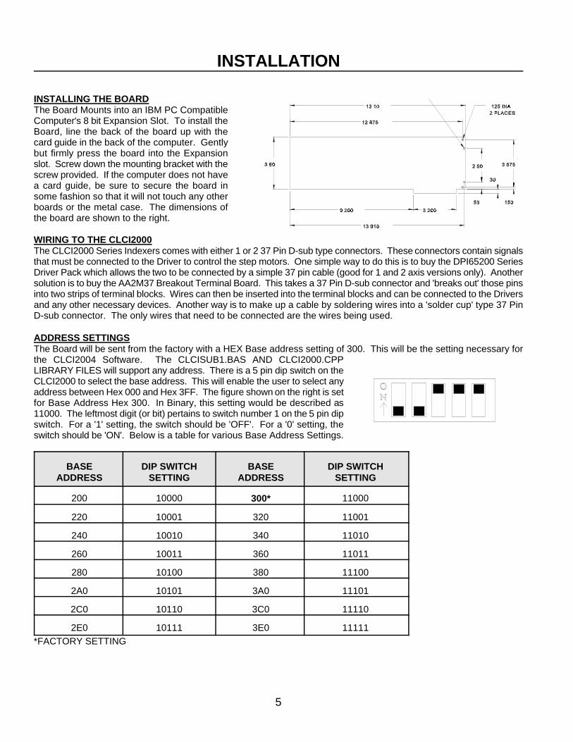
INSTALLING THE BOARDThe Board Mounts into an IBM PC CompatibleComputer's 8 bit Expansion Slot. To install theBoard, line the back of the board up with thecard guide in the back of the computer. Gentlybut firmly press the board into the Expansionslot. Screw down the mounting bracket with thescrew provided. If the computer does not havea card guide, be sure to secure the board insome fashion so that it will not touch any otherboards or the metal case. The dimensions ofthe board are shown to the right.
WIRING TO THE CLCI2000The CLCI2000 Series Indexers comes with either 1 or 2 37 Pin D-sub type connectors. These connectors contain signalsthat must be connected to the Driver to control the step motors. One simple way to do this is to buy the DPI65200 SeriesDriver Pack which allows the two to be connected by a simple 37 pin cable (good for 1 and 2 axis versions only). Anothersolution is to buy the AA2M37 Breakout Terminal Board. This takes a 37 Pin D-sub connector and 'breaks out' those pinsinto two strips of terminal blocks. Wires can then be inserted into the terminal blocks and can be connected to the Driversand any other necessary devices. Another way is to make up a cable by soldering wires into a 'solder cup' type 37 PinD-sub connector. The only wires that need to be connected are the wires being used.
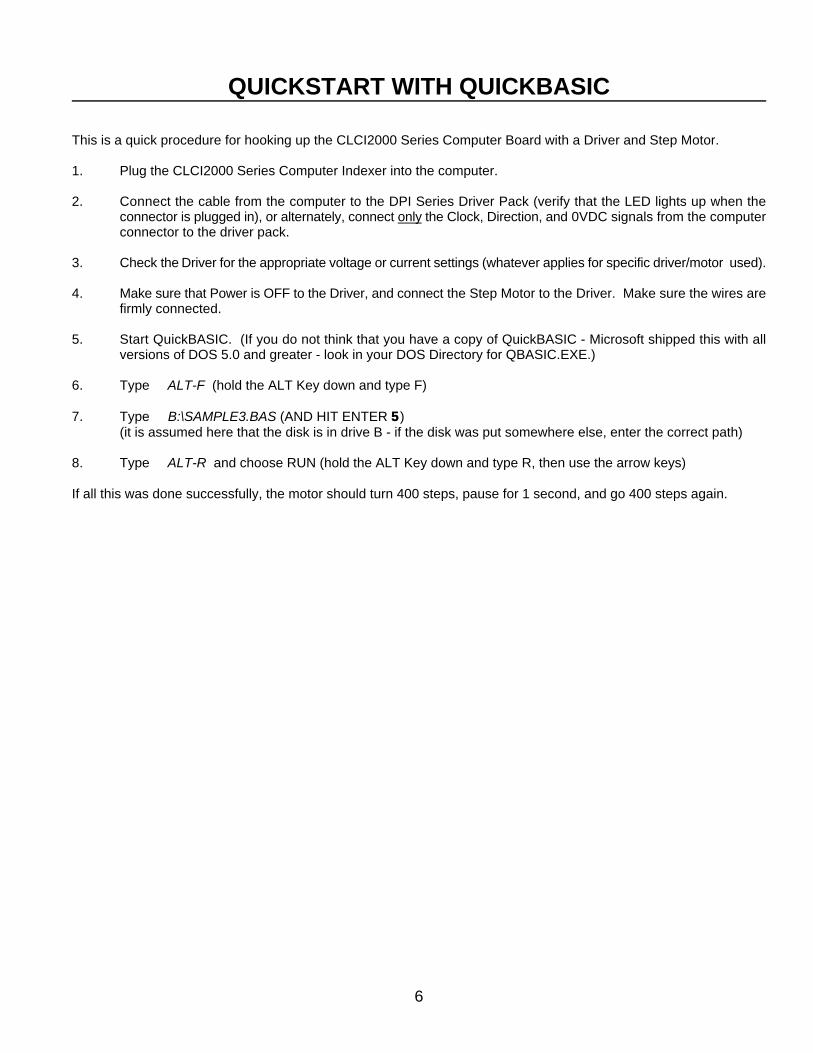
ADDRESS SETTINGSThe Board will be sent from the factory with a HEX Base address setting of 300. This will be the setting necessary forthe CLCI2004 Software. The CLCISUB1.BAS AND CLCI2000.CPPLIBRARY FILES will support any address. There is a 5 pin dip switch on theCLCI2000 to select the base address. This will enable the user to select anyaddress between Hex 000 and Hex 3FF. The figure shown on the right is setfor Base Address Hex 300. In Binary, this setting would be described as11000. The leftmost digit (or bit) pertains to switch number 1 on the 5 pin dipswitch. For a '1' setting, the switch should be 'OFF'. For a '0' setting, theswitch should be 'ON'. Below is a table for various Base Address Settings.
BASE DIP SWITCH BASE DIP SWITCHADDRESS SETTING ADDRESS SETTING
200 10000 11000300*
220 10001 320 11001
240 10010 340 11010
260 10011 360 11011
280 10100 380 11100
2A0 10101 3A0 11101
2C0 10110 3C0 11110
2E0 10111 3E0 11111
*FACTORY SETTING
6
QUICKSTART WITH QUICKBASIC
This is a quick procedure for hooking up the CLCI2000 Series Computer Board with a Driver and Step Motor.
1. Plug the CLCI2000 Series Computer Indexer into the computer.
2. Connect the cable from the computer to the DPI Series Driver Pack (verify that the LED lights up when theconnector is plugged in), or alternately, connect only the Clock, Direction, and 0VDC signals from the computerconnector to the driver pack.
3. Check the Driver for the appropriate voltage or current settings (whatever applies for specific driver/motor used).
4. Make sure that Power is OFF to the Driver, and connect the Step Motor to the Driver. Make sure the wires arefirmly connected.
5. Start QuickBASIC. (If you do not think that you have a copy of QuickBASIC - Microsoft shipped this with allversions of DOS 5.0 and greater - look in your DOS Directory for QBASIC.EXE.)
6. Type ALT-F (hold the ALT Key down and type F)
7. Type B:\SAMPLE3.BAS (AND HIT ENTER 55)(it is assumed here that the disk is in drive B - if the disk was put somewhere else, enter the correct path)
8. Type ALT-R and choose RUN (hold the ALT Key down and type R, then use the arrow keys)
If all this was done successfully, the motor should turn 400 steps, pause for 1 second, and go 400 steps again.
7
CONNECTOR DESCRIPTIONS
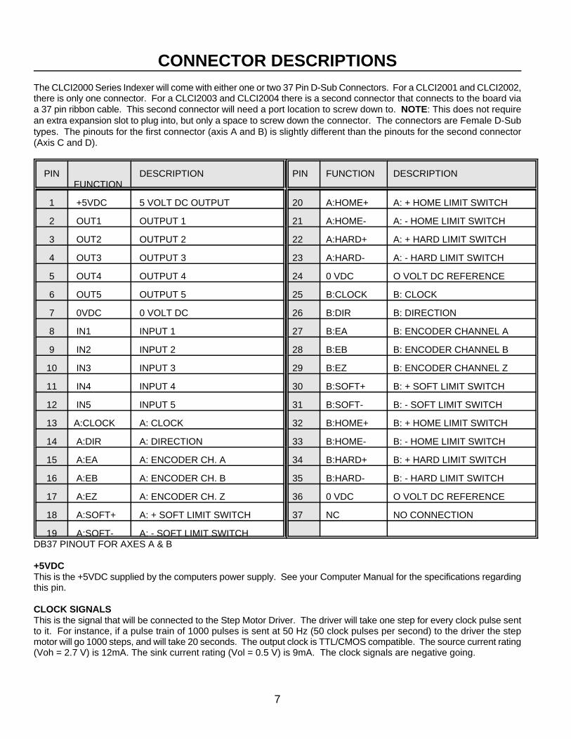
The CLCI2000 Series Indexer will come with either one or two 37 Pin D-Sub Connectors. For a CLCI2001 and CLCI2002,there is only one connector. For a CLCI2003 and CLCI2004 there is a second connector that connects to the board viaa 37 pin ribbon cable. This second connector will need a port location to screw down to. NOTE: This does not requirean extra expansion slot to plug into, but only a space to screw down the connector. The connectors are Female D-Subtypes. The pinouts for the first connector (axis A and B) is slightly different than the pinouts for the second connector(Axis C and D).
PIN DESCRIPTION PIN FUNCTION DESCRIPTIONFUNCTION
1 +5VDC 5 VOLT DC OUTPUT 20 A:HOME+ A: + HOME LIMIT SWITCH
2 OUT1 OUTPUT 1 21 A:HOME- A: - HOME LIMIT SWITCH
3 OUT2 OUTPUT 2 22 A:HARD+ A: + HARD LIMIT SWITCH
4 OUT3 OUTPUT 3 23 A:HARD- A: - HARD LIMIT SWITCH
5 OUT4 OUTPUT 4 24 0 VDC O VOLT DC REFERENCE
6 OUT5 OUTPUT 5 25 B:CLOCK B: CLOCK
7 0VDC 0 VOLT DC 26 B:DIR B: DIRECTION
8 IN1 INPUT 1 27 B:EA B: ENCODER CHANNEL A
9 IN2 INPUT 2 28 B:EB B: ENCODER CHANNEL B
10 IN3 INPUT 3 29 B:EZ B: ENCODER CHANNEL Z
11 IN4 INPUT 4 30 B:SOFT+ B: + SOFT LIMIT SWITCH
12 IN5 INPUT 5 31 B:SOFT- B: - SOFT LIMIT SWITCH
13 A:CLOCK A: CLOCK 32 B:HOME+ B: + HOME LIMIT SWITCH
14 A:DIR A: DIRECTION 33 B:HOME- B: - HOME LIMIT SWITCH
15 A:EA A: ENCODER CH. A 34 B:HARD+ B: + HARD LIMIT SWITCH
16 A:EB A: ENCODER CH. B 35 B:HARD- B: - HARD LIMIT SWITCH
17 A:EZ A: ENCODER CH. Z 36 0 VDC O VOLT DC REFERENCE
18 A:SOFT+ A: + SOFT LIMIT SWITCH 37 NC NO CONNECTION
19 A:SOFT- A: - SOFT LIMIT SWITCHDB37 PINOUT FOR AXES A & B
+5VDCThis is the +5VDC supplied by the computers power supply. See your Computer Manual for the specifications regardingthis pin.
CLOCK SIGNALSThis is the signal that will be connected to the Step Motor Driver. The driver will take one step for every clock pulse sentto it. For instance, if a pulse train of 1000 pulses is sent at 50 Hz (50 clock pulses per second) to the driver the stepmotor will go 1000 steps, and will take 20 seconds. The output clock is TTL/CMOS compatible. The source current rating(Voh = 2.7 V) is 12mA. The sink current rating (Vol = 0.5 V) is 9mA. The clock signals are negative going.
8
DIRECTION SIGNALSThis output is TTL/CMOS compatible. The source current rating (Voh = 2.7 V) is 12mA. The sink current rating (Vol =0.5 V) is 9mA. The Direction signal is +5VDC for '+' or clockwise motion, and 0VDC for '-' or counterclockwise motion.
SOFT LIMITThis input will cause the motor to ramp down to the base speed. This input contains a 2.5K pullup resistor to +5VDC.It should be activated by connecting it to the 0VDC pin, or a logic level that can sink 2.0mA at TTL levels.
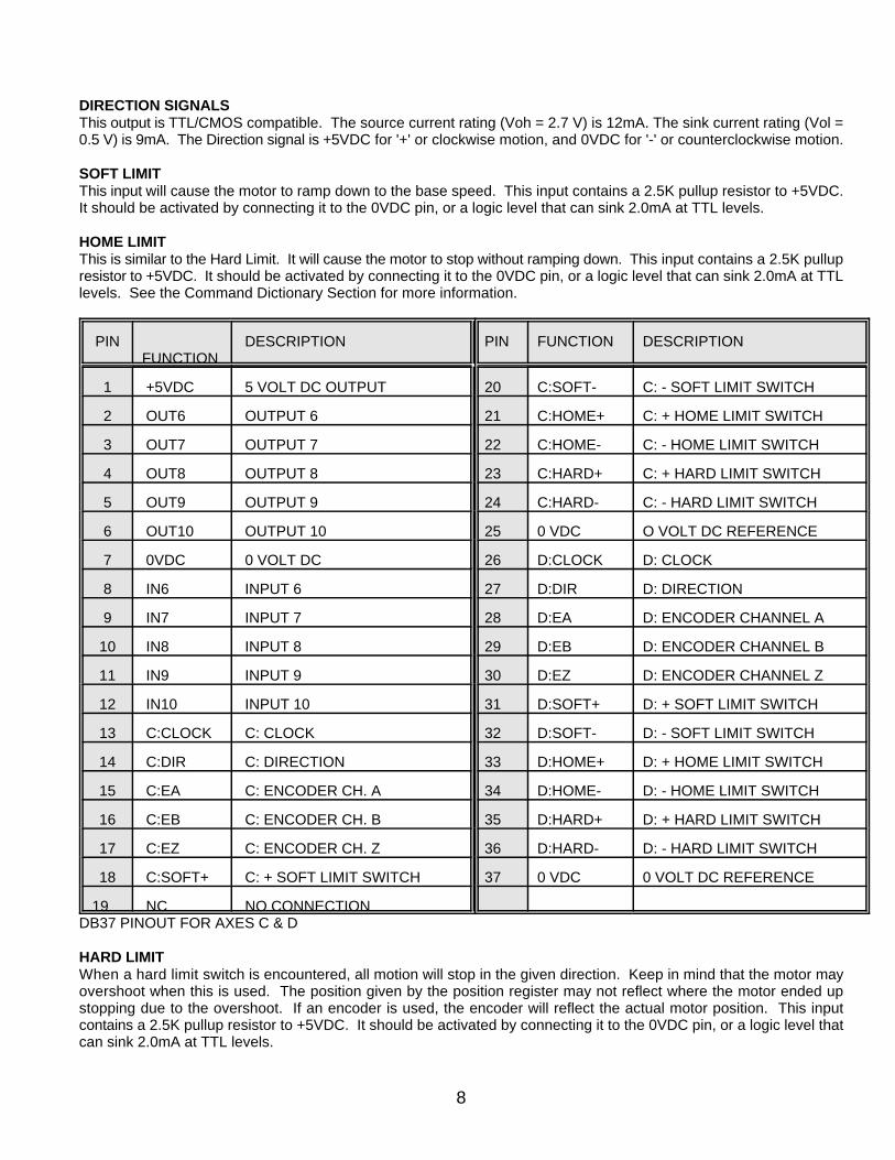
HOME LIMITThis is similar to the Hard Limit. It will cause the motor to stop without ramping down. This input contains a 2.5K pullupresistor to +5VDC. It should be activated by connecting it to the 0VDC pin, or a logic level that can sink 2.0mA at TTLlevels. See the Command Dictionary Section for more information.
PIN DESCRIPTION PIN FUNCTION DESCRIPTIONFUNCTION
1 +5VDC 5 VOLT DC OUTPUT 20 C:SOFT- C: - SOFT LIMIT SWITCH
2 OUT6 OUTPUT 6 21 C:HOME+ C: + HOME LIMIT SWITCH
3 OUT7 OUTPUT 7 22 C:HOME- C: - HOME LIMIT SWITCH
4 OUT8 OUTPUT 8 23 C:HARD+ C: + HARD LIMIT SWITCH
5 OUT9 OUTPUT 9 24 C:HARD- C: - HARD LIMIT SWITCH
6 OUT10 OUTPUT 10 25 0 VDC O VOLT DC REFERENCE
7 0VDC 0 VOLT DC 26 D:CLOCK D: CLOCK
8 IN6 INPUT 6 27 D:DIR D: DIRECTION
9 IN7 INPUT 7 28 D:EA D: ENCODER CHANNEL A
10 IN8 INPUT 8 29 D:EB D: ENCODER CHANNEL B
11 IN9 INPUT 9 30 D:EZ D: ENCODER CHANNEL Z
12 IN10 INPUT 10 31 D:SOFT+ D: + SOFT LIMIT SWITCH
13 C:CLOCK C: CLOCK 32 D:SOFT- D: - SOFT LIMIT SWITCH
14 C:DIR C: DIRECTION 33 D:HOME+ D: + HOME LIMIT SWITCH
15 C:EA C: ENCODER CH. A 34 D:HOME- D: - HOME LIMIT SWITCH
16 C:EB C: ENCODER CH. B 35 D:HARD+ D: + HARD LIMIT SWITCH
17 C:EZ C: ENCODER CH. Z 36 D:HARD- D: - HARD LIMIT SWITCH
18 C:SOFT+ C: + SOFT LIMIT SWITCH 37 0 VDC 0 VOLT DC REFERENCE
19 NC NO CONNECTIONDB37 PINOUT FOR AXES C & D
HARD LIMITWhen a hard limit switch is encountered, all motion will stop in the given direction. Keep in mind that the motor mayovershoot when this is used. The position given by the position register may not reflect where the motor ended upstopping due to the overshoot. If an encoder is used, the encoder will reflect the actual motor position. This inputcontains a 2.5K pullup resistor to +5VDC. It should be activated by connecting it to the 0VDC pin, or a logic level thatcan sink 2.0mA at TTL levels.
9
ENCODER INPUTSA Rotary Encoder is a device that measures rotation of a shaft. The encoder can be mounted on the step motor shaft,or for even greater accuracy, it can be mounted on the shaft of the load. The encoder sends signals in a format called'quadrature' to the controller which will take this data and use it to verify the motor position. The encoder has four or fivewires: Power, Ground, Phase A, Phase B, and a Marker Pulse . The encoder can be used to form a closed loop systemwhich will ensure the motor position. The guaranteed accuracy of the system will then be determined by the resolutionof the encoder. Anaheim Automation stocks a 400 line encoder. This will produce 1600 counts per revolution, whichresults in accuracies of better than 0.225E.
INPUTSThese are general purpose inputs that can be used to integrate sensors, logic, switches, or a number of other things thatwill be used in coordinating the motion. They may be used to initiate a machine cycle, or allow for operator intervention,for sensing a machine condition such as 'out of material', or to wait for a particular temperature to be reached. Theseinputs contain 2.5K pullups resistor to +5VDC, and are activated when they reach a TTL/CMOS Low Level, or 0VDC.
OUTPUTSThese are Open-Collector Darlington type outputs. They may be used to operate coolant valves, air cylinders, relays,solenoids, external logic, or, with the right interfacing, any electrically controlled device. The Outputs will go to the 0.7VDC level, and can sink a total of 500mA. The Maximum Voltage that can be applied to the Outputs is 50 VDC. (SeeSpecification Section on page 3 for more information.)
10
PROGRAMMING WITH ANAHEIM AUTOMATION LIBRARIES
Anaheim Automation has written Libraries that can be used to control the CLCI2000 Series Indexer Board in manydifferent languages. These languages include QuickBASIC, VisualBasic, C, and any Windows programming language.There are two different libraries written for the 'BASIC' languages, one library for the 'C' users, and one library for thewindows users (this Windows Library must be requested). The Libraries contain all the code necessary to control themotion with the Indexer Board.
PROGRAMMING WITH QUICKBASIC OR VISUALBASIC FOR DOSProgramming the CLCI2000 Using Quick Basic is very easy. A Library with various Subroutines and Functions has beenwritten to make the process of controlling your Step Motor Driver as painless as possible. ANAHEIM AUTOMATION'sSubroutine and Function Library CLCISUB1.BAS is found on the CLCI2000 SERIES DISK. To use this library inQuickBASIC, go to the Menu Selection File, and Choose Load File. To use this library in VISUAL BASIC go to the MenuSelection File, and Choose Add File. Be sure to have the file in the appropriate location. When you use one of theSubroutines or Functions, be sure to 'DECLARE' that Sub or Function. You may want to copy all of the DECLAREstatements from the top of the CLCISUB1.BAS programs to the top of your Program. Refer to your QuickBASICtechnical manual for further explanations.
The way to program a move in QuickBASIC is as simple as this. Lets say you would like these (motion) parameters.
Base Speed: 400 steps/secMax Speed: 5,000 steps/sec
Ramp: 200,000 steps/sec^2
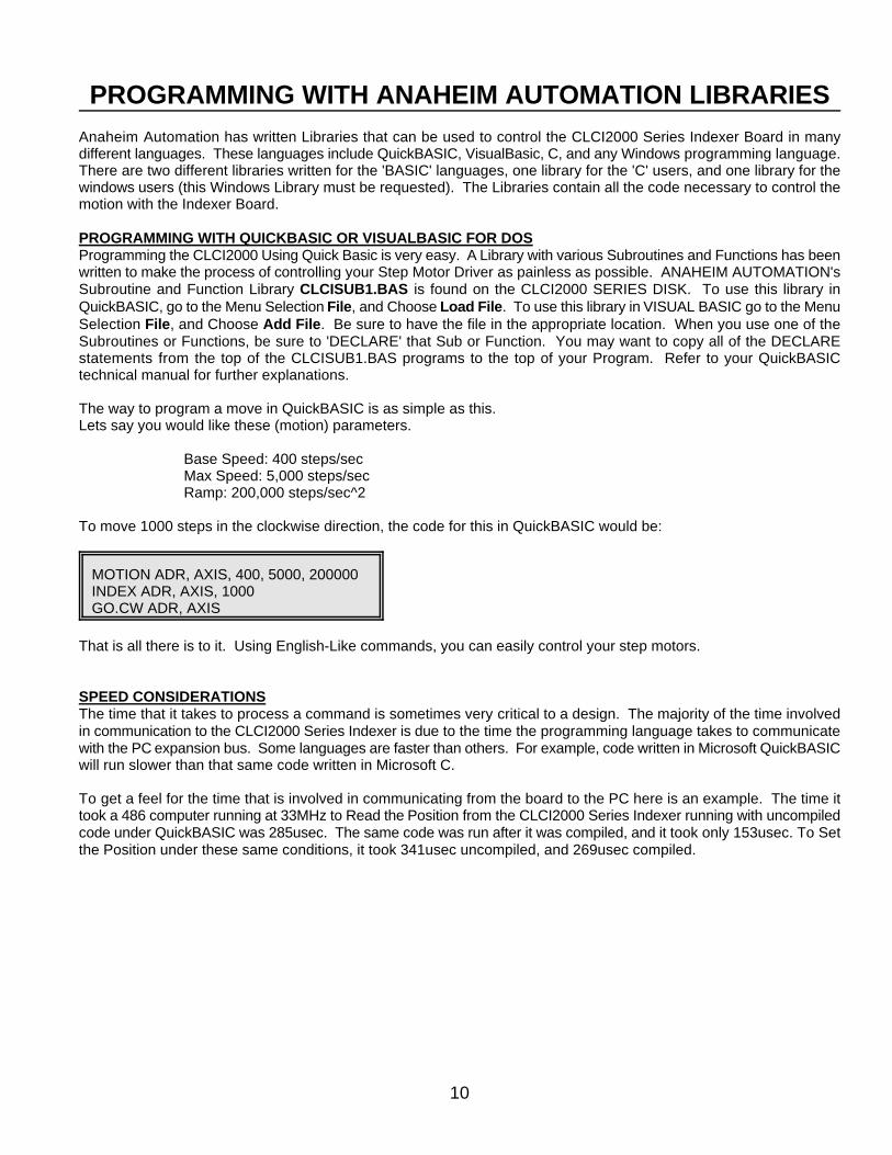
To move 1000 steps in the clockwise direction, the code for this in QuickBASIC would be:
MOTION ADR, AXIS, 400, 5000, 200000INDEX ADR, AXIS, 1000GO.CW ADR, AXIS
That is all there is to it. Using English-Like commands, you can easily control your step motors.
SPEED CONSIDERATIONSThe time that it takes to process a command is sometimes very critical to a design. The majority of the time involvedin communication to the CLCI2000 Series Indexer is due to the time the programming language takes to communicatewith the PC expansion bus. Some languages are faster than others. For example, code written in Microsoft QuickBASICwill run slower than that same code written in Microsoft C.
To get a feel for the time that is involved in communicating from the board to the PC here is an example. The time ittook a 486 computer running at 33MHz to Read the Position from the CLCI2000 Series Indexer running with uncompiledcode under QuickBASIC was 285usec. The same code was run after it was compiled, and it took only 153usec. To Setthe Position under these same conditions, it took 341usec uncompiled, and 269usec compiled.
11
CLCISUB1.BAS LIBRARY
The CLCISUB1.BAS Library is for use with QuickBASIC, VisualBasic for DOS, or any other similar 'BASIC' basedprogramming languages. This Library is set up to run CLCI2000 Series Indexers at any open addresses. The followingis a command list for all the usable Subroutines and Functions in this Library. This is a comprehensive list that will allowcomplete control of the CLCI2000 Series Index Boards. To use these commands you need to LOAD the fileCLCISUB1.BAS into your main program and DECLARE the Subroutines and Functions you wish to use. That is all thereis to it. Refer to your QuickBASIC or VisualBasic manual for more details. In all the below descriptions, these general guidelines apply:The ADDRESS is the setting on the 5 pin dip switch (see Installation). This is always given in the Hexadecimal format.For a setting of 11000, or a Base Address of 300, the correct format would be (&H300, ...) The AXIS# applies to the axis for that particular board (1, 2, 3, or 4)
BUSY (ADDRESS, AXIS#)This Function will return a 1 if the axis is Busy (clock pulses are being generated). It will return a 0 if there is no motionat all. This is a good Input to use to wait until the motion has stopped before going on in the program.
GET.BASE (BASE, MAX, RAMP) Because the motor speeds are created by a digital device, the resolution is limited to the clock oscillator that is used -in this case it is 9.8304 MHz. The result is a speed that is very close to the one desired - usually within a fraction of apercent. This Function will return the actual Base Speed obtainable with the given parameters. This is used to find outthe exact Base Speed that will be used for the specified numbers. For example, if the desired Base Speed was 500,Max Speed was 10,000, and Ramp was 2,000, the resulting Base Speed would actually be: 499.7963 Hz.
GET.MAX (BASE, MAX, RAMP) Because the motor speeds are created by a digital device, the resolution is limited to the clock oscillator that is used -in this case it is 9.8304 MHz. The result is a speed that is very close to the one desired - usually within a fraction of apercent. This Function will return the actual Max Speed obtainable with the given parameters. This is used to find outthe exact Max Speed that will be used for the specified numbers. For example, if the desired Base Speed was 500, MaxSpeed was 10,000, and Ramp was 2,000, the resulting Base Speed would actually be: 9999.593 Hz.
GET.RAMP (BASE, MAX, RAMP) Because the motor speeds are created by a digital device, the resolution is limited to the clock oscillator that is used -in this case it is 9.8304 MHz. The result is a Ramp that is very close to the one desired - usually within a fraction of apercent. This Function will return the actual Ramp obtainable with the given parameters. This is used to find out theexact Ramp that will be used for the specified numbers. For example, if the desired Base Speed was 500, Max Speedwas 10,000, and Ramp was 2,000, the resulting Ramp would actually be: 2000.784 Hz/Second.
GET.INPUT (ADDRESS, INPUT#) This Function will return the values for INPUT 1. A '1' means that the input is active, or at a TTL state of 0VDC. A '0'means that the input is at a TTL state of +5VDC or there is no connection to the input.
GO.CCW ADDRESS, AXIS#This Subroutine will Index in the counterclockwise direction. The distance that the motor will move depends on thedistance set by the A.INDEX.NUMBER command. The motion starts at Base Speed and Ramps up to Max Speed,sustains the Max Speed, and then finishes the move by ramping down to Base Speed and stopping.
GO.CW ADDRESS, AXIS#This Subroutine will Index in the clockwise direction. The distance that the motor will move depends on the distance setby the A.INDEX.NUMBER command. The motion starts at Base Speed and Ramps up to Max Speed, sustains the MaxSpeed, and then finishes the move by ramping down to Base Speed and stopping.
HARD.INPUT.CCW (ADDRESS, AXIS#) This Function will return the value of the -Hard Limit Switch. If the Limit Switch is ACTIVE or 0VDC, the Function willreturn a 1. If the Limit Switch is NOT ACTIVE, the function will return a 0.
HARD.INPUT.CW (ADDRESS, AXIS#)
12
This Function will return the value of the +Hard Limit Switch. If the Limit Switch is ACTIVE or 0VDC, the function willreturn a 1. If the Limit Switch is NOT ACTIVE, the function will return a 0.
HOME.CCW ADDRESS, AXIS#This Subroutine will HOME (sometimes called SLEW) the motor in the counterclockwise direction. The motion beginsat Base Speed, ramps up to Max Speed and continues moving in that direction until the software instructs it to dosomething different, or a hardware Limit Switch is activated.
HOME.CW ADDRESS, AXIS#This Subroutine will HOME (sometimes call SLEW) the motor in the clockwise direction. The motion begins at BaseSpeed, ramps up to Max Speed and continues moving in that direction until the software instructs it to do somethingdifferent, or a hardware Limit Switch is activated.
HOME.INPUT ADDRESS, AXIS#This Function will return the value for the Home Limit Switch. The Particular switch is determined by which Home LimitSwitch you chose with the OUTPUTS Subroutine. The default value for this is the -Home Limit Switch. This will returna 1 if the Home Limit Switch is 'active' (0VDC), and a 0 if the switch is not active.
INDEX ADDRESS, AXIS#, NUMBERThis Subroutine will set the Index Number Register. This command is used in conjunction with the GO.CW and GO.CCWCommand. The number in this register will not change until the next INDEX or POSITION Command is issued. Atypical motor that is Half-stepped will go one revolution in 400 steps.
INITIALIZE ADDRESS, AXIS#This Subroutine will set the all axes with initial settings. This must be done at the beginning of every program to ensurethat all the default setting are made, and that all the outputs are off. The commands below are executed for each axis:
INDEX 1000MOTION 200, 4000, 200000LIMIT.CONTROL 1, 1, 1SET.ENCODER 0OUTPUT 0, 0, 0, 0, 0, 1, 1
LIMIT.CONTROL ADDRESS, AXIS#, SOFT, MARK, HOMEThis Subroutine will either Activate or Deactivate the board features: SOFT LIMIT SWITCHES, ENCODER MARKERPULSE, OR HOME LIMIT SWITCH. A 1 will activate the feature, and a 0 will deactivate the feature. This commandis useful for Homing Routines and other routines that are used to ramp down to base speed or to stop the motor. TheMarker pulse is generally turned off until the rotary system is on the correct revolution to activate the pulse.
MOTION ADDRESS, AXIS#, BASE, MAX, RAMP This Subroutine will set the Base Speed, Max Speeds, and Acceleration. All three values must be entered. The BaseSpeed is the speed at which the motor starts it's motion. For Half-step applications, motors can sometimes start as highas 2,000 Hz. A Half-step speed of 400 will turn 1 revolution per second. It is normally desirable to start the motor as fastas possible. This will decrease the total time it takes to make the move. The Max Speed is the speed at which the motorwill reach it's top speed. For Half-step applications, motors can handle speeds as high as 20,000 Hz. A Max Speed of20,000 will turn the motor 50 revolutions per second. The Ramp time is the rate or increase in the speed when themotion is going from Base Speed to Max Speed. This value is in Hz/Sec*Sec. A ramp value of 1,000 will increase thespeed 1,000 Hz every second.
ONE.AT.MAX.CCW ADDRESS, AXIS#This Subroutine will go one step at the maximum speed in the CCW Direction. This is an easy way to 'Jog' the motor.
ONE.AT.MAX.CW ADDRESS, AXIS#This Subroutine will go one step at the maximum speed in the CW Direction. This is an easy way to 'Jog' the motor.
ORIGIN.INDEX.CCW ADDRESS, AXIS# This Subroutine will move in the CCW Direction at base speed until the Encoder Marker is 'active'. When the EncoderMarker is 'active' the motion will stop. This is a good way to 'home' the motor to a rotary position using the encoder's
13
marker pulse. The marker pulse must be enabled by the LIMIT.CONTROL Command for this Command to workproperly.
ORIGIN.INDEX.CW ADDRESS, AXIS# This Subroutine will move in the CW Direction at base speed until the Encoder Marker is 'active'. When the EncoderMarker is 'active' the motion will stop. This is a good way to 'home' the motor to a rotary position using the encoder'smarker pulse. The marker pulse must be enabled by the LIMIT.CONTROL Command for this Command to workproperly.
POSITION ADDRESS, AXIS#, VALUEThis Subroutine will go to the position specified. This routine reads the current position and calculates the distancerequired to move. It affects the Index Register which is changed by the A.INDEX Command. The Position can rangefrom 0 to 16,777,215. Negative numbers cannot be used with this command. Be sure to stay within the specified range.
RAMP.TO.BASE.CCW ADDRESS, AXIS#This Subroutine will ramp the motor from Max Speed to Base Speed. The move will be continued at Base Speed. Thisis a useful command for Homing to a Limit Switch.
RAMP.TO.BASE.CW ADDRESS, AXIS#This Subroutine will ramp the motor from Max Speed to Base Speed. The move will be continued at Base Speed. Thisis a useful command for Homing to a Limit Switch.
RAMP.TO.STOP.CCW ADDRESS, AXIS#This Subroutine will ramp the motor from Max Speed to Base Speed and stop. Be sure to use this command only whenthe motor is turning in the CCW direction.
RAMP.TO.STOP.CW ADDRESS, AXIS#This Subroutine will ramp the motor from Max Speed to Base Speed and stop. Be sure to use this command only whenthe motor is turning in the CW direction.
READ.ENCODER (ADDRESS, AXIS#)This Function will read the value in the Encoder Register. The Encoder Register can read a value up to 16,777,215.If the number goes beyond this number, the Register will 'spill over' and start back again at 0. For example, the if theencoder sent out 16,777,226 quadrature pulses, the Encoder Register would actually read 10. This register can be readat any time.
READ.POSITION (ADDRESS, AXIS#)This Function will return the Value in the Position Register. The Position Register can read a value up to 16,777,215.If the number goes beyond this number, the Register will 'spill over' and start back again at 0. For example, the if thenumber of steps was actually 16,777,226 - the Position Register would actually read 10. This register can be read at anytime.
SET.ENCODER ADDRESS, AXIS#, VALUEThis Subroutine will set the number in the Encoder Register. The values should range between 0 and 16,777,215.
SET.OUTPUT1 ADDRESS, OUT5, OUT4, OUT3, OUT2, OUT1, HOME.DIR.1, HOME.DIR.2This Subroutine will set the 5 outputs and the active direction for the Home Limit Switch. The first five numbers specifywhat the state of the five Outputs will be. A '1' for the Outputs will turn the Output ON, and a '0' will turn the output OFF.The last two numbers will specify which home switch will be chosen HOME.DIR.1 refers to AXIS 1 (also called axis A),and HOME.DIR.2 refers to AXIS 2 (Also refered to as Axis B). Only one home switch may be chosen for each axis ata given time. A '1' will specify that the '+' or 'CW' direction Home Limit Switch will be chosen. A '0' will specify that the'-' or 'CCW' direction Home Limit Switch has been chosen. For Example:
SET.OUTPUT.1 1,1,1,0,0,1,1would set outputs 5,4, and 3 ON, and outputs 2 and 1 Off. It would also set the +Home Limit Switch for both axis 1 and2 to be the Active Switch.
SET.OUTPUT2 ADDRESS, OUT10, OUT9, OUT8, OUT7, OUT6, HOME.DIR.3, HOME.DIR.4This Subroutine will set the 5 outputs and the active direction for the Home Limit Switch. The first five numbers specify
14
what the state of the five Outputs will be. A '1' for the Outputs will turn the Output ON, and a '0' will turn the output OFF.The last two numbers will specify which home switch will be chosen HOME.DIR.3 refers to AXIS 3 (also called Axis C),and HOME.DIR.4 refers to AXIS 4 (Also refered to as Axis D). Only one home switch may be chosen for each axis ata given time. A '1' will specify that the '+' or 'CW' direction Home Limit Switch will be chosen. A '0' will specify that the'-' or 'CCW' direction Home Limit Switch has been chosen. For Example:
SET.OUTPUT.2 1,1,1,0,0,1,1would set outputs 5,4, and 3 ON (at a 0 VDC level), and outputs 2 and 1 Off (at an OPEN level). It would also set the+Home Limit Switch for both axis 3 and 4 to be the Active Switch.
SET.POSITION ADDRESS, AXIS#, VALUEThis Subroutine will set the number in the Position Register. The values should range between 0 and 16,777,215.
SLEW.AT.BASE.CCW (ADDRESS, AXIS#)This Subroutine will SLEW the motor at Base Speed in the counterclockwise direction and continues moving in thatdirection until the software instructs it to do something different, or a hardware Limit Switch is activated.
SLEW.AT.BASE.CW (ADDRESS, AXIS#)This Subroutine will SLEW the motor at Base Speed in the clockwise direction and continues moving in that directionuntil the software instructs it to do something different, or a hardware Limit Switch is activated.
SOFT.INPUT.CCW (ADDRESS, AXIS#)This Function will return the value for the -Soft Limit Switch. A 1 will mean that the switch is active, and a 0 will meanthe switch is not active.
SOFT.INPUT.CW (ADDRESS, AXIS#)This Function will return the value for the +Soft Limit Switch. A 1 will mean that the switch is active, and a 0 will meanthe switch is not active.
STOP.MOTION ADDRESS, AXIS#This Subroutine will immediately stop the pulses.
WAIT.FOR.STOP (ADDRESS, AXIS#)This Subroutine will pause the execution of the program until the Axis has completed its motion.
NOTE: THERE ARE OTHER SUBROUTINES AND FUNCTIONS THAT ARE CONTAINED IN THIS FILE THATSHOULD NOT BE USED OR MODIFIED IN ANY WAY - THEY ARE USED INTERNALLY BY THE ABOVESUBROUTINES AND FUNCTIONS, AND ANY ALTERATION MIGHT PRODUCE UNEXPECTED RESULTS.
15
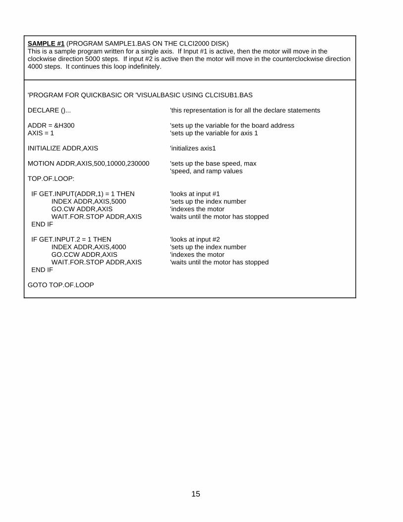
SAMPLE #1 (PROGRAM SAMPLE1.BAS ON THE CLCI2000 DISK)This is a sample program written for a single axis. If Input #1 is active, then the motor will move in theclockwise direction 5000 steps. If input #2 is active then the motor will move in the counterclockwise direction4000 steps. It continues this loop indefinitely.
'PROGRAM FOR QUICKBASIC OR 'VISUALBASIC USING CLCISUB1.BAS
DECLARE ()... 'this representation is for all the declare statements
ADDR = &H300 'sets up the variable for the board addressAXIS = 1 'sets up the variable for axis 1
INITIALIZE ADDR,AXIS 'initializes axis1
MOTION ADDR,AXIS,500,10000,230000 'sets up the base speed, max'speed, and ramp values
TOP.OF.LOOP:
IF GET.INPUT(ADDR,1) = 1 THEN 'looks at input #1INDEX ADDR,AXIS,5000 'sets up the index numberGO.CW ADDR,AXIS 'indexes the motorWAIT.FOR.STOP ADDR,AXIS 'waits until the motor has stopped
END IF
IF GET.INPUT.2 = 1 THEN 'looks at input #2INDEX ADDR,AXIS,4000 'sets up the index numberGO.CCW ADDR,AXIS 'indexes the motorWAIT.FOR.STOP ADDR,AXIS 'waits until the motor has stopped
END IF
GOTO TOP.OF.LOOP
16
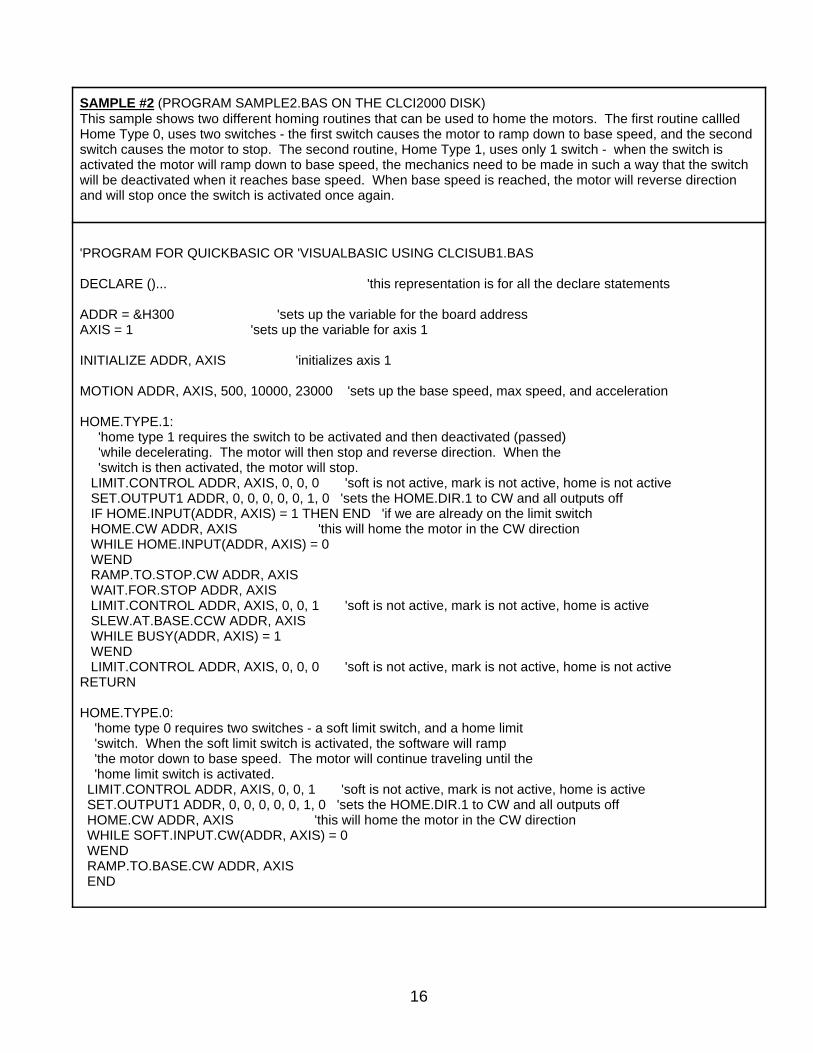
SAMPLE #2 (PROGRAM SAMPLE2.BAS ON THE CLCI2000 DISK)This sample shows two different homing routines that can be used to home the motors. The first routine callledHome Type 0, uses two switches - the first switch causes the motor to ramp down to base speed, and the secondswitch causes the motor to stop. The second routine, Home Type 1, uses only 1 switch - when the switch isactivated the motor will ramp down to base speed, the mechanics need to be made in such a way that the switchwill be deactivated when it reaches base speed. When base speed is reached, the motor will reverse directionand will stop once the switch is activated once again.
'PROGRAM FOR QUICKBASIC OR 'VISUALBASIC USING CLCISUB1.BAS
DECLARE ()... 'this representation is for all the declare statements
ADDR = &H300 'sets up the variable for the board addressAXIS = 1 'sets up the variable for axis 1
INITIALIZE ADDR, AXIS 'initializes axis 1
MOTION ADDR, AXIS, 500, 10000, 23000 'sets up the base speed, max speed, and acceleration
HOME.TYPE.1: 'home type 1 requires the switch to be activated and then deactivated (passed) 'while decelerating. The motor will then stop and reverse direction. When the 'switch is then activated, the motor will stop. LIMIT.CONTROL ADDR, AXIS, 0, 0, 0 'soft is not active, mark is not active, home is not active SET.OUTPUT1 ADDR, 0, 0, 0, 0, 0, 1, 0 'sets the HOME.DIR.1 to CW and all outputs off IF HOME.INPUT(ADDR, AXIS) = 1 THEN END 'if we are already on the limit switch HOME.CW ADDR, AXIS 'this will home the motor in the CW direction WHILE HOME.INPUT(ADDR, AXIS) = 0 WEND RAMP.TO.STOP.CW ADDR, AXIS WAIT.FOR.STOP ADDR, AXIS LIMIT.CONTROL ADDR, AXIS, 0, 0, 1 'soft is not active, mark is not active, home is active SLEW.AT.BASE.CCW ADDR, AXIS WHILE BUSY(ADDR, AXIS) = 1 WEND LIMIT.CONTROL ADDR, AXIS, 0, 0, 0 'soft is not active, mark is not active, home is not activeRETURN
HOME.TYPE.0: 'home type 0 requires two switches - a soft limit switch, and a home limit 'switch. When the soft limit switch is activated, the software will ramp 'the motor down to base speed. The motor will continue traveling until the 'home limit switch is activated. LIMIT.CONTROL ADDR, AXIS, 0, 0, 1 'soft is not active, mark is not active, home is active SET.OUTPUT1 ADDR, 0, 0, 0, 0, 0, 1, 0 'sets the HOME.DIR.1 to CW and all outputs off HOME.CW ADDR, AXIS 'this will home the motor in the CW direction WHILE SOFT.INPUT.CW(ADDR, AXIS) = 0 WEND RAMP.TO.BASE.CW ADDR, AXIS END
17
CLCISUBS.CPP PROGRAM FUNCTION DEFINITIONS
The CLCISUBS.CPP Library is for use with C or C++ programming languages. It can also be used with other versionsof 'C' or 'C++' with little or no modifications to the code. This Library is set up to run CLCI2000 Series Indexers at anyopen address. The following is a command list for all the usable Functions in this Library. This is a comprehensive listthat will allow complete control of the CLCI2000 Series Index Boards. Refer to your programming manual for informationon how to load this Library.
In all the below descriptions, these general guidelines apply:The ADDRESS is the setting on the 5 pin dip switch (see Installation). This is always given in the Hexadecimal format.For a setting of 11000, or a Base Address of 300, the correct format would be (0x300, ...) The AXIS applies to the axis for that particular board (1, 2, 3, or 4)
BUSY (ADDRESS, AXIS)This will return a 1 if the axis is Busy (clock pulses are being generated).
GET_INPUT (ADDRESS, INPUT#)This will return the value for the Specified input number 1 through 10. A return of a 1 will specify that the input is active(0VDC), and a 0 will specify that the input is not active (an open circuit).
GO_CCW (ADDRESS, AXIS) This will Index in the clockwise direction.
GO_CW (ADDRESS, AXIS)This will Index in the counterclockwise direction.
HARD_INPUT_CCW (ADDRESS, AXIS) This will return the value of the -Hard Limit Switch. If the Limit Switch is ACTIVE or 0VDC, the Function will return a 1.If the Limit Switch is NOT ACTIVE, the function will return a 0.
HARD_INPUT_CW (ADDRESS, AXIS) This will return the value of the +Hard Limit Switch. If the Limit Switch is ACTIVE or 0VDC, the function will return a 1.If the Limit Switch is NOT ACTIVE, the function will return a 0.
HOME_CCW (ADDRESS, AXIS)This will HOME (sometimes called SLEW) the motor in the counterclockwise direction.
HOME_CW (ADDRESS, AXIS) This will HOME (sometimes call SLEW) the motor in the clockwise direction.
HOME_INPUT (ADDRESS, AXIS) This will return the value of the +Home Limit or -Home Lime (determined by the LIMIT_CONTROL). If the Limit Switchis Active, the function will return a 1. If the Limit Switch is NOT ACTIVE, the function will return a 0.
INDEX (ADDRESS, AXIS, NUMBER) This will set the Index Number Register.
INITIALIZE (ADDRESS, AXIS) This will set the axis with initial settings. This must be done at the beginning of every program to ensure that the all thedefault setting are made.
LIMIT_CONTROL (ADDRESS, AXIS, SOFT, MARK, HOME) This will either Activate or Deactivate the board features: SOFT LIMIT SWITCHES, ENCODER MARKER PULSE, ORHOME LIMIT SWITCH. A 1 will activate the feature, and a 0 will deactivate the feature.
MOTION (ADDRESS, AXIS, BASE, MAX, RAMP) This will set the Base Speed, Max Speeds, and Acceleration. All three values must be entered.
18
ONE_AT_MAX_CCW (ADDRESS, AXIS) This will go one step at the maximum speed in the CCW Direction.
ONE_AT_MAX_CW (ADDRESS, AXIS) This will go one step at the maximum speed in the CW Direction.
ORIGIN_INDEX_CCW (ADDRESS, AXIS) This will move at base speed until the EZ Channel of the Encoder goes active, and the pulses will stop.
ORIGIN_INDEX_CW (ADDRESS, AXIS) This will move at base speed until the EZ Channel of the Encoder goes active, and the pulses will stop.
POSITION (ADDRESS, AXIS, VALUE) This will go to the position specified.
RAMP_TO_BASE_CCW (ADDRESS, AXIS) This will ramp the motor from Max Speed to Base Speed.
RAMP_TO_BASE_CW (ADDRESS, AXIS) This will ramp the motor from Max Speed to Base Speed.
RAMP_TO_STOP_CCW (ADDRESS, AXIS) This will ramp the motor from Max Speed to Base Speed and stop.
RAMP_TO_STOP_CW (ADDRESS, AXIS) This will ramp the motor from Max Speed to Base Speed and stop.
READ_ENCODER (ADDRESS, AXIS) This will read the value in the encoder register.
READ_POSITION (ADDRESS, AXIS) This will return the Value in the Position Register.
SET_ENCODER (ADDRESS, AXIS, VALUE) This will set the number in the Encoder Register. The values should range between 0 and 16777215.
SET_OUTPUT1 (ADDRESS, OUT5, OUT4, OUT3, OUT2, OUT1, HOME.DIR.1, HOME.DIR.2) This will set the 5 outputs and the active direction for the Home Limit Switch. The five numbers specify what the stateof the five Outputs will be. A '1' for the Outputs will turn the Output ON, and a '0' will turn the output OFF. The last twonumbers will specify which direction for the home switch (+ or -) will be chosen. Only one direction for the home switchmay be chosen for each axis at a given time. A '1' will specify that the '+' or 'CW' direction Home Limit Switch will bechosen. A '0' will specify that the '-' or 'CCW' direction Home Limit Switch has been chosen. For Example:
SET_OUTPUT1 &H300,1,1,1,0,0,1,1would set outputs 5,4, and 3 ON, and outputs 2 and 1 Off. It would also set the +Home Limit Switch for both axis 1 and2 to be the Active Switch.
SET_OUTPUT2 (ADDRESS, OUT10, OUT9, OUT8, OUT7, OUT6, HOME.DIR.1, HOME.DIR.2) This will set the 5 outputs and the active direction for the Home Limit Switch. The five numbers specify what the stateof the five Outputs will be. A '1' for the Outputs will turn the Output ON, and a '0' will turn the output OFF. The last twonumbers will specify which direction for the home switch (+ or -) will be chosen. Only one direction for the home switchmay be chosen for each axis at a given time. A '1' will specify that the '+' or 'CW' direction Home Limit Switch will bechosen. A '0' will specify that the '-' or 'CCW' direction Home Limit Switch has been chosen. For Example:
SET_OUTPUT2 &H300,1,1,0,1,0,0,0,1would set outputs 5 and 3 ON, and outputs 4,2 and 1 Off. It would also set the +Home Limit Switch for axis 3 and the-Home Limit Switch for Axis 4.
SET_POSITION (ADDRESS, AXIS, VALUE) This will set the number in the Position Register.
19
SLEW_AT_BASE_CCW (ADDRESS, AXIS) This will cause the motor to move at base speed in the CCW direction.
SLEW_AT_BASE_CW (ADDRESS, AXIS) This will cause the motor to move at base speed in the CW direction.
SOFT_INPUT_CCW (ADDRESS, AXIS) This will return the value for the -Soft Limit Switch. A 1 will mean that the switch is active, and a 0 will mean the switchis not active.
SOFT_INPUT_CW (ADDRESS, AXIS) This will return the value for the +Soft Limit Switch. A 1 will mean that the switch is active, and a 0 will mean the switchis not active.
STOP (ADDRESS, AXIS) This will immediately stop the pulses.
WAIT_FOR_STOP (ADDRESS, AXIS) This will pause the execution of the program until the Axis has completed its motion.
NOTE: THERE ARE OTHER FUNCTIONS THAT ARE CONTAINED IN THIS FILE THAT SHOULD NOT BE USEDOR MODIFIED IN ANY WAY - THEY ARE USED INTERNALLY BY THE ABOVE FUNCTIONS, AND ANYALTERATION MIGHT PRODUCE UNEXPECTED RESULTS.
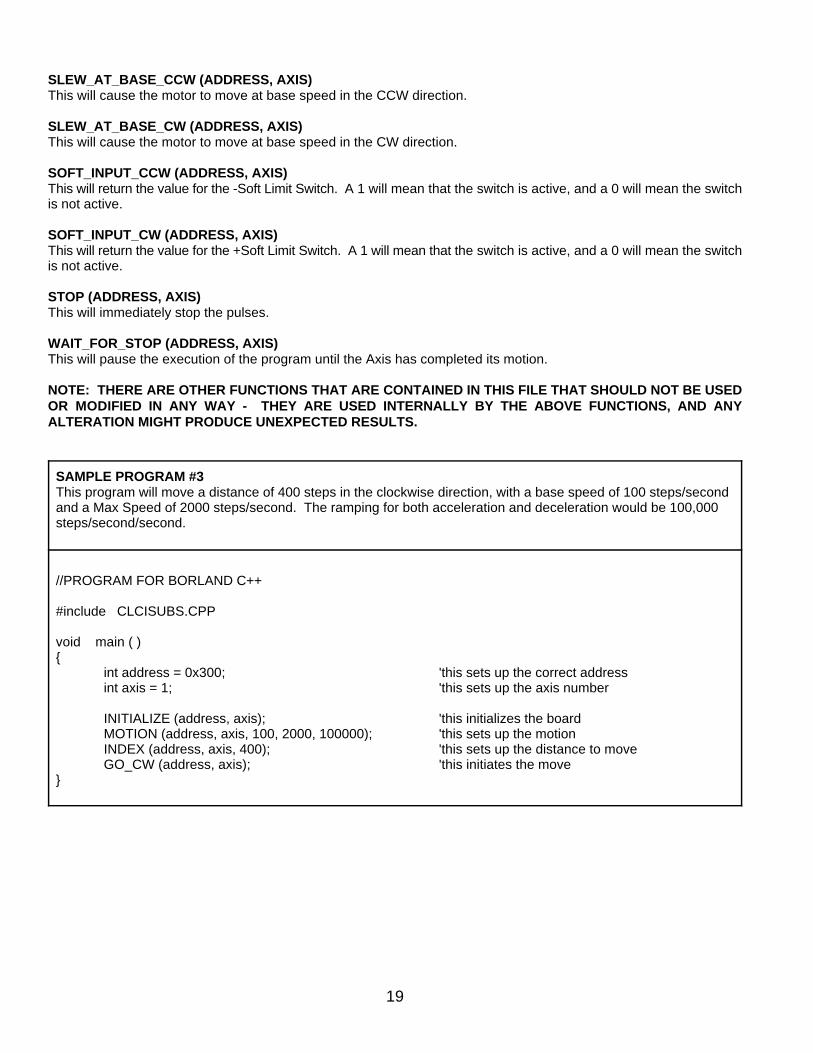
SAMPLE PROGRAM #3This program will move a distance of 400 steps in the clockwise direction, with a base speed of 100 steps/secondand a Max Speed of 2000 steps/second. The ramping for both acceleration and deceleration would be 100,000steps/second/second.
//PROGRAM FOR BORLAND C++
#include CLCISUBS.CPP
void main ( ){
int address = 0x300; 'this sets up the correct addressint axis = 1; 'this sets up the axis number
INITIALIZE (address, axis); 'this initializes the boardMOTION (address, axis, 100, 2000, 100000); 'this sets up the motionINDEX (address, axis, 400); 'this sets up the distance to moveGO_CW (address, axis); 'this initiates the move
}
20
PROGRAMMING IN WINDOWS
USING THE CLCI2000 INDEXER WITH WINDOWSTo communicate with the CLCI2000 Indexer, the programming language needs to have access to the computer bus.While running under windows, this bus can be controlled through a Dynamic Link Library, commonly called a DLL. A DLLwill allow procedures to be performed that are not part of the standard Windows Instruction Set. This DLL has beenextensively tested on Visual Basic for Windows, and can also be used for other Software Languages that can use aDynamic Link Library.
USING THE DLL WITH VISUAL BASIC FOR WINDOWSThe process of loading the DLL into the main application is very simple. This process will be described in this section.
The first step is to choose a new project. This can be done by choosing FILE, New Project.
The next step is to add the declaration file WIN2000.BAS. To do this, choose, FILE, Add File. The correct directoryshould be put in for the position of WIN2000.BAS. It is recommended to copy the WIN2000.BAS file into the directoryC:\VB (the file WIN2000.DLL should also be in this directory). Once the file is selected, click OK and the file will beadded to the Project. The project window (Window, Project) can be chosen to verify that this file has been added. Thisis all that needs to be done with the WIN2000.BAS file. No modifications to this file are necessary from this point on.The file should never be modified for any reason.
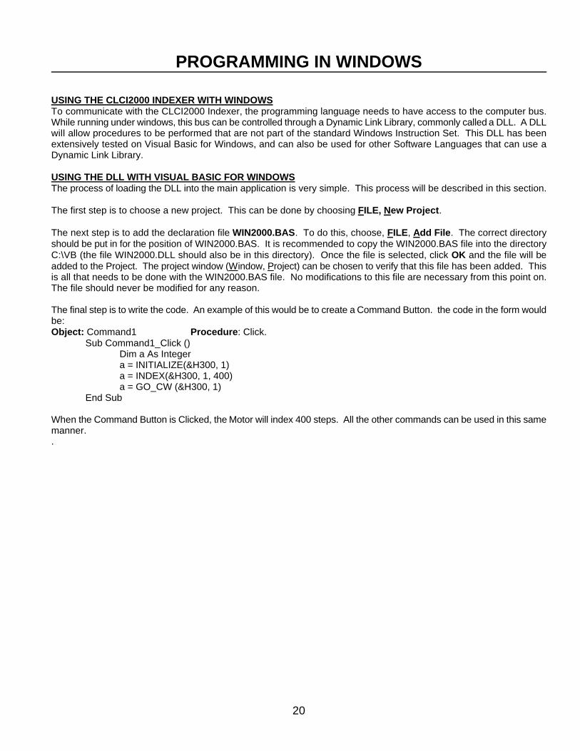
The final step is to write the code. An example of this would be to create a Command Button. the code in the form wouldbe:Object: Command1 Procedure: Click.
Sub Command1_Click ()Dim a As Integera = INITIALIZE(&H300, 1)a = INDEX(&H300, 1, 400)a = GO_CW (&H300, 1)
End Sub
When the Command Button is Clicked, the Motor will index 400 steps. All the other commands can be used in this samemanner..
21
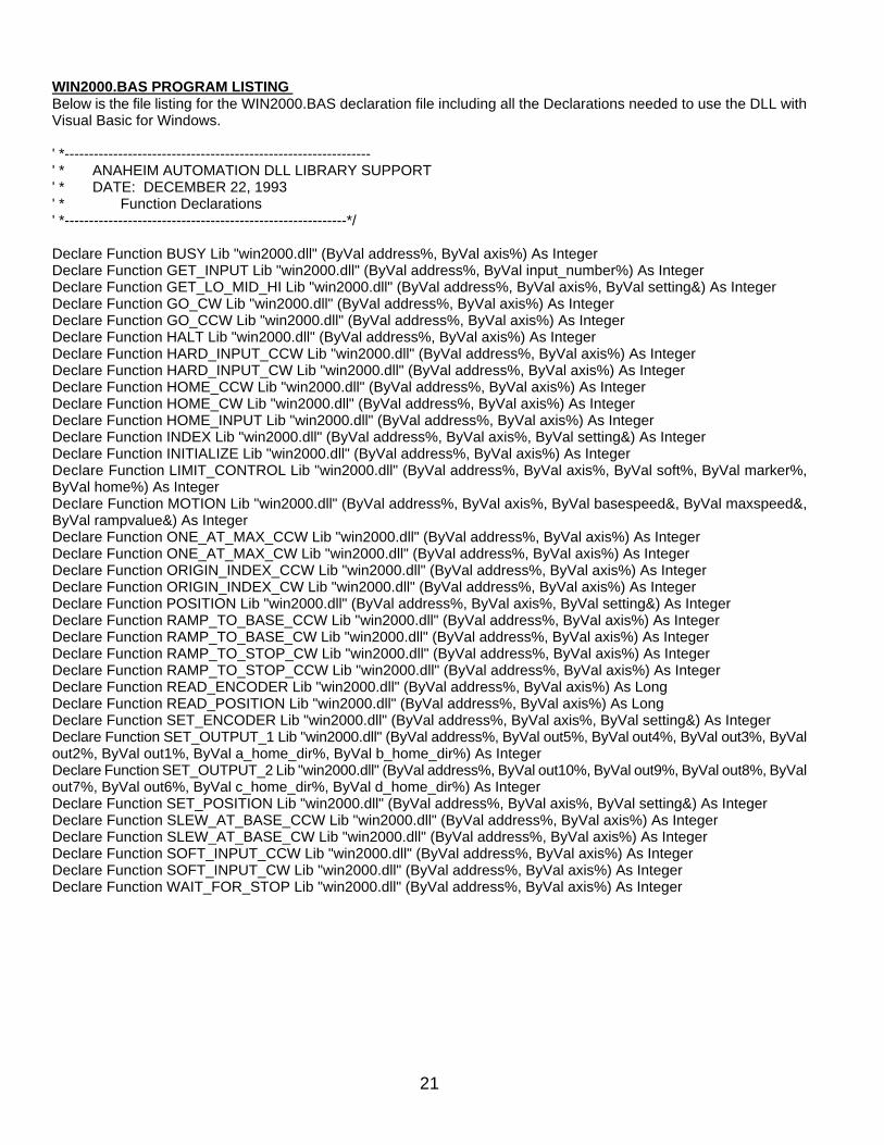
WIN2000.BAS PROGRAM LISTING Below is the file listing for the WIN2000.BAS declaration file including all the Declarations needed to use the DLL withVisual Basic for Windows.
' *---------------------------------------------------------------' * ANAHEIM AUTOMATION DLL LIBRARY SUPPORT' * DATE: DECEMBER 22, 1993' * Function Declarations' *----------------------------------------------------------*/
Declare Function BUSY Lib "win2000.dll" (ByVal address%, ByVal axis%) As IntegerDeclare Function GET_INPUT Lib "win2000.dll" (ByVal address%, ByVal input_number%) As IntegerDeclare Function GET_LO_MID_HI Lib "win2000.dll" (ByVal address%, ByVal axis%, ByVal setting&) As IntegerDeclare Function GO_CW Lib "win2000.dll" (ByVal address%, ByVal axis%) As IntegerDeclare Function GO_CCW Lib "win2000.dll" (ByVal address%, ByVal axis%) As IntegerDeclare Function HALT Lib "win2000.dll" (ByVal address%, ByVal axis%) As IntegerDeclare Function HARD_INPUT_CCW Lib "win2000.dll" (ByVal address%, ByVal axis%) As IntegerDeclare Function HARD_INPUT_CW Lib "win2000.dll" (ByVal address%, ByVal axis%) As IntegerDeclare Function HOME_CCW Lib "win2000.dll" (ByVal address%, ByVal axis%) As IntegerDeclare Function HOME_CW Lib "win2000.dll" (ByVal address%, ByVal axis%) As IntegerDeclare Function HOME_INPUT Lib "win2000.dll" (ByVal address%, ByVal axis%) As IntegerDeclare Function INDEX Lib "win2000.dll" (ByVal address%, ByVal axis%, ByVal setting&) As IntegerDeclare Function INITIALIZE Lib "win2000.dll" (ByVal address%, ByVal axis%) As IntegerDeclare Function LIMIT_CONTROL Lib "win2000.dll" (ByVal address%, ByVal axis%, ByVal soft%, ByVal marker%,ByVal home%) As IntegerDeclare Function MOTION Lib "win2000.dll" (ByVal address%, ByVal axis%, ByVal basespeed&, ByVal maxspeed&,ByVal rampvalue&) As IntegerDeclare Function ONE_AT_MAX_CCW Lib "win2000.dll" (ByVal address%, ByVal axis%) As IntegerDeclare Function ONE_AT_MAX_CW Lib "win2000.dll" (ByVal address%, ByVal axis%) As IntegerDeclare Function ORIGIN_INDEX_CCW Lib "win2000.dll" (ByVal address%, ByVal axis%) As IntegerDeclare Function ORIGIN_INDEX_CW Lib "win2000.dll" (ByVal address%, ByVal axis%) As IntegerDeclare Function POSITION Lib "win2000.dll" (ByVal address%, ByVal axis%, ByVal setting&) As IntegerDeclare Function RAMP_TO_BASE_CCW Lib "win2000.dll" (ByVal address%, ByVal axis%) As IntegerDeclare Function RAMP_TO_BASE_CW Lib "win2000.dll" (ByVal address%, ByVal axis%) As IntegerDeclare Function RAMP_TO_STOP_CW Lib "win2000.dll" (ByVal address%, ByVal axis%) As IntegerDeclare Function RAMP_TO_STOP_CCW Lib "win2000.dll" (ByVal address%, ByVal axis%) As IntegerDeclare Function READ_ENCODER Lib "win2000.dll" (ByVal address%, ByVal axis%) As LongDeclare Function READ_POSITION Lib "win2000.dll" (ByVal address%, ByVal axis%) As LongDeclare Function SET_ENCODER Lib "win2000.dll" (ByVal address%, ByVal axis%, ByVal setting&) As IntegerDeclare Function SET_OUTPUT_1 Lib "win2000.dll" (ByVal address%, ByVal out5%, ByVal out4%, ByVal out3%, ByValout2%, ByVal out1%, ByVal a_home_dir%, ByVal b_home_dir%) As IntegerDeclare Function SET_OUTPUT_2 Lib "win2000.dll" (ByVal address%, ByVal out10%, ByVal out9%, ByVal out8%, ByValout7%, ByVal out6%, ByVal c_home_dir%, ByVal d_home_dir%) As IntegerDeclare Function SET_POSITION Lib "win2000.dll" (ByVal address%, ByVal axis%, ByVal setting&) As IntegerDeclare Function SLEW_AT_BASE_CCW Lib "win2000.dll" (ByVal address%, ByVal axis%) As IntegerDeclare Function SLEW_AT_BASE_CW Lib "win2000.dll" (ByVal address%, ByVal axis%) As IntegerDeclare Function SOFT_INPUT_CCW Lib "win2000.dll" (ByVal address%, ByVal axis%) As IntegerDeclare Function SOFT_INPUT_CW Lib "win2000.dll" (ByVal address%, ByVal axis%) As IntegerDeclare Function WAIT_FOR_STOP Lib "win2000.dll" (ByVal address%, ByVal axis%) As Integer
22
CLCI2004 PROGRAM GENERATOR
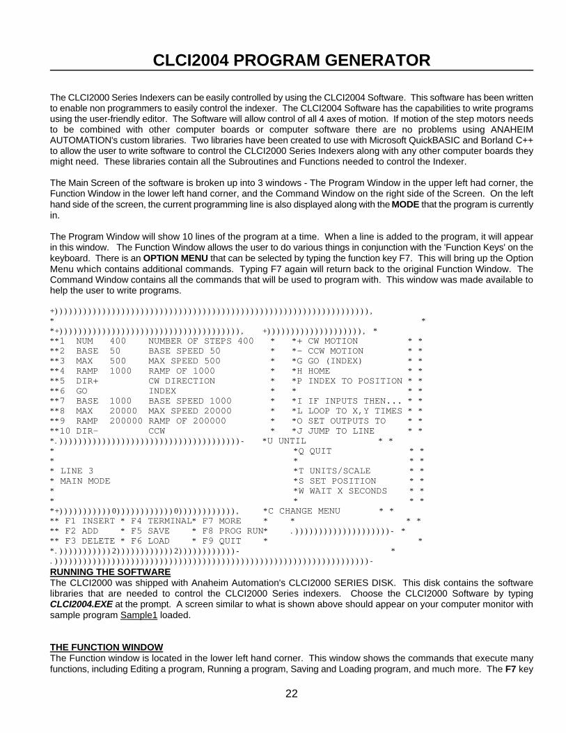
The CLCI2000 Series Indexers can be easily controlled by using the CLCI2004 Software. This software has been writtento enable non programmers to easily control the indexer. The CLCI2004 Software has the capabilities to write programsusing the user-friendly editor. The Software will allow control of all 4 axes of motion. If motion of the step motors needsto be combined with other computer boards or computer software there are no problems using ANAHEIMAUTOMATION's custom libraries. Two libraries have been created to use with Microsoft QuickBASIC and Borland C++to allow the user to write software to control the CLCI2000 Series Indexers along with any other computer boards theymight need. These libraries contain all the Subroutines and Functions needed to control the Indexer.
The Main Screen of the software is broken up into 3 windows - The Program Window in the upper left had corner, theFunction Window in the lower left hand corner, and the Command Window on the right side of the Screen. On the lefthand side of the screen, the current programming line is also displayed along with the MODE that the program is currentlyin.
The Program Window will show 10 lines of the program at a time. When a line is added to the program, it will appearin this window. The Function Window allows the user to do various things in conjunction with the 'Function Keys' on thekeyboard. There is an OPTION MENU that can be selected by typing the function key F7. This will bring up the OptionMenu which contains additional commands. Typing F7 again will return back to the original Function Window. TheCommand Window contains all the commands that will be used to program with. This window was made available tohelp the user to write programs.
+)))))))))))))))))))))))))))))))))))))))))))))))))))))))))))))))))), * * *+)))))))))))))))))))))))))))))))))))))), +)))))))))))))))))))), * **1 NUM 400 NUMBER OF STEPS 400 * *+ CW MOTION * * **2 BASE 50 BASE SPEED 50 * *- CCW MOTION * * **3 MAX 500 MAX SPEED 500 * *G GO (INDEX) * * **4 RAMP 1000 RAMP OF 1000 * *H HOME * * **5 DIR+ CW DIRECTION * *P INDEX TO POSITION * * **6 GO INDEX * * * * **7 BASE 1000 BASE SPEED 1000 * *I IF INPUTS THEN... * * **8 MAX 20000 MAX SPEED 20000 * *L LOOP TO X,Y TIMES * * **9 RAMP 200000 RAMP OF 200000 * *O SET OUTPUTS TO * * **10 DIR- CCW * *J JUMP TO LINE * * *.))))))))))))))))))))))))))))))))))))))- *U UNTIL * * * *Q QUIT * * * * * * * LINE 3 *T UNITS/SCALE * * * MAIN MODE *S SET POSITION * * * *W WAIT X SECONDS * * * * * * *+)))))))))))0))))))))))))0)))))))))))), *C CHANGE MENU * * ** F1 INSERT * F4 TERMINAL* F7 MORE * * * * ** F2 ADD * F5 SAVE * F8 PROG RUN* .))))))))))))))))))))- * ** F3 DELETE * F6 LOAD * F9 QUIT * * *.)))))))))))2))))))))))))2))))))))))))- * .))))))))))))))))))))))))))))))))))))))))))))))))))))))))))))))))))- RUNNING THE SOFTWAREThe CLCI2000 was shipped with Anaheim Automation's CLCI2000 SERIES DISK. This disk contains the softwarelibraries that are needed to control the CLCI2000 Series indexers. Choose the CLCI2000 Software by typingCLCI2004.EXE at the prompt. A screen similar to what is shown above should appear on your computer monitor withsample program Sample1 loaded.
THE FUNCTION WINDOWThe Function window is located in the lower left hand corner. This window shows the commands that execute manyfunctions, including Editing a program, Running a program, Saving and Loading program, and much more. The F7 key
23
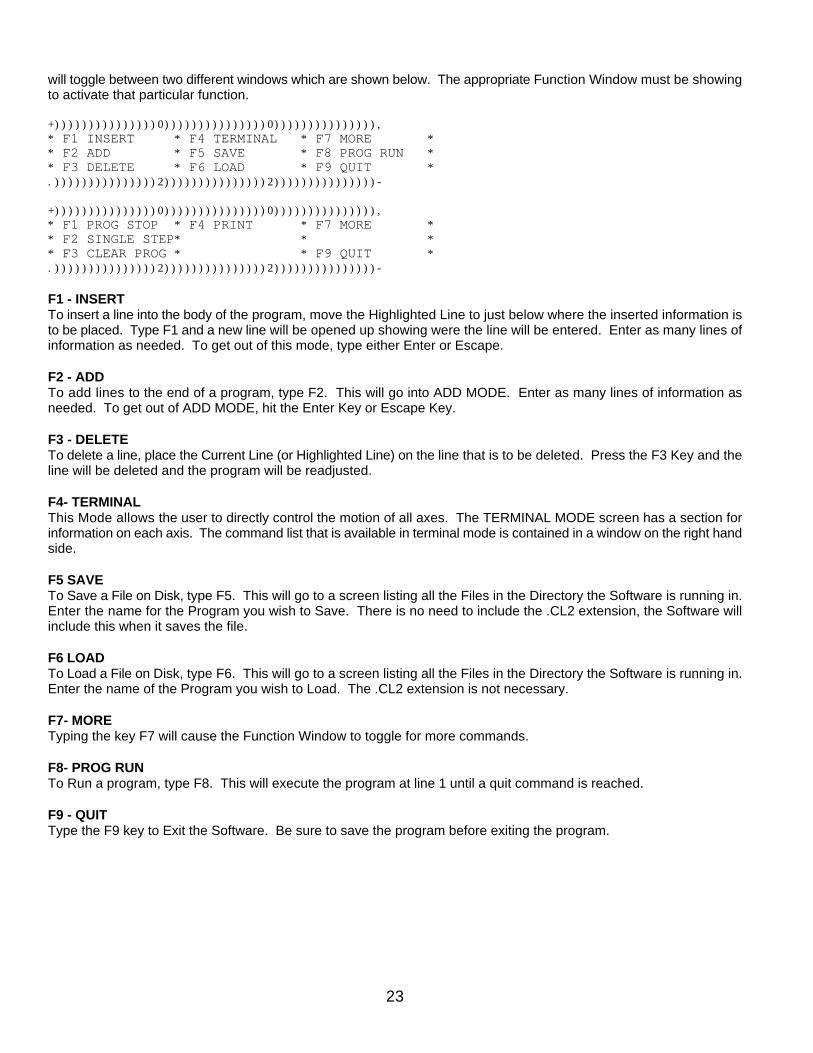
will toggle between two different windows which are shown below. The appropriate Function Window must be showingto activate that particular function.
+)))))))))))))))0)))))))))))))))0))))))))))))))),* F1 INSERT * F4 TERMINAL * F7 MORE ** F2 ADD * F5 SAVE * F8 PROG RUN ** F3 DELETE * F6 LOAD * F9 QUIT *.)))))))))))))))2)))))))))))))))2)))))))))))))))-
+)))))))))))))))0)))))))))))))))0))))))))))))))),* F1 PROG STOP * F4 PRINT * F7 MORE ** F2 SINGLE STEP* * ** F3 CLEAR PROG * * F9 QUIT *.)))))))))))))))2)))))))))))))))2)))))))))))))))-
F1 - INSERTTo insert a line into the body of the program, move the Highlighted Line to just below where the inserted information isto be placed. Type F1 and a new line will be opened up showing were the line will be entered. Enter as many lines ofinformation as needed. To get out of this mode, type either Enter or Escape.
F2 - ADDTo add lines to the end of a program, type F2. This will go into ADD MODE. Enter as many lines of information asneeded. To get out of ADD MODE, hit the Enter Key or Escape Key.
F3 - DELETETo delete a line, place the Current Line (or Highlighted Line) on the line that is to be deleted. Press the F3 Key and theline will be deleted and the program will be readjusted.
F4- TERMINALThis Mode allows the user to directly control the motion of all axes. The TERMINAL MODE screen has a section forinformation on each axis. The command list that is available in terminal mode is contained in a window on the right handside.
F5 SAVETo Save a File on Disk, type F5. This will go to a screen listing all the Files in the Directory the Software is running in.Enter the name for the Program you wish to Save. There is no need to include the .CL2 extension, the Software willinclude this when it saves the file.
F6 LOADTo Load a File on Disk, type F6. This will go to a screen listing all the Files in the Directory the Software is running in.Enter the name of the Program you wish to Load. The .CL2 extension is not necessary.
F7- MORETyping the key F7 will cause the Function Window to toggle for more commands.
F8- PROG RUNTo Run a program, type F8. This will execute the program at line 1 until a quit command is reached.
F9 - QUITType the F9 key to Exit the Software. Be sure to save the program before exiting the program.
24
By Pressing the F7 key, these commands will be available.
F1 - PROG STOPType the F1 Key to stop the execution of the program. If the program fails to stop, hold down the F1 key. NOTE: TheF1 key should not be used as an emergency stop for your system.
F2 - SINGLE STEPType the F2 Key to step the program one line at a time. This is a great way to check the program for any mistakes.
F3 - CLEAR PROGRAMType the F3 Key to clear the current program.
F4 - PRINTING A PROGRAMType the F4 Key to print the current program to a printer. The software will select LPT1 for the printing.
F7 - MORETyping the key F7 will cause the Function Window to toggle to the original command window.
F9 - QUITType the F9 key to Exit the Software. Be sure to save the program before exiting the program. The software commandwill ask if you are sure you want to quit.
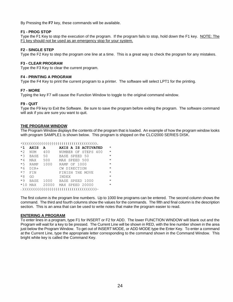
THE PROGRAM WINDOWThe Program Window displays the contents of the program that is loaded. An example of how the program window lookswith program SAMPLE1 is shown below. This program is shipped on the CLCI2000 SERIES DISK.
+)))))))))))))))))))))))))))))))))))))),*1 AXIS A AXIS A IS ACTIVATED **2 NUM 400 NUMBER OF STEPS 400 **3 BASE 50 BASE SPEED 50 **4 MAX 500 MAX SPEED 500 **5 RAMP 1000 RAMP OF 1000 **6 DIR+ CW DIRECTION **7 FIN FINISH THE MOVE **8 GO INDEX **9 BASE 1000 BASE SPEED 1000 **10 MAX 20000 MAX SPEED 20000 *.))))))))))))))))))))))))))))))))))))))-
The first column is the program line numbers. Up to 1000 line programs can be entered. The second column shows thecommand. The third and fourth columns show the values for the commands. The fifth and final column is the descriptionsection. This is an area that can be used to write notes that make the program easier to read.
ENTERING A PROGRAMTo enter lines in a program, type F1 for INSERT or F2 for ADD. The lower FUNCTION WINDOW will blank out and theProgram will wait for a key to be pressed. The Current Line will be shown in RED, with the line number shown in the areajust below the Program Window. To get out of INSERT MODE, or ADD MODE type the Enter Key. To enter a commandat the Current Line, type the appropriate letter corresponding to the command shown in the Command Window. Thisbright white key is called the Command Key.
25
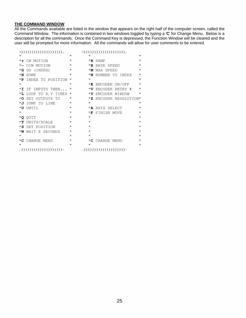
THE COMMAND WINDOWAll the Commands available are listed in the window that appears on the right half of the computer screen, called theCommand Window. The information is contained in two windows toggled by typing a 'C' for Change Menu. Below is adescription for all the commands. Once the Command Key is depressed, the Function Window will be cleared and theuser will be prompted for more information. All the commands will allow for user comments to be entered. +)))))))))))))))))))), +)))))))))))))))))))), * * * * *+ CW MOTION * *R RAMP * *- CCW MOTION * *B BASE SPEED * *G GO (INDEX) * *M MAX SPEED * *H HOME * *N NUMBER TO INDEX * *P INDEX TO POSITION * * * * * *E ENCODER ON/OFF * *I IF INPUTS THEN... * *V ENCODER RETRY # * *L LOOP TO X,Y TIMES * *Y ENCODER WINDOW * *O SET OUTPUTS TO * *Z ENCODER RESOLUTION* *J JUMP TO LINE * * * *U UNTIL * *A AXIS SELECT * * * *F FINISH MOVE * *Q QUIT * * * *T UNITS/SCALE * * * *S SET POSITION * * * *W WAIT X SECONDS * * * * * * * *C CHANGE MENU * *C CHANGE MENU * * * * * .))))))))))))))))))))- .))))))))))))))))))))-
26
CLCI2004 PROGRAM GENERATOR COMMAND DICTIONARY
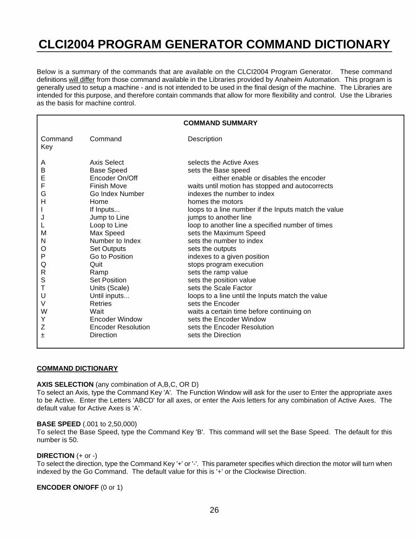
Below is a summary of the commands that are available on the CLCI2004 Program Generator. These commanddefinitions will differ from those command available in the Libraries provided by Anaheim Automation. This program isgenerally used to setup a machine - and is not intended to be used in the final design of the machine. The Libraries areintended for this purpose, and therefore contain commands that allow for more flexibility and control. Use the Librariesas the basis for machine control.
COMMAND SUMMARY
Command Command DescriptionKey
A Axis Select selects the Active AxesB Base Speed sets the Base speedE Encoder On/Off either enable or disables the encoderF Finish Move waits until motion has stopped and autocorrectsG Go Index Number indexes the number to indexH Home homes the motorsI If Inputs... loops to a line number if the Inputs match the valueJ Jump to Line jumps to another lineL Loop to Line loop to another line a specified number of timesM Max Speed sets the Maximum SpeedN Number to Index sets the number to indexO Set Outputs sets the outputsP Go to Position indexes to a given positionQ Quit stops program executionR Ramp sets the ramp valueS Set Position sets the position valueT Units (Scale) sets the Scale FactorU Until inputs... loops to a line until the Inputs match the valueV Retries sets the Encoder W Wait waits a certain time before continuing onY Encoder Window sets the Encoder WindowZ Encoder Resolution sets the Encoder Resolution± Direction sets the Direction
COMMAND DICTIONARY
AXIS SELECTION (any combination of A,B,C, OR D)To select an Axis, type the Command Key 'A'. The Function Window will ask for the user to Enter the appropriate axesto be Active. Enter the Letters 'ABCD' for all axes, or enter the Axis letters for any combination of Active Axes. Thedefault value for Active Axes is 'A'.
BASE SPEED (.001 to 2,50,000)To select the Base Speed, type the Command Key 'B'. This command will set the Base Speed. The default for thisnumber is 50.
DIRECTION (+ or -)To select the direction, type the Command Key '+' or '-'. This parameter specifies which direction the motor will turn whenindexed by the Go Command. The default value for this is '+' or the Clockwise Direction.
ENCODER ON/OFF (0 or 1)
27
To select Encoder On/Off, type the Command Key 'E'. This parameter specifies if Encoder Correction is to be Enabledor Disabled. A '1' will Enable Encoder Correction, a '0' will Disable it. The Indexer will do all the appropriate correctionsneeded when the Finish Move (F) command is executed. The default value for this is 0, or no encoder correction.
ENCODER RESOLUTION (any number)To select Encoder Resolution, type the Command Key 'Z'. This parameter specifies how many 'lines' the Encoder has.The default value for this is 400 lines.
ENCODER RETRIES (any real number)To select Encoder Retries, type the Command Key 'V'. This parameter specifies how many times the CLCI2000 will tryto obtain the correct position. For a value set at 1, the CLCI2000 will move the correct distance, and then retry once ifthe encoder value does not match the number of steps the motor was supposed to take. When the CLCI2000 does aretry, it will always retry the move at the Base Speed. The default value for Encoder Retries is 0.
ENCODER WINDOW (any integer)To select Encoder Window, type the Command Key 'Y'. This is the allowable error the encoder might have at the endof a move without correcting. The units for this is in Quadrature Pulses. For a 400 line encoder, there will be 1600quadrature pulses per one revolution. The default value for this is 20.
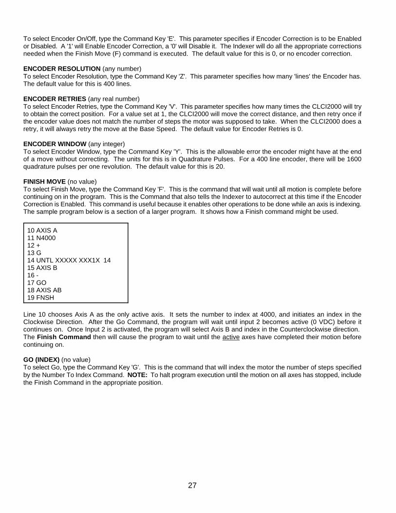
FINISH MOVE (no value)To select Finish Move, type the Command Key 'F'. This is the command that will wait until all motion is complete beforecontinuing on in the program. This is the Command that also tells the Indexer to autocorrect at this time if the EncoderCorrection is Enabled. This command is useful because it enables other operations to be done while an axis is indexing.The sample program below is a section of a larger program. It shows how a Finish command might be used.
10 AXIS A11 N400012 +13 G14 UNTL XXXXX XXX1X 1415 AXIS B16 -17 GO18 AXIS AB19 FNSH
Line 10 chooses Axis A as the only active axis. It sets the number to index at 4000, and initiates an index in theClockwise Direction. After the Go Command, the program will wait until input 2 becomes active (0 VDC) before itcontinues on. Once Input 2 is activated, the program will select Axis B and index in the Counterclockwise direction. The Finish Command then will cause the program to wait until the active axes have completed their motion beforecontinuing on.
GO (INDEX) (no value)To select Go, type the Command Key 'G'. This is the command that will index the motor the number of steps specifiedby the Number To Index Command. NOTE: To halt program execution until the motion on all axes has stopped, includethe Finish Command in the appropriate position.
28
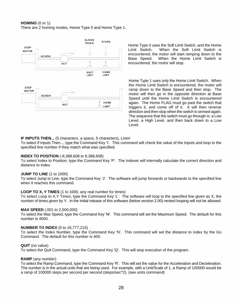
HOMING (0 or 1)There are 2 homing modes, Home Type 0 and Home Type 1.
Home Type 0 uses the Soft Limit Switch, and the HomeLimit Switch. When the Soft Limit Switch isencountered, the motor will start ramping down to theBase Speed. When the Home Limit Switch isencountered, the motor will stop.
Home Type 1 uses only the Home Limit Switch. Whenthe Home Limit Switch is encountered, the motor willramp down to the Base Speed and then stop. Themotor will then go in the opposite direction at BaseSpeed until the Home Limit Switch is encounteredagain. The Home FLAG must go past the switch thattriggers it, and come off of it. It will then reversedirection and then stop when the switch is sensed again.The sequence that the switch must go through is: a LowLevel, a High Level, and then back down to a LowLevel.
IF INPUTS THEN... (5 characters, a space, 5 characters), Line#To select If Inputs Then..., type the Command Key 'I'. This command will check the value of the Inputs and loop to thespecified line number if they match what was specified.
INDEX TO POSITION (-8,388,608 to 8,388,608)To select Index to Position, type the Command Key 'P'. The Indexer will internally calculate the correct direction anddistance to index.
JUMP TO LINE (1 to 1000)To select Jump to Line, type the Command Key 'J'. The software will jump forwards or backwards to the specified linewhen it reaches this command.
LOOP TO X, Y TIMES (1 to 1000, any real number for times)To select Loop to X,Y Times, type the Command Key 'L'. The software will loop to the specified line given as X, thenumber of times given by Y. In the initial release of this software (below version 2.00) nested looping will not be allowed.
MAX SPEED (.001 to 2,500,000)To select the Max Speed, type the Command Key 'M'. This command will set the Maximum Speed. The default for thisnumber is 4000.
NUMBER TO INDEX (0 to 16,777,215)To select the Index Number, type the Command Key 'N'. This command will set the distance to index by the GoCommand. The default for this number is 400.
QUIT (no value)To select the Quit Command, type the Command Key 'Q'. This will stop execution of the program.
RAMP (any number)To select the Ramp Command, type the Command Key 'R'. This will set the value for the Acceleration and Deceleration.The number is in the actual units that are being used. For example, with a Unit/Scale of 1, a Ramp of 100000 would bea ramp of 100000 steps per second per second (steps/sec^2). (see units command)

29
SET OUTPUTS (5 characters, a space, 5 characters)To select the command Set Outputs, type the Command Key 'O'. This command will set the outputs to the value thatis specified. At power up, all outputs are in their open collector (off) state.
SET POSITION (-8,388,608 to 8,388,608)To select the command Set Position, type the Command Key 'S'. This command will set the position to the valuespecified. Positive and Negative numbers are valid from 0 to ±8,388,608.
UNITS/SCALE (any number)To select the command Units/Scale, type the Command Key 'T'. This command is used as a scale factor to allow anyunits to be programmed. For example, on a Half-Step Driver with a 10 pitch lead screw, it takes 4000 steps to go 1 inch.A scale factor of 1/4000 or .00025 would allow all the parameters to be programmed in inches.
UNTIL (5 characters, a space, 5 characters), Line#To select the command Until, type the Command Key 'U'. This command will check the value of the Inputs and loop tothe specified line number Until they match what was specified.
WAIT (.01 to any number)To select the command Wait, type the Command Key 'W'. This command will pause the program the number of secondsspecified, with the accuracy of 10 milliseconds or better. To Wait 4.5 seconds, enter the number 4.5 for the WaitCommand.
30
ADVANCED PROGRAMMING
In modifying an existing Library, or writing a new software library, It is strongly advised that programmers should use thecurrent libraries for Basic or C, and transfer them to the different languages. The current libraries are 'bug free', so thiswill help the programmer to produce 'bug-free' code.
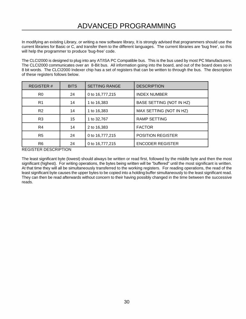
The CLCI2000 is designed to plug into any AT/ISA PC Compatible bus. This is the bus used by most PC Manufacturers.The CLCI2000 communicates over an 8-Bit bus. All information going into the board, and out of the board does so in8 bit words. The CLCI2000 Indexer chip has a set of registers that can be written to through the bus. The descriptionof these registers follows below.
REGISTER # BITS SETTING RANGE DESCRIPTION
R0 24 0 to 16,777,215 INDEX NUMBER
R1 14 1 to 16,383 BASE SETTING (NOT IN HZ)
R2 14 1 to 16,383 MAX SETTING (NOT IN HZ)
R3 15 1 to 32,767 RAMP SETTING
R4 14 2 to 16,383 FACTOR
R5 24 0 to 16,777,215 POSITION REGISTER
R6 24 0 to 16,777,215 ENCODER REGISTER
REGISTER DESCRIPTION
The least significant byte (lowest) should always be written or read first, followed by the middle byte and then the mostsignificant (highest). For writing operations, the bytes being written will be "buffered" until the most significant is written.At that time they will all be simultaneously transferred to the working registers. For reading operations, the read of theleast significant byte causes the upper bytes to be copied into a holding buffer simultaneously to the least significant read.They can then be read afterwards without concern to their having possibly changed in the time between the successivereads.
31
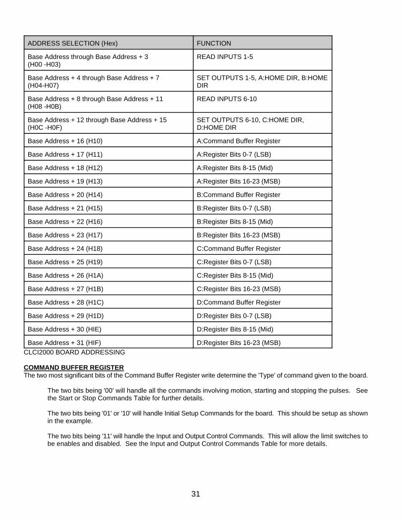
ADDRESS SELECTION (Hex) FUNCTION
Base Address through Base Address + 3 READ INPUTS 1-5(H00 -H03)
Base Address + 4 through Base Address + 7 SET OUTPUTS 1-5, A:HOME DIR, B:HOME(H04-H07) DIR
Base Address + 8 through Base Address + 11 READ INPUTS 6-10(H08 -H0B)
Base Address + 12 through Base Address + 15 SET OUTPUTS 6-10, C:HOME DIR,(H0C -H0F) D:HOME DIR
Base Address + 16 (H10) A:Command Buffer Register
Base Address + 17 (H11) A:Register Bits 0-7 (LSB)
Base Address + 18 (H12) A:Register Bits 8-15 (Mid)
Base Address + 19 (H13) A:Register Bits 16-23 (MSB)
Base Address + 20 (H14) B:Command Buffer Register
Base Address + 21 (H15) B:Register Bits 0-7 (LSB)
Base Address + 22 (H16) B:Register Bits 8-15 (Mid)
Base Address + 23 (H17) B:Register Bits 16-23 (MSB)
Base Address + 24 (H18) C:Command Buffer Register
Base Address + 25 (H19) C:Register Bits 0-7 (LSB)
Base Address + 26 (H1A) C:Register Bits 8-15 (Mid)
Base Address + 27 (H1B) C:Register Bits 16-23 (MSB)
Base Address + 28 (H1C) D:Command Buffer Register
Base Address + 29 (H1D) D:Register Bits 0-7 (LSB)
Base Address + 30 (HIE) D:Register Bits 8-15 (Mid)
Base Address + 31 (HIF) D:Register Bits 16-23 (MSB)
CLCI2000 BOARD ADDRESSING
COMMAND BUFFER REGISTERThe two most significant bits of the Command Buffer Register write determine the 'Type' of command given to the board.
The two bits being '00' will handle all the commands involving motion, starting and stopping the pulses. Seethe Start or Stop Commands Table for further details.
The two bits being '01' or '10' will handle Initial Setup Commands for the board. This should be setup as shownin the example.
The two bits being '11' will handle the Input and Output Control Commands. This will allow the limit switches tobe enables and disabled. See the Input and Output Control Commands Table for more details.
32
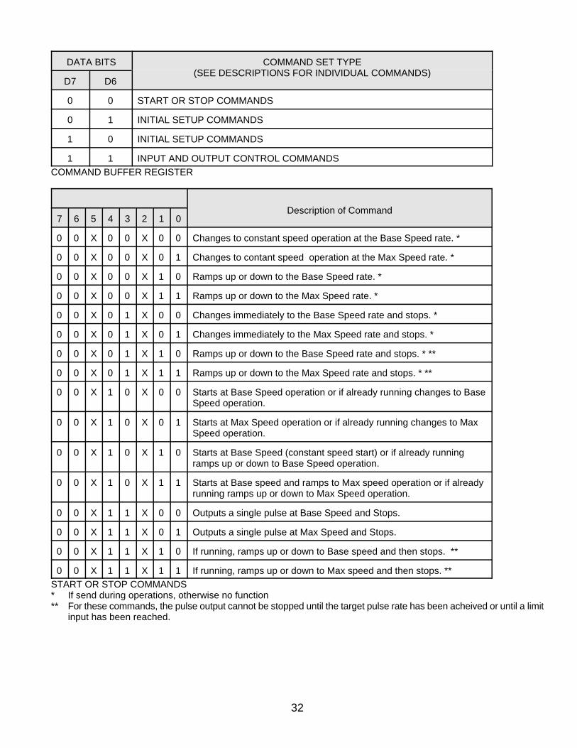
DATA BITS COMMAND SET TYPE(SEE DESCRIPTIONS FOR INDIVIDUAL COMMANDS)
D7 D6
0 0 START OR STOP COMMANDS
0 1 INITIAL SETUP COMMANDS
1 0 INITIAL SETUP COMMANDS
1 1 INPUT AND OUTPUT CONTROL COMMANDS
COMMAND BUFFER REGISTER
Description of Command7 6 5 4 3 2 1 0
0 0 X 0 0 X 0 0 Changes to constant speed operation at the Base Speed rate. *
0 0 X 0 0 X 0 1 Changes to contant speed operation at the Max Speed rate. *
0 0 X 0 0 X 1 0 Ramps up or down to the Base Speed rate. *
0 0 X 0 0 X 1 1 Ramps up or down to the Max Speed rate. *
0 0 X 0 1 X 0 0 Changes immediately to the Base Speed rate and stops. *
0 0 X 0 1 X 0 1 Changes immediately to the Max Speed rate and stops. *
0 0 X 0 1 X 1 0 Ramps up or down to the Base Speed rate and stops. * **
0 0 X 0 1 X 1 1 Ramps up or down to the Max Speed rate and stops. * **
0 0 X 1 0 X 0 0 Starts at Base Speed operation or if already running changes to BaseSpeed operation.
0 0 X 1 0 X 0 1 Starts at Max Speed operation or if already running changes to MaxSpeed operation.
0 0 X 1 0 X 1 0 Starts at Base Speed (constant speed start) or if already runningramps up or down to Base Speed operation.
0 0 X 1 0 X 1 1 Starts at Base speed and ramps to Max speed operation or if alreadyrunning ramps up or down to Max Speed operation.
0 0 X 1 1 X 0 0 Outputs a single pulse at Base Speed and Stops.
0 0 X 1 1 X 0 1 Outputs a single pulse at Max Speed and Stops.
0 0 X 1 1 X 1 0 If running, ramps up or down to Base speed and then stops. **
0 0 X 1 1 X 1 1 If running, ramps up or down to Max speed and then stops. **
START OR STOP COMMANDS* If send during operations, otherwise no function** For these commands, the pulse output cannot be stopped until the target pulse rate has been acheived or until a limit
input has been reached.
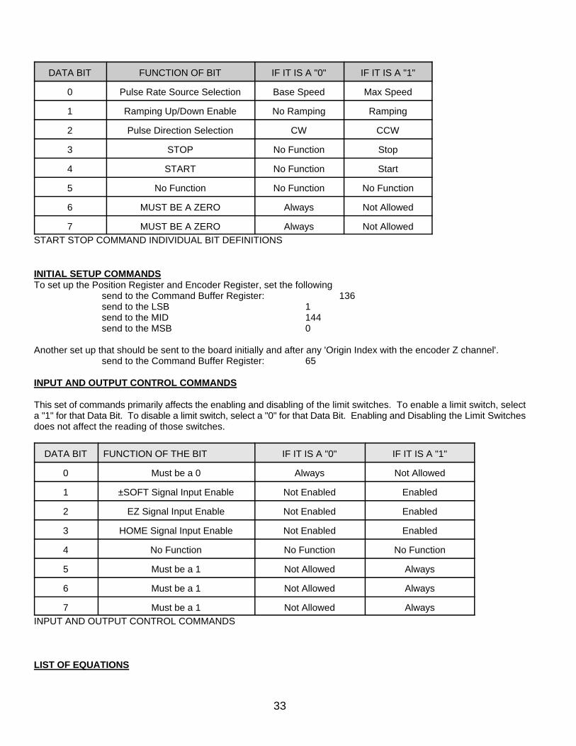
33
DATA BIT FUNCTION OF BIT IF IT IS A "0" IF IT IS A "1"
0 Pulse Rate Source Selection Base Speed Max Speed
1 Ramping Up/Down Enable No Ramping Ramping
2 Pulse Direction Selection CW CCW
3 STOP No Function Stop
4 START No Function Start
5 No Function No Function No Function
6 MUST BE A ZERO Always Not Allowed
7 MUST BE A ZERO Always Not Allowed
START STOP COMMAND INDIVIDUAL BIT DEFINITIONS
INITIAL SETUP COMMANDSTo set up the Position Register and Encoder Register, set the following
send to the Command Buffer Register: 136send to the LSB 1send to the MID 144send to the MSB 0
Another set up that should be sent to the board initially and after any 'Origin Index with the encoder Z channel'.send to the Command Buffer Register: 65
INPUT AND OUTPUT CONTROL COMMANDS
This set of commands primarily affects the enabling and disabling of the limit switches. To enable a limit switch, selecta "1" for that Data Bit. To disable a limit switch, select a "0" for that Data Bit. Enabling and Disabling the Limit Switchesdoes not affect the reading of those switches.
DATA BIT FUNCTION OF THE BIT IF IT IS A "0" IF IT IS A "1"
0 Must be a 0 Always Not Allowed
1 ±SOFT Signal Input Enable Not Enabled Enabled
2 EZ Signal Input Enable Not Enabled Enabled
3 HOME Signal Input Enable Not Enabled Enabled
4 No Function No Function No Function
5 Must be a 1 Not Allowed Always
6 Must be a 1 Not Allowed Always
7 Must be a 1 Not Allowed Always
INPUT AND OUTPUT CONTROL COMMANDS
LIST OF EQUATIONS
34
It is necessary to determine the optimum value for the R4 Factor in order to obtain the desired Base Speed and MaxSpeed. Some balance must be reached between the lowest and highest desired speeds to allow for the most accuratesettings of each. A large factor will produce the smoothest ramping, but will not allow for very high speeds. A low factorwill produce the higher speeds, but the ramping is not as smooth. In the subroutines affecting the speed settings, thehighest possible factor is used for the given Base Speed and Max Speed. The relationship between the factor and boththe Base and Max Settings is shown in equation 1 and 2.
BASE SPEED = 300 * BASE SETTING / FACTOR (EQ. 1)
MAX SPEED = 300 * MAX SETTING / FACTOR (EQ. 2)
To calculate the time it takes to ramp up or ramp down, equation 3 can be used.
TUP = 2 * RAMP SETTING * (MAX SETTING -BASE SETTING) / 9,830,400 (EQ. 3)
To calculate real acceleration values (in steps/second*second) equation 4 can be used The acceleration profile is linear.
ACCELERATION = (MAX SPEED - BASE SPEED) / TUP (EQ. 4)

35
NOTES

36

37