Embed Size (px)
Citation preview
UM-V200-E002
Programmable Logic Controllers
USER’S MANUAL LADDER LOGIC
CONTENTS
V200 Series PLC & OIS PLUS
Toshiba International Corporation
Phone: 800.894.0412 - Fax: 888.723.4773 - Web: www.clrwtr.com - Email: [email protected]
Thank you for purchasing the V200 Series PLC (Programmable Logic Controller) product from Toshiba International Corp. V200 Series products are versatile PLCs which are configured with Microsoft Windows based software.
Manual’s Purpose and Scope This manual provides information on how to safely install, operate, and maintain your TIC V200 Series PLC. This manual includes a section of general safety instructions that describes the warning labels and symbols that are used throughout the manual. Read the manual completely before installing, operating, or performing maintenance on this equipment. This manual and the accompanying drawings should be considered a permanent part of the equipment and should be readily available for reference and review. Dimensions shown in the manual are in metric and/or the English equivalent. Toshiba International Corporation reserves the right, without prior notice, to update information, make product changes, or to discontinue any product or service identified in this publication. TOSHIBA is a registered trademark of the Toshiba Corporation. All other product or trade references appearing in this manual are registered trademarks of their respective owners. Toshiba International Corporation (TIC) shall not be liable for technical or editorial omissions or mistakes in this manual, nor shall it be liable for incidental or consequential damages resulting from the use of information contained in this manual. This manual is copyrighted. No part of this manual may be photocopied or reproduced in any form without the prior written consent of Toshiba International Corporation. Toshiba International Corporation. All rights reserved. Printed in the U.S.A.
Phone: 800.894.0412 - Fax: 888.723.4773 - Web: www.clrwtr.com - Email: [email protected]

Important Notice The instructions contained in this manual are not intended to cover all details or variations in equipment types, nor may it provide for every possible contingency concerning the installation, operation, or maintenance of this equipment. Should additional information be required contact your Toshiba representative. The contents of this manual shall not become a part of or modify any prior or existing agreement, commitment, or relationship. The sales contract contains the entire obligation of Toshiba International Corporation. The warranty contained in the contract between the parties is the sole warranty of Toshiba International Corporation and any statements contained herein do not create new warranties or modify the existing warranty. Any electrical or mechanical modifications to this equipment without prior written consent of Toshiba International Corporation will void all warranties and may void the 3rd party (CE, UL, CSA, etc) safety certifications. Unauthorized modifications may also result in a safety hazard or equipment damage.
Contacting Toshiba’s Customer Support Center
Toshiba’s Customer Support Center may be contacted to obtain help in resolving any system problems that you may experience or to provide application information. The center is open from 8 a.m. to 5 p.m. (CST), Monday through Friday. The Support Center’s toll free number is US 800-231-1412 Fax 713-466-8773 — Canada 800-527-1204 — Mexico 01-800-527-1204. You may also contact Toshiba by writing to:
Toshiba International Corporation 13131 West Little York Road Houston, Texas 77041-9990 Attn: PLC Marketing
For further information on Toshiba’s products and services, please visit our website.
Phone: 800.894.0412 - Fax: 888.723.4773 - Web: www.clrwtr.com - Email: [email protected]
Manual Revisions Please have the following information available when contacting Toshiba International Corp. about this manual. Name: V200 User’s Manual Document: UM-V200-E001 Revision: Rev No. Date Description 0 2012/01/1 Initial Issue (for V200)
Phone: 800.894.0412 - Fax: 888.723.4773 - Web: www.clrwtr.com - Email: [email protected]
TABLE OF CONTENTS
General Safety Instructions and Information ................................................................................................... 1
0.1 Warning Labels Within Manual ................................................................................................................. 2
0.2 Equipment Warning Labels. .................................................................................................................. 4
0.3 Preparation ............................................................................................................................................ 4
0.4 Installation Precautions ......................................................................................................................... 6
0.5 Connection, Protection & Setup ............................................................................................................ 8
0.6 System Integration Precautions .......................................................................................................... 10
Instruction Overview ........................................................................................................................................ 5
1.1 Instruction Specifications ...................................................................................................................... 6
1.2 List of Instructions ................................................................................................................................. 7
1.2.1 I/O Instructions ............................................................................................................................... 7
1.2.2 Data Transfer .................................................................................................................................. 9
1.2.5 Logic Instructions .......................................................................................................................... 13
1.2.6 Conversion Instructions: ............................................................................................................. 16
1.2.7 Timer Instructions: ........................................................................................................................ 17
1.2.8 Counter Instructions: .................................................................................................................... 18
1.2.9 Program Control Instructions: ..................................................................................................... 19
1.2.10 Functions: ................................................................................................................................... 21
1.2.11 Special Instructions .................................................................................................................... 23
Instruction Details .......................................................................................................................................... 26
Instruction-1: NO Contact .......................................................................................................................... 27
Instruction-2: NC Contact ........................................................................................................................... 28
Instruction-3: Output .................................................................................................................................. 29
Instruction-4: Rising Edge (Transitional Contact) ...................................................................................... 30
Instruction-5: Falling Edge (Transitional Contact) ...................................................................................... 31
Instruction-6: Inverter ................................................................................................................................. 32
Instruction-7: Inverter Coil ......................................................................................................................... 33
Instruction-8: Positive Pulse Contact ......................................................................................................... 34
Instruction-9: Negative Pulse Contact ....................................................................................................... 35
Instruction-10: Positive Pulse Coil ............................................................................................................. 36
Instruction-11: Negative Pulse Coil ............................................................................................................ 37
Instruction-12: MOV WORD ...................................................................................................................... 38
Instruction-13: MOV DWord ..................................................................................................................... 39
Phone: 800.894.0412 - Fax: 888.723.4773 - Web: www.clrwtr.com - Email: [email protected]
Instruction-14: Invert Transfer ................................................................................................................... 40
Instruction-15: Table Initialize .................................................................................................................... 41
Instruction-16: Table Block Transfer ........................................................................................................... 42
Instruction-17: Table Invert Transfer .......................................................................................................... 43
Instruction-18: Data Exchange ................................................................................................................... 44
Instruction-19: Multiplexer ......................................................................................................................... 45
Instruction-20: Demultiplexer .................................................................................................................... 46
Instruction-21: Addition .............................................................................................................................. 47
Instruction-22: Double-word Addition ........................................................................................................ 49
Instruction-23: Float Addition .................................................................................................................... 50
Instruction-24: Subtraction ........................................................................................................................ 51
Instruction-25: Double-Word Subtraction .................................................................................................. 53
Instruction-26: Float Subtraction ............................................................................................................... 54
Instruction-27: Multiplication ..................................................................................................................... 55
Instruction-28: Unsigned Multiplication ..................................................................................................... 57
Instruction-29: Float Multiplication ............................................................................................................. 58
Instruction-31: Division .............................................................................................................................. 59
Instruction-32: Unsigned Division .............................................................................................................. 61
Instruction-33: Unsigned Double / Single Division ..................................................................................... 62
Instruction-34: Float Division ..................................................................................................................... 63
Instruction-35: Addition with Carry ............................................................................................................. 64
Instruction-36: Subtraction with Carry ........................................................................................................ 65
Instruction-37: Increment .......................................................................................................................... 66
Instruction-38: Decrement ......................................................................................................................... 67
Instruction-39: Log (10) ............................................................................................................................. 68
Instruction-40: Log (e) ............................................................................................................................... 69
Instruction-41: Antilog (10) ........................................................................................................................ 70
Instruction-42: Antilog (e) ........................................................................................................................... 71
Instruction-43: Square Root ...................................................................................................................... 72
Instruction-44: Greater Than ..................................................................................................................... 73
Instruction-45: Double Word Greater Than ............................................................................................... 74
Instruction-46: Unsigned Greater Than ..................................................................................................... 76
Instruction-47: Float Greater Than ............................................................................................................ 77
Instruction-48: Greater Than or Equal To .................................................................................................. 78
Instruction-49: Double Word Greater Than or Equal To ........................................................................... 79
Instruction-50: Unsigned Greater Than or Equal To ................................................................................. 80
Instruction-51: Float Greater Than or Equal To ........................................................................................ 81
Phone: 800.894.0412 - Fax: 888.723.4773 - Web: www.clrwtr.com - Email: [email protected]
Instruction-52: Equal ................................................................................................................................. 82
Instruction-53: Double Word Equal ........................................................................................................... 83
Instruction-54: Float Equal ........................................................................................................................ 84
Instruction-55: Unsigned Equal ................................................................................................................. 85
Instruction-56: Not equal ........................................................................................................................... 86
Instruction-57: Double Word Not Equal ..................................................................................................... 87
Instruction-58: Unsigned Not Equal ........................................................................................................... 88
Instruction- 59: Float Not Equal ................................................................................................................. 89
Instruction-60: Less than ........................................................................................................................... 90
Instruction-62: Unsigned Less Than ........................................................................................................ 92
Instruction-63: Float Less Than ................................................................................................................. 93
Instruction-64: Less Than or Equal ............................................................................................................ 94
Instruction-65: Double Word Less Than or Equal ...................................................................................... 95
Instruction-66: Unsigned Less Than or Equal .......................................................................................... 96
Instruction-67: Float Less Than or Equal ................................................................................................... 97
Instruction-68: Logic AND ......................................................................................................................... 98
Instruction-69: Logic OR ............................................................................................................................ 99
Instruction-70: Logic Exclusive OR ......................................................................................................... 100
Instruction-71: Logic Shift - 1 bit Shift Right ............................................................................................. 101
Instruction-72: Logic Shift - 1 bit Shift Left ................................................................................................ 102
Instruction-73: Logic Shift - n bits Shift Right ........................................................................................... 103
Instruction-74: Logic Shift - n bits Shift Left .............................................................................................. 104
Instruction-75: Shift Register ................................................................................................................... 105
Instruction-76: Bi-directional Shift Register ............................................................................................. 107
Instruction-77: 1 bit Rotate Right ............................................................................................................. 109
Instruction-78: 1 bit Rotate Left ................................................................................................................ 110
Instruction-79: n bit Rotate Right .............................................................................................................. 111
Instruction-80: n bit Rotate Left ................................................................................................................ 112
Instruction-81: Hex to ASCII Conversion ................................................................................................. 113
Instruction-82: ASCII to Hex Conversion ................................................................................................. 114
Instruction-83: Absolute Value ................................................................................................................. 115
Instruction-84: 2’s Compliment ............................................................................................................... 116
Instruction-85: Double-Word 2’s Compliment .......................................................................................... 117
Instruction-86: 7 Segment Decode .......................................................................................................... 118
Instruction-87: ASCII Conversion ............................................................................................................ 120
Instruction-88: Binary Conversion ........................................................................................................... 121
Instruction-89: BCD Conversion .............................................................................................................. 122
Phone: 800.894.0412 - Fax: 888.723.4773 - Web: www.clrwtr.com - Email: [email protected]
Instruction-90: Integer to Float ................................................................................................................. 123
Instruction-91: Float to Integer ................................................................................................................. 124
Instruction-92: ON Timer ......................................................................................................................... 125
Instruction-93: OFF Timer ........................................................................................................................ 126
Instruction-94: Single Shot Timer............................................................................................................. 127
Instruction-95: Counter ............................................................................................................................ 128
Instruction-96: Up / Down Counter ........................................................................................................... 129
Instruction-97: Subroutine Call ................................................................................................................ 130
Instruction-98: Subroutine Return ........................................................................................................... 131
Instruction-99: FOR (For next loop) ......................................................................................................... 132
Instruction-100: NEXT (FOR-NEXT loop) ............................................................................................... 133
Instruction-101: Master Control Set / Reset ............................................................................................. 134
Instruction-102: Jump Control Set / Reset ............................................................................................... 135
Instruction-103: Enable Interrupt ............................................................................................................. 136
Instruction-104: Disable Interrupt ............................................................................................................ 137
Instruction-105: Watchdog Timer Reset .................................................................................................. 138
Instruction-106: Step Sequence Initialize................................................................................................ 139
Instruction-107: Step Sequence Input ..................................................................................................... 140
Instruction-108: Step Sequence Output .................................................................................................. 141
Instruction-109: Moving Average ............................................................................................................ 142
Instruction-110: Digital Filter .................................................................................................................... 143
Instruction-111: Pre-derivative Real PID1 ............................................................................................... 144
Instruction-112: Pre-derivative Real PID4 ............................................................................................... 146
Instruction-113: Upper Limit ..................................................................................................................... 148
Instruction-114: Lower Limit..................................................................................................................... 149
Instruction-115: Maximum Value ............................................................................................................. 150
Instruction-116: Minimum Value .............................................................................................................. 151
Instruction-117: Average Value ............................................................................................................... 152
Instruction-118: Function Generator ........................................................................................................ 153
Instruction-119: USB Data log Upload ..................................................................................................... 155
Instruction-120: Device Set ..................................................................................................................... 157
Instruction-121: Device Reset ................................................................................................................. 158
Instruction-122: Register Set ................................................................................................................... 159
Instruction-123: Register Reset ............................................................................................................... 160
Instruction-124: Set Carry ........................................................................................................................ 161
Instruction-125: Reset Carry ................................................................................................................... 162
Instruction-126: Encode .......................................................................................................................... 163
Phone: 800.894.0412 - Fax: 888.723.4773 - Web: www.clrwtr.com - Email: [email protected]

Instruction-127: Decode .......................................................................................................................... 164
Instruction-128: Bit Count ........................................................................................................................ 165
Instruction-129: Flip-Flop ........................................................................................................................ 166
Instruction-130: Direct I/O ........................................................................................................................ 167
Instruction-131: Set Calendar ................................................................................................................. 168
Instruction-132: Calendar Operation ....................................................................................................... 170
Phone: 800.894.0412 - Fax: 888.723.4773 - Web: www.clrwtr.com - Email: [email protected]

General Safety Instructions and Information
• Warning Labels Within Manual
• Equipment Warning Labels
• Preparation
• Installation Precautions
• Connection, Protection & Setup
• System Integration Precautions
• 3rd Party Safety Certifications
Phone: 800.894.0412 - Fax: 888.723.4773 - Web: www.clrwtr.com - Email: [email protected]
0.1 Warning Labels Within Manual
DO NOT attempt to install, operate, maintain, or dispose of this equipment until you have read and understood all of the product warnings and user directions that are contained in this instruction manual.
Listed below are the signal words that are used throughout this manual followed by their descriptions and associated symbols. When the words DANGER, WARNING, and CAUTION are used in the manual, they will be followed by important safety information that must be carefully adhered to.
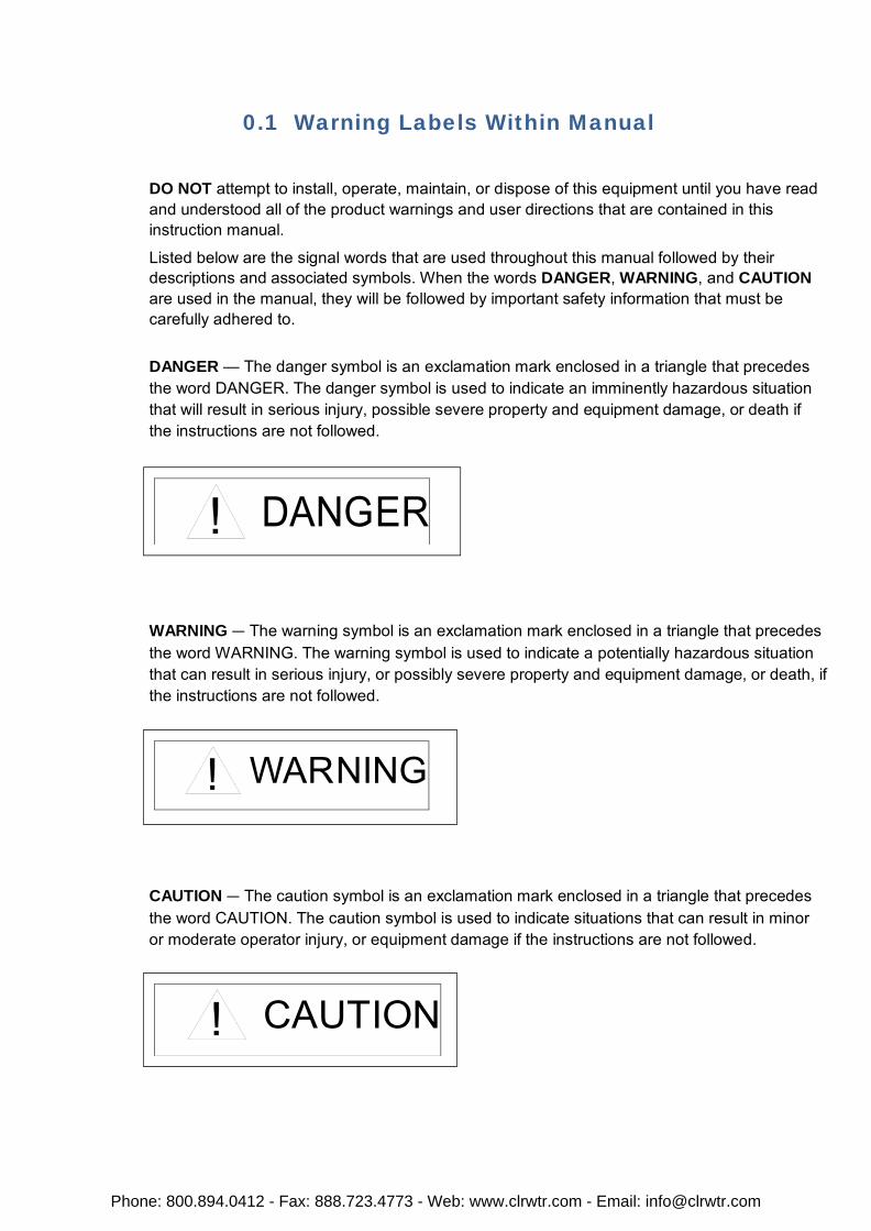
DANGER — The danger symbol is an exclamation mark enclosed in a triangle that precedes the word DANGER. The danger symbol is used to indicate an imminently hazardous situation that will result in serious injury, possible severe property and equipment damage, or death if the instructions are not followed.
WARNING — The warning symbol is an exclamation mark enclosed in a triangle that precedes the word WARNING. The warning symbol is used to indicate a potentially hazardous situation that can result in serious injury, or possibly severe property and equipment damage, or death, if the instructions are not followed.
CAUTION — The caution symbol is an exclamation mark enclosed in a triangle that precedes the word CAUTION. The caution symbol is used to indicate situations that can result in minor or moderate operator injury, or equipment damage if the instructions are not followed.
DANGER
WARNING
CAUTION
Phone: 800.894.0412 - Fax: 888.723.4773 - Web: www.clrwtr.com - Email: [email protected]
To identify special hazards, other symbols may appear in conjunction with the DANGER, WARNING, and CAUTION symbols. These warnings describe areas that require special care and/or strict adherence to the procedures to prevent serious injury and possible death.
Electrical Hazard — The electrical hazard symbol is a lightning bolt enclosed in a triangle. The electrical hazard symbol is used to indicate high voltage locations and conditions that may cause serious injury or death if the proper precautions are not observed.
Explosion Hazard — The explosion hazard symbol is an explosion image enclosed in a triangle. The explosion hazard symbol is used to indicate locations and conditions where molten exploding parts may cause serious injury or death if the proper precautions are not observed.
ELECTRICALHAZARD
EXPLOSIONHAZARD
Phone: 800.894.0412 - Fax: 888.723.4773 - Web: www.clrwtr.com - Email: [email protected]

0.2 Equipment Warning Labels.
DO NOT attempt to install, operate, maintain, or dispose of this equipment until you have read and understood all of the product warnings and user directions that are contained in this instruction manual.
Shown below are examples of warning labels that may be found attached to the equipment. DO NOT remove or cover any of the labels. If the labels are damaged or if additional labels are required, contact your Toshiba representative for additional labels.
The following are examples of the warning labels that may be found on the equipment and are there to provide useful information or to indicate an imminently hazardous situation that may result in serious injury, severe property and equipment damage, or death if the instructions are not followed.
Examples of labels that may be found on the equipment.
Phone: 800.894.0412 - Fax: 888.723.4773 - Web: www.clrwtr.com - Email: [email protected]

0.3 Preparation
Qualified Person
A Qualified Person is one that has the skills and knowledge relating to the construction, installation, operation, and maintenance of the electrical equipment and has received safety training on the hazards involved (Refer to the latest edition of NFPA 70E for additional safety requirements).
Qualified Personnel shall:
• Have carefully read the entire operation manual.
• Be trained and authorized to safely energize, de-energize, ground, lockout and tag circuits and equipment, and clear faults in accordance with established safety practices.
• Be trained in the proper care and use of protective equipment such as safety shoes, rubber gloves, hard hats, safety glasses, face shields, flash clothing, etc., in accordance with established safety practices.
• Be trained in rendering first aid.
For further information on workplace safety visit www.osha.gov.
Equipment Inspection
• Upon receipt of the equipment inspect the packaging and equipment for shipping damage.
• Carefully unpack the equipment and check for parts that were damaged from shipping, missing parts, or concealed damage. If any discrepancies are discovered, it should be noted with the carrier prior to accepting the shipment, if possible. File a claim with the carrier if necessary and immediately notify your Toshiba representative.
• DO NOT install or energize equipment that has been damaged. Damaged equipment may fail during operation resulting in further equipment damage or personal injury.
• Check to see that the model number specified on the nameplate conforms to the order specifications.
• Modification of this equipment is dangerous and must not be performed except by factory trained representatives. When modifications are required contact your Toshiba representative.
• Inspections may be required before and after moving installed equipment.
• Keep the equipment in an upright position as indicated on the shipping carton.
• Contact your Toshiba representative for assistance if required.
Phone: 800.894.0412 - Fax: 888.723.4773 - Web: www.clrwtr.com - Email: [email protected]
Handling and Storage
• Use proper lifting techniques when moving the OIS; including properly sizing up the load, and getting assistance if required.
• Store in a well-ventilated covered location and preferably in the original carton if the equipment will not be used upon receipt.
• Store in a cool, clean, and dry location. Avoid storage locations with extreme temperatures, rapid temperature changes, high humidity, moisture, dust, corrosive gases, or metal particles.
• Do not store the unit in places that are exposed to outside weather conditions (i.e., wind, rain, snow, etc.).
• Store in an upright position as indicated on the shipping carton.
• Include any other product-specific requirements.
Disposal
Never dispose of electrical components via incineration. Contact your state environmental agency for details on disposal of electrical components and packaging in your area.
0.4 Installation Precautions
Location and Ambient Requirements
• Adequate personnel working space and adequate illumination must be provided for adjustment, inspection, and maintenance of the equipment (refer to NEC Article 110-34).
• Avoid installation in areas where vibration, heat, humidity, dust, fibers, steel particles, explosive/corrosive mists or gases, or sources of electrical noise are present.
• The installation location shall not be exposed to direct sunlight.
• Allow proper clearance spaces for installation. Do not obstruct the ventilation openings. Refer to the recommended minimum installation dimensions as shown on the enclosure outline drawings.
• The ambient operating temperature shall be between 0° and 50° C (32° and 122° F).
Mounting Requirements
• Only Qualified Personnel should install this equipment.
• Install the unit in a secure upright position in a well-ventilated area.
• A noncombustible insulating floor or mat should be provided in the area immediately surrounding the electrical system at the place where maintenance operations are to be performed.
• As a minimum, the installation of the equipment should conform to the NEC Article 110 Requirements For Electrical Installations, OSHA, as well as any other applicable national, regional, or industry codes and standards.
• Installation practices should conform to the latest revision of NFPA 70E Electrical Safety Requirements for Employee Workplaces.
Phone: 800.894.0412 - Fax: 888.723.4773 - Web: www.clrwtr.com - Email: [email protected]

Conductor Routing and Grounding
• Use separate metal conduits for routing the input power, and control circuits.
• A separate ground cable should be run inside the conduit with the input power, and control circuits.
• DO NOT connect control terminal strip return marked CC to earth ground.
• Always ground the unit to prevent electrical shock and to help reduce electrical noise.
T he M e ta l O f C o n d u i t I s N o t An Ac c e p ta b le Gr o u n d .
Phone: 800.894.0412 - Fax: 888.723.4773 - Web: www.clrwtr.com - Email: [email protected]
0.5 Connection, Protection & Setup
Personnel Protection
• Installation, operation, and maintenance shall be performed by Qualified Personnel Only.
• A thorough understanding of the OIS will be required before the installation, operation, or maintenance of the OIS.
• Rotating machinery and live conductors can be hazardous and shall not come into contact with humans. Personnel should be protected from all rotating machinery and electrical hazards at all times. Depending on its program, the OIS can initiate the start and stop of rotating machinery.
• Insulators, machine guards, and electrical safeguards may fail or be defeated by the purposeful or inadvertent actions of workers. Insulators, machine guards, and electrical safeguards are to be inspected (and tested where possible) at installation and periodically after installation for potential hazardous conditions.
• Do not allow personnel near rotating machinery. Warning signs to this effect shall be posted at or near the machinery.
• Do not allow personnel near electrical conductors. Human contact with electrical conductors can be fatal. Warning signs to this effect shall be posted at or near the hazard.
• Personal protection equipment shall be provided and used to protect employees from any hazards inherent to system operation or maintenance.
System Setup Requirements
• When using the OIS as an integral part of a larger system, it is the responsibility of the OIS installer or maintenance personnel to ensure that there is a fail-safe in place (i.e., an arrangement designed to switch the system to a safe condition if there is a fault or failure).
• System safety features should be employed and designed into the integrated system in a manner such that system operation, even in the event of system failure, will not cause harm or result in personnel injury or system damage (i.e., E-Off, Auto-Restart settings, System Interlocks, etc.).
• The programming setup and system configuration of the OIS may allow it to start a motor unexpectedly. A familiarity with Auto-restart settings is a requirement to use this product.
• Improperly designed or improperly installed system interlocks may render the motor unable to start or stop on command.
Phone: 800.894.0412 - Fax: 888.723.4773 - Web: www.clrwtr.com - Email: [email protected]

The failure of external or ancillary components may cause intermittent system operation, i.e., the system may start a motor without warning or may not stop on command.
• There may be thermal or physical properties, or ancillary devices integrated into the overall system that may allow the OIS to start a motor without warning. Signs at the equipment installation must be posted to this effect.
• The operating controls and system status indicators should be clearly readable and positioned where the operator can see them without obstruction.
• Additional warnings and notifications shall be posted at the equipment installation location as deemed required by Qualified Personnel.
Phone: 800.894.0412 - Fax: 888.723.4773 - Web: www.clrwtr.com - Email: [email protected]

0.6 System Integration Precautions
The following precautions are provided as general guidelines for using an OIS in an industrial or process control system. • The Toshiba PLC is a general-purpose product. It is a system component and is used in
conjunction with other items of industrial equipment such as PLCs, Loop Controllers, Adjustable Speed Drives, etc.
• A detailed system analysis and job safety analysis should be performed by the systems designer or systems integrator before including the OIS in any new or existing system. Contact Toshiba for options availability and for application-specific system integration information if required.
• The PLC may be used to control an adjustable speed drive connected to high voltage sources and rotating machinery that is inherently dangerous if not operated safely. Interlock all energy sources, hazardous locations, and guards in order to restrict the exposure of personnel to hazards. The adjustable speed drive may start the motor without warning. Signs at the equipment installation must be posted to this effect. A familiarity with Auto-restart settings is a requirement when controlling adjustable speed drives. Failure of external or ancillary components may cause intermittent system operation, i.e., the system may start the motor without warning or may not stop on command. Improperly designed or improperly installed system interlocks and permissives may render a motor unable to start or stop on command
• Control through serial communications can fail or can also override local controls, which can create an unsafe condition. System safety features should be employed and designed into the integrated system in a manner such that system operation, even in the event of system failure, will not cause harm or result in personnel injury or system damage. Use of the built-in system protective features and interlocks of the equipment being controlled is highly recommended (i.e., emergency-off, overload protection, etc.)
• Never use the PLC units to perform emergency stops. Separate switches outside the OIS, the PLC, and the ASD should be used for emergency stops.
• Changes or modifications to the PLC program should not be made without the approval of the system designer or systems integrator. Minor changes or modifications could cause the defeat of safety interlocks and permissives. Any changes or modifications should be noted and included with the system documentation.
Phone: 800.894.0412 - Fax: 888.723.4773 - Web: www.clrwtr.com - Email: [email protected]
Instruction Overview
♦ Instruction Specifications
♦ List of Instructions
Phone: 800.894.0412 - Fax: 888.723.4773 - Web: www.clrwtr.com - Email: [email protected]
1.1 Instruction Specifications
In this section, each instruction mentioned in section 1.1 is described in detailed. For each instruction, the following items are explained:
Expression: Shows the operands required for the instruction as marked.
Function: Explains the function of the instruction with referring the operands shown on the expression box.
Execution Condition: Shows the execution condition of the instruction and the instruction’s output status.
Operand: Shows available register, device or constant value for each operand. For constant operand, available
value range is described. If the constant column is just marked (√), it means normal value range (-32768 to 32767 in 16-bit integer or -2147483648 to 2147483647 in 32-bit integer) is available. Whether index modification for a register operand is usable or not is also shown for each operand.
Example: Explains the operation of the instruction by using a typical example.
Note: Explains supplementary information, limitations, etc. for the instruction.
For a quick reference, table given in next section will describe you the purpose of each instruction, instruction timings and number of steps for each instruction.
About RAM registers, EEPROM registers and Instruction Timings: Register ‘D’, ‘BW’, ‘MW’, ‘SW’, ‘T’, ‘C’ are allocated memory in RAM for all models. ‘R’ are the retentive registers which retain their values after power cycle. ’R’ registers are allocated memory in EEPROM for V200, OIS45/55/65/7 PLUS series models. For OIS10 PLUS and OIS40 PLUS series models a battery back up for RAM is used as ‘R’ memory.
When retentive registers are used in the ladder, a call to EEPROM is invoked. As the EEPROM access is slow, the execution time is higher if retentive registers are used in the instructions. So separate execution timings are mentioned for instructions where ‘R’ registers are used. Retentive register ‘R’ in OIS10 PLUS & OIS40 PLUS are stored in Battery backup RAM. So execution time for retentive register operation is same as RAM registers (‘D’, ‘BW’ etc.) User should be careful while using ‘R’ registers in destination as the number of write operations to EEPROM is limited to 10,000,000 operations only. After that the EEPROM may become unusable.
Data retention validity for EEPROM is more than 200 years. Data retention validity for battery backup RAM is dependent on Battery life which is published by the battery manufacturer.
Phone: 800.894.0412 - Fax: 888.723.4773 - Web: www.clrwtr.com - Email: [email protected]
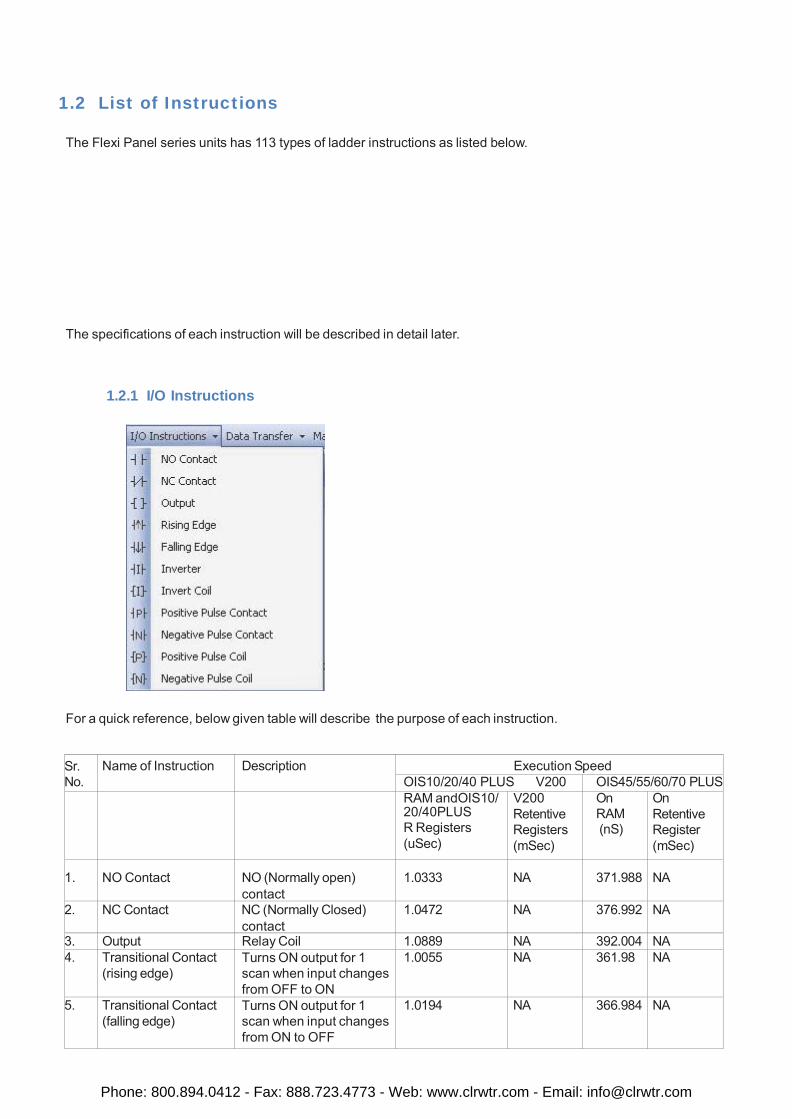
1.2 List of Instructions The Flexi Panel series units has 113 types of ladder instructions as listed below.
The specifications of each instruction will be described in detail later.
1.2.1 I/O Instructions
For a quick reference, below given table will describe the purpose of each instruction.
Sr. No.
Name of Instruction Description Execution Speed OIS10/20/40 PLUS V200 OIS45/55/60/70 PLUS
RAM andOIS10/ 20/40PLUS R Registers (uSec)
V200 Retentive Registers (mSec)
On RAM (nS)
On Retentive Register (mSec)
1.
NO Contact
NO (Normally open) contact
1.0333
NA
371.988
NA
2. NC Contact NC (Normally Closed) contact
1.0472 NA 376.992 NA
3. Output Relay Coil 1.0889 NA 392.004 NA 4. Transitional Contact
(rising edge) Turns ON output for 1 scan when input changes from OFF to ON
1.0055 NA 361.98 NA
5. Transitional Contact (falling edge)
Turns ON output for 1 scan when input changes from ON to OFF
1.0194 NA 366.984 NA
Phone: 800.894.0412 - Fax: 888.723.4773 - Web: www.clrwtr.com - Email: [email protected]
Sr. No.
Name of Instruction Description Execution Speed OIS10/20/40 PLUS V200 OIS45/55/60/70
RAM and OIS10/ 20/40PLUS
R Registers (uSec)
V200 Retentive Registers (mSec)
On RAM (nS)
On Retentive Register (mSec)
7. Inverter Inverts the input state 0.8250 NA 297 NA 8. Inverter Coil Stores the invers state of
input input into device A 1.1167 NA 402.012 NA
9. Positive Pulse Contact
Turns ON output for 1 scan when input is ON and device A changes from OFF to ON.
1.2833 NA 461.988 NA
10. Negative Pulse Contact
Turns ON output for 1 scan when input is ON and device A changes from ON to OFF
1.3389 NA 482.004 NA
11. Positive Pulse Coil Turns ON device A for 1 scan when input changes from OFF to ON
1.3250 NA 477 NA
12. Negative Pulse Coil Turns ON device A for 1 scan when input changes from ON to OFF
1.2972 NA 466.992 NA
Phone: 800.894.0412 - Fax: 888.723.4773 - Web: www.clrwtr.com - Email: [email protected]
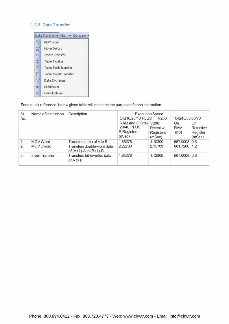
1.2.2 Data Transfer
For a quick reference, below given table will describe the purpose of each instruction.
Sr. No.
Name of Instruction Description Execution Speed OIS10/20/40 PLUS V200 OIS45/55/60/70
RAM and OIS10/ 20/40 PLUS R Registers (uSec)
V200 Retentive Registers (mSec)
On RAM (nS)
On Retentive Register (mSec)
1. MOV Word Transfers data of A to B 1.85278 1.10300 667.0008 0.6 2. MOV Dword Transfers double-word data
of (A+1)-A to (B+1)-B 2.22700 2.15709 801.7200 1.2
3. Invert Transfer Transfers bit-inverted data of A to B
1.85278 1.12806 667.0008 0.6
Phone: 800.894.0412 - Fax: 888.723.4773 - Web: www.clrwtr.com - Email: [email protected]
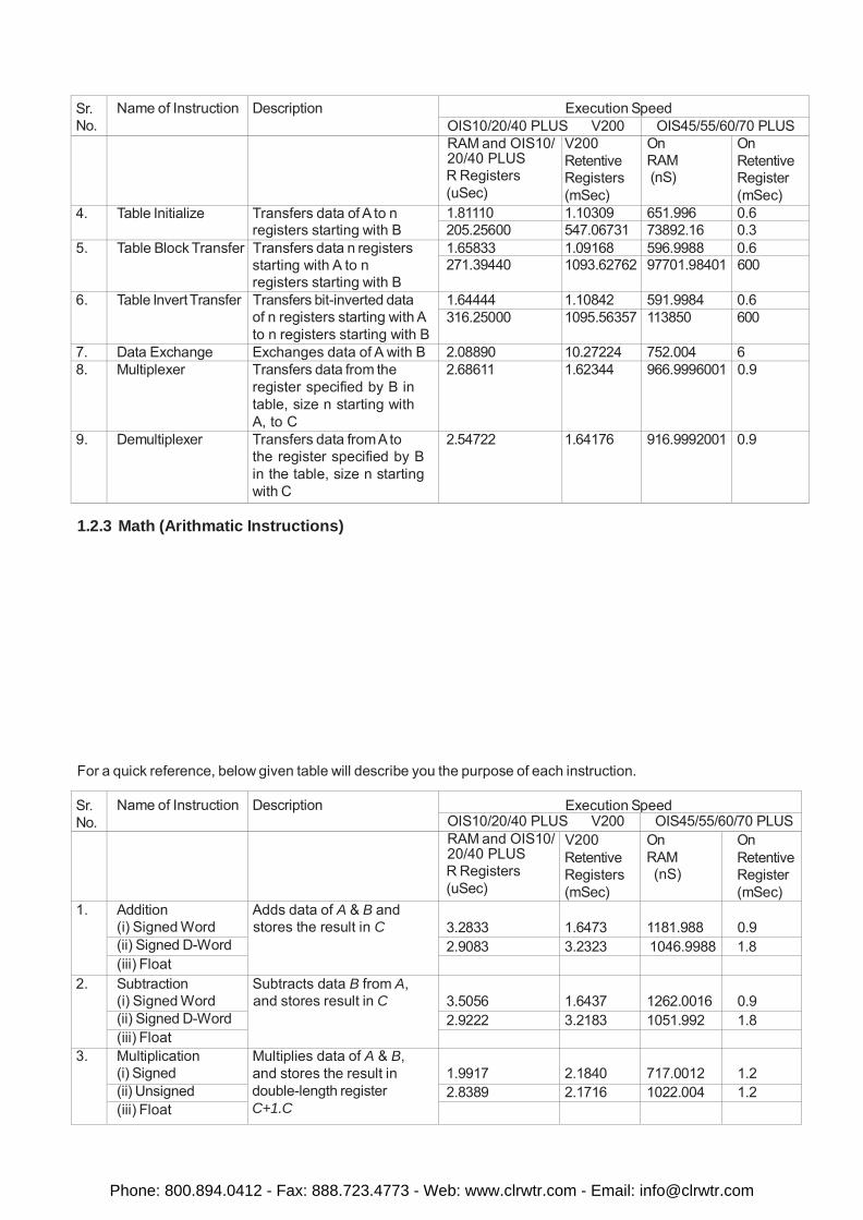
Sr. No.
Name of Instruction Description Execution Speed OIS10/20/40 PLUS V200 OIS45/55/60/70 PLUS
RAM and OIS10/ 20/40 PLUS R Registers (uSec)
V200 Retentive Registers (mSec)
On RAM (nS)
On Retentive Register (mSec)
4. Table Initialize Transfers data of A to n registers starting with B
1.81110 1.10309 651.996 0.6 205.25600 547.06731 73892.16 0.3
5. Table Block Transfer Transfers data n registers starting with A to n registers starting with B
1.65833 1.09168 596.9988 0.6 271.39440 1093.62762 97701.98401 600
6. Table Invert Transfer Transfers bit-inverted data of n registers starting with A to n registers starting with B
1.64444 1.10842 591.9984 0.6 316.25000 1095.56357 113850 600
7. Data Exchange Exchanges data of A with B 2.08890 10.27224 752.004 6 8. Multiplexer Transfers data from the
register specified by B in table, size n starting with A, to C
2.68611 1.62344 966.9996001 0.9
9. Demultiplexer Transfers data from A to the register specified by B in the table, size n starting with C
2.54722 1.64176 916.9992001 0.9
1.2.3 Math (Arithmatic Instructions)
For a quick reference, below given table will describe you the purpose of each instruction.
Sr. No.
Name of Instruction Description Execution Speed OIS10/20/40 PLUS V200 OIS45/55/60/70 PLUS
RAM and OIS10/ 20/40 PLUS R Registers (uSec)
V200 Retentive Registers (mSec)
On RAM (nS)
On Retentive Register (mSec)
1. Addition (i) Signed Word
Adds data of A & B and stores the result in C
3.2833
1.6473
1181.988
0.9
(ii) Signed D-Word 2.9083 3.2323 1046.9988 1.8 (iii) Float
2. Subtraction (i) Signed Word
Subtracts data B from A, and stores result in C
3.5056
1.6437
1262.0016
0.9
(ii) Signed D-Word 2.9222 3.2183 1051.992 1.8 (iii) Float
3. Multiplication (i) Signed
Multiplies data of A & B, and stores the result in double-length register C+1.C
1.9917
2.1840
717.0012
1.2
(ii) Unsigned 2.8389 2.1716 1022.004 1.2 (iii) Float
Phone: 800.894.0412 - Fax: 888.723.4773 - Web: www.clrwtr.com - Email: [email protected]
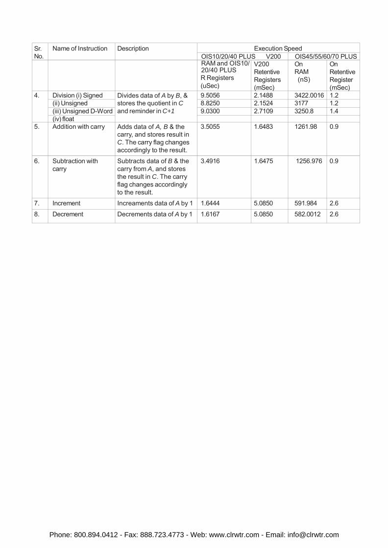
Sr. No.
Name of Instruction Description Execution Speed OIS10/20/40 PLUS V200 OIS45/55/60/70 PLUS
RAM and OIS10/ 20/40 PLUS R Registers (uSec)
V200 Retentive Registers (mSec)
On RAM (nS)
On Retentive Register (mSec)
4. Division (i) Signed Divides data of A by B, & stores the quotient in C and reminder in C+1
9.5056 2.1488 3422.0016 1.2 (ii) Unsigned 8.8250 2.1524 3177 1.2 (iii) Unsigned D-Word 9.0300 2.7109 3250.8 1.4 (iv) float
5. Addition with carry Adds data of A, B & the carry, and stores result in C. The carry flag changes accordingly to the result.
3.5055 1.6483 1261.98 0.9
6. Subtraction with carry
Subtracts data of B & the carry from A, and stores the result in C. The carry flag changes accordingly to the result.
3.4916 1.6475 1256.976 0.9
7. Increment Increaments data of A by 1 1.6444 5.0850 591.984 2.6
8. Decrement Decrements data of A by 1 1.6167 5.0850 582.0012 2.6
Phone: 800.894.0412 - Fax: 888.723.4773 - Web: www.clrwtr.com - Email: [email protected]
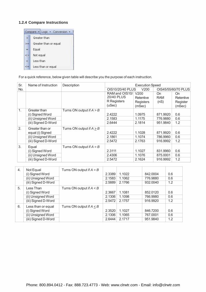
1.2.4 Compare Instructions
For a quick reference, below given table will describe you the purpose of each instruction.
Sr. No.
Name of Instruction Description Execution Speed OIS10/20/40 PLUS V200 OIS45/55/60/70 PLUS
RAM and OIS10/ 20/40 PLUS R Registers (uSec)
V200 Retentive Registers (mSec)
On RAM (nS)
On Retentive Register (mSec)
1. Greater than (i) Signed Word
Turns ON output if A > B 2.4222
1.0975
871.9920
0.6
(ii) Unsigned Word 2.1583 1.1175 776.9880 0.6 (iii) Signed D-Word 2.6444 2.1814 951.9840 1.2
2. Greater than or equal (i) Signed
Turns ON output if A > B 2.4222
1.1028
871.9920
0.6
(ii) Unsigned Word 2.1861 1.1074 786.9960 0.6 (iii) Signed D-Word 2.5472 2.1763 916.9992 1.2
3. Equal (i) Signed Word
Turns ON output if A = B 2.3111
1.1027
831.9960
0.6
(ii) Unsigned Word 2.4306 1.1076 875.0001 0.6 (iii) Signed D-Word 2.5472 2.1624 916.9992 1.2
4. Not Equal (i) Signed Word
Turns ON output if A = B
2.3389
1.1022
842.0004
0.6
(ii) Unsigned Word 2.1583 1.1062 776.9880 0.6 (iii) Signed D-Word 2.5889 2.1766 932.0040 1.2
5. Less Than (i) Signed Word
Turns ON output if A < B 2.3667
1.1081
852.0120
0.6
(ii) Unsigned Word 2.1306 1.1098 766.9980 0.6 (iii) Signed D-Word 2.5472 2.1757 916.9920 1.2
6. Less than or equal (i) Signed Word
Turns ON output if A < B 2.3520
1.1027
846.7200
0.6
(ii) Unsigned Word 2.1306 1.1065 767.0001 0.6 (iii) Signed D-Word 2.6444 2.1717 951.9840 1.2
Phone: 800.894.0412 - Fax: 888.723.4773 - Web: www.clrwtr.com - Email: [email protected]
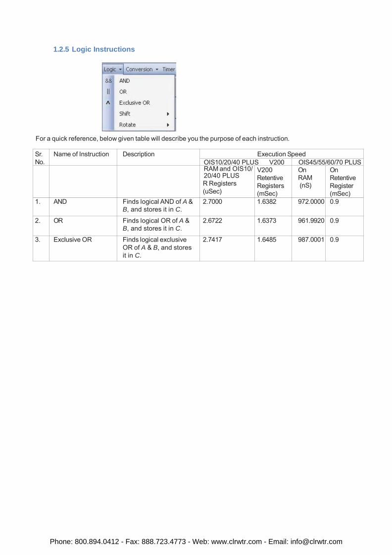
1.2.5 Logic Instructions
For a quick reference, below given table will describe you the purpose of each instruction.
Sr. No.
Name of Instruction Description Execution Speed OIS10/20/40 PLUS V200 OIS45/55/60/70 PLUS
RAM and OIS10/ 20/40 PLUS R Registers (uSec)
V200 Retentive Registers (mSec)
On RAM (nS)
On Retentive Register (mSec)
1. AND Finds logical AND of A & B, and stores it in C.
2.7000 1.6382 972.0000 0.9
2. OR Finds logical OR of A & B, and stores it in C.
2.6722 1.6373 961.9920 0.9
3. Exclusive OR Finds logical exclusive OR of A & B, and stores it in C.
2.7417 1.6485 987.0001 0.9
Phone: 800.894.0412 - Fax: 888.723.4773 - Web: www.clrwtr.com - Email: [email protected]
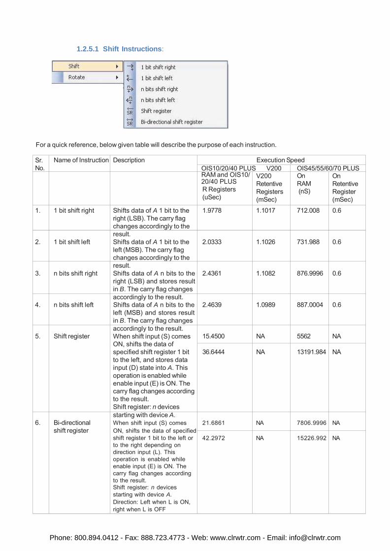
1.2.5.1 Shift Instructions:
For a quick reference, below given table will describe the purpose of each instruction.
Sr. No.
Name of Instruction Description Execution Speed OIS10/20/40 PLUS V200 OIS45/55/60/70 PLUS
RAM and OIS10/ 20/40 PLUS R Registers (uSec)
V200 Retentive Registers (mSec)
On RAM (nS)
On Retentive Register (mSec)
1. 1 bit shift right Shifts data of A 1 bit to the right (LSB). The carry flag changes accordingly to the
1.9778 1.1017 712.008 0.6
2.
1 bit shift left
result. Shifts data of A 1 bit to the left (MSB). The carry flag changes accordingly to the
2.0333
1.1026
731.988
0.6
3.
n bits shift right
result. Shifts data of A n bits to the right (LSB) and stores result in B. The carry flag changes
2.4361
1.1082
876.9996
0.6
4.
n bits shift left
accordingly to the result. Shifts data of A n bits to the left (MSB) and stores result in B. The carry flag changes
2.4639
1.0989
887.0004
0.6
5.
Shift register
accordingly to the result. When shift input (S) comes ON, shifts the data of specified shift register 1 bit to the left, and stores data input (D) state into A. This operation is enabled while enable input (E) is ON. The carry flag changes according to the result. Shift register: n devices
15.4500
NA
5562
NA
36.6444
NA
13191.984
NA
6.
Bi-directional shift register
starting with device A. When shift input (S) comes ON, shifts the data of specified shift register 1 bit to the left or to the right depending on direction input (L). This operation is enabled while enable input (E) is ON. The carry flag changes according to the result. Shift register: n devices starting with device A. Direction: Left when L is ON, right when L is OFF
21.6861
NA
7806.9996
NA
42.2972
NA
15226.992
NA
Phone: 800.894.0412 - Fax: 888.723.4773 - Web: www.clrwtr.com - Email: [email protected]
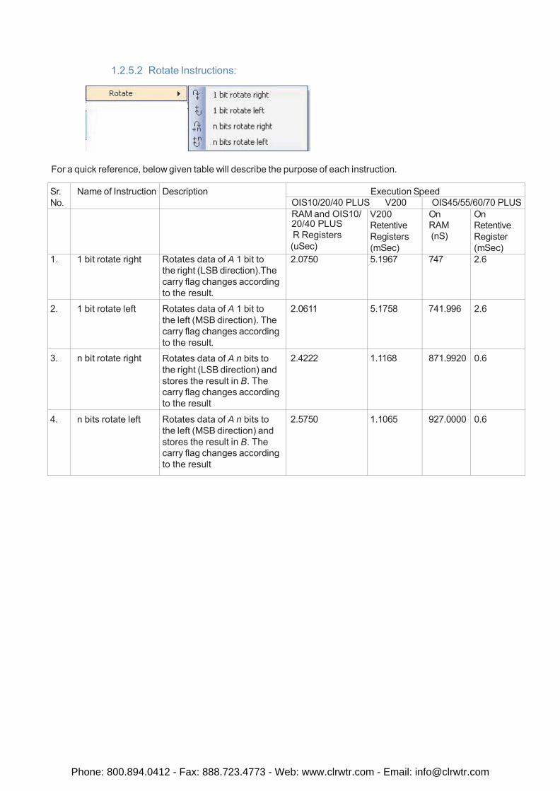
1.2.5.2 Rotate Instructions:
For a quick reference, below given table will describe the purpose of each instruction.
Sr. No.
Name of Instruction Description Execution Speed OIS10/20/40 PLUS V200 OIS45/55/60/70 PLUS
RAM and OIS10/ 20/40 PLUS R Registers (uSec)
V200 Retentive Registers (mSec)
On RAM (nS)
On Retentive Register (mSec)
1. 1 bit rotate right Rotates data of A 1 bit to the right (LSB direction).The carry flag changes according to the result.
2.0750 5.1967 747 2.6
2. 1 bit rotate left Rotates data of A 1 bit to the left (MSB direction). The carry flag changes according to the result.
2.0611 5.1758 741.996 2.6
3. n bit rotate right Rotates data of A n bits to the right (LSB direction) and stores the result in B. The carry flag changes according to the result
2.4222 1.1168 871.9920 0.6
4. n bits rotate left Rotates data of A n bits to the left (MSB direction) and stores the result in B. The carry flag changes according to the result
2.5750 1.1065 927.0000 0.6
Phone: 800.894.0412 - Fax: 888.723.4773 - Web: www.clrwtr.com - Email: [email protected]
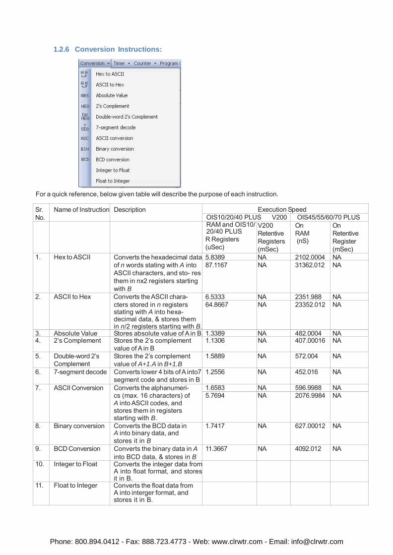
1.2.6 Conversion Instructions:
For a quick reference, below given table will describe the purpose of each instruction.
Sr. No.
Name of Instruction Description Execution Speed OIS10/20/40 PLUS V200 OIS45/55/60/70 PLUS
RAM and OIS10/ 20/40 PLUS R Registers (uSec)
V200 Retentive Registers (mSec)
On RAM (nS)
On Retentive Register (mSec)
1. Hex to ASCII Converts the hexadecimal data of n words stating with A into ASCII characters, and sto- res them in nx2 registers starting with B
5.8389 NA 2102.0004 NA 87.1167 NA 31362.012 NA
2. ASCII to Hex Converts the ASCII chara- cters stored in n registers stating with A into hexa- decimal data, & stores them in n/2 registers starting with B.
6.5333 NA 2351.988 NA 64.8667 NA 23352.012 NA
3. Absolute Value Stores absolute value of A in B. 1.3389 NA 482.0004 NA 4. 2’s Complement Stores the 2’s complement
value of A in B 1.1306 NA 407.00016 NA
5. Double-word 2’s Complement
Stores the 2’s complement value of A+1.A in B+1.B
1.5889 NA 572.004 NA
6. 7-segment decode Converts lower 4 bits of A into7 segment code and stores in B
1.2556 NA 452.016 NA
7. ASCII Conversion Converts the alphanumeri- cs (max. 16 characters) of A into ASCII codes, and stores them in registers starting with B.
1.6583 NA 596.9988 NA 5.7694 NA 2076.9984 NA
8. Binary conversion Converts the BCD data in A into binary data, and stores it in B
1.7417 NA 627.00012 NA
9. BCD Conversion Converts the binary data in A into BCD data, & stores in B
11.3667 NA 4092.012 NA
10. Integer to Float Converts the integer data from A into float format, and stores it in B.
11. Float to Integer Converts the float data from A into interger format, and stores it in B.
Phone: 800.894.0412 - Fax: 888.723.4773 - Web: www.clrwtr.com - Email: [email protected]
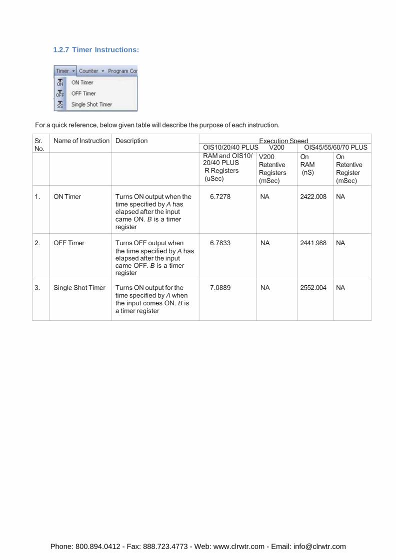
1.2.7 Timer Instructions:
For a quick reference, below given table will describe the purpose of each instruction.
Sr. No.
Name of Instruction Description Execution Speed OIS10/20/40 PLUS V200 OIS45/55/60/70 PLUS
RAM and OIS10/ 20/40 PLUS R Registers (uSec)
V200 Retentive Registers (mSec)
On RAM (nS)
On Retentive Register (mSec)
1.
ON Timer
Turns ON output when the time specified by A has elapsed after the input came ON. B is a timer register
6.7278
NA
2422.008
NA
2.
OFF Timer
Turns OFF output when the time specified by A has elapsed after the input came OFF. B is a timer register
6.7833
NA
2441.988
NA
3.
Single Shot Timer
Turns ON output for the time specified by A when the input comes ON. B is a timer register
7.0889
NA
2552.004
NA
Phone: 800.894.0412 - Fax: 888.723.4773 - Web: www.clrwtr.com - Email: [email protected]
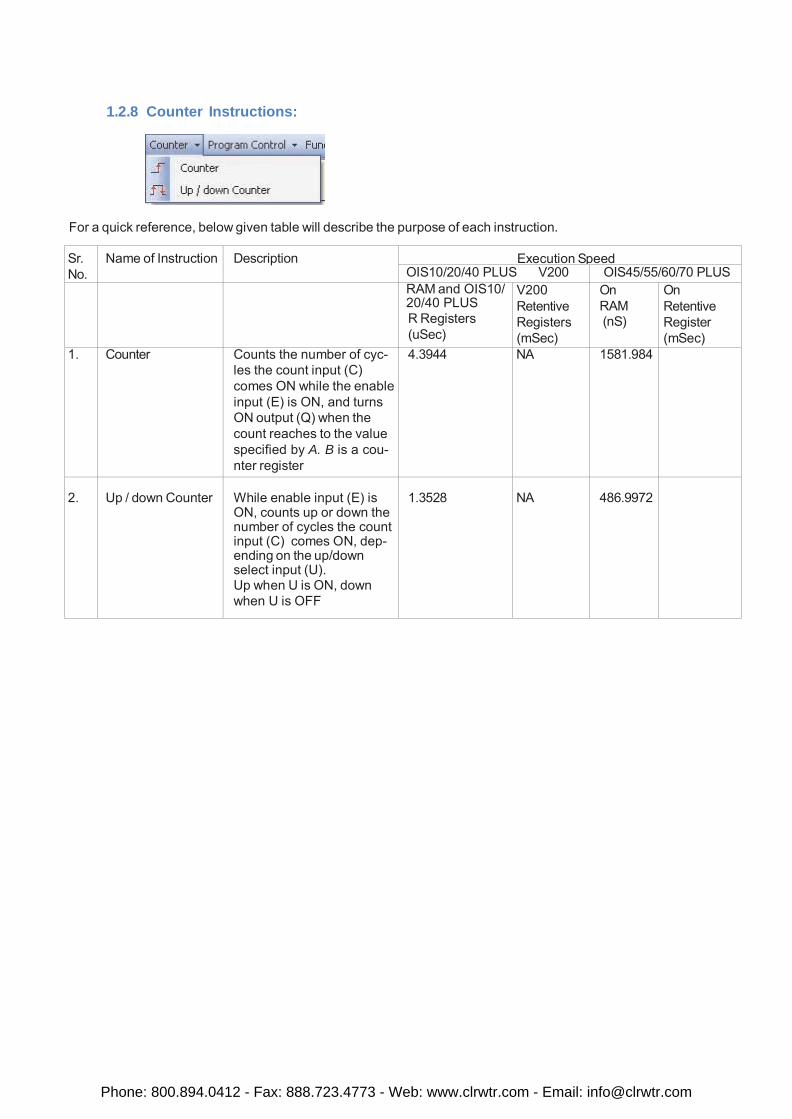
1.2.8 Counter Instructions:
For a quick reference, below given table will describe the purpose of each instruction.
Sr. No.
Name of Instruction Description Execution Speed OIS10/20/40 PLUS V200 OIS45/55/60/70 PLUS
RAM and OIS10/ 20/40 PLUS R Registers (uSec)
V200 Retentive Registers (mSec)
On RAM (nS)
On Retentive Register (mSec)
1. Counter Counts the number of cyc- les the count input (C) comes ON while the enable input (E) is ON, and turns ON output (Q) when the count reaches to the value specified by A. B is a cou- nter register
4.3944 NA 1581.984
2.
Up / down Counter
While enable input (E) is ON, counts up or down the number of cycles the count input (C) comes ON, dep- ending on the up/down select input (U). Up when U is ON, down when U is OFF
1.3528
NA
486.9972
Phone: 800.894.0412 - Fax: 888.723.4773 - Web: www.clrwtr.com - Email: [email protected]
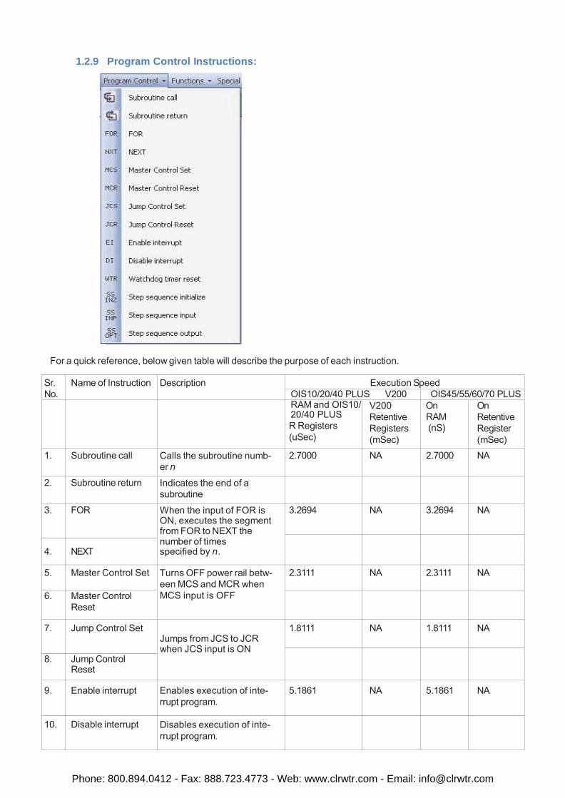
1.2.9 Program Control Instructions:
For a quick reference, below given table will describe the purpose of each instruction. Sr. No.
Name of Instruction Description Execution Speed OIS10/20/40 PLUS V200 OIS45/55/60/70 PLUS
RAM and OIS10/ 20/40 PLUS R Registers (uSec)
V200 Retentive Registers (mSec)
On RAM (nS)
On Retentive Register (mSec)
1. Subroutine call Calls the subroutine numb- er n
2.7000 NA 2.7000 NA
2. Subroutine return Indicates the end of a subroutine
3. FOR When the input of FOR is ON, executes the segment from FOR to NEXT the number of times specified by n.
3.2694 NA 3.2694 NA
4.
NEXT
5. Master Control Set Turns OFF power rail betw- een MCS and MCR when MCS input is OFF
2.3111 NA 2.3111 NA
6. Master Control Reset
7. Jump Control Set Jumps from JCS to JCR when JCS input is ON
1.8111 NA 1.8111 NA
8. Jump Control Reset
9.
Enable interrupt
Enables execution of inte- rrupt program.
5.1861
NA
5.1861
NA
10. Disable interrupt Disables execution of inte- rrupt program.
Phone: 800.894.0412 - Fax: 888.723.4773 - Web: www.clrwtr.com - Email: [email protected]
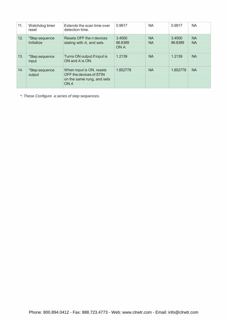
11. Watchdog timer reset
Extends the scan time over detection time.
0.9917 NA 0.9917 NA
12. *Step sequence Initialize
Resets OFF the n devices stating with A, and sets
3.4500 86.8389 ON A.
NA NA
3.4500 86.8389
NA NA
13. *Step sequence input
Turns ON output if input is ON and A is ON.
1.2139 NA 1.2139 NA
14. *Step sequence output
When input is ON, resets OFF the devices of STIN on the same rung, and sets ON A
1.852778 NA 1.852778 NA
*: These Configure a series of step sequences.
Phone: 800.894.0412 - Fax: 888.723.4773 - Web: www.clrwtr.com - Email: [email protected]
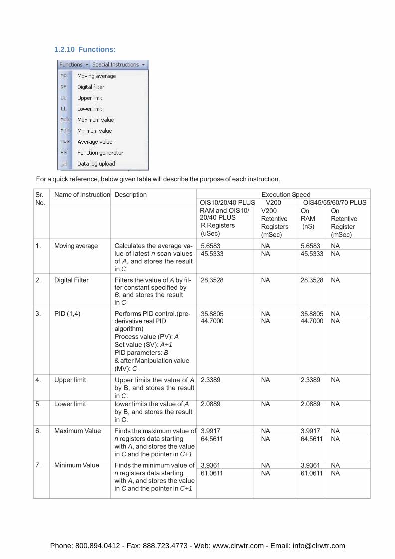
1.2.10 Functions:
For a quick reference, below given table will describe the purpose of each instruction.
Sr. No.
Name of Instruction Description Execution Speed OIS10/20/40 PLUS V200 OIS45/55/60/70 PLUS
RAM and OIS10/ 20/40 PLUS R Registers (uSec)
V200 Retentive Registers (mSec)
On RAM (nS)
On Retentive Register (mSec)
1.
Moving average
Calculates the average va- lue of latest n scan values of A, and stores the result in C
5.6583
NA
5.6583
NA 45.5333 NA 45.5333 NA
2. Digital Filter Filters the value of A by fil- ter constant specified by B, and stores the result in C
28.3528 NA 28.3528 NA
3. PID (1,4) Performs PID control.(pre- derivative real PID algorithm) Process value (PV): A Set value (SV): A+1 PID parameters: B & after Manipulation value (MV): C
35.8805 NA 35.8805 NA 44.7000 NA 44.7000 NA
4. Upper limit Upper limits the value of A by B, and stores the result in C.
2.3389 NA 2.3389 NA
5. Lower limit lower limits the value of A by B, and stores the result in C.
2.0889 NA 2.0889 NA
6. Maximum Value Finds the maximum value of n registers data starting with A, and stores the value in C and the pointer in C+1
3.9917 NA 3.9917 NA 64.5611 NA 64.5611 NA
7. Minimum Value Finds the minimum value of n registers data starting with A, and stores the value in C and the pointer in C+1
3.9361 NA 3.9361 NA 61.0611 NA 61.0611 NA
Phone: 800.894.0412 - Fax: 888.723.4773 - Web: www.clrwtr.com - Email: [email protected]
Sr. No.
Name of Instruction Description Execution Speed OIS10/20/40 PLUS V200 OIS45/55/60/70 PLUS
RAM and OIS10/ 20/40 PLUS R Registers (uSec)
V200 Retentive Registers (mSec)
On RAM (nS)
On Retentive Register (mSec)
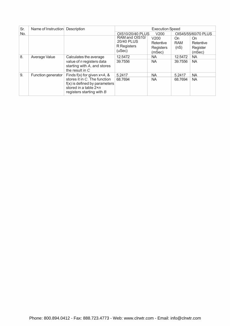
8. Average Value Calculates the average value of n registers data starting with A, and stores the result in C
12.5472 NA 12.5472 NA 39.7556 NA 39.7556 NA
9. Function generator Finds f(x) for given x=A, & stores it in C. The function f(x) is defined by parameters stored in a table 2×n registers starting with B
5.2417 NA 5.2417 NA 68.7694 NA 68.7694 NA
Phone: 800.894.0412 - Fax: 888.723.4773 - Web: www.clrwtr.com - Email: [email protected]
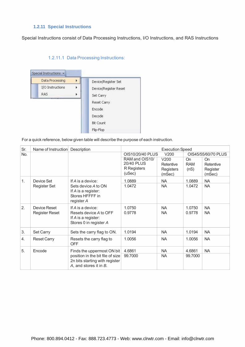
1.2.11 Special Instructions Special Instructions consist of Data Processing Instructions, I/O Instructions, and RAS Instructions
1.2.11.1 Data Processing Instructions:
For a quick reference, below given table will describe the purpose of each instruction.
Sr. Name of Instruction Description Execution Speed No. OIS10/20/40 PLUS V200 OIS45/55/60/70 PLUS
RAM and OIS10/ 20/40 PLUS R Registers (uSec)
V200 Retentive Registers (mSec)
On RAM (nS)
On Retentive Register (mSec)
1.
Device Set Register Set
If A is a device: Sets device A to ON If A is a register: Stores HFFFF in register A
1.0889
NA
1.0889
NA 1.0472 NA 1.0472 NA
2. Device Reset Register Reset
If A is a device: Resets device A to OFF If A is a register: Stores 0 in register A
1.0750 0.9778
NA NA
1.0750 0.9778
NA NA
3.
Set Carry
Sets the carry flag to ON.
1.0194
NA
1.0194
NA
4. Reset Carry Resets the carry flag to OFF
1.0056 NA 1.0056 NA
5. Encode Finds the uppermost ON bit position in the bit file of size 2n bits starting with register A, and stores it in B.
4.6861 NA 4.6861 NA 99.7000 NA 99.7000
Phone: 800.894.0412 - Fax: 888.723.4773 - Web: www.clrwtr.com - Email: [email protected]
Sr. No.
Name of Instruction Description Execution Speed OIS10/20/40 PLUS V200 OIS45/55/60/70
RAM and OIS10/ 20/40 PLUS R Registers (uSec)
V200 Retentive Registers (mSec)
On RAM (nS)
On Retentive Register (mSec)
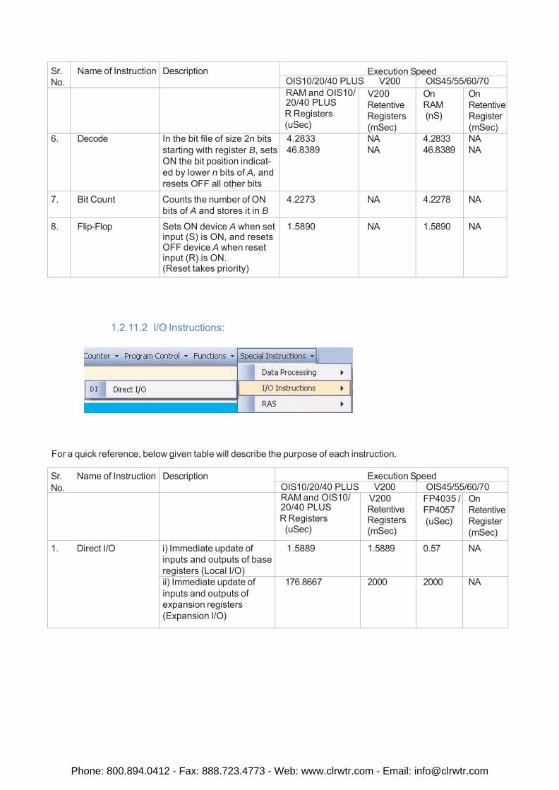
6. Decode In the bit file of size 2n bits starting with register B, sets ON the bit position indicat- ed by lower n bits of A, and resets OFF all other bits
4.2833 46.8389
NA NA
4.2833 46.8389
NA NA
7. Bit Count Counts the number of ON bits of A and stores it in B
4.2273 NA 4.2278 NA
8. Flip-Flop Sets ON device A when set input (S) is ON, and resets OFF device A when reset input (R) is ON. (Reset takes priority)
1.5890 NA 1.5890 NA
1.2.11.2 I/O Instructions:
For a quick reference, below given table will describe the purpose of each instruction.
Sr. Name of Instruction No.
Description Execution Speed OIS10/20/40 PLUS V200 OIS45/55/60/70
RAM and OIS10/ 20/40 PLUS R Registers
(uSec)
V200 Retentive Registers (mSec)
FP4035 / FP4057 (uSec)
On Retentive Register (mSec)
1. Direct I/O i) Immediate update of inputs and outputs of base registers (Local I/O)
1.5889 1.5889 0.57 NA
ii) Immediate update of inputs and outputs of expansion registers (Expansion I/O)
176.8667 2000 2000 NA
Phone: 800.894.0412 - Fax: 888.723.4773 - Web: www.clrwtr.com - Email: [email protected]
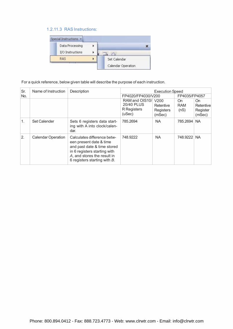
1.2.11.3 RAS Instructions:
For a quick reference, below given table will describe the purpose of each instruction.
Sr. No.
Name of Instruction Description Execution Speed FP4020/FP4030/V200 FP4035/FP4057
RAM and OIS10/ 20/40 PLUS R Registers (uSec)
V200 Retentive Registers (mSec)
On RAM (nS)
On Retentive Register (mSec)
1. Set Calender Sets 6 registers data start- ing with A into clock/calen- dar.
785.2694 NA 785.2694 NA
2. Calendar Operation Calculates difference betw- een present date & time and past date & time stored in 6 registers starting with A, and stores the result in 6 registers starting with B.
748.9222 NA 748.9222 NA
Phone: 800.894.0412 - Fax: 888.723.4773 - Web: www.clrwtr.com - Email: [email protected]

Instruction Details
Phone: 800.894.0412 - Fax: 888.723.4773 - Web: www.clrwtr.com - Email: [email protected]
Instruction-1: NO Contact
Expression:
A Input Output
Function:
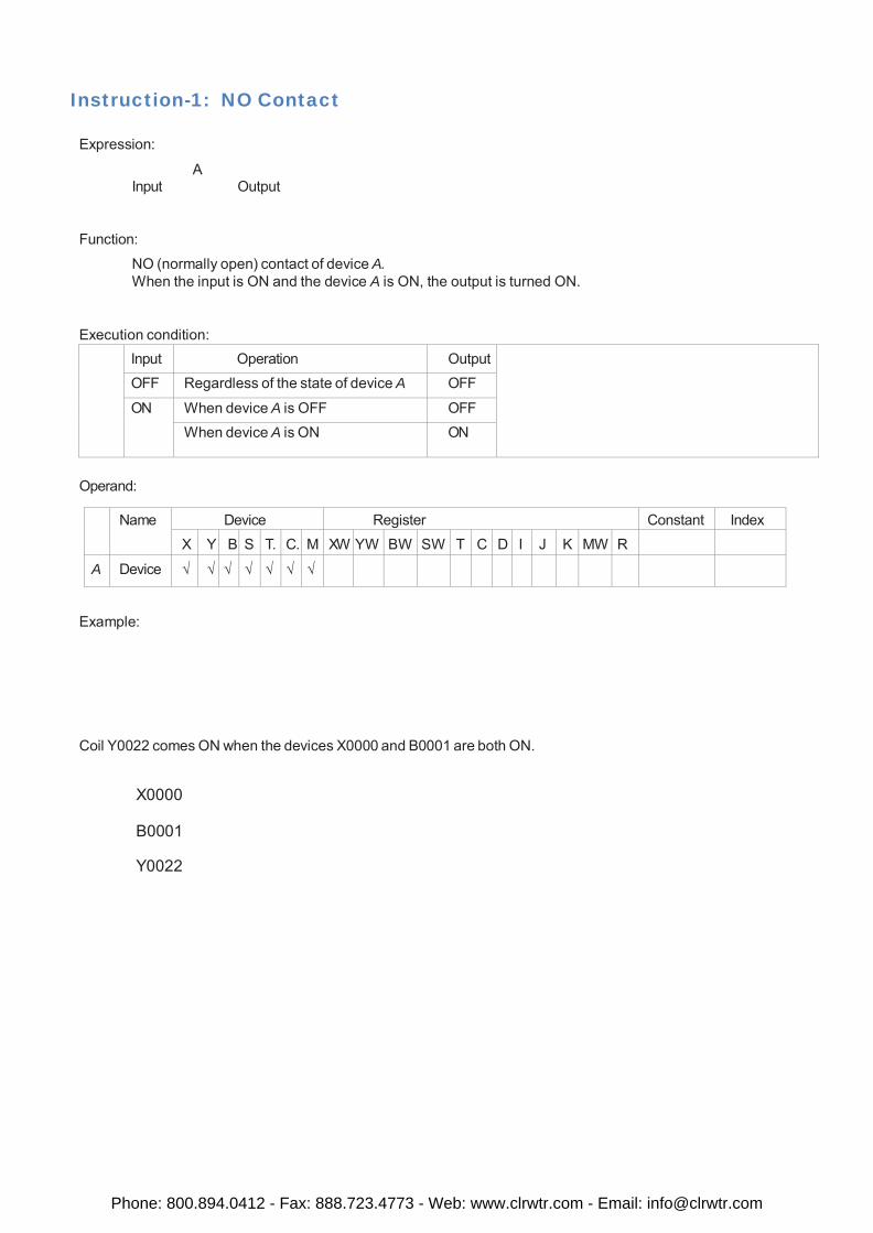
NO (normally open) contact of device A. When the input is ON and the device A is ON, the output is turned ON.
Execution condition:
Input Operation Output
OFF Regardless of the state of device A OFF
ON When device A is OFF OFF When device A is ON ON
Operand:
Name Device Register Constant Index
X Y B S T. C. M XW YW BW SW T C D I J K MW R
A Device √ √ √ √ √ √ √
Example:
Coil Y0022 comes ON when the devices X0000 and B0001 are both ON.
X0000
B0001
Y0022
Phone: 800.894.0412 - Fax: 888.723.4773 - Web: www.clrwtr.com - Email: [email protected]
Instruction-2: NC Contact
Expression:
A Input Output
Function:
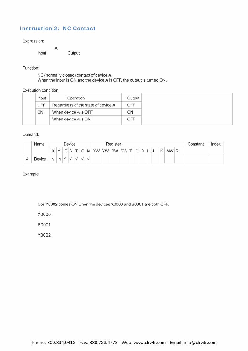
NC (normally closed) contact of device A. When the input is ON and the device A is OFF, the output is turned ON.
Execution condition:
Input
Operation
Output
OFF Regardless of the state of device A OFF
ON When device A is OFF ON
When device A is ON OFF
Operand:
Name Device Register Constant Index
X Y B S T. C. M XW YW BW SW T C D I J K MW R
A
Device
√
√
√
√
√
√
√
Example:
Coil Y0002 comes ON when the devices X0000 and B0001 are both OFF.
X0000
B0001
Y0002
Phone: 800.894.0412 - Fax: 888.723.4773 - Web: www.clrwtr.com - Email: [email protected]
Instruction-3: Output
Expression:
A Input ( )
Function:
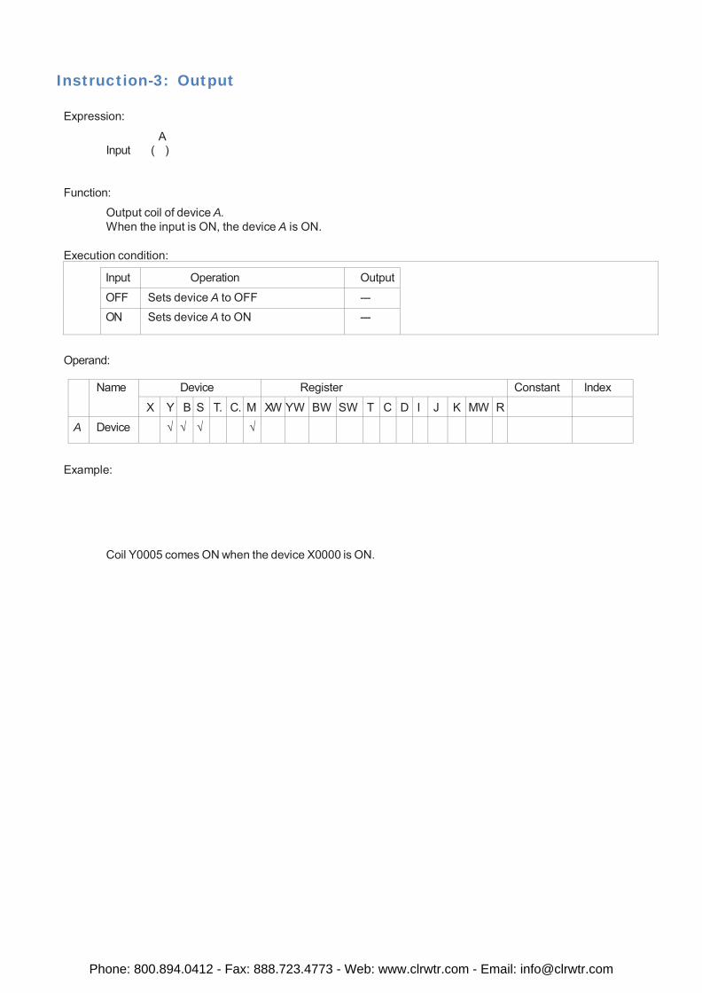
Output coil of device A. When the input is ON, the device A is ON.
Execution condition: Input Operation Output
OFF Sets device A to OFF --- ON Sets device A to ON ---
Operand:
Name Device Register Constant Index
X Y B S T. C. M XW YW BW SW T C D I J K MW R
A Device √ √ √ √
Example:
Coil Y0005 comes ON when the device X0000 is ON.
Phone: 800.894.0412 - Fax: 888.723.4773 - Web: www.clrwtr.com - Email: [email protected]
Instruction-4: Rising Edge (Transitional Contact)
Expression:
A Input Output
Function:
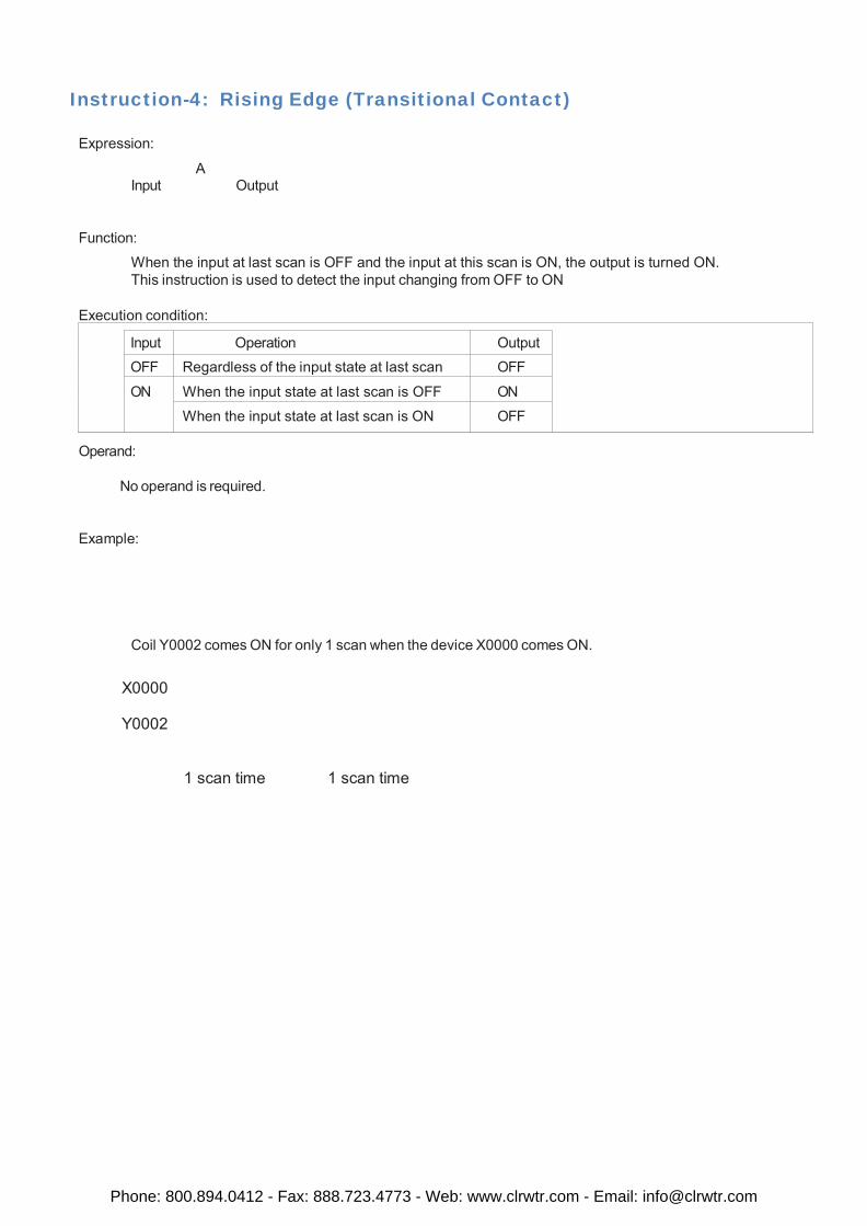
When the input at last scan is OFF and the input at this scan is ON, the output is turned ON. This instruction is used to detect the input changing from OFF to ON
Execution condition: Input Operation Output
OFF Regardless of the input state at last scan OFF
ON When the input state at last scan is OFF ON
When the input state at last scan is ON OFF
Operand:
No operand is required.
Example:
Coil Y0002 comes ON for only 1 scan when the device X0000 comes ON.
X0000
Y0002
1 scan time 1 scan time
Phone: 800.894.0412 - Fax: 888.723.4773 - Web: www.clrwtr.com - Email: [email protected]

Instruction-5: Falling Edge (Transitional Contact)
Expression:
A Input Output
Function:
When the input at last scan is ON and the input at this scan is OFF, the output is turned ON. This instruction is used to detect the input changing from ON to OFF.
Execution condition:
Input Operation Output OFF When the input state at last scan is OFF OFF
When the input state at last scan is ON ON
ON Regardless of the input state at last scan OFF
Operand:
No operand is required.
Example:
Coil Y0002 comes ON for only 1 scan when the device X0000 comes OFF.
X0000
Y0002
1 scan time 1 scan time
Phone: 800.894.0412 - Fax: 888.723.4773 - Web: www.clrwtr.com - Email: [email protected]
Instruction-6: Inverter
Expression:
A Input Output
Function:
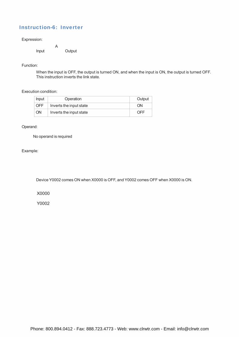
When the input is OFF, the output is turned ON, and when the input is ON, the output is turned OFF. This instruction inverts the link state.
Execution condition:
Input Operation Output
OFF Inverts the input state ON
ON Inverts the input state OFF
Operand:
No operand is required
Example:
Device Y0002 comes ON when X0000 is OFF, and Y0002 comes OFF when X0000 is ON.
X0000
Y0002
Phone: 800.894.0412 - Fax: 888.723.4773 - Web: www.clrwtr.com - Email: [email protected]
Instruction-7: Inverter Coil
Expression:
A Input ( )
Function:
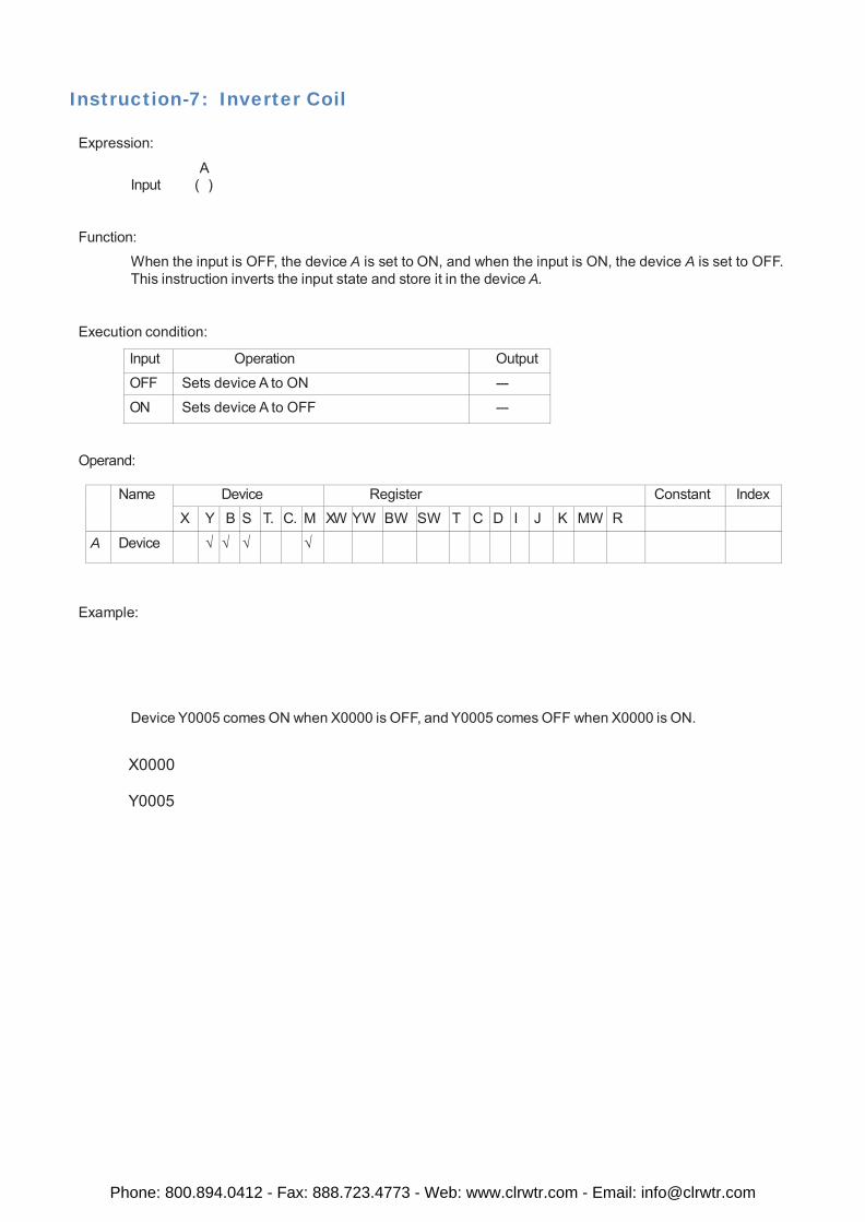
When the input is OFF, the device A is set to ON, and when the input is ON, the device A is set to OFF. This instruction inverts the input state and store it in the device A.
Execution condition:
Input Operation Output
OFF Sets device A to ON ---
ON Sets device A to OFF ---
Operand:
Name Device Register Constant Index X Y B S T. C. M XW YW BW SW T C D I J K MW R
A Device √ √ √ √
Example:
Device Y0005 comes ON when X0000 is OFF, and Y0005 comes OFF when X0000 is ON.
X0000
Y0005
Phone: 800.894.0412 - Fax: 888.723.4773 - Web: www.clrwtr.com - Email: [email protected]

Instruction-8: Positive Pulse Contact
Expression:
A Input P Output
Function:
When the input is ON and the device A is changed from OFF to ON (OFF at last scan and ON at this scan), the output is turned ON. This instruction is used to detect the device changing from OFF to ON.
Execution condition:
Input Operation Output
OFF Regardless of the state of device A OFF
ON State of device A is OFF OFF
State of device A is ON A is OFF at last scan ON A is ON at last scan OFF
Operand:
Name Device Register Constant Index
X Y B S T. C. M XW YW BW SW T C D I J K MW R
A Device √ √ √ √ √ √ √
Example:
B0100 comes ON for only 1 scan when X0000 is ON and X0003 changes to ON.
X0000
X0003
B0100
1 scan time 1 scan time
Phone: 800.894.0412 - Fax: 888.723.4773 - Web: www.clrwtr.com - Email: [email protected]
Instruction-9: Negative Pulse Contact
Expression:
A Input N Output
Function:
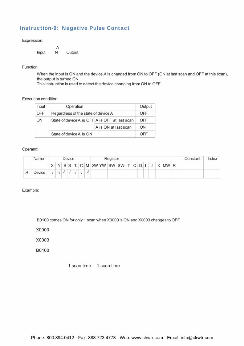
When the input is ON and the device A is changed from ON to OFF (ON at last scan and OFF at this scan), the output is turned ON. This instruction is used to detect the device changing from ON to OFF.
Execution condition:
Input Operation Output
OFF Regardless of the state of device A OFF
ON State of device A is OFF A is OFF at last scan OFF
A is ON at last scan ON State of device A is ON OFF
Operand:
Name Device Register Constant Index
X Y B S T. C. M XW YW BW SW T C D I J K MW R
A Device √ √ √ √ √ √ √
Example:
B0100 comes ON for only 1 scan when X0000 is ON and X0003 changes to OFF.
X0000
X0003
B0100
1 scan time 1 scan time
Phone: 800.894.0412 - Fax: 888.723.4773 - Web: www.clrwtr.com - Email: [email protected]
Instruction-10: Positive Pulse Coil
Expression:
A Input ( P)
Function:
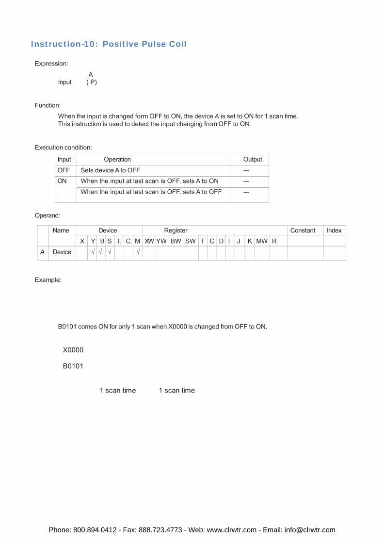
When the input is changed form OFF to ON, the device A is set to ON for 1 scan time. This instruction is used to detect the input changing from OFF to ON.
Execution condition:
Input Operation Output
OFF Sets device A to OFF --- ON When the input at last scan is OFF, sets A to ON ---
When the input at last scan is OFF, sets A to OFF ---
Operand:
Name Device Register Constant Index
X Y B S T. C. M XW YW BW SW T C D I J K MW R
A Device √ √ √ √
Example:
B0101 comes ON for only 1 scan when X0000 is changed from OFF to ON.
X0000
B0101
1 scan time 1 scan time
Phone: 800.894.0412 - Fax: 888.723.4773 - Web: www.clrwtr.com - Email: [email protected]
Instruction-11: Negative Pulse Coil
Expression:
A Input ( N)
Function:
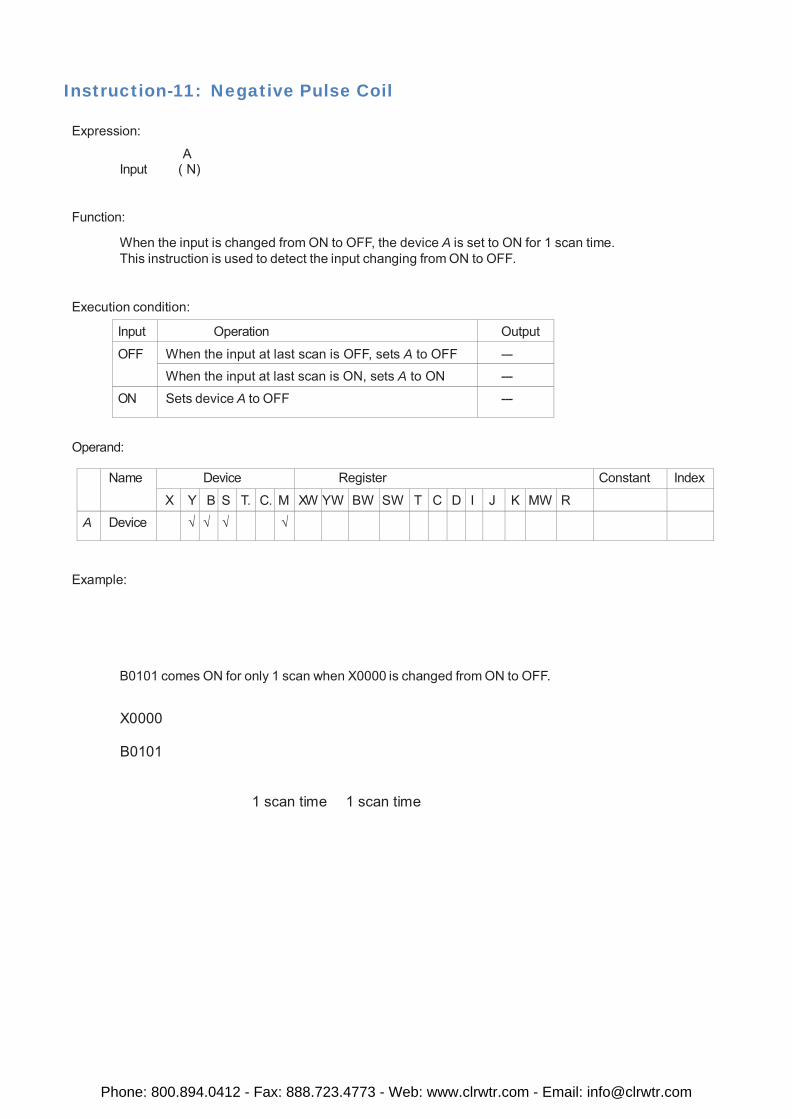
When the input is changed from ON to OFF, the device A is set to ON for 1 scan time. This instruction is used to detect the input changing from ON to OFF.
Execution condition:
Input Operation Output
OFF When the input at last scan is OFF, sets A to OFF --- When the input at last scan is ON, sets A to ON ---
ON Sets device A to OFF ---
Operand:
Name Device Register Constant Index
X Y B S T. C. M XW YW BW SW T C D I J K MW R
A Device √ √ √ √
Example:
B0101 comes ON for only 1 scan when X0000 is changed from ON to OFF.
X0000
B0101
1 scan time 1 scan time
Phone: 800.894.0412 - Fax: 888.723.4773 - Web: www.clrwtr.com - Email: [email protected]
Instruction-12: MOV WORD
Expression:
Input [ A MOV B ]
Function:
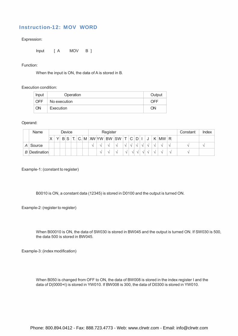
When the input is ON, the data of A is stored in B.
Execution condition:
Input Operation Output
OFF No execution OFF ON Execution ON
Operand:
Name Device Register Constant Index
X Y B S T. C. M XW YW BW SW T C D I J K MW R
A Source √ √ √ √ √ √ √ √ √ √ √ √ √ √
B Destination √ √ √ √ √ √ √ √ √ √ √ √
Example-1: (constant to register)
B0010 is ON, a constant data (12345) is stored in D0100 and the output is turned ON.
Example-2: (register to register)
When B00010 is ON, the data of SW030 is stored in BW045 and the output is turned ON. If SW030 is 500, the data 500 is stored in BW045.
Example-3: (index modification)
When B050 is changed from OFF to ON, the data of BW008 is stored in the index register I and the data of D(0000+I) is stored in YW010. If BW008 is 300, the data of D0300 is stored in YW010.
Phone: 800.894.0412 - Fax: 888.723.4773 - Web: www.clrwtr.com - Email: [email protected]
Instruction-13: MOV DWord
Expression:
Input [ A+1.A MOV B+1.B ]
Function:
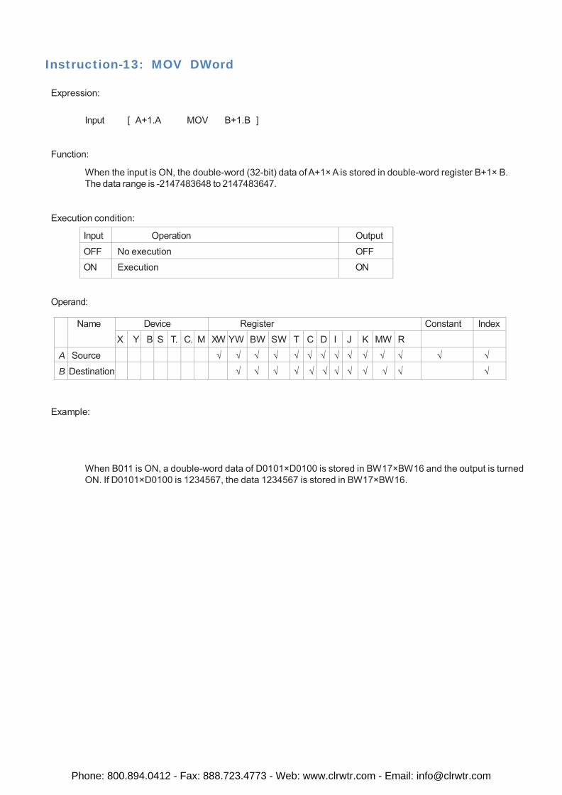
When the input is ON, the double-word (32-bit) data of A+1× A is stored in double-word register B+1× B. The data range is -2147483648 to 2147483647.
Execution condition:
Input Operation Output
OFF No execution OFF ON Execution ON
Operand:
Name Device Register Constant Index X Y B S T. C. M XW YW BW SW T C D I J K MW R
A Source √ √ √ √ √ √ √ √ √ √ √ √ √ √
B Destination √ √ √ √ √ √ √ √ √ √ √ √
Example:
When B011 is ON, a double-word data of D0101×D0100 is stored in BW17×BW16 and the output is turned ON. If D0101×D0100 is 1234567, the data 1234567 is stored in BW17×BW16.
Phone: 800.894.0412 - Fax: 888.723.4773 - Web: www.clrwtr.com - Email: [email protected]
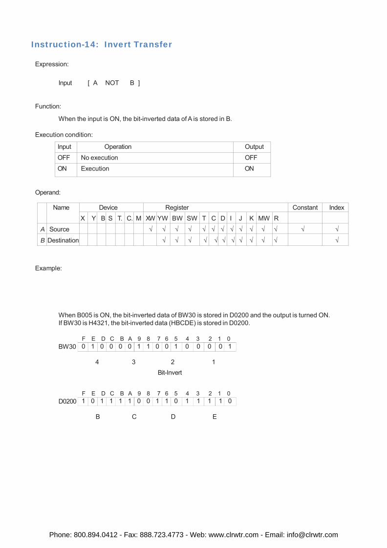
0 1 0 0 0 0 1 1 0 0 1 0 0 0 0 1
1 0 1 1 1 1 0 0 1 1 0 1 1 1 1 0
Instruction-14: Invert Transfer
Expression:
Input [ A NOT B ]
Function:
When the input is ON, the bit-inverted data of A is stored in B.
Execution condition:
Input Operation Output
OFF No execution OFF
ON Execution ON
Operand:
Name Device Register Constant Index
X Y B S T. C. M XW YW BW SW T C D I J K MW R
A Source √ √ √ √ √ √ √ √ √ √ √ √ √ √
B Destination √ √ √ √ √ √ √ √ √ √ √ √
Example:
When B005 is ON, the bit-inverted data of BW30 is stored in D0200 and the output is turned ON. If BW30 is H4321, the bit-inverted data (HBCDE) is stored in D0200.
BW30 F E D C B A 9 8 7 6 5 4 3 2 1 0
4 3 2 1
Bit-Invert
D0200 F E D C B A 9 8 7 6 5 4 3 2 1 0
B C D E
Phone: 800.894.0412 - Fax: 888.723.4773 - Web: www.clrwtr.com - Email: [email protected]
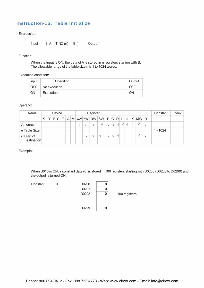
0 0 0
0
Instruction-15: Table Initialize
Expression:
Input [ A TINZ (n) B ] Output
Function:
When the input is ON, the data of A is stored in n registers starting with B. The allowable range of the table size n is 1 to 1024 words.
Execution condition:
Input Operation Output
OFF No execution OFF
ON Execution ON
Operand:
Name Device Register Constant Index
X Y B S T. C. M XW YW BW SW T C D I J K MW R
A ource √ √ √ √ √ √ √ √ √ √ √ √
n Table Size 1 - 1024
B
Start of estination
√ √ √ √ √ √ √ √
Example:
When B010 is ON, a constant data (0) is stored in 100 registers starting with D0200 (D0200 to D0299) and the output is turned ON.
Constant 0 D0200
D0201 D0202
100 registers
D0299
Phone: 800.894.0412 - Fax: 888.723.4773 - Web: www.clrwtr.com - Email: [email protected]
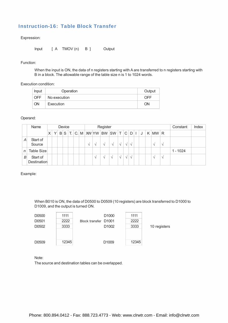
1111 2222 3333
12345
1111 2222 3333
12345
Instruction-16: Table Block Transfer
Expression:
Input [ A TMOV (n) B ] Output
Function:
When the input is ON, the data of n registers starting with A are transferred to n registers starting with B in a block. The allowable range of the table size n is 1 to 1024 words.
Execution condition:
Input Operation Output
OFF No execution OFF
ON Execution ON
Operand:
Name Device Register Constant Index
X Y B S T. C. M XW YW BW SW T C D I J K MW R
A Start of Source
√
√
√
√
√
√
√
√
√
n Table Size 1 - 1024
B Start of Destination
√ √ √ √ √ √ √ √
Example:
When B010 is ON, the data of D0500 to D0509 (10 registers) are block transferred to D1000 to D1009, and the output is turned ON.
D0500 D0501 D0502
D1000 Block transfer D1001
D1002
10 registers
D0509 D1009
Note: The source and destination tables can be overlapped.
Phone: 800.894.0412 - Fax: 888.723.4773 - Web: www.clrwtr.com - Email: [email protected]
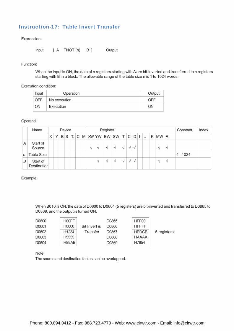
H00FF H0000 H1234 H5555 H89AB
HFF00 HFFFF HEDCB HAAAA H7654
Instruction-17: Table Invert Transfer
Expression:
Input [ A TNOT (n) B ] Output
Function:
When the input is ON, the data of n registers starting with A are bit-inverted and transferred to n registers starting with B in a block. The allowable range of the table size n is 1 to 1024 words.
Execution condition:
Input Operation Output
OFF No execution OFF
ON Execution ON
Operand:
Name Device Register Constant Index
X Y B S T. C. M XW YW BW SW T C D I J K MW R
A Start of Source
√
√
√
√
√
√
√
√
√
n Table Size 1 - 1024
B Start of Destination
√ √ √ √ √ √ √ √
Example:
When B010 is ON, the data of D0600 to D0604 (5 registers) are bit-inverted and transferred to D0865 to D0869, and the output is turned ON.
D0600 D0601 D0602 D0603 D0604
D0865 Bit Invert & D0866
Transfer D0867 D0868 D0869
5 registers
Note: The source and destination tables can be overlapped.
Phone: 800.894.0412 - Fax: 888.723.4773 - Web: www.clrwtr.com - Email: [email protected]
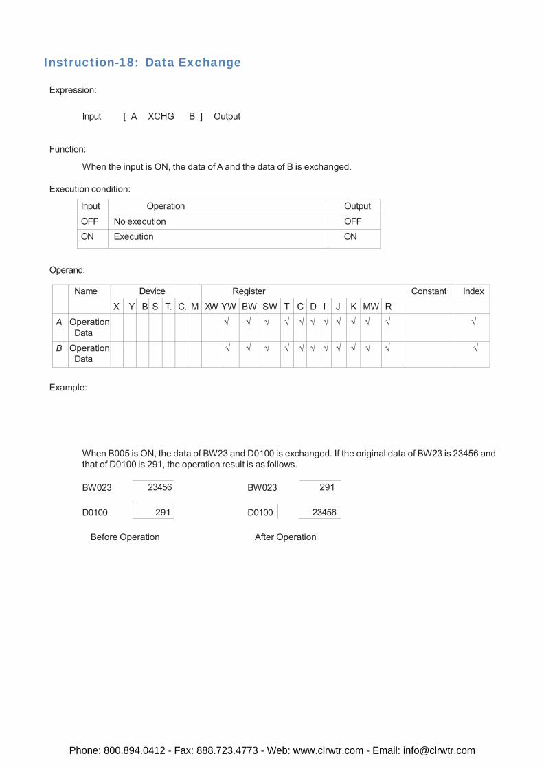
Instruction-18: Data Exchange
Expression:
Input [ A XCHG B ] Output
Function:
When the input is ON, the data of A and the data of B is exchanged.
Execution condition:
Input Operation Output
OFF No execution OFF ON Execution ON
Operand:
Name Device Register Constant Index
X Y B S T. C. M XW YW BW SW T C D I J K MW R
A Operation Data
√ √ √ √ √ √ √ √ √ √ √ √
B Operation Data
√ √ √ √ √ √ √ √ √ √ √ √
Example:
When B005 is ON, the data of BW23 and D0100 is exchanged. If the original data of BW23 is 23456 and that of D0100 is 291, the operation result is as follows.
BW023 23456 BW023 291
D0100 291 D0100 23456
Before Operation After Operation
Phone: 800.894.0412 - Fax: 888.723.4773 - Web: www.clrwtr.com - Email: [email protected]
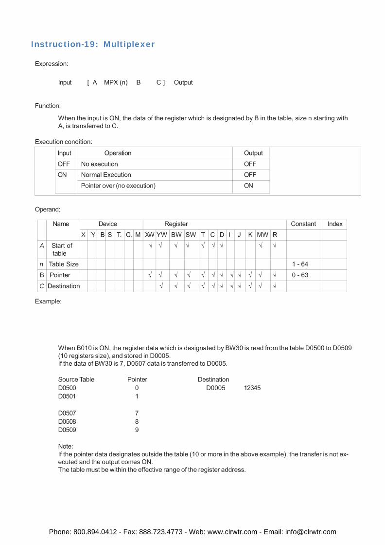
Instruction-19: Multiplexer
Expression:
Input [ A MPX (n) B C ] Output
Function:
When the input is ON, the data of the register which is designated by B in the table, size n starting with A, is transferred to C.
Execution condition:
Input Operation Output
OFF No execution OFF ON Normal Execution OFF
Pointer over (no execution) ON
Operand:
Name Device Register Constant Index
X Y B S T. C. M XW YW BW SW T C D I J K MW R
A Start of table
√ √ √ √ √ √ √ √ √
n Table Size 1 - 64
B Pointer √ √ √ √ √ √ √ √ √ √ √ √ 0 - 63
C Destination √ √ √ √ √ √ √ √ √ √ √
Example:
When B010 is ON, the register data which is designated by BW30 is read from the table D0500 to D0509 (10 registers size), and stored in D0005. If the data of BW30 is 7, D0507 data is transferred to D0005.
Source Table Pointer Destination D0500 0 D0005 12345 D0501 1
D0507 7 D0508 8 D0509 9
Note: If the pointer data designates outside the table (10 or more in the above example), the transfer is not ex- ecuted and the output comes ON. The table must be within the effective range of the register address.
Phone: 800.894.0412 - Fax: 888.723.4773 - Web: www.clrwtr.com - Email: [email protected]
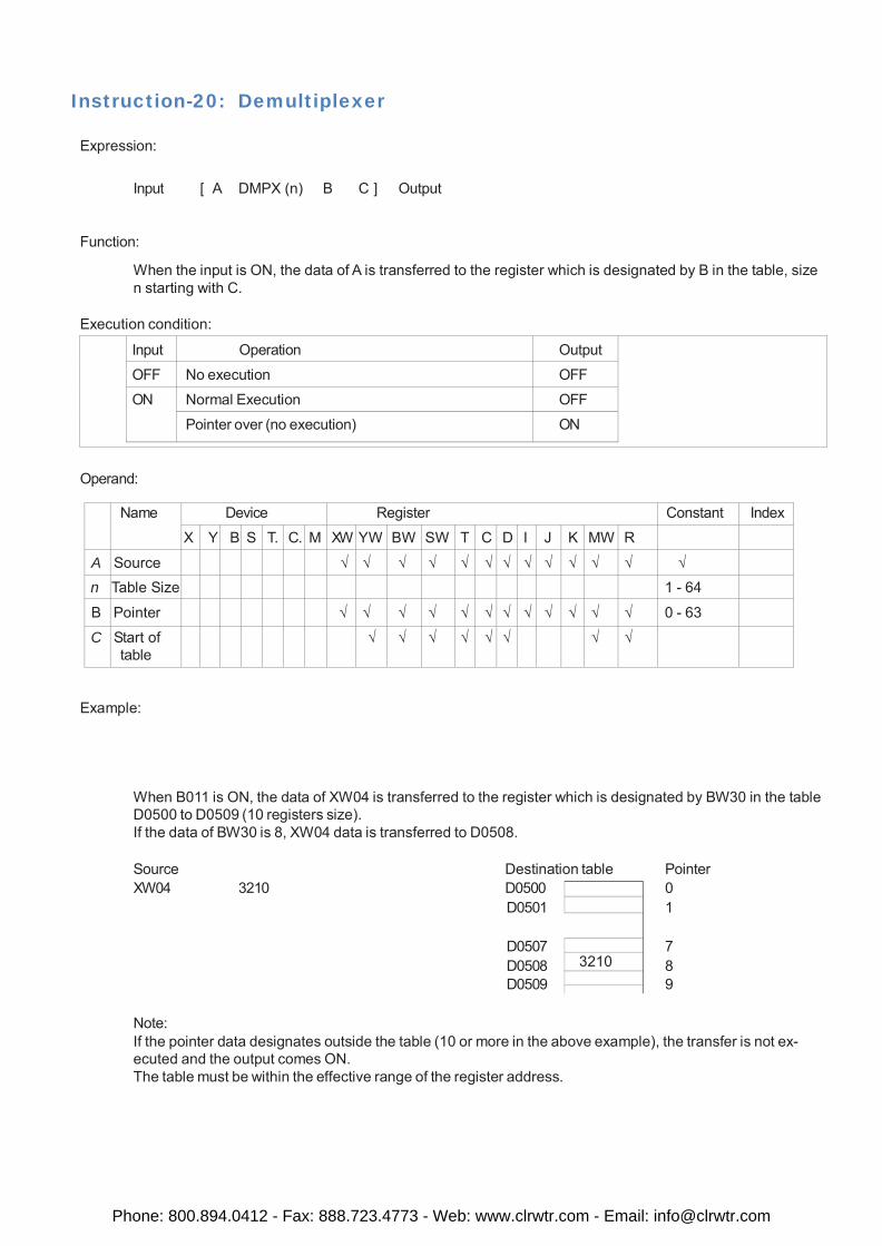
3210
Instruction-20: Demultiplexer
Expression:
Input [ A DMPX (n) B C ] Output
Function:
When the input is ON, the data of A is transferred to the register which is designated by B in the table, size n starting with C.
Execution condition:
Input Operation Output
OFF No execution OFF
ON Normal Execution OFF
Pointer over (no execution) ON
Operand:
Name Device Register Constant Index
X Y B S T. C. M XW YW BW SW T C D I J K MW R
A Source √ √ √ √ √ √ √ √ √ √ √ √ √
n Table Size 1 - 64
B Pointer √ √ √ √ √ √ √ √ √ √ √ √ 0 - 63
C Start of table
√ √ √ √ √ √ √ √
Example:
When B011 is ON, the data of XW04 is transferred to the register which is designated by BW30 in the table D0500 to D0509 (10 registers size). If the data of BW30 is 8, XW04 data is transferred to D0508.
Source Destination table Pointer XW04 3210 D0500 0
D0501 1
D0507 7 D0508 8 D0509 9
Note: If the pointer data designates outside the table (10 or more in the above example), the transfer is not ex- ecuted and the output comes ON. The table must be within the effective range of the register address.
Phone: 800.894.0412 - Fax: 888.723.4773 - Web: www.clrwtr.com - Email: [email protected]
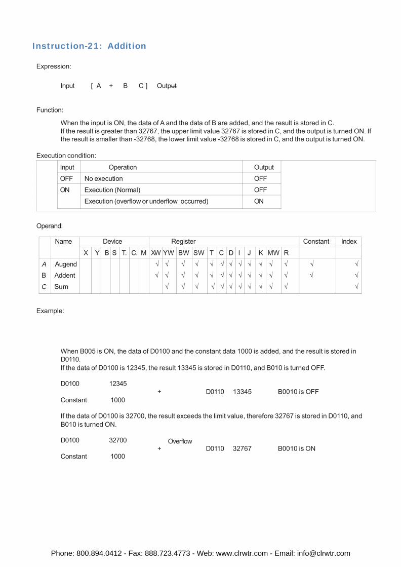
Instruction-21: Addition
Expression:
Input [ A + B C ] Output
Function:
When the input is ON, the data of A and the data of B are added, and the result is stored in C. If the result is greater than 32767, the upper limit value 32767 is stored in C, and the output is turned ON. If the result is smaller than -32768, the lower limit value -32768 is stored in C, and the output is turned ON.
Execution condition:
Input Operation Output
OFF No execution OFF
ON Execution (Normal) OFF
Execution (overflow or underflow occurred) ON
Operand:
Name Device Register Constant Index
X Y B S T. C. M XW YW BW SW T C D I J K MW R
A
B
C
Augend Addent
Sum
√
√
√
√
√
√
√
√
√
√
√
√
√
√
√
√
√
√
√
√
√
√
√
√
√
√
√
√
√
√
√
√
√
√
√
√
√
√
√
√
Example:
When B005 is ON, the data of D0100 and the constant data 1000 is added, and the result is stored in D0110. If the data of D0100 is 12345, the result 13345 is stored in D0110, and B010 is turned OFF.
D0100 12345
Constant 1000
+ D0110 13345 B0010 is OFF
If the data of D0100 is 32700, the result exceeds the limit value, therefore 32767 is stored in D0110, and B010 is turned ON.
D0100 32700
Constant 1000
Overflow + D0110 32767 B0010 is ON
Phone: 800.894.0412 - Fax: 888.723.4773 - Web: www.clrwtr.com - Email: [email protected]
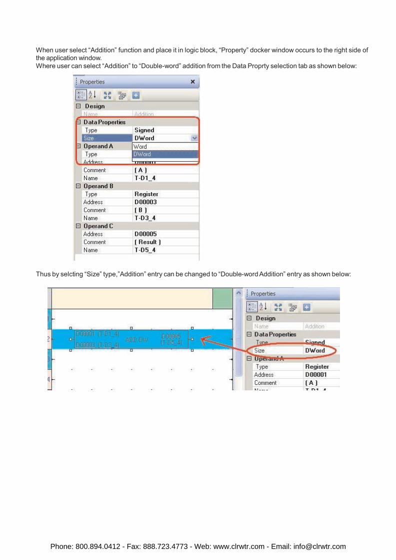
When user select “Addition” function and place it in logic block, “Property” docker window occurs to the right side of the application window. Where user can select “Addition” to “Double-word” addition from the Data Proprty selection tab as shown below:
Thus by selcting “Size” type,”Addition” entry can be changed to “Double-word Addition” entry as shown below:
Phone: 800.894.0412 - Fax: 888.723.4773 - Web: www.clrwtr.com - Email: [email protected]
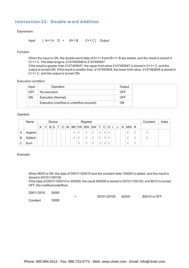
Instruction-22: Double-word Addition
Expression:
Input [ A+1.A D + B+1.B C+1.C ] Output
Function:
When the input is ON, the double-word data of A+1× A and B+1× B are added, and the result is stored in C+1× C. The data range is -2147483648 to 2147483647. If the result is greater than 2147483647, the upper limit value 2147483647 is stored in C+1× C, and the output is turned ON. If the result is smaller than -2147483648, the lower limit value -2147483648 is stored in C+1× C, and the output is turned ON.
Execution condition:
Input Operation Output
OFF No execution OFF
ON Execution (Normal) OFF
Execution (overflow or underflow occured) ON
Operand:
Name Device Register Constant Index
X Y B S T. C. M XW YW BW SW T C D I J K MW R
A
B
C
Augend
Addent
Sum
√
√
√
√
√
√
√
√
√
√
√
√
√
√
√
√
√
√
√
√
√ √
√ √
√ √
√
√
Example:
When B005 is ON, the data of D0011×D0010 and the constant data 100000 is added, and the result is stored in D0101×D0100. If the data of D0011×D0010 is 300000, the result 400000 is stored in D0101×D0100, and B010 is turned OFF. (No overflow/underflow).
D0011.D010 30000
Constant 10000
+ D0101.D0100 40000 B0010 is OFF
Phone: 800.894.0412 - Fax: 888.723.4773 - Web: www.clrwtr.com - Email: [email protected]
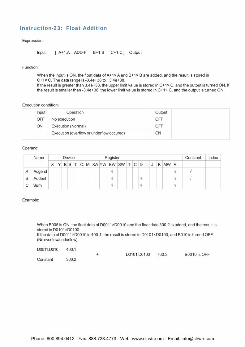
Instruction-23: Float Addition
Expression:
Input [ A+1.A ADD-F B+1.B C+1.C ] Output
Function:
When the input is ON, the float data of A+1× A and B+1× B are added, and the result is stored in C+1× C. The data range is -3.4e+38 to +3.4e+38. If the result is greater than 3.4e+38, the upper limit value is stored in C+1× C, and the output is turned ON. If the result is smaller than -3.4e+38, the lower limit value is stored in C+1× C, and the output is turned ON.
Execution condition:
Input Operation Output
OFF No execution OFF
ON Execution (Normal) OFF
Execution (overflow or underflow occured) ON
Operand:
Name Device Register Constant Index
X Y B S T. C. M XW YW BW SW T C D I J K MW R
A
B
C
Augend
Addent
Sum
√
√
√
√
√
√
√
√
√
√
Example:
When B005 is ON, the float data of D0011×D0010 and the float data 300.2 is added, and the result is stored in D0101×D0100. If the data of D0011×D0010 is 400.1, the result is stored in D0101×D0100, and B010 is turned OFF. (No overflow/underflow).
D0011.D010 400.1
Constant 300.2
+ D0101.D0100 700.3 B0010 is OFF
Phone: 800.894.0412 - Fax: 888.723.4773 - Web: www.clrwtr.com - Email: [email protected]
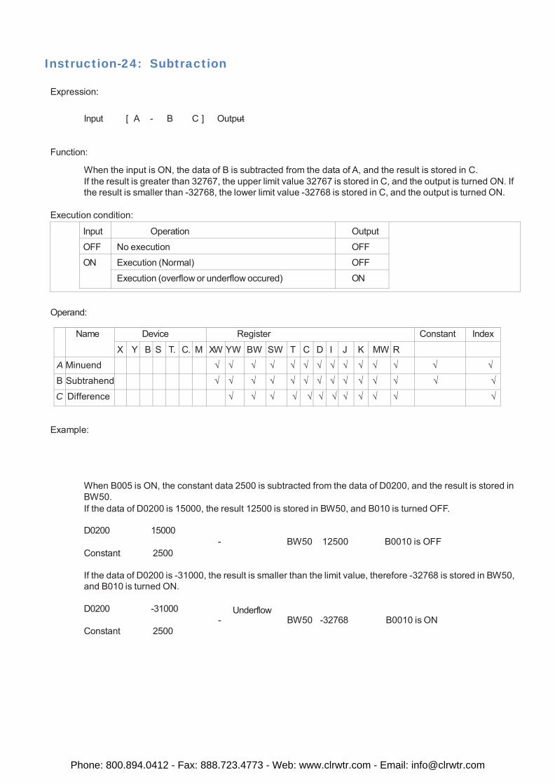
Instruction-24: Subtraction
Expression:
Input [ A - B C ] Output
Function:
When the input is ON, the data of B is subtracted from the data of A, and the result is stored in C. If the result is greater than 32767, the upper limit value 32767 is stored in C, and the output is turned ON. If the result is smaller than -32768, the lower limit value -32768 is stored in C, and the output is turned ON.
Execution condition:
Input Operation Output
OFF No execution OFF
ON Execution (Normal) OFF
Execution (overflow or underflow occured) ON
Operand:
Name Device Register Constant Index
X Y B S T. C. M XW YW BW SW T C D I J K MW R
A Minuend √ √ √ √ √ √ √ √ √ √ √ √ √ √
B S Subtrahend √ √ √ √ √ √ √ √ √ √ √ √ √ √
C Difference √ √ √ √ √ √ √ √ √ √ √ √
Example:
When B005 is ON, the constant data 2500 is subtracted from the data of D0200, and the result is stored in BW50. If the data of D0200 is 15000, the result 12500 is stored in BW50, and B010 is turned OFF.
D0200 15000
Constant 2500
- BW50 12500 B0010 is OFF
If the data of D0200 is -31000, the result is smaller than the limit value, therefore -32768 is stored in BW50, and B010 is turned ON.
D0200 -31000
Constant 2500
Underflow - BW50 -32768 B0010 is ON
Phone: 800.894.0412 - Fax: 888.723.4773 - Web: www.clrwtr.com - Email: [email protected]
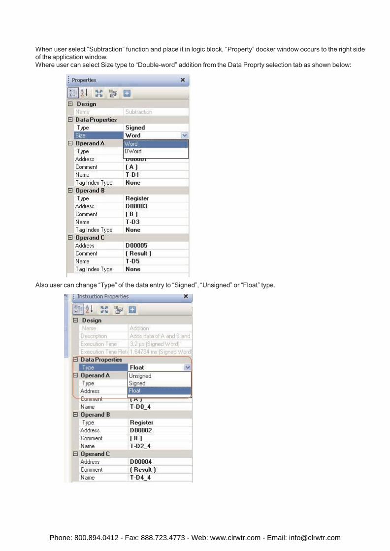
When user select “Subtraction” function and place it in logic block, “Property” docker window occurs to the right side of the application window. Where user can select Size type to “Double-word” addition from the Data Proprty selection tab as shown below:
Also user can change “Type” of the data entry to “Signed”, “Unsigned” or “Float” type.
Phone: 800.894.0412 - Fax: 888.723.4773 - Web: www.clrwtr.com - Email: [email protected]
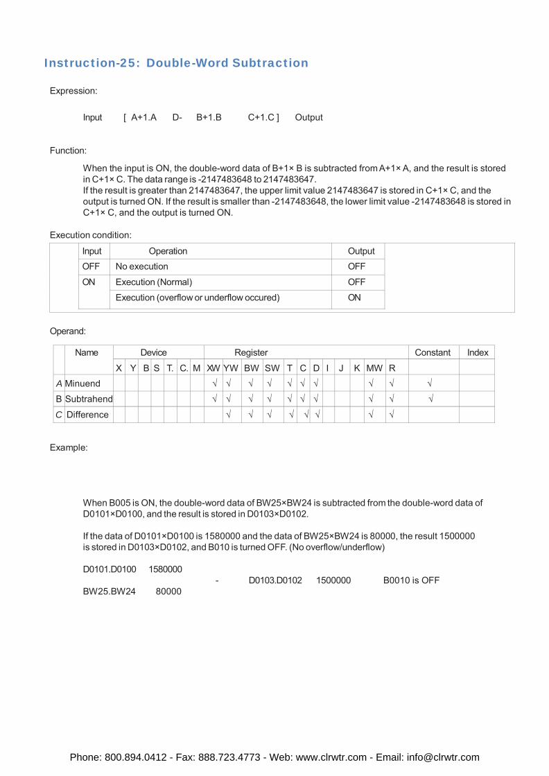
Instruction-25: Double-Word Subtraction
Expression:
Input [ A+1.A D- B+1.B C+1.C ] Output
Function:
When the input is ON, the double-word data of B+1× B is subtracted from A+1× A, and the result is stored in C+1× C. The data range is -2147483648 to 2147483647. If the result is greater than 2147483647, the upper limit value 2147483647 is stored in C+1× C, and the output is turned ON. If the result is smaller than -2147483648, the lower limit value -2147483648 is stored in C+1× C, and the output is turned ON.
Execution condition:
Input Operation Output
OFF No execution OFF
ON Execution (Normal) OFF
Execution (overflow or underflow occured) ON
Operand:
Name Device Register Constant Index
X Y B S T. C. M XW YW BW SW T C D I J K MW R
A Minuend √ √ √ √ √ √ √ √ √ √
B S Subtrahend √ √ √ √ √ √ √ √ √ √
C Difference √ √ √ √ √ √ √ √
Example:
When B005 is ON, the double-word data of BW25×BW24 is subtracted from the double-word data of D0101×D0100, and the result is stored in D0103×D0102.
If the data of D0101×D0100 is 1580000 and the data of BW25×BW24 is 80000, the result 1500000 is stored in D0103×D0102, and B010 is turned OFF. (No overflow/underflow)
D0101.D0100 1580000
BW25.BW24 80000
- D0103.D0102 1500000 B0010 is OFF
Phone: 800.894.0412 - Fax: 888.723.4773 - Web: www.clrwtr.com - Email: [email protected]
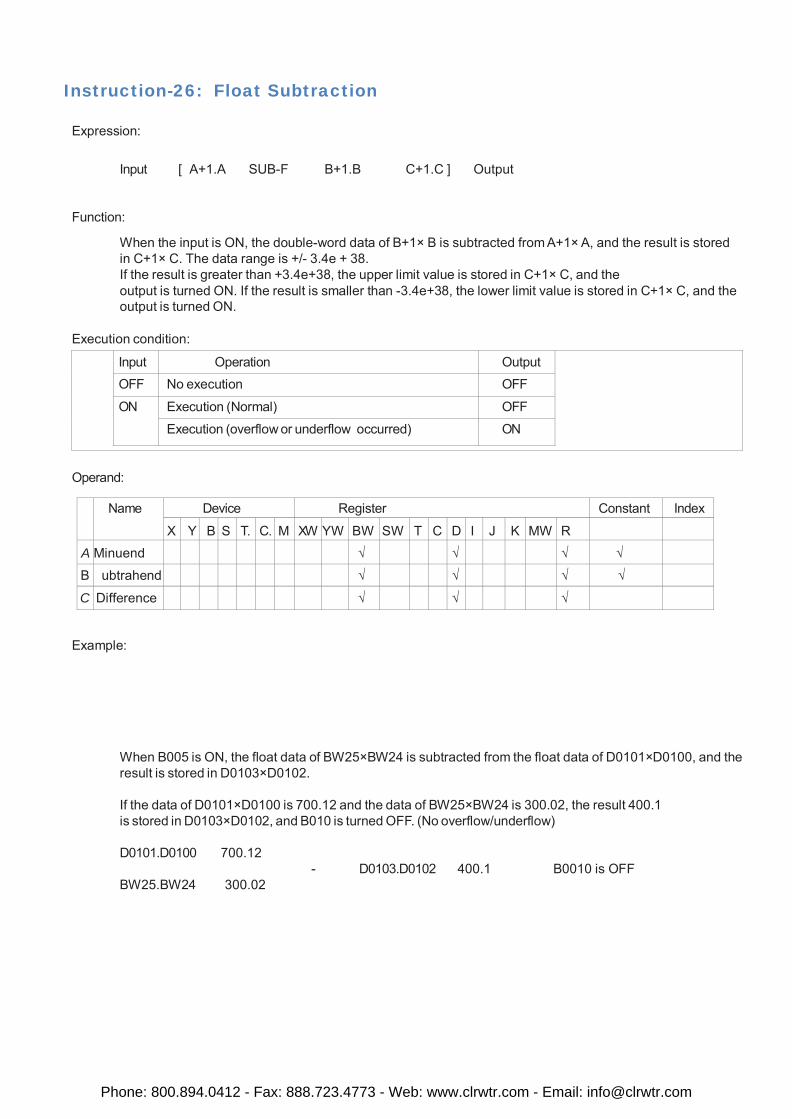
Instruction-26: Float Subtraction
Expression:
Input [ A+1.A SUB-F B+1.B C+1.C ] Output
Function:
When the input is ON, the double-word data of B+1× B is subtracted from A+1× A, and the result is stored in C+1× C. The data range is +/- 3.4e + 38. If the result is greater than +3.4e+38, the upper limit value is stored in C+1× C, and the output is turned ON. If the result is smaller than -3.4e+38, the lower limit value is stored in C+1× C, and the output is turned ON.
Execution condition:
Input Operation Output
OFF No execution OFF
ON Execution (Normal) OFF
Execution (overflow or underflow occurred) ON
Operand:
Name Device Register Constant Index
X Y B S T. C. M XW YW BW SW T C D I J K MW R
A Minuend √ √ √ √
B S ubtrahend √ √ √ √
C Difference √ √ √
Example:
When B005 is ON, the float data of BW25×BW24 is subtracted from the float data of D0101×D0100, and the result is stored in D0103×D0102.
If the data of D0101×D0100 is 700.12 and the data of BW25×BW24 is 300.02, the result 400.1 is stored in D0103×D0102, and B010 is turned OFF. (No overflow/underflow)
D0101.D0100 700.12
BW25.BW24 300.02
- D0103.D0102 400.1 B0010 is OFF
Phone: 800.894.0412 - Fax: 888.723.4773 - Web: www.clrwtr.com - Email: [email protected]
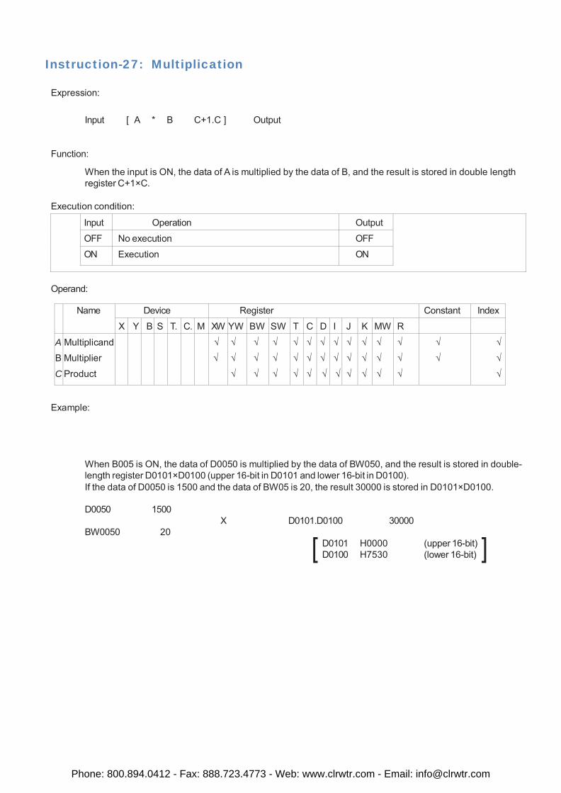
Instruction-27: Multiplication
Expression:
Input [ A * B C+1.C ] Output
Function:
When the input is ON, the data of A is multiplied by the data of B, and the result is stored in double length register C+1×C.
Execution condition:
Input Operation Output
OFF No execution OFF
ON Execution ON
Operand:
Name Device Register Constant Index
X Y B S T. C. M XW YW BW SW T C D I J K MW R
A
B
C
Multiplicand Multiplier
Product
√
√
√
√
√
√
√
√
√
√
√
√
√
√
√
√
√
√
√
√
√
√
√
√
√
√
√
√
√
√
√
√
√
√
√
√
√
√
√
√
Example:
When B005 is ON, the data of D0050 is multiplied by the data of BW050, and the result is stored in double- length register D0101×D0100 (upper 16-bit in D0101 and lower 16-bit in D0100). If the data of D0050 is 1500 and the data of BW05 is 20, the result 30000 is stored in D0101×D0100.
D0050 1500
BW0050 20
X D0101.D0100 30000
D0101 H0000 (upper 16-bit) D0100 H7530 (lower 16-bit)
Phone: 800.894.0412 - Fax: 888.723.4773 - Web: www.clrwtr.com - Email: [email protected]
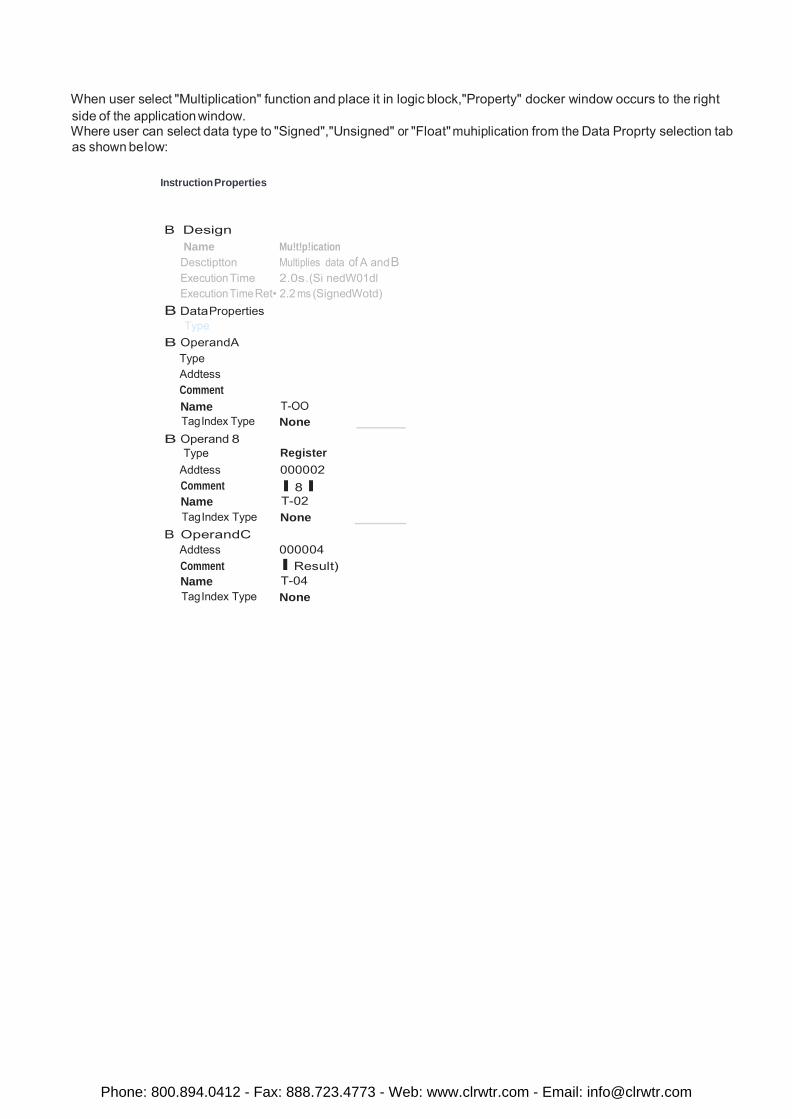
When user select "Multiplication" function and place it in logic block,"Property" docker window occurs to the right side of the application window. Where user can select data type to "Signed","Unsigned" or "Float" muhiplication from the Data Proprty selection tab as shown below:
Instruction Properties
B Design Name Mu!t!p!ication
Desctiptton Multiplies data of A and B Execution Time 2.0s.(Si nedW01dl Execution Time Ret• 2.2 ms (SignedWotd)
B DataProperties Type
B OperandA Type Addtess Comment Name T-OO Tag Index Type None
B Operand 8 Type Register
Addtess 000002 Comment Name
I 8 l T-02
Tag Index Type None B OperandC
Addtess 000004 Comment I Result) Name T-04 Tag Index Type None
Phone: 800.894.0412 - Fax: 888.723.4773 - Web: www.clrwtr.com - Email: [email protected]
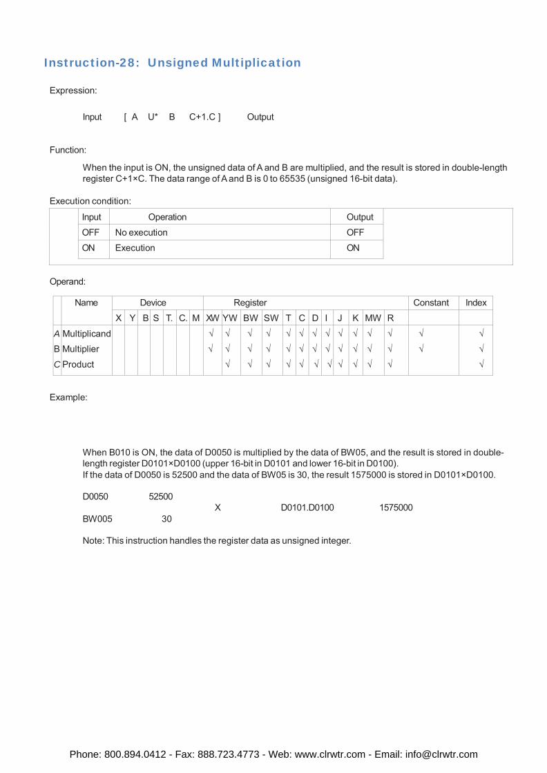
Instruction-28: Unsigned Multiplication
Expression:
Input [ A U* B C+1.C ] Output
Function:
When the input is ON, the unsigned data of A and B are multiplied, and the result is stored in double-length register C+1×C. The data range of A and B is 0 to 65535 (unsigned 16-bit data).
Execution condition:
Input Operation Output
OFF No execution OFF
ON Execution ON
Operand:
Name Device Register Constant Index
X Y B S T. C. M XW YW BW SW T C D I J K MW R
A
B
C
Multiplicand Multiplier
Product
√
√
√
√
√
√
√
√
√
√
√
√
√
√
√
√
√
√
√
√
√
√
√
√
√
√
√
√
√
√
√
√
√
√
√
√
√
√
√
√
Example:
When B010 is ON, the data of D0050 is multiplied by the data of BW05, and the result is stored in double- length register D0101×D0100 (upper 16-bit in D0101 and lower 16-bit in D0100). If the data of D0050 is 52500 and the data of BW05 is 30, the result 1575000 is stored in D0101×D0100.
D0050 52500
BW005 30
X D0101.D0100 1575000
Note: This instruction handles the register data as unsigned integer.
Phone: 800.894.0412 - Fax: 888.723.4773 - Web: www.clrwtr.com - Email: [email protected]
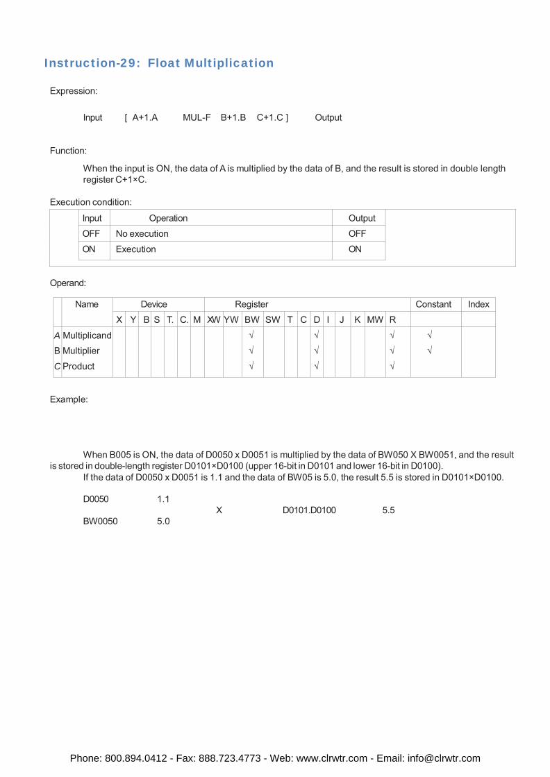
Instruction-29: Float Multiplication
Expression:
Input [ A+1.A MUL-F B+1.B C+1.C ] Output
Function:
When the input is ON, the data of A is multiplied by the data of B, and the result is stored in double length register C+1×C.
Execution condition:
Input Operation Output
OFF No execution OFF
ON Execution ON
Operand:
Name Device Register Constant Index
X Y B S T. C. M XW YW BW SW T C D I J K MW R
A
B
C
Multiplicand Multiplier
Product
√
√
√
√
√
√
√
√
√
√
√
Example:
When B005 is ON, the data of D0050 x D0051 is multiplied by the data of BW050 X BW0051, and the result is stored in double-length register D0101×D0100 (upper 16-bit in D0101 and lower 16-bit in D0100).
If the data of D0050 x D0051 is 1.1 and the data of BW05 is 5.0, the result 5.5 is stored in D0101×D0100.
D0050 1.1
BW0050 5.0
X D0101.D0100 5.5
Phone: 800.894.0412 - Fax: 888.723.4773 - Web: www.clrwtr.com - Email: [email protected]
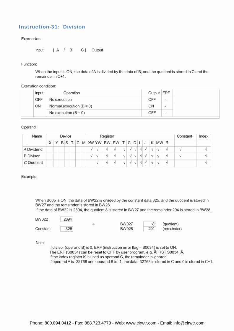
Instruction-31: Division
Expression:
Input [ A / B C ] Output
Function:
When the input is ON, the data of A is divided by the data of B, and the quotient is stored in C and the remainder in C+1.
Execution condition:
Input Operation Output ERF
OFF No execution OFF -
ON Normal execution (B = 0) ON -
No execution (B = 0) OFF -
Operand:
Name Device Register Constant Index
X Y B S T. C. M XW YW BW SW T C D I J K MW R A Dividend √ √ √ √ √ √ √ √ √ √ √ √ √ √
B Divisor √ √ √ √ √ √ √ √ √ √ √ √ √ √
C Quotient √ √ √ √ √ √ √ √ √ √ √ √
Example:
When B005 is ON, the data of BW22 is divided by the constant data 325, and the quotient is stored in BW27 and the remainder is stored in BW28. If the data of BW22 is 2894, the quotient 8 is stored in BW27 and the remainder 294 is stored in BW28.
BW022 2894 : BW027 8 (quotient) Constant 325 BW028 294 (remainder)
Note If divisor (operand B) is 0, ERF (instruction error flag = S0034) is set to ON. The ERF (S0034) can be reset to OFF by user program, e.g. Ä[ RST S0034 ]Ä. If the index register K is used as operand C, the remainder is ignored. If operand A is -32768 and operand B is -1, the data -32768 is stored in C and 0 is stored in C+1.
Phone: 800.894.0412 - Fax: 888.723.4773 - Web: www.clrwtr.com - Email: [email protected]
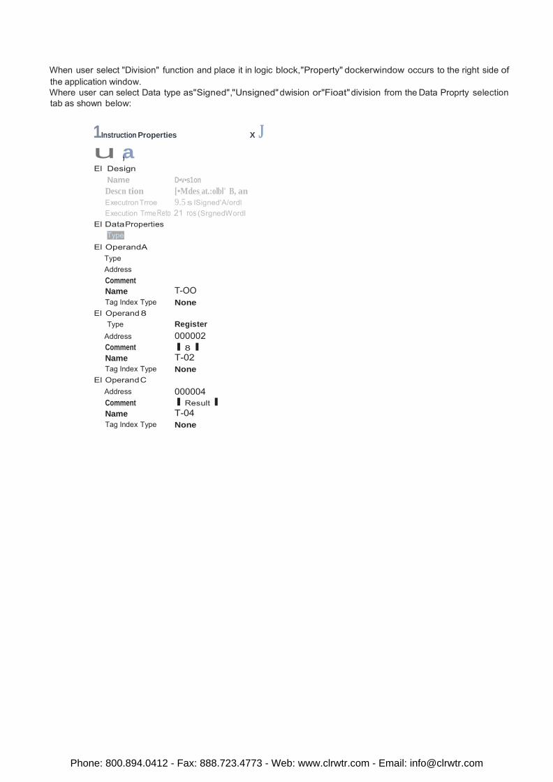
When user select "Division" function and place it in logic block,"Property" dockerwindow occurs to the right side of the application window. Where user can select Data type as"Signed","Unsigned" dwision or"Fioat" division from the Data Proprty selection tab as shown below:
1Instruction Properties X J u ,a El Design
Name D•v•s1on Descn tion [•Mdes_ at.:olbl' B, an Executron Trroe 9.5 s ISigned'A/ordl Execution Trme Reto 21 ros (SrgnedWordl
El DataProperties Type
El OperandA Type Address Comment Name T-OO Tag Index Type None
El Operand 8 Type Register
Address 000002 Comment I 8 I Name T-02 Tag Index Type None
El Operand C Address 000004 Comment I Result I Name T-04 Tag Index Type None
Phone: 800.894.0412 - Fax: 888.723.4773 - Web: www.clrwtr.com - Email: [email protected]
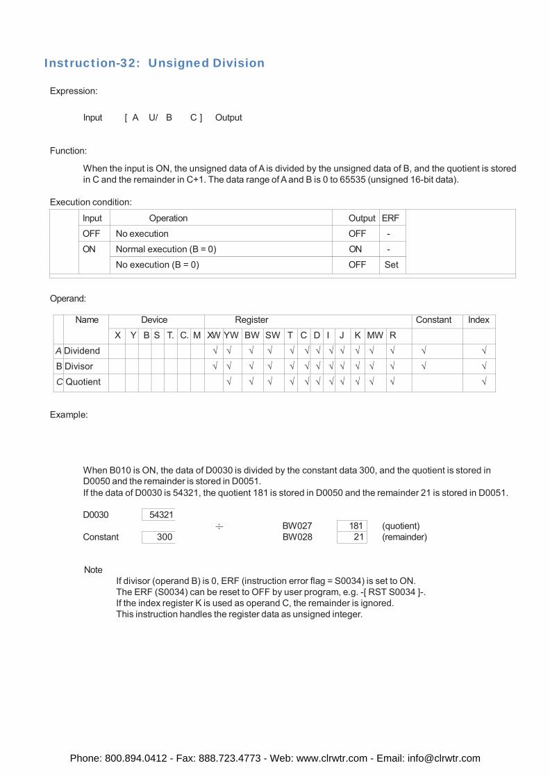
Instruction-32: Unsigned Division
Expression:
Input [ A U/ B C ] Output
Function:
When the input is ON, the unsigned data of A is divided by the unsigned data of B, and the quotient is stored in C and the remainder in C+1. The data range of A and B is 0 to 65535 (unsigned 16-bit data).
Execution condition:
Input Operation Output ERF
OFF No execution OFF -
ON Normal execution (B = 0) ON -
No execution (B = 0) OFF Set
Operand:
Name Device Register Constant Index
X Y B S T. C. M XW YW BW SW T C D I J K MW R A Dividend √ √ √ √ √ √ √ √ √ √ √ √ √ √
B Divisor √ √ √ √ √ √ √ √ √ √ √ √ √ √
C Quotient √ √ √ √ √ √ √ √ √ √ √ √
Example:
When B010 is ON, the data of D0030 is divided by the constant data 300, and the quotient is stored in D0050 and the remainder is stored in D0051. If the data of D0030 is 54321, the quotient 181 is stored in D0050 and the remainder 21 is stored in D0051.
D0030 54321 : BW027 181 (quotient) Constant 300 BW028 21 (remainder)
Note If divisor (operand B) is 0, ERF (instruction error flag = S0034) is set to ON. The ERF (S0034) can be reset to OFF by user program, e.g. -[ RST S0034 ]-. If the index register K is used as operand C, the remainder is ignored. This instruction handles the register data as unsigned integer.
Phone: 800.894.0412 - Fax: 888.723.4773 - Web: www.clrwtr.com - Email: [email protected]
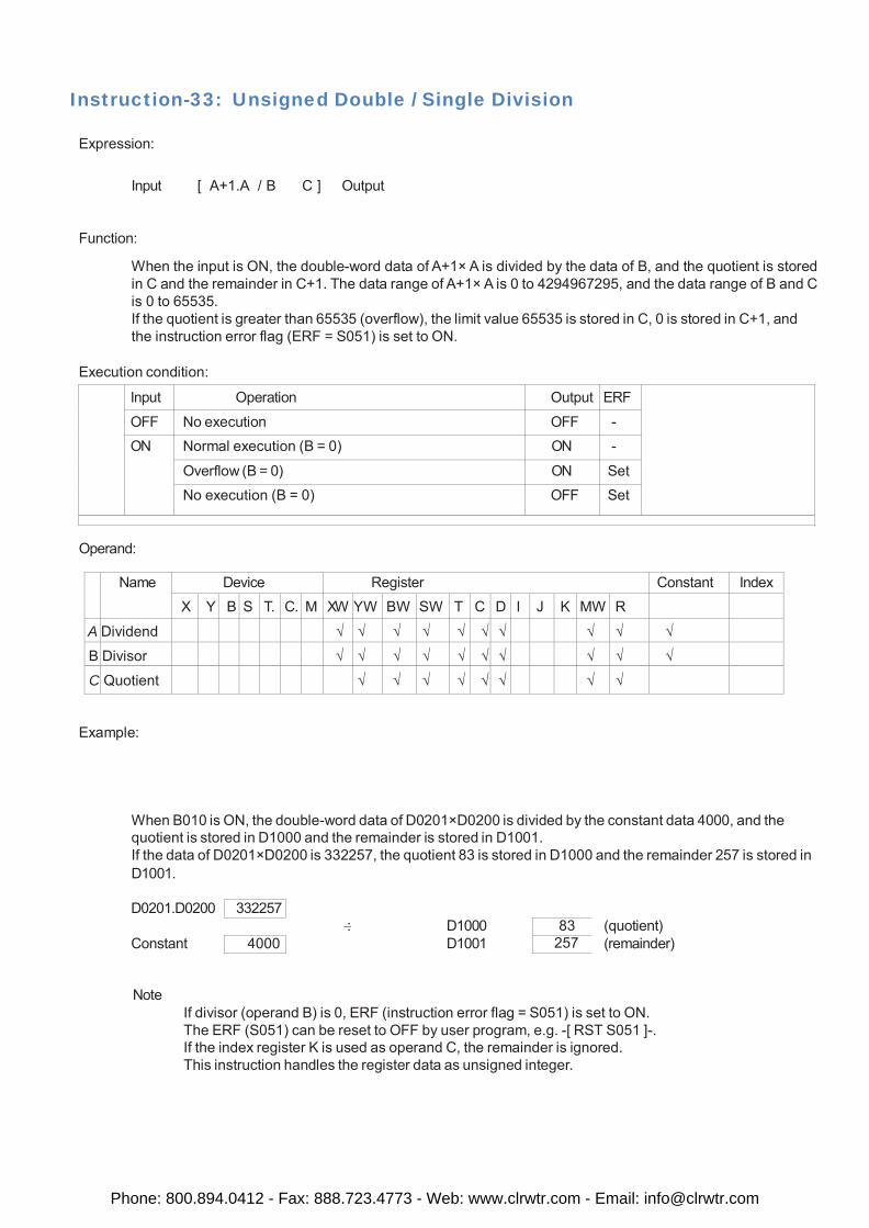
Instruction-33: Unsigned Double / Single Division
Expression:
Input [ A+1.A / B C ] Output
Function:
When the input is ON, the double-word data of A+1× A is divided by the data of B, and the quotient is stored in C and the remainder in C+1. The data range of A+1× A is 0 to 4294967295, and the data range of B and C is 0 to 65535. If the quotient is greater than 65535 (overflow), the limit value 65535 is stored in C, 0 is stored in C+1, and the instruction error flag (ERF = S051) is set to ON.
Execution condition:
Input Operation Output ERF
OFF No execution OFF - ON Normal execution (B = 0) ON -
Overflow (B = 0) ON Set No execution (B = 0) OFF Set
Operand:
Name Device Register Constant Index X Y B S T. C. M XW YW BW SW T C D I J K MW R
A Dividend √ √ √ √ √ √ √ √ √ √
B Divisor √ √ √ √ √ √ √ √ √ √
C Quotient √ √ √ √ √ √ √ √
Example:
When B010 is ON, the double-word data of D0201×D0200 is divided by the constant data 4000, and the quotient is stored in D1000 and the remainder is stored in D1001. If the data of D0201×D0200 is 332257, the quotient 83 is stored in D1000 and the remainder 257 is stored in D1001.
D0201.D0200 332257 : D1000 83 (quotient) Constant 4000 D1001 257 (remainder)
Note If divisor (operand B) is 0, ERF (instruction error flag = S051) is set to ON. The ERF (S051) can be reset to OFF by user program, e.g. -[ RST S051 ]-. If the index register K is used as operand C, the remainder is ignored. This instruction handles the register data as unsigned integer.
Phone: 800.894.0412 - Fax: 888.723.4773 - Web: www.clrwtr.com - Email: [email protected]
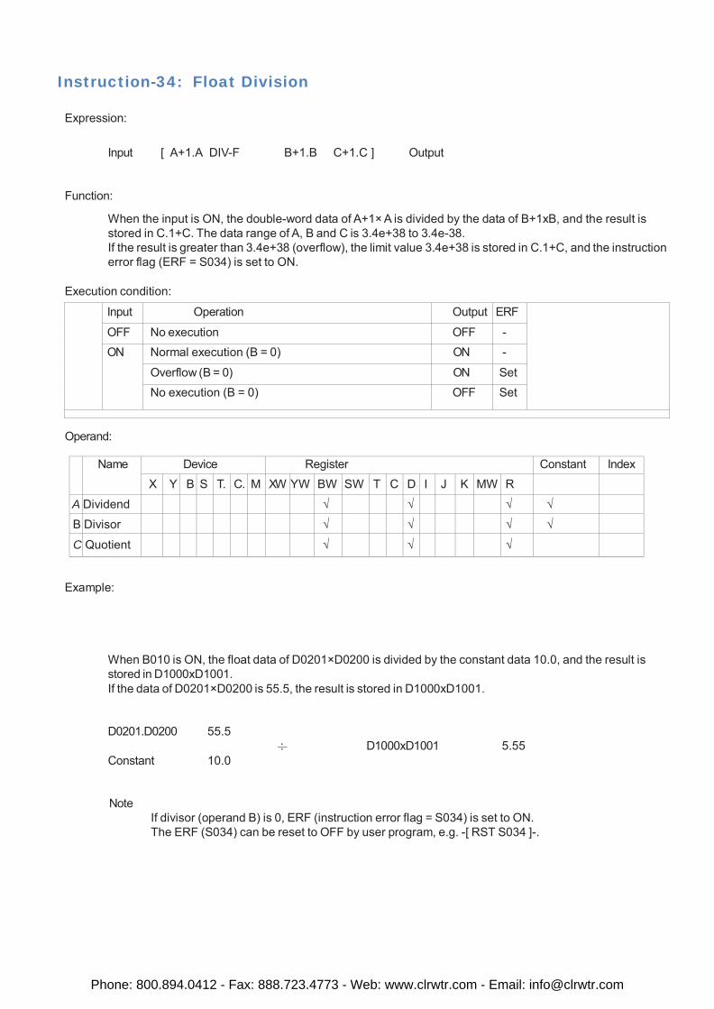
Instruction-34: Float Division
Expression:
Input [ A+1.A DIV-F B+1.B C+1.C ] Output
Function:
When the input is ON, the double-word data of A+1× A is divided by the data of B+1xB, and the result is stored in C.1+C. The data range of A, B and C is 3.4e+38 to 3.4e-38. If the result is greater than 3.4e+38 (overflow), the limit value 3.4e+38 is stored in C.1+C, and the instruction error flag (ERF = S034) is set to ON.
Execution condition:
Input Operation Output ERF
OFF No execution OFF - ON Normal execution (B = 0) ON -
Overflow (B = 0) ON Set No execution (B = 0) OFF Set
Operand:
Name Device Register Constant Index X Y B S T. C. M XW YW BW SW T C D I J K MW R
A Dividend √ √ √ √
B Divisor √ √ √ √
C Quotient √ √ √
Example:
When B010 is ON, the float data of D0201×D0200 is divided by the constant data 10.0, and the result is stored in D1000xD1001. If the data of D0201×D0200 is 55.5, the result is stored in D1000xD1001.
D0201.D0200 55.5
Constant 10.0
: D1000xD1001 5.55
Note If divisor (operand B) is 0, ERF (instruction error flag = S034) is set to ON. The ERF (S034) can be reset to OFF by user program, e.g. -[ RST S034 ]-.
Phone: 800.894.0412 - Fax: 888.723.4773 - Web: www.clrwtr.com - Email: [email protected]
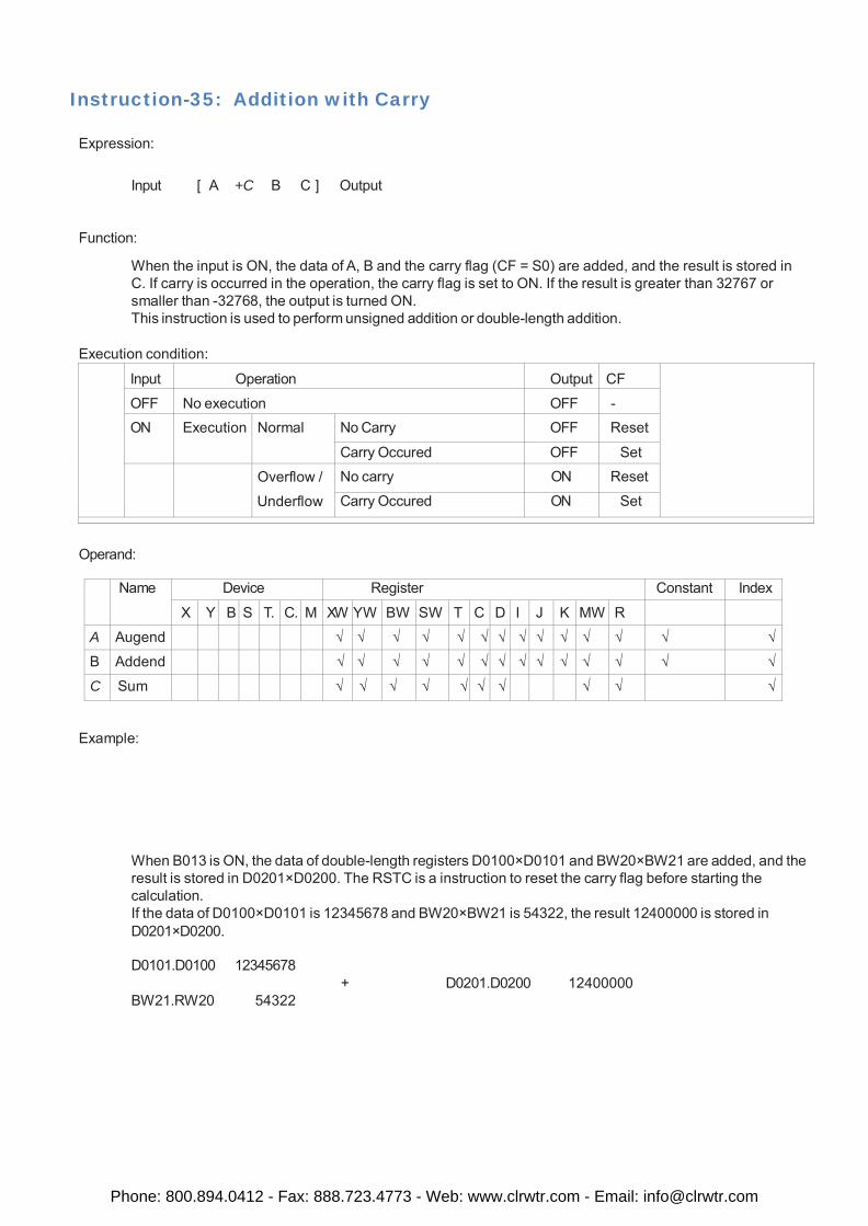
Instruction-35: Addition with Carry
Expression:
Input [ A +C B C ] Output
Function:
When the input is ON, the data of A, B and the carry flag (CF = S0) are added, and the result is stored in C. If carry is occurred in the operation, the carry flag is set to ON. If the result is greater than 32767 or smaller than -32768, the output is turned ON. This instruction is used to perform unsigned addition or double-length addition.
Execution condition:
Input Operation Output CF
OFF No execution OFF - ON Execution Normal No Carry OFF Reset
Carry Occured OFF Set Overflow /
Underflow
No carry ON Reset
Carry Occured ON Set
Operand:
Name Device Register Constant Index
X Y B S T. C. M XW YW BW SW T C D I J K MW R
A Augend √ √ √ √ √ √ √ √ √ √ √ √ √ √
B Addend √ √ √ √ √ √ √ √ √ √ √ √ √ √
C Sum √ √ √ √ √ √ √ √ √ √
Example:
When B013 is ON, the data of double-length registers D0100×D0101 and BW20×BW21 are added, and the result is stored in D0201×D0200. The RSTC is a instruction to reset the carry flag before starting the calculation. If the data of D0100×D0101 is 12345678 and BW20×BW21 is 54322, the result 12400000 is stored in D0201×D0200.
D0101.D0100 12345678
BW21.RW20 54322
+ D0201.D0200 12400000
Phone: 800.894.0412 - Fax: 888.723.4773 - Web: www.clrwtr.com - Email: [email protected]
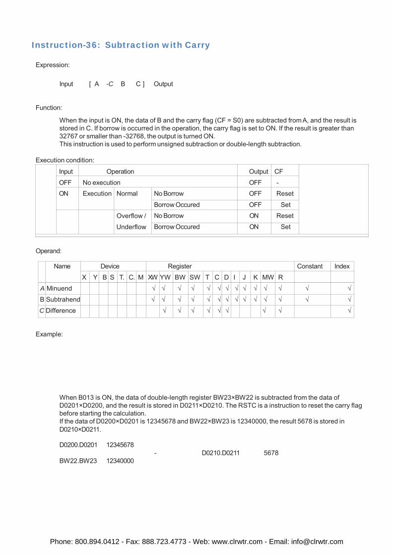
Instruction-36: Subtraction with Carry
Expression:
Input [ A -C B C ] Output
Function:
When the input is ON, the data of B and the carry flag (CF = S0) are subtracted from A, and the result is stored in C. If borrow is occurred in the operation, the carry flag is set to ON. If the result is greater than 32767 or smaller than -32768, the output is turned ON. This instruction is used to perform unsigned subtraction or double-length subtraction.
Execution condition:
Input Operation Output CF
OFF No execution OFF - ON Execution Normal No Borrow OFF Reset
Borrow Occured OFF Set Overflow /
Underflow
No Borrow ON Reset
Borrow Occured ON Set
Operand:
Name Device Register Constant Index
X Y B S T. C. M XW YW BW SW T C D I J K MW R
A Minuend √ √ √ √ √ √ √ √ √ √ √ √ √ √
B Subtrahend √ √ √ √ √ √ √ √ √ √ √ √ √ √
C Difference √ √ √ √ √ √ √ √ √
Example:
When B013 is ON, the data of double-length register BW23×BW22 is subtracted from the data of D0201×D0200, and the result is stored in D0211×D0210. The RSTC is a instruction to reset the carry flag before starting the calculation. If the data of D0200×D0201 is 12345678 and BW22×BW23 is 12340000, the result 5678 is stored in D0210×D0211.
D0200.D0201 12345678
BW22.BW23 12340000
- D0210.D0211 5678
Phone: 800.894.0412 - Fax: 888.723.4773 - Web: www.clrwtr.com - Email: [email protected]
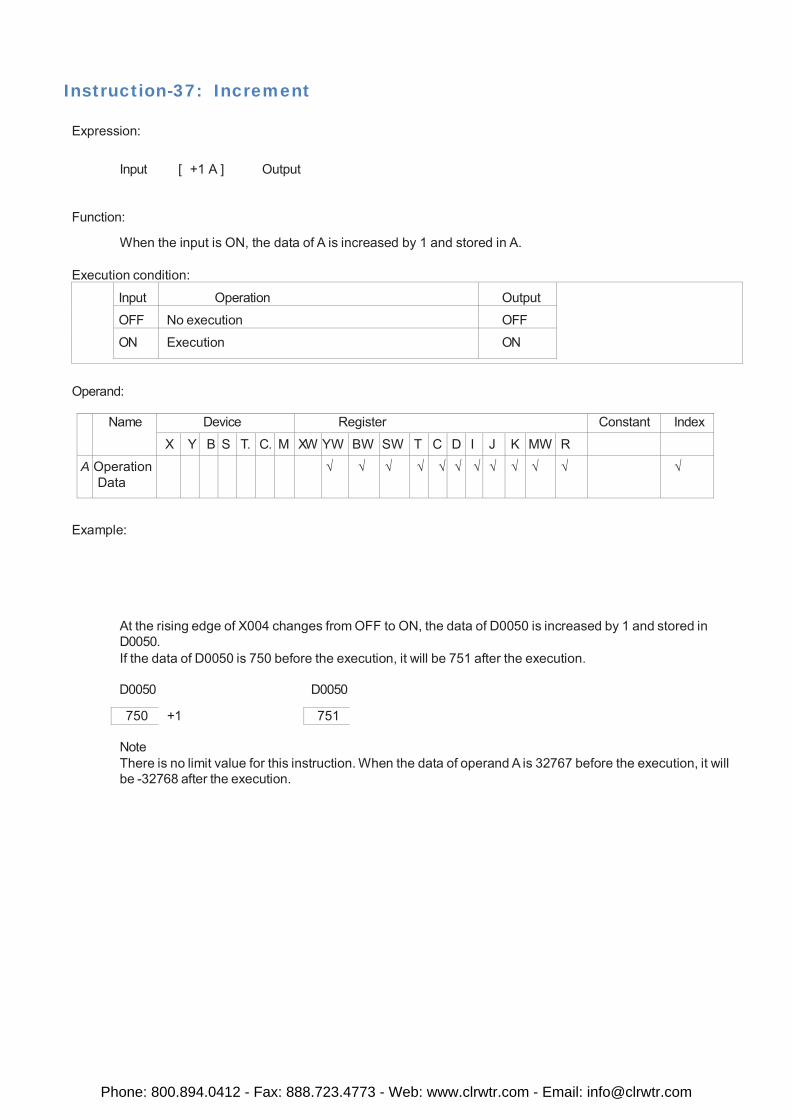
Instruction-37: Increment
Expression:
Input [ +1 A ] Output
Function:
When the input is ON, the data of A is increased by 1 and stored in A.
Execution condition:
Input
Operation
Output
OFF No execution OFF
ON Execution ON
Operand:
Name Device Register Constant Index
X Y B S T. C. M XW YW BW SW T C D I J K MW R
A Operation Data
√ √ √ √ √ √ √ √ √ √ √ √
Example:
At the rising edge of X004 changes from OFF to ON, the data of D0050 is increased by 1 and stored in D0050. If the data of D0050 is 750 before the execution, it will be 751 after the execution.
D0050 D0050
750 +1 751
Note There is no limit value for this instruction. When the data of operand A is 32767 before the execution, it will be -32768 after the execution.
Phone: 800.894.0412 - Fax: 888.723.4773 - Web: www.clrwtr.com - Email: [email protected]
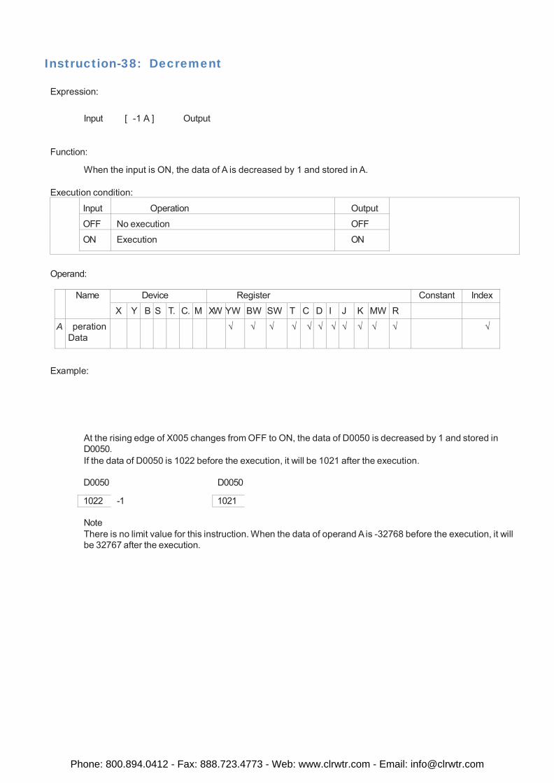
Instruction-38: Decrement
Expression:
Input [ -1 A ] Output
Function:
When the input is ON, the data of A is decreased by 1 and stored in A.
Execution condition:
Input
Operation
Output
OFF No execution OFF
ON Execution ON
Operand:
Name Device Register Constant Index
X Y B S T. C. M XW YW BW SW T C D I J K MW R
A peration Data
√ √ √ √ √ √ √ √ √ √ √ √
Example:
At the rising edge of X005 changes from OFF to ON, the data of D0050 is decreased by 1 and stored in D0050. If the data of D0050 is 1022 before the execution, it will be 1021 after the execution.
D0050 D0050
1022 -1 1021
Note There is no limit value for this instruction. When the data of operand A is -32768 before the execution, it will be 32767 after the execution.
Phone: 800.894.0412 - Fax: 888.723.4773 - Web: www.clrwtr.com - Email: [email protected]
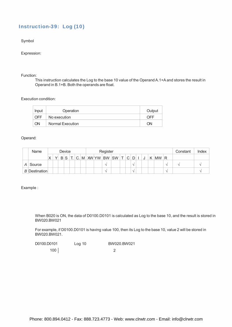
Instruction-39: Log (10)
Symbol
Expression:
Function: This instruction calculates the Log to the base 10 value of the Operand A.1+A and stores the result in Operand in B.1+B. Both the operands are float.
Execution condition:
Input
Operation
Output
OFF No execution OFF
ON Normal Execution ON
Operand:
Name Device Register Constant Index
X Y B S T. C. M XW YW BW SW T C D I J K MW R
A
Source
√
√
√
√
√
B Destination √ √ √ √
Example :
When B020 is ON, the data of D0100.D0101 is calculated as Log to the base 10, and the result is stored in BW020.BW021
For example, if D0100.D0101 is having value 100, then its Log to the base 10, value 2 will be stored in BW020.BW021.
D0100.D0101 Log 10 BW020.BW021
100 2
Phone: 800.894.0412 - Fax: 888.723.4773 - Web: www.clrwtr.com - Email: [email protected]
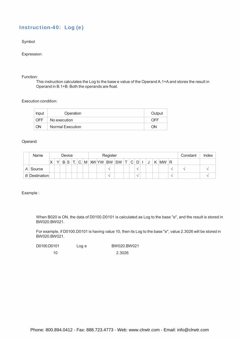
Instruction-40: Log (e)
Symbol
Expression:
Function: This instruction calculates the Log to the base e value of the Operand A.1+A and stores the result in Operand in B.1+B. Both the operands are float.
Execution condition:
Input
Operation
Output
OFF No execution OFF
ON Normal Execution ON
Operand:
Name Device Register Constant Index
X Y B S T. C. M XW YW BW SW T C D I J K MW R
A Source √ √ √ √ √ B Destination √ √ √ √
Example :
When B020 is ON, the data of D0100.D0101 is calculated as Log to the base "e", and the result is stored in BW020.BW021.
For example, if D0100.D0101 is having value 10, then its Log to the base "e", value 2.3026 will be stored in BW020.BW021.
D0100.D0101 Log e BW020.BW021
10 2.3026
Phone: 800.894.0412 - Fax: 888.723.4773 - Web: www.clrwtr.com - Email: [email protected]
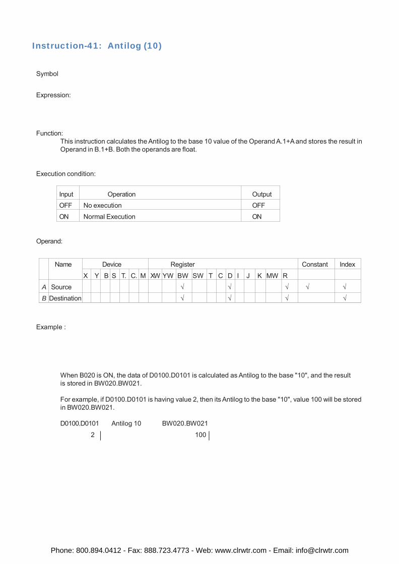
Instruction-41: Antilog (10)
Symbol
Expression:
Function: This instruction calculates the Antilog to the base 10 value of the Operand A.1+A and stores the result in Operand in B.1+B. Both the operands are float.
Execution condition:
Input
Operation
Output
OFF No execution OFF
ON Normal Execution ON
Operand:
Name Device Register Constant Index
X Y B S T. C. M XW YW BW SW T C D I J K MW R
A
Source
√
√
√
√
√
B Destination √ √ √ √
Example :
When B020 is ON, the data of D0100.D0101 is calculated as Antilog to the base "10", and the result is stored in BW020.BW021.
For example, if D0100.D0101 is having value 2, then its Antilog to the base "10", value 100 will be stored in BW020.BW021.
D0100.D0101 Antilog 10 BW020.BW021
2 100
Phone: 800.894.0412 - Fax: 888.723.4773 - Web: www.clrwtr.com - Email: [email protected]
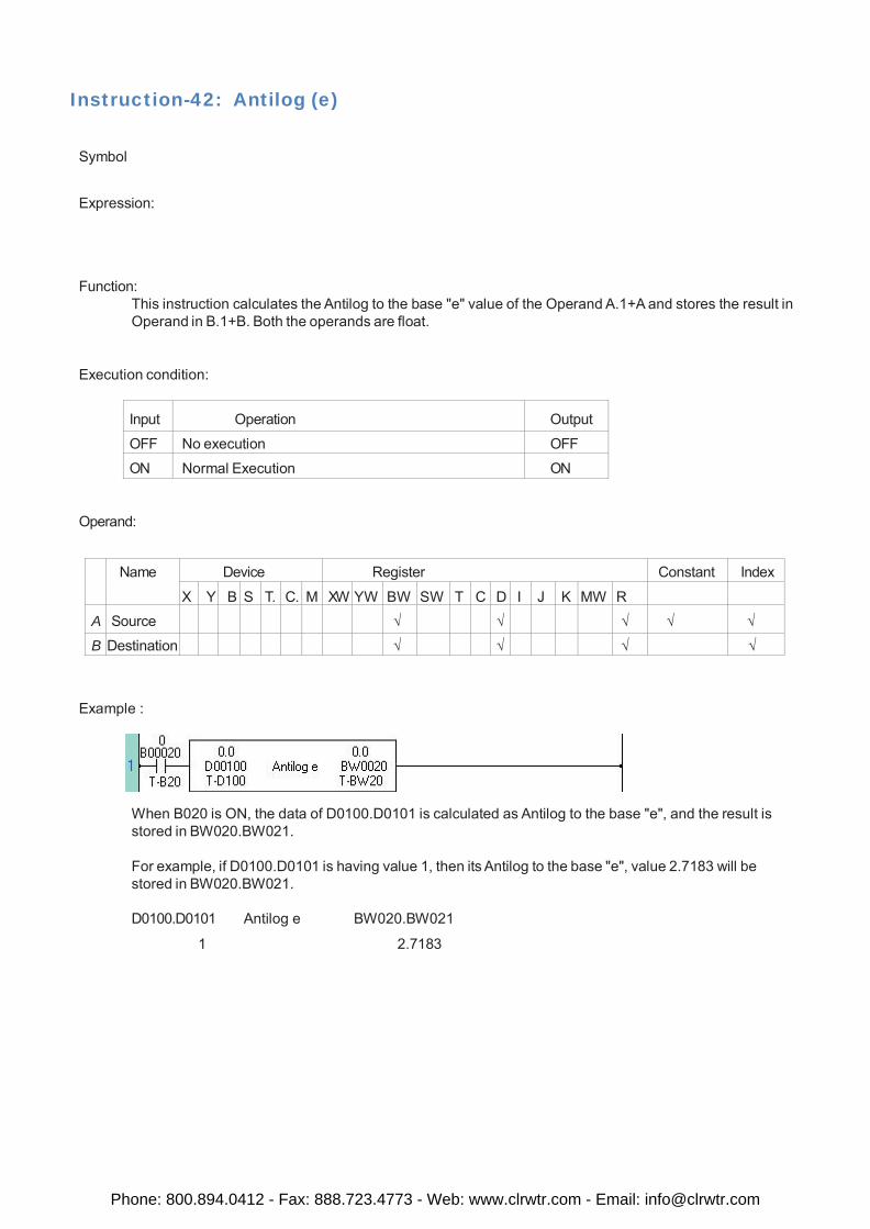
Instruction-42: Antilog (e)
Symbol
Expression:
Function: This instruction calculates the Antilog to the base "e" value of the Operand A.1+A and stores the result in Operand in B.1+B. Both the operands are float.
Execution condition:
Input
Operation
Output
OFF No execution OFF
ON Normal Execution ON
Operand:
Name Device Register Constant Index
X Y B S T. C. M XW YW BW SW T C D I J K MW R
A
Source
√
√
√
√
√
B Destination √ √ √ √
Example :
When B020 is ON, the data of D0100.D0101 is calculated as Antilog to the base "e", and the result is stored in BW020.BW021.
For example, if D0100.D0101 is having value 1, then its Antilog to the base "e", value 2.7183 will be stored in BW020.BW021.
D0100.D0101 Antilog e BW020.BW021
1 2.7183
Phone: 800.894.0412 - Fax: 888.723.4773 - Web: www.clrwtr.com - Email: [email protected]
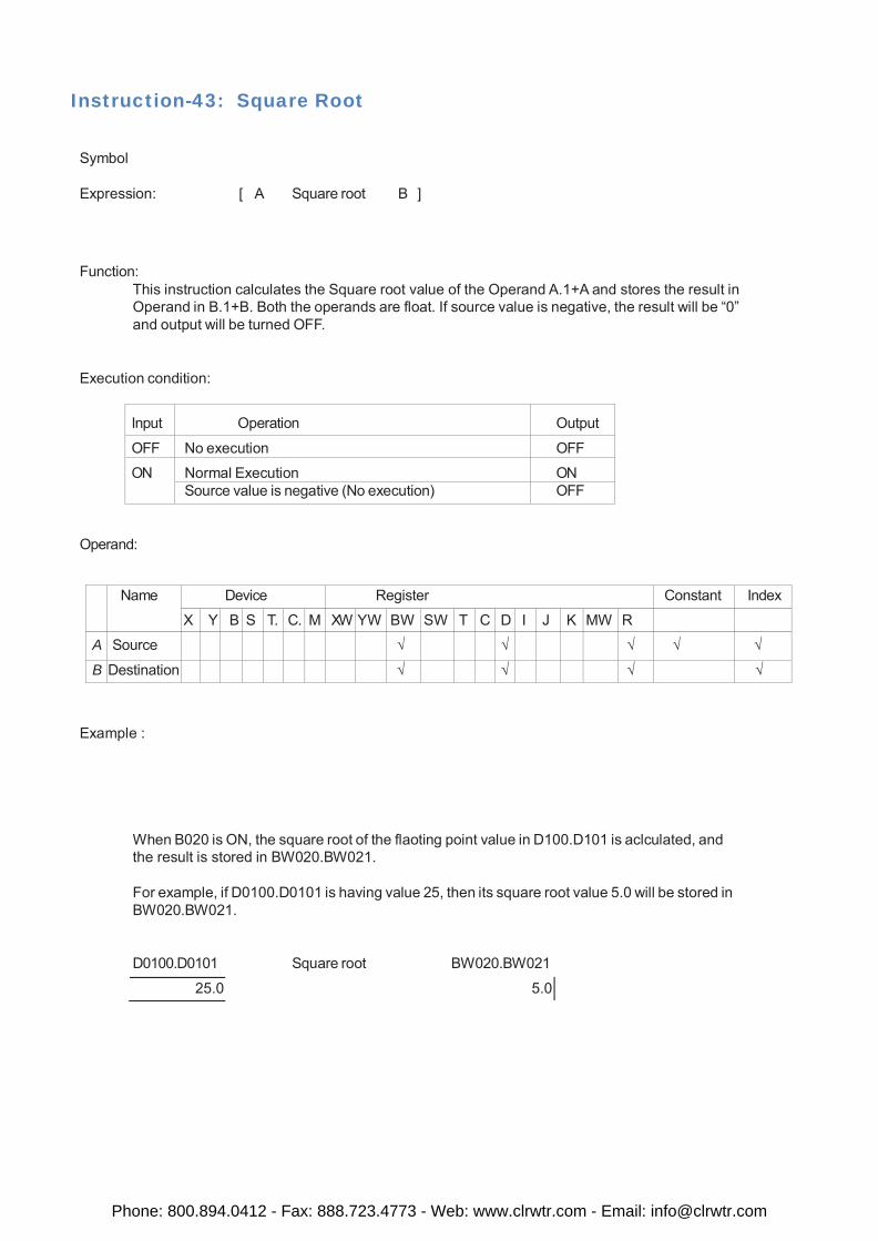
Instruction-43: Square Root
Symbol
Expression: [ A Square root B ]
Function: This instruction calculates the Square root value of the Operand A.1+A and stores the result in Operand in B.1+B. Both the operands are float. If source value is negative, the result will be “0” and output will be turned OFF.
Execution condition:
Input
Operation
Output
OFF No execution OFF
ON Normal Execution ON Source value is negative (No execution) OFF
Operand:
Name Device Register Constant Index
X Y B S T. C. M XW YW BW SW T C D I J K MW R
A Source √ √ √ √ √
B Destination √ √ √ √
Example :
When B020 is ON, the square root of the flaoting point value in D100.D101 is aclculated, and the result is stored in BW020.BW021.
For example, if D0100.D0101 is having value 25, then its square root value 5.0 will be stored in BW020.BW021.
D0100.D0101 Square root BW020.BW021
25.0 5.0
Phone: 800.894.0412 - Fax: 888.723.4773 - Web: www.clrwtr.com - Email: [email protected]
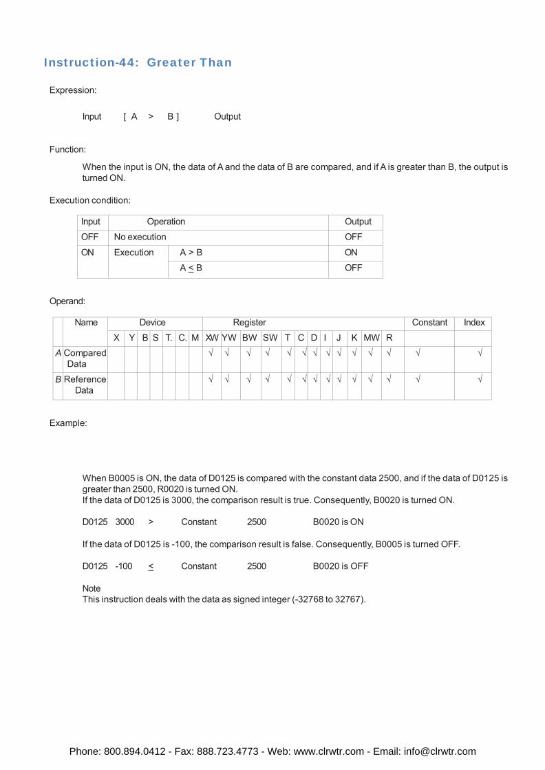
Instruction-44: Greater Than
Expression:
Input [ A > B ] Output
Function:
When the input is ON, the data of A and the data of B are compared, and if A is greater than B, the output is turned ON.
Execution condition:
Input Operation Output
OFF No execution OFF
ON Execution A > B ON
A < B OFF
Operand:
Name Device Register Constant Index
X Y B S T. C. M XW YW BW SW T C D I J K MW R A Compared
Data √ √ √ √ √ √ √ √ √ √ √ √ √ √
B Reference Data
√ √ √ √ √ √ √ √ √ √ √ √ √ √
Example:
When B0005 is ON, the data of D0125 is compared with the constant data 2500, and if the data of D0125 is greater than 2500, R0020 is turned ON. If the data of D0125 is 3000, the comparison result is true. Consequently, B0020 is turned ON.
D0125 3000 > Constant 2500 B0020 is ON
If the data of D0125 is -100, the comparison result is false. Consequently, B0005 is turned OFF.
D0125 -100 < Constant 2500 B0020 is OFF
Note This instruction deals with the data as signed integer (-32768 to 32767).
Phone: 800.894.0412 - Fax: 888.723.4773 - Web: www.clrwtr.com - Email: [email protected]
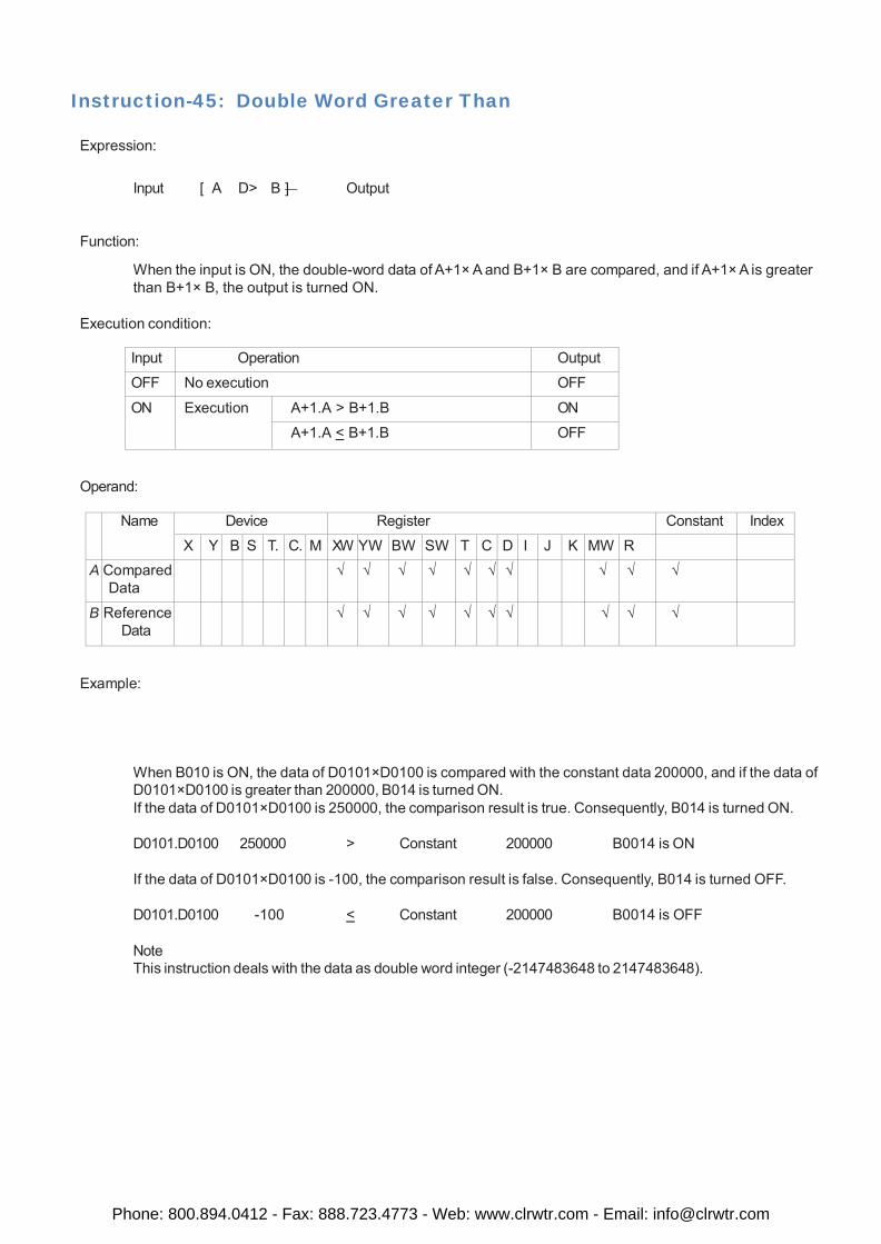
Instruction-45: Double Word Greater Than
Expression:
Input [ A D> B ] Output
Function:
When the input is ON, the double-word data of A+1× A and B+1× B are compared, and if A+1× A is greater than B+1× B, the output is turned ON.
Execution condition:
Input Operation Output
OFF No execution OFF
ON Execution A+1.A > B+1.B ON
A+1.A < B+1.B OFF
Operand:
Name Device Register Constant Index
X Y B S T. C. M XW YW BW SW T C D I J K MW R A Compared
Data √ √ √ √ √ √ √ √ √ √
B Reference Data
√ √ √ √ √ √ √ √ √ √
Example:
When B010 is ON, the data of D0101×D0100 is compared with the constant data 200000, and if the data of D0101×D0100 is greater than 200000, B014 is turned ON. If the data of D0101×D0100 is 250000, the comparison result is true. Consequently, B014 is turned ON.
D0101.D0100 250000 > Constant 200000 B0014 is ON
If the data of D0101×D0100 is -100, the comparison result is false. Consequently, B014 is turned OFF.
D0101.D0100 -100 < Constant 200000 B0014 is OFF
Note This instruction deals with the data as double word integer (-2147483648 to 2147483648).
Phone: 800.894.0412 - Fax: 888.723.4773 - Web: www.clrwtr.com - Email: [email protected]
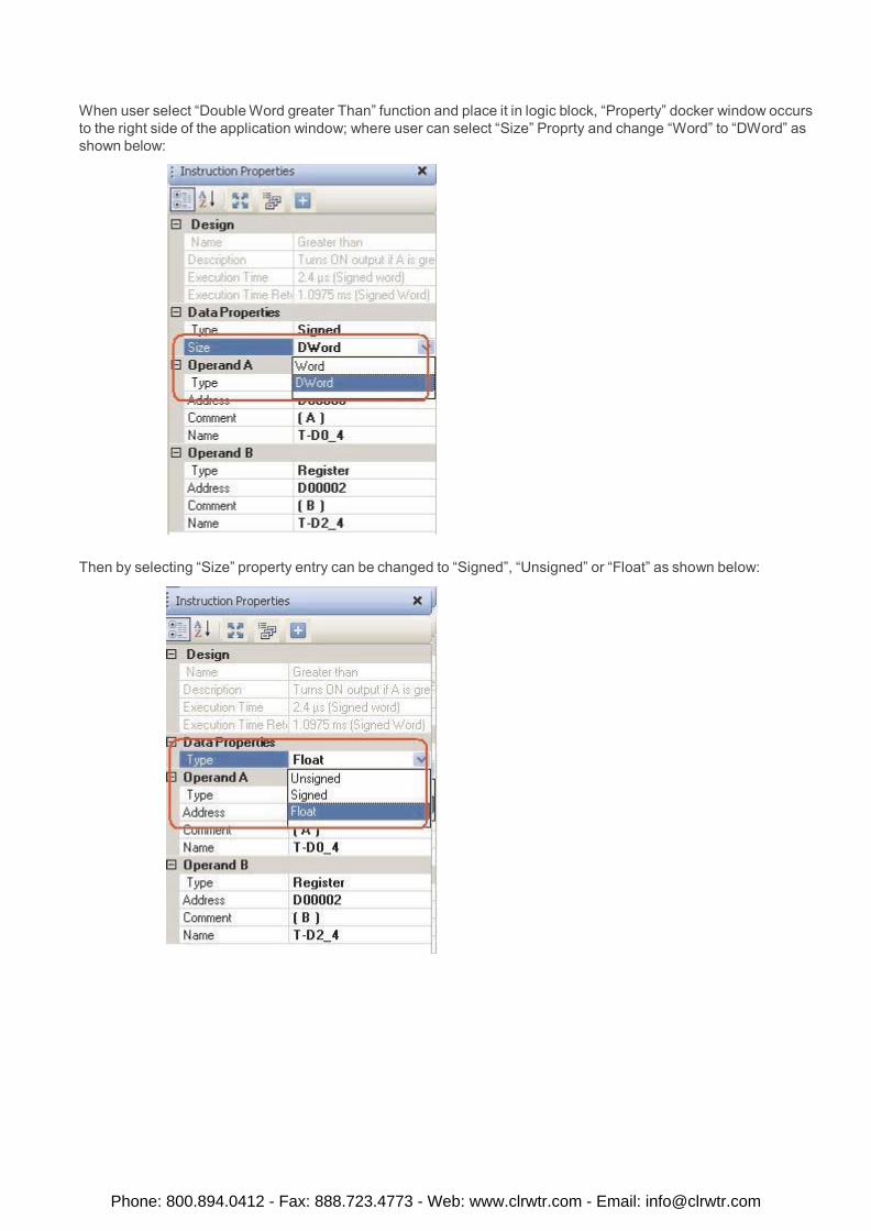
When user select “Double Word greater Than” function and place it in logic block, “Property” docker window occurs to the right side of the application window; where user can select “Size” Proprty and change “Word” to “DWord” as shown below:
Then by selecting “Size” property entry can be changed to “Signed”, “Unsigned” or “Float” as shown below:
Phone: 800.894.0412 - Fax: 888.723.4773 - Web: www.clrwtr.com - Email: [email protected]
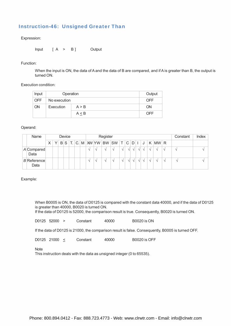
Instruction-46: Unsigned Greater Than
Expression:
Input [ A > B ] Output
Function:
When the input is ON, the data of A and the data of B are compared, and if A is greater than B, the output is turned ON.
Execution condition:
Input Operation Output
OFF No execution OFF
ON Execution A > B ON
A < B OFF
Operand:
Name Device Register Constant Index
X Y B S T. C. M XW YW BW SW T C D I J K MW R A Compared
Data √ √ √ √ √ √ √ √ √ √ √ √ √ √
B Reference Data
√ √ √ √ √ √ √ √ √ √ √ √ √ √
Example:
When B0005 is ON, the data of D0125 is compared with the constant data 40000, and if the data of D0125 is greater than 40000, B0020 is turned ON. If the data of D0125 is 52000, the comparison result is true. Consequently, B0020 is turned ON.
D0125 52000 > Constant 40000 B0020 is ON
If the data of D0125 is 21000, the comparison result is false. Consequently, B0005 is turned OFF.
D0125 21000 < Constant 40000 B0020 is OFF
Note This instruction deals with the data as unsigned integer (0 to 65535).
Phone: 800.894.0412 - Fax: 888.723.4773 - Web: www.clrwtr.com - Email: [email protected]
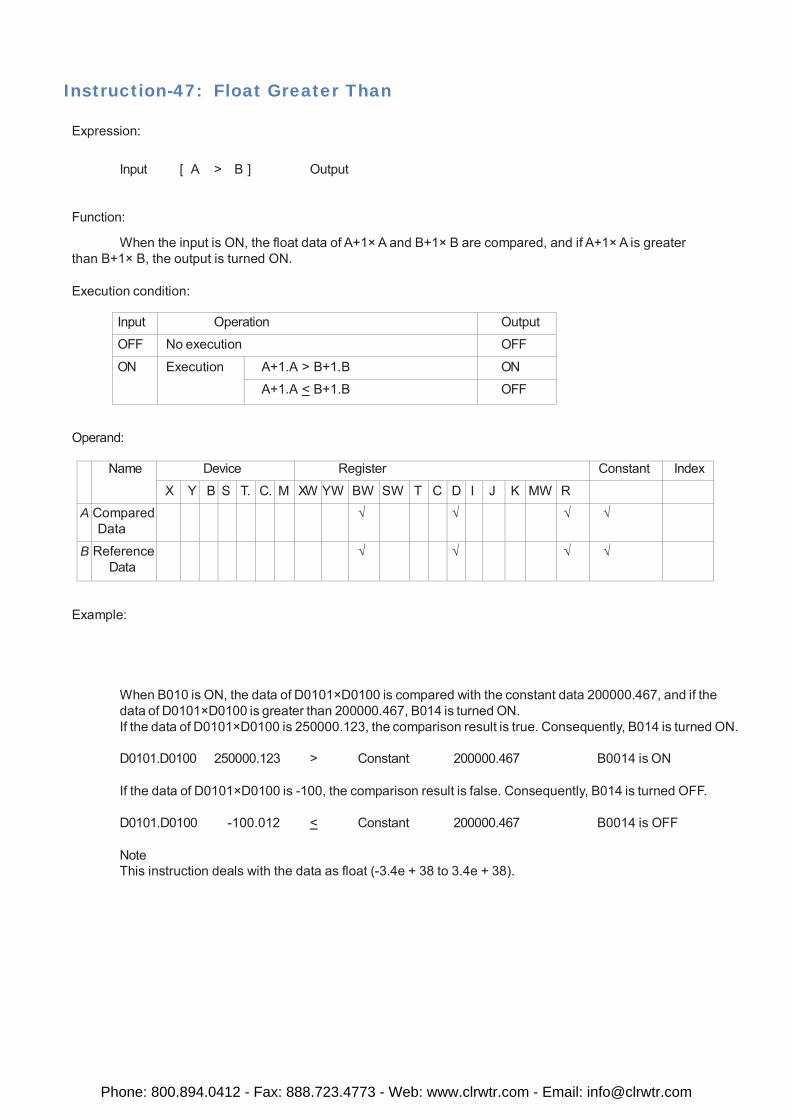
Instruction-47: Float Greater Than
Expression:
Input [ A > B ] Output
Function:
When the input is ON, the float data of A+1× A and B+1× B are compared, and if A+1× A is greater than B+1× B, the output is turned ON.
Execution condition:
Input Operation Output
OFF No execution OFF
ON Execution A+1.A > B+1.B ON
A+1.A < B+1.B OFF
Operand:
Name Device Register Constant Index
X Y B S T. C. M XW YW BW SW T C D I J K MW R A Compared
Data √ √ √ √
B Reference Data
√ √ √ √
Example:
When B010 is ON, the data of D0101×D0100 is compared with the constant data 200000.467, and if the data of D0101×D0100 is greater than 200000.467, B014 is turned ON. If the data of D0101×D0100 is 250000.123, the comparison result is true. Consequently, B014 is turned ON.
D0101.D0100 250000.123 > Constant 200000.467 B0014 is ON
If the data of D0101×D0100 is -100, the comparison result is false. Consequently, B014 is turned OFF.
D0101.D0100 -100.012 < Constant 200000.467 B0014 is OFF
Note This instruction deals with the data as float (-3.4e + 38 to 3.4e + 38).
Phone: 800.894.0412 - Fax: 888.723.4773 - Web: www.clrwtr.com - Email: [email protected]
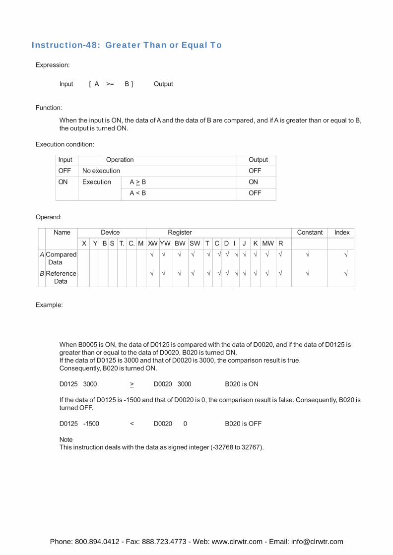
Instruction-48: Greater Than or Equal To
Expression:
Input [ A >= B ] Output
Function:
When the input is ON, the data of A and the data of B are compared, and if A is greater than or equal to B, the output is turned ON.
Execution condition:
Input Operation Output
OFF No execution OFF
ON Execution A > B ON
A < B OFF
Operand:
Name Device Register Constant Index
X Y B S T. C. M XW YW BW SW T C D I J K MW R
A B
Compared Data
Reference Data
√ √
√ √
√
√
√ √
√ √
√
√
√ √
√ √
√ √
√ √
√
√
√ √
√
√
√
√
Example:
When B0005 is ON, the data of D0125 is compared with the data of D0020, and if the data of D0125 is greater than or equal to the data of D0020, B020 is turned ON. If the data of D0125 is 3000 and that of D0020 is 3000, the comparison result is true. Consequently, B020 is turned ON.
D0125 3000 > D0020 3000 B020 is ON
If the data of D0125 is -1500 and that of D0020 is 0, the comparison result is false. Consequently, B020 is turned OFF.
D0125 -1500 < D0020 0 B020 is OFF
Note This instruction deals with the data as signed integer (-32768 to 32767).
Phone: 800.894.0412 - Fax: 888.723.4773 - Web: www.clrwtr.com - Email: [email protected]
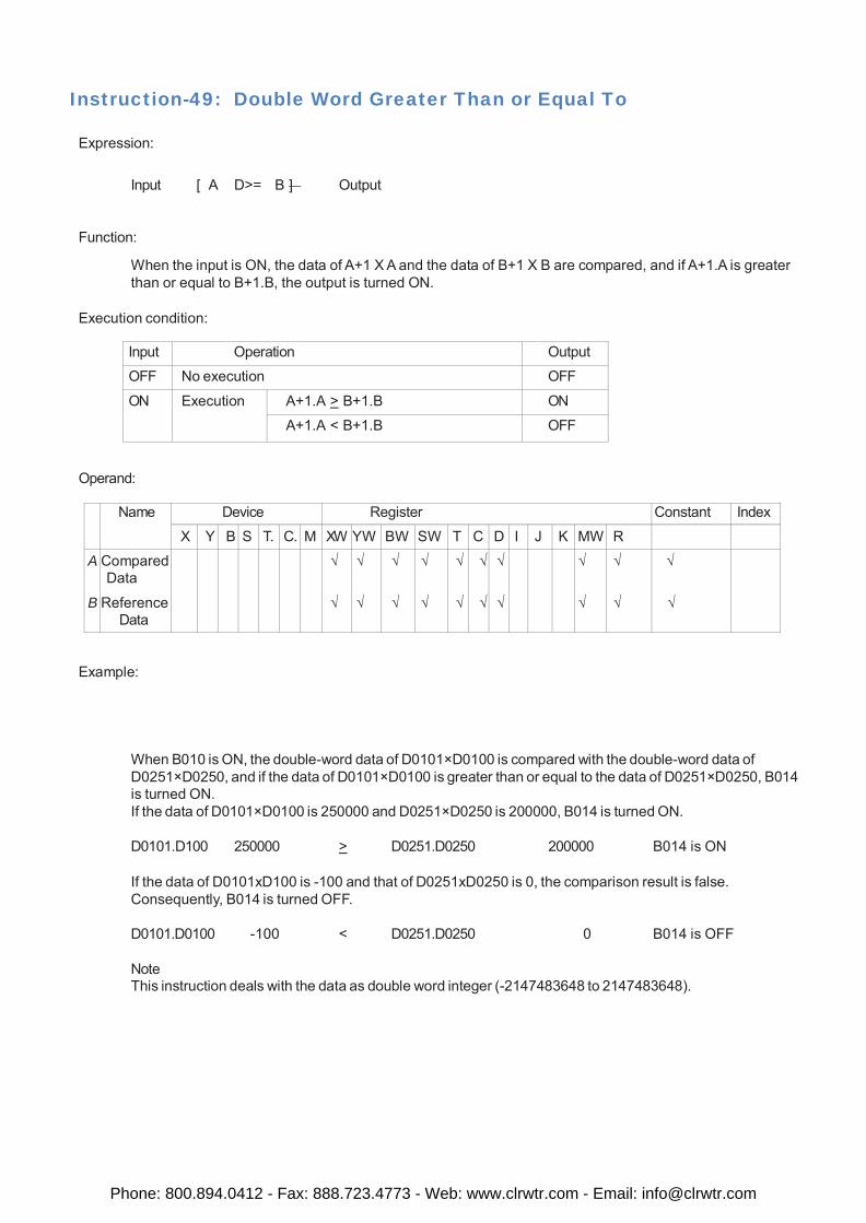
Instruction-49: Double Word Greater Than or Equal To
Expression:
Input [ A D>= B ] Output
Function:
When the input is ON, the data of A+1 X A and the data of B+1 X B are compared, and if A+1.A is greater than or equal to B+1.B, the output is turned ON.
Execution condition:
Input Operation Output
OFF No execution OFF
ON Execution A+1.A > B+1.B ON
A+1.A < B+1.B OFF
Operand:
Name Device Register Constant Index
X Y B S T. C. M XW YW BW SW T C D I J K MW R
A B
Compared Data
Reference Data
√ √
√ √
√
√
√ √
√ √
√
√
√ √
√ √
√ √
√
√
Example:
When B010 is ON, the double-word data of D0101×D0100 is compared with the double-word data of D0251×D0250, and if the data of D0101×D0100 is greater than or equal to the data of D0251×D0250, B014 is turned ON. If the data of D0101×D0100 is 250000 and D0251×D0250 is 200000, B014 is turned ON.
D0101.D100 250000 > D0251.D0250 200000 B014 is ON
If the data of D0101xD100 is -100 and that of D0251xD0250 is 0, the comparison result is false. Consequently, B014 is turned OFF.
D0101.D0100 -100 < D0251.D0250 0 B014 is OFF
Note This instruction deals with the data as double word integer (-2147483648 to 2147483648).
Phone: 800.894.0412 - Fax: 888.723.4773 - Web: www.clrwtr.com - Email: [email protected]
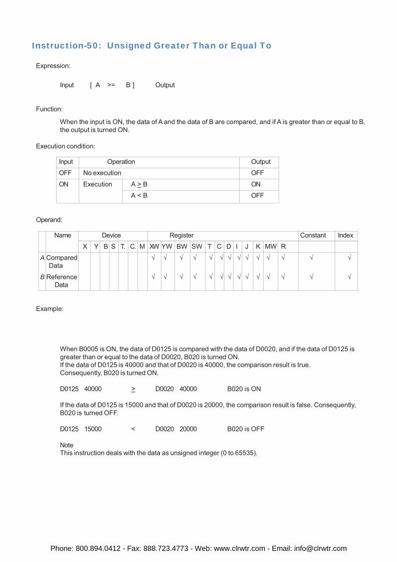
Instruction-50: Unsigned Greater Than or Equal To
Expression:
Input [ A >= B ] Output
Function:
When the input is ON, the data of A and the data of B are compared, and if A is greater than or equal to B, the output is turned ON.
Execution condition:
Input Operation Output
OFF No execution OFF
ON Execution A > B ON
A < B OFF
Operand:
Name Device Register Constant Index
X Y B S T. C. M XW YW BW SW T C D I J K MW R
A B
Compared Data
Reference Data
√ √
√ √
√
√
√ √
√ √
√
√
√ √
√ √
√ √
√ √
√ √
√ √
√
√
√
√
Example:
When B0005 is ON, the data of D0125 is compared with the data of D0020, and if the data of D0125 is greater than or equal to the data of D0020, B020 is turned ON. If the data of D0125 is 40000 and that of D0020 is 40000, the comparison result is true. Consequently, B020 is turned ON.
D0125 40000 > D0020 40000 B020 is ON
If the data of D0125 is 15000 and that of D0020 is 20000, the comparison result is false. Consequently, B020 is turned OFF.
D0125 15000 < D0020 20000 B020 is OFF
Note This instruction deals with the data as unsigned integer (0 to 65535).
Phone: 800.894.0412 - Fax: 888.723.4773 - Web: www.clrwtr.com - Email: [email protected]
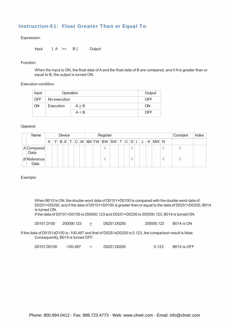
Instruction-51: Float Greater Than or Equal To
Expression:
Input [ A >= B ] Output
Function:
When the input is ON, the float data of A and the float data of B are compared, and if A is greater than or equal to B, the output is turned ON.
Execution condition:
Input Operation Output
OFF No execution OFF
ON Execution A > B ON
A < B OFF
Operand:
Name Device Register Constant Index
X Y B S T. C. M XW YW BW SW T C D I J K MW R
A B
Compared Data
Reference Data
√
√
√ √
√ √
√
√
Example:
When B010 is ON, the double-word data of D0101×D0100 is compared with the double-word data of D0251×D0250, and if the data of D0101×D0100 is greater than or equal to the data of D0251×D0250, B014 is turned ON. If the data of D0101×D0100 is 250000.123 and D0251×D0250 is 200000.123, B014 is turned ON.
D0101.D100 250000.123 > D0251.D0250 200000.123 B014 is ON
If the data of D0101xD100 is -100.467 and that of D0251xD0250 is 0.123, the comparison result is false. Consequently, B014 is turned OFF.
D0101.D0100 -100.467 < D0251.D0250 0.123 B014 is OFF
Phone: 800.894.0412 - Fax: 888.723.4773 - Web: www.clrwtr.com - Email: [email protected]
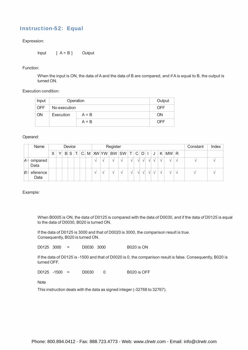
Instruction-52: Equal
Expression:
Input [ A = B ] Output
Function:
When the input is ON, the data of A and the data of B are compared, and if A is equal to B, the output is turned ON.
Execution condition:
Input Operation Output
OFF No execution OFF
ON Execution A = B ON
A = B OFF
Operand:
Name Device Register Constant Index
X Y B S T. C. M XW YW BW SW T C D I J K MW R A C ompared
Data √ √ √ √ √ √ √ √ √ √ √ √ √ √
B R eference Data
√ √ √ √ √ √ √ √ √ √ √ √ √ √
Example:
When B0005 is ON, the data of D0125 is compared with the data of D0030, and if the data of D0125 is equal to the data of D0030, B020 is turned ON.
If the data of D0125 is 3000 and that of D0020 is 3000, the comparison result is true. Consequently, B020 is turned ON.
D0125 3000 = D0030 3000 B020 is ON
If the data of D0125 is -1500 and that of D0020 is 0, the comparison result is false. Consequently, B020 is turned OFF.
D0125 -1500 = D0030 0 B020 is OFF
Note
This instruction deals with the data as signed integer (-32768 to 32767).
Phone: 800.894.0412 - Fax: 888.723.4773 - Web: www.clrwtr.com - Email: [email protected]
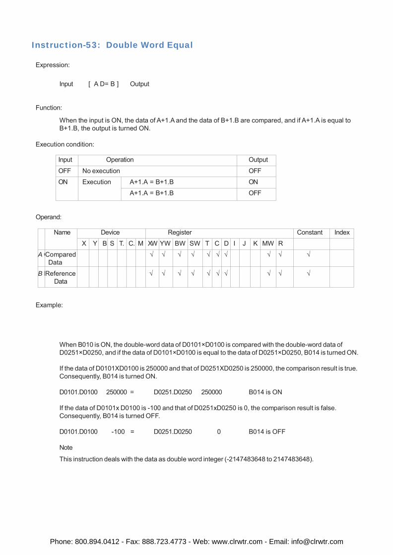
Instruction-53: Double Word Equal
Expression:
Input [ A D= B ] Output
Function:
When the input is ON, the data of A+1.A and the data of B+1.B are compared, and if A+1.A is equal to B+1.B, the output is turned ON.
Execution condition:
Input Operation Output
OFF No execution OFF
ON Execution A+1.A = B+1.B ON
A+1.A = B+1.B OFF
Operand:
Name Device Register Constant Index
X Y B S T. C. M XW YW BW SW T C D I J K MW R A C Compared
Data √ √ √ √ √ √ √ √ √ √
B R Reference Data
√ √ √ √ √ √ √ √ √ √
Example:
When B010 is ON, the double-word data of D0101×D0100 is compared with the double-word data of D0251×D0250, and if the data of D0101×D0100 is equal to the data of D0251×D0250, B014 is turned ON.
If the data of D0101XD0100 is 250000 and that of D0251XD0250 is 250000, the comparison result is true. Consequently, B014 is turned ON.
D0101.D0100 250000 = D0251.D0250 250000 B014 is ON
If the data of D0101x D0100 is -100 and that of D0251xD0250 is 0, the comparison result is false. Consequently, B014 is turned OFF.
D0101.D0100 -100 = D0251.D0250 0 B014 is OFF
Note
This instruction deals with the data as double word integer (-2147483648 to 2147483648).
Phone: 800.894.0412 - Fax: 888.723.4773 - Web: www.clrwtr.com - Email: [email protected]
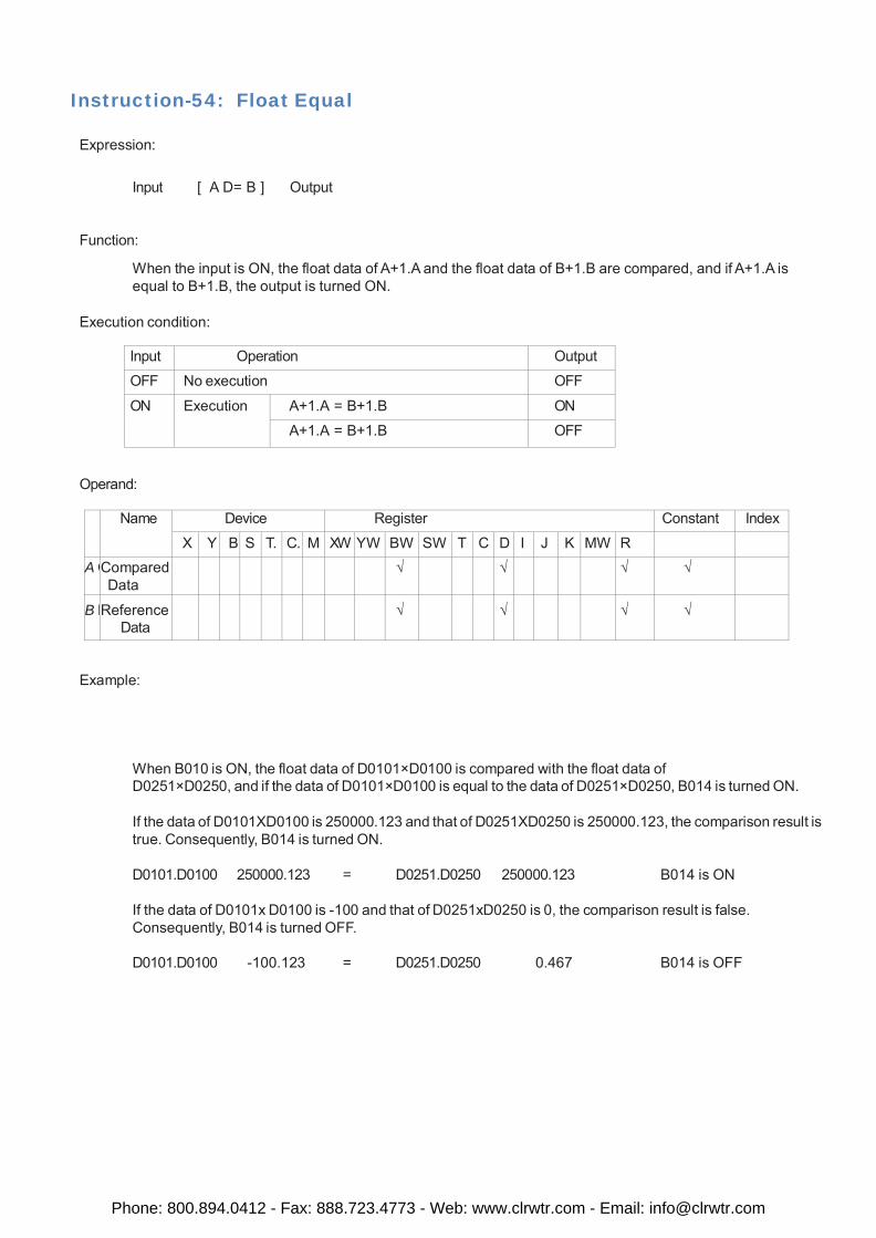
Instruction-54: Float Equal
Expression:
Input [ A D= B ] Output
Function:
When the input is ON, the float data of A+1.A and the float data of B+1.B are compared, and if A+1.A is equal to B+1.B, the output is turned ON.
Execution condition:
Input Operation Output
OFF No execution OFF
ON Execution A+1.A = B+1.B ON
A+1.A = B+1.B OFF
Operand:
Name Device Register Constant Index
X Y B S T. C. M XW YW BW SW T C D I J K MW R A C Compared
Data √ √ √ √
B R Reference Data
√ √ √ √
Example:
When B010 is ON, the float data of D0101×D0100 is compared with the float data of D0251×D0250, and if the data of D0101×D0100 is equal to the data of D0251×D0250, B014 is turned ON.
If the data of D0101XD0100 is 250000.123 and that of D0251XD0250 is 250000.123, the comparison result is true. Consequently, B014 is turned ON.
D0101.D0100 250000.123 = D0251.D0250 250000.123 B014 is ON
If the data of D0101x D0100 is -100 and that of D0251xD0250 is 0, the comparison result is false. Consequently, B014 is turned OFF.
D0101.D0100 -100.123 = D0251.D0250 0.467 B014 is OFF
Phone: 800.894.0412 - Fax: 888.723.4773 - Web: www.clrwtr.com - Email: [email protected]
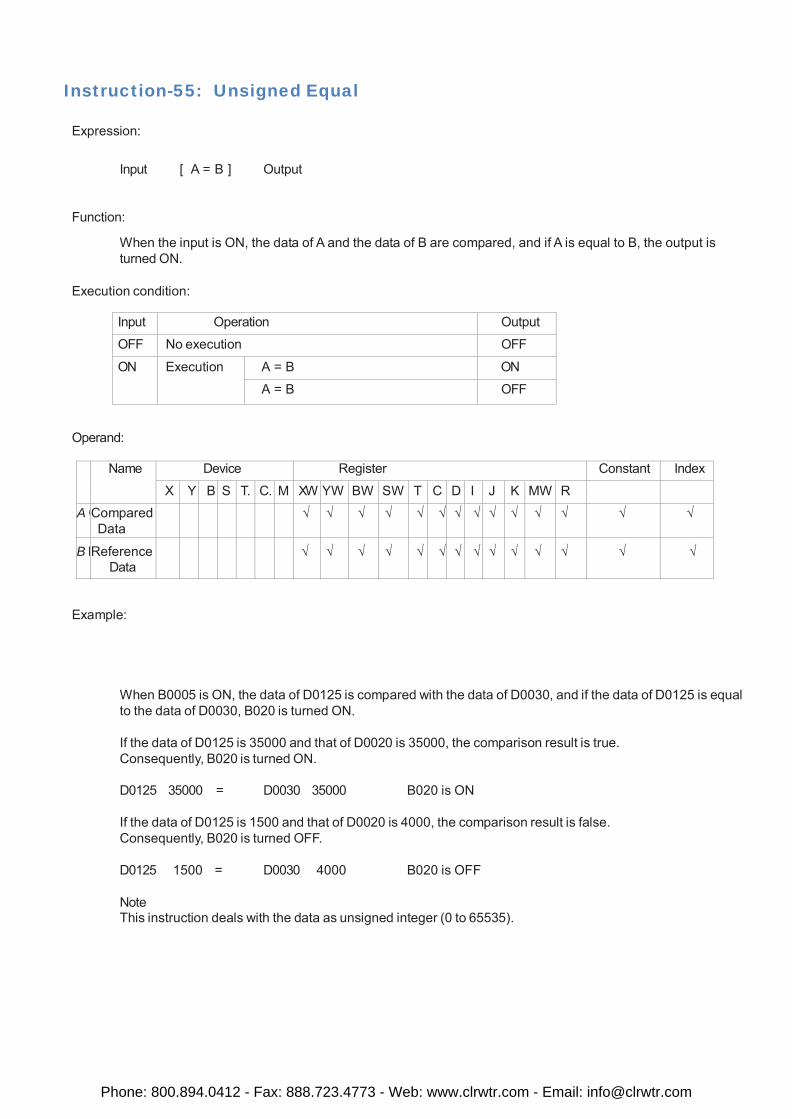
Instruction-55: Unsigned Equal
Expression:
Input [ A = B ] Output
Function:
When the input is ON, the data of A and the data of B are compared, and if A is equal to B, the output is turned ON.
Execution condition:
Input Operation Output
OFF No execution OFF
ON Execution A = B ON
A = B OFF
Operand:
Name Device Register Constant Index
X Y B S T. C. M XW YW BW SW T C D I J K MW R A C Compared
Data √ √ √ √ √ √ √ √ √ √ √ √ √ √
B R Reference Data
√ √ √ √ √ √ √ √ √ √ √ √ √ √
Example:
When B0005 is ON, the data of D0125 is compared with the data of D0030, and if the data of D0125 is equal to the data of D0030, B020 is turned ON.
If the data of D0125 is 35000 and that of D0020 is 35000, the comparison result is true. Consequently, B020 is turned ON.
D0125 35000 = D0030 35000 B020 is ON
If the data of D0125 is 1500 and that of D0020 is 4000, the comparison result is false. Consequently, B020 is turned OFF.
D0125 1500 = D0030 4000 B020 is OFF
Note This instruction deals with the data as unsigned integer (0 to 65535).
Phone: 800.894.0412 - Fax: 888.723.4773 - Web: www.clrwtr.com - Email: [email protected]
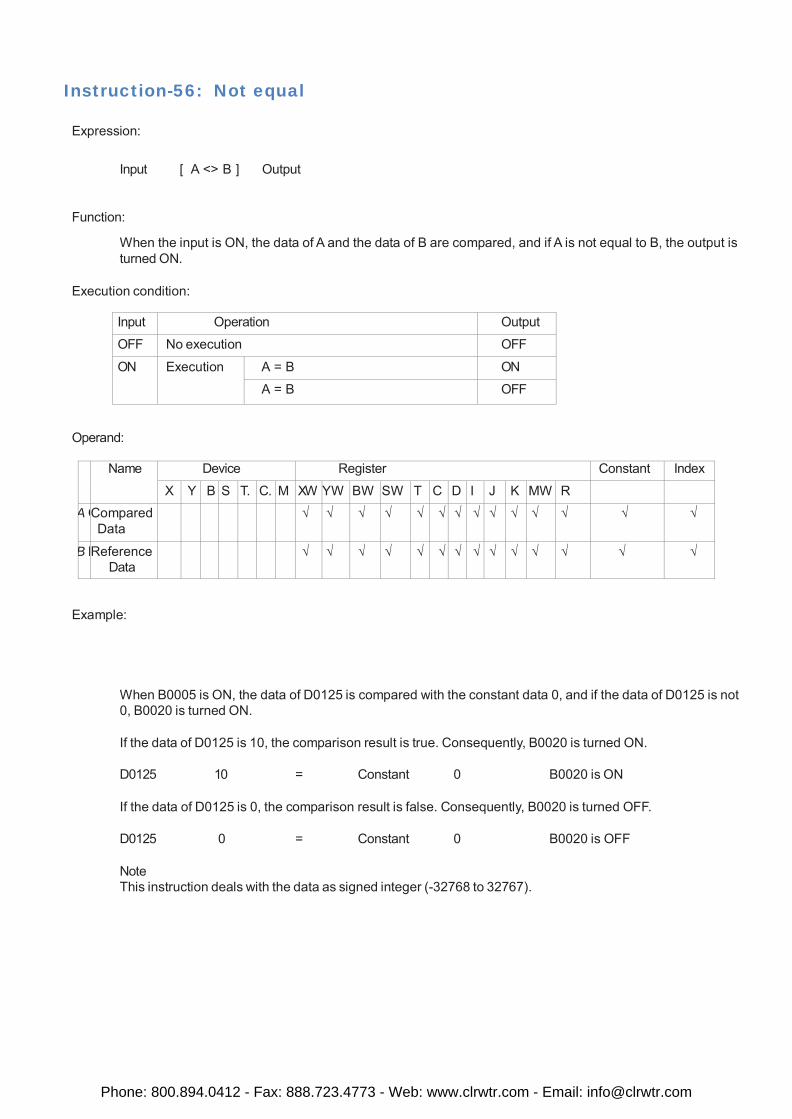
Instruction-56: Not equal
Expression:
Input [ A <> B ] Output
Function:
When the input is ON, the data of A and the data of B are compared, and if A is not equal to B, the output is turned ON.
Execution condition:
Input Operation Output
OFF No execution OFF
ON Execution A = B ON
A = B OFF
Operand:
Name Device Register Constant Index
X Y B S T. C. M XW YW BW SW T C D I J K MW R A C Compared
Data √ √ √ √ √ √ √ √ √ √ √ √ √ √
B R Reference Data
√ √ √ √ √ √ √ √ √ √ √ √ √ √
Example:
When B0005 is ON, the data of D0125 is compared with the constant data 0, and if the data of D0125 is not 0, B0020 is turned ON.
If the data of D0125 is 10, the comparison result is true. Consequently, B0020 is turned ON.
D0125 10 = Constant 0 B0020 is ON
If the data of D0125 is 0, the comparison result is false. Consequently, B0020 is turned OFF.
D0125 0 = Constant 0 B0020 is OFF
Note This instruction deals with the data as signed integer (-32768 to 32767).
Phone: 800.894.0412 - Fax: 888.723.4773 - Web: www.clrwtr.com - Email: [email protected]
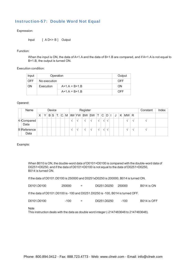
Instruction-57: Double Word Not Equal
Expression:
Input [ A D<> B ] Output
Function:
When the input is ON, the data of A+1.A and the data of B+1.B are compared, and if A+1.A is not equal to B+1.B, the output is turned ON.
Execution condition:
Input Operation Output
OFF No execution OFF
ON Execution A+1.A = B+1.B ON
A+1.A = B+1.B OFF
Operand:
Name Device Register Constant Index
X Y B S T. C. M XW YW BW SW T C D I J K MW R A C Compared
Data √ √ √ √ √ √ √ √ √ √
B R Reference Data
√ √ √ √ √ √ √ √ √ √
Example:
When B010 is ON, the double-word data of D0101×D0100 is compared with the double-word data of D0251×D0250, and if the data of D0101×D0100 is not equal to the data of D0251×D0250, B014 is turned ON.
If the data of D0101.D0100 is 250000 and D0251xD0250 is 200000, B014 is turned ON.
D0101.D0100 250000 = D0251.D0250 250000 B014 is ON
If the data of D0101.D0100 is -100 and D0251.D0250 is -100, B014 is turned OFF.
D0101.D0100 -100 = D0251.D0250 -100 B014 is OFF
Note This instruction deals with the data as double word integer (-2147483648 to 2147483648).
Phone: 800.894.0412 - Fax: 888.723.4773 - Web: www.clrwtr.com - Email: [email protected]
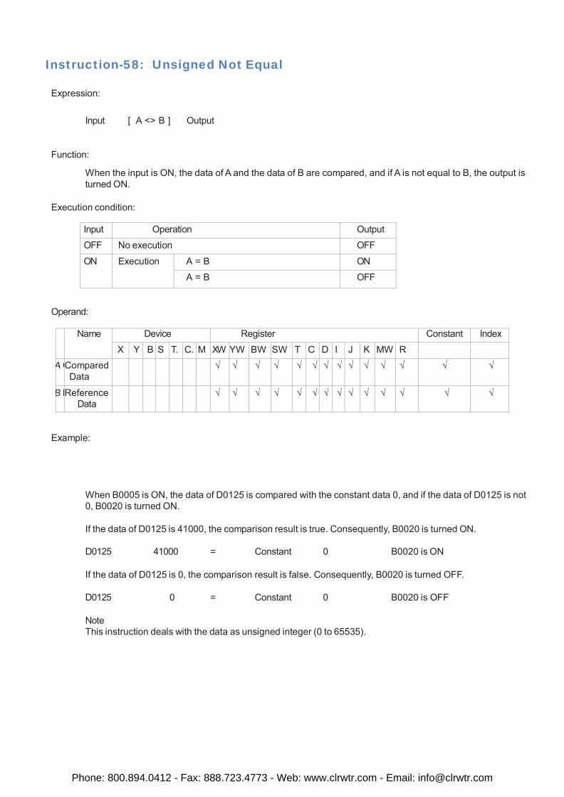
Instruction-58: Unsigned Not Equal
Expression:
Input [ A <> B ] Output
Function:
When the input is ON, the data of A and the data of B are compared, and if A is not equal to B, the output is turned ON.
Execution condition:
Input Operation Output
OFF No execution OFF
ON Execution A = B ON
A = B OFF
Operand:
Name Device Register Constant Index
X Y B S T. C. M XW YW BW SW T C D I J K MW R A C Compared
Data √ √ √ √ √ √ √ √ √ √ √ √ √ √
B R Reference Data
√ √ √ √ √ √ √ √ √ √ √ √ √ √
Example:
When B0005 is ON, the data of D0125 is compared with the constant data 0, and if the data of D0125 is not 0, B0020 is turned ON.
If the data of D0125 is 41000, the comparison result is true. Consequently, B0020 is turned ON.
D0125 41000 = Constant 0 B0020 is ON
If the data of D0125 is 0, the comparison result is false. Consequently, B0020 is turned OFF.
D0125 0 = Constant 0 B0020 is OFF
Note This instruction deals with the data as unsigned integer (0 to 65535).
Phone: 800.894.0412 - Fax: 888.723.4773 - Web: www.clrwtr.com - Email: [email protected]
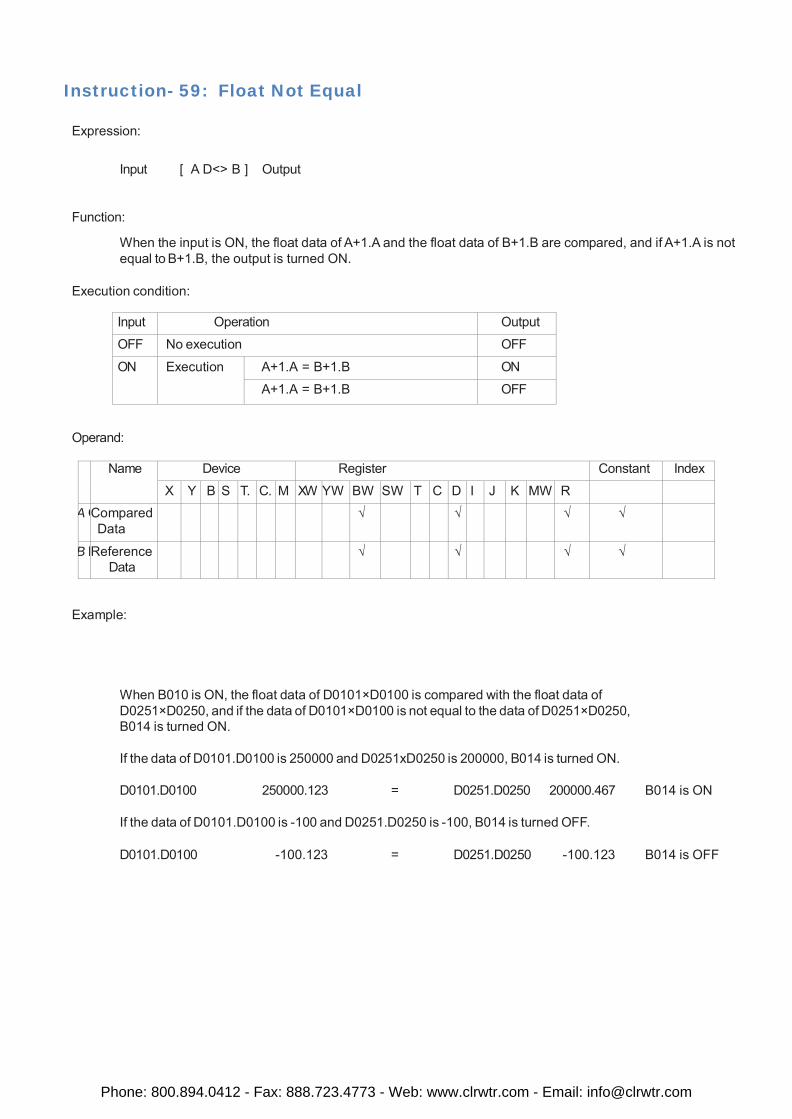
Instruction- 59: Float Not Equal
Expression:
Input [ A D<> B ] Output
Function:
When the input is ON, the float data of A+1.A and the float data of B+1.B are compared, and if A+1.A is not equal to B+1.B, the output is turned ON.
Execution condition:
Input Operation Output
OFF No execution OFF
ON Execution A+1.A = B+1.B ON
A+1.A = B+1.B OFF
Operand:
Name Device Register Constant Index
X Y B S T. C. M XW YW BW SW T C D I J K MW R A C Compared
Data √ √ √ √
B R Reference Data
√ √ √ √
Example:
When B010 is ON, the float data of D0101×D0100 is compared with the float data of D0251×D0250, and if the data of D0101×D0100 is not equal to the data of D0251×D0250, B014 is turned ON.
If the data of D0101.D0100 is 250000 and D0251xD0250 is 200000, B014 is turned ON.
D0101.D0100 250000.123 = D0251.D0250 200000.467 B014 is ON
If the data of D0101.D0100 is -100 and D0251.D0250 is -100, B014 is turned OFF.
D0101.D0100 -100.123 = D0251.D0250 -100.123 B014 is OFF
Phone: 800.894.0412 - Fax: 888.723.4773 - Web: www.clrwtr.com - Email: [email protected]
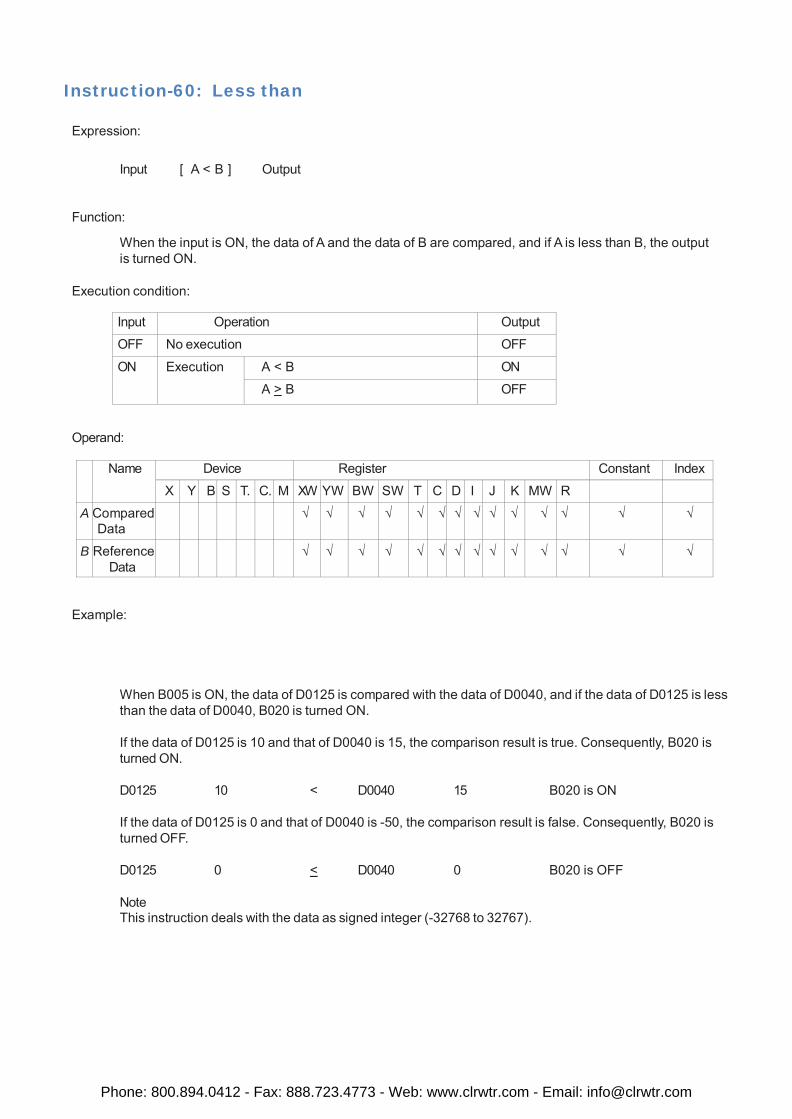
Instruction-60: Less than
Expression:
Input [ A < B ] Output
Function:
When the input is ON, the data of A and the data of B are compared, and if A is less than B, the output is turned ON.
Execution condition:
Input Operation Output
OFF No execution OFF
ON Execution A < B ON
A > B OFF
Operand:
Name Device Register Constant Index
X Y B S T. C. M XW YW BW SW T C D I J K MW R
A Compared Data
√ √ √ √ √ √ √ √ √ √ √ √ √ √
B Reference Data
√ √ √ √ √ √ √ √ √ √ √ √ √ √
Example:
When B005 is ON, the data of D0125 is compared with the data of D0040, and if the data of D0125 is less than the data of D0040, B020 is turned ON.
If the data of D0125 is 10 and that of D0040 is 15, the comparison result is true. Consequently, B020 is turned ON.
D0125 10 < D0040 15 B020 is ON
If the data of D0125 is 0 and that of D0040 is -50, the comparison result is false. Consequently, B020 is turned OFF.
D0125 0 < D0040 0 B020 is OFF
Note This instruction deals with the data as signed integer (-32768 to 32767).
Phone: 800.894.0412 - Fax: 888.723.4773 - Web: www.clrwtr.com - Email: [email protected]
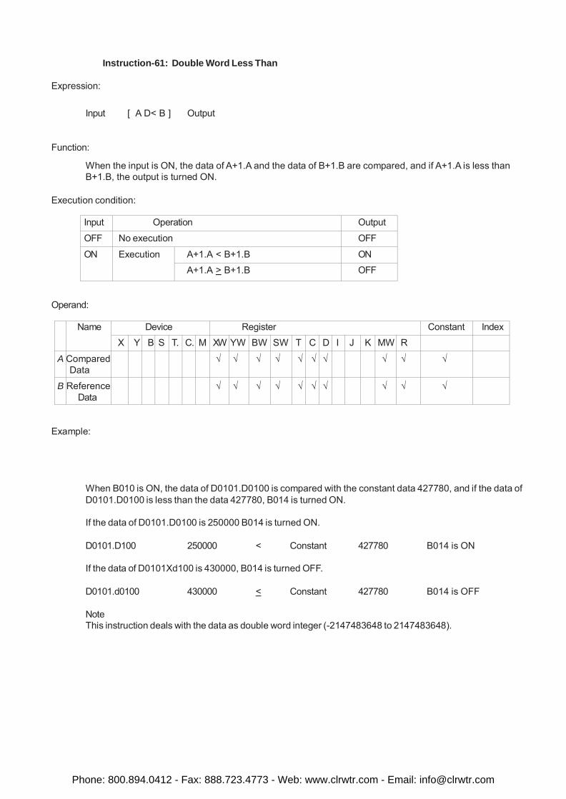
Instruction-61: Double Word Less Than
Expression:
Input [ A D< B ] Output
Function:
When the input is ON, the data of A+1.A and the data of B+1.B are compared, and if A+1.A is less than B+1.B, the output is turned ON.
Execution condition:
Input Operation Output
OFF No execution OFF
ON Execution A+1.A < B+1.B ON A+1.A > B+1.B OFF
Operand:
Name Device Register Constant Index X Y B S T. C. M XW YW BW SW T C D I J K MW R
A Compared Data
√ √ √ √ √ √ √ √ √ √
B Reference Data
√ √ √ √ √ √ √ √ √ √
Example:
When B010 is ON, the data of D0101.D0100 is compared with the constant data 427780, and if the data of D0101.D0100 is less than the data 427780, B014 is turned ON.
If the data of D0101.D0100 is 250000 B014 is turned ON.
D0101.D100 250000 < Constant 427780 B014 is ON
If the data of D0101Xd100 is 430000, B014 is turned OFF.
D0101.d0100 430000 < Constant 427780 B014 is OFF
Note This instruction deals with the data as double word integer (-2147483648 to 2147483648).
Phone: 800.894.0412 - Fax: 888.723.4773 - Web: www.clrwtr.com - Email: [email protected]
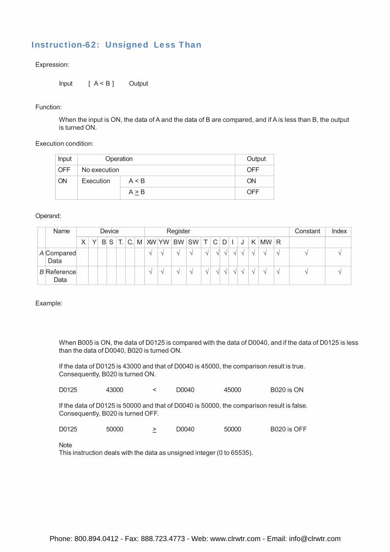
Instruction-62: Unsigned Less Than
Expression:
Input [ A < B ] Output
Function:
When the input is ON, the data of A and the data of B are compared, and if A is less than B, the output is turned ON.
Execution condition:
Input Operation Output
OFF No execution OFF
ON Execution A < B ON
A > B OFF
Operand:
Name Device Register Constant Index
X Y B S T. C. M XW YW BW SW T C D I J K MW R
A Compared Data
√ √ √ √ √ √ √ √ √ √ √ √ √ √
B Reference Data
√ √ √ √ √ √ √ √ √ √ √ √ √ √
Example:
When B005 is ON, the data of D0125 is compared with the data of D0040, and if the data of D0125 is less than the data of D0040, B020 is turned ON.
If the data of D0125 is 43000 and that of D0040 is 45000, the comparison result is true. Consequently, B020 is turned ON.
D0125 43000 < D0040 45000 B020 is ON
If the data of D0125 is 50000 and that of D0040 is 50000, the comparison result is false. Consequently, B020 is turned OFF.
D0125 50000 > D0040 50000 B020 is OFF
Note This instruction deals with the data as unsigned integer (0 to 65535).
Phone: 800.894.0412 - Fax: 888.723.4773 - Web: www.clrwtr.com - Email: [email protected]
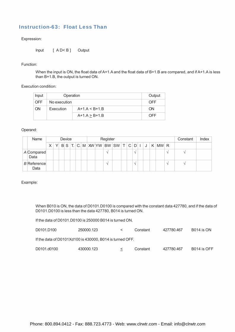
Instruction-63: Float Less Than
Expression:
Input [ A D< B ] Output
Function:
When the input is ON, the float data of A+1.A and the float data of B+1.B are compared, and if A+1.A is less than B+1.B, the output is turned ON.
Execution condition:
Input Operation Output
OFF No execution OFF
ON Execution A+1.A < B+1.B ON
A+1.A > B+1.B OFF
Operand:
Name Device Register Constant Index
X Y B S T. C. M XW YW BW SW T C D I J K MW R
A Compared Data
√ √ √ √
B Reference Data
√ √ √ √
Example:
When B010 is ON, the data of D0101.D0100 is compared with the constant data 427780, and if the data of D0101.D0100 is less than the data 427780, B014 is turned ON.
If the data of D0101.D0100 is 250000 B014 is turned ON.
D0101.D100 250000.123 < Constant 427780.467 B014 is ON
If the data of D0101Xd100 is 430000, B014 is turned OFF.
D0101.d0100 430000.123 < Constant 427780.467 B014 is OFF
Phone: 800.894.0412 - Fax: 888.723.4773 - Web: www.clrwtr.com - Email: [email protected]
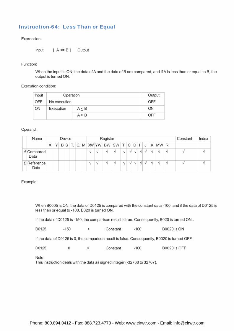
Instruction-64: Less Than or Equal
Expression:
Input [ A <= B ] Output
Function:
When the input is ON, the data of A and the data of B are compared, and if A is less than or equal to B, the output is turned ON.
Execution condition:
Input Operation Output
OFF No execution OFF
ON Execution A < B ON
A > B OFF
Operand:
Name Device Register Constant Index
X Y B S T. C. M XW YW BW SW T C D I J K MW R
A Compared Data
√ √ √ √ √ √ √ √ √ √ √ √ √ √
B Reference Data
√ √ √ √ √ √ √ √ √ √ √ √ √ √
Example:
When B0005 is ON, the data of D0125 is compared with the constant data -100, and if the data of D0125 is less than or equal to -100, B020 is turned ON.
If the data of D0125 is -150, the comparison result is true. Consequently, B020 is turned ON..
D0125 -150 < Constant -100 B0020 is ON
If the data of D0125 is 0, the comparison result is false. Consequently, B0020 is turned OFF.
D0125 0 > Constant -100 B0020 is OFF
Note This instruction deals with the data as signed integer (-32768 to 32767).
Phone: 800.894.0412 - Fax: 888.723.4773 - Web: www.clrwtr.com - Email: [email protected]
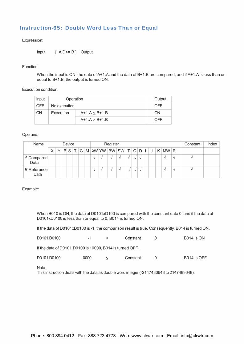
Instruction-65: Double Word Less Than or Equal
Expression:
Input [ A D<= B ] Output
Function:
When the input is ON, the data of A+1.A and the data of B+1.B are compared, and if A+1.A is less than or equal to B+1.B, the output is turned ON.
Execution condition:
Input Operation Output
OFF No execution OFF
ON Execution A+1.A < B+1.B ON
A+1.A > B+1.B OFF
Operand:
Name Device Register Constant Index
X Y B S T. C. M XW YW BW SW T C D I J K MW R
A Compared Data
√ √ √ √ √ √ √ √ √ √
B Reference Data
√ √ √ √ √ √ √ √ √ √
Example:
When B010 is ON, the data of D0101xD100 is compared with the constant data 0, and if the data of D0101xD0100 is less than or equal to 0, B014 is turned ON.
If the data of D0101xD0100 is -1, the comparison result is true. Consequently, B014 is turned ON.
D0101.D0100 -1 < Constant 0 B014 is ON
If the data of D0101.D0100 is 10000, B014 is turned OFF.
D0101.D0100 10000 < Constant 0 B014 is OFF
Note This instruction deals with the data as double word integer (-2147483648 to 2147483648).
Phone: 800.894.0412 - Fax: 888.723.4773 - Web: www.clrwtr.com - Email: [email protected]
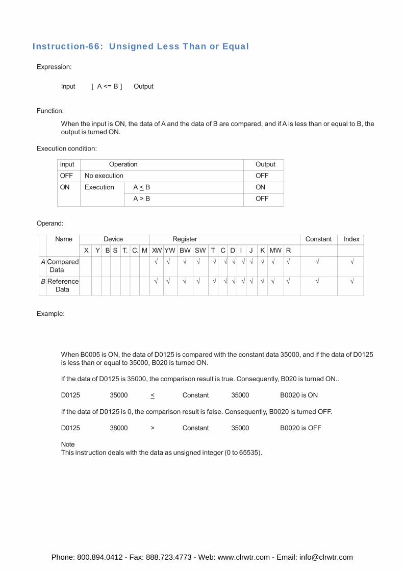
Instruction-66: Unsigned Less Than or Equal
Expression:
Input [ A <= B ] Output
Function:
When the input is ON, the data of A and the data of B are compared, and if A is less than or equal to B, the output is turned ON.
Execution condition:
Input Operation Output
OFF No execution OFF
ON Execution A < B ON
A > B OFF
Operand:
Name Device Register Constant Index
X Y B S T. C. M XW YW BW SW T C D I J K MW R
A Compared Data
√ √ √ √ √ √ √ √ √ √ √ √ √ √
B Reference Data
√ √ √ √ √ √ √ √ √ √ √ √ √ √
Example:
When B0005 is ON, the data of D0125 is compared with the constant data 35000, and if the data of D0125 is less than or equal to 35000, B020 is turned ON.
If the data of D0125 is 35000, the comparison result is true. Consequently, B020 is turned ON..
D0125 35000 < Constant 35000 B0020 is ON
If the data of D0125 is 0, the comparison result is false. Consequently, B0020 is turned OFF.
D0125 38000 > Constant 35000 B0020 is OFF
Note This instruction deals with the data as unsigned integer (0 to 65535).
Phone: 800.894.0412 - Fax: 888.723.4773 - Web: www.clrwtr.com - Email: [email protected]
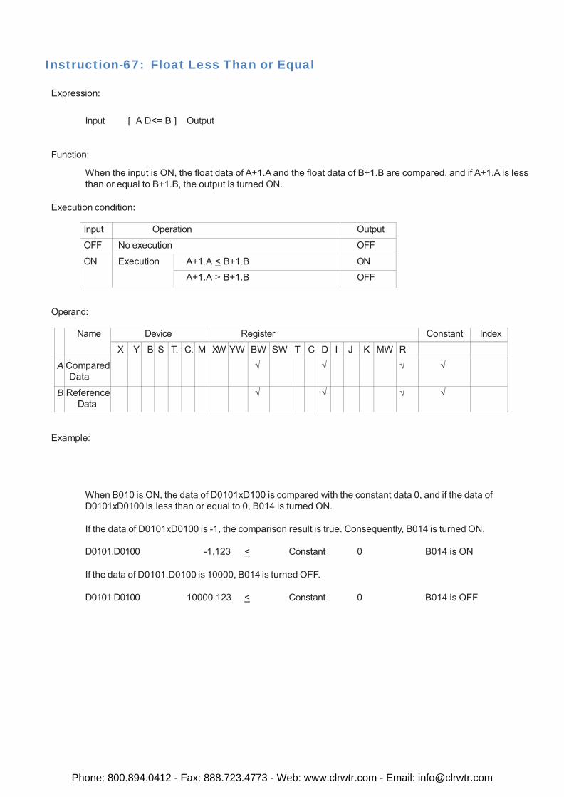
Instruction-67: Float Less Than or Equal
Expression:
Input [ A D<= B ] Output
Function:
When the input is ON, the float data of A+1.A and the float data of B+1.B are compared, and if A+1.A is less than or equal to B+1.B, the output is turned ON.
Execution condition:
Input Operation Output
OFF No execution OFF
ON Execution A+1.A < B+1.B ON
A+1.A > B+1.B OFF
Operand:
Name Device Register Constant Index
X Y B S T. C. M XW YW BW SW T C D I J K MW R
A Compared Data
√ √ √ √
B Reference Data
√ √ √ √
Example:
When B010 is ON, the data of D0101xD100 is compared with the constant data 0, and if the data of D0101xD0100 is less than or equal to 0, B014 is turned ON.
If the data of D0101xD0100 is -1, the comparison result is true. Consequently, B014 is turned ON.
D0101.D0100 -1.123 < Constant 0 B014 is ON
If the data of D0101.D0100 is 10000, B014 is turned OFF.
D0101.D0100 10000.123 < Constant 0 B014 is OFF
Phone: 800.894.0412 - Fax: 888.723.4773 - Web: www.clrwtr.com - Email: [email protected]
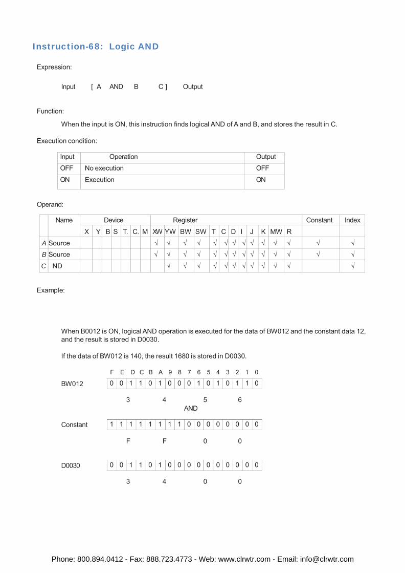
0 0 1 1 0 1 0 0 0 1 0 1 0 1 1 0
1 1 1 1 1 1 1 1 0 0 0 0 0 0 0 0
0 0 1 1 0 1 0 0 0 0 0 0 0 0 0 0
Instruction-68: Logic AND
Expression:
Input [ A AND B C ] Output
Function:
When the input is ON, this instruction finds logical AND of A and B, and stores the result in C.
Execution condition:
Input Operation Output
OFF No execution OFF
ON Execution ON
Operand:
Name Device Register Constant Index
X Y B S T. C. M XW YW BW SW T C D I J K MW R
A Source √ √ √ √ √ √ √ √ √ √ √ √ √ √ B Source √ √ √ √ √ √ √ √ √ √ √ √ √ √
C A ND √ √ √ √ √ √ √ √ √ √ √ √
Example:
When B0012 is ON, logical AND operation is executed for the data of BW012 and the constant data 12, and the result is stored in D0030.
If the data of BW012 is 140, the result 1680 is stored in D0030.
BW012
F E D C B A 9 8 7 6 5 4 3 2 1 0
3 4 5 6
AND
Constant
F F 0 0
D0030
3 4 0 0
Phone: 800.894.0412 - Fax: 888.723.4773 - Web: www.clrwtr.com - Email: [email protected]
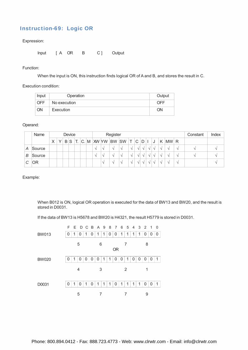
0 1 0 1 0 1 1 0 0 1 1 1 1 0 0 0
0 1 0 0 0 0 1 1 0 0 1 0 0 0 0 1
0 1 0 1 0 1 1 1 0 1 1 1 1 0 0 1
Instruction-69: Logic OR
Expression:
Input [ A OR B C ] Output
Function:
When the input is ON, this instruction finds logical OR of A and B, and stores the result in C.
Execution condition:
Input Operation Output
OFF No execution OFF
ON Execution ON
Operand:
Name Device Register Constant Index
X Y B S T. C. M XW YW BW SW T C D I J K MW R
A Source √ √ √ √ √ √ √ √ √ √ √ √ √ √
B Source √ √ √ √ √ √ √ √ √ √ √ √ √ √ C OR √ √ √ √ √ √ √ √ √ √ √ √
Example:
When B012 is ON, logical OR operation is executed for the data of BW13 and BW20, and the result is stored in D0031.
If the data of BW13 is H5678 and BW20 is H4321, the result H5779 is stored in D0031.
BW013 F E D C B A 9 8 7 6 5 4 3 2 1 0
5 6 7 8
OR
BW020
4 3 2 1
D0031
5 7 7 9
Phone: 800.894.0412 - Fax: 888.723.4773 - Web: www.clrwtr.com - Email: [email protected]
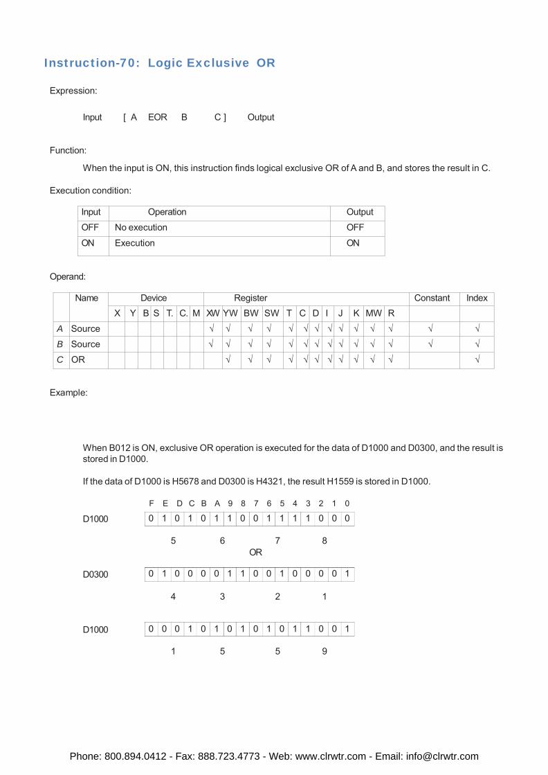
0 1 0 1 0 1 1 0 0 1 1 1 1 0 0 0
0 1 0 0 0 0 1 1 0 0 1 0 0 0 0 1
0 0 0 1 0 1 0 1 0 1 0 1 1 0 0 1
Instruction-70: Logic Exclusive OR
Expression:
Input [ A EOR B C ] Output
Function:
When the input is ON, this instruction finds logical exclusive OR of A and B, and stores the result in C.
Execution condition:
Input Operation Output
OFF No execution OFF
ON Execution ON
Operand:
Name Device Register Constant Index
X Y B S T. C. M XW YW BW SW T C D I J K MW R
A Source √ √ √ √ √ √ √ √ √ √ √ √ √ √
B Source √ √ √ √ √ √ √ √ √ √ √ √ √ √
C OR √ √ √ √ √ √ √ √ √ √ √ √
Example:
When B012 is ON, exclusive OR operation is executed for the data of D1000 and D0300, and the result is stored in D1000.
If the data of D1000 is H5678 and D0300 is H4321, the result H1559 is stored in D1000.
D1000 F E D C B A 9 8 7 6 5 4 3 2 1 0
5 6 7 8
OR
D0300
4 3 2 1
D1000
1 5 5 9
Phone: 800.894.0412 - Fax: 888.723.4773 - Web: www.clrwtr.com - Email: [email protected]
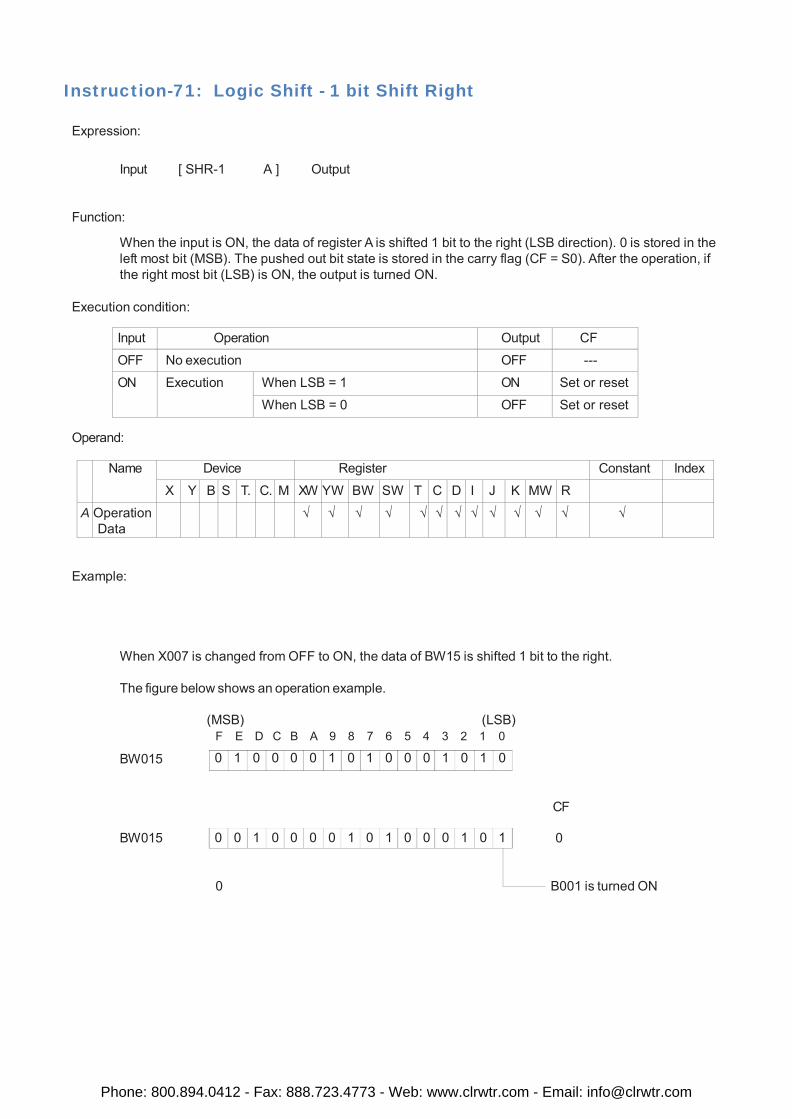
0 1 0 0 0 0 1 0 1 0 0 0 1 0 1 0
0 0 1 0 0 0 0 1 0 1 0 0 0 1 0 1
Instruction-71: Logic Shift - 1 bit Shift Right
Expression:
Input [ SHR-1 A ] Output
Function:
When the input is ON, the data of register A is shifted 1 bit to the right (LSB direction). 0 is stored in the left most bit (MSB). The pushed out bit state is stored in the carry flag (CF = S0). After the operation, if the right most bit (LSB) is ON, the output is turned ON.
Execution condition:
Input Operation Output CF
OFF No execution OFF ---
ON Execution When LSB = 1 ON Set or reset
When LSB = 0 OFF Set or reset
Operand:
Name Device Register Constant Index
X Y B S T. C. M XW YW BW SW T C D I J K MW R
A Operation Data
√ √ √ √ √ √ √ √ √ √ √ √ √
Example:
When X007 is changed from OFF to ON, the data of BW15 is shifted 1 bit to the right.
The figure below shows an operation example.
(MSB) (LSB) F E D C B A 9 8 7 6 5 4 3 2 1 0
BW015
CF
BW015 0 0 B001 is turned ON
Phone: 800.894.0412 - Fax: 888.723.4773 - Web: www.clrwtr.com - Email: [email protected]
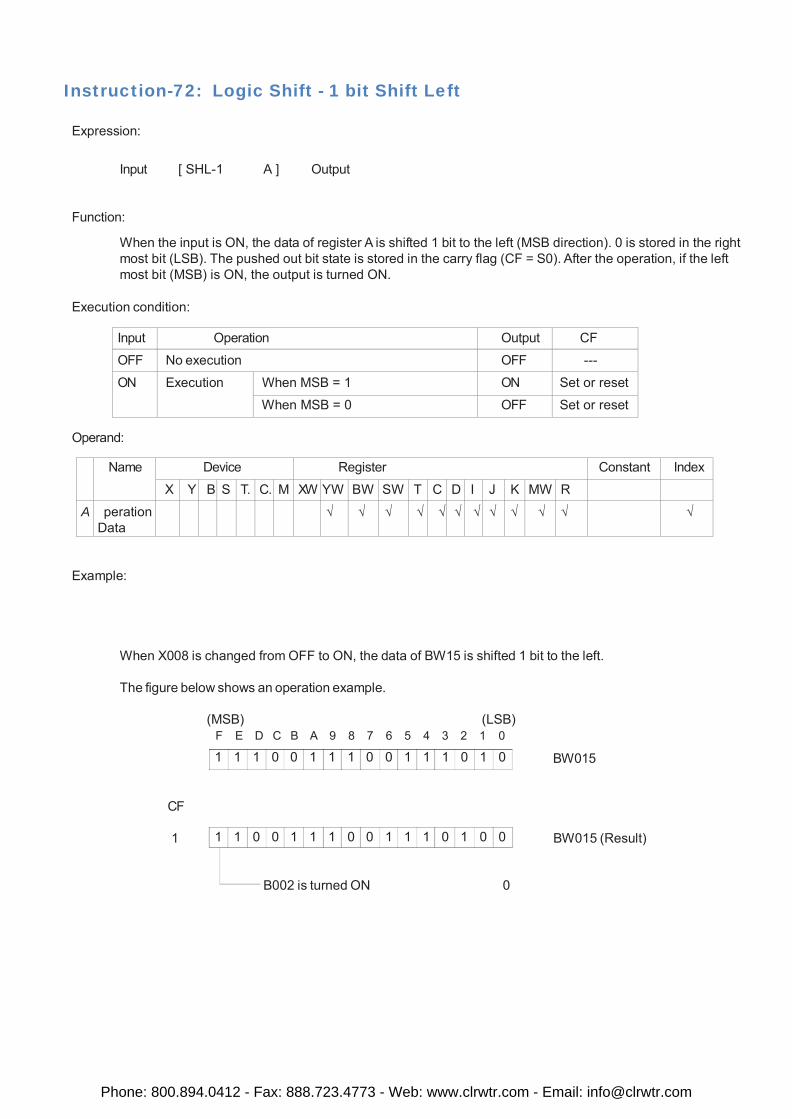
1 1 1 0 0 1 1 1 0 0 1 1 1 0 1 0
1 1 0 0 1 1 1 0 0 1 1 1 0 1 0 0
Instruction-72: Logic Shift - 1 bit Shift Left
Expression:
Input [ SHL-1 A ] Output
Function:
When the input is ON, the data of register A is shifted 1 bit to the left (MSB direction). 0 is stored in the right most bit (LSB). The pushed out bit state is stored in the carry flag (CF = S0). After the operation, if the left most bit (MSB) is ON, the output is turned ON.
Execution condition:
Input Operation Output CF
OFF No execution OFF ---
ON Execution When MSB = 1 ON Set or reset
When MSB = 0 OFF Set or reset
Operand:
Name Device Register Constant Index
X Y B S T. C. M XW YW BW SW T C D I J K MW R A peration
Data √ √ √ √ √ √ √ √ √ √ √ √
Example:
When X008 is changed from OFF to ON, the data of BW15 is shifted 1 bit to the left.
The figure below shows an operation example.
(MSB) (LSB) F E D C B A 9 8 7 6 5 4 3 2 1 0
BW015
CF
1 BW015 (Result)
B002 is turned ON 0
Phone: 800.894.0412 - Fax: 888.723.4773 - Web: www.clrwtr.com - Email: [email protected]
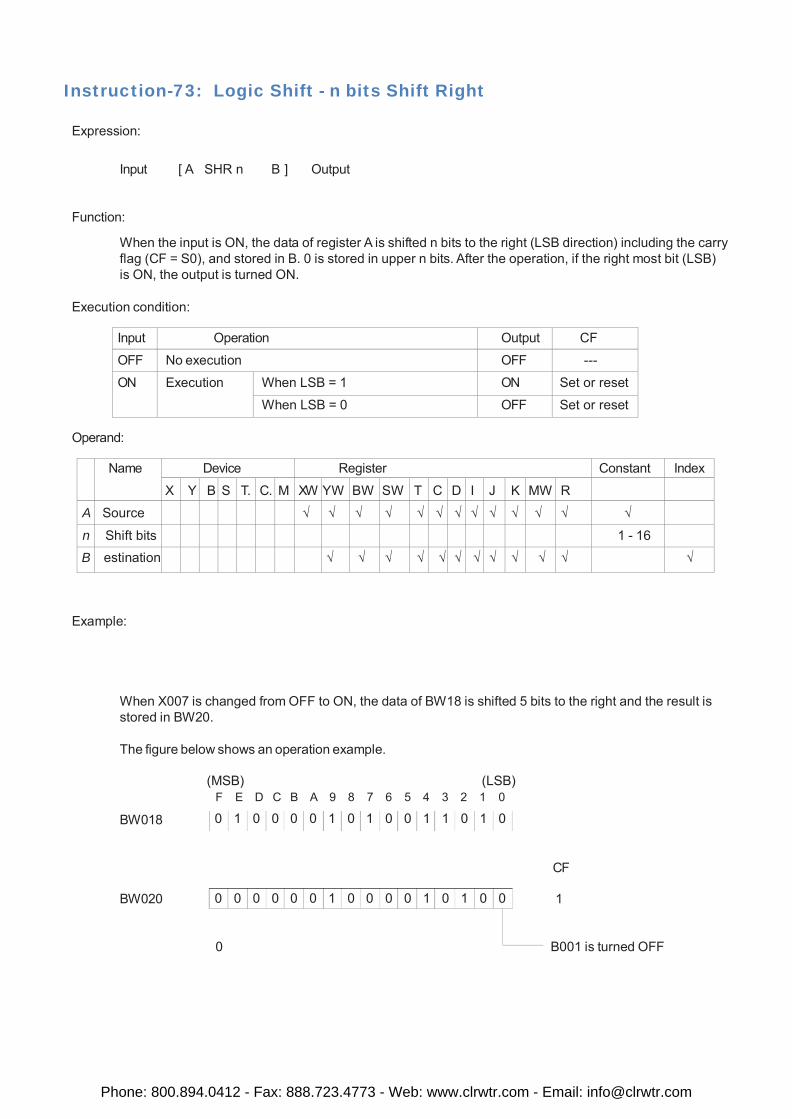
0 1 0 0 0 0 1 0 1 0 0 1 1 0 1 0
0 0 0 0 0 0 1 0 0 0 0 1 0 1 0 0
Instruction-73: Logic Shift - n bits Shift Right
Expression:
Input [ A SHR n B ] Output
Function:
When the input is ON, the data of register A is shifted n bits to the right (LSB direction) including the carry flag (CF = S0), and stored in B. 0 is stored in upper n bits. After the operation, if the right most bit (LSB) is ON, the output is turned ON.
Execution condition:
Input Operation Output CF
OFF No execution OFF ---
ON Execution When LSB = 1 ON Set or reset
When LSB = 0 OFF Set or reset
Operand:
Name Device Register Constant Index
X Y B S T. C. M XW YW BW SW T C D I J K MW R
A Source √ √ √ √ √ √ √ √ √ √ √ √ √
n Shift bits 1 - 16
B estination √ √ √ √ √ √ √ √ √ √ √ √
Example:
When X007 is changed from OFF to ON, the data of BW18 is shifted 5 bits to the right and the result is stored in BW20.
The figure below shows an operation example.
(MSB) (LSB) F E D C B A 9 8 7 6 5 4 3 2 1 0
BW018
CF
BW020 1 0 B001 is turned OFF
Phone: 800.894.0412 - Fax: 888.723.4773 - Web: www.clrwtr.com - Email: [email protected]
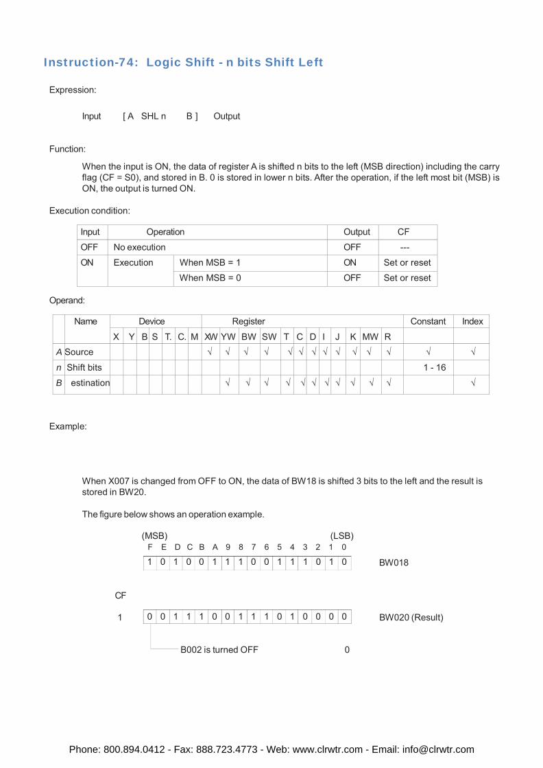
1 0 1 0 0 1 1 1 0 0 1 1 1 0 1 0
0 0 1 1 1 0 0 1 1 1 0 1 0 0 0 0
Instruction-74: Logic Shift - n bits Shift Left
Expression:
Input [ A SHL n B ] Output
Function:
When the input is ON, the data of register A is shifted n bits to the left (MSB direction) including the carry flag (CF = S0), and stored in B. 0 is stored in lower n bits. After the operation, if the left most bit (MSB) is ON, the output is turned ON.
Execution condition:
Input Operation Output CF
OFF No execution OFF ---
ON Execution When MSB = 1 ON Set or reset
When MSB = 0 OFF Set or reset
Operand:
Name Device Register Constant Index
X Y B S T. C. M XW YW BW SW T C D I J K MW R
A Source √ √ √ √ √ √ √ √ √ √ √ √ √ √
n Shift bits 1 - 16
B estination √ √ √ √ √ √ √ √ √ √ √ √
Example:
When X007 is changed from OFF to ON, the data of BW18 is shifted 3 bits to the left and the result is stored in BW20.
The figure below shows an operation example.
(MSB) (LSB) F E D C B A 9 8 7 6 5 4 3 2 1 0
BW018
CF
1 BW020 (Result)
B002 is turned OFF 0
Phone: 800.894.0412 - Fax: 888.723.4773 - Web: www.clrwtr.com - Email: [email protected]
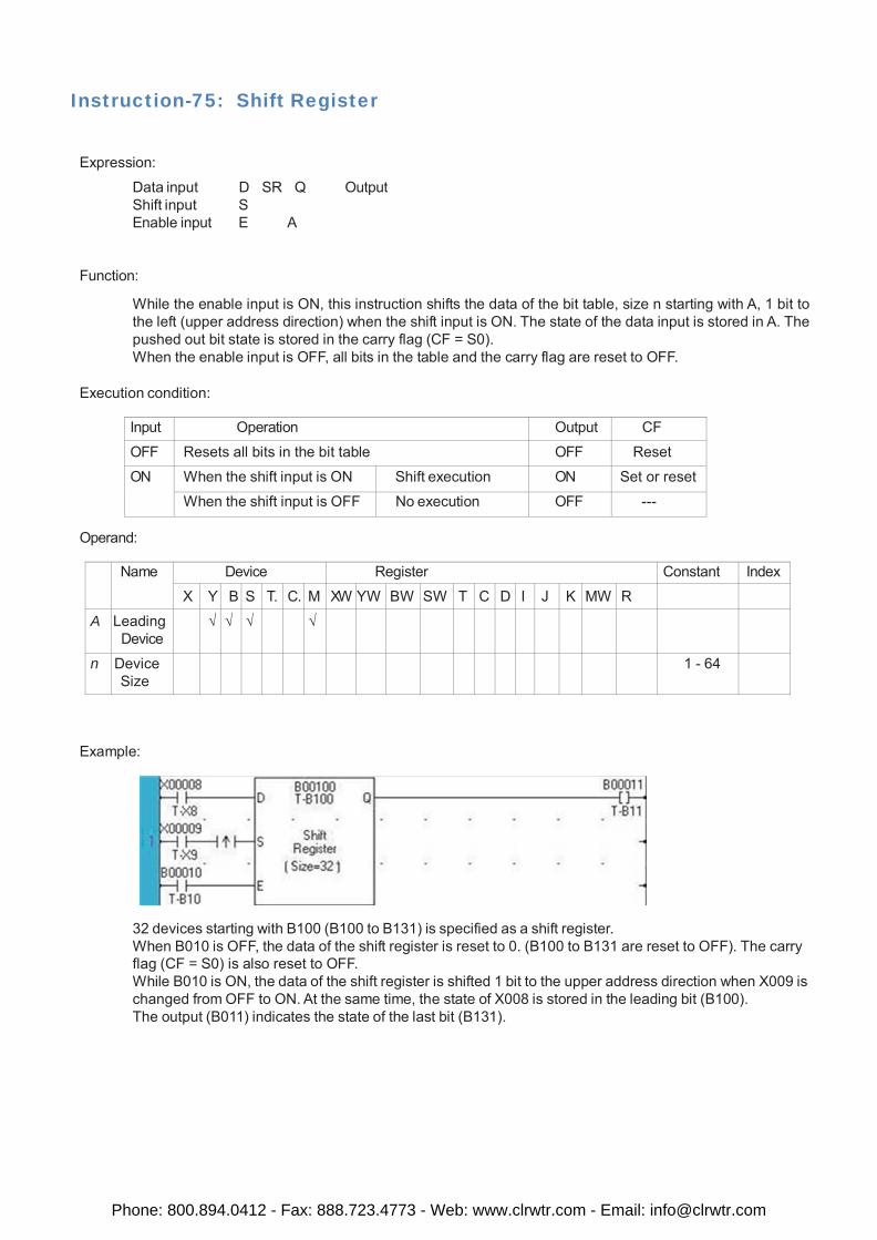
Instruction-75: Shift Register
Expression:
Data input D SR Q Output Shift input S Enable input E A
Function:
While the enable input is ON, this instruction shifts the data of the bit table, size n starting with A, 1 bit to the left (upper address direction) when the shift input is ON. The state of the data input is stored in A. The pushed out bit state is stored in the carry flag (CF = S0). When the enable input is OFF, all bits in the table and the carry flag are reset to OFF.
Execution condition:
Input Operation Output CF
OFF Resets all bits in the bit table OFF Reset
ON When the shift input is ON Shift execution ON Set or reset
When the shift input is OFF No execution OFF ---
Operand:
Name Device Register Constant Index
X Y B S T. C. M XW YW BW SW T C D I J K MW R
A Leading Device
√ √ √ √
n Device Size
1 - 64
Example:
32 devices starting with B100 (B100 to B131) is specified as a shift register. When B010 is OFF, the data of the shift register is reset to 0. (B100 to B131 are reset to OFF). The carry flag (CF = S0) is also reset to OFF. While B010 is ON, the data of the shift register is shifted 1 bit to the upper address direction when X009 is changed from OFF to ON. At the same time, the state of X008 is stored in the leading bit (B100). The output (B011) indicates the state of the last bit (B131).
Phone: 800.894.0412 - Fax: 888.723.4773 - Web: www.clrwtr.com - Email: [email protected]
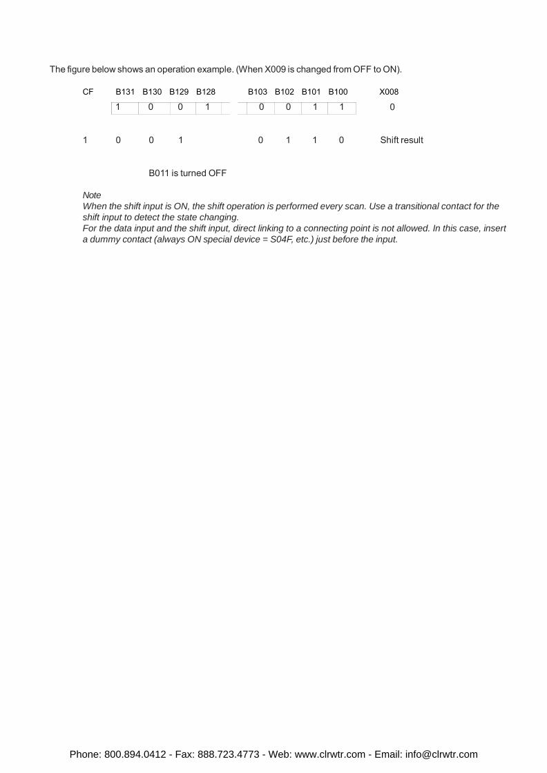
1 0 0 1
0 0 1 1
The figure below shows an operation example. (When X009 is changed from OFF to ON).
CF B131 B130 B129 B128 B103 B102 B101 B100 X008
0
1 0 0 1 0 1 1 0 Shift result
B011 is turned OFF
Note When the shift input is ON, the shift operation is performed every scan. Use a transitional contact for the shift input to detect the state changing. For the data input and the shift input, direct linking to a connecting point is not allowed. In this case, insert a dummy contact (always ON special device = S04F, etc.) just before the input.
Phone: 800.894.0412 - Fax: 888.723.4773 - Web: www.clrwtr.com - Email: [email protected]
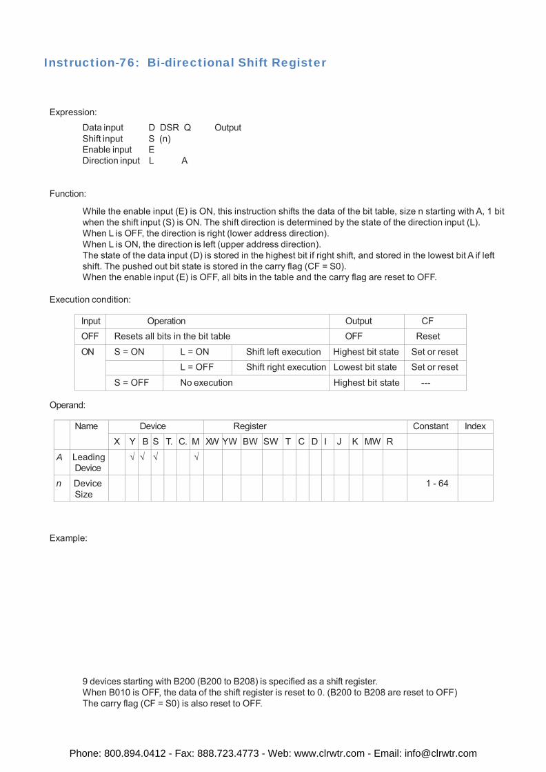
Instruction-76: Bi-directional Shift Register
Expression:
Data input D DSR Q Output Shift input S (n) Enable input E Direction input L A
Function:
While the enable input (E) is ON, this instruction shifts the data of the bit table, size n starting with A, 1 bit when the shift input (S) is ON. The shift direction is determined by the state of the direction input (L). When L is OFF, the direction is right (lower address direction). When L is ON, the direction is left (upper address direction). The state of the data input (D) is stored in the highest bit if right shift, and stored in the lowest bit A if left shift. The pushed out bit state is stored in the carry flag (CF = S0). When the enable input (E) is OFF, all bits in the table and the carry flag are reset to OFF.
Execution condition:
Input Operation Output CF OFF Resets all bits in the bit table OFF Reset
ON S = ON L = ON Shift left execution Highest bit state Set or reset L = OFF Shift right execution Lowest bit state Set or reset
S = OFF No execution Highest bit state ---
Operand:
Name Device Register Constant Index
X Y B S T. C. M XW YW BW SW T C D I J K MW R
A Leading Device
√ √ √ √
n Device Size
1 - 64
Example:
9 devices starting with B200 (B200 to B208) is specified as a shift register. When B010 is OFF, the data of the shift register is reset to 0. (B200 to B208 are reset to OFF) The carry flag (CF = S0) is also reset to OFF.
Phone: 800.894.0412 - Fax: 888.723.4773 - Web: www.clrwtr.com - Email: [email protected]
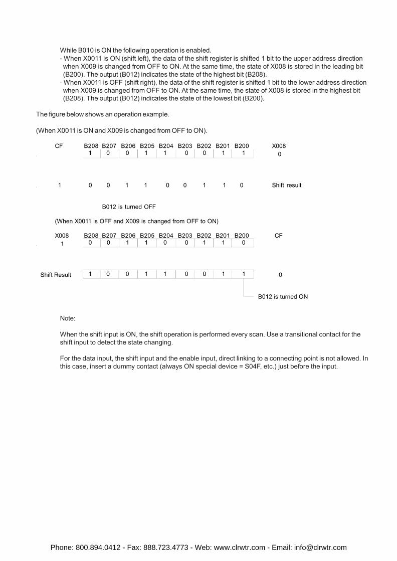
1 0 0 1 1 0 0 1 1
0 0 1 1 0 0 1 1 0
1 0 0 1 1 0 0 1 1
While B010 is ON the following operation is enabled. - When X0011 is ON (shift left), the data of the shift register is shifted 1 bit to the upper address direction when X009 is changed from OFF to ON. At the same time, the state of X008 is stored in the leading bit (B200). The output (B012) indicates the state of the highest bit (B208).
- When X0011 is OFF (shift right), the data of the shift register is shifted 1 bit to the lower address direction when X009 is changed from OFF to ON. At the same time, the state of X008 is stored in the highest bit (B208). The output (B012) indicates the state of the lowest bit (B200).
The figure below shows an operation example.
(When X0011 is ON and X009 is changed from OFF to ON).
CF B208 B207 B206 B205 B204 B203 B202 B201 B200 X008
. 0
. 1 0 0 1 1 0 0 1 1 0 Shift result
B012 is turned OFF
(When X0011 is OFF and X009 is changed from OFF to ON)
X008 B208 B207 B206 B205 B204 B203 B202 B201 B200 CF . 1
Shift Result 0 B012 is turned ON
Note:
When the shift input is ON, the shift operation is performed every scan. Use a transitional contact for the shift input to detect the state changing.
For the data input, the shift input and the enable input, direct linking to a connecting point is not allowed. In this case, insert a dummy contact (always ON special device = S04F, etc.) just before the input.
Phone: 800.894.0412 - Fax: 888.723.4773 - Web: www.clrwtr.com - Email: [email protected]
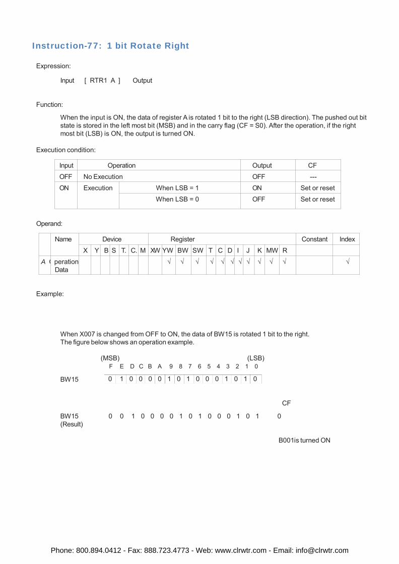
0 1 0 0 0 0 1 0 1 0 0 0 1 0 1 0
Instruction-77: 1 bit Rotate Right
Expression:
Input [ RTR1 A ] Output
Function:
When the input is ON, the data of register A is rotated 1 bit to the right (LSB direction). The pushed out bit state is stored in the left most bit (MSB) and in the carry flag (CF = S0). After the operation, if the right most bit (LSB) is ON, the output is turned ON.
Execution condition:
Input Operation Output CF
OFF No Execution OFF ---
ON Execution When LSB = 1 ON Set or reset
When LSB = 0 OFF Set or reset
Operand:
Name Device Register Constant Index
X Y B S T. C. M XW YW BW SW T C D I J K MW R
A O peration Data
√ √ √ √ √ √ √ √ √ √ √ √
Example:
When X007 is changed from OFF to ON, the data of BW15 is rotated 1 bit to the right. The figure below shows an operation example.
BW15
(MSB) (LSB) F E D C B A 9 8 7 6 5 4 3 2 1 0
CF
BW15 0 0 1 0 0 0 0 1 0 1 0 0 0 1 0 1 0 (Result)
B001is turned ON
Phone: 800.894.0412 - Fax: 888.723.4773 - Web: www.clrwtr.com - Email: [email protected]
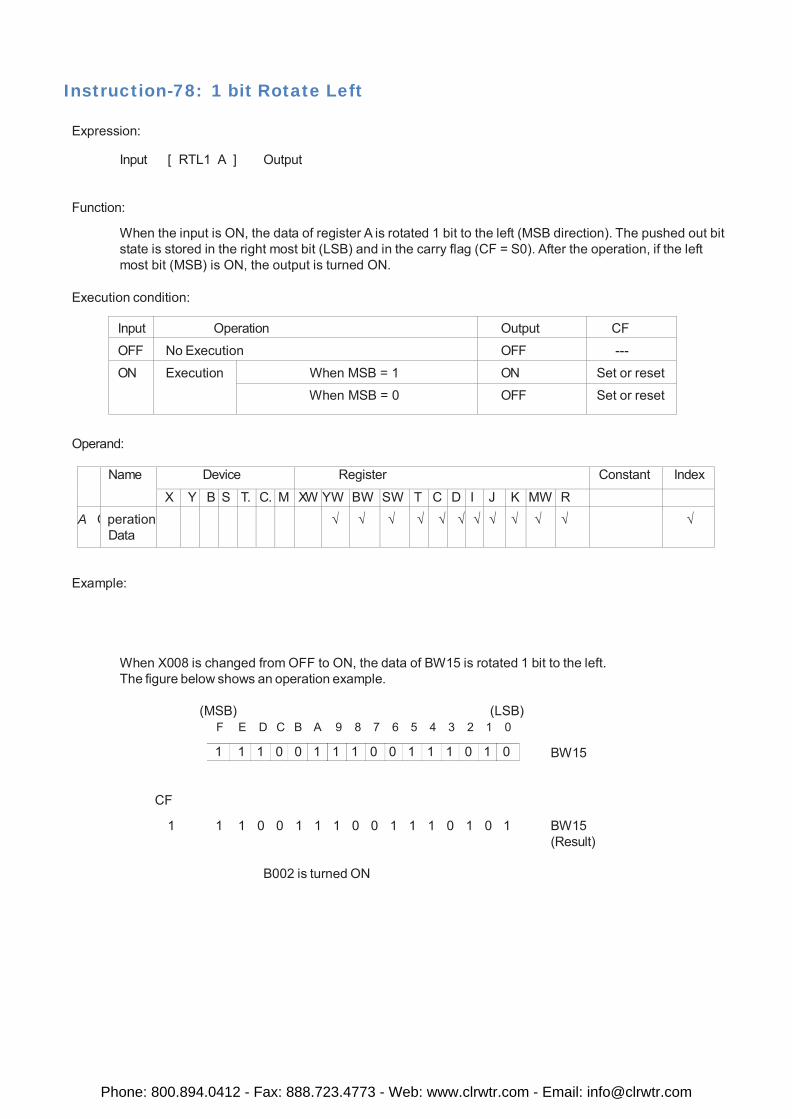
1 1 1 0 0 1 1 1 0 0 1 1 1 0 1 0
Instruction-78: 1 bit Rotate Left
Expression:
Input [ RTL1 A ] Output
Function:
When the input is ON, the data of register A is rotated 1 bit to the left (MSB direction). The pushed out bit state is stored in the right most bit (LSB) and in the carry flag (CF = S0). After the operation, if the left most bit (MSB) is ON, the output is turned ON.
Execution condition:
Input Operation Output CF
OFF No Execution OFF ---
ON Execution When MSB = 1 ON Set or reset
When MSB = 0 OFF Set or reset
Operand:
Name Device Register Constant Index
X Y B S T. C. M XW YW BW SW T C D I J K MW R A O peration
Data √ √ √ √ √ √ √ √ √ √ √ √
Example:
When X008 is changed from OFF to ON, the data of BW15 is rotated 1 bit to the left. The figure below shows an operation example.
(MSB) (LSB)
F E D C B A 9 8 7 6 5 4 3 2 1 0 BW15
CF
1 1 1 0 0 1 1 1 0 0 1 1 1 0 1 0 1 BW15 (Result)
B002 is turned ON
Phone: 800.894.0412 - Fax: 888.723.4773 - Web: www.clrwtr.com - Email: [email protected]
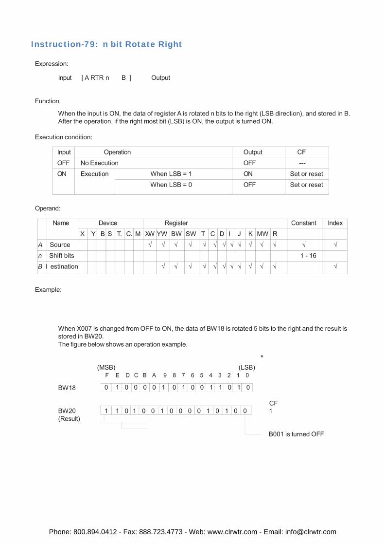
0 1 0 0 0 0 1 0 1 0 0 1 1 0 1 0
1 1 0 1 0 0 1 0 0 0 0 1 0 1 0 0
Instruction-79: n bit Rotate Right
Expression:
Input [ A RTR n B ] Output
Function:
When the input is ON, the data of register A is rotated n bits to the right (LSB direction), and stored in B. After the operation, if the right most bit (LSB) is ON, the output is turned ON.
Execution condition:
Input Operation Output CF
OFF No Execution OFF ---
ON Execution When LSB = 1 ON Set or reset
When LSB = 0 OFF Set or reset
Operand:
Name Device Register Constant Index
X Y B S T. C. M XW YW BW SW T C D I J K MW R
A Source √ √ √ √ √ √ √ √ √ √ √ √ √ √
n Shift bits 1 - 16
B D estination √ √ √ √ √ √ √ √ √ √ √ √
Example:
When X007 is changed from OFF to ON, the data of BW18 is rotated 5 bits to the right and the result is stored in BW20. The figure below shows an operation example.
BW18
* (MSB) (LSB)
F E D C B A 9 8 7 6 5 4 3 2 1 0
CF
BW20 1 (Result)
B001 is turned OFF
Phone: 800.894.0412 - Fax: 888.723.4773 - Web: www.clrwtr.com - Email: [email protected]
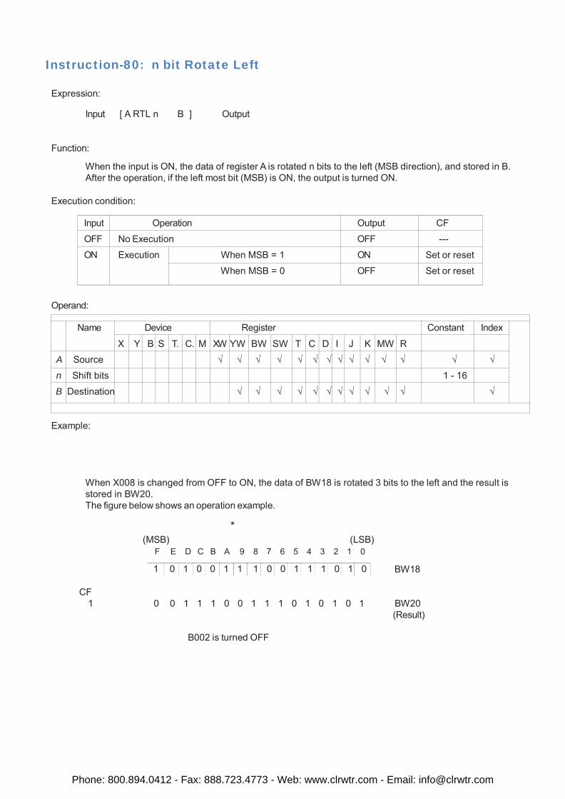
1 0 1 0 0 1 1 1 0 0 1 1 1 0 1 0
Instruction-80: n bit Rotate Left
Expression:
Input [ A RTL n B ] Output
Function:
When the input is ON, the data of register A is rotated n bits to the left (MSB direction), and stored in B. After the operation, if the left most bit (MSB) is ON, the output is turned ON.
Execution condition:
Input Operation Output CF
OFF No Execution OFF ---
ON Execution When MSB = 1 ON Set or reset
When MSB = 0 OFF Set or reset
Operand:
Name Device Register Constant Index X Y B S T. C. M XW YW BW SW T C D I J K MW R
A Source √ √ √ √ √ √ √ √ √ √ √ √ √ √
n Shift bits 1 - 16 B Destination √ √ √ √ √ √ √ √ √ √ √ √
Example:
When X008 is changed from OFF to ON, the data of BW18 is rotated 3 bits to the left and the result is stored in BW20. The figure below shows an operation example.
*
(MSB) (LSB) F E D C B A 9 8 7 6 5 4 3 2 1 0
BW18
CF
1 0 0 1 1 1 0 0 1 1 1 0 1 0 1 0 1 BW20 (Result)
B002 is turned OFF
Phone: 800.894.0412 - Fax: 888.723.4773 - Web: www.clrwtr.com - Email: [email protected]
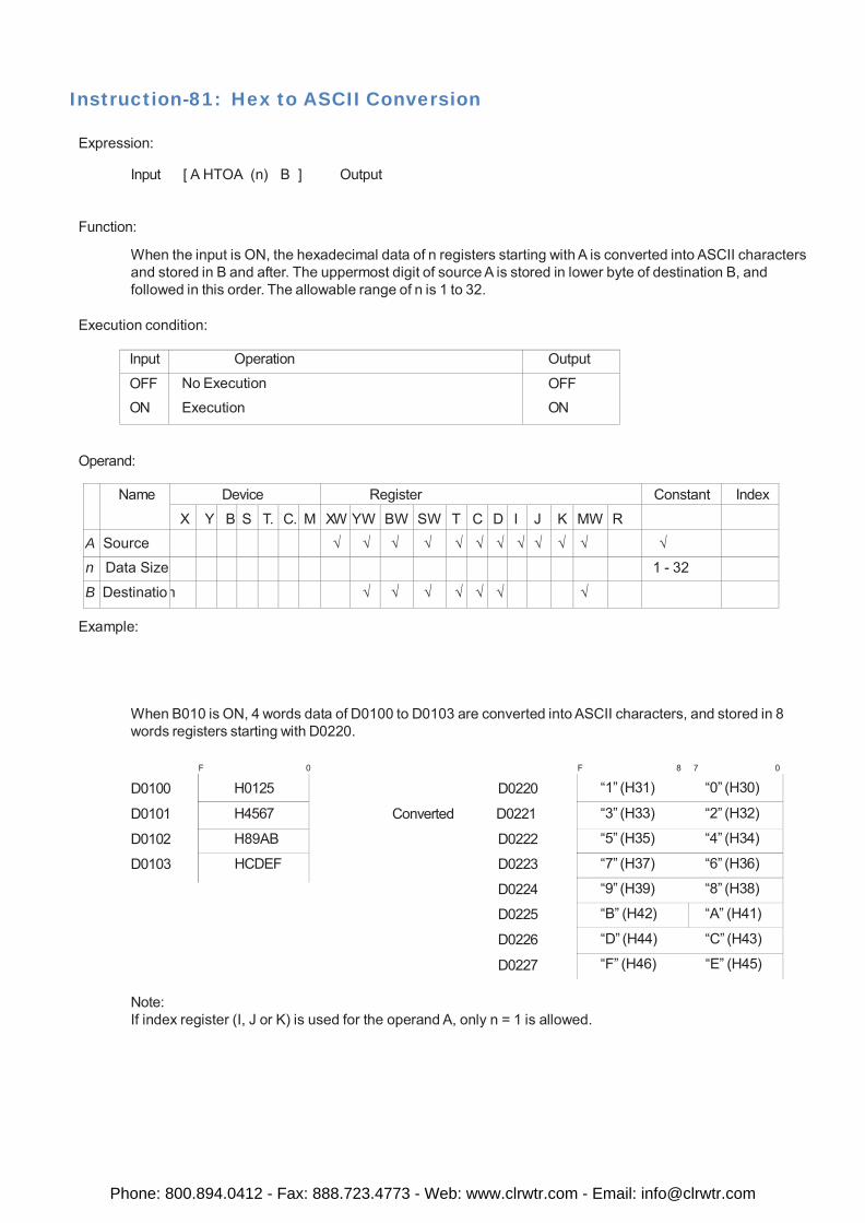
H0125
H4567
H89AB
HCDEF
“1” (H31) “0” (H30)
“3” (H33) “2” (H32)
“5” (H35) “4” (H34)
“7” (H37) “6” (H36)
“9” (H39) “8” (H38)
“B” (H42) “A” (H41)
“D” (H44) “C” (H43)
“F” (H46) “E” (H45)
Instruction-81: Hex to ASCII Conversion
Expression:
Input [ A HTOA (n) B ] Output
Function:
When the input is ON, the hexadecimal data of n registers starting with A is converted into ASCII characters and stored in B and after. The uppermost digit of source A is stored in lower byte of destination B, and followed in this order. The allowable range of n is 1 to 32.
Execution condition:
Input Operation Output
OFF ON
No Execution
Execution OFF ON
Operand:
Name Device Register Constant Index
X Y B S T. C. M XW YW BW SW T C D I J K MW R
A Source √ √ √ √ √ √ √ √ √ √ √ √
n Data Size 1 - 32
B Destinatio n √ √ √ √ √ √ √
Example:
When B010 is ON, 4 words data of D0100 to D0103 are converted into ASCII characters, and stored in 8 words registers starting with D0220.
D0100
D0101
D0102
D0103
F 0 F 8 7 0
D0220
Converted D0221
D0222
D0223
D0224
D0225
D0226
D0227
Note: If index register (I, J or K) is used for the operand A, only n = 1 is allowed.
Phone: 800.894.0412 - Fax: 888.723.4773 - Web: www.clrwtr.com - Email: [email protected]
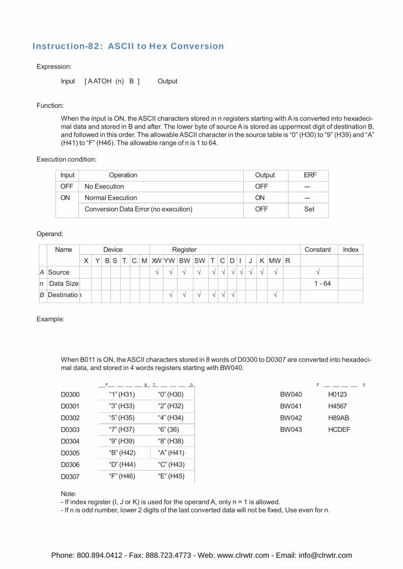
“1” (H31) “0” (H30)
“3” (H33) “2” (H32)
“5” (H35) “4” (H34)
“7” (H37) “6” (36)
“9” (H39) “8” (H38)
“B” (H42) “A” (H41)
“D” (H44) “C” (H43)
“F” (H46) “E” (H45)
Instruction-82: ASCII to Hex Conversion
Expression:
Input [ A ATOH (n) B ] Output
Function:
When the input is ON, the ASCII characters stored in n registers starting with A is converted into hexadeci- mal data and stored in B and after. The lower byte of source A is stored as uppermost digit of destination B, and followed in this order. The allowable ASCII character in the source table is “0” (H30) to “9” (H39) and “A” (H41) to “F” (H46). The allowable range of n is 1 to 64.
Execution condition:
Input Operation Output ERF
OFF No Execution OFF ---
ON Normal Execution ON ---
Conversion Data Error (no execution) OFF Set
Operand:
Name Device Register Constant Index
X Y B S T. C. M XW YW BW SW T C D I J K MW R
A Source √ √ √ √ √ √ √ √ √ √ √ √
n Data Size 1 - 64 B Destinatio n √ √ √ √ √ √ √
Example:
When B011 is ON, the ASCII characters stored in 8 words of D0300 to D0307 are converted into hexadeci- mal data, and stored in 4 words registers starting with BW040.
D0300
D0301
D0302
D0303
D0304
D0305
D0306
D0307
F 8 7 0 F 0
BW040 H0123
BW041 H4567
BW042 H89AB
BW043 HCDEF
Note: - If index register (I, J or K) is used for the operand A, only n = 1 is allowed. - If n is odd number, lower 2 digits of the last converted data will not be fixed, Use even for n.
Phone: 800.894.0412 - Fax: 888.723.4773 - Web: www.clrwtr.com - Email: [email protected]
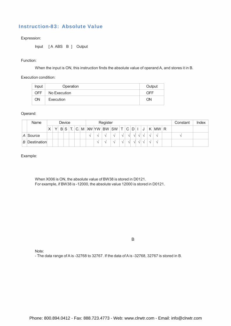
Instruction-83: Absolute Value
Expression:
Input [ A ABS B ] Output
Function:
When the input is ON, this instruction finds the absolute value of operand A, and stores it in B.
Execution condition:
Input Operation Output
OFF No Execution OFF
ON Execution ON
Operand:
Name Device Register Constant Index
X Y B S T. C. M XW YW BW SW T C D I J K MW R
A Source √ √ √ √ √ √ √ √ √ √ √ √
B Destination √ √ √ √ √ √ √ √ √ √
Example:
When X006 is ON, the absolute value of BW38 is stored in D0121. For example, if BW38 is -12000, the absolute value 12000 is stored in D0121.
B
Note: - The data range of A is -32768 to 32767. If the data of A is -32768, 32767 is stored in B.
Phone: 800.894.0412 - Fax: 888.723.4773 - Web: www.clrwtr.com - Email: [email protected]
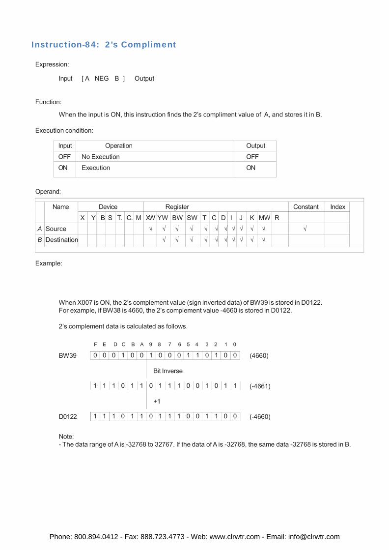
0 0 0 1 0 0 1 0 0 0 1 1 0 1 0 0
1 1 1 0 1 1 0 1 1 1 0 0 1 0 1 1
1 1 1 0 1 1 0 1 1 1 0 0 1 1 0 0
Instruction-84: 2’s Compliment
Expression:
Input [ A NEG B ] Output
Function:
When the input is ON, this instruction finds the 2’s compliment value of A, and stores it in B.
Execution condition:
Input Operation Output
OFF No Execution OFF
ON Execution ON
Operand:
Name Device Register Constant Index X Y B S T. C. M XW YW BW SW T C D I J K MW R
A Source √ √ √ √ √ √ √ √ √ √ √ √
B Destination √ √ √ √ √ √ √ √ √ √
Example:
When X007 is ON, the 2’s complement value (sign inverted data) of BW39 is stored in D0122. For example, if BW38 is 4660, the 2’s complement value -4660 is stored in D0122.
2’s complement data is calculated as follows.
BW39
F E D C B A 9 8 7 6 5 4 3 2 1 0 (4660)
Bit Inverse
(-4661)
+1
D0122 (-4660)
Note: - The data range of A is -32768 to 32767. If the data of A is -32768, the same data -32768 is stored in B.
Phone: 800.894.0412 - Fax: 888.723.4773 - Web: www.clrwtr.com - Email: [email protected]
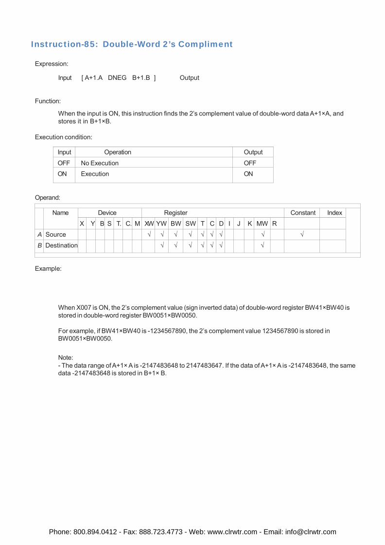
Instruction-85: Double-Word 2’s Compliment
Expression:
Input [ A+1.A DNEG B+1.B ] Output
Function:
When the input is ON, this instruction finds the 2’s complement value of double-word data A+1×A, and stores it in B+1×B.
Execution condition:
Input Operation Output
OFF No Execution OFF ON Execution ON
Operand:
Name Device Register Constant Index X Y B S T. C. M XW YW BW SW T C D I J K MW R
A Source √ √ √ √ √ √ √ √ √
B Destination √ √ √ √ √ √ √
Example:
When X007 is ON, the 2’s complement value (sign inverted data) of double-word register BW41×BW40 is stored in double-word register BW0051×BW0050.
For example, if BW41×BW40 is -1234567890, the 2’s complement value 1234567890 is stored in BW0051×BW0050.
Note: - The data range of A+1× A is -2147483648 to 2147483647. If the data of A+1× A is -2147483648, the same data -2147483648 is stored in B+1× B.
Phone: 800.894.0412 - Fax: 888.723.4773 - Web: www.clrwtr.com - Email: [email protected]
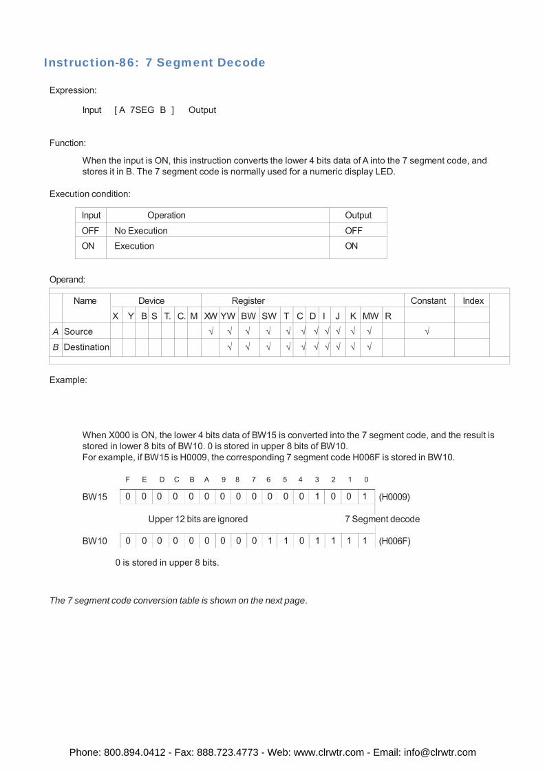
0 0 0 0 0 0 0 0 0 0 0 0 1 0 0 1
0 0 0 0 0 0 0 0 0 1 1 0 1 1 1 1
Instruction-86: 7 Segment Decode
Expression:
Input [ A 7SEG B ] Output
Function:
When the input is ON, this instruction converts the lower 4 bits data of A into the 7 segment code, and stores it in B. The 7 segment code is normally used for a numeric display LED.
Execution condition:
Input Operation Output
OFF No Execution OFF ON Execution ON
Operand:
Name Device Register Constant Index
X Y B S T. C. M XW YW BW SW T C D I J K MW R
A Source √ √ √ √ √ √ √ √ √ √ √ √
B Destination √ √ √ √ √ √ √ √ √ √
Example:
When X000 is ON, the lower 4 bits data of BW15 is converted into the 7 segment code, and the result is stored in lower 8 bits of BW10. 0 is stored in upper 8 bits of BW10. For example, if BW15 is H0009, the corresponding 7 segment code H006F is stored in BW10.
BW15
F E D C B A 9 8 7 6 5 4 3 2 1 0 (H0009)
Upper 12 bits are ignored 7 Segment decode
BW10 (H006F)
0 is stored in upper 8 bits.
The 7 segment code conversion table is shown on the next page.
Phone: 800.894.0412 - Fax: 888.723.4773 - Web: www.clrwtr.com - Email: [email protected]
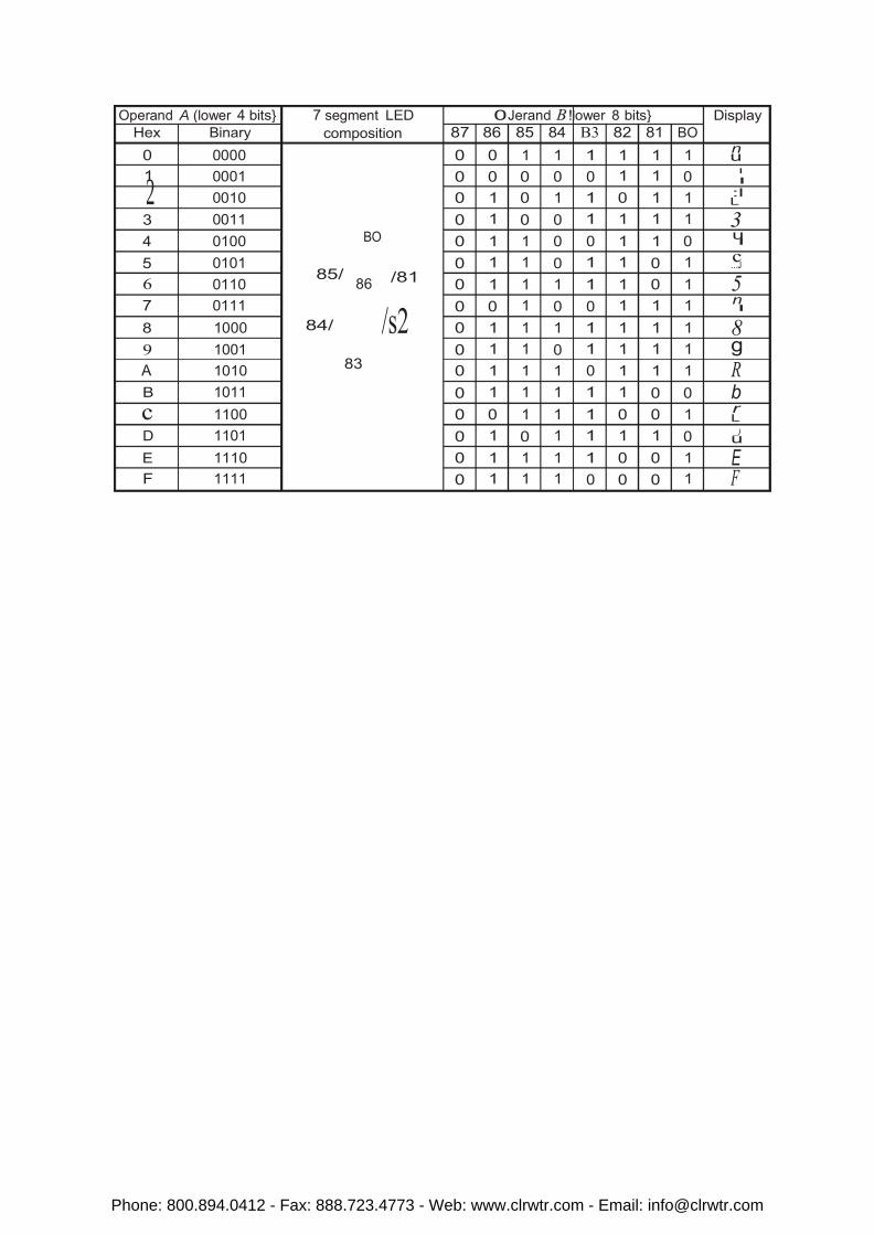
Operand A (lower 4 7 segment
Jerand lower 8 BO
86
2 I
Phone: 800.894.0412 - Fax: 888.723.4773 - Web: www.clrwtr.com - Email: [email protected]
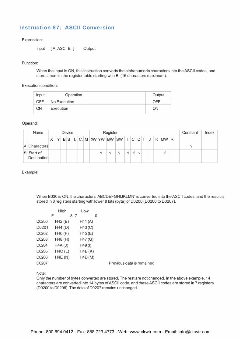
Instruction-87: ASCII Conversion
Expression:
Input [ A ASC B ] Output
Function:
When the input is ON, this instruction converts the alphanumeric characters into the ASCII codes, and stores them in the register table starting with B. (16 characters maximum).
Execution condition:
Input Operation Output
OFF No Execution OFF ON Execution ON
Operand:
Name Device Register Constant Index
X Y B S T. C. M XW YW BW SW T C D I J K MW R
A Characters √
B Start of Destination
√ √ √ √ √ √ √
Example:
When B030 is ON, the characters ‘ABCDEFGHIJKLMN’ is converted into the ASCII codes, and the result is stored in 8 registers starting with lower 8 bits (byte) of D0200 (D0200 to D0207).
High Low
F 8 7 0 D0200 H42 (B) H41 (A) D0201 H44 (D) H43 (C) D0202 H46 (F) H45 (E) D0203 H48 (H) H47 (G) D0204 H4A (J) H49 (I) D0205 H4C (L) H4B (K) D0206 H4E (N) H4D (M) D0207 Previous data is remained
Note: Only the number of bytes converted are stored. The rest are not changed. In the above example, 14 characters are converted into 14 bytes of ASCII code, and these ASCII codes are stored in 7 registers (D0200 to D0206). The data of D0207 remains unchanged.
Phone: 800.894.0412 - Fax: 888.723.4773 - Web: www.clrwtr.com - Email: [email protected]
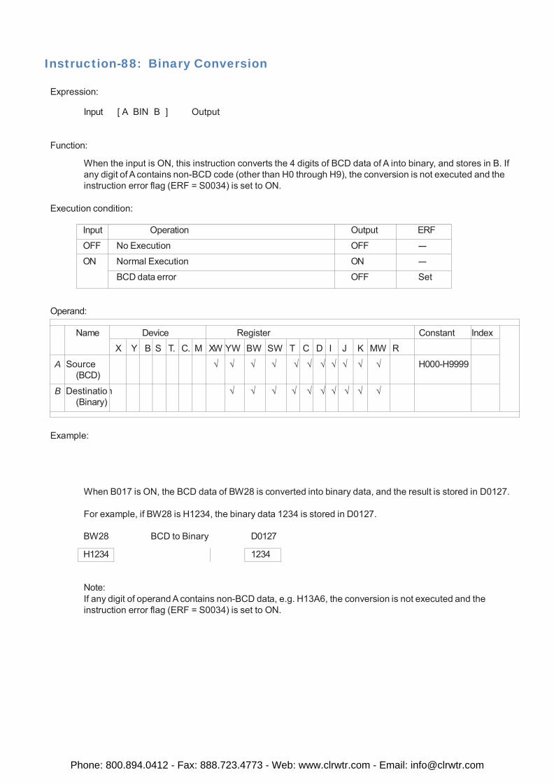
Instruction-88: Binary Conversion
Expression:
Input [ A BIN B ] Output
Function:
When the input is ON, this instruction converts the 4 digits of BCD data of A into binary, and stores in B. If any digit of A contains non-BCD code (other than H0 through H9), the conversion is not executed and the instruction error flag (ERF = S0034) is set to ON.
Execution condition:
Input Operation Output ERF
OFF No Execution OFF ---
ON Normal Execution ON ---
BCD data error OFF Set
Operand:
Name Device Register Constant Index
X Y B S T. C. M XW YW BW SW T C D I J K MW R
A Source (BCD)
√ √ √ √ √ √ √ √ √ √ √ H000-H9999
B Destinatio (Binary)
n √ √ √ √ √ √ √ √ √ √
Example:
When B017 is ON, the BCD data of BW28 is converted into binary data, and the result is stored in D0127.
For example, if BW28 is H1234, the binary data 1234 is stored in D0127.
BW28 BCD to Binary D0127
H1234 1234
Note: If any digit of operand A contains non-BCD data, e.g. H13A6, the conversion is not executed and the instruction error flag (ERF = S0034) is set to ON.
Phone: 800.894.0412 - Fax: 888.723.4773 - Web: www.clrwtr.com - Email: [email protected]
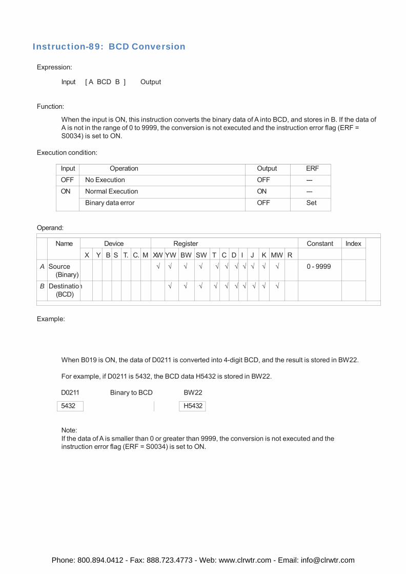
Instruction-89: BCD Conversion
Expression:
Input [ A BCD B ] Output
Function:
When the input is ON, this instruction converts the binary data of A into BCD, and stores in B. If the data of A is not in the range of 0 to 9999, the conversion is not executed and the instruction error flag (ERF = S0034) is set to ON.
Execution condition:
Input Operation Output ERF
OFF No Execution OFF ---
ON Normal Execution ON ---
Binary data error OFF Set
Operand:
Name Device Register Constant Index
X Y B S T. C. M XW YW BW SW T C D I J K MW R
A Source (Binary)
√ √ √ √ √ √ √ √ √ √ √ 0 - 9999
B Destinatio (BCD)
n √ √ √ √ √ √ √ √ √ √
Example:
When B019 is ON, the data of D0211 is converted into 4-digit BCD, and the result is stored in BW22.
For example, if D0211 is 5432, the BCD data H5432 is stored in BW22.
D0211 Binary to BCD BW22
5432 H5432
Note: If the data of A is smaller than 0 or greater than 9999, the conversion is not executed and the instruction error flag (ERF = S0034) is set to ON.
Phone: 800.894.0412 - Fax: 888.723.4773 - Web: www.clrwtr.com - Email: [email protected]
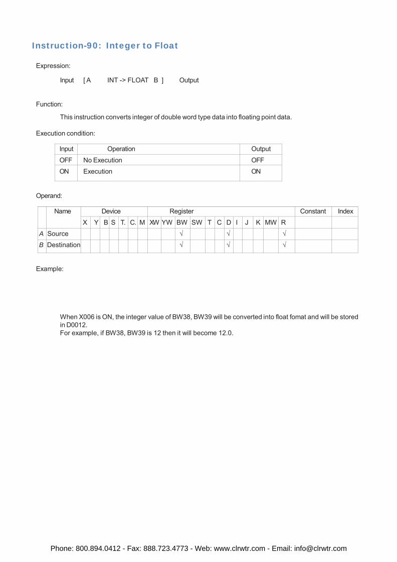
Instruction-90: Integer to Float
Expression:
Input [ A INT -> FLOAT B ] Output
Function:
This instruction converts integer of double word type data into floating point data.
Execution condition:
Input Operation Output
OFF No Execution OFF
ON Execution ON
Operand:
Name Device Register Constant Index
X Y B S T. C. M XW YW BW SW T C D I J K MW R
A Source √ √ √
B Destination √ √ √
Example:
When X006 is ON, the integer value of BW38, BW39 will be converted into float fomat and will be stored in D0012. For example, if BW38, BW39 is 12 then it will become 12.0.
Phone: 800.894.0412 - Fax: 888.723.4773 - Web: www.clrwtr.com - Email: [email protected]
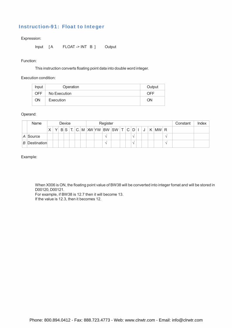
Instruction-91: Float to Integer
Expression:
Input [ A FLOAT -> INT B ] Output
Function:
This instruction converts floating point data into double word integer.
Execution condition:
Input Operation Output
OFF No Execution OFF
ON Execution ON
Operand:
Name Device Register Constant Index
X Y B S T. C. M XW YW BW SW T C D I J K MW R
A Source √ √ √
B Destination √ √ √
Example:
When X006 is ON, the floating point value of BW38 will be converted into integer fomat and will be stored in D00120, D00121. For example, if BW38 is 12.7 then it will become 13. If the value is 12.3, then it becomes 12.
Phone: 800.894.0412 - Fax: 888.723.4773 - Web: www.clrwtr.com - Email: [email protected]
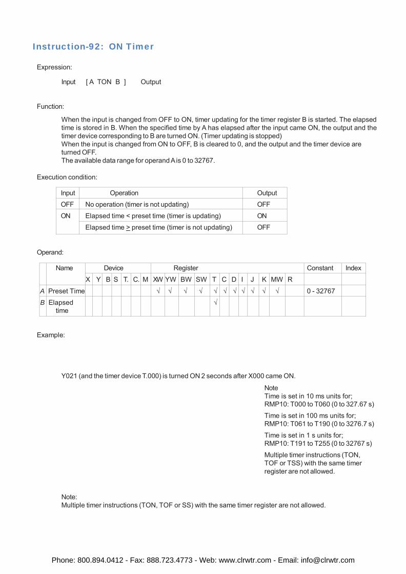
Instruction-92: ON Timer
Expression:
Input [ A TON B ] Output
Function:
When the input is changed from OFF to ON, timer updating for the timer register B is started. The elapsed time is stored in B. When the specified time by A has elapsed after the input came ON, the output and the timer device corresponding to B are turned ON. (Timer updating is stopped) When the input is changed from ON to OFF, B is cleared to 0, and the output and the timer device are turned OFF. The available data range for operand A is 0 to 32767.
Execution condition:
Input Operation Output
OFF No operation (timer is not updating) OFF
ON Elapsed time < preset time (timer is updating) ON
Elapsed time > preset time (timer is not updating) OFF
Operand:
Name Device Register Constant Index
X Y B S T. C. M XW YW BW SW T C D I J K MW R
A Preset Time √ √ √ √ √ √ √ √ √ √ √ 0 - 32767
B Elapsed time
√
Example:
Y021 (and the timer device T.000) is turned ON 2 seconds after X000 came ON.
Note Time is set in 10 ms units for; RMP10: T000 to T060 (0 to 327.67 s)
Time is set in 100 ms units for; RMP10: T061 to T190 (0 to 3276.7 s)
Time is set in 1 s units for; RMP10: T191 to T255 (0 to 32767 s)
Multiple timer instructions (TON, TOF or TSS) with the same timer register are not allowed.
Note: Multiple timer instructions (TON, TOF or SS) with the same timer register are not allowed.
Phone: 800.894.0412 - Fax: 888.723.4773 - Web: www.clrwtr.com - Email: [email protected]
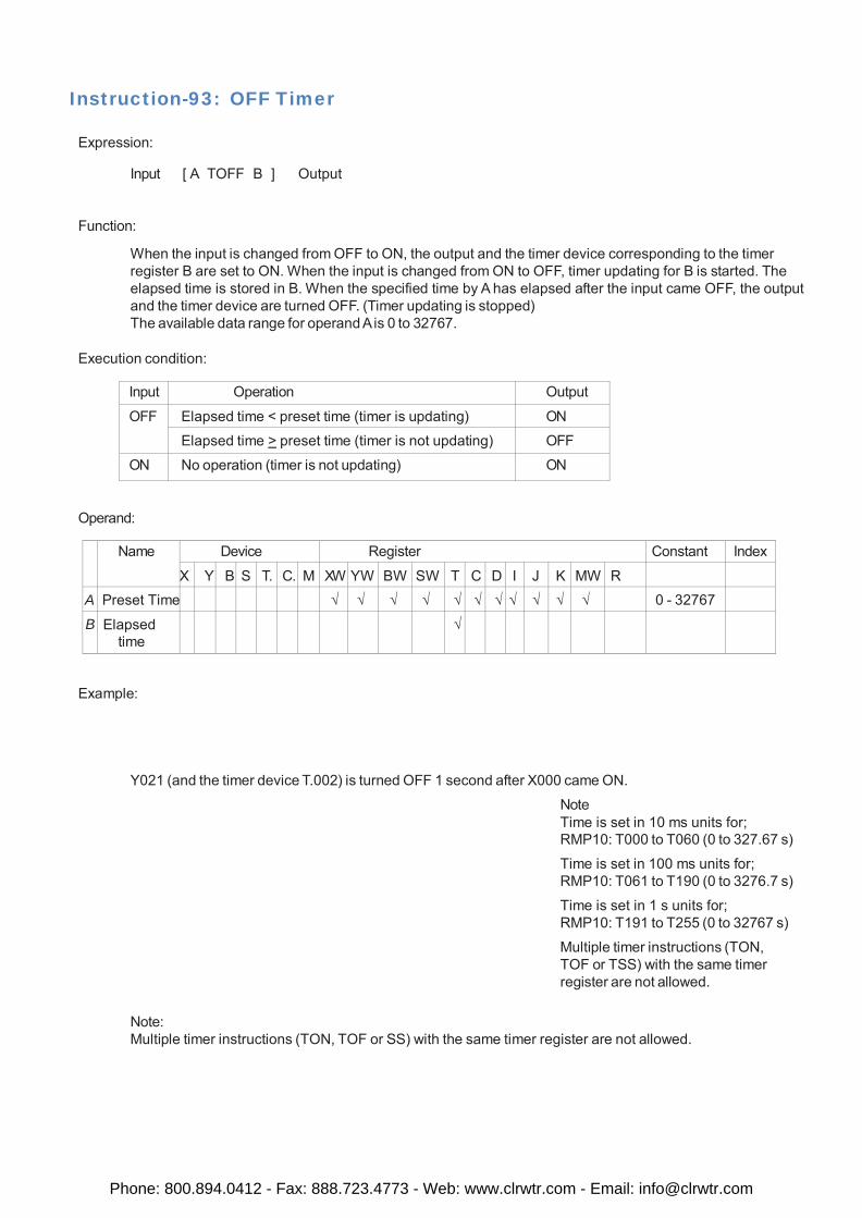
Instruction-93: OFF Timer
Expression:
Input [ A TOFF B ] Output
Function:
When the input is changed from OFF to ON, the output and the timer device corresponding to the timer register B are set to ON. When the input is changed from ON to OFF, timer updating for B is started. The elapsed time is stored in B. When the specified time by A has elapsed after the input came OFF, the output and the timer device are turned OFF. (Timer updating is stopped) The available data range for operand A is 0 to 32767.
Execution condition:
Input Operation Output
OFF Elapsed time < preset time (timer is updating) ON
Elapsed time > preset time (timer is not updating) OFF
ON No operation (timer is not updating) ON
Operand:
Name Device Register Constant Index
X Y B S T. C. M XW YW BW SW T C D I J K MW R
A Preset Time √ √ √ √ √ √ √ √ √ √ √ 0 - 32767
B Elapsed time
√
Example:
Y021 (and the timer device T.002) is turned OFF 1 second after X000 came ON.
Note Time is set in 10 ms units for; RMP10: T000 to T060 (0 to 327.67 s)
Time is set in 100 ms units for; RMP10: T061 to T190 (0 to 3276.7 s)
Time is set in 1 s units for; RMP10: T191 to T255 (0 to 32767 s)
Multiple timer instructions (TON, TOF or TSS) with the same timer register are not allowed.
Note: Multiple timer instructions (TON, TOF or SS) with the same timer register are not allowed.
Phone: 800.894.0412 - Fax: 888.723.4773 - Web: www.clrwtr.com - Email: [email protected]
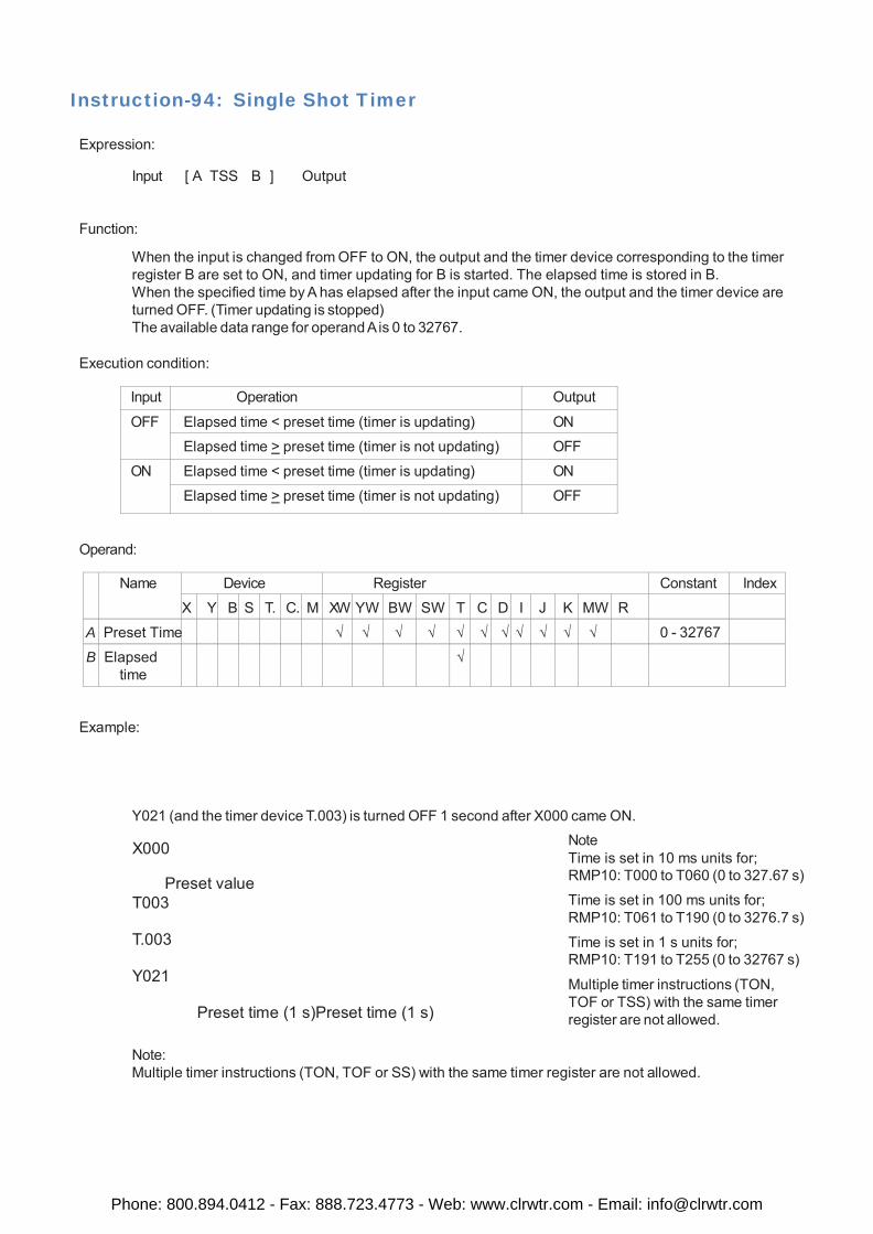
Instruction-94: Single Shot Timer
Expression:
Input [ A TSS B ] Output
Function:
When the input is changed from OFF to ON, the output and the timer device corresponding to the timer register B are set to ON, and timer updating for B is started. The elapsed time is stored in B. When the specified time by A has elapsed after the input came ON, the output and the timer device are turned OFF. (Timer updating is stopped) The available data range for operand A is 0 to 32767.
Execution condition:
Input Operation Output
OFF Elapsed time < preset time (timer is updating) ON
Elapsed time > preset time (timer is not updating) OFF
ON Elapsed time < preset time (timer is updating) ON
Elapsed time > preset time (timer is not updating) OFF
Operand:
Name Device Register Constant Index
X Y B S T. C. M XW YW BW SW T C D I J K MW R
A Preset Time √ √ √ √ √ √ √ √ √ √ √ 0 - 32767
B Elapsed time
√
Example:
Y021 (and the timer device T.003) is turned OFF 1 second after X000 came ON.
X000
Preset value T003
T.003
Y021
Preset time (1 s)Preset time (1 s)
Note Time is set in 10 ms units for; RMP10: T000 to T060 (0 to 327.67 s)
Time is set in 100 ms units for; RMP10: T061 to T190 (0 to 3276.7 s)
Time is set in 1 s units for; RMP10: T191 to T255 (0 to 32767 s)
Multiple timer instructions (TON, TOF or TSS) with the same timer register are not allowed.
Note: Multiple timer instructions (TON, TOF or SS) with the same timer register are not allowed.
Phone: 800.894.0412 - Fax: 888.723.4773 - Web: www.clrwtr.com - Email: [email protected]
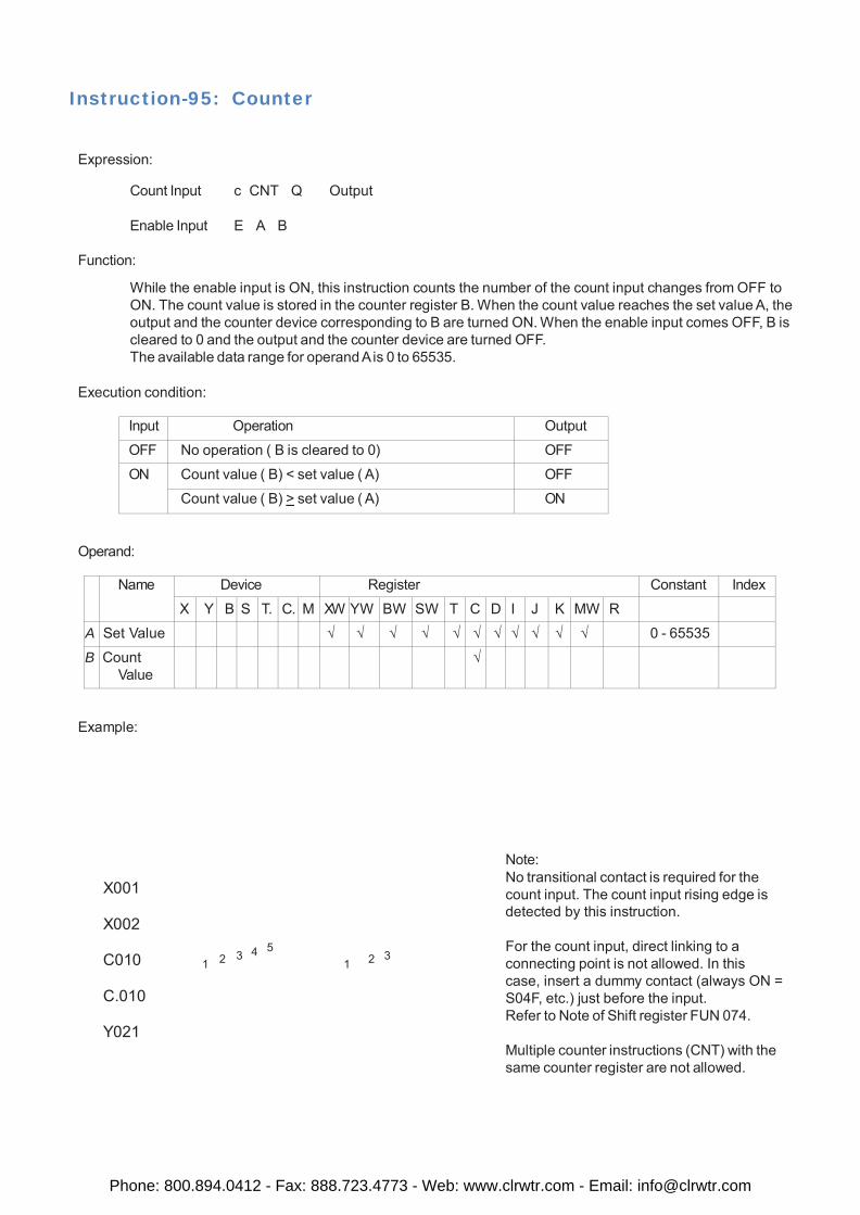
Instruction-95: Counter
Expression:
Count Input c CNT Q Output
Enable Input E A B
Function:
While the enable input is ON, this instruction counts the number of the count input changes from OFF to ON. The count value is stored in the counter register B. When the count value reaches the set value A, the output and the counter device corresponding to B are turned ON. When the enable input comes OFF, B is cleared to 0 and the output and the counter device are turned OFF. The available data range for operand A is 0 to 65535.
Execution condition:
Input Operation Output
OFF No operation ( B is cleared to 0) OFF
ON Count value ( B) < set value ( A) OFF
Count value ( B) > set value ( A) ON
Operand:
Name Device Register Constant Index
X Y B S T. C. M XW YW BW SW T C D I J K MW R
A Set Value √ √ √ √ √ √ √ √ √ √ √ 0 - 65535
B Count Value
√
Example:
X001
X002
C010
C.010
Y021
3 4 5 3
1 2 1 2
Note: No transitional contact is required for the count input. The count input rising edge is detected by this instruction. For the count input, direct linking to a connecting point is not allowed. In this case, insert a dummy contact (always ON = S04F, etc.) just before the input. Refer to Note of Shift register FUN 074. Multiple counter instructions (CNT) with the same counter register are not allowed.
Phone: 800.894.0412 - Fax: 888.723.4773 - Web: www.clrwtr.com - Email: [email protected]
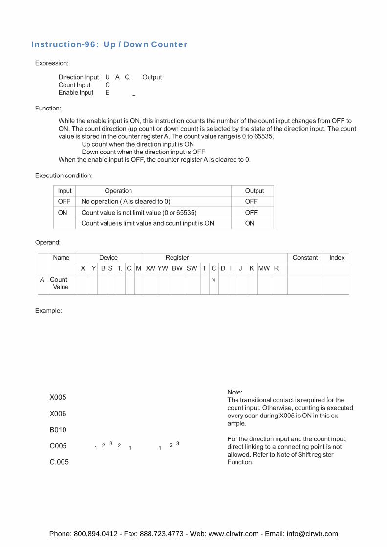
Instruction-96: Up / Down Counter
Expression:
Direction Input U A Q Output Count Input C Enable Input E
Function:
While the enable input is ON, this instruction counts the number of the count input changes from OFF to ON. The count direction (up count or down count) is selected by the state of the direction input. The count value is stored in the counter register A. The count value range is 0 to 65535.
Up count when the direction input is ON Down count when the direction input is OFF
When the enable input is OFF, the counter register A is cleared to 0.
Execution condition:
Input Operation Output
OFF No operation ( A is cleared to 0) OFF
ON Count value is not limit value (0 or 65535) OFF Count value is limit value and count input is ON ON
Operand:
Name Device Register Constant Index
X Y B S T. C. M XW YW BW SW T C D I J K MW R
A Count Value
√
Example:
X005
X006
B010
C005
C.005
1 2 3 2 1
1 2 3
Note: The transitional contact is required for the count input. Otherwise, counting is executed every scan during X005 is ON in this ex- ample. For the direction input and the count input, direct linking to a connecting point is not allowed. Refer to Note of Shift register Function.
Phone: 800.894.0412 - Fax: 888.723.4773 - Web: www.clrwtr.com - Email: [email protected]
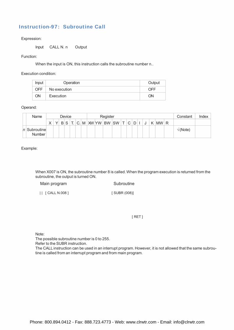
Instruction-97: Subroutine Call
Expression:
Input CALL N. n Output
Function:
When the input is ON, this instruction calls the subroutine number n..
Execution condition:
Input Operation Output
OFF No execution OFF
ON Execution ON
Operand:
Name Device Register Constant Index
X Y B S T. C. M XW YW BW SW T C D I J K MW R
n Subroutine Number
√ (Note)
Example:
When X007 is ON, the subroutine number 8 is called. When the program execution is returned from the subroutine, the output is turned ON.
Main program Subroutine
| | [ CALL N.008 ] [ SUBR (008)]
[ RET ]
Note: The possible subroutine number is 0 to 255. Refer to the SUBR instruction. The CALL instruction can be used in an interrupt program. However, it is not allowed that the same subrou- tine is called from an interrupt program and from main program.
Phone: 800.894.0412 - Fax: 888.723.4773 - Web: www.clrwtr.com - Email: [email protected]
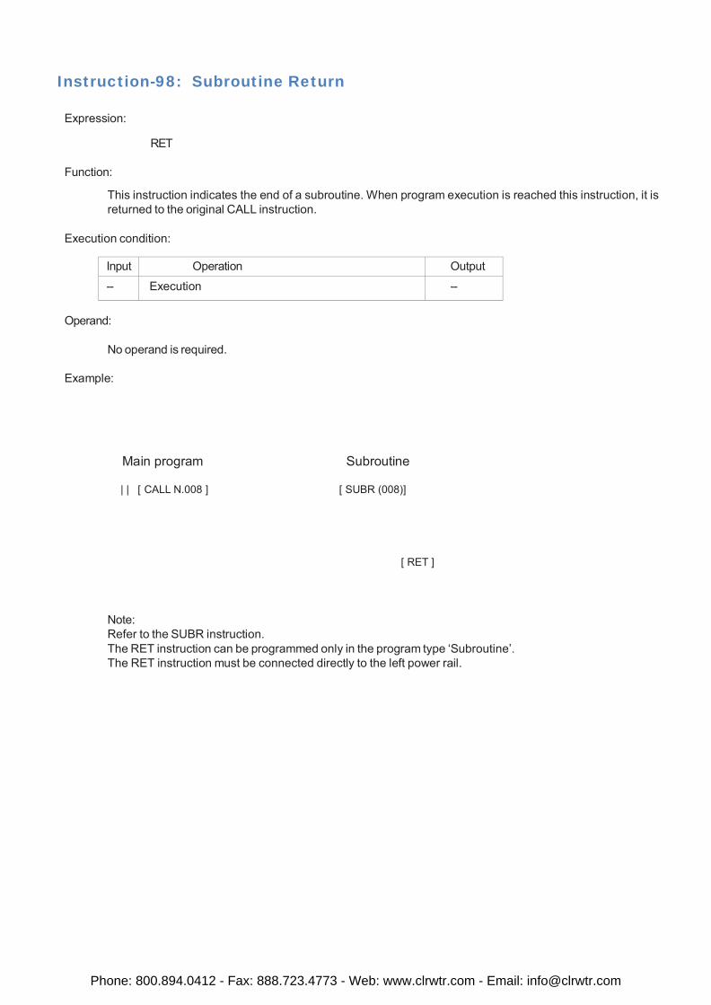
Instruction-98: Subroutine Return
Expression:
RET
Function:
This instruction indicates the end of a subroutine. When program execution is reached this instruction, it is returned to the original CALL instruction.
Execution condition:
Input Operation Output
-- Execution --
Operand:
No operand is required.
Example:
Main program Subroutine
| | [ CALL N.008 ] [ SUBR (008)]
[ RET ]
Note: Refer to the SUBR instruction. The RET instruction can be programmed only in the program type ‘Subroutine’. The RET instruction must be connected directly to the left power rail.
Phone: 800.894.0412 - Fax: 888.723.4773 - Web: www.clrwtr.com - Email: [email protected]
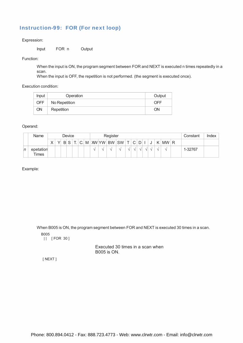
Instruction-99: FOR (For next loop)
Expression:
Input FOR n Output
Function:
When the input is ON, the program segment between FOR and NEXT is executed n times repeatedly in a scan. When the input is OFF, the repetition is not performed. (the segment is executed once).
Execution condition:
Input Operation Output
OFF No Repetition OFF
ON Repetition ON
Operand:
Name Device Register Constant Index
X Y B S T. C. M XW YW BW SW T C D I J K MW R
n epetation Times
√ √ √ √ √ √ √ √ √ √ √ 1-32767
Example:
When B005 is ON, the program segment between FOR and NEXT is executed 30 times in a scan.
B005 | | [ FOR 30 ]
[ NEXT ]
Executed 30 times in a scan when B005 is ON.
Phone: 800.894.0412 - Fax: 888.723.4773 - Web: www.clrwtr.com - Email: [email protected]
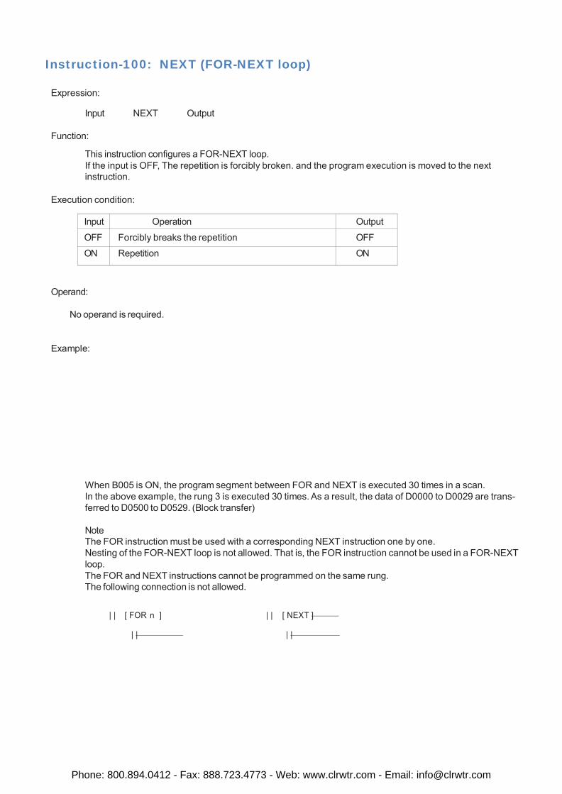
Instruction-100: NEXT (FOR-NEXT loop)
Expression:
Input NEXT Output
Function:
This instruction configures a FOR-NEXT loop. If the input is OFF, The repetition is forcibly broken. and the program execution is moved to the next instruction.
Execution condition:
Input Operation Output
OFF Forcibly breaks the repetition OFF
ON Repetition ON
Operand:
No operand is required.
Example:
When B005 is ON, the program segment between FOR and NEXT is executed 30 times in a scan. In the above example, the rung 3 is executed 30 times. As a result, the data of D0000 to D0029 are trans- ferred to D0500 to D0529. (Block transfer)
Note The FOR instruction must be used with a corresponding NEXT instruction one by one. Nesting of the FOR-NEXT loop is not allowed. That is, the FOR instruction cannot be used in a FOR-NEXT loop. The FOR and NEXT instructions cannot be programmed on the same rung. The following connection is not allowed.
| | [ FOR n ] | | [ NEXT ]
| | | |
Phone: 800.894.0412 - Fax: 888.723.4773 - Web: www.clrwtr.com - Email: [email protected]
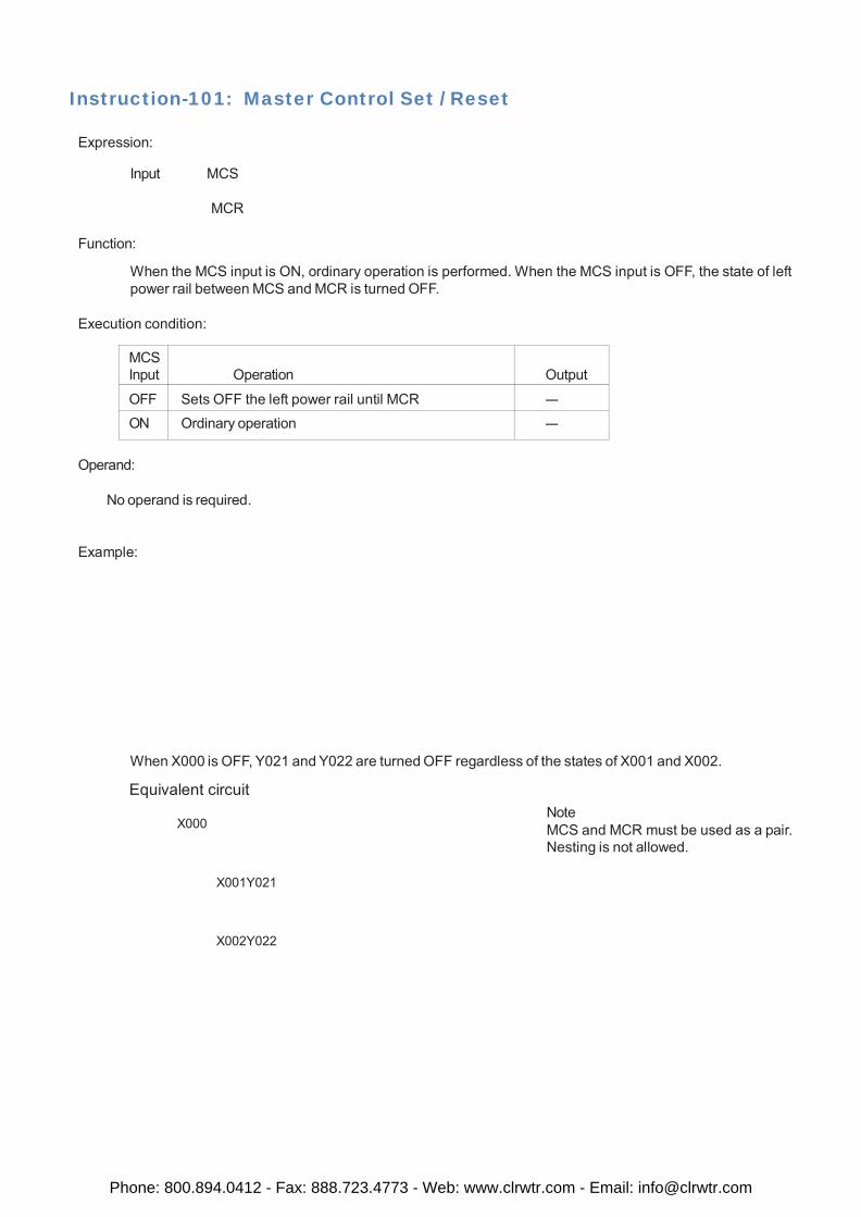
Instruction-101: Master Control Set / Reset
Expression:
Input MCS
MCR
Function:
When the MCS input is ON, ordinary operation is performed. When the MCS input is OFF, the state of left power rail between MCS and MCR is turned OFF.
Execution condition:
MCS Input
Operation
Output
OFF Sets OFF the left power rail until MCR --- ON Ordinary operation ---
Operand:
No operand is required.
Example:
When X000 is OFF, Y021 and Y022 are turned OFF regardless of the states of X001 and X002.
Equivalent circuit
X000 Note MCS and MCR must be used as a pair. Nesting is not allowed.
X001Y021
X002Y022
Phone: 800.894.0412 - Fax: 888.723.4773 - Web: www.clrwtr.com - Email: [email protected]
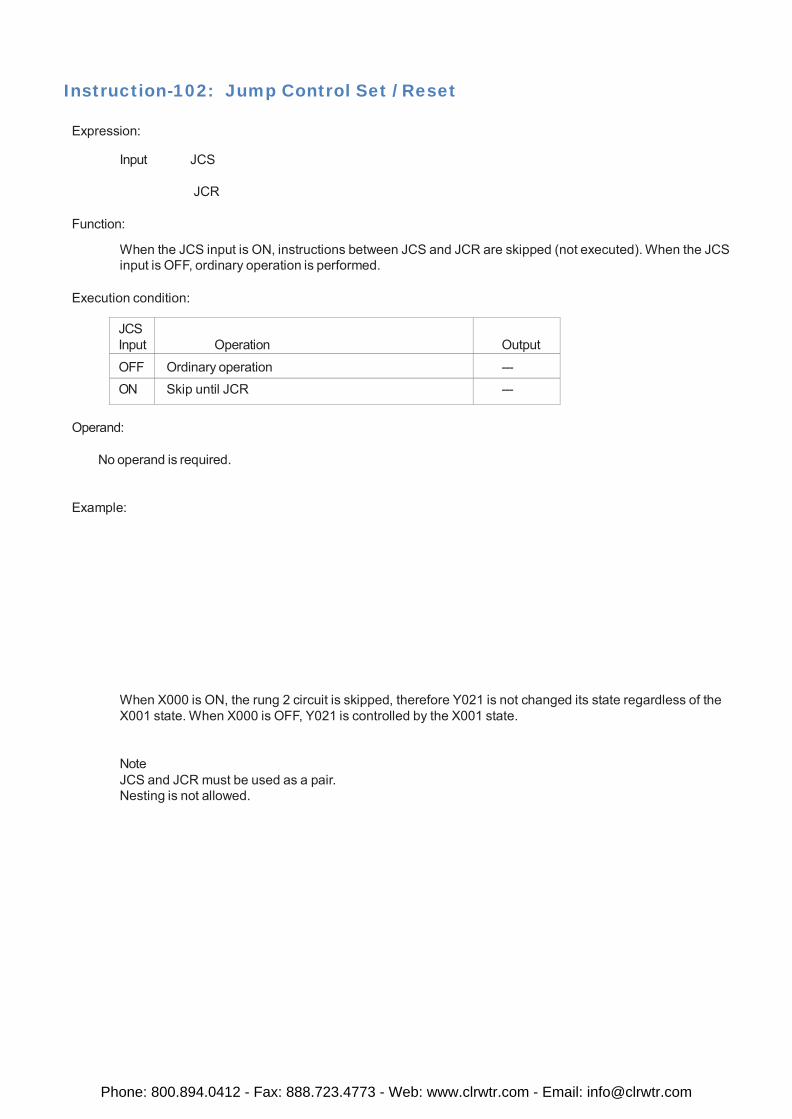
Instruction-102: Jump Control Set / Reset
Expression:
Input JCS
JCR
Function:
When the JCS input is ON, instructions between JCS and JCR are skipped (not executed). When the JCS input is OFF, ordinary operation is performed.
Execution condition:
JCS Input
Operation
Output
OFF Ordinary operation --- ON Skip until JCR ---
Operand:
No operand is required.
Example:
When X000 is ON, the rung 2 circuit is skipped, therefore Y021 is not changed its state regardless of the X001 state. When X000 is OFF, Y021 is controlled by the X001 state.
Note JCS and JCR must be used as a pair. Nesting is not allowed.
Phone: 800.894.0412 - Fax: 888.723.4773 - Web: www.clrwtr.com - Email: [email protected]
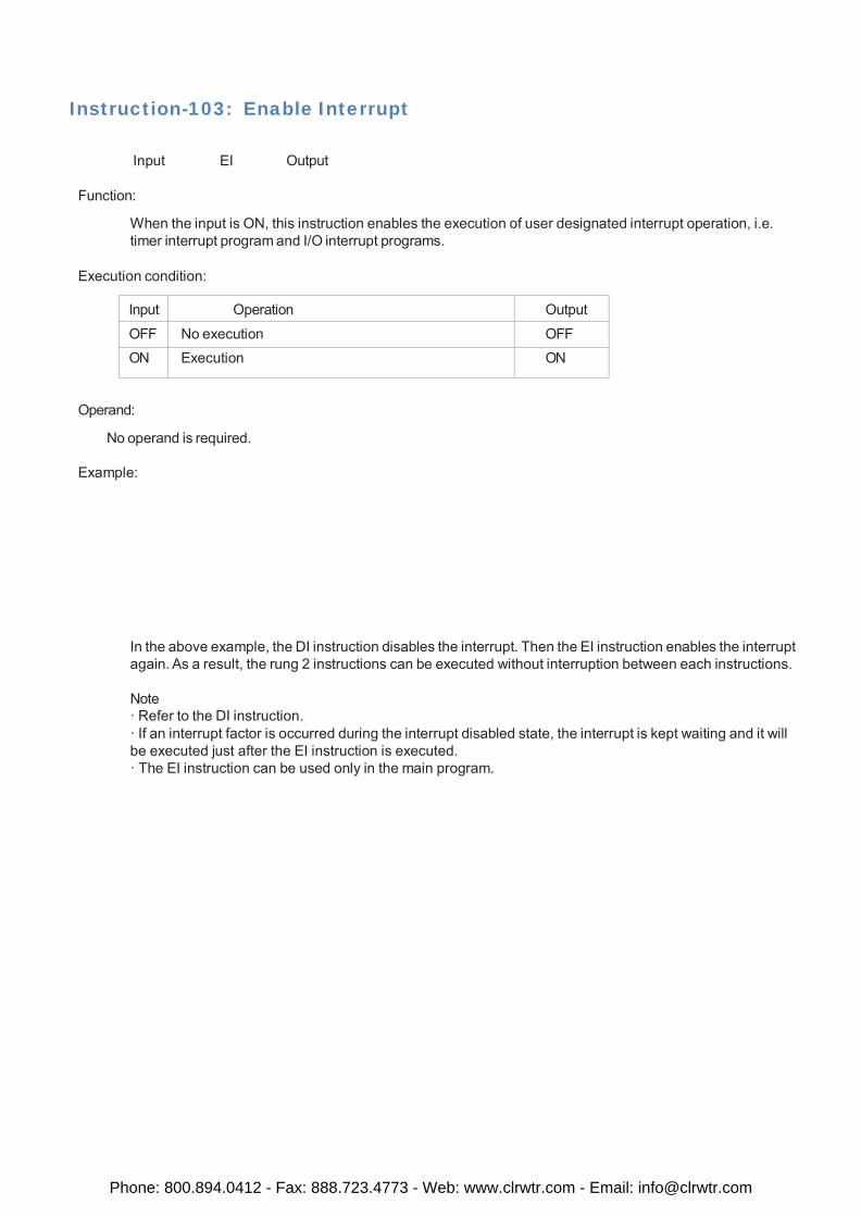
Instruction-103: Enable Interrupt
Input EI Output
Function:
When the input is ON, this instruction enables the execution of user designated interrupt operation, i.e. timer interrupt program and I/O interrupt programs.
Execution condition:
Input Operation Output
OFF No execution OFF ON Execution ON
Operand:
No operand is required.
Example:
In the above example, the DI instruction disables the interrupt. Then the EI instruction enables the interrupt again. As a result, the rung 2 instructions can be executed without interruption between each instructions.
Note · Refer to the DI instruction. · If an interrupt factor is occurred during the interrupt disabled state, the interrupt is kept waiting and it will be executed just after the EI instruction is executed. · The EI instruction can be used only in the main program.
Phone: 800.894.0412 - Fax: 888.723.4773 - Web: www.clrwtr.com - Email: [email protected]
Instruction-104: Disable Interrupt
Input DI Output
Function:
When the input is ON, this instruction disables the execution of user designated interrupt operation, i.e. timer interrupt program and I/O interrupt programs.
Execution condition:
Input Operation Output
OFF No execution OFF ON Execution ON
Operand:
No operand is required.
Example:
In the above example, the interrupt is disabled when B000 is ON, and it is enabled when B000 is OFF.
Note · Refer to the EI instruction. · If an interrupt factor is occurred during the interrupt disabled state, the interrupt is kept waiting and it will be executed just after the EI instruction is executed. · The DI instruction can be used only in the main program.
Phone: 800.894.0412 - Fax: 888.723.4773 - Web: www.clrwtr.com - Email: [email protected]
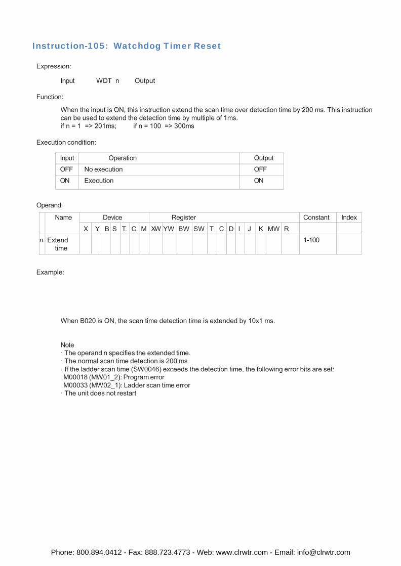
Instruction-105: Watchdog Timer Reset
Expression:
Input WDT n Output
Function:
When the input is ON, this instruction extend the scan time over detection time by 200 ms. This instruction can be used to extend the detection time by multiple of 1ms. if n = 1 => 201ms; if n = 100 => 300ms
Execution condition:
Input Operation Output
OFF No execution OFF
ON Execution ON
Operand:
Name Device Register Constant Index
X Y B S T. C. M XW YW BW SW T C D I J K MW R
n Extend time
1-100
Example:
When B020 is ON, the scan time detection time is extended by 10x1 ms.
Note · The operand n specifies the extended time. · The normal scan time detection is 200 ms · If the ladder scan time (SW0046) exceeds the detection time, the following error bits are set: M00018 (MW01_2): Program error M00033 (MW02_1): Ladder scan time error
· The unit does not restart
Phone: 800.894.0412 - Fax: 888.723.4773 - Web: www.clrwtr.com - Email: [email protected]
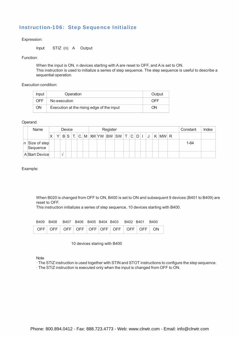
Instruction-106: Step Sequence Initialize
Expression:
Input STIZ (n) A Output
Function:
When the input is ON, n devices starting with A are reset to OFF, and A is set to ON. This instruction is used to initialize a series of step sequence. The step sequence is useful to describe a sequential operation.
Execution condition:
Input Operation Output
OFF No execution OFF
ON Execution at the rising edge of the input ON
Operand:
Name Device Register Constant Index
X Y B S T. C. M XW YW BW SW T C D I J K MW R
n Size of step Sequence
1-64
A Start Device √
Example:
When B020 is changed from OFF to ON, B400 is set to ON and subsequent 9 devices (B401 to B409) are reset to OFF. This instruction initializes a series of step sequence, 10 devices starting with B400.
B409 B408 B407 B406 B405 B404 B403 B402 B401 B400
OFF OFF OFF OFF OFF OFF OFF OFF OFF ON
10 devices staring with B400
Note · The STIZ instruction is used together with STIN and STOT instructions to configure the step sequence. · The STIZ instruction is executed only when the input is changed from OFF to ON.
Phone: 800.894.0412 - Fax: 888.723.4773 - Web: www.clrwtr.com - Email: [email protected]
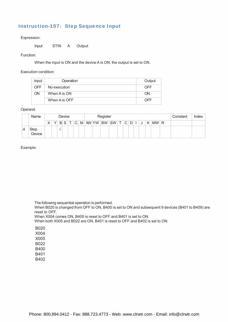
Instruction-107: Step Sequence Input
Expression:
Input STIN A Output
Function:
When the input is ON and the device A is ON, the output is set to ON.
Execution condition:
Input Operation Output
OFF No execution OFF ON When A is ON ON
When A is OFF OFF
Operand:
Name Device Register Constant Index
X Y B S T. C. M XW YW BW SW T C D I J K MW R A Step
Device √
Example:
The following sequential operation is performed. When B020 is changed from OFF to ON, B400 is set to ON and subsequent 9 devices (B401 to B409) are reset to OFF. When X004 comes ON, B400 is reset to OFF and B401 is set to ON. When both X005 and B022 are ON, B401 is reset to OFF and B402 is set to ON.
B020 X004 X005 B022 B400 B401 B402
Phone: 800.894.0412 - Fax: 888.723.4773 - Web: www.clrwtr.com - Email: [email protected]
Instruction-108: Step Sequence Output Expression:
Input STOT A Output
Function:
When the input is ON, the device A is set to ON and the devices of STIN instructions on the same rung are reset to OFF.
Execution condition:
Input Operation Output
OFF No execution ---
ON Execution ---
Operand:
Name Device Register Constant Index X Y B S T. C. M XW YW BW SW T C D I J K MW R
A Step Device
√
Example:
See example on STIN instruction.
Note: · The STIZ, STIN and STOT instructions are used together to configure the step sequence. · Two or more STOT instructions can be placed on one rung to perform simultaneous sequences.
· Two or more STIN instructions can be placed on one rung in parallel or in series to perform loop or conver- gence of sequences. (Max. 11 STIN instructions on one rung)
· To perform the conditional branch (sequence selection), separate the rungs as follows.
Phone: 800.894.0412 - Fax: 888.723.4773 - Web: www.clrwtr.com - Email: [email protected]
Instruction-109: Moving Average
Expression:
Input A MAVE (n) B C Output
Function:
When the input is ON, this instruction calculates the average value of the latest n scan’s register A data, and stores it in C. The allowable range of n is 1 to 64. This instruction is useful for filtering the analog input signal. The latest n scan’s data of A are stored in n registers starting with B, and C+1 are used as pointer.
Execution condition:
Input Operation Output
OFF No execution OFF
ON Execution ON
Operand:
Name Device Register Constant Index
X Y B S T. C. M XW YW BW SW T C D I J K MW R
A Input Data √ √ √ √ √ √ √ √ √ √ √ √
n Data Size 1 - 64
B Start of table
√ √ √ √ √ √ √
C Output data
√ √ √ √ √ √ √ √ √
Example:
The latest 5 scan’s data of XW04 is stored in D0900 to D0904 (5 registers), and the average value of them is calculated and stored in D0010. D0011 is used as internal work data.
Phone: 800.894.0412 - Fax: 888.723.4773 - Web: www.clrwtr.com - Email: [email protected]
Instruction-110: Digital Filter
Expression:
Input A DFL B C Output
Function:
When the input is ON, this instruction calculates the following formula to perform digital filtering for input data A by filter constant by B, and stores the result in C. Yn = (1 - FL) * Xn + FL * Yn-1 Here; Xn is input data specified by A FL is filter constant, 1/10000 of data specified by B (data range: 0 to 9999) Yn is output data to be stored in C Yn-1 is output data at last scan This instruction is useful for filtering the analog input signal. C+1 is used for internal work data.
Execution condition:
Input Operation Output
OFF No execution OFF
ON Execution (FL is limited within the range of 0 to 9999) ON
Operand:
Name Device Register Constant Index
X Y B S T. C. M XW YW BW SW T C D I J K MW R
A Input Data √ √ √ √ √ √ √ √ √ √ √ √
B Filter Constant
√ √ √ √ √ √ √ √
C Output data
√ √ √ √ √ √ √
Example:
The filtered data of XW04 is stored in D0110. (D0111 is used for internal work data).
Phone: 800.894.0412 - Fax: 888.723.4773 - Web: www.clrwtr.com - Email: [email protected]
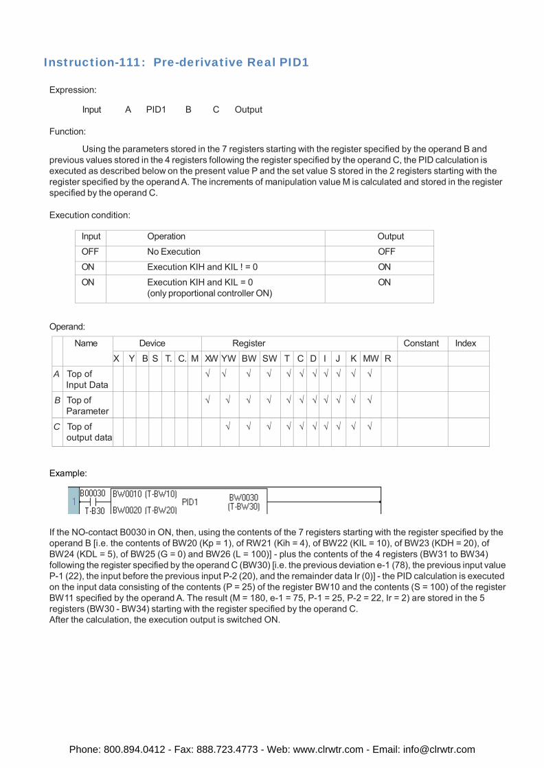
Instruction-111: Pre-derivative Real PID1
Expression:
Input A PID1 B C Output
Function:
Using the parameters stored in the 7 registers starting with the register specified by the operand B and previous values stored in the 4 registers following the register specified by the operand C, the PID calculation is executed as described below on the present value P and the set value S stored in the 2 registers starting with the register specified by the operand A. The increments of manipulation value M is calculated and stored in the register specified by the operand C.
Execution condition:
Input Operation Output
OFF No Execution OFF
ON Execution KIH and KIL ! = 0 ON
ON Execution KIH and KIL = 0 (only proportional controller ON)
ON
Operand:
Name Device Register Constant Index
X Y B S T. C. M XW YW BW SW T C D I J K MW R
A Top of Input Data
√ √ √ √ √ √ √ √ √ √ √
B Top of Parameter
√ √ √ √ √ √ √ √ √ √ √
C Top of output data
√ √ √ √ √ √ √ √ √ √
Example:
If the NO-contact B0030 in ON, then, using the contents of the 7 registers starting with the register specified by the operand B [i.e. the contents of BW20 (Kp = 1), of RW21 (Kih = 4), of BW22 (KIL = 10), of BW23 (KDH = 20), of BW24 (KDL = 5), of BW25 (G = 0) and BW26 (L = 100)] - plus the contents of the 4 registers (BW31 to BW34) following the register specified by the operand C (BW30) [i.e. the previous deviation e-1 (78), the previous input value P-1 (22), the input before the previous input P-2 (20), and the remainder data Ir (0)] - the PID calculation is executed on the input data consisting of the contents (P = 25) of the register BW10 and the contents (S = 100) of the register BW11 specified by the operand A. The result (M = 180, e-1 = 75, P-1 = 25, P-2 = 22, Ir = 2) are stored in the 5 registers (BW30 - BW34) starting with the register specified by the operand C. After the calculation, the execution output is switched ON.
Phone: 800.894.0412 - Fax: 888.723.4773 - Web: www.clrwtr.com - Email: [email protected]
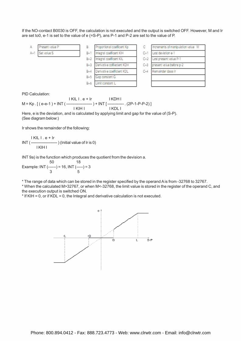
If the NO-contact B0030 is OFF, the calculation is not executed and the output is switched OFF. However, M and Ir are set to0, e-1 is set to the value of e (=S-P), ans P-1 and P-2 are set to the value of P.
PID Calculation: I KIL I . e + Ir I KDH I
M = Kp . [ ( e-e-1 ) + INT ( ------------------- ) + INT [ ------------ . (2P-1-P-P-2) ] I KIH I I KDL I
Here, e is the deviation, and is calculated by applying limit and gap for the value of (S-P). (See diagram below:)
Ir shows the remainder of the following:
I KIL I . e + Ir INT ( -------------------- ) (Initial value of Ir is 0)
I KIH I
INT 9a) is the function which produces the quotient from the devision a. 50 18
Example: INT (------) = 16, INT (-----) = 3 3 5
* The range of data which can be stored in the register specified by the operand A is from -32768 to 32767. * When the calculated M>32767, or when M<-32768, the limit value is stored in the register of the operand C, and the execution output is switched ON. * If KIH = 0, or if KDL = 0, the Integral and derivative calculation is not executed.
Phone: 800.894.0412 - Fax: 888.723.4773 - Web: www.clrwtr.com - Email: [email protected]
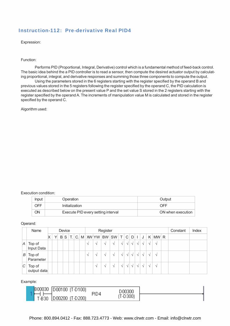
Instruction-112: Pre-derivative Real PID4
Expression:
Function:
Performs PID (Proportional, Integral, Derivative) control which is a fundamental method of feed-back control. The basic idea behind the a PID controller is to read a sensor, then compute the desired actuator output by calculat- ing proportional, integral, and derivative responses and summing those three components to compute the output.
Using the parameters stored in the 6 registers starting with the register specified by the operand B and previous values stored in the 5 registers following the register specified by the operand C, the PID calculation is executed as described below on the present value P and the set value S stored in the 2 registers starting with the register specified by the operand A. The increments of manipulation value M is calculated and stored in the register specified by the operand C.
Algorithm used:
Execution condition:
Input Operation Output
OFF Initialization OFF
ON Execute PID every setting interval ON when execution
Operand:
Name Device Register Constant Index
X Y B S T. C. M XW YW BW SW T C D I J K MW R
A Top of Input Data
√ √ √ √ √ √ √ √ √ √ √
B Top of Parameter
√ √ √ √ √ √ √ √ √ √ √
C Top of output data
√ √ √ √ √ √ √ √ √ √
Example:
Phone: 800.894.0412 - Fax: 888.723.4773 - Web: www.clrwtr.com - Email: [email protected]
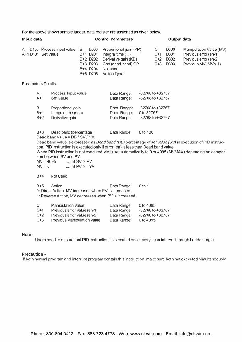
For the above shown sample ladder, data register are assigned as given below.
Input data Control Parameters Output data
A D100 Process Input value B D200 Proportional gain (KP) C D300 Manipulation Value (MV) A+1 D101 Set Value B+1 D201 Integral time (TI) C+1 D301 Previous error (en-1) B+2 D202 Derivative gain (KD) C+2 D302 Previous error (en-2) B+3 D203 Gap (dead-band) GP C+3 D303 Previous MV (MVn-1) B+4 D204 Not used B+5 D205 Action Type
Parameters Details:
A A+1
Process Input Value Set Value
Data Range: Data Range:
-32768 to +32767 -32768 to +32767
B B+1 B+2
Proportional gain Integral time (sec) Derivative gain
Data Range: Data Range: Data Range:
-32768 to +32767 0 to 32767 -32768 to +32767
B+3 Dead band (percentage) Data Range: 0 to 100 Dead band value = DB * SV / 100 Dead band value is expressed as Dead band (DB) percentage of set value (SV) in execution of PID instruc- tion. PID instruction is executed only if error (en) is less than Dead band value. When PID instruction is not executed MV is set automatically to 0 or 4095 (MVMAX) depending on compari son between SV and PV. MV = 4095 .... if SV > PV MV = 0 ..... if PV >= SV
B+4 Not Used
B+5 Action Data Range: 0 to 1 0: Direct Action, MV increases when PV is increased. 1: Reverse Action, MV decreases when PV is increased.
C Manipulation Value Data Range: 0 to 4095 C+1 Previous error Value (en-1) Data Range: -32768 to +32767 C+2 Previous error Value (en-2) Data Range: -32768 to +32767 C+3 Previous Manipulation Value Data Range: 0 to 4095
Note - Users need to ensure that PID instruction is executed once every scan interval through Ladder Logic.
Precaution - If both normal program and interrupt program contain this instruction, make sure both not executed simultaneously.
Phone: 800.894.0412 - Fax: 888.723.4773 - Web: www.clrwtr.com - Email: [email protected]
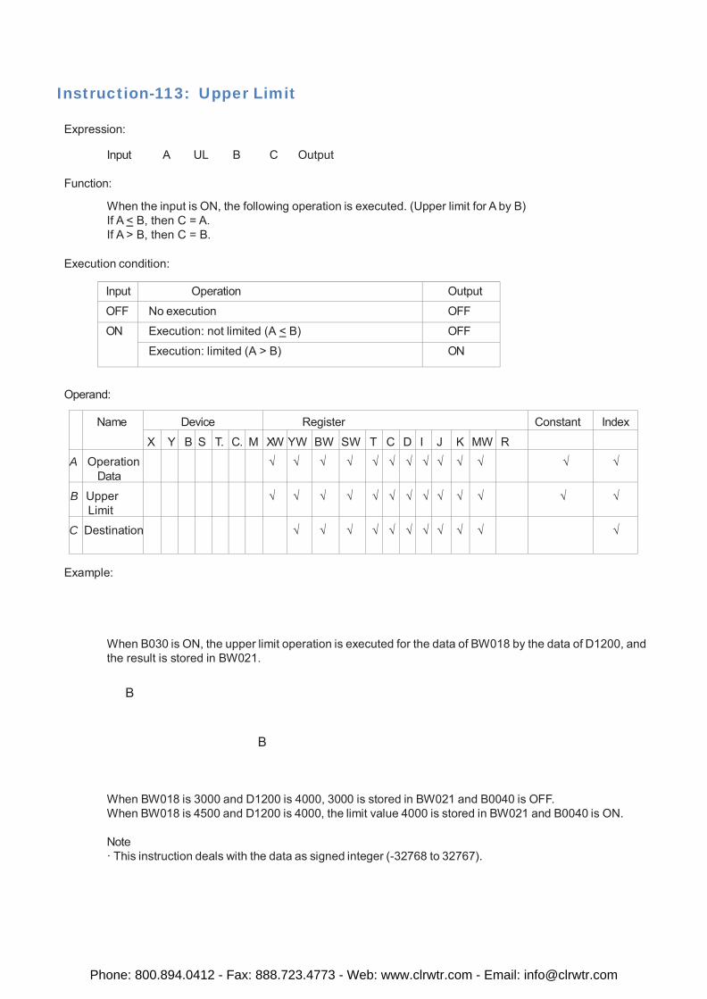
Instruction-113: Upper Limit
Expression:
Input A UL B C Output
Function:
When the input is ON, the following operation is executed. (Upper limit for A by B) If A < B, then C = A. If A > B, then C = B.
Execution condition:
Input Operation Output
OFF No execution OFF
ON Execution: not limited (A < B) OFF
Execution: limited (A > B) ON
Operand:
Name Device Register Constant Index
X Y B S T. C. M XW YW BW SW T C D I J K MW R
A Operation Data
√ √ √ √ √ √ √ √ √ √ √ √ √
B
Upper Limit
√
√
√
√
√
√
√
√
√
√
√
√
√
C
Destination
√
√
√
√
√
√
√
√
√
√
√
Example:
When B030 is ON, the upper limit operation is executed for the data of BW018 by the data of D1200, and the result is stored in BW021.
B
B
When BW018 is 3000 and D1200 is 4000, 3000 is stored in BW021 and B0040 is OFF. When BW018 is 4500 and D1200 is 4000, the limit value 4000 is stored in BW021 and B0040 is ON.
Note · This instruction deals with the data as signed integer (-32768 to 32767).
Phone: 800.894.0412 - Fax: 888.723.4773 - Web: www.clrwtr.com - Email: [email protected]
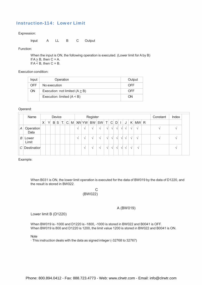
Instruction-114: Lower Limit
Expression:
Input A LL B C Output
Function:
When the input is ON, the following operation is executed. (Lower limit for A by B) If A > B, then C = A. If A < B, then C = B.
Execution condition:
Input Operation Output
OFF No execution OFF
ON Execution: not limited (A > B) OFF
Execution: limited (A < B) ON
Operand:
Name Device Register Constant Index
X Y B S T. C. M XW YW BW SW T C D I J K MW R
A Operation Data
√ √ √ √ √ √ √ √ √ √ √ √ √
B Lower Limit
√ √ √ √ √ √ √ √ √ √ √ √ √
C Destination √ √ √ √ √ √ √ √ √ √ √
Example:
When B031 is ON, the lower limit operation is executed for the data of BW019 by the data of D1220, and the result is stored in BW022.
C (BW022)
Lower limit B (D1220) A (BW019)
When BW019 is -1000 and D1220 is -1800, -1000 is stored in BW022 and B0041 is OFF. When BW019 is 800 and D1220 is 1200, the limit value 1200 is stored in BW022 and B0041 is ON.
Note · This instruction deals with the data as signed integer (-32768 to 32767)
Phone: 800.894.0412 - Fax: 888.723.4773 - Web: www.clrwtr.com - Email: [email protected]
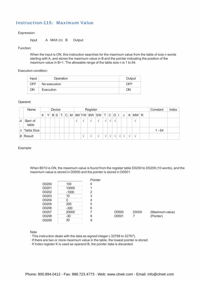
100 10000 -1000 10 0 200 -300 20000 -30 20
Instruction-115: Maximum Value
Expression:
Input A MAX (n) B Output
Function:
When the input is ON, this instruction searches for the maximum value from the table of size n words starting with A, and stores the maximum value in B and the pointer indicating the position of the maximum value in B+1. The allowable range of the table size n is 1 to 64.
Execution condition:
Input Operation Output
OFF No execution OFF
ON Execution ON
Operand:
Name Device Register Constant Index
X Y B S T. C. M XW YW BW SW T C D I J K MW R
A Start of table
√ √ √ √ √ √ √ √
n Table Size 1 - 64
B Result √ √ √ √ √ √ √ √ √ √
Example:
When B010 is ON, the maximum value is found from the register table D0200 to D0209 (10 words), and the maximum value is stored in D0500 and the pointer is stored in D0501.
D0200 D0201 D0202 D0203 D0204 D0205 D0206 D0207 D0208 D0209
Pointer 0 1 2 3 4 5 6 7 D0500 20000 (Maximum value) 8 D0501 7 (Pointer) 9
Note · This instruction deals with the data as signed integer (-32768 to 32767). · If there are two or more maximum value in the table, the lowest pointer is stored. · If Index register K is used as operand B, the pointer data is discarded.
Phone: 800.894.0412 - Fax: 888.723.4773 - Web: www.clrwtr.com - Email: [email protected]
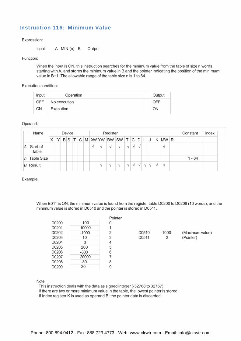
100 10000 -1000 10 0
200 -300 20000 -30 20
Instruction-116: Minimum Value
Expression:
Input A MIN (n) B Output
Function:
When the input is ON, this instruction searches for the minimum value from the table of size n words starting with A, and stores the minimum value in B and the pointer indicating the position of the minimum value in B+1. The allowable range of the table size n is 1 to 64.
Execution condition:
Input Operation Output
OFF No execution OFF
ON Execution ON
Operand:
Name Device Register Constant Index
X Y B S T. C. M XW YW BW SW T C D I J K MW R
A Start of table
√ √ √ √ √ √ √ √
n Table Size 1 - 64
B Result √ √ √ √ √ √ √ √ √ √
Example:
When B011 is ON, the minimum value is found from the register table D0200 to D0209 (10 words), and the minimum value is stored in D0510 and the pointer is stored in D0511.
D0200 D0201 D0202 D0203 D0204 D0205 D0206 D0207 D0208 D0209
Pointer 0 1 2 D0510 -1000 (Maximum value) 3 D0511 2 (Pointer) 4 5 6 7 8 9
Note · This instruction deals with the data as signed integer (-32768 to 32767). · If there are two or more minimum value in the table, the lowest pointer is stored. · If Index register K is used as operand B, the pointer data is discarded.
Phone: 800.894.0412 - Fax: 888.723.4773 - Web: www.clrwtr.com - Email: [email protected]
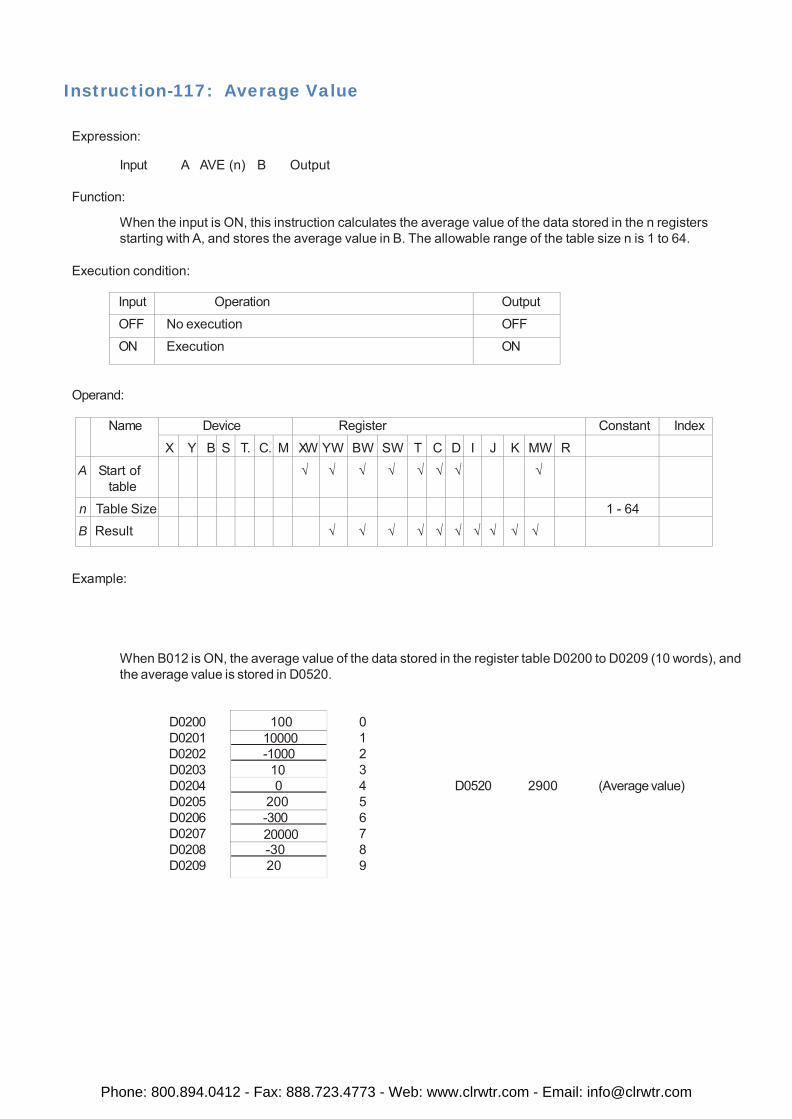
100 10000 -1000
10 0
200 -300
20000 -30
20
Instruction-117: Average Value
Expression:
Input A AVE (n) B Output
Function:
When the input is ON, this instruction calculates the average value of the data stored in the n registers starting with A, and stores the average value in B. The allowable range of the table size n is 1 to 64.
Execution condition:
Input Operation Output
OFF No execution OFF
ON Execution ON
Operand:
Name Device Register Constant Index
X Y B S T. C. M XW YW BW SW T C D I J K MW R
A Start of table
√ √ √ √ √ √ √ √
n Table Size 1 - 64
B Result √ √ √ √ √ √ √ √ √ √
Example:
When B012 is ON, the average value of the data stored in the register table D0200 to D0209 (10 words), and the average value is stored in D0520.
D0200 D0201 D0202 D0203 D0204 D0205 D0206 D0207 D0208 D0209
0 1 2 3 4 D0520 2900 (Average value) 5 6 7 8 9
Phone: 800.894.0412 - Fax: 888.723.4773 - Web: www.clrwtr.com - Email: [email protected]
Instruction-118: Function Generator
Expression:
Input A FG (n) B Output
Function:
When the input is ON, this instruction finds the function value f(x) for A as x, and stores it in C. The function f(x) is defined by the parameters stored in 2 * n registers starting with B.
Execution condition:
Input Operation Output
OFF No execution OFF ON Execution ON
Operand:
A
Name Input Value
x
Device Register Constant Index
X Y B S T. C. M XW
√
YW
√
BW
√
SW
√
T
√
C
√
D
√
I
√
J
√
K
√
MW
√
R
√
n Parameter Size
1 - 32
B Starts of Parameter
s
√ √ √ √ √ √ √ √
C Function Value f(x)
√ √ √ √ √ √ √ √ √ √
Example:
When B010 is ON, the FG instruction finds the function value f(x) for x = XW004, and stores the result in D0100. The function f(x) is defined by 2 ́ 4 = 8 parameters stored in D0600 to D0607. In this example, these parameters are set at the first scan.
Phone: 800.894.0412 - Fax: 888.723.4773 - Web: www.clrwtr.com - Email: [email protected]
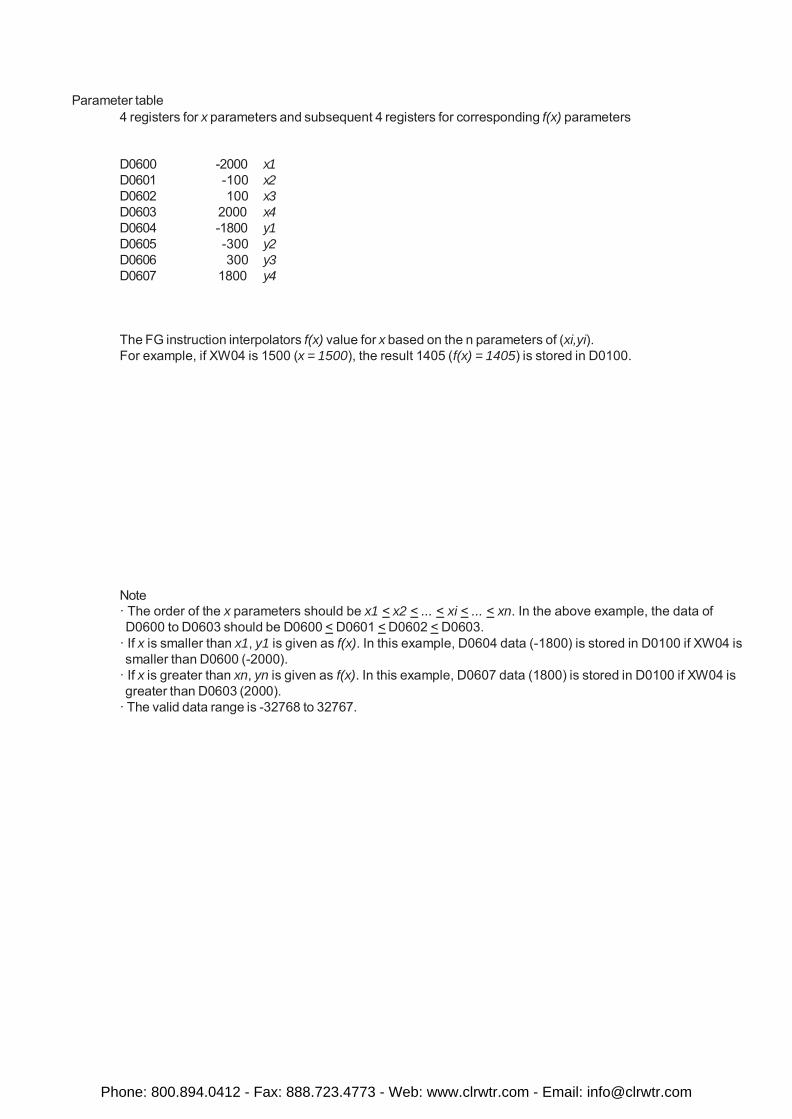
Parameter table
4 registers for x parameters and subsequent 4 registers for corresponding f(x) parameters
D0600 -2000 x1 D0601 -100 x2 D0602 100 x3 D0603 2000 x4 D0604 -1800 y1 D0605 -300 y2 D0606 300 y3 D0607 1800 y4
The FG instruction interpolators f(x) value for x based on the n parameters of (xi,yi). For example, if XW04 is 1500 (x = 1500), the result 1405 (f(x) = 1405) is stored in D0100.
Note · The order of the x parameters should be x1 < x2 < ... < xi < ... < xn. In the above example, the data of D0600 to D0603 should be D0600 < D0601 < D0602 < D0603.
· If x is smaller than x1, y1 is given as f(x). In this example, D0604 data (-1800) is stored in D0100 if XW04 is smaller than D0600 (-2000).
· If x is greater than xn, yn is given as f(x). In this example, D0607 data (1800) is stored in D0100 if XW04 is greater than D0603 (2000).
· The valid data range is -32768 to 32767.
Phone: 800.894.0412 - Fax: 888.723.4773 - Web: www.clrwtr.com - Email: [email protected]
Instruction-119: USB Data log Upload This ladder instruction is applicable on in FP-HMI with USB port support. Expression:
[A]
Input [C] LD-UPLD [D] Output [B]
Function:
The output of this instruction is a “*.csv” type file which will be uploaded in USB stick. This ladder supports only those units having, USB functionality.
Execution condition:
Input Operation Output
OFF No execution OFF
ON Execution ON
Operand:
A
Name Date time
tag
Device Register Constant Index X Y B S T. C. M XW
√
YW
√
BW
√
SW
√
T
√
C
√
D
√
I
√
J
√
K
√
MW
√
R
B Group (1-4)
√ √ √ √ √ √ √ √ √ √ √
C Filename √ √ √ √ √ √ √ √ √ √ √ D Status Reg iste r √ √ √ √ √ √ √ √ √ √
Example:
Here user needs at least 16 tag registers to execute this task. In the above shown image, once user defined tag address for “Date Time”, the application automatically considers consecutive 12 registers for date and time. i.e. If tag address D000 is for Date time, then: D0001 will be for Start Date D0002 will be for Start Month D0003 will be for Start Year D0004 will be for Start Hour D0005 will be for Start Minute
Phone: 800.894.0412 - Fax: 888.723.4773 - Web: www.clrwtr.com - Email: [email protected]

D0006 will be for Start Second D0007 will be for End Date D0008 will be for End Month D0009 will be for End Year D0010 will be for End Hour D0011 will be for End Minute D0012 will be for End Second.
Apart from this, user needs tag address for group Number (1 - 4). User also has to defined another tag address for file name. This file name is for “*.csv” output file which can be in ASCII data entry format. User can also defined file name using a string which should be no longer than 8 characters. The Status byte will show the respective status code depending on the current status of the Task , like task com- plete, task is in execution, invalid date, invalid group number, USB stick is absent, invalid entry of File output device etc. etc. Every time a new file will be created on USB stick. If old file with same name is present it will be overwritten. The data can be sorted according to group number and the Start-End Date- Time only. e.g. the csv file can open in Windows Excel sheet or in Microsoft Word or in notepad.
This function can also be carried out as an application task in the OIS PLUS dispays.
Phone: 800.894.0412 - Fax: 888.723.4773 - Web: www.clrwtr.com - Email: [email protected]
Instruction-120: Device Set
Expression:
Input DSET A Output
Function:
When the input is ON, the device A is set to ON if A is a device.
Execution condition:
Input Operation Output
OFF No execution OFF
ON Execution ON
Operand:
Name Device Register Constant Index
X Y B S T. C. M XW YW BW SW T C D I J K MW R
A Device √ √ √ √
Example:
When B010 is ON, B025 is set to ON. The state of B025 is remained even if B010 comes OFF.
Phone: 800.894.0412 - Fax: 888.723.4773 - Web: www.clrwtr.com - Email: [email protected]
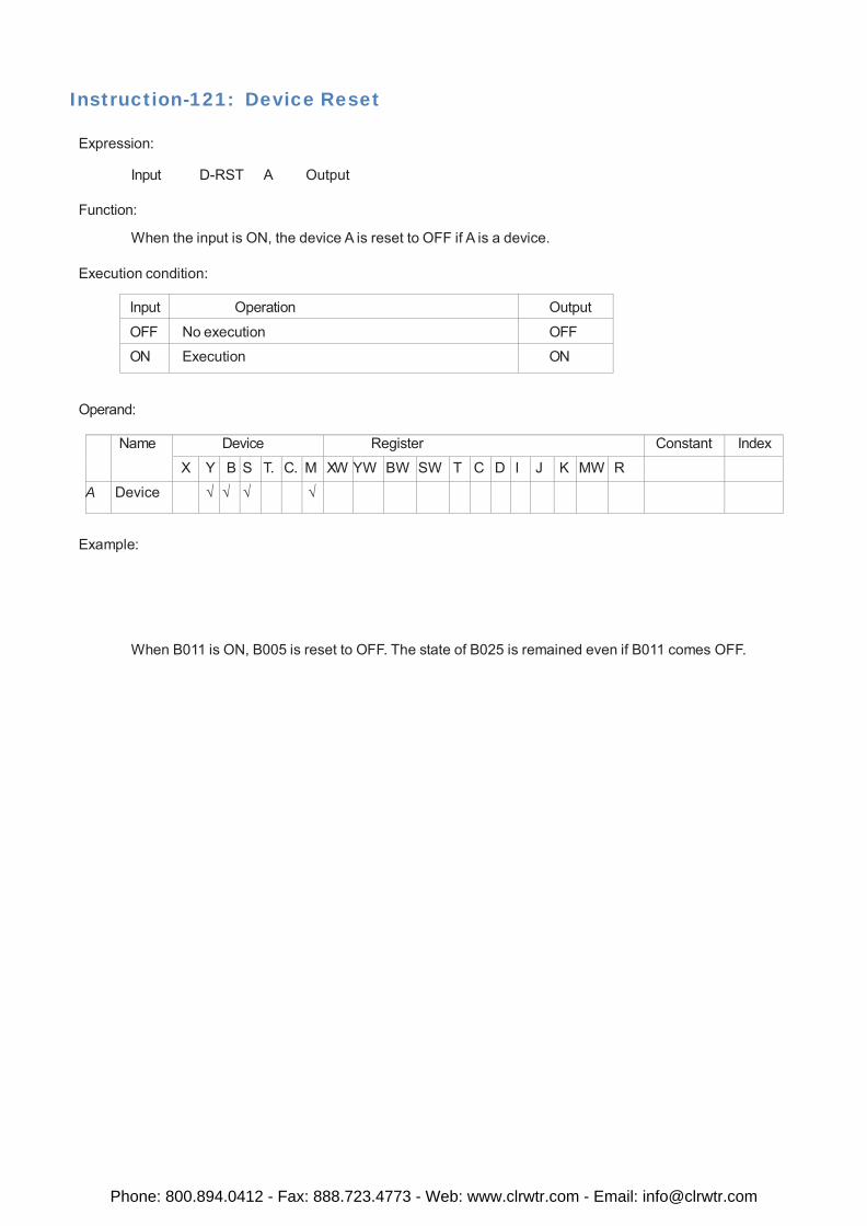
Instruction-121: Device Reset
Expression:
Input D-RST A Output
Function:
When the input is ON, the device A is reset to OFF if A is a device.
Execution condition:
Input Operation Output
OFF No execution OFF
ON Execution ON
Operand:
Name Device Register Constant Index
X Y B S T. C. M XW YW BW SW T C D I J K MW R A Device √ √ √ √
Example:
When B011 is ON, B005 is reset to OFF. The state of B025 is remained even if B011 comes OFF.
Phone: 800.894.0412 - Fax: 888.723.4773 - Web: www.clrwtr.com - Email: [email protected]
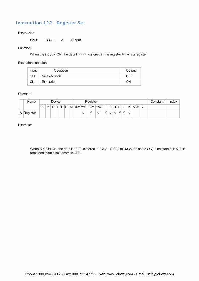
Instruction-122: Register Set
Expression:
Input R-SET A Output
Function:
When the input is ON, the data HFFFF is stored in the register A if A is a register.
Execution condition:
Input Operation Output
OFF No execution OFF
ON Execution ON
Operand:
Name Device Register Constant Index
X Y B S T. C. M XW YW BW SW T C D I J K MW R A Register √ √ √ √ √ √ √ √ √
Example:
When B010 is ON, the data HFFFF is stored in BW20. (R320 to R335 are set to ON). The state of BW20 is remained even if B010 comes OFF.
Phone: 800.894.0412 - Fax: 888.723.4773 - Web: www.clrwtr.com - Email: [email protected]
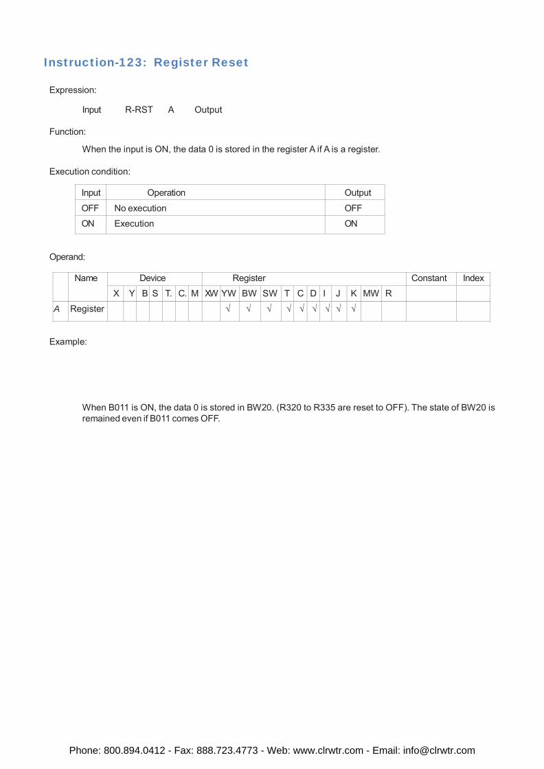
Instruction-123: Register Reset
Expression:
Input R-RST A Output
Function:
When the input is ON, the data 0 is stored in the register A if A is a register.
Execution condition:
Input Operation Output
OFF No execution OFF
ON Execution ON
Operand:
Name Device Register Constant Index
X Y B S T. C. M XW YW BW SW T C D I J K MW R
A Register √ √ √ √ √ √ √ √ √
Example:
When B011 is ON, the data 0 is stored in BW20. (R320 to R335 are reset to OFF). The state of BW20 is remained even if B011 comes OFF.
Phone: 800.894.0412 - Fax: 888.723.4773 - Web: www.clrwtr.com - Email: [email protected]
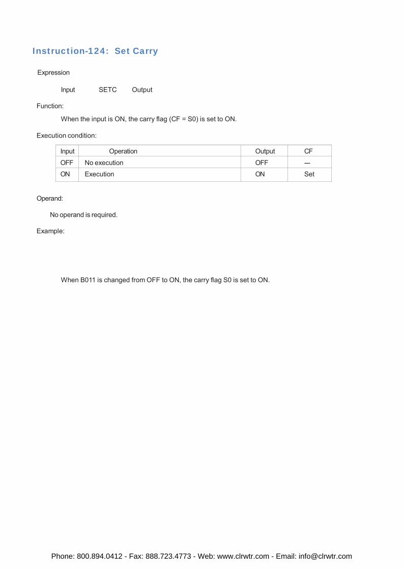
Instruction-124: Set Carry
Expression
Input SETC Output
Function:
When the input is ON, the carry flag (CF = S0) is set to ON.
Execution condition:
Input Operation Output CF
OFF No execution OFF ---
ON Execution ON Set
Operand:
No operand is required.
Example:
When B011 is changed from OFF to ON, the carry flag S0 is set to ON.
Phone: 800.894.0412 - Fax: 888.723.4773 - Web: www.clrwtr.com - Email: [email protected]
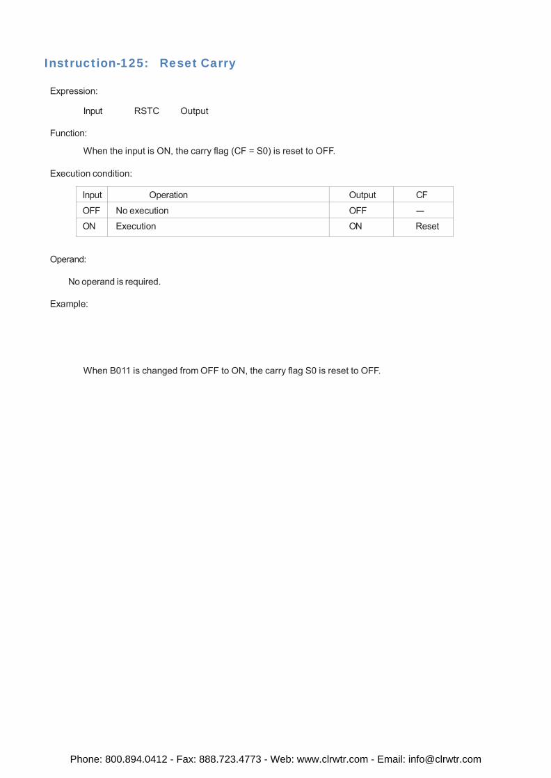
Instruction-125: Reset Carry
Expression:
Input RSTC Output
Function:
When the input is ON, the carry flag (CF = S0) is reset to OFF.
Execution condition:
Input Operation Output CF
OFF No execution OFF ---
ON Execution ON Reset
Operand:
No operand is required.
Example:
When B011 is changed from OFF to ON, the carry flag S0 is reset to OFF.
Phone: 800.894.0412 - Fax: 888.723.4773 - Web: www.clrwtr.com - Email: [email protected]
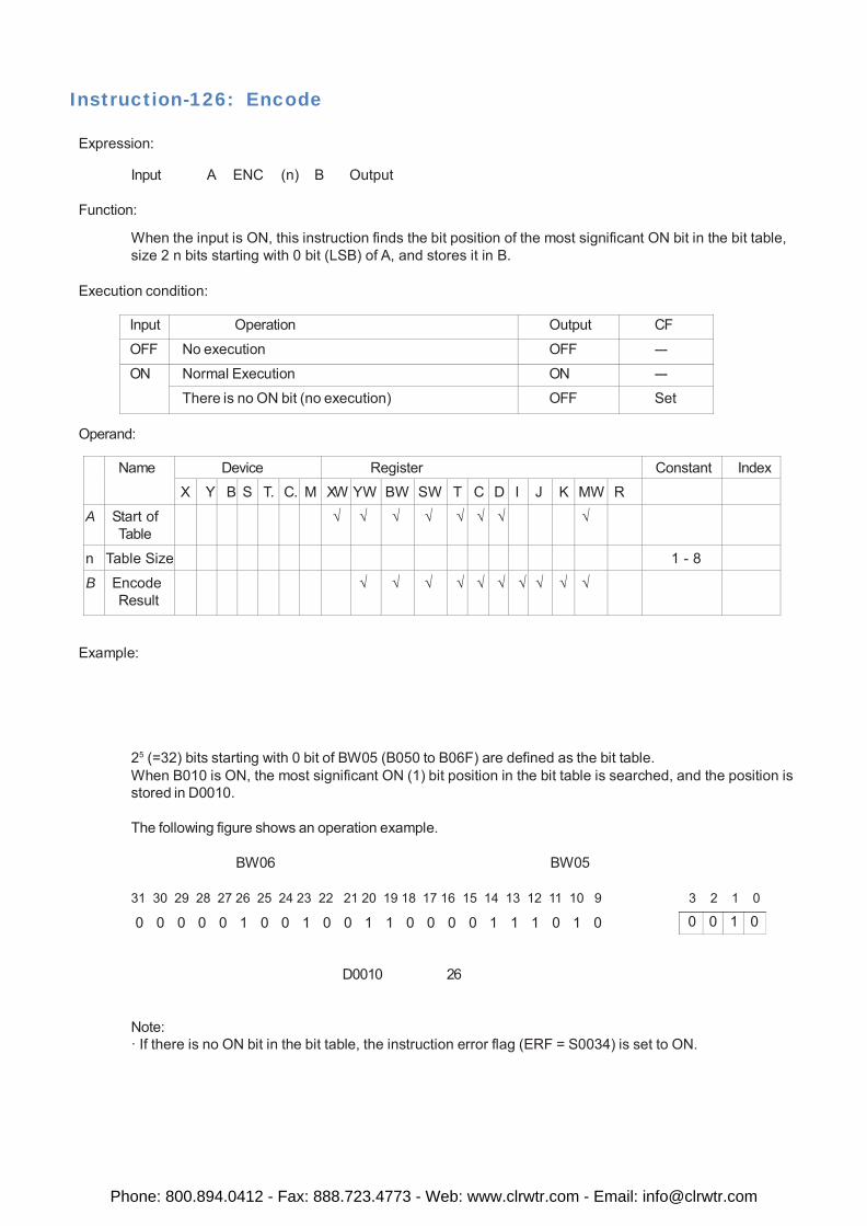
0 0 1 0
Instruction-126: Encode
Expression:
Input A ENC (n) B Output
Function:
When the input is ON, this instruction finds the bit position of the most significant ON bit in the bit table, size 2 n bits starting with 0 bit (LSB) of A, and stores it in B.
Execution condition:
Input Operation Output CF
OFF No execution OFF ---
ON Normal Execution ON ---
There is no ON bit (no execution) OFF Set
Operand:
Name Device Register Constant Index X Y B S T. C. M XW YW BW SW T C D I J K MW R
A Start of Table
√ √ √ √ √ √ √ √
n Table Size 1 - 8
B Encode Result
√ √ √ √ √ √ √ √ √ √
Example:
25 (=32) bits starting with 0 bit of BW05 (B050 to B06F) are defined as the bit table. When B010 is ON, the most significant ON (1) bit position in the bit table is searched, and the position is stored in D0010.
The following figure shows an operation example.
BW06 BW05
31 30 29 28 27 26 25 24 23 22 21 20 19 18 17 16 15 14 13 12 11 10 9 3 2 1 0
0 0 0 0 0 1 0 0 1 0 0 1 1 0 0 0 0 1 1 1 0 1 0
D0010 26
Note: · If there is no ON bit in the bit table, the instruction error flag (ERF = S0034) is set to ON.
Phone: 800.894.0412 - Fax: 888.723.4773 - Web: www.clrwtr.com - Email: [email protected]
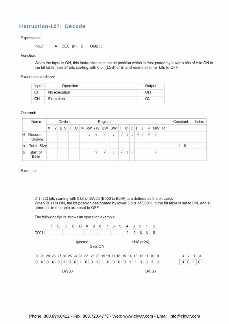
1 1 0 0 0
0 0 1 0
Instruction-127: Decode
Expression:
Input A DEC (n) B Output
Function:
When the input is ON, this instruction sets the bit position which is designated by lower n bits of A to ON in the bit table, size 2n bits starting with 0 bit (LSB) of B, and resets all other bits to OFF.
Execution condition:
Input Operation Output
OFF No execution OFF
ON Execution ON
Operand:
Name Device Register Constant Index
X Y B S T. C. M XW YW BW SW T C D I J K MW R
A Decode Source
√ √ √ √ √ √ √ √ √ √ √
n Table Size 1 - 8
B Start of Table
√ √ √ √ √ √ √
Example:
25 (=32) bits starting with 0 bit of BW05 (B050 to B06F) are defined as the bit table. When B011 is ON, the bit position designated by lower 5 bits of D0011 in the bit table is set to ON, and all other bits in the table are reset to OFF.
The following figure shows an operation example.
D0011 F E D C B A 9 8 7 6 5 4 3 2 1 0
Ignored H18 (=24)
Sets ON
31 30 29 28 27 26 25 24 23 22 21 20 19 18 17 16 15 14 13 12 11 10 9 3 2 1 0
0 0 0 0 0 1 0 0 1 0 0 1 1 0 0 0 0 1 1 1 0 1 0
BW06 BW05
Phone: 800.894.0412 - Fax: 888.723.4773 - Web: www.clrwtr.com - Email: [email protected]
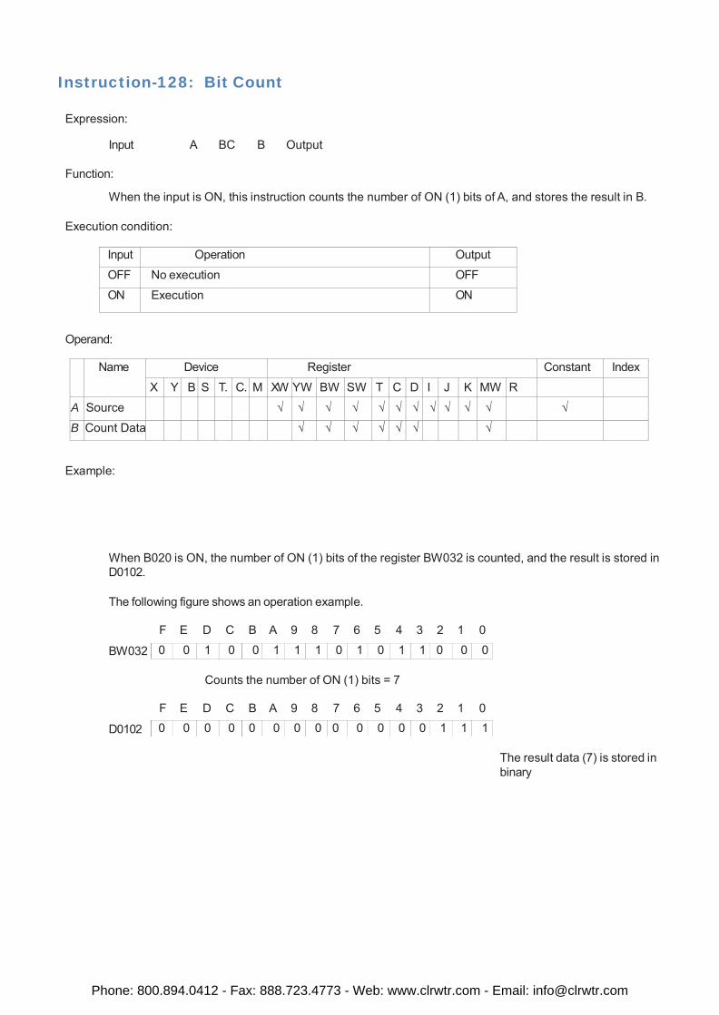
0 0 1 0 0 1 1 1 0 1 0 1 1 0 0 0
0 0 0 0 0 0 0 0 0 0 0 0 0 1 1 1
Instruction-128: Bit Count
Expression:
Input A BC B Output
Function:
When the input is ON, this instruction counts the number of ON (1) bits of A, and stores the result in B.
Execution condition:
Input Operation Output
OFF No execution OFF
ON Execution ON
Operand:
Name Device Register Constant Index
X Y B S T. C. M XW YW BW SW T C D I J K MW R
A Source √ √ √ √ √ √ √ √ √ √ √ √
B Count Data √ √ √ √ √ √ √
Example:
When B020 is ON, the number of ON (1) bits of the register BW032 is counted, and the result is stored in D0102.
The following figure shows an operation example.
BW032
F E D C B A 9 8 7 6 5 4 3 2 1 0
Counts the number of ON (1) bits = 7
D0102
F E D C B A 9 8 7 6 5 4 3 2 1 0
The result data (7) is stored in binary
Phone: 800.894.0412 - Fax: 888.723.4773 - Web: www.clrwtr.com - Email: [email protected]
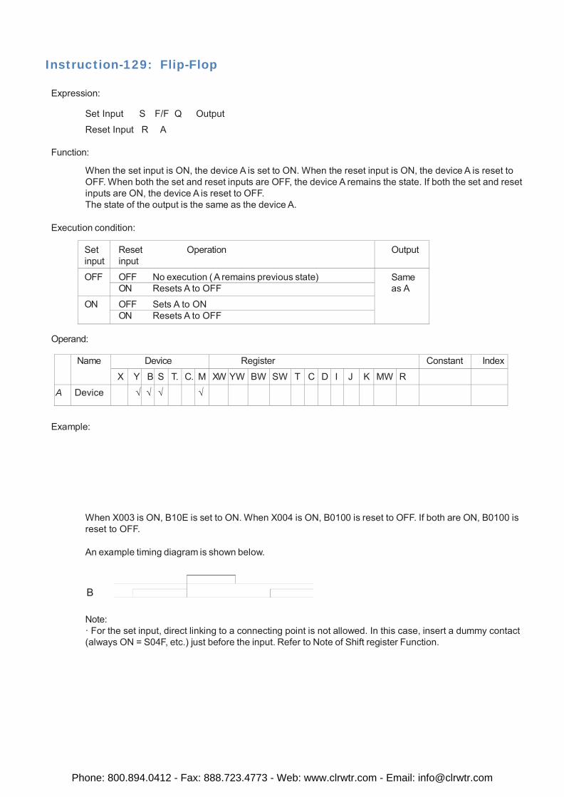
Instruction-129: Flip-Flop
Expression:
Set Input S F/F Q Output
Reset Input R A
Function:
When the set input is ON, the device A is set to ON. When the reset input is ON, the device A is reset to OFF. When both the set and reset inputs are OFF, the device A remains the state. If both the set and reset inputs are ON, the device A is reset to OFF. The state of the output is the same as the device A.
Execution condition:
Set input
Reset Operation input
Output
OFF OFF No execution ( A remains previous state) Same as A ON Resets A to OFF
ON OFF Sets A to ON ON Resets A to OFF
Operand:
Name Device Register Constant Index
X Y B S T. C. M XW YW BW SW T C D I J K MW R
A Device √ √ √ √
Example:
When X003 is ON, B10E is set to ON. When X004 is ON, B0100 is reset to OFF. If both are ON, B0100 is reset to OFF.
An example timing diagram is shown below.
B
Note: · For the set input, direct linking to a connecting point is not allowed. In this case, insert a dummy contact (always ON = S04F, etc.) just before the input. Refer to Note of Shift register Function.
Phone: 800.894.0412 - Fax: 888.723.4773 - Web: www.clrwtr.com - Email: [email protected]
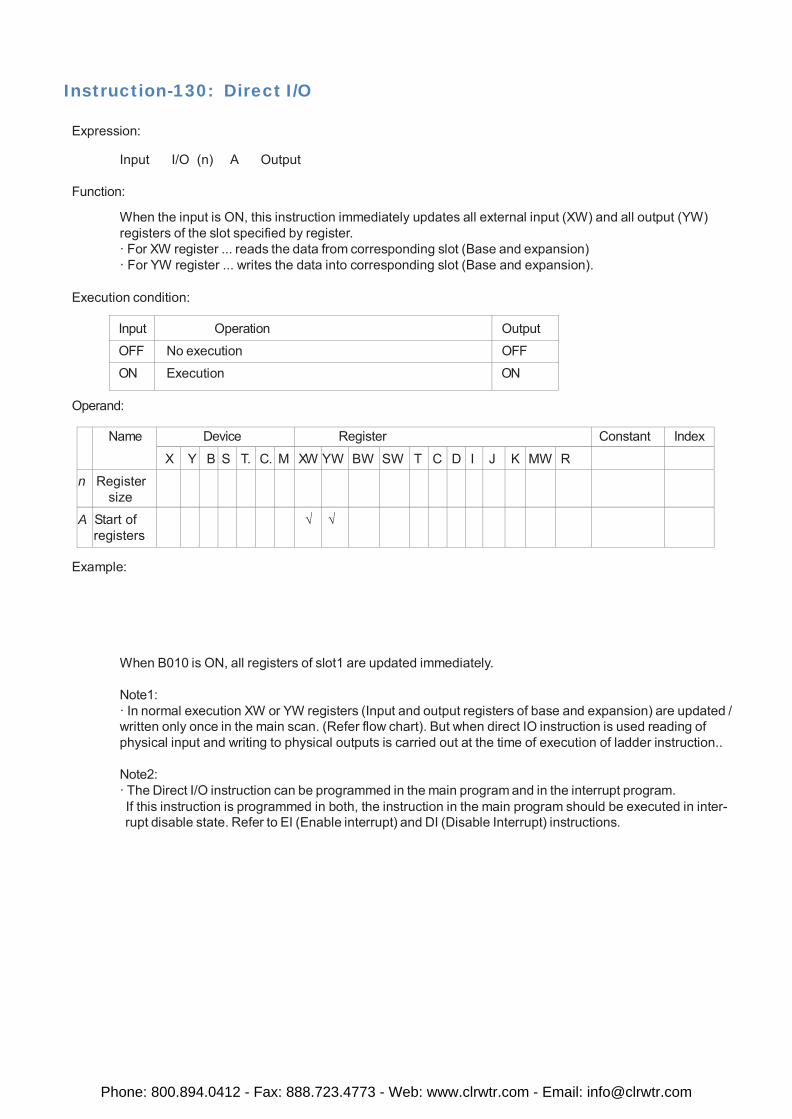
Instruction-130: Direct I/O
Expression:
Input I/O (n) A Output
Function:
When the input is ON, this instruction immediately updates all external input (XW) and all output (YW) registers of the slot specified by register. · For XW register ... reads the data from corresponding slot (Base and expansion) · For YW register ... writes the data into corresponding slot (Base and expansion).
Execution condition:
Input Operation Output
OFF No execution OFF
ON Execution ON
Operand:
Name Device Register Constant Index
X Y B S T. C. M XW YW BW SW T C D I J K MW R
n Register size
A Start of registers
√ √
Example:
When B010 is ON, all registers of slot1 are updated immediately.
Note1: · In normal execution XW or YW registers (Input and output registers of base and expansion) are updated / written only once in the main scan. (Refer flow chart). But when direct IO instruction is used reading of physical input and writing to physical outputs is carried out at the time of execution of ladder instruction..
Note2: · The Direct I/O instruction can be programmed in the main program and in the interrupt program. If this instruction is programmed in both, the instruction in the main program should be executed in inter- rupt disable state. Refer to EI (Enable interrupt) and DI (Disable Interrupt) instructions.
Phone: 800.894.0412 - Fax: 888.723.4773 - Web: www.clrwtr.com - Email: [email protected]
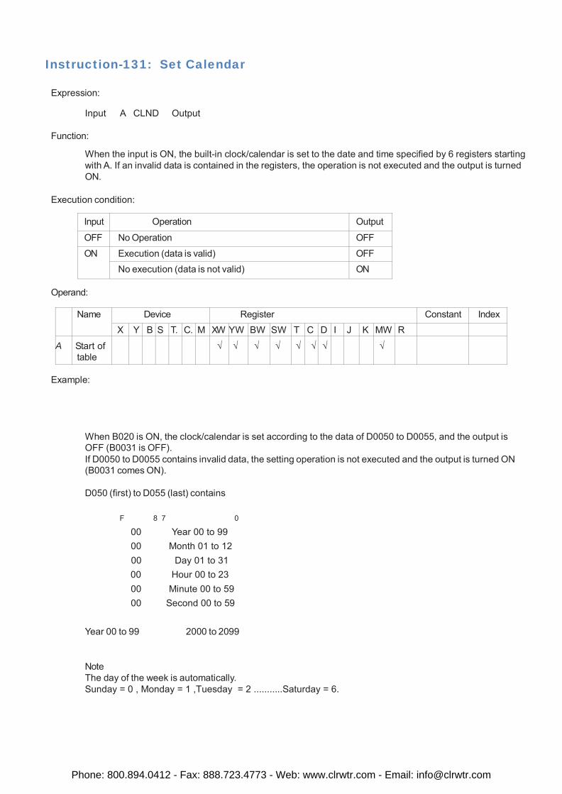
Instruction-131: Set Calendar
Expression:
Input A CLND Output
Function:
When the input is ON, the built-in clock/calendar is set to the date and time specified by 6 registers starting with A. If an invalid data is contained in the registers, the operation is not executed and the output is turned ON.
Execution condition:
Input Operation Output
OFF No Operation OFF
ON Execution (data is valid) OFF No execution (data is not valid) ON
Operand:
Name Device Register Constant Index X Y B S T. C. M XW YW BW SW T C D I J K MW R
A Start of table
√ √ √ √ √ √ √ √
Example:
When B020 is ON, the clock/calendar is set according to the data of D0050 to D0055, and the output is OFF (B0031 is OFF). If D0050 to D0055 contains invalid data, the setting operation is not executed and the output is turned ON (B0031 comes ON).
D050 (first) to D055 (last) contains
F 8 7 0
00 Year 00 to 99 00 Month 01 to 12 00 Day 01 to 31 00 Hour 00 to 23 00 Minute 00 to 59 00 Second 00 to 59
Year 00 to 99 2000 to 2099
Note The day of the week is automatically. Sunday = 0 , Monday = 1 ,Tuesday = 2 ...........Saturday = 6.
Phone: 800.894.0412 - Fax: 888.723.4773 - Web: www.clrwtr.com - Email: [email protected]
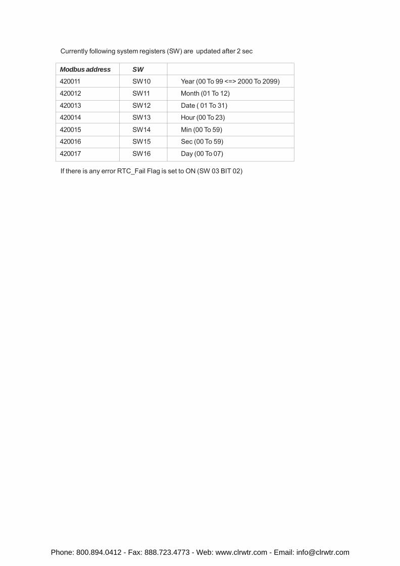
Currently following system registers (SW) are updated after 2 sec
Modbus address SW
420011 SW10 Year (00 To 99 <=> 2000 To 2099)
420012 SW11 Month (01 To 12)
420013 SW12 Date ( 01 To 31)
420014 SW13 Hour (00 To 23)
420015 SW14 Min (00 To 59)
420016 SW15 Sec (00 To 59)
420017 SW16 Day (00 To 07)
If there is any error RTC_Fail Flag is set to ON (SW 03 BIT 02)
Phone: 800.894.0412 - Fax: 888.723.4773 - Web: www.clrwtr.com - Email: [email protected]
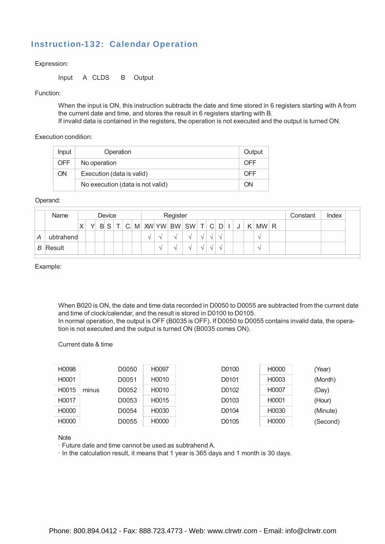
H0098 H0001 H0015 H0017 H0000 H0000
H0097 H0010 H0010 H0015 H0030 H0000
H0000 H0003 H0007 H0001 H0030 H0000
Instruction-132: Calendar Operation
Expression:
Input A CLDS B Output
Function:
When the input is ON, this instruction subtracts the date and time stored in 6 registers starting with A from the current date and time, and stores the result in 6 registers starting with B. If invalid data is contained in the registers, the operation is not executed and the output is turned ON.
Execution condition:
Input Operation Output
OFF No operation OFF
ON Execution (data is valid) OFF No execution (data is not valid) ON
Operand:
Name Device Register Constant Index
X Y B S T. C. M XW YW BW SW T C D I J K MW R
A S ubtrahend √ √ √ √ √ √ √ √
B Result √ √ √ √ √ √ √
Example:
When B020 is ON, the date and time data recorded in D0050 to D0055 are subtracted from the current date and time of clock/calendar, and the result is stored in D0100 to D0105. In normal operation, the output is OFF (B0035 is OFF). If D0050 to D0055 contains invalid data, the opera- tion is not executed and the output is turned ON (B0035 comes ON).
Current date & time
D0050 D0051
minus D0052 D0053 D0054 D0055
D0100 D0101 D0102 D0103 D0104 D0105
(Year) (Month) (Day) (Hour) (Minute)
(Second)
Note · Future date and time cannot be used as subtrahend A. · In the calculation result, it means that 1 year is 365 days and 1 month is 30 days.
Phone: 800.894.0412 - Fax: 888.723.4773 - Web: www.clrwtr.com - Email: [email protected]