Embed Size (px)
Citation preview

User'sManual
IM 01R06A00-01E-E
Model DYVortex Flowmeter(Integral Type, Remote Type)Model DYAVortex Flow Converter(Remote Type)
IM 01R06A00-01E-E3rd Edition, Jan. 2007

IM 01R06A00-01E-E3rd edition, Jan. 2007
i
CONTENTS
All Rights Reserved, Copyright © 2001. Yokogawa Electric Corporation
CONTENTSINTRODUCTION ............................................................................................. v1. HANDLING PRECAUTIONS ...................................................................1-1
1.1 Model and Specifications .................................................................................... 1-11.2 Precautions Regarding Transportation and Storage Location ........................ 1-11.3 Precautions Regarding Installation Locations .................................................. 1-1
2. INSTALLATION .......................................................................................2-12.1 Precautions Regarding Installation Locations .................................................. 2-12.2 Piping .................................................................................................................... 2-12.3 Precautions Regarding Installation .................................................................... 2-42.4 Piping to Improve Durability ............................................................................... 2-52.5 Cryogenic and High process Temperature Version Insulation........................ 2-52.6 Installing the Vortex Flow-meter ......................................................................... 2-6
3. WIRING ....................................................................................................3-13.1 Wiring Precautions .............................................................................................. 3-13.2 Wiring for Output Condition ................................................................................ 3-13.3 Connection ........................................................................................................... 3-23.4 Wiring Cables and Wires ..................................................................................... 3-43.5 Connection of the Remote Type Signal Cable................................................... 3-43.6 Method of Finishing the Signal Cable End(DYC) .............................................. 3-5
3.6.1 For Vortex Flowmeter (DY-N) .................................................................................. 3-53.6.2 For Vortex Flow Converter (DYA)............................................................................ 3-6
3.7 Wiring Cautions.................................................................................................... 3-73.8 Grounding ............................................................................................................. 3-7
4. BASIC OPERATING PROCEDURES .....................................................4-14.1 Construction of the Display ................................................................................ 4-14.2 Display Contents in Display Section .................................................................. 4-24.3 Display Contents in Display Section .................................................................. 4-3
4.3.1 Change the Display Mode from % Display to Engineering Unit............................ 4-44.3.2 Indicate the Total Rate in the Lower Display .......................................................... 4-5
4.4 Setting Mode......................................................................................................... 4-64.4.1 Structure of Setting Mode Display ........................................................................... 4-64.4.2 Method of Parameter Setting .................................................................................... 4-7
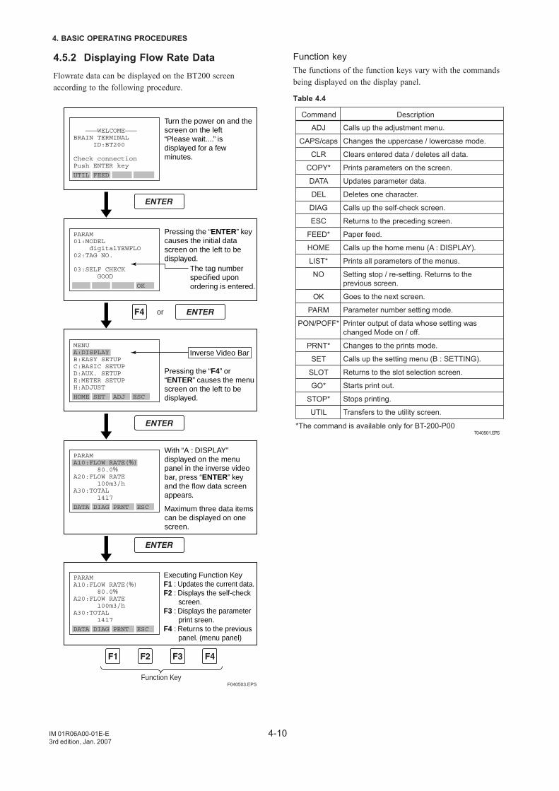
4.5 Operation for the BT200 ...................................................................................... 4-94.5.1 Connection Method for the BT200 ........................................................................... 4-94.5.2 Displaying Flow Rate Data ...................................................................................... 4-104.5.3 Setting Parameters .................................................................................................. 4-11
4.6 Operation for HART Communicator ................................................................. 4-134.6.1 Interconnection between digitalYEWFLO and HART Communicator ................ 4-134.6.2 Keys and Functions of Model 275 .......................................................................... 4-144.6.3 Display ...................................................................................................................... 4-154.6.4 Calling Up Menu Addresses ................................................................................... 4-164.6.5 Entering, Setting and Sending Data ...................................................................... 4-174.6.6 Parameters Configuration....................................................................................... 4-174.6.7 Unique Functions of HART Communicator .......................................................... 4-184.6.8 Data Renewing ......................................................................................................... 4-184.6.9 Checking for Problems ........................................................................................... 4-184.6.10 Write Protect .......................................................................................................... 4-194.6.11 Menu Tree .............................................................................................................. 4-20
iiIM 01R06A00-01E-E3rd edition, Jan. 2007
CONTENTS
5. Parameter Setup .....................................................................................5-15.1 Parameter Setup .................................................................................................. 5-15.2 Multi-Variable Type Parameter (Only for /MV) ................................................... 5-15.3 Parameters List .................................................................................................... 5-15.4 Parameter Description ......................................................................................... 5-95.5 Error Code Lists ................................................................................................. 5-17
6. OPERATION ............................................................................................6-16.1 Adjustment ........................................................................................................... 6-1
6.1.1 Zero Adjustment ........................................................................................................ 6-16.1.2 Span Adjustment ....................................................................................................... 6-16.1.3 Loop test ..................................................................................................................... 6-16.1.4 Totalizer Function Start and Totalized Value Reset ............................................... 6-16.1.5 Unit of Pulse Output (Scaling) .................................................................................. 6-26.1.6 Power Failure ............................................................................................................. 6-2
6.2 Adjustment for Manual Mode .............................................................................. 6-26.2.1 Low Cut Adjustment .................................................................................................. 6-26.2.2 Tuning ......................................................................................................................... 6-2
6.3 Other Maintenance ............................................................................................... 6-36.3.1 Cleaning Precautions ................................................................................................ 6-3
7. MAINTENANCE .......................................................................................7-17.1 Changing the Terminal Box Orientation ............................................................ 7-27.2 Indicator Removal and Rotation ......................................................................... 7-37.3 Amplifier Unit Removal........................................................................................ 7-37.4 Amplifier Unit Assembling .................................................................................. 7-37.5 Vortex Shedder Removal .................................................................................... 7-47.6 Setting Switches .................................................................................................. 7-6
7.6.1 Setting of Burnout Switch......................................................................................... 7-67.6.2 Setting of Write Protect Switch ................................................................................ 7-6
7.7 Software Configuration ....................................................................................... 7-78. TROUBLESHOOTING .............................................................................8-1
8.1 Flow ....................................................................................................................... 8-18.2 Flow (Only for /MV) .............................................................................................. 8-4
9. GENERAL DESCRIPTION ......................................................................9-19.1 Outline ................................................................................................................... 9-19.2 Standard Specifications ...................................................................................... 9-29.3 Model and Suffix Codes ...................................................................................... 9-59.4 Option Specifications .......................................................................................... 9-7
9.4.1 Option Specifications ................................................................................................ 9-79.4.2 OPTION SPECIFICATIONS (For Explosion Protected Type) ................................. 9-99.4.3 OPTION MULTI-VARIABLE (BUILD IN TEMPERATURE SENSOR) TYPE (/MV) .. 9-119.4.4 OPTION REDUCED BORE TYPE (/R1, /R2) ............................................................ 9-12
9.5 Sizing .................................................................................................................. 9-149.6 REMARKS ON INSTALLATION ......................................................................... 9-199.7 External Dimensions ......................................................................................... 9-22
IM 01R06A00-01E-E3rd edition, Jan. 2007
iii
CONTENTS
10. EXPLOSION PROTECTED TYPE INSTRUMENT ..............................10-110.1 ATEX ................................................................................................................. 10-1
10.1.1 Technical Data ....................................................................................................... 10-110.1.2 Installation .............................................................................................................. 10-210.1.3 Operation ................................................................................................................ 10-210.1.4 Maintenance and Repair ....................................................................................... 10-210.1.5 Installation Diagram of Intrinsically safe (and Note) .......................................... 10-310.1.6 Installation Diagram of Type of Protection “n” .................................................. 10-310.1.7 Data Plate ............................................................................................................... 10-410.1.8 Screw Marking ....................................................................................................... 10-4
10.2 FM ...................................................................................................................... 10-510.2.1 Technical Data ....................................................................................................... 10-510.2.2 Wiring...................................................................................................................... 10-510.2.3 Operation ................................................................................................................ 10-510.2.4 Maintenance and Repair ....................................................................................... 10-510.2.5 Installation Diagram .............................................................................................. 10-610.2.6 Data Plate ............................................................................................................... 10-7
11. PRESSURE EQUIPMENT DIRECTIVE ...............................................11-1

ivIM 01R06A00-01E-E3rd edition, Jan. 2007
CONTENTS
v
INTRODUCTION
IM 01R06A00-01E-E3rd edition, Jan. 2007
INTRODUCTION
The DY series of vortex flowmeters have been fine-tuned toyour order specifications prior to shipment. Before use, readthis manual thoroughly and familiarize yourself fully withthe features, operations and handling of digitalYEWFLO tohave the instrument deliver its full capabilities and to ensureits efficient and correct use.
Notices Regarding This Manual• This manual should be passed to the end user.• The contents of this manual are subject to change without
prior notice.• All rights reserved. No part of this document may be
reproduced or transmitted in any form or by any meanswithout the written permission of Yokogawa ElectricCorporation (hereinafter simply referred to as Yokogawa).
• This manual neither does warrant the marketability of thisinstrument nor it does warrant that the instrument will suita particular purpose of the user.
• Every effort has been made to ensure accuracy in thecontents of this manual. However, should any questionsarise or errors come to your attention, please contact yournearest Yokogawa sales office that appears on the back ofthis manual or the sales representative from which youpurchased the product.
• This manual is not intended for models with customspecifications.
• Revisions may not always be made in this manual inconjunction with changes in specifications, constructionsand/or components if such changes are not deemed tointerfere with the instrument’s functionality or perfor-mance.
Notices Regarding Safety and Modification• For the protection and safety of personnel, the instrument
and the system comprising the instrument, be sure tofollow the instructions on safety described in this manualwhen handling the product. If you handle the instrumentin a manner contrary to these instructions, Yokogawadoes not guarantee safety.
• If this instrument is used in a manner not specified in thismanual, the protection provided by this instrument maybe impaired.
• As for explosionproof model, if you yourself repair ormodify the instrument and then fail to return it to itsoriginal form, the explosion-protected construction of theinstrument will be impaired, creating a hazardouscondition. Be sure to consult Yokogawa for repairs andmodifications.
Safety and Modification Precautions• The following general safety precautions must be
observed during all phases of operation, service, andrepair of this instrument. Failure to comply with theseprecautions or with specific WARNINGS given elsewherein this manual violates safety standards of design,manufacture, and intended use of the instrument.Yokogawa assumes no liability for the customer's failureto comply with these requirements. If this instrument isused in a manner not specified in this manual, theprotection provided by this instrument may be impaired.
• The following safety symbol marks are used in this user'smanual and instrument.
WARNING
A WARNING sign denotes a hazard. It calls attentionto procedure, practice, condition or the like, which, ifnot correctly performed or adhered to, could result ininjury or death of personnel.
CAUTION
A CAUTION sign denotes a hazard. It calls attentionto procedure, practice, condition or the like, which, ifnot correctly performed or adhered to, could result indamage to or destruction of part or all of the product.
IMPORTANT
An IMPORTANT sign denotes that attention isrequired to avoid damage to the instrument or systemfailure.
NOTE
A NOTE sign denotes information necessary foressential understanding of operation and fea-tures.
Functional grounding terminal
Direct current
vi
INTRODUCTION
IM 01R06A00-01E-E3rd edition, Jan. 2007
Warranty• The warranty of this instrument shall cover the period
noted on the quotation presented to the Purchaser at thetime of purchase. The Seller shall repair the instrumentfree of charge when the failure occurred during thewarranty period.
• All inquiries on instrument failure should be directed tothe Seller’s sales representative from whom you purchasedthe instrument or your nearest sales office of the Seller.
• Should the instrument fail, contact the Seller specifyingthe model and instrument number of the product inquestion. Be specific in describing details on the failureand the process in which the failure occurred. It will behelpful if schematic diagrams and/or records of data areattached to the failed instrument.
• Whether or not the failed instrument should be repairedfree of charge shall be left solely to the discretion of theSeller as a result of an inspection by the Seller.
The Purchaser shall not be entitled to receiverepair services from the Seller free of charge,even during the warranty period, if themalfunction or damage is due to:
• improper and/or inadequate maintenance of the instrumentin question by the Purchaser.
• handling, use or storage of the instrument in questionbeyond the design and/or specifications requirements.
• use of the instrument in question in a location notconforming to the conditions specified in the Seller'sGeneral Specification or Instruction Manual.
• retrofitting and/or repair by an other party than the Selleror a party to whom the Seller has entrusted repairservices.
• improper relocation of the instrument in question afterdelivery.
• reason of force measure such as fires, earthquakes, storms/floods, thunder/lightning, or other reasons not attributableto the instrument in question.
vii
INTRODUCTION
IM 01R06A00-01E-E3rd edition, Jan. 2007
Using the Vortex Flowmeter Safely
WARNING
(1) Installation• Installation of the vortex flowmeter must be
performed by expert engineer or skilled person-nel. No operator shall be permitted to performprocedures relating to installation.
• The vortex flowmeter is a heavy instrument.Be careful that no damage is caused to person-nel through accidentally dropping it, or byexerting excessive force on the vortex flowme-ter. When moving the vortex flowmeter, alwaysuse a trolley and have at least two people carryit.
• When the vortex flowmeter is processing hotfluids, the instrument itself may become ex-tremely hot. Take sufficient care not to getburnt.
• Where the fluid being processed is a toxicsubstance, avoid contact with the fluid andavoid inhaling any residual gas, even after theinstrument has been taken off the line formaintenance and so forth.
• All procedures relating to installation mustcomply with the electrical code of the countrywhere it is used.
(2) Wiring• The wiring of the vortex flowmeter must be
performed by expert engineer or skilled person-nel. No operator shall be permitted to performprocedures relating to wiring.
• When connecting the wiring, check that thesupply voltage is within the range of the voltagespecified for this instrument before connectingthe power cable. In addition, check that novoltage is applied to the power cable beforeconnecting the wiring.
• The functional grounding must be connectedsecurely at the terminal with the mark toavoid danger to personnel.
(3) Operation• Only expert engineer or skilled personnel are
permitted to open the cover.(4) Maintenance• Maintenance on the vortex flowmeter should be
performed by expert engineer or skilled person-nel. No operator shall be permitted to performany operations relating to maintenance.
• Always conform to maintenance proceduresoutlined in this manual. If necessary, contactYokogawa.
• Care should be taken to prevent the build up ofdirt, dust or other substances on the displaypanel glass or data plate. If these surfaces doget dirty, wipe them clean with a soft dry cloth.
(5) Explosion Protected Type Instrument• For explosion proof type instrument, the de-
scription in Chapter 10 “EXPLOSION PRO-TECTED TYPE INSTRUMENT” is prior to theother description in this user's manual.
• Only trained persons use this instrument in theindustrial location.
• The functional grounding must be connectedto a suitable IS grounding system.
• Take care not to generate mechanical sparkwhen access to the instrument and peripheraldevices in hazardous locations.
(6) European Pressure Equipment Directive(PED)
• When using the instrument as a PED-compliantproduct, be sure to read Chapter 11 beforeuse.
viii
INTRODUCTION
IM 01R06A00-01E-E3rd edition, Jan. 2007
ATEX DocumentationThis procedure is only applicable to the countries inEuropean Union.
GB
All instruction manuals for ATEX Ex related products areavailable in English, German and French. Should you requireEx related instructions in your local language, you are tocontact your nearest Yokogawa office or representative.
DK
Alle brugervejledninger for produkter relateret til ATEX Exer tilgængelige på engelsk, tysk og fransk. Skulle De ønskeyderligere oplysninger om håndtering af Ex produkter på egetsprog, kan De rette henvendelse herom til den nærmesteYokogawa afdeling eller forhandler.
I
Tutti i manuali operativi di prodotti ATEX contrassegnati conEx sono disponibili in inglese, tedesco e francese. Se sidesidera ricevere i manuali operativi di prodotti Ex in lingualocale, mettersi in contatto con l’ufficio Yokogawa più vicinoo con un rappresentante.
E
Todos los manuales de instrucciones para los productosantiexplosivos de ATEX están disponibles en inglés, alemány francés. Si desea solicitar las instrucciones de estosartículos antiexplosivos en su idioma local, deberá ponerse encontacto con la oficina o el representante de Yokogawa máscercano.
NL
Alle handleidingen voor producten die te maken hebben metATEX explosiebeveiliging (Ex) zijn verkrijgbaar in hetEngels, Duits en Frans. Neem, indien u aanwijzingen op hetgebied van explosiebeveiliging nodig hebt in uw eigen taal,contact op met de dichtstbijzijnde vestiging van Yokogawa ofmet een vertegenwoordiger.
SF
Kaikkien ATEX Ex -tyyppisten tuotteiden käyttöhjeet ovatsaatavilla englannin-, saksan- ja ranskankielisinä. Mikälitarvitsette Ex -tyyppisten tuotteiden ohjeita omallapaikallisella kielellännne, ottakaa yhteyttä lähimpäänYokogawa-toimistoon tai -edustajaan.
P
Todos os manuais de instruções referentes aos produtos Exda ATEX estão disponíveis em Inglês, Alemão e Francês. Senecessitar de instruções na sua língua relacionadas comprodutos Ex, deverá entrar em contacto com a delegaçãomais próxima ou com um representante da Yokogawa.
F
Tous les manuels d’instruction des produits ATEX Ex sontdisponibles en langue anglaise, allemande et française. Sivous nécessitez des instructions relatives aux produits Exdans votre langue, veuillez bien contacter votre représentantYokogawa le plus proche.
D
Alle Betriebsanleitungen für ATEX Ex bezogene Produktestehen in den Sprachen Englisch, Deutsch und Französischzur Verfügung. Sollten Sie die Betriebsanleitungen für Ex-Produkte in Ihrer Landessprache benötigen, setzen Sie sichbitte mit Ihrem örtlichen Yokogawa-Vertreter in Verbindung.
S
Alla instruktionsböcker för ATEX Ex (explosionssäkra)produkter är tillgängliga på engelska, tyska och franska. OmNi behöver instruktioner för dessa explosionssäkra produkterpå annat språk, skall Ni kontakta närmaste Yokogawakontoreller representant.
GR
Ολα τα εγχειριδια λειτουργιαζ τωυ προιουτϖυ µεΑΤΕX Εx διατιΘευται στα Αγγλικα, Γερµαυικακαι Γαλλικα. Σε περιπτωση που χρειαζεοτεοδηγιεζ σχετικα µε Ex στηυ τοπικη γλωσσαπαρακαλουµε επικοιυωυηστε µε το πλησιεστερογραϕειο τηζ Yokogawa η αντιπροσωπο τηζ.
ix
INTRODUCTION
IM 01R06A00-01E-E3rd edition, Jan. 2007
LT
LV
PL
EST
SLO
H
BG
RO
M
CZ
SK

x
INTRODUCTION
IM 01R06A00-01E-E3rd edition, Jan. 2007
1-1
1. HANDLING PRECAUTIONS
IM 01R06A00-01E-E3rd edition, Jan. 2007
1. HANDLING PRECAUTIONS
The Model DY Vortex Flowmeter and Model DYA VortexFlow Converter are thoroughly tested at the factory beforeshipment. When these instruments are delivered, perform avisual check to ascertain that no damage occurred duringshipment.
This section describes important cautions in handling theseinstruments. Read carefully before using them.
If you have any problems or questions, contact your nearestYOKOGAWA service center or sales representative.
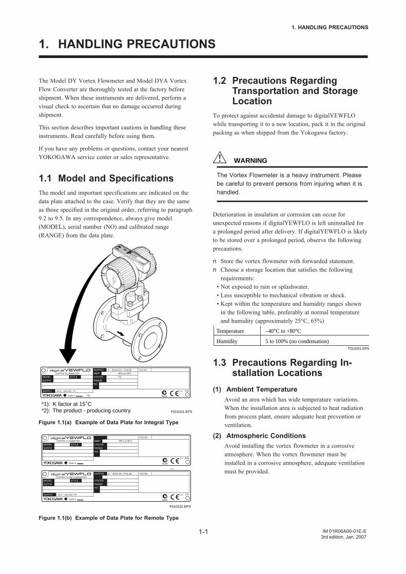
1.1 Model and SpecificationsThe model and important specifications are indicated on thedata plate attached to the case. Verify that they are the sameas those specified in the original order, referring to paragraph9.2 to 9.5. In any correspondence, always give model(MODEL), serial number (NO) and calibrated range(RANGE) from the data plate.
F010101.EPS
*1): K factor at 15°C*2): The product - producing country.
TAG NO.4 ~ 20mA DC / PULSE
MPa at 38°C
10.5 ~ 42V DC 3UA
3UA
*1)
*2)
Figure 1.1(a) Example of Data Plate for Integral Type
F010102.EPS
TAG NO.4 ~ 20mA DC / PULSE
3YA
TAG NO.
3WA
10.5 ~ 42V DC
MPa at 38°C
Figure 1.1(b) Example of Data Plate for Remote Type
1.2 Precautions RegardingTransportation and StorageLocation
To protect against accidental damage to digitalYEWFLOwhile transporting it to a new location, pack it in the originalpacking as when shipped from the Yokogawa factory.
WARNING
The Vortex Flowmeter is a heavy instrument. Pleasebe careful to prevent persons from injuring when it ishandled.
Deterioration in insulation or corrosion can occur forunexpected reasons if digitalYEWFLO is left uninstalled fora prolonged period after delivery. If digitalYEWFLO is likelyto be stored over a prolonged period, observe the followingprecautions.
n Store the vortex flowmeter with forwarded statement.n Choose a storage location that satisfies the following
requirements:• Not exposed to rain or splashwater.• Less susceptible to mechanical vibration or shock.• Kept within the temperature and humidity ranges shown
in the following table, preferably at normal temperatureand humidity (approximately 25°C, 65%)
Temperature
Humidity
–40°C to +80°C
5 to 100% (no condensation)T010201.EPS
1.3 Precautions Regarding In-stallation Locations
(1) Ambient TemperatureAvoid an area which has wide temperature variations.When the installation area is subjected to heat radiationfrom process plant, ensure adequate heat prevention orventilation.
(2) Atmospheric ConditionsAvoid installing the vortex flowmeter in a corrosiveatmosphere. When the vortex flowmeter must beinstalled in a corrosive atmosphere, adequate ventilationmust be provided.
1-2
1. HANDLING PRECAUTIONS
IM 01R06A00-01E-E3rd edition, Jan. 2007
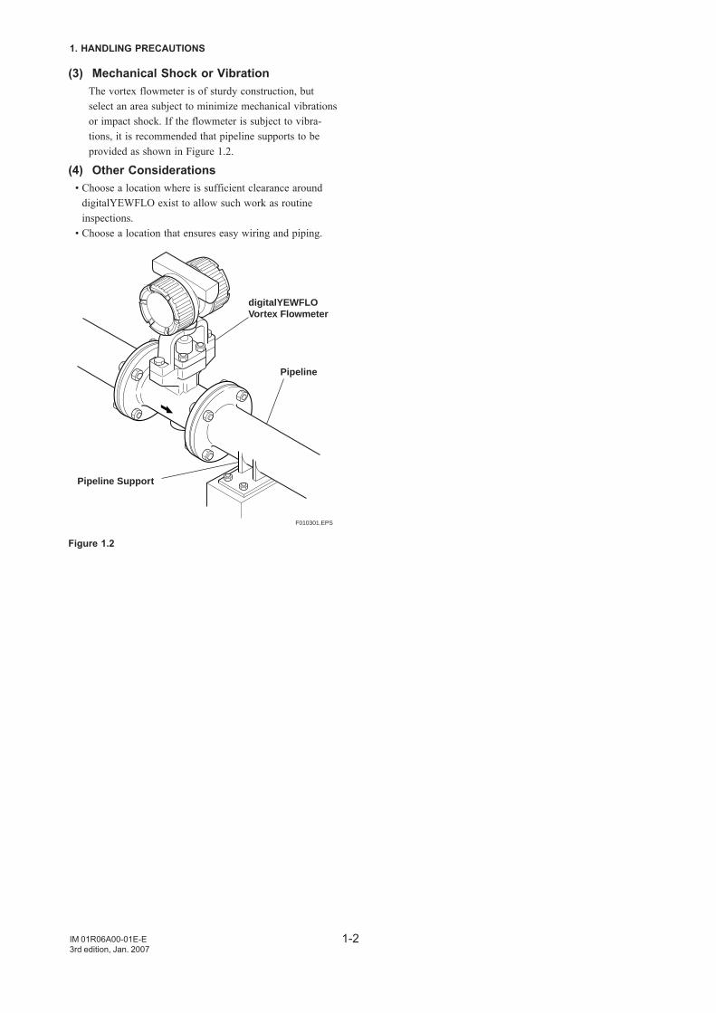
(3) Mechanical Shock or VibrationThe vortex flowmeter is of sturdy construction, butselect an area subject to minimize mechanical vibrationsor impact shock. If the flowmeter is subject to vibra-tions, it is recommended that pipeline supports to beprovided as shown in Figure 1.2.
(4) Other Considerations• Choose a location where is sufficient clearance around
digitalYEWFLO exist to allow such work as routineinspections.
• Choose a location that ensures easy wiring and piping.
F010301.EPS
digitalYEWFLOVortex Flowmeter
Pipeline
Pipeline Support
Figure 1.2
2-1
2. GENERAL DESCRIPTION
IM 01R06A00-01E-E3rd edition, Jan. 2007
2. INSTALLATION
WARNING
This instrument must be installed by expert engineeror skilled personnel. The procedures described in thischapter are not permitted for operators.
2.1 Precautions Regarding In-stallation Locations
(1) Ambient TemperatureAvoid an area which has wide temperature variations.When the installation area is subjected to heat radiationfrom process plant, ensure adequate heat prevention orventilation.
(2) Atmospheric ConditionsAvoid installing the vortex flowmeter in a corrosiveatmosphere. When the vortex flowmeter must beinstalled in a corrosive atmosphere, adequate ventilationmust be provided
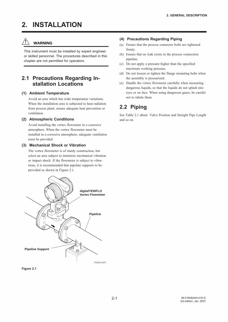
(3) Mechanical Shock or VibrationThe vortex flowmeter is of sturdy construction, butselect an area subject to minimize mechanical vibrationor impact shock. If the flowmeter is subject to vibra-tions, it is recommended that pipeline supports to beprovided as shown in Figure 2.1.
F020101.EPS
digitalYEWFLOVortex Flowmeter
Pipeline
Pipeline Support
Figure 2.1
(4) Precautions Regarding Piping(a) Ensure that the process connector bolts are tightened
firmly.(b) Ensure that no leak exists in the process connection
pipeline.(c) Do not apply a pressure higher than the specified
maximum working pressure.(d) Do not loosen or tighten the flange mounting bolts when
the assembly is pressurized.(e) Handle the vortex flowmeter carefully when measuring
dangerous liquids, so that the liquids do not splash intoeyes or on face. When using dangerous gases, be carefulnot to inhale them.
2.2 PipingSee Table 2.1 about Valve Position and Straight Pipe Lengthand so on.
2-2
2. GENERAL DESCRIPTION
IM 01R06A00-01E-E3rd edition, Jan. 2007
Piping supportTypical vibration immunity level is 1G for normal pipingcondition.Piping support should be fixed in case of over 1Gvibration level.
Installation directionIf a pipe is always filled with liquids, the pipe can beinstalled vertically or at inclined angle.
Adjacent pipesThe process pipline inner diameter should be larger thanthe digitalYEWFLO inner diameter.Use the following adjacent pipe:
Sch 40 or less:Model Code DY015 up to DY050
DY025-/R1 up to DY080-/R1DY040-/R2 up to DY100-/R2
Sch 80 or less:Model Code DY080 up to DY300
DY100-/R1 up to DY200-/R1DY150-/R2 up to DY200-/R2
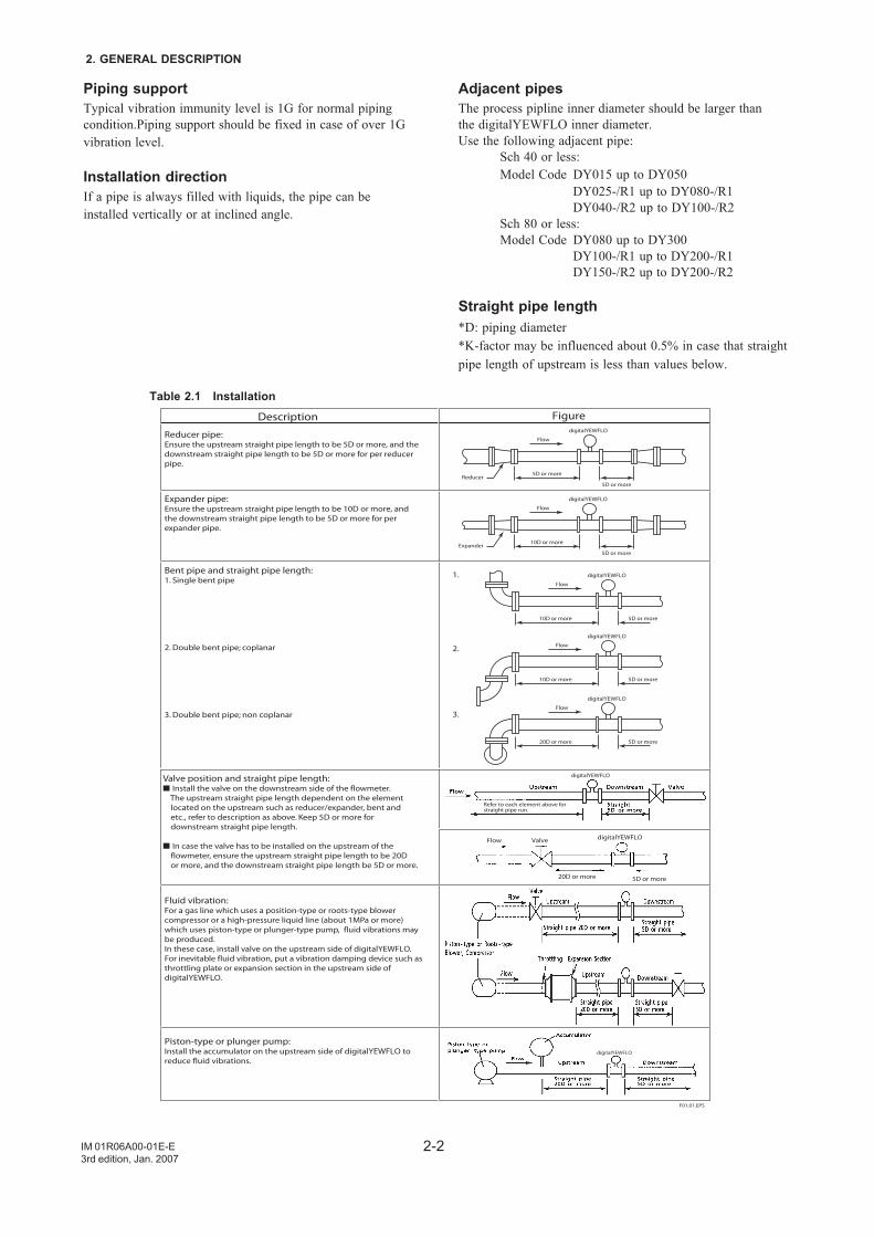
Straight pipe length*D: piping diameter*K-factor may be influenced about 0.5% in case that straightpipe length of upstream is less than values below.
Table 2.1 Installation
Refer to each element above for straight pipe run.
Reducer pipe:Ensure the upstream straight pipe length to be 5D or more, and the downstream straight pipe length to be 5D or more for per reducer pipe.
Valve position and straight pipe length: Install the valve on the downstream side of the flowmeter. The upstream straight pipe length dependent on the element located on the upstream such as reducer/expander, bent and etc., refer to description as above. Keep 5D or more for downstream straight pipe length.
In case the valve has to be installed on the upstream of the flowmeter, ensure the upstream straight pipe length to be 20D or more, and the downstream straight pipe length be 5D or more.
Piston-type or plunger pump:Install the accumulator on the upstream side of digitalYEWFLO toreduce fluid vibrations.
Expander pipe:Ensure the upstream straight pipe length to be 10D or more, and the downstream straight pipe length to be 5D or more for per expander pipe.
Bent pipe and straight pipe length:1. Single bent pipe
2. Double bent pipe; coplanar
3. Double bent pipe; non coplanar
Fluid vibration:For a gas line which uses a position-type or roots-type blower compressor or a high-pressure liquid line (about 1MPa or more) which uses piston-type or plunger-type pump, fluid vibrations may be produced.In these case, install valve on the upstream side of digitalYEWFLO. For inevitable fluid vibration, put a vibration damping device such as throttling plate or expansion section in the upstream side of digitalYEWFLO.
Description Figure
1.
2.
3.
digitalYEWFLO
Flow
5D or moreReducer
5D or more
digitalYEWFLO
Flow
10D or moreExpander
5D or more
digitalYEWFLO
F01.01.EPS
Flow digitalYEWFLO
digitalYEWFLO
Valve
5D or more20D or more
digitalYEWFLO
Flow
10D or more 5D or more
digitalYEWFLO
Flow
10D or more 5D or more
digitalYEWFLO
Flow
20D or more 5D or more
2-3
2. GENERAL DESCRIPTION
IM 01R06A00-01E-E3rd edition, Jan. 2007
Description Figure
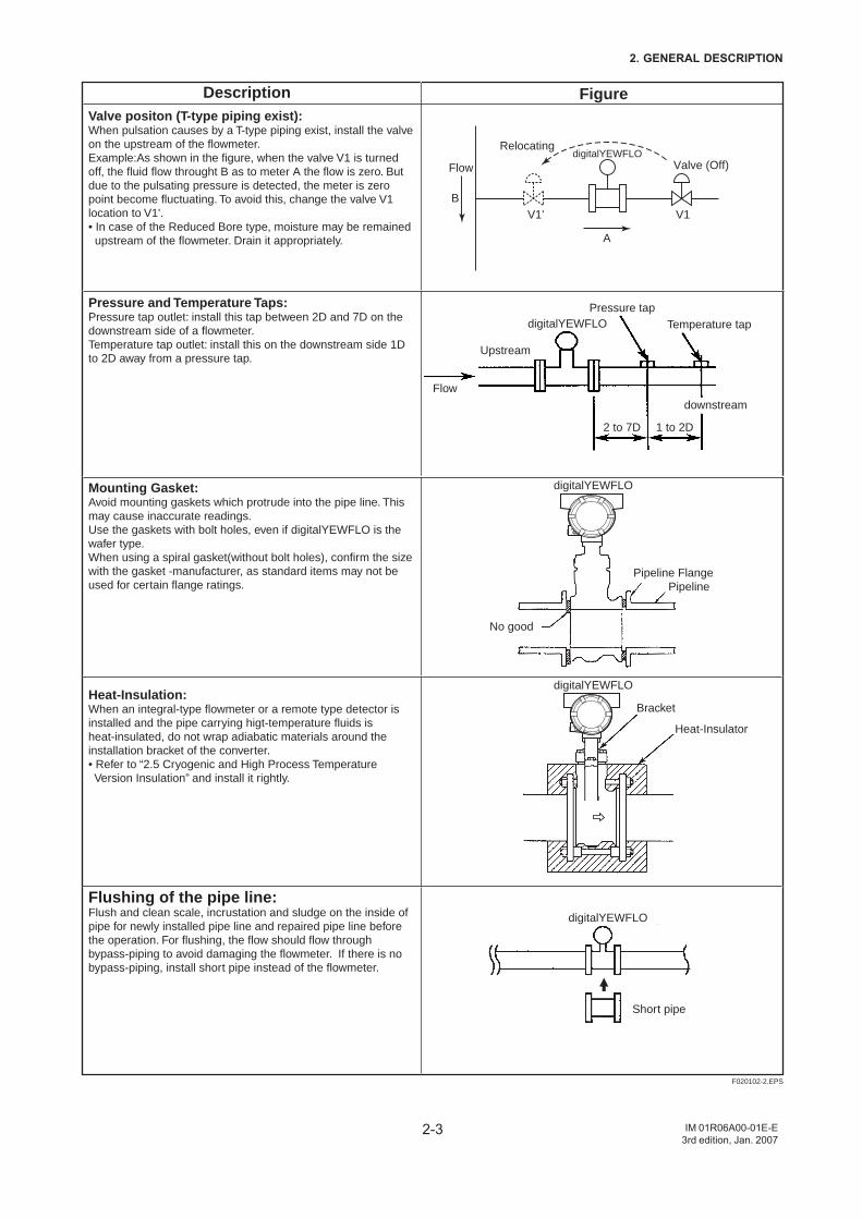
Heat-Insulation:When an integral-type flowmeter or a remote type detector is installed and the pipe carrying higt-temperature fluids is heat-insulated, do not wrap adiabatic materials around the installation bracket of the converter.• Refer to “2.5 Cryogenic and High Process Temperature Version Insulation” and install it rightly.
Flushing of the pipe line:Flush and clean scale, incrustation and sludge on the inside of pipe for newly installed pipe line and repaired pipe line before the operation. For flushing, the flow should flow through bypass-piping to avoid damaging the flowmeter. If there is no bypass-piping, install short pipe instead of the flowmeter.
Mounting Gasket:Avoid mounting gaskets which protrude into the pipe line. This may cause inaccurate readings.Use the gaskets with bolt holes, even if digitalYEWFLO is the wafer type.When using a spiral gasket(without bolt holes), confirm the size with the gasket -manufacturer, as standard items may not be used for certain flange ratings.
Pressure and Temperature Taps:Pressure tap outlet: install this tap between 2D and 7D on the downstream side of a flowmeter.Temperature tap outlet: install this on the downstream side 1D to 2D away from a pressure tap.
Valve positon (T-type piping exist):When pulsation causes by a T-type piping exist, install the valve on the upstream of the flowmeter.Example:As shown in the figure, when the valve V1 is turned off, the fluid flow throught B as to meter A the flow is zero. But due to the pulsating pressure is detected, the meter is zero point become fluctuating. To avoid this, change the valve V1 location to V1'.• In case of the Reduced Bore type, moisture may be remained upstream of the flowmeter. Drain it appropriately.
F020102-2.EPS
Relocating
Valve (Off)Flow
B
A
V1’ V1
digitalYEWFLO
digitalYEWFLO
digitalYEWFLO
digitalYEWFLO
digitalYEWFLO
Pressure tapTemperature tap
Upstream
Flowdownstream
2 to 7D 1 to 2D
Pipeline FlangePipeline
Bracket
Heat-Insulator
No good
Short pipe
2-4
2. GENERAL DESCRIPTION
IM 01R06A00-01E-E3rd edition, Jan. 2007
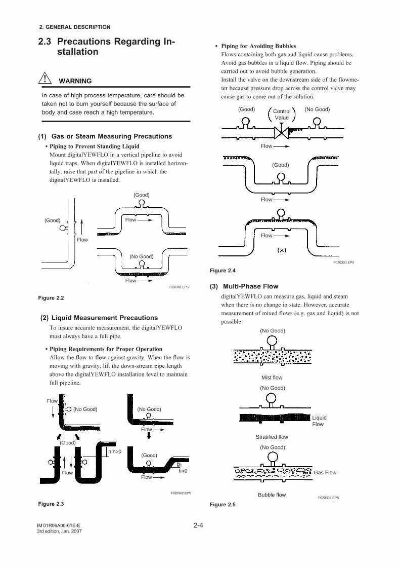
• Piping for Avoiding BubblesFlows containing both gas and liquid cause problems.Avoid gas bubbles in a liquid flow. Piping should becarried out to avoid bubble generation.Install the valve on the downstream side of the flowme-ter because pressure drop across the control valve maycause gas to come out of the solution.
F020303.EPS
Flow
Flow
Flow
(Good)
(Good)
(No Good)ControlValue
Figure 2.4
(3) Multi-Phase FlowdigitalYEWFLO can measure gas, liquid and steamwhen there is no change in state. However, accuratemeasurement of mixed flows (e.g. gas and liquid) is notpossible.
F020304.EPS
(No Good)
(No Good)
Mist flow
(No Good)
Stratified flow
Bubble flow
LiquidFlow
Gas Flow
Figure 2.5
2.3 Precautions Regarding In-stallation
WARNING
In case of high process temperature, care should betaken not to burn yourself because the surface ofbody and case reach a high temperature.
(1) Gas or Steam Measuring Precautions • Piping to Prevent Standing Liquid
Mount digitalYEWFLO in a vertical pipeline to avoidliquid traps. When digitalYEWFLO is installed horizon-tally, raise that part of the pipeline in which thedigitalYEWFLO is installed.
F020301.EPS
(Good)
(Good)
(No Good)
Flow
Flow
Flow
Figure 2.2
(2) Liquid Measurement PrecautionsTo insure accurate measurement, the digitalYEWFLOmust always have a full pipe.
• Piping Requirements for Proper OperationAllow the flow to flow against gravity. When the flow ismoving with gravity, lift the down-stream pipe lengthabove the digitalYEWFLO installation level to maintainfull pipeline.
Flow
Flow
FlowFlow
(No Good) (No Good)
(Good)
(Good)
h h>0
h h>0
F020302.EPS
Figure 2.3
2-5
2. GENERAL DESCRIPTION
IM 01R06A00-01E-E3rd edition, Jan. 2007
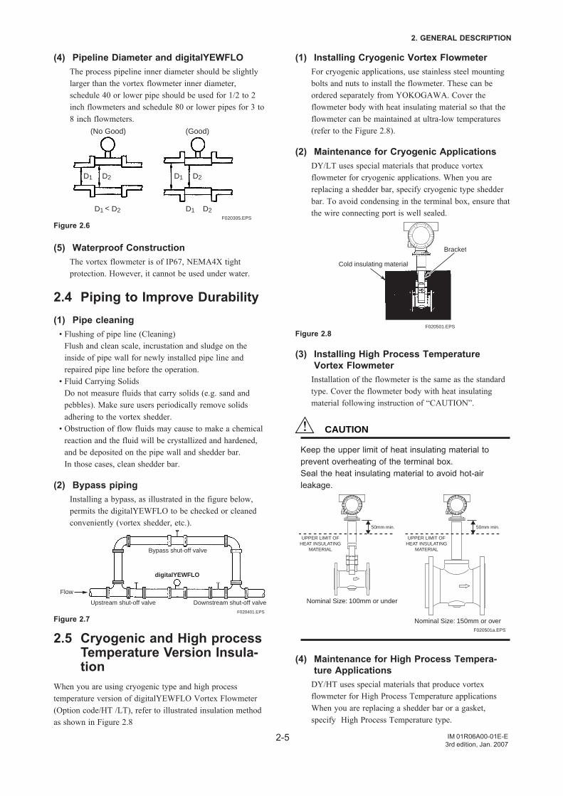
(4) Pipeline Diameter and digitalYEWFLOThe process pipeline inner diameter should be slightlylarger than the vortex flowmeter inner diameter,schedule 40 or lower pipe should be used for 1/2 to 2inch flowmeters and schedule 80 or lower pipes for 3 to8 inch flowmeters.
F020305.EPS
(No Good) (Good)
D1
D1 < D2 D1 D2
D2 D1 D2
Figure 2.6
(5) Waterproof ConstructionThe vortex flowmeter is of IP67, NEMA4X tightprotection. However, it cannot be used under water.
2.4 Piping to Improve Durability(1) Pipe cleaning
• Flushing of pipe line (Cleaning)Flush and clean scale, incrustation and sludge on theinside of pipe wall for newly installed pipe line andrepaired pipe line before the operation.
• Fluid Carrying SolidsDo not measure fluids that carry solids (e.g. sand andpebbles). Make sure users periodically remove solidsadhering to the vortex shedder.
• Obstruction of flow fluids may cause to make a chemicalreaction and the fluid will be crystallized and hardened,and be deposited on the pipe wall and shedder bar.In those cases, clean shedder bar.
(2) Bypass pipingInstalling a bypass, as illustrated in the figure below,permits the digitalYEWFLO to be checked or cleanedconveniently (vortex shedder, etc.).
F020401.EPS
Flow
Bypass shut-off valve
Upstream shut-off valve Downstream shut-off valve
digitalYEWFLO
Figure 2.7
2.5 Cryogenic and High processTemperature Version Insula-tion
When you are using cryogenic type and high processtemperature version of digitalYEWFLO Vortex Flowmeter(Option code/HT /LT), refer to illustrated insulation methodas shown in Figure 2.8
(1) Installing Cryogenic Vortex FlowmeterFor cryogenic applications, use stainless steel mountingbolts and nuts to install the flowmeter. These can beordered separately from YOKOGAWA. Cover theflowmeter body with heat insulating material so that theflowmeter can be maintained at ultra-low temperatures(refer to the Figure 2.8).
(2) Maintenance for Cryogenic ApplicationsDY/LT uses special materials that produce vortexflowmeter for cryogenic applications. When you arereplacing a shedder bar, specify cryogenic type shedderbar. To avoid condensing in the terminal box, ensure thatthe wire connecting port is well sealed.
F020501.EPS
Bracket
Cold insulating material
Figure 2.8
(3) Installing High Process TemperatureVortex Flowmeter
Installation of the flowmeter is the same as the standardtype. Cover the flowmeter body with heat insulatingmaterial following instruction of “CAUTION”.
CAUTION
Keep the upper limit of heat insulating material toprevent overheating of the terminal box.Seal the heat insulating material to avoid hot-airleakage.
UPPER LIMIT OFHEAT INSULATING
MATERIAL
UPPER LIMIT OFHEAT INSULATING
MATERIAL
50mm min. 50mm min.
Nominal Size: 100mm or under
Nominal Size: 150mm or overF020501a.EPS
(4) Maintenance for High Process Tempera-ture Applications
DY/HT uses special materials that produce vortexflowmeter for High Process Temperature applicationsWhen you are replacing a shedder bar or a gasket,specify High Process Temperature type.
2-6
2. GENERAL DESCRIPTION
IM 01R06A00-01E-E3rd edition, Jan. 2007
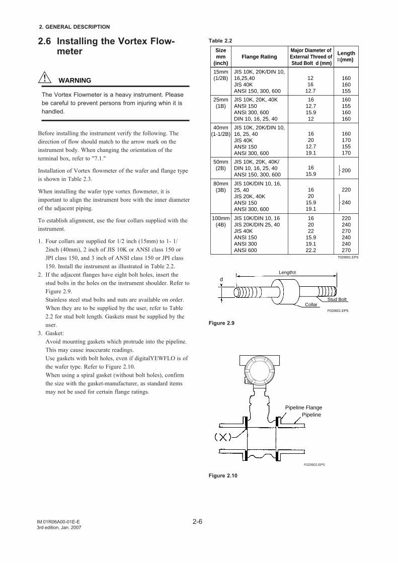
2.6 Installing the Vortex Flow-meter
WARNING
The Vortex Flowmeter is a heavy instrument. Pleasebe careful to prevent persons from injuring whin it ishandled.
Before installing the instrument verify the following. Thedirection of flow should match to the arrow mark on theinstrument body. When changing the orientation of theterminal box, refer to "7.1."
Installation of Vortex flowmeter of the wafer and flange typeis shown in Table 2.3.
When installing the wafer type vortex flowmeter, it isimportant to align the instrument bore with the inner diameterof the adjacent piping.
To establish alignment, use the four collars supplied with theinstrument.
1. Four collars are supplied for 1/2 inch (15mm) to 1- 1/2inch (40mm), 2 inch of JIS 10K or ANSI class 150 orJPI class 150, and 3 inch of ANSI class 150 or JPI class150. Install the instrument as illustrated in Table 2.2.
2. If the adjacent flanges have eight bolt holes, insert thestud bolts in the holes on the instrument shoulder. Refer toFigure 2.9.Stainless steel stud bolts and nuts are available on order.When they are to be supplied by the user, refer to Table2.2 for stud bolt length. Gaskets must be supplied by theuser.
3. Gasket:Avoid mounting gaskets which protrude into the pipeline.This may cause inaccurate readings.Use gaskets with bolt holes, even if digitalYEWFLO is ofthe wafer type. Refer to Figure 2.10.When using a spiral gasket (without bolt holes), confirmthe size with the gasket-manufacturer, as standard itemsmay not be used for certain flange ratings.
Table 2.2
T020601.EPS
Sizemm
(inch)Flange Rating
Major Diameter of External Threed of Stud Bolt d (mm)
LengthR(mm)
15mm(1/2B)
JIS 10K, 20K/DIN 10,16,25,40JIS 40KANSI 150, 300, 600
1216
12.7
160160155
25mm(1B)
JIS 10K, 20K, 40KANSI 150ANSI 300, 600DIN 10, 16, 25, 40
1612.715.912
160155160160
40mm(1-1/2B)
JIS 10K, 20K/DIN 10,16, 25, 40JIS 40KANSI 150ANSI 300, 600
1620
12.719.1
160170155170
50mm(2B)
JIS 10K, 20K, 40K/DIN 10, 16, 25, 40ANSI 150, 300, 600
1615.9
200
80mm(3B)
JIS 10K/DIN 10, 16,25, 40JIS 20K, 40KANSI 150ANSI 300, 600
1620
15.919.1
220
240
100mm(4B)
JIS 10K/DIN 10, 16JIS 20K/DIN 25, 40JIS 40KANSI 150ANSI 300ANSI 600
162022
15.919.122.2
220240270240240270
Stud BoltCollar
dLengthR
F020601.EPS
Figure 2.9
F020602.EPS
Pipeline FlangePipeline
Figure 2.10
2-7
2. GENERAL DESCRIPTION
IM 01R06A00-01E-E3rd edition, Jan. 2007
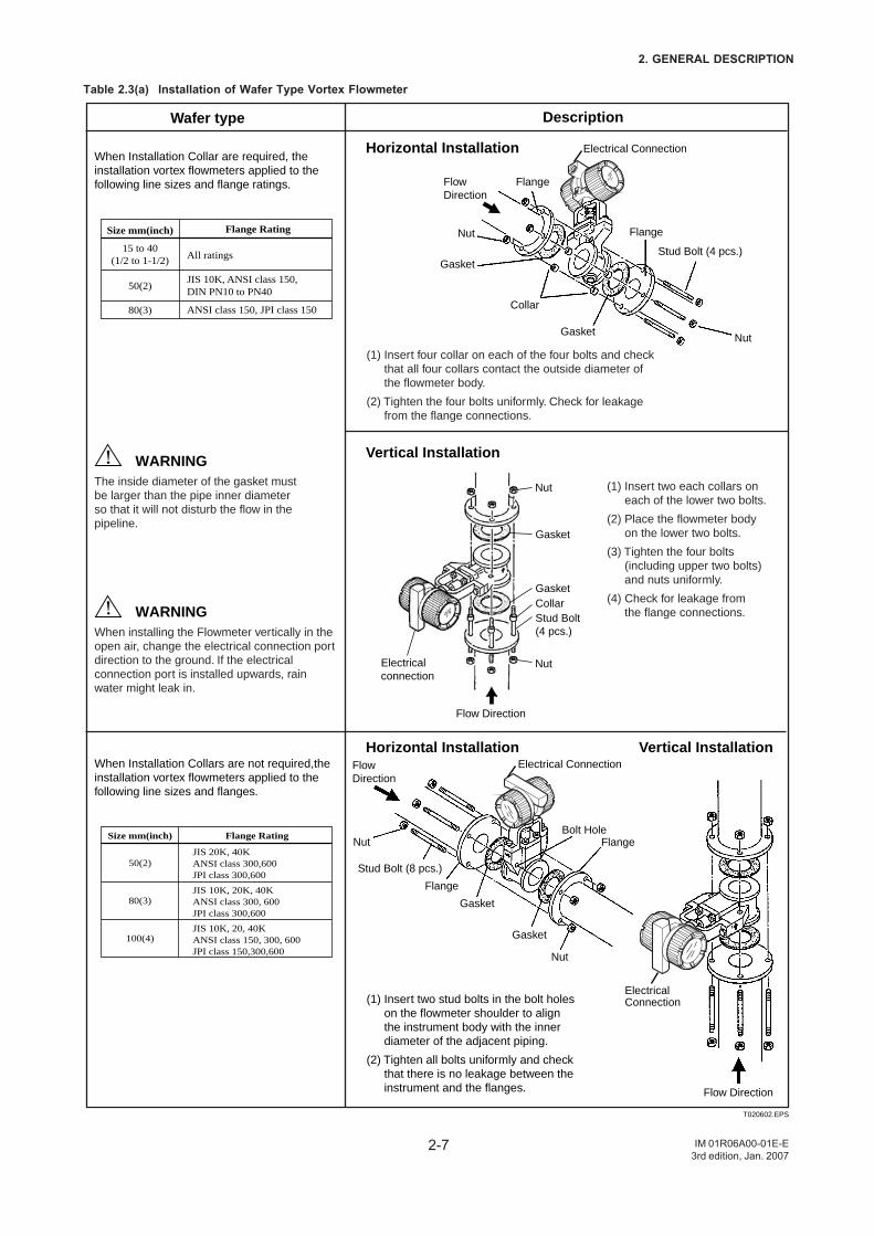
Table 2.3(a) Installation of Wafer Type Vortex Flowmeter
Size mm(inch) Flange Rating
15 to 40(1/2 to 1-1/2)
50(2)
80(3)
All ratings
JIS 10K, ANSI class 150, DIN PN10 to PN40
ANSI class 150, JPI class 150
Vertical Installation
When Installation Collar are required, the installation vortex flowmeters applied to the following line sizes and flange ratings.
The inside diameter of the gasket mustbe larger than the pipe inner diameterso that it will not disturb the flow in the pipeline.
(1) Insert two each collars oneach of the lower two bolts.
(2) Place the flowmeter body on the lower two bolts.
(3) Tighten the four bolts (including upper two bolts)and nuts uniformly.
(4) Check for leakage fromthe flange connections.
(1) Insert four collar on each of the four bolts and checkthat all four collars contact the outside diameter of the flowmeter body.
(2) Tighten the four bolts uniformly. Check for leakage from the flange connections.
Horizontal Installation
When installing the Flowmeter vertically in the open air, change the electrical connection port direction to the ground. If the electrical connection port is installed upwards, rain water might leak in.
WARNING
Wafer type Description
When Installation Collars are not required,the installation vortex flowmeters applied to the following line sizes and flanges.
Size mm(inch) Flange Rating
50(2)
80(3)
100(4)
JIS 20K, 40KANSI class 300,600JPI class 300,600
JIS 10K, 20K, 40KANSI class 300, 600JPI class 300,600
JIS 10K, 20, 40KANSI class 150, 300, 600JPI class 150,300,600
Vertical InstallationHorizontal Installation
(1) Insert two stud bolts in the bolt holeson the flowmeter shoulder to align the instrument body with the inner diameter of the adjacent piping.
(2) Tighten all bolts uniformly and checkthat there is no leakage between the instrument and the flanges.
WARNING
T020602.EPS
Flange
Nut
Nut
Gasket
Collar
Electricalconnection
Nut
Nut
Stud Bolt(4 pcs.)
CollarGasket
Gasket
Flow Direction
Flow Direction
Gasket
Flange
FlowDirection
Stud Bolt (4 pcs.)
Nut
Nut
Gasket
Bolt Hole
Gasket
Flange
Flange
FlowDirection
Stud Bolt (8 pcs.)
Electrical Connection
Electrical Connection
Electrical Connection
2-8
2. GENERAL DESCRIPTION
IM 01R06A00-01E-E3rd edition, Jan. 2007
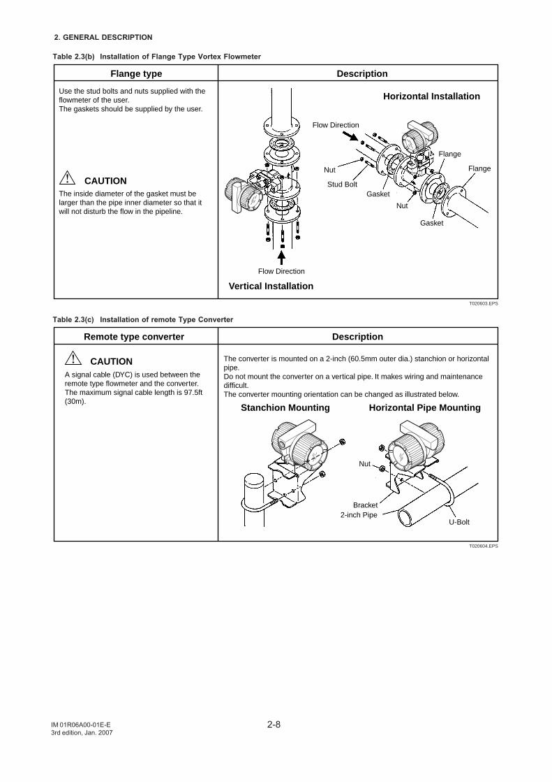
Table 2.3(b) Installation of Flange Type Vortex Flowmeter
Horizontal Installation
Vertical Installation
Use the stud bolts and nuts supplied with the flowmeter of the user. The gaskets should be supplied by the user.
Flange type Description
The inside diameter of the gasket must be larger than the pipe inner diameter so that it will not disturb the flow in the pipeline.
T020603.EPS
CAUTION
Flow Direction
Flow Direction
Nut
Nut
Stud BoltGasket
Gasket
Flange
Flange
Table 2.3(c) Installation of remote Type Converter
Remote type converter Description
A signal cable (DYC) is used between the remote type flowmeter and the converter. The maximum signal cable length is 97.5ft (30m).
The converter is mounted on a 2-inch (60.5mm outer dia.) stanchion or horizontal pipe. Do not mount the converter on a vertical pipe. It makes wiring and maintenance difficult. The converter mounting orientation can be changed as illustrated below.
T020604.EPS
CAUTION
Nut
Bracket2-inch Pipe
U-Bolt
Horizontal Pipe MountingStanchion Mounting
3-1
3.WIRING
IM 01R06A00-01E-E3rd edition, Jan. 2007
3. WIRING
WARNING
The wiring of the vortex flowmeter must be performedby expert engineer or skilled personnel. No operatorshall be permitted to perform procedures relating towiring.
CAUTION
Once all wiring is complete, check the connectionsbefore applying power to the instrument. Improperarrangements or wiring may cause a unit malfunctionor damage.
3.1 Wiring PrecautionsBe sure to observe the following precautions when wiring:
CAUTION
• In cases where the ambient temperatureexceeds 50°C (122°F), use external heat-resistant wiring with a maximum allowabletemperature of 70°C (158°F) or above.
• Do not connect cables outdoors in wet weatherin order to prevent damage from condensationand to protect the insulation.
• Do not splice the cable between the flowtubeterminal and the converter if it is too short.Replace the short cable with a cable that is theappropriate length.
• All the cable ends must be provided with roundcrimp-on terminals and be securely wired.
• Be sure to turn power off before opening thecover.
• Before turning the power on, tighten the coversecurely.
• Explosion protected types must be wired inaccordance with specific requirement (and, incertain countries, legal regulations) in order topreserve the effectiveness of their explosionprotected features.
• The terminal box cover is locked by the clamp.In case of opening the terminal box cover, usethe hexagonal wrench attached.
• Be sure to lock the cover by the clamp usingthe hexagonal wrench attached after installingthe cover.
3.2 Wiring for Output ConditionTable 3.1 shows the connection method of several outputconditions.
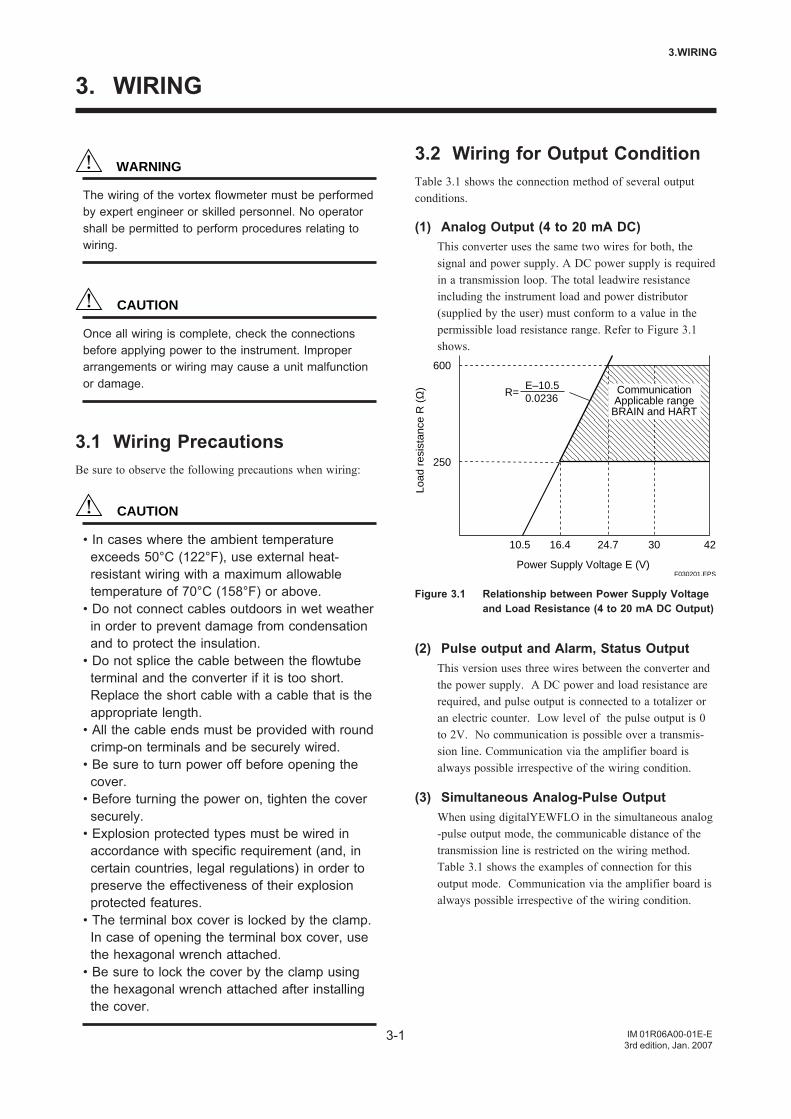
(1) Analog Output (4 to 20 mA DC)This converter uses the same two wires for both, thesignal and power supply. A DC power supply is requiredin a transmission loop. The total leadwire resistanceincluding the instrument load and power distributor(supplied by the user) must conform to a value in thepermissible load resistance range. Refer to Figure 3.1shows.
R=E–10.50.0236
250
600
10.5 16.4 24.7 30 42
Power Supply Voltage E (V)
CommunicationApplicable rangeBRAIN and HART
Load
res
ista
nce
R (
Ω)
F030201.EPS
Figure 3.1 Relationship between Power Supply Voltageand Load Resistance (4 to 20 mA DC Output)
(2) Pulse output and Alarm, Status OutputThis version uses three wires between the converter andthe power supply. A DC power and load resistance arerequired, and pulse output is connected to a totalizer oran electric counter. Low level of the pulse output is 0to 2V. No communication is possible over a transmis-sion line. Communication via the amplifier board isalways possible irrespective of the wiring condition.
(3) Simultaneous Analog-Pulse OutputWhen using digitalYEWFLO in the simultaneous analog-pulse output mode, the communicable distance of thetransmission line is restricted on the wiring method.Table 3.1 shows the examples of connection for thisoutput mode. Communication via the amplifier board isalways possible irrespective of the wiring condition.
3-2
3. WIRING
IM 01R06A00-01E-E3rd edition, Jan. 2007
IMPORTANT
For pulse output and the simultaneous analog-pulseoutput ,use the load resistance. Refer to Table 3.1.
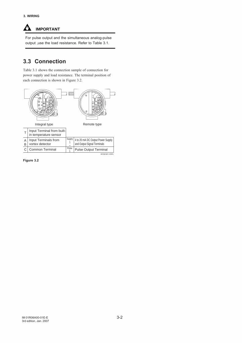
3.3 ConnectionTable 3.1 shows the connection sample of connection forpower supply and load resistance. The terminal position ofeach connection is shown in Figure 3.2.
Integral type Remote type
F030301.EPS
Input Terminal from built-in temperature sensor
Input Terminals from vortex detector
Common Terminal
4 to 20 mA DC Output Power Supply and Output Signal Terminals
Supply1–
Pulse Output TerminalPulse1
T
AB
C
Figure 3.2
3-3
3.WIRING
IM 01R06A00-01E-E3rd edition, Jan. 2007
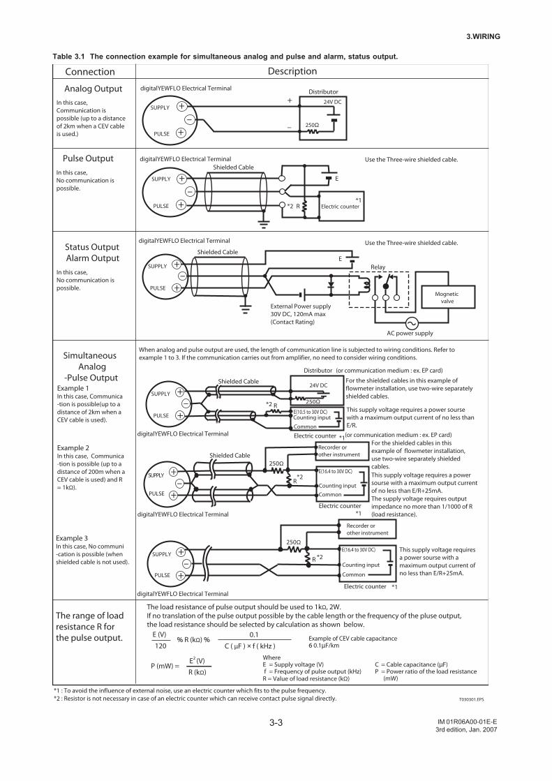
Table 3.1 The connection example for simultaneous analog and pulse and alarm, status output.
250Ω
R +
–+PULSE
SUPPLY
digitalYEWFLO Electrical Terminal
Recorder or other instrument
This supply voltage requires a power sourse with a maximum output current of no less than E/R+25mA.
Electric counter
E(16.4 to 30V DC)
Counting input
Common
+
+
digitalYEWFLO Electrical Terminal
250Ω
24V DC
PULSE
SUPPLY+
–
Distributor
–
+–
+PULSE
SUPPLY
R
E
digitalYEWFLO Electrical Terminal Use the Three-wire shielded cable.
Use the Three-wire shielded cable.
Electric counter*1
*1
*1
*1
*2
*2
*2
*2
*1 : To avoid the influence of external noise, use an electric counter which fits to the pulse frequency.*2 : Resistor is not necessary in case of an electric counter which can receive contact pulse signal directly.
Shielded Cable
Shielded Cable
PULSE
SUPPLY +–
+Mognetic
valve
AC power supply
External Power supply 30V DC, 120mA max(Contact Rating)
digitalYEWFLO Electrical Terminal
E
250Ω
R+
–+PULSE
SUPPLY
Counting input
Common
For the shielded cables in this example of flowmeter installation, use two-wire separately shielded cables.This supply voltage requires a power sourse with a maximum output current of no less than E/R+25mA.
Recorder or other instrument
Electric counter
E(16.4 to 30V DC)
Shielded Cable
The supply voltage requires output impedance no more than 1/1000 of R (load resistance).digitalYEWFLO Electrical Terminal
250ΩR
E(10.5 to 30V DC) Counting input
Common
24V DC
PULSE
SUPPLY
For the shielded cables in this example of flowmeter installation, use two-wire separately shielded cables.
This supply voltage requires a power sourse with a maximum output current of no less than E/R.
Distributor (or communication medium : ex. EP card)
(or communication medium : ex. EP card)Electric counter
+–
+
Shielded Cable
digitalYEWFLO Electrical Terminal
When analog and pulse output are used, the length of communication line is subjected to wiring conditions. Refer to example 1 to 3. If the communication carries out from amplifier, no need to consider wiring conditions.
Relay
Analog Output
Pulse Output
Status OutputAlarm Output
Simultaneous Analog
-Pulse Output
DescriptionConnection
T030301.EPS
0.1
C ( µF ) × f ( kHz ) % R (kΩ) %
120
E (V)
The load resistance of pulse output should be used to 1kΩ, 2W.If no translation of the pulse output possible by the cable length or the frequency of the pluse output,the load resistance should be selected by calculation as shown below.
Example of CEV cable capacitance6 0.1µF/km
WhereE = Supply voltage (V) f = Frequency of pulse output (kHz)R = Value of load resistance (kΩ)
C = Cable capacitance (µF) P = Power ratio of the load resistance (mW)
P (mW) =R (kΩ)
E2 (V)
Example 3In this case, No communi-cation is possible (when shielded cable is not used).
The range of load resistance R for the pulse output.
Example 1In this case, Communica-tion is possible(up to adistance of 2km when aCEV cable is used).
Example 2In this case, Communica-tion is possible (up to adistance of 200m when a CEV cable is used) and R = 1kΩ).
In this case, Communication is possible (up to a distance of 2km when a CEV cable is used.)
In this case, No communication is possible.
In this case, No communication is possible.
3-4
3. WIRING
IM 01R06A00-01E-E3rd edition, Jan. 2007
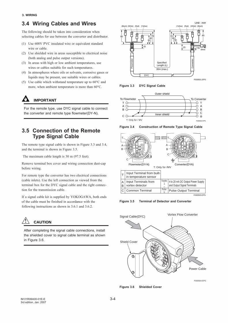
3.4 Wiring Cables and WiresThe following should be taken into consideration whenselecting cables for use between the converter and distributor.
(1) Use 600V PVC insulated wire or equivalent standardwire or cable.
(2) Use shielded wire in areas susceptible to electrical noise(both analog and pulse output versions).
(3) In areas with high or low ambient temperatures, usewires or cables suitable for such temperatures.
(4) In atmospheres where oils or solvents, corrosive gases orliquids may be present, use suitable wires or cables.
(5) Use cable which withstand temperature up to 60°C andmore, when ambient temperature is more than 60°C.
IMPORTANT
For the remote type, use DYC signal cable to connectthe converter and remote type flowmeter(DY-N).
3.5 Connection of the RemoteType Signal Cable
The remote type signal cable is shown in Figure 3.3 and 3.4,and the terminal is shown in Figure 3.5.
The maximum cable length is 30 m (97.5 feet).
Remove terminal box cover and wiring connection dust-capbefore wiring.
For remote type the converter has two electrical connections(cable inlets). Use the left connection as viewed from theterminal box for the DYC signal cable and the right connec-tion for the transmission cable.
If a signal cable kit is supplied by YOKOGAWA, both endsof the cable must be finished in accordance with thefollowing instructions as shown in 3.6.1 and 3.6.2.
CAUTION
After completing the signal cable connections, installthe shielded cover to signal cable terminal as shownin Figure 3.6.
Unit : mm
F030501.EPS
(Black) (White) (Red) (Red) (White) (Black)
(Blue)
Specified Length (L)
30m (max.)
DYC
Flo
wm
eter
Con
vert
er
80 70 70 8060
25 95
60
20
50 50
(Yellow) (Yellow)
Figure 3.3 DYC Signal Cable
AT
BC
AT
B
C
Outer shield
Inner shield
To ConverterTo Flowmeter
F030502.EPST: Only for / MV
Figure 3.4 Construction of Remote Type Signal Cable
C
BA
T T
A
B
C
Flowmeter(DY-N)T: Only for /MV
F030503.EPS
Converter(DYA)
Input Terminal from built-in temperature sensor
Input Terminals from vortex detector
Common Terminal
4 to 20 mA DC Output Power Supply and Output Signal Terminals
Supply1–
Pulse Output TerminalPulse1
T
AB
C
Figure 3.5 Terminal of Detector and Converter
F030504.EPS
Vortex Flow Converter
Shield Cover
Signal Cable(DYC)
Power Cable
Figure 3.6 Shielded Cover
3-5
3.WIRING
IM 01R06A00-01E-E3rd edition, Jan. 2007
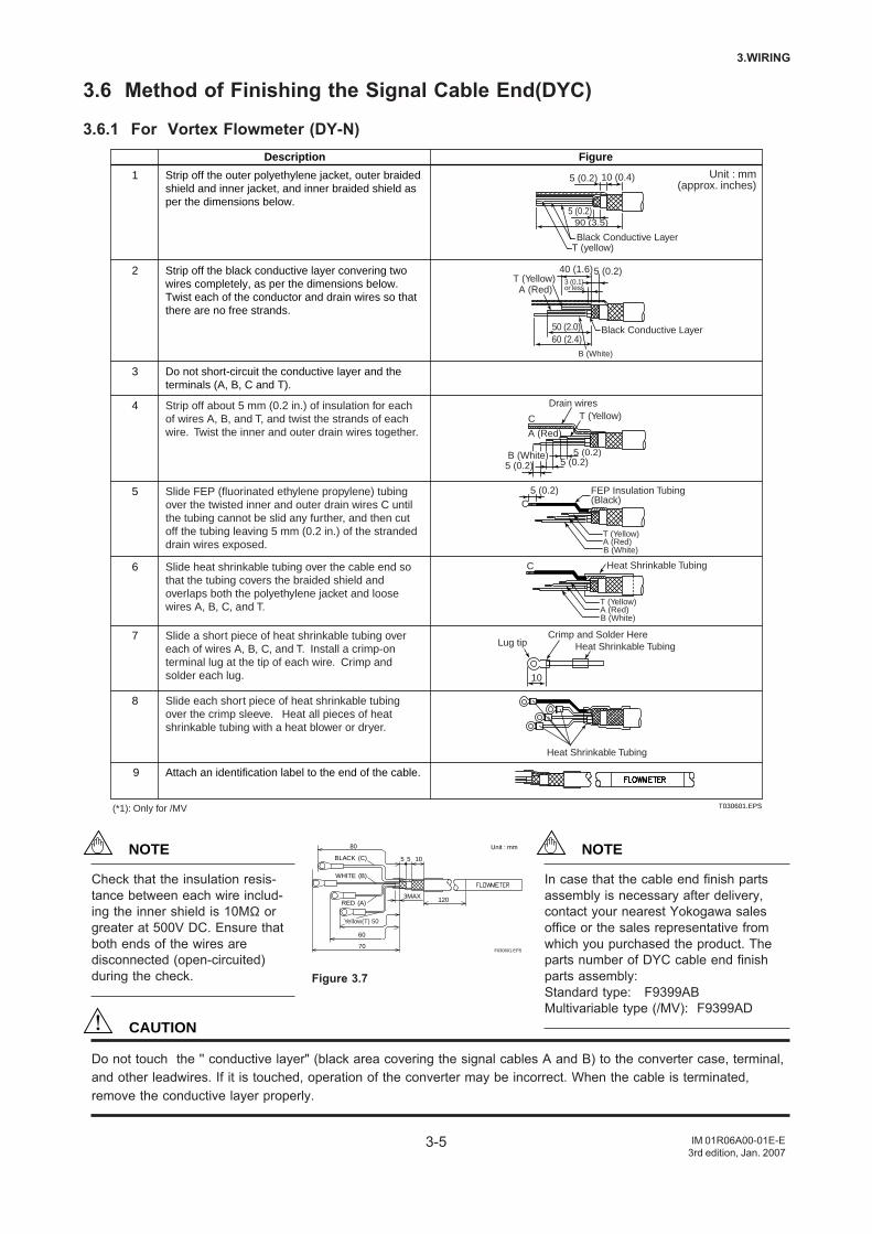
3.6 Method of Finishing the Signal Cable End(DYC)
3.6.1 For Vortex Flowmeter (DY-N)
1
2
3
4
5
6
7
8
9
Do not short-circuit the conductive layer and the terminals (A, B, C and T).
Slide FEP (fluorinated ethylene propylene) tubing over the twisted inner and outer drain wires C until the tubing cannot be slid any further, and then cut off the tubing leaving 5 mm (0.2 in.) of the stranded drain wires exposed.
Slide heat shrinkable tubing over the cable end so that the tubing covers the braided shield and overlaps both the polyethylene jacket and loose wires A, B, C, and T.
Slide a short piece of heat shrinkable tubing over each of wires A, B, C, and T. Install a crimp-on terminal lug at the tip of each wire. Crimp and solder each lug.
Slide each short piece of heat shrinkable tubing over the crimp sleeve. Heat all pieces of heat shrinkable tubing with a heat blower or dryer.
Attach an identification label to the end of the cable.
Description Figure
Unit : mm(approx. inches)
T030601.EPS
Strip off the outer polyethylene jacket, outer braided shield and inner jacket, and inner braided shield as per the dimensions below.
Strip off the black conductive layer convering two wires completely, as per the dimensions below.Twist each of the conductor and drain wires so that there are no free strands.
Strip off about 5 mm (0.2 in.) of insulation for each of wires A, B, and T, and twist the strands of each wire. Twist the inner and outer drain wires together.
(*1): Only for /MV
T (yellow)
90 (3.5)
5 (0.2) 10 (0.4)
5 (0.2)
Black Conductive Layer
Black Conductive Layer
A (Red)T (Yellow)
40 (1.6)5 (0.2)
50 (2.0)60 (2.4)
B (White)
3 (0.1) or less
Drain wiresT (Yellow)
5 (0.2)5 (0.2)5 (0.2)
B (White)
A (Red)
C
C Heat Shrinkable Tubing
Crimp and Solder HereLug tip Heat Shrinkable Tubing
Heat Shrinkable Tubing
T (Yellow)A (Red)B (White)
5 (0.2) FEP Insulation Tubing (Black)C
T (Yellow)A (Red)B (White)
10
(B)
(C)
WHITE
BLACK
(A)RED
Unit : mm
F030601.EPS
60
80
3MAX 120
105 5
70
Yellow(T) 50
Figure 3.7
CAUTION
Do not touch the '' conductive layer" (black area covering the signal cables A and B) to the converter case, terminal,and other leadwires. If it is touched, operation of the converter may be incorrect. When the cable is terminated,remove the conductive layer properly.
NOTE
Check that the insulation resis-tance between each wire includ-ing the inner shield is 10MΩ orgreater at 500V DC. Ensure thatboth ends of the wires aredisconnected (open-circuited)during the check.
NOTE
In case that the cable end finish partsassembly is necessary after delivery,contact your nearest Yokogawa salesoffice or the sales representative fromwhich you purchased the product. Theparts number of DYC cable end finishparts assembly:Standard type: F9399ABMultivariable type (/MV): F9399AD
3-6
3. WIRING
IM 01R06A00-01E-E3rd edition, Jan. 2007
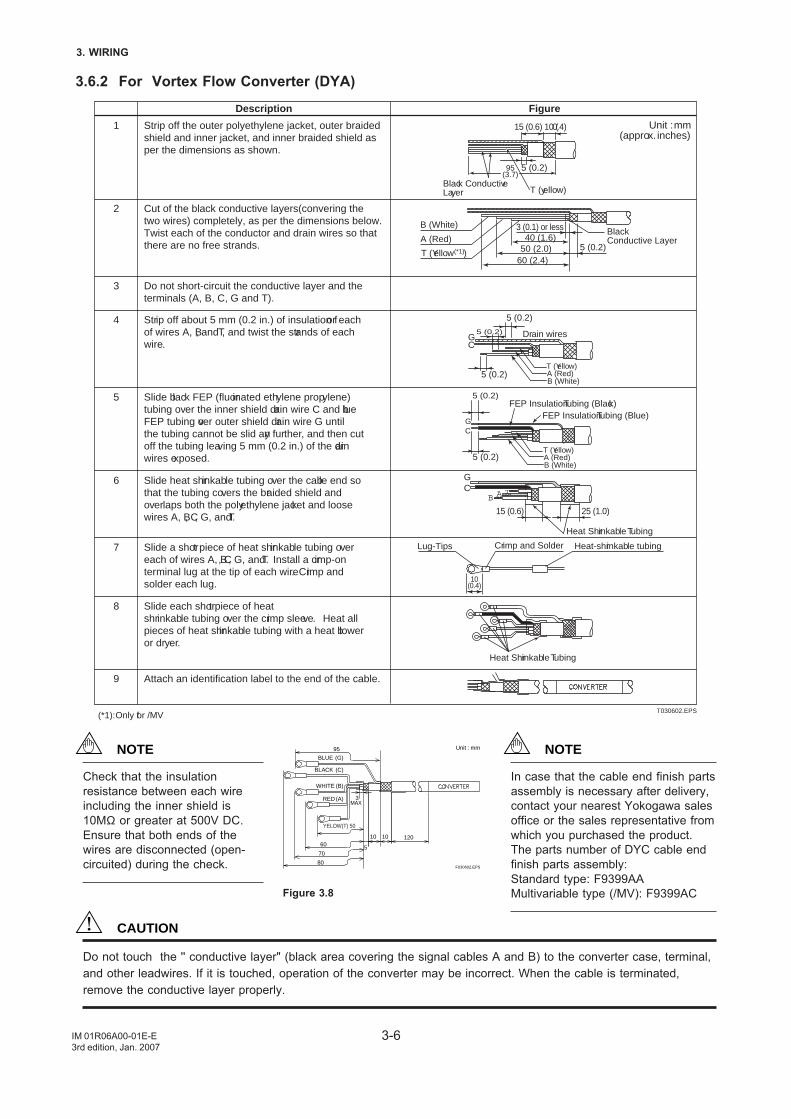
3.6.2 For Vortex Flow Converter (DYA)
1
2
3
4
5
6
7
8
9
Do not short-circuit the conductive layer and the terminals (A, B, C, G and T).
Slide black FEP (fluorinated ethylene propylene) tubing over the inner shield drain wire C and blue FEP tubing over outer shield drain wire G until the tubing cannot be slid any further, and then cut off the tubing leaving 5 mm (0.2 in.) of the drain wires exposed.
Slide heat shrinkable tubing over the cable end so that the tubing covers the braided shield and overlaps both the polyethylene jacket and loose wires A, B, C, G, and T.
Slide a short piece of heat shrinkable tubing over each of wires A, B, C, G, and T. Install a crimp-on terminal lug at the tip of each wire. Crimp and solder each lug.
Attach an identification label to the end of the cable.
T030602.EPS
Description Figure
Unit : mm(approx. inches)
Heat-shrinkable tubingCrimp and SolderLug-Tips
10(0.4)
Strip off the outer polyethylene jacket, outer braided shield and inner jacket, and inner braided shield as per the dimensions as shown.
Cut of the black conductive layers(convering the two wires) completely, as per the dimensions below.Twist each of the conductor and drain wires so that there are no free strands.
Strip off about 5 mm (0.2 in.) of insulation for each of wires A, B, and T, and twist the strands of each wire.
Slide each short piece of heat shrinkable tubing over the crimp sleeve. Heat all pieces of heat shrinkable tubing with a heat blower or dryer.
(*1): Only for /MV
B (White)
A (Red)50 (2.0)
60 (2.4)
3 (0.1) or less
5 (0.2)40 (1.6)
T (Yellow(*1))
Black Conductive Layer
5 (0.2)
Black ConductiveLayer T (yellow)
15 (0.6) 10 (0.4)
95(3.7)
5 (0.2) GC
5 (0.2)
5 (0.2)
Drain wires
CG
FEP Insulation Tubing (Blue)FEP Insulation Tubing (Black)
5 (0.2)
5 (0.2)
GC
Heat Shrinkable Tubing
TAB
Heat Shrinkable Tubing
T (Yellow)A (Red)B (White)
T (Yellow)A (Red)B (White)
25 (1.0)15 (0.6)
(A)RED
(B)WHITE
BLACK (C)
(G)BLUE
Unit : mm
F030602.EPS
70
95
60
80
12010 10
5
MAX3
YELOW(T) 50
Figure 3.8
CAUTION
Do not touch the '' conductive layer" (black area covering the signal cables A and B) to the converter case, terminal,and other leadwires. If it is touched, operation of the converter may be incorrect. When the cable is terminated,remove the conductive layer properly.
NOTE
Check that the insulationresistance between each wireincluding the inner shield is10MΩ or greater at 500V DC.Ensure that both ends of thewires are disconnected (open-circuited) during the check.
NOTE
In case that the cable end finish partsassembly is necessary after delivery,contact your nearest Yokogawa salesoffice or the sales representative fromwhich you purchased the product.The parts number of DYC cable endfinish parts assembly:Standard type: F9399AAMultivariable type (/MV): F9399AC
3-7
3.WIRING
IM 01R06A00-01E-E3rd edition, Jan. 2007
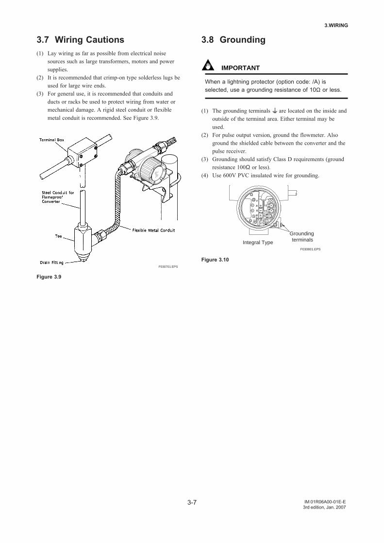
3.7 Wiring Cautions(1) Lay wiring as far as possible from electrical noise
sources such as large transformers, motors and powersupplies.
(2) It is recommended that crimp-on type solderless lugs beused for large wire ends.
(3) For general use, it is recommended that conduits andducts or racks be used to protect wiring from water ormechanical damage. A rigid steel conduit or flexiblemetal conduit is recommended. See Figure 3.9.
F030701.EPS
Figure 3.9
3.8 Grounding
IMPORTANT
When a lightning protector (option code: /A) isselected, use a grounding resistance of 10Ω or less.
(1) The grounding terminals are located on the inside andoutside of the terminal area. Either terminal may beused.
(2) For pulse output version, ground the flowmeter. Alsoground the shielded cable between the converter and thepulse receiver.
(3) Grounding should satisfy Class D requirements (groundresistance 100Ω or less).
(4) Use 600V PVC insulated wire for grounding.
Integral TypeF030801.EPS
Grounding terminals
Figure 3.10

3-8
3. WIRING
IM 01R06A00-01E-E3rd edition, Jan. 2007
4-1
4. BASIC OPERATING PROCEDURES
IM 01R06A00-01E-E3rd edition, Jan. 2007
4. BASIC OPERATING PROCEDURES
Data setting can be performed with the three keys on thefront panel (SET,SHIFT and INC) or using a handheldBRAIN(BT) terminal and HART communicator.
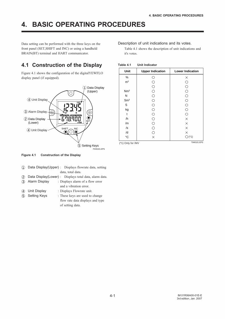
4.1 Construction of the DisplayFigure 4.1 shows the configuration of the digitalYEWFLOdisplay panel (if equipped).
SET
INCSHIFT
F040101.EPS
Data Display (Upper)
1
Unit Display4
Unit Display4
Setting Keys5
Alarm Display3
Data Display (Lower)
2
Figure 4.1 Construction of the Display
1 Data Display(Upper) : Displays flowrate data, settingdata, total data.
2 Data Display(Lower) : Displays total data, alarm data.3 Alarm Display : Displays alarm of a flow error
and a vibration error.4 Unit Display : Displays Flowrate unit.5 Setting Keys : These keys are used to change
flow rate data displays and typeof setting data.
Description of unit indications and its votes.Table 4.1 shows the description of unit indications andit's votes.
Table 4.1 Unit Indicator
Unit Upper Indication Lower Indication
%
m3
Nm3
N
Sm3
S
kg
t
/h
/m
/s
/d
°CT040101.EPS
(*1)
(*1) Only for /MV
4-2
4. BASIC OPERATING PROCEDURES
IM 01R06A00-01E-E3rd edition, Jan. 2007
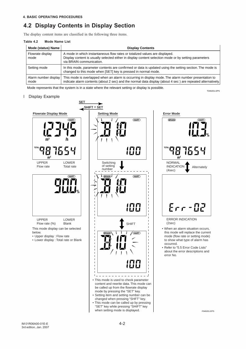
4.2 Display Contents in Display SectionThe display content items are classified in the following three items.
Table 4.2 Mode Name List
Mode (status) Name Display Contents
Flowrate display mode
Setting mode
Alarm number display mode
A mode in which instantaneous flow rates or totalized values are displayed.Display content is usually selected either in display content selection mode or by setting parameters via BRAIN communication. In this mode, parameter contents are confirmed or data is updated using the setting section. The mode is changed to this mode when [SET] key is pressed in normal mode. This mode is overlapped when an alarm is occurring in display mode. The alarm number presentation to indicate alarm contents (about 2 sec) and the normal data display (about 4 sec ) are repeated alternatively.
Mode represents that the system is in a state where the relevant setting or display is possible.T040201.EPS
l Display Example
F040201.EPS
SET
SHIFT + SET
Flowrate Display Mode Setting Mode Error Mode
UPPER Flow rate
LOWER Total rate
NORMAL INDICATION (4sec)
ERROR INDICATION (2sec)
UPPER Flow rate (%)
LOWER Blank SHIFT
Alternately
This mode display can be selected below.• Upper display : Flow rate• Lower display : Total rate or Blank
• When an alarm situation occurs, this mode will replace the current mode (flow rate or setting mode) to show what type of alarm has occurred.
• Refer to “5.5 Error Code Lists” about the error descriptions and error No.
• This mode is used to check parameter content and rewrite data. This mode can be called up from the flowrate display mode by pressing the “SET” key.
• Setting item and setting number can be changed when pressing “SHFT” key.
• This mode can be called up by pressing “SET” key while pressing “SHIFT” key when setting mode is displayed.
Switching of setting number
4-3
4. BASIC OPERATING PROCEDURES
IM 01R06A00-01E-E3rd edition, Jan. 2007
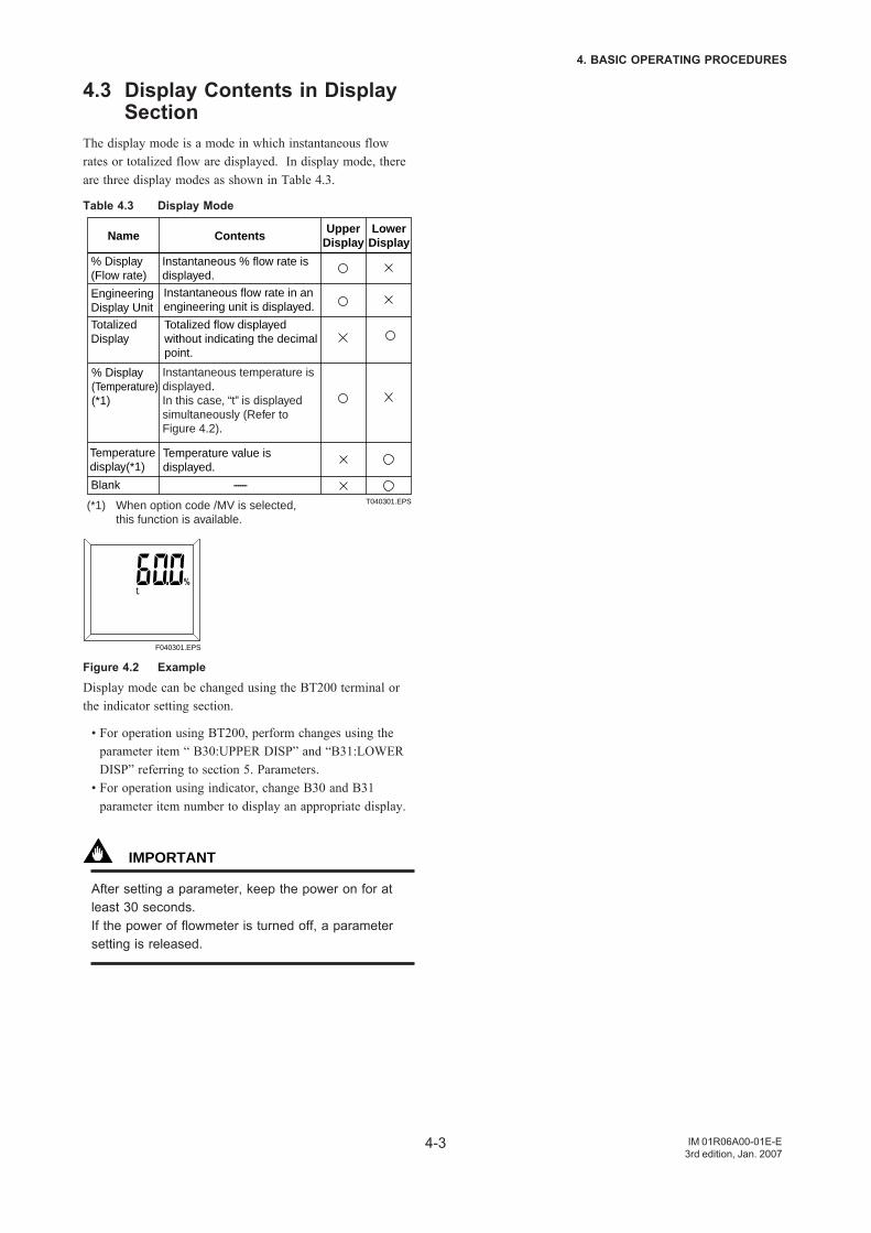
4.3 Display Contents in DisplaySection
The display mode is a mode in which instantaneous flowrates or totalized flow are displayed. In display mode, thereare three display modes as shown in Table 4.3.
Table 4.3 Display Mode
Instantaneous % flow rate isdisplayed.
% Display(Flow rate)
Instantaneous flow rate in an engineering unit is displayed.
Engineering Display Unit
Totalized flow displayed without indicating the decimal point.
Totalized Display
Name ContentsUpper
DisplayLower
Display
T040301.EPS
------Blank
% Display(Temperature)(*1)
Temperaturedisplay(*1)
Temperature value is displayed.
Instantaneous temperature is displayed.In this case, “t” is displayed simultaneously (Refer to Figure 4.2).
(*1) When option code /MV is selected, this function is available.
F040301.EPS
Figure 4.2 Example
Display mode can be changed using the BT200 terminal orthe indicator setting section.
• For operation using BT200, perform changes using theparameter item “ B30:UPPER DISP” and “B31:LOWERDISP” referring to section 5. Parameters.
• For operation using indicator, change B30 and B31parameter item number to display an appropriate display.
IMPORTANT
After setting a parameter, keep the power on for atleast 30 seconds.If the power of flowmeter is turned off, a parametersetting is released.
4-4
4. BASIC OPERATING PROCEDURES
IM 01R06A00-01E-E3rd edition, Jan. 2007
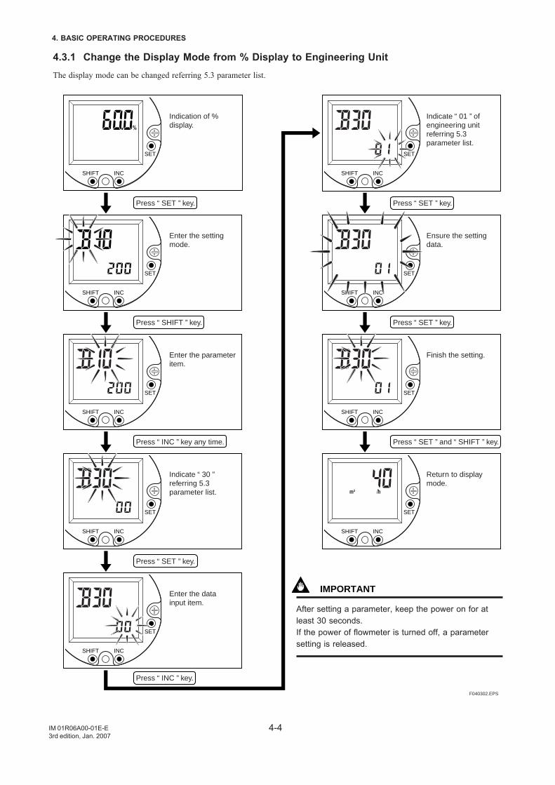
4.3.1 Change the Display Mode from % Display to Engineering UnitThe display mode can be changed referring 5.3 parameter list.
SET
INCSHIFT
SET
INCSHIFT
SET
INCSHIFT
SET
INCSHIFT
SET
INCSHIFT
SET
INCSHIFT
SET
INCSHIFT
SET
INCSHIFT
SET
INCSHIFT
F040302.EPS
Indication of % display.
Enter the setting mode.
Enter the parameter item.
Indicate “ 30 ” referring 5.3 parameter list.
Enter the data input item.
Indicate “ 01 ” of engineering unit referring 5.3 parameter list.
Ensure the setting data.
Finish the setting.
Return to display mode.
Press “ SET ” key.
Press “ SHIFT ” key.
Press “ INC ” key any time.
Press “ SET ” key.
Press “ INC ” key.
Press “ SET ” key.
Press “ SET ” key.
Press “ SET ” and “ SHIFT ” key.
IMPORTANT
After setting a parameter, keep the power on for atleast 30 seconds.If the power of flowmeter is turned off, a parametersetting is released.
4-5
4. BASIC OPERATING PROCEDURES
IM 01R06A00-01E-E3rd edition, Jan. 2007
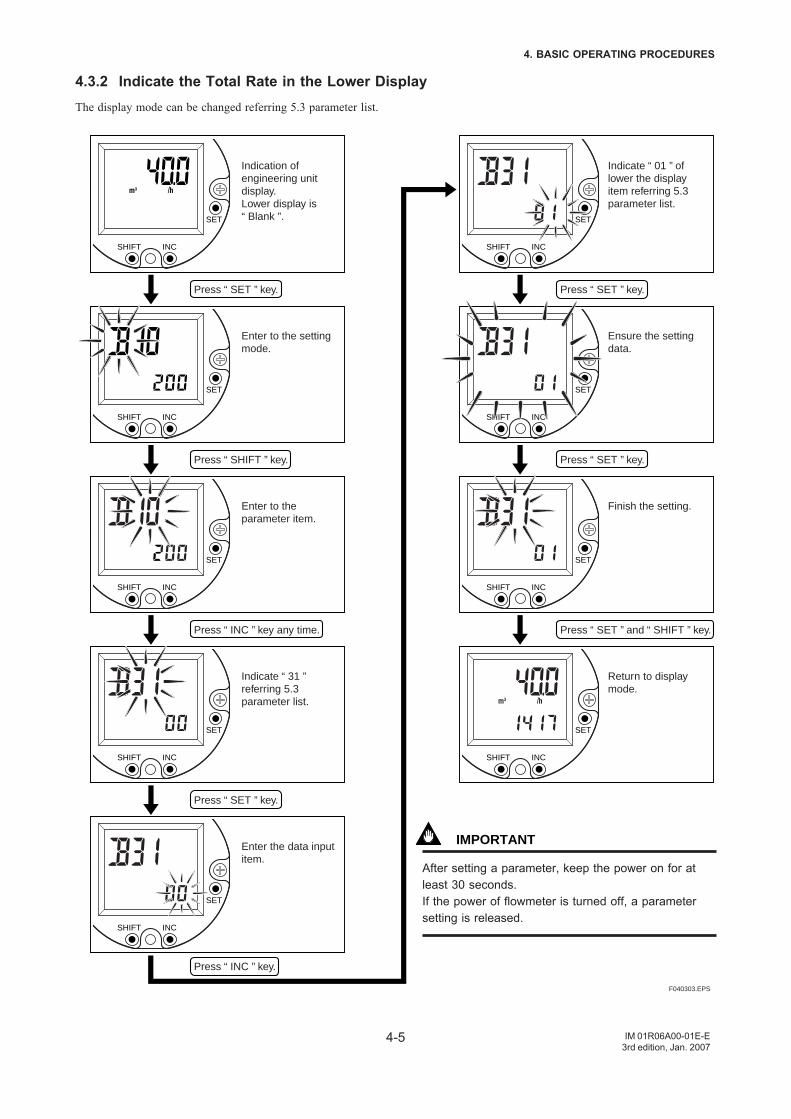
4.3.2 Indicate the Total Rate in the Lower DisplayThe display mode can be changed referring 5.3 parameter list.
SET
INCSHIFT
SET
INCSHIFT
SET
INCSHIFT
SET
INCSHIFT
SET
INCSHIFT
SET
INCSHIFT
SET
INCSHIFT
SET
INCSHIFT
SET
INCSHIFT
F040303.EPS
Press “ SET ” key.
Press “ SHIFT ” key.
Press “ INC ” key any time.
Press “ SET ” key.
Press “ INC ” key.
Press “ SET ” key.
Press “ SET ” key.
Press “ SET ” and “ SHIFT ” key.
Indication of engineering unit display.Lower display is “ Blank ”.
Enter to the setting mode.
Enter to the parameter item.
Indicate “ 31 ” referring 5.3parameter list.
Enter the data input item.
Indicate “ 01 ” of lower the display item referring 5.3 parameter list.
Ensure the setting data.
Finish the setting.
Return to display mode.
IMPORTANT
After setting a parameter, keep the power on for atleast 30 seconds.If the power of flowmeter is turned off, a parametersetting is released.
4-6
4. BASIC OPERATING PROCEDURES
IM 01R06A00-01E-E3rd edition, Jan. 2007
4.4 Setting ModeThe setting mode is used for checking parameters andrewriting data. The following is an overview of the settingmode.
NOTE
• Refer to 5.3 Parameter List and 5.4 Parameterdescription for information on how to changesetting.
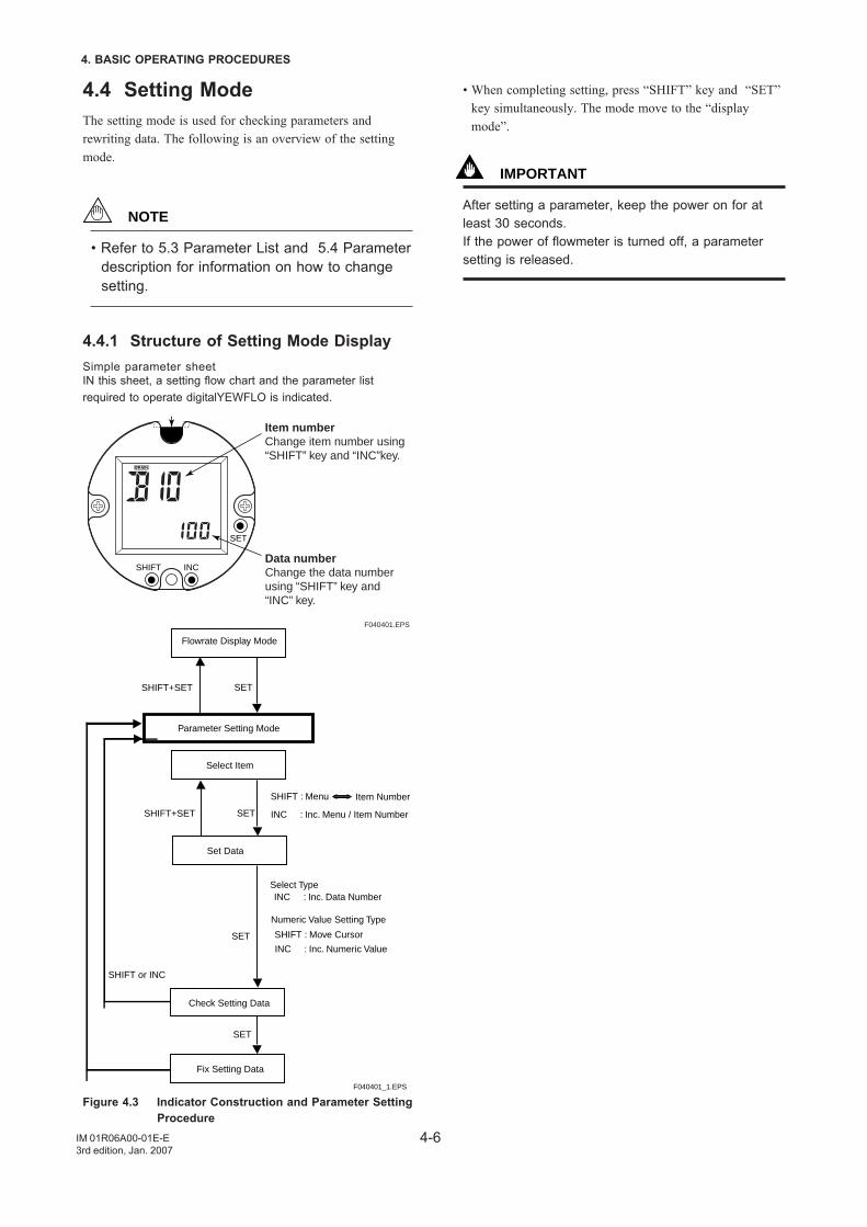
4.4.1 Structure of Setting Mode DisplaySimple parameter sheetIN this sheet, a setting flow chart and the parameter listrequired to operate digitalYEWFLO is indicated.
SET
INCSHIFT
F040401.EPS
Item numberChange item number using “SHIFT” key and “INC”key.
Data numberChange the data number using “SHIFT” key and “INC” key.
SET
Flowrate Display Mode
Parameter Setting Mode
Select Item
Set Data
Check Setting Data
Fix Setting Data
SHIFT+SET
SETSHIFT+SET
SET
SET
SHIFT or INC
SHIFT : Menu Item Number
INC : Inc. Menu / Item Number
INC : Inc. Data NumberSelect Type
Numeric Value Setting Type
SHIFT : Move Cursor
INC : Inc. Numeric Value
F040401_1.EPS
Figure 4.3 Indicator Construction and Parameter SettingProcedure
• When completing setting, press “SHIFT” key and “SET”key simultaneously. The mode move to the “displaymode”.
IMPORTANT
After setting a parameter, keep the power on for atleast 30 seconds.If the power of flowmeter is turned off, a parametersetting is released.
4-7
4. BASIC OPERATING PROCEDURES
IM 01R06A00-01E-E3rd edition, Jan. 2007
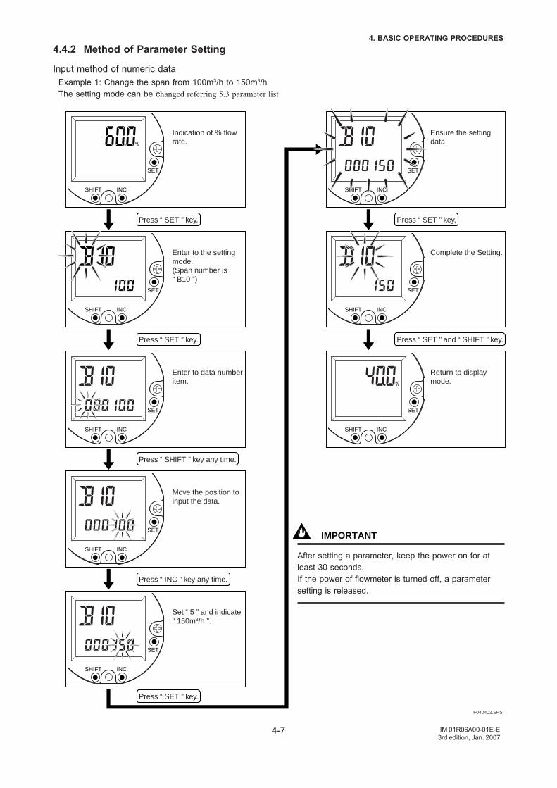
4.4.2 Method of Parameter Setting
Input method of numeric dataExample 1: Change the span from 100m3/h to 150m3/hThe setting mode can be changed referring 5.3 parameter list
SET
INCSHIFT
SET
INCSHIFT
SET
INCSHIFT
SET
INCSHIFT
SET
INCSHIFT
SET
INCSHIFT
SET
INCSHIFT
SET
INCSHIFT
F040402.EPS
Press “ SET ” key.
Press “ SET ” key.
Press “ SHIFT ” key any time.
Press “ INC ” key any time.
Press “ SET ” key.
Press “ SET ” key.
Press “ SET ” and “ SHIFT ” key.
Indication of % flow rate.
Enter to the setting mode. (Span number is “ B10 ”)
Enter to data number item.
Move the position to input the data.
Set “ 5 ” and indicate “ 150m3/h ”.
Ensure the setting data.
Complete the Setting.
Return to display mode.
IMPORTANT
After setting a parameter, keep the power on for atleast 30 seconds.If the power of flowmeter is turned off, a parametersetting is released.
4-8
4. BASIC OPERATING PROCEDURES
IM 01R06A00-01E-E3rd edition, Jan. 2007
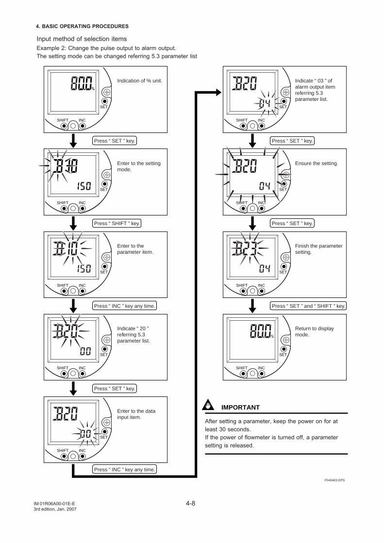
Input method of selection itemsExample 2: Change the pulse output to alarm output.The setting mode can be changed referring 5.3 parameter list
SET
INCSHIFT
SET
INCSHIFT
SET
INCSHIFT
SET
INCSHIFT
SET
INCSHIFT
SET
INCSHIFT
SET
INCSHIFT
SET
INCSHIFT
SET
INCSHIFT
F040403.EPS
Press “ SET ” key.
Press “ SHIFT ” key.
Press “ INC ” key any time.
Press “ INC ” key any time.
Press “ SET ” key.
Press “ SET ” key.
Press “ SET ” key.
Press “ SET ” and “ SHIFT ” key.
Indication of % unit.
Enter to the setting mode.
Enter to the parameter item.
Indicate “ 20 ” referring 5.3 parameter list.
Enter to the data input item.
Indicate “ 03 ” of alarm output item referring 5.3 parameter list.
Ensure the setting.
Finish the parameter setting.
Return to display mode.
IMPORTANT
After setting a parameter, keep the power on for atleast 30 seconds.If the power of flowmeter is turned off, a parametersetting is released.
4-9
4. BASIC OPERATING PROCEDURES
IM 01R06A00-01E-E3rd edition, Jan. 2007
4.5 Operation for the BT200This section describes the operation procedures using aBRAIN Terminal (BT200). For details on the functions of thedigitalYEWFLO, refer to 5.3 Parameter List. And also, seethe “BT200 Instruction Manual” (IM 1C0A11-01E) for moredetailed Information.
4.5.1 Connection Method for the BT200
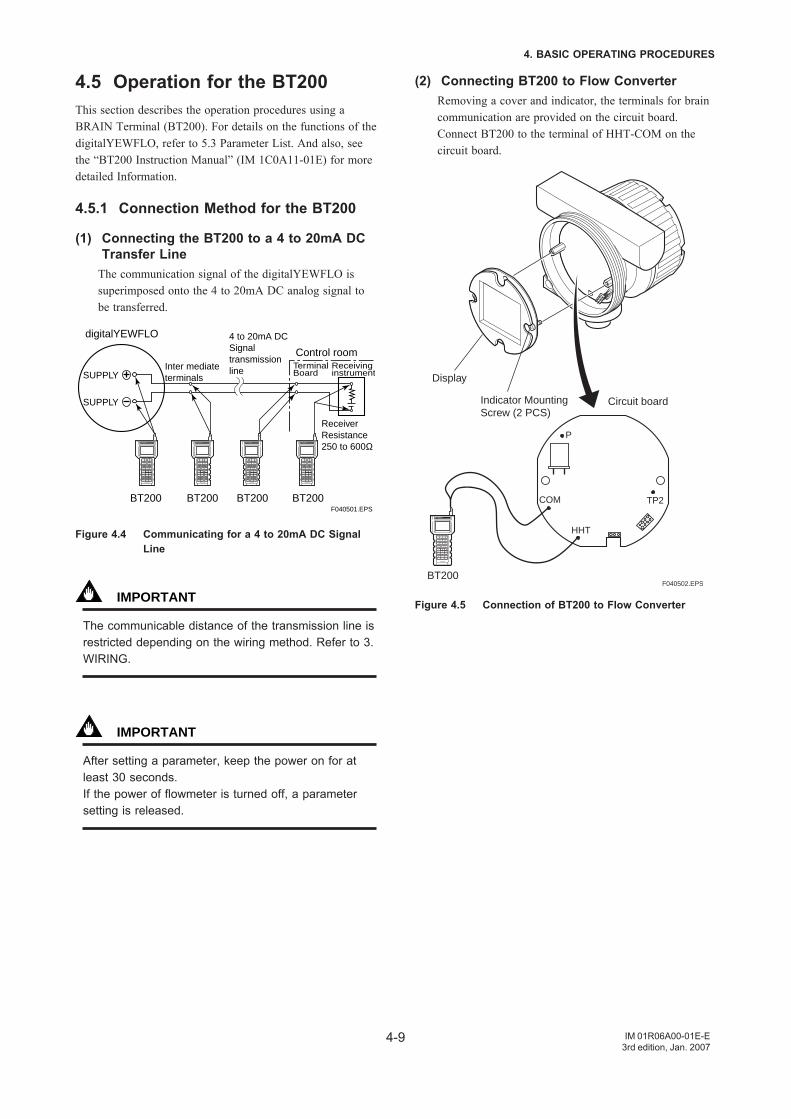
(1) Connecting the BT200 to a 4 to 20mA DCTransfer Line
The communication signal of the digitalYEWFLO issuperimposed onto the 4 to 20mA DC analog signal tobe transferred.
digitalYEWFLO
SUPPLY
BT200 BT200 BT200 BT200
Inter mediate terminals
4 to 20mA DC Signal transmission line
Control room
Receiver Resistance250 to 600Ω
Receivinginstrument
Terminal Board
SUPPLY
F040501.EPS
Figure 4.4 Communicating for a 4 to 20mA DC SignalLine
IMPORTANT
The communicable distance of the transmission line isrestricted depending on the wiring method. Refer to 3.WIRING.
IMPORTANT
After setting a parameter, keep the power on for atleast 30 seconds.If the power of flowmeter is turned off, a parametersetting is released.
(2) Connecting BT200 to Flow ConverterRemoving a cover and indicator, the terminals for braincommunication are provided on the circuit board.Connect BT200 to the terminal of HHT-COM on thecircuit board.
TP2COM
HHT
P
F040502.EPSBT200
Display
Indicator Mounting Screw (2 PCS)
Circuit board
Figure 4.5 Connection of BT200 to Flow Converter
4-10
4. BASIC OPERATING PROCEDURES
IM 01R06A00-01E-E3rd edition, Jan. 2007
4.5.2 Displaying Flow Rate DataFlowrate data can be displayed on the BT200 screenaccording to the following procedure.
F040503.EPS
Turn the power on and the screen on the left “Please wait....” is displayed for a few minutes.
Pressing the “ENTER” key causes the initial data screen on the left to be displayed.
Pressing the “F4” or “ENTER” causes the menu screen on the left to be displayed.
Executing Function Key F1 : Updates the current data.F2 : Displays the self-check
screen.F3 : Displays the parameter
print sreen.F4 : Returns to the previous
panel. (menu panel)
With “A : DISPLAY” displayed on the menu panel in the inverse video bar, press “ENTER” key and the flow data screen appears. Maximum three data items can be displayed on one screen.
The tag number specified upon ordering is entered.
Inverse Video Bar
or
Function Key
———WELCOME———BRAIN TERMINAL ID:BT200 Check connectionPush ENTER key
UTIL FEED
MENUA:DISPLAYB:EASY SETUPC:BASIC SETUPD:AUX. SETUPE:METER SETUPH:ADJUST
HOME SET ADJ ESC
PARAM01:MODEL digitalYEWFLO02:TAG NO.
03:SELF CHECK GOOD
OK
PARAMA10:FLOW RATE(%) 80.0%A20:FLOW RATE 100m3/hA30:TOTAL 1417
DATA DIAG PRNT ESC
PARAMA10:FLOW RATE(%) 80.0%A20:FLOW RATE 100m3/hA30:TOTAL 1417
DATA DIAG PRNT ESC
Function keyThe functions of the function keys vary with the commandsbeing displayed on the display panel.
Table 4.4
ADJ
CAPS/caps
CLR
COPY*
DATA
DEL
DIAG
ESC
FEED*
HOME
LIST*
NO
OK
PARM
PON/POFF*
PRNT*
SET
SLOT
GO*
STOP*
UTIL
Calls up the adjustment menu.
Changes the uppercase / lowercase mode.
Clears entered data / deletes all data.
Prints parameters on the screen.
Updates parameter data.
Deletes one character.
Calls up the self-check screen.
Returns to the preceding screen.
Paper feed.
Calls up the home menu (A : DISPLAY).
Prints all parameters of the menus.
Setting stop / re-setting. Returns to the previous screen.
Goes to the next screen.
Parameter number setting mode.
Printer output of data whose setting was changed Mode on / off.
Changes to the prints mode.
Calls up the setting menu (B : SETTING).
Returns to the slot selection screen.
Starts print out.
Stops printing.
Transfers to the utility screen.
Command Description
T040501.EPS*The command is available only for BT-200-P00
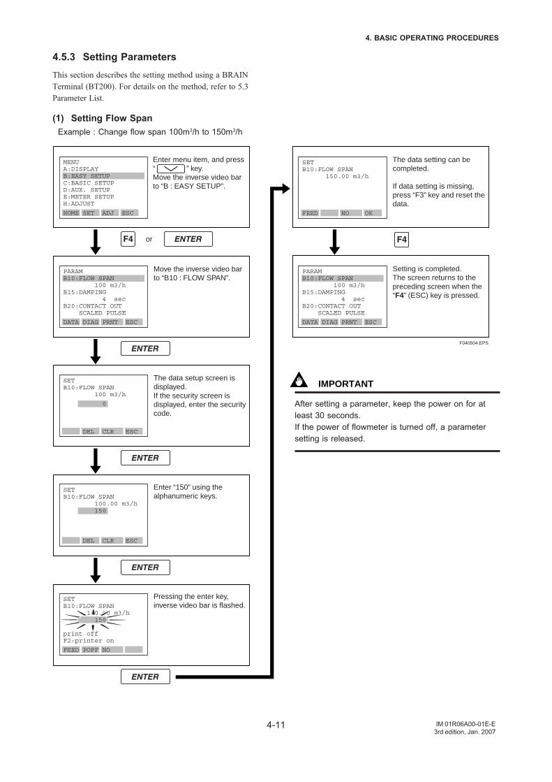
4-11
4. BASIC OPERATING PROCEDURES
IM 01R06A00-01E-E3rd edition, Jan. 2007
4.5.3 Setting ParametersThis section describes the setting method using a BRAINTerminal (BT200). For details on the method, refer to 5.3Parameter List.
(1) Setting Flow SpanExample : Change flow span 100m3/h to 150m3/h
F040504.EPS
Move the inverse video bar to “B10 : FLOW SPAN”.
The data setup screen is displayed.If the security screen is displayed, enter the security code.
Enter “150” using the alphanumeric keys.
Pressing the enter key, inverse video bar is flashed.
or
The data setting can be completed.
If data setting is missing, press “F3” key and reset the data.
Setting is completed.The screen returns to the preceding screen when the “F4” (ESC) key is pressed.
MENUA:DISPLAYB:EASY SETUPC:BASIC SETUPD:AUX. SETUPE:METER SETUPH:ADJUST
HOME SET ADJ ESC
PARAMB10:FLOW SPAN 100 m3/hB15:DAMPING 4 secB20:CONTACT OUT SCALED PULSE
DATA DIAG PRNT ESC
PARAMB10:FLOW SPAN 100 m3/hB15:DAMPING 4 secB20:CONTACT OUT SCALED PULSE
DATA DIAG PRNT ESC
SETB10:FLOW SPAN 100 m3/h
0
DEL CLR ESC
SETB10:FLOW SPAN 100.00 m3/h 150
DEL CLR ESC
SETB10:FLOW SPAN 100.00 m3/h 150 print offF2:printer on
FEED POFF NO
SETB10:FLOW SPAN 150.00 m3/h
FEED NO OK
Enter menu item, and press “ ” key.Move the inverse video bar to “B : EASY SETUP”.
IMPORTANT
After setting a parameter, keep the power on for atleast 30 seconds.If the power of flowmeter is turned off, a parametersetting is released.
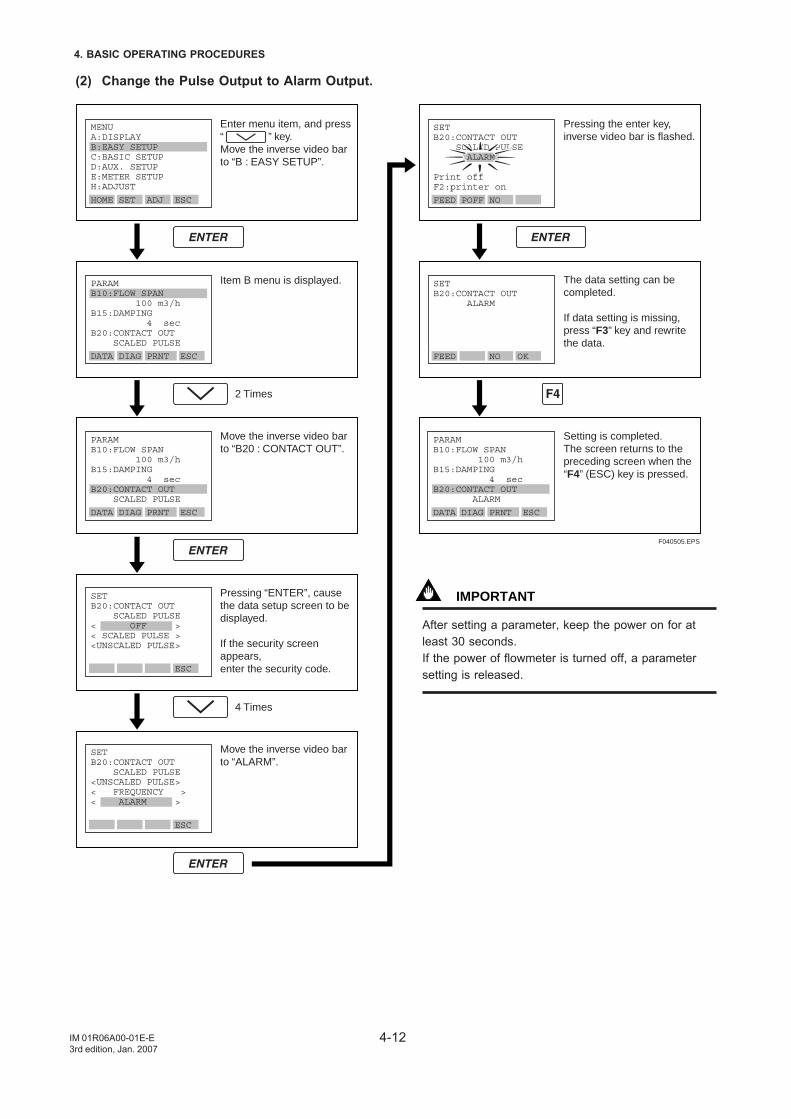
4-12
4. BASIC OPERATING PROCEDURES
IM 01R06A00-01E-E3rd edition, Jan. 2007
(2) Change the Pulse Output to Alarm Output.
F040505.EPS
Enter menu item, and press “ ” key.Move the inverse video bar to “B : EASY SETUP”.
Item B menu is displayed.
Move the inverse video bar to “B20 : CONTACT OUT”.
Pressing “ENTER”, cause the data setup screen to be displayed.
If the security screen appears, enter the security code.
Move the inverse video bar to “ALARM”.
2 Times
4 Times
Pressing the enter key, inverse video bar is flashed.
The data setting can be completed.
If data setting is missing, press “F3” key and rewrite the data.
Setting is completed.The screen returns to the preceding screen when the “F4” (ESC) key is pressed.
MENUA:DISPLAYB:EASY SETUPC:BASIC SETUPD:AUX. SETUPE:METER SETUPH:ADJUST
HOME SET ADJ ESC
PARAMB10:FLOW SPAN 100 m3/hB15:DAMPING 4 secB20:CONTACT OUT SCALED PULSE
DATA DIAG PRNT ESC
PARAMB10:FLOW SPAN 100 m3/hB15:DAMPING 4 secB20:CONTACT OUT SCALED PULSE
DATA DIAG PRNT ESC
PARAMB10:FLOW SPAN 100 m3/hB15:DAMPING 4 secB20:CONTACT OUT ALARM
DATA DIAG PRNT ESC
SETB20:CONTACT OUT SCALED PULSE< OFF >< SCALED PULSE ><UNSCALED PULSE>
ESC
SETB20:CONTACT OUT SCALED PULSE<UNSCALED PULSE>< FREQUENCY >< ALARM >
ESC
SETB20:CONTACT OUT SCALED PULSE ALARM
Print offF2:printer on
FEED POFF NO
SETB20:CONTACT OUT ALARM
FEED NO OK
IMPORTANT
After setting a parameter, keep the power on for atleast 30 seconds.If the power of flowmeter is turned off, a parametersetting is released.
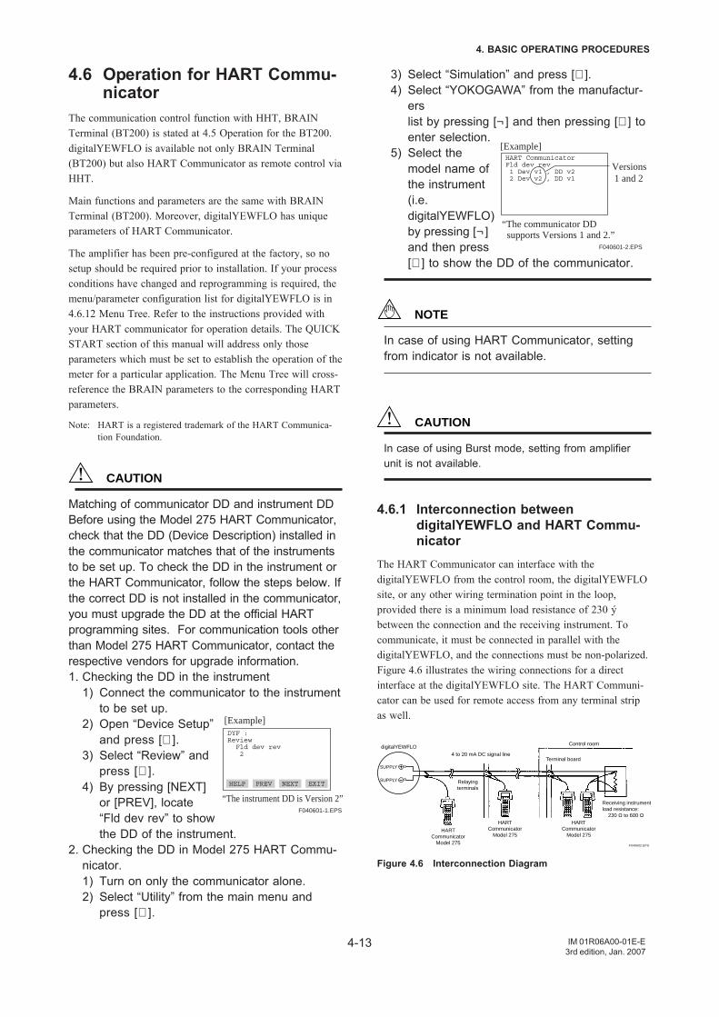
4-13
4. BASIC OPERATING PROCEDURES
IM 01R06A00-01E-E3rd edition, Jan. 2007
4.6 Operation for HART Commu-nicator
The communication control function with HHT, BRAINTerminal (BT200) is stated at 4.5 Operation for the BT200.digitalYEWFLO is available not only BRAIN Terminal(BT200) but also HART Communicator as remote control viaHHT.
Main functions and parameters are the same with BRAINTerminal (BT200). Moreover, digitalYEWFLO has uniqueparameters of HART Communicator.
The amplifier has been pre-configured at the factory, so nosetup should be required prior to installation. If your processconditions have changed and reprogramming is required, themenu/parameter configuration list for digitalYEWFLO is in4.6.12 Menu Tree. Refer to the instructions provided withyour HART communicator for operation details. The QUICKSTART section of this manual will address only thoseparameters which must be set to establish the operation of themeter for a particular application. The Menu Tree will cross-reference the BRAIN parameters to the corresponding HARTparameters.
Note: HART is a registered trademark of the HART Communica-tion Foundation.
CAUTION
Matching of communicator DD and instrument DDBefore using the Model 275 HART Communicator,check that the DD (Device Description) installed inthe communicator matches that of the instrumentsto be set up. To check the DD in the instrument orthe HART Communicator, follow the steps below. Ifthe correct DD is not installed in the communicator,you must upgrade the DD at the official HARTprogramming sites. For communication tools otherthan Model 275 HART Communicator, contact therespective vendors for upgrade information.1. Checking the DD in the instrument
1) Connect the communicator to the instrumentto be set up.
2) Open “Device Setup”and press [∅ ].
3) Select “Review” andpress [∅ ].
4) By pressing [NEXT]or [PREV], locate“Fld dev rev” to showthe DD of the instrument.
2. Checking the DD in Model 275 HART Commu-nicator.1) Turn on only the communicator alone.2) Select “Utility” from the main menu and
press [∅ ].
DYF :Review Fld dev rev 2
HELP PREV NEXT EXIT
[Example]
“The instrument DD is Version 2”F040601-1.EPS
3) Select “Simulation” and press [∅ ].4) Select “YOKOGAWA” from the manufactur-
erslist by pressing [¬ ] and then pressing [∅ ] toenter selection.
5) Select themodel name ofthe instrument(i.e.digitalYEWFLO)by pressing [¬ ]and then press[∅ ] to show the DD of the communicator.
NOTE
In case of using HART Communicator, settingfrom indicator is not available.
CAUTION
In case of using Burst mode, setting from amplifierunit is not available.
4.6.1 Interconnection betweendigitalYEWFLO and HART Commu-nicator
The HART Communicator can interface with thedigitalYEWFLO from the control room, the digitalYEWFLOsite, or any other wiring termination point in the loop,provided there is a minimum load resistance of 230 ýbetween the connection and the receiving instrument. Tocommunicate, it must be connected in parallel with thedigitalYEWFLO, and the connections must be non-polarized.Figure 4.6 illustrates the wiring connections for a directinterface at the digitalYEWFLO site. The HART Communi-cator can be used for remote access from any terminal stripas well.
+
–
4 to 20 mA DC signal line
Control room
Terminal board
Receiving instrumentload resistance:
230 Ω to 600 Ω
Relayingterminals
HARTCommunicator
Model 275
HARTCommunicator
Model 275
HARTCommunicator
Model 275
F040602.EPS
digitalYEWFLO
SUPPLY
SUPPLY
Figure 4.6 Interconnection Diagram
HART CommunicatorFld dev rev 1 Dev v1 , DD v2 2 Dev v2 , DD v1
Versions 1 and 2
[Example]
“The communicator DD supports Versions 1 and 2.”
F040601-2.EPS
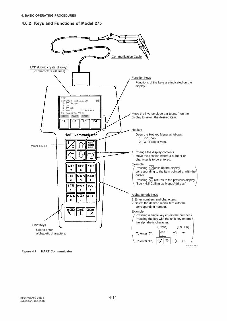
4-14
4. BASIC OPERATING PROCEDURES
IM 01R06A00-01E-E3rd edition, Jan. 2007
4.6.2 Keys and Functions of Model 275
LCD (Liquid crystal display)(21 characters × 8 lines)
Communication Cable
Function Keys
Functions of the keys are indicated on the display.
Hot key
Open the Hot key Menu as follows:1. PV Span2. Wrt Protect Menu
Shift Keys
Use to enter alphabetic characters.
1. Change the display contents.2. Move the position where a number or
character is to be entered.
ExamplePressing calls up the display corresponding to the item pointed at with the cursor.
Pressing returns to the previous display. (See 4.6.5 Calling up Menu Address.)
Alphanumeric Keys
1. Enter numbers and characters.2. Select the desired menu item with the
corresponding number.
ExamplePressing a single key enters the number.Pressing the key with the shift key enters the alphabetic character.
Move the inverse video bar (cursor) on the display to select the desired item.
ABC7
ABC7
To enter “7”,
To enter “C”,
‘7’
‘C’
(Press) (ENTER)
Power ON/OFF
F040603.EPS
DYF :Process Variables 1 PV %rnge 2 PV 3 PV AO 4 Totl 12348853 5 Reverse TotlHELP SAVE HOME
Figure 4.7 HART Communicator
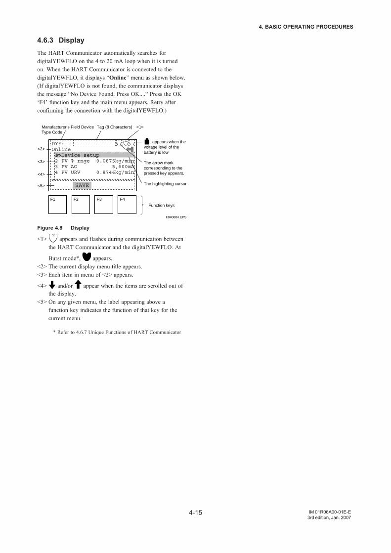
4-15
4. BASIC OPERATING PROCEDURES
IM 01R06A00-01E-E3rd edition, Jan. 2007
4.6.3 DisplayThe HART Communicator automatically searches fordigitalYEWFLO on the 4 to 20 mA loop when it is turnedon. When the HART Communicator is connected to thedigitalYEWFLO, it displays “Online” menu as shown below.(If digitalYEWFLO is not found, the communicator displaysthe message “No Device Found. Press OK....” Press the OK‘F4’ function key and the main menu appears. Retry afterconfirming the connection with the digitalYEWFLO.)
Manufacturer’s Field DeviceType Code
Tag (8 Characters) <1>
<2>
<3>
<4>
<5>
Function keys
appears when the voltage level of the battery is low
The arrow mark corresponding to the pressed key appears.
The highlighting cursor
DYF:Online 1 Device setup 2 PV % rnge 0.0875kg/min 3 PV AO 5,600mA 4 PV URV 0.8746kg/min
HELP SAVE HOME ENTER
F1 F2 F3 F4
F040604.EPS
Figure 4.8 Display
<1> appears and flashes during communication betweenthe HART Communicator and the digitalYEWFLO. At
Burst mode*, appears.<2> The current display menu title appears.<3> Each item in menu of <2> appears.
<4> and/or appear when the items are scrolled out ofthe display.
<5> On any given menu, the label appearing above afunction key indicates the function of that key for thecurrent menu.
* Refer to 4.6.7 Unique Functions of HART Communicator
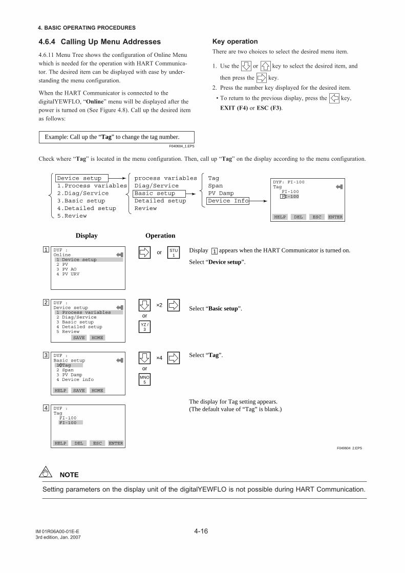
4-16
4. BASIC OPERATING PROCEDURES
IM 01R06A00-01E-E3rd edition, Jan. 2007
4.6.4 Calling Up Menu Addresses4.6.11 Menu Tree shows the configuration of Online Menuwhich is needed for the operation with HART Communica-tor. The desired item can be displayed with ease by under-standing the menu configuration.
When the HART Communicator is connected to thedigitalYEWFLO, “Online” menu will be displayed after thepower is turned on (See Figure 4.8). Call up the desired itemas follows:
Example: Call up the “Tag” to change the tag number.F040604_1.EPS
Check where “Tag” is located in the menu configuration. Then, call up “Tag” on the display according to the menu configuration.
Device setup1.Process variables2.Diag/Service3.Basic setup4.Detailed setup5.Review
process variablesDiag/ServiceBasic setupDetailed setupReview
TagSpanPV DampDevice Info
DYF :Online 1 Device setup 2 PV 3 PV AO 4 PV URV
DEL SET ESC ENTER
1
Display Operation
STU1
or
DYF :Device setup 1 Process variables 2 Diag/Service 3 Basic setup 4 Detailed setup 5 ReviewDEL SAVE HOME ENTER
2
YZ /3
×2
or
Display appears when the HART Communicator is turned on.
Select “Device setup”.
Select “Basic setup”.
Select “Tag”.
The display for Tag setting appears.(The default value of “Tag” is blank.)
1
DYF: FI-100Tag FI-100 FI-100
HELP DEL ESC ENTER
DYF :Basic setup 1 Tag 2 Span 3 PV Damp 4 Device info
HELP SAVE HOME ENTER
3
MNO5
×4
or
DYF :Tag FI-100 FI-100
HELP DEL ESC ENTER
4
F040604_2.EPS
NOTE
Setting parameters on the display unit of the digitalYEWFLO is not possible during HART Communication.
Key operationThere are two choices to select the desired menu item.
1. Use the or key to select the desired item, and
then press the key.2. Press the number key displayed for the desired item.
• To return to the previous display, press the key,EXIT (F4) or ESC (F3).
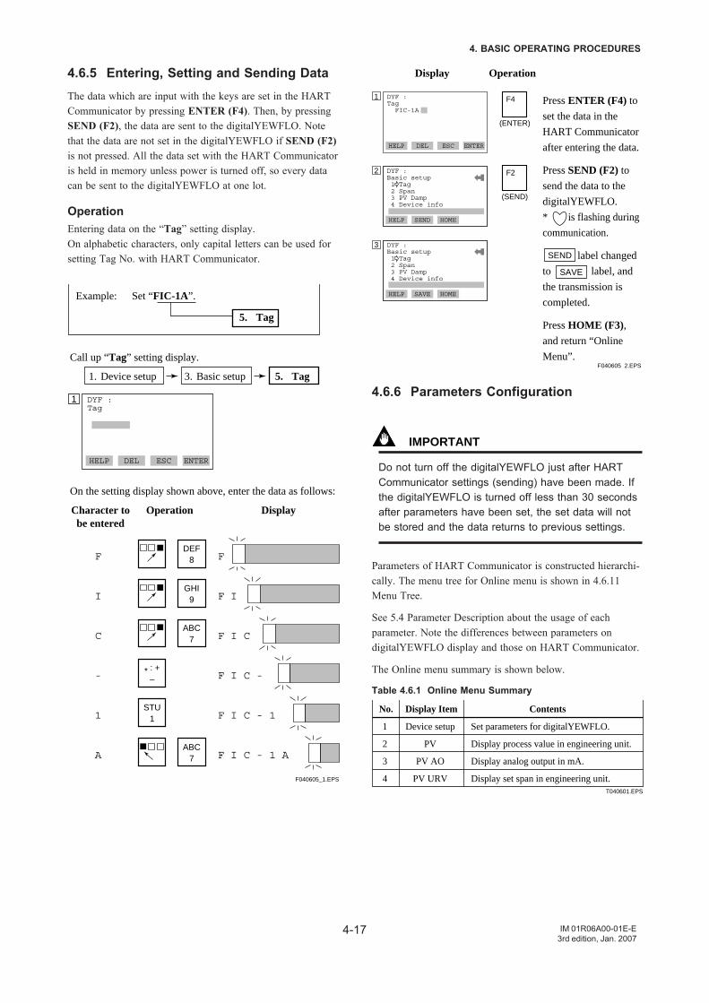
4-17
4. BASIC OPERATING PROCEDURES
IM 01R06A00-01E-E3rd edition, Jan. 2007
4.6.5 Entering, Setting and Sending DataThe data which are input with the keys are set in the HARTCommunicator by pressing ENTER (F4). Then, by pressingSEND (F2), the data are sent to the digitalYEWFLO. Notethat the data are not set in the digitalYEWFLO if SEND (F2)is not pressed. All the data set with the HART Communicatoris held in memory unless power is turned off, so every datacan be sent to the digitalYEWFLO at one lot.
OperationEntering data on the “Tag” setting display.On alphabetic characters, only capital letters can be used forsetting Tag No. with HART Communicator.
1. Device setup 3. Basic setup 5. Tag
DYF :Tag
HELP DEL ESC ENTER
1
Call up “Tag” setting display.
On the setting display shown above, enter the data as follows:
Example: Set “FIC-1A”.
5. Tag
DEF8 FF
I
C
-
1
A
GHI9 F I
ABC7 F I C
* : +– F I C -
STU1 F I C - 1
ABC7 F I C - 1 A
Character tobe entered
Operation Display
F040605_1.EPS
DYF :Tag FIC-1A
HELP DEL ESC ENTER
1
Display Operation
F4
HELP SEND HOME ENTER
2
Press ENTER (F4) to
set the data in the
HART Communicator
after entering the data.
Press SEND (F2) to
send the data to the
digitalYEWFLO.
* is flashing during
communication.
label changed
to label, and
the transmission is
completed.
Press HOME (F3),
and return “Online
Menu”.
HELP SAVE HOME ENTER
3
(ENTER)
F2
(SEND)
SEND
SAVE
DYF :Basic setup 1 Tag 2 Span 3 PV Damp 4 Device info
DYF :Basic setup 1 Tag 2 Span 3 PV Damp 4 Device info
F040605_2.EPS
4.6.6 Parameters Configuration
IMPORTANT
Do not turn off the digitalYEWFLO just after HARTCommunicator settings (sending) have been made. Ifthe digitalYEWFLO is turned off less than 30 secondsafter parameters have been set, the set data will notbe stored and the data returns to previous settings.
Parameters of HART Communicator is constructed hierarchi-cally. The menu tree for Online menu is shown in 4.6.11Menu Tree.
See 5.4 Parameter Description about the usage of eachparameter. Note the differences between parameters ondigitalYEWFLO display and those on HART Communicator.
The Online menu summary is shown below.
Table 4.6.1 Online Menu Summary
No. Display Item Contents
1
2
3
4
Device setup
PV
PV AO
PV URV
Set parameters for digitalYEWFLO.
Display process value in engineering unit.
Display analog output in mA.
Display set span in engineering unit.T040601.EPS
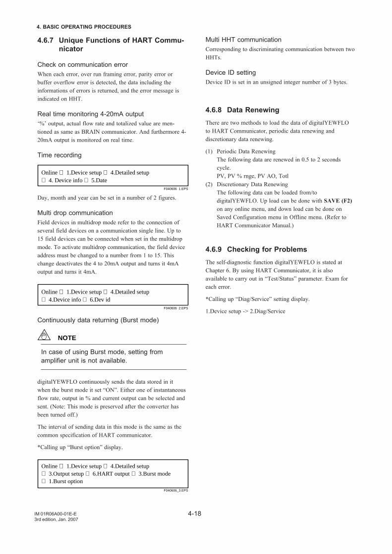
4-18
4. BASIC OPERATING PROCEDURES
IM 01R06A00-01E-E3rd edition, Jan. 2007
4.6.7 Unique Functions of HART Commu-nicator
Check on communication errorWhen each error, over run framing error, parity error orbuffer overflow error is detected, the data including theinformations of errors is returned, and the error message isindicated on HHT.
Real time monitoring 4-20mA output‘%’ output, actual flow rate and totalized value are men-tioned as same as BRAIN communicator. And furthermore 4-20mA output is monitored on real time.
Time recording
Online ⇒ 1.Device setup ⇒ 4.Detailed setup ⇒ 4. Device info ⇒ 5.Date
F040606_1.EPS
Day, month and year can be set in a number of 2 figures.
Multi drop communicationField devices in multidrop mode refer to the connection ofseveral field devices on a communication single line. Up to15 field devices can be connected when set in the multidropmode. To activate multidrop communication, the field deviceaddress must be changed to a number from 1 to 15. Thischange deactivates the 4 to 20mA output and turns it 4mAoutput and turns it 4mA.
Online ⇒ 1.Device setup ⇒ 4.Detailed setup ⇒ 4.Device info ⇒ 6.Dev id
F040606_2.EPS
Continuously data returning (Burst mode)
NOTE
In case of using Burst mode, setting fromamplifier unit is not available.
digitalYEWFLO continuously sends the data stored in itwhen the burst mode it set “ON”. Either one of instantaneousflow rate, output in % and current output can be selected andsent. (Note: This mode is preserved after the converter hasbeen turned off.)
The interval of sending data in this mode is the same as thecommon specification of HART communicator.
*Calling up “Burst option” display.
Online ⇒ 1.Device setup ⇒ 4.Detailed setup ⇒ 3.Output setup ⇒ 6.HART output ⇒ 3.Burst mode⇒ 1.Burst option
F040606_3.EPS
Multi HHT communicationCorresponding to discriminating communication between twoHHTs.
Device ID settingDevice ID is set in an unsigned integer number of 3 bytes.
4.6.8 Data RenewingThere are two methods to load the data of digitalYEWFLOto HART Communicator, periodic data renewing anddiscretionary data renewing.
(1) Periodic Data RenewingThe following data are renewed in 0.5 to 2 secondscycle.PV, PV % rnge, PV AO, Totl
(2) Discretionary Data RenewingThe following data can be loaded from/todigitalYEWFLO. Up load can be done with SAVE (F2)on any online menu, and down load can be done onSaved Configuration menu in Offline menu. (Refer toHART Communicator Manual.)
4.6.9 Checking for ProblemsThe self-diagnostic function digitalYEWFLO is stated atChapter 6. By using HART Communicator, it is alsoavailable to carry out in “Test/Status” parameter. Exam foreach error.
*Calling up “Diag/Service” setting display.
1.Device setup -> 2.Diag/Service
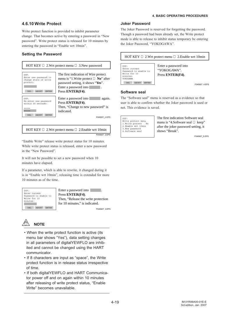
4-19
4. BASIC OPERATING PROCEDURES
IM 01R06A00-01E-E3rd edition, Jan. 2007
4.6.10 Write ProtectWrite protect function is provided to inhibit parameterchange. That becomes active by entering a password in “Newpassword”. Write protect status is released for 10 minutes byentering the password in “Enable wrt 10min”.
Setting the Password
DYF:Enter new password tochange state of writeprotect:
DEL ABORT ENTER
The first indication of Wire protect menu is “1.Write protect ⇒ No” after password setting, it shows “Yes”.Enter a password into .Press ENTER(F4).
DEL ABORT ENTER
Enter a password into again.Press ENTER(F4).Then, “Change to new password” is indicated.
HOT KEY ⇒ 2.Wrt protect menu ⇒ 3.New password
DYF:Re-enter new password within 30 seconds:
**********
F040607_1.EPS
HOT KEY ⇒ 2.Wrt protect menu ⇒ 2.Enable wrt 10minF040607_2.EPS
“Enable Write” release write protect status for 10 minutes.While write protect status is released, enter a new passwordin the “New Password”.
It will not be possible to set a new password when 10minutes have elapsed.
If a parameter, which is able to rewrite, it changed during itis in “Enable wrt 10min”, releasing time is extended for more10 minutes as of the time.
DYF:Enter currentPassword to enable toWrite for 10minutes:
DEL ABORT ENTER
Enter a password into .Press ENTER(F4).Then, “Release the write protection for 10 minutes.” is indicated.
F040607_3.EPS
NOTE
• When the write protect function is active (itsmenu bar shows “Yes”), data setting changesin all parameters of digitalYEWFLO are inhib-ited and cannot be changed using the HARTcommunicator.
• If 8 characters are input as “space”, the Writeprotect function is in release status irrespectiveof time.
• If both digitalYEWFLO and HART Communica-tor power off and on again within 10 minutesafter releasing of write protect status, “EnableWrite” becomes unavailable.
Joker PasswordThe Joker Password is reserved for forgetting the password.Though a password had been already set, the Write protectmode is able to release to inhibit status temporary be enteringthe Joker Password, “YOKOGAWA”.
DYF:Enter currentPassword to enable toWrite for 10minutes:YOKOGAWA
DEL ABORT ENTER
Enter a password into “YOKOGAWA”.Press ENTER(F4).
HOT KEY ⇒ 2.Wrt protect menu ⇒ 2.Enable wrt 10min
F040607_4.EPS
Software sealThe “Software seal” menu is reserved as a evidence so thatuser is able to confirm whether the Joker password is used ornot. This evidence is saved.
DYF:Write protect menu1.Write protect No2.Enable wrt 10min3.New password4.Software seal
The first indication Software seal manu is “4.Software seal ⇒ keep” after the joker password setting, it shows “Break”.
F040607_5.EPS
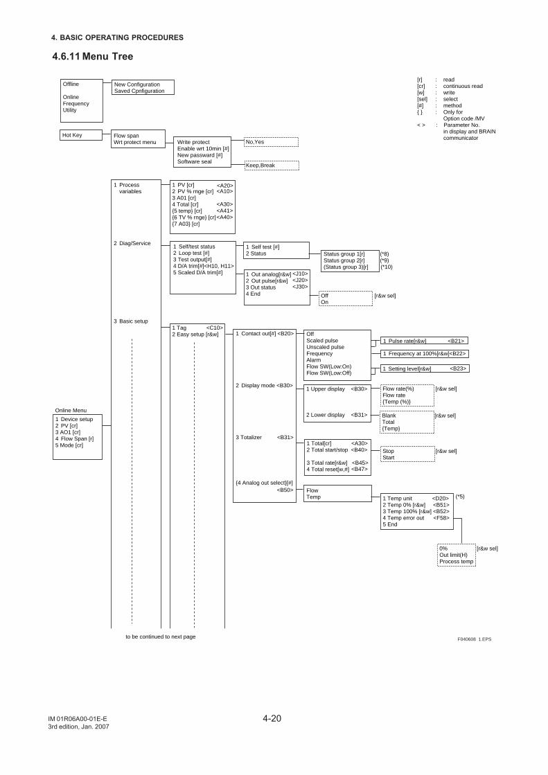
4-20
4. BASIC OPERATING PROCEDURES
IM 01R06A00-01E-E3rd edition, Jan. 2007
4.6.11 Menu Tree
1 Device setup2 PV [cr]3 AO1 [cr]4 Flow Span [r]5 Mode [cr]
1 Processvariables
2 Diag/Service
3 Basic setup
1 PV [cr]2 PV % rnge [cr] 3 A01 [cr]4 Total [cr]5 temp [cr]6 TV % rnge [cr]7 A03 [cr]
1 Self/test status2 Loop test [#]3 Test output[#]4 D/A trim[#]<H10, H11>5 Scaled D/A trim[#]
1 Self test [#]2 Status
1 Tag <C10>2 Easy setup [r&w]
1 Out analog[r&w]2 Out pulse[r&w]3 Out status4 End
Status group 1[r] (*8)Status group 2[r] (*9)(Status group 3)[r] (*10)
Online Menu
to be continued to next page
[r] : read[cr] : continuous read[w] : write[sel] : select[#] : method : Only for
Option code /MV< > : Parameter No. in display and BRAIN communicator
Offline
OnlineFrequencyUtility
New ConfigurationSaved Cpnfiguration
Hot Key Flow spanWrt protect menu Write protect
Enable wrt 10min [#]New passward [#]Software seal
No,Yes
Keep,Break
Off [r&w sel]On
1 Contact out[#] <B20>
2 Display mode <B30>
3 Totalizer <B31>
4 Analog out select[#]
OffScaled pulseUnscaled pulseFrequencyAlarmFlow SW(Low:On)Flow SW(Low:Off)
1 Pulse rate[r&w] <B21>
1 Frequency at 100%[r&w]<B22>
1 Setting level[r&w]
1 Upper display <B30>
2 Lower display <B31>
Flow rate(%) [r&w sel]Flow rateTemp (%)
Blank [r&w sel]TotalTemp
1 Total[cr] <A30>2 Total start/stop <B40>
3 Total rate[r&w] <B45>4 Total reset[w,#]
Stop [r&w sel]Start
FlowTemp 1 Temp unit <D20>
2 Temp 0% [r&w] <B51>3 Temp 100% [r&w] <B52>4 Temp error out <F58>5 End
0% [r&w sel]Out limit(H)Process temp
(*5)
F040608_1.EPS
<A20><A10>
<A30><A41><A40>
<J10><J20><J30>
<B50>
<B47>
<B23>
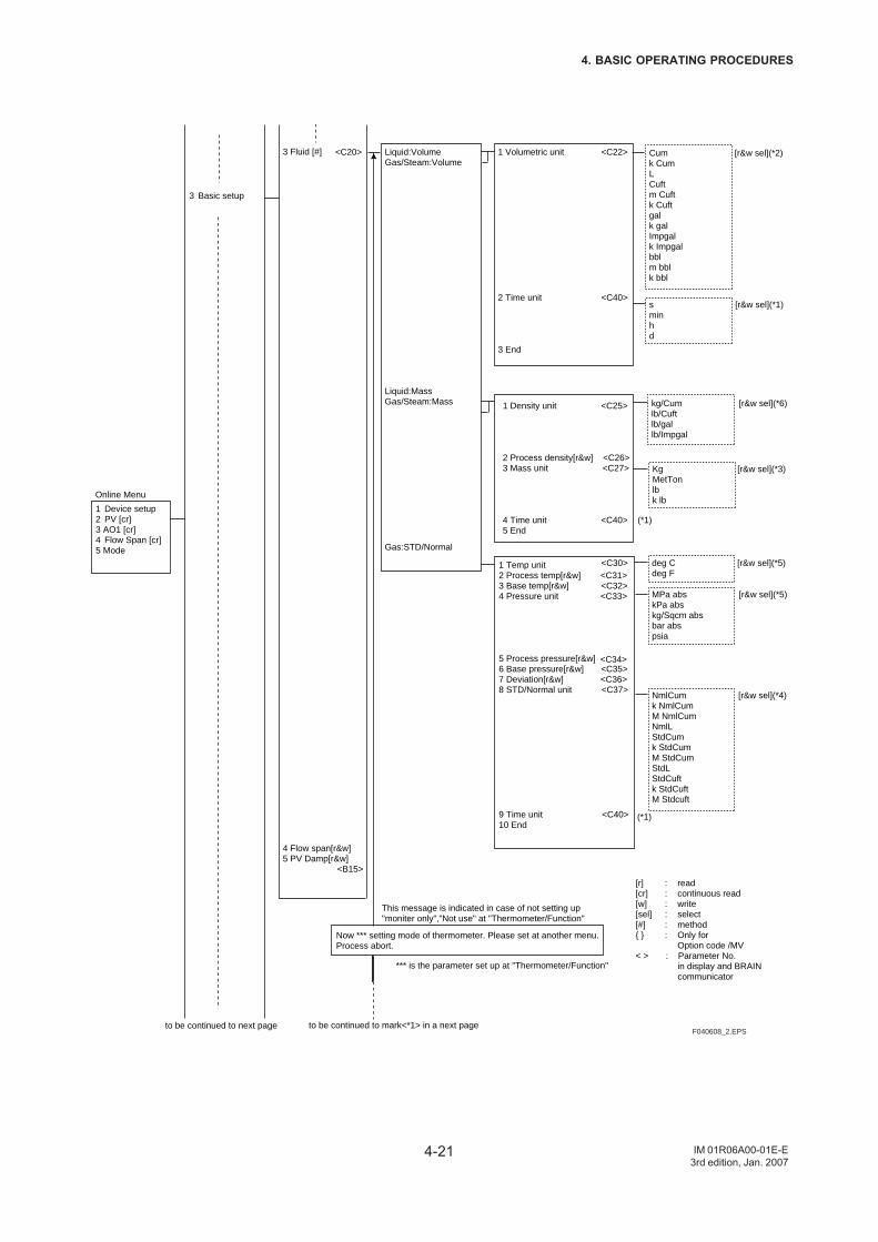
4-21
4. BASIC OPERATING PROCEDURES
IM 01R06A00-01E-E3rd edition, Jan. 2007
1 Device setup2 PV [cr]3 AO1 [cr]4 Flow Span [cr]5 Mode
3 Basic setup
3 Fluid [#]
4 Flow span[r&w]5 PV Damp[r&w] <B15>
Online Menu
to be continued to next page
Liquid:VolumeGas/Steam:Volume
Liquid:MassGas/Steam:Mass
Gas:STD/Normal
1 Volumetric unit <C22>
2 Time unit <C40>
3 End
Cum [r&w sel](*2)k CumLCuftm Cuftk Cuftgalk galImpgalk Impgalbblm bblk bbl
s [r&w sel](*1)minhd
1 Density unit <C25>
2 Process density[r&w] <C26>3 Mass unit <C27>
4 Time unit <C40> (*1)5 End
kg/Cum [r&w sel](*6)lb/Cuftlb/gallb/Impgal
Kg [r&w sel](*3)MetTonlbk lb
1 Temp unit2 Process temp[r&w] <C31>3 Base temp[r&w] <C32>4 Pressure unit <C33>
5 Process pressure[r&w]6 Base pressure[r&w] <C35>7 Deviation[r&w] <C36>8 STD/Normal unit <C37>
9 Time unit <C40> 10 End
deg C [r&w sel](*5)deg F
MPa abs [r&w sel](*5)kPa abskg/Sqcm absbar abspsia
NmlCum [r&w sel](*4)k NmlCumM NmlCumNmlLStdCumk StdCumM StdCumStdLStdCuftk StdCuftM Stdcuft
Now *** setting mode of thermometer. Please set at another menu. Process abort.
*** is the parameter set up at "Thermometer/Function"
This message is indicated in case of not setting up "moniter only","Not use" at "Thermometer/Function"
to be continued to mark<*1> in a next page
[r] : read[cr] : continuous read[w] : write[sel] : select[#] : method : Only for
Option code /MV< > : Parameter No. in display and BRAIN communicator
F040608_2.EPS
<C20>
<C34>
(*1)
<C30>
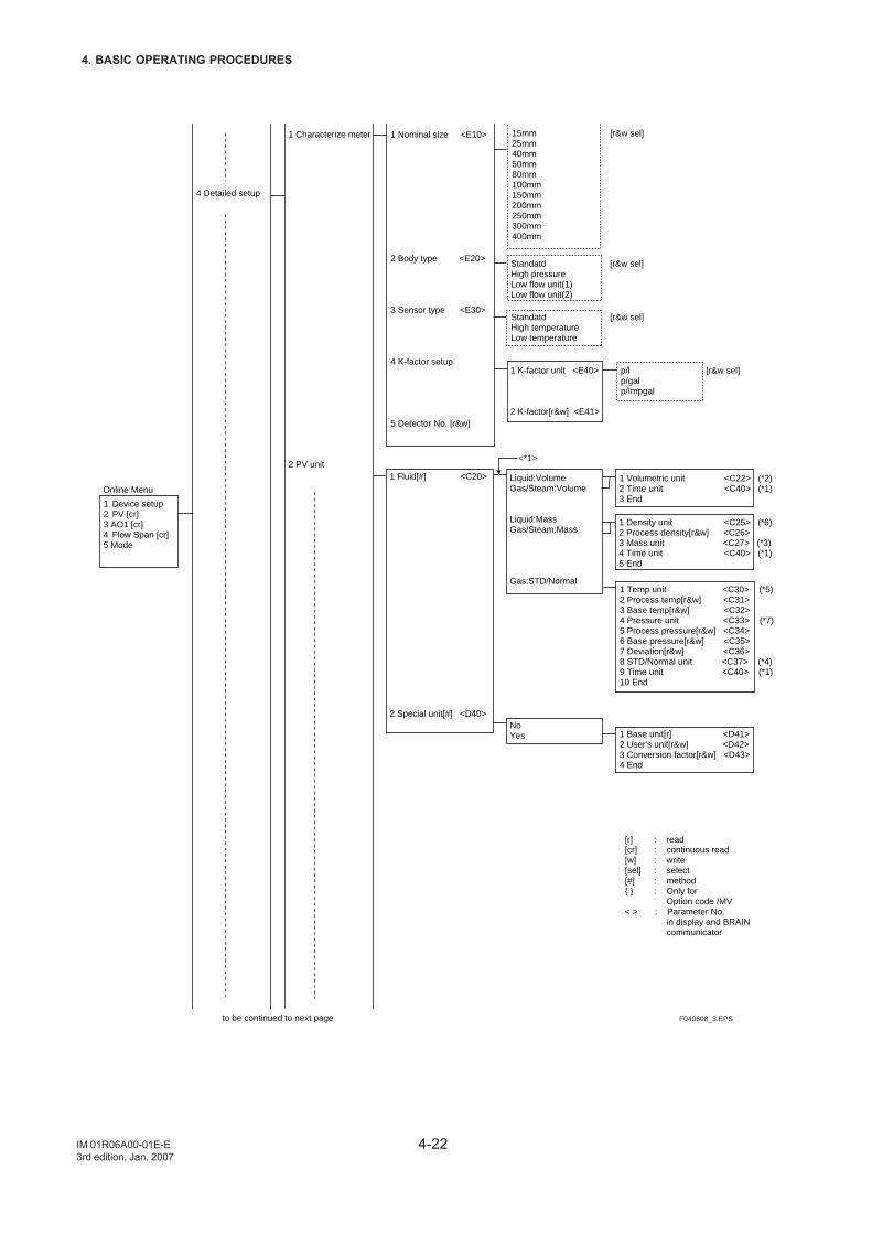
4-22
4. BASIC OPERATING PROCEDURES
IM 01R06A00-01E-E3rd edition, Jan. 2007
1 Device setup2 PV [cr]3 AO1 [cr]4 Flow Span [cr]5 Mode
4 Detailed setup
1 Characterize meter
2 PV unit
Online Menu
to be continued to next page
1 Nominal size <E10>
2 Body type <E20>
3 Sensor type <E30>
4 K-factor setup
5 Detector No. [r&w]
15mm [r&w sel]25mm40mm50mm80mm100mm150mm200mm250mm300mm400mm
Standatd [r&w sel]High pressureLow flow unit(1)Low flow unit(2)
1 K-factor unit <E40>
2 K-factor[r&w] <E41>
p/l [r&w sel]p/galp/Impgal
1 Temp unit <C30> (*5)2 Process temp[r&w] <C31>3 Base temp[r&w] <C32>4 Pressure unit <C33> (*7)5 Process pressure[r&w] <C34>6 Base pressure[r&w] <C35>7 Deviation[r&w] <C36>8 STD/Normal unit <C37> (*4)9 Time unit <C40> (*1)10 End
Standatd [r&w sel]High temperatureLow temperature
1 Fluid[#] <C20>
2 Special unit[#] <D40>
Liquid:VolumeGas/Steam:Volume
Liquid:MassGas/Steam:Mass
Gas:STD/Normal
1 Volumetric unit <C22> (*2)2 Time unit <C40> (*1)3 End
1 Density unit <C25> (*6)2 Process density[r&w] <C26>3 Mass unit <C27> (*3)4 Time unit <C40> (*1)5 End
NoYes 1 Base unit[r] <D41>
2 User's unit[r&w] <D42>3 Conversion factor[r&w] <D43>4 End
<*1>
[r] : read[cr] : continuous read[w] : write[sel] : select[#] : method : Only for
Option code /MV< > : Parameter No. in display and BRAIN communicator
F040608_3.EPS
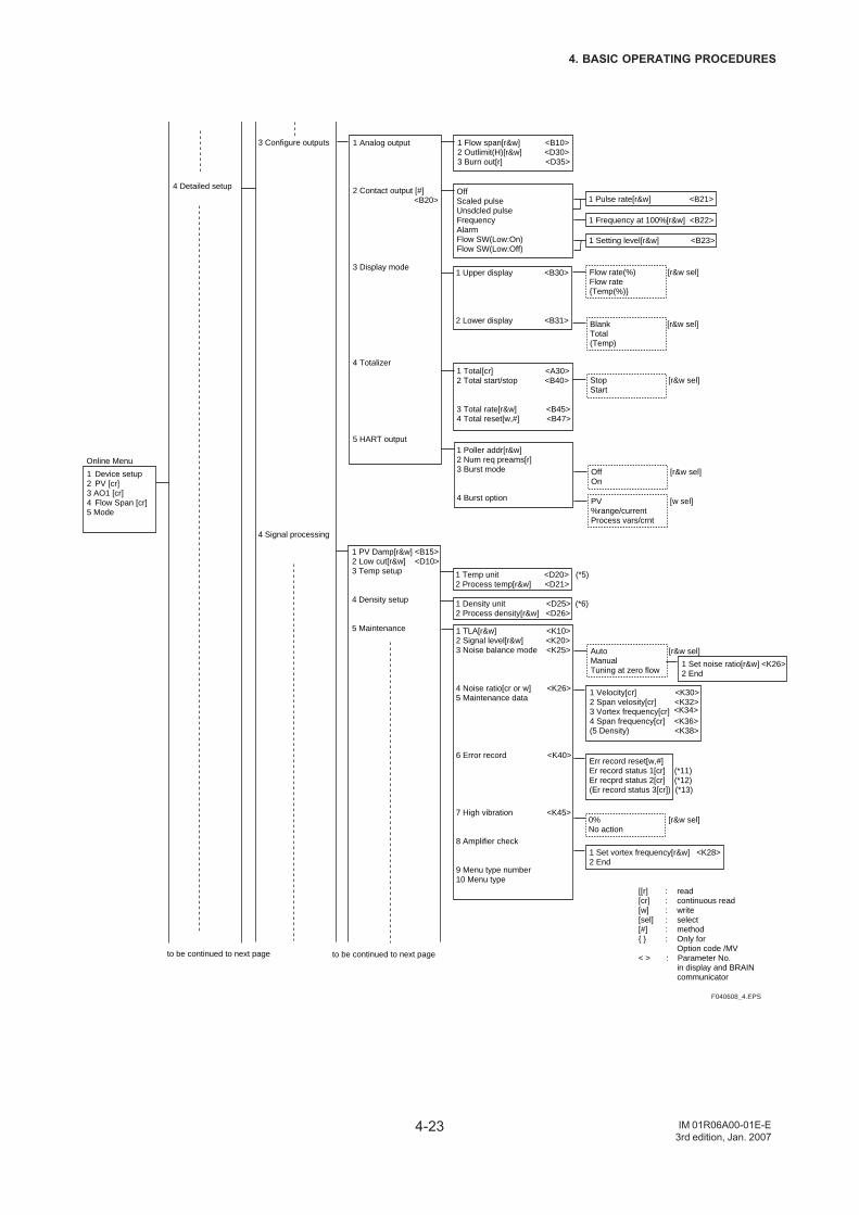
4-23
4. BASIC OPERATING PROCEDURES
IM 01R06A00-01E-E3rd edition, Jan. 2007
1 Device setup2 PV [cr]3 AO1 [cr]4 Flow Span [cr]5 Mode
4 Detailed setup
3 Configure outputs
4 Signal processing
Online Menu
to be continued to next page
1 Analog output
2 Contact output [#] <B20>
3 Display mode
4 Totalizer
5 HART output
Blank [r&w sel]Total(Temp)
1 Set noise ratio[r&w] <K26>2 End
1 Flow span[r&w] <B10>2 Outlimit(H)[r&w] <D30>3 Burn out[r] <D35>
1 TLA[r&w] <K10>2 Signal level[r&w] <K20>3 Noise balance mode <K25>
4 Noise ratio[cr or w] <K26>5 Maintenance data
6 Error record <K40>
7 High vibration <K45>
8 Amplifier check
9 Menu type number10 Menu type
1 PV Damp[r&w] <B15>2 Low cut[r&w] <D10>3 Temp setup
4 Density setup
5 Maintenance
1 Temp unit <D20> (*5)2 Process temp[r&w] <D21>
1 Pulse rate[r&w] <B21>OffScaled pulseUnsdcled pulseFrequencyAlarmFlow SW(Low:On)Flow SW(Low:Off)
1 Frequency at 100%[r&w] <B22>
1 Setting level[r&w] <B23>
1 Upper display <B30>
2 Lower display <B31>
Flow rate(%) [r&w sel]Flow rateTemp(%)
1 Total[cr] <A30>2 Total start/stop <B40>
3 Total rate[r&w] <B45>4 Total reset[w,#] <B47>
Stop [r&w sel]Start
1 Poller addr[r&w]2 Num req preams[r]3 Burst mode
4 Burst option
Off [r&w sel]On
PV [w sel]%range/currentProcess vars/crnt
1 Density unit <D25> (*6)2 Process density[r&w] <D26>
Auto [r&w sel]ManualTuning at zero flow
1 Velocity[cr] <K30>2 Span velosity[cr] <K32>3 Vortex frequency[cr]4 Span frequency[cr] <K36>(5 Density) <K38>
Err record reset[w,#]Er record status 1[cr] (*11)Er recprd status 2[cr] (*12)(Er record status 3[cr]) (*13)
0% [r&w sel]No action
1 Set vortex frequency[r&w] <K28>2 End
to be continued to next page
[[r] : read[cr] : continuous read[w] : write[sel] : select[#] : method : Only for
Option code /MV< > : Parameter No. in display and BRAIN communicator
F040608_4.EPS
<K34>
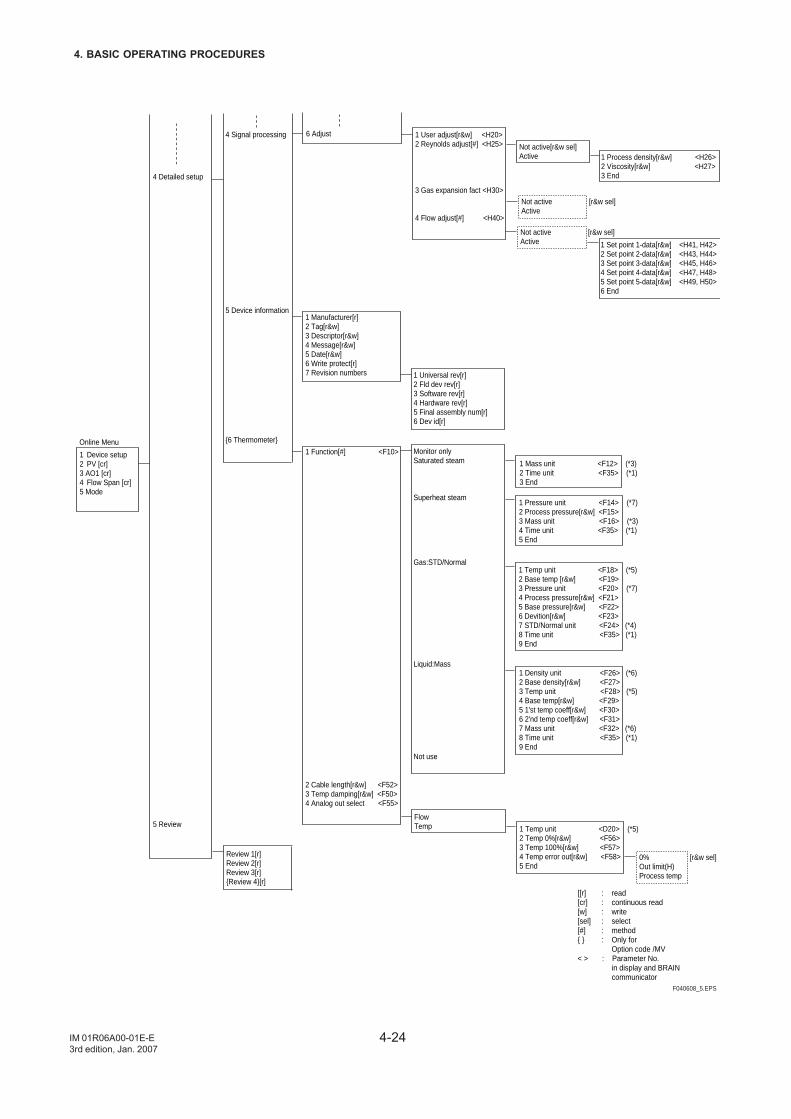
4-24
4. BASIC OPERATING PROCEDURES
IM 01R06A00-01E-E3rd edition, Jan. 2007
1 Device setup2 PV [cr]3 AO1 [cr]4 Flow Span [cr]5 Mode
4 Detailed setup
5 Review
4 Signal processing
5 Device information
6 ThermometerOnline Menu
6 Adjust
1 Process density[r&w] <H26>2 Viscosity[r&w] <H27>3 End
1 User adjust[r&w] <H20>2 Reynolds adjust[#] <H25>
3 Gas expansion fact <H30>
4 Flow adjust[#] <H40>
1 Manufacturer[r]2 Tag[r&w]3 Descriptor[r&w]4 Message[r&w]5 Date[r&w]6 Write protect[r]7 Revision numbers 1 Universal rev[r]
2 Fld dev rev[r]3 Software rev[r]4 Hardware rev[r]5 Final assembly num[r]6 Dev id[r]
Not active [r&w sel]Active
1 Mass unit <F12> (*3)2 Time unit <F35> (*1)3 End
Not active[r&w sel]Active
Not active [r&w sel]Active 1 Set point 1-data[r&w] <H41, H42>
2 Set point 2-data[r&w] <H43, H44>3 Set point 3-data[r&w] <H45, H46>4 Set point 4-data[r&w] <H47, H48>5 Set point 5-data[r&w] <H49, H50>6 End
1 Function[#] <F10>
2 Cable length[r&w] <F52>3 Temp damping[r&w] <F50>4 Analog out select <F55>
Monitor onlySaturated steam
Superheat steam
Gas:STD/Normal
Liquid:Mass
Not use
1 Pressure unit <F14> (*7)2 Process pressure[r&w] <F15>3 Mass unit <F16> (*3)4 Time unit <F35> (*1)5 End
1 Temp unit <F18> (*5) 2 Base temp [r&w] <F19>3 Pressure unit <F20> (*7)4 Process pressure[r&w] <F21>5 Base pressure[r&w] <F22>6 Devition[r&w] <F23>7 STD/Normal unit <F24> (*4)8 Time unit <F35> (*1)9 End
1 Density unit <F26> (*6)2 Base density[r&w] <F27>3 Temp unit <F28> (*5)4 Base temp[r&w] <F29>5 1'st temp coeff[r&w] <F30>6 2'nd temp coeff[r&w] <F31>7 Mass unit <F32> (*6)8 Time unit <F35> (*1)9 End
FlowTemp 1 Temp unit <D20> (*5)
2 Temp 0%[r&w] <F56>3 Temp 100%[r&w] <F57>4 Temp error out[r&w] <F58>5 End
0% [r&w sel]Out limit(H)Process temp
Review 1[r]Review 2[r]Review 3[r]Review 4[r]
[[r] : read[cr] : continuous read[w] : write[sel] : select[#] : method : Only for
Option code /MV< > : Parameter No. in display and BRAIN communicator
F040608_5.EPS
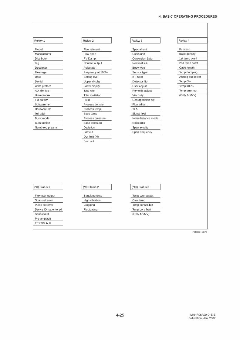
4-25
4. BASIC OPERATING PROCEDURES
IM 01R06A00-01E-E3rd edition, Jan. 2007
F040608_6.EPS
Review 1
Model
Manufacturer
Distributor
Tag
Descriptor
Message
Date
Dev id
Write protect
AO alrm typ
Universal rev
Fld dev rev
Software rev
Hardware rev
Poll addr
Burst mode
Burst option
Numb req preams
Review 2
Flow rate unit
Flow span
PV Damp
Contact output
Pulse rate
Frequency at 100%
Setting level
Upper display
Lower display
Total rate
Total start/stop
Fluid
Process density
Process temp
Base temp
Process pressure
Base pressure
Deviation
Low cut
Out limit (H)
Burn out
Review 3
Special unit
User’s unit
Conversion faetor
Nominal size
Body type
Sensor type
K - factor
Detector No.
User adjust
Reynolds adjust
Viscosity
Gas expansion fact
Flow adjust
TLA
Signal level
Noise balance mode
Noise ratio
Span velocity
Span frequency
Review 4
Function
Base density
1st temp coeff
2nd temp coeff
Cable length
Temp damping
Analog out select
Temp 0%
Temp 100%
Temp error out
(Only for /MV)
(*8) Status 1
Flow over output
Span set error
Pulse set error
Device ID nat entered
Sensor fault
Pre-amp fault
EEPROM fault
(*9) Status 2
Transient noise
High vibration
Clogging
Fluctuating
(*10) Status 3
Temp over output
Over temp
Temp sensor fault
Temp conv fault
(Only for /MV)

4-26
4. BASIC OPERATING PROCEDURES
IM 01R06A00-01E-E3rd edition, Jan. 2007
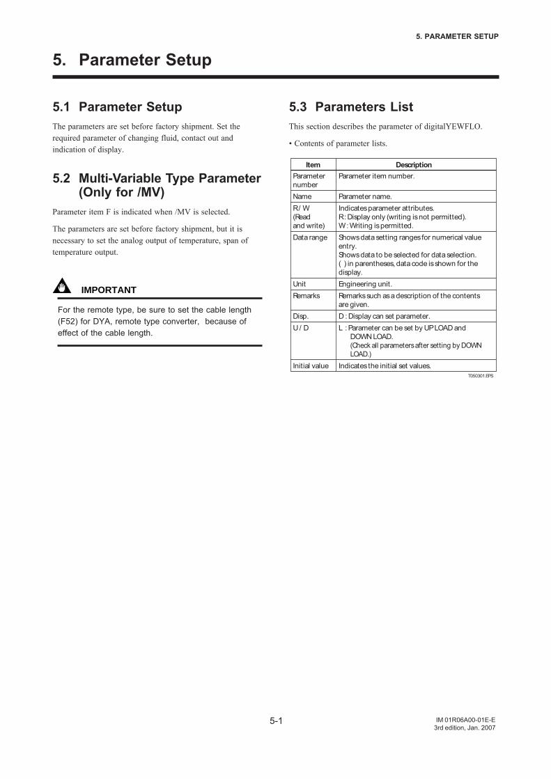
5-1
5. PARAMETER SETUP
IM 01R06A00-01E-E3rd edition, Jan. 2007
5. Parameter Setup
5.1 Parameter SetupThe parameters are set before factory shipment. Set therequired parameter of changing fluid, contact out andindication of display.
5.2 Multi-Variable Type Parameter(Only for /MV)
Parameter item F is indicated when /MV is selected.
The parameters are set before factory shipment, but it isnecessary to set the analog output of temperature, span oftemperature output.
IMPORTANT
For the remote type, be sure to set the cable length(F52) for DYA, remote type converter, because ofeffect of the cable length.
5.3 Parameters ListThis section describes the parameter of digitalYEWFLO.
• Contents of parameter lists.
T050301.EPS
ItemParameternumberNameR / W (Readand write)Data range
UnitRemarks
Disp.U / D
Initial value
Parameter item number.
Parameter name.Indicates parameter attributes.R : Display only (writing is not permitted).W : Writing is permitted.Shows data setting ranges for numerical value entry.Shows data to be selected for data selection.( ) in parentheses, data code is shown for the display.Engineering unit.Remarks such as a description of the contents are given.D : Display can set parameter.L : Parameter can be set by UP LOAD and
DOWN LOAD.(Check all parameters after setting by DOWN LOAD.)
Indicates the initial set values.
Description
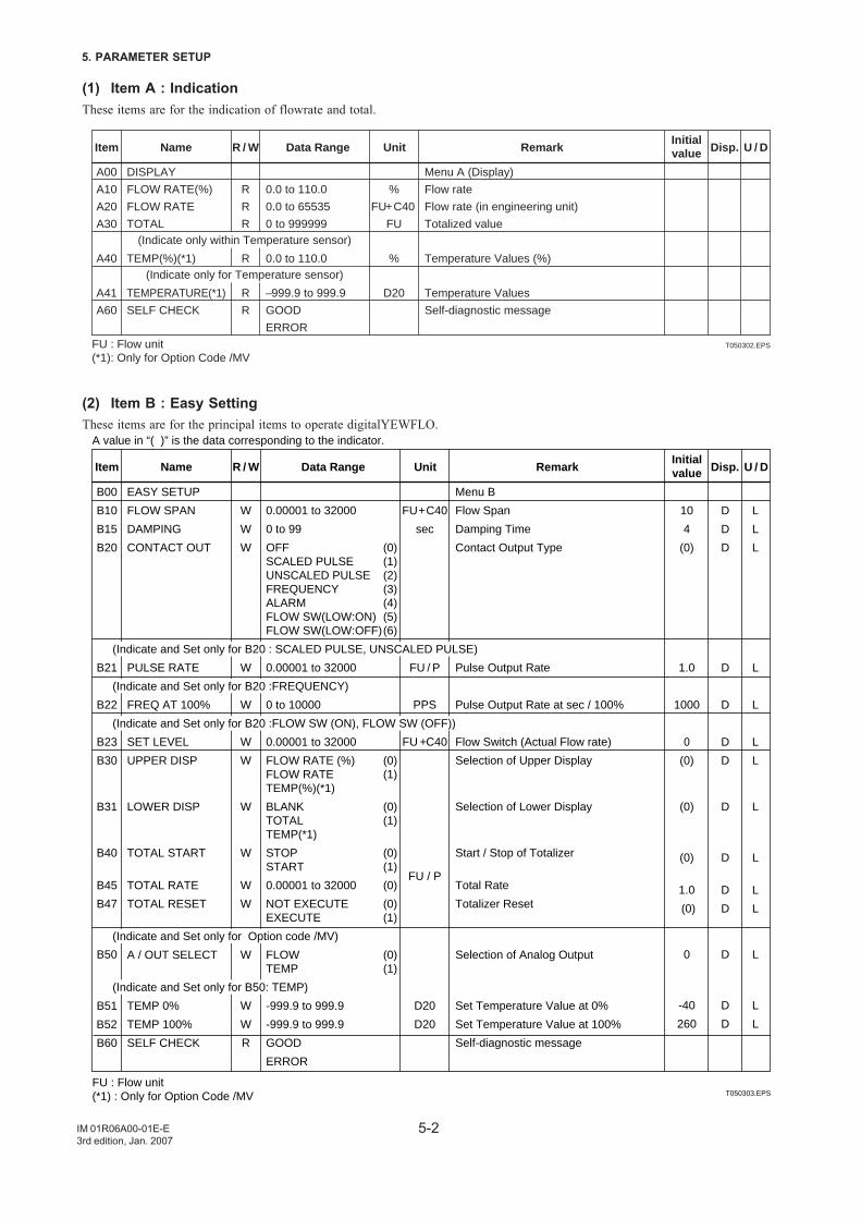
5-2
5. PARAMETER SETUP
IM 01R06A00-01E-E3rd edition, Jan. 2007
(1) Item A : IndicationThese items are for the indication of flowrate and total.
T050302.EPS
(Indicate only within Temperature sensor)
(Indicate only for Temperature sensor)
A00
A10
A20
A30
A40
A41
A60
R
R
R
R
R
R
%
FU+C40
FU
%
D20
DISPLAY
FLOW RATE(%)
FLOW RATE
TOTAL
TEMP(%)(*1)
TEMPERATURE(*1)
SELF CHECK
0.0 to 110.0
0.0 to 65535
0 to 999999
0.0 to 110.0
–999.9 to 999.9
GOOD
ERROR
Menu A (Display)
Flow rate
Flow rate (in engineering unit)
Totalized value
Temperature Values (%)
Temperature Values
Self-diagnostic message
Item Name R / W Data Range Unit RemarkInitialvalue Disp. U / D
FU : Flow unit(*1): Only for Option Code /MV
(2) Item B : Easy SettingThese items are for the principal items to operate digitalYEWFLO.
T050303.EPS
B00
B10
B15
B20
B21
B22
B23
B30
B31
B40
B45
B47
B50
B51
B60
W
W
W
W
W
W
W
W
W
W
W
W
W
W
R
FU + C40
sec
FU / P
PPS
FU +C40
FU / P
D20
D20
10
4
(0)
1.0
1000
0
(0)
(0)
(0)
1.0
(0)
0
-40
260
D
D
D
D
D
D
D
D
D
D
D
D
D
D
L
L
L
L
L
L
L
L
L
L
L
L
L
L
EASY SETUP
FLOW SPAN
DAMPING
CONTACT OUT
(Indicate and Set only for B20 : SCALED PULSE, UNSCALED PULSE)
PULSE RATE
(Indicate and Set only for B20 :FREQUENCY)
FREQ AT 100%
(Indicate and Set only for B20 :FLOW SW (ON), FLOW SW (OFF))
SET LEVEL
UPPER DISP
LOWER DISP
TOTAL START
TOTAL RATE
TOTAL RESET
(Indicate and Set only for Option code /MV)
A / OUT SELECT
(Indicate and Set only for B50: TEMP)
TEMP 0%
TEMP 100%
SELF CHECK
0.00001 to 32000
0 to 99
OFF (0)SCALED PULSE (1)UNSCALED PULSE (2)FREQUENCY (3)ALARM (4)FLOW SW(LOW:ON) (5)FLOW SW(LOW:OFF)(6)
0.00001 to 32000
0 to 10000
0.00001 to 32000
FLOW RATE (%) (0)FLOW RATE (1)TEMP(%)(*1)
BLANK (0)TOTAL (1)TEMP(*1)
STOP (0)START (1)
0.00001 to 32000 (0)
NOT EXECUTE (0)EXECUTE (1)
FLOW (0)TEMP (1)
-999.9 to 999.9
-999.9 to 999.9
GOOD
ERROR
Menu B
Flow Span
Damping Time
Contact Output Type
Pulse Output Rate
Pulse Output Rate at sec / 100%
Flow Switch (Actual Flow rate)
Selection of Upper Display
Selection of Lower Display
Start / Stop of Totalizer
Total Rate
Totalizer Reset
Selection of Analog Output
Set Temperature Value at 0%
Set Temperature Value at 100%
Self-diagnostic message
Item Name R / W Data Range Unit RemarkInitialvalue Disp. U / D
FU : Flow unit(*1) : Only for Option Code /MV
A value in “( )” is the data corresponding to the indicator.
B52
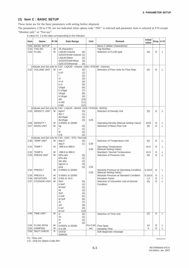
5-3
5. PARAMETER SETUP
IM 01R06A00-01E-E3rd edition, Jan. 2007
(3) Item C : BASIC SETUPThese items are for the basic parameters with setting before shipment.The parameters, C20 to C50, are not indicated when option code “/MV” is selected and parameter item is selected in F10 except“Monitor only” or “Not use”.
T050304.EPS
C00C10C20
C22
C25
C26C27
C30
C31
C32C33
C34
C35C36C37
C40
C45C50C60
WW
W
W
WW
W
W
WW
W
WWW
W
WWR
C25
C30
C30
C33
C33
FU+C40sec
(0)
(0)
(0)
1024(0)
(0)
15.0
15.0(0)
0.1013
0.10131.0(0)
(2)
104
D
D
D
DD
D
D DD
D DDD
D
DD
L
L
L
LL
L
L LL
L LLL
L
LL
BASIC SETUPTAG NO.FLUID
(Indicate and Set only for C20 : LIQUID : Volume, GAS / STEAM : Volume)VOLUME UNIT
(Indicate and Set only for C20 : LIQUID : MASS, GAS / STEAM : MASS)DENSITY UNIT
DENSITY fMASS UNIT
(Indicate and Set only for C20 : GAS : STD / Normal)TEMP UNIT
TEMP f TEMP bPRESS UNIT
PRESS f PRESS bDEVIATIONSTD/NOR UNIT
TIME UNIT
FLOW SPANDAMPINGSELF CHECK
16 charactersLIQUID:Volume (0)GAS/STEAM:Volume (1)LIQUID:Mass (2)GAS/STEAM:Mass (3)GAS:STD/Normal (4)
m3 (0)k m3 (1)l (2)cf (3)m cf (4)k cf (5)USgal (6)k USgal (7)UKgal (8)k UKgal (9)bbl (10)m bbl (11)k bbl (12)
kg/m3 (0)lb/c f (1)lb/USgal (2)lb/UKgal (3)0.00001 to 32000kg (0)t (1)lb (2)k lb (3)
deg C (0)deg F (1)-999.9 to 999.9 -999.9 to 999.9MPa abs (0)kPa abs (1)bar abs (2)kg/cm2 a (3)psia (4)0.00001 to 32000 0.00001 to 320000.001 to 10.0Nm3 (0)k Nm3 (1)M Nm3 (2)Nl (3)Sm3 (4)k Sm3 (5)M Sm3 (6)Sl (7)scf (8)k scf (9)M scf (10)/s (0)/m (1)/h (2)/d (3)0.00001 to 320000 to 99GOODERROR
Menu C (Meter characterize)Tag NumberSelection of FLUID type
Selection of Flow Units for Flow Rate
Selection of Density Unit
Operating Density (Manual Setting Value)Selection of Mass Flow Unit
Selection of Temperature Unit
Operating Temperature (Manual Setting Value)Standard / Normal TemperatureSelection of Pressure Unit
Absolute Pressure at Operating Condition (Manual Setting Value)Absolute Pressure at Standard ConditionDeviation FactorSelection of Volumetric Unit at Normal Condition
Selection of Time Unit
Flow SpanDamping Time Self-diagnostic message
Item Name R / W Data Range Unit RemarkInitialvalue Disp. U / D
FU : Flow unit(*1) : Only for Option Code /MV
A value in “( )” is the data corresponding to the indicator.
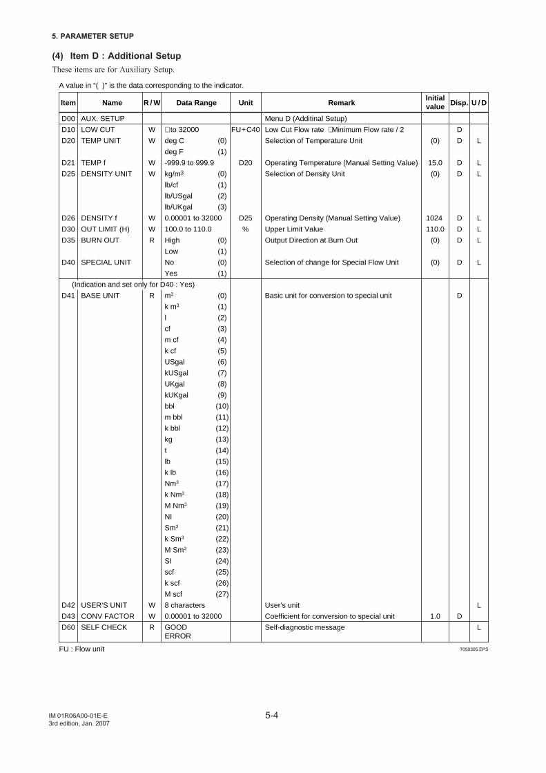
5-4
5. PARAMETER SETUP
IM 01R06A00-01E-E3rd edition, Jan. 2007
(4) Item D : Additional SetupThese items are for Auxiliary Setup.
T050305.EPS
D00
D10
D20
D21
D25
D26
D30
D35
D40
D41
D42
D43
D60
W
W
W
W
W
W
R
R
W
W
R
FU + C40
D20
D25
%
(0)
15.0
(0)
1024
110.0
(0)
(0)
1.0
D
D
D
D
D
D
D
D
D
D
L
L
L
L
L
L
L
L
L
AUX. SETUP
LOW CUT
TEMP UNIT
TEMP f
DENSITY UNIT
DENSITY f
OUT LIMIT (H)
BURN OUT
SPECIAL UNIT
(Indication and set only for D40 : Yes)
BASE UNIT
USER’S UNIT
CONV FACTOR
SELF CHECK
∗ to 32000
deg C (0)
deg F (1)
-999.9 to 999.9
kg/m3 (0)
lb/cf (1)
lb/USgal (2)
lb/UKgal (3)
0.00001 to 32000
100.0 to 110.0
High (0)
Low (1)
No (0)
Yes (1)
m3 (0)
k m3 (1)
l (2)
cf (3)
m cf (4)
k cf (5)
USgal (6)
kUSgal (7)
UKgal (8)
kUKgal (9)
bbl (10)
m bbl (11)
k bbl (12)
kg (13)
t (14)
lb (15)
k lb (16)
Nm3 (17)
k Nm3 (18)
M Nm3 (19)
NI (20)
Sm3 (21)
k Sm3 (22)
M Sm3 (23)
SI (24)
scf (25)
k scf (26)
M scf (27)
8 characters
0.00001 to 32000
GOODERROR
Menu D (Additinal Setup)
Low Cut Flow rate ∗ Minimum Flow rate / 2
Selection of Temperature Unit
Operating Temperature (Manual Setting Value)
Selection of Density Unit
Operating Density (Manual Setting Value)
Upper Limit Value
Output Direction at Burn Out
Selection of change for Special Flow Unit
Basic unit for conversion to special unit
User’s unit
Coefficient for conversion to special unit
Self-diagnostic message
Item Name R / W Data Range Unit RemarkInitialvalue Disp. U / D
FU : Flow unit
A value in “( )” is the data corresponding to the indicator.
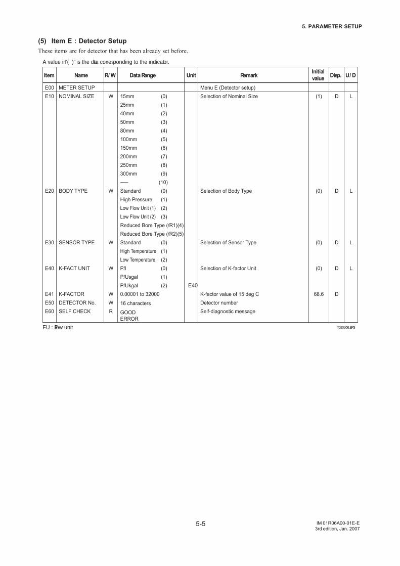
5-5
5. PARAMETER SETUP
IM 01R06A00-01E-E3rd edition, Jan. 2007
(5) Item E : Detector SetupThese items are for detector that has been already set before.
T050306.EPS
E00E10
E20
E30
E40
E41E50E60
W
W
W
W
WWR
E40
(1)
(0)
(0)
(0)
68.6
D
D
D
D
D
L
L
L
L
METER SETUPNOMINAL SIZE
BODY TYPE
SENSOR TYPE
K-FACT UNIT
K-FACTORDETECTOR No.SELF CHECK
15mm (0)25mm (1)40mm (2)50mm (3)80mm (4)100mm (5)150mm (6)200mm (7)250mm (8)300mm (9)-------- (10)Standard (0)High Pressure (1)Low Flow Unit (1) (2)Low Flow Unit (2) (3)Reduced Bore Type (/R1)(4)Reduced Bore Type (/R2)(5)Standard (0)High Temperature (1)Low Temperature (2)P/l (0)P/Usgal (1)P/Ukgal (2)0.00001 to 32000
16 characters
GOODERROR
Menu E (Detector setup)Selection of Nominal Size
Selection of Body Type
Selection of Sensor Type
Selection of K-factor Unit
K-factor value of 15 deg CDetector numberSelf-diagnostic message
Item Name R / W Data Range Unit Remark Initialvalue Disp. U / D
FU : Flow unit
A value in “( )” is the data corresponding to the indicator.
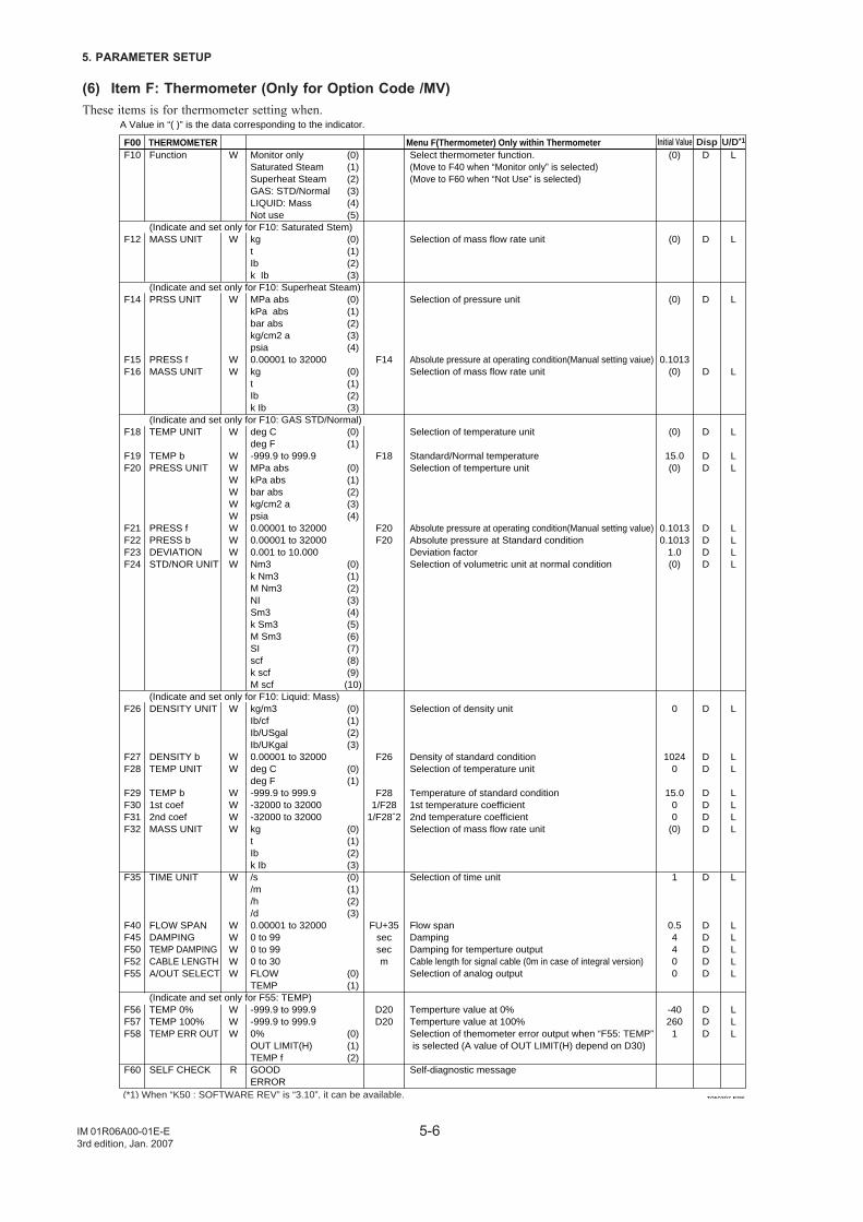
5-6
5. PARAMETER SETUP
IM 01R06A00-01E-E3rd edition, Jan. 2007
(6) Item F: Thermometer (Only for Option Code /MV)These items is for thermometer setting when.
F10
F12
F14
F15F16
F18
F19F20
F21F22F23F24
F26
F27F28
F29F30F31F32
F35
F40F45F50F52F55
F56F57F58
F60
W
W
W
WW
W
WWWWWWWWWW
W
WW
WWWW
W
WWWWW
WWW
R
F14
F18
F20F20
F26
F281/F28
1/F28ˆ2
FU+35secsecm
D20D20
(0)
(0)
(0)
0.1013(0)
(0)
15.0(0)
0.10130.1013
1.0(0)
0
10240
15.000
(0)
1
0.54400
-402601
D
D
D
D
D
DD
DDDD
D
DD
DDDD
D
DDDDD
DDD
L
L
L
L
L
LL
LLLL
L
LL
LLLL
L
LLLLL
LLL
Function
(Indicate and set only for F10: Saturated Stem)MASS UNIT
(Indicate and set only for F10: Superheat Steam)PRSS UNIT
PRESS fMASS UNIT
(Indicate and set only for F10: GAS STD/Normal)TEMP UNIT
TEMP bPRESS UNIT
PRESS fPRESS bDEVIATIONSTD/NOR UNIT
(Indicate and set only for F10: Liquid: Mass)DENSITY UNIT
DENSITY bTEMP UNIT
TEMP b1st coef2nd coefMASS UNIT
TIME UNIT
FLOW SPANDAMPINGTEMP DAMPINGCABLE LENGTHA/OUT SELECT
(Indicate and set only for F55: TEMP)TEMP 0%TEMP 100%TEMP ERR OUT
SELF CHECK
Monitor only (0)Saturated Steam (1)Superheat Steam (2)GAS: STD/Normal (3)LIQUID: Mass (4)Not use (5)
kg (0)t (1)Ib (2)k Ib (3)
MPa abs (0)kPa abs (1)bar abs (2)kg/cm2 a (3)psia (4)0.00001 to 32000kg (0)t (1)Ib (2)k Ib (3)
deg C (0)deg F (1)-999.9 to 999.9MPa abs (0)kPa abs (1)bar abs (2)kg/cm2 a (3)psia (4)0.00001 to 320000.00001 to 320000.001 to 10.000Nm3 (0)k Nm3 (1)M Nm3 (2)NI (3)Sm3 (4)k Sm3 (5)M Sm3 (6)SI (7)scf (8)k scf (9)M scf (10)
kg/m3 (0)Ib/cf (1)Ib/USgal (2)Ib/UKgal (3)0.00001 to 32000deg C (0)deg F (1)-999.9 to 999.9-32000 to 32000-32000 to 32000kg (0)t (1)Ib (2)k Ib (3)/s (0)/m (1)/h (2)/d (3)0.00001 to 320000 to 990 to 990 to 30FLOW (0)TEMP (1)
-999.9 to 999.9-999.9 to 999.90% (0)OUT LIMIT(H) (1)TEMP f (2)GOODERROR
Select thermometer function.(Move to F40 when “Monitor only” is selected)(Move to F60 when “Not Use” is selected)
Selection of mass flow rate unit
Selection of pressure unit
Absolute pressure at operating condition(Manual setting vaiue)Selection of mass flow rate unit
Selection of temperature unit
Standard/Normal temperatureSelection of temperture unit
Absolute pressure at operating condition(Manual setting value)Absolute pressure at Standard conditionDeviation factorSelection of volumetric unit at normal condition
Selection of density unit
Density of standard conditionSelection of temperature unit
Temperature of standard condition1st temperature coefficient2nd temperature coefficientSelection of mass flow rate unit
Selection of time unit
Flow spanDampingDamping for temperture outputCable length for signal cable (0m in case of integral version)Selection of analog output
Temperture value at 0%Temperture value at 100%Selection of themometer error output when “F55: TEMP” is selected (A value of OUT LIMIT(H) depend on D30)
Self-diagnostic message
F00 THERMOMETER Menu F(Thermometer) Only within Thermometer
A Value in “( )” is the data corresponding to the indicator.
(*1) When “K50 : SOFTWARE REV” is “3.10”, it can be available.
U/D*1DispInitial Value
T050307.EPS
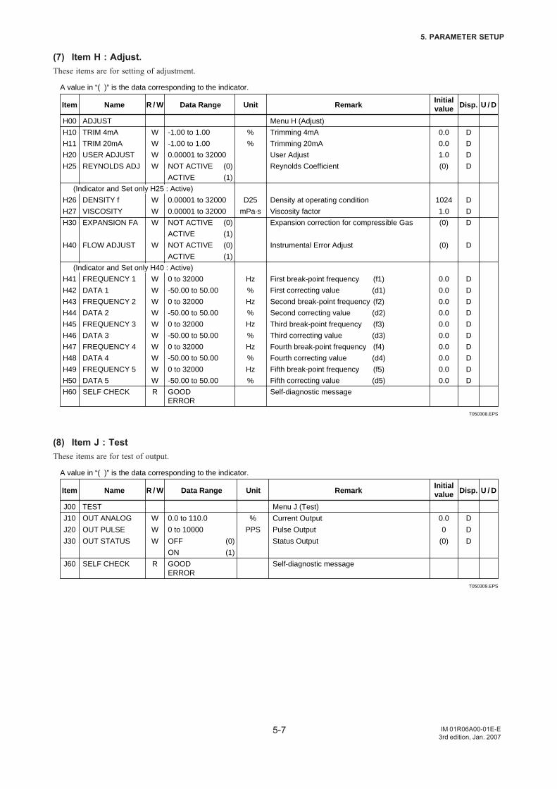
5-7
5. PARAMETER SETUP
IM 01R06A00-01E-E3rd edition, Jan. 2007
(7) Item H : Adjust.These items are for setting of adjustment.
T050308.EPS
H00
H10
H11
H20
H25
H26
H27
H30
H40
H41
H42
H43
H44
H45
H46
H47
H48
H49
H50
H60
W
W
W
W
W
W
W
W
W
W
W
W
W
W
W
W
W
W
R
%
%
D25
mPa.s
Hz
%
Hz
%
Hz
%
Hz
%
Hz
%
0.0
0.0
1.0
(0)
1024
1.0
(0)
(0)
0.0
0.0
0.0
0.0
0.0
0.0
0.0
0.0
0.0
0.0
D
D
D
D
D
D
D
D
D
D
D
D
D
D
D
D
D
D
ADJUST
TRIM 4mA
TRIM 20mA
USER ADJUST
REYNOLDS ADJ
(Indicator and Set only H25 : Active)
DENSITY f
VISCOSITY
EXPANSION FA
FLOW ADJUST
(Indicator and Set only H40 : Active)
FREQUENCY 1
DATA 1
FREQUENCY 2
DATA 2
FREQUENCY 3
DATA 3
FREQUENCY 4
DATA 4
FREQUENCY 5
DATA 5
SELF CHECK
-1.00 to 1.00
-1.00 to 1.00
0.00001 to 32000
NOT ACTIVE (0)
ACTIVE (1)
0.00001 to 32000
0.00001 to 32000
NOT ACTIVE (0)
ACTIVE (1)
NOT ACTIVE (0)
ACTIVE (1)
0 to 32000
-50.00 to 50.00
0 to 32000
-50.00 to 50.00
0 to 32000
-50.00 to 50.00
0 to 32000
-50.00 to 50.00
0 to 32000
-50.00 to 50.00
GOODERROR
Menu H (Adjust)
Trimming 4mA
Trimming 20mA
User Adjust
Reynolds Coefficient
Density at operating condition
Viscosity factor
Expansion correction for compressible Gas
Instrumental Error Adjust
First break-point frequency (f1)
First correcting value (d1)
Second break-point frequency (f2)
Second correcting value (d2)
Third break-point frequency (f3)
Third correcting value (d3)
Fourth break-point frequency (f4)
Fourth correcting value (d4)
Fifth break-point frequency (f5)
Fifth correcting value (d5)
Self-diagnostic message
Item Name R / W Data Range Unit RemarkInitialvalue Disp. U / D
A value in “( )” is the data corresponding to the indicator.
(8) Item J : TestThese items are for test of output.
T050309.EPS
J00
J10
J20
J30
J60
W
W
W
R
%
PPS
0.0
0
(0)
D
D
D
TEST
OUT ANALOG
OUT PULSE
OUT STATUS
SELF CHECK
0.0 to 110.0
0 to 10000
OFF (0)
ON (1)
GOODERROR
Menu J (Test)
Current Output
Pulse Output
Status Output
Self-diagnostic message
Item Name R / W Data Range Unit RemarkInitialvalue Disp. U / D
A value in “( )” is the data corresponding to the indicator.
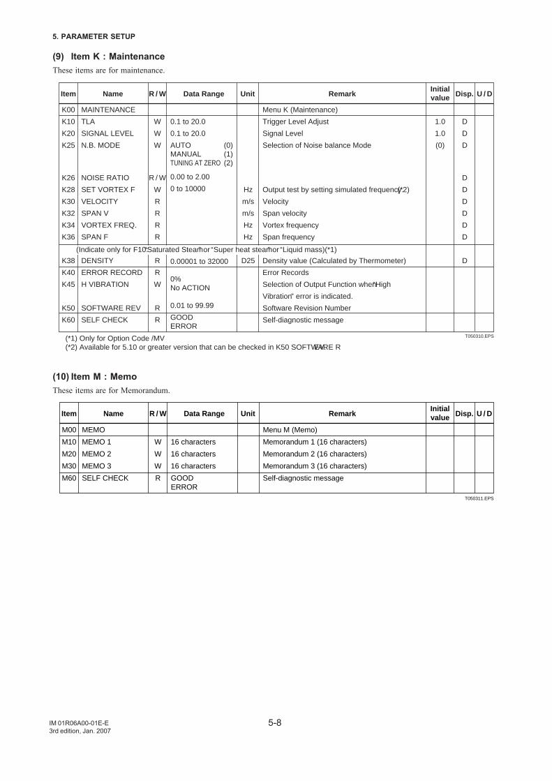
5-8
5. PARAMETER SETUP
IM 01R06A00-01E-E3rd edition, Jan. 2007
(9) Item K : MaintenanceThese items are for maintenance.
T050310.EPS
K00
K10
K20
K25
K26
K28
K30
K32
K34
K36
K38
K40
K45
K50
K60
W
W
W
R / W
W
R
R
R
R
R
R
W
R
R
Hz
m/s
m/s
Hz
Hz
D25
1.0
1.0
(0)
D
D
D
D
D
D
D
D
D
D
MAINTENANCE
TLA
SIGNAL LEVEL
N.B. MODE
NOISE RATIO
SET VORTEX F
VELOCITY
SPAN V
VORTEX FREQ.
SPAN F
DENSITY
ERROR RECORD
H VIBRATION
SOFTWARE REV
SELF CHECK
0.1 to 20.0
0.1 to 20.0
AUTO (0)MANUAL (1)TUNING AT ZERO (2)
0.00 to 2.00
0 to 10000
0.00001 to 32000
0%No ACTION
0.01 to 99.99
GOODERROR
Menu K (Maintenance)
Trigger Level Adjust
Signal Level
Selection of Noise balance Mode
Output test by setting simulated frequency.(*2)
Velocity
Span velocity
Vortex frequency
Span frequency
Density value (Calculated by Thermometer)
Error Records
Selection of Output Function when “High
Vibration” error is indicated.
Software Revision Number
Self-diagnostic message
Item Name R / W Data Range Unit RemarkInitialvalue Disp. U / D
(Indicate only for F10: “Saturated Steam” or “Super heat steam” or “Liquid mass)(*1)
(*1) Only for Option Code /MV(*2) Available for 5.10 or greater version that can be checked in K50 SOFTWARE REV.
(10) Item M : MemoThese items are for Memorandum.
T050311.EPS
M00
M10
M20
M30
M60
W
W
W
R
MEMO
MEMO 1
MEMO 2
MEMO 3
SELF CHECK
16 characters
16 characters
16 characters
GOODERROR
Menu M (Memo)
Memorandum 1 (16 characters)
Memorandum 2 (16 characters)
Memorandum 3 (16 characters)
Self-diagnostic message
Item Name R / W Data Range Unit RemarkInitialvalue Disp. U / D
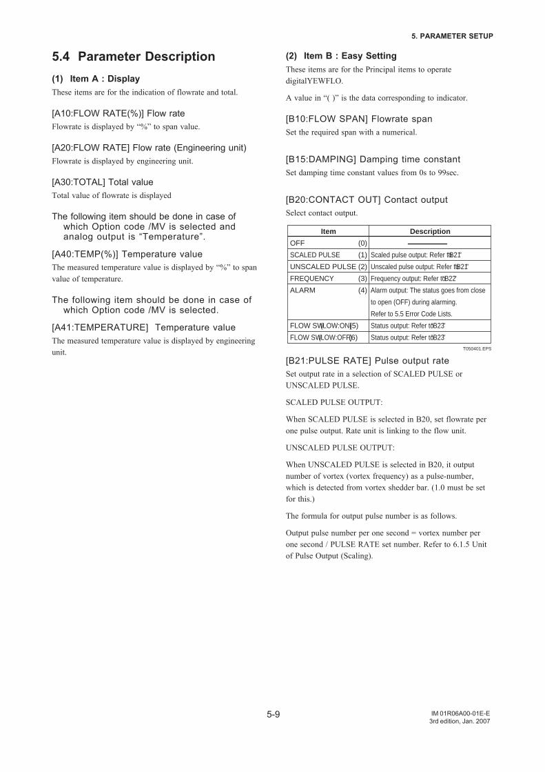
5-9
5. PARAMETER SETUP
IM 01R06A00-01E-E3rd edition, Jan. 2007
5.4 Parameter Description(1) Item A : DisplayThese items are for the indication of flowrate and total.
[A10:FLOW RATE(%)] Flow rateFlowrate is displayed by “%” to span value.
[A20:FLOW RATE] Flow rate (Engineering unit)Flowrate is displayed by engineering unit.
[A30:TOTAL] Total valueTotal value of flowrate is displayed
The following item should be done in case ofwhich Option code /MV is selected andanalog output is “Temperature”.
[A40:TEMP(%)] Temperature valueThe measured temperature value is displayed by “%” to spanvalue of temperature.
The following item should be done in case ofwhich Option code /MV is selected.
[A41:TEMPERATURE] Temperature valueThe measured temperature value is displayed by engineeringunit.
(2) Item B : Easy SettingThese items are for the Principal items to operatedigitalYEWFLO.
A value in “( )” is the data corresponding to indicator.
[B10:FLOW SPAN] Flowrate spanSet the required span with a numerical.
[B15:DAMPING] Damping time constantSet damping time constant values from 0s to 99sec.
[B20:CONTACT OUT] Contact outputSelect contact output.
T050401.EPS
OFF (0)
SCALED PULSE (1)
UNSCALED PULSE (2)
FREQUENCY (3)
ALARM (4)
FLOW SW (LOW:ON) (5)
FLOW SW (LOW:OFF) (6)
Scaled pulse output: Refer to “B21”
Unscaled pulse output: Refer to “B21”
Frequency output: Refer to “B22”
Alarm output: The status goes from close
to open (OFF) during alarming.
Refer to 5.5 Error Code Lists.
Status output: Refer to “B23”
Status output: Refer to “B23”
Item Description
[B21:PULSE RATE] Pulse output rateSet output rate in a selection of SCALED PULSE orUNSCALED PULSE.
SCALED PULSE OUTPUT:
When SCALED PULSE is selected in B20, set flowrate perone pulse output. Rate unit is linking to the flow unit.
UNSCALED PULSE OUTPUT:
When UNSCALED PULSE is selected in B20, it outputnumber of vortex (vortex frequency) as a pulse-number,which is detected from vortex shedder bar. (1.0 must be setfor this.)
The formula for output pulse number is as follows.
Output pulse number per one second = vortex number perone second / PULSE RATE set number. Refer to 6.1.5 Unitof Pulse Output (Scaling).
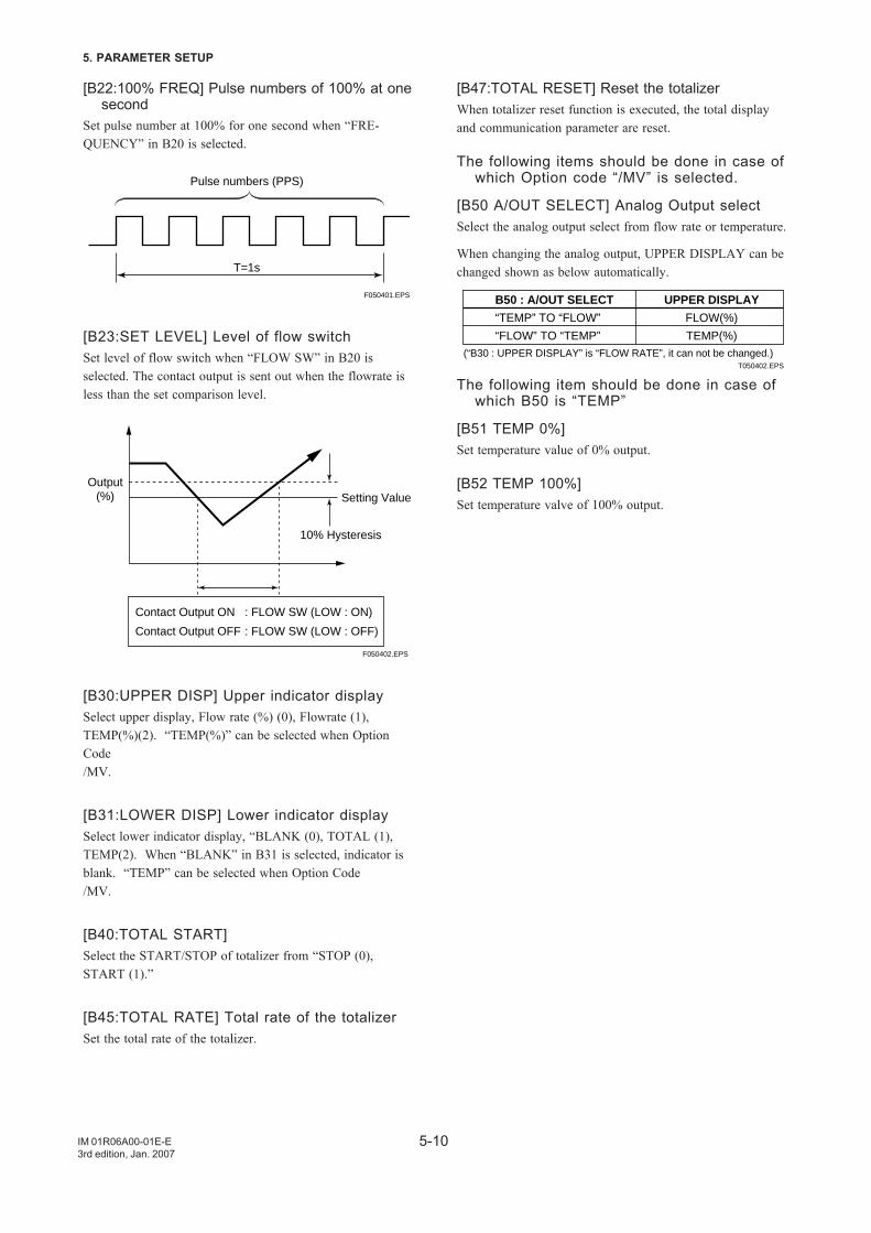
5-10
5. PARAMETER SETUP
IM 01R06A00-01E-E3rd edition, Jan. 2007
[B22:100% FREQ] Pulse numbers of 100% at onesecond
Set pulse number at 100% for one second when “FRE-QUENCY” in B20 is selected.
F050401.EPS
Pulse numbers (PPS)
T=1s
[B23:SET LEVEL] Level of flow switchSet level of flow switch when “FLOW SW” in B20 isselected. The contact output is sent out when the flowrate isless than the set comparison level.
Output(%) Setting Value
10% Hysteresis
Contact Output ON : FLOW SW (LOW : ON)
Contact Output OFF : FLOW SW (LOW : OFF)
F050402.EPS
[B30:UPPER DISP] Upper indicator displaySelect upper display, Flow rate (%) (0), Flowrate (1),TEMP(%)(2). “TEMP(%)” can be selected when OptionCode/MV.
[B31:LOWER DISP] Lower indicator displaySelect lower indicator display, “BLANK (0), TOTAL (1),TEMP(2). When “BLANK” in B31 is selected, indicator isblank. “TEMP” can be selected when Option Code/MV.
[B40:TOTAL START]Select the START/STOP of totalizer from “STOP (0),START (1).”
[B45:TOTAL RATE] Total rate of the totalizerSet the total rate of the totalizer.
[B47:TOTAL RESET] Reset the totalizerWhen totalizer reset function is executed, the total displayand communication parameter are reset.
The following items should be done in case ofwhich Option code “/MV” is selected.
[B50 A/OUT SELECT] Analog Output selectSelect the analog output select from flow rate or temperature.
When changing the analog output, UPPER DISPLAY can bechanged shown as below automatically.
B50 : A/OUT SELECT
“TEMP” TO “FLOW”
“FLOW” TO “TEMP”
UPPER DISPLAY
FLOW(%)
TEMP(%)(“B30 : UPPER DISPLAY” is “FLOW RATE”, it can not be changed.)
T050402.EPS
The following item should be done in case ofwhich B50 is “TEMP”
[B51 TEMP 0%]Set temperature value of 0% output.
[B52 TEMP 100%]Set temperature valve of 100% output.
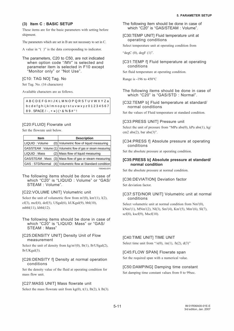
5-11
5. PARAMETER SETUP
IM 01R06A00-01E-E3rd edition, Jan. 2007
(3) Item C : BASIC SETUPThese items are for the basic parameters with setting beforeshipment.
The parameters which are set in B are not necessary to set in C.
A value in “( )” is the data corresponding to indicator.
The parameters, C20 to C50, are not indicatedwhen option code “/MV” is selected andparameter item is selected in F10 except“Monitor only” or “Not Use”.
[C10: TAG NO] Tag. NoSet Tag. No. (16 characters)
Available characters are as follows.
A B C D E F G H I J K L M N O P Q R S T U V W X Y Z a
b c d e f g h i j k l m n o p q r s t u v w x y z 0 1 2 3 4 5 6 7
8 9 . SPACE / - , + * ) ( ’ & % $ # “ !
[C20:FLUID] Flowrate unitSet the flowrate unit below.
T050403.EPS
LIQUID : Volume (0)
GAS/STEAM : Volume (1)
LIQUID : Mass (2)
GAS/STEAM : Mass (3)
GAS : STD/Normal (4)
Volumetric flow of Iiquid measuring
Volumetric flow of gas or steam measuring
Mass flow of liquid measuring
Mass flow of gas or steam measuring
Volumetric flow at Standard condition
Item Description
The following items should be done in case ofwhich “C20” is “LIQUID : Volume” or “GAS/STEAM : Volume”.
[C22:VOLUME UNIT] Volumetric unitSelect the unit of volumetric flow from m3(0), km3(1), l(2),cf(3), mcf(4), def(5), USgal(6), kUKgal(9), bbl(10),mbbl(11), kbbl(12).
The following items should be done in case ofwhich “C20” is “LIQUID: Mass” or “GAS/STEAM : Mass”
[C25:DENSITY UNIT] Density Unit of Flowmeasurement
Select the unit of density from kg/m3(0), lb(1), lb/USgal(2),lb/UKgal(3).
[C26:DENSITY f] Density at normal operationconditions
Set the density value of the fluid at operating condition formass flow unit.
[C27:MASS UNIT] Mass flowrate unitSelect the mass flowrate unit from kg(0), t(1), lb(2), k lb(3).
The following item should be done in case ofwhich “C20” is “GAS/STEAM : Volume”.
[C30:TEMP UNIT] Fluid temperature unit atoperating conditions
Select temperature unit at operating condition from
“degC (0), degF (1)”.
[C31:TEMP f] Fluid temperature at operatingconditions
Set fluid temperature at operating condition.
Range is -196 to 450°C
The following items should be done in case ofwhich “C20” is “GAS/STD : Normal”.
[C32:TEMP b] Fluid temperature at standard/normal conditions
Set the values of Fluid temperature at standard condition.
[C33:PRESS UNIT] Pressure unitSelect the unit of pressure from “MPa abs(0), kPa abs(1), kg/cm2 abs(2), bar abs(3)”.
[C34:PRESS f] Absolute pressure at operatingconditions
Set the absolute pressure at operating condition.
[C35:PRESS b] Absolute pressure at standard/normal condition
Set the absolute pressure at normal condition.
[C36:DEVIATION] Deviation factorSet deviation factor.
[C37:STD/NOR UNIT] Volumetric unit at normalconditions
Select volumetric unit at normal condition from Nm3(0),kNm3(1), MNm3(2), Nl(3), Sm3(4), Km3(5), Mm3(6), Sl(7),scf(8), kscf(9), Mscf(10).
[C40:TIME UNIT] TIME UNITSelect time unit from “/s(0), /m(1), /h(2), d(3)”
[C45:FLOW SPAN] Flowrate spanSet the required span with a numerical value.
[C50:DAMPING] Damping time constantSet damping time constant values from 0 to 99sec.
5-12
5. PARAMETER SETUP
IM 01R06A00-01E-E3rd edition, Jan. 2007
(4) Item D (AUX SETUP)These items are for Auxiliary setup.
A value in “( )” is the data corresponding to indicator.
[D10:LOW CUT] Low-cut flowrate
NOTE
For D10 setting, be sure to set “NOMINAL SIZE”in E10 firstly.
Set to noise elimination or zero flow in the low flowrate (orlow frequency) range. The settable range for low cut flowrateis more than half-minimum flowrate.
NOTE
D10: LOW CUT can be set after the items forcompensations (H25, H30, H40) are set to“ACTIVE”.
[D20:TEMP UNIT] Fluid temperature unit atoperating conditions
Select temperature unit at operating condition from“degC (0), degF (1)”.
[D21:TEMP f] Fluid temperature at operatingconditions
Set fluid temperature at operating condition.
Range is -196 to 450°C
[D25:DENSITY UNIT] Density Unit of Flowmeasurement
Select the unit of density from kg/m3(0), lb(1), lb/USgal(2),lb/UKgal(3).
[D26:DENSITY f] Density at normal operationconditions
Set the density value of the fluid at operating condition formass flow unit
[D30:OUT LIMIT] Limit value of output andindication
Set limit value of output from 100.0% to 110.0%
[D35:BURN OUT] Indication of the outputdirection at burn out
This is indication of the output direction at burn out. Refer to“6.1.6 Burn out” when the output direction can be changed.
[D40:SPECIAL UNIT] Change to specialflowrate unit
Select the availability of changing to special flowrate Unitfrom “No(0)” or “Yes(1)”
[D41:BASE UNIT] Indication of the specialflowrate unit
Indication of the basic flowrate unit when item D40 is“Yes(1)”
[D42:USER'S UNIT] Free unit for usersSet in up to 8 alphanumeric characters when item D40 is“Yes(1)”
5-13
5. PARAMETER SETUP
IM 01R06A00-01E-E3rd edition, Jan. 2007
(5) Item E (METER SETUP)These items are for detector set up that has already been setbefore shipment.
A value in “( )” is the data corresponding to indicator.
[E10:NOMINAL SIZE] Nominal size of thedetector
Select the nominal size of the flowmeter, from “15mm(0),25mm(1), 40mm(2), 50mm(3), 80mm(4), 100mm(5),150mm(6), 200mm(7), 250mm(8), 300mm(9)”
[E20:BODY TYPE] Body type for the detectorSelect body type for detector from standard or high pressure.Standard (0) : Standard typeHigh Pressure (1) : High Pressure type (tokuchu)Low Flow Unit (1) (2) : Reduced Bore type (option : /R1)Low Flow Unit (2) (3) : Reduced Bore type (option : /R2)
NOTE
Parameter setting for the Reduced Bore type,Select Low Flow Unit (1) or (2) and set. Setnominal size of the model code to E10:NOMINAL SIZE.
[E30:SENSOR TYPE] Sensor type for thedetector
Select sensor type for the detector from standard or HT/LT
[E40:K-FACTOR UNIT],Select this unit from p/l, p/Usgal, p/Ukgal.
[E41:K-FACTOR]The flowmeter data plate includes a K-factor (KM) at 15°Cfor the combined detector.
[E50:DETECTOR NO.] Detector number offlowmeter
Set the serial number using 16 alphanumeric characters of thedetector combined converter.
(6) ltem F (Thermometer)These items are for setting of thermometer and availablewhen build in thermometer type (Option code: /MV).
[F10: Function] Thermometer functionSelect the thermometer function.
Monitor only(0): Only temperature measurement.
Saturated Steam: Mass Flow rate is calculated from densityvalues by temperature measurementusing saturated steam table.
Superheat Steam: Mass Flow rate is calculated from densityvalues by temperature measured by usingsteam table. In order to measuresuperheat steam. It is necessary to makeconstant pressure value.
GAS: STD/Normal: Volumetric flow rate at standardcondition is calculated by using Pressure-Temperature correction. It is necessary tomale constant pressure value.
Liquid: Mass: Mass flow rate is calculated by using thedensity change values depend ontemperature values by which thesecondary order function is used.
The following item should be done in case ofwhich F10 is Saturated steam
[F12 MASS UNlT] Mass flow unitSelect mass rate unit from kg(0), t(1), lb(2), k lb(3).
The following items should be done in case ofwhich F10 is Superheat steam
[F14 PRESS UNIT] Pressure unitSelect pressure unit from MPa abs(0), kPa abs(1), bar abs(2),kg/cm2 a(3), psia(4).
[F15 PRESS f] Pressure valueSet absolute pressure values at operating condition.
[F16 MASS UNIT] Mass flow unitSelect mass flow unit from kg(0), t(1), lb(2), k lb(3).
The following items should be done in case of which F10 isGAS: STD/Normal
[F18 TEMP UNIT] Temperature unitSelect temperature unit from deg C(0), deg F (1).
[F19 TEMP b] Temperature bSet temperature value at normal/standard condition.
5-14
5. PARAMETER SETUP
IM 01R06A00-01E-E3rd edition, Jan. 2007
[F20 PRESS UNIT] Pressure unitSelect pressure unit from MPa abs(0), kPa abs(1), bar abs(2),kg/cm2 a(3), psia(4).
[F21 PRESS f] Pressure value fSet absolute pressure values at operating condition.
[F22 PRESS b] Pressure value bSet absolute pressure values at normal/standard Condition.
[F23 DEVIATION] Daviation factorSet the daviation factor.
[F24 STD/NOR UNIT] Standard/Normal unitSelect Volumetric unit at standard/normal condition FromNm3(0), k Nm3(1), M Nm3(2), Nl(3), Sm3(4)
k Sm3(5), M Sm3(6), Sl(7), scf(8), k scf(9), M scf(10)
The following item should be done in case ofwhich F10 is LIQUID:MASS
[F26 DENSITY UNIT] Density unitSelect density unit from kg/m3(0), lb/cf(1), lb/Usgal(2), lb/Ukgal(3).
[F27 DENSlTY b] Density bSet density value at standard condition.
[F28 TEMP UNIT] Temperature unitSelect temperature unit from deg C(0), deg F(1).
[F29 TEMP b] Temperature bSet temperature value at standard condition
[F30 1st coef] lst coefficientSet lst temperature coefficient using the density correction.
[F31 2nd coef] 2nd coefficientSet lst temperature coefficient using the density correction.
[F32 MASS UNIT] Mass unitSelect mass flow rate unit from kg(0), t(1), lb(2), k lb(3).
[F35 TIME UNIT] Time unitSelect time unit from /s(0), /m(1), /h(2), /d(3).
[F40 FLOW SPAN] Flow spanSet span flow rate, 0 to 32000.
[F45 DAMPING] Flow dampingSet flow damping, 0 to 99sec.
[F50 TEMP DAMPING] Temperature dampingSet temperature damping, 0 to 99sec.
[F52 CABLE LENGTH] Cable length of signalcable(DYC)
Set cable length(m) of signal cable for DYA.
When type of model is integral, cable length is set in 0m.
IMPORTANT
Be sure to set this parameter to correct temperaturemeasurement error, occured by cable length.
[F55 A/OUT SELECT] Analog out selectSelect the analog output from FLOW(0), TEMP(1).
The following item should be done in case ofwhich F55 is TEMP
[F56 TEMP 0%] Temperature at 0%Set temperature value at 0%.
[F57 TEMP 100%] Temperature at 100%Set temperature value at 100%.
[F58 TEMP ERR OUT] Output selection ofthermometer error
Select output function when thermometer error from 0%(0),OUTLIMIT(H)(1), TEMP f.
In case of OUT LIMIT(H), it is based on parameter “D30”
5-15
5. PARAMETER SETUP
IM 01R06A00-01E-E3rd edition, Jan. 2007
(7) Item H (ADJUST)This item for setting of adjustment.
[H10, H11:TRIM 4mA, TRIM 20mA] Triming of4mA and 20mA
Fine tuning adjustment of 4mA and 20mA output.
Fine tuning range is form -1.00% to 1.00%.
[H20:USER ADJUST] Conversion factor foruser setting.
Set conversion factor by user.
This conversion factor is converted into measurementflowrate.
[H25:REYNOLDS ADJ] Reynolds adjustmentSelect the Reynolds adjustment.
This adjustment should be done in case of their errorcompensation, because error of vortex flowmeter should beincreased when it come to low reynolds numbers.
The following item should be done in case ofwhich “H25” is “ACTIVE”.
[H26:DENSITY f]Set the density at operating condition.
[H27:VISCOSITY]Set the value of density and viscosity at standard conditions.These values should be used for Reynolds adjustment.Reynolds number(Re) is calculated as shown in the formulabelow.
Q · pfRe = 354 x
D · v
Q : Volumetric flow (m3/h)D : Internal diameter (m)pf : Density at operating conditionµ : Viscosity (m Pa · s (cp))
Flowrate error of vortex flowmeter increases as Reynoldsnumber decrease less than 20000.
By setting H25, H26, H27, it corrects the error.
[H30:EXPANSION FA] Gas expansion correc-tion.
When measuring a compressibility gas by mass flow (SteamM, Gas M) and standard condition (Gas Qn), this expansionfactor is useful to correct the deviation from the ideal gaslaw.
[H40:FLOW ADJUST] Select a break pointcorrection
Select a break point correction for the instrumental error from“NOT ACTIVE(0) OR ACTIVE(1)”.
[H41, H45:FLOW ADJUST] Instrumental ErrorCorrection
n Correct the instrumental error in flowmeter characteristicsusing 1 line-segment approximation (with five correctionfactors).
(1)Flow frequency input at line segments needs to bef1-f2-f3-f4-f5.When four correction factors are available, line segmentsneed to be f4=f5 and d4=d5.When three correction factors are available, linesegments need to be f3=f4=f5 and d3=d4=d5.
(2)When a flow input of f1 or less is present, correct theinstrumental error as the corrected value=d1.
(3)When a flow input of f5 or more is present, correct theinstrumental error as the corrected value=d5.
(4)Abscissa (f1 to f5) : Set the break-point frequencies asparameters.
(5)Ordinate (d1 to d5) : Set the corrected value (%) at eachbreak-point as parameters.
Qs-ISet value = - ∞ 100 I
WhereQs : Correct flowrate determined by a reference apparatusI : Indication of vortex flowmeter
• Definition of error varies with the type of flowmeter. Becareful of the difference in signs in the error and correctedvalue.
f(Hz)Qf = ∞ 100 K-factor
holds and the error is included in the K-factor.Therefore, for the region where the K-factor shift on thepositive side, the corrected value is negative.The corrected value when the calibration fluid of theflowmeter and the fluid to be measured are different mustbe set as a corrected value obtained by making bothabscissas agree with respect to the Reynolds number.
NOTE
D10: LOW CUT can be set after the items forcompensations (H25, H30, H40) are set to“ACTIVE”.
5-16
5. PARAMETER SETUP
IM 01R06A00-01E-E3rd edition, Jan. 2007
(8) Item J (TEST)These items are for test of output.
A value in “( )” is the data corresponding to indicator.
[J10:OUT ANALOG] 4 to 20mA Current output.It tests 4 to 20mA Current output. Electric current of the setvalue (%) which designates 4 to 20mA as 0 to 100%.
When this test is executed, transistor contact output (Pulse,Alarm, Status) is fixed at ON or OFF (not determined).
Exiting this parameter item or stopping access after tenminutes, this function will be reset automatically.
[J20:OUT PULSE] Pulse outputIt tests Pulse output.
The number of pulses which is set (unit: PPS) is output.
Exiting this parameter item or stopping access after tenminutes, this function will be reset automatically.
When this test is executed, current output is fixed at 0%(4mA).
[J30:OUT STATUS] Status output testStatus output test can be executed (OFF(0) or ON(1)).
When this test is executed, current output is fixed at 0%(4mA).
Exiting this parameter item or stopping access after tenminutes, this function will be reset automatically.
(9) Item K (Maintenance)These items are for maintenance.
A value in “( )” is the data corresponding to indicator.
[K10:TLA] TLA AdjustmentTrigger level (TLA) is adjusted upon shipment. Therefore,TLA adjustment is nonnecessity. But set TLA adjustmentbelow as
• The measurement of Low flow rate area is required.• Mechanical vibration and impact are applied to
digitalYEWFLO and Zero point and low flow rate area isoutput.
Note: Refer to “6.2 Adjustment for Manual Mode”.
[K20:SIGNAL LEVEL]Set the signal level.
[K25:N. B. MODE]Set the Noise Balance Mode from “AUTO(0)” or“MANUAL(1)” or “TUNING AT ZERO(2)”
[K26:N. B.RATIO] The ratio of Noise Balance.When “NOISE BALANCE MODE (N. B. MODE)” is“AUTO”, noise balance value is the indication only.
When N.B. mode is “MANUAL”, the noise balance can beadjusted entering the setting values.
Note: Refer to “6.2 Adjustment for Manual Mode”.
[K28:SET VORTEX F] Output test by settingsimulated frequency.
Amplifier check is executed by simulated frequency input.
Output to be able to check are, analog output, pulse output/contact output.
Test status also can be seen on display board.
NOTE
• In case of multi-variable type (/MV), outputvalue is calculated by setting density andtemperature.
• Available for 5.10 or greater version that canbe checked in K50 SOFTWARE REV.
[K30:VELOCITY] Flow velocityIndication of flow velocity at the operating conditions.
[K32:SPAN V] Flow span velocityIndication of flow span velocity.
When /MV is selected and “F10 : FUNCTION” is “SaturatedSteam” or “Superheat Steam” and “GAS : STD/Normal” or“LIQUID : Mass”, the display of span velocity may differfrom an actual value.
[K34:VORTEX FREQ.] Vortex frequency.Indication of vortex frequency at operating conditions.
[K36:SPAN F] Span vortex frequency.Indication of span vortex frequency.
When /MV is selected and “F10 : FUNCTION” is “SaturatedSteam” or “Superheat Steam” and “GAS : STD/Normal” or“LIQUID : Mass”, the display of span frequency may differfrom an actual value.
[K40:ERROR RECORD] Error recordThe error record can be indicated.
• The error is recorded as history.• The error history is not time-series data.• The error history can be holded for 30 days.
In order to clear an error record, set the video inverse bar by“< >” and press “ENTER”key twice.
[K50:SOFTWARE REV] Software revisionThe software revision can be indicated.
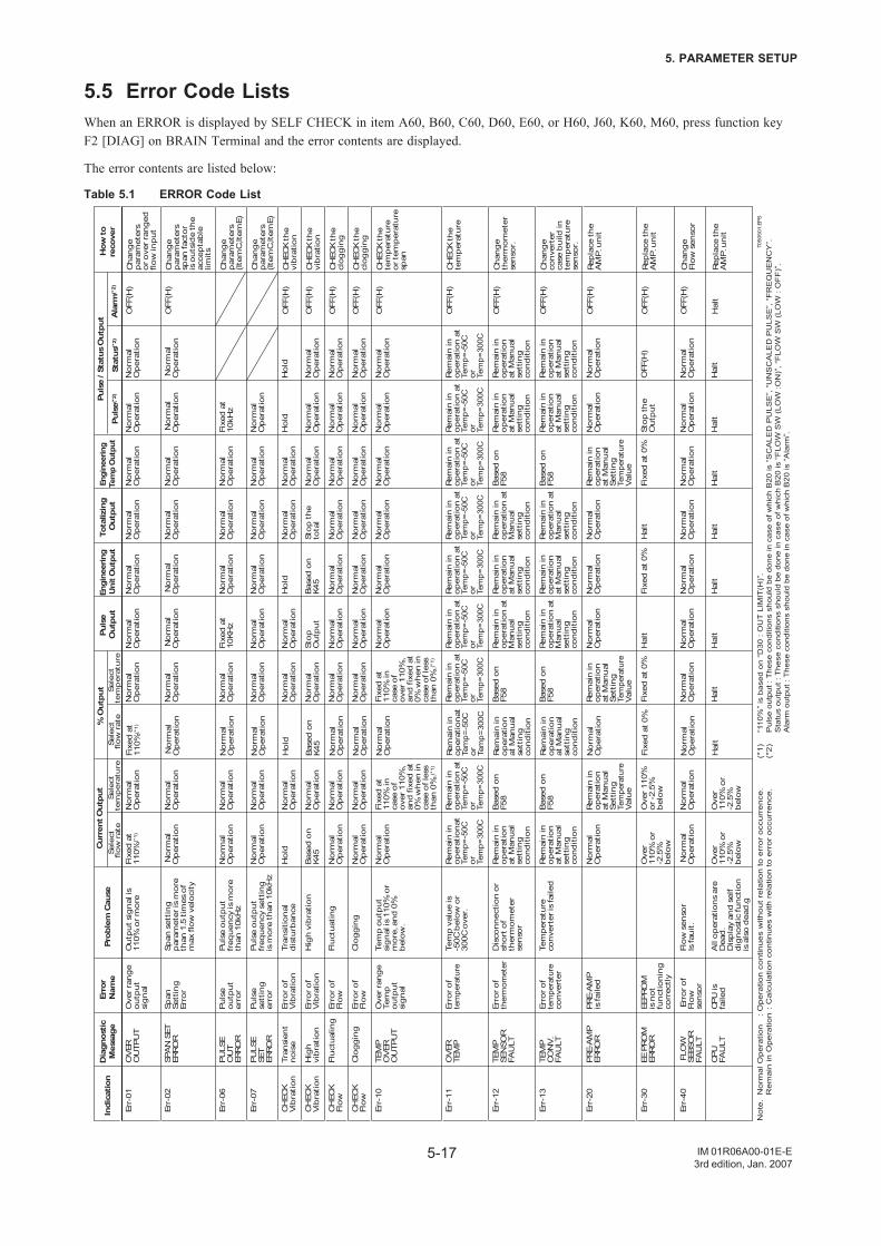
5-17
5. PARAMETER SETUP
IM 01R06A00-01E-E3rd edition, Jan. 2007
5.5 Error Code ListsWhen an ERROR is displayed by SELF CHECK in item A60, B60, C60, D60, E60, or H60, J60, K60, M60, press function keyF2 [DIAG] on BRAIN Terminal and the error contents are displayed.
The error contents are listed below:
Table 5.1 ERROR Code List
T050
501.
EPS
Engi
neer
ing
Uni
t Out
put
Engi
neer
ing
Tem
p O
utpu
tPu
lse
Out
put
Cur
rent
Out
put
Prob
lem
Cau
seEr
ror
Nam
eD
iagn
ostic
Mes
sage
Indi
catio
n
Err-
01
Err-
02
Err-
06
Err-
07
CH
ECK
Vib
rati
on
CH
ECK
Vib
rati
on
CH
ECK
Flow
CH
ECK
Flow
Err-
10
Err-
11
Err-
12
Err-
13
Err-
20
Err-
30
Err-
40
OV
ERO
UTP
UT
SPA
N S
ET
ERRO
R
PULS
EO
UT
ERRO
R
PULS
ESE
TER
ROR
Tran
sien
tnois
e
Hig
hvi
bra
tion
Fluct
ual
ing
Clo
gg
ing
TEM
PO
VER
OU
TPU
T
OV
ERTE
MP
TEM
PSE
NSO
RFA
ULT
TEM
PC
ON
V.
FAU
LT
PRE-
AM
PER
ROR
EE P
ROM
ER
ROR
FLO
WSE
BSO
RFA
ULT
CPU
FAU
LT
Ove
r ran
ge
outp
ut
sig
nal
Span
Sett
ing
Erro
r
Puls
eoutp
ut
erro
r
Puls
ese
ttin
ger
ror
Erro
r of
Vib
rati
on
Erro
r of
Vib
rati
on
Erro
r of
Flow
Erro
r of
Flow
Ove
r ran
ge
Tem
poutp
ut
sig
nal
Erro
r of
tem
pera
ture
Erro
r of
ther
mom
eter
Erro
r of
tem
pera
ture
conve
rter
PRE-
AM
Pis
faile
d
EEPR
OM
is n
ot
funct
ionin
gco
rrec
tly
Err
or o
fFl
ow
senso
r
CPU
is
faile
d
Outp
ut s
ignal
is
110%
or m
ore
Span
set
ting
p
aram
eter
is m
ore
than
1.5
tim
es o
f m
ax fl
ow
vel
oci
ty
Puls
e outp
ut
freq
uen
cy is
more
th
an 1
0kH
z
Puls
e outp
ut
freq
uen
cy s
etti
ng
is m
ore
than
10k
Hz
Tran
siti
onal
dis
turb
ance
Hig
h v
ibra
tion
Fluct
uat
ing
Clo
gg
ing
Tem
p o
utp
ut
sig
nal
is 1
10%
or
more
, and
0%
b
elow
.
Tem
p v
alue
is-5
0C b
elow
or
300C
ove
r.
Dis
connec
tion o
r sh
ort
of
ther
mom
eter
senso
r
Tem
per
ature
conve
rter
is fa
iled
Flow
sen
sor
Is fa
uit
.
All
op
erat
ions
are
Dea
d.
Dis
pla
y an
d s
elf
dig
nost
ic fu
nct
ion
is a
lso d
ead
.g
Fixe
d a
t 11
0%(*
1)
Norm
al
Op
erat
ion
Norm
alO
per
atio
n
Norm
alO
per
atio
n
Hold
Base
d o
nK4
5
Norm
alO
per
atio
n
Norm
alO
per
atio
n
Norm
alO
per
atio
n
Rem
ain in
op
erat
ionat
Tem
p=-5
0Cor
Tem
p=30
0C
Rem
ain in
op
erat
ion
at M
anual
se
ttin
gco
nd
itio
n
Rem
ain in
op
erat
ion
at M
anual
se
ttin
gco
nd
itio
n
Norm
alO
per
atio
n
Ove
r11
0% o
r -2
.5%
bel
ow
Norm
al
Op
erat
ion
Ove
r11
0% o
r -2
.5%
bel
ow
Norm
alO
per
atio
n
Norm
alO
per
atio
n
Fixe
d a
t 10
KHz
Norm
alO
per
atio
n
Norm
alO
per
atio
n
Stop
Outp
ut
Norm
alO
per
atio
n
Norm
alO
per
atio
n
Norm
alO
per
atio
n
Rem
ain in
op
erat
ion a
t Te
mp=
-50C
or
Tem
p=30
0C
Rem
ain in
op
erat
ion a
t M
anual
sett
ing
cond
itio
n
Rem
ain in
op
erat
ion a
t M
anual
sett
ing
cond
itio
n
Norm
alO
per
atio
n
Hal
t
Norm
alO
per
atio
n
Hal
t
Norm
alO
per
atio
n
Norm
al
Op
erat
ion
Norm
alO
per
atio
n
Norm
alO
per
atio
n
Hold
Base
d o
nK4
5
Norm
alO
per
atio
n
Norm
alO
per
atio
n
Norm
alO
per
atio
n
Rem
ain in
op
erat
ion a
t Te
mp=
-50C
or
Tem
p=30
0C
Rem
ain in
op
erat
ion
at M
anual
se
ttin
gco
nd
itio
n
Rem
ain in
op
erat
ion
at M
anual
se
ttin
gco
nd
itio
n
Norm
alO
per
atio
n
Fixe
d a
t 0%
Norm
alO
per
atio
n
Hal
t
Norm
alO
per
atio
n
Norm
al
Op
erat
ion
Fixe
d a
t 10
kHz
Norm
alO
per
atio
n
Hold
Norm
alO
per
atio
n
Norm
alO
per
atio
n
Norm
alO
per
atio
n
Norm
alO
per
atio
n
Rem
ain in
op
erat
ion a
t Te
mp=
-50C
or
Tem
p=30
0C
Rem
ain in
op
erat
ion
at M
anual
se
ttin
gco
nd
itio
n
Rem
ain in
op
erat
ion
at M
anual
se
ttin
gco
nd
itio
n
Norm
alO
per
atio
n
Stop
the
Outp
ut
Norm
alO
per
atio
n
Hal
t
Norm
alO
per
atio
n
Norm
al
Op
erat
ion
Hold
Norm
alO
per
atio
n
Norm
alO
per
atio
n
Norm
alO
per
atio
n
Norm
alO
per
atio
n
Rem
ain in
op
erat
ion a
t Te
mp=
-50C
or
Tem
p=30
0C
Rem
ain in
op
erat
ion
at M
anual
se
ttin
gco
nd
itio
n
Rem
ain in
op
erat
ion
at M
anual
se
ttin
gco
nd
itio
n
Norm
alO
per
atio
n
OFF
(H)
Norm
alO
per
atio
n
Hal
t
Norm
alO
per
atio
n
Norm
alO
per
atio
n
Norm
alO
per
atio
n
Norm
alO
per
atio
n
Norm
alO
per
atio
n
Stop
the
tota
l
Norm
alO
per
atio
n
Norm
alO
per
atio
n
Norm
alO
per
atio
n
Rem
ain in
op
erat
ion a
t Te
mp=
-50C
or
Tem
p=30
0C
Rem
ain in
op
erat
ion a
t M
anual
sett
ing
cond
itio
n
Rem
ain in
op
erat
ion a
t M
anual
sett
ing
cond
itio
n
Norm
alO
per
atio
n
Hal
t
Norm
alO
per
atio
n
Hal
t
Chan
ge
par
amet
ers
or o
ver r
ang
ed
flow
inp
ut
Chan
ge
par
amet
ers
span
fact
or
is o
uts
ide
the
acce
pta
ble
limit
s
Chan
ge
par
amet
ers
(Item
C,It
emE)
Chan
ge
par
amet
ers
(Item
C,It
emE)
CH
ECK
the
vib
rati
on
CH
ECK
the
vib
rati
on
CH
ECK
the
clog
gin
g
CH
ECK
the
clog
gin
g
CH
ECK
the
tem
per
ature
or t
emp
erat
ure
sp
an
CH
ECK
the
tem
per
ature
Chan
ge
ther
mom
eter
senso
r.
Chan
ge
conve
rter
case
build
in
tem
per
ature
senso
r.
Rep
lace
the
AM
P. u
nit
Rep
lace
the
AM
P. u
nit
Chan
ge
Flow
sen
sor
Rep
lace
the
AM
P. u
nit
Tota
lizin
gO
utp
utH
ow to
reco
ver
No
te.
No
rma
l Op
era
tion
:
Op
era
tion
co
ntin
ue
s w
itho
ut
rela
tion
to
err
or
occ
urr
en
ce.
R
em
ain
in O
pe
ratio
n :
Ca
lcu
latio
n c
on
tinu
es
with
re
latio
n t
o e
rro
r o
ccu
rre
nce
.
Norm
alO
per
atio
n
Norm
alO
per
atio
n
Norm
alO
per
atio
n
Norm
alO
per
atio
n
Norm
alO
per
atio
n
Norm
alO
per
atio
n
Norm
alO
per
atio
n
Norm
alO
per
atio
n
Fixe
d a
t 11
0% in
ca
se o
f ove
r 110
%,
and
fixe
d a
t 0%
when
in
case
of l
ess
than
0%
.(*1)
Rem
ain in
op
erat
ion a
t Te
mp=
-50C
or
Tem
p=30
0C
Base
d o
n
F58
Base
d o
n
F58
Rem
ain in
op
erat
ion
at M
anual
Se
ttin
gTe
mpe
ratu
reV
alue
Ove
r 110
%
or -
2.5%
bel
ow
Norm
alO
per
atio
n
Ove
r11
0% o
r -2
.5%
bel
ow
Norm
alO
per
atio
n
Norm
alO
per
atio
n
Norm
alO
per
atio
n
Norm
alO
per
atio
n
Norm
alO
per
atio
n
Norm
alO
per
atio
n
Norm
alO
per
atio
n
Norm
alO
per
atio
n
Fixe
d a
t 11
0% in
ca
se o
f ove
r 110
%,
and
fixe
d a
t 0%
when
in
case
of l
ess
than
0%
.(*1)
Rem
ain in
op
erat
ion a
t Te
mp=
-50C
or
Tem
p=30
0C
Base
d o
n
F58
Base
d o
n
F58
Rem
ain in
op
erat
ion
at M
anual
Se
ttin
gTe
mpe
ratu
reV
alue
Fixe
d a
t 0%
Norm
alO
per
atio
n
Hal
t
Norm
alO
per
atio
n
Norm
alO
per
atio
n
Norm
alO
per
atio
n
Norm
alO
per
atio
n
Norm
alO
per
atio
n
Norm
alO
per
atio
n
Norm
alO
per
atio
n
Norm
alO
per
atio
n
Norm
alO
per
atio
n
Rem
ain in
op
erat
ion a
t Te
mp=
-50C
or
Tem
p=30
0C
Base
d o
n
F58
Base
d o
n
F58
Rem
ain in
op
erat
ion
at M
anual
Se
ttin
gTe
mpe
ratu
reV
alue
Fixe
d a
t 0%
Norm
alO
per
atio
n
Hal
t
Sele
ctflow
rat
eSele
ctte
mp
era
ture
Sele
ctflow
rat
eSele
ctte
mp
era
ture
% O
utp
utPu
lse
/ Sta
tus
Out
put
Puls
e(*2
)St
atus
(*2)
Ala
rm(*
2)
Fixe
d a
t 11
0%(*
1)
Norm
al
Op
erat
ion
Norm
alO
per
atio
n
Norm
alO
per
atio
n
Hold
Base
d o
nK4
5
Norm
alO
per
atio
n
Norm
alO
per
atio
n
Norm
alO
per
atio
n
Rem
ain in
op
erat
ionat
Tem
p=-5
0Cor
Tem
p=30
0C
Rem
ain in
op
erat
ion
at M
anual
se
ttin
gco
nd
itio
n
Rem
ain in
op
erat
ion
at M
anual
se
ttin
gco
nd
itio
n
Norm
alO
per
atio
n
Fixe
d a
t 0%
Norm
alO
per
atio
n
Hal
t
OFF
(H)
OFF
(H)
OFF
(H)
OFF
(H)
OFF
(H)
OFF
(H)
OFF
(H)
OFF
(H)
OFF
(H)
OFF
(H)
OFF
(H)
OFF
(H)
OFF
(H)
Hal
t
(*1
) “1
10%
” is
bas
ed o
n “D
30 :
OU
T L
IMIT
(H)”
.(*
2)
Pul
se o
utpu
t : T
hese
con
ditio
ns s
houl
d be
don
e in
cas
e of
whi
ch B
20 is
“S
CA
LED
PU
LSE
”, “
UN
SC
ALE
D P
ULS
E”,
“F
RE
QU
EN
CY
”.
Sta
tus
outp
ut :
The
se c
ondi
tions
sho
uld
be d
one
in c
ase
of w
hich
B20
is “
FLO
W S
W (
LOW
:ON
)”, “
FLO
W S
W (
LOW
: O
FF
)”.
A
larm
out
put :
The
se c
ondi
tions
sho
uld
be d
one
in c
ase
of w
hich
B20
is “
Ala
rm”.

5-18
5. PARAMETER SETUP
IM 01R06A00-01E-E3rd edition, Jan. 2007
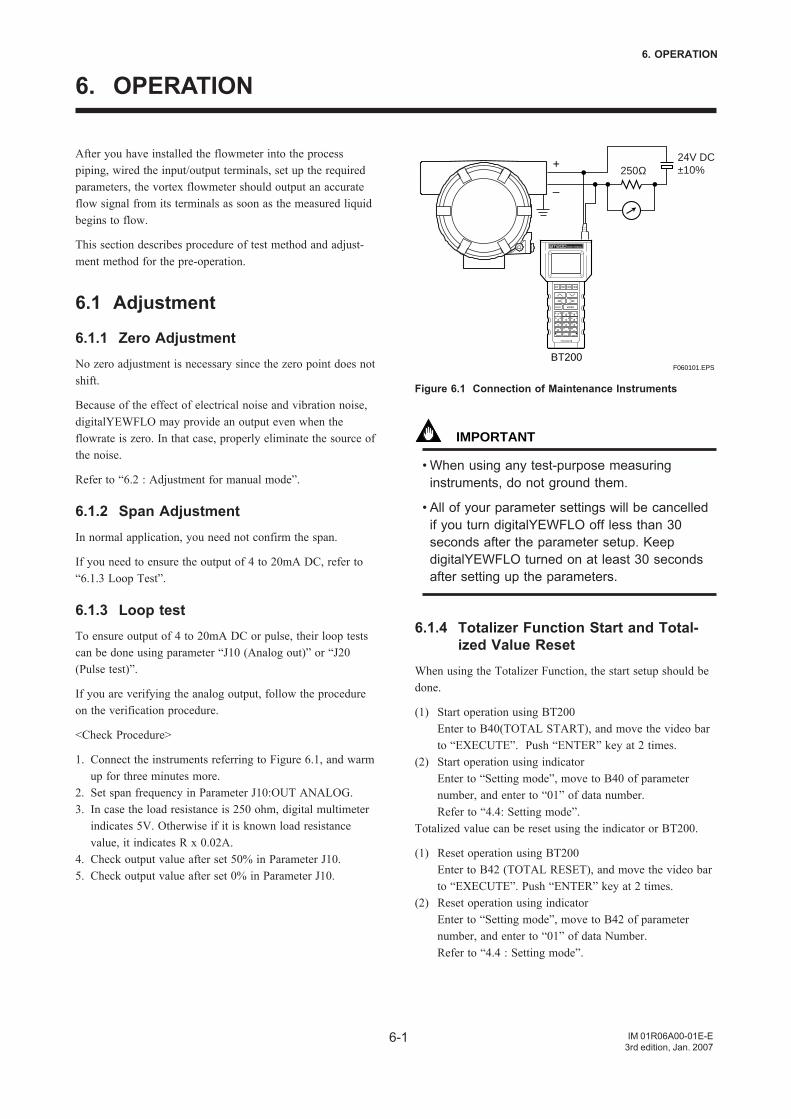
6-1
6. OPERATION
IM 01R06A00-01E-E3rd edition, Jan. 2007
After you have installed the flowmeter into the processpiping, wired the input/output terminals, set up the requiredparameters, the vortex flowmeter should output an accurateflow signal from its terminals as soon as the measured liquidbegins to flow.
This section describes procedure of test method and adjust-ment method for the pre-operation.
6.1 Adjustment
6.1.1 Zero AdjustmentNo zero adjustment is necessary since the zero point does notshift.
Because of the effect of electrical noise and vibration noise,digitalYEWFLO may provide an output even when theflowrate is zero. In that case, properly eliminate the source ofthe noise.
Refer to “6.2 : Adjustment for manual mode”.
6.1.2 Span AdjustmentIn normal application, you need not confirm the span.
If you need to ensure the output of 4 to 20mA DC, refer to“6.1.3 Loop Test”.
6.1.3 Loop testTo ensure output of 4 to 20mA DC or pulse, their loop testscan be done using parameter “J10 (Analog out)” or “J20(Pulse test)”.
If you are verifying the analog output, follow the procedureon the verification procedure.
<Check Procedure>
1. Connect the instruments referring to Figure 6.1, and warmup for three minutes more.
2. Set span frequency in Parameter J10:OUT ANALOG.3. In case the load resistance is 250 ohm, digital multimeter
indicates 5V. Otherwise if it is known load resistancevalue, it indicates R x 0.02A.
4. Check output value after set 50% in Parameter J10.5. Check output value after set 0% in Parameter J10.
+
–
F060101.EPS
250Ω24V DC±10%
BT200
Figure 6.1 Connection of Maintenance Instruments
IMPORTANT
• When using any test-purpose measuringinstruments, do not ground them.
• All of your parameter settings will be cancelledif you turn digitalYEWFLO off less than 30seconds after the parameter setup. KeepdigitalYEWFLO turned on at least 30 secondsafter setting up the parameters.
6.1.4 Totalizer Function Start and Total-ized Value Reset
When using the Totalizer Function, the start setup should bedone.
(1) Start operation using BT200Enter to B40(TOTAL START), and move the video barto “EXECUTE”. Push “ENTER” key at 2 times.
(2) Start operation using indicatorEnter to “Setting mode”, move to B40 of parameternumber, and enter to “01” of data number.Refer to “4.4: Setting mode”.
Totalized value can be reset using the indicator or BT200.
(1) Reset operation using BT200Enter to B42 (TOTAL RESET), and move the video barto “EXECUTE”. Push “ENTER” key at 2 times.
(2) Reset operation using indicatorEnter to “Setting mode”, move to B42 of parameternumber, and enter to “01” of data Number.Refer to “4.4 : Setting mode”.
6. OPERATION
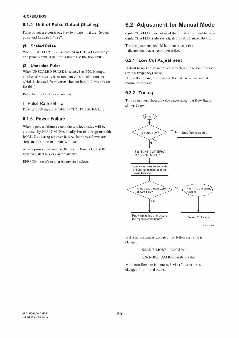
6-2
6. OPERATION
IM 01R06A00-01E-E3rd edition, Jan. 2007
6.1.5 Unit of Pulse Output (Scaling)Pulse output are constructed by two units, that are “Scaledpulse and Unscaled Pulse”.
(1) Scaled PulseWhen SCALED PULSE is selected in B20, set flowrate perone pulse output. Rate unit is linking to the flow unit.
(2) Unscaled PulseWhen UNSCALED PULSE is selected in B20, it outputnumber of vortex (vortex frequency) as a pulse-number,which is detected from vortex shedder bar. (1.0 must be setfor this.)
Refer to 7.6 (1) Flow calculation.
l Pulse Rate settingPulse rate setting are settable by “B21:PULSE RATE”.
6.1.6 Power FailureWhen a power failure occurs, the totalized value will beprotected by EEPROM (Electrically Erasable ProgrammableROM). But during a power failure, the vortex flowmeterstops and also the totalizing will stop.
After a power is recovered, the vortex flowmeter and thetotalizing start to work automatically.
EEPROM doesn’t need a battery for backup.
6.2 Adjustment for Manual ModedigitalYEWFLO does not need the initial adjustment becausedigitalYEWFLO is always adjusted by itself automatically.
These adjustments should be done in case thatindicator reads over zero at zero flow.
6.2.1 Low Cut Adjustment Adjust to noise elimination or zero flow in the low flowrate(or low frequency) range. The settable range for low cut flowrate is below half ofminimum flowrate.
6.2.2 TuningThis adjustment should be done according to a flow figureshown below.
START
Is it zero flow?No
No
Stop flow to be zero
Yes
Yes
Set "TUNING AT ZERO"of "K25:N.B MODE"
Wait more than 30 secondsEnsure the complete of thetuning function.
Is indication reads zeroat zero flow?
Finishing the tuningfunctios
Retry the tuning and ensurethe pipeline conditions? Ensure TLA value
F060201.EPS
If this adjustment is executed, the following value ischanged.
K25:N.B MODE = MANUAL
K26:NOISE RATIO=Constant value
Minimum flowrate is increased when TLA value ischanged form initial value.
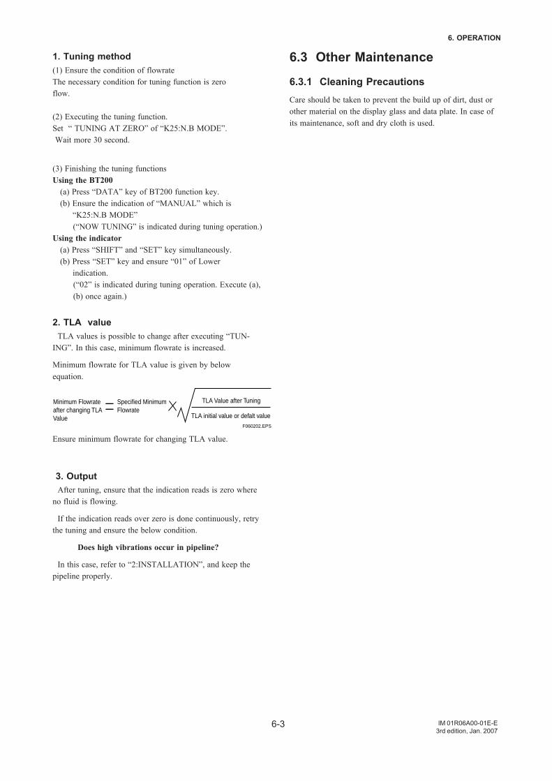
6-3
6. OPERATION
IM 01R06A00-01E-E3rd edition, Jan. 2007
1. Tuning method(1) Ensure the condition of flowrateThe necessary condition for tuning function is zeroflow.
(2) Executing the tuning function.Set “ TUNING AT ZERO” of “K25:N.B MODE”. Wait more 30 second.
(3) Finishing the tuning functionsUsing the BT200 (a) Press “DATA” key of BT200 function key. (b) Ensure the indication of “MANUAL” which is “K25:N.B MODE”
(“NOW TUNING” is indicated during tuning operation.)Using the indicator (a) Press “SHIFT” and “SET” key simultaneously. (b) Press “SET” key and ensure “01” of Lower indication.
(“02” is indicated during tuning operation. Execute (a), (b) once again.)
2. TLA value TLA values is possible to change after executing “TUN-ING”. In this case, minimum flowrate is increased.
Minimum flowrate for TLA value is given by belowequation.
Minimum Flowrateafter changing TLAValue
Specified MinimumFlowrate
TLA Value after Tuning
TLA initial value or defalt valueF060202.EPS
Ensure minimum flowrate for changing TLA value.
3. Output After tuning, ensure that the indication reads is zero whereno fluid is flowing.
If the indication reads over zero is done continuously, retrythe tuning and ensure the below condition.
Does high vibrations occur in pipeline?
In this case, refer to “2:INSTALLATION”, and keep thepipeline properly.
6.3 Other Maintenance
6.3.1 Cleaning PrecautionsCare should be taken to prevent the build up of dirt, dust orother material on the display glass and data plate. In case ofits maintenance, soft and dry cloth is used.

6-4
6. OPERATION
IM 01R06A00-01E-E3rd edition, Jan. 2007
7-1
7. MAINTENANCE
IM 01R06A00-01E-E3rd edition, Jan. 2007
7. MAINTENANCE
CAUTION
• Disassemble work should be done only for error occurrence.• Maintenance work must be carried out by expert engineer or skilled personnel and not by operators.• Before opening the cover, it is important to ensure that at least 10 minutes have passed since the
power was turned off. Furthermore, opening of the cover must also be carried out by expert engineer orskilled personnel.
CAUTION
• It is prohibited by law for the user to modify flameproof instruments. It is not permitted to add or removeindicators. If modification is required, contact YOKOGAWA.
• Explosion protected type must be, as a rule, removed to a non-hazardous area for maintenance and bedisassembled and reassembled to the original state.
• For TIIS, ATEX and SAA explosion proof, the display cover is locked by the clamp. In case of openingthe display cover, use the hexagonal wrench attached.
• Be sure to lock the cover by the clamp using the hexagonal wrench attached after installing the cover.
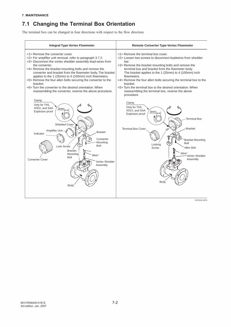
7-2
7. MAINTENANCE
IM 01R06A00-01E-E3rd edition, Jan. 2007
7.1 Changing the Terminal Box OrientationThe terminal box can be changed in four directions with respect to the flow direction.
Integral Type Vortex Flowmeter Remote Converter Type Vortex Flowmeter
<1> Remove the converter cover.<2> For amplifier unit removal, refer to paragraph 3.7.2.<3> Disconnect the vortex shedder assembly lead-wires from
the converter.<4> Remove the bracket mounting bolts and remove the
converter and bracket from the flowmeter body. The bracket applies to the 1 (25mm) to 4 (100mm) inch flowmeters.
<5> Remove the four allen bolts securing the converter to the bracket.
<6> Turn the converter to the desired orientation. When reassembling the converter, reverse the above procedure.
<1> Remove the terminal box cover.<2> Loosen two screws to disconnect leadwires from shedder
bar.<3> Remove the bracket mounting bolts and remove the
terminal box and bracket from the flowmeter body. The bracket applies to the 1 (25mm) to 4 (100mm) inch flowmeters.
<4> Remove the four allen bolts securing the terminal box to the bracket.
<5> Turn the terminal box to the desired orientation. When reassembling the terminal box, reverse the above procedure.
Amplifier UnitIndicator
Converter Cover
* *
BracketMountingBolt
Body
Bracket
Vortex ShedderAssembly
Converter MountingBolt
Wire*
Terminal Box Cover
Terminal Box
Bracket
Allen Bolt
Bracket Mounting Bolt
Wire*Vortex Shedder Assembly
Body
Wire Color Terminal
RedWhite
AB
Wire Color Terminal
RedWhite
AB
Locking Screw
Shielded Cover
Clamp Only for TIIS,ATEX, and SAAExplosion proof
Lock Screw
Clamp Only for TIIS,ATEX, and SAAExplosion proof
3mm3mm
F070101.EPS
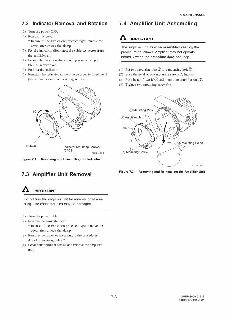
7-3
7. MAINTENANCE
IM 01R06A00-01E-E3rd edition, Jan. 2007
7.4 Amplifier Unit Assembling
IMPORTANT
The amplifier unit must be assembled keeping theprocedure as follows. Amplifier may not operatenormally when the procedure does not keep.
(1) Put two-mounting pins 1 into mounting hole 2 .(2) Push the head of two mounting screws 4 lightly.(3) Push head of two IC 5 and mount the amplifier unit 3 .(4) Tighten two mounting screws 4 .
F070401.EPS
Amplifier Unit
Mounting Screw
Mounting Holes
Mounting Pins
IC
1
2
3
4
5
Figure 7.2 Removing and Reinstalling the Amplifier Unit
7.2 Indicator Removal and Rotation(1) Turn the power OFF.(2) Remove the cover.
* In case of the Explosion protected type, remove thecover after unlock the clamp.
(3) For the indicator, disconnect the cable connector fromthe amplifier unit.
(4) Loosen the two indicator mounting screws using aPhillips screwdriver.
(5) Pull out the indicator.(6) Reinstall the indicator in the reverse order to its removal
(above) and secure the mounting screws.
F070201.EPS
Indicator
90°
Indicator Mounting Screws (2PCS)
Figure 7.1 Removing and Reinstalling the Indicator
7.3 Amplifier Unit Removal
IMPORTANT
Do not turn the amplifier unit for removal or assem-bling. The connector pins may be damaged.
(1) Turn the power OFF.(2) Remove the converter cover.
* In case of the Explosion protected type, remove thecover after unlock the clamp.
(3) Remove the indicator according to the proceduresdescribed in paragraph 7.2.
(4) Loosen the terminal screws and remove the amplifierunit.
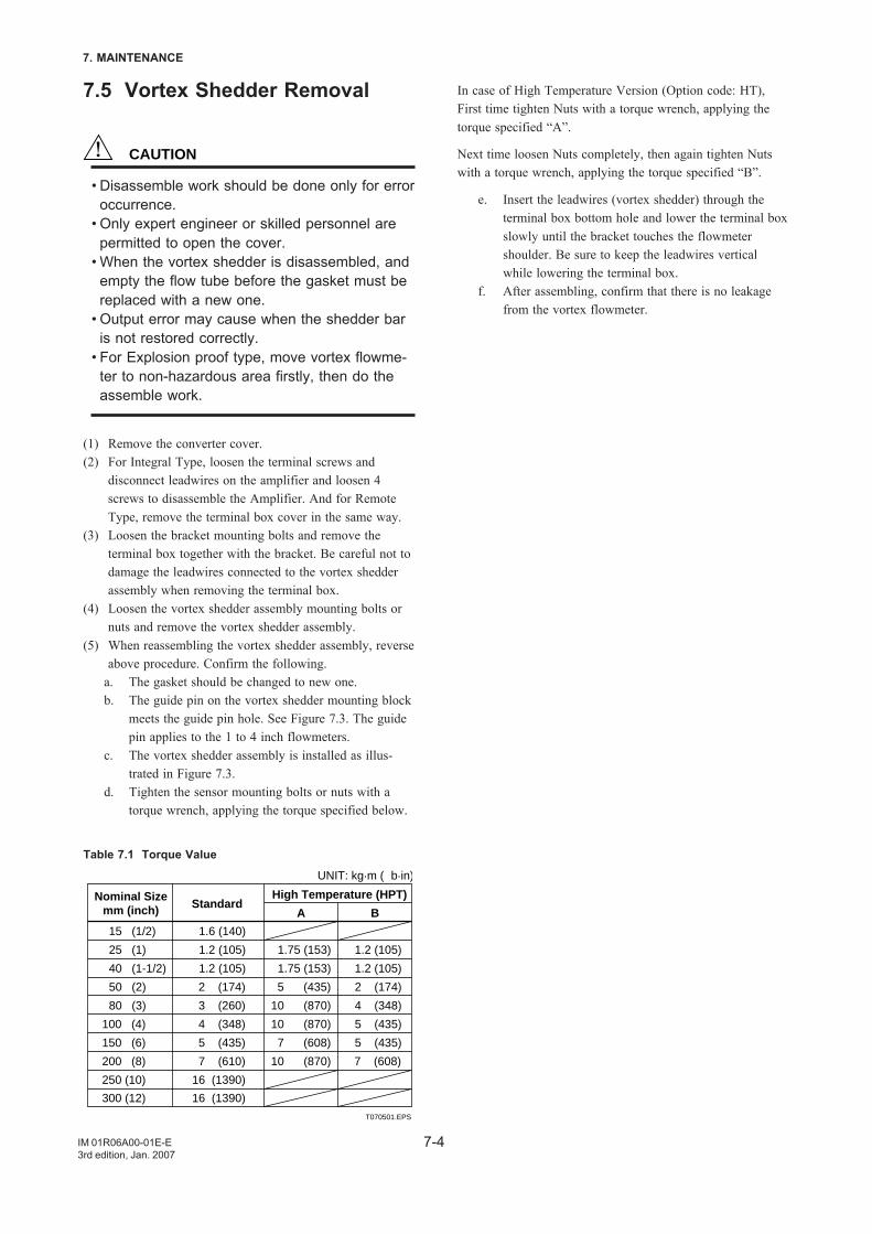
7-4
7. MAINTENANCE
IM 01R06A00-01E-E3rd edition, Jan. 2007
7.5 Vortex Shedder Removal
CAUTION
• Disassemble work should be done only for erroroccurrence.
• Only expert engineer or skilled personnel arepermitted to open the cover.
• When the vortex shedder is disassembled, andempty the flow tube before the gasket must bereplaced with a new one.
• Output error may cause when the shedder baris not restored correctly.
• For Explosion proof type, move vortex flowme-ter to non-hazardous area firstly, then do theassemble work.
(1) Remove the converter cover.(2) For Integral Type, loosen the terminal screws and
disconnect leadwires on the amplifier and loosen 4screws to disassemble the Amplifier. And for RemoteType, remove the terminal box cover in the same way.
(3) Loosen the bracket mounting bolts and remove theterminal box together with the bracket. Be careful not todamage the leadwires connected to the vortex shedderassembly when removing the terminal box.
(4) Loosen the vortex shedder assembly mounting bolts ornuts and remove the vortex shedder assembly.
(5) When reassembling the vortex shedder assembly, reverseabove procedure. Confirm the following.
a. The gasket should be changed to new one.b. The guide pin on the vortex shedder mounting block
meets the guide pin hole. See Figure 7.3. The guidepin applies to the 1 to 4 inch flowmeters.
c. The vortex shedder assembly is installed as illus-trated in Figure 7.3.
d. Tighten the sensor mounting bolts or nuts with atorque wrench, applying the torque specified below.
Table 7.1 Torque Value
15 (1/2) 1.6 (140)
25 (1) 1.2 (105) 1.75 (153) 1.2 (105)
40 (1-1/2) 1.2 (105) 1.75 (153) 1.2 (105)
50 (2) 2 (174) 5 (435) 2 (174)
80 (3) 3 (260) 10 (870) 4 (348)
100 (4) 4 (348) 10 (870) 5 (435)
150 (6) 5 (435) 7 (608) 5 (435)
200 (8) 7 (610) 10 (870) 7 (608)
250 (10) 16 (1390)
300 (12) 16 (1390)
T070501.EPS
Nominal Sizemm (inch) Standard
A
High Temperature (HPT)
B
UNIT: kg.m ( b.in)
In case of High Temperature Version (Option code: HT),First time tighten Nuts with a torque wrench, applying thetorque specified “A”.
Next time loosen Nuts completely, then again tighten Nutswith a torque wrench, applying the torque specified “B”.
e. Insert the leadwires (vortex shedder) through theterminal box bottom hole and lower the terminal boxslowly until the bracket touches the flowmetershoulder. Be sure to keep the leadwires verticalwhile lowering the terminal box.
f. After assembling, confirm that there is no leakagefrom the vortex flowmeter.
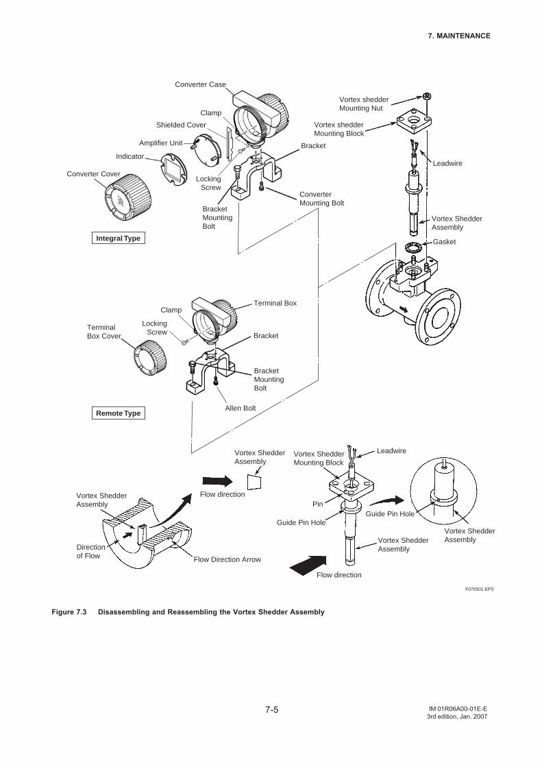
7-5
7. MAINTENANCE
IM 01R06A00-01E-E3rd edition, Jan. 2007
Integral Type
Remote Type
F070501.EPS
Color Wire
Red
White
A
B
Vortex shedder Mounting Nut
Vortex shedder Mounting Block
Bracket
Converter Mounting Bolt
Leadwire
Vortex Shedder Assembly
Vortex Shedder Assembly
Gasket
Amplifier Unit
LockingScrew
LockingScrew
Clamp
Shielded Cover
Converter Case
Indicator
Converter Cover
Bracket Mounting Bolt
Terminal Box
Bracket
Bracket Mounting Bolt
Allen Bolt
Terminal Box Cover
Flow direction
Flow direction
Flow Direction Arrow
Vortex Shedder Assembly
Direction of Flow
LeadwireVortex Shedder Mounting Block
Guide Pin Hole
PinGuide Pin Hole
Vortex Shedder Assembly
Vortex Shedder Assembly
*
Clamp
Figure 7.3 Disassembling and Reassembling the Vortex Shedder Assembly
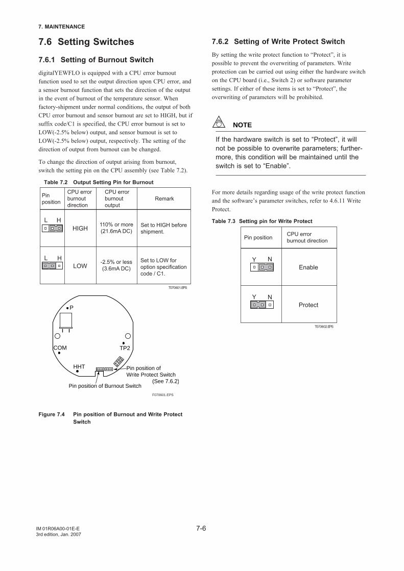
7-6
7. MAINTENANCE
IM 01R06A00-01E-E3rd edition, Jan. 2007
7.6 Setting Switches
7.6.1 Setting of Burnout SwitchdigitalYEWFLO is equipped with a CPU error burnoutfunction used to set the output direction upon CPU error, anda sensor burnout function that sets the direction of the outputin the event of burnout of the temperature sensor. Whenfactory-shipment under normal conditions, the output of bothCPU error burnout and sensor burnout are set to HIGH, but ifsuffix code/C1 is specified, the CPU error burnout is set toLOW(-2.5% below) output, and sensor burnout is set toLOW(-2.5% below) output, respectively. The setting of thedirection of output from burnout can be changed.
To change the direction of output arising from burnout,switch the setting pin on the CPU assembly (see Table 7.2).
Table 7.2 Output Setting Pin for Burnout
Pinposition
CPU errorburnoutdirection
CPU errorburnoutoutput
Remark
110% or more(21.6mA DC)
-2.5% or less(3.6mA DC)
Set to HIGH before shipment.
Set to LOW for option specification code / C1.
T070601.EPS
HIGH
LOW
HL
HL
TP2COM
HHT
P
F070601.EPS
Pin position of Burnout Switch
Pin position of Write Protect Switch (See 7.6.2)
Figure 7.4 Pin position of Burnout and Write ProtectSwitch
7.6.2 Setting of Write Protect SwitchBy setting the write protect function to “Protect”, it ispossible to prevent the overwriting of parameters. Writeprotection can be carried out using either the hardware switchon the CPU board (i.e., Switch 2) or software parametersettings. If either of these items is set to “Protect”, theoverwriting of parameters will be prohibited.
NOTE
If the hardware switch is set to “Protect”, it willnot be possible to overwrite parameters; further-more, this condition will be maintained until theswitch is set to “Enable”.
For more details regarding usage of the write protect functionand the software’s parameter switches, refer to 4.6.11 WriteProtect.
Table 7.3 Setting pin for Write Protect
Pin position CPU errorburnout direction
T070602.EPS
Enable
Protect
NY
NY
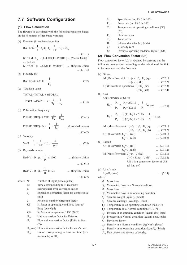
7-7
7. MAINTENANCE
IM 01R06A00-01E-E3rd edition, Jan. 2007
7.7 Software Configuration(1) Flow CalculationThe flowrate is calculated with the following equations basedon the N number of generated vortices:
(a) Flowrate (in engineering units)
RATE=N. 1t
. εf. εe
. εr . 1
KT . Uk . UTM
.... (7.1.1)KT=KM . UKT
. 1–4.81x(Tf–15)x10–5.... (Metric Units).... (7.1.2)KT=KM . 1–2.627x(Tf–59)x10–5 .... (English Units)
.... (7.1.3)(b) Flowrate (%)
RATE(%)=RATE . 1
FS
.... (7.2)
(c) Totalized value
TOTAL=TOTAL + nTOTAL
1TR
1UTM
TOTAL=RATE · t · · .... (7.3)
(d) Pulse output frequency
PULSE FREQ=RATE · 1
PR ·
1UTM
.... (7.4.1)
PULSE FREQ= N · 1t ·
1PR
.... (Unscaled pulses)
.... (7.4.2)(e) Velocity
V=N . 1t .
1KT
. UKT . 4
πD2.... (7.5)
(f) Reynolds number
Red=V . D . ρf . 1
µ x 1000 .... (Metric Units)
.... (7.6.1)
Red=V . D . ρf . 1
µ x 124 .... (English Units)
.... (7.6.2)where N: Number of input pulses (pulse)
∆t: Time corresponding to N (seconds)εf: Instrumental error correction factorεe: Expansion correction factor for compressive
fluidεr: Reynolds number correction factorKT: K-factor at operating conditions (pulses/
litre) (pulse/gal)KM: K-factor at temperature 15°C (59°F)UKT: Unit conversion factor for K-factorUk: Flow unit conversion factor (Refer to item
(2))Uk(user): Flow unit conversion factor for user’s unitUTM: Factor corresponding to flow unit time (ex./
m (minute) is 60.)
SE: Span factor (ex. E+ 3 is 103.)PE: Pulse rate (ex. E+ 3 is 103.)Tf: Temperature at operating conditions (°C)
(°F)FS: Flowrate spanTE: Total factorD: Internal diameter (m) (inch)µ : Viscosity (cP)ρf: Density at operating conditions (kg/m3) (lb/ft3)
(2) Flow Conversion Factor (Uk)Flow conversion factor Uk is obtained by carrying out thefollowing computation depending on the selection of the fluidto be measured and the flow unit.
(a) SteamM (Mass flowrate): Uk=ρf . Uρf . Uk (kg) .... (7.7.1)
Uk=ρf . Uk (lb) .... (7.7.2)Qf (Flowrate at operation): Uk=Uk (m
3) .... (7.7.3)Uk=Uk (acf) .... (7.7.4)
(b) GasQn: (Flowrate at STP):
Uk = Uk (Nm3)Pf
Pn
Pf + 273.15
Pn + 273.15
1
K· ·· .... (7.8)
Uk = Uk (scf)Pf
Pn
1
K
(Tn-32) + 273.15
(Tn-32) + 273.15
95
95
· ··
M: (Mass flowrate): Uk=ρf . Uρf . Uk (kg) .... (7.9.1)Uk=ρf . Uρf . Uk (lb) .... (7.9.2)
Qf: (Flowrate): Uk=Uk (m3) .... (7.10.1)
Uk=Uk (acf) .... (7.10.2)(c) Liquid
Qf: (Flowrate): Uk=Uk (m3) .... (7.11.1)
Uk=Uk (acf) .... (7.11.2)M (Mass flowrate): Uk=ρf . U (kg) .... (7.12.1)
Uk=7.481xρf . U (lb) .... (7.12.2)7.481 is a conversion factor of U.Sgal into acf
(d) User’s unitUk=Uk (user) .... (7.13)
whereM: Mass flowQn: Volumetric flow in a Normal conditionM: Mass flowQf: Volumetric flow in an operating conditionρf: Specific weight (kg/m3), (lb/acf)hf: Specific enthalpy (kcal/kg), (Btu/lb)Tf: Temperature in an operating condition (°C), (°F)Tn: Temperature in a Normal condition (°C), (°F)Pf: Pressure in an operating condition (kg/cm2 abs), (psia)Pn: Pressure in a Normal condition (kg/cm2 abs), (psia)K: Deviation factorρn: Density in a Normal condition (kg/Nm3), (lb/scf)ρf: Density in an operating condition (kg/m3), (lb/acf)Uρf: Unit conversion factors of density.
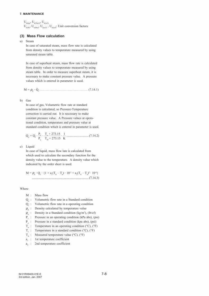
7-8
7. MAINTENANCE
IM 01R06A00-01E-E3rd edition, Jan. 2007
Uk(kg), Uk(Nm3), Uk(m3)
Uk(lb), Uk(Btu), Uk(scf) , Uk(acf): Unit conversion factors
(3) Mass Flow calculationa) Steam
In case of saturated steam, mass flow rate is calculatedfrom density values to temperature measured by usingsaturated steam table.
In case of superheat steam, mass flow rate is calculatedfrom density values to temperature measured by usingsteam table. In order to measure superheat steam, it isnecessary to make constant pressure value. A pressurevalues which is entered in parameter is used.
M = ρft · Qf .......................................................................................................... (7.14.1)
b) GasIn case of gas, Volumetric flow rate at standardcondition is calculated, so Pressure-Temperaturecorrection is carried out. It is necessary to makeconstant pressure value. A Pressure values at opera-tional condition, temperature and pressure value atstandard condition which is entered in parameter is used.
Qn = Qf · –– · –––––––––– · –– ............................ (7.14.2)
c) LiquidIn case of liquid, mass flow late is calculated fromwhich used to calculate the secondary function for thedensity value to the temperature. A density value whichindicated by the order sheet is used.
M = ρn · Qf · 1 + a1(Tft – Tn) · 10-2 + a2(Tft – Tn)2 · 10-6
........................................................................ (7.14.3)
Where
M : Mass flowQn : Volumetric flow rate in a Standard conditionQf : Volumetric flow rate in a operating conditionρft : Density calculated by temperature valueρn : Density in a Standard condition (kg/m3), (lb/cf)Pf : Pressure in an operating condition (kPa abs), (psi)Pn : Pressure in a standard condition (kpa abs), (psi)Tn : Temperature in an operating condition (°C), (°F)Tf : Temperature in a standard condition (°C), (°F)Tft : Measured temperature value (°C), (°F)a1 : 1st temperature coefficienta2 : 2nd temperature coefficient
Pf Tn + 273.15 1Pn TfT + 273.15 K
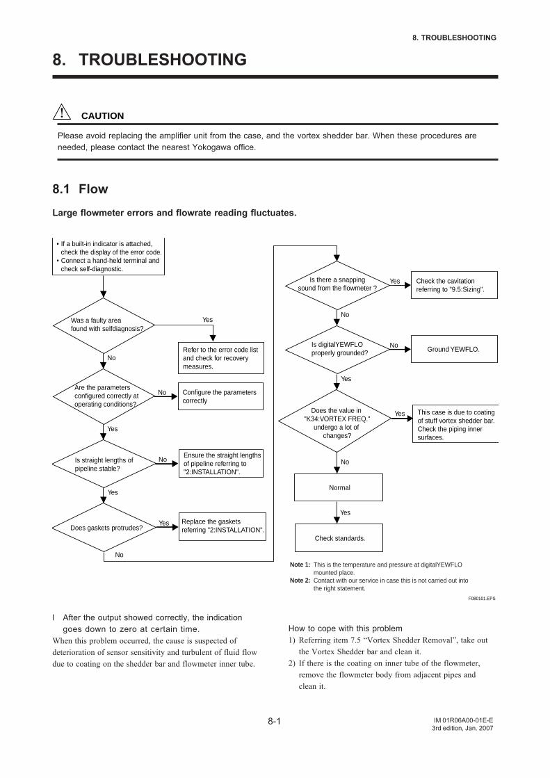
8-1
8. TROUBLESHOOTING
IM 01R06A00-01E-E3rd edition, Jan. 2007
8. TROUBLESHOOTING
CAUTION
Please avoid replacing the amplifier unit from the case, and the vortex shedder bar. When these procedures areneeded, please contact the nearest Yokogawa office.
8.1 Flow
Large flowmeter errors and flowrate reading fluctuates.
Are the parametersconfigured correctly at operating conditions?
Is straight lengths of pipeline stable?
Configure the parameterscorrectly
No
Yes
Yes
Was a faulty area found with selfdiagnosis?
No
Ensure the straight lengths of pipeline referring to "2:INSTALLATION".
No
Does gaskets protrudes?
Yes
Replace the gaskets referring "2:INSTALLATION".
Yes
Refer to the error code list and check for recovery measures.
• If a built-in indicator is attached, check the display of the error code.
• Connect a hand-held terminal and check self-diagnostic.
Is there a snappingsound from the flowmeter ?
Check the cavitation referring to "9.5:Sizing".
Yes
Is digitalYEWFLO properly grounded?
No
Ground YEWFLO.No
Does the value in "K34:VORTEX FREQ."
undergo a lot of changes?
Yes
This case is due to coating of stuff vortex shedder bar.Check the piping inner surfaces.
Normal
No
Check standards.
Yes
Yes
F080101.EPS
Note 1:
Note 2:
This is the temperature and pressure at digitalYEWFLOmounted place.Contact with our service in case this is not carried out intothe right statement.
No
l After the output showed correctly, the indicationgoes down to zero at certain time.
When this problem occurred, the cause is suspected ofdeterioration of sensor sensitivity and turbulent of fluid flowdue to coating on the shedder bar and flowmeter inner tube.
How to cope with this problem1) Referring item 7.5 “Vortex Shedder Removal”, take out
the Vortex Shedder bar and clean it.2) If there is the coating on inner tube of the flowmeter,
remove the flowmeter body from adjacent pipes andclean it.
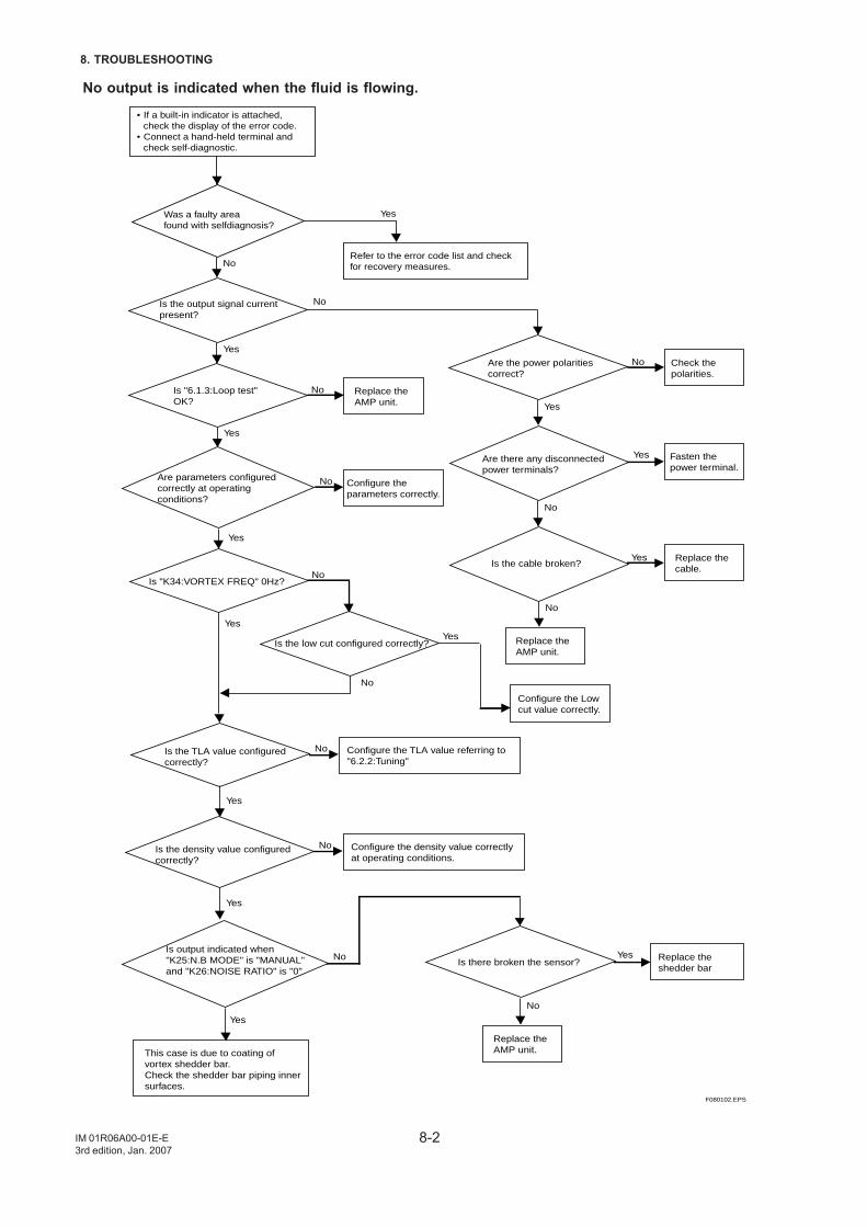
8-2
8. TROUBLESHOOTING
IM 01R06A00-01E-E3rd edition, Jan. 2007
No output is indicated when the fluid is flowing.
Is the output signal currentpresent?
Is "6.1.3:Loop test"OK?
Check the polarities.
NoYes
Are parameters configuredcorrectly at operating conditions?
Yes
Yes
Is "K34:VORTEX FREQ" 0Hz?
Yes
Are the power polarities correct?
No
Are there any disconnectedpower terminals?
Fasten the power terminal.
No
Yes
Is the cable broken?Replace the cable.
Yes
No
Replace the AMP unit.
Replace the AMP unit.
No
Configure the parameters correctly.
No
Is the low cut configured correctly?
Configure the Low cut value correctly.
Is the TLA value configured correctly?
No
No
Configure the TLA value referring to"6.2.2:Tuning"
No
Is the density value configured correctly?
Configure the density value correctlyat operating conditions.
No
Yes
Yes
Yes
Is output indicated when "K25:N.B MODE" is "MANUAL"and "K26:NOISE RATIO" is "0"
NoIs there broken the sensor?
No
Replace the AMP unit.
Replace the shedder bar
Yes
Yes
This case is due to coating of vortex shedder bar.Check the shedder bar piping inner surfaces.
Yes
F080102.EPS
YesWas a faulty area found with selfdiagnosis?
NoRefer to the error code list and check for recovery measures.
• If a built-in indicator is attached, check the display of the error code.
• Connect a hand-held terminal and check self-diagnostic.
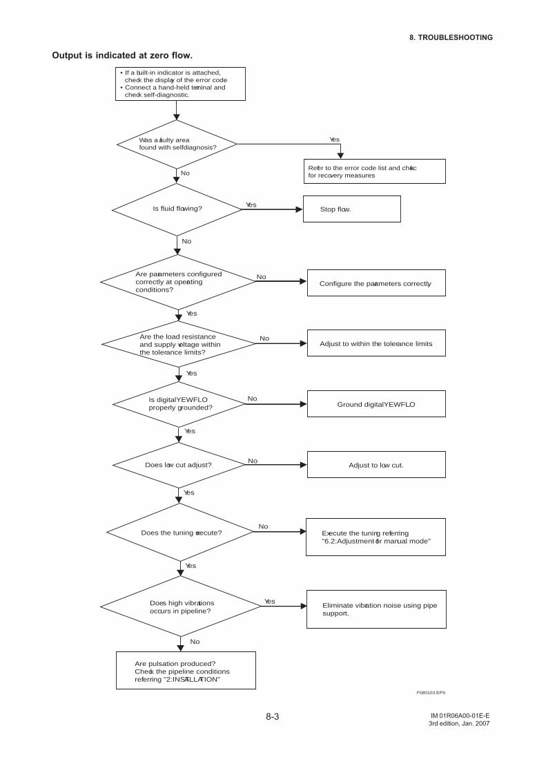
8-3
8. TROUBLESHOOTING
IM 01R06A00-01E-E3rd edition, Jan. 2007
Output is indicated at zero flow.
Is fluid flowing?
Are parameters configuredcorrectly at operating conditions?
Stop flow.
No
Yes
Configure the parameters correctly.No
Are the load resistanceand supply voltage withinthe tolerance limits?
Yes
Adjust to within the tolerance limits.
Yes
No
Yes
Is digitalYEWFLO properly grounded?
NoGround digitalYEWFLO.
No
Yes
Does low cut adjust? Adjust to low cut.
Does the tuning execute?No
Execute the tuning referring "6.2:Adjustment for manual mode"
Yes
Does high vibrations occurs in pipeline?
No
Eliminate vibration noise using pipesupport.
Yes
Are pulsation produced?Check the pipeline conditions referring "2:INSTALLATION"
F080103.EPS
YesWas a faulty area found with selfdiagnosis?
NoRefer to the error code list and check for recovery measures.
• If a built-in indicator is attached, check the display of the error code.
• Connect a hand-held terminal and check self-diagnostic.
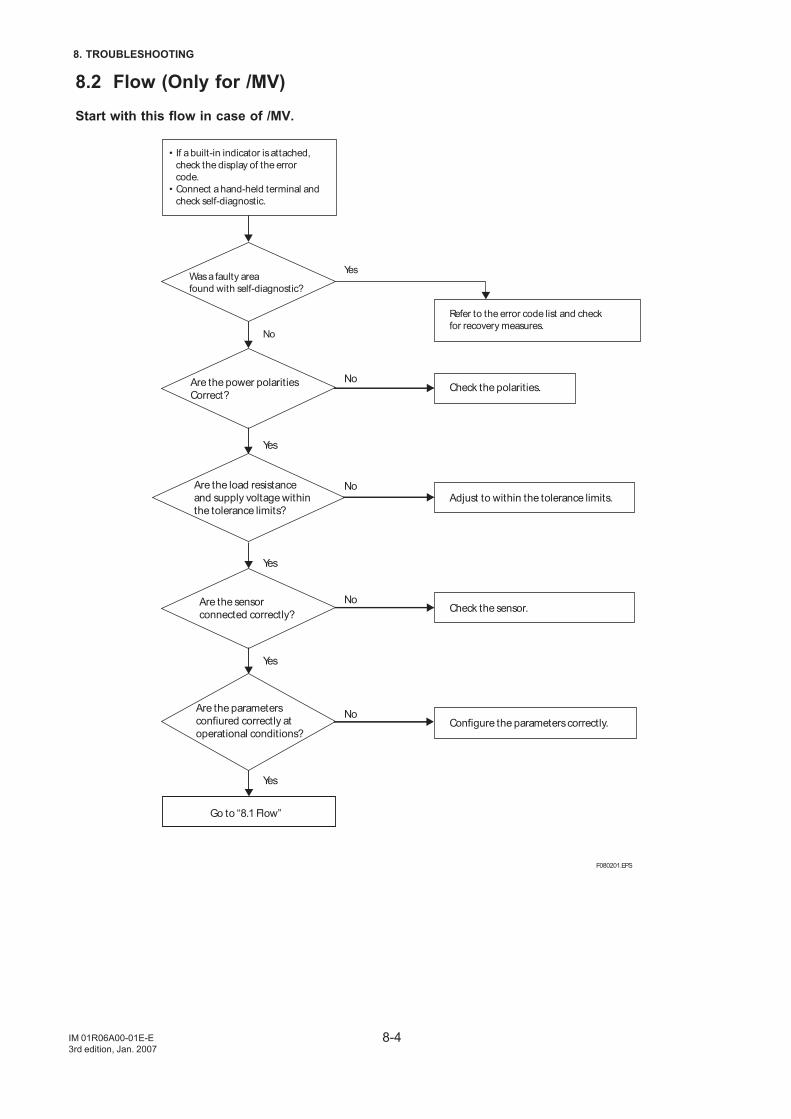
8-4
8. TROUBLESHOOTING
IM 01R06A00-01E-E3rd edition, Jan. 2007
8.2 Flow (Only for /MV)
Start with this flow in case of /MV.
Are the power polarities
Correct?
Are the load resistance
and supply voltage within
the tolerance limits?
Check the polarities.No
Yes
No
Are the sensor
connected correctly?
Yes
Adjust to within the tolerance limits.
Yes
Yes
No
Are the parameters
confiured correctly at
operational conditions?Configure the parameters correctly.
No
Go to “8.1 Flow”
F080201.EPS
YesWas a faulty area
found with self-diagnostic?
No
Refer to the error code list and check
for recovery measures.
• If a built-in indicator is attached,
check the display of the error
code.
• Connect a hand-held terminal and
check self-diagnostic.
Check the sensor.
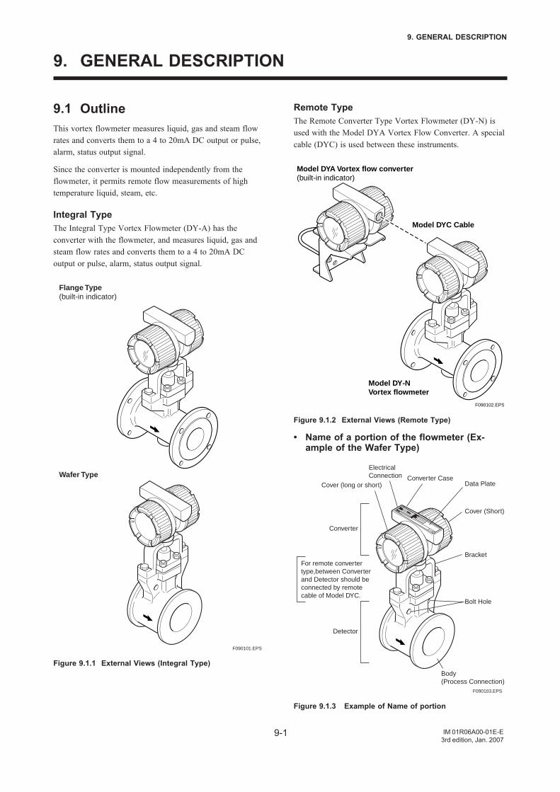
9-1
9. GENERAL DESCRIPTION
IM 01R06A00-01E-E3rd edition, Jan. 2007
9. GENERAL DESCRIPTION
9.1 OutlineThis vortex flowmeter measures liquid, gas and steam flowrates and converts them to a 4 to 20mA DC output or pulse,alarm, status output signal.
Since the converter is mounted independently from theflowmeter, it permits remote flow measurements of hightemperature liquid, steam, etc.
Integral TypeThe Integral Type Vortex Flowmeter (DY-A) has theconverter with the flowmeter, and measures liquid, gas andsteam flow rates and converts them to a 4 to 20mA DCoutput or pulse, alarm, status output signal.
F090101.EPS
Flange Type(built-in indicator)
Wafer Type
Figure 9.1.1 External Views (Integral Type)
Remote TypeThe Remote Converter Type Vortex Flowmeter (DY-N) isused with the Model DYA Vortex Flow Converter. A specialcable (DYC) is used between these instruments.
F090102.EPS
Model DYA Vortex flow converter(built-in indicator)
Model DYC Cable
Model DY-NVortex flowmeter
Figure 9.1.2 External Views (Remote Type)
• Name of a portion of the flowmeter (Ex-ample of the Wafer Type)
F090103.EPS
3UA
Cover (long or short)
Converter
Detector
Converter CaseData Plate
Cover (Short)
ElectricalConnection
Bracket
Bolt Hole
Body(Process Connection)
For remote converter type,between Converter and Detector should be connected by remote cable of Model DYC.
Figure 9.1.3 Example of Name of portion
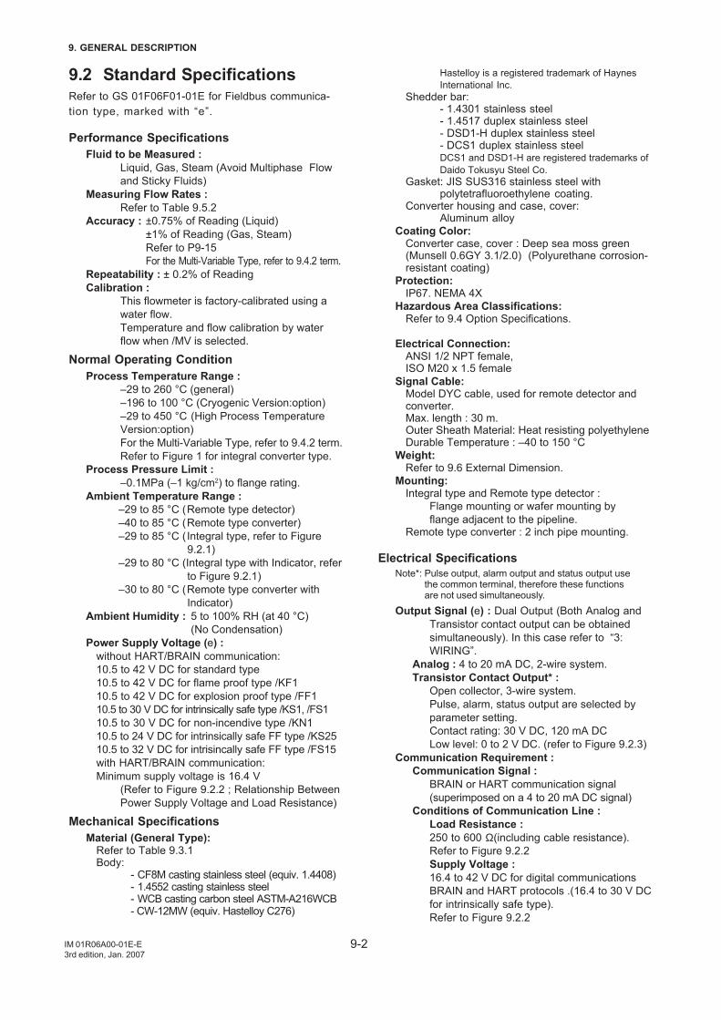
9-2
9. GENERAL DESCRIPTION
IM 01R06A00-01E-E3rd edition, Jan. 2007
9.2 Standard SpecificationsRefer to GS 01F06F01-01E for Fieldbus communica-tion type, marked with “e”.
Performance SpecificationsFluid to be Measured :
Liquid, Gas, Steam (Avoid Multiphase Flowand Sticky Fluids)
Measuring Flow Rates :Refer to Table 9.5.2
Accuracy : ±0.75% of Reading (Liquid)±1% of Reading (Gas, Steam)Refer to P9-15For the Multi-Variable Type, refer to 9.4.2 term.
Repeatability : ± 0.2% of ReadingCalibration :
This flowmeter is factory-calibrated using awater flow.Temperature and flow calibration by waterflow when /MV is selected.
Normal Operating ConditionProcess Temperature Range :
–29 to 260 °C (general)–196 to 100 °C (Cryogenic Version:option)–29 to 450 °C (High Process TemperatureVersion:option)For the Multi-Variable Type, refer to 9.4.2 term.Refer to Figure 1 for integral converter type.
Process Pressure Limit :–0.1MPa (–1 kg/cm2) to flange rating.
Ambient Temperature Range :–29 to 85 °C (Remote type detector)–40 to 85 °C (Remote type converter)–29 to 85 °C (Integral type, refer to Figure
9.2.1)–29 to 80 °C (Integral type with Indicator, refer
to Figure 9.2.1)–30 to 80 °C (Remote type converter with
Indicator)Ambient Humidity : 5 to 100% RH (at 40 °C)
(No Condensation)Power Supply Voltage (e) :
without HART/BRAIN communication:10.5 to 42 V DC for standard type10.5 to 42 V DC for flame proof type /KF110.5 to 42 V DC for explosion proof type /FF110.5 to 30 V DC for intrinsically safe type /KS1, /FS110.5 to 30 V DC for non-incendive type /KN110.5 to 24 V DC for intrinsically safe FF type /KS2510.5 to 32 V DC for intrisincally safe FF type /FS15with HART/BRAIN communication:Minimum supply voltage is 16.4 V
(Refer to Figure 9.2.2 ; Relationship BetweenPower Supply Voltage and Load Resistance)
Mechanical SpecificationsMaterial (General Type):
Refer to Table 9.3.1Body:
- CF8M casting stainless steel (equiv. 1.4408)- 1.4552 casting stainless steel- WCB casting carbon steel ASTM-A216WCB- CW-12MW (equiv. Hastelloy C276)
Hastelloy is a registered trademark of HaynesInternational Inc.
Shedder bar:- 1.4301 stainless steel- 1.4517 duplex stainless steel- DSD1-H duplex stainless steel- DCS1 duplex stainless steelDCS1 and DSD1-H are registered trademarks ofDaido Tokusyu Steel Co.
Gasket: JIS SUS316 stainless steel withpolytetrafluoroethylene coating.
Converter housing and case, cover:Aluminum alloy
Coating Color:Converter case, cover : Deep sea moss green(Munsell 0.6GY 3.1/2.0) (Polyurethane corrosion-resistant coating)
Protection:IP67. NEMA 4X
Hazardous Area Classifications:Refer to 9.4 Option Specifications.
Electrical Connection:ANSI 1/2 NPT female,ISO M20 x 1.5 female
Signal Cable:Model DYC cable, used for remote detector andconverter.Max. length : 30 m.Outer Sheath Material: Heat resisting polyethyleneDurable Temperature : –40 to 150 °C
Weight:Refer to 9.6 External Dimension.
Mounting:Integral type and Remote type detector :
Flange mounting or wafer mounting byflange adjacent to the pipeline.
Remote type converter : 2 inch pipe mounting.
Electrical SpecificationsNote*: Pulse output, alarm output and status output use
the common terminal, therefore these functionsare not used simultaneously.
Output Signal (e) : Dual Output (Both Analog andTransistor contact output can be obtainedsimultaneously). In this case refer to “3:WIRING”.
Analog : 4 to 20 mA DC, 2-wire system.Transistor Contact Output* :
Open collector, 3-wire system.Pulse, alarm, status output are selected byparameter setting.Contact rating: 30 V DC, 120 mA DCLow level: 0 to 2 V DC. (refer to Figure 9.2.3)
Communication Requirement :Communication Signal :
BRAIN or HART communication signal(superimposed on a 4 to 20 mA DC signal)
Conditions of Communication Line :Load Resistance :250 to 600 Ω(including cable resistance).Refer to Figure 9.2.2Supply Voltage :16.4 to 42 V DC for digital communicationsBRAIN and HART protocols .(16.4 to 30 V DCfor intrinsically safe type).Refer to Figure 9.2.2
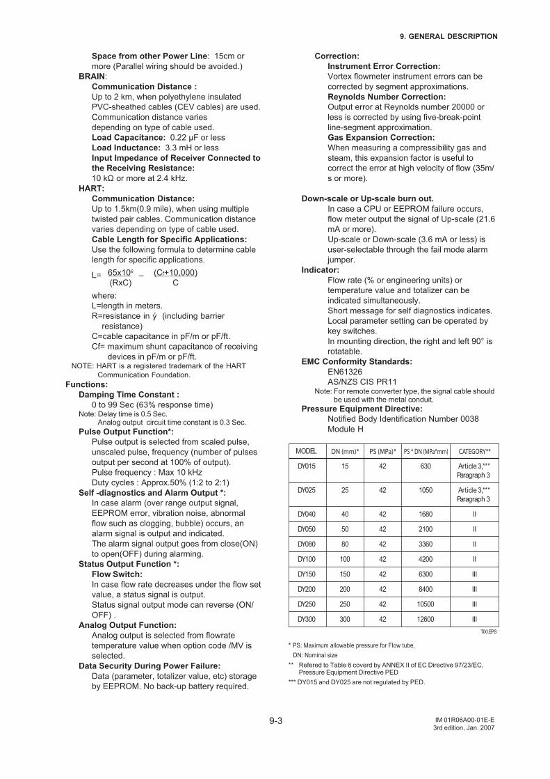
9-3
9. GENERAL DESCRIPTION
IM 01R06A00-01E-E3rd edition, Jan. 2007
Space from other Power Line: 15cm ormore (Parallel wiring should be avoided.)
BRAIN:Communication Distance :Up to 2 km, when polyethylene insulatedPVC-sheathed cables (CEV cables) are used.Communication distance variesdepending on type of cable used.Load Capacitance: 0.22 µF or lessLoad Inductance: 3.3 mH or lessInput Impedance of Receiver Connected tothe Receiving Resistance:10 kΩ or more at 2.4 kHz.
HART:Communication Distance:Up to 1.5km(0.9 mile), when using multipletwisted pair cables. Communication distancevaries depending on type of cable used.Cable Length for Specific Applications:Use the following formula to determine cablelength for specific applications.
L= 65x106 – (Cf+10,000)(RxC) C
where:L=length in meters.R=resistance in ý (including barrier
resistance)C=cable capacitance in pF/m or pF/ft.Cf= maximum shunt capacitance of receiving
devices in pF/m or pF/ft.NOTE: HART is a registered trademark of the HART
Communication Foundation.Functions:
Damping Time Constant :0 to 99 Sec (63% response time)
Note: Delay time is 0.5 Sec.Analog output circuit time constant is 0.3 Sec.
Pulse Output Function*:Pulse output is selected from scaled pulse,unscaled pulse, frequency (number of pulsesoutput per second at 100% of output).Pulse frequency : Max 10 kHzDuty cycles : Approx.50% (1:2 to 2:1)
Self -diagnostics and Alarm Output *:In case alarm (over range output signal,EEPROM error, vibration noise, abnormalflow such as clogging, bubble) occurs, analarm signal is output and indicated.The alarm signal output goes from close(ON)to open(OFF) during alarming.
Status Output Function *:Flow Switch:In case flow rate decreases under the flow setvalue, a status signal is output.Status signal output mode can reverse (ON/OFF) .
Analog Output Function:Analog output is selected from flowratetemperature value when option code /MV isselected.
Data Security During Power Failure:Data (parameter, totalizer value, etc) storageby EEPROM. No back-up battery required.
Correction:Instrument Error Correction:Vortex flowmeter instrument errors can becorrected by segment approximations.Reynolds Number Correction:Output error at Reynolds number 20000 orless is corrected by using five-break-pointline-segment approximation.Gas Expansion Correction:When measuring a compressibility gas andsteam, this expansion factor is useful tocorrect the error at high velocity of flow (35m/s or more).
Down-scale or Up-scale burn out.In case a CPU or EEPROM failure occurs,flow meter output the signal of Up-scale (21.6mA or more).Up-scale or Down-scale (3.6 mA or less) isuser-selectable through the fail mode alarmjumper.
Indicator:Flow rate (% or engineering units) ortemperature value and totalizer can beindicated simultaneously.Short message for self diagnostics indicates.Local parameter setting can be operated bykey switches.In mounting direction, the right and left 90° isrotatable.
EMC Conformity Standards:EN61326AS/NZS CIS PR11
Note: For remote converter type, the signal cable shouldbe used with the metal conduit.
Pressure Equipment Directive:Notified Body Identification Number 0038Module H
T00.EPS
6300
8400
42
150
200
250
2100
100
1680
1050
4200
630
3360
10500
42
42
42
42
42
42
42
40
25
50
80
42
15DY015
III
12600
III
III300 42
II
DY300
Article 3,***
Paragraph 3
II
II
III
II
DY050
PS (MPa)*
DY025
MODEL DN (mm)* CATEGORY**PS * DN (MPa*mm)
DY250
DY100
DY040
DY200
DY150
Article 3,***
Paragraph 3
DY080
* PS: Maximum allowable pressure for Flow tube, DN: Nominal size** Refered to Table 6 coverd by ANNEX II of EC Directive 97/23/EC,
Pressure Equipment Directive PED*** DY015 and DY025 are not regulated by PED.
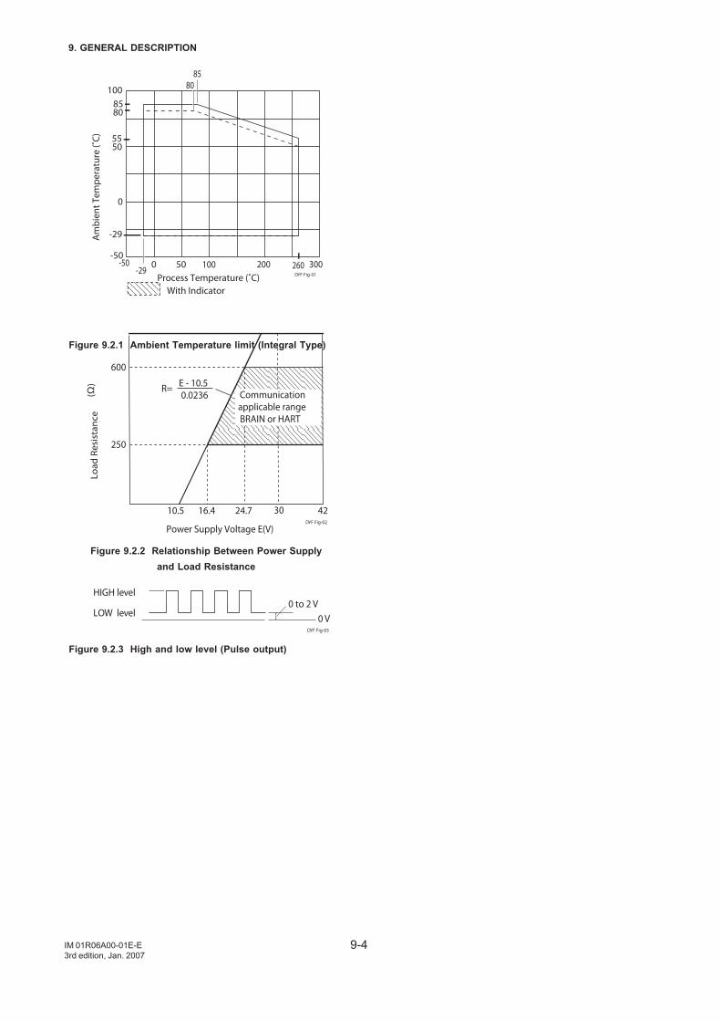
9-4
9. GENERAL DESCRIPTION
IM 01R06A00-01E-E3rd edition, Jan. 2007
R= E - 10.50.0236
250
600
10.5 16.4 24.7 42
Power Supply Voltage E(V)
(Ω)
Communicationapplicable rangeBRAIN or HART
30
Load
Res
ista
nce
DYF Fig-02
Figure 9.2.2 Relationship Between Power Supplyand Load Resistance
HIGH level
LOW level 0 V0 to 2 V
DYF Fig-03
Figure 9.2.3 High and low level (Pulse output)
200100500-50-29
100
50
0
300Process Temperature (˚C)
With Indicator
Am
bien
t Tem
pera
ture
(˚C)
85
-50260
85
-29
80
80
DYF Fig-01
55
Figure 9.2.1 Ambient Temperature limit (Integral Type)
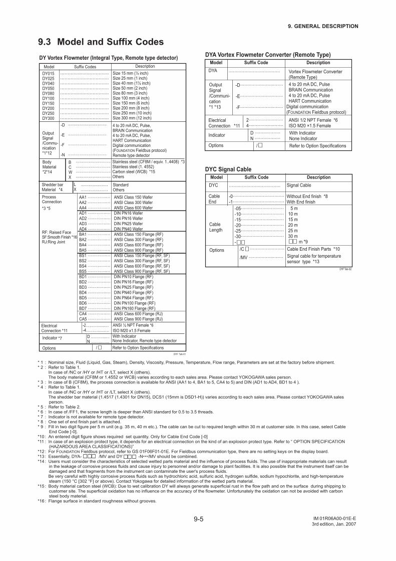
9-5
9. GENERAL DESCRIPTION
IM 01R06A00-01E-E3rd edition, Jan. 2007
9.3 Model and Suffix Codes
/
ANSI Class 150 WaferANSI Class 300 Wafer ANSI Class 600 Wafer DIN PN16 Wafer DIN PN16 Wafer DIN PN25 Wafer DIN PN40 Wafer ANSI Class 150 Flange (RF)ANSI Class 300 Flange (RF)ANSI Class 600 Flange (RF)ANSI Class 900 Flange (RF)ANSI Class 150 Flange (RF, SF)ANSI Class 300 Flange (RF, SF)ANSI Class 600 Flange (RF, SF)ANSI Class 900 Flange (RF, SF)DIN PN10 Flange (RF)DIN PN16 Flange (RF)DIN PN25 Flange (RF)DIN PN40 Flange (RF)DIN PN64 Flange (RF)DIN PN100 Flange (RF)DIN PN160 Flange (RF)ANSI Class 600 Flange (RJ)ANSI Class 900 Flange (RJ)
Model Suffix Codes DescriptionDY015DY025DY040DY050DY080DY100DY150DY200DY250DY300
……………………………………………………………………………………………………………………………………………………………………………………………………………………………………………………………………………………………………
Size 15 mm (½ inch)Size 25 mm (1 inch)Size 40 mm (1½ inch)Size 50 mm (2 inch)Size 80 mm (3 inch)Size 100 mm (4 inch)Size 150 mm (6 inch)Size 200 mm (8 inch)Size 250 mm (10 inch)Size 300 mm (12 inch)
OutputSignal/Commu-nication*1*12
4 to 20 mA DC, Pulse,BRAIN Communication4 to 20 mA DC, Pulse,HART CommunicationDigital communication(FOUNDATION Fieldbus protocol)Remote type detector
Process Connection*3 *5
RF: Raised FaceSF:Smooth Finish *16RJ:Ring Joint
AA1 ….………..…AA2 ….………..…AA4 ….………..… AD1 ….………..…AD2 ….………..…AD3 ….………..…AD4 ….………..… BA1 ….………..…BA2 ….………..…BA4 ….………..…BA5 ….………..…BS1 ….………..…BS2 ….………..…BS4 ….………..…BS5 ….………..…BD1 ….………..…BD2 ….………..…BD3 ….………..…BD4 ….………..…BD5 ….………..…BD6 ….………..…BD7 ….………..…CA4 ….………..…CA5 ….………..…
ANSI ½ NPT Female *6 ISO M20 x1.5 Female
-2……….......…-4……….......…
ElectricalConnection *11
D ………...…N ……..........
DY Vortex Flowmeter (Integral Type, Remote type detector)
-D …………………………
-E …………………………
-F …………………………
-N …………………………
BodyMaterial*2*14
B ………………………C ………………………W ………………………X ………………………
Stainless steel (CF8M / equiv. 1..4408) *3Stainless steel (1. 4552) Carbon steel (WCB) *15Others
Shedder barMaterial *4
L …………………X …………………
Standard Others
Indicator *7
Options
With IndicatorNone Indicator, Remote type detector Refer to Option Specifications
DYF Tab-01
DYA Vortex Flowmeter Converter (Remote Type)
DYC Signal Cable
Model Suffix Code DescriptionDYA ……………………………… Vortex Flowmeter Converter
(Remote Type)
Indicator D ………………N ………………
Options
Output Signal/Communi-cation *1 *13
4 to 20 mA DC, PulseBRAIN Communication4 to 20 mA DC, PulseHART Communication
Digital communication(FOUNDATION Fieldbus protocol)
ANSI 1/2 NPT Female *6 ISO M20 ×1.5 Female
Cable End Finish Parts *10Signal cable for temperature sensor type *13
-D…………………………
-E…………………………
-F…………………………
ElectricalConnection *11
2…………………… 4……………………
/C ……………………
/MV ……………………
/
Model Suffix Code DescriptionDYC ……………………………… Signal Cable
Cable End
Cable Length
Options
-0………………………………-1………………………………
Without End finish *8With End finish 5 m10 m15 m20 m25 m30 m m *9
-05…………………………-10…………………………-15…………………………-20…………………………-25…………………………-30…………………………-
With IndicatorNone IndicatorRefer to Option Specifications
DYF Tab-02
* 1 : Nominal size, Fluid (Liquid, Gas, Steam), Density, Viscosity, Pressure, Temperature, Flow range, Parameters are set at the factory before shipment.* 2 : Refer to Table 1. In case of /NC or /HY or /HT or /LT, select X (others). The body material (CF8M or 1.4552 or WCB) varies according to each sales area. Please contact YOKOGAWA sales person.* 3 : In case of B (CF8M), the process connection is available for ANSI (AA1 to 4, BA1 to 5, CA4 to 5) and DIN (AD1 to AD4, BD1 to 4 ).* 4 : Refer to Table 1. In case of /NC or /HY or /HT or /LT, select X (others). The shedder bar material (1.4517 (1.4301 for DN15), DCS1 (15mm is DSD1-H)) varies according to each sales area. Please contact YOKOGAWA sales
person.* 5 : Refer to Table 2.* 6 : In case of /FF1, the screw length is deeper than ANSI standard for 0.5 to 3.5 threads.* 7 : Indicator is not available for remote type detector.* 8 : One set of end finish part is attached.* 9 : Fill in two digit figure per 5 m unit (e.g. 35 m, 40 m etc.). The cable can be cut to required length within 30 m at customer side. In this case, select Cable
End Code [-0].*10 : An entered digit figure shows required set quantity. Only for Cable End Code [-0]*11 : In case of an explosion protect type, it depends for an electrical connection on the kind of an explosion protect type. Refer to “ OPTION SPECIFICATION
(HAZARDOUS AREA CLASSIFICATIONS)” *12 : For FOUNDATION Fieldbus protocol, refer to GS 01F06F01-01E. For Fieldbus communication type, there are no setting keys on the display board.*13 : Essentially, DYA- /MV and DY -N***/MV should be combined. *14 : Users must consider the characteristics of selected wetted parts material and the influence of process fluids. The use of inappropriate materials can result
in the leakage of corrosive process fluids and cause injury to personnel and/or damage to plant facilities. It is also possible that the instrument itself can be damaged and that fragments from the instrument can contaminate the user's process fluids.
Be very careful with highly corrosive process fluids such as hydrochloric acid, sulfuric acid, hydrogen sulfide, sodium hypochlorite, and high-temperature steam (150 °C [302 °F] or above). Contact Yokogawa for detailed information of the wetted parts material.
*15 : Body material carbon steel (WCB): Due to wet calibration DY will always generate superficial rust in the flow path and on the surface during shipping to customer site. The superficial oxidation has no influence on the accuracy of the flowmeter. Unfortunately the oxidation can not be avoided with carbon steel body material.
*16 : Flange surface in standard roughness without grooves.
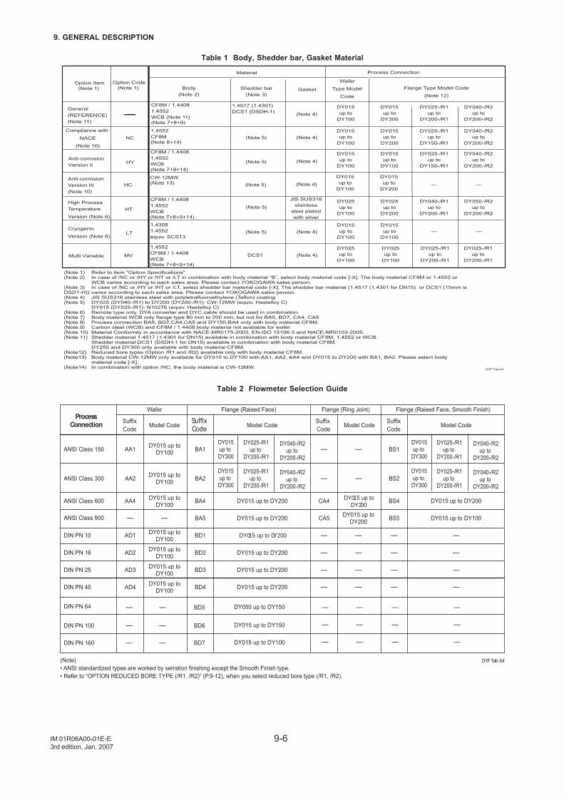
9-6
9. GENERAL DESCRIPTION
IM 01R06A00-01E-E3rd edition, Jan. 2007
Table 1 Body, Shedder bar, Gasket Material
Option Item
(Note 1)
Material
General
(REFERENCE)
(Note 11)
Option Code
(Note 1)
CF8M / 1.4408
1.4552
WCB (Note 11)
(Note 7+8+9)
Body
(Note 2)
Shedder bar
(Note 3)
1.4517 (1.4301)
DCS1 (DSDH-1)
Anti-corrosion
Version II
CF8M / 1.4408
1.4552
WCB
(Note 7+9+14)
(Note 5)
High Process
Temperature
Version (Note 6)
Cryogenic
Version (Note 6)
(Note 5)
HY
HT
LT
1.4308
1.4552
equiv. SCS13
JIS SUS316
stainless
steel plated
with silver
(Note 4)
Gasket
(Note 4)
(Note 4)
Process Connection
Wafer
Type Model
Code
Flange Type Model Code
(Note 12)
(Note 5)
DYF Tab-03
Multi Variable MV DCS1 (Note 4)
1.4552
CF8M / 1.4408
WCB
(Note 7+8+9+14)
(Note 1) Refer to item "Option Specifications"(Note 2) In case of /NC or /HY or /HT or /LT in combination with body material ”B”, select body material code [-X]. The body material CF8M or 1.4552 or WCB varies according to each sales area. Please contact YOKOGAWA sales person.(Note 3) In case of /NC or /HY or /HT or /LT, select shedder bar material code [-X]. The shedder bar material (1.4517 (1.4301 for DN15) or DCS1 (15mm is DSD1-H)) varies according to each sales area. Please contact YOKOGAWA sales person.(Note 4) JIS SUS316 stainless steel with polytetrafluoroethylene (Teflon) coating(Note 5) DY025 (DY040-/R1) to DY200 (DY200-/R1): CW-12MW (equiv. Hastelloy C) DY015 (DY025-/R1): N10276 (equiv. Hastelloy C)(Note 6) Remote type only. DYA converter and DYC cable should be used in combination.(Note 7) Body material WCB only flange type 80 mm to 200 mm, but not for BA5, BD7, CA4, CA5(Note 8) Process connection BA5, BD7,CA4,CA5 and DY150-BA4 only with body material CF8M.(Note 9) Carbon steel (WCB) and CF8M / 1.4408 body material not available for wafer. (Note 10) Material Conformity in accordance with NACE-MR0175-2003, EN-ISO 15156-3 and NACE-MR0103-2005.(Note 11) Shedder material 1.4517 (1.4301 for DN15) available in combination with body material CF8M, 1.4552 or WCB. Shedder material DCS1 (DSDH-1 for DN15) available in combination with body material CF8M. DY250 and DY300 only available with body material CF8M.(Note12) Reduced bore types (Option /R1 and /R2) available only with body material CF8M.(Note13) Body material CW-12MW only available for DY015 to DY100 with AA1, AA2, AA4 and DY015 to DY200 with BA1, BA2. Please select body material code [-X].(Note14) In combination with option /HC, the body material is CW-12MW.
Compliance with
NACE
(Note 10)
NC
1.4552
CF8M
(Note 8+14)(Note 5) (Note 4)
CF8M / 1.4408
1.4552
WCB
(Note 7+8+9+14)
DY015
up to
DY100
DY015
up to
DY300
DY015
up to
DY100
DY025
up to
DY100
DY015
up to
DY100
DY025
up to
DY100
DY015
up to
DY100
DY015
up to
DY100
DY015
up to
DY100
DY015
up to
DY200
DY025
up to
DY200
DY025-/R1
up to
DY200-/R1
DY025-/R1
up to
DY150-/R1
DY025-/R1
up to
DY150-/R1
DY040-/R1
up to
DY200-/R1
DY040-/R2
up to
DY200-/R2
DY040-/R2
up to
DY200-/R2
DY040-/R2
up to
DY200-/R2
DY050-/R2
up to
DY200-/R2
DY025
up to
DY100
DY025-/R1
up to
DY200-/R1
DY025-/R1
up to
DY200-/R1
Anti-corrosion
Version III
(Note 10)
CW-12MW
(Note 13) (Note 5)HC (Note 4)
DY015
up to
DY100
DY015
up to
DY200
— —
— —
Table 2 Flowmeter Selection Guide
DYF Tab-04(Note)• ANSI standardized types are worked by serration finishing except the Smooth Finish type.• Refer to “OPTION REDUCED BORE TYPE (/R1, /R2)” (P.9-12), when you select reduced bore type (/R1, /R2).
DY015 up toDY100
DY015 up toDY100
DY015 up toDY100 DY015 up to DY200 DY015 up to DY200
DY015 up to DY200 DY015 up to DY100
DY015 up to DY200
DY015 up to DY200
DY015 up to DY200
DY015 up to DY200
——
DY015 up toDY100
DY015 up toDY100
DY015 up toDY100
DY015 up toDY100
—
—
DY015 up toDY200
DY015 up toDY200
—
—
—
—
—
—
—
—
DY015up to DY300
DY025-/R1up to
DY200-/R1
DY040-/R2up to
DY200-/R2
DY015up to DY300
DY025-/R1up to
DY200-/R1
DY040-/R2up to
DY200-/R2
DY015up to DY300
DY025-/R1up to
DY200-/R1
DY040-/R2up to
DY200-/R2
DY015up to DY300
DY025-/R1up to
DY200-/R1
DY040-/R2up to
DY200-/R2
Wafer Flange (Raised Face) Flange (Ring Joint) Flange (Raised Face, Smooth Finish)Process
Connection SuffixCode
SuffixCodeModel Code Model Code Model CodeModel Code
ANSI Class 150
ANSI Class 300
ANSI Class 600
ANSI Class 900
DIN PN 10
DIN PN 16
DIN PN 25
DIN PN 40
AA1
AA2
AA4
AD1
AD2
AD3
AD4
BA5
BA1
BA2
BA4
BD1
BD2
BD3
BD4
Suffix Code
CA5
—
—
CA4
—
—
—
—
SuffixCode
BS5
BS1
BS2
BS4
—
—
—
—
DIN PN 64
DIN PN 100
DIN PN 160
—
—
—
—
—
—
BD5
BD6
BD7
DY050 up to DY150
DY015 up to DY150
DY015 up to DY100
—
—
—
—
—
—
—
—
—
—
—
—
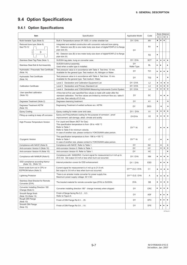
9-7
9. GENERAL DESCRIPTION
IM 01R06A00-01E-E3rd edition, Jan. 2007
9.4 Option Specifications
9.4.1 Option Specifications
DY***-D,E / DYACurrent signal for measurement is 4 mA up to 21.6 mA.Set output to 3.6 mA or less when burn-out occurred.
DY
DY
Converter installing direction 180° change inversely when shipped.
DY / DYACompliance with NAMUR43. Current signal for measurement is 4 mA up to 20.5 mA. Set output 3.6 mA or less when burn-out occurred.
DY***-D,E / DYAThere is an arrester inside converter for power supply line.Maximum power supply voltage: 30 V DC
DYTest pressure value is in accordance with Table 4. Test time: 10 min.Available for the general type. Test medium: Water.
DYWafer Type
SUS304 bolt/nut assembly.Used when a wafer type is installed.
Integrated and welded construction with concentric reduced bore piping.R1 : Detector size (B) is one meter body size down of digitalYEWFLO to flange pipe size (A).
R2 : Detector size (B) is two meter body size down of digitalYEWFLO to flange pipe size (A).
DYTest pressure value is in accordance with Table 4. Test time: 10 min.Available for the general type. Test medium: Air, Nitrogen or Water.
DYAThe bracket material for remote converter type (DYA) is SUS304.
Anti-corrosion Version II. Refer to Table 1.DYCompliance with NACE. Refer to Table 1.
DY / DYAEpoxy coating for meter cover and case.
DYDegrease cleansing treatment.
DY / DYASUS304 tag plate, hung on converter case.
DY / DYA
DY
Built in Temperature sensor (Pt 1000 ) in vortex shedder bar.
DYF Tab-07-1
DY / DYADY / DYADY / DYA
L2L3L4
C1
CRC
HY
Level 2 Declaration and Calibration Equipment ListLevel 3 Declaration and Primary Standard ListLevel 4 Declaration and YOKOGAWA Measuring Instruments Control System
Calibration Certificate
DY***-N LT
DY***-N HT
Cryogenic Version
High Process Temperature Version
This specification temperature is from -196 to +100 °CRefer to Table 1In case of another size, please contact to YOKOGAWA sales person.
For Liquid and Steam (NOT for Gas)This specification temperature is from -29 to +450 °CRefer to Table 1Refer to Table 5 for minimum velocity.In case of another size, please contact to YOKOGAWA sales person.
Down-scale burn-out in CPU or EEPROM failure (Note 3)
Converter Installing Direction 180Change (Note 4)
NMCompliance with NAMUR (Note 6)
ALightning Protector
T02Hydrostatic Test Certificate(Note 14)
BLStainless Steel Bolt & Nut Assembly
T01Hydrostatic / Pneumatic Test Certificate(Note 14)
SBStainless Steel Bracket for Remote Converter (DYA)
Anti-corrosion Version II (Note 10)NCCompliance with NACE (Note 9)
X1Epoxy Coating
K1Degrease Treatment (Note 2)
SCTStainless Steel Tag Plate (Note 1)
MV
R1
R2
Multi-Variable Type (Note 5)
Reduced bore type (Note 8)See P.9-12
Item Specification Applicable Model Code
DYAnti-corrosion Version III. Refer to Table 1. HCAnti-corrosion Version III (Note 10)
DYFinish of flange facing Ra 3.2 ... 6.3.Refer to Figure 6.
ASFSmooth flange finish(Note 10) (Note 13)
DYFinish of DIN Flange Ra 6.3 ... 25. DFCRough DIN Flange(Note 10)
DYFinish of DIN Flange Ra 0.8 ...1.6. DFESmooth DIN Flange(Note 10)
DYA flow test at five user specified flow values is made with water after the standard calibration. The flow values are limited by minimum flow acc. table 8and max. flow velocity of 5.5 m/s.
SCUser specified calibration(Note 10)
Degrease Treatment ASTM(Note 10)
Degreasing Treatment of wetted surfaces acc. ASTM. DY DEG
Pilling up coating to keep off corrosion Epoxy and Polyurethane coating for the purpose of corrosion - proof improvement; salt damage, alkali, climate and acidity
X2DY/DYA
ESD compliance according Namur Internal protection covers for ESD enhancement(Note 12)
DY / DYA ESD(Note 10)
BA
Body MaterialB C W X
• ••••
••
•
••••••
••••
•••
••••••••••••
•••
•••••••
•••
•••••
••••
••••
••••
•••••••••
••••••••••••••
••••
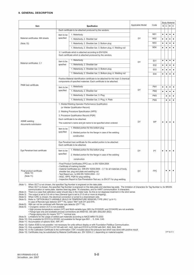
9-8
9. GENERAL DESCRIPTION
IM 01R06A00-01E-E3rd edition, Jan. 2007
Item Specification Code
(Note 1) When /SCT is not chosen, the specified Tag Number is engraved on the data plate. When /SCT is chosen, the specified Tag Number is engraved on the data plate and stainless tag plate. The limitation of characters for Tag Number is, for BRAIN communication or name plate, stainles steel tag plate: 16 characters, and for HART communication: 8 characters.(Note 2) There is a case that calibration water should stay in the meter tube. So this is not degrease treatment in the strict sense.(Note 3) The output is set to 3.6 mA or less (General type is set to 21.6 mA or more at shipping).(Note 4) When /CRC is chosen, the electrical connection is turned to a downstream side.(Note 5) Refer to “OPTION MULTI-VARIABLE (BUILD IN TEMPERATURE SENSOR) TYPE (/MV)” (p.9-11) In case of Remote type detector (DY***-N), select “/MV” both DY and DYA.(Note 6) /NM can not be combined with Remote type detector (DY***-N).(Note 8) • Cryogenic version (/LT) is not available. • High process temperature version (/HT) and Multi-variable type (/MV) for DY025/R1 and DY040/R2 are not available. • Flange type only and available process connections are ANSI150, 300 (BA1,BA2,BS1,BS2). • Flange piping size (A) means “DY***-” nominal size.(Note 9) Limitations for the usage of wetted part materials according to NACE-MR0175-2003(Note 10) Only available for DY015 to DY200; not available for flange type BS1 ... 5, CA4, CA5.(Note 11) Accumulation of options /E04, /WP, /PT(Note 12) Option /ESD is not possible / not necessary for units without display or with Foundation Fieldbus Communication.(Note 13) Only available for DY015 to DY100 with AA1, AA2, AA4 and DY015 to DY200 with BA1, BA2, BA4, BA5.(Note 14) In the Calibration Certificate is the confirmation (”OK”) included about the pressure test which was done with positive result.(Note 15) Certificates may be substituted by Material Certificates acc. EN 10204-3.1, depending on material supplier.
Applicable Model
DYF Tab-07-2
Each certificate to be attached produced by the vendors.
1. Meterbody
1. Meterbody, 2. Shedder bar
1. Meterbody, 2. Shedder bar, 3. Bottom plug
1. Meterbody, 2. Shedder bar, 3. Bottom plug, 4. Welding rod
3.1 certificate which is attached according to EN10204.Each certificate which is attached produced by the vendors.
1. Meterbody
1. Meterbody, 2. Shedder bar
1. Meterbody, 2. Shedder bar, 3. Bottom plug
1. Meterbody, 2. Shedder bar, 3. Bottom plug, 4. Welding rod
Positive Material Identification certificate to be attached for the main 3 chemical components of specified materials. Each certificate to be attached.
1. Meterbody
1. Meterbody, 2. Shedder bar
1. Meterbody, 2. Shedder bar, 3. Plug
1. Meterbody, 2. Shedder bar, 3. Plug, 4. Plate
1. Welder/Welding Operator Performance Qualification (or Welder Qualification Record)
2. Welding Procedure Specification (WPS)
3. Procedure Qualification Record (PQR)
Each certificate to be attached.
The customer’s name and job name to be specified when ordered.
1. Welded portion for the bottom plug
2. Welded portion for the flange in case of the welding
construction
Material certificates: Mill sheets
(Note 15)
Material certificates: 3.1
PAMI test certificate
ASME weldingdocuments submission
Dye Penetrant test certificate
Item to be specified
Item to be specified
Item to be specified
Item to be specified
Item to be specified
M01
M02
M03
M04
E01
E02
E03
E04
PM1
PM2
WP
PT
DY
DY
DY
DY
DY
1. Welded portion for the bottom plug
2. Welded portion for the flange in case of the welding construction
Dye Penetrant test certificate for the welded portion to be attached. Each certificate to be attached.
Final product certificate FPCDY
- Final Product Certificates (FPC) acc. to EN 10204:2004- Certificate of marking transfer- material Certificates acc. DIN EN 10204:2004 – 3.1 for all materials of body, shedder bar, plug and plate and welding rod.- Test Report acc. to DIN EN 10204:2004 - 2.2- WQC, WPS, PQR for plug welding.- Inspection Report to Dye-Penetration-Test acc. to EN 571 for plug welding.
(Note 10)(Note 11)
Body MaterialB C W X
PM3
PM4
••••
••••••••
••••
••••••••••••••••
••••••••••••••
••••
••••
•••
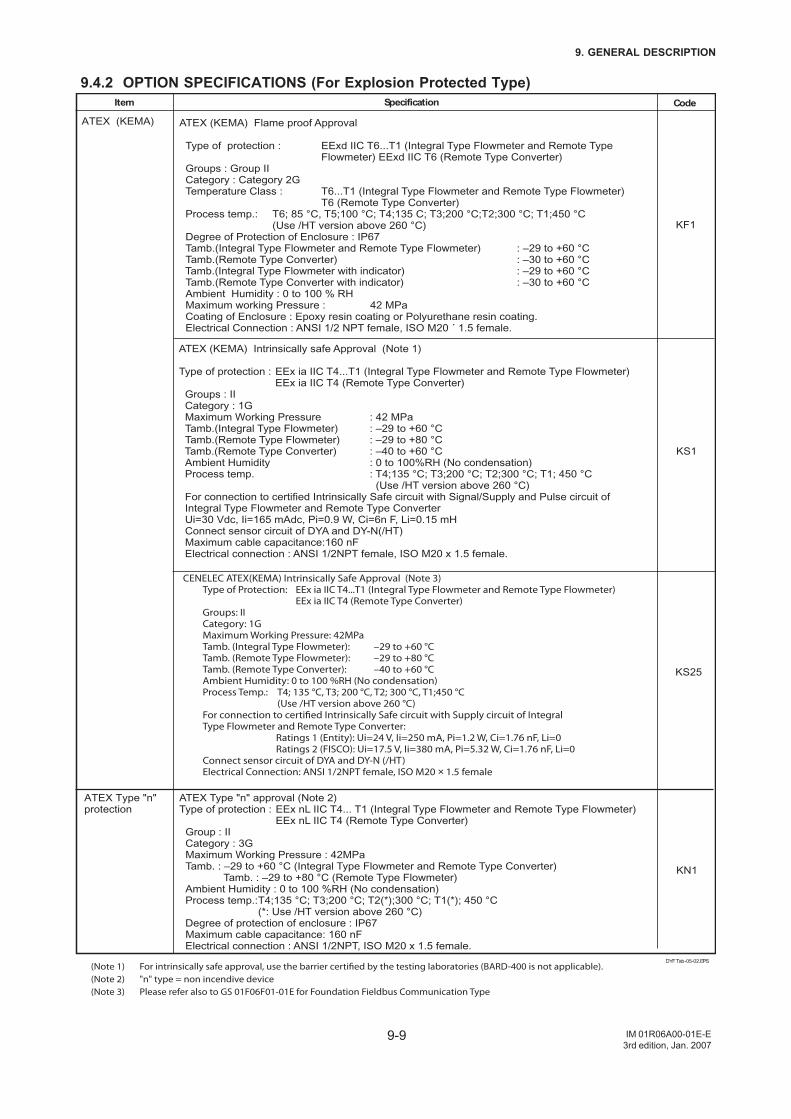
9-9
9. GENERAL DESCRIPTION
IM 01R06A00-01E-E3rd edition, Jan. 2007
9.4.2 OPTION SPECIFICATIONS (For Explosion Protected Type)
KS25
KN1
DYF Tab-05-02.EPS
Code
(Note 1) For intrinsically safe approval, use the barrier certified by the testing laboratories (BARD-400 is not applicable).(Note 2) "n" type = non incendive device(Note 3) Please refer also to GS 01F06F01-01E for Foundation Fieldbus Communication Type
KF1
KS1
SpecificationItem
ATEX (KEMA) Intrinsically safe Approval (Note 1)
Type of protection : EEx ia IIC T4...T1 (Integral Type Flowmeter and Remote Type Flowmeter) EEx ia IIC T4 (Remote Type Converter) Groups : II Category : 1G Maximum Working Pressure : 42 MPa Tamb.(Integral Type Flowmeter) : –29 to +60 °C Tamb.(Remote Type Flowmeter) : –29 to +80 °C Tamb.(Remote Type Converter) : –40 to +60 °C Ambient Humidity : 0 to 100%RH (No condensation) Process temp. : T4;135 °C; T3;200 °C; T2;300 °C; T1; 450 °C (Use /HT version above 260 °C) For connection to certified Intrinsically Safe circuit with Signal/Supply and Pulse circuit of Integral Type Flowmeter and Remote Type Converter Ui=30 Vdc, Ii=165 mAdc, Pi=0.9 W, Ci=6n F, Li=0.15 mH Connect sensor circuit of DYA and DY-N(/HT) Maximum cable capacitance:160 nF Electrical connection : ANSI 1/2NPT female, ISO M20 x 1.5 female.
ATEX (KEMA) Flame proof Approval
Type of protection : EExd IIC T6...T1 (Integral Type Flowmeter and Remote Type Flowmeter) EExd IIC T6 (Remote Type Converter) Groups : Group II Category : Category 2G Temperature Class : T6...T1 (Integral Type Flowmeter and Remote Type Flowmeter) T6 (Remote Type Converter) Process temp.: T6; 85 °C, T5;100 °C; T4;135 C; T3;200 °C;T2;300 °C; T1;450 °C (Use /HT version above 260 °C) Degree of Protection of Enclosure : IP67 Tamb.(Integral Type Flowmeter and Remote Type Flowmeter) : –29 to +60 °C Tamb.(Remote Type Converter) : –30 to +60 °C Tamb.(Integral Type Flowmeter with indicator) : –29 to +60 °C Tamb.(Remote Type Converter with indicator) : –30 to +60 °C Ambient Humidity : 0 to 100 % RH Maximum working Pressure : 42 MPa Coating of Enclosure : Epoxy resin coating or Polyurethane resin coating. Electrical Connection : ANSI 1/2 NPT female, ISO M20 ´ 1.5 female.
ATEX (KEMA)
ATEX Type "n" protection
ATEX Type "n" approval (Note 2)Type of protection : EEx nL IIC T4... T1 (Integral Type Flowmeter and Remote Type Flowmeter) EEx nL IIC T4 (Remote Type Converter) Group : II Category : 3G Maximum Working Pressure : 42MPa Tamb. : –29 to +60 °C (Integral Type Flowmeter and Remote Type Converter) Tamb. : –29 to +80 °C (Remote Type Flowmeter) Ambient Humidity : 0 to 100 %RH (No condensation) Process temp.: T4;135 °C; T3;200 °C; T2(*);300 °C; T1(*); 450 °C (*: Use /HT version above 260 °C) Degree of protection of enclosure : IP67 Maximum cable capacitance: 160 nF Electrical connection : ANSI 1/2NPT, ISO M20 x 1.5 female.
CENELEC ATEX(KEMA) Intrinsically Safe Approval (Note 3) Type of Protection: EEx ia IIC T4...T1 (Integral Type Flowmeter and Remote Type Flowmeter) EEx ia IIC T4 (Remote Type Converter) Groups: II Category: 1G Maximum Working Pressure: 42MPa Tamb. (Integral Type Flowmeter): –29 to +60 °C Tamb. (Remote Type Flowmeter): –29 to +80 °C Tamb. (Remote Type Converter): –40 to +60 °C Ambient Humidity: 0 to 100 %RH (No condensation) Process Temp.: T4; 135 °C, T3; 200 °C, T2; 300 °C, T1;450 °C (Use /HT version above 260 °C) For connection to certified Intrinsically Safe circuit with Supply circuit of Integral Type Flowmeter and Remote Type Converter: Ratings 1 (Entity): Ui=24 V, Ii=250 mA, Pi=1.2 W, Ci=1.76 nF, Li=0 Ratings 2 (FISCO): Ui=17.5 V, Ii=380 mA, Pi=5.32 W, Ci=1.76 nF, Li=0 Connect sensor circuit of DYA and DY-N (/HT) Electrical Connection: ANSI 1/2NPT female, ISO M20 × 1.5 female
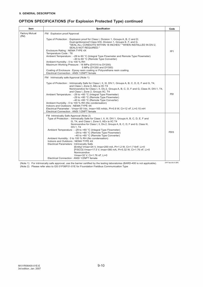
9-10
9. GENERAL DESCRIPTION
IM 01R06A00-01E-E3rd edition, Jan. 2007
OPTION SPECIFICATIONS (For Explosion Protected Type) continued
DYF Tab-05-01.EPS
Code
(Note 1) For intrinsically safe approval, use the barrier certified by the testing laboratories (BARD-400 is not applicable).(Note 2) Please refer also to GS 01F06F01-01E for Foundation Fieldbus Communication Type
FF1
FS1
SpecificationItem
FM Intrinsically safe Approval (Note 1) Type of Protection : Intrinsically Safe for Class I, II, III, DIV.1, Groups A, B, C, D, E, F and G, T4, and Class I, Zone 0, AEx ia IIC T4 Nonincendive for Class I, II, Div.2, Groups A, B, C, D, F and G, Class III, DIV.1, T4, and Class I, Zone 2, Groups IIC, T4 Ambient Temperature : –29 to +60 °C (Integral Type Flowmeter) –29 to +80 °C (Remote Type Flowmeter) –40 to +60 °C (Remote Type Converter) Ambient Humidity : 0 to 100 % RH (No condensation) Indoors and Outdoors : NEMA TYPE 4X Electrical Parameter : Vmax=30 Vdc, Imax=165 mAdc, Pi=0.9 W, Ci=12 nF, Li=0.15 mH Electrical Connection : ANSI 1/2NPT female
FM Explosion proof Approval
Type of Protection : Explosion proof for Class I, Division 1, Groups A, B, C and D; Dust-ignitionproof Class II/III, Division 1, Groups E, F, and G. "SEAL ALL CONDUITS WITHIN 18 INCHES." "WHEN INSTALLED IN DIV.2, SEALS NOT REQUIRED." Enclosure Rating : NEMA TYPE 4X Temperature Code : T6 Ambient Temperature : –29 to 60 °C (Integral Type Flowmeter and Remote Type Flowmeter) –40 to 60 °C (Remote Type Converter) Ambient Humidity : 0 to 100 % RH Maximum Working Pressure : 16 MPa (DY015 to DY200) 5 MPa (DY250 and DY300) Coating of Enclosure : Epoxy resin coating or Polyurethane resin coating. Electrical Connection : ANSI 1/2NPT female
Factory Mutual (FM)
FM Intrinsically Safe Approval (Note 2) Type of Protection : Intrinsically Safe for Class I, II, III, DIV.1, Groups A, B, C, D, E, F and G, T4, and Class I, Zone 0, AEx ia IIC T4 Nonincendive for Class I, II, Div.2, Groups A, B, C, D, F and G, Class III, DIV.1, T4 Ambient Temperature : –29 to +60 °C (Integral Type Flowmeter) –29 to +80 °C (Remote Type Flowmeter) –40 to +60 °C (Remote Type Converter) Ambient Humidity : 0 to 100 % RH (No condensation) Indoors and Outdoors : NEMA TYPE 4X Electrical Parameters : Intrinsically Safe [Entity] Vmax=24 V, Imax=250 mA, Pi=1.2 W, Ci=1.7 6nF, Li=0 [FISCO] Vmax=17.5 V, Imax=380 mA, Pi=5.32 W, Ci=1.76 nF, Li=0 Nonincendive Vmax=32 V, Ci=1.76 nF, Li=0 Electrical Connection : ANSI 1/2NPT female
FS15
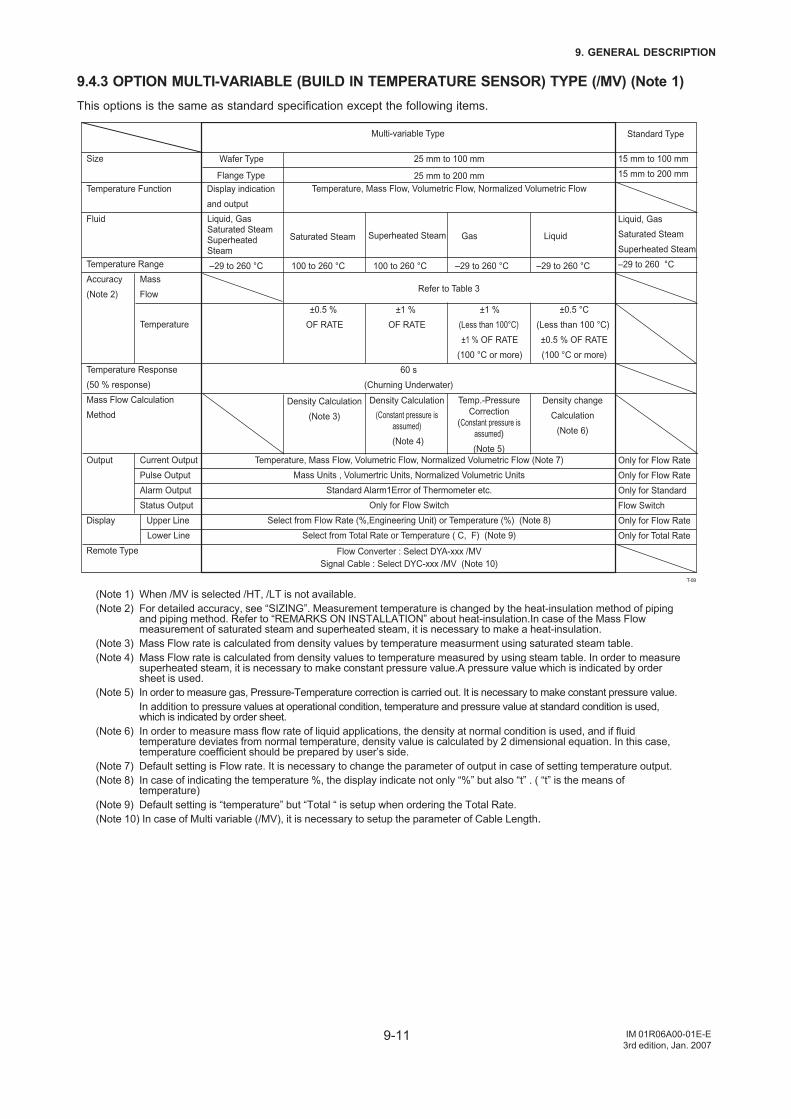
9-11
9. GENERAL DESCRIPTION
IM 01R06A00-01E-E3rd edition, Jan. 2007
9.4.3 OPTION MULTI-VARIABLE (BUILD IN TEMPERATURE SENSOR) TYPE (/MV) (Note 1)This options is the same as standard specification except the following items.
T-09
Size
Temperature Function
Fluid
Temperature Range
Accuracy
(Note 2)
Temperature Response
(50 % response)
Mass Flow Calculation
Method
Output
Display
Remote Type
Mass
Flow
Temperature
Current Output
Pulse Output
Alarm Output
Status Output
Upper Line
Lower Line
Standard Type
15 mm to 100 mm
15 mm to 200 mm
Liquid, Gas
Saturated Steam
Superheated Steam
–29 to 260 °C
Only for Flow Rate
Only for Flow Rate
Only for Standard
Flow Switch
Only for Flow Rate
Only for Total Rate
Liquid, GasSaturated SteamSuperheated Steam
Display indication
and output
Temperature, Mass Flow, Volumetric Flow, Normalized Volumetric Flow
Multi-variable Type
Saturated Steam Superheated Steam Gas Liquid
–29 to 260 °C 100 to 260 °C 100 to 260 °C –29 to 260 °C –29 to 260 °C
Temperature, Mass Flow, Volumetric Flow, Normalized Volumetric Flow (Note 7)
Mass Units , Volumertric Units, Normalized Volumetric Units
Standard Alarm1Error of Thermometer etc.
Only for Flow Switch
Select from Flow Rate (%,Engineering Unit) or Temperature (%) (Note 8)
Select from Total Rate or Temperature ( C, F) (Note 9)
Flow Converter : Select DYA-xxx /MV
Signal Cable : Select DYC-xxx /MV (Note 10)
60 s
(Churning Underwater)
Wafer Type
Flange Type
25 mm to 100 mm
25 mm to 200 mm
±0.5 %
OF RATE
±1 %
OF RATE
±1 %
(Less than 100°C)
±1 % OF RATE
(100 °C or more)
±0.5 °C
(Less than 100 °C)
±0.5 % OF RATE
(100 °C or more)
Density Calculation
(Note 3)
Density Calculation
(Constant pressure is
assumed)
(Note 4)
Temp.-Pressure
Correction
(Constant pressure is
assumed)
(Note 5)
Density change
Calculation
(Note 6)
Refer to Table 3
(Note 1) When /MV is selected /HT, /LT is not available.(Note 2) For detailed accuracy, see “SIZING”. Measurement temperature is changed by the heat-insulation method of piping
and piping method. Refer to “REMARKS ON INSTALLATION” about heat-insulation.In case of the Mass Flowmeasurement of saturated steam and superheated steam, it is necessary to make a heat-insulation.
(Note 3) Mass Flow rate is calculated from density values by temperature measurment using saturated steam table.(Note 4) Mass Flow rate is calculated from density values to temperature measured by using steam table. In order to measure
superheated steam, it is necessary to make constant pressure value.A pressure value which is indicated by ordersheet is used.
(Note 5) In order to measure gas, Pressure-Temperature correction is carried out. It is necessary to make constant pressure value.In addition to pressure values at operational condition, temperature and pressure value at standard condition is used,which is indicated by order sheet.
(Note 6) In order to measure mass flow rate of liquid applications, the density at normal condition is used, and if fluidtemperature deviates from normal temperature, density value is calculated by 2 dimensional equation. In this case,temperature coefficient should be prepared by user’s side.
(Note 7) Default setting is Flow rate. It is necessary to change the parameter of output in case of setting temperature output.(Note 8) In case of indicating the temperature %, the display indicate not only “%” but also “t” . ( “t” is the means of
temperature)(Note 9) Default setting is “temperature” but “Total “ is setup when ordering the Total Rate.(Note 10) In case of Multi variable (/MV), it is necessary to setup the parameter of Cable Length.
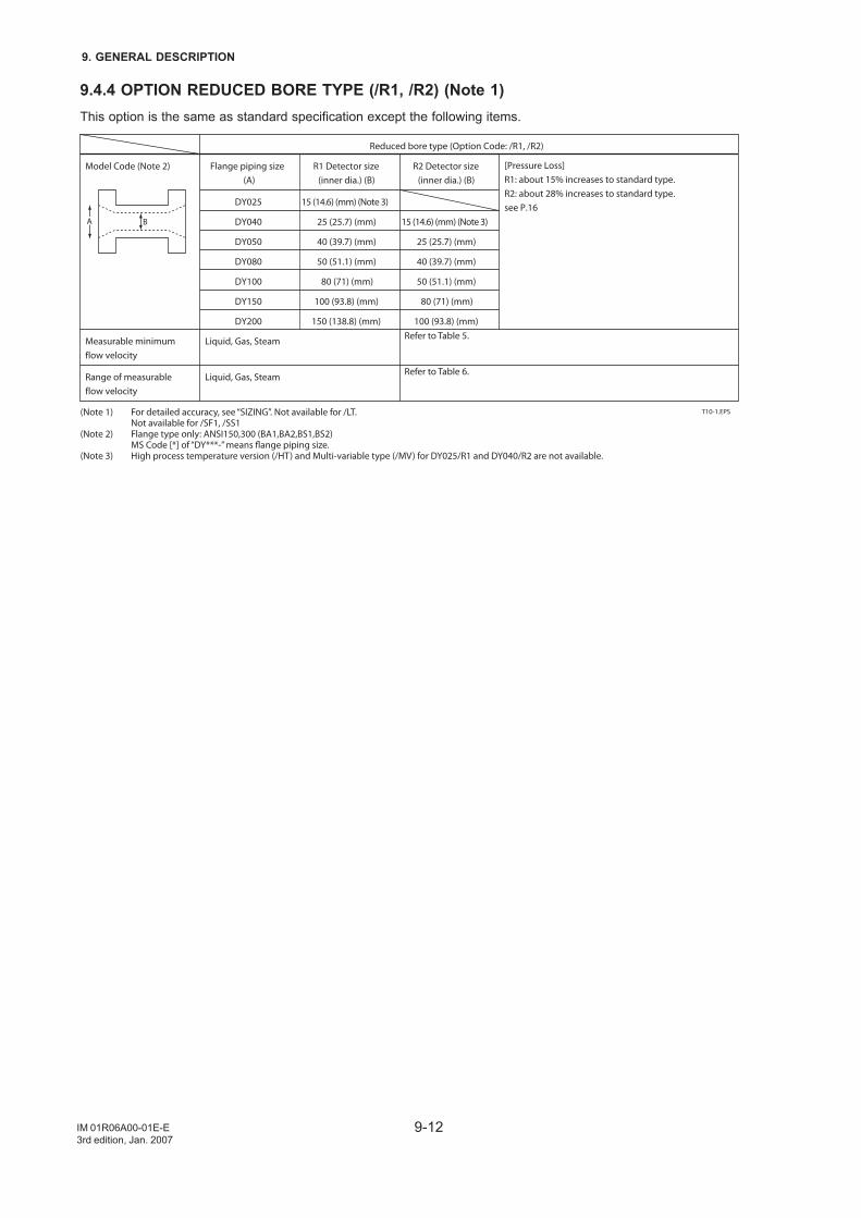
9-12
9. GENERAL DESCRIPTION
IM 01R06A00-01E-E3rd edition, Jan. 2007
9.4.4 OPTION REDUCED BORE TYPE (/R1, /R2) (Note 1)This option is the same as standard specification except the following items.
BA
(Note 1) For detailed accuracy, see “SIZING”. Not available for /LT. Not available for /SF1, /SS1(Note 2) Flange type only: ANSI150,300 (BA1,BA2,BS1,BS2) MS Code [*] of “DY***-” means flange piping size. (Note 3) High process temperature version (/HT) and Multi-variable type (/MV) for DY025/R1 and DY040/R2 are not available.
T10-1.EPS
Model Code (Note 2)
Measurable minimumflow velocity
Range of measurableflow velocity
Reduced bore type (Option Code: /R1, /R2)
Flange piping size(A)
DY025
DY040
DY050
DY080
DY100
DY150
DY200
R1 Detector size(inner dia.) (B)
Refer to Table 5.
Refer to Table 6.
15 (14.6) (mm) (Note 3)
25 (25.7) (mm)
40 (39.7) (mm)
50 (51.1) (mm)
80 (71) (mm)
100 (93.8) (mm)
150 (138.8) (mm)
R2 Detector size(inner dia.) (B)
15 (14.6) (mm) (Note 3)
25 (25.7) (mm)
40 (39.7) (mm)
50 (51.1) (mm)
80 (71) (mm)
100 (93.8) (mm)
Liquid, Gas, Steam
Liquid, Gas, Steam
[Pressure Loss]R1: about 15% increases to standard type.R2: about 28% increases to standard type.see P.16
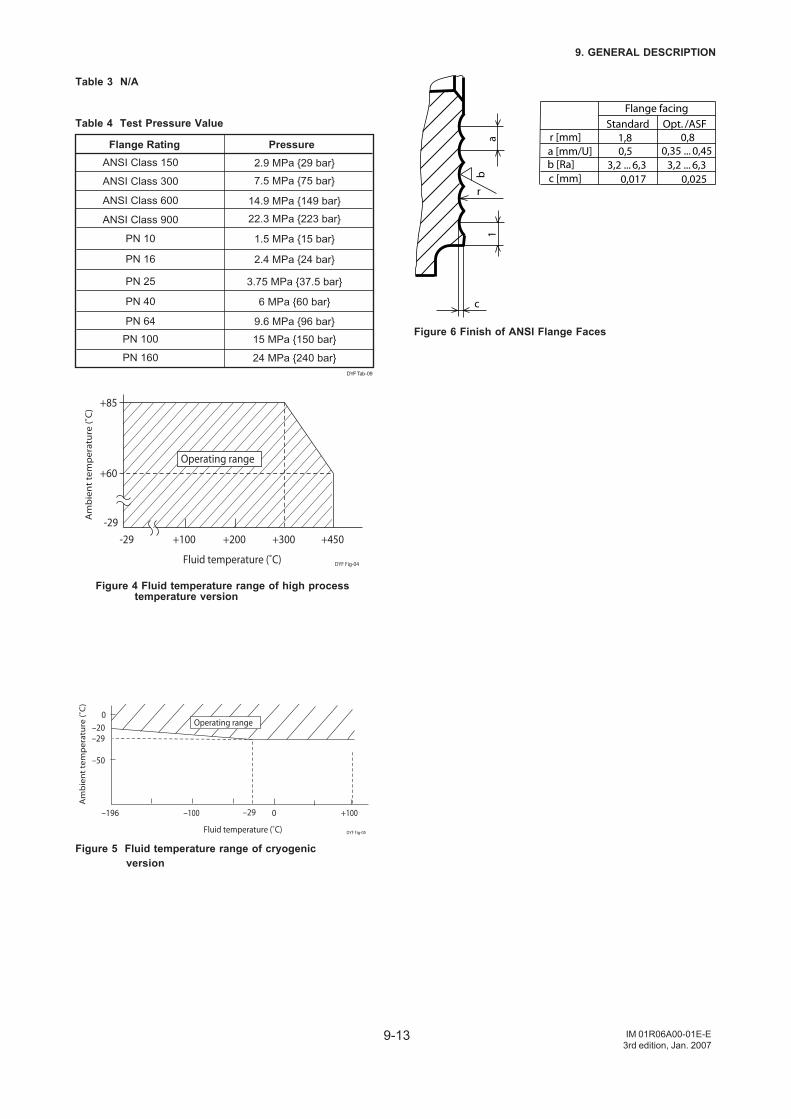
9-13
9. GENERAL DESCRIPTION
IM 01R06A00-01E-E3rd edition, Jan. 2007
Table 3 N/A
Table 4 Test Pressure Value
DYF Tab-09
PN 10 1.5 MPa 15 bar
PN 16 2.4 MPa 24 bar
PN 25 3.75 MPa 37.5 bar
PN 40 6 MPa 60 bar
PN 64 9.6 MPa 96 bar
PN 100 15 MPa 150 bar
PN 160 24 MPa 240 bar
ANSI Class 150
ANSI Class 300
ANSI Class 600
ANSI Class 900
PressureFlange Rating
2.9 MPa 29 bar
7.5 MPa 75 bar
14.9 MPa 149 bar
22.3 MPa 223 bar
-29 +100 +200 +300 +450
+85
+60
-29
Fluid temperature (˚C)
Am
bie
nt
tem
per
atu
re (˚
C)
Operating range
DYF Fig-04
Figure 4 Fluid temperature range of high process temperature version
Figure 6 Finish of ANSI Flange Faces
–196 –100 –29 0
0
–50
–20
Fluid temperature (˚C)
Am
bie
nt t
emp
erat
ure
(˚C
)
Operating range
+100
DYF Fig-05
–29
Figure 5 Fluid temperature range of cryogenic version
c
ab
1
rc [mm]b [Ra]a [mm/U]r [mm]
Standard Opt. /ASF
Flange facing
1,80,5
3,2 ... 6,30,017
0,80,35 ... 0,45
3,2 ... 6,30,025
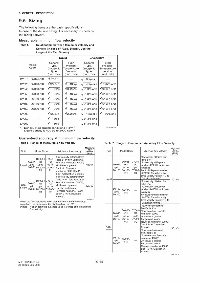
9-14
9. GENERAL DESCRIPTION
IM 01R06A00-01E-E3rd edition, Jan. 2007
9.5 SizingThe following items are the basic specifications.In case of the definite sizing, it is necessary to check bythe sizing software.
Measurable minimum flow velocityTable 5 Relationship between Minimum Velocity and
Density (In case of “Gas, Steam”, Use theLarge of the Two Values)
Liquid GAS, Steam
r : Density at operating conditions (kg/m3) Liquid density is 400 up to 2000 kg/m3
HighProcess
TemperatureVersion
(unit: m/s)
––
490/ρ
302.5/ρ
160/ρ
160/ρ
160/ρ
160/ρ
202.5/ρ
––
––
ModelCode
DY015
DY025
DY040
DY050
DY080
DY100
DY150
DY200
DY250
DY300
DY025-/R1
DY040-/R1
DY050-/R1
DY080-/R1
DY100-/R1
DY150-/R1
DY200-/R1
––
––
––
HighProcess
Temperatureversion
(unit: m/s)
––
125/ρ or 2
90.3/ρ or 2
61.3/ρ or 2
61.3/ρ or 2
61.3/ρ or 2
61.3/ρ or 3
80/ρ or 3
––
––
General Type,
Cryogenic Type
(unit: m/s)
250 /ρ
122.5/ρ
90/ρ
90/ρ
90/ρ
90/ρ
90/ρ
122.5/ρ
160/ρ
160/ρ
GeneralType,
CryogenicType
(unit: m/s)
80/ρ or 3
45/ρ or 2
31.3/ρ or 2
31.3/ρ or 2
31.3/ρ or 2
31.3/ρ or 2
31.3/ρ or 3
45/ρ or 3
61.3/ρ or 3
61.3/ρ or 3DYF Tab-10
Guaranteed accuracy at minimum flow velocityTable 6 Range of Measurable flow velocity
When the flow velocity is lower than minimum, both the analog output and the pulse output is displayed as zero “0”.(Note) A span setting is available up to 1.5 times of the maximum flow velocity.
Fluid
Liquid
Gas,Steam
Model Code
DY015 up to
DY300
DY015 up to
DY300
DY025-/R1
up to DY200-/
R1
DY025-/R1
up to DY200-/
R1
DY040-/R2
up to DY200-/
R2
DY040-/R2
up to DY200-/
R2
Maximumflow
velocity(Note)
10 m/s
80 m/s
Minimum flow velocity
“flow velocity obtained from Table 5” or “flow velocity at Reynolds number of 5000”, whichever is greater.For liquid Reynolds number of 5000: See P. 9-16 “Calculation formula”.“flow velocity obtained from Table 5” or “flow velocity at Reynolds number of 5000”, whichever is greater.For Gas and steam Reynolds number of 5000: See P. 9-16 “Calculation formula”.
DYF Tab-11
Table 7 Range of Guaranteed Accuracy Flow Velocity
“flow velocity obtained from Table 5” or “flow velocity at Reynolds number of 20000”, whichever is greater.For liquid Reynolds number of 20000: The value is four times velocity value in P. 9-16 “Calculation formula”.“flow velocity obtained from Table 5” or “flow velocity at Reynolds number of 40000”, whichever is greater.For liquid Reynolds number of 40000: The value is eight times velocity value in P. 9-16 “Calculation formula”.“flow velocity obtained fromTable 5” or “flow velocity at Reynolds number of 20000”, whichever is greater.For gas and steam Reynolds number of 20000: See P. 9-16 “Calculation formula”.“flow velocity obtained fromTable 5” or “flow velocity at Reynolds number of 40000”, whichever is greater.For gas and steam Reynolds number of 40000 See P. 9-16 “Calculation formula”.
DYFTab-12
Fluid Model Code Minimum flow velocityMaximum
flowvelocity(Note)
10 m/s
80 m/s
Liquid
Gas,Steam
DY015up to
DY100
DY150up to
DY300
DY015up to
DY100
DY150up to
DY300
DY025-/R1
up toDY150-
/R1
DY200-/R1
DY025-/R1
up toDY150-
/R1
DY200-/R1
DY040-/R2
up toDY200-
/R2
—
DY040-/R2
up toDY200-
/R2
—
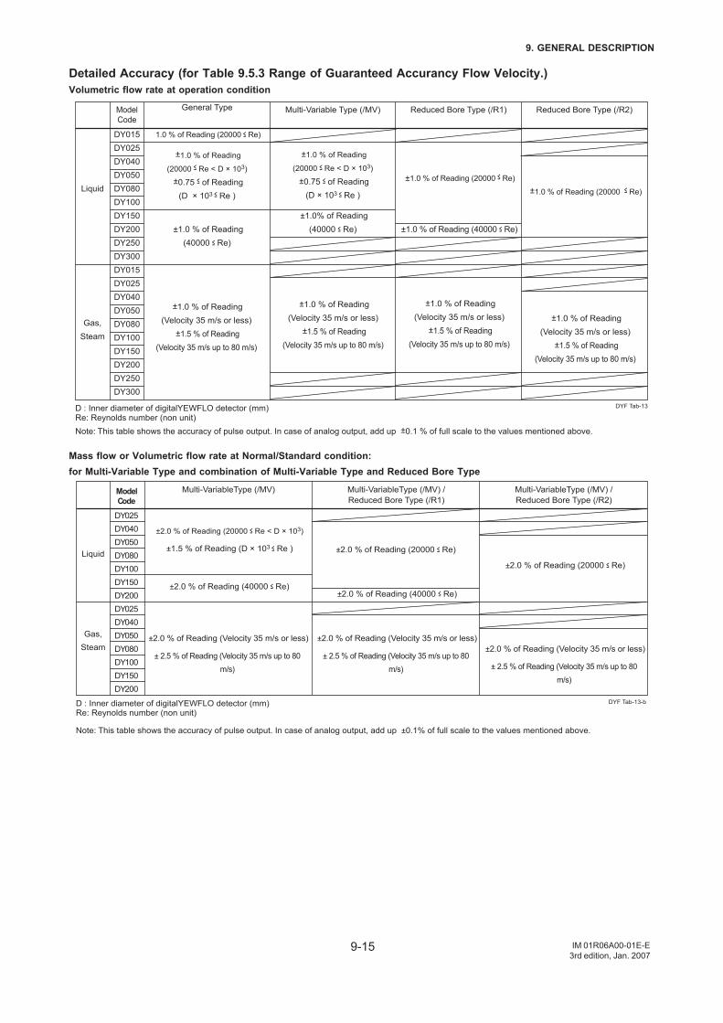
9-15
9. GENERAL DESCRIPTION
IM 01R06A00-01E-E3rd edition, Jan. 2007
Detailed Accuracy (for Table 9.5.3 Range of Guaranteed Accurancy Flow Velocity.)Volumetric flow rate at operation condition
D : Inner diameter of digitalYEWFLO detector (mm)Re: Reynolds number (non unit)Note: This table shows the accuracy of pulse output. In case of analog output, add up ±0.1 % of full scale to the values mentioned above.
Liquid
Gas,Steam
ModelCode
DY015DY025DY040DY050DY080DY100DY150DY200DY250DY300DY015DY025DY040DY050DY080DY100DY150DY200DY250DY300
General Type Multi-Variable Type (/MV) Reduced Bore Type (/R1)
1.0 % of Reading (20000 ≤ Re)
±1.0 % of Reading
(20000 ≤ Re < D × 103)
±0.75 ≤ of Reading(D × 103 ≤ Re )
±1.0 % of Reading
(20000 ≤ Re < D × 103)
±0.75 ≤ of Reading(D × 103 ≤ Re )
±1.0 % of Reading (20000 ≤ Re)
±1.0 % of Reading(40000 ≤ Re)
±1.0% of Reading(40000 ≤ Re) ±1.0 % of Reading (40000 ≤ Re)
Reduced Bore Type (/R2)
±1.0 % of Reading (20000 ≤ Re)
DYF Tab-13
±1.0 % of Reading(Velocity 35 m/s or less)
±1.5 % of Reading (Velocity 35 m/s up to 80 m/s)
±1.0 % of Reading(Velocity 35 m/s or less)
±1.5 % of Reading (Velocity 35 m/s up to 80 m/s)
±1.0 % of Reading(Velocity 35 m/s or less)
±1.5 % of Reading (Velocity 35 m/s up to 80 m/s)
±1.0 % of Reading(Velocity 35 m/s or less)
±1.5 % of Reading (Velocity 35 m/s up to 80 m/s)
Mass flow or Volumetric flow rate at Normal/Standard condition:for Multi-Variable Type and combination of Multi-Variable Type and Reduced Bore Type
D : Inner diameter of digitalYEWFLO detector (mm)Re: Reynolds number (non unit)
Note: This table shows the accuracy of pulse output. In case of analog output, add up ±0.1% of full scale to the values mentioned above.
Liquid
Gas,Steam
ModelCode
DY025DY040DY050DY080DY100DY150DY200DY025DY040DY050DY080DY100DY150DY200
Multi-VariableType (/MV) Multi-VariableType (/MV) /Reduced Bore Type (/R1)
±2.0 % of Reading (20000 ≤ Re < D × 103)
±1.5 % of Reading (D × 103 ≤ Re )
±2.0 % of Reading (40000 ≤ Re)
±2.0 % of Reading (Velocity 35 m/s or less)
± 2.5 % of Reading (Velocity 35 m/s up to 80 m/s)
Multi-VariableType (/MV) /Reduced Bore Type (/R2)
DYF Tab-13-b
±2.0 % of Reading (40000 ≤ Re)
±2.0 % of Reading (20000 ≤ Re)
±2.0 % of Reading (20000 ≤ Re)
±2.0 % of Reading (Velocity 35 m/s or less)
± 2.5 % of Reading (Velocity 35 m/s up to 80 m/s)
±2.0 % of Reading (Velocity 35 m/s or less)
± 2.5 % of Reading (Velocity 35 m/s up to 80 m/s)
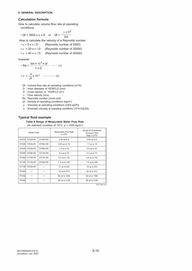
9-16
9. GENERAL DESCRIPTION
IM 01R06A00-01E-E3rd edition, Jan. 2007
Calculation formulaHow to calculate volume flow rate at operating
conditions. υ x D2
• Qf = 3600 x υ x S or Qf = 354
How to calculate the velocity of a Reynolds number. • υ = 5 x ν / D (Reynolds number of 5000) • υ = 20 x ν / D (Reynolds number of 20000) • υ = 40 x ν / D (Reynolds number of 40000)
however 354 x 10
3 x Qf • Re = ········· (1) ν x D
µ • ν = __ x 10 3 ················· (2) ρf
Qf : Volume flow rate at operating conditions (m3/h)D : Inner diameter of YEWFLO (mm)S : Cross section of YEWFLO (m2)υ : Flow velocity (m/s)
Re : Reynolds number (none unit)ρf : Density at operating conditions (kg/m3)µ : Viscosity at operating conditions (mPa·scP)ν : Kinematic viscosity at operating conditions (10-6m2/scSt)
Typical fluid exampleTable 8 Range of Measurable Water Flow Rate(At standard condition of 15°C, ρ = 1000 kg/m3)
DYF Tab-14-b
Model CodeRange of Guaranteed
Accuracy FlowRate in m3/h
Measurable Flow Ratein m3/h
DY015
DY025
DY040
DY050
DY080
DY100
DY150
DY200
DY250
DY300
DY025-/R1
DY040-/R1
DY050-/R1
DY080-/R1
DY100-/R1
DY150-/R1
DY200-/R1
—
—
—
DY040-/R2
DY050-/R2
DY080-/R2
DY100-/R2
DY150-/R2
DY200-/R2
—
—
—
—
0.30 up to 6
0.65 up to 18
1.3 up to 44
2.2 up to 73
4.3 up to 142
7.5 up to 248
17 up to 544
34 up to 973
60 up to 1506
86 up to 2156
0.94 up to 6
1.7 up to 18
2.6 up to 44
3.3 up to 73
4.6 up to 142
7.5 up to 248
18 up to 544
34 up to 973
60 up to 1506
86 up to 2156
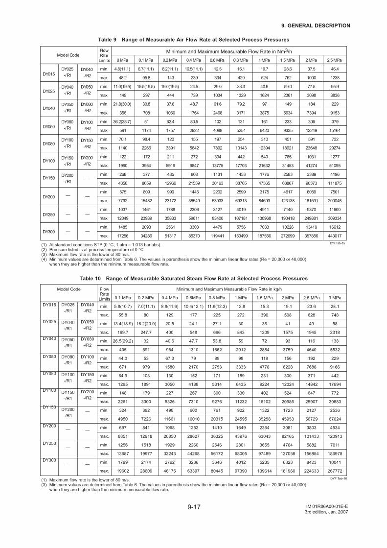
9-17
9. GENERAL DESCRIPTION
IM 01R06A00-01E-E3rd edition, Jan. 2007
Table 9 Range of Measurable Air Flow Rate at Selected Process Pressures
min.
max.
min.
max.
min.
max.
min.
max.
min.
max.
min.
max.
min.
max.
min.
max.
min.
max.
min.
max.
DY015
DY025
DY040
DY050
DY080
DY100
DY150
DY200
DY250
DY300
DY025-/R1
DY040-/R1
DY050-/R1
DY080-/R1
DY100-/R1
DY150-/R1
DY200-/R1
—
—
—
DY040-/R2
DY050-/R2
DY080-/R2
DY100-/R2
DY150-/R2
DY200-/R2
—
—
—
—
Model CodeFlowRateLimits
Minimum and Maximum Measurable Flow Rate in Nm3/h
0 MPa
4.8(11.1)
48.2
11.0(19.5)
149
21.8(30.0)
356
36.2(38.7)
591
70.1
1140
122
1990
268
4358
575
7792
1037
12049
1485
17256
0.1 MPa
6.7(11.1)
95.8
15.5(19.5)
297
30.8
708
51
1174
98.4
2266
172
3954
377
8659
809
15482
1461
23939
2093
34286
0.2 MPa
8.2(11.1)
143
19.0(19.5)
444
37.8
1060
62.4
1757
120
3391
211
5919
485
12960
990
23172
1788
35833
2561
51317
0.4 MPa
10.5(11.1)
239
24.5
739
48.7
1764
80.5
2922
155
5642
272
9847
808
21559
1445
38549
2306
59611
3303
85370
0.6 MPa
12.5
334
29.0
1034
61.6
2468
102
4088
197
7892
334
13775
1131
30163
2202
53933
3127
83400
4479
119441
0.8 MPa
16.1
429
33.3
1329
79.2
3171
131
5254
254
10143
442
17703
1453
38765
2599
69313
4019
107181
5756
153499
1 MPa
19.7
524
40.6
1624
97
3875
161
6420
310
12394
540
21632
1776
47365
3175
84693
4911
130968
7033
187556
1.5 MPa
28.6
762
59.0
2361
149
5634
233
9335
451
18021
786
31453
2583
68867
4617
123138
7140
190418
10226
272699
2 MPa
37.5
1000
77.5
3098
184
7394
306
12249
591
23648
1031
41274
3389
90373
6059
161591
9370
249881
13419
357856
2.5 MPa
46.4
1238
95.9
3836
229
9153
379
15164
732
29274
1277
51095
4196
111875
7501
200046
11600
309334
16612
443017
(1) At standard conditions STP (0 °C, 1 atm = 1.013 bar abs).(2) Pressure listed is at process temperature of 0 °C.(3) Maximum flow rate is the lower of 80 m/s.(4) Minimum values are determined from Table 6. The values in parenthesis show the minimum linear flow rates (Re = 20,000 or 40,000) when they are higher than the minimum measurable flow rate.
DYF Tab-15
Table 10 Range of Measurable Saturated Steam Flow Rate at Selected Process Pressures
Minimum and Maximum Measurable Flow Rate in kg/h
0.1 MPa
5.8(10.7)
55.8
13.4(18.9)
169.7
26.5(29.2)
405
44.0
671
84.9
1295
148
2261
324
4950
697
8851
1256
13687
1799
19602
0.2 MPa
7.0(11.1)
80
16.2(20.0)
247.7
32
591
53
979
103
1891
179
3300
392
7226
841
12918
1518
19977
2174
28609
0.4 MPa
8.8(11.6)
129
20.5
400
40.6
954
67.3
1580
130
3050
227
5326
498
11661
1068
20850
1929
32243
2762
46175
0.6MPa
10.4(12.1)
177
24.1
548
47.7
1310
79
2170
152
4188
267
7310
600
16010
1252
28627
2260
44268
3236
63397
0.8 MPa
11.6(12.3)
225
27.1
696
53.8
1662
89
2753
171
5314
300
9276
761
20315
1410
36325
2546
56172
3646
80445
1 MPa
12.8
272
30
843
59
2012
98
3333
189
6435
330
11232
922
24595
1649
43976
2801
68005
4012
97390
1.5 MPa
15.3
390
36
1209
72
2884
119
4778
231
9224
402
16102
1322
35258
2364
63043
3655
97489
5235
139614
2 MPa
19.1
508
41
1575
93
3759
156
6228
300
12024
524
20986
1723
45953
3081
82165
4764
127058
6823
181960
2.5 MPa
23.6
628
49
1945
116
4640
192
7688
371
14842
647
25907
2127
56729
3803
101433
5882
156854
8423
224633
3 MPa
28.1
748
58
2318
138
5532
229
9166
442
17694
772
30883
2536
67624
4534
120913
7011
186978
10041
267772
(1) Maximum flow rate is the lower of 80 m/s.(3) Minimum values are determined from Table 6. The values in parenthesis show the minimum linear flow rates (Re = 20,000 or 40,000) when they are higher than the minimum measurable flow rate.
DYF Tab-16
min.
max.
min.
max.
min.
max.
min.
max.
min.
max.
min.
max.
min.
max.
min.
max.
min.
max.
min.
max.
DY015
DY025
DY040
DY050
DY080
DY100
DY150
DY200
DY250
DY300
DY025-/R1
DY040-/R1
DY050-/R1
DY080-/R1
DY100-/R1
DY150-/R1
DY200-/R1
—
—
—
DY040-/R2
DY050-/R2
DY080-/R2
DY100-/R2
DY150-/R2
DY200-/R2
—
—
—
—
Model Code FlowRateLimits
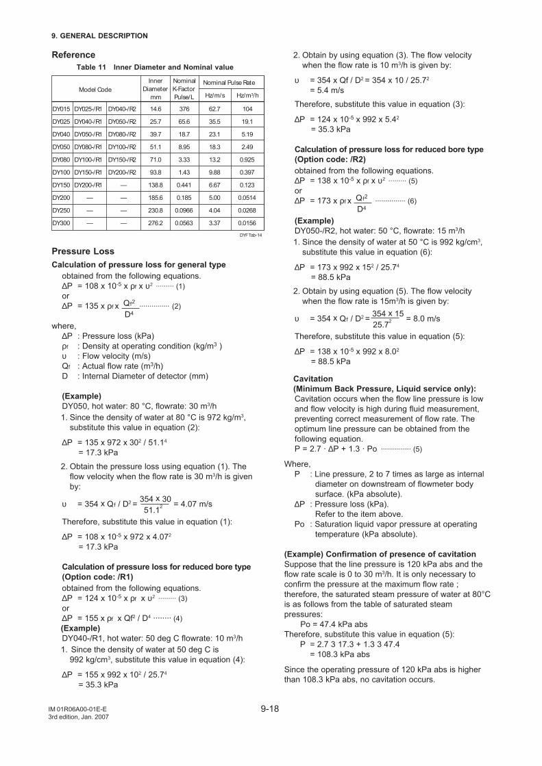
9-18
9. GENERAL DESCRIPTION
IM 01R06A00-01E-E3rd edition, Jan. 2007
ReferenceTable 11 Inner Diameter and Nominal value
Model CodeInner
Diametermm
NominalK-FactorPulse/L
Nominal Pulse Rate
DY015
DY025
DY040
DY050
DY080
DY100
DY150
DY200
DY250
DY300
DY025-/R1
DY040-/R1
DY050-/R1
DY080-/R1
DY100-/R1
DY150-/R1
DY200-/R1
—
—
—
DY040-/R2
DY050-/R2
DY080-/R2
DY100-/R2
DY150-/R2
DY200-/R2
—
—
—
—
14.6
25.7
39.7
51.1
71.0
93.8
138.8
185.6
230.8
276.2
376
65.6
18.7
8.95
3.33
1.43
0.441
0.185
0.0966
0.0563
62.7
35.5
23.1
18.3
13.2
9.88
6.67
5.00
4.04
3.37
104
19.1
5.19
2.49
0.925
0.397
0.123
0.0514
0.0268
0.0156
DYF Tab-14
Hz/m/s Hz/m3/h
Pressure LossCalculation of pressure loss for general type
obtained from the following equations.∆P = 108 x 10-5 x ρf x υ2 ········· (1)or∆P = 135 x ρf x Qf2
··············· (2)D4
where,∆P : Pressure loss (kPa)ρf : Density at operating condition (kg/m3 )υ : Flow velocity (m/s)Qf : Actual flow rate (m3/h)D : Internal Diameter of detector (mm)
(Example)DY050, hot water: 80 °C, flowrate: 30 m3/h1. Since the density of water at 80 °C is 972 kg/m3,
substitute this value in equation (2):
∆P = 135 x 972 x 302 / 51.14
= 17.3 kPa
2. Obtain the pressure loss using equation (1). Theflow velocity when the flow rate is 30 m3/h is givenby:
υ = 354 x Qf / D2 = 354 x 30 = 4.07 m/s 51.12
Therefore, substitute this value in equation (1):
∆P = 108 x 10-5 x 972 x 4.072
= 17.3 kPa
Calculation of pressure loss for reduced bore type(Option code: /R1)obtained from the following equations.∆P = 124 x 10-5 x ρf x υ2 ········· (3)or∆P = 155 x ρf x Qf2 / D4 ········ (4)(Example)DY040-/R1, hot water: 50 deg C flowrate: 10 m3/h1. Since the density of water at 50 deg C is
992 kg/cm3, substitute this value in equation (4):
∆P = 155 x 992 x 102 / 25.74
= 35.3 kPa
2. Obtain by using equation (3). The flow velocitywhen the flow rate is 10 m3/h is given by:
υ = 354 x Qf / D2 = 354 x 10 / 25.72
= 5.4 m/s
Therefore, substitute this value in equation (3):
∆P = 124 x 10-5 x 992 x 5.42
= 35.3 kPa
Calculation of pressure loss for reduced bore type(Option code: /R2)obtained from the following equations.∆P = 138 x 10-5 x ρf x υ2 ········· (5)or∆P = 173 x ρf x Qf2
··············· (6)D4
(Example)DY050-/R2, hot water: 50 °C, flowrate: 15 m3/h1. Since the density of water at 50 °C is 992 kg/cm3,
substitute this value in equation (6):
∆P = 173 x 992 x 152 / 25.74
= 88.5 kPa
2. Obtain by using equation (5). The flow velocitywhen the flow rate is 15m3/h is given by:
υ = 354 x Qf / D2 = 354 x 15 = 8.0 m/s 25.72
Therefore, substitute this value in equation (5):
∆P = 138 x 10-5 x 992 x 8.02
= 88.5 kPa
Cavitation(Minimum Back Pressure, Liquid service only):Cavitation occurs when the flow line pressure is lowand flow velocity is high during fluid measurement,preventing correct measurement of flow rate. Theoptimum line pressure can be obtained from thefollowing equation.P = 2.7 · ∆P + 1.3 · Po
··············· (5)
Where,P : Line pressure, 2 to 7 times as large as internal
diameter on downstream of flowmeter bodysurface. (kPa absolute).
∆P : Pressure loss (kPa).Refer to the item above.
Po : Saturation liquid vapor pressure at operatingtemperature (kPa absolute).
(Example) Confirmation of presence of cavitationSuppose that the line pressure is 120 kPa abs and theflow rate scale is 0 to 30 m3/h. It is only necessary toconfirm the pressure at the maximum flow rate ;therefore, the saturated steam pressure of water at 80°Cis as follows from the table of saturated steampressures:
Po = 47.4 kPa absTherefore, substitute this value in equation (5):
P = 2.7 3 17.3 + 1.3 3 47.4= 108.3 kPa abs
Since the operating pressure of 120 kPa abs is higherthan 108.3 kPa abs, no cavitation occurs.
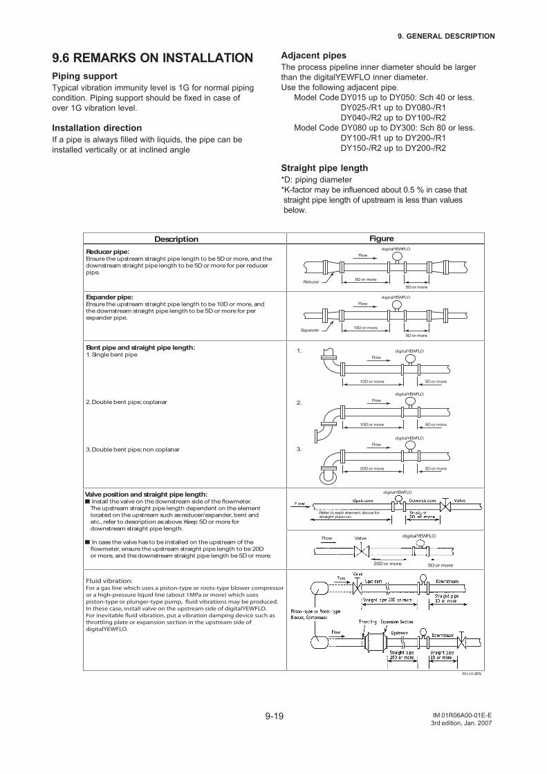
9-19
9. GENERAL DESCRIPTION
IM 01R06A00-01E-E3rd edition, Jan. 2007
9.6 REMARKS ON INSTALLATIONPiping supportTypical vibration immunity level is 1G for normal pipingcondition. Piping support should be fixed in case ofover 1G vibration level.
Installation directionIf a pipe is always filled with liquids, the pipe can beinstalled vertically or at inclined angle
Adjacent pipesThe process pipeline inner diameter should be largerthan the digitalYEWFLO inner diameter.Use the following adjacent pipe.
Model Code DY015 up to DY050: Sch 40 or less.DY025-/R1 up to DY080-/R1DY040-/R2 up to DY100-/R2
Model Code DY080 up to DY300: Sch 80 or less.DY100-/R1 up to DY200-/R1DY150-/R2 up to DY200-/R2
Straight pipe length*D: piping diameter*K-factor may be influenced about 0.5 % in case thatstraight pipe length of upstream is less than valuesbelow.
Refer to each element above forstraight pipe run.
Reducer pipe:Ensure the upstream straight pipe length to be 5D or more, and the
downstream straight pipe length to be 5D or more for per reducer
pipe.
Valve position and straight pipe length: Install the valve on the downstream side of the flowmeter.
The upstream straight pipe length dependent on the element
located on the upstream such as reducer/expander, bent and
etc., refer to description as above. Keep 5D or more for
downstream straight pipe length.
In case the valve has to be installed on the upstream of the
flowmeter, ensure the upstream straight pipe length to be 20D
or more, and the downstream straight pipe length be 5D or more.
Expander pipe:Ensure the upstream straight pipe length to be 10D or more, and
the downstream straight pipe length to be 5D or more for per
expander pipe.
Bent pipe and straight pipe length:1. Single bent pipe
2. Double bent pipe; coplanar
3. Double bent pipe; non coplanar
Fluid vibration:For a gas line which uses a piston-type or roots-type blower compressor or a high-pressure liquid line (about 1MPa or more) which uses piston-type or plunger-type pump, fluid vibrations may be produced.In these case, install valve on the upstream side of digitalYEWFLO. For inevitable fluid vibration, put a vibration damping device such as throttling plate or expansion section in the upstream side of digitalYEWFLO.
Description Figure
1.
2.
3.
digitalYEWFLO
Flow
5D or moreReducer
5D or more
digitalYEWFLO
Flow
10D or moreExpander
5D or more
digitalYEWFLO
F01.01.EPS
FlowdigitalYEWFLO
Valve
5D or more20D or more
digitalYEWFLO
Flow
10D or more 5D or more
digitalYEWFLO
Flow
10D or more 5D or more
digitalYEWFLO
Flow
20D or more 5D or more

9-20
9. GENERAL DESCRIPTION
IM 01R06A00-01E-E3rd edition, Jan. 2007
Description Figure
Heat-Insulation:
When an integral-type flowmeter or a remote type detector is
installed and the pipe carrying high-temperature fluids is
heat-insulated, do not wrap adiabatic materials around the
installation bracket of the converter.
Flushing of the pipe line:
Flush and clean scale, incrustation and sludge on the inside of
pipe for newly installed pipe line and repaired pipe line before
the operation. For flushing, the flow should flow through
bypass-piping to avoid damaging the flowmeter. If there is no
bypass-piping, install short pipe instead of the flowmeter.
Mounting Gasket:
Avoid mounting gaskets which protrude into the pipe line. This may
cause inaccurate readings.
Use the gasket with bolt holes, even if digitalYEWFLO is the wafer type.
When using a spiral gasket(without bolt holes), confirm the size with the
gasket -manufacturer, as standard items may not be used for certain
flange ratings.
Pressure and Temperature Taps:
Pressure tap outlet: install this tap between 2D and 7D on the
downstream side of a flowmeter.
Temperature tap outlet: install this on the downstream side 1D to 2D
away from a pressure tap.
Valve positon (T-type piping exist):
When pulsation caused by a T-type piping exist, install the valve on the
upstream of the flowmeter.
Example: As shown in the figure, when the valve V1 is turned off, the
fluid flow through B as to meter A the flow is zero. But due to the
pulsating pressure is detected, the meter´s zero point becomes
fluctuating. To avoid this, change the valve V1 location to V1'.
F01.02.EPS
Relocating
Valve (Off)Flow
B
A
V1’ V1
Piston-type or plunger pump:Install the accumulator on the upstream side of digitalYEWFLO
to reduce fluid vibrations.digitalYEWFLO
Bracket
Heat-Insulator
Pressure tap
Temperature tap
Upstream
Flow
downstream
2 to 7D 1 to 2D
Pipeline Flange
Pipeline
No good
Short pipe
digitalYEWFLO
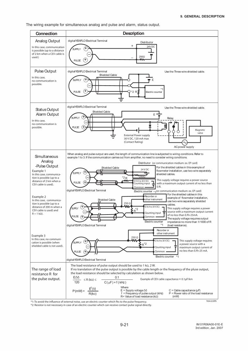
9-21
9. GENERAL DESCRIPTION
IM 01R06A00-01E-E3rd edition, Jan. 2007
The wiring example for simultaneous analog and pulse and alarm, status output.
250 Ω
R+
–+PULSE
SUPPLY
digitalYEWFLO Electrical Terminal
Recorder or
other instrument
This supply voltage requires a power source with a maximum output current of no less than E/R+25 mA.
Electric counter
E(16.4 to 30 V DC)
Counting input
Common
+
+
digitalYEWFLO Electrical Terminal
250Ω
24V DC
PULSE
SUPPLY
+
–
Distributor
–
+
–
+PULSE
SUPPLY
R
E
digitalYEWFLO Electrical Terminal Use the Three-wire shielded cable.
Use the Three-wire shielded cable.
Electric counter*1
*1
*1
*1
*2
*2
*2
*2
*1: To avoid the influence of external noise, use an electric counter which fits to the pulse frequency.*2: Resistor is not necessary in case of an electric counter which can receive contact pulse signal directly.
Shielded Cable
Shielded Cable
PULSE
SUPPLY +–
+Magnetic
valve
AC power supply
External Power supply 30 V DC, 120 mA max(Contact Rating)
digitalYEWFLO Electrical Terminal
E
250 Ω
R
+–
+PULSE
SUPPLY
Counting input
Common
For the shielded cables in this
example of flowmeter installation,
use two-wire separately shielded
cables.
This supply voltage requires a power source with a maximum output current of no less than E/R+25mA.
Recorder or
other instrument
Electric counter
E(16.4 to 30 V DC)
Shielded Cable
The supply voltage requires output
impedance no more than 1/1000 of R
(load resistance).digitalYEWFLO Electrical Terminal
250ΩR
E(10.5 to 30 V DC) Counting input
Common
24 V DC
PULSE
SUPPLY
For the shielded cables in this example of
flowmeter installation, use two-wire separately
shielded cables.
This supply voltage requires a power source with a maximum output current of no less than E/R.
Distributor (or communication medium: ex. EP card)
(or communication medium: ex. EP card)Electric counter
+
–
+
Shielded Cable
digitalYEWFLO Electrical Terminal
When analog and pulse output are used, the length of communication line is subjected to wiring conditions. Refer to
example 1 to 3. If the communication carries out from amplifier, no need to consider wiring conditions.
Relay
T004.02.EPS
Analog Output
Pulse Output
Status Output
Alarm Output
Simultaneous
Analog
-Pulse Output
DescriptionConnection
0.1
C ( µF ) × f ( kHz ) ≤ R (kΩ) ≤
120
E (V)
The load resistance of pulse output should be used to 1 kΩ, 2 W.If no translation of the pulse output is possible by the cable length or the frequency of the pluse output,the load resistance should be selected by calculation as shown below.
Example of CEV cable capacitance = = 0.1µF/km
WhereE = Supply voltage (V) f = Frequency of pulse output (kHz)R = Value of load resistance (kΩ)
C = Cable capacitance (µF)P = Power ratio of the load resistance
(mW)
P (mW) =R (kΩ)
E2(V)
Example 3In this case, no communi-cation is possible (when shielded cable is not used).
The range of load resistance R for the pulse output.
Example 1In this case, communica-tion is possible (up to adistance of 2 km when aCEV cable is used).
Example 2In this case, communica-tion is possible (up to adistance of 200 m when a CEV cable is used) and R = 1 kΩ).
In this case, communication is possible (up to a distance of 2 km when a CEV cable is used.)
In this case, no communication is possible.
In this case, no communication is possible.
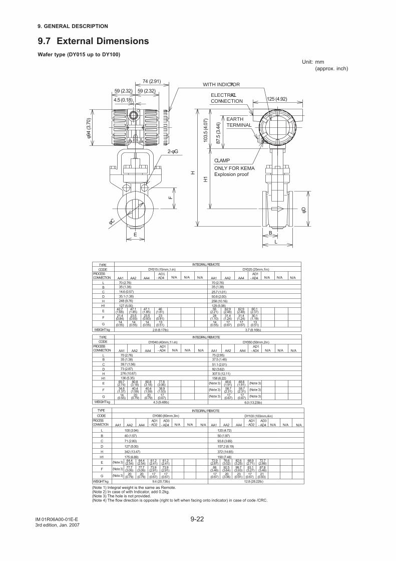
9-22
9. GENERAL DESCRIPTION
IM 01R06A00-01E-E3rd edition, Jan. 2007
9.7 External DimensionsWafer type (DY015 up to DY100)
Unit: mm(approx. inch)
H1
H
125 (4.92)
L
φD
B
φC
2-φG
74 (2.91)
F
E
59 (2.32)
4.5 (0.18)
59 (2.32)ELECTRICAL CONNECTION
CLAMPONLY FOR KEMA Explosion proof
WITH INDICATOR
EARTH TERMINAL
φ94
(3.7
0)
103.
5 (4
.07)
87.5
(3.4
4)
6.0 (13.23lb)4.3 (9.48lb)
AA1 AA2 AA4AD1
- AD4 AA1 AA2 AA4AD1
- AD470 (2.76)
39.7 (1.56)73 (2.87)
69.7(2.74)
80.8(3.18)
80.8(3.18)
77.8(3.06)
34.8(1.37)
40.4(1.59)
40.4(1.59)
38.9(1.53)
17(0.67)
14(0.55)
20(0.79)
20(0.79)
48.6(1.91)
48.6(1.91)
58.7(2.31)
58.7(2.31)
17(0.67)
17(0.67)
75 (2.95)35 (1.38) 37.5 (1.48)
92 (3.62)51.1 (2.01)
158 (6.22)307.5 (12.11)
136 (5.35)276 (10.87)
12.8 (28.22lb)9.4 (20.73lb)
372 (14.65)190 (7.48)
342 (13.47)175 (6.89)
157.2 (6.19)93.8 (3.69)50 (1.97)120 (4.72)
72.7(2.86)
68.9(2.71)
82.6(3.25)
76.6(3.02)
72.9(2.87)
87.8(3.46)
83.1(3.27)
99.7(3.93)
88(3.46)
92.5(3.64)
21(0.83)
23(0.91)
17(0.67)
17(0.67)
20(3.06)
20(0.79)
20(0.79)
17(0.67)
17(0.67)
77.7(3.06)
77.7(3.06)
73.9(2.91)
73.9(2.91)
- AD4AD3
61.2(2.41)
61.2(2.41)
64.4(2.54)
64.4(2.54)
127 (5.00)71 (2.80)40 (1.57)100 (3.94)
DY080 (80mm,3in)
AA4AA2AA1 - AD2AD1
AA4AA2AA1
DY100 (100mm,4in)AD1
- AD2AD3
- AD4
INTEGRAL/REMOTE
(Note 1) Integral weight is the same as Remote.(Note 2) In case of with Indicator, add 0.2kg.(Note 3) The hole is not provided.(Note 4) The flow direction is opposite (right to left when facing onto indicator) in case of code /CRC.
L
CDH
H1E
F
G
DY040 (40mm,11/2in) DY050 (50mm,2in)
B
INTEGRAL/REMOTE
B
G
F
EH1HDC
L
TYPECODE
PROCESSCONNECTION
TYPECODE
PROCESSCONNECTION
3.7 (8.16lb)2.8 (6.17lb)
258 (10.16)129 (5.08)
50.8 (2.00)25.7 (1.01)
70 (2.76)
60.1(2.37)
62.9(2.48)
62.9(2.48)
56(2.21)
30.1(1.19)
31.4(1.24)
31.4(1.24)
28(1.10)
13(0.51)
14(0.55)
17(0.67)
17(0.67)
DY025 (25mm,1in)
14(0.55)
14(0.55)
14(0.55)
13(0.51)
23(0.91)
23.5(0.93)
23.5(0.93)
21.4(0.84)
46(1.81)
47.1(1.85)
47.1(1.85)
42.7(1.68)
127 (5.00)
35.1 (1.38)248 (9.76)
14.6 (0.57)
70 (2.76)35 (1.38)35 (1.38)
DY015 (15mm,1/2in)
- AD4AD1
AA4AA2AA1- AD4AD1
AA4AA2AA1
G
F
EH1HDC
L
PROCESSCONNECTION
B
INTEGRAL/REMOTETYPECODE
WEIGHT kg
WEIGHT kg
WEIGHT kg
(Note 3)
(Note 3)
(Note 3)
(Note 3)
(Note 3)
(Note 3)
(Note 3)
(Note 3)
(Note 3)
N/A N/A N/A N/A N/A N/A
N/A N/A N/A N/A N/A N/A
N/A N/A N/A N/A N/A N/A
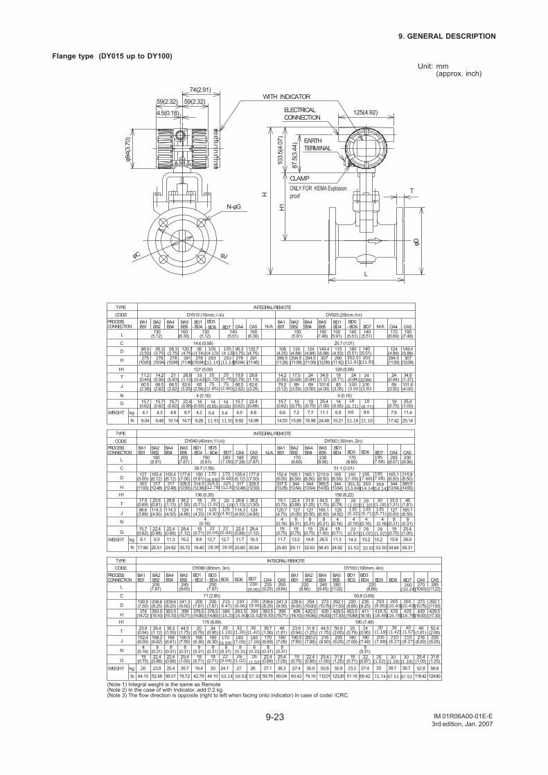
9-23
9. GENERAL DESCRIPTION
IM 01R06A00-01E-E3rd edition, Jan. 2007
Flange type (DY015 up to DY100)Unit: mm
(approx. inch)
125(4.92)
87.5
(3.4
4)
103.
5(4.
07)
H1
φD
H
N-φG
φJφC
4.5(0.18)
59(2.32) 59(2.32)
74(2.91)
φ94(
3.70
)
L
T
CLAMP
EARTHTERMINAL
ELECTRICALCONNECTION
WITH INDICATOR
ONLY FOR KEMA Explosion proof
6.94.2
25.4(1.00)
101.6(4.00)
34.9(1.37)
307(12.09)
149.4(5.88)
150(5.91)
190(7.48)
22.4(0.88)
82.6(3.25)
28.8(1.13)
291(11.46)
120.7(4.75)
130(5.12)
160(6.30)
INTEGRAL/REMOTE
85(3.35)
89(3.50)
89(3.50)
79.2(3.12)
4 (0.16)15.7
(0.62)
25.7 (1.01)
150(5.91)
DY025 (25mm,1in)
14(0.55)
15.7(0.62)
15.7(0.62)
15.7(0.62)
4 (0.16)
65(2.56)
66.5(2.62)
66.5(2.62)
60.5(2.38)
D
14.6 (0.58)
130(5.12)
BD1- BD4- BD4
BD1BA1BS1
BA2BS2
BA4BS4
BA5BS5
BA1BS1
BA2BS2
BA4BS4
BA5BS5
BA1BS1
BA2BS2
BA4BS4
BA5BS5
BA1BS1
BA2BS2
BA4BS4
BA5BS5
BA1BS1
BA2BS2
BA4BS4
BA5BS5
BA1BS1
BA2BS2
BA4BS4
BA5BS5
PROCESSCONNECTION
TYPECODE
L
C
H
H1T
J
NG
95(3.74)
88.9(3.50)
95.3(3.75)
95.3(3.75)
275(10.83)
278(10.94)
278(10.94)
278(10.94)127 (5.00)
11.2(0.44)
14.2(0.56)
21(0.83)
16(0.63)
108(4.25)
124(4.88)
124(4.88)
115(4.53)
286.5(11.28)
294.5(11.59)
294.5(11.59)
290(11.42)
14.2(0.56)
17.5(0.69)
24(0.94)
18(0.71)
129 (5.08)
19(0.75)
19(0.75)
14(0.55)
4.1 4.3 4.6 6.6 7.2 7.7 kglb
WEIGHT
kglb
WEIGHT
kglb
WEIGHT
6.7
15.7(0.62)
66.5(2.62)
19.9(0.78)
278(10.94)
95.3(3.75)
140(5.51)
CA4
4.5
22.4(0.88)
82.6(3.25)
28.8(1.13)
291(11.46)
120.7(4.75)
160(6.30)
CA5
6.8 11.1
19(0.75)
89(3.50)
24(0.94)
294.5(11.59)
124(4.88)
170(6.69)
CA4
7.9
25.4(1.00)
101.6(4.00)
34.9(1.37)
307(12.09)
149.4(5.88)
190(7.48)
CA5
11.4
15.219.269.04 9.48 10.14 14.55 15.88 16.9814.77 9.92 14.99 24.48 17.42 25.14
11.38.8
25.4(1.00)
8(0.31)
165.1(6.50)
44.5(1.75)
369.5(14.55)
215.9(8.50)
170(6.69)
230(9.06)
28.4(1.12)
124(4.88)
38.2(1.50)
328.5(12.93)
177.8(7.00)
150(5.91)
200(7.87)
DY050 ( 50mm, 2in)
D
DY040 (40mm,11/2in)BD1
- BD4- BD4BD1
L
C
HH1
T
J
N
G
150(5.91)
39.7 (1.56)127
(5.00)155.4(6.12)
155.4(6.12)
150(5.91)
303(11.93)
317(12.48)
317(12.48)
314.5(12.38)136 (5.35)18
(0.71)17.5
(0.69)20.6
(0.81)28.8
(1.13)98.6
(3.88)114.3(4.50)
114.3(4.50)
110(4.33)
4(0.16)
15.7(0.62)
22.4(0.88)
22.4(0.88)
18(0.71)
170(6.69)
51.1 (2.01)165
(6.50)152.4(6.00)
165.1(6.50)
165.1(6.50)
344(13.54)
344(13.54)
344(13.54)
337.5(13.29)
158 (6.22)19.1
(0.75)22.4
(0.88)31.8
(1.25)20
(0.79)120.7(4.75)
127(5.00)
127(5.00)
125(4.92)
4(0.16)
4(0.16)
8(0.31)
8(0.31)
19(0.75)
19(0.75)
19(0.75)
18(0.71)
8.1 9.3 11.3 11.7 13.2 14.8
INTEGRAL/REMOTE
PROCESSCONNECTION
TYPECODE
16.2
22.4(0.88)
114.3(4.50)
28.8(1.13)
317(12.48)
155.4(6.12)
185(7.28)
CA4
11.7
28.4(1.12)
124(4.88)
38.2(1.50)
328.5(12.93)
177.8(7.00)
200(7.87)
CA5
16.3 26.5
19(0.75)
8(0.31)
127(5.00)
33.3(1.31)
344(13.54)
165.1(6.50)
205(8.07)
CA4
15.8
25.4(1.00)
8(0.31)
165.1(6.50)
46(1.81)
369.5(14.55)
215.9(8.50)
230(9.06)
CA5
26.9
24.9219.4017.86 20.51 24.92 25.80 29.11 32.6335.72 25.80 35.94 58.43 34.84 59.31
27.423.22019.4
31.8(1.25)
235(9.25)
50.9(2.00)
439.5(17.30)
292.1(11.50)
280(11.02)
200(7.87)
25.4(1.00)
8(0.31)
190.5(7.50)
44.5(1.75)
399(15.71)
209.6(8.25)
245(9.65)
DY100 (100mm, 4in)
D
DY080 (80mm, 3in)
L
C
HH1
T
J
N
G
BD1- BD2
BD3- BD4 - BD2
BD1 BD3 - BD4
200(7.87)
71 (2.80)200
(7.87)200
(7.87)190.5(7.50)
209.6(8.25)
241.3(9.50)
374(14.72)
383.5(15.10)
383.5(15.10)
378.5(14.90)
378.5(14.90)
175 (6.89)23.9
(0.94)28.4
(1.12)38.2
(1.50)20
(0.79)24
(0.95)160
(6.30)160
(6.30)152.4(6.00)
168.2(6.62)
168(6.61)
8(0.31)
8(0.31)
8(0.31)
8(0.31)
19(0.75)
22.4(0.88)
22.4(0.88)
18(0.71)
18(0.71)
4(0.16)
220(8.66)
220(8.66)
240(9.45)
93.8 (3.69)228.6(9.00)
254(10.00)
273(10.75)
220(8.66)
235(9.25)
409(16.10)
420.5(16.56)
430(16.93)
403.5(15.89)
411(16.18)
190 (7.48)24
(0.95)23.9
(0.94)31.8
(1.25)44.5
(1.75)20
(0.79)190.5(7.50)
200.2(7.88)
216(8.50)
180(7.09)
190(7.48)
8(0.31)
19(0.75)
22.4(0.88)
25.4(1.00)
18(0.71)
22(0.87)
20 23.8 25.4 27.4 35.9 50.8
INTEGRAL/REMOTE
PROCESSCONNECTION
TYPECODE
35.7
22.4(0.88)
8(0.31)
170(6.69)
39.7(1.56)
383.5(15.10)
235(9.25)
CA4
209.6(8.25)
27.1
25.4(1.00)
8(0.31)
180(7.09)
46(1.81)
399(15.71)
250(9.84)
CA5
241.3(9.50)
36.3 55.9
25.4(1.00)
216(8.50)
46(1.81)
430(16.93)
273(10.75)
270(10.63)
CA4
52.8
31.8(1.25)
235(9.25)
52.4(2.06)
439.5(17.30)
292.1(11.50)
285(11.22)
CA5
56.6
60.4251.1644.1042.7844.10 52.48 56.01 60.42 79.16 112.0178.72 59.76 80.04 123.26 116.42 124.80
(Note 1) Integral weight is the same as Remote(Note 2) In the case of with Indicator, add 0.2 kg(Note 3) The flow direction is opposite (right to left when facing onto indicator) in case of code/ /CRC.
DY015 (15mm,1/2in)
5.4
75(2.95)
- BD6BD5
105(4.13)283
(11.14)
20(0.79)
12.7
- BD6BD5
170(6.69)324.5
(12.78)
125(4.92)
2724.1
BD5 BD6
2158.47)
230(9.06)
386(15.2)
393.5(15.50)
28(1.10)
32(1.26)
170(6.69)
180(7.09)
22(0.04)
26(1.02)
BD7
5.4
BD7
12.7
325(12.8)
28(1.10)
180(7.09)
BD7230
(9.06)
26
394(15.52
36(1.42)
14(0.55)
14(0.55)
8(0.31)
8(0.31)
8(0.31)
57.3359.5353.14
28.0028.00
11.9111.91
26(1.02)
180(7.09)
230(9.06)
22(0.04)
22(0.04)
26(1.02)
125(4.92)
170(6.69)
75(2.95)
20(0.79)
105(4.13)283
(11.14)
9.6
100(3.93
- BD6BD5
302.5(11.91)
18(0.71)
15.214.3
BD5 BD6
351.5(13.84)
359(14.14)
135(5.32)
145(5.71)
22(0.87)
39.733
BD5 BD6
250(9.85)
265(10.43)
418.5(16.48)
426(16.78)
30(1.18)
36(1.42)
200(7.88)
210(8.27)
26(1.02)
BD7
9.6
303(11.93
BD7195
(7.68)
15.2
30(1.18)
BD7260
(10.24)
39.7
40(1.57)
265(10.43)
426(16.78)
210(8.27)
30(1.18)
30(1.18)
180(7.09)
195(7.68)
195(7.68)
359(14.14)
26(1.02)
28(1.10)
4(0.16)
4(0.16)
4(0.16)26
(1.02)26
(1.02)
145(5.71)
140(5.51)
140(5.51)
140(5.51)
140(5.51)
24(0.94)
24(0.94)100(3.93
18(0.71)
21.16 21.16
31.52 33.50 33.50
72.74 87.51 87.51
N/AN/A
N/A
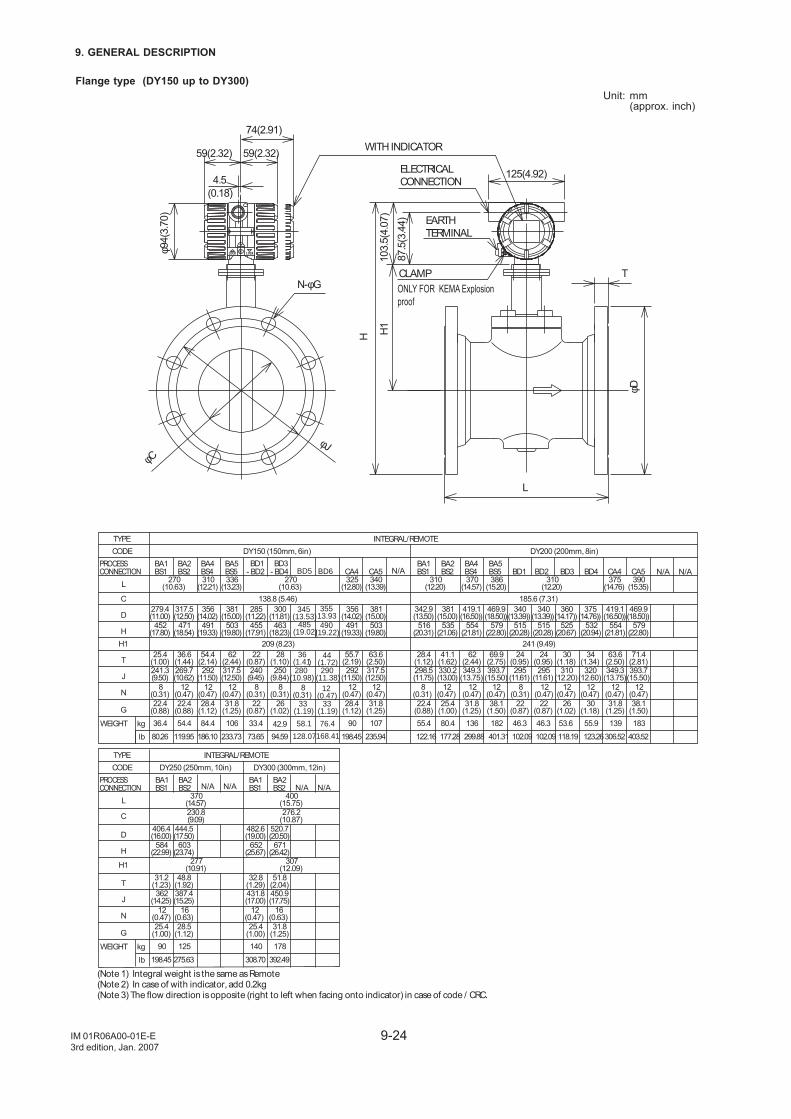
9-24
9. GENERAL DESCRIPTION
IM 01R06A00-01E-E3rd edition, Jan. 2007
Flange type (DY150 up to DY300)Unit: mm
(approx. inch)
ONLY FOR KEMA Explosion proof
CLAMP
ELECTRICALCONNECTION
WITH INDICATOR
H
125(4.92)
φCφJ
N-φG
74(2.91)
φ94(
3.70
)59(2.32) 59(2.32)
4.5(0.18)
φD
L
T
H110
3.5(
4.07
)87
.5(3
.44) EARTH
TERMINAL
(Note 1) Integral weight is the same as Remote (Note 2) In case of with indicator, add 0.2kg(Note 3) The flow direction is opposite (right to left when facing onto indicator) in case of code / CRC.
BA1BS1
BA2BS2
BA4BS4
BA5BS5
BA1BS1
BA2BS2
BA4BS4
BA5BS5
kglb
WEIGHT 13955.953.646.342.933.4
22(0.87)
295(11.61)
24(0.95)
515(20.28)
340(13.39))
270(10.63)
31.8(1.25)
12(0.47)
317.5(12.50)
62(2.44)
503(19.80)
356(14.02)
336(13.23)
310(12.21)
DY200 (200mm, 8in)
D
DY150 (150mm, 6in)
L
C
HH1
T
J
N
G
BD1- BD2
BD3- BD4 BD1 BD2 BD3 BD4
270(10.63)
138.8 (5.46)285
(11.22)300
(11.81)279.4(11.00)
317.5(12.50)
381(15.00)
452(17.80)
471(18.54)
491(19.33)
455(17.91)
463(18.23)
209 (8.23)25.4
(1.00)36.6
(1.44)54.4
(2.14)22
(0.87)28
(1.10)240
(9.45)250
(9.84)241.3(9.50)
269.7(10.62)
292(11.50)
12(0.47)
12(0.47)
8(0.31)
8(0.31)
22.4(0.88)
22.4(0.88)
28.4(1.12)
22(0.87)
26(1.02)
8(0.31)
310(12.20)
310(12.20)
386(15.20)
375(14.76)
185.6 (7.31)342.9(13.50)
375(14.76))
381(15.00)
419.1(16.50))
469.9(18.50))
340(13.39))
360(14.17))
419.1(16.50))
516(20.31)
535(21.06)
554(21.81)
579(22.80)
515(20.28)
525(20.67)
532(20.94)
554(21.81)
241 (9.49)30
(1.18)28.4
(1.12)41.1
(1.62)62
(2.44)69.9
(2.75)24
(0.95)34
(1.34)63.6
(2.50)298.5(11.75)
330.2(13.00)
349.3(13.75)
393.7(15.50)
295(11.61)
310(12.20)
320(12.60)
349.3(13.75)
25.4(1.00)
22.4(0.88)
31.8(1.25)
38.1(1.50)
22(0.87)
26(1.02)
30(1.18)
31.8(1.25)
36.4 54.4 84.4 55.4 80.4 136 182
INTEGRAL/REMOTE
PROCESSCONNECTION
TYPECODE
106
28.4(1.12)
12(0.47)
292(11.50)
55.7(2.19)
491(19.33)
325(12.80)
CA4
356(14.02)
90
31.8(1.25)
12(0.47)
12(0.47)
12(0.47)
12(0.47)
8(0.31)
12(0.47)
12(0.47)
12(0.47)
8(0.31)
12(0.47)
12(0.47)
317.5(12.50)
63.6(2.50)
503(19.80)
340(13.39)
CA5
381(15.00)
107 46.3
38.1(1.50)
393.7(15.50)
71.4(2.81)
579(22.80)
469.9(18.50))
390(15.35)
CA4
183
CA5
306.52123.26118.19102.0994.5973.6580.26 119.95 186.10 122.16 177.28 299.88 401.31233.73 198.45 235.94 102.09 403.52
370(14.57)
BA1BS1
BA2BS2
BA1BS1
BA2BS2
kglb
WEIGHT
DY300 (300mm, 12in)
D
DY250 (250mm, 10in)
L
C
H
H1
T
J
N
G
370(14.57)
406.4(16.00)
444.5(17.50)
584(22.99)
603(23.74)
31.2(1.23)
48.8(1.92)
362(14.25)
387.4(15.25)
12(0.47)
28.5(1.12)
25.4(1.00)
16(0.63)
400(15.75)
230.8(9.09)
276.2(10.87)
277(10.91)
307(12.09)
482.6(19.00)
520.7(20.50)
652(25.67)
671(26.42)
32.8(1.29)
51.8(2.04)
431.8(17.00)
450.9(17.75)
31.8(1.25)
25.4(1.00)
90 125 140 178
INTEGRAL/REMOTE
PROCESSCONNECTION
TYPECODE
16(0.63)
12(0.47)
198.45 275.63 308.70 392.49
BD5 BD6
345(13.53)
485(19.02)
35513.93490
(19.22)
36(1.41)280
(10.98)8
(0.31)33
(1.19)
58.1 76.4
44(1.72)290
(11.38)12
(0.47)
128.07168.41
33(1.19)
N/A
N/A N/A N/A N/A
N/A N/A
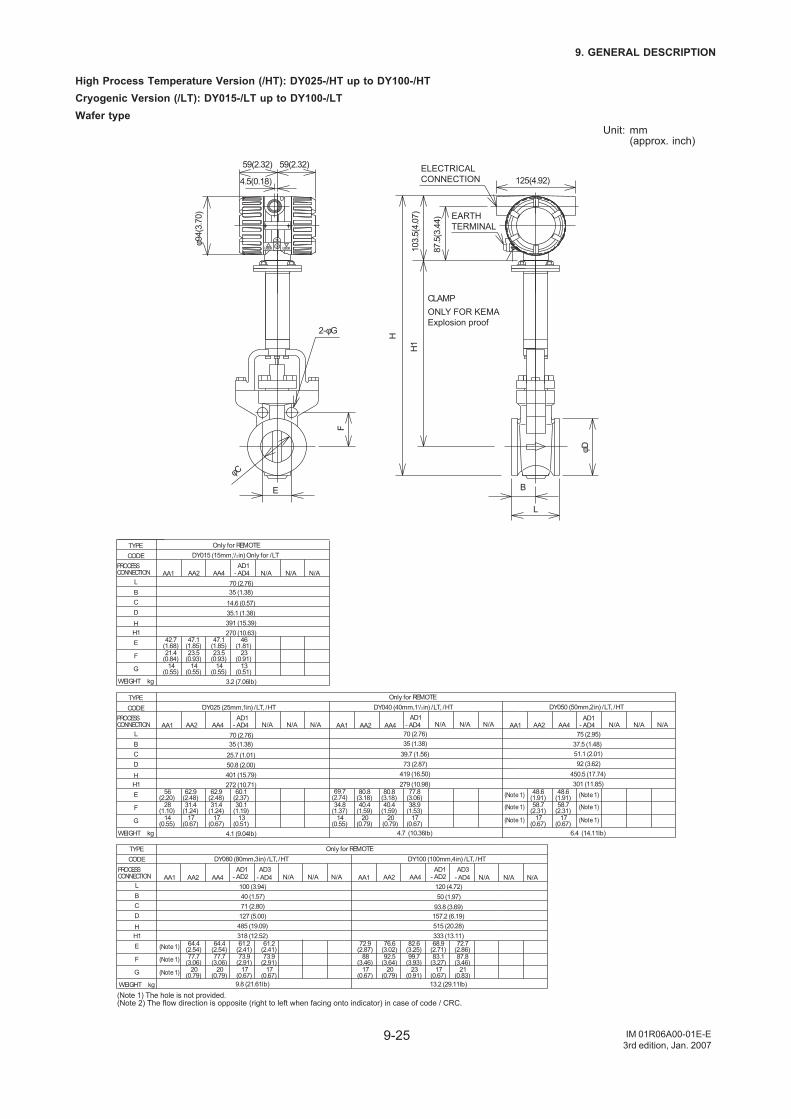
9-25
9. GENERAL DESCRIPTION
IM 01R06A00-01E-E3rd edition, Jan. 2007
High Process Temperature Version (/HT): DY025-/HT up to DY100-/HTCryogenic Version (/LT): DY015-/LT up to DY100-/LTWafer type
Unit: mm(approx. inch)
ONLY FOR KEMA Explosion proof
H110
3.5(
4.07
)
B
H
125(4.92)
L
φD
φC
2-φG
4.5(0.18)
59(2.32)59(2.32)
φ94(
3.70
)
F
E
87.5
(3.4
4)
ELECTRICAL CONNECTION
CLAMP
EARTH TERMINAL
DY015 (15mm,1/2in) Only for /LTOnly for REMOTE
515 (20.28)333 (13.11)
485 (19.09)318 (12.52)
157.2 (6.19)93.8 (3.69)50 (1.97)120 (4.72)
72.7(2.86)
68.9(2.71)
82.6(3.25)
76.6(3.02)
72.9(2.87)
87.8(3.46)
83.1(3.27)
99.7(3.93)
88(3.46)
92.5(3.64)
21(0.83)
23(0.91)
17(0.67)
17(0.67)
20(0.79)
20(0.79)
20(0.79)
17(0.67)
17(0.67)
77.7(3.06)
77.7(3.06)
73.9(2.91)
73.9(2.91)
- AD4AD3
61.2(2.41)
61.2(2.41)
64.4(2.54)
64.4(2.54)
127 (5.00)71 (2.80)40 (1.57)100 (3.94)
DY080 (80mm,3in) /LT, /HT
AA4AA2AA1 - AD2AD1
AA4AA2AA1
DY100 (100mm,4in) /LT, /HTAD1
- AD2AD3
- AD4
AA1 AA2 AA4AD1
- AD4 AA1 AA2 AA4AD1
- AD4
DY040 (40mm,11/2in) /LT, /HT
70 (2.76)
39.7 (1.56)73 (2.87)
69.7(2.74)
80.8(3.18)
80.8(3.18)
77.8(3.06)
34.8(1.37)
40.4(1.59)
40.4(1.59)
38.9(1.53)
17(0.67)
14(0.55)
20(0.79)
20(0.79)
DY050 (50mm,2in) /LT, /HT
48.6(1.91)
48.6(1.91)
58.7(2.31)
58.7(2.31)
17(0.67)
17(0.67)
(Note 1)
(Note 1)
(Note 1)
(Note 1)
(Note 1)
(Note 1)
(Note 1)
(Note 1)
(Note 1)
75 (2.95)
92 (3.62)51.1 (2.01)
301 (11.85)450.5 (17.74)
279 (10.98)419 (16.50)
AA1 AA2 AA4AD1
- AD4
DY025 (25mm,1in) /LT, /HT
17(0.67)
17(0.67)
14(0.55)
13(0.51)
28(1.10)
31.4(1.24)
31.4(1.24)
30.1(1.19)
56(2.20)
62.9(2.48)
62.9(2.48)
60.1(2.37)
70 (2.76)
25.7 (1.01)50.8 (2.00)
272 (10.71)401 (15.79)
Only for REMOTE
Only for REMOTE
4.1 (9.04lb) 4.7 (10.36lb) 6.4 (14.11lb)
13.2 (29.11lb)9.8 (21.61lb)
(Note 1) The hole is not provided.(Note 2) The flow direction is opposite (right to left when facing onto indicator) in case of code / CRC.
35 (1.38) 35 (1.38) 37.5 (1.48)
kgWEIGHT
D
L
C
HH1
B
E
F
G
PROCESSCONNECTION
TYPECODE
AA1 AA2 AA4AD1
- AD4
14(0.55)
14(0.55)
14(0.55)
13(0.51)
21.4(0.84)
23.5(0.93)
23.5(0.93)
23(0.91)
42.7(1.68)
47.1(1.85)
47.1(1.85)
46(1.81)
70 (2.76)
14.6 (0.57)35.1 (1.38)
270 (10.63)391 (15.39)
3.2 (7.06lb)
35 (1.38)
kgWEIGHT
D
L
C
HH1
B
E
F
G
PROCESSCONNECTION
TYPECODE
kgWEIGHT
D
L
C
HH1
B
E
F
G
PROCESSCONNECTION
TYPECODE
N/A N/A N/A
N/A N/A N/A N/A N/A N/A N/A N/A N/A
N/A N/A N/AN/A N/A N/A
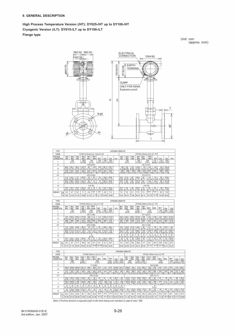
9-26
9. GENERAL DESCRIPTION
IM 01R06A00-01E-E3rd edition, Jan. 2007
High Process Temperature Version (/HT): DY025-/HT up to DY100-/HTCryogenic Version (/LT): DY015-/LT up to DY100-/LTFlange type
Unit: mm(approx. inch)
φCφJ
N-φG
φD
H
59(2.32)
4.5(0.18)
59(2.32)
H1
T
L
103.5
(4.0
7)
87.5
(3.4
4)
φ94(3
.70)
125(4.92)
ELECTRICAL CONNECTION
CLAMP
EARTH
TERMINAL
ONLY FOR KEMA
Explosion proof
BA1BS1
BA2BS2
BA4BS4
BA5BS5
BA1BS1
BA2BS2
BA4BS4
BA5BS5
kglb
WEIGHT 8.37.34.6
25.4(1.00)
101.6(4.00)
34.9(1.37)
450(17.72)
149.4(5.88)
150(5.91)
170(6.69)
190(7.48)
22.4(0.88)
82.6(2.25)
28.8(1.13)
434(17.09)
120.7(4.75)
130(5.12)
160(6.30)
DY025 (25mm,2 in) /LT, /HT
D
DY015 (15mm,1/2 in) Only for /LT
BD1- BD4- BD4
BD1
L
C
HH1
T
JN
G
130(5.12)
14.6 (0.57)88.9
(3.50)95.3
(3.75)95.3
(3.75)95
(3.74)418
(16.46)421
(16.57)421
(16.57)421
(16.57)270 (10.63)16
(0.63)11.2
(0.44)14.2
(0.56)21
(0.83)60.5
(2.38)66.5
(2.62)66.5
(2.62)65
(2.56)4 (0.16)
15.7(0.62)
15.7(0.62)
15.7(0.62)
14(0.55)
CA4150
(5.91)25.7 (1.01)115
(4.53)108
(4.25)124
(4.88)124
(4.88)124
(4.88)438
(17.24)438
(17.24)433
(17.05)430
(16.93)438
(17.24)272 (10.71)
14.2(0.56)
17.5(0.69)
24(0.94)
18(0.71)
24(0.94)
79.2(3.12)
89(3.50)
89(3.50)
85(3.35)
89(3.50)
4 (0.16)15.7
(0.62)19
(0.75)19
(0.75)14
(0.55)19
(0.75)4.5 4.7 5.0 7.0 7.6 8.1
INTEGRAL/REMOTE
PROCESSCONNECTION
TYPECODE
7.1
15.7(0.62)
66.5(2.62)
19.9(0.78)
421(16.57)
95.3(3.75)
140(5.51)
CA4
4.9
22.4(0.88)
82.6(2.25)
28.8(1.13)
434(17.09)
120.7(4.75)
160(6.30)
CA5
7.2 11.5
25.4(1.00)
101.6(4.00)
34.9(1.37)
450(17.18)
149.4(5.88)
190(7.48)
CA5
11.8
18.3016.1010.149.92 10.36 11.03 15.44 16.76 17.8615.66 10.80 15.88 25.36 26.02
BA1BS1
BA2BS2
BA4BS4
BA5BS5
BA1BS1
BA2BS2
BA4BS4
BA5BS5
kglb
WEIGHT 11.79.2
25.4(1.00)
25.4(1.00)
165.1(6.50)
165.1(6.50)
44.5(1.75)
46(1.81)
513(20.20)
513(20.20)
215.9(8.50)
215.9(8.50)
170(6.69)
230(9.06)
230(9.06)
28.4(1.12)
124(4.88)
38.2(1.50)
472(18.58)
177.8(7.00)
150(5.91)
200(7.87)
DY050 (50mm,2in) /LT, /HT
D
DY040 (40mm,11/2 in) /LT, /HTBD1
- BD4- BD4BD1
L
C
HH1
T
J
N
G
150(5.91)
39.7 (1.56)127
(5.00)155.4(6.12)
155.4(6.12)
150(5.91)
446(17.56)
460(18.11)
460(18.11)
458(18.03)279 (10.98)18
(0.71)17.5
(0.69)20.6
(0.81)28.8
(1.13)98.6
(3.88)114.3(4.50)
114.3(4.50)
110(4.33)
4(0.16)
15.7(0.62)
22.4(0.88)
22.4(0.88)
18(0.71)
CA4170
(6.69)51.1 (2.01)165
(6.50)152.4(6.00)
165.1(6.50)
165.1(6.50)
487(19.17)
487(19.17)
487(19.17)
481(18.94)
301 (11.85)19.1
(0.75)22.4
(0.88)31.8
(1.25)20
(0.79)120.7(4.75)
127(5.00)
127(5.00)
125(4.92)
4(0.16)
4(0.16)
8(0.31)
8(0.31)
8(0.31)
8(0.31)
8(0.31)
19(0.75)
19(0.75)
19(0.75)
18(0.71)
8.5 9.7 11.7 12.1 13.6 15.2
INTEGRAL/REMOTE
PROCESSCONNECTION
TYPECODE
16.6
22.4(0.88)
114.3(4.50)
28.8(1.13)
460(18.11)
155.4(6.12)
185(7.28)
CA4
12.1
28.4(1.12)
124(4.88)
38.2(1.50)
472(18.58)
177.8(7.00)
200(7.87)
CA5
16.7 26.9
19(0.75)
127(5.00)
33.3(1.31)
487(19.17)
165.1(6.50)
205(8.07)
CA5
16.2 27.3
25.8020.2918.74 21.39 25.80 26.68 29.99 33.5236.60 26.68 36.82 59.32 35.72 60.20
(Note 1) The flow direction is opposite (right to left when facing onto indicator) in case of code / CRC.
BA1BS1
BA2BS2
BA4BS4
BA5BS5
BA1BS1
BA2BS2
BA4BS4
BA5BS5
kglb
WEIGHT 27.823.620.419.8
31.8(1.25)
235(9.25)
50.9(2.00)
583(22.95)
292.1(11.50)
280(11.02)
200(7.87)
25.4(1.00)
8(0.31)
190.5(7.50)
44.5(1.75)
542(21.34)
209.6(8.25)
245(9.65)
DY100 (100mm,4in) /LT, /HT
D
DY080 (80mm,3 in) /LT, /HT
L
C
HH1
T
J
N
G
BD1- BD2
BD3- BD4 - BD2
BD1 BD3 - BD4
200(7.87)
71 (2.80)200
(7.87)200
(7.87)190.5(7.50)
209.6(8.25)
241.3(9.50)
517(20.35)
527(20.75)
527(20.75)
522(20.55)
522(20.55)
318 (12.52)23.9
(0.94)28.4
(1.12)38.2
(1.50)20
(0.79)24
(0.94)160
(6.30)160
(6.30)152.4(6.00)
168.2(6.62)
168(6.61)
8(0.31)
8(0.31)
8(0.31)
8(0.31)
19(0.75)
22.4(0.88)
22.4(0.88)
18(0.71)
18(0.71)
4(0.16)
220(8.66)
220(8.66)
240(9.45)
93.8 (3.69)228.6(9.00)
254(10.00)
273(10.75)
220(8.66)
235(9.25)
552(21.73)
564(22.20)
573(22.56)
547(21.54)
554(21.81)
333 (13.11)24
(0.94)23.9
(0.94)31.8
(1.25)44.5
(1.75)20
(0.79)190.5(7.50)
200.2(7.88)
216(8.50)
180(7.09)
190(7.48)
8(0.31)
19(0.75)
22.4(0.88)
25.4(1.00)
18(0.71)
22(0.87)
20.4 24.2 25.8 27.7 36.3 51.2
INTEGRAL/REMOTE
PROCESSCONNECTION
TYPECODE
36.1
22.4(0.88)
8(0.31)
170(6.69)
39.7(1.56)
527(20.75)
235(9.25)
CA4
209.6(8.25)
27.5
25.4(1.00)
8(0.31)
180(7.09)
46(1.81)
542(21.34)
250(9.84)
CA5
241.3(9.50)
36.7 56.3
25.4(1.00)
216(8.50)
46(1.81)
573(22.56)
273(10.75)
270(10.63)
CA4
53.2
31.8(1.25)
235(9.25)
52.4(2.06)
583(22.95)
292.1(11.50)
285(11.22)
CA5
57.0
61.3052.0444.9843.6644.98 53.36 56.89 61.30 80.04 112.9079.60 60.64 80.92 124.14 117.31 125.69
BD7BD5
- BD6
20(0.78
426(16.71)
75(2.94)
5.8
BD5- BD6
446(15.50)
140(5.49)
18(0.71)
24(0.94)100
(3.92)
10.0
- BD6BD5
170(6.67)468
(18.36)
26(1.02)
125(4.90)
22(0.86)13.1
BD5 BD6
180(7.06)
195(7.65)
495(19.42)
502(19.69)
28(1.10)
135(5.30)
145(5.69)
26(1.02
14.7 15.6
BD6BD5
569(22.32)
562(22.04)
265(10.40)
250(9.81)
210(8.24)
200(7.85)
30(1.18)
40.133.4
BD6BD5
537(21.07)
529(20.75)
230(9.02)
215(8.53)
32(1.25)
28(1.10)
27.424.5
105(4.12)
BD7
10.0
BD7180
(7.06)
13.1
BD7195
(7.65)
15.6
BD7
36(1.41)
27.4
BD7260
(10.2)
40(1.57)
40.1
140(5.51)
170(6.69)
105(4.12)
14(0.55)
20(0.78
426(16.71)
75(2.94)
5.8
14(0.55)
446(15.50)
140(5.49)
18(0.71)
24(0.94)100
(3.92)
170(6.67)468
(18.36)
26(1.02)
22(0.86)
125(4.90)
4(0.16)
4(0.16)
4(0.16)
22(0.86)
26(1.02)
195(7.65)502
(19.69)
28(1.10)145
(5.69)
26(1.02
230(9.06)
8(0.31)
8(0.31)
8(0.31)
26(1.02)
26(1.02)
26(1.02)
170(6.69)
180(7.09)
180(7.09)
22(0.86)
210(8.24)
36(1.41)
30(1.18)
30(1.18)
265(10.40)
569(22.32)
54.02 40.41 40.41 73.64 88.4288.42
28.88 28.88 32.41 34.40 34.40
12.79 12.79 22.05 22.05
230(9.02)537
(21.07)
N/A
N/A N/A
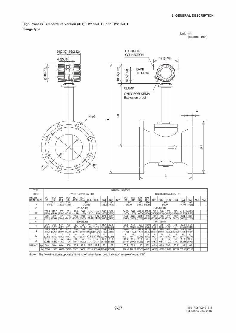
9-27
9. GENERAL DESCRIPTION
IM 01R06A00-01E-E3rd edition, Jan. 2007
High Process Temperature Version (/HT): DY150-/HT up to DY200-/HTFlange type
Unit: mm(approx. inch)
ELECTRICAL
CONNECTION
CLAMP
N-φG
φCφJ
φD
H1
H
L
T
59(2.32) 59(2.32)
103.5
(4.0
7)
87.5
(3.4
4)
φ94(3
.70)
125(4.92)4.5(0.18)
EARTH
TERMINAL
ONLY FOR KEMA
Explosion proof
(Note 1) The flow direction is opposite (right to left when facing onto indicator) in case of code / CRC.
BA1BS1
BA2BS2
BA4BS4
BA5BS5
BA1BS1
BA2BS2
BA4BS4
BA5BS5
kg
lb
WEIGHT 13955.953.646.342.933.4
22(0.87)
295(11.61)
24(0.95)
645(25.39)
340(13.39))
270(10.63)
31.8(1.25)
12(0.47)
317.5(12.50)
62(2.44)
633(24.92)
356(14.02)
336(13.23)
310(12.20)
DY200 (200mm,8in) / HT
D
DY150 (150mm,6in) / HT
L
C
H
H1
T
J
N
G
BD1- BD2
BD3- BD4 BD1 BD2 BD3 BD4
270(10.63)
138.8 (5.46)
285(11.22)
300(11.81)
279.4(11.00)
317.5(12.50)
381(15.00)
582(22.91)
601(23.66)
621(24.45)
585(23.03)
593(23.35)
339 (13.35)
25.4(1.00)
36.6(1.44)
54.4(2.14)
22(0.87)
28(1.10)
240(9.45)
250(9.84)
241.3(9.50)
269.7(10.62)
292(11.50)
12(0.47)
12(0.47)
8(0.31)
8(0.31)
22.4(0.88)
22.4(0.88)
28.4(1.12)
22(0.87)
26(1.02)
8(0.31)
310(12.20)
310(12.20)
386(15.20)
375(14.77)
185.6 (7.31)
342.9(13.50)
375(14.76))
381(15.00)
419.1(16.50))
469.9(18.50))
340(13.39))
360(14.17))
419.1(16.50))
646(25.43)
665(26.18)
684(26.93)
709(27.91)
645(25.39)
655(25.79)
662(26.06)
684(26.93)
371 (14.61)
30(1.18)
28.4(1.12)
41.1(1.62)
62(2.44)
69.9(2.75)
24(0.95)
34(1.34)
63.6(2.50)
298.5(11.75)
330.2(13.00)
349.3(13.75)
393.7(15.50)
295(11.61)
310(12.20)
320(12.60)
349.3(13.75)
25.4(1.00)
22.4(0.88)
31.8(1.25)
38.1(1.50)
22(0.87)
26(1.02)
30(1.18)
31.8(1.25)
36.4 54.4 84.4 55.4 80.4 136 182
INTEGRAL/REMOTE
PROCESSCONNECTION
TYPE
CODE
106
28.4(1.12)
12(0.47)
292(11.50)
55.7(2.19)
621(24.45)
325(12.80)
CA4
356(14.02)
90
31.8(1.25)
12(0.47)
12(0.47)
12(0.47)
12(0.47)
8(0.31)
12(0.47)
12(0.47)
12(0.47)
8(0.31)
12(0.47)
12(0.47)
317.5(12.50)
63.6(2.50)
633(24.92)
340(13.39)
CA5
381(15.00)
107 46.3
38.1(1.50)
393.7(15.50)
71.4(2.81)
709(27.91)
469.9(18.50))
390(15.35)
CA4
183
CA5
306.50123.26118.19102.0994.5973.6580.26 119.95 186.10 122.16 177.28 299.88 401.31233.73 198.45 235.94 102.09 403.52
370(14.57)
BD5 BD6
345(13.37)
355(13.76)
615(23.83)
620(24.02)
36(1.39)
44(1.71)
280(10.85)
290(11.24)
33(1.28)
58.1 76.4
8(0.31)
12(0.47)
128.10 168.45
33(1.28)
N/A N/A N/A
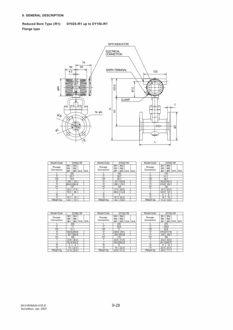
9-28
9. GENERAL DESCRIPTION
IM 01R06A00-01E-E3rd edition, Jan. 2007
Reduced Bore Type (/R1): DY025-/R1 up to DY150-/R1Flange type
N- φG
φC
φCS
φJ
ELECTRICALCONNECTION
EARTH TERMINAL
WITH INDICATOR
87.5103.
5
CLAMP
HH1
125
T
L
φD
5974
594.5
φ94
15025.714.6
DY025 /R1
127
4
15039.725.7
129
4
BA1BS1BP1
108284.5
14.279.2
15.75.5
BA2BS2BP2
124292.5
17.589
197.0
DY040 /R1BA1BS1BP1
127296
17.598.6
15.79.4
BA2BS2BP2
155.4310
20.6114.3
22.412.6
DY050 /R1BA1BS1BP1
152.4315.5
19.1120.7
419
11.4
BA2BS2BP2
165.1322
22.4127
819
13.6
Model Code
ProcessConnection
LC
CSDH
H1TJNG
Weight kg
Model Code
ProcessConnection
LC
CSDHH1TJNG
Weight kg
Model Code
ProcessConnection
LC
CSDHH1TJNG
Weight kg
136
17051.139.7
Model Code
ProcessConnection
LC
CSDH
H1TJNG
Weight kg
Model Code
ProcessConnection
LC
CSDHH1TJNG
Weight kg
Model Code
ProcessConnection
LC
CSDHH1TJNG
Weight kg
DY080 /R1BA1BS1BP1
190.5357
23.9152.4
419
21.9
BA2BS2BP2
209.6366.5
28.4168.2
822.426.9
DY100 /R1BA1BS1BP1
228.6393
23.9190.5
1930.6
BA2BS2BP2
254405.5
31.8200.2
22.441.0
DY150 /R1BA1BS1BP1
279.4433
25.4241.3
822.449.4
BA2BS2BP2
317.5452
36.6269.7
1222.471.7
20071
51.1
158 175 190
8
22093.871
270138.893.8
N/A N/A N/A N/A N/A N/A
N/A N/A N/A N/A N/A N/A
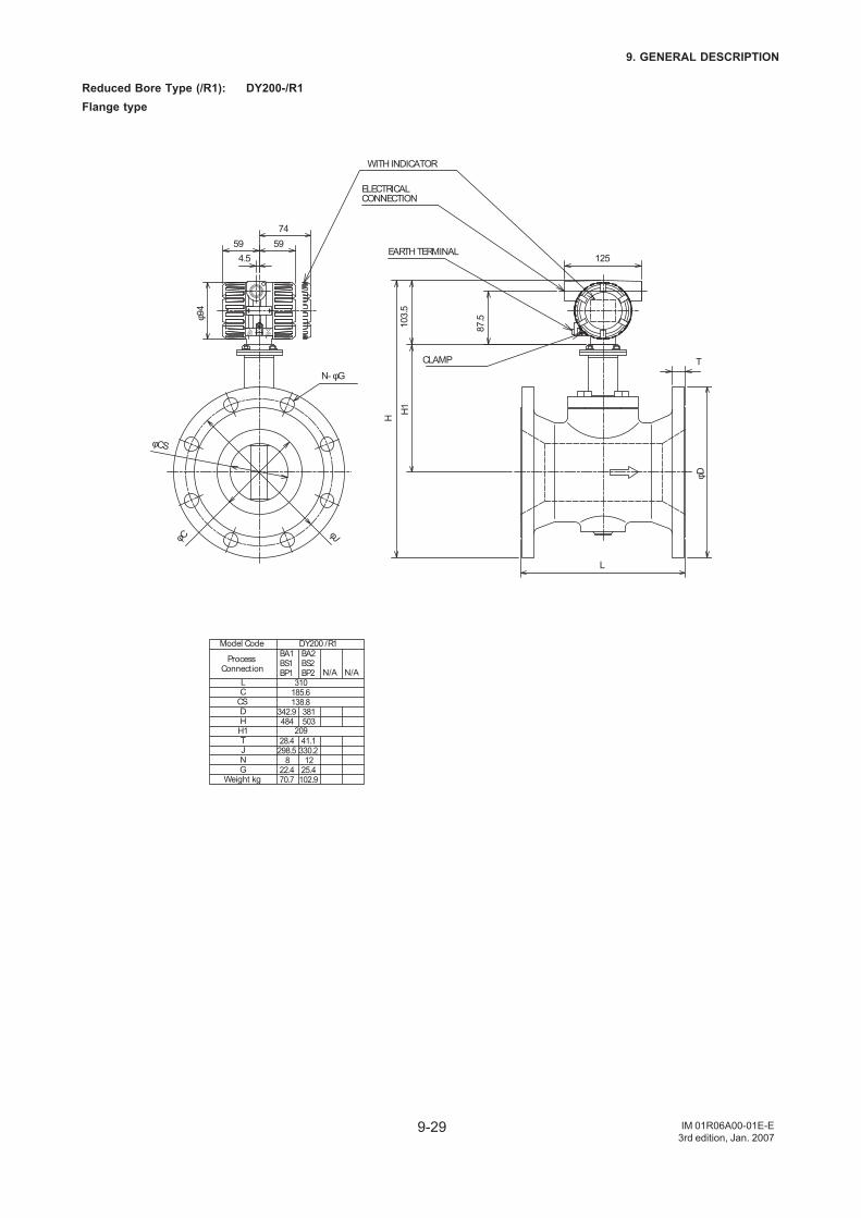
9-29
9. GENERAL DESCRIPTION
IM 01R06A00-01E-E3rd edition, Jan. 2007
Reduced Bore Type (/R1): DY200-/R1Flange type
N- φG
φC
φCS
φJ
ELECTRICALCONNECTION
EARTH TERMINAL
WITH INDICATOR
87.5103.
5
CLAMP
H
H1
125
T
L
φD
5974
594.5
φ94
Model Code
ProcessConnection
LC
CSDH
H1TJNG
Weight kg
310185.6138.8
DY200 /R1
209
BA1BS1BP1
342.9484
28.4298.5
822.470.7
BA2BS2BP2
381503
41.1330.2
1225.4102.9
N/A N/A
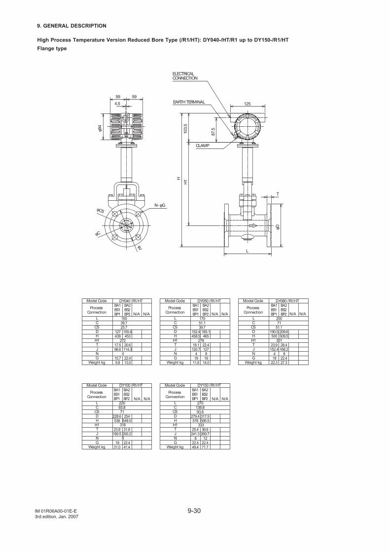
9-30
9. GENERAL DESCRIPTION
IM 01R06A00-01E-E3rd edition, Jan. 2007
High Process Temperature Version Reduced Bore Type (/R1/HT): DY040-/HT/R1 up to DY150-/R1/HTFlange type
N- φG
φC
φCS
φJ
ELECTRICALCONNECTION
EARTH TERMINAL
87.5103.
5
CLAMP
HH1
125
T
L
φD
59 594.5
φ94
DY040 /R1/HT
272
4
BA1BS1BP1
127439
17.598.6
15.79.8
BA2BS2BP2
155.4453
20.6114.3
22.413.0
DY050 /R1/HTBA1BS1BP1
152.4458.5
19.1120.7
419
11.8
BA2BS2BP2
165.1465
22.4127
819
14.0
DY080 /R1/HTBA1BS1BP1
190.5500
23.9152.4
419
22.3
BA2BS2BP2
209.6509.5
28.4168.2
822.427.3
279 301
17051.139.7
20071
51.1
15039.725.7
Model Code
ProcessConnection
LC
CSDHH1TJNG
Weight kg
Model Code
ProcessConnection
LC
CSDHH1TJNG
Weight kg
Model Code
ProcessConnection
LC
CSDHH1TJNG
Weight kg
Model Code
ProcessConnection
LC
CSDHH1TJNG
Weight kg
Model Code
ProcessConnection
LC
CSDHH1TJNG
Weight kg
DY100 /R1/HTBA1BS1BP1
228.6536
23.9190.5
1931.0
BA2BS2BP2
254548.5
31.8200.2
22.441.4
DY150 /R1/HTBA1BS1BP1
279.4576
25.4241.3
822.449.4
BA2BS2BP2
317.5595.5
36.6269.7
1222.471.7
22093.871
318
8
333
270138.893.8
N/A N/A N/A N/A N/A N/A
N/A N/A N/A N/A
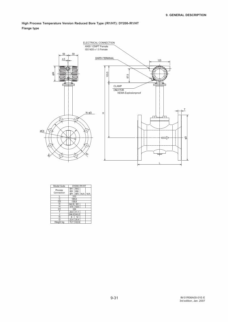
9-31
9. GENERAL DESCRIPTION
IM 01R06A00-01E-E3rd edition, Jan. 2007
High Process Temperature Version Reduced Bore Type (/R1/HT): DY200-/R1/HTFlange type
φD
N- φG
φCS
φCφJ
125
87.5103.
5T
L
H
φ94
4.5
59 59
ELECTRICAL CONNECTIONANSI 1/2NPT FemaleISO M20 x 1.5 Female
CLAMPONLY FOR
KEMA Explosionproof
EARTH TERMINAL
Model Code
ProcessConnection
LC
CSDH
H1TJNG
Weight kg
310185.6138.8
DY200 /R1/HT
339
BA1BS1BP1
342.9614
28.4298.5
822.470.7
BA2BS2BP2
381633
41.1330.2
1225.4102.9
N/A N/A
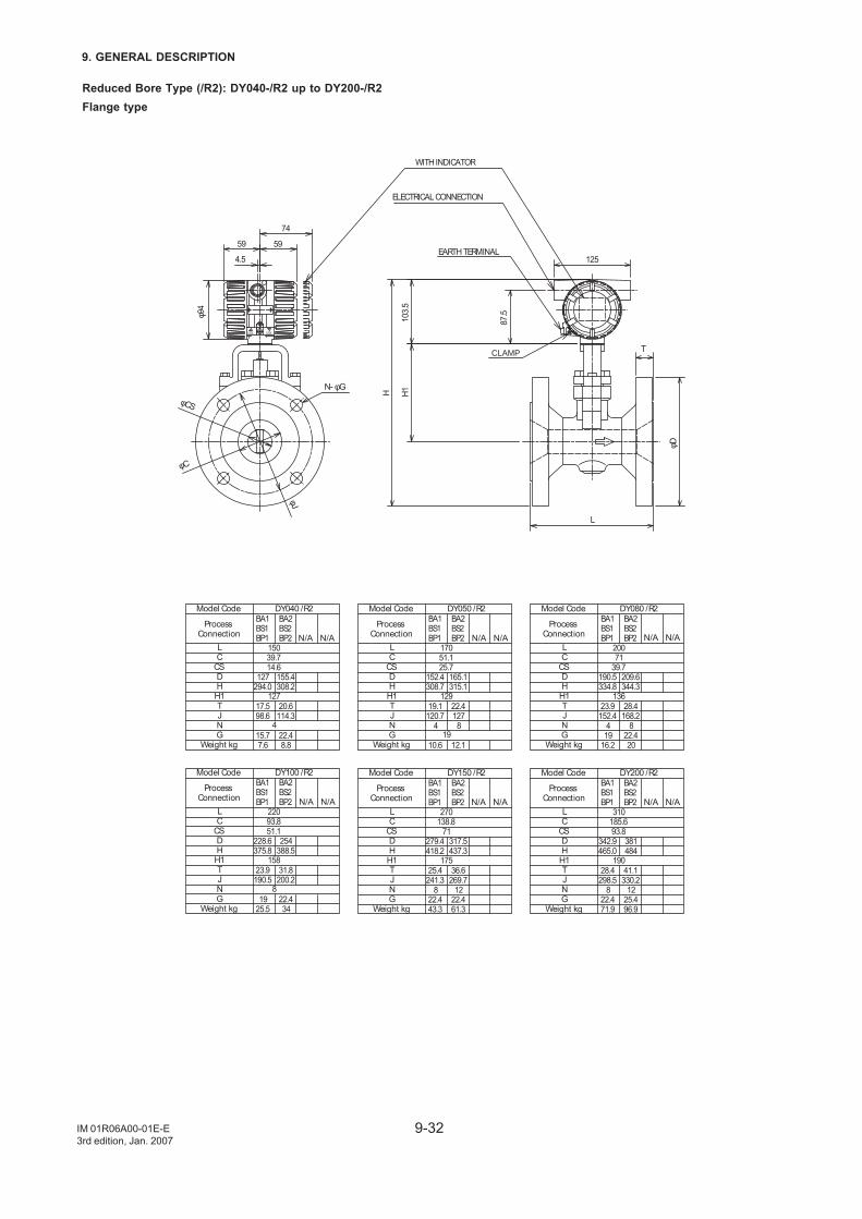
9-32
9. GENERAL DESCRIPTION
IM 01R06A00-01E-E3rd edition, Jan. 2007
Reduced Bore Type (/R2): DY040-/R2 up to DY200-/R2Flange type
φCS
φC
φJ
N- φG
15039.714.6
DY040 /R2
127
4
BA1BS1BP1
127294.0
17.598.6
15.77.6
BA2BS2BP2
155.4308.2
20.6114.3
22.48.8
Model Code
ProcessConnection
LC
CSDHH1TJNG
Weight kg
22093.851.1
DY100 /R2
158
8
BA1BS1BP1
228.6375.8
23.9190.5
1925.5
BA2BS2BP2
254388.5
31.8200.2
22.434
Model Code
ProcessConnection
LC
CSDHH1TJNG
Weight kg
17051.125.7
DY050 /R2
129
19
BA1BS1BP1
152.4308.7
19.1120.7
4
10.6
BA2BS2BP2
165.1315.1
22.4127
8
12.1
Model Code
ProcessConnection
LC
CSDHH1TJNG
Weight kg
20071
39.7
DY080 /R2
136
BA1BS1BP1
190.5334.8
23.9152.4
419
16.2
BA2BS2BP2
209.6344.3
28.4168.2
822.420
Model Code
ProcessConnection
LC
CSDHH1TJNG
Weight kg
270138.8
71
DY150 /R2
175
BA1BS1BP1
279.4418.2
25.4241.3
822.443.3
BA2BS2BP2
317.5437.3
36.6269.7
1222.461.3
Model Code
ProcessConnection
LC
CSDHH1TJNG
Weight kg
310185.693.8
DY200 /R2
190
BA1BS1BP1
342.9465.0
28.4298.5
822.471.9
BA2BS2BP2
381484
41.1330.2
1225.496.9
Model Code
ProcessConnection
LC
CSDHH1TJNG
Weight kg
N/A N/A N/A N/A N/A N/A
N/A N/AN/A N/AN/A N/A
59
74
59
H
4.5
φ94
125
87.5103.
5
L
T
H1
WITH INDICATOR
ELECTRICAL CONNECTION
EARTH TERMINAL
CLAMP
φD
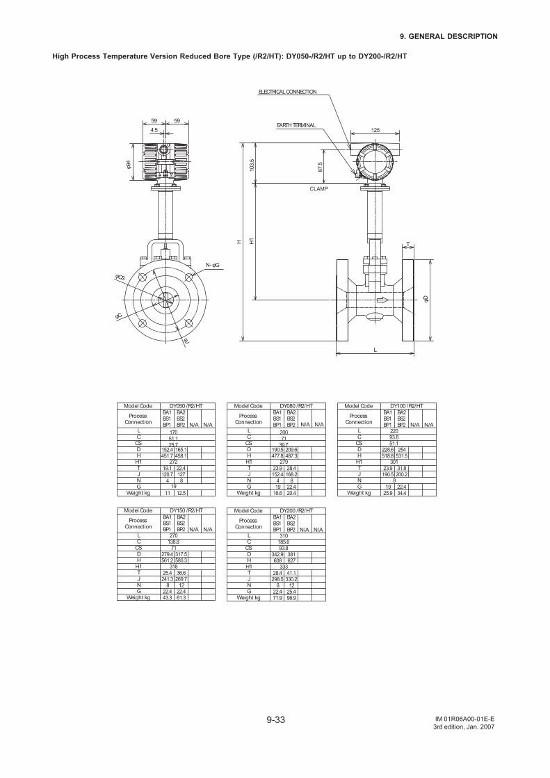
9-33
9. GENERAL DESCRIPTION
IM 01R06A00-01E-E3rd edition, Jan. 2007
High Process Temperature Version Reduced Bore Type (/R2/HT): DY050-/R2/HT up to DY200-/R2/HT
φCS
φC
φJ
N- φG
17051.125.7
DY050 /R2/HT
272
19
BA1BS1BP1
152.4451.7
19.1120.7
4
11
BA2BS2BP2
165.1458.1
22.4127
8
12.5
Model Code
ProcessConnection
LC
CSDHH1TJNG
Weight kg
20071
39.7
DY080 /R2/HT
279
BA1BS1BP1
190.5477.8
23.9152.4
419
16.6
BA2BS2BP2
209.6487.3
28.4168.2
822.420.4
Model Code
ProcessConnection
LC
CSDHH1TJNG
Weight kg
270138.8
71
DY150 /R2/HT
318
BA1BS1BP1
279.4561.2
25.4241.3
822.443.3
BA2BS2BP2
317.5580.3
36.6269.7
1222.461.3
Model Code
ProcessConnection
LC
CSDHH1TJNG
Weight kg
22093.851.1
DY100 /R2/HT
301
8
BA1BS1BP1
228.6518.8
23.9190.5
1925.9
BA2BS2BP2
254531.5
31.8200.2
22.434.4
Model Code
ProcessConnection
LC
CSDHH1TJNG
Weight kg
310185.693.8
DY200 /R2/HT
333
BA1BS1BP1
342.9608
28.4298.5
822.471.9
BA2BS2BP2
381627
41.1330.2
1225.496.9
Model Code
ProcessConnection
LC
CSDHH1TJNG
Weight kg
N/A N/A N/A N/A N/A N/A
N/A N/A N/A N/A
H1
φD
T
L
125φ9
44.5
H
5959
87.5
103.
5
CLAMP
EARTH TERMINAL
ELECTRICAL CONNECTION
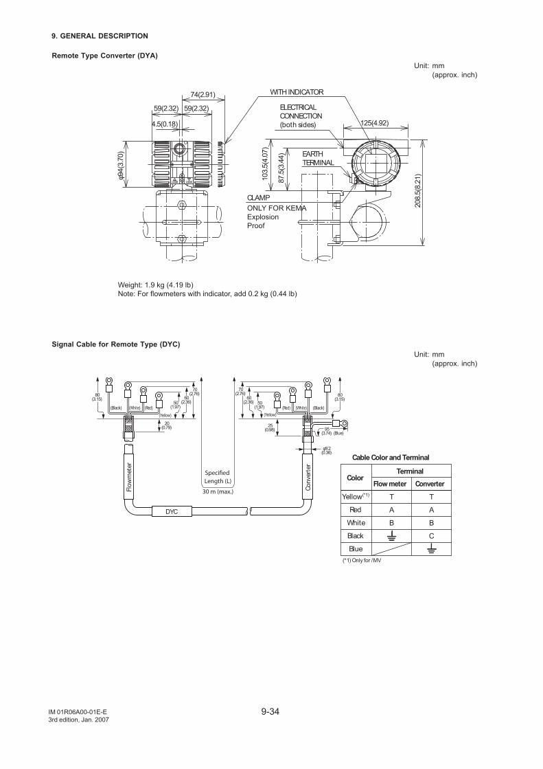
9-34
9. GENERAL DESCRIPTION
IM 01R06A00-01E-E3rd edition, Jan. 2007
Remote Type Converter (DYA)Unit: mm
(approx. inch)
Weight: 1.9 kg (4.19 lb)Note: For flowmeters with indicator, add 0.2 kg (0.44 lb)
4.5(0.18)
59(2.32) 59(2.32)
125(4.92)
103.
5(4.
07)
74(2.91)
φ94(
3.70
)
208.
5(8.
21)
87.5
(3.4
4)
WITH INDICATOR
CLAMPONLY FOR KEMA ExplosionProof
ELECTRICALCONNECTION(both sides)
EARTHTERMINAL
Signal Cable for Remote Type (DYC)Unit: mm
(approx. inch)
(Black) (White) (Red) (Red) (White) (Black)
80(3.15)
70(2.76)
70(2.76) 80
(3.15)
φ9.2(0.36)
(Blue)
60(2.36)
25(0.98) 95
(3.74)
60(2.36)50
(1.97)
20(0.79)
Specified Length (L)
30 m (max.)
DYC
Flo
wm
ete
r
Convert
er
Color
Cable Color and Terminal
Terminal
Yellow(*1)
Red
White
Black
Blue
Flow meter
T
A
B
Converter
T
A
B
C
(Yellow) (Yellow)
(*1) Only for /MV
50(1.97)
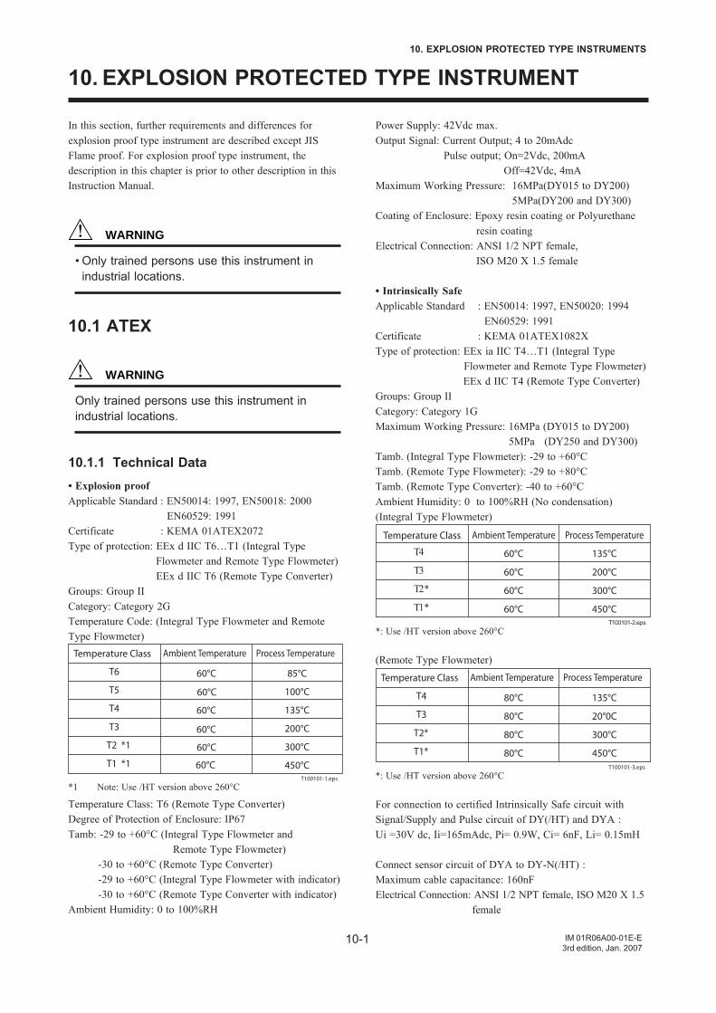
10-1
10. EXPLOSION PROTECTED TYPE INSTRUMENTS
IM 01R06A00-01E-E3rd edition, Jan. 2007
10. EXPLOSION PROTECTED TYPE INSTRUMENT
In this section, further requirements and differences forexplosion proof type instrument are described except JISFlame proof. For explosion proof type instrument, thedescription in this chapter is prior to other description in thisInstruction Manual.
WARNING
• Only trained persons use this instrument inindustrial locations.
10.1 ATEX
WARNING
Only trained persons use this instrument inindustrial locations.
10.1.1 Technical Data• Explosion proofApplicable Standard : EN50014: 1997, EN50018: 2000
EN60529: 1991Certificate : KEMA 01ATEX2072Type of protection: EEx d IIC T6…T1 (Integral Type Flowmeter and Remote Type Flowmeter) EEx d IIC T6 (Remote Type Converter)Groups: Group IICategory: Category 2GTemperature Code: (Integral Type Flowmeter and RemoteType Flowmeter)
Ambient Temperature Process Temperature
60°C 85°C
100°C
135°C
200°C
300°C
450°C
T6
Temperature Class
T5
T4
T3
T2 *1
T1 *1T100101-1.eps
60°C
60°C
60°C
60°C
60°C
*1 Note: Use /HT version above 260°C
Temperature Class: T6 (Remote Type Converter)Degree of Protection of Enclosure: IP67Tamb: -29 to +60°C (Integral Type Flowmeter and
Remote Type Flowmeter) -30 to +60°C (Remote Type Converter) -29 to +60°C (Integral Type Flowmeter with indicator) -30 to +60°C (Remote Type Converter with indicator)
Ambient Humidity: 0 to 100%RH
Power Supply: 42Vdc max.Output Signal: Current Output; 4 to 20mAdc
Pulse output; On=2Vdc, 200mA Off=42Vdc, 4mA
Maximum Working Pressure: 16MPa(DY015 to DY200)5MPa(DY200 and DY300)
Coating of Enclosure: Epoxy resin coating or Polyurethane resin coatingElectrical Connection: ANSI 1/2 NPT female, ISO M20 X 1.5 female
• Intrinsically SafeApplicable Standard : EN50014: 1997, EN50020: 1994
EN60529: 1991Certificate : KEMA 01ATEX1082XType of protection: EEx ia IIC T4…T1 (Integral Type
Flowmeter and Remote Type Flowmeter) EEx d IIC T4 (Remote Type Converter)Groups: Group IICategory: Category 1GMaximum Working Pressure: 16MPa (DY015 to DY200) 5MPa (DY250 and DY300)Tamb. (Integral Type Flowmeter): -29 to +60°CTamb. (Remote Type Flowmeter): -29 to +80°CTamb. (Remote Type Converter): -40 to +60°CAmbient Humidity: 0 to 100%RH (No condensation)(Integral Type Flowmeter)
Ambient Temperature Process Temperature
60°C 135°C
60°C 200°C
60°C 300°C
60°C 450°C
T4
Temperature Class
T3
T2*
T1*T100101-2.eps
*: Use /HT version above 260°C
(Remote Type Flowmeter)Ambient Temperature Process Temperature
80°C 135°C
80°C 20°0C
80°C 300°C
80°C 450°C
T4
Temperature Class
T3
T2*
T1*
T100101-3.eps
*: Use /HT version above 260°C
For connection to certified Intrinsically Safe circuit withSignal/Supply and Pulse circuit of DY(/HT) and DYA :Ui =30V dc, Ii=165mAdc, Pi= 0.9W, Ci= 6nF, Li= 0.15mH
Connect sensor circuit of DYA to DY-N(/HT) :Maximum cable capacitance: 160nFElectrical Connection: ANSI 1/2 NPT female, ISO M20 X 1.5
female
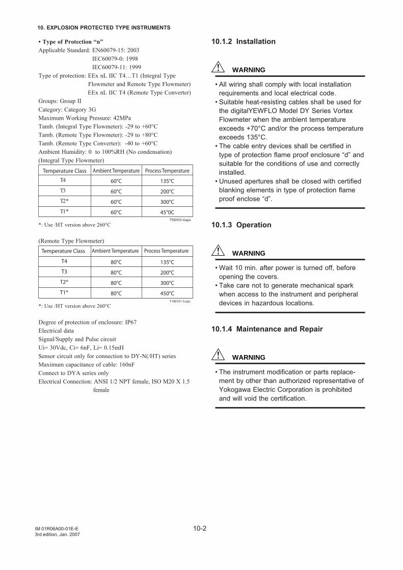
10-2
10. EXPLOSION PROTECTED TYPE INSTRUMENTS
IM 01R06A00-01E-E3rd edition, Jan. 2007
• Type of Protection “n”Applicable Standard: EN60079-15: 2003
IEC60079-0: 1998IEC60079-11: 1999
Type of protection: EEx nL IIC T4…T1 (Integral Type Flowmeter and Remote Type Flowmeter)
EEx nL IIC T4 (Remote Type Converter)Groups: Group IICategory: Category 3GMaximum Working Pressure: 42MPaTamb. (Integral Type Flowmeter): -29 to +60°CTamb. (Remote Type Flowmeter): -29 to +80°CTamb. (Remote Type Converter): -40 to +60°CAmbient Humidity: 0 to 100%RH (No condensation)(Integral Type Flowmeter)
Ambient Temperature Process Temperature
60°C 135°C
60°C 200°C
60°C 300°C
60°C 45°0C
T4
Temperature Class
T3
T2*
T1*T100101-4.eps
*: Use /HT version above 260°C
(Remote Type Flowmeter)Ambient Temperature Process Temperature
80°C 135°C
80°C 200°C
80°C 300°C
80°C 450°C
T4
Temperature Class
T3
T2*
T1*
T100101-5.eps
*: Use /HT version above 260°C
Degree of protection of enclosure: IP67Electrical dataSignal/Supply and Pulse circuitUi= 30Vdc, Ci= 6nF, Li= 0.15mHSensor circuit only for connection to DY-N(/HT) seriesMaximum capacitance of cable: 160nFConnect to DYA series onlyElectrical Connection: ANSI 1/2 NPT female, ISO M20 X 1.5
female
10.1.2 Installation
WARNING
• All wiring shall comply with local installationrequirements and local electrical code.
• Suitable heat-resisting cables shall be used forthe digitalYEWFLO Model DY Series VortexFlowmeter when the ambient temperatureexceeds +70°C and/or the process temperatureexceeds 135°C.
• The cable entry devices shall be certified intype of protection flame proof enclosure “d” andsuitable for the conditions of use and correctlyinstalled.
• Unused apertures shall be closed with certifiedblanking elements in type of protection flameproof enclose “d”.
10.1.3 Operation
WARNING
• Wait 10 min. after power is turned off, beforeopening the covers.
• Take care not to generate mechanical sparkwhen access to the instrument and peripheraldevices in hazardous locations.
10.1.4 Maintenance and Repair
WARNING
• The instrument modification or parts replace-ment by other than authorized representative ofYokogawa Electric Corporation is prohibitedand will void the certification.
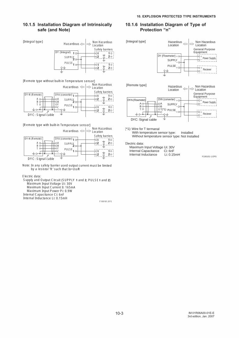
10-3
10. EXPLOSION PROTECTED TYPE INSTRUMENTS
IM 01R06A00-01E-E3rd edition, Jan. 2007
10.1.5 Installation Diagram of Intrinsicallysafe (and Note)
DY (Integral)
SUPPLY
PULSE
Safety barriers
[Integral type]
[Remote type with built-in Temperature sensor]
DYA (converter)
SUPPLY
PULSE
ABTC
ABT
Safety barriersDY-N (Remote)
DYC: Signal cable
Note: In any safety barrier used output current must be limited by a resistor ‘R’ such that Io=Uo/R
Electric data: Supply and Output Circuit (SUPPLY and , PULSE and ) Maximum Input Voltage Ui: 30V Maximum Input Current Ii: 165mA Maximum Input Power Pi: 0.9WInternal Capacitance Ci: 6nFInternal Inductance Li: 0.15mH
Hazardous Non HazardousLocation
[Remote type without built-in Temperature sensor]
DYA (converter)
SUPPLY
PULSE
ABTC
ABT
Safety barriersDY-N (Remote)
DYC: Signal cable
Hazardous Non HazardousLocation
Hazardous Non HazardousLocation
F100101.EPS
10.1.6 Installation Diagram of Type ofProtection “n”
Power Supply
Power Supply
Reciever
Reciever
DY (Flowmeter)
DY-N (Flowmeter)
SUPPLY
PULSE
[Integral type]
(*1): Wire for T termanal With temperature sensor type: Installed Without temperature sensor type: Not Installed
Electric data: Maximum Input Voltage Ui: 30V Internal Capacitance Ci: 6nF Internal Inductance Li: 0.15mH
[Remote type]
DYA (converter)
SUPPLY
PULSE
ABT(*1)C
ABT
DYC: Signal cable
Non HazardousLocation
Non HazardousLocation
HazardousLocation
HazardousLocation
F100101-1.EPS
General Purpose Equipment
General Purpose Equipment
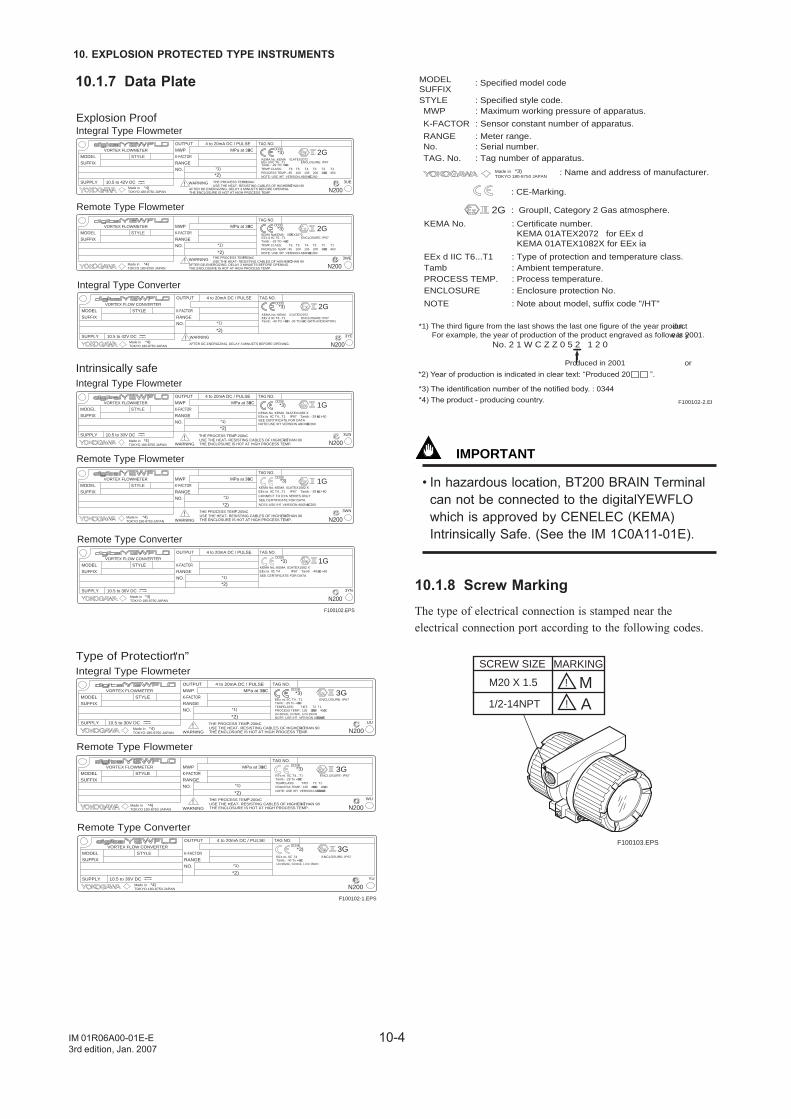
10-4
10. EXPLOSION PROTECTED TYPE INSTRUMENTS
IM 01R06A00-01E-E3rd edition, Jan. 2007
10.1.7 Data Plate
NOTE:USE /HT VERSION ABOVE 2608C
MPa at 388CMWP
WARNING
1G
3UN10.5 to 30V DC
4 to 20mA DC / PULSE
STYLEMODEL
SUFFIX
SUPPLY
K-FACTOR
OUTPUT
RANGE
NO.
TAG NO.
!
VORTEX FLOWMETER
MPa at 388CMWP
WARNING
1G
3WN
STYLEMODEL
SUFFIX
K-FACTOR
RANGE
NO.
TAG NO.
!
VORTEX FLOWMETER
EEx ia IIC T4...T1 IP67 Tamb : -29 to +608CKEMA No.:KEMA 01ATEX1082 X
SEE CERTIFICATE FOR DATA
Explosion ProofIntegral Type Flowmeter
Remote Type Flowmeter
Intrinsically safeIntegral Type Flowmeter
Remote Type Flowmeter
MPa at 388CMWP
WARNING THE PROCESS TEMP. ^ 2008C
Tamb.: -29 TO +608CTEMP CLASS: T6 T5 T4 T3 T2 T1PROCESS TEMP.: 85 100 135 200 300 4508C NOTE: USE /HT VERSION ABOVE 2608C
EEx d IIC T6...T1 ENCLOSURE: IP67KEMA No.:KEMA 01ATEX2072
*3) 2G
3UE10.5 to 42V DC
4 to 20mA DC / PULSE
STYLEMODEL
SUFFIX
SUPPLY
K-FACTOR
OUTPUT
RANGE
NO.
TAG NO.
!
VORTEX FLOWMETER
MPa at 388CMWP
3WE
STYLEMODEL
SUFFIX
K-FACTOR
RANGE
NO.
TAG NO.
VORTEX FLOWMETER
F100102.EPS
*1)
*1)
*1)
*1)
*3)
*3)
*4)
*3) 2G
USE THE HEAT- RESISTING CABLES OF HIGHER THAN 908CAFTER DE-ENERGIZING, DELAY 3 MINUETS BEFORE OPENING.THE ENCLOSURE IS HOT AT HIGH PROCESS TEMP.
WARNING!
TOKYO 180-8750 JAPANMade in
*4)
*4)TOKYO 180-8750 JAPANMade in
*4)TOKYO 180-8750 JAPANMade in
TOKYO 180-8750 JAPANMade in
Integral Type Converter
WARNING
*3) 2G
3YE10.5 to 42V DC
4 to 20mA DC / PULSE
STYLEMODEL
SUFFIX
SUPPLY
K-FACTOR
OUTPUT
RANGE
NO.
TAG NO.
!
VORTEX FLOW CONVERTER
*1)
*4)TOKYO 180-8750 JAPANMade in
1G
3YN10.5 to 30V DC
4 to 20mA DC / PULSE
STYLEMODEL
SUFFIX
SUPPLY
K-FACTOR
OUTPUT
RANGE
NO.
TAG NO.
VORTEX FLOW CONVERTER
Remote Type Converter
*1)
*3)
*4)TOKYO 180-8750 JAPANMade in
THE PROCESS TEMP. ^ 2008CUSE THE HEAT- RESISTING CABLES OF HIGHER THAN 908C
AFTER DE-ENERGIZING, DELAY 3 MINUETS BEFORE OPENING.THE ENCLOSURE IS HOT AT HIGH PROCESS TEMP.
Tamb.: -29 TO +608CTEMP CLASS: T6 T5 T4 T3 T2 T1PROCESS TEMP.: 85 100 135 200 300 4508C NOTE: USE /HT VERSION ABOVE 2608C
EEx d IIC T6...T1 ENCLOSURE: IP67KEMA No.:KEMA 01ATEX2072
Tamb.: -40 TO +608C/ -30 TO 608C (WITH INDICATOR)EEx d IIC T6...T1 ENCLOSURE: IP67KEMA No.:KEMA 01ATEX2072
AFTER DE-ENERGIZING, DELAY 3 MINUETS BEFORE OPENING.
NOTE:USE /HT VERSION ABOVE 2608C
EEx ia IIC T4...T1 IP67 Tamb : -29 to +808CKEMA No.:KEMA 01ATEX1082 X
SEE CERTIFICATE FOR DATACONNECT TO DYA SERIES ONLY
EEx ia IIC T4 IP67 Tamb : -40 to +608CKEMA No.:KEMA 01ATEX1082 X
SEE CERTIFICATE FOR DATA
THE PROCESS TEMP. ^ 2008CUSE THE HEAT- RESISTING CABLES OF HIGHER THAN 908CTHE ENCLOSURE IS HOT AT HIGH PROCESS TEMP.
THE PROCESS TEMP. ^ 2008CUSE THE HEAT- RESISTING CABLES OF HIGHER THAN 908CTHE ENCLOSURE IS HOT AT HIGH PROCESS TEMP.
N200
N200
N200
N200
N200
N200
*2)
*2)
*2)
*2)
*2)
*2)
MPa at 388CMWP
WARNING
3G
UU10.5 to 30V DC
4 to 20mA DC / PULSE
STYLEMODEL
SUFFIX
SUPPLY
K-FACTOR
OUTPUT
RANGE
NO.
TAG NO.
!
VORTEX FLOWMETER
MPa at 388CMWP
WARNING
3G
WU
STYLEMODEL
SUFFIX
K-FACTOR
RANGE
NO.
TAG NO.
!
VORTEX FLOWMETER
Type of Protection “n”Integral Type Flowmeter
Remote Type Flowmeter
Tamb.: -29 To +808CTEMP CLASS: T4 T3 T2 T1PROCESS TEMP.: 135 200 300 4508C Ui=30Vdc, Ci=6nF, Li=0.15mHNOTE: USE /HT VERSION ABOVE 2608C
EEx nL IIC T4...T1 ENCLOSURE: IP67
Tamb.: -29 To +808CTEMP CLASS: T4 T3 T2 T1PROCESS TEMP.: 135 200 300 4508C NOTE: USE /HT VERSION ABOVE 2608C
EEx nL IIC T4...T1 ENCLOSURE: IP67
Tamb.: -40 To +608CUi=30Vdc, Ci=6nF, Li=0.15mH
EEx nL IIC T4 ENCLOSURE: IP67
F100102-1.EPS
*1)
*1)
*3)
*3)
*4) TOKYO 180-8750 JAPANMade in
*4)TOKYO 180-8750 JAPANMade in
3G
YU10.5 to 30V DC
4 to 20mA DC / PULSE
STYLEMODEL
SUFFIX
SUPPLY
K-FACTOR
OUTPUT
RANGE
NO.
TAG NO.
VORTEX FLOW CONVERTER
Remote Type Converter
*1)
*3)
*4)TOKYO 180-8750 JAPANMade in
THE PROCESS TEMP. ^ 2008CUSE THE HEAT- RESISTING CABLES OF HIGHER THAN 908CTHE ENCLOSURE IS HOT AT HIGH PROCESS TEMP.
THE PROCESS TEMP. ^ 2008CUSE THE HEAT- RESISTING CABLES OF HIGHER THAN 908CTHE ENCLOSURE IS HOT AT HIGH PROCESS TEMP.
N200
N200
N200
*2)
*2)
*2)
*1) The third figure from the last shows the last one figure of the year production. For example, the year of production of the product engraved as follow is year 2001. No. 2 1 W C Z Z 0 5 2 1 2 0
Produced in 2001 or
*3) The identification number of the notified body. : 0344 *4) The product - producing country.
MODELSUFFIX
MWP : Maximum working pressure of apparatus.
K-FACTOR : Sensor constant number of apparatus.
RANGE : Meter range.No. : Serial number.
TOKYO 180-8750 JAPANMade in *3) : Name and address of manufacturer.
TAG. No. : Tag number of apparatus.
: CE-Marking.
2G : GroupII, Category 2 Gas atmosphere.
KEMA No. : Certificate number. KEMA 01ATEX2072 for EEx d KEMA 01ATEX1082X for EEx ia
EEx d IIC T6...T1 : Type of protection and temperature class.Tamb : Ambient temperature. PROCESS TEMP. : Process temperature.ENCLOSURE : Enclosure protection No.
NOTE : Note about model, suffix code "/HT"
: Specified model code
STYLE : Specified style code.
F100102-2.EP
*2) Year of production is indicated in clear text: “Produced 20 ”.
IMPORTANT
• In hazardous location, BT200 BRAIN Terminalcan not be connected to the digitalYEWFLOwhich is approved by CENELEC (KEMA)Intrinsically Safe. (See the IM 1C0A11-01E).
10.1.8 Screw MarkingThe type of electrical connection is stamped near theelectrical connection port according to the following codes.
SCREW SIZE
M20 X 1.5
1/2-14NPT
!
!
MA
MARKING
F100103.EPS
10-5
10. EXPLOSION PROTECTED TYPE INSTRUMENTS
IM 01R06A00-01E-E3rd edition, Jan. 2007
10.2 FM10.2.1 Technical Data• Explosion ProofApplicable Standard: FM3600, FM3611, FM3615, FM3810,
Including Suppliment 1 ANSI/NEMA 250
Type of Protection: Explosionproof for Class I, Division 1, Groups A,B, C and D;
Dust-ignition proof for Class II/III, Division 1, Groups E, F,and G.
"SEAL ALL CONDUITS 18 INCHES." " WHENINSTALLED IN DIV.2, SEALS NOT REQUIRED"
Enclosure Rating: NEMA TYPE 4XTemperature Code: T6Ambient Temperature: -29 to 60°C (Integral Type Flowmeter
and Remote Type Flowmeter) -40 to 60°C (Remote Type Converter)
Ambient Humidity: 0 to 100%RHPower Supply: 42Vdc max. (Integral Type Flowmeter and
Remote Type Converter)Output Signal (Integral Type Flowmeter):
Current Output; 4 to 20mAdcPulse Output; On=2Vdc, 200mA
Off=42Vdc, 4mAOutput Signal (Remote Type Flowmeter):
Output Signal to Converter; 30Vp-p, 100µAp-pInput/Output Signal (Remote Type Converter):
Current Output; 4 to 20mAdcPulse Output; On=2Vdc, 200mA
Off=42Vdc, 4mAInput Signal from Flowmeter; 30Vp-p, 100µAp-p
Maximum Working Pressure: 15MPa (2160psi) (DY015 to DY200)
5MPa (720psi) (DY250 and DY300)Coating of Enclosure: Epoxy resin coating or Polyurethane
resin coating.
• Intrinsically SafeApplicable Standard: FM3600, FM3610, FM3611, FM3810,
Including Suppliment 1ANSI/NEMA 250
Type of Protection: Intrinsically safe for Class I, II, III, Div.1, Groups A, B, C, D, E, F and G,T4
and Class I, Zone 0, AEx ia IIC T4 Nonincendive for Class I, II, Div. 2, Groups A, B, C, D, F and G, Class III, Div.1, T4, and Class I, Zone 2, Group IIC, T4Ambient Temperature: –29 to +60°C
(Integral Type Flowmeter)–29 to +80°C
(Remote Type Flowmeter)–40 to +80°C
(Remote Type Converter)Ambient Humidity: 0 to +100% RH (No condensation)Indoors and Outdoors: NEMA Type 4XElectrical Parameters:Vmax=30Vdc, Imax=165mAdc, Pi=0.9W, Ci=12nF, Li=0.15mHElectrical connection : ANSI 1/2 NPT female
10.2.2 Wiring• Explosion proof
WARNING
• All wiring shall comply with National ElectricalCode ANSI/NFPA 70 and Local ElectricalCode.
• “SEAL ALL CONDUITS 18 INCHES” " WHENINSTALLED DIV.2, SEALS NOT REQUIRED".
• Intrinsically Safe
WARNING
• The FM Approved Hand Held Communicatormay be connected at any point in the loopbetween the digitalYEWFLO and the ControlEquipment.
10.2.3 Operation• Explosion proof
WARNING
• Note a warning label worded as follows. Warning: OPEN CIRCUIT BEFORE REMOV-
ING COVER.INSTALL IN ACCORDANCE WITHTHE INSTRUCTION MANUAL (IM)IF6A1-01E.
• Take care not to generate mechanical sparkwhen access to the instrument and peripheraldevices in hazardous locations.
10.2.4 Maintenance and Repair
WARNING
• The instrument modification or part replace-ments by other than authorized representativeof Yokogawa Electric Corporation is prohibitedand will void the approval of FM Approvals.
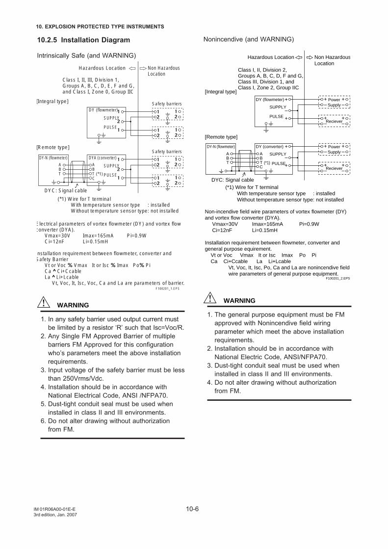
10-6
10. EXPLOSION PROTECTED TYPE INSTRUMENTS
IM 01R06A00-01E-E3rd edition, Jan. 2007
10.2.5 Installation Diagram
Intrinsically Safe (and WARNING)
F100201_1.EPS
[Remote type]
DYA (converter)
SUPPLY
PULSE
ABT (*1)C
ABT
DY (flowmeter)
SUPPLY
PULSE
Safety barriers
Safety barriers[Integral type]
DY-N (flowmeter)
Hazardous Location
Class I, II, III, Division 1,Groups A, B, C, D, E, F and G,and Class I, Zone 0, Group IIC
Non HazardousLocation
DYC: Signal cable
(*1) Wire for T terminal With temperature sensor type : installed Without temperature sensor type: not installed
Electrical parameters of vortex flowmeter (DY) and vortex flow converter (DYA).
Vmax=30V Imax=165mA Pi=0.9WCi=12nF Li=0.15mH
nstallation requirement between flowmeter, converter and Safety Barrier Vt or Voc Vmax It or Isc Imax Po Pi
Ca Ci+Ccable La Li+Lcable Vt, Voc, It, Isc, Voc, Ca and La are parameters of barrier.
WARNING
1. In any safety barrier used output current mustbe limited by a resistor ‘R’ such that Isc=Voc/R.
2. Any Single FM Approved Barrier of multiplebarriers FM Approved for this configurationwho’s parameters meet the above installationrequirements.
3. Input voltage of the safety barrier must be lessthan 250Vrms/Vdc.
4. Installation should be in accordance withNational Electrical Code, ANSI /NFPA70.
5. Dust-tight conduit seal must be used wheninstalled in class II and III environments.
6. Do not alter drawing without authorizationfrom FM.
Nonincendive (and WARNING)
Hazardous Location Non HazardousLocation
Class I, II, Division 2,Groups A, B, C, D, F and G,Class III, Division 1, andClass I, Zone 2, Group IIC
[Integral type]
[Remote type]
DY (flowmeter)
SUPPLY
PULSE
+ +–
+–
+–
+–
+
–
PowerSupply
Reciever
DY (converter)DY-N (flowmeter)
SUPPLY
PULSE
+ +–
+–
+–
+–
+
–
PowerSupply
Reciever
ABTC
ABT (*1)
DYC: Signal cable(*1) Wire for T terminal With temperature sensor type : installed Without temperature sensor type: not installed
Non-incendive field wire parameters of vortex flowmeter (DY)and vortex flow converter (DYA). Vmax=30V Imax=165mA Pi=0.9W Ci=12nF Li=0.15mH
Installation requirement between flowmeter, converter andgeneral purpose equirement. Vt or Voc Vmax It or Isc Imax Po Pi Ca Ci+Ccable La Li+Lcable
Vt, Voc, It, Isc, Po, Ca and La are nonincendive fieldwire parameters of general purpose equipment.
F100201_2.EPS
WARNING
1. The general purpose equipment must be FMapproved with Nonincendive field wiringparameter which meet the above installationrequirements.
2. Installation should be in accordance withNational Electric Code, ANSI/NFPA70.
3. Dust-tight conduit seal must be used wheninstalled in class II and III environments.
4. Do not alter drawing without authorizationfrom FM.
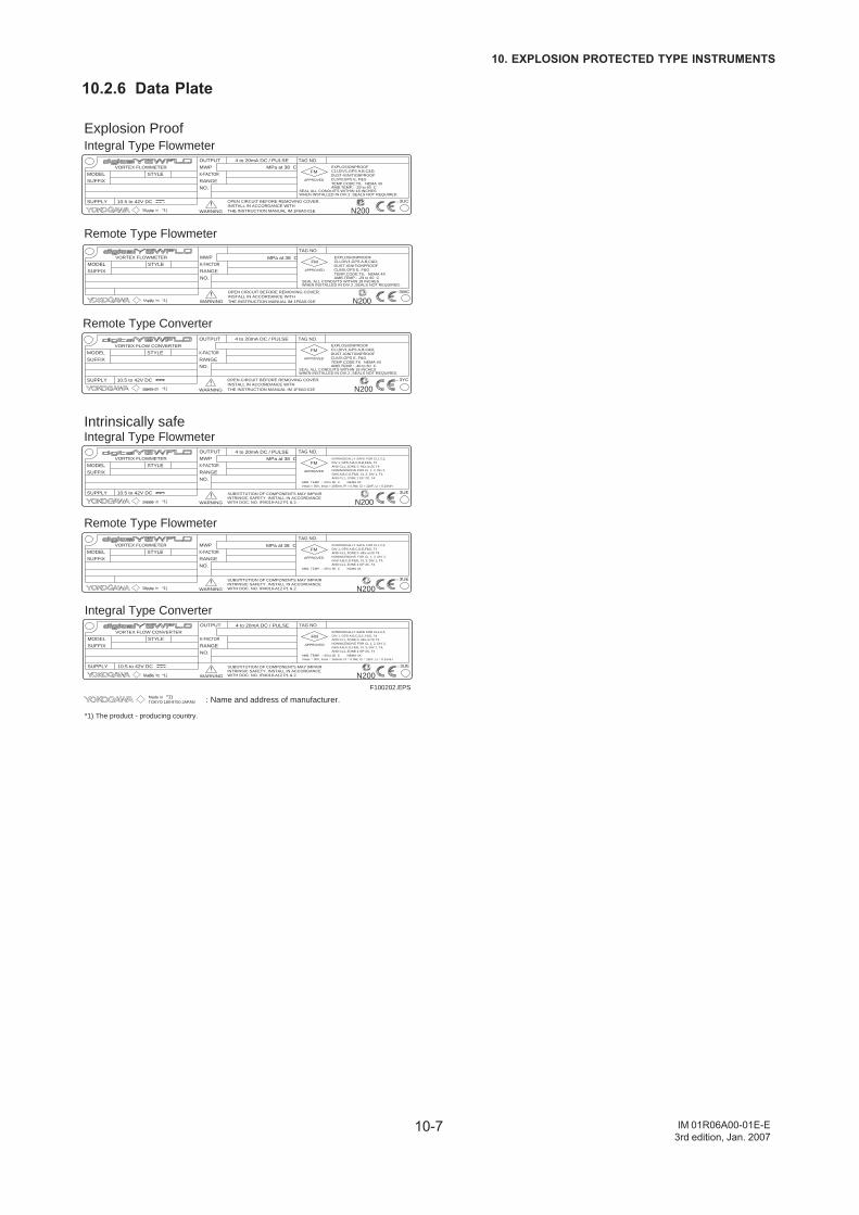
10-7
10. EXPLOSION PROTECTED TYPE INSTRUMENTS
IM 01R06A00-01E-E3rd edition, Jan. 2007
10.2.6 Data Plate
AMB.TEMP.: -29 to 60 CTEMP.CODE:T6, NEMA 4X
EXPLOSIONPROOF CLI,DIV1,GPS A,B,C&D;
MWP
3UC10.5 to 42V DC
STYLEMODEL
SUFFIX
SUPPLY
K-FACTOR
OUTPUT
RANGE
NO.
TAG NO.
VORTEX FLOWMETER
WARNING
!
SEAL ALL CONDUITS WITHIN 18 INCHES
DUST-IGNITIONPROOF CLII/III,GPS E, F&GAPPROVED
FM
THE INSTRUCTION MANUAL IM 1F6A0-01E
OPEN CIRCUIT BEFORE REMOVING COVER.
MWP
3UE10.5 to 42V DC
STYLEMODEL
SUFFIX
SUPPLY
K-FACTOR
OUTPUT
RANGE
NO.
TAG NO.
VORTEX FLOWMETER
WARNING
!
APPROVED
FM
SUBSTITUTION OF COMPONENTS MAY IMPAIR INTRINSIC SAFETY. INSTALL IN ACCORDANCE WITH DOC. NO. IFM019-A12 P1 & 2.
SUBSTITUTION OF COMPONENTS MAY IMPAIR INTRINSIC SAFETY. INSTALL IN ACCORDANCE WITH DOC. NO. IFM019-A12 P1 & 2.
SUBSTITUTION OF COMPONENTS MAY IMPAIR INTRINSIC SAFETY. INSTALL IN ACCORDANCE WITH DOC. NO. IFM019-A12 P1 & 2.
MWP
3UE
STYLEMODEL
SUFFIX
K-FACTOR
RANGE
NO.
TAG NO.
VORTEX FLOWMETER
WARNING
!
APPROVED
FM
WHEN INSTALLED IN DIV.2 ,SEALS NOT REQUIRED.
INSTALL IN ACCORDANCE WITH
THE INSTRUCTION MANUAL IM 1F6A0-01E
OPEN CIRCUIT BEFORE REMOVING COVER.INSTALL IN ACCORDANCE WITH
AMB.TEMP.: -29 to 60 CTEMP.CODE:T6, NEMA 4X
EXPLOSIONPROOF CLI,DIV1,GPS A,B,C&D;
SEAL ALL CONDUITS WITHIN 18 INCHES
DUST-IGNITIONPROOF CLII/III,GPS E, F&G
WHEN INSTALLED IN DIV.2 ,SEALS NOT REQUIRED.
AMB.TEMP.: -40 to 60 CTEMP.CODE:T6 NEMA 4X
EXPLOSIONPROOF CLI,DIV1,GPS A,B,C&D;
3YC10.5 to 42V DC
STYLEMODEL
SUFFIX
SUPPLY
K-FACTOR
OUTPUT
RANGE
NO.
TAG NO.
VORTEX FLOW CONVERTER
WARNING
!
SEAL ALL CONDUITS WITHIN 18 INCHES
DUST-IGNITIONPROOF CLII/III,GPS E, F&GAPPROVED
FM
THE INSTRUCTION MANUAL IM 1F6A0-01E
OPEN CIRCUIT BEFORE REMOVING COVER.
WHEN INSTALLED IN DIV.2 ,SEALS NOT REQUIRED.
INSTALL IN ACCORDANCE WITH
4 to 20mA DC / PULSE
INTRINSICALLY SAFE FOR CL1,2,3,DIV 1, GPS A,B,C,D,E,F&G, T4AND CL1, ZONE 0. AEx ia 2C T4NONINCENDIVE FOR CL 1, 2, DIV 2,GAS A,B,C,D,F&G, CL 3, DIV 1, T4,AND CL1, ZONE 2 GP 2C, T4
AMB. TEMP. : -40 to 60 C NEMA 4XVmax = 30V, Imax = 165mA, Pi = 0.9W, Ci = 12nF, Li = 0.15mH
INTRINSICALLY SAFE FOR CL1,2,3,DIV 1, GPS A,B,C,D,E,F&G, T4AND CL1, ZONE 0. AEx ia 2C T4NONINCENDIVE FOR CL 1, 2, DIV 2,GAS A,B,C,D,F&G, CL 3, DIV 1, T4,AND CL1, ZONE 2 GP 2C, T4
AMB. TEMP. : -29 to 80 C NEMA 4X
INTRINSICALLY SAFE FOR CL1,2,3,DIV 1, GPS A,B,C,D,E,F&G, T4AND CL1, ZONE 0. AEx ia 2C T4NONINCENDIVE FOR CL 1, 2, DIv 2,GAS A,B,C,D,F&G, CL 3, DIV 1, T4,AND CL1, ZONE 2 GP 2C, T4
AMB. TEMP. : -29 to 60 C NEMA 4XVmax = 30V, Imax = 165mA, Pi = 0.9W, Ci = 12nF, Li = 0.15mH
3UE10.5 to 42V DC
STYLEMODEL
SUFFIX
SUPPLY
K-FACTOR
OUTPUT
RANGE
NO.
TAG NO.
VORTEX FLOW CONVERTER
WARNING
!
APPROVED
FM
Integral Type Converter4 to 20mA DC / PULSE
N200
N200
N200
N200
N200
N200
*1)
*1)
*1)
*1)
*1)
Integral Type Flowmeter
Remote Type Flowmeter
Explosion Proof
Intrinsically safeIntegral Type Flowmeter
Remote Type Flowmeter
MPa at 38 C
4 to 20mA DC / PULSE
MPa at 38 C
4 to 20mA DC / PULSE
MPa at 38 C
F100202.EPS
MWP
3WC
STYLEMODEL
SUFFIX
K-FACTOR
RANGE
NO.
TAG NO.
VORTEX FLOWMETER
WARNING
!
APPROVED
FMMPa at 38 C
Remote Type Converter
*1)
TOKYO 180-8750 JAPANMade in *1) : Name and address of manufacturer.
*1) The product - producing country.

10-8
10. EXPLOSION PROTECTED TYPE INSTRUMENTS
IM 01R06A00-01E-E3rd edition, Jan. 2007
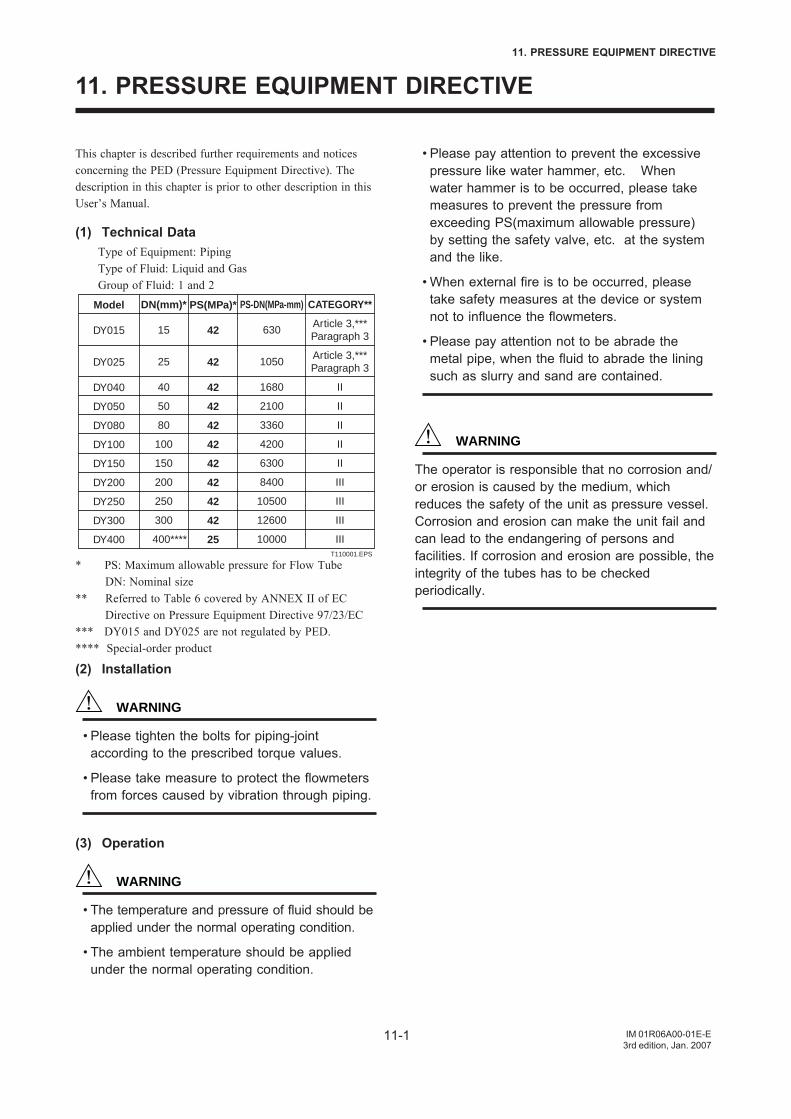
11-1
11. PRESSURE EQUIPMENT DIRECTIVE
IM 01R06A00-01E-E3rd edition, Jan. 2007
11. PRESSURE EQUIPMENT DIRECTIVE
This chapter is described further requirements and noticesconcerning the PED (Pressure Equipment Directive). Thedescription in this chapter is prior to other description in thisUser’s Manual.
(1) Technical DataType of Equipment: PipingType of Fluid: Liquid and GasGroup of Fluid: 1 and 2
Model
DY015
DY025
DY040
DY050
DY080
DY100
DY150
DY200
DY250
DY300
DY400
DN(mm)*
15
25
40
50
80
100
150
200
250
300
400****
PS(MPa)*
42
42
42
42
42
42
42
42
42
42
25
CATEGORY**
Article 3,***Paragraph 3
Article 3,***Paragraph 3
II
II
II
II
II
III
III
III
III
PS-DN(MPa-mm)
630
1050
1680
2100
3360
4200
6300
8400
10500
12600
10000T110001.EPS
* PS: Maximum allowable pressure for Flow Tube DN: Nominal size
** Referred to Table 6 covered by ANNEX II of EC Directive on Pressure Equipment Directive 97/23/EC
*** DY015 and DY025 are not regulated by PED.**** Special-order product
(2) Installation
WARNING
• Please tighten the bolts for piping-jointaccording to the prescribed torque values.
• Please take measure to protect the flowmetersfrom forces caused by vibration through piping.
(3) Operation
WARNING
• The temperature and pressure of fluid should beapplied under the normal operating condition.
• The ambient temperature should be appliedunder the normal operating condition.
• Please pay attention to prevent the excessivepressure like water hammer, etc. Whenwater hammer is to be occurred, please takemeasures to prevent the pressure fromexceeding PS(maximum allowable pressure)by setting the safety valve, etc. at the systemand the like.
• When external fire is to be occurred, pleasetake safety measures at the device or systemnot to influence the flowmeters.
• Please pay attention not to be abrade themetal pipe, when the fluid to abrade the liningsuch as slurry and sand are contained.
WARNING
The operator is responsible that no corrosion and/or erosion is caused by the medium, whichreduces the safety of the unit as pressure vessel.Corrosion and erosion can make the unit fail andcan lead to the endangering of persons andfacilities. If corrosion and erosion are possible, theintegrity of the tubes has to be checkedperiodically.

IM 01R06A00-01E-H3rd edition, Jan. 2007
Subject to change without notice. Copyright ©
Manufactured by: or Produced by :Yokogawa Electric Corporation RotaYokogawa2-9-32 Nakacho Rheinstr. 8Musashino-Shi; Tokio 180 D-79664 WehrJapan Germany
IM 01R06A00-01E-E 3rd edition is based on IM 1F6A0-01E up to 10th edition.