Embed Size (px)
Citation preview
USG Ceiling Solutions
SUSPENSION SYSTEMS ACCESSORIES GUIDE
USG SUSPENSION SYSTEMS ACCESSORIES—MOLDINGSAngle Molding Angle Molding w/Gasket M7CE Shadow Molding
Use for standard ceiling perimeters. Use in Clean Room applications with USG Donn® Brand CE™ Acoustical Suspension System.
For creating reveals at ceiling perimeters. Also helps to hide imperfections in drywall partitions and bulkheads.
Length x A x B x C x D
A
B
C
D
US Channel Wall Molding US Channel Wall Molding w/Gasket US28CE F-Molding
Use with C-8 clip to hold down perimeter ceiling panels.
Length x A x B x C
B
A
C
Use with C-8 clip in Clean Room applications with USG Donn® Brand CE™ Acoustical Suspension System.
Use to create ceiling breaks, soffits and changes in elevation.
Catalog Number Description Packaging/Ctn.
LF Pcs. Wt. (lb.)
ANGLE MOLDING M71 12'x7/8"x7/8" Wall Molding 480 40 63
M7OL 12'x7/8"x7/8" Overlapping Wall Molding 480 40 63
M7A 12'x7/8"x7/8" Aluminum Wall Molding 480 40 26
M7-10 10'x7/8"x7/8" Wall Molding 400 40 26
M7SS 12'x7/8"x7/8" Stainless Steel Wall Molding 240 20 31
M7Z 12'x7/8"x7/8" Hot-Dipped Galvanized Steel Wall Molding 480 40 58
M91 12'x9/16"x15/16" Wall Molding 480 40 55
M9-10 10'x9/16"x15/16" Wall Molding 400 40 23
M12 10'x1"x1-1/2" Wall Molding 250 25 63
MC11A25 10'x1"x1" Aluminum Cap Wall Molding 250 25 39
M7CE 12'x7/8"x7/8" Wall Molding w/gaskets 240 48 59
M20SM 10'x1"x2" Heavy Duty Wall Molding 250 25 80
M20SM-2 10'x2"x2" Wall Molding 200 20 76
M202 10'x1"x2" Wall Molding 250 25 55
SHADOW MOLDINGLength x A x B x C x D
(See illustration above)
MS125 12'x15/16"x1/4"x1/4"x 9/16" (Option 1) 300 25 46
12'x 9/16"x1/4"x 1/4"x 15/16" (Option 2)
MS144 12'x3/4"x3/8"x1/2"x3/4" (Option 1) 300 25 48
12'x3/4"x1/2"x3/8"x3/4" (Option 2)
MS1543 12'x7/8"x3/4"x3/4"x7/8" 300 25 67
MS164 12'x3/4"x3/4"x3/4"x3/4" 300 25 62
MS1743 12'x7/8"x3/8"x3/8"x9/16" (Option 1) 300 25 43
12'x9/16"x3/8"x3/8"x7/8" (Option 2)
MS274 10'x7/8"x3/4"x9/32"x1-1/4" 200 20 54
US CHANNEL WALL MOLDING
US12 10'x3/4"x1/2"x1" U-Molding 500 50 44
US20 10'x1-1/4"x1/2"x1" U-Molding 300 30 57
US28 10'x1-11/16"x1/2"x1" U-Molding 300 30 63
US31 10' 1-15/16"x1/2"x1" U-Molding 300 30 70
UA25 10'x1-9/16"x1/2"x1" Aluminum U-Molding 300 30 33
U-2-3/32 12'x2-3/32"x7/8"x1-1/8" Aluminum U-Molding, Flat White 360 30 90
US28CE 10'x1-11/16"x1/2"x1" U-Molding w/gaskets, Flat White 300 30 63
F-MOLDING MF8 10'x1/2" F-Molding (for 1/2" panels) 100 10 28
MF10 10'x5/8" F-Molding (for 5/8" panels) 100 10 29
Notes1. M7 and M9 available in standard and advantage colors in half carton quantities only, 240 LF per carton. 2. Not all M20 moldings are available in all areas. Please contact your USG Sales Representative. 3. MS154 and MS174 available with exposed horizontal leg painted a color.
ORDER SAMPLES/LITERATUREUSG: [email protected]
fax: 888 874-2348 | usg.com CGC: contact Sales Representative
TECHNICAL SERVICES800 USG.4YOU (874-4968)
FOR MOST UP-TO-DATE TECHNICAL INFORMATION
AND LEED REPORT TOOLusgdesignstudio.com cgcdesignstudio.com
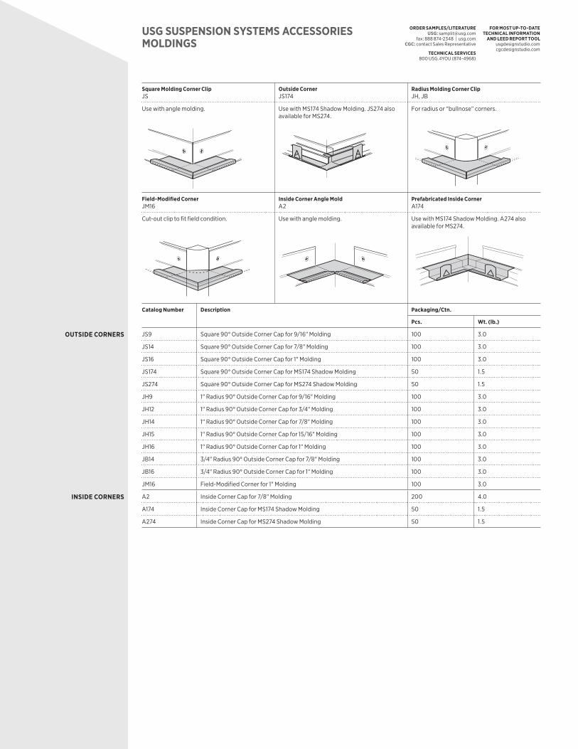
USG SUSPENSION SYSTEMS ACCESSORIESMOLDINGS
Square Molding Corner Clip JS
Outside CornerJS174
Radius Molding Corner ClipJH, JB
Use with angle molding.
Use with MS174 Shadow Molding. JS274 also available for MS274.
For radius or “bullnose” corners.
Field-Modified Corner JM16
Inside Corner Angle Mold A2
Prefabricated Inside Corner A174
Cut-out clip to fit field condition. Use with angle molding. Use with MS174 Shadow Molding. A274 also available for MS274.
Catalog Number Description Packaging/Ctn.
Pcs. Wt. (lb.)
OUTSIDE CORNERS JS9 Square 90° Outside Corner Cap for 9/16" Molding 100 3.0
JS14 Square 90° Outside Corner Cap for 7/8" Molding 100 3.0
JS16 Square 90° Outside Corner Cap for 1" Molding 100 3.0
JS174 Square 90° Outside Corner Cap for MS174 Shadow Molding 50 1.5
JS274 Square 90° Outside Corner Cap for MS274 Shadow Molding 50 1.5
JH9 1" Radius 90° Outside Corner Cap for 9/16" Molding 100 3.0
JH12 1" Radius 90° Outside Corner Cap for 3/4" Molding 100 3.0
JH14 1" Radius 90° Outside Corner Cap for 7/8" Molding 100 3.0
JH15 1" Radius 90° Outside Corner Cap for 15/16" Molding 100 3.0
JH16 1" Radius 90° Outside Corner Cap for 1" Molding 100 3.0
JB14 3/4" Radius 90° Outside Corner Cap for 7/8" Molding 100 3.0
JB16 3/4" Radius 90° Outside Corner Cap for 1" Molding 100 3.0
JM16 Field-Modified Corner for 1" Molding 100 3.0
INSIDE CORNERS A2 Inside Corner Cap for 7/8" Molding 200 4.0
A174 Inside Corner Cap for MS174 Shadow Molding 50 1.5
A274 Inside Corner Cap for MS274 Shadow Molding 50 1.5
ORDER SAMPLES/LITERATUREUSG: [email protected]
fax: 888 874-2348 | usg.com CGC: contact Sales Representative
TECHNICAL SERVICES800 USG.4YOU (874-4968)
FOR MOST UP-TO-DATE TECHNICAL INFORMATION
AND LEED REPORT TOOLusgdesignstudio.com cgcdesignstudio.com
USG SUSPENSION SYSTEMS ACCESSORIESMOLDINGS
Square Molding Corner Clip JS
Outside CornerJS174
Radius Molding Corner ClipJH, JB
Use with angle molding.
Use with MS174 Shadow Molding. JS274 also available for MS274.
For radius or “bullnose” corners.
Field-Modified Corner JM16
Inside Corner Angle Mold A2
Prefabricated Inside Corner A174
Cut-out clip to fit field condition. Use with angle molding. Use with MS174 Shadow Molding. A274 also available for MS274.
Catalog Number Description Packaging/Ctn.
Pcs. Wt. (lb.)
OUTSIDE CORNERS JS9 Square 90° Outside Corner Cap for 9/16" Molding 100 3.0
JS14 Square 90° Outside Corner Cap for 7/8" Molding 100 3.0
JS16 Square 90° Outside Corner Cap for 1" Molding 100 3.0
JS174 Square 90° Outside Corner Cap for MS174 Shadow Molding 50 1.5
JS274 Square 90° Outside Corner Cap for MS274 Shadow Molding 50 1.5
JH9 1" Radius 90° Outside Corner Cap for 9/16" Molding 100 3.0
JH12 1" Radius 90° Outside Corner Cap for 3/4" Molding 100 3.0
JH14 1" Radius 90° Outside Corner Cap for 7/8" Molding 100 3.0
JH15 1" Radius 90° Outside Corner Cap for 15/16" Molding 100 3.0
JH16 1" Radius 90° Outside Corner Cap for 1" Molding 100 3.0
JB14 3/4" Radius 90° Outside Corner Cap for 7/8" Molding 100 3.0
JB16 3/4" Radius 90° Outside Corner Cap for 1" Molding 100 3.0
JM16 Field-Modified Corner for 1" Molding 100 3.0
INSIDE CORNERS A2 Inside Corner Cap for 7/8" Molding 200 4.0
A174 Inside Corner Cap for MS174 Shadow Molding 50 1.5
A274 Inside Corner Cap for MS274 Shadow Molding 50 1.5
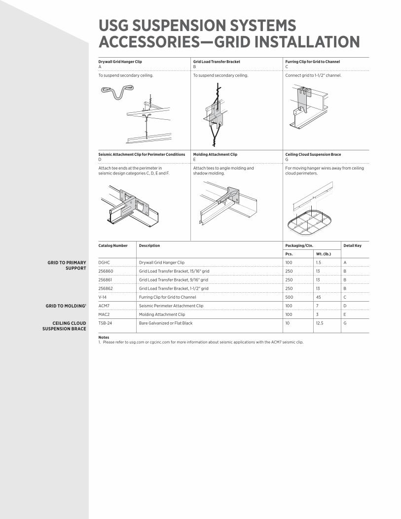
USG SUSPENSION SYSTEMS ACCESSORIES—GRID INSTALLATIONDrywall Grid Hanger ClipA
Grid Load Transfer BracketB
Furring Clip for Grid to ChannelC
To suspend secondary ceiling. To suspend secondary ceiling. Connect grid to 1-1/2" channel.
Seismic Attachment Clip for Perimeter ConditionsD
Molding Attachment ClipE
Ceiling Cloud Suspension BraceG
Attach tee ends at the perimeter in seismic design categories C, D, E and F.
Attach tees to angle molding and shadow molding.
For moving hanger wires away from ceiling cloud perimeters.
Catalog Number Description Packaging/Ctn. Detail Key
Pcs. Wt. (lb.)
GRID TO PRIMARY SUPPORT
DGHC Drywall Grid Hanger Clip 100 1.5 A
256860 Grid Load Transfer Bracket, 15/16" grid 250 13 B
256861 Grid Load Transfer Bracket, 9/16" grid 250 13 B
256862 Grid Load Transfer Bracket, 1-1/2" grid 250 13 B
V-14 Furring Clip for Grid to Channel 500 45 C
GRID TO MOLDING1 ACM7 Seismic Perimeter Attachment Clip 100 7 D
MAC2 Molding Attachment Clip 100 3 E
CEILING CLOUD SUSPENSION BRACE
TSB-24 Bare Galvanized or Flat Black 10 12.5 G
Notes1. Please refer to usg.com or cgcinc.com for more information about seismic applications with the ACM7 seismic clip.
ORDER SAMPLES/LITERATUREUSG: [email protected]
fax: 888 874-2348 | usg.com CGC: contact Sales Representative
TECHNICAL SERVICES800 USG.4YOU (874-4968)
FOR MOST UP-TO-DATE TECHNICAL INFORMATION
AND LEED REPORT TOOLusgdesignstudio.com cgcdesignstudio.com
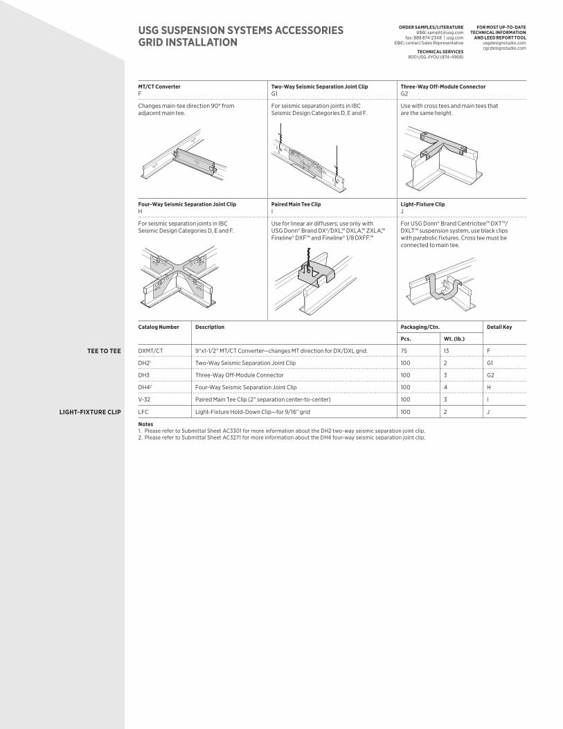
USG SUSPENSION SYSTEMS ACCESSORIESGRID INSTALLATION
MT/CT ConverterF
Two-Way Seismic Separation Joint ClipG1
Three-Way Off-Module Connector G2
Changes main-tee direction 90° from adjacent main tee.
For seismic separation joints in IBC Seismic Design Categories D, E and F.
Use with cross tees and main tees that are the same height.
Four-Way Seismic Separation Joint ClipH
Paired Main Tee Clip I
Light-Fixture ClipJ
For seismic separation joints in IBC Seismic Design Categories D, E and F.
Use for linear air diffusers; use only with USG Donn® Brand DX®/DXL,™ DXLA,™ ZXLA,™ Fineline® DXF™ and Fineline® 1/8 DXFF.™
For USG Donn® Brand Centricitee™ DXT™/ DXLT™ suspension system, use black clips with parabolic fixtures. Cross tee must be connected to main tee.
Catalog Number Description Packaging/Ctn. Detail Key
Pcs. Wt. (lb.)
TEE TO TEE DXMT/CT 9"x1-1/2" MT/CT Converter—changes MT direction for DX/DXL grid. 75 13 F
DH21 Two-Way Seismic Separation Joint Clip 100 2 G1
DH3 Three-Way Off-Module Connector 100 3 G2
DH42 Four-Way Seismic Separation Joint Clip 100 4 H
V-32 Paired Main Tee Clip (2" separation center-to-center) 100 3 I
LIGHT-FIXTURE CLIP LFC Light-Fixture Hold-Down Clip—for 9/16" grid 100 2 J
Notes1. Please refer to Submittal Sheet AC3301 for more information about the DH2 two-way seismic separation joint clip.2. Please refer to Submittal Sheet AC3271 for more information about the DH4 four-way seismic separation joint clip.
ORDER SAMPLES/LITERATUREUSG: [email protected]
fax: 888 874-2348 | usg.com CGC: contact Sales Representative
TECHNICAL SERVICES800 USG.4YOU (874-4968)
FOR MOST UP-TO-DATE TECHNICAL INFORMATION
AND LEED REPORT TOOLusgdesignstudio.com cgcdesignstudio.com
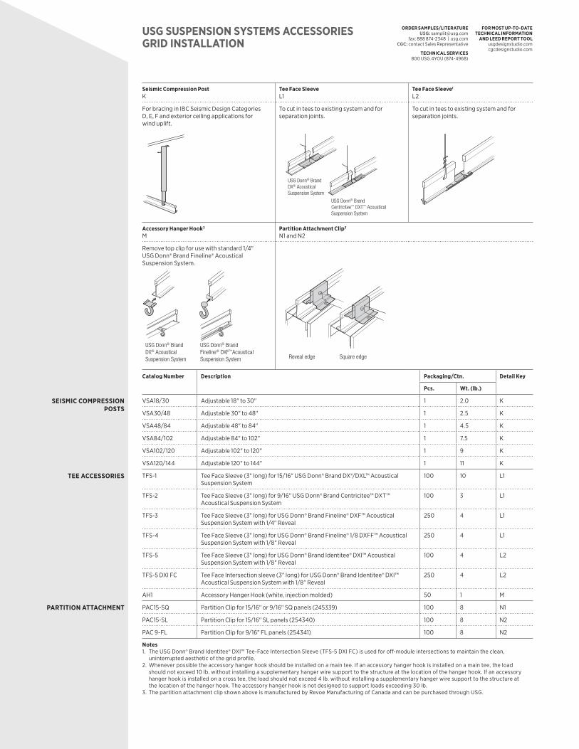
Seismic Compression PostK
Tee Face SleeveL1
Tee Face Sleeve1
L2
For bracing in IBC Seismic Design Categories D, E, F and exterior ceiling applications for wind uplift.
To cut in tees to existing system and for separation joints.
USG Donn® Brand DX® Acoustical Suspension System
USG Donn® Brand Centricitee™ DXT™ Acoustical Suspension System
To cut in tees to existing system and for separation joints.
Accessory Hanger Hook2
MPartition Attachment Clip3
N1 and N2
Remove top clip for use with standard 1/4" USG Donn® Brand Fineline® Acoustical Suspension System.
USG Donn® Brand DX® Acoustical Suspension System
USG Donn® Brand Fineline® DXF™Acoustical Suspension System Square edgeReveal edge
Catalog Number Description Packaging/Ctn. Detail Key
Pcs. Wt. (lb.)
SEISMIC COMPRESSION POSTS
VSA18/30 Adjustable 18" to 30" 1 2.0 K
VSA30/48 Adjustable 30" to 48" 1 2.5 K
VSA48/84 Adjustable 48" to 84" 1 4.5 K
VSA84/102 Adjustable 84" to 102" 1 7.5 K
VSA102/120 Adjustable 102" to 120" 1 9 K
VSA120/144 Adjustable 120" to 144" 1 11 K
TEE ACCESSORIES TFS-1 Tee Face Sleeve (3" long) for 15/16" USG Donn® Brand DX®/DXL™ Acoustical Suspension System
100 10 L1
TFS-2 Tee Face Sleeve (3" long) for 9/16" USG Donn® Brand Centricitee™ DXT™ Acoustical Suspension System
100 3 L1
TFS-3 Tee Face Sleeve (3" long) for USG Donn® Brand Fineline® DXF™ Acoustical Suspension System with 1/4" Reveal
250 4 L1
TFS-4 Tee Face Sleeve (3" long) for USG Donn® Brand Fineline® 1/8 DXFF™ Acoustical Suspension System with 1/8" Reveal
250 4 L1
TFS-5 Tee Face Sleeve (3" long) for USG Donn® Brand Identitee® DXI™ Acoustical Suspension System with 1/8" Reveal
100 4 L2
TFS-5 DXI FC Tee Face Intersection sleeve (3" long) for USG Donn® Brand Identitee® DXI™ Acoustical Suspension System with 1/8" Reveal
250 4 L2
AH1 Accessory Hanger Hook (white, injection molded) 50 1 M
PARTITION ATTACHMENT PAC15-SQ Partition Clip for 15/16" or 9/16" SQ panels (245339) 100 8 N1
PAC15-SL Partition Clip for 15/16" SL panels (254340) 100 8 N2
PAC 9-FL Partition Clip for 9/16" FL panels (254341) 100 8 N2
Notes1. The USG Donn® Brand Identitee® DXI™ Tee-Face Intersection Sleeve (TFS-5 DXI FC) is used for off-module intersections to maintain the clean,
uninterrupted aesthetic of the grid profile.2. Whenever possible the accessory hanger hook should be installed on a main tee. If an accessory hanger hook is installed on a main tee, the load
should not exceed 10 lb. without installing a supplementary hanger wire support to the structure at the location of the hanger hook. If an accessory hanger hook is installed on a cross tee, the load should not exceed 4 lb. without installing a supplementary hanger wire support to the structure at the location of the hanger hook. The accessory hanger hook is not designed to support loads exceeding 30 lb.
3. The partition attachment clip shown above is manufactured by Revoe Manufacturing of Canada and can be purchased through USG.
USG SUSPENSION SYSTEMS ACCESSORIESGRID INSTALLATION
ORDER SAMPLES/LITERATUREUSG: [email protected]
fax: 888 874-2348 | usg.com CGC: contact Sales Representative
TECHNICAL SERVICES800 USG.4YOU (874-4968)
FOR MOST UP-TO-DATE TECHNICAL INFORMATION
AND LEED REPORT TOOLusgdesignstudio.com cgcdesignstudio.com
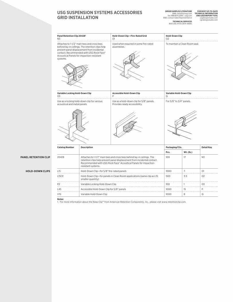
Panel Retention Clip 204281
N3Hold-Down Clip—Fire-Rated GridO1
Hold-Down ClipO2
Attaches to 1-1/2" main tees and cross tees behind lay-in ceilings. The retention clips help prevent panel displacement from incidental contact. Recommended with USG Rock Face® Acoustical Panels for impaction-resistant systems.
Used when required in some fire-rated assemblies.
To maintain a Clean Room seal.
Variable Locking Hold-Down ClipO3
Accessible Hold-Down ClipP
Variable Hold-Down ClipQ
Use as a locking hold-down clip for various acoustical and metal panels.
Use as a hold-down clip for 5/8" panels. Provides ready accessibility.
For 5/8" to 3/4" panels.
Catalog Number Description Packaging/Ctn. Detail Key
Pcs. Wt. (lb.)
PANEL RETENTION CLIP 20428 Attaches to 1-1/2" main tees and cross tees behind lay-in ceilings. The retention clips help prevent panel displacement from incidental contact. Recommended with USG Rock Face® Acoustical Panels for impaction-resistant systems.
100 17 N3
HOLD-DOWN CLIPS L15 Hold-Down Clip—for 5/8" fire-rated panels 1000 7 O1
L15CE Hold-Down Clip—for panels in Clean Room applications (same clip as L15; smaller quantity)
500 3.5 O2
PZ Variable Locking Hold-Down Clip 100 1 O3
L45 Accessible Hold-Down Clip for 5/8" panels 1000 15 P
V15 Variable Hold-Down Clip 1000 8 Q
Notes1. For more information about the Keep Clip™ from American Retention Components, Inc., please visit www.retentionclip.com.
USG SUSPENSION SYSTEMS ACCESSORIESGRID INSTALLATION
ORDER SAMPLES/LITERATUREUSG: [email protected]
fax: 888 874-2348 | usg.com CGC: contact Sales Representative
TECHNICAL SERVICES800 USG.4YOU (874-4968)
FOR MOST UP-TO-DATE TECHNICAL INFORMATION
AND LEED REPORT TOOLusgdesignstudio.com cgcdesignstudio.com
Panel Retention Clip 204281
N3Hold-Down Clip—Fire-Rated GridO1
Hold-Down ClipO2
Attaches to 1-1/2" main tees and cross tees behind lay-in ceilings. The retention clips help prevent panel displacement from incidental contact. Recommended with USG Rock Face® Acoustical Panels for impaction-resistant systems.
Used when required in some fire-rated assemblies.
To maintain a Clean Room seal.
Variable Locking Hold-Down ClipO3
Accessible Hold-Down ClipP
Variable Hold-Down ClipQ
Use as a locking hold-down clip for various acoustical and metal panels.
Use as a hold-down clip for 5/8" panels. Provides ready accessibility.
For 5/8" to 3/4" panels.
Catalog Number Description Packaging/Ctn. Detail Key
Pcs. Wt. (lb.)
PANEL RETENTION CLIP 20428 Attaches to 1-1/2" main tees and cross tees behind lay-in ceilings. The retention clips help prevent panel displacement from incidental contact. Recommended with USG Rock Face® Acoustical Panels for impaction-resistant systems.
100 17 N3
HOLD-DOWN CLIPS L15 Hold-Down Clip—for 5/8" fire-rated panels 1000 7 O1
L15CE Hold-Down Clip—for panels in Clean Room applications (same clip as L15; smaller quantity)
500 3.5 O2
PZ Variable Locking Hold-Down Clip 100 1 O3
L45 Accessible Hold-Down Clip for 5/8" panels 1000 15 P
V15 Variable Hold-Down Clip 1000 8 Q
Notes1. For more information about the Keep Clip™ from American Retention Components, Inc., please visit www.retentionclip.com.
USG SUSPENSION SYSTEMS ACCESSORIESGRID INSTALLATION

ORDER SAMPLES/LITERATUREUSG: [email protected]
fax: 888 874-2348 | usg.com CGC: contact Sales Representative
TECHNICAL SERVICES800 USG.4YOU (874-4968)
FOR MOST UP-TO-DATE TECHNICAL INFORMATION
AND LEED REPORT TOOLusgdesignstudio.com cgcdesignstudio.com
Wall Spring ClipR
Miter Closure Clip for USG Donn® Brand Fineline® Acoustical Suspension SystemS
USG Celebration™ Hold-Down Channel ClipT
To hold down perimeter ceiling panels. Useful for maintaining Clean Room seal with US28CE molding.
For closing off unused miters. To maintain a Clean Room seal.
Partition Attachment ClipU
T-BoltV
USG Donn® Brand Fineline® Acoustical Suspension System Cut-Off DieW
To screw-attach ceiling-height partitions. To bolt-attach partitions, signage or pendant-mounted indirect lighting.
Use to field-cut USG Donn® Brand Fineline® tees.
Catalog Number Description Packaging/Ctn. Detail Key
Pcs. Wt. (lb.)
HOLD-DOWN CLIPS1 C-8 Wall Spring Clip 2000 29 R
C-8CE Wall Spring Clip (same clip as C-8; smaller quantity) 500 8 R
MCC3 2" Miter Closure Clip for 1/8" USG Donn® Brand Fineline® Acoustical Suspension System
50 1 S
MCC2 2" Miter Closure Clip for standard USG Donn® Brand Fineline® Acoustical Suspension System
50 1 S
T15 10"x11/32"x1-9/16"x3/4" Panel Hold-Down Clip 500 30 T
U-2-3/32 10"x11/32"x2-3/32"x3/4" Panel Hold-Down Clip 500 30 T
USG DONN® BRAND FINELINE® ACOUSTICAL
SUSPENSION SYSTEM ACCESSORIES
PAC1 3" Partition Attachment Clip 50 1 U
TB1 1"x1/4"–20 T-Bolt 100 1 V
FC1 USG Donn® Brand Fineline® Acoustical Suspension System Cut-Off Die (scaffold mount)
1 10 W
Note1. Please refer to USG Exterior Ceiling Applications (SC2561) for more information about exterior ceiling applications with the T15 and U-2-3/32
hold-down clips. Use T-15 hold-down clip with UA25 molding and use U-2-3/32 hold-down clip with U-2-3/32 molding.
USG SUSPENSION SYSTEMS ACCESSORIESGRID INSTALLATION
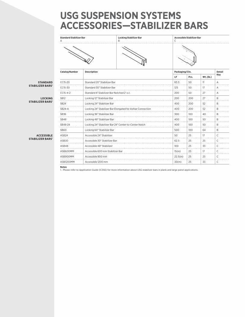
Standard Stabilizer BarA
Locking Stabilizer BarB
Accessible Stabilizer Bar C
Catalog Number Description Packaging/Ctn. Detail Key
LF Pcs. Wt. (lb.)
STANDARD STABILIZER BARS1
CC15-20 Standard 20" Stabilizer Bar 83.3 50 11 A
CC15-30 Standard 30" Stabilizer Bar 125 50 17 A
CC15-4-2 Standard 4' Stabilizer Bar Notched 2' o.c. 200 50 27 A
LOCKING STABILIZER BARS1
SB12 Locking 12" Stabilizer Bar 200 200 27 B
SB24 Locking 24" Stabilizer Bar 400 200 52 B
SB24-A Locking 24" Stabilizer Bar Elongated for Ashlar Connection 400 200 52 B
SB36 Locking 36" Stabilizer Bar 300 100 40 B
SB48 Locking 48" Stabilizer Bar 400 100 50 B
SB48-24 Locking 24" Stabilizer Bar 24" Center-to-Center Notch 400 100 50 B
SB60 Locking 60" Stabilizer Bar 500 100 64 B
ACCESSIBLE STABILIZER BARS1
ASB24 Accessible 24" Stabilizer 50 25 17 C
ASB30 Accessible 30" Stabilizer Bar 62.5 25 25 C
ASB48 Accessible 48" Stabilizer 100 25 33 C
ASB600MM Accessible 600 mm Stabilizer Bar 15(m) 25 17 C
ASB900MM Accessible 900 mm 22.5(m) 25 25 C
ASB1200MM Accessible 1200 mm 30(m) 25 33 C
Notes1. Please refer to Application Guide (IC592) for more information about USG stabilizer bars in plank and large panel applications.
USG SUSPENSION SYSTEMS ACCESSORIES—STABILIZER BARS
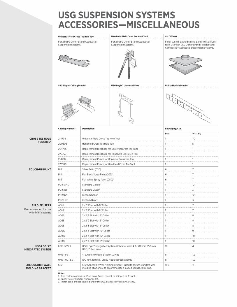
USG SUSPENSION SYSTEMS ACCESSORIES—MISCELLANEOUSUniversal Field Cross Tee Hole Tool Handheld Field Cross Tee Hold Tool Air Diffuser
For all USG Donn® Brand Acoustical Suspension Systems.
For all USG Donn® Brand Acoustical Suspension Systems.
Field-cut foil-backed ceiling panel to fit diffuser face. Use with USG Donn® Brand Fineline® and Centricitee™ Acoustical Suspension Systems.
SB2 Sloped Ceiling Bracket USG Logix™ Universal Yoke Utility Module Bracket
Catalog Number Description Packaging/Ctn.
Pcs. Wt. (lb.)
CROSS TEE HOLE PUNCHES3
215738 Universal Field Cross Tee Hole Tool 1 30
200308 Handheld Cross Tee Hole Tool 1 5
204755 Replacement Die Block for Universal Cross Tee Tool 1 1
276759 Replacement Die Block for Handheld Cross Tee Tool 1 1
214418 Replacement Punch for Universal Cross Tee Tool 1 1
276760 Replacement Punch for Handheld Cross Tee Tool 1 1
TOUCH-UP PAINT B15 Silver Satin (020) 6 7
B14 Flat Black Spray Paint (205)1 6 7
B13 Flat White Spray Paint (050)1 6 7
PC15 GAL Standard Gallon2 1 12
PC16 QT Standard Quart2 1 3
PC19 GAL Custom Gallon 1 12
PC20 QT Custom Quart 1 3
AIR DIFFUSERS Recommended for use
with 9/16" systems
AD16 2'x2' 1 Slot with 6" Collar 1 7
AD18 2'x2' 1 Slot with 8" Collar 1 7
AD26 2'x2' 2 Slot with 6" Collar 1 8
AD28 2'x2' 2 Slot with 8" Collar 1 8
AD38 2'x2' 3 Slot with 8" Collar 1 8
AD310 2'x2' 3 Slot with 10" Collar 1 9
AD410 2'x2' 4 Slot with 10" Collar 1 10
AD412 2'x2' 4 Slot with 12" Collar 1 10
USG LOGIX™ INTEGRATED SYSTEM
LGXUNVYK USG Logix™ Integrated System Universal Yoke 4, 6, 100 mm, 150 mm, HDG, 2-Part Yoke
10 4
UMB-4-6 4, 6, Utility Module Bracket (UMB) 8 1.9
UMB-100-150 100 mm, 150 mm, Utility Module Bracket (UMB) 8 1.9
ADJUSTABLE WALL MOLDING BRACKET
SB2 SB2 Adjustable Wall Molding Bracket—used to secure standard wall molding at an angle to accommodate a sloped acoustical ceiling.
100 11
Notes1. One carton contains six 12 oz. cans. Paints cannot be shipped air freight.2. Specify color number from price list.3. Punch tools are not covered under the USG Standard Product Warranty.
AC2396/rev. 6-17© 2017 USG Corporation and/or its affiliates. All rights reserved.Printed in U.S.A.
Manufactured byUSG Interiors, LLC550 West Adams StreetChicago, IL 60661
NoticeThe information in this document is subject to change without notice. CGC Inc. or USG Corp. assumes no responsibility for any errors that may inadvertently appear in this document.
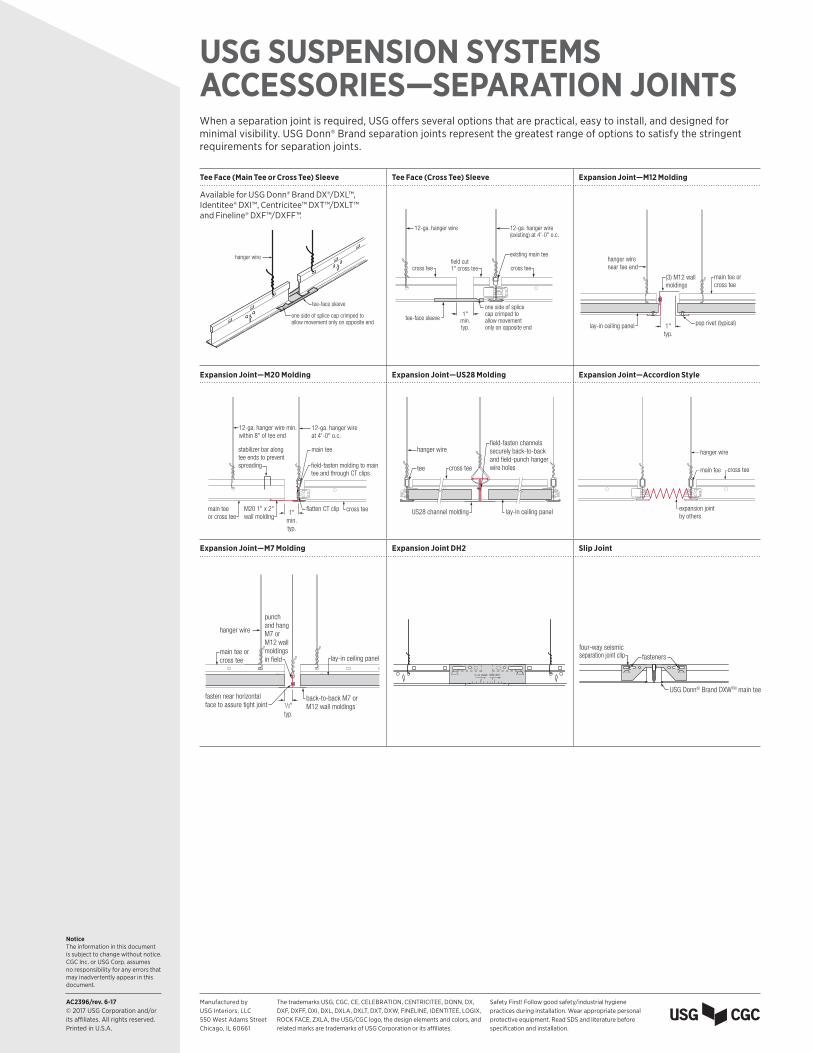
USG SUSPENSION SYSTEMS ACCESSORIES—SEPARATION JOINTSWhen a separation joint is required, USG offers several options that are practical, easy to install, and designed for minimal visibility. USG Donn® Brand separation joints represent the greatest range of options to satisfy the stringent requirements for separation joints.
Tee Face (Main Tee or Cross Tee) Sleeve Tee Face (Cross Tee) Sleeve Expansion Joint—M12 Molding
Available for USG Donn® Brand DX®/DXL™, Identitee® DXI™, Centricitee™ DXT™/DXLT™ and Fineline® DXF™/DXFF™.
tee-face sleeve
one side of splice cap crimped to allow movement only on opposite end
hanger wire
tee-face sleeve
one side of splice cap crimped to allow movement only on opposite end
existing main tee
12-ga. hanger wire(existing) at 4'-0" o.c.
1"min.typ.
field cut 1" cross tee
12-ga. hanger wire
cross tee cross teehanger wirenear tee end
(3) M12 wall moldings
main tee or cross tee
pop rivet (typical)1"typ.
lay-in ceiling panel
Expansion Joint—M20 Molding Expansion Joint—US28 Molding Expansion Joint—Accordion Style
main tee
field-fasten molding to maintee and through CT clips
flatten CT clip
12-ga. hanger wireat 4'-0" o.c.
1"min.typ.
12-ga. hanger wire min. within 8" of tee end
cross teeM20 1" x 2" wall molding
main tee or cross tee
stabilizer bar alongtee ends to prevent spreading tee
hanger wire
cross tee
lay-in ceiling panel
field-fasten channelssecurely back-to-backand field-punch hanger wire holes
US28 channel molding
main tee
hanger wire
cross tee
expansion joint by others
Expansion Joint—M7 Molding Expansion Joint DH2 Slip Joint
hanger wire
back-to-back M7 or M12 wall moldings
main tee or cross tee
fasten near horizontalface to assure tight joint 1/2"
typ.
lay-in ceiling panel
punch and hang M7 or M12 wall moldings in field
four-way seismicseparation joint clip fasteners
USG Donn® Brand DXWTM main tee
The trademarks USG, CGC, CE, CELEBRATION, CENTRICITEE, DONN, DX, DXF, DXFF, DXI, DXL, DXLA, DXLT, DXT, DXW, FINELINE, IDENTITEE, LOGIX, ROCK FACE, ZXLA, the USG/CGC logo, the design elements and colors, and related marks are trademarks of USG Corporation or its affiliates.
Safety First! Follow good safety/industrial hygiene practices during installation. Wear appropriate personal protective equipment. Read SDS and literature before specification and installation.
AC2396/rev. 6-17© 2017 USG Corporation and/or its affiliates. All rights reserved.Printed in U.S.A.
Manufactured byUSG Interiors, LLC550 West Adams StreetChicago, IL 60661
NoticeThe information in this document is subject to change without notice. CGC Inc. or USG Corp. assumes no responsibility for any errors that may inadvertently appear in this document.
USG SUSPENSION SYSTEMS ACCESSORIES—SEPARATION JOINTSWhen a separation joint is required, USG offers several options that are practical, easy to install, and designed for minimal visibility. USG Donn® Brand separation joints represent the greatest range of options to satisfy the stringent requirements for separation joints.
Tee Face (Main Tee or Cross Tee) Sleeve Tee Face (Cross Tee) Sleeve Expansion Joint—M12 Molding
Available for USG Donn® Brand DX®/DXL™, Identitee® DXI™, Centricitee™ DXT™/DXLT™ and Fineline® DXF™/DXFF™.
tee-face sleeve
one side of splice cap crimped to allow movement only on opposite end
hanger wire
tee-face sleeve
one side of splice cap crimped to allow movement only on opposite end
existing main tee
12-ga. hanger wire(existing) at 4'-0" o.c.
1"min.typ.
field cut 1" cross tee
12-ga. hanger wire
cross tee cross teehanger wirenear tee end
(3) M12 wall moldings
main tee or cross tee
pop rivet (typical)1"typ.
lay-in ceiling panel
Expansion Joint—M20 Molding Expansion Joint—US28 Molding Expansion Joint—Accordion Style
main tee
field-fasten molding to maintee and through CT clips
flatten CT clip
12-ga. hanger wireat 4'-0" o.c.
1"min.typ.
12-ga. hanger wire min. within 8" of tee end
cross teeM20 1" x 2" wall molding
main tee or cross tee
stabilizer bar alongtee ends to prevent spreading tee
hanger wire
cross tee
lay-in ceiling panel
field-fasten channelssecurely back-to-backand field-punch hanger wire holes
US28 channel molding
main tee
hanger wire
cross tee
expansion joint by others
Expansion Joint—M7 Molding Expansion Joint DH2 Slip Joint
hanger wire
back-to-back M7 or M12 wall moldings
main tee or cross tee
fasten near horizontalface to assure tight joint 1/2"
typ.
lay-in ceiling panel
punch and hang M7 or M12 wall moldings in field
four-way seismicseparation joint clip fasteners
USG Donn® Brand DXWTM main tee
The trademarks USG, CGC, CE, CELEBRATION, CENTRICITEE, DONN, DX, DXF, DXFF, DXI, DXL, DXLA, DXLT, DXT, DXW, FINELINE, IDENTITEE, LOGIX, ROCK FACE, ZXLA, the USG/CGC logo, the design elements and colors, and related marks are trademarks of USG Corporation or its affiliates.
Safety First! Follow good safety/industrial hygiene practices during installation. Wear appropriate personal protective equipment. Read SDS and literature before specification and installation.
AC2396/6-17© 2017 USG Corporation and/or its affiliates. All rights reserved. Printed in U.S.A.The trademarks USG, CGC, the USG/CGC logo, the design elements and colors, and related marks are trademarks of USG Corporation or affiliates.
CONTACT INFORMATIONManufactured byUnited States Gypsum Company550 West Adams StreetChicago, IL 60661
PRODUCT INFORMATION For the most up-to-datetechnical information,visit usgdesignstudio.comor cgcdesignstudio.com
CUSTOMER SERVICE800 950-3839
TECHNICAL SERVICE800 USG.4YOU (874-4968)
WEBSITESusg.comcgcinc.comusgdesignstudio.comcgcdesignstudio.com
LIMITATIONSInterior applications only
NOTICEWe shall not be liable for incidental and consequential damages, directly or indirectly sustained, nor for any loss caused by application of these goods not in accordance with current printed instructions or for other than the intended use. Our liability is expressly limited to replacement of defective goods. Any claim shall be deemed waived unless made in writing to us within thirty (30) days from date it was or reasonably should have been discovered.
SAFETY FIRST! Follow good safety/industrial hygiene practices during installation. Wear appropriate personal protective equipment. Read SDS and literature before specifi cation and installation.