Embed Size (px)
Citation preview
Using ArcToolbox™
Corey TuckerGIS by ESRI ™

Copyright © 1999, 2000 Environmental Systems Research Institute, Inc.All rights reserved.Printed in the United States of America.
The information contained in this document is the exclusive property of Environmental Systems Research Institute, Inc. This work is protected underUnited States copyright law and other international copyright treaties and conventions. No part of this work may be reproduced or transmitted in anyform or by any means, electronic or mechanical, including photocopying and recording, or by any information storage or retrieval system, except asexpressly permitted in writing by Environmental Systems Research Institute, Inc. All requests should be sent to Attention: Contracts Manager,Environmental Systems Research Institute, Inc., 380 New York Street, Redlands, CA 92373-8100, USA.
The information contained in this document is subject to change without notice.
CONTRIBUTING WRITERSIan DeMerchant, Barbara Bicking, Chris Boyd, Jason Pardy, Mike Conly and Ghislain Prince, Gary Kabot, and Ashley Pengelley
U.S. GOVERNMENT RESTRICTED/LIMITED RIGHTSAny software, documentation, and/or data delivered hereunder is subject to the terms of the License Agreement. In no event shall the U.S. Governmentacquire greater than RESTRICTED/LIMITED RIGHTS. At a minimum, use, duplication, or disclosure by the U.S. Government is subject to restrictionsas set forth in FAR §52.227-14 Alternates I, II, and III (JUN 1987); FAR §52.227-19 (JUN 1987) and/or FAR §12.211/12.212 (Commercial TechnicalData/Computer Software); and DFARS §252.227-7015 (NOV 1995) (Technical Data) and/or DFARS §227.7202 (Computer Software), as applicable.Contractor/Manufacturer is Environmental Systems Research Institute, Inc., 380 New York Street, Redlands, CA 92373-8100, USA.
ESRI and the ESRI globe logo are trademarks of Environmental Systems Research Institute, Inc., registered in the United States and certain othercountries; registration is pending in the European Community. ArcInfo, ArcToolbox, ArcCatalog, AML, TABLES, ARCPLOT, ArcGIS, GIS by ESRI, theESRI Press logo, and the ArcInfo logo are trademarks and www.esri.com is a service mark of Environmental Systems Research Institute, Inc. TheWindows logo is a trademark of Microsoft Corporation.
The names of other companies and products herein are trademarks or registered trademarks of their respective trademark owners.
00Attribution.p65 11/29/2000, 9:10 AM1
iii
Contents 1 Introducing ArcToolbox 1The tools 3How ArcToolbox helps you work 3Tips on learning ArcToolbox 4
2 Quick-start tutorial 7Exercise 1: Organizing your data in ArcCatalog 9Exercise 2: Processing the forest stands 12Exercise 3: Processing the streams and roads 16Exercise 4: Converting data 20Exercise 5: Creating the analysis coverage 22Exercise 6: Computing the timber value 24
3 ArcToolbox basics 27Starting ArcToolbox 28What are toolsets? 29Starting a tool 31Finding the tools you need 32Getting help 34The precision environment 38Setting the precision 39Using relates 40Defining relates 41Using ArcCatalog 43Dragging and dropping data 44Operating tools in batch mode 45Saving a wizard�s contents 48The Geoprocessing Server 49Using a Geoprocessing Server 50Connection properties 51Checking a remote process 52Scheduling a remote process 53
01TOC.p65 11/29/2000, 3:25 PM3
iv USING ARCTOOLBOX
4 Creating your own look 55Turning off toolsets and tools 56Turning off tool descriptions and Help nodes 57Adding to the My Tools toolset 58Placing tools on top 60
5 Adding a custom tool 61Requirements for a custom tool 62Creating a custom tool in Visual Basic 6.0 63Enabling drag and drop 67Adding a custom tool 69
Appendix A 73VB code for a custom tool class 74VB code for a custom tool form 78Enabling drag and drop in a text box for ArcCatalog 81Enabling drag and drop in a text box for Windows Explorer 86
Appendix B 87Starting the Geoprocessing Server 88Accessing data on UNIX or Windows NT 90Setting server defaults 91Pausing, resuming, and shutting down a service 93Adding another instance 94Troubleshooting server problems 95Common errors 96
Glossary 99
Index 103
01TOC.p65 11/29/2000, 3:25 PM4
IN THIS CHAPTER
1
Introducing ArcToolbox 1• The tools
• How ArcToolbox helps you work
• Tips on learning ArcToolbox
Welcome to ESRI® ArcToolbox� software, the application that providesaccess to all of ArcInfo� software�s powerful coverage processing andanalysis functions. ArcToolbox provides a very rich and powerful set ofgeoprocessing functions�well over 100 tools for easy access and use. It iseasy to find the tool you wish to use and start it to perform the desiredgeoprocessing operation.
ArcInfo is well known for its advanced geoprocessing capabilities. Most ofthe tools in ArcToolbox are used to manipulate ArcInfo coverages, thepopular geographic information system (GIS) data type. The tools inArcToolbox create and integrate a vast array of data formats into usable GISdatabases, perform advanced GIS analysis, and manipulate GIS data. WithArcToolbox, virtually all major spatial data formats can be converted to andfrom ArcInfo coverages, grids, and triangulated irregular networks (TINs).Topology can be generated and maintained; map sheets can be joined,clipped, and split; and advanced coverage-based modeling tools can be used.
ArcToolbox allows you to perform tasks such as:
� Finding the datasets necessary for an overlay using ArcCatalog� softwareand dragging them onto the Overlay Wizard in ArcToolbox
� Converting 20 coverages into Drawing Exchange Format (DXF) filesusing the Coverage to DXF tool in a single operation
� Creating ARC Macro Language (AML�) scripts and processing them ona remote machine (UNIX® or Windows NT®) at a scheduled time
02Ch01.p65 12/18/2000, 10:29 AM1
2 USING ARCTOOLBOX
� Creating custom tools in the Microsoft® Windows®
development environment of your choice and installingthem as custom tools in ArcToolbox
� Using the Project Wizard to change the coordinatereference system of a coverage and look at its newgeographic view in ArcCatalog
� Building coverage topology using the Clean tool andadding feature attributes using the Join Tables tool
02Ch01.p65 11/29/2000, 3:26 PM2
INTRODUCING ARCTOOLBOX 3
ArcToolbox is organized into toolsets that provide solutions fordifferent types of tasks. The four main toolsets are:
� Data Management Tools
� Analysis Tools
� Conversion Tools
� My Tools
Numerous tools, organized in categories of smaller toolsets, arecontained in each main toolset. The tools are organized in alogical manner based on the type of solution they provide.
A fully customizable toolset called My Tools is provided. Youcan place tools from any toolset within it or add a custom toolyou create to build on the power of the existing tools. You willquickly realize how customizable ArcToolbox truly is.
The tools How ArcToolbox helps you work
ArcToolbox offers a simple visual interface that guides youthrough a task, providing all the information and help you need toefficiently complete the job. If you�re a longtime user, you nolonger need to type your geoprocessing or conversion commandsinto a command line or create and debug an AML. ArcCataloghelps you locate and access the datasets you need to complete avariety of tasks easily and efficiently using ArcToolbox.
Processing locally or remotely
You may have very large datasets located on powerful servermachines (UNIX or Windows NT) that are connected to yourpersonal computer. ArcToolbox lets you compose ageoprocessing job on your machine and run it on the remotemachine using an ArcInfo Geoprocessing Server. For informationon how to run jobs remotely using a Geoprocessing Server, seeChapter 3, �ArcToolbox basics�.
02Ch01.p65 11/29/2000, 3:27 PM3
4 USING ARCTOOLBOX
If you�re new to GIS, remember that you don�t have to learneverything about ArcToolbox to get immediate results. Beginlearning ArcToolbox by reading Chapter 2, �Quick-start tutorial�.In Chapter 2, you�ll learn how easy it is to use the various tools inArcToolbox in conjunction with ArcCatalog, and you�ll gaininsight into the steps you can take to complete certain tasks.ArcToolbox comes with the data used in the tutorial, so you canfollow along step by step at your computer. You can also read thetutorial without using your computer.
Finding answers to questions
Like most people, your goal is to complete your tasks whileinvesting a minimum amount of time and effort in learning howto use software. You want intuitive, easy-to-use software thatgives you immediate results, without having to read pages ofdocumentation. However, when you do have a question, you wantthe answer quickly so that you can complete your task. That�swhat this book is all about�getting you the answers you needwhen you need them.
This book describes geoprocessing tasks�from basic to ad-vanced�that you�ll perform with ArcToolbox. Although you canread this book from start to finish, you�ll likely use it more as areference. When you want to know how to do a particular task,such as operating a tool in batch mode, just look it up in the tableof contents or index. What you�ll find is a concise, step-by-stepdescription of how to complete the task. Some chapters alsoinclude detailed information that you can read if you want tolearn more about the concepts behind the tasks. You may alsorefer to the glossary in this book if you come across any unfamil-iar GIS terms or need to refresh your memory.
Tips on learning ArcToolbox
About this book
This book is designed to introduce ArcToolbox and its capabili-ties. The topics covered in the various tasks and the tutorial inChapter 2 assume you are familiar with geoprocessing and thefundamentals of GIS. If you have never used a GIS before or feelyou need to refresh your knowledge, please take some time toread Getting Started with ArcGIS, which you received in yourArcInfo package. You don�t need to read it to continue with thisbook, but you should use it as a reference if you encounter taskswith which you are unfamiliar.
Chapter 3 covers all of the basic and some of the advancedfunctions of ArcToolbox. Chapter 4 shows you how to customizethe ArcToolbox interface to match your needs.
Chapter 5 discusses custom tools and how to create them usingthe Visual Basic® (VB) programming language. This taskassumes you have some experience with VB and the ArcInfoOpen Development Environment (ODE). However, if you havenot used either of these environments, you will still be able tocomplete the tasks as long as you have Visual Basic 5.0 or 6.0installed.
Getting help on your computer
In addition to this book, ArcToolbox software�s online Helpsystem is a valuable resource for learning how to use the soft-ware. To learn how to use Help on your computer, see �Gettinghelp� in Chapter 3 of this book.
Contacting ESRI
If you need to contact ESRI for technical support, see the productregistration and support card you received with ArcToolbox orrefer to �Getting technical support� in the online Help system�s�Getting more help� section. You can also visit ESRI on the Web
02Ch01.p65 11/29/2000, 3:27 PM4
INTRODUCING ARCTOOLBOX 5
at www.esri.com for more information on ArcToolbox andArcInfo.
ESRI education solutions
ESRI provides educational opportunities related to geographicinformation science, GIS applications, and technology. You canchoose among instructor-led courses, Web-based courses, andself-study workbooks to find education solutions that fit yourlearning style and pocketbook. For more information, go towww.esri.com/education.
02Ch01.p65 11/29/2000, 3:27 PM5

02Ch01.p65 11/29/2000, 3:27 PM6
IN THIS CHAPTER
7
Quick-start tutorial 2• Exercise 1: Organizing your data
in ArcCatalog
• Exercise 2: Processing the foreststands
• Exercise 3: Processing thestreams and roads
• Exercise 4: Converting data
• Exercise 5: Creating the analysiscoverage
• Exercise 6: Computing the timbervalue
Conducting a GIS processing project is easier than ever with the powerfultools in ArcToolbox. When used in conjunction with ArcCatalog�the applica-tion for browsing, storing, organizing, and distributing data�ArcToolbox letsyou meet the geoprocessing needs of your project quickly and efficiently.
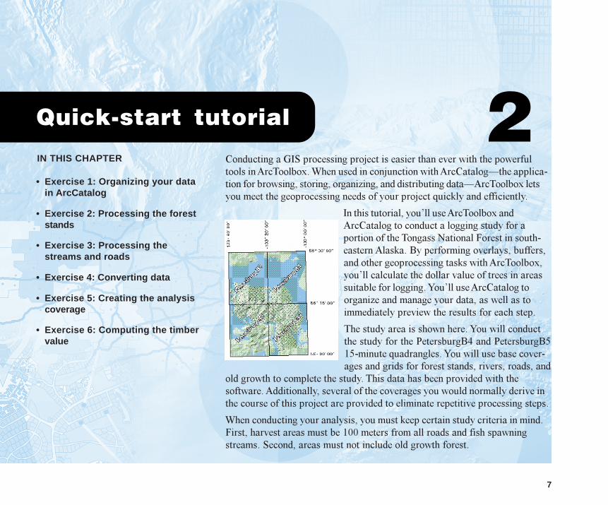
In this tutorial, you�ll use ArcToolbox andArcCatalog to conduct a logging study for aportion of the Tongass National Forest in south-eastern Alaska. By performing overlays, buffers,and other geoprocessing tasks with ArcToolbox,you�ll calculate the dollar value of trees in areassuitable for logging. You�ll use ArcCatalog toorganize and manage your data, as well as toimmediately preview the results for each step.
The study area is shown here. You will conductthe study for the PetersburgB4 and PetersburgB515-minute quadrangles. You will use base cover-ages and grids for forest stands, rivers, roads, and
old growth to complete the study. This data has been provided with thesoftware. Additionally, several of the coverages you would normally derive inthe course of this project are provided to eliminate repetitive processing steps.
When conducting your analysis, you must keep certain study criteria in mind.First, harvest areas must be 100 meters from all roads and fish spawningstreams. Second, areas must not include old growth forest.
03Ch02.p65 12/18/2000, 10:30 AM7
8 USING ARCTOOLBOX
You�ll use several datasets throughout the course of theproject. The following table provides descriptions of thesedatasets.
Coverage Description
Oldgrowgrid Grid of old growth forest stands
Overlay3 Overlay of buffered roads and streams,forest stands, and old growth forest
Road Major roads
Roadbuf Major roads buffered 100 meters
Standb5 Forest stands for PetersburgB5 in Univer-sal Transverse Mercator (UTM)
Standddb4 Forest stands for PetersburgB4 in decimaldegrees
Stream Streams
The data you�ll need for this tutorial is included on theArcToolbox installation disk. The datasets were providedcourtesy of the USDA Forest Service, Tongass NationalForest, Ketchikan Area. They have been simplified byESRI. The Forest Service cannot assure the reliability orsuitability of this information. Original data was compiledfrom various sources, and spatial information may not meetNational Map Accuracy Standards. This information maybe updated, corrected, or otherwise modified without notice.
All exercises in the tutorial are processed locally, ratherthan being sent to a Geoprocessing Server for remoteprocessing. It is recommended that you do not use theGeoprocessing Server for this tutorial if you have ArcInfoWorkstation installed locally. If you need to use a
Geoprocessing Server, see �Using a Geoprocessing Server�in Chapter 3 before you start the tutorial.
This tutorial is designed to let you explore the capabilities ofArcToolbox and ArcCatalog at your own pace and withoutthe need for additional assistance. You�ll need about onehour of focused time to complete the six exercises in thetutorial. However, you can also perform the exercises oneat a time if you wish.
03Ch02.p65 11/29/2000, 3:29 PM8
QUICK-START TUTORIAL 9
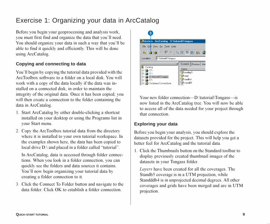
Exercise 1: Organizing your data in ArcCatalog
Before you begin your geoprocessing and analysis work,you must first find and organize the data that you�ll need.You should organize your data in such a way that you�ll beable to find it quickly and efficiently. This will be doneusing ArcCatalog.
Copying and connecting to data
You�ll begin by copying the tutorial data provided with theArcToolbox software to a folder on a local disk. You willwork with a copy of the data locally if the data was in-stalled on a connected disk, in order to maintain theintegrity of the original data. Once it has been copied, youwill then create a connection to the folder containing thedata in ArcCatalog.
1. Start ArcCatalog by either double-clicking a shortcutinstalled on your desktop or using the Programs list inyour Start menu.
2. Copy the ArcToolbox tutorial data from the directorywhere it is installed to your own tutorial workspace. Inthe examples shown here, the data has been copied tolocal drive D:\ and placed in a folder called �tutorial�.
In ArcCatalog, data is accessed through folder connec-tions. When you look in a folder connection, you canquickly see the folders and data sources it contains.You�ll now begin organizing your tutorial data bycreating a folder connection to it.
3. Click the Connect To Folder button and navigate to thedata folder. Click OK to establish a folder connection.
Your new folder connection�D:\tutorial\Tongass�isnow listed in the ArcCatalog tree. You will now be ableto access all of the data needed for your project throughthat connection.
Exploring your data
Before you begin your analysis, you should explore thedatasets provided for the project. This will help you get abetter feel for ArcCatalog and the tutorial data.
1. Click the Thumbnails button on the Standard toolbar todisplay previously created thumbnail images of thedatasets in your Tongass folder.
Layers have been created for all the coverages. TheStandb5 coverage is in a UTM projection, whileStandddb4 is in unprojected decimal degrees. All othercoverages and grids have been merged and are in UTMprojection.
3
03Ch02.p65 11/29/2000, 3:29 PM9
10 USING ARCTOOLBOX
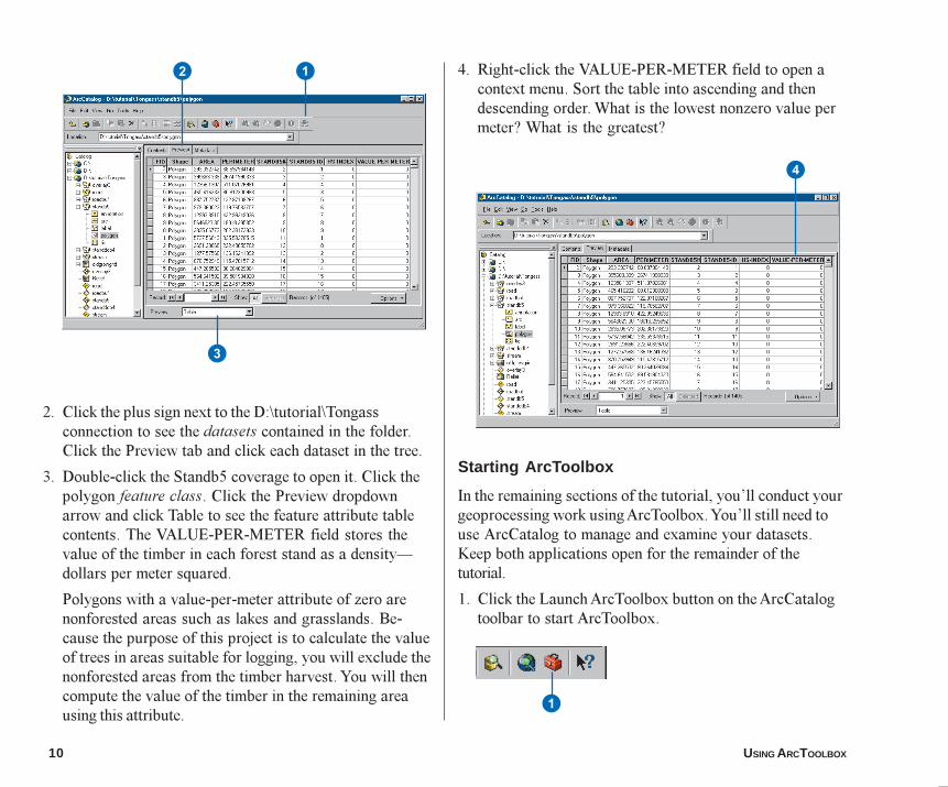
4. Right-click the VALUE-PER-METER field to open acontext menu. Sort the table into ascending and thendescending order. What is the lowest nonzero value permeter? What is the greatest?
Starting ArcToolbox
In the remaining sections of the tutorial, you�ll conduct yourgeoprocessing work using ArcToolbox. You�ll still need touse ArcCatalog to manage and examine your datasets.Keep both applications open for the remainder of thetutorial.
1. Click the Launch ArcToolbox button on the ArcCatalogtoolbar to start ArcToolbox.
2. Click the plus sign next to the D:\tutorial\Tongassconnection to see the datasets contained in the folder.Click the Preview tab and click each dataset in the tree.
3. Double-click the Standb5 coverage to open it. Click thepolygon feature class. Click the Preview dropdownarrow and click Table to see the feature attribute tablecontents. The VALUE-PER-METER field stores thevalue of the timber in each forest stand as a density�dollars per meter squared.
Polygons with a value-per-meter attribute of zero arenonforested areas such as lakes and grasslands. Be-cause the purpose of this project is to calculate the valueof trees in areas suitable for logging, you will exclude thenonforested areas from the timber harvest. You will thencompute the value of the timber in the remaining areausing this attribute.
2
3
1
4
1
03Ch02.p65 11/29/2000, 3:30 PM10
QUICK-START TUTORIAL 11
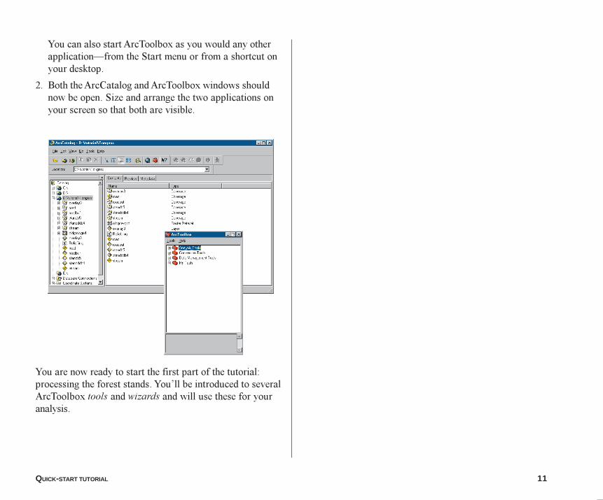
You can also start ArcToolbox as you would any otherapplication�from the Start menu or from a shortcut onyour desktop.
2. Both the ArcCatalog and ArcToolbox windows shouldnow be open. Size and arrange the two applications onyour screen so that both are visible.
You are now ready to start the first part of the tutorial:processing the forest stands. You�ll be introduced to severalArcToolbox tools and wizards and will use these for youranalysis.
03Ch02.p65 11/29/2000, 3:30 PM11
12 USING ARCTOOLBOX
Exercise 2: Processing the forest stands
In the first exercise, you prepared for the latter exercisesby organizing your data. Now you are ready to beginprocessing your data. Two forest stand coverages�Standddb4 and Standb5�currently cover the entire studyarea. Before you can begin your study, these coveragesmust be merged.
As noted in Exercise 1, the Standb5 coverage is projectedin a UTM coordinate system, while the Standddb4 coverageis in unprojected decimal degrees. In order for you toconduct a meaningful analysis of these areas, the coveragesmust share the same coordinate system. For this reason,you will project Standddb4 to match the coordinate systemof Standb5. Once this is done, the topology will have to berebuilt as it is lost when a coverage is projected.
Projecting a coverage
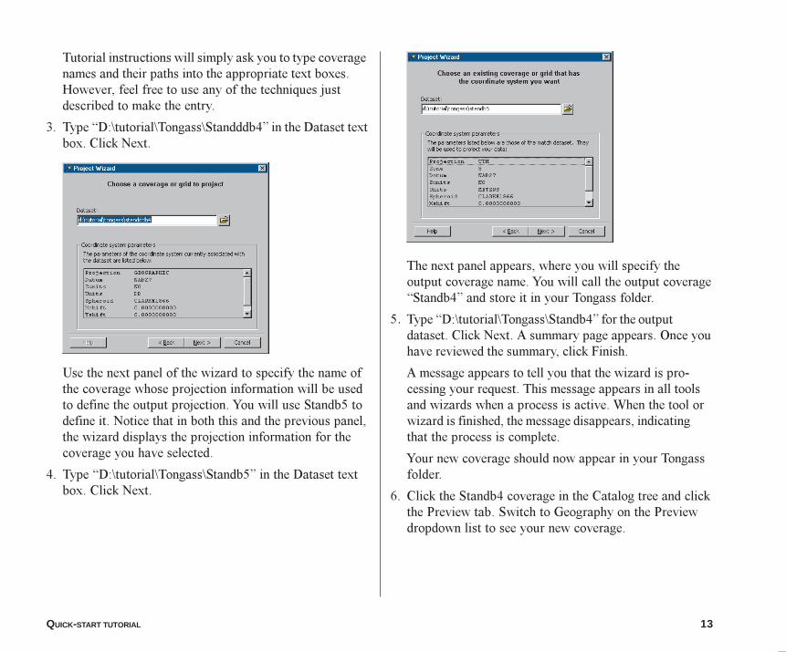
ArcToolbox software�s Project Wizard lets you easilyproject a coverage to another coordinate system. You canuse the Project Wizard to manually define the outputprojection (you supply all the projection parameters), or youcan have the wizard use the projection information stored inan existing coverage. For this study, you�ll use the wizard toproject the Standddb4 coverage to match the coordinatesystem of Standb5.
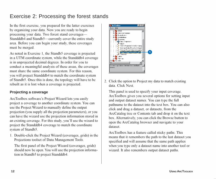
1. Double-click the Project Wizard (coverages, grids) in theProjections toolset of Data Management Tools.
The first panel of the Project Wizard (coverages, grids)should now be open. You will use the projection informa-tion in Standb5 to project Standddb4.
2. Click the option to Project my data to match existingdata. Click Next.
This panel is used to specify your input coverage.ArcToolbox gives you several options for setting inputand output dataset names. You can type the fullpathname to the dataset into the text box. You can alsoclick and drag a dataset, or datasets, from theArcCatalog tree or Contents tab and drop it on the textbox. Alternatively, you can click the Browse button toopen the ArcCatalog browser and navigate to yourdataset.
ArcToolbox has a feature called sticky paths. Thismeans that it remembers the path to the last dataset youspecified and will assume that the same path applieswhen you type only a dataset name into another tool orwizard. It also remembers output dataset paths.
1
03Ch02.p65 11/29/2000, 3:30 PM12
QUICK-START TUTORIAL 13
Tutorial instructions will simply ask you to type coveragenames and their paths into the appropriate text boxes.However, feel free to use any of the techniques justdescribed to make the entry.
3. Type �D:\tutorial\Tongass\Standddb4� in the Dataset textbox. Click Next.
Use the next panel of the wizard to specify the name ofthe coverage whose projection information will be usedto define the output projection. You will use Standb5 todefine it. Notice that in both this and the previous panel,the wizard displays the projection information for thecoverage you have selected.
4. Type �D:\tutorial\Tongass\Standb5� in the Dataset textbox. Click Next.
The next panel appears, where you will specify theoutput coverage name. You will call the output coverage�Standb4� and store it in your Tongass folder.
5. Type �D:\tutorial\Tongass\Standb4� for the outputdataset. Click Next. A summary page appears. Once youhave reviewed the summary, click Finish.
A message appears to tell you that the wizard is pro-cessing your request. This message appears in all toolsand wizards when a process is active. When the tool orwizard is finished, the message disappears, indicatingthat the process is complete.
Your new coverage should now appear in your Tongassfolder.
6. Click the Standb4 coverage in the Catalog tree and clickthe Preview tab. Switch to Geography on the Previewdropdown list to see your new coverage.
03Ch02.p65 11/29/2000, 3:31 PM13
14 USING ARCTOOLBOX
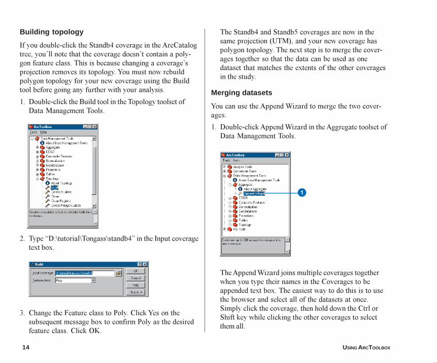
Building topology
If you double-click the Standb4 coverage in the ArcCatalogtree, you�ll note that the coverage doesn�t contain a poly-gon feature class. This is because changing a coverage�sprojection removes its topology. You must now rebuildpolygon topology for your new coverage using the Buildtool before going any further with your analysis.
1. Double-click the Build tool in the Topology toolset ofData Management Tools.
2. Type �D:\tutorial\Tongass\standb4� in the Input coveragetext box.
3. Change the Feature class to Poly. Click Yes on thesubsequent message box to confirm Poly as the desiredfeature class. Click OK.
The Standb4 and Standb5 coverages are now in thesame projection (UTM), and your new coverage haspolygon topology. The next step is to merge the cover-ages together so that the data can be used as onedataset that matches the extents of the other coveragesin the study.
Merging datasets
You can use the Append Wizard to merge the two cover-ages.
1. Double-click Append Wizard in the Aggregate toolset ofData Management Tools.
The Append Wizard joins multiple coverages togetherwhen you type their names in the Coverages to beappended text box. The easiest way to do this is to usethe browser and select all of the datasets at once.Simply click the coverage, then hold down the Ctrl orShift key while clicking the other coverages to selectthem all.
1
03Ch02.p65 11/29/2000, 3:31 PM14
QUICK-START TUTORIAL 15
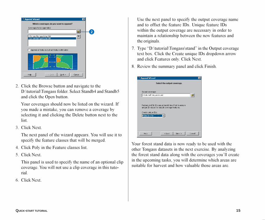
2. Click the Browse button and navigate to theD:\tutorial\Tongass folder. Select Standb4 and Standb5and click the Open button.
Your coverages should now be listed on the wizard. Ifyou made a mistake, you can remove a coverage byselecting it and clicking the Delete button next to thelist.
3. Click Next.
The next panel of the wizard appears. You will use it tospecify the feature classes that will be merged.
4. Click Poly in the Feature classes list.
5. Click Next.
This panel is used to specify the name of an optional clipcoverage. You will not use a clip coverage in this tuto-rial.
6. Click Next.
Use the next panel to specify the output coverage nameand to offset the feature IDs. Unique feature IDswithin the output coverage are necessary in order tomaintain a relationship between the new features andthe originals.
7. Type �D:\tutorial\Tongass\stand� in the Output coveragetext box. Click the Create unique IDs dropdown arrowand click Features only. Click Next.
8. Review the summary panel and click Finish.
Your forest stand data is now ready to be used with theother Tongass datasets in the next exercise. By analyzingthe forest stand data along with the coverages you�ll createin the upcoming tasks, you will determine which areas aresuitable for harvest and how valuable those areas are.
2
03Ch02.p65 11/29/2000, 3:31 PM15
16 USING ARCTOOLBOX
In the last exercise, you processed the forest stands; nowyou will process the streams and roads data to eliminate theareas that do not meet the first of the specified criteria:harvest areas must be at least 100 meters from all fishspawning streams and roads.
To process the streams, you will first select and extractstream segments flagged as fish spawning grounds andplace them in a new coverage named Fish. You will thengenerate a 100-meter buffer around each segment.
To meet the second part of the criterium�harvest areasmust be at least 100 meters from roads�you would have tocreate a similar buffer. However, this step has already beencompleted for you to avoid repetition; the extracted roadsare represented by the Roadbuf coverage.
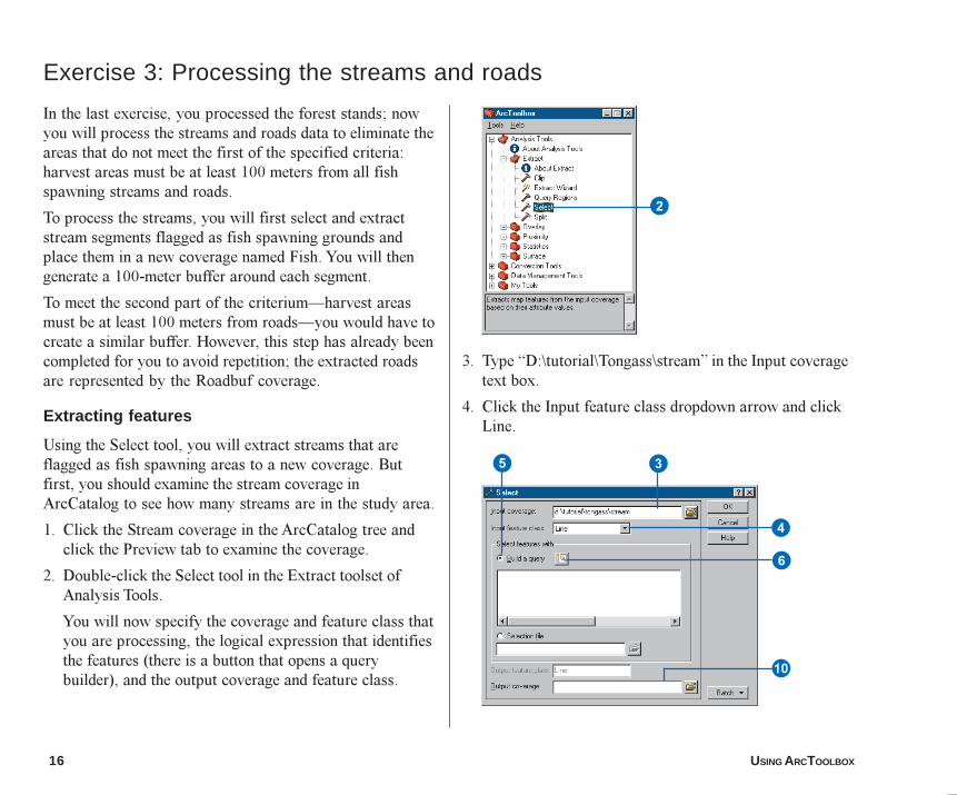
Extracting features
Using the Select tool, you will extract streams that areflagged as fish spawning areas to a new coverage. Butfirst, you should examine the stream coverage inArcCatalog to see how many streams are in the study area.
1. Click the Stream coverage in the ArcCatalog tree andclick the Preview tab to examine the coverage.
2. Double-click the Select tool in the Extract toolset ofAnalysis Tools.
You will now specify the coverage and feature class thatyou are processing, the logical expression that identifiesthe features (there is a button that opens a querybuilder), and the output coverage and feature class.
3. Type �D:\tutorial\Tongass\stream� in the Input coveragetext box.
4. Click the Input feature class dropdown arrow and clickLine.
Exercise 3: Processing the streams and roads
2
6
Q
3
4
5
03Ch02.p65 11/29/2000, 3:32 PM16
QUICK-START TUTORIAL 17
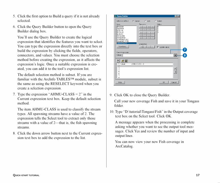
5. Click the first option to Build a query if it is not alreadyselected.
6. Click the Query Builder button to open the QueryBuilder dialog box.
You�ll use the Query Builder to create the logicalexpression that identifies the features you want to select.You can type the expression directly into the text box orbuild the expression by clicking the fields, operators,connectors, and values. You must choose the selectionmethod before creating the expression, as it affects theexpression�s logic. Once a suitable expression is cre-ated, you can add it to the tool�s expression list.
The default selection method is subset. If you arefamiliar with the ArcInfo TABLES� module, subset isthe same as using the RESELECT keyword when youcreate a selection expression.
7. Type the expression �AHMU-CLASS = 2� in theCurrent expression text box. Keep the default selectionmethod.
The item AHMU-CLASS is used to classify the streamtypes. All spawning streams have a value of 2. Theexpression tells the Select tool to extract only thosestreams with a value of 2�that is, the fish spawningstreams.
8. Click the down arrow button next to the Current expres-sion text box to add the expression to the list.
9. Click OK to close the Query Builder.
Call your new coverage Fish and save it in your Tongassfolder.
10. Type �D:\tutorial\Tongass\Fish� in the Output coveragetext box on the Select tool. Click OK.
A message appears when the processing is completeasking whether you want to see the output tool mes-sages. Click Yes and review the number of input andoutput lines.
You can now view your new Fish coverage inArcCatalog.
8
7
03Ch02.p65 11/29/2000, 3:32 PM17
18 USING ARCTOOLBOX
Creating a buffer
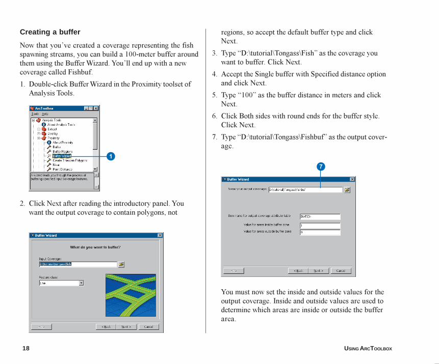
Now that you�ve created a coverage representing the fishspawning streams, you can build a 100-meter buffer aroundthem using the Buffer Wizard. You�ll end up with a newcoverage called Fishbuf.
1. Double-click Buffer Wizard in the Proximity toolset ofAnalysis Tools.
2. Click Next after reading the introductory panel. Youwant the output coverage to contain polygons, not
regions, so accept the default buffer type and clickNext.
3. Type �D:\tutorial\Tongass\Fish� as the coverage youwant to buffer. Click Next.
4. Accept the Single buffer with Specified distance optionand click Next.
5. Type �100� as the buffer distance in meters and clickNext.
6. Click Both sides with round ends for the buffer style.Click Next.
7. Type �D:\tutorial\Tongass\Fishbuf� as the output cover-age.
You must now set the inside and outside values for theoutput coverage. Inside and outside values are used todetermine which areas are inside or outside the bufferarea.
71
03Ch02.p65 11/29/2000, 3:33 PM18
QUICK-START TUTORIAL 19
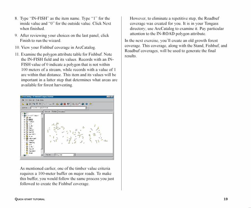
8. Type �IN-FISH� as the item name. Type �1� for theinside value and �0� for the outside value. Click Nextwhen finished.
9. After reviewing your choices on the last panel, clickFinish to run the wizard.
10. View your Fishbuf coverage in ArcCatalog.
11. Examine the polygon attribute table for Fishbuf. Notethe IN-FISH field and its values. Records with an IN-FISH value of 0 indicate a polygon that is not within100 meters of a stream, while records with a value of 1are within that distance. This item and its values will beimportant in a latter step that determines what areas areavailable for forest harvesting.
As mentioned earlier, one of the timber value criteriarequires a 100-meter buffer on major roads. To makethis buffer, you would follow the same process you justfollowed to create the Fishbuf coverage.
However, to eliminate a repetitive step, the Roadbufcoverage was created for you. It is in your Tongassdirectory; use ArcCatalog to examine it. Pay particularattention to the IN-ROAD polygon attribute.
In the next exercise, you�ll create an old growth forestcoverage. This coverage, along with the Stand, Fishbuf, andRoadbuf coverages, will be used to generate the finalresults.
03Ch02.p65 11/29/2000, 3:33 PM19
20 USING ARCTOOLBOX
In the previous exercises, you processed forest stands,streams, and roads to help in your study. Now, you�llconvert the grid of old growth forest areas into a coveragethat will be used in an overlay with the forest stands. Thisgrid was created exclusively for this tutorial; it was notprovided by the Forest Service.
You�ll use the Grid to Polygon Coverage tool to completethe conversion.
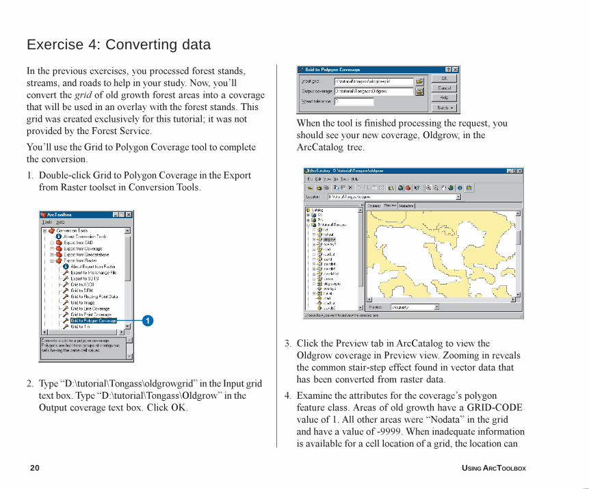
1. Double-click Grid to Polygon Coverage in the Exportfrom Raster toolset in Conversion Tools.
2. Type �D:\tutorial\Tongass\oldgrowgrid� in the Input gridtext box. Type �D:\tutorial\Tongass\Oldgrow� in theOutput coverage text box. Click OK.
Exercise 4: Converting data
When the tool is finished processing the request, youshould see your new coverage, Oldgrow, in theArcCatalog tree.
3. Click the Preview tab in ArcCatalog to view theOldgrow coverage in Preview view. Zooming in revealsthe common stair-step effect found in vector data thathas been converted from raster data.
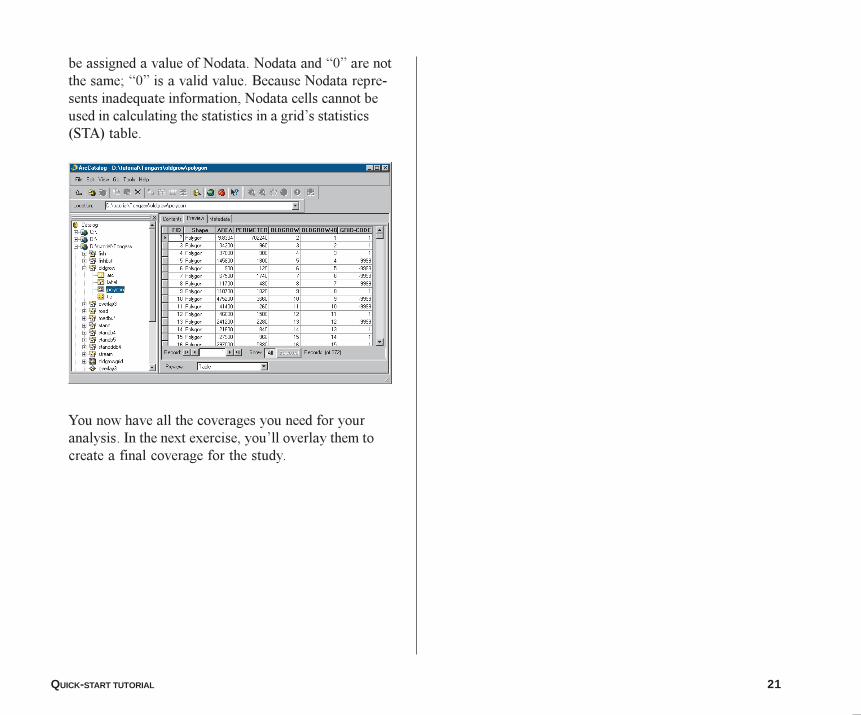
4. Examine the attributes for the coverage�s polygonfeature class. Areas of old growth have a GRID-CODEvalue of 1. All other areas were �Nodata� in the gridand have a value of -9999. When inadequate informationis available for a cell location of a grid, the location can
1
03Ch02.p65 11/29/2000, 3:33 PM20
QUICK-START TUTORIAL 21
be assigned a value of Nodata. Nodata and �0� are notthe same; �0� is a valid value. Because Nodata repre-sents inadequate information, Nodata cells cannot beused in calculating the statistics in a grid�s statistics(STA) table.
You now have all the coverages you need for youranalysis. In the next exercise, you�ll overlay them tocreate a final coverage for the study.
03Ch02.p65 11/29/2000, 3:33 PM21
22 USING ARCTOOLBOX
Now that you have organized, processed, and convertedyour data, you are ready to create the final analysis cover-age. To create the final analysis coverage, it is necessary tooverlay the Stand, Fishbuf, Roadbuf, and Oldgrow cover-ages. This would normally require you to perform two unionoverlays�Roadbuf with Fishbuf, and Stand withOldgrow�and then intersect the two resulting coverages tocreate the final analysis coverage.
However, to avoid repetitive tasks, you will only performone union overlay�Roadbuf with Fishbuf�so that youcan experience the Overlay wizard. The final coveragerequired for the analysis has been created for you and isnamed Overlay3. You will examine the Overlay3 coverageat the end of this section.
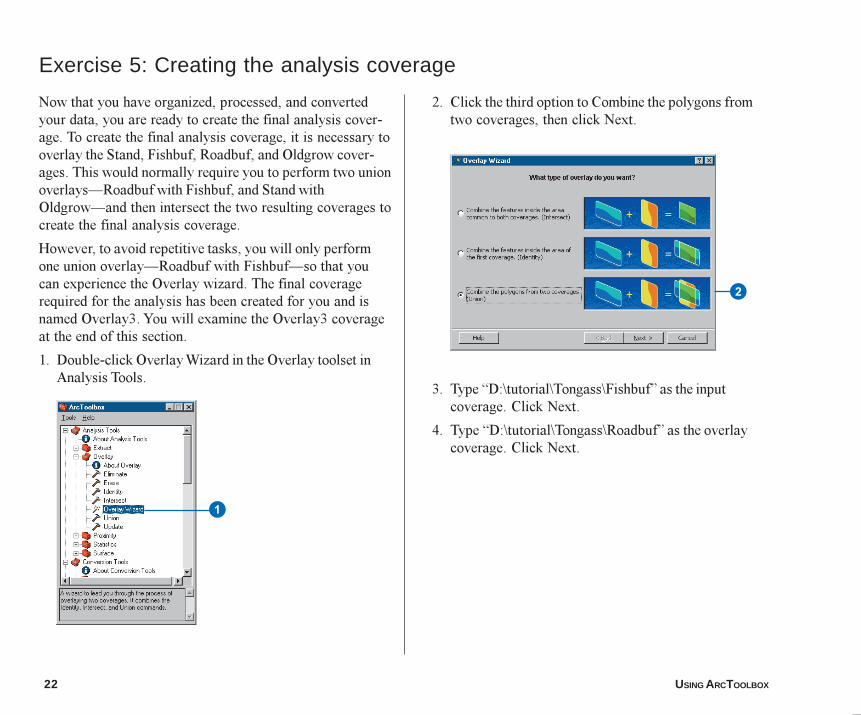
1. Double-click Overlay Wizard in the Overlay toolset inAnalysis Tools.
Exercise 5: Creating the analysis coverage
2. Click the third option to Combine the polygons fromtwo coverages, then click Next.
3. Type �D:\tutorial\Tongass\Fishbuf� as the inputcoverage. Click Next.
4. Type �D:\tutorial\Tongass\Roadbuf� as the overlaycoverage. Click Next.
2
1
03Ch02.p65 11/29/2000, 3:34 PM22
QUICK-START TUTORIAL 23
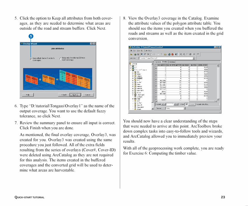
5. Click the option to Keep all attributes from both cover-ages, as they are needed to determine what areas areoutside of the road and stream buffers. Click Next.
6. Type �D:\tutorial\Tongass\Overlay1� as the name of theoutput coverage. You want to use the default fuzzytolerance, so click Next.
7. Review the summary panel to ensure all input is correct.Click Finish when you are done.
As mentioned, the final overlay coverage, Overlay3, wascreated for you. Overlay3 was created using the sameprocedure you just followed. All of the extra fieldsresulting from the series of overlays (Cover#, Cover-ID)were deleted using ArcCatalog as they are not requiredfor this analysis. The items created in the bufferedcoverages and the converted grid will be used to deter-mine what areas are harvestable.
5
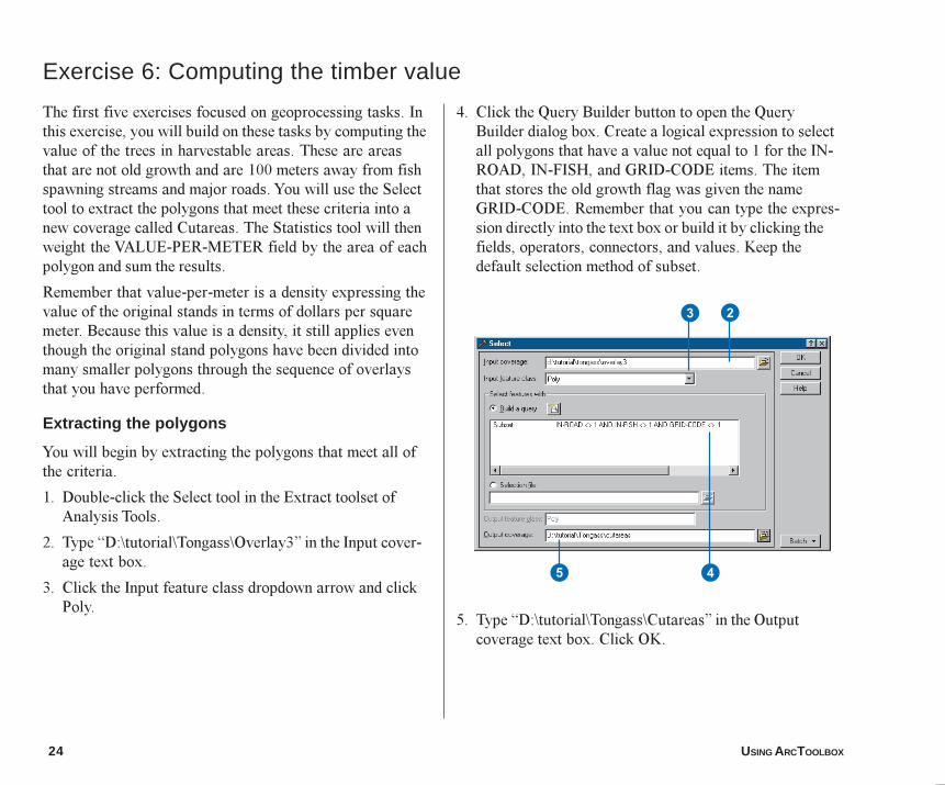
8. View the Overlay3 coverage in the Catalog. Examinethe attribute values of the polygon attribute table. Youshould see the items you created when you buffered theroads and streams as well as the item created in the gridconversion.
You should now have a clear understanding of the stepsthat were needed to arrive at this point. ArcToolbox brokedown complex tasks into easy-to-follow tools and wizards,and ArcCatalog allowed you to immediately preview yourresults.
With all of the geoprocessing work complete, you are readyfor Exercise 6: Computing the timber value.
03Ch02.p65 11/29/2000, 3:34 PM23
24 USING ARCTOOLBOX
The first five exercises focused on geoprocessing tasks. Inthis exercise, you will build on these tasks by computing thevalue of the trees in harvestable areas. These are areasthat are not old growth and are 100 meters away from fishspawning streams and major roads. You will use the Selecttool to extract the polygons that meet these criteria into anew coverage called Cutareas. The Statistics tool will thenweight the VALUE-PER-METER field by the area of eachpolygon and sum the results.
Remember that value-per-meter is a density expressing thevalue of the original stands in terms of dollars per squaremeter. Because this value is a density, it still applies eventhough the original stand polygons have been divided intomany smaller polygons through the sequence of overlaysthat you have performed.
Extracting the polygons
You will begin by extracting the polygons that meet all ofthe criteria.
1. Double-click the Select tool in the Extract toolset ofAnalysis Tools.
2. Type �D:\tutorial\Tongass\Overlay3� in the Input cover-age text box.
3. Click the Input feature class dropdown arrow and clickPoly.
Exercise 6: Computing the timber value
4. Click the Query Builder button to open the QueryBuilder dialog box. Create a logical expression to selectall polygons that have a value not equal to 1 for the IN-ROAD, IN-FISH, and GRID-CODE items. The itemthat stores the old growth flag was given the nameGRID-CODE. Remember that you can type the expres-sion directly into the text box or build it by clicking thefields, operators, connectors, and values. Keep thedefault selection method of subset.
5. Type �D:\tutorial\Tongass\Cutareas� in the Outputcoverage text box. Click OK.
5 4
3 2
03Ch02.p65 11/29/2000, 3:34 PM24
QUICK-START TUTORIAL 25
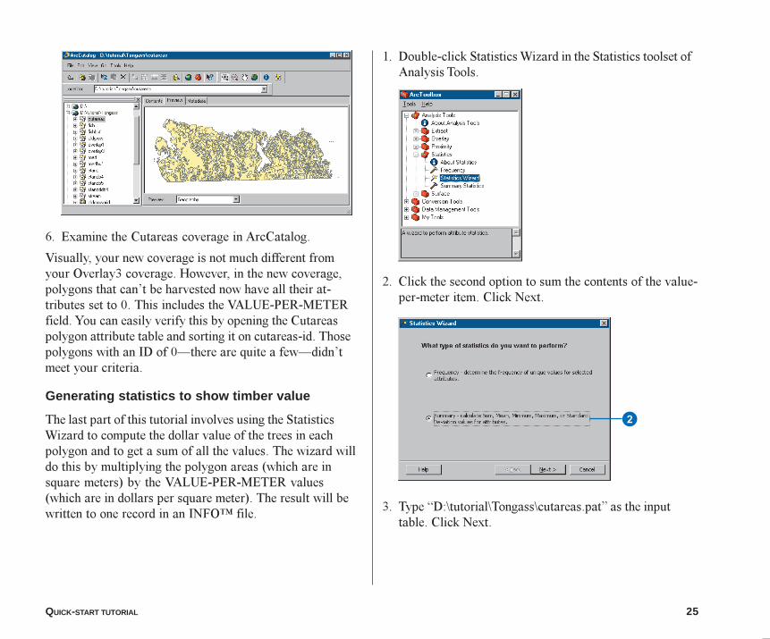
6. Examine the Cutareas coverage in ArcCatalog.
Visually, your new coverage is not much different fromyour Overlay3 coverage. However, in the new coverage,polygons that can�t be harvested now have all their at-tributes set to 0. This includes the VALUE-PER-METERfield. You can easily verify this by opening the Cutareaspolygon attribute table and sorting it on cutareas-id. Thosepolygons with an ID of 0�there are quite a few�didn�tmeet your criteria.
Generating statistics to show timber value
The last part of this tutorial involves using the StatisticsWizard to compute the dollar value of the trees in eachpolygon and to get a sum of all the values. The wizard willdo this by multiplying the polygon areas (which are insquare meters) by the VALUE-PER-METER values(which are in dollars per square meter). The result will bewritten to one record in an INFO� file.
1. Double-click Statistics Wizard in the Statistics toolset ofAnalysis Tools.
2. Click the second option to sum the contents of the value-per-meter item. Click Next.
3. Type �D:\tutorial\Tongass\cutareas.pat� as the inputtable. Click Next.
2
03Ch02.p65 11/29/2000, 3:34 PM25
26 USING ARCTOOLBOX
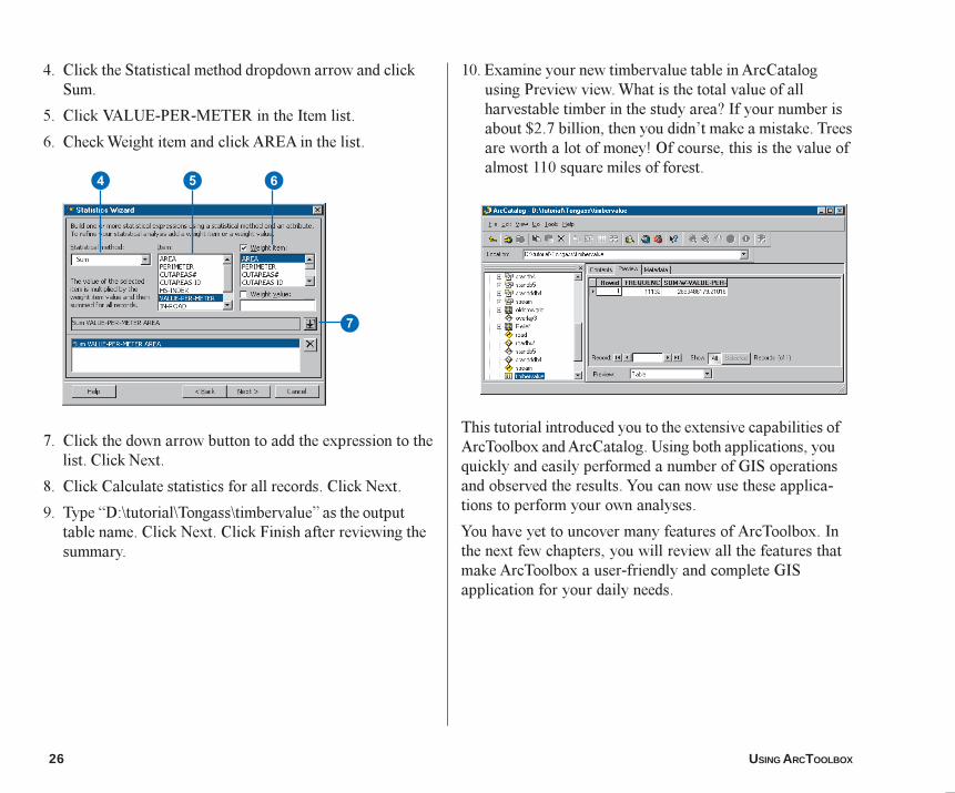
4. Click the Statistical method dropdown arrow and clickSum.
5. Click VALUE-PER-METER in the Item list.
6. Check Weight item and click AREA in the list.
7. Click the down arrow button to add the expression to thelist. Click Next.
8. Click Calculate statistics for all records. Click Next.
9. Type �D:\tutorial\Tongass\timbervalue� as the outputtable name. Click Next. Click Finish after reviewing thesummary.
10. Examine your new timbervalue table in ArcCatalogusing Preview view. What is the total value of allharvestable timber in the study area? If your number isabout $2.7 billion, then you didn�t make a mistake. Treesare worth a lot of money! Of course, this is the value ofalmost 110 square miles of forest.
This tutorial introduced you to the extensive capabilities ofArcToolbox and ArcCatalog. Using both applications, youquickly and easily performed a number of GIS operationsand observed the results. You can now use these applica-tions to perform your own analyses.
You have yet to uncover many features of ArcToolbox. Inthe next few chapters, you will review all the features thatmake ArcToolbox a user-friendly and complete GISapplication for your daily needs.
4 5 6
7
03Ch02.p65 11/29/2000, 3:35 PM26
27
IN THIS CHAPTER
3• Starting ArcToolbox
• What are toolsets?
• Starting a tool
• Finding the tools you need
• Getting help
• Setting the precision environment
• Using and defining relates
• Using ArcCatalog
• Dragging and dropping data
• Operating tools in batch mode
• Batch processing in wizards
• Using a Geoprocessing Server
• Checking a remote process
• Scheduling a remote process
ArcToolbox basics
ArcToolbox lets you work with data from different sources, run a tool orwizard on multiple datasets, and direct where the processing will occur. Toolsand wizards are arranged in a logical manner to help you find them quicklyand start the task at hand.
You�ll find that using ArcToolbox with ArcCatalog increases your productivitywhen performing geoprocessing or conversion tasks. It doesn�t take long tobecome familiar with the ArcToolbox interface, as the tools are organized intotoolsets that have names that are representative of functions.
Ch03.p65 12/19/2000, 9:34 AM27
28 USING ARCTOOLBOX
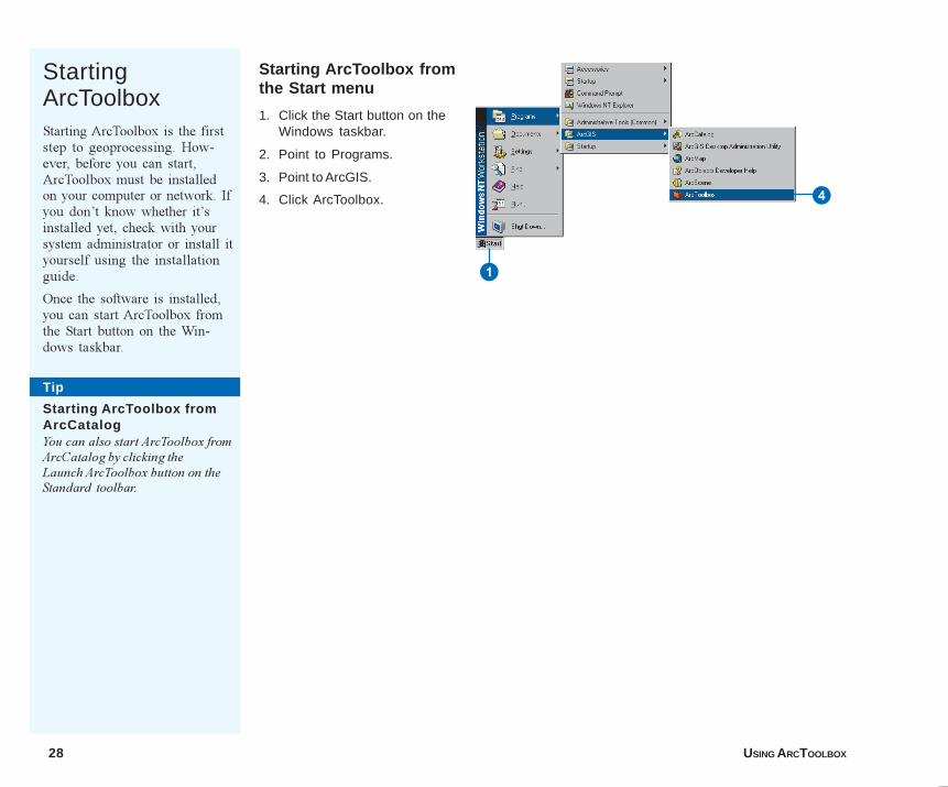
StartingArcToolboxStarting ArcToolbox is the firststep to geoprocessing. How-ever, before you can start,ArcToolbox must be installedon your computer or network. Ifyou don�t know whether it�sinstalled yet, check with yoursystem administrator or install ityourself using the installationguide.
Once the software is installed,you can start ArcToolbox fromthe Start button on the Win-dows taskbar.
Starting ArcToolbox fromthe Start menu
1. Click the Start button on theWindows taskbar.
2. Point to Programs.
3. Point to ArcGIS.
4. Click ArcToolbox.
Tip
Starting ArcToolbox fromArcCatalogYou can also start ArcToolbox fromArcCatalog by clicking theLaunch ArcToolbox button on theStandard toolbar.
4
1
04Ch03.p65 11/29/2000, 3:37 PM28
ARCTOOLBOX BASICS 29
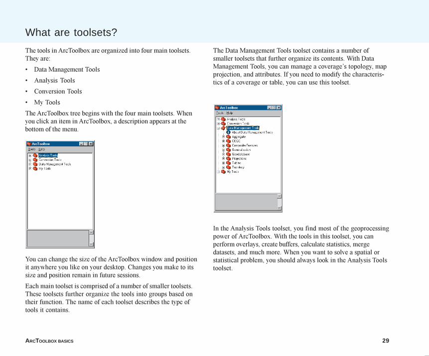
The tools in ArcToolbox are organized into four main toolsets.They are:
� Data Management Tools
� Analysis Tools
� Conversion Tools
� My Tools
The ArcToolbox tree begins with the four main toolsets. Whenyou click an item in ArcToolbox, a description appears at thebottom of the menu.
You can change the size of the ArcToolbox window and positionit anywhere you like on your desktop. Changes you make to itssize and position remain in future sessions.
Each main toolset is comprised of a number of smaller toolsets.These toolsets further organize the tools into groups based ontheir function. The name of each toolset describes the type oftools it contains.
The Data Management Tools toolset contains a number ofsmaller toolsets that further organize its contents. With DataManagement Tools, you can manage a coverage�s topology, mapprojection, and attributes. If you need to modify the characteris-tics of a coverage or table, you can use this toolset.
In the Analysis Tools toolset, you find most of the geoprocessingpower of ArcToolbox. With the tools in this toolset, you canperform overlays, create buffers, calculate statistics, mergedatasets, and much more. When you want to solve a spatial orstatistical problem, you should always look in the Analysis Toolstoolset.
What are toolsets?
04Ch03.p65 11/29/2000, 3:37 PM29
30 USING ARCTOOLBOX
See Also
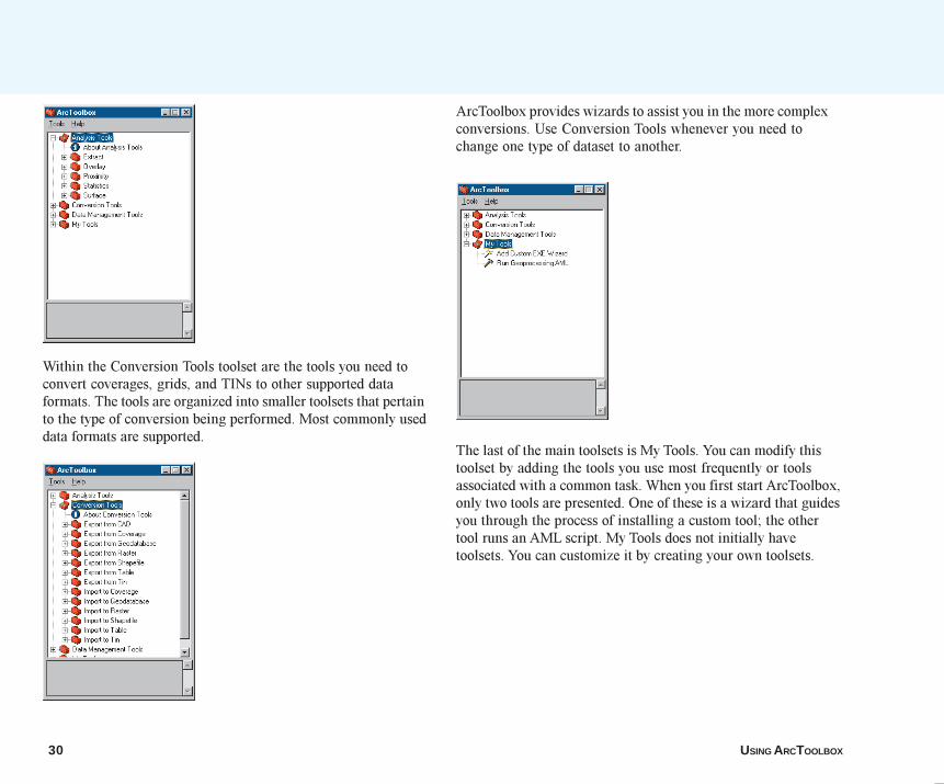
Within the Conversion Tools toolset are the tools you need toconvert coverages, grids, and TINs to other supported dataformats. The tools are organized into smaller toolsets that pertainto the type of conversion being performed. Most commonly useddata formats are supported.
ArcToolbox provides wizards to assist you in the more complexconversions. Use Conversion Tools whenever you need tochange one type of dataset to another.
The last of the main toolsets is My Tools. You can modify thistoolset by adding the tools you use most frequently or toolsassociated with a common task. When you first start ArcToolbox,only two tools are presented. One of these is a wizard that guidesyou through the process of installing a custom tool; the othertool runs an AML script. My Tools does not initially havetoolsets. You can customize it by creating your own toolsets.
04Ch03.p65 11/29/2000, 3:38 PM30
ARCTOOLBOX BASICS 31
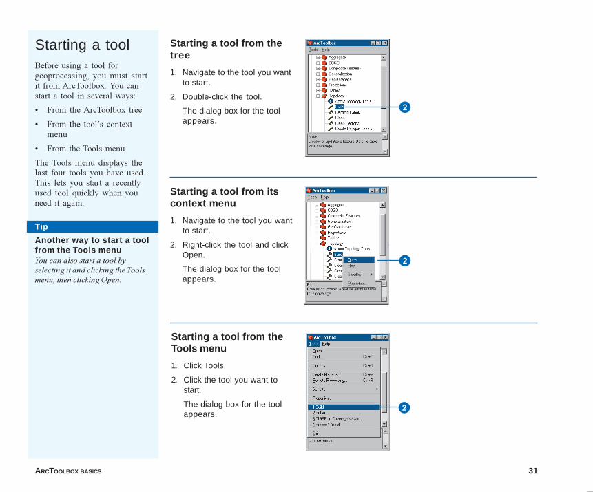
Starting a toolBefore using a tool forgeoprocessing, you must startit from ArcToolbox. You canstart a tool in several ways:
� From the ArcToolbox tree
� From the tool�s contextmenu
� From the Tools menu
The Tools menu displays thelast four tools you have used.This lets you start a recentlyused tool quickly when youneed it again.
Starting a tool from thetree
1. Navigate to the tool you wantto start.
2. Double-click the tool.
The dialog box for the toolappears.
Starting a tool from itscontext menu
1. Navigate to the tool you wantto start.
2. Right-click the tool and clickOpen.
The dialog box for the toolappears.
Starting a tool from theTools menu
1. Click Tools.
2. Click the tool you want tostart.
The dialog box for the toolappears.
2
2
2
Tip
Another way to start a toolfrom the Tools menuYou can also start a tool byselecting it and clicking the Toolsmenu, then clicking Open.
04Ch03.p65 11/29/2000, 3:38 PM31
32 USING ARCTOOLBOX
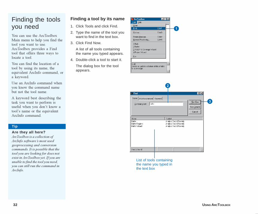
Finding the toolsyou needYou can use the ArcToolboxMain menu to help you find thetool you want to use.ArcToolbox provides a Findtool that offers three ways tolocate a tool.
You can find the location of atool by using its name, theequivalent ArcInfo command, ora keyword.
Use an ArcInfo command whenyou know the command namebut not the tool name.
A keyword best describing thetask you want to perform isuseful when you don�t know atool�s name or the equivalentArcInfo command.
Finding a tool by its name
1. Click Tools and click Find.
2. Type the name of the tool youwant to find in the text box.
3. Click Find Now.
A list of all tools containingthe name you typed appears.
4. Double-click a tool to start it.
The dialog box for the toolappears.
1
Tip
Are they all here?ArcToolbox is a collection ofArcInfo software�s most usedgeoprocessing and conversioncommands. It is possible that thetool you are looking for does notexist in ArcToolbox yet. If you areunable to find the tool you need,you can still run the command inArcInfo.
2
3
List of tools containingthe name you typed inthe text box
04Ch03.p65 11/29/2000, 3:38 PM32
ARCTOOLBOX BASICS 33
Tip
Using the Tab keyYou can use the Tab key to movethe focus on a tool from oneArcToolbox element to another.When a text box has focus, it has anactive cursor. A button with focushas a highlighted outline. Theelement with focus is the one youare currently using.
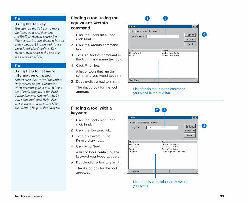
Finding a tool using theequivalent ArcInfocommand
1. Click the Tools menu andclick Find.
2. Click the ArcInfo commandtab.
3. Type an ArcInfo command inthe Command name text box.
4. Click Find Now.
A list of tools that run thecommand you typed appears.
5. Double-click a tool to start it.
The dialog box for the toolappears.
Finding a tool with akeyword
1. Click the Tools menu andclick Find.
2. Click the Keyword tab.
3. Type a keyword in theKeyword text box.
4. Click Find Now.
A list of tools containing thekeyword you typed appears.
5. Double-click a tool to start it.
The dialog box for the toolappears.
Tip
Using Help to get moreinformation on a toolYou can use the ArcToolbox onlineHelp system to get informationwhen searching for a tool. When alist of tools appears in the Finddialog box, you can right-click atool name and click Help. Forinstructions on how to use Help,see �Getting help� in this chapter.
2 3
4
List of tools that run the commandyou typed in the text box
2 3
4
List of tools containing the keywordyou typed
04Ch03.p65 11/29/2000, 3:39 PM33
34 USING ARCTOOLBOX
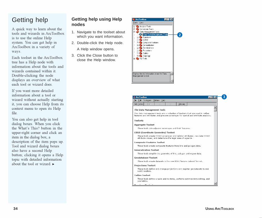
Getting helpA quick way to learn about thetools and wizards in ArcToolboxis to use the online Helpsystem. You can get help inArcToolbox in a variety ofways.
Each toolset in the ArcToolboxtree has a Help node withinformation about the tools andwizards contained within it.Double-clicking the nodedisplays an overview of whateach tool or wizard does.
If you want more detailedinformation about a tool orwizard without actually startingit, you can choose Help from itscontext menu to open its Helpfile.
You can also get help in tooldialog boxes. When you clickthe What�s This? button in theupper-right corner and click anitem in the dialog box, adescription of the item pops up.Tool and wizard dialog boxesalso have a second Helpbutton; clicking it opens a Helptopic with detailed informationabout the tool or wizard. u
Getting help using Helpnodes
1. Navigate to the toolset aboutwhich you want information.
2. Double-click the Help node.
A Help window opens.
3. Click the Close button toclose the Help window.
3
2
04Ch03.p65 11/29/2000, 3:39 PM34
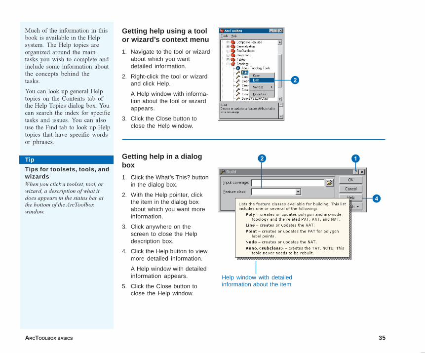
ARCTOOLBOX BASICS 35
Much of the information in thisbook is available in the Helpsystem. The Help topics areorganized around the maintasks you wish to complete andinclude some information aboutthe concepts behind thetasks.
You can look up general Helptopics on the Contents tab ofthe Help Topics dialog box. Youcan search the index for specifictasks and issues. You can alsouse the Find tab to look up Helptopics that have specific wordsor phrases.
Getting help in a dialogbox
1. Click the What’s This? buttonin the dialog box.
2. With the Help pointer, clickthe item in the dialog boxabout which you want moreinformation.
3. Click anywhere on thescreen to close the Helpdescription box.
4. Click the Help button to viewmore detailed information.
A Help window with detailedinformation appears.
5. Click the Close button toclose the Help window.
Getting help using a toolor wizard’s context menu
1. Navigate to the tool or wizardabout which you wantdetailed information.
2. Right-click the tool or wizardand click Help.
A Help window with informa-tion about the tool or wizardappears.
3. Click the Close button toclose the Help window.
Tip
Tips for toolsets, tools, andwizardsWhen you click a toolset, tool, orwizard, a description of what itdoes appears in the status bar atthe bottom of the ArcToolboxwindow.
2
12
4
Help window with detailedinformation about the item
04Ch03..p65 12/18/2000, 12:30 PM35
36 USING ARCTOOLBOX
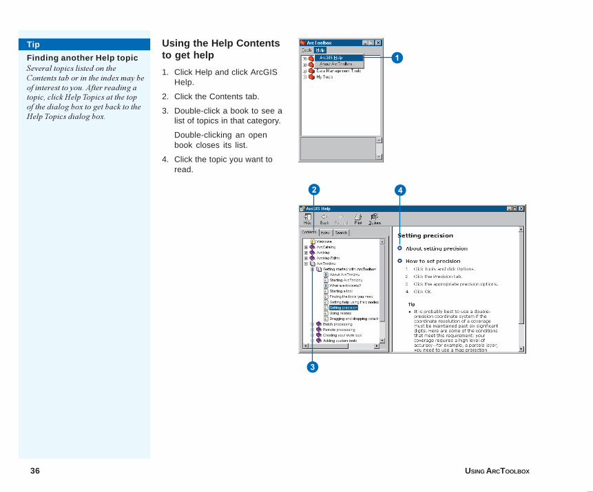
Using the Help Contentsto get help
1. Click Help and click ArcGISHelp.
2. Click the Contents tab.
3. Double-click a book to see alist of topics in that category.
Double-clicking an openbook closes its list.
4. Click the topic you want toread.
Tip
Finding another Help topicSeveral topics listed on theContents tab or in the index may beof interest to you. After reading atopic, click Help Topics at the topof the dialog box to get back to theHelp Topics dialog box.
1
3
2 4
04Ch03.p65 11/29/2000, 3:40 PM36
ARCTOOLBOX BASICS 37
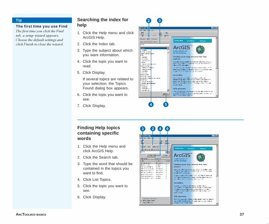
Finding Help topicscontaining specificwords
1. Click the Help menu andclick ArcGIS Help.
2. Click the Search tab.
3. Type the word that should becontained in the topics youwant to find.
4. Click List Topics.
5. Click the topic you want tosee.
6. Click Display.
Searching the index forhelp
1. Click the Help menu and clickArcGIS Help.
2. Click the Index tab.
3. Type the subject about whichyou want information.
4. Click the topic you want toread.
5. Click Display.
If several topics are related toyour selection, the TopicsFound dialog box appears.
6. Click the topic you want tosee.
7. Click Display.
Tip
The first time you use FindThe first time you click the Findtab, a setup wizard appears.Choose the default settings andclick Finish to close the wizard.
23 4 6
4 5
2 3
04Ch03.p65 11/29/2000, 3:40 PM37
38 USING ARCTOOLBOX
Coordinate precision refers to the mathematical exactness of acoordinate and is based on the possible number of significantdigits that can be stored for each coordinate. ESRI datasets arestored in either single- or double-precision coordinates. Singleprecision stores up to seven significant digits for each coordi-nate. This means that values of 4,999,999.6 units to 5,000,000.4units are rounded off to 5,000,000 units when stored in singleprecision. However, a value of 5,000,000.6 is rounded off to5,000,001 units when stored in single precision. This discrepancycan easily be avoided by using a double-precision coordinatesystem. Double precision stores up to 15 significant digits(typically 13 to 14) and retains a mathematical precision of muchless than one meter at a global extent. Note that mathematicalprecision does not, by itself, define accuracy. It is, however, amajor factor in coverage resolution.
The computer can only discern a limited number of decimalplaces, depending on the precision being used. For single-precision coordinates, the computer assumes that values such as1.2345678 and 1.23456789 are equal because numbers beyond theseventh digit are ignored. You might imagine a very, very smallhalo surrounding each coordinate that is equal to the resolutionof coordinate storage on the computer. Coordinates with overlap-ping halos are seen by the computer to represent the samelocation.
Coverages stored with either single- or double-precision coordi-nates can be used interchangeably; for example, you can displaysingle- and double-precision coverages over each other, overlaythem, merge them, and so on. This capability, however, does notreplace the need to be clear and deliberate about how youencode, store, and manage each coverage. Base your decision ofwhich type of precision to use on the desired level of coordinateaccuracy to be maintained for each coverage.
The coordinate systems for many map projections use largecoordinate values�for example, State Plane and UTM coordi-
The precision environment
nates contain values in the two million to six million range. Inthese cases, you can use double-precision coordinates tomaintain accuracy of less than one unit beyond the decimal point.
As mentioned, double-precision coverages can store up to15 significant digits. This is sufficient to map any point on theearth to better than a millimeter of accuracy. However, double-precision coverages require additional storage space. Thus, itmay be worthwhile to store coverages that require high levels ofaccuracy (such as parcels) in a double-precision coordinatesystem and coverages needing less accuracy (such as soils) in asingle-precision coordinate system.
The Precision tab in the Options dialog box defines the coordi-nate precision of new and derived coverages created during anArcToolbox session. The tab establishes two rules: creation andprocessing.
The creation rule specifies the precision with which to create allnew coverages. Any time a new coverage is created, the coordi-nate precision of the new coverage is defined by the currentcreation rule. Single precision is the default. Thus, if you want tocreate double-precision coverages, you must set the precision ofa new dataset to double.
The processing rule specifies the precision with which to createall derived coverages. When a new coverage is derived from oneor more existing coverages (for example, the result of the Buffer orUpdate tools), the coordinate precision of the new coveragereflects the current processing rule. For example, the outputcoverage precision can be the highest of a set of input coverages.Thus, if all input coverages are in a single-precision coordinatesystem, the output coverage will be single precision; if at leastone of the coverages is double precision, the output coverage isdouble precision, and so on. To create double-precision cover-ages regardless of the precision of the input coverages, set theprocessing rule to double before you begin.
04Ch03.p65 11/29/2000, 3:40 PM38
ARCTOOLBOX BASICS 39
Setting theprecisionBefore you begin using thetools in ArcToolbox, youshould determine what theprecision of your outputcoverages should be. Be carefulnot to use more precision thanis necessary, as the higher theprecision setting, the more diskspace you will need to store it.
It is probably best to use adouble-precision coordinatesystem if the coordinateresolution of a coverage mustbe maintained past six signifi-cant digits. Here are some of theconditions that meet thisrequirement:
� Your coverage requires ahigh level of accuracy�forexample, a parcels layer.
� You need to use a mapprojection whose coordinatevalues exceed the availablecoordinate precision.
� You are changing datums�for example, from NAD27 toNAD83.
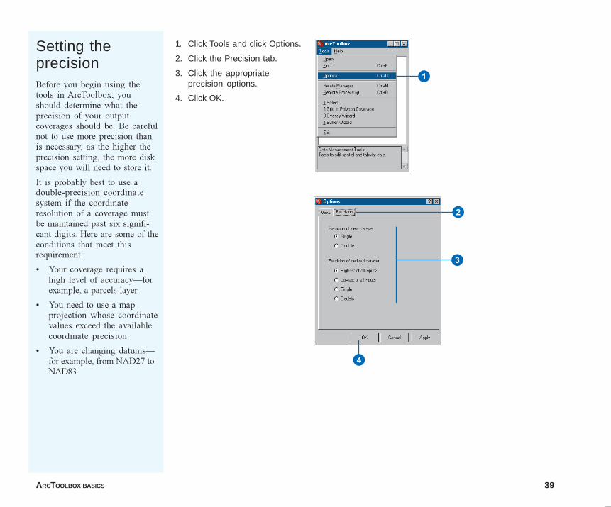
1. Click Tools and click Options.
2. Click the Precision tab.
3. Click the appropriateprecision options.
4. Click OK.
1
2
4
3
04Ch03.p65 11/29/2000, 3:40 PM39
40 USING ARCTOOLBOX
The ability to store related information in tables is an example ofthe flexibility of ArcToobox. Attribute data can be stored infeature attribute tables, related files, or external database man-agement system (DBMS) tables.
You can also temporarily associate additional attribute tables witha coverage�s feature attribute table using an operation known as arelate. A relate makes a connection between a record in the featureattribute table and a corresponding record in the related attributetable. An item in one table is used as a relate key to a correspond-ing item or column in the related table.
The relate is a defined and named relational join between featureattribute tables, INFO files, and external DBMS tables. The relateenvironment exploits all the advantages of a relational datastructure. In ArcToolbox, a relate is a named relationship betweenan item appearing in a feature attribute table (or many tables) anda related INFO datafile or external attribute table. A relate consistsof:
� A relation name�used to identify and access the relate.
� A table identifier�identifies the related table to be accessed.This can be an INFO file, table, or view in an external DBMS.
� A database name�identifies the DBMS in which the table isstored (for example, INFO or a connection to one of thesupported external DBMS systems).
� An item�item in the feature attribute table or INFO file thatrelates to the related table.
� A relate column�the item or column name in the relatedattribute table that relates back to the feature attribute table orINFO file item.
� A relate type�specifies the type of connection made anddepends on the database being interfaced. For INFO access,type can be Linear, Ordered, or Link; for DBMS tables, it mustbe First.
� A relate access�specifies the mode of access (for example,RW, RO, or AUTO).
No specific source table name is stored as part of the relate;relates are item based, not table based. This way, the same relatecan be used to relate more than one feature attribute table to therelated table.
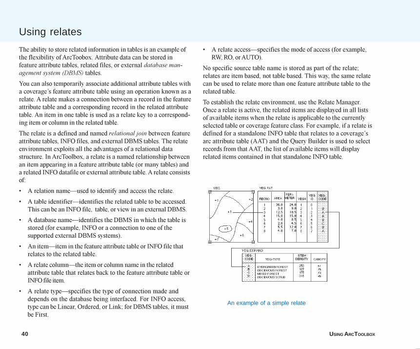
To establish the relate environment, use the Relate Manager.Once a relate is active, the related items are displayed in all listsof available items when the relate is applicable to the currentlyselected table or coverage feature class. For example, if a relate isdefined for a standalone INFO table that relates to a coverage�sarc attribute table (AAT) and the Query Builder is used to selectrecords from that AAT, the list of available items will displayrelated items contained in that standalone INFO table.
Using relates
An example of a simple relate
04Ch03.p65 11/29/2000, 3:40 PM40
ARCTOOLBOX BASICS 41
Defining relatesRelated tables are accessed bythe Query Builder. This is usedby a number of tools that offerthe option of an attributeselection such as the Select toolor Extract Wizard. Your relate ismaintained by ArcToolbox, soyou need only define the relateonce.
You can define up to100 different relates as part ofthe relate environment at anytime. However, only 30 can beused simultaneously during anoperation. Once the relateenvironment contains100 relates, you can�t replace arelate with a new relate.However, you can either updatethe parameters of an existingrelate or delete a relate anddefine another.
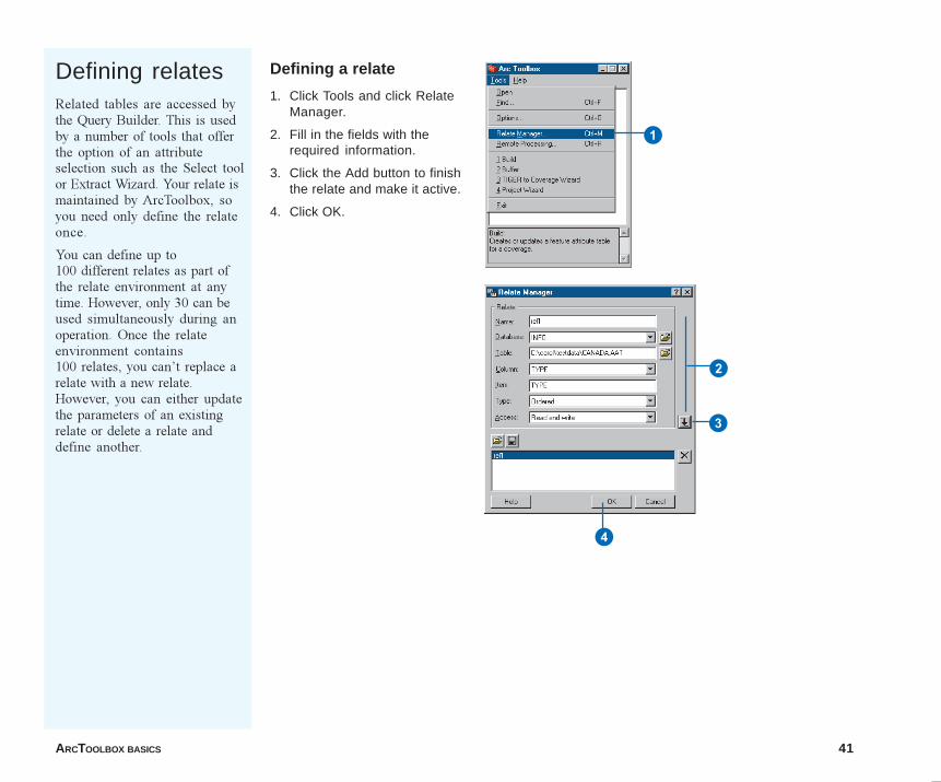
Defining a relate
1. Click Tools and click RelateManager.
2. Fill in the fields with therequired information.
3. Click the Add button to finishthe relate and make it active.
4. Click OK.
3
2
4
1
04Ch03.p65 11/29/2000, 3:40 PM41
42 USING ARCTOOLBOX
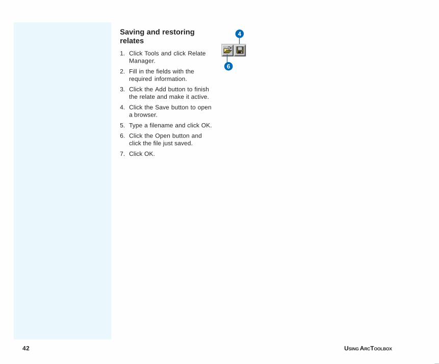
Saving and restoringrelates
1. Click Tools and click RelateManager.
2. Fill in the fields with therequired information.
3. Click the Add button to finishthe relate and make it active.
4. Click the Save button to opena browser.
5. Type a filename and click OK.
6. Click the Open button andclick the file just saved.
7. Click OK.
4
6
04Ch03.p65 11/29/2000, 3:40 PM42
ARCTOOLBOX BASICS 43
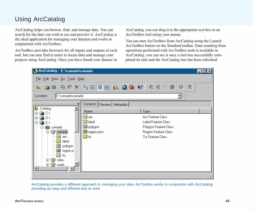
Using ArcCatalog
ArcCatalog provides a different approach to managing your data. ArcToolbox works in conjunction with ArcCatalog,providing an easy and efficient way to work.
ArcCatalog helps you browse, find, and manage data. You cansearch for the data you wish to use and preview it. ArcCatalog isthe ideal application for managing your datasets and works inconjunction with ArcToolbox.
ArcToolbox provides browsers for all inputs and outputs of eachtool, but you may find it easier to locate data and manage yourprojects using ArcCatalog. Once you have found your dataset in
ArcCatalog, you can drag it to the appropriate text box in anArcToolbox tool using your mouse.
You can start ArcToolbox from ArcCatalog using the LaunchArcToolbox button on the Standard toolbar. Data resulting fromoperations performed with ArcToolbox tools is available inArcCatalog; you can see it once a tool has successfully com-pleted its task and the ArcCatalog tree has been refreshed.
04Ch03.p65 11/29/2000, 3:41 PM43
44 USING ARCTOOLBOX
Tip
Using Windows ExplorerDatasets and files can also bedragged onto tools from WindowsExplorer when the required accessis read-only. For example, you candrag a coverage folder onto a textbox on the Union tool; however,you can�t drag a coverage fromWindows Explorer onto the Buildtool, as the tool requires writeaccess to the coverage. Multipledatasets and files can also bedragged and dropped fromWindows Explorer.
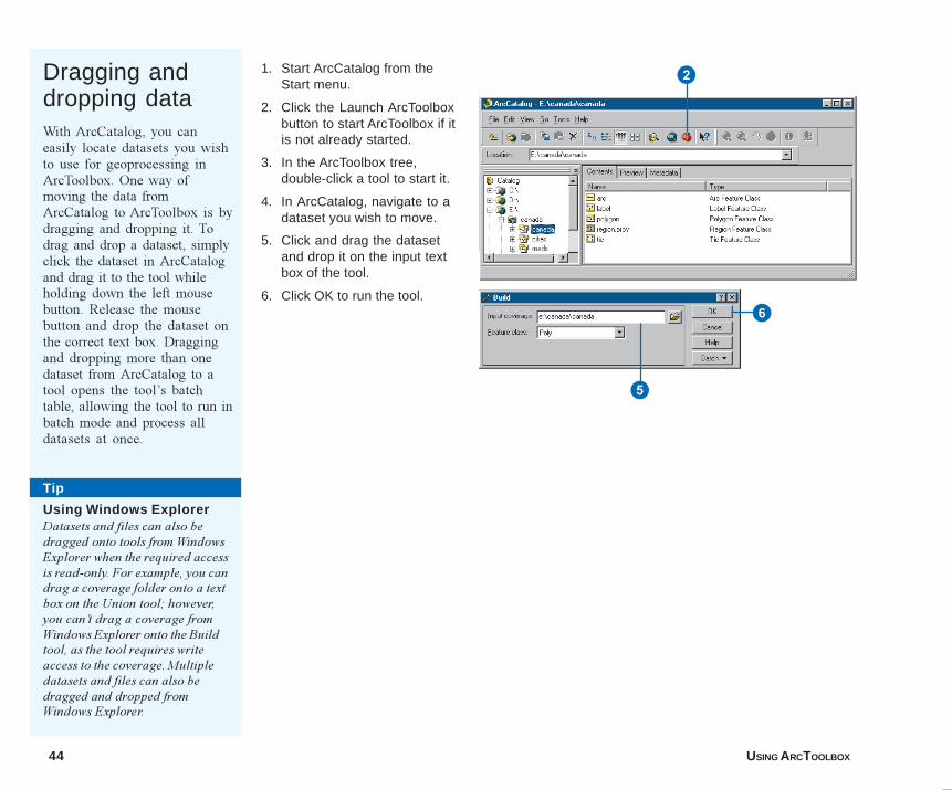
Dragging anddropping dataWith ArcCatalog, you caneasily locate datasets you wishto use for geoprocessing inArcToolbox. One way ofmoving the data fromArcCatalog to ArcToolbox is bydragging and dropping it. Todrag and drop a dataset, simplyclick the dataset in ArcCatalogand drag it to the tool whileholding down the left mousebutton. Release the mousebutton and drop the dataset onthe correct text box. Draggingand dropping more than onedataset from ArcCatalog to atool opens the tool�s batchtable, allowing the tool to run inbatch mode and process alldatasets at once.
1. Start ArcCatalog from theStart menu.
2. Click the Launch ArcToolboxbutton to start ArcToolbox if itis not already started.
3. In the ArcToolbox tree,double-click a tool to start it.
4. In ArcCatalog, navigate to adataset you wish to move.
5. Click and drag the datasetand drop it on the input textbox of the tool.
6. Click OK to run the tool.
5
6
2
04Ch03.p65 11/29/2000, 3:41 PM44
ARCTOOLBOX BASICS 45
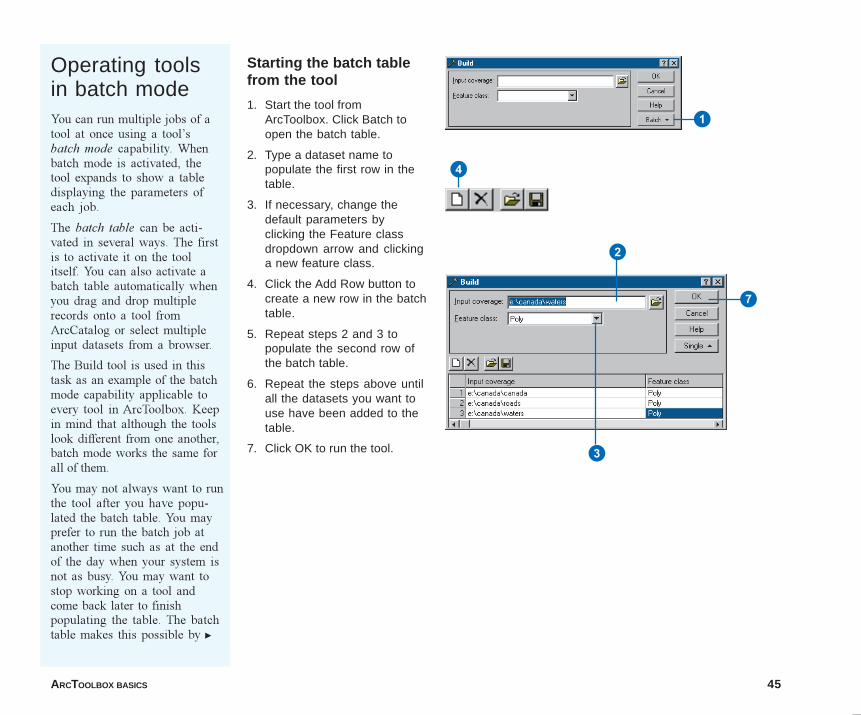
Starting the batch tablefrom the tool
1. Start the tool fromArcToolbox. Click Batch toopen the batch table.
2. Type a dataset name topopulate the first row in thetable.
3. If necessary, change thedefault parameters byclicking the Feature classdropdown arrow and clickinga new feature class.
4. Click the Add Row button tocreate a new row in the batchtable.
5. Repeat steps 2 and 3 topopulate the second row ofthe batch table.
6. Repeat the steps above untilall the datasets you want touse have been added to thetable.
7. Click OK to run the tool.
Operating toolsin batch modeYou can run multiple jobs of atool at once using a tool�sbatch mode capability. Whenbatch mode is activated, thetool expands to show a tabledisplaying the parameters ofeach job.
The batch table can be acti-vated in several ways. The firstis to activate it on the toolitself. You can also activate abatch table automatically whenyou drag and drop multiplerecords onto a tool fromArcCatalog or select multipleinput datasets from a browser.
The Build tool is used in thistask as an example of the batchmode capability applicable toevery tool in ArcToolbox. Keepin mind that although the toolslook different from one another,batch mode works the same forall of them.
You may not always want to runthe tool after you have popu-lated the batch table. You mayprefer to run the batch job atanother time such as at the endof the day when your system isnot as busy. You may want tostop working on a tool andcome back later to finishpopulating the table. The batchtable makes this possible by u
4
1
2
3
7
04Ch03.p65 11/29/2000, 3:41 PM45
46 USING ARCTOOLBOX
letting you save its contents toan AML script.
You can edit the AML scriptscreated by ArcToolbox, but thisis not recommended as it maycorrupt them. Rather, youshould append a script bysaving to one that alreadyexists. In so doing, you cancompose an AML that performsmany tasks.
You can load an AML that hasparameters from numeroustools, but only the validparameters for the current toolare loaded. When you save toan AML, the tool�s parametersare always appended to thecontents of the script if italready exists. For example,suppose an AML has entriesfrom the Build and Clean tools.When it is loaded into the Buildtool, only the entries pertainingto the Build tool are used, andthe rest are left out.
Within the My Tools toolset isa tool that can run any AMLthat starts at the Arc: prompt.You can run any existing AMLin your organization or one youhave created using a tool.
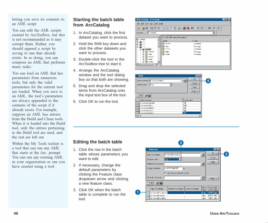
Starting the batch tablefrom ArcCatalog
1. In ArcCatalog, click the firstdataset you want to process.
2. Hold the Shift key down andclick the other datasets youwant to process.
3. Double-click the tool in theArcToolbox tree to start it.
4. Arrange the ArcCatalogwindow and the tool dialogbox so that both are showing.
5. Drag and drop the selecteditems from ArcCatalog ontothe input text box of the tool.
6. Click OK to run the tool.
Editing the batch table
1. Click the row in the batchtable whose parameters youwant to edit.
2. If necessary, change thedefault parameters byclicking the Feature classdropdown arrow and clickinga new feature class.
3. Click OK when the batchtable is complete to run thetool.
5
1
2
3
04Ch03.p65 11/29/2000, 3:41 PM46
ARCTOOLBOX BASICS 47
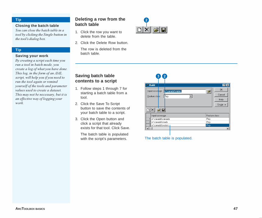
Saving batch tablecontents to a script
1. Follow steps 1 through 7 forstarting a batch table from atool.
2. Click the Save To Scriptbutton to save the contents ofyour batch table to a script.
3. Click the Open button andclick a script that alreadyexists for that tool. Click Save.
The batch table is populatedwith the script’s parameters.
Tip
Saving your workBy creating a script each time yourun a tool in batch mode, youcreate a log of what you have done.This log, in the form of an AMLscript, will help you if you need torun the tool again or remindyourself of the tools and parametervalues used to create a dataset.This may not be necessary, but it isan effective way of logging yourwork.
Tip
Closing the batch tableYou can close the batch table in atool by clicking the Single button inthe tool�s dialog box.
Deleting a row from thebatch table
1. Click the row you want todelete from the table.
2. Click the Delete Row button.
The row is deleted from thebatch table.
2
32
The batch table is populated.
04Ch03.p65 11/29/2000, 3:41 PM47
48 USING ARCTOOLBOX
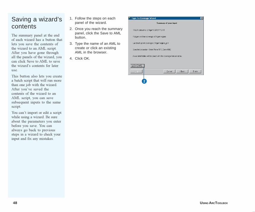
Saving a wizard’scontentsThe summary panel at the endof each wizard has a button thatlets you save the contents ofthe wizard to an AML script.After you have gone throughall the panels of the wizard, youcan click Save to AML to savethe wizard�s contents for lateruse.
This button also lets you createa batch script that will run morethan one job with the wizard.After you�ve saved thecontents of the wizard to anAML script, you can savesubsequent inputs to the samescript.
You can�t import or edit a scriptwhile using a wizard. Be sureabout the parameters you enterbefore you save. You canalways go back to previoussteps in a wizard to check yourinput and fix any mistakes.
1. Follow the steps on eachpanel of the wizard.
2. Once you reach the summarypanel, click the Save to AMLbutton.
3. Type the name of an AML tocreate or click an existingAML in the browser.
4. Click OK.
2
04Ch03.p65 11/29/2000, 3:42 PM48
ARCTOOLBOX BASICS 49
The Geoprocessing Server
ArcToolbox can perform remote processing on another machinethat has been set up as a Geoprocessing Server; this machine canbe either a Windows NT or UNIX system. The GeoprocessingServer is installed separately from ArcToolbox and runs as aseparate application. For complete information about the installa-tion of a Geoprocessing Server and how to enable GeoprocessingServer client desktops, see Appendix B, the �GeoprocessingServer Administration Guide� .
In ArcToolbox, you can connect to any machine that has beenactivated as a server. After connecting to a server, you canspecify whether or not you want tasks to run remotely. This front-and back-office approach lets you compose tasks on yourdesktop but process the data where it resides, creating a moreefficient work environment.
Before you can process jobs remotely, you must add a servername to a list of available servers. You must provide and verifyconnection information before the server can become active on aclient desktop. Once a server is activated and chosen, all of theArcToolbox tasks run on the remote server. All subsequent tasksrun by ArcToolbox will use the remote server. You can�t run sometasks locally and others remotely without changing the process-ing state.
When you connect to a Geoprocessing Server, you must specifythe Geoprocessing Server instance running on the server youwant to use. An instance is one installation of the GeoprocessingServer running on a host machine. Multiple GeoprocessingServer instances may exist on one server, so an instance nameidentifies the installation you want to use. Your desktop computercan communicate with an instance once the instance name and itscommunication information is specified in your Windows servicesfile.
The Geoprocessing Server manages the jobs you post to theserver and sends you the results of the job when it is complete.
Typically, the job order is decided by the first in, first out rule, butyou can also specify when a job should run using the schedulingoption of the server. You may schedule your jobs to maximizeefficiency on your server and complete tasks when their resultsare needed.
Only AML scripts that execute nongraphic commands availablein the ARC module are supported by the Geoprocessing Server.This means the AML you use can�t switch from one module toanother. For example, you can�t run an AML that starts in ARCand then switches to ARCPLOT� software to start a displaycanvas. Using the Run AML Script tool, you can run existingAMLs from ArcToolbox and have them processed anywhere youlike.
The following pages show you how to connect to aGeoprocessing Server, send and schedule jobs, and check forresults.
04Ch03.p65 11/29/2000, 3:42 PM49
50 USING ARCTOOLBOX
Tip
Where is your data?If your data is located on a remotesystem that has superior resources,such as a faster CPU, make it aGeoprocessing Server and processyour data there instead of on adesktop client. This is a great wayto take advantage of your powerfulUNIX system.
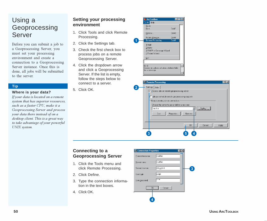
Setting your processingenvironment
1. Click Tools and click RemoteProcessing.
2. Click the Settings tab.
3. Check the first check box toprocess jobs on a remoteGeoprocessing Server.
4. Click the dropdown arrowand click a GeoprocessingServer. If the list is empty,follow the steps below toconnect to a server.
5. Click OK.
Using aGeoprocessingServerBefore you can submit a job toa Geoprocessing Server, youmust set your processingenvironment and create aconnection to a GeoprocessingServer instance. Once this isdone, all jobs will be submittedto the server.
Connecting to aGeoprocessing Server
1. Click the Tools menu andclick Remote Processing.
2. Click Define.
3. Type the connection informa-tion in the text boxes.
4. Click OK.
1
3
4
2
3 45
Ch03.p65 12/19/2000, 11:19 AM50
ARCTOOLBOX BASICS 51
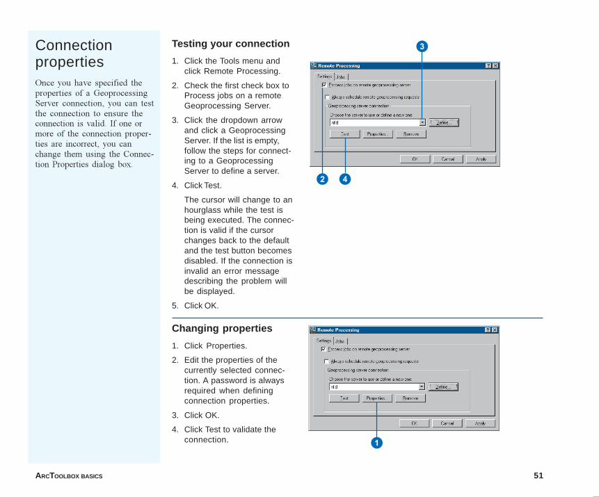
ConnectionpropertiesOnce you have specified theproperties of a GeoprocessingServer connection, you can testthe connection to ensure theconnection is valid. If one ormore of the connection proper-ties are incorrect, you canchange them using the Connec-tion Properties dialog box.
Testing your connection
1. Click the Tools menu andclick Remote Processing.
2. Check the first check box toProcess jobs on a remoteGeoprocessing Server.
3. Click the dropdown arrowand click a GeoprocessingServer. If the list is empty,follow the steps for connect-ing to a GeoprocessingServer to define a server.
4. Click Test.
The cursor will change to anhourglass while the test isbeing executed. The connec-tion is valid if the cursorchanges back to the defaultand the test button becomesdisabled. If the connection isinvalid an error messagedescribing the problem willbe displayed.
5. Click OK.
Changing properties
1. Click Properties.
2. Edit the properties of thecurrently selected connec-tion. A password is alwaysrequired when definingconnection properties.
3. Click OK.
4. Click Test to validate theconnection.
3
2 4
1
04Ch03.p65 11/29/2000, 3:43 PM51
52 USING ARCTOOLBOX
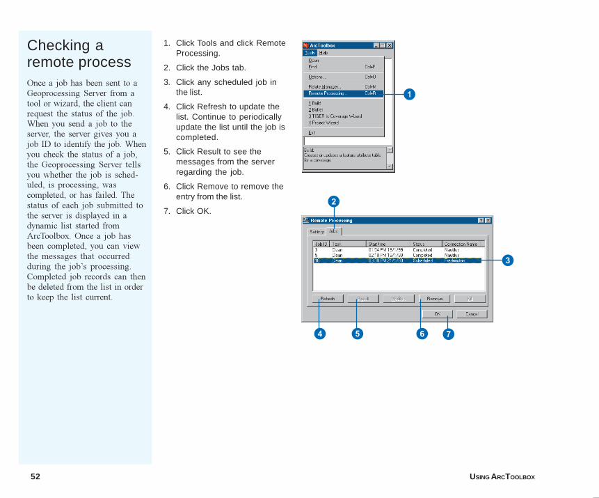
Checking aremote processOnce a job has been sent to aGeoprocessing Server from atool or wizard, the client canrequest the status of the job.When you send a job to theserver, the server gives you ajob ID to identify the job. Whenyou check the status of a job,the Geoprocessing Server tellsyou whether the job is sched-uled, is processing, wascompleted, or has failed. Thestatus of each job submitted tothe server is displayed in adynamic list started fromArcToolbox. Once a job hasbeen completed, you can viewthe messages that occurredduring the job�s processing.Completed job records can thenbe deleted from the list in orderto keep the list current.
1. Click Tools and click RemoteProcessing.
2. Click the Jobs tab.
3. Click any scheduled job inthe list.
4. Click Refresh to update thelist. Continue to periodicallyupdate the list until the job iscompleted.
5. Click Result to see themessages from the serverregarding the job.
6. Click Remove to remove theentry from the list.
7. Click OK.2
3
74 5 6
1
04Ch03.p65 11/29/2000, 3:43 PM52
ARCTOOLBOX BASICS 53
Tip
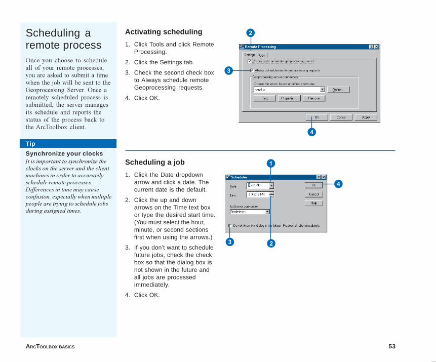
Scheduling aremote processOnce you choose to scheduleall of your remote processes,you are asked to submit a timewhen the job will be sent to theGeoprocessing Server. Once aremotely scheduled process issubmitted, the server managesits schedule and reports thestatus of the process back tothe ArcToolbox client.
Activating scheduling
1. Click Tools and click RemoteProcessing.
2. Click the Settings tab.
3. Check the second check boxto Always schedule remoteGeoprocessing requests.
4. Click OK.
Scheduling a job
1. Click the Date dropdownarrow and click a date. Thecurrent date is the default.
2. Click the up and downarrows on the Time text boxor type the desired start time.(You must select the hour,minute, or second sectionsfirst when using the arrows.)
3. If you don’t want to schedulefuture jobs, check the checkbox so that the dialog box isnot shown in the future andall jobs are processedimmediately.
4. Click OK.
Tip
Synchronize your clocksIt is important to synchronize theclocks on the server and the clientmachines in order to accuratelyschedule remote processes.Differences in time may causeconfusion, especially when multiplepeople are trying to schedule jobsduring assigned times.
1
23
4
3
2
4
Ch03.p65 12/19/2000, 11:32 AM53

04Ch03.p65 11/29/2000, 3:43 PM54
IN THIS CHAPTER
55
Creating your own look 4• Turning off toolsets and tools
• Turning off Help nodes and tooldescriptions
• Adding to the My Tools toolset
• Placing tools on top
As you use ArcToolbox, you may notice that you are only using tools from afew specific toolsets or that you are using tools from numerous toolsets tocomplete a routine task. You may not want to navigate through all of thesetoolsets to find the tools you commonly use. To make your work easier,ArcToolbox offers a way to personalize the organization of your tools. Youcan customize the ArcToolbox tree so that only the toolsets and tools youneed are visible, thereby creating your own look and feel.
In Chapter 2, you were introduced to the My Tools toolset and learned how itcan serve as your custom work area. In this chapter, you will create customtoolsets and add preexisting tools. You will also learn how to change thechoices available in the Data Management Tools, Analysis Tools, and Con-version Tools toolsets, eliminating those tools you do not use. This will helpyou find the tools you want more efficiently.
05Ch04.p65 12/18/2000, 10:32 AM55
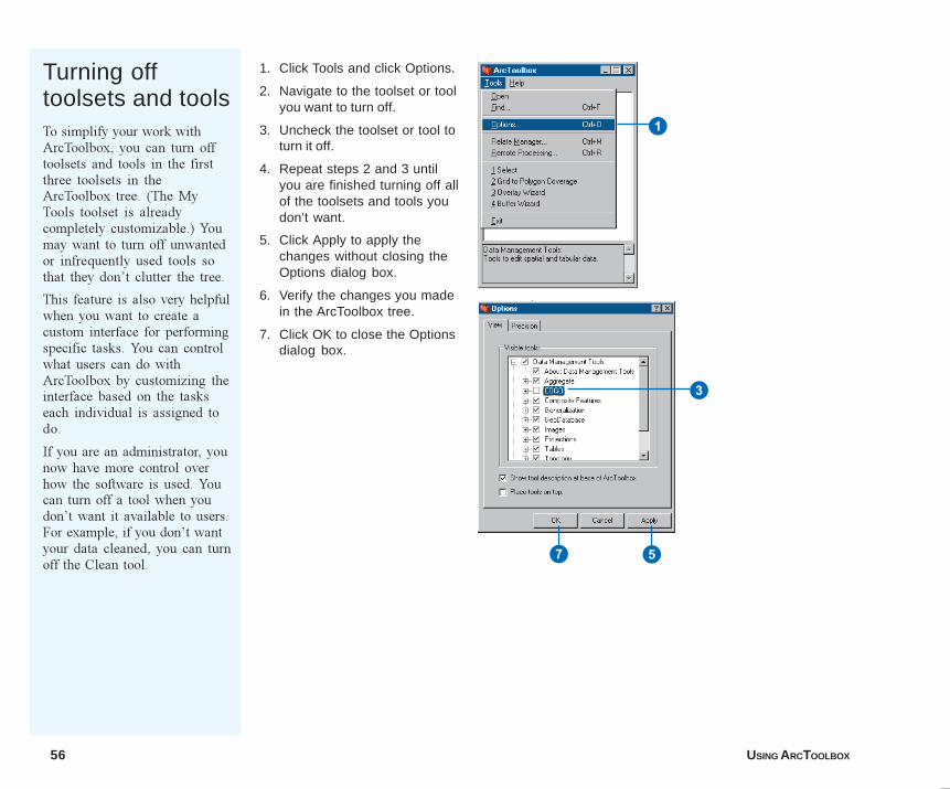
56 USING ARCTOOLBOX
Turning offtoolsets and toolsTo simplify your work withArcToolbox, you can turn offtoolsets and tools in the firstthree toolsets in theArcToolbox tree. (The MyTools toolset is alreadycompletely customizable.) Youmay want to turn off unwantedor infrequently used tools sothat they don�t clutter the tree.
This feature is also very helpfulwhen you want to create acustom interface for performingspecific tasks. You can controlwhat users can do withArcToolbox by customizing theinterface based on the taskseach individual is assigned todo.
If you are an administrator, younow have more control overhow the software is used. Youcan turn off a tool when youdon�t want it available to users.For example, if you don�t wantyour data cleaned, you can turnoff the Clean tool.
1. Click Tools and click Options.
2. Navigate to the toolset or toolyou want to turn off.
3. Uncheck the toolset or tool toturn it off.
4. Repeat steps 2 and 3 untilyou are finished turning off allof the toolsets and tools youdon’t want.
5. Click Apply to apply thechanges without closing theOptions dialog box.
6. Verify the changes you madein the ArcToolbox tree.
7. Click OK to close the Optionsdialog box.
1
3
7 5
05Ch04.p65 11/29/2000, 3:46 PM56
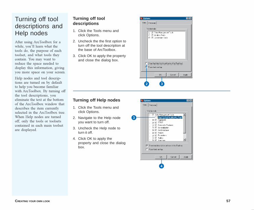
CREATING YOUR OWN LOOK 57
Turning off tooldescriptions andHelp nodesAfter using ArcToolbox for awhile, you�ll learn what thetools do, the purpose of eachtoolset, and what tools theycontain. You may want toreduce the space needed todisplay this information, givingyou more space on your screen.
Help nodes and tool descrip-tions are turned on by defaultto help you become familiarwith ArcToolbox. By turning offthe tool descriptions, youeliminate the text at the bottomof the ArcToolbox window thatdescribes the item currentlyselected in the ArcToolbox tree.When Help nodes are turnedoff, only the tools or toolsetscontained in each main toolsetare displayed.
Turning off tooldescriptions
1. Click the Tools menu andclick Options.
2. Uncheck the the first option toturn off the tool description atthe base of ArcToolbox.
3. Click OK to apply the propertyand close the dialog box.
Turning off Help nodes
1. Click the Tools menu andclick Options.
2. Navigate to the Help nodeyou want to turn off.
3. Uncheck the Help node toturn it off.
4. Click OK to apply theproperty and close the dialogbox.
2 3
4
3
05Ch04.p65 11/29/2000, 3:47 PM57
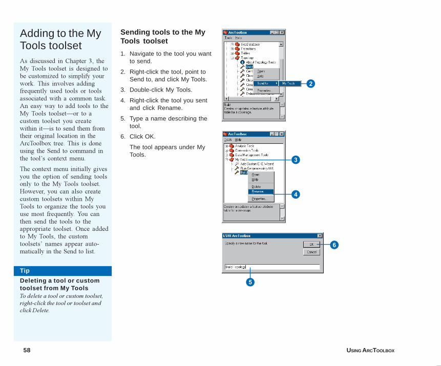
58 USING ARCTOOLBOX
Adding to the MyTools toolsetAs discussed in Chapter 3, theMy Tools toolset is designed tobe customized to simplify yourwork. This involves addingfrequently used tools or toolsassociated with a common task.An easy way to add tools to theMy Tools toolset�or to acustom toolset you createwithin it�is to send them fromtheir original location in theArcToolbox tree. This is doneusing the Send to command inthe tool�s context menu.
The context menu initially givesyou the option of sending toolsonly to the My Tools toolset.However, you can also createcustom toolsets within MyTools to organize the tools youuse most frequently. You canthen send the tools to theappropriate toolset. Once addedto My Tools, the customtoolsets� names appear auto-matically in the Send to list.
Sending tools to the MyTools toolset
1. Navigate to the tool you wantto send.
2. Right-click the tool, point toSend to, and click My Tools.
3. Double-click My Tools.
4. Right-click the tool you sentand click Rename.
5. Type a name describing thetool.
6. Click OK.
The tool appears under MyTools.
2
5
6
4
3
Tip
Deleting a tool or customtoolset from My ToolsTo delete a tool or custom toolset,right-click the tool or toolset andclick Delete.
05Ch04.p65 11/29/2000, 3:47 PM58
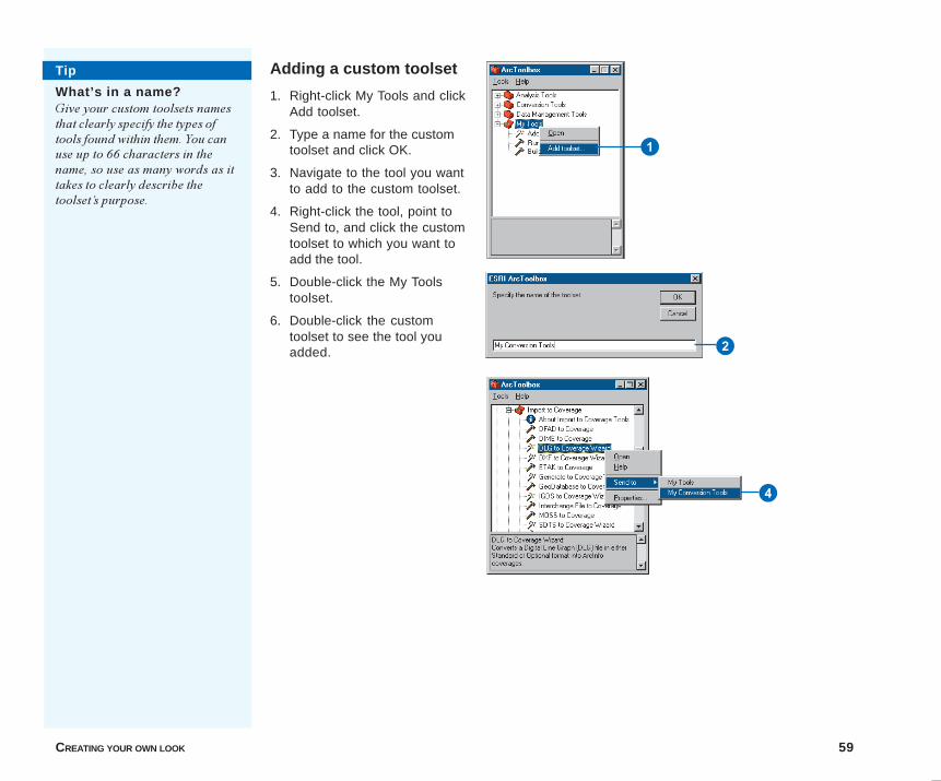
CREATING YOUR OWN LOOK 59
Adding a custom toolset
1. Right-click My Tools and clickAdd toolset.
2. Type a name for the customtoolset and click OK.
3. Navigate to the tool you wantto add to the custom toolset.
4. Right-click the tool, point toSend to, and click the customtoolset to which you want toadd the tool.
5. Double-click the My Toolstoolset.
6. Double-click the customtoolset to see the tool youadded. 2
4
Tip
What’s in a name?Give your custom toolsets namesthat clearly specify the types oftools found within them. You canuse up to 66 characters in thename, so use as many words as ittakes to clearly describe thetoolset�s purpose.
1
05Ch04.p65 11/29/2000, 3:47 PM59
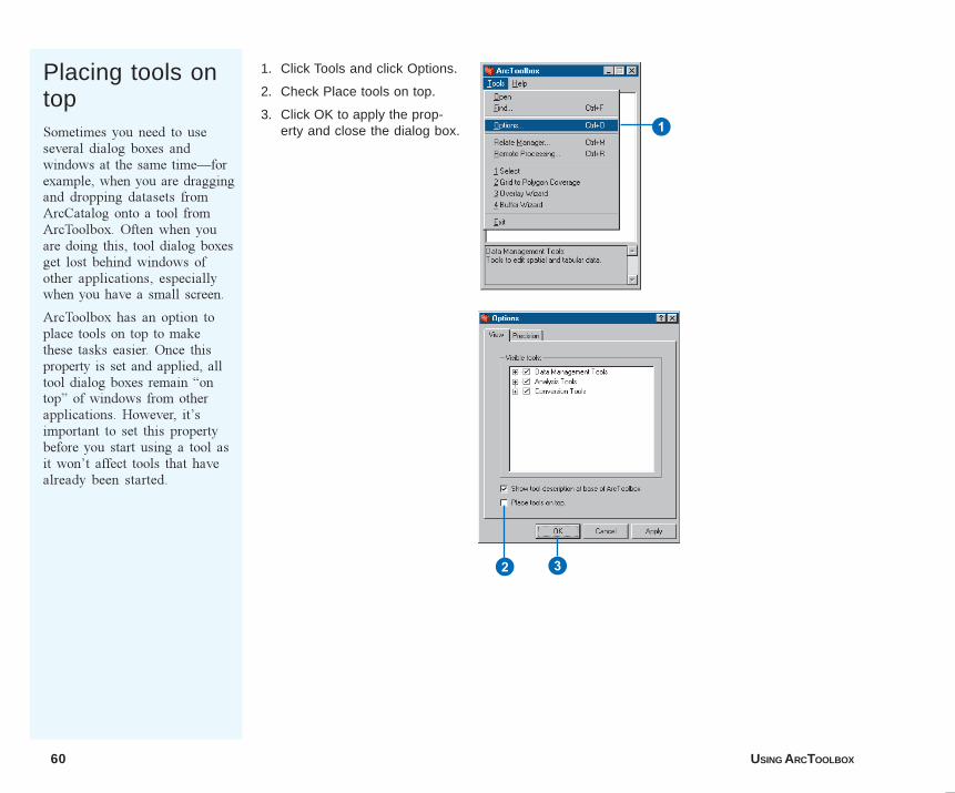
60 USING ARCTOOLBOX
Placing tools ontopSometimes you need to useseveral dialog boxes andwindows at the same time�forexample, when you are draggingand dropping datasets fromArcCatalog onto a tool fromArcToolbox. Often when youare doing this, tool dialog boxesget lost behind windows ofother applications, especiallywhen you have a small screen.
ArcToolbox has an option toplace tools on top to makethese tasks easier. Once thisproperty is set and applied, alltool dialog boxes remain �ontop� of windows from otherapplications. However, it�simportant to set this propertybefore you start using a tool asit won�t affect tools that havealready been started.
1. Click Tools and click Options.
2. Check Place tools on top.
3. Click OK to apply the prop-erty and close the dialog box. 1
32
05Ch04.p65 11/29/2000, 3:48 PM60
IN THIS CHAPTER
61
Adding a custom tool 5• Requirements for a custom tool
• Creating a custom tool in VisualBasic 6.0
• Enabling drag and drop
• Adding a custom tool
Although ArcToolbox provides a long list of tools, you may want to add to itscapabilities so that you can perform additional tasks. You can do so bydeveloping and installing new tools to meet your requirements.
A custom tool can be a system executable (EXE) or a class contained in adynamic link library (DLL). The executable tool can run any applicationthat runs on the platform you�re using. This could be a word processor,spreadsheet, or computer-aided design (CAD) application that supplementsyour use of ArcToolbox. If you have a DLL, it must meet some simplerequirements in order for it to work.
In this chapter, you will learn how to create a very simple custom tool andadd it to ArcToolbox. The example in this chapter uses Visual Basic 6.0 asthe development environment, but you could use any developer environment,such as Visual C++®, Delphi®, or Sybase® PowerBuilder®, to construct acustom tool EXE or DLL.
The custom tool must be fully self-contained. ArcToolbox provides only theArc automation server, which allows access to the full range of functions inthe ARC module. The tool must handle all validation, execution, and errorchecking.
06Ch05.p65 12/18/2000, 10:34 AM61
62 USING ARCTOOLBOX
When creating and adding custom tools, certain requirementsmust be met. These requirements depend on the type of customtool you�re working with: DLL or EXE.
DLL
Every DLL that is installed as a custom tool must have a classthat implements the IArcToolBoxTool Component Object Model(COM) interface. This interface provides ArcToolbox with theinformation it needs to store and execute the tool from theArcToolbox tree. Custom tools must also support theIArcToolboxFind interface if the tool is to be supported by theArcToolbox Find tool. The IArcToolboxFind interface providesinformation required by the Find tool such as keywords and whatARC commands are used. If the custom tool references the ODEArc automation server, then it should implement theIArcToolBoxODE interface so it can use the Arc automationserver defined in the ArcToolbox application�this savesresources and improves performance. You can learn more aboutthese interfaces by using the ESRI Object browser or the VBObject Browser.
The class can be called whatever you want. For an example of aclass definition that meets the above requirements, refer to theexample in Appendix A. In this example, a VB form calledfrmDescribe is opened from inside the class.
Executables
There are no requirements for executables used as ArcToolboxcustom tools, except that the executable must operate in thecurrent operating environment and handle its own errors andvalidation. For example, you could add ArcCatalog as a customtool simply by using the executable found in its installationdirectory.
Requirements for a custom tool
06Ch05.p65 11/29/2000, 3:49 PM62
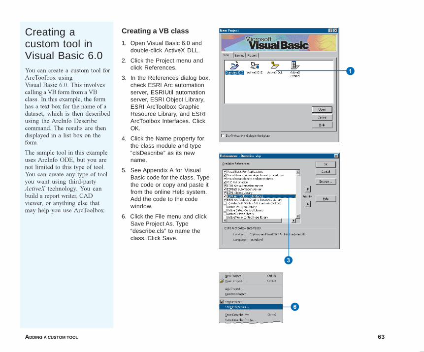
ADDING A CUSTOM TOOL 63
Creating acustom tool inVisual Basic 6.0You can create a custom tool forArcToolbox usingVisual Basic 6.0. This involvescalling a VB form from a VBclass. In this example, the formhas a text box for the name of adataset, which is then describedusing the ArcInfo Describecommand. The results are thendisplayed in a list box on theform.
The sample tool in this exampleuses ArcInfo ODE, but you arenot limited to this type of tool.You can create any type of toolyou want using third-partyActiveX technology. You canbuild a report writer, CADviewer, or anything else thatmay help you use ArcToolbox.
Creating a VB class
1. Open Visual Basic 6.0 anddouble-click ActiveX DLL.
2. Click the Project menu andclick References.
3. In the References dialog box,check ESRI Arc automationserver, ESRIUtil automationserver, ESRI Object Library,ESRI ArcToolbox GraphicResource Library, and ESRIArcToolbox Interfaces. ClickOK.
4. Click the Name property forthe class module and type“clsDescribe” as its newname.
5. See Appendix A for VisualBasic code for the class. Typethe code or copy and paste itfrom the online Help system.Add the code to the codewindow.
6. Click the File menu and clickSave Project As. Type“describe.cls” to name theclass. Click Save.
6
1
3
06Ch05.p65 11/29/2000, 3:49 PM63
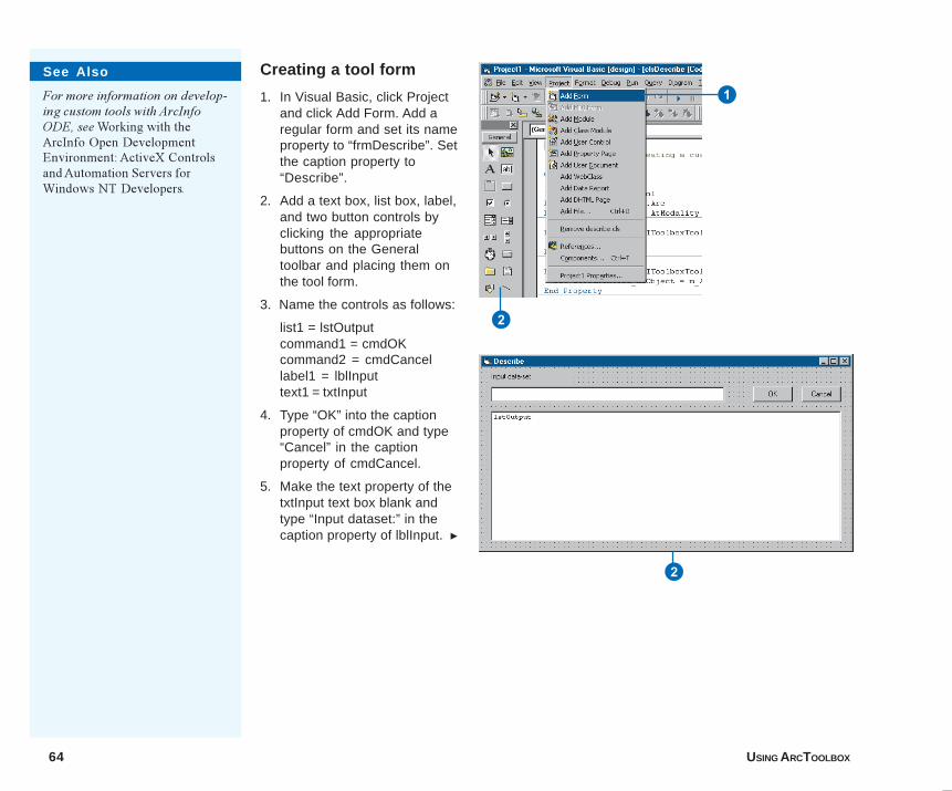
64 USING ARCTOOLBOX
Creating a tool form
1. In Visual Basic, click Projectand click Add Form. Add aregular form and set its nameproperty to “frmDescribe”. Setthe caption property to“Describe”.
2. Add a text box, list box, label,and two button controls byclicking the appropriatebuttons on the Generaltoolbar and placing them onthe tool form.
3. Name the controls as follows:
list1 = lstOutputcommand1 = cmdOKcommand2 = cmdCancellabel1 = lblInputtext1 = txtInput
4. Type “OK” into the captionproperty of cmdOK and type“Cancel” in the captionproperty of cmdCancel.
5. Make the text property of thetxtInput text box blank andtype “Input dataset:” in thecaption property of lblInput. u
See Also
For more information on develop-ing custom tools with ArcInfoODE, see Working with theArcInfo Open DevelopmentEnvironment: ActiveX Controlsand Automation Servers forWindows NT Developers.
2
1
2
06Ch05.p65 11/29/2000, 3:50 PM64
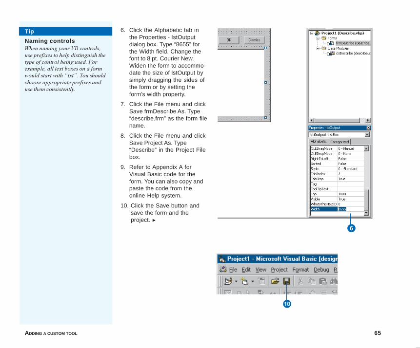
ADDING A CUSTOM TOOL 65
6. Click the Alphabetic tab inthe Properties - IstOutputdialog box. Type “8655” forthe Width field. Change thefont to 8 pt. Courier New.Widen the form to accommo-date the size of lstOutput bysimply dragging the sides ofthe form or by setting theform’s width property.
7. Click the File menu and clickSave frmDescribe As. Type“describe.frm” as the form filename.
8. Click the File menu and clickSave Project As. Type“Describe” in the Project Filebox.
9. Refer to Appendix A forVisual Basic code for theform. You can also copy andpaste the code from theonline Help system.
10. Click the Save button andsave the form and theproject. u
Tip
Naming controlsWhen naming your VB controls,use prefixes to help distinguish thetype of control being used. Forexample, all text boxes on a formwould start with �txt�. You shouldchoose appropriate prefixes anduse them consistently.
6
Q
06Ch05.p65 11/29/2000, 3:50 PM65
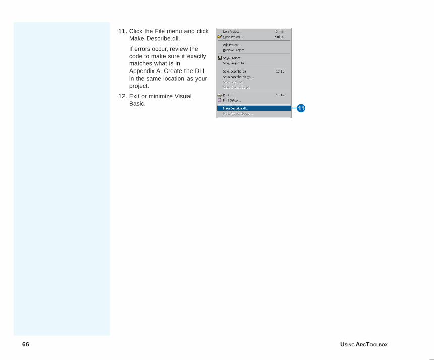
66 USING ARCTOOLBOX
11. Click the File menu and clickMake Describe.dll.
If errors occur, review thecode to make sure it exactlymatches what is inAppendix A. Create the DLLin the same location as yourproject.
12. Exit or minimize VisualBasic.
W
06Ch05.p65 11/29/2000, 3:50 PM66
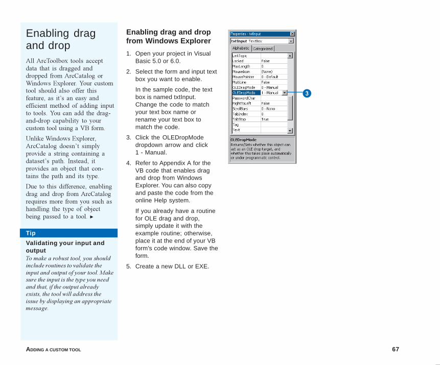
ADDING A CUSTOM TOOL 67
Tip
Validating your input andoutputTo make a robust tool, you shouldinclude routines to validate theinput and output of your tool. Makesure the input is the type you needand that, if the output alreadyexists, the tool will address theissue by displaying an appropriatemessage.
Enabling dragand dropAll ArcToolbox tools acceptdata that is dragged anddropped from ArcCatalog orWindows Explorer. Your customtool should also offer thisfeature, as it�s an easy andefficient method of adding inputto tools. You can add the drag-and-drop capability to yourcustom tool using a VB form.
Unlike Windows Explorer,ArcCatalog doesn�t simplyprovide a string containing adataset�s path. Instead, itprovides an object that con-tains the path and its type.
Due to this difference, enablingdrag and drop from ArcCatalogrequires more from you such ashandling the type of objectbeing passed to a tool. u
Enabling drag and dropfrom Windows Explorer
1. Open your project in VisualBasic 5.0 or 6.0.
2. Select the form and input textbox you want to enable.
In the sample code, the textbox is named txtInput.Change the code to matchyour text box name orrename your text box tomatch the code.
3. Click the OLEDropModedropdown arrow and click1 - Manual.
4. Refer to Appendix A for theVB code that enables dragand drop from WindowsExplorer. You can also copyand paste the code from theonline Help system.
If you already have a routinefor OLE drag and drop,simply update it with theexample routine; otherwise,place it at the end of your VBform’s code window. Save theform.
5. Create a new DLL or EXE.
3
06Ch05.p65 11/29/2000, 3:50 PM67
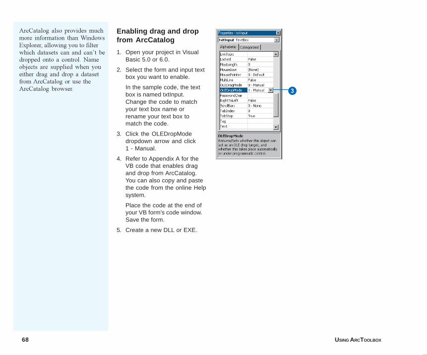
68 USING ARCTOOLBOX
Enabling drag and dropfrom ArcCatalog
1. Open your project in VisualBasic 5.0 or 6.0.
2. Select the form and input textbox you want to enable.
In the sample code, the textbox is named txtInput.Change the code to matchyour text box name orrename your text box tomatch the code.
3. Click the OLEDropModedropdown arrow and click1 - Manual.
4. Refer to Appendix A for theVB code that enables dragand drop from ArcCatalog.You can also copy and pastethe code from the online Helpsystem.
Place the code at the end ofyour VB form’s code window.Save the form.
5. Create a new DLL or EXE.
3
ArcCatalog also provides muchmore information than WindowsExplorer, allowing you to filterwhich datasets can and can�t bedropped onto a control. Nameobjects are supplied when youeither drag and drop a datasetfrom ArcCatalog or use theArcCatalog browser.
06Ch05.p65 11/29/2000, 3:50 PM68
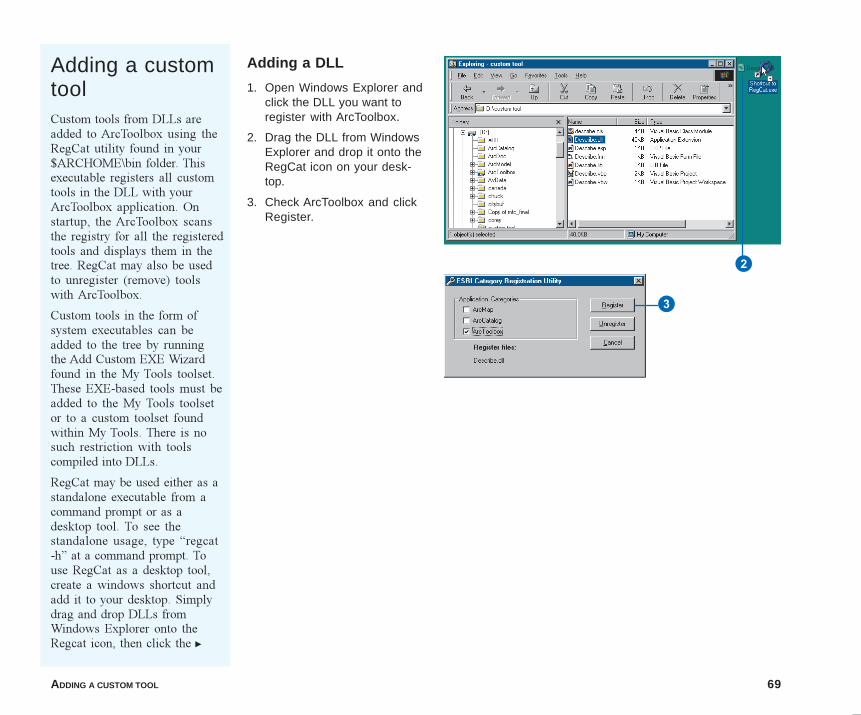
ADDING A CUSTOM TOOL 69
Adding a customtoolCustom tools from DLLs areadded to ArcToolbox using theRegCat utility found in your$ARCHOME\bin folder. Thisexecutable registers all customtools in the DLL with yourArcToolbox application. Onstartup, the ArcToolbox scansthe registry for all the registeredtools and displays them in thetree. RegCat may also be usedto unregister (remove) toolswith ArcToolbox.
Custom tools in the form ofsystem executables can beadded to the tree by runningthe Add Custom EXE Wizardfound in the My Tools toolset.These EXE-based tools must beadded to the My Tools toolsetor to a custom toolset foundwithin My Tools. There is nosuch restriction with toolscompiled into DLLs.
RegCat may be used either as astandalone executable from acommand prompt or as adesktop tool. To see thestandalone usage, type �regcat-h� at a command prompt. Touse RegCat as a desktop tool,create a windows shortcut andadd it to your desktop. Simplydrag and drop DLLs fromWindows Explorer onto theRegcat icon, then click the u
Adding a DLL
1. Open Windows Explorer andclick the DLL you want toregister with ArcToolbox.
2. Drag the DLL from WindowsExplorer and drop it onto theRegCat icon on your desk-top.
3. Check ArcToolbox and clickRegister.
2
3
06Ch05.p65 11/29/2000, 3:51 PM69
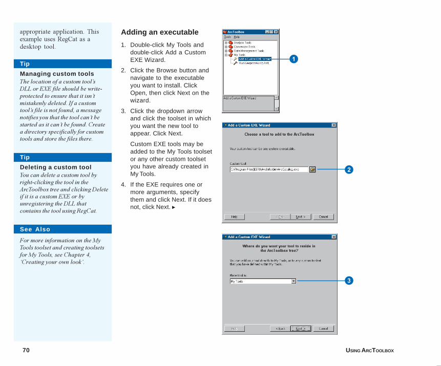
70 USING ARCTOOLBOX
Tip
Managing custom toolsThe location of a custom tool�sDLL or EXE file should be write-protected to ensure that it isn�tmistakenly deleted. If a customtool�s file is not found, a messagenotifies you that the tool can�t bestarted as it can�t be found. Createa directory specifically for customtools and store the files there.
Adding an executable
1. Double-click My Tools anddouble-click Add a CustomEXE Wizard.
2. Click the Browse button andnavigate to the executableyou want to install. ClickOpen, then click Next on thewizard.
3. Click the dropdown arrowand click the toolset in whichyou want the new tool toappear. Click Next.
Custom EXE tools may beadded to the My Tools toolsetor any other custom toolsetyou have already created inMy Tools.
4. If the EXE requires one ormore arguments, specifythem and click Next. If it doesnot, click Next. u
Tip
Deleting a custom toolYou can delete a custom tool byright-clicking the tool in theArcToolbox tree and clicking Deleteif it is a custom EXE or byunregistering the DLL thatcontains the tool using RegCat.
1
2
3
See Also
For more information on the MyTools toolset and creating toolsetsfor My Tools, see Chapter 4,�Creating your own look�.
appropriate application. Thisexample uses RegCat as adesktop tool.
06Ch05.p65 11/29/2000, 3:51 PM70
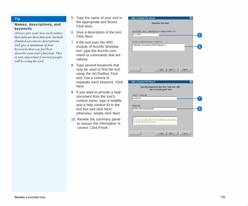
ADDING A CUSTOM TOOL 71
Tip
Names, descriptions, andkeywordsAlways give your new tools namesthat indicate their function. Includedetailed yet concise descriptionsand give a minimum of fourkeywords that you feel bestdescribe your tool�s function. Thisis very important if several peoplewill be using the tool.
7
8
5. Type the name of your tool inthe appropriate text boxes.Click Next.
6. Give a description of the tool.Click Next.
7. If the tool uses the ARCmodule of ArcInfo Worksta-tion, type the ArcInfo com-mand or commands that areutilized.
8. Type several keywords thatmay be used to find the toolusing the ArcToolbox Findtool. Use a comma toseparate each keyword. ClickNext.
9. If you want to provide a helpdocument from the tool’scontext menu, type a helpfileand a help context ID in thetext box and click Next;otherwise, simply click Next.
10. Review the summary panelto ensure the information iscorrect. Click Finish.
5
6Manages and previews all ESRI datasets.
06Ch05.p65 12/18/2000, 10:57 AM71

06Ch05.p65 11/29/2000, 3:51 PM72
IN THIS APPENDIX
73
Appendix
• VB code for a custom tool class
• VB code for a custom tool form
• Enabling drag and drop in a textbox for ArcCatalog
• Enabling drag and drop in a textbox for Windows Explorer
The Visual Basic samples found in this appendix are also available in the�Adding custom tools� section of the ArcToolbox online Help system. Usethose samples for copying and pasting into Visual Basic.
A
07AppA.p65 12/18/2000, 10:36 AM 73
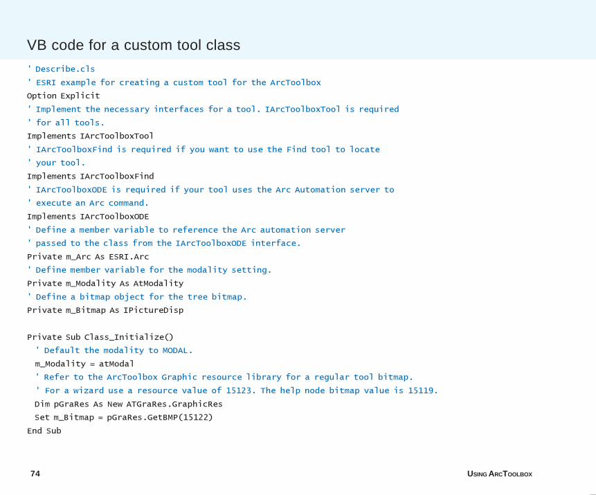
74 USING ARCTOOLBOX
' Describe.cls
' ESRI example for creating a custom tool for the ArcToolbox
Option Explicit
' Implement the necessary interfaces for a tool. IArcToolboxTool is required
' for all tools.
Implements IArcToolboxTool
' IArcToolboxFind is required if you want to use the Find tool to locate
' your tool.
Implements IArcToolboxFind
' IArcToolboxODE is required if your tool uses the Arc Automation server to
' execute an Arc command.
Implements IArcToolboxODE
' Define a member variable to reference the Arc automation server
' passed to the class from the IArcToolboxODE interface.
Private m_Arc As ESRI.Arc
' Define member variable for the modality setting.
Private m_Modality As AtModality
' Define a bitmap object for the tree bitmap.
Private m_Bitmap As IPictureDisp
Private Sub Class_Initialize()
' Default the modality to MODAL.
m_Modality = atModal
' Refer to the ArcToolbox Graphic resource library for a regular tool bitmap.
' For a wizard use a resource value of 15123. The help node bitmap value is 15119.
Dim pGraRes As New ATGraRes.GraphicRes
Set m_Bitmap = pGraRes.GetBMP(15122)
End Sub
VB code for a custom tool class
07AppA.p65 11/29/2000, 3:52 PM74
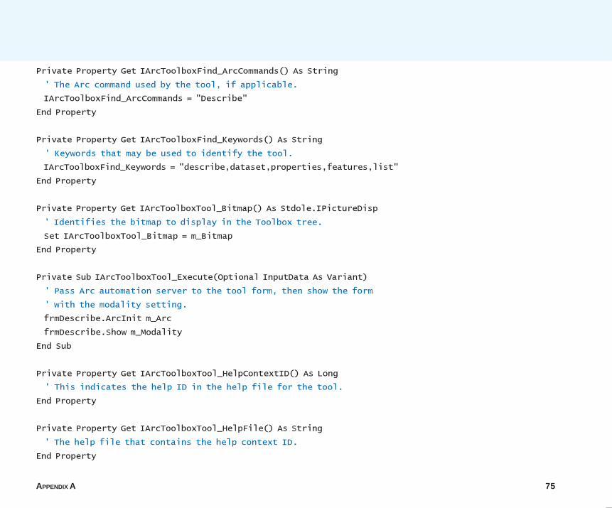
APPENDIX A 75
Private Property Get IArcToolboxFind_ArcCommands() As String
' The Arc command used by the tool, if applicable.
IArcToolboxFind_ArcCommands = "Describe"
End Property
Private Property Get IArcToolboxFind_Keywords() As String
' Keywords that may be used to identify the tool.
IArcToolboxFind_Keywords = "describe,dataset,properties,features,list"
End Property
Private Property Get IArcToolboxTool_Bitmap() As Stdole.IPictureDisp
' Identifies the bitmap to display in the Toolbox tree.
Set IArcToolboxTool_Bitmap = m_Bitmap
End Property
Private Sub IArcToolboxTool_Execute(Optional InputData As Variant)
' Pass Arc automation server to the tool form, then show the form
' with the modality setting.
frmDescribe.ArcInit m_Arc
frmDescribe.Show m_Modality
End Sub
Private Property Get IArcToolboxTool_HelpContextID() As Long
' This indicates the help ID in the help file for the tool.
End Property
Private Property Get IArcToolboxTool_HelpFile() As String
' The help file that contains the help context ID.
End Property
07AppA.p65 11/29/2000, 3:52 PM75
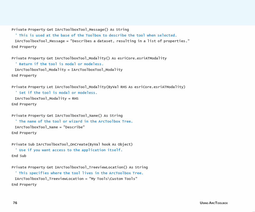
76 USING ARCTOOLBOX
Private Property Get IArcToolboxTool_Message() As String
' This is used at the base of the Toolbox to describe the tool when selected.
IArcToolboxTool_Message = "Describes a dataset, resulting in a list of properties."
End Property
Private Property Get IArcToolboxTool_Modality() As esriCore.esriATModality
' Return if the tool is modal or modeless.
IArcToolboxTool_Modality = IArcToolboxTool_Modality
End Property
Private Property Let IArcToolboxTool_Modality(ByVal RHS As esriCore.esriATModality)
' Set if the tool is modal or modeless.
IArcToolboxTool_Modality = RHS
End Property
Private Property Get IArcToolboxTool_Name() As String
' The name of the tool or wizard in the ArcToolbox Tree.
IArcToolboxTool_Name = "Describe"
End Property
Private Sub IArcToolboxTool_OnCreate(ByVal hook As Object)
' Use if you want access to the application itself.
End Sub
Private Property Get IArcToolboxTool_TreeviewLocation() As String
' This specifies where the tool lives in the ArcToolbox Tree.
IArcToolboxTool_TreeviewLocation = "My Tools\Custom Tools"
End Property
07AppA.p65 11/29/2000, 3:52 PM76
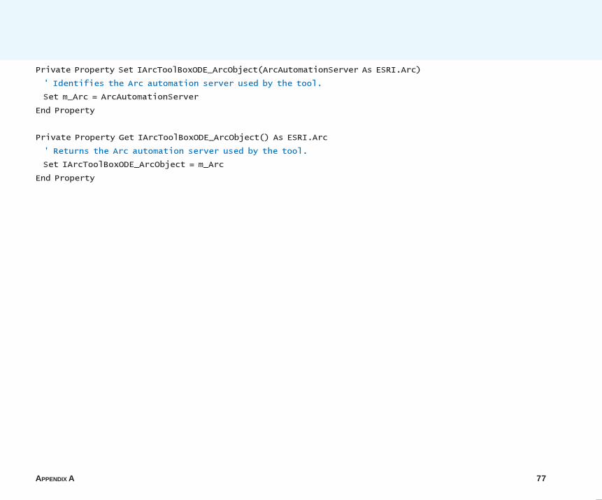
APPENDIX A 77
Private Property Set IArcToolBoxODE_ArcObject(ArcAutomationServer As ESRI.Arc)
' Identifies the Arc automation server used by the tool.
Set m_Arc = ArcAutomationServer
End Property
Private Property Get IArcToolBoxODE_ArcObject() As ESRI.Arc
' Returns the Arc automation server used by the tool.
Set IArcToolBoxODE_ArcObject = m_Arc
End Property
07AppA.p65 11/29/2000, 3:52 PM77
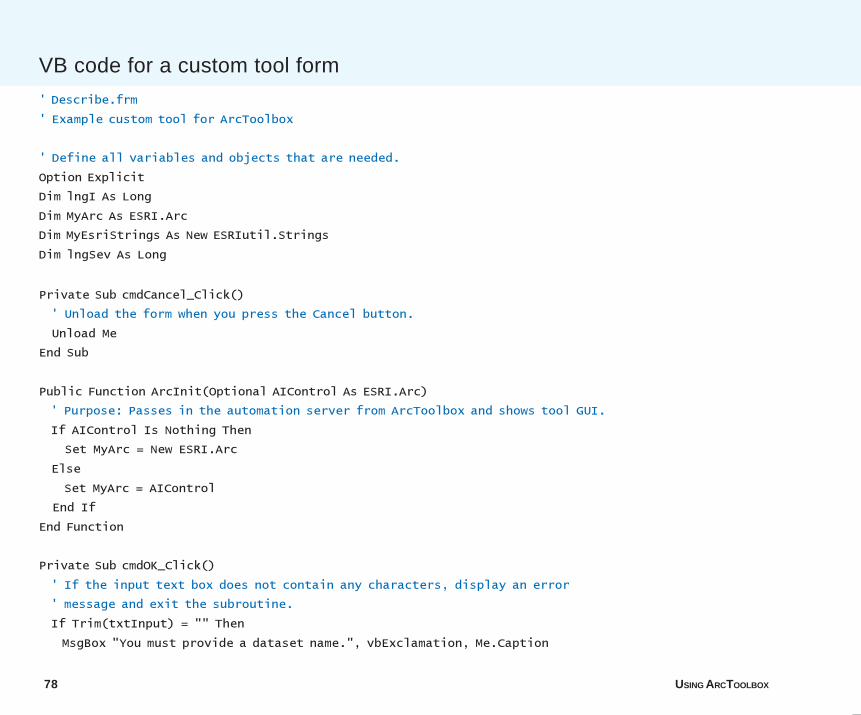
78 USING ARCTOOLBOX
' Describe.frm
' Example custom tool for ArcToolbox
' Define all variables and objects that are needed.
Option Explicit
Dim lngI As Long
Dim MyArc As ESRI.Arc
Dim MyEsriStrings As New ESRIutil.Strings
Dim lngSev As Long
Private Sub cmdCancel_Click()
' Unload the form when you press the Cancel button.
Unload Me
End Sub
Public Function ArcInit(Optional AIControl As ESRI.Arc)
' Purpose: Passes in the automation server from ArcToolbox and shows tool GUI.
If AIControl Is Nothing Then
Set MyArc = New ESRI.Arc
Else
Set MyArc = AIControl
End If
End Function
Private Sub cmdOK_Click()
' If the input text box does not contain any characters, display an error
' message and exit the subroutine.
If Trim(txtInput) = "" Then
MsgBox "You must provide a dataset name.", vbExclamation, Me.Caption
VB code for a custom tool form
07AppA.p65 11/29/2000, 3:52 PM78
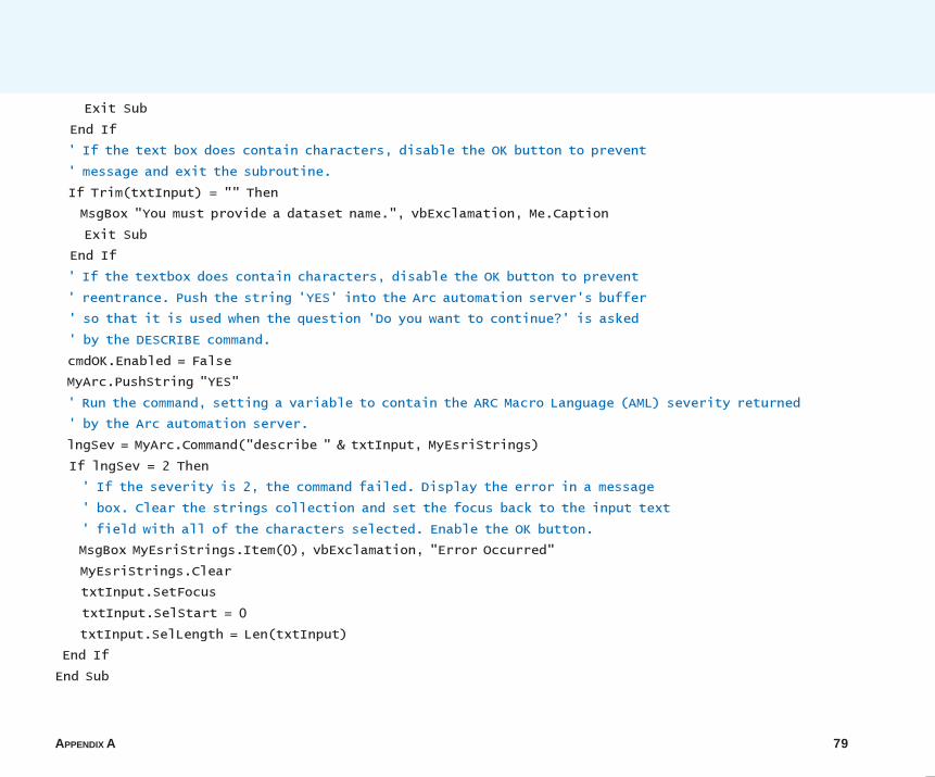
APPENDIX A 79
Exit Sub
End If
' If the text box does contain characters, disable the OK button to prevent
' message and exit the subroutine.
If Trim(txtInput) = "" Then
MsgBox "You must provide a dataset name.", vbExclamation, Me.Caption
Exit Sub
End If
' If the textbox does contain characters, disable the OK button to prevent
' reentrance. Push the string 'YES' into the Arc automation server's buffer
' so that it is used when the question 'Do you want to continue?' is asked
' by the DESCRIBE command.
cmdOK.Enabled = False
MyArc.PushString "YES"
' Run the command, setting a variable to contain the ARC Macro Language (AML) severity returned
' by the Arc automation server.
lngSev = MyArc.Command("describe " & txtInput, MyEsriStrings)
If lngSev = 2 Then
' If the severity is 2, the command failed. Display the error in a message
' box. Clear the strings collection and set the focus back to the input text
' field with all of the characters selected. Enable the OK button.
MsgBox MyEsriStrings.Item(0), vbExclamation, "Error Occurred"
MyEsriStrings.Clear
txtInput.SetFocus
txtInput.SelStart = 0
txtInput.SelLength = Len(txtInput)
End If
End Sub
07AppA.p65 11/29/2000, 3:52 PM79
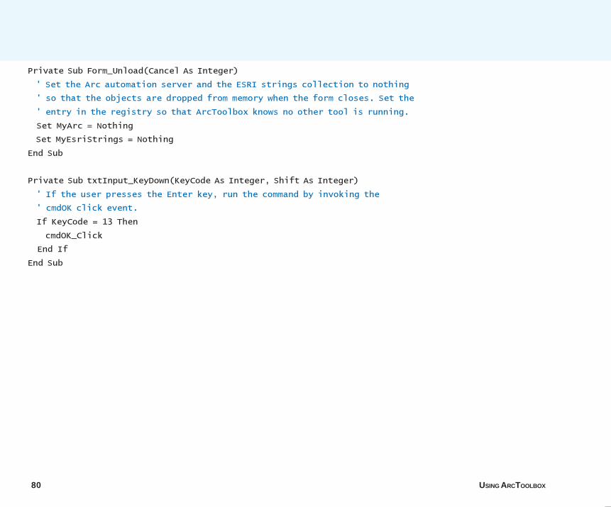
80 USING ARCTOOLBOX
Private Sub Form_Unload(Cancel As Integer)
' Set the Arc automation server and the ESRI strings collection to nothing
' so that the objects are dropped from memory when the form closes. Set the
' entry in the registry so that ArcToolbox knows no other tool is running.
Set MyArc = Nothing
Set MyEsriStrings = Nothing
End Sub
Private Sub txtInput_KeyDown(KeyCode As Integer, Shift As Integer)
' If the user presses the Enter key, run the command by invoking the
' cmdOK click event.
If KeyCode = 13 Then
cmdOK_Click
End If
End Sub
07AppA.p65 11/29/2000, 3:52 PM80
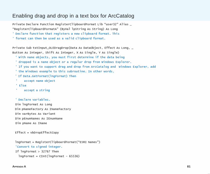
APPENDIX A 81
Private Declare Function RegisterClipboardFormat Lib �user32� Alias _
�RegisterClipboardFormatA� (ByVal lpString As String) As Long
' Declare function that registers a new clipboard format. This
' format can then be used as a valid clipboard format.
Private Sub txtInput_OLEDragDrop(Data As DataObject, Effect As Long, _
Button As Integer, Shift As Integer, X As Single, Y As Single)
' With name objects, you must first determine if the data being
' dropped is a name object or a regular drop from Windows Explorer.
' If you want to support drag and drop from ArcCatalog and Windows Explorer, add
' the Windows example to this subroutine. In other words,
' If Data.GetFormat(lngFormat) Then
' accept name object
' Else
' accept a string
' Declare variables.
Dim lngFormat As Long
Dim pNameFactory As INameFactory
Dim varBytes As Variant
Dim pEnumNames As IEnumName
Dim pName As IName
Effect = vbDropEffectCopy
lngFormat = RegisterClipboardFormat(�ESRI Names�)
'Convert to signed integer.
If lngFormat > 32767 Then
lngFormat = CInt(lngFormat - 65536)
Enabling drag and drop in a text box for ArcCatalog
07AppA.p65 11/29/2000, 3:52 PM81
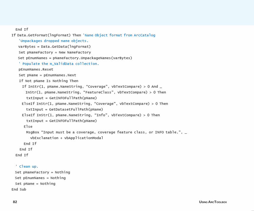
82 USING ARCTOOLBOX
End If
If Data.GetFormat(lngFormat) Then 'Name Object format from ArcCatalog
'Unpackages dropped name objects.
varBytes = Data.GetData(lngFormat)
Set pNameFactory = New NameFactory
Set pEnumNames = pNameFactory.UnpackageNames(varBytes)
' Populate the m_ValidData collection.
pEnumNames.Reset
Set pName = pEnumNames.Next
If Not pName Is Nothing Then
If InStr(1, pName.NameString, �Coverage�, vbTextCompare) > 0 And _
InStr(1, pName.NameString, �FeatureClass�, vbTextCompare) > 0 Then
txtInput = GetINFOFullPath(pName)
ElseIf InStr(1, pName.NameString, �Coverage�, vbTextCompare) > 0 Then
txtInput = GetDatasetFullPath(pName)
ElseIf InStr(1, pName.NameString, �Info�, vbTextCompare) > 0 Then
txtInput = GetINFOFullPath(pName)
Else
MsgBox �Input must be a coverage, coverage feature class, or INFO table.�, _
vbExclamation + vbApplicationModal
End If
End If
End If
' Clean up.
Set pNameFactory = Nothing
Set pEnumNames = Nothing
Set pName = Nothing
End Sub
07AppA.p65 11/29/2000, 3:52 PM82
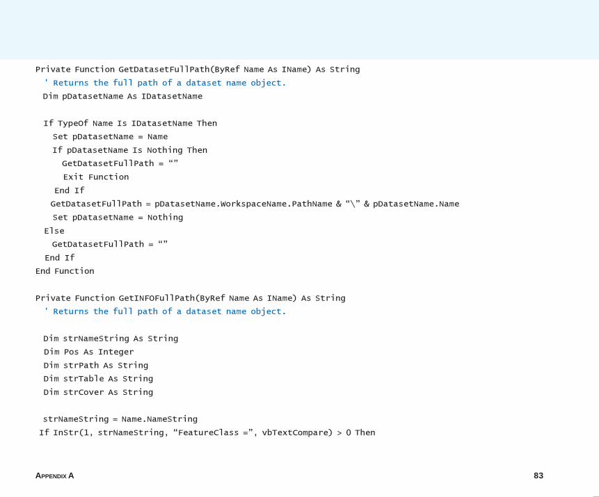
APPENDIX A 83
Private Function GetDatasetFullPath(ByRef Name As IName) As String
' Returns the full path of a dataset name object.
Dim pDatasetName As IDatasetName
If TypeOf Name Is IDatasetName Then
Set pDatasetName = Name
If pDatasetName Is Nothing Then
GetDatasetFullPath = ��
Exit Function
End If
GetDatasetFullPath = pDatasetName.WorkspaceName.PathName & �\� & pDatasetName.Name
Set pDatasetName = Nothing
Else
GetDatasetFullPath = ��
End If
End Function
Private Function GetINFOFullPath(ByRef Name As IName) As String
' Returns the full path of a dataset name object.
Dim strNameString As String
Dim Pos As Integer
Dim strPath As String
Dim strTable As String
Dim strCover As String
strNameString = Name.NameString
If InStr(1, strNameString, �FeatureClass =�, vbTextCompare) > 0 Then
07AppA.p65 11/29/2000, 3:52 PM83
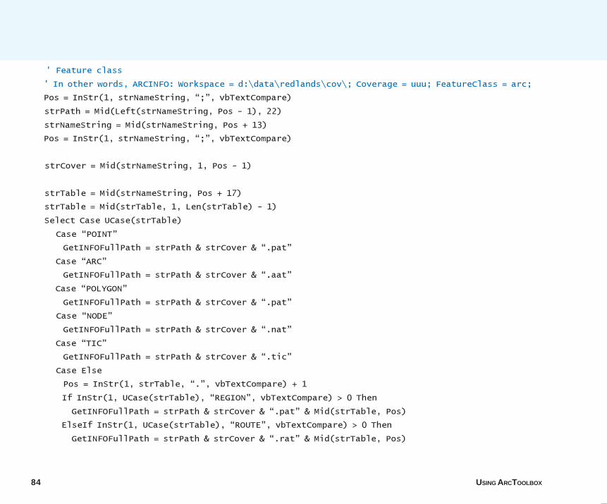
84 USING ARCTOOLBOX
' Feature class
' In other words, ARCINFO: Workspace = d:\data\redlands\cov\; Coverage = uuu; FeatureClass = arc;
Pos = InStr(1, strNameString, �;�, vbTextCompare)
strPath = Mid(Left(strNameString, Pos - 1), 22)
strNameString = Mid(strNameString, Pos + 13)
Pos = InStr(1, strNameString, �;�, vbTextCompare)
strCover = Mid(strNameString, 1, Pos - 1)
strTable = Mid(strNameString, Pos + 17)
strTable = Mid(strTable, 1, Len(strTable) - 1)
Select Case UCase(strTable)
Case �POINT�
GetINFOFullPath = strPath & strCover & �.pat�
Case �ARC�
GetINFOFullPath = strPath & strCover & �.aat�
Case �POLYGON�
GetINFOFullPath = strPath & strCover & �.pat�
Case �NODE�
GetINFOFullPath = strPath & strCover & �.nat�
Case �TIC�
GetINFOFullPath = strPath & strCover & �.tic�
Case Else
Pos = InStr(1, strTable, �.�, vbTextCompare) + 1
If InStr(1, UCase(strTable), �REGION�, vbTextCompare) > 0 Then
GetINFOFullPath = strPath & strCover & �.pat� & Mid(strTable, Pos)
ElseIf InStr(1, UCase(strTable), �ROUTE�, vbTextCompare) > 0 Then
GetINFOFullPath = strPath & strCover & �.rat� & Mid(strTable, Pos)
07AppA.p65 11/29/2000, 3:52 PM84
APPENDIX A 85
ElseIf InStr(1, UCase(strTable), �SECTION�, vbTextCompare) > 0 Then
GetINFOFullPath = strPath & strCover & �.sec� & Mid(strTable, Pos)
ElseIf InStr(1, UCase(strTable), �ANNOTATION�, vbTextCompare) > 0 Then
GetINFOFullPath = strPath & strCover & �.tat� & Mid(strTable, Pos)
Else
GetINFOFullPath = ��
End If
End Select
ElseIf InStr(1, strNameString, �InfoTable =�, vbTextCompare) > 0 Then
' Standalone INFO table.
' In other words, ARCINFO: Workspace = d:\data\redlands\cov; InfoTable = monk1.add;
Pos = InStr(1, strNameString, �;�, vbTextCompare)
strPath = Mid(Left(strNameString, Pos - 1), 22)
Pos = InStr(1, strNameString, �;�, vbTextCompare)
strTable = Mid(strNameString, Pos + 14)
strTable = Mid(strTable, 1, Len(strTable) - 1)
GetINFOFullPath = strPath & �\� & strTable
Else
GetINFOFullPath = ��
End If
End Function
07AppA.p65 11/29/2000, 3:52 PM85
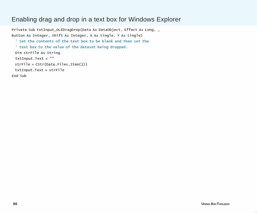
86 USING ARCTOOLBOX
Private Sub txtInput_OLEDragDrop(Data As DataObject, Effect As Long, _
Button As Integer, Shift As Integer, X As Single, Y As Single)
' Set the contents of the text box to be blank and then set the
' text box to the value of the dataset being dropped.
Dim strFile As String
txtInput.Text = ""
strFile = CStr(Data.Files.Item(1))
txtInput.Text = strFile
End Sub
Enabling drag and drop in a text box for Windows Explorer
07AppA.p65 11/29/2000, 3:52 PM86
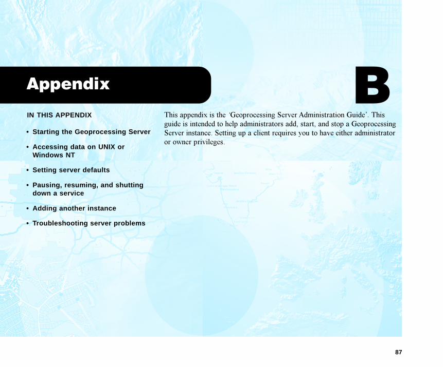
87
IN THIS APPENDIX
• Starting the Geoprocessing Server
• Accessing data on UNIX orWindows NT
• Setting server defaults
• Pausing, resuming, and shuttingdown a service
• Adding another instance
• Troubleshooting server problems
Appendix
This appendix is the �Geoprocessing Server Administration Guide�. Thisguide is intended to help administrators add, start, and stop a GeoprocessingServer instance. Setting up a client requires you to have either administratoror owner privileges.
B
08AppB.p65 12/18/2000, 10:38 AM 87
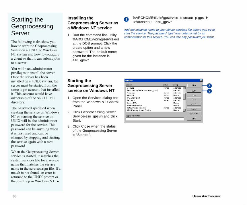
88 USING ARCTOOLBOX
Starting theGeoprocessingServerThe following tasks show youhow to start the GeoprocessingServer on a UNIX or WindowsNT system and how to configurea client so that it can submit jobsto a server.
You will need administratorprivileges to install the server.Once the server has beeninstalled on a UNIX system, theserver must be started from thesame login account that installedit. This account would haveownership of the ARCHOMEdirectory.
The password specified whencreating the service on WindowsNT or starting the service onUNIX will be the administratorpassword for the service. Thispassword can be anything whenit is first used and can bechanged by stopping and startingthe service again with a newpassword.
When the Geoprocessing Serverservice is started, it searches thesystem services file for a servicename that matches the servicename in the services.rqm file. If amatch is not found, an error isreturned to the UNIX prompt orthe event log in Windows NT. u
Installing theGeoprocessing Server asa Windows NT service
1. Run the command line utility%ARCHOME%\bin\gpservice.exeat the DOS prompt. Click thecreate option and a newpassword. The default namegiven for the instance isesri_gpsvr.
Starting theGeoprocessing Serverservice on Windows NT
1. Open the Services dialog boxfrom the Windows NT ControlPanel.
2. Click Geoprocessing ServerService(esri_gpsvr) and clickStart.
3. Click Close when the statusof the Geoprocessing Serveris “Started”.
1%ARCHOME%\bin\gpservice -o create -p gps -HD:\arcexe80 -i esri_gpsvr
Add the instance name to your server services file before you try tostart the service. The password “gps” was determined by anadministrator for this service. You can use any password you want.
32
08AppB.p65 11/30/2000, 11:46 AM88
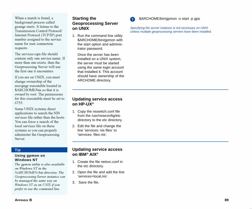
APPENDIX B 89
Starting theGeoprocessing Serveron UNIX
1. Run the command line utility$ARCHOME/bin/gpmon withthe start option and adminis-trator password.
Once the server has beeninstalled on a UNIX system,the server must be startedusing the same login accountthat installed it. This accountshould have ownership of theARCHOME directory.
Updating service accesson HP-UX®
1. Copy the nsswitch.conf filefrom the /usr/newconfig/etcdirectory to the etc directory.
2. Edit the file and change theline ‘services: nis files’ to‘services: files nis’.
Updating service accesson IBM ® AIX®
1. Create the file netsvc.conf inthe etc directory.
2. Open the file and add the line‘services=local,nis’.
3. Save the file.
1 $ARCHOME/bin/gpmon -o start -p gpsWhen a match is found, abackground process calledgiomgr starts. It listens to theTransmission Control Protocol/Internet Protocol (TCP/IP) portnumber assigned to the servicename for user connectionrequests.
The services.rqm file shouldcontain only one service name. Ifmore than one exists, then theGeoprocessing Server will usethe first one it encounters.
If you are on UNIX, you mustchange ownership of thearcrqmgr executable located in$ARCHOME/bin so that it isowned by root. The permissionsfor this executable must be set to6755.
Some UNIX systems directapplications to search the NISservices file rather than the hosts.You can force a search of thelocal services file on thesesystems so you can properlyadminister the GeoprocessingServer.
Specifying the server instance is not necessary on UNIXunless multiple geoprocessing servers have been installed.
Tip
Using gpmon onWindows NTThe gpmon utility is also availableon Windows NT in the%ARCHOME%\bin directory. TheGeoprocessing Server instance canbe managed the same way onWindows NT as on UNIX if youprefer to use the command line.
08AppB.p65 11/30/2000, 11:46 AM89
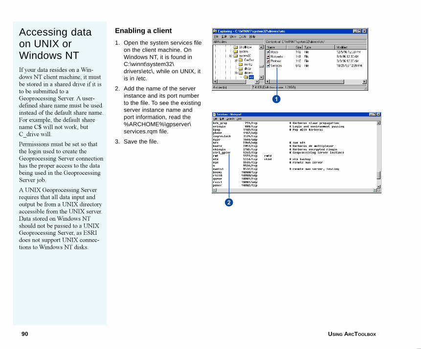
90 USING ARCTOOLBOX
Enabling a client
1. Open the system services fileon the client machine. OnWindows NT, it is found inC:\winnt\system32\drivers\etc\, while on UNIX, itis in /etc.
2. Add the name of the serverinstance and its port numberto the file. To see the existingserver instance name andport information, read the%ARCHOME%\gpserver\services.rqm file.
3. Save the file.
Accessing dataon UNIX orWindows NTIf your data resides on a Win-dows NT client machine, it mustbe stored in a shared drive if it isto be submitted to aGeoprocessing Server. A user-defined share name must be usedinstead of the default share name.For example, the default sharename C$ will not work, butC_drive will.
Permissions must be set so thatthe login used to create theGeoprocessing Server connectionhas the proper access to the databeing used in the GeoprocessingServer job.
A UNIX Geoprocessing Serverrequires that all data input andoutput be from a UNIX directoryaccessible from the UNIX server.Data stored on Windows NTshould not be passed to a UNIXGeoprocessing Server, as ESRIdoes not support UNIX connec-tions to Windows NT disks.
2
1
08AppB.p65 11/30/2000, 11:46 AM90
APPENDIX B 91
Setting serverdefaultsAs a Geoprocessing Serveradministrator, you can set themaximum number of requeststhat can be managed by theserver at one time. You can alsolimit the number of serverprocesses that can be activated.By setting the maximum numberof processes, you can controlhow many jobs are executedconcurrently by the server.
A Geoprocessing Server onlyuses one license at a time,regardless of the number of jobsbeing processed. If a license isnot available, requests are placedin a queue until a licensebecomes available. The queueoperates on a first in, first outrule. Administrators can list orupdate the contents of the queueusing the gpmon utility.
The allowable time difference inseconds, which is the maximumdifference a client�s clock candeviate from the server�s clock,can also be set.
A path may be set to a locationwhere temporary disk space isalso available for the server.
Setting the maximumnumber of requests
1. Open the rqmgr.defs filelocated in $ARCHOME/gpserver.
2. Change the maximumnumber of requests asdesired.
3. Save the file and quit.
Setting the maximumnumber of processes
1. Open the rqmgr.defs filelocated in $ARCHOME/gpserver.
2. Change the maximumnumber of processes asdesired.
3. Save the file and quit.
Setting the maximumtime difference allowed
1. Open the rqmgr.defs filelocated in $ARCHOME/gpserver.
2. Set the maximum client/server time differenceallowed as desired.
3. Save the file and quit.
08AppB.p65 11/30/2000, 11:46 AM91
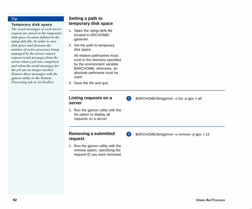
92 USING ARCTOOLBOX
Setting a path totemporary disk space
1. Open the rqmgr.defs filelocated in ARCHOME/gpserver.
2. Set the path to temporarydisk space.
All relative pathnames mustexist in the directory specifiedby the environment variable$ARCHOME; otherwise, anabsolute pathname must beused.
3. Save the file and quit.
Listing requests on aserver
1. Run the gpmon utility with thelist option to display allrequests on a server.
Removing a submittedrequest
1. Run the gpmon utility with theremove option, specifying therequest ID you want removed.
$ARCHOME/bin/gpmon -o list -p gps -t all1
$ARCHOME/bin/gpmon -o remove -p gps -t 13
Tip
Temporary disk spaceThe result messages of each serverrequest are stored in the temporarydisk space location defined in therqmgr.defs file. In order to savedisk space and decrease thenumber of active processes beingmanaged by the server, removerequest result messages from theserver when a job has completedand when the result messages forthe job are no longer needed.Remove these messages with thegpmon utility or the RemoteProcessing tab in ArcToolbox.
1
08AppB.p65 11/30/2000, 11:46 AM92
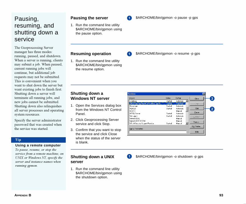
APPENDIX B 93
Pausing,resuming, andshutting down aserviceThe Geoprocessing Servermanager has three modes:running, paused, and shutdown.When a server is running, clientsmay submit a job. When paused,current running jobs willcontinue, but additional jobrequests may not be submitted.This is convenient when youwant to shut down the server butwant existing jobs to finish first.Shutting down a server willterminate all running jobs, andnew jobs cannot be submitted.Shutting down also relinquishesall server processes and operatingsystem resources.
Specify the server administratorpassword that was created whenthe service was started.
Pausing the server
1. Run the command line utility$ARCHOME/bin/gpmon usingthe pause option.
Resuming operation
1. Run the command line utility$ARCHOME/bin/gpmon usingthe resume option.
Shutting down aWindows NT server
1. Open the Services dialog boxfrom the Windows NT ControlPanel.
2. Click Geoprocessing Serverservice and click Stop.
3. Confirm that you want to stopthe service and click Closewhen the status of the serveris blank.
Shutting down a UNIXserver
1. Run the command line utility$ARCHOME/bin/gpmon usingthe shutdown option.
1 $ARCHOME/bin/gpmon -o pause -p gps
$ARCHOME/bin/gpmon -o resume -p gps1
$ARCHOME/bin/gpmon -o shutdown -p gps1
2
3
Tip
Using a remote computerTo pause, resume, or stop theservice from a remote machine, onUNIX or Windows NT, specify theserver and instance names whenrunning gpmon.
08AppB.p65 11/30/2000, 11:46 AM93
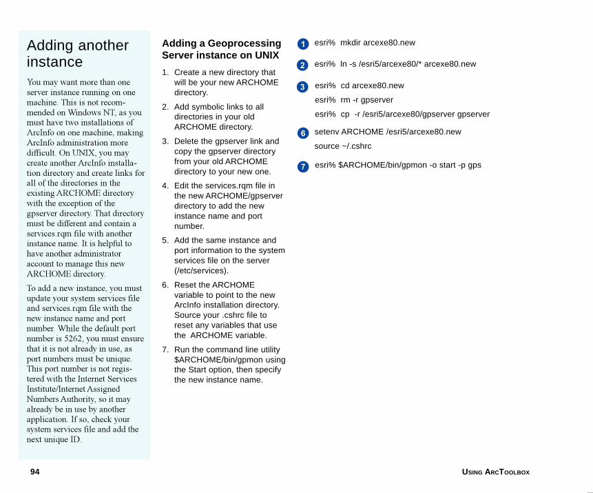
94 USING ARCTOOLBOX
Adding anotherinstanceYou may want more than oneserver instance running on onemachine. This is not recom-mended on Windows NT, as youmust have two installations ofArcInfo on one machine, makingArcInfo administration moredifficult. On UNIX, you maycreate another ArcInfo installa-tion directory and create links forall of the directories in theexisting ARCHOME directorywith the exception of thegpserver directory. That directorymust be different and contain aservices.rqm file with anotherinstance name. It is helpful tohave another administratoraccount to manage this newARCHOME directory.
To add a new instance, you mustupdate your system services fileand services.rqm file with thenew instance name and portnumber. While the default portnumber is 5262, you must ensurethat it is not already in use, asport numbers must be unique.This port number is not regis-tered with the Internet ServicesInstitute/Internet AssignedNumbers Authority, so it mayalready be in use by anotherapplication. If so, check yoursystem services file and add thenext unique ID.
Adding a GeoprocessingServer instance on UNIX
1. Create a new directory thatwill be your new ARCHOMEdirectory.
2. Add symbolic links to alldirectories in your oldARCHOME directory.
3. Delete the gpserver link andcopy the gpserver directoryfrom your old ARCHOMEdirectory to your new one.
4. Edit the services.rqm file inthe new ARCHOME/gpserverdirectory to add the newinstance name and portnumber.
5. Add the same instance andport information to the systemservices file on the server(/etc/services).
6. Reset the ARCHOMEvariable to point to the newArcInfo installation directory.Source your .cshrc file toreset any variables that usethe ARCHOME variable.
7. Run the command line utility$ARCHOME/bin/gpmon usingthe Start option, then specifythe new instance name.
esri% $ARCHOME/bin/gpmon -o start -p gps
1
2
3
esri% mkdir arcexe80.new
esri% ln -s /esri5/arcexe80/* arcexe80.new
esri% cd arcexe80.new
esri% rm -r gpserver
esri% cp -r /esri5/arcexe80/gpserver gpserver
setenv ARCHOME /esri5/arcexe80.new
source ~/.cshrc
7
6
08AppB.p65 11/30/2000, 11:46 AM94
APPENDIX B 95
Troubleshootingserver problemsThe Geoprocessing Server has arequest server error log thatcaptures all of its errors. When acommand fails, consult this logfor helpful information.
Occasionally, you may not beable to shut down an instancedue to hung processes or becausethe instance itself has beencorrupted. These problems mayoccur for various reasons such asa system malfunction. In thiscase, you can use the Killp utilityto stop the instance so you canstart a new one.
You may want to reset the serverso you can start it from itsoriginal state. Doing this willdelete all submitted jobs and allof the results currently residingon the server. Only do this if youare sure this information is notrequired by anyone who previ-ously submitted a job to theserver.
Reading the serverrequest error log
1. Open and read the filerqmgr.err found in%ARCHOME%\gpserver.
Killing the server process
1. Find the process ID of theGeoprocessing Server. Usethe task manager on Win-dows NT or use ‘ps -ef | grepgp’ on UNIX.
2. Run the command line utility%ARCHOME%\gpserver\killpwith the process ID to stopthe server instance.
Resetting the server
1. Stop the server if it is stillrunning (refer to ‘Shuttingdown a Windows NT server’or ‘Shutting down a UNIXserver’, earlier in this appen-dix).
2. Delete the directory with thesame name as the instancein the gpserver directorylocated in ARCHOME.
3. Delete all of the files in thetmp_results and aml directo-ries also located in thegpserver directory.
4. Start the server.
$ARCHOME/gpserver/killp 42702
08AppB.p65 11/30/2000, 11:46 AM95
96 USING ARCTOOLBOX
Common errors
This section outlines the causes and solutions to some errors youmay experience when using the Geoprocessing Server.
Unable to find results of a job submitted to a UNIXserver
I submit a job request to my remote Geoprocessing Server, andthe Remote Processing dialog box states that it is completed.When I review the results of the job, I see something similar tothis:
AML ERROR�unable to run file
line 3 of file /test/temp/arcexe80/gpserver/amls/request9.aml
AML MESSAGE�stopping execution of AML file due toERROR condition
The request9.aml in $ARCHOME/gpserver/amls on the UNIXserver looks like this:
&codepage ANSI
Precision Single Highest
&RUN \\tashi\hippo1\james\sample.aml
Cause:
1. The Geoprocessing Server was unable to find the AML as thedrive /hippo1 was not mounted on the server.
2. The share name set in the NFS software is HIPPODRIVE, butthe mount point of the drive on the UNIXserver is /hippo.
For example, Windows NT sees \\HIPPO\HIPPODRIVE ratherthan \\hippo\hippo1.
Solution:
1. Mount the disk with the AML on it to the UNIX server.
2. Ensure the Windows NT share name and the UNIX disk nameare the same.
When running a job on a UNIX server, the jobcompletes but the results of the job state an AMLerror because the input data does not exist.
Here are the job results:
SET SCHEMAWRITE lock on \\tashi\ashley\data\streams
Coverage \\tashi\ashley\data\streams does not exist
AML MESSAGE�stopping execution of AML due toERROR condition
The AML request ($ARCHOME/gpserver/amls/request2.aml)appears as follows:
&codepage ANSI
LOCKMANAGER \\tashi\ashley\data\streams SETSCHEMAWRITE
Precision single highest
Build \\tashi\ashley\data\streams lines
LOCKMANAGER \\tashi\ashley\data\streams
Cause:
UNIX cannot resolve the pathname. UNIX is looking for the dataat the location of /ashley/data/streams. In reality, the data islocated at /regina/ashley/data/streams. The problem is that whenthe UNIX box was mapped from Windows NT, it was mapped to\\tashi\ashley. The share name ashley was set by the UNIX systemadministrator through an NFS package�in this case it wasSAMBA.
08AppB.p65 11/30/2000, 11:46 AM96
APPENDIX B 97
Solution:
Make sure that the share name is the same as the disk on UNIX.The UNIX administrator needs to make sure that the share nameis the same as the UNIX disk name. In this example, the problemis resolved by mapping \\tashi\regina on Windows NT.
Unable to start the Geoprocessing Server, error1067
The following error is given when gpmon is used to start theserver:
Error 1067: The process terminated unexpectedly
C:\arcexe80\gpserver> gpmon -o start -p gps -i esri_gpsvr
esri_gpsvr service failed during initialization.
Please check event log or error log files.
Error starting esri_gpsvr service(997)
Could not start Geoprocessing Server - Check Network and$ARCHOME disk.
Cause:
The appropriate files or directories were not created in the%ARCHOME%\gpserver directory.
The gpserver directory should contain the following files:
rqmgr.defs, services.rqm
Solution:
Reinstall ArcInfo Workstation to ensure the required files for theGeoprocessing Server exist.
Unable to start the Geoprocessing Server, error2140. An internal Windows NT error occurred.
Solution:
1. Make sure the following directories exist:
%ARCHOME%\gpserver\tmp_results
%ARCHOME%\gpserver\amls exist.
2. Make sure all users sending jobs to the server have full accessto the tmp_results and amls directories.
3. If you still have this problem, make a note of the contents ofthe %ARCHOME%\gpserver\rqmgr.err file and contact ESRITechnical Support.
08AppB.p65 11/30/2000, 11:46 AM97

08AppB.p65 11/30/2000, 11:46 AM98
99
ArcToolbox treeDisplays ArcToolbox toolsets and tools grouped by functionality.
batch mode operationExecutes a given tool two or more times. Includes a utility to save the batch entries as ageoprocessing ARC Macro Language (AML) script and reload the AML for later execution.
batch tableDisplays the input name, user-selected parameters, and output name, where applicable, for all batchentries.
CADSee computer-aided design.
computer-aided designAn automated system for the design, drafting, and display of graphically oriented information.
coverage1. A digital version of a map forming the basic unit of vector data storage in ArcInfo. A coveragestores geographic features as primary features (such as arcs, nodes, polygons, and label points)and secondary features (such as tics, map extent, links, and annotation). Associated featureattribute tables describe and store attributes of the geographic features.
2. A set of thematically associated data considered as a unit. A coverage usually represents a singletheme such as soils, streams, roads, or land use.
custom toolA tool created by a user and added to the ArcToolbox My Tools toolset.
custom toolsetA folder created by a user within the ArcToolbox My Tools toolset to hold custom tools or groupfrequently used ArcToolbox tools.
Glossary
09Glossary.p65 11/29/2000, 3:55 PM99
100 USING ARCTOOLBOX
database management systemA set of computer programs for organizing the information in adatabase. A DBMS supports the structuring of the database in astandard format and provides tools for data input, verification,storage, retrieval, query, and manipulation.
datasetA named collection of logically related data items arranged in aprescribed manner.
DBMSSee database management system.
DLLSee dynamic link library.
dynamic link libraryModules that contain functions and data. A DLL is loaded atruntime by its calling modules (EXE or DLL).
EXESee executable.
executableA program file created from one or more source code filestranslated into machine code and linked together.
exit stateThe condition of a tool upon closure. If a tool fails due to aprogramming bug or command failure, the exit state will be�failed�.
feature class1. A classification describing the format of geographic featuresand supporting data in a coverage. Coverage feature classes forrepresenting geographic features include point, arc, node, route-system, route, section, polygon, and region. One or morecoverage features are used to model geographic features; forexample, arcs and nodes can be used to model linear featuressuch as street centerlines. The tic, annotation, link, and boundaryfeature classes provide supporting data for coverage datamanagement and viewing.
2. The conceptual representation of a geographic feature. Whenreferring to geographic features, feature classes include point,line, area, and surface.
geoprocessingGIS operations such as geographic feature overlay, coverageselection and analysis, topology processing, and dataconversion.
Geoprocessing ServerA UNIX- or Windows NT-operating computer that processesgeoprocessing tasks remotely. It includes a utility to scheduleremote processing.
gridA geographic data model representing information as an array ofequally sized square cells arranged in rows and columns. Eachgrid cell is referenced by its geographic x,y location.
Help nodeA branch in the ArcToolbox tree, providing overview Help forArcToolbox toolsets.
09Glossary.p65 11/29/2000, 3:55 PM100
GLOSSARY 101
jobA task scheduled on a Geoprocessing Server for immediate orlater remote processing. A job can be a single tool or batch modeexecution.
layerA collection of similar geographic features�such as streams,lakes, highways, political boundaries, or wildlife habitats�in aparticular geographic area for display on a map. A layer doesn�tstore geographic data itself, but instead references the datastored in a data source such as a coverage or shapefile. You cancreate and manage layers as you would any other type of data inyour database.
relate managerA utility used to build, modify, save, and delete connections(relates) between tables. Saved connections can be reactivated infuture ArcToolbox sessions.
relational joinThe operation of relating and physically merging two attributetables using their common item.
toolAn entity in ArcToolbox that performs a specific geoprocessingtask such as generalizing lines. A tool can belong to one or moretoolsets.
toolsetA grouping of tools that perform a similar geoprocessing task.Custom toolsets can be created within the My Tools toolset tohold custom tools as well as to group frequently usedArcToolbox tools.
wizardA tool that leads a user step by step through an unusually long,difficult, or complex task.
09Glossary.p65 11/29/2000, 3:55 PM101

09Glossary.p65 11/29/2000, 3:55 PM102
103
12Index A
Accuracy 38ActiveX 63Add tools 58Analysis Tools 29Append Wizard 14Arc automation server 61ARC Macro Language (AML) 30
AML scripts 49creating 46editing 46
ArcCatalog 3dragging and dropping from 44. See also
ArcCatalogLaunch ArcToolbox button 43minibrowser and name objects 68Preview tab 16Standard toolbar 43standard toolbar 9thumbnail images 9. See also ArcCatalogusing name objects 68
arcrqmgr executable 89ArcToolbox tree
customizing 55defined 99described 55
Attribute table values 23
B
Batch job 45Batch mode 44, 45
defined 99Save AML script 46
Batch table 44adding a row 45defined 99deleting rows 47editing 46Save To Script 47
Buffer Wizard 18
C
C++ 61Client desktop 49COM interface
IToolBoxTool 62Connection 9
disk 9folder 9
Context menu 10Conversion Tools 29Coordinate precision 38
creation rule 38processing rule 38setting 39
Coordinate resolution 39Coverage
defined 99described 1
Custom toolsadding 69defined 99described 61enabling drag and drop 67requirements 62Sample VB code 73VB class 63VB form 62, 63
Custom toolset 58adding 59defined 99renaming 58Sample VB code 55
D
Data Management Tools 29Database management system (DBMS)
defined 100described 40
Datasetdefined 100
10Index.p65 11/29/2000, 3:56 PM103
104 USING ARCTOOLBOX
Delphi 61DLL 61, 62Double-precision 38
conditions for using 39Drag and drop 44
enabling 67Dynamic link library (DLL)
defined 100described 61installing as custom tool 69
E
ESRI ArcToolbox Interfaces 63Esri_gpsvr instance 88ESRIUtil automation server 63EXE 61Executable (EXE)
defined 100installing as custom tool 70
Extract Wizard 41
F
Feature attribute tables 40Feature class
defined 100described 14topology 14
Findusing a keyword 32using a name 32using an ArcInfo command 32
Find tool 32
G
Geographic information system (GIS) 1Geoprocessing
defined 100described 1
Geoprocessing Server 8, 49adding an instance 94altering NIS services file 89arcrqmgr executable 89creating a connection 50defined 100editing connection properties 51enabling a client 90getting a job ID 52Jobs tab 52managing processes 91pausing 93request server error log 95resuming 93rqmgr.defs file 91running AML scripts 49scheduling a remote process 53services.rqm 94services.rqm file 88setting a port number 94setting server defaults 91Settings tab 50shutting down 93starting 88starting a service 88stopping a service 93testing connection 51using a shared directory 90
Geoprocessing Server instance 49, 87gpmon 93Gpmon utility 89, 92Gpservice 88Grid
defined 100Grid to Polygon Coverage tool 20
H
Help 34concepts 35Find 35
Help (continued)Help file 34Help node 34Help topic 34Index 35What�s This? button 34
Help node. See also Helpdefined 100described 57turning off 57
I
Input and output 12. See also Sticky pathssticky paths 12
J
Jobdefined 101described 3multiple jobs 45scheduling 53
K
Killp utility 95
L
Layerdefined 101described 9
M
Main toolsets 3, 29My Tools 3
adding a custom toolset 59sending tools to 58
10Index.p65 11/29/2000, 3:56 PM104
INDEX 105
N
Name object 68
O
Open Development Environment(ODE) 4, 63
OptionsPrecision tab 38
Overlay Wizard 22
P
Placing tools on top 60Port number 94PowerBuilder 61Precision environment 38Precision tab 38Processing environment 50Projections 12
Q
Query Builder 16
R
Relate environment 40Relate manager
defined 101described 40
Related files 40Relates 40
opening 42saving 42
Remote Processing. See also GeoprocessingServer
Remote processingdefining a server connection 50getting a job's status 52Jobs tab 52Settings tab 50
Rqmgr.defs file 91
S
Select tool 16Send to 58Services file 94Services.rqm file 88, 94Shared directory 90Significant digits 38Single-precision 38Standard toolbar 9Starting ArcToolbox 28
from the start button 28from the start menu 11from Windows taskbar 28programs menu 28
State Plane 38Statistics tool 24Statistics Wizard 25Sticky paths 12
T
TCP/IP 89Technical support 4Thumbnail button 9Thumbnail images 9Tool 11, 63
creating a custom tool. See also Tooldefined 101described 29finding a tool 32parameters 45size and position 29starting
Tool (continued)starting (continued)
from ArcToolbox tree 31from tool menu 31from tool's context menu 31
Toolset 3defined 101described 29turning off 56
Tutorial 8
U
UTM 38
V
Visual Basic (VB) 4, 61Sample VB code 73VB class 63VB form 63
W
Windows Explorer 67Wizard
defined 101described 11Save to AML 48summary panel 48
www.esri.com 5
10Index.p65 11/29/2000, 3:56 PM105

10Index.p65 12/20/2000, 9:53 AM 106