Embed Size (px)
Citation preview
Using IEC 61850 Analogue GOOSE Messages for OLTC Control of Parallel Transformers
Goran Leci,
Končar-Power Plant and Electric Traction Engineering Inc., Croatia
Zoran Gajić, ABB SA Products, Sweden
Samir Aganović, ABB SA Products, Sweden
Josip Benović, TSO (HEP), Croatia
Sergio Gazzari, ABB Croatia
1. Introduction
2. Parallel control (circulating current method)
3. Automatic tap changer controller (ATCC)
4. Inter IED communication (GOOSE messages)
5. Conclusion
1. Introduction
Automatic voltage control can be either for single transformer or for parallel transfomers
Voltage automatic control function is designed to maintain service voltage at the LV side of a PT within
given limits around a set target voltage Uset
Voltage control function measures the magnitude of the LV side busbar voltage UB and compares it to the Uset
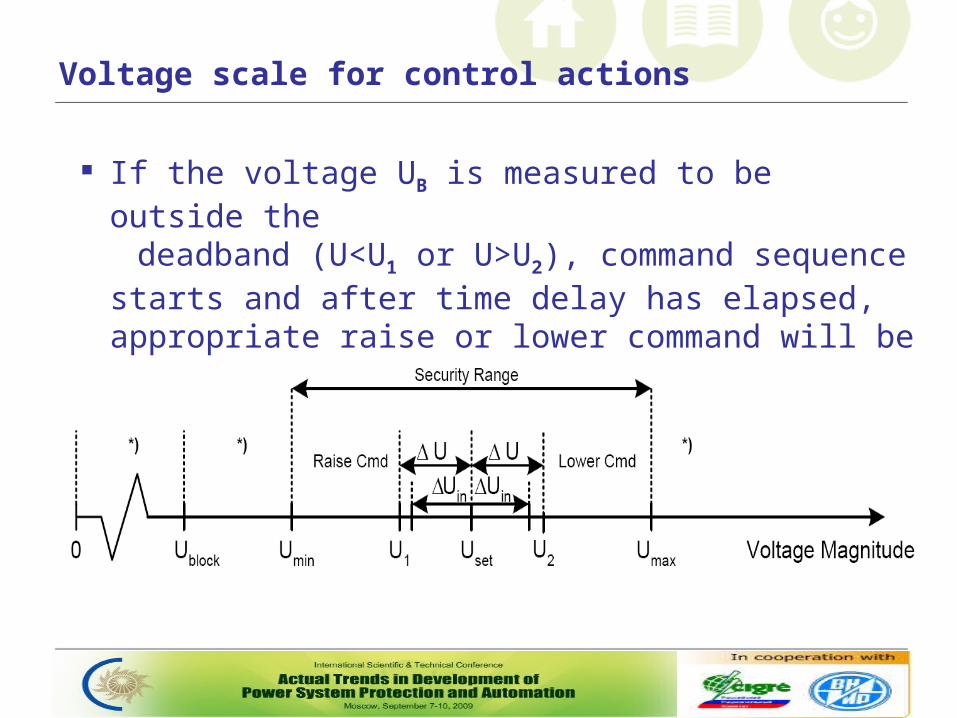
Voltage scale for control actions
If the voltage UB is measured to be outside the deadband (U<U1 or U>U2), command sequence starts
and after time delay has elapsed, appropriate raise or lower command will be issued
Introduction
Parallel control of PTs means control of two or more PTs connected to the same busbar on LV side Parallel control can be made by three alternative methods:
- reverse reactance method,- master-follower method*,- circulating current method*
* Requires communication among the voltage control functions on the PTs in parallel group
2. Parallel control with the circulating current method
PT with a higher no-load voltage on LV side (higher tap position) will produce circulating current, while other one with lower no-load voltage will receive circulating current
When load is put on the PTs, the circulating current will remain the same, it will be superimposed on the load current in each PT
Parallel control with the circulating current method
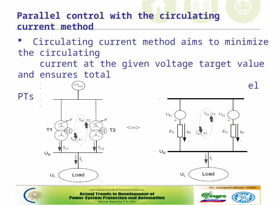
Circulating current method aims to minimize the circulating current at the given voltage target value and ensures total reactive load is shared between parallel PTs in proportion to their rating
Parallel control with the circulating current method
Method requires extensive exchange of data between the voltage control functions
Summary of required signals to be communicated for circulating current method:
- measured busbar voltage, - measured transformer current (real and imaginary parts), - voltage set point, - blocked status, control in manual, timer on ...
3. ATCC installation
Two 20 MVA, 110/20 kV, YNd5 transformers with OLTC
Each PT has dedicated IED with integrated protection and control functions
Automatic control of parallel transformers is done by circulating current method (∆Isinɸ)
Information exchange between voltage control functions for PTs in parallel are done by GOOSE messages in accordance with IEC 61850 standard
ATCC installation
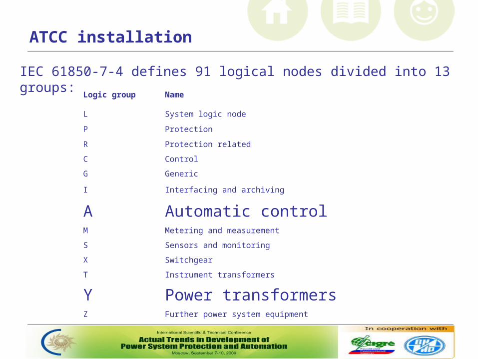
IEC 61850-7-4 defines 91 logical nodes divided into 13 groups:
Logic group Name
L System logic node
P Protection
R Protection related
C Control
G Generic
I Interfacing and archiving
A Automatic control M Metering and measurement
S Sensors and monitoring
X Switchgear
T Instrument transformers
Y Power transformersZ Further power system equipment
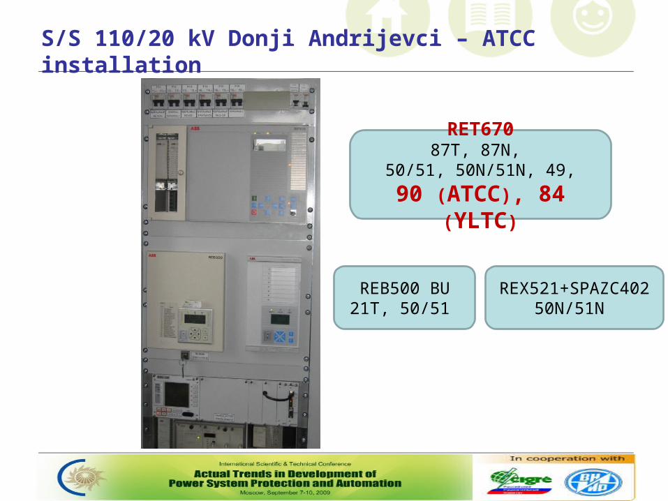
S/S 110/20 kV Donji Andrijevci – ATCC installation
RET67087T, 87N,
50/51, 50N/51N, 49,
90 (ATCC), 84 (YLTC)
REB500 BU21T, 50/51
REX521+SPAZC40250N/51N
Logical nodes ATCC and YLTC
ATCC represents regulator itselfs and integrates funcionality like: - voltage measurement and supervision, - timing, line drop compensation, - circulating current measurement and supervision etc.
YLTC represents OLTC mechanism and integrates funcionality like: - tap position reading, - OLTC mechanism supervision, - issuing of the manual and automatic raise and lower commands
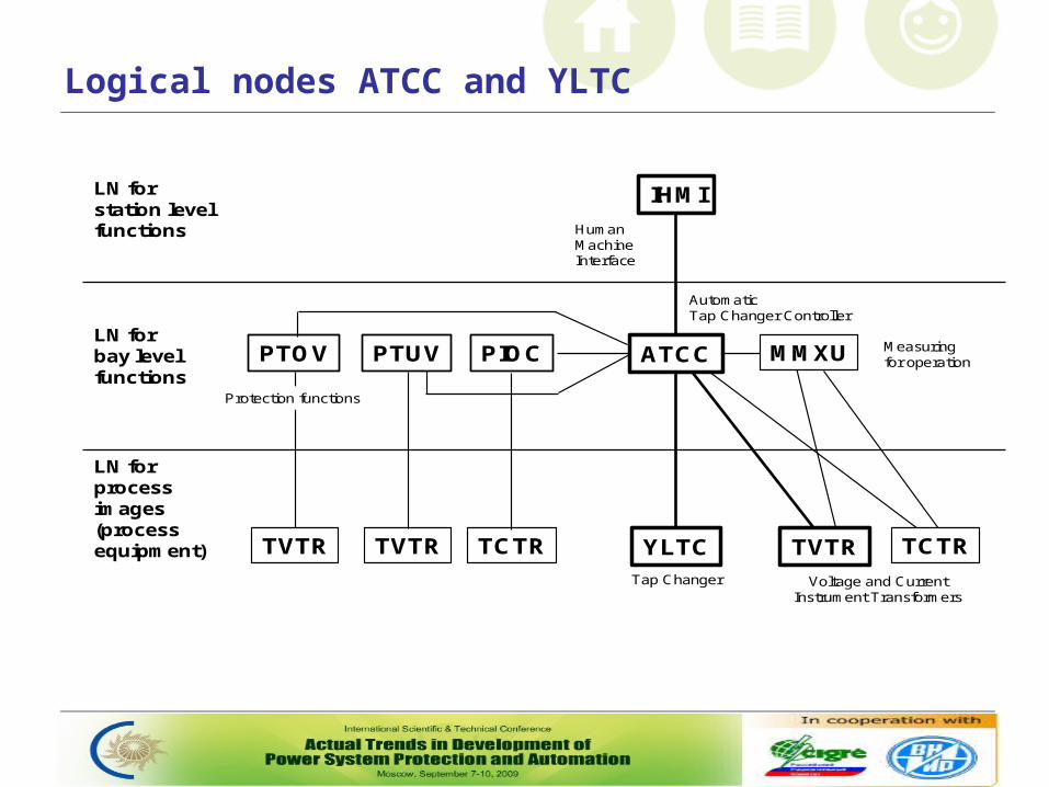
Logical nodes ATCC and YLTC
LN forprocess images(process equipment)
LN forbay levelfunctions
LN forstation levelfunctions
YLTC
ATCC
IHMI
Tap Changer
AutomaticTap Changer Controller
TVTR
Voltage and CurrentInstrument Transformers
Measuring for operation
Human Machine Interface
PIOCPTOV MMXU
TVTRTVTR TCTR
PTUV
Protection functions
TCTR
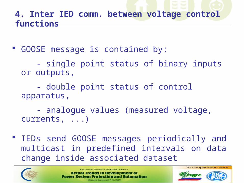
4. Inter IED comm. between voltage control functions
GOOSE message is contained by:
- single point status of binary inputs or outputs,
- double point status of control apparatus,
- analogue values (measured voltage, currents, ...)
IEDs send GOOSE messages periodically and multicast in predefined intervals on data change inside associated dataset
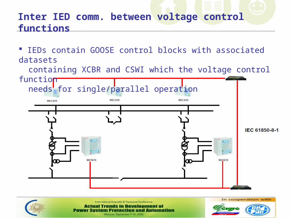
Inter IED comm. between voltage control functions
IEDs contain GOOSE control blocks with associated datasets containing XCBR and CSWI which the voltage control function needs for single/parallel operation
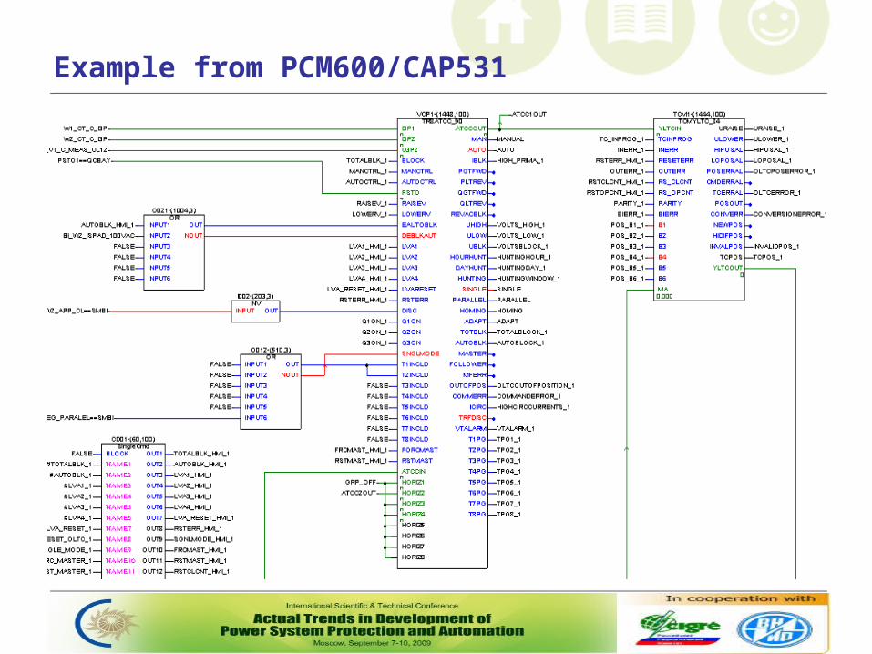
Example from PCM600/CAP531
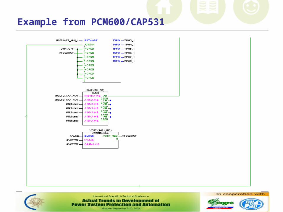
Example from PCM600/CAP531
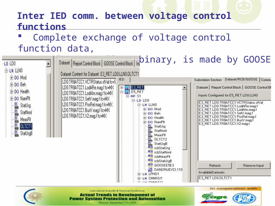
Inter IED comm. between voltage control functions
Complete exchange of voltage control function data, analog as well as binary, is made by GOOSE messages
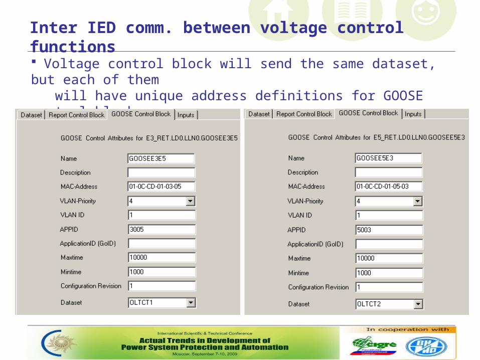
Inter IED comm. between voltage control functions
Voltage control block will send the same dataset, but each of them will have unique address definitions for GOOSE control block
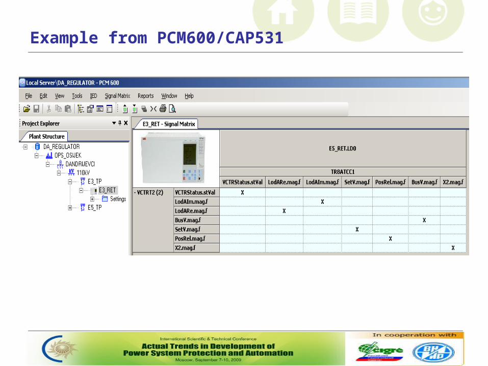
Example from PCM600/CAP531
5. Conclusion
For parallel transformer application, we used circulating current method (requires comm. between voltage control functions in parallel group)
Chosen comm. interface is GOOSE interbay communication based on IEC 61850-8-1
Since September 2007 three S/Ss with such control are in full operation and all engineering process is done by Končar engineers with Croatian TSO and ABB help

Questions?