Embed Size (px)
Citation preview
Using NCSL DAQ Software to Readout a
CAEN V792 QDC
Timothy Hoagland
December 2, 2004

Abstract
The paper’s purpose is to assist the reader in setting up and reading outdata from a CAEN V792. It covers what electronics will be needed and howthey should be setup. It will show what modifications will need to be done tothe software and gives code to be used. Testing for the code is also covered toa limited extent. Finally it covers how to get SpecTcl to produce a histogramof your events.
This paper assumes that you are at least somewhat familiar with Linuxsince the DAQ software runs on a Linux box. It also assumes that you alittle familiar with C++. Finally it will be helpful if you know how to usean oscilloscope, as that will be needed to setup your electronics.
All the code is available at:http://docs/daq/samples/CAEN V792/CAEN V792.zip
CONTENTS 1
Contents
1 A Brief Description of the CAEN V792 3
2 A Minimal Electronics Setup 3
3 Sofware Modifications 63.1 Readout Skeleton Modification . . . . . . . . . . . . . . . . . . 6
3.1.1 Writing an Event Segment . . . . . . . . . . . . . . . . 63.1.2 Modifying Skeleton.cpp . . . . . . . . . . . . . . . . . . 103.1.3 Making Readout . . . . . . . . . . . . . . . . . . . . . 113.1.4 Testing Readout . . . . . . . . . . . . . . . . . . . . . 11
3.2 Modifying SpecTcl . . . . . . . . . . . . . . . . . . . . . . . . 123.2.1 Writing an Event Processor . . . . . . . . . . . . . . . 123.2.2 Modifying MySpecTclApp.cpp . . . . . . . . . . . . . . 163.2.3 Making SpecTcl . . . . . . . . . . . . . . . . . . . . . . 17
3.3 Writing the SpecTecl Script . . . . . . . . . . . . . . . . . . . 183.4 Attaching to live data . . . . . . . . . . . . . . . . . . . . . . 18
4 Testing and Running 194.1 Testing SpecTcl . . . . . . . . . . . . . . . . . . . . . . . . . . 194.2 Testing everything together . . . . . . . . . . . . . . . . . . . 21
5 More information 22
6 Complete Sample Code 236.1 MyEventSegment.h . . . . . . . . . . . . . . . . . . . . . . . . 236.2 MyEventSegment.cpp . . . . . . . . . . . . . . . . . . . . . . . 246.3 MyEventProcessor.h . . . . . . . . . . . . . . . . . . . . . . . 266.4 MyEventProcessor.cpp . . . . . . . . . . . . . . . . . . . . . . 27
LIST OF FIGURES 2
List of Figures
1 A simple electronics setup to readout a CAEN V792 . . . . . . 42 Pulser output signal . . . . . . . . . . . . . . . . . . . . . . . 53 A sprectrum of Channel 1 from the CAEN V792 QDC . . . . 21
1 A BRIEF DESCRIPTION OF THE CAEN V792 3
1 A Brief Description of the CAEN V792
The CAEN V792 is a 12 bit charge integrating digitizer. It has 32 channelson a one unit wide VME module. The acceptable input is a negative signalof with up 400 pC of charge. For a complete understanding of the module Isuggest that you obtain a copy of the product manual, available as a PDFat http://www.caen.it/.
2 A Minimal Electronics Setup
The following items will be needed to build our simple setup:
• CAEN V792
• VME Crate
• VME controller
• NIM Crate
• NIM Discriminator
• NIM Gate and Delay generator (3 Channels)
• LEMO to Ribbon cable converter (probably NIM)
• VME CAEN V262 - I/O controller
• Pulser
• 50 Ohm LEMO terminator
• Various length LEMO cables
• Oscilloscope
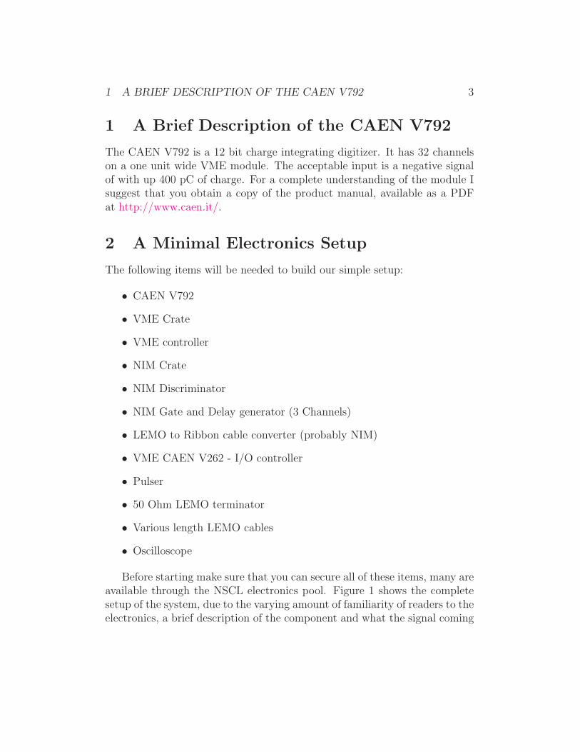
Before starting make sure that you can secure all of these items, many areavailable through the NSCL electronics pool. Figure 1 shows the completesetup of the system, due to the varying amount of familiarity of readers to theelectronics, a brief description of the component and what the signal coming
2 A MINIMAL ELECTRONICS SETUP 4
Pulser
LEMO –
Ribbon Cable
ConverterCh 1
Ribbon
Output
Constant
Fraction
Discriminator
Output
CAEN V792
Gate
Ch 1
Gate & Delay
GeneratorChannel 2
Start
out
Gate and Delay
GeneratorChannel 1
CAEN V262
StartStop
out
In0
SHP2
Gate & Delay
GeneratorChannel 3
Start out
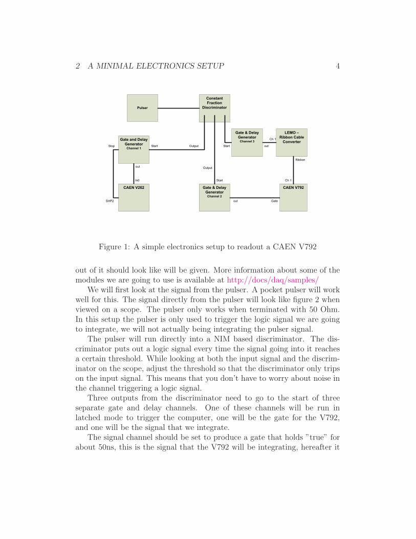
Figure 1: A simple electronics setup to readout a CAEN V792
out of it should look like will be given. More information about some of themodules we are going to use is available at http://docs/daq/samples/
We will first look at the signal from the pulser. A pocket pulser will workwell for this. The signal directly from the pulser will look like figure 2 whenviewed on a scope. The pulser only works when terminated with 50 Ohm.In this setup the pulser is only used to trigger the logic signal we are goingto integrate, we will not actually being integrating the pulser signal.
The pulser will run directly into a NIM based discriminator. The dis-criminator puts out a logic signal every time the signal going into it reachesa certain threshold. While looking at both the input signal and the discrim-inator on the scope, adjust the threshold so that the discriminator only tripson the input signal. This means that you don’t have to worry about noise inthe channel triggering a logic signal.
Three outputs from the discriminator need to go to the start of threeseparate gate and delay channels. One of these channels will be run inlatched mode to trigger the computer, one will be the gate for the V792,and one will be the signal that we integrate.
The signal channel should be set to produce a gate that holds ”true” forabout 50ns, this is the signal that the V792 will be integrating, hereafter it
2 A MINIMAL ELECTRONICS SETUP 5
Figure 2: Pulser output signal
will be referred to as the integration channel. After the signal is set connectit to channel one of the V792 via the LEMO to Ribbon cable converter.The gate channel of the gate and delay channel should be set so that startsbefore the integration signal and ends after the integration signal. The overall width of this gate should be about 100 ns. When the gate is set connectto one of the LEMO connections on the QDC, place a 50 ohm terminator inthe empty connector.
NOTE: Ribbon cable can difficult to work with because it is easy to get ittwisted and lose track, of which end is which. To avoid this look carefullyat the coloring on the cable you are using and be sure it is plugged in thecorrect channel of the QDC
The third discriminator channel will be combined with a CAEN V262 totrigger the computer when there is data on the V792. This channel will berun in latched mode meaning that it will be given both a start and a stopsignal for the gate. The start signal is the signal from the discriminator. Thediscriminator output will go to the IN0 of the CAEN V262 I/O module. Acable running from the SHP2 output of the V262 to the stop of the gate anddelay generator will provide the computer generated stop.
At this point your setup should be complete. Now is good time to makesure that your setup is the same as Figure 1. If everything is setup correctlythe BUSY and DRDY lights on the V792 should be lit up.
3 SOFWARE MODIFICATIONS 6
NOTE: The setup shown in figure 1 does not have a dead time lockout, thatis it could try to process a second event while the computer is still busy. Thiswill not be a problem as long as source is a predictable as a pulser but wouldbe problematic if we replaced the pulser with a detector signal.
3 Sofware Modifications
The software modifications needed to make the above setup work can bedivided into three tasks. First is telling the software what electronics we areusing. Second is telling the software how to make sense of what it reads.Finally we have to tell the software how to graph what it has.
3.1 Readout Skeleton Modification
In order to tell the software about our electronics we are going to develop aC++ class for our module. That class will be a derived class but we don’tneed to concern ourselves with the details of the parent class. Like all of thesoftware tailoring we need to do, most of the details are hidden and we needonly to fill in a few holes.
The following commands will make a new directory and copy the skeletonfiles to it.
mkdir -p ~/experiment/readout
cd ~/experiment/readout
cp /usr/opt/daq/pReadoutSkeleton/* .
3.1.1 Writing an Event Segment
Now that we have obtained a copy of the Skeleton file we can began to thinkabout the modifications we need to make. We need to tell the software whatkind of module we are using, how to initialize it, how to clear it, and howto read it. We will do this by creating a class called by MyEventSegment.In order to follow good coding practice and to make our code as versatileas possible we will write our class in two separate files, a header file and an

3 SOFWARE MODIFICATIONS 7
implementation file. Start by creating a file called ”MyEventSement.h”. Itshould look like this:
#ifndef __MYEVENTSEGMENT_H
#define __MTEVENTSEGMENT_H
#include <spectrodaq.h>
#include <CEventSegment.h>
#include <CDocumentedPacket.h>
#include <CAENcard.h>
#define CAENTIMEOUT 50
// Declares a class derived from CEventSegment
class MyEventSegment : public CEventSegment
{
private:
CDocumentedPacket m_MyPacket;
CAENcard* module;
unsigned short ID;
short slot;
public:
// Defines packet info
MyEventSegment(short slot,unsigned short Id);
// One time Module setup
virtual void Initialize();
// Resets data buffer
virtual void Clear();
// Reads data buffer
virtual DAQWordBufferPtr& Read(DAQWordBufferPtr& rBuf);
virtual unsigned int MaxSize();
};
#endif
This includes all of the definitions and classes that we will take advantageof, as well as declaring all of our functions. The next step is to implementthe functions. A file called MyEventSegment.cpp should be created for thatpurpose. First we have to include the header file we just created, we will also
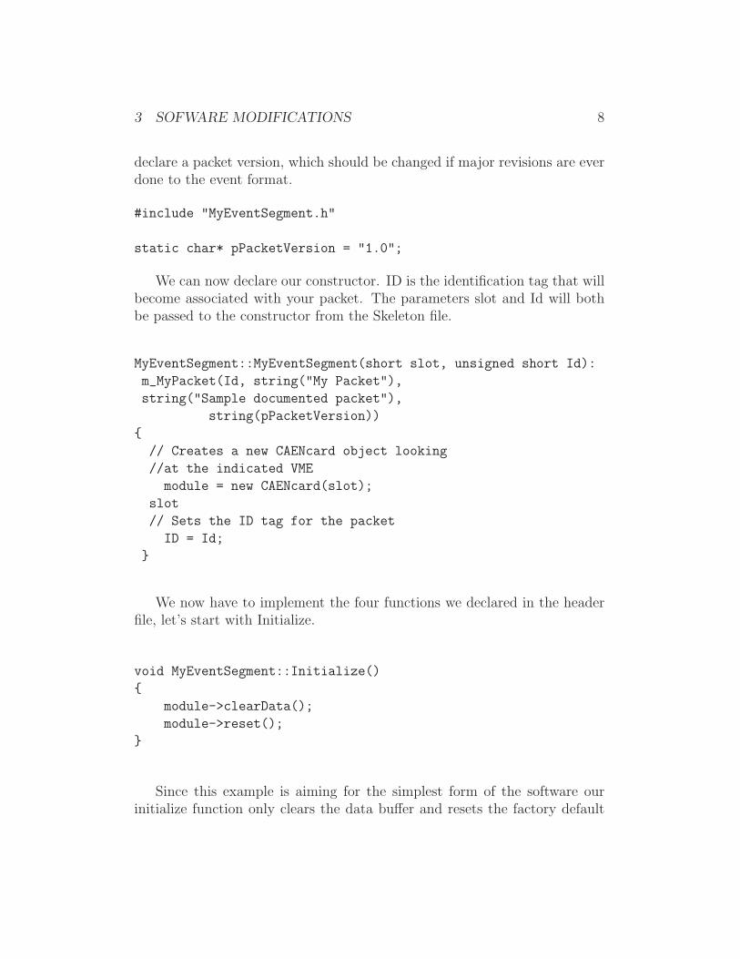
3 SOFWARE MODIFICATIONS 8
declare a packet version, which should be changed if major revisions are everdone to the event format.
#include "MyEventSegment.h"
static char* pPacketVersion = "1.0";
We can now declare our constructor. ID is the identification tag that willbecome associated with your packet. The parameters slot and Id will bothbe passed to the constructor from the Skeleton file.
MyEventSegment::MyEventSegment(short slot, unsigned short Id):
m_MyPacket(Id, string("My Packet"),
string("Sample documented packet"),
string(pPacketVersion))
{
// Creates a new CAENcard object looking
//at the indicated VME
module = new CAENcard(slot);
slot
// Sets the ID tag for the packet
ID = Id;
}
We now have to implement the four functions we declared in the headerfile, let’s start with Initialize.
void MyEventSegment::Initialize()
{
module->clearData();
module->reset();
}
Since this example is aiming for the simplest form of the software ourinitialize function only clears the data buffer and resets the factory default
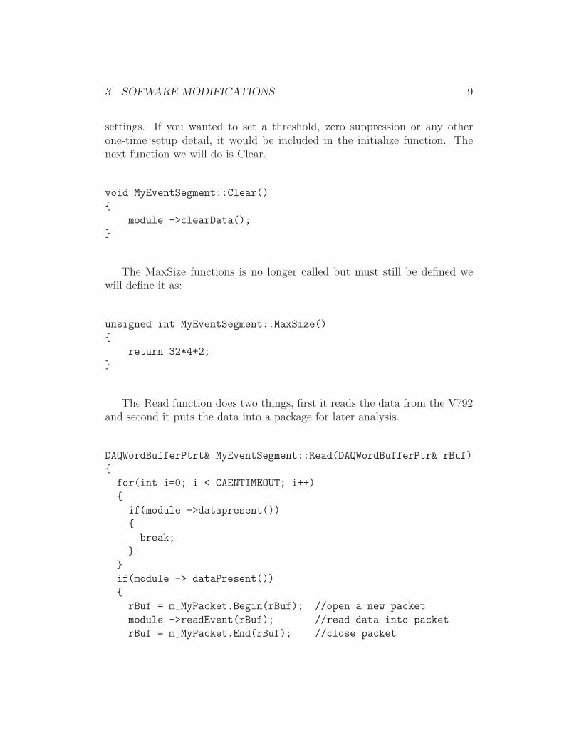
3 SOFWARE MODIFICATIONS 9
settings. If you wanted to set a threshold, zero suppression or any otherone-time setup detail, it would be included in the initialize function. Thenext function we will do is Clear.
void MyEventSegment::Clear()
{
module ->clearData();
}
The MaxSize functions is no longer called but must still be defined wewill define it as:
unsigned int MyEventSegment::MaxSize()
{
return 32*4+2;
}
The Read function does two things, first it reads the data from the V792and second it puts the data into a package for later analysis.
DAQWordBufferPtrt& MyEventSegment::Read(DAQWordBufferPtr& rBuf)
{
for(int i=0; i < CAENTIMEOUT; i++)
{
if(module ->datapresent())
{
break;
}
}
if(module -> dataPresent())
{
rBuf = m_MyPacket.Begin(rBuf); //open a new packet
module ->readEvent(rBuf); //read data into packet
rBuf = m_MyPacket.End(rBuf); //close packet
3 SOFWARE MODIFICATIONS 10
}
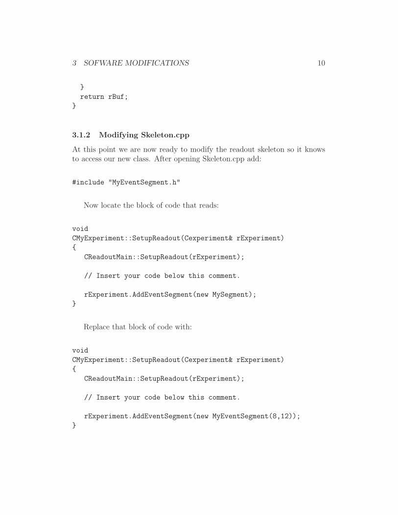
return rBuf;
}
3.1.2 Modifying Skeleton.cpp
At this point we are now ready to modify the readout skeleton so it knowsto access our new class. After opening Skeleton.cpp add:
#include "MyEventSegment.h"
Now locate the block of code that reads:
void
CMyExperiment::SetupReadout(Cexperiment& rExperiment)
{
CReadoutMain::SetupReadout(rExperiment);
// Insert your code below this comment.
rExperiment.AddEventSegment(new MySegment);
}
Replace that block of code with:
void
CMyExperiment::SetupReadout(Cexperiment& rExperiment)
{
CReadoutMain::SetupReadout(rExperiment);
// Insert your code below this comment.
rExperiment.AddEventSegment(new MyEventSegment(8,12));
}
3 SOFWARE MODIFICATIONS 11
The two numbers in the MyEventSegment call are the VME slot numberand the packet ID, respectively. You will need to replace these numbers withvalues that reflect your own setup. Be sure to note what ID you use, thatwill be needed later.
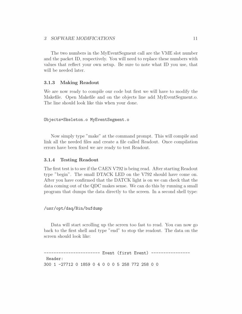
3.1.3 Making Readout
We are now ready to compile our code but first we will have to modify theMakefile. Open Makefile and on the objects line add MyEventSegment.o.The line should look like this when your done.
Objects=Skeleton.o MyEventSegment.o
Now simply type ”make” at the command prompt. This will compile andlink all the needed files and create a file called Readout. Once compilationerrors have been fixed we are ready to test Readout.
3.1.4 Testing Readout
The first test is to see if the CAEN V792 is being read. After starting Readouttype ”begin”. The small DTACK LED on the V792 should have come on.After you have confirmed that the DATCK light is on we can check that thedata coming out of the QDC makes sense. We can do this by running a smallprogram that dumps the data directly to the screen. In a second shell type:
/usr/opt/daq/Bin/bufdump
Data will start scrolling up the screen too fast to read. You can now goback to the first shell and type ”end” to stop the readout. The data on thescreen should look like:
----------------------- Event (first Event) ----------------
Header:
300 1 -27712 0 1859 0 4 0 0 0 5 258 772 258 0 0
3 SOFWARE MODIFICATIONS 12
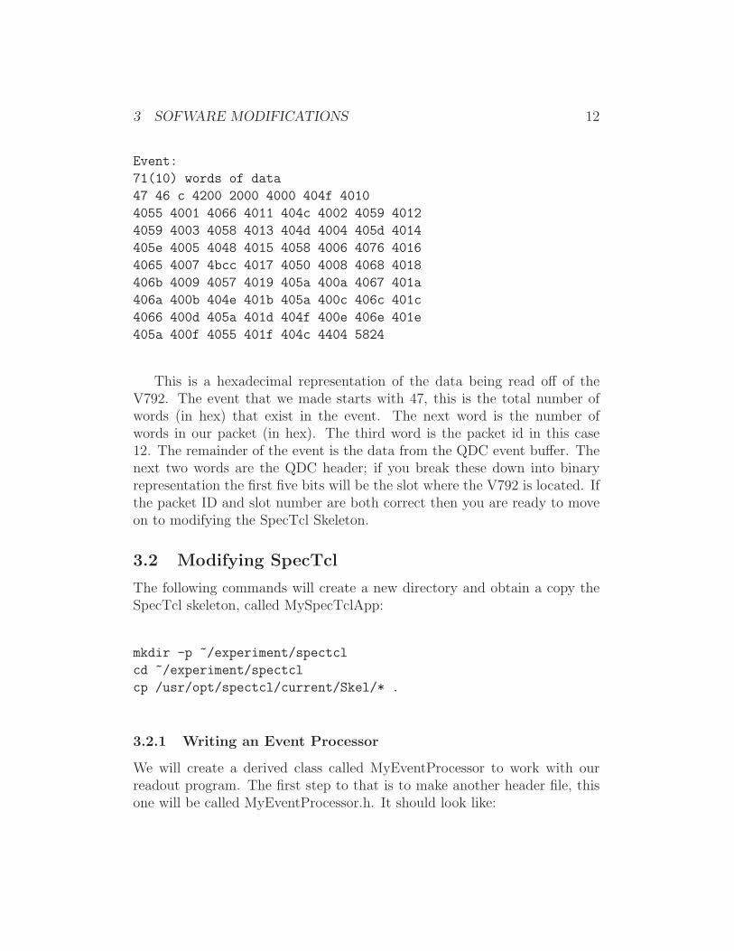
Event:
71(10) words of data
47 46 c 4200 2000 4000 404f 4010
4055 4001 4066 4011 404c 4002 4059 4012
4059 4003 4058 4013 404d 4004 405d 4014
405e 4005 4048 4015 4058 4006 4076 4016
4065 4007 4bcc 4017 4050 4008 4068 4018
406b 4009 4057 4019 405a 400a 4067 401a
406a 400b 404e 401b 405a 400c 406c 401c
4066 400d 405a 401d 404f 400e 406e 401e
405a 400f 4055 401f 404c 4404 5824
This is a hexadecimal representation of the data being read off of theV792. The event that we made starts with 47, this is the total number ofwords (in hex) that exist in the event. The next word is the number ofwords in our packet (in hex). The third word is the packet id in this case12. The remainder of the event is the data from the QDC event buffer. Thenext two words are the QDC header; if you break these down into binaryrepresentation the first five bits will be the slot where the V792 is located. Ifthe packet ID and slot number are both correct then you are ready to moveon to modifying the SpecTcl Skeleton.
3.2 Modifying SpecTcl
The following commands will create a new directory and obtain a copy theSpecTcl skeleton, called MySpecTclApp:
mkdir -p ~/experiment/spectcl
cd ~/experiment/spectcl
cp /usr/opt/spectcl/current/Skel/* .
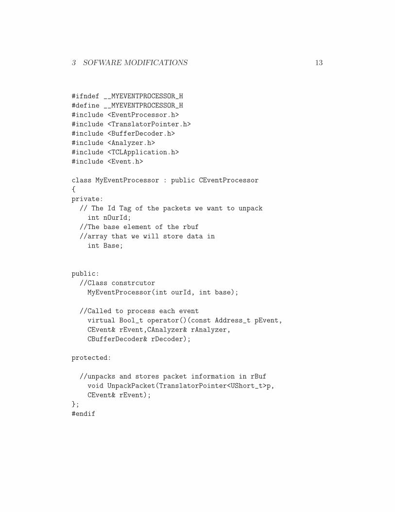
3.2.1 Writing an Event Processor
We will create a derived class called MyEventProcessor to work with ourreadout program. The first step to that is to make another header file, thisone will be called MyEventProcessor.h. It should look like:
3 SOFWARE MODIFICATIONS 13
#ifndef __MYEVENTPROCESSOR_H
#define __MYEVENTPROCESSOR_H
#include <EventProcessor.h>
#include <TranslatorPointer.h>
#include <BufferDecoder.h>
#include <Analyzer.h>
#include <TCLApplication.h>
#include <Event.h>
class MyEventProcessor : public CEventProcessor
{
private:
// The Id Tag of the packets we want to unpack
int nOurId;
//The base element of the rbuf
//array that we will store data in
int Base;
public:
//Class constrcutor
MyEventProcessor(int ourId, int base);
//Called to process each event
virtual Bool_t operator()(const Address_t pEvent,
CEvent& rEvent,CAnalyzer& rAnalyzer,
CBufferDecoder& rDecoder);
protected:
//unpacks and stores packet information in rBuf
void UnpackPacket(TranslatorPointer<UShort_t>p,
CEvent& rEvent);
};
#endif
3 SOFWARE MODIFICATIONS 14
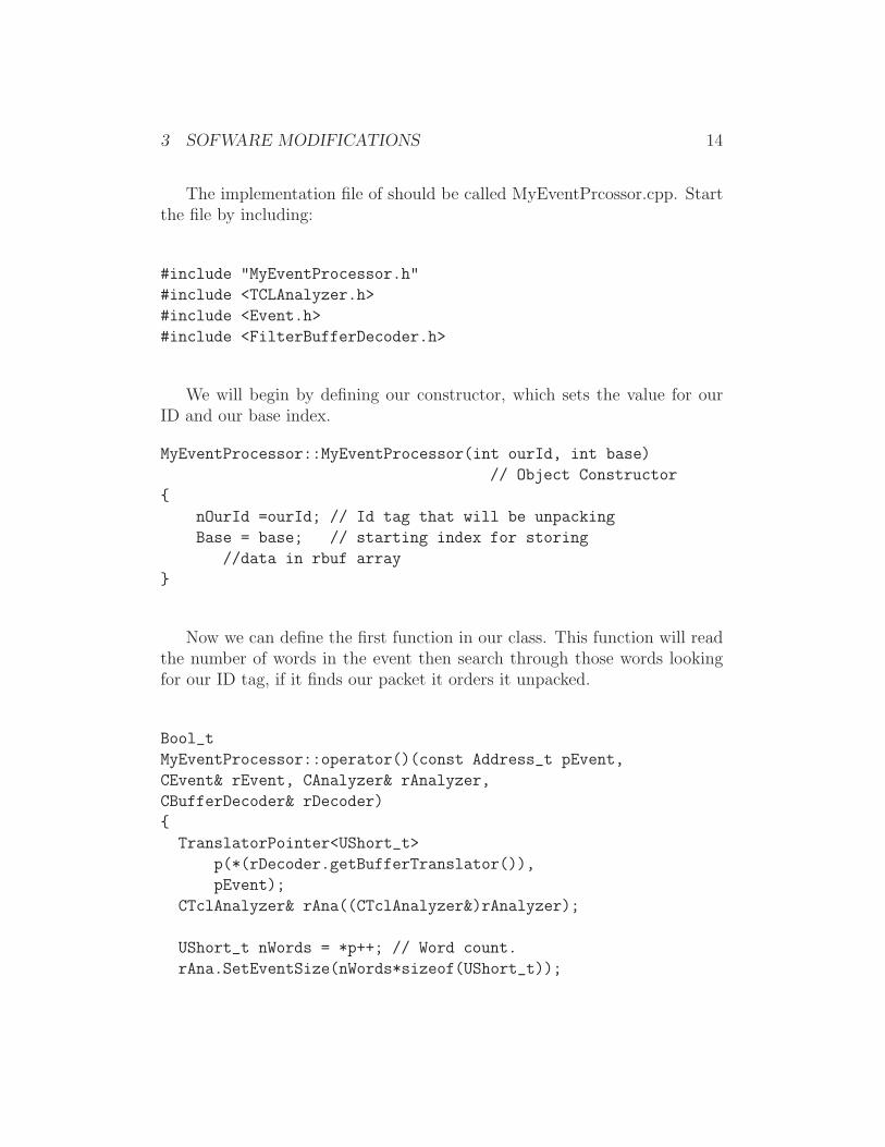
The implementation file of should be called MyEventPrcossor.cpp. Startthe file by including:
#include "MyEventProcessor.h"
#include <TCLAnalyzer.h>
#include <Event.h>
#include <FilterBufferDecoder.h>
We will begin by defining our constructor, which sets the value for ourID and our base index.
MyEventProcessor::MyEventProcessor(int ourId, int base)
// Object Constructor
{
nOurId =ourId; // Id tag that will be unpacking
Base = base; // starting index for storing
//data in rbuf array
}
Now we can define the first function in our class. This function will readthe number of words in the event then search through those words lookingfor our ID tag, if it finds our packet it orders it unpacked.
Bool_t
MyEventProcessor::operator()(const Address_t pEvent,
CEvent& rEvent, CAnalyzer& rAnalyzer,
CBufferDecoder& rDecoder)
{
TranslatorPointer<UShort_t>
p(*(rDecoder.getBufferTranslator()),
pEvent);
CTclAnalyzer& rAna((CTclAnalyzer&)rAnalyzer);
UShort_t nWords = *p++; // Word count.
rAna.SetEventSize(nWords*sizeof(UShort_t));
3 SOFWARE MODIFICATIONS 15
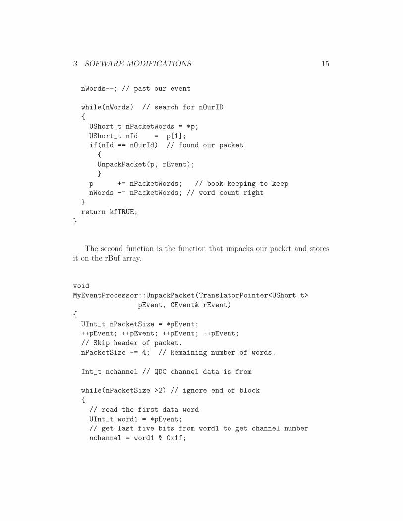
nWords--; // past our event
while(nWords) // search for nOurID
{
UShort_t nPacketWords = *p;
UShort_t nId = p[1];
if(nId == nOurId) // found our packet
{
UnpackPacket(p, rEvent);
}
p += nPacketWords; // book keeping to keep
nWords -= nPacketWords; // word count right
}
return kfTRUE;
}
The second function is the function that unpacks our packet and storesit on the rBuf array.
void
MyEventProcessor::UnpackPacket(TranslatorPointer<UShort_t>
pEvent, CEvent& rEvent)
{
UInt_t nPacketSize = *pEvent;
++pEvent; ++pEvent; ++pEvent; ++pEvent;
// Skip header of packet.
nPacketSize -= 4; // Remaining number of words.
Int_t nchannel // QDC channel data is from
while(nPacketSize >2) // ignore end of block
{
// read the first data word
UInt_t word1 = *pEvent;
// get last five bits from word1 to get channel number
nchannel = word1 & 0x1f;
3 SOFWARE MODIFICATIONS 16
++pEvent; //advance read pointer
UInt_t word2 = *pEvent; // read the second data word
// get last twelve bits of word 2 = digitized value
UInt_t QDCValue = word2 & 0x7ff;
// place the QDCValue into the [th] element of rbuf array
rEvent[Base + nchannel] = QDCValue;
++pEvent; // advance read pointer
nPacketSize -=2; // adjust remaining word count
//next line is a test line to be removed later
cerr<< "found a value of " << QDCValue
<<" at channel " << nchannel <<endl;
// test line - remove after testing
}
return rBuf;
}
3.2.2 Modifying MySpecTclApp.cpp
We are now ready to make some changes to the MySpecTclApp.cpp file.After the last #include add these lines:
#include MyEventProcessor.h
MyEventProcessor MyProcessor;
Now locate the CreateAnalysisPipeline function that looks like this:
void
CMySpecTclApp::CreateAnalysisPipeline(CAnalyzer& rAnalyzer)
{
#ifdef WITHF77UNPACKER

3 SOFWARE MODIFICATIONS 17
RegisterEventProcessor(legacyunpacker);
#endif
RegisterEventProcessor(Stage1);
RegisterEventProcessor(Stage2);
}
Edit the function so that it uses the MyEventProcessor class we justmade. The values of our base index and our and our packet Id should bepassed here. The base index is the starting array index that the values willbe stored at, the Id is the same as you used earlier.
void
CMySpecTclApp::CreateAnalysisPipeline(CAnalyzer& rAnalyzer)
{
RegisterEventProcessor(MyProcessor(101, 12);
}
3.2.3 Making SpecTcl
We are now ready to edit our Makefile so that we can compile our program.The first task is to find the line that reads:
OBJECTS=MySpecTclApp.o
and make it read
OBJECTS=MySpecTclApp.o MyEventProcessor.o
The second change is to add a couple of lines to the end of the file.
3 SOFWARE MODIFICATIONS 18
MyEventProcessor.o: MyEventProcessor.cpp MyEventProcessor.h
$(CXXCOMPILE) MyEventProcessor.cpp
You can now run ”make” to compile your code to make a file calledSpecTcl. Fix all compilation errors before continuing.
3.3 Writing the SpecTecl Script
The last piece of code we have to write is the spectcl setup script. This thepiece of code that tells the software what is available to histogram. Start bycreating a file called setup.tcl that looks like
set slot 101; #QDCbase address used earlier earlier
#Define 32 parameters named QDC0...QDC31 starting in slot 101
for {set i 0} {$i <= 31} {incr i} {
parameter QDC$i $slot 12;
incr slot
}
#define a 1-d spectrum for each parameter:
for {set i 0} {$i <= 31} {incr i} {
spectrum QDC$i 1 QDC$i {{0 4095 2048}; # 12 bit
}
sbind -all; #make all spectrum displayable
3.4 Attaching to live data
To process data online as you will need to add an ”Attach online” buttonthat will get the data being streamed from the readout program. This scriptwill be called ”AttachButton” and will include a call to our setup.tcl script

4 TESTING AND RUNNING 19
source setup.tcl
proc Attach {} {
attach -pipe /usr/opt/daq/Bin/spectcldaq tcp://spdaqXX:2602/
start
}
button .attach -command Attach -text "Attach Online"
pack .attach
The spdaqXX above must be replaced with the DAQ computer you areworking at.
4 Testing and Running
We are now ready to test our event processor. Begin by starting Readoutand beginning a run. Then start SpecTcl.
4.1 Testing SpecTcl
When SpecTcl starts a window with a command prompt will open type:
source AttachButton
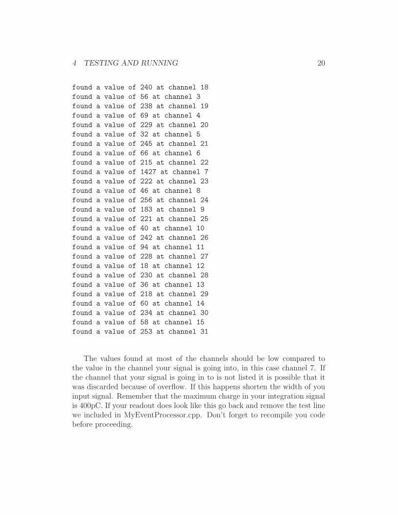
This will create an ”attach online” button in the SpecTcl window. Click thisattach online button. The window in which you started SpecTcl should nowbe scrolling text. This is the test line we added in our code earlier. If younow go to the window where you are running readout and type ”end” thescrolling will stop and you can see what you have. The last 32 lines shouldlook like:
found a value of 60 at channel 0
found a value of 209 at channel 16
found a value of 62 at channel 1
found a value of 218 at channel 17
found a value of 43 at channel 2
4 TESTING AND RUNNING 20
found a value of 240 at channel 18
found a value of 56 at channel 3
found a value of 238 at channel 19
found a value of 69 at channel 4
found a value of 229 at channel 20
found a value of 32 at channel 5
found a value of 245 at channel 21
found a value of 66 at channel 6
found a value of 215 at channel 22
found a value of 1427 at channel 7
found a value of 222 at channel 23
found a value of 46 at channel 8
found a value of 256 at channel 24
found a value of 183 at channel 9
found a value of 221 at channel 25
found a value of 40 at channel 10
found a value of 242 at channel 26
found a value of 94 at channel 11
found a value of 228 at channel 27
found a value of 18 at channel 12
found a value of 230 at channel 28
found a value of 36 at channel 13
found a value of 218 at channel 29
found a value of 60 at channel 14
found a value of 234 at channel 30
found a value of 58 at channel 15
found a value of 253 at channel 31
The values found at most of the channels should be low compared tothe value in the channel your signal is going into, in this case channel 7. Ifthe channel that your signal is going in to is not listed it is possible that itwas discarded because of overflow. If this happens shorten the width of youinput signal. Remember that the maximum charge in your integration signalis 400pC. If your readout does look like this go back and remove the test linewe included in MyEventProcessor.cpp. Don’t forget to recompile you codebefore proceeding.
4 TESTING AND RUNNING 21
0 500 1000 1500 20000
1000
2000
3000
4000
5000
6000
7000
8000
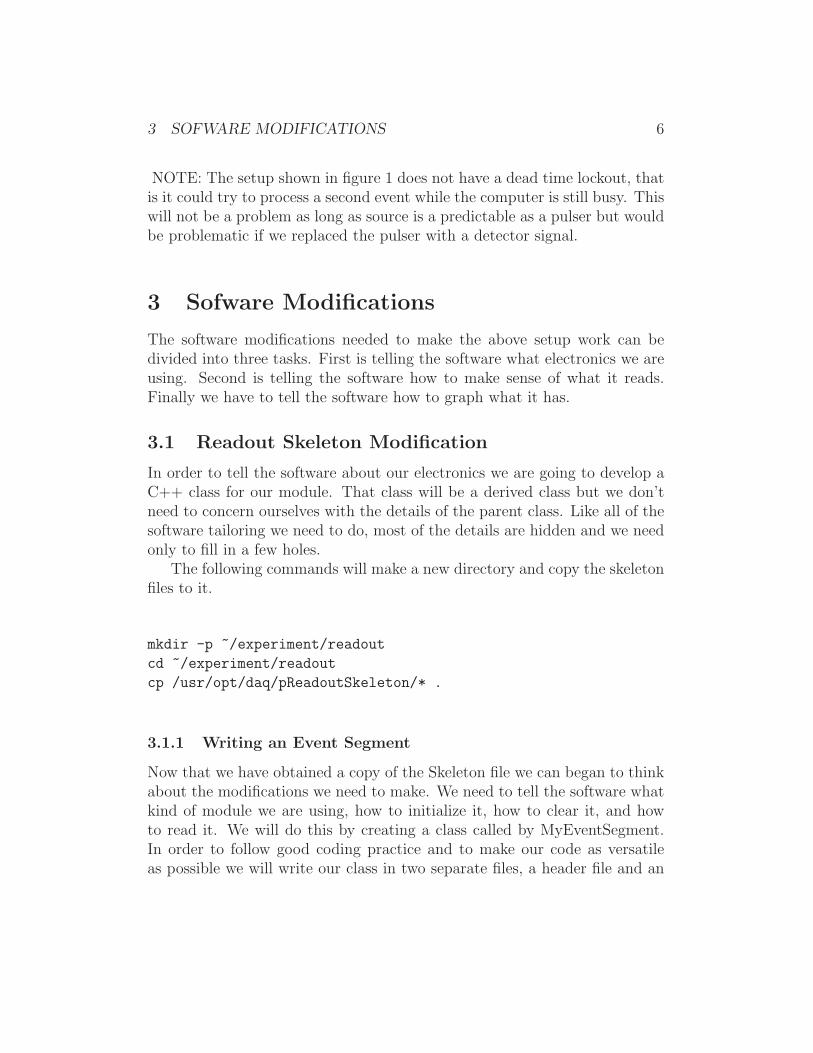
[30] TDC7
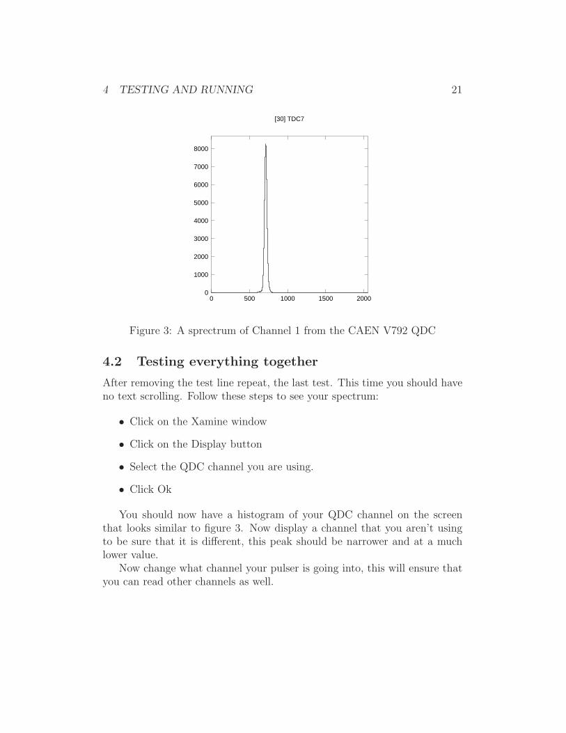
Figure 3: A sprectrum of Channel 1 from the CAEN V792 QDC
4.2 Testing everything together
After removing the test line repeat, the last test. This time you should haveno text scrolling. Follow these steps to see your spectrum:
• Click on the Xamine window
• Click on the Display button
• Select the QDC channel you are using.
• Click Ok
You should now have a histogram of your QDC channel on the screenthat looks similar to figure 3. Now display a channel that you aren’t usingto be sure that it is different, this peak should be narrower and at a muchlower value.
Now change what channel your pulser is going into, this will ensure thatyou can read other channels as well.
5 MORE INFORMATION 22
5 More information
You have now developed a fully functional DAQ system. Although it is notvery complicated it can be very versatile. With only small changes you will beable read a CAEN V775, or V785. Slightly more changes are required to readout other modules but the steps and ideas that are in MyEventSegement andMyEventProcessor are the same regardless of what modules you are reading.
More information is available at: http://docs.nscl.msu.edu/ andshould be your first source for help. If that doesn’t help [email protected]
Please help with the accuracy of the paper. If you find any kind of errorplease report it at [email protected].

6 COMPLETE SAMPLE CODE 23
6 Complete Sample Code
The complete code needed to readout out a V792 can be found athttp://docs.nscl.msu.edu/daq/samples/. The computer you are using willneed to be specified in the ”abutton” script and both the Readout code andSpecTcl code will need be compiled.
6.1 MyEventSegment.h
/*
This is the header file to define the MyEventSegment class, which
is derived from CEventSegment. This class can be used to read
out any number of CAEN modules covered by the CAENcard class.
Those cards include the V785, V775, and V792.
Tim Hoagland
11/3/04
*/
#ifndef __MYEVENTSEGMENT_H
#define __MTEVENTSEGMENT_H
#include <spectrodaq.h>
#include <CEventSegment.h>
#include <CDocumentedPacket.h>
#include <CAENcard.h>
#define CAENTIMEOUT 50
// Declares a class derived from CEventSegment
class MyEventSegment : public CEventSegment
{
private:
CDocumentedPacket m_MyPacket;
CAENcard* module;
unsigned short ID;
short slot;
public:
MyEventSegment(short slot,unsigned short Id);
// Defines packet info
virtual void Initialize();
// One time Module setup
virtual void Clear();
// Resets data buffer
virtual unsigned int MaxSize();
virtual DAQWordBufferPtr& Read(DAQWordBufferPtr& rBuf);
// Reads data buffer
};
#endif
6 COMPLETE SAMPLE CODE 24
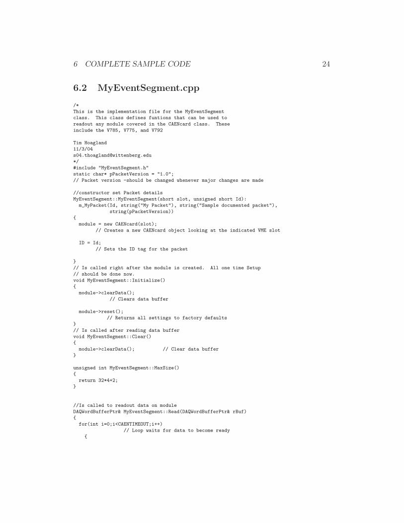
6.2 MyEventSegment.cpp
/*
This is the implementation file for the MyEventSegment
class. This class defines funtions that can be used to
readout any module covered in the CAENcard class. These
include the V785, V775, and V792
Tim Hoagland
11/3/04
*/
#include "MyEventSegment.h"
static char* pPacketVersion = "1.0";
// Packet version -should be changed whenever major changes are made
//constructor set Packet details
MyEventSegment::MyEventSegment(short slot, unsigned short Id):
m_MyPacket(Id, string("My Packet"), string("Sample documented packet"),
string(pPacketVersion))
{
module = new CAENcard(slot);
// Creates a new CAENcard object looking at the indicated VME slot
ID = Id;
// Sets the ID tag for the packet
}
// Is called right after the module is created. All one time Setup
// should be done now.
void MyEventSegment::Initialize()
{
module->clearData();
// Clears data buffer
module->reset();
// Returns all settings to factory defaults
}
// Is called after reading data buffer
void MyEventSegment::Clear()
{
module->clearData(); // Clear data buffer
}
unsigned int MyEventSegment::MaxSize()
{
return 32*4+2;
}
//Is called to readout data on module
DAQWordBufferPtr& MyEventSegment::Read(DAQWordBufferPtr& rBuf)
{
for(int i=0;i<CAENTIMEOUT;i++)
// Loop waits for data to become ready
{
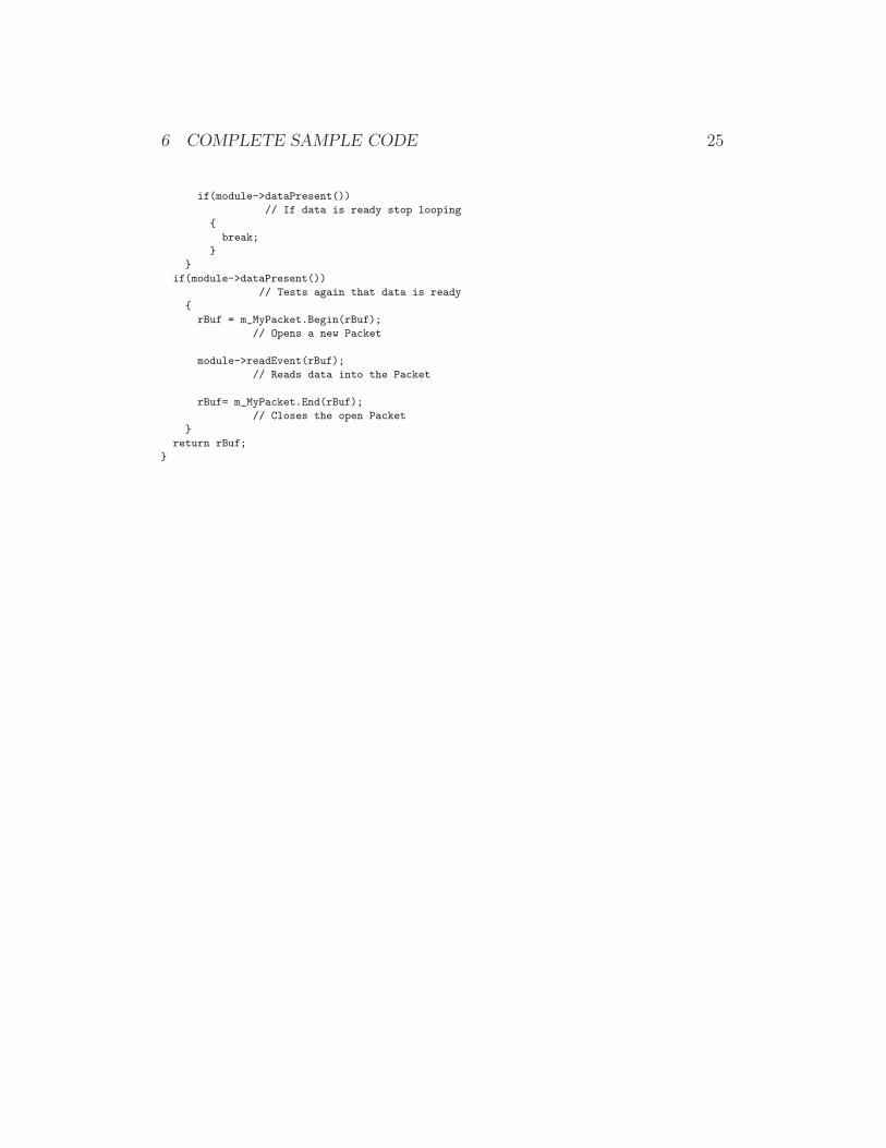
6 COMPLETE SAMPLE CODE 25
if(module->dataPresent())
// If data is ready stop looping
{
break;
}
}
if(module->dataPresent())
// Tests again that data is ready
{
rBuf = m_MyPacket.Begin(rBuf);
// Opens a new Packet
module->readEvent(rBuf);
// Reads data into the Packet
rBuf= m_MyPacket.End(rBuf);
// Closes the open Packet
}
return rBuf;
}
6 COMPLETE SAMPLE CODE 26
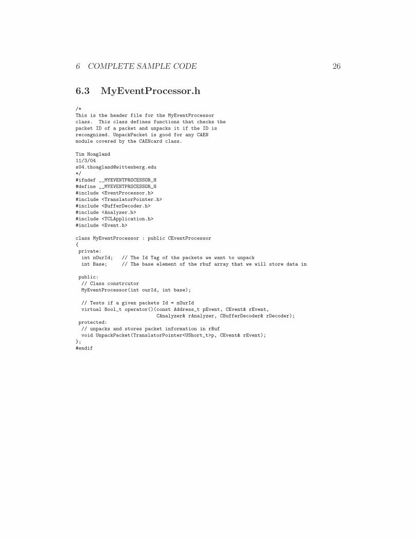
6.3 MyEventProcessor.h
/*
This is the header file for the MyEventProcessor
class. This class defines functions that checks the
packet ID of a packet and unpacks it if the ID is
recongnized. UnpackPacket is good for any CAEN
module covered by the CAENcard class.
Tim Hoagland
11/3/04
*/
#ifndef __MYEVENTPROCESSOR_H
#define __MYEVENTPROCESSOR_H
#include <EventProcessor.h>
#include <TranslatorPointer.h>
#include <BufferDecoder.h>
#include <Analyzer.h>
#include <TCLApplication.h>
#include <Event.h>
class MyEventProcessor : public CEventProcessor
{
private:
int nOurId; // The Id Tag of the packets we want to unpack
int Base; // The base element of the rbuf array that we will store data in
public:
// Class constrcutor
MyEventProcessor(int ourId, int base);
// Tests if a given packets Id = nOurId
virtual Bool_t operator()(const Address_t pEvent, CEvent& rEvent,
CAnalyzer& rAnalyzer, CBufferDecoder& rDecoder);
protected:
// unpacks and stores packet information in rBuf
void UnpackPacket(TranslatorPointer<UShort_t>p, CEvent& rEvent);
};
#endif
6 COMPLETE SAMPLE CODE 27
6.4 MyEventProcessor.cpp
/*
This is the implementation file for the MyEventProcessor
class. This class defines functions that checks the
packet ID of a packet and unpacks it if the ID is
recongnized. UnpackPacket is good for any CAEN
module covered by the CAENcard class.
Tim Hoagland
11/3/04
*/
#include "MyEventProcessor.h"
#include <TCLAnalyzer.h>
#include <Event.h>
#include <FilterBufferDecoder.h>
int i=0;
MyEventProcessor::MyEventProcessor(int ourId, int base) // Object Constructor
{
nOurId =ourId; // Id tag that will be unpacking
Base = base; // starting index for storing data in rbuf array
}
Bool_t MyEventProcessor::operator()(const Address_t pEvent, CEvent& rEvent,
CAnalyzer& rAnalyzer, CBufferDecoder& rDecoder)
{
TranslatorPointer<UShort_t> p(*(rDecoder.getBufferTranslator()), pEvent);
CTclAnalyzer& rAna((CTclAnalyzer&)rAnalyzer);
UShort_t nWords=*p++; // get number of words in the packet
rAna.SetEventSize(nWords*sizeof(UShort_t));
nWords--;
while(nWords) // Search packet for ID tag
{
UShort_t nPacketWords=*p;
UShort_t nId = p[1];
if(nId == nOurId)
{
UnpackPacket(p, rEvent);
}
p +=nPacketWords;
nWords -= nPacketWords;
}
return kfTRUE;
}
void MyEventProcessor::UnpackPacket(TranslatorPointer<UShort_t> pEvent,
CEvent& rEvent)
{
UInt_t nPacketSize = *pEvent; // get number of words let to be read
++pEvent;++pEvent;++pEvent;++pEvent; // skip over Id info and Header words
nPacketSize -=4; // adjust words remaining

6 COMPLETE SAMPLE CODE 28
Int_t nchannel;
while(nPacketSize>2) // ignore end of block words
{
UInt_t word1 = *pEvent; // read the first data word
nchannel = word1 & 0x1f; // get last five bits from word1 to get channel number
++pEvent; //advance read pionter
UInt_t word2 = *pEvent; // read the second data word
UInt_t QDCValue = word2 & 0x7ff; // get last twelve bits of word 2 = digitized value
rEvent[Base + nchannel] = QDCValue; // place the QDCValue into the [th] element of rbuf array
++pEvent; // advance read pionter
nPacketSize -=2; // adjust remaing word count
// Below this line is a test line that can be uncommented to look at raw data
//cerr << "found a value of " <<QDCValue << " at channel " << nchannel <<endl;
}
return rEvent;
}


![GUTHLE QDC [Autosaved]](https://img.pdfslide.net/doc/110x75/58a252991a28abe8738b6029/guthle-qdc-autosaved.jpg)