Embed Size (px)
Citation preview
Using Slocum Gliders for
Coordinated Spatial Sampling
Hans Christian Woithe
Dept. of Computer Science
Rutgers University
Piscataway, New Jersey 08854
Email: [email protected]
Ulrich Kremer
Dept. of Computer Science
Rutgers University
Piscataway, New Jersey 08854
Email: [email protected]
Abstract—Buoyancy driven Autonomous Underwater Vehicles(AUVs), such as the Slocum glider, allow for a prolonged presenceto study the oceans. They can operate for weeks or even monthsrecording oceanographic data for a fraction of the cost of researchvessels. However, the vehicles are limited to the number of sensorsthat can be carried onboard. Alternatively, a group of AUVsperforming formation flight, where AUVs maintain particularpositions relative to each other, could be used to observe oceanconditions and phenomena at a high spatiotemporal resolutioncarrying a variety of sensors. The vehicles can conceptually act asa single science instrument that can be easier and less expensiveto deploy than higher cost, large AUVs.
In this paper we propose and evaluate, using simulations,an effective coordination strategy for formation flight whichmonitors the formation quality using underwater communication.If an AUV drifts out of formation, all vehicles are instructedthrough underwater communication to resurface in order toreestablish the formation. Overall, this strategy is able to keepa formation of gliders longer than the traditional approach andcan gather significantly more data samples, which correspondsto an overall decrease in the per sample energy cost.
I. INTRODUCTION
Buoyancy driven Autonomous Underwater Vehicles (AUVs)
allow for a prolonged presence of scientific sensors in the
oceans. They operate for weeks or even months recording
oceanographic data for a fraction of the overall cost of research
vessels. Formation flight is a form of swarming where AUVs
maintain a particular position relative to each other and allows
for the observation of ocean conditions and phenomena at a
high spatiotemporal resolution [1]. In addition, formation flight
enables AUVs with different sensor payloads to conceptually
act as a single science instrument allowing enhanced sensing
capabilities to be implemented by groups of lower cost, small
AUVs instead of higher cost, large AUVs [2].
Maintaining a swarm formation is a difficult challenge. Gen-
eral localization technologies, such as GPS, are unavailable
underwater. Various factors may also account for a vehicle
to drift out of formation, including environmental conditions,
dead reckoning, and even a vehicle’s particular ballast con-
figuration to name a few. Current approaches to establish and
maintain formation using the Slocum glider, the target vehicle
of our research, is through radio and satellite communication
during the AUV’s periodic surfacings [3], [4]. The vehicles
are typically programmed to surface at predetermined time
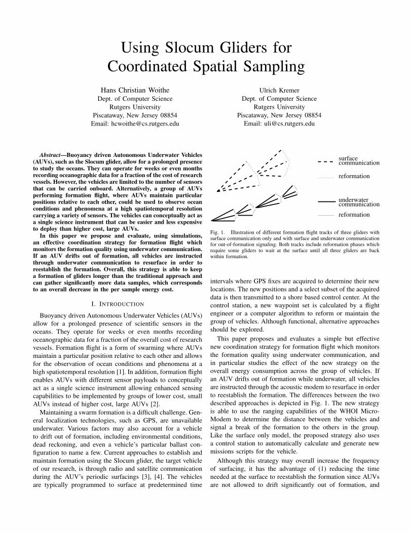
communication
reformation
reformation
communication
underwater
surface
Fig. 1. Illustration of different formation flight tracks of three gliders withsurface communication only and with surface and underwater communicationfor out-of-formation signaling. Both tracks include reformation phases whichrequire some gliders to wait at the surface until all three gliders are backwithin formation.
intervals where GPS fixes are acquired to determine their new
locations. The new positions and a select subset of the acquired
data is then transmitted to a shore based control center. At the
control station, a new waypoint set is calculated by a flight
engineer or a computer algorithm to reform or maintain the
group of vehicles. Although functional, alternative approaches
should be explored.
This paper proposes and evaluates a simple but effective
new coordination strategy for formation flight which monitors
the formation quality using underwater communication, and
in particular studies the effect of the new strategy on the
overall energy consumption across the group of vehicles. If
an AUV drifts out of formation while underwater, all vehicles
are instructed through the acoustic modem to resurface in order
to reestablish the formation. The differences between the two
described approaches is depicted in Fig. 1. The new strategy
is able to use the ranging capabilities of the WHOI Micro-
Modem to determine the distance between the vehicles and
signal a break of the formation to the others in the group.
Like the surface only model, the proposed strategy also uses
a control station to automatically calculate and generate new
missions scripts for the vehicle.
Although this strategy may overall increase the frequency
of surfacing, it has the advantage of (1) reducing the time
needed at the surface to reestablish the formation since AUVs
are not allowed to drift significantly out of formation, and
0
2
4
6
8
10
12
14
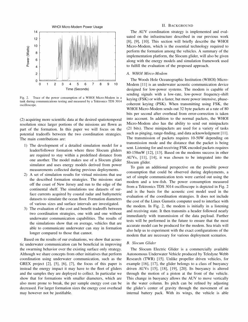
0 1 2 3 4 5 6 7 8 9 10
Pow
er
(Watt
s)
Time (Seconds)
WHOI Micro-Modem Power Usage
Fig. 2. Trace of the power consumption of a WHOI Micro-Modem in atank during communications testing and measured by a Tektronics TDS 3014oscilloscope.
(2) acquiring more scientific data at the desired spatiotemporal
resolution since larger portions of the missions are flown as
part of the formation. In this paper we will focus on the
potential tradeoffs between the two coordination strategies.
The main contributions are:
1) The development of a detailed simulation model for a
leader/follower formation where three Slocum gliders
are required to stay within a predefined distance from
one another. The model makes use of a Slocum glider
simulator and uses energy models derived from power
measurements collected during previous deployments.
2) A set of simulation results for virtual missions that use
the described formation strategies. The missions start
off the coast of New Jersey and run to the edge of the
continental shelf. The simulations use datasets of sur-
face currents acquired by coastal radar and bathymetric
datasets to simulate the ocean floor. Formation diameters
of various sizes and surface intervals are investigated.
3) The evaluation of the cost and benefit tradeoffs between
two coordination strategies, one with and one without
underwater communication capabilities. The results of
the simulations show that on average, vehicles that are
able to communicate underwater can stay in formation
longer compared to those that cannot.
Based on the results of our evaluations, we show that acous-
tic underwater communication can be beneficial in improving
the swarming behavior over the existing surface only strategy.
Although we share concepts from other initiatives that perform
coordination using underwater communication, such as the
GREX project [2], [5], [6], [7], the focus of this paper is
instead the energy impact it may have to the fleet of gliders
and the samples they are deployed to collect. In particular we
show that for formations with smaller diameters, which are
also more prone to break, the per sample energy cost can be
decreased. For larger formation sizes the energy cost overhead
may however not be justifiable.
II. BACKGROUND
The AUV coordination strategy is implemented and eval-
uated on the infrastructure described in our previous work
[8], [9], [10]. This section will briefly describe the WHOI
Micro-Modem, which is the essential technology required to
perform the formation among the vehicles. A summary of the
implementation platform, the Slocum glider, will also be given
along with the energy models and simulation framework used
to fulfill the evaluation of the proposed approach.
A. WHOI Mirco-Modem
The Woods Hole Oceanographic Institution (WHOI) Micro-
Modem [11] is an underwater acoustic communication device
designed for low-power systems. The modem is capable of
sending signals with a low-rate, low-power frequency-shift
keying (FSK) or with a faster, but more power intensive, phase-
coherent keying (PSK). When transmitting using FSK, the
WHOI Micro-Modem sends out 32 byte packets at a rate of 80
bits per second after overhead from error-correction is taken
into account. In addition to the normal packets, the WHOI
Micro-Modem also has the ability to send out minipackets
(21 bits). These minipackets are used for a variety of tasks
such as pinging, range-finding, and data acknowledgment [11].
The transmission of packets requires 10-50W depending on
transmission mode and the distance that the packet is being
sent. Listening for and receiving FSK encoded packets requires
80-158mW [12], [13]. Based on the modems success in other
AUVs, [11], [14], it was chosen to be integrated into the
Slocum glider.
To gain an additional perspective on the possible power
consumption that could be observed during deployments, a
set of simple communication tests were carried out using the
modem and a tow-fish. The power consumption measured
from a Tektronics TDS 3014 oscilloscope is depicted in Fig. 2
and is the basis for the acoustic cost model used in the
evaluation of the coordination strategies. It does not include
the cost of the Linux Gumstix computer used to interface with
the modem. In Fig. 2, the modem is initially in a listening
and receiving state. It then transmits a header followed nearly
immediately with transmission of the data payload. Further
tests will be performed in the future to ensure that the most
accurate model can be produced for the modem. Sea trials will
also help us to experiment with the exact configurations of the
modem that are necessary for various deployment scenarios.
B. Slocum Glider
The Slocum Electric Glider is a commercially available
Autonomous Underwater Vehicle produced by Teledyne Webb
Research (TWR) [15]. Unlike propeller driven vehicles, for
example [16], [17], the glider belongs to a class of buoyancy
driven AUVs [15], [18], [19], [20]. Its buoyancy is altered
through the motion of a piston at the front of the vehicle.
This change in buoyancy allows the AUV to move vertically
in the water column. Its pitch can be refined by adjusting
the glider’s center of gravity through the movement of an
internal battery pack. With its wings, the vehicle is able
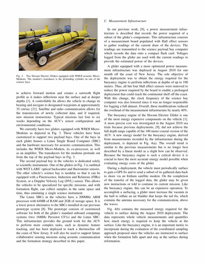
Fig. 3. Two Slocum Electric Gliders equipped with WHOI acoustic Micro-Modems. The modem’s transducer is the protruding cylinder on one of thescience bays.
to achieve forward motion and creates a sawtooth flight
profile as it makes inflections near the surface and at deeper
depths [1]. A controllable fin allows the vehicle to change its
bearing and navigate to designated waypoints at approximately
35 cm/sec [21]. Satellite and radio communication allows for
the transmission of newly collected data, and if required,
new mission instructions. Typical missions last four to six
weeks depending on the AUV’s sensor configuration and
environmental conditions.
We currently have two gliders equipped with WHOI Micro-
Modems as depicted in Fig. 3. These vehicles have been
customized to support two payload bays. One of the bays in
each glider houses a Linux Single Board Computer (SBC)
and the hardware necessary for acoustic communication. This
includes the WHOI Micro-Modem, its co-processor, as well
as an amplifier. The transducers for the modems protrude out
from the top of the payload bays in Fig. 3.
The second payload bay in the vehicles is dedicated solely
to scientific instruments. One of the gliders in Fig. 3 is outfitted
with WET LABS’ optical backscatter and fluorometer sensors.
The other vehicle’s science bay is modular so that it can be
equipped with a Fluorescence, Induction and Relations (FIRe)
System, or a Doppler Velocity Log (DVL) sensor. This allows
the vehicles to be specialized for specific missions, and with
formation flight, can collect samples in the same space and
time, thus emulating a single science instrument.
The Linux SBCs in the vehicles have a 200MHz ARM
processor with 64MB of RAM and 2GB of storage space. It is
a lower power alternative to the SBCs installed in our previous
prototype system [8]. The prototype consists of customized
software for both of the glider’s standard onboard computing
systems (two 16MHz Persistor CF1s) and the Linux SBC.
This infrastructure provides the ground work for the AUV
to perform more complex tasks, such as dynamic feature
tracking, and has been deployed to track a thermocline off
the coast of New Jersey. It will also be used to support future
collaborative sensing missions using acoustic communication
and the formation strategy described in this paper.
C. Measurement Infrastructure
In our previous work, [9], a power measurement infras-
tructure is described that records the power required of a
subset of the glider’s components. This infrastructure consists
of a measurement board populated with Hall effect sensors
to gather readings of the current draw of the devices. The
readings are transmitted to the science payload bay computer
which records the data onto a compact flash card. Voltages
logged from the glider are used with the current readings to
provide the estimated power of the devices.
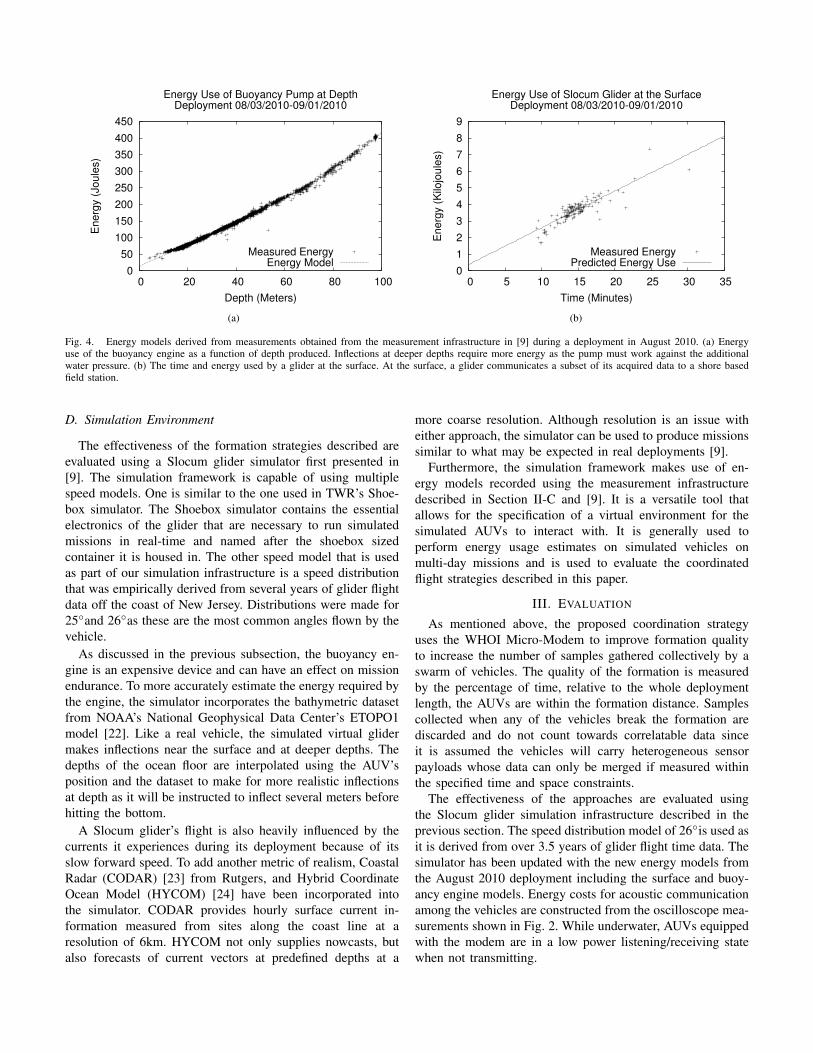
A glider equipped with a more optimized power measure-
ment infrastructure was deployed in August 2010 for one
month off the coast of New Jersey. The sole objective of
the deployment was to obtain the energy required for the
buoyancy engine to perform inflections at depths of up to 100
meters. Thus, all but four Hall effect sensors were removed to
reduce the power required by the board to enable a prolonged
deployment that could reach the continental shelf off the coast.
With this change, the clock frequency of the science bay
computer was also lowered since it was no longer responsible
for logging a full dataset. Overall, these modifications reduced
the overhead of the measurement infrastructure by nearly 40%.
The buoyancy engine of the Slocum Electric Glider is one
of the most energy expensive components on the vehicle [1].
A more precise cost was investigated in the August 2010 sea
trials because previous deployments, [9], did not achieve the
full depth range capable of the 100 meter coastal version of the
AUV. A new energy model for the buoyancy engine, derived
from measurements recorded by the infrastructure during the
deployment, is depicted in Fig. 4(a). The overall trend is
similar to the previous measurements but is no longer best
described by a linear model as a slight bow can be observed.
Because the buoyancy engine is such a critical device it is
crucial to have the most accurate energy model possible when
evaluating energy costs of the glider.
During a deployment, the vehicle must periodically surface
to gain a GPS fix and to send a subset of its gathered data back
to shore via an Iridium satellite modem. On the completion
of the transfer of the logged data, the glider may be given
new instructions or told to continue its current mission. Like
the buoyancy engine, this can be an expensive operation. To
accomplish a surfacing, a glider must increase the vacuum in
the hull to inflate an air bladder that keeps the tail fin, which
contains the antenna necessary for the communication, above
the waves.
Fig. 4(b) contains the measured energy required for the
vehicle to surface during the August 2010 deployment. The
data represents whole vehicle measurements and quantifies
how much energy is required to keep the vehicle at the
surface. Like the buoyancy engine, it is an important metric to
incorporate during the evaluation of the coordinated sampling
approach proposed since the vehicles are instructed to surface
when the formation falls apart and stay at the surface during
reformation.
0
50
100
150
200
250
300
350
400
450
0 20 40 60 80 100
Energ
y (
Joule
s)
Depth (Meters)
Energy Use of Buoyancy Pump at DepthDeployment 08/03/2010-09/01/2010
Measured EnergyEnergy Model
(a)
0
1
2
3
4
5
6
7
8
9
0 5 10 15 20 25 30 35
Energ
y (
Kilo
joule
s)
Time (Minutes)
Energy Use of Slocum Glider at the SurfaceDeployment 08/03/2010-09/01/2010
Measured EnergyPredicted Energy Use
(b)
Fig. 4. Energy models derived from measurements obtained from the measurement infrastructure in [9] during a deployment in August 2010. (a) Energyuse of the buoyancy engine as a function of depth produced. Inflections at deeper depths require more energy as the pump must work against the additionalwater pressure. (b) The time and energy used by a glider at the surface. At the surface, a glider communicates a subset of its acquired data to a shore basedfield station.
D. Simulation Environment
The effectiveness of the formation strategies described are
evaluated using a Slocum glider simulator first presented in
[9]. The simulation framework is capable of using multiple
speed models. One is similar to the one used in TWR’s Shoe-
box simulator. The Shoebox simulator contains the essential
electronics of the glider that are necessary to run simulated
missions in real-time and named after the shoebox sized
container it is housed in. The other speed model that is used
as part of our simulation infrastructure is a speed distribution
that was empirically derived from several years of glider flight
data off the coast of New Jersey. Distributions were made for
25◦and 26◦as these are the most common angles flown by the
vehicle.
As discussed in the previous subsection, the buoyancy en-
gine is an expensive device and can have an effect on mission
endurance. To more accurately estimate the energy required by
the engine, the simulator incorporates the bathymetric dataset
from NOAA’s National Geophysical Data Center’s ETOPO1
model [22]. Like a real vehicle, the simulated virtual glider
makes inflections near the surface and at deeper depths. The
depths of the ocean floor are interpolated using the AUV’s
position and the dataset to make for more realistic inflections
at depth as it will be instructed to inflect several meters before
hitting the bottom.
A Slocum glider’s flight is also heavily influenced by the
currents it experiences during its deployment because of its
slow forward speed. To add another metric of realism, Coastal
Radar (CODAR) [23] from Rutgers, and Hybrid Coordinate
Ocean Model (HYCOM) [24] have been incorporated into
the simulator. CODAR provides hourly surface current in-
formation measured from sites along the coast line at a
resolution of 6km. HYCOM not only supplies nowcasts, but
also forecasts of current vectors at predefined depths at a
more coarse resolution. Although resolution is an issue with
either approach, the simulator can be used to produce missions
similar to what may be expected in real deployments [9].
Furthermore, the simulation framework makes use of en-
ergy models recorded using the measurement infrastructure
described in Section II-C and [9]. It is a versatile tool that
allows for the specification of a virtual environment for the
simulated AUVs to interact with. It is generally used to
perform energy usage estimates on simulated vehicles on
multi-day missions and is used to evaluate the coordinated
flight strategies described in this paper.
III. EVALUATION
As mentioned above, the proposed coordination strategy
uses the WHOI Micro-Modem to improve formation quality
to increase the number of samples gathered collectively by a
swarm of vehicles. The quality of the formation is measured
by the percentage of time, relative to the whole deployment
length, the AUVs are within the formation distance. Samples
collected when any of the vehicles break the formation are
discarded and do not count towards correlatable data since
it is assumed the vehicles will carry heterogeneous sensor
payloads whose data can only be merged if measured within
the specified time and space constraints.
The effectiveness of the approaches are evaluated using
the Slocum glider simulation infrastructure described in the
previous section. The speed distribution model of 26◦is used as
it is derived from over 3.5 years of glider flight time data. The
simulator has been updated with the new energy models from
the August 2010 deployment including the surface and buoy-
ancy engine models. Energy costs for acoustic communication
among the vehicles are constructed from the oscilloscope mea-
surements shown in Fig. 2. While underwater, AUVs equipped
with the modem are in a low power listening/receiving state
when not transmitting.
−75˚
−75˚
−74˚
−74˚
−73˚
−73˚
39˚ 39˚
40˚ 40˚
Lat
itude
(Deg
rees
)
Longitude (Degrees)
Deployment 06/24/2009−07/09/2009
(a) (b)
Fig. 5. (a) The flight path of the glider deployment used as the basis of the simulated missions. (b) An hourly average of the surface currents measuredusing CODAR during the deployment.
The simulation involves a virtual deployment of three
Slocum gliders flying a multi-day mission in a leader/follower
formation. One vehicle is designated the leader and will remain
so throughout the mission. If any of the followers are detected
to not be within the formation, the leader and any followers
still in the formation will remain at the surface while waiting
for trailing gliders to rejoin the group.
The simulated mission is inspired by a 15 day glider
deployment from late June to early July of 2009 off the coast
of New Jersey. The flight path of the vehicle during the mission
is depicted in Fig. 5(a). The AUV was at times exposed to
significant currents which caused it to drift south as it made
its journey to the continental shelf.
Surface currents measured throughout the deployment, us-
ing CODAR, are used for all simulations. Overall, the CODAR
coverage of the deployment area was satisfactory throughout
the whole mission and was one of the reasons this specific
deployment was chosen. An hourly average of the surface
currents measured using CODAR during the deployment is
shown in Fig. 5(b). The current vectors, in Fig. 5(b), off the
coast of New Jersey are quite strong and are likely partially
responsible for the southward drift of the vehicle in Fig. 5(a).
The virtual AUVs in the simulations are deployed at the
same time and place the real vehicle was and are instructed to
target a similar waypoint near the continental shelf. To reduce
simulation time, only the flight leg from shore to the shelf is
considered. This flight typically takes the glider five to ten days
to complete depending on the season and other environmental
conditions.
The baseline formation strategy used for comparison does
not use acoustic underwater communication. Gliders using this
strategy will surface at predetermined time intervals where
they can obtain and communicate their positions to the others
in the swarm through a proxy, shore based, control station.
Followers out of formation are given new instructions to fly
near the leader’s most current position; the remaining vehicles
wait with the leader at the surface. The swarm only continues
its mission when all vehicles have again flocked together.
The alternative approach, which uses the WHOI Micro-
Modem, also performs predetermined vehicle surfacings. Like
the baseline, the AUVs can use satellite communication with
the base station to organize the formation. In addition, the
vehicles are able to use the modem’s ranging capabilities,
using minipackets, to approximate their distance from one
another while underwater [14]. This is performed in 15 minute
intervals in our simulations. Then, if it is determined that the
followers are out of the formation range, the leader will send
an immediate surface request to the group using the modem.
A two minute transmission cost is charged to perform this
task. Any recoordination is again determined at the surface
and accomplished through the control center.
The simulations for both strategies rely on two important
parameters, namely the surface interval time and the formation
distance. The surface interval describes the interval of time
in hours the gliders should resurface; the formation distance
parameter specifies the size of the radius the following gliders
have to be in from the leader to be considered within the
formation. Simulations were performed for the two approaches
with formation distances ranging from 0.5–5km and surface
intervals from 1–6 hours. When a glider surfaces, it remains at
the surface for a minimum of 15 minutes to communicate with
the field station and to obtain accurate GPS fixes. AUVs may
stay at the surface longer if they are waiting for the swarm to
reorganize. At the start of a particular simulation instance,
small random noise factors are created such as compass
errors for each glider and perturbations applied to interpolated
current vectors. For each of the formation size and surface
interval parameter pairs, 50 simulations were performed so that
their overall trend on the two strategies can be determined. All
3,600 simulations were performed with a runtime of several
days on a six node, 80 processor, computing cluster with
256GB of RAM.
40
50
60
70
80
90
100
1 2 3 4 5 6
Pe
rce
nta
ge
Surface Interval (Hours)
Staying In Formation Using Suface Only Communication
0.5km1km2km3km4km5km
(a)
1.0
1.5
2.0
2.5
3.0
3.5
4.0
4.5
5.0
5.5
6.0
1 2 3 4 5 6
En
erg
y (
Me
ga
jou
les)
Surface Interval (Hours)
Total Energy Staying In Formation Using Suface Only Communication
0.5km1km2km3km4km5km
(b)
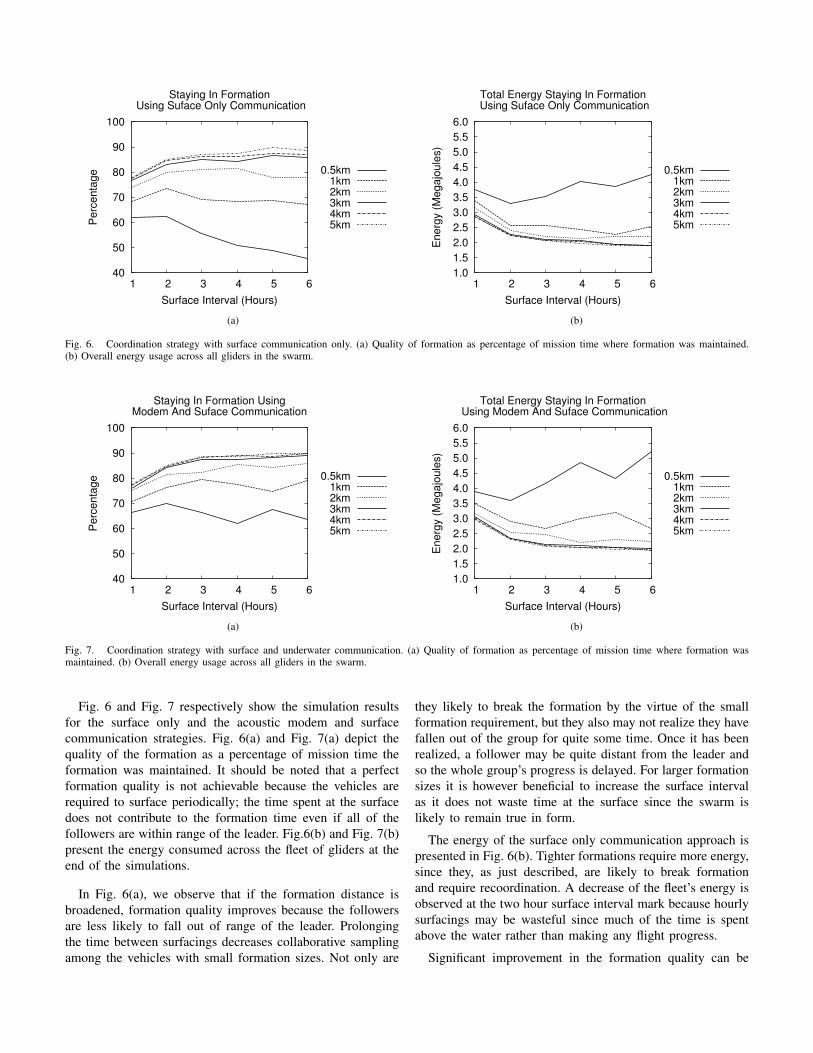
Fig. 6. Coordination strategy with surface communication only. (a) Quality of formation as percentage of mission time where formation was maintained.(b) Overall energy usage across all gliders in the swarm.
40
50
60
70
80
90
100
1 2 3 4 5 6
Pe
rce
nta
ge
Surface Interval (Hours)
Staying In Formation UsingModem And Suface Communication
0.5km1km2km3km4km5km
(a)
1.0
1.5
2.0
2.5
3.0
3.5
4.0
4.5
5.0
5.5
6.0
1 2 3 4 5 6
En
erg
y (
Me
ga
jou
les)
Surface Interval (Hours)
Total Energy Staying In Formation Using Modem And Suface Communication
0.5km1km2km3km4km5km
(b)
Fig. 7. Coordination strategy with surface and underwater communication. (a) Quality of formation as percentage of mission time where formation wasmaintained. (b) Overall energy usage across all gliders in the swarm.
Fig. 6 and Fig. 7 respectively show the simulation results
for the surface only and the acoustic modem and surface
communication strategies. Fig. 6(a) and Fig. 7(a) depict the
quality of the formation as a percentage of mission time the
formation was maintained. It should be noted that a perfect
formation quality is not achievable because the vehicles are
required to surface periodically; the time spent at the surface
does not contribute to the formation time even if all of the
followers are within range of the leader. Fig.6(b) and Fig. 7(b)
present the energy consumed across the fleet of gliders at the
end of the simulations.
In Fig. 6(a), we observe that if the formation distance is
broadened, formation quality improves because the followers
are less likely to fall out of range of the leader. Prolonging
the time between surfacings decreases collaborative sampling
among the vehicles with small formation sizes. Not only are
they likely to break the formation by the virtue of the small
formation requirement, but they also may not realize they have
fallen out of the group for quite some time. Once it has been
realized, a follower may be quite distant from the leader and
so the whole group’s progress is delayed. For larger formation
sizes it is however beneficial to increase the surface interval
as it does not waste time at the surface since the swarm is
likely to remain true in form.
The energy of the surface only communication approach is
presented in Fig. 6(b). Tighter formations require more energy,
since they, as just described, are likely to break formation
and require recoordination. A decrease of the fleet’s energy is
observed at the two hour surface interval mark because hourly
surfacings may be wasteful since much of the time is spent
above the water rather than making any flight progress.
Significant improvement in the formation quality can be
achieved using the proposed approach as shown in Fig. 7(a).
For small formation sizes with large surface intervals the
difference is the most dramatic because the vehicles in the
group have the ability to surface and recoordinate when
necessary. So it may be the case that during a simulation with
six hour surface intervals, the AUVs resurface every few hours
if the environmental conditions caused the formation to break.
In the same simulation, conditions could have been such that
the group did not need to surface at all for the entire six hours.
Larger formation sizes do not benefit as much with use of the
modem. Again, large formation sizes cause the vehicles to
not fall out of place very often which translates into fewer
rendezvous.
In Fig. 7(b), all of the simulations experience an energy
overhead. Even if the AUVs do not surface based on a surface
request by the leader, they carry the overhead of constantly
listening to hear for those requests. They must also periodically
reply to the leader’s range finding packets. Short formation
sizes are the most difficult to achieve and maintain, and so
they require the most energy regardless of the coordination
strategy used.
Overall, the new strategy is able to keep a glider formation
longer, but at the cost of an additional energy overhead.
For small formation granularities the tradeoff is clearly in
our favor, in the best case increasing the flight time within
formation by 49% while requiring only 13% more energy.
This corresponds to a 25% decrease in the energy cost per
collaborative data sample collected in the formation compared
to surface only communication. For larger formations this
is not the case since maintaining the formation and the
corresponding energy budget are comparable across the two
strategies.
IV. CONCLUSION
In this paper we show that low-bandwidth underwater
communication can be effectively used to maintain an AUV
formation in addition to surface communication. An overview
of the WHOI Micro-Modem and its measured power con-
sumption using an oscilloscope were provided. A summary of
the power measurement infrastructure, energy models derived
from a deployment equipped with the infrastructure, and
the simulation framework used in the evaluation were also
described.
The evaluation of the baseline surface only communication
and surface in addition to underwater communication forma-
tion strategies were performed and subsequently discussed.
Across nearly all simulations with varying formation distances
and surface times, the new strategy was able to stay in
formation longer. However, it also comes with an increase in
energy consumption for the entire swarm as compared to the
surface only communication approach.
Our formation strategy was especially effective for forma-
tions with small formation distances between the leader and
follower AUVs in the swarm and is the likely configuration
to be used in real deployments. For larger formation sizes,
some improvement in formation quality could still be achieved,
but the slight increase in energy costs may not be justifiable
as both strategies perform nearly the same. In the best case,
our strategy was able to achieve a 49% longer flight within
formation, costing only 13% more energy, but reducing the
overall data sample energy cost by 25%.
V. FUTURE WORK
The integration of the WHOI Micro-Modem stack into the
Slocum Glider is still in progress. Most of the hardware
installation of the modem has been accomplished, however
the software infrastructure needed to integrate the modem
into the rest of the glider’s systems must still be put in
place. Depending on the processing capabilities needed by the
applications during deployment, the software interface to the
modem could be either implemented on the vehicle’s science
bay computer or on the Linux SBCs we have installed as part
of our previous work [8]. The science bay computer provides
a lower power alternative but cannot support complex tasks
while also interacting with sensors.
We have kept the described formation algorithm very simple
to make it easier to implement in real sea trials. In the future,
we do not plan to keep the gliders within the formation at the
surface waiting for the rendezvous to complete as it can be
very dangerous at the surface. We may also not restrict that
a glider is designated as a leader for the entire duration of
the mission. For example, it may be advantageous to demote
the leader and promote a follower that is closer to a target
waypoint.
When the software infrastructure is in place, initial testing
will occur in a controlled environment such as a lake or
swimming pool. This should allow for basic communication
tests between gliders and a tow-fish lowered from a research
vessel. Once communication is established, gaining correct
range information between gliders is also required for our
formation strategy.
Another key component that must be in place is a commu-
nication protocol that allows the vehicles to interact with one
another. One such option is the Compact Control Language
(CCL) [25]. This would allow the Slocum glider to interoper-
ate with other vehicles in the future to create heterogeneous
swarms. More importantly, it will also be used to debug the
vehicles from topside during sea trials. Dynamic Compact
Control Language (DCCL) [26], inspired by CCL, is an
alternative option that produces more compact messages and
has support for data compression and encryption.
When the needed components are achieved individually, the
final hurdle is to ensure that communication, ranging, and
control all succeed together. Having a glider automatically
surface when it is out of range of a tow-fish lowered from a
vessel would mark an important stepping stone in realizing the
proposed formation strategy. Because all of these components
are extremely critical, they must all be tested extensively to
ensure long term formation deployments are possible.
We would also like to continue to perform more power
measurements to gain a better understanding of the power
requirements of the glider’s components including the acoustic
modem stack. For example, it would be useful to have a more
crisp model of the idle, receive, and transmit costs of the mo-
dem during deployments so that in the future communication
can be planned accordingly. A cost model may, for example,
determine that certain messages are not worthwhile sending
given the remaining energy budget of the mission.
The measurements will be made by the next generation of
the power measurement infrastructure. It is designed to be
more adaptable, so it can be easily altered for the sensor set
equipped for the mission. Any newly collected readings will be
used to build and improve the energy models for the simulation
framework [9]. This will more accurately determine any trade-
offs that coordination or swarming algorithms may provide.
Finally, we are planning to investigate other forms of coor-
dination. We may, for instance, have vehicles perform adaptive
data sampling across the group. Thus, a vehicle may trigger
another to start collecting readings because it has detected
something of interest using its own sensors. The behaviors
needed for plume detection and tracking would also be an
ideal application for a group of AUVs and should also be
explored.
ACKNOWLEDGEMENTS
This research has been partially funded by NSF awards
CSR-CSI #0720836 and MRI #0821607. We would also like
to thank David Aragon, Tina Haskins, Chip Haldeman, Oscar
Schofield and Scott Glenn from the Institute of Marine and
Coastal Sciences at Rutgers University for their continued
support.
REFERENCES
[1] O. Schofield, J. Kohut, D. Aragon, L. Creed, J. Graver, C. Haldeman,J. Kerfoot, H. Roarty, C. Jones, D. Webb, and S. Glenn, “Slocum gliders:Robust and ready,” J. Field Robotics, vol. 24, no. 6, pp. 473–485, 2007.
[2] L. Brignone, J. Alves, and J. Opderbecke, “Grex sea trials: first expe-riences in multiple underwater vehicle coordination based on acousticcommunication,” in OCEANS 2009 - EUROPE, May 2009, pp. 1–6.
[3] E. Fiorelli, N. E. Leonard, P. Bhatta, D. A. Paley, R. Bachmayer, andD. M. Fratantoni, “Multi-auv control and adaptive sampling in montereybay,” Oceanic Engineering, IEEE Journal of, vol. 31, no. 4, pp. 935–948,2006.
[4] N. E. Leonard, D. A. Paley, R. E. Davis, D. M. Fratantoni, F. Lekien,and F. Zhang, “Coordinated control of an underwater glider fleet in anadaptive ocean sampling field experiment in monterey bay,” J. Field
Robotics, vol. 27, no. 6, pp. 718–740, 2010.[5] A. Aguiary, J. Almeiday, M. Bayaty, B. Cardeiray, R. Cunhay,
A. Hauslery, P. Mauryay, A. Oliveiray, A. Pascoaly, A. Pereira, M. Rufi-noy, L. Sebastiaoy, C. Silvestrey, and F. Vanniy, “Cooperative au-tonomous marine vehicle motion control in the scope of the eu grexproject: Theory and practice,” in OCEANS 2009 - EUROPE, May 2009,pp. 1–10.
[6] R. Engel and J. Kalwa, “Relative positioning of multiple underwatervehicles in the grex project,” in OCEANS 2009 - EUROPE, May 2009,pp. 1–7.
[7] J. Kalwa, “The grex-project: Coordination and control of cooperat-ing heterogeneous unmanned systems in uncertain environments,” inOCEANS 2009 - EUROPE, May 2009, pp. 1–9.
[8] H. Woithe and U. Kremer, “A programming architecture for smartautonomous underwater vehicles,” in Intelligent Robots and Systems,
2009. IROS 2009. IEEE/RSJ International Conference on, 2009, pp.4433–4438.
[9] H. C. Woithe, I. Chigirev, D. Aragon, M. Iqbal, Y. Shames, S. Glenn,O. Schofield, I. Seskar, and U. Kremer, “Slocum glider energy measure-ment and simulation infrastructure,” in OCEANS 2010 IEEE - Sydney,May 2010, pp. 1–8.
[10] H. Woithe and U. Kremer, “An interactive slocum glider flight simula-tor,” in OCEANS 2010 IEEE - Seattle, 2010.
[11] L. Freitag, M. Grund, S. Singh, J. Partan, P. Koski, and K. Ball,“The WHOI micro-modem: an acoustic communications and navigationsystem for multiple platforms,” in OCEANS, 2005. Proceedings of
MTS/IEEE, vol. 2, 2005, pp. 1086–1092.[12] A. F. Harris, III, M. Stojanovic, and M. Zorzi, “When underwater acous-
tic nodes should sleep with one eye open: idle-time power managementin underwater sensor networks,” in WUWNet ’06: Proceedings of the
1st ACM international workshop on Underwater networks. New York,NY, USA: ACM, 2006, pp. 105–108.
[13] Woods Hole Oceanographic Institution, “Whoi acousticcommunications: Micro-modem,” Woods Hole, MA,http://acomms.whoi.edu/umodem/.
[14] S. Singh, M. Grund, B. Bingham, R. Eustice, H. Singh, and L. Freitag,“Underwater acoustic navigation with the WHOI micro-modem,” inOCEANS 2006, 2006, pp. 1–4.
[15] Teledyne Webb Research, “Slocum glider,” Falmouth, MA,http//www.webbresearch.com/slocum.htm.
[16] Hydroid, LLC., “Remus AUV,” http//www.hydroidnc.com/.[17] J. Bellingham, B. Hobson, M. A. Godin, B. Kieft, J. Erikson,
R. McEwen, C. Kecy, Y. Zhang, T. Hoover, and E. Mellinger, “A small,long-range auv with flexible speed and payload,” in Ocean Sciences
Meeting Meeting, Abstract MT15A-14, Portland, OR, Feb. 2010.[18] R. Davis, E. Eriksen, and C. Jones, “Autonomous buoyancy-driven
underwater gliders,” In: Technology and Applications of Autonomous
Underwater Vehicles, G. Griffiths (Ed), Taylor & Francis, London, pp.37–58, 2002.
[19] C. C. Eriksen, T. J. Osse, R. D. Light, T. Wen, T. W. Lehman, P. L. Sabin,J. W. Ballard, and A. M. Chiodi, “Seaglider: A long-range autonomousunderwater vehicle for oceanographic research,” in IEEE Journal of
Oceanic Engineering, vol. 26, no. 4, Oct. 2001.[20] J. Sherman, R. E. Davis, W. Owens, and J. Valdes, “The autonomous
underwater glider s̈pray,̈” in IEEE Journal of Oceanic Engineering,vol. 26, no. 4, 2001.
[21] J. G. Graver, R. Bachmayer, N. E. Leonard, and D. M. Fratantoni,“Underwater glider model parameter identification,” in Proceedings
13th International Symposium on Unmanned Untethered Submersible
Technology, 2003.[22] National Oceanic and Atmospheric Administration, “National geophys-
ical data center,” http://www.ngdc.noaa.gov/.[23] Rutgers University, Coastal Ocean Observation Lab, “CODAR,”
http://marine.rutgers.edu/cool/codar.html.[24] HYCOM consortium, “HYCOM,” http://www.hycom.org/.[25] R. Stokey, L. Freitag, and M. Grund, “A compact control language for
AUV acoustic communication,” in Oceans 2005 - Europe, vol. 2, 2005,pp. 1133–1137.
[26] T. Schneider and H. Schmidt, “The dynamic compact control lan-guage: A compact marshalling scheme for acoustic communications,”in OCEANS 2010 IEEE - Sydney, May 2010, pp. 1–10.


![DYNAMICS & CONTROL OF UNDERWATER GLIDERS II ......gliders includes Slocum [26], Seaglider [4], and Spray [25]. (Figure 1 shows a solid model of the Slocum gilder.) These “legacy](https://img.pdfslide.net/doc/110x75/60e3371a8f334459e067d3dc/dynamics-control-of-underwater-gliders-ii-gliders-includes-slocum.jpg)