Embed Size (px)
Citation preview
Liebert®UTILITYSURE
INDUSTRIAL MODULAR RECTIFIER BATTERY CHARGER
Liebert UtilitySure
UtilitySureTM is a reliable industrial modular rectifier battery charger with stateof-the- art technology. UtilitySureTM is designed to meet the most demanding specifications of industrial requirements. UtilitySureTM product includes a wide choice of ratings and operator friendly features.
Available in 24, 48, 110 & 220 nominal voltages.
Benefits
• Highest availability of power:- Hot-swappable modules to reduce
the MTTR (Mean Time to Repair).
- MTBF (Mean time between
failures) > 2,50,000 hrs.
- Various redundancy levels - N+1
(or) N+2 (or) N+N toimprove load
continuity.
• Monitoring:- State-of-the-art Individual DC
feeder earth leakage monitoring.
- Battery Monitoring System (BMS).
- Each Feeder status monitoring
(On/o�/trip).
• High electrical performances:- Wide input voltage tolerance to
comply with the worst utility
conditions.
- Near Unity input power factor, low
THDi rejection and low in rush
current to save installation and
operation costs.
- High e�iciency to lower power
consumption.
• Industrial flexibility:- Suitable for all battery types
(Lead Acid or Nickel-Cadmium or
Plante).
- Scalability to meet the evolving
load changes.
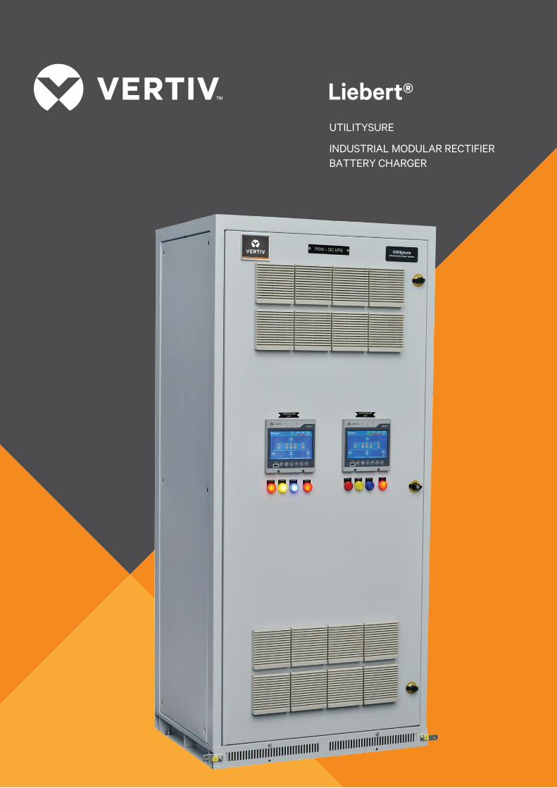
BLOCK DIAGRAM OF A MODULAR DC UPS (FCBC)
Controller
rectifier module-1
Input
rectifier module-N
Load
Battery
rectifier module-2
Key Features
• Large and colour LCD (touch-pad
user interface - optional with
EMU10 controller)
• USB port to import / export
system configuration
(optional with EMU10 controller)
• Low voltage ripple to optimize
battery life
• In-built galvanic isolation (inside
rectifier modules)
• Ingress protection up to IP 55
• Suits all weather conditions: works
from - 40° C to 70° C
Applications
UtilitySureTM suits all DC UPS
applications where modular design
concept is key for maintenance with
highest uptime. It is best suitable
for all critical applications such as:
• Power generation
• Oil & gas
• Rail transportation infrastructures
• Power transmission and
distribution substations
• Other industries

24V 48V 110V 220V
75A, 1Ph (ER2475S) / 30A, 1Ph (ER4830S) 10A, 1Ph (ER11010S) 5A, 1Ph (ER22005S)
75A, 1Ph (R24-2200) 50A, 1Ph (ER4850S) 20A, 3Ph (ER11020T) 1 0A, 3Ph (ER22010T)
- 40A, 3Ph (ER11040T) 20A, 3Ph (ER22020T)
DETAILS OF RECTIFIER MODULES :We have the following ratings of rectifier modules:
The details of each rectifier module are as follows:
1-Phase Modules 3-Phase Modules
Parameter ER22005S ER11010S ER4850S ER2475S / ER22020T ER22010T ER11040T ER11020T
R24-2200
AC Input Voltage (V) 85-286 (Single Phase) 85-290 (Single Phase) 305-530V 323-475V 305-530V 323-475V
(3 Phase, 3 Wire) (3 Phase, 3 Wire) (3 Phase, 3 Wire) (3 Phase, 3 Wire)
AC input frequency 45 - 65 45 - 65
AC input current (A) <4 <4 <10 <10 <15 <10 <15 <10
Efficiency ≥91 % ≥91 % ≥90.5 % ≥90% ≥92.5% ≥92% 92 % ≥92 %
Power Factor ≥0.99 ≥0.99 ≥0.99 ≥0.99 ≥0.99 ≥0.92 ≥0.99 ≥0.92
THD ≤5% ≤5% ≤5% ≤5% ≤5% ≤30% ≤5% ≤30%
DC Output Voltage 176 - 286 88- 143 42 - 68 21 - 39 176 - 320 176 - 320 88-160 88-160
Range(V)
Rated Current (A) 5 10 50 75 20 10 40 20
Output Power (W) 1430 1430 2900 2175 5720 2860 5720 2860
Ripple Factor <=0.1% RMS <=0.1% RMS ≤0.1% RMS ≤0.5% RMS ≤0.1% RMS ≤0.1% RMS ≤0.1% RMS ≤0.1% RMS
Current Stabilizing ≤±1.0 % ≤±1.0 % ≤±1.0 % ≤±1.0 % ≤±0.5 % ≤±0.5 % ≤±0.5% ≤±0.5%Accuracy
Voltage Stabilizing ≤±0.5 % ≤±0.5 % ≤±0.5 % ≤±0.7 % ≤±0.5 % ≤±0.5 % ≤±0.5 % ≤±0.5 %
Accuracy
CE & ROHS CE CERTIFIED & ROHS COMPLIANT (R5)
Noise (dB) ≤55 ≤55 ≤55 ≤55 ≤50 ≤52 ≤50 ≤52
145H 145H 132H 132H 244H 176H 244H 176H
72W 72W 85W 85W 88W 88W 88W 88W
280D 280D 287D 287D 380 D 315 D 380 D 315D
Weight (kg) <3 <3 <3.5 <3.5 <10 <6 < 10 <6
Dimension (mm)
Liebert UtilitySure
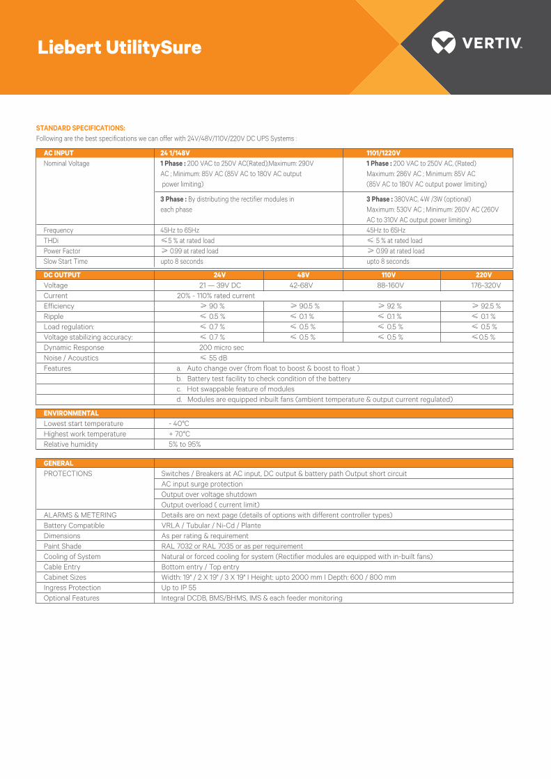
STANDARD SPECIFICATIONS: Following are the best specifications we can offer with 24V/48V/110V/220V DC UPS Systems :
GENERAL PROTECTIONS Switches / Breakers at AC input, DC output & battery path Output short circuit AC input surge protection Output over voltage shutdown Output overload ( current limit)ALARMS & METERING Details are on next page (details of options with different controller types)Battery Compatible VRLA / Tubular / Ni-Cd / PlanteDimensions As per rating & requirementPaint Shade RAL 7032 or RAL 7035 or as per requirementCooling of System Natural or forced cooling for system (Rectifier modules are equipped with in-built fans)Cable Entry Bottom entry / Top entryCabinet Sizes Width: 19" / 2 X 19" / 3 X 19" I Height: upto 2000 mm I Depth: 600 / 800 mmIngress Protection Up to IP 55Optional Features Integral DCDB, BMS/BHMS, IMS & each feeder monitoring
ENVIRONMENTAL Lowest start temperature - 40°CHighest work temperature + 70°CRelative humidity 5% to 95%
DC OUTPUT 24V 48V 110V 220VVoltage 21 — 39V DC 42-68V 88-160V 176-320VCurrent 20% - 110% rated currentEfficiency ≥ 90 % ≥ 90.5 % ≥ 92 % ≥ 92.5 %Ripple ≤ 0.5 % ≤ 0.1 % ≤ 0.1 % ≤ 0.1 %Load regulation: ≤ 0.7 % ≤ 0.5 % ≤ 0.5 % ≤ 0.5 %Voltage stabilizing accuracy: ≤ 0.7 % ≤ 0.5 % ≤ 0.5 % ≤0.5 %Dynamic Response 200 micro secNoise / Acoustics ≤ 55 dBFeatures a. Auto change over (from float to boost & boost to float ) b. Battery test facility to check condition of the battery c. Hot swappable feature of modules d. Modules are equipped inbuilt fans (ambient temperature & output current regulated)
AC INPUT 24 1/148V 1101/1220VNominal Voltage 1 Phase : 200 VAC to 250V AC(Rated),Maximum: 290V 1 Phase : 200 VAC to 250V AC, (Rated) AC ; Minimum: 85V AC (85V AC to 180V AC output Maximum: 286V AC ; Minimum: 85V AC power limiting) (85V AC to 180V AC output power limiting)
3 Phase : By distributing the rectifier modules in 3 Phase : 380VAC, 4W /3W (optional) each phase Maximum: 530V AC ; Minimum: 260V AC (260V AC to 310V AC output power limiting)Frequency 45Hz to 65Hz 45Hz to 65HzTHDi ≤5 % at rated load ≤ 5 % at rated loadPower Factor ≥ 0.99 at rated load ≥ 0.99 at rated loadSlow Start Time upto 8 seconds upto 8 seconds
Liebert UtilitySure
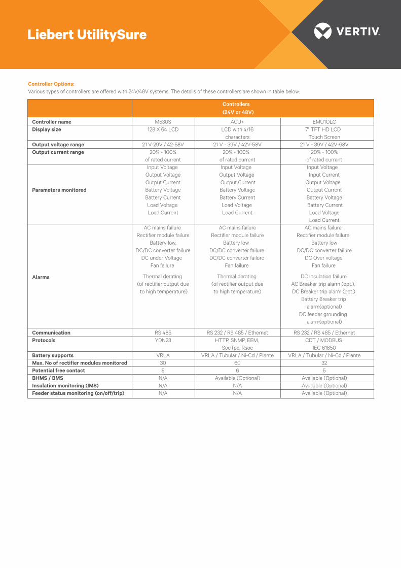
Controller Options:Various types of controllers are offered with 24V/48V systems. The details of these controllers are shown in table below:
Controller name M530S ACU+ EMU1OLCDisplay size 128 X 64 LCD LCD with 4/16 7" TFT HD LCD characters Touch Screen Output voltage range 21 V-29V / 42-58V 21 V - 39V / 42V-58V 21 V - 39V / 42V-68VOutput current range 20% - 100% 20% - 100% 20% - 100% of rated current of rated current of rated current Input Voltage Input Voltage Input Voltage Output Voltage Output Voltage Input Current Output Current Output Current Output Voltage Battery Voltage Battery Voltage Output Current Battery Current Battery Current Battery Voltage Load Voltage Load Voltage Battery Current Load Current Load Current Load Voltage Load Current AC mains failure AC mains failure AC mains failure Rectifier module failure Rectifier module failure Rectifier module failure Battery low, Battery low Battery low DC/DC converter failure DC/DC converter failure DC/DC converter failure DC under Voltage DC/DC converter failure DC Over voltage Fan failure Fan failure Fan failure
Thermal derating Thermal derating DC Insulation failure (of rectifier output due (of rectifier output due AC Breaker trip alarm (opt.), to high temperature) to high temperature) DC Breaker trip alarm (opt.) Battery Breaker trip alarm(optional) DC feeder grounding alarm(optional)
Communication RS 485 RS 232 / RS 485 / Ethernet RS 232 / RS 485 / EthernetProtocols YDN23 HTTP, SNMP, EEM, CDT / MODBUS SocTpe, Rsoc IEC 61850Battery supports VRLA VRLA / Tubular / Ni-Cd / Plante VRLA / Tubular / Ni-Cd / PlanteMax. No of rectifier modules monitored 30 60 32Potential free contact 5 6 5BHMS / BMS N/A Available (Optional) Available (Optional)Insulation monitoring (IMS) N/A N/A Available (Optional)Feeder status monitoring (on/off/trip) N/A N/A Available (Optional)
Parameters monitored
Alarms
Controllers(24V or 48V)
Liebert UtilitySure
Liebert UtilitySure
Controllers(110V or 220V)
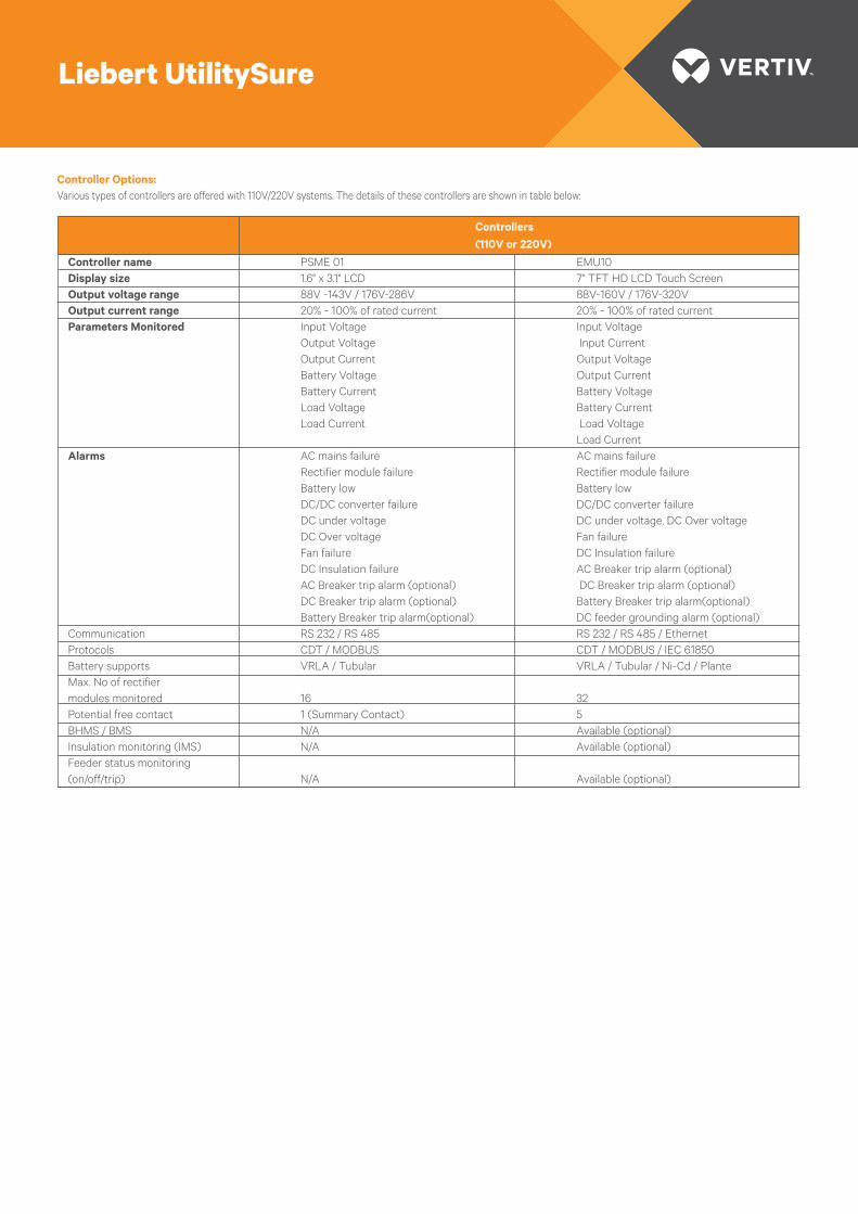
Controller name PSME 01 EMU10Display size 1.6" x 3.1" LCD 7" TFT HD LCD Touch ScreenOutput voltage range 88V -143V / 176V-286V 88V-160V / 176V-320VOutput current range 20% - 100% of rated current 20% - 100% of rated currentParameters Monitored Input Voltage Input Voltage Output Voltage Input Current Output Current Output Voltage Battery Voltage Output Current Battery Current Battery Voltage Load Voltage Battery Current Load Current Load Voltage Load CurrentAlarms AC mains failure AC mains failure Rectifier module failure Rectifier module failure Battery low Battery low DC/DC converter failure DC/DC converter failure DC under voltage DC under voltage, DC Over voltage DC Over voltage Fan failure Fan failure DC Insulation failure DC Insulation failure AC Breaker trip alarm (optional) AC Breaker trip alarm (optional) DC Breaker trip alarm (optional) DC Breaker trip alarm (optional) Battery Breaker trip alarm(optional) Battery Breaker trip alarm(optional) DC feeder grounding alarm (optional)Communication RS 232 / RS 485 RS 232 / RS 485 / EthernetProtocols CDT / MODBUS CDT / MODBUS / IEC 61850Battery supports VRLA / Tubular VRLA / Tubular / Ni-Cd / PlanteMax. No of rectifier modules monitored 16 32Potential free contact 1 (Summary Contact) 5BHMS / BMS N/A Available (optional)Insulation monitoring (IMS) N/A Available (optional)Feeder status monitoring (on/off/trip) N/A Available (optional)
Controller Options:Various types of controllers are offered with 110V/220V systems. The details of these controllers are shown in table below:
Liebert UtilitySure
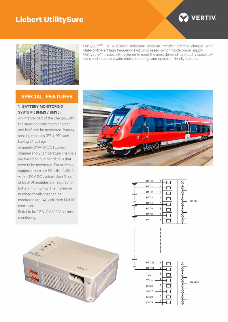
UtilitySureTM is a reliable industrial modular rectifier battery charger with state-of-the-art high frequency switching based switch-mode power supply.UtilitySureTM is specially designed to meet the most demanding industry specifica-tions and includes a wide choice of ratings and operator friendly features.
1. BATTERY MONITORING SYSTEM ( BHMS / BMS ) :An integral part of the charger, with
the same controller,both charger
and BMS can be monitored. Battery
sensing modules (EBU-01) each
having 24 voltage
channels(0.1V-16.5V), 1 current
channel and 2 temperature channels
are based on number of cells that
need to be monitored. For example,
suppose there are 55 cells of VRLA
with a 110V DC system; then 3 nos.
of EBU-01 modules are required for
battery monitoring. The maximum
number of cells that can be
monitored are 240 cells with EMU10
controller.
Suitable for 1.2 V /2V / 12 V battery
monitoring.
SPECIAL FEATURES
3. FEEDER STATUS (ON/OFF/TRIP) MONITORING :Tripping of DC feeders can be
easily monitored by connecting
each feeder (MCB/MCCB) trip
contact to EGU-01 sampling module
which will send signal to control-
ler(EMU10). One EGU-01 can have
28 feeder inputs.
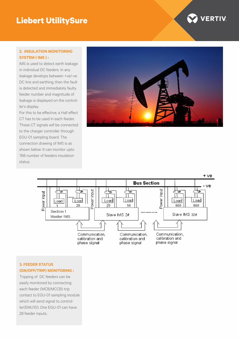
2. INSULATION MONITORING SYSTEM ( IMS ) :IMS is used to detect earth leakage
in individual DC feeders. In any
leakage develops between +ve/-ve
DC line and earthing, then the fault
is detected and immediately faulty
feeder number and magnitude of
leakage is displayed on the control-
ler's display.
For this to be e�ective, a Hall e�ect
CT has to be used in each feeder.
These CT signals will be connected
to the charger controller through
EGU-01 sampling board. The
connection drawing of IMS is as
shown below: It can monitor upto
768 number of feeders insulation
status.
Liebert UtilitySure
28 29 56 869 869
32#

2. FCBC WITH VOLTAGE DROP-PING DIODESThis configuration is very similar to
the one described above. The extra
feature is Dropper Diodes Chain which
is required when there is only
one FCBC and battery boost charging
voltage is far high and if the voltage at
load terminals needs to be limited
within +/-10% of nominal
system voltage. During float mode and
AC mails fails condition the VDD shall
be bypassed through DC contractor.
1. FCBCIn this configuration, charger is
connected directly to battery and
load. Normally, the charger will be in
float mode trickle charging the
battery and supplying the load. When
AC mains fail the battery will supply
the load. On restoration of power, the
charger will switch to boost mode,
charging the battery and supplying
the load. In the mode, boost voltage
will be appeared across the load
terminal.
There is also an option for integral DC
distribution board.
POSSIBLE CONFIGURATIONS:
Liebert UtilitySure
Input Load
Input LoadVDD
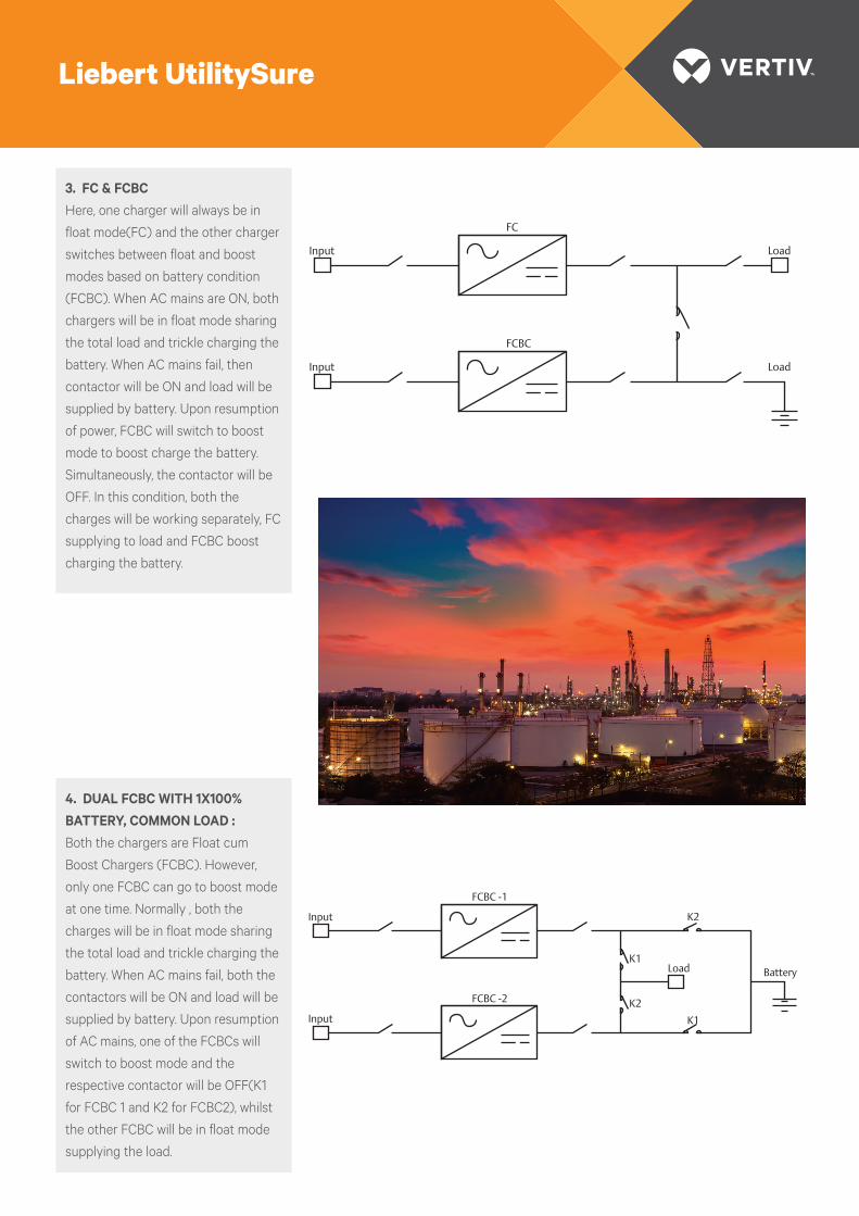
3. FC & FCBC Here, one charger will always be in
float mode(FC) and the other charger
switches between float and boost
modes based on battery condition
(FCBC). When AC mains are ON, both
chargers will be in float mode sharing
the total load and trickle charging the
battery. When AC mains fail, then
contactor will be ON and load will be
supplied by battery. Upon resumption
of power, FCBC will switch to boost
mode to boost charge the battery.
Simultaneously, the contactor will be
OFF. In this condition, both the
charges will be working separately, FC
supplying to load and FCBC boost
charging the battery.
Input
FC
Load
Input
FCBC
Load
4. DUAL FCBC WITH 1X100% BATTERY, COMMON LOAD : Both the chargers are Float cum
Boost Chargers (FCBC). However,
only one FCBC can go to boost mode
at one time. Normally , both the
charges will be in float mode sharing
the total load and trickle charging the
battery. When AC mains fail, both the
contactors will be ON and load will be
supplied by battery. Upon resumption
of AC mains, one of the FCBCs will
switch to boost mode and the
respective contactor will be OFF(K1
for FCBC 1 and K2 for FCBC2), whilst
the other FCBC will be in float mode
supplying the load.
Input
FCBC -1
Input
FCBC -2
K2
K1
Load BatteryK1
K2
Liebert UtilitySure
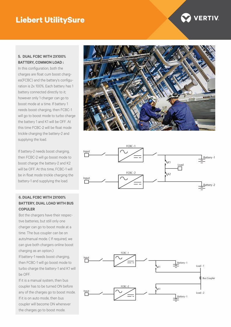
5. DUAL FCBC WITH 2X100% BATTERY, COMMON LOAD :In this configuration, both the
charges are float cum boost charg-
es(FCBC) and the battery's configu-
ration is 2x 100%. Each battery has 1
battery connected directly to it;
however only 1 charger can go to
boost mode at a time. If battery 1
needs boost charging, then FCBC-1
will go to boost mode to turbo charge
the battery 1 and K1 will be OFF. At
this time FCBC-2 will be float mode
trickle charging the battery-2 and
supplying the load.
If battery-2 needs boost charging,
then FCBC-2 will go boost mode to
boost charge the battery-2 and K2
will be OFF. At this time, FCBC-1 will
be in float mode trickle charging the
battery-1 and supplying the load.
Input
FCBC -1
Input
FCBC -2
LoadK1
K2
Battery -1
Battery -2
Input
FCBC -1
Input
FCBC -2
Load - 1K1
Battery -1
Load - 2
K1
Battery -1
Bus Coupler
6. DUAL FCBC WITH 2X100% BATTERY, DUAL LOAD WITH BUS COPULER Bot the chargers have their respec-
tive batteries, but still only one
charger can go to boost mode at a
time. The bus coupler can be on
auto/manual mode. ( If required, we
can give both chargers online boost
charging as an option.)
If battery-1 needs boost charging,
then FCBC-1 will go boost mode to
turbo charge the battery-1 and K1 will
be OFF.
If it is a manual system, then bus
coupler has to be turned ON before
any of the charges go to boost mode.
If it is on auto mode, then bus
coupler will become ON whenever
the charges go to boost mode.
Liebert UtilitySure

| © 2016 Vertiv Co. All rights reserved.
Plot No. C-20, Road No. 19, Wagle Estate, Thane (W), Maharashtra - 400 604. India.VertivCo.com
E-mail : [email protected] free : 1-800-2096070