Embed Size (px)
Citation preview
Long-Term Evolution
Mobile Telecommunications Networks
WMNet Lab
Background
Long-Term Evolution
Define a new packet-only wideband radio with flat architecture as part of 3GPP radio technology family
2004: identifying requirements from different players in the field
2005: feasibility study started
Key issues
Multiple access method
Network architecture in terms of functional split between radio access and core network
2
Background
Key requirements
Packet-switched domain optimized
Server to UE round-trip time below 30ms and access delay below 300ms
Peak Rates UL/DL 50/100Mbps
Good level of mobility and security ensured
Improved terminal power efficiency
Frequency allocation flexibility
Higher Capacity compare with R6 HSDPA/HSUPA reference case
3
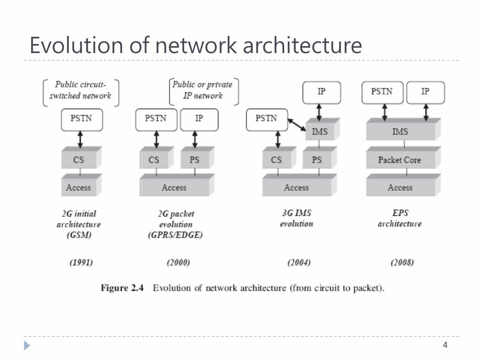
Evolution of network architecture
4
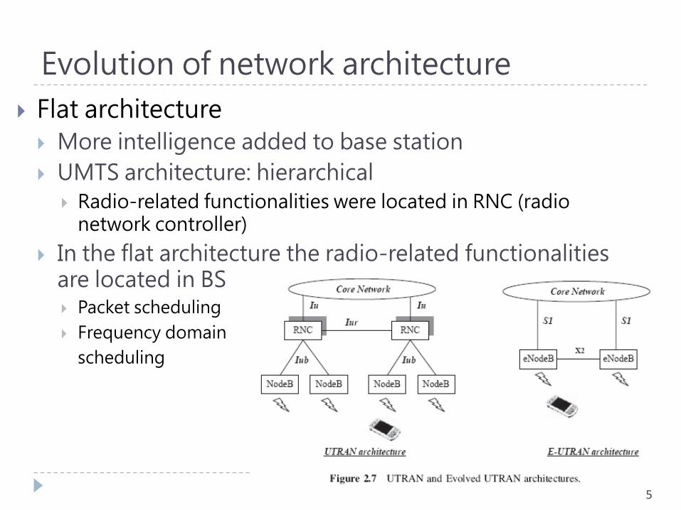
Evolution of network architecture
Flat architecture
More intelligence added to base station
UMTS architecture: hierarchical
Radio-related functionalities were located in RNC (radio network controller)
In the flat architecture the radio-related functionalities are located in BS Packet scheduling
Frequency domain
scheduling
5
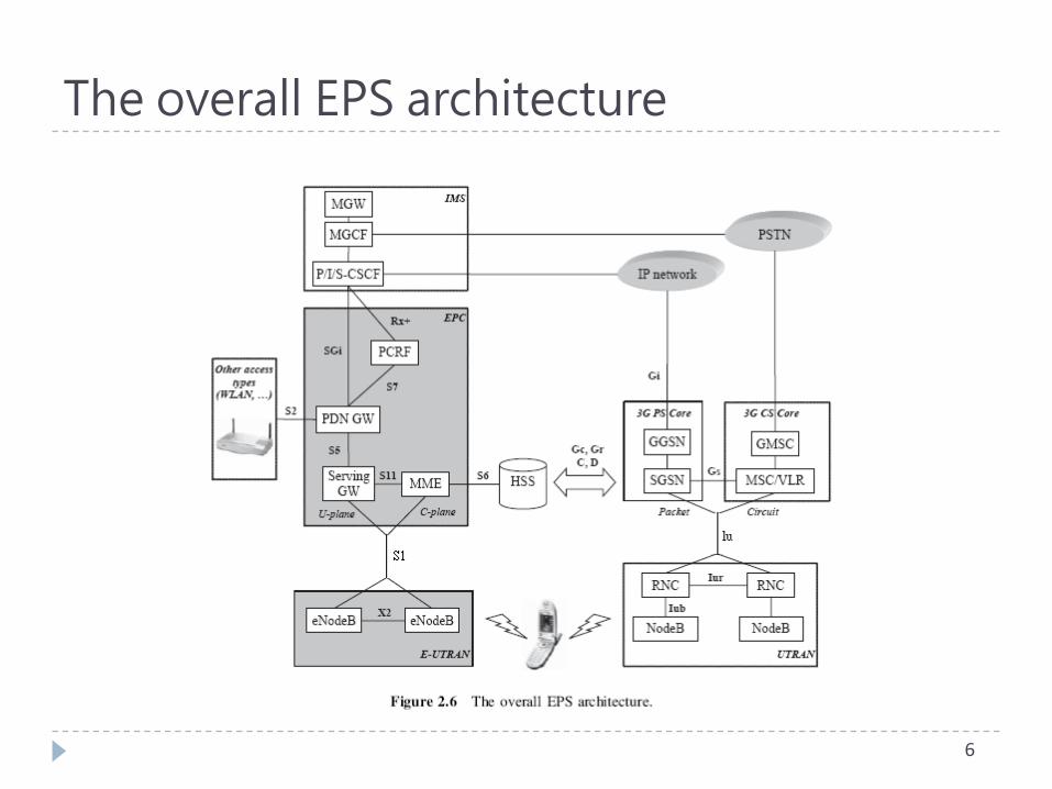
The overall EPS architecture
6
EPC: functional entities
MME (Mobility Management Entity)
Control plane functions
Security procedures
Terminal-to-network session handling
Idle terminal location management
Serving GW (Serving Gateway)
Packets are routed through this point for intra E-UTRAN mobility and other 3GPP technologies
PDN GW (Packet Data Network Gateway)
Sessions towards the external Packet Data Networks
Supports policy enforcement features, packet filtering and charging support
7
EPC: functional entities
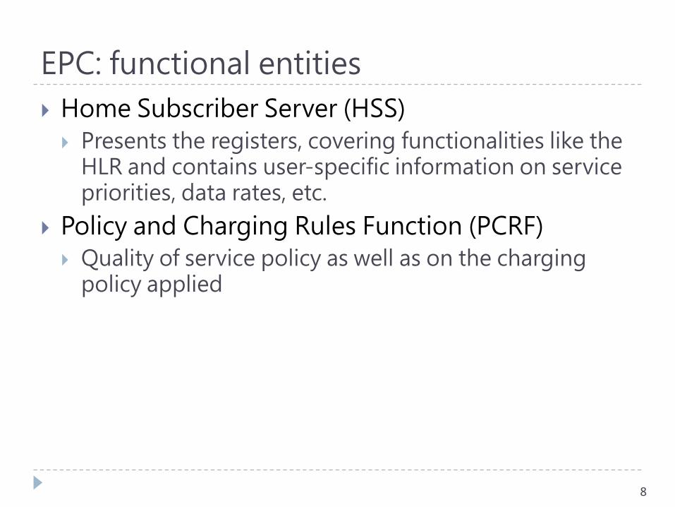
Home Subscriber Server (HSS)
Presents the registers, covering functionalities like the HLR and contains user-specific information on service priorities, data rates, etc.
Policy and Charging Rules Function (PCRF)
Quality of service policy as well as on the charging policy applied
8
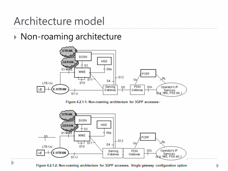
Architecture model
Non-roaming architecture
9
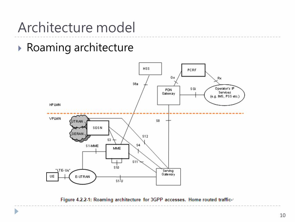
Architecture model
Roaming architecture
10
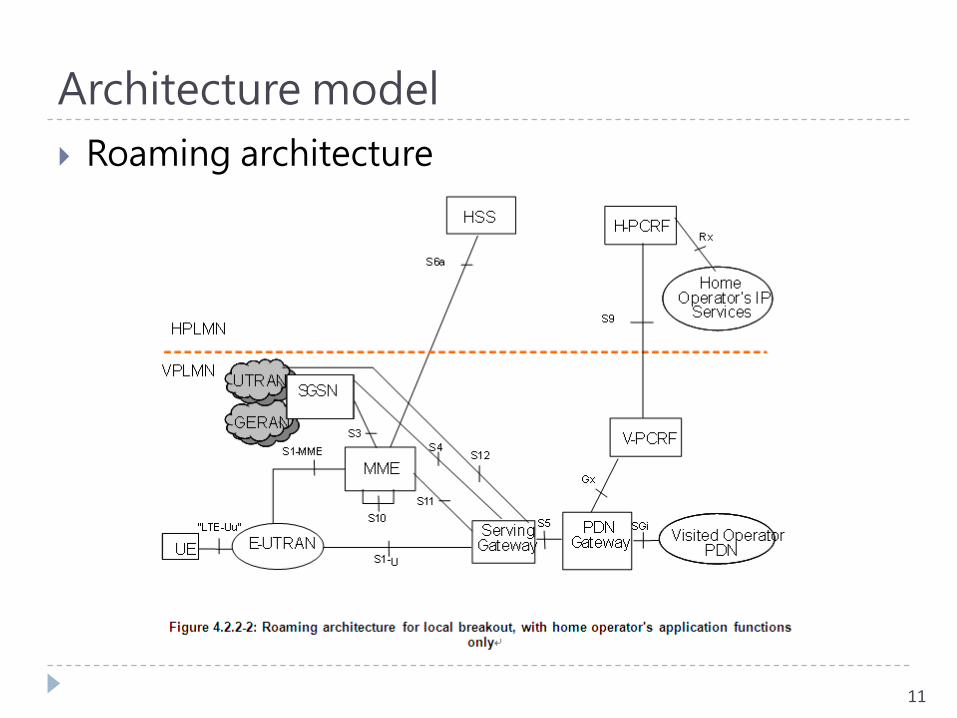
Architecture model
Roaming architecture
11
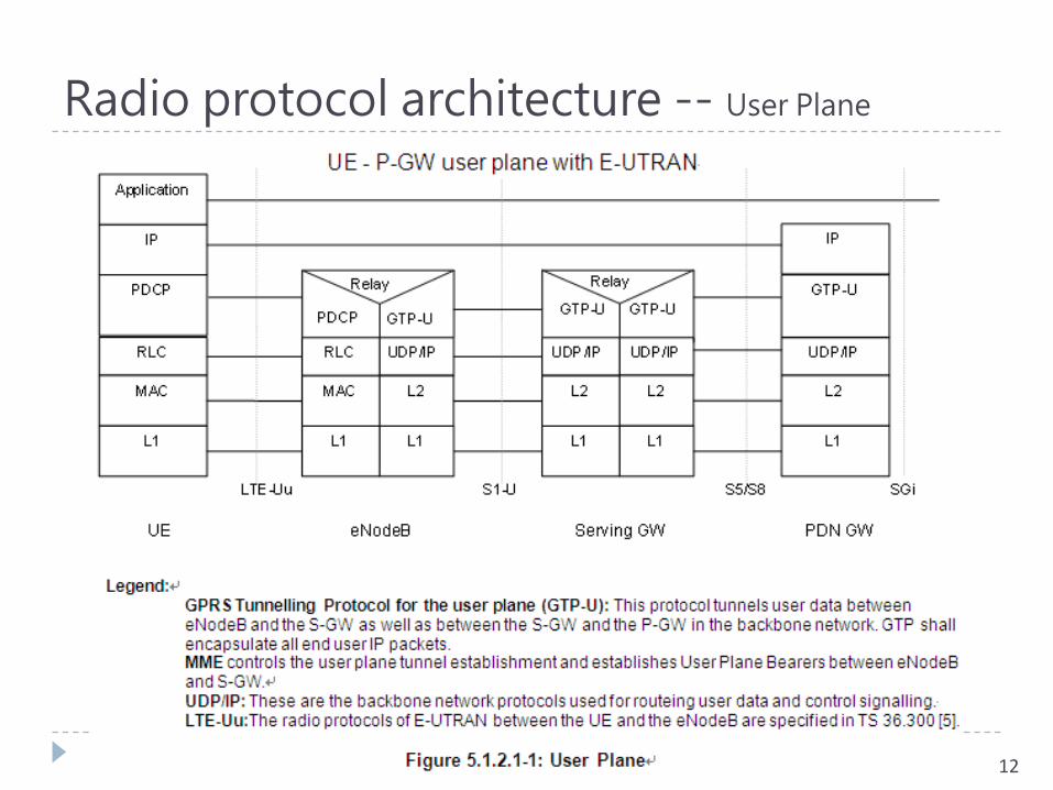
Radio protocol architecture -- User Plane
12
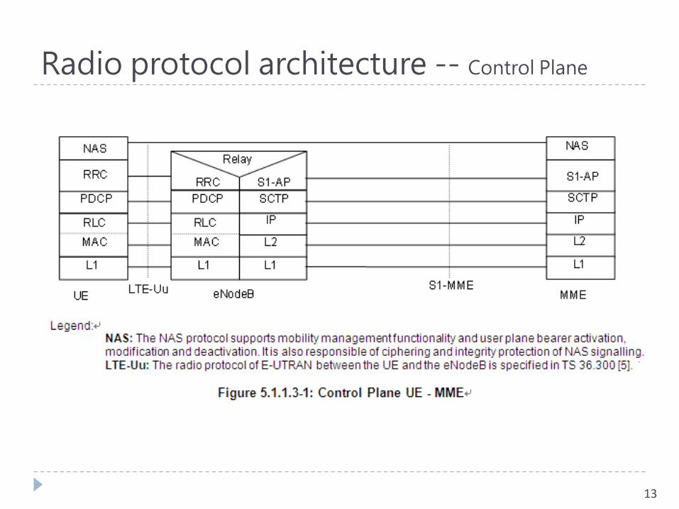
Radio protocol architecture -- Control Plane
13
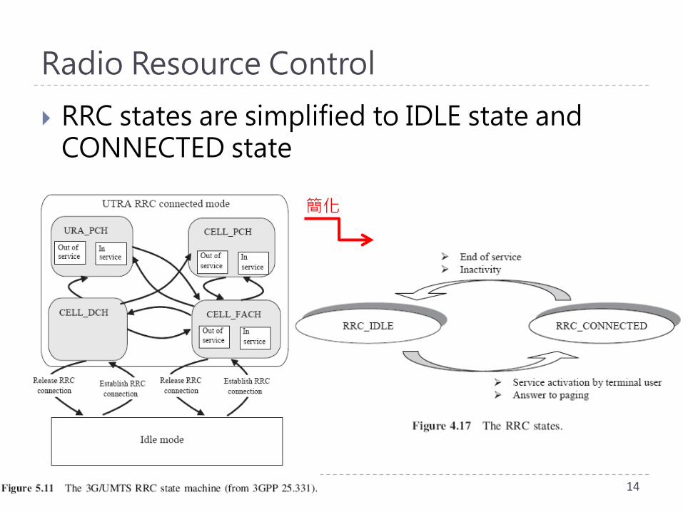
Radio Resource Control
RRC states are simplified to IDLE state and CONNECTED state
14
簡化
Radio Resource Control
15
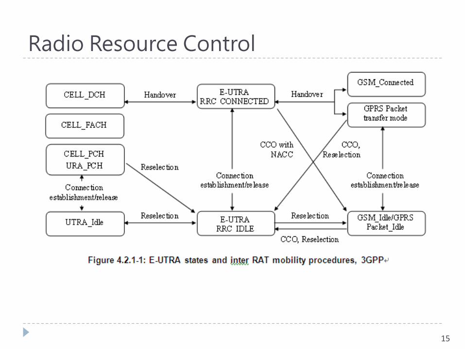
Radio Resource Control
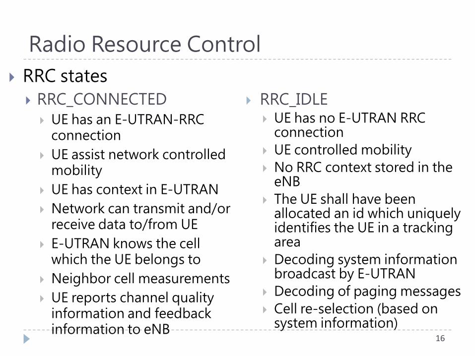
RRC states
RRC_CONNECTED
UE has an E-UTRAN-RRC connection
UE assist network controlled mobility
UE has context in E-UTRAN
Network can transmit and/or receive data to/from UE
E-UTRAN knows the cell which the UE belongs to
Neighbor cell measurements
UE reports channel quality information and feedback information to eNB
16
RRC_IDLE UE has no E-UTRAN RRC
connection
UE controlled mobility
No RRC context stored in the eNB
The UE shall have been allocated an id which uniquely identifies the UE in a tracking area
Decoding system information broadcast by E-UTRAN
Decoding of paging messages
Cell re-selection (based on system information)
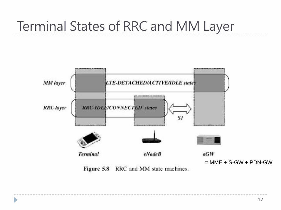
Terminal States of RRC and MM Layer
17
= MME + S-GW + PDN-GW
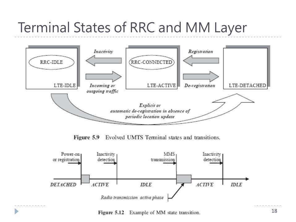
Terminal States of RRC and MM Layer
18
Terminal States of MM Layer
LTE-DETACHED The mobile is not registered to the network
LTE-IDLE The mobile is registered to the network, but not
active Low power consumption mode
Location management at the Tracking Area level
Resume a previously active data session without having to Set up the EPC bearers
Renegotiate the associated Quality of Service attributes
LTE-ACTIVE The only real active state
The terminal is exchanging data and signaling information with the network (RRC connection being set up)
19
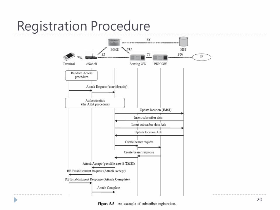
Registration Procedure
20
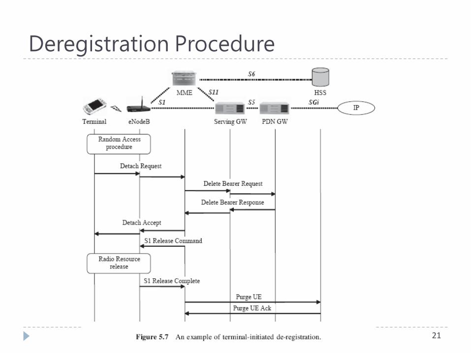
Deregistration Procedure
21

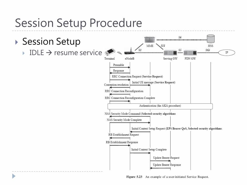
Session Setup Procedure
Session Setup
There are two types of procedures in session setup
Service Request
An IDLE to ACTIVE terminal state transition because the user is resuming a data session or activating a new service
Dedicated Bearer activation
A new application service activation while the terminal is in ACTIVE mode
22
Session Setup Procedure
Session Setup IDLE resume service
23
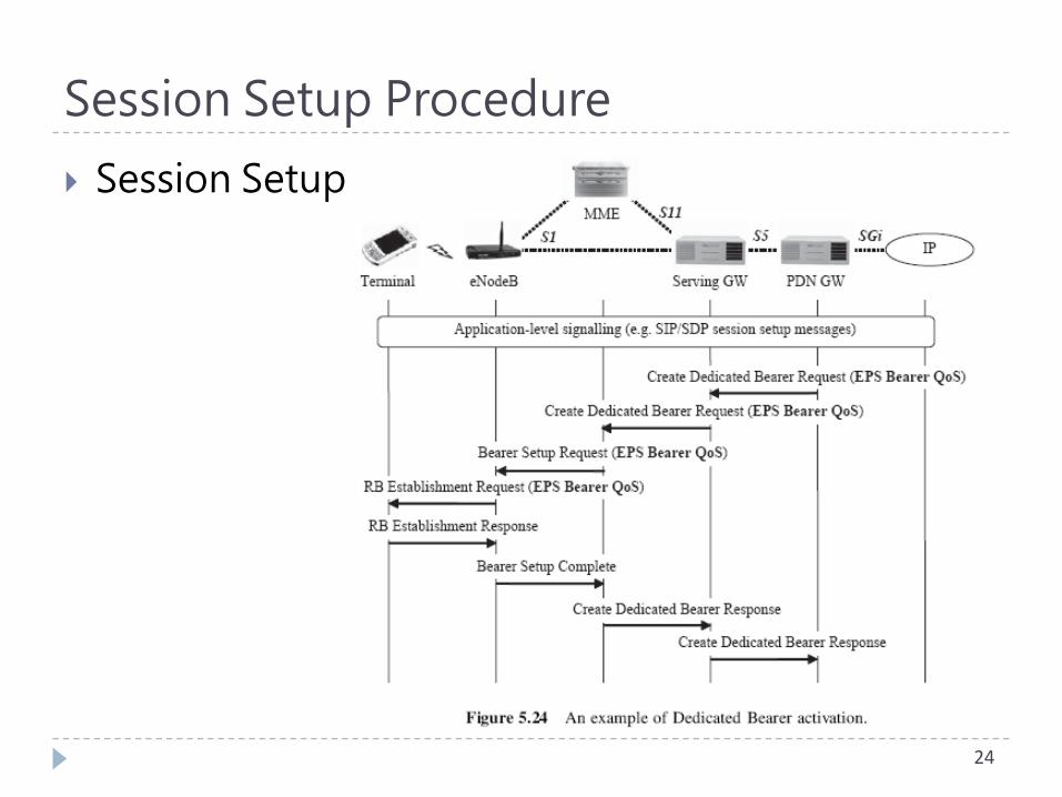
Session Setup Procedure
Session Setup
24
Mobility Management
Mobility in ACTIVE mode
UE assisted network controlled handover
The decision to move / choice for the target cell is made by the current serving eNodeB
25
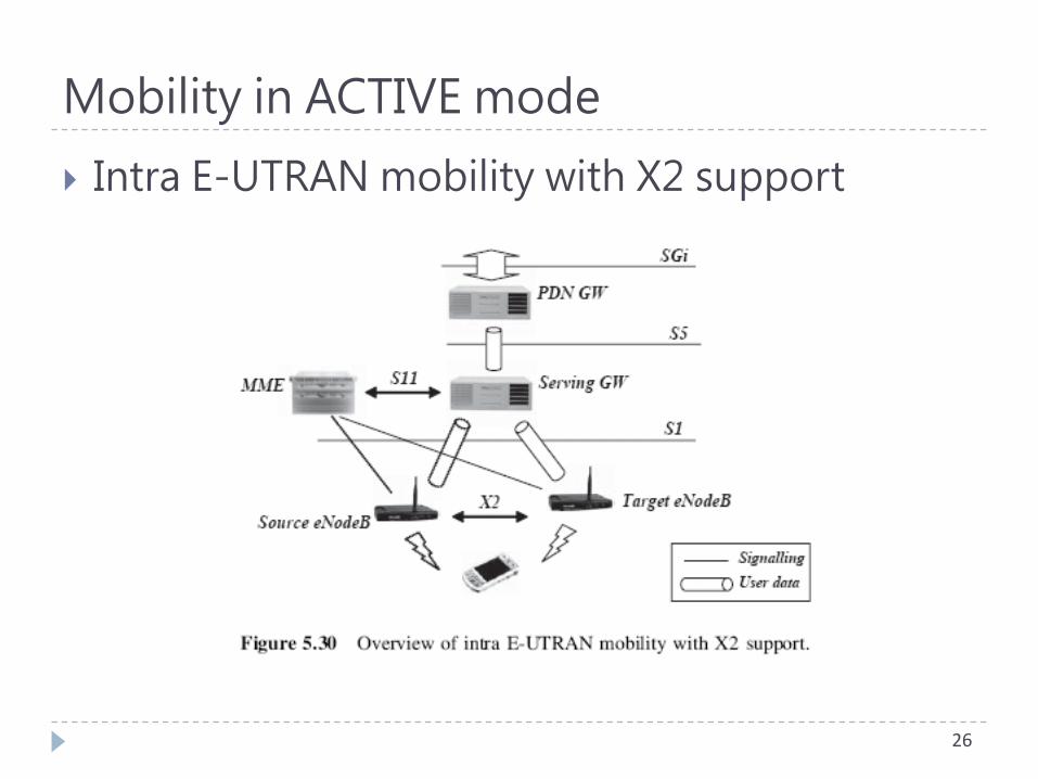
Mobility in ACTIVE mode
Intra E-UTRAN mobility with X2 support
26
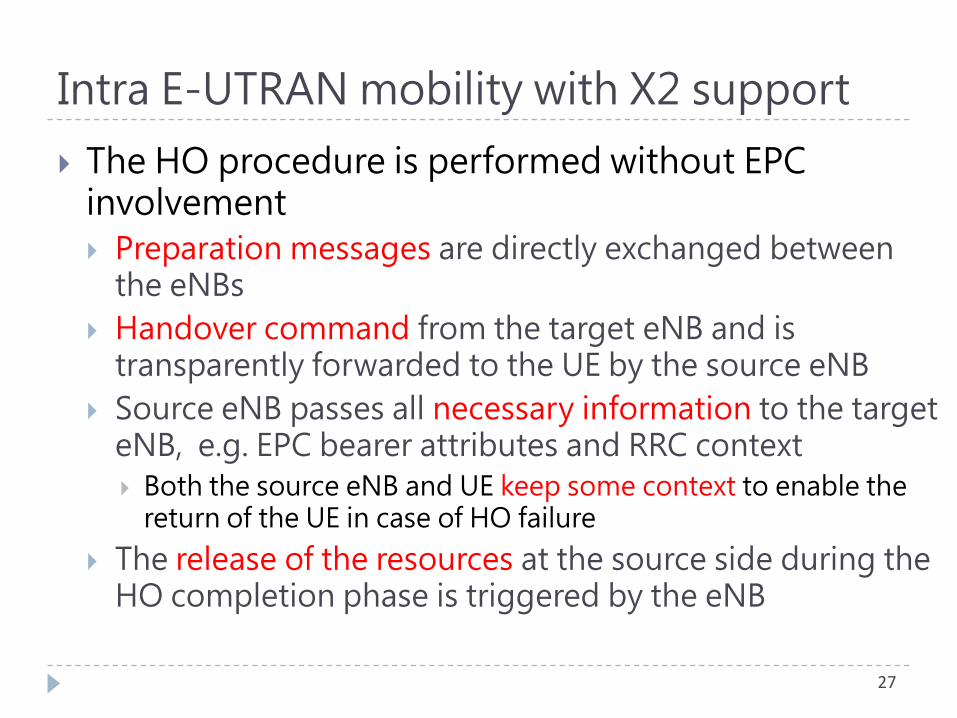
The HO procedure is performed without EPC involvement
Preparation messages are directly exchanged between the eNBs
Handover command from the target eNB and is transparently forwarded to the UE by the source eNB
Source eNB passes all necessary information to the target eNB, e.g. EPC bearer attributes and RRC context
Both the source eNB and UE keep some context to enable the return of the UE in case of HO failure
The release of the resources at the source side during the HO completion phase is triggered by the eNB
27
Intra E-UTRAN mobility with X2 support

Intra E-UTRAN mobility with X2 support
28
The source eNodeB sends a
Handover Request message over
the X2 interface to the target
eNodeB, which allocates all
needed resources to accept the
incoming terminal and associated
bearers
Intra E-UTRAN mobility with X2 support
29
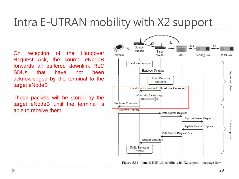
On reception of the Handover
Request Ack, the source eNodeB
forwards all buffered downlink RLC
SDUs that have not been
acknowledged by the terminal to the
target eNodeB
Those packets will be stored by the
target eNodeB until the terminal is
able to receive them
Intra E-UTRAN mobility with X2 support
30
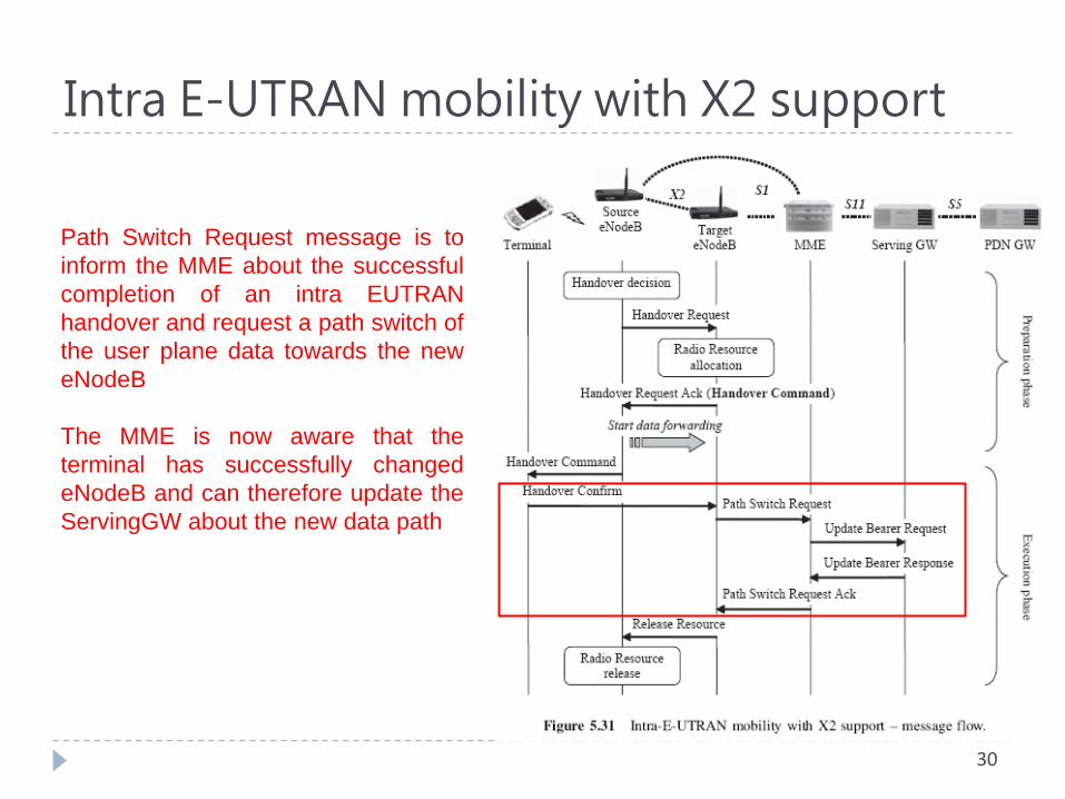
Path Switch Request message is to
inform the MME about the successful
completion of an intra EUTRAN
handover and request a path switch of
the user plane data towards the new
eNodeB
The MME is now aware that the
terminal has successfully changed
eNodeB and can therefore update the
ServingGW about the new data path
Intra E-UTRAN mobility with X2 support
31
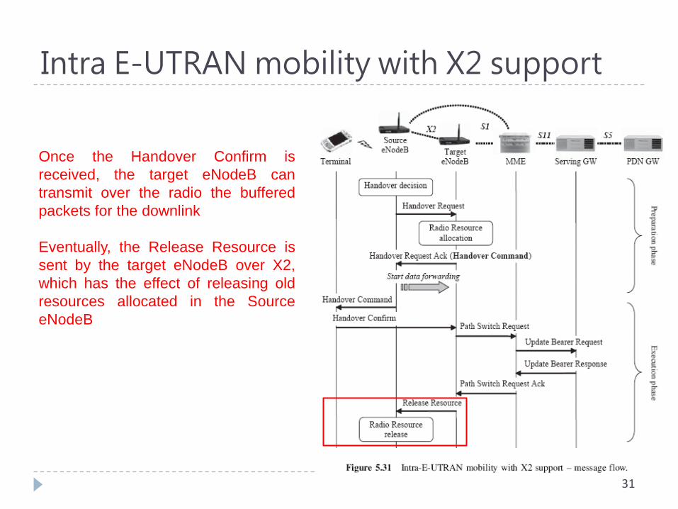
Once the Handover Confirm is
received, the target eNodeB can
transmit over the radio the buffered
packets for the downlink
Eventually, the Release Resource is
sent by the target eNodeB over X2,
which has the effect of releasing old
resources allocated in the Source
eNodeB
Mobility in ACTIVE mode
Intra E-UTRAN mobility without X2 support
In some cases, it may happen that the X2 interface is not available between eNodeBs
This may result from
network equipment failure
operator is not willing to deploy X2 connectivity between eNodeB for cost reasons
The MME is no longer transparent to the handover process
it acts as a signaling relay between the two eNodeBs
32
Intra E-UTRAN mobility without X2 support
33
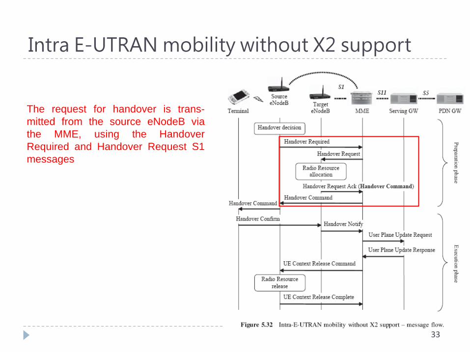
The request for handover is trans-
mitted from the source eNodeB via
the MME, using the Handover
Required and Handover Request S1
messages

Mobility in ACTIVE mode
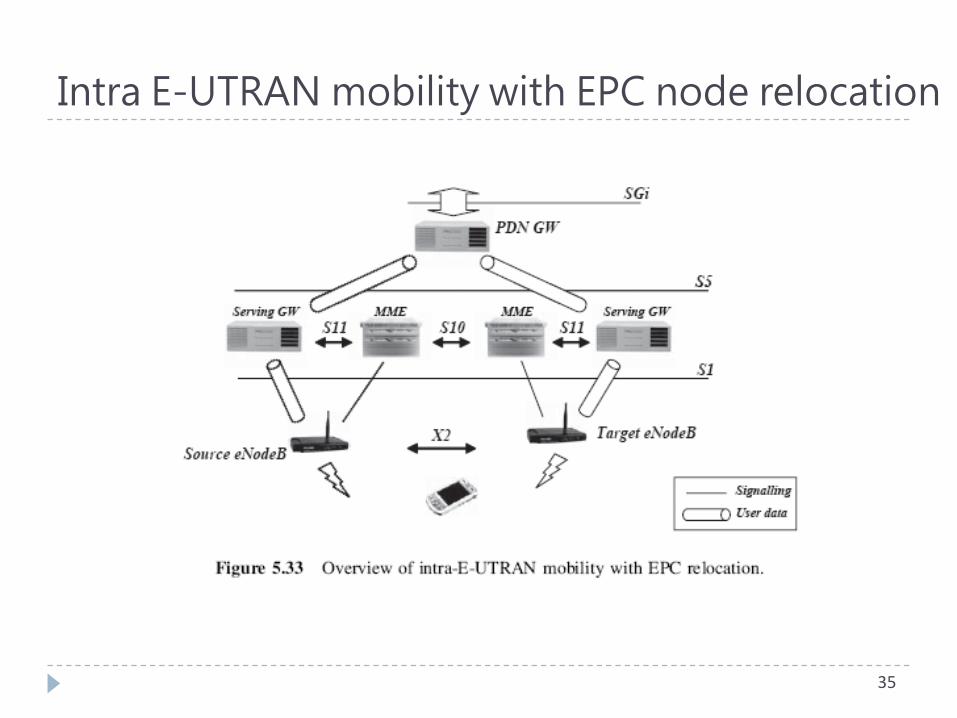
Intra E-UTRAN mobility with EPC node relocation
The target eNodeB has no connectivity with the current MME and Serving GW
From the terminal and eNodeB perspective, this handover is not different from the previous �no X2 support� case
The only real difference relies on the fact that the session needs also to be handed over from one MME to the other
34
Intra E-UTRAN mobility with EPC node relocation
35
Intra E-UTRAN mobility with EPC node relocation
36
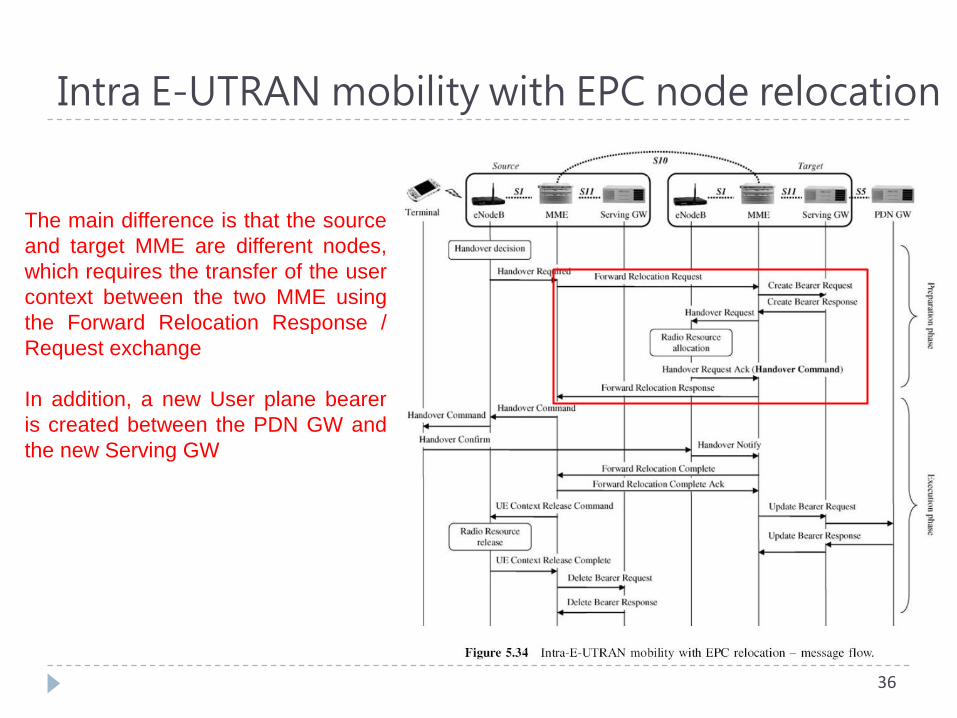
The main difference is that the source
and target MME are different nodes,
which requires the transfer of the user
context between the two MME using
the Forward Relocation Response /
Request exchange
In addition, a new User plane bearer
is created between the PDN GW and
the new Serving GW
Intra E-UTRAN mobility with EPC node relocation
37
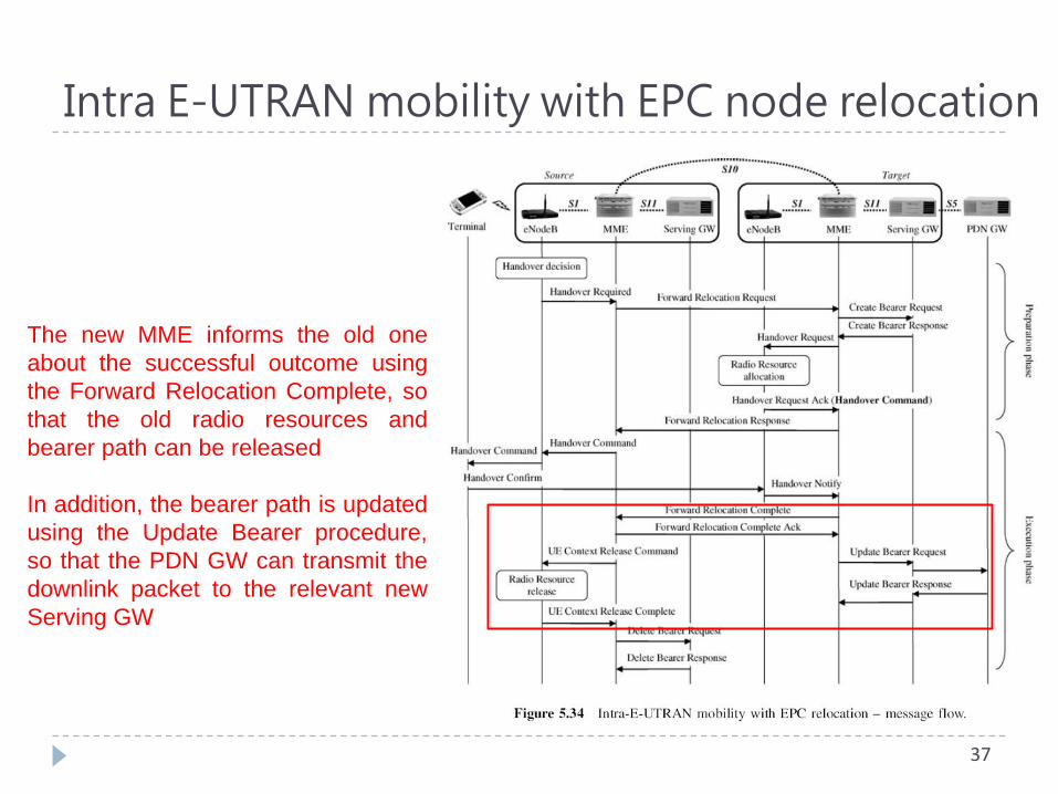
The new MME informs the old one
about the successful outcome using
the Forward Relocation Complete, so
that the old radio resources and
bearer path can be released
In addition, the bearer path is updated
using the Update Bearer procedure,
so that the PDN GW can transmit the
downlink packet to the relevant new
Serving GW
Mobility Management
Mobility in IDLE mode
UE controlled handover
Tracking Area
Similar to Routing Area or UTRAN Registration Area
Defined as a set of contiguous cells
38
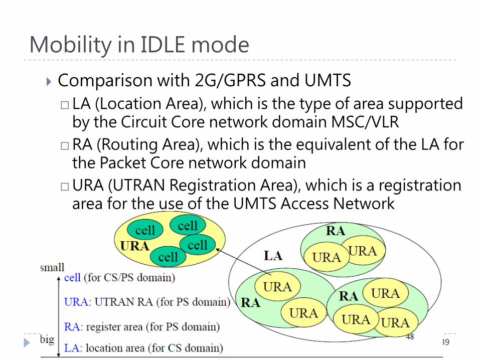
Mobility in IDLE mode
Comparison with 2G/GPRS and UMTS
LA (Location Area), which is the type of area supported by the Circuit Core network domain MSC/VLR
RA (Routing Area), which is the equivalent of the LA for the Packet Core network domain
URA (UTRAN Registration Area), which is a registration area for the use of the UMTS Access Network
39
Mobility in IDLE mode – Tracking area update
40
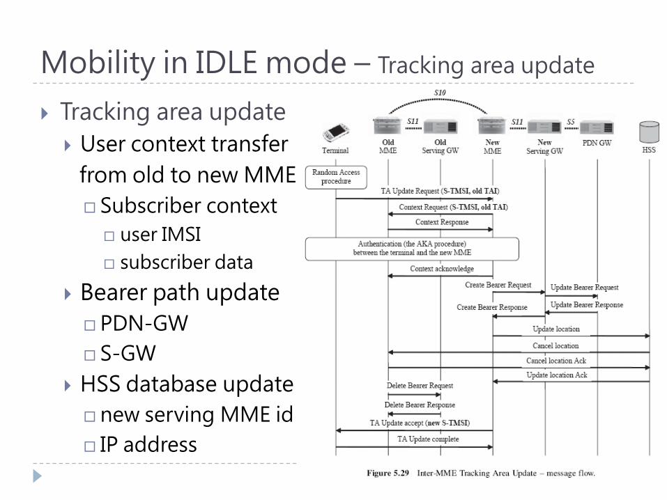
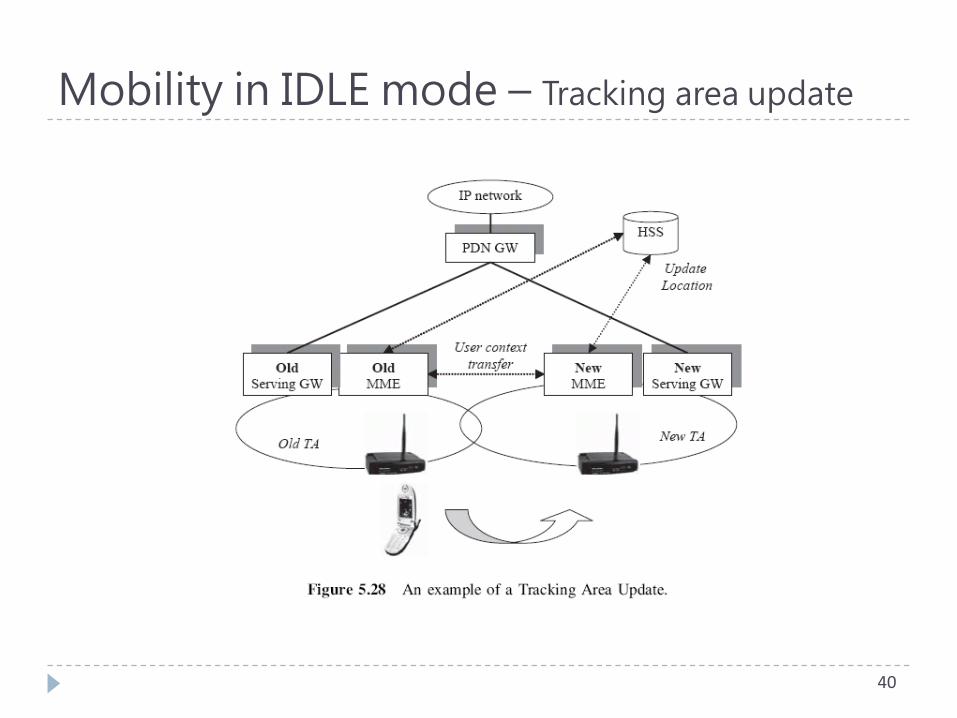
Mobility in IDLE mode – Tracking area update
Tracking area update
User context transfer
from old to new MME
Subscriber context
user IMSI
subscriber data
Bearer path update
PDN-GW
S-GW
HSS database update
new serving MME id
IP address
41