Embed Size (px)
Citation preview
IntroductionOne of the most distinctive advantages of DCopen-arc smelting is the ability to process fineraw materials without any major issues withregard to the operability of the furnace, metalrecovery, and metal quality. This has beendemonstrated in Mintek’s DC arc pilot plantfacilities over a period of about three decades(Curr et al., 1983). The materials that havebeen processed include laterite (Kotze, 2002),chromite fines (Curr et al., 1983), manganesefines (Lagendijk et al., 2010), PGM concen-trates (Shaw et al., 2013), electric arc furnace(EAF) dust (Denton et al., 2005; Abdellatif,2002a) and stainless steel (SS) dust (Dentonet al., 2005; Abdellatif, 2002a; Goff andDenton, 2004), and petroleum fly ash(Abdellatif, 2002b). The top particle size ofsuch materials can vary from a few millimetres(e.g. laterite) to micrometres (EAF and SSdust). Dusting, whether due to physical carry-over of feed or to the arc side reactions, hasbeen proven to be a non-issue. As such, theapplications of DC open-arc furnaces have thepotential to be extended to other raw materialssuch as particulate nickel oxide, which has aparticle size much less than 100 µm.
Nickel oxide is typically produced fromlaterite ore by sulphuric acid leaching, purifi-cation, and precipitation as basic nickelcarbonate (BNC) (Rhamdhani, Jak, and Hayes,2008) or as mixed hydroxide precipitate(MHP) (Mackenzie, Virnig, and Feather,2006), and finally calcining at moderatetemperatures (800–1200°C). The NiO productis very fine, with an average particle size inthe range of 10–20 µm and a NiO content ofmore than 99%.
Nickel oxide can be reduced to nickel metalby electrolysis (Moskalyk and Alfantazi,2002), hydrogen reduction (Agrawal et al.,2006), or by the carbonyl process (Terekhofand Emmanuel, 2012). An alternativeapproach would be to smelt the NiO in a DCopen-arc furnace in the presence of slag fluxesand a carbonaceous reducing agent. Thisalternative might offer faster reaction kinetics,and thus a smaller processing unit, ascompared with hydrogen or CO reduction. Inaddition, it provides almost prompt metalseparation from the slag, which allows themetal to be cast as required. The DC optionmay offer lower capital costs in comparison tothe electrolytic process, as well as minimizingenvironmental pollution. This approach wasinvestigated using Mintek’s 200 kW DC arcfacility. The results of the investigation aresummarized in this paper.
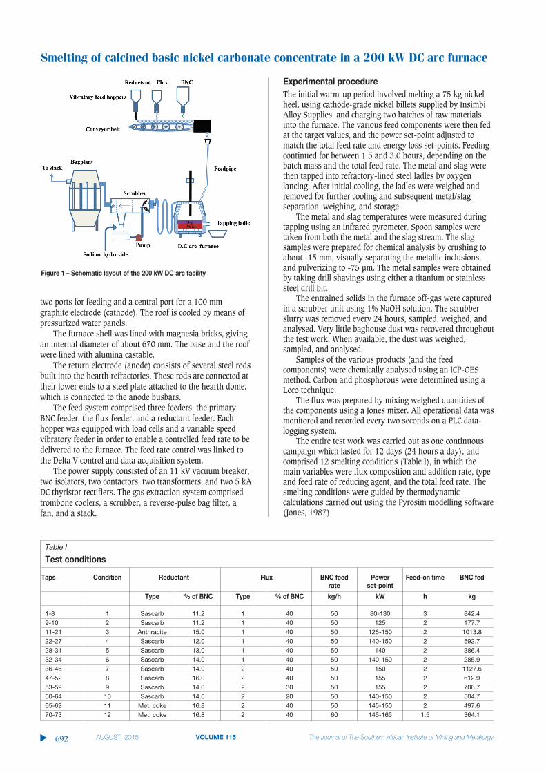
DC arc pilot plantThe 200 kW DC arc pilot plant consists of a DCpower supply, refractory-lined furnace, and anoff-gas treatment system (Figure 1). Thefurnace comprises a refractory-lined cylindricalsteel shell, a domed base, and a conical roof.The furnace shell has an unlined internaldiameter of 980 mm and is provided withwater-spray cooling. The conical roof contains
Smelting of calcined basic nickelcarbonate concentrate in a 200 kW DCarc furnaceby M. Abdellatif*
SynopsisCalcined basic nickel carbonate (BNC) concentrate was smelted in a pilot-scale DC arc furnace to produce a nickel metal. The furnace was contin-uously operated for 12 days (24 hour/day), during which twelve differentsmelting conditions were investigated, with the major variables beingreductant type and feed rate, flux composition and addition, and BNC feedrate.
The 200 kW DC arc furnace was operated at power levels between 110and 165 kW and at a total feed rate of 78 to 96 kg/h, resulting in anaverage slag and metal tapping temperature of about 1650°C. A total of 7.2 t of BNC were smelted, producing about 5.44 t of nickel metal and 2.94t of slag. Nickel recoveries of 96.4% and higher were achieved, and theslag nickel content was as low as 0.1%. The major impurities in the metalwere iron (mostly from oxygen lancing) and carbon. The calculated feedcarry-over was less than 0.85% and the graphite electrode consumptionwas between 2.8–3.3 kg/MWh.
Keywordsnickel smelting, DC arc furnace, calcined basic nickel carbonate, BNC.
* Mintek, Randburg.© The Southern African Institute of Mining and
Metallurgy, 2015. ISSN 2225-6253. Paper receivedJan. 2014 and revised paper received May 2014.
691The Journal of The Southern African Institute of Mining and Metallurgy VOLUME 115 AUGUST 2015 ▲
http://dx.doi.org/10.17159/2411-9717/2015/v115n8a5
Smelting of calcined basic nickel carbonate concentrate in a 200 kW DC arc furnace
two ports for feeding and a central port for a 100 mmgraphite electrode (cathode). The roof is cooled by means ofpressurized water panels.
The furnace shell was lined with magnesia bricks, givingan internal diameter of about 670 mm. The base and the roofwere lined with alumina castable.
The return electrode (anode) consists of several steel rodsbuilt into the hearth refractories. These rods are connected attheir lower ends to a steel plate attached to the hearth dome,which is connected to the anode busbars.
The feed system comprised three feeders: the primaryBNC feeder, the flux feeder, and a reductant feeder. Eachhopper was equipped with load cells and a variable speedvibratory feeder in order to enable a controlled feed rate to bedelivered to the furnace. The feed rate control was linked tothe Delta V control and data acquisition system.
The power supply consisted of an 11 kV vacuum breaker,two isolators, two contactors, two transformers, and two 5 kADC thyristor rectifiers. The gas extraction system comprisedtrombone coolers, a scrubber, a reverse-pulse bag filter, afan, and a stack.
Experimental procedureThe initial warm-up period involved melting a 75 kg nickelheel, using cathode-grade nickel billets supplied by InsimbiAlloy Supplies, and charging two batches of raw materialsinto the furnace. The various feed components were then fedat the target values, and the power set-point adjusted tomatch the total feed rate and energy loss set-points. Feedingcontinued for between 1.5 and 3.0 hours, depending on thebatch mass and the total feed rate. The metal and slag werethen tapped into refractory-lined steel ladles by oxygenlancing. After initial cooling, the ladles were weighed andremoved for further cooling and subsequent metal/slagseparation, weighing, and storage.
The metal and slag temperatures were measured duringtapping using an infrared pyrometer. Spoon samples weretaken from both the metal and the slag stream. The slagsamples were prepared for chemical analysis by crushing toabout -15 mm, visually separating the metallic inclusions,and pulverizing to -75 µm. The metal samples were obtainedby taking drill shavings using either a titanium or stainlesssteel drill bit.
The entrained solids in the furnace off-gas were capturedin a scrubber unit using 1% NaOH solution. The scrubberslurry was removed every 24 hours, sampled, weighed, andanalysed. Very little baghouse dust was recovered throughoutthe test work. When available, the dust was weighed,sampled, and analysed.
Samples of the various products (and the feedcomponents) were chemically analysed using an ICP-OESmethod. Carbon and phosphorous were determined using aLeco technique.
The flux was prepared by mixing weighed quantities ofthe components using a Jones mixer. All operational data wasmonitored and recorded every two seconds on a PLC data-logging system.
The entire test work was carried out as one continuouscampaign which lasted for 12 days (24 hours a day), andcomprised 12 smelting conditions (Table I), in which themain variables were flux composition and addition rate, typeand feed rate of reducing agent, and the total feed rate. Thesmelting conditions were guided by thermodynamiccalculations carried out using the Pyrosim modelling software(Jones, 1987).
▲
692 AUGUST 2015 VOLUME 115 The Journal of The Southern African Institute of Mining and Metallurgy
Figure 1 – Schematic layout of the 200 kW DC arc facility
Table I
Test conditions
Taps Condition Reductant Flux BNC feed Power Feed-on time BNC fedrate set-point
Type % of BNC Type % of BNC kg/h kW h kg
1-8 1 Sascarb 11.2 1 40 50 80-130 3 842.49-10 2 Sascarb 11.2 1 40 50 125 2 177.711-21 3 Anthracite 15.0 1 40 50 125-150 2 1013.822-27 4 Sascarb 12.0 1 40 50 140-150 2 592.728-31 5 Sascarb 13.0 1 40 50 140 2 386.432-34 6 Sascarb 14.0 1 40 50 140-150 2 285.936-46 7 Sascarb 14.0 2 40 50 150 2 1127.647-52 8 Sascarb 16.0 2 40 50 155 2 612.953-59 9 Sascarb 14.0 2 30 50 155 2 706.760-64 10 Sascarb 14.0 2 20 50 140-150 2 504.765-69 11 Met. coke 16.8 2 40 50 145-150 2 497.670-73 12 Met. coke 16.8 2 40 60 145-165 1.5 364.1
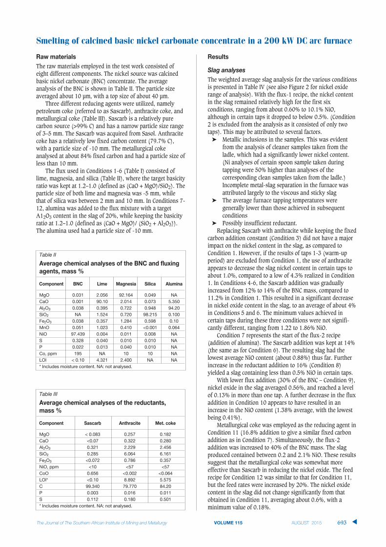
Raw materialsThe raw materials employed in the test work consisted ofeight different components. The nickel source was calcinedbasic nickel carbonate (BNC) concentrate. The averageanalysis of the BNC is shown in Table II. The particle sizeaveraged about 10 µm, with a top size of about 40 µm.
Three different reducing agents were utilized, namelypetroleum coke (referred to as Sascarb), anthracite coke, andmetallurgical coke (Table III). Sascarb is a relatively purecarbon source (>99% C) and has a narrow particle size rangeof 3–5 mm. The Sascarb was acquired from Sasol. Anthracitecoke has a relatively low fixed carbon content (79.7% C),with a particle size of -10 mm. The metallurgical cokeanalysed at about 84% fixed carbon and had a particle size ofless than 10 mm.
The flux used in Conditions 1-6 (Table I) consisted oflime, magnesia, and silica (Table II), where the target basicityratio was kept at 1.2–1.0 (defined as (CaO + MgO)/SiO2). Theparticle size of both lime and magnesia was -5 mm, whilethat of silica was between 2 mm and 10 mm. In Conditions 7-12, alumina was added to the flux mixture with a targetA12O3 content in the slag of 20%, while keeping the basicityratio at 1.2–1.0 (defined as (CaO + MgO)/ (SiO2 + Al2O3)).The alumina used had a particle size of -10 mm.
Results
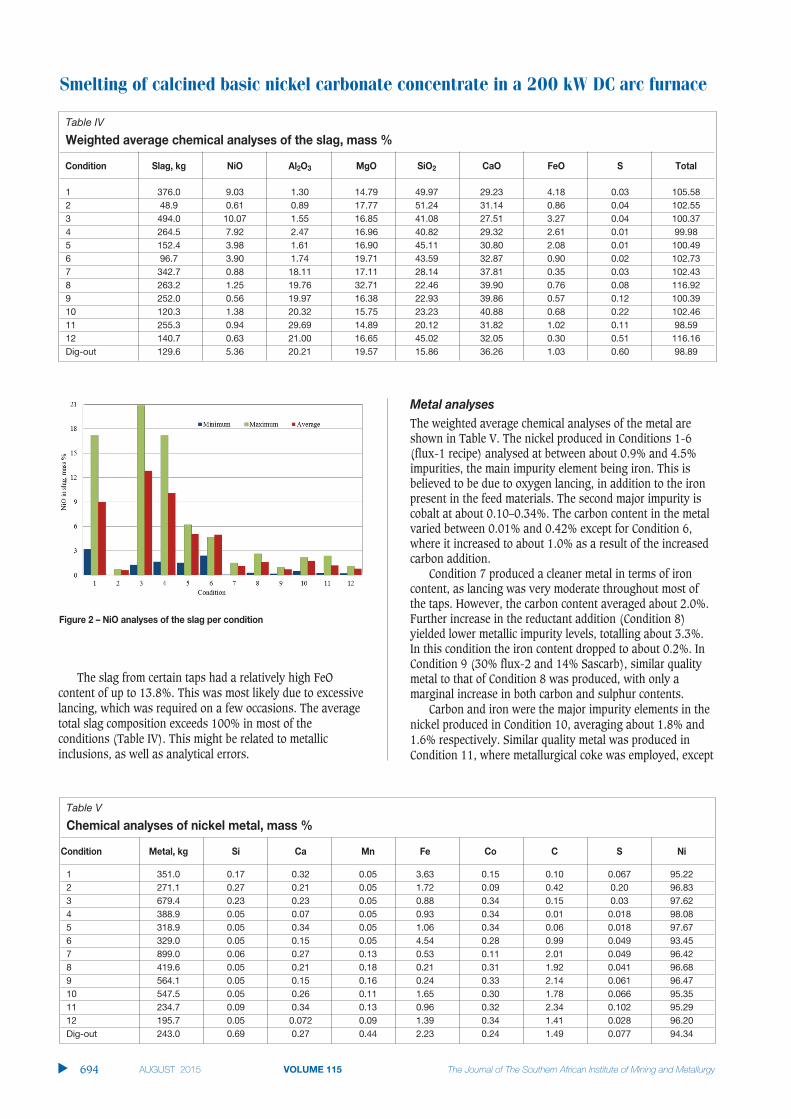
Slag analysesThe weighted average slag analysis for the various conditionsis presented in Table IV (see also Figure 2 for nickel oxiderange of analysis). With the flux-1 recipe, the nickel contentin the slag remained relatively high for the first sixconditions, ranging from about 0.60% to 10.1% NiO,although in certain taps it dropped to below 0.5%. (Condition2 is excluded from the analysis as it consisted of only twotaps). This may be attributed to several factors.
➤ Metallic inclusions in the samples. This was evidentfrom the analysis of cleaner samples taken from theladle, which had a significantly lower nickel content.(Ni analyses of certain spoon sample taken duringtapping were 50% higher than analyses of thecorresponding clean samples taken from the ladle.)Incomplete metal-slag separation in the furnace wasattributed largely to the viscous and sticky slag
➤ The average furnace tapping temperatures weregenerally lower than those achieved in subsequentconditions
➤ Possibly insufficient reductant.Replacing Sascarb with anthracite while keeping the fixed
carbon addition constant (Condition 3) did not have a majorimpact on the nickel content in the slag, as compared toCondition 1. However, if the results of taps 1-3 (warm-upperiod) are excluded from Condition 1, the use of anthraciteappears to decrease the slag nickel content in certain taps toabout 1.0%, compared to a low of 4.3% realized in Condition1. In Conditions 4-6, the Sascarb addition was graduallyincreased from 12% to 14% of the BNC mass, compared to11.2% in Condition 1. This resulted in a significant decreasein nickel oxide content in the slag, to an average of about 4%in Conditions 5 and 6. The minimum values achieved incertain taps during these three conditions were not signifi-cantly different, ranging from 1.22 to 1.86% NiO.
Condition 7 represents the start of the flux-2 recipe(addition of alumina). The Sascarb addition was kept at 14%(the same as for Condition 6). The resulting slag had thelowest average NiO content (about 0.88%) thus far. Furtherincrease in the reductant addition to 16% (Condition 8)yielded a slag containing less than 0.5% NiO in certain taps.
With lower flux addition (30% of the BNC – Condition 9),nickel oxide in the slag averaged 0.56%, and reached a levelof 0.13% in more than one tap. A further decrease in the fluxaddition in Condition 10 appears to have resulted in anincrease in the NiO content (1.38% average, with the lowestbeing 0.41%).
Metallurgical coke was employed as the reducing agent inCondition 11 (16.8% addition to give a similar fixed carbonaddition as in Condition 7). Simultaneously, the flux-2addition was increased to 40% of the BNC mass. The slagproduced contained between 0.2 and 2.1% NiO. These resultssuggest that the metallurgical coke was somewhat moreeffective than Sascarb in reducing the nickel oxide. The feedrecipe for Condition 12 was similar to that for Condition 11,but the feed rates were increased by 20%. The nickel oxidecontent in the slag did not change significantly from thatobtained in Condition 11, averaging about 0.6%, with aminimum value of 0.18%.
Smelting of calcined basic nickel carbonate concentrate in a 200 kW DC arc furnace
693The Journal of The Southern African Institute of Mining and Metallurgy VOLUME 115 AUGUST 2015 ▲
Table III
Average chemical analyses of the reductants,mass %
Component Sascarb Anthracite Met. coke
MgO < 0.083 0.257 0.182CaO <0.07 0.322 0.280Al2O3 0.321 2.229 2.456SiO2 0.285 6.064 6.161Fe3O3 <0.072 0.786 0.357NiO, ppm <10 <57 <57CoO 0.656 <0.002 <0.064LOI* <0.10 8.892 5.575C 99.340 79.770 84.20P 0.003 0.016 0.011S 0.112 0.180 0.501* Includes moisture content. NA: not analysed.
Table II
Average chemical analyses of the BNC and fluxingagents, mass %
Component BNC Lime Magnesia Silica Alumina
MgO 0.031 2.056 92.164 0.049 NACaO 0.001 90.10 2.014 0.073 5.350Al2O3 0.038 0.395 0.722 0.948 94.20SiO2 NA 1.524 0.720 98.215 0.100Fe2O3 0.038 0.357 1.284 0.598 0.10MnO 0.051 1.023 0.410 <0.001 0.064NiO 97.439 0.004 0.011 0.008 NAS 0.328 0.040 0.010 0.010 NAP 0.022 0.013 0.040 0.010 NACo, ppm 195 NA 10 10 NALOI < 0.10 4.321 2.400 NA NA* Includes moisture content. NA: not analysed.
Smelting of calcined basic nickel carbonate concentrate in a 200 kW DC arc furnace
The slag from certain taps had a relatively high FeOcontent of up to 13.8%. This was most likely due to excessivelancing, which was required on a few occasions. The averagetotal slag composition exceeds 100% in most of theconditions (Table IV). This might be related to metallicinclusions, as well as analytical errors.
Metal analysesThe weighted average chemical analyses of the metal areshown in Table V. The nickel produced in Conditions 1-6(flux-1 recipe) analysed at between about 0.9% and 4.5%impurities, the main impurity element being iron. This isbelieved to be due to oxygen lancing, in addition to the ironpresent in the feed materials. The second major impurity iscobalt at about 0.10–0.34%. The carbon content in the metalvaried between 0.01% and 0.42% except for Condition 6,where it increased to about 1.0% as a result of the increasedcarbon addition.
Condition 7 produced a cleaner metal in terms of ironcontent, as lancing was very moderate throughout most ofthe taps. However, the carbon content averaged about 2.0%.Further increase in the reductant addition (Condition 8)yielded lower metallic impurity levels, totalling about 3.3%.In this condition the iron content dropped to about 0.2%. InCondition 9 (30% flux-2 and 14% Sascarb), similar qualitymetal to that of Condition 8 was produced, with only amarginal increase in both carbon and sulphur contents.
Carbon and iron were the major impurity elements in thenickel produced in Condition 10, averaging about 1.8% and1.6% respectively. Similar quality metal was produced inCondition 11, where metallurgical coke was employed, except
▲
694 AUGUST 2015 VOLUME 115 The Journal of The Southern African Institute of Mining and Metallurgy
Table IV
Weighted average chemical analyses of the slag, mass %
Condition Slag, kg NiO Al2O3 MgO SiO2 CaO FeO S Total
1 376.0 9.03 1.30 14.79 49.97 29.23 4.18 0.03 105.582 48.9 0.61 0.89 17.77 51.24 31.14 0.86 0.04 102.553 494.0 10.07 1.55 16.85 41.08 27.51 3.27 0.04 100.374 264.5 7.92 2.47 16.96 40.82 29.32 2.61 0.01 99.985 152.4 3.98 1.61 16.90 45.11 30.80 2.08 0.01 100.496 96.7 3.90 1.74 19.71 43.59 32.87 0.90 0.02 102.737 342.7 0.88 18.11 17.11 28.14 37.81 0.35 0.03 102.438 263.2 1.25 19.76 32.71 22.46 39.90 0.76 0.08 116.929 252.0 0.56 19.97 16.38 22.93 39.86 0.57 0.12 100.3910 120.3 1.38 20.32 15.75 23.23 40.88 0.68 0.22 102.4611 255.3 0.94 29.69 14.89 20.12 31.82 1.02 0.11 98.5912 140.7 0.63 21.00 16.65 45.02 32.05 0.30 0.51 116.16Dig-out 129.6 5.36 20.21 19.57 15.86 36.26 1.03 0.60 98.89
Figure 2 – NiO analyses of the slag per condition
Table V
Chemical analyses of nickel metal, mass %
Condition Metal, kg Si Ca Mn Fe Co C S Ni
1 351.0 0.17 0.32 0.05 3.63 0.15 0.10 0.067 95.222 271.1 0.27 0.21 0.05 1.72 0.09 0.42 0.20 96.833 679.4 0.23 0.23 0.05 0.88 0.34 0.15 0.03 97.624 388.9 0.05 0.07 0.05 0.93 0.34 0.01 0.018 98.085 318.9 0.05 0.34 0.05 1.06 0.34 0.06 0.018 97.676 329.0 0.05 0.15 0.05 4.54 0.28 0.99 0.049 93.457 899.0 0.06 0.27 0.13 0.53 0.11 2.01 0.049 96.428 419.6 0.05 0.21 0.18 0.21 0.31 1.92 0.041 96.689 564.1 0.05 0.15 0.16 0.24 0.33 2.14 0.061 96.4710 547.5 0.05 0.26 0.11 1.65 0.30 1.78 0.066 95.3511 234.7 0.09 0.34 0.13 0.96 0.32 2.34 0.102 95.2912 195.7 0.05 0.072 0.09 1.39 0.34 1.41 0.028 96.20Dig-out 243.0 0.69 0.27 0.44 2.23 0.24 1.49 0.077 94.34
for the iron and carbon contents, which averaged about 1.0%and 2.3% respectively. With a higher smelting rate duringCondition 12, iron content increased to about 1.4%, while thelevel of carbon decreased to 1.4% compared to 2.3%Condition 11.
Fume analysesThe major component in the fume product is nickel oxide(about 48%, Table VI), making it suitable for recycling toeither the furnace or the calciner, depending on the sulphurcontent and other impurities. Semi-quantitative XRD analysissuggested that the crystalline phases are 32% Ni, 51% NiO,12% Ni3S2, and 5% CaCO3.
Scrubber productsThe normalized sludge analysis appears to be similar to thatof the fume, particularly with regards to nickel oxide andsulphur contents (Table VII). Therefore, it might be possibleto recycle the sludge to the calciner in order to remove themoisture and to minimize the sulphur content before feedingit to the furnace.
Several samples were taken from the effluent stream. Thenickel content was well below 2 ppm in all of these samples,and therefore the effluent stream required only neutralizingbefore disposal.
Feed carry-overThe proportion of the feed materials that escaped the furnacewith the off-gas was calculated via two approaches. The firstassumed that all the fume and scrubber sludge (dry basis)were unreacted materials and therefore represented the totallosses. This approach results in a feed carry-over of about0.85%. The second approach was based on the calciumcontent in the fume and scrubber sludge relative to that inthe feed materials. Specifically, the feed carry-over wascalculated from the following relationship:
Carry-over = Mass% Ca in fume × Fume masses × 100%/(Mass% Ca in feed × Total mass fed)
This approach resulted in a feed carry-over of about0.5%, which is significantly less than that of the first
approach. Nevertheless, both methods suggest that the feedlosses to the off-gas were very low, particularly given thescale of operation and the particle size of the feedcomponents.
Overall mass balanceThe overall mass balance for the entire test campaign showsan accountability of about 103%, or about 308 kg of excessproducts, as compared to the masses fed (Table VIII). This isbelieved to be related to the CO/CO2 mass ratio of 1.22/1.0 aspredicted by Pyrosim (Jones, 1987), oxygen lancing, whichintroduced more than 368 kg of iron into the furnaceproducts, and refractory erosion.
For the first flux recipe, the overall accountability was93.7%, representing a deficit of about 333 kg. This is mostlyslag and metal build-up in the furnace that could not betapped at the end of this period. Conversely, the flux-2 recipeexhibited an overall accountability of about 111%, or asurplus of about 640 kg.
Nickel mass balanceFor the flux-1 recipe, the nickel accountability was about90.3%, compared to about 101.0% for the flux-2 recipe.Inclusion of the metal digout in the flux-2 recipe period isbelieved to be the major reason for this. Based onmineralogical examination of three slag samples, metallicnickel in the slag ranged from about 2.1% to 5.4% (massbasis), averaging about 4.23% in the samples tested. This isequivalent to about 125 kg of metal trapped in the slag.Taking this into account, the overall nickel accountabilityimproves to over 98.2%.
Nickel recoveries averaged about 96.4% and 99.5% forthe flux-1 test work and 88.8 and 99.7%, for flux-2, formetal and slag masses and analyses respectively.
Energy balance and electrode consumptionBased on the measured heat losses and the total energyinput, the furnace thermal efficiency averaged about 36.5%in Conditions 1–6. It dropped to about 29.5% in Conditions7–12, possibly due to refractory erosion. It should be notedthat the furnace power intensity averaged about 300 kW persquare metre of furnace hearth area during the first sixconditions. It then increased to 390 kW/m2 for the rest of thetest work, except for Condition 12 where it averaged about450 kW/m2.
Smelting of calcined basic nickel carbonate concentrate in a 200 kW DC arc furnace
The Journal of The Southern African Institute of Mining and Metallurgy VOLUME 115 AUGUST 2015 695 ▲
Table VII
Chemical analyses of the sludge, mass %MgO 4.32 CoO 0.18Al2O3 1.01 C 1.38SiO2 3.29 SO3 10.20CaO 4.18 Na 0.40MnO 0.72 Fe2O3 0.42NiO 28.90 Total* 53.23*Balance is mostly moisture
Table VI
Chemical analyses of the fume, mass %MgO 7.67 Fe2O3 0.97Al2O3 1.68 NiO 48.17SiO2 6.10 CoO 0.46CaO 5.71 C 0.47MnO 1.04 SO3 12.73P 0.01 Total* 85.55* Balance is mostly moisture
Table VIII
Overall mass balance for the two flux recipes
In, kg Out, kg
Flux 1 Flux 2 Flux 1 Flux 2
BNC 3298.9 3909.5 Slag 1432.2 1503.8Reductant 436.5 576.7 Metal 2356.4 3085.5Silica 668.8 295.7 Fume 30.5 64.9Magnesia 221.4 215.9 Off-gas 1138.4 1811.7Lime 590.3 605.1 Sludge 0.0 53.4Alumina 0.0 277.3Ni heel 75.0 0.0Total 5290.8 5880.3 4957.5 6519.3Accountability 93.7% 110.9%Surplus (deficit) (333.4kg) 639.0kg
Smelting of calcined basic nickel carbonate concentrate in a 200 kW DC arc furnace
The electrode consumption was 3.3 kg/MWh in the firstsix conditions. Longer arc length, and thus lower currentdensity, and more steady operation during the flux-2 testwork contributed to the almost 38% drop in electrodeconsumption (2.8 kg/MWh), as compared to the flux-1recipe.
DiscussionAlthough the nickel recovery during flux-2 test work wasvery high at fixed carbon additions of 14% of BNC or higher,it is believed that further optimization can be achieved. Alarger and better sealed furnace may reduce air ingress, andthus carbon losses through oxidation. The carbon additioncould be adjusted to control the carbon content of the metaland to increase the slag sulphur capacity, in addition tocontrolling the reduction of nickel oxide. These are somewhatcontradictory objectives, but a balance may need to be found.Proper selection of the reducing agent and the fluxcomponents can help reduce the sulphur content in the metal(Pashkeev et al., 2011; Shankar, 2006; Ren, Hu, and Chou,2013; Wang et al., 2009), and thus its refining requirements,if any.
Smelting of the BNC in the presence of a CaO-MgO-SiO2slag (flux-1 test work) was somewhat difficult and resultedin slags with relatively high nickel contents. However,increased fixed carbon additions tended to increase nickelrecovery, as is shown by the drop in the average nickelcontent in the slag. Nickel losses to the slag are believed to beaffected by metallic inclusions, as the slag tended to besticky. The formation of high-melting compounds (carbides)could have affected the flowing characteristics of the slag andhindered the settling of the metal.
With flux-2 recipe there did not appear to be a clearrelationship between the average nickel content of the slagand the fixed carbon addition within the range studied. Thelowest carbon addition during this period (about 13.6%) wassufficient to lower the nickel levels to below 1.0%, on
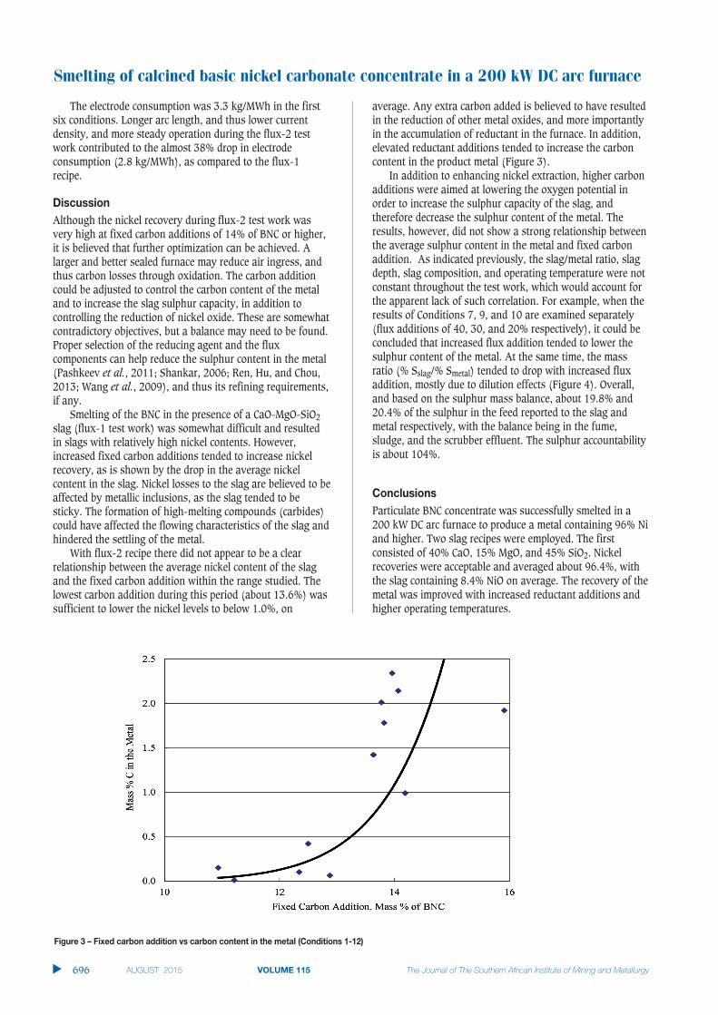
average. Any extra carbon added is believed to have resultedin the reduction of other metal oxides, and more importantlyin the accumulation of reductant in the furnace. In addition,elevated reductant additions tended to increase the carboncontent in the product metal (Figure 3).
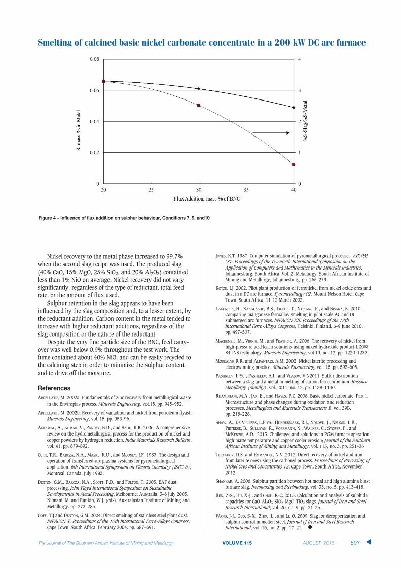
In addition to enhancing nickel extraction, higher carbonadditions were aimed at lowering the oxygen potential inorder to increase the sulphur capacity of the slag, andtherefore decrease the sulphur content of the metal. Theresults, however, did not show a strong relationship betweenthe average sulphur content in the metal and fixed carbonaddition. As indicated previously, the slag/metal ratio, slagdepth, slag composition, and operating temperature were notconstant throughout the test work, which would account forthe apparent lack of such correlation. For example, when theresults of Conditions 7, 9, and 10 are examined separately(flux additions of 40, 30, and 20% respectively), it could beconcluded that increased flux addition tended to lower thesulphur content of the metal. At the same time, the massratio (% Sslag/% Smetal) tended to drop with increased fluxaddition, mostly due to dilution effects (Figure 4). Overall,and based on the sulphur mass balance, about 19.8% and20.4% of the sulphur in the feed reported to the slag andmetal respectively, with the balance being in the fume,sludge, and the scrubber effluent. The sulphur accountabilityis about 104%.
ConclusionsParticulate BNC concentrate was successfully smelted in a200 kW DC arc furnace to produce a metal containing 96% Niand higher. Two slag recipes were employed. The firstconsisted of 40% CaO, 15% MgO, and 45% SiO2. Nickelrecoveries were acceptable and averaged about 96.4%, withthe slag containing 8.4% NiO on average. The recovery of themetal was improved with increased reductant additions andhigher operating temperatures.
▲
696 AUGUST 2015 VOLUME 115 The Journal of The Southern African Institute of Mining and Metallurgy
Figure 3 – Fixed carbon addition vs carbon content in the metal (Conditions 1-12)
Nickel recovery to the metal phase increased to 99.7%when the second slag recipe was used. The produced slag(40% CaO, 15% MgO, 25% SiO2, and 20% Al2O3) containedless than 1% NiO on average. Nickel recovery did not varysignificantly, regardless of the type of reductant, total feedrate, or the amount of flux used.
Sulphur retention in the slag appears to have beeninfluenced by the slag composition and, to a lesser extent, bythe reductant addition. Carbon content in the metal tended toincrease with higher reductant additions, regardless of theslag composition or the nature of the reductant.
Despite the very fine particle size of the BNC, feed carry-over was well below 0.9% throughout the test work. Thefume contained about 40% NiO, and can be easily recycled tothe calcining step in order to minimize the sulphur contentand to drive off the moisture.
ReferencesABDELLATIF, M. 2002a. Fundamentals of zinc recovery from metallurgical waste
in the Enviroplas process. Minerals Engineering, vol.15. pp. 945–952.
ABDELLATIF, M. 2002b. Recovery of vanadium and nickel from petroleum flyash.Minerals Engineering, vol. 15. pp. 953–96.
AGRAWAL, A., KUMAR, V., PANDEY, B.D., and SAHU, K.K. 2006. A comprehensivereview on the hydrometallurgical process for the production of nickel andcopper powders by hydrogen reduction. India Materials Research Bulletin,vol. 41. pp. 879–892.
CURR, T.R., BARCZA, N.A., MASKE, K.U., and MOONEY, J.F. 1983. The design andoperation of transferred-arc plasma systems for pyrometallurgicalapplication. 6th International Symposium on Plasma Chemistry (ISPC-6),Montreal, Canada, July 1983.
DENTON, G.M., BARCZA, N.A., SCOTT, P.D., and FULTON, T. 2005. EAF dustprocessing. John Floyd International Symposium on SustainableDevelopments in Metal Processing, Melbourne, Australia, 3–6 July 2005.Nilmani, M. and Rankin, W.J. (eds). Australasian Institute of Mining andMetallurgy. pp. 273–283.
GOFF, T.J and DENTON, G.M. 2004. Direct smelting of stainless steel plant dust.INFACON X. Proceedings of the 10th Internatonal Ferro-Alloys Congress,Cape Town, South Africa, February 2004. pp. 687–691.
JONES, R.T. 1987. Computer simulation of pyrometallurgical processes. APCOM’87. Proceedings of the Twentieth International Symposium on theApplication of Computers and Mathematics in the Minerals Industries,Johannesburg, South Africa. Vol. 2: Metallurgy. South African Institute ofMining and Metallurgy, Johannesburg. pp. 265–279.
KOTZE, I.J. 2002. Pilot plant production of ferronickel from nickel oxide ores anddust in a DC arc furnace. Pyrometallurgy 02, Mount Nelson Hotel, CapeTown, South Africa, 11-12 March 2002.
LAGENDIJK, H., XAKALASHE, B.S., LIGEGE, T., NTIKANG, P., and BISAKA, K. 2010.Comparing manganese ferroalloy smelting in pilot scale AC and DCsubmerged arc furnaces. INFACON XII. Proceedings of the 12thInternational Ferro-Alloys Congress, Helsinki, Finland, 6–9 June 2010. pp. 497–507.
MACKENZIE, M., VIRNIG, M., and FEATHER, A. 2006. The recovery of nickel fromhigh-pressure acid leach solutions using mixed hydroxide product-LIX(R)
84-INS technology. Minerals Engineering, vol.19, no. 12. pp. 1220–1233.
MOSKALYK R.R. and ALFANTAZI, A.M. 2002. Nickel laterite processing andelectrowinning practice. Minerals Engineering, vol. 15. pp. 593–605.
PASHKEEV, I. YU., PASHKEEV, A.I., and VLASOV, V.N2011. Sulfur distributionbetween a slag and a metal in melting of carbon ferrochromium. RussianMetallurgy (Metally), vol. 2011, no. 12. pp. 1138–1140.
RHAMDHANI, M.A., JAK, E., and HAYES, P.C. 2008. Basic nickel carbonate; Part I.Microstructure and phase changes during oxidation and reductionprocesses. Metallurgical and Materials Transactions B, vol. 39B. pp. 218–228.
SHAW, A., DE VILLIERS, L.P.VS., HUNDERMARK, R.J., NDLOVU, J., NELSON, L.R.,PIETERSE, B., SULLIVAN, R., VOERMANN, N., WALKER, C.. STOBER, F., andMCKENZIE, A.D. 2013. Challenges and solutions in PGM furnace operation:high matte temperature and copper cooler erosion; Journal of the SouthernAfrican Institute of Mining and Metallurgy, vol. 113, no. 3. pp. 251–26
TEREKHOV, D.S. and EMMANUEL, N.V. 2012. Direct recovery of nickel and ironfrom laterite ores using the carbonyl process. Proceedings of Processing ofNickel Ores and Concentrates’12, Cape Town, South Africa, November2012.
SHANKAR, A. 2006. Sulphur partition between hot metal and high alumina blastfurnace slag. Ironmaking and Steelmaking, vol. 33, no. 5. pp. 413–418.
REN, Z-S., HU, X-J., and CHOU, K-C. 2013. Calculation and analysis of sulphidecapacities for CaO-Al2O3-SiO2-MgO-TiO2 slags. Journal of Iron and SteelResearch International, vol. 20, no. 9. pp. 21–25.
WANG, J-J., GUO, S-X., ZHOU, L., and LI, Q. 2009. Slag for decopperization andsulphur control in molten steel. Journal of Iron and Steel ResearchInternational, vol. 16, no. 2. pp. 17–21. ◆
Smelting of calcined basic nickel carbonate concentrate in a 200 kW DC arc furnace
The Journal of The Southern African Institute of Mining and Metallurgy VOLUME 115 AUGUST 2015 697 ▲
Figure 4 – Influence of flux addition on sulphur behaviour, Conditions 7, 9, and10