Embed Size (px)
DESCRIPTION
vaisalanews_147_1998 Vaisala's customer magazine. Vaisala News discusses applications where Vaisala's products, solutions and services are in use. It also contains scientific articles written by external experts and other current news items
Citation preview
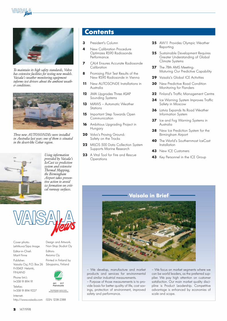
To maintain its high safety standards, Volvohas extensive facilities for testing new models.Vaisala’s weather monitoring equipmentinforms test drivers about the ambient weath-er conditions.
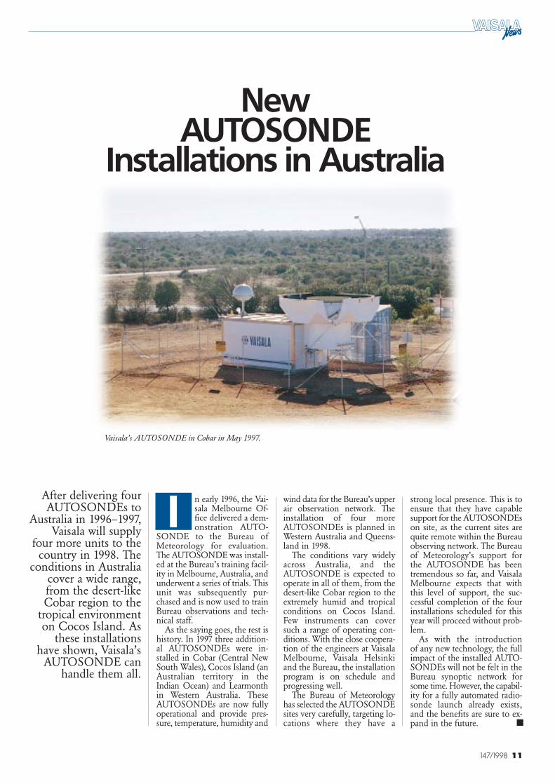
Three new AUTOSONDEs were installedin Australia last year; one of them is situatedin the desert-like Cobar region.
Using informationprovided by Vaisala’sIceCast ice predictionsystem and extensiveThermal Mapping,the BirminghamAirport takes preven-tive action to avoidice formation on criti-cal runway surfaces.
2 147/19982
Contents3 President’s Column
4 New Calibration ProcedureOptimizes RS90 RadiosondePerformance
7 CAL4 Ensures Accurate RadiosondeCalibration
8 Promising Pilot Test Results of theNew RS90 Radiosonde in Vienna
11 New AUTOSONDE Installations inAustralia
12 JMA Upgrades Three ASAPSounding Systems
13 MAWS – Automatic WeatherStations
15 Important Step Towards OpenCommunication
16 Ambitious Upgrading Project inHungary
20 Volvo’s Proving Ground: Safety on the Tracks
22 MILOS 500 Data Collection SystemSupports Marine Research
23 A Vital Tool for Fire and RescueOperations
Cover photo:Lehtikuva/Sipa Image
Editor-in-Chief:Marit Finne
Publisher:Vaisala Oyj, P.O. Box 26FI-00421 Helsinki,FINLAND
Phone (int.):(+358 9) 894 91
Telefax:(+358 9) 894 9227
Internet:http://www.vaisala.com
Design and Artwork:Non-Stop Studiot Oy
Editors:Axioma Oy
Printed in Finland bySävypaino, Finland
ISSN 1238-2388
Vaisala in Brief
– We develop, manufacture and marketproducts and services for environmentaland similar industrial measurements.– Purpose of those measurements is to pro-vide basis for better quality of life, cost sav-ings, protection of environment, improvedsafety and performance.
25 AW11 Provides Olympic WeatherReporting
25 Sustainable Development RequiresGreater Understanding of GlobalClimate Systems
27 The 78th AMS Meeting:Maturing Our Predictive Capability
29 Vaisala’s Global ICE Activities
30 New Predictive Road ConditionMonitoring for Flanders
32 Finland’s Traffic Management Centre
34 Ice Warning System Improves TrafficSafety in Moscow
36 Latvia Expands Its Road WeatherInformation System
37 Ice and Fog Warning Systems inAustralia
38 New Ice Prediction System for theBirmingham Airport
40 The World’s Southernmost IceCastInstallation
43 New ICE Customers
43 Key Personnel in the ICE Group
– We focus on market segments where wecan be world leaders, as the preferred sup-plier. We pay high attention on customersatisfaction. Our main market quality disci-pline is Product Leadership. Competitiveadvantage is enhanced by economies ofscale and scope.
3147/1998
President’s Column■ ■ ■ ■ ■ ■
hen people developsomething new –either procedures orproducts – there are
usually three common themes:simplification, automation andintegration. The same is truefor weather observations. Vai-sala has always looked boldlyto the future, aiming to createnew products that offer addedvalue to our customers. Insteadof simply comparing one prod-uct to another, we look at mar-ket needs from a wider perspec-tive.
Today, full automation ofupper air observations is a factof life. As the many operativeAUTOSONDE systems haveproved, our concept is reliableand efficient. This technologyhas set a new standard for ourvision of the observation net-work in the next millennium.
Radiosonde product genera-tions seldom change. New prod-ucts must represent significantadvances before it is worth-while to verify their perfor-mance. After years of researchand development work, we arenow launching a new-genera-tion RS90 radiosonde. All the
sensors in the RS90 radiosondeare new. The accuracy of tem-perature measurements hasbeen improved significantly,humidity measurements revivequickly after exposure to icyconditions, and the pressuresensor maintains its accuratecalibration even in harsh envi-ronments. To optimize the per-formance of these sensors andachieve the greatest benefitfrom them, we have integratedcompletely new calibrationequipment in our radiosondeproduction. This was a majorchallenge because we set muchhigher demands than those fortraditional weather chambers.
Mini Automatic WeatherStations (MAWS) represent anew way of thinking aboutweather station structure. Thecompact design and easy con-figuration of the MAWS arebrand new. Although mostapplications are in the opera-tive weather services field, theMAWS will no doubt findusers in new applications re-quiring real-time weather meas-urements.
Road and airport runway sys-tems for ice and fog warning
are now used in many locationsin both the Northern andSouthern hemispheres. The im-plementation of these systemshas created new models forwinter maintenance. Whereverthey are used, these systems seta new standard for operations.
A new standard is also need-ed for the quality of the globalweather observation network.To improve our understandingof climate variation andchanges, we have to build evenbetter models of climate behav-ior. This requires input fromresearch, and correspondingly,better weather observations interms of geographical coverage,time and measurement param-eters. The financial input need-ed for continuous develop-ment must be impressed on thenational authorities, who shouldalso be involved in the devel-opment of the new standard.
Pekka KetonenPresident and CEO
Setting New Standards
W
4 147/1998
When development of the new-generation RS90radiosonde began, the decision was made tooptimize the calibration process and equipmentused with it. The goal was to take full advantageof the advanced features of the entirely new pres-sure, temperature and humidity sensor of thenew radiosonde. The following article describesVaisala’s state-of-the-art calibration process forradiosonde sensors. It also discusses the factorsaffecting the uncertainty of radiosonde measure-ments. All the information included is based onthe texts cited in the references.
The CAL4 has four pressurechambers with constant tempera-ture and variable air pressure.The nominal temperatures are+60, +25, -33, and -72 °C. TheRS90 pressure sensors are cali-brated at nominal pressure lev-els of 1080, 900, 800, 600, 400,200, 100, 50, 20 and 2 hPa.
A fifth order polynomial pres-sure calibration curve is fitted toten pressure calibration points at+25 °C. The temperature de-pendence is calculated as thedeviation from the +25 °C cali-bration.
The CAL4 has seven cham-bers dedicated to temperaturecalibration. The RS90 tempera-ture sensors are calibrated attemperature levels of -90, -72, -52, -33, -6, +25, and +60 °C.The fifth order polynomial is fit-ted to the seven temperature cali-bration points. The RS90 hu-midity sensors are calibrated at atemperature of +25 °C in fourchambers at nominal humiditiesof 0, 30, 60 and 90% RH. Thesecond order polynomial is fit-ted through these four measure-ment points. The temperaturedependence correction is doneand checked in a chamber with anominal temperature of -33 °C.
Ari Paukkunen, Ph. Lic. (Phys.)Project ManagerUpper Air DivisionVaisala Helsinki, Finland
New Calibration Procedure Optimizes RS90 Radiosonde
Performance
aisala’s new CAL4radiosonde calibra-tion equipment wasspecifically designed
for the RS90 radiosonde. Theresult is a state-of-the-art calibra-tion system that meets the high-est performance standards,offering high accuracy with lowshort-term and long-term uncer-tainties. In the developmentprocess, the following require-ments for a good industrial cali-bration system were carefullyconsidered:
• Individual calibration ofeach sensor with sensorelectronics
• Accurate and unbiasedmathematical modeling ofthe sensors
• Stable and well character-ized calibration chambers
• Internationally traceablelow uncertainty workingreferences and instruments
• Computer aided test (CAT)instrument set-up
• High level of automation
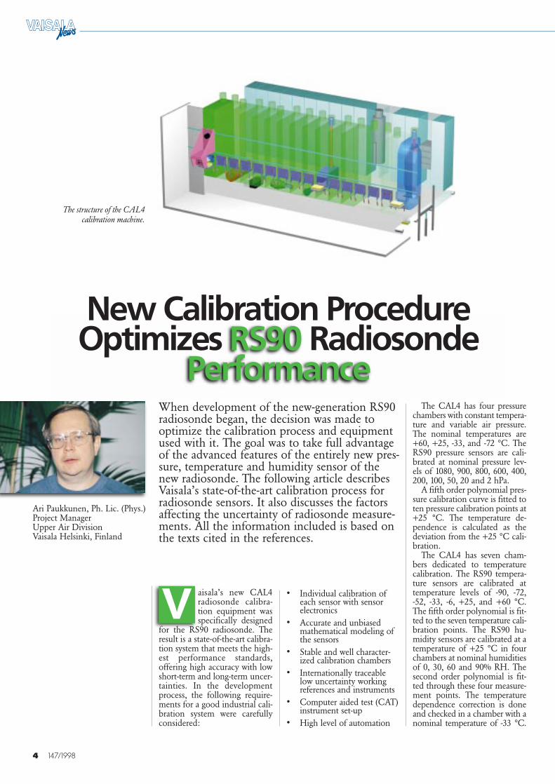
The structure of the CAL4calibration machine.
V
5147/1998
Temperature dependence wastested to be unlinear as a func-tion of temperature accuratelyand accurately enough linear as afunction of humidity.
References forradiosonde calibration
The quality of CAL4 calibra-tions is controlled by repeatingthe calibration of a test sampleafter one day, and after 1, 2, 4, 6,8, 12, and 24 months.
In addition, an independentmeasurement system is used tomonitor and specify the calibra-tion uncertainty. The third – andmore stringent – cross-checkingmethod is a flight simulationtest for a completed radiosonde.This is done in an environmen-tal chamber with variable pres-sure, temperature and humidity.
Working references forradiosonde calibration with theCAL4
A complete range of pressuresensors is used as working refer-ences for each pressure cham-ber, while a separate ambientpressure reference is used to meas-ure the stability of these sensorsduring the process. When everthe control limit is exceeded,immediate test actions are done.
The working references arecalibrated at the MeasurementStandards Laboratory (MSL) atVaisala Finland (ref. 1). The pres-sure range of the working refer-ences is from 0 to 1100 hPa. Thecalibration is repeated every 12months. The ambient pressurereference is calibrated at MSLfrom 950 hPa to 1050 hPa at 6month intervals.
Each of the seven tempera-ture chambers has nine refer-ence sensors. Each set of ninethermistors is calibrated at 7
points in the range of ±3 °Cabout the chamber nominal tem-perature. The thermistors are cali-brated at MSL at 6 month in-tervals.
A set of dewpoint meters isused as a working reference forhumidity. The dewpoint metersare calibrated at MSL at 12month intervals. The calibrationof reference thermistors is de-scribed above. The reference value – expressed as relative hu-midity (over water) – is calculat-ed using the reference dewpointreading and the chamber tem-perature by using Wexler andHyland formulations for satura-tion vapour pressures (ref. 5 and6). The long-term stability of thehumidity references is measuredby using the measured equiva-lent water temperature of the airsaturator.
Traceability and uncertainty ofprimary references
The Measurement StandardsLaboratory (ref. 1) maintainsprimary standards for pressure,temperature and humidity atVaisala Oy and calibrates theworking references used inradiosonde production.
The uncertainty presented iscalculated according to ref. 3,where all the uncertainty factorsare characterized by the estimat-ed variations and degree of free-dom or by the standard devia-tion. The combined uncertaintyis characterized as the sum ofthe squares of the deviations.The value found is then multi-plied by a factor of 2 (k = 2) toget the 2 sigma confidence level.
The primary standards forpressure are the Ruska-2465Pressure Balance, MKS-Bara-tron 627 Absolute PressureTransducer and MKS SRG-2Spinning Rotor Gage. Their cali-bration is directly traceable tothe National Institute of Stand-ards and Technology (NIST,USA), and their recalibrationinterval is 36 months. Betweencalibrations, the primary stand-ards are compared with a similarset of working standards at 6month intervals to be sure thatany sudden functional changeshave not happened to the pri-mary standard.
The measurement uncertain-ties of absolute pressure (k = 2)and the ranges covered withthese instruments are as follows:
• ±2% of reading from 0.1 to20 Pa, with MKS SRG-2Spinning Rotor Gage,
• 0.5% of reading from 20 to50 hPa, with MKS-BaratronAbsolute PressureTransducer,
• (0.005% of reading + 0.08Pa) from 50 hPa to 130 kPa,with Ruska-2465 PressureBalance.
The primary standards for tem-perature are the Hart 1575 Ther-mometer and Hart 5681 Stand-ard Platinum Resistance Ther-mometer. The Hart 1575 Ther-mometer is traceable to theFinnish National MeasurementStandards Laboratory for resist-ance1 via the MeasurementStandards Laboratory. The cali-bration interval is 12 months.
The Hart 5681 StandardPlatinum Resistance Thermom-eter is traceable to the FinnishNational Measurement Stand-ards Laboratory for tempera-ture2. The calibration interval is60 months. Between calibra-tions, the primary standards arecompared with a Water TriplePoint and the appropriate cor-rection is used at 2 month inter-vals. The calibration of theworking references is performedin a HART 7100 calibration bath(stirred liquid). The stability ofthe bath is measured at 12month intervals.
The measurement uncertain-ty (k = 2) of these instruments is±0.02 °C for a range from -100to +100 °C. The primary stand-ards for humidity are theGeneral Eastern M-3 dewpointmeter with a DR-2 sensor and aGeneral Eastern M-3 dewpointmeter with a 1311-DR/SR sen-sor. They are traceable to theNational Physical Laboratory(NPL, England). The GeneralEastern M-3 Dew-Point Meterwith a DR-2 or 1311-DR/SRsensor is calibrated every 24months. Between calibrations,the primary standards are com-pared with each other at 12month intervals.
The measurement uncertain-ty and dewpoint range coveredwith these instruments is as fol-lows:
• 0.24 °C from -74 to +20 °Cwith GE 1311-DR/SR sen-sor
• 0.22 °C from 0 to +80 °Cwith GE DR-2 sensor.
Short-term and long-termuncertainty of CAL4
The calculation of the short-term uncertainty of CAL4 (sr)is based on the following esti-mations:
• Uncertainty of the primarystandard (chapter ofTraceability and uncertaintyof primary references),
• Uncertainty of calibrationin MSL,
• Instability of the workingreferences,
• Temperature dependence ofthe working references,
• Sampling rate,
• Unstability of the calibra-tion chamber.
The results are presented inTable 1.
The unstability of the work-ing reference is a factor in thelong-term uncertainty of calibra-tion (s l ) and depends on thecontrol procedure. Other typesof long-term unstabilities (likechanges in CAL4 chambers)cannot be estimated. They areassumed to be negligible and areeliminated with other controlprocedures (repeated calibra-tion, etc.).
Long-term uncertainty is re-lated to systematic errors.Radiosonde based uncertainties(ss) (resolution, measurementnoise, short-term sensor unsta-bilities, time response, and soon) can basically be definedwith special measurements andestimates.
Uncertainty estimated as thestandard deviation of differ-ences in repeated calibration(src) includes uncertainties srand ss. This means that:
1Belongs organizationally to the Technical Research Centre of Finland.
2Belongs organizationally to the Center for Metrology and Accreditation.
6 147/1998
The measured values for src aregiven in table 2.
The uncertainty is calculatedaccording to ref. 2 and ref. 3,where all the uncertainty factorsare characterized by the estimat-ed variations and degree of free-dom or by the standard devia-tion. The combined uncertaintyis characterized as the sum ofthe squares of the deviations.The value found is then multi-plied by a factor of 2 (k = 2) toget the 2 sigma confidence level(95.45%); the 3 sigma confi-dence level is 99.73%, and the 1sigma is 68.26% for normal dis-tribution.
The values in Tables 1 and 2are preliminary and subject tochange during the ramp up ofCAL4 to high production vol-umes.
CAL4 calibrationuncertainty is a factor inRS90 uncertaintyestimation in soundings
The evaluation scheme pre-sented here is subject to detailedanalysis and testing. The resultswill be presented at a later stage.
If sl is added to src, an ini-tial (low) estimate (st1) of totaluncertainty (st) for an individ-ual RS90 radiosonde is reached:
If a specific general purposemeasurement system (indepen-dently from CAL4) is used tomonitor and specify the uncer-tainty of the RS90 radiosonde,a standard deviation of meas-ured differences to measure-ment reference (sm) and aver-age value (xm) are calculatedfrom sample inspection ofRS90 production. This meas-urement system has its ownuncertainty reference (sar ).The measured differences arerelated to st, sar, ss, andthey can be summed as squaresof the deviations:
and the high estimate is now
The representativeness ofst2 depends on selected testpoints and test chamber condi-tions (temperature with or with-out humidity, for example).
When a radiosonde is flyingwith a balloon, a new set ofuncertainties must be consid-ered. They are mainly attribut-able to dynamic measurementor new phenomena (comparedwith CAL4) like solar radiation.All these factors can be estimat-ed as uncertainty components(ref. 2) and further combined asthe sum of squares of devia-tions (sf). The value of stchanges as a function of severalvariables and therefore theexpression is complicated toformulate. The total uncertain-ty of the RS90 sonde (srs) insoundings can be estimated if(sso) is the RS90’s uncertaintyof calibration.
Uncertainty (sso) can beestimated as an example withst1, st2. The repeatability orreproducibility of soundingsmust be defined to give the gen-eral variability of soundingmeasurements, and it can becompared with st .
Further considerations
Vaisala is constantly working todetermine and improve theaccuracy of radiosonde meas-urements and minimize theiruncertainty. Further findingswill be published in futureissues of Vaisala News.
UNCERTAINTY PRESSURE TEMPERATURE HUMIDITYhPa °C % RH
0....1070 +60.......-90 0......90
SHORT TERM (sr, k=2) < 0.2 < 0.01 < 0.3....0.8
LONG-TERM (sl, k=2) < 0.12 < 0.03....0.04 < 0.5....2
TOTAL < 0.23 < 0.3....0.04 < 0.6.....2.1
Table 1. Estimated preliminary short- (σr) and long-term (σl ) uncertainty of CAL4 calibration at differentcalibration points for a 2 sigma confidence level.
PRESSURE TEMPERATURE HUMIDITYhPa °C % RH
src (k=2) < 0.4 < 0.1 < 2
average < 0.15 < 0.05 < 1
Table 2. Measured preliminary values for the standard deviation of differences in repeated calibrations (σrc ) for a 2sigma confidence level.
(1) src $ÏwwwwXsr C2+ Xsl C2
(2) stl $ÏwwwwXsrc C2+ Xsl C2
(3) xm + 3sm $ 3• ÏwwwwwwwXst C2 + Xsar C2 + Xss C2 $ xm – 3sm
(4) st2 #ÏwwwwwwwwwXxmY3 + sm C2 – Xsar C2 – Xss C2
(5) st2 ,ÏwwwwwwwXxmY3+ sm C2 – Xsar C2
(6) srs 5ÏwwwwXsso C2 + Xsf C2
Xst C can be estimated as Xst2C if the maximal value of Xxm 63sm C is used
References:
1. Antero Pitkäkoski: Traceabilityof measurements at the Radio-sonde Production of Vaisala Oy,(22 September 1997) internalreport.2. Guide to the Expression ofUncertainty in Measurements,First edition 1993, ISBN 92-67-10188-9, International Organiza-tion for Standardization.3. Expression of Uncertainty ofMeasurement in Calibration(EARL-R2,1997) EuropeanCooperation for Accreditationof Laboratories.4. Guide to MeteorologicalInstruments and Methods ofObservation, Sixth edition,WMO-No.8, 1996
5. Wexler, Arnold: VapourPressure Formulation for Waterin Range 0 to 100 °C, Journal ofResearch of the National Bureauof Standards-A. Physics andChemistry Vol 80A Nos 5 and6, September-December 1976,pp 775-785.6. Hyland, Richard and Wexler,Arnold: Formulation ofThermodynamic Properties ofSaturated phases of H2O from173.15 K to 473.15 K, AshraeTransactions 1983, part 2A, pp500-513.
■
7147/1998
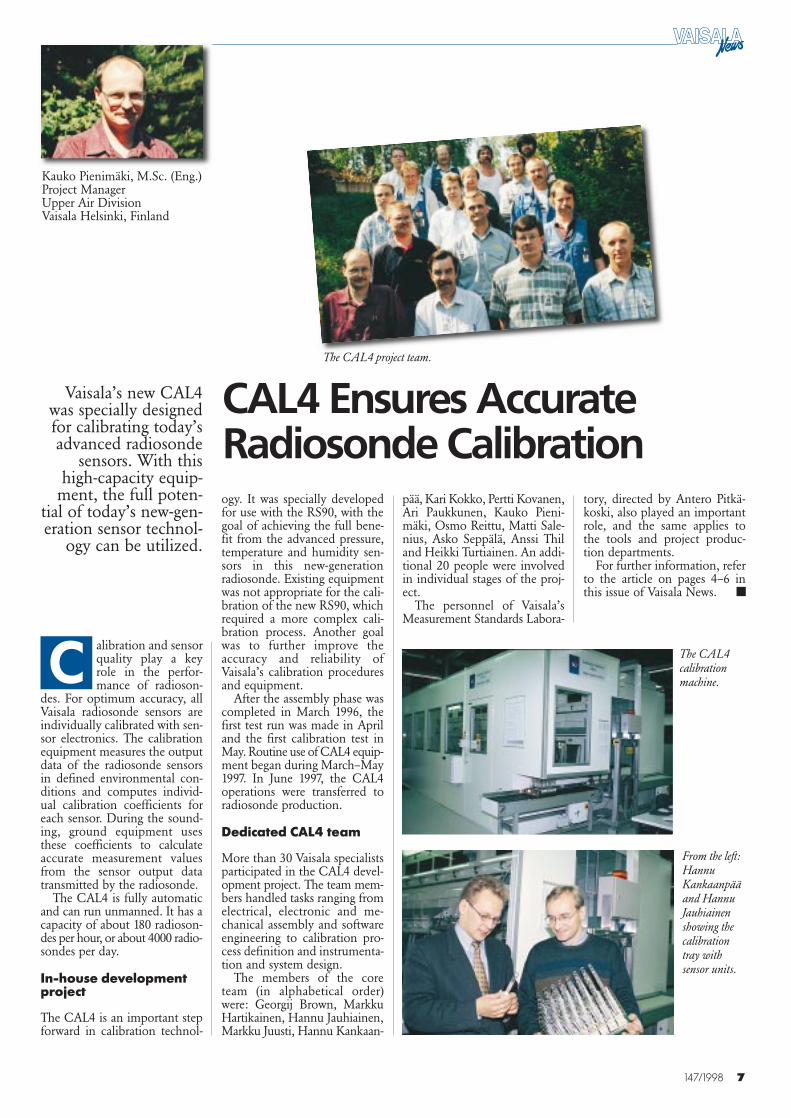
Kauko Pienimäki, M.Sc. (Eng.)Project ManagerUpper Air DivisionVaisala Helsinki, Finland
tory, directed by Antero Pitkä-koski, also played an importantrole, and the same applies tothe tools and project produc-tion departments.
For further information, referto the article on pages 4–6 inthis issue of Vaisala News.
Vaisala’s new CAL4was specially designedfor calibrating today’sadvanced radiosonde
sensors. With thishigh-capacity equip-
ment, the full poten-tial of today’s new-gen-eration sensor technol-
ogy can be utilized.
alibration and sensorquality play a keyrole in the perfor-mance of radioson-
des. For optimum accuracy, allVaisala radiosonde sensors areindividually calibrated with sen-sor electronics. The calibrationequipment measures the outputdata of the radiosonde sensorsin defined environmental con-ditions and computes individ-ual calibration coefficients foreach sensor. During the sound-ing, ground equipment usesthese coefficients to calculateaccurate measurement valuesfrom the sensor output datatransmitted by the radiosonde.
The CAL4 is fully automaticand can run unmanned. It has acapacity of about 180 radioson-des per hour, or about 4000 radio-sondes per day.
In-house developmentproject
The CAL4 is an important stepforward in calibration technol-
ogy. It was specially developedfor use with the RS90, with thegoal of achieving the full bene-fit from the advanced pressure,temperature and humidity sen-sors in this new-generationradiosonde. Existing equipmentwas not appropriate for the cali-bration of the new RS90, whichrequired a more complex cali-bration process. Another goalwas to further improve theaccuracy and reliability ofVaisala’s calibration proceduresand equipment.
After the assembly phase wascompleted in March 1996, thefirst test run was made in Apriland the first calibration test inMay. Routine use of CAL4 equip-ment began during March–May1997. In June 1997, the CAL4operations were transferred toradiosonde production.
Dedicated CAL4 team
More than 30 Vaisala specialistsparticipated in the CAL4 devel-opment project. The team mem-bers handled tasks ranging fromelectrical, electronic and me-chanical assembly and softwareengineering to calibration pro-cess definition and instrumenta-tion and system design.
The members of the coreteam (in alphabetical order)were: Georgij Brown, MarkkuHartikainen, Hannu Jauhiainen,Markku Juusti, Hannu Kankaan-
pää, Kari Kokko, Pertti Kovanen,Ari Paukkunen, Kauko Pieni-mäki, Osmo Reittu, Matti Sale-nius, Asko Seppälä, Anssi Thiland Heikki Turtiainen. An addi-tional 20 people were involvedin individual stages of the proj-ect.
The personnel of Vaisala’sMeasurement Standards Labora-
CAL4 Ensures AccurateRadiosonde Calibration
■
C
From the left:HannuKankaanpääand HannuJauhiainenshowing thecalibrationtray withsensor units.
The CAL4 project team.
The CAL4calibrationmachine.
8 147/1998
In a series of twinsoundings, ZAMG car-ried out a month-long
comparison testbetween Vaisala’s RS80
and new RS90radiosondes.
Conducted in Viennain May 1997, the test
demonstrated the goodperformance of the
RS90 and the advan-tages of the RS90 overthe RS80 for synoptic
observations.Based on the test
results, ZAMG beganusing Vaisala’s RS90
radiosonde for routinesoundings at its aero-
logical station inNovember 1997.
ublic and privatedemand for the ser-vices of ZAMG(Zentralanstalt für
Meteorologie und Geodynamik),including weather forecasts,weather observations, and stormand black-ice warnings, hasincreased in Austria,” says Mr.Kurt Zimmermann, Head ofZAMG’s Remote SensingDivision. “We have to be pre-pared to meet the needs of evermore demanding customers.For this reason, ZAMG wantsto be at the forefront with itsuse of advanced weather ob-servation technology.”
As Mr. Zimmermann ex-plains, his department is respon-sible for the ZAMG meteoro-logical measurement networkthroughout Austria, as well asweather radars and satellite re-ceiving systems. Today, their
meteorological network consistsof 160 weather stations of vary-ing designs. It is ZAMG’s policyto develop their own observa-tion systems and integrate themwith equipment from othermanufacturers.
“ZAMG conducts soundingswith wind- and radiosondes twice
or four times a day. In July 1996,we replaced our old radiosound-ing system with Vaisala equip-ment. Thanks to this change,just one person is needed to op-erate the system,” explains Mr.Erwin Polreich, from ZAMG’sRemote Sensing Division.
Marit FinneEditor-in-ChiefVaisala NewsVaisala Helsinki, Finland
Promising Pilot Test Results of the
New RS90 Radiosonde in Vienna
P
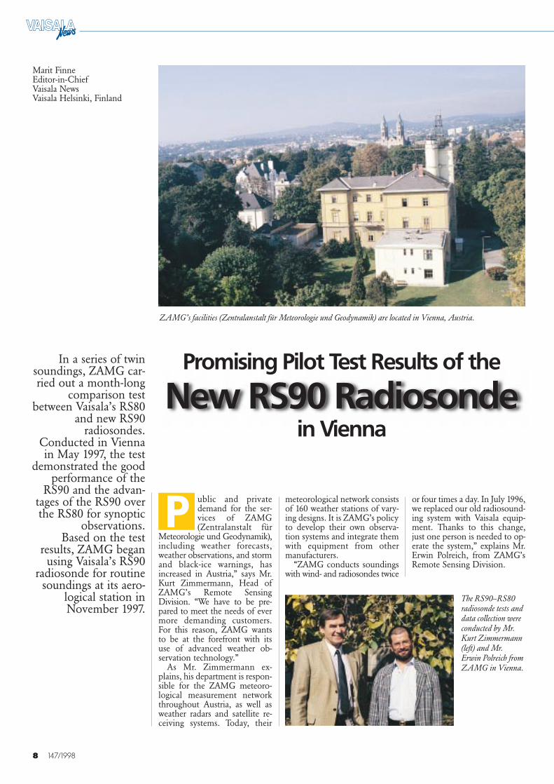
ZAMG’s facilities (Zentralanstalt für Meteorologie und Geodynamik) are located in Vienna, Austria.
The RS90–RS80radiosonde tests anddata collection wereconducted by Mr.Kurt Zimmermann(left) and Mr.Erwin Polreich fromZAMG in Vienna.
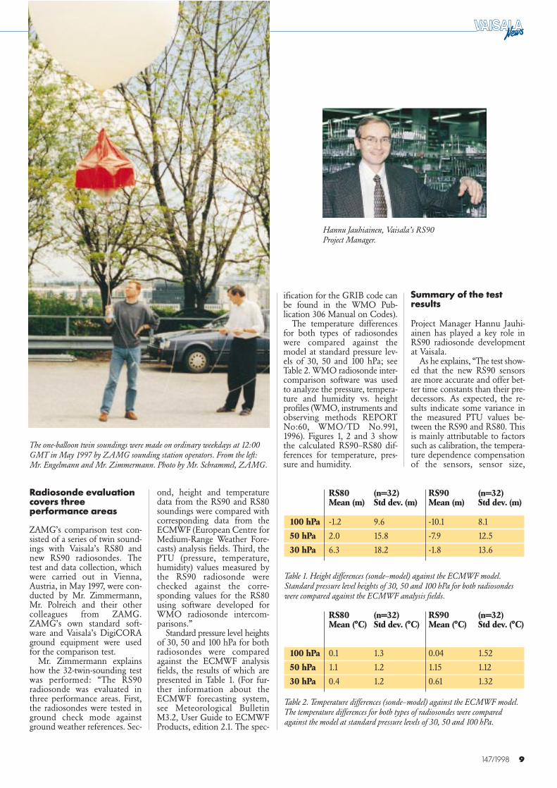
Hannu Jauhiainen, Vaisala’s RS90 Project Manager.
9147/1998
The one-balloon twin soundings were made on ordinary weekdays at 12:00GMT in May 1997 by ZAMG sounding station operators. From the left:Mr. Engelmann and Mr. Zimmermann. Photo by Mr. Schrammel, ZAMG.
Summary of the testresults
Project Manager Hannu Jauhi-ainen has played a key role inRS90 radiosonde developmentat Vaisala.
As he explains, “The test show-ed that the new RS90 sensorsare more accurate and offer bet-ter time constants than their pre-decessors. As expected, the re-sults indicate some variance inthe measured PTU values be-tween the RS90 and RS80. Thisis mainly attributable to factorssuch as calibration, the tempera-ture dependence compensationof the sensors, sensor size,
ification for the GRIB code canbe found in the WMO Pub-lication 306 Manual on Codes).
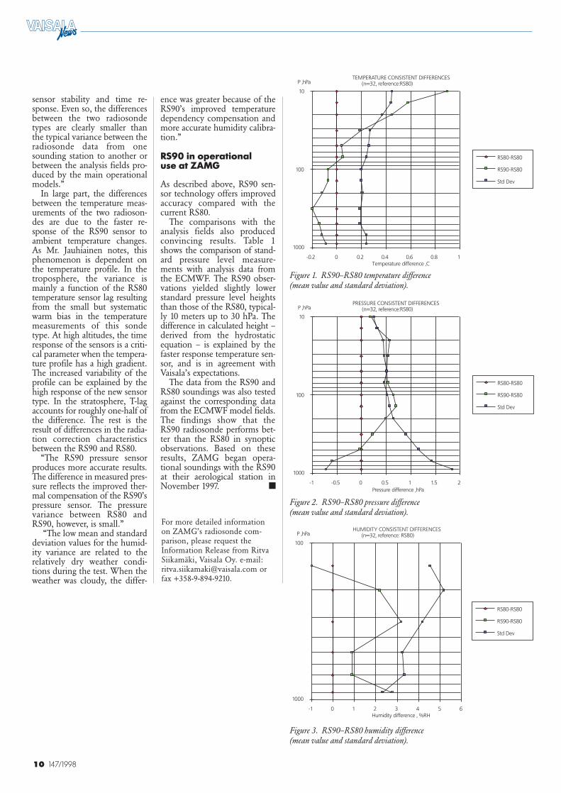
The temperature differencesfor both types of radiosondeswere compared against themodel at standard pressure lev-els of 30, 50 and 100 hPa; seeTable 2. WMO radiosonde inter-comparison software was usedto analyze the pressure, tempera-ture and humidity vs. heightprofiles (WMO, instruments andobserving methods REPORTNo:60, WMO/TD No.991,1996). Figures 1, 2 and 3 showthe calculated RS90–RS80 dif-ferences for temperature, pres-sure and humidity.
Radiosonde evaluationcovers threeperformance areas
ZAMG’s comparison test con-sisted of a series of twin sound-ings with Vaisala’s RS80 andnew RS90 radiosondes. Thetest and data collection, whichwere carried out in Vienna,Austria, in May 1997, were con-ducted by Mr. Zimmermann,Mr. Polreich and their othercolleagues from ZAMG.ZAMG’s own standard soft-ware and Vaisala’s DigiCORAground equipment were usedfor the comparison test.
Mr. Zimmermann explainshow the 32-twin-sounding testwas performed: “The RS90radiosonde was evaluated inthree performance areas. First,the radiosondes were tested inground check mode againstground weather references. Sec-
ond, height and temperaturedata from the RS90 and RS80soundings were compared withcorresponding data from theECMWF (European Centre forMedium-Range Weather Fore-casts) analysis fields. Third, thePTU (pressure, temperature,humidity) values measured bythe RS90 radiosonde werechecked against the corre-sponding values for the RS80using software developed forWMO radiosonde intercom-parisons.”
Standard pressure level heightsof 30, 50 and 100 hPa for bothradiosondes were comparedagainst the ECMWF analysisfields, the results of which arepresented in Table 1. (For fur-ther information about theECMWF forecasting system,see Meteorological BulletinM3.2, User Guide to ECMWFProducts, edition 2.1. The spec-
RS80 (n=32) RS90 (n=32)Mean (m) Std dev. (m) Mean (m) Std dev. (m)
100 hPa -1.2 9.6 -10.1 8.1
50 hPa 2.0 15.8 -7.9 12.5
30 hPa 6.3 18.2 -1.8 13.6
Table 1. Height differences (sonde–model) against the ECMWF model.Standard pressure level heights of 30, 50 and 100 hPa for both radiosondeswere compared against the ECMWF analysis fields.
RS80 (n=32) RS90 (n=32)Mean (°C) Std dev. (°C) Mean (°C) Std dev. (°C)
100 hPa 0.1 1.3 0.04 1.52
50 hPa 1.1 1.2 1.15 1.12
30 hPa 0.4 1.2 0.61 1.32
Table 2. Temperature differences (sonde–model) against the ECMWF model.The temperature differences for both types of radiosondes were comparedagainst the model at standard pressure levels of 30, 50 and 100 hPa.
10 147/1998
sensor stability and time re-sponse. Even so, the differencesbetween the two radiosondetypes are clearly smaller thanthe typical variance between theradiosonde data from onesounding station to another orbetween the analysis fields pro-duced by the main operationalmodels.”
In large part, the differencesbetween the temperature meas-urements of the two radioson-des are due to the faster re-sponse of the RS90 sensor toambient temperature changes.As Mr. Jauhiainen notes, thisphenomenon is dependent onthe temperature profile. In thetroposphere, the variance ismainly a function of the RS80temperature sensor lag resultingfrom the small but systematicwarm bias in the temperaturemeasurements of this sondetype. At high altitudes, the timeresponse of the sensors is a criti-cal parameter when the tempera-ture profile has a high gradient.The increased variability of theprofile can be explained by thehigh response of the new sensortype. In the stratosphere, T-lagaccounts for roughly one-half ofthe difference. The rest is theresult of differences in the radia-tion correction characteristicsbetween the RS90 and RS80.
“The RS90 pressure sensorproduces more accurate results.The difference in measured pres-sure reflects the improved ther-mal compensation of the RS90’spressure sensor. The pressurevariance between RS80 andRS90, however, is small.”
“The low mean and standarddeviation values for the humid-ity variance are related to therelatively dry weather condi-tions during the test. When theweather was cloudy, the differ-
ence was greater because of theRS90’s improved temperaturedependency compensation andmore accurate humidity calibra-tion.”
RS90 in operational use at ZAMG
As described above, RS90 sen-sor technology offers improvedaccuracy compared with thecurrent RS80.
The comparisons with the analysis fields also producedconvincing results. Table 1shows the comparison of stand-ard pressure level measure-ments with analysis data fromthe ECMWF. The RS90 obser-vations yielded slightly lowerstandard pressure level heightsthan those of the RS80, typical-ly 10 meters up to 30 hPa. Thedifference in calculated height –derived from the hydrostaticequation – is explained by thefaster response temperature sen-sor, and is in agreement withVaisala’s expectations.
The data from the RS90 andRS80 soundings was also testedagainst the corresponding datafrom the ECMWF model fields.The findings show that theRS90 radiosonde performs bet-ter than the RS80 in synopticobservations. Based on theseresults, ZAMG began opera-tional soundings with the RS90at their aerological station inNovember 1997.
For more detailed informationon ZAMG’s radiosonde com-parison, please request theInformation Release from RitvaSiikamäki, Vaisala Oy. e-mail:[email protected] orfax +358-9-894-9210.
10
100
1000
-0.2 0 0.2 0.4 0.6 0.8 1
RS80-RS80
RS90-RS80
Std Dev
TEMPERATURE CONSISTENT DIFFERENCES(n=32, reference:RS80)P ,hPa
Temperature difference ,C
10
100
1000
-1 -0.5 0 0.5 1 1.5 2
RS80-RS80
RS90-RS80
Std Dev
PRESSURE CONSISTENT DIFFERENCES(n=32, reference:RS80)P ,hPa
Pressure difference ,hPa
100
1000
-1 0 1 2 3 4 5 6
RS80-RS80
RS90-RS80
Std Dev
HUMIDITY CONSISTENT DIFFERENCES(n=32, reference: RS80)P ,hPa
Humidity difference , %RH
■
Figure 3. RS90–RS80 humidity difference (mean value and standard deviation).
Figure 1. RS90–RS80 temperature difference (mean value and standard deviation).
Figure 2. RS90–RS80 pressure difference (mean value and standard deviation).
11147/1998
After delivering fourAUTOSONDEs to
Australia in 1996–1997,Vaisala will supply
four more units to thecountry in 1998. The
conditions in Australiacover a wide range,from the desert-likeCobar region to the
tropical environmenton Cocos Island. As
these installationshave shown, Vaisala’s
AUTOSONDE canhandle them all.
n early 1996, the Vai-sala Melbourne Of-fice delivered a dem-onstration AUTO-
SONDE to the Bureau ofMeteorology for evaluation.The AUTOSONDE was install-ed at the Bureau’s training facil-ity in Melbourne, Australia, andunderwent a series of trials. Thisunit was subsequently pur-chased and is now used to trainBureau observations and tech-nical staff.
As the saying goes, the rest ishistory. In 1997 three addition-al AUTOSONDEs were in-stalled in Cobar (Central NewSouth Wales), Cocos Island (anAustralian territory in theIndian Ocean) and Learmonthin Western Australia. TheseAUTOSONDEs are now fullyoperational and provide pres-sure, temperature, humidity and
wind data for the Bureau’s upperair observation network. Theinstallation of four moreAUTOSONDEs is planned inWestern Australia and Queens-land in 1998.
The conditions vary widelyacross Australia, and theAUTOSONDE is expected tooperate in all of them, from thedesert-like Cobar region to theextremely humid and tropicalconditions on Cocos Island.Few instruments can coversuch a range of operating con-ditions. With the close coopera-tion of the engineers at VaisalaMelbourne, Vaisala Helsinkiand the Bureau, the installationprogram is on schedule andprogressing well.
The Bureau of Meteorologyhas selected the AUTOSONDEsites very carefully, targeting lo-cations where they have a
strong local presence. This is toensure that they have capablesupport for the AUTOSONDEson site, as the current sites arequite remote within the Bureauobserving network. The Bureauof Meteorology’s support forthe AUTOSONDE has beentremendous so far, and VaisalaMelbourne expects that withthis level of support, the suc-cessful completion of the fourinstallations scheduled for thisyear will proceed without prob-lem.
As with the introduction of any new technology, the fullimpact of the installed AUTO-SONDEs will not be felt in theBureau synoptic network forsome time. However, the capabil-ity for a fully automated radio-sonde launch already exists,and the benefits are sure to ex-pand in the future. ■
I
New AUTOSONDE
Installations in Australia
Vaisala’s AUTOSONDE in Cobar in May 1997.
12 147/1998
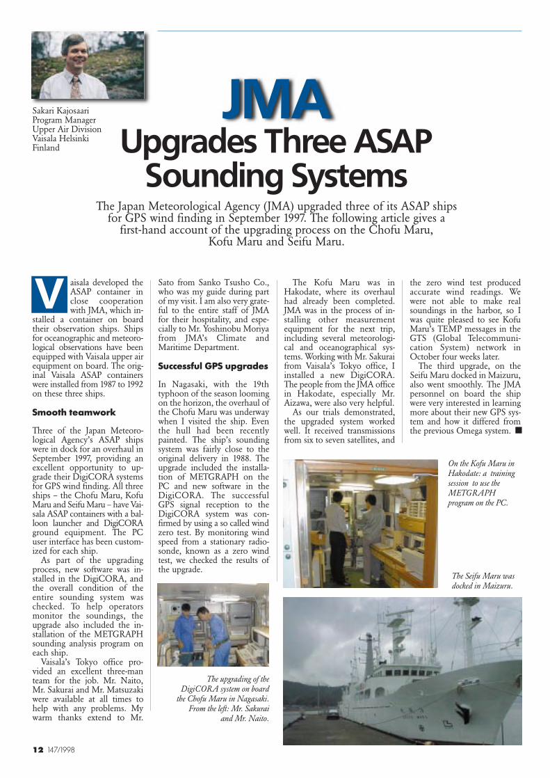
aisala developed theASAP container inclose cooperationwith JMA, which in-
stalled a container on boardtheir observation ships. Shipsfor oceanographic and meteoro-logical observations have beenequipped with Vaisala upper airequipment on board. The orig-inal Vaisala ASAP containerswere installed from 1987 to 1992on these three ships.
Smooth teamwork
Three of the Japan Meteoro-logical Agency’s ASAP shipswere in dock for an overhaul inSeptember 1997, providing anexcellent opportunity to up-grade their DigiCORA systemsfor GPS wind finding. All threeships – the Chofu Maru, KofuMaru and Seifu Maru – have Vai-sala ASAP containers with a bal-loon launcher and DigiCORAground equipment. The PCuser interface has been custom-ized for each ship.
As part of the upgradingprocess, new software was in-stalled in the DigiCORA, andthe overall condition of theentire sounding system waschecked. To help operatorsmonitor the soundings, theupgrade also included the in-stallation of the METGRAPHsounding analysis program oneach ship.
Vaisala’s Tokyo office pro-vided an excellent three-manteam for the job. Mr. Naito,Mr. Sakurai and Mr. Matsuzakiwere available at all times tohelp with any problems. Mywarm thanks extend to Mr.
The Kofu Maru was inHakodate, where its overhaulhad already been completed.JMA was in the process of in-stalling other measurementequipment for the next trip,including several meteorologi-cal and oceanographical sys-tems. Working with Mr. Sakuraifrom Vaisala’s Tokyo office, Iinstalled a new DigiCORA.The people from the JMA officein Hakodate, especially Mr.Aizawa, were also very helpful.
As our trials demonstrated,the upgraded system workedwell. It received transmissionsfrom six to seven satellites, and
the zero wind test producedaccurate wind readings. Wewere not able to make realsoundings in the harbor, so Iwas quite pleased to see KofuMaru’s TEMP messages in theGTS (Global Telecommuni-cation System) network inOctober four weeks later.
The third upgrade, on theSeifu Maru docked in Maizuru,also went smoothly. The JMApersonnel on board the shipwere very interested in learningmore about their new GPS sys-tem and how it differed fromthe previous Omega system.
The Japan Meteorological Agency (JMA) upgraded three of its ASAP shipsfor GPS wind finding in September 1997. The following article gives a
first-hand account of the upgrading process on the Chofu Maru, Kofu Maru and Seifu Maru.
On the Kofu Maru inHakodate: a trainingsession to use theMETGRAPHprogram on the PC.
JMA Upgrades Three ASAP
Sounding Systems
The upgrading of theDigiCORA system on board
the Chofu Maru in Nagasaki.From the left: Mr. Sakurai
and Mr. Naito.
The Seifu Maru wasdocked in Maizuru.
Sato from Sanko Tsusho Co.,who was my guide during partof my visit. I am also very grate-ful to the entire staff of JMAfor their hospitality, and espe-cially to Mr. Yoshinobu Moriyafrom JMA’s Climate andMaritime Department.
Successful GPS upgrades
In Nagasaki, with the 19thtyphoon of the season loomingon the horizon, the overhaul ofthe Chofu Maru was underwaywhen I visited the ship. Eventhe hull had been recentlypainted. The ship’s soundingsystem was fairly close to theoriginal delivery in 1988. Theupgrade included the installa-tion of METGRAPH on thePC and new software in theDigiCORA. The successfulGPS signal reception to theDigiCORA system was con-firmed by using a so called windzero test. By monitoring windspeed from a stationary radio-sonde, known as a zero windtest, we checked the results ofthe upgrade.
■
V
Sakari KajosaariProgram ManagerUpper Air DivisionVaisala HelsinkiFinland
13147/1998
MAWS
Hannu Kokko, B.Sc. (Eng.)Product ManagerSurface Weather DivisionVaisala HelsinkiFinland
Reliability and accuracy at a low cost-of-ownership
Vaisala’s new low-costMini Automatic
Weather Stations(MAWS) combine the
company’s provensensor technology
with a new compactdesign. Derived from
the same expertise thatmade MILOS 500 the
leading AWS for thesynoptic observations,MAWS stations offer
an excellent alternativefor applications requir-ing ease of installationand use at a competi-
tive price.
mall MAWS weath-er stations are new-generation series ofautomatic weather
stations (AWS) for both perma-nent installations and applica-tions requiring portability. TheMAWS offers high perfor-mance in a very compact pack-age. These stations are an idealchoice for a wide range ofmeteorological applicationsrequiring reliable and accuratemeteorological measurementsat a low cost-of-ownership.
User-friendly weatherstation
The MAWS is simple to set up.All sensors are equipped withready-made cables and connec-tors for easy installation, andall components fit togethereffortlessly. No special tools arerequired for installation.
Once the station is assem-bled and the power is connect-ed, the MAWS is fully opera-tional. Sensor measurements, cal-culations, data logging andtransmission are performed ac-cording to a user-configured pro-gram.The operation of the MAWS is
easy to modify with the help ofthe Windows-based “Lizard”set-up program. This set-uputility provides straightforwardbasic setup procedures usingready-made templates thatguide the user through the sim-ple set-up routines. While easyto use, there are enough set-upoptions to satisfy even themost demanding user.
Accurate and reliable
Utilizing Vaisala’s field-provendesign and accurate sensors,MAWS provides features thatwere previously available onlyin larger systems. The basicsuite of sensors measures wind,pressure, temperature, relativehumidity and precipitation. Inaddition, measurements can bemade of soil/water tempera-tures, solar radiation, net radia-tion and water level.
The use of a 32-bit CPU, a16-bit A/D conversion and ad-vanced software ensure the con-tinuous accuracy of the weath-er information.
The mechanical design is com-pact, rugged and weatherproof,and can tolerate operation indifficult conditions. The MAWSis made from corrosion-resis-tant anodized aluminum, withdouble 0-ring seals used in theenclosure. The cables are madefrom high-quality polyurethane,with molded connectors thatare watertight in compliancewith the IP68 standard.
The built-in quality controlsoftware checks the sensor dataagainst the user-set climatologi-cal limits and the step changesbetween successive measure-
ments. This ensures the reliabil-ity of the measured data.
The MAWS series of smallAWSs offers low power con-sumption and high processingcapacity in the same unit. Thedesign of MAWS ensures reli-able operation with low main-tenance costs.
Versatile characteristics
Data output: Convenient pre-formatted data messages covermost needs, but the data out-puts can also be formattedfreely to meet the needs of theuser’s applications. Alarm mes-sages are automatically sentwhenever a user-set alarmthreshold has been exceeded.Each sensor and calculated pa-rameter has its own alarm set-tings.
Versatile data logging:MAWS provides easy data log-ging. Two megabytes of secureflash memory is available forthe logging of measured andcalculated data and completereports. Several logging sched-ules are possible, all user select-able. Various statistical calcula-tions can be made on-site, thusreducing the amount of data tobe transmitted or logged.
Calculations: Statistical cal-culations include minimum,maximum, averages, standarddeviation, and cumulative val-ues, calculated over user setintervals. In addition, there is alibrary of ready-made calcula-tions, including unit conver-sions, dew point, QNH, QFF,QFE, evapotranspiration, windchill and heat stress, forexample.
S
- Automatic Weather Stations
14 147/1998
Communication options:The MAWS weather station hasup to five serial ports for inter-facing with telemetry, termi-nals, and displays. One RS-232port is standard. Two optionalplug-in modules can be usedfor even greater versatility.There is a dual RS-232 modulefor short distance communica-tion and an isolated RS-485module for distances up to1,500 meters. The DMX501fixed line modem handleslonger distances. Data can beaccessed on-site with a PC orhandheld terminal, or remotelywith a radio modem.
Upgrading: The design ofthe MAWS enables easy systemupgrading with new sensors, cal-culations, output formats, andlogging schedules at any timeto accommodate changing re-quirements. The software modi-fications are made using theLizard set-up program, with thenew sensors simply connectedto the free connectors.
Power supply options: TheMAWS offers low power con-sumption. Using a standard 2.2W solar panel and 1.3 Ah/6 Vbattery, the MAWS can operateindependently for extended pe-riods of time. An extra solarpanel and batteries, as well as amains power supply are alloptional.
MAWS stations also interfacewith UHF and Spread Spec-trum radios.
For more detailed information andspecifications for the MAWS andits sensors, please visit and book-mark our Web site at:www.vaisala.com
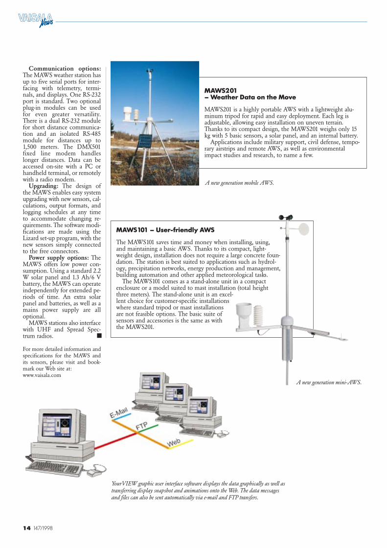
MAWS101 – User-friendly AWS
The MAWS101 saves time and money when installing, using,and maintaining a basic AWS. Thanks to its compact, light-weight design, installation does not require a large concrete foun-dation. The station is best suited to applications such as hydrol-ogy, precipitation networks, energy production and management,building automation and other applied meteorological tasks.
The MAWS101 comes as a stand-alone unit in a compactenclosure or a model suited to mast installation (total heightthree meters). The stand-alone unit is an excel-lent choice for customer-specific installationswhere standard tripod or mast installationsare not feasible options. The basic suite ofsensors and accessories is the same as withthe MAWS201.
MAWS201 – Weather Data on the Move
MAWS201 is a highly portable AWS with a lightweight alu-minum tripod for rapid and easy deployment. Each leg isadjustable, allowing easy installation on uneven terrain.Thanks to its compact design, the MAWS201 weighs only 15kg with 5 basic sensors, a solar panel, and an internal battery.
Applications include military support, civil defense, tempo-rary airstrips and remote AWS, as well as environmentalimpact studies and research, to name a few.
YourVIEW graphic user interface software displays the data graphically as well astransferring display snapshot and animations onto the Web. The data messagesand files can also be sent automatically via e-mail and FTP transfers.
A new generation mini-AWS.
A new generation mobile AWS.
■
15147/1998
Kai InhaR&D ManagerSurface Weather DivisionVaisala HelsinkiFinland
New communication modules
Important Step TowardsOpen Communication
aisala has developeda new communica-tion concept forlinking Vaisala’s new
wind displays, sensors andautomatic weather stations.This concept also supportscommunication between Vai-sala units and third party prod-ucts. The new communicationmodules are another step towardsopen systems and open com-munication, where customerscan select between differentindustry standard communica-tion methods. At no extra cost,customers can choose the mostuseful solution, and whenneeds or standards change, thesystem is easy to update.
Versatile modules forharsh environments
Vaisala’s basic products typical-ly come with an RS-232C port.Some large systems, includingthe MILOS 500, can be expand-ed using plug-in PCB modulessuch as modems. These boards
are relatively expensive, howev-er, and they occupy expansionslots that could be used other-wise.
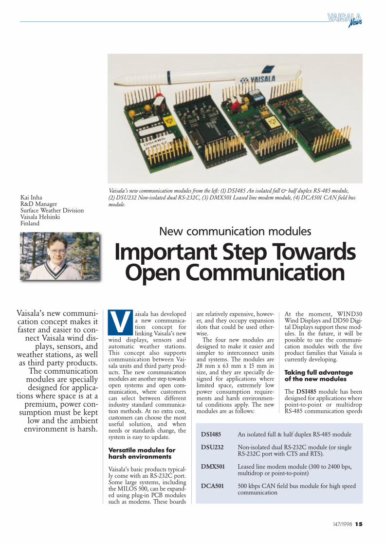
The four new modules aredesigned to make it easier andsimpler to interconnect unitsand systems. The modules are28 mm x 63 mm x 15 mm insize, and they are specially de-signed for applications wherelimited space, extremely lowpower consumption require-ments and harsh environmen-tal conditions apply. The newmodules are as follows:
At the moment, WIND30Wind Displays and DD50 Digi-tal Displays support these mod-ules. In the future, it will bepossible to use the communi-cation modules with the fiveproduct families that Vaisala iscurrently developing.
Taking full advantage of the new modules
The DSI485 module has beendesigned for applications wherepoint-to-point or multidropRS-485 communication speeds
Vaisala’s new communi-cation concept makes itfaster and easier to con-
nect Vaisala wind dis-plays, sensors, and
weather stations, as wellas third party products.
The communicationmodules are speciallydesigned for applica-
tions where space is at apremium, power con-
sumption must be keptlow and the ambient
environment is harsh.
V
DSI485 An isolated full & half duplex RS-485 module
DSU232 Non-isolated dual RS-232C module (or single RS-232C port with CTS and RTS).
DMX501 Leased line modem module (300 to 2400 bps,multidrop or point-to-point)
DCA501 500 kbps CAN field bus module for high speedcommunication
Vaisala’s new communication modules from the left: (1) DSI485 An isolated full & half duplex RS-485 module, (2) DSU232 Non-isolated dual RS-232C, (3) DMX501 Leased line modem module, (4) DCA501 CAN field busmodule.
16 147/1998
Dr. Tamas Prager, DirectorHungarian Meteorological ServiceBudapest, Hungary
The HungarianMeteorological Service
(HMS) has begun anextensive update of itsmeteorological equip-
ment. Ever sinceHMS started the step-by-step automation ofthe country’s meteoro-
logical network in1991, Vaisala’s
advanced technology,including radiosound-ing and synoptic and
climatological stations,has been used in the
network.
n line with its long-term strategy, thenew directorate ofHMS decided to
rationalize all of its profession-al activities. The final goal wasto ensure the continuation anddevelopment of basic opera-tional activities, including mete-orological observations, weath-er forecasting and climatologi-cal data archiving. Ambitiousupgrading and step-by-stepautomation of the meteorolo-gical and environmental observ-ing systems began in 1992.HMS has also provided stafftraining on the new technologyand operating methods.
Upgrades ofradiosounding stations
The first step in the moderniza-tion process was to refurbishobsolete radiosounding equip-ment at each of HMS’s twoaerological stations. The oldSoviet-based ground equip-ment at the central Budapest-Lorinc observatory was re-placed with a Vaisala DigiCORAsounding system and RS-80radiosondes in spring 1991.This was followed in 1994 bythe replacement of the sametechnology at the Szeged aero-logical station with Vaisala PC-CORA ground equipment.
The experience of the pastsix years has been very positive:the new equipment has ‘revolu-tionized’ aerological operationsin Hungary. After retraining,
Hungary automates
Ambitious
can reach up to 38 kbps andwhere isolation is required be-cause of long cabling and exter-nal noise. The DSI485 alsoeliminates the troublesomeground loops that easily lead tounpredictability in system in-stallation and to unstable op-erations. The communicationprotocol depends on the hostunit.
The DSU232 carries twoindependent RS-232C chan-nels. It can also be used in amode where only one channelwith CTS and RTS handshakesignals is in use. The module isdesigned for applications re-quiring local serial port expan-sion. It has no isolation but likeall new modules, it is very wellprotected against overvoltage,EMI and ESD.
The DMX501 is a completemodem for leased lines. It iscompliant with several modemstandards such as 300 bps V.21,1200 bps V.22 & V.23 and 2400bps V.22 bis. The module isadapted for systems with com-munication distances rangingfrom zero to over ten kilo-meters using leased telephonegrade cables. Although the mo-dem is not approved by PTTs,it has been designed to meetmost of the relevant standards.
Any commercial brand withthe required modes can be usedas the third party modem withthe DMX501. The DMX55 andDMX50 system modems of theMILOS 500 are also compat-ible. However, it should benoted that the DMX501 is notan AT modem and that thepossible modes depend on the
Vaisala host system carrying themodule.
The DCA501 CAN (Con-trolled Area Network) modulewas designed to interface withfast industrial measurementand control systems. Data ratescan reach up to 500 kbps. Themodule has its own communi-cations processor, which is pre-programmed to handle all theerror correction and packagehandling procedures that arerequired in a CAN network.The DCA501 module will onlytransfer correctly addressed mes-sages to the host, and in thisway dramatically reduces thehost system CPU load. A typi-cal conductor is a twisted pairless than 100 meters in length.
The module is non-isolatedaccording to Basic CAN stand-ards, but it can deal withextended CAN messages. CANcommunication is used be-tween Vaisala’s QLC50 units indistributed real-time measure-ment systems, for instance.
Vaisala is studying futureenvironmental measurementapplications. The special com-munication needs and stand-ards in the field of buildingautomation, for example, havebeen identified, and new com-munication modules for thesefuture applications are nowunder development.
For more information aboutCAN, please visit the followingwww site: http://www.can-cia.de (CiA standsfor CAN In Automation)
I
■
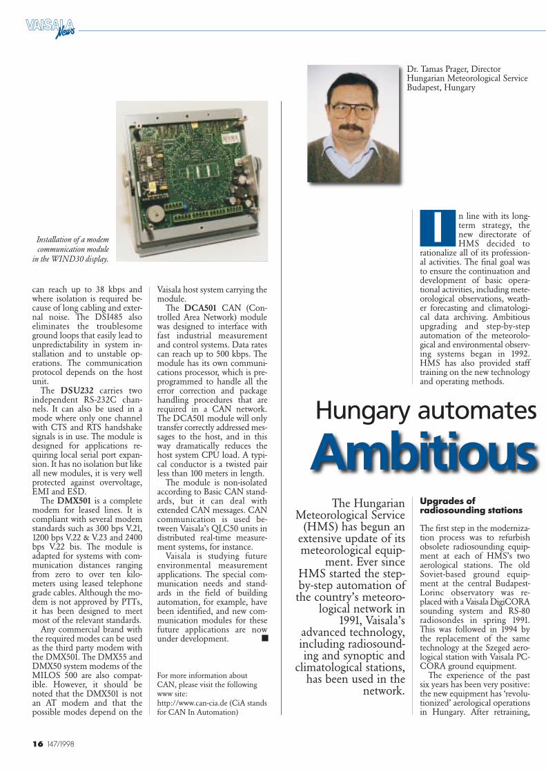
Installation of a modemcommunication module
in the WIND30 display.

16 147/1998
Dr. Tamas Prager, DirectorHungarian Meteorological ServiceBudapest, Hungary
The HungarianMeteorological Service
(HMS) has begun anextensive update of itsmeteorological equip-
ment. Ever sinceHMS started the step-by-step automation ofthe country’s meteoro-
logical network in1991, Vaisala’s
advanced technology,including radiosound-ing and synoptic and
climatological stations,has been used in the
network.
n line with its long-term strategy, thenew directorate ofHMS decided to
rationalize all of its profession-al activities. The final goal wasto ensure the continuation anddevelopment of basic opera-tional activities, including mete-orological observations, weath-er forecasting and climatologi-cal data archiving. Ambitiousupgrading and step-by-stepautomation of the meteorolo-gical and environmental observ-ing systems began in 1992.HMS has also provided stafftraining on the new technologyand operating methods.
Upgrades ofradiosounding stations
The first step in the moderniza-tion process was to refurbishobsolete radiosounding equip-ment at each of HMS’s twoaerological stations. The oldSoviet-based ground equip-ment at the central Budapest-Lorinc observatory was re-placed with a Vaisala DigiCORAsounding system and RS-80radiosondes in spring 1991.This was followed in 1994 bythe replacement of the sametechnology at the Szeged aero-logical station with Vaisala PC-CORA ground equipment.
The experience of the pastsix years has been very positive:the new equipment has ‘revolu-tionized’ aerological operationsin Hungary. After retraining,
Hungary automates
Ambitious
can reach up to 38 kbps andwhere isolation is required be-cause of long cabling and exter-nal noise. The DSI485 alsoeliminates the troublesomeground loops that easily lead tounpredictability in system in-stallation and to unstable op-erations. The communicationprotocol depends on the hostunit.
The DSU232 carries twoindependent RS-232C chan-nels. It can also be used in amode where only one channelwith CTS and RTS handshakesignals is in use. The module isdesigned for applications re-quiring local serial port expan-sion. It has no isolation but likeall new modules, it is very wellprotected against overvoltage,EMI and ESD.
The DMX501 is a completemodem for leased lines. It iscompliant with several modemstandards such as 300 bps V.21,1200 bps V.22 & V.23 and 2400bps V.22 bis. The module isadapted for systems with com-munication distances rangingfrom zero to over ten kilo-meters using leased telephonegrade cables. Although the mo-dem is not approved by PTTs,it has been designed to meetmost of the relevant standards.
Any commercial brand withthe required modes can be usedas the third party modem withthe DMX501. The DMX55 andDMX50 system modems of theMILOS 500 are also compat-ible. However, it should benoted that the DMX501 is notan AT modem and that thepossible modes depend on the
Vaisala host system carrying themodule.
The DCA501 CAN (Con-trolled Area Network) modulewas designed to interface withfast industrial measurementand control systems. Data ratescan reach up to 500 kbps. Themodule has its own communi-cations processor, which is pre-programmed to handle all theerror correction and packagehandling procedures that arerequired in a CAN network.The DCA501 module will onlytransfer correctly addressed mes-sages to the host, and in thisway dramatically reduces thehost system CPU load. A typi-cal conductor is a twisted pairless than 100 meters in length.
The module is non-isolatedaccording to Basic CAN stand-ards, but it can deal withextended CAN messages. CANcommunication is used be-tween Vaisala’s QLC50 units indistributed real-time measure-ment systems, for instance.
Vaisala is studying futureenvironmental measurementapplications. The special com-munication needs and stand-ards in the field of buildingautomation, for example, havebeen identified, and new com-munication modules for thesefuture applications are nowunder development.
For more information aboutCAN, please visit the followingwww site: http://www.can-cia.de (CiA standsfor CAN In Automation)
I
■
Installation of a modemcommunication module
in the WIND30 display.
17147/1998
the observers and technicalstaff at each station were freedfor other tasks utilizing the newtechnology. The modern equip-ment made it possible to mergethe jobs of weather observersand radiosonde operators atboth observatories.
Since September 1997, thephase-out of the OMEGAwindfinding system has pre-sented a new challenge forradiosounding. After intensiveconsultation with Vaisala ex-perts and a field study carriedout in September 1996, HMSmade the decision to upgradeits radiosounding equipmentto a LORAN-C windfindingsystem. Plans have also beenmade to use GPS windfindingin radiosounding operationsstarting in the year 2000.
Modernization ofmeteorologicalobserving networkgains momentum
In 1992, the directorate of theMeteorological Service made astrategic decision to modernizeits synoptic and climate obser-vation networks.
At both synoptic and clima-tological stations, the traditionalmanually operated instrumentswere to be replaced by auto-matic equipment that could beoperated in a stand-alone re-gime, without human surveil-lance. The need for moderniza-tion was becoming pressing inHungary, because the existingmeteorological instruments werein poor technical condition, andthere were fewer voluntary ob-servers available to run the sta-
tions. Strategic considerationsincluded the need to reduceobservation and maintenancecosts, upgrade old systems withadvanced technology, and reas-sign the retained observers tomore appropriate tasks.
Completion of the moderni-zation was planned in two proj-ects: the Synoptic NetworkAutomation Project (SNAP)and the Climate Network Auto-mation Project (CNAP).
Synoptic NetworkAutomation Project
The Synoptic Network Auto-mation Project (SNAP) beganin 1992, when HMS invitedseveral companies to tender forthe automatic synoptic stations.
After a careful evaluation ofthe options, HMS awardedVaisala a contract for five
MILOS 500 weather stations,which were subsequently in-stalled at various synoptic sta-tions in 1993.
The experts at HMS wereconvinced of the need for an ad-vanced solution that met hightechnical requirements for qual-ity, reliability and low main-tenance costs. Vaisala’s MILOS500 automatic weather station,which is an automatic environ-mental data acquisition system,met these requirements. Design-ed for extreme conditions, it ismodular and cost-effective, withhigh processing power and flexi-bility in terms of configuration.
In the beginning, the stationhad data communications aswell as data collection and pro-cessing problems. The conclu-sion at the end of this pilotphase was to revamp the proj-
ect for operations in theHungarian environment. Inclose cooperation technicalexperts from Vaisala, HMS andKöszofa Bt. (a local informa-tion technology company)solved all the problems in oneyear, and the final network architecture was created.
The pace of installation workhas been very rapid since 1995.Seventeen MILOS 500 stationswere operational by the end ofthat year, and in 1996 the num-ber of operating stations reach-ed 27.
By the end of 1997, all themanned synoptic stations inHungary, which are operatedjointly by the MeteorologicalService (17), the HungarianHome Defense Forces (6) andsome educational institutions(2), were automated, and sevenstand-alone MILOS 500s were
also installed at new sites. Withthese 32 stations (all owned byHMS and maintained uni-formly) the first phase of auto-mation was successfully com-pleted.
Architecture of thesynoptic network
The network operation design-ed in 1995 was so successfulthat it is currently working with-out significant changes, with theexception of some minor soft-ware updates and modifica-tions. It is based on the soft-ware for the MILOS 500 andYourWay, as well as the KTXdata communications softwaredeveloped by Köszofa. In addi-tion to its basic function, KTXis also suitable for electronicmail, status checks, interroga-
its observation network
Upgrading Project
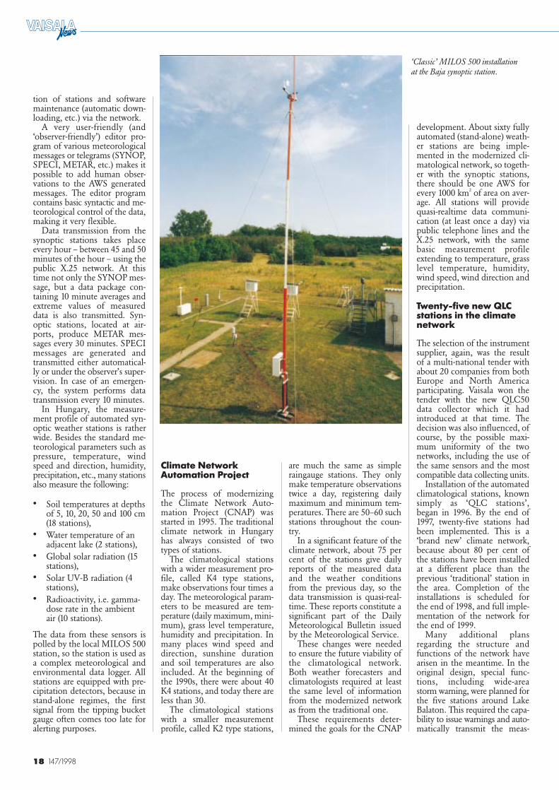
MILOS 500 installation in the Sopronwindmill, which houses the synoptic station.
18 147/1998
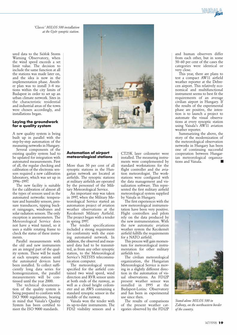
‘Classic’ MILOS 500 installationat the Baja synoptic station.
are much the same as simpleraingauge stations. They onlymake temperature observationstwice a day, registering dailymaximum and minimum tem-peratures. There are 50–60 suchstations throughout the coun-try.
In a significant feature of theclimate network, about 75 percent of the stations give dailyreports of the measured dataand the weather conditionsfrom the previous day, so thedata transmission is quasi-real-time. These reports constitute asignificant part of the DailyMeteorological Bulletin issuedby the Meteorological Service.
These changes were neededto ensure the future viability ofthe climatological network.Both weather forecasters andclimatologists required at leastthe same level of informationfrom the modernized networkas from the traditional one.
These requirements deter-mined the goals for the CNAP
development. About sixty fullyautomated (stand-alone) weath-er stations are being imple-mented in the modernized cli-matological network, so togeth-er with the synoptic stations,there should be one AWS forevery 1000 km2 of area on aver-age. All stations will providequasi-realtime data communi-cation (at least once a day) viapublic telephone lines and theX.25 network, with the samebasic measurement profileextending to temperature, grasslevel temperature, humidity,wind speed, wind direction andprecipitation.
Twenty-five new QLCstations in the climatenetwork
The selection of the instrumentsupplier, again, was the resultof a multi-national tender withabout 20 companies from bothEurope and North Americaparticipating. Vaisala won thetender with the new QLC50data collector which it had introduced at that time. Thedecision was also influenced, ofcourse, by the possible maxi-mum uniformity of the twonetworks, including the use ofthe same sensors and the mostcompatible data collecting units.
Installation of the automatedclimatological stations, knownsimply as ‘QLC stations’,began in 1996. By the end of1997, twenty-five stations hadbeen implemented. This is a‘brand new’ climate network,because about 80 per cent ofthe stations have been installedat a different place than theprevious ‘traditional’ station inthe area. Completion of theinstallations is scheduled forthe end of 1998, and full imple-mentation of the network forthe end of 1999.
Many additional plansregarding the structure andfunctions of the network havearisen in the meantime. In theoriginal design, special func-tions, including wide-areastorm warning, were planned forthe five stations around LakeBalaton. This required the capa-bility to issue warnings and auto-matically transmit the meas-
tion of stations and softwaremaintenance (automatic down-loading, etc.) via the network.
A very user-friendly (and‘observer-friendly’) editor pro-gram of various meteorologicalmessages or telegrams (SYNOP,SPECI, METAR, etc.) makes itpossible to add human obser-vations to the AWS generatedmessages. The editor programcontains basic syntactic and me-teorological control of the data,making it very flexible.
Data transmission from thesynoptic stations takes placeevery hour – between 45 and 50minutes of the hour – using thepublic X.25 network. At thistime not only the SYNOP mes-sage, but a data package con-taining 10 minute averages andextreme values of measureddata is also transmitted. Syn-optic stations, located at air-ports, produce METAR mes-sages every 30 minutes. SPECImessages are generated andtransmitted either automatical-ly or under the observer’s super-vision. In case of an emergen-cy, the system performs datatransmission every 10 minutes.
In Hungary, the measure-ment profile of automated syn-optic weather stations is ratherwide. Besides the standard me-teorological parameters such aspressure, temperature, windspeed and direction, humidity,precipitation, etc., many stationsalso measure the following:
• Soil temperatures at depthsof 5, 10, 20, 50 and 100 cm(18 stations),
• Water temperature of anadjacent lake (2 stations),
• Global solar radiation (15stations),
• Solar UV-B radiation (4stations),
• Radioactivity, i.e. gamma-dose rate in the ambientair (10 stations).
The data from these sensors ispolled by the local MILOS 500station, so the station is used asa complex meteorological andenvironmental data logger. Allstations are equipped with pre-cipitation detectors, because instand-alone regimes, the firstsignal from the tipping bucketgauge often comes too late foralerting purposes.
Climate NetworkAutomation Project
The process of modernizingthe Climate Network Auto-mation Project (CNAP) wasstarted in 1995. The traditionalclimate network in Hungaryhas always consisted of twotypes of stations.
The climatological stationswith a wider measurement pro-file, called K4 type stations,make observations four times aday. The meteorological param-eters to be measured are tem-perature (daily maximum, mini-mum), grass level temperature,humidity and precipitation. Inmany places wind speed anddirection, sunshine durationand soil temperatures are alsoincluded. At the beginning ofthe 1990s, there were about 40K4 stations, and today there areless than 30.
The climatological stationswith a smaller measurementprofile, called K2 type stations,
19147/1998
‘Classic’ MILOS 500 installationat the Gyõr synoptic station.
CT25K laser ceilometer wereinstalled. The measuring instru-ments were complemented bystandard workstations for theflight controller and the avia-tion meteorologist. The work-stations were configured withthe data management and vis-ualization software. This repre-sented the first military airfieldmeteorological system suppliedby Vaisala in Hungary.
The first experiences with thenew meteorological instrumen-tation have been very positive.Flight controllers and pilotsrely on the data produced bythe new instrumentation. Withthe new automatic aviationweather system the Kecskemétairfield fulfills the requirementsfor a NATO airfield.
This process will gain momen-tum for meteorological instru-mentation for other militaryairfields too.
The civilian meteorologicalorganization, the HungarianMeteorological Service is mov-ing in a slightly different direc-tion in the automation of vis-ual observations. An FD12Ppresent weather sensor wasinstalled in 1995 at theBudapest-Lorinc Observatoryand has been in experimentaluse since then.
The results of comparisonsof the present weather cat-egories observed by the FD12P
ured data to the Siófok StormWarning Observatory, whenthe wind speed exceeds a setlimit value. The decision toinclude the same function at allthe stations was made later on,and the idea is now in theimplementation phase. Anoth-er plan was to install 3–4 sta-tions within the city limits ofBudapest in order to set up anurban climate network. Sites inthe characteristic residentialand industrial areas of the townwere chosen accordingly, andinstallations began.
Laying the groundworkfor a quality system
A new quality system is beingbuilt up in parallel with thestep-by-step automation of themeasuring networks in Hungary.
Several components of theexisting quality system had tobe updated for integration withautomated measurements. Firstof all, the regular checking andcalibration of the electronic sen-sors required a new calibrationlaboratory, which was set up in1996–1997.
The new facility is suitablefor the calibration of almost allthe types of sensors used in theautomated networks: tempera-ture and humidity sensors, pres-sure transducers, tipping buck-et raingauges, windvanes andsolar radiation sensors. The onlyexception is anemometers. TheMeteorological Service doesnot have a wind tunnel, so ituses a stable rotating frame tocheck the status of these instru-ments.
Parallel measurements withthe old and new instrumentsare an integral part of the qual-ity system. These will be madeat each synoptic station untilthe automated devices havebeen installed. To collect suffi-ciently long data series forhomogenization, the parallelmeasurements will be con-tinued until the year 2000.
The technical documenta-tion of the quality system isbeing prepared to conform withISO 9000 regulations, bearingin mind that Vaisala’s QualitySystem has been certified tomeet the ISO 9000 standards.
Automation of airportmeteorological stations
More than 50 per cent of allsynoptic stations in the Hun-garian network are located atairfields. The synoptic stationsat military airfields are operatedby the personnel of the Mili-tary Meteorological Service.
An important step was takenin 1997, when the Military Me-teorological Service started anautomation project of aviationweather observations at theKecskemét Military Airfield.The project began with a tenderin spring 1997.
The tender specificationsincluded a strong requirementfor conformity with the exist-ing automated network. Inaddition, the observed and meas-ured data had to be transmit-ted, as from any other synopticstation, to the MeteorologicalService’s NETSYS telecommu-nication computer.
The meteorological systemspecified for the airfield con-tained two wind speed, winddirection and RVR sensor unitsat both ends of the runway, aswell as a cloud height ceilom-eter and an AWS containing astandard synoptic sensor in themiddle of the runway.
Vaisala won the tender withits up-to-date instruments. TheFD12 visibility sensors and a
■
Stand-alone MILOS 500 inZáhony, on the northeastern borderof the country.
and human observers differfrom each other, but in some50–60 per cent of the cases thecategories were identical orvery close.
This year, there are plans totest a compact AW11 airfieldweather reporter at the Debre-cen airport. This relatively eco-nomical and multifunctionalinstrument seems to best fit therequirements of an averagecivilian airport in Hungary. Ifthe results of the experimentalphase are positive, the inten-tion is to launch a project toautomate the visual observa-tions at every synoptic stationusing Vaisala’s AW11 aviationweather reporter.
Summarizing the above, thestory of the modernization ofthe meteorological observationnetworks in Hungary has beenone of continuing successfulcooperation between Hungar-ian meteorological organiza-tions and Vaisala.
20 147/1998
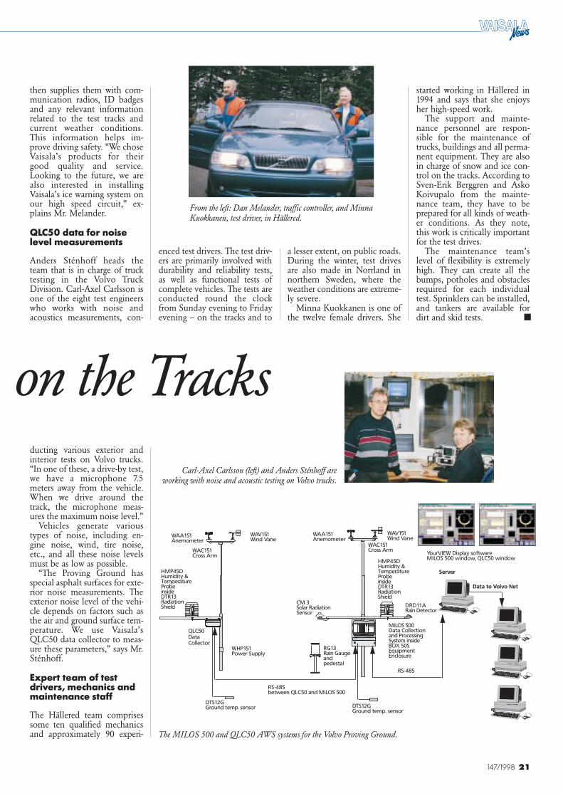
The Volvo Proving Ground in Hällered, Sweden.
eflecting the carmak-er’s own rigorousquality requirements,Volvo’s model range
meets some of the highest safe-ty standards in the world. Thecompany’s Proving Ground islocated in Hällered, 80 kmfrom the Volvo facilities inGothenburg, Sweden. About180 people are employed here,equipping test vehicles, per-forming test drives and labora-tory tests and evaluating theresults.
The site has eleven tracks fortesting various performanceparameters, including high-speed response, durability, han-dling, response on gravel roads
and slopes, comfort, corrosion,skipad and braking, and lowfriction conditions.
In addition to the test tracks,Hällered has facilities for in-door testing and analysis. Theseinclude a measurement plat-form and associated measuringequipment for water leakagetests, a fueling test chamber, aheating chamber and salt-spray/climate chambers.
Weather monitoringsystems support drivingsafety
As part of the Volvo Car Cor-poration’s Test Department,the Volvo Proving Ground pro-
vides an important resource forthe department’s work. Mr.Dan Melander works as a traf-fic controller in Hällered. He isresponsible for security andsafety conditions on the tracks,and he also plans the drivingtests. Mr. Melander has workedfor 25 years in Hällered. He vis-ited Vaisala in December 1997.
Weather condition monitor-ing is especially important toensure the safety of test drivers.Vaisala delivered a completeweather monitoring system,including MILOS 500 andQLC50 automatic weather sta-tions, as well as an applicationspecific YourVIEW graphicaluser interface and data collec-tion software. The new systemswere ordered through LiveData AB, Vaisala’s distributorin Sweden.
Hällered’s eleven tracks andcomputerized traffic controlsystem have been built to en-sure the optimum reliability ofthe test results and maximumdriving safety. Using com-puterized traffic control sys-tems, the traffic controllers are
Marit FinneEditor-in-ChiefVaisala News Vaisala Helsinki Finland
Vaisala’s MILOS 500weather station and
QLC50 data collectorwere installed in
spring 1998 at theVolvo Proving Ground
in Hällered, Sweden.The new equipment
will be used for weath-er monitoring at the
site where Volvo testsand develops its cars,
trucks and buses.
able to supervise the tests on allthe tracks and register theweather conditions during thetests. The MILOS 500 stationwas installed to monitor theweather conditions very closethe main track. The data it pro-duces is especially useful forbraking and fuel consumptiontests. The QLC50 data is usedwith noise measurements. Bothstations have sensors for winddirection and speed, air tem-perature and relative humidityand ground temperature. Inaddition, the MILOS 500 sta-tion measures air pressure, solarradiation, precipitation and thepresence of rain.
The MILOS 500 functionsas a master station, collecting thedata from both test tracks andforwarding it to the graphicaluser terminal. The YourVIEWGraphical User Interface soft-ware is used for displaying dataseparately from both sites onseveral PC terminals. In addi-tion, the data is also forwardedto Volvo’s PC network.
The test drivers are bookedby the traffic controller, who
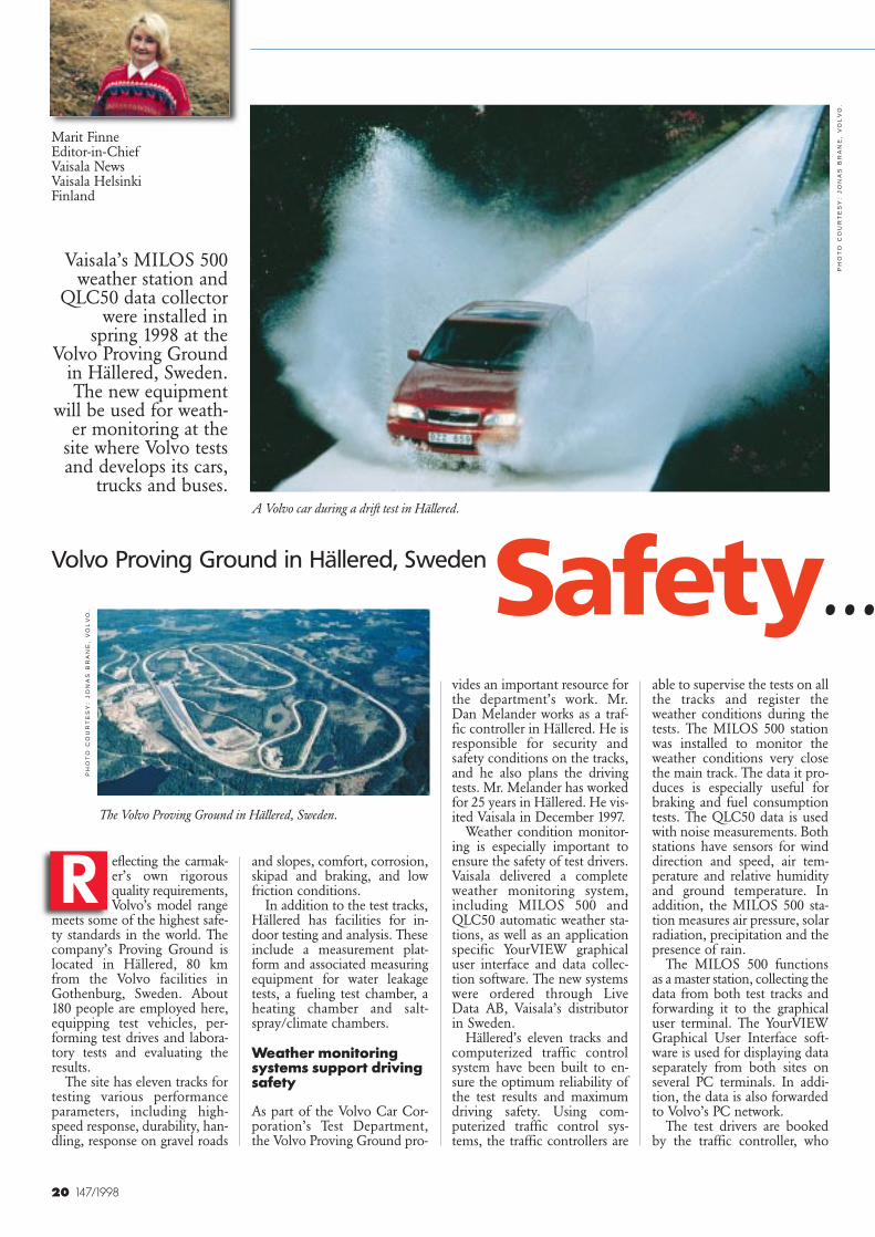
A Volvo car during a drift test in Hällered.
PH
OT
O C
OU
RT
ES
Y:
JO
NA
S B
RA
NE
, V
OL
VO
.
PH
OT
O C
OU
RT
ES
Y:
JO
NA
S B
RA
NE
, V
OL
VO
.
R
Volvo Proving Ground in Hällered, SwedenSafety...
21147/1998
YourVIEW Display softwareMILOS 500 window, QLC50 window
RG13Rain Gaugeandpedestal
DRD11ARain Detector
MILOS 500Data Collectionand ProcessingSystem insideBOX 50SEquipmentEnclosure
WAV151Wind Vane
WAC151Cross Arm
CM 3Solar RadiationSensor
HMP45DHumidity &TemperatureProbeinsideDTR13RadiationShield
WAA151Anemometer
WAV151Wind Vane
WAC151Cross Arm
QLC50DataCollector
WAA151Anemometer
RS-485between QLC50 and MILOS 500
RS-485
HMP45DHumidity &TemperatureProbeinsideDTR13RadiationShield
WHP151Power Supply
DTS12GGround temp. sensor DTS12G
Ground temp. sensor
Server
Data to Volvo Net
Carl-Axel Carlsson (left) and Anders Sténhoff areworking with noise and acoustic testing on Volvo trucks.
then supplies them with com-munication radios, ID badgesand any relevant informationrelated to the test tracks andcurrent weather conditions.This information helps im-prove driving safety. “We choseVaisala’s products for theirgood quality and service.Looking to the future, we arealso interested in installingVaisala’s ice warning system onour high speed circuit,” ex-plains Mr. Melander.
QLC50 data for noiselevel measurements
Anders Sténhoff heads theteam that is in charge of trucktesting in the Volvo TruckDivision. Carl-Axel Carlsson isone of the eight test engineerswho works with noise andacoustics measurements, con-
a lesser extent, on public roads.During the winter, test drivesare also made in Norrland innorthern Sweden, where theweather conditions are extreme-ly severe.
Minna Kuokkanen is one ofthe twelve female drivers. She
The MILOS 500 and QLC50 AWS systems for the Volvo Proving Ground.
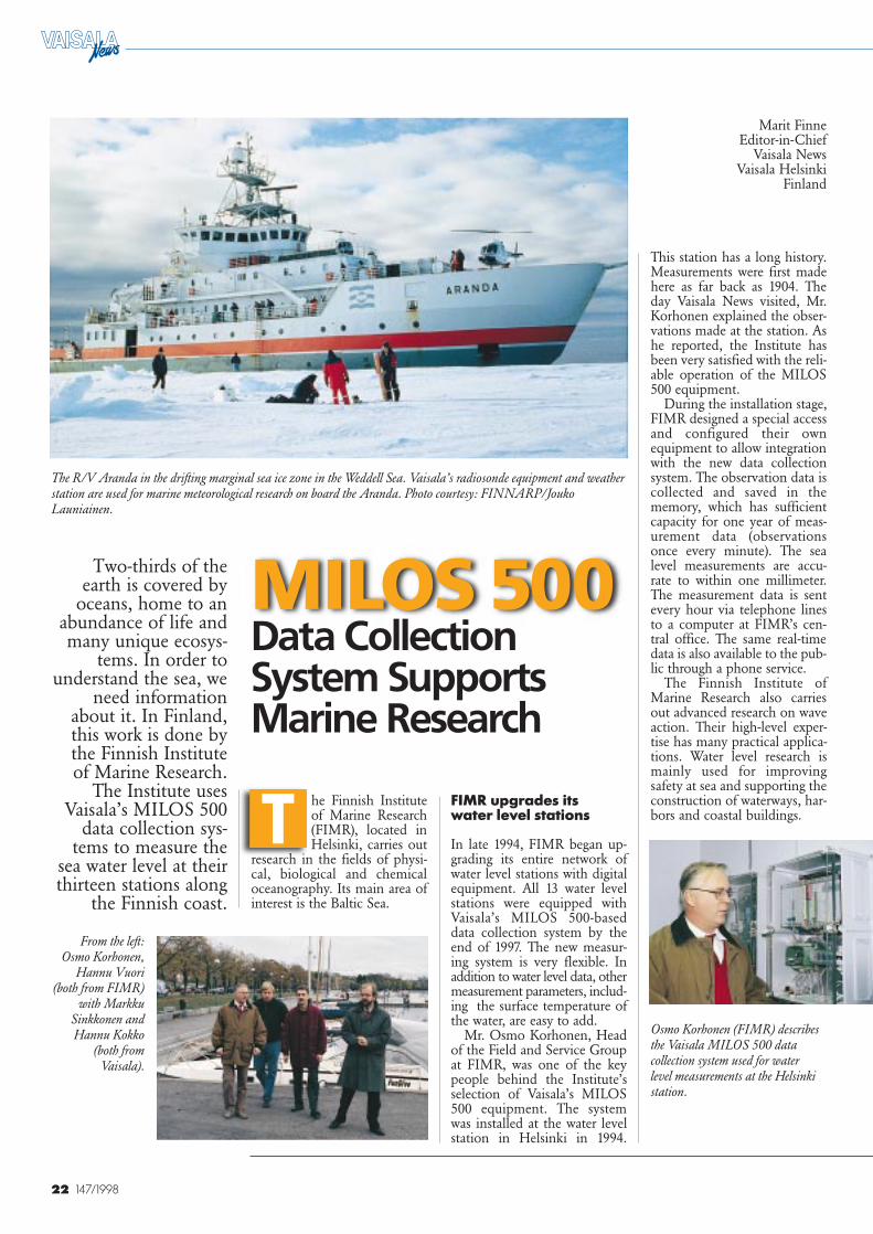
From the left: Dan Melander, traffic controller, and MinnaKuokkanen, test driver, in Hällered.
enced test drivers. The test driv-ers are primarily involved withdurability and reliability tests,as well as functional tests ofcomplete vehicles. The tests areconducted round the clockfrom Sunday evening to Fridayevening – on the tracks and to
ducting various exterior andinterior tests on Volvo trucks.“In one of these, a drive-by test,we have a microphone 7.5meters away from the vehicle.When we drive around thetrack, the microphone meas-ures the maximum noise level.”
Vehicles generate varioustypes of noise, including en-gine noise, wind, tire noise,etc., and all these noise levelsmust be as low as possible.
“The Proving Ground hasspecial asphalt surfaces for exte-rior noise measurements. Theexterior noise level of the vehi-cle depends on factors such asthe air and ground surface tem-perature. We use Vaisala’sQLC50 data collector to meas-ure these parameters,” says Mr.Sténhoff.
Expert team of testdrivers, mechanics andmaintenance staff
The Hällered team comprisessome ten qualified mechanicsand approximately 90 experi-
on the Tracks
started working in Hällered in1994 and says that she enjoysher high-speed work.
The support and mainte-nance personnel are respon-sible for the maintenance oftrucks, buildings and all perma-nent equipment. They are alsoin charge of snow and ice con-trol on the tracks. According toSven-Erik Berggren and AskoKoivupalo from the mainte-nance team, they have to beprepared for all kinds of weath-er conditions. As they note,this work is critically importantfor the test drives.
The maintenance team’slevel of flexibility is extremelyhigh. They can create all thebumps, potholes and obstaclesrequired for each individualtest. Sprinklers can be installed,and tankers are available fordirt and skid tests. ■
22 147/1998
The R/V Aranda in the drifting marginal sea ice zone in the Weddell Sea. Vaisala’s radiosonde equipment and weatherstation are used for marine meteorological research on board the Aranda. Photo courtesy: FINNARP/JoukoLauniainen.
This station has a long history.Measurements were first madehere as far back as 1904. Theday Vaisala News visited, Mr.Korhonen explained the obser-vations made at the station. Ashe reported, the Institute hasbeen very satisfied with the reli-able operation of the MILOS500 equipment.
During the installation stage,FIMR designed a special accessand configured their ownequipment to allow integrationwith the new data collectionsystem. The observation data iscollected and saved in thememory, which has sufficientcapacity for one year of meas-urement data (observationsonce every minute). The sealevel measurements are accu-rate to within one millimeter.The measurement data is sentevery hour via telephone linesto a computer at FIMR’s cen-tral office. The same real-timedata is also available to the pub-lic through a phone service.
The Finnish Institute ofMarine Research also carriesout advanced research on waveaction. Their high-level exper-tise has many practical applica-tions. Water level research ismainly used for improvingsafety at sea and supporting theconstruction of waterways, har-bors and coastal buildings.
he Finnish Instituteof Marine Research(FIMR), located inHelsinki, carries out
research in the fields of physi-cal, biological and chemicaloceanography. Its main area ofinterest is the Baltic Sea.
Marit FinneEditor-in-Chief
Vaisala NewsVaisala Helsinki
Finland
MILOS 500Data CollectionSystem SupportsMarine Research
Two-thirds of theearth is covered by
oceans, home to anabundance of life andmany unique ecosys-
tems. In order tounderstand the sea, we
need informationabout it. In Finland,this work is done bythe Finnish Instituteof Marine Research.
The Institute usesVaisala’s MILOS 500
data collection sys-tems to measure the
sea water level at theirthirteen stations along
the Finnish coast.
T
Osmo Korhonen (FIMR) describesthe Vaisala MILOS 500 datacollection system used for waterlevel measurements at the Helsinkistation.
From the left:Osmo Korhonen,
Hannu Vuori(both from FIMR)
with MarkkuSinkkonen andHannu Kokko
(both fromVaisala).
FIMR upgrades its water level stations
In late 1994, FIMR began up-grading its entire network ofwater level stations with digitalequipment. All 13 water levelstations were equipped withVaisala’s MILOS 500-baseddata collection system by theend of 1997. The new measur-ing system is very flexible. Inaddition to water level data, othermeasurement parameters, includ-ing the surface temperature ofthe water, are easy to add.
Mr. Osmo Korhonen, Headof the Field and Service Groupat FIMR, was one of the keypeople behind the Institute’sselection of Vaisala’s MILOS500 equipment. The systemwas installed at the water levelstation in Helsinki in 1994.
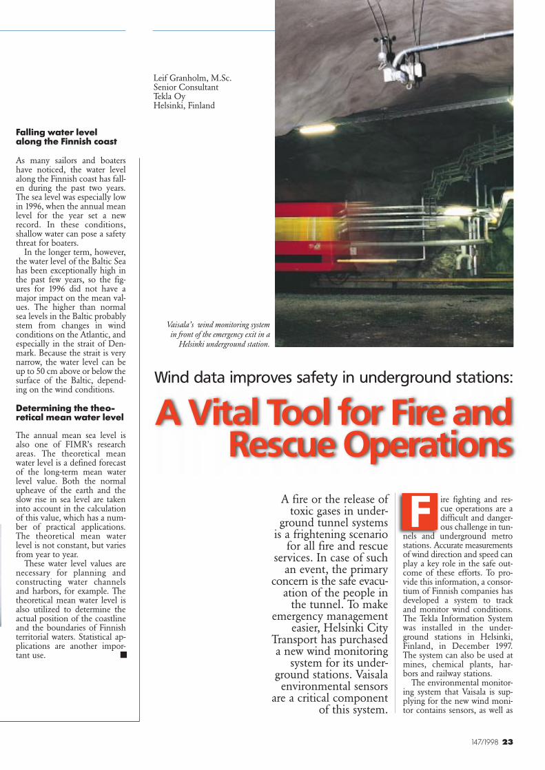
23147/1998
Wind data improves safety in underground stations:
A Vital Tool for Fire andRescue Operations
Leif Granholm, M.Sc.Senior ConsultantTekla OyHelsinki, Finland
A fire or the release oftoxic gases in under-
ground tunnel systemsis a frightening scenario
for all fire and rescueservices. In case of such
an event, the primaryconcern is the safe evacu-
ation of the people inthe tunnel. To make
emergency managementeasier, Helsinki City
Transport has purchaseda new wind monitoring
system for its under-ground stations. Vaisalaenvironmental sensors
are a critical componentof this system.
ire fighting and res-cue operations are adifficult and danger-ous challenge in tun-
nels and underground metrostations. Accurate measurementsof wind direction and speed canplay a key role in the safe out-come of these efforts. To pro-vide this information, a consor-tium of Finnish companies hasdeveloped a system to trackand monitor wind conditions.The Tekla Information Systemwas installed in the under-ground stations in Helsinki,Finland, in December 1997.The system can also be used atmines, chemical plants, har-bors and railway stations.
The environmental monitor-ing system that Vaisala is sup-plying for the new wind moni-tor contains sensors, as well as
Falling water level along the Finnish coast
As many sailors and boatershave noticed, the water levelalong the Finnish coast has fall-en during the past two years.The sea level was especially lowin 1996, when the annual meanlevel for the year set a newrecord. In these conditions,shallow water can pose a safetythreat for boaters.
In the longer term, however,the water level of the Baltic Seahas been exceptionally high inthe past few years, so the fig-ures for 1996 did not have amajor impact on the mean val-ues. The higher than normalsea levels in the Baltic probablystem from changes in windconditions on the Atlantic, andespecially in the strait of Den-mark. Because the strait is verynarrow, the water level can beup to 50 cm above or below thesurface of the Baltic, depend-ing on the wind conditions.
Determining the theo-retical mean water level
The annual mean sea level isalso one of FIMR’s researchareas. The theoretical meanwater level is a defined forecastof the long-term mean waterlevel value. Both the normalupheave of the earth and theslow rise in sea level are takeninto account in the calculationof this value, which has a num-ber of practical applications.The theoretical mean waterlevel is not constant, but variesfrom year to year.
These water level values arenecessary for planning andconstructing water channelsand harbors, for example. Thetheoretical mean water level isalso utilized to determine theactual position of the coastlineand the boundaries of Finnishterritorial waters. Statistical ap-plications are another impor-tant use.
Vaisala’s wind monitoring systemin front of the emergency exit in a
Helsinki underground station.
F
■
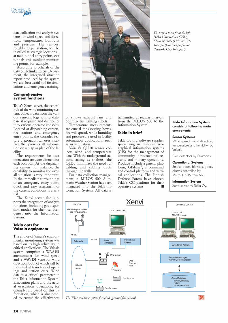
24 147/1998
data collection and analysis sys-tems for wind speed and direc-tion, temperature, humidityand pressure. The sensors,roughly 10 per station, will beinstalled at strategic locations –at train tunnel entry points, exittunnels and outdoor monitor-ing points, for example.
According to officials of theCity of Helsinki Rescue Depart-ment, the integrated situationreport produced by the systemwill also be a useful tool for simu-lations and emergency training.
Comprehensive system functions
Tekla’s Xenvi server, the centralhub of the wind monitoring sys-tem, collects data from the vari-ous sensors, logs it in a data-base if required and distributesit to various operator consoles.Located at dispatching centers,fire stations and emergencyentry points, the consoles fea-ture a geographical user inter-face that presents all informa-tion on a map or plan of the fa-cility.
The requirements for user interaction are quite different foreach location. At the dispatch-ing centers, for instance, thecapability to monitor the over-all situation is very important.In the immediate surroundingsof an emergency entry point,quick and easy assessment ofthe current conditions is essen-tial.
The Xenvi server also sup-ports the integration of analysisfunctions, including gas disper-sion models for chemical acci-dents, into the InformationSystem.
Tekla opts for Vaisala equipment
The choice of Vaisala’s environ-mental monitoring system wasbased on its high reliability incritical applications. The Vaisalasystem comprises a WAA151anemometer for wind speedand a WAV151 vane for winddirection, both of which will bemounted at train tunnel open-ings and station exits. Winddata is a critical parameter inthe Tekla Information System.Evacuation plans and the actu-al evacuation operations, forexample, are based on this in-formation, which is also need-ed to ensure the effectiveness
of smoke exhaust fans andoptimize fire fighting efforts.
Temperature measurementsare crucial for assessing how afire will spread, while humidityand pressure are used in facilityautomation applications suchas air ventilation.
Vaisala’s QLI50 sensor col-lects wind and temperaturedata. With the underground sta-tions acting as shelters, theQLI50 minimizes the need forcabling and cabling ductsthrough the walls.
For data collection manage-ment, a MILOS 500 Auto-matic Weather Station has beenintegrated into the Tekla In-formation System. All data is
transmitted at regular intervalsfrom the MILOS 500 to theInformation System.
Tekla in brief
Tekla Oy is a software supplierspecializing in real-time geo-graphical information systems(GIS) for the management ofcommunity infrastructures, se-curity and military operations.Products include a general plat-form, GISbase®, a commandand control platform and verti-cal applications. The FinnishDefense Forces have chosenTekla’s CC platform for theiroperative systems.
XenviXenvi
LANLAN
Ethernet,Ethernet,
fiberfiber
Meteorological stationMeteorological station
- gas, wind, air, etc ... - gas, wind, air, etc ...
Sensor
connection
Control UnitControl Unit
24 h /24 H usage24 h /24 H usage
Transaction manager
real time, decentralization
Surveillance
ProgramData units
RS-232
RS-485
segm.
CONTROL CENTERCONTROL CENTER
Smoke alarmSmoke alarm
RS-232
Wind sensorsWind sensors
Gas detectorGas detector
Fire alarmFire alarm
Surveillance Pogram
STATION
Local Control Unit Local Control Unit
Central Database
- sensors, statistics, - history, - background maps
Tekla Information Systemconsists of following maincomponents:
Sensor SystemsWind speed, wind direction,temperature and humidity byVaisala.
Gas detectors by Environics.
Operational SystemsSmoke doors, blowers, gates,alarms controlled byMicroSCADA from ABB.
Information SystemXenvi server by Tekla Oy.
The Tekla real-time system for wind, gas and fire control.
The project team from the left:Pekka Hämäläinen (Tekla),Klaus Niskala (Helsinki CityTransport) and Seppo Jussila(Helsinki City Transport).
■
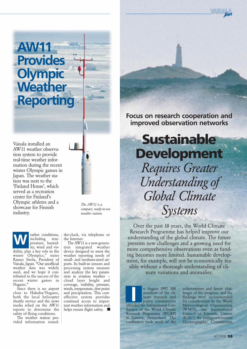
25147/1998
Vaisala installed anAW11 weather observa-tion system to providereal-time weather infor-mation during the recentwinter Olympic games inJapan. The weather sta-tion was next to the‘Finland House’, whichserved as a recreationcenter for Finland’sOlympic athletes and ashowcase for Finnishindustry.
eather conditions,including tem-perature, humid-ity, wind and vis-
ibility, play a key role in thewinter Olympics,” statesRauno Sirola, President ofVaisala, Japan. “Our unofficialweather data was widelyused, and we hope it con-tributed to the success of therecent winter games inNagano.”
Since there is no airportclose to Hakuba/Nagano,both the local helicoptershuttle service and the newsmedia relied on the AW11reports to determine thesafety of flying conditions.
The weather station pro-vided information round-
the-clock, via telephone orthe Internet.
The AW11 is a new-genera-tion integrated weatherdevice designed to meet theweather reporting needs ofsmall- and medium-sized air-ports. Its built-in sensors andprocessing system measureand analyze the key param-eters in aviation weather –cloud layer height andcoverage, visibility, pressure,winds, temperature, dew pointand precipitation. This cost-effective system providescontinual access to impor-tant weather information andhelps ensure flight safety.
WOver the past 18 years, the World Climate
Research Programme has helped improve ourunderstanding of the global climate. The futurepresents new challenges and a growing need formore comprehensive observations even as fund-ing becomes more limited. Sustainable develop-ment, for example, will not be economically fea-sible without a thorough understanding of cli-
mate variations and anomalies.
Focus on research cooperation andimproved observation networks
SustainableDevelopmentRequires GreaterUnderstanding ofGlobal Climate
SystemsThe AW11 is acompact, ready-to-useweather station.
AW11 ProvidesOlympicWeatherReporting
n August 1997, 300members of the cli-mate research andpolicy communities
attended the International Con-ference of the World ClimateResearch Programme (WCRP)in Geneva, Switzerland. Theconference took stock of the
achievements and future chal-lenges of the program, and thefindings were recommendedfor consideration by the WorldMeteorological Organization(WMO), the InternationalCouncil of Scientific Unions(ICSU), the IntergovernmentalOceanographic Commission
I■
26 147/1998
(IOC) of UNESCO, andthrough them, the nationalgovernments of all the coun-tries of the world.
Concern about insufficientfunding and research needs wasalso voiced at the conference.The human influence on theenvironment has acceleratedchanges in the global climate,prompting a greater need forclimate observations and obser-vation networks. At the sametime, however, several coun-tries are reducing their fundingfor climate research.
Detailed studies ofclimate changes andvariations
The WCRP was established in1979 as the research branch ofthe international, interdiscipli-nary and interagency WorldClimate Programme. The pur-pose of the WCRP is to studythe behavior of the global cli-mate system, and thus improvethe understanding and predic-tion of climate changes andvariations.
A better understanding ofglobal climate mechanisms willhelp promote sustainable de-velopment. It will also make aninvaluable contribution to pre-dicting and managing weatherextremes such as flood anddrought and the threat of hu-man-induced climate change.
Wide-rangingachievements
During its 18-year history, theWCRP has contributed to cli-mate research on many levels,first of all by encouraging thecommitment of nations toresearch on critical climateissues. On a smaller scale, theWCRP has been involved inmany research projects thathave improved our understand-ing of climate phenomena.
One of the most notable tri-umphs is our capability to pre-dict climate anomalies relatedto El Niño – the SouthernOscillation (ENSO) phenom-enon – several seasons in ad-vance. These predictions haveapplications in everyday life: inearly response to drought, waterresource management, agricul-ture and public health. ENSOresearch has benefitted bothdeveloping and developed coun-tries on both sides of the Pa-cific Ocean.
WCRP studies of atmos-pheric, hydrological and ocean-ic conditions have led to a bet-ter understanding of importantclimate system processes. Thisknowledge is reflected in im-proved modelling of the cou-pled physical climate system:atmosphere, oceans, land andcryosphere. With better mod-els, the prediction of naturalclimate variations is now moreaccurate and reliable.
Systematic observations havebeen made of the oceans’ three-dimensional structure, and thishas yielded new knowledgeabout ocean circulation andbehavior. Data about ocean cur-rents and changes in sea level isessential for understanding cli-mate change and managingocean and coastal resources.
Future research goals
During the next decade, theoverall research priorities of theWCRP are as follows:
• To assess the nature andpredictability of seasonalto interdecadal variationsin the climate system glob-ally and regionally; to pro-vide a scientific basis forpredicting these phenom-ena, utilizing this informa-tion in climate services andthrough them, promotingsustainable development.
• To detect climate changeand its causes, and projectthe magnitude and rate ofhuman-induced climatechange, regional variations,and related sea level rises.
The research required to reachthese two targets is closely inter-connected. Particular effortshould be made to developcooperation between researchprojects and government bodies.
This work must be comple-mented by the systematic ob-servation of all key climate vari-ables. All the nations involvedin climate research activitiesmust be prepared to invest inthese observations.
Growing need for climate data
Progress in climate science,applications and services de-pends on the timely availabilityof global and specialized obser-vations. The operational weath-er observation systems that areintegrated in the WMO WorldWeather Watch (WWW), how-ever, are under serious threat inseveral regions of the world.The maintenance and improve-ment of these networks are ofcritical importance.
Other operational and quasi-operational climate-related ob-servational systems are or mayalso become threatened by alack of funding.
To enable seasonal andlonger-term predictions as wellas the detection of climatechange, further developmentof an operational ocean observ-ing system is crucial. Existingresearch-specific observationalnetworks should be expandedand incorporated into routineglobal climate observations.
Special attention must alsobe paid to those areas of theglobe where the level of moni-toring is currently very low ornon-existent. These areas in-clude the equatorial regionsand much of the southern hemi-sphere, for example. The lackof observation capacity inmany countries is a major con-cern and an obstacle to pro-gress.
Climate data should bearchived in electronic form, soit can be fully exploited in cli-mate analysis and modelling.Support for electronic archiv-ing as well as other data man-agement and information sys-tems is inadequate. Since every-one should have access to thedata, distribution and qualitycontrol are other issues thatneed to be addressed.
Priority on funding forobservation networks
The participants in the WCRPconference agreed that compre-hensive observations of the cli-
mate system are critical, andthey noted with concern thedecline in conventional obser-vation networks in some re-gions. This is a serious threat tocontinuing progress in climateresearch. Without action toreverse this decline and devel-op the Global Climate Obser-vation System, the ability tocharacterize climate changeand variations will deterioratedramatically.
In drought-prone parts ofAfrica, for example, climatechange detection and predic-tion could become impossible.In the long run, this wouldundermine resource manage-ment in these countries andtheir ability to adopt sustain-able development.
In the view of the WCRP, itis critically important for thenations of the world to intensi-fy their commitment to co-operative international researchand its associated global obser-vation, research and serviceprograms. Arrangements shouldbe made to ensure funding andsupport for the essential obser-vation networks of the GlobalClimate Observing System(GCOS) and its oceanographicand terrestrial counterparts. ■
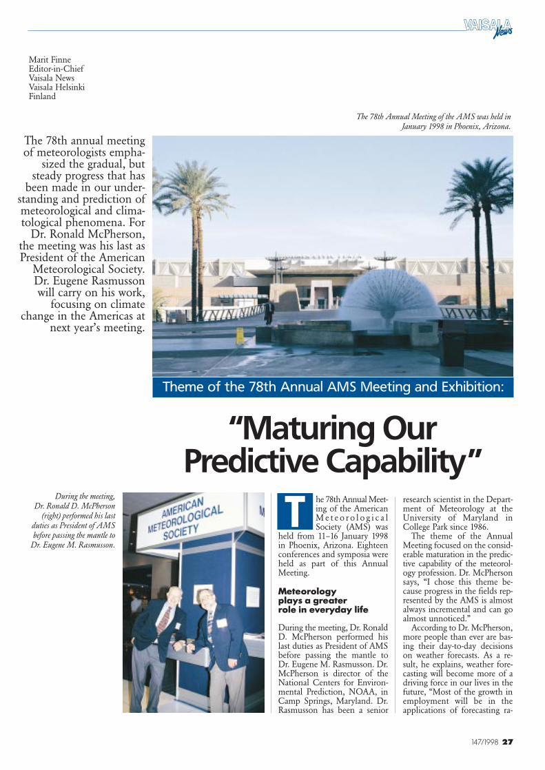
27147/1998
he 78th Annual Meet-ing of the AmericanM e t e o r o l o g i c a lSociety (AMS) was
held from 11–16 January 1998in Phoenix, Arizona. Eighteenconferences and symposia wereheld as part of this AnnualMeeting.
Meteorology plays a greater role in everyday life
During the meeting, Dr. RonaldD. McPherson performed hislast duties as President of AMSbefore passing the mantle toDr. Eugene M. Rasmusson. Dr.McPherson is director of theNational Centers for Environ-mental Prediction, NOAA, inCamp Springs, Maryland. Dr.Rasmusson has been a senior
research scientist in the Depart-ment of Meteorology at theUniversity of Maryland inCollege Park since 1986.
The theme of the AnnualMeeting focused on the consid-erable maturation in the predic-tive capability of the meteorol-ogy profession. Dr. McPhersonsays, “I chose this theme be-cause progress in the fields rep-resented by the AMS is almostalways incremental and can goalmost unnoticed.”
According to Dr. McPherson,more people than ever are bas-ing their day-to-day decisionson weather forecasts. As a re-sult, he explains, weather fore-casting will become more of adriving force in our lives in thefuture, “Most of the growth inemployment will be in theapplications of forecasting ra-
“Maturing Our Predictive Capability”
Marit FinneEditor-in-ChiefVaisala NewsVaisala HelsinkiFinland
The 78th annual meetingof meteorologists empha-
sized the gradual, butsteady progress that has
been made in our under-standing and prediction ofmeteorological and clima-tological phenomena. For
Dr. Ronald McPherson,the meeting was his last asPresident of the American
Meteorological Society.Dr. Eugene Rasmussonwill carry on his work,
focusing on climatechange in the Americas at
next year’s meeting.
During the meeting, Dr. Ronald D. McPherson
(right) performed his lastduties as President of AMSbefore passing the mantle to
Dr. Eugene M. Rasmusson.
Theme of the 78th Annual AMS Meeting and Exhibition:
T
The 78th Annual Meeting of the AMS was held in January 1998 in Phoenix, Arizona.

28 147/1998
ther than forecasting itself. In thefuture, students will be expect-ed to be competent in meteor-ology, but also in whatevertheir employer’s main interestmight be.” He urged studentsto adhere to sound science inthe pursuit of their profession,to be responsible for carryingout high-quality service, and tomaintain high ethical stand-ards.
1999 theme focuses on the Americas
The next 79th Annual Meetingwill be held in Dallas, Texas.The new AMS President, Dr.Rasmusson, has established‘Climate and Global Changewith a Focus on the Americas’as the theme of the meeting.The leaders of many currentnational and international pro-grams dealing with issues of cli-mate and global change andtheir impact on the Americashave already agreed to presenttheir findings at this meeting.
Observations and the futurestrengthening of the bridgebetween scientific research andapplications to meet societalneeds will be another impor-tant aspect of the meeting.
“We plan to continue Dr.McPherson’s 1998 theme in thecontext of seasonal to interan-nual climate prediction. Thecenterpiece of this aspect of theannual meeting will be theSecond Hayes Symposium onSeasonal to Interannual Pre-diction. This symposium willinclude a retrospective look atthe 1997–1998 El Niño WarmEpisode. Finally, I should men-tion the special symposiumbeing planned for the annualmeeting to commemorate the25th Anniversary of the GARPAtlantic Tropical Experiment(GATE),” says Dr. Rasmusson.
More than 130 companies displayed the latest hardware, systems and software in the fields ofmeteorology, oceanography and hydrology at the AMS Exhibition. There were more than 300stands at the event, and about 3,500 conference visitors (including exhibitors) from 37 countrieswere registered.
Vaisala’s eye-catching 40-foot exhibition stand showcased a number of new product develop-ment advances. The upper air equipment on display included GPS radiosondes for accurate,high-resolution wind measurements; the AUTOSONDE, which fully automates radiosondeobservations; and the compact MW15 DigiCORA II radiosounding set. In addition, the RD93GPS Dropsonde for accurate aircraft deployed soundings was also exhibited.
Surface weather equipment included the CT25 laser ceilometer, the new standard for cloudheight measurement; QLC50 and MILOS 500 weather stations configured with new WIND30and 20 Displays; and a full line of sensors for accurate and reliable surface weather observations.
Vaisala also exhibited meteorological airport observation systems. The AW11 aviation reporter,a ready-to-use system for small airports, contains all the sensors and features of a completeAWOS (Automated Weather Observing System) in one integrated package, as well as a newThunderstorm Sensor.
Vaisala’s personnel gave three presentations at the 78th AMS Meeting. These included ‘On theGlobal Windfinding Accuracy of Terrestrial Navaids’ by Juhana Jaatinen, ‘GPS – the GlobalWindfinding Method’ by Timo Saarnimo, and ‘AUTOSONDE – Outstanding Reliability inPerformance Tests’ by Ken Goss.
Vaisala’s exhibition stand showcased a number of new product development advances.
AMS Exhibition in Phoenix
■
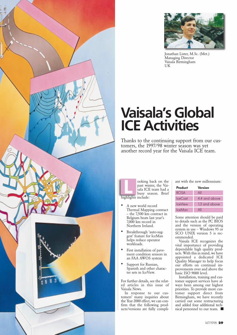
29147/1998
Vaisala’s GlobalICE ActivitiesThanks to the continuing support from our cus-tomers, the 1997/98 winter season was yetanother record year for the Vaisala ICE team.
ooking back on thepast winter, the Vai-sala ICE team had abusy season. Brief
highlights include:
• A new world recordThermal Mapping contract– the 7,500 km contract inBelgium beats last year’s7,000 km record inNorthern Ireland.
• Breakthrough ‘auto-sug-gest’ feature for IceManhelps reduce operatorworkloads.
• First installation of pave-ment condition sensors inan FAA AWOS system
• Support for Russian,Spanish and other charac-ter sets in IceView.
For further details, see the relat-ed articles in this issue ofVaisala News.
In response to our cus-tomers’ many inquiries aboutthe Year 2000 effect, we can con-firm that the following prod-ucts/versions are fully compli-
ant with the new millennium:
Product VersionROSA All
IceCast 4.4 and above
IceView 1.3 and above
IceMan All
Some attention should be paidto details such as the PC BIOSand the version of operatingsystem in use – Windows 95 orSCO UNIX version 5 is rec-ommended.
Vaisala ICE recognizes thevital importance of providingdependable high quality prod-ucts. With this in mind, we haveappointed a dedicated ICEQuality Manager to help focusour efforts on continual im-provements over and above thebasic ISO 9000 level.
Installation, training and cus-tomer support services have al-ways been among our highestpriorities. To provide more cus-tomer support direct fromBirmingham, we have recentlycarried out some restructuringand added four additional tech-nical personnel to our team.
L
■
Jonathan Lister, M.Sc. (Met.)Managing DirectorVaisala BirminghamUK
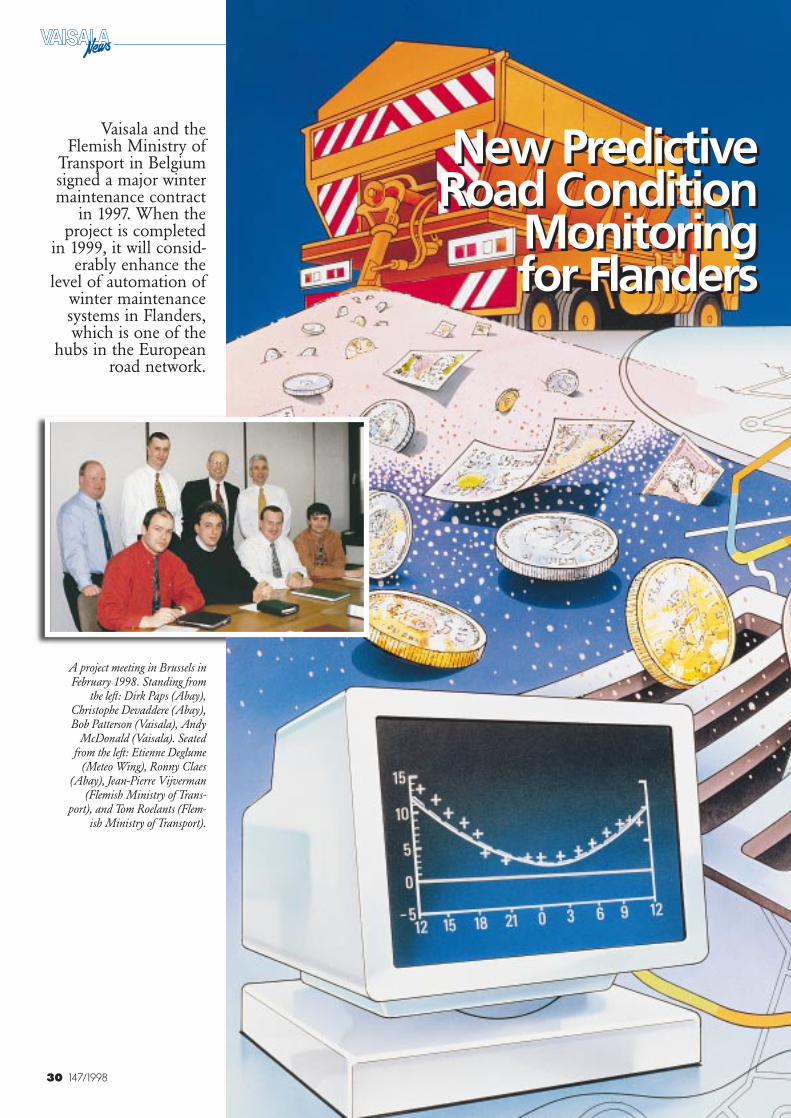
30 147/1998
New Predictive Road Condition
Monitoring for Flanders
New Predictive Road Condition
Monitoring for Flanders
Vaisala and theFlemish Ministry of
Transport in Belgiumsigned a major wintermaintenance contract
in 1997. When theproject is completed
in 1999, it will consid-erably enhance the
level of automation ofwinter maintenancesystems in Flanders,which is one of the
hubs in the Europeanroad network.
A project meeting in Brussels inFebruary 1998. Standing from
the left: Dirk Paps (Abay),Christophe Devaddere (Abay),Bob Patterson (Vaisala), Andy
McDonald (Vaisala). Seatedfrom the left: Etienne Deglume
(Meteo Wing), Ronny Claes(Abay), Jean-Pierre Vijverman
(Flemish Ministry of Trans-port), and Tom Roelants (Flem-
ish Ministry of Transport).
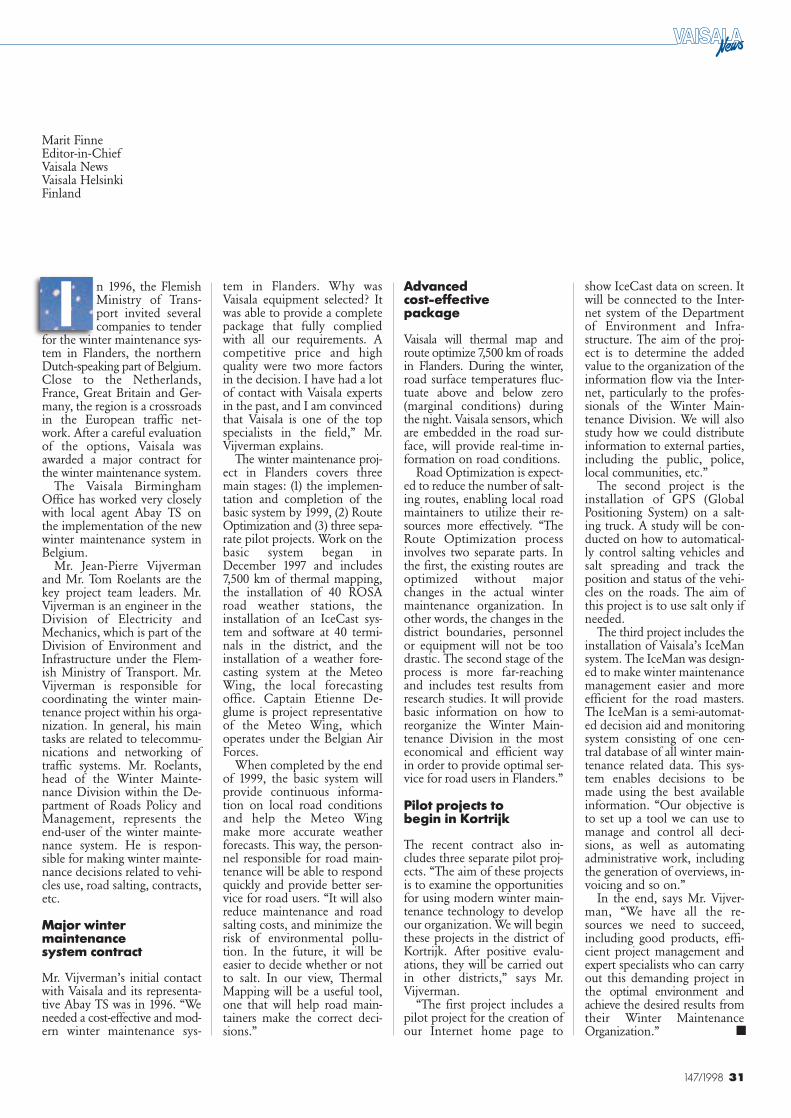
31147/1998
Marit FinneEditor-in-ChiefVaisala NewsVaisala HelsinkiFinland
tem in Flanders. Why wasVaisala equipment selected? Itwas able to provide a completepackage that fully compliedwith all our requirements. Acompetitive price and highquality were two more factorsin the decision. I have had a lotof contact with Vaisala expertsin the past, and I am convincedthat Vaisala is one of the topspecialists in the field,” Mr.Vijverman explains.
The winter maintenance proj-ect in Flanders covers threemain stages: (1) the implemen-tation and completion of thebasic system by 1999, (2) RouteOptimization and (3) three sepa-rate pilot projects. Work on thebasic system began inDecember 1997 and includes7,500 km of thermal mapping,the installation of 40 ROSAroad weather stations, theinstallation of an IceCast sys-tem and software at 40 termi-nals in the district, and theinstallation of a weather fore-casting system at the MeteoWing, the local forecastingoffice. Captain Etienne De-glume is project representativeof the Meteo Wing, whichoperates under the Belgian AirForces.
When completed by the endof 1999, the basic system willprovide continuous informa-tion on local road conditionsand help the Meteo Wingmake more accurate weatherforecasts. This way, the person-nel responsible for road main-tenance will be able to respondquickly and provide better ser-vice for road users. “It will alsoreduce maintenance and roadsalting costs, and minimize therisk of environmental pollu-tion. In the future, it will beeasier to decide whether or notto salt. In our view, ThermalMapping will be a useful tool,one that will help road main-tainers make the correct deci-sions.”
Advanced cost-effective package
Vaisala will thermal map androute optimize 7,500 km of roadsin Flanders. During the winter,road surface temperatures fluc-tuate above and below zero(marginal conditions) duringthe night. Vaisala sensors, whichare embedded in the road sur-face, will provide real-time in-formation on road conditions.
Road Optimization is expect-ed to reduce the number of salt-ing routes, enabling local roadmaintainers to utilize their re-sources more effectively. “TheRoute Optimization processinvolves two separate parts. Inthe first, the existing routes areoptimized without majorchanges in the actual wintermaintenance organization. Inother words, the changes in thedistrict boundaries, personnelor equipment will not be toodrastic. The second stage of theprocess is more far-reachingand includes test results fromresearch studies. It will providebasic information on how toreorganize the Winter Main-tenance Division in the mosteconomical and efficient wayin order to provide optimal ser-vice for road users in Flanders.”
Pilot projects to begin in Kortrijk
The recent contract also in-cludes three separate pilot proj-ects. “The aim of these projectsis to examine the opportunitiesfor using modern winter main-tenance technology to developour organization. We will beginthese projects in the district ofKortrijk. After positive evalu-ations, they will be carried outin other districts,” says Mr.Vijverman.
“The first project includes apilot project for the creation ofour Internet home page to
show IceCast data on screen. Itwill be connected to the Inter-net system of the Departmentof Environment and Infra-structure. The aim of the proj-ect is to determine the addedvalue to the organization of theinformation flow via the Inter-net, particularly to the profes-sionals of the Winter Main-tenance Division. We will alsostudy how we could distributeinformation to external parties,including the public, police,local communities, etc.”
The second project is theinstallation of GPS (GlobalPositioning System) on a salt-ing truck. A study will be con-ducted on how to automatical-ly control salting vehicles andsalt spreading and track theposition and status of the vehi-cles on the roads. The aim ofthis project is to use salt only ifneeded.
The third project includes theinstallation of Vaisala’s IceMansystem. The IceMan was design-ed to make winter maintenancemanagement easier and moreefficient for the road masters.The IceMan is a semi-automat-ed decision aid and monitoringsystem consisting of one cen-tral database of all winter main-tenance related data. This sys-tem enables decisions to bemade using the best availableinformation. “Our objective isto set up a tool we can use tomanage and control all deci-sions, as well as automatingadministrative work, includingthe generation of overviews, in-voicing and so on.”
In the end, says Mr. Vijver-man, “We have all the re-sources we need to succeed,including good products, effi-cient project management andexpert specialists who can carryout this demanding project inthe optimal environment andachieve the desired results fromtheir Winter MaintenanceOrganization.”
n 1996, the FlemishMinistry of Trans-port invited severalcompanies to tender
for the winter maintenance sys-tem in Flanders, the northernDutch-speaking part of Belgium.Close to the Netherlands,France, Great Britain and Ger-many, the region is a crossroadsin the European traffic net-work. After a careful evaluationof the options, Vaisala wasawarded a major contract forthe winter maintenance system.
The Vaisala BirminghamOffice has worked very closelywith local agent Abay TS onthe implementation of the newwinter maintenance system inBelgium.
Mr. Jean-Pierre Vijvermanand Mr. Tom Roelants are thekey project team leaders. Mr.Vijverman is an engineer in theDivision of Electricity andMechanics, which is part of theDivision of Environment andInfrastructure under the Flem-ish Ministry of Transport. Mr.Vijverman is responsible forcoordinating the winter main-tenance project within his orga-nization. In general, his maintasks are related to telecommu-nications and networking oftraffic systems. Mr. Roelants,head of the Winter Mainte-nance Division within the De-partment of Roads Policy andManagement, represents theend-user of the winter mainte-nance system. He is respon-sible for making winter mainte-nance decisions related to vehi-cles use, road salting, contracts,etc.
Major wintermaintenance system contract
Mr. Vijverman’s initial contactwith Vaisala and its representa-tive Abay TS was in 1996. “Weneeded a cost-effective and mod-ern winter maintenance sys-
I
■
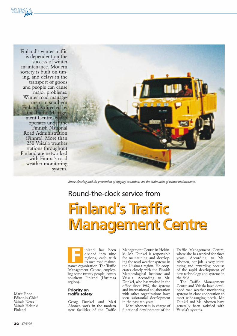
32 147/1998
Snow clearing and the prevention of slippery conditions are the main tasks of winter maintenance.
Marit FinneEditor-in-ChiefVaisala NewsVaisala HelsinkiFinland
inland has beendivided into nineregions, each withits own road mainte-
nance organization. The TrafficManagement Centre, employ-ing some twenty people, coverssouthern Finland (Uusimaaregion).
Priority on traffic safety
Georg Dunkel and MariAhonen work in the modernnew facilities of the Traffic
Traffic Management Centre,where she has worked for threeyears. According to Ms.Ahonen, her job is very inter-esting and rewarding becauseof the rapid development ofnew technology and systems inthe field.
The Traffic ManagementCentre and Vaisala have devel-oped road weather monitoringsystems in close cooperation tomeet wide-ranging needs. Mr.Dunkel and Ms. Ahonen havegenerally been satisfied withVaisala’s systems.
Round-the-clock service from
Finland’s TrafficManagement Centre
Round-the-clock service from
Finland’s TrafficManagement Centre
Finland’s winter trafficis dependent on the
success of wintermaintenance. Modernsociety is built on tim-ing, and delays in the
transport of goodsand people can cause
major problems.Winter road manage-
ment in southernFinland is directed by
the Traffic Manage-ment Centre, which
operates under theFinnish National
Road Administration(Finnra). More than250 Vaisala weatherstations throughout
Finland are networkedwith Finnra’s road
weather monitoringsystem.
F Management Centre in Helsin-ki. Mr. Dunkel is responsiblefor maintaining and develop-ing the road weather systems inthe Uusimaa region. He coop-erates closely with the FinnishMeteorological Institute andVaisala. According to Mr.Dunkel, who has worked in theoffice since 1987, the systemsand international collaborationwith other organizations haveseen substantial developmentin the past ten years.
Mari Ahonen is in charge offunctional development of the
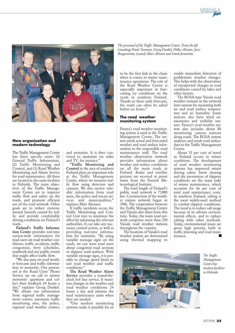
33147/1998
New organization andmodern technology
The Traffic Management Centrehas three specific units: (1)General Traffic Information,(2) Traffic Monitoring andControl, and (3) Road WeatherMonitoring and Alarm Servicefor road maintenance. All threeare located in the same facilitiesin Helsinki. The main objec-tives of the Traffic Manage-ment Centre are to improvetraffic flow and safety on theroads, and promote efficientuse of the road network. Othergoals are to reduce environ-mental hazards caused by traf-fic and provide comfortabledriving conditions on Finland’sroads.
Finland’s Traffic Informa-tion Centre provides real-timenation-wide information forroad users on road weather con-ditions, traffic accidents, trafficcongestion, ferry schedules,roadwork and any public eventsthat might affect traffic flow.
“We also pass on road weath-er forecasts and traffic informa-tion to motorists. Our person-nel at the Road Users’ PhoneService are on call to answermotorists’ questions and col-lect their feedback 24 hours aday,” explains Georg Dunkel.“We obtain our informationfrom regional traffic manage-ment centres, automatic trafficmonitoring sites, the police,regional road weather centres,
and motorists. It is then con-veyed to motorists via radioand TV, for instance.”
“Traffic Monitoring andControl in the area of southernFinland plays an important roleat the Traffic ManagementCentre, where we monitor traf-fic flow using detectors andcameras. We also receive valu-able information from roadusers, the police and rescue ser-vices and municipalities,”explains Mari Ahonen.
If traffic incidents occur, theTraffic Monitoring and Con-trol Unit tries to minimize theeffect by informing the relevantauthorities. It can take any nec-essary control action, as well asproviding real-time informa-tion for motorists. “By usingvariable message signs on theroads, we can warn road usersabout congested road sectionsor slippery road surfaces. Withvariable message signs, it is pos-sible to change speed limits tosuit road weather and trafficconditions.”
The Road Weather AlarmService provides a round-the-clock hot line service. It moni-tors changes in the weather androad weather conditions 24hours a day and informs theroad maintenance units whenthey are needed.
“Our modern monitoringsystems make it possible for us
to be the first link in the chainwhen it comes to winter main-tenance operations. The role ofthe Road Weather Centre isespecially important in fore-casting icy conditions on theroads in southern Finland.Thanks to these early forecasts,the roads can often be saltedbefore ice forms.”
The road weathermonitoring system
Finnra’s road weather monitor-ing system is used at the TrafficManagement Centre. The sys-tem sends actual and forecastedweather and road surface infor-mation to the responsible roadmaintenance staff. The roadweather observation networkprovides information aboutweather and surface conditionson all the main roads inFinland. Radar and satellitepictures are received at presettimes from the Finnish Me-teorological Institute.
The total length of Finland’spublic road network is 77,800km. Construction of the weath-er station network began in1986. The cooperation betweenthe Traffic Management Centreand Vaisala also dates from thistime. Today, the main road net-work comprises more than 250Vaisala road weather stationsthroughout the country.
The locations of Vaisala’s roadweather station are determinedusing thermal mapping to
enable immediate detection ofproblematic weather changes.This helps with the observationof unexpected changes in roadconditions caused by lakes andother factors.
The ROSA-type Vaisala roadweather stations in the networkhave sensors for measuring bothair and road surface tempera-ture and air humidity. Somestations also have wind an-emometer and visibility sen-sors. Finnra’s road weather sys-tem also includes about 80monitoring camera stationsalong roads. The ROSA systemanalyzes and sends road surfacedata to the Traffic ManagementCentre.
About 35 per cent of travelin Finland occurs in winterconditions. The developmentof road weather monitoringsystems has improved winterdriving safety. Snow clearingand the prevention of slipperyconditions are the main tasksof winter maintenance, whichaccounts for 66 per cent oftotal road maintenance costs.In southern Finland, salting isthe most widely-used methodto combat slippery conditions.The trend is to reduce salt usagebecause of its adverse environ-mental effects, and to replacesalting with other methods.Today, environmental issues aregiven high priority, both intraffic planning and road main-tenance.
The personnel of the Traffic Management Centre. From the left(standing) Pentti Turunen, Georg Dunkel, Pekka Ahonen, JussiBorgenström; (seated) Mari Ahonen and Irmeli Jernström.
■
The TrafficManagementCentre hasmodern facilitiesin Helsinki.
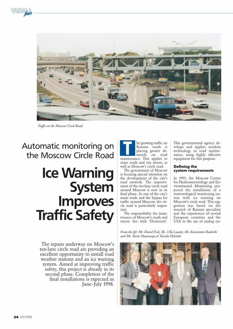
34 147/1998
Traffic on the Moscow Circle Road.
he growing traffic onRussian roads isplacing greater de-mands on road
maintenance. This applies tomain roads and city streets, aswell as Moscow’s circle road.
The government of Moscowis focusing special attention onthe development of the city’sroad network. The improve-ment of the ten-lane circle roadaround Moscow is now in itsfinal phase. As one of the city’smain roads and the bypass fortraffic around Moscow, the cir-cle road is particularly impor-tant.
The responsibility for main-tenance of Moscow’s roads andstreets lies with ‘Dorinvest’.
This governmental agency de-velops and applies moderntechnology to road mainte-nance, using highly effectiveequipment for this purpose.
Defining the system requirements
In 1995, the Moscow Centrefor Hydrometeorology and En-vironmental Monitoring pro-posed the installation of ameteorological monitoring sys-tem with ice warning onMoscow’s circle road. This sug-gestion was based on theresearch of Russian specialistsand the experiences of severalEuropean countries and theUSA in the use of analog sys-
The repairs underway on Moscow’sten-lane circle road are providing anexcellent opportunity to install roadweather stations and an ice warningsystem. Aimed at improving trafficsafety, this project is already in itssecond phase. Completion of the
final installations is expected inJune–July 1998.
T
From the left: Mr. David Frid, Ms. Ulla Laanti, Mr. Konstantin Radetskiand Mr. Taisto Haavasoja at Vaisala Helsinki.
Ice WarningSystem
Improves Traffic Safety
Automatic monitoring onthe Moscow Circle Road
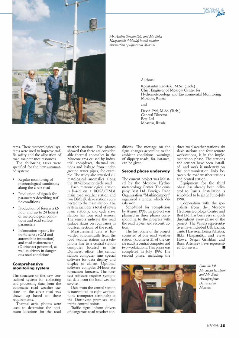
35147/1998
three road weather stations, sixslave stations and four remoteworkstations, is in the imple-mentation phase. The stationsand sensors have been install-ed, and work is underway onthe communication links be-tween the road weather stationsand central station.
Equipment for the thirdphase has already been deliv-ered to Russia. Installation isscheduled to begin in June–July1998.
Cooperation with the spe-cialists from the MoscowHydrometeorology Centre andBest Ltd. has been very smooththroughout every phase of theproject. The Vaisala representa-tives have included Ulla Laanti,Taisto Haavasoja, Leena Puhakka,Ilkka Haapamäki, and SteveHowe. Sergei Grishkin andBoris Artemjev have represent-ed Dorinvest.
ditions. The message on thesigns changes according to theambient conditions; warningsof slippery roads, for instance,can be given.
Second phase underway
The current project was initiat-ed by the Moscow Hydro-meteorology Center. The com-pany Best Ltd. Foreign TradeOrganization “Mashinoimport”organized a tender, which Vai-sala won.
Scheduled for completionby August 1998, the project wasplanned in three phases corre-sponding to the progress withthe road repairs and reconstruc-tion.
The first phase of the projectconsisted of one road weatherstation (kilometer 21 of the cir-cle road), a central computer andtwo workstations. This phase wascompleted in July 1997. Thesecond phase, including the
tems. These meteorological sys-tems were used to improve traf-fic safety and the allocation ofroad maintenance resources.
The following tasks werespecified for the new automat-ed system:
• Regular monitoring ofmeteorological conditionsalong the circle road
• Production of signals forparameters describing traf-fic conditions
• Production of forecasts (2-hour and up to 24 hours)of meteorological condi-tions and road surfaceparameters
• Information reports fortraffic safety (GAI andautomobile inspection)and road maintenance(Dorinvest) personnel, aswell as drivers in danger-ous road conditions
Comprehensivemonitoring system
The structure of the new cen-tralized system for collectingand processing data from theautomatic road weather sta-tions on the circle road wasdrawn up based on theserequirements.
Thermal aerial photos wereused to determine the opti-mum locations for the road
weather stations. The photosshowed that there are consider-able thermal anomalies in theMoscow area caused by indus-trial complexes, thermal sta-tions and leakage from under-ground water pipes, for exam-ple. The study also revealed cli-matological anomalies alongthe 109-kilometer circle road.
Each meteorological stationis based on a ROSA/DM31main road weather station andtwo DM31R slave stations con-nected to the main station. Thesystem includes a total of sevenmain stations, and each slavestation has four road sensors.The sensors indicate the roadsurface status on four lanes infourteen sections of the road.
Measurement data is for-warded automatically from theroad weather station via a tele-phone line to a central stationcomputer located in theDorinvest office. The centralstation computer runs specialsoftware for data display anddisplay of alarms. Optionalsoftware compiles 24-hour iceformation forecasts. The fore-cast software requires synopti-cal data from the local weatherservice.
Data from the central stationis transmitted to eight worksta-tions (computer terminals) atthe Dorinvest premises andtraffic control points.
Traffic signs inform driversof dangerous road weather con-
Authors:
Konstantin Radetski, M.Sc. (Tech.)Chief Engineer of Moscow Centre for Hydrometeorology and Environmental Monitoring Moscow, Russia
and
David Frid, M.Sc. (Tech.)General DirectorBest Ltd.Moscow, Russia
■
Mr. Andrei Simkin (left) and Mr. IlkkaHaapamäki (Vaisala) install weatherobservation equipment in Moscow.
From the left: Mr. Sergei Grishkinand Mr. BorisArtemjev fromDorinvest inMoscow.
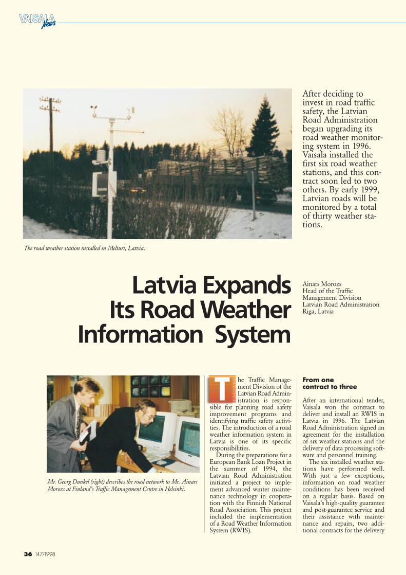
36 147/1998
Ainars Morozs Head of the TrafficManagement DivisionLatvian Road AdministrationRiga, Latvia
he Traffic Manage-ment Division of theLatvian Road Admin-istration is respon-
sible for planning road safetyimprovement programs andidentifying traffic safety activi-ties. The introduction of a roadweather information system inLatvia is one of its specificresponsibilities.
During the preparations for aEuropean Bank Loan Project inthe summer of 1994, theLatvian Road Administrationinitiated a project to imple-ment advanced winter mainte-nance technology in coopera-tion with the Finnish NationalRoad Association. This projectincluded the implementationof a Road Weather InformationSystem (RWIS).
The road weather station installed in Melturi, Latvia.
Mr. Georg Dunkel (right) describes the road network to Mr. AinarsMorozs at Finland’s Traffic Management Centre in Helsinki.
T
After deciding toinvest in road trafficsafety, the LatvianRoad Administrationbegan upgrading itsroad weather monitor-ing system in 1996.Vaisala installed thefirst six road weatherstations, and this con-tract soon led to twoothers. By early 1999,Latvian roads will bemonitored by a totalof thirty weather sta-tions.
Latvia Expands Its Road Weather
Information System
From one contract to three
After an international tender,Vaisala won the contract todeliver and install an RWIS inLatvia in 1996. The LatvianRoad Administration signed anagreement for the installationof six weather stations and thedelivery of data processing soft-ware and personnel training.
The six installed weather sta-tions have performed well.With just a few exceptions,information on road weatherconditions has been receivedon a regular basis. Based onVaisala’s high-quality guaranteeand post-guarantee service andtheir assistance with mainte-nance and repairs, two addi-tional contracts for the delivery
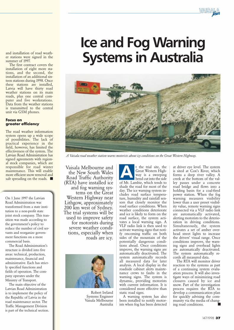
37147/1998
and installation of road weath-er stations were signed in thesummer of 1997.
The first contract covers theinstallation of eight more sta-tions, and the second, theinstallation of an additional six-teen stations during 1998. Oncethese stations are installed,Latvia will have thirty roadweather stations on its mainroads, plus one central com-puter and five workstations.Data from the weather stationsis transmitted to the centralunit via GSM phones.
Focus on greater efficiency
The road weather informationsystem opens up a wide scopeof possibilities. The lack ofpractical experience in thefield, however, has limited theeffectiveness of the system. TheLatvian Road Administration hassigned agreements with region-al stock companies, which areresponsible for road wintermaintenance. This will enablemore efficient snow removal andsalt spreading on the roads.
Ice and Fog WarningSystems in Australia
Robert IrelandSystems Engineer
Vaisala MelbourneAustralia
Vaisala Melbourne andthe New South Wales
Road Traffic Authority(RTA) have installed ice
and fog warning sys-tems on the Great
Western Highway nearLithgow, approximately200 km west of Sydney.The trial systems will be
used to improve safetyfor motorists during
severe weather condi-tions, especially when
roads are icy.
t the trial site, theGreat Western High-way is a sweepingbend cut into the side
of Mt. Lambie, which tends toshade the road for most of theday. The ice warning system in-cludes road surface tempera-ture, humidity and rainfall sen-sors that closely monitor theroad surface conditions. Whenweather conditions deteriorateand ice is likely to form on theroad surface, the system acti-vates a local warning sign. AVLF radio link is then used toactivate warning signs that noti-fy oncoming traffic on bothsides of the mountain of thepotentially dangerous condi-tions ahead. Once conditionsimprove, the warning signs areautomatically deactivated. Thesystem automatically recordsall measured data for lateranalysis. A local display in theroadside cabinet alerts mainte-nance crews to faults in thewarning signs. The system isdynamic, providing motoristswith current information. It isconsidered more effective thanstatic road signs.
A warning system has alsobeen installed to notify motor-ists when fog has been detected
at driver eye level. The systemis sited at Cox’s River, whichforms a deep river valley. Acreek at the bottom of the val-ley passes under a concreteroad bridge and flows into aholding basin for a coal-firedpower station. When the fogwarning measures visibilitylower than a user preset visibil-ity value, remote warning signsconnected via a VLF radio linkare automatically activated,alerting motorists to the deterio-ration in driving conditions.Simultaneously, the systemactivates a set of amber over-head street lights to increasethe drivers’ visual range. Onceconditions improve, the warn-ing signs and overhead lightsare automatically deactivated.The system automatically re-cords all measured data.
The RTA will monitor driverreaction to the systems as partof a continuing system evalu-ation process. It will also inves-tigate ways of minimizing roadclosures caused by ice andsnow. Part of the investigationprocess requires the RTA todevelop a communication planfor quickly advising the com-munity via the media of chang-ing road conditions.
On 1 June 1997 the LatvianRoad Administration wastransformed from a state insti-tution to a non-profit statejoint stock company. This tran-sition was made according tothe government’s policy toreduce the number of civil ser-vants and reorganize govern-ment functions on a morecommercial basis.
The Road Administration’sstructure is divided into fiveareas: technical, production,maintenance, financial andadministrative. Each has strict-ly specified functions andfields of operation. The com-pany operates under theMinistry of Transport.
The main objective of theLatvian Road Administrationis to implement the policy ofthe Republic of Latvia in theroad maintenance sector. TheTraffic Management Divisionis part of the technical section.
A■
■
A Vaisala road weather station warns motorists about icy conditions on the Great Western Highway.
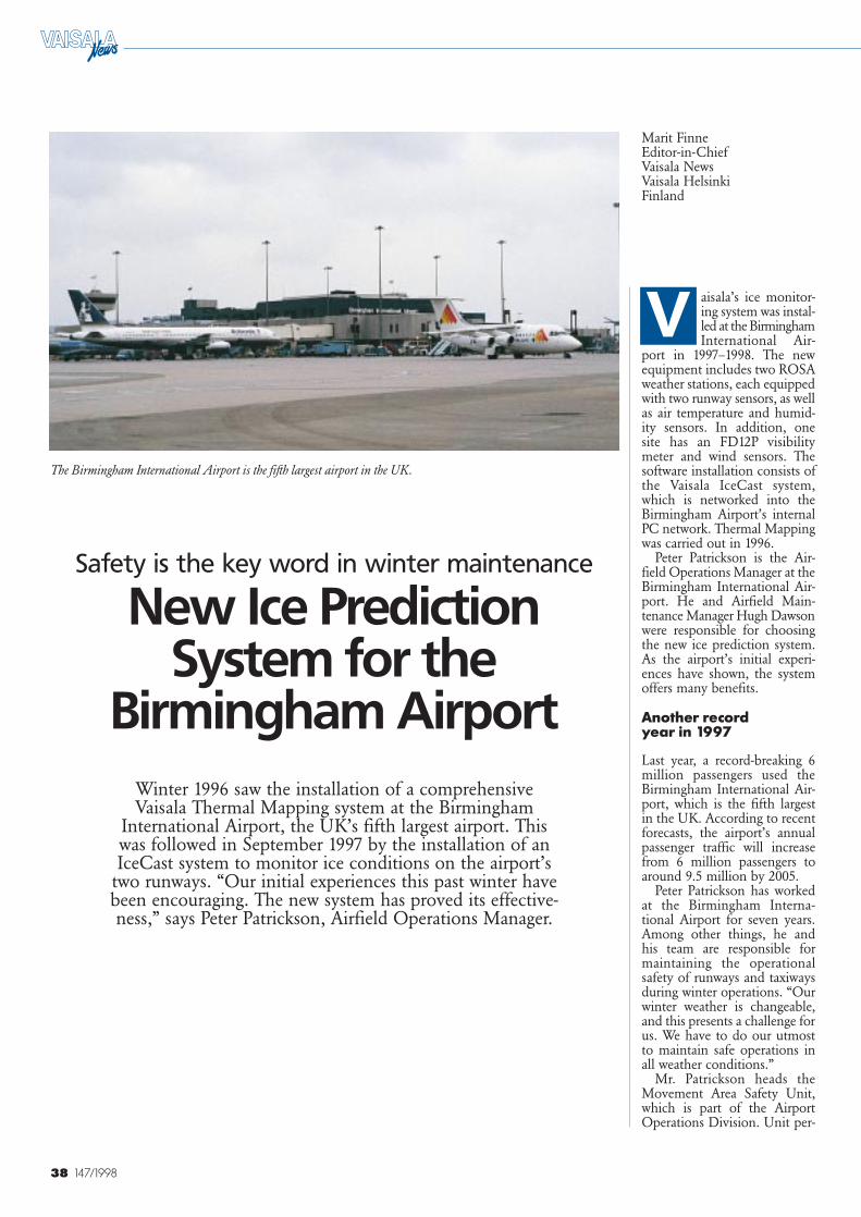
38 147/1998
The Birmingham International Airport is the fifth largest airport in the UK.
Safety is the key word in winter maintenance
New Ice PredictionSystem for the
Birmingham Airport
Marit FinneEditor-in-ChiefVaisala NewsVaisala HelsinkiFinland
Winter 1996 saw the installation of a comprehensiveVaisala Thermal Mapping system at the Birmingham
International Airport, the UK’s fifth largest airport. Thiswas followed in September 1997 by the installation of anIceCast system to monitor ice conditions on the airport’s
two runways. “Our initial experiences this past winter havebeen encouraging. The new system has proved its effective-ness,” says Peter Patrickson, Airfield Operations Manager.
aisala’s ice monitor-ing system was instal-led at the BirminghamInternational Air-
port in 1997–1998. The newequipment includes two ROSAweather stations, each equippedwith two runway sensors, as wellas air temperature and humid-ity sensors. In addition, onesite has an FD12P visibilitymeter and wind sensors. Thesoftware installation consists ofthe Vaisala IceCast system,which is networked into theBirmingham Airport’s internalPC network. Thermal Mappingwas carried out in 1996.
Peter Patrickson is the Air-field Operations Manager at theBirmingham International Air-port. He and Airfield Main-tenance Manager Hugh Dawsonwere responsible for choosingthe new ice prediction system.As the airport’s initial experi-ences have shown, the systemoffers many benefits.
Another record year in 1997
Last year, a record-breaking 6million passengers used theBirmingham International Air-port, which is the fifth largestin the UK. According to recentforecasts, the airport’s annualpassenger traffic will increasefrom 6 million passengers toaround 9.5 million by 2005.
Peter Patrickson has workedat the Birmingham Interna-tional Airport for seven years.Among other things, he andhis team are responsible formaintaining the operationalsafety of runways and taxiwaysduring winter operations. “Ourwinter weather is changeable,and this presents a challenge forus. We have to do our utmostto maintain safe operations inall weather conditions.”
Mr. Patrickson heads theMovement Area Safety Unit,which is part of the AirportOperations Division. Unit per-
V
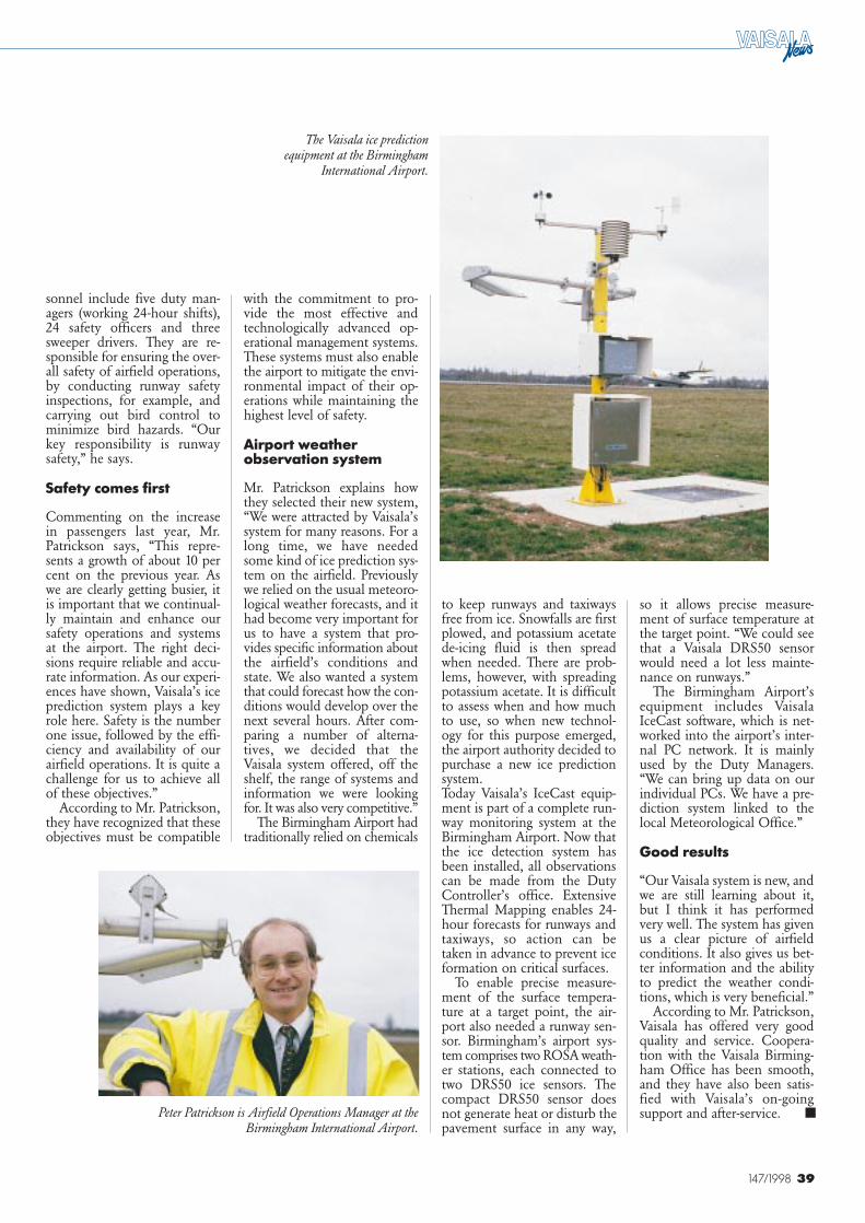
39147/1998
The Vaisala ice predictionequipment at the Birmingham
International Airport.
sonnel include five duty man-agers (working 24-hour shifts),24 safety officers and threesweeper drivers. They are re-sponsible for ensuring the over-all safety of airfield operations,by conducting runway safetyinspections, for example, andcarrying out bird control tominimize bird hazards. “Ourkey responsibility is runwaysafety,” he says.
Safety comes first
Commenting on the increasein passengers last year, Mr.Patrickson says, “This repre-sents a growth of about 10 percent on the previous year. Aswe are clearly getting busier, itis important that we continual-ly maintain and enhance oursafety operations and systemsat the airport. The right deci-sions require reliable and accu-rate information. As our experi-ences have shown, Vaisala’s iceprediction system plays a keyrole here. Safety is the numberone issue, followed by the effi-ciency and availability of ourairfield operations. It is quite achallenge for us to achieve allof these objectives.”
According to Mr. Patrickson,they have recognized that theseobjectives must be compatible
with the commitment to pro-vide the most effective andtechnologically advanced op-erational management systems.These systems must also enablethe airport to mitigate the envi-ronmental impact of their op-erations while maintaining thehighest level of safety.
Airport weatherobservation system
Mr. Patrickson explains howthey selected their new system,“We were attracted by Vaisala’ssystem for many reasons. For along time, we have neededsome kind of ice prediction sys-tem on the airfield. Previouslywe relied on the usual meteoro-logical weather forecasts, and ithad become very important forus to have a system that pro-vides specific information aboutthe airfield’s conditions andstate. We also wanted a systemthat could forecast how the con-ditions would develop over thenext several hours. After com-paring a number of alterna-tives, we decided that theVaisala system offered, off theshelf, the range of systems andinformation we were lookingfor. It was also very competitive.”
The Birmingham Airport hadtraditionally relied on chemicals
to keep runways and taxiwaysfree from ice. Snowfalls are firstplowed, and potassium acetatede-icing fluid is then spreadwhen needed. There are prob-lems, however, with spreadingpotassium acetate. It is difficultto assess when and how muchto use, so when new technol-ogy for this purpose emerged,the airport authority decided topurchase a new ice predictionsystem.Today Vaisala’s IceCast equip-ment is part of a complete run-way monitoring system at theBirmingham Airport. Now thatthe ice detection system hasbeen installed, all observationscan be made from the DutyController’s office. ExtensiveThermal Mapping enables 24-hour forecasts for runways andtaxiways, so action can betaken in advance to prevent iceformation on critical surfaces.
To enable precise measure-ment of the surface tempera-ture at a target point, the air-port also needed a runway sen-sor. Birmingham’s airport sys-tem comprises two ROSA weath-er stations, each connected totwo DRS50 ice sensors. Thecompact DRS50 sensor doesnot generate heat or disturb thepavement surface in any way,
so it allows precise measure-ment of surface temperature atthe target point. “We could seethat a Vaisala DRS50 sensorwould need a lot less mainte-nance on runways.”
The Birmingham Airport’sequipment includes VaisalaIceCast software, which is net-worked into the airport’s inter-nal PC network. It is mainlyused by the Duty Managers.“We can bring up data on ourindividual PCs. We have a pre-diction system linked to thelocal Meteorological Office.”
Good results
“Our Vaisala system is new, andwe are still learning about it,but I think it has performedvery well. The system has givenus a clear picture of airfieldconditions. It also gives us bet-ter information and the abilityto predict the weather condi-tions, which is very beneficial.”
According to Mr. Patrickson,Vaisala has offered very goodquality and service. Coopera-tion with the Vaisala Birming-ham Office has been smooth,and they have also been satis-fied with Vaisala’s on-goingsupport and after-service.Peter Patrickson is Airfield Operations Manager at the
Birmingham International Airport.■
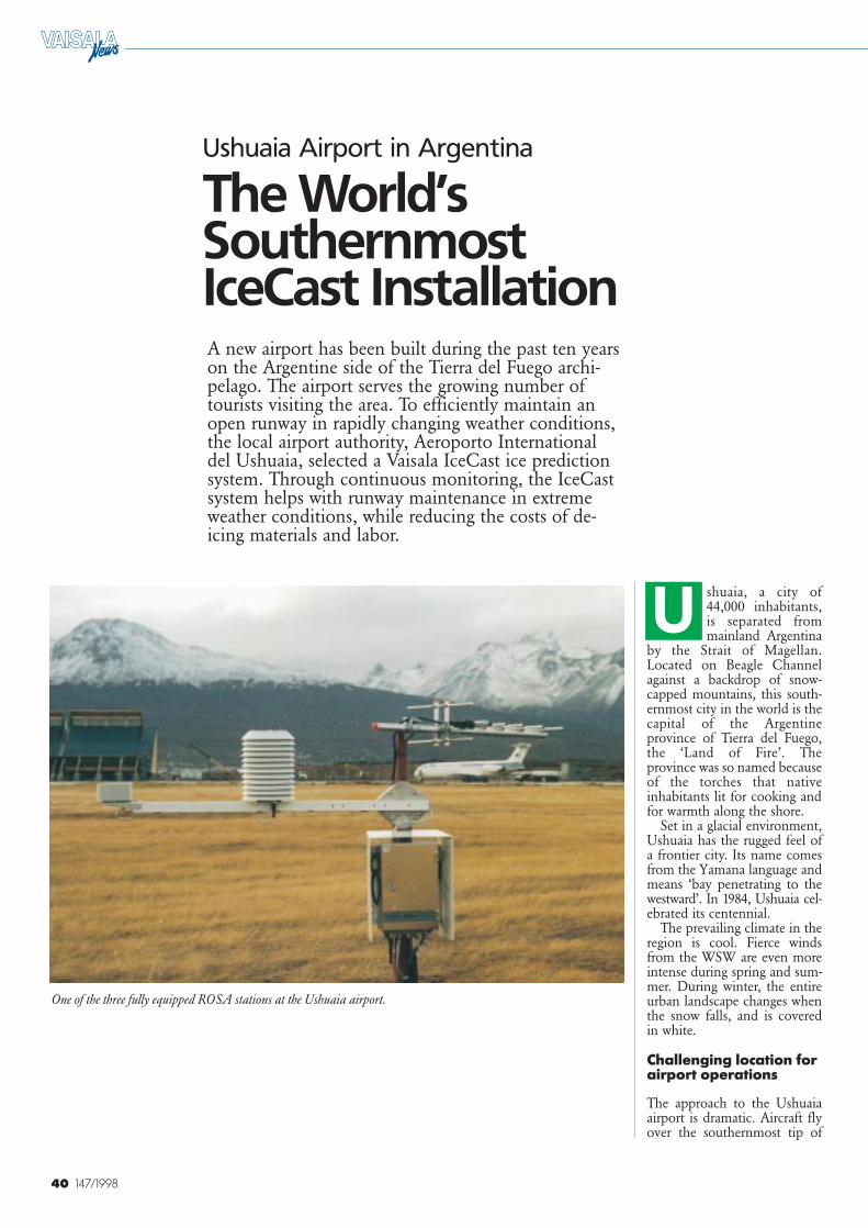
40 147/1998
Ushuaia Airport in Argentina
The World’sSouthernmost IceCast InstallationA new airport has been built during the past ten yearson the Argentine side of the Tierra del Fuego archi-pelago. The airport serves the growing number oftourists visiting the area. To efficiently maintain anopen runway in rapidly changing weather conditions,the local airport authority, Aeroporto Internationaldel Ushuaia, selected a Vaisala IceCast ice predictionsystem. Through continuous monitoring, the IceCastsystem helps with runway maintenance in extremeweather conditions, while reducing the costs of de-icing materials and labor.
shuaia, a city of44,000 inhabitants,is separated frommainland Argentina
by the Strait of Magellan.Located on Beagle Channelagainst a backdrop of snow-capped mountains, this south-ernmost city in the world is thecapital of the Argentineprovince of Tierra del Fuego,the ‘Land of Fire’. Theprovince was so named becauseof the torches that nativeinhabitants lit for cooking andfor warmth along the shore.
Set in a glacial environment,Ushuaia has the rugged feel ofa frontier city. Its name comesfrom the Yamana language andmeans ‘bay penetrating to thewestward’. In 1984, Ushuaia cel-ebrated its centennial.
The prevailing climate in theregion is cool. Fierce windsfrom the WSW are even moreintense during spring and sum-mer. During winter, the entireurban landscape changes whenthe snow falls, and is coveredin white.
Challenging location forairport operations
The approach to the Ushuaiaairport is dramatic. Aircraft flyover the southernmost tip of
One of the three fully equipped ROSA stations at the Ushuaia airport.
U
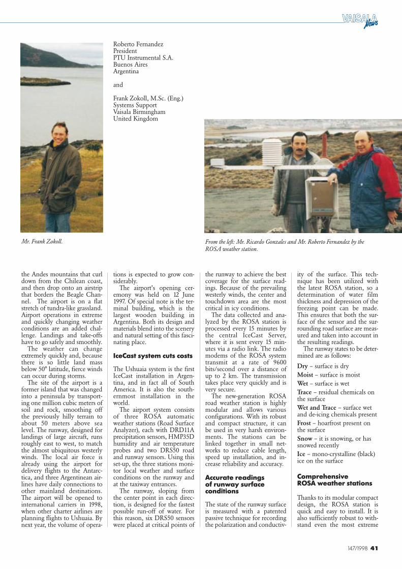
41147/1998
From the left: Mr. Ricardo Gonzales and Mr. Roberto Fernandez by theROSA weather station.
Mr. Frank Zokoll.
the Andes mountains that curldown from the Chilean coast,and then drop onto an airstripthat borders the Beagle Chan-nel. The airport is on a flatstretch of tundra-like grassland.Airport operations in extremeand quickly changing weatherconditions are an added chal-lenge. Landings and take-offshave to go safely and smoothly.
The weather can changeextremely quickly and, becausethere is so little land massbelow 50° latitude, fierce windscan occur during storms.
The site of the airport is aformer island that was changedinto a peninsula by transport-ing one million cubic meters ofsoil and rock, smoothing offthe previously hilly terrain toabout 50 meters above sealevel. The runway, designed forlandings of large aircraft, runsroughly east to west, to matchthe almost ubiquitous westerlywinds. The local air force isalready using the airport fordelivery flights to the Antarc-tica, and three Argentinean air-lines have daily connections toother mainland destinations.The airport will be opened tointernational carriers in 1998,when other charter airlines areplanning flights to Ushuaia. Bynext year, the volume of opera-
tions is expected to grow con-siderably.
The airport’s opening cer-emony was held on 12 June1997. Of special note is the ter-minal building, which is thelargest wooden building inArgentina. Both its design andmaterials blend into the sceneryand natural setting of this fasci-nating place.
IceCast system cuts costs
The Ushuaia system is the firstIceCast installation in Argen-tina, and in fact all of SouthAmerica. It is also the south-ernmost installation in theworld.
The airport system consistsof three ROSA automaticweather stations (Road SurfaceAnalyzer), each with DRD11Aprecipitation sensors, HMP35Dhumidity and air temperatureprobes and two DRS50 roadand runway sensors. Using thisset-up, the three stations moni-tor local weather and surfaceconditions on the runway andat the taxiway entrances.
The runway, sloping fromthe center point in each direc-tion, is designed for the fastestpossible run-off of water. Forthis reason, six DRS50 sensorswere placed at critical points of
Roberto FernandezPresidentPTU Instrumental S.A.Buenos AiresArgentina
and
Frank Zokoll, M.Sc. (Eng.)Systems SupportVaisala BirminghamUnited Kingdom
the runway to achieve the bestcoverage for the surface read-ings. Because of the prevailingwesterly winds, the center andtouchdown area are the mostcritical in icy conditions.
The data collected and ana-lyzed by the ROSA station isprocessed every 15 minutes bythe central IceCast Server,where it is sent every 15 min-utes via a radio link. The radiomodems of the ROSA systemtransmit at a rate of 9600bits/second over a distance ofup to 2 km. The transmissiontakes place very quickly and isvery secure.
The new-generation ROSAroad weather station is highlymodular and allows variousconfigurations. With its robustand compact structure, it canbe used in very harsh environ-ments. The stations can belinked together in small net-works to reduce cable length,speed up installation, and in-crease reliability and accuracy.
Accurate readings of runway surfaceconditions
The state of the runway surfaceis measured with a patentedpassive technique for recordingthe polarization and conductiv-
ity of the surface. This tech-nique has been utilized withthe latest ROSA station, so adetermination of water filmthickness and depression of thefreezing point can be made.This ensures that both the sur-face of the sensor and the sur-rounding road surface are meas-ured and taken into account inthe resulting readings.
The runway states to be deter-mined are as follows:
Dry – surface is dryMoist – surface is moistWet – surface is wetTrace – residual chemicals onthe surfaceWet and Trace – surface wetand de-icing chemicals presentFrost – hoarfrost present onthe surfaceSnow – it is snowing, or hassnowed recentlyIce – mono-crystalline (black)ice on the surface
Comprehensive ROSA weather stations
Thanks to its modular compactdesign, the ROSA station isquick and easy to install. It isalso sufficiently robust to with-stand even the most extreme

42 147/1998
weather conditions. Because ofits integrated system operationand unique detection principlefor determining amount of thede-icing chemicals and thefreezing point, the station per-forms all required measure-ments, compiles the results andprovides the interpretation ofits input in a user-friendly for-mat.
The data is displayed in vari-ous ways in the IceCast Server,in tabular or graphical form, orin data blocks overlaying theairport map for a quick over-view. The various runway sur-face conditions, warnings andice alarms are displayed in auser-friendly format. Becausethe weather can change ex-tremely quickly in Ushuaia, itis important for users to makequick decisions. So they haveto understand the effect andcombinations of various air,surface, ground, depth and dewpoint temperatures, as well asthe freezing point. All this datais provided by the ice detectionsystem, which helps usersdetermine how conditions willdevelop.
The ice detection systemonly makes predictions for thenext several hours, by follow-ing slopes and correlating themwith pre-defined thresholds foruser alarms. For 24-hour andlonger forecasts, the forecastingoffice uses FORECAST soft-
ware to produce highly accu-rate predictions of surface tem-peratures and conditions, cloudamount and height, and pre-cipitation.
Additionally, an alarm box isconnected to the computer togive audible and visual alarmsin case of critical runway con-ditions. This box is currently inthe meteorologists’ office, butwhen the airport building isready, it will be moved to thewinter maintenance facilities.Although it will be located nextto the workstation, the alarmbox is directly controlled bythe IceCast Server. As theworkstation is not necessarilyupdated as often as the datacollected by the weather sta-tions, this allows for the fastestpossible alarms in case of haz-ardous conditions.
In the future, the worksta-tion will be located at the win-ter maintenance facilities. Localcompanies will be responsiblefor winter maintenance, andwill use the workstations tomonitor weather conditions atthe airport.
An Uninterruptable PowerSupply (UPS) secures the safetyof the system operation, asbreaks in the power supply arequite common in Ushuaia, andthe backup power system at theairport is already serving allother installations.
Sea Lion’s Island with thousands of cormorants who, wing-to-wing and toe-to-toe, cling to every available square inch of the rock.
■
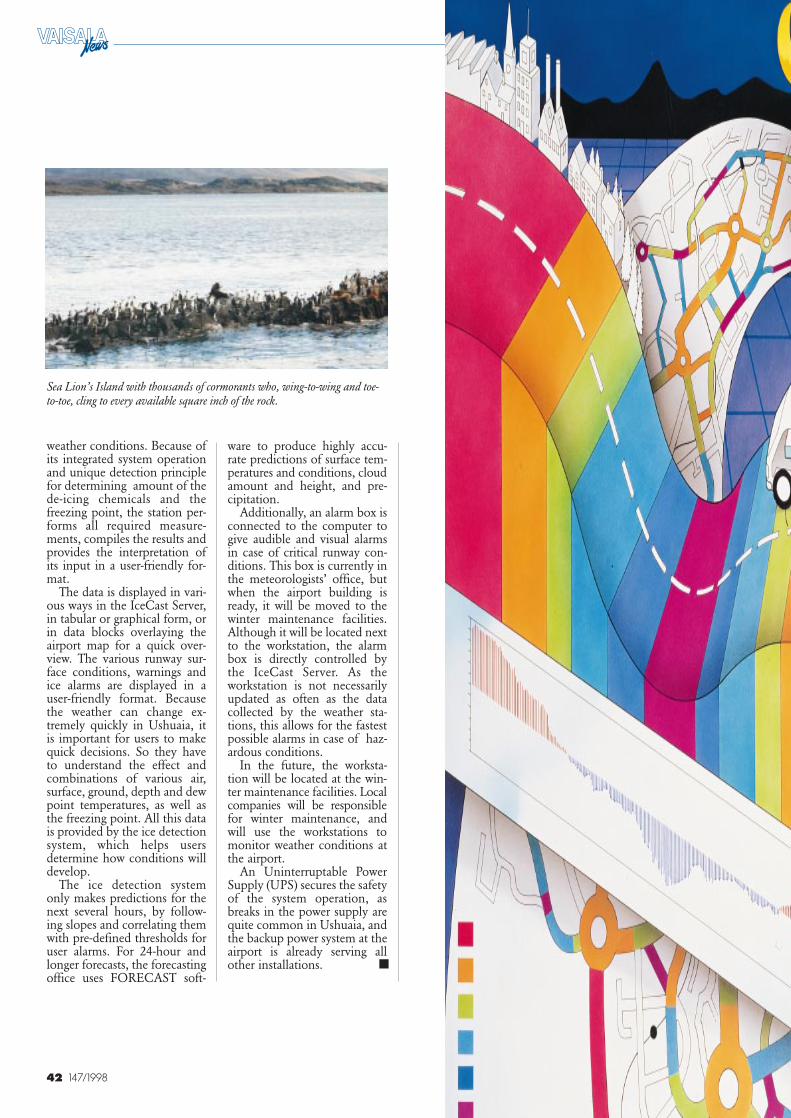
43
New ICECustomers
Andy McDonald, M.Sc. (Met.)Marketing ManagerVaisala BirminghamUK
1997saw an unprec-edented growth in
the number of new Vaisala cus-tomers for ICE productsaround the world, reaffirmingour position as the number onesupplier of ice prediction tech-nology.
Thermal Mapping
More than 100,000 km of newThermal Mapping contractswere signed and completed,bringing the total distance cov-ered since 1985 to over1,000,000 km. Specifically, newprojects were undertaken inBelgium, the Czech Republic,Japan, Switzerland, the UKand the USA.
Salting RouteOptimization
Salting Route Optimizationwas carried out for customersin Belgium, the UK and theUSA on more than 22,000 kmof road network.
IceCast Ice PredictionSystem
New customer installations ofIceCast software and ROSAweather stations were completedin Argentina, Belgium, China,the Czech Republic, Finland,France, Germany, Hungary, Italy,Japan, Latvia, Norway, Poland,Slovakia, Spain, Sweden, Russia,Sweden and Switzerland.
Key Personnel in the ICE Group
Vaisala’s ICE Group is an inter-national team, with research anddevelopment contributions fromFinland and active sales, mar-keting and support from theUK. One of the main advan-tages of global activities is theinternational experience gainedfrom many different opera-tional cultures. Designing prod-ucts to meet global needs is astimulating challenge for theICE development team.
Vaisala’s main contact peopleare as follows:
Jonathan Lister, ICE SBUManager (Birmingham) – hasoverall control of the ICE Stra-tegic Business Unit within theVaisala Group and is alsoManaging Director of the Vai-sala Birmingham Office.
Andy McDonald, ICE Sales& Marketing Manager (Birming-ham) – has overall responsibil-ity for sales and marketing forthe ICE SBU.
Steve Laux, ICE Technical &Resources Manager (Birming-ham) – responsible for ICE SBUoperational matters and theproject management organiza-tion.
Taisto Haavasoja, ICE R&DManager – Hardware (Helsinki)– responsible for the develop-ment of ROSA road weatherstations at the Helsinki Office.
Andy Hutchinson, ICER&D Manager – Software (Bir-mingham) – responsible formanaging software develop-ment of IceCast, IceView, andIceMan software products fromthe Vaisala Birmingham Office.
Brooke Pearson, Area SalesManager (Birmingham) – re-sponsible for sales in part ofthe UK and the Germanicspeaking countries of easternEurope, and for sales supportfor Vaisala’s Tokyo Office.
Paul Hutchinson, Area SalesManager (Birmingham) –responsible for sales in part ofthe UK.
Leon Shneider, NationalSales Manager (Boston) – re-sponsible for managing sales inNorth America.
David Bullock, Sales Man-ager (Birmingham) – respon-sible for sales in part of theUK.
Jussi Paananen, Area Man-ager (Helsinki) – responsiblefor sales in eastern Europe.
Leena Puhakka, Sales Man-ager (Helsinki) – responsiblefor sales in eastern Europe.
Aki Paananen, Area Man-ager (Helsinki) – responsiblefor sales in Russia.
Ulla Laanti, Sales Manager(Helsinki) – responsible forsales in Russia.
Seichi Matsui, Sales Man-ager (Tokyo) – responsible forsales in Japan.