Embed Size (px)
Citation preview
8/11/2019 VALV SELENOIDE
http://slidepdf.com/reader/full/valv-selenoide 1/4
TECHNICAL DATA
June 5, 2013 Deluge 273a
SOLENOID VALVES
RATED TO 250 PSI (17.2 BAR)
The Viking Corporation, 210 N Industrial Park Drive, Hastings MI 49058
Telephone: 269-945-9501 Technical Services: 877-384-5464 Fax: 269-818-1680 Email: [email protected]
Form No. F_020101
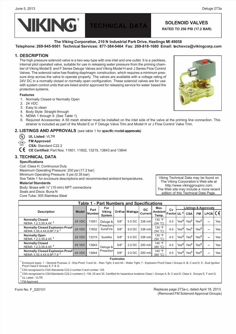
1. DESCRIPTIONThe high pressure solenoid valve is a two-way type with one inlet and one outlet. It is a packless,
internal pilot operated valve, suitable for use in releasing water pressure from the priming cham-
ber of Viking Model E and F Series Deluge Valves and Viking Model H and J Series Flow Control
Valves. The solenoid valve has floating diaphragm construction, which requires a minimum pres-
sure drop across the valve to operate properly. The valves are available with a voltage rating of
24V DC in a normally closed or normally open configuration. These solenoid valves are for use
with system control units that are listed and/or approved for releasing service for water based fire
protection systems.
Features
Normally Closed or Normally Open
24 VDC
Easy to clean
Body Style: Straight through
NEMA 1 through 9. (See Table 1)Required Accessories: A 50 mesh strainer must be installed on the inlet side of the valve at the priming line connection. This
strainer is included as part of the Model E or F Deluge Valve Trim and Model H or J Flow Control Valve Trim.
2. LISTINGS AND APPROVALS (see table 1 for specific model approvals)specific model approvals)
UL Listed: VLTR
FM Approved
CSA: Standard C22.2
CE Certified: Part Nos. 11601, 11602, 13215, 13843 and 13844
3. TECHNICAL DATASpecifications
Coil: Class H, Continuous Duty
Maximum Operating Pressure: 250 psi (17.2 bar)
Minimum Operating Pressure: 5 psi (0.35 bar)See Table 1 for enclosure descriptions and recommended ambient temperatures.
Material Standards
Body: Brass with ½” (15 mm) NPT connections
Seals and Discs: Buna N
Core Tube: 305 Stainless Steel
1.
2.
3.
4.
5.6.
Table 1 - Part Numbers and Specifications
Description ModelPart
Number
For
Viking
System
Orifice WattageDC
Current
Max.
Ambient
Temp.
Cv
Factor
Listings & Approvals
UL 4 CSA FM LPCB
Normally Closed
NEMA 1,2,3,3S,4,4X 1 24 VDC 11601 Deluge &
Preaction,
SureFire
5/8" 9.0 DC 338 mA130 °F
(54 °C)4.0 Yes4 Yes2 Yes5 -- Yes
Normally Closed Explosion Proof
NEMA 3,3S,4,4X,6,6P,7,9 1 24 VDC 11602 5/8" 9.0 DC 338 mA130 °F
(54 °C)4.0 Yes4 Yes3 Yes5 -- Yes
Normally OpenNEMA 1,2,3,3S,4,4X 1 24 VDC 13215 Surefire 5/8" 9.0 DC 338 mA
130 °F(54 °C)
4.0 Yes4 Yes2 Yes5 -- Yes
Normally Closed
NEMA 1,2,3,3S,4,4X 1 24 VDC 13843Deluge &
Preaction
5/8" 2.0 DC 250 mA140 °F
(60 °C)4.0 Yes4 Yes2 Yes5 -- Yes
Normally Closed Explosion Proof
NEMA 3,3S,4,4X,6,6P,7,9 1 24 VDC 13844 5/8" 2.0 DC 250 mA140 °F
(60 °C)4.0 Yes4 Yes3 Yes5 -- Yes
Footnotes1 Enclosure types: 1 - General Purpose, 2 - Drip-Proof, 3 and 3s - Rain Tight, 4 and 4X - Water Tight, 7 - Explosion Proof Class I Groups A, B, C and D, 9 - Dust Ignition
Proof Class II Groups E, F & G.2 CSA recognized to CSA Standards C22.2 number 0 and number 129.
3 CSA recognized to CSA Standards C22.2 numbers 0, 139, 25 and 30. Certified for hazardous locations Class I, Groups A, B, C and D; Class II, Groups E, F and G.
4 UL Listed - VLTR.
5 FM Approved
Viking Technical Data may be found onThe Viking Corporation’s Web site at
http://www.vikinggroupinc.com.The Web site may include a more recent
edition of this Technical Data Page.
Replaces page 273a-c, dated April 18, 2013
(Removed FM Solenoid Approval Groups
8/11/2019 VALV SELENOIDE
http://slidepdf.com/reader/full/valv-selenoide 2/4
TECHNICAL DATA
JUne 5, 2013Deluge 273b
SOLENOID VALVES
RATED TO 250 PSI (17.2 BAR)
The Viking Corporation, 210 N Industrial Park Drive, Hastings MI 49058
Telephone: 269-945-9501 Technical Services: 877-384-5464 Fax: 269-818-1680 Email: [email protected]
Core and Plugnut: 430F Stainless Steel
Springs: 302 Stainless Steel
4. INSTALLATIONCheck nameplate for correct unit, including voltage and mode of operation. Follow all installation and maintenance instructions
enclosed with the valve.
Standard solenoids may be mounted in any position. However, for optimum life and performance, solenoids should be mounted
vertically and upright with the coil upright.
A 50 mesh strainer is required on the inlet side of the valve at the priming line connection. This strainer is included as part of the
Model E & F Deluge Valve Trim and Model H or J Flow Control Valve Trim. Install the strainer as indicated on Viking’s trim draw
ing. Install the solenoid according to markings on the valve body. Apply pipe-joint compound sparingly to male pipe threads only
If applied to valve threads, it may enter the valve and cause operation difficulty or leakage. Avoid putting pipe compound on firs
two male threads as well.
The unit must be wired in accordance with local and national electrical codes. For valves equipped with water tight enclosures
the electrical fittings must be approved for use in the hazardous location.
Upon completing the installation, the entire system must be tested for proper operation. See system description and testinginstructions for additional information.
5. OPERATIONThe solenoid valve is an internal pilot operated valve with pilot and bleed orifices utilizing line pressure for operation. Normally closed
de-energized valves open when energized. Power is applied to the solenoid coil, causing the solenoid core to lift, opening the pilot
orifice to the outlet side of the valve. This relieves pressure on the top side of the diaphragm and allows the line pressure to open the
valve. When de-energized, the solenoid core reseals the pilot orifice, allowing the line pressure to build above the diaphragm, closing
the valve.
Normally closed solenoid valves are commonly used as releases for Viking deluge and flow control valves. Opening the solenoid valve
allows the deluge or flow control valve to open.
Note: When using a normally closed solenoid valve as a release, a system will not operate automatically on total loss of power. Fo
this reason, it is recommended and normally required that an emergency battery back-up, supervised power supply be provided to
maintain fire protection during interruptions of the main power system and to meet the requirements of appropriate Authorities Having
Jurisdiction.
6. INSPECTIONS, TESTS AND MAINTENANCE
WARNING: PRIOR TO OPERATING THE SOLENOID VALVE, BE SURE TO CLOSE THE SYSTEM CONTROL VALVE TO AVOID
UNINTENTIONAL OPERATION OF THE DELUGE VALVE.
Inspections: It is imperative that the system is inspected and tested on a regular basis in accordance with NFPA 25. The frequency
of the inspections may vary due to contaminated water supplies, corrosive water supplies, or corrosive atmospheres. In addi-
tion, the alarm devices, detection systems, or other connected trim may require a more frequent schedule. Refer to the system
description and applicable codes for minimum requirements.
The valve must be operated at least monthly. The valve must open and close freely. When open, the water flow must be clea
and clean at the proper flow rate. When closed, a total water shut-off must be observed. After the test, the strainer must be
cleaned. Prior to cleaning the strainer, the priming line valve must be closed and the priming line depressurized. After the straine
is cleaned, the priming line valve must be reopened.
The valve must be inspected at least monthly for cracks, corrosion, leakage, etc., and cleaned, repaired, or replaced as neces-
sary.
At least annually, the valve diaphragms and seats must be inspected and, if necessary, repaired or replaced.
WARNING: CLOSE SYSTEM CONTROL VALVE, TURN OFF POWER SUPPLY, AND DEPRESSURIZE VALVE BEFORE DISAS-
SEMBLING VALVE. IT IS NOT NECESSARY TO REMOVE THE VALVE FROM THE PIPE LINE TO MAKE INSPECTIONS.
1.
2.
3.
4.
5.
1.
2.
3.
4.
Any system maintenance that involves placing a control valve or detection system out of service will impair the fire protection capa-
bilities of that system. Prior to proceeding, appropriate impairment procedures per NFPA 25 shall be followed with the notification of
all Authorities Having Jurisdiction. Consideration should be given to employment of a fire patrol in the affected areas.
Failure to follow these instructions could cause improper system operation, resulting in serious personal injury and/or
property damage.
8/11/2019 VALV SELENOIDE
http://slidepdf.com/reader/full/valv-selenoide 3/4
TECHNICAL DATA
June 5, 2013 Deluge 273c
SOLENOID VALVES
RATED TO 250 PSI (17.2 BAR)
The Viking Corporation, 210 N Industrial Park Drive, Hastings MI 49058
Telephone: 269-945-9501 Technical Services: 877-384-5464 Fax: 269-818-1680 Email: [email protected]
When lubricating valve components, use a high grade silicone grease (Dow Corning® 111 Compound Lubricant or equal).
When reassembling, tighten parts to torque values indicated in ASCO’s maintenance instructions (packed with valve). After maintenance is completed, operate the valve a few times to be sure of proper operation. A metallic “click” signifies the so
lenoid is operating.
It is recommended that the valve be replaced at seven-year intervals. Shorter intervals may be required if the valve is subject to
corrosive water supplies or atmospheres.
All service must be performed by qualified personnel. Upon completion of inspections or replacement of the valve, the entire
system must be checked for proper operation. See appropriate system description and testing instructions for additional informa
tion.
7. AVAILABILITYThe Viking Solenoid Valve is available through a network of domestic and international distributors. See the Viking Corp. Web site fo
closest distributor or contact The Viking Corporation.
8. GUARANTEEFor details of warranty, refer to Viking’s current list price schedule or contact Viking directly.
5.
6.7.
8.
9.
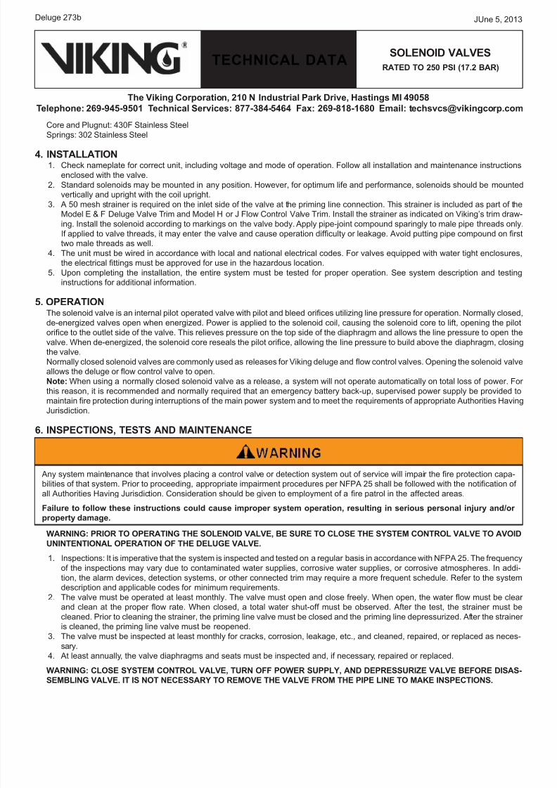
Figure 1
Dimensions for Part Numbers 11601 and 13215
8/11/2019 VALV SELENOIDE
http://slidepdf.com/reader/full/valv-selenoide 4/4
TECHNICAL DATA
JUne 5, 2013Deluge 273d
SOLENOID VALVES
RATED TO 250 PSI (17.2 BAR)
The Viking Corporation, 210 N Industrial Park Drive, Hastings MI 49058
Telephone: 269-945-9501 Technical Services: 877-384-5464 Fax: 269-818-1680 Email: [email protected]
Form No. F_020101
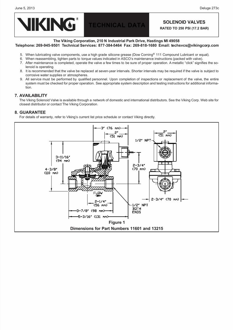
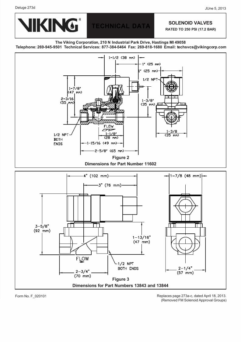
Figure 2
Dimensions for Part Number 11602
Figure 3
Dimensions for Part Numbers 13843 and 13844
Replaces page 273a-c, dated April 18, 2013
(Removed FM Solenoid Approval Groups