Embed Size (px)
Citation preview
Vapor Recovery Test Procedure
TP-206.4
Volumetric Efficiency of Phase I Vapor Recovery Systems for Aboveground Storage Tanks
Adopted: November 7, 2014
California Air Resources Board November 7, 2014 TP-206.4, Page 1
California Environmental Protection Agency
Air Resources Board
Vapor Recovery Test Procedure
TP-206.4
Volumetric Efficiency of Phase I Vapor Recovery Systems for Aboveground Storage Tanks
Definitions common to all certification and test procedures are in:
D-200 Definitions for Vapor Recovery Procedures For the purpose of this procedure, the terms “ARB” or “CARB" refer to the Air Resources Board, and the term "Executive Officer" refers to the CARB Executive Officer, or his or her authorized representative or designee. 1 PURPOSE AND APPLICABILITY
The purpose of this procedure is to quantify the transfer efficiency when a bulk gasoline delivery is made between a cargo tank and a gasoline dispensing facility (GDF) with an aboveground storage tank (AST or tank). This procedure is used to determine compliance with the Phase I transfer efficiency performance standard specified in Vapor
Recovery Certification Procedure 206 (CP-206), “Certification Procedures for Vapor Recovery Systems at Gasoline Dispensing Facilities Using Aboveground Storage Tanks.”
2 PRINCIPLE AND SUMMARY OF TEST PROCEDURE
During a gasoline delivery, the cargo tank and GDF are instrumented with test equipment in order to determine the amount of vapor returned to the cargo tank and the amount of vapor discharged to atmosphere through the GDF vent pipe. Upon conclusion of the fuel delivery, if the ullage pressure in the AST is greater than 1.00 inches water column (WC), the amount of vapor discharged through the GDF vent pipe is monitored for one hour.
For a one hour time frame immediately prior to the fuel delivery, the amount of vapor discharged through the GDF vent pipe attributed to standing losses (also known as breathing losses) is determined by way of direct measurement using a volume meter. The amount of vapor discharged from the GDF vent pipe attributed to standing losses is deducted from the amount of vapor discharged through the GDF vent pipe during and after the fuel delivery.
From these parameters the Phase I transfer or volumetric efficiency is determined. If a Phase I system fails to meet the volumetric efficiency performance standard referenced
California Air Resources Board TP-206.4, Page 2
in CP-206, the cargo tank shall be tested in accordance with TP-204.2, Determination of One Minute Static Pressure Performance of Vapor Recovery Systems of Cargo Tanks, for compliance with the daily static pressure standard for cargo tanks as specified in Section 3.2 of CP-204, “Certification Procedure for Vapor Recovery Systems of Cargo Tanks,” to determine if the failure can be attributed to the cargo tank.
3 BIASES AND INTERFERENCES
3.1 Standing Losses (also known as breathing losses)
AST, particularly those constructed with a single wall of steel (non-insulated), are prone to diurnal standing loss emissions which occur daily when solar radiation and ambient temperatures increase, causing the formation of vapors which will increase ullage pressures. When the ullage pressure reaches the positive relief setting of the pressure vacuum vent valve, vapors are discharged into the atmosphere through the vent pipe. These standing loss emissions occur during idle periods (periods of no fuel transfer) and are not attributed to the design of the Phase I system. Because standing loss emissions can bias the results of this test toward non-compliance, they must be measured and deducted from the efficiency calculation.
3.2 Establishing Baseline Standing Loss Vent Volume
3.2.1 The volume and rate of vapor discharged through the GDF vent pipe associated with standing losses will vary significantly based on ambient temperature, exposure to sunlight, tank capacity, tank color, and tank construction (insulated versus non-insulated). This volume can be measured directly by using a volume meter specified in section 5 of this procedure.
3.2.2 Baseline standing loss vent volume should only be measured when the ambient temperature is stable (temperature changes no greater than 10°F from beginning to end of the monitoring period), during full sun exposure. Early morning and late afternoon time frames should be avoided due to rising and falling temperatures and exposure to solar radiation.
3.2.3 Baseline standing loss vent volume should only be measured when the AST ullage pressure is at, or greater than, the pressure vacuum vent valve relief setting (between positive 2.5 and positive 6.0 inches WC per CP-206; and when the AST ullage volume is constant, with no dispensing or delivering activities during the monitoring period.
3.2.4 In order to establish baseline standing loss vent volume, the pressure vacuum vent valve used during the test must have zero flow at pressures less than the positive relief setting. Currently, the only pressure vacuum vent valve to meet this requirement is the “PV-Zero” manufactured by Franklin Fueling Systems (PV-Zero). Due to the unique design of the PV-Zero, when the ullage pressure reaches the positive relief setting and
California Air Resources Board TP-206.4, Page 3
vapors are discharged to atmosphere, a distinct vent volume can be captured and recorded by the instrumentation specified in this test procedure.
3.2.5 If the positive relief setting of the PV Zero pressure vacuum vent valve is set higher than the positive relief setting of the existing pressure vacuum vent valve, the results of this test will be biased toward passing. If the positive relief setting of the PV Zero pressure vacuum vent valve is set lower than the positive relief setting of the existing pressure vacuum vent valve, the results of this test will be biased toward failure. To eliminate this bias, the positive relief setting of the PV Zero must be within +/- 1.00 inch WC pressure of the existing pressure vacuum vent valve.
3.2.6 Ambient temperature differences of 10°F or greater between the establishment of the baseline and the Phase I delivery and waiting period will preclude the use of this procedure.
3.3 Leaks Within the Vapor Containment and Collection System
3.3.1 Any vapor leaks exceeding 100% of the Lower Explosive Limit (LEL) during the gasoline bulk delivery precludes the use of this procedure.
3.3.2 Gasoline cargo tanks exceeding the allowable daily static pressure performance standard, as defined in Section 3.2 of CP-204, preclude the use of this procedure.
3.3.3 The presence of vapor leaks in the GDF, greater than the static pressure performance specified in Section 4.2 of CP-206, preclude use of this procedure.
3.4 Liquid Volumes and Headspace
3.4.1 Unusually large cargo tank headspace volumes may cause low volumetric efficiency under certain conditions. Conversely, unusually small cargo tank headspace volumes may result in unusually high efficiency. During the Certification Process for a Phase I system, the cargo tank headspace volumes should be between 3.0 and 10.0 percent of the total cargo tank capacity prior to the delivery.
3.4.2 Ullage volumes of greater than 80% may cause low volumetric efficiency under certain conditions. Conversely, ullage volumes of less than 20% may result in unusually high efficiency.
3.5 Location of Instrumentation
3.5.1 The location chosen to measure AST pressure may not represent the pressure that is present in every location of the vapor recovery system. In order to avoid this bias and to provide consistency, the location used for monitoring AST ullage pressure shall be at the vent pipe.
California Air Resources Board TP-206.4, Page 4
3.5.2 Ambient temperature measurements may be biased depending on the location of the temperature probe. Ambient temperature probes shall be installed within a radiation shield at least five (5) feet above the surrounding grade.
3.5.3 Digital manometers installed in direct sunlight or in a location that is exposed directly to wind and rain can produce erroneous results and/or produce a potentially dangerous condition. Care should be taken to protect/shield the digital manometers from environmental conditions.
3.6 Taking a fuel level measurement via manual gauge port (stick port) should be performed without relieving the AST ullage pressure. A fuel level measurement taken from a stick port, particularly on single-wall ASTs can be biased if the ullage space is at positive pressure or under vacuum. If the ullage pressure is positive, the measurement stick reading will be biased high as the pressure pushes the fuel up the drop tube. In order to correct this measurement, obtain an ullage pressure reading using a digital manometer (inches of WC) and multiply that value by 1.28 to convert inches of WC into inches of gasoline. Then, subtract the inches of gasoline from the value obtained from the measurement stick reading. If the tank is under vacuum, add the inches of gasoline to the number obtained off the stick gauge.
For example, if the ullage pressure of a single-wall AST is at 3.5 inches of WC positive pressure and the value obtained by the measurement stick is 30 inches of gasoline, the following correction factor would be applied:
Corrected Reading = inches of gasoline from stick reading – (positive pressure of ullage x conversion factor of 1.28)
= 30 inches of gasoline – (3.5 inches of WC x 1.28)
= 25.52 inches of gasoline
The conversion factor of 1.28 is obtained by dividing the density of water (8.34 lb/gallon water) by the density of gasoline (6.5 lb/gallon gasoline).
4 SENSITIVITY, PRECISION AND RANGE
4.1 Digital Manometers. The maximum full-scale range of the device shall not exceed 20 inches WC with minimum sensitivity of 1.00 inches WC and minimum accuracy of 0.5 percent of full scale. Digital manometers shall be calibrated as described in Section 5 of this procedure.
4.2 Vapor Return Volume Meter. Minimum full-scale range shall be 5,000 CFH with a maximum rated back pressure less than 1.10 inches WC. The meter shall have an internal diameter of 3 inches, equal to that of a cargo tank vapor return hose.
California Air Resources Board TP-206.4, Page 5
4.3 Vent Pipe Volume Meter. Minimum full-scale range shall be 800 CFH with a maximum rated back pressure less than 0.26 inches WC. The meter shall have an internal diameter of at least 1.5 inches.
4.4 Temperature Gauges. Maximum range of 0 to 150F and accurate to within 2F.
4.5 Barometric Pressure Gauge. Minimum accuracy of 0.08 inches of mercury (1.1 inches WC or 2.7 millibar).
5 EQUIPMENT
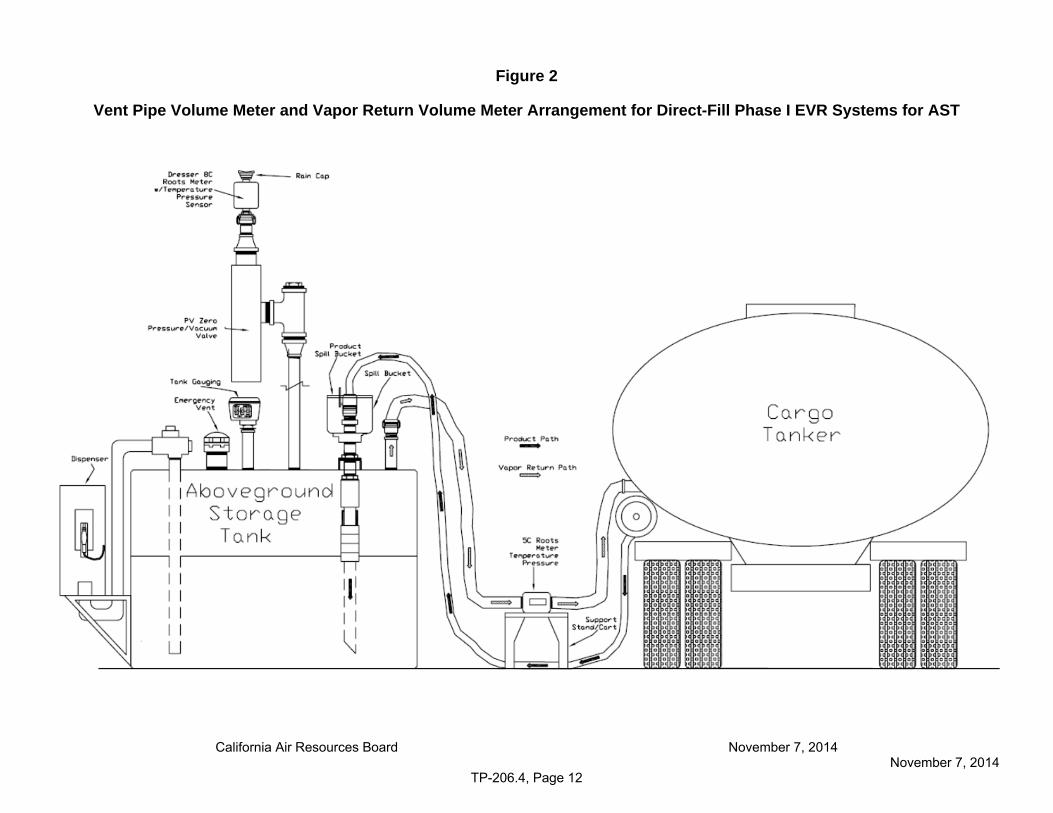
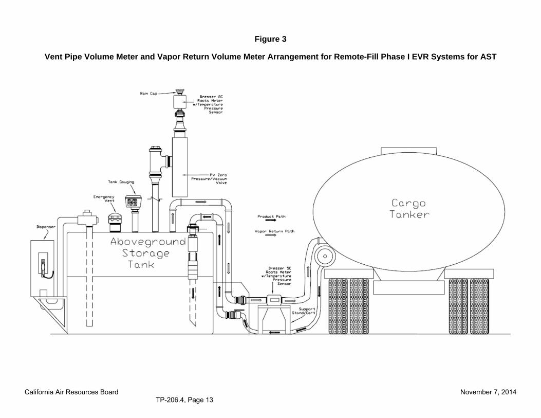
5.1 Vent Pipe Volume Meter. Use a volume meter with minimum specifications described in Section 4 to measure the amount of vapor discharged to atmosphere through the vent pipe(s). The meter shall be equipped with a pressure gauge and temperature probe as described in Section 4 on the inlet side. The meter shall be connected to the GDF in a fashion as to maintain intrinsic safety, as shown in Figure 2 (direct-fill Phase I configuration) or Figure 3 (remote-fill configuration).
5.2 Vapor Return Volume Meter(s). Use a volume meter with minimum specifications described in Section 4 to measure the amount of vapor returned to the cargo tank from the AST. The meter shall be equipped with a pressure gauge and temperature probe as described in Section 4 on the inlet side. The meter shall be connected to the GDF in a fashion as to maintain intrinsic safety, as shown in Figure 2 (direct-fill Phase I configuration) or Figure 3 (remote-fill Phase I configuration).
5.3 The volume meters shall be proofed against a standard reference meter prior to their initial use in the field or at intervals not to exceed 180 days. Calibration shall be performed at a minimum of three flow rates representing 25, 50 and 75 percent of rated capacity. An official statement of proofing is required.
5.4 Leak Detection
5.4.1 Liquid Leak Detection Solution. Phase I components are not certified with an allowable leak rate and shall not leak. Compliance shall be verified by the use of commercial liquid leak detection solution when the vapor containment space of the AST is subject to non-zero pressure, or
5.4.2 Alternatively use Combustible Gas Detector. Use a Bacharach Instrument Company Model 0023-7356®, or equivalent, to quantify any vapor leaks occurring during the gasoline bulk drop.
5.5 Barometer. Use a mercury, aneroid, or equivalent barometer with minimum specifications described in Section 4.5 to measure the barometric pressure during testing. The result shall be used to correct the volume of vapor returned or discharged.

California Air Resources Board TP-206.4, Page 6
5.6 Temperature Gauges. Use a minimum of two thermometers, ThermocouplesTM, temperature gauges, or equivalent, to measure the vapor temperature at each meter. The results shall be used to correct the volume of vapor returned or discharged.
5.7 Stopwatch. Use a stopwatch accurate to within 0.1 seconds to time the delivery rate.
5.8 Franklin Fueling Systems PV-Zero pressure vacuum vent valve. A PV-Zero is used to establish baseline standing loss vent volume. See Figures 1A and 1B for a typical PV-Zero installation configurations.
5.9 Digital Manometers. All digital manometers shall be tested for accuracy using a reference gauge, incline manometer, or National Institute of Standards and Technology (NIST) traceable standard within six (6) months prior to the test. Accuracy checks shall be performed at a minimum of five points (e.g., 10, 25, 50, 75, and 90 percent of full scale) each for both positive and negative pressure readings.
Figure 1A: Typical Installation of PV-Zero on Single-Wall AST
California Air Resources Board TP-206.4, Page 7
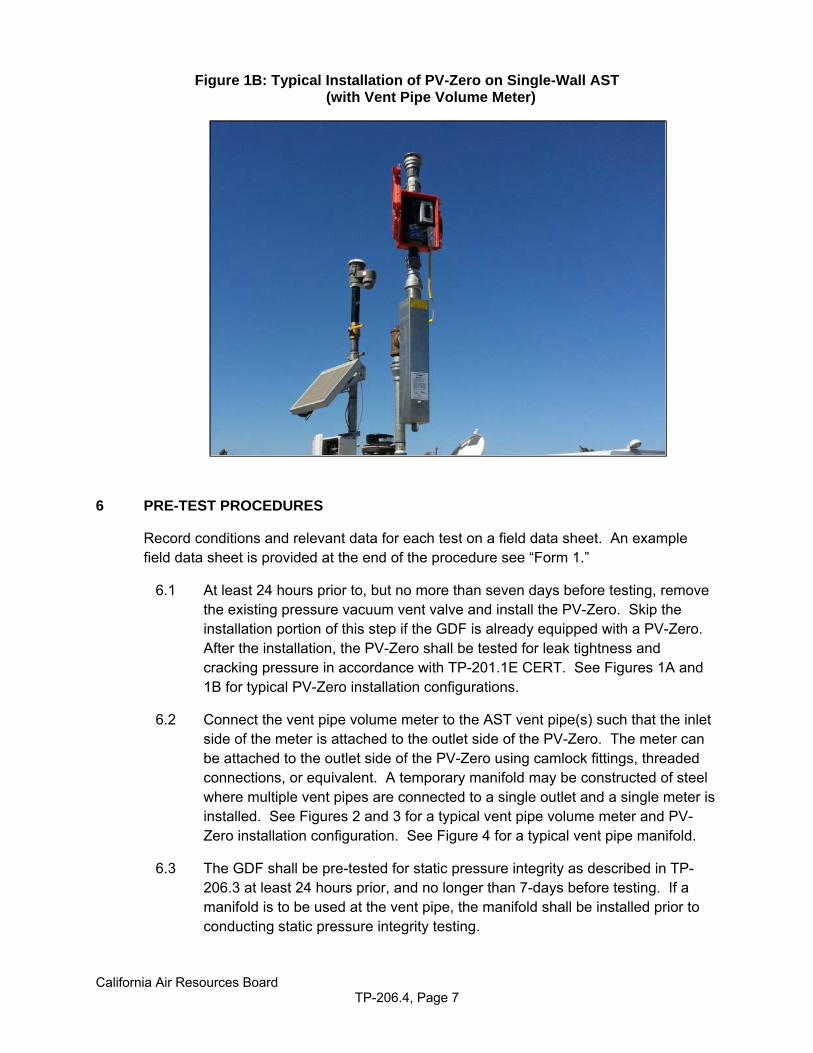
Figure 1B: Typical Installation of PV-Zero on Single-Wall AST (with Vent Pipe Volume Meter)
6 PRE-TEST PROCEDURES
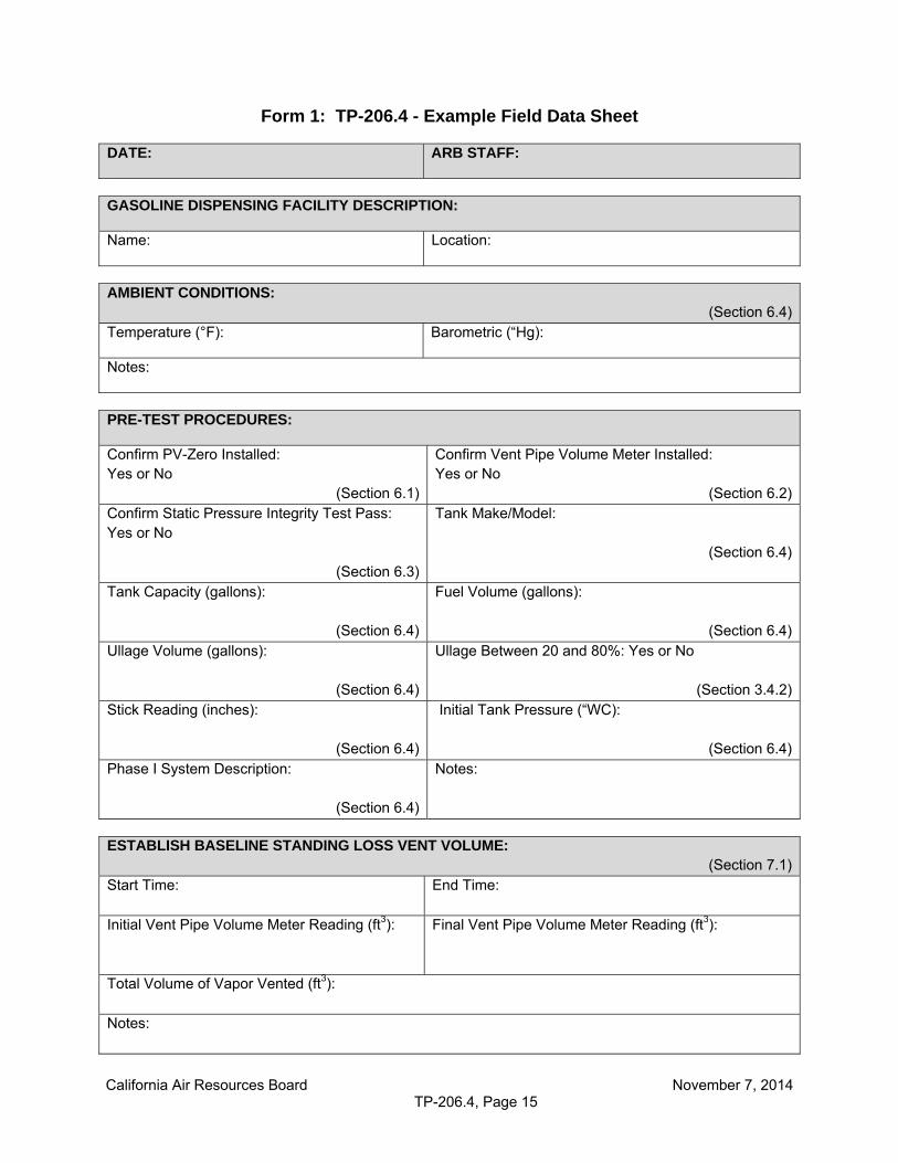
Record conditions and relevant data for each test on a field data sheet. An example field data sheet is provided at the end of the procedure see “Form 1.”
6.1 At least 24 hours prior to, but no more than seven days before testing, remove the existing pressure vacuum vent valve and install the PV-Zero. Skip the installation portion of this step if the GDF is already equipped with a PV-Zero. After the installation, the PV-Zero shall be tested for leak tightness and cracking pressure in accordance with TP-201.1E CERT. See Figures 1A and 1B for typical PV-Zero installation configurations.
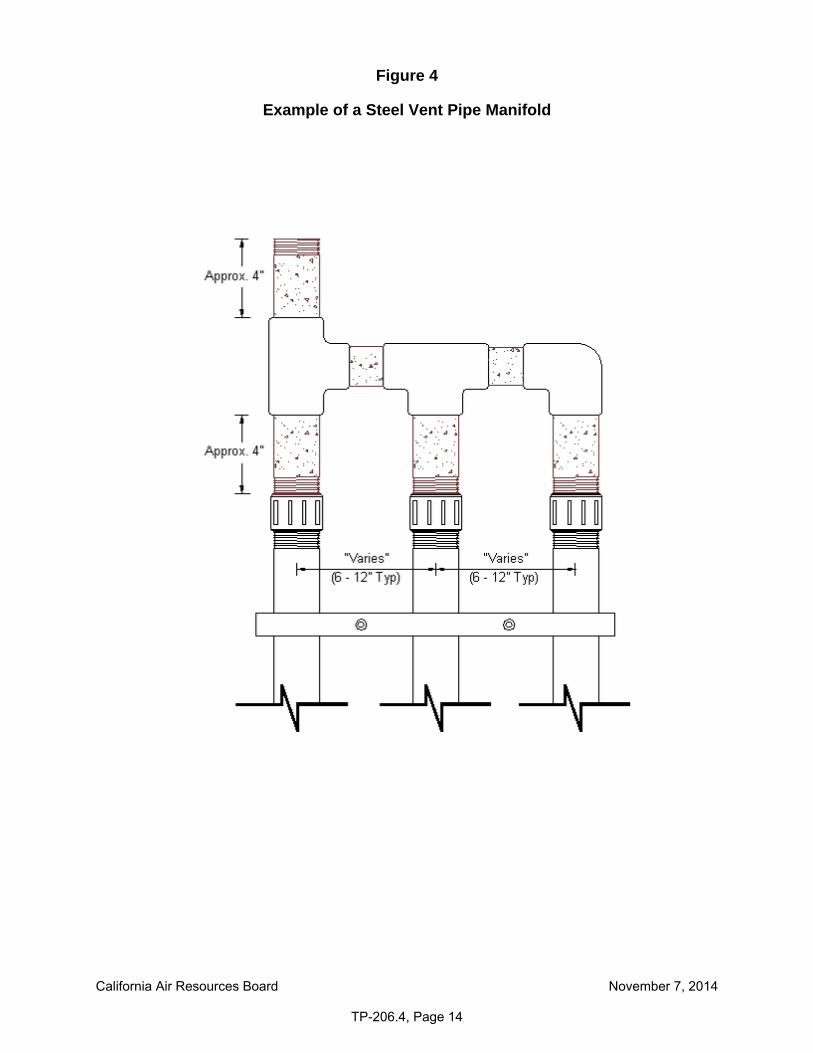
6.2 Connect the vent pipe volume meter to the AST vent pipe(s) such that the inlet side of the meter is attached to the outlet side of the PV-Zero. The meter can be attached to the outlet side of the PV-Zero using camlock fittings, threaded connections, or equivalent. A temporary manifold may be constructed of steel where multiple vent pipes are connected to a single outlet and a single meter is installed. See Figures 2 and 3 for a typical vent pipe volume meter and PV-Zero installation configuration. See Figure 4 for a typical vent pipe manifold.
6.3 The GDF shall be pre-tested for static pressure integrity as described in TP-206.3 at least 24 hours prior, and no longer than 7-days before testing. If a manifold is to be used at the vent pipe, the manifold shall be installed prior to conducting static pressure integrity testing.
California Air Resources Board TP-206.4, Page 8
6.4 Record ambient conditions (ambient temperature, barometric pressure), tank make/model, tank capacity, fuel volume, fuel level (stick reading), ullage volume, and initial tank pressure on the field data sheet. An example field data sheet is provided at the end of this procedure, see “Form 1”. A fuel measurement is needed to determine ullage volume for the pre-test leak decay. The ullage volume is calculated by subtracting the total volume of gasoline in the tank from the total tank capacity. If the fuel level cannot be measured without venting the ullage pressure of the AST (see section 3.6 of this test procedure), then the fuel volume at the time of the static pressure integrity test must be the volume for the Phase I efficiency test. No product dispensing can occur after this measurement is taken. To minimize disruption of the operation of the GDF, conduct the static pressure integrity test as close to the minimum 24-hour period prior to the Phase I efficiency test as possible.
7 TESTING
7.1 Establish Baseline Standing Loss Vent Volume
7.1.1 At least one hour prior to the fuel delivery, measure the ullage pressure of the AST. If the ullage pressure is less than 1.00 inch of WC pressure, enter a zero in the calculation 9.2 for baseline and proceed to section 7.2. If the ullage pressure is equal to or greater than 1.00 inch of WC pressure, establish baseline standing loss vent volume for a one-hour time frame. For single-wall tanks, establishing a baseline is required unless it is determined unnecessary by the Executive Officer.
7.1.2 Standing loss vent volume can be measured through the vent pipe volume meter. Prior to the one hour monitoring period, reset the digital totalizer on the vent pipe volume meter to zero. Record the initial vent pipe volume meter reading. Then record the final vent pipe volume meter reading on the display after one hour on the field data sheet.
7.1.3 Upon initiation and conclusion of the one-hour monitoring period, make note of the start time and end time on the field data sheet, as well as the total volume of vapor that was vented. This volume, measured in cubic feet or gallons, is the baseline standing loss vent volume.
7.2 Taking caution to avoid relieving the ullage pressure of the AST; connect the vapor return meter(s) to the appropriate Phase I vapor connection(s) using metal fittings in order to maintain intrinsic safety. Use a metal vapor poppet if required to avoid venting. Connect the cargo tank vapor return hose to the outlet side of the vapor return meter. The meter will be in line between the Phase I connection and the cargo tank vapor return hose as illustrated in Figures 2 and 3.
7.3 Connect the product line from the cargo tank to the AST. Verify that the appropriate fuel transfer coupler is being utilized.
California Air Resources Board TP-206.4, Page 9
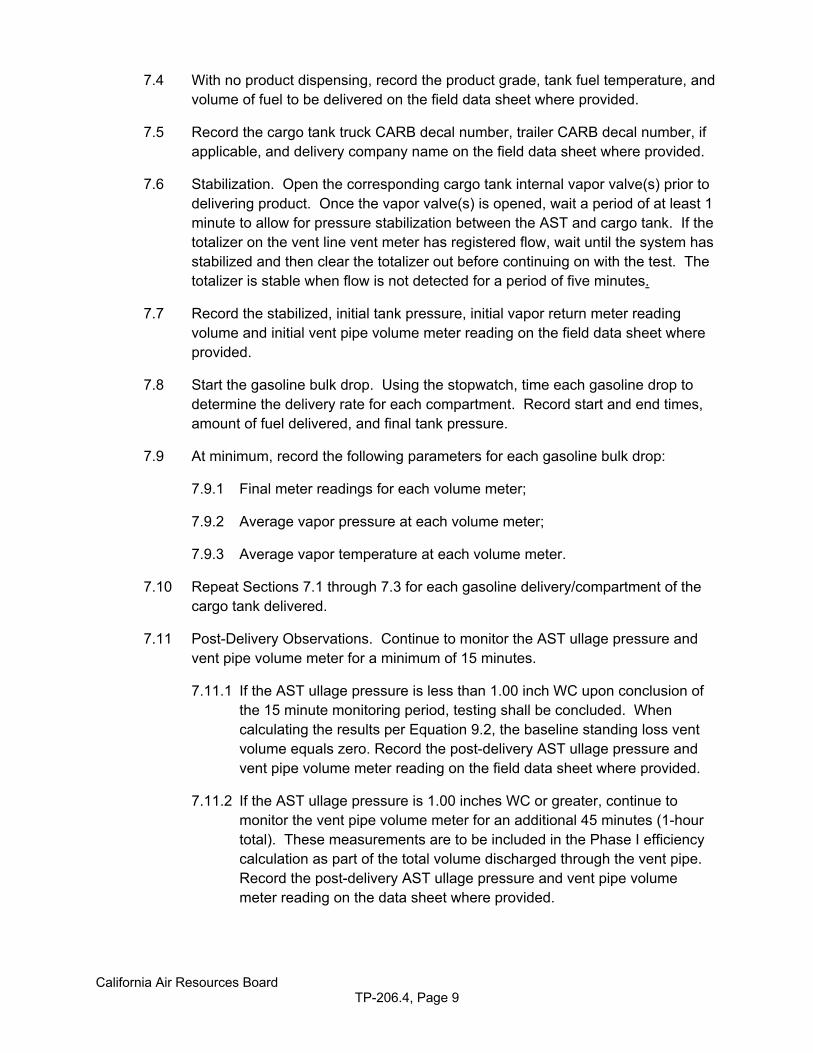
7.4 With no product dispensing, record the product grade, tank fuel temperature, and volume of fuel to be delivered on the field data sheet where provided.
7.5 Record the cargo tank truck CARB decal number, trailer CARB decal number, if applicable, and delivery company name on the field data sheet where provided.
7.6 Stabilization. Open the corresponding cargo tank internal vapor valve(s) prior to delivering product. Once the vapor valve(s) is opened, wait a period of at least 1 minute to allow for pressure stabilization between the AST and cargo tank. If the totalizer on the vent line vent meter has registered flow, wait until the system has stabilized and then clear the totalizer out before continuing on with the test. The totalizer is stable when flow is not detected for a period of five minutes.
7.7 Record the stabilized, initial tank pressure, initial vapor return meter reading volume and initial vent pipe volume meter reading on the field data sheet where provided.
7.8 Start the gasoline bulk drop. Using the stopwatch, time each gasoline drop to determine the delivery rate for each compartment. Record start and end times, amount of fuel delivered, and final tank pressure.
7.9 At minimum, record the following parameters for each gasoline bulk drop:
7.9.1 Final meter readings for each volume meter;
7.9.2 Average vapor pressure at each volume meter;
7.9.3 Average vapor temperature at each volume meter.
7.10 Repeat Sections 7.1 through 7.3 for each gasoline delivery/compartment of the cargo tank delivered.
7.11 Post-Delivery Observations. Continue to monitor the AST ullage pressure and vent pipe volume meter for a minimum of 15 minutes.
7.11.1 If the AST ullage pressure is less than 1.00 inch WC upon conclusion of the 15 minute monitoring period, testing shall be concluded. When calculating the results per Equation 9.2, the baseline standing loss vent volume equals zero. Record the post-delivery AST ullage pressure and vent pipe volume meter reading on the field data sheet where provided.
7.11.2 If the AST ullage pressure is 1.00 inches WC or greater, continue to monitor the vent pipe volume meter for an additional 45 minutes (1-hour total). These measurements are to be included in the Phase I efficiency calculation as part of the total volume discharged through the vent pipe. Record the post-delivery AST ullage pressure and vent pipe volume meter reading on the data sheet where provided.
California Air Resources Board TP-206.4, Page 10
8 POST TEST PROCEDURES
8.1 At conclusion of the bulk delivery, ensure that each of the cargo tank internal vapor valves is closed prior to removing connections.
8.2 Disconnect the vapor return hose from the outlet side of the vapor return meter.
8.3 Disconnect the vapor return meter(s) from the AST taking care to avoid venting ullage pressure.
8.4 Verify the quantity of gasoline delivered to each AST using the facility tank gauge monitor or with a manual tank gauging stick.
8.5 The static pressure integrity of the vapor recovery system as determined by TP-206.3 shall be verified no less than three hours after, but not more than 48 hours after completion of the fuel delivery. Failure of the static pressure integrity test shall invalidate the results from this test procedure.
8.6 Remove the temporary manifold (if constructed) and disconnect the vent pipe volume meter from the outlet of the PV-Zero.
8.7 If the PV-Zero is not the original pressure vacuum vent valve being utilized on the tank, then remove the PV-Zero and re-install the original pressure vacuum vent valve.
9 CALCULATING RESULTS
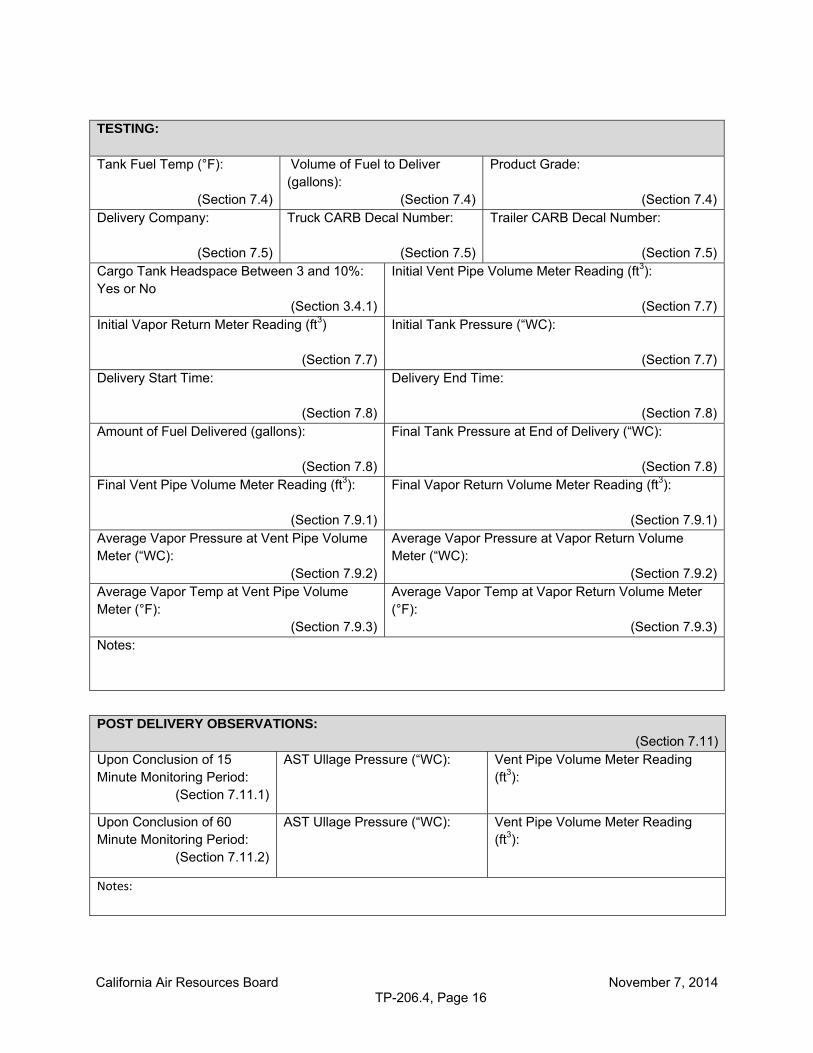
Record the following calculations and results on a field data sheet. An example field data sheet is provided at the end of the procedure: see “Form 1: TP-206.4 – Example Field Data Sheet.”
9.1 Baseline Standing Loss Vent Volume
The total baseline standing loss vent volume is the volume discharged through the vent pipe over a one-hour time frame directly prior to the fuel delivery. The value obtained from the vent pipe volume meter will be in cubic feet. To convert this volume to gallons, multiply by the conversion factor of 7.481 gallons/cubic feet.
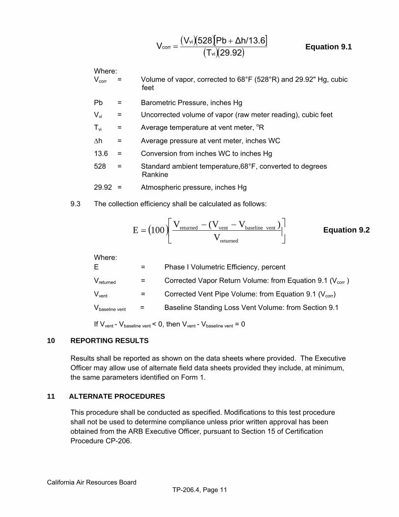
9.2 The measured volume of vapor passed through the vapor return volume meter to the cargo tank and the volume of vapor discharged through the vent pipe volume meter shall be corrected to standard conditions as follows:
California Air Resources Board TP-206.4, Page 11
29.92T
∆h/13.6Pb528VV
vi
vicorr
Where: Vcorr = Volume of vapor, corrected to 68°F (528°R) and 29.92" Hg, cubic feet Pb = Barometric Pressure, inches Hg
Vvi = Uncorrected volume of vapor (raw meter reading), cubic feet
Tvi = Average temperature at vent meter, oR
h = Average pressure at vent meter, inches WC
13.6 = Conversion from inches WC to inches Hg
528 = Standard ambient temperature,68°F, converted to degrees Rankine
29.92 = Atmospheric pressure, inches Hg
9.3 The collection efficiency shall be calculated as follows:
returned
ventbaselineventreturned
V
)VV(V100E
Where: E = Phase I Volumetric Efficiency, percent
Vreturned = Corrected Vapor Return Volume: from Equation 9.1 (Vcorr )
Vvent = Corrected Vent Pipe Volume: from Equation 9.1 (Vcorr)
Vbaseline vent = Baseline Standing Loss Vent Volume: from Section 9.1 If Vvent - Vbaseline vent < 0, then Vvent - Vbaseline vent = 0 10 REPORTING RESULTS
Results shall be reported as shown on the data sheets where provided. The Executive Officer may allow use of alternate field data sheets provided they include, at minimum, the same parameters identified on Form 1.
11 ALTERNATE PROCEDURES
This procedure shall be conducted as specified. Modifications to this test procedure shall not be used to determine compliance unless prior written approval has been obtained from the ARB Executive Officer, pursuant to Section 15 of Certification Procedure CP-206.
Equation 9.1
Equation 9.2
California Air Resources Board November 7, 2014 November 7, 2014
TP-206.4, Page 12
Figure 2
Vent Pipe Volume Meter and Vapor Return Volume Meter Arrangement for Direct-Fill Phase I EVR Systems for AST
California Air Resources Board November 7, 2014 TP-206.4, Page 13
Figure 3
Vent Pipe Volume Meter and Vapor Return Volume Meter Arrangement for Remote-Fill Phase I EVR Systems for AST
California Air Resources Board November 7, 2014
TP-206.4, Page 14
Figure 4
Example of a Steel Vent Pipe Manifold
California Air Resources Board November 7, 2014 TP-206.4, Page 15
Form 1: TP-206.4 - Example Field Data Sheet
DATE: ARB STAFF:
GASOLINE DISPENSING FACILITY DESCRIPTION:
Name: Location:
AMBIENT CONDITIONS:
(Section 6.4)Temperature (°F): Barometric (“Hg):
Notes:
PRE-TEST PROCEDURES:
Confirm PV-Zero Installed: Yes or No
(Section 6.1)
Confirm Vent Pipe Volume Meter Installed: Yes or No
(Section 6.2)Confirm Static Pressure Integrity Test Pass: Yes or No
(Section 6.3)
Tank Make/Model:
(Section 6.4)
Tank Capacity (gallons):
(Section 6.4)
Fuel Volume (gallons):
(Section 6.4) Ullage Volume (gallons):
(Section 6.4)
Ullage Between 20 and 80%: Yes or No
(Section 3.4.2)Stick Reading (inches):
(Section 6.4)
Initial Tank Pressure (“WC):
(Section 6.4) Phase I System Description:
(Section 6.4)
Notes:
ESTABLISH BASELINE STANDING LOSS VENT VOLUME:
(Section 7.1) Start Time:
End Time:
Initial Vent Pipe Volume Meter Reading (ft3):
Final Vent Pipe Volume Meter Reading (ft3):
Total Volume of Vapor Vented (ft3): Notes:
California Air Resources Board November 7, 2014 TP-206.4, Page 16
TESTING: Tank Fuel Temp (°F):
(Section 7.4)
Volume of Fuel to Deliver (gallons):
(Section 7.4)
Product Grade:
(Section 7.4) Delivery Company:
(Section 7.5)
Truck CARB Decal Number:
(Section 7.5)
Trailer CARB Decal Number:
(Section 7.5)Cargo Tank Headspace Between 3 and 10%: Yes or No
(Section 3.4.1)
Initial Vent Pipe Volume Meter Reading (ft3):
(Section 7.7)Initial Vapor Return Meter Reading (ft3)
(Section 7.7)
Initial Tank Pressure (“WC):
(Section 7.7)Delivery Start Time:
(Section 7.8)
Delivery End Time:
(Section 7.8)Amount of Fuel Delivered (gallons):
(Section 7.8)
Final Tank Pressure at End of Delivery (“WC):
(Section 7.8)Final Vent Pipe Volume Meter Reading (ft3):
(Section 7.9.1)
Final Vapor Return Volume Meter Reading (ft3):
(Section 7.9.1)Average Vapor Pressure at Vent Pipe Volume Meter (“WC):
(Section 7.9.2)
Average Vapor Pressure at Vapor Return Volume Meter (“WC):
(Section 7.9.2)Average Vapor Temp at Vent Pipe Volume Meter (°F):
(Section 7.9.3)
Average Vapor Temp at Vapor Return Volume Meter (°F):
(Section 7.9.3)Notes:
POST DELIVERY OBSERVATIONS: (Section 7.11)
Upon Conclusion of 15 Minute Monitoring Period:
(Section 7.11.1)
AST Ullage Pressure (“WC):
Vent Pipe Volume Meter Reading (ft3):
Upon Conclusion of 60 Minute Monitoring Period:
(Section 7.11.2)
AST Ullage Pressure (“WC):
Vent Pipe Volume Meter Reading (ft3):
Notes:
California Air Resources Board November 7, 2014 TP-206.4, Page 17
CALCULATIONS: Baseline Standing Loss Vent Volume (gallons):
(Section 9.1)Total Vent Pipe Volume Discharge During Delivery and Post Delivery Observation Period (cubic feet):
(Section 9.2)Collection Efficiency (% Phase I Volumetric Efficiency):
(Section 9.3)