Embed Size (px)
Citation preview
Type
V5-4011
V5-4015
V5-4018
V5-4022
V5-4030
V5-4037
V5-4045
V5-4055
W
230
290
375
D
120
180
230
L
420
450
581
D2
160
210
230
H
218
217
261
D3
400
430
551
L
H
H
MENUESC
ENTERDATA
FWDJOGREV
STOP
RESET
FWD REV ALM HZ V A
L
WD2
D3
D1
* STORED CHARGE DO NOT TOUCH UNTIL 10 MIN. AFTER DISCONNECTION
* RISK OF ELECTRIC SHOCK-DUAL SUPPLYDISCONNECT MAINS AND LOADSHARING
WARNING!
* DO NOT CONNECT AC POWER TO OUTPUT TERMINALS OF "U V W"
BEFORE SERVICE
V5 series 3-phase 11~55KW
VB3/VB5/V5 series general types of inverters
compatible motor power 0.4~55 kW
Excellent performance Stable and reliable
Xinje Electronic Co.,Ltd.4th Floor Building 7,Originality Park,100 Dicui Road,Wuxi City,JiangsuProvince , ChinaTel:0510-85166657 85123803Fax:0510-85111290Http://www.thinget.com、www.xinje.comE-mail:[email protected]
Open loop vector control for current obtains high torque at low speed, output torque can up to 100% of rated torque at 1 Hz.
The inverter stops running when reaching the preset length.
Swing frequency control
Group P9 is swing frequency parameters which are designed for textile, fiber and other industries need traverse and winding functions. Users can adjust the preset frequency and center frequency.
Auto-energy-saving running
Optimize the V/F curve according to the load conditions to fulfill energy-saving running.
Fixed-length control
Add vector control to enhance the performance
Perfect basic functions
Communication function
Exhaustive protection function
Human oriented design of the structure
3-phase 380 V inverters support vector control function. The inverters can read the motor information and match to the motors automatically in auto-learning mode.
4 Built-in PI adjustment functionIt is easy to build the closed-loop process control system, improvethe system precision.
5 Multi-speed running Implement the multi-speed running through the built-in PLC orcontrol terminals. Support up to 7 speeds.
Excellent
product performance
6 High speed pulse I/O Terminal X6 can input pulse up to 20 kHz which is used to control the pulse frequency;
Terminal DO can output pulse up to 20 kHz. Self-defined functions, PLC or other controllers can read the internal variable value of the inverter via frequency measurement.
7 Flexible I/O terminals The I/O can be defined as a variety of functions which makes the products easier to be controlled and more selections to be chosen.
8 On-line parameters modificationChange the parameters without stopping the inverter which makes the operation more convenient.
9 Speed tracking function If needs to startup the motor again when the motor is about to stop, the inverter can track the current speed and startup it without impact.
Users can set the frequency through panel potentiometer,numerickeyboard, terminal UP/DOWN, analog terminal VI/CI, pulse, combination and serial port remote setting.
Brake unit
1 High starting torque
2 Auto-learning
11
12
13
14
RS-485 interface supports Modbus-RTU protocol.
Support master-slave multi-machine linkage function.
17
18
overcurrent protection
overvoltage protection
undervoltage protection
overheat protection: inverter will lock the output and stop freely when overheating
overload protection: inverter will lock the output and stop freely when overloading
19
20
21
22
23
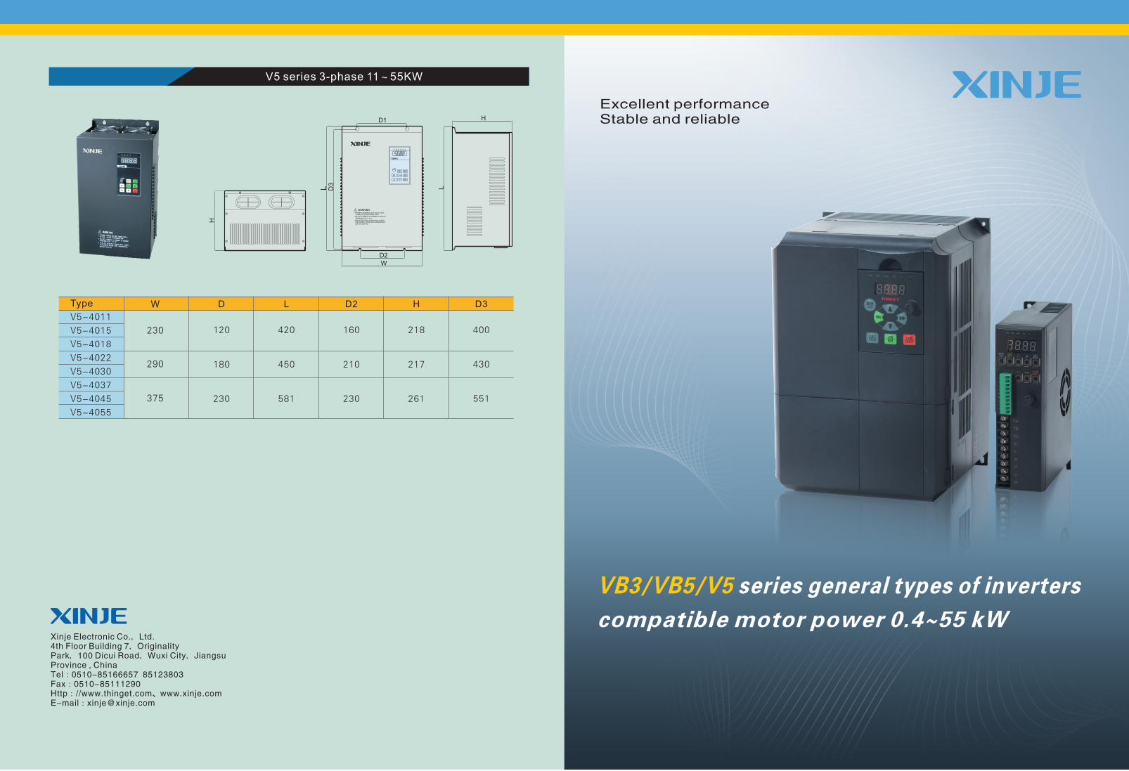
The installation environment is compliant to IP20
Compact volume, space saving, can be installed side by side seamlessly
24
25
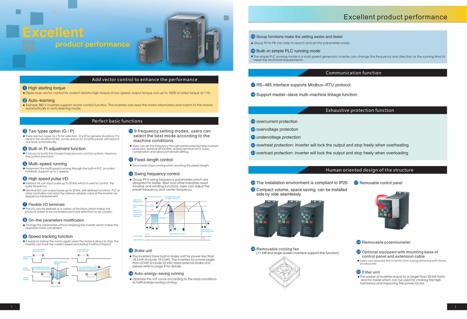
Removable cooling fan (11 kW and larger power inverters support this function)
26
Removable control panel27
Users can operate the inverter from a long distance with these accessories
The power of inverters equal to or larger than 30 kW have reactor inside which can be used for choking the high harmonics and improving the power factor.
Removable potentiometer
Optional equipped with mounting base of control panel and extension cable
Filter unit
28
29
30
There are two types (G / P) for selection. G is fit for general situations. P is ideal in the situation of fan, pump and so on. Inverter power will improve one level automatically.
3 Two types option (G / P)
The inverters have built-in brake unit for power less than 18.5 kW (include 18.5 kW). The inverters for power larger than 22 kW (include 22 kW) need external brake unit, please refer to page 8 for details.
Group functions make the setting easier and faster
Group P0 to PB can help to search and set the parameters easily.
Built-in simple PLC running mode
15
16
The simple PLC running mode is a multi-speed generator; inverter can change the frequency and direction as the running time tomeet the technical requirements.
9 frequency setting modes, users can select the best mode according to the machine conditions
10
Excellent product performance
1 2
Input power supply
max permissible power-off time
max permissible power-off time
output frequency
output voltage
the inverter tracks down the speed from power-off
the inverter follows up the speed from the start frequency
Speed synchronous detection
B.B. time
speed search
B.B. time
upper limit frequency PH
center frequencyPset
lower limit frequency PL
preset swing frequency
running frequency Pz swing frequency widthAw=Pset x P9.04
textile snap frequency= Aw x P9.05
startup waiting timeP9.03
accelerate as acceleration time
swing frequency period
decelerate as deceleration time
time1
run command
stop command
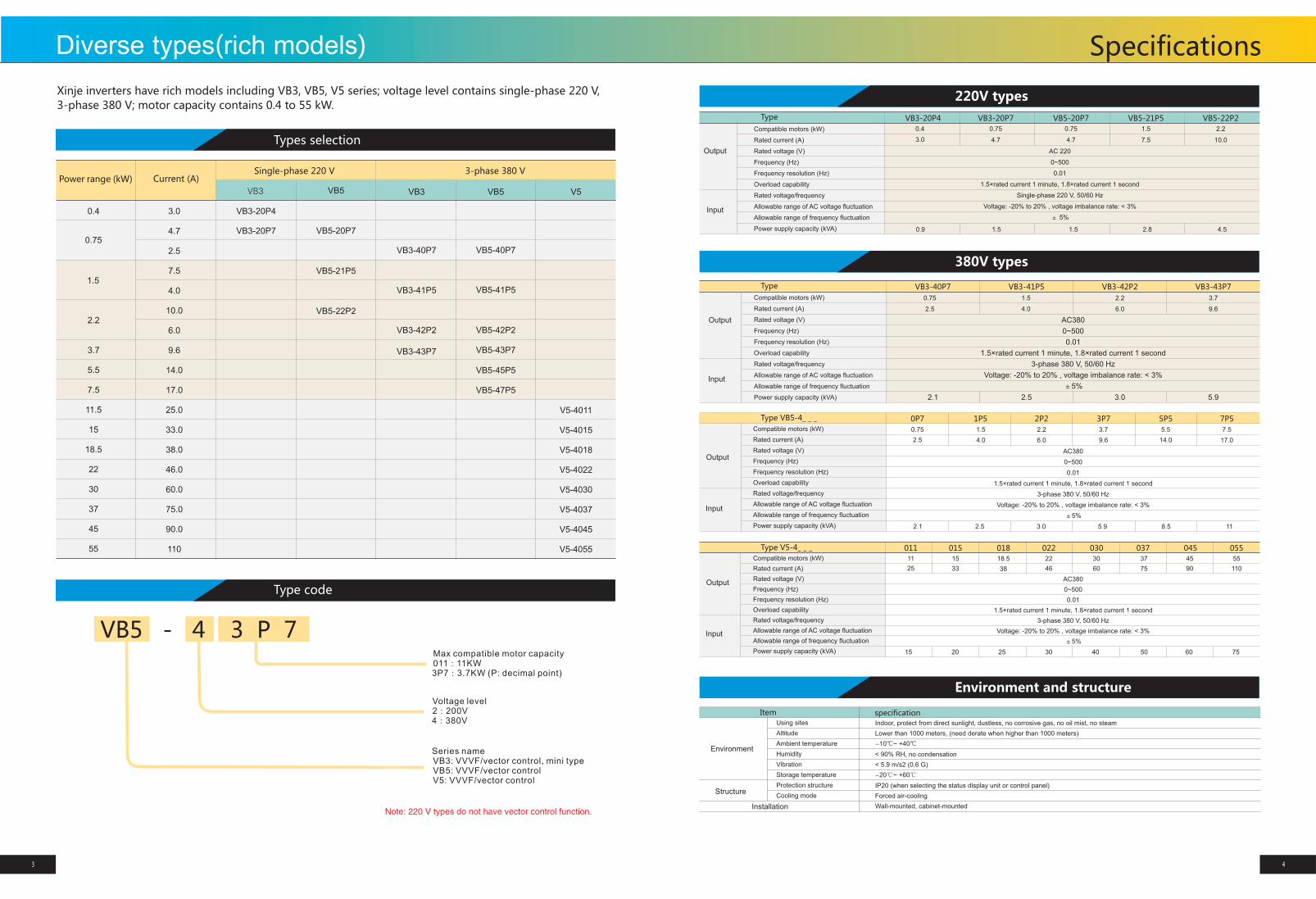
Xinje inverters have rich models including VB3, VB5, V5 series; voltage level contains single-phase 220 V,
3-phase 380 V; motor capacity contains 0.4 to 55 kW.
Power range (kW) Current (A)
0.4
0.75
1.5
2.2
3.7
5.5
7.5
11.5
15
18.5
22
30
37
45
55
3.0
4.7
2.5
7.5
4.0
10.0
6.0
9.6
14.0
17.0
25.0
33.0
38.0
46.0
60.0
75.0
90.0
110
Single-phase 220 V 3-phase 380 V
VB3
VB3-20P4
VB3-20P7
VB5
VB5-21P5
VB5-22P2
VB5-20P7
VB3
VB3-40P7
VB3-41P5
VB3-42P2
VB3-43P7
VB5
VB5-40P7
VB5-41P5
VB5-42P2
VB5-43P7
VB5-45P5
VB5-47P5
V5
V5-4011
V5-4015
V5-4018
V5-4022
V5-4030
V5-4037
V5-4045
V5-4055
VB5 - 4 3 P 7
Series name VB3: VVVF/vector control, mini type VB5: VVVF/vector control V5: VVVF/vector control
Voltage level 2:200V 4:380V
Max compatible motor capacity 011:11KW 3P7:3.7KW (P: decimal point)
Note: 220 V types do not have vector control function.
Compatible motors (kW)
Rated current (A)
Rated voltage (V)
Frequency (Hz)
Frequency resolution (Hz)
Overload capability
Rated voltage/frequency
Allowable range of AC voltage fluctuation
Allowable range of frequency fluctuation
Power supply capacity (kVA)
Type
Output
Input
VB3-20P4 VB3-20P7 VB5-20P7 VB5-22P2
0.4
3.0
0.75
4.7
0.75
4.7
2.2
10.0
AC 220
0~500
0.01
1.5×rated current 1 minute, 1.8×rated current 1 second
Single-phase 220 V, 50/60 Hz
Voltage: -20% to 20% , voltage imbalance rate: < 3%
± 5%
0.9 1.5 2.8 4.5
Type VB5-4_ _ _
VB3-40P7 VB3-41P5 VB3-42P2 VB3-43P7
0.75
2.5
AC380
0~500
0.01
3-phase 380 V, 50/60 Hz
±5%
1.5×rated current 1 minute, 1.8×rated current 1 second
Voltage: -20% to 20% , voltage imbalance rate: < 3%
2.1 2.5 3.0 5.9
0P7 1P5 2P2 3P7 5P5 7P5
0.75
2.5
2.1 2.5 3.0 5.9 8.5 11
1.5
4.0
1.5
4.0
2.2
6.0
3.7
9.6
2.2
6.0
3.7
9.6
5.5
14.0
7.5
17.0
Type V5-4_ _ _ 011 015 018 022 030 045 055037
11
25
15
33
18.5
38
30
60
22
46
37
75
45
90
55
110
15 20 25 30 40 50 60 75
Item
Using sites
Altitude
Ambient temperature
Humidity
Vibration
Storage temperature
Protection structure
Cooling mode
Environment
Structure
Installation
specification
Indoor, protect from direct sunlight, dustless, no corrosive gas, no oil mist, no steam
Lower than 1000 meters, (need derate when higher than 1000 meters)
< 90% RH, no condensation
< 5.9 m/s2 (0.6 G)
-20℃ ~ +60℃
IP20 (when selecting the status display unit or control panel)
Forced air-cooling
Wall-mounted, cabinet-mounted
-10℃~ +40℃
信捷变频产品选型表Types selection
Type code
220V types
380V types
Environment and structure
SpecificationsDiverse types(rich models)
VB5-21P5
1.5
7.5
1.5
3 4
Output
Input
Compatible motors (kW)
Rated current (A)
Rated voltage (V)
Frequency (Hz)
Frequency resolution (Hz)
Overload capability
Rated voltage/frequency
Allowable range of AC voltage fluctuation
Allowable range of frequency fluctuation
Power supply capacity (kVA)
Output
Input
Type
Compatible motors (kW)
Rated current (A)
Rated voltage (V)
Frequency (Hz)
Frequency resolution (Hz)
Overload capability
Rated voltage/frequency
Allowable range of AC voltage fluctuation
Allowable range of frequency fluctuation
Power supply capacity (kVA)
AC380
0~500
0.01
3-phase 380 V, 50/60 Hz
±5%
1.5×rated current 1 minute, 1.8×rated current 1 second
Voltage: -20% to 20% , voltage imbalance rate: < 3%
Output
Input
Compatible motors (kW)
Rated current (A)
Rated voltage (V)
Frequency (Hz)
Frequency resolution (Hz)
Overload capability
Rated voltage/frequency
Allowable range of AC voltage fluctuation
Allowable range of frequency fluctuation
Power supply capacity (kVA)
AC380
0~500
0.01
3-phase 380 V, 50/60 Hz
±5%
1.5×rated current 1 minute, 1.8×rated current 1 second
Voltage: -20% to 20% , voltage imbalance rate: < 3%
Item Specification
LED digital display
External meter display
Key lock
Protection function
Accessories
Co
ntro
l fun
ctio
ns
Ru
nn
ing
fun
ctio
ns
Control
panel
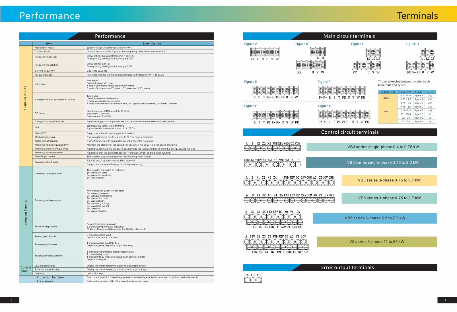
Figure A
The relationship between main circuit
terminals and types:
Voltage level
220V
380V
Power (kW)
0.4~0.75
0.75~2.2
0.75~3.7
0.75~3.7
5.5~7.5
11~18.5
22~30
37~55
Figure
figure A
figure B
figure C
figure D
figure E
figure F
figure G
figure H
Series
VB3
VB5
VB3
VB5
VB5
V5
V5
V5
Performance
VB3 series single-phase 0.4 to 0.75 kW
VB5 series single-phase 0.75 to 2.2 kW
TA TB TC
Main circuit terminals
Control circuit terminals
Error output terminals
Performance
5 6
Modulation mode
Control mode
Frequency accuracy
Frequency resolution
Startup frequency
Torque increase
V/F curve
Acceleration and deceleration curves
DC brake
Energy consumption brake
Jog
Built-in PID
Multi-speed running
Textile swing frequency
Automatic voltage regulation (AVR)
Automatic energy-saving running
Automatic current restriction
Fixed-length control
Communication function
Command running channel
Frequency setting channel
Switch setting channel
Analog input channel
Analog output channel
Switch/pulse output channel
Space voltage vector modulation SVPWM
Optimal vector control (Optimal low-frequency dead zone compensation)
Digital setting: the highest frequency × ±0.01%Analog setting: the highest frequency × ±0.2%
Digital setting: 0.01 HzAnalog setting: the highest frequency × 0.1%
0.40 Hz to 20.00 Hz
Automatic increase the torque, manual increase the torque by 0.1% to 30.0%
Five modesConstant torque V/F curve1 kind of user-defined multi-segment V/F curve
nd th nd3 kinds of torque curve (2 power, 1.7 power, and 1.2 power)
Two modesLinear acceleration/decelerationS curve acceleration/deceleration7 kinds of acceleration/deceleration time, unit options: minute/second, up to 6000 minutes
Start frequency of DC brake: 0 to 15.00 HzBrake time: 0 to 60.0 sBrake current: 0 to 80%
Built-in energy consumption brake unit, enable to connect external brake resistor
Jog frequency range: 0.1 to 50.00 HzJog acceleration/deceleration time: 0.1 to 60.0 s
Easy to form the closed loop control system
Run in multi-speed mode via built-in PLC or control terminals
Swing frequency with adjustable preset and center frequency
Maintain the stability of the output voltage when the power line voltage is changing
Automatic optimize the V/F curve according to the load condition to fulfill the energy-saving running
Automatic limit the current to prevent from overcurrent and trip when running
The inverter stops running when reaches the preset length
RS-485 port, support Modbus-RTU protocol
Support master-slave linkage function (developing)
Three modes can switch to each otherSet via control panelSet via control terminalsSet via serial port
Nine modes can switch to each otherSet via potentiometerSet via Up/Down buttonsSet via function codeSet via serial portSet via analog voltageSet via analog currentSet via pulseSet via combination
Forward/backward command6 channels programmable digital input35 kinds of functions (X6 supports 0 to 20 kHz pulse input)
2 channels analog inputOptions: 4 to 20 mA / 0 to 10 V
1 channel analog input 0 to 10 VOutput the preset frequency, output frequency
1 channel programmable open collector output1 channel relay output1 channel 0 to 20 kHz pulse output (open collector signal)Output multi-signal
Display the preset frequency, output voltage, output current
Display the output frequency, output current, output voltage
Lock all the keys
Overcurrent protection, overvoltage protection, undervoltage protection, overheat protection, overload protection
Brake unit, extension cable of the control panel, control panel
Figure B Figure C Figure D
Figure E Figure F
Figure G Figure H
VB3 series 3-phase 0.75 to 3.7 kW
VB5 series 3-phase 0.75 to 3.7 kW
VB5 series 3-phase 5.5 to 7.5 kW
V5 series 3-phase 11 to 55 kW
Terminals
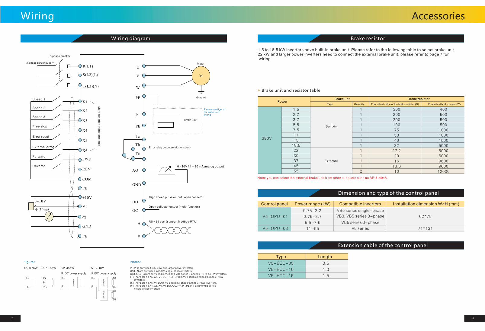
R(L1)
S(L2)(L)
T(L3)(N)
U
V
W
M
X1
X2
X3
X4
X5
X6
FWD
REV
COM
Ta
Tb
Tc
P+
PB
+10V
VI
CI
GND
OC
DO
Open collector output (multi-function)
High speed pulse output / open collector
A
B
GND
AO
Error relay output (multi-function)
RS-485 port (support Modbus-RTU)
0 - 10V / 4 – 20 mA analog output
Brake unit
0~10V
4~20mA
Motor
Ground
3-phase breaker
3-phase power supply
PE
(1) P- is only used in 5.5 kW and larger power inverters.
(2) L, N are only used in 220 V single-phase inverters.(3) L1, L2, L3 are only used in VB3 and VB5 series 3-phase 0.75 to 3.7 kW inverters.(4) There are no X5, X6, VI, DO, P+, P-, PB in VB3 series 3-phase 0.75 to 3.7 kW inverters.(5) There are no X5, VI, DO in VB5 series 3-phase 0.75 to 3.7 kW inverters.(6) There are no X4, X5, X6, VI, DO, OC, P+, P-, PB in VB3 and VB5 series single-phase inverters.
Mu
lti-fun
ctio
n in
pu
t term
ina
ls
Speed 1
Free stop
PE
PE
Wiring diagram
Brake resistor
1.5 to 18.5 kW inverters have built-in brake unit. Please refer to the following table to select brake unit.22 kW and larger power inverters need to connect the external brake unit, please refer to page 7 for wiring.
Brake unit and resistor table
380V
1.5
2.2
3.7
5.5
7.5
11
15
18.5
22
30
37
45
55
1
1
1
1
1
1
1
1
1
1
1
1
2
300
200
200
100
75
50
40
32
27.2
20
16
13.6
10
400
500
500
500
1000
1000
1500
5000
5000
6000
9600
9600
12000
V5-ECC-05
V5-ECC-10
V5-ECC-15
Type Length
0.5
1.0
1.5
Dimension and type of the control panel
Extension cable of the control panel
Control panel
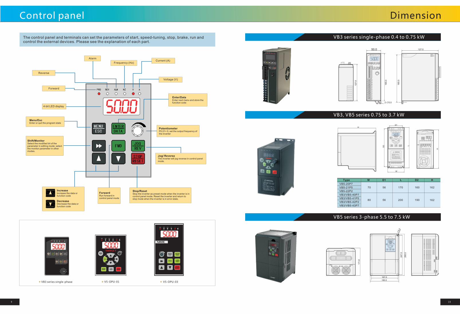
V5-OPU-01
V5-OPU-03
0.75~3.7
5.5~7.5
11~55
62*75
71*131
Please see figure1for brake unit wiring
Figure1 Notes:
7 8
Note: you can select the external brake unit from other suppliers such as BRU-4045.
0.75~2.2
VB5 series single-phase
Wiring
Speed 2
Speed 3
Error reset
External error
Forward
Reverse
P+
PB
P+
PB
P-
P+
P-
P+
P-
B1
B2
B1
B2
P1DC power supply
1.5~3.7KW 5.5~18.5KW
P1DC power supply
bra
ke u
nit
bra
ke u
nit
bra
ke u
nit
22~45KW 55~75KW
PowerBrake unit
Type
Built-in
Quantity
Brake resistor
External
Equivalent value of the brake resistor (Ω) Equivalent brake power (W)
Power range (kW) Compatible inverters Installation dimension W×H (mm)
VB3, VB5 series 3-phase
VB5 series 3-phase
V5 series
Accessories
VB3 series single-phase 0.4 to 0.75 kW
FWD REW ALM HZ V A
MENU
ESC
ENTER
ESC
JOG
REV
STOP
RESET
FWDSTOP
RESETFWD
ENT
DATA
JOG
REV
MENU
ESC
FWD REV ALM HZ V A
The control panel and terminals can set the parameters of start, speed-tuning, stop, brake, run and control the external devices. Please see the explanation of each part.
FWD REW ALM HZ V A
FWD
MENU
ESC
ENTER
DATAJOG
REVSTOP
RESET
Alarm
Reverse
Current (A)
Forward
VB3 series single-phase V5-OPU-01 V5-OPU-03
H
U V WP+ PB
TATBTCL1 L3
L NL2
H
L
W
D2
D1
MENUESC
FWD
ENTDATA
JOGREV
STOPRESET
FWD REV ALM HZ V A
WARNING!
* STORED CHARGE DO NOT TOUCHUNTIL 10 MIN. AFTER DISCO-
* RISK OF ELECTRIC SHOCK-DUALSUPPLY DISCONNECT MAINS AND
* DO NOT CONNECT AC POWER TOOUTPUT TERMINALS OF "U V W"
LOADSHARING BEFORE SERVICE
NNECTION
FWD REV ALM HZ V A
127.0
165.0
127.0
TA
TB
PE
RS
TU
VW
165.0
50.0
2-∅5.0
MENUESC
JOGREV
ENTDATA
FWDSTOPRESET
FWD REV ALM HZ V A
Type W D1 L D2 H
VB5-20P7
VB5-21P5
VB5-22P2
VB3/VB5-40P7
VB3/VB5-41P5
VB3/VB5-42P2
VB3/VB5-43P7
70
80
56
56
170
200
160
190
162
162
VB3, VB5 series 0.75 to 3.7 kW
171.8
MENUESC
FWD
ENTDATA
JOGREV
STOPRESET
FWD REV ALM HZ V A
167.0
260.0
247.5
∅5.
0
180.0
VB5 series 3-phase 5.5 to 7.5 kW
DimensionControl panel
9 10
4-bit LED display
Menu/EscEnter or quit the program state
Shift/MonitorSelect the modified bit of the parameter in editing mode; selectthe monitor parameter in other modes.
IncreaseIncrease the data or function code
DecreaseDecrease the data or function code
ForwardRun forward in control panel mode
Stop/ResetStop the inverter as preset mode when the inverter is in control panel mode. Reset the inverter and return to stop mode when the inverter is in error state.
Jog/ ReverseThe inverter will jog reverse in control panel mode.
PotentiometerP0.01= 0, set the output frequency ofthe inverter
Enter/DataEnter next menu and store the function code
Voltage (V)
Frequency (Hz)