Embed Size (px)
Citation preview
www.vce.com
VCE Vblock® and VxBlock™Systems 540Architecture Overview
Document revision 1.7
April 2016
Revision history
Date Document revision Description of changes
April 2016 1.7 Updated to include the followingCisco switches:
• Cisco Nexus 3172TQ Switch
February 2016 1.6 Updated to include the following:
• 8 EMC X-Bricks, 20 TB
• 6 and 8 EMC X-Bricks, 40 TB
November 2015 1.5 Updated to include 40 TB EMC X-Brick
October 2015 1.4 Updated to include VMware vSphere6.0 with Cisco Nexus 1000V Switch
August 2015 1.3 Updated to include VxBlockSystems. Added support for VMwarevSphere 6.0 with VMware VDS onthe VxBlock System and for existingVblock Systems.
February 2015 1.2 Updated Intelligent PhysicalInfrastructure appliance information.
December 2014 1.1 Updates to Vblock System 540 Gen2.0
October 2014 1.0 Initial version
VCE Vblock® and VxBlock™ Systems 540 Architecture Overview Revision history
2© 2014-2016 VCE Company, LLC.
All Rights Reserved.
Contents
Introduction.................................................................................................................................................5
Accessing VCE documentation.................................................................................................................6
System overview.........................................................................................................................................7System architecture and components.................................................................................................... 7Base configurations and scaling.............................................................................................................9Connectivity overview...........................................................................................................................12
Network topology........................................................................................................................... 12
Compute layer overview...........................................................................................................................15Compute overview................................................................................................................................15Cisco Unified Computing System.........................................................................................................15Cisco UCS fabric interconnects............................................................................................................16Cisco Trusted Platform Module............................................................................................................ 16VCE bare metal support policy.............................................................................................................16Disjoint layer 2 configuration................................................................................................................ 17
Storage layer overview.............................................................................................................................19Storage layer hardware........................................................................................................................ 19EMC XtremIO storage arrays............................................................................................................... 19EMC XtremIO storage array configurations and capacities................................................................. 22EMC XtremIO storage array physical specifications............................................................................ 23
Network layer overview............................................................................................................................25Network layer hardware....................................................................................................................... 25Port utilization.......................................................................................................................................26
Cisco Nexus 3172TQ Switch - management networking...............................................................26Cisco Nexus 3064-T Switch - management networking................................................................ 27Cisco Nexus 5548UP Switch......................................................................................................... 28Cisco Nexus 5596UP Switch......................................................................................................... 28Cisco Nexus 9396PX Switch......................................................................................................... 29Cisco MDS 9148S Multilayer Fabric Switch...................................................................................29
Virtualization layer overview....................................................................................................................31Virtualization components.................................................................................................................... 31VMware vSphere Hypervisor ESXi.......................................................................................................31VMware vCenter Server....................................................................................................................... 32
Management..............................................................................................................................................35Management components overview.....................................................................................................35Management hardware components....................................................................................................35
Contents VCE Vblock® and VxBlock™ Systems 540 Architecture Overview
3© 2014-2016 VCE Company, LLC.
All Rights Reserved.
Management software components..................................................................................................... 36Management network connectivity....................................................................................................... 37
System infrastructure...............................................................................................................................39Cabinets overview................................................................................................................................ 39Intelligent Physical Infrastructure appliance......................................................................................... 39Cabinet types....................................................................................................................................... 39Power options.......................................................................................................................................40
Sample configurations............................................................................................................................. 42Sample VCE Systems with EMC XtremIO........................................................................................... 42
Additional references............................................................................................................................... 47Virtualization components.................................................................................................................... 47Compute components.......................................................................................................................... 47Network components............................................................................................................................47Storage components............................................................................................................................ 48
VCE Vblock® and VxBlock™ Systems 540 Architecture Overview Contents
4© 2014-2016 VCE Company, LLC.
All Rights Reserved.
IntroductionThis document describes the high-level design of the VCE System. This document also describes thehardware and software components that VCE includes in the VCE System.
In this document, the Vblock System and VxBlock System are referred to as VCE Systems.
The VCE Glossary provides terms, definitions, and acronyms that are related to VCE.
To suggest documentation changes and provide feedback on this book, send an e-mail to [email protected]. Include the name of the topic to which your feedback applies.
Introduction VCE Vblock® and VxBlock™ Systems 540 Architecture Overview
5© 2014-2016 VCE Company, LLC.
All Rights Reserved.
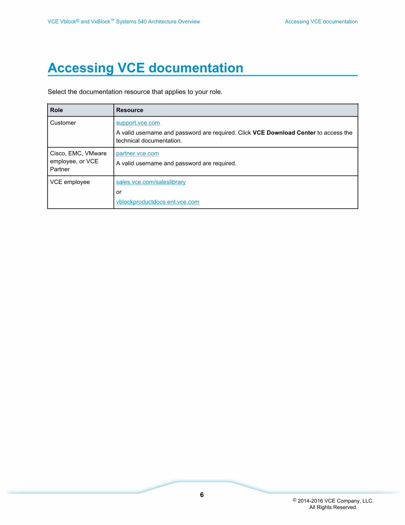
Accessing VCE documentationSelect the documentation resource that applies to your role.
Role Resource
Customer support.vce.com
A valid username and password are required. Click VCE Download Center to access thetechnical documentation.
Cisco, EMC, VMwareemployee, or VCEPartner
partner.vce.com
A valid username and password are required.
VCE employee sales.vce.com/saleslibrary
or
vblockproductdocs.ent.vce.com
VCE Vblock® and VxBlock™ Systems 540 Architecture Overview Accessing VCE documentation
6© 2014-2016 VCE Company, LLC.
All Rights Reserved.
System overview
System architecture and componentsVCE Systems are modular platforms with defined scale points that meet the higher performance andavailability requirements of an enterprise's business-critical applications.
Refer to the VCE Systems Physical Planning Guide for information about cabinets and their components,the Intelligent Physical Infrastructure solution, and environmental, security, power, and thermalmanagement.
VCE Systems are designed for deployments involving large numbers of VMs and users. VCE Systemsprovide the following features:
• Deliver a multi-controller, scale-out architecture with consolidation and efficiency for theenterprise
• Allow scaling of resources through common and fully redundant building blocks
• Use a SAN storage medium
Note: Local boot disks are optional and available only for bare metal blades
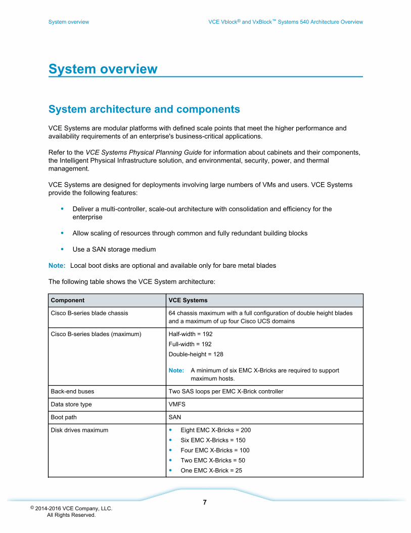
The following table shows the VCE System architecture:
Component VCE Systems
Cisco B-series blade chassis 64 chassis maximum with a full configuration of double height bladesand a maximum of up four Cisco UCS domains
Cisco B-series blades (maximum) Half-width = 192
Full-width = 192
Double-height = 128
Note: A minimum of six EMC X-Bricks are required to supportmaximum hosts.
Back-end buses Two SAS loops per EMC X-Brick controller
Data store type VMFS
Boot path SAN
Disk drives maximum • Eight EMC X-Bricks = 200
• Six EMC X-Bricks = 150
• Four EMC X-Bricks = 100
• Two EMC X-Bricks = 50
• One EMC X-Brick = 25
System overview VCE Vblock® and VxBlock™ Systems 540 Architecture Overview
7© 2014-2016 VCE Company, LLC.
All Rights Reserved.
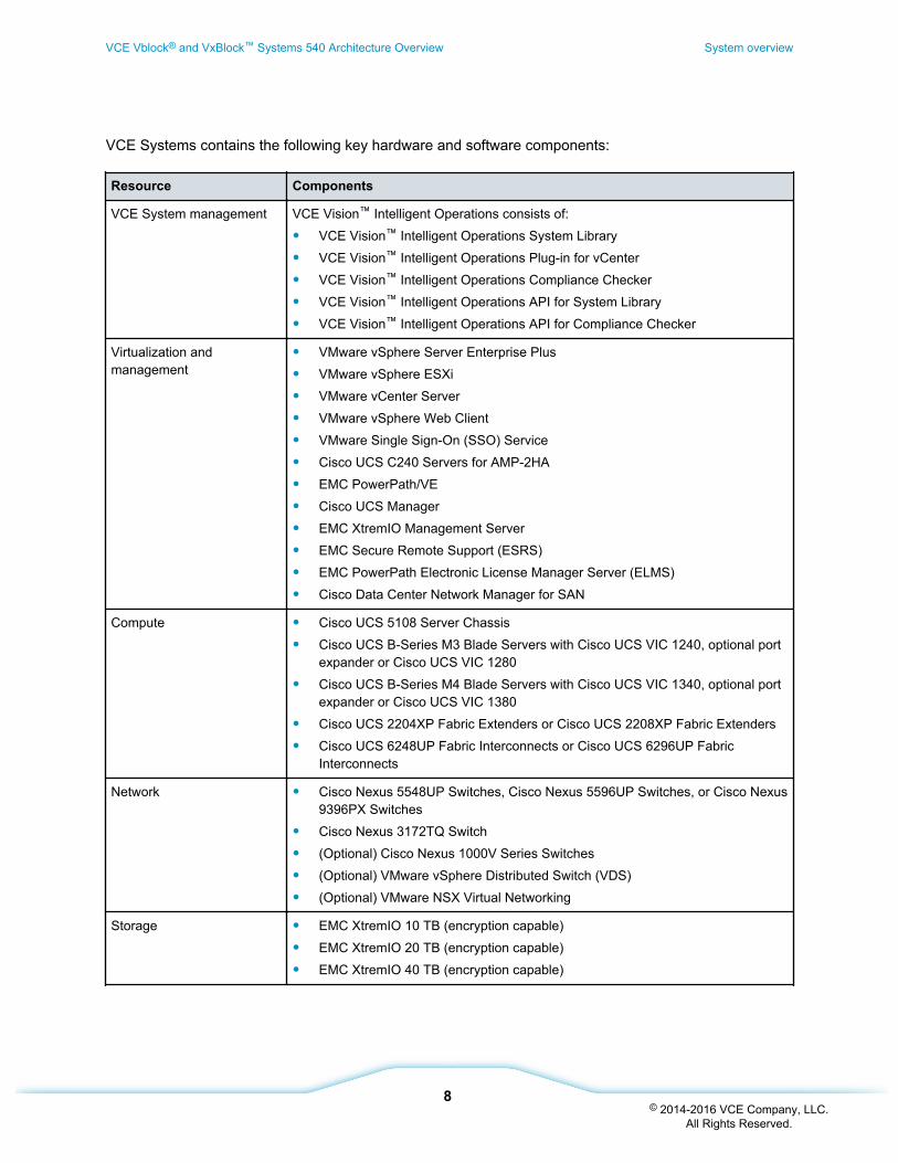
VCE Systems contains the following key hardware and software components:
Resource Components
VCE System management VCE Vision™ Intelligent Operations consists of:
• VCE Vision™ Intelligent Operations System Library
• VCE Vision™ Intelligent Operations Plug-in for vCenter
• VCE Vision™ Intelligent Operations Compliance Checker
• VCE Vision™ Intelligent Operations API for System Library
• VCE Vision™ Intelligent Operations API for Compliance Checker
Virtualization andmanagement
• VMware vSphere Server Enterprise Plus
• VMware vSphere ESXi
• VMware vCenter Server
• VMware vSphere Web Client
• VMware Single Sign-On (SSO) Service
• Cisco UCS C240 Servers for AMP-2HA
• EMC PowerPath/VE
• Cisco UCS Manager
• EMC XtremIO Management Server
• EMC Secure Remote Support (ESRS)
• EMC PowerPath Electronic License Manager Server (ELMS)
• Cisco Data Center Network Manager for SAN
Compute • Cisco UCS 5108 Server Chassis
• Cisco UCS B-Series M3 Blade Servers with Cisco UCS VIC 1240, optional portexpander or Cisco UCS VIC 1280
• Cisco UCS B-Series M4 Blade Servers with Cisco UCS VIC 1340, optional portexpander or Cisco UCS VIC 1380
• Cisco UCS 2204XP Fabric Extenders or Cisco UCS 2208XP Fabric Extenders
• Cisco UCS 6248UP Fabric Interconnects or Cisco UCS 6296UP FabricInterconnects
Network • Cisco Nexus 5548UP Switches, Cisco Nexus 5596UP Switches, or Cisco Nexus9396PX Switches
• Cisco Nexus 3172TQ Switch
• (Optional) Cisco Nexus 1000V Series Switches
• (Optional) VMware vSphere Distributed Switch (VDS)
• (Optional) VMware NSX Virtual Networking
Storage • EMC XtremIO 10 TB (encryption capable)
• EMC XtremIO 20 TB (encryption capable)
• EMC XtremIO 40 TB (encryption capable)
VCE Vblock® and VxBlock™ Systems 540 Architecture Overview System overview
8© 2014-2016 VCE Company, LLC.
All Rights Reserved.
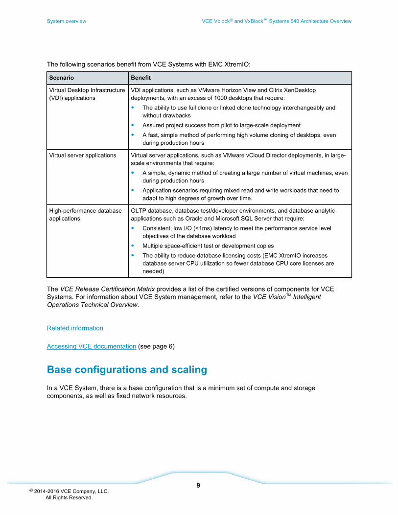
The following scenarios benefit from VCE Systems with EMC XtremIO:
Scenario Benefit
Virtual Desktop Infrastructure(VDI) applications
VDI applications, such as VMware Horizon View and Citrix XenDesktopdeployments, with an excess of 1000 desktops that require:
• The ability to use full clone or linked clone technology interchangeably andwithout drawbacks
• Assured project success from pilot to large-scale deployment
• A fast, simple method of performing high volume cloning of desktops, evenduring production hours
Virtual server applications Virtual server applications, such as VMware vCloud Director deployments, in large-scale environments that require:
• A simple, dynamic method of creating a large number of virtual machines, evenduring production hours
• Application scenarios requiring mixed read and write workloads that need toadapt to high degrees of growth over time.
High-performance databaseapplications
OLTP database, database test/developer environments, and database analyticapplications such as Oracle and Microsoft SQL Server that require:
• Consistent, low I/O (<1ms) latency to meet the performance service levelobjectives of the database workload
• Multiple space-efficient test or development copies
• The ability to reduce database licensing costs (EMC XtremIO increasesdatabase server CPU utilization so fewer database CPU core licenses areneeded)
The VCE Release Certification Matrix provides a list of the certified versions of components for VCESystems. For information about VCE System management, refer to the VCE Vision™ IntelligentOperations Technical Overview.
Related information
Accessing VCE documentation (see page 6)
Base configurations and scalingIn a VCE System, there is a base configuration that is a minimum set of compute and storagecomponents, as well as fixed network resources.
System overview VCE Vblock® and VxBlock™ Systems 540 Architecture Overview
9© 2014-2016 VCE Company, LLC.
All Rights Reserved.
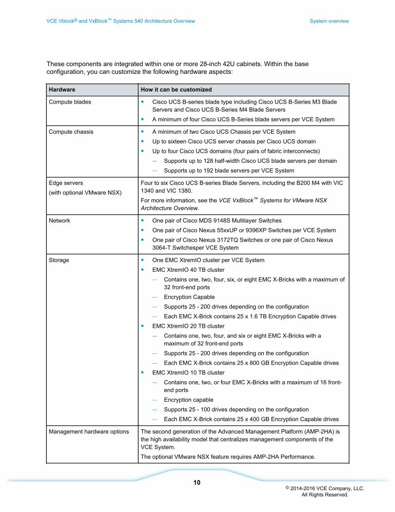
These components are integrated within one or more 28-inch 42U cabinets. Within the baseconfiguration, you can customize the following hardware aspects:
Hardware How it can be customized
Compute blades • Cisco UCS B-series blade type including Cisco UCS B-Series M3 BladeServers and Cisco UCS B-Series M4 Blade Servers
• A minimum of four Cisco UCS B-Series blade servers per VCE System
Compute chassis • A minimum of two Cisco UCS Chassis per VCE System
• Up to sixteen Cisco UCS server chassis per Cisco UCS domain
• Up to four Cisco UCS domains (four pairs of fabric interconnects)— Supports up to 128 half-width Cisco UCS blade servers per domain— Supports up to 192 blade servers per VCE System
Edge servers
(with optional VMware NSX)
Four to six Cisco UCS B-series Blade Servers, including the B200 M4 with VIC1340 and VIC 1380.
For more information, see the VCE VxBlock™ Systems for VMware NSXArchitecture Overview.
Network • One pair of Cisco MDS 9148S Multilayer Switches
• One pair of Cisco Nexus 55xxUP or 9396XP Switches per VCE System
• One pair of Cisco Nexus 3172TQ Switches or one pair of Cisco Nexus3064-T Switchesper VCE System
Storage • One EMC XtremIO cluster per VCE System
• EMC XtremIO 40 TB cluster— Contains one, two, four, six, or eight EMC X-Bricks with a maximum of
32 front-end ports— Encryption Capable— Supports 25 - 200 drives depending on the configuration— Each EMC X-Brick contains 25 x 1.6 TB Encryption Capable drives
• EMC XtremIO 20 TB cluster— Contains one, two, four, and six or eight EMC X-Bricks with a
maximum of 32 front-end ports— Supports 25 - 200 drives depending on the configuration— Each EMC X-Brick contains 25 x 800 GB Encryption Capable drives
• EMC XtremIO 10 TB cluster— Contains one, two, or four EMC X-Bricks with a maximum of 16 front-
end ports— Encryption capable— Supports 25 - 100 drives depending on the configuration— Each EMC X-Brick contains 25 x 400 GB Encryption Capable drives
Management hardware options The second generation of the Advanced Management Platform (AMP-2HA) isthe high availability model that centralizes management components of theVCE System.
The optional VMware NSX feature requires AMP-2HA Performance.
VCE Vblock® and VxBlock™ Systems 540 Architecture Overview System overview
10© 2014-2016 VCE Company, LLC.
All Rights Reserved.
Together, the components offer balanced CPU, I/O bandwidth, and storage capacity relative to thecompute and storage arrays in the VCE System. All components have N+N or N+1 redundancy.
Scaling up compute resources
Compute resources can be scaled up as necessary to meet increasingly stringent requirements. Themaximum supported configuration differs based on core components.
To scale up compute resources, you can add blade packs and chassis activation kits when VCE Systemsare built or after they are deployed. Cisco UCS blades are sold in packs of two, and include two identicalCisco UCS blades.
The base configuration of each VCE System includes two blade packs. The maximum number of bladepacks depends on the selected scale point. Each blade type must have a minimum of two blade packs asa base configuration and can be increased in single blade pack increments thereafter. Each blade pack isadded along with license packs for the following software:
• Cisco UCS Manager (UCSM)
• VMware vSphere ESXi
• Cisco Nexus 1000V Series Switch (Cisco Nexus 1000V Advanced Edition only) (if required)
• EMC PowerPath/VE
Note: License packs for VMware vSphere ESXi, Cisco Nexus 1000V Series Switch, and EMCPowerPath/VE are not available for bare metal blades.
The Vblock System Blade Pack Reference provides a list of supported Cisco UCS blades.
The power supplies and fabric extenders for all chassis are pre-populated and cabled, and all requiredTwinax cables and transceivers are populated. However, in base VCE System configurations, there are aminimum of two Cisco UCS 5108 Server Chassis. There are no unpopulated server chassis unless theyare ordered that way. This limited licensing reduces the entry cost for VCE Systems.
As more blades are added and additional chassis are required, chassis activation kits are addedautomatically to an order. The kit contains software licenses to enable additional fabric interconnect ports.
Only enough port licenses for the minimum number of chassis to contain the blades are ordered. Addchassis activation kits up-front to allow for flexibility in the field or to initially spread the blades across alarger number of chassis.
Optionally, add expansion cabinets with additional resources.
Scaling up storage resources
To scale up storage resources, you can add EMC X-Bricks to VCE Systems. Adding EMC X-Bricks mightrequire a data migration service, depending on the cluster firmware. Additionally, EMC X-Bricks must beplaced in contiguous RUs. VCE Systems place EMC XtremIO components in a dedicated rack.
System overview VCE Vblock® and VxBlock™ Systems 540 Architecture Overview
11© 2014-2016 VCE Company, LLC.
All Rights Reserved.
Related information
Storage layer hardware (see page 19)
Connectivity overviewComponents and interconnectivity in VCE Systems conceptually subdivide into compute, storage, andnetwork layers are described.
The following table describes the layers:
Layer Description
Compute Contains the following compute power components:
• Cisco UCS blade servers
• Cisco UCS chassis
• Cisco UCS fabric interconnects
Storage Contains EMC XtremIO as the storage component.
Network Contains the following components to provide switching and routing between thecompute and storage layers in a VCE System, and between the VCE Systemand the external network:
• Cisco MDS switches
• Cisco Nexus switches
All components incorporate redundancy into the design.
Related information
Compute layer (see page 15)
Storage layer (see page 19)
Network layer (see page 25)
Network topology
In the network topology for the VCE System, LAN and SAN connectivity is segregated into separateswitches in the VCE System.
LAN switching uses either the Cisco Nexus 9396PX Switch, Cisco Nexus 5548UP Switch, or Cisco Nexus5596UP Switch. SAN switching uses the Cisco MDS 9148S Multilayer Fabric Switch.
Note: The optional VMware NSX feature uses the Cisco Nexus 9396PX switches for LAN switching. Formore information, see the VCE VxBlock™ Systems for VMware NSX Architecture Overview.
VCE Vblock® and VxBlock™ Systems 540 Architecture Overview System overview
12© 2014-2016 VCE Company, LLC.
All Rights Reserved.
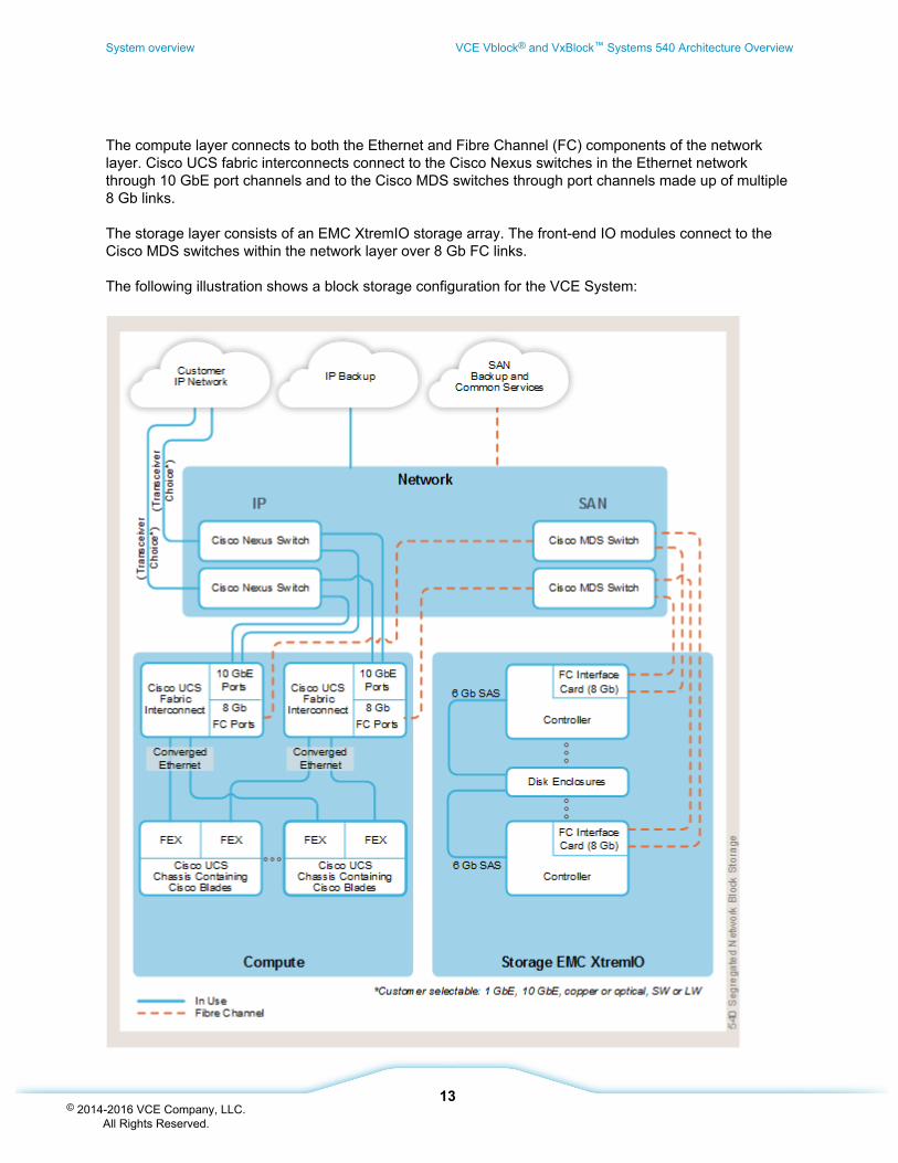
The compute layer connects to both the Ethernet and Fibre Channel (FC) components of the networklayer. Cisco UCS fabric interconnects connect to the Cisco Nexus switches in the Ethernet networkthrough 10 GbE port channels and to the Cisco MDS switches through port channels made up of multiple8 Gb links.
The storage layer consists of an EMC XtremIO storage array. The front-end IO modules connect to theCisco MDS switches within the network layer over 8 Gb FC links.
The following illustration shows a block storage configuration for the VCE System:
System overview VCE Vblock® and VxBlock™ Systems 540 Architecture Overview
13© 2014-2016 VCE Company, LLC.
All Rights Reserved.
SAN boot storage configuration
VMware vSphere ESXi hosts always boot over the FC SAN from a 10 GB Boot LUN, which contains thehypervisor's locker for persistent storage of logs and other diagnostic files. The remainder of the storagecan be presented as VMFS data stores or as raw device mappings (RDM).
VCE Vblock® and VxBlock™ Systems 540 Architecture Overview System overview
14© 2014-2016 VCE Company, LLC.
All Rights Reserved.
Compute layer
Compute overviewCisco UCS B-Series Blades installed in the Cisco UCS chassis provide computing power in a VCESystem.
Fabric extenders (FEX) in the Cisco UCS chassis connect to Cisco fabric interconnects over convergedEthernet. Up to eight 10 GbE ports on each Cisco UCS fabric extender connect northbound to the fabricinterconnects, regardless of the number of blades in the chassis. These connections carry IP and storagetraffic.
VCE uses multiple ports for each fabric interconnect for 8 Gb Fibre Channel (FC). These ports connect toCisco MDS storage switches and the connections carry FC traffic between the compute layer and thestorage layer. These connections also enable SAN booting of the Cisco UCS blades.
Cisco Unified Computing SystemThis topic provides an overview of the Cisco Unified Compute System (UCS) data center platform thatunites compute, network, and storage access.
Optimized for virtualization, the Cisco UCS integrates a low-latency, lossless 10 Gb Ethernet unifiednetwork fabric with enterprise-class, x86-based servers (the Cisco B-Series).
VCE Systems contain a number of Cisco UCS 5108 Server Chassis. Each chassis can contain up toeight half-width Cisco UCS B-Series M3 and M4 Blade Servers, four full-width, or two double-heightblades. The full-width, double-height blades must be installed at the bottom of the chassis.
In a VCE System, each chassis also includes Cisco UCS fabric extenders and Cisco UCS B-SeriesConverged Network Adapters.
VCE Systems powered by Cisco UCS offer the following features:
• Built-in redundancy for high availability
• Hot-swappable components for serviceability, upgrade, or expansion
• Fewer physical components than in a comparable system built piece by piece
• Reduced cabling
• Improved energy efficiency over traditional blade server chassis
The Vblock System Blade Pack Reference provides a list of supported Cisco UCS blades.
Compute layer VCE Vblock® and VxBlock™ Systems 540 Architecture Overview
15© 2014-2016 VCE Company, LLC.
All Rights Reserved.
Related information
Accessing VCE documentation (see page 6)
Cisco Unified Compute System fabric interconnectsCisco Unified Computing System (UCS) fabric interconnects provide network connectivity andmanagement capabilities to the Cisco UCS blades and chassis.
Cisco UCS fabric interconnects offer line-rate, low-latency, lossless 10 Gigabit Ethernet and FibreChannel over Ethernet (FCoE) functions.
VCE Systems use Cisco UCS 6248UP or Cisco UCS 6296UP Fabric Interconnects.
The optional VMware NSX feature uses Cisco UCS 6296UP Fabric Interconnects to accommodate theport count needed for VMware NSX external connectivity (edges). For more information, see the VCEVxBlock™ Systems for VMware NSX Architecture Overview.
Cisco Trusted Platform ModuleCisco TPM provides authentication and attestation services that provide safer computing in allenvironments. Cisco TPM is a computer chip that securely stores artifacts such as passwords,certificates, or encryption keys that authenticate the VCE System.
Cisco TPM is available by default in the VCE System as a component in the Cisco UCS B-Series M3Blade Servers and Cisco UCS B-Series M4 Blade Servers, and is shipped disabled. The Vblock SystemBlade Pack Reference contains additional information about Cisco TPM.
VCE supports only the Cisco TPM hardware. VCE does not support the Cisco TPM functionality. Becausemaking effective use of the Cisco TPM involves the use of a software stack from a vendor with significantexperience in trusted computing, VCE defers to the software stack vendor for configuration andoperational considerations relating to the Cisco TPM.
Related information
www.cisco.com
VCE bare metal support policySince many applications cannot be virtualized due to technical and commercial reasons, VCE Systemssupport bare metal deployments, such as non-virtualized operating systems and applications.
VCE Vblock® and VxBlock™ Systems 540 Architecture Overview Compute layer
16© 2014-2016 VCE Company, LLC.
All Rights Reserved.
While it is possible for VCE Systems to support these workloads (with caveats noted below), due to thenature of bare metal deployments, VCE is able to provide only “reasonable effort" support for systemsthat comply with the following requirements:
• VCE Systems contain only VCE published, tested, and validated hardware and softwarecomponents. The VCE Release Certification Matrix provides a list of the certified versions ofcomponents for VCE Systems.
• The operating systems used on bare-metal deployments for compute and storage componentsmust comply with the published hardware and software compatibility guides from Cisco and EMC.
• For bare metal configurations that include other hypervisor technologies (Hyper-V, KVM, etc.),those hypervisor technologies are not supported by VCE. VCE Support is provided only onVMware Hypervisors.
VCE reasonable effort support includes VCE acceptance of customer calls, a determination of whether aVCE System is operating correctly, and assistance in problem resolution to the extent possible.
VCE is unable to reproduce problems or provide support on the operating systems and applicationsinstalled on bare metal deployments. In addition, VCE does not provide updates to or test those operatingsystems or applications. The OEM support vendor should be contacted directly for issues and patchesrelated to those operating systems and applications.
Related information
Accessing VCE documentation (see page 6)
Disjoint layer 2 configurationIn the disjoint layer 2 configuration, traffic is split between two or more different networks at the fabricinterconnect to support two or more discrete Ethernet clouds. The Cisco UCS servers connect to twodifferent clouds.
Upstream disjoint layer 2 networks allow two or more Ethernet clouds that never connect to be accessedby VMs located in the same Cisco UCS domain.
Compute layer VCE Vblock® and VxBlock™ Systems 540 Architecture Overview
17© 2014-2016 VCE Company, LLC.
All Rights Reserved.
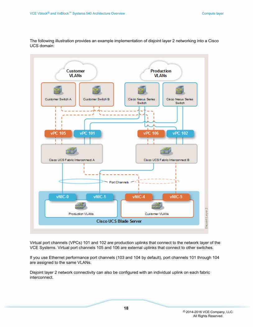
The following illustration provides an example implementation of disjoint layer 2 networking into a CiscoUCS domain:
Virtual port channels (VPCs) 101 and 102 are production uplinks that connect to the network layer of theVCE Systems. Virtual port channels 105 and 106 are external uplinks that connect to other switches.
If you use Ethernet performance port channels (103 and 104 by default), port channels 101 through 104are assigned to the same VLANs.
Disjoint layer 2 network connectivity can also be configured with an individual uplink on each fabricinterconnect.
VCE Vblock® and VxBlock™ Systems 540 Architecture Overview Compute layer
18© 2014-2016 VCE Company, LLC.
All Rights Reserved.
Storage layer
Storage layer hardwareThis topic provides an overview of the storage layer hardware for EMC XtremIO.
EMC XtremIO fully leverages the properties of random access flash media. The resulting systemaddresses the demands of mixed workloads with superior random I/O performance, instant responsetimes, scalability, flexibility, and administrator agility. EMC XtremIO delivers consistent low latencyresponse times (below <1 ms) with a set of non-stop data services. Features include:
• Inline data reduction and compression
• Thin provisioning
• Snapshots
• 99.999 percent availability enhances host performance
• Unprecedented responsiveness for enterprise applications
The EMC XtremIO Management Server is a virtual machine that provides a browser-based GUI for devicecreation, management, and monitoring of EMC XtremIO storage arrays.
Related information
EMC XtremIO storage array configurations and capacities (see page 22)
EMC XtremIO storage arrays (see page 19)
EMC XtremIO storage array physical specifications (see page 23)
EMC XtremIO storage arraysThis topic provides an overview of the common EMC XtremIO storage array characteristics across allEMC XtremIO models.
The following illustration shows the interconnection of EMC XtremIO in VCE Systems.
EMC XtremIO storage arrays include the following features:
• Two 8 Gb Fibre Channel (FC) ports per controller (four per EMC X-Brick)
• 25 drives per EMC X-Brick
• Encryption capable
Storage layer VCE Vblock® and VxBlock™ Systems 540 Architecture Overview
19© 2014-2016 VCE Company, LLC.
All Rights Reserved.
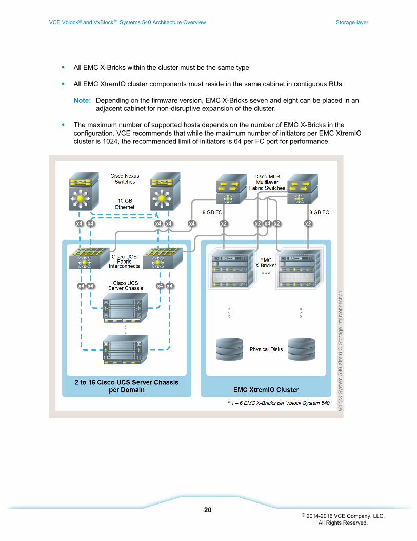
• All EMC X-Bricks within the cluster must be the same type
• All EMC XtremIO cluster components must reside in the same cabinet in contiguous RUs
Note: Depending on the firmware version, EMC X-Bricks seven and eight can be placed in anadjacent cabinet for non-disruptive expansion of the cluster.
• The maximum number of supported hosts depends on the number of EMC X-Bricks in theconfiguration. VCE recommends that while the maximum number of initiators per EMC XtremIOcluster is 1024, the recommended limit of initiators is 64 per FC port for performance.
VCE Vblock® and VxBlock™ Systems 540 Architecture Overview Storage layer
20© 2014-2016 VCE Company, LLC.
All Rights Reserved.
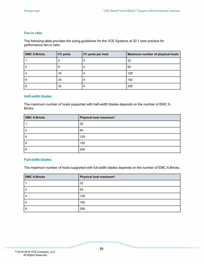
Fan-in ratio
The following table provides the sizing guidelines for the VCE Systems at 32:1 best practice forperformance fan-in ratio:
EMC X-Bricks FC ports FC ports per host Maximum number of physical hosts
1 4 4 32
2 8 4 64
4 16 4 128
6 24 4 192
8 32 4 256
Half-width blades
The maximum number of hosts supported with half-width blades depends on the number of EMC X-Bricks:
EMC X-Bricks Physical host maximum*
1 32
2 64
4 128
6 192
8 256
Full-width blades
The maximum number of hosts supported with full-width blades depends on the number of EMC X-Bricks:
EMC X-Bricks Physical host maximum*
1 32
2 64
4 128
6 192
8 256
Storage layer VCE Vblock® and VxBlock™ Systems 540 Architecture Overview
21© 2014-2016 VCE Company, LLC.
All Rights Reserved.
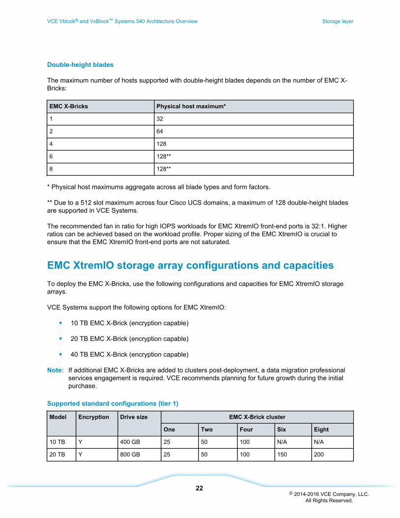
Double-height blades
The maximum number of hosts supported with double-height blades depends on the number of EMC X-Bricks:
EMC X-Bricks Physical host maximum*
1 32
2 64
4 128
6 128**
8 128**
* Physical host maximums aggregate across all blade types and form factors.
** Due to a 512 slot maximum across four Cisco UCS domains, a maximum of 128 double-height bladesare supported in VCE Systems.
The recommended fan in ratio for high IOPS workloads for EMC XtremIO front-end ports is 32:1. Higherratios can be achieved based on the workload profile. Proper sizing of the EMC XtremIO is crucial toensure that the EMC XtremIO front-end ports are not saturated.
EMC XtremIO storage array configurations and capacitiesTo deploy the EMC X-Bricks, use the following configurations and capacities for EMC XtremIO storagearrays.
VCE Systems support the following options for EMC XtremIO:
• 10 TB EMC X-Brick (encryption capable)
• 20 TB EMC X-Brick (encryption capable)
• 40 TB EMC X-Brick (encryption capable)
Note: If additional EMC X-Bricks are added to clusters post-deployment, a data migration professionalservices engagement is required. VCE recommends planning for future growth during the initialpurchase.
Supported standard configurations (tier 1)
Model Encryption Drive size EMC X-Brick cluster
One Two Four Six Eight
10 TB Y 400 GB 25 50 100 N/A N/A
20 TB Y 800 GB 25 50 100 150 200
VCE Vblock® and VxBlock™ Systems 540 Architecture Overview Storage layer
22© 2014-2016 VCE Company, LLC.
All Rights Reserved.
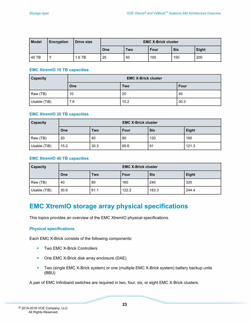
Model Encryption Drive size EMC X-Brick cluster
One Two Four Six Eight
40 TB Y 1.6 TB 25 50 100 150 200
EMC XtremIO 10 TB capacities
Capacity EMC X-Brick cluster
One Two Four
Raw (TB) 10 20 40
Usable (TiB) 7.6 15.2 30.3
EMC XtremIO 20 TB capacities
Capacity EMC X-Brick cluster
One Two Four Six Eight
Raw (TB) 20 40 80 120 160
Usable (TiB) 15.2 30.3 60.6 91 121.3
EMC XtremIO 40 TB capacities
Capacity EMC X-Brick cluster
One Two Four Six Eight
Raw (TB) 40 80 160 240 320
Usable (TiB) 30.6 61.1 122.2 183.3 244.4
EMC XtremIO storage array physical specificationsThis topics provides an overview of the EMC XtremIO physical specifications.
Physical specifications
Each EMC X-Brick consists of the following components:
• Two EMC X-Brick Controllers
• One EMC X-Brick disk array enclosure (DAE)
• Two (single EMC X-Brick system) or one (multiple EMC X-Brick system) battery backup units(BBU)
A pair of EMC Infiniband switches are required in two, four, six, or eight EMC X-Brick clusters.
Storage layer VCE Vblock® and VxBlock™ Systems 540 Architecture Overview
23© 2014-2016 VCE Company, LLC.
All Rights Reserved.
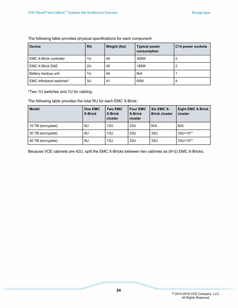
The following table provides physical specifications for each component:
Device RU Weight (lbs) Typical powerconsumption
C14 power sockets
EMC X-Brick controller 1U 40 309W 2
EMC X-Brick DAE 2U 45 185W 2
Battery backup unit 1U 44 N/A 1
EMC Infiniband switches* 3U 41 65W 4
*Two 1U switches and 1U for cabling.
The following table provides the total RU for each EMC X-Brick:
Model One EMCX-Brick
Two EMCX-Brickcluster
Four EMCX-Brickcluster
Six EMC X-Brick cluster
Eight EMC X-Brickcluster
10 TB (encrypted) 6U 13U 23U N/A N/A
20 TB (encrypted) 6U 13U 23U 33U 33U+10**
40 TB (encrypted) 6U 13U 23U 33U 33U+10**
Because VCE cabinets are 42U, split the EMC X-Bricks between two cabinets as (6+2) EMC X-Bricks.
VCE Vblock® and VxBlock™ Systems 540 Architecture Overview Storage layer
24© 2014-2016 VCE Company, LLC.
All Rights Reserved.
Network layer
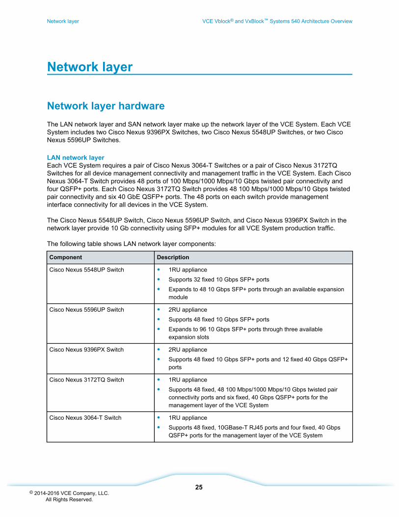
Network layer hardwareThe LAN network layer and SAN network layer make up the network layer of the VCE System. Each VCESystem includes two Cisco Nexus 9396PX Switches, two Cisco Nexus 5548UP Switches, or two CiscoNexus 5596UP Switches.
LAN network layerEach VCE System requires a pair of Cisco Nexus 3064-T Switches or a pair of Cisco Nexus 3172TQSwitches for all device management connectivity and management traffic in the VCE System. Each CiscoNexus 3064-T Switch provides 48 ports of 100 Mbps/1000 Mbps/10 Gbps twisted pair connectivity andfour QSFP+ ports. Each Cisco Nexus 3172TQ Switch provides 48 100 Mbps/1000 Mbps/10 Gbps twistedpair connectivity and six 40 GbE QSFP+ ports. The 48 ports on each switch provide managementinterface connectivity for all devices in the VCE System.
The Cisco Nexus 5548UP Switch, Cisco Nexus 5596UP Switch, and Cisco Nexus 9396PX Switch in thenetwork layer provide 10 Gb connectivity using SFP+ modules for all VCE System production traffic.
The following table shows LAN network layer components:
Component Description
Cisco Nexus 5548UP Switch • 1RU appliance
• Supports 32 fixed 10 Gbps SFP+ ports
• Expands to 48 10 Gbps SFP+ ports through an available expansionmodule
Cisco Nexus 5596UP Switch • 2RU appliance
• Supports 48 fixed 10 Gbps SFP+ ports
• Expands to 96 10 Gbps SFP+ ports through three availableexpansion slots
Cisco Nexus 9396PX Switch • 2RU appliance
• Supports 48 fixed 10 Gbps SFP+ ports and 12 fixed 40 Gbps QSFP+ports
Cisco Nexus 3172TQ Switch • 1RU appliance
• Supports 48 fixed, 48 100 Mbps/1000 Mbps/10 Gbps twisted pairconnectivity ports and six fixed, 40 Gbps QSFP+ ports for themanagement layer of the VCE System
Cisco Nexus 3064-T Switch • 1RU appliance
• Supports 48 fixed, 10GBase-T RJ45 ports and four fixed, 40 GbpsQSFP+ ports for the management layer of the VCE System
Network layer VCE Vblock® and VxBlock™ Systems 540 Architecture Overview
25© 2014-2016 VCE Company, LLC.
All Rights Reserved.
SAN network layer
VCE Systems contain two Cisco MDS switches to provide Fibre Channel (FC) connectivity between thecompute and storage layer components. These switches comprise two separate fabrics. Connectionsfrom the storage components provide 8 Gb of bandwidth. Cisco UCS fabric interconnects provide a FCport channel of four 8 Gb connections (32 Gb bandwidth) to each fabric. This can be increased to eightconnections for 64 Gb bandwidth or sixteen connections for 128 Gb bandwidth. These connections alsofacilitate SAN booting of the blades in the compute layer.
Two Cisco MDS 9148S Multilayer Fabric Switches provide:
• FC connectivity between the compute layer components and the storage layer components
• Connectivity for backup and business continuity requirements when configured
Note: Inter-Switch Links (ISLs) to existing SAN or between switches is not permitted.
Cisco MDS 9148S Multilayer Fabric Switches provide 12 to 48 line-rate ports for non-blocking 16 Gbpsthroughput. 24 are licensed; additional ports can be licensed as needed.
Port utilizationThis section describes the switch port utilization for Cisco Nexus switches in the networking configuration.
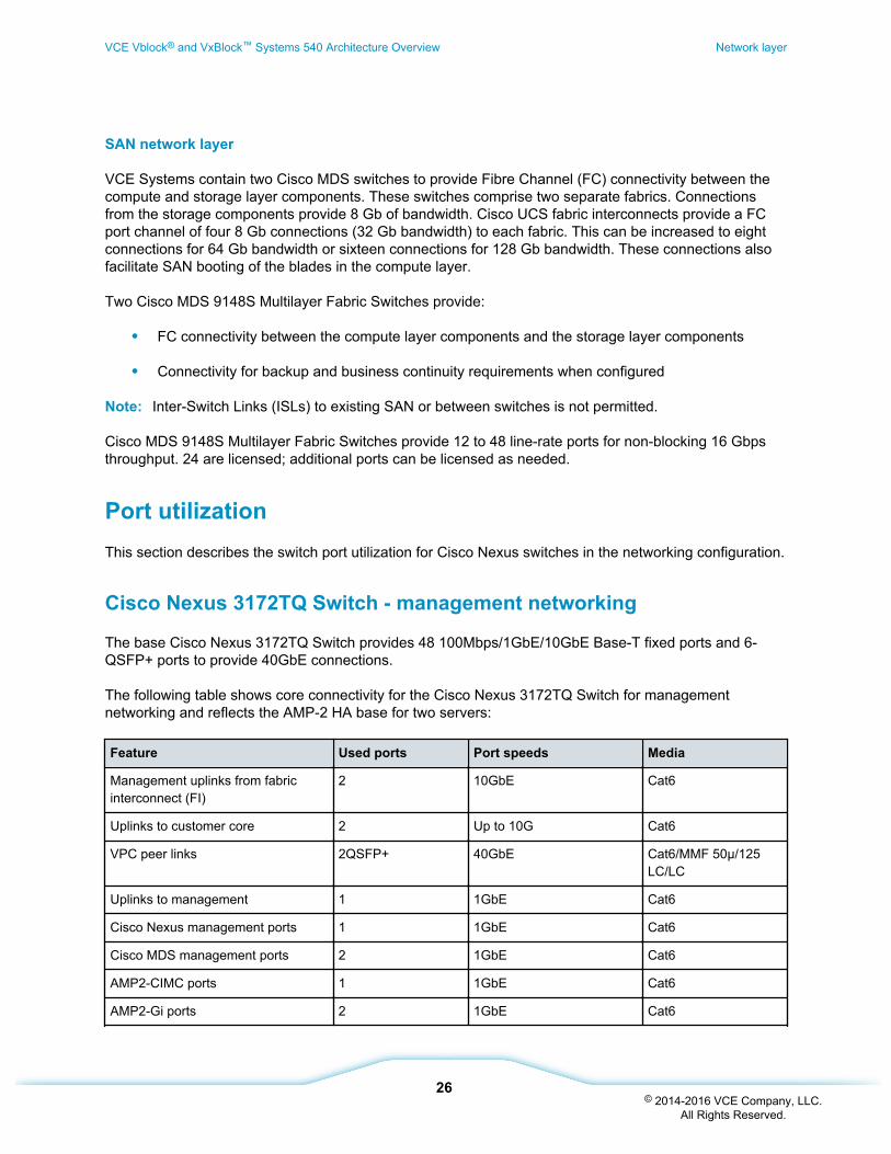
Cisco Nexus 3172TQ Switch - management networking
The base Cisco Nexus 3172TQ Switch provides 48 100Mbps/1GbE/10GbE Base-T fixed ports and 6-QSFP+ ports to provide 40GbE connections.
The following table shows core connectivity for the Cisco Nexus 3172TQ Switch for managementnetworking and reflects the AMP-2 HA base for two servers:
Feature Used ports Port speeds Media
Management uplinks from fabricinterconnect (FI)
2 10GbE Cat6
Uplinks to customer core 2 Up to 10G Cat6
VPC peer links 2QSFP+ 40GbE Cat6/MMF 50µ/125LC/LC
Uplinks to management 1 1GbE Cat6
Cisco Nexus management ports 1 1GbE Cat6
Cisco MDS management ports 2 1GbE Cat6
AMP2-CIMC ports 1 1GbE Cat6
AMP2-Gi ports 2 1GbE Cat6
VCE Vblock® and VxBlock™ Systems 540 Architecture Overview Network layer
26© 2014-2016 VCE Company, LLC.
All Rights Reserved.
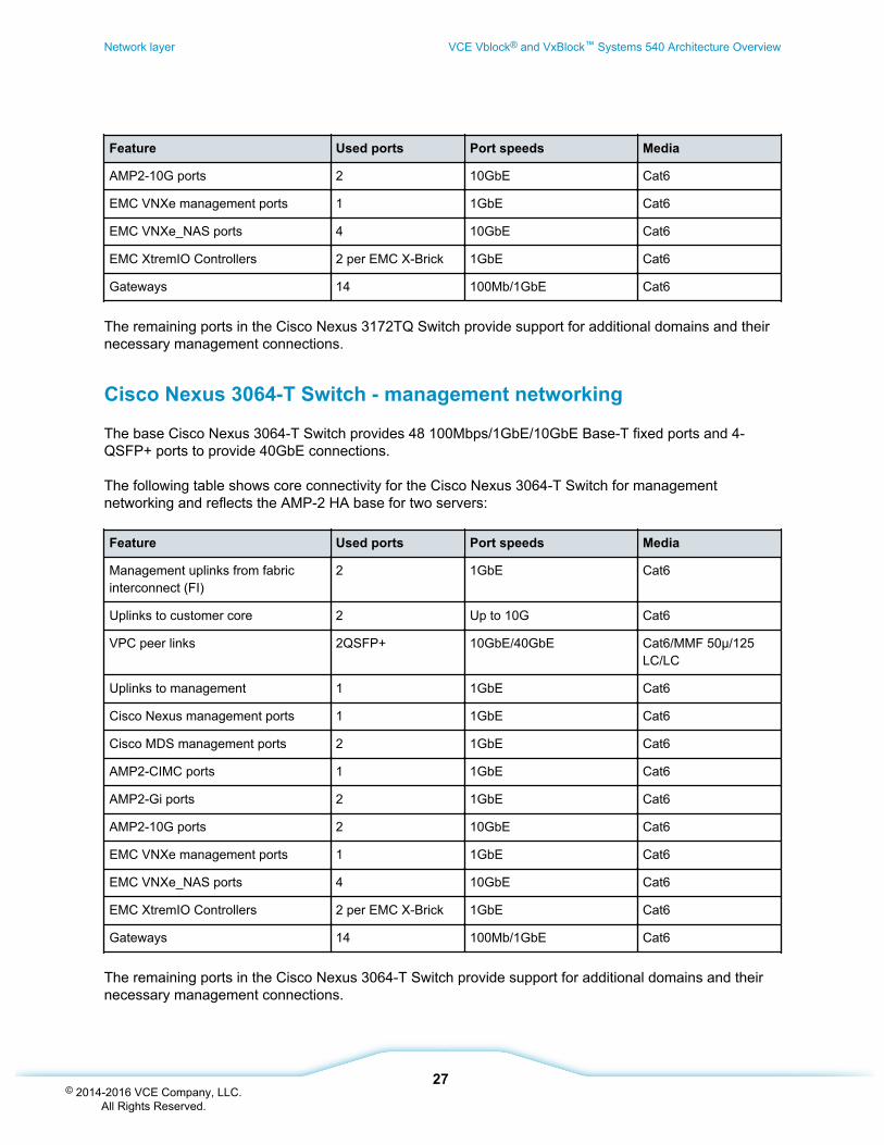
Feature Used ports Port speeds Media
AMP2-10G ports 2 10GbE Cat6
EMC VNXe management ports 1 1GbE Cat6
EMC VNXe_NAS ports 4 10GbE Cat6
EMC XtremIO Controllers 2 per EMC X-Brick 1GbE Cat6
Gateways 14 100Mb/1GbE Cat6
The remaining ports in the Cisco Nexus 3172TQ Switch provide support for additional domains and theirnecessary management connections.
Cisco Nexus 3064-T Switch - management networking
The base Cisco Nexus 3064-T Switch provides 48 100Mbps/1GbE/10GbE Base-T fixed ports and 4-QSFP+ ports to provide 40GbE connections.
The following table shows core connectivity for the Cisco Nexus 3064-T Switch for managementnetworking and reflects the AMP-2 HA base for two servers:
Feature Used ports Port speeds Media
Management uplinks from fabricinterconnect (FI)
2 1GbE Cat6
Uplinks to customer core 2 Up to 10G Cat6
VPC peer links 2QSFP+ 10GbE/40GbE Cat6/MMF 50µ/125LC/LC
Uplinks to management 1 1GbE Cat6
Cisco Nexus management ports 1 1GbE Cat6
Cisco MDS management ports 2 1GbE Cat6
AMP2-CIMC ports 1 1GbE Cat6
AMP2-Gi ports 2 1GbE Cat6
AMP2-10G ports 2 10GbE Cat6
EMC VNXe management ports 1 1GbE Cat6
EMC VNXe_NAS ports 4 10GbE Cat6
EMC XtremIO Controllers 2 per EMC X-Brick 1GbE Cat6
Gateways 14 100Mb/1GbE Cat6
The remaining ports in the Cisco Nexus 3064-T Switch provide support for additional domains and theirnecessary management connections.
Network layer VCE Vblock® and VxBlock™ Systems 540 Architecture Overview
27© 2014-2016 VCE Company, LLC.
All Rights Reserved.
Related information
Management components overview (see page 35)
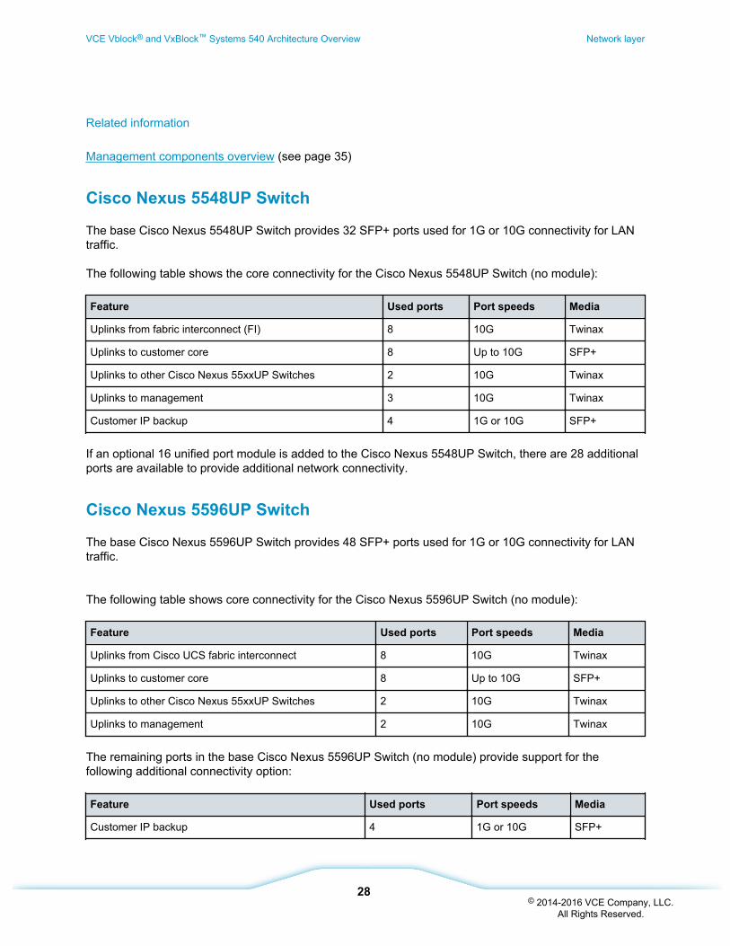
Cisco Nexus 5548UP Switch
The base Cisco Nexus 5548UP Switch provides 32 SFP+ ports used for 1G or 10G connectivity for LANtraffic.
The following table shows the core connectivity for the Cisco Nexus 5548UP Switch (no module):
Feature Used ports Port speeds Media
Uplinks from fabric interconnect (FI) 8 10G Twinax
Uplinks to customer core 8 Up to 10G SFP+
Uplinks to other Cisco Nexus 55xxUP Switches 2 10G Twinax
Uplinks to management 3 10G Twinax
Customer IP backup 4 1G or 10G SFP+
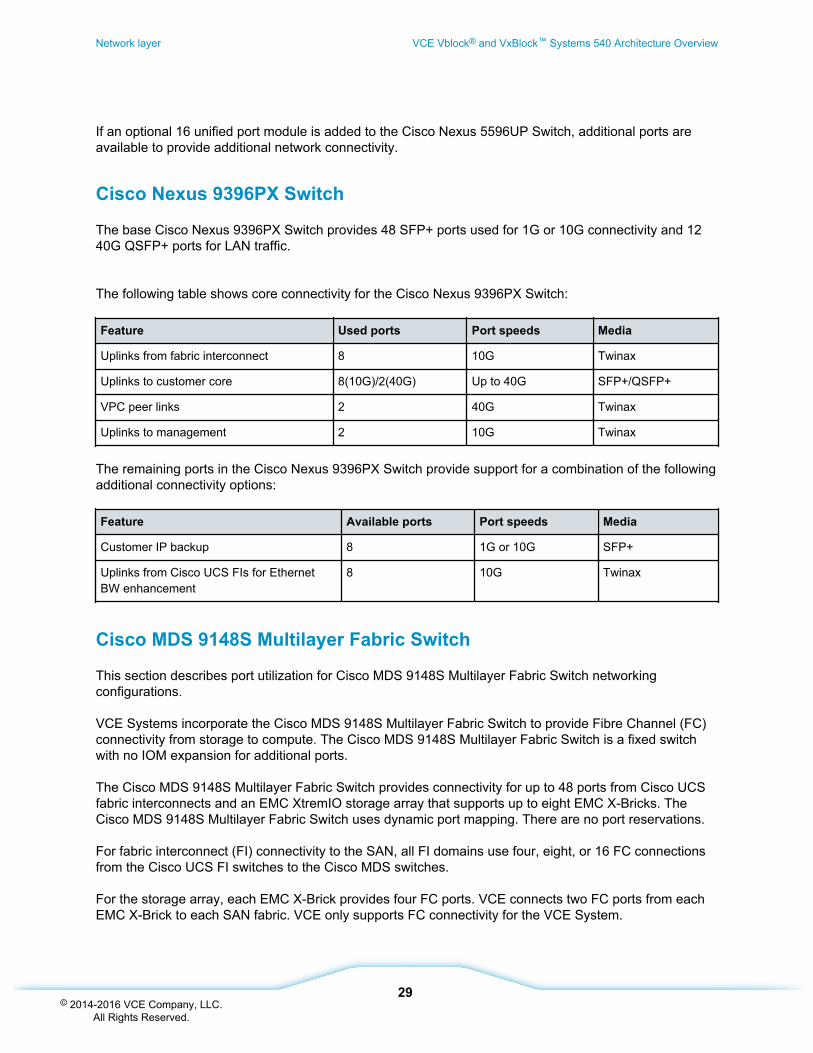
If an optional 16 unified port module is added to the Cisco Nexus 5548UP Switch, there are 28 additionalports are available to provide additional network connectivity.
Cisco Nexus 5596UP Switch
The base Cisco Nexus 5596UP Switch provides 48 SFP+ ports used for 1G or 10G connectivity for LANtraffic.
The following table shows core connectivity for the Cisco Nexus 5596UP Switch (no module):
Feature Used ports Port speeds Media
Uplinks from Cisco UCS fabric interconnect 8 10G Twinax
Uplinks to customer core 8 Up to 10G SFP+
Uplinks to other Cisco Nexus 55xxUP Switches 2 10G Twinax
Uplinks to management 2 10G Twinax
The remaining ports in the base Cisco Nexus 5596UP Switch (no module) provide support for thefollowing additional connectivity option:
Feature Used ports Port speeds Media
Customer IP backup 4 1G or 10G SFP+
VCE Vblock® and VxBlock™ Systems 540 Architecture Overview Network layer
28© 2014-2016 VCE Company, LLC.
All Rights Reserved.
If an optional 16 unified port module is added to the Cisco Nexus 5596UP Switch, additional ports areavailable to provide additional network connectivity.
Cisco Nexus 9396PX Switch
The base Cisco Nexus 9396PX Switch provides 48 SFP+ ports used for 1G or 10G connectivity and 1240G QSFP+ ports for LAN traffic.
The following table shows core connectivity for the Cisco Nexus 9396PX Switch:
Feature Used ports Port speeds Media
Uplinks from fabric interconnect 8 10G Twinax
Uplinks to customer core 8(10G)/2(40G) Up to 40G SFP+/QSFP+
VPC peer links 2 40G Twinax
Uplinks to management 2 10G Twinax
The remaining ports in the Cisco Nexus 9396PX Switch provide support for a combination of the followingadditional connectivity options:
Feature Available ports Port speeds Media
Customer IP backup 8 1G or 10G SFP+
Uplinks from Cisco UCS FIs for EthernetBW enhancement
8 10G Twinax
Cisco MDS 9148S Multilayer Fabric Switch
This section describes port utilization for Cisco MDS 9148S Multilayer Fabric Switch networkingconfigurations.
VCE Systems incorporate the Cisco MDS 9148S Multilayer Fabric Switch to provide Fibre Channel (FC)connectivity from storage to compute. The Cisco MDS 9148S Multilayer Fabric Switch is a fixed switchwith no IOM expansion for additional ports.
The Cisco MDS 9148S Multilayer Fabric Switch provides connectivity for up to 48 ports from Cisco UCSfabric interconnects and an EMC XtremIO storage array that supports up to eight EMC X-Bricks. TheCisco MDS 9148S Multilayer Fabric Switch uses dynamic port mapping. There are no port reservations.
For fabric interconnect (FI) connectivity to the SAN, all FI domains use four, eight, or 16 FC connectionsfrom the Cisco UCS FI switches to the Cisco MDS switches.
For the storage array, each EMC X-Brick provides four FC ports. VCE connects two FC ports from eachEMC X-Brick to each SAN fabric. VCE only supports FC connectivity for the VCE System.
Network layer VCE Vblock® and VxBlock™ Systems 540 Architecture Overview
29© 2014-2016 VCE Company, LLC.
All Rights Reserved.
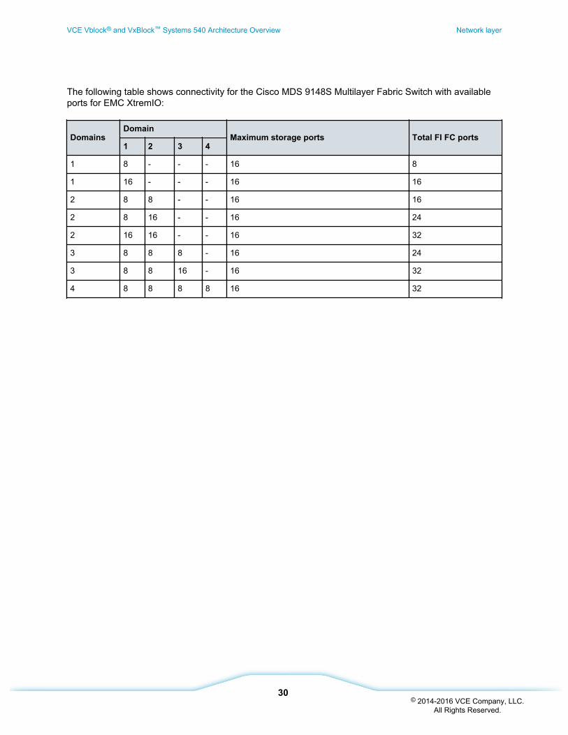
The following table shows connectivity for the Cisco MDS 9148S Multilayer Fabric Switch with availableports for EMC XtremIO:
DomainsDomain
Maximum storage ports Total FI FC ports1 2 3 4
1 8 - - - 16 8
1 16 - - - 16 16
2 8 8 - - 16 16
2 8 16 - - 16 24
2 16 16 - - 16 32
3 8 8 8 - 16 24
3 8 8 16 - 16 32
4 8 8 8 8 16 32
VCE Vblock® and VxBlock™ Systems 540 Architecture Overview Network layer
30© 2014-2016 VCE Company, LLC.
All Rights Reserved.
Virtualization layer
Virtualization componentsVMware vSphere is the virtualization platform that provides the foundation for the private cloud. The coreVMware vSphere components are the VMware vSphere ESXi and VMware vCenter Server formanagement. Depending on the version that you are running, VMware vSphere 5.x includes a SingleSign-on (SSO) component as a standalone Windows server or as an embedded service on the vCenterserver.VMware vSphere 6.0 includes a pair of Platform Service Controller Linux appliances to provide theSingle Sign-on (SSO) service.
The hypervisors are deployed in a cluster configuration. The cluster allows dynamic allocation ofresources, such as CPU, memory, and storage. The cluster also provides workload mobility and flexibilitywith the use of VMware vMotion and Storage vMotion technology.
VMware vSphere Hypervisor ESXiThe VMware vSphere Hypervisor ESXi runs in the management servers and in VCE Systems usingVMware vSphere Server Enterprise Plus.
The lightweight hypervisor requires very little space to run (less than six GB of storage required to install)and has minimal management overhead.
VMware vSphere ESXi does not contain a console operating system. The VMware vSphere HypervisorESXi boots from the SAN through an independent Fibre Channel (FC) LUN presented from the EMCstorage array to the compute blades. The FC LUN also contains the hypervisor's locker for persistentstorage of logs and other diagnostic files to provide stateless computing in VCE Systems. The statelesshypervisor (PXE boot into memory) is not supported.
Cluster configuration
VMware vSphere ESXi hosts and their resources are pooled together into clusters. These clusterscontain the CPU, memory, network, and storage resources available for allocation to virtual machines(VMs). Clusters can scale up to a maximum of 32 hosts for VMware vSphere 5.1/5.5 and 64 hosts forVMware vSphere 6.0. Clusters can support thousands of VMs.
The clusters can also support a variety of Cisco UCS blades running inside the same cluster.
Note: Some advanced CPU functionality might be unavailable if more than one blade model is running ina given cluster.
Data stores
VCE Systems support a mixture of data store types: block level storage using VMFS or file level storageusing NFS. The maximum size per VMFS volume is 64 TB (50 TB VMFS3 @ 1 MB). Beginning with
Virtualization layer VCE Vblock® and VxBlock™ Systems 540 Architecture Overview
31© 2014-2016 VCE Company, LLC.
All Rights Reserved.
VMware vSphere 5.5, the maximum VMDK file size is 62 TB. Each host/cluster can support a maximumof 255 volumes.
VCE optimizes the advanced settings for VMware vSphere ESXi hosts that are deployed in VCE Systemsto maximize the throughput and scalability of NFS data stores. VCE Systems currently support amaximum of 256 NFS data stores per host.
Virtual networks
Virtual networking in the Advanced Management Platform uses the VMware Virtual Standard Switch(VSS). Virtual networking is managed by either the Cisco Nexus 1000V distributed virtual switch orVMware vSphere Distributed Switch (VDS). The Cisco Nexus 1000V Series Switch ensures consistent,policy-based network capabilities to all servers in the data center by allowing policies to move with a VMduring live migration. This provides persistent network, security, and storage compliance.
Alternatively, virtual networking in VCE Systems is managed by VMware VDS with comparable featuresto the Cisco Nexus 1000V where applicable. The VMware VDS option consists of both a VMware VSSand a VMware VDS and uses a minimum of four uplinks presented to the hypervisor.
The implementation of Cisco Nexus 1000V for VMware vSphere 5.1/5.5 and VMware VDS for VMwarevSphere 5.5 use intelligent network Class of Service (CoS) marking and Quality of Service (QoS) policiesto appropriately shape network traffic according to workload type and priority. With VMware vSphere 6.0,QoS is set to Default (Trust Host). The vNICs are equally distributed across all available physical adapterports to ensure redundancy and maximum bandwidth where appropriate. This provides generalconsistency and balance across all Cisco UCS blade models, regardless of the Cisco UCS VirtualInterface Card (VIC) hardware. Thus, VMware vSphere ESXi has a predictable uplink interface count. Allapplicable VLANs, native VLANs, MTU settings, and QoS policies are assigned to the virtual networkinterface cards (vNICs) to ensure consistency in case the uplinks need to be migrated to the VMwarevSphere Distributed Switch (VDS) after manufacturing.
VMware vCenter ServerThis topic describes the VMware vCenter Server which is a central management point for the hypervisorsand VMs.
VMware vCenter is installed on a 64-bit Windows Server. VMware Update Manager is installed on a 64-bit Windows Server and runs as a service to assist with host patch management.
VMware vCenter Server provides the following functionality:
• Cloning of VMs
• Template creation
• VMware vMotion and VMware Storage vMotion
• Initial configuration of VMware Distributed Resource Scheduler (DRS) and VMware vSpherehigh-availability clusters
VCE Vblock® and VxBlock™ Systems 540 Architecture Overview Virtualization layer
32© 2014-2016 VCE Company, LLC.
All Rights Reserved.
VMware vCenter Server also provides monitoring and alerting capabilities for hosts and VMs. Systemadministrators can create and apply alarms to all managed objects in VMware vCenter Server, including:
• Data center, cluster, and host health, inventory, and performance
• Data store health and capacity
• VM usage, performance, and health
• Virtual network usage and health
Databases
The back-end database that supports VMware vCenter Server and VUM is Microsoft SQL 2012.
Authentication
VMware Single Sign-On (SSO) Service integrates multiple identity sources including Active Directory,Open LDAP, and local accounts for authentication. VMware SSO is available in VMware vSphere 5.x andlater. VMware vCenter Server, Inventory, Web Client, SSO, Core Dump Collector, and VUM run asseparate Windows services, which can be configured to use a dedicated service account depending onsecurity and directory services requirements.
VCE supported features
VCE supports the following VMware vCenter Server features:
• VMware SSO Service (version 5.x and later)
• VMware vSphere Web Client (used with VCE Vision™ Intelligent Operations)
• VMware vSphere Distributed Switch (VDS)
• VMware vSphere High Availability
• VMware DRS
• VMware Fault Tolerance
• VMware vMotion
— Layer 3 capability available for compute resources (version 6.0 and higher)
• VMware Storage vMotion
• Raw Device Maps
• Resource Pools
• Storage DRS (capacity only)
Virtualization layer VCE Vblock® and VxBlock™ Systems 540 Architecture Overview
33© 2014-2016 VCE Company, LLC.
All Rights Reserved.
• Storage-driven profiles (user-defined only)
• Distributed power management (up to 50 percent of VMware vSphere ESXi hosts/blades)
• VMware Syslog Service
• VMware Core Dump Collector
• VMware vCenter Web Services
Related information
Management components overview (see page 35)
VCE Vblock® and VxBlock™ Systems 540 Architecture Overview Virtualization layer
34© 2014-2016 VCE Company, LLC.
All Rights Reserved.
Management
Management components overviewThe Advanced Management Platform (AMP-2HA) provides a single management point for VCE Systems.
The AMP-2HA provides the ability to:
• Run the Core and VCE Optional Management Workloads
• Monitor and manage VCE System health, performance, and capacity
• Provide network and fault isolation for management
• Eliminate resource overhead on VCE Systems
The Core Management Workload is the minimum set of required management software to install, operate,and support VCE Systems. This includes all hypervisor management, element managers, virtualnetworking components (Cisco Nexus 1000V or VMware vSphere Distributed Switch (VDS)), and VCEVision™ Intelligent Operations Software.
The VCE Optional Management Workload is non-Core Management Workloads, which are supported andinstalled by VCE, and whose primary purpose is to manage components in VCE Systems. The listincludes but is not limited to EMC Data Protection, security, or storage management tools such as EMCAvamar Administrator, EMC InsightIQ for Isilon, and VMware vCNS appliances (vShield Edge/Manager).
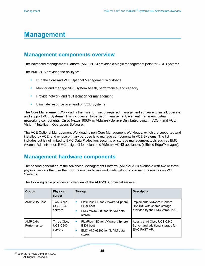
Management hardware componentsThe second generation of the Advanced Management Platform (AMP-2HA) is available with two or threephysical servers that use their own resources to run workloads without consuming resources on VCESystems.
The following table provides an overview of the AMP-2HA physical servers:
Option Physicalserver
Storage Description
AMP-2HA Base Two CiscoUCS C240servers
• FlexFlash SD for VMware vSphereESXi boot
• EMC VNXe3200 for file VM datastores
Implements VMware vSphereHA/DRS with shared storageprovided by the EMC VNXe3200.
AMP-2HAPerformance
Three CiscoUCS C240servers
• FlexFlash SD for VMware vSphereESXi boot
• EMC VNXe3200 for file VM datastores
Adds a third Cisco UCS C240Server and additional storage forEMC FAST VP.
Management VCE Vblock® and VxBlock™ Systems 540 Architecture Overview
35© 2014-2016 VCE Company, LLC.
All Rights Reserved.
Management software componentsSoftware is delivered pre-configured with the second generation of the Advanced Management Platform(AMP-2HA).
AMP-2HA is delivered pre-configured with the following software components which are dependent onthe selected VCE Release Certification Matrix:
• Microsoft Windows Server 2008 R2 SP1 Standard x64
• Microsoft Windows Server 2012 R2 Standard x64
• VMware vSphere Enterprise Plus
• VMware vSphere Hypervisor ESXi
• VMware Single Sign-On (SSO) Service
• VMware vSphere Web Client Service
• VMware vSphere Inventory Service
• VMware vCenter Server
• Vmware vCenter Database using Microsoft SQL Server 2012 Standard Edition
• VMware vCenter Update Manager
• VMware vSphere client
• VMware vSphere Syslog Collector service (optional)
• VMware vSphere Core Dump service (optional)
• VMware vSphere Distributed Switch (VDS) or Cisco Nexus 1000V virtual supervisor module(VSM)
• EMC PowerPath/VE Electronic License Management Server (ELMS)
• EMC Secure Remote Support (ESRS)
• Array Management modules, including, but not limited to, EMC XtremIO Management Server andPowerPath Viewer
• Cisco Prime Data Center Network Manager and Device Manager
• (Optional) EMC RecoverPoint management software that includes EMC RecoverPointManagement Application and EMC RecoverPoint Deployment Manager
VCE Vblock® and VxBlock™ Systems 540 Architecture Overview Management
36© 2014-2016 VCE Company, LLC.
All Rights Reserved.

Management network connectivityThis topic provides an overview of Advanced Management Platform (AMP-2HA) network connectivity andserver assignments.
AMP-2HA network connectivity
The following illustration provides an overview of the network connectivity for AMP-2HA:
Management VCE Vblock® and VxBlock™ Systems 540 Architecture Overview
37© 2014-2016 VCE Company, LLC.
All Rights Reserved.
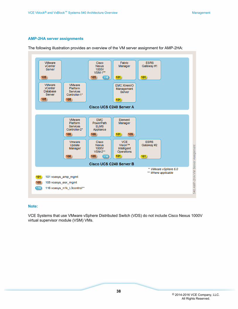
AMP-2HA server assignments
The following illustration provides an overview of the VM server assignment for AMP-2HA:
Note:
VCE Systems that use VMware vSphere Distributed Switch (VDS) do not include Cisco Nexus 1000Vvirtual supervisor module (VSM) VMs.
VCE Vblock® and VxBlock™ Systems 540 Architecture Overview Management
38© 2014-2016 VCE Company, LLC.
All Rights Reserved.
System infrastructure
Cabinets overviewIn each VCE System, the compute and network layer components are distributed in the cabinets.Distributing the components in this manner balances out the power draw and reduces the size of thepower distribution units (PDUs) that are required.
Each cabinet has a capacity for physical dimensions such as weight, heat dissipation, power draw, RUspace, and receptacle count. This design improves flexibility when upgrading or expanding VCE Systemsas capacity needs increase.
For some configurations, VCE preinstalls all wiring based on the predefined layouts.
VCE cabinets are designed to be installed contiguously to one another in the data center. If the base andexpansion cabinets need to be physically separated, customized cabling is needed, which incursadditional cost and delivery delays.
Note: The cable length is not the same as distance between cabinets. The cable must route through thecabinets and through the cable channels overhead or in the floor.
Related information
Power options (see page 40)
Intelligent Physical Infrastructure applianceThe Intelligent Physical Infrastructure (IPI) appliance allows users to collect and monitor environmentaldata, and monitor control power and security.
For more information about the IPI appliance, refer to the administration guide for your VCE System andto the VCE Intelligent Physical Infrastructure (IPI) Appliance User Manual.
Related information
Accessing VCE documentation (see page 6)
Cabinet typesThis topic provides an overview of the sample cabinets for VCE Systems.
System infrastructure VCE Vblock® and VxBlock™ Systems 540 Architecture Overview
39© 2014-2016 VCE Company, LLC.
All Rights Reserved.
Sample compute and network cabinet
A sample compute and network cabinet can contain:
• Cisco Nexus 5548UP, Cisco Nexus 5596UP, or Cisco Nexus 9396PX Switches
• Cisco Nexus 3064-T Switches or Cisco Nexus 3172TQ Switches
• Cisco MDS 9148S Switches
• Cisco UCS C240 Servers
• EMC VNXe3200
• Cisco Nexus 6248UP or Cisco Nexus 6296UP Fabric Interconnects
• Cisco UCS 5108 Server Chassis
• EMC XtremIO storage array cluster
If VCE System configurations expand, a compute and network expansion cabinet can be added foradditional Cisco UCS 5108 chassis. This modular design makes it easier to add hardware later ifnecessary.
The compute and network expansion cabinet can be expanded in a modular configuration.
Power optionsVCE Systems support several power distribution unit (PDU) options inside and outside of North America.
Power options for VCE System cabinets
The following table lists the PDUs that are available:
PDU Power specifications Number per CN or S
IEC 60309 3P+PE 3-phase Delta / 60A 2 pairs of PDUs per cabinet
NEMA L15-30P 3-phase Delta / 30A 3 pairs of PDUs per cabinet
NEMA L6-30P Single phase / 30A 3 pairs of PDUs per cabinet
IEC 60309 3P+N+PE 3-phase WYE / 30 / 32A / 2 pairs of PDUs per cabinet
IEC 60309 2P+E Single phase / 32A 3 pairs of PDUs per cabinet
VCE Vblock® and VxBlock™ Systems 540 Architecture Overview System infrastructure
40© 2014-2016 VCE Company, LLC.
All Rights Reserved.
Balancing cabinet maximum usable power
The VCE System maximum usable power must be balanced in the cabinets based on the amount ofcomponents in the cabinet. The maximum kilowatt draw for a VCE System PDU that has been derated to80 percent is listed in the following table:
Power option Kilowatt draw per PDU
3-Phase Delta 60A@208V 17.3
3-Phase Delta 30A@208V 8.6
3-Phase WYE 32A@230V 17.7
Single Phase 30A@208V 5
Single Phase 32A@230V 5.9
Note: The kilowatt draw per PDU is an approximate measurement.
The following PDU limitations per cabinet are for a VCE System with one or more Cisco UCS 5108 BladeServer Chassis installed:
Power option Number of Cisco UCS5108 Blade ServerChassis
Maximum PDUs per cabinet
Three-Phase Delta 60A 1-3 One pair
Three-Phase Delta 60A 4-6 Two pair
Three-Phase Delta 30A 1-3 Two pair
Three-Phase Delta 30A 4 Three pair
Three-Phase WYE 30A or 32A 1-3 One pair
Three-Phase WYE 30A or 32A 4-6 Two pair
Single Phase 30A or 32A 1 Two pair
Single Phase 30A or 32A 2 Three pair
Related information
Accessing VCE documentation (see page 6)
System infrastructure VCE Vblock® and VxBlock™ Systems 540 Architecture Overview
41© 2014-2016 VCE Company, LLC.
All Rights Reserved.
Sample configurations
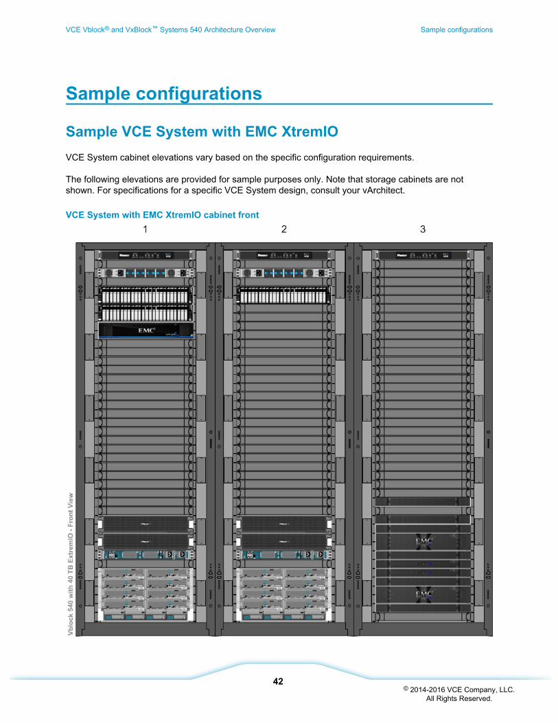
Sample VCE System with EMC XtremIOVCE System cabinet elevations vary based on the specific configuration requirements.
The following elevations are provided for sample purposes only. Note that storage cabinets are notshown. For specifications for a specific VCE System design, consult your vArchitect.
VCE System with EMC XtremIO cabinet front
VCE Vblock® and VxBlock™ Systems 540 Architecture Overview Sample configurations
42© 2014-2016 VCE Company, LLC.
All Rights Reserved.
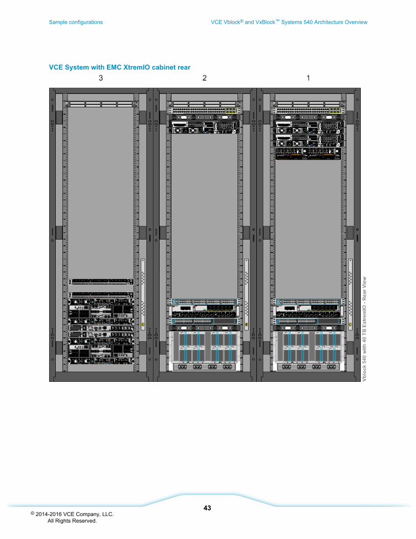
VCE System with EMC XtremIO cabinet rear
Sample configurations VCE Vblock® and VxBlock™ Systems 540 Architecture Overview
43© 2014-2016 VCE Company, LLC.
All Rights Reserved.
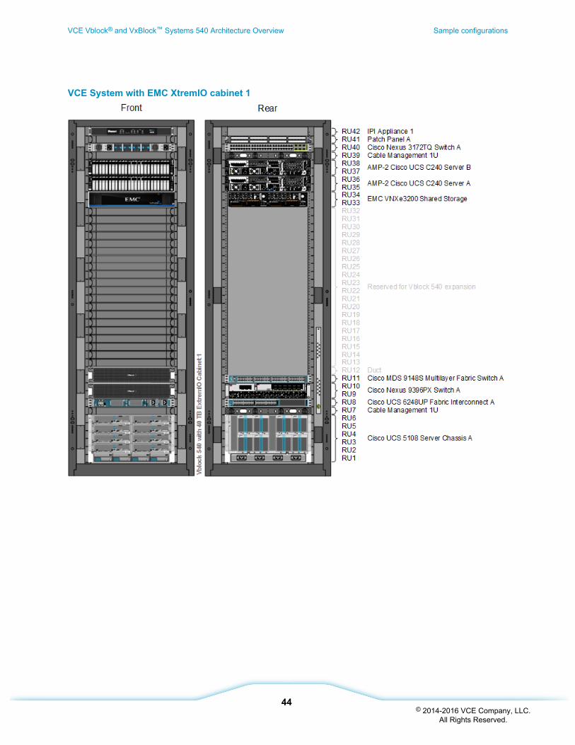
VCE System with EMC XtremIO cabinet 1
VCE Vblock® and VxBlock™ Systems 540 Architecture Overview Sample configurations
44© 2014-2016 VCE Company, LLC.
All Rights Reserved.
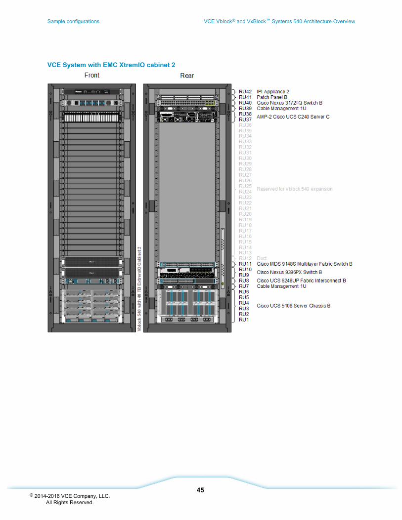
VCE System with EMC XtremIO cabinet 2
Sample configurations VCE Vblock® and VxBlock™ Systems 540 Architecture Overview
45© 2014-2016 VCE Company, LLC.
All Rights Reserved.
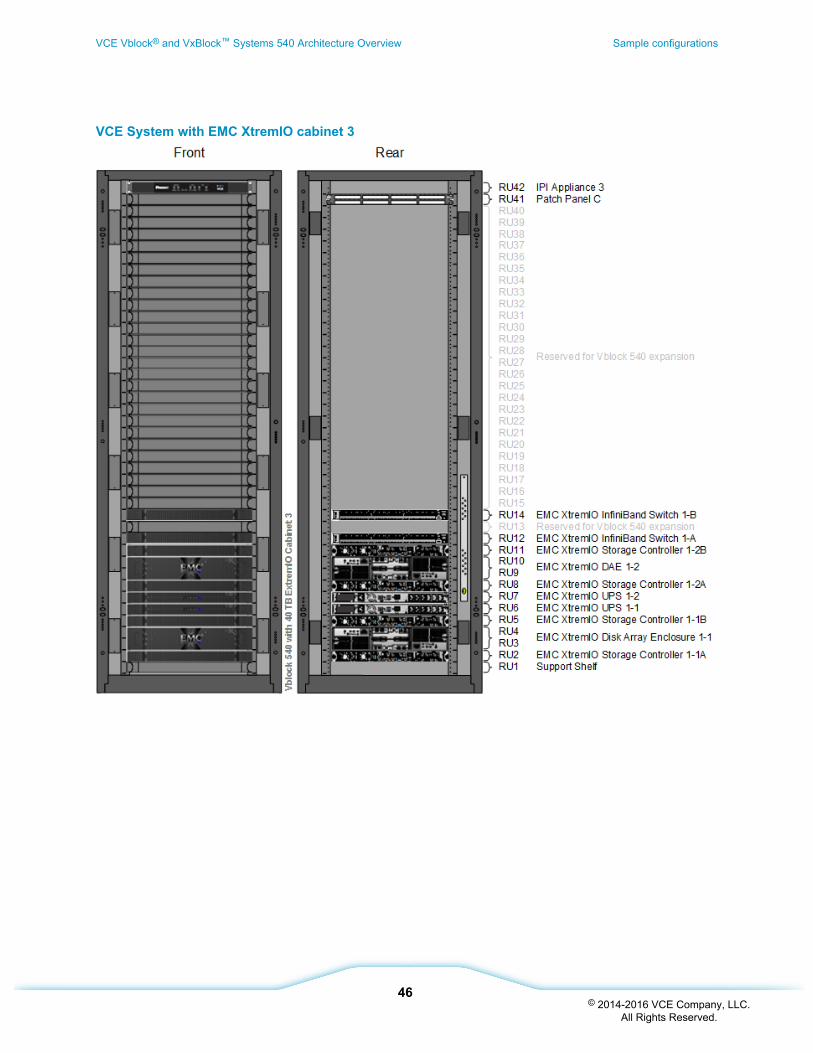
VCE System with EMC XtremIO cabinet 3
VCE Vblock® and VxBlock™ Systems 540 Architecture Overview Sample configurations
46© 2014-2016 VCE Company, LLC.
All Rights Reserved.
Additional references
Virtualization components
Product Description Link to documentation
VMware vCenterServer
Provides a scalable and extensible platform that formsthe foundation for virtualization management.
http://www.vmware.com/products/vcenter-server/
VMware vSphereESXi
Virtualizes all application servers and providesVMware high availability (HA) and dynamic resourcescheduling (DRS).
http://www.vmware.com/products/vsphere/
Compute components
Product Description Link
Cisco UCS B-SeriesBlade Servers
Servers that adapt to application demands,intelligently scale energy use, and offer best-in-classvirtualization.
www.cisco.com/en/US/products/ps10280/index.html
Cisco UCS Manager Provides centralized management capabilities forthe Cisco Unified Computing System (UCS).
www.cisco.com/en/US/products/ps10281/index.html
Cisco UCS 2200 SeriesFabric Extenders
Bring unified fabric into the blade-server chassis,providing up to eight 10 Gbps connections eachbetween blade servers and the fabric interconnect.
http://www.cisco.com/c/en/us/support/servers-unified-computing/ucs-2200-series-fabric-extenders/tsd-products-support-series-home.html
Cisco UCS 5100 SeriesBlade Server Chassis
Chassis that supports up to eight blade servers andup to two fabric extenders in a six rack unit (RU)enclosure.
www.cisco.com/en/US/products/ps10279/index.html
Cisco UCS 6200 SeriesFabric Interconnects
Cisco UCS family of line-rate, low-latency, lossless,10 Gigabit Ethernet, Fibre Channel over Ethernet(FCoE), and Fibre Channel functions. Providenetwork connectivity and management capabilities.
www.cisco.com/en/US/products/ps11544/index.html
Network components
Product Description Link to documentation
Cisco Nexus 1000VSeries Switches
A software switch on a server that deliversCisco VN-Link services to virtual machineshosted on that server.
www.cisco.com/en/US/products/ps9902/index.html
Additional references VCE Vblock® and VxBlock™ Systems 540 Architecture Overview
47© 2014-2016 VCE Company, LLC.
All Rights Reserved.
Product Description Link to documentation
VMware vSphereDistributed Switch(VDS)
A VMware vCenter-managed softwareswitch that delivers advanced networkservices to virtual machines hosted on thatserver.
http://www.vmware.com/products/vsphere/features/distributed-switch.html
Cisco Nexus 5000Series Switches
Simplifies data center transformation byenabling a standards-based, high-performance unified fabric.
http://www.cisco.com/c/en/us/products/switches/nexus-5000-series-switches/index.html
Cisco MDS 9148SMultilayer FabricSwitch
Provides 48 line-rate 16-Gbps ports andoffers cost-effective scalability through on-demand activation of ports.
http://www.cisco.com/c/en/us/products/collateral/storage-networking/mds-9148s-16g-multilayer-fabric-switch/datasheet-c78-731523.html
Cisco Nexus 3064-T Switch
Provides management access to all VCESystem components using vPC technologyto increase redundancy and scalability.
http://www.cisco.com/c/en/us/support/switches/nexus-3064-t-switch/model.html
Cisco Nexus3172TQ Switch
Provides management access to all VCESystem components using vPC technologyto increase redundancy and scalability.
http://www.cisco.com/c/en/us/products/collateral/switches/nexus-3000-series-switches/data_sheet_c78-729483.html
Cisco Nexus9396PX Switch
Provides high scalability, performance, andexceptional energy efficiency in a compactform factor. Designed to support CiscoApplication Centric Infrastructure (ACI).
http://www.cisco.com/c/en/us/support/switches/nexus-9396px-switch/model.html
Storage components
Product Description Link
EMC XtremIO Delivers industry-leading performance, scale, andefficiency for hybrid cloud environments.
https://www.emc.com/collateral/data-sheet/h12451-xtremio-4-system-specifications-ss.pdf
VCE Vblock® and VxBlock™ Systems 540 Architecture Overview Additional references
48© 2014-2016 VCE Company, LLC.
All Rights Reserved.
www.vce.com
About VCE
VCE, an EMC Federation Company, is the world market leader in converged infrastructure and converged solutions. VCEaccelerates the adoption of converged infrastructure and cloud-based computing models that reduce IT costs while improvingtime to market. VCE delivers the industry's only fully integrated and virtualized cloud infrastructure systems, allowingcustomers to focus on business innovation instead of integrating, validating, and managing IT infrastructure. VCE solutionsare available through an extensive partner network, and cover horizontal applications, vertical industry offerings, andapplication development environments, allowing customers to focus on business innovation instead of integrating, validating,and managing IT infrastructure.
For more information, go to http://www.vce.com.
Copyright 2014-2016 VCE Company, LLC. All rights reserved. VCE, VCE Vision, VCE Vscale, Vblock, VxBlock, VxRack,and the VCE logo are registered trademarks or trademarks of VCE Company LLC. All other trademarks used herein are theproperty of their respective owners.
49© 2014-2016 VCE Company, LLC.
All Rights Reserved.