Embed Size (px)
Citation preview
VDSL/ADSL2+ Dual Band AC1600 Gigabit Gateway with VoIP – NF18ACV 1 of 96
UG01040 v1.5 March 2021 © NetComm Wireless 2021
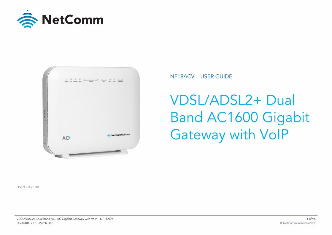
NF18ACV – USER GUIDE
VDSL/ADSL2+ Dual Band AC1600 Gigabit Gateway with VoIP
Doc No. UG01040
VDSL/ADSL2+ Dual Band AC1600 Gigabit Gateway with VoIP – NF18ACV 2 of 96
UG01040 v1.5 March 2021 © NetComm Wireless 2021
Important Notice
This device, like any wireless device, operates using radio signals which cannot guarantee the
transmission and reception of data in all conditions. While the delay or loss of signal is rare, you
should not rely solely on any wireless device for emergency communications or otherwise use
the device in situations where the interruption of data connectivity could lead to death,
personal injury, property damage, data loss, or other loss. NetComm Wireless accepts no
responsibility for any loss or damage resulting from errors or delays in transmission or
reception, or the failure of the NetComm NF18ACV to transmit or receive such data.
Copyright
Copyright© 2021 NetComm Wireless Limited. All rights reserved.
The information contained herein is proprietary to NetComm Wireless. No part of this
document may be translated, transcribed, reproduced, in any form, or by any means without
prior written consent of NetComm Wireless.
Trademarks and registered trademarks are the property of NetComm Wireless Limited or their
respective owners. Specifications are subject to change without notice. Images shown may vary
slightly from the actual product.
Note – This document is subject to change without notice.
Save our environment
When this equipment has reached the end of its useful life, it must be taken to a recycling
centre and processed separately from domestic waste.
The cardboard box, the plastic contained in the packaging, and the parts that make up this
device can be recycled in accordance with regionally established regulations. Never dispose of
this electronic equipment along with domestic waste. You may be subject to penalties or
sanctions under the law. Instead, ask for disposal instructions from your municipal government.
Please be responsible and protect our environment.
Document history
This guide covers the following product:
VDSL/ADSL2+ Dual Band AC1600 Gigabit Gateway with VoIP (NF18ACV)
V E R . D O C U M E N T D E S C R I P T I O N D A T E
v1.0 Initial document release August 2017
v1.1 Additions and changes to Advanced Setup section June 2018
v1.2 User Guide for new User Interface December 2018
v1.3 Corrected Access List screenshot September 2019
v1.4 Includes changes from Release Note R6B017 April 2020
v1.5 Added notes about Block list limitations and SAMBA support March 2021
Table i. – Document revision history
VDSL/ADSL2+ Dual Band AC1600 Gigabit Gateway with VoIP – NF18ACV 3 of 96
UG01040 v1.5 March 2021 © NetComm Wireless 2021
Contents
Overview ............................................................................................................ 5
Introduction ......................................................................................................................................................... 5 Target audience .................................................................................................................................................. 5 Prerequisites ........................................................................................................................................................ 5 Notation ............................................................................................................................................................... 5
Welcome............................................................................................................ 6
Product overview ................................................................................................. 6
Package contents ................................................................................................ 6
Product features .................................................................................................. 6
Perfect for ............................................................................................................................................................ 6 Key features ......................................................................................................................................................... 7 NF18ACV ............................................................................................................................................................. 7
nbn and UFB ready........................................................................................................................................ 7 Triple play services ........................................................................................................................................ 7 Enhanced wireless experience ...................................................................................................................... 7 Media sharing ................................................................................................................................................ 7
Interfaces ........................................................................................................... 8
Front view ............................................................................................................................................................ 8 LED indicators ............................................................................................................................................... 8
Rear view............................................................................................................................................................ 10 Left side view ..................................................................................................................................................... 11 Pedestal label .................................................................................................................................................... 11
Safety and product care ..................................................................................... 11
Transport and handling ...................................................................................... 12
Physical dimensions and weight ........................................................................... 12
Installation and configuration .............................................................................. 12
Placement of your NF18ACV ........................................................................................................................... 12 Avoiding obstacles and interference .............................................................................................................. 12 Cordless phones................................................................................................................................................ 13 Choose the “quietest” channel for your wireless network ........................................................................... 13
Hardware installation ......................................................................................... 13
Connect a client via Ethernet cable ................................................................................................................ 13 Connect a client wirelessly ............................................................................................................................... 13 Connect a client via WPS.................................................................................................................................. 14
Initial NF18ACV configuration............................................................................. 15
Log in .................................................................................................................................................................. 15 Set up options ................................................................................................................................................... 16
Start the Setup Wizard ................................................................................................................................. 16 Go to the Main Menu................................................................................................................................... 16
Setup Wizard.................................................................................................... 17
INTERNET settings............................................................................................................................................ 17 ADSL ............................................................................................................................................................ 18 VDSL............................................................................................................................................................. 19 Ethernet WAN .............................................................................................................................................. 20
WIRELESS settings ............................................................................................................................................ 21 WIRELESS 2.4GHz ........................................................................................................................................ 21 WIRELESS 5GHz ........................................................................................................................................... 21
PHONE settings ................................................................................................................................................ 22 Using a phone handset with your router ..................................................................................................... 22 PHONE LINE settings .................................................................................................................................. 22
GATEWAY SECURITY settings ........................................................................................................................ 23 Network Security .......................................................................................................................................... 23 GATEWAY SECURITY settings..................................................................................................................... 23
TIMEZONE settings .......................................................................................................................................... 24 SUMMARY .......................................................................................................................................................... 25
VDSL/ADSL2+ Dual Band AC1600 Gigabit Gateway with VoIP – NF18ACV 4 of 96
UG01040 v1.5 March 2021 © NetComm Wireless 2021
NF18ACV default settings .................................................................................. 26
Restore Factory Default settings ..................................................................................................................26
SUMMARY........................................................................................................ 27
Gateway Information ....................................................................................................................................28 Internet Information .....................................................................................................................................28 Wireless 2.4 GHz ..........................................................................................................................................29 Wireless 5 GHz .............................................................................................................................................29 USB Devices .................................................................................................................................................30 Phone Details ...............................................................................................................................................30 Wired Devices ..............................................................................................................................................31
INTERNET ........................................................................................................ 32
Edit a service ................................................................................................................................................33 Create a new connection ................................................................................................................................. 33
WIRELESS ........................................................................................................ 34
PHONE ............................................................................................................ 36
PARENTAL CONTROL ....................................................................................... 39
CONTENT SHARING ......................................................................................... 41
ADVANCED ..................................................................................................... 42
Diagnostics – Information ................................................................................................................................ 43 Diagnostics – Statistics ..................................................................................................................................... 46 Diagnostics – Troubleshooting ....................................................................................................................... 50 Diagnostics – Logs............................................................................................................................................ 52 Routing – NAT................................................................................................................................................... 54 Routing – Routing ............................................................................................................................................. 58 Routing – DDNS ............................................................................................................................................... 60 Management – TR-069 Client.......................................................................................................................... 61 Management – SNMP Agent .......................................................................................................................... 63 Management – Passwords ............................................................................................................................... 64 Management – LED Control............................................................................................................................ 65
LAN ..................................................................................................................................................................... 66 Local Area Network – IPv4 ........................................................................................................................... 66 Local Area Network – IPv6 ........................................................................................................................... 69 Local Area Network – VLAN ........................................................................................................................ 71 Wireless Advanced Settings – Wireless Bridge ........................................................................................... 72 Wireless Advanced Settings – MAC Filter ................................................................................................... 73 Wireless Advanced Settings – Advanced .................................................................................................... 74
Phone – SIP Settings ......................................................................................................................................... 81 System ................................................................................................................................................................ 83 QoS ..................................................................................................................................................................... 86 Security ............................................................................................................................................................... 92
VDSL/ADSL2+ Dual Band AC1600 Gigabit Gateway with VoIP – NF18ACV 5 of 96
UG01040 v1.5 March 2021 © NetComm Wireless 2021
Overview
Introduction
This manual provides information related to the installation, operation, and use of the
NF18ACV.
Target audience
The individual reading this manual is presumed to have a basic understanding of
telecommunications terminology and concepts.
Prerequisites
Before continuing with the installation of your NF18ACV, please confirm that you meet the
minimum system requirements below.
An activated ADSL/VDSL or pre-configured WAN connection.
A computer with a working Ethernet adapter or wireless 802.11a/b/g/n/ac capability and
the TCP/IP Protocol installed.
A current version of a web browser such as Internet Explorer®, Mozilla Firefox® or
Google Chrome™.
Notation
The following symbols are used in this manual:
Note – This note contains useful information.
Important – This is important information that may require your attention.
Warning – This is a warning that may require immediate action in order to avoid damage
or injury.
VDSL/ADSL2+ Dual Band AC1600 Gigabit Gateway with VoIP – NF18ACV 6 of 96
UG01040 v1.5 March 2021 © NetComm Wireless 2021
Welcome
Thank you for purchasing a NetComm Wireless NF18ACV. This guide contains all the
information you need to configure your device.
Product overview
Fully featured VDSL2 / ADSL2+ gateway
4 x Gigabit Ethernet 10/100/1000 LAN ports
nbn and UFB ready – ultra-fast connection to nbn and UFB fibre network - 1 x
10/100/1000 Gigabit Ethernet WAN port
VoIP feature for HD quality voice calls - connect up to 2 telephones
Next generation WiFi 802.11 AC1600, dual band concurrent, for multiple high-speed
wireless connections
2 x WPS push buttons for the quick and easy connection of wireless devices on both
2.4GHz and 5GHz bands
Access and share media and file content across the wireless home network
Device performance monitoring and management through TR-069
Package contents
The NF18ACV package consists of:
1 x NetComm Wireless NF18ACV VDSL2/ADSL2+ Dual Band AC1600 Wireless
Gigabit Gateway with VoIP
1 x RJ45 Ethernet cable
1 x RJ11 Telephone cable
1 x WiFi Security card
1 x Warranty card
1 x Power supply (12V/2A)
If any of these items are missing or damaged, please contact NetComm Wireless Support
immediately by visiting the NetComm Wireless Support website at:
http://www.netcommwireless.com/contact-forms/support
Product features
Perfect for
Ultra-fast connection to your fixed line VDSL2/ADSL2+ service
High-speed connection to nbn or UFB Fibre networks FTTN/FTTB and FTTH/FTTP
Triple play services offer including Voice over IP
Creating a powerful wireless home network and media sharing
VDSL/ADSL2+ Dual Band AC1600 Gigabit Gateway with VoIP – NF18ACV 7 of 96
UG01040 v1.5 March 2021 © NetComm Wireless 2021
Key features
Fully featured VDSL2 / ADSL2+ gateway
4 x Gigabit Ethernet 10/100/1000 LAN ports
nbn and UFB ready – ultra-fast connection to nbn and UFB fibre network - 1 x
10/100/1000 Gigabit Ethernet WAN port
VoIP feature for HD quality voice calls - connect up to 2 telephones
Next generation WiFi 802.11 AC1600, dual band concurrent, for multiple high-speed
wireless connections
2x WPS push buttons for the quick and easy connection of wireless devices on both
2.4GHz and 5GHz bands
Access and share media and file content across the wireless home network
Device performance monitoring and management through TR-069
NF18ACV
The NetComm Wireless NF18ACV smart residential VDSL2/ADSL2+ wireless gateway brings an
enhanced and blazing fast broadband experience to the home.
nbn and UFB ready
Featuring VDSL2/ADSL2 technologies as well as a Gigabit WAN port, the NF18ACV is a 3-in-1
gateway that provides access to ADSL networks, VDSL and all nbn and UFB fibre network
options: FTTN, FTTB, FTTH
Triple play services
The NF18ACV is a triple play services enabler that supports the transmission of high-speed
data, multi HD/UHD IPTV and over the top video streaming, VoIP feature for HD quality voice
calls with the capacity to connect 2 phones.
Enhanced wireless experience
The NF18ACV gateway embeds the newest generation of WiFi (802.11 ac) for powerful access
point and video grade wireless capabilities. It allows both 2.4GHz and 5GHz bands to work
concurrently, ensuring interoperability with all wireless equipment in the house.
The NF18ACV is equipped with 5GHz 3 x 3 MIMO and 2.4GHz 2 x 2 MIMO internal antennas to
provide optimum reception while offering a powerful signal throughout the home. Create an
ultra-fast 1600 Mbps1 WiFi home network and connect a multitude of wireless devices such as
smart TVs, set top boxes, laptops, tablets, computers, NAS, smart phones and gaming consoles
with upgraded coverage and performance.
Media sharing
Connect a USB device to the NF18ACV gateway, access and share all A/V media and file
content with all of the connected devices in the house in real time. The NF18ACV becomes the
media hub of the house using DLNA/UPnP standard and enhanced wireless capabilities to
create a reliable high-speed home network.
1 Maximum wireless signal rate and coverage values are derived from IEEE Standard 802.11n and 802.11ac
specifications. Actual wireless speed and coverage are dependent on network and environmental conditions
included but not limited to volume of network traffic, building materials and construction/layout.
VDSL/ADSL2+ Dual Band AC1600 Gigabit Gateway with VoIP – NF18ACV 8 of 96
UG01040 v1.5 March 2021 © NetComm Wireless 2021
Interfaces
The NF18ACV is designed to be placed on a desktop with the front facing outward.
All of the cables exit from the rear for easy organization and the power ON/OFF and WPS
buttons on the side.
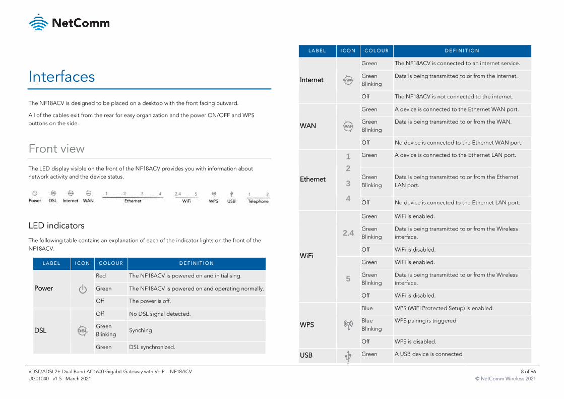
Front view
The LED display visible on the front of the NF18ACV provides you with information about
network activity and the device status.
LED indicators
The following table contains an explanation of each of the indicator lights on the front of the
NF18ACV.
L A B E L I C O N C O L O U R D E F I N I T I O N
Power
Red The NF18ACV is powered on and initialising.
Green The NF18ACV is powered on and operating normally.
Off The power is off.
DSL
Off No DSL signal detected.
Green
Blinking Synching
Green DSL synchronized.
L A B E L I C O N C O L O U R D E F I N I T I O N
Internet
Green The NF18ACV is connected to an internet service.
Green
Blinking
Data is being transmitted to or from the internet.
Off The NF18ACV is not connected to the internet.
WAN
Green A device is connected to the Ethernet WAN port.
Green
Blinking
Data is being transmitted to or from the WAN.
Off No device is connected to the Ethernet WAN port.
Ethernet
1
2
3
4
Green A device is connected to the Ethernet LAN port.
Green
Blinking
Data is being transmitted to or from the Ethernet
LAN port.
Off No device is connected to the Ethernet LAN port.
WiFi
2.4
Green WiFi is enabled.
Green
Blinking
Data is being transmitted to or from the Wireless
interface.
Off WiFi is disabled.
5
Green WiFi is enabled.
Green
Blinking
Data is being transmitted to or from the Wireless
interface.
Off WiFi is disabled.
WPS
Blue WPS (WiFi Protected Setup) is enabled.
Blue
Blinking
WPS pairing is triggered.
Off WPS is disabled.
USB
Green A USB device is connected.
VDSL/ADSL2+ Dual Band AC1600 Gigabit Gateway with VoIP – NF18ACV 9 of 96
UG01040 v1.5 March 2021 © NetComm Wireless 2021
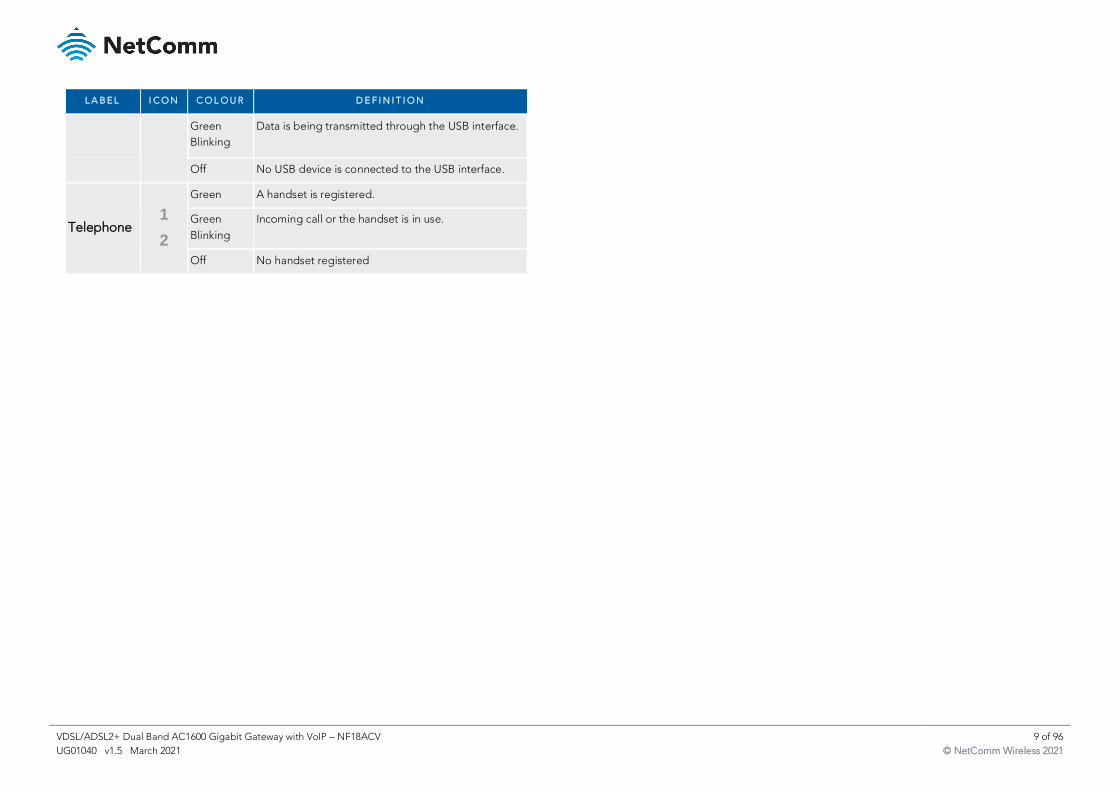
L A B E L I C O N C O L O U R D E F I N I T I O N
Green
Blinking
Data is being transmitted through the USB interface.
Off No USB device is connected to the USB interface.
Telephone 1
2
Green A handset is registered.
Green
Blinking
Incoming call or the handset is in use.
Off No handset registered
VDSL/ADSL2+ Dual Band AC1600 Gigabit Gateway with VoIP – NF18ACV 10 of 96
UG01040 v1.5 March 2021 © NetComm Wireless 2021
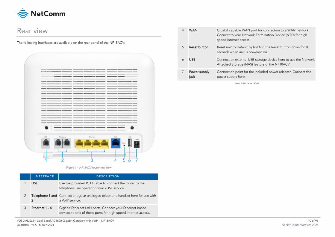
Rear view
The following interfaces are available on the rear panel of the NF18ACV:
Figure 1 – NF18ACV router rear view
I N T E R F A C E D E S C R I P T I O N
1 DSL Use the provided RJ11 cable to connect the router to the
telephone line operating your xDSL service.
2 Telephone 1 and
2
Connect a regular analogue telephone handset here for use with
a VoIP service.
3 Ethernet 1 - 4 Gigabit Ethernet LAN ports. Connect your Ethernet based
devices to one of these ports for high-speed internet access.
4 WAN Gigabit capable WAN port for connection to a WAN network.
Connect to your Network Termination Device (NTD) for high-
speed internet access.
5 Reset button Reset unit to Default by holding the Reset button down for 10
seconds when unit is powered on.
6 USB Connect an external USB storage device here to use the Network
Attached Storage (NAS) feature of the NF18ACV.
7 Power supply
jack
Connection point for the included power adapter. Connect the
power supply here.
Rear interface table
VDSL/ADSL2+ Dual Band AC1600 Gigabit Gateway with VoIP – NF18ACV 11 of 96
UG01040 v1.5 March 2021 © NetComm Wireless 2021
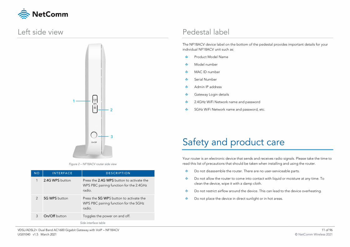
Left side view
Figure 2 – NF18ACV router side view
N O I N T E R F A C E D E S C R I P T I O N
1 2.4G WPS button Press the 2.4G WPS button to activate the
WPS PBC pairing function for the 2.4GHz
radio.
2 5G WPS button Press the 5G WPS button to activate the
WPS PBC pairing function for the 5GHz
radio.
3 On/Off button Toggles the power on and off.
Side interface table
Pedestal label
The NF18ACV device label on the bottom of the pedestal provides important details for your
individual NF18ACV unit such as:
Product Model Name
Model number
MAC ID number
Serial Number
Admin IP address
Gateway Login details
2.4GHz WiFi Network name and password
5GHz WiFi Network name and password, etc.
Safety and product care
Your router is an electronic device that sends and receives radio signals. Please take the time to
read this list of precautions that should be taken when installing and using the router.
Do not disassemble the router. There are no user-serviceable parts.
Do not allow the router to come into contact with liquid or moisture at any time. To
clean the device, wipe it with a damp cloth.
Do not restrict airflow around the device. This can lead to the device overheating.
Do not place the device in direct sunlight or in hot areas.
VDSL/ADSL2+ Dual Band AC1600 Gigabit Gateway with VoIP – NF18ACV 12 of 96
UG01040 v1.5 March 2021 © NetComm Wireless 2021
Transport and handling
When transporting the NF18ACV, it is recommended to return the product in the original
packaging. This ensures that the product will not be damaged.
Attention – In the event the product needs to be returned, ensure it is securely packaged with
appropriate padding to prevent damage during courier transport.
Physical dimensions and weight
The table below lists the physical dimensions and weight of the NF18ACV.
D I M E N S I O N S
Width 216 mm
Height 173 mm
Depth 61 mm
Weight 420 grams
Physical dimensions and weigh table
Installation and configuration
Placement of your NF18ACV
The wireless connection between your NF18ACV and your WiFi devices will be strong when
they are in close proximity and have direct line of sight. As your client device moves further
away from the NF18ACV or solid objects block direct line of sight to the router, your wireless
connection and performance may degrade. This may or may not be directly noticeable, and is
greatly affected by the individual installation environment.
If you have concerns about your network’s performance that might be related to range or
obstruction factors, try moving the computer to a position between three to five meters from
the NF18ACV in order to see if distance is the problem.
Note – While some of the items listed below can affect network performance, they will not prohibit your
wireless network from functioning; if you are concerned that your network is not operating at its maximum
effectiveness, this check list may help
If you experience difficulties connecting wirelessly between your WiFi Devices and your
NF18ACV, please try the following steps:
In multi-storey homes, place the NF18ACV on a floor that is as close to the centre of the
home as possible. This may mean placing the NF18ACV on an upper floor.
Try not to place the NF18ACV near a cordless telephone that operates at the same
radio frequency as the NF18ACV (2.4GHz/5GHz).
Avoiding obstacles and interference
Avoid placing your NF18ACV near devices that may emit radio “noise,” such as microwave
ovens. Dense objects that can inhibit wireless communication include:
Refrigerators
Washers and/or dryers
Metal cabinets
Large aquariums
VDSL/ADSL2+ Dual Band AC1600 Gigabit Gateway with VoIP – NF18ACV 13 of 96
UG01040 v1.5 March 2021 © NetComm Wireless 2021
Metallic-based, UV-tinted windows
If your wireless signal seems weak in some spots, make sure that objects such as
those listed above are not blocking the signal’s path (between your devices and the
NF18ACV).
Cordless phones
If the performance of your wireless network is impaired after considering the above issues, and
you have a cordless phone:
Try moving cordless phones away from your NF18ACV and your wireless-enabled
computers.
Unplug and remove the battery from any cordless phone that operates on the 2.4GHz or
5GHz band (check manufacturer’s information). If this fixes the problem, your phone
may be interfering with the NF18ACV.
If your phone supports channel selection, change the channel on the phone to the
farthest channel from your wireless network. For example, change the phone to channel
1 and move your NF18ACV to channel 11. See your phone’s user manual for detailed
instructions.
If necessary, consider switching to a 900MHz or 1800MHz cordless phone.
Choose the “quietest” channel for your wireless network
In locations where homes or offices are close together, such as apartment buildings or office
complexes, there may be wireless networks nearby that can conflict with your wireless network.
Your wireless adapter may include a utility to assist in scanning for the least congested network,
otherwise you may be able to find another piece of software that can be used. These tools
display a graphical representation of the wireless networks in range and the channels on which
they are operating.
Try to find a channel which is not as busy and does not overlap with another one. Channels 1, 6
and 11 are the only channels on 2.4GHz which do not overlap with one another and you should
ideally choose one of these channels.
Experiment with more than one of the available channels, in order to find the clearest
connection and avoid interference from neighbouring cordless phones or other wireless
devices.
Hardware installation
1 Connect the power adapter to the Power socket on the back of the NF18ACV.
2 Plug the power adapter into the wall socket and switch on the power.
3 Wait approximately 60 seconds for the NF18ACV to power up.
Connect a client via Ethernet cable
1 Connect the yellow Ethernet cable provided to one of the yellow ports marked
‘Ethernet’ at the back of the NF18ACV.
2 Connect the other end of the yellow Ethernet cable to your computer.
3 Wait approximately 30 seconds for the connection to establish.
4 Open your Web browser, and enter http://192.168.20.1 into the address bar and press
enter.
5 Follow the steps to set up your NF18ACV.
Connect a client wirelessly
1 Ensure WiFi is enabled on your device (e.g. computer/laptop/smartphone).
2 Scan for wireless networks in your area and connect to the network name that matches
the Wireless network name configured on the NF18ACV.
VDSL/ADSL2+ Dual Band AC1600 Gigabit Gateway with VoIP – NF18ACV 14 of 96
UG01040 v1.5 March 2021 © NetComm Wireless 2021
Note – Refer to the included Wireless Security Card for the default SSID and wireless security
key of your NF18ACV.
3 When prompted for your wireless security settings, enter the Wireless security key
configured on the NF18ACV.
4 Wait approximately 30 seconds for the connection to establish.
5 Open your Web browser, and enter http://192.168.20.1 into the address bar and press
Enter.
6 Follow the steps to set up your NF18ACV.
Connect a client via WPS
The NF18ACV provides three methods to establish a connection with client devices using the
WPS (WiFi Protected Setup™) functionality.
Connect a device using the WPS button (default setting)
1 Bring a WPS enabled device within WiFi range and press its WPS (it may be physical or
virtual, e.g. on its user interface) button.
2 Press the WPS button on the left side of the NF18ACV. Its WPS orange icon will blink for
up to two minutes.
3 Once the device is connected, the WPS LED will remain illuminated and details of the
device will be added to the Wireless Clients list.
Connect a device using its WPS PIN
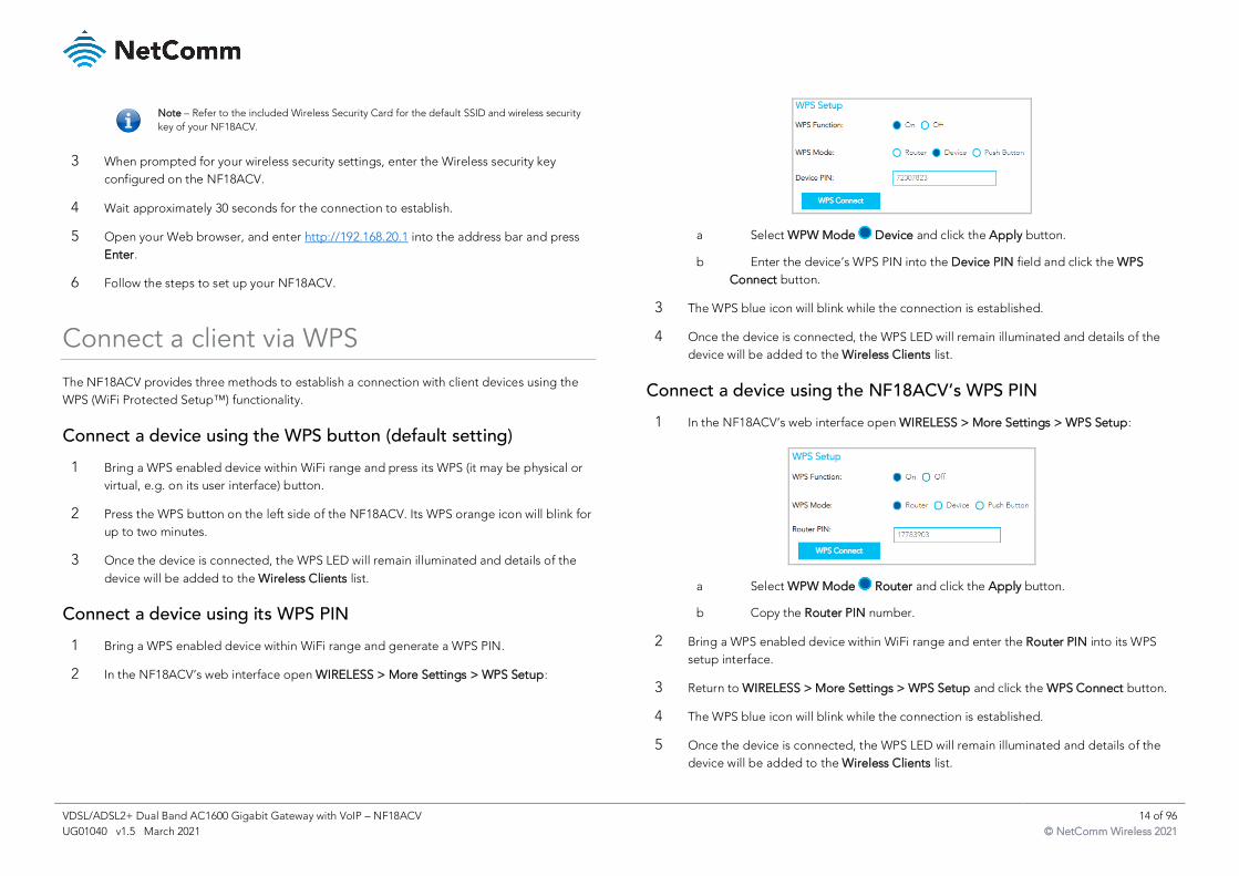
1 Bring a WPS enabled device within WiFi range and generate a WPS PIN.
2 In the NF18ACV’s web interface open WIRELESS > More Settings > WPS Setup:
a Select WPW Mode Device and click the Apply button.
b Enter the device’s WPS PIN into the Device PIN field and click the WPS
Connect button.
3 The WPS blue icon will blink while the connection is established.
4 Once the device is connected, the WPS LED will remain illuminated and details of the
device will be added to the Wireless Clients list.
Connect a device using the NF18ACV’s WPS PIN
1 In the NF18ACV’s web interface open WIRELESS > More Settings > WPS Setup:
a Select WPW Mode Router and click the Apply button.
b Copy the Router PIN number.
2 Bring a WPS enabled device within WiFi range and enter the Router PIN into its WPS
setup interface.
3 Return to WIRELESS > More Settings > WPS Setup and click the WPS Connect button.
4 The WPS blue icon will blink while the connection is established.
5 Once the device is connected, the WPS LED will remain illuminated and details of the
device will be added to the Wireless Clients list.
VDSL/ADSL2+ Dual Band AC1600 Gigabit Gateway with VoIP – NF18ACV 15 of 96
UG01040 v1.5 March 2021 © NetComm Wireless 2021
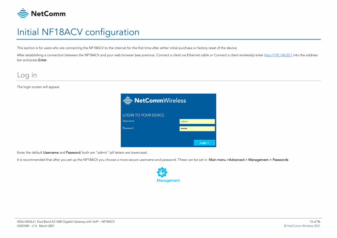
Initial NF18ACV configuration
This section is for users who are connecting the NF18ACV to the internet for the first time after either initial purchase or factory reset of the device.
After establishing a connection between the NF18ACV and your web browser (see previous: Connect a client via Ethernet cable or Connect a client wirelessly) enter http://192.168.20.1 into the address
bar and press Enter.
Log in
The login screen will appear:
Enter the default Username and Password: both are “admin” (all letters are lowercase).
It is recommended that after you set up the NF18ACV you choose a more secure username and password. These can be set in: Main menu >Advanced > Management > Passwords
VDSL/ADSL2+ Dual Band AC1600 Gigabit Gateway with VoIP – NF18ACV 16 of 96
UG01040 v1.5 March 2021 © NetComm Wireless 2021
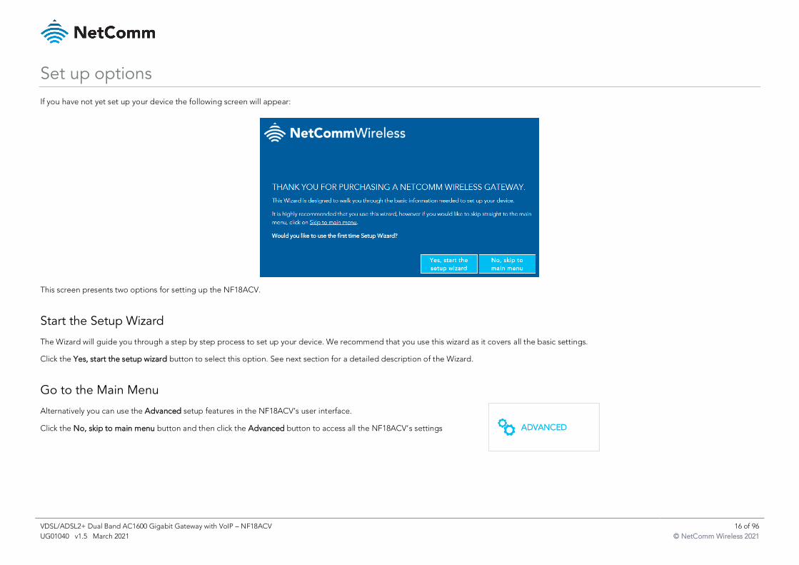
Set up options
If you have not yet set up your device the following screen will appear:
This screen presents two options for setting up the NF18ACV.
Start the Setup Wizard
The Wizard will guide you through a step by step process to set up your device. We recommend that you use this wizard as it covers all the basic settings.
Click the Yes, start the setup wizard button to select this option. See next section for a detailed description of the Wizard.
Go to the Main Menu
Alternatively you can use the Advanced setup features in the NF18ACV’s user interface.
Click the No, skip to main menu button and then click the Advanced button to access all the NF18ACV’s settings
VDSL/ADSL2+ Dual Band AC1600 Gigabit Gateway with VoIP – NF18ACV 17 of 96
UG01040 v1.5 March 2021 © NetComm Wireless 2021
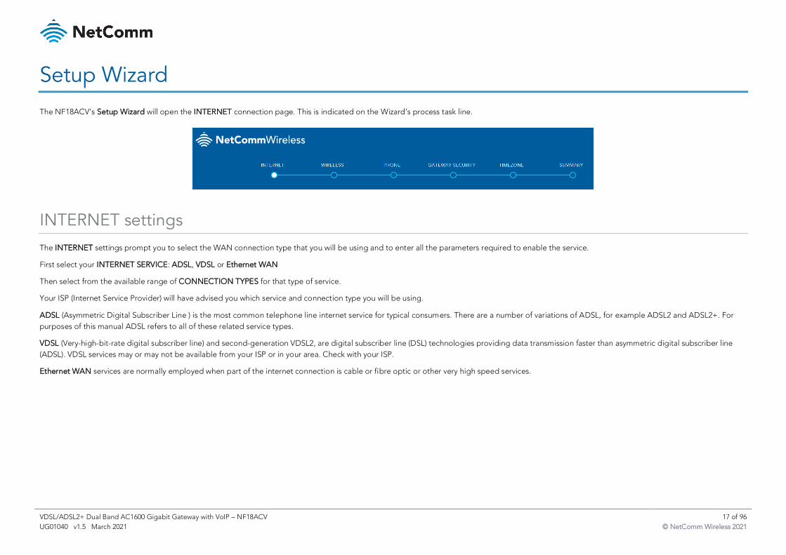
Setup Wizard
The NF18ACV’s Setup Wizard will open the INTERNET connection page. This is indicated on the Wizard’s process task line.
INTERNET settings
The INTERNET settings prompt you to select the WAN connection type that you will be using and to enter all the parameters required to enable the service.
First select your INTERNET SERVICE: ADSL, VDSL or Ethernet WAN
Then select from the available range of CONNECTION TYPES for that type of service.
Your ISP (Internet Service Provider) will have advised you which service and connection type you will be using.
ADSL (Asymmetric Digital Subscriber Line ) is the most common telephone line internet service for typical consumers. There are a number of variations of ADSL, for example ADSL2 and ADSL2+. For
purposes of this manual ADSL refers to all of these related service types.
VDSL (Very-high-bit-rate digital subscriber line) and second-generation VDSL2, are digital subscriber line (DSL) technologies providing data transmission faster than asymmetric digital subscriber line
(ADSL). VDSL services may or may not be available from your ISP or in your area. Check with your ISP.
Ethernet WAN services are normally employed when part of the internet connection is cable or fibre optic or other very high speed services.
VDSL/ADSL2+ Dual Band AC1600 Gigabit Gateway with VoIP – NF18ACV 18 of 96
UG01040 v1.5 March 2021 © NetComm Wireless 2021
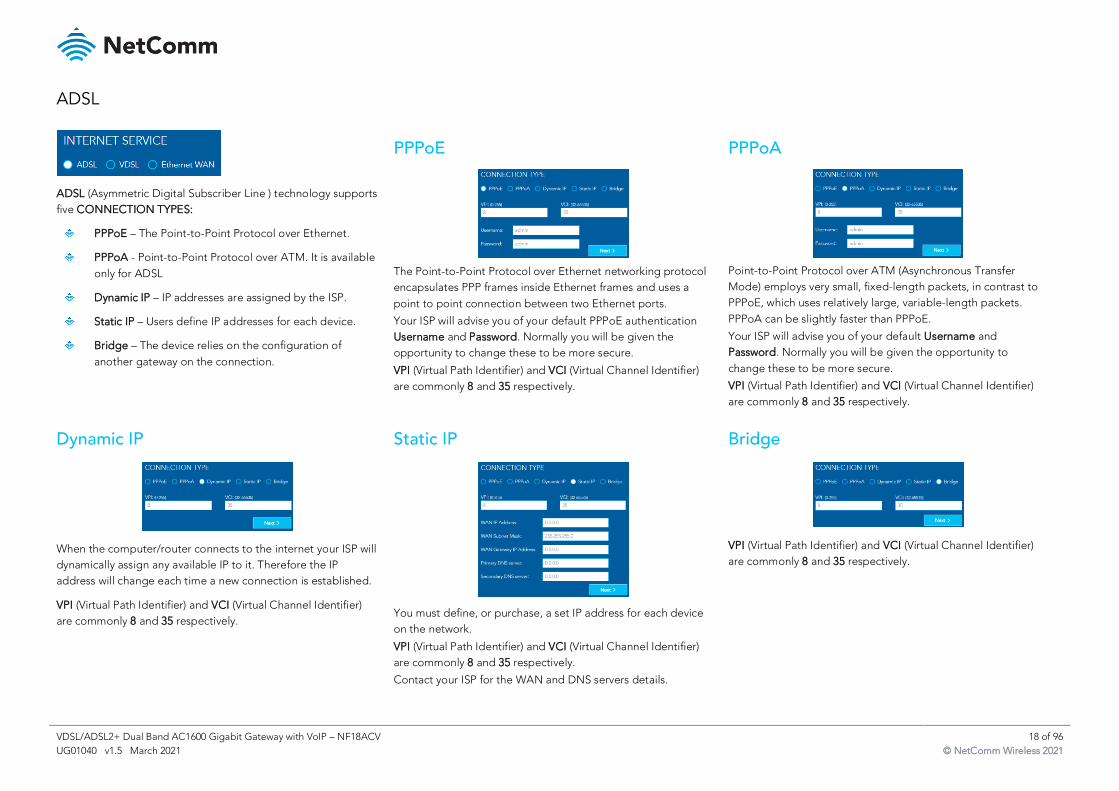
ADSL
ADSL (Asymmetric Digital Subscriber Line ) technology supports
five CONNECTION TYPES:
PPPoE – The Point-to-Point Protocol over Ethernet.
PPPoA - Point-to-Point Protocol over ATM. It is available
only for ADSL
Dynamic IP – IP addresses are assigned by the ISP.
Static IP – Users define IP addresses for each device.
Bridge – The device relies on the configuration of
another gateway on the connection.
PPPoE
The Point-to-Point Protocol over Ethernet networking protocol
encapsulates PPP frames inside Ethernet frames and uses a
point to point connection between two Ethernet ports.
Your ISP will advise you of your default PPPoE authentication
Username and Password. Normally you will be given the
opportunity to change these to be more secure.
VPI (Virtual Path Identifier) and VCI (Virtual Channel Identifier)
are commonly 8 and 35 respectively.
PPPoA
Point-to-Point Protocol over ATM (Asynchronous Transfer
Mode) employs very small, fixed-length packets, in contrast to
PPPoE, which uses relatively large, variable-length packets.
PPPoA can be slightly faster than PPPoE.
Your ISP will advise you of your default Username and
Password. Normally you will be given the opportunity to
change these to be more secure.
VPI (Virtual Path Identifier) and VCI (Virtual Channel Identifier)
are commonly 8 and 35 respectively.
Dynamic IP
When the computer/router connects to the internet your ISP will
dynamically assign any available IP to it. Therefore the IP
address will change each time a new connection is established.
VPI (Virtual Path Identifier) and VCI (Virtual Channel Identifier)
are commonly 8 and 35 respectively.
Static IP
You must define, or purchase, a set IP address for each device
on the network.
VPI (Virtual Path Identifier) and VCI (Virtual Channel Identifier)
are commonly 8 and 35 respectively.
Contact your ISP for the WAN and DNS servers details.
Bridge
VPI (Virtual Path Identifier) and VCI (Virtual Channel Identifier)
are commonly 8 and 35 respectively.
VDSL/ADSL2+ Dual Band AC1600 Gigabit Gateway with VoIP – NF18ACV 19 of 96
UG01040 v1.5 March 2021 © NetComm Wireless 2021
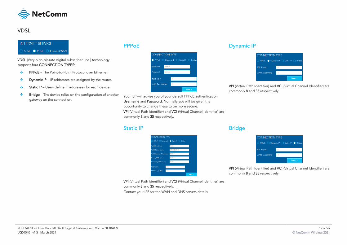
VDSL
VDSL (Very-high-bit-rate digital subscriber line ) technology
supports four CONNECTION TYPES:
PPPoE – The Point-to-Point Protocol over Ethernet.
Dynamic IP – IP addresses are assigned by the router.
Static IP – Users define IP addresses for each device.
Bridge – The device relies on the configuration of another
gateway on the connection.
PPPoE
Your ISP will advise you of your default PPPoE authentication
Username and Password. Normally you will be given the
opportunity to change these to be more secure.
VPI (Virtual Path Identifier) and VCI (Virtual Channel Identifier) are
commonly 8 and 35 respectively.
Dynamic IP
VPI (Virtual Path Identifier) and VCI (Virtual Channel Identifier) are
commonly 8 and 35 respectively.
Static IP
VPI (Virtual Path Identifier) and VCI (Virtual Channel Identifier) are
commonly 8 and 35 respectively.
Contact your ISP for the WAN and DNS servers details.
Bridge
VPI (Virtual Path Identifier) and VCI (Virtual Channel Identifier) are
commonly 8 and 35 respectively.

VDSL/ADSL2+ Dual Band AC1600 Gigabit Gateway with VoIP – NF18ACV 20 of 96
UG01040 v1.5 March 2021 © NetComm Wireless 2021
Ethernet WAN
Ethernet WAN (Wide Area Network) technology supports four
CONNECTION TYPES:
PPPoE – The Point-to-Point Protocol over Ethernet.
Dynamic IP – IP addresses are assigned by the router.
Static IP – Users define IP addresses for each device.
Bridge – The device relies on the configuration of another
gateway on the connection.
PPPoE
Your ISP will advise you of your default PPPoE authentication
Username and Password. Normally you will be given the
opportunity to change these to be more secure.
VPI (Virtual Path Identifier) and VCI (Virtual Channel Identifier) are
commonly 8 and 35 respectively.
Dynamic IP
VPI (Virtual Path Identifier) and VCI (Virtual Channel Identifier) are
commonly 8 and 35 respectively.
Static IP
VPI (Virtual Path Identifier) and VCI (Virtual Channel Identifier) are
commonly 8 and 35 respectively.
Contact your ISP for the WAN and DNS servers details.
Bridge
VPI (Virtual Path Identifier) and VCI (Virtual Channel Identifier) are
commonly 8 and 35 respectively.
When you have completed the INTERNET settings, click the Next > button to proceed to the Wizard’s WIRELESS settings.
VDSL/ADSL2+ Dual Band AC1600 Gigabit Gateway with VoIP – NF18ACV 21 of 96
UG01040 v1.5 March 2021 © NetComm Wireless 2021
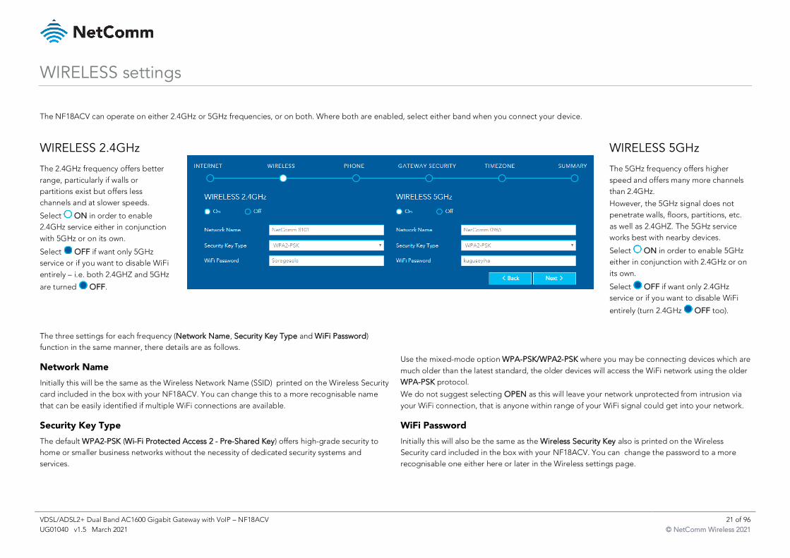
WIRELESS settings
The NF18ACV can operate on either 2.4GHz or 5GHz frequencies, or on both. Where both are enabled, select either band when you connect your device.
WIRELESS 2.4GHz
The 2.4GHz frequency offers better
range, particularly if walls or
partitions exist but offers less
channels and at slower speeds.
Select ON in order to enable
2.4GHz service either in conjunction
with 5GHz or on its own.
Select OFF if want only 5GHz
service or if you want to disable WiFi
entirely – i.e. both 2.4GHZ and 5GHz
are turned OFF.
WIRELESS 5GHz
The 5GHz frequency offers higher
speed and offers many more channels
than 2.4GHz.
However, the 5GHz signal does not
penetrate walls, floors, partitions, etc.
as well as 2.4GHZ. The 5GHz service
works best with nearby devices.
Select ON in order to enable 5GHz
either in conjunction with 2.4GHz or on
its own.
Select OFF if want only 2.4GHz
service or if you want to disable WiFi
entirely (turn 2.4GHz OFF too).
The three settings for each frequency (Network Name, Security Key Type and WiFi Password)
function in the same manner, there details are as follows.
Network Name
Initially this will be the same as the Wireless Network Name (SSID) printed on the Wireless Security
card included in the box with your NF18ACV. You can change this to a more recognisable name
that can be easily identified if multiple WiFi connections are available.
Security Key Type
The default WPA2-PSK (Wi-Fi Protected Access 2 - Pre-Shared Key) offers high-grade security to
home or smaller business networks without the necessity of dedicated security systems and
services.
Use the mixed-mode option WPA-PSK/WPA2-PSK where you may be connecting devices which are
much older than the latest standard, the older devices will access the WiFi network using the older
WPA-PSK protocol.
We do not suggest selecting OPEN as this will leave your network unprotected from intrusion via
your WiFi connection, that is anyone within range of your WiFi signal could get into your network.
WiFi Password
Initially this will also be the same as the Wireless Security Key also is printed on the Wireless
Security card included in the box with your NF18ACV. You can change the password to a more
recognisable one either here or later in the Wireless settings page.
VDSL/ADSL2+ Dual Band AC1600 Gigabit Gateway with VoIP – NF18ACV 22 of 96
UG01040 v1.5 March 2021 © NetComm Wireless 2021
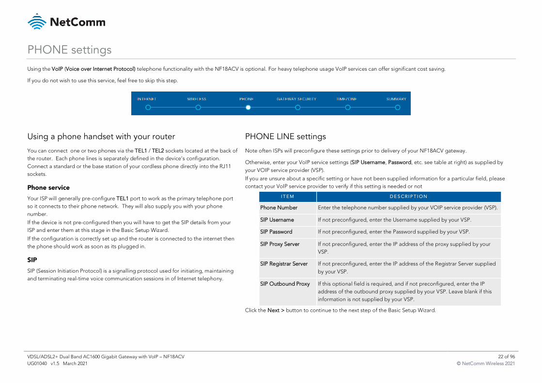
PHONE settings
Using the VoIP (Voice over Internet Protocol) telephone functionality with the NF18ACV is optional. For heavy telephone usage VoIP services can offer significant cost saving.
If you do not wish to use this service, feel free to skip this step.
Using a phone handset with your router
You can connect one or two phones via the TEL1 / TEL2 sockets located at the back of
the router. Each phone lines is separately defined in the device’s configuration.
Connect a standard or the base station of your cordless phone directly into the RJ11
sockets.
Phone service
Your ISP will generally pre-configure TEL1 port to work as the primary telephone port
so it connects to their phone network. They will also supply you with your phone
number.
If the device is not pre-configured then you will have to get the SIP details from your
ISP and enter them at this stage in the Basic Setup Wizard.
If the configuration is correctly set up and the router is connected to the internet then
the phone should work as soon as its plugged in.
SIP
SIP (Session Initiation Protocol) is a signalling protocol used for initiating, maintaining
and terminating real-time voice communication sessions in of Internet telephony.
PHONE LINE settings
Note often ISPs will preconfigure these settings prior to delivery of your NF18ACV gateway.
Otherwise, enter your VoIP service settings (SIP Username, Password, etc. see table at right) as supplied by
your VOIP service provider (VSP).
If you are unsure about a specific setting or have not been supplied information for a particular field, please
contact your VoIP service provider to verify if this setting is needed or not
I T E M D E S C R I P T I O N
Phone Number Enter the telephone number supplied by your VOIP service provider (VSP).
SIP Username If not preconfigured, enter the Username supplied by your VSP.
SIP Password If not preconfigured, enter the Password supplied by your VSP.
SIP Proxy Server If not preconfigured, enter the IP address of the proxy supplied by your
VSP.
SIP Registrar Server If not preconfigured, enter the IP address of the Registrar Server supplied
by your VSP.
SIP Outbound Proxy If this optional field is required, and if not preconfigured, enter the IP
address of the outbound proxy supplied by your VSP. Leave blank if this
information is not supplied by your VSP.
Click the Next > button to continue to the next step of the Basic Setup Wizard.
VDSL/ADSL2+ Dual Band AC1600 Gigabit Gateway with VoIP – NF18ACV 23 of 96
UG01040 v1.5 March 2021 © NetComm Wireless 2021
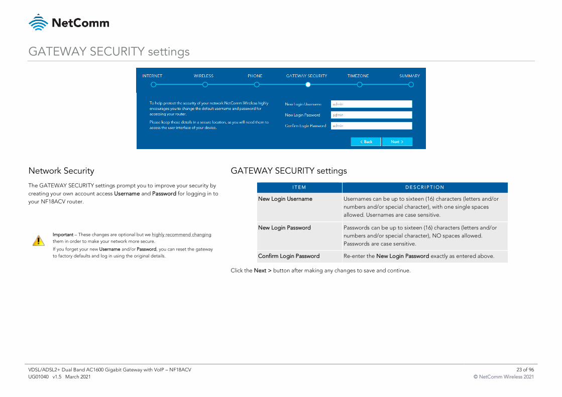
GATEWAY SECURITY settings
Network Security
The GATEWAY SECURITY settings prompt you to improve your security by
creating your own account access Username and Password for logging in to
your NF18ACV router.
Important – These changes are optional but we highly recommend changing
them in order to make your network more secure.
If you forget your new Username and/or Password, you can reset the gateway
to factory defaults and log in using the original details.
GATEWAY SECURITY settings
I T E M D E S C R I P T I O N
New Login Username Usernames can be up to sixteen (16) characters (letters and/or
numbers and/or special character), with one single spaces
allowed. Usernames are case sensitive.
New Login Password Passwords can be up to sixteen (16) characters (letters and/or
numbers and/or special character), NO spaces allowed.
Passwords are case sensitive.
Confirm Login Password Re-enter the New Login Password exactly as entered above.
Click the Next > button after making any changes to save and continue.
VDSL/ADSL2+ Dual Band AC1600 Gigabit Gateway with VoIP – NF18ACV 24 of 96
UG01040 v1.5 March 2021 © NetComm Wireless 2021
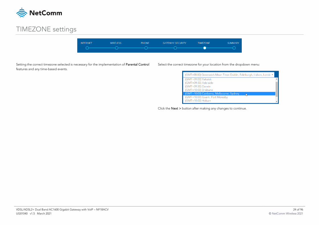
TIMEZONE settings
Setting the correct timezone selected is necessary for the implementation of Parental Control
features and any time-based events.
Select the correct timezone for your location from the dropdown menu:
Click the Next > button after making any changes to continue.
VDSL/ADSL2+ Dual Band AC1600 Gigabit Gateway with VoIP – NF18ACV 25 of 96
UG01040 v1.5 March 2021 © NetComm Wireless 2021
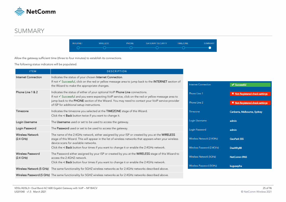
SUMMARY
Allow the gateway sufficient time (three to four minutes) to establish its connections.
The following status indicators will be populated.
I T E M D E S C R I P T I O N
Internet Connection Indicates the status of your chosen Internet Connection.
If not ✓ Successful, click on the red or yellow message area to jump back to the INTERNET section of
the Wizard to make the appropriate changes.
Phone Line 1 & 2 Indicates the status of either of your optional VoIP Phone Line connections.
If not ✓ Successful and you were expecting VoIP service, click on the red or yellow message area to
jump back to the PHONE section of the Wizard. You may need to contact your VoIP service provider
of ISP for additional setup instructions.
Timezone Indicates the timezone you selected at the TIMEZONE stage of this Wizard.
Click the < Back button twice if you want to change it.
Login Username The Username used or set to be used to access the gateway.
Login Password The Password used or set to be used to access the gateway.
Wireless Network
(2.4 GHz)
The name of the 2.4GHz network, either assigned by your ISP or created by you at the WIRELESS
stage of this Wizard. This will appear in the list of wireless networks that appears when your wireless
device scans for available networks.
Click the < Back button four times if you want to change it or enable the 2.4GHz network.
Wireless Password
(2.4 GHz)
The Password either assigned by your ISP or created by you at the WIRELESS stage of this Wizard to
access the 2.4GHZ network.
Click the < Back button four times if you want to change it or enable the 2.4GHz network.
Wireless Network (5 GHz) The same functionality for 5GHZ wireless networks as for 2.4GHz networks described above.
Wireless Password (5 GHz) The same functionality for 5GHZ wireless networks as for 2.4GHz networks described above.
VDSL/ADSL2+ Dual Band AC1600 Gigabit Gateway with VoIP – NF18ACV 26 of 96
UG01040 v1.5 March 2021 © NetComm Wireless 2021
NF18ACV default settings
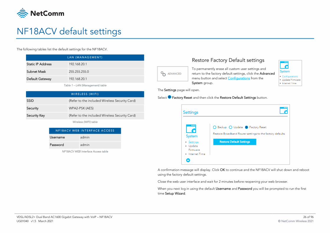
The following tables list the default settings for the NF18ACV.
L A N ( M A N A G E M E N T )
Static IP Address 192.168.20.1
Subnet Mask 255.255.255.0
Default Gateway 192.168.20.1
Table 1 – LAN (Management) table
W I R E L E S S ( W I F I )
SSID (Refer to the included Wireless Security Card)
Security WPA2-PSK (AES)
Security Key (Refer to the included Wireless Security Card)
Wireless (WIFI) table
N F 1 8 A C V W E B I N T E R F A C E A C C E S S
Username admin
Password admin
NF18ACV WEB Interface Access table
Restore Factory Default settings
To permanently erase all custom user settings and
return to the factory default settings, click the Advanced
menu button and select Configurations from the
System group.
The Settings page will open.
Select Factory Reset and then click the Restore Default Settings button.
A confirmation message will display. Click OK to continue and the NF18ACV will shut down and reboot
using the factory default settings.
Close the web user interface and wait for 2 minutes before reopening your web browser.
When you next log in using the default Username and Password you will be prompted to run the first
time Setup Wizard.
VDSL/ADSL2+ Dual Band AC1600 Gigabit Gateway with VoIP – NF18ACV 27 of 96
UG01040 v1.5 March 2021 © NetComm Wireless 2021
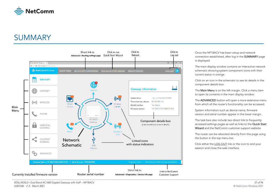
SUMMARY
Once the NF18ACV has been setup and network
connection established, after log in the SUMMARY page
is displayed.
The main display window contains an interactive network
schematic showing system component icons with their
current status in orange.
Click on an icon in the schematic to see its details in the
component details box.
The Main Menu is on the left margin. Click a menu item
to open its contents in the main display window.
The ADVANCED button will open a more extensive menu
from which all the router’s functionality can be accessed.
System information such as device name, firmware
version and serial number appear in the lower margin.
The task bars also include two direct link to frequently
accessed settings pages as well as links to the Quick Start
Wizard and the NetComm customer support website.
The router can be rebooted directly from this page using
the button in the top menu bar.
Click either the LOG OUT link or the icon to end your
session and close the web interface.
VDSL/ADSL2+ Dual Band AC1600 Gigabit Gateway with VoIP – NF18ACV 28 of 96
UG01040 v1.5 March 2021 © NetComm Wireless 2021
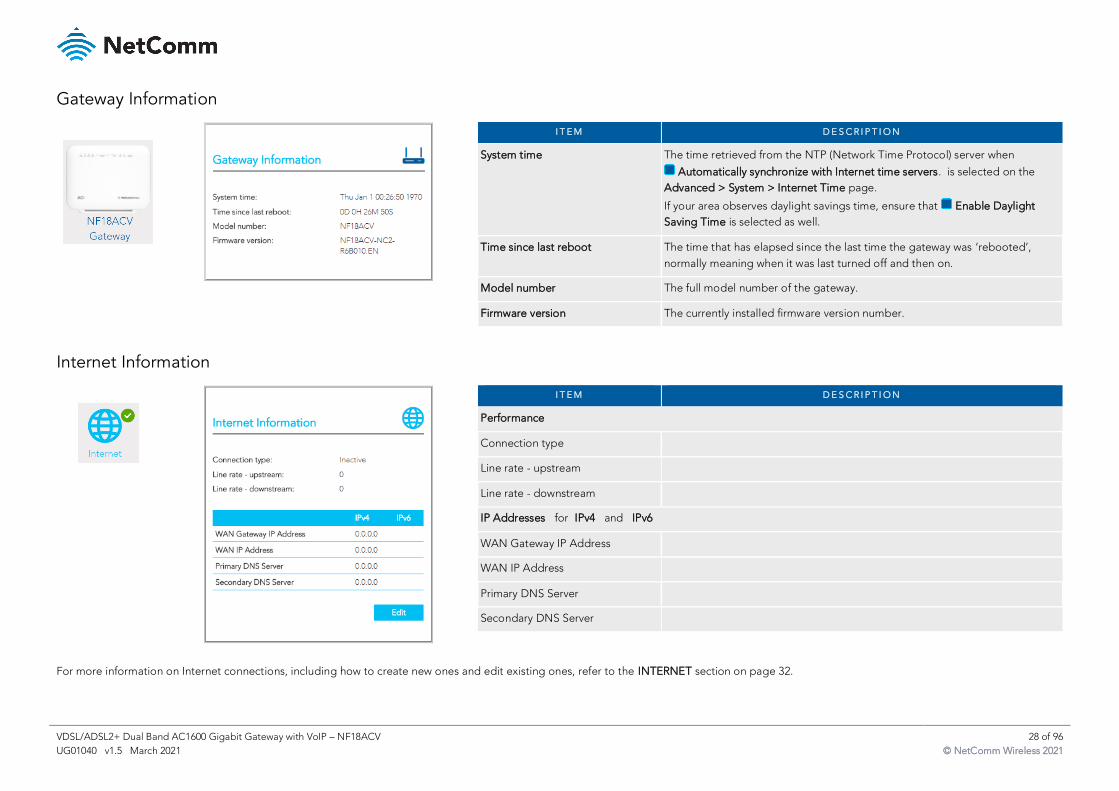
Gateway Information
I T E M D E S C R I P T I O N
System time The time retrieved from the NTP (Network Time Protocol) server when
Automatically synchronize with Internet time servers. is selected on the
Advanced > System > Internet Time page.
If your area observes daylight savings time, ensure that Enable Daylight
Saving Time is selected as well.
Time since last reboot The time that has elapsed since the last time the gateway was ‘rebooted’,
normally meaning when it was last turned off and then on.
Model number The full model number of the gateway.
Firmware version The currently installed firmware version number.
Internet Information
I T E M D E S C R I P T I O N
Performance
Connection type
Line rate - upstream
Line rate - downstream
IP Addresses for IPv4 and IPv6
WAN Gateway IP Address
WAN IP Address
Primary DNS Server
Secondary DNS Server
For more information on Internet connections, including how to create new ones and edit existing ones, refer to the INTERNET section on page 32.
VDSL/ADSL2+ Dual Band AC1600 Gigabit Gateway with VoIP – NF18ACV 29 of 96
UG01040 v1.5 March 2021 © NetComm Wireless 2021
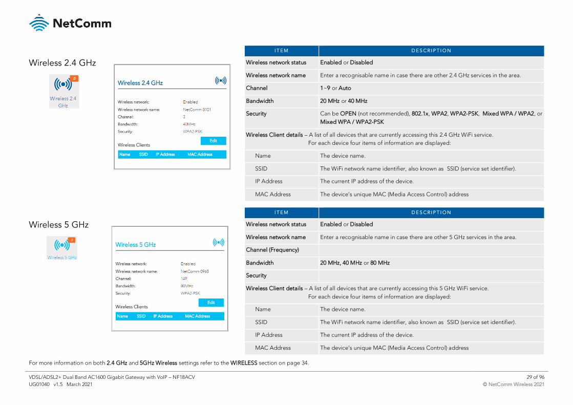
Wireless 2.4 GHz
I T E M D E S C R I P T I O N
Wireless network status Enabled or Disabled
Wireless network name Enter a recognisable name in case there are other 2.4 GHz services in the area.
Channel 1~9 or Auto
Bandwidth 20 MHz or 40 MHz
Security Can be OPEN (not recommended), 802.1x, WPA2, WPA2-PSK, Mixed WPA / WPA2, or
Mixed WPA / WPA2-PSK
Wireless Client details – A list of all devices that are currently accessing this 2.4 GHz WiFi service.
For each device four items of information are displayed:
Name The device name.
SSID The WiFi network name identifier, also known as SSID (service set identifier).
IP Address The current IP address of the device.
MAC Address The device’s unique MAC (Media Access Control) address
Wireless 5 GHz
I T E M D E S C R I P T I O N
Wireless network status Enabled or Disabled
Wireless network name Enter a recognisable name in case there are other 5 GHz services in the area.
Channel (Frequency)
Bandwidth 20 MHz, 40 MHz or 80 MHz
Security
Wireless Client details – A list of all devices that are currently accessing this 5 GHz WiFi service.
For each device four items of information are displayed:
Name The device name.
SSID The WiFi network name identifier, also known as SSID (service set identifier).
IP Address The current IP address of the device.
MAC Address The device’s unique MAC (Media Access Control) address
For more information on both 2.4 GHz and 5GHz Wireless settings refer to the WIRELESS section on page 34.
VDSL/ADSL2+ Dual Band AC1600 Gigabit Gateway with VoIP – NF18ACV 30 of 96
UG01040 v1.5 March 2021 © NetComm Wireless 2021
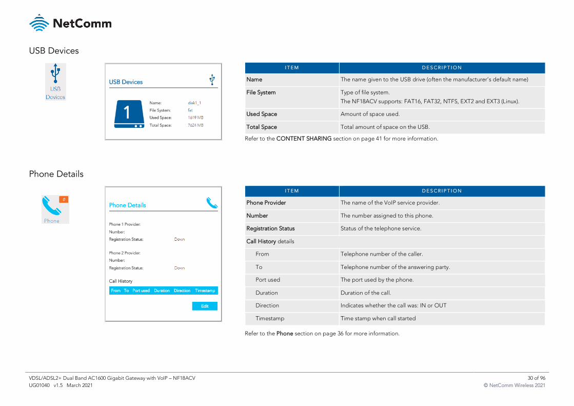
USB Devices
I T E M D E S C R I P T I O N
Name The name given to the USB drive (often the manufacturer’s default name)
File System Type of file system.
The NF18ACV supports: FAT16, FAT32, NTFS, EXT2 and EXT3 (Linux).
Used Space Amount of space used.
Total Space Total amount of space on the USB.
Refer to the CONTENT SHARING section on page 41 for more information.
Phone Details
I T E M D E S C R I P T I O N
Phone Provider The name of the VoIP service provider.
Number The number assigned to this phone.
Registration Status Status of the telephone service.
Call History details
From Telephone number of the caller.
To Telephone number of the answering party.
Port used The port used by the phone.
Duration Duration of the call.
Direction Indicates whether the call was: IN or OUT
Timestamp Time stamp when call started
Refer to the Phone section on page 36 for more information.
VDSL/ADSL2+ Dual Band AC1600 Gigabit Gateway with VoIP – NF18ACV 31 of 96
UG01040 v1.5 March 2021 © NetComm Wireless 2021
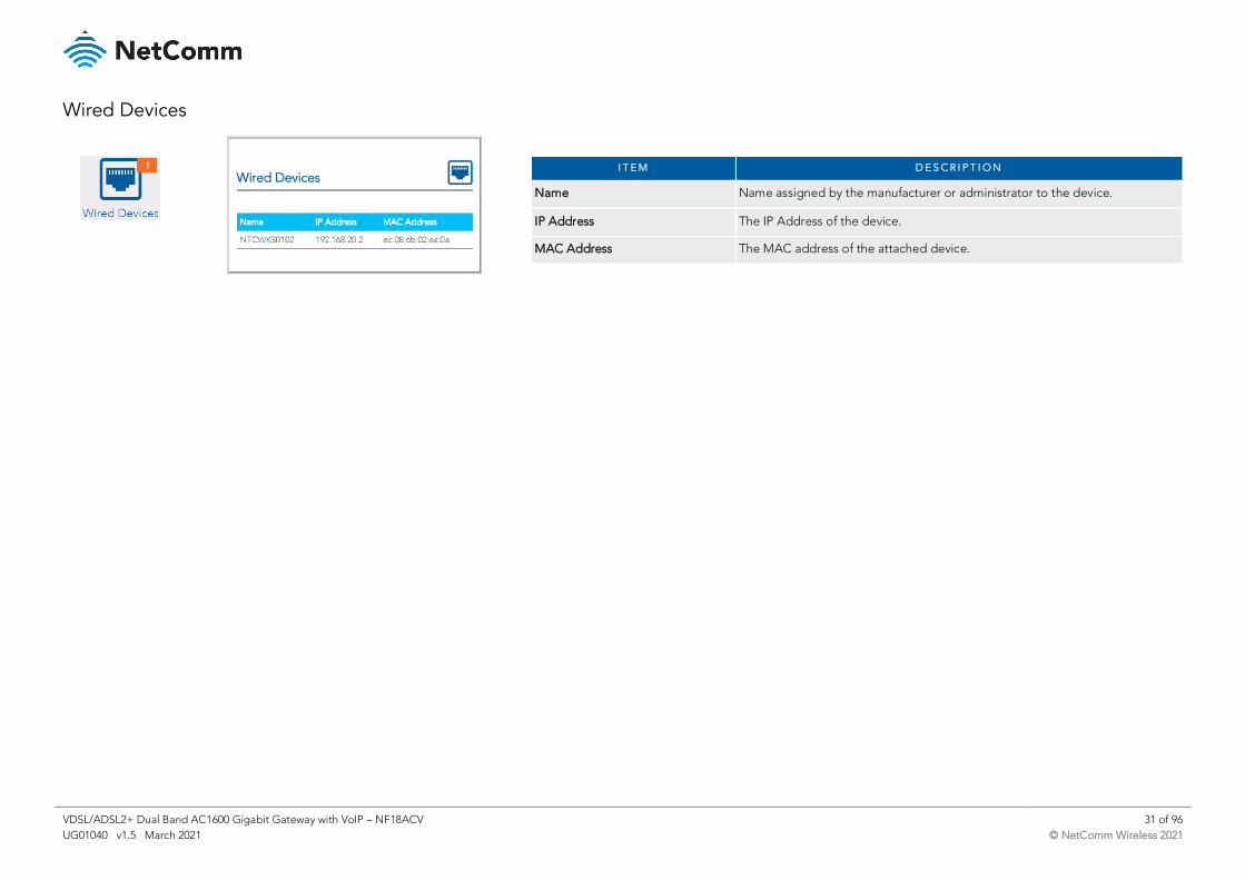
Wired Devices
I T E M D E S C R I P T I O N
Name Name assigned by the manufacturer or administrator to the device.
IP Address The IP Address of the device.
MAC Address The MAC address of the attached device.
VDSL/ADSL2+ Dual Band AC1600 Gigabit Gateway with VoIP – NF18ACV 32 of 96
UG01040 v1.5 March 2021 © NetComm Wireless 2021
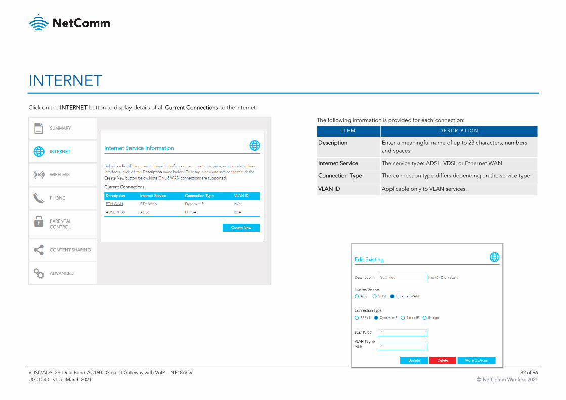
INTERNET
Click on the INTERNET button to display details of all Current Connections to the internet.
The following information is provided for each connection:
I T E M D E S C R I P T I O N
Description Enter a meaningful name of up to 23 characters, numbers
and spaces.
Internet Service The service type: ADSL, VDSL or Ethernet WAN
Connection Type The connection type differs depending on the service type.
VLAN ID Applicable only to VLAN services.
VDSL/ADSL2+ Dual Band AC1600 Gigabit Gateway with VoIP – NF18ACV 33 of 96
UG01040 v1.5 March 2021 © NetComm Wireless 2021
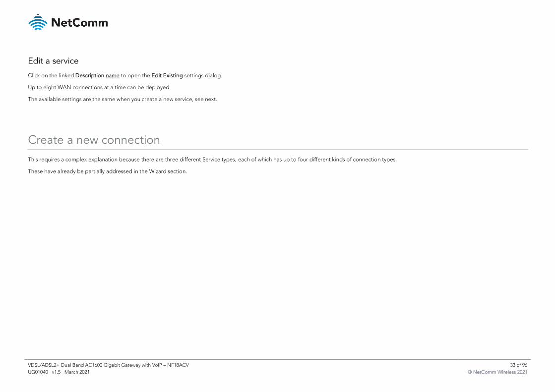
Edit a service
Click on the linked Description name to open the Edit Existing settings dialog.
Up to eight WAN connections at a time can be deployed.
The available settings are the same when you create a new service, see next.
Create a new connection
This requires a complex explanation because there are three different Service types, each of which has up to four different kinds of connection types.
These have already be partially addressed in the Wizard section.
VDSL/ADSL2+ Dual Band AC1600 Gigabit Gateway with VoIP – NF18ACV 34 of 96
UG01040 v1.5 March 2021 © NetComm Wireless 2021
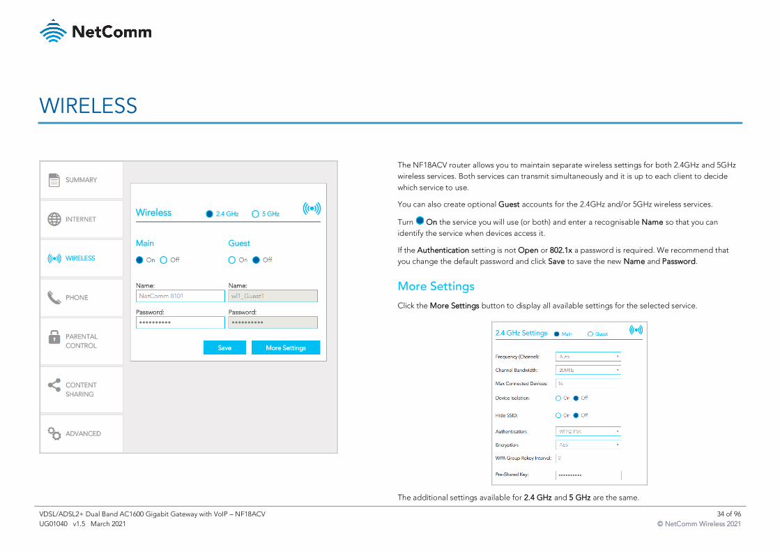
WIRELESS
The NF18ACV router allows you to maintain separate wireless settings for both 2.4GHz and 5GHz
wireless services. Both services can transmit simultaneously and it is up to each client to decide
which service to use.
You can also create optional Guest accounts for the 2.4GHz and/or 5GHz wireless services.
Turn On the service you will use (or both) and enter a recognisable Name so that you can
identify the service when devices access it.
If the Authentication setting is not Open or 802.1x a password is required. We recommend that
you change the default password and click Save to save the new Name and Password.
More Settings
Click the More Settings button to display all available settings for the selected service.
The additional settings available for 2.4 GHz and 5 GHz are the same.
VDSL/ADSL2+ Dual Band AC1600 Gigabit Gateway with VoIP – NF18ACV 35 of 96
UG01040 v1.5 March 2021 © NetComm Wireless 2021
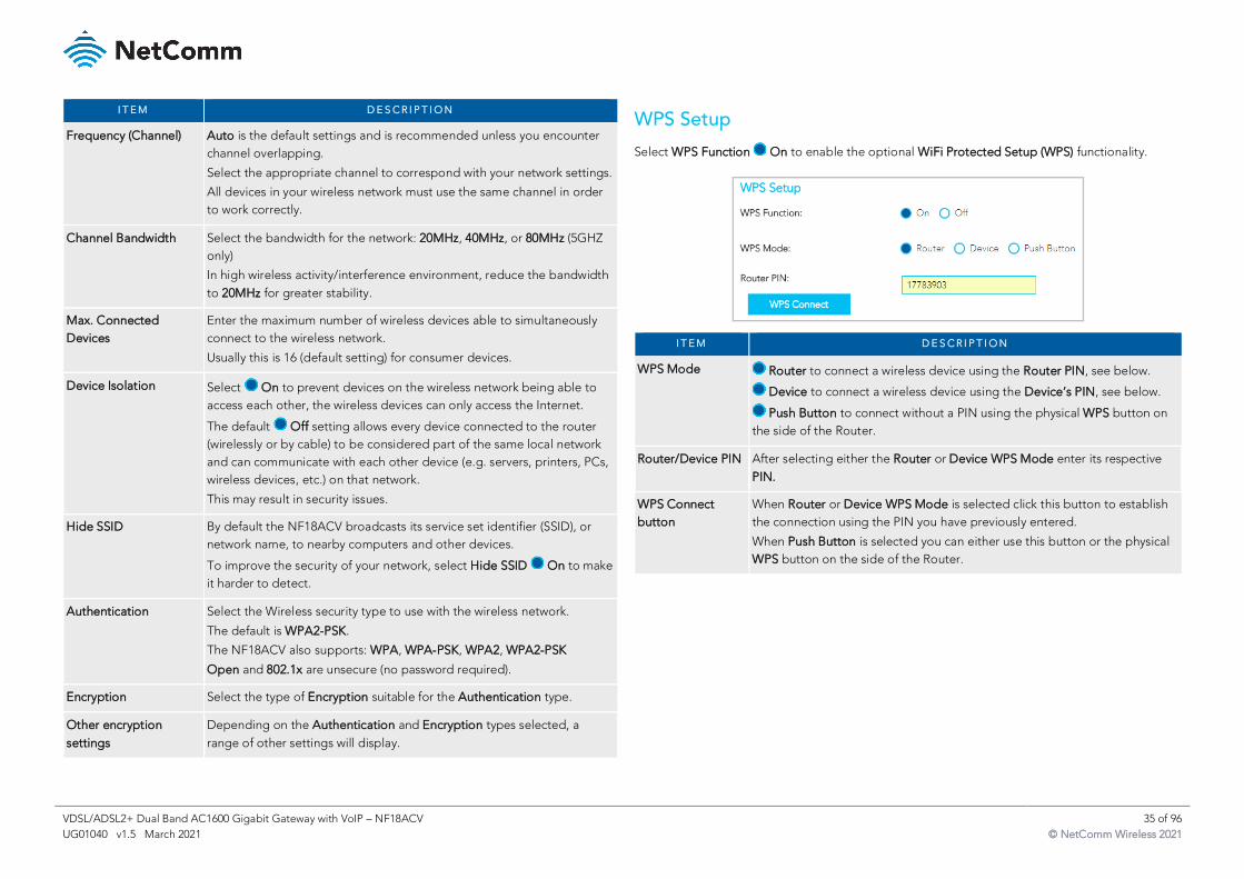
I T E M D E S C R I P T I O N
Frequency (Channel) Auto is the default settings and is recommended unless you encounter
channel overlapping.
Select the appropriate channel to correspond with your network settings.
All devices in your wireless network must use the same channel in order
to work correctly.
Channel Bandwidth Select the bandwidth for the network: 20MHz, 40MHz, or 80MHz (5GHZ
only)
In high wireless activity/interference environment, reduce the bandwidth
to 20MHz for greater stability.
Max. Connected
Devices
Enter the maximum number of wireless devices able to simultaneously
connect to the wireless network.
Usually this is 16 (default setting) for consumer devices.
Device Isolation Select On to prevent devices on the wireless network being able to
access each other, the wireless devices can only access the Internet.
The default Off setting allows every device connected to the router
(wirelessly or by cable) to be considered part of the same local network
and can communicate with each other device (e.g. servers, printers, PCs,
wireless devices, etc.) on that network.
This may result in security issues.
Hide SSID By default the NF18ACV broadcasts its service set identifier (SSID), or
network name, to nearby computers and other devices.
To improve the security of your network, select Hide SSID On to make
it harder to detect.
Authentication Select the Wireless security type to use with the wireless network.
The default is WPA2-PSK.
The NF18ACV also supports: WPA, WPA-PSK, WPA2, WPA2-PSK
Open and 802.1x are unsecure (no password required).
Encryption Select the type of Encryption suitable for the Authentication type.
Other encryption
settings
Depending on the Authentication and Encryption types selected, a
range of other settings will display.
WPS Setup
Select WPS Function On to enable the optional WiFi Protected Setup (WPS) functionality.
I T E M D E S C R I P T I O N
WPS Mode Router to connect a wireless device using the Router PIN, see below.
Device to connect a wireless device using the Device’s PIN, see below.
Push Button to connect without a PIN using the physical WPS button on
the side of the Router.
Router/Device PIN After selecting either the Router or Device WPS Mode enter its respective
PIN.
WPS Connect
button
When Router or Device WPS Mode is selected click this button to establish
the connection using the PIN you have previously entered.
When Push Button is selected you can either use this button or the physical
WPS button on the side of the Router.
VDSL/ADSL2+ Dual Band AC1600 Gigabit Gateway with VoIP – NF18ACV 36 of 96
UG01040 v1.5 March 2021 © NetComm Wireless 2021
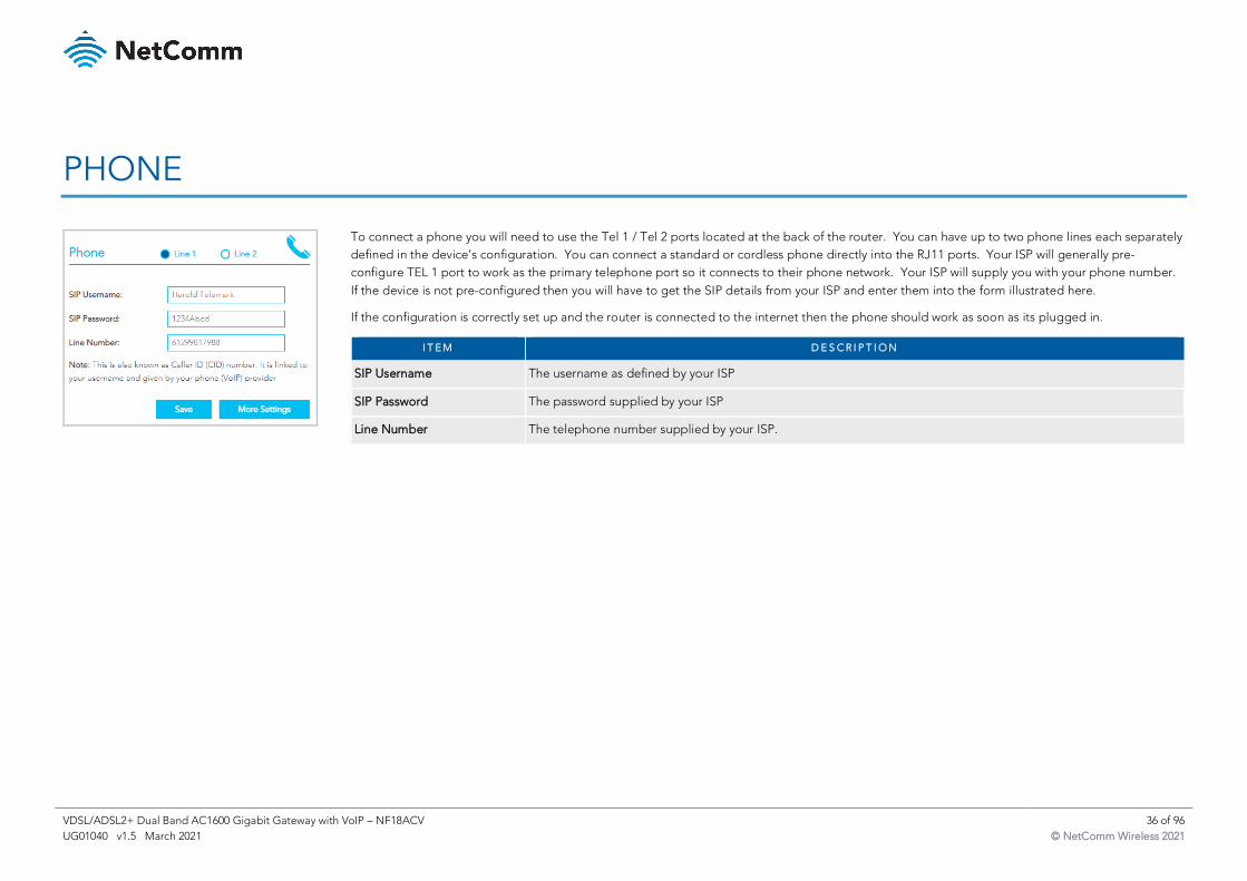
PHONE
To connect a phone you will need to use the Tel 1 / Tel 2 ports located at the back of the router. You can have up to two phone lines each separately
defined in the device’s configuration. You can connect a standard or cordless phone directly into the RJ11 ports. Your ISP will generally pre-
configure TEL 1 port to work as the primary telephone port so it connects to their phone network. Your ISP will supply you with your phone number.
If the device is not pre-configured then you will have to get the SIP details from your ISP and enter them into the form illustrated here.
If the configuration is correctly set up and the router is connected to the internet then the phone should work as soon as its plugged in.
I T E M D E S C R I P T I O N
SIP Username The username as defined by your ISP
SIP Password The password supplied by your ISP
Line Number The telephone number supplied by your ISP.
VDSL/ADSL2+ Dual Band AC1600 Gigabit Gateway with VoIP – NF18ACV 37 of 96
UG01040 v1.5 March 2021 © NetComm Wireless 2021
Click the More Settings button to show additional settings for the selected line.
I T E M D E S C R I P T I O N
SIP Proxy The IP address of the proxy.
SIP Proxy Port The port that this proxy is listening on. By default, the port value is 5060.
SIP Registrar Enter the IP address of the SIP registrar.
SIP Registrar Port The port that SIP registrar is listening on. By default, the port value is 5060.
SIP Outbound Proxy Click Enable if your network service provider requires the use of an outbound proxy.
This is an additional proxy, through which all outgoing calls are directed. In some cases, the outbound proxy is
placed alongside the firewall and it is the only way to let SIP traffic pass from the internal network to the Internet.
SIP Outbound Proxy Enter the IP address of the outbound proxy.
SIP Outbound Proxy Port The port that the outbound proxy is listening on.
By default, the port value is 5060.
Show / Hide buttons For additional Advanced Calling Features that may be supported by your ISP, click Show. See next section.
Apply button Click to save and apply any changes.
VDSL/ADSL2+ Dual Band AC1600 Gigabit Gateway with VoIP – NF18ACV 38 of 96
UG01040 v1.5 March 2021 © NetComm Wireless 2021
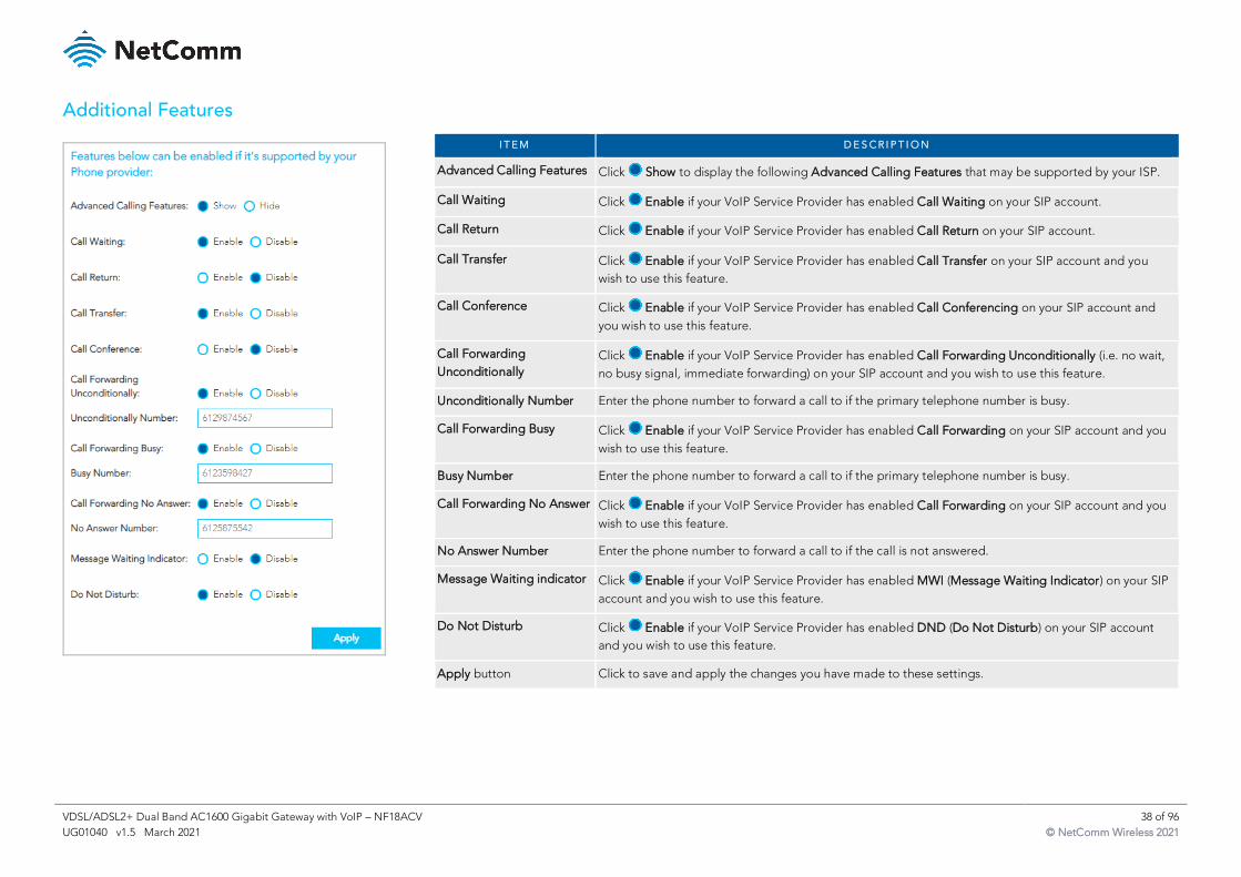
Additional Features
I T E M D E S C R I P T I O N
Advanced Calling Features Click Show to display the following Advanced Calling Features that may be supported by your ISP.
Call Waiting Click Enable if your VoIP Service Provider has enabled Call Waiting on your SIP account.
Call Return Click Enable if your VoIP Service Provider has enabled Call Return on your SIP account.
Call Transfer Click Enable if your VoIP Service Provider has enabled Call Transfer on your SIP account and you
wish to use this feature.
Call Conference Click Enable if your VoIP Service Provider has enabled Call Conferencing on your SIP account and
you wish to use this feature.
Call Forwarding
Unconditionally
Click Enable if your VoIP Service Provider has enabled Call Forwarding Unconditionally (i.e. no wait,
no busy signal, immediate forwarding) on your SIP account and you wish to use this feature.
Unconditionally Number Enter the phone number to forward a call to if the primary telephone number is busy.
Call Forwarding Busy Click Enable if your VoIP Service Provider has enabled Call Forwarding on your SIP account and you
wish to use this feature.
Busy Number Enter the phone number to forward a call to if the primary telephone number is busy.
Call Forwarding No Answer Click Enable if your VoIP Service Provider has enabled Call Forwarding on your SIP account and you
wish to use this feature.
No Answer Number Enter the phone number to forward a call to if the call is not answered.
Message Waiting indicator Click Enable if your VoIP Service Provider has enabled MWI (Message Waiting Indicator) on your SIP
account and you wish to use this feature.
Do Not Disturb Click Enable if your VoIP Service Provider has enabled DND (Do Not Disturb) on your SIP account
and you wish to use this feature.
Apply button Click to save and apply the changes you have made to these settings.
VDSL/ADSL2+ Dual Band AC1600 Gigabit Gateway with VoIP – NF18ACV 39 of 96
UG01040 v1.5 March 2021 © NetComm Wireless 2021
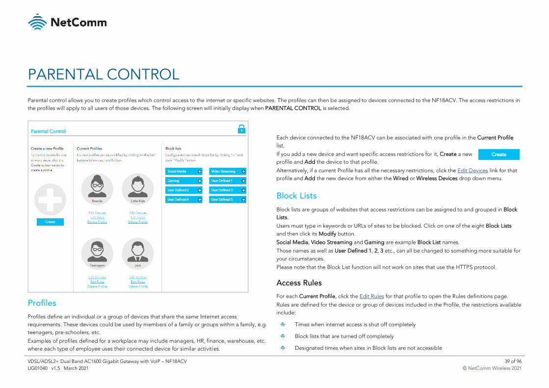
PARENTAL CONTROL
Parental control allows you to create profiles which control access to the internet or specific websites. The profiles can then be assigned to devices connected to the NF18ACV. The access restrictions in
the profiles will apply to all users of those devices. The following screen will initially display when PARENTAL CONTROL is selected.
Profiles
Profiles define an individual or a group of devices that share the same Internet access
requirements. These devices could be used by members of a family or groups within a family, e.g.
teenagers, pre-schoolers, etc.
Examples of profiles defined for a workplace may include managers, HR, finance, warehouse, etc.
where each type of employee uses their connected device for similar activities.
Each device connected to the NF18ACV can be associated with one profile in the Current Profile
list.
If you add a new device and want specific access restrictions for it, Create a new
profile and Add the device to that profile.
Alternatively, if a current Profile has all the necessary restrictions, click the Edit Devices link for that
profile and Add the new device from either the Wired or Wireless Devices drop down menu.
Block Lists
Block lists are groups of websites that access restrictions can be assigned to and grouped in Block
Lists.
Users must type in keywords or URLs of sites to be blocked. Click on one of the eight Block Lists
and then click its Modify button.
Social Media, Video Streaming and Gaming are example Block List names.
Those names as well as User Defined 1, 2, 3 etc., can all be changed to something more suitable for
your circumstances.
Please note that the Block List function will not work on sites that use the HTTPS protocol.
Access Rules
For each Current Profile, click the Edit Rules for that profile to open the Rules definitions page.
Rules are defined for the device or group of devices included in the Profile, the restrictions available
include:
Times when internet access is shut off completely
Block lists that are turned off completely
Designated times when sites in Block lists are not accessible
VDSL/ADSL2+ Dual Band AC1600 Gigabit Gateway with VoIP – NF18ACV 40 of 96
UG01040 v1.5 March 2021 © NetComm Wireless 2021
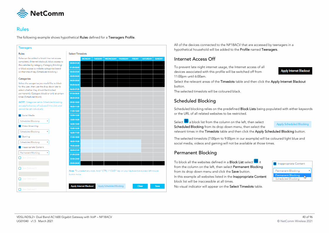
Rules
The following example shows hypothetical Rules defined for a Teenagers Profile.
All of the devices connected to the NF18ACV that are accessed by teenagers in a
hypothetical household will be added to the Profile named Teenagers.
Internet Access Off
To prevent late night internet usage, the Internet access of all
devices associated with this profile will be switched off from
11:00pm until 6:00am.
Select the relevant areas of the Timeslots table and then click the Apply Internet Blackout
button.
The selected timeslots will be coloured black.
Scheduled Blocking
Scheduled blocking relies on the predefined Block Lists being populated with either keywords
or the URL of all related websites to be restricted.
Select a block list from the column on the left, then select
Scheduled Blocking from its drop down menu, then select the
relevant times in the Timeslots table and then click the Apply Scheduled Blocking button.
The selected timeslots (7:00pm to 9:00pm in our example) will be coloured light blue and
social media, videos and gaming will not be available at those times.
Permanent Blocking
To block all the websites defined in a Block List select it
from the column on the left, then select Permanent Blocking
from its drop down menu and click the Save button.
In this example all websites listed in the Inappropriate Content
block list will be inaccessible at all times.
No visual indicator will appear on the Select Timeslots table.
VDSL/ADSL2+ Dual Band AC1600 Gigabit Gateway with VoIP – NF18ACV 41 of 96
UG01040 v1.5 March 2021 © NetComm Wireless 2021
CONTENT SHARING
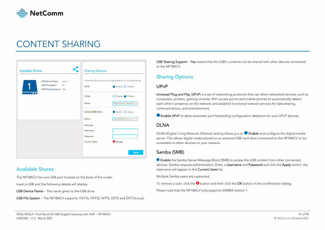
USB Sharing Support – Yes means that the USB’s contents can be shared with other devices connected
to the NF18ACV.
Sharing Options
UPnP
Universal Plug and Play (UPnP) is a set of networking protocols that can allow networked devices, such as
computers, printers, gaming console, WiFi access points and mobile phones to automatically detect
each other's presence on the network and establish functional network services for data sharing,
communications, and entertainment.
Enable UPnP to allow automatic port forwarding configuration detection for your UPnP devices.
DLNA
DLNA (Digital Living Network Alliance) setting allows you to Enable and configure the digital media
server. This allows digital media stored on an external USB hard drive connected to the NF18ACV to be
accessible to other devices on your network.
Samba (SMB)
Enable the Samba Server Message Block (SMB) to access the USB content from other connected
devices. Samba requires authentication. Enter a Username and Password and click the Apply button, the
Username will appear in the Current Users list.
Multiple Samba users are supported.
To remove a user, click the button and then click the OK button in the confirmation dialog.
Please note that the NF18ACV only supports SAMBA version 1.
Available Shares
The NF18ACV has one USB port located on the back of the router.
Insert a USB and the following details will display:
USB Device Name – The name given to the USB drive.
USB File System – The NF18ACV supports: FAT16, FAT32, NTFS, EXT2 and EXT3 (Linux).
VDSL/ADSL2+ Dual Band AC1600 Gigabit Gateway with VoIP – NF18ACV 42 of 96
UG01040 v1.5 March 2021 © NetComm Wireless 2021
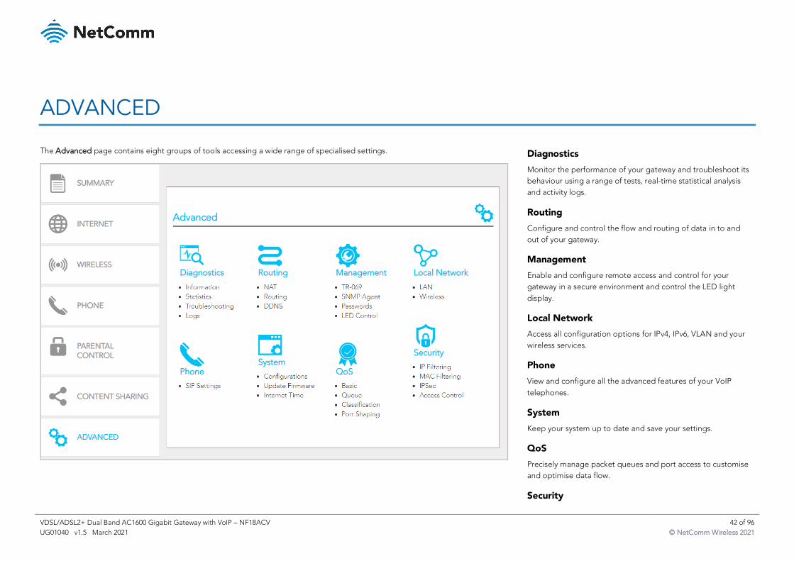
ADVANCED
The Advanced page contains eight groups of tools accessing a wide range of specialised settings.
Diagnostics
Monitor the performance of your gateway and troubleshoot its
behaviour using a range of tests, real-time statistical analysis
and activity logs.
Routing
Configure and control the flow and routing of data in to and
out of your gateway.
Management
Enable and configure remote access and control for your
gateway in a secure environment and control the LED light
display.
Local Network
Access all configuration options for IPv4, IPv6, VLAN and your
wireless services.
Phone
View and configure all the advanced features of your VoIP
telephones.
System
Keep your system up to date and save your settings.
QoS
Precisely manage packet queues and port access to customise
and optimise data flow.
Security
VDSL/ADSL2+ Dual Band AC1600 Gigabit Gateway with VoIP – NF18ACV 43 of 96
UG01040 v1.5 March 2021 © NetComm Wireless 2021
Control access and set up firewalls to prevent intrusion or
define filters to allow specific access.
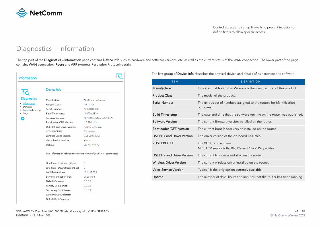
Diagnostics – Information
The top part of the Diagnostics – Information page contains Device Info such as hardware and software versions, etc. as well as the current status of the WAN connection. The lower part of the page
contains WAN connection, Route and ARP (Address Resolution Protocol) details.
The first group of Device info describes the physical device and details of its hardware and software.
I T E M D E F I N I T I O N
Manufacturer Indicates that NetComm Wireless is the manufacturer of this product.
Product Class The model of the product.
Serial Number The unique set of numbers assigned to the routers for identification
purposes.
Build Timestamp The date and time that the software running on the router was published.
Software Version The current firmware version installed on the router.
Bootloader (CFE) Version The current boot loader version installed on the router.
DSL PHY and Driver Version The driver version of the on-board DSL chip.
VDSL PROFILE The VDSL profile in use.
NF18ACV supports 8a, 8b, 12a and 17a VDSL profiles.
DSL PHY and Driver Version The current line driver installed on the router.
Wireless Driver Version The current wireless driver installed on the router.
Voice Service Version “Voice” is the only option currently available.
Uptime The number of days, hours and minutes that the router has been running.
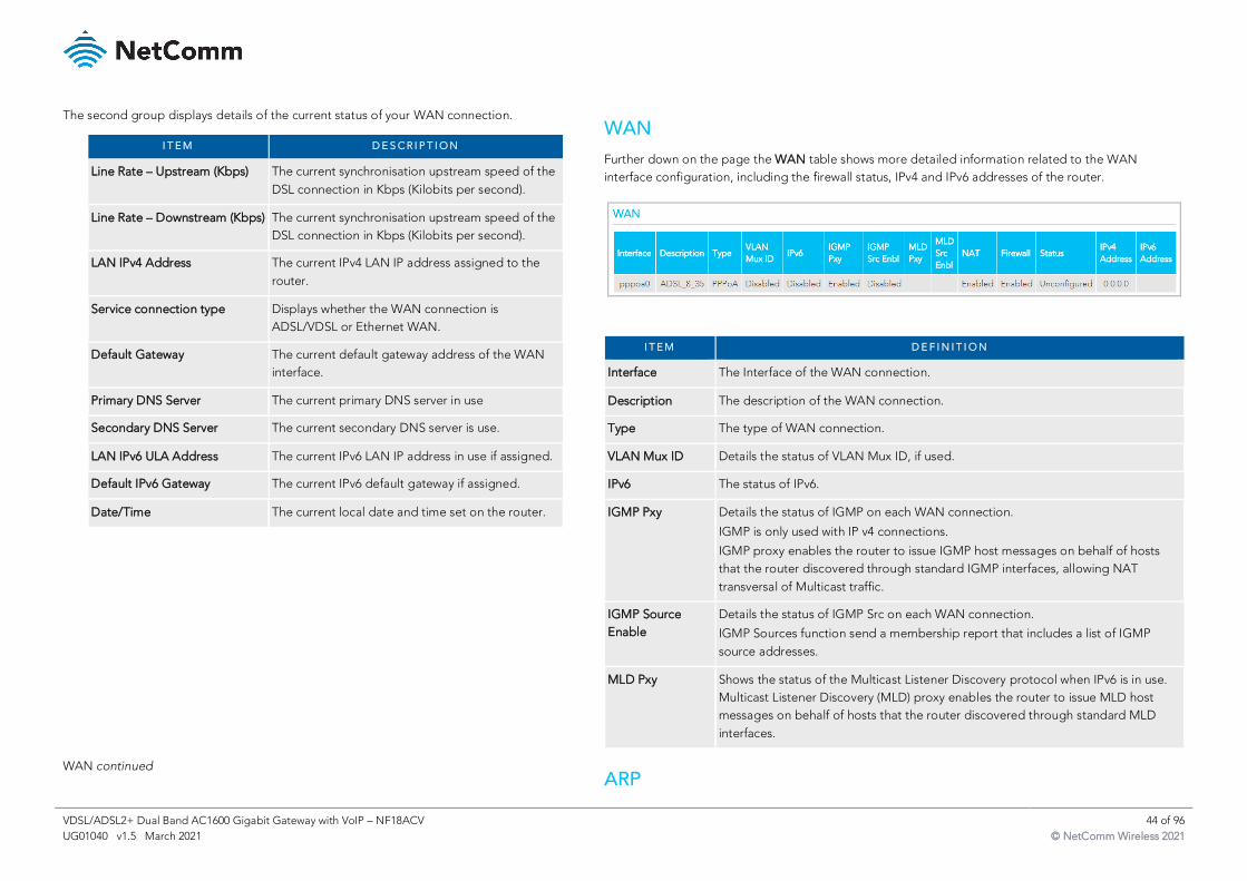
VDSL/ADSL2+ Dual Band AC1600 Gigabit Gateway with VoIP – NF18ACV 44 of 96
UG01040 v1.5 March 2021 © NetComm Wireless 2021
The second group displays details of the current status of your WAN connection.
I T E M D E S C R I P T I O N
Line Rate – Upstream (Kbps) The current synchronisation upstream speed of the
DSL connection in Kbps (Kilobits per second).
Line Rate – Downstream (Kbps) The current synchronisation upstream speed of the
DSL connection in Kbps (Kilobits per second).
LAN IPv4 Address The current IPv4 LAN IP address assigned to the
router.
Service connection type Displays whether the WAN connection is
ADSL/VDSL or Ethernet WAN.
Default Gateway The current default gateway address of the WAN
interface.
Primary DNS Server The current primary DNS server in use
Secondary DNS Server The current secondary DNS server is use.
LAN IPv6 ULA Address The current IPv6 LAN IP address in use if assigned.
Default IPv6 Gateway The current IPv6 default gateway if assigned.
Date/Time The current local date and time set on the router.
WAN
Further down on the page the WAN table shows more detailed information related to the WAN
interface configuration, including the firewall status, IPv4 and IPv6 addresses of the router.
I T E M D E F I N I T I O N
Interface The Interface of the WAN connection.
Description The description of the WAN connection.
Type The type of WAN connection.
VLAN Mux ID Details the status of VLAN Mux ID, if used.
IPv6 The status of IPv6.
IGMP Pxy Details the status of IGMP on each WAN connection.
IGMP is only used with IP v4 connections.
IGMP proxy enables the router to issue IGMP host messages on behalf of hosts
that the router discovered through standard IGMP interfaces, allowing NAT
transversal of Multicast traffic.
IGMP Source
Enable
Details the status of IGMP Src on each WAN connection.
IGMP Sources function send a membership report that includes a list of IGMP
source addresses.
MLD Pxy Shows the status of the Multicast Listener Discovery protocol when IPv6 is in use.
Multicast Listener Discovery (MLD) proxy enables the router to issue MLD host
messages on behalf of hosts that the router discovered through standard MLD
interfaces.
WAN continued ARP
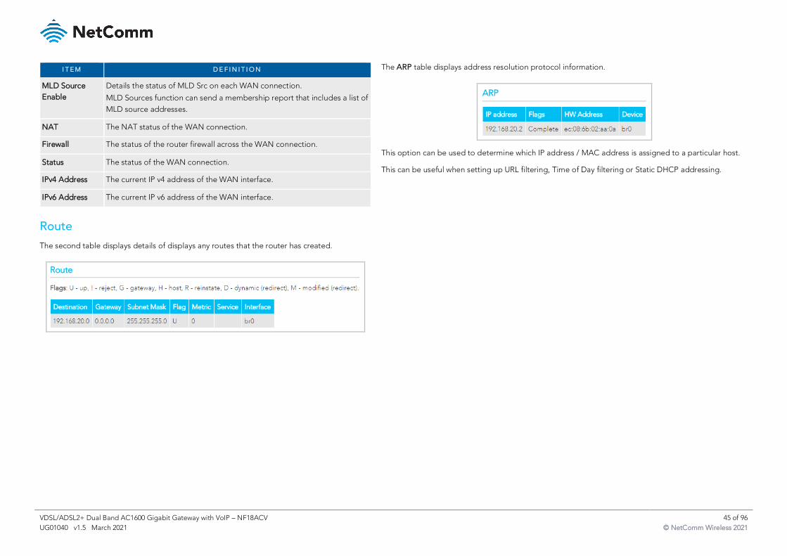
VDSL/ADSL2+ Dual Band AC1600 Gigabit Gateway with VoIP – NF18ACV 45 of 96
UG01040 v1.5 March 2021 © NetComm Wireless 2021
I T E M D E F I N I T I O N
MLD Source
Enable
Details the status of MLD Src on each WAN connection.
MLD Sources function can send a membership report that includes a list of
MLD source addresses.
NAT The NAT status of the WAN connection.
Firewall The status of the router firewall across the WAN connection.
Status The status of the WAN connection.
IPv4 Address The current IP v4 address of the WAN interface.
IPv6 Address The current IP v6 address of the WAN interface.
Route
The second table displays details of displays any routes that the router has created.
The ARP table displays address resolution protocol information.
This option can be used to determine which IP address / MAC address is assigned to a particular host.
This can be useful when setting up URL filtering, Time of Day filtering or Static DHCP addressing.
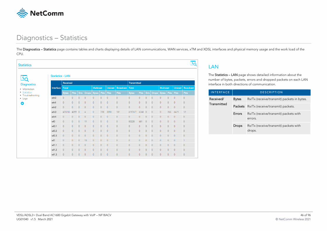
VDSL/ADSL2+ Dual Band AC1600 Gigabit Gateway with VoIP – NF18ACV 46 of 96
UG01040 v1.5 March 2021 © NetComm Wireless 2021
Diagnostics – Statistics
The Diagnostics – Statistics page contains tables and charts displaying details of LAN communications, WAN services, xTM and XDSL interfaces and physical memory usage and the work load of the
CPU.
LAN
The Statistics – LAN page shows detailed information about the
number of bytes, packets, errors and dropped packets on each LAN
interface in both directions of communication.
I N T E R F A C E D E S C R I P T I O N
Received/
Transmitted
Bytes Rx/Tx (receive/transmit) packets in bytes.
Packets Rx/Tx (receive/transmit) packets.
Errors Rx/Tx (receive/transmit) packets with
errors.
Drops Rx/Tx (receive/transmit) packets with
drops.
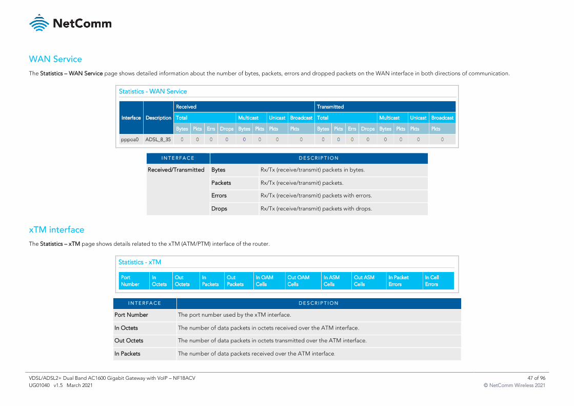
VDSL/ADSL2+ Dual Band AC1600 Gigabit Gateway with VoIP – NF18ACV 47 of 96
UG01040 v1.5 March 2021 © NetComm Wireless 2021
WAN Service
The Statistics – WAN Service page shows detailed information about the number of bytes, packets, errors and dropped packets on the WAN interface in both directions of communication.
I N T E R F A C E D E S C R I P T I O N
Received/Transmitted Bytes Rx/Tx (receive/transmit) packets in bytes.
Packets Rx/Tx (receive/transmit) packets.
Errors Rx/Tx (receive/transmit) packets with errors.
Drops Rx/Tx (receive/transmit) packets with drops.
xTM interface
The Statistics – xTM page shows details related to the xTM (ATM/PTM) interface of the router.
I N T E R F A C E D E S C R I P T I O N
Port Number The port number used by the xTM interface.
In Octets The number of data packets in octets received over the ATM interface.
Out Octets The number of data packets in octets transmitted over the ATM interface.
In Packets The number of data packets received over the ATM interface.
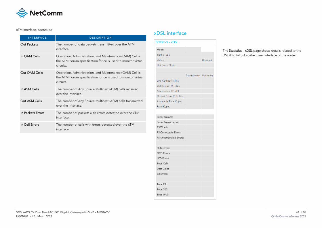
VDSL/ADSL2+ Dual Band AC1600 Gigabit Gateway with VoIP – NF18ACV 48 of 96
UG01040 v1.5 March 2021 © NetComm Wireless 2021
xTM interface, continued
I N T E R F A C E D E S C R I P T I O N
Out Packets The number of data packets transmitted over the ATM
interface.
In OAM Cells Operation, Administration, and Maintenance (OAM) Cell is
the ATM Forum specification for cells used to monitor virtual
circuits.
Out OAM Cells Operation, Administration, and Maintenance (OAM) Cell is
the ATM Forum specification for cells used to monitor virtual
circuits.
In ASM Cells The number of Any Source Multicast (ASM) cells received
over the interface.
Out ASM Cells The number of Any Source Multicast (ASM) cells transmitted
over the interface.
In Packets Errors The number of packets with errors detected over the xTM
interface.
In Cell Errors The number of cells with errors detected over the xTM
interface.
xDSL interface
The Statistics – xDSL page shows details related to the
DSL (Digital Subscriber Line) interface of the router..
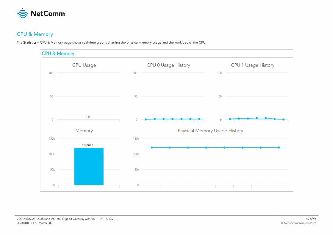
VDSL/ADSL2+ Dual Band AC1600 Gigabit Gateway with VoIP – NF18ACV 49 of 96
UG01040 v1.5 March 2021 © NetComm Wireless 2021
CPU & Memory
The Statistics – CPU & Memory page shows real-time graphs charting the physical memory usage and the workload of the CPU.
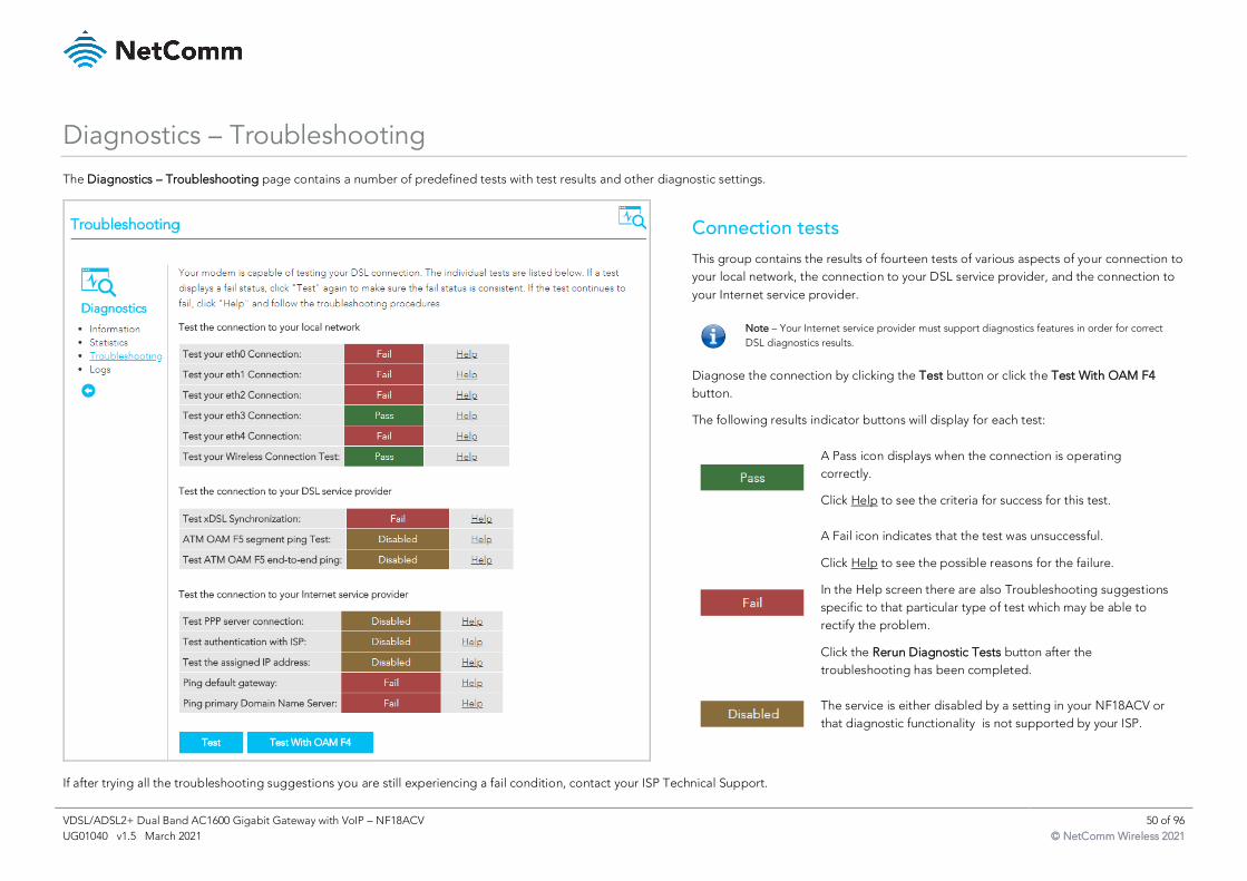
VDSL/ADSL2+ Dual Band AC1600 Gigabit Gateway with VoIP – NF18ACV 50 of 96
UG01040 v1.5 March 2021 © NetComm Wireless 2021
Diagnostics – Troubleshooting
The Diagnostics – Troubleshooting page contains a number of predefined tests with test results and other diagnostic settings.
Connection tests
This group contains the results of fourteen tests of various aspects of your connection to
your local network, the connection to your DSL service provider, and the connection to
your Internet service provider.
Note – Your Internet service provider must support diagnostics features in order for correct
DSL diagnostics results.
Diagnose the connection by clicking the Test button or click the Test With OAM F4
button.
The following results indicator buttons will display for each test:
A Pass icon displays when the connection is operating
correctly.
Click Help to see the criteria for success for this test.
A Fail icon indicates that the test was unsuccessful.
Click Help to see the possible reasons for the failure.
In the Help screen there are also Troubleshooting suggestions
specific to that particular type of test which may be able to
rectify the problem.
Click the Rerun Diagnostic Tests button after the
troubleshooting has been completed.
The service is either disabled by a setting in your NF18ACV or
that diagnostic functionality is not supported by your ISP.
If after trying all the troubleshooting suggestions you are still experiencing a fail condition, contact your ISP Technical Support.
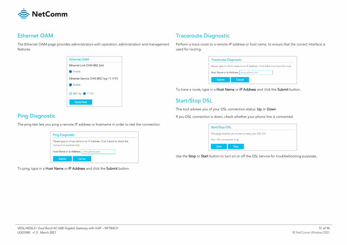
VDSL/ADSL2+ Dual Band AC1600 Gigabit Gateway with VoIP – NF18ACV 51 of 96
UG01040 v1.5 March 2021 © NetComm Wireless 2021
Ethernet OAM
The Ethernet OAM page provides administrators with operation, administration and management
features.
Ping Diagnostic
The ping test lets you ping a remote IP address or hostname in order to test the connection.
To ping, type in a Host Name or IP Address and click the Submit button.
Traceroute Diagnostic
Perform a trace route to a remote IP address or host name, to ensure that the correct interface is
used for routing.
To trace a route, type in a Host Name or IP Address and click the Submit button.
Start/Stop DSL
This tool advises you of your DSL connection status: Up or Down
If you DSL connection is down, check whether your phone line is connected.
Use the Stop or Start button to turn on or off the DSL service for troubleshooting purposes.
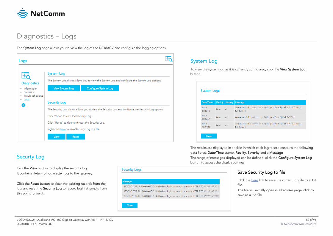
VDSL/ADSL2+ Dual Band AC1600 Gigabit Gateway with VoIP – NF18ACV 52 of 96
UG01040 v1.5 March 2021 © NetComm Wireless 2021
Diagnostics – Logs
The System Log page allows you to view the log of the NF18ACV and configure the logging options.
Securty Log
System Log
To view the system log as it is currently configured, click the View System Log
button.
The results are displayed in a table in which each log record contains the following
data fields: Date/Time stamp, Facility, Severity and a Message
The range of messages displayed can be defined, click the Configure System Log
button to access the display settings.
Cick the View button to display the security log.
It contains details of login attempts to the gateway.
Click the Reset button to clear the existing records from the
log and reset the Security Log to record login attempts from
this point forward..
Save Security Log to file
Click the here link to save the current log file to a .txt
file.
The file will initially open in a browser page, click to
save as a .txt file.
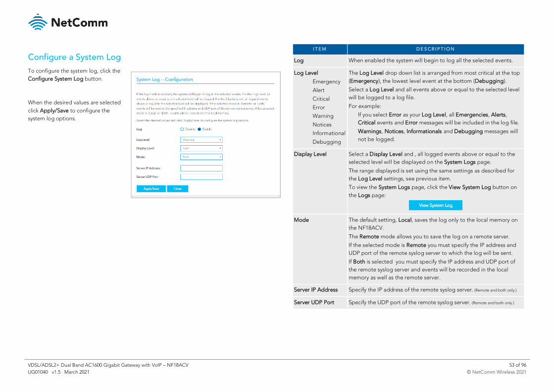
VDSL/ADSL2+ Dual Band AC1600 Gigabit Gateway with VoIP – NF18ACV 53 of 96
UG01040 v1.5 March 2021 © NetComm Wireless 2021
Configure a System Log
To configure the system log, click the
Configure System Log button.
When the desired values are selected
click Apply/Save to configure the
system log options.
I T E M D E S C R I P T I O N
Log When enabled the system will begin to log all the selected events.
Log Level
Emergency
Alert
Critical
Error
Warning
Notices
Informational
Debugging
The Log Level drop down list is arranged from most critical at the top
(Emergency), the lowest level event at the bottom (Debugging).
Select a Log Level and all events above or equal to the selected level
will be logged to a log file.
For example:
If you select Error as your Log Level, all Emergencies, Alerts,
Critical events and Error messages will be included in the log file.
Warnings, Notices, Informationals and Debugging messages will
not be logged.
Display Level Select a Display Level and , all logged events above or equal to the
selected level will be displayed on the System Logs page.
The range displayed is set using the same settings as described for
the Log Level settings, see previous item.
To view the System Logs page, click the View System Log button on
the Logs page:
Mode The default setting, Local, saves the log only to the local memory on
the NF18ACV.
The Remote mode allows you to save the log on a remote server.
If the selected mode is Remote you must specify the IP address and
UDP port of the remote syslog server to which the log will be sent.
If Both is selected you must specify the IP address and UDP port of
the remote syslog server and events will be recorded in the local
memory as well as the remote server.
Server IP Address Specify the IP address of the remote syslog server. (Remote and both only.)
Server UDP Port Specify the UDP port of the remote syslog server. (Remote and both only.)
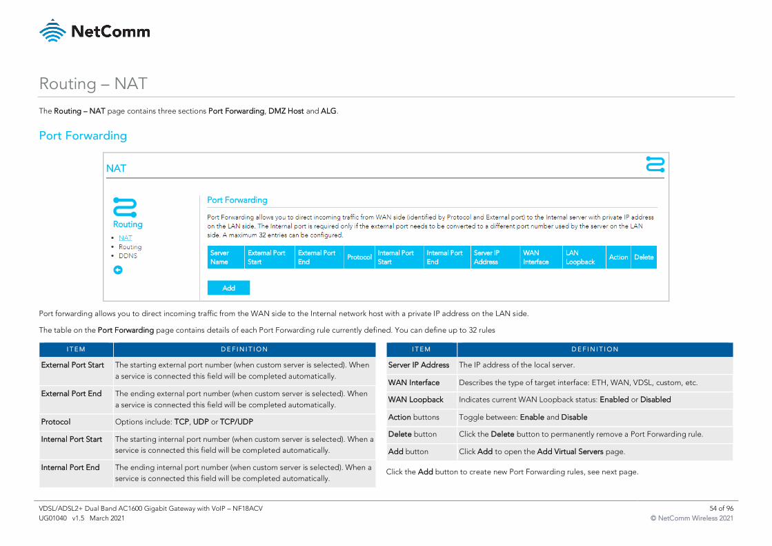
VDSL/ADSL2+ Dual Band AC1600 Gigabit Gateway with VoIP – NF18ACV 54 of 96
UG01040 v1.5 March 2021 © NetComm Wireless 2021
Routing – NAT
The Routing – NAT page contains three sections Port Forwarding, DMZ Host and ALG.
Port Forwarding
Port forwarding allows you to direct incoming traffic from the WAN side to the Internal network host with a private IP address on the LAN side.
The table on the Port Forwarding page contains details of each Port Forwarding rule currently defined. You can define up to 32 rules
I T E M D E F I N I T I O N
External Port Start The starting external port number (when custom server is selected). When
a service is connected this field will be completed automatically.
External Port End The ending external port number (when custom server is selected). When
a service is connected this field will be completed automatically.
Protocol Options include: TCP, UDP or TCP/UDP
Internal Port Start The starting internal port number (when custom server is selected). When a
service is connected this field will be completed automatically.
Internal Port End The ending internal port number (when custom server is selected). When a
service is connected this field will be completed automatically.
I T E M D E F I N I T I O N
Server IP Address The IP address of the local server.
WAN Interface Describes the type of target interface: ETH, WAN, VDSL, custom, etc.
WAN Loopback Indicates current WAN Loopback status: Enabled or Disabled
Action buttons Toggle between: Enable and Disable
Delete button Click the Delete button to permanently remove a Port Forwarding rule.
Add button Click Add to open the Add Virtual Servers page.
Click the Add button to create new Port Forwarding rules, see next page.
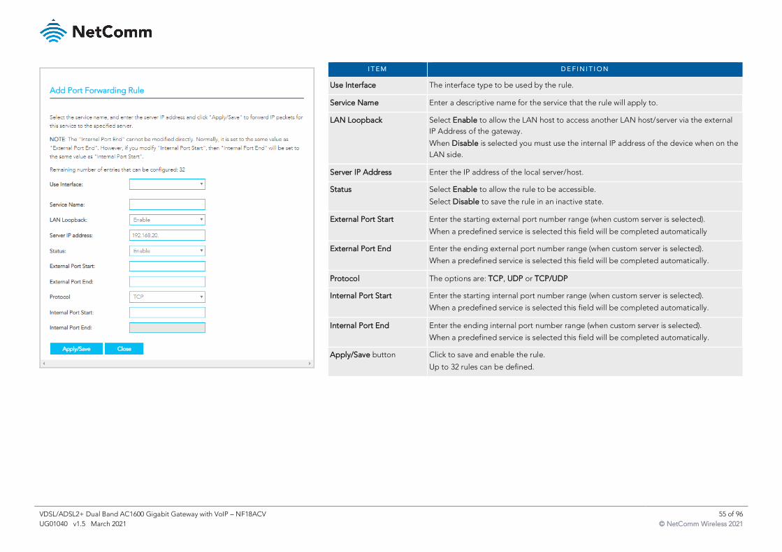
VDSL/ADSL2+ Dual Band AC1600 Gigabit Gateway with VoIP – NF18ACV 55 of 96
UG01040 v1.5 March 2021 © NetComm Wireless 2021
I T E M D E F I N I T I O N
Use Interface The interface type to be used by the rule.
Service Name Enter a descriptive name for the service that the rule will apply to.
LAN Loopback Select Enable to allow the LAN host to access another LAN host/server via the external
IP Address of the gateway.
When Disable is selected you must use the internal IP address of the device when on the
LAN side.
Server IP Address Enter the IP address of the local server/host.
Status Select Enable to allow the rule to be accessible.
Select Disable to save the rule in an inactive state.
External Port Start Enter the starting external port number range (when custom server is selected).
When a predefined service is selected this field will be completed automatically
External Port End Enter the ending external port number range (when custom server is selected).
When a predefined service is selected this field will be completed automatically.
Protocol The options are: TCP, UDP or TCP/UDP
Internal Port Start Enter the starting internal port number range (when custom server is selected).
When a predefined service is selected this field will be completed automatically.
Internal Port End Enter the ending internal port number range (when custom server is selected).
When a predefined service is selected this field will be completed automatically.
Apply/Save button Click to save and enable the rule.
Up to 32 rules can be defined.
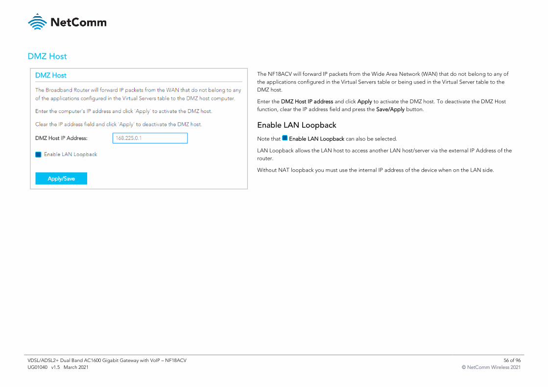
VDSL/ADSL2+ Dual Band AC1600 Gigabit Gateway with VoIP – NF18ACV 56 of 96
UG01040 v1.5 March 2021 © NetComm Wireless 2021
DMZ Host
The NF18ACV will forward IP packets from the Wide Area Network (WAN) that do not belong to any of
the applications configured in the Virtual Servers table or being used in the Virtual Server table to the
DMZ host.
Enter the DMZ Host IP address and click Apply to activate the DMZ host. To deactivate the DMZ Host
function, clear the IP address field and press the Save/Apply button.
Enable LAN Loopback
Note that Enable LAN Loopback can also be selected.
LAN Loopback allows the LAN host to access another LAN host/server via the external IP Address of the
router.
Without NAT loopback you must use the internal IP address of the device when on the LAN side.
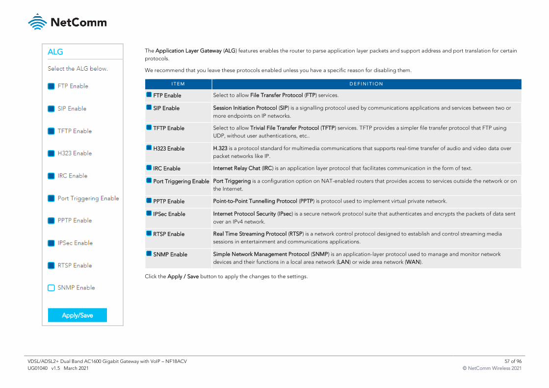
VDSL/ADSL2+ Dual Band AC1600 Gigabit Gateway with VoIP – NF18ACV 57 of 96
UG01040 v1.5 March 2021 © NetComm Wireless 2021
The Application Layer Gateway (ALG) features enables the router to parse application layer packets and support address and port translation for certain
protocols.
We recommend that you leave these protocols enabled unless you have a specific reason for disabling them.
I T E M D E F I N I T I O N
FTP Enable Select to allow File Transfer Protocol (FTP) services.
SIP Enable Session Initiation Protocol (SIP) is a signalling protocol used by communications applications and services between two or
more endpoints on IP networks.
TFTP Enable Select to allow Trivial File Transfer Protocol (TFTP) services. TFTP provides a simpler file transfer protocol that FTP using
UDP, without user authentications, etc..
H323 Enable H.323 is a protocol standard for multimedia communications that supports real-time transfer of audio and video data over
packet networks like IP.
IRC Enable Internet Relay Chat (IRC) is an application layer protocol that facilitates communication in the form of text.
Port Triggering Enable Port Triggering is a configuration option on NAT-enabled routers that provides access to services outside the network or on
the Internet.
PPTP Enable Point-to-Point Tunnelling Protocol (PPTP) is protocol used to implement virtual private network.
IPSec Enable Internet Protocol Security (IPsec) is a secure network protocol suite that authenticates and encrypts the packets of data sent
over an IPv4 network.
RTSP Enable Real Time Streaming Protocol (RTSP) is a network control protocol designed to establish and control streaming media
sessions in entertainment and communications applications.
SNMP Enable Simple Network Management Protocol (SNMP) is an application-layer protocol used to manage and monitor network
devices and their functions in a local area network (LAN) or wide area network (WAN).
Click the Apply / Save button to apply the changes to the settings.
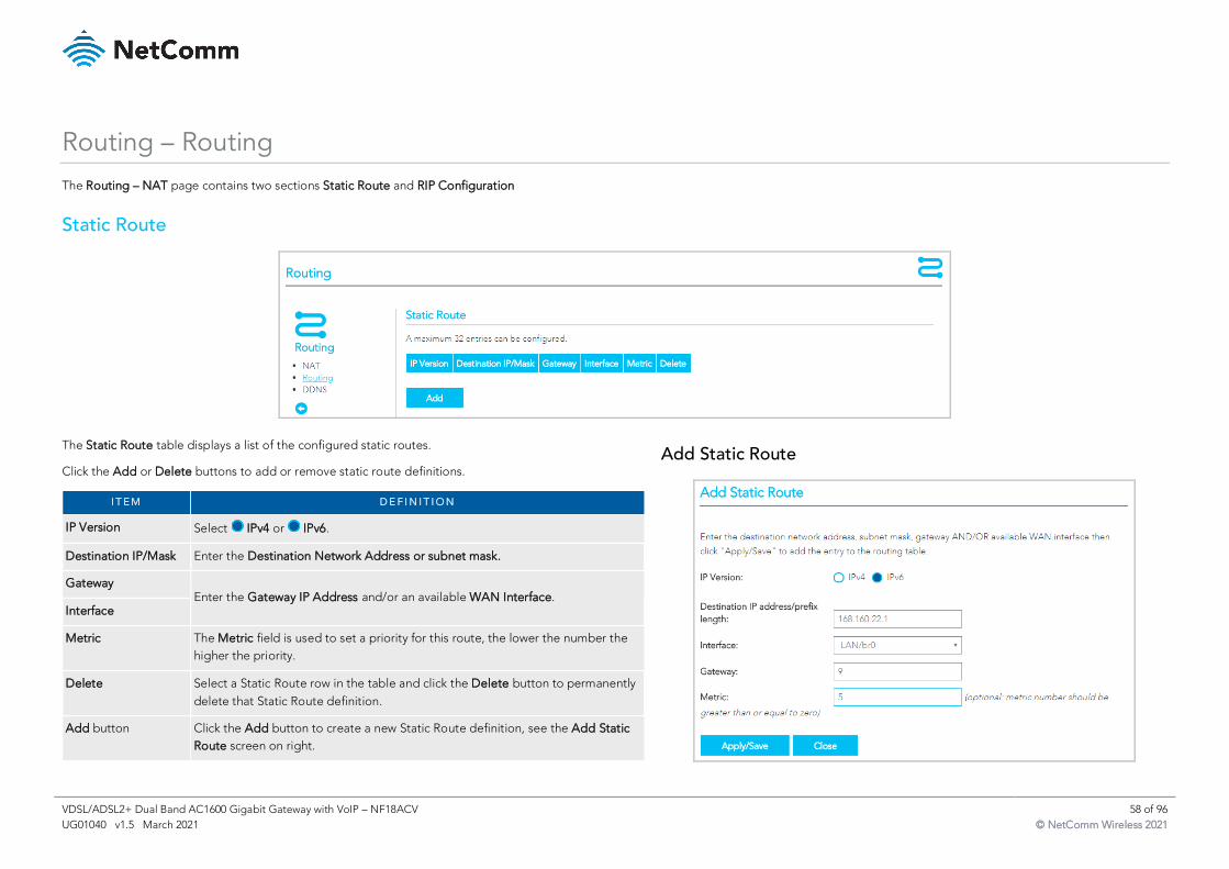
VDSL/ADSL2+ Dual Band AC1600 Gigabit Gateway with VoIP – NF18ACV 58 of 96
UG01040 v1.5 March 2021 © NetComm Wireless 2021
Routing – Routing
The Routing – NAT page contains two sections Static Route and RIP Configuration
Static Route
The Static Route table displays a list of the configured static routes.
Click the Add or Delete buttons to add or remove static route definitions.
I T E M D E F I N I T I O N
IP Version Select IPv4 or IPv6.
Destination IP/Mask Enter the Destination Network Address or subnet mask.
Gateway Enter the Gateway IP Address and/or an available WAN Interface.
Interface
Metric The Metric field is used to set a priority for this route, the lower the number the
higher the priority.
Delete Select a Static Route row in the table and click the Delete button to permanently
delete that Static Route definition.
Add button Click the Add button to create a new Static Route definition, see the Add Static
Route screen on right.
Add Static Route
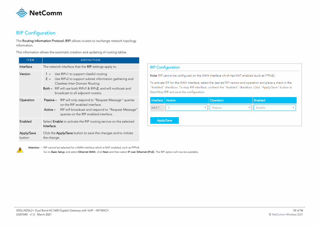
VDSL/ADSL2+ Dual Band AC1600 Gigabit Gateway with VoIP – NF18ACV 59 of 96
UG01040 v1.5 March 2021 © NetComm Wireless 2021
RIP Configuration
The Routing Information Protocol (RIP) allows routers to exchange network topology
information.
This information allows the automatic creation and updating of routing tables.
I T E M D E F I N I T I O N
Interface The network interface that the RIP settings apply to.
Version 1 – Use RIPv1 to support classful routing.
2 – Use RIPv2 to support subnet information gathering and
Classless Inter-Domain Routing.
Both – RIP will use both RIPv1 & RIPv2, and will multicast and
broadcast to all adjacent routers.
Operation Passive – RIP will only respond to “Request Message” queries
on the RIP enabled interface.
Active – RIP will broadcast and respond to “Request Message”
queries on the RIP enabled interface.
Enabled Select Enable to activate the RIP routing service on the selected
Interface.
Apply/Save
button
Click the Apply/Save button to save the changes and to initiate
the change.
Attention – RIP cannot be selected for a WAN interface which is NAT enabled, such as PPPoE.
Go to Basic Setup and select Ethernet WAN, click Next and then select IP over Ethernet (IPoE). The RIP option will now be available.
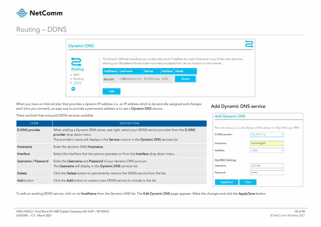
VDSL/ADSL2+ Dual Band AC1600 Gigabit Gateway with VoIP – NF18ACV 60 of 96
UG01040 v1.5 March 2021 © NetComm Wireless 2021
Routing – DDNS
When you have an Internet plan that provides a dynamic IP address (i.e. an IP address which is dynamically assigned and changes
each time you connect), an easy way to provide a permanent address is to use a Dynamic DNS service.
There are both free and paid DDNS services available.
I T E M D E F I N I T I O N
D-DNS provider When adding a Dynamic DNS server, see right, select your DDNS service provider from the D-DNS
provider drop down menu
The provider’s name will display in the Service column in the Dynamic DNS services list.
Hostname Enter the dynamic DNS Hostname.
Interface Select the interface that the service operates on from the Interface drop down menu.
Username / Password Enter the Username and Password of your dynamic DNS account.
The Username will display in the Dynamic DNS services list.
Delete Click the Delete button to permanently remove the DDNS service from the list.
Add button Click the Add button to create a new DDNS service to include in the list.
Add Dynamic DNS service
To edit an existing DDNS service, click on its HostName from the Dynamic DNS list. The Edit Dynamic DNS page appears. Make the changes and click the Apply/Save button.
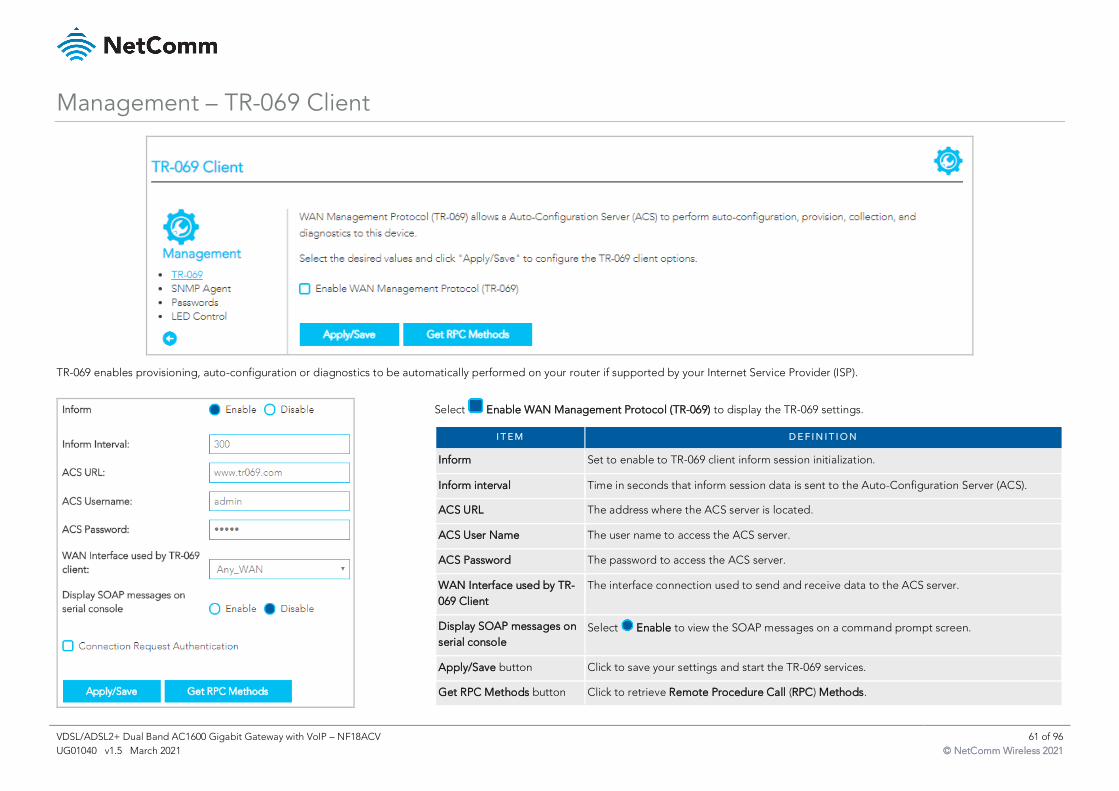
VDSL/ADSL2+ Dual Band AC1600 Gigabit Gateway with VoIP – NF18ACV 61 of 96
UG01040 v1.5 March 2021 © NetComm Wireless 2021
Management – TR-069 Client
TR-069 enables provisioning, auto-configuration or diagnostics to be automatically performed on your router if supported by your Internet Service Provider (ISP).
Select Enable WAN Management Protocol (TR-069) to display the TR-069 settings.
I T E M D E F I N I T I O N
Inform Set to enable to TR-069 client inform session initialization.
Inform interval Time in seconds that inform session data is sent to the Auto-Configuration Server (ACS).
ACS URL The address where the ACS server is located.
ACS User Name The user name to access the ACS server.
ACS Password The password to access the ACS server.
WAN Interface used by TR-
069 Client
The interface connection used to send and receive data to the ACS server.
Display SOAP messages on
serial console
Select Enable to view the SOAP messages on a command prompt screen.
Apply/Save button Click to save your settings and start the TR-069 services.
Get RPC Methods button Click to retrieve Remote Procedure Call (RPC) Methods.
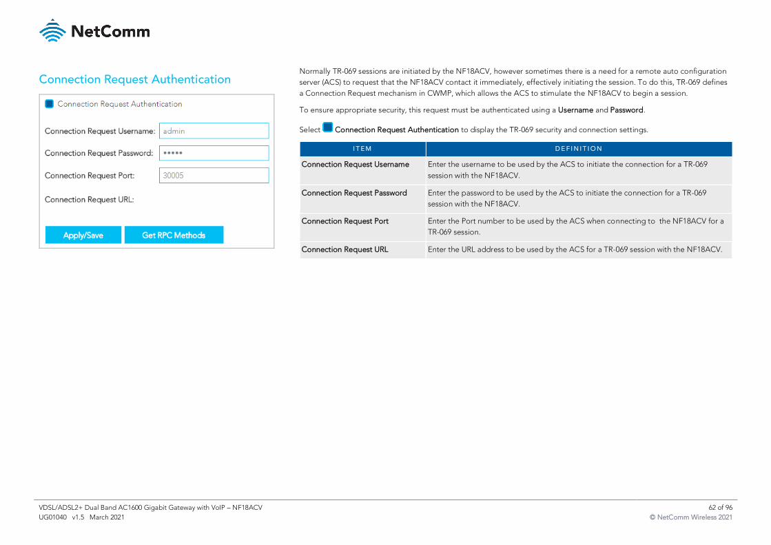
VDSL/ADSL2+ Dual Band AC1600 Gigabit Gateway with VoIP – NF18ACV 62 of 96
UG01040 v1.5 March 2021 © NetComm Wireless 2021
Connection Request Authentication
Normally TR-069 sessions are initiated by the NF18ACV, however sometimes there is a need for a remote auto configuration
server (ACS) to request that the NF18ACV contact it immediately, effectively initiating the session. To do this, TR-069 defines
a Connection Request mechanism in CWMP, which allows the ACS to stimulate the NF18ACV to begin a session.
To ensure appropriate security, this request must be authenticated using a Username and Password.
Select Connection Request Authentication to display the TR-069 security and connection settings.
I T E M D E F I N I T I O N
Connection Request Username Enter the username to be used by the ACS to initiate the connection for a TR-069
session with the NF18ACV.
Connection Request Password Enter the password to be used by the ACS to initiate the connection for a TR-069
session with the NF18ACV.
Connection Request Port Enter the Port number to be used by the ACS when connecting to the NF18ACV for a
TR-069 session.
Connection Request URL Enter the URL address to be used by the ACS for a TR-069 session with the NF18ACV.
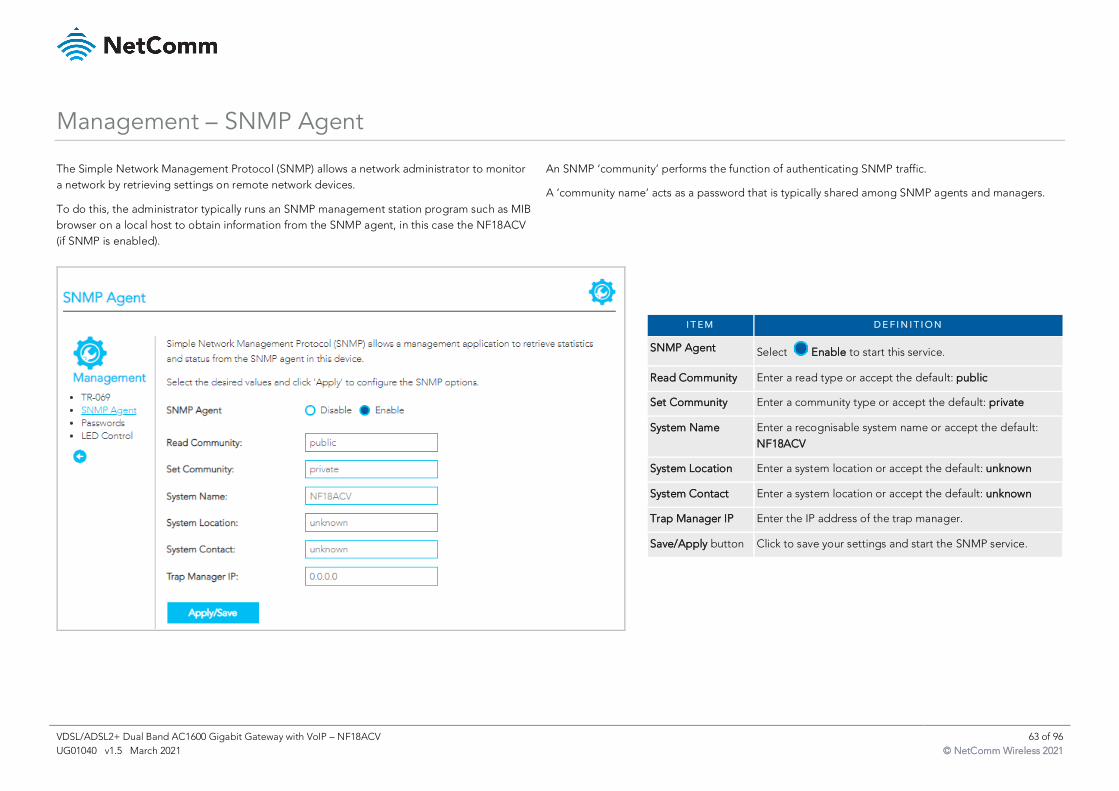
VDSL/ADSL2+ Dual Band AC1600 Gigabit Gateway with VoIP – NF18ACV 63 of 96
UG01040 v1.5 March 2021 © NetComm Wireless 2021
Management – SNMP Agent
The Simple Network Management Protocol (SNMP) allows a network administrator to monitor
a network by retrieving settings on remote network devices.
To do this, the administrator typically runs an SNMP management station program such as MIB
browser on a local host to obtain information from the SNMP agent, in this case the NF18ACV
(if SNMP is enabled).
An SNMP ‘community’ performs the function of authenticating SNMP traffic.
A ‘community name’ acts as a password that is typically shared among SNMP agents and managers.
I T E M D E F I N I T I O N
SNMP Agent Select Enable to start this service.
Read Community Enter a read type or accept the default: public
Set Community Enter a community type or accept the default: private
System Name Enter a recognisable system name or accept the default:
NF18ACV
System Location Enter a system location or accept the default: unknown
System Contact Enter a system location or accept the default: unknown
Trap Manager IP Enter the IP address of the trap manager.
Save/Apply button Click to save your settings and start the SNMP service.
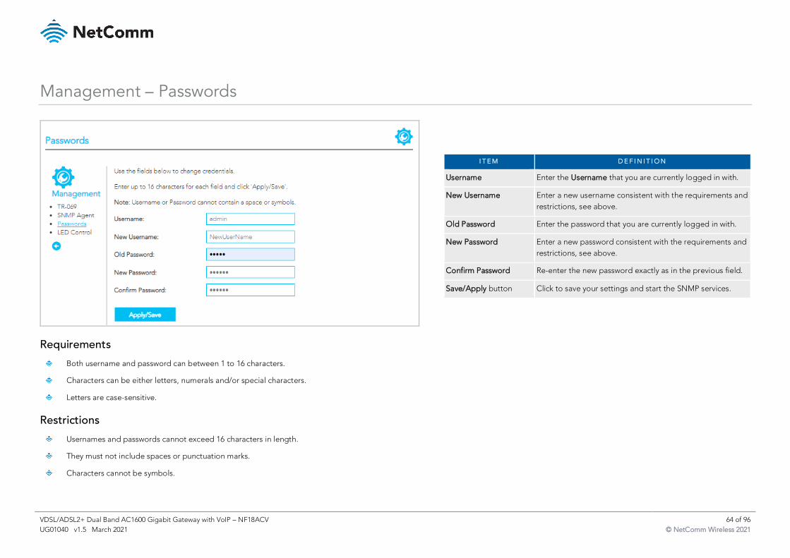
VDSL/ADSL2+ Dual Band AC1600 Gigabit Gateway with VoIP – NF18ACV 64 of 96
UG01040 v1.5 March 2021 © NetComm Wireless 2021
Management – Passwords
Requirements
Both username and password can between 1 to 16 characters.
Characters can be either letters, numerals and/or special characters.
Letters are case-sensitive.
Restrictions
Usernames and passwords cannot exceed 16 characters in length.
They must not include spaces or punctuation marks.
Characters cannot be symbols.
I T E M D E F I N I T I O N
Username Enter the Username that you are currently logged in with.
New Username Enter a new username consistent with the requirements and
restrictions, see above.
Old Password Enter the password that you are currently logged in with.
New Password Enter a new password consistent with the requirements and
restrictions, see above.
Confirm Password Re-enter the new password exactly as in the previous field.
Save/Apply button Click to save your settings and start the SNMP services.
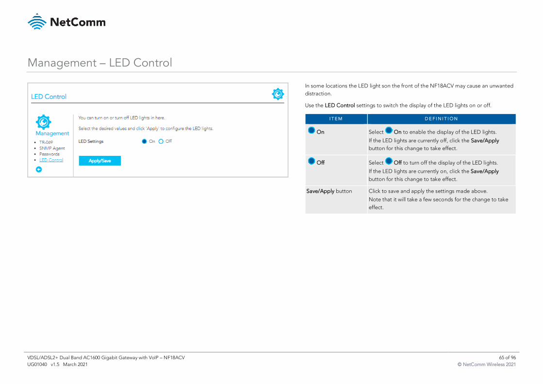
VDSL/ADSL2+ Dual Band AC1600 Gigabit Gateway with VoIP – NF18ACV 65 of 96
UG01040 v1.5 March 2021 © NetComm Wireless 2021
Management – LED Control
In some locations the LED light son the front of the NF18ACV may cause an unwanted
distraction.
Use the LED Control settings to switch the display of the LED lights on or off.
I T E M D E F I N I T I O N
On Select On to enable the display of the LED lights.
If the LED lights are currently off, click the Save/Apply
button for this change to take effect.
Off Select Off to turn off the display of the LED lights.
If the LED lights are currently on, click the Save/Apply
button for this change to take effect.
Save/Apply button Click to save and apply the settings made above.
Note that it will take a few seconds for the change to take
effect.
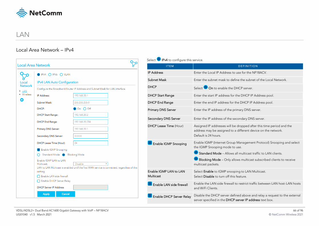
VDSL/ADSL2+ Dual Band AC1600 Gigabit Gateway with VoIP – NF18ACV 66 of 96
UG01040 v1.5 March 2021 © NetComm Wireless 2021
LAN
Local Area Network – IPv4
Select IPv4 to configure this service.
I T E M D E F I N I T I O N
IP Address Enter the Local IP Address to use for the NF18ACV.
Subnet Mask Enter the subnet mask to define the subnet of the Local Network.
DHCP Select On to enable the DHCP server.
DHCP Start Range Enter the start IP address for the DHCP IP Address pool.
DHCP End Range Enter the end IP address for the DHCP IP Address pool.
Primary DNS Server Enter the IP address of the primary DNS server.
Secondary DNS Server Enter the IP address of the secondary DNS server.
DHCP Lease Time (Hour) Assigned IP addresses will be dropped after this time period and the
address may be assigned to a different device on the network.
Default is 24 hours.
Enable IGMP Snooping Enable IGMP (Internet Group Management Protocol) Snooping and select
the IGMP Snooping mode to use.
Standard Mode – Allows all multicast traffic to LAN clients.
Blocking Mode – Only allows multicast subscribed clients to receive
multicast packets.
Enable IGMP LAN to LAN
Multicast
Select Enable to IGMP snooping to LAN Multicast.
Select Disable to turn off this feature.
Enable LAN side firewall Enable the LAN side firewall to restrict traffic between LAN host-LAN hosts
and WiFi Clients.
Enable DHCP Server Relay Disable the DHCP server defined above and relay a request to the external
server specified in the DHCP server IP address text box.
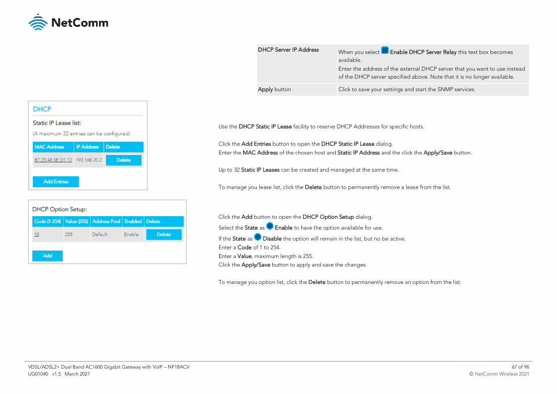
VDSL/ADSL2+ Dual Band AC1600 Gigabit Gateway with VoIP – NF18ACV 67 of 96
UG01040 v1.5 March 2021 © NetComm Wireless 2021
DHCP Server IP Address When you select Enable DHCP Server Relay this text box becomes
available.
Enter the address of the external DHCP server that you want to use instead
of the DHCP server specified above. Note that it is no longer available.
Apply button Click to save your settings and start the SNMP services.
Use the DHCP Static IP Lease facility to reserve DHCP Addresses for specific hosts.
Click the Add Entries button to open the DHCP Static IP Lease dialog.
Enter the MAC Address of the chosen host and Static IP Address and the click the Apply/Save button.
Up to 32 Static IP Leases can be created and managed at the same time.
To manage you lease list, click the Delete button to permanently remove a lease from the list.
Click the Add button to open the DHCP Option Setup dialog.
Select the State as Enable to have the option available for use.
If the State as Disable the option will remain in the list, but no be active.
Enter a Code of 1 to 254.
Enter a Value, maximum length is 255.
Click the Apply/Save button to apply and save the changes.
To manage you option list, click the Delete button to permanently remove an option from the list.
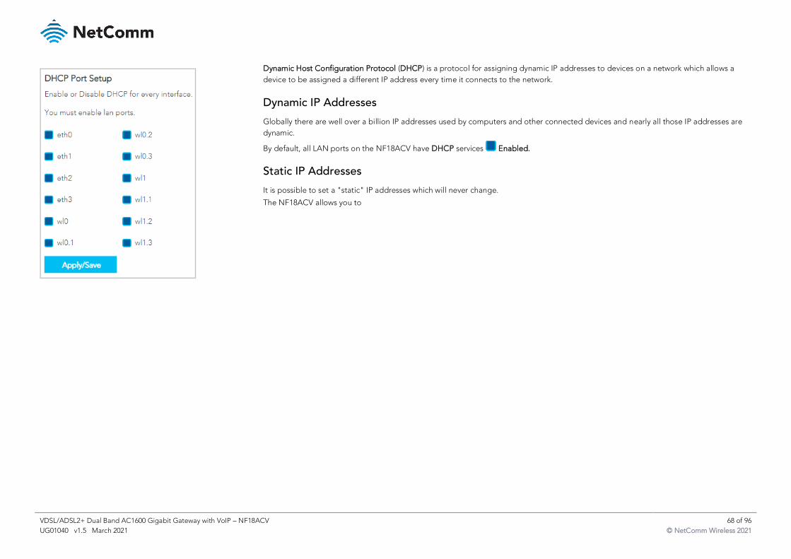
VDSL/ADSL2+ Dual Band AC1600 Gigabit Gateway with VoIP – NF18ACV 68 of 96
UG01040 v1.5 March 2021 © NetComm Wireless 2021
Dynamic Host Configuration Protocol (DHCP) is a protocol for assigning dynamic IP addresses to devices on a network which allows a
device to be assigned a different IP address every time it connects to the network.
Dynamic IP Addresses
Globally there are well over a billion IP addresses used by computers and other connected devices and nearly all those IP addresses are
dynamic.
By default, all LAN ports on the NF18ACV have DHCP services Enabled.
Static IP Addresses
It is possible to set a "static" IP addresses which will never change.
The NF18ACV allows you to
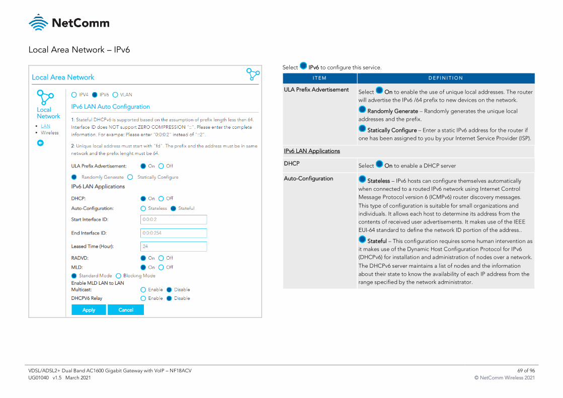
VDSL/ADSL2+ Dual Band AC1600 Gigabit Gateway with VoIP – NF18ACV 69 of 96
UG01040 v1.5 March 2021 © NetComm Wireless 2021
Local Area Network – IPv6
Select IPv6 to configure this service.
I T E M D E F I N I T I O N
ULA Prefix Advertisement Select On to enable the use of unique local addresses. The router
will advertise the IPv6 /64 prefix to new devices on the network.
Randomly Generate – Randomly generates the unique local
addresses and the prefix.
Statically Configure – Enter a static IPv6 address for the router if
one has been assigned to you by your Internet Service Provider (ISP).
IPv6 LAN Applications
DHCP Select On to enable a DHCP server
Auto-Configuration Stateless – IPv6 hosts can configure themselves automatically
when connected to a routed IPv6 network using Internet Control
Message Protocol version 6 (ICMPv6) router discovery messages.
This type of configuration is suitable for small organizations and
individuals. It allows each host to determine its address from the
contents of received user advertisements. It makes use of the IEEE
EUI-64 standard to define the network ID portion of the address..
Stateful – This configuration requires some human intervention as
it makes use of the Dynamic Host Configuration Protocol for IPv6
(DHCPv6) for installation and administration of nodes over a network.
The DHCPv6 server maintains a list of nodes and the information
about their state to know the availability of each IP address from the
range specified by the network administrator.
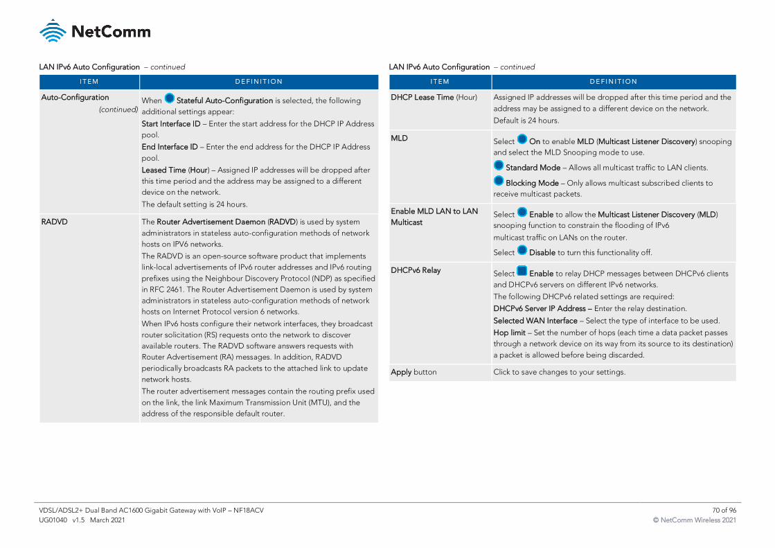
VDSL/ADSL2+ Dual Band AC1600 Gigabit Gateway with VoIP – NF18ACV 70 of 96
UG01040 v1.5 March 2021 © NetComm Wireless 2021
LAN IPv6 Auto Configuration – continued
I T E M D E F I N I T I O N
Auto-Configuration
(continued) When Stateful Auto-Configuration is selected, the following
additional settings appear:
Start Interface ID – Enter the start address for the DHCP IP Address
pool.
End Interface ID – Enter the end address for the DHCP IP Address
pool.
Leased Time (Hour) – Assigned IP addresses will be dropped after
this time period and the address may be assigned to a different
device on the network.
The default setting is 24 hours.
RADVD The Router Advertisement Daemon (RADVD) is used by system
administrators in stateless auto-configuration methods of network
hosts on IPV6 networks.
The RADVD is an open-source software product that implements
link-local advertisements of IPv6 router addresses and IPv6 routing
prefixes using the Neighbour Discovery Protocol (NDP) as specified
in RFC 2461. The Router Advertisement Daemon is used by system
administrators in stateless auto-configuration methods of network
hosts on Internet Protocol version 6 networks.
When IPv6 hosts configure their network interfaces, they broadcast
router solicitation (RS) requests onto the network to discover
available routers. The RADVD software answers requests with
Router Advertisement (RA) messages. In addition, RADVD
periodically broadcasts RA packets to the attached link to update
network hosts.
The router advertisement messages contain the routing prefix used
on the link, the link Maximum Transmission Unit (MTU), and the
address of the responsible default router.
LAN IPv6 Auto Configuration – continued
I T E M D E F I N I T I O N
DHCP Lease Time (Hour) Assigned IP addresses will be dropped after this time period and the
address may be assigned to a different device on the network.
Default is 24 hours.
MLD Select On to enable MLD (Multicast Listener Discovery) snooping
and select the MLD Snooping mode to use.
Standard Mode – Allows all multicast traffic to LAN clients.
Blocking Mode – Only allows multicast subscribed clients to
receive multicast packets.
Enable MLD LAN to LAN
Multicast Select Enable to allow the Multicast Listener Discovery (MLD)
snooping function to constrain the flooding of IPv6
multicast traffic on LANs on the router.
Select Disable to turn this functionality off.
DHCPv6 Relay Select Enable to relay DHCP messages between DHCPv6 clients
and DHCPv6 servers on different IPv6 networks.
The following DHCPv6 related settings are required:
DHCPv6 Server IP Address – Enter the relay destination.
Selected WAN Interface – Select the type of interface to be used.
Hop limit – Set the number of hops (each time a data packet passes
through a network device on its way from its source to its destination)
a packet is allowed before being discarded.
Apply button Click to save changes to your settings.
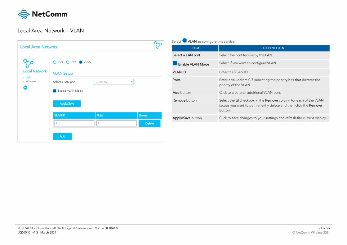
VDSL/ADSL2+ Dual Band AC1600 Gigabit Gateway with VoIP – NF18ACV 71 of 96
UG01040 v1.5 March 2021 © NetComm Wireless 2021
Local Area Network – VLAN
Select VLAN to configure this service.
I T E M D E F I N I T I O N
Select a LAN port Select the port for use by the LAN.
Enable VLAN Mode Select if you want to configure VLAN.
VLAN ID Enter the VLAN ID..
Pbits Enter a value from 0-7 indicating the priority bits that dictates the
priority of the VLAN.
Add button Click to create an additional VLAN port.
Remove button Select the checkbox in the Remove column for each of the VLAN
setups you want to permanently delete and then click the Remove
button.
Apply/Save button Click to save changes to your settings and refresh the current display.
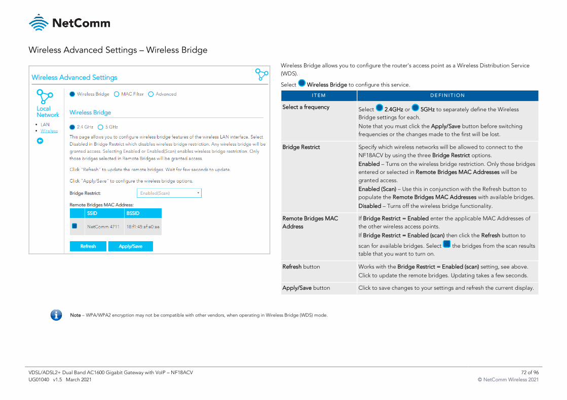
VDSL/ADSL2+ Dual Band AC1600 Gigabit Gateway with VoIP – NF18ACV 72 of 96
UG01040 v1.5 March 2021 © NetComm Wireless 2021
Wireless Advanced Settings – Wireless Bridge
Wireless Bridge allows you to configure the router’s access point as a Wireless Distribution Service
(WDS).
Select Wireless Bridge to configure this service.
I T E M D E F I N I T I O N
Select a frequency Select 2.4GHz or 5GHz to separately define the Wireless
Bridge settings for each.
Note that you must click the Apply/Save button before switching
frequencies or the changes made to the first will be lost.
Bridge Restrict Specify which wireless networks will be allowed to connect to the
NF18ACV by using the three Bridge Restrict options.
Enabled – Turns on the wireless bridge restriction. Only those bridges
entered or selected in Remote Bridges MAC Addresses will be
granted access.
Enabled (Scan) – Use this in conjunction with the Refresh button to
populate the Remote Bridges MAC Addresses with available bridges.
Disabled – Turns off the wireless bridge functionality.
Remote Bridges MAC
Address
If Bridge Restrict = Enabled enter the applicable MAC Addresses of
the other wireless access points.
If Bridge Restrict = Enabled (scan) then click the Refresh button to
scan for available bridges. Select the bridges from the scan results
table that you want to turn on.
Refresh button Works with the Bridge Restrict = Enabled (scan) setting, see above.
Click to update the remote bridges. Updating takes a few seconds.
Apply/Save button Click to save changes to your settings and refresh the current display.
Note – WPA/WPA2 encryption may not be compatible with other vendors, when operating in Wireless Bridge (WDS) mode.
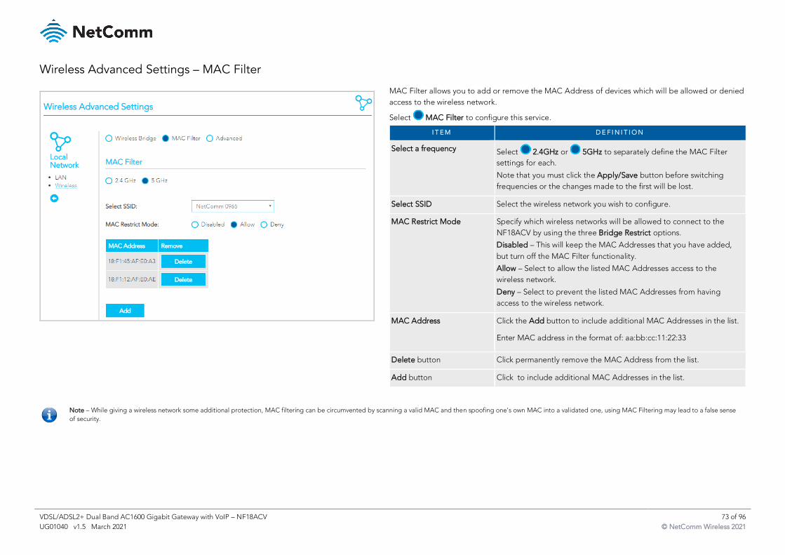
VDSL/ADSL2+ Dual Band AC1600 Gigabit Gateway with VoIP – NF18ACV 73 of 96
UG01040 v1.5 March 2021 © NetComm Wireless 2021
Wireless Advanced Settings – MAC Filter
MAC Filter allows you to add or remove the MAC Address of devices which will be allowed or denied
access to the wireless network.
Select MAC Filter to configure this service.
I T E M D E F I N I T I O N
Select a frequency Select 2.4GHz or 5GHz to separately define the MAC Filter
settings for each.
Note that you must click the Apply/Save button before switching
frequencies or the changes made to the first will be lost.
Select SSID Select the wireless network you wish to configure.
MAC Restrict Mode Specify which wireless networks will be allowed to connect to the
NF18ACV by using the three Bridge Restrict options.
Disabled – This will keep the MAC Addresses that you have added,
but turn off the MAC Filter functionality.
Allow – Select to allow the listed MAC Addresses access to the
wireless network.
Deny – Select to prevent the listed MAC Addresses from having
access to the wireless network.
MAC Address Click the Add button to include additional MAC Addresses in the list.
Enter MAC address in the format of: aa:bb:cc:11:22:33
Delete button Click permanently remove the MAC Address from the list.
Add button Click to include additional MAC Addresses in the list.
Note – While giving a wireless network some additional protection, MAC filtering can be circumvented by scanning a valid MAC and then spoofing one's own MAC into a validated one, using MAC Filtering may lead to a false sense
of security.
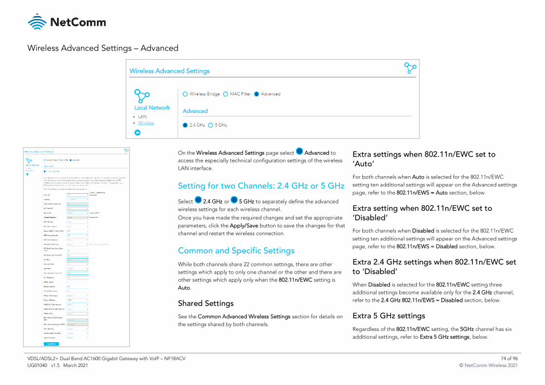
VDSL/ADSL2+ Dual Band AC1600 Gigabit Gateway with VoIP – NF18ACV 74 of 96
UG01040 v1.5 March 2021 © NetComm Wireless 2021
Wireless Advanced Settings – Advanced
On the Wireless Advanced Settings page select Advanced to
access the especially technical configuration settings of the wireless
LAN interface.
Setting for two Channels: 2.4 GHz or 5 GHz
Select 2.4 GHz or 5 GHz to separately define the advanced
wireless settings for each wireless channel.
Once you have made the required changes and set the appropriate
parameters, click the Apply/Save button to save the changes for that
channel and restart the wireless connection.
Common and Specific Settings
While both channels share 22 common settings, there are other
settings which apply to only one channel or the other and there are
other settings which apply only when the 802.11n/EWC setting is
Auto.
Shared Settings
See the Common Advanced Wireless Settings section for details on
the settings shared by both channels.
Extra settings when 802.11n/EWC set to ‘Auto’
For both channels when Auto is selected for the 802.11n/EWC
setting ten additional settings will appear on the Advanced settings
page, refer to the 802.11n/EWS = Auto section, below.
Extra setting when 802.11n/EWC set to ‘Disabled’
For both channels when Disabled is selected for the 802.11n/EWC
setting ten additional settings will appear on the Advanced settings
page, refer to the 802.11n/EWS = Disabled section, below.
Extra 2.4 GHz settings when 802.11n/EWC set to ‘Disabled’
When Disabled is selected for the 802.11n/EWC setting three
additional settings become available only for the 2.4 GHz channel,
refer to the 2.4 GHz 802.11n/EWS = Disabled section, below.
Extra 5 GHz settings
Regardless of the 802.11n/EWC setting, the 5GHz channel has six
additional settings, refer to Extra 5 GHz settings, below.
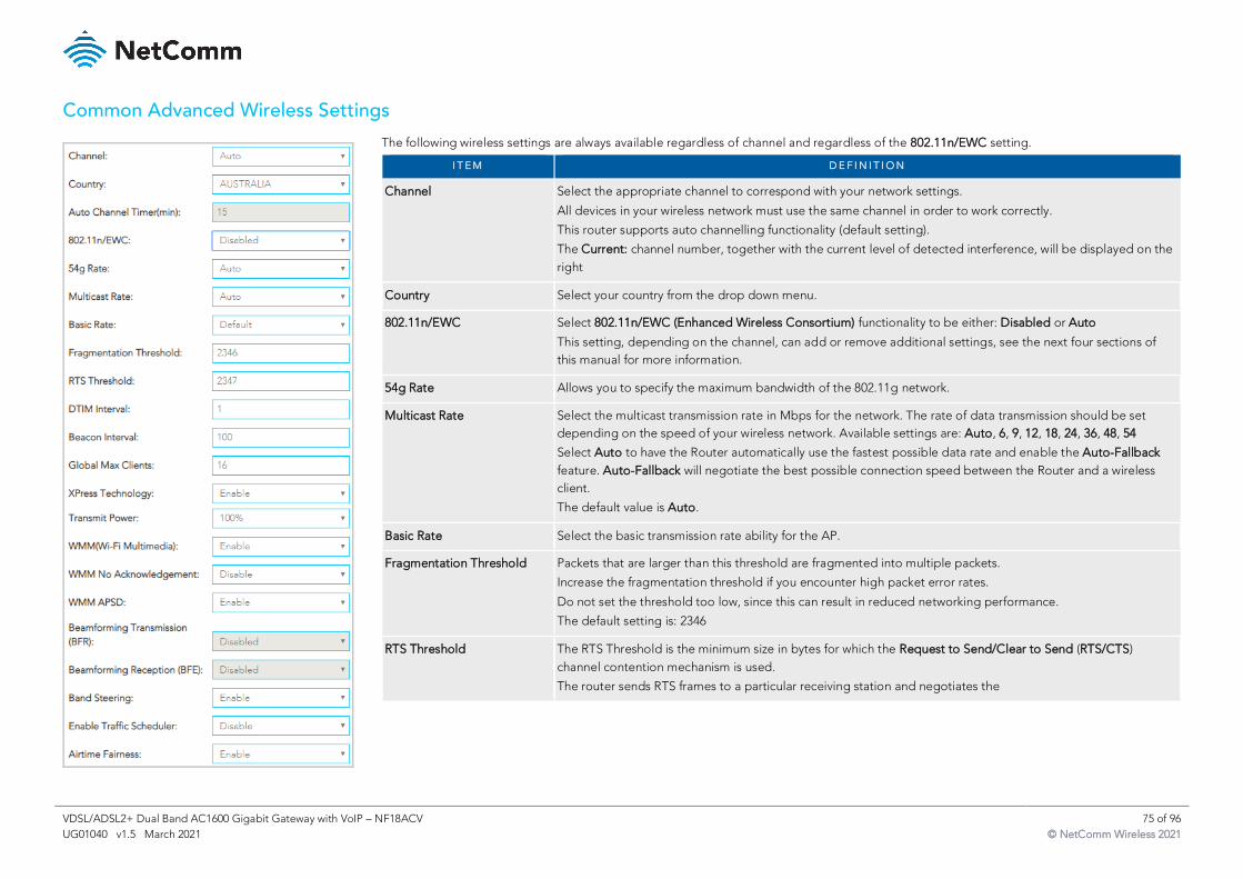
VDSL/ADSL2+ Dual Band AC1600 Gigabit Gateway with VoIP – NF18ACV 75 of 96
UG01040 v1.5 March 2021 © NetComm Wireless 2021
Common Advanced Wireless Settings
The following wireless settings are always available regardless of channel and regardless of the 802.11n/EWC setting.
I T E M D E F I N I T I O N
Channel Select the appropriate channel to correspond with your network settings.
All devices in your wireless network must use the same channel in order to work correctly.
This router supports auto channelling functionality (default setting).
The Current: channel number, together with the current level of detected interference, will be displayed on the
right
Country Select your country from the drop down menu.
802.11n/EWC Select 802.11n/EWC (Enhanced Wireless Consortium) functionality to be either: Disabled or Auto
This setting, depending on the channel, can add or remove additional settings, see the next four sections of
this manual for more information.
54g Rate Allows you to specify the maximum bandwidth of the 802.11g network.
Multicast Rate Select the multicast transmission rate in Mbps for the network. The rate of data transmission should be set
depending on the speed of your wireless network. Available settings are: Auto, 6, 9, 12, 18, 24, 36, 48, 54
Select Auto to have the Router automatically use the fastest possible data rate and enable the Auto-Fallback
feature. Auto-Fallback will negotiate the best possible connection speed between the Router and a wireless
client.
The default value is Auto.
Basic Rate Select the basic transmission rate ability for the AP.
Fragmentation Threshold Packets that are larger than this threshold are fragmented into multiple packets.
Increase the fragmentation threshold if you encounter high packet error rates.
Do not set the threshold too low, since this can result in reduced networking performance.
The default setting is: 2346
RTS Threshold The RTS Threshold is the minimum size in bytes for which the Request to Send/Clear to Send (RTS/CTS)
channel contention mechanism is used.
The router sends RTS frames to a particular receiving station and negotiates the
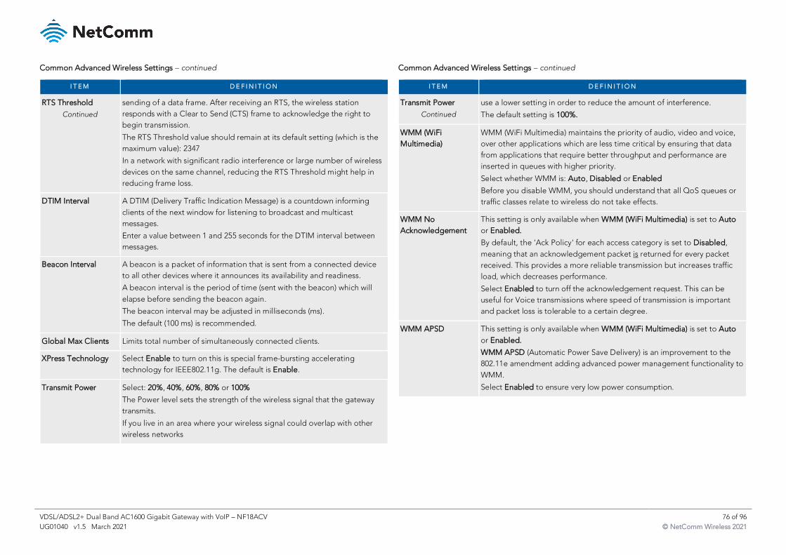
VDSL/ADSL2+ Dual Band AC1600 Gigabit Gateway with VoIP – NF18ACV 76 of 96
UG01040 v1.5 March 2021 © NetComm Wireless 2021
Common Advanced Wireless Settings – continued
I T E M D E F I N I T I O N
RTS Threshold
Continued
sending of a data frame. After receiving an RTS, the wireless station
responds with a Clear to Send (CTS) frame to acknowledge the right to
begin transmission.
The RTS Threshold value should remain at its default setting (which is the
maximum value): 2347
In a network with significant radio interference or large number of wireless
devices on the same channel, reducing the RTS Threshold might help in
reducing frame loss.
DTIM Interval A DTIM (Delivery Traffic Indication Message) is a countdown informing
clients of the next window for listening to broadcast and multicast
messages.
Enter a value between 1 and 255 seconds for the DTIM interval between
messages.
Beacon Interval A beacon is a packet of information that is sent from a connected device
to all other devices where it announces its availability and readiness.
A beacon interval is the period of time (sent with the beacon) which will
elapse before sending the beacon again.
The beacon interval may be adjusted in milliseconds (ms).
The default (100 ms) is recommended.
Global Max Clients Limits total number of simultaneously connected clients.
XPress Technology Select Enable to turn on this is special frame-bursting accelerating
technology for IEEE802.11g. The default is Enable.
Transmit Power Select: 20%, 40%, 60%, 80% or 100%
The Power level sets the strength of the wireless signal that the gateway
transmits.
If you live in an area where your wireless signal could overlap with other
wireless networks
Common Advanced Wireless Settings – continued
I T E M D E F I N I T I O N
Transmit Power
Continued
use a lower setting in order to reduce the amount of interference.
The default setting is 100%.
WMM (WiFi
Multimedia)
WMM (WiFi Multimedia) maintains the priority of audio, video and voice,
over other applications which are less time critical by ensuring that data
from applications that require better throughput and performance are
inserted in queues with higher priority.
Select whether WMM is: Auto, Disabled or Enabled
Before you disable WMM, you should understand that all QoS queues or
traffic classes relate to wireless do not take effects.
WMM No
Acknowledgement
This setting is only available when WMM (WiFi Multimedia) is set to Auto
or Enabled.
By default, the 'Ack Policy' for each access category is set to Disabled,
meaning that an acknowledgement packet is returned for every packet
received. This provides a more reliable transmission but increases traffic
load, which decreases performance.
Select Enabled to turn off the acknowledgement request. This can be
useful for Voice transmissions where speed of transmission is important
and packet loss is tolerable to a certain degree.
WMM APSD This setting is only available when WMM (WiFi Multimedia) is set to Auto
or Enabled.
WMM APSD (Automatic Power Save Delivery) is an improvement to the
802.11e amendment adding advanced power management functionality to
WMM.
Select Enabled to ensure very low power consumption.
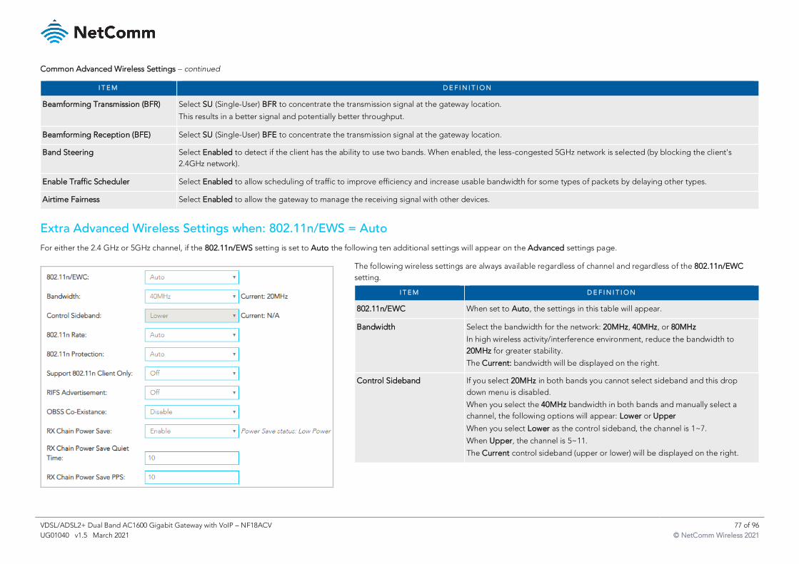
VDSL/ADSL2+ Dual Band AC1600 Gigabit Gateway with VoIP – NF18ACV 77 of 96
UG01040 v1.5 March 2021 © NetComm Wireless 2021
Common Advanced Wireless Settings – continued
I T E M D E F I N I T I O N
Beamforming Transmission (BFR) Select SU (Single-User) BFR to concentrate the transmission signal at the gateway location.
This results in a better signal and potentially better throughput.
Beamforming Reception (BFE) Select SU (Single-User) BFE to concentrate the transmission signal at the gateway location.
Band Steering Select Enabled to detect if the client has the ability to use two bands. When enabled, the less-congested 5GHz network is selected (by blocking the client's
2.4GHz network).
Enable Traffic Scheduler Select Enabled to allow scheduling of traffic to improve efficiency and increase usable bandwidth for some types of packets by delaying other types.
Airtime Fairness Select Enabled to allow the gateway to manage the receiving signal with other devices.
Extra Advanced Wireless Settings when: 802.11n/EWS = Auto
For either the 2.4 GHz or 5GHz channel, if the 802.11n/EWS setting is set to Auto the following ten additional settings will appear on the Advanced settings page.
The following wireless settings are always available regardless of channel and regardless of the 802.11n/EWC
setting.
I T E M D E F I N I T I O N
802.11n/EWC When set to Auto, the settings in this table will appear.
Bandwidth Select the bandwidth for the network: 20MHz, 40MHz, or 80MHz
In high wireless activity/interference environment, reduce the bandwidth to
20MHz for greater stability.
The Current: bandwidth will be displayed on the right.
Control Sideband If you select 20MHz in both bands you cannot select sideband and this drop
down menu is disabled.
When you select the 40MHz bandwidth in both bands and manually select a
channel, the following options will appear: Lower or Upper
When you select Lower as the control sideband, the channel is 1~7.
When Upper, the channel is 5~11.
The Current control sideband (upper or lower) will be displayed on the right.
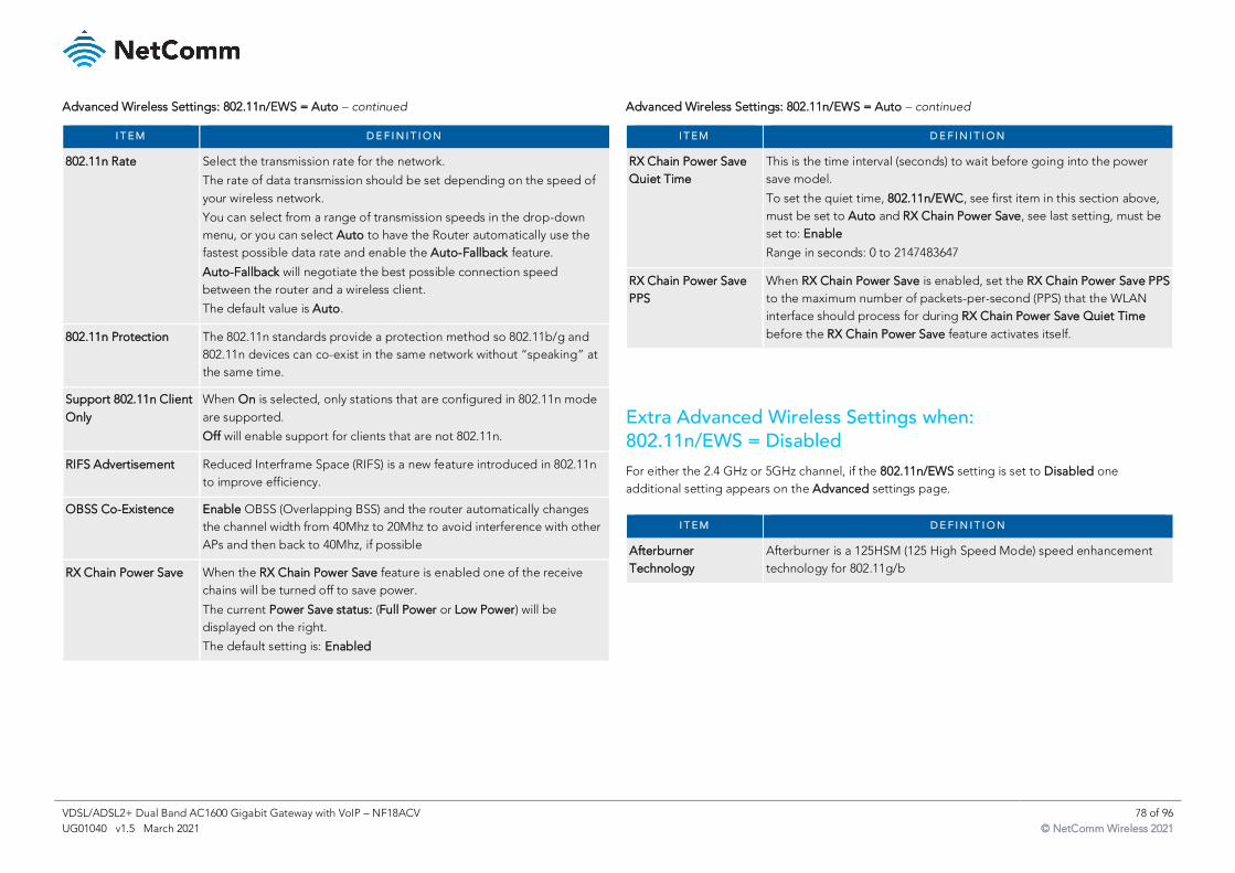
VDSL/ADSL2+ Dual Band AC1600 Gigabit Gateway with VoIP – NF18ACV 78 of 96
UG01040 v1.5 March 2021 © NetComm Wireless 2021
Advanced Wireless Settings: 802.11n/EWS = Auto – continued
I T E M D E F I N I T I O N
802.11n Rate Select the transmission rate for the network.
The rate of data transmission should be set depending on the speed of
your wireless network.
You can select from a range of transmission speeds in the drop-down
menu, or you can select Auto to have the Router automatically use the
fastest possible data rate and enable the Auto-Fallback feature.
Auto-Fallback will negotiate the best possible connection speed
between the router and a wireless client.
The default value is Auto.
802.11n Protection The 802.11n standards provide a protection method so 802.11b/g and
802.11n devices can co-exist in the same network without “speaking” at
the same time.
Support 802.11n Client
Only
When On is selected, only stations that are configured in 802.11n mode
are supported.
Off will enable support for clients that are not 802.11n.
RIFS Advertisement Reduced Interframe Space (RIFS) is a new feature introduced in 802.11n
to improve efficiency.
OBSS Co-Existence Enable OBSS (Overlapping BSS) and the router automatically changes
the channel width from 40Mhz to 20Mhz to avoid interference with other
APs and then back to 40Mhz, if possible
RX Chain Power Save When the RX Chain Power Save feature is enabled one of the receive
chains will be turned off to save power.
The current Power Save status: (Full Power or Low Power) will be
displayed on the right.
The default setting is: Enabled
Advanced Wireless Settings: 802.11n/EWS = Auto – continued
Extra Advanced Wireless Settings when: 802.11n/EWS = Disabled
For either the 2.4 GHz or 5GHz channel, if the 802.11n/EWS setting is set to Disabled one
additional setting appears on the Advanced settings page.
I T E M D E F I N I T I O N
RX Chain Power Save
Quiet Time
This is the time interval (seconds) to wait before going into the power
save model.
To set the quiet time, 802.11n/EWC, see first item in this section above,
must be set to Auto and RX Chain Power Save, see last setting, must be
set to: Enable
Range in seconds: 0 to 2147483647
RX Chain Power Save
PPS
When RX Chain Power Save is enabled, set the RX Chain Power Save PPS
to the maximum number of packets-per-second (PPS) that the WLAN
interface should process for during RX Chain Power Save Quiet Time
before the RX Chain Power Save feature activates itself.
I T E M D E F I N I T I O N
Afterburner
Technology
Afterburner is a 125HSM (125 High Speed Mode) speed enhancement
technology for 802.11g/b
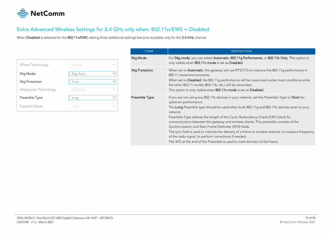
VDSL/ADSL2+ Dual Band AC1600 Gigabit Gateway with VoIP – NF18ACV 79 of 96
UG01040 v1.5 March 2021 © NetComm Wireless 2021
Extra Advanced Wireless Settings for 2.4 GHz only when: 802.11n/EWS = Disabled
When Disabled is selected for the 802.11n/EWC setting three additional settings become available only for the 2.4 GHz channel.
I T E M D E F I N I T I O N
54g Mode For 54g mode, you can select Automatic, 802.11g Performance, or 802.11b Only. This option is
only visible when 802.11n mode is set as Disabled.
54g Protection When set to Automatic, the gateway will use RTS/CTS to improve the 802.11g performance in
802.11 mixed environments.
When set to Disabled, the 802.11g performance will be maximized under most conditions while
the other 802.11 modes (802.11b, etc.) will be secondary.
This option is only visible when 802.11n mode is set as Disabled.
Preamble Type If you are not using any 802.11b devices in your network, set the Preamble Type to Short for
optimum performance.
The Long Preamble type should be used when both 802.11g and 802.11b devices exist on your
network.
Preamble Type defines the length of the Cyclic Redundancy Check (CRC) block for
communication between the gateway and wireless clients. The preamble consists of the
Synchronization and Start Frame Delimiter (SFD) fields.
The sync field is used to indicate the delivery of a frame to wireless stations, to measure frequency
of the radio signal, to perform corrections if needed.
The SFD at the end of the Preamble is used to mark the start of the frame.
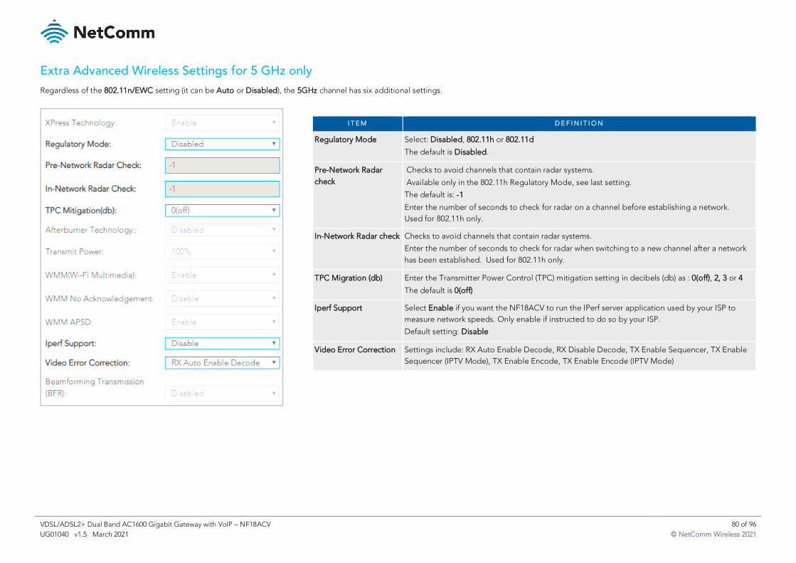
VDSL/ADSL2+ Dual Band AC1600 Gigabit Gateway with VoIP – NF18ACV 80 of 96
UG01040 v1.5 March 2021 © NetComm Wireless 2021
Extra Advanced Wireless Settings for 5 GHz only
Regardless of the 802.11n/EWC setting (it can be Auto or Disabled), the 5GHz channel has six additional settings.
I T E M D E F I N I T I O N
Regulatory Mode Select: Disabled, 802.11h or 802.11d
The default is Disabled.
Pre-Network Radar
check
Checks to avoid channels that contain radar systems.
Available only in the 802.11h Regulatory Mode, see last setting.
The default is: -1
Enter the number of seconds to check for radar on a channel before establishing a network.
Used for 802.11h only.
In-Network Radar check Checks to avoid channels that contain radar systems.
Enter the number of seconds to check for radar when switching to a new channel after a network
has been established. Used for 802.11h only.
TPC Migration (db) Enter the Transmitter Power Control (TPC) mitigation setting in decibels (db) as : 0(off), 2, 3 or 4
The default is 0(off)
Iperf Support Select Enable if you want the NF18ACV to run the IPerf server application used by your ISP to
measure network speeds. Only enable if instructed to do so by your ISP.
Default setting: Disable
Video Error Correction Settings include: RX Auto Enable Decode, RX Disable Decode, TX Enable Sequencer, TX Enable
Sequencer (IPTV Mode), TX Enable Encode, TX Enable Encode (IPTV Mode)
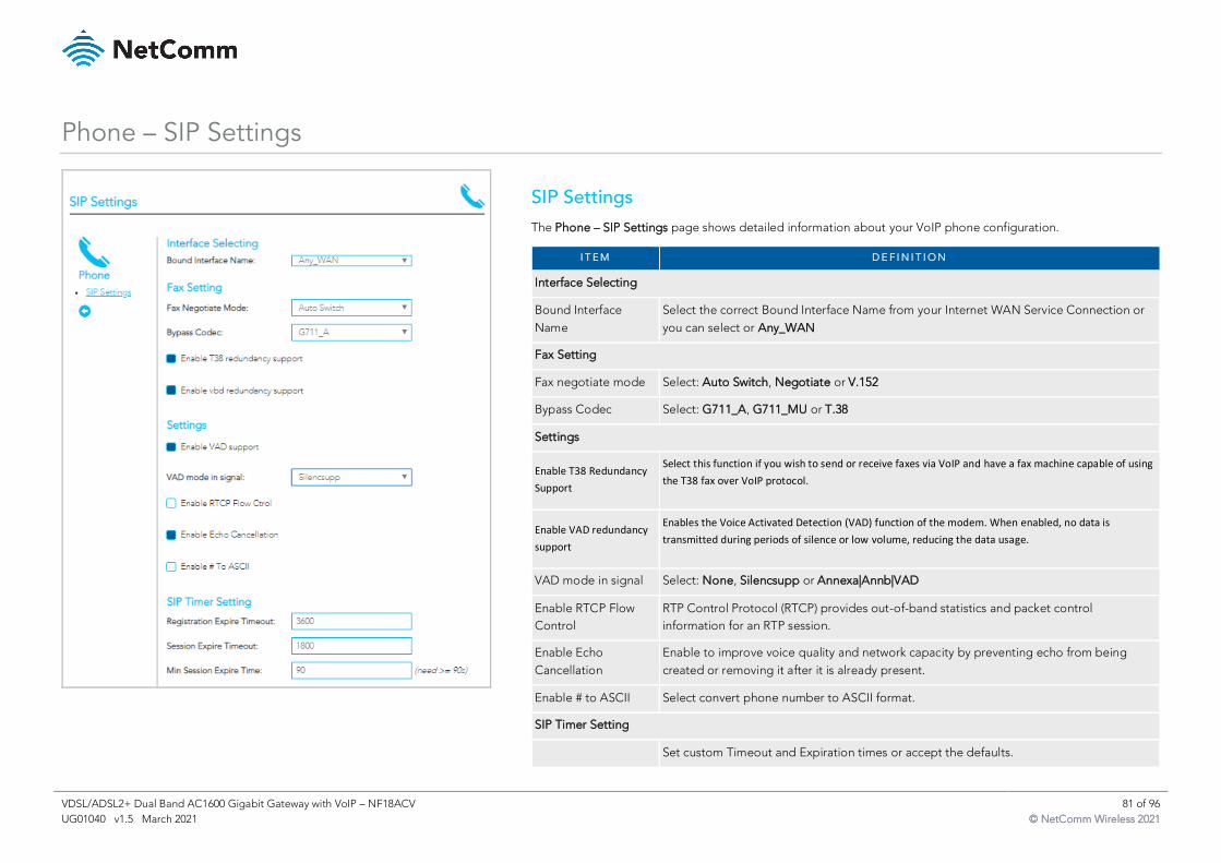
VDSL/ADSL2+ Dual Band AC1600 Gigabit Gateway with VoIP – NF18ACV 81 of 96
UG01040 v1.5 March 2021 © NetComm Wireless 2021
Phone – SIP Settings
SIP Settings
The Phone – SIP Settings page shows detailed information about your VoIP phone configuration.
I T E M D E F I N I T I O N
Interface Selecting
Bound Interface
Name
Select the correct Bound Interface Name from your Internet WAN Service Connection or
you can select or Any_WAN
Fax Setting
Fax negotiate mode Select: Auto Switch, Negotiate or V.152
Bypass Codec Select: G711_A, G711_MU or T.38
Settings
Enable T38 Redundancy
Support
Select this function if you wish to send or receive faxes via VoIP and have a fax machine capable of using
the T38 fax over VoIP protocol.
Enable VAD redundancy
support
Enables the Voice Activated Detection (VAD) function of the modem. When enabled, no data is
transmitted during periods of silence or low volume, reducing the data usage.
VAD mode in signal Select: None, Silencsupp or Annexa|Annb|VAD
Enable RTCP Flow
Control
RTP Control Protocol (RTCP) provides out-of-band statistics and packet control
information for an RTP session.
Enable Echo
Cancellation
Enable to improve voice quality and network capacity by preventing echo from being
created or removing it after it is already present.
Enable # to ASCII Select convert phone number to ASCII format.
SIP Timer Setting
Set custom Timeout and Expiration times or accept the defaults.
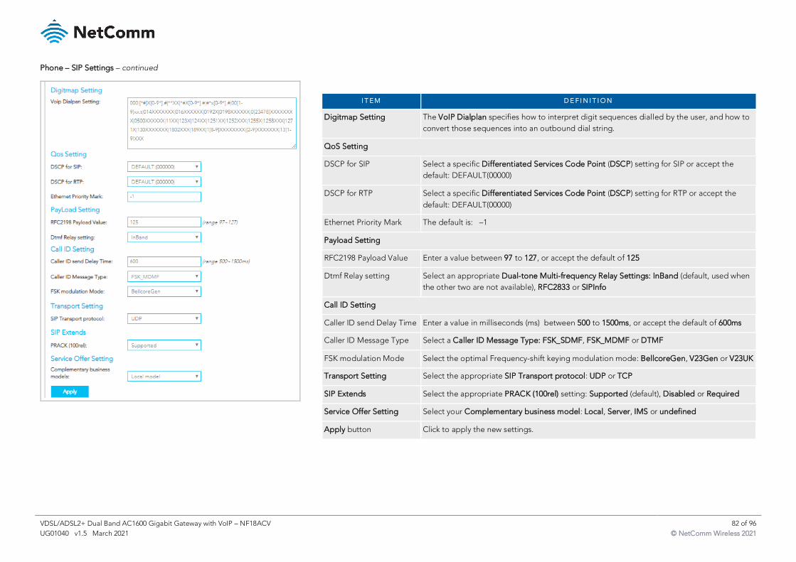
VDSL/ADSL2+ Dual Band AC1600 Gigabit Gateway with VoIP – NF18ACV 82 of 96
UG01040 v1.5 March 2021 © NetComm Wireless 2021
Phone – SIP Settings – continued
I T E M D E F I N I T I O N
Digitmap Setting The VoIP Dialplan specifies how to interpret digit sequences dialled by the user, and how to
convert those sequences into an outbound dial string.
QoS Setting
DSCP for SIP Select a specific Differentiated Services Code Point (DSCP) setting for SIP or accept the
default: DEFAULT(00000)
DSCP for RTP Select a specific Differentiated Services Code Point (DSCP) setting for RTP or accept the
default: DEFAULT(00000)
Ethernet Priority Mark The default is: –1
Payload Setting
RFC2198 Payload Value Enter a value between 97 to 127, or accept the default of 125
Dtmf Relay setting Select an appropriate Dual-tone Multi-frequency Relay Settings: InBand (default, used when
the other two are not available), RFC2833 or SIPInfo
Call ID Setting
Caller ID send Delay Time Enter a value in milliseconds (ms) between 500 to 1500ms, or accept the default of 600ms
Caller ID Message Type Select a Caller ID Message Type: FSK_SDMF, FSK_MDMF or DTMF
FSK modulation Mode Select the optimal Frequency-shift keying modulation mode: BellcoreGen, V23Gen or V23UK
Transport Setting Select the appropriate SIP Transport protocol: UDP or TCP
SIP Extends Select the appropriate PRACK (100rel) setting: Supported (default), Disabled or Required
Service Offer Setting Select your Complementary business model: Local, Server, IMS or undefined
Apply button Click to apply the new settings.
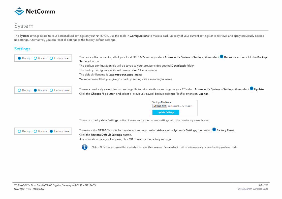
VDSL/ADSL2+ Dual Band AC1600 Gigabit Gateway with VoIP – NF18ACV 83 of 96
UG01040 v1.5 March 2021 © NetComm Wireless 2021
System
The System settings relate to your personalised settings on your NF18ACV. Use the tools in Configurations to make a back-up copy of your current settings or to retrieve and apply previously backed-
up settings. Alternatively you can reset all settings to the factory default settings.
Settings
To create a file containing all of your local NF18ACV settings select Advanced > System > Settings, then select Backup and then click the Backup
Settings button.
The backup configuration file will be saved to your browser’s designated Downloads folder.
The backup configuration file will have a .conf file extension.
The default filename is: backupsettings.conf
We recommend that you give you backup settings file a meaningful name.
To use a previously saved backup settings file to reinstate those settings on your PC select Advanced > System > Settings, then select Update.
Click the Choose File button and select a previously saved backup settings file (file extension .conf).
Then click the Update Settings button to over-write the current settings with the previously saved ones.
To restore the NF18ACV to its factory default settings, select Advanced > System > Settings, then select Factory Reset.
Click the Restore Default Settings button.
A confirmation dialog will appear, click OK to restore the factory settings.
Note – All factory settings will be applied except your Username and Password which will remain as per any personal setting you have made.
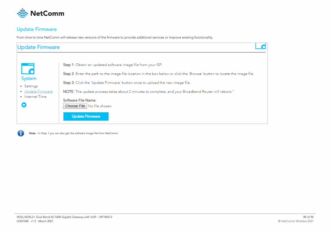
VDSL/ADSL2+ Dual Band AC1600 Gigabit Gateway with VoIP – NF18ACV 84 of 96
UG01040 v1.5 March 2021 © NetComm Wireless 2021
Update Firmware
From time to time NetComm will release new versions of the firmware to provide additional services or improve existing functionality.
Note – In Step 1 you can also get the software image file from NetComm.
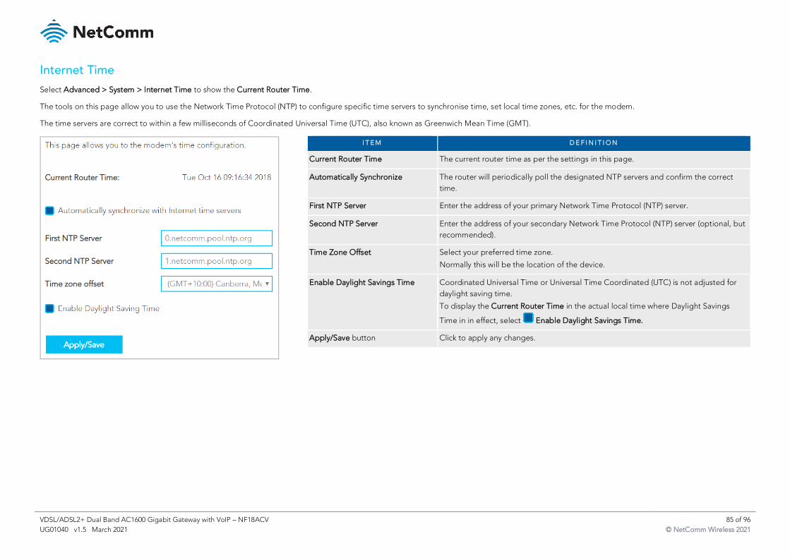
VDSL/ADSL2+ Dual Band AC1600 Gigabit Gateway with VoIP – NF18ACV 85 of 96
UG01040 v1.5 March 2021 © NetComm Wireless 2021
Internet Time
Select Advanced > System > Internet Time to show the Current Router Time.
The tools on this page allow you to use the Network Time Protocol (NTP) to configure specific time servers to synchronise time, set local time zones, etc. for the modem.
The time servers are correct to within a few milliseconds of Coordinated Universal Time (UTC), also known as Greenwich Mean Time (GMT).
I T E M D E F I N I T I O N
Current Router Time The current router time as per the settings in this page.
Automatically Synchronize The router will periodically poll the designated NTP servers and confirm the correct
time.
First NTP Server Enter the address of your primary Network Time Protocol (NTP) server.
Second NTP Server Enter the address of your secondary Network Time Protocol (NTP) server (optional, but
recommended).
Time Zone Offset Select your preferred time zone.
Normally this will be the location of the device.
Enable Daylight Savings Time Coordinated Universal Time or Universal Time Coordinated (UTC) is not adjusted for
daylight saving time.
To display the Current Router Time in the actual local time where Daylight Savings
Time in in effect, select Enable Daylight Savings Time.
Apply/Save button Click to apply any changes.
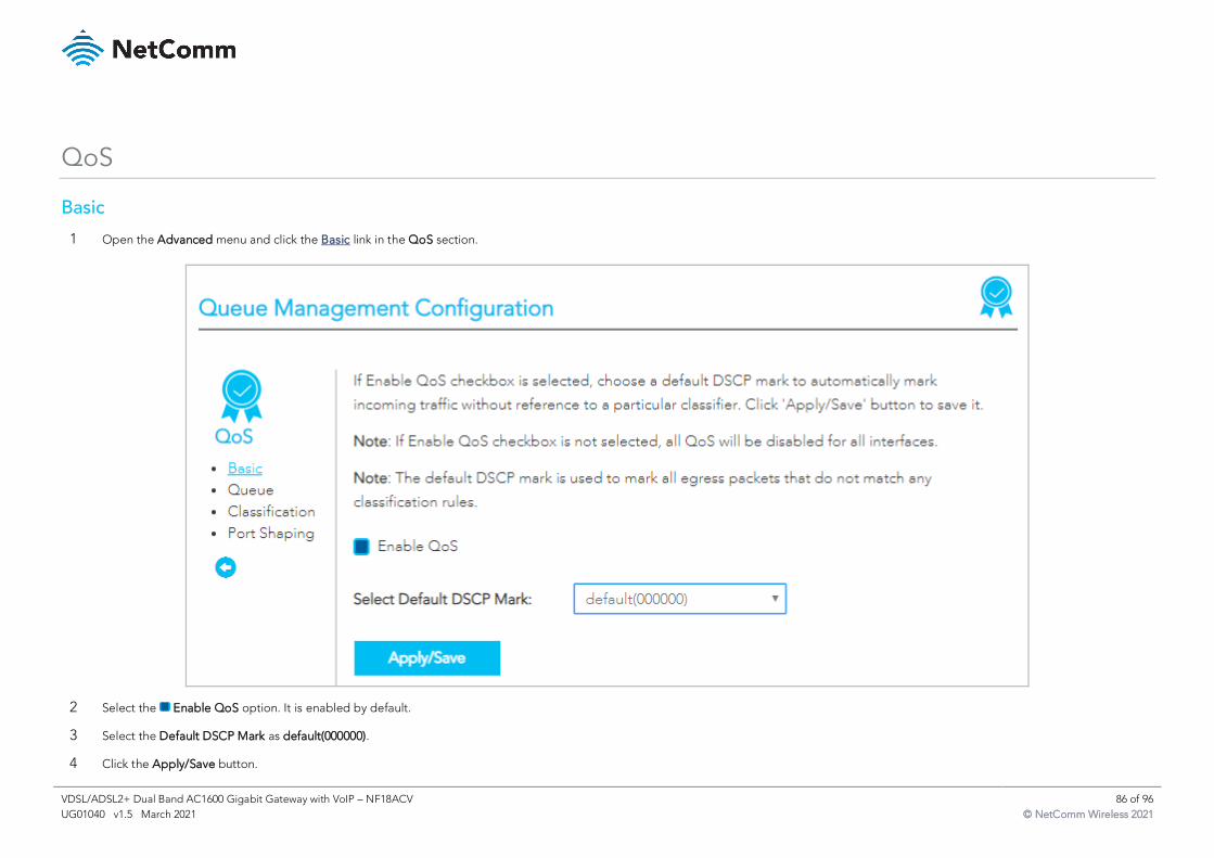
VDSL/ADSL2+ Dual Band AC1600 Gigabit Gateway with VoIP – NF18ACV 86 of 96
UG01040 v1.5 March 2021 © NetComm Wireless 2021
QoS
Basic
1 Open the Advanced menu and click the Basic link in the QoS section.
2 Select the Enable QoS option. It is enabled by default.
3 Select the Default DSCP Mark as default(000000).
4 Click the Apply/Save button.
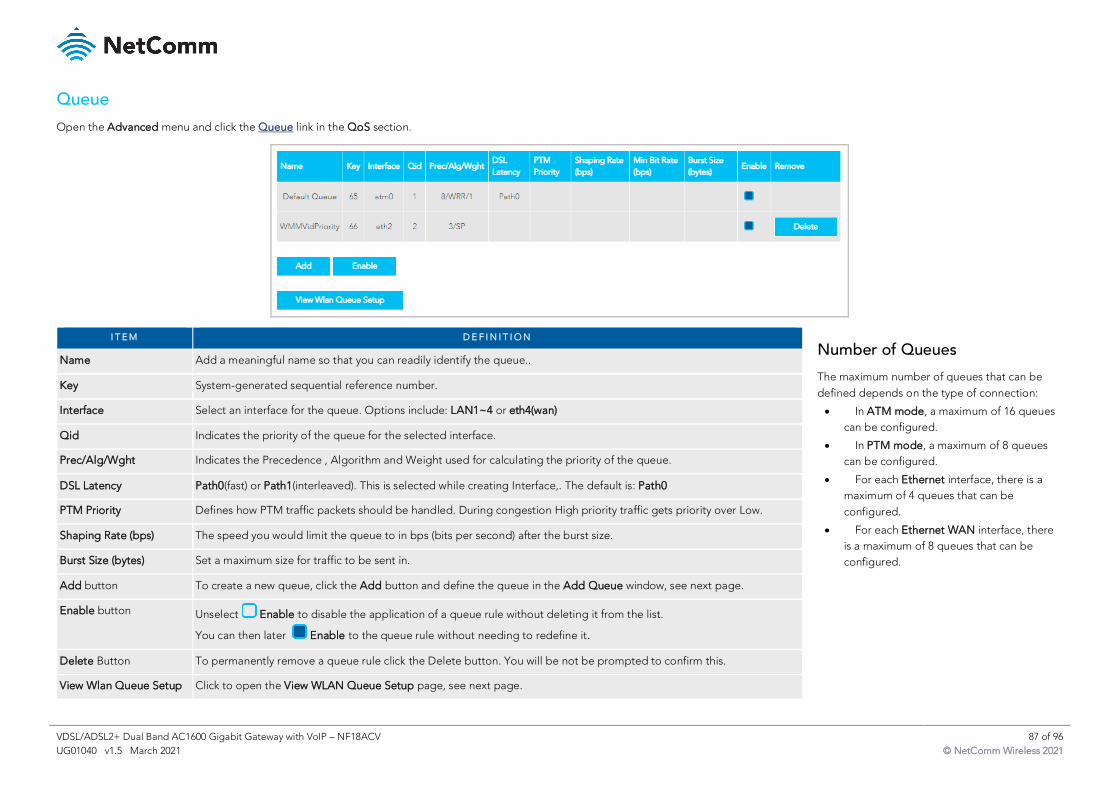
VDSL/ADSL2+ Dual Band AC1600 Gigabit Gateway with VoIP – NF18ACV 87 of 96
UG01040 v1.5 March 2021 © NetComm Wireless 2021
Queue
Open the Advanced menu and click the Queue link in the QoS section.
I T E M D E F I N I T I O N
Name Add a meaningful name so that you can readily identify the queue..
Key System-generated sequential reference number.
Interface Select an interface for the queue. Options include: LAN1~4 or eth4(wan)
Qid Indicates the priority of the queue for the selected interface.
Prec/Alg/Wght Indicates the Precedence , Algorithm and Weight used for calculating the priority of the queue.
DSL Latency Path0(fast) or Path1(interleaved). This is selected while creating Interface,. The default is: Path0
PTM Priority Defines how PTM traffic packets should be handled. During congestion High priority traffic gets priority over Low.
Shaping Rate (bps) The speed you would limit the queue to in bps (bits per second) after the burst size.
Burst Size (bytes) Set a maximum size for traffic to be sent in.
Add button To create a new queue, click the Add button and define the queue in the Add Queue window, see next page.
Enable button Unselect Enable to disable the application of a queue rule without deleting it from the list.
You can then later Enable to the queue rule without needing to redefine it.
Delete Button To permanently remove a queue rule click the Delete button. You will be not be prompted to confirm this.
View Wlan Queue Setup Click to open the View WLAN Queue Setup page, see next page.
Number of Queues
The maximum number of queues that can be
defined depends on the type of connection:
• In ATM mode, a maximum of 16 queues
can be configured.
• In PTM mode, a maximum of 8 queues
can be configured.
• For each Ethernet interface, there is a
maximum of 4 queues that can be
configured.
• For each Ethernet WAN interface, there
is a maximum of 8 queues that can be
configured.
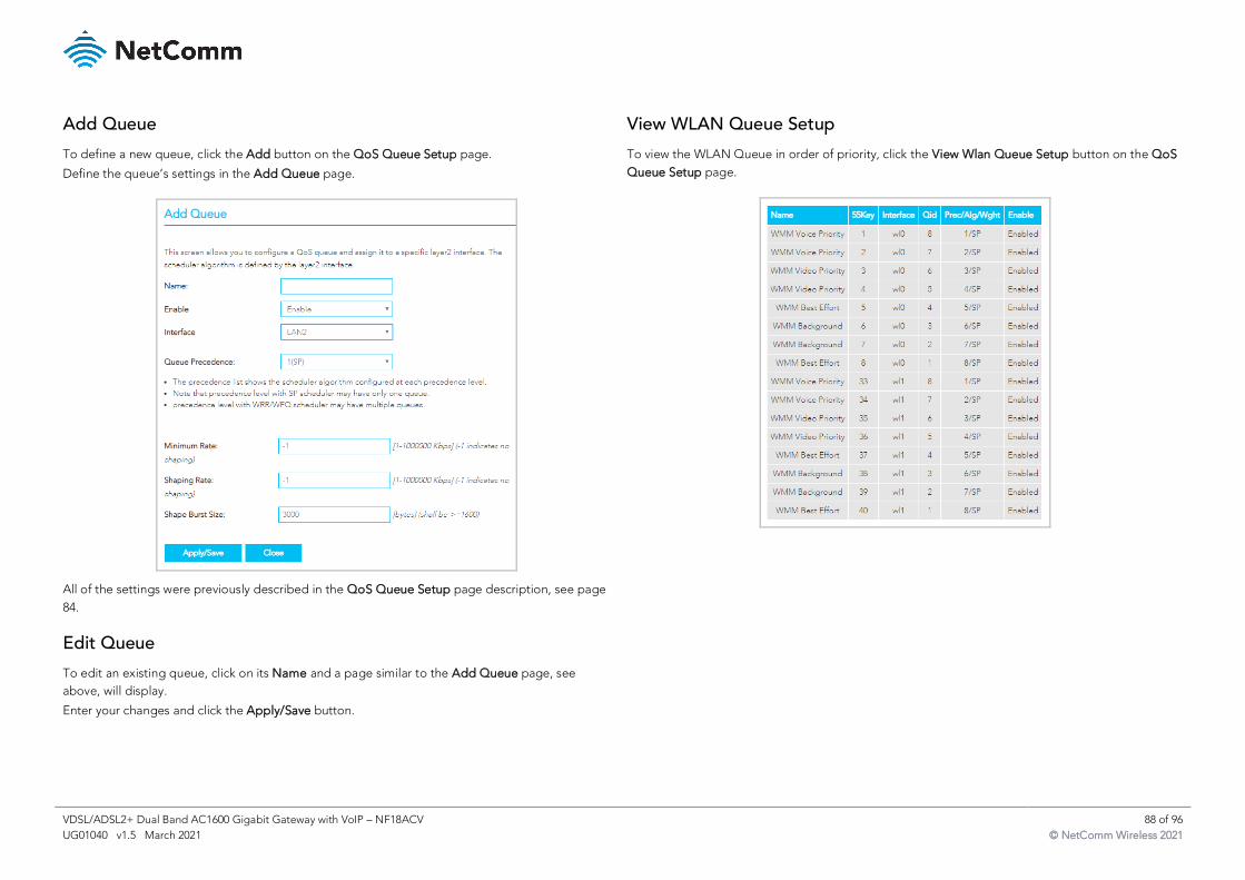
VDSL/ADSL2+ Dual Band AC1600 Gigabit Gateway with VoIP – NF18ACV 88 of 96
UG01040 v1.5 March 2021 © NetComm Wireless 2021
Add Queue
To define a new queue, click the Add button on the QoS Queue Setup page.
Define the queue’s settings in the Add Queue page.
All of the settings were previously described in the QoS Queue Setup page description, see page
84.
Edit Queue
To edit an existing queue, click on its Name and a page similar to the Add Queue page, see
above, will display.
Enter your changes and click the Apply/Save button.
View WLAN Queue Setup
To view the WLAN Queue in order of priority, click the View Wlan Queue Setup button on the QoS
Queue Setup page.
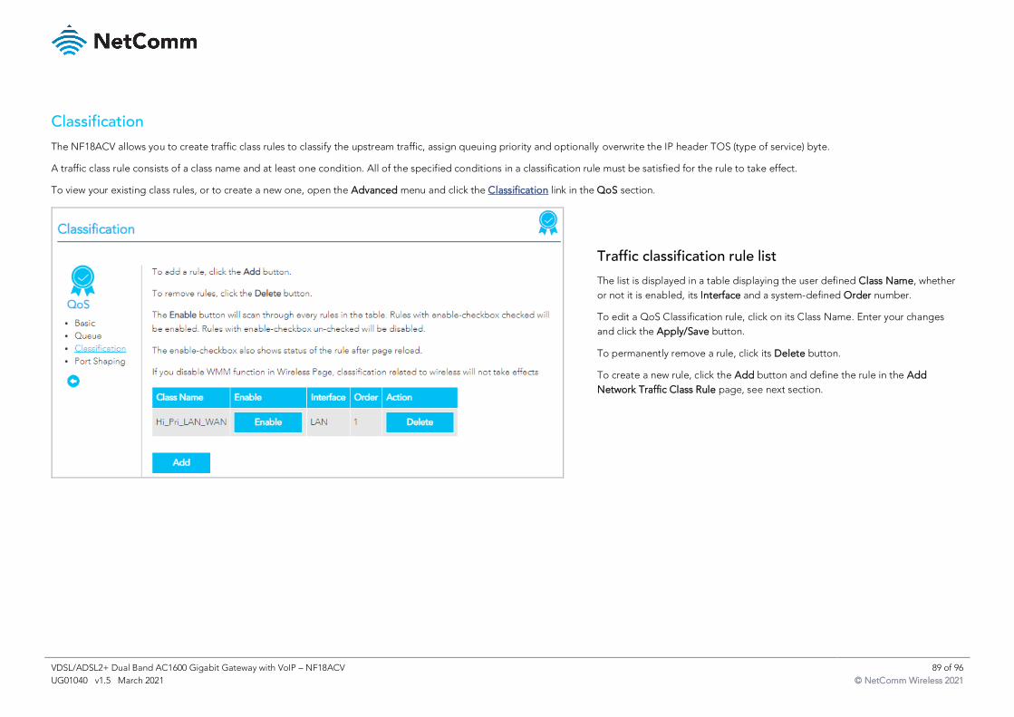
VDSL/ADSL2+ Dual Band AC1600 Gigabit Gateway with VoIP – NF18ACV 89 of 96
UG01040 v1.5 March 2021 © NetComm Wireless 2021
Classification
The NF18ACV allows you to create traffic class rules to classify the upstream traffic, assign queuing priority and optionally overwrite the IP header TOS (type of service) byte.
A traffic class rule consists of a class name and at least one condition. All of the specified conditions in a classification rule must be satisfied for the rule to take effect.
To view your existing class rules, or to create a new one, open the Advanced menu and click the Classification link in the QoS section.
Traffic classification rule list
The list is displayed in a table displaying the user defined Class Name, whether
or not it is enabled, its Interface and a system-defined Order number.
To edit a QoS Classification rule, click on its Class Name. Enter your changes
and click the Apply/Save button.
To permanently remove a rule, click its Delete button.
To create a new rule, click the Add button and define the rule in the Add
Network Traffic Class Rule page, see next section.
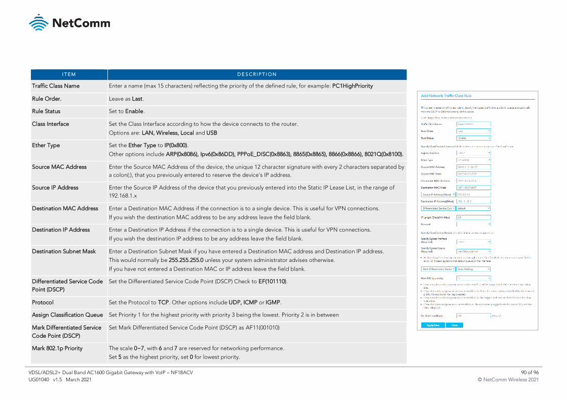
VDSL/ADSL2+ Dual Band AC1600 Gigabit Gateway with VoIP – NF18ACV 90 of 96
UG01040 v1.5 March 2021 © NetComm Wireless 2021
I T E M D E S C R I P T I O N
Traffic Class Name Enter a name (max 15 characters) reflecting the priority of the defined rule, for example: PC1HighPriority
Rule Order. Leave as Last.
Rule Status Set to Enable.
Class Interface Set the Class Interface according to how the device connects to the router.
Options are: LAN, Wireless, Local and USB
Ether Type Set the Ether Type to IP(0x800).
Other options include ARP(0x8086), Ipv6(0x86DD), PPPoE_DISC(0x8863), 8865(0x8865), 8866(0x8866), 8021Q(0x8100).
Source MAC Address Enter the Source MAC Address of the device, the unique 12 character signature with every 2 characters separated by
a colon(:), that you previously entered to reserve the device's IP address.
Source IP Address Enter the Source IP Address of the device that you previously entered into the Static IP Lease List, in the range of
192.168.1.x
Destination MAC Address Enter a Destination MAC Address if the connection is to a single device. This is useful for VPN connections.
If you wish the destination MAC address to be any address leave the field blank.
Destination IP Address Enter a Destination IP Address if the connection is to a single device. This is useful for VPN connections.
If you wish the destination IP address to be any address leave the field blank.
Destination Subnet Mask Enter a Destination Subnet Mask if you have entered a Destination MAC address and Destination IP address.
This would normally be 255.255.255.0 unless your system administrator advises otherwise.
If you have not entered a Destination MAC or IP address leave the field blank.
Differentiated Service Code
Point (DSCP)
Set the Differentiated Service Code Point (DSCP) Check to EF(101110).
Protocol Set the Protocol to TCP. Other options include UDP, ICMP or IGMP.
Assign Classification Queue Set Priority 1 for the highest priority with priority 3 being the lowest. Priority 2 is in between
Mark Differentiated Service
Code Point (DSCP)
Set Mark Differentiated Service Code Point (DSCP) as AF11(001010)
Mark 802.1p Priority The scale 0~7, with 6 and 7 are reserved for networking performance.
Set 5 as the highest priority, set 0 for lowest priority.
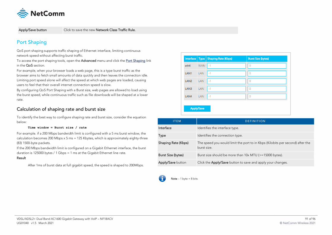
VDSL/ADSL2+ Dual Band AC1600 Gigabit Gateway with VoIP – NF18ACV 91 of 96
UG01040 v1.5 March 2021 © NetComm Wireless 2021
Apply/Save button Click to save the new Network Class Traffic Rule.
Port Shaping
QoS port shaping supports traffic shaping of Ethernet interface, limiting continuous
network speed without affecting burst traffic.
To access the port shaping tools, open the Advanced menu and click the Port Shaping link
in the QoS section.
For example, when your browser loads a web page, this is a type burst traffic as the
browser aims to fetch small amounts of data quickly and then leaves the connection idle.
Limiting port speed alone will affect the speed at which web pages are loaded, causing
users to feel that their overall internet connection speed is slow.
By configuring QoS Port Shaping with a Burst size, web pages are allowed to load using
the burst speed, while continuous traffic such as file downloads will be shaped at a lower
rate.
Calculation of shaping rate and burst size
To identify the best way to configure shaping rate and burst size, consider the equation
below:
Time window = Burst size / rate
For example. if a 200 Mbps bandwidth limit is configured with a 5 ms burst window, the
calculation becomes 200 Mbps x 5 ms = 125 Kbytes, which is approximately eighty-three
(83) 1500-byte packets.
If the 200 Mbps bandwidth limit is configured on a Gigabit Ethernet interface, the burst
duration is 125000 bytes / 1 Gbps = 1 ms at the Gigabit Ethernet line rate.
Result
After 1ms of burst data at full gigabit speed, the speed is shaped to 200Mbps.
I T E M D E F I N I T I O N
Interface Identifies the interface type.
Type Identifies the connection type.
Shaping Rate (Kbps) The speed you would limit the port to in Kbps (Kilobits per second) after the
burst size.
Burst Size (bytes) Burst size should be more than 10x MTU (>=15000 bytes).
Apply/Save button Click the Apply/Save button to save and apply your changes.
Note – 1 byte = 8 bits
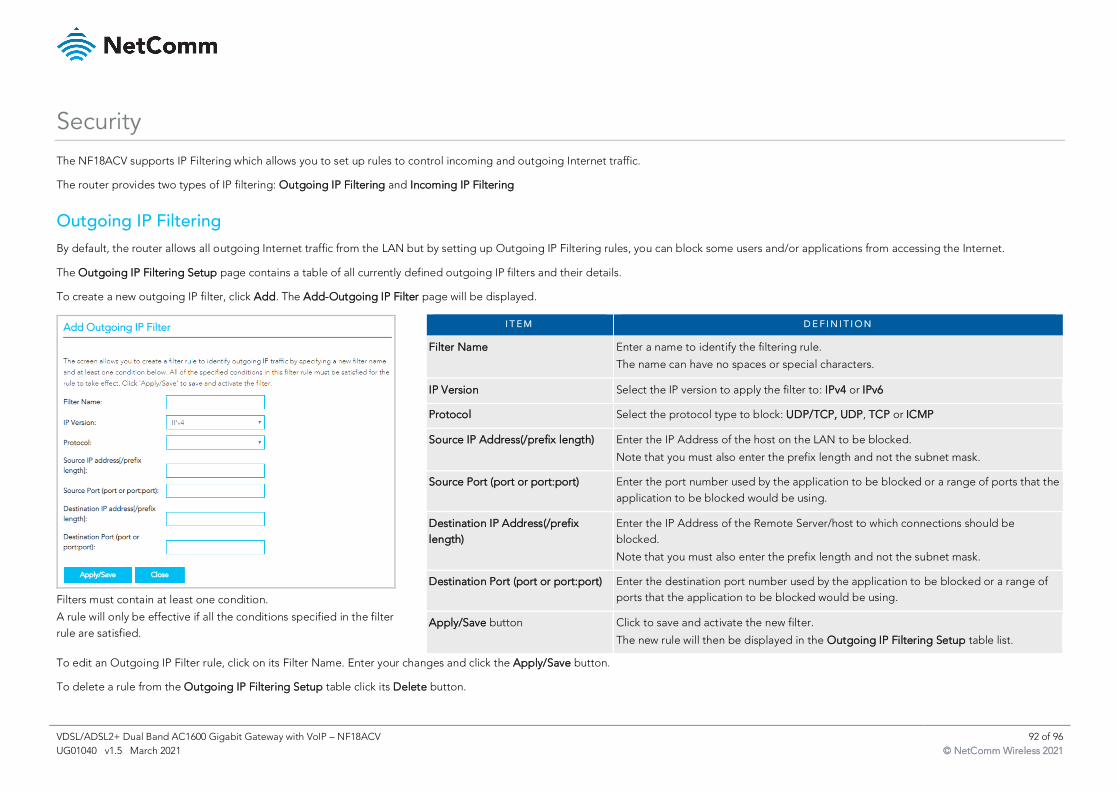
VDSL/ADSL2+ Dual Band AC1600 Gigabit Gateway with VoIP – NF18ACV 92 of 96
UG01040 v1.5 March 2021 © NetComm Wireless 2021
Security
The NF18ACV supports IP Filtering which allows you to set up rules to control incoming and outgoing Internet traffic.
The router provides two types of IP filtering: Outgoing IP Filtering and Incoming IP Filtering
Outgoing IP Filtering
By default, the router allows all outgoing Internet traffic from the LAN but by setting up Outgoing IP Filtering rules, you can block some users and/or applications from accessing the Internet.
The Outgoing IP Filtering Setup page contains a table of all currently defined outgoing IP filters and their details.
To create a new outgoing IP filter, click Add. The Add-Outgoing IP Filter page will be displayed.
Filters must contain at least one condition.
A rule will only be effective if all the conditions specified in the filter
rule are satisfied.
I T E M D E F I N I T I O N
Filter Name Enter a name to identify the filtering rule.
The name can have no spaces or special characters.
IP Version Select the IP version to apply the filter to: IPv4 or IPv6
Protocol Select the protocol type to block: UDP/TCP, UDP, TCP or ICMP
Source IP Address(/prefix length) Enter the IP Address of the host on the LAN to be blocked.
Note that you must also enter the prefix length and not the subnet mask.
Source Port (port or port:port) Enter the port number used by the application to be blocked or a range of ports that the
application to be blocked would be using.
Destination IP Address(/prefix
length)
Enter the IP Address of the Remote Server/host to which connections should be
blocked.
Note that you must also enter the prefix length and not the subnet mask.
Destination Port (port or port:port) Enter the destination port number used by the application to be blocked or a range of
ports that the application to be blocked would be using.
Apply/Save button Click to save and activate the new filter.
The new rule will then be displayed in the Outgoing IP Filtering Setup table list.
To edit an Outgoing IP Filter rule, click on its Filter Name. Enter your changes and click the Apply/Save button.
To delete a rule from the Outgoing IP Filtering Setup table click its Delete button.
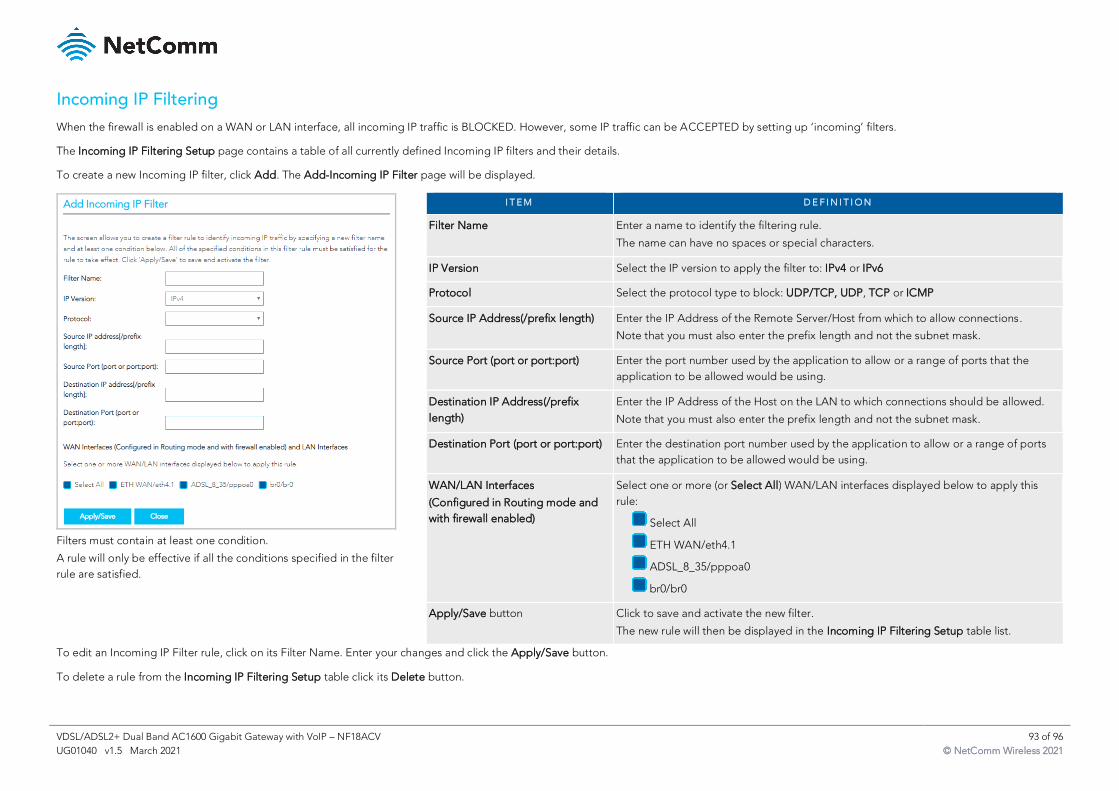
VDSL/ADSL2+ Dual Band AC1600 Gigabit Gateway with VoIP – NF18ACV 93 of 96
UG01040 v1.5 March 2021 © NetComm Wireless 2021
Incoming IP Filtering
When the firewall is enabled on a WAN or LAN interface, all incoming IP traffic is BLOCKED. However, some IP traffic can be ACCEPTED by setting up ‘incoming’ filters.
The Incoming IP Filtering Setup page contains a table of all currently defined Incoming IP filters and their details.
To create a new Incoming IP filter, click Add. The Add-Incoming IP Filter page will be displayed.
Filters must contain at least one condition.
A rule will only be effective if all the conditions specified in the filter
rule are satisfied.
I T E M D E F I N I T I O N
Filter Name Enter a name to identify the filtering rule.
The name can have no spaces or special characters.
IP Version Select the IP version to apply the filter to: IPv4 or IPv6
Protocol Select the protocol type to block: UDP/TCP, UDP, TCP or ICMP
Source IP Address(/prefix length) Enter the IP Address of the Remote Server/Host from which to allow connections.
Note that you must also enter the prefix length and not the subnet mask.
Source Port (port or port:port) Enter the port number used by the application to allow or a range of ports that the
application to be allowed would be using.
Destination IP Address(/prefix
length)
Enter the IP Address of the Host on the LAN to which connections should be allowed.
Note that you must also enter the prefix length and not the subnet mask.
Destination Port (port or port:port) Enter the destination port number used by the application to allow or a range of ports
that the application to be allowed would be using.
WAN/LAN Interfaces
(Configured in Routing mode and
with firewall enabled)
Select one or more (or Select All) WAN/LAN interfaces displayed below to apply this
rule:
Select All
ETH WAN/eth4.1
ADSL_8_35/pppoa0
br0/br0
Apply/Save button Click to save and activate the new filter.
The new rule will then be displayed in the Incoming IP Filtering Setup table list.
To edit an Incoming IP Filter rule, click on its Filter Name. Enter your changes and click the Apply/Save button.
To delete a rule from the Incoming IP Filtering Setup table click its Delete button.
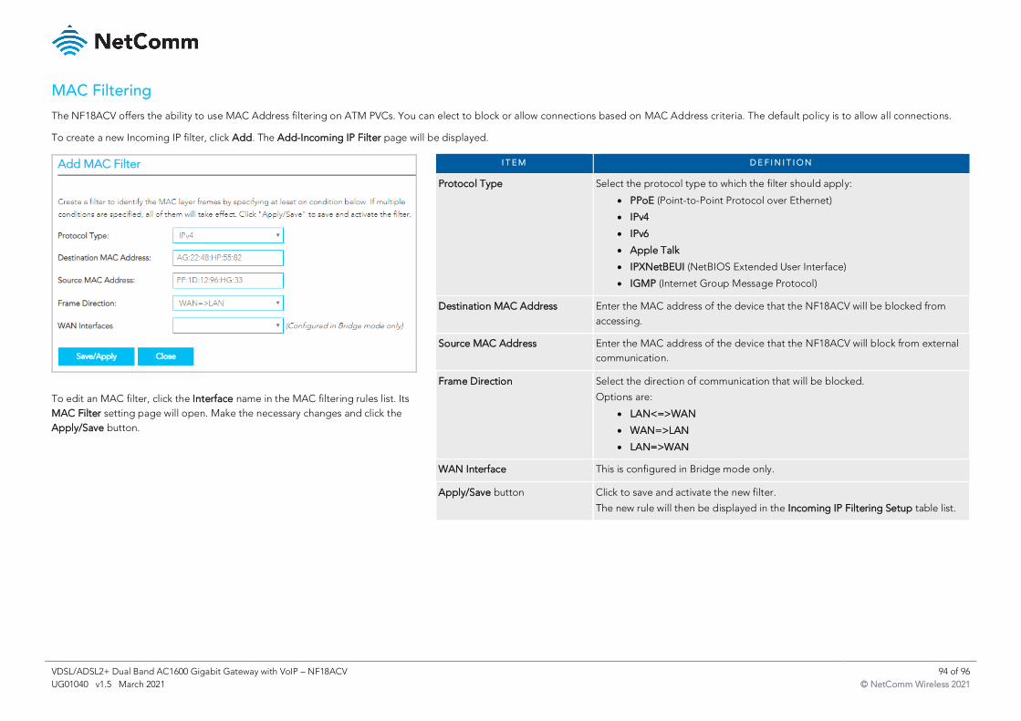
VDSL/ADSL2+ Dual Band AC1600 Gigabit Gateway with VoIP – NF18ACV 94 of 96
UG01040 v1.5 March 2021 © NetComm Wireless 2021
MAC Filtering
The NF18ACV offers the ability to use MAC Address filtering on ATM PVCs. You can elect to block or allow connections based on MAC Address criteria. The default policy is to allow all connections.
To create a new Incoming IP filter, click Add. The Add-Incoming IP Filter page will be displayed.
To edit an MAC filter, click the Interface name in the MAC filtering rules list. Its
MAC Filter setting page will open. Make the necessary changes and click the
Apply/Save button.
I T E M D E F I N I T I O N
Protocol Type Select the protocol type to which the filter should apply:
• PPoE (Point-to-Point Protocol over Ethernet)
• IPv4
• IPv6
• Apple Talk
• IPXNetBEUI (NetBIOS Extended User Interface)
• IGMP (Internet Group Message Protocol)
Destination MAC Address Enter the MAC address of the device that the NF18ACV will be blocked from
accessing.
Source MAC Address Enter the MAC address of the device that the NF18ACV will block from external
communication.
Frame Direction Select the direction of communication that will be blocked.
Options are:
• LAN<=>WAN
• WAN=>LAN
• LAN=>WAN
WAN Interface This is configured in Bridge mode only.
Apply/Save button Click to save and activate the new filter.
The new rule will then be displayed in the Incoming IP Filtering Setup table list.
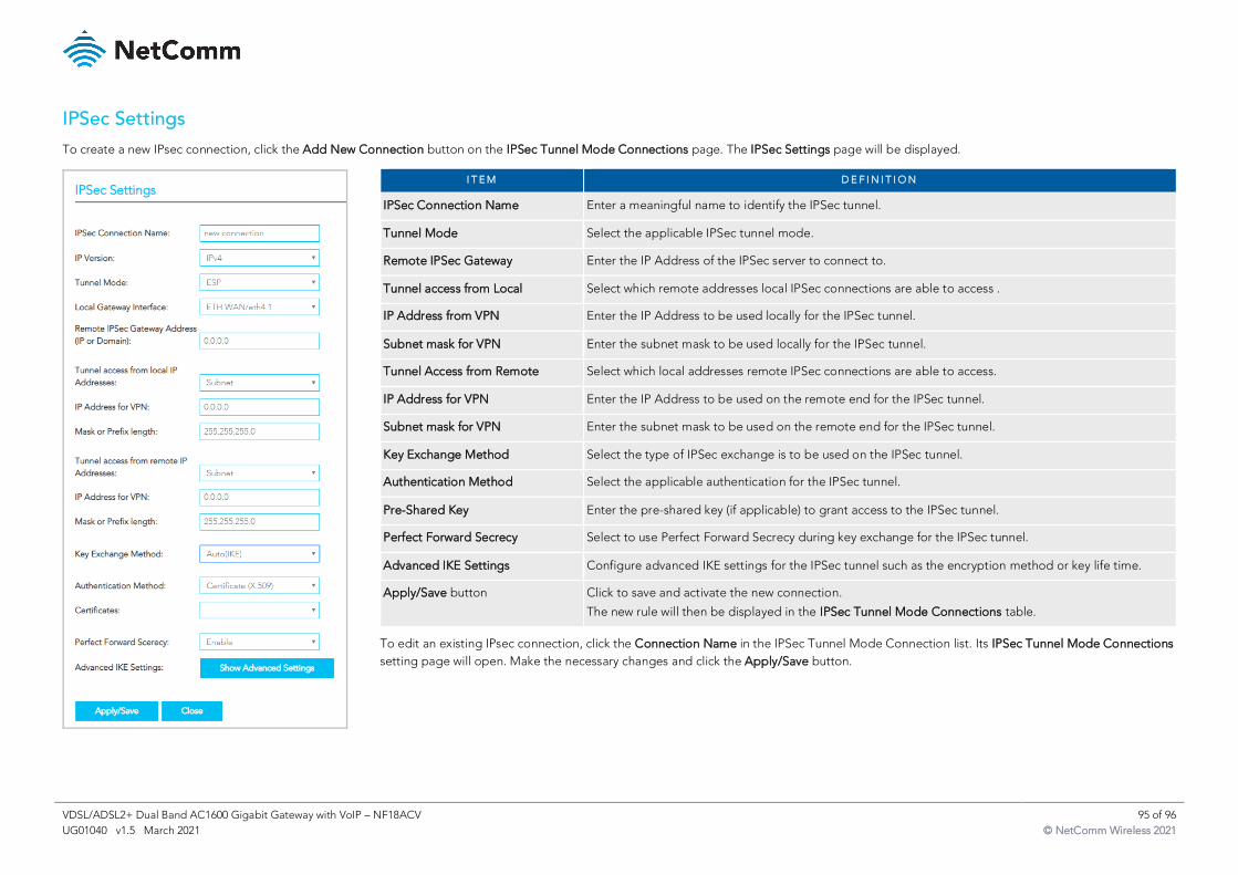
VDSL/ADSL2+ Dual Band AC1600 Gigabit Gateway with VoIP – NF18ACV 95 of 96
UG01040 v1.5 March 2021 © NetComm Wireless 2021
IPSec Settings
To create a new IPsec connection, click the Add New Connection button on the IPSec Tunnel Mode Connections page. The IPSec Settings page will be displayed.
I T E M D E F I N I T I O N
IPSec Connection Name Enter a meaningful name to identify the IPSec tunnel.
Tunnel Mode Select the applicable IPSec tunnel mode.
Remote IPSec Gateway Enter the IP Address of the IPSec server to connect to.
Tunnel access from Local Select which remote addresses local IPSec connections are able to access .
IP Address from VPN Enter the IP Address to be used locally for the IPSec tunnel.
Subnet mask for VPN Enter the subnet mask to be used locally for the IPSec tunnel.
Tunnel Access from Remote Select which local addresses remote IPSec connections are able to access.
IP Address for VPN Enter the IP Address to be used on the remote end for the IPSec tunnel.
Subnet mask for VPN Enter the subnet mask to be used on the remote end for the IPSec tunnel.
Key Exchange Method Select the type of IPSec exchange is to be used on the IPSec tunnel.
Authentication Method Select the applicable authentication for the IPSec tunnel.
Pre-Shared Key Enter the pre-shared key (if applicable) to grant access to the IPSec tunnel.
Perfect Forward Secrecy Select to use Perfect Forward Secrecy during key exchange for the IPSec tunnel.
Advanced IKE Settings Configure advanced IKE settings for the IPSec tunnel such as the encryption method or key life time.
Apply/Save button Click to save and activate the new connection.
The new rule will then be displayed in the IPSec Tunnel Mode Connections table.
To edit an existing IPsec connection, click the Connection Name in the IPSec Tunnel Mode Connection list. Its IPSec Tunnel Mode Connections
setting page will open. Make the necessary changes and click the Apply/Save button.
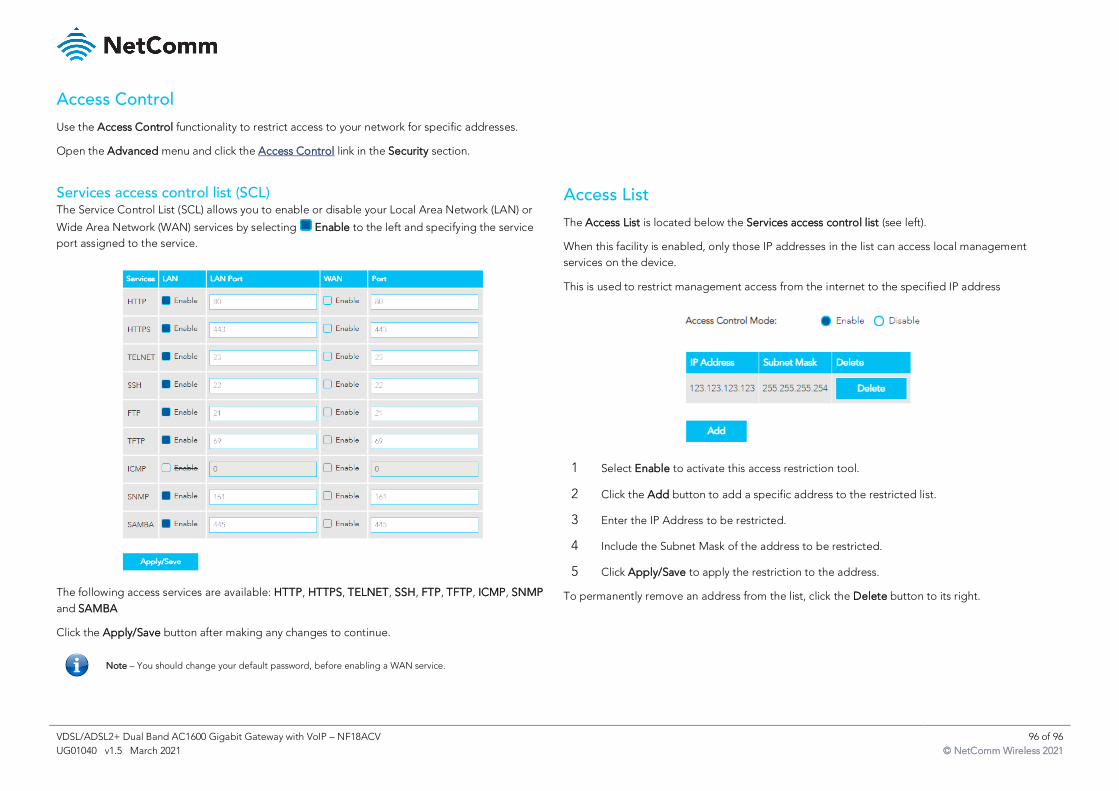
VDSL/ADSL2+ Dual Band AC1600 Gigabit Gateway with VoIP – NF18ACV 96 of 96
UG01040 v1.5 March 2021 © NetComm Wireless 2021
Access Control
Use the Access Control functionality to restrict access to your network for specific addresses.
Open the Advanced menu and click the Access Control link in the Security section.
Services access control list (SCL) The Service Control List (SCL) allows you to enable or disable your Local Area Network (LAN) or
Wide Area Network (WAN) services by selecting Enable to the left and specifying the service
port assigned to the service.
The following access services are available: HTTP, HTTPS, TELNET, SSH, FTP, TFTP, ICMP, SNMP
and SAMBA
Click the Apply/Save button after making any changes to continue.
Access List
The Access List is located below the Services access control list (see left).
When this facility is enabled, only those IP addresses in the list can access local management
services on the device.
This is used to restrict management access from the internet to the specified IP address
1 Select Enable to activate this access restriction tool.
2 Click the Add button to add a specific address to the restricted list.
3 Enter the IP Address to be restricted.
4 Include the Subnet Mask of the address to be restricted.
5 Click Apply/Save to apply the restriction to the address.
To permanently remove an address from the list, click the Delete button to its right.
Note – You should change your default password, before enabling a WAN service.