Embed Size (px)
Citation preview
TRANSPORTATION RESEARCH RECORD 1233 51
Vehicle Impact Testing of Lightweight Lighting Standards
ROGER L. STOUGHTON, ABBAS ABGHARI, JOHN P. DUSEL,
]ACK L. HEDGECOCK, AND DORAN L. GLAUZ
This paper presents the results of seven full-scale vehicular crash tests on 35-ft-high breakaway lighting standards with 20-ft-long mast arms and compares them with the recommended crash test criteria in NCHRP Report 230 and with the new 1985 AASHTO specifications for structural supports. The test devices consisted of an aluminum lighting standard with cast aluminum breakaway couplings, a lightweight steel lighting standard with cast aluminum breakaway couplings and a triangular slip base, and a typical California Department of Transportation (Caltrans) type 31 lighting standard with a triangular slip base. The lighting standards tested met the requirements of NCHRP Report 230 with minor exceptions. The 1985 AASHTO specifications for breakaway bases, however were met in all seven crash tests. Although the die-cast , . aluminum coupling proved to be an effective breakaway device when impacted by 1,800-lb cars, excessive porosity and lack of compliance with Caltrans specifications preclude the use of these couplings as a standard Caltrans breakaway device. The Caltrans triangular steel slip base proved to be an effective breakaway device when impacted by 1,800-lb cars.
The concept of a breakaway mechanism for highway lighting standards was initiated by the Road Research Laboratory of the Ministry of Transport in England in the late 1950s (1). Preliminary research indicated that, to minimize occupant injury and vehicle damage when a vehicle collides with a highway appurtenance, a breakaway device should be incorporated at the base of appurtenances. A breakaway device is a mechanism that fractures or yields when struck by a vehicle but is strong enough to withstand static and wind loads. Since then, much research has been directed toward developing new breakaway systems and evaluating existing systems for smaller cars.
According to a survey by the Texas Transportation Institute (TTI), most states did not use breakaway devices for their highway appurtenances until late 1966 (2). On August 1 of that year, FHWA issued an instructional memorandum stating that breakaway or yielding supports should be used for the sign supports and lighting standards adjacent to the shoulders of federal highways (2).
The acceptance criteria for breakaway luminaire supports set by FHWA in June 1968 (3) specified an upper limit of 1,100 lb-sec for change in vehicle momentum during impacts. This was based on the data then available . The vehicle weight and impacting speed were not specified. A second set of criteria issued by FHWA in November 1970 ( 4) called for a maximum of 400 lb-sec momentum change for pendulum tests. This type of test was popular because of its low cost compared with that of full-scale crash tests.
Office of Transportation Laboratory, California Department of Transportation, Sacramento, Calif. 95819.
In 1973, TRB initiated an extensive project NCHRP 22-2, and in 1974 published NCHRP Report 153 (5). This report contained the first comprehensive test matrix outlining crash test conditions for evaluation of the dynamic performance of highway appurtenances. Two tests were recommended for breakaway or yielding supports: a 4,500-lb vehicle (test 1) and a 2,250-lb vehicle (test 2) impacting the test article at 40 and 20 mph, respectively. The report specified a maximum change of vehicle momentum of 1,100 lb-sec for this type of highway appurtenance (test 1 only). The commentary suggested a desirable maximum of 750 lb/sec for the design of new devices.
In 1975, AASHTO specifications for breakaway supports ( 6) set the same criteria (an 1, 100 lb-sec change in momentum) as the FHWA criteria; however, AASHTO specified a 2,250-lb test vehicle and required satisfactory performance over a speed range of 20 to 60 mph. The specification also called for a maximum desirable momentum change of 750 lb-sec to minimize accident severity.
In 1978, an updated version of NCHRP Report 153 was published as Transportation Research Circular 191 (7). The circular eliminated test 1 and replaced it with a test using a 2,250-lb car at 60 mph. The momentum change requirements were also revised to meet the 1975 AASHTO specifications.
In March 1981, revised crash test procedures were published in NCHRP Report 230 (8) to account for the continuous increase in the lightweight car population. These procedures recommended that two crash tests be conducted on breakaway or yielding supports using 1,800-lb cars: (a) test 62, head-on at the center point of bumper at 20 mph; and (b) test 63, head-on at the quarter point of bumper at 60 mph. The report also called for 2,250-lb vehicle tests, but these were not performed when it became evident that tests using the 1,800-lb vehicles would control.
The 1975 AASHTO specifications for breakaway supports were revised in 198'5 (9). In the new specifications, the weight of the crash test vehicle was lowered from 2,250 lb to 1,800 lb, and the change in momentum acceptance criteria (a maximum of 1,100 lb-sec and preferably 750 lb-sec momentum change for 2,250-lb cars) was changed by substituting a change in velocity criterion of 15 ft/sec and preferably 10 ft/sec. Also, a 4-in stub height clearance was added to reduce the likelihood of vehicle undercarriage snagging.
The steel breakaway lighting standards used alongside California highways were qualified in 1975 and earlier with crash tests using 2,250-lb and 4,500-lb passenger vehicles (10,11). It was thought that 1,800-lb cars might have difficulty meeting the new crash test guidelines when impacting the heavy steel type 31 lighting standard, which weighs 883 lb when equipped
52
with a 20-ft mast arm and 50-lb luminaire. Also , the breakaway energy of the triangular slip base may increase with time due to weathering effects (dirt and corrosion) and the tendency for the zinc layers to pressure weld with continuous high clamping force. Thus, there is concern that the type 31 triangular slip base might eventually fail even if it met the criteria at the time of installation.
The primary objective of this research project was to determine , through full-scale crash tests, if a suitable lightweight lighting standard with a breakaway base could satisfy the crash test criteria recommended in NCHRP Report 230 for 1,800-lb cars. The aim was to find a lighter weight lighting standard that would have a lower breakaway energy than the type 31 steel lighting standard used by the California Department of Transportation (Caltrans). An attempt was made to find a breakaway mechanism for the base of the poles that would be simpler to install and would require less energy to break away than the Caltrans triangular slip base. Tests were conducted to determine if the Cal trans type 31 steel lighting standard would satisfy the NCHRP Report 230 criteria. The crash test results were also compared with the 1985 AASHTO specifications .
TEST PROGRAM
A total of seven full-scale vehicular crash tests (tests 401 through 407) were conducted at the Caltrans Dynamic Test Facility in West Sacramento. Honda Civic automobiles (i979 vintage), each weighing 1,800 lb, were used as the crash vehicles. All tests were carried out according to the recommended procedures in NCHRP Report 230 . The test matrix is shown in Table 1.
Because of the large amount of porosity observed in the die-cast aluminum couplings, a considerable amount of testing (x-rays and static tests including tensile , restrained shear , fatigue, and corrosion) was done on both the die-cast and extruded aluminum couplings . As a result of these tests , a comprehensive specification controlling aluminum couplings was composed.
DAT A ACQUISITION SYSTEMS AND ANALYSIS
Test data were recorded by both high-speed motion picture photography and electronic instrumentation .
TABLE 1 CRASH TEST MA TRIX
Lighting Standards
Height of Length of Total Test Pole Mast Arm Weight Breakaway No . Type ltt) lit) lib) Device Type
TRANSPOR TATION RESEARCH R ECORD 1233
Several high-speed movie cameras and two sequence cameras located near the impact area were used to record the instant when impact occurred in each crash test. The test vehicles and lighting standards were photographed before, during, and after impact with a normal-speed movie camera and still cameras. Data from the high-speed movies were reduced on a Vanguard Analyzer.
Three accelerometers were mounted on the floor of each test vehicle in the passenger compartment at the center of gravity to measure longitudinal, lateral, and vertical accelerations. Also, three rate gyro transducers were mounted on the floor of each test vehicle (close to the accelerometers) to measure the roll , pitch, and yaw of the vehicle after impact. Accelerometer data were used to judge the occupant risk during impact.
An unrestrained anthropomorphic dummy with a triaxial accelerometer mounted in its head cavity was placed in the driver's seat of the test vehicle. The dummy, named "Willie Makit," is a part 572 dummy built by the Sierra Engineering Company to conform to federal motor vehicle safety standards . Willie represented a 50th percentile American male weighing 165 lb . A high-speed camera mounted in the vehicle recorded the dummy's motion , and a triaxia! accelerometer mounted in the dummy's head recorded the longitudinal, lateral , and vertical accelerations during impact . The accelerometer data were then used to calculate the head injury criterion.
Detailed descriptions of the photographic and electronic instrumentation, camera arrangement, data collection and reduction techniques, accelerometer data, and results of x-rays and static tests of aluminum couplings are given in the project report (12).
TEST DESCRIPTIONS AND RESULTS
Aluminum Lighting Standard With Aluminum Breakaway Couplings
Two tests-401 and 402-were conducted to evaluate a lightweight lighting standard similar in dimensions to a Caltrans type 31 but made from aluminum (35 ft x 10 in OD bottom x 8 in OD top x 0.188 in) and equipped with aluminum breakaway couplings to meet NCHRP Report 230 requirements. The pole base was reinforced with a 2-ft-long aluminum cylindrical sleeve section, 0.257 in thick , inserted inside
Vehicle Test Characteris tics
Weight Without Dummy Point of Impact Dummy Weight Impact Velocity"
Year/Type (iiJ) (ii.J) (i11.) (111l-'it )
401 Aluminum 35 20 394 Aluminum coupling 79/Honda 1.890 165 12 RCL 58.6(60) 402 Aluminum 35 20 394 Aluminum coupling 79/Honda 403 Steel 35 20 651 Aluminum coupling 79/Honda 404 CA-31 35 20 883 Slip base 79/Honda 405 CA-31 35 20 883 Slip base 79/Honda 406 Steel 35 20 627 .4 Slip base 79/Honda 407 Steel 35 20 639.4 Slip base 79/Honda
NOTE: RCL = right of centerline on front bumper; CA-31 = standard Caltrans type 31 • Numbers in parentheses show the desi red speed in mph.
1,850 165 Center 19.6(20) 1,870 165 9.5 RCL 59. 1(60) 1,865 165 Center 19.9(20) 1,885 165 13.6 RCL 53 .9(60) 1,850 165 18.75 58.8(60) 1,840 165 3 RCL 23.7(20)
Stoughton et al.
the pole and welded at the base to ensure a quick shear transfer of the impacting force to the breakaway support. The sleeve would also help the bottom of the pole to resist crushing or denting in the bumper contact area.
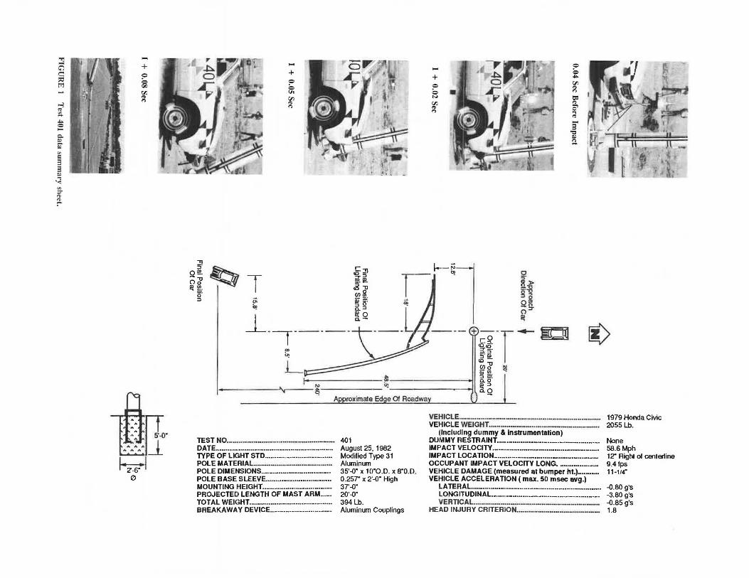
Results of Test 401
A summary of the results of test 401 and the photos taken before, during, and after the impact are shown in Figure 1. A 1979 Honda Civic test vehicle impacted the base of the aluminum pole 12 in to the right of the centerline of the front bumper (a 3-in deviation from the desired quarter point location of 15 in to the right of centerline) at 58.6 mph. The couplings sheared off as intended, and the vehicle pushed the pole base up in the air so that it cleared the car, which decelerated in a fairly straight line without any significant yaw. The surface of the aluminum pole at the impact point of the front bumper was not dented or deformed. The top of the pole, however, swung and impacted the asphalt pavement, destroying the end cap and bending the back of the top edge of the pole. This caused the truss-type mast arm to buckle severely in two places. (The pole was reusable, however, for crash test 402.) The luminaire came off of the end of the mast arm shortly after initial impact and was badly damaged. The final position of the vehicle after it was braked remotely and the final location and the schematic damage of the lighting standard are shown in Figure 1. As shown, the lighting standard rotated 180° and came to rest well out of the way of traffic in the imaginary outside lane.
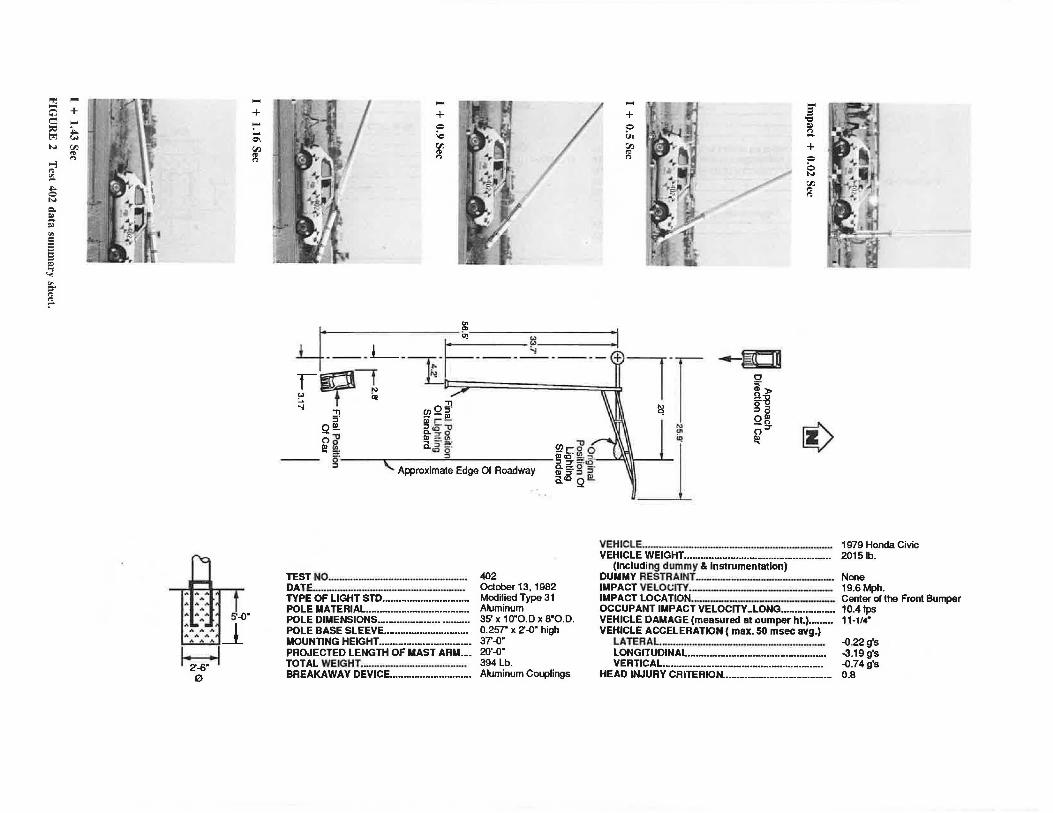
Results of Test 402
The summary of the results of test 402 and the photos taken before, during, and after the impact are shown in Figure 2. The 1979 Honda Civic test vehicle impacted the aluminum pole at the center of the front bumper at 19.6 mph. Upon impact, the couplings sheared off and the vehicle pushed and bumped the pole along in front as it decelerated. The pole was pushed over slowly, and it rolled on the roof as the vehicle barely passed under the pole shoe base. The vehicle traveled in a nearly straight line after impact, drifting slightly to the left with virtually no yaw. As with test 401, the aluminum pole sustained no damage from the impact of the vehicle's front bumper. The top of the pole, however, swung down and impacted the asphalt pavement, damaging the end cap and top edge of the pole tube and fracturing the upper cast aluminum mast arm clamping band. The mast arm did not buckle as it did in test 401. The luminaire broke into pieces and scattered over a large area, well into the imaginary traffic lanes. Figure 2 shows the final position of the vehicle after it was braked remotely and the final location and schematic damage of the lighting standard. As shown in the figure, the lighting standard came to rest with the mast arm projecting about 6 ft (assuming a 20-ft distance from the pole to the roadway edge) into the outside traffic lane.
Modified Caltrans Type 31 Steel Lighting Standard With Aluminum Breakaway Couplings
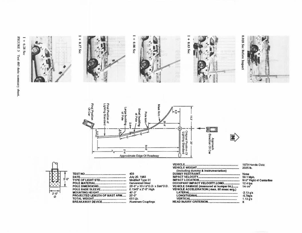
Test 403 was conducted to evaluate a modified Caltrans type 31 steel lighting standard made from a 0.1196-in-thick steel
53
(35 ft x lOY16 in OD x 5% in OD x 0.1196 in)-a thinner gauge than the standard pole. The pole was reinforced at the bottom with a 2-ft-long, 0.1345-in-thick steel cylindrical sleeve section, inserted inside the pole and welded to the base plate. This ensures a rapid shear transfer to the breakaway base and provides sufficient strength to resist crushing or denting of the pole in the vehicle contact area.
A summary of the test results and photos taken before, during, and after the impact are shown in Figure 3. The test vehicle, a 1979 Honda Civic, first impacted the base of the thin-walled steel lighting standard 91/2 in (15 in desired) to the right of the centerline of the front bumper at 59.1 mph. The vehicle solidly impacted the pole and sheared off the couplings at the base of the top stainless steel studs. Shortly after the initial impact, the base plate on the lighting standard pole hooked under the Honda's deformed front bumper, and the whole front end was lifted about 1 ft off the ground by the moving mass of the pole. As the car continued to travel downstream, the base plate on the bottom of the pole unhooked from the front bumper. The pole continued moving upward well over the car's roof, while the car proceeded in a nearly straight line beneath the pole. The steel pole was badly buckled, and it was torn at the mast arm-to-pole connection plates. There was also a slight dent in the pole where the initial bumper contact had occurred. The luminaire was totally demolished, with some debris falling into the imaginary outside traffic lane. The final position of the vehicle after it was braked remotely and the final location and damage of the lighting standard are shown schematically in Figure 3.
Aluminum Breakaway Coupling Performance
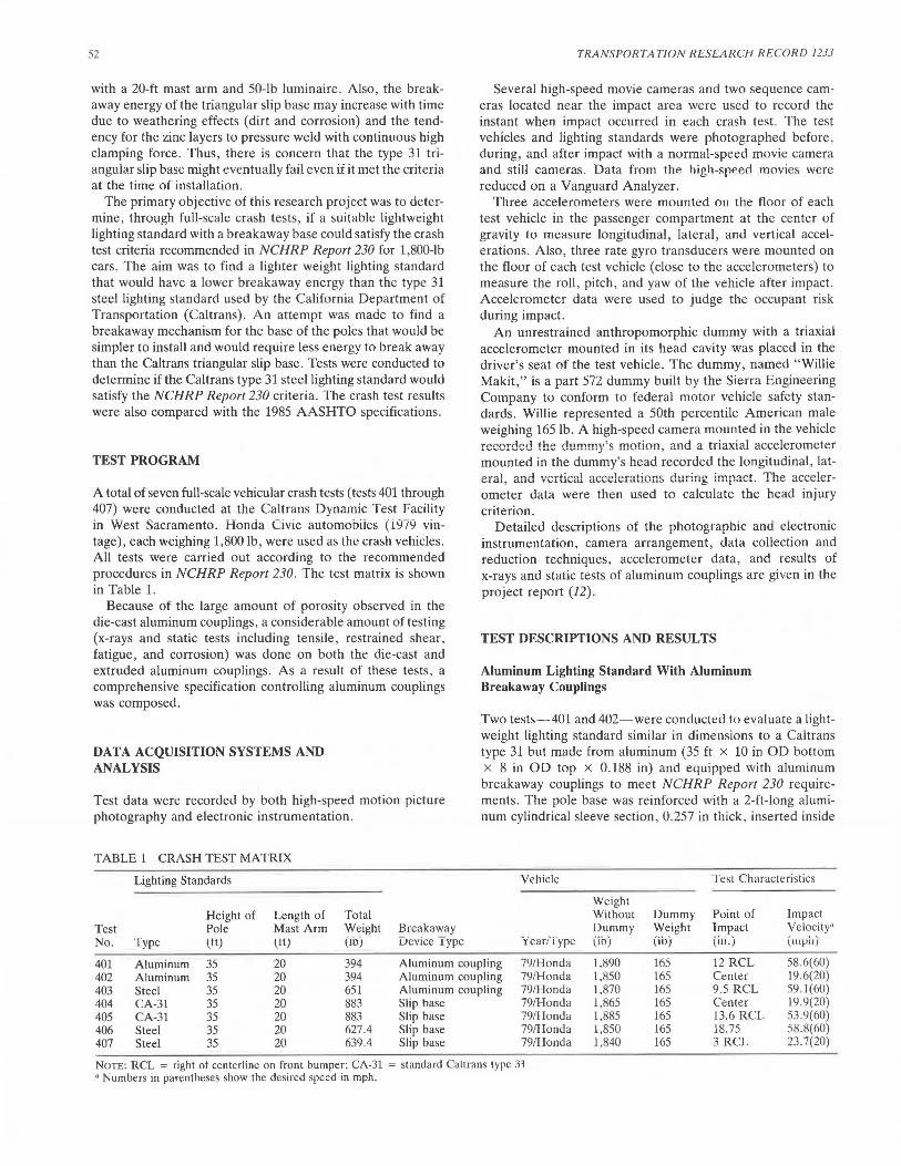
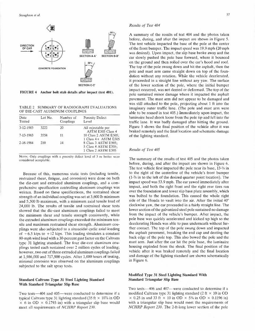
In all three tests ( 401, 402, and 403) with aluminum couplings, the couplings fractured as expected, with the bottom twothirds remaining intact on the anchor bar studs. Cracks initiated in the root of the "V" notches at the top of the couplings and progressed downward until they reached a location near the base of the top stainless steel stud. The two stainless steel studs on the upstream side of the lighting standard, which remained in the holes in the shoe base at the bottom of the aluminum pole, impacted and bent the two downstream anchor bar stubs, which were directly in their path. A schematic of the vehicle approach direction and the anchor bar stubs after the impact in test 401 are shown in Figure 4. This direction offers the highest shear resistance as required by NCHRP Report 230. This condition would not normally be present because of the typically skewed approach angle of an errant vehicle.
Excessive porosity was noted on the fractured surfaces of the broken couplings. To evaluate the porosity defects, x-rays and radiographic evaluation were performed by a private testing company in Sacramento and verified by technicians at the Caltrans lab. X-rays were taken of each coupling at 0° and 90°, and were then classified according to the porosity and shrinkage defect levels for %-in-thick sections shown in ASTM E505 reference radiographs. Results of the Caltrans verification radiographs are summarized in Table 2. Only couplings with a porosity defect level of 3 or better were considered acceptable. Since most of the couplings had an unacceptable amount of porosity, they were considered structurally unreliable, although the ones with excessive porosity met the breakaway requirements.
""l
5 c
" ti:j
.....
...., '" ~ "'" = ..... c. ~ &;
"' c 3 3 ~ ,.., '<
"' :r
'" ~
.... + = 0 Q()
"' '" "
::J·a s--0· A A AJ_ A A A _._....,.
~I 0
·. A';(t 'i . · o 7 ,· , I· . 1L r : .1 'hl
. ,, 4 • ...
"Tl s· Qe!. ()"ti
Ill~ ()" :::>
I
~· ~i~
f:5!b.] j, " .:. • • .
~ T "' Ci
.... + = 0 Ul
"' '" "
I
~::!1 :r :::> :.I!!. ~ "ti cn8 ~g. a.:::>
_L·--,·----l!lO a.-
Q)
~
L~
.... + := = N
"' '" "
0
~- > =-~ gg 2g. ()
Ill +)--r .._. rO <g:c§: -=> ~- ~
cn'"8 ~ Qi 5!?. •
= 0 "'" "' '" " = '" O' ..., '" .... 3
"C ~ :::;.
~ i)
1-- -----'...,._ _ _'._- ~ ~ ----~~' :J =· a. 0 Ill:::> a.Q
TEST NO ........ --···-·········-········- ·· ·····--·-· DATE ....•..... ·- ··························-··············-- ·· TYPE OF LIGHT STD .•............•.........•..•.....•• POLE MATERIAL·-·········-·····- ·-·- ·-·········· POLE DIMENSIONS ...............••......•........••.. POLE BASE SLEEVE ...•......•...............•....... MOUNTING HEIGHT .•...•.........•........•....•....•• PROJECTED LENGTH OF MAST ARM .....• TOTAL WEIGHT .......................................... . BREAKAWAY DEVICE ..............•......•......••..
401 August 25, 1982 Modilied Type 31 Aluminum 35'--0" x 10"0.D. x 8"0.D. 0.257" x 2'-0" High 37'--0" 20'-0" 394 Lb. Aluminum Couplings
VEHICLE ..•..•.•.• ·-·········-·········-··-·-··- - -·--·---····-·· 1979 Honda Civic VEHICLE WEIGHT •• ---····-·- --·····-·-·-···---······-···· 2055 Lb.
(Including dummy & Instrumentation) DUllllMY RESTRAINT .................................... _................ None
IMPACT VELOCITY •• ·-···-·····--···-··-······-··-·---··· 58.6 Mph IMPACT l.OCATION...................................................... 12" Right of centerline OCCUPANT IMPACT VELOCITY LONG. .................... 9.4 fps VEHICLE DAMAGE (measured at bumper ht.)........... 11-114• VElilCLE ACCELERATION (max. 50 msec avg.)
LATERAL. .• ·-········-···-···-················-···················-· --0.80 g's LONGITUDINAL......................................................... -3.80 g's VERTICAL .......... ..................... -··-·-·-·-···-···---- --0.85 g's
HEAD IN.JURY CRITERION. ...... - ............................ -... 1.8
~ .... s + c: .... := . t"l t; N rJJ
'" "' ...., '" ~ .i:. = N
=-~ S' "' = El El ~ ....
"<
"' =-'" '" ...
I
"I",. .. "" .. AIA,,. .oi.I
~ 0
-+ .... .... Q'I rJj
'" "'
5'-0"
_l
-- .... .... + + El
'Cl = = ~
ic u. ::?.. rJj rJj + '" '" "' "' =
Q
/ N rJj
'" "'
i_-f ~ " :1 r~-~t--~ ---~---- ~-Tf ~ie:D p t q ~ N ~ os· q ...,. ~ g?-"'
!2 ~> :::-.:g ga
:;· !)l C~ n: ~~ ~~.~ ~~
Qg_ {)
Ill ll) Ill ~ C.,5~r --- g C Approximate Edge 01 Roadway
TEST NO.·---·-·-·---·--······-···-···--·-· DATE-···-··-·········-·········-··········-··· ···-··· TYPE OF LIGHT STD •....••...•••....•.••....••••.•. POLE MATERIAL ..•.•.••..•••••.•••••.•••••....•.••• _ POLE DIMENSIONS •••..••••...••••....•••...•.•••.. POLE BASE SLEEVE •...••...••••....••••...••••.•. MOUNTING HEIGHT ••.•••••.•.••••••...•••.••.••• - .• PROJECTED LENGTH OF MAST ARM ...• TOTAL WEIGHT ...... ·--··-·-··-····-·---·· BREAKAWAY DEVICE ...••.•.•••.•...•.•••...•••...
402 October 13, 1982 Modified Type 31 Aluminum 35" x 10"0.D x 8"0.D. 0.257" x 2'-0" high 37'-0" 20·-0· 394 Lb. Aluminum Couplings
VEHICLE •• ·--···-- ···-··---·--·-··-··-------·--- 1979 Honda Civic VEHICLE WEIGHT ..................................... ·-·············· 2015 lb.
(Including dummy & Instrumentation) DUMMY RESTRAINT-·-----·---···-·--···-----· None IMPACT VELOCITY .. --·---·------·---·--- 19.6 Mph. IMPACT LOCATION ... ·--·--·--··---·-···--·-···- Center of the Front Bumper OCCUPANT IMPACT VELOCITY •• LONG .................... 10.4 lps VEHICLE DAMAGE (measured at oumper ht.)......... 11-114" VEHICLE ACCELERATION (max. 50 msec avg.)
LATERAL .. ·-···------···-·--·--··-··-···----· -0.22g's LONGITUDINAL .................................................. . -3.19 g's VERTICAL .•...••.•...••••..•••••.•.•••.••••••••.•••••.....•..•.•••.• -0.74g's
HEAD INJURY CRITERION ....................................... . 0.8
~ ....
' fl ... C'l + : •.;.... ' c:: = ::i:i ;... ~· ~: t'l QC .... '1l
"' ...., "' "' ~ ""' = ....
I l ~··~ • Q. .. ;;; ,. _ .A l I., "' c 9 9 .. .., ....,
"' :r "' ~
=~:ns--0· A A A _l
A A A
, .. 2'-6"·~ 0
+ ? .... ....:i '1l
"' "'
::n ::l
Qi!!. () "'tJ Ill g ., B-
::l
r-,, ce· s· a-~ 5"'0
<O 0
SQ~ §g Q. 0 a-
.... + = ~ 00
"' "'
-I": t + I " •~, . ? • A • = .. . w .j A :F!r
~ i/·n l"/7 ~--.1 t . --. --. ffi-~
~~S· a- :s· S"!!!.
<O ·-o "' (/)I) C1
~ibli]
0
~- )>
5-:g ~ i-----------~~·---------1 ~~ "? I
-.,, Ill-· ~ =· Q. 0 Ill ::l
Q~ () :::r
roxlmate Edge Of Roadway
TEST NO .. ·--·-··············-·-··-·--·-·········-· DATE ...... ·-·-··················-········----···-··· TYPE OF LIGHT STD ..••••••...•..••••.••••........••• POLE MATERIAL. .......••••••.••.•..•••.•..........••.. POLE DIMENSIONS •...••••••••••••••••.•••.•...••••••. POLE BASE SLEEVE ...•••.•••••••••••••••.•....•.•••• MOUNTING HEIGHT·-········-·- -········· .. ·-··· PROJECTED LENGTH OF MAST ARM-••• TOTAL WEIGHT ••...•.....••••• ·--················-··· BREAKAWAY DEVICE .•••••. ·-·····-········-····
403 July 20, 1983 Modified Type 31 Galvanized Steel 35'--0" x 10111&"0.D. x 5318"0.D. 0.1345" x 2"--0" High 40•.3• 20·--0· 651 Lb. Aluminum Cot.plings
a.Q Ill
VEHICLE .. - --··-··-·-- ··-·-······- ···--···-·-··-·-·---VEHICLE WEIGHT----···-·- .. -·-- ·--- - - ·-······-
(lncluding dummy & Instrumentation) DUMMY RESTRAINL--- - --·------··-·--IMPACT VELOCITY •• --·-··-··-·-··-··-·-----···-· IMPACT LOCATION ..................... -···-·······-·····--·-·· OCCUPAIU IMPACT VELOCITY.LONG .................. .. VEHICLE DAMAGE (measured at bumper ht.)-···VEHICLE ACCELERATION (·max. 50 msec avg.)
LATERAL ••••••••• ·-·--·-··-·····-········--·-·--···-·· LONGITUDINAL ....... -··-······-··----·-·---···-VERTICAL ........... - .. --·--···-··-···-·--·-----
HEAD INJURY CRITERION ..... -···-···-···-·-···-··-····
= Q .... QC
'1l
"' "' = "' O' .., "' ... 9
'C .. ::;.
1979 Honda Civic 2035 lb.
Nooe 59.1 Mph. 9112· Right d Centerlne 12.41ps 14-114"
-2.13 g's -5.78g's 1.13 g's 8
Stoughton et al.
DIRECTION OF CAR -
CONCRETE FOUNDATION
SECTION A-A' SECTION B-B'
SECTION C-C'
FIGURE 4 Anchor bolt stub details after impact (test 401).
TABLE 2 SUMMARY OF RADIOGRAPH EVALUATIONS OF DIE-CAST ALUMINUM COUPLINGS
Date Lot No. Number of Porosity Defect Tested Couplings Level
3-12-1983 3222 20 All rejectable per ASTM E505 Class 4
7-13-1983 3558 11 10 Class 2 ASTM E505; 1 Class 4 + ASTM E505
2-16-1984 210 14 8 Class 3 ASTM E505; 5 Class 4 ASTM E505; 1 Class 2 ASTM E505
NOTE: Only couplings with a porosity defect level of 3 or better were considered acceptable.
Because of this, numerous static tests (including tensile, restrained shear, fatigue, and corrosion) were done on both the die-cast and extruded aluminum couplings, and a comprehensive specification controlling aluminum couplings was written. Based on these specifications, the restrained shear strength of an individual coupling was set at 3,600 lb minimum and 5,500 lb maximum, with a minimum axial tensile load of 24,000 lb. The results of tensile and restrained shear tests showed that the die-cast aluminum couplings failed to meet the minimum shear and tensile strength consistently, while the extruded aluminum couplings exceeded the minimum tensile and maximum restrained shear strength. Aluminum couplings were also subjected to a sinusoidal cyclic axial loading of + 6.5 kips to + 12 kips. This loading simulates a constant 80-mph wind load with a 30-percent gust factor on the Caltrans type 31 lighting standard. The four die-cast aluminum couplings tested each sustained over 2 million cycles of loading; however, two out of three extruded aluminum couplings failed at 1,986,000 and 717,900 cycles . After 1,000 hours of testing, minimal corrosion was observed on the aluminum couplings subjected to the salt spray tests.
Standard Caltrans Type 31 Steel Lighting Standard With Standard Triangular Slip Base
Two tests-404 and 405-were conducted to determine if a typical Caltrans type 31 lighting standard (35 ft x 107/a in OD x 6 in OD x 0.1793 in) with a triangular slip base would meet all requirements of NCHRP Report 230.
57
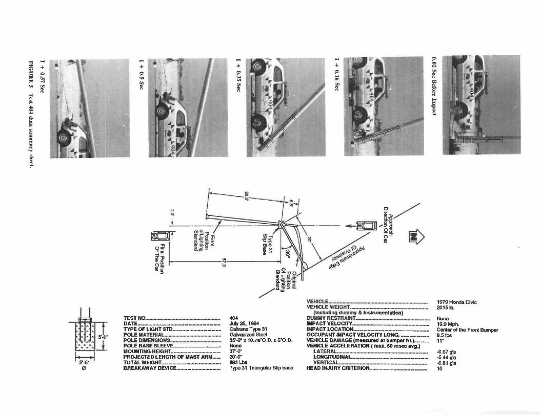
Results of Test 404
A summary of the results of test 404 and the photos taken before, during, and after the impact are shown in Figure 5. The test vehicle impacted the base of the pole at the center of the front bumper. The impact speed was 19. 9 mph (20 mph was desired). Upon impact, the slip base broke away and the car slowly pushed the pole base forward, where it bounced on the ground and then rolled over the car's hood and roof. The top of the pole swung down and hit the asphalt, then the pole and mast arm came straight down on top of the foundation without any rotation. While the vehicle decelerated, it proceeded in a straight line without any yaw. The surface of the lower section of the pole, where the initial bumper impact occurred, was not dented or deformed. The top of the pole sustained minor damage where it impacted the asphalt pavement. The mast arm did not appear to be damaged and was still attached to the pole, projecting about 1 ft into the imaginary outer traffic lane. (The pole and mast arm were able to be reused in test 405.) Immediately upon impact, the luminaire head shook loose from the pole tip and fell into the traffic lane . It was badly damaged after hitting the ground. Figure 5 shows the final position of the vehicle after it was braked remotely and the final location and schematic damage of the lighting standard.
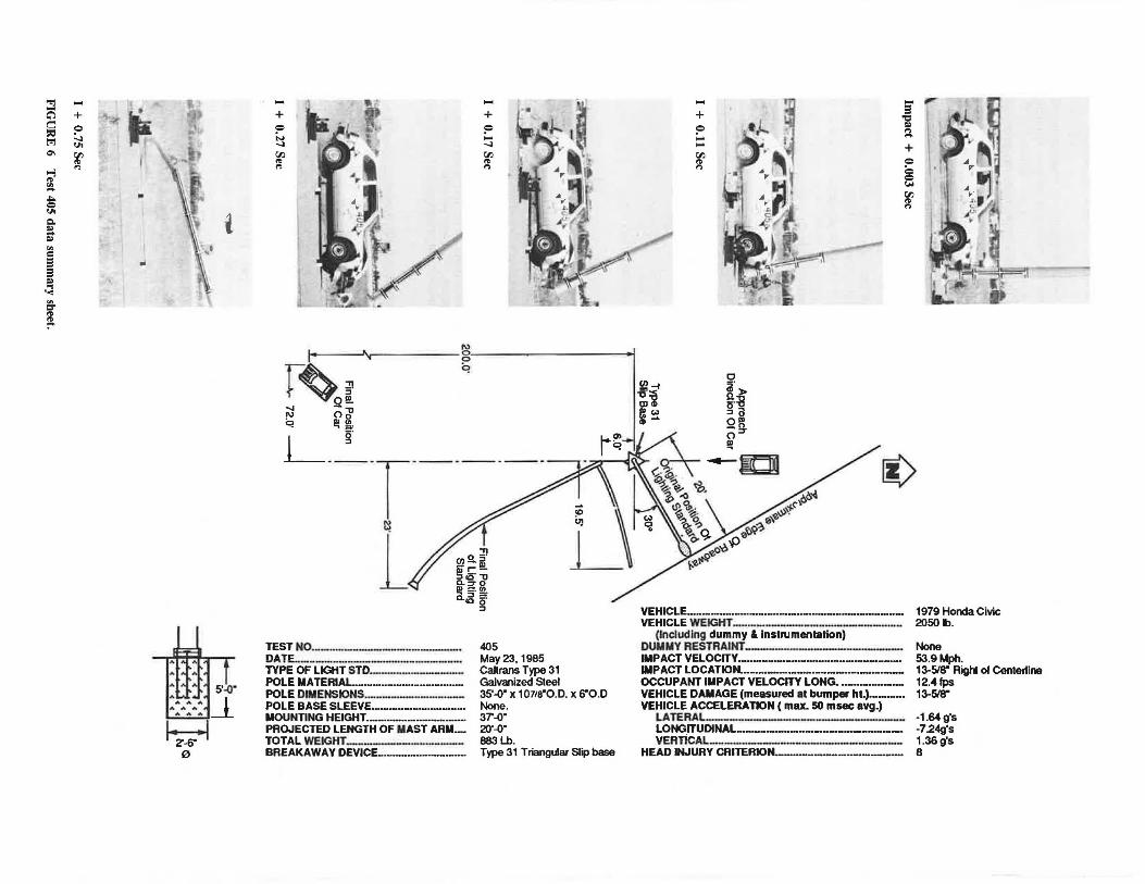
Results of Test 405
The summary of the results of test 405 and the photos taken before, during, and after the impact are shown in Figure 6. The test vehicle first impacted the pole near its base, 13-% in to the right of the centerline of the vehicle's front bumper (1-3/s in to the left of the desired quarter point location). The impact speed was 53.9 mph. The car yawed immediately after impact, and both the right front and the right rear tires ran over the foundation and lower slip base plate assembly, which was bolted to the foundation. This caused the whole right side of the Honda to vault into the air. After the initial 40° clockwise yaw, the car proceeded in a fairly straight line. The lower section of the galvanized steel pole sustained no damage from the impact of the vehicle's bumper. After impact, the pole base was quickly accelerated and kicked up high so the decelerating Honda was able to pass underneath without further contact. The top of the pole swung down and impacted the asphalt pavement, breaking the end cap and denting the back edge of the pole top. This also bowed the pole and the mast arm. Just after the car hit the pole base, the luminaire housing exploded from the shock. The final position of the vehicle after it was braked remotely and the final location and damage of the lighting standard are shown schematically in Figure 6.
Modified Type 31 Steel Lighting Standard With Standard Triangular Slip Base
Two tests-406 and 407-were conducted to determine if a modified Caltrans type 31 lighting standard (2 ft x 10 in OD x 0.25 in and 33 ft x 10 in OD x 5% in OD x 0.1196 in) with a triangular slip base would meet the requirements of NCHRP Report 230. The 2-ft-long lower section of the pole
"'1 ~
c;':l 0 ::= l"1 ..,. ..., "' :!/.. ..... = ..... c. co S' "' = a = co ., "<
"' :::r "' ~
~ r-111 ' + 1·· ~ r~. t:ll ~ ..... ~ lf\ I
~ : I ' I ' .l' \ \ .. 11:; • ,j, '
s;c1· .. "'::"-:"l_j ~ ~ -
0
; ~ ~.::fP'"il' ' ~ -, ~ ~
+ ~;i,". I (.I
I + +
Q t )f~I =
~ I Vo ' i.: ' .... ..,. t:ll ' i \
'A ~ I t:ll
"' ., . "
I ~· I a.. :
"' Ci
~f
05' I
~>/ !±:g 0.., ~ ·- -- - --l!!bl!l /~~ Ii) ~i.r=~- ~~;:::::::~_~=~~-===~ ~
(I) Q. "ll - r ~"Tl [ <g: == ~-
(1)-1 -a' -< OJ~ el <:.> -ID
-1-
!!? ::-.o -a..5 :l
CD ·-::T"lJ CD 0 • Q'I_ 0 fl!. :"'--------.!
~ 5· '"! :l
TEST NO·-··-·- ···- ·········· .. ······-·--···-··· DATE .......................... - ............................. .. TYPE OF LIGHT STD ................................. .. POLE MATERIAL.. ...... - ·--·- - ---POLE DIMENSIONS ............... -----··-·· POLE BASE SLEEVE ................................ .. MOUNTING HEIGHT .................................. .. PROJECTED LENGTH OF MAST ARM ..... . TOT AL WEIGHT ......................................... .. BREAKAWAY DEVICE .............................. ..
giQ"llO !!l~ £::>. a. :::r = 'e.
/~ =.o:l / c...s:l l!!.
404 July 26, 1984 canrans Type 31 Galvanized Steel 35'--0" x 10.718"0.D. x 6"0.D. None 37'--0" 20·--0· 883 Lbs. Type 31 Triangular Slip base
VEHJCLE ...... - .... ·----·---··- -·····--·- - -··-·--VEHICLE WEIGHT .............. - ............................ ___ _
(lncludlng dummy & Instrumentation) DUMUY RESTRAINT ........... - .. - ... ---··---·----·-lllPACT VELOCITY ••• - ................................................ . IMPACT LOCATION ................................. - ................. . OCCUPAN'T IMPACT VELOCITY LONG ................... .. VEHICLE DAMAGE (measured at bumper ht.) ......... .. VEHICLE ACCELERATION (max. 50 msec avg.)
LATERAL ..... ---- ----·- ---- .. ·--··-···-- ·· LONGITUDINAL ........... - ....................... -·-··--···-VERTICAL ........... - ... ----·- -·-··-·---···-·------
HEAD INJURY CRITERION ................................... - •••
= = N t:ll
"' " = "' 8' ., "' ~ a
"Cl co :::..
1979 Honda Civic 2015 lb.
None 19.9Mph. Center of the Front Bumper 8.Sfps 11·
--0.87 g's -5.44g's --0.81 g's 10
"l - ''Tr~~ - .. c;'l + ' ' '" ~ J ~ o<;>;° ~ ~ ? . ' ~ ., ~ ' I''( ~ "1 I
;(l f :.;,,..I t
~ 0 , . ~ .&;;.. I ~ Q ' Clo I I
~ .~: ~\ i = "' c 9 9 = ., '<
"' =-"' ~
5' .:o· ~-1 ~
0
;: ~ w -~ll
+
~ , ~ ? .... .......
~ {·. >' Cl.l
"' I ~~ ~ · l"l ,.,.
14 ~~r. l 1 ... 11
g
r~oi q
-.,, .....i Oo ~ Ill~
i_ __ g ·r·------L
TEST NO·------------··--·---· DATE.·------·----·--··--·------TYPE OF LIGHT STD .• ---····---··--POLE MATERIAL-·--·----··----···-·POLE DlllENSIONS.----·--··-····--POLE BASE SLEEVE·-······-·-··········-····· MOUNTING HEIGHT.·-·----------·· PROJECTED LENGTH OF MAST ARIL. TOTAL WEIGHT·---·---·---···--BREAKAWAY DEVICE-·---·-·-·----··
405 May23, 1985 Caltrans Type 31 Galvanized Steel 35'-0" x 1011e·o.D. x 6"0.D None. 3T-0" 20·-0· 883 Lb. Type 31 Triangular Slip base
~-f
!~ m~
- ~ ~ l ; ~ . . }\l A~ ·
. . ·~ I~
c a·> ~~ ::J a Q!'l o::T ~
-9 -= = l"l -+ Q
g ~
Cl.l
"' l"l
i)
VEHICLE--·---·---·--·--·--··-··--··-··------ 1979 Honda Civic VEHICLE WEIGHT--·--·----·--------·---·-- 2050 lb.
(Including dummy & Instrumentation) DUllllY RESTRAINT----·-----·-------· None IMPACT VELOCITY ••••.• --····-···--·········-········-···--···· 53.9 Mph. IMPACT LOCATION .. ·-····-········-····--·········-···-······-- 13-518" Rigti of Centerline OCCUPANT IMPACT VELOCITY LONG.·-------- 12.4 lps VEHICLE DAMAGE (measured et bumper ht.)·--··--· 13-518" VEHICLE ACCELERATION (max. 50 msec avg.)
LATERAL-·-·--------------------- ·1.64 g's LONGITUDINAL.--·-···-·····-·-···---···· .. -··-··· .. -· ·7.24g's VERTICAL-··--·----··------------- 1.36 g's
HEAD INJURY CRITERION-------··-----·--· 8
60
was made of 0.25-in-thick steel pipe to ensure a quick transfer of shear force to the breakaway base and to ensure that the pole had sufficient strength in the vehicle contact area.
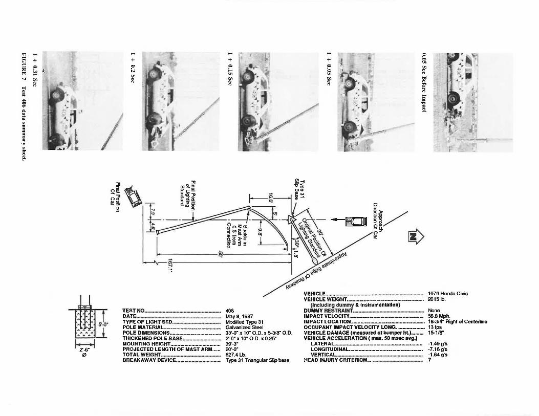
Results of Test 406
A summary of the results of test 406 and the photos taken before, during, and after the impact are shown in Figure 7. The vehicle impacted the pole 18% in (15 in desired) to the right of the centerline of the front bumper at 58.6 mph. Upon impact, the pole base was pushed up and over the roof of the decelerating vehicle without contacting the roof. As in test 405, both the right front and right rear tires of the Honda ran over the lower slip base assembly, which was bolted to the top of the foundation. This lifted the whole right side of the car into the air just after the right rear tire cleared the foundation. The off-centered hit caused a substantial clockwise yaw (approximately 30°) just after impact; however, the car seemed to straighten out after traveling a short distance. The surface of the pole where the initial bumper impact occurred was not dented or deformed. After impact, the pole tip and the mast arm swung down and impacted the asphalt pavement, breaking lhe emi cap and flattening the back edge of the pole top. The mast arm buckled approximately 6 in from the mast arm-to-pole end piate, and the main pole had a slight permanent bow about 15 ft from its tip. At the initial impact of the car and the pole base, the luminaire exploded from the impact shock at the end of the mast arm. Various parts of the luminaire then came raining down outside the imaginary traffic lanes. Figure 7 illustrates the final position of the vehicle after it was braked remotely and the final location and the schematic damage of the lighting standard.
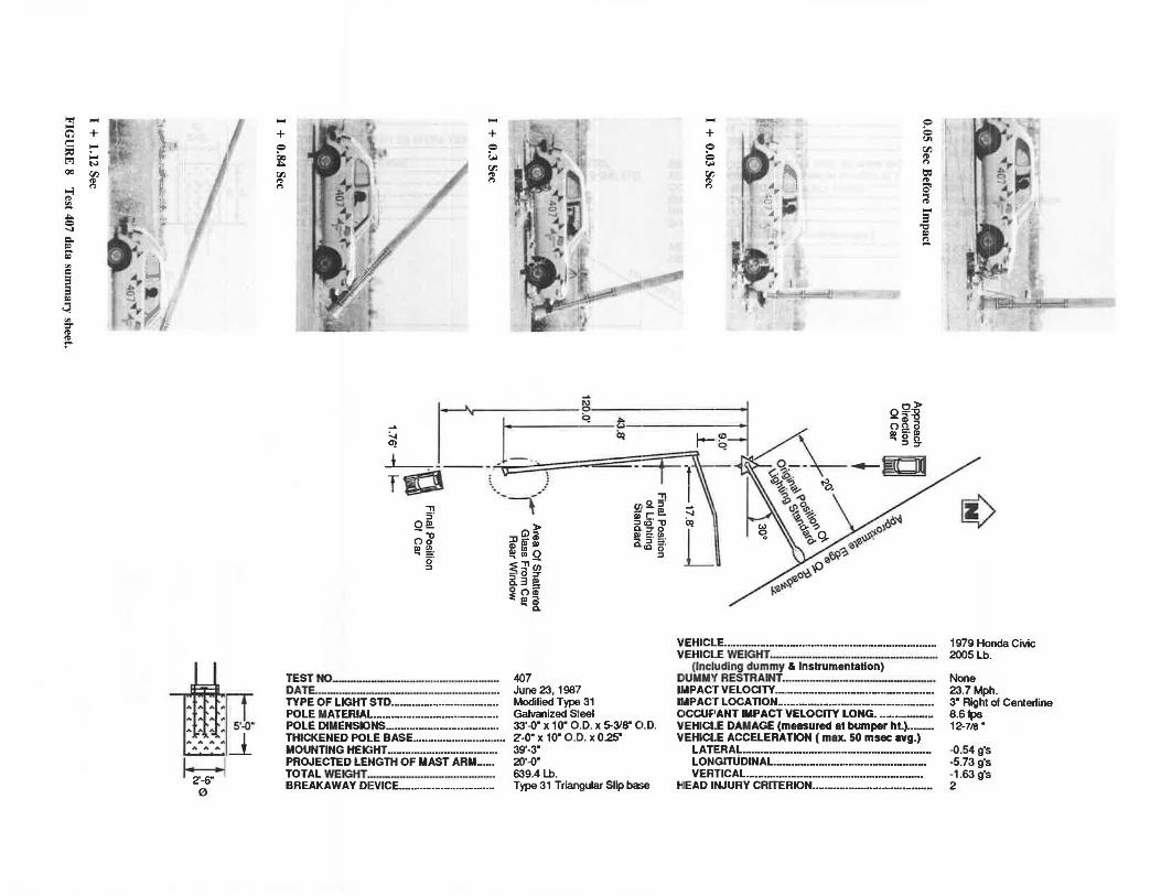
Results of Test 407
The summary of the results of test 407 and the photos taken before, during, and after the impact are shown in Figure 8. The test vehicle impacted the base of the pole 3 in to the right of the centerline of the front bumper (desired on center). The impact speed was 23.7 mph (20 mph desired). Just after the vehicle impacted the pole, it pushed the base of the pole off the lower slip base plate and the pole was gently pushed ahead . After impact , the pole base plate hooked under the car's front bumper and lifted the front end slightly. The pole did not kick over the car, but rolled on the hood and roof and finally hooked and shattered the rear window. After impacting the pole, the vehicle decelerated without yaw while traveling in a straight line. The surface of the pole where the initial bumper impact occurred was not dented or deformed. The tip of the pole and the mast arm swung down and impacted the asphalt pavement. The luminaire broke into pieces, and !~!!!!!:!!!!S of th~ h•!!lin:.irf"o ho11~ine_ 1:.nclf~rl in the ima£im1ry
outer traffic lane. The final position of the vehicle after it was braked remotely and the final location and the damage of the lighting standard are shown schematically in Figure 8.
Triangular Slip Base Performance
In all tests, the Caltrans slip bases functioned as designed. The slip bases were oriented so that the breakaway energy
TRANSPORTATION RESEARCH RECORD 1233
would be maximum when impacted, as required by NCHRP Report 230. To obtain this maximum breakaway energy, the approach direction of the crash car was adjusted so that the car would hit one of the three clamping bolts head-on, bisecting the 60° angle formed by that bolt and the other two back ones.
Nuts used on the 1-in clamping bolts were lubricated with teflon spray, and each was torqued to 200 ft-lb per Caltrans specifications. As a check on clamping bolt tensions, the length of the bolts was measured with a micrometer before and after installation, and elongations of the bolts were determined. The tension in each bolt was then ascertained from tensionversus-elongation curves for similar bolts (same grip length as the field grip length) tested in direct tension. The tension was also determined from torque-versus-tension curves of similar galvanized clamping bolts; these values were compared with those obtained from the tension-versus-elongation curves (12).
DISCUSSION OF TEST RESULTS
NCHRP Report 230 recommends the following three appraisal factors for evaluating crash test performance:
1. Structural adequacy, 2. Occupant risk, and 3. Vehicle after-collision trajectory.
Structural Adequacy
In Table 6 of NCHRP Report 230, the structural adequacy evaluation criteria for breakaway or yielding supports are defined as follows:
B. The test article shall readily activate in a predictable manner by breaking away or yielding. D. Detached elements, fragments or other debris from the test article shall not penetrate or show potential for penetrating the passenger compartment or present undue hazard to other traffic.
Part B was satisfied in all seven crash tests since the breakaway devices (die-cast aluminum couplings or triangular slip bases) sheared off upon impact as expected. Part D was also satisfied in tests 401 (58.6 mph), 403 (59.1 mph), 405 (53.9 mph), and 406 (58.8 mph) since the car kicked the pole up high enough that it had no problem passing beneath the pole with no contact . Although the speed in test 405 was 53.9 mph (60 mph desired), it can be concluded that a 60-mph test would also pass part D.
In tests 402 (19.6 mph), 404 (19.9 mph), an<l 407 (23.7 mph), the pole did not kick up high enough to clear the car but rolled over the roof and then slid off. It seemed that the lighting standards tested were too heavy for an 1,800-lb car at 20 mph. In test 402, the pole dented the roof of the car, and the final position of the lighting standard projected 5.9 ft into the traffic lane. In test 407, the rear window was shattered as the pole rolled off the roof. Although no significant damage was done to the passenger compartment, part D was not strictly satisfied in these tests. It should be noted that the pole caused more damage to the car in test 407 than in test 404, even though the lighting standard in test 407 was lighter
..,, .... .... C'l + ~ = ::i::l (,. ~ trl .... ...;i ['1 ,. ...., ,.., ,. i!4.
"'" = ~ Cl. :.0 ;-"' = 3 3 ~ .,
'""" "' =-,. ~
F ' j.~~' ~
- -~
~ 0
s--0·
,, 5·
O!!!. ;di ~~
~r
.... + = i..> ['1 ,. ,..,
.... •. i "jµ .... ~ -~ .. =
+ + ·1 = -.., "' ? 'O"j = ~ -; ['1 .... ~~· = i <-" '. ., ,.
"' "' fft.c. ~ ,..,
['1 : ~1 ['1 t:ll ,. ,. ~ - ··i:l'
,. ,.., ,.., O' ., ,. .... 3
"Cl :.0 :::..
---~-~, -
0
a-~/ -·"!i! go
~~ i)
::n fg~ m~~ ~~ g; r- !!!. Ill a>
~~l L__;b~m~ ~~= ~~ c..'° er
~---:: ;,~· ~ - ~-- .-liDJll g~3:gi ~~'\"'\ ~U]IJ!n Cl'·~~ a>--2£ ~-<) • no>a> IS!o ~3§~ ,~ ~ ~~
>--------~ %. 9- oo~ '? JO~ . ~,,.
e~ . e~'?
o--0.p 't-'l-tl'~-e;
~
~en---~~~~~~~~~~~~~~-~~--.~
~
VEHICLE .•.••••.••••••..•••••.••• ·-········-································ 1979 Honda Civic
TEST NO ...................................................... .
DATE .... ·---··----···-------·---·-TYPE OF LIGHT STD.·-------------POLE MATERIAL .••••.•••...•••.•.••••••.•.•.••••....•••• POLE DIMENSIONS ..••.•.•.•..•••.••.....•••••.....•••• THICKENED POLE BASE. .......................... . MOUNTING HEIGHT ..••..••...••••........•••••....•••• PROJECTED LENGTH OF MAST ARM ....•. TOTAL WEIGHT ............................ -------BREAKAWAY DEVICE .••••.....•.•.•.....•••.........
406 Mays, 1987 Modified Type 31 Galvanized Steel 33·--0· x 1 o· o.o. x s...31a· o.o. 2'--0" x 10· 0.0. x 0.25" 39'-3" 20·--0· 627.4 Lb. Type 31 Triangular Slip base
VEHICLE WEIGHT....................................................... 2015 lb. (Including dummy & Instrumentation)
DUMMY RESTRAINT--------------·- None IMPACT VELOCITY ...... --·····--·······-·····-···-··········· 58.8 Mph. IMPACT LOCATION .••••••••••••• ·-·························-··-····· 18-314" Righi of Centerline OCCUPANT IMPACT VELOCITY LONG. ................... 13 fps VEHICLE DAMAGE (measured at bumper ht.)......... 15-118" VEHICLE ACCELERATION (max. 50 msec avg.)
LATERAL. ............................. - ............................. .. -1.49 g's LONGITUDINAL .................................................... . -7.16 g's VERTICAL.-----------------------· -1.64 g's
~EAD INJURY CRITERION ..• -··-·---------·- 7
.., - ,~~ ~ , - ~~r~· .... - . '- • ...- .., Q - ' ... , . .. t} ·~ .... <f • C'} + ~·· } + - "' .i + + ~· . r. ~ s ~ ~·~_:· . ;~ ? · · ·-~.. . ... ? ? : •. 00 "' ..,. \:c QC ·• ~ ~ Q ' '" ['!l N .• . , .i;. (j' 'M .-~ r>
QC 00 r· 00 I - / ' l(l 00 t:=I ~ ~ l ' r> ~ ~ ~ -"l _, '~ ~~ ,.~ l . ,. , I ~ - ~·~ ' ' ~ ~ ,, ,. -~ ll ~· ... . , . •.•. = ~ [,C ~~~f I ... ,./... .· .. .:llf ~~-· ~ a. r-; .. 'a.I • ~ • "' ' - ~ •_ -. .. -
:0
"' = 3 3 :0
~ "' :r
~
:t:11~~·-0· A AA A _l
A A A
I ~·-6" • 1 0
~ L-.. !_l --.·u::::: T'° ·-,-"Tl
5· O!!!. ;d' ~~ a·
::I
TEST"°--·--·- - - ·---- - -···-······- ---DATE..-·-···-----·--·- ·- ····-- -···-- ·-· TYPE OF LIGHT STD .•..•••..•••••...••••••.••••••••.... POLE MATERIAL. •..•• - ................................. . POLE DIMENSIONS ..................................... . THICKENED POLE BASE ..•• ·-···········-··········· MOUNTING HEIGHT •. ·-······-·················-····· PROJECTED LENGTH OF MAST ARM-....
TOTAL WEIGHT·-·- .. ·--···- ···- ·-···--······· BREAKAWAY DEVICE ••••....•••.....•...........•...
> G) i
~PI Pl !!l Ul Q :E::, (/) - · 0 :::r a. 3 !! 0 ()<II
~ !!1 [
407 June 23, 1987 Modified TYJ>EI 31 Galvanized S:leel
0 5' ~· ;:: !!!. ~.a· "ti a :::ro !!l :. !!!. Q~ 5·
::I
33'-0" x 10" Oi.D. x 5-3'8" O.D. 2'-0" x 10· 0.1'.> . x 0.25" 39•.3• 20·-0· 639.4 Lb. Type 31 Triangular Slip ba:ie
VEHICLE •.....••••••.....•••..•••••..•.••.••••••••••••••.•••••••.••••.•..•••••. VEHICLE WEIGHT·-···-·- - -----··--- ···---··
(Including dummy & Instrumentation) DUMllV RESTRAINT.--·----··- - - -------· IMPACT VELOCITY·-·--·-····-··········-· ............... - .... . lllllPAC'r LOCATION ................................................... . CICCUF'ANT IMPACT VELOCITY LONG ••••••••••••••••••• V'EHICl.E DAMAGE (measured at bumper ht.) ......... VEHICl.E ACCELERATION (max. 50 msec avg.)
LATERAL .... - .... ·-- ·----···--···-- ·--·--····---LONGrrUDINAL.--·--·-· .... ·-- --- --- --·--VERTICAL. .............. --·--····-··-······· .. ·····-······-·
HEAD INJURY CRITERION ....................................... .
(>
1979 Honda Civic 2005 Lb.
None 23.7Mph. 3" Righi of Centerline 8.61ps 12-718.
-0.54 g's -5.73 g's -1.63 g's 2
Stoughton et al.
than that used in test 404 ( 639 .4 versus 883 lb) and the speed was more in test 407 (23.7 versus 19.9 mph). In other words, damage to the car roof can be worse at lower speeds. Also, the luminaire debris fell into the outer traffic lane in all tests except tests 401 and 406. In an actual accident, this type of debris could cause some damage to traffic in the outside lane. Thus, none of the tests completely satisfied the structural adequacy criterion: either there was some damage to the passenger compartment from the falling pole, or the lighting standard and luminaire debris created a potential hazard to traffic in the outside lane. However, since NCHRP Report 230 does not clearly define what is meant by passenger compartment intrusion or what constitutes undue hazard to other traffic, it was judged that in all seven tests no significant damage to the passengers or to nearby traffic was likely to occur. Rear window shattering may occur over a range of low impact speeds (somewhere between 20 and 40 mph), no matter how effective the breakaway device, because of the pole mass and low trajectory.
Occupant Risk
The occupant risk as defined in NCHRP Report 230 relates to the degree of hazard to which occupants in the impacting vehicle would be subjected. It is measured in terms of the velocity with which a hypothetical unrestrained occupant strikes the instrument panel or door and the subsequent occupant ridedown accelerations. NCHRP Report 230 recommends maximum values of 15 ft/sec for the occupant impact velocity and 15 g for the occupant ridedown acceleration. Also, a head injury criterion (HIC) of less than 1,000 is recommended for the dummy. The report also states that the vehicle should remain upright during and after collision (moderate roll, pitching, and yawing are acceptable) and the integrity of the passenger compartment must be maintained with no intrusion or deformation.
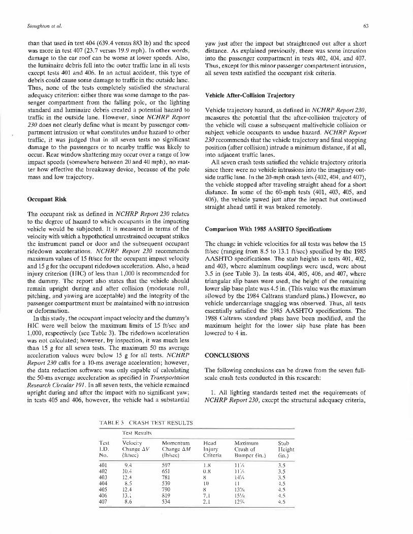
In this study, the occupant impact velocity and the dummy's HIC were well below the maximum limits of 15 ft/sec and 1,000, respectively (see Table 3). The ridedown acceleration was not calculated; however, by inspection, it was much less than 15 g for all seven tests. The maximum 50 ms average acceleration values were below 15 g for all tests. NCHRP Report 230 calls for a 10-ms average acceleration; however, the data reduction software was only capable of calculating the 50-ms average acceleration as specified in Transportation Research Circular 191. In all seven tests, the vehicle remained upright during and after the impact with no significant yaw; in tests 405 and 406, however, the vehicle had a substantial
TABLE 3 CRASH TEST RES UL TS
Test Results
Test Velocity Momentum l.D. Change t:i.V Change t:i.M No. (ft/sec) (lb/sec)
401 9.4 597 402 10.4 651 403 12.4 781 404 8.5 539 405 12.4 790 406 13.1 819 407 8.6 534
63
yaw just after the impact but straightened out after a short distance. As explained previously, there was some intrusion into the passenger compartment in tests 402, 404, and 407. Thus, except for this minor passenger compartment intrusion, all seven tests satisfied the occupant risk criteria.
Vehicle After-Collision Trajectory
Vehicle trajectory hazard, as defined in NCHRP Report 230, measures the potential that the after-collision trajectory of the vehicle will cause a subsequent multivehicle collision or subject vehicle occupants to undue hazard. NCHRP Report 230 recommends that the vehicle trajectory and final stopping position (after collision) intrude a minimum distance, if at all, into adjacent traffic lanes.
All seven crash tests satisfied the vehicle trajectory criteria since there were no vehicle intrusions into the imaginary outside traffic lane. In the 20-mph crash tests (402, 404, and 407), the vehicle stopped after traveling straight ahead for a short distance. In some of the 60-mph tests (401, 403, 405, and 406), the vehicle yawed just after the impact but continued straight ahead until it was braked remotely.
Comparison With 1985 AASHTO Specifications
The change in vehicle velocities for all tests was below the 15 ft/sec (ranging from 8.5 to 13.1 ft/sec) specified by the 1985 AASHTO specifications. The stub heights in tests 401, 402, and 403, where aluminum couplings were used, were about 3.5 in (see Table 3). In tests 404, 405, 406, and 407, where triangular slip bases were used, the height of the remaining lower slip base plate was 4.5 in. (This value was the maximum allowed by the 1984 Caltrans standard plans.) However, no vehicle undercarriage snagging was observed. Thus, all tests essentially satisfied the 1985 AASHTO specifications. The 1988 Caltrans standard plans have been modified, and the maximum height for the lower slip base plate has been lowered to 4 in.
CONCLUSIONS
The following conclusions can be drawn from the seven fullscale crash tests conducted in this research:
1. All lighting standards tested met the requirements of NCHRP Report 230, except the structural adequacy criteria,
Head Maximum Stub Injury Crush of Height Criteria Bumper (in.) (in.)
1.8 II'/, 3.5 0.8 111. 3.5 8 14'/, 3.5 10 11 4.5 8 13% 4.5 7.1 15'/., 4.5 2.1 127
/., 4.5
64
which were not fully satisfied because of small intrusions of the poles into the passenger compartment of the car or adjacent traffic lanes. The lighting standards met the 1985 AASHTO specifications for breakaway bases.
2. The rather porous die-cast aluminum couplings proved to be an effective breakaway device when impacted by 1,800-lb cars. The results showed a maximum change in velocity of 12.4 ft/sec. However, aluminum couplings are not recommended as a standard Caltrans breakaway device at this time because of the following conditions:
• Excessive porosity was observed on the fractured surfaces of the couplings, and subsequent x-rays proved that the couplings were not acceptable based on Caltrans specifications and limits in ASTM E505 reference radiographs.
• The two downstream anchor bolts bent upon impact and may be costly to repair or replace. This problem, however, has apparently been solved in some of the new couplings by the use of a flush-mounted female anchor system.
• The results of tension and shear tests of aluminum couplings showed that neither the die-cast nor the extruded aluminum couplings available at the time complied with Caltrans specifications.
3. The 35-ft-high lightweight aluminum lighting standard with a 20-ft-long truss-type mast arm proved to be effective and reusable after it was impacted at 20 mph; however, it was damaged at 60 mph.
4. The 35-ft-high lightweight steel lighting standard with a 20-ft-long mast arm sustained serious damage afte1 it was impacted at 60 mph.
5. The triangular steel slip base proved to be an effective breakaway device when impacted by 1,800-lb cars. The relatively high slip base boii tension did not appear to affect the slip base performance.
6. Neither the trajectory and final position (after impact) of any of the lighting standards tested nor luminaire debris would create serious hazard or likelihood of injuries to either occupants of the impacted vehicle or to passengers of vehicles in the outside traffic lane.
7. Damage to the crash vehicles in all seven tests was repairable.
ACKNOWLEDGMENTS
This research was sponsored by FHW A. The authors gratefully acknowledge the valuable technical consultation provided by Ed Tye, Earl Riker, and Jay Folsom of Caltrans.
TRANSPORTATION RESEARCH RECORD 1233
REFERENCES
1. T. C. Edwards, J. E. Martinez, W. F. McFarland, and H. E. Ross. NCHRP REPORT 77: Development of Design Criteria for Safer Luminaire Supports. HRB, National Research Council, Washington, D.C., 1969.
2. T. C. Edwards, T. J. Hirsch, and R. M. Olson. Design Criteria for Breakaway Sign Supports. In Highway Research Record 222, HRB, National Research Council, Washington, D.C., 1968.
3. Application of Highway Safety Measures-Breakaway Luminaire Supports. FHWA Circular Memorandum. FHWA, U.S. Department of Transportation, 1968.
4. Application of Highway Safety Measures-Breakaway Luminaire Supports. FHWA Notice. FHWA, U.S. Department of Transportation, 1970.
5. NCHRP Report 153: Recommended Procedures for Vehicle Crash Testing of Highway Appurtenances. TRB, National Research Council, Washington, D.C., 1974.
6. Standard Specifications for Structural Supports for Highway Signs, Luminaires, and Traffic Signals. AASHTO, Washington, D.C., 1975.
7. Transportation Research Circular 191: Recommended Procedures for Vehicle Crash Testing of Highway Appurtenances. TRB, National Research Council, Washington, D.C., 1978.
8. NCHRP Report 230: Recommended Procedures for the Safety Performance Evaluation of Highway Appurtenances. TRB, National Research Council, Washington, D.C. 1981.
9. Standard Specificatio.n.s for Structural Supports for Highi·vay Sig.•1s, Luminaires, and Traffic Signals. AASHTO, Washington, D.C., 1985.
10. Nordlin et al. Dynamic Tests of Breakaway Lighting Standards Using Small Automobiles. Report CA-DOT-TL-6490-1-75-47. California Department of Transportation, Sacramento, 1975.
il. E. F. Nordlin, W. H. Ames, and KN. Field. Dynamic Tests of Five Breakaway Lighting Standard Base Designs. In Highway Research Record 259, HRB, National Research Council, Washington, D.C., 1969.
12. A. Abghari, R. L. Stoughton, and J. P. Dusel, Vehicle Impact Testing of Lightweight Lighting Standards, Report FHW A/CAI TL-88/07. California Department of Transportation, Sacramento, 1988.
The findings and conclusions in this paper represent the views of the authors and not necessarily the official views or policies of the state of California or the U.S. government. This paper is not an endorsement of products or manufacturers.
Publication of this paper sponsored by Committee on Roadside Safety Features.