Embed Size (px)
Citation preview
Vehicle Propulsion Systems
Lecture 6
Electric & Hybrid Electric Propulsion Systems Part I
1

Team
• Chris [email protected] K37.2, +41 44 63 2 2466
• Philipp [email protected]+41 78 633 5876
• Andyn [email protected]+41 58 765 4441
• Andreas [email protected] K39, +41 44 63 2 8066
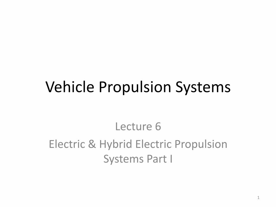
Planning of Lectures and Exercises:Week Lecture, Friday, 8:15-10:00, ML F34 Book
chp.Exercise , Friday, 12:00-13:30, CHN E46
38, 20.09.2019 Introduction, goals, overview propulsion systems and options
1 Introduction
39, 27.09.2019 Fuel consumption prediction I 2 Exercise I, Milestone 1
40, 04.10.2019 Fuel consumption prediction II 2 Exercise I, Presentation
41, 11.10.2019 IC engine propulsion systems I 3 Exercise II, Milestone 1
42, 18.10.2019 IC engine propulsion systems II 3 Exercise II, Milestone 2
43, 25.10.2019 Hybrid electric propulsion systems I 4 Exercise II, Presentation
44, 01.11.2019 Hybrid electric propulsion systems II 4 Exercise III, Milestone 1
45, 08.11.2019 Hybrid electric propulsion systems III 4 Exercise III, Milestone 2
46, 15.11.2019 Non-electric hybrid propulsion systems 5 Exercise III, Presentation
47, 22.11.2019 Supervisory Control Algorithms I 7 Exercise IV, Milestone 1
48, 29.11.2019 Supervisory Control Algorithms II 7 Exercise IV, Milestone 2
49, 06.12.2019 Supervisory Control Algorithms III 7 Exercise IV, Milestone 3
50, 13.12.2019 Case Study Exercise IV, Presentation
51, 20.12.2019 Tutorial Lecture, Q & A
Today
• “Quasi Steady-State” Modeling
• Electric & Hybrid-Electric Propulsion Systems
• Electric Motors
13
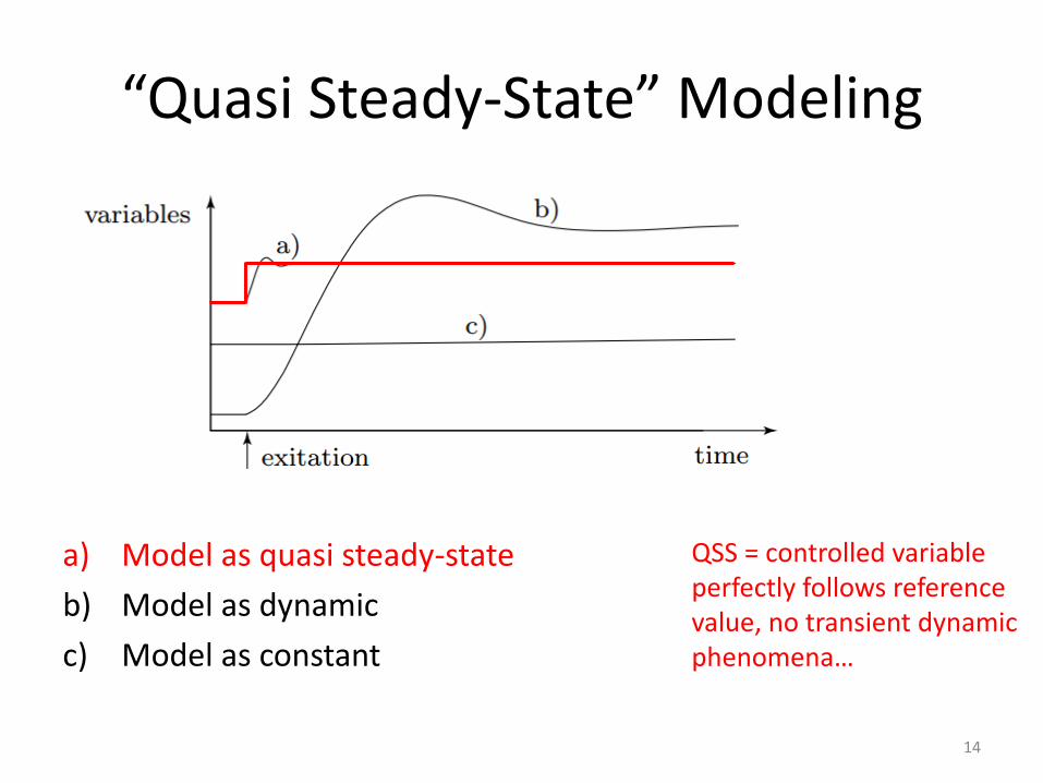
“Quasi Steady-State” Modeling
a) Model as quasi steady-state
b) Model as dynamic
c) Model as constant
QSS = controlled variable perfectly follows reference value, no transient dynamic phenomena…
14
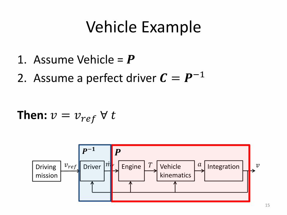
Vehicle Example
1. Assume Vehicle = 𝑷
2. Assume a perfect driver 𝑪 = 𝑷−1
Then: 𝑣 = 𝑣𝑟𝑒𝑓 ∀ 𝑡
Drivingmission
Driver Engine Vehiclekinematics
Integration 𝑣𝑎𝑇ሶ𝑚𝑓𝑣𝑟𝑒𝑓
𝑷𝑷−𝟏
15
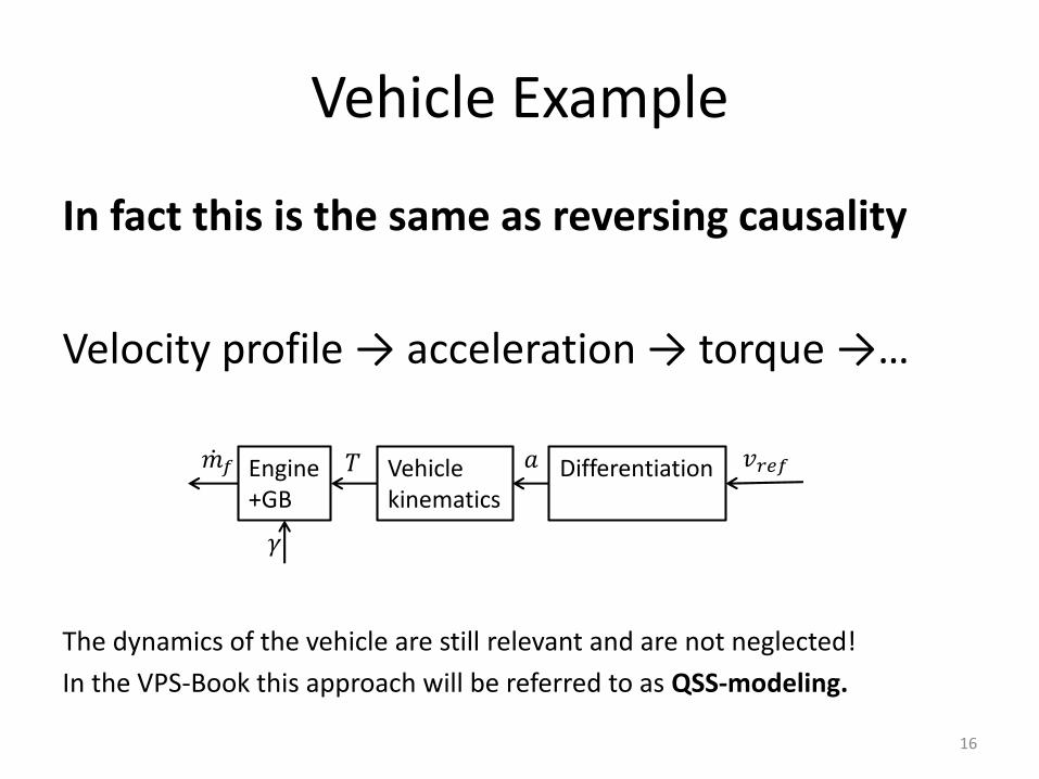
Vehicle Example
In fact this is the same as reversing causality
Velocity profile → acceleration → torque →…
The dynamics of the vehicle are still relevant and are not neglected!
In the VPS-Book this approach will be referred to as QSS-modeling.
Engine+GB
Vehiclekinematics
Differentiation 𝑣𝑟𝑒𝑓𝑎𝑇ሶ𝑚𝑓
𝛾
16
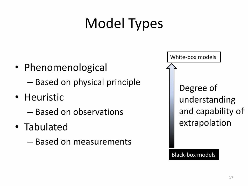
Model Types
• Phenomenological
– Based on physical principle
• Heuristic
– Based on observations
• Tabulated
– Based on measurements
Degree of understandingand capability of extrapolation
White-box models
Black-box models
17
Today
• “Quasi Steady-State” Modeling
• Electric & Hybrid-Electric Propulsion Systems
– Motivation
– Topologies and classification
– Energy management
– Optimization of hybrid powertrains
• Electric Motors
18
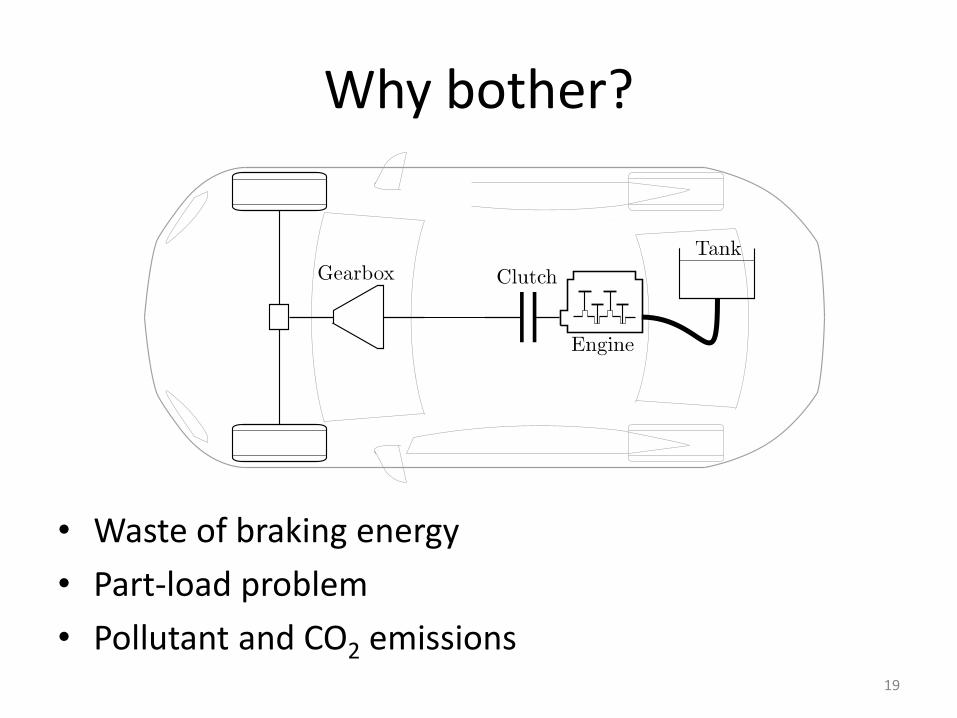
Why bother?
• Waste of braking energy
• Part-load problem
• Pollutant and CO2 emissions19
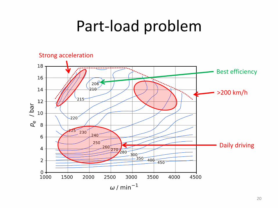
Part-load problem
Best efficiency
Daily driving
Strong acceleration
>200 km/h
20
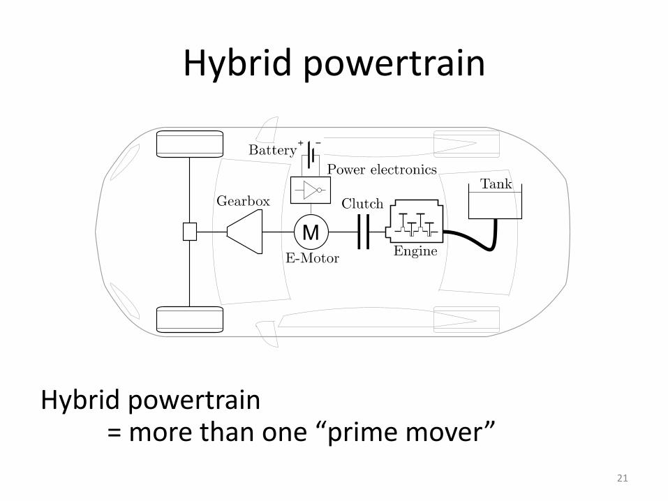
Hybrid powertrain
Hybrid powertrain = more than one “prime mover”
21
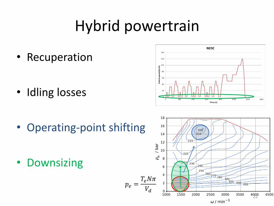
Hybrid powertrain
• Recuperation
• Idling losses
• Operating-point shifting
• Downsizing
𝑝𝑒 =𝑇𝑒𝑁𝜋
𝑉𝑑22
Today
• “Quasi Steady-State” Modeling
• Electric & Hybrid-Electric Propulsion Systems
– Motivation
– Topologies and classification
– Energy management
– Optimization of hybrid powertrains
• Electric Motors
24
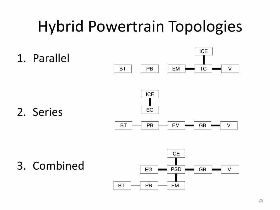
Hybrid Powertrain Topologies
1. Parallel
2. Series
3. Combined
25
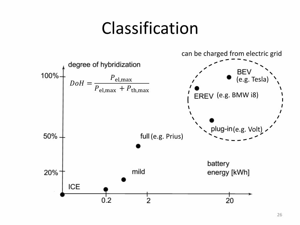
Classification
𝐷𝑜𝐻 =𝑃el,max
𝑃el,max + 𝑃th,max
(e.g. Prius)
can be charged from electric grid
f
(e.g. Volt)
(e.g. BMW i8)
(e.g. Tesla)
26
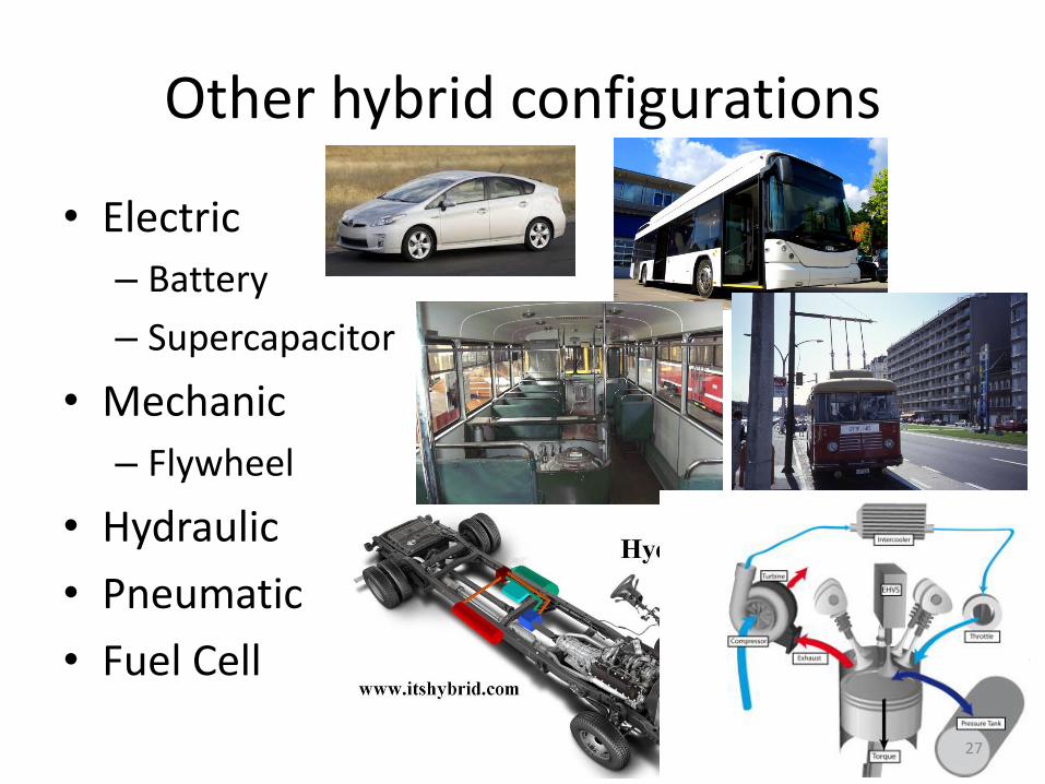
Other hybrid configurations
• Electric
– Battery
– Supercapacitor
• Mechanic
– Flywheel
• Hydraulic
• Pneumatic
• Fuel Cell
27
Today
• “Quasi Steady-State” Modeling
• Electric & Hybrid-Electric Propulsion Systems
– Motivation
– Topologies and classification
– Energy management
– Optimization of hybrid powertrains
• Electric Motors
28
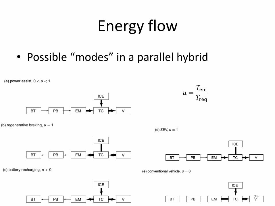
Energy flow
• Possible “modes” in a parallel hybrid
𝑢 =𝑇em𝑇req
29
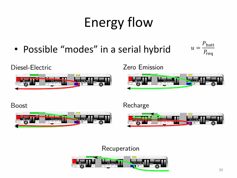
Energy flow
• Possible “modes” in a serial hybrid 𝑢 =𝑃batt𝑃req
30
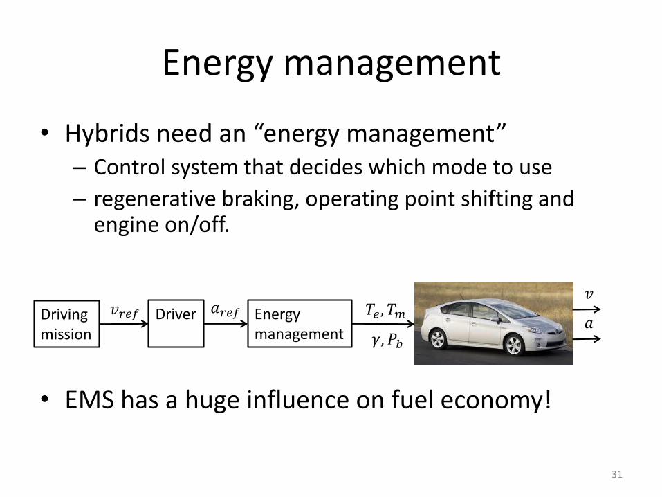
Energy management
• Hybrids need an “energy management”– Control system that decides which mode to use
– regenerative braking, operating point shifting and engine on/off.
• EMS has a huge influence on fuel economy!
Drivingmission
Driver 𝑎𝑟𝑒𝑓𝑣𝑟𝑒𝑓 Energymanagement
𝑇𝑒 , 𝑇𝑚
𝛾, 𝑃𝑏
𝑣
𝑎
31
Today
• “Quasi Steady-State” Modeling
• Electric & Hybrid-Electric Propulsion Systems
– Motivation
– Topologies and classification
– Energy management
– Optimization of hybrid powertrains
• Electric Motors
32
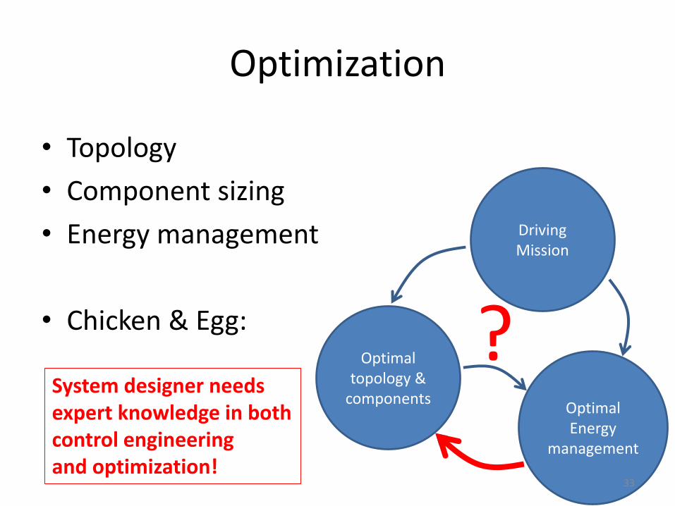
Optimization
• Topology
• Component sizing
• Energy management
• Chicken & Egg:Optimal
topology & components
Optimal Energy
management
Driving Mission
?System designer needs expert knowledge in bothcontrol engineering and optimization!
33
Today
• “Quasi Steady-State” Modeling
• Electric & Hybrid-Electric Propulsion Systems
• Electric Motors
– Types and Working principles
– Modeling
– DC-Converter / Power-Inverter
43
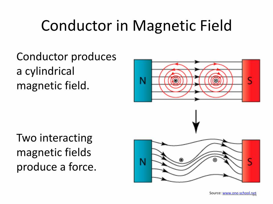
Conductor in Magnetic Field
Conductor produces a cylindrical magnetic field.
Two interacting magnetic fields produce a force.
Source: www.one-school.net44
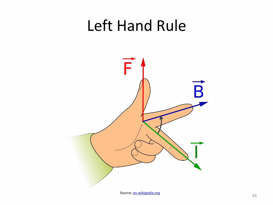
Left Hand Rule
Source: en.wikipedia.org45
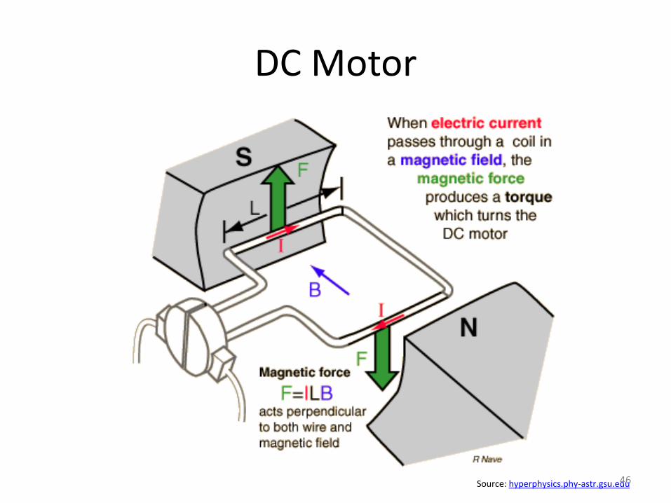
DC Motor
Source: hyperphysics.phy-astr.gsu.edu46
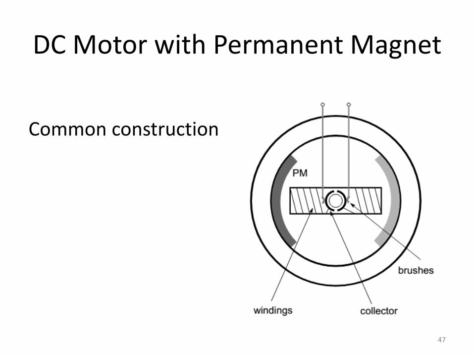
DC Motor with Permanent Magnet
Common construction
47
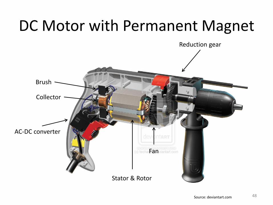
DC Motor with Permanent Magnet
Brush
Stator & Rotor
AC-DC converter
Reduction gear
Fan
Collector
Source: deviantart.com 48
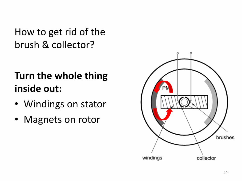
How to get rid of the brush & collector?
Turn the whole thing inside out:
• Windings on stator
• Magnets on rotor
49
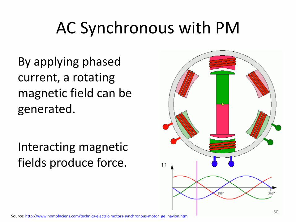
AC Synchronous with PM
By applying phased current, a rotating magnetic field can be generated.
Interacting magnetic fields produce force.
Source: http://www.homofaciens.com/technics-electric-motors-synchronous-motor_ge_navion.htm50
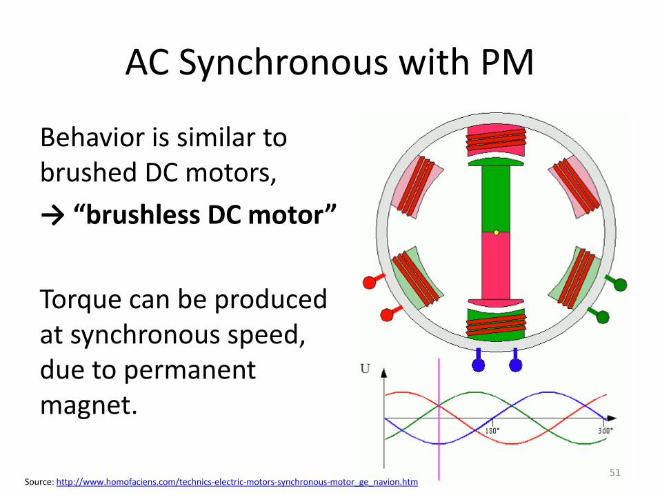
AC Synchronous with PM
Behavior is similar to brushed DC motors,
→ “brushless DC motor”
Torque can be produced at synchronous speed, due to permanent magnet.
Source: http://www.homofaciens.com/technics-electric-motors-synchronous-motor_ge_navion.htm51
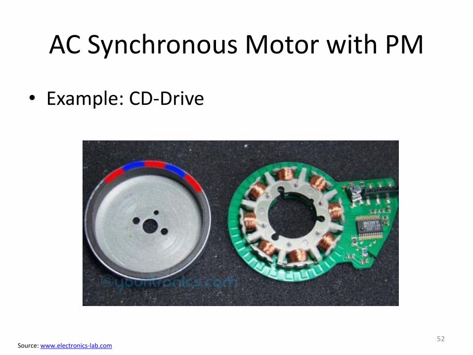
AC Synchronous Motor with PM
• Example: CD-Drive
Source: www.electronics-lab.com52
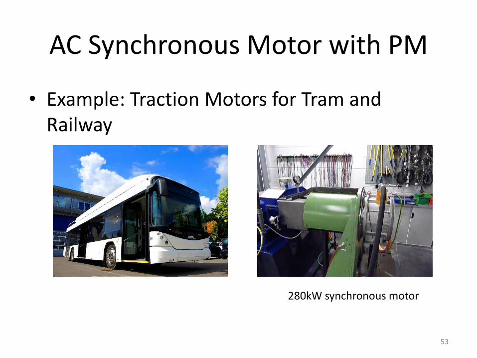
AC Synchronous Motor with PM
• Example: Traction Motors for Tram and Railway
280kW synchronous motor
53
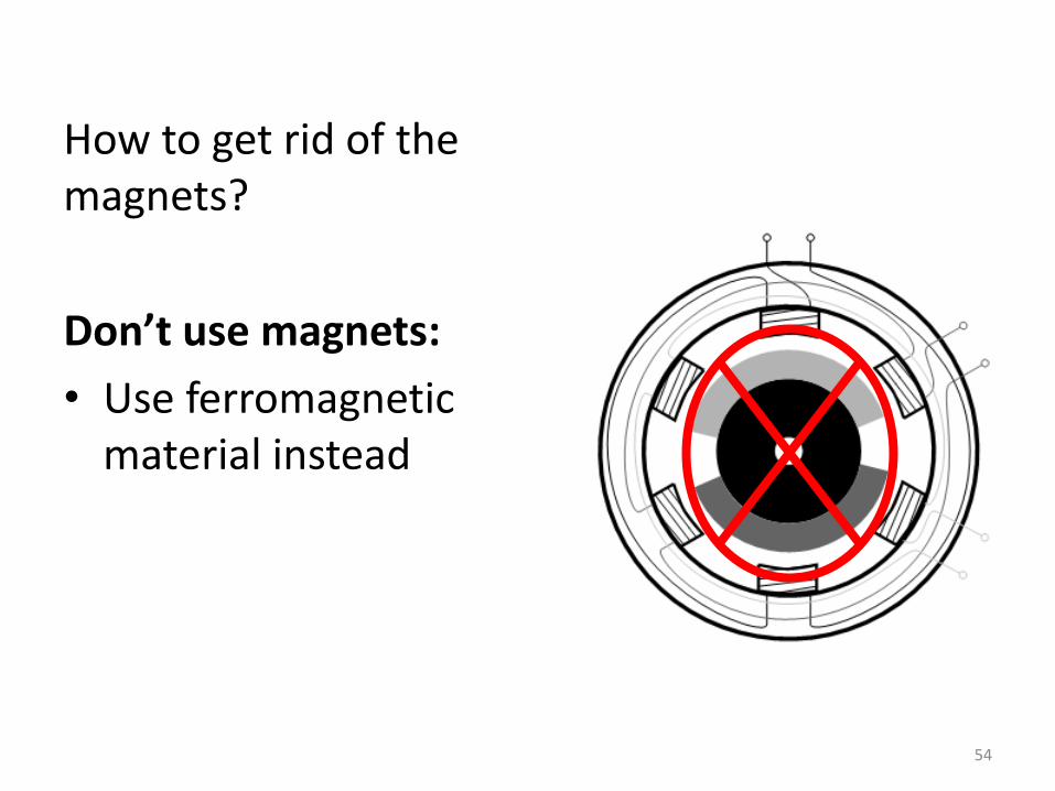
How to get rid of the magnets?
Don’t use magnets:
• Use ferromagnetic material instead
54
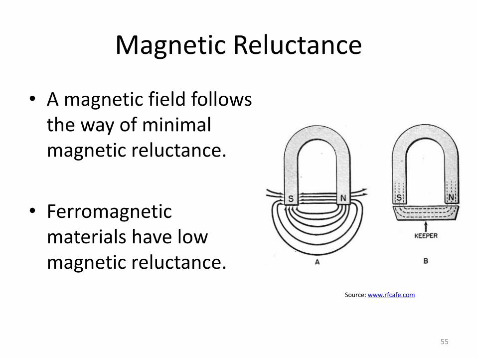
Magnetic Reluctance
• A magnetic field follows the way of minimal magnetic reluctance.
• Ferromagnetic materials have low magnetic reluctance.
Source: www.rfcafe.com
55
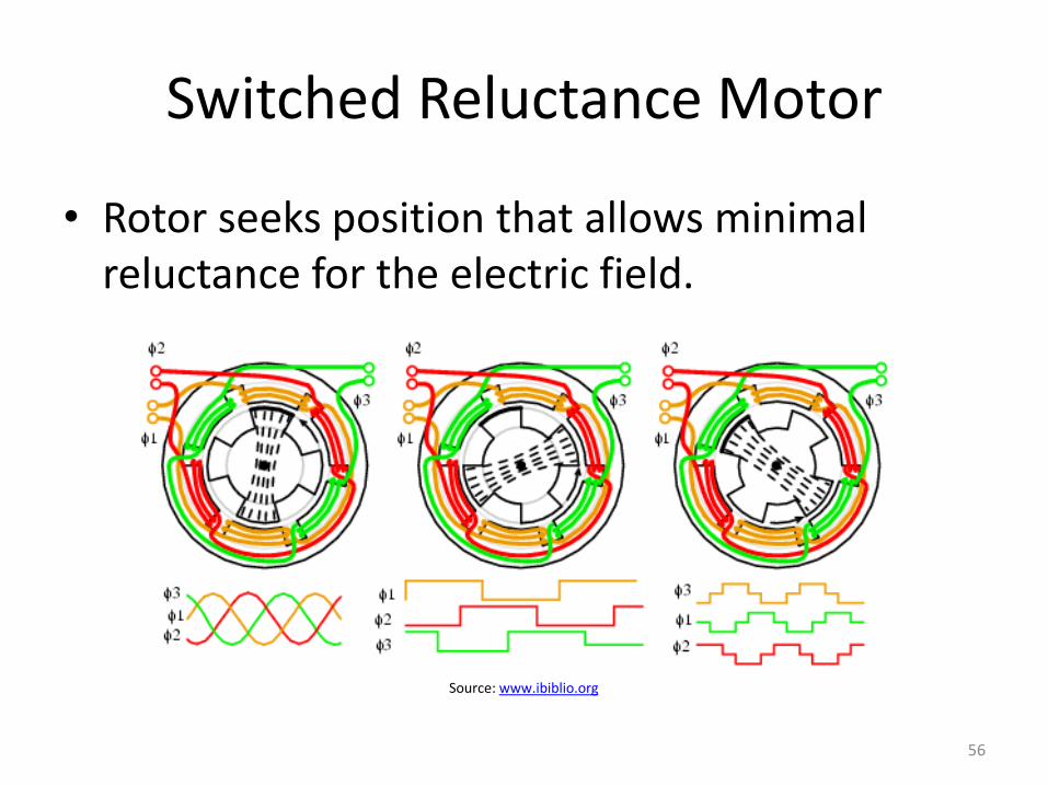
Switched Reluctance Motor
• Rotor seeks position that allows minimal reluctance for the electric field.
Source: www.ibiblio.org
56
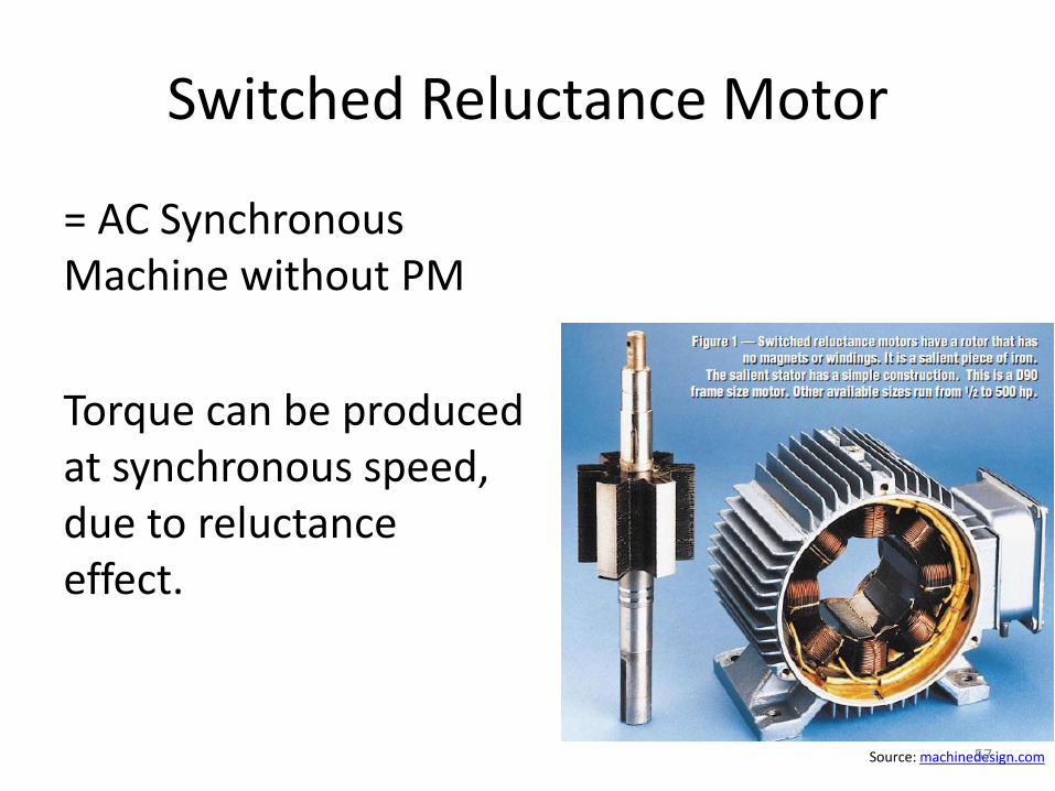
Switched Reluctance Motor
= AC Synchronous Machine without PM
Torque can be produced at synchronous speed, due to reluctance effect.
Source: machinedesign.com57
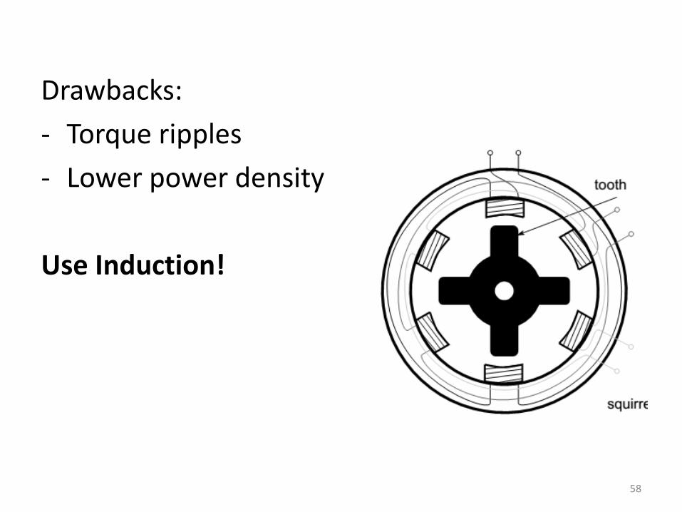
Drawbacks:
- Torque ripples
- Lower power density
Use Induction!
58
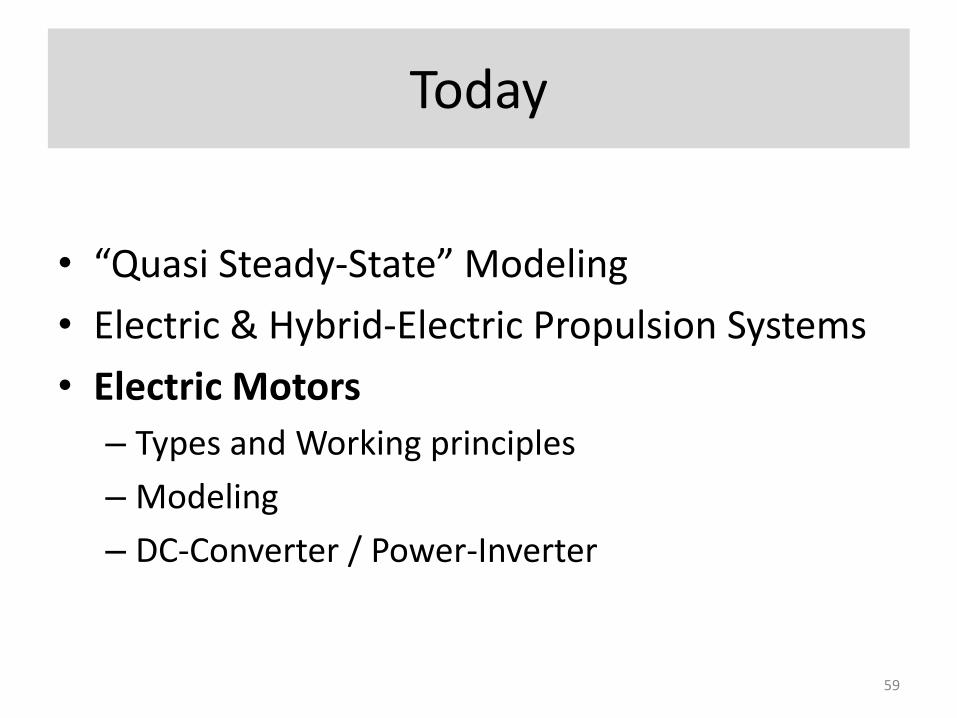
Today
• “Quasi Steady-State” Modeling
• Electric & Hybrid-Electric Propulsion Systems
• Electric Motors
– Types and Working principles
– Modeling
– DC-Converter / Power-Inverter
59
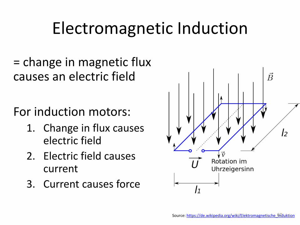
Electromagnetic Induction
= change in magnetic flux causes an electric field
For induction motors:1. Change in flux causes
electric field
2. Electric field causes current
3. Current causes force
Source: https://de.wikipedia.org/wiki/Elektromagnetische_Induktion60
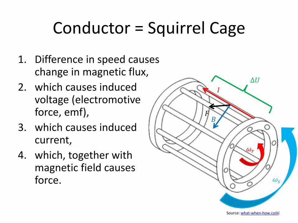
Conductor = Squirrel Cage
1. Difference in speed causes change in magnetic flux,
2. which causes induced voltage (electromotive force, emf),
3. which causes induced current,
4. which, together with magnetic field causes force.
Δ𝑈
𝐼
𝐵𝐹
Source: what-when-how.com
𝜔𝑟
𝜔𝑠
61
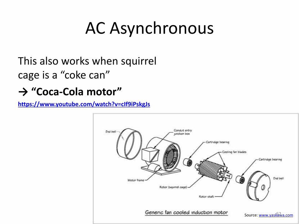
AC Asynchronous
This also works when squirrel cage is a “coke can”
→ “Coca-Cola motor”https://www.youtube.com/watch?v=cIf9iPskgJs
Source: www.yaskawa.com62
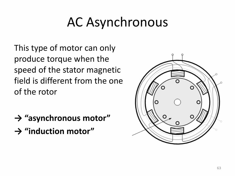
AC Asynchronous
This type of motor can only produce torque when the speed of the stator magnetic field is different from the one of the rotor
→ “asynchronous motor”
→ “induction motor”
63
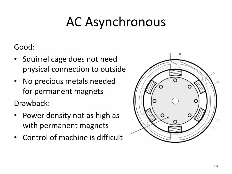
AC Asynchronous
Good:
• Squirrel cage does not need physical connection to outside
• No precious metals needed for permanent magnets
Drawback:
• Power density not as high as with permanent magnets
• Control of machine is difficult
64
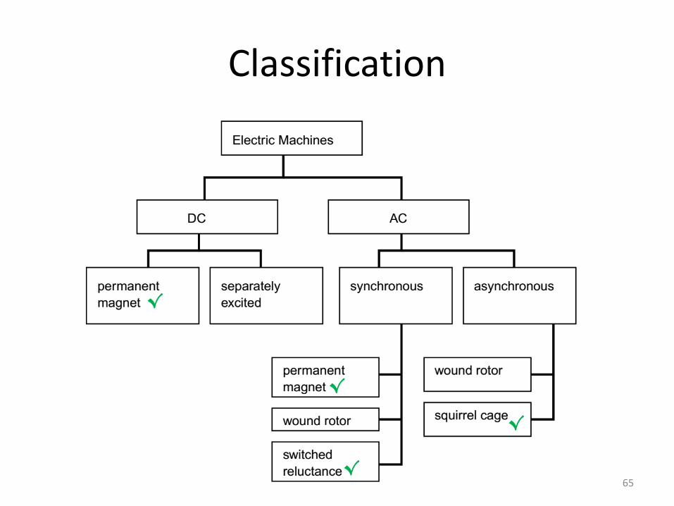
Classification
√
√
√
√
65