Embed Size (px)
DESCRIPTION
Vertex Detector Cable Considerations. Bill Cooper Fermilab. VXD. Power Distribution. This is a difficult problem with no ideal solution yet. One possibility is to provide power distributors a short distance from “ladders” so that ladders can be powered in series. - PowerPoint PPT Presentation
Citation preview
Vertex Detector Cable Considerations
Bill Cooper
Fermilab
VXD
Bill Cooper LCWS 2008 2
Power Distribution
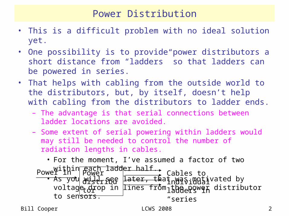
• This is a difficult problem with no ideal solution yet.• One possibility is to provide power distributors a short distance from
“ladders” so that ladders can be powered in series.• That helps with cabling from the outside world to the distributors,
but, by itself, doesn’t help with cabling from the distributors to ladder ends.– The advantage is that serial connections between ladder locations are
avoided.
– Some extent of serial powering within ladders would may still be needed to control the number of radiation lengths in cables.
• For the moment, I’ve assumed a factor of two within each ladder half.
• As you will see later, that was motivated by voltage drop in lines from the power distributor to sensors.
Power distributor
Power in Cables to individual ladders in “series”
Bill Cooper LCWS 2008 3
Power Distribution
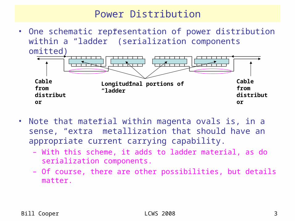
• One schematic representation of power distribution within a “ladder” (serialization components omitted)
• Note that material within magenta ovals is, in a sense, “extra” metallization that should have an appropriate current carrying capability.– With this scheme, it adds to ladder material, as do serialization
components.
– Of course, there are other possibilities, but details matter.
Longitudinal portions of “ladder”Cable from distributor
Cable from distributor
Bill Cooper LCWS 2008 4
Power with ILC Beam Structure
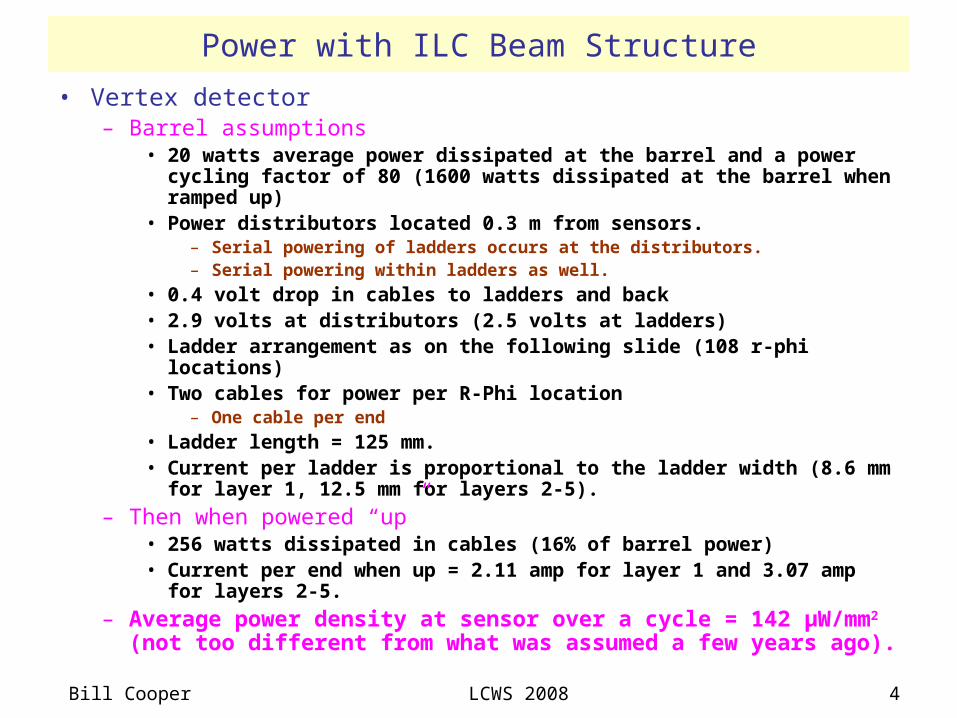
• Vertex detector– Barrel assumptions
• 20 watts average power dissipated at the barrel and a power cycling factor of 80 (1600 watts dissipated at the barrel when ramped up)
• Power distributors located 0.3 m from sensors.– Serial powering of ladders occurs at the distributors.– Serial powering within ladders as well.
• 0.4 volt drop in cables to ladders and back • 2.9 volts at distributors (2.5 volts at ladders)• Ladder arrangement as on the following slide (108 r-phi locations)• Two cables for power per R-Phi location
– One cable per end
• Ladder length = 125 mm.• Current per ladder is proportional to the ladder width (8.6 mm for layer
1, 12.5 mm for layers 2-5).
– Then when powered “up”• 256 watts dissipated in cables (16% of barrel power)• Current per end when up = 2.11 amp for layer 1 and 3.07 amp for layers
2-5.
– Average power density at sensor over a cycle = 142 µW/mm2 (not too different from what was assumed a few years ago).
Bill Cooper LCWS 2008 5
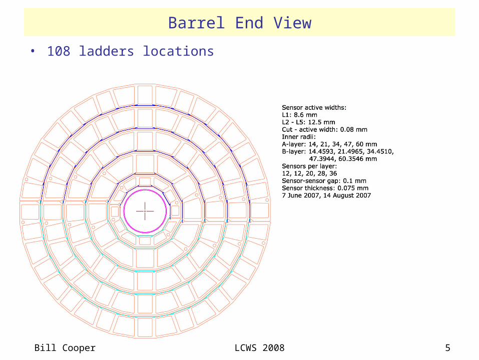
Barrel End View
• 108 ladders locations
Bill Cooper LCWS 2008 6
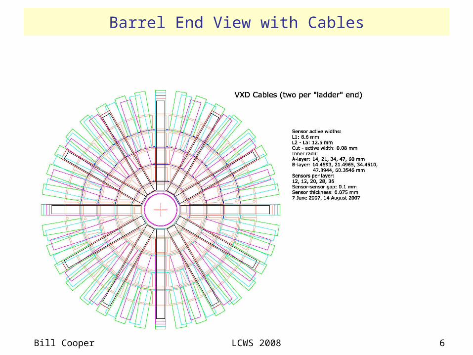
Barrel End View with Cables
Bill Cooper LCWS 2008 7
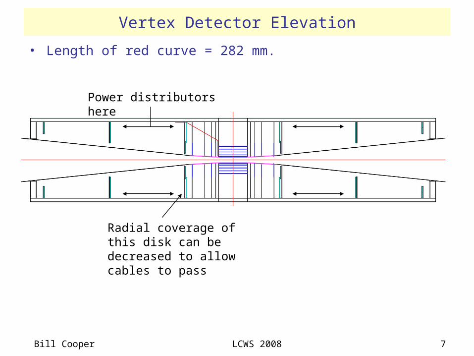
• Length of red curve = 282 mm.
Vertex Detector Elevation
Power distributors here
Radial coverage of this disk can be decreased to allow cables to pass
Bill Cooper LCWS 2008 8
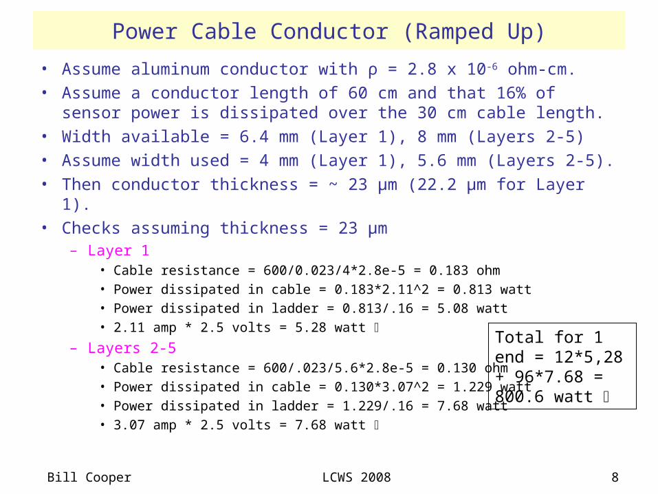
Power Cable Conductor (Ramped Up)
• Assume aluminum conductor with ρ = 2.8 x 10⁻⁶ ohm-cm.• Assume a conductor length of 60 cm and that 16% of sensor power
is dissipated over the 30 cm cable length.• Width available = 6.4 mm (Layer 1), 8 mm (Layers 2-5)• Assume width used = 4 mm (Layer 1), 5.6 mm (Layers 2-5).• Then conductor thickness = ~ 23 µm (22.2 µm for Layer 1).• Checks assuming thickness = 23 µm
– Layer 1• Cable resistance = 600/0.023/4*2.8e-5 = 0.183 ohm• Power dissipated in cable = 0.183*2.11^2 = 0.813 watt• Power dissipated in ladder = 0.813/.16 = 5.08 watt• 2.11 amp * 2.5 volts = 5.28 watt
– Layers 2-5• Cable resistance = 600/.023/5.6*2.8e-5 = 0.130 ohm• Power dissipated in cable = 0.130*3.07^2 = 1.229 watt• Power dissipated in ladder = 1.229/.16 = 7.68 watt• 3.07 amp * 2.5 volts = 7.68 watt
Total for 1 end = 12*5,28 + 96*7.68 = 800.6 watt
Bill Cooper LCWS 2008 9
Cable Layers
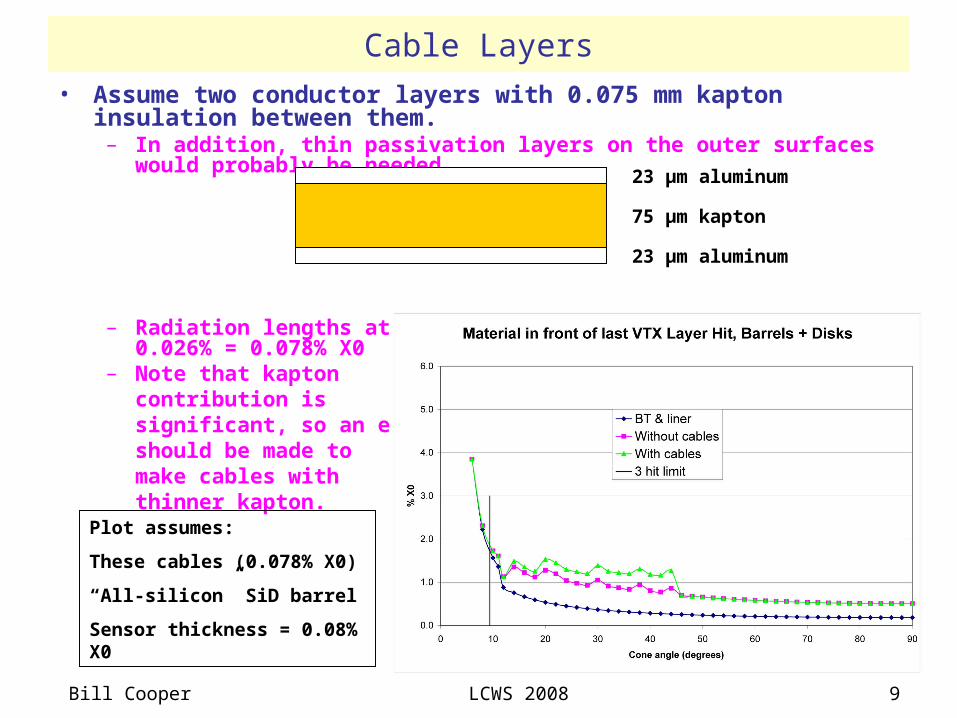
• Assume two conductor layers with 0.075 mm kapton insulation between them.
– In addition, thin passivation layers on the outer surfaces would probably be needed.
– Radiation lengths at normal incidence = 0.026% + 0.026% + 0.026% = 0.078% X0
– Note that kapton contribution is significant, so an effort should be made to make cables with thinner kapton.
23 µm aluminum
23 µm aluminum
75 µm kapton
Plot assumes:
These cables (0.078% X0)
“All-silicon” SiD barrel
Sensor thickness = 0.08% X0
Bill Cooper LCWS 2008 10
Magnetic Field Effects (1)
• Assume 5 T field and a radial cable run of length 5 cm.• Assume a common ground for all “ladders” at the barrel.• Assume supply power is removed from one ladder and all other
ladders are powered.– Then return current of each cable from that ladder is an appropriate
fraction of the total return current: ~ 640 amp / 2 * 107/108^2 = 2.9 amp.
– Since supply and return currents do not balance in that cable, a lateral force is exerted on the cable.
– F = 2.9 amp * 0.05 m * 5 T = 0.72 N (equivalent to 72 grams)
– Half that is too much force to apply to a ladder end.
– Depending on the way in which distributors work, this effect might be reduced by a factor of n if n ladders were in series.
• Solution:– Provide power isolation at supplies.
– Please note that end-to-end power isolation would probably be needed in any case to avoid a significant ground loop.
Bill Cooper LCWS 2008 11
Magnetic Field Effects (2)
• Consider a standard flex-cable with two conductor layers.– Assume 0.075 mm kapton between layers.
– Torque on the radial run (layers 2-5) = 3.07 amp * 5 T * 75 e-6 m * 0.05 m = 5.8 e-5 N-m = 0.058 N-mm (equivalent to 5.8 gram-mm).
– For a cable width of 8 mm, that might be acceptable if power were steady-state.
– With power cycling, I think vibration would be a real issue.
• Solution:– Provide three conductor layers in the cable, for example, return – supply
– return.• Then torques cancel. • In principle, the total amount of conductor can remain the same.• Due to the added kapton layer, the number of radiation lengths at
normal incidence represented by a cable increases from 0.078% to 0.104%.
– Perhaps the kapton could be thinner.
• Cable bending stiffness increases by a factor ~ 1.9.

Bill Cooper LCWS 2008 12
Conclusions
• There has been some progress.• Considerable development and prototyping remain.• There is ample room for new and better ideas.