Embed Size (px)
Citation preview
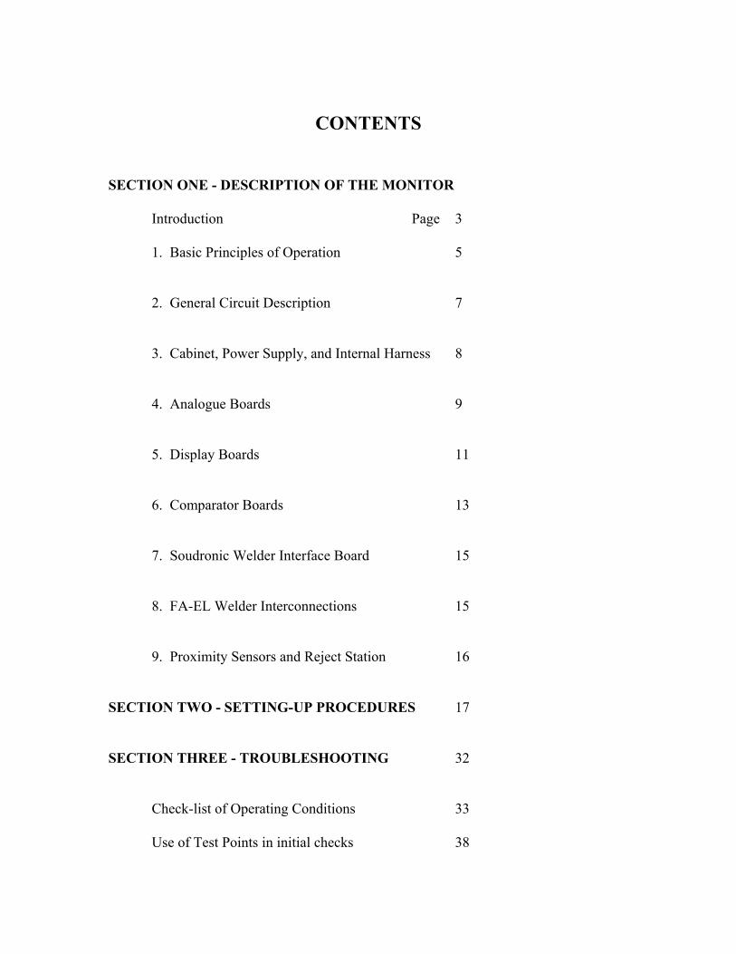
VERTEX WELD MONITOR SERVICE MANUAL
For the WM series of Weld Monitors manufactured by the Automation & Controls Division of Metal Box Engineering plc
(later CarnaudMetalbox Engineering) IMPORTANT - Read 'Safety Precautions' in Introduction
Presented at Vertex Training Seminars
© Vertex International Inc. 1998 (download for your own use only)
CONTENTS
SECTION ONE - DESCRIPTION OF THE MONITOR
Introduction Page 3 1. Basic Principles of Operation 5 2. General Circuit Description 7 3. Cabinet, Power Supply, and Internal Harness 8 4. Analogue Boards 9 5. Display Boards 11 6. Comparator Boards 13 7. Soudronic Welder Interface Board 15 8. FA-EL Welder Interconnections 15 9. Proximity Sensors and Reject Station 16 SECTION TWO - SETTING-UP PROCEDURES 17 SECTION THREE - TROUBLESHOOTING 32 Check-list of Operating Conditions 33 Use of Test Points in initial checks 38

SECTION ONE - DESCRIPTION OF THE MONITOR Introduction This manual is intended to be a 'stand-alone' guide to the use, maintenance and repair of the WM-series Weld Monitors manufactured by Metal Box (later CarnaudMetalbox, or CMB). It will be helpful, but not necessary, to have a copy of the Metal Box Manual EL 15 or EL 30 available for reference as you use this book. The WM-series Weld Monitors are complex pieces of electronic instrumentation, designed to take full advantage of modern microprocessor and integrated circuit capabilities. Nevertheless they are a straightforward design. Many common causes of breakdown can be located and corrected on site without specialist knowledge. Defective elements in the system can be isolated and replaced without the need to probe into the detailed circuitry. This manual will guide you in doing this, and also describes the internal circuitry of each circuit board for the benefit of those with the necessary knowledge and experience. It should be emphasized that component failure is rare - most breakdowns are the result of damage or disruption to the external circuitry. For this reason please pay particular attention to the Check-list (Section III), to establish that the fault is not external.
SAFETY PRECAUTIONS Before investigating any abnormality in the operation of a Weld Monitor, take steps to ensure that all personnel involved are familiar with the safety precautions to be observed in servicing electrical equipment. When access is obtained to monitor internal and external wiring, a variety of alternating and direct current voltages are exposed. Unintended contact with these voltages can cause personal injury, plus damage to the Monitor and/or test equipment. If you are uncertain about what voltage may be present in a particular place, check with a suitable instruments (such as a digital multimeter or high impedance oscilloscope) before touching or disconnecting wires. If you are not experienced in the servicing of electrical equipment, do not attempt to 'explore' Monitor circuitry. If in any doubt, return the board or Monitor complete to Vertex International, or call for us to make a troubleshooting visit. TEST EQUIPMENT Very little can be accomplished with only a test meter (such as 'Simpson' or 'Fluke' type). For any serious servicing, a dual-trace high-impedance oscilloscope ('scope') is essential. If access to circuitry within the electronic rack is desired, obtain an extender board (part number 681294-B) from Vertex. Test leads (Part No. 356-16-001) will allow easy connection of the scope to test points TP21, 22 and 23.
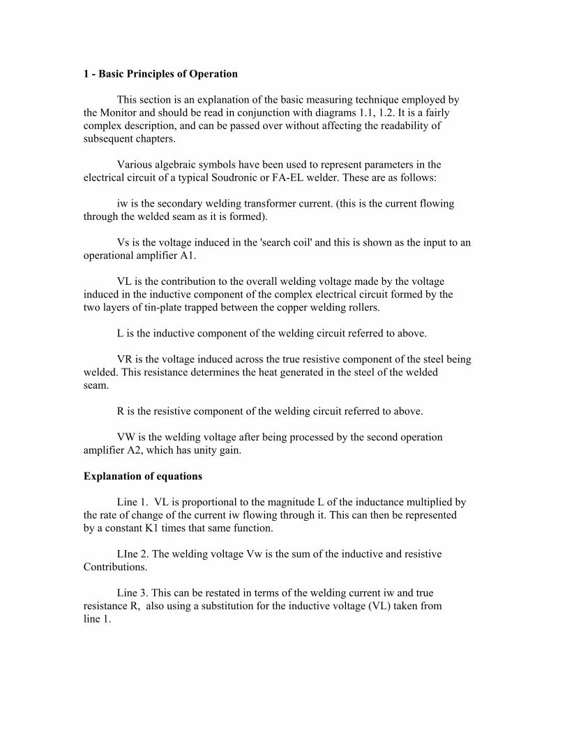
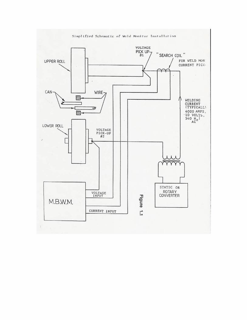
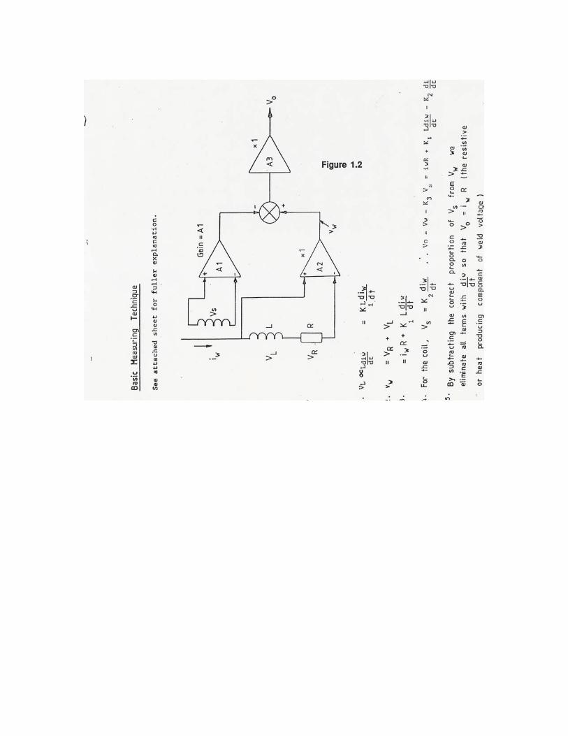
1 - Basic Principles of Operation This section is an explanation of the basic measuring technique employed by the Monitor and should be read in conjunction with diagrams 1.1, 1.2. It is a fairly complex description, and can be passed over without affecting the readability of subsequent chapters. Various algebraic symbols have been used to represent parameters in the electrical circuit of a typical Soudronic or FA-EL welder. These are as follows: iw is the secondary welding transformer current. (this is the current flowing through the welded seam as it is formed). Vs is the voltage induced in the 'search coil' and this is shown as the input to an operational amplifier A1. VL is the contribution to the overall welding voltage made by the voltage induced in the inductive component of the complex electrical circuit formed by the two layers of tin-plate trapped between the copper welding rollers. L is the inductive component of the welding circuit referred to above. VR is the voltage induced across the true resistive component of the steel being welded. This resistance determines the heat generated in the steel of the welded seam. R is the resistive component of the welding circuit referred to above. VW is the welding voltage after being processed by the second operation amplifier A2, which has unity gain. Explanation of equations Line 1. VL is proportional to the magnitude L of the inductance multiplied by the rate of change of the current iw flowing through it. This can then be represented by a constant K1 times that same function. LIne 2. The welding voltage Vw is the sum of the inductive and resistive Contributions. Line 3. This can be restated in terms of the welding current iw and true resistance R, also using a substitution for the inductive voltage (VL) taken from line 1.
Line 4. The search coil, which is also an inductive device, produces an output which can be expressed as a constant K2 times the rate of change of current. The output voltage of the whole circuit in this diagram is VO which is the result of subtracting 'something' from Vw. This 'something' is Vs multiplied by the adjustable gain of the amplifier A1, so it can be represented by another constant K3 times Vs. We have derived an expression for Vw on line 3, and for Vs here on line 4, so now we have a long expression containing two terms with diw/dt multiplied by constants. Line 5. Since we have control of one of the constants by adjusting the gain of A1, we can make these two terms cancel out, leaving only VO=iwR. This is what we want P an output voltage which is related to the true weld resistance and weld current, unaffected by the inductance of the circuit. In early analogue boards, the output is integrated during a single half-cycle of the weld current to arrive at an I2R result, which is an expression of the energy applied to the weld. Later boards average this energy over the time interval of each half-cycle to correct for variations in timing and arrive at a power value. In summary, the function of the front-end circuitry of the weld monitor is to provide an output voltage which accurately reflects the true welding energy, which is contributing directly to heat. Obviously, only the heat produced in the steel itself can contribute towards the melting and subsequent welding of the seam. It is by monitoring changes in the heat-producing energy that we can predict success or failure of the welded seam mechanically.
2 - General Circuit Description The basic weld monitor combines three separate functions. The main function of the machine is to measure and display the amount of electrical energy which is being applied to the welded can side seam. Having made information about this energy available to the operator in the form of a digital display, a second section of circuitry allows the operator to choose what range of energy values can be allowed in normal production. Cans which have sections of their welded seam outside this chosen range will be removed from the conveyor by the reject station. The third function of the machine is to detect contamination trapped in the overlap. When such contamination is detected, it is necessary to reduce the welding current immediately in order to protect the copper wire from breakage. A separate section of circuitry performs this function. Once the corrected resistive component of the weld voltage (VO) has been derived (as described in Section 1 above), this is applied to a voltage-to-frequency converter which produces a train of pulses at a frequency proportional to VO. These pulses are counted and used to derive the quality coefficient. It is this number which is averaged and displayed as the three-digit quality coefficient on the display board front panel. Since the apparently continuous welding process is in fact a series of individual 'nuggets', the quality coefficient number is totaled for each individual nugget and it is this total which is compared with the acceptable range of quality coefficient in the second section of the circuitry. Once the quality coefficient has been determined, it is compared against the range of values set up on the switches on the front of the comparator board. A set-point has been chosen to correspond with the running conditions on the welder. A margin above this set-point and a margin below this set-point are also determined by experiment to establish the safe operating range of the welder under the prevailing conditions. The comparator board essentially consists of a numerical comparison circuit which can generate 'hot' or 'cold' failure signals according to whether the quality coefficient strays above or below the predetermined range. The contamination failure circuitry operates in a slightly different fashion from the basic integrating circuitry. The contamination failure level is adjustable by a front panel control on the Analogue board. The number wheels associated with this control represent a threshold voltage in the range 0 to 9.99 volts. This threshold determines when the contamination circuitry will decide that the voltage across the weld rollers has become excessive. Excessive voltage excursions usually are associated with the presence of contamination in the overlap between the tin plate surfaces. The threshold voltage should, of course, be set to give a suitable margin of
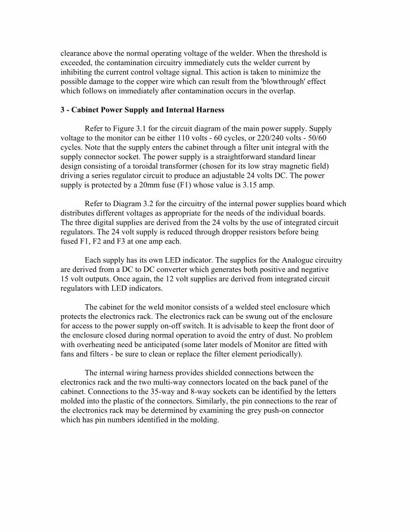
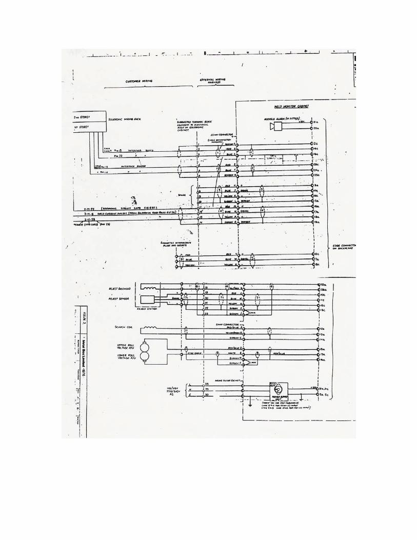
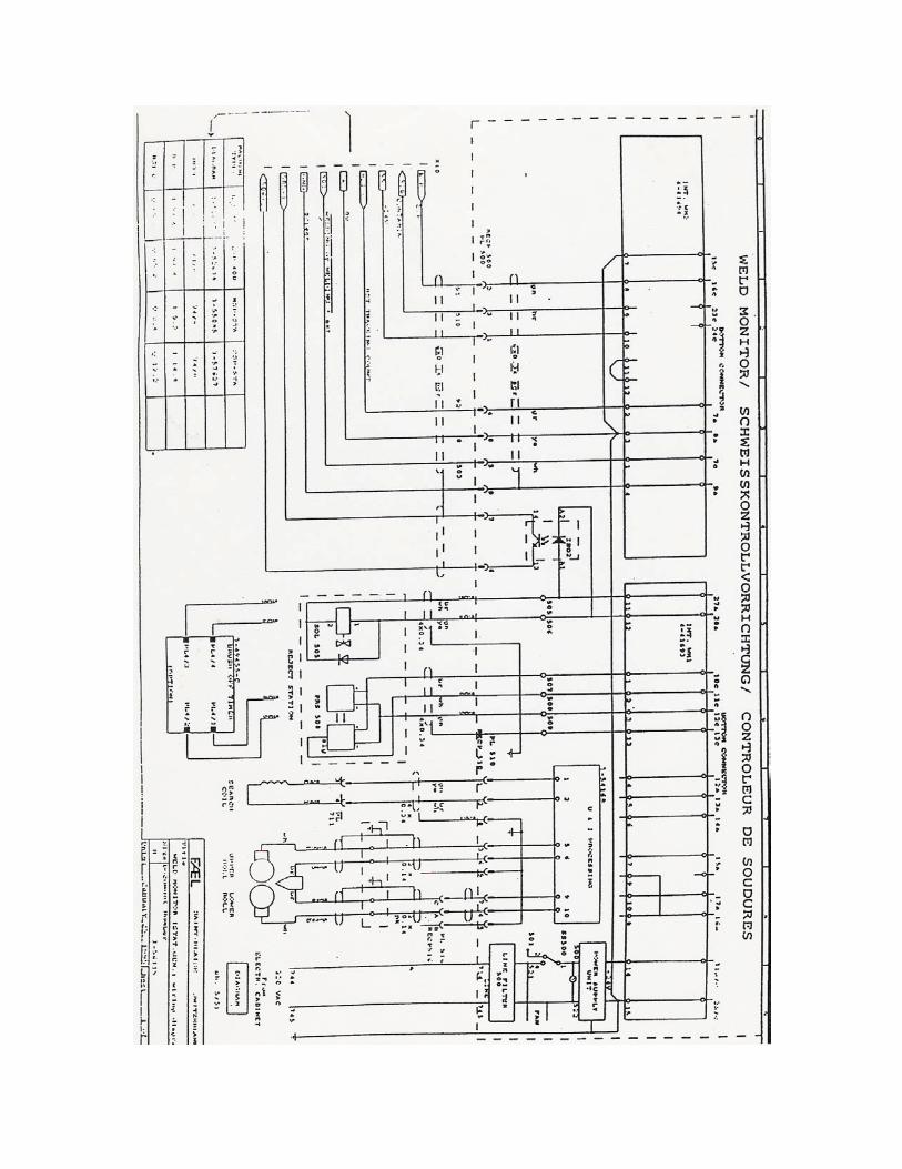
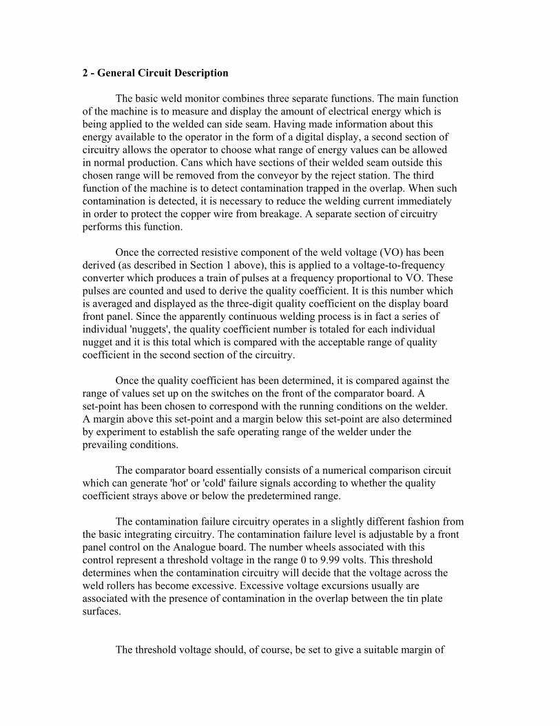
clearance above the normal operating voltage of the welder. When the threshold is exceeded, the contamination circuitry immediately cuts the welder current by inhibiting the current control voltage signal. This action is taken to minimize the possible damage to the copper wire which can result from the 'blowthrough' effect which follows on immediately after contamination occurs in the overlap. 3 - Cabinet Power Supply and Internal Harness Refer to Figure 3.1 for the circuit diagram of the main power supply. Supply voltage to the monitor can be either 110 volts - 60 cycles, or 220/240 volts - 50/60 cycles. Note that the supply enters the cabinet through a filter unit integral with the supply connector socket. The power supply is a straightforward standard linear design consisting of a toroidal transformer (chosen for its low stray magnetic field) driving a series regulator circuit to produce an adjustable 24 volts DC. The power supply is protected by a 20mm fuse (F1) whose value is 3.15 amp. Refer to Diagram 3.2 for the circuitry of the internal power supplies board which distributes different voltages as appropriate for the needs of the individual boards. The three digital supplies are derived from the 24 volts by the use of integrated circuit regulators. The 24 volt supply is reduced through dropper resistors before being fused F1, F2 and F3 at one amp each. Each supply has its own LED indicator. The supplies for the Analogue circuitry are derived from a DC to DC converter which generates both positive and negative 15 volt outputs. Once again, the 12 volt supplies are derived from integrated circuit regulators with LED indicators. The cabinet for the weld monitor consists of a welded steel enclosure which protects the electronics rack. The electronics rack can be swung out of the enclosure for access to the power supply on-off switch. It is advisable to keep the front door of the enclosure closed during normal operation to avoid the entry of dust. No problem with overheating need be anticipated (some later models of Monitor are fitted with fans and filters - be sure to clean or replace the filter element periodically). The internal wiring harness provides shielded connections between the electronics rack and the two multi-way connectors located on the back panel of the cabinet. Connections to the 35-way and 8-way sockets can be identified by the letters molded into the plastic of the connectors. Similarly, the pin connections to the rear of the electronics rack may be determined by examining the grey push-on connector which has pin numbers identified in the molding.
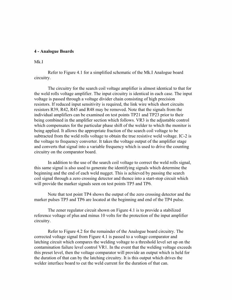
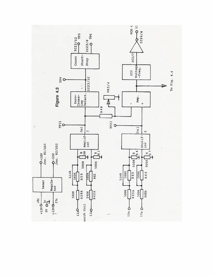
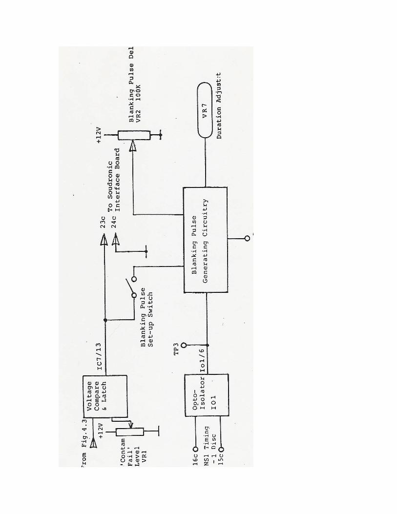
4 - Analogue Boards Mk.I Refer to Figure 4.1 for a simplified schematic of the Mk.I Analogue board circuitry. The circuitry for the search coil voltage amplifier is almost identical to that for the weld rolls voltage amplifier. The input circuitry is identical in each case. The input voltage is passed through a voltage divider chain consisting of high precision resistors. If reduced input sensitivity is required, the link wire which short circuits resistors R39, R42, R45 and R48 may be removed. Note that the signals from the individual amplifiers can be examined on test points TP21 and TP23 prior to their being combined in the amplifier section which follows. VR3 is the adjustable control which compensates for the particular phase shift of the welder to which the monitor is being applied. It allows the appropriate fraction of the search coil voltage to be subtracted from the weld rolls voltage to obtain the true resistive weld voltage. IC-2 is the voltage to frequency converter. It takes the voltage output of the amplifier stage and converts that signal into a variable frequency which is used to drive the counting circuitry on the comparator board. In addition to the use of the search coil voltage to correct the weld rolls signal, this same signal is also used to generate the identifying signals which determine the beginning and the end of each weld nugget. This is achieved by passing the search coil signal through a zero crossing detector and thence into a start-stop circuit which will provide the marker signals seen on test points TP5 and TP6. Note that test point TP4 shows the output of the zero crossing detector and the marker pulses TP5 and TP6 are located at the beginning and end of the TP4 pulse. The zener regulator circuit shown on Figure 4.1 is to provide a stabilized reference voltage of plus and minus 10 volts for the protection of the input amplifier circuitry. Refer to Figure 4.2 for the remainder of the Analogue board circuitry. The corrected voltage signal from Figure 4.1 is passed to a voltage comparator and latching circuit which compares the welding voltage to a threshold level set up on the contamination failure level control VR1. In the event that the welding voltage exceeds this preset level, then the voltage comparator will provide an output which is held for the duration of that can by the latching circuitry. It is this output which drives the welder interface board to cut the weld current for the duration of that can.
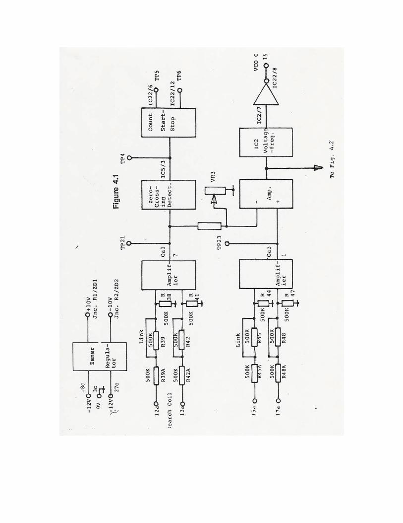
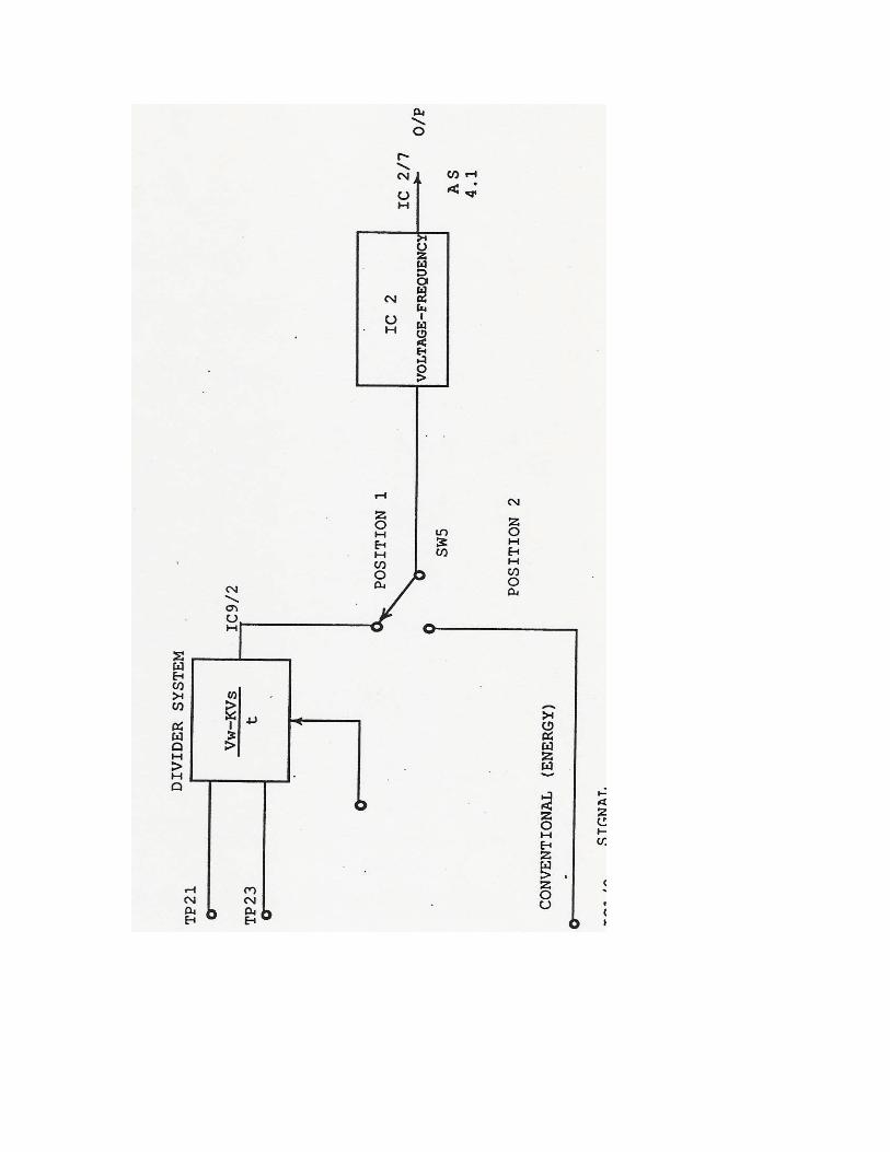
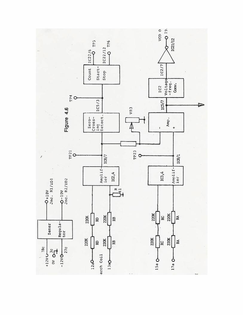
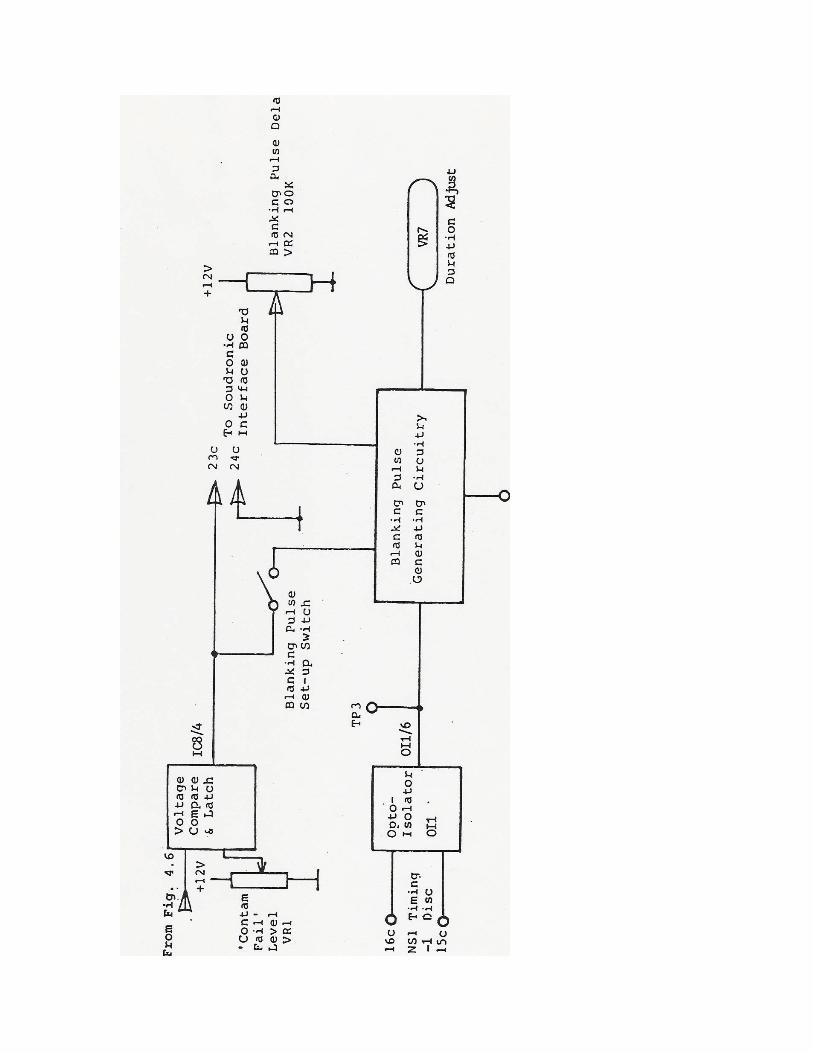
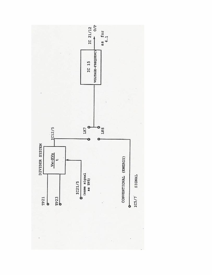
The essential synchronization between the welder and the monitor is provided by a reference signal derived from the Soudronic B89 (NS1-1 on earlier welders) timing disk, or feed chain sensor on a FA-EL welder. This signal is used to generate a signal pulse once per can. The signal arrives on the Analogue board where it is isolated by an opto-isolator IO-2 before the pulse is fed to the blanking pulse generating circuitry. The function of the blanking pulse circuitry is to provide a pulse of a predetermined length which occurs at an adjustable point on the can such that the area of uncertainty between bodies can be ignored by the monitor. In order to achieve this, the duration of the blanking pulse is selected by SW1 which is adjusted to suit the particular model of welder. The position of the blanking pulse is adjusted by means of front panel VR2 which is the blanking pulse delay control. The position of the blanking pulse can be made visible by holding down the blanking pulse 'set-up' switch which couples the blanking pulse circuit to the welding current cut-off circuit on the welder interface board. Mk.II The Mk.II Analogue Board is fundamentally the same as the Mk.I, with detail design improvements and an additional circuit offering improved performance on constant-current welders. For welders fitted with the later 'by-pass' design of Soudronic control system, (characterised by having thyristor firing 'windows' which do not reach to the zero-voltage level), the Mk.II is essential, since the zero-crossing detector fitted to the Mk.I will not work reliably on these machines. For differences in component numbering, refer to Figure 4.3, 4.4. Figure 4.5 illustrates the additional divider circuit referred to above, which performs a division on the 'heat' signal by a factor proportional to the duration of each nugget. This greatly reduces errors caused by fluctuations in the period of the frequency converter output. The net result is a 'power' signal, which is passed to the remainder of the circuit in the same way as for the Mk.I board. The choice of 'Mk.I' or 'Mk.II' operation is made by SW5a. Mk.III The Mk.III board is a further improvement on the Mk.II, with new-technology amplifiers in the early stages of amplification, greatly reducing the noise factor of this stage of the circuit. The rest of the circuit has been re-designed to take advantage of newer integrated circuits, allowing a reduced parts count for better reliability. Refer to Figures 4.6,4.7,4.8 for numbering revisions. Both the Mk.II and the Mk.III require a two-stage adjustment procedure, and each is different (see later in this manual for details).
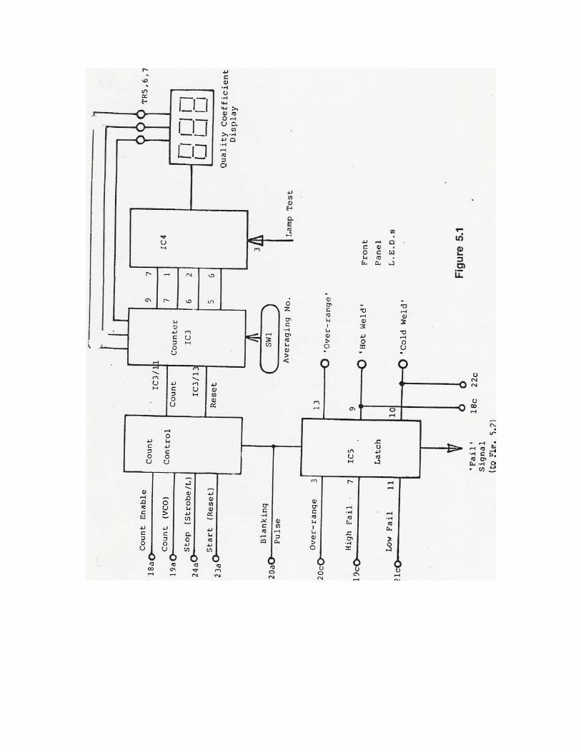
Mk.IV The latest Mk.IV Analogue Board is essential for any welder which has a high frequency inverter power supply (such as the Unisoud offered by Soudronic). It can be fitted to any existing welder to replace earlier analogue boards, but for high frequency applications it requires the matching semiconductor current pickup to replace the standard search coil. The Mk.IV board is the easiest of the series to adjust - see details later. 5 - Display Boards Mk.I The main function of the display board is to accept the train of pulses generated by the Analogue board and convert these into a visible numerical display. In addition, the display board tracks the progress of cans along the conveyor towards the reject station and displays the appropriate tracking count as a two-digit display. When a can is judged to be unacceptably hot or cold welded, the display board indicates this with an appropriate front panel lamp. Refer to Figure 5.1. The function of the count control circuitry is to organize the counting procedure into individual periods, one per nugget. To do this, it makes use of the 'stop' and 'start' signals generated by the zero-crossing detector on the Analogue board. The count enable signal is the same signal which may be seen on test point TP4. It can be seen that the count signal from the voltage controlled oscillator (VCO) is only allowed to pass to the counter circuitry (IC-3) when the appropriate counting period is active. The count is prevented from passing in between nuggets and during the blanking pulse which occurs between can bodies. The counter (IC3) accumulates the pulses from the VCO and averages them according to the setting of SW1. The output of the counter is passed to IC4 which is a lamp driver circuit controlling the 3-digit quality coefficient display. Note that the three individual digits of the display are multiplexed by IC3 via transistors TR5,6, 7. IC5 is the latching circuitry which determines when a failure has occurred. The output of the comparator board is brought into this circuit, which determines whether the failure occured during a portion of the can which is being examined. Failures which occur during the blanking pulse period are ignored. The output of the latch is used to generate a 'fail' signal which is passed to the can tracking circuitry. In addition, the type of failure is indicated on the front panel by illuminating the appropriate light emitting diode indicator.
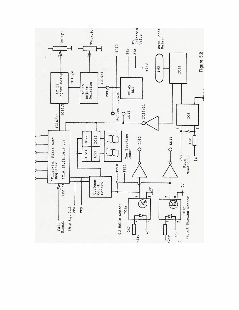
Refer to Figure 5.2. The can tracking circuitry makes use of an ingenious circuit element known as a 'first in, first out' (FIFO) register consisting of integrated circuits IC16 through 21. The function of this type of register is to accept data pulses into memory in response to clock pulses, which can then be recovered from memory in the same order in which they were entered in response to a second (totally separate) clock pulse. This allows the monitor to track a failed can down a length of conveyor until it reaches the reject station. This is achieved by entering failure signals into the FIFO under the control of the weld rolls proximity sensor and to remove the same signal from the FIFO under the control of the reject station sensor. Under normal operating conditions, no signal is passed out of the register. When a failure occurs, however, this failure signal is entered into the register by the weld rolls count signal and emerges some time later determined by the difference between the counts at the weld rolls and at the reject station. When the failure signal emerges from the memory, it is passed through a reject delay circuit and then to a reject duration circuit. The function of these two circuits is to synchronize the firing of the pneumatic ram at the reject station so that a clean and reliable rejection action takes place. The delay is adjusted to suit the speed of the conveyor. Since the signal to fire the pneumatic ram is synchronized with the reject station sensor, it is only necessary to make a small adjustment to accurately position the point of firing. Normally, the reject duration should remain at its preset value (30 milliseconds). Note that the signal to the pneumatic solenoid value is buffered by transistor TR9 and reed relay RL1. The can tracking counters are controlled by signals from magnetic proximity detectors located at the weld rolls and at the reject station. The signals from these sensors are buffered by optical isolators which eliminate the risk of introducing electrical noise into the internal circuitry of the monitor. The function of the weld rolls sensor is to count up. The reject station sensor counts the same counter downward. The resulting number is displayed on the two-digit can tracking count display. In order to reduce the damaging effects of miscounts on the can tracking system, an automatic reset is provided within the monitor. Every time that the welder feed is turned off (such as may occur when the line backs up), the timer circuit IC31 senses the cut off of welding current and after a predetermined delay (set by SW3), resets the can tracking counter to zero. In normal operation, this counter would be at zero when no more cans remained between the weld rolls and the reject station, but in the event of a miscount, this is not the case.
Mk.II
The Mk.II Display Board is essentially the same as the Mk.I, with the following enhancements:
• The range of the can tracking counter has been extended to allow greater distances between the weld rolls and the reject station - now up to 160 can intervals. This fact is reflected in the three-digit counter on the front panel, replacing the previous two-digit version.
• To ensure reliable counting of can streams with very closely-spaced cans using the later photo-electric sensors, a pulse-stretcher circuit has been added. This requires adjustment for best operation - see the adjustment section of this manual.
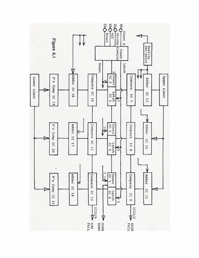
6 - Comparator Boards Mk.I The function of the comparator board is straightforward. It checks the quality coefficient of each and every nugget against the acceptable range set up on the front panel switches. In the event that any nugget strays outside the acceptable range, then the appropriate failure signal is generated. The comparator board counts the train of pulses from the VCO on the Analogue board in the same way as the counter previously described on the display board. The count control circuitry organizes stop, start and reset in the same way. The count arrived at on the counter circuits is latched by circuits IC4, IC5 and IC6 for presentation to the comparator circuitry. The comparator circuitry operates by comparing the count with the upper and lower limits of the acceptable range. To arrive at the upper limit of the range, the number chosen on the upper limit switches is added to the number set up on the quality set point switches. This number is then presented to integrated circuits IC7, 8 and 9 for comparison with the count. In the same way, the lower limit number is subtracted from the quality set point. Since this machine operates with digital electronics, this subtraction has to be performed by first obtaining the complement of the number set up on the lower limit switches and then adding this number to the quality set point. This concept will be familiar to those people who have studied binary arithmetic. In the event that the count for any given nugget falls outside the preselected range, an appropriate high or low failure signal will be generated and passed to the display board. In the event that the count for a particular nugget exceeds the range of the counter, this will be indicated by an overrange signal. Mk.II The Mk.II Comparator Board represents a complete change of approach for this board. Instead of being dedicated to one task only, the new board is based on a microprocessor, and can be re-assigned new functions by replacing its program chip. The Mk.II, however, was issued with a program which merely duplicates the operation of the Mk.I, pending development of new programs. Mk.III The Mk.III designation was used to describe a Mk.II Comparator with revised software fitted. The most common version used an averaging algorithm to detect slow changes in quality coefficient by comparing the average of the previous four nuggets against a tightened pair of limits (3/8 of the value set on the panel switches).
Mk.IV The Mk.IV Comparator extends the principle of programmability by adding controls to monitor the 'profile' and 'taper' of the heat signal along the can. The board has been designed to be sensitive to the small changes in weld quality that occur with overlap faults, without rejecting a high proportion of cans with acceptable welds. The Mk.IV board is retrofittable to any existing WM-series weld monitor, taking the position currently occupied by the standard Mk.I, Mk.II or Mk.III comparators. The Mk.IV uses the same measurement input as earlier comparators; the quality coefficient (QC) is obtained for each weld nugget along the can seam. However this value is compared to operator set limits using more advanced algorithms. As before, the QC is compared with a set point and upper and lower limits. However, there are two further algorithms, called 'taper' and 'profile' which are designed to detect QC drift. They both use an average QC value, which shows trends clearly but smooths out short-term disturbances. They do not use the operator set point, but determine changes by automatically comparing successive averages. 'Taper' uses a 'moving average algorithm', which is sensitive to trends in QC value. The 'taper' limit defines the maximum allowable gradient of the QC change. Restarting the calculation on the leading edge of each seam, the program obtains the average of the first 16 nuggets, and then the next 16. The two averages are subtracted, and the difference compared to the 'taper' limit percentage which is set by the operator. The program continues by calculating a new 16 nugget average using the next weld cycle. A comparison is then performed every nugget until the end of the can. 'Profile' splits the can into nugget sections and saves the average QC of each section. If the can is not failed by any of the other tests, then this is saved as a 'good' profile. The next can is split into the same sections, and the average is compared with the 'good' average. The maximum deviation allowed is the operator set 'profile' limit percentage. It is possible for the 'profile' algorithm to detect very small changes in overlap.
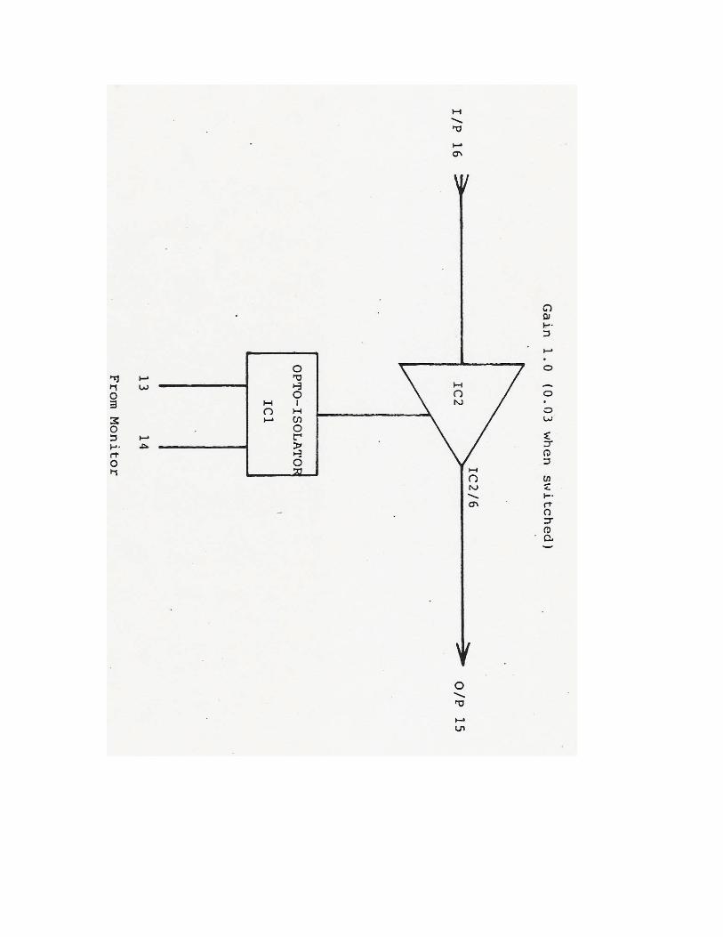
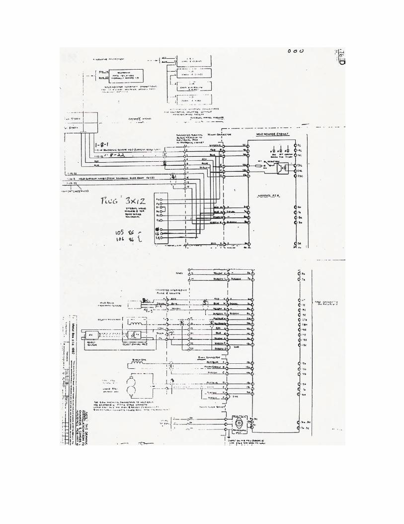
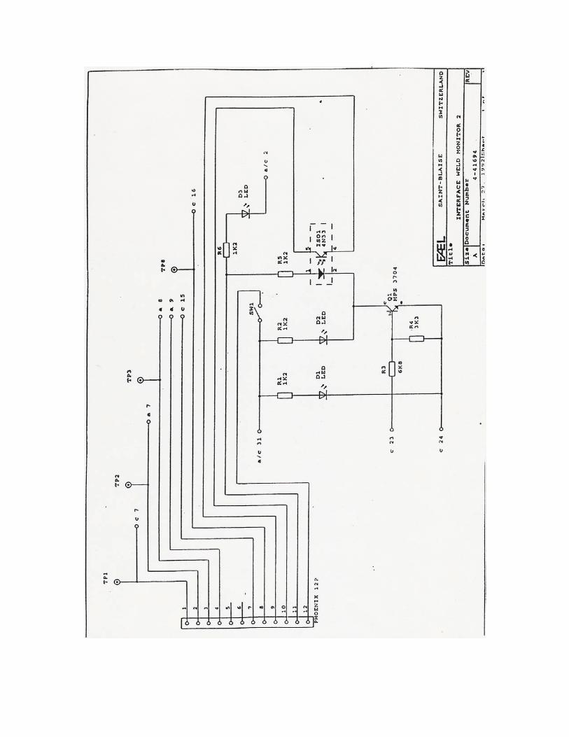
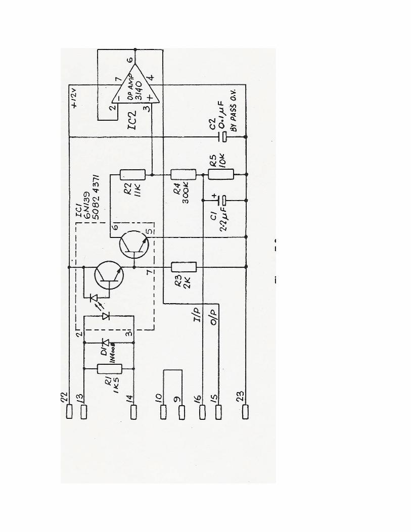
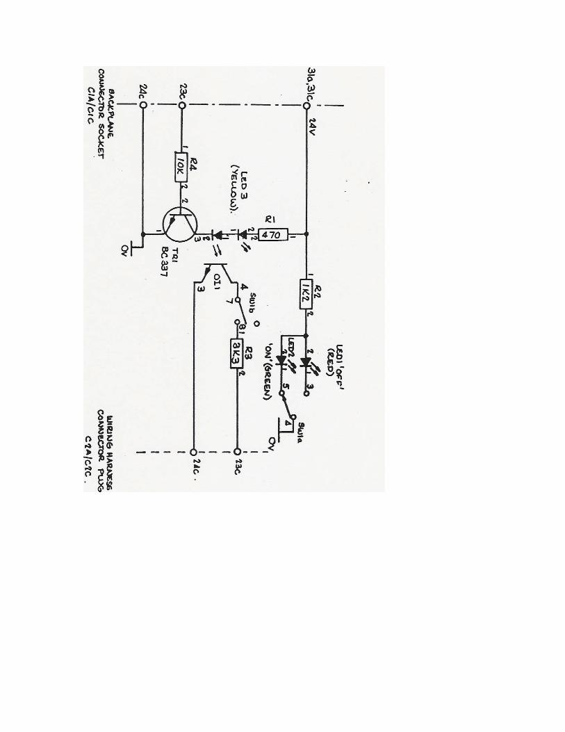
7 - Soudronic Welder Interface Boards Welder-Mounted Version The interface board is located within the Soudronic electronics rack. When the monitor was commissioned, connections were made between the interface board and the current control circuitry of the Soudronic welder. The connection between the monitor and the interface board is optically isolated to prevent the possibility of interference between the two pieces of equipment. Operation of the interface board is simple. When a digital signal is received from the monitor, the optical isolator switches the gain of the amplifier IC-2 from its normal value of 1.0 to approximately .03. Under normal operating conditions, the current control voltage of the Soudronic welder passes through this amplifier unchanged since the gain is unity. However, when it is desired to cut the welding current, the monitor can reduce this control voltage to 3% of its previous value by activating the optical isolator. Figure 7.1 shows this circuit in block diagram form. Figure 7.2 gives the full schematic of the circuit board. Integral Version The integral version of the Interface board is intended for use on 4000/5000 series welders fitted with the new control systems, see Figure 7.3. It connects to the Soudronic-provided current control input on the welder, avoiding the need for any boards to be resident inside the welder control cabinet. It can be retrofitted to earlier welders which have been fitted with constant-current controls. The method of control is digital, eliminating the possibility of interference from the welder circuitry.
8 - FA-EL Welder Interconnections On a FA-EL welder whose Monitor was fitted by FA-EL, the integral interface board function is very similar to the original, but was accomplished on two boards manufactured by FA-EL themselves (see Figs. 7.4, 7.5, 7.6). The significant differences are:
• Different wire numbers, and the connections are spread over two boards.
• The interface switch is UP to disable the current control (LED on). Vertex disagrees with the method chosen by FA-EL to obtain synchronising signals from the welder (use of the 'current on' photocell for both timing signal and weld rolls proximity functions). We recommend that these signals be separated, with the timing signal coming from either the existing pin chain sensor or a specially fitted magnetic sensor which pulses once per can when mounted near the pin chain or squaring chain. A new 18mm unshielded weld rolls proximity sensor should be fitted between 1/2 and 3/4 of the can height downstream from the weld rolls. Connect both these signals according to the wiring diagrams for a Soudronic installation. Contact Vertex for more assistance if needed. 9 - Proximity Sensors and Reject Stations The magnetic proximity sensors used on the Metal Box weld monitor system are standard 18-millimeter unshielded magnetic proximity switches. Other brands or types are not recommended for use with the monitor. Note that the positioning of the sensors can be important in achieving reliable can tracking. On some conveyors, the speed requirement is such that the sensors have to be positioned far enough away from the line of cans to reliably distinguish the inter-can gap without being too far. Do not expect the weld rolls proximity sensor to distinguish the gap between can bodies. Its function is to inform the monitor when a body is in the process of being welded so that the monitor can accept the blanking pulse for that can as its count signal. Note that some versions of the proximity sensor supplied have their connections labeled in German. In this case, the abbreviation for brown is 'bn', the abbreviation for blue is 'bl', and the abbreviation for black is 'sw' (schwarz). The black lead is the signal lead. The photo-electric (Mk.II) version of the reject station employs a photo-electric sensor, giving the ability to detect much smaller gaps between cans. Other than the physical difference dictated by the new sensor, operation of the station is the same.
Operation of the reject station is straight-forward and needs no routine maintenance. Likely cause of problems are the air supply and the solenoid valve. In the event that excessive water or oil are introduced into the reject station from the air line, problems may be experienced with sluggish operation of the pneumatic ram. In this case stripping and cleaning is called for. Note that a defective pressure regulator can give the same symptoms. Ensure that the regulated air supply is in the range 30 to 50 PSI. Manual testing of the reject station can be accomplished by using a screw driver to rotate the manual control on the solenoid valve body. A quarter turn of this control will activate the solenoid valve and hence the ram. Disassembly of the solenoid valve is not recommended. In the event that it is attempted in an emergency, take care to ensure that the nylon sleeves within the valve body are correctly orientated to allow the proper air flow.

SECTION TWO - ADJUSTMENT PROCEDURES OSCILLOSCOPE ADJUSTMENT PROCEDURES Preferably, the oscilloscope will not have a grounded power cord. Use an isolating transformer if possible or a two-pin to three-pin adapter to lift the ground connection. Note that removal of the ground connection raises safety issues when using the scope - if you do not fully understand the safety requirements when using an ungrounded scope, then DO NOT REMOVE THE SCOPE GROUND CONNECTION. ZERO-IN HORIZONTAL AXIS 1) Switch to 'GND' on Channel 'AC-GND-DC' selector. 2) Set 0.5 millisecond/division sweep time. 3) Set 'trigger' control to 'AUTO' trigger. 4) Move 'vertical position' knob to give suitable position of the horizontal line for use as your zero-voltage axis. VIEW A PULSE OR WAVEFORM 1) Select AUTO trigger to see a signal before using the NORMAL trigger setting for a more stable picture. 2) Select 'real time' if the scope is a storage type. 3) Screen will update according to the timebase sweep frequency - adjust to suit the signal being examined (most welder signals are either at the rate of one cycle per can, or the higher rate of the weld current frequency - perhaps 540 cycles per second). 4) Select either AC or DC voltage (normally DC). 5) The trigger source should be INT, adjust the trigger level for a stable picture. TESTING BEFORE ADJUSTMENT OF Mk. I or Mk.II ANALOGUE BOARD Use this procedure if there is any doubt about the operation of the monitor. 1) Switch off the monitor's power supply. 2) Release each board's front panel screws, pull out all the boards except the power supply board and analogue board.
3) Switch on the monitor's power and test the following points. If they are OK re-insert each removed board, one at a time (turning off the monitor's power each time before inserting the board, then turning it back on again), and recheck all the test points after each one until all the boards are installed. If normal signals at these points are not found after an insertion, the last board you inserted could be short-circuiting one or more of the monitor's power supplies. (Scope probe on x1 setting. All pulses are +12V 'square' pulses). Test Point Conditions Signal to be expected TP3 Welder drive rotating Timing disc pulse (such as B89) TP4 Making cans Count enable pulse from analogue board TP5 Making cans Reset pulse from analogue board TP6 Making cans Strobe latch pulse from analogue board TP7 Welder drive rotating Blanking pulse from analogue board TP21 Making cans Search coil 'sine wave' TP23 Making cans Voltage pick-up 'sine wave' PREPARATION FOR ADJUSTMENT OF Mk.I or Mk.II ANALOGUE BOARD 1) Turn monitor off. 2) Install extender card behind analogue board. 3) Turn off air to reject station or slide red switch on Display Board to right. 4) Turn off interface board, red LED will come on. 5) Set contamination fail (multi turn pot) to '900'.
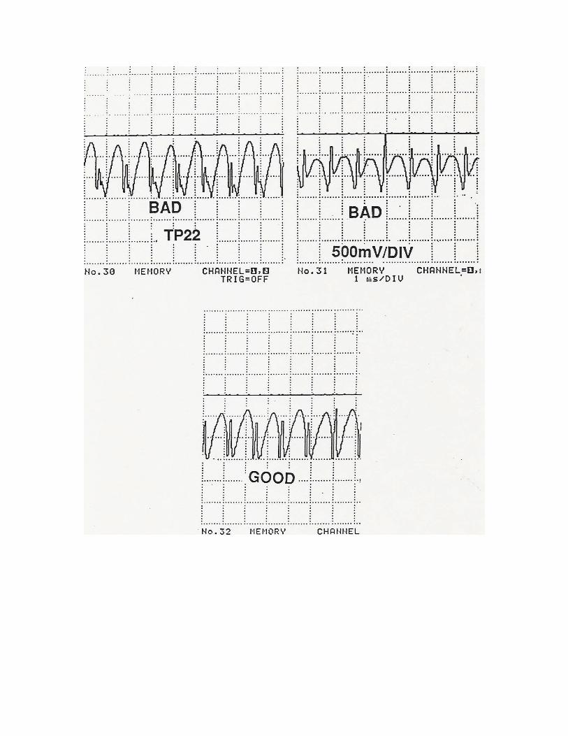
CONVENTIONAL ENERGY MONITORING ADJUSTMENT - Mk.I or Mk.II ANALOGUE BOARD 1) (Mk.II only) Place SW5A (red) into position #2. 2) Place scope on TP22, ground on front panel power supply Ov test point. 3) Set up (DC, AUTO, real time, 1ms/div, 500mv/div). 4) Turn monitor on. 5) Run good quality cans with an inspector present. (Mk.II only) Check position of SW4: -if at right use VR3 pot -if at left use VR4 pot (switch slider points towards active pot). 6) Adjust selected pot (VR3 on Mk.I) as noted on wave sketch, objective is to line up the bottoms of the two waves (optimize) at 0v (see Figure 1 later in this section). 7) Stop welder. 8) Turn monitor off. 9) (Mk.II only) Place SW5A (red) into position #1. 10) Turn monitor on. POWER MONITORING ADJUSTMENT (Mk.II only) 1) Place scope on TP24 (on analogue board at bottom). 2) Set up scope (DC,AUTO, real time, 1ms/div, 2v/div). 2) Run good quality cans with an inspector present. 3) Adjust pot VR5 until you get 5VAC peak to peak, if a distortion of the wave develops at zero axis, this is OK. 4) Stop welder.
QUALITY COEFFICIENT ADJUSTMENT (Mk.I only) 1) Run good quality cans with an inspector present. 2) Observe quality coefficient number on Display Board red display. 3) If average reading is over 700, remove links across R45, R48. If the reading is still over 700, remove links across R39, R42 (see section 4 of this Manual). 4) If the reading is lower than 150, check the above-mentioned links and replace any which are missing. QUALITY COEFFICIENT ADJUSTMENT (Mk.II only) 1) Run good quality cans with an inspector present. 2) Adjust pot VR6 while looking at quality coefficient display, turn counter-clockwise until number will not go any lower, find the minimum point (record this as min). 3) Turn pot VR6 clockwise until the display achieves a maximum. Watch for a peak as the read-out will begin to drop when over maximum point (record the maximum number as max). 4) Take the numbers obtained and find the set point. Here is an example using typical numbers such as max = 460, min = 70: = min + ( (max-min)/2 ) = 70 + ( (460-70)/2 ) = 70 + (390/2) = 70 + 195 = 265
5) Turn VR6 until the quality coefficient display equals the calculation from previous step. 6) Adjust the set point thumb-wheel switches to match the quality coefficient. This will set the operating limits to the center point of the linear range of calibration. Any deliberate changes in the welding conditions, (such as a change in the basis weight of the plate or a change in the weld current), can now be compensated for using the set point thumb wheel. Temporarily, set the upper and lower limit switches to be 10% of the set point number. 7) Turn the monitor off. 8) Remove the extender card from behind the analogue board, replace the analogue board in the chassis. 9) Turn on the air supply to the reject station. 10) Turn on the monitor. 11) Turn 'on' the interface board, the green LED will come on. 12) The monitor is functional at this point, but make a test to determine proper limits as soon as possible. CONTAMINATION FAILURE LEVEL ADJUSTMENT 1) Run good quality cans with an inspector present. 2) Locate multi-turn 'CONTAM FAIL LEVEL' knob on the analogue board front panel, and turn it down until the red LED above it begins to blink (this is the minimum setting). 3) Observe the dial reading (example=786), ensure that the reject station kicks off all the cans that may have a 'stitched' seam as a result of this procedure. 4) Turn the dial setting back up +50 to +100 points. This must be fine tuned later while running. Start with + 75 for this procedure. (example: 786+75=851) 5) Stop the welder.
BLANKING PULSE ADJUSTMENT 1) Adjust pot VR7 fully counterclockwise, then five turns clockwise to make the pulse visible for a starting point. 2) Ensure the welder timing pulse (B89, NS1-1 or chain sensor) is properly adjusted before starting this procedure (look for a good signal on TP3). 3) Hold the blanking pulse set-up switch down. 4) Make a short run of good quality cans with an inspector present. 5) Inspect the cans for a visible blanking pulse (cold weld); 1/8" - 3/16" at each end should be unwelded. 6) Adjust the blanking pulse delay multi-turn pot until the pulse is at the end of the can; finalise by repeating these steps until satisfied. 7) Use pot VR7 to adjust length of blanking pulse clockwise or counterclockwise to set 1/8" - 3/16" on each end of the can. PERFORMANCE TEST 1) Run good quality cans with an inspector present. 2) Record quality coefficient from monitor display card. 3) Record current setting on welder (this is the 'good' set point). 4) Stop production. 5) Activate air brush-off downline to reject all cans. 6) Run good quality cans with an inspector present. 7) Adjust current upward until cans are unacceptably hot (ignore monitor & rejects). 8) Record current setting on welder (this is now the 'hot' limit). 9) Adjust current downward until cans are unacceptably cold (ignore monitor & rejects). 10) Record current setting on welder (this is now the 'cold' limit).
NOTE: At this point we know the acceptable current and the hot/cold current limits. The monitor, if properly set, should be in linear calibration within this range. 11) We are now going to increase the current up through the acceptable point, back up to the hot limit, watching the quality coefficient display for linearity across this range. NOTE:
• If totally linear, no flat spots, all is OK.
• If an early flat spot occurs, it could mean the set point from the calculation in previous step (setting VR6) was too low, or insufficient voltage on TP24 (optimum 5V).
• If a late flat spot or total drop-off occurs, it could mean the set point from the calculation in the previous step (4) VR6 was too high, or excess voltage on TP24 (optimum 5V). PREPARING FOR ADJUSTMENT - Mk. III ANALOGUE BOARD 1) Turn monitor off. 2) Check link positions on Analogue Board, as follows: Mk.III Analogue Board Link Settings recommended for OPERATION (see below for settings recommended for beginning ADJUSTMENT) We recommend the following 'standard' settings for most applications: Link 1 Right Link 2 Left Link 3 Right Link 4 Right Link 5 Left Link 7 Link 9 Link 11 Link 15 Link 17 Link 18 Up Mk.III Analogue Board Link Functions These links are positioned either left or right (towards the front or rear of the circuit board)
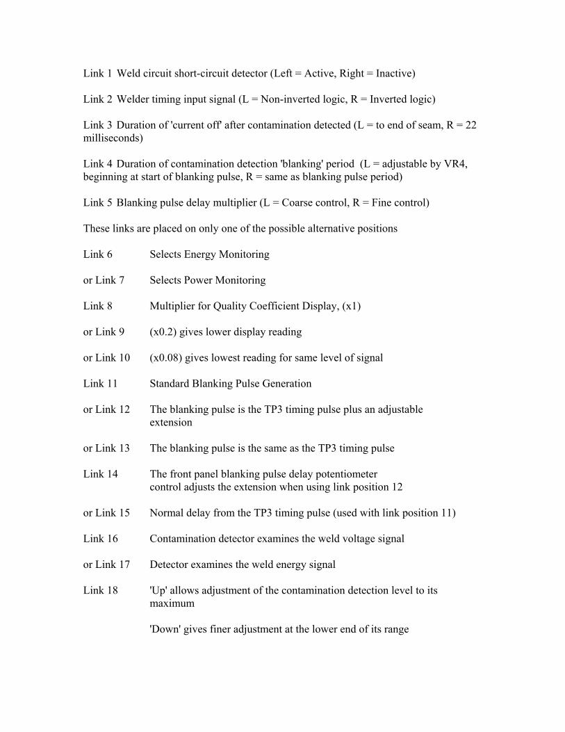
Link 1 Weld circuit short-circuit detector (Left = Active, Right = Inactive) Link 2 Welder timing input signal (L = Non-inverted logic, R = Inverted logic) Link 3 Duration of 'current off' after contamination detected (L = to end of seam, R = 22 milliseconds) Link 4 Duration of contamination detection 'blanking' period (L = adjustable by VR4, beginning at start of blanking pulse, R = same as blanking pulse period) Link 5 Blanking pulse delay multiplier (L = Coarse control, R = Fine control) These links are placed on only one of the possible alternative positions Link 6 Selects Energy Monitoring or Link 7 Selects Power Monitoring Link 8 Multiplier for Quality Coefficient Display, (x1) or Link 9 (x0.2) gives lower display reading or Link 10 (x0.08) gives lowest reading for same level of signal Link 11 Standard Blanking Pulse Generation or Link 12 The blanking pulse is the TP3 timing pulse plus an adjustable extension or Link 13 The blanking pulse is the same as the TP3 timing pulse Link 14 The front panel blanking pulse delay potentiometer control adjusts the extension when using link position 12 or Link 15 Normal delay from the TP3 timing pulse (used with link position 11) Link 16 Contamination detector examines the weld voltage signal or Link 17 Detector examines the weld energy signal Link 18 'Up' allows adjustment of the contamination detection level to its maximum 'Down' gives finer adjustment at the lower end of its range
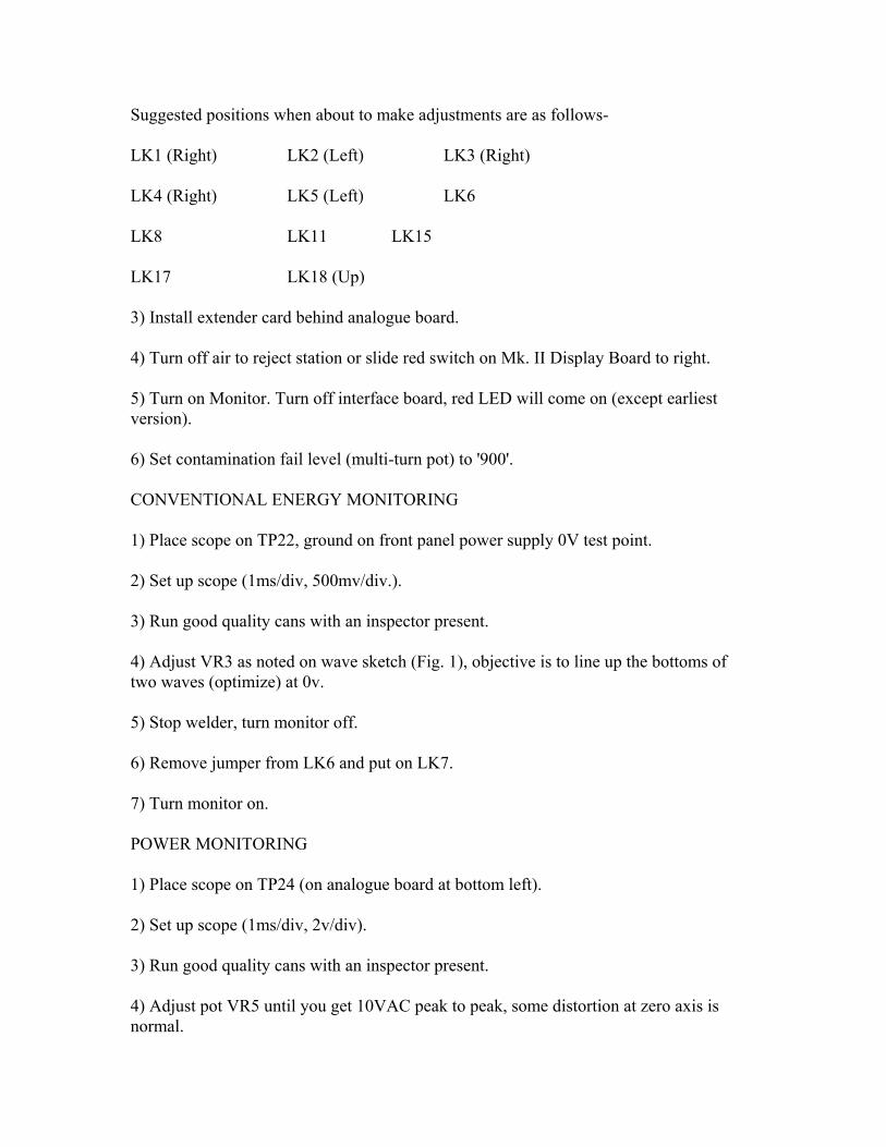
Suggested positions when about to make adjustments are as follows- LK1 (Right) LK2 (Left) LK3 (Right) LK4 (Right) LK5 (Left) LK6 LK8 LK11 LK15 LK17 LK18 (Up) 3) Install extender card behind analogue board. 4) Turn off air to reject station or slide red switch on Mk. II Display Board to right. 5) Turn on Monitor. Turn off interface board, red LED will come on (except earliest version). 6) Set contamination fail level (multi-turn pot) to '900'. CONVENTIONAL ENERGY MONITORING 1) Place scope on TP22, ground on front panel power supply 0V test point. 2) Set up scope (1ms/div, 500mv/div.). 3) Run good quality cans with an inspector present. 4) Adjust VR3 as noted on wave sketch (Fig. 1), objective is to line up the bottoms of two waves (optimize) at 0v. 5) Stop welder, turn monitor off. 6) Remove jumper from LK6 and put on LK7. 7) Turn monitor on. POWER MONITORING 1) Place scope on TP24 (on analogue board at bottom left). 2) Set up scope (1ms/div, 2v/div). 3) Run good quality cans with an inspector present. 4) Adjust pot VR5 until you get 10VAC peak to peak, some distortion at zero axis is normal.
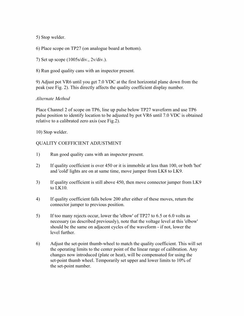
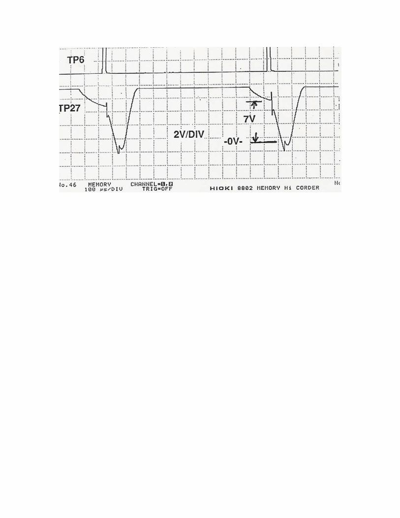
5) Stop welder. 6) Place scope on TP27 (on analogue board at bottom). 7) Set up scope (1005s/div., 2v/div.). 8) Run good quality cans with an inspector present. 9) Adjust pot VR6 until you get 7.0 VDC at the first horizontal plane down from the peak (see Fig. 2). This directly affects the quality coefficient display number. Alternate Method Place Channel 2 of scope on TP6, line up pulse below TP27 waveform and use TP6 pulse position to identify location to be adjusted by pot VR6 until 7.0 VDC is obtained relative to a calibrated zero axis (see Fig.2). 10) Stop welder. QUALITY COEFFICIENT ADJUSTMENT 1) Run good quality cans with an inspector present. 2) If quality coefficient is over 450 or it is immobile at less than 100, or both 'hot' and 'cold' lights are on at same time, move jumper from LK8 to LK9. 3) If quality coefficient is still above 450, then move connector jumper from LK9 to LK10. 4) If quality coefficient falls below 200 after either of these moves, return the connector jumper to previous position. 5) If too many rejects occur, lower the 'elbow' of TP27 to 6.5 or 6.0 volts as necessary (as described previously), note that the voltage level at this 'elbow' should be the same on adjacent cycles of the waveform - if not, lower the level further. 6) Adjust the set-point thumb-wheel to match the quality coefficient. This will set the operating limits to the center point of the linear range of calibration. Any changes now introduced (plate or heat), will be compensated for using the set-point thumb wheel. Temporarily set upper and lower limits to 10% of the set-point number.
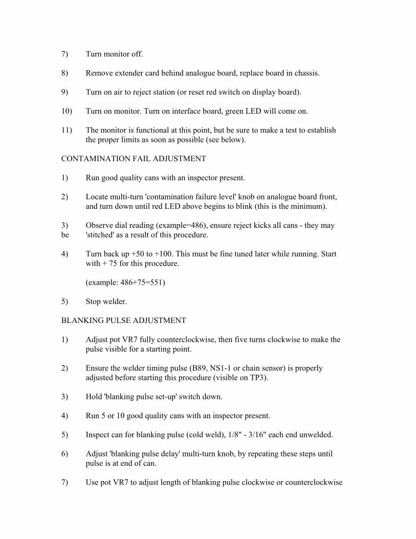
7) Turn monitor off. 8) Remove extender card behind analogue board, replace board in chassis. 9) Turn on air to reject station (or reset red switch on display board). 10) Turn on monitor. Turn on interface board, green LED will come on. 11) The monitor is functional at this point, but be sure to make a test to establish the proper limits as soon as possible (see below). CONTAMINATION FAIL ADJUSTMENT 1) Run good quality cans with an inspector present. 2) Locate multi-turn 'contamination failure level' knob on analogue board front, and turn down until red LED above begins to blink (this is the minimum). 3) Observe dial reading (example=486), ensure reject kicks all cans - they may be 'stitched' as a result of this procedure. 4) Turn back up +50 to +100. This must be fine tuned later while running. Start with + 75 for this procedure. (example: 486+75=551) 5) Stop welder. BLANKING PULSE ADJUSTMENT 1) Adjust pot VR7 fully counterclockwise, then five turns clockwise to make the pulse visible for a starting point. 2) Ensure the welder timing pulse (B89, NS1-1 or chain sensor) is properly adjusted before starting this procedure (visible on TP3). 3) Hold 'blanking pulse set-up' switch down. 4) Run 5 or 10 good quality cans with an inspector present. 5) Inspect can for blanking pulse (cold weld), 1/8" - 3/16" each end unwelded. 6) Adjust 'blanking pulse delay' multi-turn knob, by repeating these steps until pulse is at end of can. 7) Use pot VR7 to adjust length of blanking pulse clockwise or counterclockwise
to set 1/8" - 3/16" on each end. ALTERNATIVE (COARSE) BLANKING PULSE ADJUSTMENT 1) Adjust pot VR7 fully counterclockwise then five turns clockwise to make the pulse visible for a starting point. 2) Ensure the welder timing pulse (B89, NS1-1 or chain sensor) is properly adjusted before starting this procedure (TP3). 3) Place scope Ch-1 on TP7. 4) Set up scope (5ms/div., 2v/div.). 5) Place scope Ch-2 on TP22. 6) Set up scope (5ms/div., 0.5v/div.) 7) Run good quality cans with an inspector present. 8) Adjust blanking pulse delay multi-turn pot, until TP7 (blanking pulse) is centered on the roller-bounce disturbance in the TP22 current reduction zone (small 'wiggles' in the TP22 wave form). 9) Once this is done fine tuning may be required. Run good quality cans with an inspector present. 10) Depress blanking pulse set-up switch, the welder may give a 'saw tooth' failure and shut the welder feed down, but it will stitch about 5 cans before it shuts down. 11) Check cans for blanking pulse (cold weld), 1/8" - 3/16" each end unwelded. 12) Adjust blanking pulse delay multi-turn pot until pulse is at end of can, by repeating these steps until satisfied. 13) If necessary, use pot VR7 to adjust length of blanking pulse clockwise or counterclockwise to set 1/8" - 3/16" on each end.
PERFORMANCE TEST 1) Run good quality cans with an inspector present. 2) Record quality coefficient from monitor display card. 3) Record current setting on welder (this is the good set point). 4) Stop production. 5) Activate air brush-off. 6) Run good quality cans with an inspector present. 7) Adjust current upward until cans are unacceptably hot (ignore monitor & rejects). 8) Record current setting on welder (this is now the 'hot' limit). 9) Adjust current downward until cans are unacceptably cold (ignore monitor & rejects). 10) Record current setting on welder (this is now the 'cold' limit). NOTE: At this point we know the acceptable current and the hot/cold current limits. The monitor if properly set, should be in linear calibration within this range. 11) We now increase the current up through the acceptable point, back up to the hot limit, watching the quality coefficient display for linearity across this range. NOTE: If totally linear, no flat spots, all is OK.
• If an early flat spot occurs, it could mean insufficient voltage on TP27 (optimum 7.0V), or on TP24 (optimum 10v).
• If a late flat spot or total drop off occurs, it could mean excessive voltage on TP27 or on TP24. Return to 'Power Monitoring Setup' above to correct this.
ADJUSTMENT INSTRUCTIONS - VERTEX MK.IV ANALOGUE BOARD The Vertex Mk.IV Analogue Board for the WM-3 series of weld monitors is a plug-in
replacement for earlier versions of the Analogue Board. It offers improved performance and maintainability. With its optional current pickup it can be used on lines equipped with the new 'Unisoud' power supply. This is the only way the Monitor can continue to be used when the Unisoud power supply is fitted.
If the Mk.IV is being used on a line which has a standard type of 'Search Coil' pickup, it is only necessary to replace the earlier board with the new Mk. IV. Make sure that the link settings for links 1 and 2 are set to the left ('COIL') in this case. DO NOT PULL OUT OR REPLACE ANY MONITOR BOARD WITH THE MONITOR SWITCHED ON!
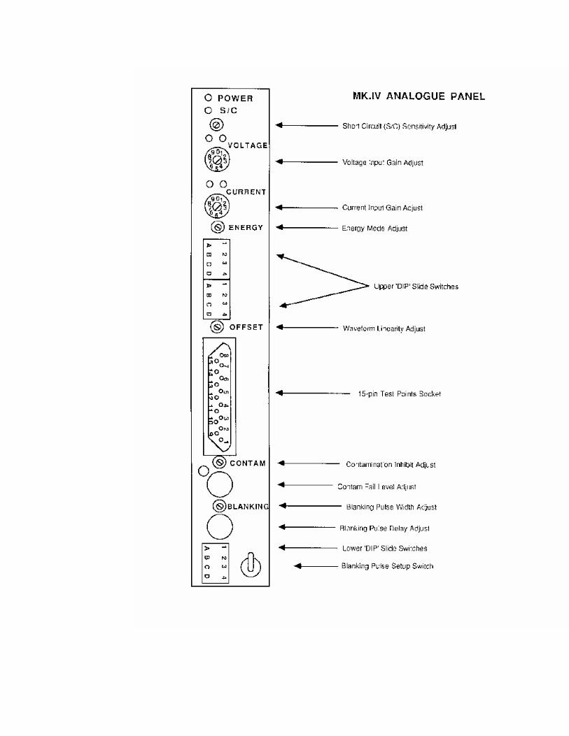
It may be necessary to experiment with the polarity of the Search Coil connections to obtain normal results when making adjustments. This is most easily done by reversing the connections at the Search Coil itself. If the line is to use the newer technology current pickup (optional on lines with traditional power supplies, mandatory on Unisoud-equipped lines) set links 1,2 to the right, and please call Vertex for assistance with the current pickup installation. These instructions assume that the board and associated current pickup have been correctly installed. Refer to the diagram and list of front panel controls below to identify the various switches, potentiometers and indicator lights. If replacing a previously installed Mk. IV board, review the present settings for your installation and make the new board the same. If a control is not mentioned below, its setting does not affect the performance of this board when used in your application. NOTE: It is not necessary, nor is it advisable to attempt to adjust the board with it mounted on an extender card. Doing so exposes the sensitive circuitry to the high level of electromagnetic interference from any Unisoud-equipped welder. Turn the display board output switch 'off' to disable the reject station, and switch the integral interface board output off to prevent the monitor from cutting the weld current while you are making adjustments. Working from the top of the front panel downwards, check the following conditions: a.) The 'Power On' L.E.D. must be illuminated, if the weld monitor power is on. b.) The 'S/C' (short circuit) L.E.D. should be off. Because of the difficulty in making this adjustment unless the welder insulation has just been replaced, we recommend that this circuit be desensitized by adjusting the potentiometer fully counter-clockwise (this is a multi-turn potentiometer). c.) Adjust the welder to make good cans. While the welder is making cans, turn the 'Voltage' rotary switch around from 0 to 9, using a suitable small screwdriver. Turn the switch down from 9 until only the green L.E.D. above this switch is lit, then turn it down one more position. d.) Use the same procedure to adjust the 'Current' switch.
e.) Using a suitable screwdriver, adjust the 'Energy' potentiometer while watching the Quality Coefficient display on the Display Board. When you adjust this control from fully counter-clockwise to fully clockwise while making cans, you should see that the Quality Coefficient number enters a 'dip' area around the middle of the range - it falls fairly quickly to about 75% of its value, remains low for perhaps a couple of turns of the 'Energy' potentiometer, then climbs quickly back to about the same level as it was before. Adjust the 'Energy' control until the displayed number is at its lowest value between the two high end points. The optimum point is where the numbers just begin to rise quickly while turning the control clockwise. f.) Adjust the Contamination Level Control in the same way as for the Mk.III Analogue Board. g.) Adjust the Blanking Pulse width and delay in the same way as for the Mk.III Analogue Board. The setup or 'tuning' of the Analogue Board is now complete. Turn the display board output switch 'on' to enable the reject station, and switch the integral interface board output on. Proceed to adjust the Comparator Board settings for best production monitoring. Analogue Board Mk.IV - Typical Settings Voltage Rotary Switch - to suit situation, preferably mid-range (2-7) Current Rotary Switch - as above Upper Slide Switches Settings 1 (Right) Left = Power Monitoring Right = Energy Monitoring 2 (Right) Not used 3 (Right) Not used D (Left) Use this to invert the polarity of B89/NS1-1 signal input
(‘sync signal for blanking pulse) 1 (Right) L = To end of seam R = Contam. current shutdown22ms. B (Left) L = During Blanking Pulse R = Contam. inhibit can be varied (with CONTAM pot) C (Right) L = Contam. signal from voltage R = From energy waveform D (Right) L = As set on switch above R = From power waveform (disregard
switch setting above) Lower Slide Switches A (Left) L = Blanking Pulse delay on pot R = Sync signal extend on pot B (Left) L = Blanking Pulse adjustable R = BP length fixed (= sync signal) 3 (Right) L = Extend sync signal 4 (Right) L = Coarse BP delay adjust R = Fine BP delay adjust
On Board Jumper Links - BE SURE TO SET THESE CORRECTLY TO AVOID DAMAGE TO THE BOARD OR CURRENT PICKUP LK2 Left )
) These settings correspond to the 'SEARCH COIL' Setting LK1 Left ) LK2 Right )
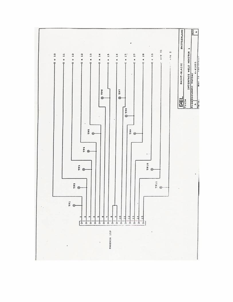
) These settings correspond to the 'CURRENT PICKUP' Setting LK1 Right ) The three 'FREQUENCY' links are to be set on the appropriate row to suit the frequency of the welder. Test Point Signals The 15-pin D-type socket on the front panel of the board is numbered in the standard way for this type of socket (see diagram below). Many of the signals correspond to those found on the Mk. III Analogue Board, and their equivalent test point numbers are given. View the signals with an oscilloscope (preferably a dual-channel type), using pin 1 as the ground (0V) reference. 1 Ground (zero volts) reference of Monitor power supply. 3 Voltage-to-frequency converter signal to be adjusted with 'ENERGY' pot
when the top slide switch is in the Right (Energy) position. To be adjusted with the 'OFFSET' pot when the slide switch is in the Left (Power) position. Equivalent to TP22 on Mk.III Analogue Board.
4 Divider signal equivalent to TP27 on Mk.III Analogue Board. 5 Integrator signal. 6 Multiplier signal (TP25). 7 Filtered, amplified Voltage input signal (TP26). 8 Voltage input signal (TP23). 9, 10 Reference level for Contamination Failure detector. 11 Blanking Pulse (TP28). Adjust Duration with 'BLANKING' screwdriver
pot. 12 Zero Crossing signal.
13 Phase shifted Current input signal (TP24). 14 Filtered, amplified Current input signal. 15 Current input signal (TP21). INSTALLATION INSTRUCTIONS - VERTEX SEMICONDUCTOR CURRENT PICKUP (Part No. WMANCPU) FOR USE WITH MK.IV ANALOGUE BOARD
The Vertex WMANCPU Current Pickup for the WM-3 series of weld monitors is a
replacement for the earlier Search Coil. It is mandatory for use with welders equipped with the 'Unisoud' power supply, and offers improved performance when used with all other types of power supply. When used with the Unisoud high-frequency supply, it is paired with the Mk. IV Analogue Board, which has the necessary high-frequency capability.
The Current Pickup is comprised of two elements: the pickup unit which is clamped around the copper current busbar, and the power supply, which is usually mounted on or near the Weld Monitor cabinet.
It is optional to interrupt the existing cabling inside or outside the cabinet, with arguments in favor of either choice.
Inside installation. Read the rest of this section before choosing a position for the small power supply
printed circuit board (typically about 4" above the two round connectors on the back wall of the Monitor cabinet, since it is necessary to interrupt the cables going to the smaller round connector). Drill two suitable holes in the back wall of the Monitor Cabinet, spaced at the spacing of the two insulated standoff pillars of the small Current Pickup (CPU) power supply board. Inspect the internal wiring harness to gain access to cables 1, 2 and 3 on the smaller round 8-pin rear panel connector (you may choose to remove cable 1 completely from the 8-pin round connector, since its signals no longer originate from the existing external wiring. The red and blue wires of cable 1 should both be routed to the 12a terminal on the CPU board (they are originally on pin A of the 8-pin connector). The yellow and green wires of cable 1 go to 13a on the CPU board (originally on pin B). Tape back the cable shield with electrical tape.
Cables 2 and 3 can be interrupted (cut) about 6" from the connector so that all four cut ends will reach the terminals on the CPU board. Take care to label the cut ends to avoid confusion after they are separated. The red and blue wires of cable 2 from the backplane of the Monitor internal chassis both go to the 15a terminal on the CPU board. The remaining red and blue wires of cable 2 which run to the cabinet back panel round connector go to either one of the two terminals marked 'V' on the CPU board. The shield of this short run of cable 2 should be connected to the 0V terminal beside the +24V terminal on the CPU board.
The red and blue wires of cable 3 from the back panel round connector both go to the other 'V' terminal, with the cable shield going to the same 0v terminal as above. The red and blue wires of cable 3 from the electronics backplane go to terminal 17a of the CPU board, with the shield taped back.
Make a suitable hole in the back wall of the cabinet, protect the edges of the hole to prevent chafing the cable and lead the CPU cable from the pickup unit through to the connections on the spring-loaded terminal strip, which has wire color markings to guide you. Connect the shield of this cable to the same 0V terminal as the other cables.
Connect the +24V and 0V terminals of the CPU to the internal power supply unit of the Monitor. BEWARE! the positive and negative wires on the Power Supply unit may be the same color - check which is which before turning on! Outside installation.
This choice of installation requires a small box or enclosure (preferably metal) to
protect the CPU board outside the Monitor cabinet. The box must be electrically grounded to the Monitor cabinet. Read the rest of this section before choosing a position for this box (typically about 4" above the two round connectors on the back wall of the cabinet, since it is necessary to interrupt the external cables going to the smaller round connector). Mount the CPU board inside the box, make suitable holes in the box for the various cables, and protect the edges of the holes to prevent chafing the cables.
Inspect the external wiring harness to gain access to cables 1, 2 and 3 on the smaller round 8-pin rear panel connector (you may choose to remove the rest of cable 1 once the connector end has been terminated inside the CPU box). The red and blue wires of cable 1 should both be routed to the 12a terminal on the CPU board (they connect to pin A of the 8-pin connector). The yellow and green wires of cable 1 go to 13a on the CPU board (connected to pin B). Tape back the cable shield with electrical tape.
Cables 2 and 3 can be interrupted (cut) about 10" from the connector so that all four cut ends will reach the terminals on the CPU board. Take care to label the cut ends to avoid confusion after they are separated. The red and blue wires of cable 2 from the 8-pin connector both go to the 15a terminal on the CPU board. Tape back the shield. The red and blue wires of the rest of cable 2 which originates from the external wiring harness go to either one of the two terminals marked 'V' on the CPU board. The shield of this run of cable 2 should be connected to the 0V terminal beside the +24V terminal on the CPU board. The center conductor wire of shielded co-axial cable 3 from the 8-pin connector goes to the 17a terminal, with the cable shield taped back. The center conductor wire of cable 3 from the external wiring goes to the remaining, unconnected 'V' terminal on the CPU board, with the shield connected to 0V.
Lead the CPU cable from the pickup unit through to the connections on the spring-loaded terminal strip, which has wire color markings to guide you. Connect the shield of this cable to the same 0V terminal as the other cables.
Connect the +24V and 0V terminals of the CPU to the internal power supply unit of the Monitor. BEWARE! the positive and negative wires on the Power Supply unit may be the same color - check which is which before turning on!

Addendum to Setup Instructions for Vertex Mk.IV Analogue Board used with CMB WM-series Weld Monitors installed on Soudronic bodymakers having ‘Unisoud’ power supplies.
Introduction This document is provided as an extension to the original Instructions which include important details of default switch settings and test point pin signal allocations. It offers a more comprehensive sequence of settings to facilitate the adjustment of ‘difficult’ installations. Procedure
1. Refer to the original Instructions for the default switch settings recommended for this Board. Disable the Monitor’s Integral Interface Board by setting its switch to the ‘OFF’ position, and turn off the air supply to the reject station.
2. Refer to the attached diagrams for typical waveforms and voltages to be found
on the various test point pins on the 15-way connector on the front panel of the Board. Test pin connections are listed on the fourth page of the original Instructions.
3. With the top slide switch on the front panel in the right-hand (‘Energy’)
position, attach an oscilloscope probe to test pin 3 on the 15-way test connector on the front panel of the Analogue board. Work with the ‘trigger’ control on the ‘scope to obtain a stable image of the waveform similar to the one shown on the attached diagram.
4. Adjust the rotary ‘Voltage’ switch clockwise from zero until the waveform
exhibits a flattened top as the signal exceeds the supply voltage. Back off as necessary to achieve a result just below the setting which flattens the top of the waveform.
5. Repeat as in 4 above for the ‘Current’ rotary switch. The final result should be
a combination of Voltage and Current settings as high as possible without flattening the top of the pin 3 signal waveform.
6. Observe the pin 3 waveform carefully. Adjust the ‘energy’ multi-turn
potentiometer and watch for a lowering of the waveform. The correct adjustment corresponds approximately to the lowest overall magnitude of this waveform. Refer to the diagram to see the two ‘tell-tale’ points which can be equalized to achieve this. These two points rise and fall alternately – at one point the left-hand point will be higher than the right-hand one, then after adjustment the opposite is the case. The optimum setting is when they are both at the same level.
7. Observe the Quality Coefficient number on the Display Board and note its value. Adjust the ‘energy’ potentiometer referred to above in paragraph 6 and watch for the rise and fall of the display number. Its behaviour should be as described in the original Instructions – after moving the potentiometer counter-clockwise several turns, it should fall while adjusting clockwise. After a moderately steep fall, it should be at a low level close to the number noted above, then rise more quickly to a higher level. The optimum setting is at the lowest value obtainable. This should be close to the ‘balance point’ established in 6 above (if not, repeat the procedure and review the changes in the display number). The ‘lowest value’ setting is preferable to the ‘equalised tell-tale points’ setting, although they should be close together.
8. If difficulty is experienced in obtaining a satisfactory numeric display by the
above procedure, return to the Voltage and Current switch settings after finding the optimum adjustment. It may be possible to raise the Voltage and Current switch settings further without introducing a flattening of the waveform, after which the final stages of the adjustment can be repeated, usually achieving a higher display number.
9. Slide the top switch to the left-hand (‘Power’) setting and adjust the ‘Offset’
potentiometer to achieve the least possible ‘castellation’ or jaggedness on the waveform. Return the switch to the right-hand position. (It is rare that the display value is high enough to use in the ‘Power’ mode, but if it is above 100, then it may be considered desirable to run in the ‘Power’ mode, which compensates for unbalanced thyristor packs and some other conditions.)
ADJUSTMENT OF THE MK.IV COMPARATOR BOARD The Mk.IV Comparator will be sensitive to weld faults ONLY IF CORRECTLY CONFIGURED. Quality tests must be carried out on the line in full production to determine the optimum limit setting. A method of determining the limits is suggested here, but there will be other ways of achieving good weld monitoring. Ensure that all other modules in the monitor are fully commissioned and adjusted. Check:
• Blanking pulse is correctly positioned over can gap, and correct size.
• Reject/counting system working correctly.
• Quality coefficient display is stable. Note that the limits increase in proportion to the average magnitude of the QC, for increased sensitivity the QC should be larger. The magnitude of the QC is dependent on the commissioning of the board. Note: These features should be periodically checked on any weld monitor. DETERMINING AND MAINTAINING SUITABLE LIMITS When using the Mk.IV Comparator the absolute upper and lower limits determined by the following procedure will be valid until there is a significant change in welding conditions, such as a plate change. Disturbances where the QC remains within the absolute limits but which produce unacceptable welds will now be detected by the 'profile' and 'taper' test. The absolute upper and lower limits values are more critical than the quality set-point value. With no changes in welding conditions, drift in the normal operating QC within the range of the absolute limits, away from the set- point, can be accepted without monitor adjustment. On comparators without the 'profile' and 'taper' test, it was sometimes necessary to have smaller limits than those determined using the absolute limits method in order to detect some welding faults. This meant that the quality set point was sometimes adjusted whenever the QC value drifted in production, in order to stop 'good' cans being rejected.
This practice is not encouraged as the limits might be adjusted outside the acceptable quality levels determined by absolute limits. WELD QUALITY SHOULD ALWAYS BE CHECKED USING ESTABLISHED TEST PROCEDURES BEFORE THE SET POINT OR ANY LIMIT IS ADJUSTED. ABSOLUTE UPPER LIMIT Increase the welding power a step at a time until commercially unacceptable 'hot' welds are just detectable. Note the average QC value during production, this is the 'ABSOLUTE UPPER LIMIT'. It is most important to produce several cans for each change of welding power to avoid misleading results. ABSOLUTE LOWER LIMIT Reduce the welding power a step at a time until commercially unacceptable 'cold' welds are just detectable using established test procedures. Produce several cans at this power setting and note the average QC, this is the 'ABSOLUTE LOWER LIMIT'. QUALITY SET POINT On the welding machine, set the welding power to achieve optimum weld quality. Adjust the quality set point to the value observed on the 'quality coefficient' display during production, this is the SET POINT. CALCULATING UPPER AND LOWER LIMITS ABSOLUTE UPPER LIMIT minus SET POINT = UPPER LIMIT (thumbwheel) SET POINT minus ABSOLUTE LOWER LIMIT = LOWER LIMIT (thumbwheel) Select the UPPER LIMIT, SET POINT and LOWER LIMIT values on the comparator board thumbwheel switches. DETERMINING 'PROFILE' AND 'TAPER' LIMITS 'Profile' and 'Taper' each have possible limit values of 1-9 (1 = most sensitive, 9 = least sensitive, 0 = off), and each value is related to a measured change of the QC value. However, a scale factor is used in the software and it is not possible to determine the limit settings by observing the QC in the same way as for the absolute limits. Production trials must be undertaken to determine suitable limits. In order to distinguish between absolute, 'profile' and 'taper' tests, the latter two tests each have an LED indicator, situated above its limit thumbwheel. The LED will flash when the test detects a failed can. Hot or cold failure indication is shown on the display board. Setting a 'profile' or 'taper' limit to 0 will turn that test off. This should only be used to
evaluate the other test. To determine the optimum limit for 'profile', select wide upper and lower limits and turn the 'taper' test off. To then determine the limit for 'taper', turn the 'profile' test off. Starting at 9, reduce the limit until a few 'good' cans are rejected. Increase the limit by 1 and inspect any rejected cans. It is necessary to have long term, full production in order to correctly establish a suitable limit. When limits for both tests have been determined, set both limits to the optimum value and ensure correct absolute limits are selected. It may be necessary to adjust the 'profile' and 'taper' limits if a significant change in welding conditions occurs. AUTOMATIC FIRST CAN REJECTION It is possible to configure the Mk.IV comparator so that every first can is automatically rejected, providing the QC falls to a level below the absolute lower limit for 'wire-on-wire'. This feature is selected by a link situated near to the EPROM. Position 1 (left) selects automatic first can rejection. Position 2 (right) selects NO automatic rejection. Both positions reject any can failed using the measured QC value. ACCEPTABLE RANGE OF WELDER 1) Make this check at least once per shift, preferably at the start. 2) Establish a good running setting for the welder (there is no point in adjusting the Monitor to a badly running welder). Note the Quality Coefficient display on the Monitor and record it. Note the reading on the welder current control knob and record it. 3) Turn on the air brush-off on the line; set the Quality Coefficient Set Point switches on the Comparator Board to the reading established above. 4) Increase the current on the welder and check the quality of the cans. Make increases a step at a time until the cans are unacceptably hot. For the purposes of this test, we are not concerned with cosmetic blemishes, but weld weaknesses that are apparent when the seam is torn down. 5) Record the welder current knob setting - this is the welder hot limit. 6) Reduce the current below the normal setting and find the minimum acceptable level in the same way.

7) Record the welder current knob setting - this is the welder cold limit. 8) Observe the action of the Monitor reject station at this cold limit. If the Monitor rejects all the cans, increase the lower limit number on the Comparator Board until the monitor starts to reject about 50% of the cans as 'bad', then reduce it again just enough to reject all cans. This has matched the Monitor's lower setting to the prevailing welder performance. 9) Repeat this procedure with the upper limit at the high welder current setting.

SECTION THREE - TROUBLESHOOTING CHECK-LIST OF OPERATING CONDITIONS The most frequent cause of faulty operation is broken or short circuited external wiring. Follow this check-list first, to eliminate external causes of problems. Power Problems Not all power indicators illuminated on Monitor front panel. Unplug 3-pin power plug from rear of Monitor cabinet. CAUTION - HIGH VOLTAGE. Check voltage present on 2 outer pins. Should be 110 VAC or 220/240 VAC as appropriate for installed links on power supply input. If not present, check main supply source and wiring. If voltage correct, confirm that internal rocker or toggle switch (located on power supply assembly in rear of cabinet) is on 'on' position. Reinsert power plug into socket. If power indicator light on power supply inside cabinet does not illuminate, check 3.15 Amp 20mm fuse located on power supply assembly (either in center of voltage selector disc or in holder on power supply circuit board - later models). Do not replace this fuse with any other rating, otherwise the monitor's protection will be jeopardized - damage can result. Check that the internal power supply voltage is between 23 and 25VDC (measured at its output terminal strip - WARNING! beware of high voltage cables near this point). If the power light is on, but the Monitor front panel has no lights illuminated, check security of plug connecting internal wiring harness to backplane wiring. Note that this plug must be correctly located on the backplane - lower set of pins. the plug has pin numbers molded on it - pin 1 is at the upper end of the connector pins. If the plug is correctly located, check the fuses on the power supply board. The correct value for these fuses is - 1A (top three) or 500 ma (lower one - F4). Once again, do not replace these fuses with other types or other ratings. If one or more fuses have blown, unscrew the retaining screws holding the Comparator, Display and Analogue Boards (plus any additional Management Option Boards) in the electronics rack, and partially remove the boards from the rack before trying a replacement fuse. This should leave only the Power Supplies PCB plugged in. If all five green LEDs are now illuminated, test the voltages on the five test points. From the top, these should be 12V, 12v, 5V, 12V, -12V. Measure these voltages against the 0V test point at the bottom of the Power Supply PCB front panel. A voltage within 0.5V of the specified level is acceptable. If all five LEDs do not light, or the voltages are not within range, replace the Power Supplies PCB. If the voltages are all correct, plug in the other boards one at a time. Switch off

the Monitor while plugging in boards, then turn on again and see if the fuses are still sound. Obviously, if a particular board causes a fuse to blow, that board is suspect, and should be unplugged and kept to one side while the remaining boards are checked (with a fresh fuse!). If one or more boards is suspected as being faulty, either proceed to the appropriate circuit description in this manual, or return the board to Vertex International for repair. Operating Problems Problems arising from connections to the Soudronic or FA-EL Electronics Rack Breaks or short-circuits in the cables connecting the Monitor to the welder electronics can cause a number of faults, as follows. If the 'Pass' light does not blink while welding good cans, and the Can Tracking counter continuously decreases, check cable 1. Absence of the B89 (NS1-1 on earlier welders, or chain sensor on FA-EL) timing signal can be confirmed by observing test point TP3. There should be a 12V pulse on this test point occurring at the same rate as the cans are produced. If the Monitor fails to cut the welding current after a contaminated seam is detected (test with a blank whose edge is 'contaminated' with a piece of regular-style Scotch™ tape) check cable 2. Failures in cable 4 cause the automatic zero feature on the can tracker to cease operation. Confirm this by pressing the 'reset' button on the Display Board while making cans, then stopping the welder feed and welding current. The can tracking count will decrease to some arbitrary value, and should then zero shortly after the last can passes the reject station. As well as checking the cable 4 connections, try a different setting of SW3 on the Display Board. SW3 determines the time delay after the Monitor senses that the current has been turned off until it zeroes the can tracking counter. Note that all connections between the Monitor and the welder electronics are optically isolated, so the possibility of interference between the two is virtually eliminated. If welding problems are suspected as being related to operation of the Monitor, remove the power cord from the rear of the Monitor to see if the problem disappears.
For older installations where the interface board is within the Soudronic cabinet only: Total isolation can most practically be achieved by using the spare Soudronic link board to replace the Metal Box interface board. Connectors 15 and 16 on the Soudronic link board should be joined with a short link wire (Note that this link and the other one usually found on this board between pins 9 and 10 are the only ones which should be present on the link board). NOTE: Always turn off the main power to the Soudronic welder before removing or replacing boards in the Soudronic electronic rack. The Monitor will perform most of its functions with the above exchange performed, but will not cut the weld current after contamination is detected. For newer installations with integral interface board: Remove the 35-way round connector from the rear of the Monitor cabinet to ensure complete isolation from the Soudronic electronics. Reject Station does not operate Check air supply pressure in range 30-50 p.s.i. Check for contaminants in the air supply - water, rust or oil can clog the solenoid valve shuttle and prevent operation. This can often be cleared by actuating the manual control located on the body of the solenoid valve within the reject station (just below the electrical coil, a screwdriver will turn it 90!). Turn this control back and forth several times until the air cylinder reliably moves a full stroke. Check continuity of wiring from large plug in rear of Monitor to terminal strip in reject station - see Diagram 680474-D in EL 15 or EL 30. Check continuity of solenoid valve coil in Reject Station - resistance should be approximately 100 ohms (although a value in the range 50 – 250 ohms is acceptable). WARNING! - one end of the solenoid valve coil is wired directly to +24VDC. The coil is actuated by 'pulling' the other end down to 0V (GND) through the relay RL-1 located on the Display Board. This means that when this relay is de-energized, both ends of the solenoid coil will read +24V on a typical voltmeter. It is possible to energize the coil for test purposes by temporarily connecting the negative (-) terminal to 0V (GND). If you accidentally pick the positive (+) terminal and ground it, the main 3.15A fuse will blow in the Monitor 24V power supply. The same warning applies to the use of an oscilloscope ground lead when using a probe to check for a reject pulse - if your scope is not isolated from ground, it will either cause the valve to operate continuously when you connect the ground lead to the negative solenoid connection, or blow the 24V fuse if you connect it to the positive end!
If the 'Reject' L.E.D. on the Display Board illuminates but no 24 V D.C. pulse is present across the solenoid valve terminals, check or replace the output relay RL-1 on the Display Board. If 'Reject' L.E.D. does not illuminate even when a reject should have occurred (confirm this by temporarily setting the quality coefficient set point on the Comparator Board to an abnormally high value - forcing the Monitor to reject all cans), check that SW2 on the Display Board is in position B. Can Tracking Counter fails to remain stable Remember that the weld rolls proximity sensor makes the can tracking counter count up, while the reject station sensor counts it down. The first task is to note whether the count is increasing or decreasing, since this provides a clue to the source of the problem. If the count is increasing or decreasing continuously at the same rate as cans being produced, it indicates that either the up or down count circuit has failed - usually because of a defective sensor. Check for 12V pulses on test point TP8 (up-count) or TP9 (down-count) while cans are running. Note that the pulses on TP8 are the result of combining the steady output of the weld rolls sensor (TP10) - which does not normally pulse - with the blanking pulse from TP7, so check TP7 if no pulses are present on TP8. If the count changes intermittently, it is necessary to check whether the miscount is associated with the reject function. This can usually be discovered by watching the 'Reject' LED and the can tracker count display. If the count fluctuates simultaneously with rejects, this is usually because the reject action is not throwing the cans cleanly off the conveyor. Adjust the 'Delay' control until the cans leave the conveyor in a parallel motion, without turning or tumbling. Check that the gap between cans at the reject station is at least an inch and that the cans are not rocking from side to side as they pass the reject sensor. Check that magnetic sensors are not too far from the cans, giving intermittent detection. A typical distance would be between 1/8" and 1/4". Note that moving the reject sensor closer to the can not only risks damage to the sensor from can wrecks, but reduces the sensor's ability to detect the inter-can gap. The later photo-electric sensors used on the reject station allow better detection of narrow gaps.
Special Note: On some machines it has been noted that very low or very high settings on the Blanking Pulse Delay control (less than 050 or more than 400) can give intermittent miscounts - particularly on the higher speed welders. Cure this by rotating the Soudronic B89 (NS1-1 on earlier welders) timing disc a few degrees in
the directon of rotation and then resetting the Blanking Pulse Delay control, which should now be correct at some value above 050. Erratic Readings on the Quality Coefficient Display The Q.C. display shows a small fluctuation during normal production. If this fluctuation increases noticeably, this can be for several reasons. Check whether there has been a change in the materials being used - different batches of plate or copper wire can introduce changes in the weld characteristics. Check that the Blanking Pulse is correctly positioned relative to the seam. If it has moved for some reason (perhaps the timing disc on the welder is loose, or has been moved) the Monitor will be measuring in the inter-blank gap which has varying quality coefficients. Frequently, it is found that instability of the Quality Coefficient is the result of an unintended connection between the shield of an external cable and the body of the welder. All cables to voltage and current pick-up points are shielded. In every case, this shield should be unbroken all the way from the plug to the pick-up point, but at the pick-up point the shield must be insulated from any contact with either cables or metalwork. Correct shielding action to prevent the entry of electrical interference depends on this. NOTE: Sometimes the accidental shorting of a shield to the welding arm can destroy the small circuit tracks on the backplane of the Monitor. When this happens, the Monitor is inoperable until the tracks are repaired If a shield is not connected all the way through to the end of the cable, or if it is short-circuited to the metalwork of the welder, electrical 'noise' can be introduced into the signal input. Similarly, the signal connections must be good and not short-circuited to other parts of the machine. This warning applies to all external cables from the Monitor - the outer ends of their shields must not be connected to anything. They are grounded at the Monitor end. A good way of guaranteeing that there is no short-circuit to ground is to lift the Monitor cabinet clear of whatever it is mounted on, rest it on something insulating (blocks of wood are fine), remove the power cord and check for any continuity between the 0V test point and the welder ground (Note: this test has to be done with both the Monitor and the Welder switched off). There should be no connection. If there is, remove the various connectors from the back of the cabinet one at a time and re-check. Check the shields on any cable that causes continuity when plugged in. At the same time, check that there is a good connection between the ground (center) connector of the power connector on the cord which you removed and the welder ground (CAUTION! - High Voltage).
Use of Test Points in Initial Checks The various test points (both external and internal) provide useful information about the operation of the Monitor. The following notes describe these signals. Be sure to use only a high-impedance oscilloscope to examine the test points, preferably a dual-trace to allow relative timing measurements. Disconnect the grounding of the scope power lead (use an adapter plug if necessary) and ground the scope to the Monitor at the OV test point (Power Supply Printed Circuit Board - Front Panel). TP3 12V timing pulse from welder electronics generated by B89 timing disc (NS1-1 on earlier welders, or chain sensor on FA-EL). Should be clean, with sharp edges occurring reliably once per can. TP4 Higher frequency 12V pulse occurring once per weld nugget. (Double the frequency of the frequency converter to obtain the number of pulses per second. For instance - FBB540 welder has 1080 pulses per second at TP4). Absence of this signal indicates a failure on the Analogue Board. TP5 Same frequency as TP4 but much shorter pulse (may need extra brightness on some scopes). Occurs towards the end of the pulse on TP4. Absence of this signal indicates a failure on the Analogue Board. TP6 As for TP5 but occurs at the beginning of the TP4 pulse. Note: there are relatively brief interruptions in this waveform coinciding with the blanking pulse. TP7 12V Blanking pulse - occurs at the same rate as TP3. Duration adjustable according to setting of SW-1 on Analogue Board Mk.I, VR7 potentiometer on Mk.II and Mk.III. Position relative to TP3 adjusted by Blanking Pulse Delay control. Note: Most Monitors have a setting of approximately 050-100, check the B89 (NS1-1 on earlier welders) timing disc setting on the welder. Absence of this signal indicates a failure on the Analogue Board. TP8 12V pulses here are generated by combining the output of the weld rolls proximity sensor with the blanking pulse. This is effectively the 'up-count' signal for the can tracking counter. Absence of this signal indicates a failure on the Display Board, or a defective weld rolls sensor (check TP10). TP9 The 12V signal here is the output of the reject station sensor (see TP11) 'squared-up' by passing it through a Schmitt trigger. On a Mk.II Display board, the duration of this pulse is adjusted to be about 50% of the can interval by means of VR3. Absence of this signal indicates a failure on the Display Board, or a defective reject station sensor (check TP11). TP10 Weld Rolls sensor output. Does not normally pulse, unless the
inter-blank gap is abnormally large at the weld rolls sensor (may show a rounded rise from the low level coinciding with the gap between the cans, but this has no effect). This signal is at a low (0V) level when metal is present, 12V when there is no can. Failure of this signal may indicate a defect on the Display Board or a defective Weld Rolls sensor. TP11 Reject Station sensor output (0-12V). The 'rounded' edges on this signal are the result of filter components R71, C51 on the Display Board. This is the output of the sensor after it has passed through an optical isolator. Failure of this signal may indicate a defect on the Display Board or a defective Reject Station sensor. TP12 This 'Reject' signal has a brief 12V pulse at the beginning of each can, but only remains at a high level if a defective weld nugget is detected. Test this by 'forcing' a fault with an abnormal QC set point. TP13 Use this test point to confirm that the duration of the pulse to the reject station solenoid valve is correct (30 ms). 'Force' rejects (see above), and adjust if necessary with the 'Duration' control on the Display Board front panel.