Embed Size (px)
Citation preview
VEX ARM® Cortex®-based Microcontroller and VEXnet Joystick User Guide
1. VEX ARM® Cortex®-based Microcontroller and VEXnet Joystick Pairing Procedure:a. The Joystick must first be paired to the VEX ARM® Cortex®-based Microcontroller before they will work using
VEXnet Keys. Pairing requires a USB A-A Cable and a VEX 7.2V Battery. This process must be completed each time you use a Joystick or Microcontroller with a new mate. A Joystick can only communicate with the Microcontroller that it has been paired with. During the Pairing Process, the ID from the VEX ARM® Cortex®-based Microcontroller is transferred to the Joystick, thus mating the two units together.
b. Start with the Microcontroller and Joystick turned OFF.c. Connect the Microcontroller to the Joystick using a USB A-A Cable.d. Connect the 7.2V Robot Battery to the Microcontroller.e. Power up only the Microcontroller.f. A successful tether is indicated by a Solid Green VEXnet LED on both the Joystick and the Microcontroller (See Figure
Below).– The Solid Green VEXnet LED must remain ON both units at the same time for a minimum of 5 seconds.– Disregard the other LEDs as you are only interested in the VEXnet LED.– Pairing may take up to one minute to complete.
g. Once the units have finished pairing, turn OFF the Microcontroller.h. Disconnect the USB A-A Cable from both units.i. Disconnect the 7.2V Robot Battery from the Microcontroller.
0430
Page 1 of 14
VEX ARM® Cortex®-based Microcontroller and VEXnet Joystick User Guide
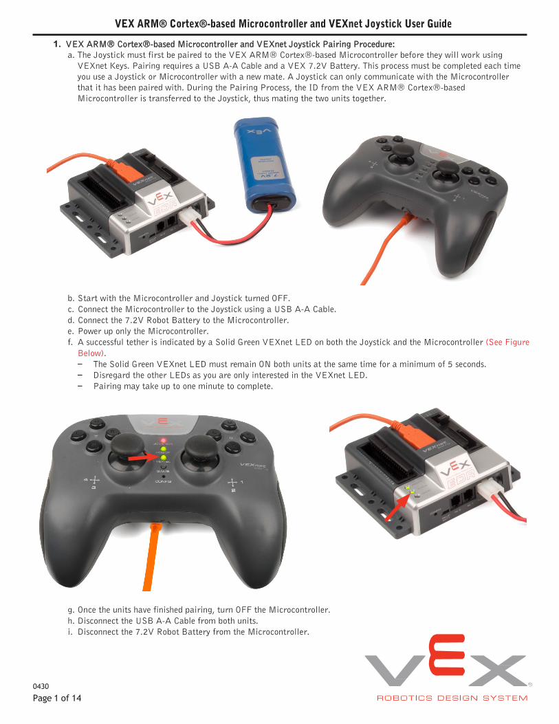
2. Basic connections; batteries, Microcontroller, Joysticks and (2) VEXnet keys.
a. Attach a 7.2v battery and a VEXnet USB Key to the Microcontroller as shown.b. Install six identical batteries as shown. Use Alkaline, Ni-Cad or Ni-MH type batteries, but DO NOT mix different
kinds of batteries. Charge rechargeable batteries only with a quality charger designed for your battery type.
c. Reinstall the battery cover (insert the two tabs of the battery cover first along the back edge of the battery cover to aidin installation) and then tighten the cover screw. Then add the VEXnet USB Key as shown.
Page 2 of 14
VEX ARM® Cortex®-based Microcontroller and VEXnet Joystick User Guide
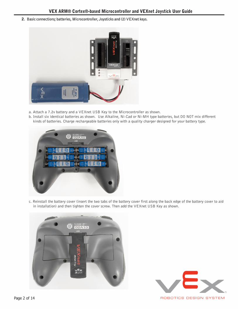
d. You can also power your Joystick directly from a standard wall outlet using the Joystick Power Adapter (276-1710).Simply plug this cable into your Joystick’s PROGRAM/FACTORY port and you can operate your Joystick withoutthe use of batteries. Please note: when using the Joystick Power Adapter, it is not necessary to turn your JoystickON. Also, the JOYSTICK/POWER LED can be ignored.
e. Turn on the Microcontroller and Joystick by setting the power switches to ON as shown in the two pictures below.
Page 3 of 14
VEX ARM® Cortex®-based Microcontroller and VEXnet Joystick User Guide
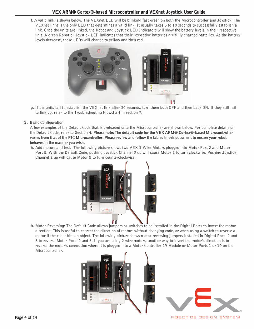
f. A valid link is shown below. The VEXnet LED will be blinking fast green on both the Microcontroller and Joystick. TheVEXnet light is the only LED that determines a valid link. It usually takes 5 to 10 seconds to successfully establish alink. Once the units are linked, the Robot and Joystick LED Indicators will show the battery levels in their respectiveunit. A green Robot or Joystick LED indicates that their respective batteries are fully charged batteries. As the batterylevels decrease, these LEDs will change to yellow and then red.
g. If the units fail to establish the VEXnet link after 30 seconds, turn them both OFF and then back ON. If they still failto link up, refer to the Troubleshooting Flowchart in section 7.
3. Basic ConfigurationA few examples of the Default Code that is preloaded onto the Microcontroller are shown below. For complete details on the Default Code, refer to Section 4. Please note: The default code for the VEX ARM® Cortex®-based Microcontroller varies from that of the PIC Microcontroller. Please review and follow the tables in this document to ensure your robot behaves in the manner you wish.a. Add motors and test. The following picture shows two VEX 3-Wire Motors plugged into Motor Port 2 and Motor
Port 5. With the Default Code, pushing Joystick Channel 3 up will cause Motor 2 to turn clockwise. Pushing JoystickChannel 2 up will cause Motor 5 to turn counterclockwise.
b. Motor Reversing: The Default Code allows jumpers or switches to be installed in the Digital Ports to invert the motordirection. This is useful to correct the direction of motors without changing code, or when using a switch to reverse amotor if the robot hits an object. The following picture shows motor reversing jumpers installed in Digital Ports 2 and5 to reverse Motor Ports 2 and 5. If you are using 2-wire motors, another way to invert the motor’s direction is toreverse the motor’s connection where it is plugged into a Motor Controller 29 Module or Motor Ports 1 or 10 on theMicrocontroller.
Page 4 of 14
VEX ARM® Cortex®-based Microcontroller and VEXnet Joystick User Guide
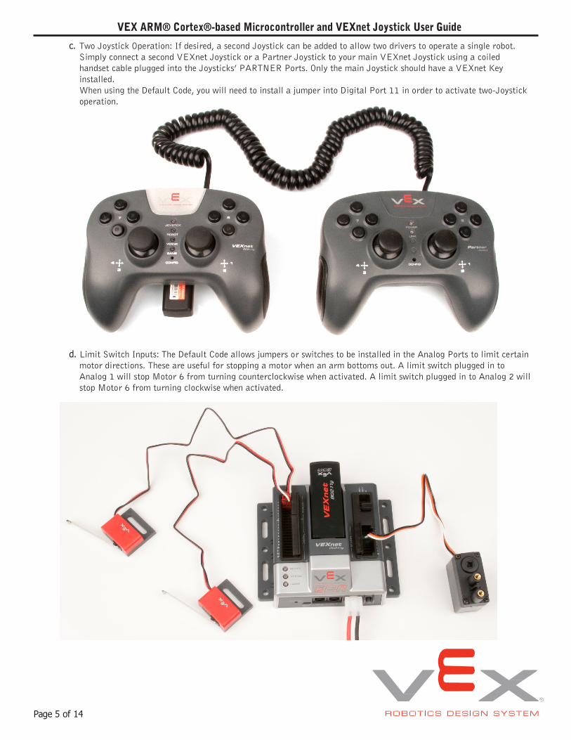
c. Two Joystick Operation: If desired, a second Joystick can be added to allow two drivers to operate a single robot.Simply connect a second VEXnet Joystick or a Partner Joystick to your main VEXnet Joystick using a coiledhandset cable plugged into the Joysticks’ PARTNER Ports. Only the main Joystick should have a VEXnet Keyinstalled.When using the Default Code, you will need to install a jumper into Digital Port 11 in order to activate two-Joystickoperation.
d. Limit Switch Inputs: The Default Code allows jumpers or switches to be installed in the Analog Ports to limit certainmotor directions. These are useful for stopping a motor when an arm bottoms out. A limit switch plugged in toAnalog 1 will stop Motor 6 from turning counterclockwise when activated. A limit switch plugged in to Analog 2 willstop Motor 6 from turning clockwise when activated.
Page 5 of 14
VEX ARM® Cortex®-based Microcontroller and VEXnet Joystick User Guide
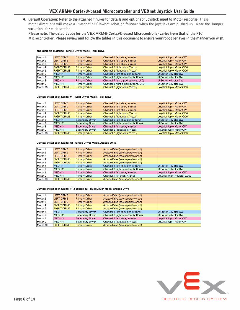
4. Default Operation: Refer to the attached figures for details and options of Joystick input to Motor response. These motor directions will make a Protobot or Clawbot robot go forward when the joysticks are pushed up. Note the Jumper variations for each section.Please note: The default code for the VEX ARM® Cortex®-based Microcontroller varies from that of the PIC Microcontroller. Please review and follow the tables in this document to ensure your robot behaves in the manner you wish.
Page 6 of 14
Motor 1 LEFT DRIVE Joystick Right = Motor CW Motor 2 LEFT DRIVE Joystick Right = Motor CW Motor 3 LEFT DRIVE Joystick Right = Motor CW Motor 4 RIGHT DRIVE Joystick Right = Motor CW Motor 5 RIGHT DRIVE Joystick Right = Motor CW Motor 10 RIGHT DRIVE Joystick Right = Motor CW
Motor 1 LEFT DRIVE Joystick Up = Motor CW Motor 2 LEFT DRIVE Joystick Up = Motor CW Motor 3 LEFT DRIVE Joystick Up = Motor CW Motor 4 RIGHT DRIVE Joystick Up = Motor CCW Motor 5 RIGHT DRIVE Joystick Up = Motor CCW Motor 10 RIGHT DRIVE Joystick Up = Motor CCW
VEX ARM® Cortex®-based Microcontroller and VEXnet Joystick User Guide
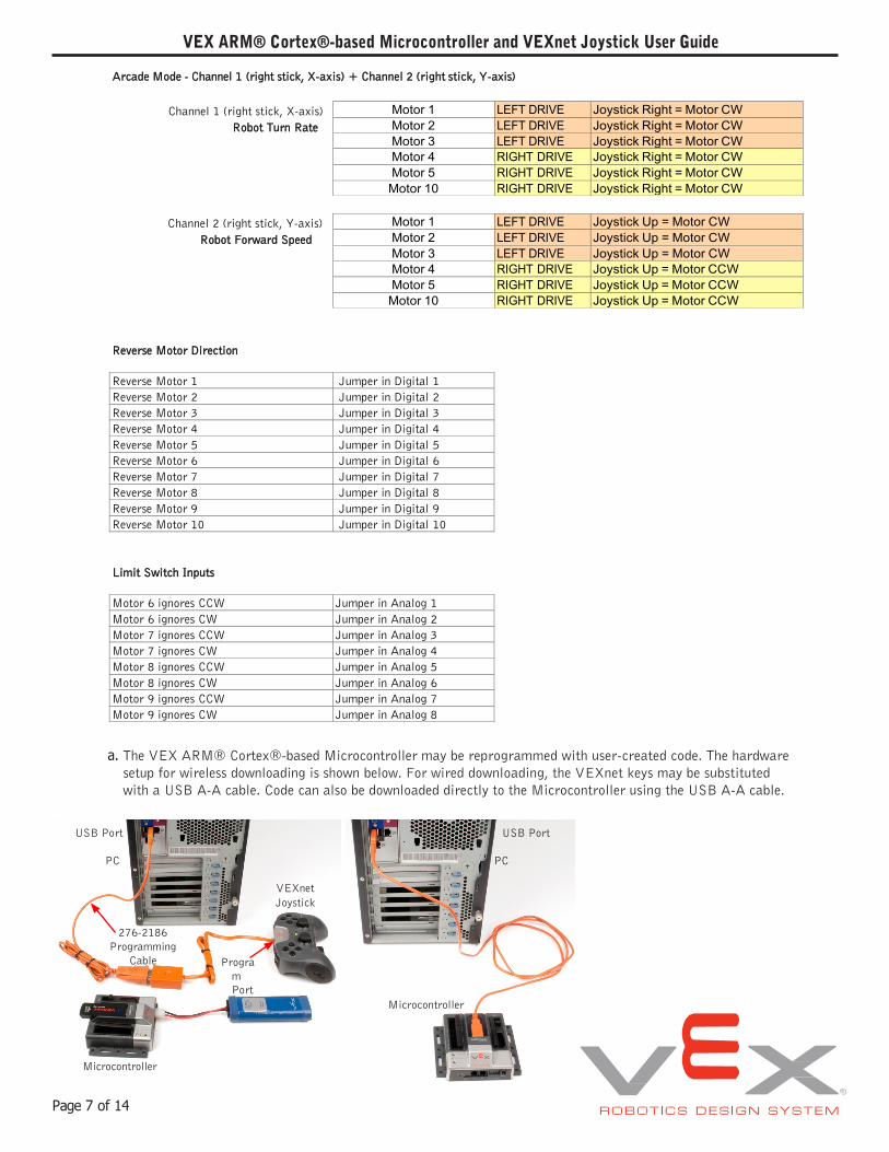
Arcade Mode - Channel 1 (right stick, X-axis) + Channel 2 (right stick, Y-axis)
Channel 1 (right stick, X-axis) Robot Turn Rate
Channel 2 (right stick, Y-axis) Robot Forward Speed
Reverse Motor Direction
Reverse Motor 1 Jumper in Digital 1 Reverse Motor 2 Jumper in Digital 2 Reverse Motor 3 Jumper in Digital 3 Reverse Motor 4 Jumper in Digital 4 Reverse Motor 5 Jumper in Digital 5 Reverse Motor 6 Jumper in Digital 6 Reverse Motor 7 Jumper in Digital 7 Reverse Motor 8 Jumper in Digital 8 Reverse Motor 9 Jumper in Digital 9 Reverse Motor 10 Jumper in Digital 10
Limit Switch Inputs
Motor 6 ignores CCW Jumper in Analog 1 Motor 6 ignores CW Jumper in Analog 2 Motor 7 ignores CCW Jumper in Analog 3 Motor 7 ignores CW Jumper in Analog 4 Motor 8 ignores CCW Jumper in Analog 5 Motor 8 ignores CW Jumper in Analog 6 Motor 9 ignores CCW Jumper in Analog 7 Motor 9 ignores CW Jumper in Analog 8
a. The VEX ARM® Cortex®-based Microcontroller may be reprogrammed with user-created code. The hardware setup for wireless downloading is shown below. For wired downloading, the VEXnet keys may be substituted with a USB A-A cable. Code can also be downloaded directly to the Microcontroller using the USB A-A cable.
USB Port USB Port
PC PC
VEXnet Joystick
276-2186 Programming
Cable Program Port
Microcontroller
Microcontroller
Page 7 of 14
VEX ARM® Cortex®-based Microcontroller and VEXnet Joystick User Guide
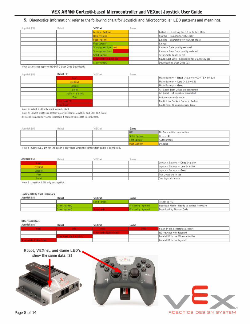
5. Diagnostics Information: refer to the following chart for Joystick and Microcontroller LED patterns and meanings.
Joystick [5] Robot VEXnet Game Medium (yellow) Initialize - Looking for PC or Tether Mate Blip (yellow) Startup - Looking for USB Key Fast (yellow) Linking - Searching for VEXnet Mate Fast (green) Linked Slow (green / yell ow) Linked - Data quality reduced Slow (green / red ) Linked - Poor Data quality reduced Solid (green) Tethered to Mate or PC Slow (red) single blink Fault: Lost Link - Searching for VEXnet Mate Slow (green) Downloading User Code [1]
Note 1: Does not apply to ROBOTC User Code Downloads
Joystick [5] Robot [1] VEXnet Game (red) Main Battery = Dead (<5.5v) or CORTEX Off [2]
(yellow) Main Battery = Low (<6.5v) [2]
(green) Main Battery = Good
Solid All Good: Both Joysticks connected Solid + 1 Blink All Good: Tx1 Joystick connected
Fast Autonomous only mode Fast (red) [3] Fault: Low Backup Battery (0v-8v) Slow (red) Fault: User Microprocessor Issue
Note 1: Robot LED only work when Linked Note 2: Lowest CORTEX battery color latched at Joystick and CORTEX Note
3: No Backup Battery only indicated if competition cable is connected.
Joystick [5] Robot VEXnet Game Off No Competition connection Solid (green) Driver [4] Fast (green) Autonomous Fast (yellow) Disabled
Note 4 : Game LED Driver Indicator is only used when the competition cable is connected.
Joystick [5] Robot VEXnet Game (red) Joystick Battery = Dead (<5.5v)
(yellow) Joystick Battery = Low (<6.5v)
(green) Joystick Battery = Good
Fast Two Joysticks in use Solid One Joystick in use
Note 5 : Joystick LED only on Joystick.
Update Utility Tool Indicators Joystick [5] Robot VEXnet Game
Solid (green) Tether to PC Slow (green) Flickering (green) Bootload Mode - Ready to update firmware Slow (green) Slow (red) Flickering (green) Downloading Master Code
Other Indicators Joystick [5] Robot VEXnet Game
(red) (red) (red) (red) Flash on all 3 indicates a Reset Slow (red) double blink NO VEXnet Key detected
Slow (red) double blink Invaild ID in the Microcontroller Slow (red) double blink Invaild ID in the Joystick
Robot, VEXnet, and Game LED’s show the same data [2]
Page 8 of 14
VEX ARM® Cortex®-based Microcontroller and VEXnet Joystick User Guide
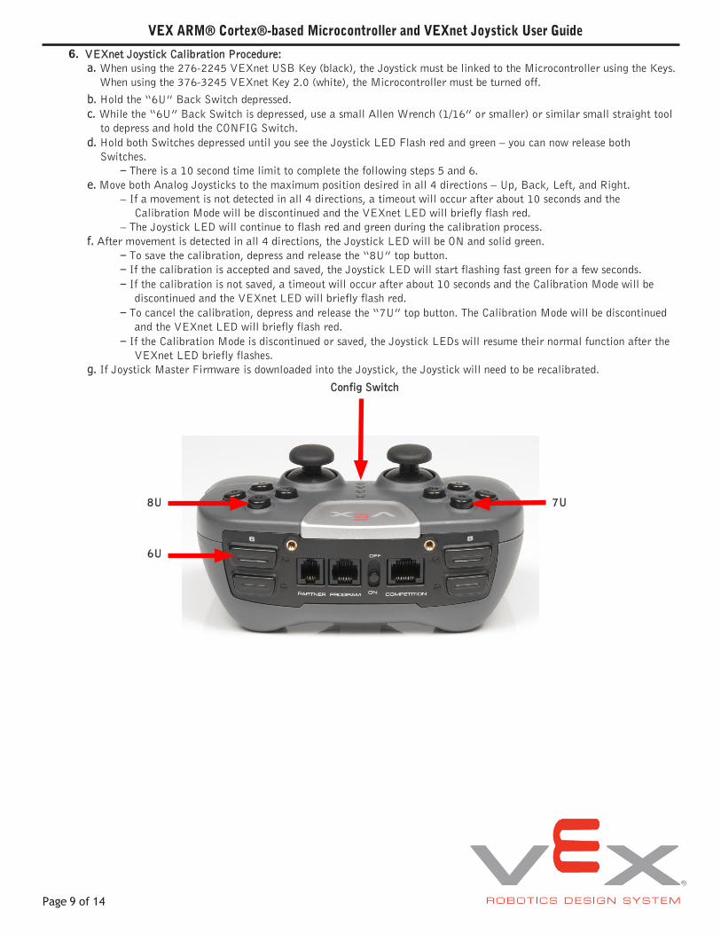
6. VEXnet Joystick Calibration Procedure:a. When using the 276-2245 VEXnet USB Key (black), the Joystick must be linked to the Microcontroller using the Keys.
When using the 376-3245 VEXnet Key 2.0 (white), the Microcontroller must be turned off.b. Hold the “6U” Back Switch depressed.c. While the “6U” Back Switch is depressed, use a small Allen Wrench (1/16” or smaller) or similar small straight tool
to depress and hold the CONFIG Switch.d. Hold both Switches depressed until you see the Joystick LED Flash red and green – you can now release both
Switches.– There is a 10 second time limit to complete the following steps 5 and 6.
e. Move both Analog Joysticks to the maximum position desired in all 4 directions – Up, Back, Left, and Right.– If a movement is not detected in all 4 directions, a timeout will occur after about 10 seconds and the
Calibration Mode will be discontinued and the VEXnet LED will briefly flash red. – The Joystick LED will continue to flash red and green during the calibration process.
f. After movement is detected in all 4 directions, the Joystick LED will be ON and solid green.– To save the calibration, depress and release the “8U” top button.– If the calibration is accepted and saved, the Joystick LED will start flashing fast green for a few seconds.– If the calibration is not saved, a timeout will occur after about 10 seconds and the Calibration Mode will be
discontinued and the VEXnet LED will briefly flash red. – To cancel the calibration, depress and release the “7U” top button. The Calibration Mode will be discontinued
and the VEXnet LED will briefly flash red. – If the Calibration Mode is discontinued or saved, the Joystick LEDs will resume their normal function after the
VEXnet LED briefly flashes. g. If Joystick Master Firmware is downloaded into the Joystick, the Joystick will need to be recalibrated.
Config Switch
8U 7U
6U
Page 9 of 14
VEX ARM® Cortex®-based Microcontroller and VEXnet Joystick User Guide
Page 10 of 14
Is theGame LEDflashing?
Do allLEDs
flash Red in arepeating
cycle?
Is theRobot LEDblinking?
Fastor slowblink?
Is theVEXnet LED
green?
Does the Microcontroller
turn on?
Start
Singleor double
blink?
Do all motors workcorrectly?
Are youhaving troublerunning yourcompetitionautonomous
code?
Is theRobot LED on the Microcontroller
consistently red?
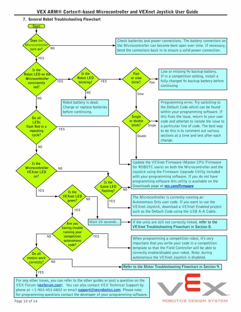
7. General Robot Troubleshooting Flowchart
Check batteries and power connections. The battery connectors on the Microcontroller can become bent open over time. If necessary, bend the connectors back in to ensure a solid power connection.
Low or missing 9v backup battery. If in a competition setting, install a fully charged 9v backup battery before continuing
Programming error. Try switching to the Default Code which can be found within your programming software. If this fixes the issue, return to your user code and attempt to isolate the issue to a particular line of code. The best way to do this is to comment out various sections at a time and test after each change.
If the units are still not correctly linked, refer to the VEXnet Troubleshooting Flowchart in Section 8.
Robot battery is dead. Charge or replace batteries before continuing.
Fast
Single
Double
Slow
YES
YES
NO
NO
NO
NO
NO
NO
NO
NO
YES
YES
YES
YES
YES
YES
Update the VEXnet Firmware (Master CPU Firmware for ROBOTC users) on both the Microcontroller and the Joystick using the Firmware Upgrade Utility included with your programming software. If you do not have programming software this utility is available on the Downloads page at vex.com/firmware
The Microcontroller is currently running an Autonomous Only user code. If you want to use the VEXnet Joystick, download a VEXnet Enabled project such as the Default Code using the USB A-A Cable.
When programming a competition robot, it’s very important that you write your code in a competition template so that the Field Controller will be able to correctly enable/disable your robot. Note: during autonomous the VEXnet Joystick is disabled.
For any other issues, you can refer to the other guides or post a question on the VEX Forum (vexforum.com). You can also contact VEX Technical Support by phone at +1-903-453-0802 or email [email protected]. Please note: for programming questions contact the developer of your programming software.
Wait 20 seconds…
Refer to the Motor Troubleshooting Flowchart in Section 9.
Is the Microcontroller VEXnet LED
on?
NO
YES
VEX ARM® Cortex®-based Microcontroller and VEXnet Joystick User Guide
Page 11 of 14
Is theJoystick LED
solid?
Doboth units turn
on?
Are both VEXnet LEDs
on?
Singleor double
blink?
Is theJoystick LED
red?
IsVEXnet
LED flashing multiplecolors?
What coloris the VEXnet
LED?
Forlonger than 20
seconds?
Start
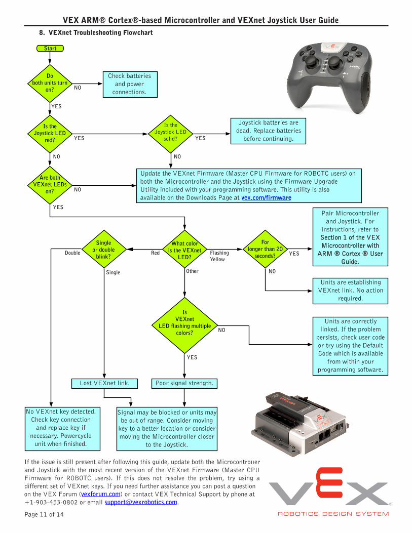
8. VEXnet Troubleshooting Flowchart
Update the VEXnet Firmware (Master CPU Firmware for ROBOTC users) on both the Microcontroller and the Joystick using the Firmware Upgrade Utility included with your programming software. This utility is also available on the Downloads Page at vex.com/firmware
Check batteries and power
connections.
Joystick batteries are dead. Replace batteries
before continuing.
Signal may be blocked or units may be out of range. Consider moving
key to a better location or consider moving the Microcontroller closer
to the Joystick.
Poor signal strength.Lost VEXnet link.
No VEXnet key detected. Check key connection
and replace key if necessary. Powercycle
unit when finished.
Units are correctly linked. If the problem
persists, check user code or try using the Default Code which is available
from within your programming software.
Units are establishing VEXnet link. No action
required.
If the issue is still present after following this guide, update both the Microcontroller and Joystick with the most recent version of the VEXnet Firmware (Master CPU Firmware for ROBOTC users). If this does not resolve the problem, try using a different set of VEXnet keys. If you need further assistance you can post a questionon the VEX Forum (vexforum.com) or contact VEX Technical Support by phone at +1-903-453-0802 or email [email protected].
NO
NO
NO
NO
NO
NO
YES
YES
YES
YES
YES
Flashing Yellow
OtherSingle
Double Red
YES
Pair Microcontroller and Joystick. For
instructions, refer to Section 1 of the VEX Microcontroller with
ARM ® Cortex ® User Guide.
VEX ARM® Cortex®-based Microcontroller and VEXnet Joystick User Guide
Page 12 of 14
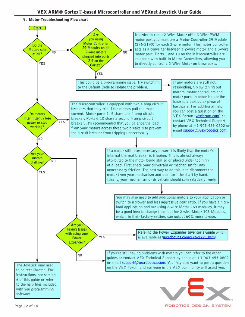
Do theMotors spin
at all?
Areyou using
Motor Controller29 Modules on all
2-wire motorsplugged into ports
2-9 on theCortex?
Are yourmotors
drifting?
Do motorsintermittently lose
power or stopworking?
Are youhaving Issues
with using yourPower
Expander?
Start
In order to run a 2-Wire Motor off a 3-Wire PWM motor port you must use a Motor Controller 29 Module (276-2193) for each 2-wire motor. This motor controller acts as a converter between a 2-wire motor and a 3-wire motor port. Ports 1 and 10 on the Microcontroller are equipped with built-in Motor Controllers, allowing you to directly control a 2-Wire Motor on these ports.
The Microcontroller is equipped with two 4 amp circuit breakers that may trip if the motors pull too much current. Motor ports 1- 5 share one 4 amp circuit breaker. Ports 6-10 share a second 4 amp circuit breaker. It’s recommended that you balance the load from your motors across these two breakers to prevent the circuit breaker from tripping unnecessarily.
If any motors are still not responding, try switching out motors, motor controllers and motor ports in order isolate the issue to a particular piece of hardware. For additional help, you can post a question on the VEX Forum (vexforum.com) or contact VEX Technical Support by phone at +1-903-453-0802 or email [email protected].
This could be a programming issue. Try switching to the Default Code to isolate the problem.
If a motor still loses necessary power it is likely that the motor’s internal thermal breaker is tripping. This is almost always attributed to the motor being stalled or placed under too high of a load. First check your drivetrain or mechanism for any unnecessary friction. The best way to do this is to disconnect the motor from your mechanism and then turn the shaft by hand. Ideally, your mechanism or drivetrain should spin relatively freely.
If you’re still having problems with motors you can refer to the other guides or contact VEX Technical Support by phone at +1-903-453-0802 or email [email protected]. You may also want to post a question on the VEX Forum and someone in the VEX community will assist you.The Joystick may need
to be recalibrated. For instructions, see section 6 of this guide or refer to the help files included with you programming software.
You may also need to add additional motors to your application or switch to a slower and less aggressive gear ratio. If you have a high-load application and are using 2-wire Motor 269 modules, it may be a good idea to change them out for 2-wire Motor 393 Modules, which, in their factory setting, can output 60% more torque.
Refer to the Power Expander Inventor’s Guide which is available at vexrobotics.com/276-2271.html
YES
YES
YES
YES
YES
NO
NO
NO
NO
NO
9. Motor Troubleshooting Flowchart
VEX ARM® Cortex®-based Microcontroller and VEXnet Joystick User Guide
Page 13 of 14
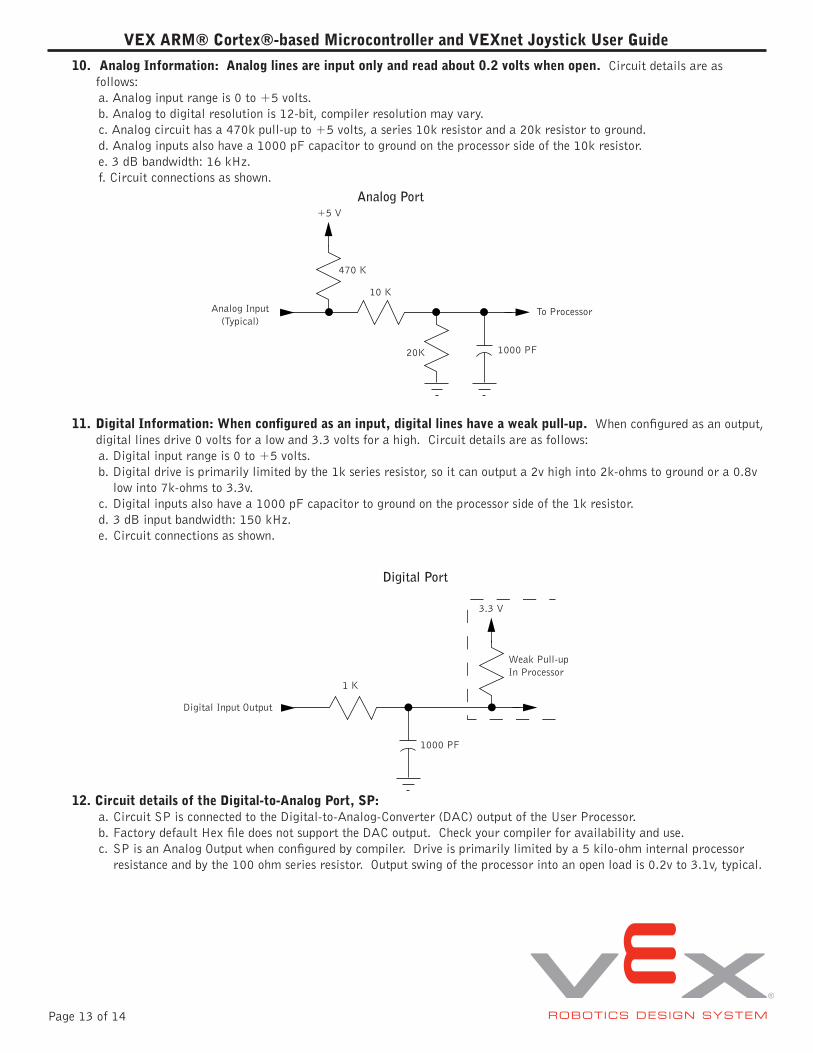
10. Analog Information: Analog lines are input only and read about 0.2 volts when open. Circuit details are asfollows:a. Analog input range is 0 to +5 volts.b. Analog to digital resolution is 12-bit, compiler resolution may vary.c. Analog circuit has a 470k pull-up to +5 volts, a series 10k resistor and a 20k resistor to ground.d. Analog inputs also have a 1000 pF capacitor to ground on the processor side of the 10k resistor.e. 3 dB bandwidth: 16 kHz.f. Circuit connections as shown.
Weak Pull-up In Processor
Digital Input Output
1000 PF
3.3 V
1 K
Digital Port
Analog Input(Typical)
To Processor
20K 1000 PF
470 K
10 K
+5 VAnalog Port
11. DigitalInformation:Whenconfiguredasaninput,digitallineshaveaweakpull-up. When configured as an output,digital lines drive 0 volts for a low and 3.3 volts for a high. Circuit details are as follows:a. Digital input range is 0 to +5 volts.b. Digital drive is primarily limited by the 1k series resistor, so it can output a 2v high into 2k-ohms to ground or a 0.8v
low into 7k-ohms to 3.3v.c. Digital inputs also have a 1000 pF capacitor to ground on the processor side of the 1k resistor.d. 3 dB input bandwidth: 150 kHz.e. Circuit connections as shown.
12. CircuitdetailsoftheDigital-to-AnalogPort,SP:a. Circuit SP is connected to the Digital-to-Analog-Converter (DAC) output of the User Processor.b. Factory default Hex file does not support the DAC output. Check your compiler for availability and use.c. SP is an Analog Output when configured by compiler. Drive is primarily limited by a 5 kilo-ohm internal processor
resistance and by the 100 ohm series resistor. Output swing of the processor into an open load is 0.2v to 3.1v, typical.
VEX ARM® Cortex®-based Microcontroller and VEXnet Joystick User Guide
Page 14 of 14
13. 2-WireMotorPortoutputs:a. Motor Port 1 and Motor Port 10.b. Maximum motor stall current: 3.0 amps at 8.5 volts.c. Motor chop rate: determined by the compiler. Default code chop rate: 1 kHz.d. Overcurrent protection: Motor Port 1 through Motor Port 5 shares one 4 amp circuit breaker. Motor Port 6 through
Motor Port 10 shares a second 4 amp circuit breaker.
14. 3-WireMotorPortoutputs:a. Motor Ports 2 through 9.b. Maximum motor stall current: internally limited by motor assembly.c. Motor PWM output: determined by the compiler. Default is 1 to 2 milliseconds high time and a 17 millisecond period.d. Overcurrent protection: Motor Port 1 through Motor Port 5 shares one 4 amp circuit breaker. Motor Port 6 through
Motor Port 10 shares a second 4 amp circuit breaker.
15. UART Connections:a. Ground, Power (+5v), RX data in, TX data out. Data rate, byte width, (transmit) stop bits, parity, etc. are determined
by the compiler.b. Default for LCD data: 19,200 baud, 8 data bits, 1 stop bit, no parity and no flow control.
16. I2C Connections: a. Ground, Power (+5v), Clock, Data. Data rate, byte width, (transmit) stop bits, parity, etc. are determined by the
compiler.b. The factory default Hex file does not support I2C.
17. Notes:a. Do not use a USB Hub with the VEX ARM® Cortex®-based Microcontroller or VEXnet Joystick. Always make a
connection directly to a PC USB port when needed. USB Hub performance is not supported.


![ROBOTC for VEX Cortex and PIC VEXnet Remote Controlbssdt.weebly.com/uploads/1/3/2/6/13266197/robotc...ROBOTC for VEX Cortex and PIC VEXnet Remote Control vexRT[] Array that contains](https://img.pdfslide.net/doc/110x75/60e60742d77063770e564eb0/robotc-for-vex-cortex-and-pic-vexnet-remote-robotc-for-vex-cortex-and-pic-vexnet.jpg)