Embed Size (px)
Citation preview

*Optimized Cascade services are provided by ConocoPhillips Company, Phillips LNG Technology Services Company and Bechtel Corporation via a collaborative relationship with ConocoPhillips Company. Optimized Cascade, the Optimized Cascade logo, ConocoPhillips and its logo are trademarks of ConocoPhillips Company. Bechtel and its logos are trademarks of Bechtel Group Inc.
Viability of Combined Cycle Drivers for LNG Plants Ram Tekumalla, Maheep Jain and Vibhor Mehrotra Bechtel Corporation Houston, TX, USA [email protected]
Karl Masani ConocoPhillips Company Houston, TX, USA [email protected] AIChE Spring Meeting, April 2007 7thTopical Conference on Natural Gas Utilization Houston, Texas, 22-26, 2007
Introduction Liquefied natural gas plants have increased in size to take advantage of economies of scale and rapidly growing markets. Designers of LNG facilities must consider the impact of numerous variables such as capital and operating costs, thermal efficiency, availability, reliability, environmental regulations, and project schedule. For many LNG projects, driver configuration remains one of the largest areas of study. This is because driver and compressor configuration sets the plant capacity, represents a large share of capital costs for the liquefaction facility, and determines the fuel gas consumption and emissions. This paper presents the viability of combined cycle drivers for LNG compressors, based on the ConocoPhillips Optimized Cascade process. The basis for the paper is a dynamic simulation study sponsored by the ConocoPhillips-Bechtel Global LNG Collaboration Product Development Center (PDC). The paper also presents preliminary economic analysis supporting the combined cycle driver configuration. Throughout this paper, combined cycle refers to a combination of gas turbines, waste heat recovery, and steam turbines. Combined cycle drivers provide an attractive design alternative for LNG plants. Qualls and Hunter, 2003, described how a combined cycle plant successfully reduces capital costs and increases thermal efficiency for Optimized Cascade plants. The main advantage of the combined cycle drivers is the reduction in fuel
59
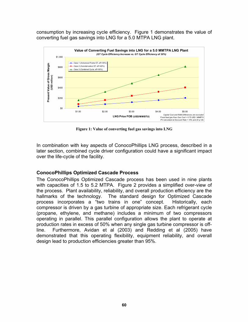
consumption by increasing cycle efficiency. Figure 1 demonstrates the value of converting fuel gas savings into LNG for a 5.0 MTPA LNG plant.
Value of Converting Fuel Savings into LNG for a 5.0 MMTPA LNG Plant(GT Cycle Efficiency Increase vs. GT Cycle Efficiency of 30%)
$0
$200
$400
$600
$800
$1,000
$1.00 $2.00 $3.00 $4.00 $5.00
LNG Price FOB (USD/MMBTU)
Pres
ent V
alue
of G
ross
Mar
gin
(USD
mill
ion)
Case 1 (Advanced Frame GT, eff=35%)
Case 2 (Aeroderivative GT, eff=40%)
Case 3 (Combined Cycle, eff=50%)
Capital Cost and RAM Differences are excludedFixed feed gas flow: Gas Cost = 0.75 USD / MMBTUPV calculated at Discount Rate = 10% and 20 yr life
Figure 1: Value of converting fuel gas savings into LNG
In combination with key aspects of ConocoPhillips LNG process, described in a later section, combined cycle driver configuration could have a significant impact over the life-cycle of the facility.
ConocoPhillips Optimized Cascade Process The ConocoPhillips Optimized Cascade process has been used in nine plants with capacities of 1.5 to 5.2 MTPA. Figure 2 provides a simplified over-view of the process. Plant availability, reliability, and overall production efficiency are the hallmarks of the technology. The standard design for Optimized Cascade process incorporates a “two trains in one” concept. Historically, each compressor is driven by a gas turbine of appropriate size. Each refrigerant cycle (propane, ethylene, and methane) includes a minimum of two compressors operating in parallel. This parallel configuration allows the plant to operate at production rates in excess of 50% when any single gas turbine compressor is off-line. Furthermore, Avidan et al (2003) and Redding et al (2005) have demonstrated that this operating flexibility, equipment reliability, and overall design lead to production efficiencies greater than 95%.
60
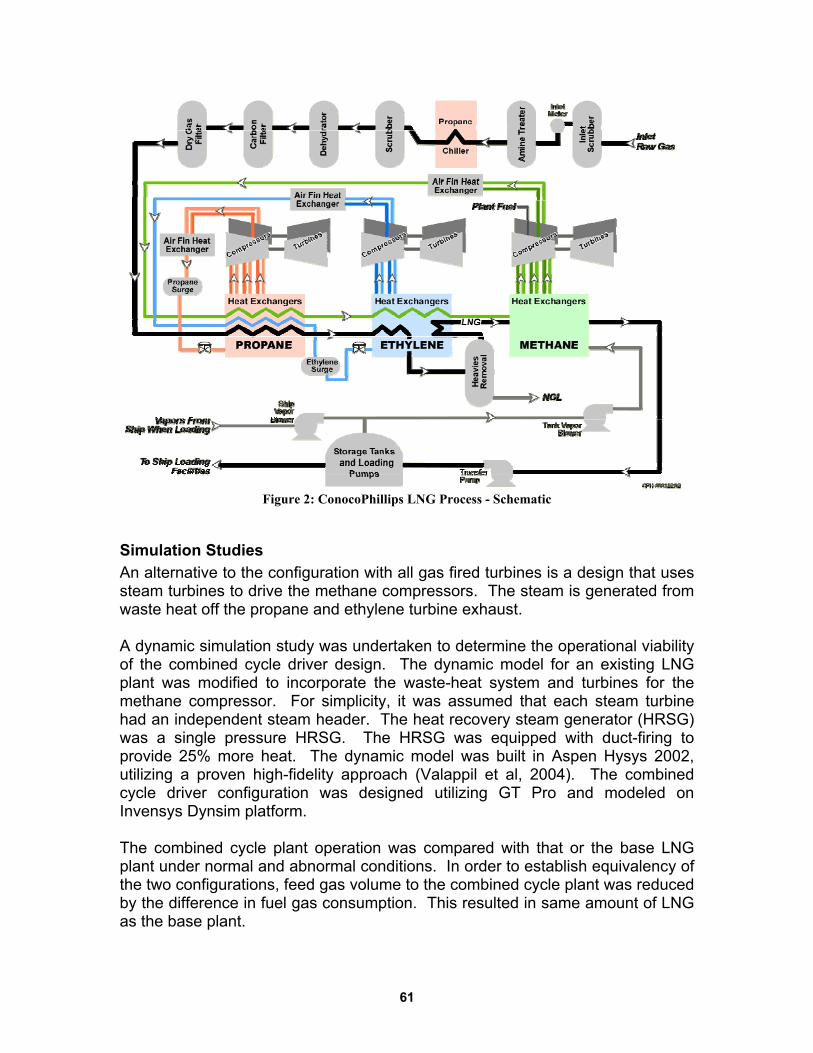
Figure 2: ConocoPhillips LNG Process - Schematic
Simulation Studies An alternative to the configuration with all gas fired turbines is a design that uses steam turbines to drive the methane compressors. The steam is generated from waste heat off the propane and ethylene turbine exhaust. A dynamic simulation study was undertaken to determine the operational viability of the combined cycle driver design. The dynamic model for an existing LNG plant was modified to incorporate the waste-heat system and turbines for the methane compressor. For simplicity, it was assumed that each steam turbine had an independent steam header. The heat recovery steam generator (HRSG) was a single pressure HRSG. The HRSG was equipped with duct-firing to provide 25% more heat. The dynamic model was built in Aspen Hysys 2002, utilizing a proven high-fidelity approach (Valappil et al, 2004). The combined cycle driver configuration was designed utilizing GT Pro and modeled on Invensys Dynsim platform. The combined cycle plant operation was compared with that or the base LNG plant under normal and abnormal conditions. In order to establish equivalency of the two configurations, feed gas volume to the combined cycle plant was reduced by the difference in fuel gas consumption. This resulted in same amount of LNG as the base plant.
61
During normal operation, the combined cycle plant produces an equivalent amount of LNG as the base plant without requiring supplemental firing. Efficiency of the turbine heat cycle increased from 28% (lower heating value) for the base plant to 43% for the combined cycle driver configuration. The two most critical abnormal scenarios in an LNG plant are compressor trips and turn down to half-rate. The study shows that the combined cycle driver configuration had a minimal impact on the operational flexibility.
Operational Analysis
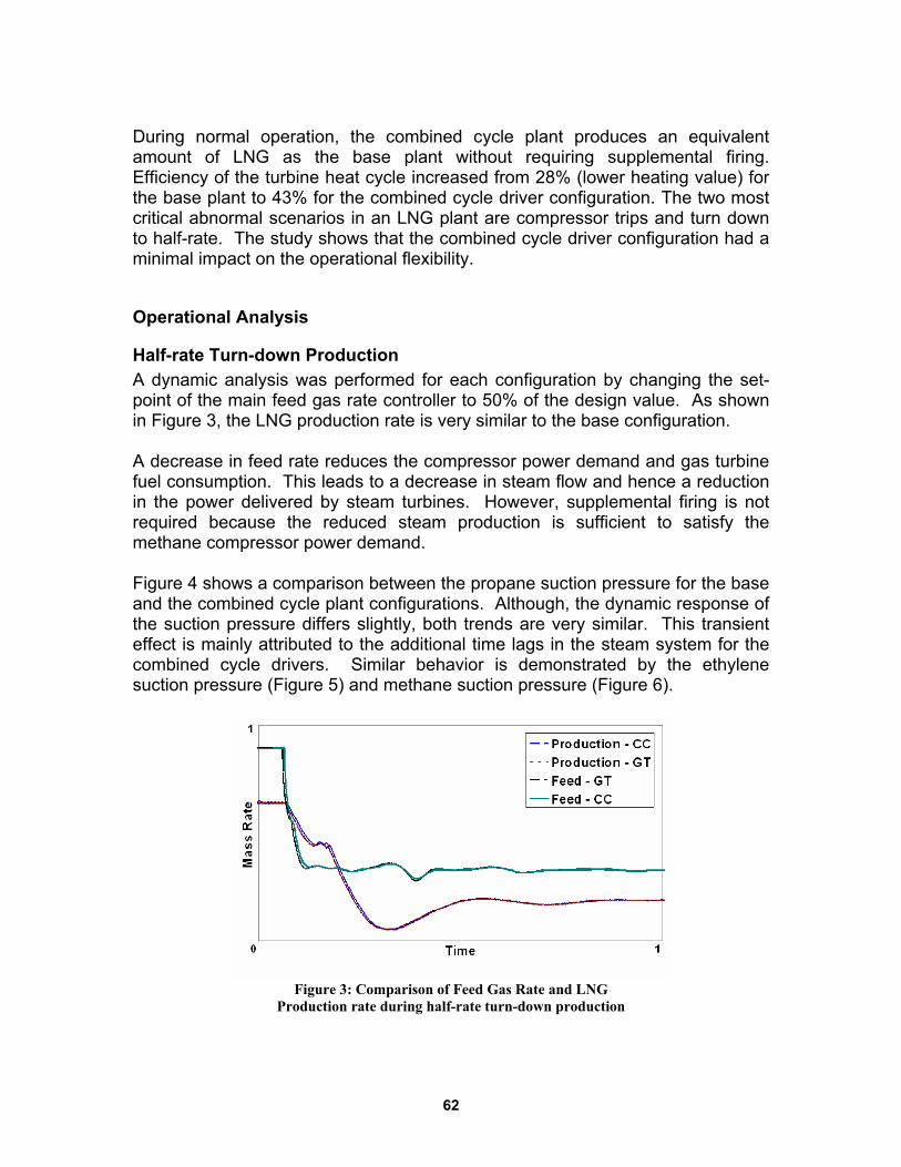
Half-rate Turn-down Production A dynamic analysis was performed for each configuration by changing the set-point of the main feed gas rate controller to 50% of the design value. As shown in Figure 3, the LNG production rate is very similar to the base configuration. A decrease in feed rate reduces the compressor power demand and gas turbine fuel consumption. This leads to a decrease in steam flow and hence a reduction in the power delivered by steam turbines. However, supplemental firing is not required because the reduced steam production is sufficient to satisfy the methane compressor power demand. Figure 4 shows a comparison between the propane suction pressure for the base and the combined cycle plant configurations. Although, the dynamic response of the suction pressure differs slightly, both trends are very similar. This transient effect is mainly attributed to the additional time lags in the steam system for the combined cycle drivers. Similar behavior is demonstrated by the ethylene suction pressure (Figure 5) and methane suction pressure (Figure 6).
Figure 3: Comparison of Feed Gas Rate and LNG
Production rate during half-rate turn-down production
62
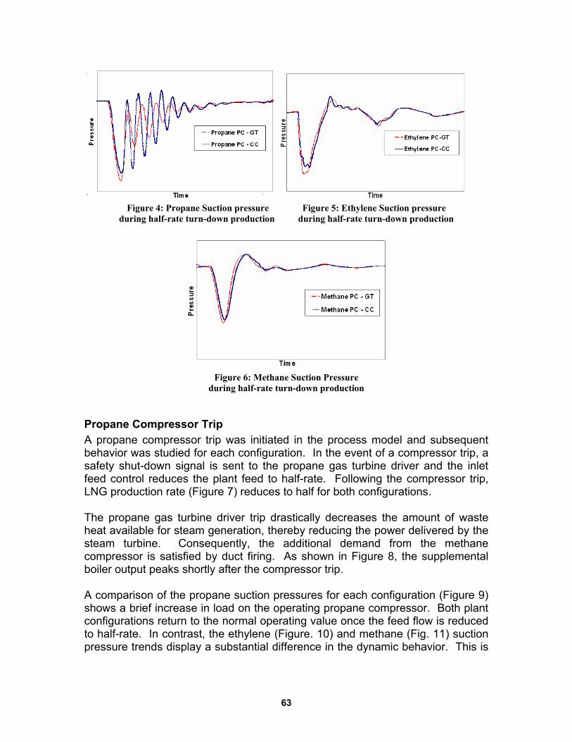
Figure 4: Propane Suction pressure Figure 5: Ethylene Suction pressure
during half-rate turn-down production during half-rate turn-down production
Figure 6: Methane Suction Pressure
during half-rate turn-down production
Propane Compressor Trip A propane compressor trip was initiated in the process model and subsequent behavior was studied for each configuration. In the event of a compressor trip, a safety shut-down signal is sent to the propane gas turbine driver and the inlet feed control reduces the plant feed to half-rate. Following the compressor trip, LNG production rate (Figure 7) reduces to half for both configurations. The propane gas turbine driver trip drastically decreases the amount of waste heat available for steam generation, thereby reducing the power delivered by the steam turbine. Consequently, the additional demand from the methane compressor is satisfied by duct firing. As shown in Figure 8, the supplemental boiler output peaks shortly after the compressor trip. A comparison of the propane suction pressures for each configuration (Figure 9) shows a brief increase in load on the operating propane compressor. Both plant configurations return to the normal operating value once the feed flow is reduced to half-rate. In contrast, the ethylene (Figure. 10) and methane (Fig. 11) suction pressure trends display a substantial difference in the dynamic behavior. This is
63
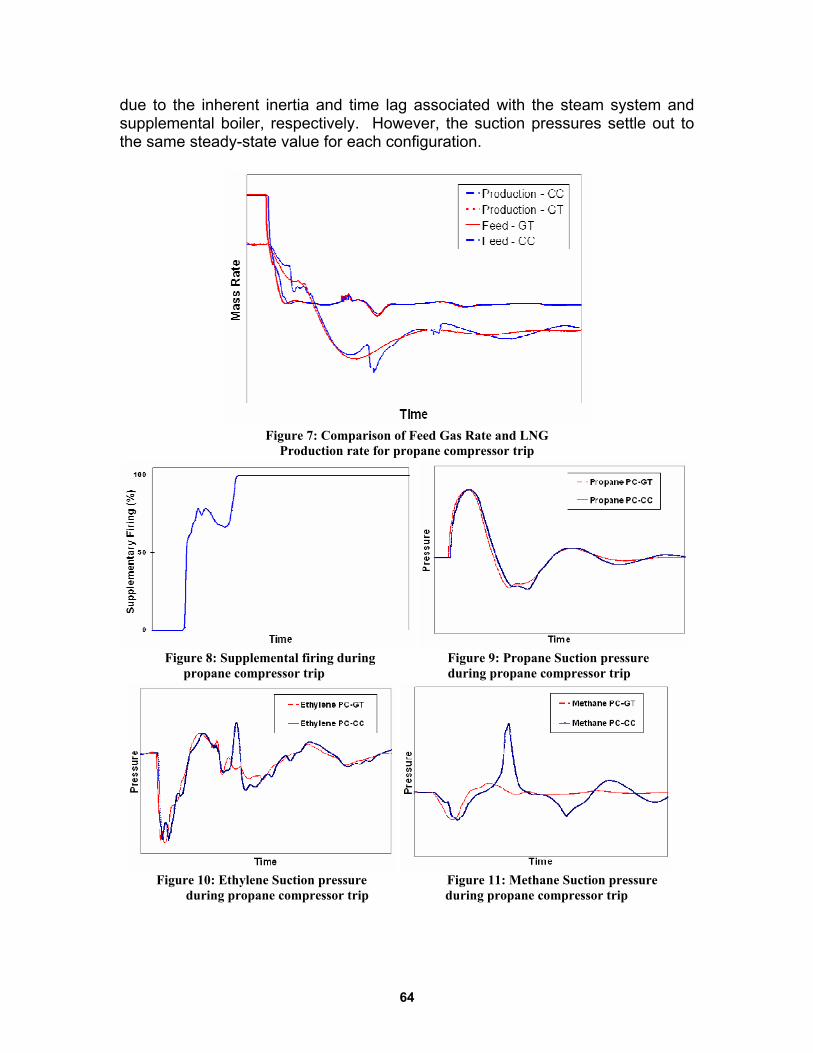
due to the inherent inertia and time lag associated with the steam system and supplemental boiler, respectively. However, the suction pressures settle out to the same steady-state value for each configuration.
Figure 7: Comparison of Feed Gas Rate and LNG
Production rate for propane compressor trip
Figure 8: Supplemental firing during Figure 9: Propane Suction pressure
propane compressor trip during propane compressor trip
Figure 10: Ethylene Suction pressure Figure 11: Methane Suction pressure
during propane compressor trip during propane compressor trip
64
Economic Analysis Reliability, availability, and maintainability (RAM) are three primary components that influence LNG production at a liquefaction facility. As described earlier, reliability is a key feature for the Optimized Cascade process using the “two-in-one” train concept. The largest single impact on production is the availability of the turbine drivers. Reliability of most proven gas turbines is in excess of 99% and availability is over of 96%. The availability is highly dependent on the owner’s scheduled maintenance strategy and the turbine selected (i.e. frame or aeroderivative). A detailed economic evaluation is needed to justify a combined cycle liquefaction plant. The value provided by the increase in thermal efficiency of the combined cycle plant will have to be evaluated against the increase in capital and maintenance costs and the decrease in plant availability. The cost of operations and maintenance does not have a major impact on the economic analysis and can be ignored in a preliminary evaluation. The major factors affecting the economics are the cost of gas supply and the LNG sales price. Gas supply to a liquefaction facility is also an issue, as it is usually constrained in some manner. A combined cycle design conserves some feed gas that can be valued in at least two ways. The first method assumes that the feed gas rate decreases while keeping the LNG production constant. The savings would be the value of the feed gas saved using the cost of the gas. The second technique assumes that the fuel gas saved would be converted into LNG. The extra LNG could be produced by two different schemes. In the first, the feed gas rate remains constant and the LNG production rate increases. This increase will likely require some additional investment to increase capacity. The second way would be to produce the LNG when the gas supply is no longer at plateau, but has declined. The actual gas production would keep the plant full longer. Both methods should be evaluated in pre-FEED in order to maximize the value to the owners.
Conclusion and Discussion This paper demonstrated the operational viability of a combined cycle driver for ConocoPhillips Optimized Cascade process. For the chosen configuration, the hallmark flexibility of the Optimized Cascade process was retained. A HRSG with duct firing may be necessary to maintain performance over various operating upsets.
65
The decision on driver selection should take into account a rigorous economic analysis. Steam turbines lead to decreased availability and increased start-up times. The impact of these variables should be balanced against potential gains from efficiency improvements. Further, it should be recognized that a combined cycle configuration need not be limited to the liquefaction. There is increasing interest for LNG facilities driven by electric motors alone (Martinez et al, 2005). In such cases, the combined cycle concept could be utilized for on-site power generation to monetize efficiencies. References • “A Focus on Balance – A Novel Approach Taking the Phillips Optimized
Cascade LNG Process Into The Future”, Qualls, W. and Hunter, P., AIChE Spring National Meeting, 2003.
• “All Electric Motor Drives for LNG Plants”, Martinez, B., Meher-Homji, C., Paschal, J. and Eaton, A., Gastech 2005.
• “Natural Gas Liquefaction Process Designers Look for Larger More Efficient Liquefaction Designs”, Avidan, A., Varnell and Martinez, B., Oil & Gas Journal, August 2003.
• “Egyptian LNG, the Value of Standardization”, Redding, P., Hernandez, R., Qualls, W. and Avidan, A., Gastech 2005.
• “Virtual Simulation of LNG Plant”, Valappil, J., Mehrotra, V., Messersmith, D. and Bruner, P., LNG Journal, Jan/Feb 2004
66

Biography
3000 Post Oak Blvd., Houston, TX 77056 Phone: 713-235-4340 E-mail: [email protected]. Ram Tekumalla is a Senior Simulation Specialist with the Advanced Simulation & Analysis Group, Bechtel Corporation, Houston. He is involved in development of dynamic models for a variety of projects. Over the past 4 years, he has used his expertise to develop Operator Training Simulators for 3 LNG plants. Ram is actively involved in various studies sponsored by the Bechtel – ConocoPhillips LNG Project Development Center. Ram Tekumalla started his career in 1998. He worked at Cape Software and Invensys prior to joining Bechtel. Ram earned his M.S in Chemical Engineering from the University of Massachusetts, Amherst; and B.E. (Hons) in Chemical Engineering from Birla Institute of Technology & Science, Pilani.
67

68