Embed Size (px)
Citation preview
VIBRATION ANALYSIS OF A CRACKED BEAM WITH ELASTIC SUPPORT
A THESIS SUBMITTED IN PARTIAL FULFILLMENT
OF THE REQUIREMENTS FOR THE DEGREE OF
Master of Technology In
Machine Design and Analysis
By
THULASI RAM NALLA
Department of Mechanical Engineering
National Institute of Technology
Rourkela
2007
VIBRATION ANALYSIS OF A CRACKED BEAM WITH ELASTIC SUPPORT
A THESIS SUBMITTED IN PARTIAL FULFILLMENT
OF THE REQUIREMENTS FOR THE DEGREE OF
Master of Technology In
Mechanical Engineering
By
THULASI RAM NALLA
Under the Guidance of
Prof. R.K.BEHERA
Department of Mechanical Engineering
National Institute of Technology
Rourkela
2007
National Institute of Technology
Rourkela
CERTIFICATE This is to certify that the thesis entitled, “Vibration Analysis of a Cracked Beam with
Elastic Support” submitted by Sri ThulasiRam Nalla in partial fulfillment of the
requirements for the award of Master of Technology in Mechanical Engineering with
specialization in “Machine Design and Analysis” at National Institute of Technology,
Rourkela (Deemed University) is an authentic work carried out by him under my
supervision and guidance.
To the best of my knowledge, the matter embodied in the thesis has not been submitted to
any other University / Institute for the award of any Degree or Diploma.
Prof.R.K.Behera Dept. of Mechanical Engg. National Institute of Technology Rourkela – 769008 Date

ACKNOWLEDGEMENT
Successful completion of work will never be one man’s task. It requires hard
work in right direction. There are many who have helped to make my experience as a
student a rewarding one.
In particular, I express my gratitude and deep regards to my thesis guide
Prof.R.K.Behera first for his valuable guidance, constant encouragement & kind co-
operation throughout period of work which has been instrumental in the success of thesis.
I also express my sincere gratitude to Dr. B. K. Nanda, Head of the Department,
Mechanical Engineering, for providing valuable departmental facilities.
I would like to thank my fellow post-graduate students, Mr.SadikaBaba,
Mr.KrishnaSwamy and,Mr.Rajesh who made learning science a joy.
Thulasi Ram Nalla
Contents
S.no Title Page
Abstract iii
List of tables iv
List of Figures v
Nomenclature vii
1 Introduction 1
2 Literature survey 2
3 Crack Theory
3.1 Regimes of cracked body 9
3.2 Modes of fracture 10
3.3 Physical parameters affecting 10
3.4 Dynamic characteristics of cracked structures 11
3.5 Classification of cracks 11
3.6 Crack propagation 12
4 Problem
4.1 Problem definition 14
4.2 Frequency analysis of beam without crack
supported by elastic support
14
4.3 Beam with single crack 17
4.4 Method of analysis 20
4.5 Stability of boundaries 23
5 Modal analysis – Summary of steps
5.1 Define materials 25
5.2 Model the geometry 26
5.3 Generate mesh 26
5.3.1 Element type 26
5.3.2 Meshing 29
5.4 Apply boundary condition and solving
30
i
5.5 Viewing results and saving 30
6 Results& Discussion
6.1 Numerical Results 31
6.2 Simulation Results 47
6.3 Discussions 52
7 Conclusions &Scope for further work 54
8 References 55
ii
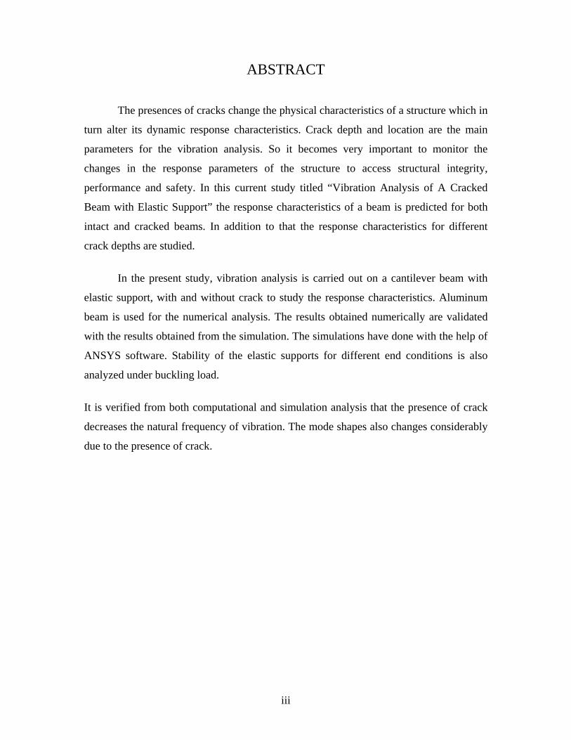
ABSTRACT
The presences of cracks change the physical characteristics of a structure which in
turn alter its dynamic response characteristics. Crack depth and location are the main
parameters for the vibration analysis. So it becomes very important to monitor the
changes in the response parameters of the structure to access structural integrity,
performance and safety. In this current study titled “Vibration Analysis of A Cracked
Beam with Elastic Support” the response characteristics of a beam is predicted for both
intact and cracked beams. In addition to that the response characteristics for different
crack depths are studied.
In the present study, vibration analysis is carried out on a cantilever beam with
elastic support, with and without crack to study the response characteristics. Aluminum
beam is used for the numerical analysis. The results obtained numerically are validated
with the results obtained from the simulation. The simulations have done with the help of
ANSYS software. Stability of the elastic supports for different end conditions is also
analyzed under buckling load.
It is verified from both computational and simulation analysis that the presence of crack
decreases the natural frequency of vibration. The mode shapes also changes considerably
due to the presence of crack.
iii
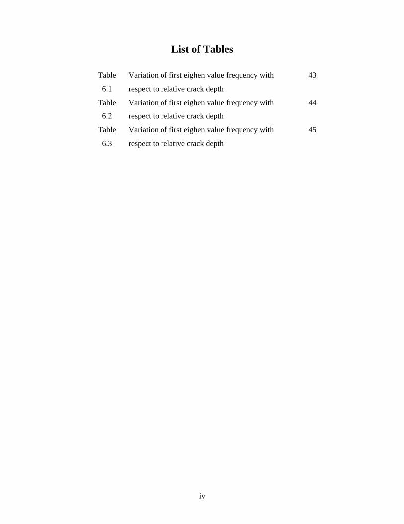
List of Tables
Table
6.1
Variation of first eighen value frequency with
respect to relative crack depth
43
Table
6.2
Variation of first eighen value frequency with
respect to relative crack depth
44
Table
6.3
Variation of first eighen value frequency with
respect to relative crack depth
45
iv
List of Figures
Fig 3.1 Regimes of a cracked beam 9
Fig 3.2 Three basic modes of fracture 10
Fig 4.2.1 Beam with elastic support 14
Fig 4.3.1 Single cracked beam with elastic support 17
Fig 4.4.1 Loading and supporting conditions for an elastic rod 20
Fig 4.4.2 Loading and supporting conditions for an deformation
rod
20
Fig 5.1 Plane 82 element 27
Fig 5.2 Plane 2 element 28
Fig 5.3 Combin14 element 29
Fig 5.4 Meshing of crack region 29
Fig 6.1 Stability boundaries for the elastically supported beam,
* *O LK , K 0, 5, 9.869, 20, = ∞ = ∞
33
Fig 6.2 Stability boundaries for the elastically supported beam,
* *O LK , K 0, 10, 20, 50, = ∞ = ∞
35
Fig 6.3 First mode of transverse vibration , a/w=0.01,
L1/L=0.125
36
Fig 6.4 Second mode of transverse vibration, a/w=0.01,
L1/L=0.125
36
Fig 6.5 Third mode of transverse vibration, a/w=0.01,
L1/L=0.125
37
Fig 6.6 First mode of transverse vibration, a/w=0.1667,
L1/L=0.125
37
Fig 6.7 Second mode of transverse vibration, a/w=0.1667,
L1/L=0.125
38
Fig 6.8 Third mode of transverse vibration, a/w=0.1667,
L1/L=0.125
38
Fig 6.9 First mode of transverse vibration ,a/w=0.334,
L1/L=0.125
39
v
Fig 6.10 Second mode of transverse vibration, a/w=0.334,
L1/L=0.125
39
Fig 6.11 Third mode of transverse vibration, a/w=0.334,
L1/L=0.125
40
Fig 6.12 First mode of transverse vibration, a/w=0.5,
L1/L=0.125
40
Fig 6.13 Second mode of transverse vibration, a/w=0.5,
L1/L=0.125
41
Fig 6.14 Third mode of transverse vibration, a/w=0.5,
L1/L=0.125
41
Fig 6.15 First mode of transverse vibration, a/w=0.01,
L1/L=0.125
42
Fig 6.16 Second mode of transverse vibration,
a/w=0.01,L1/L=0.125
42
Fig 6.17 Third mode of transverse vibration, a/w=0.01,
L1/L=0.125
43
Fig 6.18 Variation of first eigen value of a cracked beam vs.
relative crack depth
44
Fig 6.19 Variation of second eigen value of a cracked beam vs.
relative crack depth
45
Fig 6.20 Variation of third eigen value of a cracked beam vs.
relative crack depth
46
Fig 6.21 First mode of transverse vibration for uncracked beam
using ANSYS
47
Fig 6.22 Second mode of transverse vibration for uncracked beam
using ANSYS
47
Fig 6.23 Third mode of transverse vibration for uncracked beam
using ANSYS
47
Fig 6.24 First mode transverse a/w=0.01,L1/L=0.125 by ANSYS 48
vi
Fig 6.25 Second mode of transverse vibration, a/w=0.01,
L1/L=0.125 using ANSYS
48
Fig 6.26 Third mode of transverse vibration, a/w=0.01,
L1/L=0.125 using ANSYS
48
Fig 6.27 First mode of transverse vibration, a/w=0.1667,
L1/L=0.125 using ANSYS
49
Fig 6.28 Second mode of transverse vibration, a/w=0.1667
L1/L=0.125, using ANSYS
49
Fig 6.29 Third mode of transverse vibration, a/w=0.1667,
L1/L=0.125 using ANSYS
49
Fig 6.30 First mode of transverse vibration, a/w=0.334,
L1/L=0.125 using ANSYS
50
Fig 6.31 Second mode of transverse vibration, a/w=0.334 using
ANSYS
50
Fig 6.32 Third mode of transverse vibration, a/w=0.334 using
ANSYS
50
Fig 6.33 First mode of transverse vibration, a/w=0.5 using
ANSYS
51
Fig 6.34 Second mode of transverse vibration, a/w=0.5,L using
ANSYS
51
Fig 6.35 Third mode of transverse vibration, a/w=0.5,L1/L=0.125
using ANSYS
51
vii
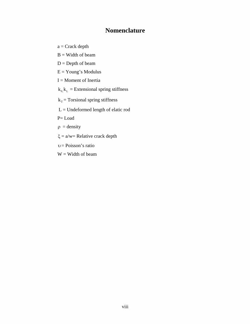
Nomenclature
a = Crack depth
B = Width of beam
D = Depth of beam
E = Young’s Modulus
I = Moment of Inertia
0, Lk k = Extensional spring stiffness
Tk = Torsional spring stiffness
L = Undeformed length of elatic rod
P= Load
ρ = density
ξ = a/w= Relative crack depth
υ= Poisson’s ratio
W = Width of beam
viii

CHAPTER 1
INTRODUCTION
1. INTRODUCTION
The most common structural defect is the existence of a crack. Cracks are present
in structures due to various reasons. The presence of a crack could not only cause a local
variation in the stiffness but it could affect the mechanical behavior of the entire structure
to a considerable extent.
In early 1970s the dynamic response of cracked beams and rotors has been
investigated increasingly because damages in rotating shaft of various power
transmissions occurred quite often. Cracks may be caused by fatigue under service
conditions as a result of the limited fatigue strength. They may also occur due to
mechanical defects. Another group of cracks are initiated during the manufacturing
processes. Generally they are small in sizes. Such small cracks are known to propagate
due to fluctuating stress conditions. If these propagating cracks remain undetected and
reach their critical size, then a sudden structural failure may occur.
If a structure is defective, there is a change in the stiffness and damping of the
structure in the region of the defect. Usually, stiffness decreases and damping increases if
the defect appears in the form of a micro or macro crack. A reduction in stiffness implies
a reduction in the natural frequencies of vibration. A crack on a structural member
introduces a local flexibility which is a function of the crack depth. Major characteristics
of structures, which undergo change due to presence of crack, are
• The natural frequency
• The amplitude response due to vibration
• Mode shape.
Hence it is possible to use natural frequency measurements to detect cracks.
The objective is to carry out vibration analysis on a cantilever beam with elastic
support with and without crack. The results obtained analytically are validated with the
simulation results. Stability of the elastic supports for different end conditions is also
analyzed under buckling load.
1

CHAPTER 2
LITERATURE REVIEW
2. LITERATURE REVIEW
For vibrational analysis of cracked beams and possible crack detection, the fracture
mechanics procedure is generally preferred. According to this procedure the crack
occurring in a beam would reduce the local stiffness at the location of crack. In using the
fracture mechanics model, the local stiffness at the crack section is calculated using
Castigliano’s second theorem as applicable to fracture mechanics formulations. The
calculated local stiffness is then modeled by a flexural spring for the bending vibration of
a cracked beam. To establish the vibration equations, the cracked is represented by two
structures connected by flexural spring.
Irwin [1,2], A crack on an elastic structural element introduces considerable local
flexibility due to the strain energy concentration in the vicinity of the crack tip under
load. This effect has been recognized long ago. A local compliance has been used to
quantify, in a microscopic way, the relation between the applied load and the strain
energy concentration around the tip of the crack.
Krawczuk and ostachowicz [3,4,5] have analyzed the effect of positions and depth of two
cracks on the natural frequencies of a cantilever beam and shaft. A finite element
methods has been used for modeling the cracked beam and has proposed that finite
element method can be used for cracked rotor analysis.
Dimarogonas [6, 7] has noticed that for small cr4ack depths the decrease in natural
frequency is proportional to the square of crack depth ratio.
Matvev et al. [8] expressions for bending vibrations of an Euler-Bernoulli cracked beam
have been analyzed. They have studied the effects of the ratio of crack location to the
length of the beam and also ratio of depth of the crack to the height of the beam. They
have investigated the variation of the natural frequency of the cracked beam.
2
Adams et al. [9] have studied a free-free bar with localized damage. The damage has
been modeled by a linear spring of infinitesimal length separating two sections of the bar.
They have shown analytical and experimental results for natural frequencies of
longitudinal vibration.
Springer et al. [10] have examined the free longitudinal vibration of a bar with free ends
and two cracks located symmetrically at the centre of the span. The cracks have been
modeled in two ways. One is using linear springs, the other is using reductions in cross-
sectional area. The changes in natural frequencies are close to those obtained from
experiments.
Krawczuk and Ostachowicz [11,12] have investigated the effect of the longitudinal static
loads on lateral vibrations of beams.
Silva and Gomez [13-15] have performed an extensive experimental dynamic analysis for
the prediction of the location and the depth of cracks in straight beams. They have
described the experimental techniques and presented the results obtained for various
locations and depths of crack.
Chondros et al. [16] have analyzed the lateral vibration of cracked Euler-Bernoulli beams
with single or double edge cracks. Their analysis can be used for the prediction of the
dynamic response of a simply supported beam with open surface cracks.
Papadopoulos [17] has studied the torsional vibrations of rotors with transverse surface
crack. The crack has been modelled by way of a local flexibility matrix which was
subsequently calculated analytically and measured experimentally. A good agreement has
been obtained between the theoretical and experimental results.
Pandey et al. [18] have reported the changes in mode shapes due to presence of crack in
structures.
3
Qian et al.[19] have used a finite element model to analyze the effect of crack closure on
the transverse vibration of a beam. The stiffness matrix of the system has been deduced
from the stress intensity factors, and it gives two values, one for the close crack
(uncracked beam) and for the other for the open crack. The sign of the stress on the crack
faces has been used to determine if the crack is open or closed at each time step.
Zheng and Fan[20] have presented a modified Fourier Series (MFS) method for
computing the natural frequencies of a non-uniform with an arbitrary number of
transverse open cracks.Based on modified Fourier series, one can treat the cracked beam
in the most usual way and thus reduce the problem to a simple one.
Timoshenko and Gere [21] have obtained the exact solutions to the non-linear differential
equations governing large deformations of an elastic rod only in cases of very simple
loading and boundary conditions, such as end-loaded, fixed-free or simply supported
columns. By necessity, approximate solution techniques have been employed for
problems involving more general loads and supports.
Wang [22] have utilized a power series expansion method to study the postbuckling of a
column under a distributed axial load. In the classical analysis of buckling of columns,
the deflection is assumed small and the square of their derivatives is neglected. The
differential equation based upon the approximate expression of curvature has been used
in calculating buckling load. Results from this kind of calculation gives the buckling load
at which the lateral deflection of column is indeterminate and unbounded. Wang [23, 24]
have pointed out the limitations of power series methods.
Tauchert and Lu [25] have utilized an energy approach to investigate the postbuckling of
an initially deformed, simply supported rod. In actual case, however, the column will
have finite and determinate deflection at the critical load. Such paradoxical result is due
to the fact that the approximate theory is used in the analysis. A simple variation of the
well-known method of minimizing a function of several variables by changing one
parameter at a time is described. This variation is such that when the procedure is applied
to a quadratic form, it causes conjugate directions to be chosen, so the ultimate rate of
4
convergence is fast when the method and it ensures that the convergence rate from a bad
approximation to a minimum is always efficient. Practical applications of the procedure
have proved to the very satisfactory, and numerical examples are given in which
functions of up to twenty variables are minimized. The method finds an unconstrained
minimum of a function of several variables without calculating derivatives. The examples
presented and the theory behind the method suggests that it is significantly more efficient
than other methods which have been referred to, but it does contain two unsatisfactory
features. The first is that as the number of variables increases there is a tendency for new
directions to be chosen less often. This could be overcome by always using a new
direction and forcing the remaining directions to be conjugate to than new one by a
projection technique, but this would require each iteration to demand approximately three
times as many function values. The ultimate convergence criterion is also unsatisfactory,
but it is not an essential part of the method and any improved criterion could easily
incorporated.
Wilson and Snyder [26] have numerically integrated the equations governing the finite
deformation of an elastic cantilever beam with a tip payload and an eccentric tip follower
load. A high flexure manipulator arm is modeled as a cantilever beam with a tip payload
and an eccentric tip follower load that drives the arm. The shapes of the resulting elastic
curves for finite deformations (the elastica) are calculated in terms of nondimensional
system parameters. For critical combinations of these parameters, a small increment in
the driving follower load causes an abrupt change in the shape of elastica. The abrupt
change in tip angle is typically of the order of ∏ radians. These results are applicable to
the design of high flexure robotic manipulators.
Dimarogonas, et al. [27] have computed the flexibility matrix for a transverse surface
crack for a shaft subjected to bending.
Chondros, et al. [28] have combined the spring hinge model with fracture mechanics
results, and developed a frequency spectral method to identify cracks in various
structures. For a known crack position this method correlated the crack depth to the
changes in natural frequencies of the first three modes.
5
Dimarogonas, et al. [29] have studied the influence of a circumferential crack upon the
torsional dynamic behavior of a shaft. They have found that due to the presence of crack,
the torsional natural frequencies decreases due to the added flexibility. The strain energy
release function is related to the compliance of the cracked shaft due to the introduction
of a crack.
Rizos, et al. [30] have determined the crack location and its depth in a cantilever beam
from the vibration modes. They achieved this by measuring the flexural vibrations of a
cantilever beam with rectangular cross-section with a transverse surface crack. Analytical
results are used to relate the measured vibration modes to the crack location and depth.
From the measured amplitudes at two points of the structure vibrating at one of its natural
modes, the respective vibration frequency and an analytical solution of the dynamic
response, the crack location can be found and depth can be estimated with satisfactory
accuracy
Mermertas, et al. [31] have studied the effect of mass attachment on the transverse
vibration characteristics of a cracked cantilever beam. Investigation of the cracked beam
has been carried out theoretically. The governing equation for free vibrations of the
cracked beam is constructed from the Bernoulli-Euler beam elements. To model the
transverse vibration, the crack is represented by a rotational spring. The relative changes
of the first three natural frequencies as a function of the location of the attached mass are
presented. The crack was located in two different distances from the fixed end of the
beam. The results for the changes of the natural frequencies of a cracked beam carrying a
point mass are compared with the results of the beam without a crack.
Bamnios, et al. [32] have investigated the influence of the transverse surface crack on the
dynamic behavior of cantilever beam both analytically and experimentally. They have
modeled the crack as rotational spring and related the change in natural frequency and
mechanical impedance to the location and crack depth.
6
Nahvi, et al. [33] have developed an analytical and experimental approach for crack
detection in cantilever beams by vibration analysis. To avoid non-linearity, it is assumed
that the crack is always open. To identify the crack, contours of the normalized frequency
in terms of the normalized crack depth and location are plotted. The intersection of
contours with the constant modal natural frequency planes is used to relate the crack
location and depth. A minimization approach is employed for identifying the cracked
element within the cantilever beam.
Chandra Kishen, et al. [34] have studied the fracture behavior of cracked beams and
columns using finite element analysis. Assuming that failure occurs due to crack
propagation when the mode I stress intensity factor reaches the fracture toughness of the
material, the failure load of cracked columns are determined for different crack depths
and slenderness ratios.
Krawczuk, et al. [35] formulated a cracked beam finite element based on Elastic - plastic
fracture mechanics and finite element method. Crack tip plasticity, at the cracked cross-
section, is included in the model of local flexibility. The inertia and stiffness matrices
take into account the effect of flexural bending deformation due to the crack presence.
Octachowitz et al [36] presented a method for analysis of the effect of two open cracks
upon the frequencies of the natural flexural vibration in a cantilever beam. Two types of
cracks are considered: double-sided, occurring in the case of cyclic loadings, and single-
sided crack, which in principle occurs as a result of fluctuating loadings. It is also
assumed that the cracks occur in the first mode fracture i.e. the opening mode. It is
concluded that in the case of two cracks of different depths, the larger crack has the most
significant effect on natural vibration frequencies. It is also concluded that double-sided
cracks affect the vibration frequencies to a smaller degree than single cracks with same
relative depth of crack and the same position.
Behera [37] in his research work has developed the theoretical expressions to find out the
natural frequencies and mode shapes for the cantilever beam with single crack.
Experiments have been conducted to prove the authenticity of the theory developed.
7
Parhi [38] has studied the dynamic behavior of a beam/rotor structures with transverse
crack subjected to external force. He has investigated the dynamic response of structures
subjected to moving mass and dynamic response of rotors in viscous fluids with a single
crack. Experiments have been conducted, and compared with theoretical results. He
found that there is a change in the mode shapes with crack.
8

CHAPTER 3
CRACK THEORY
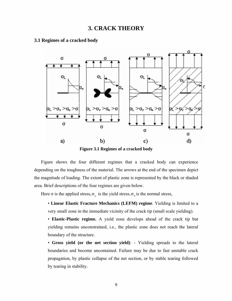
3. CRACK THEORY 3.1 Regimes of a cracked body
Figure 3.1 Regimes of a cracked body
Figure shows the four different regimes that a cracked body can experience
depending on the toughness of the material. The arrows at the end of the specimen depict
the magnitude of loading. The extent of plastic zone is represented by the black or shaded
area. Brief descriptions of the four regimes are given below.
Here σ is the applied stress, is the yield stress,yσ nσ is the normal stress,
• Linear Elastic Fracture Mechanics (LEFM) regime. Yielding is limited to a
very small zone in the immediate vicinity of the crack tip (small scale yielding).
• Elastic-Plastic regime. A yield zone develops ahead of the crack tip but
yielding remains unconstrained, i.e., the plastic zone does not reach the lateral
boundary of the structure.
• Gross yield (or the net section yield): - Yielding spreads to the lateral
boundaries and become uncontained. Failure may be due to fast unstable crack
propagation, by plastic collapse of the net section, or by stable tearing followed
by tearing in stability.
9
• General yielding: - The applied stress is larger than the yield stress. The whole
structure is plasticized. Plastic collapse and tearing instability are the dominant
failure modes.
Limitations of LEFM: - The LEFM solutions for crack tip stress fields predict infinite
stresses at the tip. Since real materials yield at a finite stress, the LEFM solutions lose
their validity in the immediate vicinity of the crack tip. However according to
McClintock and Irwin, the basic assumptions of fracture mechanics remain valid if the
yielding is confined to a very small plastic zone at the crack tip surround by a elastic
region in which the crack tip stress field is governing the stress distribution.
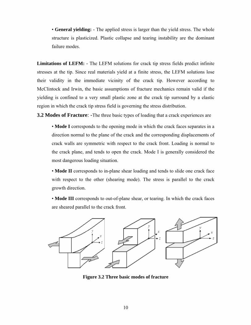
3.2 Modes of Fracture: -The three basic types of loading that a crack experiences are
• Mode I corresponds to the opening mode in which the crack faces separates in a
direction normal to the plane of the crack and the corresponding displacements of
crack walls are symmetric with respect to the crack front. Loading is normal to
the crack plane, and tends to open the crack. Mode I is generally considered the
most dangerous loading situation.
• Mode II corresponds to in-plane shear loading and tends to slide one crack face
with respect to the other (shearing mode). The stress is parallel to the crack
growth direction.
• Mode III corresponds to out-of-plane shear, or tearing. In which the crack faces
are sheared parallel to the crack front.
Figure 3.2 Three basic modes of fracture
10
3.3 Stress Intensity Factor (SIF), K: - It is defined as a measure of the stress field
intensity near the tip of an ideal crack in a linear elastic solid when the crack surfaces are
displaced in the opening mode (Mode I). (SIFs) are used to define the magnitude of the
singular stress and displacement fields (local stresses and displacements near the crack
tip). The SIF depends on the loading, the crack size, the crack shape, and the geometric
boundaries of the specimen. The recommended units for K are MPa√m. it is customary to
write the general formula in the form K=Yσ aπ where σ is the applied stress, a is crack
depth, Y is dimensionless shape factor.
3.4 Physical parameters affecting Dynamic characteristics of cracked
structures:
Usually the physical dimensions, boundary conditions, the material properties of
the structure play important role for the determination of its dynamic response. Their
vibrations cause changes in dynamic characteristics of structures. In addition to this
presence of a crack in structures modifies its dynamic behavior. The following aspects of
the crack greatly influence the dynamic response of the structure.
(i) The position of crack
(ii) The depth of crack
(iii) The orientation of crack
(iv) The number of cracks
3.5 Classification of cracks
Based on their geometries, cracks can be broadly classified as follows:
• Cracks perpendicular to the beam axis are known as “transverse cracks”.
These are the most common and most serious as they reduce the cross-section and
thereby weaken the beam. They introduce a local flexibility in the stiffness of the
beam due to strain energy concentration in the vicinity of the crack tip.
• Cracks parallel to the beam axis are known as “longitudinal cracks”. They are
not that common but they pose danger when the tensile load is applied is at right
angles to the crack direction i.e. perpendicular to beam axis or the perpendicular
to crack.
11
• “Slant cracks” (cracks at an angle to the beam axis) are also encountered, but are
not very common. These influence the torsion behavior of the beam. Their effect
on lateral vibrations is less than that of transverse cracks of comparable severity.
• Cracks that open when the affected part of the material is subjected to tensile
stresses and close when the stress is reversed are known as “breathing cracks”.
The stiffness of the component is most influenced when under tension. The
breathing of the crack results in non-linearity’s in the vibration behavior of the
beam. Cracks breathe when crack sizes are small, running speeds are low and
radial forces are large .Most theoretical research efforts are concentrated on
“transverse breathing” cracks due to their direct practical relevance.
• Cracks that always remain open are known as “gaping cracks”. They are more
correctly called “notches”. Gaping cracks are easy to mimic in a laboratory
environment and hence most experimental work is focused on this particular
crack type.
• Cracks that open on the surface are called “surface cracks”. They can normally
be detected by techniques such as dye-penetrates or visual inspection.
• Cracks that do not show on the surface are called “subsurface cracks”. Special
techniques such as ultrasonic, magnetic particle, radiography or shaft voltage drop
are needed to detect them. Surface cracks have a greater effect than subsurface
cracks on the vibration behavior of shafts.
3.6 Crack Propagation
In 1920, Griffith formulated the concept that a crack in an ideally brittle
component will propagate if the total energy of the system is lowered with crack
propagation. In other words, if the change in elastic strain energy due to crack extension
is larger than the energy required to create new crack surfaces, the crack will propagate.
The Griffith theory in equation form is:
sd(W )dPda da
≥ (3.6.1)
12
Where a is the crack depth, Ws is the work done by external forces per unit
thickness, and P is the potential energy supplied by the internal strain energy and external
forces. The crack will propagate if dpda
− is greater than or equal to sdWda
In 1949, Irwin extended Griffith's theory to ductile materials by including the
energy dissipated by local plastic flow. He postulated that the energy due to plastic
deformation must be added to the surface energy associated with the creation of new
crack surfaces. For ductile materials, the surface energy term is often negligible
compared to the energy associated with plastic deformation. In 1956, Irwin defined a new
quantity, G, the strain energy release rate (also called the crack extension force or the
crack driving force). The strain energy release rate for a linear elastic material is defined
as the total energy absorbed during cracking per unit increase in the crack length and per
unit thickness. The crack will propagate when a critical strain energy release rate, Gc, is
achieved (when G is greater than or equal to the crack resistance energy, Gc). The
equation below shows Irwin's modification to the Griffith theory, where U is the strain
energy stored in the body per unit thickness.
sd(W )dP dUGda da da
= − = = − (3.6.2)
13

CHAPTER 4
PROBLEM
4. PROBLEM
4.1 PROBLEM DEFINITION
The problem involves calculation of natural frequencies and mode shapes for
cantilever beam with elastic support without a crack and with single crack of different
crack depths. The results calculated analytically are validated with the results obtained by
simulation analysis.
Stability of the elastic supports for different end conditions is also analyzed under
buckling load.
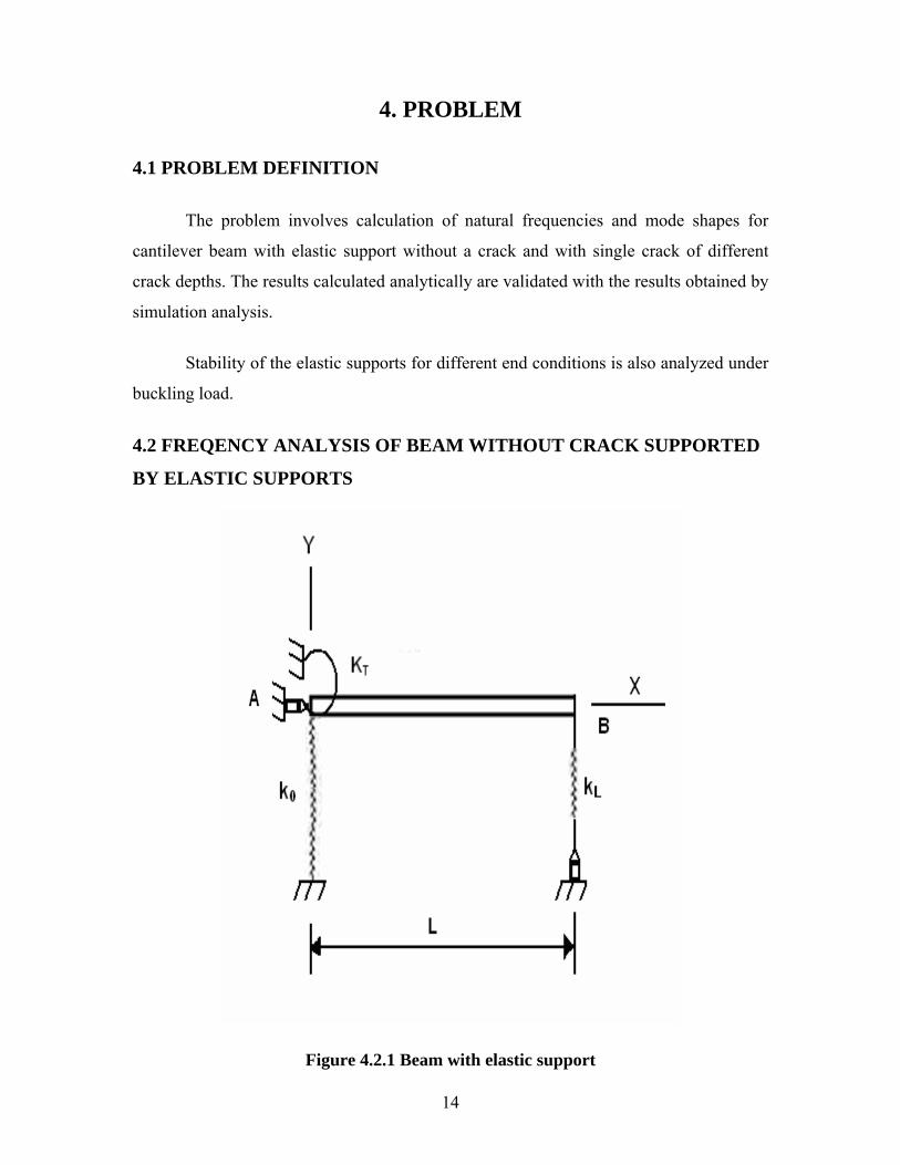
4.2 FREQENCY ANALYSIS OF BEAM WITHOUT CRACK SUPPORTED
BY ELASTIC SUPPORTS
Figure 4.2.1 Beam with elastic support
14
A slender, elastic rod of undeformed length L, elastically supported by extensional
springs having stiffness , and , and a torsional spring of stiffness ,as shown in
Fig.
0k Lk Tk
Boundary conditions for beam: 3
0 3
d w(0)k w(0) EIdx
− = (4.1)
3
L 3
d w(L)k w(L) EIdx
= (4.2)
2
T 2
dw(0) d w(0)k EIdx dx
= (4.3)
2
2
d w(L)0 EIdx
= (4.4)
The displacements of the beam is
1 2 3 4Y( ) A cos( ) A sin( ) A cosh( ) A sinh( )..........(3)β = λβ + λβ + λβ + λβ (4.5)
λ and β are non dimensional parameter given by 2 4
4 AL x,EI L
ω ρλ = β = (4.6)
The normal function coefficients of matrix are obtained from equation (4.5) using
boundary conditions given by equations (4.1-4.4).The obtained system matrix is
* 3 * 30 0
* 3 * 3 * 3 * 3L L L L
2* *T T
32 2 2 2
42 2 2 2
1k k
k cos sin k sin cos k cosh sinh k sinh cosh0k k
EI EI EI EIcos sin cosh sinhL L L L
AAAA
⎡ ⎤− −λ − −λ ⎡ ⎤⎢ ⎥λ − λ λ λ + λ λ λ − λ λ λ − λ λ ⎢ ⎥⎢ ⎥ ⎢ ⎥⎢ ⎥ =λ −λ ⎢ ⎥⎢ ⎥ ⎢ ⎥λ λ λ λ⎢ ⎥− λ − λ λ λ ⎢ ⎥⎣ ⎦⎢ ⎥⎣ ⎦
3 3* * *0 L T0 L T
k L k L k Lk ,k ,kEI EI EI
= = =
Where x is the coordinate along the beam, L is the length of the beam,ω is the natural
angular frequency.
Aluminum has taken the beam. The properties of the Aluminum
Density of Aluminum=2.77 gm/cm3
15
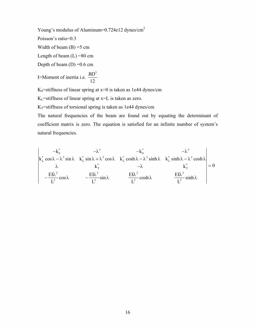
Young’s modulus of Aluminum=0.724e12 dynes/cm2
Poisson’s ratio=0.3
Width of beam (B) =5 cm
Length of beam (L) =80 cm
Depth of beam (D) =0.6 cm
I=Moment of inertia i.e. 3
12BD
K0=stiffness of linear spring at x=0 is taken as 1e44 dynes/cm
KL=stiffness of linear spring at x=L is taken as zero.
KT=stiffness of torsional spring is taken as 1e44 dynes/cm
The natural frequencies of the beam are found out by equating the determinant of
coefficient matrix is zero. The equation is satisfied for an infinite number of system’s
natural frequencies.
* 3 * 30 0
* 3 * 3 * 3 * 3L L L L
* *T T
2 2 2 2
2 2 2 2
k kk cos sin k sin cos k cosh sinh k sinh cosh
0k kEI EI EI EIcos sin cosh sinh
L L L L
− −λ − −λλ − λ λ λ + λ λ λ − λ λ λ − λ λ
=λ −λ
λ λ λ λ− λ − λ λ λ
16
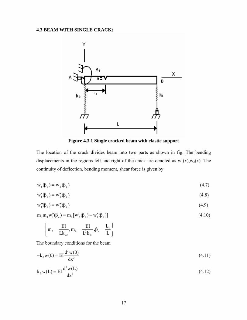
4.3 BEAM WITH SINGLE CRACK:
Figure 4.3.1 Single cracked beam with elastic support
The location of the crack divides beam into two parts as shown in fig. The bending
displacements in the regions left and right of the crack are denoted as w1(x),w2(x). The
continuity of deflection, bending moment, shear force is given by
1 c 2 cw ( ) w ( )β = β (4.7)
1 c 2 cw ( ) w ( )′′ ′′β = β (4.8)
1 c 2 cw ( ) w ( )′′′ ′′′β = β (4.9)
3 4 1 c 4 2 c 1 cm m w ( ) m [w ( ) w ( )]′′ ′ ′β = β − β (4.10)
13 4 c2
22 21
LEI EIm ,m ,Lk LL k
⎡ ⎤= = β =⎢ ⎥
⎣ ⎦
The boundary conditions for the beam 3
0 3
d w(0)k w(0) EIdx
− = (4.11)
3
L 3
d w(L)k w(L) EIdx
= (4.12)
17
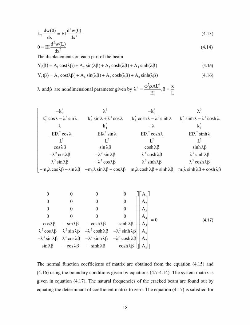
2
T 2
dw(0) d w(0)k EIdx dx
= (4.13)
2
2
d w(L)0 EIdx
= (4.14)
The displacements on each part of the beam
1 1 2 3 4Y ( ) A cos( ) A sin( ) A cosh( ) A sinh( )β = λβ + λβ + λβ + λβ (4.15)
2 5 6 7 8Y ( ) A cos( ) A sin( ) A cosh( ) A sinh( )β = λβ + λβ + λβ + λβ (4.16)
λ andβ are nondimensional parameter given by 2 4
4 AL x,EI L
ω ρλ = β =
* 3 * 30 0
* 3 * 3 * 3 * 3L L L L
* *T T
2 2 2 2
2 2 2 2
2 2 2 2
3 3 3
k kk cos sin k sin cos k cosh sinh k sinh cosh
k kEI cos EI sin EI cosh EI sinh
L L L Lcos sin cosh sinh
cos sin cosh sinhsin cos sinh
− λ − λλ − λ λ λ + λ λ λ − λ λ λ − λ λλ −λ
λ λ λ λ λ λ λ λ− −
λβ λβ λβ λβ−λ λβ −λ λβ λ λβ λ λβλ λβ −λ λβ λ 3
3 3 3 3
coshm cos sin m sin cos m cosh sinh m sinh cosh
⎡⎢⎢⎢⎢⎢⎢⎢⎢⎢⎢
λβ λ λβ⎢⎢− λ λβ − λβ − λ λβ + λβ λ λβ + λβ λ λβ + λβ⎣
1
2
3
4
52 2 2 2
63 3 3 3
7
8
A0 0 0 0A0 0 0 0A0 0 0 0A0 0 0 0
0Acos sin cosh sinhAcos sin cosh sinhAsin cos sinh coshAsin cos sinh cosh
⎡ ⎤⎤⎢ ⎥⎥⎢ ⎥⎥⎢ ⎥⎥⎢ ⎥⎥⎢ ⎥⎥ =⎢ ⎥⎥− λβ − λβ − λβ − λβ⎢ ⎥⎥
λ λβ λ λβ −λ λβ −λ λβ ⎢ ⎥⎥⎢ ⎥⎥−λ λβ λ λβ −λ λβ −λ λβ⎢ ⎥⎥
λβ − λβ − λβ − λβ ⎥ ⎢ ⎥⎦ ⎣ ⎦
(4.17)
The normal function coefficients of matrix are obtained from the equation (4.15) and
(4.16) using the boundary conditions given by equations (4.7-4.14). The system matrix is
given in equation (4.17). The natural frequencies of the cracked beam are found out by
equating the determinant of coefficient matrix to zero. The equation (4.17) is satisfied for
18
an infinite number of system’s natural frequencies. Knowing the natural frequency and
setting A1=1, the other values A
2 to A
8 are found out.
Where Ai for i = 1…8 are normal function constant. Substituting any one of these back
into equations (4.15) and (4.16) yields a corresponding set of relative values for A1
to A8
they are called mode shapes corresponding to the natural frequency.
The influence coefficients are calculated as follows.
[ ]1
211 1
0
2C F ( ) ξdBE
ξπ= ξ ξ
′ ∫
1
12 21 1 20
12C C [F ( )F ( )]dE BW
ξπ= = ξ ξ ξ
′ ∫ ξ
12
22 220
72C [F (E BW
ξπ= ξ ξ
′ ∫ )] dξ
where aW
ξ = (Re lativecrack de pth) and 2
EE1
′ =− υ
The functions F1 and F2 are dependent on the crack depth ‘a’ and are approximated by
( ) ( )( )
30.5
1
a a0.752 2.02 0.37 1 sina 2w a w 2F tanaw a 2w cos 2w
w⎧ ⎫⎡ ⎤π+ + −⎪ ⎪⎡ π ⎤⎛ ⎞ ⎛ ⎞ ⎣ ⎦= ⎨ ⎬⎜ ⎟ ⎜ ⎟⎢ ⎥ ππ⎝ ⎠ ⎝ ⎠⎣ ⎦ ⎪ ⎪⎩ ⎭
( )( )
40.5
2
a0.923 0.199 1 sina 2w a 2wF tanaw a 2w cos 2w
⎧ ⎫⎡ ⎤π+ −⎪ ⎪⎡ π ⎤⎛ ⎞ ⎛ ⎞ ⎣ ⎦= ⎨ ⎬⎜ ⎟ ⎜ ⎟⎢ ⎥ ππ⎝ ⎠ ⎝ ⎠⎣ ⎦ ⎪ ⎪⎩ ⎭
The stiffness matrix for the cracked beam is obtained as
1
11 12 11 12
21 22 21 22
K K C CK
K K C C
−⎡ ⎤ ⎡ ⎤
= =⎢ ⎥ ⎢ ⎥⎣ ⎦ ⎣ ⎦
19
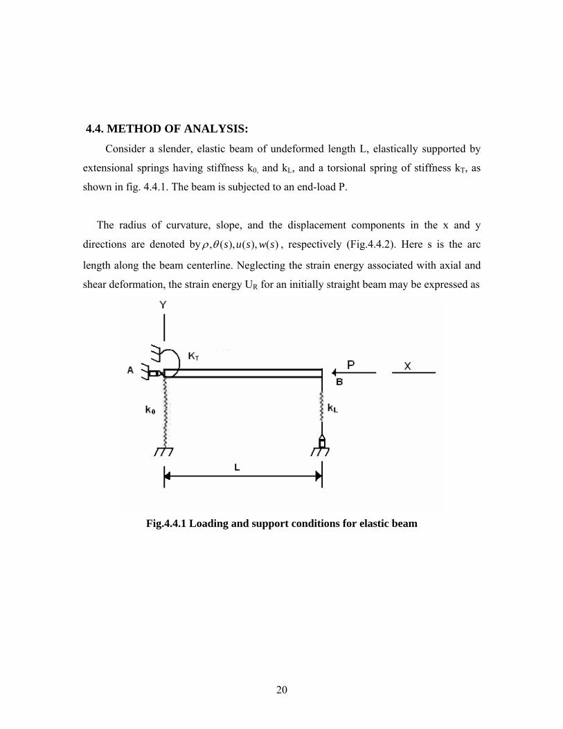
4.4. METHOD OF ANALYSIS:
Consider a slender, elastic beam of undeformed length L, elastically supported by
extensional springs having stiffness k0, and kL, and a torsional spring of stiffness kT, as
shown in fig. 4.4.1. The beam is subjected to an end-load P.
The radius of curvature, slope, and the displacement components in the x and y
directions are denoted by , ( ), ( ), ( )s u s w sρ θ , respectively (Fig.4.4.2). Here s is the arc
length along the beam centerline. Neglecting the strain energy associated with axial and
shear deformation, the strain energy UR for an initially straight beam may be expressed as
Fig.4.4.1 Loading and support conditions for elastic beam
20
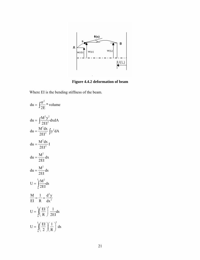
Figure 4.4.2 deformation of beam
Where EI is the bending stiffness of the beam.
2
du * volume2Eσ
= ∫
2 2
2
M ydu dxdA2EI
= ∫
22
2
M dxdu y dA2EI
= ∫
2
2
M dxdu I2EI
=
2Mdu dx2EI
=
2Mdu ds2EI
=
L 2
0
MU d2EI
= ∫ s
2
2
M 1 d yEI R dx
= =
2L
0
EI 1U dR 2EI
⎛ ⎞= ⎜ ⎟⎝ ⎠∫ s
2L
0
EI 1U d2 R
⎛ ⎞⎛ ⎞= ⎜ ⎟⎜ ⎟⎝ ⎠⎝ ⎠∫ s
21
2L
R0
EI 1U d2⎛ ⎞
= ⎜ ⎟ρ⎝ ⎠∫ s
An exact expression for the curvature
1 ddsθ
=ρ
dwsinds
θ =
1 dwsinds
− ⎛ ⎞θ = ⎜ ⎟⎝ ⎠
22
2
d wd dxds dw1
dx
θ=
⎛ ⎞− ⎜ ⎟⎝ ⎠
2
2
2
d w1 d dx
ds dw1dx
θ= =
ρ ⎛ ⎞− ⎜ ⎟⎝ ⎠
The strain energy US of the linear spring is
2 2s 0 L T
1 1 1U k [w(0)] k [w(L)] k [ (0)2 2 2
= + + 2]θ
Where w(L), (0)θ can be expressed as
dw sin ds= θ L L
0 0
dw sin ds= θ∫ ∫
L
0
w(L) w(0) sin ds− = θ∫
L
0
w(L) sin ds w(0)= θ +∫
Potential energy VP=force*displacement
VP=p*u (L)
Where u(L) denotes the displacement in the x direction at the end of the rod. Assuming
rod is inextensible, u(L) can be expressed as
22
L
0
u(L) L cos ds− = − θ∫
dwsinds
θ =
2cos 1 sinθ = − θ
2L
0
dwu(L) L 1 dsds
⎛ ⎞− = − − ⎜ ⎟⎝ ⎠∫
Thus the total potential energy R SU U VPΠ = + + of the system, written in terms of the
transverse displacement w(s), is given by 2
2L 2
2 20 L2
0
d wEI 1 1ds ds k [w(0)] k [w(L)]2 2 2dw1
ds
⎡ ⎤⎢ ⎥⎢ ⎥∏ = + +⎢ ⎥
⎛ ⎞⎢ ⎥− ⎜ ⎟⎢ ⎥⎝ ⎠⎣ ⎦
∫
2 2L1
T0
1 dw(0) dwk sin P L 1 ds2 ds ds
−⎡ ⎤⎡ ⎤⎛ ⎞ ⎛ ⎞⎢+ − − −⎜ ⎟ ⎜ ⎟⎢ ⎥ ⎢ ⎥⎝ ⎠ ⎝ ⎠⎣ ⎦ ⎣ ⎦
∫ ⎥
Where expressed in terms of the slope ( )sθ rather than the total potential energy
becomes
( )w s
22L L2 2
0 T0 0
EI d 1 1 1ds k [w(0)] sin ds w(0) k [ (0)] p L cos ds2 ds 2 2 2
L
0
⎡ ⎤ ⎡θ⎛ ⎞∏ = + + θ + + θ − − θ⎤
⎢ ⎥ ⎢⎜ ⎟⎝ ⎠
⎥⎣ ⎦ ⎣
∫ ∫⎦
∫
4.5 STABILITY BOUNDARIES: Stability loads for the elastically supported beam as shown in Fig (4.4.1). can be obtained
by finding non-trival solutions to the corresponding linearized problem. The linearized
differential equation is
4 2
2 24 4
d y d w p0,EIdx dx
+ β = β = (4.18)
And the associated boundary conditions are
3
0 3
d w(0) dw(0)k w(0) EI pdxdx
− = + (4.19)
3
L 3
d w(L) dw(L)k w(L) EI pdxdx
= + (4.20)
23
2
T 2
dw(0) d w(0)k EIdx dx
= (4.21)
2
2
d w(L)0 EIdx
= (4.22)
For convenience in analysis the following non-dimensional quantities are introduced.
3 3 2
* * * *0 L T0 L T
k L k L k L PLk ,k ,k , L,pEI EI EI EI
= = = Ω = β = (4.23)
Non-trival solutions of the above equations correspond to the roots of the characteristic
equation
(4.24)
* * * * * 2 * * 3 * 40 L T 0 L 0 T 0k k k cos k k sin k k cos k sin− Ω Ω + Ω Ω + Ω Ω − Ω Ω
* * * * * 3 * 40 L T L T Lk k k sin k k cos k sin 0+ Ω + Ω Ω − Ω Ω =
The smallest positive root of this equation, say crΩ , yields the critical load
2* crcr 2
EIP
LΩ
= ( 4.25)
Buckling loads for beams having various special types of support conditions can be
obtained through appropriate reduction of the general formulation (4.24). For the case of
a finite torsional spring stiffness kT*and a finite vertical extensional spring stiffness kL
*,
but an infinite extensional spring stiffness k0*, the characteristic equation (4.24) reduces
to
* * * 2 4 * *cos sin sin sin 0L T L L Tk k k k k− Ω Ω+ Ω Ω−Ω Ω+ Ω = (4.26)
For the special case where one end of the beam is restrained by a torsional spring and a
hinge while the other end is supported by a roller (k0=kL=∞ ). Equation (4.26) further
reduces to
(4.27) * 2 *cos sin sin 0T Tk k− Ω Ω+Ω Ω+ Ω =
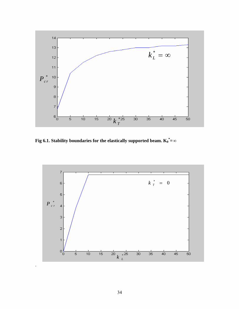
This case is represented by the curve labeled kL*=∞ in Fig 6.1. In this case buckling load
falls in the range of. *6.76 13.153≤ ≤crP
Next consider the case of one end rigidly clamped (k0*=kT
*=∞ ), and one end supported
by a vertical spring. The characteristic equation (4.24) then reduces to
24
* 3 *cos cos sin 0Lk k− Ω Ω+Ω Ω+ Ω =L (4.28) The corresponding stability boundary is given by the curve labeled kT
*= in Fig 6.2. In
this case.
∞*1.571 13.153≤ ≤crP
25

CHAPTER 5
MODAL ANALYSIS-Summary of steps
1. Main Menu> Preferences
2. (check) “Structural”
3. [OK]
5.1.2 Define Constant Material Properties
Here the material properties are specified as follows Young’s modulus E =0 .724*10
12 dyne/cm
2,
Poisons ratio =0.3,
Density, ρ = 2.77 gm/cm3
Step followed are:
1. Select Main Menu> Preprocessor> Material Props> Material Models
2. Then double-click “Structural”, then “Linear”, then “Elastic”, then “Isotropic”
and enter the values mentioned above and click [OK]
3. Now double-click on “Density”, enter density value, click [OK] and exit
materials menu.
5.2. MODEL THE GEOMETRY First key points are created, these key points are joined to form line segments and then
using these lines areas are formed. The crack is modeled by creating two key points at the
same coordinates and then using these key points two lines lying at the same location are
created in transverse direction, these lines indicate crack
The steps followed are:
Main menu> Preprocessor> Modeling> Create> key points> In Active CS
Main menu> Preprocessor> Modeling> Create> Lines> line> Straight line
Main menu> Preprocessor> Modeling> Create> Areas> Arbitrary> By lines
5.3 GENARATE MESH
5.3.1 Element type
27
The recommended element type for a 2-D crack model is PLANE82 and SOLID95
for 3-D crack model. Combination14 is used for elastic support.
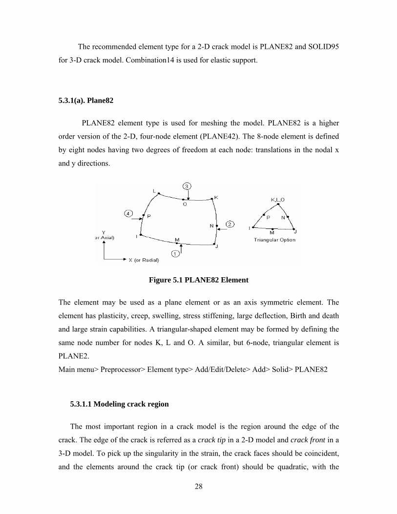
5.3.1(a). Plane82
PLANE82 element type is used for meshing the model. PLANE82 is a higher
order version of the 2-D, four-node element (PLANE42). The 8-node element is defined
by eight nodes having two degrees of freedom at each node: translations in the nodal x
and y directions.
Figure 5.1 PLANE82 Element
The element may be used as a plane element or as an axis symmetric element. The
element has plasticity, creep, swelling, stress stiffening, large deflection, Birth and death
and large strain capabilities. A triangular-shaped element may be formed by defining the
same node number for nodes K, L and O. A similar, but 6-node, triangular element is
PLANE2.
Main menu> Preprocessor> Element type> Add/Edit/Delete> Add> Solid> PLANE82
5.3.1.1 Modeling crack region
The most important region in a crack model is the region around the edge of the
crack. The edge of the crack is referred as a crack tip in a 2-D model and crack front in a
3-D model. To pick up the singularity in the strain, the crack faces should be coincident,
and the elements around the crack tip (or crack front) should be quadratic, with the
28
5. MODAL ANALYSIS -- SUMMARY OF STEPS
Following steps show the guidelines for carrying out Modal analysis. Details step by step
explanation is presented in further sections.
5.1 Define Materials
1. Set preferences. (Structural)
2. Define constant material properties.
5.2 Model the Geometry
3. Follow bottom up modeling and create the geometry
5.3 Generate Mesh
4. Define element type.
5. Mesh the area.
5.4 Apply Boundary Conditions
8. Apply constraints to the model.
5.5 Obtain Solution
9. Specify analysis types and options.
10. Solve.
5.1 DEFINE MATERIALS
5.1.1 Set Preferences
Purpose of setting preferences is to filter quantities that pertain to this discipline only.
On clicking preference option, many disciplines are listed like structural, thermal,
electromagnetic, fluid etc. here structural option is checked out and so only quantities
related to structural analysis will be highlighted. Step followed are:
26
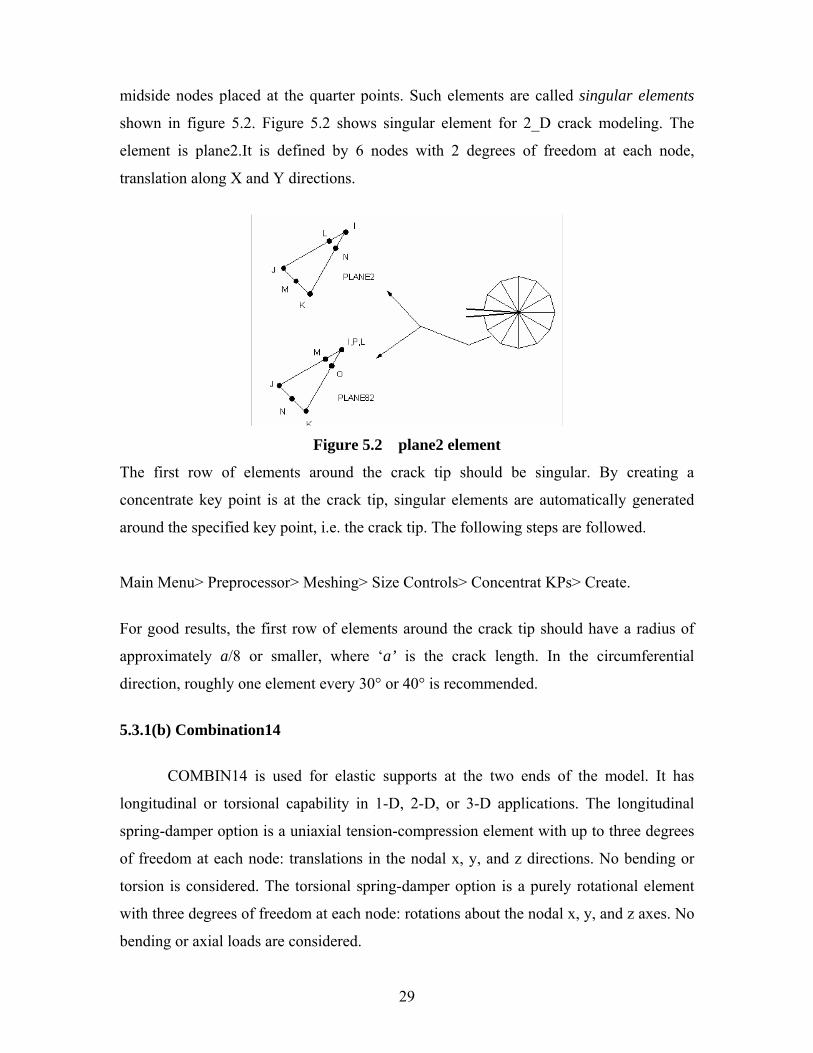
midside nodes placed at the quarter points. Such elements are called singular elements
shown in figure 5.2. Figure 5.2 shows singular element for 2_D crack modeling. The
element is plane2.It is defined by 6 nodes with 2 degrees of freedom at each node,
translation along X and Y directions.
Figure 5.2 plane2 element
The first row of elements around the crack tip should be singular. By creating a
concentrate key point is at the crack tip, singular elements are automatically generated
around the specified key point, i.e. the crack tip. The following steps are followed.
Main Menu> Preprocessor> Meshing> Size Controls> Concentrat KPs> Create.
For good results, the first row of elements around the crack tip should have a radius of
approximately a/8 or smaller, where ‘a’ is the crack length. In the circumferential
direction, roughly one element every 30° or 40° is recommended.
5.3.1(b) Combination14
COMBIN14 is used for elastic supports at the two ends of the model. It has
longitudinal or torsional capability in 1-D, 2-D, or 3-D applications. The longitudinal
spring-damper option is a uniaxial tension-compression element with up to three degrees
of freedom at each node: translations in the nodal x, y, and z directions. No bending or
torsion is considered. The torsional spring-damper option is a purely rotational element
with three degrees of freedom at each node: rotations about the nodal x, y, and z axes. No
bending or axial loads are considered.
29
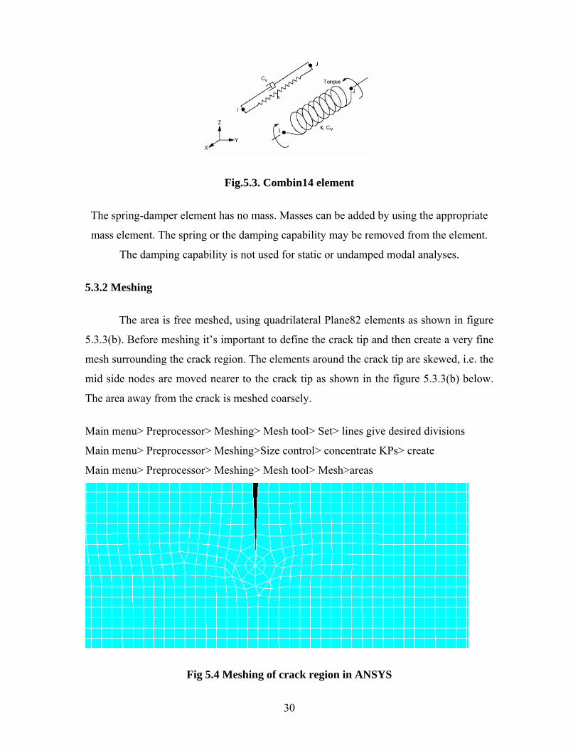
Fig.5.3. Combin14 element
The spring-damper element has no mass. Masses can be added by using the appropriate
mass element. The spring or the damping capability may be removed from the element.
The damping capability is not used for static or undamped modal analyses.
5.3.2 Meshing
The area is free meshed, using quadrilateral Plane82 elements as shown in figure
5.3.3(b). Before meshing it’s important to define the crack tip and then create a very fine
mesh surrounding the crack region. The elements around the crack tip are skewed, i.e. the
mid side nodes are moved nearer to the crack tip as shown in the figure 5.3.3(b) below.
The area away from the crack is meshed coarsely.
Main menu> Preprocessor> Meshing> Mesh tool> Set> lines give desired divisions
Main menu> Preprocessor> Meshing>Size control> concentrate KPs> create
Main menu> Preprocessor> Meshing> Mesh tool> Mesh>areas
Fig 5.4 Meshing of crack region in ANSYS
30
5.4. Applying Boundary Conditions and Solving
The nodes of linear spring support and torsional spring support at one end
(starting) of the cantilever beam are restricted in all degree of freedom for and nodes of
the beam at that end also restricted along X direction . The nodes of linear spring at the
other of the beam are restricted in Y direction. First static analysis is carried out and then
the analysis type is changed from static to modal analysis. In modal analysis, the number
of modes to be extracted is specified. The numbers of modes extracted are 3 and then
they are expanded to view the results. No external load is given as this is free vibration
analysis. Then this model is solved for the results.
Main menu> Solution>Analysis type> New analysis>Modal
Main menu> Solution>Define loads> Apply> Structural> Displacements> on nodes
5.5 Viewing results and saving
To view the results first mode results should be read. We can view the different
natural frequencies and mode shapes. The frequency for different modes shapes are listed
as result summary. After completing all these file has to be saved by a file name for
future viewing and modifications.
The above steps are repeated for different conditions like single crack of 0.06mm,
1mm, 2mm and3mm depth and with no crack.
31

CHAPTER 6
RESULTS AND DISCUSSIONS
6. RESULTS&DISCUSSIONS
6.1 NUMERICAL RESULTS
*crP
* 0Lk =
*Tk
*c rP
*Tk
* 5Lk =
32
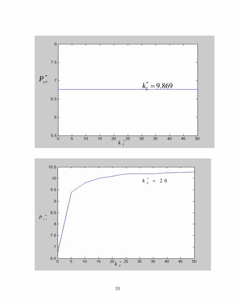
*crP
*Tk
* 9.869Lk =
*
Tk
* 2 0Lk =
*c rP
33
*Tk
*c rP
*Lk = ∞
Fig 6.1. Stability boundaries for the elastically supported beam. K0
*= ∞
* 0Tk =
*c rP
*Lk
.
34
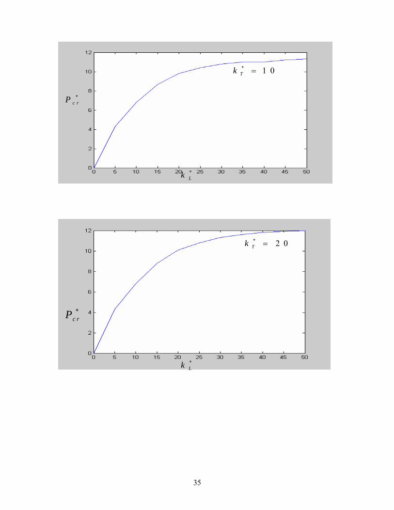
* 1 0Tk =
*c rP
*Lk
* 2 0Tk =
*c rP
*Lk
35
*c rP
*Lk
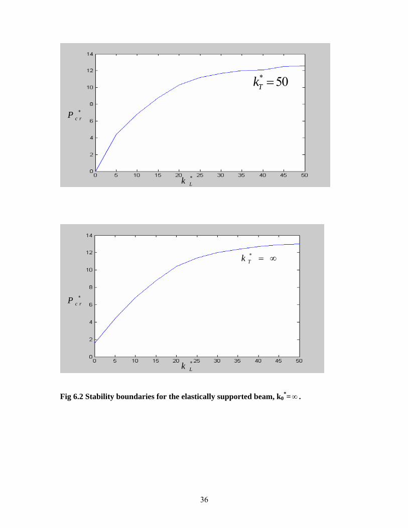
* 50Tk =
*Tk = ∞
*Lk
*c rP
Fig 6.2 Stability boundaries for the elastically supported beam, k0
*= . ∞
36
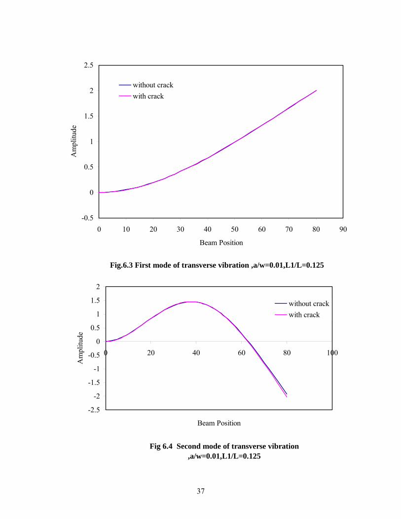
Fig.6.3 First mode of transverse vibration ,a/w=0.01,L1/L=0.125
-0.5
0
0.5
1
1.5
2
2.5
0 10 20 30 40 50 60 70 80 90
Beam Position
Am
plitu
dewithout crackwith crack
Fig 6.4 Second mode of transverse vibration ,a/w=0.01,L1/L=0.125
-2.5
-2
-1.5
-1
-0.5
0
0.5
1
1.5
2
0 20 40 60 80 100
Beam Position
Am
plitu
de
without crackwith crack
37
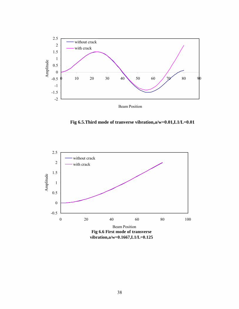
Fig 6.5.Third mode of tranverse vibration,a/w=0.01,L1/L=0.01
-2-1.5
-1-0.5
00.5
11.5
22.5
0 10 20 30 40 50 60 70 80 9
Beam Position
Am
plitu
de
0
without crackwith crack
Fig 6.6 First mode of transverse vibration,a/w=0.1667,L1/L=0.125
-0.5
0
0.5
1
1.5
2
2.5
0 20 40 60 80
Beam Position
Am
plitu
de
100
without crackwith crack
38
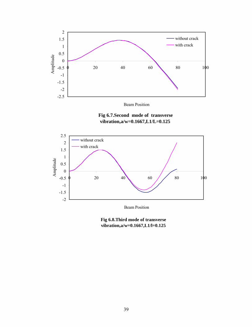
Fig 6.7.Second mode of transverse vibration,a/w=0.1667,L1/L=0.125
-2.5-2
-1.5-1
-0.50
0.51
1.52
0 20 40 60 80
Beam Position
Am
plitu
de
100
without crackwith crack
Fig 6.8.Third mode of transverse vibration,a/w=0.1667,L1/l=0.125
-2-1.5
-1-0.5
00.5
11.5
22.5
0 20 40 60 80
Beam Position
Am
plitu
de
100
without crackwith crack
39
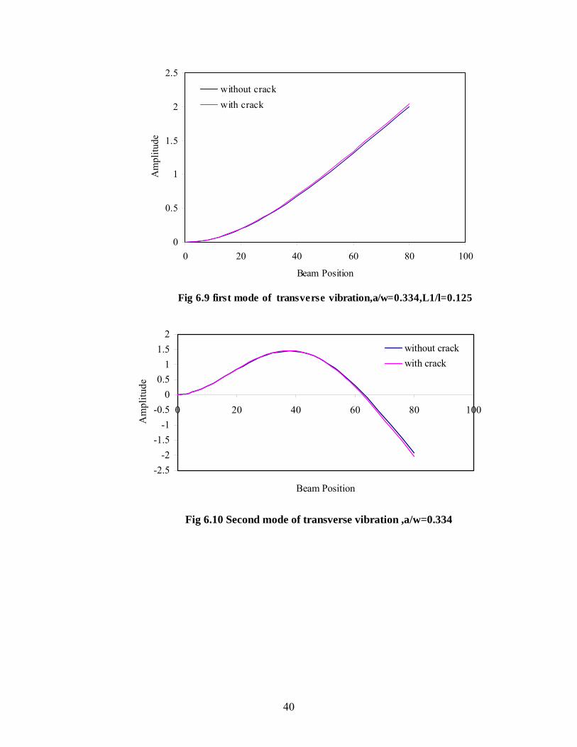
Fig 6.9 first mode of transverse vibration,a/w=0.334,L1/l=0.125
0
0.5
1
1.5
2
2.5
0 20 40 60 80
Beam Position
Am
plitu
d
100
e
without crackwith crack
Fig 6.10 Second mode of transverse vibration ,a/w=0.334
-2.5-2
-1.5-1
-0.50
0.51
1.52
0 20 40 60 80
Beam Position
Am
plitu
de
100
without crackwith crack
40
Fig.6.11 Third mode of transverse vibration,a/w=0.334,L1/L=0.125
-2-1.5
-1
-0.50
0.51
1.52
2.5
0 20 40 60 80
Beam Position
Am
plitu
de100
without crack
with crack
Fig. 6.12 First mode of transverse vibration,a/w=0.5,L1/L=0.125
0
0.5
1
1.5
2
2.5
0 20 40 60 80
Beam Position
Am
plitu
de
100
without crackwith crack
41
Fig 6.13. Second mode of transverse vibration.a/w=0.5,L1/L=0.125.
-2.5
-2
-1.5
-1
-0.5
0
0.5
1
1.5
2
0 20 40 60 80
Beam Position
Am
plitu
de100
without crackwith crack
Fig 6.14 Third mode of transverse vibration,a/w=0.5,L1/l=0.125
-2
-1.5
-1
-0.5
0
0.5
1
1.5
2
2.5
0 20 40 60 80
Beam Position
Am
plitu
de
100
without crack
with crack
42
Fig 6.15 First mode of transverse vibration,a/w= 0.01,L1/L=0.125
0.0504
0.0506
0.0508
0.051
0.0512
0.0514
0.0516
0.0518
0.052
9.975 9.98 9.985 9.99 9.995 10 10.005 10.01
Beam Position
Am
plitu
de
without crackwith crack
Fig 6.16 Second mode of transverse vibration,a/w= 0.01,L1/L=0.125
0.264
0.266
0.268
0.27
0.272
0.274
0.276
0.278
9.975 9.98 9.985 9.99 9.995 10 10.005 10.01
Beam Position
Am
plitu
de
without crackwith crack
43
Fig 6.17 Third mode of transverse vibration,a/w= 0.01,L1/L=0.125
0.64880.649
0.64920.64940.64960.6498
0.650.65020.65040.65060.6508
0.651
9.986 9.988 9.99 9.992 9.994 9.996 9.998 10 10.002 10.004
Beam Position
Am
plitu
de
without crackwith crack
Relative crack depth
Frequency of First eigen value
Frequency found out in ANSYS
0.01 48.2 48.22 0.1667 48.0988 48.099 0.334 47.7 47.77
0.5 46.84 46.9 0.6 45.709 45.715
0.7 43.48941 43.4895 0.8 38.5589 38.5596 0.9 26.26 26.265
0.99 3.175 3.1772
Table 6.1 Variation of first eighen value frequency with respect to relative crack
depth.
44
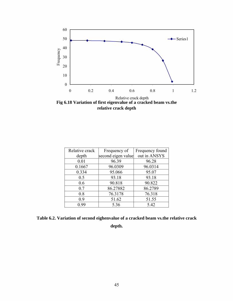
Fig 6.18 Variation of first eigenvalue of a cracked beam vs.the relative crack depth
0
10
20
30
40
50
60
0 0.2 0.4 0.6 0.8 1 1.2
Relative crack depth
Freq
uenc
y
Series1
Relative crack depth
Frequency of second eigen value
Frequency found out in ANSYS
0.01 96.39 96.28 0.1667 96.0309 96.0314 0.334 95.066 95.07 0.5 93.18 93.18 0.6 90.818 90.822 0.7 86.27882 86.2789 0.8 76.3178 76.318 0.9 51.62 51.55 0.99 5.36 5.42
Table 6.2. Variation of second eighenvalue of a cracked beam vs.the relative crack
depth.
45
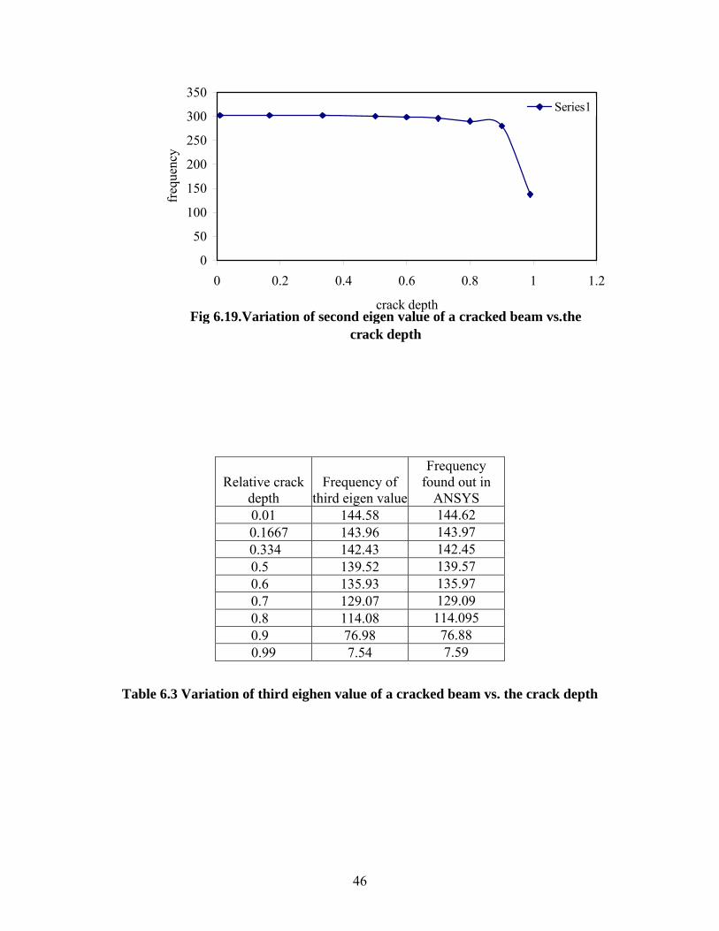
Fig 6.19.Variation of second eigen value of a cracked beam vs.the crack depth
0
50
100
150
200
250
300
350
0 0.2 0.4 0.6 0.8 1 1.2
crack depth
freq
uenc
y
Series1
Relative crack depth
Frequency of third eigen value
Frequency found out in
ANSYS 0.01 144.58 144.62
0.1667 143.96 143.97 0.334 142.43 142.45
0.5 139.52 139.57 0.6 135.93 135.97 0.7 129.07 129.09 0.8 114.08 114.095 0.9 76.98 76.88
0.99 7.54 7.59
Table 6.3 Variation of third eighen value of a cracked beam vs. the crack depth
46
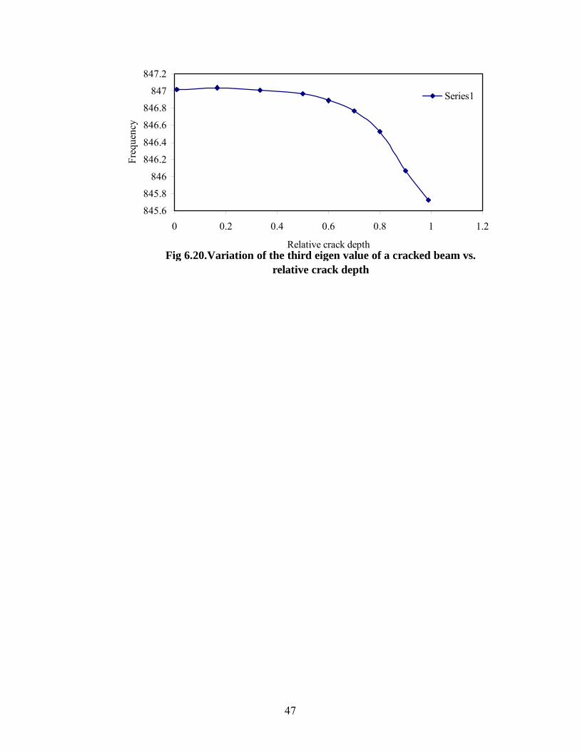
Fig 6.20.Variation of the third eigen value of a cracked beam vs. relative crack depth
845.6
845.8
846
846.2
846.4
846.6
846.8
847
847.2
0 0.2 0.4 0.6 0.8 1 1.2
Relative crack depth
Freq
uenc
y
Series1
47
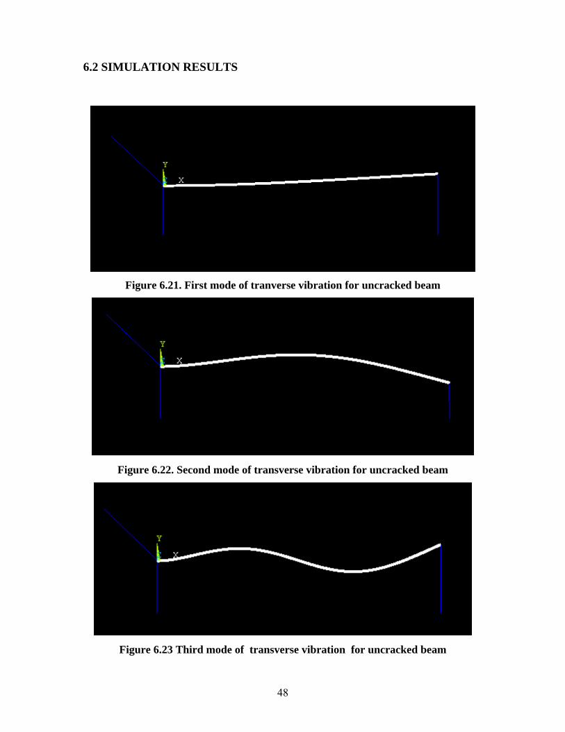
6.2 SIMULATION RESULTS
Figure 6.21. First mode of tranverse vibration for uncracked beam
Figure 6.22. Second mode of transverse vibration for uncracked beam
Figure 6.23 Third mode of transverse vibration for uncracked beam
48
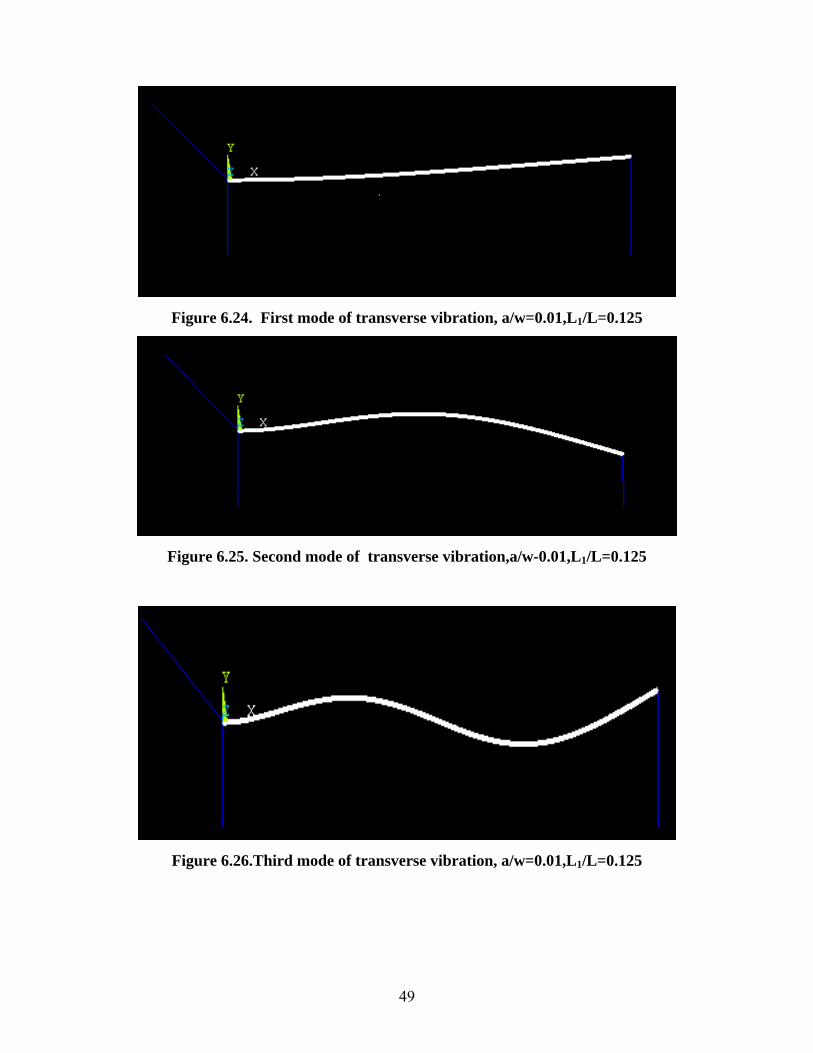
Figure 6.24. First mode of transverse vibration, a/w=0.01,L1/L=0.125
Figure 6.25. Second mode of transverse vibration,a/w-0.01,L1/L=0.125
Figure 6.26.Third mode of transverse vibration, a/w=0.01,L1/L=0.125
49
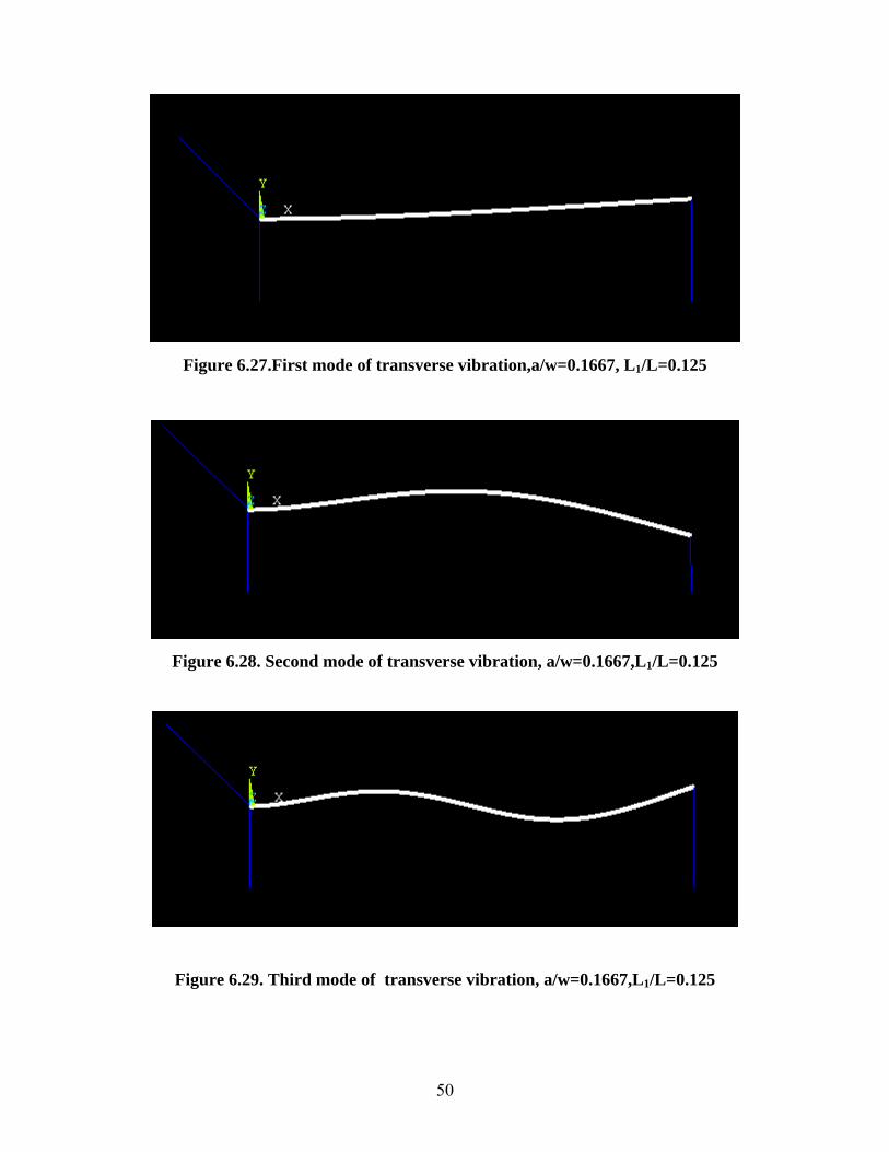
Figure 6.27.First mode of transverse vibration,a/w=0.1667, L1/L=0.125
Figure 6.28. Second mode of transverse vibration, a/w=0.1667,L1/L=0.125
Figure 6.29. Third mode of transverse vibration, a/w=0.1667,L1/L=0.125
50
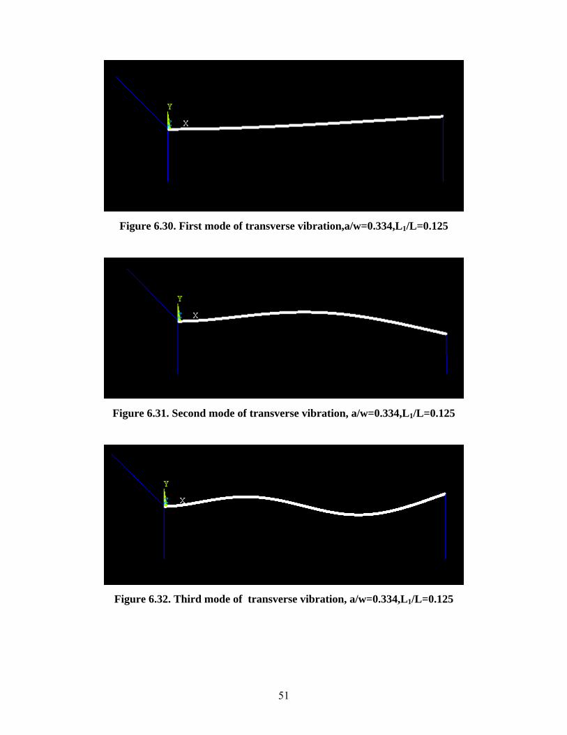
Figure 6.30. First mode of transverse vibration,a/w=0.334,L1/L=0.125
Figure 6.31. Second mode of transverse vibration, a/w=0.334,L1/L=0.125
Figure 6.32. Third mode of transverse vibration, a/w=0.334,L1/L=0.125
51
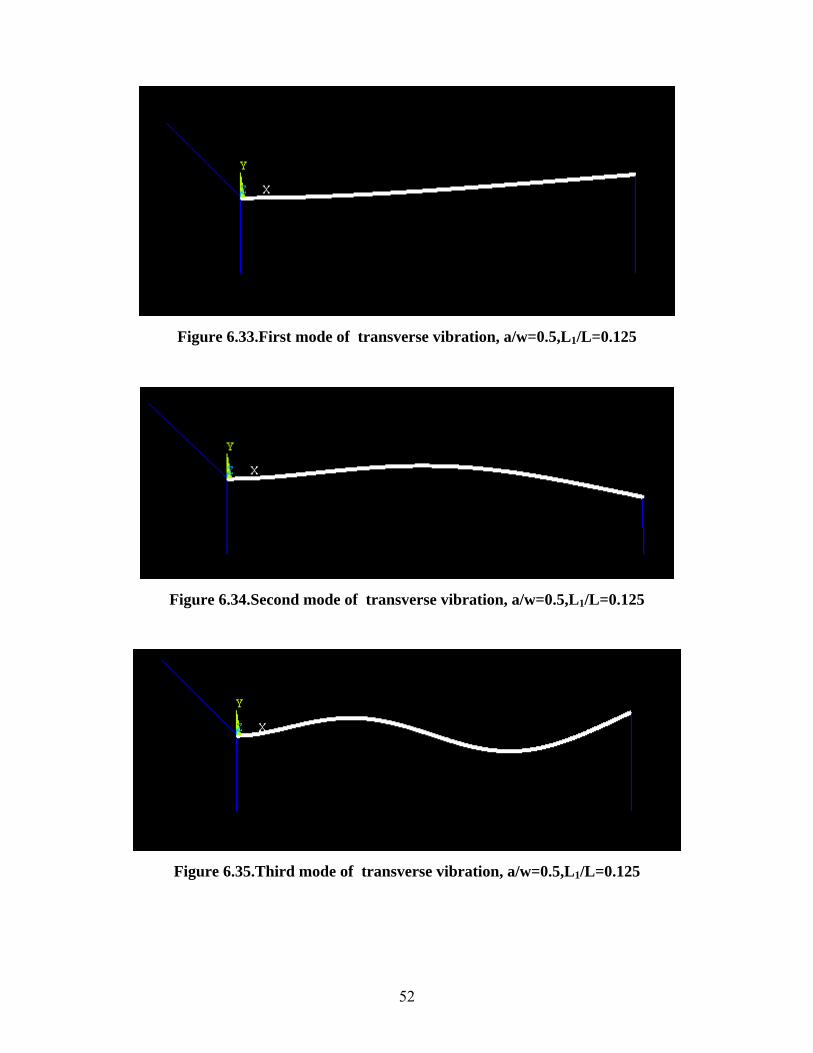
Figure 6.33.First mode of transverse vibration, a/w=0.5,L1/L=0.125
Figure 6.34.Second mode of transverse vibration, a/w=0.5,L1/L=0.125
Figure 6.35.Third mode of transverse vibration, a/w=0.5,L1/L=0.125
52
6.3 DISCUSSIONS
An aluminium beam with elastic springs ( ) with a
uniform cross-section area of 80 cm,breadth 5 cm, depth 6 mm, modulus of elasticity
E=0.724×10
44 440 L Tk 10 ,k 0,k 10= = =
12 dynes/cm2, Poisson’s ratio (υ )=0.3, and density (ρ )=2.77 gm/cm3 is
considered for the numerical analysis. The crack is situated at one position
(L1/L=10/8=0.125). The crack depths are chosen such that a/w=0.01,0.1667,0.334 and
0.5. The first, second, and third natural frequencies corresponding to various crack
conditions are calculated. The fundamental mode shapes for trasverse vibration of
cracked and uncracked beams are plotted and compared. The magnified view of the mode
shapes is also plotted for the elastic beams in the vicinity of the crack in order to observe
the change in the mode shape. The numerical results are shown in Figs.6.3-6.20.The
simulation results obtained by ANSYS software are shown in Figs.6.21-6.35. The critical
load found out for two different end conditions are shown in Figs.6.1 and 6.2.
The results obtained from the numerical analysis are presented in graphical forms.
In Fig 6.13.It is evident that there is an appreciate variation between the natural frequency
of cracked and uncracked cantilever beams. With the increase in mode of vibration this
difference increases. The transverse vibration first, second and third mode shapes for
single crack aluminium beam are shown in Figs.(6.3)-(6.5).In these figures, the relative
crack depth considered is 0.01.In Figs. 6.6-6.8 the relative crack depth considered is
0.1667 . In Figs. 6.9-6.11 the relative crack depths are considered as 0.334. In Figs. 6.12-
6.14 the relative crack depth considered as 0.5.and in figures (6.3)–(6.14) the relative
crack position is fixed at 0.125.
For moderate cracks (a/w=0.1667) appreciable changes in mode shapes are
noticed and for deep cracks (a/w=0.5) the change in mode shapes are quite substantial.
Further more, the numerical results indicate that the deviation between the fundamental
mode shapes of the cracked and uncracked beam is always sharply changes at the crack
location. Such behaviours are noticed in the magnified views of the mode shapes (Figs.
6.15-6.17. The changes of natural frequencies with respect to crack depths are shown in
53
Figs.6.18-6.20. Measurable changes in natural frequencies can be observed for relatively
deep cracks.
For minute crack (a/w=0.01) the magnified views of transverse mode shapes at the crack
locations are depicted in Figs.6.15-6.17. From these figures it is observed that the mode
shapes change sharply at the crack locations.
Figs. 6.1 and 6.2 show the stability boundaries for elastically supported columns for two
conditions. One is at one end of the column restrained by a torsional spring and a hinge
while the other end is supported by roller. Secondly, one end rigidly clamped and the
other end is supported by a vertical spring. For these two cases, the critical loads are
found out. The curves in these figures represent stability boundaries, i.e. points below
these curves correspond to values of load and stiffnesses for which the beam is
remains in a stable unbuckled state.
*P * *T Lk ,k
54

CHAPTER 7
CONCLUSIONS AND SCOPE FOR FURTHER WORK
7. CONCLUSION& SCOPE FOR FURTHER WORK
The numerical results are shown in fig 6.3-6.20 and the simulation analysis results
are shown in fig 6.21-6.35.it is observed that the natural frequency of beam for a single
crack decreases as compared to the uncracked cantilever beam condition. The frequency
of the cracked cantilever beam decreases with increase in the crack depth for the all
modes of vibration.
For minute crack depth there is minor change in mode shapes between the
cracked and uncracked beam. For moderate crack depth (a = 3mm) the change in mode
shapes are quite substantial. For deep crack (a ≥ 5mm) the change in mode shapes can be
easily distinguished.
In the case of one end of the beam restrained by a torsional spring and a hinge while the
other end is supported by roller ( * *0 Lk k= = ∞ ), the critical load found out in the range of
6.76 13.153 as shown in fig 6.1 ≤ *crP ≤
In the case of one end rigidly clamped ( * *0 Tk k= = ∞ ), and one end supported by a
vertical spring (Fig 6.2), the critical load found out in the range of *cr1.571 P 13.153≤ ≤
FURTHER WORK
• The cracked cantilever can be analyzed under the influence of external forces.
• The dynamic response of the cracked beams can be analyzed for different crack
orientations
• Stability study of the cracked beams can be done.
55

CHAPTER 8
REFERENCES
8. REFERENCES
1. Irwin, G.R., analysis of stresses and strains near the end of a crack traversing a
plate, Journal of Applied Mechanics, 1957, 24,361-364.
2. Irwin, G.R., Relation of stresses near a crack to the crack extension force. 9th
Congress Applied Mechanics, Brussels, 1957.
3. Krawczuk, M. and Ostachowicz. W.M., Transverse natural vibrations of a cracked
beam loaded with a constant axial force. Journal of Vibration and acoustics,
Trans. ASME, 1993,115, pp.428-524.
4. Ostachowicz. W.M. and Krawczuk, M., Analysis of the effect of cracks on the
natural frequencies of a cantilever beam. Journal of Sound and vibrations.1991,
150, pp.191-201.
5. Ostachowicz. W. M. and krawczuck, M., Coupled torsional and bending
vibrations of a rotor with an open crack. Archive of Applied Mechanics, Vol. 62,
1992, pp.191-201.
6. Dimorogonas, A.D., Dynamic response of cracked rotors. General Electric Co.,
Internal report, Schenectady, NY, U.S.A., 1971.
7. Dimorogonas, A.D., Dynamics of cracked shafts, General Electric Co., Technical
information Series. DF-74-LS-79, 1974.
8. Matveev, V.V. and Bovsunovsky, A.P., Vibration based diagnostics of fatigue
damage of beam-like structures, Journal of Sound and vibration, 249(1), 2002,
pp.23-40.
9. Adams, R.D., Cawley, P., Pye, C.J. and stone, B.J., A vibration technique for non-
destructively assessing the integrity of structures. Journal of Mechanical
Engineering Science., 1978.
10. Springer, W.T., Lawrence, k.L. and Lawley, T.J., The effect of a symmetric
discontinuity on adjascent material in a longitudinally vibrating uniform beam.
Experimental Mechanics, 1987, 27, pp. 168-171.
11. Krawczuk, M. and Ostachowicz, W.M., Parametric vibrations of beam with crack.
Ing.Arch., 1992, 62,463-473.
12. [12].Krawczuk, M.natural vibration of cracked rotating beams. Acta Mechanica,
1993, 99, pp.35-48.
56
13. Silva, J.M.M. and Gomez, A.J.M.A.m Experimental dynamic analysis of cracked
free-free beams. Exp. Mech., 1990, 30, pp.20-25.
14. Araujo Gomez, A.J.M. and Montalvaoe Silva, J.M., Theoretical and Experimental
data on crack depth effects in the dynamic behaviour of free-free beams. Int.
Modal Analysis Conference, IMAC, Vol.9. Union Coll, Schenectady, NY,U.S.A.,
1991, pp. 274-283.
15. Araujo Gomez, A.J.M. and Montalvaoe Silva, J.M., Experimental determination
of the influence of the cross-section size in the dynamic behaviour of cracked
beams. Proc. IMMDC2, Los Angels, U.S.A., 1990, pp.124-130.
16. Chondros T.G, Dimarogonas A.D and Yao, J., A continuos cracked beam
vibration theory. Journal of Sound and Vibration, Vol.215, 1998, pp.17-34.
17. Papadopoulos, C.A., Torsional vibrations of rotors with transverse surface
cracks,. Computers and Structures Vol.51, No.6, 1994, pp.713-718.
18. Pandey.A.K, Biswas, m. and Samman, M.M., Damage detection from changes in
curvature mode shapes. Journal of Sound and vibration, 1991, 145, pp. 321-332.
19. Qian, G.-L., Gu, S.-N. and Jian J.-S., The dynamic bahaviour and crack detection
of a beam with a crack. Journal of Sound and Vibration, 1990, 138(2), pp.233-
243.
20. Zheng, D.Y. and Fan, S.C., Natural frequencies of a non-uniform beam with
multiple cracks via modified Fourier series. Journal of Sound and Vibration,
Vol.242 (4), 2001, pp. 701-717.
21. Timoshenko, S.P. and Gere, J.M., Theory of Elastic Stability, 2nd edn. McGraw-
Hill, New York (1961).
22. Wang, T.M, Postbuckling of column under distributed axial load. J.engg Mech.
97. 1323 (1971).
23. Wang, C.Y, Large deformation of a heavy cantilever. Q. appl. Math. 39, 261,
(1981).
24. Wang.C.Y, A critical review of the heavy elastica. International Journal of
Mechanical Sciences. 28, 549 (1986).
25. Tauchert, T.R and W.Y.Lu, W.Y, Large deformation and postbuckling behavior
of an initially deformed rod. Int. J. Non-Linear Mech. 22,511 (1987).
57
2266.. Wilson, J.F and Snyder, J.M, The elastica with end load flip-over. Journal of
Applied Mechanics. 55, 845 (1988).
27. Dimarogonas, A.D., and Papadopoulos, C.A., “Vibration of cracked shaft in
bending”, Journal of Sound and Vibration, 1983, 91, 583-593.
28. Chondros, T.G., and Dimarogonas, A.D., “Identification of cracks in welded
joints of complex structures, Journal of Sound and Vibration, 1980, 69, 531-538.
29. Dimarogonas, A.D., and Massouros, G., “Torsional vibration of a shaft with
circumferential crack”, Engineering Fracture Mechanics, 1980, 15, 439 – 444.
30. Rizos, P.F., Aspragathos, N., and Dimarogonas, A.D., “Identification of cracked
location and magnitude in a cantilever beam from the vibrational modes”, Journal
of Sound and Vibration, 1989, 138 (3), 381 – 388.
31. Mermertas, V., and Erol, H., “Effect of mass attachment on the free vibration of
cracked beams”, The 8th
International Congress on Sound and Vibration, Hong
Kong, , 2001, 2803 – 2810.
32. Bamnios, G., and Trochides, A., “Dynamic behavior of cracked cantilever beam”,
Applied Aoustics, 1995, 97 – 112.
33. Dimarogonas, A.D., “Vibration of cracked structures: a state of art review”,
Engineering Fracture Mechanics, 1996, 55, 831 – 857.
34. Chandra Kishen, J.M., and Kumar, A., “Finite element analysis for fracture
behavior of cracked beam-columns”, Finite Elements in Analysis and Design,
2004, 40, 1773 –1789.
35. Krawczuk, M., Zak, A., and Ostachowicz, W., “Elastic beam finite element with a
transverse elasto-plastic crack”, Finite Elements in Analysis and Design, 2000,
34, 61 – 73.
36. .Ostachowicz W.M., and Krawezuk, M., “Analysis of effect of cracks on the
natural frequencies of a cantilever beam”, Journal of sound and vibration, 1991,
150(2),pp.19-201.
37. Behera, R.K., "Vibration of a cracked cantilever beam", M.E.Thesis
38. Parhi, D.R.K., "Dynamic behavior of beam/rotor -structures with transverse crack
subjected to external force", PhD thesis.
58