Embed Size (px)
Citation preview
Vibration Considerations When Planning a Facility
By: Jack DankowskiFabreeka International, United States of America
Introduction
This paper is designed to offer realistic approaches to solve ground vibrationproblems by anticipation, identification, analysis, design and test. A wide varietyof offerings are discussed ranging from the seismic "in-ground" pad, to the"overkill" method of suspending whole floors. The discussion includes wavepropagation of the soil, vibration of foundations, isolation of seismic masses,design trade-offs, and vibration survey field measurements by recent techniques.Additional subjects such as vibration generated by machinery and human factorengineering are discussed.
Vibrations
Vibration is a phenomenon which exists and presents itself in many ways, suchas heartbeat, car travel or earthquakes to name a few. This paper considers onlyground and ground related vibrations which cause objectionable effects inindustry where buildings, machinery, sensitive equipment and humans must beconsidered.
Vibration may be categorized into the microseism range which is ever present inthe earth's crust and the induced vibrations which are caused by man and naturesuch as earthquakes, wind, water and storms. Microscopic vibrations at theatomic/molecular level are considered nil and not discussed in this paper.
Microseisms appear at the earth's surface as a result of motion from within theearth. Seismological centers around the world record such ground vibrationsfrom a period of 16.67 seconds to frequencies of approximately 10 Hz.Microseisms usually have an amplitude of less than 10-7 g over the samefrequency range (Alsup, 1963). It may be concluded that microseisms should notbe considered in the vibration control criteria.
Fabreeka International, Inc.
2
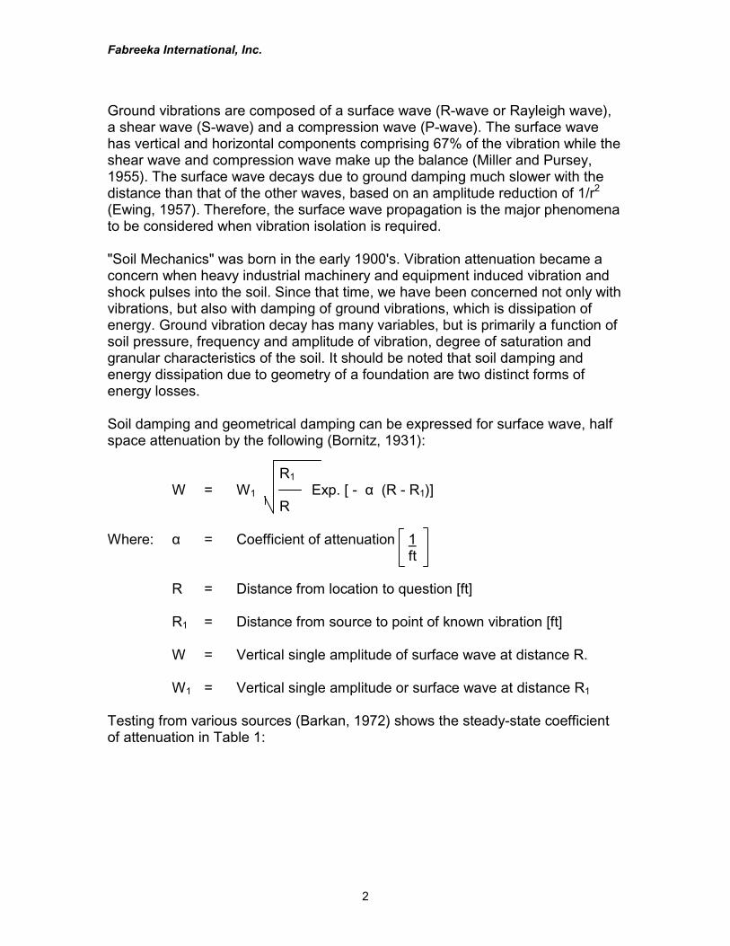
Ground vibrations are composed of a surface wave (R-wave or Rayleigh wave),a shear wave (S-wave) and a compression wave (P-wave). The surface wavehas vertical and horizontal components comprising 67% of the vibration while theshear wave and compression wave make up the balance (Miller and Pursey,1955). The surface wave decays due to ground damping much slower with thedistance than that of the other waves, based on an amplitude reduction of 1/r2
(Ewing, 1957). Therefore, the surface wave propagation is the major phenomenato be considered when vibration isolation is required.
"Soil Mechanics" was born in the early 1900's. Vibration attenuation became aconcern when heavy industrial machinery and equipment induced vibration andshock pulses into the soil. Since that time, we have been concerned not only withvibrations, but also with damping of ground vibrations, which is dissipation ofenergy. Ground vibration decay has many variables, but is primarily a function ofsoil pressure, frequency and amplitude of vibration, degree of saturation andgranular characteristics of the soil. It should be noted that soil damping andenergy dissipation due to geometry of a foundation are two distinct forms ofenergy losses.
Soil damping and geometrical damping can be expressed for surface wave, halfspace attenuation by the following (Bornitz, 1931):
R1W = W1 Exp. [ - α (R - R1)]
R
Where: α = Coefficient of attenuation 1ft
R = Distance from location to question [ft]
R1 = Distance from source to point of known vibration [ft]
W = Vertical single amplitude of surface wave at distance R.
W1 = Vertical single amplitude or surface wave at distance R1
Testing from various sources (Barkan, 1972) shows the steady-state coefficientof attenuation in Table 1:
Fabreeka International, Inc.
3
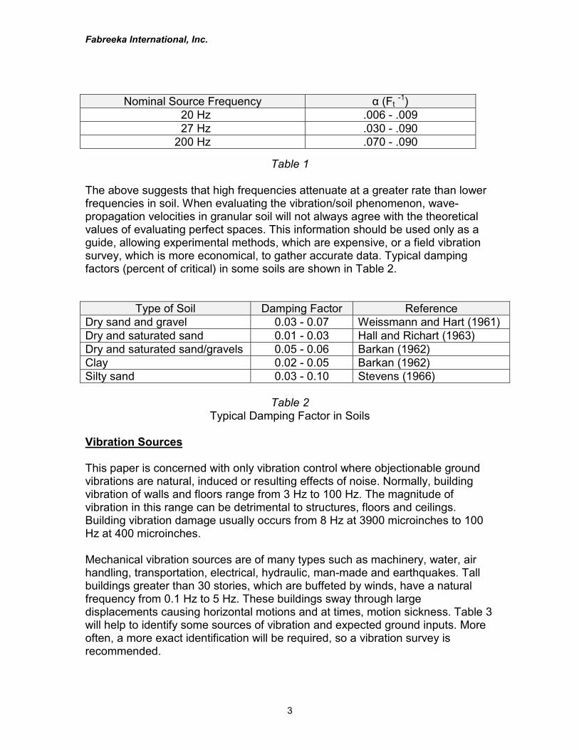
Nominal Source Frequency α (Ft -1) 20 Hz .006 - .009 27 Hz .030 - .090200 Hz .070 - .090
Table 1
The above suggests that high frequencies attenuate at a greater rate than lowerfrequencies in soil. When evaluating the vibration/soil phenomenon, wave-propagation velocities in granular soil will not always agree with the theoreticalvalues of evaluating perfect spaces. This information should be used only as aguide, allowing experimental methods, which are expensive, or a field vibrationsurvey, which is more economical, to gather accurate data. Typical dampingfactors (percent of critical) in some soils are shown in Table 2.
Type of Soil Damping Factor ReferenceDry sand and gravel 0.03 - 0.07 Weissmann and Hart (1961)Dry and saturated sand 0.01 - 0.03 Hall and Richart (1963)Dry and saturated sand/gravels 0.05 - 0.06 Barkan (1962)Clay 0.02 - 0.05 Barkan (1962)Silty sand 0.03 - 0.10 Stevens (1966)
Table 2Typical Damping Factor in Soils
Vibration Sources
This paper is concerned with only vibration control where objectionable groundvibrations are natural, induced or resulting effects of noise. Normally, buildingvibration of walls and floors range from 3 Hz to 100 Hz. The magnitude ofvibration in this range can be detrimental to structures, floors and ceilings.Building vibration damage usually occurs from 8 Hz at 3900 microinches to 100Hz at 400 microinches.
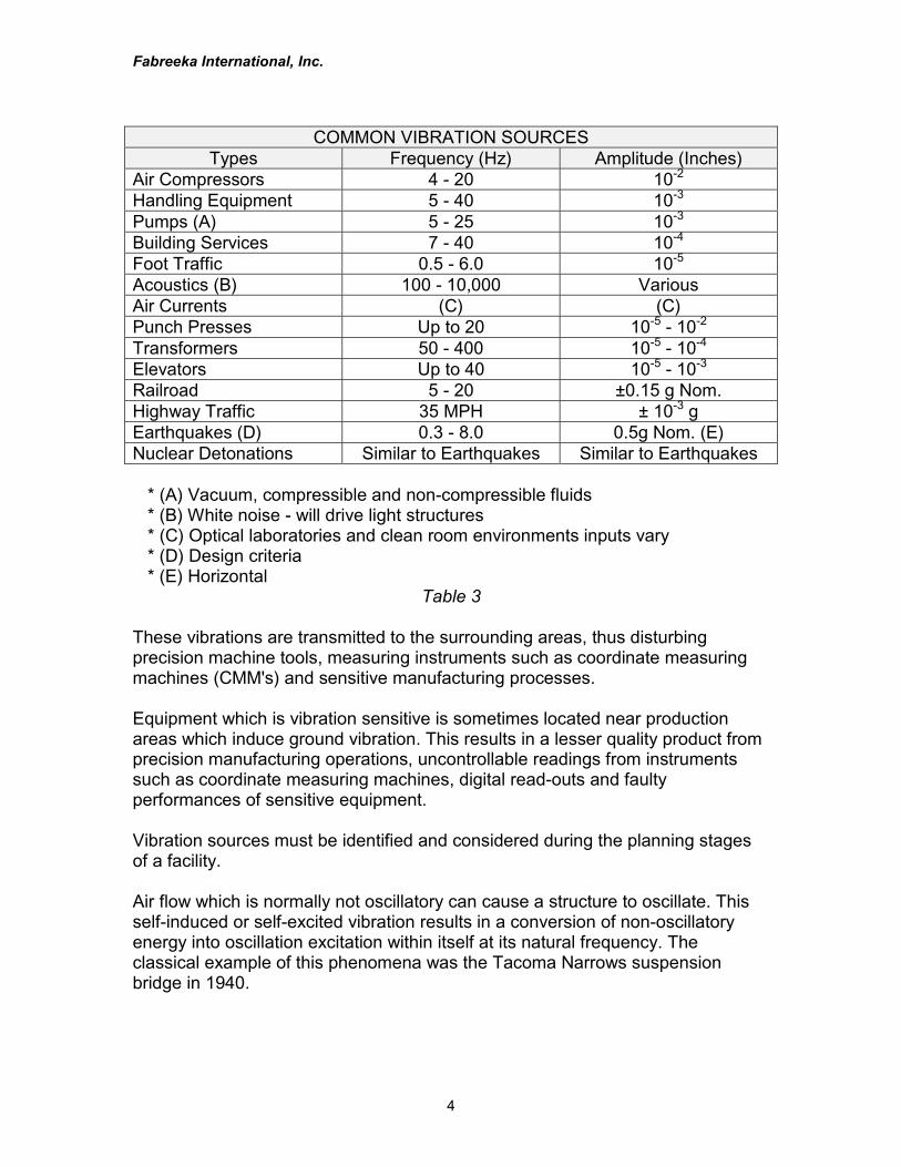
Mechanical vibration sources are of many types such as machinery, water, airhandling, transportation, electrical, hydraulic, man-made and earthquakes. Tallbuildings greater than 30 stories, which are buffeted by winds, have a naturalfrequency from 0.1 Hz to 5 Hz. These buildings sway through largedisplacements causing horizontal motions and at times, motion sickness. Table 3will help to identify some sources of vibration and expected ground inputs. Moreoften, a more exact identification will be required, so a vibration survey isrecommended.
Fabreeka International, Inc.
4
COMMON VIBRATION SOURCESTypes Frequency (Hz) Amplitude (Inches)
Air Compressors 4 - 20 10-2
Handling Equipment 5 - 40 10-3
Pumps (A) 5 - 25 10-3
Building Services 7 - 40 10-4
Foot Traffic 0.5 - 6.0 10-5
Acoustics (B) 100 - 10,000 VariousAir Currents (C) (C)Punch Presses Up to 20 10-5 - 10-2
Transformers 50 - 400 10-5 - 10-4
Elevators Up to 40 10-5 - 10-3
Railroad 5 - 20 ±0.15 g Nom.Highway Traffic 35 MPH ± 10-3 gEarthquakes (D) 0.3 - 8.0 0.5g Nom. (E)Nuclear Detonations Similar to Earthquakes Similar to Earthquakes
* (A) Vacuum, compressible and non-compressible fluids * (B) White noise - will drive light structures * (C) Optical laboratories and clean room environments inputs vary * (D) Design criteria * (E) Horizontal
Table 3
These vibrations are transmitted to the surrounding areas, thus disturbingprecision machine tools, measuring instruments such as coordinate measuringmachines (CMM's) and sensitive manufacturing processes.
Equipment which is vibration sensitive is sometimes located near productionareas which induce ground vibration. This results in a lesser quality product fromprecision manufacturing operations, uncontrollable readings from instrumentssuch as coordinate measuring machines, digital read-outs and faultyperformances of sensitive equipment.
Vibration sources must be identified and considered during the planning stagesof a facility.
Air flow which is normally not oscillatory can cause a structure to oscillate. Thisself-induced or self-excited vibration results in a conversion of non-oscillatoryenergy into oscillation excitation within itself at its natural frequency. Theclassical example of this phenomena was the Tacoma Narrows suspensionbridge in 1940.
Fabreeka International, Inc.
5
A more common and noticeable example are weights or wind guides, usuallyless than one cubic foot in volume, hanging on electrical power and telephonelines to influence the line natural frequency and prevent wind induced "galloping"of the lines.
Vibration Measurement (Survey)
Vibration measurement (survey) establishes the degree and magnitude of avibratory environment. Usually vibration surveys are performed in variouslocations, so portable equipment should be used. Some major companies havethe capabilities of acquiring their own measurements, however, most rely uponconsultants or companies in the field of shock and vibration control.
The normal displacement range of interest in a vibration survey is less than 5microinches for installation locations of very sensitive equipment to 5000microinches for motions of large structures.
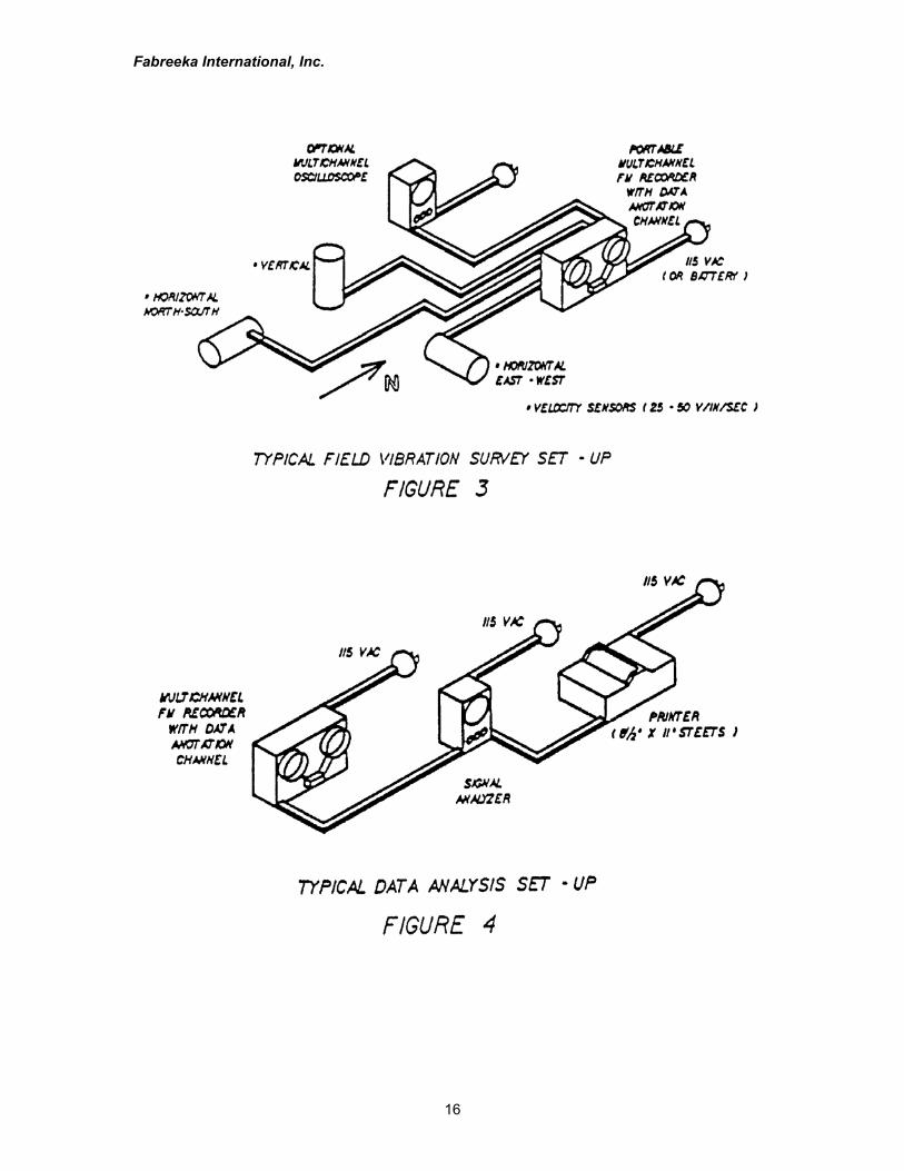
Seismic vibration sensors used in field vibration surveys should be ruggedvelocity transducers or accelerometers. Velocity transducers are normally largerthan accelerometers in size and produce a greater output (25 to 50 v/in/sec)without using amplifiers. Accelerometers have less of a voltage output in volt/g.Accelerometers are smaller, and since they have a small voltage output,amplification is required to raise the signal output from the diagnosticinstrumentation noise levels. Vibration surveys should identify the disturbingfrequencies with respect to amplitude of displacement, velocity and "g" level inthe vertical and horizontal (X and Y) directions when sensors are attached firmlyto the floor or ground. Good instrumentation will allow a resolution of at least onemicroinch displacement from 1 Hz to 100 Hz. See Figure 3.
Vibration surveys can determine:
1. Direction of the vibration source.2. If the ground vibration exceeds the limit (sensitivity level)
established by the equipment manufacturer of the equipment inquestion.
3. If isolation is required.4. Power Spectrum Density (PSD) of the source.5. Performance of an isolation system by comparing the floor vibration
with respect to the isolated equipment.
Reputable manufacturers of vibration isolation equipment will supply testequipment for field testing of the supplied isolation system during equipmentinstallation.
Fabreeka International, Inc.
6
Survey test equipment should also measure vibration outside the range ofinterest thus allowing for unexpected vibration inputs such as beat frequencies,shock pulses and transients, all of which occur often in real life.
Vibration measurement of a rigid seismic mass, pad or structure can reveal notonly amplitudes in the vertical and horizontal directions but modes of vibration.When using at least two transducers, the translation mode and/or rotation can bemeasured simultaneously.
Multi-channel measurements are used to determine mode shapes of structures.A rigid structure vibrating in the vertical direction, such as a floating seismic massor a concrete base, could have all vertical motion at any point in phase. By usingone transducer as a reference and by placing at least two other transducers nearthe edge of the structure, a phase and amplitude comparison is achieved,indicating a predominant mode. Horizontal motion is identified in the samemanner using horizontal transducers. When rocking motion is present, therelative vertical amplitudes increase linearly with distance on the horizontal line.A phase shift of 180° will be noticed when crossing the zero point on the sameline. When identifying a twisting motion, horizontal vibration in a directionperpendicular to a radius of the axis of rotation, the amplitude will increase indirect proportion to the distance from the rotational axis, with a 180° phase shifton opposite sides. The output from all transducers may be recorded on a directwriting, multi-channel oscillograph or on magnetic tape for later analysis. Byexamining the wave forms, the mode shapes of the structure, whether flexible,torsional or fundamental can be determined.
Vibration measurement data in many ways depends on how much and how in-depth a diagnostic study is required. If frequencies of interest are confined to aknown bandwidth such as 1 Hz to 100 Hz, then signals generated by the sensorscan be amplified and conditioned by band-pass filters having variable high andlow cut-off frequencies. The signals are monitored and then recorded. Thistechnique allows a manual frequency spectrum analysis while providing thecapability of observing selected frequencies and band widths for short periods oftime. A more versatile approach uses a Frequency Sweep Analyzer in which avery narrow band-pass is automatically swept through the frequency rangeresulting in a display of amplitudes versus frequency. These two methods requirethat the vibrations remain unchanged (steady-state) during the 2 - 5 minutes ittakes to sweep through the frequency range. The most current approach usesthe Real Time Signal Analyzer which displays the frequency spectruminstantaneously and continuously. In this manner, rapid analysis is gained whilerealizing a change in frequency content due to input variations which might bemissed during a sweep analysis. See Figure 4.
Fabreeka International, Inc.
7
Vibration Isolation Criteria
When considering the location and installation of equipment which is sensitive tovibration or equipment which induces shock or vibration into the ground orsurrounding structures, major questions will arise. Serious vibration considerationshould be given when designing a new facility in a new or existing building.
The first design step should be an analysis which clearly describes the vibrationinfluences of all variables involved and which will then permit intelligent decisionsto be made regarding location, performance and cost trade-offs. An essentialingredient when redesigning or relocating an existing facility is having a vibrationsurvey performed which defines present vibration levels. When designing newconstruction, vibration criteria from equipment manufacturers and an analysisshould be given to the architect. Some of the design considerations of theproposed installation using sensitive equipment are as follows:
Determine the threshold sensitivity of the equipment to be installed,that is, the lowest frequency at a specific amplitude at which theequipment can operate satisfactorily without degradation due tovibration input. As an example, for a typical coordinate measuringmachine (CMM), the threshold sensitivity would be 10 microinchesat 5 Hz to 100 Hz in all three axes. Sometimes the manufacturerwill specify limits in velocity or acceleration amplitudes with respectto frequency.
Ambient vibrations are determined by vibration surveys or byanalysis of the architectural structural design. Both cases shouldallow for vibrational growth which always develops with time. Thispermits equipment usage with typical increase of industrial andenvironmental vibration levels without affecting performance.
Many times the human environmental impact due to vibration andnoise is overlooked, resulting in persons being affectedphysiologically and psychologically, so work in the immediatevibration zone should be considered. An acceptable level should beplanned and provided for. Standards defining these levels areavailable. Safe levels would be at or below a velocity of 10-3
inches/second with "g" level of less than 10-4.
Fabreeka International, Inc.
8
A special type of vibration phenomenon which sometimes is present instructures, such as a suspended upper floor or balcony, is referred to as a "beatfrequency". This periodic vibration usually is less than 1 Hz and is considered arectilinear vibration occurring as a result of two sinusoidal frequency componentsthat differ by a small amount as compared to either frequency component. Thebeat wave form is similar to a sinusoid having an increasing and decreasingamplitude which is equal to the difference of the two component frequencies. Atypical example would be a hotel or industrial building where air conditioningunits, compressors, pumps or electrical generators are located. The beatfrequency is difficult to predict but can be isolated at the source level. Note thatbeat frequencies are easily noticeable to humans and are very distracting,particularly when riding in a multi-engine aircraft with unsynchronized engineRPM.
Basically, there are two methods of isolation: 1) Isolating equipment that inducesshock or vibration into the ground, 2) Isolating floor-borne vibrations.
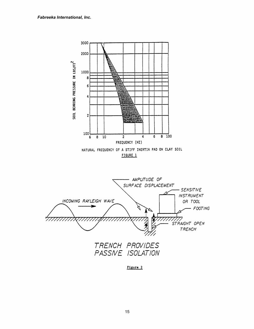
First would be the foundation of the classic "in-ground concrete pad". This isusually designed by the architect or his structural engineer. Isolation of this typeis predictable and tends to change with load. This approach is permanent; so ifthe equipment is moved, isolation is lost and new construction would be required.Foundation or in-ground pad isolation as shown in Figure 1 (Dynamic Tests,1962) is usually effective above 20 Hz. The least expensive form of isolation isplacing sensitive equipment far away from a vibrational source; however, in mostcases, it is not practical. When an in-ground concrete pad can be used, the padnatural frequency and the type of base the pad is poured onto cannot beoverlooked, since amplification may occur, thus defeating the purpose of the pad.Increased isolator efficiency can be enhanced by providing a trench around thepad. See Figure 2.
The second method would be to isolate the equipment from the supporting floorby means of a low frequency vibration isolation system. This approach may usethe following basic types: metal springs, elastomeric springs, pneumatic isolatorsand/or a combination of the same. These elements have been used for manyyears as the principal resilient media for attenuation of mechanical vibration. Thecritical properties of these elements are deflection, stiffness (spring-rate), load-carrying capacity, damping, natural frequency and exposure to temperature,water, solvents and radiation. When given a seismic mass and payload, thenatural frequencies of the system are determined by the isolator stiffness andmass stiffness separation. Seismic isolators normally have vertical and horizontalnatural frequencies of 0.4 Hz to 5 Hz.
Fabreeka International, Inc.
9
Metal springs have been used for vibration isolation for over 100 years. Leaf,extension and compression springs are some of the more common types usedfor vibration isolation. Note that metal springs have negligible inherent dampingand usually require separate dampers such as in automobiles. Moreover,undamped helical springs have a surge which impairs isolation. By using anotherspring in series, metal springs surge would be minimized but not eliminated.Helical springs are normally not considered when low frequency isolation isrequired, since helical spring length would be excessive and stability becomes ofmuch concern.
Elastomeric (rubber) types have also been used in many forms for at least acentury. Although elastomeric isolators are the most common, they are normallynot used for low frequency isolation, since the natural frequency lower limit is 6Hz to 8 Hz when used in compression or shear. A special case, an elastomericisolator of low horizontal frequency made of laminations of elastomer and metalplates, is used for isolating buildings and bridges. These isolators, which havehigh vertical stiffness and low horizontal stiffness, are used to isolate structuresfrom the horizontal surface wave of an earthquake. Note that elastomers have anominal damping range from 5% to 17% of critical.
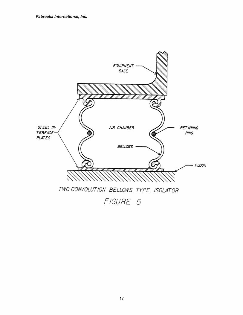
Pneumatic isolators (air springs) are widely used when low frequency isolation isrequired for instruments, equipment or large shock displacements. One type ofpneumatic isolator which is used in vehicle suspensions is of the bellows type.See Figure 5. This type of isolator has low stiffness vertically and normally poorlateral stability. When using the bellows type for seismic isolation, restraints arerequired to ensure lateral stability. The bellows concept has variable volume andlittle hysteresis damping due to the rubber bladders. These thick bladderstransmit vibrations at low amplitude inputs.
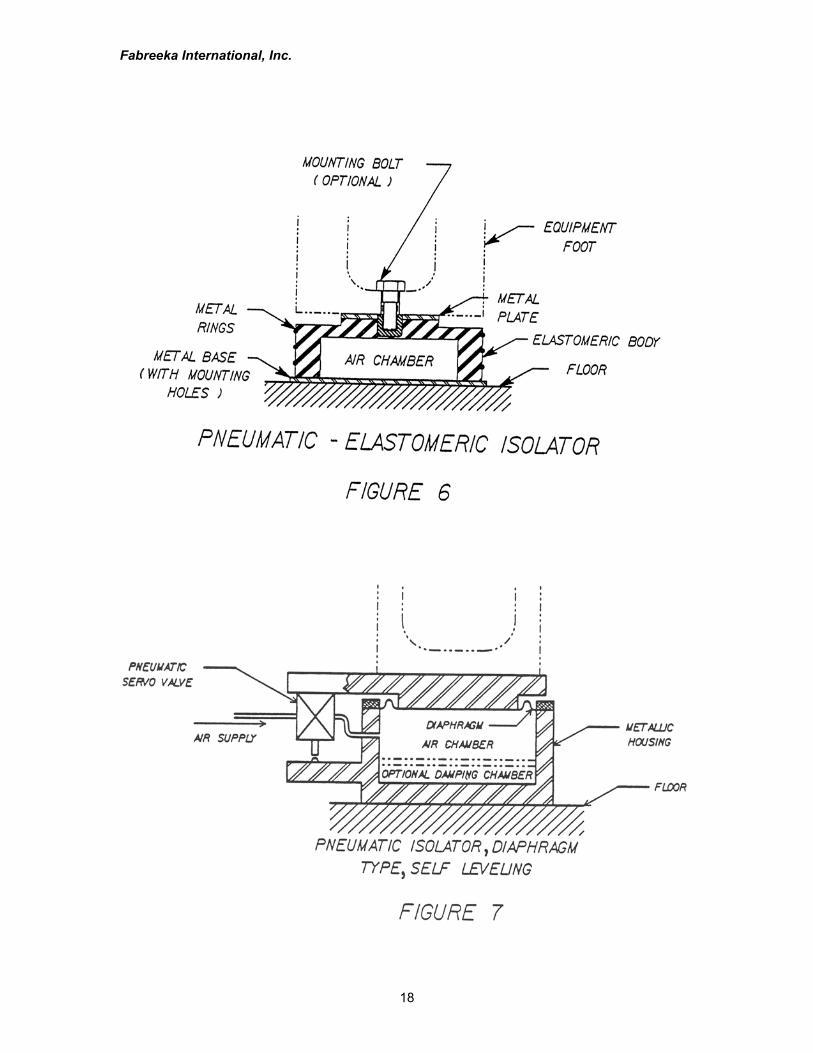
Another type of pneumatic isolator is the pneumatic-elastomeric type which isdescribed by Schubert (1974), shown in Figure 6. This type of isolator offersnatural frequencies of 3 Hz to 5.5 Hz depending on the pressure required tosupport the load. This unit has a vertical to horizontal stiffness ratio ofapproximately one. The prime advantage is the thick elastomeric wall which actsas a secondary isolator of approximately 10 Hz when deflated, unlike the thinwall of the bellows type which offers no support. The pneumatic-elastomeric typealso acts as a snubber if vertical shock is realized. As in the bellows type,damping is inherent due to the elastomeric material. Other isolators of a similarnature which offer shock and vibration control are also in wide use.
Fabreeka International, Inc.
10
A more widely used pneumatic vibration isolator is the "piston-in-a-cylinderconcept," shown in Figure 7, where a very thin single-ply elastomeric diaphragm(0.015 inch to 0.060 inch) reduces the transmission path for micro "g" amplitudeinputs. This isolator uses a constant effective area diaphragm. The dynamicperformance characteristics of these isolators also provides static stability andautomatic level control for varying loadings within a wide load-carrying capability.
When using the laws of gas compression to derive the increase in pressureassociated with the reduction in volume, the stiffness and natural frequency ofthe pneumatic isolator supporting a mass depends primarily on the volume of theisolator. If the load is changed and the pressure is adjusted to keep the heightthe same, the vertical natural frequency is constant. The theoretical basis ofvibration isolation using air springs with servo control is discussed by Cavanaugh(1976).
Automatic height control is valuable when instruments and equipment must bekept level when the load and/or its distribution is changed. Air isolators havebeen developed (Kunica, 1965) which incorporate a mechanical or electronicpneumatic servo valve to control the internal pressure supply. When the load isincreased, the air pressure is increased, and when the load is reduced, thepressure is also reduced, maintaining the spring at a constant height. The basicdesign of this isolator consists of a metallic air chamber which also supports theload when the isolator is depressurized. A flexible diaphragm seals the cylinderand the piston which supports the payload. The diaphragm operates nominally atzero deflection because the load is maintained at a constant height by the servovalve.
Pneumatic isolators with a constant natural frequency of 1.5 Hz to 2.3 Hz arenormally "off the shelf" isolators. These isolators can be modified to lower thenatural frequency by increasing the volume of air. In this way, a vertical naturalfrequency of less than 1 Hz can be realized. By contrast, mounting on helicalsprings having a vertical natural frequency of 1 Hz is unthinkable because thesprings would have a static deflection of about 10 inches.
To summarize, the pneumatic isolator air spring has natural frequencies of 0.5 to5 Hz and is impractical with any other form of isolator. It is readily adaptable foruse with a height sensing valve to maintain the height, level and naturalfrequency when the load or its distribution changes. The mounting is designed sothat if for any reason the air spring becomes deflated, the seismic mass will droponly 0.25 inch to rest on the isolator body.
Fabreeka International, Inc.
11
The design of a system is not a "do-it-yourself" recipe. The decision depends onthe size, complexity and importance of the proposed installation. It would beadvisable to seek a specialist in vibration, such as a major supplier of vibrationisolators, who is experienced in the design and application of their products, andwho offers services ranging from technical advice to system design, supply andinstallation of complete isolating systems and performing vibration surveys.
When isolating a seismic mass in a pit, design requirements should includeaccess for cleaning, drainage of the pit, lighting and accessibility to inspect,adjust and maintain. The design should be such that either the load can beremoved from the isolators or the isolators may be unloaded individually. Amplespace is allowed between the inertial block and the sides of the pit for access tothe isolators.
If isolators are supporting a "floating floor", access can be made from above thefloor. By leaving holes for the isolators, the slab is then raised by using screws incover plates fixed over the holes.
The isolator should have a metal housing that can support the load if the isolatorfails. Normally when air is lost, the system will drop approximately 0.25 inch veryslowly, resulting in a "graceful failure". When using other types (e.g. air bellows),provision should be made for the load to be transferred to a suitable support ifthe isolator fails or is deflated. Also with the bellows type, side stops should beprovided so that the lateral deflection cannot exceed the permissible amount.
The design of the seismic mounting allows the seismic mass to be coupled onlythrough the isolators. Other connections, such as hoses and electrical cables,must be flexible so that the transmission of vibration and noise betweenequipment and supporting structure is minimized.
Severe vibration of a seismically mounted machine can cause loosening of pipejoints and even cracking of pipes, as well as malfunction of the machine itself.This is particularly so if the machine has angular as well as translational vibrationbecause of the magnification of the amplitude with distance from the axis ofrotation.
The design basis for the seismic block natural frequency assumes that theseismic mass is a rigid body with a stiffness at least 100 times more than theisolator. In practice, this is a reasonable assumption for inertia blocks. Withvibration sources, sensitive equipment installations are usually assessed only onoverall performance. The installation is accepted if the equipment attains therequired standard of performance or output, such as a surface finish produced bya grinding machine or resolution of an electron microscope.
Fabreeka International, Inc.
12
Costs
The discussion of cost is limited to an overview of the discussed isolator types,construction cost and portability. When vibration problems are anticipated in anew or existing facility, an analysis or a vibration survey is a must to avoid costlyoversights or guessing. Since elastomer and metal springs inherently have ahigher natural frequency meaning less isolation, pneumatic isolators must beconsidered.
Construction costs for isolation pads, seismic masses and the like are additive tothe isolation system cost. With small items such as a coordinate measuringmachine with a 4 foot by 6 foot granite base, isolators alone are required. Largeconcrete seismic masses and bases introduce additive cost but are required forlarge payloads.
Normally, pneumatic isolators of this type are portable or at least semi-portable,so consideration should be given for future use at other possible locations. Whenusing concrete, it is assumed the installation is permanent and will not berelocated. When vibration isolation is required, a non-permanent system is lesscostly and can be relocated at a later time. In any event, the isolator shouldalways be movable. Floating floors are only isolated seismic inertia blocks ofanother shape and are not always used, since vibration induced into one cornerwill always be transmitted to other areas of the floating floor with little attenuation.
Use standard or semi-standard pneumatic isolators to reduce costs; however,there is no substitute for special isolators (0.4 Hz to 1.0 Hz) when circumstancesrequire it.
Summary
The comparisons between servo-controlled pneumatic isolators, rubber andmetal springs isolators were discussed. This paper states that for the isolation oflow-level/wide-frequency disturbances, pneumatic thin diaphragm isolatorsconstitute a far superior solution. The added benefits of static stability, constantnatural frequency and automatic precision-leveling independent of the supportedmass, make the servo-controlled pneumatic isolators unique, but appropriate, forisolating precision equipment from vibration.
In most cases, self-leveling pneumatic isolators are designed for applicationinvolving sensitive medical, scientific, manufacturing, assembly, test or Q.C.equipment. When high isolator efficiency (12 dB/octave) is required, conventionalelastomer or metal spring cannot match the performance of pneumatic isolators.Pneumatic system technology permits a wide range of variations for exceptionalneeds.

Fabreeka International, Inc.
13
An inertia block may be necessary for some installations. The design of theseblocks is critical and best left to the experts. A poorly designed inertia mass maybe worse than none at all and a costly mistake.
--------------------------------------------------------------------------
References
1. Alsup, S.A., "Preliminary study of acceleration levels at LRSM sites in theUnited States," The Geotechnical Corp., Garland, Texas, TR 63-19, p.8(1963).
2. Barkan, D.D. (1962), Dynamics of Bases and Foundations (translated fromRussian by L. Drashevska, and translation edited by G.P. Tschebotarioff),McGraw-Hill Book Co. (New York), 434pp.
3. Bornitz, G. (1931), "Uber die Ausbreitung der von Groszkolbenmaschinenerzeugten Bodenschwingungen in die Tiefe," J. Spring (Berlin).
4. Cavanaugh, Richard D. (1976). Air Suspension and Servo-ControlledIsolation Systems, in Shock and Vibration Handbook, 2nd ed., Chap. 33, CyrilM. Harris and Charles E. Crede, Eds., McGraw-Hill, New York.
5. "Dynamic Tests-Guidance, Control and Aeroballistics Facility RedstoneArsenal, Alabama." U.S. Army Engineer Waterways Experiment Station, Corpof Engineers. pp. 8-9. (1962).
6. Ewing, W.M., Jardetzky, W.S., and Press, F. (1957), Elastic Waves inLayered Media, McGraw-Hill Book Co. (New York), 380 pp.
7. Hall, J.R., Jr., and Richart, F.E., Jr. (1963), "Dissipation of Elastic WaveEnergy in Granular Soils," J. Soil Mech, and Found. Div., Proc. ASCE, Vol.89, No. SM 6, pp.27-56.
8. Kunica, Serge (1965). Servo-Controlled Pneumatic Isolators - TheirProperties and Applications, ASME Paper 65-WA/MD-12.
9. Miller, G.F., and Pursey, H. "On the Partition of Energy Between ElasticWaves in a Semi-Infinite Solid, "Proceedings, Royal Soc. of London, Vol. 223,Series A, (1955) pp. 56-69.
10. Schubert, Dale W. (1974). Dynamic Characteristics of a Pneumatic-Elastomeric Shock and Vibration Isolator for Heavy Machinery, Inst. Environ.Sci. Proc. 20th Annual. Meeting, p. 244-251.
Fabreeka International, Inc.
14
11. Steffens, R.J. (1952), "The Assessment of Vibration Intensity and ItsApplications to the Study of Building Vibrations," National Building StudiesSpecial Report No. 19, Dept. of Scientific and Ind. Research, BuildingResearch Station, London.
12. Stevens, H.W. (1966), "Measurement of the Complex Moduli and Damping ofSoils under Dynamic Loads," U.S. Army Cold Regions Research and Eng.Laboratory, Hanover, N.H., Tech. Rep. No. 173.
13. Weissmann, G.F., and Hart, R.R. (1961), "Damping Capacity of SomeGranular Soils," ASTM STP No. 305, pp. 45-54.
14. Woods, R.D. (1968), "Screening of Surface Waves in Soils," J. Soil Mech,and Found. Div., Proc. ASCE, Vol. 94, No. SM 4, July, pp. 951-979.
Fabreeka International, Inc.
15
Fabreeka International, Inc.
16
Fabreeka International, Inc.
17
Fabreeka International, Inc.
18