Embed Size (px)
Citation preview
Vickers®
Solenoid Operated Directional Valves Catalog
DG4V-3 flows to 80 l/min (21 USgpm), 6* design
DG4V-3S flows to 40 l/min (10.5 USgpm), 6* design
ISO 4401, size 03; ANSI/B93.7M-D03
Table of Contents
Introduction 01
Features and Benefits 02
Characteristics 03
Functional Symbols 04
Model Code 05
Operating Data 07
Performance Data 09
Installation Dimensions 12
DG4V-3-*A(L)-(V)M-S6-U-**-60 14
DG4V-3-*A(L)-(Z)-(V)M-S3-FPA5W-*2-60 14
DG4V-3-*A(L)-(Z)-(V)M-S4-FPA5W-*2-60 14
DG4V-3-*A(L)-(Z)-(V)M-S5-F-*2-60 14
Electrical Plugs and Connectors 15
Subplates, Connection Plates and Mounting Surfaces 18
DGMA-3-B-1* Blanking Plate 19
DGMA-3-C2-11 Crossover Plate 19
DGMA-3-T*-1*-* Tapping Plate 19
DGAM-3-01-1*-R (Metric bolt tapping) DGAM-3-01-1* (UNC bolt tapping) 20
Adaptor plate, Size 05 to 03 for pressure up to 210 bar (3000 psi) 20
DGVM-3-1*-*, DGMS-3-1E(Y)-1*-* Single station subplate, rear and side tapped port 21
DGMS-3-3E-1*-* Multi-station subplate 22
Mounting Surface 23
Appendix 24
Mounting Bolts 24
Spare Parts Data 25
Seal Kits 25
Solenoid Coils 25
Mass, approx. kg (lb) 25
Mounting Attitude 25
Temperature Limits 26
Fluid Temperature 26
Fluid Cleanliness 26
Ordering Procedure 26
1Eaton Vickers Solenoid Operated Directional Valves Product Catalog V-VLDI-MC011-E September 2008
Introduction
These solenoid operated directional control valves are for directing and stopping flow at any point in a hydrau-lic system. This 60-design series has been specially designed and developed to cover expanded demands in the industry as well as the many traditional uses of the earlier designs. Some of the more important benefits to users are outlined.
• Efficient control of greater hydraulic powers without increasing solenoid power consumption.
• Installed cost and space savings from higher power/weight-and-size ratios.
• Increases system efficiency; the result of improved manufacture of spools and bores.
General description
• Installation flexibility resulting from choice of numerous combinations of solenoid connectors and locations.
• Multi-fluid capability with-out need to change seals.
• Higher sustained machine productivity and higher uptime because of proven fatigue life and endurance, tested over 20 million cycles.
• Solenoid coils can be changed quickly and easily without leakage from hydraulic system.
• Compact, cost effective system design when used with Vickers® SystemStak™ valves and subplates.
DG4V-3 and DG4V-3S High and standard performance models:
• Up to 80 l/min (21 USgpm) and up to 40 l/min (10.5 USgpm) respectively at 350 bar (5000 psi).
• Builds on Eaton's experi-ence as the major supplier of size 03 valves world-wide.
• Offers designers the opportunity to select the optimum value package for each application.
• International standard interface. The valve mounting face conforms to ISO 4401, size 03 and is compatible with related international standards.
Features and Benefits
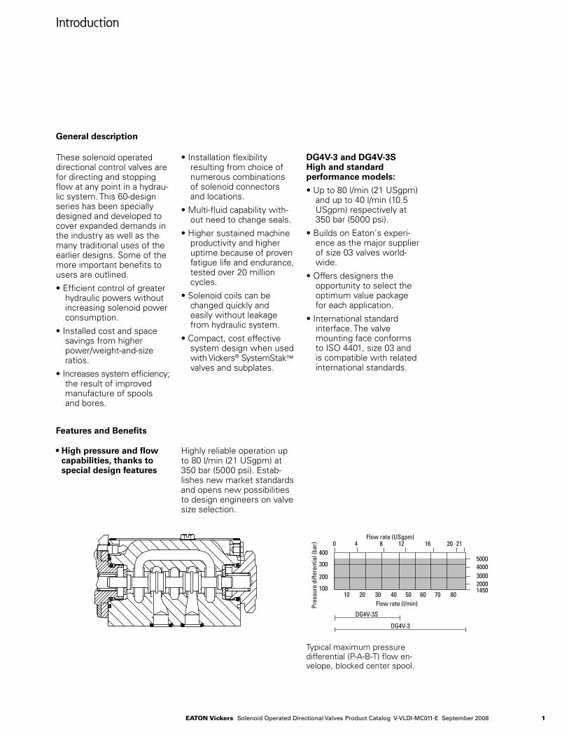
• High pressure and flow capabilities, thanks to special design features
Highly reliable operation up to 80 l/min (21 USgpm) at 350 bar (5000 psi). Estab-lishes new market standards and opens new possibilities to design engineers on valve size selection.
Typical maximum pressure differential (P-A-B-T) flow en-velope, blocked center spool.
10 20 30 40 50 60 70 80100
200
300
400
14502000300040005000
0 4 8 12 16 20 21
DG4V-3S
DG4V-3
Flow rate (l/min)
Flow rate (USgpm)
Pres
sure
diffe
rent
ial (
bar)
Pres
sure
diffe
rent
ial (
psi)
10 20 30 40 50 60 70 80100
200
300
400
14502000300040005000
0 4 8 12 16 20 21
DG4V-3S
DG4V-3
Flow rate (l/min)
Flow rate (USgpm)
Pres
sure
diffe
rent
ial (
bar)
Pres
sure
diffe
rent
ial (
psi)
2 Eaton Vickers Solenoid Operated Directional Valves Product Catalog V-VLDI-MC011-E September 2008
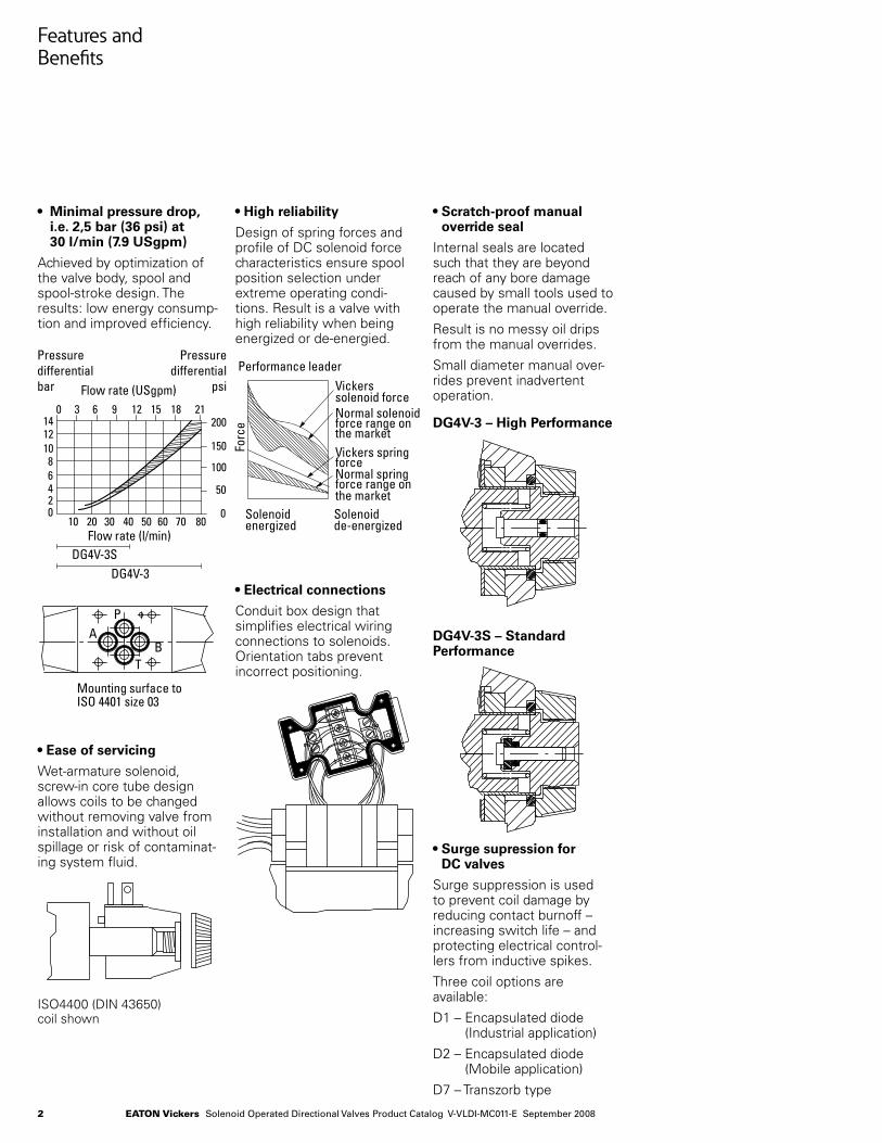
• Surge supression for DC valves
Surge suppression is used to prevent coil damage by reducing contact burnoff – increasing switch life – and protecting electrical control-lers from inductive spikes.
Three coil options are available:
D1 – Encapsulated diode (Industrial application)
D2 – Encapsulated diode (Mobile application)
D7 – Transzorb type
Features and Benefits
• Minimal pressure drop, i.e. 2,5 bar (36 psi) at 30 l/min (7.9 USgpm)
Achieved by optimization of the valve body, spool and spool-stroke design. The results: low energy consump-tion and improved efficiency.
• High reliability
Design of spring forces and profile of DC solenoid force characteristics ensure spool position selection under extreme operating condi-tions. Result is a valve with high reliability when being energized or de-energied.
• Scratch-proof manual override seal
Internal seals are located such that they are beyond reach of any bore damage caused by small tools used to operate the manual override.
Result is no messy oil drips from the manual overrides.
Small diameter manual over-rides prevent inadvertent operation.
• Ease of servicing
Wet-armature solenoid, screw-in core tube design allows coils to be changed without removing valve from installation and without oil spillage or risk of contaminat-ing system fluid.
• Electrical connections
Conduit box design that simplifies electrical wiring connections to solenoids. Orientation tabs prevent incorrect positioning.
DG4V-3 – High Performance
DG4V-3S – Standard Performance
ISO4400 (DIN 43650) coil shown
Mounting surface toISO 4401 size 03
P
TB
A
Vickerssolenoid forceNormal solenoidforce range onthe marketVickers springforceNormal springforce range onthe marketSolenoidde-energized
Solenoidenergized
Performance leader
Forc
e
10 20 30 40 50 60 70 800
50
100
150
2000 3
DG4V-3SDG4V-3
Flow rate (l/min)
Flow rate (USgpm)
Pressuredifferentialbar
Pressuredifferential
psi
18 21
02468
101214
151296
3Eaton Vickers Solenoid Operated Directional Valves Product Catalog V-VLDI-MC011-E September 2008
Characteristics
High performance DG4V-3, 6* design
Standard performance DG4V-3S, 6* design
Mounting interface
ISO 4401 size 03 ANSI/B93.7M size D03 CETOP RP65H, size 3 DIN 24340, NG6
Basic characteristics
Maximum pressure: DG4V-3 350 bar (5075 psi) DG4V-3S 350 bar (5075 psi)
Maximum flow: DG4V-3 up to 80 l/min
(21 USgpm)DG4V-3S up to 40 l/min
(10.5 USgpm)
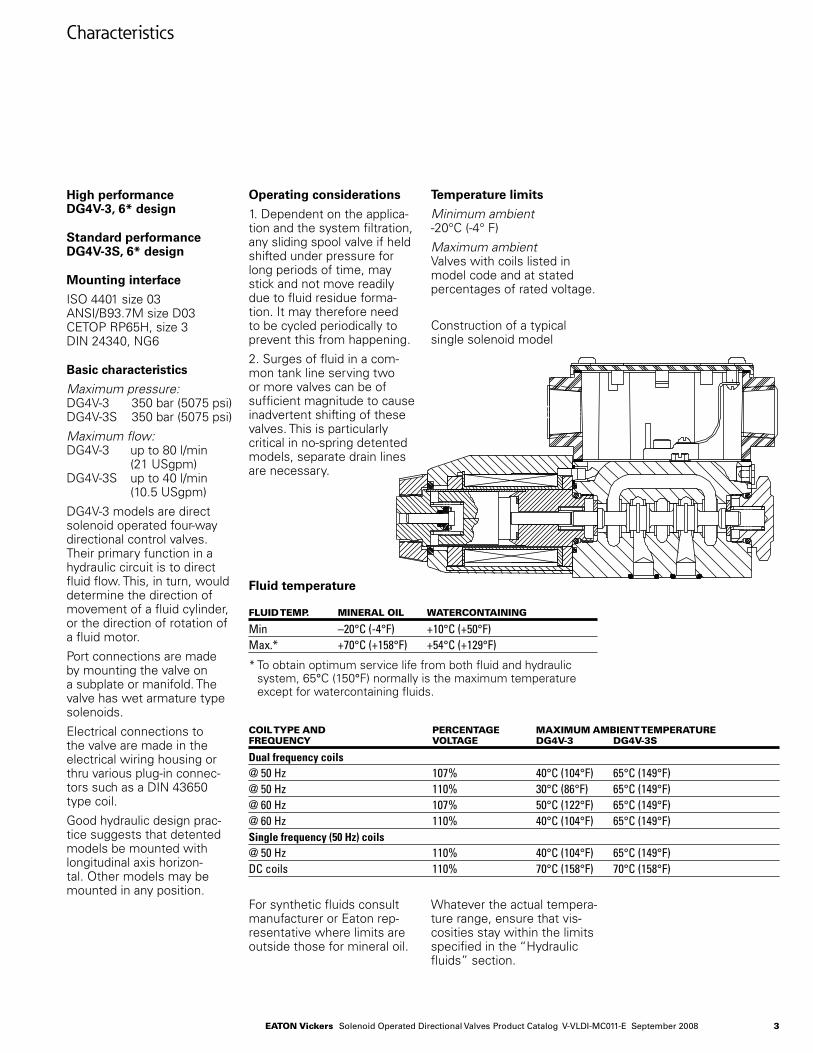
DG4V-3 models are direct solenoid operated four-way directional control valves.Their primary function in a hydraulic circuit is to direct fluid flow. This, in turn, would determine the direction of movement of a fluid cylinder, or the direction of rotation of a fluid motor.
Port connections are made by mounting the valve on a subplate or manifold. The valve has wet armature type solenoids.
Electrical connections to the valve are made in the electrical wiring housing or thru various plug-in connec-tors such as a DIN 43650 type coil.
Good hydraulic design prac-tice suggests that detented models be mounted with longitudinal axis horizon-tal. Other models may be mounted in any position.
Operating considerations
1. Dependent on the applica-tion and the system filtration, any sliding spool valve if held shifted under pressure for long periods of time, may stick and not move readily due to fluid residue forma-tion. It may therefore need to be cycled periodically to prevent this from happening.
2. Surges of fluid in a com-mon tank line serving two or more valves can be of sufficient magnitude to cause inadvertent shifting of these valves. This is particularly critical in no-spring detented models, separate drain lines are necessary.
Temperature limits
Minimum ambient -20°C (-4° F)
Maximum ambient Valves with coils listed in model code and at stated percentages of rated voltage.
Construction of a typical single solenoid model
Fluid temperature
Fluid tEmp. minEral oil WatErcontaining
Min –20°C (-4°F) +10°C (+50°F)Max.* +70°C (+158°F) +54°C (+129°F)
* To obtain optimum service life from both fluid and hydraulic system, 65°C (150°F) normally is the maximum temperature except for watercontaining fluids.
coil typE and pErcEntagE maximum ambiEnt tEmpEraturEFrEquEncy VoltagE dg4V-3 dg4V-3S
Dual frequency coils @ 50 Hz 107% 40°C (104°F) 65°C (149°F)@ 50 Hz 110% 30°C (86°F) 65°C (149°F)@ 60 Hz 107% 50°C (122°F) 65°C (149°F)@ 60 Hz 110% 40°C (104°F) 65°C (149°F)Single frequency (50 Hz) coils@ 50 Hz 110% 40°C (104°F) 65°C (149°F)DC coils 110% 70°C (158°F) 70°C (158°F)
For synthetic fluids consult manufacturer or Eaton rep-resentative where limits are outside those for mineral oil.
Whatever the actual tempera-ture range, ensure that vis-cosities stay within the limits specified in the “Hydraulic fluids” section.
4 Eaton Vickers Solenoid Operated Directional Valves Product Catalog V-VLDI-MC011-E September 2008
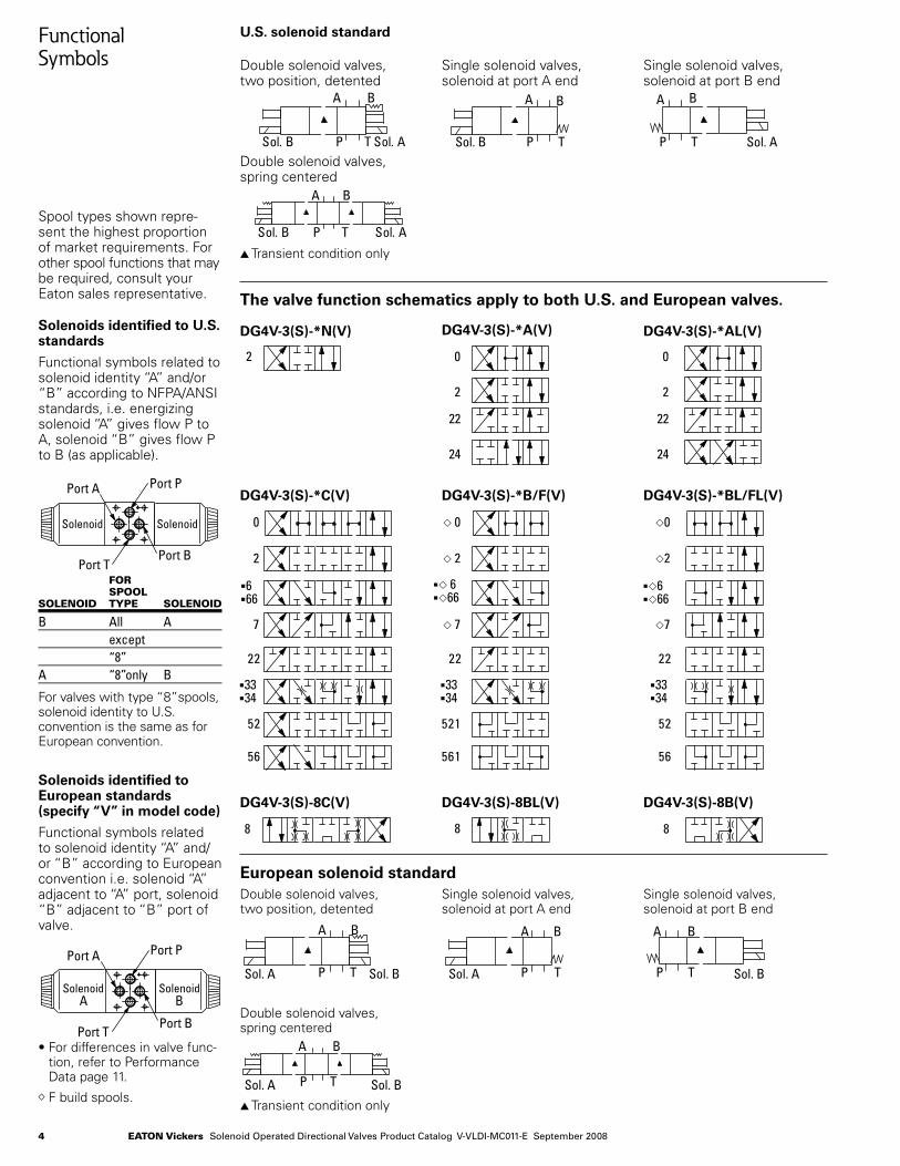
Functional Symbols
Spool types shown repre-sent the highest proportion of market requirements. For other spool functions that may be required, consult your Eaton sales representative.
Solenoids identified to U.S. standards
Functional symbols related to solenoid identity “A” and/or “B” according to NFPA/ANSI standards, i.e. energizing solenoid “A” gives flow P to A, solenoid “B” gives flow P to B (as applicable).
For SpoolSolEnoid typE SolEnoid
B All A except “8”A “8” only B
For valves with type “8”spools, solenoid identity to U.S. convention is the same as for European convention.
Solenoids identified to European standards (specify “V” in model code)
Functional symbols related to solenoid identity “A” and/or “B” according to European convention i.e. solenoid “A” adjacent to “A” port, solenoid “B” adjacent to “B” port of valve.
• For differences in valve func-tion, refer to Performance Data page 11.
◊ F build spools.
U.S. solenoid standard
Double solenoid valves, two position, detented
Single solenoid valves, solenoid at port A end
Single solenoid valves, solenoid at port B end
Double solenoid valves, spring centered
s Transient condition only
s Transient condition only
The valve function schematics apply to both U.S. and European valves.
European solenoid standard
DG4V-3(S)-*N(V)
DG4V-3(S)-*C(V)
DG4V-3(S)-8C(V)
DG4V-3(S)-*A(V) DG4V-3(S)-*AL(V)
DG4V-3(S)-*B/F(V) DG4V-3(S)-*BL/FL(V)
DG4V-3(S)-8BL(V) DG4V-3(S)-8B(V)
Double solenoid valves, two position, detented
Single solenoid valves, solenoid at port A end
Single solenoid valves, solenoid at port B end
Double solenoid valves, spring centered
Port A Port P
Port TPort B
SolenoidA
SolenoidB
Port A Port P
Port TPort B
Solenoid Solenoid
P T
A B
B .loS A .loS P T
A B
Sol. B P T
A B
Sol. A
P T
A B
B .loS A .loS
P T
A B
B .loS A .loS P T
A B
Sol. B P T
A B
Sol. A
P T
A B
B .loS A .loS
P T
A B
B .loS A .loS P T
A B
Sol. B P T
A B
Sol. A
P T
A B
B .loS A .loS
P T
A B
B .loS A .loS P T
A B
Sol. B P T
A B
Sol. A
P T
A B
B .loS A .loS
2 0
2
0
2
22
24
22
24
2 0
2
0
2
22
24
22
24
2 0
2
0
2
22
24
22
24
0
2
666
7
3334
0
2
7
0
2
7
222222
2512525
6516565
3334
3334
666
666
0
2
666
7
3334
0
2
7
0
2
7
222222
2512525
6516565
3334
3334
666
666
0
2
666
7
3334
0
2
7
0
2
7
222222
2512525
6516565
3334
3334
666
666
88 8 88 8 88 8
P T
A B
Sol. A Sol. B P T
A B
Sol. BP T
A B
Sol. AP T
A B
Sol. A Sol. B P T
A B
Sol. BP T
A B
Sol. AP T
A B
Sol. A Sol. B P T
A B
Sol. BP T
A B
Sol. A
P T
A B
Sol. A Sol. B
5Eaton Vickers Solenoid Operated Directional Valves Product Catalog V-VLDI-MC011-E September 2008
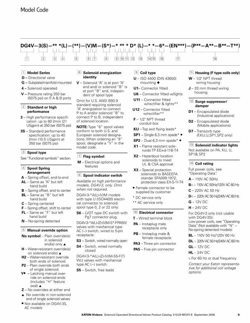
Model Code
DG4V—3(S)—** *(L)—(**)—(V)M—(S*)—* ** * D* (L)—* *—6*—(EN***)—(P**—A**—B**—T**)
1 Model SeriesD – Directional valve
G – Subplate/manifold mounted
4 – Solenoid operated
V – Pressure rating 350 bar (5075 psi) on P, A & B ports
2 Standard or high performance
3 – High performance specifi-cation: up to 80 l/min (21 USgpm) at 350 bar (5075 psi)
3S – Standard performance specification: up to 40 l/min (10.5 USgpm) at 350 bar (5075 psi)
3 Spool type
See “Functional symbols” section.
4 Spool Spring Arrangement
A – Spring offset, end-to-end AL – Same as “A” but left
hand build B – Spring offset, end to center BL – Same as “B” but left
hand build C – Spring centered F – Spring offset, shift to center FL – Same as “F” but left
hand build N – No-spring detented
5 Manual override option
No symbol – Plain override(s) in solenoid end(s) only s
H – Water-resistant override(s) on solenoid end(s) s
H2 – Water-resistant override both ends of solenoid.
P2 – Plain override both ends of single solenoid.
Yl – Latching manual over-ride on solenoid ends (includes “H” feature seal) s
Z – No overrides at either end s No override in non-solenoid
end of single solenoid valves l Not available on DG4V-3S,
AC models
6 Solenoid energization identity
V – Solenoid “A” is at port “A” end and/ or solenoid “B” is at port “B” end, indepen-dent of spool type
Omit for U.S. ANSI B93.9 standard requiring solenoid “A’’ energization to connect P to A and/or solenoid “B’’ to connect P to B, independent of solenoid location.
NOTE: Type “8” spool valves conform to both U.S. and European solenoid designa-tions. When ordering an “8” spool, designate a “V” in the model code.
7 Flag symbol
M – Electrical options and features
8 Spool indicator switch
Available on high performance models, DG4V-3, only. Omit when not required.
DG4V-3-*A(L)-(V)M models with type U (ISO4400) electri-cal connector to solenoid; spool type 0, 2 or 22 only:
S6 – LVDT type DC switch with Pg7 connector plug.
DG4V-3-*A(L)-(Z)-(V)M-S*-FPA5W valves with mechanical type AC (~) switch, wired to 5-pin receptacle:
S3 – Switch, wired normally open
S4 – Switch, wired normally closed
DG4V-3-*A(L)-(Z)-(V)M-S5-F(T)W/J valves with mechanical type AC (~) switch:
S5 – Switch, free leads
9 Coil type
U – ISO 4400 (DIN 43650) mounting u
U1– Connector fitted
U6 – Connector fitted w/lights
U11 – Connector fitted w/rectifier & lights**
U12 – Connector fitted w/rectifier**
F – 1/2" NPT thread conduit box
KU – Top exit flying leads*
SP1 – Single 6,3 mm spade* u
SP2 – Dual 6,3 mm spade* u
X1 – Flame resistant sole-noids TP EEx-d-11B-T4
X2 – Hazardous location solenoids to meet UL & CSA approval
X3 – Special protection solenoids to BASEEFA standar SFA009:1972, protection class EX-S-11-T4
u Female connector to be supplied by customer
* DC service only** AC service only
10 Electrical connector
T – Wired terminal block
PA – Instaplug male receptacle only
PB – Instaplug male & female receptacle
PA3 – Three pin connector
PA5 – Five pin connector
7654321 8 9 1210 1311 14 1615 1817
11 Housing (F type coils only)
W – 1/2" NPT thread wiring housing
J – 20 mm thread wiring housing
12 Surge suppressor/damper
D1 – Encapsulated diode (Industrial applications)
D2 – Encapsulated diode (Mobile applications)
D7 – Transzorb type (F,KU,U,SP1,SP2 only)
13 Solenoid indicator lightsNot available on PA, KU, U, SP1& SP2
14 Coil rating
Full power coils, see “Operating Data”.
A – 110V AC 50Hz
B◊ – 110V AC 50Hz/120V AC 60 Hz
C – 220V AC 50 Hz
D◊ – 220V AC 50 Hz/240V AC 60 Hz
G – 12V DC
H – 24V DC
For DG4V-3 only (not usable with DG4V-3S):Low power coils, see “Operating Data”. (Not available with “N” – No-spring detented models)
BL – 110V 50 Hz/120V 60 Hz
DL – 220V AC 50 Hz/240V AC 60 Hz
GL – 12V DC
HL – 24V DC◊ For 60 Hz or dual frequency
Contact your Eaton representa-tive for additional coil voltage options.
6 Eaton Vickers Solenoid Operated Directional Valves Product Catalog V-VLDI-MC011-E September 2008
Model Code
DG4V—3(S)—** *(L)—(**)—(V)M—(S*)—* ** * D* (L)—* *—6*—(EN***)—(P**—A**—B**—T**)
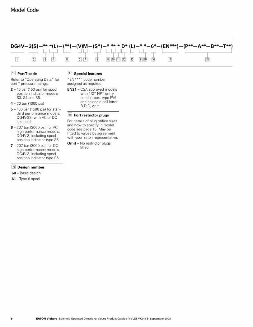
15 Port T code
Refer to “Operating Data” for port T pressure ratings.
2 – 10 bar (150 psi) for spool position indicator models S3, S4 and S5.
4 – 70 bar (1000 psi)
5 – 100 bar (1500 psi) for stan-dard performance models, DG4V-3S, with AC or DC solenoids.
6 – 207 bar (3000 psi) for AC high performance models, DG4V-3, including spool position indicator type S6.
7 – 207 bar (3000 psi) for DC high performance models, DG4V-3, including spool position indicator type S6.
16 Design number
60 – Basic design
61 – Type 8 spool
17 Special features
“EN***” code number assigned as required.
EN21 – CSA approved models with 1/2” NPT entry conduit box, type FW and solenoid coil letter B,D,G, or H.
18 Port restrictor plugs
For details of plug orifice sizes and how to specify in model code see page 15. May be fitted to valves by agreement with your Eaton representative.
Omit – No restrictor plugs fitted
7654321 8 9 1210 1311 14 1615 1817
7Eaton Vickers Solenoid Operated Directional Valves Product Catalog V-VLDI-MC011-E September 2008
Operating Data
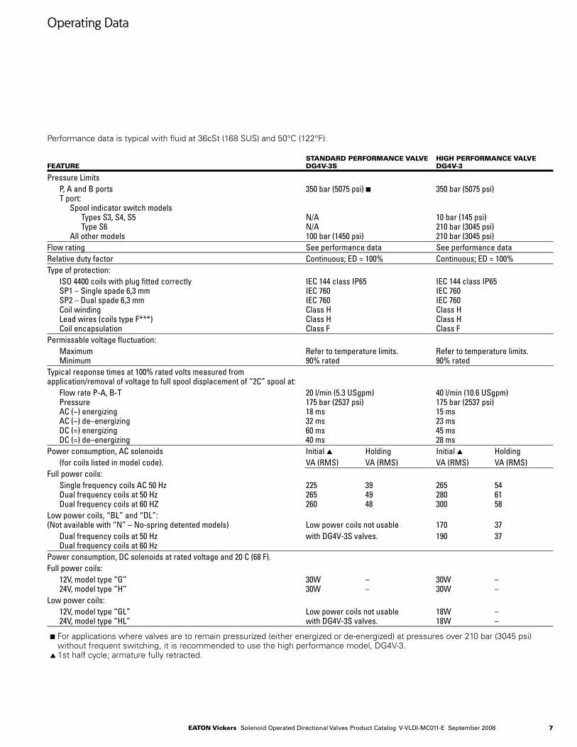
Performance data is typical with fluid at 36cSt (168 SUS) and 50°C (122°F).
Standard pErFormancE ValVE HigH pErFormancE ValVEFEaturE dg4V-3S dg4V-3
Pressure Limits P, A and B ports 350 bar (5075 psi) n 350 bar (5075 psi) T port: Spool indicator switch models Types S3, S4, S5 N/A 10 bar (145 psi) Type S6 N/A 210 bar (3045 psi) All other models 100 bar (1450 psi) 210 bar (3045 psi)Flow rating See performance data See performance dataRelative duty factor Continuous; ED = 100% Continuous; ED = 100%Type of protection: ISO 4400 coils with plug fitted correctly IEC 144 class IP65 IEC 144 class IP65 SP1 – Single spade 6,3 mm IEC 760 IEC 760 SP2 – Dual spade 6,3 mm IEC 760 IEC 760 Coil winding Class H Class H Lead wires (coils type F***) Class H Class H Coil encapsulation Class F Class FPermissable voltage fluctuation: Maximum Refer to temperature limits. Refer to temperature limits. Minimum 90% rated 90% ratedTypical response times at 100% rated volts measured from application/removal of voltage to full spool displacement of “2C” spool at: Flow rate P-A, B-T 20 l/min (5.3 USgpm) 40 l/min (10.6 USgpm) Pressure 175 bar (2537 psi) 175 bar (2537 psi) AC (~) energizing 18 ms 15 ms AC (~) de–energizing 32 ms 23 ms DC (=) energizing 60 ms 45 ms DC (=) de–energizing 40 ms 28 msPower consumption, AC solenoids Initial s Holding Initial s Holding (for coils listed in model code). VA (RMS) VA (RMS) VA (RMS) VA (RMS)Full power coils: Single frequency coils AC 50 Hz 225 39 265 54 Dual frequency coils at 50 Hz 265 49 280 61 Dual frequency coils at 60 HZ 260 48 300 58Low power coils, “BL” and “DL”: (Not available with “N” – No-spring detented models) Low power coils not usable 170 37 Dual frequency coils at 50 Hz with DG4V-3S valves. 190 37 Dual frequency coils at 60 HzPower consumption, DC solenoids at rated voltage and 20 C (68 F).Full power coils: 12V, model type “G” 30W – 30W – 24V, model type “H” 30W – 30W –Low power coils: 12V, model type “GL” Low power coils not usable 18W – 24V, model type “HL” with DG4V-3S valves. 18W –
n For applications where valves are to remain pressurized (either energized or de-energized) at pressures over 210 bar (3045 psi) without frequent switching, it is recommended to use the high performance model, DG4V-3.
s 1st half cycle; armature fully retracted.
8 Eaton Vickers Solenoid Operated Directional Valves Product Catalog V-VLDI-MC011-E September 2008
Operating Data
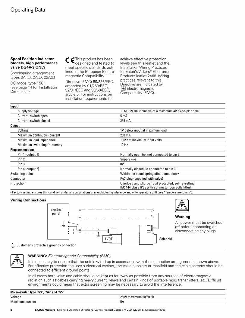
Spool Position Indicator Models, high performance valve DG4V-3 ONLY
Spool/spring arrangement types 0A (L), 2A(L), 22A(L)
DC model type “S6” (see page 14 for Installation Dimension)
This product has been designed and tested to
meet specific standards out-lined in the European Electro-magnetic Compatibility.
Directive (EMC) 89/336/EEC, amended by 91/263/EEC, 92/31/EEC and 93/68/EEC, article 5. For instructions on installation requirements to
achieve effective protection levels see this leaflet and the Installation Wiring Practices for Eaton's Vickers® Electronic Products leaflet 2468. Wiring practices relevant to this Directive are indicated by • Electromagnetic Compatibility (EMC).
Input: Supply voltage 10 to 35V DC inclusive of a maximum 4V pk-to-pk ripple Current, switch open 5 mA Current, switch closed 255 mAOutput: Voltage 1V below input at maximum load Maximum continuous current 250 mA Maximum load impedance 136Ω at maximum input volts Maximum switching frequency 10 HzPlug connections: Pin 1 (output 1) Normally open (ie. not connected to pin 3) Pin 2 Supply +ve Pin 3 0V Pin 4 (output 2) Normally closed (ie.connected to pin 3)Switching point Within the spool spring offset condition •Connector Pg7 plug (supplied with valve)Protection Overload and short-circuit protected; self re-setting. IEC 144 class IP65 with connector correctly fitted.• Factory setting ensures this condition under all combinations of manufacturing tolerance and of temperature drift (see “Temperature Limits”).
Wiring Connections
Warning
All power must be switched off before connecting or disconnecting any plugs
•
•
WARNING: Electromagnetic Compatibility (EMC)
It is necessary to ensure that the unit is wired up in accordance with the connection arrangements shown above. For effective protection the user’s electrical cabinet, the valve subplate or manifold and the cable screens should be connected to efficient ground points.
In all cases both valve and cable should be kept as far away as possible from any sources of electromagnetic radiation such as cables carrying heavy current, relays and certain kinds of portable radio transmitters, etc. Difficult environments could mean that extra screening may be necessary to avoid the interference.
Micro-switch type “S3”, “S4” and “S5”Voltage 250V maximum 50/60 HzMaximum current 5A
Electricpanel
Customer’s protective ground connection
SolenoidLVDT
9Eaton Vickers Solenoid Operated Directional Valves Product Catalog V-VLDI-MC011-E September 2008
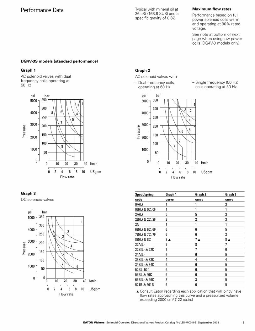
Performance Data Typical with mineral oil at 36 cSt (168.6 SUS) and a specific gravity of 0.87.
Maximum flow rates
Performance based on full power solenoid coils warm and operating at 90% rated voltage.
See note at bottom of next page when using low power coils (DG4V-3 models only).
DG4V-3S models (standard performance)
Graph 1
AC solenoid valves with dual frequency coils operating at 50 Hz
Graph 2
AC solenoid valves with
– Dual frequency coils operating at 60 Hz
Graph 3
DC solenoid valves
s Consult Eaton regarding each application that will jointly have flow rates approaching this curve and a pressurized volume exceeding 2000 cm3 (122 cu.in.)
Spool/spring Graph 1 Graph 2 Graph 3code curve curve curve0A(L) 1 1 30B(L) & 0C, 0F 1 1 12A(L) 5 5 32B(L) & 2C, 2F 2 2 32N 1 1 16B(L) & 6C, 6F 6 6 57B(L) & 7C, 7F 6 6 28B(L) & 8C 8 s 7 s 8 s22A(L) 9 8 722B(L) & 22C 7 7 624A(L) 6 6 533B(L) & 33C 4 4 434B(L) & 34C 6 6 552BL, 52C, 6 6 556BL & 56C 6 6 566B(L) & 66C 3 3 5521B & 561B 6 6 5
Pres
sure
psi bar5000
4000
3000
2000
1000
00 10 20 30 40 l/min
0 2 4 6 8 10 USgpmFlow rate
50
100
150
200
250
300
350
9
8
7
6
54
32
1
0 10 20 30 40 l/min
0 2 4 6 8 10 USgpmFlow rate
psi bar5000
4000
3000
2000
1000
0
50
100
150
200
250
300
350
Pres
sure
1
23
4
56
78
– Single frequency (50 Hz) coils operating at 50 Hz
0 10 20 30 40 l/min
0 2 4 6 8 10 USgpmFlow rate
psi bar5000
4000
3000
2000
1000
0 0
50
100
150
200
250
300
350
Pres
sure
1
23
4
5
67
8
10 Eaton Vickers Solenoid Operated Directional Valves Product Catalog V-VLDI-MC011-E September 2008
Performance Data
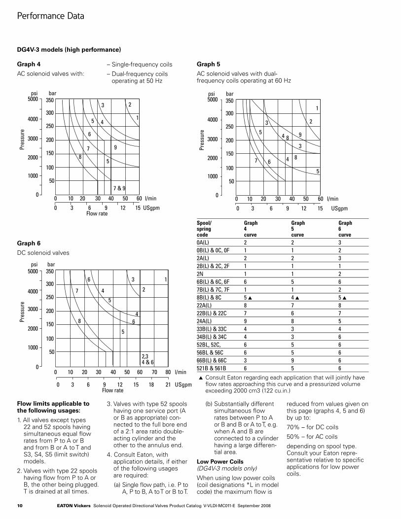
DG4V-3 models (high performance)
Graph 4
AC solenoid valves with:
Graph 5
AC solenoid valves with dual- frequency coils operating at 60 Hz
Graph 6
DC solenoid valves
Spool/ Graph Graph Graphspring 4 5 6code curve curve curve0A(L) 2 2 30B(L) & 0C, 0F 1 1 22A(L) 2 2 32B(L) & 2C, 2F 1 1 12N 1 1 26B(L) & 6C, 6F 6 5 67B(L) & 7C, 7F 1 1 28B(L) & 8C 5 s 4 s 5 s22A(L) 8 7 822B(L) & 22C 7 6 724A(L) 9 8 533B(L) & 33C 4 3 434B(L) & 34C 4 3 652BL, 52C, 6 5 656BL & 56C 6 5 666B(L) & 66C 3 9 6521B & 561B 6 5 6
s Consult Eaton regarding each application that will jointly have flow rates approaching this curve and a pressurized volume exceeding 2000 cm3 (122 cu.in.)
Flow limits applicable to the following usages:
1. All valves except types 22 and 52 spools having simultaneous equal flow rates from P to A or B and from B or A to T and S3, S4, S5 (limit switch) models.
2. Valves with type 22 spools having flow from P to A or B, the other being plugged. T is drained at all times.
3. Valves with type 52 spools having one service port (A or B as appropriate) con-nected to the full bore end of a 2:1 area ratio double-acting cylinder and the other to the annulus end.
4. Consult Eaton, with application details, if either of the following usages are required:
(a) Single flow path, i.e. P to A, P to B, A to T or B to T.
(b) Substantially different simultaneous flow rates between P to A or B and B or A to T, e.g. when A and B are connected to a cylinder having a large differen-tial area.
Low Power Coils (DG4V-3 models only)
When using low power coils (coil designations *L in model code) the maximum flow is
reduced from values given on this page (graphs 4, 5 and 6) by up to:
70% – for DC coils
50% – for AC coils
depending on spool type. Consult your Eaton repre-sentative relative to specific applications for low power coils.
– Single-frequency coils
– Dual-frequency coils operating at 50 Hz
psi bar
0 3 6 9 12 15
100 20 30 40 50 60 l/min
USgpm
350
300
250
200
150
100
50
0
1000
2000
3000
4000
5000
Pres
sure
1
23
45
6
78
7 & 9
9
5
Flow rate
psi bar350
300
250
200
150
100
50
0
1000
2000
3000
4000
5000
Pres
sure
100 20 30 40 50 60 l/min
0 3 6 9 12 15 USgpm
1
2
3
94 8
4 86
5
7
3
5
0 10 20 30 40 50 60 70 80 l/min
0 3 6 9 12 15 21 USgpm18
psi
0
1000
2000
3000
4000
5000
Pres
sure
bar350
300
250
200
150
100
50
1
2
3
4
5
6
7
8
5
2,34 & 6
Flow rate
46
11Eaton Vickers Solenoid Operated Directional Valves Product Catalog V-VLDI-MC011-E September 2008
Performance Data
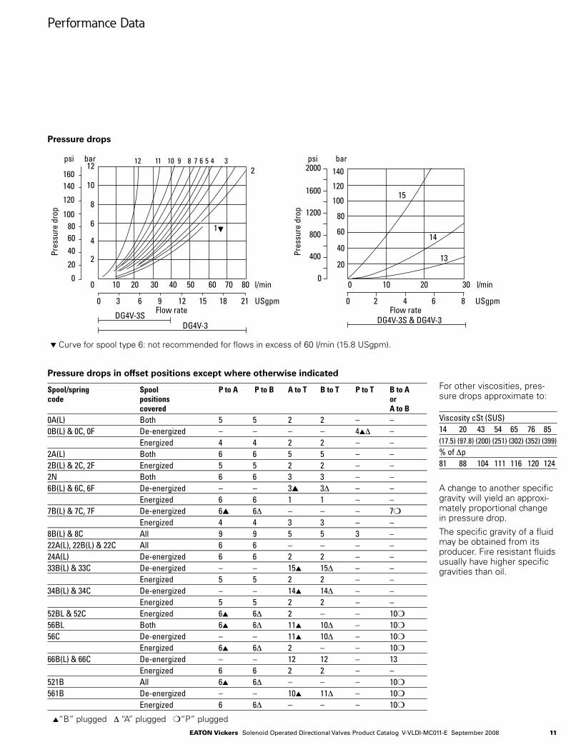
Pressure drops
t Curve for spool type 6: not recommended for flows in excess of 60 l/min (15.8 USgpm).
Pressure drops in offset positions except where otherwise indicatedFor other viscosities, pres-sure drops approximate to:
Viscosity cSt (SUS)14 20 43 54 65 76 85(17.5) (97.8) (200) (251) (302) (352) (399)% of ∆p81 88 104 111 116 120 124
A change to another specific gravity will yield an approxi-mately proportional change in pressure drop.
The specific gravity of a fluid may be obtained from its producer. Fire resistant fluids usually have higher specific gravities than oil.
Spool/spring Spool P to A P to B A to T B to T P to T B to A code positions or covered A to B0A(L) Both 5 5 2 2 – –0B(L) & 0C, 0F De-energized – – – – 4s∆ – Energized 4 4 2 2 – –2A(L) Both 6 6 5 5 – –2B(L) & 2C, 2F Energized 5 5 2 2 – –2N Both 6 6 3 3 – –6B(L) & 6C, 6F De-energized – – 3s 3∆ – – Energized 6 6 1 1 – –7B(L) & 7C, 7F De-energized 6s 6∆ – – – 7m
Energized 4 4 3 3 – –8B(L) & 8C All 9 9 5 5 3 –22A(L), 22B(L) & 22C All 6 6 – – – –24A(L) De-energized 6 6 2 2 – –33B(L) & 33C De-energized – – 15s 15∆ – – Energized 5 5 2 2 – –34B(L) & 34C De-energized – – 14s 14∆ – – Energized 5 5 2 2 – –52BL & 52C Energized 6s 6∆ 2 – – 10m 56BL Both 6s 6∆ 11s 10∆ – 10m 56C De-energized – – 11s 10∆ – 10m
Energized 6s 6∆ 2 – – 10m
66B(L) & 66C De-energized – – 12 12 – 13 Energized 6 6 2 2 – –521B All 6s 6∆ – – – 10m 561B De-energized – – 10s 11∆ – 10m
Energized 6 6∆ – – – 10m
s“B” plugged ∆ “A” plugged m“P” plugged
10 20 30 40 50 60 70 800
2
4
6
8
10
12
0 3 6 9 12 15 18 21
160140
120
100806040
20
0
Pres
sure
dro
p
Flow rate
l/min
USgpm
psi bar 12 11 10 9 8 7 6 5 4 32
1
DG4V-3SDG4V-3
10 20 30 nim/l0
0 2 4 6 8 USgpm
140
120
100
80
60
40
20
15
14
13
psi bar2000
1600
1200
800
400
0
DG4V-3S & DG4V-3Flow rate
Pres
sure
dro
p
12 Eaton Vickers Solenoid Operated Directional Valves Product Catalog V-VLDI-MC011-E September 2008
Single solenoid modelss
DG4V-3(S)-*A(-**) n
DG4V-3(S)-*B(-**) n
DG4V-3(S)-8BL(-**)
DG3V-3(S)-*F n
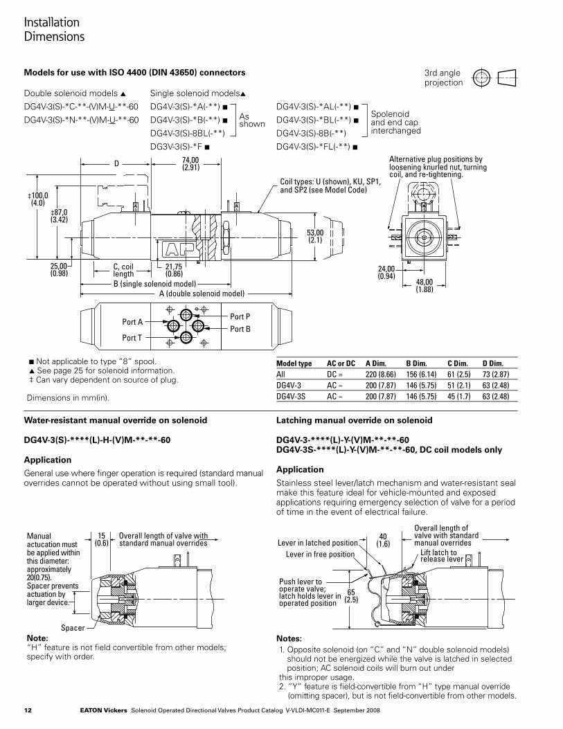
Installation Dimensions
Models for use with ISO 4400 (DIN 43650) connectors
Double solenoid models s
DG4V-3(S)-*C-**-(V)M-U-**-60
DG4V-3(S)-*N-**-(V)M-U-**-60
DG4V-3(S)-*AL(-**) n
DG4V-3(S)-*BL(-**) n
DG4V-3(S)-8B(-**)
DG4V-3(S)-*FL(-**) n
3rd angle projection
n Not applicable to type “8” spool. s See page 25 for solenoid information. ‡ Can vary dependent on source of plug.
Model type AC or DC A Dim. B Dim. C Dim. D Dim.All DC = 220 (8.66) 156 (6.14) 61 (2.5) 73 (2.87)DG4V-3 AC ~ 200 (7.87) 146 (5.75) 51 (2.1) 63 (2.48)DG4V-3S AC ~ 200 (7.87) 146 (5.75) 45 (1.7) 63 (2.48)
Water-resistant manual override on solenoid
DG4V-3(S)-****(L)-H-(V)M-**-**-60
Application
General use where finger operation is required (standard manual overrides cannot be operated without using small tool).
Note: “H” feature is not field convertible from other models; specify with order.
Latching manual override on solenoid
DG4V-3-****(L)-Y-(V)M-**-**-60 DG4V-3S-****(L)-Y-(V)M-**-**-60, DC coil models only
Application
Stainless steel lever/latch mechanism and water-resistant seal make this feature ideal for vehicle-mounted and exposed applications requiring emergency selection of valve for a period of time in the event of electrical failure.
Notes:1. Opposite solenoid (on “C” and “N” double solenoid models)
should not be energized while the valve is latched in selected position; AC solenoid coils will burn out under
this improper usage.2. “Y” feature is field-convertible from “H” type manual override
(omitting spacer), but is not field-convertible from other models.
As shown
Spolenoid and end cap interchanged
24,00(0.94)
Coil types: U (shown), KU, SP1,and SP2 (see Model Code)
A (double solenoid model)
87,0(3.42)
53,00(2.1)
B (single solenoid model)
21,75(0.86)
25,00(0.98)
100,0(4.0)
D 74,00(2.91)
48,00(1.88)
Alternative plug positions byloosening knurled nut, turningcoil, and re-tightening.
Port APort P
Port TPort B
C, coillength
Spacer
15(0.6)
Overall length of valve withstandard manual overrides
Overall length of valve with standard manual overridesLever in latched position
Lever in free position Lift latch torelease lever
65(2.5)
40(1.6)
Manualactucation mustbe applied withinthis diameter:approximately20(0.75).Spacer prevents actuation bylarger device.
Push lever tooperate valve;latch holds lever inoperated position
Dimensions in mm(in).
13Eaton Vickers Solenoid Operated Directional Valves Product Catalog V-VLDI-MC011-E September 2008
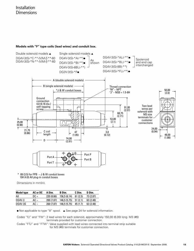
Installation Dimensions
Models with “F” type coils (lead wires) and conduit box.
Double solenoid models s
DG4V-3(S)-*C-**-(V)M-F-**-60 DG4V-3(S)-*N-**-(V)M-F-**-60
Single solenoid models s
DG4V-3(S)-*A(-**)l
DG4V-3(S)-*B(-**)l
DG4V-3(S)-8BL(-**)
DG3V-3(S)-*Fl
DG4V-3(S)-*AL(-**)l
DG4V-3(S)-*BL(-**)l
DG4V-3(S)-8B(-**)
DG4V-3(S)-*FL(-**)l
Dimensions in mm(in).
As shown
Spolenoid and end cap interchanged
Model type AC or DC A Dim. B Dim. C Dim. D Dim.All DC = 220 (8.66) 156,5 (6.14) 61 (2.5) 73 (2.87)DG4V-3 AC ~ 200 (7.87) 146,5 (5.75) 51 (2.1) 63 (2.48)DG4V-3S AC ~ 200 (7.87) 146,5 (5.75) 45 (1.7) 63 (2.48)
l Not applicable to type “8” spool. s See page 24 for solenoid information.
Codes “FJ” and “FW”: 2 lead wires for each solenoid, approximately 150,00 (6.00) long. M3 (#6) terminals provided for customer connection.
Codes “FTJ” and “FTW”: Valve supplied with lead wires connected into terminal strip suitable for M3 (#6) terminals for customer connection.
47(1.85)
Groundconnection4,0 (0.16 dia.)self–tappingscrew
Two leadwires per
solenoid withM3 size
terminals forcustomer
connections
24,00(0.94)
25,00(0.98)
3,0(0.12)
*J & W conduit boxesThread connection“W”– NPT“J”– M20 × 1.5-8H
91,00(3.57)
21,75(0.86) 48,00
(1.88)
50,00(2.0)
A (double solenoid models)
B (single solenoid models)
C coillength
D74,00(2.91)
68,75(2.71)
53,00(2.1)
Port APort P
Port TPort B
* 89 (3.5) for FPB – J & W conduit boxes104 (4.0) All plug-in conduit boxes
14 Eaton Vickers Solenoid Operated Directional Valves Product Catalog V-VLDI-MC011-E September 2008
Installation Dimensions
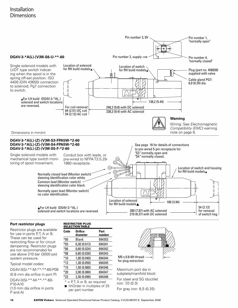
DG4V-3-*A(L)-(V)M-S6-U-**-60
DG4V-3-*A(L)-(Z)-(V)M-S3-FPA5W-*2-60 DG4V-3-*A(L)-(Z)-(V)M-S4-FPA5W-*2-60 DG4V-3-*A(L)-(Z)-(V)M-S5-F-*2-60
Single solenoid models with LVDT type switch indicat-ing when the spool is in the spring off-set position. ISO 4400 (DIN 43650) connection to solenoid; Pg7 connection to switch.
Single solenoid models with mechanical type switch moni-toring of spool movement.
Warning
Wiring: See Electromagnetic Compatibility (EMC) warning note on page 8.
•
Port restrictor plugs
Restrictor plugs are available for use in ports P, T, A or B. These can be used for restricting flow or for circuit dampening. Restrictor plugs are not recommended for use above 210 bar (3000 psi) system pressure.
Typical model codes:
DG4V-3(S)-**-M-**-**-60-P08(0.8 mm dia orifice in port P)
DG4V-3(S)-**-M-**-**-60-P10-A10(1.0 mm dia orifice in ports P and A)
rEStrictor plug SElEction tablE
Code Orifice Part diameter number*00 Blank 694353*03 0,30 (0.012) 694341*06 0,60 (0.024) 694342*08 0,80 (0.030) 694343*10 1,00 (0.040) 694344*13 1,30 (0.050) 694345*15 1,50 (0.060) 694346*20 2,00 (0.080) 694347*23 2,30 (0.090) 694348* = P, T, A or B, as requiredn hhOrder in multiples of 25
per part number
Maximum port dia in subplate/manifold block:
For steel and SG (ductile) iron: 7,0 (0.3)
For gray iron: 6,5 (0.25)
Dimensions in mm(in)
248,2 (9.8) with DC solenoid238,2 (9.4) with AC solenoid
For coil removal:64 (2.51) DC coil54 (2.12) AC coil
138,2 (5.44)
Location of solenoidfor RH build models
Location of switchfor RH build models Plug (part no. 458939)
supplied with valve
Cable gland PG7:6,0 (0.24) dia.
Pin number 2, supply +ve
Pin number 3, 0V Pin number 1,“normally open”
Pin number 4,“normally closed”
For LH build (DG4V-3-*AL )solenoid and switch locationsare reversed.
For LH build (DG4V-3-*AL )solenoid and switch locations are reversed. 200 (7.87) with AC solenoid
210 (8.27) with DC solenoid
100 (3.94)
Location of switch and housingfor RH build models
Normally closed lead (Monitor switch)sleeving identification color white.Common lead (Monitor switch)sleeving identification color black.
Normally open lead (Monitor switch)no color identification.
Location of solenoidfor RH build models
54 (2.12)for removalof switch hsg.
See page 16 for details of connections to pre-wired 5-pin receptacle for:“S3” normally open and“S4” normally closed.Conduit box with leads, or
pre-wired to NFPA T3.5.29-1980 receptacle.
M5 x 0.8-6H threadfor plug extraction
15Eaton Vickers Solenoid Operated Directional Valves Product Catalog V-VLDI-MC011-E September 2008
Electrical Plugs and Connectors
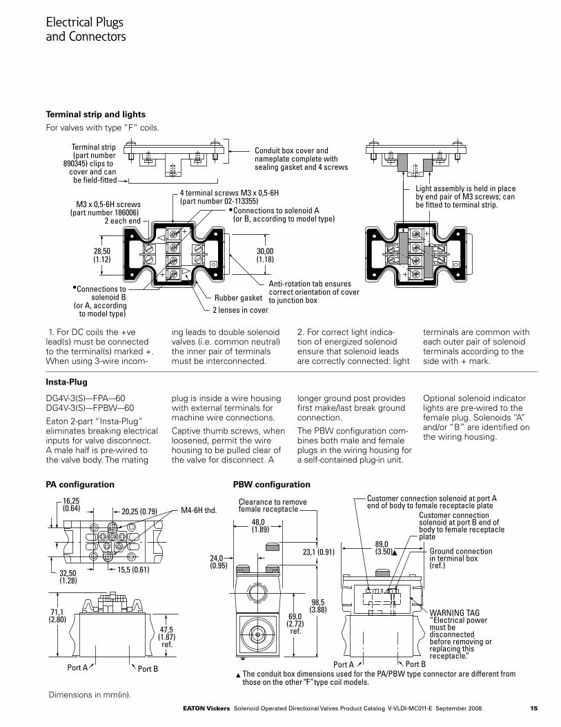
Terminal strip and lights
For valves with type “F” coils.
1. For DC coils the +ve lead(s) must be connected to the terminal(s) marked +. When using 3-wire incom-
ing leads to double solenoid valves (i.e. common neutral) the inner pair of terminals must be interconnected.
2. For correct light indica-tion of energized solenoid ensure that solenoid leads are correctly connected: light
terminals are common with each outer pair of solenoid terminals according to the side with + mark.
DG4V-3(S)---FPA---60 DG4V-3(S)---FPBW---60
Eaton 2-part “Insta-Plug” eliminates breaking electrical inputs for valve disconnect. A male half is pre-wired to the valve body. The mating
plug is inside a wire housing with external terminals for machine wire connections.
Captive thumb screws, when loosened, permit the wire housing to be pulled clear of the valve for disconnect. A
longer ground post provides first make/last break ground connection.
The PBW configuration com-bines both male and female plugs in the wiring housing for a self-contained plug-in unit.
Optional solenoid indicator lights are pre-wired to the female plug. Solenoids “A” and/or “B” are identified on the wiring housing.
Insta-Plug
PA configuration PBW configuration
Dimensions in mm(in).
Terminal strip(part number
890345) clips tocover and can
be field-fitted
M3 x 0,5-6H screws(part number 186006)
2 each end
4 terminal screws M3 x 0,5-6H (part number 02-113355)
Connections to solenoid A(or B, according to model type)
Connections tosolenoid B
(or A, accordingto model type)
Rubber gasket
Conduit box cover andnameplate complete withsealing gasket and 4 screws
Anti-rotation tab ensurescorrect orientation of coverto junction box
28,50(1.12)
30,00(1.18)
Light assembly is held in placeby end pair of M3 screws; canbe fitted to terminal strip.
2 lenses in cover
24,0(0.95)
71,1(2.80)
16,25(0.64)
47,5(1.87)
ref.
Port A Port B Port A
15,5 (0.61)
20,25 (0.79)
32,50(1.28)
M4-6H thd.48,0(1.89)
89,0(3.50) Ground connection
in terminal box(ref.)
WARNING TAG“Electrical powermust bedisconnectedbefore removing orreplacing thisreceptacle”.
Customer connection solenoid at port Aend of body to female receptacle plate
Customer connectionsolenoid at port B end ofbody to female receptacleplate
69,0(2.72)
ref.
98,5(3.88)
23,1 (0.91)
Clearance to removefemale receptacle
The conduit box dimensions used for the PA/PBW type connector are different fromthose on the other “F” type coil models.
Port B
16 Eaton Vickers Solenoid Operated Directional Valves Product Catalog V-VLDI-MC011-E September 2008
Electrical Plugs and Connectors
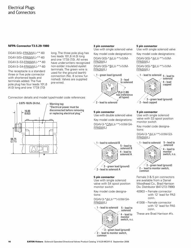
NFPA Connector T3.5.29-1980
DG4V-3(S)–FPA3W(L)-**-60
DG4V-3(S)–FPA5W(L)-**-60
DG4V-3–S3-FPA5W(L)-**-60
DG4V-3–S4-FPA5W(L)-**-60
The receptacle is a standard three or five pole connector with shortened leads and terminals added. The five pole plug has four leads 101,6 (4.0) long and one 177,8 (7.0)
long. The three pole plug has two leads 101,6 (4.0) long and one 177,8 (7.0). All wires have underwriters recognized non-solder insulated eyelet terminals. The green wire is used for the ground (earth) connection (No. 8 screw fur-nished). Valves are supplied pre-wired.
3 pin connector Use with single solenoid valve
Key model code designations:
DG4V-3(S)-*A(L)(-**)-(V)M-FPA3W(L)
DG4V-3(S)-*B(L)(-**)-(V)M-FPA3W(L)
5 pin connector Use with single solenoid valve with S3 spool position monitor switch
Key model code designa-tions:
DG4V-3-*A(L)(-**)-(V)M-S3-FPA5W(L)
5 pin connector Use with single solenoid valve
Key model code designations:
DG4V-3(S)-*A(L)(-**)-(V)M-FPA5W(L)
DG4V-3(S)-*B(L)(-**)-(V)M-FPA5W(L)
5 pin connector Use with single solenoid valve with S4 spool position monitor switch
Key model code designa-tions:
DG4V-3-*A(L)(-**)-(V)M-S4-FPA5W(L)
5 pin connector Use with double solenoid valve
Key model code designations:
DG4V-3-*C/N(L)(-**)-(V)M-S4-FPA5W(L)
Female 3 & 5 pin connectors are available from a Daniel Woodhead Co., Brad Harrison Div. Distributor (847-272-7990)
40903 – Female connector with 12' lead for PA3 conn.
41308 – Female connector with 12' lead for PA5 conn.
These are Brad Harrison #’s.
Connection details and model type/model code references
68,75(2.71)
16,00(0.62)
0.875-16UN-2A thd. Warning tag:“Electrical power must bedisconnected before removingor replacing electrical plug.”
412 3
5 4 – lead tosolenoid A
1 – lead to solenoid B
3 – green lead (ground)
5 – lead tosolenoid B
2 – lead to solenoid A
12
325,4 (1.00)
hex (referenceall types)
3 – leadto solenoid
1 – green lead (ground)
2 – lead to solenoid
412 3
54 – lead tomonitorswitch, n.o.
1 – lead to solenoid
3 – green lead (ground)
5 – lead tosolenoid
4 – lead tomonitorswitch, n.c.
5 – lead tosolenoid
2 – lead to monitor switch, common
2 – lead to monitor switch, common
412 3
5
1 – lead to solenoid
3 – green lead (ground)
412 3
54 – leadcapped
1 – lead to solenoid
3 – green lead (ground)
5 – lead tosolenoid
2 – lead capped
412 3
5 4 – lead tosolenoid A
1 – lead to solenoid B
3 – green lead (ground)
5 – lead tosolenoid B
2 – lead to solenoid A
12
325,4 (1.00)
hex (referenceall types)
3 – leadto solenoid
1 – green lead (ground)
2 – lead to solenoid
412 3
54 – lead tomonitorswitch, n.o.
1 – lead to solenoid
3 – green lead (ground)
5 – lead tosolenoid
4 – lead tomonitorswitch, n.c.
5 – lead tosolenoid
2 – lead to monitor switch, common
2 – lead to monitor switch, common
412 3
5
1 – lead to solenoid
3 – green lead (ground)
412 3
54 – leadcapped
1 – lead to solenoid
3 – green lead (ground)
5 – lead tosolenoid
2 – lead capped
17Eaton Vickers Solenoid Operated Directional Valves Product Catalog V-VLDI-MC011-E September 2008
Electrical Plugs and Connectors
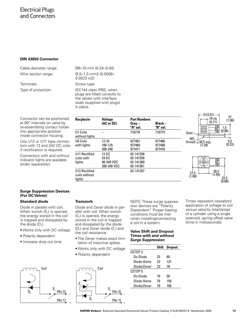
Cable diameter range: Ø6–10 mm (0.24–0.40)
Wire section range: Ø,5–1,5 mm2 (0.0008–0.0023 in2)
Terminals: Screw type
Type of protection: IEC144 class IP65, when plugs are fitted correctly to the valves with interface seals (supplied with plugs) in place.
DIN 43650 Connector
Connector can be positioned at 90° intervals on valve by re-assembling contact holder into appropriate position inside connector housing.
Use U12 or U11 type connec-tors with 12 and 24V DC coils if rectification is required.
Connectors with and without indicator lights are available (order separately):
Recptacle Voltage Part Numbers (AC or DC) Gray – Black – "A" sol. "B" sol.U1 Coils – 710776 710775without lightsU6 Coils 12-24 977467 977466with lights 100-125 977469 977468 200-240 977471 977470U11 Rectified 12 DC 02-141358 coils with 24 DC 02-141359 lights 98-240 VDC 02-141360 200-240 VDC 02-141361U12 Rectified 02-141357coils withoutlights
Surge Suppression Devices (For DC Valves)
Standard diode
Diode in parallel with coil. When switch (S1) is opened, the energy stored in the coil is trapped and dissipated by the diode (D1).
• Works only with DC voltage
• Polarity dependent
• Increase drop out time
Transzorb
Diode and Zener diode in par-allel with coil. When switch (S1) is opened, the energy stored in the coil is trapped and dissipated by the diode (D1) and Zener diode (Z1) and the coil resistance.
• The Zener makes exact limi-tation of inductive spikes.
• Works only with DC voltage
• Polarity dependent
NOTE: These surge suppres-sion devices are “Polarity Dependent.” Proper biasing conditions must be met when installing/connecting a coil in a system.
Valve Shift and Dropout Times with and without Surge Suppression
Shift Dropout CETOP 3 Do Diode 23 60 Diode Alone 23 131 Diode/Zener 23 78CETOP 5 Do Diode 70 50 Diode Alone 70 158 Diode/Zener 70 100
Times represent cessation/application of voltage to coil versus velocity (start/stop) of a cylinder using a single solenoid, spring offset valve (time in milliseconds).
Seal
51(2.01)27
(1.06)
22,5(0.88)�
M3thread 5,5
(0.22)
1,5(0.06)
30,5 sq.(1.20)
26,5(1.04)27,5
(1.08)
18 sq.(0.71)
Coil Coil
(No 2)S1
(No 1)
(No 2)S1
(No 1)
D1
D1
Z1
18 Eaton Vickers Solenoid Operated Directional Valves Product Catalog V-VLDI-MC011-E September 2008
Subplates, Connection Plates and Mounting Surfaces
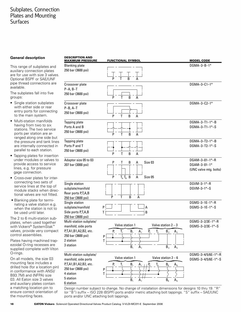
General description
This range of subplates and auxiliary connection plates are for use with size 3 valves. Optional BSPF or SAE/UNF pipe thread connections are available.
The subplates fall into five groups:
• Single station subplates with either side or rear entry ports for connecting to the main system.
• Multi-station manifolds having from two to six stations. The two service ports per station are ar-ranged along one side but the pressure and tank lines are internally connected in parallel to each station.
• Tapping plates for insertion under modules or valves to provide access to service lines, e.g. for pressure gage connection.
• Cross-over plates for inter-connecting two sets of service lines at the top of module stacks when direc-tional valves are not fitted.
• Blanking plate for termi-nating a valve station e.g. when the station is not to be used until later.
The 2 to 6 multi-station sub-plates, when used together with Vickers® SystemStak™ valves, provide very compact control assemblies.
Plates having machined trap-ezoidal O-ring recesses are supplied complete with Viton O-rings.
On all models, the size 03 mounting face includes a drilled hole (for a location pin) in conformance with ANSI/B93.7M) and (NFPA) size 03. All Eaton size 3 valves and auxiliary plates contain a matching location pin to ensure correct orientation of the mounting faces.
Design number subject to change. No change of installation dimensions for designs 10 thru 19. “R” (or “B”) suffix – ISO 228 (BSPF) ports and/or metric attaching bolt tappings. “S” suffix – SAE/UNC ports and/or UNC attaching bolt tappings.
dEScription andmaximum prESSurE Functional Symbol modEl codE
Blanking plate DGMA–3–B–1*250 bar (3600 psi)
Crossover plate DGMA–3–C1–1*P–A, B–T250 bar (3600 psi)
Crossover plate DGMA–3–C2–1*P–B, A–T250 bar (3600 psi)
Tapping plate DGMA–3–T1–1*–BPorts A and B DGMA–3–T1–1*–S250 bar (3600 psi)
Tapping plate DGMA–3–T2–1*–BPorts P and T DGMA–3–T2–1*–S250 bar (3600 psi)
Adaptor size 05 to 03 DGAM–3–01–1*–R207 bar (3000 psi) DGAM–3–01–1* (UNC valve mtg. bolts)
Single station DGVM–3–1*–Rsubplate/manifold DGVM–3–1*–SRear ports P,T,A,B250 bar (3600 psi)Single station DGMS–3–1E–1*–Rsubplate/manifold DGMS–3–1E–1*–SSide ports P,T,A,B250 bar (3600 psi)Multi-station subplate/ DGMS–3–2/3E–1*–Rmanifold; side ports DGMS–3–2/3E–1*–SP,T,A1,B1,A2,B2, etc.250 bar (3600 psi)2 station3 station
Multi-station subplate/ DGMS–3–4/5/6E–1*–Rmanifold; side ports DGMS–3–4/5/6E–1*–SP,T,A1,B1,A2,B2, etc.250 bar (3600 psi)4 station5 station6 station
P T B A
P T B A
P T B A
P T B A
BTAP
PT
B1 A 1
P T B A
P1 T1 B1 A 1
B 2 A 2
P2 T2 B 2 A 2
PT
B1 A 1
P1 T1 B1 A 1
B6 A 6
P6 T6 B6 A 6
Valve station 1 Valve station 2 – 6
Valve station 1 Valve station 2 – 3
Size 03
Size 05
P T B A
P T B A
P TA TB B A
19Eaton Vickers Solenoid Operated Directional Valves Product Catalog V-VLDI-MC011-E September 2008
46,0 (1.8)
73,0(2.9)
4 holes Ø 5,6 (0.22 dia.) counterbored to �Ø 9,5 (0.374 dia)
Nameplate
P T B A
P T B A
22,0 (0.9)
46,0 (1.8)
75,0(3.0)
48,5 (1.9)
Nameplate
A
T
B
P
A
T
B
P
24,4 (1.0)
10,0 (0.4)
22,0 (0.9)
11,0 (0.43)
P T B A
P T B A
20,0(0.78)
46,0 (1.8)48,4 (1.9)
75,0(3.0)
Nameplate
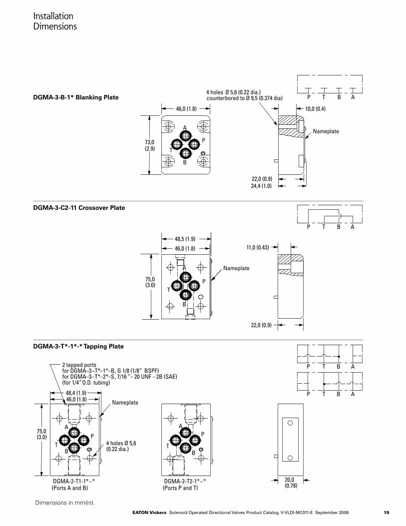
2 tapped portsfor DGMA–3–T*–1*–B, G 1/8 (1/8” BSPF)for DGMA–3–T*–2*–S, 7/16 ”– 20 UNF –2B (SAE)(for 1/4” O.D. tubing)
DGMA-2-T1-1*–*(Ports A and B)
DGMA-2-T2-1*–*(Ports P and T)
A
TB
P
A
TB
P4 holes Ø 5,6(0.22 dia.)
Installation Dimensions
DGMA-3-B-1* Blanking Plate
DGMA-3-C2-11 Crossover Plate
DGMA-3-T*-1*-* Tapping Plate
Dimensions in mm(in).
20 Eaton Vickers Solenoid Operated Directional Valves Product Catalog V-VLDI-MC011-E September 2008
Installation Dimensions
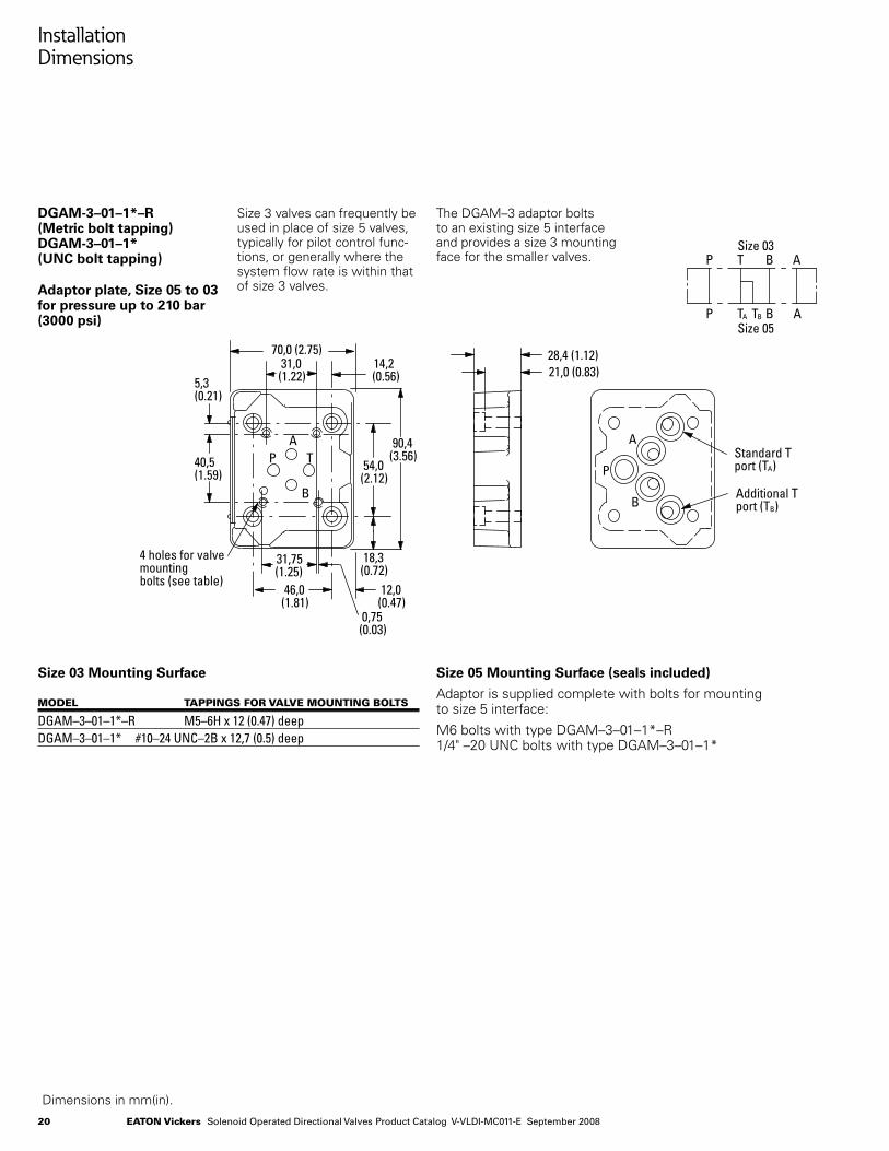
DGAM-3–01–1*–R (Metric bolt tapping)DGAM-3–01–1* (UNC bolt tapping)
Adaptor plate, Size 05 to 03 for pressure up to 210 bar (3000 psi)
Size 3 valves can frequently be used in place of size 5 valves, typically for pilot control func-tions, or generally where the system flow rate is within that of size 3 valves.
The DGAM–3 adaptor bolts to an existing size 5 interface and provides a size 3 mounting face for the smaller valves.
Dimensions in mm(in).
Size 03 Mounting Surface
modEl tappingS For ValVE mounting boltS
DGAM–3–01–1*–R M5–6H x 12 (0.47) deepDGAM–3–01–1* #10–24 UNC–2B x 12,7 (0.5) deep
Size 05 Mounting Surface (seals included)
Adaptor is supplied complete with bolts for mounting to size 5 interface:
M6 bolts with type DGAM–3–01–1*–R 1/4" –20 UNC bolts with type DGAM–3–01–1* BT
AP
70,0 (2.75)31,0
(1.22)
90,4(3.56)
54,0(2.12)
18,3(0.72)
31,75(1.25)
46,0(1.81)
12,0(0.47)
0,75(0.03)
40,5(1.59)
5,3(0.21)
14,2(0.56)
28,4 (1.12)21,0 (0.83)
Standard Tport (TA)
Additional Tport (TB)
4 holes for valvemountingbolts (see table)
P TA B A
Size 03
Size 05
P T B A
TB
DGMSDGVM
72,0(2.83)
84,0 (3.3)72,0 (2.83)19,75(0.78)
6,0(0.24)
84,0(3.31)
35,0(1.37)
20,0(.787)
6,0(0.24)
16,0 (0.63)
57,25(2.25)
35,0(1.38)
12,75 (0.5)
59,25(2.33)
36,00(1.42)
12,75 (0.5)
4 holes tapped accordingto model type (see table)
4 ports .750-16 UNF-2Bfor side ports.
4 ports .750-16 UNF-2Bfor rear ports.
5,6 (.22) dia. thru13,0 (.51) spotfaceto depth shown. 4holes for mounting.
PA
B
TA
P
B
B
T P
A
B
P
A
T
P T B A
21Eaton Vickers Solenoid Operated Directional Valves Product Catalog V-VLDI-MC011-E September 2008
Installation Dimensions
Dimensions in mm(in).
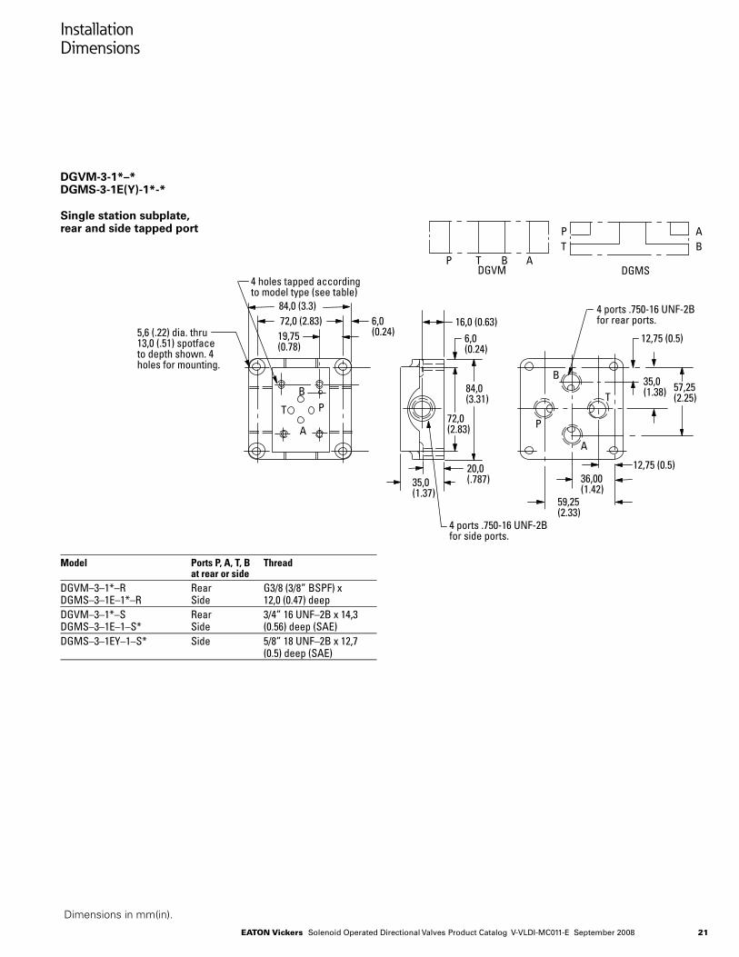
DGVM-3-1*–* DGMS-3-1E(Y)-1*-*
Single station subplate, rear and side tapped port
Model Ports P, A, T, B Thread at rear or sideDGVM–3–1*–R Rear G3/8 (3/8” BSPF) xDGMS–3–1E–1*–R Side 12,0 (0.47) deepDGVM–3–1*–S Rear 3/4” 16 UNF–2B x 14,3DGMS–3–1E–1–S* Side (0.56) deep (SAE)DGMS–3–1EY–1–S* Side 5/8” 18 UNF–2B x 12,7 (0.5) deep (SAE)
BTAP
70,0 (2.75)31,0
(1.22)
90,4(3.56)
54,0(2.12)
18,3(0.72)
31,75(1.25)
46,0(1.81)
12,0(0.47)
0,75(0.03)
40,5(1.59)
5,3(0.21)
14,2(0.56)
28,4 (1.12)21,0 (0.83)
Standard Tport (TA)
Additional Tport (TB)
4 holes for valvemountingbolts (see table)
P TA B A
Size 03
Size 05
P T B A
TB
DGMSDGVM
72,0(2.83)
84,0 (3.3)72,0 (2.83)19,75(0.78)
6,0(0.24)
84,0(3.31)
35,0(1.37)
20,0(.787)
6,0(0.24)
16,0 (0.63)
57,25(2.25)
35,0(1.38)
12,75 (0.5)
59,25(2.33)
36,00(1.42)
12,75 (0.5)
4 holes tapped accordingto model type (see table)
4 ports .750-16 UNF-2Bfor side ports.
4 ports .750-16 UNF-2Bfor rear ports.
5,6 (.22) dia. thru13,0 (.51) spotfaceto depth shown. 4holes for mounting.
PA
B
TA
P
B
B
T P
A
B
P
A
T
P T B A
22 Eaton Vickers Solenoid Operated Directional Valves Product Catalog V-VLDI-MC011-E September 2008
Dimensions in mm(in).
Installation Dimensions
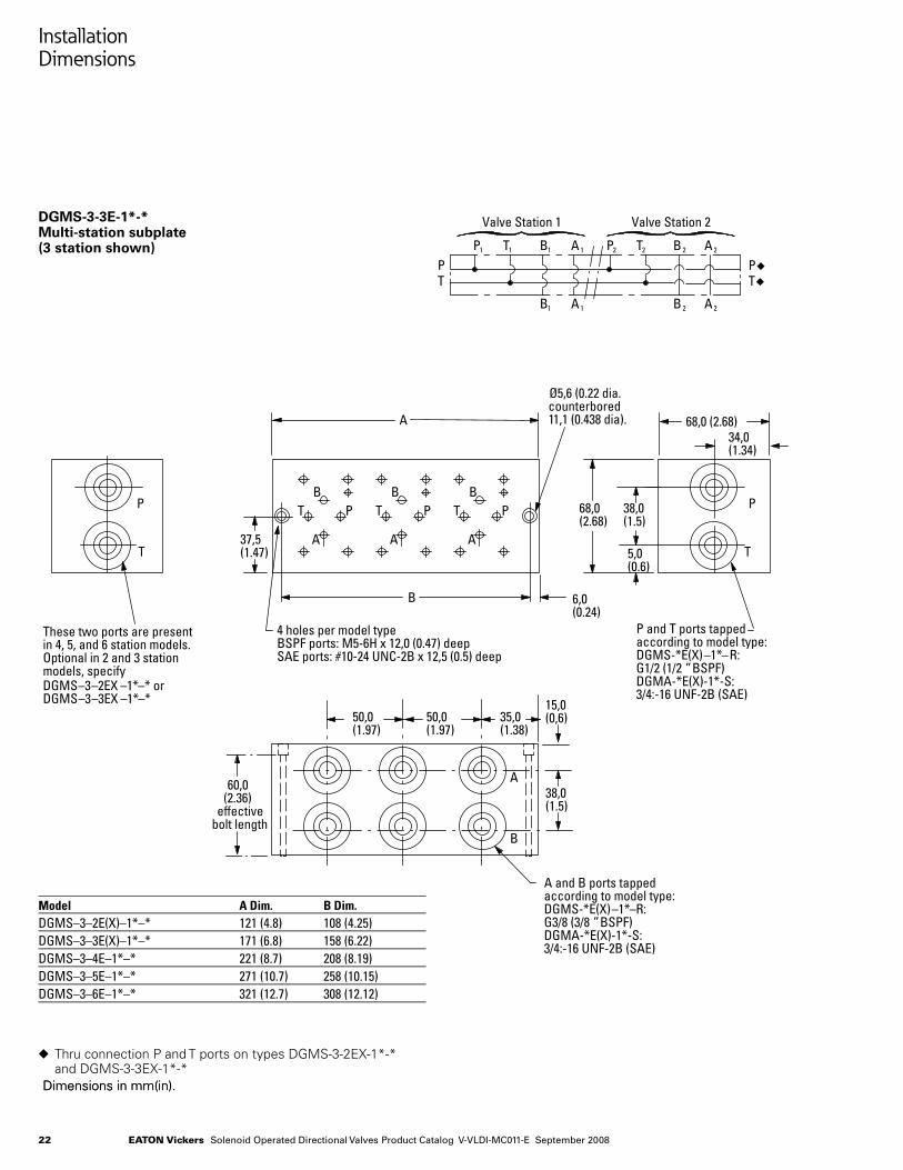
DGMS-3-3E-1*-* Multi-station subplate (3 station shown)
Model A Dim. B Dim. DGMS–3–2E(X)–1*–* 121 (4.8) 108 (4.25)DGMS–3–3E(X)–1*–* 171 (6.8) 158 (6.22)DGMS–3–4E–1*–* 221 (8.7) 208 (8.19)DGMS–3–5E–1*–* 271 (10.7) 258 (10.15)DGMS–3–6E–1*–* 321 (12.7) 308 (12.12)
Dimensions in mm(in).
u Thru connection P and T ports on types DGMS-3-2EX-1*-* and DGMS-3-3EX-1*-*
68,0(2.68)
6,0(0.24)
P
T37,5(1.47)
B
A
These two ports are presentin 4, 5, and 6 station models.Optional in 2 and 3 stationmodels, specifyDGMS–3–2EX –1*–* orDGMS–3–3EX –1*–*
4 holes per model type BSPF ports: M5-6H x 12,0 (0.47) deepSAE ports: #10-24 UNC-2B x 12,5 (0.5) deep
PT
A
P and T ports tappedaccording to model type:DGMS-*E(X)–1*–R:G1/2 (1/2 ” BSPF)DGMA-*E(X)-1*-S:3/4:-16 UNF-2B (SAE)
68,0 (2.68)34,0(1.34)
38,0(1.5)
5,0(0.6)
38,0(1.5)
15,0(0,6)
PT
B1 A 1
P1 T1 B1 A 1
B 2 A 2
P2 T2 B 2 A 2
Valve Station 1 Valve Station 2
B
Ø5,6 (0.22 dia. counterbored11,1 (0.438 dia).
PT
A
BPT
A
B
60,0(2.36)
effectivebolt length
P
T
50,0(1.97)
50,0(1.97)
35,0(1.38)
A
B
A and B ports tappedaccording to model type:DGMS-*E(X)–1*–R:G3/8 (3/8 ” BSPF)DGMA-*E(X)-1*-S:3/4:-16 UNF-2B (SAE)
PT
23Eaton Vickers Solenoid Operated Directional Valves Product Catalog V-VLDI-MC011-E September 2008
Installation Dimensions
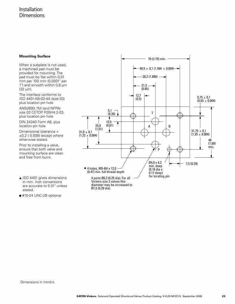
Mounting Surface
When a subplate is not used, a machined pad must be provided for mounting. The pad must be flat within 0,01 mm per 100 mm (0.0001" per 1") and smooth within 0,8 μm (32 μin).
The interface conforms to ISO 4401-AB-03-4A (size 03) plus location pin hole
ANSI/B93.7M (and NFPA) size 03 CETOP R35H4.2-03, plus location pin hole
DIN 24340 Form A6, plus location pin hole
Dimensional tolerance = ±0,2 ( 0.008) except where otherwise stated.
Prior to installing a valve, ensure that both valve and mounting surface are clean and free from burrs.
s ISO 4401 gives dimensions in mm. Inch conversions are accurate to 0.01" unless stated.
n #10-24 UNC-2B optional
12,7(0.5)
40,5 ± 0,1 (1.594 ± 0.004)
31,0 ± 0,1(1.22 ± 0.004)
25,9(1.01)
30,2 (1.890)
21,5(0.85)
70 (2.75) min.
48(1.89)min.
5,1(0.20)
15,5(0.61)
4 holes, M5-6H x 12,0(0.47) min. full thread depth
4 ports �Ø6,3 (0.25 dia). For allVickers size 3 valves thisdiameter may be increased toØ7,5 (0.29 dia).
P
B
T
A
Ø4,0 x 4,3min. deep(0.16 dia x0.17 deep)for locating pin
31,75 ± 0,1(1.25 ± 0.004)
0,75 ± 0,1(0.03 ± 0.004)
7,5 (0.29)
Dimensions in mm(in).
24 Eaton Vickers Solenoid Operated Directional Valves Product Catalog V-VLDI-MC011-E September 2008
Appendix
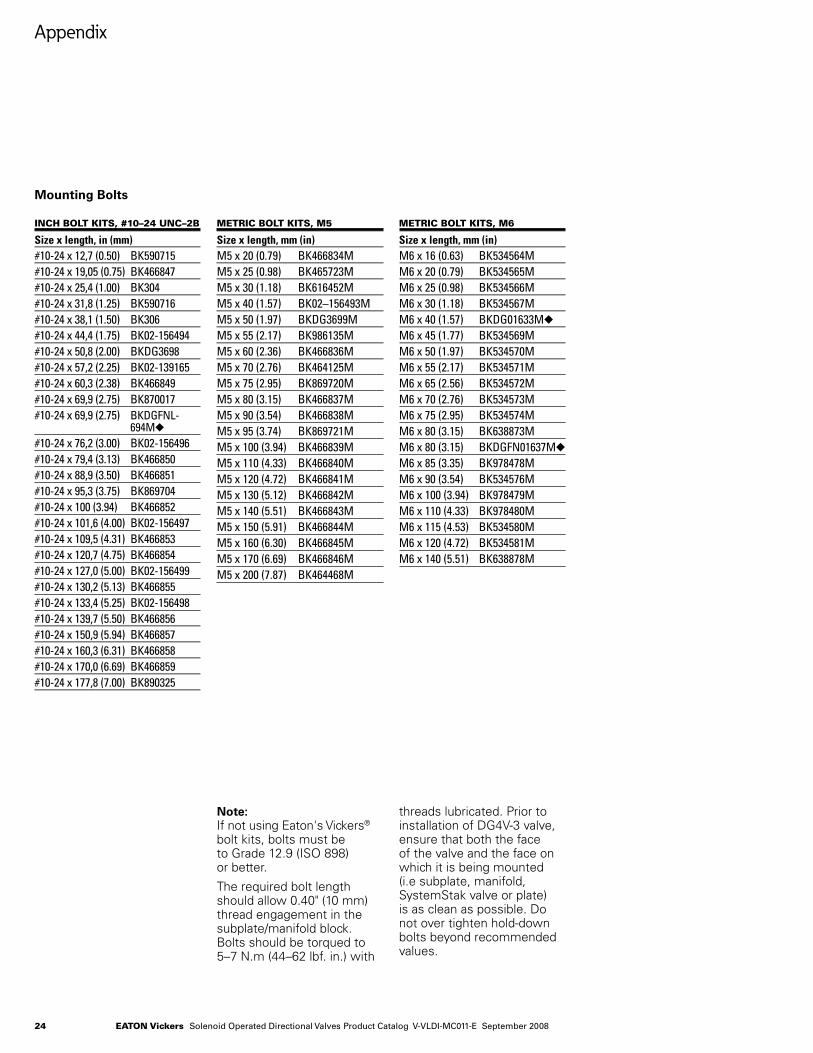
Note: If not using Eaton's Vickers® bolt kits, bolts must be to Grade 12.9 (ISO 898) or better.
The required bolt length should allow 0.40" (10 mm) thread engagement in the subplate/manifold block. Bolts should be torqued to 5–7 N.m (44–62 lbf. in.) with
threads lubricated. Prior to installation of DG4V-3 valve, ensure that both the face of the valve and the face on which it is being mounted (i.e subplate, manifold, SystemStak valve or plate) is as clean as possible. Do not over tighten hold-down bolts beyond recommended values.
incH bolt kitS, #10–24 unc–2b
Size x length, in (mm)#10-24 x 12,7 (0.50) BK590715#10-24 x 19,05 (0.75) BK466847#10-24 x 25,4 (1.00) BK304#10-24 x 31,8 (1.25) BK590716#10-24 x 38,1 (1.50) BK306#10-24 x 44,4 (1.75) BK02-156494#10-24 x 50,8 (2.00) BKDG3698#10-24 x 57,2 (2.25) BK02-139165#10-24 x 60,3 (2.38) BK466849#10-24 x 69,9 (2.75) BK870017#10-24 x 69,9 (2.75) BKDGFNL- 694Mu #10-24 x 76,2 (3.00) BK02-156496#10-24 x 79,4 (3.13) BK466850#10-24 x 88,9 (3.50) BK466851#10-24 x 95,3 (3.75) BK869704#10-24 x 100 (3.94) BK466852#10-24 x 101,6 (4.00) BK02-156497#10-24 x 109,5 (4.31) BK466853#10-24 x 120,7 (4.75) BK466854#10-24 x 127,0 (5.00) BK02-156499#10-24 x 130,2 (5.13) BK466855#10-24 x 133,4 (5.25) BK02-156498#10-24 x 139,7 (5.50) BK466856#10-24 x 150,9 (5.94) BK466857#10-24 x 160,3 (6.31) BK466858#10-24 x 170,0 (6.69) BK466859#10-24 x 177,8 (7.00) BK890325
Mounting Bolts
mEtric bolt kitS, m5
Size x length, mm (in)M5 x 20 (0.79) BK466834MM5 x 25 (0.98) BK465723MM5 x 30 (1.18) BK616452MM5 x 40 (1.57) BK02–156493MM5 x 50 (1.97) BKDG3699MM5 x 55 (2.17) BK986135MM5 x 60 (2.36) BK466836MM5 x 70 (2.76) BK464125MM5 x 75 (2.95) BK869720MM5 x 80 (3.15) BK466837MM5 x 90 (3.54) BK466838MM5 x 95 (3.74) BK869721MM5 x 100 (3.94) BK466839MM5 x 110 (4.33) BK466840MM5 x 120 (4.72) BK466841MM5 x 130 (5.12) BK466842MM5 x 140 (5.51) BK466843MM5 x 150 (5.91) BK466844MM5 x 160 (6.30) BK466845MM5 x 170 (6.69) BK466846MM5 x 200 (7.87) BK464468M
mEtric bolt kitS, m6
Size x length, mm (in)M6 x 16 (0.63) BK534564MM6 x 20 (0.79) BK534565MM6 x 25 (0.98) BK534566MM6 x 30 (1.18) BK534567MM6 x 40 (1.57) BKDG01633Mu
M6 x 45 (1.77) BK534569MM6 x 50 (1.97) BK534570MM6 x 55 (2.17) BK534571MM6 x 65 (2.56) BK534572MM6 x 70 (2.76) BK534573MM6 x 75 (2.95) BK534574MM6 x 80 (3.15) BK638873MM6 x 80 (3.15) BKDGFN01637Mu M6 x 85 (3.35) BK978478MM6 x 90 (3.54) BK534576MM6 x 100 (3.94) BK978479MM6 x 110 (4.33) BK978480MM6 x 115 (4.53) BK534580MM6 x 120 (4.72) BK534581MM6 x 140 (5.51) BK638878M
25Eaton Vickers Solenoid Operated Directional Valves Product Catalog V-VLDI-MC011-E September 2008
Appendix
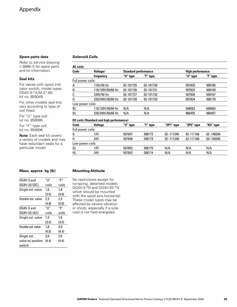
Spare parts data
Refer to service drawing I–3886–S for spare parts and kit information.
Seal kits
For valves with spool indi-cator switch, model types DG4V-3-*A-M-S*-60: kit no. 859049
For other models seal kits vary according to type of coil fitted:
For “U” type coil: kit no. 858995
For “F” type coil: kit no. 858996
Note: Each seal kit covers a variety of models and may have redundant seals for a particular model.
No restrictions except for no-spring, detented models DG4V-3-*N and DG4V-3S-*N which should be mounted with the spool axis horizontal. These model types may be affected by severe vibration or shock, especially if a sole-noid is not held energized.
DG4V-3 and “U” “F”DG4V-3S (DC) coils coilsSingle sol. valve 1,6 1,8 (3.5) (4.0)Double sol. valve 2,2 2,3 (4.8) (5.0)DG4V-3 and “U” “F”DG4V-3S (AC) coils coilsSingle sol. valve 1,5 1,6 (3.3) (3.5)Double sol. valve 1,8 2,0 (4.0) (4.4)Single sol. 2,0 2,0valve w/ position (4.4) (4.4)switch
Mounting AttitudeMass, approx. kg (lb)
AC coilsCode Voltage/ Standard performance High performance frequency “U” type “F” type “U” type “F” typeFull power coils:A 110V/50 Hz 02-101725 02-101730 507825 508166B 110/120V/50/60 Hz 02-101726 02-101731 507833 508169C 220V/50 Hz 02-101727 02-101732 507826 508167D 220/240V/50/60 Hz 02-101728 02-101733 507834 508170Low power coils:BL 110/120V/50/60 Hz N/A N/A 598562 698563DL 220/240V/50/60 Hz N/A N/A 866455 866457
DC coils (Standard and high performance)Code Voltage “U” type “F” type “SP1” type “SP2” type “KU” typeFull power coils:G 12V 507847 508172 02–111246 02-111166 02–140394H 24V 507848 508173 02–111248 02-111168 02–140395Low power coils:GL 12V 507855 508175 N/A N/A N/AHL 24V 507852 508174 N/A N/A N/A
Solenoid Coils
26 Eaton Vickers Solenoid Operated Directional Valves Product Catalog V-VLDI-MC011-E September 2008
Appendix
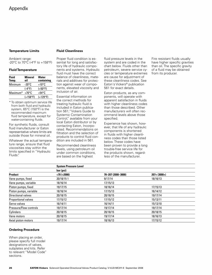
Ambient range: -20°C to 70°C (-4°F to +158°F)
Fluid Temperature
Fluid Mineral WaterTemp. oil containingMinimum -20°C +10°C (-4°F) (+50°F)Maximum* +70°C +54°C (+158°F) (+129°F)
* To obtain optimum service life from both fluid and hydraulic system, 65°C (150°F) is the recommended maximum fluid temperature, except for water-containing fluids.
For synthetic fluids, consult fluid manufacturer or Eaton representative where limits are outside those for mineral oil.
Whatever the actual tempera-ture range, ensure that fluid viscosities stay within the limits specified in “Hydraulic Fluids”.
Temperature Limits
Proper fluid condition is es-sential for long and satisfac-tory life of hydraulic compo-nents and systems. Hydraulic fluid must have the correct balance of cleanliness, mate-rials and additives for protec-tion against wear of compo-nents, elevated viscosity and inclusion of air.
Essential information on the correct methods for treating hydraulic fluid is included in Eaton publica-tion 561;“Vickers Guide to Systemic Contamination Control,” available from your local Eaton distributor or by contacting Eaton, Incorpo-rated. Recommendations on filtration and the selection of products to control fluid con-dition are included in 561.
Recommended cleanliness levels, using petroleum oil under common conditions, are based on the highest
fluid pressure levels in the system and are coded in the chart below. Fluids other than petroleum, severe service cy-cles or temperature extremes are cause for adjustment of these cleanliness codes. See Eaton's Vickers® publication 561 for exact details.
Eaton products, as any com-ponents, will operate with apparent satisfaction in fluids with higher cleanliness codes than those described. Other manufacturers will often rec-ommend levels above those specified.
Experience has shown, how-ever, that life of any hydraulic components is shortened in fluids with higher cleanli-ness codes than those listed below. These codes have been proven to provide a long trouble-free service life for the products shown, regard-less of the manufacturer.
Fire resistant fluids usually have higher specific gravities than oil. The specific gravity of a fluid may be obtained from its producer.
Fluid Cleanliness
When placing an order, please specify full model designations of valves, subplates and kits. Refer to relevant “Model Code” sections.
Ordering Procedure
System Pressure Level bar (psi)Product <70 (<2000) 70–207 (2000–3000) 207+ (3000+)Vane pumps, fixed 20/18/15 1 9/17/14 18/16/13Vane pumps, variable 18/16/14 17/15/13Piston pumps, fixed 19/17/15 18/16/14 17/15/13Piston pumps, variable 18/16/14 17/15/13 16/14/12Directional valves 20/18/15 20/18/15 19/17/14Proportional valves 17/15/12 17/15/12 15/13/11Servo valves 16/14/11 16/14/11 15/13/10Pressure/Flow controls 19/17/14 19/17/14 19/17/14Cylinders 20/18/15 20/18/15 20/18/15Vane motors 20/18/15 19/17/14 18/16/13Axial piston motors 19/17/14 18/16/13 17/15/12

This page left intentionally blank.

This page left intentionally blank.

This page left intentionally blank.

Eaton Hydraulics Operations USA14615 Lone Oak RoadEden Prairie, MN 55344USATel: 952-937-9800Fax: 952-294-7722www.eaton.com/hydraulics
EatonHydraulics Operations EuropeRoute de la Longeraie 71110 MorgesSwitzerlandTel: +41 (0) 21 811 4600Fax: +41 (0) 21 811 4601
Eaton Hydraulics Operations Asia Pacific 11th Floor Hong Kong New World Tower 300 Huaihai Zhong Road Shanghai 200021 China Tel: 86-21-6387-9988 Fax: 86-21-6335-3912
© 2008 Eaton CorporationAll Rights Reserved Printed in USADocument No. V-VLDI-MC011-ESupersedes GB-2072BSeptember 2008