Embed Size (px)
Citation preview
5018/EN/1197/A
DG**V-2-10 & Size 02 SystemStak Valves250 bar (3600 psi) 30 l/min (7.9 USgpm)ISO/DIS 4401-02-02
Vickers®
Directional Controls
2
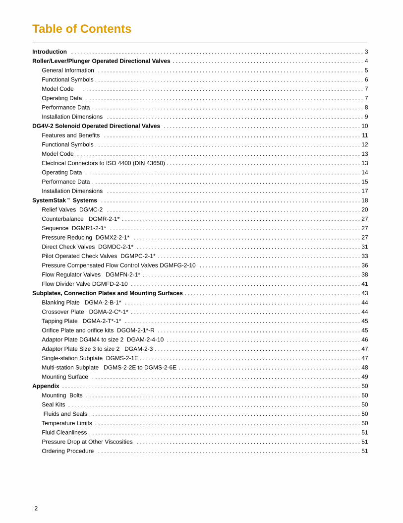
Table of Contents
Introduction 3. . . . . . . . . . . . . . . . . . . . . . . . . . . . . . . . . . . . . . . . . . . . . . . . . . . . . . . . . . . . . . . . . . . . . . . . . . . . . . . . . . . . . . . . . . . . . . . . . .
Roller/Lever/Plunger Operated Directional Valves 4. . . . . . . . . . . . . . . . . . . . . . . . . . . . . . . . . . . . . . . . . . . . . . . . . . . . . . . . . . . . . . . .
General Information 5. . . . . . . . . . . . . . . . . . . . . . . . . . . . . . . . . . . . . . . . . . . . . . . . . . . . . . . . . . . . . . . . . . . . . . . . . . . . . . . . . . . . . . . . .
Functional Symbols 6. . . . . . . . . . . . . . . . . . . . . . . . . . . . . . . . . . . . . . . . . . . . . . . . . . . . . . . . . . . . . . . . . . . . . . . . . . . . . . . . . . . . . . . . . .
Model Code 7. . . . . . . . . . . . . . . . . . . . . . . . . . . . . . . . . . . . . . . . . . . . . . . . . . . . . . . . . . . . . . . . . . . . . . . . . . . . . . . . . . . . . . . . . . . . . .
Operating Data 7. . . . . . . . . . . . . . . . . . . . . . . . . . . . . . . . . . . . . . . . . . . . . . . . . . . . . . . . . . . . . . . . . . . . . . . . . . . . . . . . . . . . . . . . . . . . .
Performance Data 8. . . . . . . . . . . . . . . . . . . . . . . . . . . . . . . . . . . . . . . . . . . . . . . . . . . . . . . . . . . . . . . . . . . . . . . . . . . . . . . . . . . . . . . . . . .
Installation Dimensions 9. . . . . . . . . . . . . . . . . . . . . . . . . . . . . . . . . . . . . . . . . . . . . . . . . . . . . . . . . . . . . . . . . . . . . . . . . . . . . . . . . . . . . .
DG4V-2 Solenoid Operated Directional Valves 10. . . . . . . . . . . . . . . . . . . . . . . . . . . . . . . . . . . . . . . . . . . . . . . . . . . . . . . . . . . . . . . . . .
Features and Benefits 11. . . . . . . . . . . . . . . . . . . . . . . . . . . . . . . . . . . . . . . . . . . . . . . . . . . . . . . . . . . . . . . . . . . . . . . . . . . . . . . . . . . . . .
Functional Symbols 12. . . . . . . . . . . . . . . . . . . . . . . . . . . . . . . . . . . . . . . . . . . . . . . . . . . . . . . . . . . . . . . . . . . . . . . . . . . . . . . . . . . . . . . . .
Model Code 13. . . . . . . . . . . . . . . . . . . . . . . . . . . . . . . . . . . . . . . . . . . . . . . . . . . . . . . . . . . . . . . . . . . . . . . . . . . . . . . . . . . . . . . . . . . . . . .
Electrical Connectors to ISO 4400 (DIN 43650) 13. . . . . . . . . . . . . . . . . . . . . . . . . . . . . . . . . . . . . . . . . . . . . . . . . . . . . . . . . . . . . . . . .
Operating Data 14. . . . . . . . . . . . . . . . . . . . . . . . . . . . . . . . . . . . . . . . . . . . . . . . . . . . . . . . . . . . . . . . . . . . . . . . . . . . . . . . . . . . . . . . . . . .
Performance Data 15. . . . . . . . . . . . . . . . . . . . . . . . . . . . . . . . . . . . . . . . . . . . . . . . . . . . . . . . . . . . . . . . . . . . . . . . . . . . . . . . . . . . . . . . . .
Installation Dimensions 17. . . . . . . . . . . . . . . . . . . . . . . . . . . . . . . . . . . . . . . . . . . . . . . . . . . . . . . . . . . . . . . . . . . . . . . . . . . . . . . . . . . . .
SystemStak� Systems 18. . . . . . . . . . . . . . . . . . . . . . . . . . . . . . . . . . . . . . . . . . . . . . . . . . . . . . . . . . . . . . . . . . . . . . . . . . . . . . . . . . . . . . .
Relief Valves DGMC-2 20. . . . . . . . . . . . . . . . . . . . . . . . . . . . . . . . . . . . . . . . . . . . . . . . . . . . . . . . . . . . . . . . . . . . . . . . . . . . . . . . . . . . .
Counterbalance DGMR-2-1* 27. . . . . . . . . . . . . . . . . . . . . . . . . . . . . . . . . . . . . . . . . . . . . . . . . . . . . . . . . . . . . . . . . . . . . . . . . . . . . . . .
Sequence DGMR1-2-1* 27. . . . . . . . . . . . . . . . . . . . . . . . . . . . . . . . . . . . . . . . . . . . . . . . . . . . . . . . . . . . . . . . . . . . . . . . . . . . . . . . . . . .
Pressure Reducing DGMX2-2-1* 27. . . . . . . . . . . . . . . . . . . . . . . . . . . . . . . . . . . . . . . . . . . . . . . . . . . . . . . . . . . . . . . . . . . . . . . . . . . .
Direct Check Valves DGMDC-2-1* 31. . . . . . . . . . . . . . . . . . . . . . . . . . . . . . . . . . . . . . . . . . . . . . . . . . . . . . . . . . . . . . . . . . . . . . . . . . .
Pilot Operated Check Valves DGMPC-2-1* 33. . . . . . . . . . . . . . . . . . . . . . . . . . . . . . . . . . . . . . . . . . . . . . . . . . . . . . . . . . . . . . . . . . . .
Pressure Compensated Flow Control Valves DGMFG-2-10 36. . . . . . . . . . . . . . . . . . . . . . . . . . . . . . . . . . . . . . . . . . . . . . . . . . . . . .
Flow Regulator Valves DGMFN-2-1* 38. . . . . . . . . . . . . . . . . . . . . . . . . . . . . . . . . . . . . . . . . . . . . . . . . . . . . . . . . . . . . . . . . . . . . . . . .
Flow Divider Valve DGMFD-2-10 41. . . . . . . . . . . . . . . . . . . . . . . . . . . . . . . . . . . . . . . . . . . . . . . . . . . . . . . . . . . . . . . . . . . . . . . . . . . . .
Subplates, Connection Plates and Mounting Surfaces 43. . . . . . . . . . . . . . . . . . . . . . . . . . . . . . . . . . . . . . . . . . . . . . . . . . . . . . . . . . .
Blanking Plate DGMA-2-B-1* 44. . . . . . . . . . . . . . . . . . . . . . . . . . . . . . . . . . . . . . . . . . . . . . . . . . . . . . . . . . . . . . . . . . . . . . . . . . . . . . .
Crossover Plate DGMA-2-C*-1* 44. . . . . . . . . . . . . . . . . . . . . . . . . . . . . . . . . . . . . . . . . . . . . . . . . . . . . . . . . . . . . . . . . . . . . . . . . . . . .
Tapping Plate DGMA-2-T*-1* 45. . . . . . . . . . . . . . . . . . . . . . . . . . . . . . . . . . . . . . . . . . . . . . . . . . . . . . . . . . . . . . . . . . . . . . . . . . . . . . .
Orifice Plate and orifice kits DGOM-2-1*-R 45. . . . . . . . . . . . . . . . . . . . . . . . . . . . . . . . . . . . . . . . . . . . . . . . . . . . . . . . . . . . . . . . . . . .
Adaptor Plate DG4M4 to size 2 DGAM-2-4-10 46. . . . . . . . . . . . . . . . . . . . . . . . . . . . . . . . . . . . . . . . . . . . . . . . . . . . . . . . . . . . . . . . .
Adaptor Plate Size 3 to size 2 DGAM-2-3 47. . . . . . . . . . . . . . . . . . . . . . . . . . . . . . . . . . . . . . . . . . . . . . . . . . . . . . . . . . . . . . . . . . . . .
Single-station Subplate DGMS-2-1E 47. . . . . . . . . . . . . . . . . . . . . . . . . . . . . . . . . . . . . . . . . . . . . . . . . . . . . . . . . . . . . . . . . . . . . . . . . .
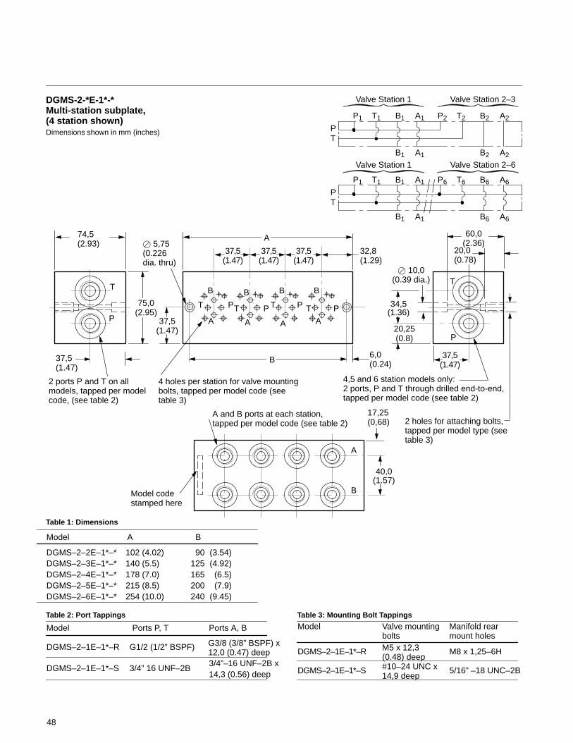
Multi-station Subplate DGMS-2-2E to DGMS-2-6E 48. . . . . . . . . . . . . . . . . . . . . . . . . . . . . . . . . . . . . . . . . . . . . . . . . . . . . . . . . . . . .
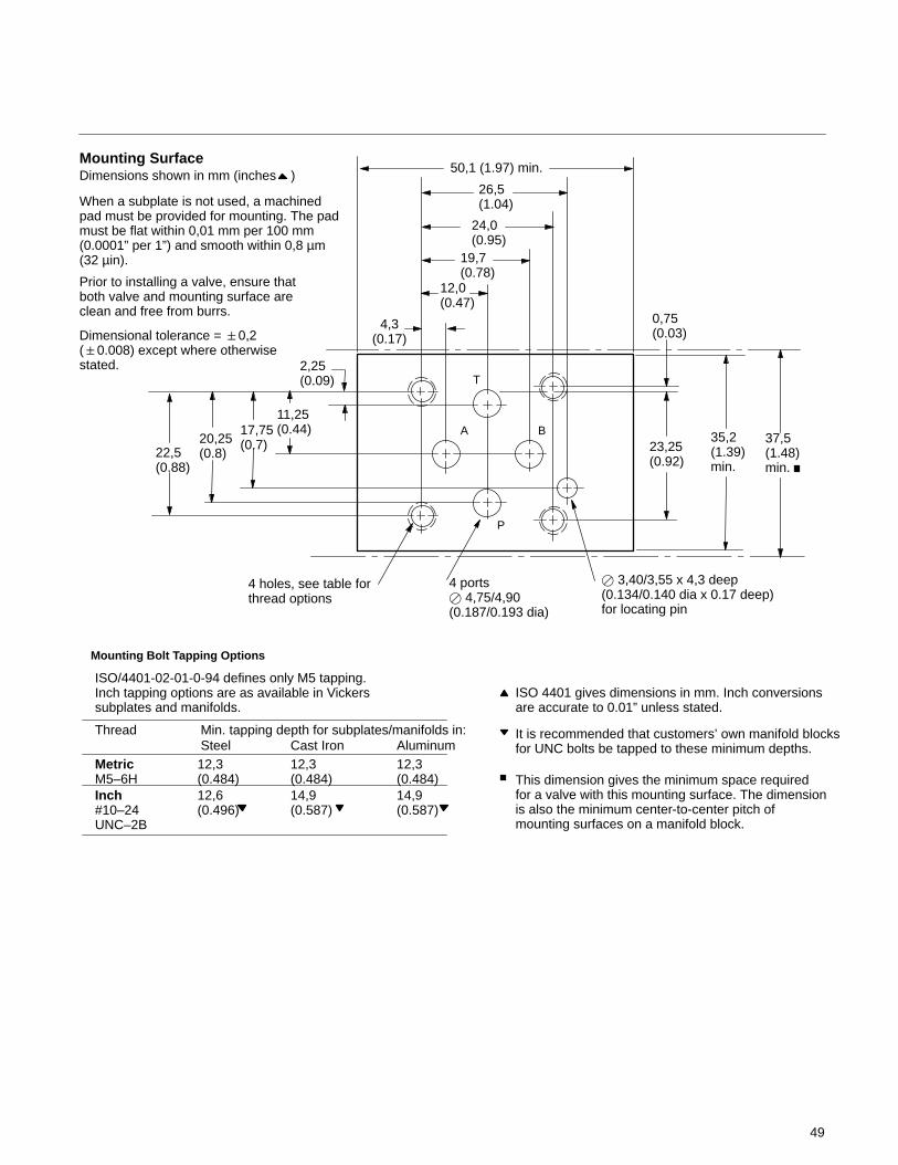
Mounting Surface 49. . . . . . . . . . . . . . . . . . . . . . . . . . . . . . . . . . . . . . . . . . . . . . . . . . . . . . . . . . . . . . . . . . . . . . . . . . . . . . . . . . . . . . . . . .
Appendix 50. . . . . . . . . . . . . . . . . . . . . . . . . . . . . . . . . . . . . . . . . . . . . . . . . . . . . . . . . . . . . . . . . . . . . . . . . . . . . . . . . . . . . . . . . . . . . . . . . . . .
Mounting Bolts 50. . . . . . . . . . . . . . . . . . . . . . . . . . . . . . . . . . . . . . . . . . . . . . . . . . . . . . . . . . . . . . . . . . . . . . . . . . . . . . . . . . . . . . . . . . . .
Seal Kits 50. . . . . . . . . . . . . . . . . . . . . . . . . . . . . . . . . . . . . . . . . . . . . . . . . . . . . . . . . . . . . . . . . . . . . . . . . . . . . . . . . . . . . . . . . . . . . . . . . .
Fluids and Seals 50. . . . . . . . . . . . . . . . . . . . . . . . . . . . . . . . . . . . . . . . . . . . . . . . . . . . . . . . . . . . . . . . . . . . . . . . . . . . . . . . . . . . . . . . . . .
Temperature Limits 50. . . . . . . . . . . . . . . . . . . . . . . . . . . . . . . . . . . . . . . . . . . . . . . . . . . . . . . . . . . . . . . . . . . . . . . . . . . . . . . . . . . . . . . . .
Fluid Cleanliness 51. . . . . . . . . . . . . . . . . . . . . . . . . . . . . . . . . . . . . . . . . . . . . . . . . . . . . . . . . . . . . . . . . . . . . . . . . . . . . . . . . . . . . . . . . . .
Pressure Drop at Other Viscosities 51. . . . . . . . . . . . . . . . . . . . . . . . . . . . . . . . . . . . . . . . . . . . . . . . . . . . . . . . . . . . . . . . . . . . . . . . . . .
Ordering Procedure 51. . . . . . . . . . . . . . . . . . . . . . . . . . . . . . . . . . . . . . . . . . . . . . . . . . . . . . . . . . . . . . . . . . . . . . . . . . . . . . . . . . . . . . . .
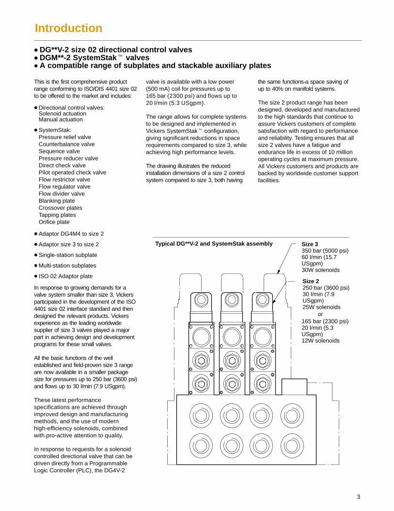
Size 3350 bar (5000 psi)60 l/min (15.7USgpm)30W solenoids
Size 2250 bar (3600 psi)30 l/min (7.9USgpm)25W solenoids
or165 bar (2300 psi)20 l/min (5.3USgpm)12W solenoids
Typical DG**V-2 and SystemStak assembly
3
Introduction
� DG**V-2 size 02 directional control valves� DGM**-2 SystemStak� valves� A compatible range of subplates and stackable auxiliary plates
This is the first comprehensive productrange conforming to ISO/DIS 4401 size 02to be offered to the market and includes:
� Directional control valves:Solenoid actuationManual actuation
� SystemStak:Pressure relief valveCounterbalance valveSequence valvePressure reducer valveDirect check valvePilot operated check valveFlow restrictor valveFlow regulator valveFlow divider valveBlanking plateCrossover platesTapping platesOrifice plate
� Adaptor DG4M4 to size 2
� Adaptor size 3 to size 2
� Single-station subplate
� Multi-station subplates
� ISO 02 Adaptor plate
In response to growing demands for avalve system smaller than size 3, Vickersparticipated in the development of the ISO4401 size 02 interface standard and thendesigned the relevant products. Vickersexperience as the leading worldwidesupplier of size 3 valves played a majorpart in achieving design and developmentprograms for these small valves.
All the basic functions of the wellestablished and field-proven size 3 rangeare now available in a smaller packagesize for pressures up to 250 bar (3600 psi)and flows up to 30 l/min (7.9 USgpm).
These latest performancespecifications are achieved throughimproved design and manufacturingmethods, and the use of modernhigh-efficiency solenoids, combinedwith pro-active attention to quality.
In response to requests for a solenoidcontrolled directional valve that can bedriven directly from a ProgrammableLogic Controller (PLC), the DG4V-2
valve is available with a low power(500 mA) coil for pressures up to165 bar (2300 psi) and flows up to20 l/min (5.3 USgpm).
The range allows for complete systemsto be designed and implemented inVickers SystemStak� configuration,giving significant reductions in spacerequirements compared to size 3, whileachieving high performance levels.
The drawing illustrates the reducedinstallation dimensions of a size 2 controlsystem compared to size 3, both having
the same functions-a space saving ofup to 40% on manifold systems.
The size 2 product range has beendesigned, developed and manufacturedto the high standards that continue toassure Vickers customers of completesatisfaction with regard to performanceand reliability. Testing ensures that allsize 2 valves have a fatigue andendurance life in excess of 10 millionoperating cycles at maximum pressure.All Vickers customers and products arebacked by worldwide customer supportfacilities.
4
Manually Actuated Control ValvesDG2/17/21V-2 10 Series
General description andapplication benefits
Vickers directional valves offer versatilityof application for the many directionalcontrol requirements of hydraulicmachinery. Ruggedness of design,manufacturing quality, and worldwideparts and service availability maximizeuptime.
These valves are available in anISO/DIS 4401-02-02 interface. Leveroperated, roller cam and plungeroperated models offer the followingapplication benefits:
� Efficient control of high hydraulicpowers, ideal for such applications asgate valves.
� Low internal leakage reduces powerlosses, increases system efficiency -the result of improved manufacturingtechniques for spools and bores.
� Viton� seals with multi-fluid capabilitywithout need to change seals.
� High sustained machine productivityand higher uptime because of provenfatigue and endurance life- tested toover 10 million cycles.
� Compact and cost-effective systemdesign when used with VickersSystemStak� valves andmulti-station subplates.
Viton� is a registered trademark of E.I. DuPont
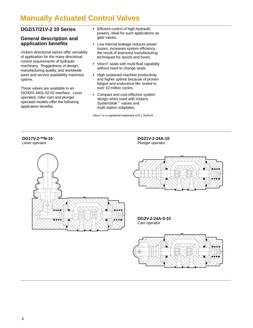
DG17V-2-**N-10Lever operator
DG21V-2-24A-10Plunger operator
DG2V-2-24A-5-10Cam operator
5
General Information
General DescriptionThree types of valve are available withdifferent controls primarily for controllingstarting, stopping and direction of fluidflow in a system.
Basically, the valves are developed fromthe well-known series of DG4V-2-10series solenoid operated valves. Thesemanual valves are available with achoice of mechanically operated spooltypes, depending on valve configuration.All spools have been designed toprovide good low-shock characteristics.External regulation of the control inputby lever, cam or plunger operationallows matching to virtually anyrequirement where electrical control isnot appropriate.
Models include no-spring, spring offset,spring centered and detented versions.
DG**V-2-*-10Lever/Cam/PlungerOperated
Operating InformationThe DG21V-2 plunger operator valves areinternally drained to port T. They may beused only when surges or back pressurein the tank line cannot overcome the forceapplied to depress the plunger.
DG2/17/21 models must be releasedfrom the actuated position, withoutrestriction to ensure proper spring return.
Cam operated directional control valveinstallation recommendations:
� Maximum cam angle 15°
� Cam should not drive roller at itsvertical centerline to avoid any sideloading on roller lever mechanism.
Actuation ForceUnder rated conditions*, theapproximate actuation force will be asshown in the chart below:
��������� �� �����������
DG17V-2-*C(L) 25-40N (6 -9)
DG17V-2-*A(L) 25-40N (6 -9)
DG17V-2-*N(L) 10-17N (2-4)
DG2V-2 125-160N (28-36)
DG21V-2 125-160N (28-36)
������������������������������������������������
�������������������������������� ���� !"����
�#$$��������������������������������������� ������
!"������#$$�������������������������������������
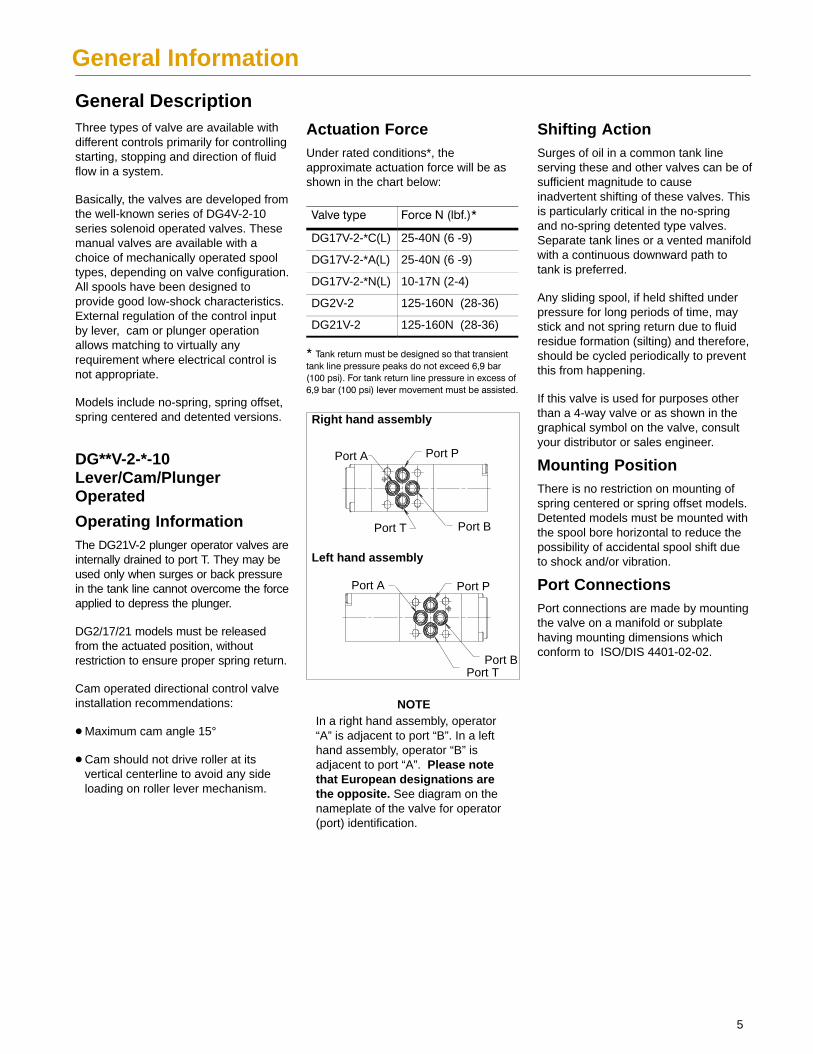
Port TPort B
Port A Port P
Port PPort A
Port BPort T
Left hand assembly
Right hand assembly
NOTEIn a right hand assembly, operator“A” is adjacent to port “B”. In a lefthand assembly, operator “B” isadjacent to port “A”. Please notethat European designations arethe opposite. See diagram on thenameplate of the valve for operator(port) identification.
Shifting ActionSurges of oil in a common tank lineserving these and other valves can be ofsufficient magnitude to causeinadvertent shifting of these valves. Thisis particularly critical in the no-springand no-spring detented type valves.Separate tank lines or a vented manifoldwith a continuous downward path totank is preferred.
Any sliding spool, if held shifted underpressure for long periods of time, maystick and not spring return due to fluidresidue formation (silting) and therefore,should be cycled periodically to preventthis from happening.
If this valve is used for purposes otherthan a 4-way valve or as shown in thegraphical symbol on the valve, consultyour distributor or sales engineer.
Mounting PositionThere is no restriction on mounting ofspring centered or spring offset models.Detented models must be mounted withthe spool bore horizontal to reduce thepossibility of accidental spool shift dueto shock and/or vibration.
Port ConnectionsPort connections are made by mountingthe valve on a manifold or subplatehaving mounting dimensions whichconform to ISO/DIS 4401-02-02.
6
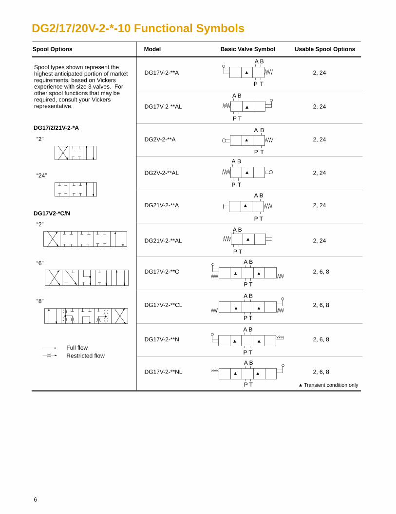
DG2/17/20V-2-*-10 Functional Symbols
“2”
“8”
DG17/2/21V-2-*A
DG2V-2-**A
DG17V-2-**C
DG21V-2-**A
Full flowRestricted flow
Spool Options Usable Spool Options
DG17V-2-**A
Model Basic Valve Symbol
DG17V-2-**N
“24”
A B
P T
A B
P T
DG2V-2-**AL
DG17V-2-**AL
A B
P T
A B
P T
A B
P T
A B
P T
A B
P T
A B
P T
A B
P T
A B
P T
“2”
DG17V2-*C/N
DG21V-2-**AL
DG17V-2-**CL
DG17V-2-**NL
2, 24
2, 24
2, 24
2, 24
2, 24
2, 24
2, 6, 8
2, 6, 8
2, 6, 8
2, 6, 8
“6”
Spool types shown represent thehighest anticipated portion of marketrequirements, based on Vickersexperience with size 3 valves. Forother spool functions that may berequired, consult your Vickersrepresentative.
Transient condition only
7
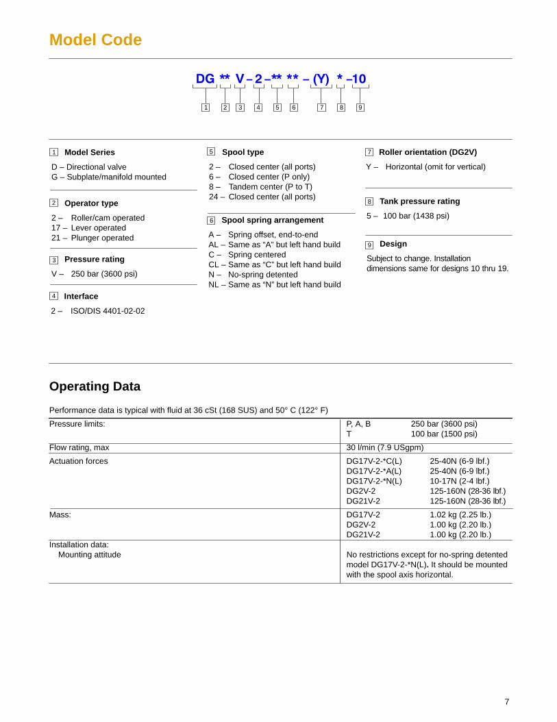
Model Code
Performance data is typical with fluid at 36 cSt (168 SUS) and 50° C (122° F)
Pressure limits: P, A, B 250 bar (3600 psi)T 100 bar (1500 psi)
Flow rating, max 30 l/min (7.9 USgpm)
Actuation forces DG17V-2-*C(L) 25-40N (6-9 lbf.)DG17V-2-*A(L) 25-40N (6-9 lbf.)DG17V-2-*N(L) 10-17N (2-4 lbf.)DG2V-2 125-160N (28-36 lbf.)DG21V-2 125-160N (28-36 lbf.)
Mass: DG17V-2 1.02 kg (2.25 lb.)DG2V-2 1.00 kg (2.20 lb.)DG21V-2 1.00 kg (2.20 lb.)
Installation data:Mounting attitude No restrictions except for no-spring detented
model DG17V-2-*N(L). It should be mounted with the spool axis horizontal.
Design
Subject to change. Installationdimensions same for designs 10 thru 19.
Operator type
2 – Roller/cam operated17 – Lever operated21 – Plunger operated
3 41
1 Model Series
D – Directional valveG – Subplate/manifold mounted
Spool type
2 – Closed center (all ports)6 – Closed center (P only)8 – Tandem center (P to T)24 – Closed center (all ports)
Spool spring arrangement
A – Spring offset, end-to-endAL – Same as “A” but left hand buildC – Spring centeredCL – Same as “C” but left hand buildN – No-spring detentedNL – Same as “N” but left hand build
Interface
2 – ISO/DIS 4401-02-02
2
3
4
5
5
Pressure rating
V – 250 bar (3600 psi)
Operating Data
76
7
6
Tank pressure rating
5 – 100 bar (1438 psi)
8
9
Roller orientation (DG2V)
Y – Horizontal (omit for vertical)
8 92
8
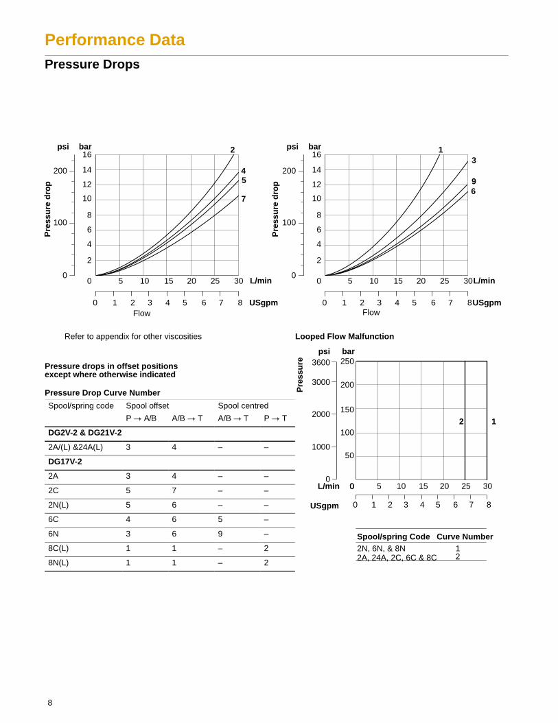
Performance DataPressure Drops
Pressure drops in offset positionsexcept where otherwise indicated
Pressure Drop Curve Number
Spool/spring code Spool offset Spool centred
P � A/B A/B � T A/B � T P � T
DG2V-2 & DG21V-2
2A/(L) &24A(L) 3 4 – –
DG17V-2
2A 3 4 – –
2C 5 7 – –
2N(L) 5 6 – –
6C 4 6 5 –
6N 3 6 9 –
8C(L) 1 1 – 2
8N(L) 1 1 – 2
2N, 6N, & 8N2A, 24A, 2C, 6C & 8C
Refer to appendix for other viscosities
bar
0
psi
Pre
ssu
re d
rop
0 L/min
0 4 8 USgpm
5 10 15 20 25 30
1 2 5 6 73
2
4
6
8
10
12
100
12
5200 14
16
7
Flow
bar
0
psi
Pre
ssu
re d
rop
0 L/min
0 4 8USgpm
5 10 15 20 25 30
1 2 5 6 73
2
4
6
8
10
12
100
3
6
200 14
16
Flow
94
0L/min
0 4 8
5 10 15 20 25 30
1 2 5 6 73
12
Looped Flow Malfunction
0
bar
0
psi
50
100
150
200
250
1000
2000
3000
3600
Pre
ssu
re
Spool/spring Code Curve Number
USgpm
12
9
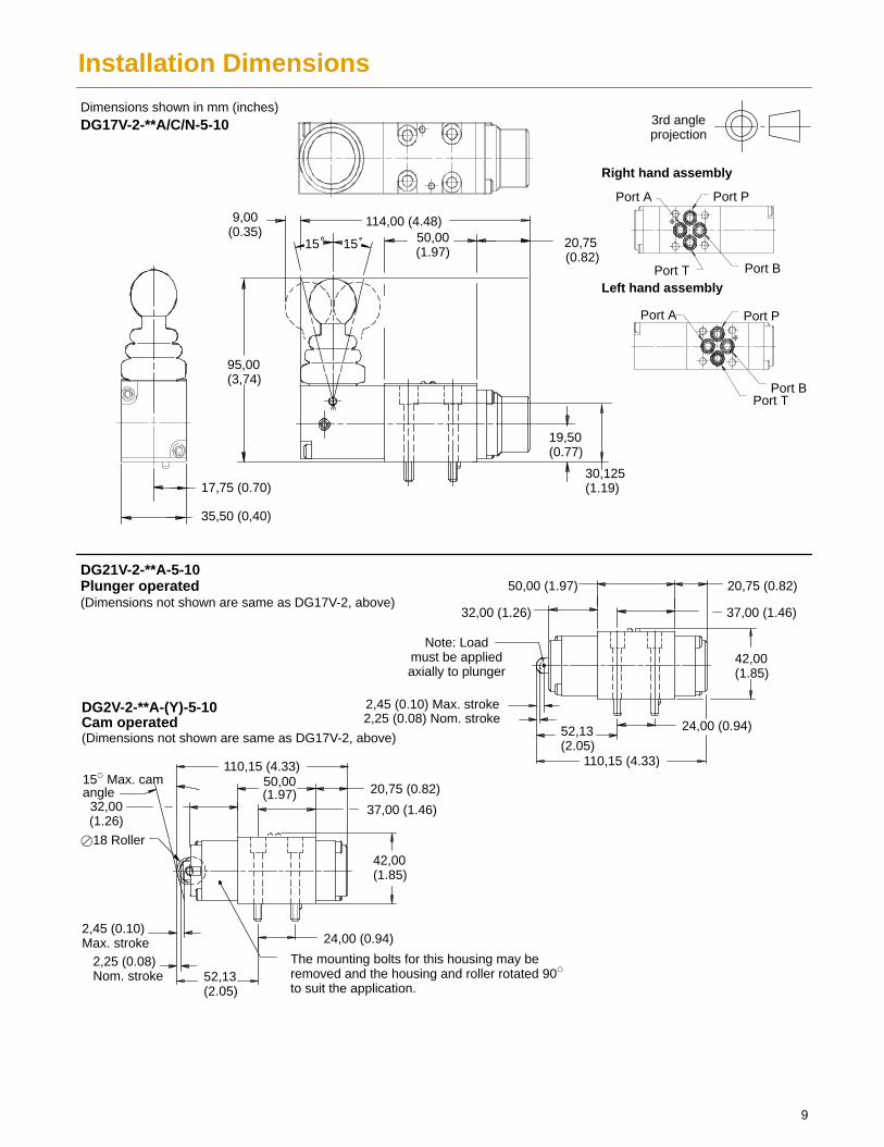
Installation Dimensions
50,00(1.97)
15� Max. camangle
DG17V-2-**A/C/N-5-10Dimensions shown in mm (inches)
3rd angleprojection
9,00(0.35) 50,00
(1.97)1515
19,50(0.77)
30,125(1.19)
95,00(3,74)
35,50 (0,40)
17,75 (0.70)
114,00 (4.48)
20,75 (0.82)
Note: Loadmust be appliedaxially to plunger
32,00 (1.26)
50,00 (1.97)
37,00 (1.46)
20,75 (0.82)
42,00(1.85)
24,00 (0.94)
2,45 (0.10) Max. stroke2,25 (0.08) Nom. stroke
52,13(2.05)
37,00 (1.46)
20,75 (0.82)
42,00(1.85)
24,00 (0.94)
32,00(1.26)
2,45 (0.10) Max. stroke
2,25 (0.08) Nom. stroke
�18 Roller
The mounting bolts for this housing may beremoved and the housing and roller rotated 90�
to suit the application.
DG21V-2-**A-5-10Plunger operated(Dimensions not shown are same as DG17V-2, above)
DG2V-2-**A-(Y)-5-10Cam operated(Dimensions not shown are same as DG17V-2, above)
52,13(2.05)
Port TPort B
Port A Port P
Port PPort A
Port BPort TLeft hand assembly
Right hand assembly
110,15 (4.33) 110,15 (4.33)
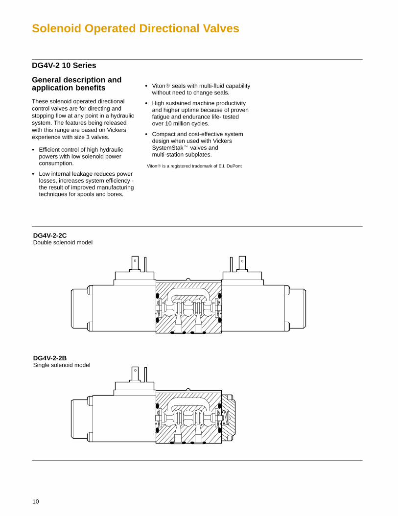
DG4V-2-2CDouble solenoid model
DG4V-2-2BSingle solenoid model
10
Solenoid Operated Directional Valves
DG4V-2 10 Series
General description andapplication benefits
These solenoid operated directionalcontrol valves are for directing andstopping flow at any point in a hydraulicsystem. The features being releasedwith this range are based on Vickersexperience with size 3 valves.
� Efficient control of high hydraulicpowers with low solenoid powerconsumption.
� Low internal leakage reduces powerlosses, increases system efficiency -the result of improved manufacturingtechniques for spools and bores.
� Viton� seals with multi-fluid capabilitywithout need to change seals.
� High sustained machine productivityand higher uptime because of provenfatigue and endurance life- testedover 10 million cycles.
� Compact and cost-effective systemdesign when used with VickersSystemStak� valves andmulti-station subplates.
Viton� is a registered trademark of E.I. DuPont
11
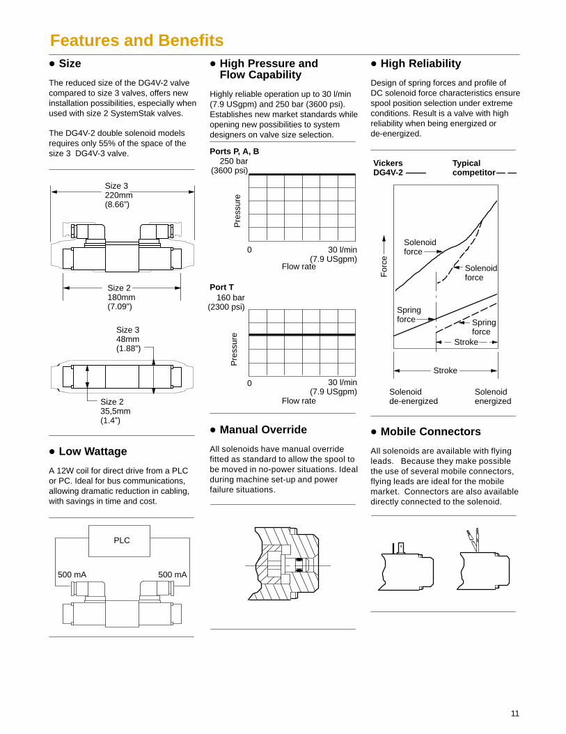
Features and Benefits� Size
The reduced size of the DG4V-2 valvecompared to size 3 valves, offers newinstallation possibilities, especially whenused with size 2 SystemStak valves.
The DG4V-2 double solenoid modelsrequires only 55% of the space of thesize 3 DG4V-3 valve.
Size 3220mm(8.66”)
Size 2180mm(7.09”)
Size 348mm(1.88”)
Size 235,5mm(1.4”)
� Low Wattage
A 12W coil for direct drive from a PLCor PC. Ideal for bus communications,allowing dramatic reduction in cabling,with savings in time and cost.
PLC
500 mA 500 mA
� High Pressure andFlow Capability
Highly reliable operation up to 30 l/min(7.9 USgpm) and 250 bar (3600 psi).Establishes new market standards whileopening new possibilities to systemdesigners on valve size selection.
0 30 l/min(7.9 USgpm)
250 bar(3600 psi)
Ports P, A, B
0 30 l/min(7.9 USgpm)
160 bar(2300 psi)
Port T
Pre
ssur
e
Flow rate
Flow rate
Pre
ssur
e
� Manual Override
All solenoids have manual overridefitted as standard to allow the spool tobe moved in no-power situations. Idealduring machine set-up and powerfailure situations.
� High Reliability
Design of spring forces and profile ofDC solenoid force characteristics ensurespool position selection under extremeconditions. Result is a valve with highreliability when being energized orde-energized.
VickersDG4V-2
Typicalcompetitor
Solenoidforce
Solenoidde-energized
Solenoidenergized
Stroke
Springforce Spring
force
SolenoidforceF
orce
Stroke
� Mobile Connectors
All solenoids are available with flyingleads. Because they make possiblethe use of several mobile connectors,flying leads are ideal for the mobilemarket. Connectors are also availabledirectly connected to the solenoid.
B
Sol. B
Double solenoid valves,two position, detented
Single solenoid valves,solenoid at port A end
Single solenoid valves,solenoid at port B end
P T
A B
Sol. ASol. B P T
A B
Sol. B P T
A B
Sol. A
P T
A B
Sol. ASol. B
DG4V-2-*N(V) valves DG4V-2-*A(V) valves DG4V-2-*AL(V) valves
Double solenoid valves,spring centered
0
2
6
7
33
2
0
2
6
7
33
0
2
6
7
33
2 2
DG4V-2-*C(V) valves DG4V-2-*B(V) valves DG4V-2-*BL(V) valves
8 88
DG4V-2-8C(V) valves DG4V-2-8B(V) valvesDG4V-2-8BL(V) valves
Double solenoid valves,two position, detented
Single solenoid valves,solenoid at port A end
Single solenoid valves,solenoid at port B end
P T
A B
Sol. A P T
A
Sol. BP T
A B
Sol. A
P T
A B
Sol. A Sol. B
Double solenoid valves,spring centered
European Solenoid Standard
U.S. Solenoid Standard
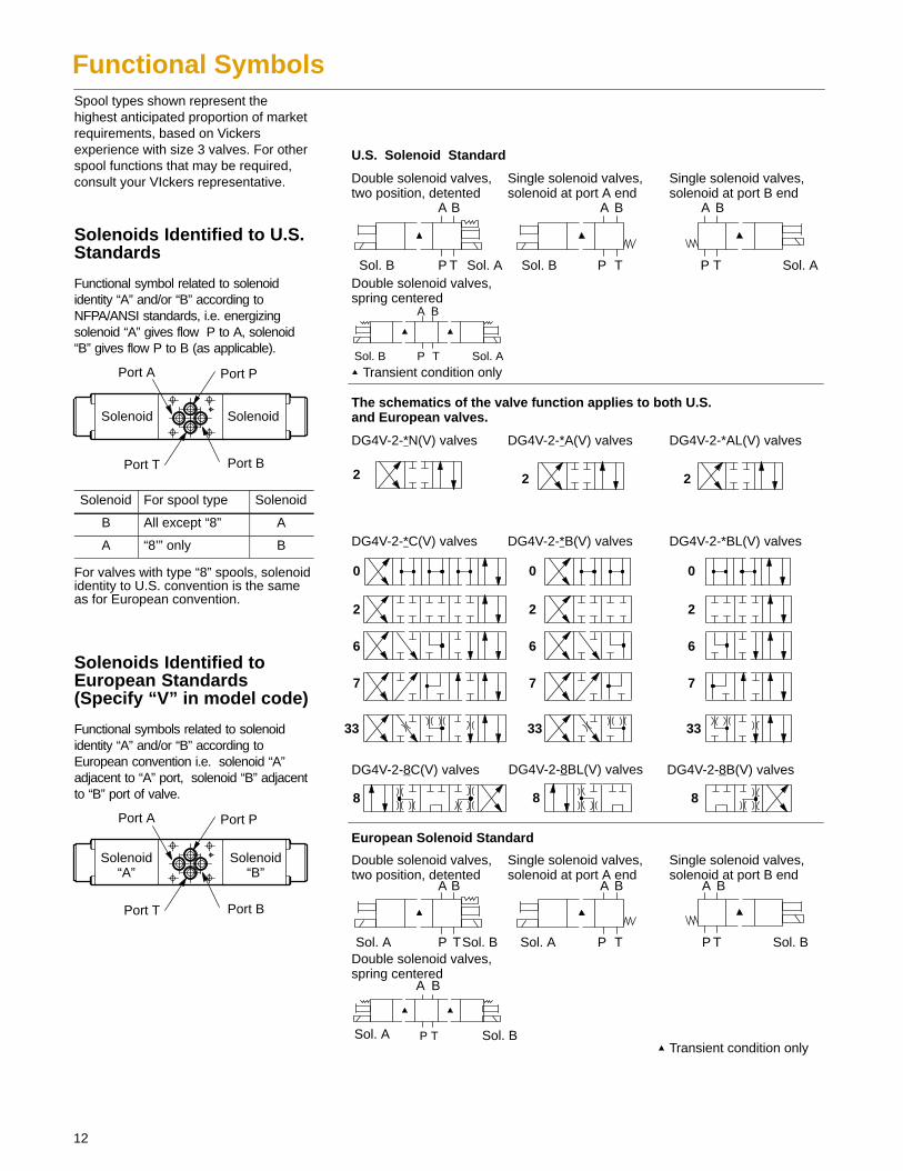
The schematics of the valve function applies to both U.S. and European valves.
Transient condition only
Transient condition only
12
Functional SymbolsSpool types shown represent thehighest anticipated proportion of marketrequirements, based on Vickersexperience with size 3 valves. For otherspool functions that may be required,consult your VIckers representative.
Solenoids Identified to U.S.Standards
Functional symbol related to solenoididentity “A” and/or “B” according toNFPA/ANSI standards, i.e. energizingsolenoid “A” gives flow P to A, solenoid“B” gives flow P to B (as applicable).
Port A Port P
Port T Port B
Solenoid Solenoid
Solenoid For spool type Solenoid
B All except “8” A
A “8’” only B
For valves with type “8” spools, solenoididentity to U.S. convention is the sameas for European convention.
Solenoids Identified toEuropean Standards(Specify “V” in model code)
Functional symbols related to solenoididentity “A” and/or “B” according toEuropean convention i.e. solenoid “A”adjacent to “A” port, solenoid “B” adjacentto “B” port of valve.
Port A Port P
Port T Port B
Solenoid“A”
Solenoid“B”
13
Model Code
3 4 5 876 9 101 2
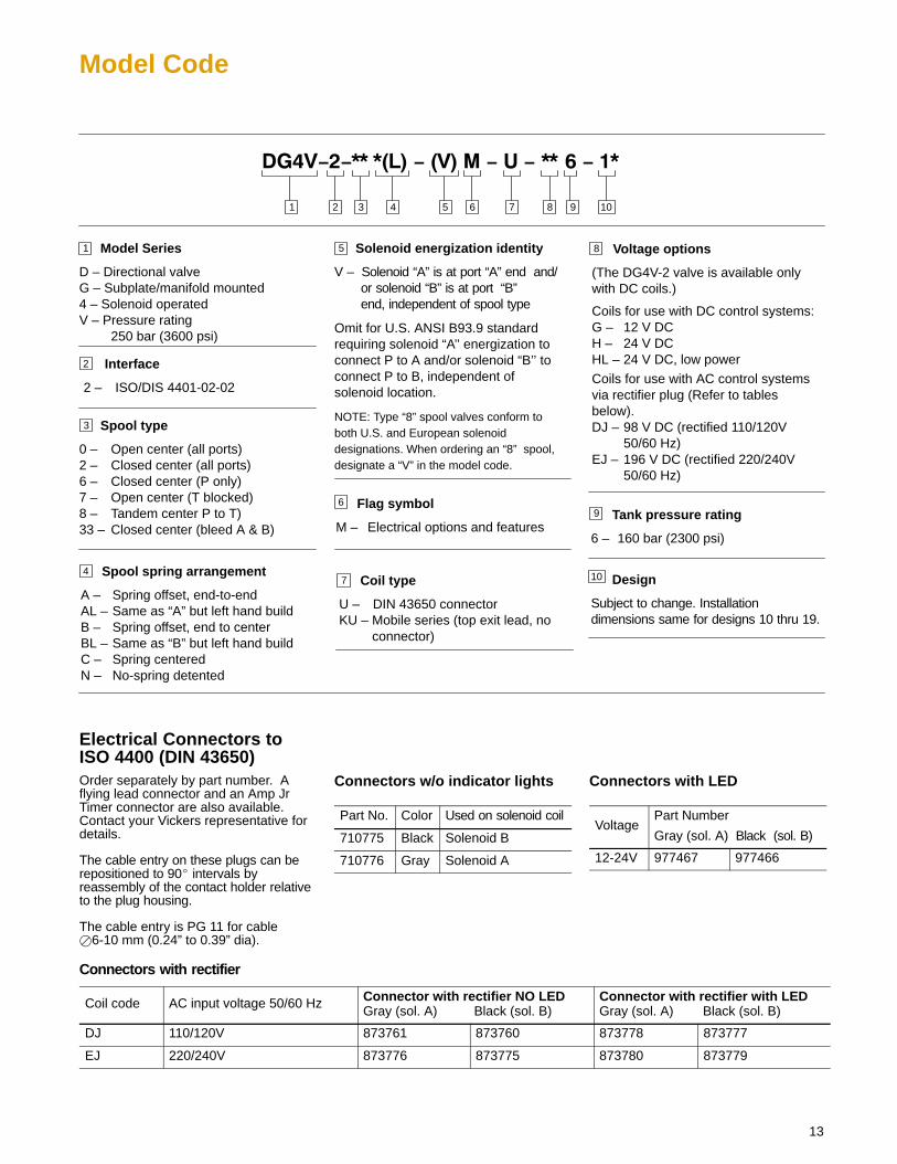
1 Model Series
D – Directional valveG – Subplate/manifold mounted4 – Solenoid operatedV – Pressure rating
250 bar (3600 psi)
Spool type
0 – Open center (all ports)2 – Closed center (all ports)6 – Closed center (P only)7 – Open center (T blocked)8 – Tandem center P to T)33 – Closed center (bleed A & B)
Solenoid energization identity
V – Solenoid “A” is at port “A” end and/ or solenoid “B” is at port “B” end, independent of spool type
Omit for U.S. ANSI B93.9 standardrequiring solenoid “A’’ energization toconnect P to A and/or solenoid “B’’ toconnect P to B, independent ofsolenoid location.
NOTE: Type “8” spool valves conform toboth U.S. and European solenoiddesignations. When ordering an “8” spool,designate a “V” in the model code.
Spool spring arrangement
A – Spring offset, end-to-endAL – Same as “A” but left hand buildB – Spring offset, end to centerBL – Same as “B” but left hand buildC – Spring centeredN – No-spring detented
Interface
2 – ISO/DIS 4401-02-02
2
3
4
Voltage options
(The DG4V-2 valve is available onlywith DC coils.)
Coils for use with DC control systems:G – 12 V DCH – 24 V DCHL – 24 V DC, low power
Coils for use with AC control systemsvia rectifier plug (Refer to tablesbelow).DJ – 98 V DC (rectified 110/120V
50/60 Hz)EJ – 196 V DC (rectified 220/240V
50/60 Hz)
7 Coil type
U – DIN 43650 connectorKU – Mobile series (top exit lead, no connector)
8
Tank pressure rating
6 – 160 bar (2300 psi)
6
5
9Flag symbol
M – Electrical options and features
10 Design
Subject to change. Installationdimensions same for designs 10 thru 19.
Electrical Connectors toISO 4400 (DIN 43650)Order separately by part number. Aflying lead connector and an Amp JrTimer connector are also available.Contact your Vickers representative fordetails.
The cable entry on these plugs can berepositioned to 90� intervals byreassembly of the contact holder relativeto the plug housing.
The cable entry is PG 11 for cable�6-10 mm (0.24” to 0.39” dia).
Connectors with rectifier
Connectors w/o indicator lights
Part No. Color Used on solenoid coil
710775 Black Solenoid B
710776 Gray Solenoid A
Connectors with LED
VoltagePart Number
Gray (sol. A) Black (sol. B)
12-24V 977467 977466
Coil code AC input voltage 50/60 Hz Connector with rectifier NO LEDGray (sol. A) Black (sol. B)
Connector with rectifier with LEDGray (sol. A) Black (sol. B)
DJ 110/120V 873761 873760 873778 873777
EJ 220/240V 873776 873775 873780 873779
14
Operating Data
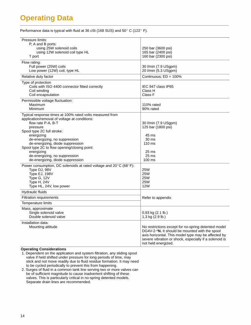
Performance data is typical with fluid at 36 cSt (168 SUS) and 50� C (122� F).
Pressure limits:P, A and B ports:
using 25W solenoid coilsusing 12W solenoid coil type HL
T port
250 bar (3600 psi)165 bar (2400 psi)160 bar (2300 psi)
Flow rating:Full power (25W) coilsLow power (12W) coil, type HL
30 l/min (7.9 USgpm)20 l/min (5.3 USgpm)
Relative duty factor Continuous; ED = 100%
Type of protectionCoils with ISO 4400 connector fitted correctlyCoil windingCoil encapsulation
IEC 947 class IP65Class HClass F
Permissible voltage fluctuation:MaximumMinimum
110% rated90% rated
Typical response times at 100% rated volts measured fromapplication/removal of voltage at conditions:
flow rate P-A, B-Tpressure
Spool type 2C full stroke:energizingde-energizing, no suppressionde-energizing, diode suppression
Spool type 2C to flow opening/closing point:energizingde-energizing, no suppressionde-energizing, diode suppression
30 l/min (7.9 USgpm)125 bar (1800 psi)
45 ms30 ms
110 ms
25 ms25 ms
100 ms
Power consumption, DC solenoids at rated voltage and 20�C (68�F):Type DJ, 98VType EJ, 198VType G, 12VType H, 24VType HL, 24V, low power
25W25W25W25W12W
Hydraulic fluids
Filtration requirements Refer to appendixTemperature limits
Mass, approximateSingle solenoid valveDouble solenoid valve
0,93 kg (2.1 lb.)1,3 kg (2.9 lb.)
Installation data:Mounting attitude No restrictions except for no-spring detented model
DG4V-2-*N. It should be mounted with the spoolaxis horizontal. This model type may be affected bysevere vibration or shock, especially if a solenoid isnot held energized.
Operating Considerations1. Dependent on the application and system filtration, any sliding spool
valve if held shifted under pressure for long periods of time, maystick and not move readily due to fluid residue formation. It may needto be cycled periodically to prevent this from happening.
2. Surges of fluid in a common tank line serving two or more valves canbe of sufficient magnitude to cause inadvertent shifting of thesevalves. This is particularly critical in no-spring detented models.Separate drain lines are recommended.
15
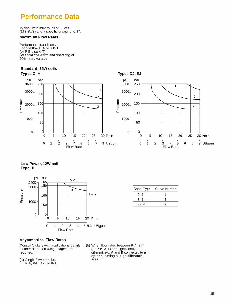
Performance DataTypical with mineral oil at 36 cSt(168 SUS) and a specific gravity of 0.87.
Maximum Flow Rates
Performance conditions:Looped flow P-A plus B-T(or P-B plus A-T).Solenoid coil warm and operating at90% rated voltage.
Standard, 25W coilsTypes G, H Types DJ, EJ
Low Power, 12W coil Type HL
psi bar3600
3000
2000
1000
0
250
200
150
100
50
00 5 10 15 20 25 30
0 1 2 3 4 5 6 7 8
l/min
USgpmFlow Rate
Pre
ssur
e
psi bar3600
3000
2000
1000
0
250
200
150
100
50
00 5 10 15 20 25 30
0 1 2 3 4 5 6 7 8
l/min
USgpmFlow Rate
Pre
ssur
e
psi bar24002000
1000
0
165150
100
50
00 5 10 15 20 l/min
0 1 2 3 4 5 5.3 USgpmFlow Rate
Pre
ssur
e
1 & 2
1 & 23
11
2
3
1 1
2
3
Spool Type Curve Number
0, 27, 833, 6
123
Asymmetrical Flow RatesConsult Vickers with applications detailsif either of the following usages arerequired:
(a) Single flow path, i.e.P-A, P-B, A-T or B-T.
(b) When flow rates between P-A, B-T(or P-B, A-T) are significantly different, e.g. A and B connected to a cylinder having a large differential area.
16
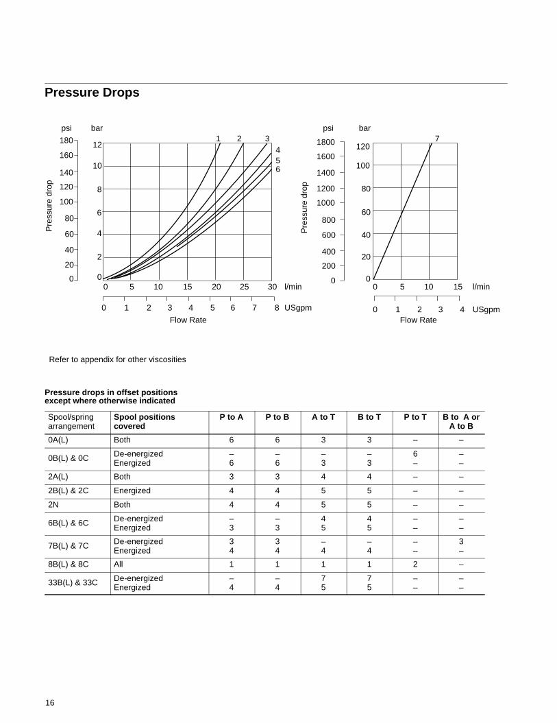
Pressure Drops
100
Pre
ssur
e dr
op
psi bar
180
160
140
120
100
80
60
40
20
0
12
10
8
6
4
2
00 5 10 15 20 25 30
0 1 2 3 4 5 6 7 8 0 1 2 3 4
bar
120
80
60
40
20
0
Pre
ssur
e dr
op
psi
1800
1600
1400
1200
1000
800
600
400
200
0l/min
USgpm
l/min
USgpm
0 5 10 15
1 2 34
65
7
Refer to appendix for other viscosities
Flow Rate Flow Rate
Pressure drops in offset positionsexcept where otherwise indicated
Spool/spring arrangement
Spool positionscovered
P to A P to B A to T B to T P to T B to A orA to B
0A(L) Both 6 6 3 3 – –
0B(L) & 0C De-energizedEnergized
–6
–6
–3
–3
6–
––
2A(L) Both 3 3 4 4 – –
2B(L) & 2C Energized 4 4 5 5 – –
2N Both 4 4 5 5 – –
6B(L) & 6C De-energizedEnergized
–3
–3
45
45
––
––
7B(L) & 7C De-energizedEnergized
34
34
–4
–4
––
3–
8B(L) & 8C All 1 1 1 1 2 –
33B(L) & 33C De-energizedEnergized
–4
–4
75
75
––
––
17
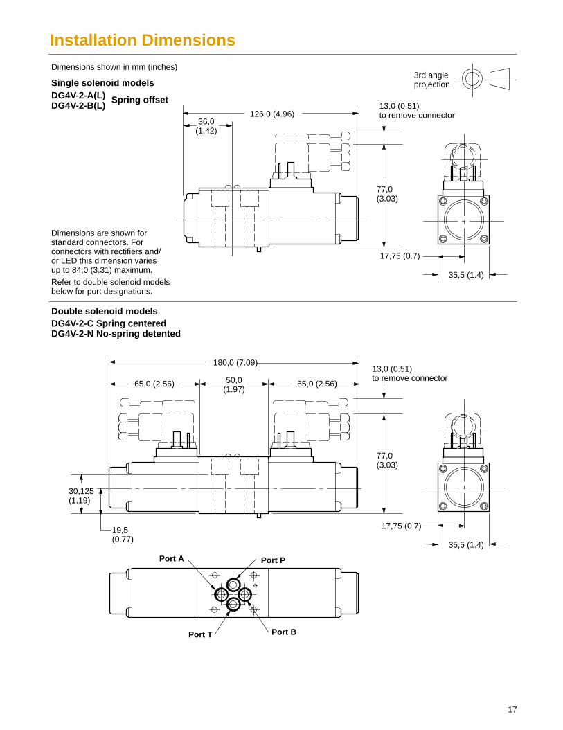
Installation Dimensions
13,0 (0.51)to remove connector
36,0(1.42)
50,0(1.97)
Single solenoid models
Double solenoid models
Port A Port P
Port T Port B
126,0 (4.96)
35,5 (1.4)
17,75 (0.7)
35,5 (1.4)
17,75 (0.7)
180,0 (7.09)
65,0 (2.56) 65,0 (2.56)
30,125(1.19)
19,5(0.77)
77,0(3.03)
13,0 (0.51)to remove connector
DG4V-2-A(L)DG4V-2-B(L)
DG4V-2-C Spring centeredDG4V-2-N No-spring detented
Spring offset
Refer to double solenoid modelsbelow for port designations.
77,0(3.03)
Dimensions are shown forstandard connectors. Forconnectors with rectifiers and/or LED this dimension variesup to 84,0 (3.31) maximum.
Dimensions shown in mm (inches)3rd angleprojection
18
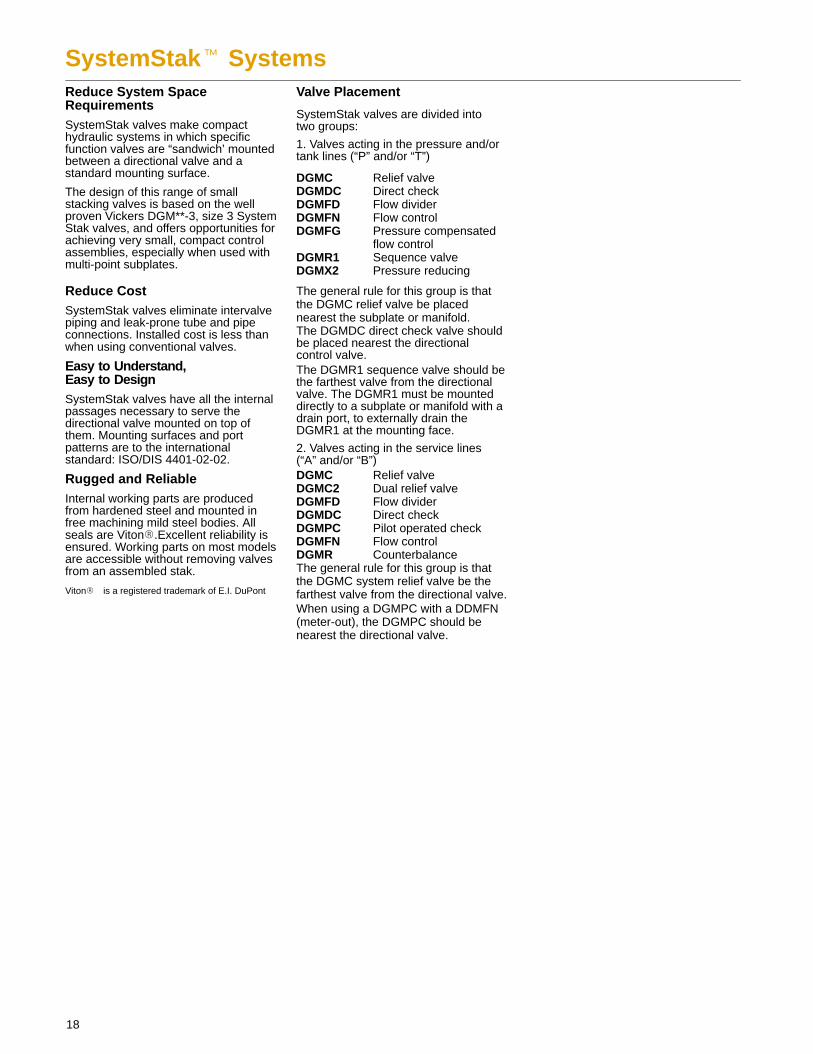
SystemStak� SystemsReduce System SpaceRequirementsSystemStak valves make compacthydraulic systems in which specificfunction valves are “sandwich’ mountedbetween a directional valve and astandard mounting surface.
The design of this range of smallstacking valves is based on the wellproven Vickers DGM**-3, size 3 SystemStak valves, and offers opportunities forachieving very small, compact controlassemblies, especially when used withmulti-point subplates.
Reduce CostSystemStak valves eliminate intervalvepiping and leak-prone tube and pipeconnections. Installed cost is less thanwhen using conventional valves.
Easy to Understand,Easy to DesignSystemStak valves have all the internalpassages necessary to serve thedirectional valve mounted on top ofthem. Mounting surfaces and portpatterns are to the internationalstandard: ISO/DIS 4401-02-02.
Rugged and ReliableInternal working parts are producedfrom hardened steel and mounted infree machining mild steel bodies. Allseals are Viton�.Excellent reliability isensured. Working parts on most modelsare accessible without removing valvesfrom an assembled stak.
Viton� is a registered trademark of E.I. DuPont
Valve Placement
SystemStak valves are divided into two groups:
1. Valves acting in the pressure and/ortank lines (“P” and/or “T”)
DGMC Relief valveDGMDC Direct checkDGMFD Flow dividerDGMFN Flow controlDGMFG Pressure compensated
flow controlDGMR1 Sequence valveDGMX2 Pressure reducing
The general rule for this group is thatthe DGMC relief valve be placednearest the subplate or manifold.The DGMDC direct check valve shouldbe placed nearest the directional control valve.The DGMR1 sequence valve should bethe farthest valve from the directionalvalve. The DGMR1 must be mounteddirectly to a subplate or manifold with adrain port, to externally drain theDGMR1 at the mounting face.
2. Valves acting in the service lines(“A” and/or “B”)DGMC Relief valveDGMC2 Dual relief valveDGMFD Flow dividerDGMDC Direct checkDGMPC Pilot operated checkDGMFN Flow controlDGMR CounterbalanceThe general rule for this group is thatthe DGMC system relief valve be thefarthest valve from the directional valve.When using a DGMPC with a DDMFN(meter-out), the DGMPC should benearest the directional valve.
19
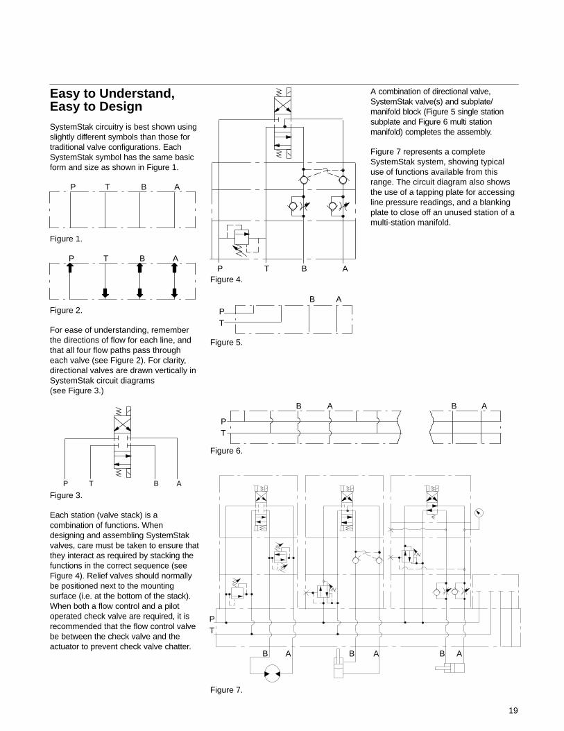
Easy to Understand,Easy to DesignSystemStak circuitry is best shown usingslightly different symbols than those fortraditional valve configurations. EachSystemStak symbol has the same basicform and size as shown in Figure 1.
P T B A
Figure 1.
P T B A
Figure 2.
For ease of understanding, rememberthe directions of flow for each line, andthat all four flow paths pass througheach valve (see Figure 2). For clarity,directional valves are drawn vertically inSystemStak circuit diagrams(see Figure 3.)
P T B A
Figure 3.
Each station (valve stack) is acombination of functions. Whendesigning and assembling SystemStakvalves, care must be taken to ensure thatthey interact as required by stacking thefunctions in the correct sequence (seeFigure 4). Relief valves should normallybe positioned next to the mountingsurface (i.e. at the bottom of the stack).When both a flow control and a pilotoperated check valve are required, it isrecommended that the flow control valvebe between the check valve and theactuator to prevent check valve chatter.
P T B AFigure 4.
PT
B A
Figure 5.
A combination of directional valve,SystemStak valve(s) and subplate/manifold block (Figure 5 single stationsubplate and Figure 6 multi stationmanifold) completes the assembly.
Figure 7 represents a completeSystemStak system, showing typicaluse of functions available from thisrange. The circuit diagram also showsthe use of a tapping plate for accessingline pressure readings, and a blankingplate to close off an unused station of amulti-station manifold.
PT
B A
Figure 6.
B A
Figure 7.
PT
B AB AB A
DGMC-2-PT-**
Typical Sectional View
P T B AP T B A
P T B AP T B A
Functional SymbolsDGMC-2-BA-**
DGMC-2-AT-**-BT-** DGMC-2-AB-**-BA-**
20
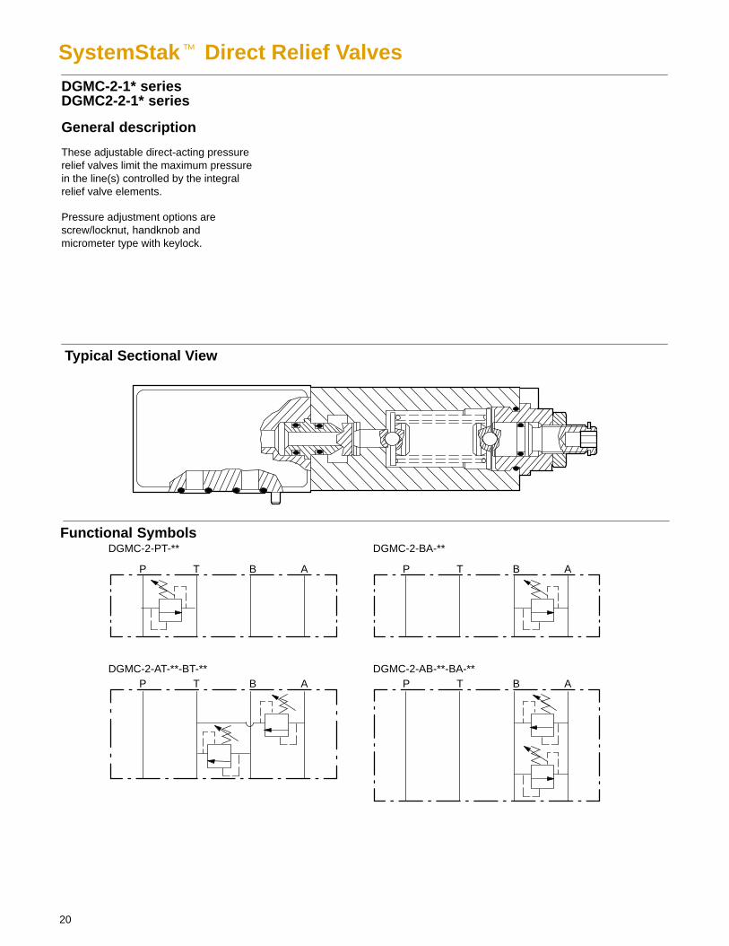
SystemStak� Direct Relief ValvesDGMC-2-1* seriesDGMC2-2-1* series
General description
These adjustable direct-acting pressurerelief valves limit the maximum pressurein the line(s) controlled by the integralrelief valve elements.
Pressure adjustment options arescrew/locknut, handknob andmicrometer type with keylock.
21
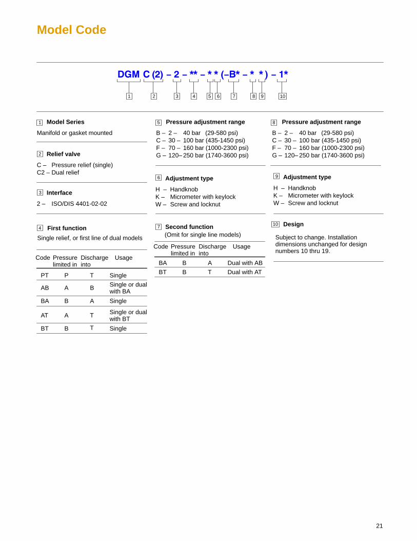
Model Code
3 4 5 876 91 2
1 Model Series
Manifold or gasket mounted
Interface
2 – ISO/DIS 4401-02-02
Adjustment type
H – HandknobK – Micrometer with keylockW – Screw and locknut
First function
Relief valve
C – Pressure relief (single)C2 – Dual relief
2
3
4 7
5
6
Pressure adjustment range
B – 2 – 40 bar (29-580 psi)C – 30 – 100 bar (435-1450 psi)F – 70 – 160 bar (1000-2300 psi)G – 120– 250 bar (1740-3600 psi)
Code Pressurelimited in
Dischargeinto
Usage
PT
AB
BA
AT
BT
Single
Single or dualwith BA
Single or dualwith BT
P
A
B
A
B
T
Single
Single
B
A
T
T
Second function
Code Pressurelimited in
Dischargeinto
Usage
BA
BT
Dual with AB
Dual with AT
B
B
A
T
(Omit for single line models) Single relief, or first line of dual models
10
Adjustment type
H – HandknobK – Micrometer with keylockW – Screw and locknut
Design
Subject to change. Installationdimensions unchanged for designnumbers 10 thru 19.
9
10
8 Pressure adjustment range
B – 2 – 40 bar (29-580 psi)C – 30 – 100 bar (435-1450 psi)F – 70 – 160 bar (1000-2300 psi)G – 120– 250 bar (1740-3600 psi)
22
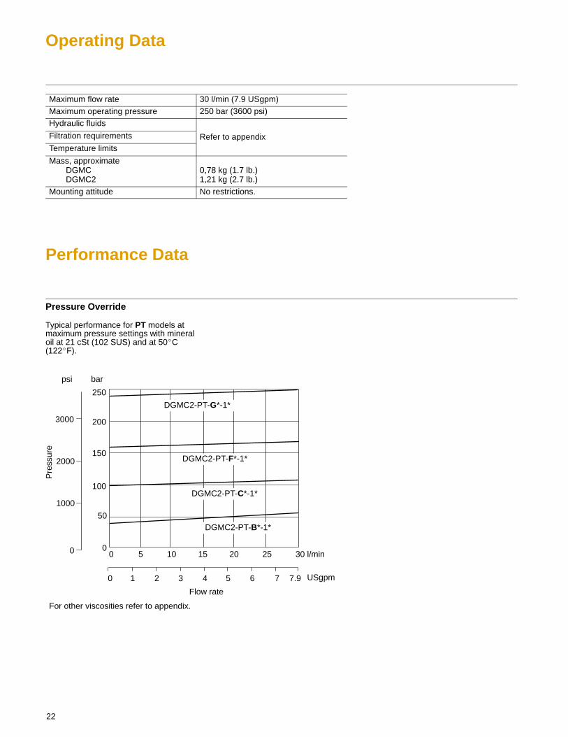
Operating Data
Maximum flow rate 30 l/min (7.9 USgpm)Maximum operating pressure 250 bar (3600 psi)Hydraulic fluids
Filtration requirements Refer to appendixTemperature limits
Mass, approximateDGMCDGMC2
0,78 kg (1.7 lb.)1,21 kg (2.7 lb.)
Mounting attitude No restrictions.
Performance Data
Pressure Override
Typical performance for PT models atmaximum pressure settings with mineraloil at 21 cSt (102 SUS) and at 50�C(122�F).
psi
l/min
USgpm
For other viscosities refer to appendix.
0
1000
2000
3000
Pre
ssur
e
0 1 2 3 4 5 6 7 7.9
Flow rate
5 10 15 20 25 30
DGMC2-PT-G*-1*
DGMC2-PT-F*-1*
DGMC2-PT-C*-1*
DGMC2-PT-B*-1*50
00
bar
250
200
150
100
23
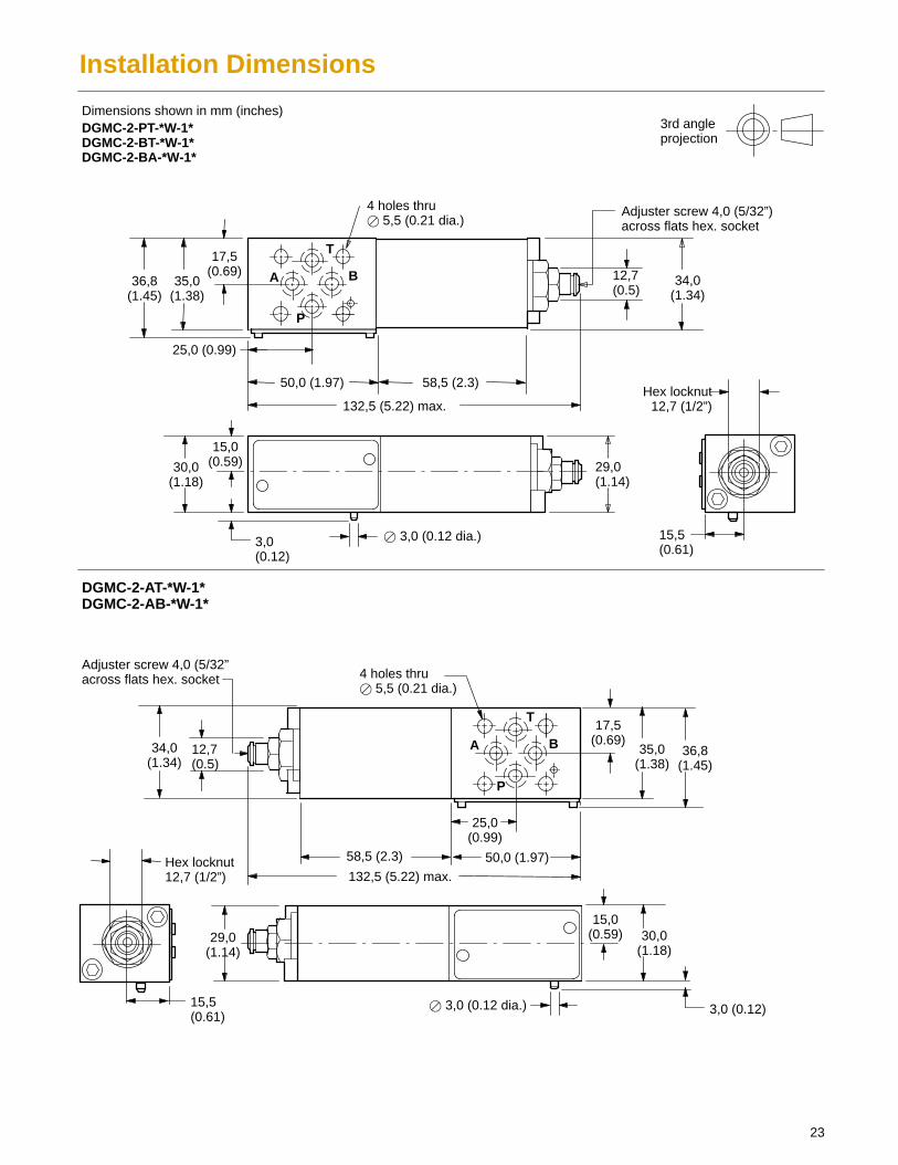
Installation Dimensions
29,0(1.14)
58,5 (2.3)
58,5 (2.3)
4 holes thru� 5,5 (0.21 dia.)
25,0 (0.99)
DGMC-2-PT-*W-1*DGMC-2-BT-*W-1*DGMC-2-BA-*W-1*
Dimensions shown in mm (inches)3rd angleprojection
4 holes thru� 5,5 (0.21 dia.)
50,0 (1.97)
132,5 (5.22) max.
17,5(0.69)
34,0(1.34)
36,8(1.45)
A B
P
T
Hex locknut12,7 (1/2”)
Adjuster screw 4,0 (5/32”)across flats hex. socket
30,0(1.18)
15,0(0.59)
3,0(0.12)
29,0(1.14)
� 3,0 (0.12 dia.) 15,5(0.61)
A B
P
T
15,5(0.61)
12,7(0.5)
35,0(1.38)
132,5 (5.22) max.
50,0 (1.97)
25,0(0.99)
17,5(0.69)
35,0(1.38)
36,8(1.45)
12,7(0.5)
34,0(1.34)
� 3,0 (0.12 dia.)
15,0(0.59) 30,0
(1.18)
3,0 (0.12)
Adjuster screw 4,0 (5/32”across flats hex. socket
DGMC-2-AT-*W-1*DGMC-2-AB-*W-1*
Hex locknut12,7 (1/2”)
24
58,5 (2.3)
DGMC2-2-AB-*W-BA-*W-1*DGMC2-2-AT-*W-BT-*W-1*
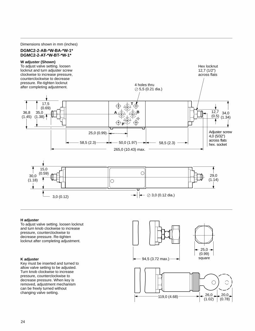
Dimensions shown in mm (inches)
34,0(1.34)
12,7(0.5)
29,0(1.14)
25,0 (0.99)
50,0 (1.97)
265,0 (10.43) max.
58,5 (2.3)
17,5(0.69)
36,8(1.45)
35,0(1.38)
4 holes thru� 5,5 (0.21 dia.)
A B
P
T
Hex locknut12,7 (1/2”)across flats
Adjuster screw 4,0 (5/32”)across flatshex. socket
15,0(0.59)
30,0(1.18)
3,0 (0.12) � 3,0 (0.12 dia.)
94,5 (3.72 max.)
25,0(0.99)square
20,0(0.78)
26,0(1.02)
119,0 (4.68)
W adjuster (Shown)To adjust valve setting. loosenlocknut and turn adjuster screwclockwise to increase pressure,counterclockwise to decreasepressure. Re-tighten locknutafter completing adjustment.
H adjuster To adjust valve setting. loosen locknutand turn knob clockwise to increasepressure, counterclockwise todecrease pressure. Re-tightenlocknut after completing adjustment.
K adjuster Key must be inserted and turned toallow valve setting to be adjusted.Turn knob clockwise to increasepressure, counterclockwise todecrease pressure. When key isremoved, adjustment mechanismcan be freely turned withoutchanging valve setting.
Typical Sectional View
25
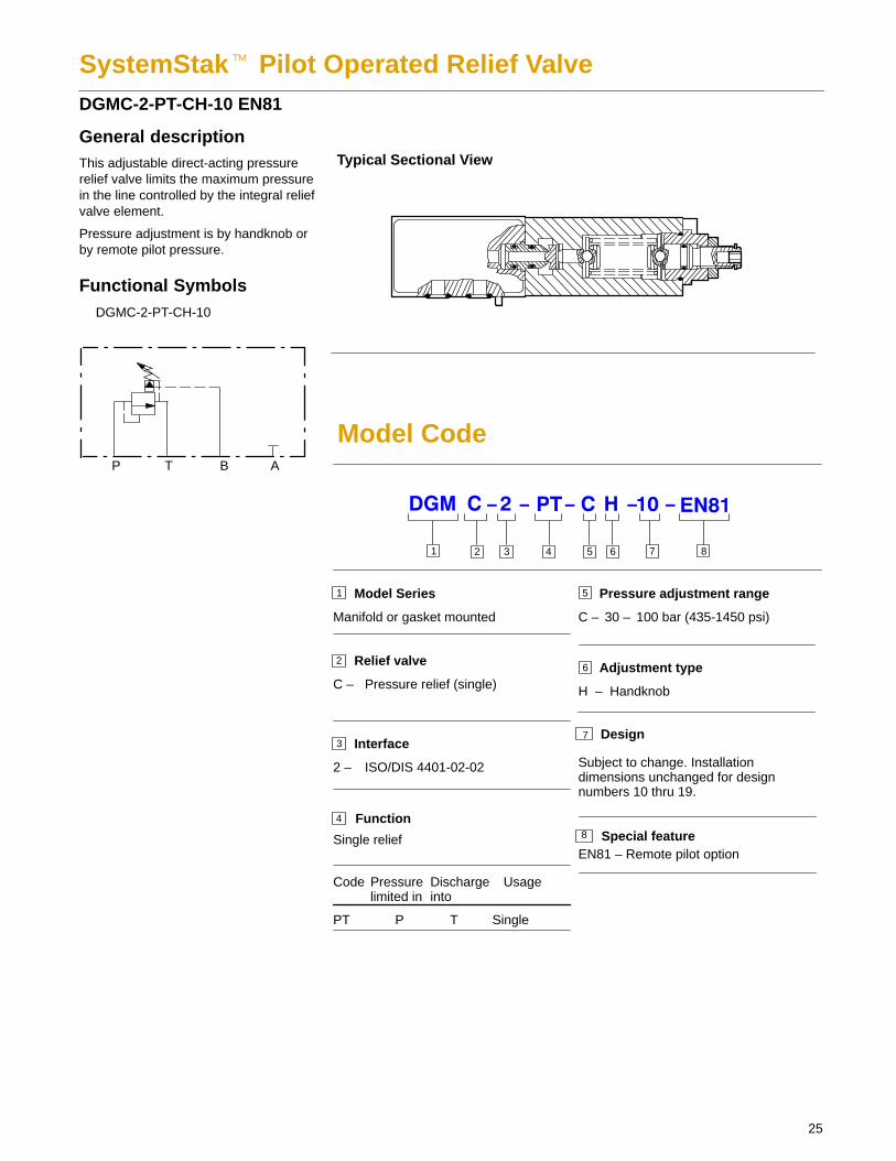
SystemStak� Pilot Operated Relief Valve DGMC-2-PT-CH-10 EN81
General descriptionThis adjustable direct-acting pressurerelief valve limits the maximum pressurein the line controlled by the integral reliefvalve element.
Pressure adjustment is by handknob orby remote pilot pressure.
Functional Symbols
P T B A
DGMC-2-PT-CH-10
Model Code
3 4 5 61 2
1 Model Series
Manifold or gasket mounted
Interface
2 – ISO/DIS 4401-02-02
Relief valve
C – Pressure relief (single)
2
3
Function4
Code Pressurelimited in
Dischargeinto
Usage
PT SingleP T
Single relief
5 Pressure adjustment range
C – 30 – 100 bar (435-1450 psi)
Adjustment type
H – Handknob
6
Design
Subject to change. Installationdimensions unchanged for designnumbers 10 thru 19.
7
8 Special featureEN81 – Remote pilot option
7 8
26
Operating Data
Maximum flow rate 30 l/min (7.9 USgpm)Maximum operating pressure 250 bar (3600 psi)Hydraulic fluids
Filtration requirements Refer to appendixTemperature limits
Mass, approximate 0,78 kg (1.7 lb.)Mounting attitude No restrictions.
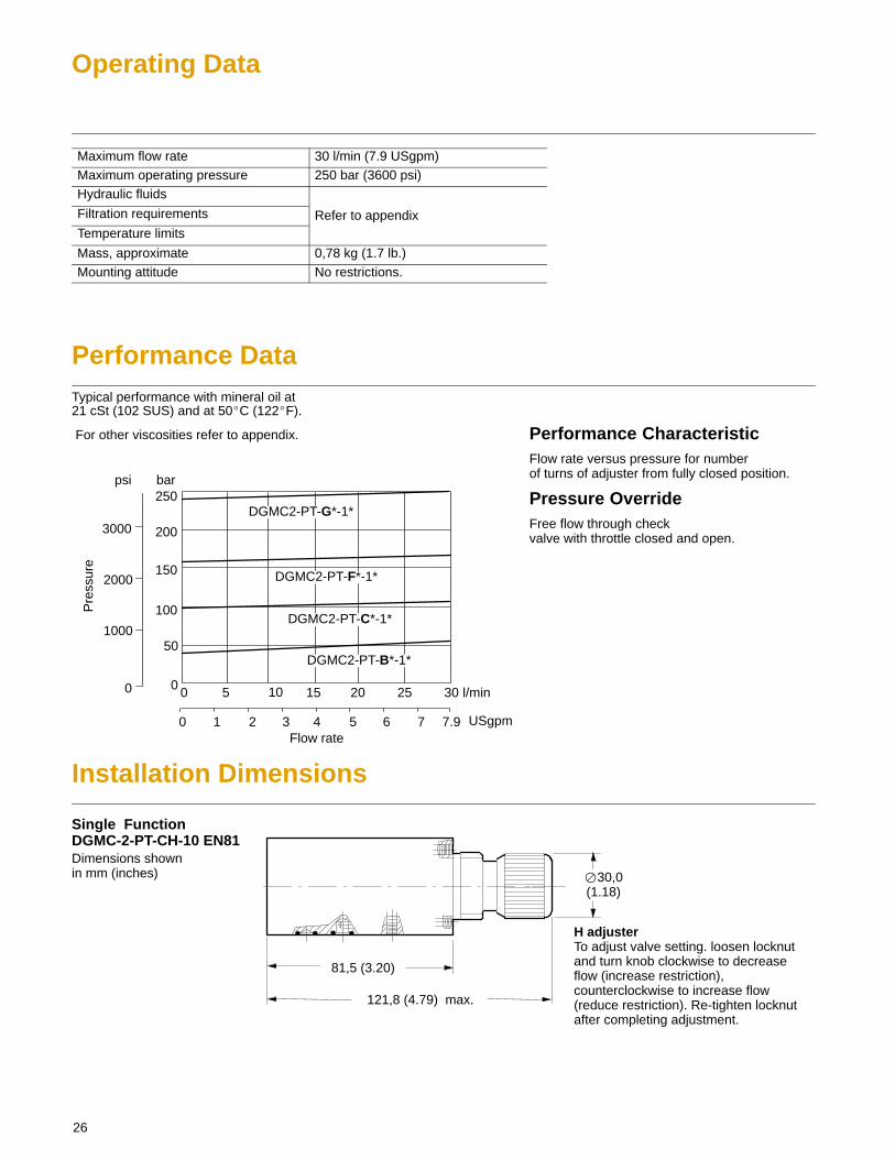
Performance DataTypical performance with mineral oil at21 cSt (102 SUS) and at 50�C (122�F).
For other viscosities refer to appendix.
psi
l/min
USgpm
0
1000
2000
3000
Pre
ssur
e
0 1 2 4 5 6 7 7.9Flow rate
5 15 20 25 30
DGMC2-PT-G*-1*
DGMC2-PT-F*-1*
DGMC2-PT-C*-1*
DGMC2-PT-B*-1*50
0
bar250
200
150
100
0
3
10
Performance CharacteristicFlow rate versus pressure for number of turns of adjuster from fully closed position.
Pressure OverrideFree flow through check valve with throttle closed and open.
Installation Dimensions
Single FunctionDGMC-2-PT-CH-10 EN81Dimensions shownin mm (inches) �30,0
(1.18)
H adjuster To adjust valve setting. loosen locknutand turn knob clockwise to decreaseflow (increase restriction),counterclockwise to increase flow(reduce restriction). Re-tighten locknutafter completing adjustment.
81,5 (3.20)
121,8 (4.79) max.
Typical Sectional Views
Functional Symbols
P T B A
P T B A P T B A
P T B A
P T B A
DGMR-2-TB
DGMR1-2-PP
DGMX2-2-PA
DGMX2-2-PB
DGMX2-2-PP
DGMX2-2-P*-*W-10
DGMR1-2-PP-*W-10
27
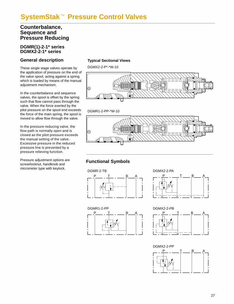
SystemStak� Pressure Control ValvesCounterbalance,Sequence andPressure Reducing
DGMR(1)-2-1* seriesDGMX2-2-1* series
General description
These single stage valves operate bythe application of pressure on the end ofthe valve spool, acting against a springwhich is loaded by means of the manualadjustment mechanism.
In the counterbalance and sequencevalves, the spool is offset by the springsuch that flow cannot pass through thevalve. When the force exerted by thepilot pressure on the spool end exceedsthe force of the main spring, the spool ismoved to allow flow through the valve.
In the pressure reducing valve, theflow path is normally open and isclosed as the pilot pressure exceedsthe manual setting of the valve.Excessive pressure in the reducedpressure line is prevented by apressure relieving function.
Pressure adjustment options arescrew/locknut, handknob andmicrometer type with keylock.
28
Model Code
3 4 5 761 2
1 Model Series
Manifold or gasket mounted
Interface
2 – ISO/DIS 4401-02-02
Adjustment type
H – HandknobK – Micrometer with keylockW – Screw and locknut
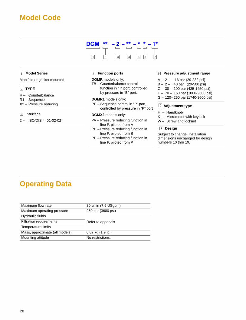
Function ports
TYPE
R – CounterbalanceR1– SequenceX2 – Pressure reducing
2
3
4
6
DGMR models only:
Design
Subject to change. Installationdimensions unchanged for designnumbers 10 thru 19.
TB – Counterbalance control function in “T” port, controlledby pressure in “B” port.
DGMR1 models only:PP – Sequence control in “P” port,
controlled by pressure in “P” port
DGMX2 models only:
PA – Pressure reducing function in line P, piloted from A
PB – Pressure reducing function in line P, piloted from B
PP – Pressure reducing function in line P, piloted from P
7
5 Pressure adjustment range
A – 2 – 16 bar (29-232 psi)B – 2 – 40 bar (29-580 psi)C – 30 – 100 bar (435-1450 psi)F – 70 – 160 bar (1000-2300 psi)G – 120– 250 bar (1740-3600 psi)
Operating Data
Maximum flow rate 30 l/min (7.9 USgpm)Maximum operating pressure 250 bar (3600 psi)Hydraulic fluids
Filtration requirements Refer to appendixTemperature limits
Mass, approximate (all models) 0,87 kg (1.9 lb.)Mounting attitude No restrictions.
29
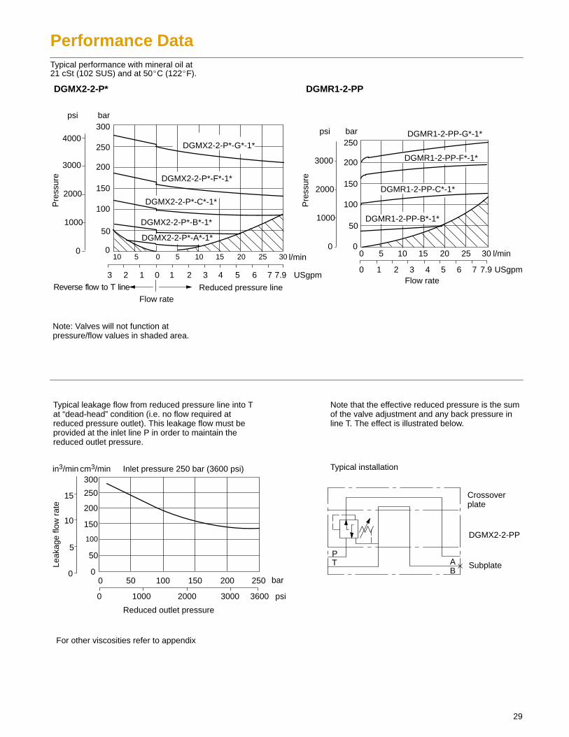
Performance DataTypical performance with mineral oil at21 cSt (102 SUS) and at 50�C (122�F).
2000
Pre
ssur
e
psi bar
l/min
USgpm
Note: Valves will not function atpressure/flow values in shaded area.
DGMR1-2-PPDGMX2-2-P*
0
50
100
150
200
250
0
1000
3000
0 1 2 3 4 5 6 7 7.9
0 5 10 15 20 25 30l/min0 5 10 15 20 25 30510
3 2 1 0 1 2 3 4 5 6 7 7.9 USgpm
bar
0
50
100
150
200
250
300
0
1000
2000
3000
4000
psi
Flow rate
Flow rateReverse flow to T line Reduced pressure line
Pre
ssur
e
0
50
100
150
200
250
300
0
5
10
15
Leak
age
flow
rat
e
Reduced outlet pressure
Inlet pressure 250 bar (3600 psi)
0 50 100 150 200 250 bar
10000 2000 3000 3600 psi
in3/min cm3/min
For other viscosities refer to appendix
Typical leakage flow from reduced pressure line into Tat “dead-head” condition (i.e. no flow required atreduced pressure outlet). This leakage flow must beprovided at the inlet line P in order to maintain thereduced outlet pressure.
Note that the effective reduced pressure is the sumof the valve adjustment and any back pressure inline T. The effect is illustrated below.
DGMR1-2-PP-F*-1*
DGMR1-2-PP-G*-1*
DGMR1-2-PP-C*-1*
DGMR1-2-PP-B*-1*
DGMX2-2-P*-G*-1*
DGMX2-2-P*-F*-1*
DGMX2-2-P*-C*-1*
DGMX2-2-P*-B*-1*
DGMX2-2-P*-A*-1*
Typical installation
Crossoverplate
DGMX2-2-PP
SubplateAB
PT
30
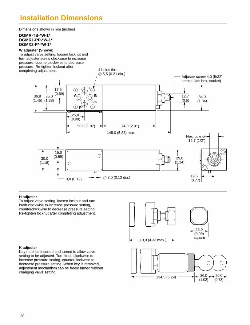
Installation Dimensions
110,0 (4.33 max.)
74,0 (2.91)
DGMR-TB-*W-1*DGMR1-PP-*W-1*DGMX2-P*-*W-1*
Dimensions shown in mm (inches)
34,0(1.34)
12,7(0.5)
29,0(1.14)
25,0(0.99)
50,0 (1.97)
148,0 (5.83) max.
17,5(0.69)
36,8(1.45)
35,0(1.38)
4 holes thru� 5,5 (0.21 dia.)
A B
P
T
15,0(0.59)30,0
(1.18)
3,0 (0.12) � 3,0 (0.12 dia.)
25,0(0.99)
20,0(0.78)
26,0(1.02)
134,5 (5.29)
W adjuster (Shown)To adjust valve setting. loosen locknut andturn adjuster screw clockwise to increasepressure, counterclockwise to decreasepressure. Re-tighten locknut aftercompleting adjustment.
H adjuster To adjust valve setting. loosen locknut and turnknob clockwise to increase pressure setting,counterclockwise to decrease pressure setting.Re-tighten locknut after completing adjustment.
K adjuster Key must be inserted and turned to allow valvesetting to be adjusted. Turn knob clockwise toincrease pressure setting, counterclockwise todecrease pressure setting. When key is removed,adjustment mechanism can be freely turned withoutchanging valve setting.
19,5(0.77)
square
Adjuster screw 4,0 (5/32”across flats hex. socket)
Hex locknut12,7 (1/2”)

Typical Sectional Views
DGMDC-2-Y-P*-1* DGMDC-2-X-T*-1*
31
SystemStak� Direct Check ValvesDGMDC-2, 1* series
General description
These valves allow free flow in onedirection in the line in which the checkvalve element is located, i.e. either lineP or line T. Flow in the oppositedirection is not possible.
Functional Symbols
P T B A
DGMDC-2-Y-P*
P T B A
DGMDC-2-X-T*
3 5 61 2
1 Model Series
Manifold or gasket mounted
Interface
2 – ISO/DIS 4401-02-02
Direction of flow andcheck location
Type
DC –Direct check
2
3
4
5
6
Check valve cracking pressure
K – 1 bar (14.5 psi)M – 2,5 bar (36 psi)
Design
Subject to change. Installationdimensions unchanged for designnumbers 10 thru 19.
X-T – Free flow away from actuator, in line T
4
Y-P – Free flow towards actuator, in line P
Model Code
32
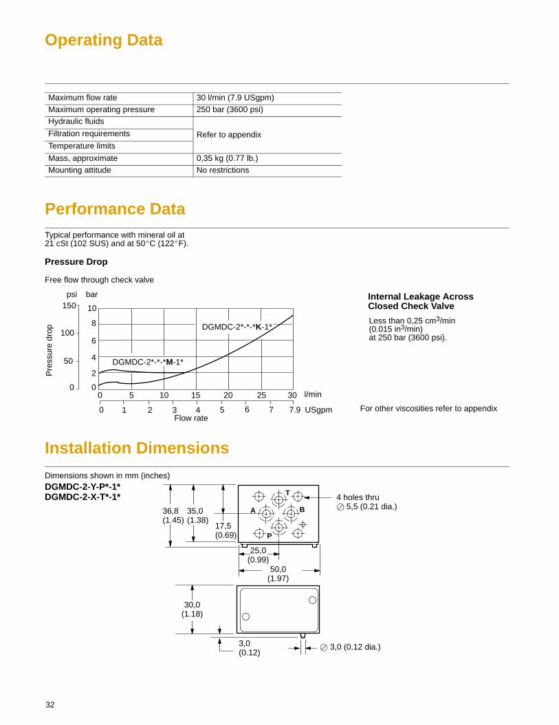
Operating Data
Maximum flow rate 30 l/min (7.9 USgpm)Maximum operating pressure 250 bar (3600 psi)Hydraulic fluids
Filtration requirements Refer to appendixTemperature limits
Mass, approximate 0,35 kg (0.77 lb.)Mounting attitude No restrictions
Performance DataTypical performance with mineral oil at21 cSt (102 SUS) and at 50�C (122�F).
Pressure Drop
Free flow through check valve
DGMDC-2*-*-*K-1*
Pre
ssur
e dr
op
psi bar
l/min0
50
100
150
0 1 2 3 4 5 6 7
0 5 10 15 20 25 30
Flow rateFor other viscosities refer to appendix7.9
2
4
6
8
10
0
USgpm
DGMDC-2*-*-*M-1*
Internal Leakage AcrossClosed Check Valve
Less than 0,25 cm3/min(0.015 in3/min) at 250 bar (3600 psi).
Installation Dimensions
A
DGMDC-2-Y-P*-1*DGMDC-2-X-T*-1*
Dimensions shown in mm (inches)
25,0(0.99)
50,0(1.97)
17,5(0.69)
36,8(1.45)
35,0(1.38)
4 holes thru� 5,5 (0.21 dia.)B
P
T
30,0(1.18)
3,0(0.12)
� 3,0 (0.12 dia.)
Functional Symbols
P T B A
DGMPC-2-AB*-BA*-1*
P T B A
DGMPC-2-BA*-1*
P T B A
DGMPC-2-AB*-1*
B1 A1
B1 A1
B1 A1
33
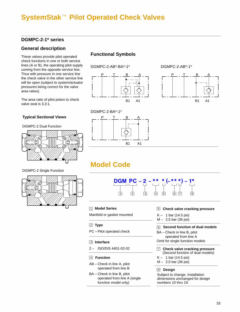
SystemStak� Pilot Operated Check Valves
DGMPC-2-1* series
General description
These valves provide pilot operatedcheck functions in one or both servicelines (A or B), the operating pilot supplycoming from the opposite service line.Thus with pressure in one service linethe check valve in the other service linewill be open (subject to system/actuatorpressures being correct for the valvearea ratios).
The area ratio of pilot piston to checkvalve seat is 3,3:1.
Typical Sectional Views
DGMPC-2 Dual Function
DGMPC-2 Single Function
3 5 61 2
1 Model Series
Manifold or gasket mounted
Interface
2 – ISO/DIS 4401-02-02
Function
Type
PC – Pilot operated check
2
3
4
5 Check valve cracking pressure
K – 1 bar (14.5 psi)M – 2,5 bar (36 psi)
DesignSubject to change. Installationdimensions unchanged for designnumbers 10 thru 19.
AB – Check in line A, pilot operated from line B
4
Model Code
7 8
BA – Check in line B, pilot operated from line A (single function model only)
Second function of dual models
BA – Check in line B, pilot operated from line A
Omit for single function models
Check valve cracking pressure
K – 1 bar (14.5 psi)M – 2,5 bar (36 psi)
(Second function of dual models)
6
7
8
34
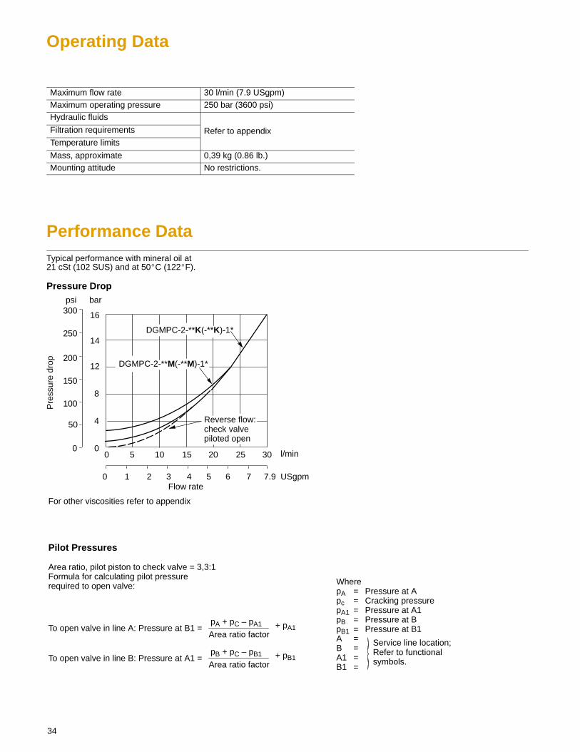
Operating Data
Maximum flow rate 30 l/min (7.9 USgpm)Maximum operating pressure 250 bar (3600 psi)Hydraulic fluids
Filtration requirements Refer to appendixTemperature limits
Mass, approximate 0,39 kg (0.86 lb.)Mounting attitude No restrictions.
Performance DataTypical performance with mineral oil at21 cSt (102 SUS) and at 50�C (122�F).
Pressure Drop
Pre
ssur
e dr
op
psi bar
l/min0
50
100
150
0 1 2 3 4 5 6 7
0 5 10 15 20 25 30
Flow rate
For other viscosities refer to appendix
7.9
4
8
12
0
USgpm
14
16
250
200
300
DGMPC-2-**K(-**K)-1*
DGMPC-2-**M(-**M)-1*
Reverse flow:check valvepiloted open
Pilot Pressures
Area ratio, pilot piston to check valve = 3,3:1Formula for calculating pilot pressurerequired to open valve:
To open valve in line A: Pressure at B1 =pA + pC – pA1
Area ratio factor+ pA1
To open valve in line B: Pressure at A1 =pB + pC – pB1
Area ratio factor+ pB1
WherepA = Pressure at Apc = Cracking pressurepA1 = Pressure at A1pB = Pressure at BpB1 = Pressure at B1A =B =A1 =B1 =
Service line location;Refer to functionalsymbols.
35
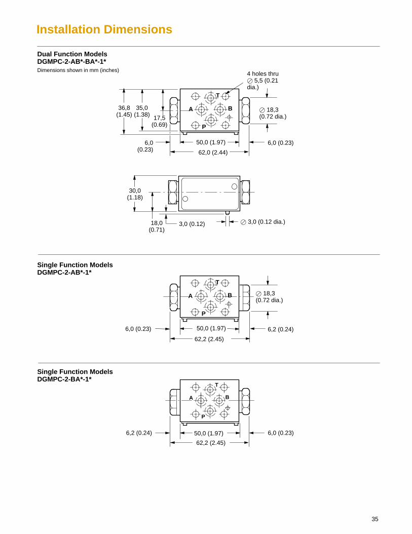
Installation Dimensions
50,0 (1.97)
50,0 (1.97)
Dual Function ModelsDGMPC-2-AB*-BA*-1*Dimensions shown in mm (inches)
62,0 (2.44)
17,5(0.69)
36,8(1.45)
35,0(1.38)
30,0(1.18)
3,0 (0.12) � 3,0 (0.12 dia.)
4 holes thru� 5,5 (0.21dia.)
50,0 (1.97) 6,0 (0.23)
18,0(0.71)
62,2 (2.45)
6,2 (0.24)
� 18,3(0.72 dia.)
6,0 (0.23)
62,2 (2.45)
6,2 (0.24) 6,0 (0.23)
Single Function ModelsDGMPC-2-AB*-1*
Single Function ModelsDGMPC-2-BA*-1*
� 18,3(0.72 dia.)
6,0(0.23)
A B
P
T
A B
P
T
A B
P
T
Typical Sectional View
36
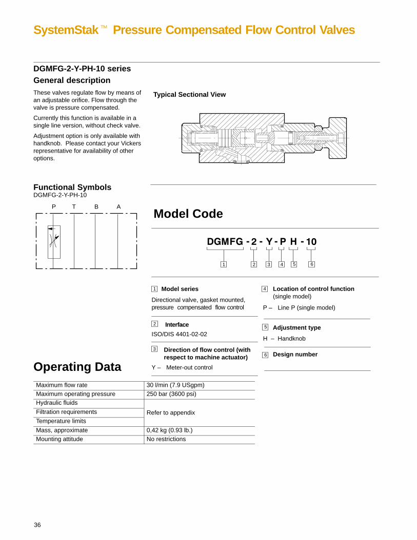
SystemStak� Pressure Compensated Flow Control Valves
DGMFG-2-Y-PH-10 seriesGeneral descriptionThese valves regulate flow by means ofan adjustable orifice. Flow through thevalve is pressure compensated.
Currently this function is available in asingle line version, without check valve.
Adjustment option is only available withhandknob. Please contact your Vickersrepresentative for availability of otheroptions.
P T B A
DGMFG-2-Y-PH-10Functional Symbols
Operating DataMaximum flow rate 30 l/min (7.9 USgpm)Maximum operating pressure 250 bar (3600 psi)Hydraulic fluids
Filtration requirements Refer to appendixTemperature limits
Mass, approximate 0,42 kg (0.93 lb.)Mounting attitude No restrictions
Adjustment type
H – Handknob
P – Line P (single model)
31
1 Model series
Directional valve, gasket mounted,pressure compensated flow control
Direction of flow control (withrespect to machine actuator)
2
4
4
Model Code
Location of control function(single model)
Y – Meter-out control
2
Interface
ISO/DIS 4401-02-02
3
5 6
5
6 Design number
37
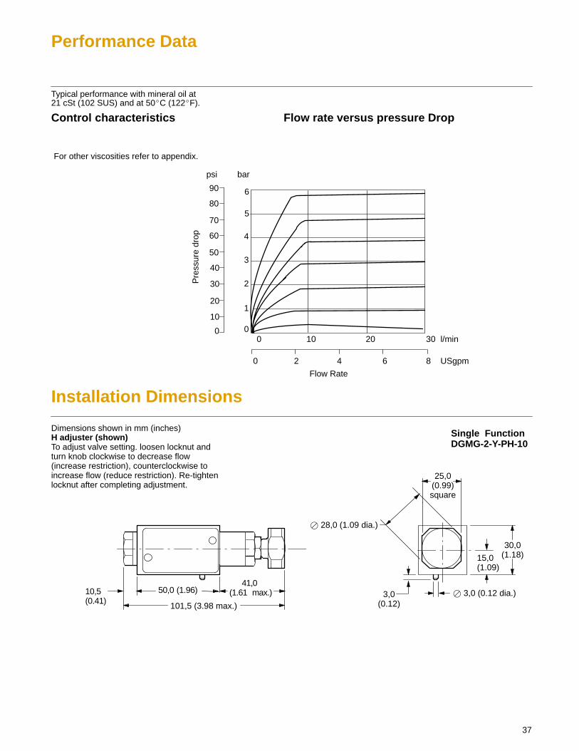
Performance Data
Typical performance with mineral oil at21 cSt (102 SUS) and at 50�C (122�F).
Control characteristics Flow rate versus pressure Drop
0
1
80
For other viscosities refer to appendix.
psi bar
90
70
60
50
30
20
10
0
6
5
4
3
2
010 20 30
0 2 4 6 8
Pre
ssur
e dr
op
l/min
USgpm
Flow Rate
40
Installation Dimensions
50,0 (1.96)
Dimensions shown in mm (inches) Single FunctionDGMG-2-Y-PH-10
H adjuster (shown) To adjust valve setting. loosen locknut andturn knob clockwise to decrease flow(increase restriction), counterclockwise toincrease flow (reduce restriction). Re-tightenlocknut after completing adjustment.
41,0 (1.61 max.)
30,0(1.18)
3,0(0.12)
� 28,0 (1.09 dia.)
101,5 (3.98 max.)
10,5(0.41)
25,0(0.99)square
15,0(1.09)
� 3,0 (0.12 dia.)
Typical Sectional View
38
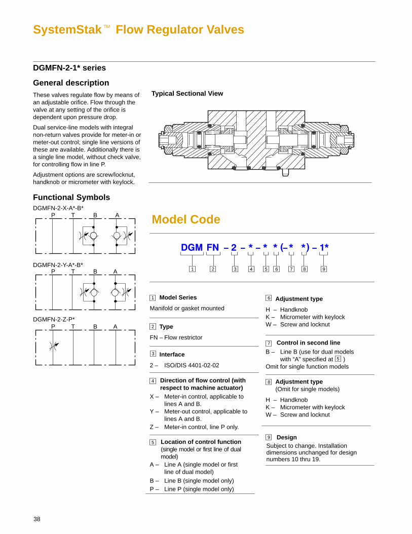
SystemStak� Flow Regulator Valves
DGMFN-2-1* series
General descriptionThese valves regulate flow by means ofan adjustable orifice. Flow through thevalve at any setting of the orifice isdependent upon pressure drop.
Dual service-line models with integralnon-return valves provide for meter-in ormeter-out control; single line versions ofthese are available. Additionally there isa single line model, without check valve,for controlling flow in line P.
Adjustment options are screw/locknut,handknob or micrometer with keylock.
P T B ADGMFN-2-X-A*-B*
P T B A
P T B A
Functional Symbols
DGMFN-2-Y-A*-B*
DGMFN-2-Z-P*
3 5 61 2
1 Model Series
Manifold or gasket mounted
Interface
2 – ISO/DIS 4401-02-02
Direction of flow control (withrespect to machine actuator)
Type
FN – Flow restrictor
2
3
4
DesignSubject to change. Installationdimensions unchanged for designnumbers 10 thru 19.
X – Meter-in control, applicable tolines A and B.
4
Model Code
7 9
Y – Meter-out control, applicable tolines A and B.
Control in second line
B – Line B (use for dual models with “A” specified at )
Omit for single function models
7
9
8
Z – Meter-in control, line P only.
Location of control function(single model or first line of dualmodel)
5
A – Line A (single model or first line of dual model)
B – Line B (single model only)P – Line P (single model only)
Adjustment type
H – HandknobK – Micrometer with keylockW – Screw and locknut
6
5
Adjustment type(Omit for single models)
H – HandknobK – Micrometer with keylockW – Screw and locknut
8
39
Operating Data
Maximum flow rate 30 l/min (7.9 USgpm)Maximum operating pressure 250 bar (3600 psi)Hydraulic fluids
Filtration requirements Refer to appendixTemperature limits
Mass, approximate 0,42 kg (0.92 lb.)Mounting attitude No restrictions
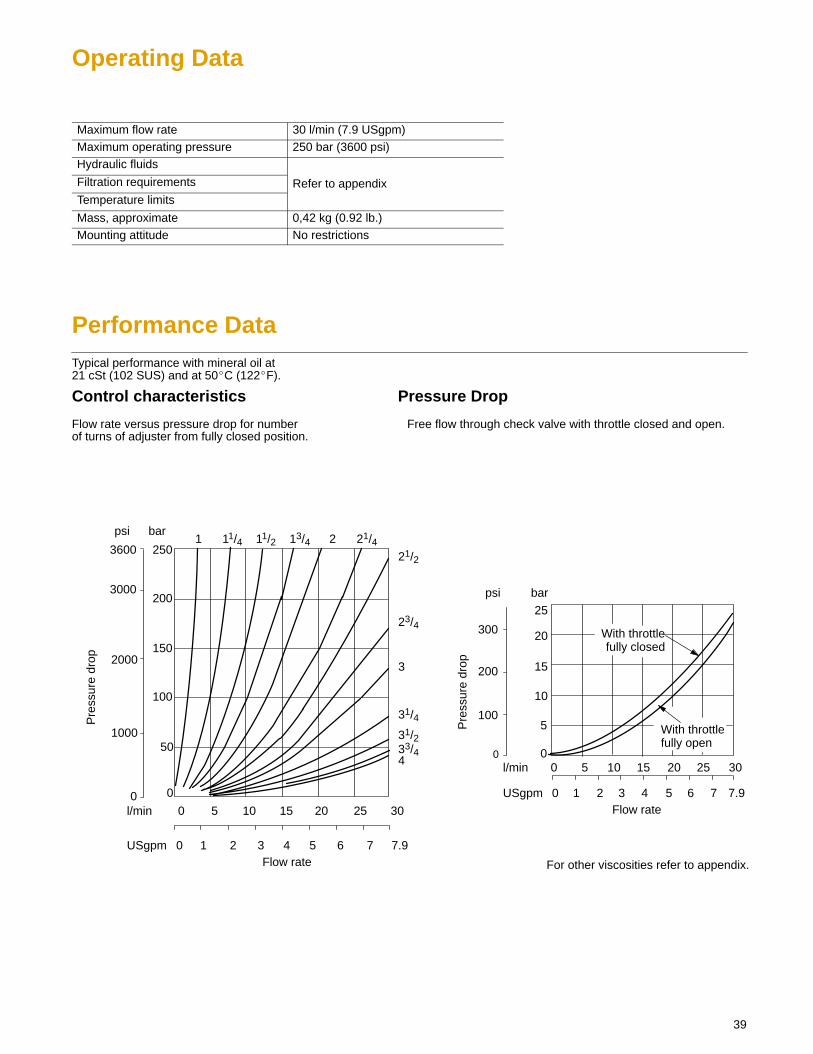
Performance DataTypical performance with mineral oil at21 cSt (102 SUS) and at 50�C (122�F).
Control characteristics Pressure Drop
Flow rate versus pressure drop for number Free flow through check valve with throttle closed and open.of turns of adjuster from fully closed position.
With throttlefully open
For other viscosities refer to appendix.
psi bar
0
5
10
15
20
25
200
0
100
300
5 10 15 20 25 30l/min 0
0 1 2 3 4 5 6 7 7.9USgpm
With throttlefully closed
Pre
ssur
e dr
op
Flow rate
psi bar
250
200
150
100
50
00
1000
2000
3000
36001 211/4 11/2 13/4 21/4
21/2
23/4
3
31/4
31/233/44
0 1 2 3 4 5 6 7 7.9
5 10 15 20 25 30l/min
USgpmFlow rate
0
Pre
ssur
e dr
op
40
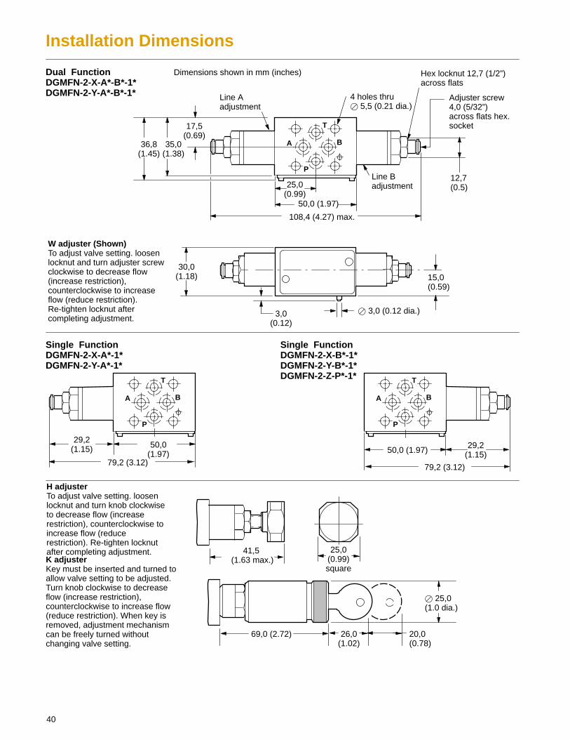
Installation Dimensions
41,5 (1.63 max.)
79,2 (3.12)
25,0(0.99)square
25,0(0.99)
Dual FunctionDGMFN-2-X-A*-B*-1*DGMFN-2-Y-A*-B*-1*
Dimensions shown in mm (inches)
4 holes thru� 5,5 (0.21 dia.)
50,0 (1.97)
108,4 (4.27) max.
17,5(0.69)
36,8(1.45)
Hex locknut 12,7 (1/2”)across flats
30,0(1.18)
3,0(0.12)
� 3,0 (0.12 dia.)
12,7(0.5)
35,0(1.38)
15,0(0.59)
Line Aadjustment
Line Badjustment
Single FunctionDGMFN-2-X-A*-1*DGMFN-2-Y-A*-1*
Single FunctionDGMFN-2-X-B*-1*DGMFN-2-Y-B*-1*DGMFN-2-Z-P*-1*
29,2(1.15) 50,0
(1.97)29,2
(1.15)50,0 (1.97)
79,2 (3.12)
W adjuster (Shown)To adjust valve setting. loosenlocknut and turn adjuster screwclockwise to decrease flow(increase restriction),counterclockwise to increaseflow (reduce restriction).Re-tighten locknut aftercompleting adjustment.
H adjuster To adjust valve setting. loosenlocknut and turn knob clockwiseto decrease flow (increaserestriction), counterclockwise toincrease flow (reducerestriction). Re-tighten locknutafter completing adjustment.K adjuster Key must be inserted and turned toallow valve setting to be adjusted.Turn knob clockwise to decreaseflow (increase restriction),counterclockwise to increase flow(reduce restriction). When key isremoved, adjustment mechanismcan be freely turned withoutchanging valve setting.
20,0(0.78)
26,0(1.02)
69,0 (2.72)
� 25,0(1.0 dia.)
Adjuster screw4,0 (5/32”)across flats hex.socket
A B
P
T
A B
P
T
A B
P
T
Typical Sectional View
41
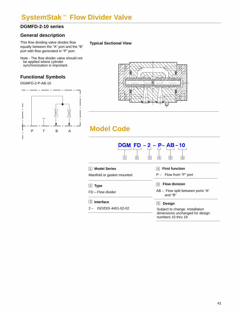
SystemStak� Flow Divider Valve DGMFD-2-10 series
General descriptionThis flow dividing valve divides flowequally between the “A” port and the “B”port with flow generated in “P” port.
Note - The flow divider valve should notbe applied where cylindersynchronization is important.
P T B A
DGMFD-2-P-AB-10
Functional Symbols
3 51 2
1 Model Series
Manifold or gasket mounted
Interface
2 – ISO/DIS 4401-02-02
First function
Type
FD – Flow divider
2
3
4
Design
Subject to change. Installationdimensions unchanged for designnumbers 10 thru 19.
P – Flow from “P” port
4
Model Code
Flow division5
AB – Flow split between ports “A” and “B”
6
6
42
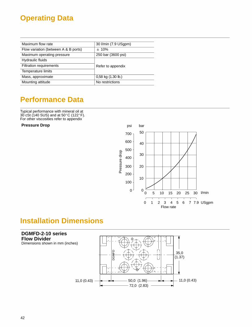
Operating Data
Maximum flow rate 30 l/min (7.9 USgpm)Flow variation (between A & B ports) � 10%Maximum operating pressure 250 bar (3600 psi)Hydraulic fluids
Filtration requirements Refer to appendixTemperature limits
Mass, approximate 0,58 kg (1.30 lb.)Mounting attitude No restrictions
Performance DataTypical performance with mineral oil at30 cSt (140 SUS) and at 50�C (122�F).For other viscosities refer to appendix
Pre
ssur
e dr
op
psi bar
l/min0
0 1 2 3 4 5 6 7
0 5 10 15 20 25 30
Flow rate7.9
10
20
30
0
USgpm
40
50700
Pressure Drop
600
500
400
300
200
100
Installation Dimensions
DG
MF
D
72,0 (2.83)50,0 (1.96) 11,0 (0.43)11,0 (0.43)
35,0(1.37)
Dimensions shown in mm (inches)
DGMFD-2-10 seriesFlow Divider
43
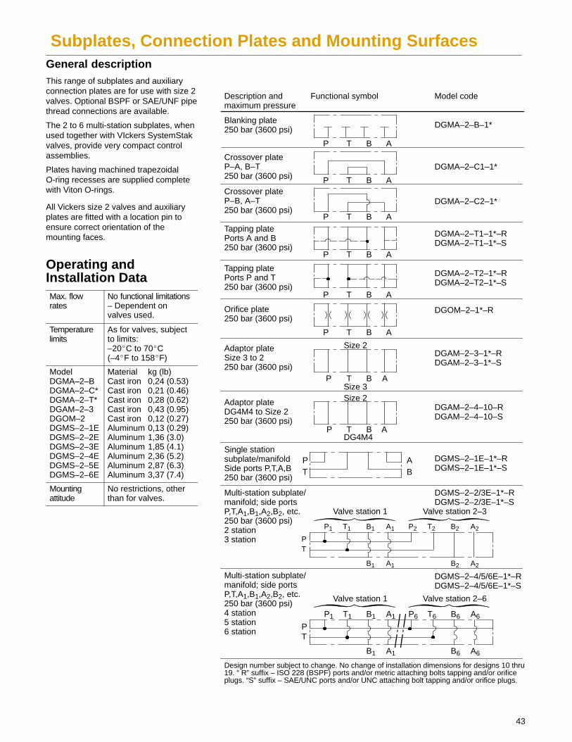
Subplates, Connection Plates and Mounting SurfacesGeneral descriptionThis range of subplates and auxiliaryconnection plates are for use with size 2valves. Optional BSPF or SAE/UNF pipethread connections are available.
The 2 to 6 multi-station subplates, whenused together with VIckers SystemStakvalves, provide very compact controlassemblies.
Plates having machined trapezoidalO-ring recesses are supplied completewith Viton O-rings.
All Vickers size 2 valves and auxiliaryplates are fitted with a location pin toensure correct orientation of themounting faces.
Operating andInstallation DataMax. flowrates
No functional limitations– Dependent onvalves used.
Temperature limits
As for valves, subjectto limits:–20�C to 70�C(–4�F to 158�F)
ModelDGMA–2–BDGMA–2–C*DGMA–2–T*DGAM–2–3DGOM–2DGMS–2–1EDGMS–2–2EDGMS–2–3EDGMS–2–4EDGMS–2–5EDGMS–2–6E
Material kg (lb)Cast iron 0,24 (0.53)Cast iron 0,21 (0.46)Cast iron 0,28 (0.62)Cast iron 0,43 (0.95)Cast iron 0,12 (0.27)Aluminum 0,13 (0.29)Aluminum 1,36 (3.0)Aluminum 1,85 (4.1)Aluminum 2,36 (5.2)Aluminum 2,87 (6.3)Aluminum 3,37 (7.4)
Mounting attitude
No restrictions, otherthan for valves.
Description andmaximum pressure
Functional symbol Model code
Blanking plate250 bar (3600 psi)
P T B A
DGMA–2–B–1*
Crossover plateP–A, B–T250 bar (3600 psi) P T B A
DGMA–2–C1–1*
Crossover plateP–B, A–T250 bar (3600 psi)
P T B A
DGMA–2–C2–1*
Tapping platePorts A and B250 bar (3600 psi)
P T B A
DGMA–2–T1–1*–RDGMA–2–T1–1*–S
Tapping platePorts P and T250 bar (3600 psi)
DGMA–2–T2–1*–RDGMA–2–T2–1*–S
Orifice plate250 bar (3600 psi)
P T B A
DGOM–2–1*–R
Adaptor plateSize 3 to 2250 bar (3600 psi)
P T B A
DGAM–2–3–1*–RDGAM–2–3–1*–S
Size 2
Size 3
Single station subplate/manifoldSide ports P,T,A,B250 bar (3600 psi)
T BA DGMS–2–1E–1*–R
DGMS–2–1E–1*–SP
Multi-station subplate/manifold; side ports P,T,A1,B1,A2,B2, etc.250 bar (3600 psi)2 station3 station P
T
B1 A1
DGMS–2–2/3E–1*–RDGMS–2–2/3E–1*–S
P T B A
P1 T1 B1 A1
B2 A2
P2 T2 B2 A2
Multi-station subplate/manifold; side ports P,T,A1,B1,A2,B2, etc.250 bar (3600 psi)4 station5 station6 station
PT
B1 A1
DGMS–2–4/5/6E–1*–RDGMS–2–4/5/6E–1*–S
P1 T1 B1 A1
B6 A6
P6 T6 B6 A6
Design number subject to change. No change of installation dimensions for designs 10 thru19. “ R” suffix – ISO 228 (BSPF) ports and/or metric attaching bolts tapping and/or orificeplugs. “S” suffix – SAE/UNC ports and/or UNC attaching bolt tapping and/or orifice plugs.
Valve station 1 Valve station 2–3
Valve station 1 Valve station 2–6
Adaptor plateDG4M4 to Size 2250 bar (3600 psi)
P T B A
DGAM–2–4–10–RDGAM–2–4–10–S
DG4M4
Size 2
44
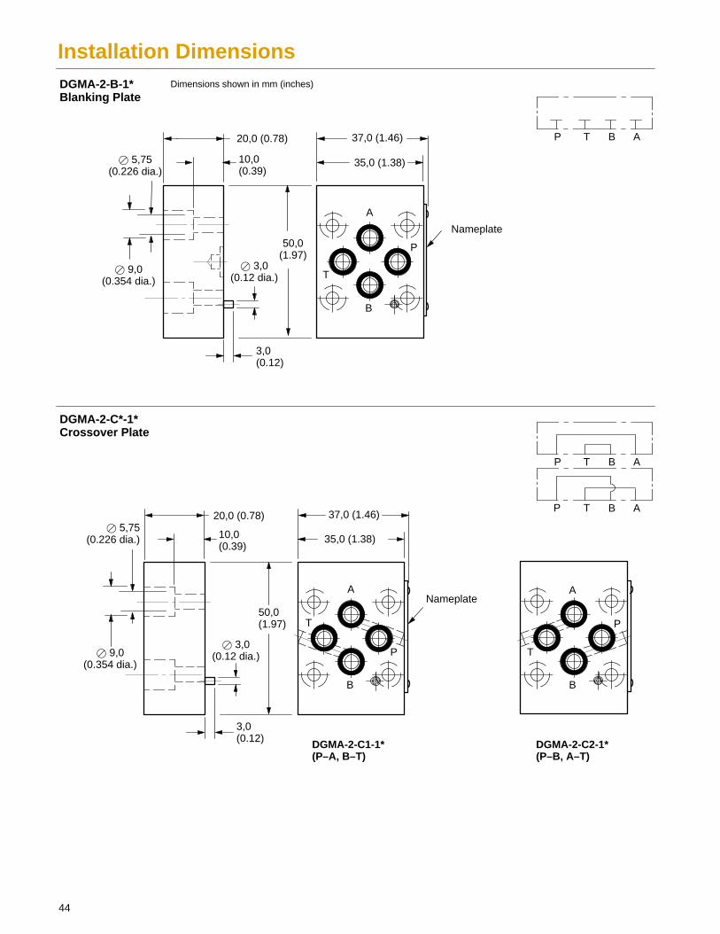
Installation Dimensions
37,0 (1.46)
37,0 (1.46)
Dimensions shown in mm (inches)
P T B A
P T B A
P T B A
� 3,0(0.12 dia.)
50,0(1.97)
3,0(0.12)
� 5,75(0.226 dia.)
� 9,0(0.354 dia.)
Nameplate
20,0 (0.78)
10,0 (0.39)
DGMA-2-C1-1*(P–A, B–T)
DGMA-2-C2-1*(P–B, A–T)
DGMA-2-B-1*Blanking Plate
DGMA-2-C*-1*Crossover Plate
A
T
B
P
35,0 (1.38)
A
T
B
P
� 3,0(0.12 dia.)
50,0(1.97)
3,0(0.12)
� 5,75(0.226 dia.)
� 9,0(0.354 dia.)
Nameplate
20,0 (0.78)
10,0 (0.39)
A
T
B
P
35,0 (1.38)
45
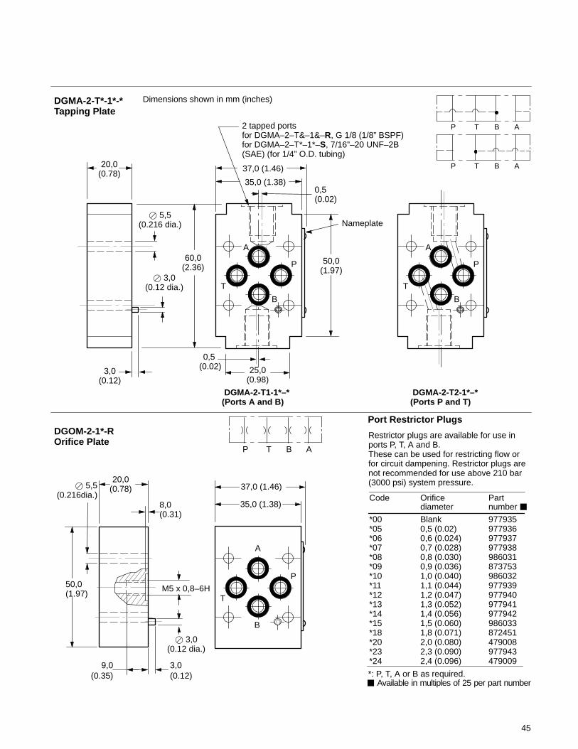
*00 Blank 977935*05 0,5 (0.02) 977936*06 0,6 (0.024) 977937*07 0,7 (0.028) 977938*08 0,8 (0.030) 986031*09 0,9 (0.036) 873753*10 1,0 (0.040) 986032*11 1,1 (0.044) 977939*12 1,2 (0.047) 977940*13 1,3 (0.052) 977941*14 1,4 (0.056) 977942*15 1,5 (0.060) 986033*18 1,8 (0.071) 872451*20 2,0 (0.080) 479008*23 2,3 (0.090) 977943*24 2,4 (0.096) 479009
20,0(0.78)
Dimensions shown in mm (inches)
P T B A
P T B A
� 3,0(0.12 dia.)
3,0(0.12)
20,0(0.78)
� 5,5(0.216 dia.)
35,0 (1.38)
37,0 (1.46)
60,0(2.36)
25,0(0.98)
50,0(1.97)
Nameplate
2 tapped portsfor DGMA–2–T&–1&–R, G 1/8 (1/8” BSPF)for DGMA–2–T*–1*–S, 7/16”–20 UNF–2B(SAE) (for 1/4” O.D. tubing)
DGMA-2-T1-1*–*(Ports A and B)
DGMA-2-T2-1*–*(Ports P and T)
� 3,0(0.12 dia.)
3,0(0.12)
35,0 (1.38)
37,0 (1.46)
8,0(0.31)
M5 x 0,8–6H50,0(1.97)
� 5,5(0.216dia.)
P T B A
DGMA-2-T*-1*-*Tapping Plate
DGOM-2-1*-ROrifice Plate
Port Restrictor Plugs
Restrictor plugs are available for use inports P, T, A and B. These can be used for restricting flow orfor circuit dampening. Restrictor plugs arenot recommended for use above 210 bar(3000 psi) system pressure.
Code Orifice Partdiameter number �
A
T
B
P
A
T
B
P
0,5 (0.02)
0,5 (0.02)
A
T
B
P
� Available in multiples of 25 per part number*: P, T, A or B as required.
9,0(0.35)
46
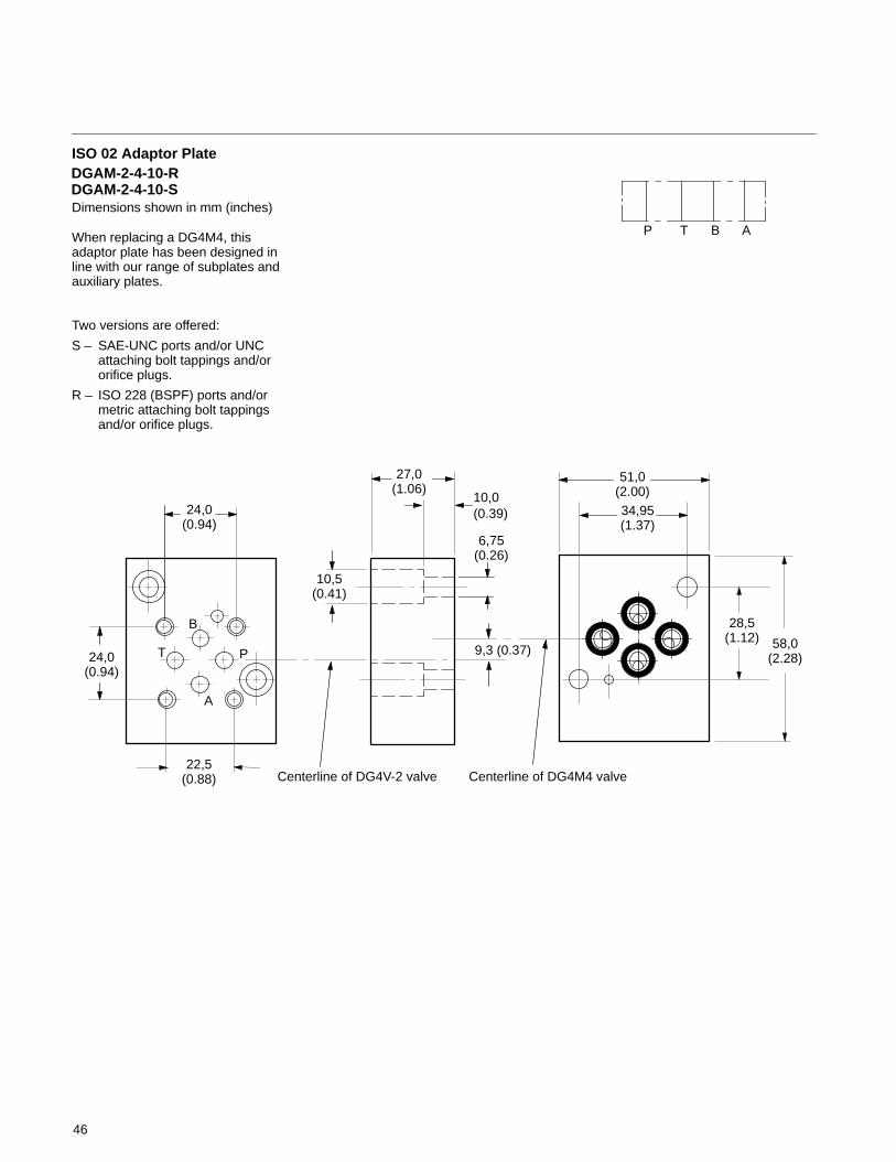
Dimensions shown in mm (inches)
ISO 02 Adaptor Plate
When replacing a DG4M4, thisadaptor plate has been designed inline with our range of subplates andauxiliary plates.
Two versions are offered:
S – SAE-UNC ports and/or UNC attaching bolt tappings and/or orifice plugs.
R – ISO 228 (BSPF) ports and/or metric attaching bolt tappings and/or orifice plugs.
DGAM-2-4-10-RDGAM-2-4-10-S
27,0(1.06)
58,0(2.28)
51,0(2.00)
B
PT
A
6,75(0.26)
10,5(0.41)
28,5(1.12)
24,0(0.94)
22,5(0.88)
34,95(1.37)
10,0(0.39)
P T B A
Centerline of DG4V-2 valve Centerline of DG4M4 valve
9,3 (0.37)
24,0(0.94)

47
23,25(0.92)
Dimensions shown in mm (inches)
DGAM-2-3–1*–R (Metric bolt tapping) DGAM-2-3–1*–S (UNC bolt tapping)
� 5,75(0.226 dia.)
46,0(1.81)
60,0(2.36)
A
B
T P
P T B A
Size 2 valves can frequently be used in place ofsize 3 valves, or generally where the system flowrate is within that of size 2 valves..
The DGAM–2 adaptor plate bolts to an existingsize 3 interface and provides a size 2 mountingface for the smaller valves.
P T B ASize 2
Size 3
24,0(0.95)
7,0 (0.28)
22,5(0.88)
0.75(0.03)
4,25(0.17)
23,0(0.9)
10,0(0.39)
� 10,0(0.39 dia.)
48,0 (1.9)
32,5(1.279)
6,75(0.26)
40,5(1.59)
31,0(1.22)
0,75(0.03)
P
B
T
A
4 holes for valve mounting bolts (see table)
Size 2 Mounting Face Size 3 Mounting Face(ISO 4401 Size 03)
Model Tappings for valve mounting boltsDGAM–2–3–1*–RDGAM–2–3–1*–S
M5 x 12,3 (0.48) deep#10–24 UNC x 14,9 (0.587) deep
75,0 (2.95)
62,0 (2.44)
75,0(2.95)
62,0(2.44)
6,5(0.26)6,5
(0.26)
P T
B
A
4 holes for valve mounting bolts (see table)
18,5(0.73)
� 5,75(0.226 dia.)
34,5(1.36)
� 10,0(0.39 dia.)
4 ports (see table)
20,0(0.78)
Model codestamped here
Model Valve mountingbolt tappings
DGMS–2–1E–1*–R M5 x 12,3 (0.48) deepG3/8 (3/8” BSPF) x12,0 (0.47) deep3/4” 16 UNF–2B x14,3 (0.56) deep
DGMS–2–1E–1*–S #10–24 UNC x 14,9(0.587) deep
Ports P, A, T, Btappings
T BAP
Adaptor plate, Size 3 to 2for pressure up to 250 bar (3600 psi)
DGMS-2-1E-1*-*Single station subplate,side tapped port
9,75(0.38)
48
P
T
37,5(1.47)
Dimensions shown in mm (inches)
74,5(2.93)
75,0(2.95)
6,0(0.24)
P
Model
DGMS–2–1E–1*–R G1/2 (1/2” BSPF)
3/4” 16 UNF–2BDGMS–2–1E–1*–S3/4”–16 UNF–2B x14,3 (0.56) deep
Ports P, T
37,5(1.47)
B
A
37,5(1.47)
2 ports P and T on allmodels, tapped per modelcode, (see table 2)
4 holes per station for valve mountingbolts, tapped per model code (seetable 3)
32,8(1.29)
PT
A
T
2 holes for attaching bolts,tapped per model type (seetable 3)
4,5 and 6 station models only:2 ports, P and T through drilled end-to-end,tapped per model code (see table 2)
60,0(2.36)
20,0(0.78)
� 10,0(0.39 dia.)
34,5(1.36)
20,25(0.8)
40,0(1.57)
17,25(0,68)
A and B ports at each station,tapped per model code (see table 2)
Model codestamped here
Ports A, B
G3/8 (3/8” BSPF) x12,0 (0.47) deep
Model
DGMS–2–1E–1*–R M5 x 12,3(0.48) deep#10–24 UNC x14,9 deep
DGMS–2–1E–1*–S 5/16” –18 UNC–2B
Valve mountingbolts
Manifold rearmount holes
M8 x 1,25–6H
DGMS–2–2E–1*–*DGMS–2–3E–1*–*DGMS–2–4E–1*–*DGMS–2–5E–1*–*DGMS–2–6E–1*–*
102 (4.02)140 (5.5)178 (7.0)215 (8.5)254 (10.0)
90 (3.54)125 (4.92)165 (6.5)200 (7.9)240 (9.45)
Model A B
Table 1: Dimensions
Table 2: Port Tappings Table 3: Mounting Bolt Tappings
PT
B1 A1
P1 T1 B1 A1
B2 A2
P2 T2 B2 A2
PT
B1 A1
P1 T1 B1 A1
B6 A6
P6 T6 B6 A6
Valve Station 1 Valve Station 2–6
Valve Station 1 Valve Station 2–3DGMS-2-*E-1*-*Multi-station subplate,(4 station shown)
B
� 5,75(0.226dia. thru)
PT
A
B
PT
A
B
PT
A
B
A
B
37,5(1.47)
37,5(1.47)
37,5(1.47)
49
19,7(0.78)
24,0(0.95)
Dimensions shown in mm (inches )Mounting Surface
When a subplate is not used, a machinedpad must be provided for mounting. The padmust be flat within 0,01 mm per 100 mm(0.0001” per 1”) and smooth within 0,8 µm(32 µin).
Prior to installing a valve, ensure thatboth valve and mounting surface areclean and free from burrs.
Dimensional tolerance = �0,2(�0.008) except where otherwisestated.
4,3(0.17)
37,5(1.48)min.
12,0(0.47)
26,5(1.04)
50,1 (1.97) min.
0,75(0.03)
23,25(0.92)
35,2(1.39)min.
2,25(0.09)
11,25(0.44)
20,25(0.8)22,5
(0.88)
17,75(0.7)
Mounting Bolt Tapping Options
ISO/4401-02-01-0-94 defines only M5 tapping.Inch tapping options are as available in Vickerssubplates and manifolds.
Thread Min. tapping depth for subplates/manifolds in:Steel Cast Iron Aluminum
MetricM5–6HInch#10–24UNC–2B
12,3(0.484)
12,3(0.484)
12,3(0.484)
12,6(0.496)
14,9(0.587)
14,9(0.587)
4 holes, see table forthread options
4 ports� 4,75/4,90(0.187/0.193 dia)
P
B
T
A
� 3,40/3,55 x 4,3 deep(0.134/0.140 dia x 0.17 deep)for locating pin
ISO 4401 gives dimensions in mm. Inch conversionsare accurate to 0.01” unless stated.
This dimension gives the minimum space requiredfor a valve with this mounting surface. The dimensionis also the minimum center-to-center pitch ofmounting surfaces on a manifold block.
It is recommended that customers’ own manifold blocksfor UNC bolts be tapped to these minimum depths.
50
Appendix
Mounting BoltsMetric bolt kits, M5-6H
DG**V-2SystemStak
For subplates/manifolds in steel, cast iron or aluminum
DG**V-2DG**V-2 + 1 moduleDG**V-2 + 2 modulesDG**V-2 + 3 modules
BK02-156493BK 464125MBK 466839MBK 466842M
Inch bolt kits, #10-24 UNC-2B
DG**V-2 SystemStak For subplates/manifolds in: Steel Cast iron Aluminum
DG**V-2DG**V-2 + 1 moduleDG**V-2 + 2 modulesDG**V-2 + 3 modules
BK 590720 BK02-156494 BK02-156494BK 870017 BK 870017 BK02-156496BK02-156497 BK02-156497 BK02-156497BK02-156499 BK02-156498 BK02-156498
Note: If not using Vickers bolt kits, bolts must be to Grade 12.9 (ISO 898) or better.
Bolts should be torqued to 5-7 N.m (44-62 lbf. in.) with threads lubricated. Prior toinstallation of DG4V-2 valve, ensure that both the face of the valve and the face onwhich it is being mounted (i.e. subplate, manifold, SystemStak valve or plate) is asclean as possible. Do not over tighten hold-down bolts beyond recommended values.
Seal Kits
Model Seal Kit
DG**V-2 02-156492
DGMC(S)-2 02-157032
DGMR(1)/X(2) 02-157033
DGMDC02-157030
DGMPC02-157030
DGMFN 02-157031
Fluids and Seals
Materials and seals used in these valvesare compatible with anti-wear hydraulicoils, water-in-oil emulsions, waterglycols, and non-alkyl-based phosphateesters. The extreme operating viscosityrange is from 500 to 13 cSt (2270 to 70SUS) but the recommended operatingrange is 54 to 13 cSt (245 to 70 SUS).
Temperature Limits
Ambient range -20�C to 70�C. . . . (-4�F to +158�F)
Fluid Temperature
FluidTemp.
Mineraloil
Watercontaining
Minimum -20�C(-4�F)
+10�C(+50�F)
Maximum* +70�C(+158�F)
+54�C(+129�F)
* To obtain optimum service life fromboth fluid and hydraulic system, 65�C(150�F) is the recommended maximumfluid temperature, except forwater-containing fluids.
For synthetic fluids, consult fluidmanufacturer or Vickers representativewhere limits are outside those formineral oil.
Whatever the actual temperature range,ensure that fluid viscosities stay withinthe limits specified in “Hydraulic Fluids”.
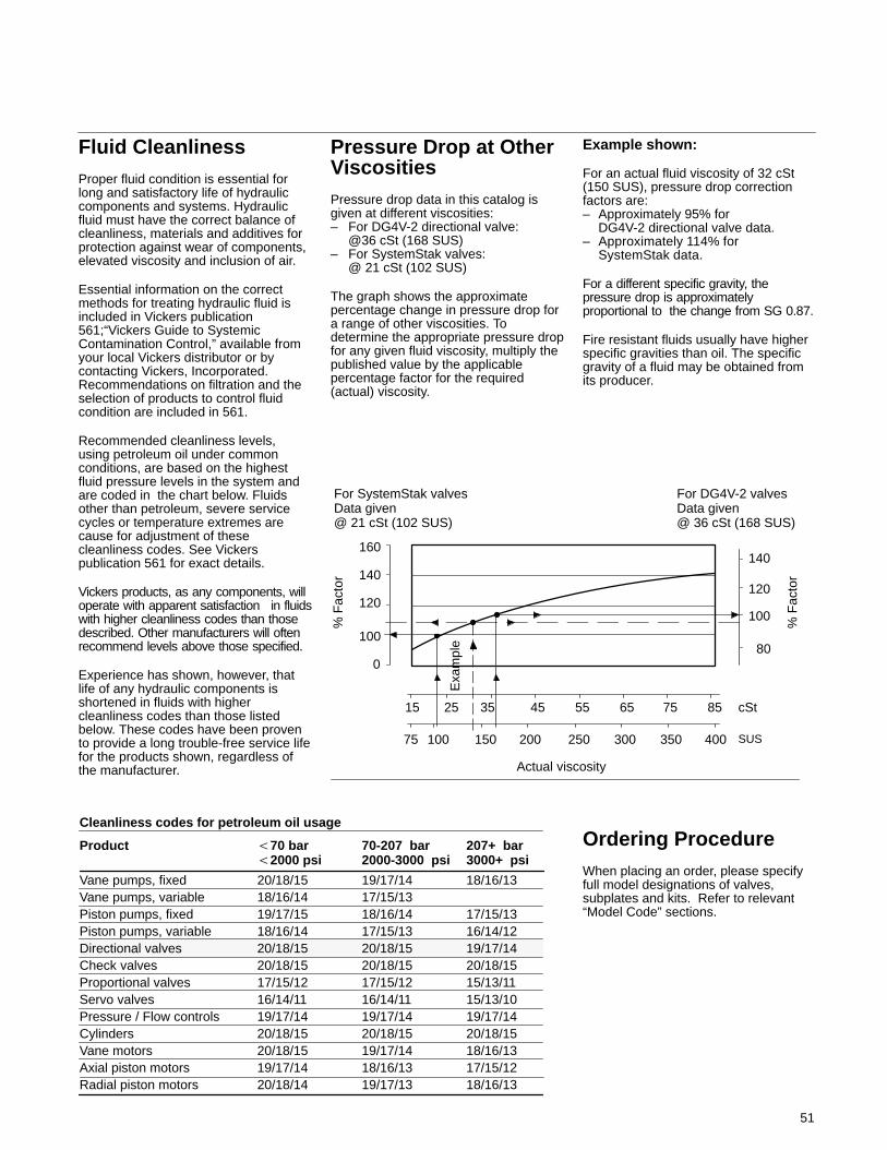
Product �70 bar 70-207 bar 207+ bar�2000 psi 2000-3000 psi 3000+ psi
Vane pumps, fixed 20/18/15 19/17/14 18/16/13Vane pumps, variable 18/16/14 17/15/13Piston pumps, fixed 19/17/15 18/16/14 17/15/13Piston pumps, variable 18/16/14 17/15/13 16/14/12Directional valves 20/18/15 20/18/15 19/17/14Check valves 20/18/15 20/18/15 20/18/15Proportional valves 17/15/12 17/15/12 15/13/11Servo valves 16/14/11 16/14/11 15/13/10Pressure / Flow controls 19/17/14 19/17/14 19/17/14Cylinders 20/18/15 20/18/15 20/18/15Vane motors 20/18/15 19/17/14 18/16/13Axial piston motors 19/17/14 18/16/13 17/15/12Radial piston motors 20/18/14 19/17/13 18/16/13
Cleanliness codes for petroleum oil usage
For SystemStak valvesData given@ 21 cSt (102 SUS)
For DG4V-2 valvesData given@ 36 cSt (168 SUS)
160
140
120
100
0
15 25 35 45 55 65 75 85 cSt
75 100 150 200 250 300 350 400 SUS
80
100
120
140
% F
acto
r
% F
acto
r
Actual viscosity
Exa
mpl
e
51
Fluid CleanlinessProper fluid condition is essential forlong and satisfactory life of hydrauliccomponents and systems. Hydraulicfluid must have the correct balance ofcleanliness, materials and additives forprotection against wear of components,elevated viscosity and inclusion of air.
Essential information on the correctmethods for treating hydraulic fluid isincluded in Vickers publication561;“Vickers Guide to SystemicContamination Control,” available fromyour local Vickers distributor or bycontacting Vickers, Incorporated.Recommendations on filtration and theselection of products to control fluidcondition are included in 561.
Recommended cleanliness levels,using petroleum oil under commonconditions, are based on the highestfluid pressure levels in the system andare coded in the chart below. Fluidsother than petroleum, severe servicecycles or temperature extremes arecause for adjustment of thesecleanliness codes. See Vickerspublication 561 for exact details.
Vickers products, as any components, willoperate with apparent satisfaction in fluidswith higher cleanliness codes than thosedescribed. Other manufacturers will oftenrecommend levels above those specified.
Experience has shown, however, thatlife of any hydraulic components isshortened in fluids with highercleanliness codes than those listedbelow. These codes have been provento provide a long trouble-free service lifefor the products shown, regardless ofthe manufacturer.
Pressure Drop at OtherViscositiesPressure drop data in this catalog isgiven at different viscosities:– For DG4V-2 directional valve:
@36 cSt (168 SUS)– For SystemStak valves:
@ 21 cSt (102 SUS)
The graph shows the approximatepercentage change in pressure drop fora range of other viscosities. Todetermine the appropriate pressure dropfor any given fluid viscosity, multiply thepublished value by the applicablepercentage factor for the required(actual) viscosity.
Example shown:
For an actual fluid viscosity of 32 cSt(150 SUS), pressure drop correctionfactors are:– Approximately 95% for
DG4V-2 directional valve data.– Approximately 114% for
SystemStak data.
For a different specific gravity, thepressure drop is approximatelyproportional to the change from SG 0.87.
Fire resistant fluids usually have higherspecific gravities than oil. The specificgravity of a fluid may be obtained fromits producer.
Ordering ProcedureWhen placing an order, please specifyfull model designations of valves,subplates and kits. Refer to relevant“Model Code” sections.