Embed Size (px)
Citation preview
Virgo Control Noise Reduction
Gabriele Vajente
Scuola Normale Superiore, Pisa University and INFN Sezione di Pisa
LSC-Virgo collaboration meetingPasadena, March 17th -20th 2008
Gabriele Vajente – LSC-Virgo Meeting – Pasadena March 19th 2008 2
Summary
Many sensitivity improvements after the end of VSR1
Made possible by large reduction of control noises
Angular control noise (alignment system)
Longitudinal control noise (locking system)
VSR1 end (Sept. 2007)Last (March 2008)Design
Gabriele Vajente – LSC-Virgo Meeting – Pasadena March 19th 2008 3
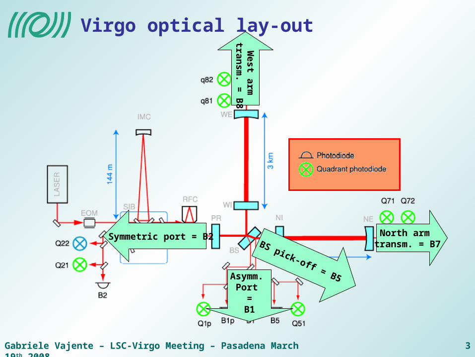
Virgo optical lay-out
Symmetric port = B2W
est arm tran
sm. =
B8
North arm transm. = B7BS pick-off = B5Asymm.
Port =
B1
Gabriele Vajente – LSC-Virgo Meeting – Pasadena March 19th 2008 4
Longitudinal control noise
Gabriele Vajente – LSC-Virgo Meeting – Pasadena March 19th 2008 5
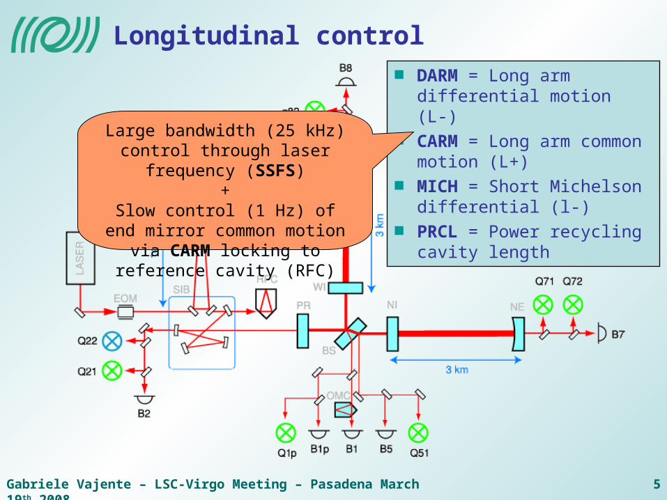
Longitudinal control
DARM = Long arm differential motion (L-)
CARM = Long arm common motion (L+)
MICH = Short Michelson differential (l-)
PRCL = Power recycling cavity length
Large bandwidth (25 kHz) control through laser frequency (SSFS)
+Slow control (1 Hz) of end mirror
common motion via CARM locking to reference cavity (RFC)
Gabriele Vajente – LSC-Virgo Meeting – Pasadena March 19th 2008 6
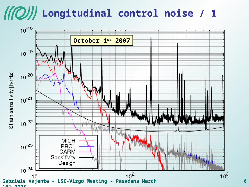
Longitudinal control noise / 1
October 1st 2007
Gabriele Vajente – LSC-Virgo Meeting – Pasadena March 19th 2008 7
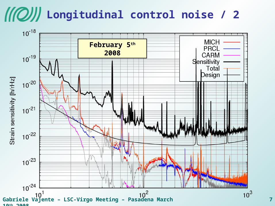
Longitudinal control noise / 2
February 5th 2008
Gabriele Vajente – LSC-Virgo Meeting – Pasadena March 19th 2008 8
Longitudinal control improvements / 1
Main modulation frequency 6.24 MHz used for longitudinal and angular control
Resonant in PRC
Anti-resonant in Fabry-Perot cavities
TEM 01 resonant in Fabry-Perot Cavity (Anderson-Giordano technique)
After the run, new modulation at 8.32 MHz phase-locked to main one
Not resonant in PRC or FP
ITF reflection demodulated at 8.32 MHz
Gabriele Vajente – LSC-Virgo Meeting – Pasadena March 19th 2008 9
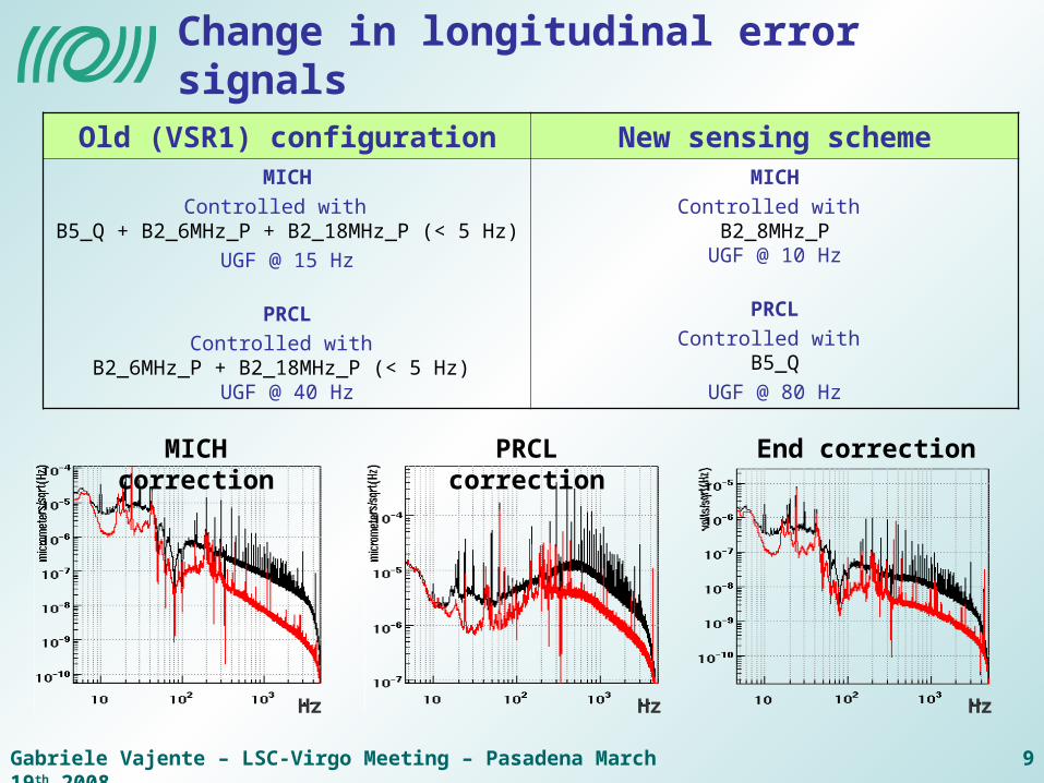
Change in longitudinal error signals
Old (VSR1) configuration New sensing schemeMICH
Controlled with B5_Q + B2_6MHz_P + B2_18MHz_P (< 5 Hz)
UGF @ 15 Hz
PRCL
Controlled with B2_6MHz_P + B2_18MHz_P (< 5 Hz)
UGF @ 40 Hz
MICH
Controlled with B2_8MHz_P
UGF @ 10 Hz
PRCL
Controlled with B5_Q
UGF @ 80 Hz
MICH correction PRCL correction End correction
Hz Hz Hz
Gabriele Vajente – LSC-Virgo Meeting – Pasadena March 19th 2008 10
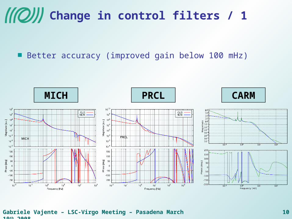
Change in control filters / 1
Better accuracy (improved gain below 100 mHz)
MICH PRCL CARM
Gabriele Vajente – LSC-Virgo Meeting – Pasadena March 19th 2008 11
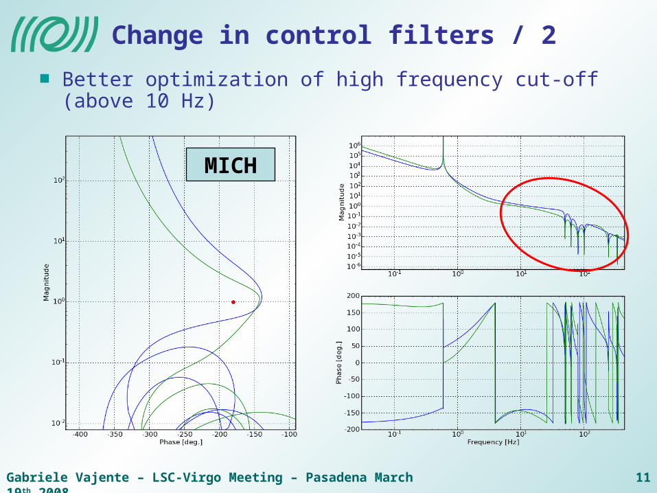
Change in control filters / 2
Better optimization of high frequency cut-off (above 10 Hz)
MICH
Gabriele Vajente – LSC-Virgo Meeting – Pasadena March 19th 2008 12
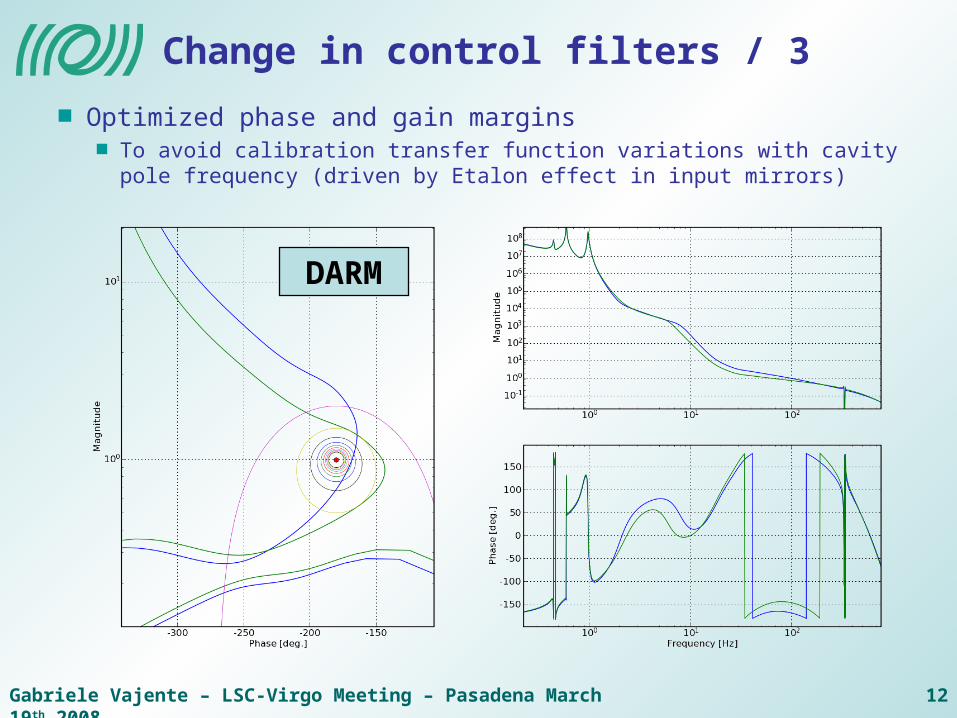
Change in control filters / 3
Optimized phase and gain marginsTo avoid calibration transfer function variations with cavity pole frequency (driven by Etalon effect in input mirrors)
DARM
Gabriele Vajente – LSC-Virgo Meeting – Pasadena March 19th 2008 13
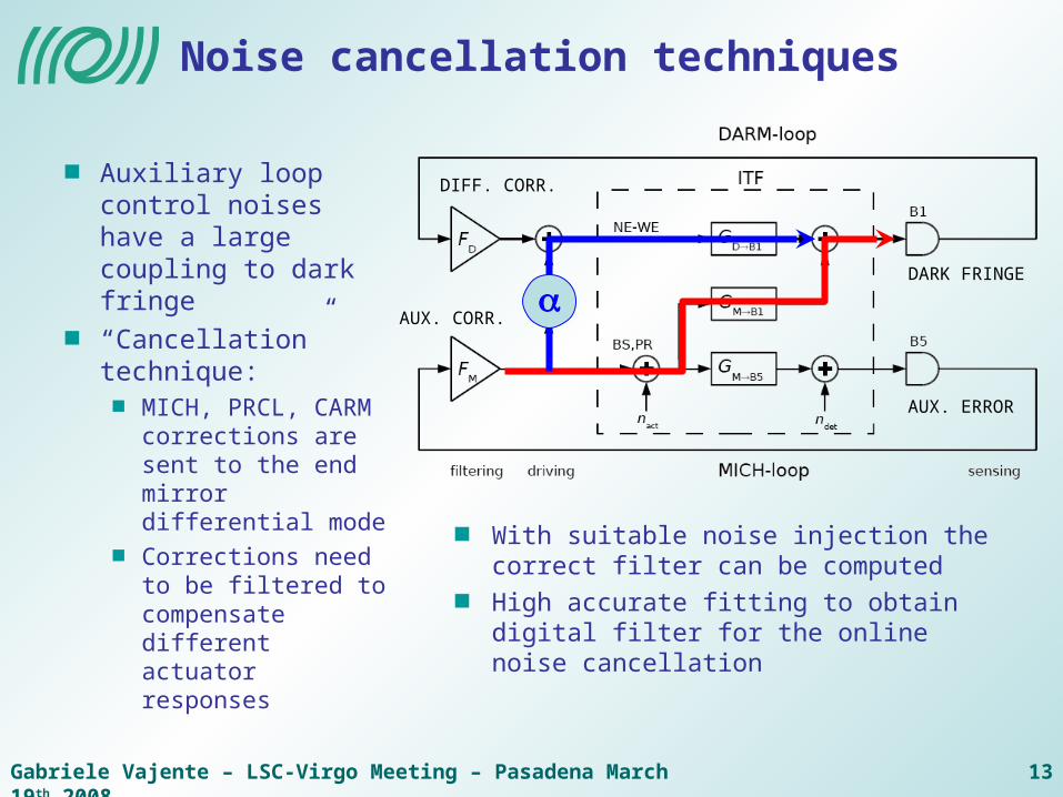
Noise cancellation techniques
Auxiliary loop control noises have a large coupling to dark fringe
“Cancellation” technique:
MICH, PRCL, CARM corrections are sent to the end mirror differential mode
Corrections need to be filtered to compensate different actuator responses
With suitable noise injection the correct filter can be computed
High accurate fitting to obtain digital filter for the online noise cancellation
DARK FRINGE
AUX. ERROR
DIFF. CORR.
AUX. CORR.
Gabriele Vajente – LSC-Virgo Meeting – Pasadena March 19th 2008 14
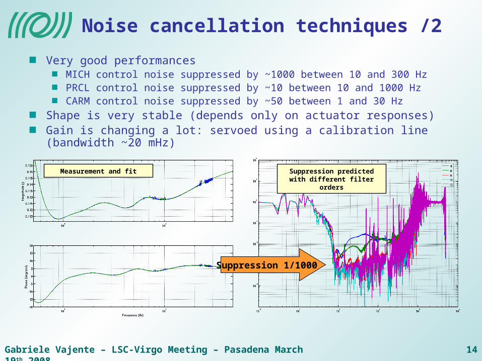
Noise cancellation techniques /2
Suppression 1/1000
Suppression predicted with different filter orders
Measurement and fit
Very good performancesMICH control noise suppressed by ~1000 between 10 and 300 HzPRCL control noise suppressed by ~10 between 10 and 1000 HzCARM control noise suppressed by ~50 between 1 and 30 Hz
Shape is very stable (depends only on actuator responses)Gain is changing a lot: servoed using a calibration line (bandwidth ~20 mHz)
Gabriele Vajente – LSC-Virgo Meeting – Pasadena March 19th 2008 15
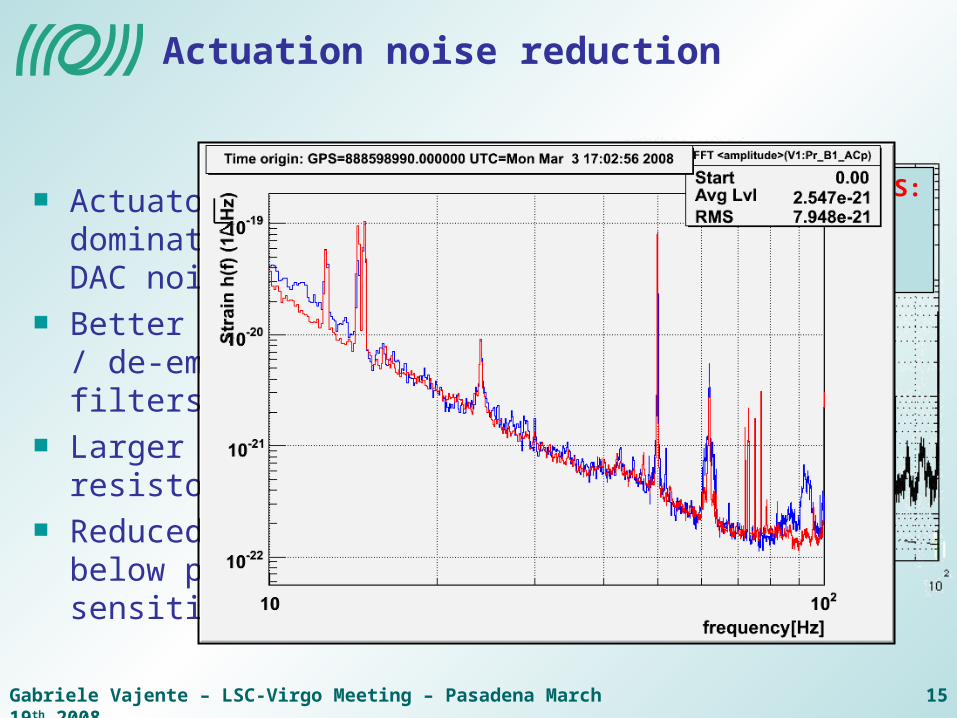
Actuation noise reduction
Actuator noise dominated by DAC noise
Better emphasis / de-emphasis filters
Larger series resistor
Reduced well below present sensitivity
UPPER LIMITS:DAC marionetteDAC mirror
Gabriele Vajente – LSC-Virgo Meeting – Pasadena March 19th 2008 16
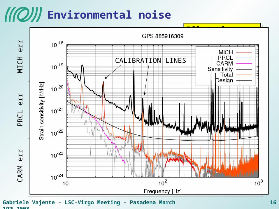
Environmental noiseEffect of switching central hall air conditioning off
CALIBRATION LINES
PR
CL
err
MIC
H e
rrC
AR
M e
rr
Gabriele Vajente – LSC-Virgo Meeting – Pasadena March 19th 2008 17
Angular control noise
Gabriele Vajente – LSC-Virgo Meeting – Pasadena March 19th 2008 18
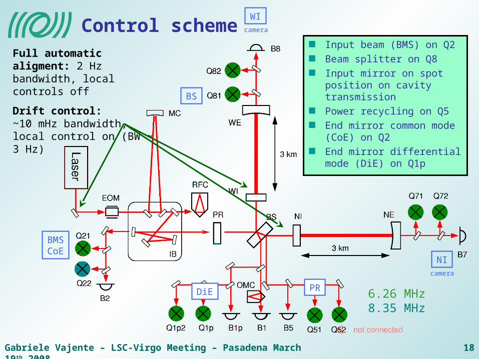
Control scheme
6.26 MHz8.35 MHz
BS
DiE
BMSCoE
WIcamera
NIcamera
PR
Input beam (BMS) on Q2
Beam splitter on Q8
Input mirror on spot position on cavity transmission
Power recycling on Q5
End mirror common mode (CoE) on Q2
End mirror differential mode (DiE) on Q1p
Full automatic aligment: 2 Hz bandwidth, local controls off
Drift control:~10 mHz bandwidth, local control on (BW ~ 3 Hz)
Gabriele Vajente – LSC-Virgo Meeting – Pasadena March 19th 2008 19
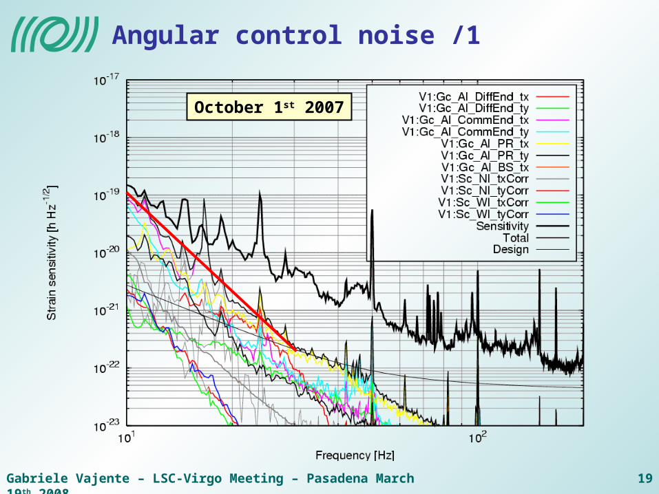
Angular control noise /1
October 1st 2007
Gabriele Vajente – LSC-Virgo Meeting – Pasadena March 19th 2008 20
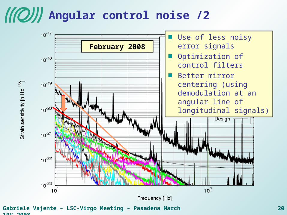
Angular control noise /2
February 2008Use of less noisy error signals
Optimization of control filters
Better mirror centering (using demodulation at an angular line of longitudinal signals)

Gabriele Vajente – LSC-Virgo Meeting – Pasadena March 19th 2008 21
Galvo centering systems
Quadrant-diodes mounted on translation stages
Noisy and slow
Better centering with galvo systems
Installed on both end benches
Avoid mis-alignments induced by quadrant mis-centering
Galvo OFF Galvo ON
Sca
le x
10
Normalized mis-centering
Normalized mis-centering
Gabriele Vajente – LSC-Virgo Meeting – Pasadena March 19th 2008 22
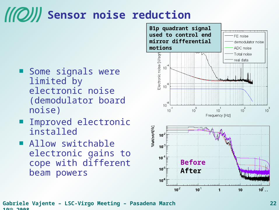
Sensor noise reduction
Some signals were limited by electronic noise (demodulator board noise)Improved electronic installed Allow switchable electronic gains to cope with different beam powers
B1p quadrant signal used to control end mirror differential motions
BeforeAfter
Gabriele Vajente – LSC-Virgo Meeting – Pasadena March 19th 2008 23
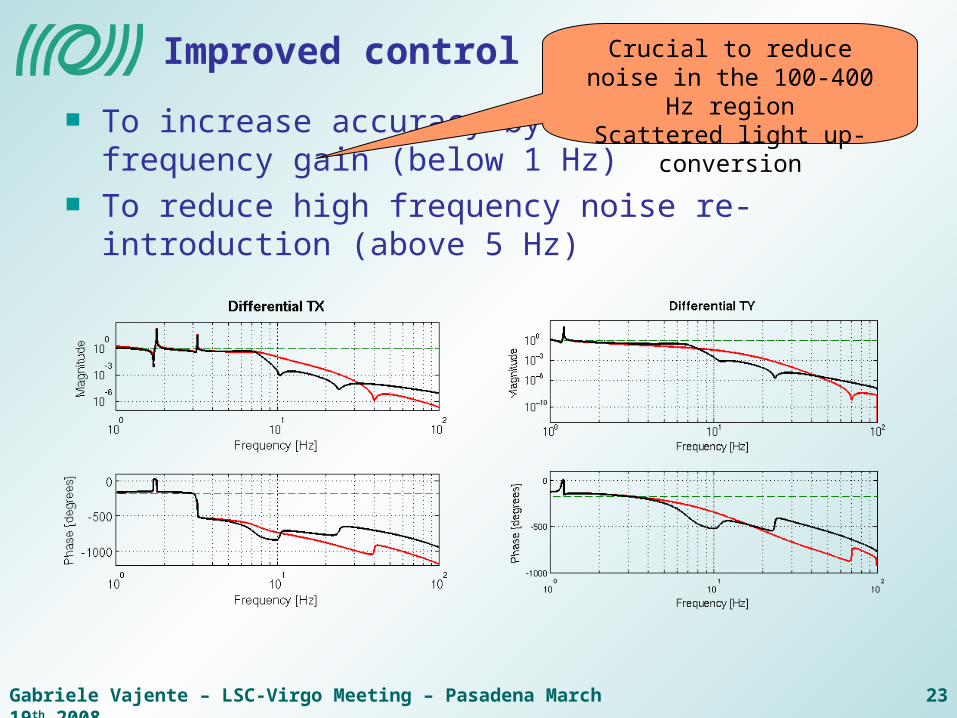
Improved control filters
To increase accuracy by increasing low frequency gain (below 1 Hz)
To reduce high frequency noise re-introduction (above 5 Hz)
Crucial to reduce noise in the 100-400 Hz region
Scattered light up-conversion
Gabriele Vajente – LSC-Virgo Meeting – Pasadena March 19th 2008 24
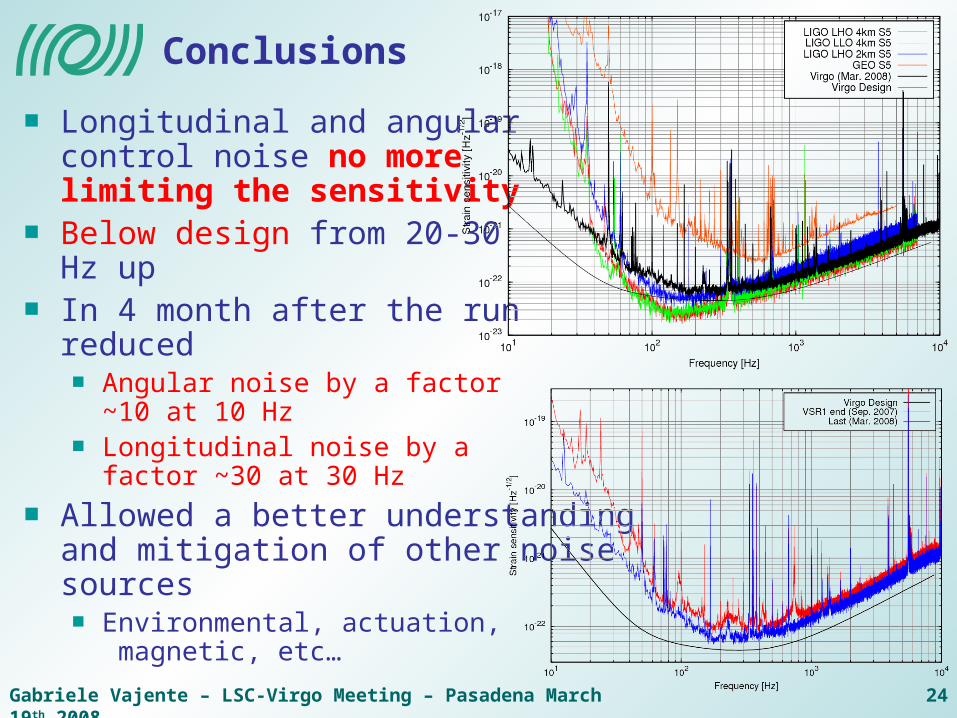
Conclusions
Longitudinal and angular control noise no more limiting the sensitivityBelow design from 20-30 Hz upIn 4 month after the runreduced
Angular noise by a factor ~10 at 10 HzLongitudinal noise by a factor ~30 at 30 Hz
Allowed a better understanding and mitigation of other noise sources
Environmental, actuation, magnetic, etc…