Embed Size (px)
Citation preview
7/23/2019 Visco Meters
http://slidepdf.com/reader/full/visco-meters 1/28
4/27/2011
1
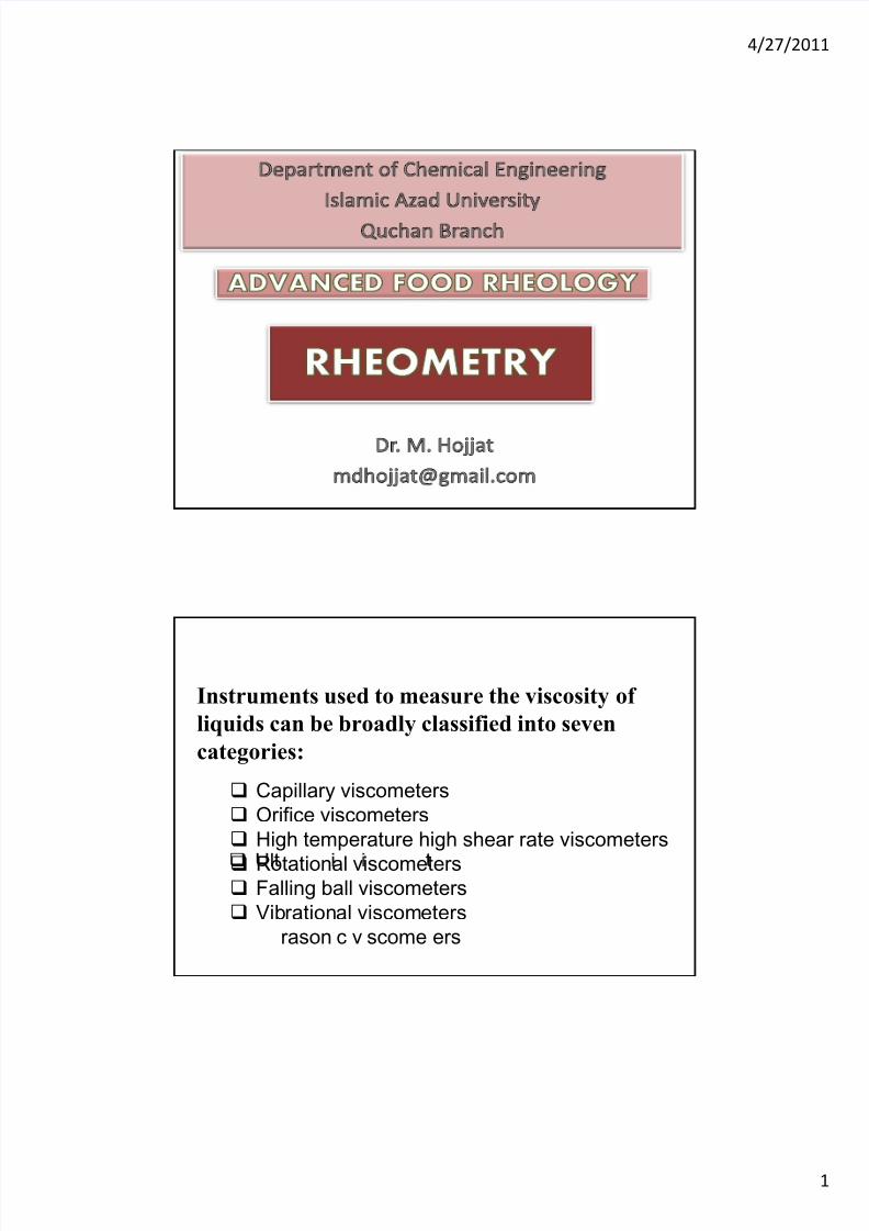
Capillary viscometers
Instruments used to measure the viscosity of
liquids can be broadly classified into seven
categories:
Orifice viscometers
High temperature high shear rate viscometers
Rotational viscometers Falling ball viscometers
Vibrational viscometers
rason c v scome ers
7/23/2019 Visco Meters
http://slidepdf.com/reader/full/visco-meters 2/28
4/27/2011
2
A number of viscometers are also available that combinefeatures of two or three types of viscometers noted above,
such as:
Friction tube
Norcross
Brookfield
Viscosity sensitive rotameter
Continuous consistency viscometers
num er o ns rumen s are a so au oma e or con nuousmeasurement of viscosity and for process control.
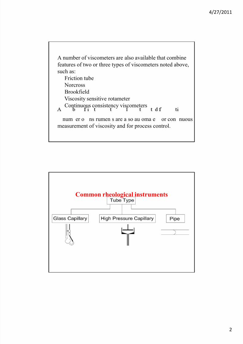
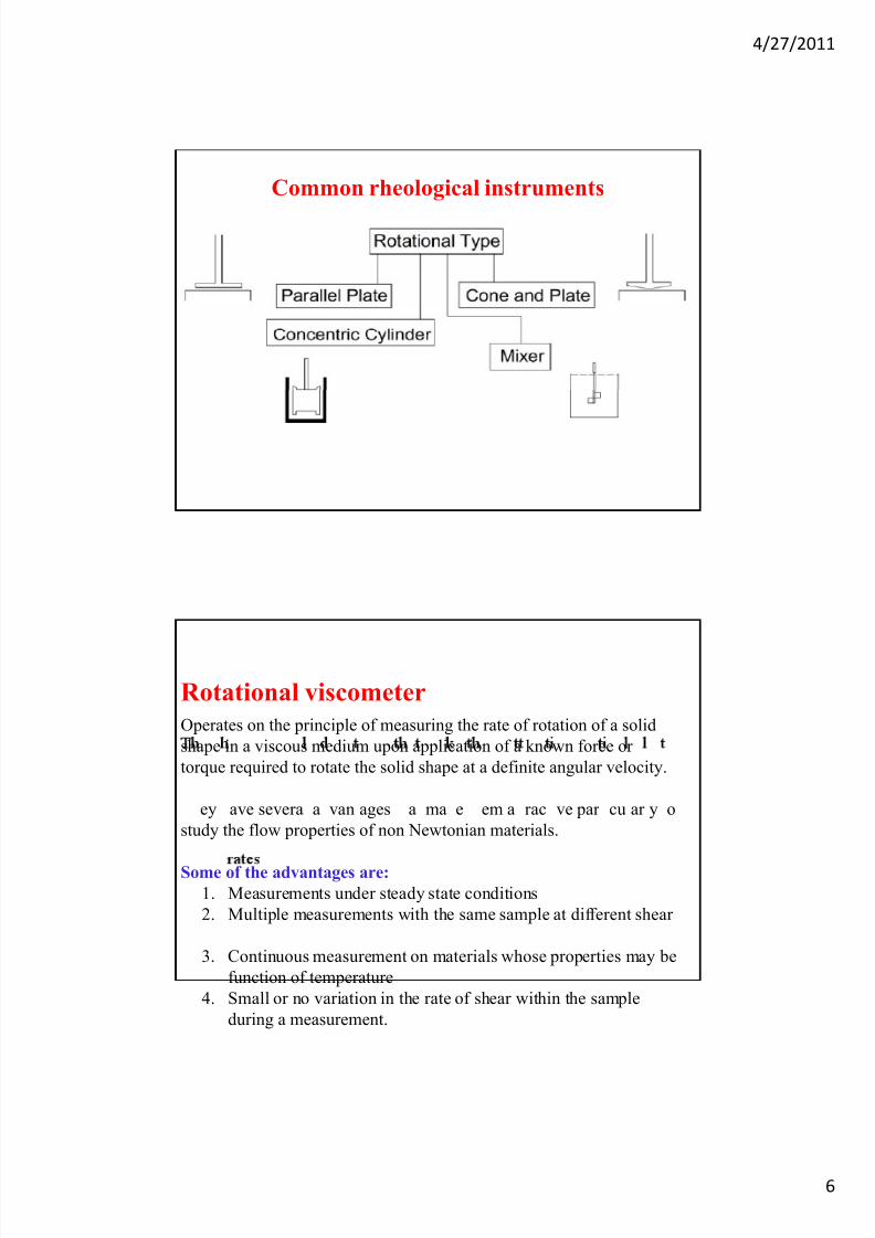
Common rheological instruments
7/23/2019 Visco Meters
http://slidepdf.com/reader/full/visco-meters 3/28
4/27/2011
3
CAPILLARY VISCOMETERS
Capillary viscometers are most widely used for measuring viscosity
of Newtonian liquids.
They are simple in operation; require a small volume of sample
liquid, temperature control is simple, and inexpensive.
Capillary viscometers are capable of providing direct calculation of
viscosity from the rate of flow, pressure and various dimensions of
the instruments.
Most of the capillary viscometers must be first calibrated with one or
more liquids of known viscosity to obtain “constants” for that
particular viscometer.
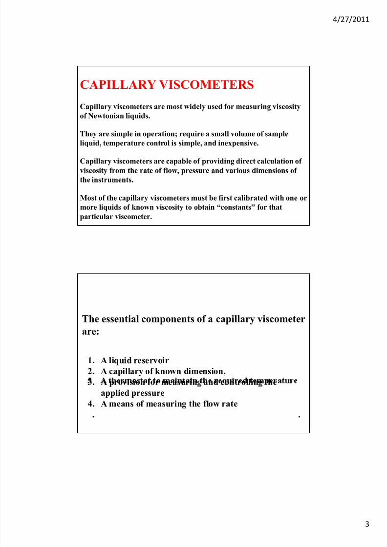
The essential components of a capillary viscometer
are:
1. A liquid reservoir
2. A capillary of known dimension,
3. A provision for measuring and controlling theapplied pressure
4. A means of measuring the flow rate
. .
7/23/2019 Visco Meters
http://slidepdf.com/reader/full/visco-meters 4/28
4/27/2011
4
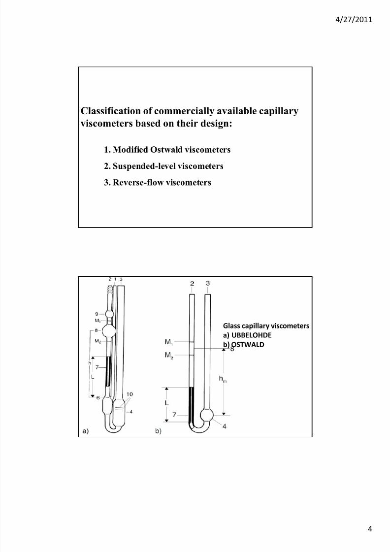
Classification of commercially available capillary
viscometers based on their design:
1. Modified Ostwald viscometers
2. Suspended-level viscometers
3. Reverse-flow viscometers
Glass capillary viscometers
a) UBBELOHDE
b) OSTWALD
7/23/2019 Visco Meters
http://slidepdf.com/reader/full/visco-meters 5/28
4/27/2011
5
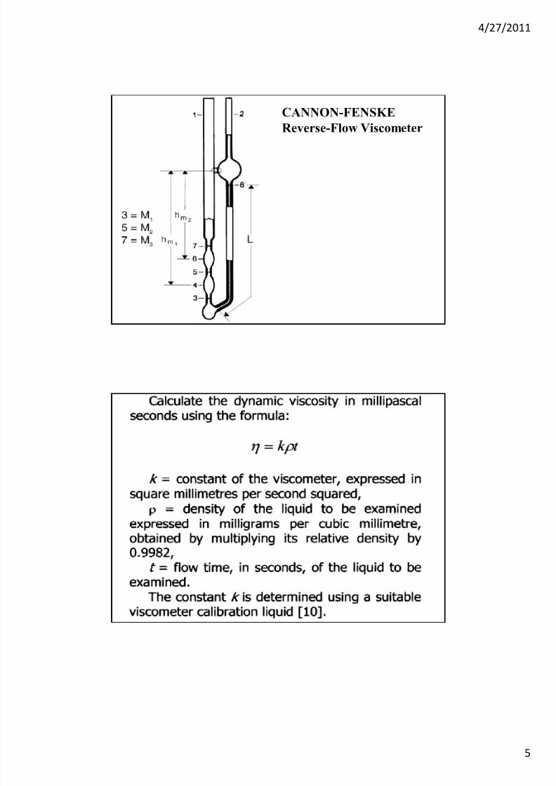
CANNON-FENSKE
Reverse-Flow Viscometer
7/23/2019 Visco Meters
http://slidepdf.com/reader/full/visco-meters 6/28
4/27/2011
6
Common rheological instruments
Operates on the principle of measuring the rate of rotation of a solid
shape in a viscous medium upon application of a known force or
torque required to rotate the solid shape at a definite angular velocity.
Rotational viscometer
ey ave severa a van ages a ma e em a rac ve par cu ar y o
study the flow properties of non Newtonian materials.
Some of the advantages are:1. Measurements under steady state conditions
2. Multiple measurements with the same sample at different shear
3. Continuous measurement on materials whose properties may be
function of temperature
4. Small or no variation in the rate of shear within the sample
during a measurement.
7/23/2019 Visco Meters
http://slidepdf.com/reader/full/visco-meters 7/28
4/27/2011
7
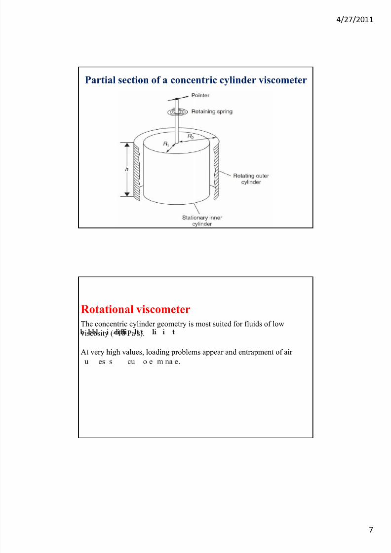
Partial section of a concentric cylinder viscometer
The concentric cylinder geometry is most suited for fluids of low
viscosity (<10 Pa s).
At very high values, loading problems appear and entrapment of air
Rotational viscometer
u es s cu o e m na e.
7/23/2019 Visco Meters
http://slidepdf.com/reader/full/visco-meters 8/28
4/27/2011
8
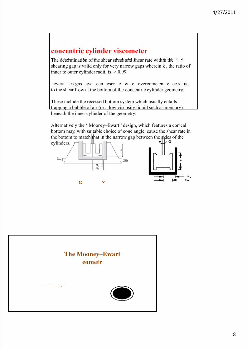
The determination of the shear stress and shear rate within theshearing gap is valid only for very narrow gaps wherein k , the ratio of
inner to outer cylinder radii, is > 0.99.
concentric cylinder viscometer
evera es gns ave een escr e w c overcome en e ec s ue
to the shear flow at the bottom of the concentric cylinder geometry.
These include the recessed bottom system which usually entails
trapping a bubble of air (or a low viscosity liquid such as mercury)
beneath the inner cylinder of the geometry.
Alternatively the ‘ Mooney–Ewart ’ design, which features a conical
bottom may, with suitable choice of cone angle, cause the shear rate in
the bottom to match that in the narrow gap between the sides of the
cylinders.
The Mooney–Ewart
eometr
7/23/2019 Visco Meters
http://slidepdf.com/reader/full/visco-meters 9/28
4/27/2011
9
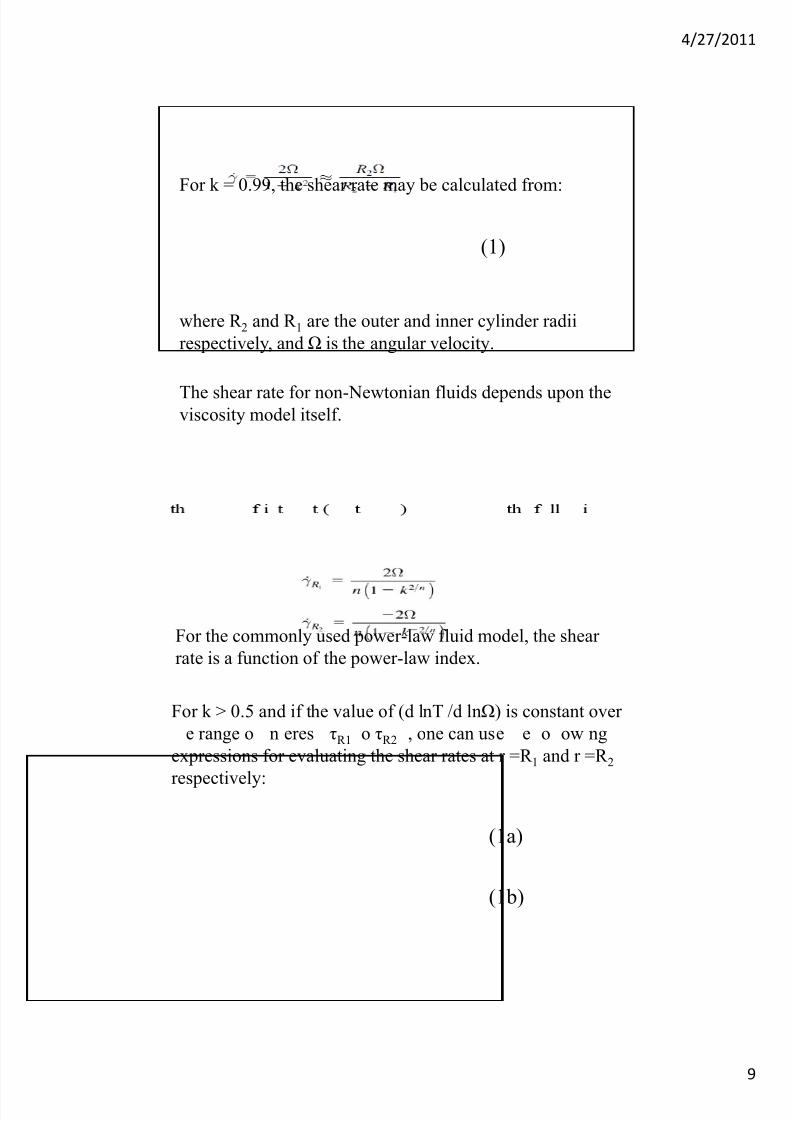
For k = 0.99, the shear rate may be calculated from:
(1)
where R 2 and R 1 are the outer and inner cylinder radii
respectively, and Ω is the angular velocity.
The shear rate for non-Newtonian fluids depends upon theviscosity model itself.
For k > 0.5 and if the value of (d lnT /d lnΩ) is constant over
For the commonly used power-law fluid model, the shear
rate is a function of the power-law index.
e range o n eres τR1 o τR2 , one can use e o ow ng
expressions for evaluating the shear rates at r =R 1 and r =R 2
respectively:
(1a)
(1b)
7/23/2019 Visco Meters
http://slidepdf.com/reader/full/visco-meters 10/28
4/27/2011
10
Many commercial instruments employ k > 0.9 and it is not
uncommon to calculate the shear rate by assuming the fluidto be Newtonian.
It is therefore useful to ascertain the extent of uncertainty in
us ng t s approx mat on.
The ratio of the shear rates at r R1 , for a power-law fluid (γPL)
and for a Newtonian fluid (γ N) is given as:
Evidently for a Newtonian fluid, n = 1, this ratio is unity
c
For typical shear-thinning substances encountered in
industrial practice, the flow behaviour index ranges from
~0.2 to 1. Over this range and for k > 0.99, the error in using
equation (1) is at most 3%.
It rises to 10% for k = 0.98 and n = 0.2.
In this geometry, the shear stress is evaluated from torque
data.
(1d)
Thus, the shear stress varies as (1/r 2 ) from τR1 at r =R 1 to τR2
at r =R 2 .
(1e)
7/23/2019 Visco Meters
http://slidepdf.com/reader/full/visco-meters 11/28
4/27/2011
11
For k > 0.99, R 1≈R 2 and therefore, the two values are very
close and shear stress is given as:
(1f)
To minimize end effects, the lower end of the inner cylinder
is a truncated cone. The shear rate in this region is equal to
that between the cylinders if the cone angle, α, is related to
the cylinder radii by:
(1g)
The main sources of error in the concentric
cylinder type measuring geometry:
.
2. Wall slip
3. Inertia and secondary flows
4. Viscous heating effects5. Eccentricities due to misalignment of the geometry
7/23/2019 Visco Meters
http://slidepdf.com/reader/full/visco-meters 12/28
4/27/2011
12
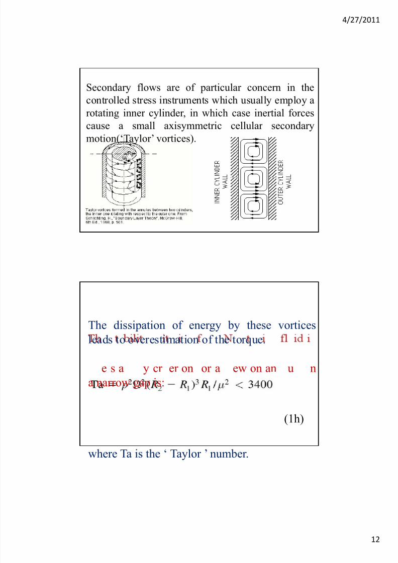
Secondary flows are of particular concern in the
controlled stress instruments which usually employ arotating inner cylinder, in which case inertial forces
cause a small axisymmetric cellular secondary
motion(‘Taylor’ vortices).
The dissipation of energy by these vortices
leads to overestimation of the torque.
e s a y cr er on or a ew on an u n
a narrow gap is:
(1h)
where Ta is the ‘ Taylor ’ number.
7/23/2019 Visco Meters
http://slidepdf.com/reader/full/visco-meters 13/28
4/27/2011
13
In the case of non-Newtonian polymer solutions (and narrow gaps), the stability limit
increases.
When the outer cylinder is rotating, stable
Couette flow may be maintained until the onset
of turbulence at a Reynolds number, Re, of ca.
where Re= ρ Ω R2(R2-R1 )/ μ(Van Wazer et al., 1963).
An important restriction is the requirement for
a narrow shearing gap between the cylinders.
rec measuremen s o s ear ra es can on y e
made if the shear rate is constant (or very
nearly so) throughout the shearing gap.
fulfil this requirement.
7/23/2019 Visco Meters
http://slidepdf.com/reader/full/visco-meters 14/28
4/27/2011
14
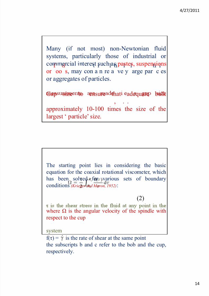
Many (if not most) non-Newtonian fluidsystems, particularly those of industrial or
commercial interest such as pastes, suspensions
or oo s, may con a n re a ve y arge par c es
or aggregates of particles.
Gap size to ensure that adequate bulk
, . .approximately 10-100 times the size of the
largest ‘ particle’ size.
The starting point lies in considering the basic
equation for the coaxial rotational viscometer, which
has been solved for various sets of boundary
conditions (Krieger and Maron, 1952):
(2)
where Ω is the angular velocity of the spindle with
respect to the cup
system
f(τ) = is the rate of shear at the same point
the subscripts b and c refer to the bob and the cup,
respectively.

7/23/2019 Visco Meters
http://slidepdf.com/reader/full/visco-meters 15/28
4/27/2011
15
Assuming the infinite cup boundary condition, τc
(shear stress on the cup) in equation (2) becomesequal to zero and the expression may be
differentiated with respect to τ b giving:
The rate of shear may be obtained by evaluating
(3)
(graphically) either of the derivatives on the righthand side of equation (3).
In a system which displays yield stress behaviour, the
integral in the general expression for the rate of shear
need not be evaluated from the bob all the way to the
.
This is due to the fact that, for such a system, noshearing takes place where τ is less than the yield
value, τ0 . Thus the integral need only be evaluated
rom e o o e cr ca ra us, crit, e ra us a
which τ=τ0.
7/23/2019 Visco Meters
http://slidepdf.com/reader/full/visco-meters 16/28
4/27/2011
16
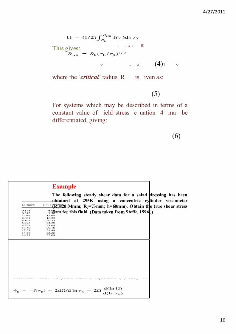
This gives:
(4)
where the ‘ critical ’ radius R is iven as:
(5)
For systems which may be described in terms of a
constant value of ield stress e uation 4 ma be
differentiated, giving:
(6)
The following steady shear data for a salad dressing has been
obtained at 295K using a concentric cylinder viscometer
(R 1=20.04mm; R 2=73mm; h=60mm). Obtain the true shear stress
data for this fluid. (Data taken from Steffe, 1996 .)
Example
7/23/2019 Visco Meters
http://slidepdf.com/reader/full/visco-meters 17/28
4/27/2011
17
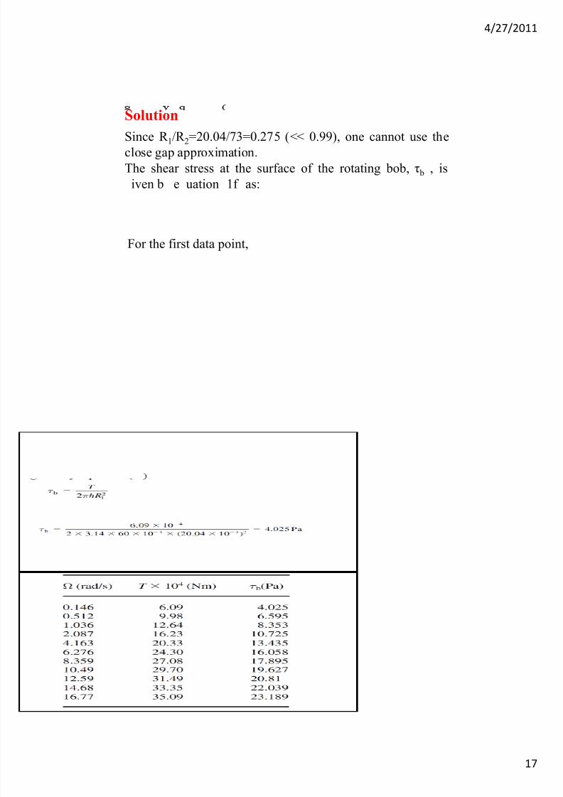
Since R 1/R 2=20.04/73=0.275 (<< 0.99), one cannot use theclose gap approximation.
The shear stress at the surface of the rotating bob, τ b , is
iven b e uation 1f as:
Solution
For the first data point,
7/23/2019 Visco Meters
http://slidepdf.com/reader/full/visco-meters 18/28
4/27/2011
18
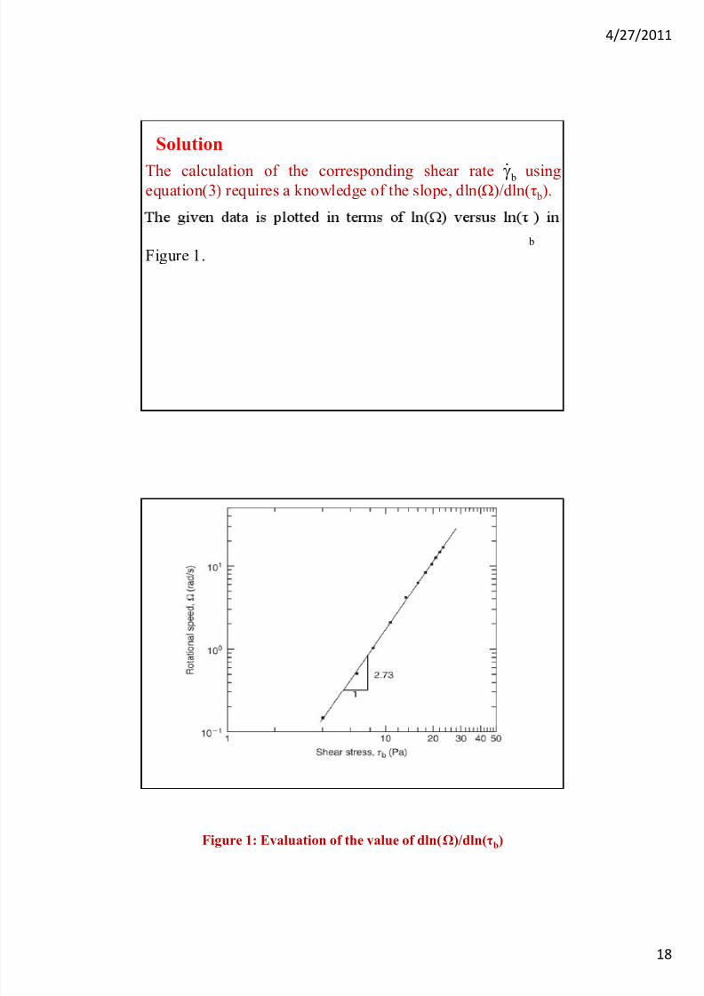
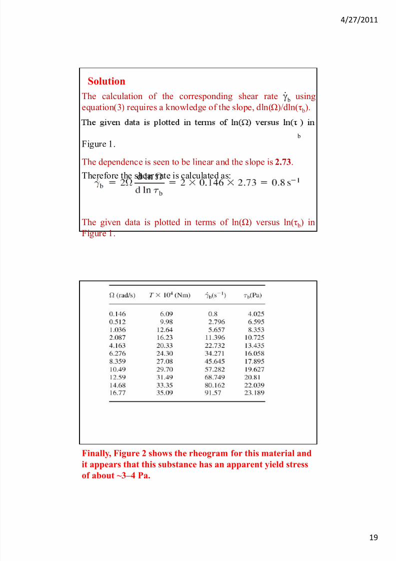
Solution
The calculation of the corresponding shear rate usingequation(3) requires a knowledge of the slope, dln(Ω)/dln(τ b).
b
b
Figure 1.
Figure 1: Evaluation of the value of dln(Ω)/dln(τb)
7/23/2019 Visco Meters
http://slidepdf.com/reader/full/visco-meters 19/28
4/27/2011
19
Solution
The calculation of the corresponding shear rate usingequation(3) requires a knowledge of the slope, dln(Ω)/dln(τ b).
b
b
Figure 1.
The dependence is seen to be linear and the slope is 2.73.
Therefore the shear rate is calculated as:
The given data is plotted in terms of ln(Ω) versus ln(τ b) in
Figure 1.
Finally, Figure 2 shows the rheogram for this material and
it appears that this substance has an apparent yield stress
of about ~3–4 Pa.
7/23/2019 Visco Meters
http://slidepdf.com/reader/full/visco-meters 20/28
4/27/2011
20
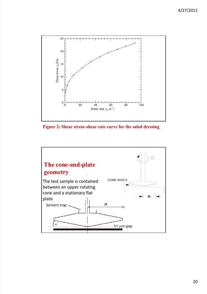
Figure 2: Shear stress–shear rate curve for the salad dressing
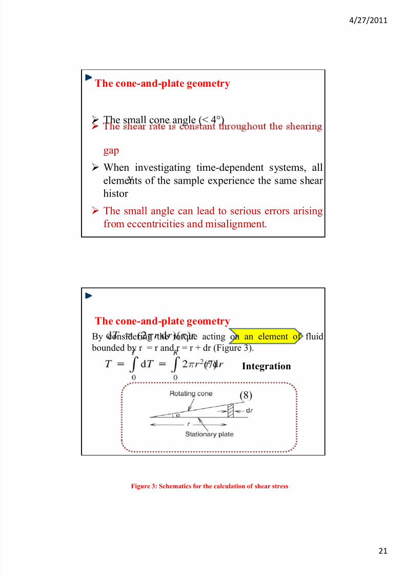
The cone-and-plate
geometry
The test sample is contained
between an upper rotating
cone and a stationary flat
plate
7/23/2019 Visco Meters
http://slidepdf.com/reader/full/visco-meters 21/28
4/27/2011
21
The cone-and-plate geometry
The small cone angle (< 4°)
gap
When investigating time-dependent systems, all
elements of the sample experience the same shear
histor
The small angle can lead to serious errors arising
from eccentricities and misalignment.
The cone-and-plate geometry
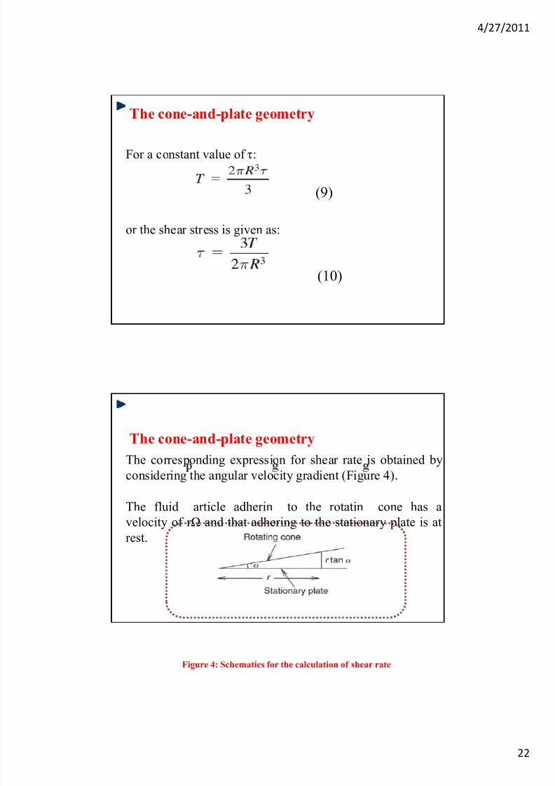
By considering the torque acting on an element of fluid
bounded by r = r and r = r + dr (Figure 3).
Integration(7)
(8)
Figure 3: Schematics for the calculation of shear stress
7/23/2019 Visco Meters
http://slidepdf.com/reader/full/visco-meters 22/28
4/27/2011
22
The cone-and-plate geometry
For a constant value of τ:
or the shear stress is given as:
(9)
(10)
The cone-and-plate geometry
The corresponding expression for shear rate is obtained by
considering the angular velocity gradient (Figure 4).
The fluid article adherin to the rotatin cone has a
velocity of r Ω and that adhering to the stationary plate is at
rest.
Figure 4: Schematics for the calculation of shear rate
7/23/2019 Visco Meters
http://slidepdf.com/reader/full/visco-meters 23/28
4/27/2011
23
The cone-and-plate geometry
The velocity gradient or shear rate is estimated as:
Since shear rate does not depend upon the value of r , the
fluid everywhere experiences the same level of shearing.
For small values of α , it is justified to use theapproximation tan α = α in equation (11).
Advantages
1. homogeneous shear field (for cone angles up to about
4°)
2. The theory involved is straightforward and simple
3. Only a small volume of sample is needed (2.5 ml at
most)
4. The mass and hence inertia of the platen held by thetorsion bar are low
5. Both normal stress and oscillatory measurements are
eas y ma e
6. The technique can be used for a wide range of fluids
7. It is easy to observe is the fluid is behaving strangely
e.g. fracturing
7/23/2019 Visco Meters
http://slidepdf.com/reader/full/visco-meters 24/28
4/27/2011
24
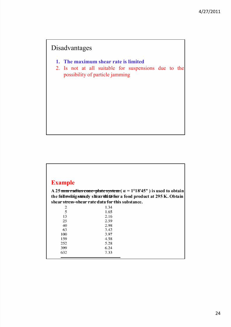
Disadvantages
1. The maximum shear rate is limited
2. Is not at all suitable for suspensions due to the
possibility of particle jamming
A 25 mm radius cone–plate system ( α = 1°18ʹ45ʺ ) is used to obtain
the following steady shear data for a food product at 295 K. Obtain
shear stress–shear rate data for this substance.
Example
7/23/2019 Visco Meters
http://slidepdf.com/reader/full/visco-meters 25/28
4/27/2011
25
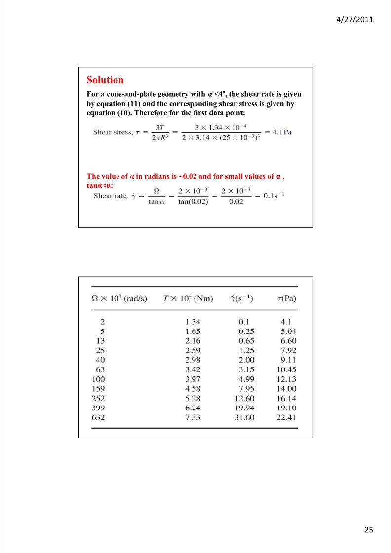
For a cone-and-plate geometry withα
<4º, the shear rate is givenby equation (11) and the corresponding shear stress is given by
equation (10). Therefore for the first data point:
Solution
The value of α in radians is ~0.02 and for small values of α ,
tanα≈α:
7/23/2019 Visco Meters
http://slidepdf.com/reader/full/visco-meters 26/28
4/27/2011
26
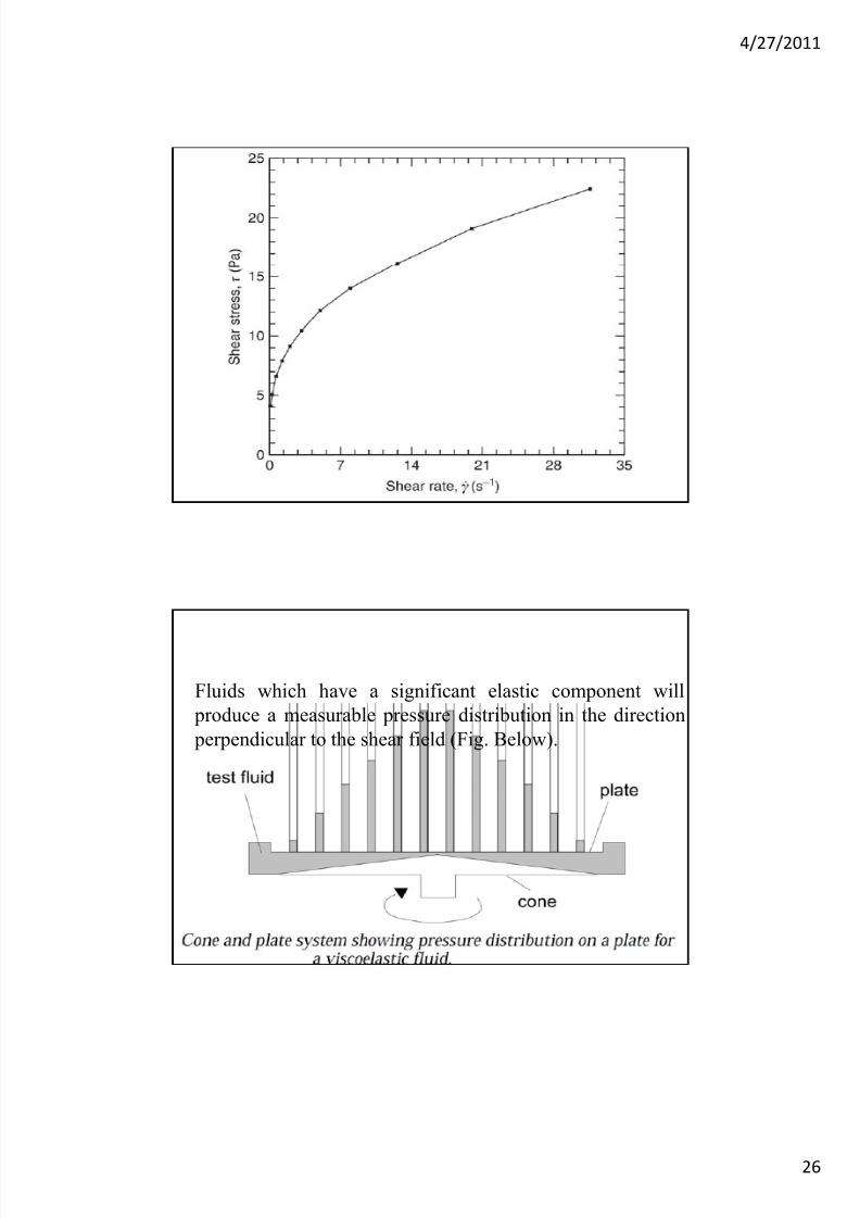
Fluids which have a significant elastic component will
produce a measurable pressure distribution in the direction
perpendicular to the shear field (Fig. Below).
7/23/2019 Visco Meters
http://slidepdf.com/reader/full/visco-meters 27/28
4/27/2011
27
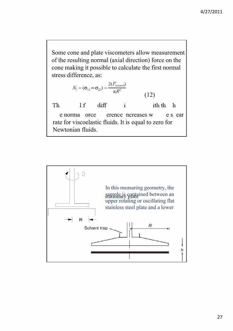
Some cone and plate viscometers allow measurement
of the resulting normal (axial direction) force on the
cone making it possible to calculate the first normal
stress difference, as:
(12)
e norma orce erence ncreases w e s earrate for viscoelastic fluids. It is equal to zero for
Newtonian fluids.
In this measuring geometry, the
sample is contained between an
upper rotating or oscillating flat
stainless steel plate and a lower
7/23/2019 Visco Meters
http://slidepdf.com/reader/full/visco-meters 28/28
4/27/2011
In contrast to the cone-and-plate geometry, the shear
strain is proportional to the gap height, h.
Advantages
1. It allows precise determination of rheological
parameters in oscillatory flow.
2. Loading and unloading of samples are easier than
in the cone-and-plate or concentric cylinder
geometries, particularly in the case of highly viscous
liquids or ‘ soft solids ’ such as foods, gels, etc.
1. When the fluid has a yield value difficulties arise if
shearing stresses fall below this value at any point.