Embed Size (px)
Citation preview
ELSEVIER Robotics and Autonomous Systems 19 (1997) 347-358
Robotics and
Autonomous Systems
Vision for man-machine interaction
James L. Crowley 1 IMAG Project .PRIMA, Institut National Polytechnique de Grenoble, 46 Ave Fdlix Viallet, 38031 Grenoble, France
Abstract
Computer vision provides a powerful tool for the interaction between man and machine. The barrier between physical objects (paper, pencils~ calculators) and their electronic counterparts limits both the integration of computing into human tasks, and the population willing to adapt to the required input devices. Computer vision, coupled with video projection using low cost devices, makes it possible for a human to use any convenient object, including fingers, as digital input devices. In such an "augmented reality", information is projected onto ordinary objects and acquired by watching the way objects are manipulated. In the first part of this paper we describe experiments with techniques for watching the hands and recognizing gestures.
Vision of the face is an important aspect of human-to-human communication. We have been experimenting with the use of computer vision "watch the face". In the second part of this paper we describe techniques for detecting, tracking and recognizing faces. When combined with real time image processing and active control of camera parameters, these techniques can greatly reduce the communications bandwidth required for videophone and videoconference communications.
Keywords: Computer visiton; Multi-modal man-machine interaction; Eigenfaces; Tracking; Principal components analysis
I. Vision and man-machine interaction
One of the effects of the continued exponential growth in available computing power has been an ex- ponential decrease in the cost of hardware for real time computer vision. This trend has been accelerated by the recent integralion of image acquisition process- ing hardware for muRi-media applications in personal computers. Lowered cost has meant more widespread experimentation in ~eal time computer vision, creat- ing a rapid evolution in robustness and reliability and the development of architectures for integrated vision systems [9].
Man-machine interaction provides a fertile appli- cations domain for this technological evolution. The
1 E-mail: [email protected].
barrier between physical objects (paper, pencils, cal- culators) and their electronic counterparts limits both the integration of computing into human tasks, and the population willing to adapt to the required input de- vices. Computer vision, coupled with video projection using low cost devices, makes it possible for human to use any convenient object, including fingers, as digital input devices. Computer vision can permit a machine to track, identify and watch the face of a user. This offers the possibility of reducing bandwidth for video- telephone applications, for following the attention of a user by tracking his fixation point, and for exploiting facial expression as an additional information channel between man and machine.
Traditional computer vision techniques have been oriented toward using contrast contours (edges) to de- scribe polyhedral objects. This approach has proved
0921-8890/97/$17.00 © 1997 Elsevier Science B.V. All rights reserved PII S0921-8890(96)00061-9
348 J.L. Crowley/Robotics and Autonomous Systems 19 (1997) 347-358
fragile even for man-made objects in a laboratory en- vironment, and inappropriate for watching deformable non-polyhedric objects such as hands as faces. Thus man-machine interaction requires computer vision scientists to "go back to basics" to design techniques adapted to the problem. The following sections de- scribe experiments with techniques for watching hands and faces.
2. Watching hands: Gestures as an input device
Human gesture serves three functional roles [6]: semiotic, ergotic, and epistemic. • The semiotic function of gesture is to communicate
meaningful information. The structure of a semi- otic gesture is conventional and commonly results from shared cultural experience. The good-bye ges- ture, the American sign language, the operational gestures used to guide airplanes on the ground, and even the vulgar "finger", each illustrates the semotic function of gesture.
• The ergotic function of gesture is associated with the notion of work. It corresponds to the capacity of humans to manipulate the real world, to create arti- facts, or to change the state of the environment by "direct manipulation". Shaping pottery from clay, wiping dust, etc. result from ergotic gestures.
• The epistemic function of gesture allows humans to learn from the environment through tactile experi- ence. By moving your hand over an object, you ap- preciate its structure, you may discover the material it is made of, as well as other properties. All three functions may be augmented using an in-
strument: Examples include a handkerchief for the semiotic good-bye gesture, a turn-table for the ergotic shape-up gesture of pottery, or a dedicated artifact to explore the world (for example, a retro-active system such as the pantograph [18] to sense the invisible).
In human-computer interaction, gesture has been primarily exploited for its ergotic function: typing on a keyboard, moving a mouse, and clicking buttons. The epistemic role of gesture has emerged effectively from pen computing and virtual reality: ergotic gestures ap- plied to an electronic pen, to a data-glove or to a body- suit are transformed into meaningful expressions for the computer system. Special purpose interaction lan- guages have been defined, typically 2-D pen gestures
as in the Apple Newton, or 3-D hand gestures to nav- igate in virtual spaces or to control objects remotely [21.
With the exception of the electronic pen and the keyboard both of which have their non-computerized counterparts, mouses, data-gloves, and body-suits are "artificial add-on's" that wire user down to the com- puter. They are not real end-user instruments (as a hammer would be), but convenient tricks for computer scientists to sense human gesture.
We claim that computer vision can transform ordi- nary artifacts and even body parts into effective input devices. Krueger's seminal work on the video place [13], followed recently by Wellner's concept of digi- tal desk [22] show that the camera can be used as a non-intrusive sensor for human gesture. However, to be effective the processing behind the camera must be fast and robust. The techniques used by Krueger and Wellner are simple concept demonstrations. They are fast but fragile and work only within highly con- strained environments.
We are exploring advanced computer vision tech- niques to non-intrusively observe human gesture in a fast and robust manner. In Section 2.2, we present Fin- gerPaint, an experiment in the use of cross-correlation as a means of tracking natural pointing devices for a digital desk. By "natural pointing device", we mean a bare finger or any real world artifact such as a pen or an eraser.
2.1. Projecting the workspace
In the digital desk a computer screen is projected onto a physical desk using a video projector, such as a liqiud-crystal "data-show" working with standard overhead projector. A video camera is set up to watch the workspace such that the surface of the projected image and the surface of the imaged area coincide. This coincidence cannot match "pixel to pixel" unless the camera and projector occupy the same physical space and use the same optics. Since this is impos- sible, it is necessary to master the transformation be- tween the real workspace, and the imaged area. This transformation is a mapping between two planes.
The projection of a plane to another plane is an affine transformation. Thus the video projector can be used to project a reference frame onto the physical desk in the form of a set of points. The camera image
J.L Crowley /Robotics and Autonomous Systems 19 (1997) 347-358 349
Fig. 1. Drawing and placing with "fingerPaint" (from [3]).
of these four points permits the calibration of six co- efficients (A, B, C,/9, E, F) which transform image coordinates (i, j ) to workspace coordinates (x, y).
x = Ai + Bj + C, y--- Di + E j + F.
The visual processes required for the digital desk are relatively simple. The basic operation is tracking of a pointing device such as finger, a pencil or an eraser. Such tracking should be supported by methods to de- termine what device to track and to detect when track- ing has failed. A method is also required to detect the equivalent of "mouse-down" and "mouse-up" events.
The tracking problem can be ,expressed as: "Given an observation of an object at time t, determine the most likely position of the same object at time t + A T". If different objects can be used as a pointing device, then the system must include some form of "trig- ger" which includes presentation of the pointing de- vice to the system. The observation of the pointing device gives a small neighborhood, w(n, m), of an im- age p(i, j ) . This neighborhood will serve as a "ref- erence template". The tracking problem can then be expressed: given the position of the pointing device in the kth image, determine the most likely position of the pointing device in the (k + l)th image. The size of the tracked neighborhood must be determined such that the neighborhood includes a sufficiently large por- tion of the object to be tracked with a minimum of the background.
We have experimented with a number of differ- ent approaches to track pointing devices: these in- clude color, correlation tracking, principal components and active contours (snakes) [3,5]. The active con-
tour model [12] presented problems which we be- lieve can be resolved, but which will require additional experiments. Our currrent demonstration uses cross- correlation and principal components analysis.
2.2. FingerPaint
As a simple demonstration, we constructed a pro- gram called "FingerPaint". 2 Fingerpaint runs on an Apple Quadra AV/840 and uses a workspace projected with an overhead projector using a liquid-crystal dis- play "data-show". A CCD camera with an 18 mm lens observes this workspace and provides visual input. "Finger-down" and "finger-up" events are simulated using the space bar of the keyboard but they could be sensed using a microphone attached to the surface of the desk. As illustrated in Fig. 1, any "natural pointing device" such as finger can be used to draw pictures and letters, or to move a drawing.
The image at time (k+ 1)AT to be searched will be noted as Pk+l (i, j ) . The search process can generally be accelerated by restricting the search to a region of this image, denoted s(i, j ) , and called a "Region of Interest". Our system uses a square search region of size M x M centered on the location where the reference template was detected in the previous image.
The robustness of the tracking system is reasonable but, as discussed below, its performance is inadequate with respect to Fitt's law [6]. Preliminary experiments with local users indicate, however, that the current
2 The FingerPaint system has been implemented by Francois Berard.
350 J.L. Crowley /Robotics and Autonomous Systems 19 (1997) 347-358
performanCe is acceptable for investigation purposes. In addition, the widespread availability of image ac- quisition and processing hardware adequate for real time correlation should alleviate our current perfor- mance problem. Most importantly, this demonstration has permitted us to explore the problems involved in watching the gesture.
2.3. Correlation as a tracking technique for the digital desk
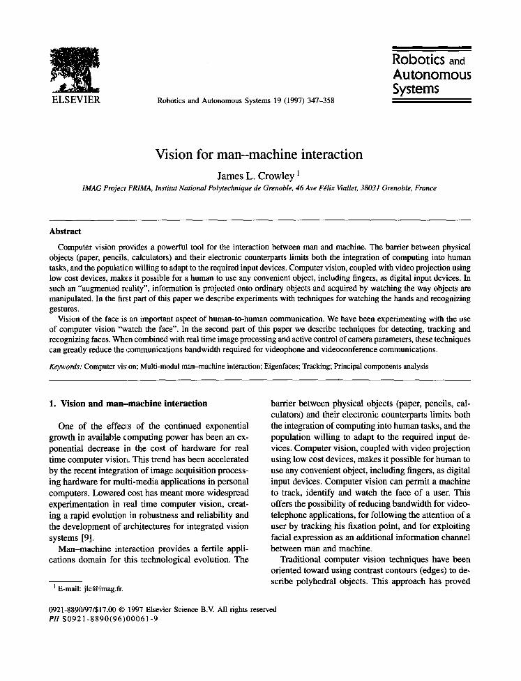
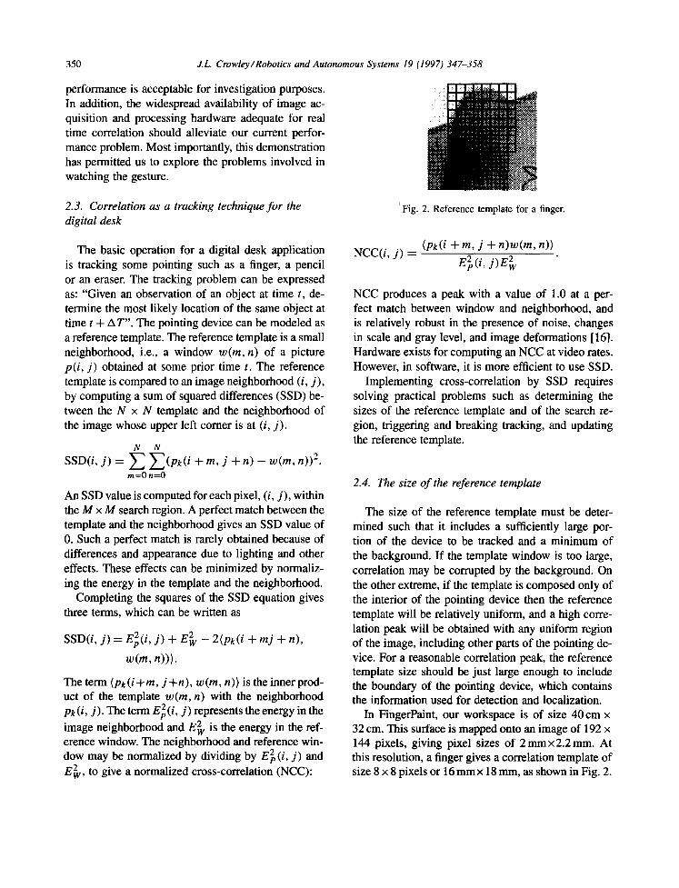
~Fig. 2. Reference template for a finger.
The basic operation for a digital desk application is tracking some pointing such as a finger, a pencil or an eraser. The tracking problem can be expressed as: "Given an observation of an object at time t, de- termine the most likely location of the same object at time t + A T". The pointing device can be modeled as a reference template. The reference template is a small neighborhood, i.e., a window w(m, n) of a picture p(i, j) obtained at some prior time t. The reference template is compared to an image neighborhood (i, j ) , by computing a sum of squared differences (SSD) be- tween the N x N template and the neighborhood of the image whose upper left comer is at (i, j ) .
N N
J) = E E (pk(i + m' j + n) - n)) 2. SSD(i, w(m, m=0 n=0
An SSD value is computed for each pixel, (i, j ) , within the M x M search region. A perfect match between the template and the neighborhood gives an SSD value of 0. Such a perfect match is rarely obtained because of differences and appearance due to lighting and other effects. These effects can be minimized by normaliz- ing the energy in the template and the neighborhood.
Completing the squares of the SSD equation gives three terms, which can be written as
SSD(i, j ) = E2(i, j) + E 2 - 2(pk(i + mj + n),
w(m, n))).
The term (pk(i+m, j+n), w(m, n)) is the inner prod- uct of the template w(m, n) with the neighborhood pk(i, j). The term E2(i, j) represents the energy in the
image neighborhood and E 2 is the energy in the ref- erence window. The neighborhood and reference win- dow may be normalized by dividing by E~(i, j) and E~v, to give a normalized cross-correlation (NCC):
(p~(i + m, j + n)w(m, n)) NCC(i, j ) = E2 (i ' j ) E 2
NCC produces a peak with a value of 1.0 at a per- fect match between window and neighborhood, and is relatively robust in the presence of noise, changes in scale and gray level, and image deformations [16]. Hardware exists for computing an NCC at video rates. However, in software, it is more efficient to use SSD.
Implementing cross-correlation by SSD requires solving practical problems such as determining the sizes of the reference template and of the search re- gion, triggering and breaking tracking, and updating the reference template.
2.4. The size of the reference template
The size of the reference template must be deter- mined such that it includes a sufficiently large por- tion of the device to be tracked and a minimum of the background. If the template window is too large, correlation may be corrupted by the background. On the other extreme, if the template is composed only of the interior of the pointing device then the reference template will be relatively uniform, and a high corre- lation peak will be obtained with any uniform region of the image, including other parts of the pointing de- vice. For a reasonable correlation peak, the reference template size should be just large enough to include the boundary of the pointing device, which contains the information used for detection and localization.
In FingerPaint, our workspace is of size 40 cm x 32 cm. This surface is mapped onto an image of 192 x 144 pixels, giving pixel sizes of 2mmx2.2mm. At this resolution, a finger gives a correlation template of size 8 x 8 pixels or 16 mmx 18 mm, as shown in Fig. 2.
J.L Crowley /Robotics and Autonomous Systems 19 (1997) 347-358 351
2.5. The size of the search region
The size M of the' search region depends on the speed of the pointing device. Considerations based on Fitt's law indicate a need for tracking speeds of up to 180 cm/s. To verify this, we performed an experiment in which a finger was filmed making typical pointing movements in our workspace. The maximum speed observed in this experiment was Vm=139cm/s. Expressed in pixels this gives Vm =695 pixels per second.
Given an image processing cycle time of AT sec- onds and a maximum pointer speed of Vm pixels per second, it is possible to specify that the point- ing device will be tound within a radius of M = ATVm pixels of its position in the previous frame. For images of 192 x 144 pixels, our built-in dig- itizer permits us to register images at a maximum frame rate of 24 frames per second, giving a cycle time of ATmax = 41.7 ms. This represents an upper limit on image acquisition speed which is attainable only if image tracking were to take no computation time.
The computational cost of cross-correlation is di- rectly proportional to the number of pixels in the search region. Reducing the number of pixels will de- crease the time needed for the inner loop of corre- lation by the same amount. This, in turn, increases the number of times that correlation can be operated within a unit time, timber decreasing the region over which the search must be performed. Thus there is an inverse relation between the width of the search re- gion, M, and the maximum tracking speed, Vm. The smaller the search region, the faster the finger move- ment that can be tracked, up to a limit set by digitizing hardware.
The fastest tracking movement can be expected at a relatively small search region. This is confirmed by experiments. To verify the inverse relation be- tween M and Vm, we systematically varied the size of the search region from M = 10 to M = 46 pixels and measured the cycle time that was ob- tained. The maximum speed of 126 pixels per sec- ond is obtained with M = 26. Although this is 5.5 times less than the maximum desirable speed (i.e., 695 pixesl per second), the system is quite usable to perform drawing and placements in a "natural" way.
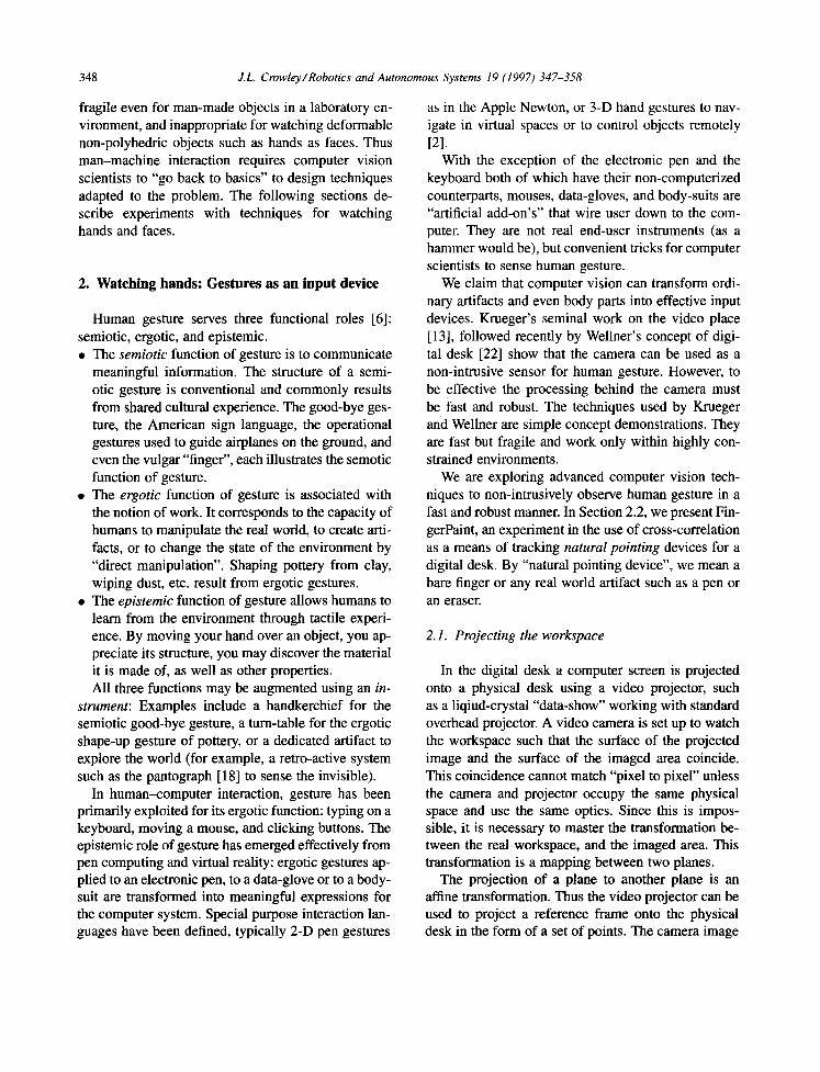
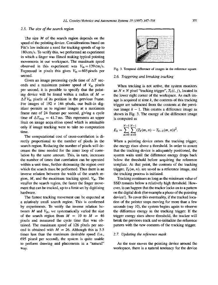
Fig. 3. Temporal difference of images in the reference square.
2.6. Triggering and breaking tracking
When tracking is not active, the system monitors an N x N pixel "tracking trigger", Tk(i, j ) , located in the lower right comer of the workspace. As each im- age is acquired at time k, the contents of this tracking trigger are subtracted from the contents at the previ- ous image k - 1. This creates a difference image as shown in Fig. 3. The energy of the difference image is computed as
N-1N-1 ek = f ] n) - rk_l(m, n)) 2.
m=0 n=0
When a pointing device enters the tracking trigger, the energy rises above a threshold. In order to assure that the tracking device is adequately positioned, the system waits until the difference energy drops back below the threshold before acquiring the reference template. At that point, the contents of the tracking trigger, Tk (m, n), are saved as a reference image, and the tracking process is initiated.
Tracking continues as long as the minimum value of SSD remains below a relatively high threshold. How- ever, it can happen that the tracker locks on to a pattern on the digital desk (for example a photo of the pointing device!). To cover this eventuality, if the tracked loca- tion of the pointer stops moving for more than a few seconds (say 10), the system begins again to observe the difference energy in the tracking trigger. If the trigger energy rises above threshold, the tracker will break the previous track and re-initialize the reference pattern with the new contents of the tracking trigger.
2.7. Updating the reference mask
As the user moves the pointing device around the workspace, there is a natural tendency for the device
3 5 2 J.L. Crowley/Robotics and Autonomous Systems 19 (1997) 347-358
:~̀:~.~̀~.~..:.:.:~..̀~̀~:.~̀:~..~..:.:.:.:~....̀.̀.̀.̀....:~.:.:..~.~..:~:..~:~:~...̀:.:.........:...... '-~.'.~.~:~:":~':..'.:..:.:.:.i~' .'.:::: ~.'.:.:.:...':'.'.'.':' ::::: : :: :::-: :~-~:~ .'..'.: ::: ::: J-'.': .~:~.". :~ ~.:'.':~i~:':?.:~:':~.~-~: ":~'~-i~.i~ • ~:~:.̀ .̀.̀ .::~.:~.::::::~.:~:~:i.~:!~.~.~:.̀ .:~i~:..̀ .~̀ .~:̀ ..~!~::~..̀ :~ ~!~!i!.~!!.~.~.!!:!~ i~!~.~.:.:.:.:~̀..:̀.~.i~..̀..:~:~:~:~:!::.~:~::::~::..̀...~i:~..̀::!~:...:i:~:...:i:i:i:i:::::~:~:::::::.̀::..̀.:~ ~::',~:~:::::.,.:.~::.~,:~:~ ~.~.~ .~,." • ." ~ ; ~ .~+~..." . R ~ . - " . ~ + . . ~ .:.:..~.,: .~
~.~.'.~ ~.~ ~'~"~:.~i ~ : ~ . . '~!:~:~:.'::" " ::~.,' ~ ~ , s ~ "~'~ ":~:'": ~ ,'::~-'..:.~.'..'. ,'~.'.~-:~::::,~ ~:.'v ' ~:~::.,:" ~.~:.'.:.:.:.:'" ~:,.~
~'x~'~'~":::' . . . . . . . . '~ " ~:::' ~ ~ i i ~ : ' " : " ' " . . . . . . . .
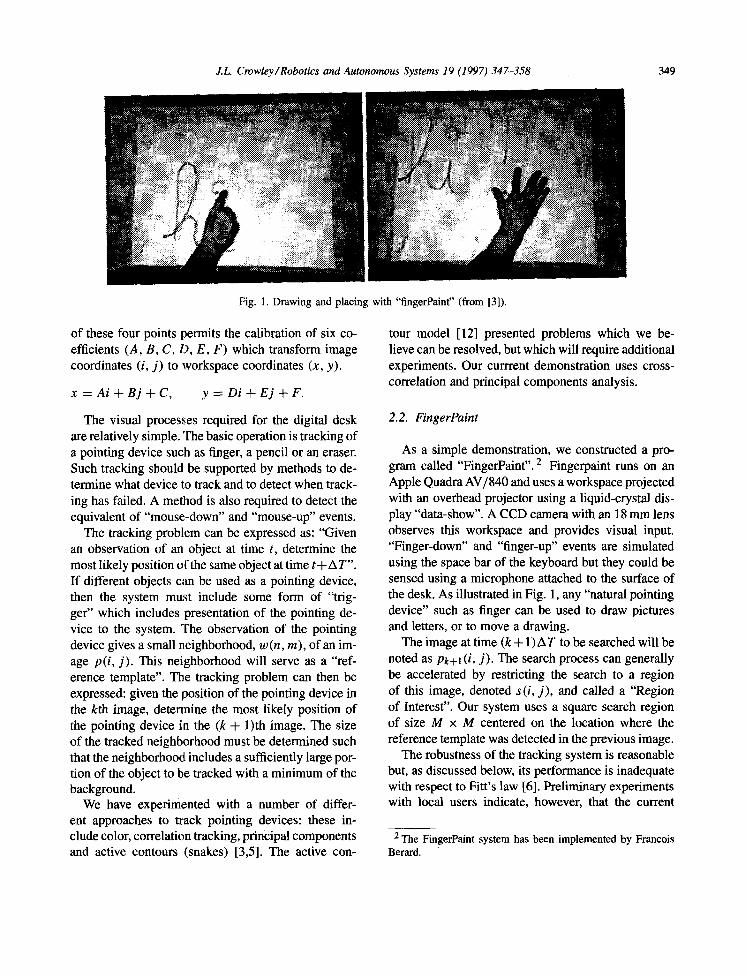
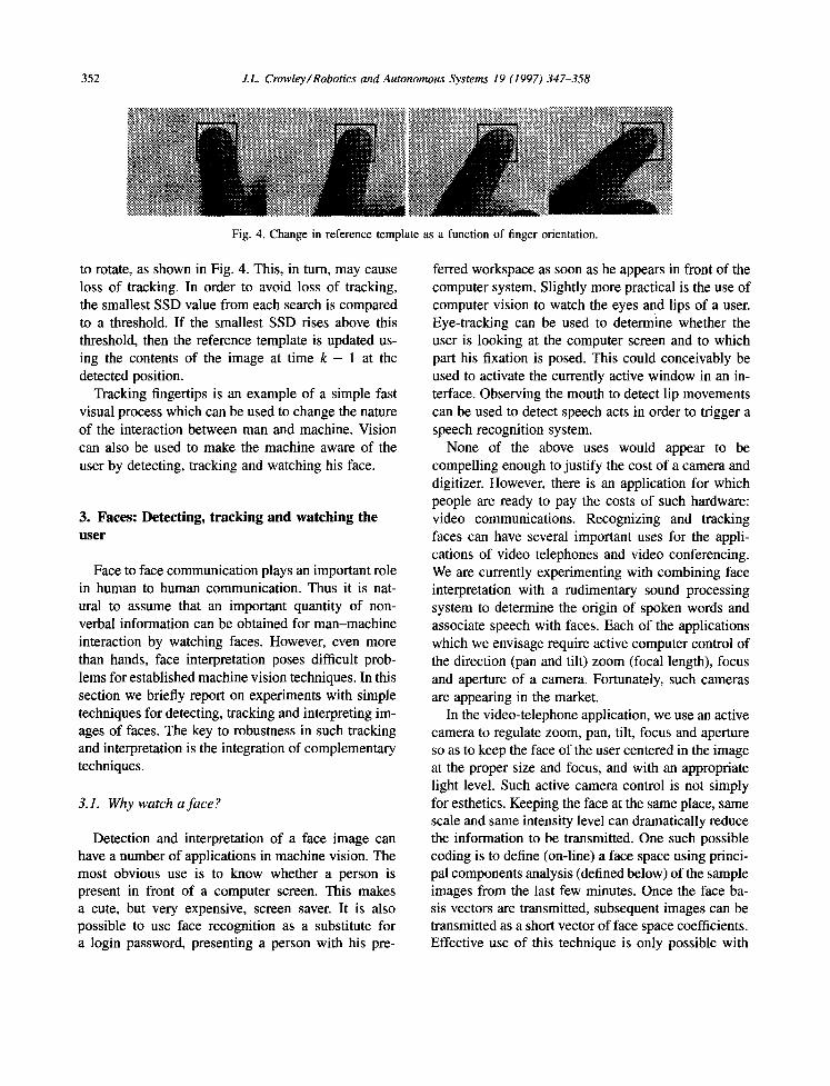
Fig. 4. Change in reference template as a function of finger orientation.
to rotate, as shown in Fig. 4. This, in turn, may cause loss of tracking. In order to avoid loss of tracking, the smallest SSD value from each search is compared to a threshold. If the smallest SSD rises above this threshold, then the reference template is updated us- ing the contents of the image at time k - 1 at the detected position.
Tracking fingertips is an example of a simple fast visual process which can be used to change the nature of the interaction between man and machine. Vision can also be used to make the machine aware of the user by detecting, tracking and watching his face.
3. Faces: Detecting, tracking and watching the user
Face to face communication plays an important role in human to human communication. Thus it is nat- ural to assume that an important quantity of non- verbal information can be obtained for man-machine interaction by watching faces. However, even more than hands, face interpretation poses difficult prob- lems for established machine vision techniques. In this section we briefly report on experiments with simple techniques for detecting, tracking and interpreting im- ages of faces. The key to robustness in such tracking and interpretation is the integration of complementary techniques.
3.1. Why watch a face ?
Detection and interpretation of a face image can have a number of applications in machine vision. The most obvious use is to know whether a person is present in front of a computer screen. This makes a cute, but very expensive, screen saver. It is also possible to use face recognition as a substitute for a login password, presenting a person with his pre-
ferred workspace as soon as he appears in front of the computer system. Slightly more practical is the use of computer vision to watch the eyes and lips of a user. Eye-tracking can be used to determine whether the user is looking at the computer screen and to which part his fixation is posed. This could conceivably be used to activate the currently active window in an in- terface. Observing the mouth to detect lip movements can be used to detect speech acts in order to trigger a speech recognition system.
None of the above uses would appear to be compelling enough to justify the cost of a camera and digitizer. However, there is an application for which people are ready to pay the costs of such hardware: video communications. Recognizing and tracking faces can have several important uses for the appli- cations of video telephones and video conferencing. We are currently experimenting with combining face interpretation with a rudimentary sound processing system to determine the origin of spoken words and associate speech with faces. Each of the applications which we envisage require active computer control of the direction (pan and tilt) zoom (focal length), focus and aperture of a camera. Fortunately, such cameras are appearing in the market.
In the video-telephone application, we use an active camera to regulate zoom, pan, flit, focus and aperture so as to keep the face of the user centered in the image at the proper size and focus, and with an appropriate light level. Such active camera control is not simply for esthetics. Keeping the face at the same place, same scale and same intensity level can dramatically reduce the information to be transmitted. One such possible coding is to define (on-line) a face space using princi- pal components analysis (defined below) of the sample images from the last few minutes. Once the face ba- sis vectors are transmitted, subsequent images can be transmitted as a short vector of face space coefficients. Effective use of this technique is only possible with
J.L Crowley /Robotics and Autonomous Systems 19 (1997) 347-358 353
active camera control. Other image codings can also be accelerated if the face image is normalized in po- sition, size, gray level and held in focus.
In the videoconference scenario, a passive camera with a wide-angle lens provides a global view of the persons seated around a conference table. An active camera provides a close-up of whichever person is speaking. When no one is speaking, and during tran- sitions of the close-up camera, the wide-angle camera view can be transmitted. Face detection, operating on the wide-angle images, can be used to estimate the location of conference participants around the table. When a participant speaks, the high-resolution cam- era can zoom onto the face of the speaker and hold the face in the center of the image.
What are the technologies required for the above applications? Both scenarios require an ability to de- tect and track faces, and an ability to servo control pan, tilt, zoom, focus and aperture so as to maintain a selected face in the desired position, scale and contrast level. From a hardware standpoint, such an application requires a camera for which these axes can be con- trolled. Such camera heads are increasingly appearing in the market. For example, we have purchased a small RS232 controllable camera from a Japanese manufac- turer which produces excellent color images for title more than the price of a normal color camera.
A second hardware requirement is the ability to dig- itize and process images at something close to video rates. The classic bottleneck here is communication of the image between the frame-grabber and the pro- cessor. Fortunately, the rush to multi-media applica- tions has pushed a number of vendors to produce workstations in which a frame-grabber is linked to the processor by such a high speed bus. Typical hardware available for a reasonable cost permits acquisition of up to 20 frames pe~r second at full image size and full video rates for reduced resolution images. Adding simple image proce:ssing can reduce frame rates to 2-10 Hz (depending on image resolution). Such work- stations are suitable for concept demonstrations and for experiments needed to define performance spec- ifications. An additional factor of 2 (18 months) in bandwidth and processing power will bring us to full video rates.
The questions we ask in the laboratory are: What software algorithms can be used for face detection, tracking and recognition, and what are the system's
concepts needed to tie these processes together. Sys- tem's concepts have been the subject of our ESPRIT Basic Research Project "Vision as Process", described in the book [9] or the paper [8] for more details.
3.2. Detection: Finding a face with color
One of the simplest methods for detecting pixels which might be part of a face is to look for skin color. Human skin has a particular hue and saturation. The intensity, however, will vary as a function of the rela- tive direction to the illumination. Of course, the per- ceived hue and saturation will be the product of the color of the ambient light and the skin color [20].
We have found that candidate pixels for faces and hands can be detected very rapidly using a normalized color histogram. Histogram color can be normalized for changes in intensity by dividing the color vector by the luminance. This permits us to convert a color vector [R, G, B] having three dimensions into a vector
• [r, g] of normalized color having two dimensions. The normalized color histogram H(r, g) provides a fast means of skin detection. The histogram is initialized by observing a patch of the skin and counting the number of times each normalized color value occurs. The histogram contains the number of pixels which exhibit a particular color vector [r, g]. Dividing by the total number of pixels in the histogram, N, gives the probability of obtaining a particular vector given that the pixel observes skin:
1 P (color/skin) = ~ H (r, g).
Bayes rule can be used to determine the probability of skin given the color has values [r, g]:
P(skin) P (skin/color) - - - P (color/skin).
P (color)
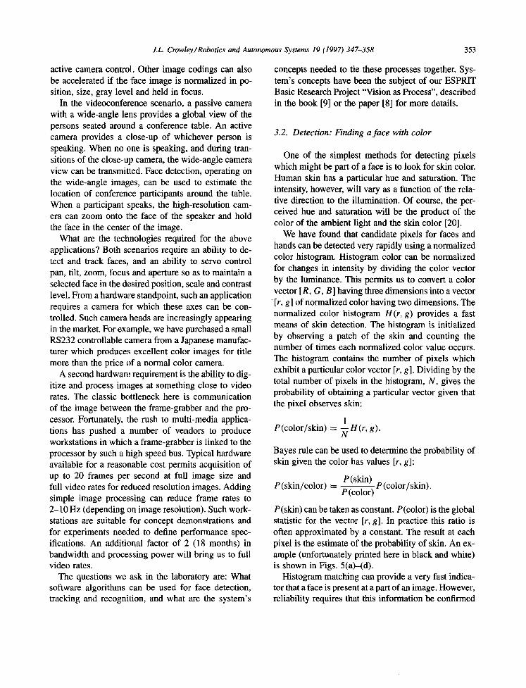
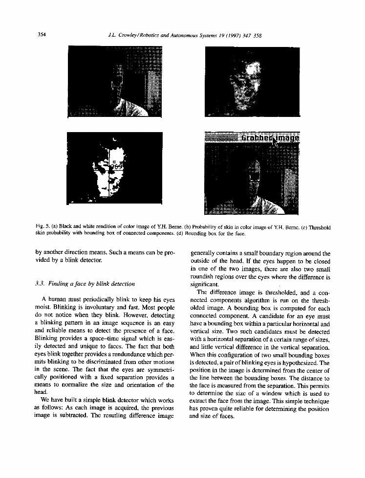
P(skin) can be taken as constant. P(color) is the global statistic for the vector [r, g]. In practice this ratio is often approximated by a constant. The result at each pixel is the estimate of the probability of skin. An ex- ample (unfortunately printed here in black and white) is shown in Figs. 5(a)-(d).
Histogram matching can provide a very fast indica- tor that a face is present at a part of an image. However, reliability requires that this information be confirmed
354 J.L. Crowley/Robotics and Autonomous Systems 19 (1997) 347-358
Fig. 5. (a) Black and white rendition of color image of Y.H. Berne. (b) Probability of skin in color image of Y.H. Berne. (c) Threshold skin probability with bounding box of connected components. (d) Bounding box for the face.
by another direction means. Such a means can be pro- vided by a blink detector.
3.3. Finding a face by blink detection
A human must periodically blink to keep his eyes moist. Blinking is involuntary and fast. Most people do not notice when they blink. However, detecting a blinking pattern in an image sequence is an easy and reliable means to detect the presence of a face. Blinking provides a space-time signal which is eas- ily detected and unique to faces. The fact that both eyes blink together provides a rendundance which per- mits blinking to be discriminated from other motions in the scene. The fact that the eyes are symmetri- cally positioned with a fixed separation provides a means to normalize the size and orientation of the head.
We have built a simple blink detector which works as follows: As each image is acquired, the previous image is subtracted. The resutling difference image
generally contains a small boundary region around the outside of the head. If the eyes happen to be closed in one of the two images, there are also two small roundish regions over the eyes where the difference is significant.
The difference image is thresholded, and a con- nected components algorithm is run on the thresh- olded image. A bounding box is computed for each connected component. A candidate for an eye must have a bounding box within a particular horizontal and vertical size. Two such candidates must be detected with a horizontal separation of a certain range of sizes, and little vertical difference in the vertical separation. When this configuration of two small bounding boxes is detected, a pair of blinking eyes is hypothesized. The position in the image is determined from the center of the line between the bounding boxes. The distance to the face is measured from the separation. This permits to determine the size of a window which is used to extract the face from the image. This simple technique has proven quite reliable for determining the position and size of faces.
J . L . Crowley/Robotics and Autonomous Systems 19 (1997) 347-358 3 5 5
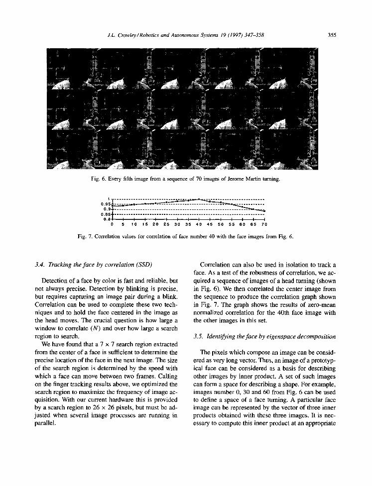
F i g . 6. Every fifth image from a sequence of 70 images of Jerome Martin turning.
I T . . . . . . . . . . . . . . . . . . . . . . ~ ] ~ l ~ l ~ . . . . . . . . . . . . . . . . . . 0 . 9 5 ~ . - - ~ : . . ~ . - ~ l ~ = ~ = - - - ' ~ - - . . . . . . . . . . . . . . . . . . . . . . . . - - ' ~ -~ , . . =~ . . . . . . . . . . .
O. 9 + - _ . . . . . . . . . . . . . . . . . . . . . . . . . . . . . . . . . . . . . . . . . . . . . . . . . _ _ _ _ . ' ~_ , , . . . . . , . ~ . . , ,
0 . 8 5 1 • . . . . . . . . . . . . . . . . . . . . . . . . . . . . . . . . . . . . . . . . . . . . . . . . . . . . . . . . . . . . . . . . 0 . 8 / I I I I I I I I I ! I I I I
0 5 1 0 1 5 2 0 2 5 3 0 3 5 4 0 4 5 5 0 5 5 6 0 6 5 7 0
Fig. 7. Correlation values for correlation of face number 40 with the face images from Fig. 6.
3.4. Tracking the face by correlation (SSD)
Detection of a face by color is fast and reliable, but not always precise. Detection by blinking is precise, but requires capturing an image pair during a blink. Correlation can be used to complete these two tech- niques and to hold the face centered in the image as the head moves. The crucial question is how large a window to correlate (N) and over how large a search region to search.
We have found that a 7 × 7 search region extracted from the center of a face is sufficient to determine the precise location of the face in the next image. The size of the search region is determined by the speed with which a face can move between two frames. Calling on the finger tracking results above, we optimized the search region to maximize the frequency of image ac- quisition. With our current hardware this is provided by a search region to 26 × 26 pixels, but must be ad- justed when several image processes are running in parallel.
Correlation can also be used in isolation to track a face. As a test of the robustness of correlation, we ac- quired a sequence of images of a head turning (shown in Fig. 6). We then correlated the center image from the sequence to produce the correlation graph shown in Fig. 7. The graph shows the results of zero-mean normalized correlation for the 40th face image with the other images in this set.
3.5. Identifying the face by eigenspace decomposition
The pixels which compose an image can be consid- ered as very long vector. Thus, an image of a prototyp- ical face can be considered as a basis for describing other images by inner product. A set of such images can form a space for describing a shape. For example, images number 0, 30 and 60 from Fig. 6 can be used to define a space of a face turning. A particular face image can be represented by the vector of three inner products obtained with these three images. It is nec- essary to compute this inner product at an appropriate
3 5 6 J . L . C r o w l e y / R o b o t i c s a n d A u t o n o m o u s S y s t e m s 1 9 ( 1 9 9 7 ) 3 4 7 - 3 5 8
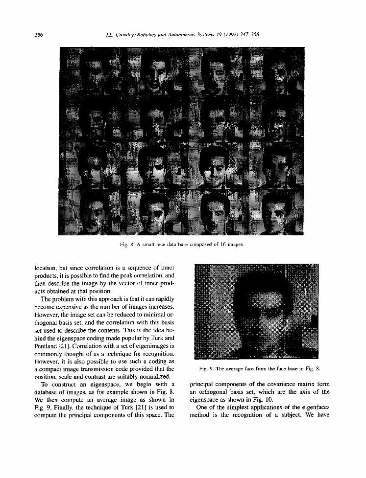
Fig. 8. A small face data base composed of 16 images.
location, but since correlation is a sequence of inner products, it is possible to find the peak correlation, and then describe the image by the vector of inner prod- ucts obtained at that position.
The problem with this approach is that it can rapidly become expensive as the number of images increases. However, the image set can be reduced to minimal or- thogonal basis set, and the correlation with this basis set used to describe the contents. This is the idea be- hind the eigenspace coding made popular by Turk and Pentland [21 ]. Correlation with a set of eigenimages is commonly thought of as a technique for recognition. However, it is also possible to use such a coding as a compact image transmission code provided that the position, scale and contrast are suitably normalized.
To construct an eigenspace, we begin with a database of images, as for example shown in Fig. 8. We then compute an average image as shown in Fig. 9. Finally, the technique of Turk [21] is used to compute the principal components of this space. The
i iii!i!iiil)il i
:::::::::::::::;:;: ii?iiiiiiii!!!{i!!~i! : ::~i.:::~:::':~ ""
i!iiii::iiiiiiiiii ................... :lii ...... ~?: i;.?ii::
........... !i
::::::::::::::::::::::::::: :::::::::::::::::::::::::: . . . . . .
:)3:)3:3:) :5 )5:i:'(.'~5~3~ i iiiiiiiiiiiiiii iii~i!~ig~ ............................ ::: ................... i : i~
" " ' "$ :~:<:~:~A~ ::)~:~:~2~:.~ ~. 'w. '
7 ~ '>%"z ~ . # z <
,iii® i . . ,,, ,, .., ,. ,
L:ii~ . . . . . . . . . . . . .
Fig. 9. The average face from the face base in Fig. 8.
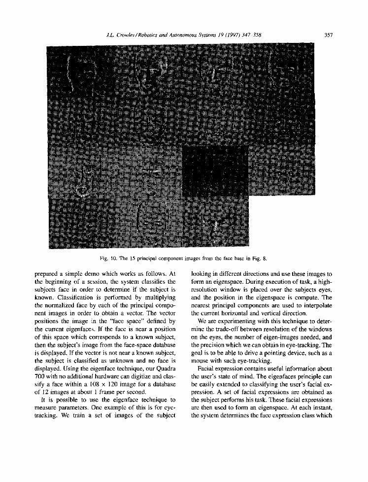
principal components of the covariance matrix form an orthogonal basis set, which are the axis of the eigenspace as shown in Fig. 10.
One of the simplest applications of the eigenfaces method is the recognition of a subject. We have
J.L. Crowlev /Robotics and Autonomous Svstems 19 (1997) 347-358 357
Fig. 10. The 15 principal component images from the face base in Fig. 8.
prepared a simple demo which works as follows. At the beginning of a session, the system classifies the subjects face in order to determine if the subject is known. Classification is performed by multiplying the normalized face by each of the principal compo- nent images in order to obtain a vector. The vector positions the image in the "face space" defined by the current eigenface:~. If the face is near a position of this space which corresponds to a known subject, then the subject's image from the face-space database is displayed. If the vector is not near a known subject, the subject is classified as unknown and no face is displayed. Using the eigenface technique, our Quadra 700 with no additional hardware can digitize and clas- sify a face within a 108 x 120 image for a database of I2 images at about 1 frame per second.
It is possible to use the eigenface technique to measure parameters. One example of this is for eye- tracking. We train a set of images of the subject
looking in different directions and use these images to form an eigenspace. During execution of task, a high- resolution window is placed over the subjects eyes, and the position in the eigenspace is compute. The nearest principal components are used to interpolate the current horizontal and vertical direction.
We are experimenting with this technique to deter- mine the trade-off between resolution of the windows on the eyes, the number of eigen-images needed, and the precision which we can obtain in eye-tracking. The goal is to be able to drive a pointing device, such as a mouse with such eye-tracking.
Facial expression contains useful information about the user's state of mind. The eigenfaces principle can be easily extended to classifying the user's facial ex- pression. A set of facial expressions are obtained as the subject performs his task. These facial expressions are then used to form an eigenspace. At each instant, the system determines the face expression class which
358 J.L. Crowley/Robotics and Autonomous Systems 19 (1997) 347-358
most closely corresponds to the user 's current expres- sion. In this way, we can exper iment by anticipating
the user 's "mood" based on facial expression.
4. Conclusion
In this paper we have presented some pre l iminary
results with detect ion and tracking of fingers and faces. We have also exper imented with eye-tracking using
snakes and other techniques based on signal process- ing, as well as face interpretat ion using eigenfaces. It
is increasingly apparent that computer vision has the potential to provide a rich new source of interaction modes for c o m p u t e r - h u m a n interaction. Vision can make the machine "aware" of the user, his movements and environment , in ways that are yet to be invented.
References
[1] E Anandan, Measuring visual motion from image sequence, Ph. D. Dissertation and COINS Technical Report 87-21, University of Massachusetts, Amherst, 1987.
[2] T. Baudel and M. Beaudouin-Lafon, Charade: Re- mote control of objects using free-hand gestures, Communications of the ACM 36 (7) (1993) 28-35.
[3] E Berard, Vision par ordinateur pour la r~alit~ augment6e: Application au bureau num6rique, M6moire du D.E.A. en Informatique, Univerist6 Joseph Fourier, 1994.
[4] A. Blake and M. Israd, 3D Position, attitude and shape input using video tracking of hands and lips, ACM - SIGGRAPH Ann. Conf. on Computer Graphics (1994).
15] C. Cadoz, Les r6alitfs virtuelles, Dominos, Flammarion, 1994.
[6] S.K. Card, T.E Moran and N. Newell, The Psychology of Human-Computer Interaction (Lawrence Erlbaum, London, 1983).
[7] J. Coutaz, Interfaces hommes-ordinateur conception et r6alisation, Dunod Informatique, 1994.
[8] J.L. Crowley and J.M. Bedrune, Integration and control of reactive visual processes, Proc. European Conf. on Computer Vision (ECCV)-'94, Stockholm (May 1994).
[9] J.L. Crowley and H. Christensen, Vision as Process (Springer, Heidelberg, 1994).
[10] C. Harris, Tracking with rigid models, in: Active Vision (MIT Press, Cambridge, MA, 1992).
[11] H. Inoue, T. Tashikawa and M.I. Inaba, Robot vision system with a correlation chip for real time tracking, optical flow, and depth map generation, Proc. IEEE Conf. on Robotics and Automation, Nice (1992).
[12] M. Kass, A. Witkin and D. Terzopoulos, Snakes: Active contour models, Proc. 1st Int. Conf. on Computer Vision (1987) 259-268.
[ 13] M. Krueger, Artificial Reality H (Addison-Wesley, Reading, MA, 1991).
[14] P. Maes, T. Darrel, B. Blumberg and A. Pentland, The ALIVE system: Full body interaction with animated autonomous agent, M.I.T Media Laboratory Perceptual Computing Technical Report No. 257, 194.
[15] J. Martin, Suivi et interpr6tation de Geste: Application de la vision par ordinateur 'a l'Interaction homme-machine, Rapport DEA Informatique, IMAG-INPG, 1995.
[16] J. Martin and J.L. Crowley, Experimental comparison of correlation techniques, IAS-4, Int. Conf. on Intelligent Autonomous Systems, Karlsruhe (1995).
[17] W. Newman and P. Wellner. A desk supporting computer- based interaction with paper documents, Proc. CH1'92 (1992) 587-592.
[18] C. Ramstein, The pantograph: A large workspace haptic device for multimodal human computer interaction, CHI'94 Interactive Experience, Adjunct Proc. (1994) 57- 58.
[19] J.M. Rehg and T. Kanade, DigitEyes: Vision-based human hand tracking, Carnegie Mellon University Technical Report CMU-CS-93-220, 1993.
[20] B. Schiele and A. Waibul, Gaze tracking based on face color, Int. Workshop on Face and Gesture Recognition, Zurich (1995).
[21] M. Turk and A. Pentland, Eigenfaces for recognition Journal of Cognitive Neuroscience 3 (1) (1991) 71-86.
[22] P. Wellner, Interacting with paper on the Digital/Desk, communications of the ACM 36 (7) (1993).
[23] P. Wellner, W. Mackay and R. Gold, Computer-augmented environments: Back to the real world, Communications of the ACM (special issue) 36 (7) (1993).
[24] J.M. Wozencraft and I.M. Jacobs, Principals of Communication Engineering (Wiley, New York, 1965).
James L. Crowley holds the post of Professor at the Institut National Polytechnique de Grenoble (INPG). He teaches courses in Artificial Intel- ligence, Machine Vision, and Robotics at l'Ecole National Sup~rieure d'Informatique et de Math6matiques Appliqu6s (ENSIMAG). Within the Laboratory GRAVIR of the Institut IMAG, Professor Crowley directs the project PRIMA. PRIMA has as its goal the development of techniques
for integrating perception, action and reasoning. He is coor- diantor of the European Computer Vision Network (ECVnet), a EC "Network of Excellence". HE is also coordinator of the DG XlI Human Capital and Mobility network SMARTnet, whose subject is the development of techniques for a mobile autonomous surveillance robot. Professor Crowley has pub- lished two books, two special issues of journals, and over 90 articles on vision and mobile robotics.