Embed Size (px)
Citation preview

Visionscape® FrontRunner™ User’s Manual
83-100026-02
v4.1.0, February 2010
Copyright ©2010Microscan Systems, Inc.Tel: 425.226.5700 / 800.251.7711Fax: 425.226.8250ISO 9001 CertifiedIssued by TüV USAAll rights reserved. The information contained herein is proprietary and is provided solely for the purpose of allowing customers to operate and/or service Microscan manufactured equipment and is not to be released, reproduced, or used for any other purpose without written permission of Microscan.Throughout this manual, trademarked names might be used. We state herein that we are using the names to the benefit of the trademark owner, with no intention of infringement.
DisclaimerThe information and specifications described in this manual are subject to change without notice.
Latest Manual VersionFor the latest version of this manual, see the Download Center on our web site at: www.microscan.com.
Technical SupportFor technical support, e-mail: [email protected].
Warranty and Terms of SaleFor Standard Warranty information, see: www.microscan.com/warranty.
Microscan Systems, Inc.Renton HeadquartersTel: 425.226.5700 / 800.251.7711Fax: 425.226.8250
Nashua OfficeTel: 603.598.8400Fax: 603.577.5918
Microscan EuropeTel: 31 172 4233 60Fax: 31 172 4233 66
Microscan Asia PacificTel: 65 6846 1214Fax: 65 6846 4641
v4.1.0, February 2010 Visionscape FrontRunner™ User’s Manual v
Contents
PREFACE Welcome! ix
Purpose of This Manual ixManual Conventions ix
CHAPTER 1 Visionscape® Overview 1-1
Introduction 1-1Visionscape® Hardware 1-2VS-1 Smart Camera Overview 1-4
Supported PCs 1-9VS-1 Smart Camera Models 1-10
Effective Frame Per Second and Pipeline Operation Formulas 1-10Triggering Rules for Single Channel Devices 1-12
Setup and Runtime 1-12Visionscape® V4.1 Firmware 1-13IntelliFind™ on the VS-1 Smart Camera 1-13
Messages 1-14Visionscape® Software Structure and Concepts 1-15
Steps and Trees 1-15Job Step 1-16Vision System Step 1-16Inspection 1-17Snapshot and Acquire 1-18
Contents
vi Visionscape FrontRunner™ User’s Manual v4.1.0, February 2010
Jobs 1-20Jobs and Storage in Non-Volatile Memory 1-20Combining Jobs for Operation as a Multi-Inspection Job on the VS-1 Smart Camera 1-21
CHAPTER 2 FrontRunner™ 2-1
Overview 2-1Visionscape® V4.1 Firmware 2-2Basic Concepts 2-2
Device Toolbar and Device Buttons 2-2Adding a Software System 2-4Adding and Controlling a Smart Camera 2-5
Important Visionscape® Steps 2-6The Acquire Step 2-6The Snapshot Step 2-7The Vision System Step 2-8
Focus and Lighting 2-8Exposure Time 2-9Steps and Tools 2-9
Adding Steps and Tools 2-9Training and Untraining Tools 2-10Trying Out a Job 2-10Downloading a Job 2-11Saving a Job 2-11Saving an Image 2-11Starting a Job 2-12
Advanced Concepts 2-13Multiple Views 2-13Software Systems 2-19Displaying I/O Transitions 2-20
Simulating Triggers 2-21Examining I/O Transitions (Digital Soft Scope) 2-23
Camera Calibration 2-25The Part Queue 2-25
Windows You’ll See In FrontRunner™ 2-25The Main FrontRunner™ Window 2-25The Setup Window 2-27
Setup Window Toolbar Buttons 2-29
Contents
v4.1.0, February 2010 Visionscape FrontRunner™ User’s Manual vii
The Context Menu 2-34The Editor Window 2-36
Editor Window Toolbar Buttons 2-37The Reports Window 2-39The I/O Display Window 2-42The Network Overview Window 2-43
Changing a Camera’s Name 2-45Changing a Camera’s IP Settings 2-46Changing a Camera’s Password 2-47
Menus You’ll See in FrontRunner™ 2-48File Menu 2-48View Menu 2-50Help Menu 2-53
Miscellaneous 2-54Displaying Important Information About a Camera 2-54Configuring I/O Buttons 2-54
What I/O Buttons Look Like 2-57Saving I/O Buttons 2-57
Enabling ROI Masking 2-58
CHAPTER 3 Camera Calibration 3-1
Using Robust Calibration 3-1Using Quick Calibration 3-8
Advanced Options 3-12Using Previously Saved Calibration Data 3-16
CHAPTER 4 The Part Queue 4-1
Setting Up and Starting the Part Queue 4-2Storing Qualified Images 4-4
Viewing Images in the Part Queue 4-7
Contents
viii Visionscape FrontRunner™ User’s Manual v4.1.0, February 2010
Saving Images and Records 4-8Saving Current Image from the Part Queue 4-8Saving All Images from the Part Queue 4-9Saving Current Image with Graphics from the Part Queue 4-10Saving All Images with Graphics from the Part Queue 4-10Saving the Current Record from the Part Queue 4-11Saving All Records from the Part Queue 4-12Selecting the Default Folder Location 4-13
APPENDIX A Creating a Good Image A-1
Determining Field Of View (FOV) A-1Selecting a Lens A-2Illuminating the Part A-4
Lighting Considerations A-5Types of Lighting A-5
Fluorescent Versus Incandescent Lighting A-6Lasers A-7Strobe Lights A-7
Diffuse Versus Point-Source Lighting A-7Placement of Light Sources A-9
Front Lighting A-9Side Lighting (dark field) A-9Back Lighting A-10
Polarized Light A-10Advanced Lighting A-11
DOAL A-12CDI A-13SCDI A-14
Aperture A-15Depth of Field A-16Lighting Tips A-16
Index
v4.1.0, February 2010 Visionscape FrontRunner™ User’s Manual ix
Preface
PREFACE Welcome!
Purpose of This Manual
• Chapter 1 is a generic overview of the Visionscape® product family.
• Chapter 2 describes the FrontRunner™ Graphical User Interface environment.
• Chapter 3 provides a specific guide to camera calibration using the facilities contained in FrontRunner™.
• Chapter 4 provides specific information about the Part Queue.
Manual ConventionsThe following typographical conventions are used throughout this manual.
• Items emphasizing important information are bolded.
• Menu selections, menu items and entries in screen images are indicated as: Run (triggered), Modify..., etc.

Preface
x Visionscape FrontRunner™ User’s Manual v4.1.0, February 2010
v4.1.0, February 2010 Visionscape FrontRunner™ User’s Manual 1-1
1
Visi
onsc
ape®
O
verv
iew
1
CHAPTER 1 Visionscape® Overview
This chapter covers the basic Visionscape® concepts in terms of the hardware and vision application development.
Introduction
At its highest level, Visionscape is a set of software and hardware that allows you to create and operate machine vision applications without having to consider the details of data connection and information flows in the software or how the underlying hardware is configured.
All Visionscape applications, commonly referred to as “Jobs,” have the following components and characteristics:
• A Machine Vision Program — Commonly referred to as an “AVP” or “Job”. A Job is a collection of Visionscape® steps.
• Visionscape Steps — Steps are completely encapsulated machine vision operations and tools. Steps pass information to each other and take care of all hardware and memory management. A Visionscape® Job is a tree of steps. The order of the tree defines the order of execution and flow of data.
• A Vision System Step is present at the top of each Job. The Vision System Step represents the hardware on which the Job is to run - either a Smart Camera, a Vision System comprised of GigE Cameras, or a software system.
Chapter 1 Visionscape® Overview
1-2 Visionscape FrontRunner™ User’s Manual v4.1.0, February 2010
• All Steps contain Datums, which represent the inputs to and outputs from a Step or Tool.
Visionscape® Vision SystemsThe hardware platform on which the Visionscape application is to run is generically called a Vision System. Visionscape supports several types of Vision Systems:
• The VS-1 Smart Camera — A networked Smart Camera for use in machine vision and traceability applications. It has integrated lighting, optics, imaging, processing, I/O, and communications.
• Visionscape GigE System — A Vision System comprised of one or more Visionscape GigE cameras.
• Visionscape Software System — Visionscape can mimic a hardware system by running a software emulation. The software system may be used for application development using stored images. Typically, a software key is required for full operation.
Visionscape® FrontRunner™ Overview
Visi
onsc
ape®
O
verv
iew
1
v4.1.0, February 2010 Visionscape FrontRunner™ User’s Manual 1-3
Visionscape® FrontRunner™ Overview
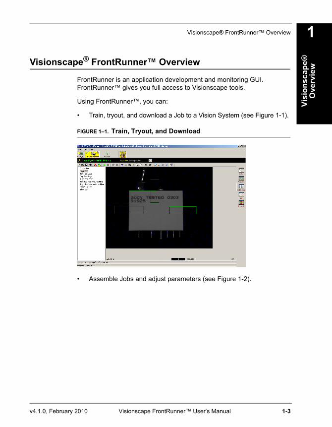
FrontRunner is an application development and monitoring GUI. FrontRunner™ gives you full access to Visionscape tools.
Using FrontRunner™, you can:
• Train, tryout, and download a Job to a Vision System (see Figure 1-1).
FIGURE 1–1. Train, Tryout, and Download
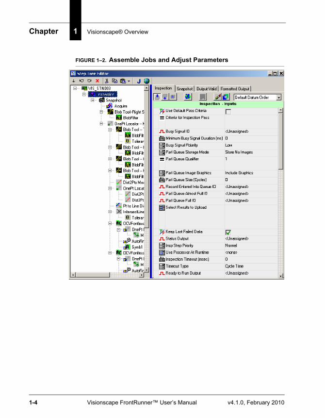
• Assemble Jobs and adjust parameters (see Figure 1-2).
Chapter 1 Visionscape® Overview
1-4 Visionscape FrontRunner™ User’s Manual v4.1.0, February 2010
FIGURE 1–2. Assemble Jobs and Adjust Parameters
Visionscape® FrontRunner™ Overview
Visi
onsc
ape®
O
verv
iew
1
v4.1.0, February 2010 Visionscape FrontRunner™ User’s Manual 1-5
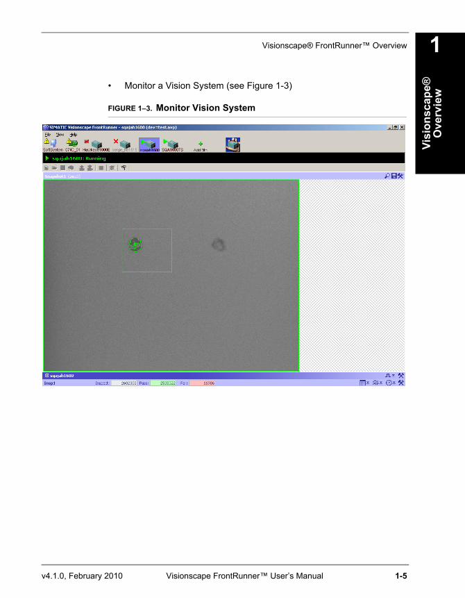
• Monitor a Vision System (see Figure 1-3)
FIGURE 1–3. Monitor Vision System
Chapter 1 Visionscape® Overview
1-6 Visionscape FrontRunner™ User’s Manual v4.1.0, February 2010
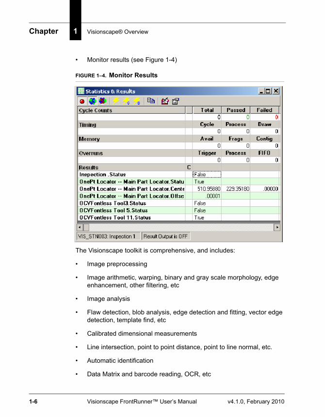
• Monitor results (see Figure 1-4)
FIGURE 1–4. Monitor Results
The Visionscape toolkit is comprehensive, and includes:
• Image preprocessing
• Image arithmetic, warping, binary and gray scale morphology, edge enhancement, other filtering, etc
• Image analysis
• Flaw detection, blob analysis, edge detection and fitting, vector edge detection, template find, etc
• Calibrated dimensional measurements
• Line intersection, point to point distance, point to line normal, etc.
• Automatic identification
• Data Matrix and barcode reading, OCR, etc
Visionscape® 4.1 Firmware
Visi
onsc
ape®
O
verv
iew
1
v4.1.0, February 2010 Visionscape FrontRunner™ User’s Manual 1-7
• Custom processing options
• Custom measurements and custom scripted tools
Setup and RuntimeWhen working with Visionscape® applications, you access the Visionscape® Vision hardware in one of two modes:
• In Setup mode, the setup objects control the hardware. You can train and tryout tools and debug your vision application.
• In Runtime mode, you download your vision applications to the runtime hardware objects for full speed operations. The runtime objects control the hardware, and the setup objects cannot be used to edit the Job. You can start and stop vision inspections at runtime, as well as receive inspection results and runtime images.
Note: Setup and Runtime modes are mutually exclusive. That is, only one mode can control a vision system.
Visionscape® 4.1 Firmware
Note: If you open a Visionscape® V4.0 Job using Visionscape® V4.1, the Job automatically becomes a V4.1 Job, even if no changes are made to the Job.
You can monitor, but not program, a V4.0 Job on a VS-1 Smart Camera with FrontRunner™. Also, you can upload a V4.0 Job and save it to your PC, at which time it becomes a V4.1 Job.
The IntelliFind™ Tool
IntelliFind™ is a very capable and robust object locator tool that is invariant to many changes in the images, such as contrast, intensity variation, scale, translation, rotation, noise, and occlusion. IntelliFind™ allows a feature or object to be found, and it can significantly reduce the
Chapter 1 Visionscape® Overview
1-8 Visionscape FrontRunner™ User’s Manual v4.1.0, February 2010
complexity and robustness of locating features in an image. It is well suited where an object reference must be found before it is inspected or gauged.
When building a Job in FrontRunner™ (for more information, see Chapter 2), you can insert an IntelliFind™ tool by selecting it from the Insert Tool dialog box (Image/PreProcessing tab). You can always insert and use IntelliFind™ in a Job, even if a key cannot be found to unlock it. In this case, IntelliFind™ runs in demonstration mode, with recurring messages requesting that you insert the key. You can make changes to tryout the Job, but you cannot save the Job to disk. When connected to a VS-1 Smart Camera IntelliFind™ model, no hardware dongle is required to tryout the Job. Essentially, the VS-1 Smart Camera acts as a hardware dongle, but only for that VS-1 Smart Camera currently selected in FrontRunner™ (focused device).
Note:You cannot upgrade a non-IntelliFind™ VS-1 Smart Camera in the field.
Visionscape® Software Structure and Concepts
Steps and TreesA Step represents a piece of vision functionality in Visionscape®. Applications are a collection of steps. To provide order to this collection, the steps are arranged in a Tree. The Tree represents not only the containment of a set of steps, but also represents a data connection between these steps. In other words, a step can receive a set of data inputs, act on this data, and produce a set of data outputs. The tree represents the connection of particular data outputs to data inputs.
The most common piece of data to be passed from one step to another is a buffer. A buffer is a piece of memory that contains image data.
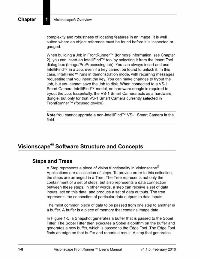
In Figure 1-5, a Snapshot generates a buffer that is passed to the Sobel Filter. The Sobel Filter then executes a Sobel algorithm on the buffer and generates a new buffer, which is passed to the Edge Tool. The Edge Tool finds an edge on that buffer and reports a result. A step that generates
Visionscape® Software Structure and Concepts
Visi
onsc
ape®
O
verv
iew
1
v4.1.0, February 2010 Visionscape FrontRunner™ User’s Manual 1-9
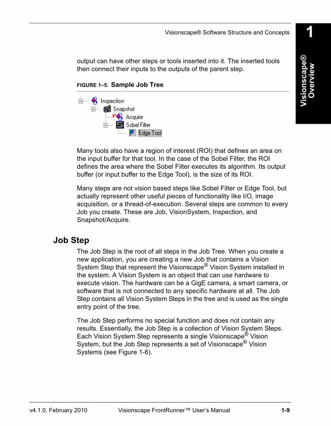
output can have other steps or tools inserted into it. The inserted tools then connect their inputs to the outputs of the parent step.
FIGURE 1–5. Sample Job Tree
Many tools also have a region of interest (ROI) that defines an area on the input buffer for that tool. In the case of the Sobel Filter, the ROI defines the area where the Sobel Filter executes its algorithm. Its output buffer (or input buffer to the Edge Tool), is the size of its ROI.
Many steps are not vision based steps like Sobel Filter or Edge Tool, but actually represent other useful pieces of functionality like I/O, image acquisition, or a thread-of-execution. Several steps are common to every Job you create. These are Job, VisionSystem, Inspection, and Snapshot/Acquire.
Job StepThe Job Step is the root of all steps in the Job Tree. When you create a new application, you are creating a new Job that contains a Vision System Step that represent the Visionscape® Vision System installed in the system. A Vision System is an object that can use hardware to execute vision. The hardware can be a GigE camera, a smart camera, or software that is not connected to any specific hardware at all. The Job Step contains all Vision System Steps in the tree and is used as the single entry point of the tree.
The Job Step performs no special function and does not contain any results. Essentially, the Job Step is a collection of Vision System Steps. Each Vision System Step represents a single Visionscape® Vision System, but the Job Step represents a set of Visionscape® Vision Systems (see Figure 1-6).
Chapter 1 Visionscape® Overview
1-10 Visionscape FrontRunner™ User’s Manual v4.1.0, February 2010
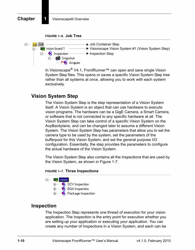
FIGURE 1–6. Job Tree
In Visionscape® V4.1, FrontRunner™ can open and save single Vision System Step files. This opens or saves a specific Vision System Step tree rather than all systems at once, allowing you to work with each system exclusively.
Vision System StepThe Vision System Step is the step representation of a Vision System itself. A Vision System is an object that can use hardware to execute vision programs. The hardware can be a GigE Camera, a Smart Camera, or software that is not connected to any specific hardware at all. The Vision System Step can take control of a specific Vision System on the AvpBackplane, and can be changed later to assume a different Vision System. The Vision System Step has parameters that allow you to set the camera type to be used by the system, set the parameters of the bufferpool for this Vision System, and set the general purpose I/O configuration. Essentially, the step provides the parameters to configure the actual hardware of the Vision System.
The Vision System Step also contains all the Inspections that are used by the Vision System, as shown in Figure 1-7.
FIGURE 1–7. Three Inspections
InspectionThe Inspection Step represents one thread of execution for your vision application. The Inspection is the entry point for execution whether you are setting up your application or executing your application. You can create any number of Inspections in a Vision System, and each can be
Visionscape Vision System #1 (Vision System Step)Job Container Step
Inspection Step
Visionscape® Software Structure and Concepts
Visi
onsc
ape®
O
verv
iew
1
v4.1.0, February 2010 Visionscape FrontRunner™ User’s Manual 1-11
started and stopped asynchronously. In a typical inspection, you use a Snapshot/Acquire to acquire an image, execute vision tools on that image, and then report results either through I/O or through the Inspection Report.
Creating multiple inspections allows you to create inspections with tools that execute either synchronously or asynchronously.
Note: The preceding statement is generally applicable to Visionscape®. In the case of the VS-1 Smart Camera: while multiple inspections are still supported, care should be taken to make sure that multiple Snapshot steps do not attempt to use the single “camera” at the same time.
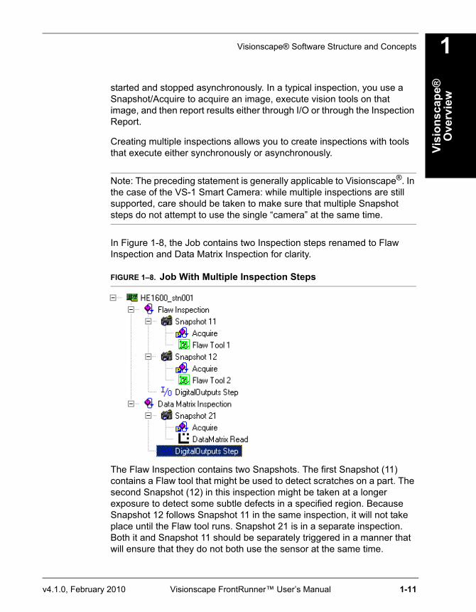
In Figure 1-8, the Job contains two Inspection steps renamed to Flaw Inspection and Data Matrix Inspection for clarity.
FIGURE 1–8. Job With Multiple Inspection Steps
The Flaw Inspection contains two Snapshots. The first Snapshot (11) contains a Flaw tool that might be used to detect scratches on a part. The second Snapshot (12) in this inspection might be taken at a longer exposure to detect some subtle defects in a specified region. Because Snapshot 12 follows Snapshot 11 in the same inspection, it will not take place until the Flaw tool runs. Snapshot 21 is in a separate inspection. Both it and Snapshot 11 should be separately triggered in a manner that will ensure that they do not both use the sensor at the same time.
Chapter 1 Visionscape® Overview
1-12 Visionscape FrontRunner™ User’s Manual v4.1.0, February 2010
Snapshot and AcquireThe Snapshot and Acquire steps work together to provide image acquisition capabilities for the Job. Acquire is the image creator; Snapshot is the image receiver.
Acquire is a special step that knows how to capture images from the camera or disk, utilizing triggers and strobes. You can program the camera selection, trigger, and strobe in the Acquire step. When executing, the Acquire sets up the Camera I/O Card or Smart Camera digitizer according to your selection and captures images into a list, called a frame list. When an image is set into the list, the Snapshot can then pull the frame from the list and turn it into a buffer that is then passed along to its contained steps.
The execution of the Acquire depends on your trigger selection. The letter “P” at the left of the Acquire step in the Job Tree means the Acquire step is a preprocessing step of the Snapshot. Though it is a child of the Snapshot, it is executed before the Snapshot. When no triggers are selected (see Figure 1–8, “Job With Multiple Inspection Steps,” on page 1-11), the Flaw Inspection tree is executed in the following order:
AcquireSnapshotFlawTool1AcquireSnapshotFlaw Tool2Digital Outputs Step
This changes when you select a trigger. In order to maximize image acquisition along with inspection execution, when a trigger is selected, the images are pipelined to the running Inspection. The hardware acquires images from the camera when the trigger is fired using the appropriate acquisition definition and instruct the Acquire Step that an image frame (or buffer) is available. The Acquire Step creates a Frame Datum from the image and pushes it onto its frame list. The Snapshot, running within the Inspection thread, will remove the images from the frame list when it executes. In this way, a triggered acquisition pipelines the image to the running inspection. This allows multiple images to be captured so the vision on the system production line does not miss parts.
Jobs
Visi
onsc
ape®
O
verv
iew
1
v4.1.0, February 2010 Visionscape FrontRunner™ User’s Manual 1-13
Jobs
Jobs and Storage in Non-Volatile MemoryThe maximum Non-Volatile Memory area for Jobs is 16MB for the VS-1 Smart Camera (32/128), and 6MB for the VS-1 Smart Camera (16/64). This includes the Job plus any support files if used in the avp:
• IntelliFind models
• OCV/OCR Fonts
• Perl scripts
• Acquire Tool tiff or bmp image list (when programmed to capture from disk)
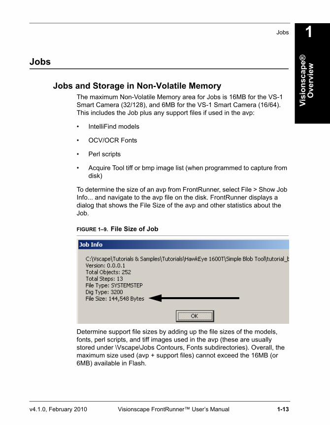
To determine the size of an avp from FrontRunner, select File > Show Job Info... and navigate to the avp file on the disk. FrontRunner displays a dialog that shows the File Size of the avp and other statistics about the Job.
FIGURE 1–9. File Size of Job
Determine support file sizes by adding up the file sizes of the models, fonts, perl scripts, and tiff images used in the avp (these are usually stored under \Vscape\Jobs Contours, Fonts subdirectories). Overall, the maximum size used (avp + support files) cannot exceed the 16MB (or 6MB) available in Flash.
Chapter 1 Visionscape® Overview
1-14 Visionscape FrontRunner™ User’s Manual v4.1.0, February 2010
Combining Jobs for Operation as a Multi-Inspection Job on the VS-1 Smart Camera
Because the VS-1 Smart Camera Non-Volatile Memory file system does not support multiple separate avp files in this release, separate inspection Jobs that would live in separate avp files for other devices must be combined into a single avp with multiple inspections for the purpose of running on the Smart Camera. This is done by loading each avp into a separate Software System (which does not change the camera definition selected and other system dependent parameters like IO assignment), and then copying all the Inspections of the second avp and pasting them into the first avp. Then, the first avp can be saved to disk and loaded/flashed later onto the desired VS-1 Smart Camera device.
v4.1.0, February 2010 Visionscape FrontRunner™ User’s Manual 2-1
2
Fron
tRun
ner™
2
CHAPTER 2 FrontRunner™
OverviewFrontRunner™ is a comprehensive vision development environment you use to create, edit, tryout, and run vision applications.
Note: Use AppRunner to monitor a Job on the device (see the Visionscape® AppRunner™ User’s Manual).
When working with Visionscape® applications, you access the Visionscape® Vision hardware in one of two modes:
• In Setup mode, the setup objects control the hardware. You can train and tryout tools and debug your Job.
• In Runtime mode, you download your Job to the GigE Camera or VS-1 Smart Camera for full speed operations. The runtime objects control the hardware; the set-up objects cannot be used to edit the Job. You can start and stop vision inspections at runtime, as well as receive inspection results and runtime images.
Note: The Setup and Runtime modes are mutually exclusive: only one mode can control a vision system.
FrontRunner™ supports single or multiple Visionscape® Vision Systems. You can create and save vision Jobs in FrontRunner™, train tools, examine Inspection reports, and monitor I/O activity. FrontRunner™ is
Chapter 2 FrontRunner™
2-2 Visionscape FrontRunner™ User’s Manual v4.1.0, February 2010
equally applicable to Visionscape® GigE Camera products and Smart Camera vision systems. It is the GUI you should use to develop and train vision applications for the VS-1 Smart Camera.
Note: Visionscape® V4.1 does not support AppFactory™.
When Visionscape® is installed, a Visionscape® program folder is created on your Start Menu. A shortcut for starting FrontRunner™ is located there. Start FrontRunner™ using this icon. Alternatively, select Start > Visionscape > Visionscape FrontRunner.
Visionscape® V4.1 Firmware
Note: If you open a Visionscape® V4.0 Job using Visionscape® V4.1, the Job automatically becomes a V4.1 Job, even if no changes are made to the Job.
You can monitor, but not program, a V4.0 Job on a VS-1 Smart Camera with FrontRunner™. Also, you can upload a V4.0 Job and save it to your PC, at which time it becomes a V4.1 Job.
Basic ConceptsBefore you do anything with your VS-1 Smart Camera, make sure it is mounted properly and wired correctly. You will find mounting and wiring information in Chapter 2 of the VS-1 Smart Camera Guide.
Device Toolbar and Device ButtonsWhen you start FrontRunner for the very first time, if you have not installed any Visionscape® GigE Cameras or created any Software Systems, you will see the following:
• A Device Toolbar that contains no devices (Figure 2–1)
• The dialog box in Figure 2–2
Basic Concepts
Fron
tRun
ner™
2
v4.1.0, February 2010 Visionscape FrontRunner™ User’s Manual 2-3
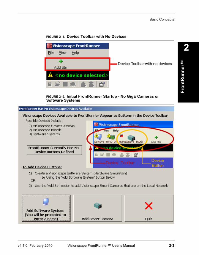
FIGURE 2–1. Device Toolbar with No Devices
FIGURE 2–2. Initial FrontRunner Startup - No GigE Cameras or Software Systems
Device Toolbar with no devices
Chapter 2 FrontRunner™
2-4 Visionscape FrontRunner™ User’s Manual v4.1.0, February 2010
FrontRunner needs a Device on which to operate, so the dialog box in Figure 2–2 enables you to:
• Create a Software System; see “Adding a Software System” on page 2-4
• Add a button for a Smart Camera; see “Adding and Controlling a Smart Camera” on page 2-5
• Quit out of the dialog box and remain at the main FrontRunner window
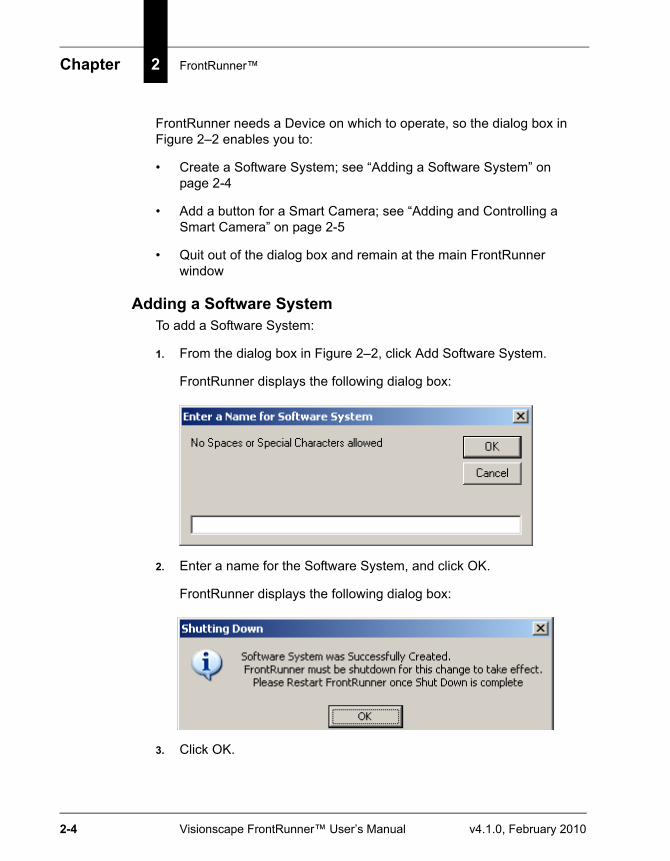
Adding a Software SystemTo add a Software System:
1. From the dialog box in Figure 2–2, click Add Software System.
FrontRunner displays the following dialog box:
2. Enter a name for the Software System, and click OK.
FrontRunner displays the following dialog box:
3. Click OK.
Basic Concepts
Fron
tRun
ner™
2
v4.1.0, February 2010 Visionscape FrontRunner™ User’s Manual 2-5
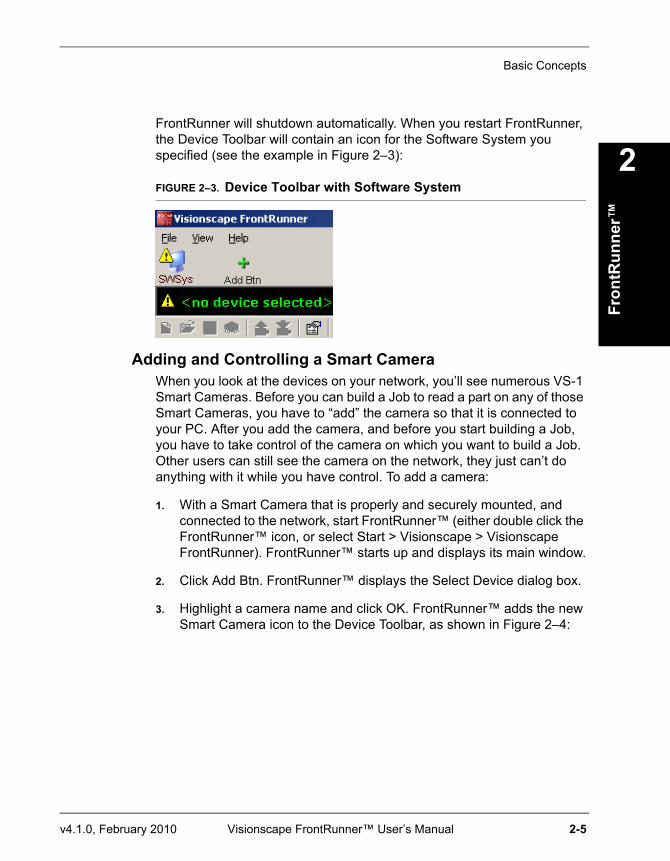
FrontRunner will shutdown automatically. When you restart FrontRunner, the Device Toolbar will contain an icon for the Software System you specified (see the example in Figure 2–3):
FIGURE 2–3. Device Toolbar with Software System
Adding and Controlling a Smart CameraWhen you look at the devices on your network, you’ll see numerous VS-1 Smart Cameras. Before you can build a Job to read a part on any of those Smart Cameras, you have to “add” the camera so that it is connected to your PC. After you add the camera, and before you start building a Job, you have to take control of the camera on which you want to build a Job. Other users can still see the camera on the network, they just can’t do anything with it while you have control. To add a camera:
1. With a Smart Camera that is properly and securely mounted, and connected to the network, start FrontRunner™ (either double click the FrontRunner™ icon, or select Start > Visionscape > Visionscape FrontRunner). FrontRunner™ starts up and displays its main window.
2. Click Add Btn. FrontRunner™ displays the Select Device dialog box.
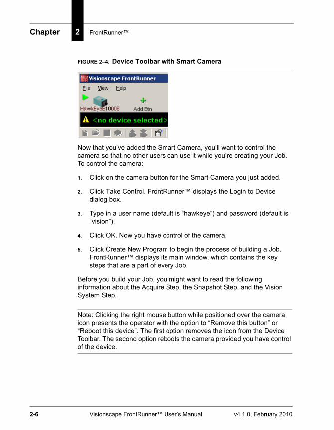
3. Highlight a camera name and click OK. FrontRunner™ adds the new Smart Camera icon to the Device Toolbar, as shown in Figure 2–4:
Chapter 2 FrontRunner™
2-6 Visionscape FrontRunner™ User’s Manual v4.1.0, February 2010
FIGURE 2–4. Device Toolbar with Smart Camera
Now that you’ve added the Smart Camera, you’ll want to control the camera so that no other users can use it while you’re creating your Job. To control the camera:
1. Click on the camera button for the Smart Camera you just added.
2. Click Take Control. FrontRunner™ displays the Login to Device dialog box.
3. Type in a user name (default is “hawkeye”) and password (default is “vision”).
4. Click OK. Now you have control of the camera.
5. Click Create New Program to begin the process of building a Job. FrontRunner™ displays its main window, which contains the key steps that are a part of every Job.
Before you build your Job, you might want to read the following information about the Acquire Step, the Snapshot Step, and the Vision System Step.
Note: Clicking the right mouse button while positioned over the camera icon presents the operator with the option to “Remove this button” or “Reboot this device”. The first option removes the icon from the Device Toolbar. The second option reboots the camera provided you have control of the device.
Basic Concepts
Fron
tRun
ner™
2
v4.1.0, February 2010 Visionscape FrontRunner™ User’s Manual 2-7
Important Visionscape® StepsAfter you click Create New Program, and before you add any steps or tools to your Job, we’ll look at the following steps, which are key steps in a Visionscape® Job:
• The Acquire Step
• The Snapshot Step
• The Vision System Step
The Acquire StepThe Acquire step is one of the most important steps in Visionscape®, since it is the step where you can specify the following:
• Acquisition method, which is how the camera acquires images. Acquisitions can be triggered or non-triggered.
• Gain and Offset, which determine what is applied to the incoming video signal.
Note: The Visionscape® Tools Reference contains detailed information about Gain and Offset:
Chapter 1 describes these advanced datums on the Acquire properties page.
Chapter 13 describes the GainOffset Filter in detail.
• Exposure time, which is the amount of time, in micro seconds, that the camera’s CCD will integrate light. Exposure Time can freeze motion when not using a strobe, or if you are using a strobe, it can prevent ambient light from affecting your image.
• Photometry and Lighting, which is the light source powered by the camera.
• Triggers, which can be virtual or physical
The Acquire step is inserted automatically as a component of the Snapshot step. There is always a one-to-one relationship between
Chapter 2 FrontRunner™
2-8 Visionscape FrontRunner™ User’s Manual v4.1.0, February 2010
Acquire and Snapshot. For complete information about the Acquire step, see Chapter 1 of the Visionscape® Tools Reference.
The Snapshot StepAfter the Acquire step acquires images, the Snapshot step pulls the image frames from the frame datum list and passes them on to the vision tools in the inspection for further processing.
When steps are inserted into a Snapshot, all their input buffer datums are automatically connected to the output buffer datum of Snapshot. The output buffer datum of Snapshot is the last image acquired. These steps then process or analyze this image.
The Snapshot step also defines a point of calibration in the step tree. When calibrated, the Snapshot contains a special Part tree that defines the calibration data. A typical calibration Job is simply a Blob Step. The Blob Step is used by the Calibration Manager to find the calibration blobs in the image and update its “PhysCalDots” Point List datum, calculate the calibration matrices, then update the Calibration Result Datum in the Snapshot. The Calibration Result Datum (“CalResult”) contains the mean and max residuals, the pixels per unit and units per pixel in x and y, the camera angle, and the UX and VY perspectives. For complete information about the Snapshot step, see Chapter 1 of the Visionscape® Tools Reference.
The Vision System StepThe Vision System step represents the vision system device that performs the inspection and can be a Smart Camera, GigE Camera, or software system. Some features, which you can configure, include:
• Buffer counts
• Camera selection
• Digitizer and digitizer mode
• I/O point configuration
A Vision System step is always created with an Inspection step, which represents an inspection task. You can add additional inspection steps. Multiple inspection steps are necessary when an application has to support multiple asynchronous inspections.

Basic Concepts
Fron
tRun
ner™
2
v4.1.0, February 2010 Visionscape FrontRunner™ User’s Manual 2-9
I/O consists of both physical I/O and virtual I/O. Virtual I/O provides the PC with a set of I/O points that behave much like physical I/O points, but can only be accessed by software. They have the advantage of being both inputs and outputs at the same time, and they can hold 32-bit values instead of a binary state. This enables software on the PC to communicate with the Job using a mechanism that is conceptually similar to using physical I/O but without requiring special hardware and wiring. By default, the system has 2048 virtual I/O points. For complete information about the Visions System step, see Chapter 1 of the Visionscape® Tools Reference.
Focus and LightingNow that you have control of a Smart Camera, it’s time to place a part in front of the lens and adjust the focus using Live Video. Live Video shows you exactly what the Smart Camera sees in real time. You want the part to be as clear and distinct as possible. Use the Zoom buttons (just to the right of the Live Video button) to enlarge the part as needed.
Lighting is extremely important for machine vision. If the part you want to read is not properly illuminated, then the results will be less than optimal. When lighting a part, consider the following:
• Surface Characteristics
• Geometry
• Size
• Region of Interest (ROI)
These considerations will determine what type of light you need to adequately illuminate your part. For information about Optics and Lighting, see Chapter 3 of VS-1 Smart Camera Guide.
Exposure TimeDepending on the lighting you use, you may have to adjust the exposure time for the camera. Exposure time is the amount of time, in micro seconds, that the camera’s CCD integrates light. Exposure time can freeze motion when you are not using a strobe or, if you are using a strobe, it can prevent ambient light from affecting your image. You set the exposure time in the Exposure Time (us) property on the Acquire Step
Chapter 2 FrontRunner™
2-10 Visionscape FrontRunner™ User’s Manual v4.1.0, February 2010
properties page from the Editor window. For more information about the Exposure Time (us) property in the Acquire Step, see Chapter 1 of the Visionscape® Tools Reference. For more information about the Editor window, see “The Editor Window” on page 2-38.
Steps and ToolsWe’ve seen that every Visionscape® Job starts with the same steps (Vision System, Inspection, Snapshot, Acquire). From this point on, it’s up to you to add the steps and tools, building the Job, that accomplishes the task that you want to accomplish. Visionscape® tools fit into the following categories:
• Analysis tools
• Image and Pre-processing tools
• Measurement tools
• Program control tools
• Script tools
For complete information about Visionscape® tools, see the Visionscape® Tools Reference.
Adding Steps and ToolsNow that we’re at the main FrontRunner™ window, it’s time to add one or more tools. The procedure would be similar to the following:
1. Open the Editor window.
2. Add a tool.
3. Adjust properties.
4. Close or minimize the Editor window.
5. Acquire an image
6. Adjust the tool’s region of interest (ROI).
7. Train the tool, if applicable.
8. Tryout the Job.
Basic Concepts
Fron
tRun
ner™
2
v4.1.0, February 2010 Visionscape FrontRunner™ User’s Manual 2-11
9. Download the Job to the Smart Camera.
10. Start the Job on the Smart Camera.
For examples of complete Visionscape® Jobs, see Chapters 2 and 3 of Getting Started With VS-1 Smart Camera, and Chapter 4 of Getting Started With Visionscape® GigE Cameras.
Training and Untraining ToolsSome tools (like the Barcode Tool and the Data Matrix Tool) can be trained. When you train a tool, you’re “telling” the tool what to expect when it reads an image. For example, if you train the Data Matrix tool to read a Data Matrix with 12 rows and 12 columns, the Data Matrix tool will fail when it encounters a Data Matrix with 16 rows and 16 columns.
You can untrain a tool that’s been trained. When you untrain a tool, you are effectively “opening it up” to read a larger variety of images. For example, if you untrain the Data Matrix tool that was trained to read a Data Matrix with 12 rows and 12 columns, it will read a Data Matrix with 12 rows and 12 columns, 16 rows and 16 columns, and so on.
Trying Out a JobAfter you’ve built your Job, and before you’ve downloaded it to a device to run it, you’ll want to try out the Job on the PC, to fine tune it. FrontRunner™ allows you to try out a step, try out the entire Job on one image, or try out the entire Job on multiple images.
Note: In the Settings dialog box , notice the Acquire Images During Tryout option. When this option is checked, FrontRunner™ loads each image that you specified in the Acquire step, one at a time. If you uncheck this option, and click Tryout Program on PC Once and then Stop repeatedly, your Job will run on only the image that is loaded currently.
Downloading a JobAfter you’ve tried out the Job and confirmed that it runs as you want it to, you can download it to the device using Download Program from PC to Device.
Chapter 2 FrontRunner™
2-12 Visionscape FrontRunner™ User’s Manual v4.1.0, February 2010
Saving a JobUse the Save Program button to save the current Job to disk on the PC. If the Job already resides on disk, FrontRunner™ will simply save the Job without displaying the Save Job dialog box. If you want to save the current Job with a different name, select File > Save Job As. In the File name text box, type a different name for the Job you want to save, and then click Save.
Note: If the current Job changes through editing, the Save button is red.
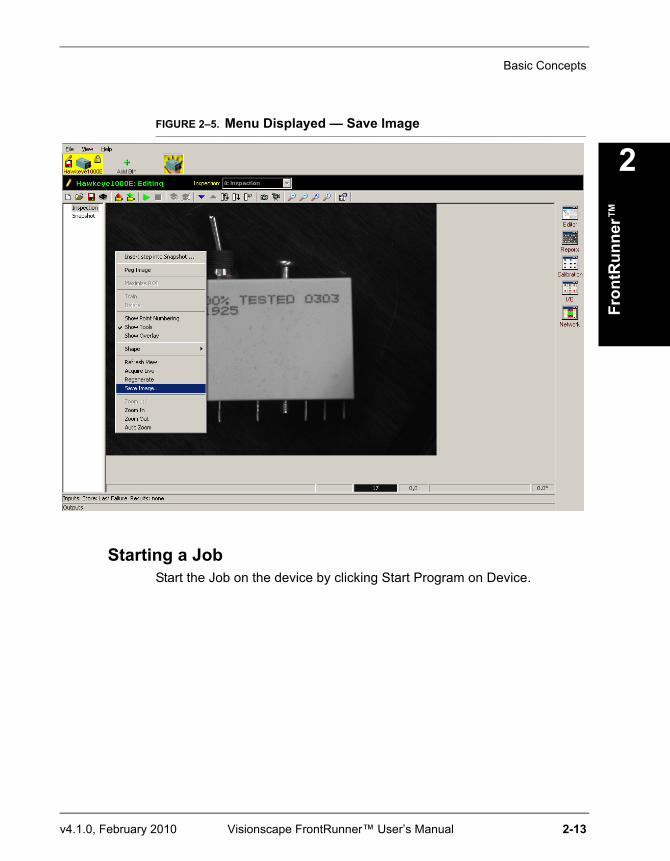
Saving an ImageRight click on the image. In the menu that is displayed (Figure 2–5), select Save Image... to save the current image to the disk on the PC. When the Save As dialog box is displayed, enter a name for the image you are saving.
Basic Concepts
Fron
tRun
ner™
2
v4.1.0, February 2010 Visionscape FrontRunner™ User’s Manual 2-13
FIGURE 2–5. Menu Displayed — Save Image
Starting a JobStart the Job on the device by clicking Start Program on Device.
Chapter 2 FrontRunner™
2-14 Visionscape FrontRunner™ User’s Manual v4.1.0, February 2010
Advanced Concepts
Multiple Views
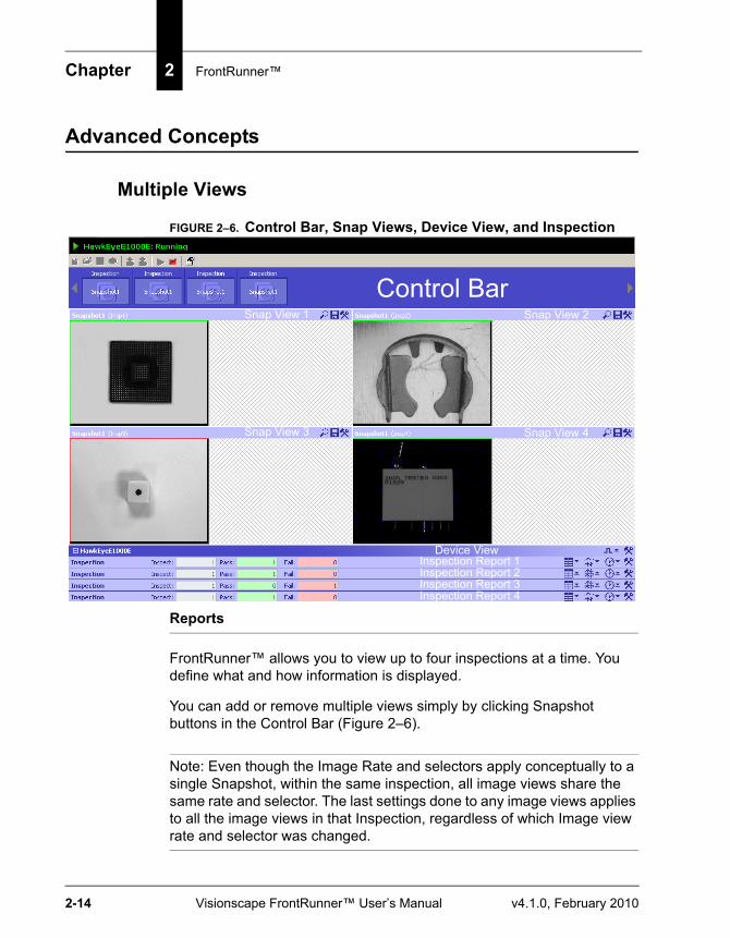
FIGURE 2–6. Control Bar, Snap Views, Device View, and Inspection
Reports
FrontRunner™ allows you to view up to four inspections at a time. You define what and how information is displayed.
You can add or remove multiple views simply by clicking Snapshot buttons in the Control Bar (Figure 2–6).
Note: Even though the Image Rate and selectors apply conceptually to a single Snapshot, within the same inspection, all image views share the same rate and selector. The last settings done to any image views applies to all the image views in that Inspection, regardless of which Image view rate and selector was changed.
Snap View 1 Snap View 2
Snap View 3 Snap View 4
Control Bar
Device ViewInspection Report 1Inspection Report 2Inspection Report 3Inspection Report 4

Advanced Concepts
Fron
tRun
ner™
2
v4.1.0, February 2010 Visionscape FrontRunner™ User’s Manual 2-15
The FrontRunner™ window has four major areas in the Runtime view:
• Control Bar — This toolbar allows you to select Inspections with their associated Snapshot (Camera views). There is a Camera view button for the focused Inspection to add/remove Snapshot view while the device (Smart Camera or GigE Camera) is running. You can select the layout to determine how the views are to be arranged for a particular Inspection. Use the Ctrl key to select multiple Snap Views.
• Snap View Area — This area displays the selected Snapshot views for the Inspection based on the layout you select. You can zoom the image, save graphics, and change the view refresh rate and freeze mode by operating a drop-down menu in the Snapview of interest.
• Inspection View Area — In this area, you can display output datums results and timing information. You can also show results associated with this Inspection.
• Device View — In this area, you operate controls to define a set of I/O buttons and status lights that monitor the device I/O or generate virtual triggers for any Inspections running on the device, either one shot or periodic (you enter the period).
Figure 2–7 shows four Snap views, with zoom buttons and drop-down menus expanded.
Chapter 2 FrontRunner™
2-16 Visionscape FrontRunner™ User’s Manual v4.1.0, February 2010
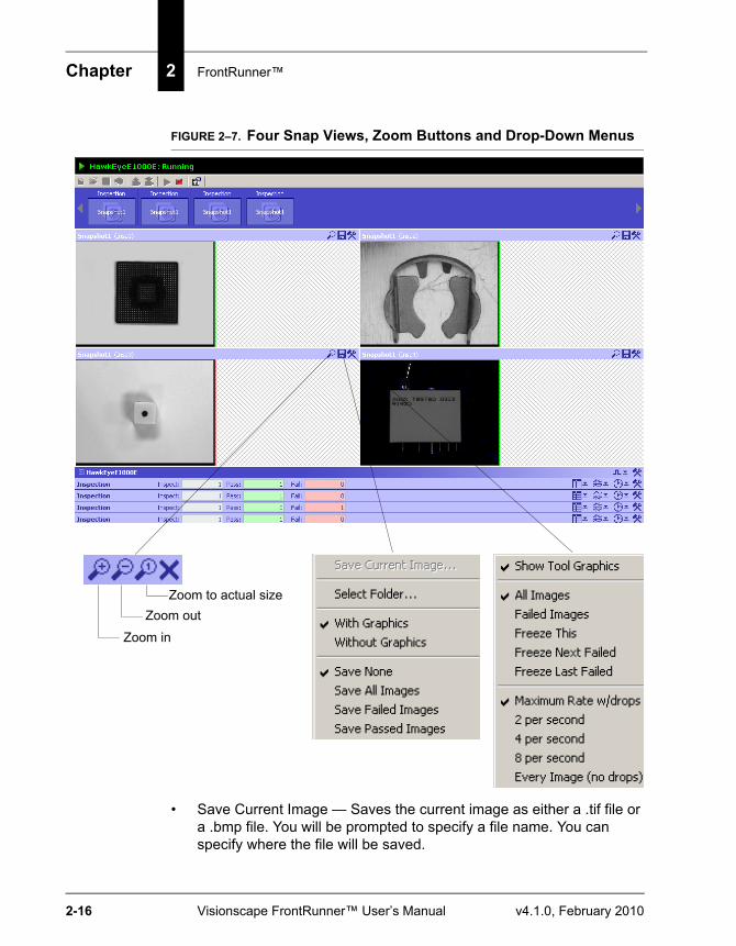
FIGURE 2–7. Four Snap Views, Zoom Buttons and Drop-Down Menus
• Save Current Image — Saves the current image as either a .tif file or a .bmp file. You will be prompted to specify a file name. You can specify where the file will be saved.
Zoom to actual sizeZoom out
Zoom in
Advanced Concepts
Fron
tRun
ner™
2
v4.1.0, February 2010 Visionscape FrontRunner™ User’s Manual 2-17
• Select Folder — Displays the Browse For Folder dialog box, which allows you to specify where images and reports are saved. Use the New Folder button to create a new folder for images and reports.
• With Graphics / Without Graphics — Specifies whether or not you want to include tool graphics with the saved images.
• Save None / Save All Images / Save Failed Images / Save Passed Images — Specifies what images you want to save (if any).
• Show Tool Graphics — By default, FrontRunner™ displays the tool graphics with the captured image.
• All Images / Failed Images — Specifies what kind of images FrontRunner™ should display.
Note: Any change you make apply to all snapshots in the Inspection.
• Freeze This / Freeze Next Failed / Freeze Last Failed — Specifies which image FrontRunner™ should freeze.
Note: Any change you make apply to all snapshots in the Inspection.
• Maximum Rate w/drops / ... / Every Image (no drops) — Specifies the rate at which FrontRunner™ should display images.
Note: Any change you make apply to all snapshots in the Inspection.
When the image rate is set to Maximum Rate w/Drops or any of the 2, 4, or 8 per second rates, priority is given to the running of the Inspection such that images are sent only when there is enough idle time to do so (for example, while waiting for the next image to be acquired from the camera). If there is little or no idle time, then the Image view may refresh very slowly and appear to either show always the same image or not refresh any image at all. This can happen in the most extreme cases in full pipeline with no idle time left; in this case, the display will freeze for long periods of time. If seeing a “live” image is required, then the avp should be designed to allow for some idle time while still maintaining the inspection rate required by the external triggering source. A special case of this are Software
Chapter 2 FrontRunner™
2-18 Visionscape FrontRunner™ User’s Manual v4.1.0, February 2010
Systems which do not have Hardware to assist in producing idle time (for example, while the digitizer is sending the image to memory). For this special case, either select the Every Image (no drops) or insert a WaitStep in the avp with a small wait time (let say 10 msec) to allow the image to be rendered on the screen.
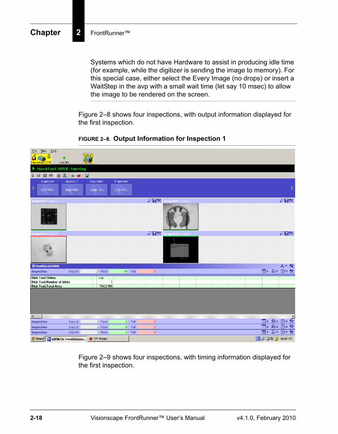
Figure 2–8 shows four inspections, with output information displayed for the first inspection.
FIGURE 2–8. Output Information for Inspection 1
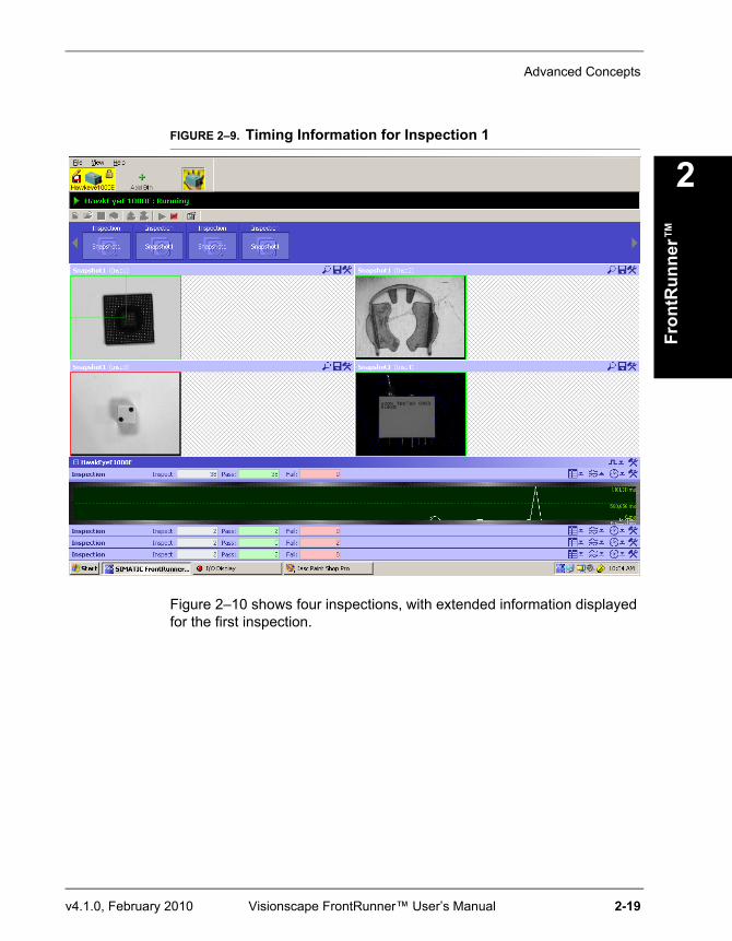
Figure 2–9 shows four inspections, with timing information displayed for the first inspection.
Advanced Concepts
Fron
tRun
ner™
2
v4.1.0, February 2010 Visionscape FrontRunner™ User’s Manual 2-19
FIGURE 2–9. Timing Information for Inspection 1
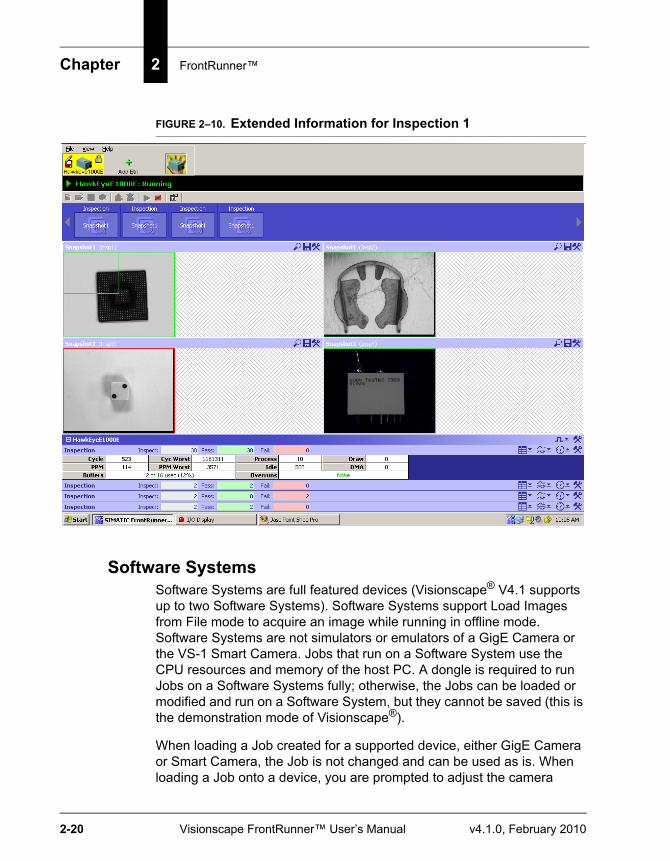
Figure 2–10 shows four inspections, with extended information displayed for the first inspection.
Chapter 2 FrontRunner™
2-20 Visionscape FrontRunner™ User’s Manual v4.1.0, February 2010
FIGURE 2–10. Extended Information for Inspection 1
Software SystemsSoftware Systems are full featured devices (Visionscape® V4.1 supports up to two Software Systems). Software Systems support Load Images from File mode to acquire an image while running in offline mode. Software Systems are not simulators or emulators of a GigE Camera or the VS-1 Smart Camera. Jobs that run on a Software System use the CPU resources and memory of the host PC. A dongle is required to run Jobs on a Software Systems fully; otherwise, the Jobs can be loaded or modified and run on a Software System, but they cannot be saved (this is the demonstration mode of Visionscape®).
When loading a Job created for a supported device, either GigE Camera or Smart Camera, the Job is not changed and can be used as is. When loading a Job onto a device, you are prompted to adjust the camera
Advanced Concepts
Fron
tRun
ner™
2
v4.1.0, February 2010 Visionscape FrontRunner™ User’s Manual 2-21
definition if the device is different from the one the Job was created on. Warnings that require user action are shown if the I/O assignments are out of range for the device or if the Job uses IntelliFind™ but is loaded on a device that does not support this tool.
Creating Jobs for these Systems is the same as creating Jobs for other physical devices with the following differences:
• No specific camera definitions for a specific device are programmed into the VisionSystemStep camera channels. The default for Software Systems is Sentech A33. You must change the camera definition in the VisionSystemStep properties page if a different (usually) image size is required, or if your are working offline and plan to load the Job later on a physical device.
• By default, the Acquire Tool is programmed to Load Images from File, as there is no digitizer available on a Software System (Image List is empty originally and must be populated also). When loaded on a physical device, you must change the Acquire mode to Acquire from Camera to enable acquisition from the device CCD sensor.
For complete information about the Acquire and the Vision System step, see Chapter 1 of the Visionscape® Tools Reference
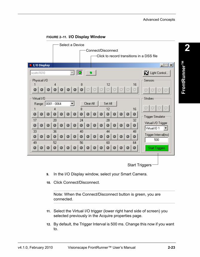
Displaying I/O TransitionsThe I/O Display (Figure 2–11) watches I/O transitions for Physical I/O, Sensors, Strobes, and all 2048 Virtual I/O points. You can also use the green Click to record transitions to a DSS file button to record transitions over time to a DSS file and examine the transitions using the Digital Soft Scope tool (see “Examining I/O Transitions (Digital Soft Scope)” on page 2-24). You can select the Vision System in the list at the top, then connect or disconnect the display using the green Connection button. I/O states are updated in the display as they occur. When an I/O point is asserted, the button turns red. You can also click the button to toggle the I/O point. For GPIO points programmed as inputs as well as for Sensors, clicking the button has no effect. You can display 128 points of the Virtual I/O at one time. Use the Range: list box to select the points you want to display.
Chapter 2 FrontRunner™
2-22 Visionscape FrontRunner™ User’s Manual v4.1.0, February 2010
Simulating Triggers
Note: For more information about triggers with the VS-1 Smart Camera, see the Advanced Triggering Techniques section in Chapter 1 of the Visionscape® Tools Reference.
FrontRunner™ allows you to simulate a trigger in a Job for diagnostic purposes.
Use the following procedure to simulate a trigger:
1. Create a new Job or open an existing Job.
2. Click Editor to display the Editor window.
3. In the left pane, select Acquire.
Note: You may have to click the Acquire tab.
4. In the right pane, click to the right of the Trigger property.
5. From the leftmost pull-down menu, select Virtual Point.
6. To the right of Virtual Point, select a number. For example, 0001.
7. Close the Editor window.
8. Click the I/O button.
FrontRunner™ displays the I/O Display window, as shown in Figure 2–11.
Advanced Concepts
Fron
tRun
ner™
2
v4.1.0, February 2010 Visionscape FrontRunner™ User’s Manual 2-23
FIGURE 2–11. I/O Display Window
9. In the I/O Display window, select your Smart Camera.
10. Click Connect/Disconnect.
Note: When the Connect/Disconnect button is green, you are connected.
11. Select the Virtual I/O trigger (lower right hand side of screen) you selected previously in the Acquire properties page.
12. By default, the Trigger Interval is 500 ms. Change this now if you want to.
Select a DeviceConnect/Disconnect
Start Triggers
Click to record transitions in a DSS file
Chapter 2 FrontRunner™
2-24 Visionscape FrontRunner™ User’s Manual v4.1.0, February 2010
13. In the FrontRunner™ window, click Settings.
FrontRunner™ displays the Settings dialog box.
14. In the Settings dialog box, click to select Use I/O During Tryout and Use Triggers During Tryout.
15. Close the Settings dialog box.
16. Download the Job to the Smart Camera.
17. Start the Job.
18. In the I/O display window, click Start Triggers.
Important NoteWhen using Virtual I/O points to generate triggers at regular interval, as programmed in the Visionscape® IO Display or the FrontRunner RunView IO bar the accuracy of the timing between triggers will depend on the Operating System the avp runs on and also on the number of Virtual I/O points programmed to be triggers. The following information provide guidelines based on Device/OS configurations:
• GigE Cameras and Software Systems — Triggers generated by the avp, IO display and FrontRunner IO bar.
– Windows XP — Accuracy +/- 5 msec typical, trigger to trigger time increases as more triggers are generated.
– Windows 2000 — Accuracy +/- 25 msec typical, trigger to trigger time increases as more triggers are generated.
Note: The values above are typical and may vary from PC to PC. Accuracy should be measured/tested first for the particular avp for the particular PC.
When greater accuracy than the Device allows is required, physical triggers should be used instead.
Examining I/O Transitions (Digital Soft Scope)Digital Soft Scope examines I/O transitions recorded in a DSS file:
Advanced Concepts
Fron
tRun
ner™
2
v4.1.0, February 2010 Visionscape FrontRunner™ User’s Manual 2-25
1. From the FrontRunner™ View menu, click Digital Soft Scope.
2. From the DSS File menu, select Open.
3. Select a DSS file (*.dss) and click Open.
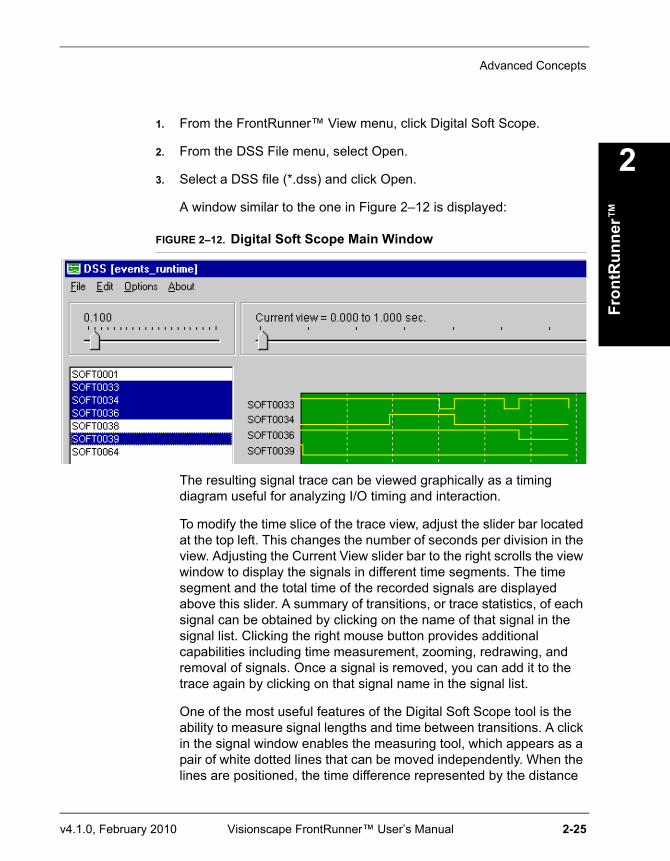
A window similar to the one in Figure 2–12 is displayed:
FIGURE 2–12. Digital Soft Scope Main Window
The resulting signal trace can be viewed graphically as a timing diagram useful for analyzing I/O timing and interaction.
To modify the time slice of the trace view, adjust the slider bar located at the top left. This changes the number of seconds per division in the view. Adjusting the Current View slider bar to the right scrolls the view window to display the signals in different time segments. The time segment and the total time of the recorded signals are displayed above this slider. A summary of transitions, or trace statistics, of each signal can be obtained by clicking on the name of that signal in the signal list. Clicking the right mouse button provides additional capabilities including time measurement, zooming, redrawing, and removal of signals. Once a signal is removed, you can add it to the trace again by clicking on that signal name in the signal list.
One of the most useful features of the Digital Soft Scope tool is the ability to measure signal lengths and time between transitions. A click in the signal window enables the measuring tool, which appears as a pair of white dotted lines that can be moved independently. When the lines are positioned, the time difference represented by the distance
Chapter 2 FrontRunner™
2-26 Visionscape FrontRunner™ User’s Manual v4.1.0, February 2010
between them is displayed at the bottom of the main window. This time is continuously adjusted as the tools move.
Camera CalibrationFor complete information about calibrating the VS-1 Smart Camera, see Chapter 3, “Camera Calibration”.
The Part QueueFor complete information about the Part Queue, see Chapter 4, “The Part Queue”.
Windows You’ll See In FrontRunner™
The Main FrontRunner™ Window
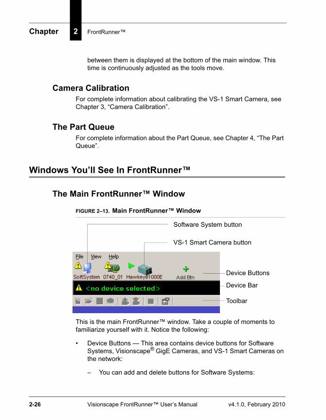
FIGURE 2–13. Main FrontRunner™ Window
This is the main FrontRunner™ window. Take a couple of moments to familiarize yourself with it. Notice the following:
• Device Buttons — This area contains device buttons for Software Systems, Visionscape® GigE Cameras, and VS-1 Smart Cameras on the network:
– You can add and delete buttons for Software Systems:
Device Buttons
Device Bar
Toolbar
Software System button
VS-1 Smart Camera button
Windows You’ll See In FrontRunner™
Fron
tRun
ner™
2
v4.1.0, February 2010 Visionscape FrontRunner™ User’s Manual 2-27
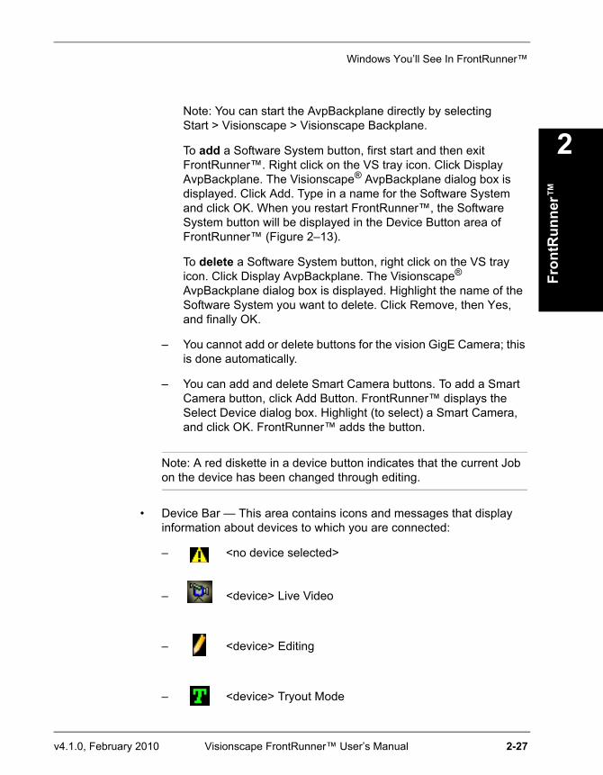
Note: You can start the AvpBackplane directly by selecting Start > Visionscape > Visionscape Backplane.
To add a Software System button, first start and then exit FrontRunner™. Right click on the VS tray icon. Click Display AvpBackplane. The Visionscape® AvpBackplane dialog box is displayed. Click Add. Type in a name for the Software System and click OK. When you restart FrontRunner™, the Software System button will be displayed in the Device Button area of FrontRunner™ (Figure 2–13).
To delete a Software System button, right click on the VS tray icon. Click Display AvpBackplane. The Visionscape® AvpBackplane dialog box is displayed. Highlight the name of the Software System you want to delete. Click Remove, then Yes, and finally OK.
– You cannot add or delete buttons for the vision GigE Camera; this is done automatically.
– You can add and delete Smart Camera buttons. To add a Smart Camera button, click Add Button. FrontRunner™ displays the Select Device dialog box. Highlight (to select) a Smart Camera, and click OK. FrontRunner™ adds the button.
Note: A red diskette in a device button indicates that the current Job on the device has been changed through editing.
• Device Bar — This area contains icons and messages that display information about devices to which you are connected:
– <no device selected>
– <device> Live Video
– <device> Editing
– <device> Tryout Mode
Chapter 2 FrontRunner™
2-28 Visionscape FrontRunner™ User’s Manual v4.1.0, February 2010
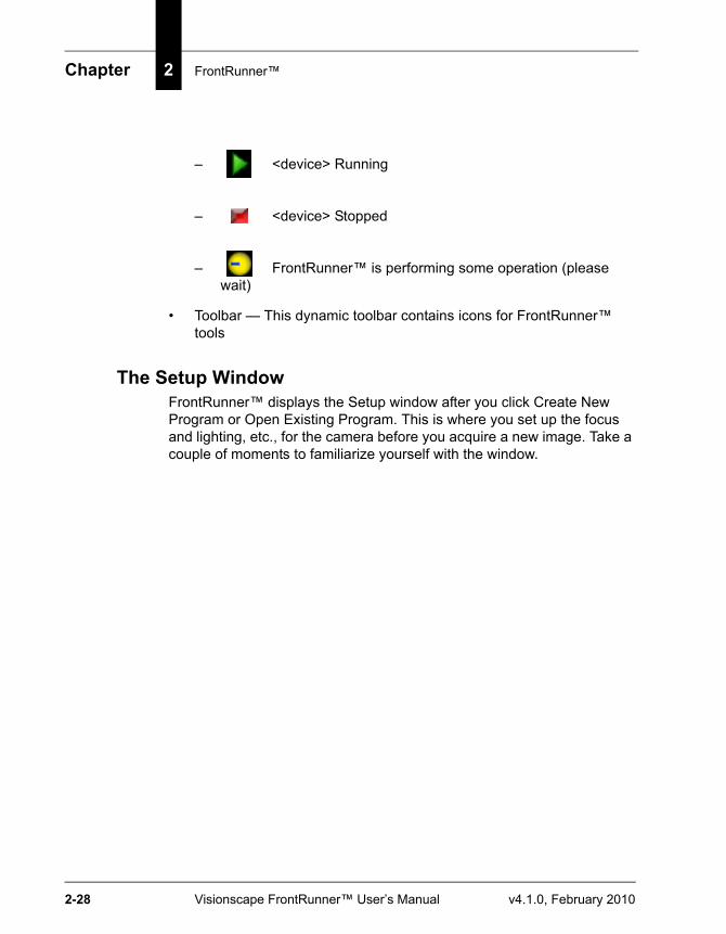
– <device> Running
– <device> Stopped
– FrontRunner™ is performing some operation (please wait)
• Toolbar — This dynamic toolbar contains icons for FrontRunner™ tools
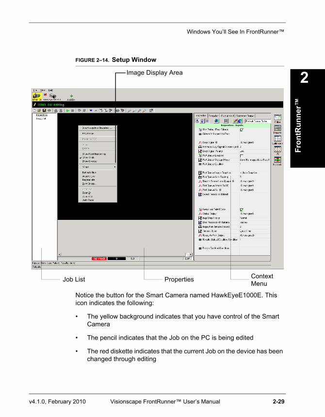
The Setup WindowFrontRunner™ displays the Setup window after you click Create New Program or Open Existing Program. This is where you set up the focus and lighting, etc., for the camera before you acquire a new image. Take a couple of moments to familiarize yourself with the window.
Windows You’ll See In FrontRunner™
Fron
tRun
ner™
2
v4.1.0, February 2010 Visionscape FrontRunner™ User’s Manual 2-29
FIGURE 2–14. Setup Window
Notice the button for the Smart Camera named HawkEyeE1000E. This icon indicates the following:
• The yellow background indicates that you have control of the Smart Camera
• The pencil indicates that the Job on the PC is being edited
• The red diskette indicates that the current Job on the device has been changed through editing
Job List
Image Display Area
Properties ContextMenu
Chapter 2 FrontRunner™
2-30 Visionscape FrontRunner™ User’s Manual v4.1.0, February 2010
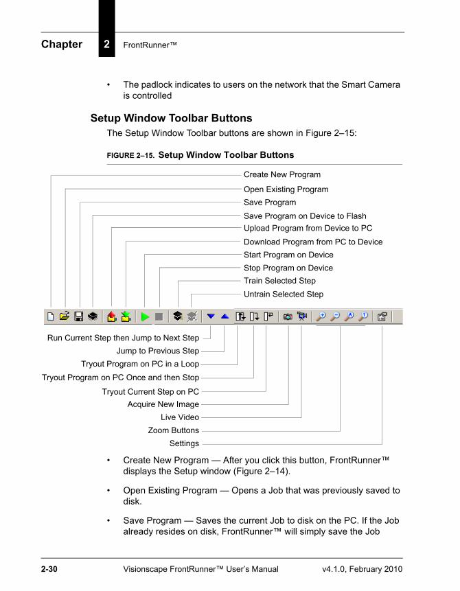
• The padlock indicates to users on the network that the Smart Camera is controlled
Setup Window Toolbar ButtonsThe Setup Window Toolbar buttons are shown in Figure 2–15:
FIGURE 2–15. Setup Window Toolbar Buttons
• Create New Program — After you click this button, FrontRunner™ displays the Setup window (Figure 2–14).
• Open Existing Program — Opens a Job that was previously saved to disk.
• Save Program — Saves the current Job to disk on the PC. If the Job already resides on disk, FrontRunner™ will simply save the Job
Create New Program
Open Existing ProgramSave Program
Save Program on Device to FlashUpload Program from Device to PC
Download Program from PC to DeviceStart Program on DeviceStop Program on DeviceTrain Selected StepUntrain Selected Step
Run Current Step then Jump to Next StepJump to Previous Step
Tryout Program on PC in a LoopTryout Program on PC Once and then Stop
Tryout Current Step on PCAcquire New Image
Live Video
SettingsZoom Buttons
Windows You’ll See In FrontRunner™
Fron
tRun
ner™
2
v4.1.0, February 2010 Visionscape FrontRunner™ User’s Manual 2-31
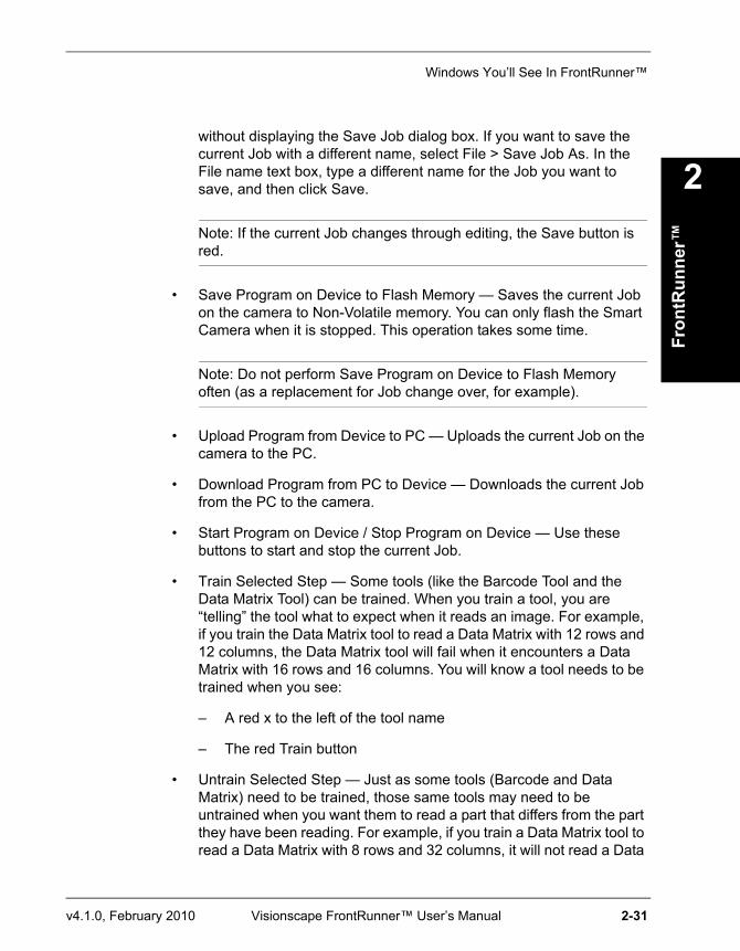
without displaying the Save Job dialog box. If you want to save the current Job with a different name, select File > Save Job As. In the File name text box, type a different name for the Job you want to save, and then click Save.
Note: If the current Job changes through editing, the Save button is red.
• Save Program on Device to Flash Memory — Saves the current Job on the camera to Non-Volatile memory. You can only flash the Smart Camera when it is stopped. This operation takes some time.
Note: Do not perform Save Program on Device to Flash Memory often (as a replacement for Job change over, for example).
• Upload Program from Device to PC — Uploads the current Job on the camera to the PC.
• Download Program from PC to Device — Downloads the current Job from the PC to the camera.
• Start Program on Device / Stop Program on Device — Use these buttons to start and stop the current Job.
• Train Selected Step — Some tools (like the Barcode Tool and the Data Matrix Tool) can be trained. When you train a tool, you are “telling” the tool what to expect when it reads an image. For example, if you train the Data Matrix tool to read a Data Matrix with 12 rows and 12 columns, the Data Matrix tool will fail when it encounters a Data Matrix with 16 rows and 16 columns. You will know a tool needs to be trained when you see:
– A red x to the left of the tool name
– The red Train button
• Untrain Selected Step — Just as some tools (Barcode and Data Matrix) need to be trained, those same tools may need to be untrained when you want them to read a part that differs from the part they have been reading. For example, if you train a Data Matrix tool to read a Data Matrix with 8 rows and 32 columns, it will not read a Data
Chapter 2 FrontRunner™
2-32 Visionscape FrontRunner™ User’s Manual v4.1.0, February 2010
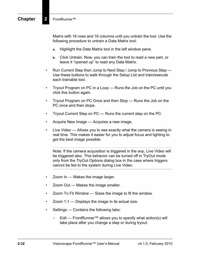
Matrix with 16 rows and 16 columns until you untrain the tool. Use the following procedure to untrain a Data Matrix tool:
a. Highlight the Data Matrix tool in the left window pane.
b. Click Untrain. Now, you can train the tool to read a new part, or leave it “opened up” to read any Data Matrix.
• Run Current Step then Jump to Next Step / Jump to Previous Step — Use these buttons to walk through the Setup List and train/execute each trainable tool.
• Tryout Program on PC in a Loop — Runs the Job on the PC until you click this button again.
• Tryout Program on PC Once and then Stop — Runs the Job on the PC once and then stops.
• Tryout Current Step on PC — Runs the current step on the PC.
• Acquire New Image — Acquires a new image.
• Live Video — Allows you to see exactly what the camera is seeing in real time. This makes it easier for you to adjust focus and lighting to get the best image possible.
Note: If the camera acquisition is triggered in the avp, Live Video will be triggered also. This behavior can be turned off in TryOut mode only from the TryOut Options dialog box in the case where triggers cannot be fed to the system during Live Video.
• Zoom In — Makes the image larger.
• Zoom Out — Makes the image smaller.
• Zoom To Fit Window — Sizes the image to fit the window.
• Zoom 1:1 — Displays the image in its actual size.
• Settings — Contains the following tabs:
– Edit — FrontRunner™ allows you to specify what action(s) will take place after you change a step or during tryout.
Windows You’ll See In FrontRunner™
Fron
tRun
ner™
2
v4.1.0, February 2010 Visionscape FrontRunner™ User’s Manual 2-33
• Automatic Run Step after Change — When checked, FrontRunner™ automatically runs the step after a change is made to its ROI or properties. By default, this is checked.
• Acquire Images During Tryout — In Tryout mode, when this option is checked, FrontRunner™ loads each image that you specified in the Acquire step, one at a time. If you uncheck this option, and click Tryout Program on PC Once and then Stop repeatedly, your Job will run on only the image that is loaded currently.
• Use I/O During Tryout — Enables/disables I/O during tryout.
• Use Triggers During Tryout — Enables/disables triggers when running a tryout.
• Automatic Train Step after Change — When checked, FrontRunner™ automatically trains (when appropriate) the step after a tool is inserted, moved, or resized.
• Delay Between Steps in Tryout — When checked, FrontRunner™ slows down the “action” by adding a delay between each tool so that you can see specific tool activity.
• Show Properties — Allows you to specify where a tool’s properties page is displayed in Tryout View:
– Hide
– Below View (default)
– Right of View
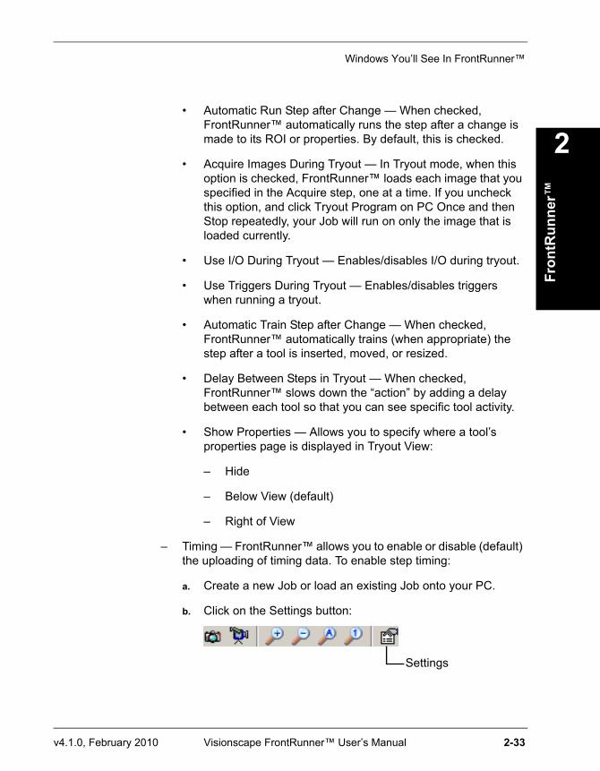
– Timing — FrontRunner™ allows you to enable or disable (default) the uploading of timing data. To enable step timing:
a. Create a new Job or load an existing Job onto your PC.
b. Click on the Settings button:
Settings
Chapter 2 FrontRunner™
2-34 Visionscape FrontRunner™ User’s Manual v4.1.0, February 2010
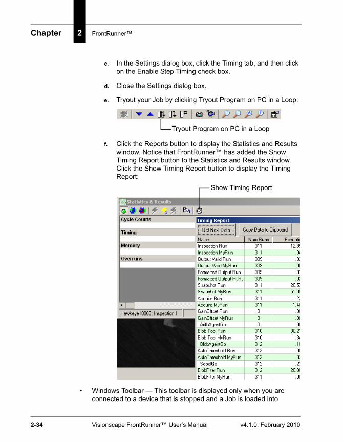
c. In the Settings dialog box, click the Timing tab, and then click on the Enable Step Timing check box.
d. Close the Settings dialog box.
e. Tryout your Job by clicking Tryout Program on PC in a Loop:
f. Click the Reports button to display the Statistics and Results window. Notice that FrontRunner™ has added the Show Timing Report button to the Statistics and Results window. Click the Show Timing Report button to display the Timing Report:
• Windows Toolbar — This toolbar is displayed only when you are connected to a device that is stopped and a Job is loaded into
Tryout Program on PC in a Loop
Show Timing Report
Windows You’ll See In FrontRunner™
Fron
tRun
ner™
2
v4.1.0, February 2010 Visionscape FrontRunner™ User’s Manual 2-35
FrontRunner™ for editing. This area contains buttons for the following tools:
– Editor (see “The Editor Window” on page 2-38)
– Reports (see “The Reports Window” on page 2-41)
– Calibration (see Chapter 3, “Camera Calibration”)
– I/O (see “The I/O Display Window” on page 2-44)
– Network (see “The Network Overview Window” on page 2-45)
The Context MenuTo display the context menu, right click on the image display area.
Chapter 2 FrontRunner™
2-36 Visionscape FrontRunner™ User’s Manual v4.1.0, February 2010
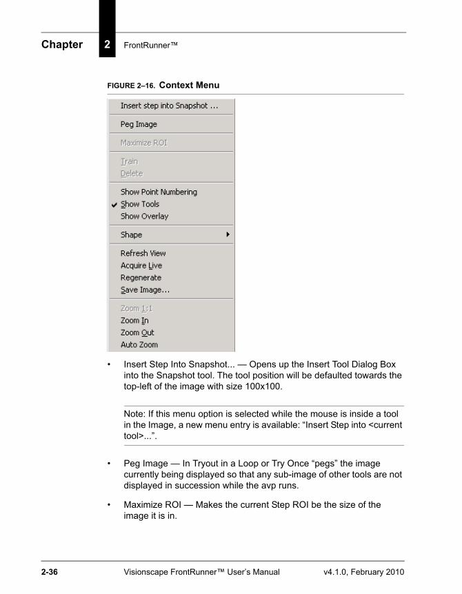
FIGURE 2–16. Context Menu
• Insert Step Into Snapshot... — Opens up the Insert Tool Dialog Box into the Snapshot tool. The tool position will be defaulted towards the top-left of the image with size 100x100.
Note: If this menu option is selected while the mouse is inside a tool in the Image, a new menu entry is available: “Insert Step into <current tool>...”.
• Peg Image — In Tryout in a Loop or Try Once “pegs” the image currently being displayed so that any sub-image of other tools are not displayed in succession while the avp runs.
• Maximize ROI — Makes the current Step ROI be the size of the image it is in.

Windows You’ll See In FrontRunner™
Fron
tRun
ner™
2
v4.1.0, February 2010 Visionscape FrontRunner™ User’s Manual 2-37
• Train — Same as the Toolbar Button Training Hat if the selected tool (i.e., ROI) is a trainable tool.
• Delete — Same as Step Editor Delete button for the currently selected tool (i.e., by its ROI).
Note: Not all tools can be deleted this way as some tools in the avp have no ROI and are not visible in the image.,
• Show Point Numbering — Number the vertices of the ROI. Clicking on these special points allows the ROI shape to be changed; clicking elsewhere simply moves the ROI.
• Show Tools — Hide all the Tools ROIs so that the image (with results graphics if the tools have run) can be seen without their clutter underneath.
• Show Overlay — If Custom VB code has written in the overlay for this image, these additional typically non-tool graphics can be hidden or shown on the image.
• Shape > Hide Current Shape — Add the current Tool ROI. This tool ROI can no longer be selected or changed.
Note: More than one ROI can be hidden this way.
• Shape > Show All — Restore all the ROIs so that they all appear again and can be edited with the mouse.
• Shape > Zoom To Shape — Zooms the image such that the selected ROI occupies the entire viewing area.
• Refresh View — Repaints the current image (including graphics).
• Acquire Live — Same as LiveVideo button in toolbar.
• Regenerate — If the image being displayed on the screen is the output of an Image Processing tool (i.e., Morphology, Sobel, etc.), then Regenerate takes a new Picture and runs the Image Processing tool to show the resulting output image.
Chapter 2 FrontRunner™
2-38 Visionscape FrontRunner™ User’s Manual v4.1.0, February 2010
• Save Image... — Saves the current Image in TIFF format with no graphics to disk. You are prompted for a file name and location.
• Zoom In — Makes the image larger.
• Zoom Out — Makes the image smaller.
• Zoom To Fit Window — Sizes the image to fit the window.
• Zoom 1:1 — Displays the image in its actual size.
Saving an ImageRight click on the image you want to save. In the Context menu, select Save Image... to save the current image to the PC. When the Save As dialog box is displayed, enter a name for the image you are saving.
The Editor WindowFrontRunner™ displays the Editor window after you click Editor. This is where you adjust properties for a step or tool. Take a couple of moments to familiarize yourself with the window.
Windows You’ll See In FrontRunner™
Fron
tRun
ner™
2
v4.1.0, February 2010 Visionscape FrontRunner™ User’s Manual 2-39
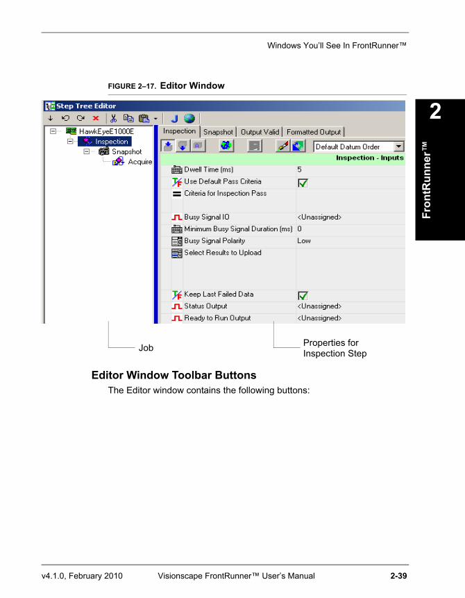
FIGURE 2–17. Editor Window
Editor Window Toolbar ButtonsThe Editor window contains the following buttons:
Job Properties forInspection Step
Chapter 2 FrontRunner™
2-40 Visionscape FrontRunner™ User’s Manual v4.1.0, February 2010
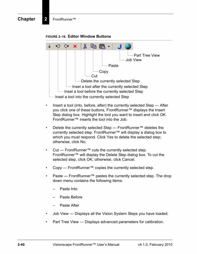
FIGURE 2–18. Editor Window Buttons
• Insert a tool (into, before, after) the currently selected Step — After you click one of these buttons, FrontRunner™ displays the Insert Step dialog box. Highlight the tool you want to insert and click OK. FrontRunner™ inserts the tool into the Job.
• Delete the currently selected Step — FrontRunner™ deletes the currently selected step. FrontRunner™ will display a dialog box to which you must respond. Click Yes to delete the selected step; otherwise, click No.
• Cut — FrontRunner™ cuts the currently selected step. FrontRunner™ will display the Delete Step dialog box. To cut the selected step, click OK; otherwise, click Cancel.
• Copy — FrontRunner™ copies the currently selected step.
• Paste — FrontRunner™ pastes the currently selected step. The drop down menu contains the following items:
– Paste Into
– Paste Before
– Paste After
• Job View — Displays all the Vision System Steps you have loaded.
• Part Tree View — Displays advanced parameters for calibration.
Part Tree ViewJob View
PasteCopy
Cut
Inset a tool after the currently selected StepInset a tool before the currently selected Step
Inset a tool into the currently selected Step
Delete the currently selected Step
Windows You’ll See In FrontRunner™
Fron
tRun
ner™
2
v4.1.0, February 2010 Visionscape FrontRunner™ User’s Manual 2-41
The Reports Window
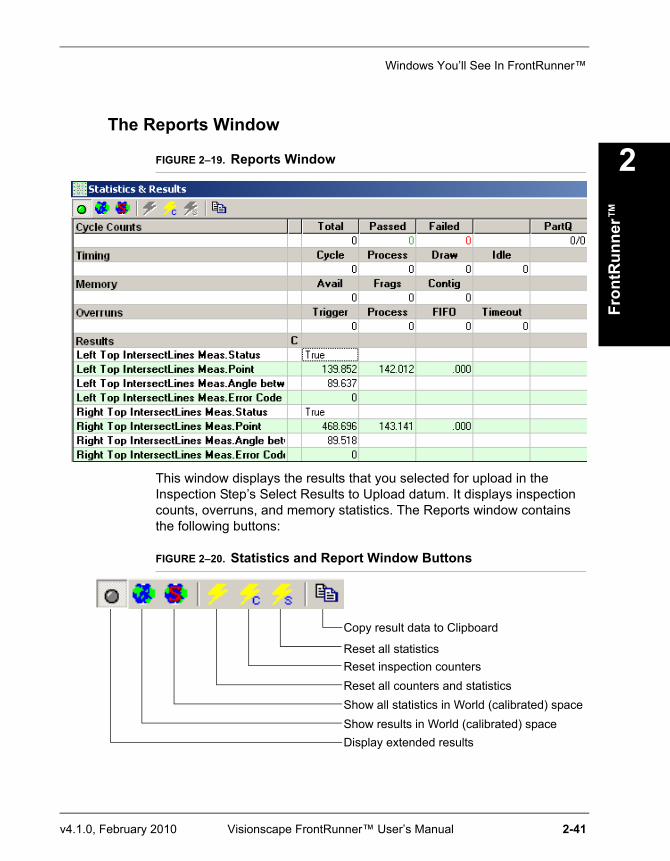
FIGURE 2–19. Reports Window
This window displays the results that you selected for upload in the Inspection Step’s Select Results to Upload datum. It displays inspection counts, overruns, and memory statistics. The Reports window contains the following buttons:
FIGURE 2–20. Statistics and Report Window Buttons
Display extended resultsShow results in World (calibrated) spaceShow all statistics in World (calibrated) spaceReset all counters and statisticsReset inspection countersReset all statistics
Copy result data to Clipboard
Chapter 2 FrontRunner™
2-42 Visionscape FrontRunner™ User’s Manual v4.1.0, February 2010
Button Descriptions
• Display Extended Results — This LED turns green if the inspection passed, and red if the inspection failed.
• Show results in World (calibrated) space — Shows results in a world coordinate versus a pixel coordinate system.
• Show all statistics in World (calibrated) space — Shows statistics in a world coordinate versus a pixel coordinate system.
• Reset all counters and statistics — Resets both the counters and the statistics to zero.
• Reset inspection counters — Resets only the counters to zero.
• Reset all statistics — Resets only the statistics to zero.
• Copy result data to Clipboard — Copies the data to the Clipboard as tab-delimited text.
Statistics
• Cycle Counts — Displays the total number of inspection cycles so far, as well as the number of passed and failed inspections. The “PartQ” column is only relevant if you have activated the Part Queue (see Chapter 4, “The Part Queue”) in your inspection. It displays the current number of entries in the Queue, and the maximum size of the Queue. So, if you’ve set the size of the Queue to be 20, and there are currently 5 entries in it, then “5/20” is displayed.
• Timing — Displays timing information on the last inspection cycle. All times are in milliseconds.
– Cycle — Time between triggers.
– Cycle Worst — Worst time between triggers.
– Process — Actual time spent processing the image. This will not include image acquisition time in a standard triggered Job.
– Draw — Time spent rendering graphics.
– PPM — Number of parts per minute.
Windows You’ll See In FrontRunner™
Fron
tRun
ner™
2
v4.1.0, February 2010 Visionscape FrontRunner™ User’s Manual 2-43
– PPM Worst — Worst number of parts per minute.
– Idle — Amount of time within the cycle during which the inspection was doing nothing. When your Idle time is at or very close to 0, that is telling you that you are getting close to overrunning.
• Overruns — The total number of overruns that have occurred so far.
Results Section
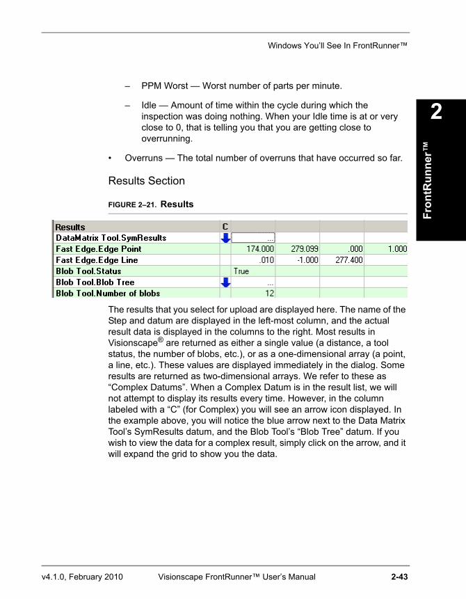
FIGURE 2–21. Results
The results that you select for upload are displayed here. The name of the Step and datum are displayed in the left-most column, and the actual result data is displayed in the columns to the right. Most results in Visionscape® are returned as either a single value (a distance, a tool status, the number of blobs, etc.), or as a one-dimensional array (a point, a line, etc.). These values are displayed immediately in the dialog. Some results are returned as two-dimensional arrays. We refer to these as “Complex Datums”. When a Complex Datum is in the result list, we will not attempt to display its results every time. However, in the column labeled with a “C” (for Complex) you will see an arrow icon displayed. In the example above, you will notice the blue arrow next to the Data Matrix Tool’s SymResults datum, and the Blob Tool’s “Blob Tree” datum. If you wish to view the data for a complex result, simply click on the arrow, and it will expand the grid to show you the data.
Chapter 2 FrontRunner™
2-44 Visionscape FrontRunner™ User’s Manual v4.1.0, February 2010
The I/O Display Window
FIGURE 2–22. I/O Display Window
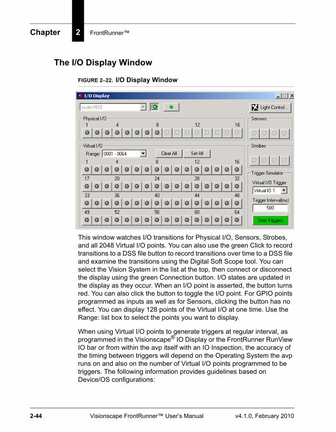
This window watches I/O transitions for Physical I/O, Sensors, Strobes, and all 2048 Virtual I/O points. You can also use the green Click to record transitions to a DSS file button to record transitions over time to a DSS file and examine the transitions using the Digital Soft Scope tool. You can select the Vision System in the list at the top, then connect or disconnect the display using the green Connection button. I/O states are updated in the display as they occur. When an I/O point is asserted, the button turns red. You can also click the button to toggle the I/O point. For GPIO points programmed as inputs as well as for Sensors, clicking the button has no effect. You can display 128 points of the Virtual I/O at one time. Use the Range: list box to select the points you want to display.
When using Virtual I/O points to generate triggers at regular interval, as programmed in the Visionscape® IO Display or the FrontRunner RunView IO bar or from within the avp itself with an IO Inspection, the accuracy of the timing between triggers will depend on the Operating System the avp runs on and also on the number of Virtual I/O points programmed to be triggers. The following information provides guidelines based on Device/OS configurations:
Windows You’ll See In FrontRunner™
Fron
tRun
ner™
2
v4.1.0, February 2010 Visionscape FrontRunner™ User’s Manual 2-45
• VS-1 Smart Cameras — Accuracy < 1 msec, independent of the number of virtual triggers generated by the avp. Trigger to trigger time depends on relative priority of Inspection.
• GigE Camera and Software Systems — Triggers generated by the avp, IO display and FrontRunner IO bar.
– Windows XP — Accuracy +/- 5 msec typical, trigger to trigger time increases as more triggers are generated.
– Windows 2000 — Accuracy +/- 25 msec typical, trigger to trigger time increases as more triggers are generated.
Note: The values above are typical and may vary from PC to PC. Accuracy should be measured/tested first for the particular avp for the particular PC.
When greater accuracy than the Device allows is required, use physical triggers.
The Network Overview WindowYou can display the Network Overview window in either of the following ways:
• From FrontRunner™, select View > Network Overview.
Chapter 2 FrontRunner™
2-46 Visionscape FrontRunner™ User’s Manual v4.1.0, February 2010
• From the deskstop, select Start > Programs > Microscan Visionscape > Tools > Visionscape Network Browser.
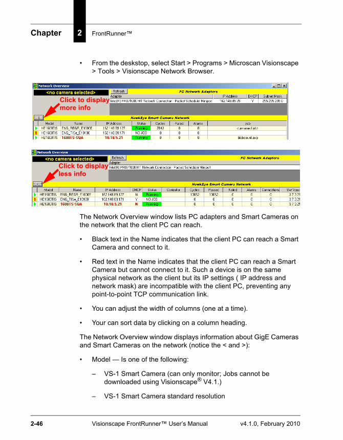
The Network Overview window lists PC adapters and Smart Cameras on the network that the client PC can reach.
• Black text in the Name indicates that the client PC can reach a Smart Camera and connect to it.
• Red text in the Name indicates that the client PC can reach a Smart Camera but cannot connect to it. Such a device is on the same physical network as the client but its IP settings ( IP address and network mask) are incompatible with the client PC, preventing any point-to-point TCP communication link.
• You can adjust the width of columns (one at a time).
• Your can sort data by clicking on a column heading.
The Network Overview window displays information about GigE Cameras and Smart Cameras on the network (notice the < and >):
• Model — Is one of the following:
– VS-1 Smart Camera (can only monitor; Jobs cannot be downloaded using Visionscape® V4.1.)
– VS-1 Smart Camera standard resolution
Click to displaymore info
Click to displayless info
Windows You’ll See In FrontRunner™
Fron
tRun
ner™
2
v4.1.0, February 2010 Visionscape FrontRunner™ User’s Manual 2-47
– VS-1 Smart Camera high resolution
– VS-1 Smart Camera standard resolution with IntelliFind™
– VS-1 Smart Camera high resolution with IntelliFind™
• Name — The name of the Smart Camera
• IP Address — The IP address of the Smart Camera
• DHCP — Is either of the following:
– Y — The Smart Camera is using dynamic IP addressing
– N — The Smart Camera is using static IP addressing
• Status — The status of the Smart Camera
• Controller — The IP address of the PC that is controlling the Smart Camera
• Job — The name of the Job that is loaded on the Smart Camera
Note: For the Job name to be displayed in the Network Overview window, you must first save the Job to disk, then download it to the Smart Camera.
• Cycles — The total number of cycles
• Passed — The number of cycles that passed
• Failed — The number of cycles that failed
• Alarms — The total number of alarms
• Connections — The number of connections to the Smart Camera
• SW Version — The version of the software running on the Smart Camera
• Subnet Mask — The subnet mask of the Smart Camera
• MAC Address — The MAC address of the Smart Camera
Chapter 2 FrontRunner™
2-48 Visionscape FrontRunner™ User’s Manual v4.1.0, February 2010
Changing a Camera’s Name
Note: You will need the user name and password for the camera whose name you want to change.
From the Network Overview window, you can change the name of the Smart Camera over Ethernet without a serial connection and HyperTerminal. This change is dynamic and does not require you to reboot the Smart Camera.
Use the following procedure to change the camera name:
1. Select View > Network Overview.
FrontRunner™ displays the Network Overview window.
2. Click on the name of the camera whose name you want to change.
FrontRunner™ displays the Change Network Settings button.

Windows You’ll See In FrontRunner™
Fron
tRun
ner™
2
v4.1.0, February 2010 Visionscape FrontRunner™ User’s Manual 2-49
3. Click Change Network Settings.
FrontRunner™ displays the Camera is Selected dialog box.
4. Click Yes.
5. Enter a user name (default is hawkeye) and password (default is vision).
FrontRunner™ displays the Change HawkEye Network Settings dialog box.
6. Double click (to highlight and select) the original camera name.
7. Type in a new name for the camera.
8. Click OK.
FrontRunner™ changes the original camera name to the new camera name.
Changing a Camera’s IP Settings
Note: You will need the user name and password for the camera whose IP settings you want to change.
From the Network Overview window, you can change the IP Settings (Static IP or DHCP) of the Smart Camera over Ethernet without a serial connection and HyperTerminal. After the changes, the Smart Camera will reboot automatically.
Use the following procedure to change the IP settings:
1. Select View > Network Overview.
FrontRunner™ displays the Network Overview window.
2. Click Change Network Settings.
FrontRunner™ displays the Change HawkEye Network Settings dialog box.
Chapter 2 FrontRunner™
2-50 Visionscape FrontRunner™ User’s Manual v4.1.0, February 2010
3. Do either of the following:
a. If a DHCP server is available on the same physical network as the device, then select Obtain an IP address automatically.
Note: The Smart Camera may take up to one minute to acquire a new IP address.
b. If no DHCP server is available, select Use the following IP address, and fill in the IP address and Subnet mask for the device.
Note: Make sure the IP address and Subnet mask are compatible with one of the adapters in the PC.
4. Click OK.
FrontRunner™ displays the “Login to device” dialog box.
5. Enter the user name and password for the camera.
6. Click OK.
The Smart Camera reboots automatically, and the changes take effect.
Changing a Camera’s Password
Note: You’ll need the user name and password for the camera whose password you want to change.
Use the following procedure to change a camera’s password:
1. Start FrontRunner™ by clicking Start > Visionscape > Visionscape FrontRunner.
2. Click on the name of the camera whose password you want to change.
3. Click Take Control.
FrontRunner™ displays the Login to Device dialog box.
4. Enter the user name (default is hawkeye) and password (default is vision) for the camera.
Menus You’ll See in FrontRunner™
Fron
tRun
ner™
2
v4.1.0, February 2010 Visionscape FrontRunner™ User’s Manual 2-51
5. Click OK.
Notice that the Take Control button changes color and becomes the Release button.
6. Right click on the Release button and highlight Change User ID and Password.
FrontRunner™ displays the Change User Name and Password dialog box.
7. In the Password text box, type the new password for the camera
8. In the Confirm Password text box, re-type the new password for the camera.
9. Click OK.
The camera’s password has been changed.
Menus You’ll See in FrontRunner™
File MenuThe File menu contains the following menu items:
• New Job — Displays the Setup window.
• Open Job — Opens a Job that was previously saved to disk.
• Close Job — Closes the current Job.
• Upload Job — Uploads the current Job on the camera to the PC.
• Save Job — Saves the current Job to disk on the PC. If the Job already resides on disk, FrontRunner™ will simply save the Job without displaying the Save Job dialog box. If you want to save the current Job with a different name, select File > Save Job As. In the File name text box, type a different name for the Job you want to save, and then click Save.
Chapter 2 FrontRunner™
2-52 Visionscape FrontRunner™ User’s Manual v4.1.0, February 2010
• Save Job As — Allows you to save the current Job to disk on the PC and give the Job another name. FrontRunner™ displays the Save As dialog box. Specify a name and click Save.
Menus You’ll See in FrontRunner™
Fron
tRun
ner™
2
v4.1.0, February 2010 Visionscape FrontRunner™ User’s Manual 2-53
• Dump Job to Text File — Creates a text file containing a listing of each loaded Vision System. After you select this menu item, FrontRunner™ displays the Save Vision System Tree as Text dialog box. Specify a name for the text file and click Save.
• Show Job Info — Displays the header information for a Job:
– Job name
– Version of the software used to create the Job
– Total objects
– Total steps
– File type
– Digitizer type
• Configure Device — Displays a dialog box containing tabs for the following:
– Serial Ports — The COM ports are indexed to the target platform’s available UARTs. The default is NONE, which will construct the output string datum but not transmit the result on any port.
After you select Configure Device, FrontRunner™ displays the Configure dialog box. Configure the various parameters, then click Apply and then OK.
Note: For the VS-1 Smart Cameras, the serial ports are named RS232-<Number>. For example, the VS-1 Smart Camera single serial port is called RS232-1.
– TCP Ports — The TCP ports are indexed according to the port settings specified in the Configure Device dialog box. For example, if Starting Serial TCP Port is 49211, then selecting TCP1 will output on port 49211, TCP2 on port 49212, etc. The default is NONE, which will construct the output string datum but not transmit the result on any port.
After you select Configure Device, FrontRunner™ displays the Configure dialog box. Click the TCP Ports tab. Type in the appropriate information, then click Apply and then OK.
Chapter 2 FrontRunner™
2-54 Visionscape FrontRunner™ User’s Manual v4.1.0, February 2010
Range: 2000 - 5000 and 49210 - 49500
• Options — Displays a dialog box containing tabs for the following:
– Runtime
• PC Runtime Priority — This setting is used when FrontRunner™ is running a vision application. When the application starts, the runtime priority of the process is changed using this setting. The options are “Normal”, “High”, and “Realtime”.
Note: You must be logged into an account that has access rights to change the process setting accordingly. By default, only Administrators and Power Users have this right. It can be changed for Windows XP in the Control Panel > Administrative Tools > Local Security Policy console. In the console, select the Local Policies group, and then User Rights Assignments. You’ll need to add your user account to the “Increase scheduling priority” setting if you are not running as an Administrator.
– Reports — From this page, you can set the start-up options for the report and decimal accuracy:
• Number of x decimal places — Use this option to set the decimal accuracy of floating-point values in the report. The default is 3 for pixel decimal places; the default is 5 for world decimal places.
• Use Calibrated Space when activated — When this option is checked and the report is activated, by default, the report will use calibrated space. Otherwise, values are shown in the report in pixel space when the report is started.
View MenuThe View menu contains the following menu items:
• Network Overview — Displays the Network Overview window, which displays critical information about VS-1 Smart Cameras on the network. See “The Network Overview Window” on page 2-45.
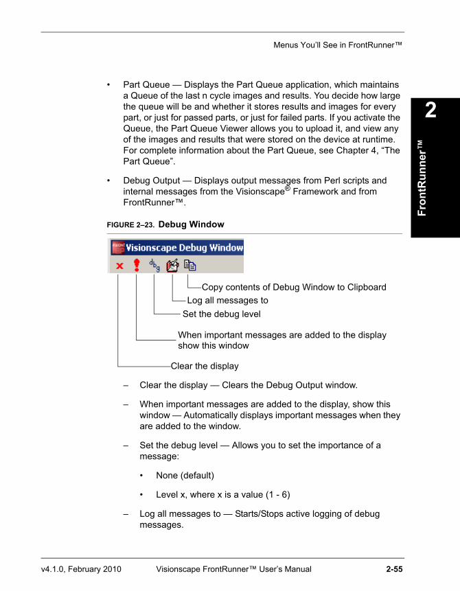
Menus You’ll See in FrontRunner™
Fron
tRun
ner™
2
v4.1.0, February 2010 Visionscape FrontRunner™ User’s Manual 2-55
• Part Queue — Displays the Part Queue application, which maintains a Queue of the last n cycle images and results. You decide how large the queue will be and whether it stores results and images for every part, or just for passed parts, or just for failed parts. If you activate the Queue, the Part Queue Viewer allows you to upload it, and view any of the images and results that were stored on the device at runtime. For complete information about the Part Queue, see Chapter 4, “The Part Queue”.
• Debug Output — Displays output messages from Perl scripts and internal messages from the Visionscape® Framework and from FrontRunner™.
FIGURE 2–23. Debug Window
– Clear the display — Clears the Debug Output window.
– When important messages are added to the display, show this window — Automatically displays important messages when they are added to the window.
– Set the debug level — Allows you to set the importance of a message:
• None (default)
• Level x, where x is a value (1 - 6)
– Log all messages to — Starts/Stops active logging of debug messages.
Clear the display
When important messages are added to the displayshow this window
Set the debug levelLog all messages to
Copy contents of Debug Window to Clipboard
Chapter 2 FrontRunner™
2-56 Visionscape FrontRunner™ User’s Manual v4.1.0, February 2010
Note: Active logging of debug messages can affect Visionscape’s ability to process Jobs.
– Copy contents of Debug Window to Clipboard — Copies the contents to the Clipboard as tab-delimited text.
• I/O Display — See “The I/O Display Window” on page 2-44.
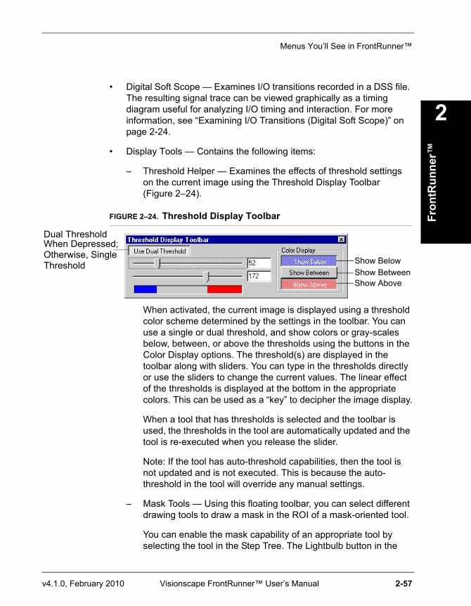
Menus You’ll See in FrontRunner™
Fron
tRun
ner™
2
v4.1.0, February 2010 Visionscape FrontRunner™ User’s Manual 2-57
• Digital Soft Scope — Examines I/O transitions recorded in a DSS file. The resulting signal trace can be viewed graphically as a timing diagram useful for analyzing I/O timing and interaction. For more information, see “Examining I/O Transitions (Digital Soft Scope)” on page 2-24.
• Display Tools — Contains the following items:
– Threshold Helper — Examines the effects of threshold settings on the current image using the Threshold Display Toolbar (Figure 2–24).
FIGURE 2–24. Threshold Display Toolbar
When activated, the current image is displayed using a threshold color scheme determined by the settings in the toolbar. You can use a single or dual threshold, and show colors or gray-scales below, between, or above the thresholds using the buttons in the Color Display options. The threshold(s) are displayed in the toolbar along with sliders. You can type in the thresholds directly or use the sliders to change the current values. The linear effect of the thresholds is displayed at the bottom in the appropriate colors. This can be used as a “key” to decipher the image display.
When a tool that has thresholds is selected and the toolbar is used, the thresholds in the tool are automatically updated and the tool is re-executed when you release the slider.
Note: If the tool has auto-threshold capabilities, then the tool is not updated and is not executed. This is because the auto-threshold in the tool will override any manual settings.
– Mask Tools — Using this floating toolbar, you can select different drawing tools to draw a mask in the ROI of a mask-oriented tool.
You can enable the mask capability of an appropriate tool by selecting the tool in the Step Tree. The Lightbulb button in the
Show BelowShow BetweenShow Above
Dual ThresholdWhen Depressed;Otherwise, SingleThreshold
Chapter 2 FrontRunner™
2-58 Visionscape FrontRunner™ User’s Manual v4.1.0, February 2010
Masking Toolbar is enabled. When you click it, it “lights up”, enabling the mask in the tool and enabling the drawing tool buttons of the toolbar. You can then select any of the drawing tools, and draw the mask using the mouse or select the “pointer” to return to standard tool selection/insertion with the mouse.
• Fill ROI — Fills the entire ROI of the masked tool.
• Clear ROI — Erases the entire ROI of the masked tool.
Help MenuThe Help menu contains the following menu items:
• Visionscape® ReadMe File — Click on this menu item to open the Visionscape® V4.1 ReadMe file.
• Visionscape® User Manual — Click on this menu item to open the Visionscape® User Manual PDF.
• Visionscape® Tools Reference — Click on this menu item to open the Visionscape® Tools Reference PDF.
• Getting Started With VS-1 Smart Camera — Click on this menu item to open the Getting Started With VS-1 Smart Camera PDF.
• Getting Started With Visionscape® GigE Camera — Click on this menu item to open the Getting Started With Visionscape® GigE Camera PDF.
• Visionscape® Documentation (Overview) — Click on this menu item to display an overview of the documentation set.
• Visionscape® Tutorials and Samples — Click on this menu item to display sample Jobs and Tutorials.
• About Visionscape® FrontRunner™ — Displays the FrontRunner™ version number and the address for Microscan. Click OK to close the window.
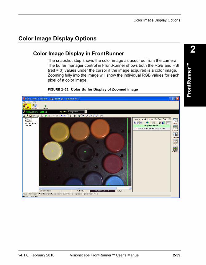
Color Image Display Options
Fron
tRun
ner™
2
v4.1.0, February 2010 Visionscape FrontRunner™ User’s Manual 2-59
Color Image Display Options
Color Image Display in FrontRunnerThe snapshot step shows the color image as acquired from the camera. The buffer manager control in FrontRunner shows both the RGB and HSI (red = 0) values under the cursor if the image acquired is a color image. Zooming fully into the image will show the individual RGB values for each pixel of a color image.
FIGURE 2–25. Color Buffer Display of Zoomed Image
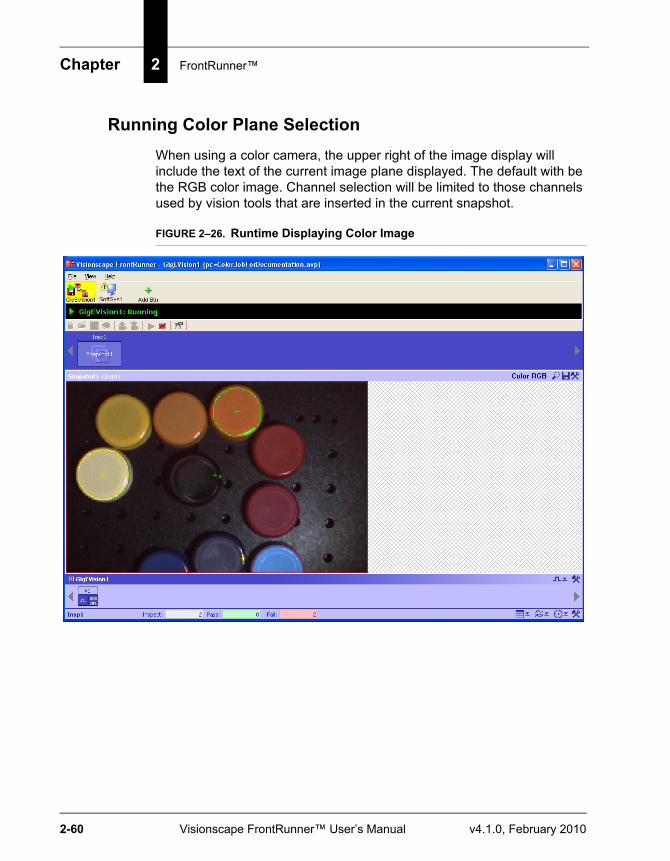
Chapter 2 FrontRunner™
2-60 Visionscape FrontRunner™ User’s Manual v4.1.0, February 2010
Running Color Plane SelectionWhen using a color camera, the upper right of the image display will include the text of the current image plane displayed. The default with be the RGB color image. Channel selection will be limited to those channels used by vision tools that are inserted in the current snapshot.
FIGURE 2–26. Runtime Displaying Color Image
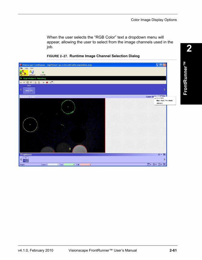
Color Image Display Options
Fron
tRun
ner™
2
v4.1.0, February 2010 Visionscape FrontRunner™ User’s Manual 2-61
When the user selects the “RGB Color” text a dropdown menu will appear, allowing the user to select from the image channels used in the job.
FIGURE 2–27. Runtime Image Channel Selection Dialog
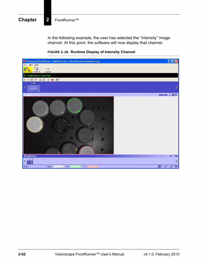
Chapter 2 FrontRunner™
2-62 Visionscape FrontRunner™ User’s Manual v4.1.0, February 2010
In the following example, the user has selected the “Intensity” image channel. At this point, the software will now display that channel.
FIGURE 2–28. Runtime Display of Intensity Channel
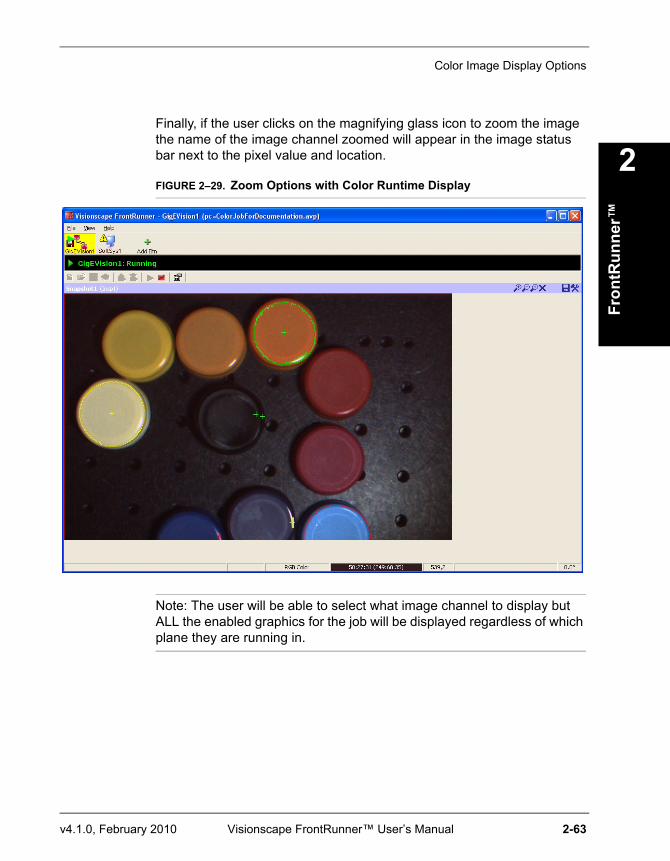
Color Image Display Options
Fron
tRun
ner™
2
v4.1.0, February 2010 Visionscape FrontRunner™ User’s Manual 2-63
Finally, if the user clicks on the magnifying glass icon to zoom the image the name of the image channel zoomed will appear in the image status bar next to the pixel value and location.
FIGURE 2–29. Zoom Options with Color Runtime Display
Note: The user will be able to select what image channel to display but ALL the enabled graphics for the job will be displayed regardless of which plane they are running in.
Chapter 2 FrontRunner™
2-64 Visionscape FrontRunner™ User’s Manual v4.1.0, February 2010
Miscellaneous
Displaying Important Information About a CameraTo display the important information about a Smart Camera, simply hover the mouse pointer over the camera button. Information includes:
• Type of Smart Camera
• IP address of PC controlling the camera
• Name of currently loaded Job
• Date currently loaded Job was created or modified
• Name of PC controlling camera
• IP address and MAC address of the camera
• Version of software on the camera
Configuring I/O ButtonsAfter a Job has been downloaded to the device, and the device is in Run mode, you can configure I/O buttons, as shown in Figure 2–30.
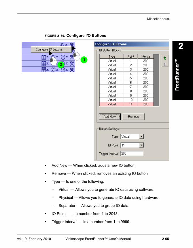
Miscellaneous
Fron
tRun
ner™
2
v4.1.0, February 2010 Visionscape FrontRunner™ User’s Manual 2-65
FIGURE 2–30. Configure I/O Buttons
• Add New — When clicked, adds a new IO button.
• Remove — When clicked, removes an existing IO button
• Type — Is one of the following:
– Virtual — Allows you to generate IO data using software.
– Physical — Allows you to generate IO data using hardware.
– Separator — Allows you to group IO data.
• IO Point — Is a number from 1 to 2048.
• Trigger Interval — Is a number from 1 to 9999.
1 2
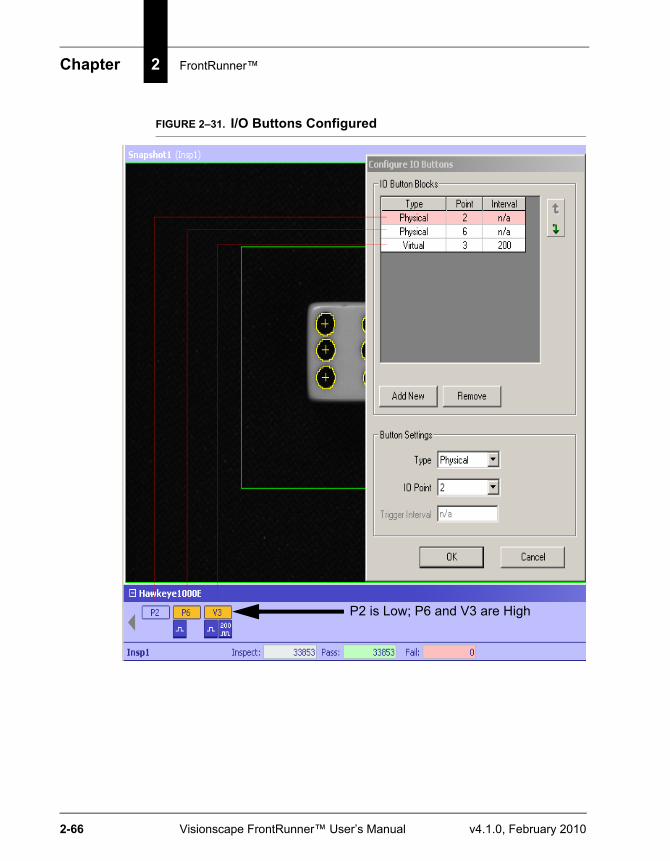
Chapter 2 FrontRunner™
2-66 Visionscape FrontRunner™ User’s Manual v4.1.0, February 2010
FIGURE 2–31. I/O Buttons Configured
P2 is Low; P6 and V3 are High
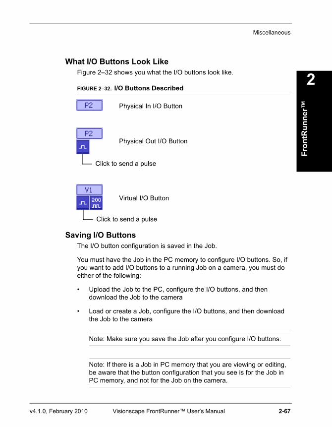
Miscellaneous
Fron
tRun
ner™
2
v4.1.0, February 2010 Visionscape FrontRunner™ User’s Manual 2-67
What I/O Buttons Look LikeFigure 2–32 shows you what the I/O buttons look like.
FIGURE 2–32. I/O Buttons Described
Saving I/O ButtonsThe I/O button configuration is saved in the Job.
You must have the Job in the PC memory to configure I/O buttons. So, if you want to add I/O buttons to a running Job on a camera, you must do either of the following:
• Upload the Job to the PC, configure the I/O buttons, and then download the Job to the camera
• Load or create a Job, configure the I/O buttons, and then download the Job to the camera
Note: Make sure you save the Job after you configure I/O buttons.
Note: If there is a Job in PC memory that you are viewing or editing, be aware that the button configuration that you see is for the Job in PC memory, and not for the Job on the camera.
Physical In I/O Button
Physical Out I/O Button
Virtual I/O Button
Click to send a pulse
Click to send a pulse
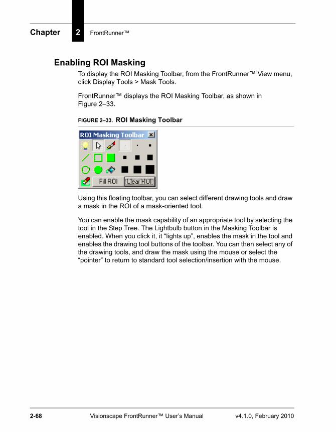
Chapter 2 FrontRunner™
2-68 Visionscape FrontRunner™ User’s Manual v4.1.0, February 2010
Enabling ROI MaskingTo display the ROI Masking Toolbar, from the FrontRunner™ View menu, click Display Tools > Mask Tools.
FrontRunner™ displays the ROI Masking Toolbar, as shown in Figure 2–33.
FIGURE 2–33. ROI Masking Toolbar
Using this floating toolbar, you can select different drawing tools and draw a mask in the ROI of a mask-oriented tool.
You can enable the mask capability of an appropriate tool by selecting the tool in the Step Tree. The Lightbulb button in the Masking Toolbar is enabled. When you click it, it “lights up”, enables the mask in the tool and enables the drawing tool buttons of the toolbar. You can then select any of the drawing tools, and draw the mask using the mouse or select the “pointer” to return to standard tool selection/insertion with the mouse.
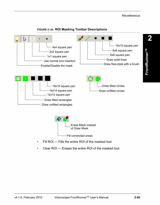
Miscellaneous
Fron
tRun
ner™
2
v4.1.0, February 2010 Visionscape FrontRunner™ User’s Manual 2-69
FIGURE 2–34. ROI Masking Toolbar Descriptions
• Fill ROI — Fills the entire ROI of the masked tool.
• Clear ROI — Erases the entire ROI of the masked tool.
Enable/Disable the mask
Use normal tool insertion1x1 square pen
2x2 square pen4x4 square pen
Draw free-style with a brushDraw solid lines
6x6 square pen8x8 square pen
10x10 square pen
Draw unfilled rectanglesDraw filled rectangles
12x12 square pen14x14 square pen
16x16 square penDraw unfilled circles
Draw filled circles
Fill connected areas
Erase Mask insteadof Draw Mask

Chapter 2 FrontRunner™
2-70 Visionscape FrontRunner™ User’s Manual v4.1.0, February 2010
v4.1.0, February 2010 Visionscape FrontRunner™ User’s Manual 3-1
3
Cam
era
Cal
ibra
tion
3CHAPTER 3 Camera Calibration
Calibration provides a way for measurement values in your Job to be converted from pixels to world units (inches, millimeters, etc.). The Calibration dialog box provides you with three options for calibrating one or more Snapshot steps with a Job. For additional information about calibration, see Chapter 2 of the Visionscape® Tools Reference.
This remainder of this chapter contains information about:
• “Using Robust Calibration” on page 3-1
• “Using Quick Calibration” on page 3-9
• “Using Previously Saved Calibration Data” on page 3-17
Using Robust Calibration
Note: Before you begin this procedure, you need a valid calibration target similar to the one shown in Figure 3–1.
Robust Calibration uses a single Blob tool to find all of the dots on the Calibration target. The center position of each dot, in pixels, is compared to the position data you enter in the “Robust Calibration: Enter Cal Target Dot Locations” screen to calculate forward and backward transform matrices that are used to convert pixel values to world, and world values to pixels.
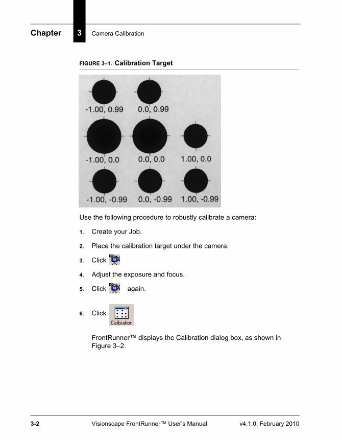
Chapter 3 Camera Calibration
3-2 Visionscape FrontRunner™ User’s Manual v4.1.0, February 2010
FIGURE 3–1. Calibration Target
Use the following procedure to robustly calibrate a camera:
1. Create your Job.
2. Place the calibration target under the camera.
3. Click
4. Adjust the exposure and focus.
5. Click again.
6. Click
FrontRunner™ displays the Calibration dialog box, as shown in Figure 3–2.
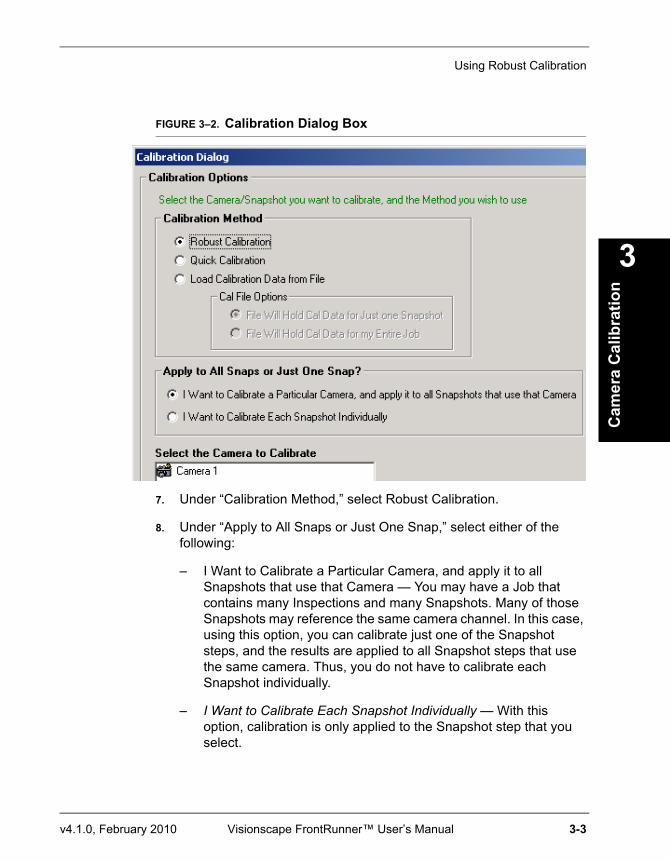
Using Robust Calibration
Cam
era
Cal
ibra
tion
3
v4.1.0, February 2010 Visionscape FrontRunner™ User’s Manual 3-3
FIGURE 3–2. Calibration Dialog Box
7. Under “Calibration Method,” select Robust Calibration.
8. Under “Apply to All Snaps or Just One Snap,” select either of the following:
– I Want to Calibrate a Particular Camera, and apply it to all Snapshots that use that Camera — You may have a Job that contains many Inspections and many Snapshots. Many of those Snapshots may reference the same camera channel. In this case, using this option, you can calibrate just one of the Snapshot steps, and the results are applied to all Snapshot steps that use the same camera. Thus, you do not have to calibrate each Snapshot individually.
– I Want to Calibrate Each Snapshot Individually — With this option, calibration is only applied to the Snapshot step that you select.
Chapter 3 Camera Calibration
3-4 Visionscape FrontRunner™ User’s Manual v4.1.0, February 2010
9. Under “Select the Camera to Calibrate”, highlight (to select) a camera.
– If you select “I Want to Calibrate a Particular Camera, and apply it to all Snapshots that use that Camera”, “Select the Camera to Calibrate” will list the cameras that are being used in the current Job.
– If you select “I Want to Calibrate Each Snapshot Individually”, then each Inspection step is listed, with each of its Snapshots underneath.
10. Click Next.
FrontRunner™ displays the Calibration screen shown in Figure 3–3.
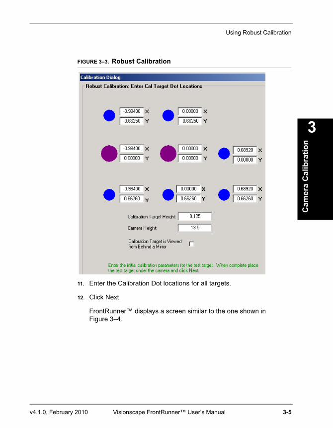
Using Robust Calibration
Cam
era
Cal
ibra
tion
3
v4.1.0, February 2010 Visionscape FrontRunner™ User’s Manual 3-5
FIGURE 3–3. Robust Calibration
11. Enter the Calibration Dot locations for all targets.
12. Click Next.
FrontRunner™ displays a screen similar to the one shown in Figure 3–4.
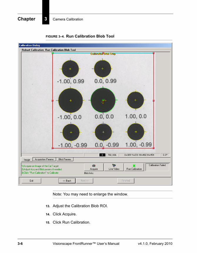
Chapter 3 Camera Calibration
3-6 Visionscape FrontRunner™ User’s Manual v4.1.0, February 2010
FIGURE 3–4. Run Calibration Blob Tool
Note: You may need to enlarge the window.
13. Adjust the Calibration Blob ROI.
14. Click Acquire.
15. Click Run Calibration.
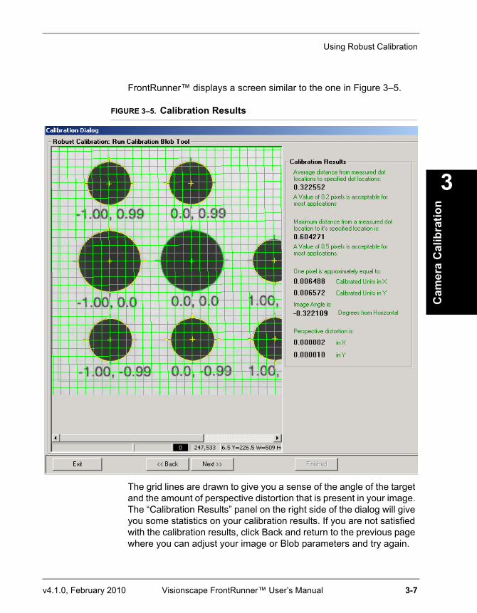
Using Robust Calibration
Cam
era
Cal
ibra
tion
3
v4.1.0, February 2010 Visionscape FrontRunner™ User’s Manual 3-7
FrontRunner™ displays a screen similar to the one in Figure 3–5.
FIGURE 3–5. Calibration Results
The grid lines are drawn to give you a sense of the angle of the target and the amount of perspective distortion that is present in your image. The “Calibration Results” panel on the right side of the dialog will give you some statistics on your calibration results. If you are not satisfied with the calibration results, click Back and return to the previous page where you can adjust your image or Blob parameters and try again.
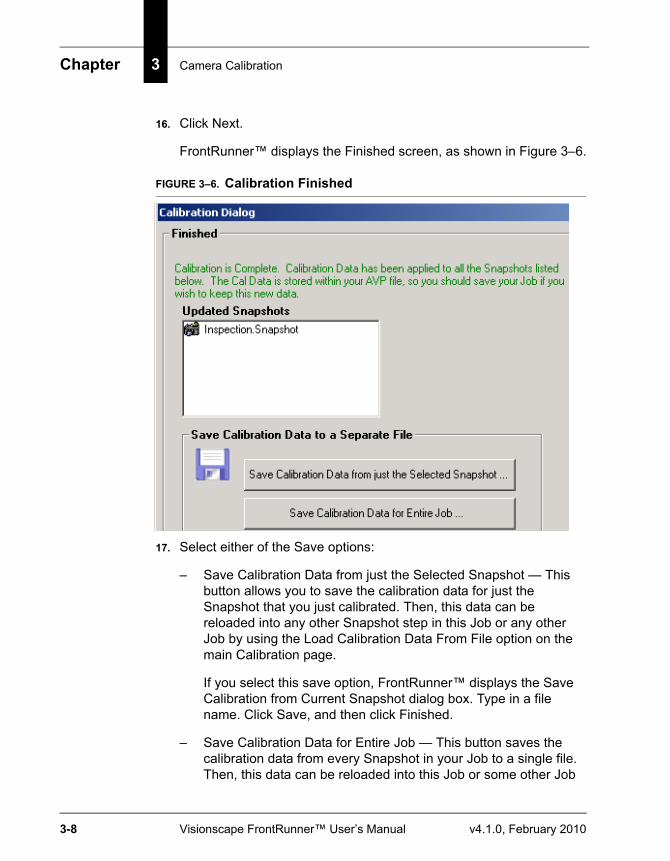
Chapter 3 Camera Calibration
3-8 Visionscape FrontRunner™ User’s Manual v4.1.0, February 2010
16. Click Next.
FrontRunner™ displays the Finished screen, as shown in Figure 3–6.
FIGURE 3–6. Calibration Finished
17. Select either of the Save options:
– Save Calibration Data from just the Selected Snapshot — This button allows you to save the calibration data for just the Snapshot that you just calibrated. Then, this data can be reloaded into any other Snapshot step in this Job or any other Job by using the Load Calibration Data From File option on the main Calibration page.
If you select this save option, FrontRunner™ displays the Save Calibration from Current Snapshot dialog box. Type in a file name. Click Save, and then click Finished.
– Save Calibration Data for Entire Job — This button saves the calibration data from every Snapshot in your Job to a single file. Then, this data can be reloaded into this Job or some other Job

Using Quick Calibration
Cam
era
Cal
ibra
tion
3
v4.1.0, February 2010 Visionscape FrontRunner™ User’s Manual 3-9
using the Load Calibration Data From File option on the main Calibration page, and then selecting the File Will hold Cal Data for my Entire Job.
Note: You can only reload this data into an Job that has the same number of Snapshots.
If you select this save option, FrontRunner™ displays the Save Calibration for Entire Job dialog box. Type in a file name, click Save, and then click Finished.
It’s important to understand that when Calibration is performed, the data is stored in the Snapshot step(s) of the Job, so the Job needs to be saved when done. You do not need to use the Save options on this page unless you want to load the Calibration Data into another Job, or unless you want to simply have a backup.
Using Quick CalibrationUse the following procedure to quick calibrate a camera:
1. Create your Job.
2. Place the calibration target under the camera.
3. Click
4. Adjust the exposure and focus.
5. Click again.
6. Click
FrontRunner™ displays the Calibration dialog box, as shown in Figure 3–7.
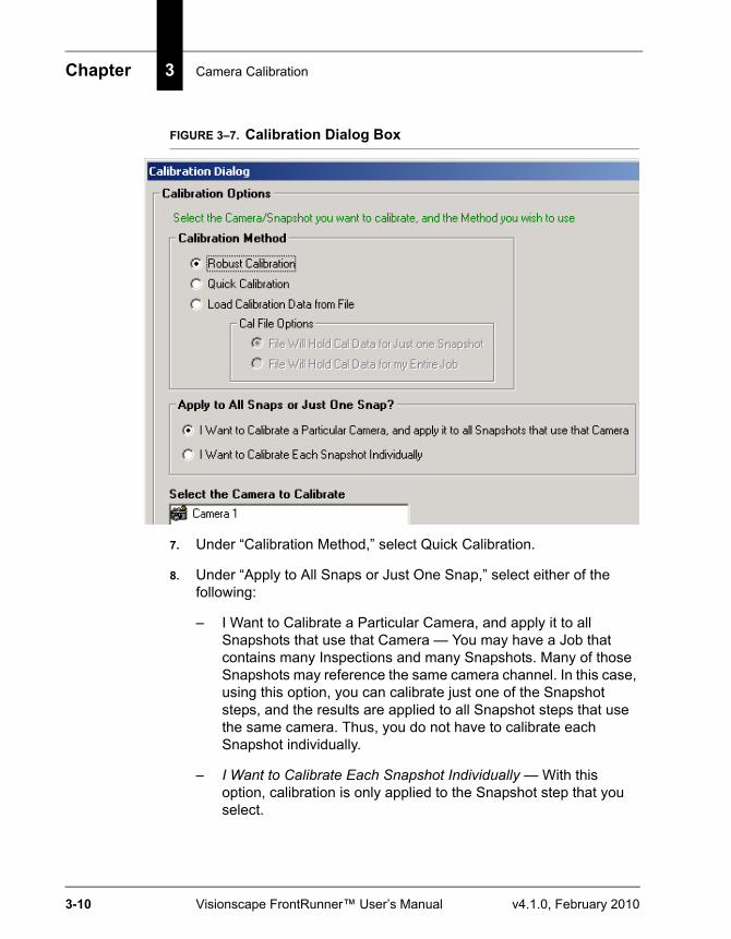
Chapter 3 Camera Calibration
3-10 Visionscape FrontRunner™ User’s Manual v4.1.0, February 2010
FIGURE 3–7. Calibration Dialog Box
7. Under “Calibration Method,” select Quick Calibration.
8. Under “Apply to All Snaps or Just One Snap,” select either of the following:
– I Want to Calibrate a Particular Camera, and apply it to all Snapshots that use that Camera — You may have a Job that contains many Inspections and many Snapshots. Many of those Snapshots may reference the same camera channel. In this case, using this option, you can calibrate just one of the Snapshot steps, and the results are applied to all Snapshot steps that use the same camera. Thus, you do not have to calibrate each Snapshot individually.
– I Want to Calibrate Each Snapshot Individually — With this option, calibration is only applied to the Snapshot step that you select.
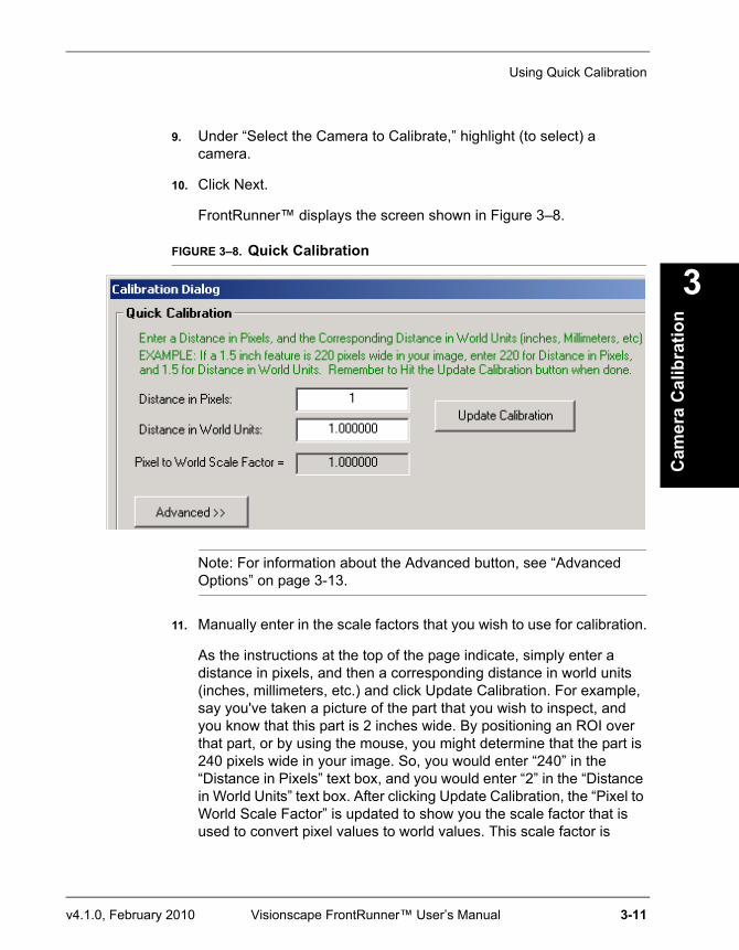
Using Quick Calibration
Cam
era
Cal
ibra
tion
3
v4.1.0, February 2010 Visionscape FrontRunner™ User’s Manual 3-11
9. Under “Select the Camera to Calibrate,” highlight (to select) a camera.
10. Click Next.
FrontRunner™ displays the screen shown in Figure 3–8.
FIGURE 3–8. Quick Calibration
Note: For information about the Advanced button, see “Advanced Options” on page 3-13.
11. Manually enter in the scale factors that you wish to use for calibration.
As the instructions at the top of the page indicate, simply enter a distance in pixels, and then a corresponding distance in world units (inches, millimeters, etc.) and click Update Calibration. For example, say you've taken a picture of the part that you wish to inspect, and you know that this part is 2 inches wide. By positioning an ROI over that part, or by using the mouse, you might determine that the part is 240 pixels wide in your image. So, you would enter “240” in the “Distance in Pixels” text box, and you would enter “2” in the “Distance in World Units” text box. After clicking Update Calibration, the “Pixel to World Scale Factor” is updated to show you the scale factor that is used to convert pixel values to world values. This scale factor is
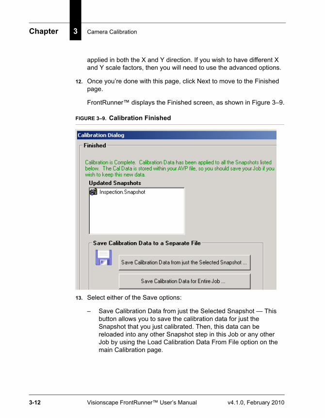
Chapter 3 Camera Calibration
3-12 Visionscape FrontRunner™ User’s Manual v4.1.0, February 2010
applied in both the X and Y direction. If you wish to have different X and Y scale factors, then you will need to use the advanced options.
12. Once you’re done with this page, click Next to move to the Finished page.
FrontRunner™ displays the Finished screen, as shown in Figure 3–9.
FIGURE 3–9. Calibration Finished
13. Select either of the Save options:
– Save Calibration Data from just the Selected Snapshot — This button allows you to save the calibration data for just the Snapshot that you just calibrated. Then, this data can be reloaded into any other Snapshot step in this Job or any other Job by using the Load Calibration Data From File option on the main Calibration page.
Using Quick Calibration
Cam
era
Cal
ibra
tion
3
v4.1.0, February 2010 Visionscape FrontRunner™ User’s Manual 3-13
If you select this save option, FrontRunner™ displays the Save Calibration from Current Snapshot dialog box. Type in a file name. Click Save, and then click Finished.
– Save Calibration Data for Entire Job — This button saves the calibration data from every Snapshot in your Job to a single file. Then, this data can be reloaded into this Job or some other Job using the Load Calibration Data From File option on the main Calibration page, and then selecting the File Will hold Cal Data for my Entire Job.
Note: You can only reload this data into an Job that has the same number of Snapshots.
If you select this save option, FrontRunner™ displays the Save Calibration for Entire Job dialog box. Type in a file name. Click Save, and then click Finished.
It is important to understand that when Calibration is performed, the data is stored in the Snapshot step(s) of the Job, so the Job needs to be saved when done. You do not need to use the Save options on this page unless you want to load the Calibration Data into another Job, or unless you want to simply have a back-up.
Advanced OptionsPress Advanced to display a page with a new set of controls, as shown in Figure 3–10.
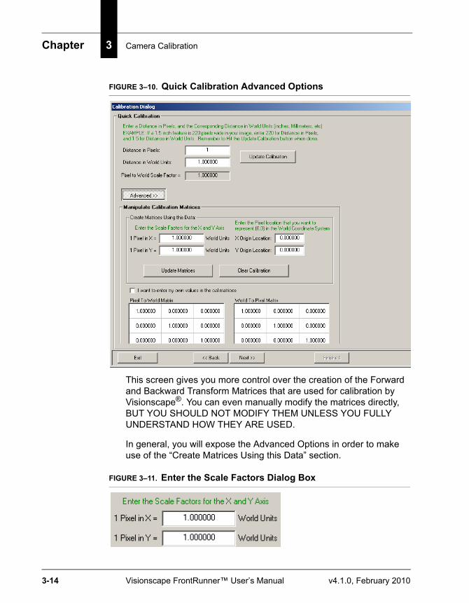
Chapter 3 Camera Calibration
3-14 Visionscape FrontRunner™ User’s Manual v4.1.0, February 2010
FIGURE 3–10. Quick Calibration Advanced Options
This screen gives you more control over the creation of the Forward and Backward Transform Matrices that are used for calibration by Visionscape®. You can even manually modify the matrices directly, BUT YOU SHOULD NOT MODIFY THEM UNLESS YOU FULLY UNDERSTAND HOW THEY ARE USED.
In general, you will expose the Advanced Options in order to make use of the “Create Matrices Using this Data” section.
FIGURE 3–11. Enter the Scale Factors Dialog Box
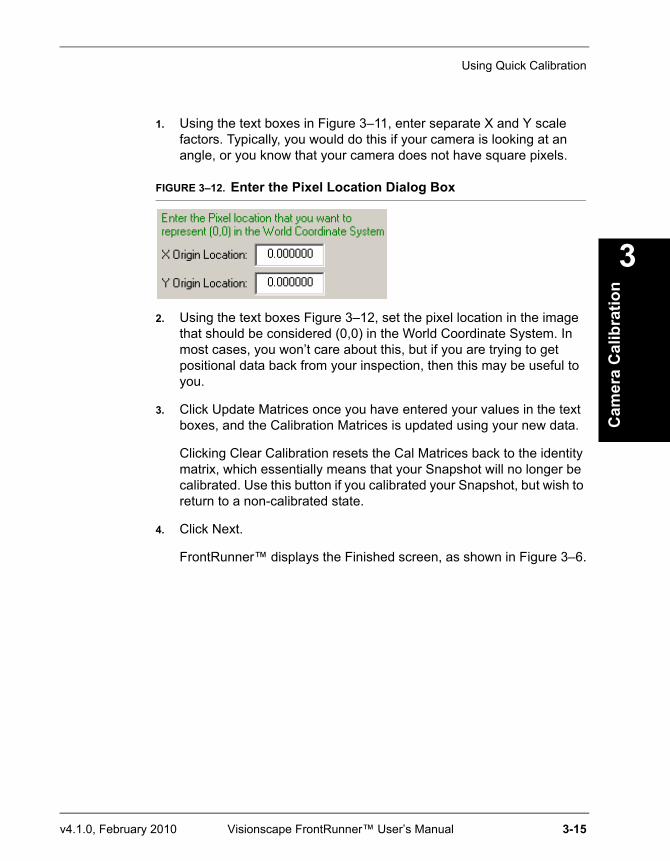
Using Quick Calibration
Cam
era
Cal
ibra
tion
3
v4.1.0, February 2010 Visionscape FrontRunner™ User’s Manual 3-15
1. Using the text boxes in Figure 3–11, enter separate X and Y scale factors. Typically, you would do this if your camera is looking at an angle, or you know that your camera does not have square pixels.
FIGURE 3–12. Enter the Pixel Location Dialog Box
2. Using the text boxes Figure 3–12, set the pixel location in the image that should be considered (0,0) in the World Coordinate System. In most cases, you won’t care about this, but if you are trying to get positional data back from your inspection, then this may be useful to you.
3. Click Update Matrices once you have entered your values in the text boxes, and the Calibration Matrices is updated using your new data.
Clicking Clear Calibration resets the Cal Matrices back to the identity matrix, which essentially means that your Snapshot will no longer be calibrated. Use this button if you calibrated your Snapshot, but wish to return to a non-calibrated state.
4. Click Next.
FrontRunner™ displays the Finished screen, as shown in Figure 3–6.
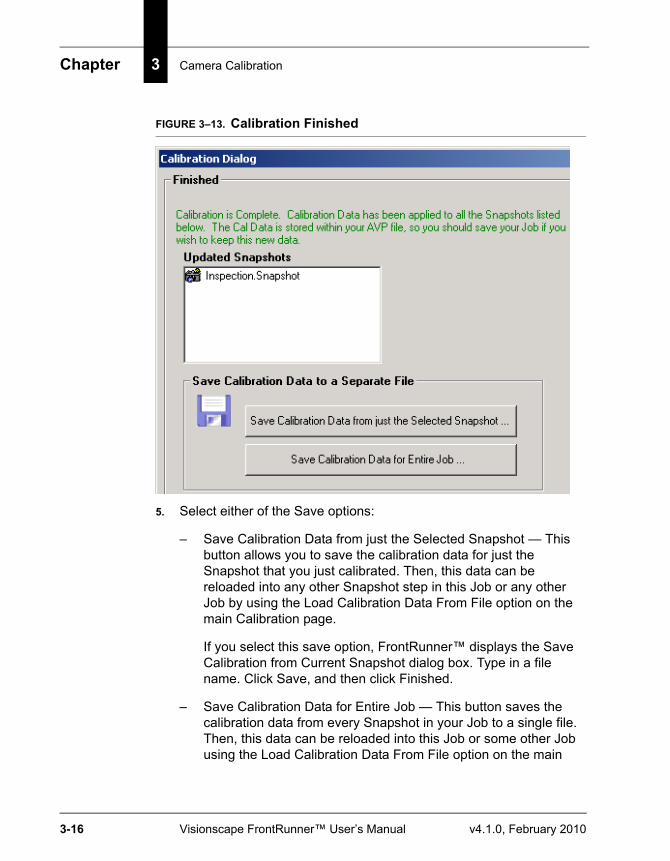
Chapter 3 Camera Calibration
3-16 Visionscape FrontRunner™ User’s Manual v4.1.0, February 2010
FIGURE 3–13. Calibration Finished
5. Select either of the Save options:
– Save Calibration Data from just the Selected Snapshot — This button allows you to save the calibration data for just the Snapshot that you just calibrated. Then, this data can be reloaded into any other Snapshot step in this Job or any other Job by using the Load Calibration Data From File option on the main Calibration page.
If you select this save option, FrontRunner™ displays the Save Calibration from Current Snapshot dialog box. Type in a file name. Click Save, and then click Finished.
– Save Calibration Data for Entire Job — This button saves the calibration data from every Snapshot in your Job to a single file. Then, this data can be reloaded into this Job or some other Job using the Load Calibration Data From File option on the main
Using Previously Saved Calibration Data
Cam
era
Cal
ibra
tion
3
v4.1.0, February 2010 Visionscape FrontRunner™ User’s Manual 3-17
Calibration page, and then selecting the File Will hold Cal Data for my Entire Job.
Note: You can only reload this data into an Job that has the same number of Snapshots.
If you select this save option, FrontRunner™ displays the Save Calibration for Entire Job dialog box. Type in a file name. Click Save, and then click Finished.
It is important to understand that when Calibration is performed, the data is stored in the Snapshot step(s) of the Job, so the Job needs to be saved when done. You do not need to use the Save options on this page unless you want to load the Calibration Data into another Job, or unless you want to simply have a back-up.
Using Previously Saved Calibration DataWhen calibration is performed, FrontRunner™ stores the data in the Snapshot step(s) of the Job. This means you must save a Job after calibration is completed.
You do not need to use the Save options on this page unless you want to load the Calibration Data into another Job, or unless you want to simply have a backup.
Use the following procedure to load calibration data that was previously saved:
1. Create a new Job or open an existing Job.
2. Click
FrontRunner™ displays the Calibration dialog box, as shown in Figure 3–14.
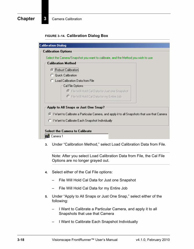
Chapter 3 Camera Calibration
3-18 Visionscape FrontRunner™ User’s Manual v4.1.0, February 2010
FIGURE 3–14. Calibration Dialog Box
3. Under “Calibration Method,” select Load Calibration Data from File.
Note: After you select Load Calibration Data from File, the Cal File Options are no longer grayed out.
4. Select either of the Cal File options:
– File Will Hold Cal Data for Just one Snapshot
– File Will Hold Cal Data for my Entire Job
5. Under “Apply to All Snaps or Just One Snap,” select either of the following:
– I Want to Calibrate a Particular Camera, and apply it to all Snapshots that use that Camera
– I Want to Calibrate Each Snapshot Individually
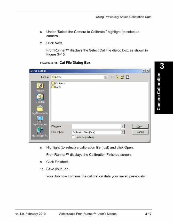
Using Previously Saved Calibration Data
Cam
era
Cal
ibra
tion
3
v4.1.0, February 2010 Visionscape FrontRunner™ User’s Manual 3-19
6. Under “Select the Camera to Calibrate,” highlight (to select) a camera.
7. Click Next.
FrontRunner™ displays the Select Cal File dialog box, as shown in Figure 3–15.
FIGURE 3–15. Cal File Dialog Box
8. Highlight (to select) a calibration file (.cal) and click Open.
FrontRunner™ displays the Calibration Finished screen.
9. Click Finished.
10. Save your Job.
Your Job now contains the calibration data your saved previously.

Chapter 3 Camera Calibration
3-20 Visionscape FrontRunner™ User’s Manual v4.1.0, February 2010
v4.1.0, February 2010 Visionscape FrontRunner™ User’s Manual 4-1
4
The
Part
Que
ue
4
CHAPTER 4 The Part Queue
Every Inspection step maintains a queue of the last n cycle images and results. You decide how large the queue will be and what gets stored in it:
• Results and images for every part
• Results and images for passed parts
• Results and images for failed parts
If you activate the Queue, the Part Queue Viewer allows you to upload it, and view any of the images and results that were stored on the device at runtime.
Note: The Part Queue allows you to review runtime images only.
The remainder of this chapter contains information about:
• “Setting Up and Starting the Part Queue” on page 4-2
• “Viewing Images in the Part Queue” on page 4-7
• “Saving Images and Records” on page 4-8
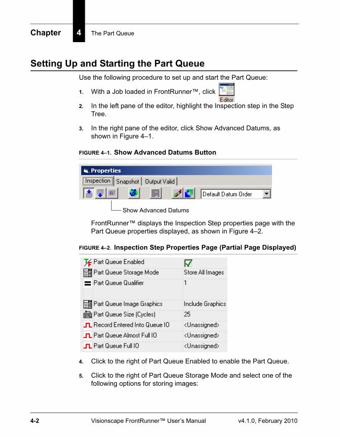
Chapter 4 The Part Queue
4-2 Visionscape FrontRunner™ User’s Manual v4.1.0, February 2010
Setting Up and Starting the Part QueueUse the following procedure to set up and start the Part Queue:
1. With a Job loaded in FrontRunner™, click
2. In the left pane of the editor, highlight the Inspection step in the Step Tree.
3. In the right pane of the editor, click Show Advanced Datums, as shown in Figure 4–1.
FIGURE 4–1. Show Advanced Datums Button
FrontRunner™ displays the Inspection Step properties page with the Part Queue properties displayed, as shown in Figure 4–2.
FIGURE 4–2. Inspection Step Properties Page (Partial Page Displayed)
4. Click to the right of Part Queue Enabled to enable the Part Queue.
5. Click to the right of Part Queue Storage Mode and select one of the following options for storing images:
Show Advanced Datums
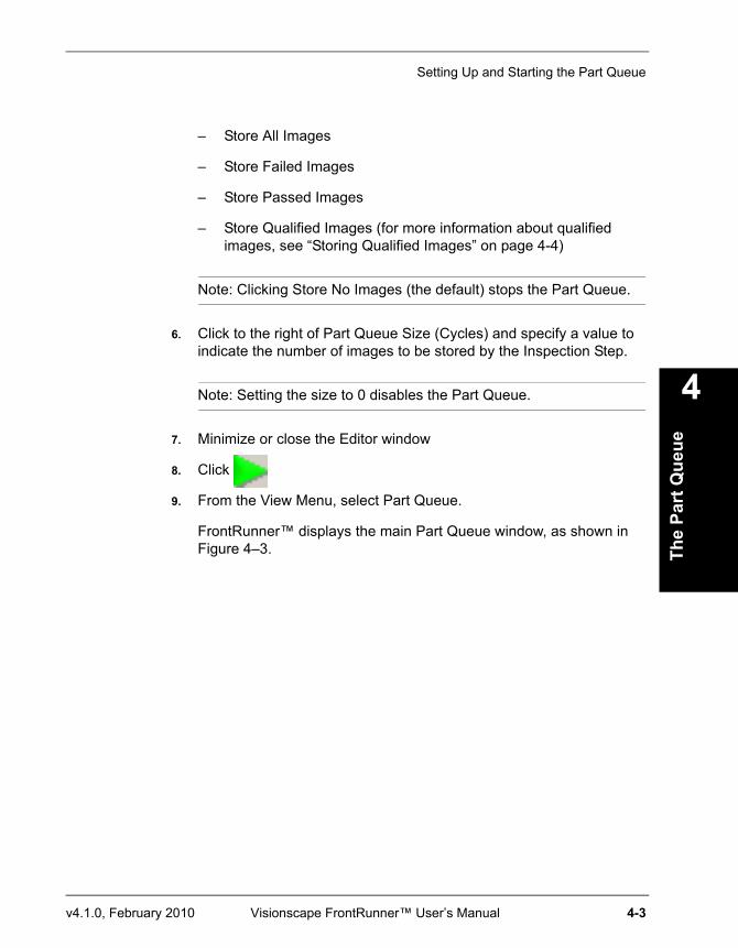
Setting Up and Starting the Part Queue
The
Part
Que
ue
4
v4.1.0, February 2010 Visionscape FrontRunner™ User’s Manual 4-3
– Store All Images
– Store Failed Images
– Store Passed Images
– Store Qualified Images (for more information about qualified images, see “Storing Qualified Images” on page 4-4)
Note: Clicking Store No Images (the default) stops the Part Queue.
6. Click to the right of Part Queue Size (Cycles) and specify a value to indicate the number of images to be stored by the Inspection Step.
Note: Setting the size to 0 disables the Part Queue.
7. Minimize or close the Editor window
8. Click
9. From the View Menu, select Part Queue.
FrontRunner™ displays the main Part Queue window, as shown in Figure 4–3.
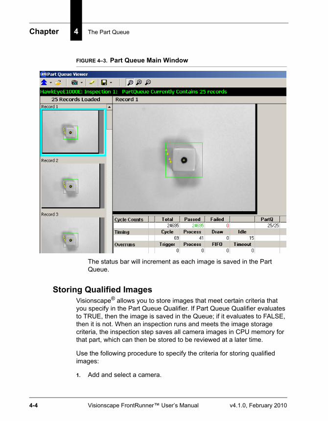
Chapter 4 The Part Queue
4-4 Visionscape FrontRunner™ User’s Manual v4.1.0, February 2010
FIGURE 4–3. Part Queue Main Window
The status bar will increment as each image is saved in the Part Queue.
Storing Qualified ImagesVisionscape® allows you to store images that meet certain criteria that you specify in the Part Queue Qualifier. If Part Queue Qualifier evaluates to TRUE, then the image is saved in the Queue; if it evaluates to FALSE, then it is not. When an inspection runs and meets the image storage criteria, the inspection step saves all camera images in CPU memory for that part, which can then be stored to be reviewed at a later time.
Use the following procedure to specify the criteria for storing qualified images:
1. Add and select a camera.
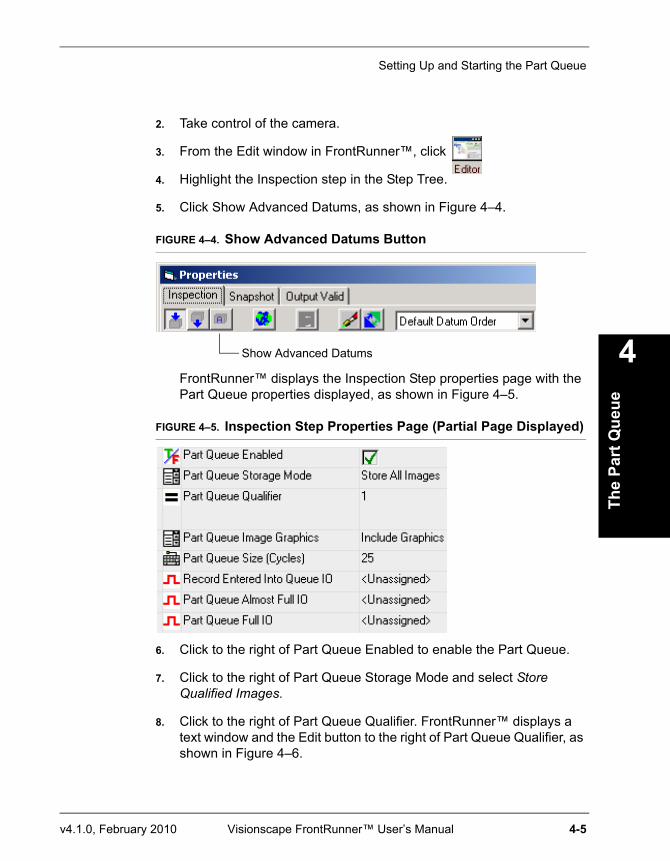
Setting Up and Starting the Part Queue
The
Part
Que
ue
4
v4.1.0, February 2010 Visionscape FrontRunner™ User’s Manual 4-5
2. Take control of the camera.
3. From the Edit window in FrontRunner™, click
4. Highlight the Inspection step in the Step Tree.
5. Click Show Advanced Datums, as shown in Figure 4–4.
FIGURE 4–4. Show Advanced Datums Button
FrontRunner™ displays the Inspection Step properties page with the Part Queue properties displayed, as shown in Figure 4–5.
FIGURE 4–5. Inspection Step Properties Page (Partial Page Displayed)
6. Click to the right of Part Queue Enabled to enable the Part Queue.
7. Click to the right of Part Queue Storage Mode and select Store Qualified Images.
8. Click to the right of Part Queue Qualifier. FrontRunner™ displays a text window and the Edit button to the right of Part Queue Qualifier, as shown in Figure 4–6.
Show Advanced Datums
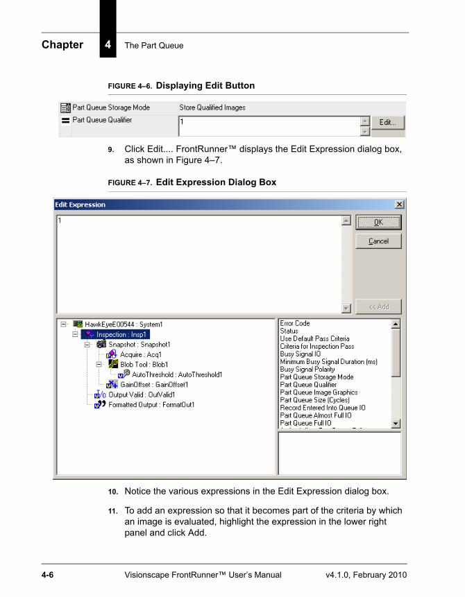
Chapter 4 The Part Queue
4-6 Visionscape FrontRunner™ User’s Manual v4.1.0, February 2010
FIGURE 4–6. Displaying Edit Button
9. Click Edit.... FrontRunner™ displays the Edit Expression dialog box, as shown in Figure 4–7.
FIGURE 4–7. Edit Expression Dialog Box
10. Notice the various expressions in the Edit Expression dialog box.
11. To add an expression so that it becomes part of the criteria by which an image is evaluated, highlight the expression in the lower right panel and click Add.
Viewing Images in the Part Queue
The
Part
Que
ue
4
v4.1.0, February 2010 Visionscape FrontRunner™ User’s Manual 4-7
FrontRunner™ adds the expression to the upper panel.
12. When you are finished adding expressions, click OK.
Note: For detailed information about expressions, see Chapter 8 of the Visionscape® Tools Reference.
Viewing Images in the Part QueueAfter setting up and starting the Part Queue, you can view images in the queue:
1. To upload Part Queue, click
Note: By default, this clears the camera.
FrontRunner™ displays a screen similar to the one in Figure 4–8. This screen displays:
– A vertical column of images in the queue
– A green (pass)/red (fail) status for the currently selected image
– Cycle information for the currently selected image
– A larger image of the currently selected image
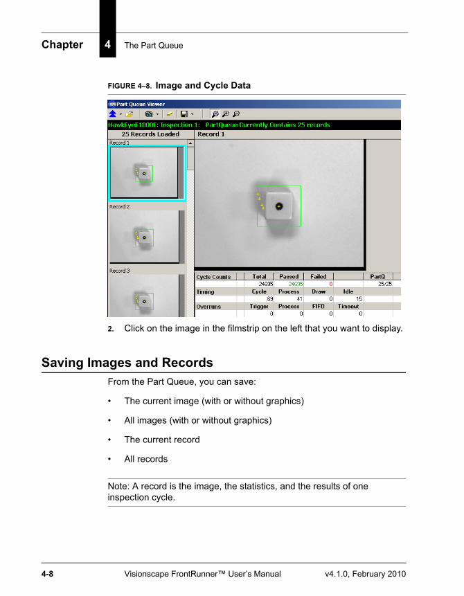
Chapter 4 The Part Queue
4-8 Visionscape FrontRunner™ User’s Manual v4.1.0, February 2010
FIGURE 4–8. Image and Cycle Data
2. Click on the image in the filmstrip on the left that you want to display.
Saving Images and RecordsFrom the Part Queue, you can save:
• The current image (with or without graphics)
• All images (with or without graphics)
• The current record
• All records
Note: A record is the image, the statistics, and the results of one inspection cycle.
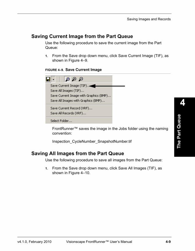
Saving Images and Records
The
Part
Que
ue
4
v4.1.0, February 2010 Visionscape FrontRunner™ User’s Manual 4-9
Saving Current Image from the Part QueueUse the following procedure to save the current image from the Part Queue:
1. From the Save drop down menu, click Save Current Image (TIF), as shown in Figure 4–9.
FIGURE 4–9. Save Current Image
FrontRunner™ saves the image in the Jobs folder using the naming convention:
Inspection_CycleNumber_SnapshotNumber.tif
Saving All Images from the Part QueueUse the following procedure to save all images from the Part Queue:
1. From the Save drop down menu, click Save All Images (TIF), as shown in Figure 4–10.
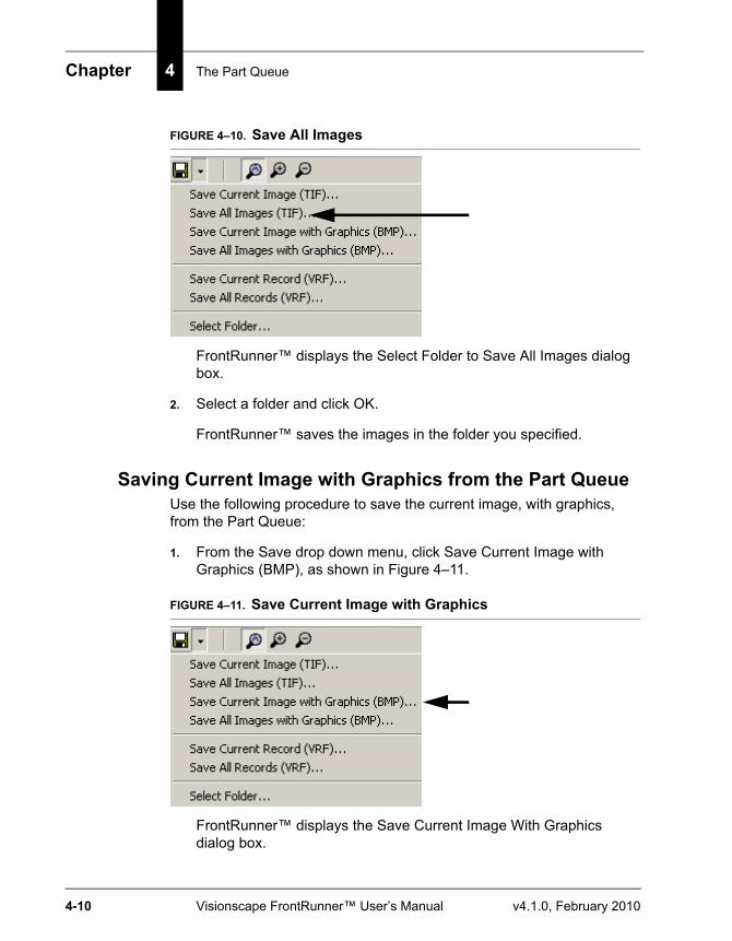
Chapter 4 The Part Queue
4-10 Visionscape FrontRunner™ User’s Manual v4.1.0, February 2010
FIGURE 4–10. Save All Images
FrontRunner™ displays the Select Folder to Save All Images dialog box.
2. Select a folder and click OK.
FrontRunner™ saves the images in the folder you specified.
Saving Current Image with Graphics from the Part QueueUse the following procedure to save the current image, with graphics, from the Part Queue:
1. From the Save drop down menu, click Save Current Image with Graphics (BMP), as shown in Figure 4–11.
FIGURE 4–11. Save Current Image with Graphics
FrontRunner™ displays the Save Current Image With Graphics dialog box.
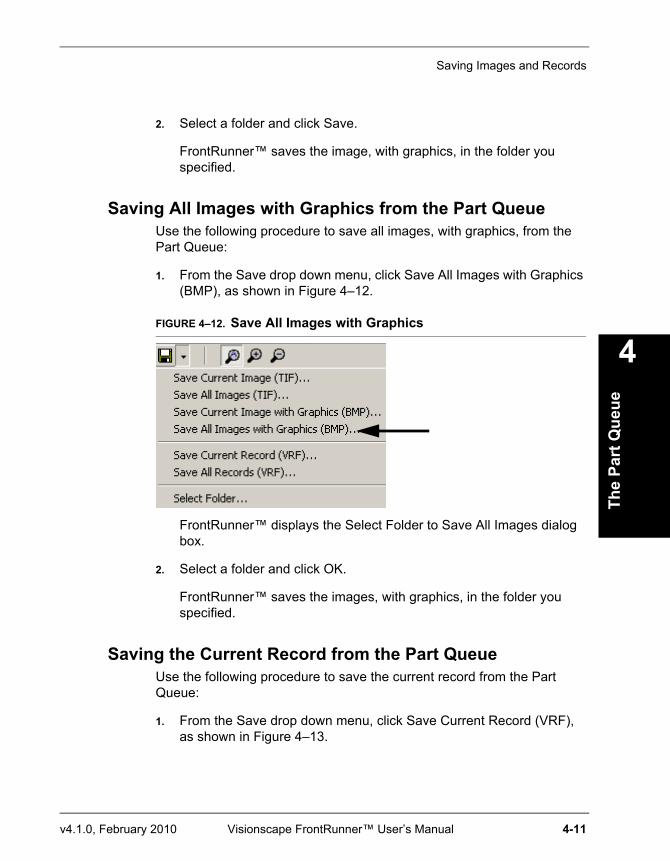
Saving Images and Records
The
Part
Que
ue
4
v4.1.0, February 2010 Visionscape FrontRunner™ User’s Manual 4-11
2. Select a folder and click Save.
FrontRunner™ saves the image, with graphics, in the folder you specified.
Saving All Images with Graphics from the Part QueueUse the following procedure to save all images, with graphics, from the Part Queue:
1. From the Save drop down menu, click Save All Images with Graphics (BMP), as shown in Figure 4–12.
FIGURE 4–12. Save All Images with Graphics
FrontRunner™ displays the Select Folder to Save All Images dialog box.
2. Select a folder and click OK.
FrontRunner™ saves the images, with graphics, in the folder you specified.
Saving the Current Record from the Part QueueUse the following procedure to save the current record from the Part Queue:
1. From the Save drop down menu, click Save Current Record (VRF), as shown in Figure 4–13.
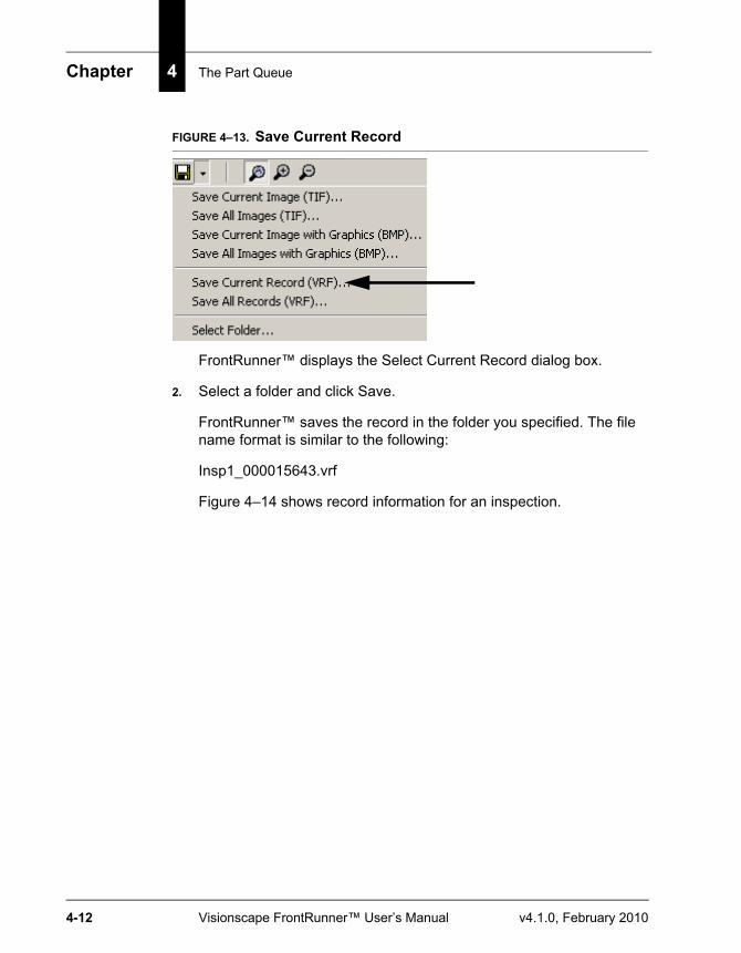
Chapter 4 The Part Queue
4-12 Visionscape FrontRunner™ User’s Manual v4.1.0, February 2010
FIGURE 4–13. Save Current Record
FrontRunner™ displays the Select Current Record dialog box.
2. Select a folder and click Save.
FrontRunner™ saves the record in the folder you specified. The file name format is similar to the following:
Insp1_000015643.vrf
Figure 4–14 shows record information for an inspection.
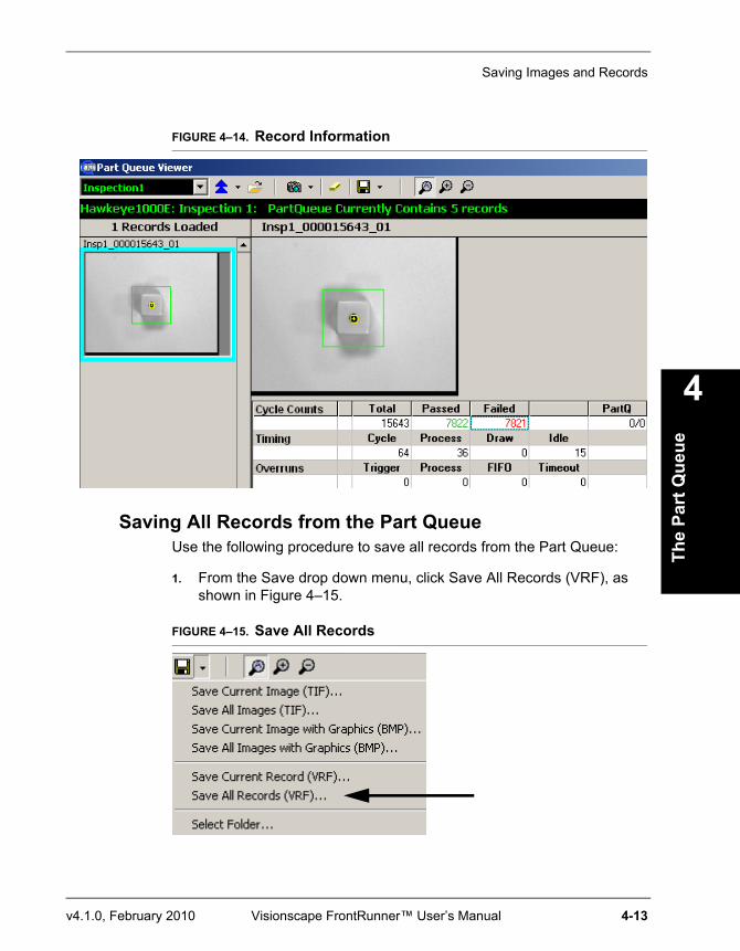
Saving Images and Records
The
Part
Que
ue
4
v4.1.0, February 2010 Visionscape FrontRunner™ User’s Manual 4-13
FIGURE 4–14. Record Information
Saving All Records from the Part QueueUse the following procedure to save all records from the Part Queue:
1. From the Save drop down menu, click Save All Records (VRF), as shown in Figure 4–15.
FIGURE 4–15. Save All Records
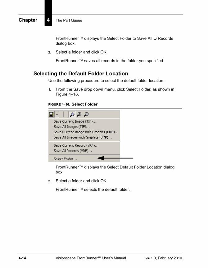
Chapter 4 The Part Queue
4-14 Visionscape FrontRunner™ User’s Manual v4.1.0, February 2010
FrontRunner™ displays the Select Folder to Save All Q Records dialog box.
2. Select a folder and click OK.
FrontRunner™ saves all records in the folder you specified.
Selecting the Default Folder LocationUse the following procedure to select the default folder location:
1. From the Save drop down menu, click Select Folder, as shown in Figure 4–16.
FIGURE 4–16. Select Folder
FrontRunner™ displays the Select Default Folder Location dialog box.
2. Select a folder and click OK.
FrontRunner™ selects the default folder.
v4.1.0, February 2010 Visionscape FrontRunner™ User’s Manual Index-1
Index
Numerics35mm SLR Cameras A-4
AAcquire
images during tryout 2-11, 2-31new image 2-31step 2-6
works with snapshot step 1-18Adding
camera 2-5device buttons 2-25software system 2-4, 2-26
Advanced Datumsdisplaying 4-2, 4-5
All Imagessaving 2-16
Aperture A-15Automatic
run step after change 2-31train step after change 2-32
BBack Lighting A-10Benchmark A-1Browse For Folder Dialog Box 2-16Buffer 1-15Bufferpool 1-16
Buttonsadding
smart camera in frontrunner 2-26software system 2-4, 2-26
clear roi 2-53, 2-59click to record transitions to a dss file 2-
20, 2-42deleting smart camera in frontrunner 2-
26device
adding 2-25display timing report 2-33fill roi 2-53, 2-59lightbulb 2-52, 2-58wizard
next 2-31previous 2-31
zoom 2-31, 2-36
CCalibration
datasaving 3-7, 3-11, 3-15using saved 3-16
dialog box 3-1quick 3-8robust 3-1
Cameraadding 2-5controlling 2-5ip address
changing 2-46, 2-47name
changing 2-45Changing
cameraip address 2-46, 2-47name 2-45
ip settings 2-46
Index
Index-2 Visionscape FrontRunner™ User’s Manual v4.1.0, February 2010
Clearroi button 2-53, 2-59the display 2-51
Click to record transitions to a DSS file button 2-20, 2-42
Clipboardcopy
contents of debug window do 2-51result data to 2-40
Close Job 2-48Combining Jobs 1-21Configure
device 2-49dialog box 2-49
Configuringserial ports 2-49tcp ports 2-49
Controllingcamera 2-5
Copycontents of debug window to
clipboard 2-51result data to clipboard 2-40
Counters and Statisticsreset all 2-40
Create New Program 2-29Creating Good Images A-1Current Image
saving 2-15Cycle Counts 2-40
DData
using saved calibration 3-16Debug Output 2-51
windowclearing the display 2-51
Default Folderselecting (partq) 4-13
Delay Between Steps in Tryout 2-32Delete
step dialog box 2-38the currently selected step 2-38
Deletingsoftware system 2-26
Depth Of Field A-16
Devicebuttons
adding 2-25configure 2-49toolbar 2-2
Dialog Boxesbrowse for folder 2-16calibration 3-1configure device 2-49delete step 2-38edit expression 4-6enter the pixel location 3-14enter the scale factors 3-13insert step 2-38save
calibration for entire job 3-8, 3-12, 3-16calibration from current snapshot 3-7, 3-
11, 3-15
job 2-29, 2-48vision system tree as text 2-49
select cal file 3-18Diffuse Lighting A-7Digital
soft scope 2-23Digital Soft Scope 2-52Display
extended results 2-40timing report 2-33tools 2-52
Displayingi/o 2-20info about job 2-49ip address of camera 2-54mac address of camera 2-54properties pages 2-32roi masking toolbar 2-58
Download Program from PC to Device 2-11, 2-30
Dumpingjob to text file 2-49
Index
v4.1.0, February 2010 Visionscape FrontRunner™ User’s Manual Index-3
EEdit
expression dialog box 4-6parameters
setting 2-31Enable
part queue 4-2, 4-5Enter the
pixel location dialog box 3-14scale factors dialog box 3-13
Every Image (no drops) 2-16Exposure Time
setting 2-9Expressions
and storing qualified images 4-6
FFailed Images
saving 2-16Field Of View (FOV) A-2, A-4File Menu 2-48
close job 2-48configure device 2-49dump job to text file 2-49new job 2-48open job 2-48options 2-50
reports 2-50runtime 2-50
save job 2-48save job as 2-48show job info 2-49upload job 2-48
Fill ROI Button 2-53, 2-59Firmware
co-existence of V4.0 and V4.1 1-13, 2-2Fluorescent Lighting A-6Focal Length A-2Folder
selecting 2-16Frame Datum List 2-7Freeze
last failed 2-16next failed 2-16this 2-16
Front Lighting A-9
FrontRunnerdisplaying version number 2-53main window icons 2-26menus 2-48multiple views 2-13what it is 2-1what it supports 2-1windows 2-25
F-Stop A-15
HHelp Menu 2-53
II/O
display 2-20transitions 2-20
examining 2-23I/O Display 2-51Icons
main FrontRunner window 2-26Illumination A-4Image
acquire new 2-31saving all with graphics in part queue 4-
10saving current 2-15saving current in part queue 4-8saving current with graphics in part
queue4-10
Imagesacquire during tryout 2-11, 2-31saving all in part queue 4-9storing qualified 4-4
Incandescent Lighting A-6Insert a tool
after the currently selected Step 2-38before the currently selected Step 2-38into the currently selected Step 2-38
Insert Step Dialog Box 2-38Inspection
countersresetting 2-40
step 1-17IntelliFind 1-13
Index
Index-4 Visionscape FrontRunner™ User’s Manual v4.1.0, February 2010
messages 1-14IP Address
of cameradisplaying 2-54
IP Settingschanging 2-46
JJob
close 2-48displaying info about 2-49new 2-48open 2-48open existing 2-29save 2-48save as 2-48save with different name 2-29, 2-48step 1-16tree 1-16
sample 1-15tryout 2-10upload 2-48view 2-38
Jobscombining 1-21storage in non-volatile memory 1-20
Jump to Previous Step 2-31
LLaser Lighting A-7Lens
chart A-2extension ring A-4
Lightbulb Button 2-52, 2-58Lighting Factors A-4Live Video 2-31Log
all messages to 2-51
MMAC Address
of cameradisplaying 2-54
Mask Tools 2-52Maximum Rate w/drops 2-16Measuring Signal Lengths 2-24Menus
file 2-48help 2-53view 2-50
Messagesintellifind 1-14
Modesruntime 1-12setup 1-12
Multiple Viewsfrontrunner 2-13
NNetwork Overview 2-50Network Overview Window 2-44New Job 2-48Non-Volatile Memory
job storage in 1-20Number
displaying frontrunner version 2-53of x decimal places 2-50
OOpen
existing job 2-29existing program 2-29job 2-48
Options 2-50Overruns 2-41
PPart Queue
enabled 4-2, 4-5saving
all images 4-9all images with graphics 4-10all records 4-12current image 4-8current image with graphics 4-10current record 4-11images 4-8records 4-8
selecting default folder 4-13setting up 4-2starting 4-2view images in 4-7
Part Tree View 2-38Passed Images
Index
v4.1.0, February 2010 Visionscape FrontRunner™ User’s Manual Index-5
saving 2-16Paste
after 2-38before 2-38into 2-38
PCruntime priority 2-50
Point-Source Lighting A-7Polarized Light A-10Program
create new 2-29download from pc to device 2-30open existing 2-29save 2-29save on device to flash 2-30start on device 2-30stop on device 2-30tryout on pc in a loop 2-31tryout on pc once and then stop 2-11, 2-
31upload from device to pc 2-30
Properties Pagesdisplaying in tryout view 2-32
QQualified Image
storing 4-4what it is 4-4
Quick Calibration 3-8
RRecord
saving current in part queue 4-11Records
saving all in part queue 4-12Reports
optionssetting 2-50
Resetall counters and statistics 2-40all statistics 2-40inspection counters 2-40
Resultsdisplay extended 2-40show in world (calibrated) space 2-40
Robust
calibration 3-1ROI Masking Toolbar
displaying 2-58Run Current Step then Jump to Next
Step 2-31Runtime
mode 1-12options
setting 2-50
SSave
all images 2-16calibration
for entire job dialog box 3-8, 3-12, 3-16from current snapshot dialog box 3-7, 3-
11, 3-15
calibration datafor entire job 3-8from just the selected snapshot 3-7
current image 2-15failed images 2-16none 2-16passed images 2-16program 2-29program on device to flash 2-30vision system tree as text dialog box 2-
49Save Job 2-48
as 2-48dialog box 2-29, 2-48
Savingall images (partq) 4-9all images with graphics (partq) 4-10all records (partq) 4-12calibration data 3-7, 3-11, 3-15current image (partq) 4-8current image with graphics (partq) 4-10current record (partq) 4-11part queue
images 4-8records 4-8
Selectcal file dialog box 3-18folder 2-16results to upload 2-39
Index
Index-6 Visionscape FrontRunner™ User’s Manual v4.1.0, February 2010
Selectingdefault folder (partq) 4-13
Selecting a Lens A-2Serial Ports
configuring 2-49Set the debug level 2-51Setting
edit parameters 2-31exposure time 2-9reports options 2-50
runtimeoptions 2-50
timing parameters 2-32Setting Up
part queue 4-2Settings 2-11, 2-31
ipchanging 2-46
Setupmode 1-12
Showadvanced datums 4-2, 4-5all statistics in world (calibrated)
space 2-40properties 2-32results in world (calibrated) space 2-40tool graphics 2-16
Side Lighting A-9Signal Lengths
measuring 2-24Simulating Triggers 2-21Single Channel Devices
triggering rules 1-12Smart Camera
ip settingschanging 2-46
Smart Camera Buttonsadding in frontrunner 2-26deleting in frontrunner 2-26
Snapshot Step 2-7works with acquire step 1-18
Software System 2-19adding 2-4, 2-26deleting 2-26
Start
program on device 2-30Starting
part queue 4-2Statistics
reset all 2-40show all in world (calibrated) space 2-40
Stepjump to previous 2-31run current and then jump to next step 2-
31train selected 2-30tryout current on pc 2-31untrain selected 2-30what it is 1-15
Stepsacquire 2-6snapshot 2-7vision system 2-8
Stopprogram on device 2-30
Storingqualified images 4-4
Strobe Lighting A-7
TTCP Ports
configuring 2-49Text File
dump job to 2-49Threshold Helper 2-52Timing 2-40
parameterssetting 2-32
Toolbardevice 2-2
Toolsdisplay 2-52training 2-10untraining 2-10
Train Selected Step 2-30Training Tools 2-10Transitions
i/o 2-20Tree
what it is 1-15Triggering Rules
Index
v4.1.0, February 2010 Visionscape FrontRunner™ User’s Manual Index-7
single channel devices 1-12Triggers
simulating 2-21Tryout
current step on pc 2-31job 2-10
Tryout Programon PC in a Loop 2-31on pc once and then stop 2-11, 2-31
UUntrain Selected Step 2-30Untraining Tools 2-10Upload
job 2-48Upload Program from Device to PC 2-30Use
calibrated space when activated 2-50i/o during tryout 2-32triggers during tryout 2-32
VVersion Number
displaying frontrunner 2-53Video
starting live 2-31stopping live 2-31
View Menu 2-50debug output 2-51digital soft scope 2-23, 2-52display tools 2-52
mask tools 2-52, 2-58threshold helper 2-52
i/o display 2-51network overview 2-50
Viewing Imagespart queue 4-7
Vision System Step 1-16, 2-8
WWhen
important messages are added to the display, show this window 2-51
Windowsnetwork overview 2-44
With Graphics 2-16Without Graphics 2-16
Wizardnext 2-31previous 2-31
ZZoom
buttons 2-31, 2-36

Index
Index-8 Visionscape FrontRunner™ User’s Manual v4.1.0, February 2010