Embed Size (px)
Citation preview

Vivado Design Suite
Tutorial
Using Constraints
UG945 (v2013.4) December 19, 2013
Notice of Disclaimer
The information disclosed to you hereunder (the "Materials") is provided solely for the selection and use of Xilinx products. To the
maximum extent permitted by applicable law: (1) Materials are made available "AS IS" and with all faults, Xilinx hereby DISCLAIMS
ALL WARRANTIES AND CONDITIONS, EXPRESS, IMPLIED, OR STATUTORY, INCLUDING BUT NOT LIMITED TO WARRANTIES OF
MERCHANTABILITY, NON-INFRINGEMENT, OR FITNESS FOR ANY PARTICULAR PURPOSE; and (2) Xilinx shall not be liable (whether
in contract or tort, including negligence, or under any other theory of liability) for any loss or damage of any kind or nature related
to, arising under, or in connection with, the Materials (including your use of the Materials), including for any direct, indirect, special,
incidental, or consequential loss or damage (including loss of data, profits, goodwill, or any type of loss or damage suffered as a
result of any action brought by a third party) even if such damage or loss was reasonably foreseeable or Xilinx had been advised of
the possibility of the same. Xilinx assumes no obligation to correct any errors contained in the Materials or to notify you of updates
to the Materials or to product specifications. You may not reproduce, modify, distribute, or publicly display the Materials without
prior written consent. Certain products are subject to the terms and conditions of the Limited Warranties which can be viewed at
http://www.xilinx.com/warranty.htm; IP cores may be subject to warranty and support terms contained in a license issued to you by
Xilinx. Xilinx products are not designed or intended to be fail-safe or for use in any application requiring fail-safe performance; you
assume sole risk and liability for use of Xilinx products in Critical Applications: http://www.xilinx.com/warranty.htm#critapps.
©Copyright 2012-2013 Xilinx, Inc. Xilinx, the Xilinx logo, Artix, Vivado, ISE, Kintex, Spartan, Virtex, Vivado, Zynq, and other designated
brands included herein are trademarks of Xilinx in the United States and other countries. All other trademarks are the property of
their respective owners.
Revision History
Date Version Revision
12/19/2013 2013.4 Corrected broken cross-reference.
12/18/2013 2013.4 Validated with release.
11/12/2013 2013.3 Validated with release.
06/19/2013 2013.2 Validated with release.
04/25/2013 2013.1 Minor editorial update.
03/20/2013 2013.1 Validated with release.
Using Constraints www.xilinx.com 3
UG945 (v2013.4) December 19, 2013
Table of Contents
Revision History ........................................................................................................................................................... 2
Table of Contents ................................................................................................................................................................................. 3
Vivado Using Constraints Tutorial ................................................................................................................................................. 4
Overview ........................................................................................................................................................................ 4
Tutorial Design Description .................................................................................................................................... 5
Software Requirements ............................................................................................................................................ 5
Hardware Requirements .......................................................................................................................................... 5
Preparing the Tutorial Design Files ...................................................................................................................... 5
Lab 1: Defining Timing Constraints ............................................................................................................................................... 6
Step 1: Opening the Example Project ................................................................................................................. 6
Step 2: Defining Constraint Sets and Files ........................................................................................................ 8
Step 3: Creating a Clock Constraint ..................................................................................................................... 9
Step 4: Saving Constraints.................................................................................................................................... 14
Step 5: Reporting Clock Interactions ................................................................................................................ 15
Step 6: Creating an Input Delay Constraint ................................................................................................... 16
Summary ..................................................................................................................................................................... 21
Lab 2: Setting Physical Constraints ............................................................................................................................................. 22
Step 1: Opening the Project ................................................................................................................................ 22
Step 2: Adding Placement Constraints ............................................................................................................ 22
Step 3: Defining Additional Physical Constraints ........................................................................................ 25
Step 4: Defining Constraints with Object Properties .................................................................................. 26
Setting Cell Properties....................................................................................................................................... 26
Setting Design Properties ................................................................................................................................ 28
Step 5: Saving Constraints.................................................................................................................................... 30
Summary ..................................................................................................................................................................... 30
Send Feedback

Using Constraints www.xilinx.com 4
UG945 (v2013.4) December 19, 2013
Vivado Using Constraints Tutorial
Overview
This tutorial is comprised of various labs which demonstrate aspects of constraining a design in
the Vivado® Design Suite. The constraints format supported by the Vivado Design Suite is
called Xilinx® Design Constraints (XDC), which is a combination of the industry standard
Synopsys® Design Constraints and proprietary Xilinx constraints.
Important! The Vivado Design Suite does not support the UCF format. For information
on migrating UCF constraints to XDC commands refer to the ISE to Vivado Design Suite
Migration Guide (UG911).
XDCs are not just simple strings; they are Tcl commands that the Vivado Tcl interpreter
sequentially reads and parses. You can enter design constraints in several ways at different
points in the design flow. You can store XDCs in one or more files that can be added to a
constraint set in Vivado Project Mode, or read the same files directly into memory using the
read_xdc command in Non-Project Mode. For more information on Project and Non-Project
Modes, refer to the Vivado Design Suite User Guide: Design Flows Overview (UG892). With a
design open in Vivado, you can also type constraints as commands directly in the Tcl console or
at the Tcl command prompt. This is particularly powerful for defining, validating and debugging
new constraints interactively in the design.
The Vivado Design Suite synthesis and implementation tools are timing driven. Having accurate
and correct timing constraints is vital for meeting design goals and ensuring correct operation.
Because the Vivado tools are timing driven, it is important to fully constrain a design, but not
over-constrain, or under-constrain it. Over-constraining a design can lead to long run-times and
sub-optimal results because the tool can struggle with unrealistic design objectives. Under
constraining a design can cause the Vivado tools to perform unnecessary optimizations, such as
examining paths with multicycle delays or false paths, and prevent focus on the real critical
paths.
This tutorial discusses different methods for defining and applying design constraints.
TIP: You can also learn more about defining constraints in the Vivado Design Suite by
viewing the quick take video at http://www.xilinx.com/csi/training/vivado/design-
constraints-overview.htm.
Send Feedback
Tutorial Design Description
Using Constraints www.xilinx.com 5
UG945 (v2013.4) December 19, 2013
Tutorial Design Description
The sample design used throughout this tutorial consists of a small design called
project_cpu_netlist. There is a top-level EDIF netlist source file, as well as an XDC
constraints file.
The design targets an XC7K70T device. A small design is used to allow the tutorial to be run with
minimal hardware requirements and to enable timely completion of the tutorial, as well as to
minimize the data size.
Software Requirements
This tutorial requires that the 2013.4 Vivado Design Suite software release or later is installed.
For installation instructions and information, see the Vivado Design Suite User Guide: Release
Notes, Installation, and Licensing (UG973).
Hardware Requirements
The supported Operating Systems include Redhat 5.6 Linux 64 and 32 bit, and Windows 7, 64
and 32 bit.
Xilinx recommends a minimum of 2 GB of RAM when using the Vivado tool.
Preparing the Tutorial Design Files
You can find the files for this tutorial in the Vivado Design Suite examples directory at the
following location:
<Vivado_install_area>/Vivado/<version>/examples/Vivado_Tutorial
You can also extract the provided zip file, at any time, to write the tutorial files to your local
directory, or to restore the files to their starting condition.
Extract the zip file contents from the software installation into any write-accessible location.
<Vivado_install_area>/Vivado/<version>/examples/Vivado_Tutorial.zip
The location of the extracted Vivado_Tutorial directory is referred to as the <Extract_Dir> in this
Tutorial.
Note: You will modify the tutorial design data while working through this tutorial. You should
use a new copy of the original Vivado_Tutorial directory each time you start this tutorial.
Send Feedback
Step 1: Opening the Example Project
Using Constraints www.xilinx.com 6
UG945 (v2013.4) December 19, 2013
Lab 1: Defining Timing Constraints
In this lab, you will learn two methods of creating constraints for a design. You will be using the
CPU Netlist example design that is included in the Vivado IDE.
Step 1: Opening the Example Project
Open the Vivado IDE:
On Linux,
Change to the directory where the lab materials are stored: 1.
cd <Extract_Dir>/Vivado_Tutorial
Launch the Vivado IDE: vivado 2.
On Windows,
Launch the Vivado Design Suite IDE: 1.
Start > All Programs > Xilinx Design Tools > Vivado 2013.x > Vivado 2013.x1
Note: As an alternative, click the Vivado 2013.x Desktop icon to start the Vivado IDE.
The Vivado IDE Getting Started page contains links to open or create projects and to view
documentation.
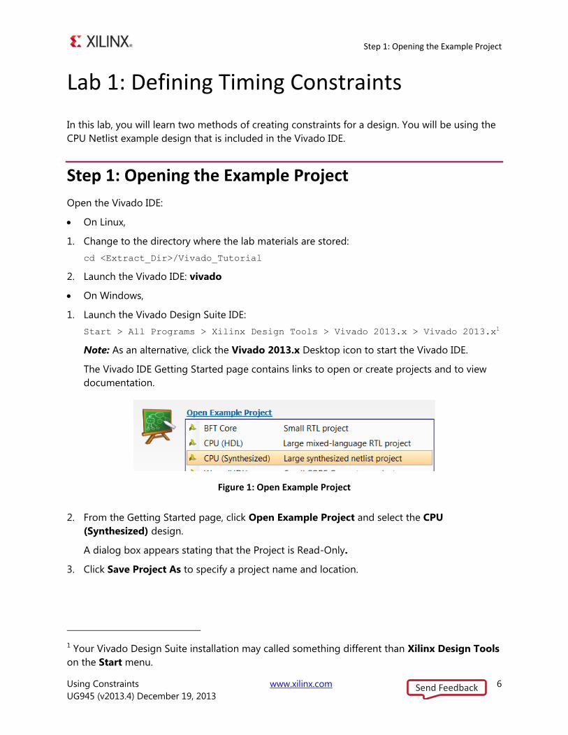
Figure 1: Open Example Project
From the Getting Started page, click Open Example Project and select the CPU 2.
(Synthesized) design.
A dialog box appears stating that the Project is Read-Only.
Click Save Project As to specify a project name and location. 3.
1 Your Vivado Design Suite installation may called something different than Xilinx Design Tools
on the Start menu.
Send Feedback
Step 1: Opening the Example Project
Using Constraints www.xilinx.com 7
UG945 (v2013.4) December 19, 2013
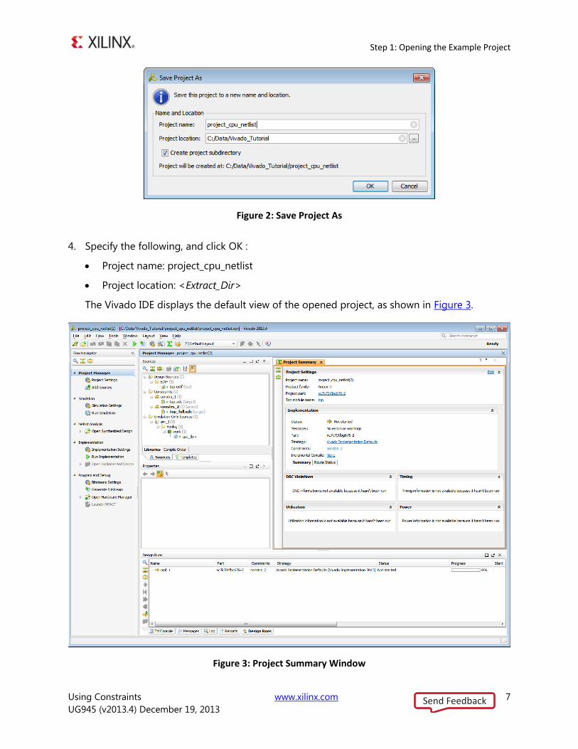
Figure 2: Save Project As
Specify the following, and click OK : 4.
Project name: project_cpu_netlist
Project location: <Extract_Dir>
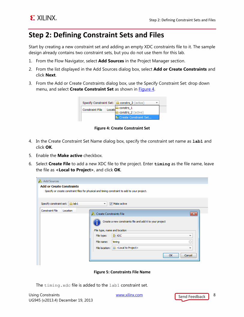
The Vivado IDE displays the default view of the opened project, as shown in Figure 3.
Figure 3: Project Summary Window
Send Feedback
Step 2: Defining Constraint Sets and Files
Using Constraints www.xilinx.com 8
UG945 (v2013.4) December 19, 2013
Step 2: Defining Constraint Sets and Files
Start by creating a new constraint set and adding an empty XDC constraints file to it. The sample
design already contains two constraint sets, but you do not use them for this lab.
From the Flow Navigator, select Add Sources in the Project Manager section. 1.
From the list displayed in the Add Sources dialog box, select Add or Create Constraints and 2.
click Next.
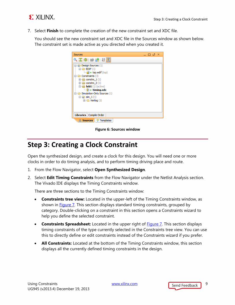
From the Add or Create Constraints dialog box, use the Specify Constraint Set: drop down 3.
menu, and select Create Constraint Set as shown in Figure 4.
Figure 4: Create Constraint Set
In the Create Constraint Set Name dialog box, specify the constraint set name as lab1 and 4.
click OK.
Enable the Make active checkbox. 5.
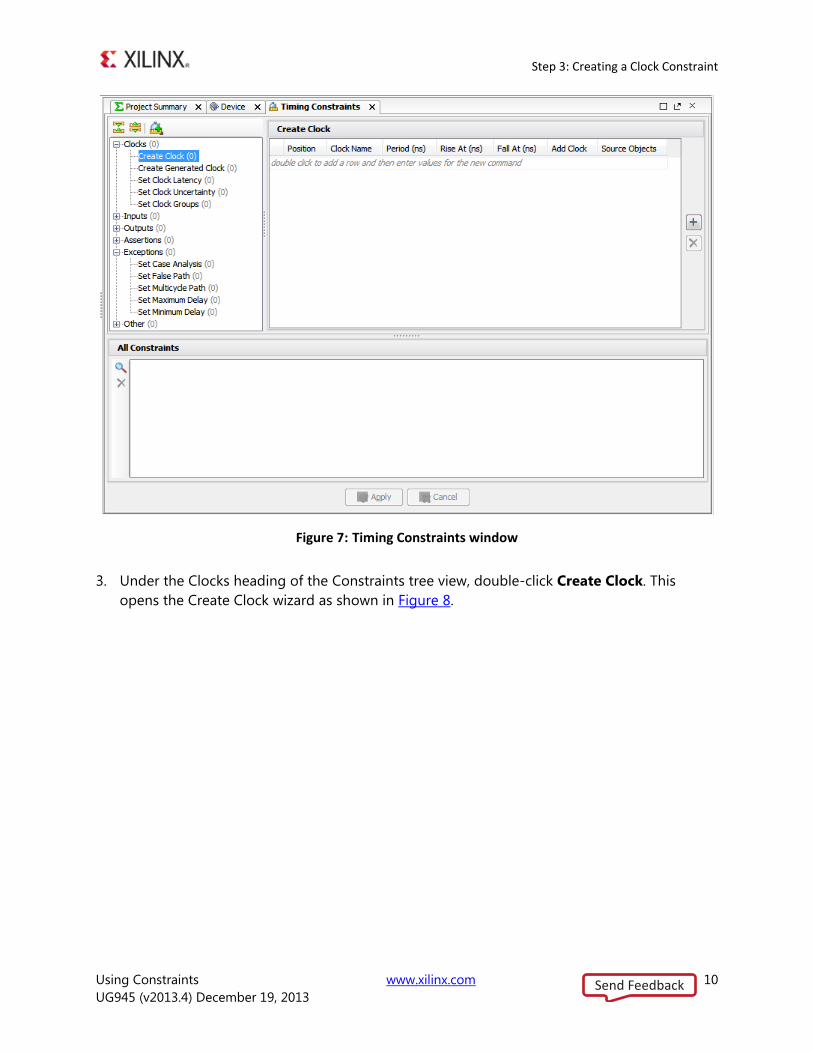
Select Create File to add a new XDC file to the project. Enter timing as the file name, leave 6.
the file as <Local to Project>, and click OK.
Figure 5: Constraints File Name
The timing.xdc file is added to the lab1 constraint set.
Send Feedback
Step 3: Creating a Clock Constraint
Using Constraints www.xilinx.com 9
UG945 (v2013.4) December 19, 2013
Select Finish to complete the creation of the new constraint set and XDC file. 7.
You should see the new constraint set and XDC file in the Sources window as shown below.
The constraint set is made active as you directed when you created it.
Figure 6: Sources window
Step 3: Creating a Clock Constraint
Open the synthesized design, and create a clock for this design. You will need one or more
clocks in order to do timing analysis, and to perform timing driving place and route.
From the Flow Navigator, select Open Synthesized Design. 1.
Select Edit Timing Constraints from the Flow Navigator under the Netlist Analysis section. 2.
The Vivado IDE displays the Timing Constraints window.
There are three sections to the Timing Constraints window:
Constraints tree view: Located in the upper-left of the Timing Constraints window, as
shown in Figure 7. This section displays standard timing constraints, grouped by
category. Double-clicking on a constraint in this section opens a Constraints wizard to
help you define the selected constraint.
Constraints Spreadsheet: Located in the upper right of Figure 7. This section displays
timing constraints of the type currently selected in the Constraints tree view. You can use
this to directly define or edit constraints instead of the Constraints wizard if you prefer.
All Constraints: Located at the bottom of the Timing Constraints window, this section
displays all the currently defined timing constraints in the design.
Send Feedback
Step 3: Creating a Clock Constraint
Using Constraints www.xilinx.com 10
UG945 (v2013.4) December 19, 2013
Figure 7: Timing Constraints window
Under the Clocks heading of the Constraints tree view, double-click Create Clock. This 3.
opens the Create Clock wizard as shown in Figure 8.
Send Feedback
Step 3: Creating a Clock Constraint
Using Constraints www.xilinx.com 11
UG945 (v2013.4) December 19, 2013
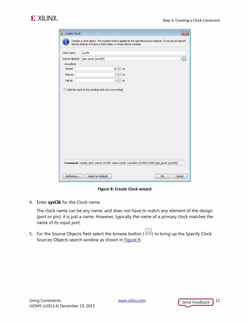
Figure 8: Create Clock wizard
Enter sysClk for the Clock name. 4.
The clock name can be any name, and does not have to match any element of the design
(port or pin); it is just a name. However, typically the name of a primary clock matches the
name of its input port.
For the Source Objects field select the browse button ( ) to bring up the Specify Clock 5.
Sources Objects search window as shown in Figure 9.
Send Feedback
Step 3: Creating a Clock Constraint
Using Constraints www.xilinx.com 12
UG945 (v2013.4) December 19, 2013
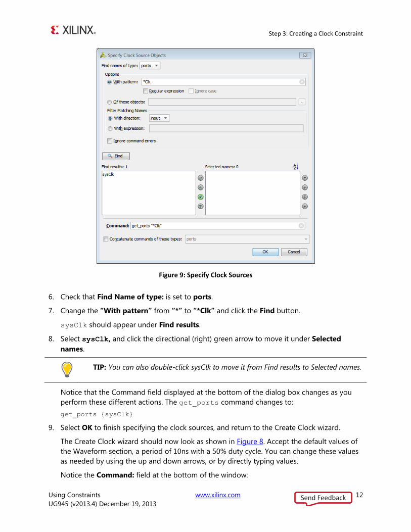
Figure 9: Specify Clock Sources
Check that Find Name of type: is set to ports. 6.
Change the “With pattern” from “*” to “*Clk” and click the Find button. 7.
sysClk should appear under Find results.
Select sysClk, and click the directional (right) green arrow to move it under Selected 8.
names.
TIP: You can also double-click sysClk to move it from Find results to Selected names.
Notice that the Command field displayed at the bottom of the dialog box changes as you
perform these different actions. The get_ports command changes to:
get_ports {sysClk}
Select OK to finish specifying the clock sources, and return to the Create Clock wizard. 9.
The Create Clock wizard should now look as shown in Figure 8. Accept the default values of
the Waveform section, a period of 10ns with a 50% duty cycle. You can change these values
as needed by using the up and down arrows, or by directly typing values.
Notice the Command: field at the bottom of the window:
Send Feedback
Step 3: Creating a Clock Constraint
Using Constraints www.xilinx.com 13
UG945 (v2013.4) December 19, 2013
create_clock –period 10.000 –name sysClk –waveform {0.000 5.000}
[get_ports {sysClk}]
The Vivado IDE displays the Tcl command form of all constraints created by design wizards
for your review. This is useful for learning the Tcl command syntax, and for verifying the final
constraint before adding it.
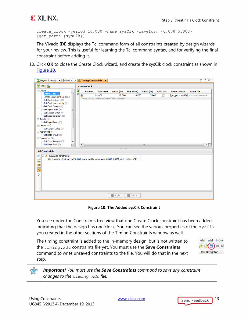
Click OK to close the Create Clock wizard, and create the sysClk clock constraint as shown in 10.
Figure 10.
Figure 10: The Added sysClk Constraint
You see under the Constraints tree view that one Create Clock constraint has been added,
indicating that the design has one clock. You can see the various properties of the sysClk
you created in the other sections of the Timing Constraints window as well.
The timing constraint is added to the in-memory design, but is not written to
the timing.xdc constraints file yet. You must use the Save Constraints
command to write unsaved constraints to the file. You will do that in the next
step.
Important! You must use the Save Constraints command to save any constraint
changes to the timing.xdc file.
Send Feedback
Step 4: Saving Constraints
Using Constraints www.xilinx.com 14
UG945 (v2013.4) December 19, 2013
Step 4: Saving Constraints
Constraint management is a critical issue in your design flow, and the Vivado Design Suite
provides you the flexibility of adding new constraints into an existing constraint file, overwriting
existing constraints, or creating a new constraint file to track design changes.
You have created a primary clock for the design, but the constraint exists only in the Vivado
Design Suite in-memory design. You have not yet saved the constraint to the timing.xdc file.
Click the Save Constraints button, or use the File > Save Constraints command from the 1.
main menu.
Because the active constraints set, lab1, does not have a target constraint file defined, the
Save Constraints dialog box opens to let you to select the target file for saving new
constraints.
You can save the constraints to an existing file, or create a new one.
TIP: As an alternative to this step, you could right-click on the timing.xdc file in
the Sources window, and use the Make Target command from the popup menu.
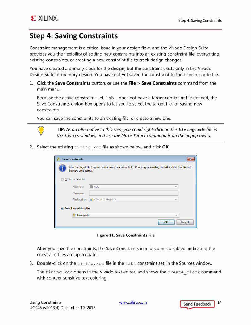
Select the existing timing.xdc file as shown below, and click OK. 2.
Figure 11: Save Constraints File
After you save the constraints, the Save Constraints icon becomes disabled, indicating the
constraint files are up-to-date.
Double-click on the timing.xdc file in the lab1 constraint set, in the Sources window. 3.
The timing.xdc opens in the Vivado text editor, and shows the create_clock command
with context-sensitive text coloring.
Send Feedback
Step 5: Reporting Clock Interactions
Using Constraints www.xilinx.com 15
UG945 (v2013.4) December 19, 2013
Step 5: Reporting Clock Interactions
The Vivado Design Suite assumes that all clocks are related by default unless you specify
otherwise by defining clock groups or other timing exceptions. The set_clock_groups
command specifies asynchronous clock domains, and disables timing analysis between them.
You can also explicitly identify timing exceptions using set_multicycle_path, or using
set_false_path for example. For more information on using these constraints refer to the
Vivado Design Suite User Guide: Using Constraints (UG903).
Vivado automatically infers timing constraints for paths that cross between two different clock
domains, called inter-clock paths, making assumptions regarding phase and offset whenever
possible. The Report Clock Interaction command reports inter-clock paths, to help identify
potential problems such as metastability, data loss, or incoherency.
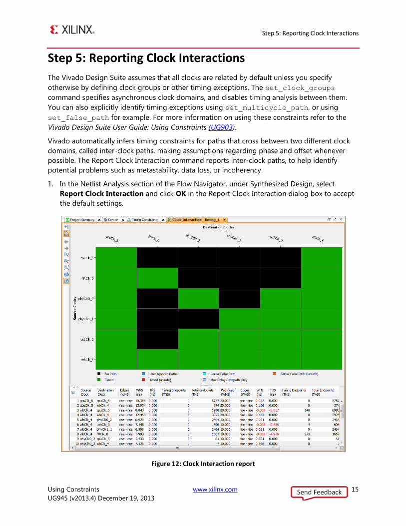
In the Netlist Analysis section of the Flow Navigator, under Synthesized Design, select 1.
Report Clock Interaction and click OK in the Report Clock Interaction dialog box to accept
the default settings.
Figure 12: Clock Interaction report
Send Feedback
Step 6: Creating an Input Delay Constraint
Using Constraints www.xilinx.com 16
UG945 (v2013.4) December 19, 2013
The Vivado IDE generates a graphical matrix illustrating the relationship of the various clocks
in the design as shown in Figure 12. For this design the primary clock (sysClk) connects to an
MMCM, which generates six additional clocks. The clock interactions shown are between
these generated clocks.
The Clock Interaction report shows asynchronous clocks (black), paths between two clock
domains that are related (green), paths constrained as false paths (red), or constrained as
partial false paths (yellow) in which only some elements of the timing path are unrelated.
Important! Green in the matrix does not mean that timing is good, it simply means
that the clock domains are constrained.
In addition, unsafe timed and unsafe partial false paths are reported. In the Clock Interaction
report, unsafe means that there is no common primary clock, or no expandable clock period
within the first 1000 clock cycles, between the source clock and the destination. The Vivado
timing engine selects edges on the launch and capture clocks based on the first 1000 cycles,
but these edges may not reflect the true relationship between the clocks.
Note: The colors described here are the default colors. Your colors may be configured
differently from those shown in Figure 12.
Close the Clock Interaction window by clicking on the in the window tab. 2.
Step 6: Creating an Input Delay Constraint
Static timing paths start at clocked elements, and end at clocked elements. Input and Output
ports are not clocked elements, and by default Vivado timing analysis does not time paths to or
from I/O ports in the design, instead starting or ending at the pins of cells. To include delay from
or to the physical pin of the device, or from the system-level design, you must first assign
input/output delay constraints to the FPGA ports.
In this step you assign an input delay onto the or1200_clmode port. Before that, report timing
for paths starting from that port to see what happens when no input_delay is assigned.
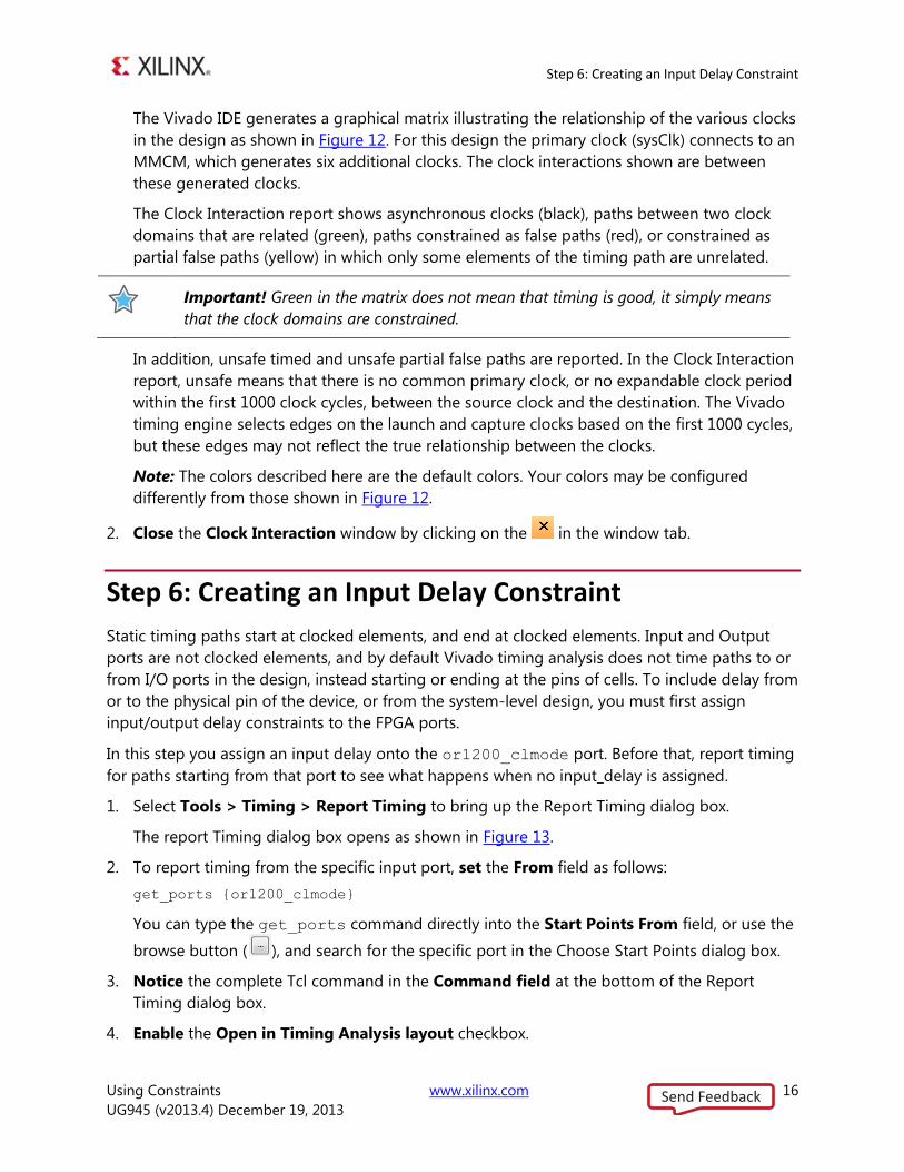
Select Tools > Timing > Report Timing to bring up the Report Timing dialog box. 1.
The report Timing dialog box opens as shown in Figure 13.
To report timing from the specific input port, set the From field as follows: 2.
get_ports {or1200_clmode}
You can type the get_ports command directly into the Start Points From field, or use the
browse button ( ), and search for the specific port in the Choose Start Points dialog box.
Notice the complete Tcl command in the Command field at the bottom of the Report 3.
Timing dialog box.
Enable the Open in Timing Analysis layout checkbox. 4.
Send Feedback
Step 6: Creating an Input Delay Constraint
Using Constraints www.xilinx.com 17
UG945 (v2013.4) December 19, 2013
Figure 13: Report Timing dialog box
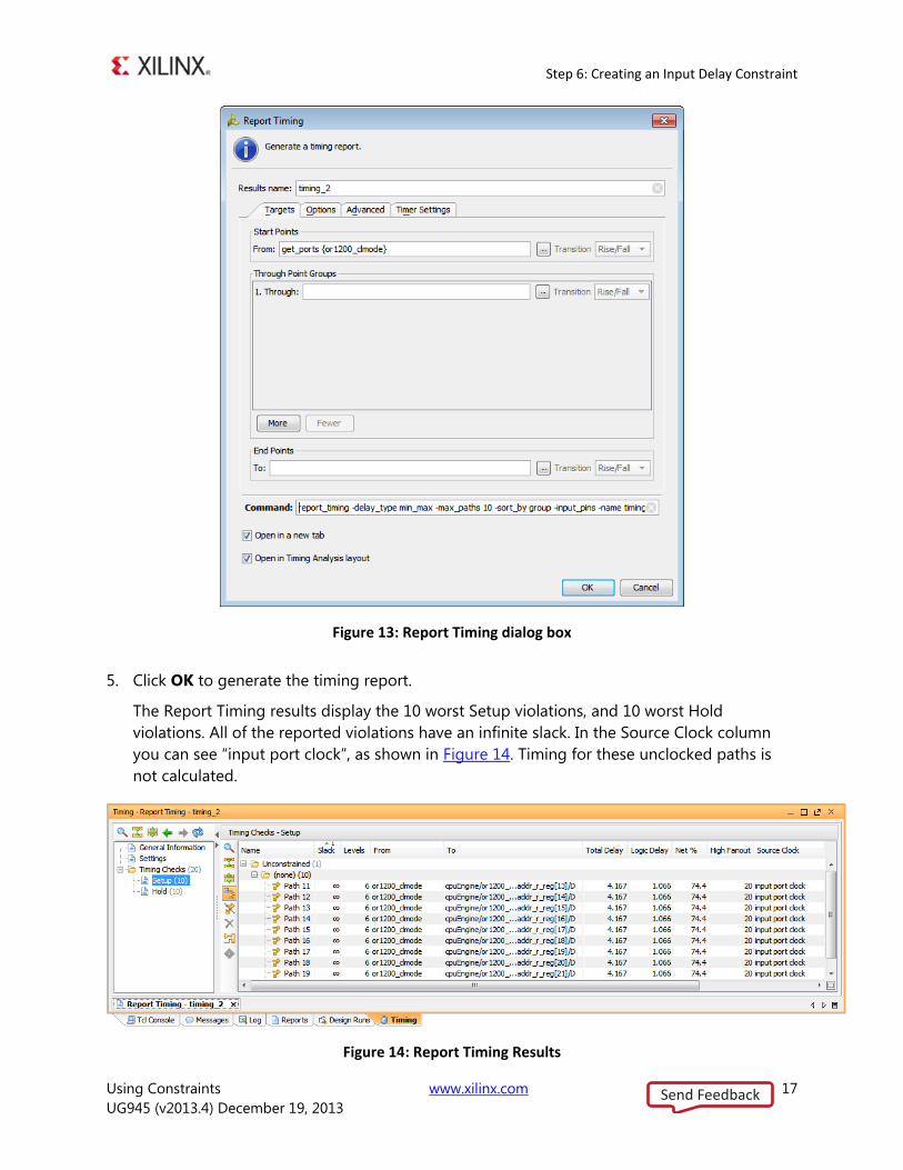
Click OK to generate the timing report. 5.
The Report Timing results display the 10 worst Setup violations, and 10 worst Hold
violations. All of the reported violations have an infinite slack. In the Source Clock column
you can see “input port clock”, as shown in Figure 14. Timing for these unclocked paths is
not calculated.
Figure 14: Report Timing Results
Send Feedback
Step 6: Creating an Input Delay Constraint
Using Constraints www.xilinx.com 18
UG945 (v2013.4) December 19, 2013
Look in the Tcl Console to see the run details of the report_timing command. 6.
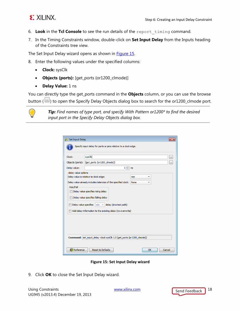
In the Timing Constraints window, double-click on Set Input Delay from the Inputs heading 7.
of the Constraints tree view.
The Set Input Delay wizard opens as shown in Figure 15.
Enter the following values under the specified columns: 8.
Clock: sysClk
Objects (ports): [get_ports {or1200_clmode}]
Delay Value: 1 ns
You can directly type the get_ports command in the Objects column, or you can use the browse
button ( ) to open the Specify Delay Objects dialog box to search for the or1200_clmode port.
Tip: Find names of type port, and specify With Pattern or1200* to find the desired
input port in the Specify Delay Objects dialog box.
Figure 15: Set Input Delay wizard
Click OK to close the Set Input Delay wizard. 9.
Send Feedback
Step 6: Creating an Input Delay Constraint
Using Constraints www.xilinx.com 19
UG945 (v2013.4) December 19, 2013
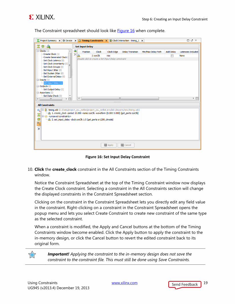
The Constraint spreadsheet should look like Figure 16 when complete.
Figure 16: Set Input Delay Constraint
Click the create_clock constraint in the All Constraints section of the Timing Constraints 10.
window.
Notice the Constraint Spreadsheet at the top of the Timing Constraint window now displays
the Create Clock constraint. Selecting a constraint in the All Constraints section will change
the displayed constraints in the Constraint Spreadsheet section.
Clicking on the constraint in the Constraint Spreadsheet lets you directly edit any field value
in the constraint. Right-clicking on a constraint in the Constraint Spreadsheet opens the
popup menu and lets you select Create Constraint to create new constraint of the same type
as the selected constraint.
When a constraint is modified, the Apply and Cancel buttons at the bottom of the Timing
Constraints window become enabled. Click the Apply button to apply the constraint to the
in-memory design, or click the Cancel button to revert the edited constraint back to its
original form.
Important! Applying the constraint to the in-memory design does not save the
constraint to the constraint file. This must still be done using Save Constraints.
Send Feedback
Step 6: Creating an Input Delay Constraint
Using Constraints www.xilinx.com 20
UG945 (v2013.4) December 19, 2013
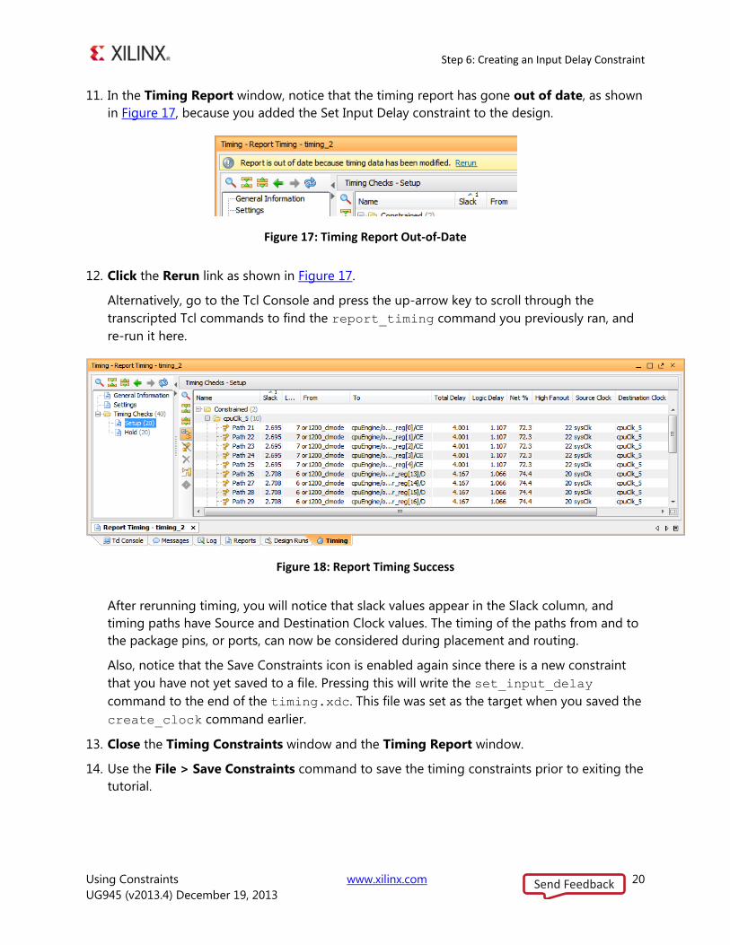
In the Timing Report window, notice that the timing report has gone out of date, as shown 11.
in Figure 17, because you added the Set Input Delay constraint to the design.
Figure 17: Timing Report Out-of-Date
Click the Rerun link as shown in Figure 17. 12.
Alternatively, go to the Tcl Console and press the up-arrow key to scroll through the
transcripted Tcl commands to find the report_timing command you previously ran, and
re-run it here.
Figure 18: Report Timing Success
After rerunning timing, you will notice that slack values appear in the Slack column, and
timing paths have Source and Destination Clock values. The timing of the paths from and to
the package pins, or ports, can now be considered during placement and routing.
Also, notice that the Save Constraints icon is enabled again since there is a new constraint
that you have not yet saved to a file. Pressing this will write the set_input_delay
command to the end of the timing.xdc. This file was set as the target when you saved the
create_clock command earlier.
Close the Timing Constraints window and the Timing Report window. 13.
Use the File > Save Constraints command to save the timing constraints prior to exiting the 14.
tutorial.
Send Feedback
Summary
Using Constraints www.xilinx.com 21
UG945 (v2013.4) December 19, 2013
Summary
At this point you may either continue to Lab #2: Setting Physical Constraints, or exit the Vivado
Design Suite and continue later.
You have learned how to add timing constraints to a design using a constraint wizard and the
Constraints spreadsheet from the Timing Constraints window in the Vivado IDE.
You can also use the Tcl Console to interactively add and apply constraints to the design as Tcl
commands.
Still another approach is to work directly with the XDC file to create design constraints.
Send Feedback
Step 1: Opening the Project
Using Constraints www.xilinx.com 22
UG945 (v2013.4) December 19, 2013
Lab 2: Setting Physical Constraints
In this lab, you will create physical constraints for the CPU Netlist design, observing how actions
in the GUI call Tcl commands. Using Tcl commands, complex operations are easily scripted for
repeated use, at various stages of the flow.
Note: If you are continuing from Lab1, and your design is open, skip ahead to Step 2: Adding
Placement Constraints.
Step 1: Opening the Project
This lab continues from the end of Lab #1 in this tutorial. You must complete Lab #1 prior to
beginning Lab #2. If you closed the tool, or closed the tutorial project at the end of Lab #1, you
will need to open them again.
Start by loading the Vivado Integrated Design Environment (IDE). 1.
Launch Vivado IDE from the icon on the Windows desktop, or
Type vivado from a command terminal.
The Vivado IDE opens.
From the main menu, click File > Open Recent Project and select the project you saved in 2.
Lab #1.
After the project has finished opening, from the Flow Navigator select Open Synthesized 3.
Design.
The synthesized netlist opens with the Device window displayed.
Step 2: Adding Placement Constraints
Explore some of the design hierarchy, and begin placing logic elements to create physical
constraints.
Select the Netlist window and expand the clkgen hierarchy. 1.
Expand the Leaf Cells folder and select the mmcm_adv_inst (MMCME2_ADV) cell. 2.
Send Feedback
Step 2: Adding Placement Constraints
Using Constraints www.xilinx.com 23
UG945 (v2013.4) December 19, 2013
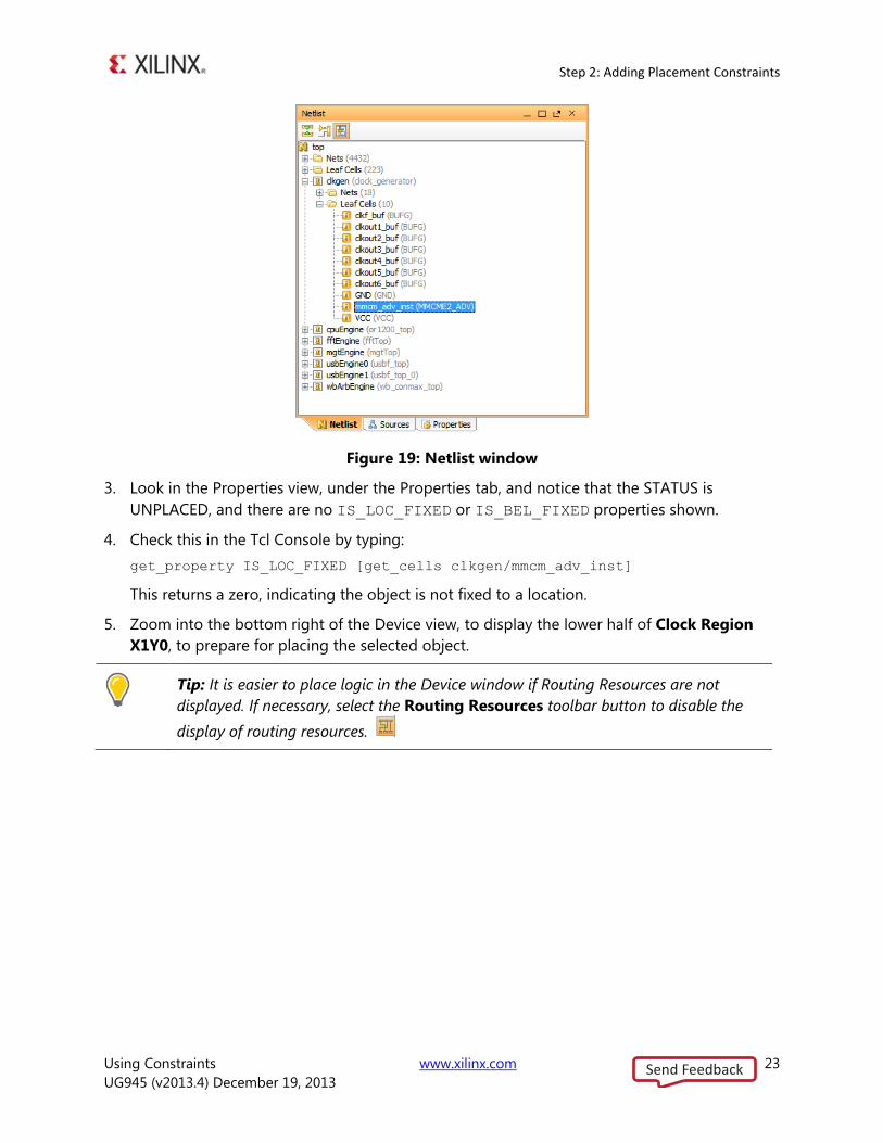
Figure 19: Netlist window
Look in the Properties view, under the Properties tab, and notice that the STATUS is 3.
UNPLACED, and there are no IS_LOC_FIXED or IS_BEL_FIXED properties shown.
Check this in the Tcl Console by typing: 4.
get_property IS_LOC_FIXED [get_cells clkgen/mmcm_adv_inst]
This returns a zero, indicating the object is not fixed to a location.
Zoom into the bottom right of the Device view, to display the lower half of Clock Region 5.
X1Y0, to prepare for placing the selected object.
Tip: It is easier to place logic in the Device window if Routing Resources are not
displayed. If necessary, select the Routing Resources toolbar button to disable the
display of routing resources.
Send Feedback
Step 2: Adding Placement Constraints
Using Constraints www.xilinx.com 24
UG945 (v2013.4) December 19, 2013
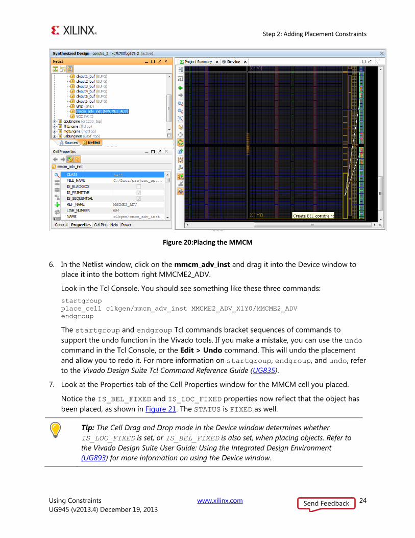
Figure 20:Placing the MMCM
In the Netlist window, click on the mmcm_adv_inst and drag it into the Device window to 6.
place it into the bottom right MMCME2_ADV.
Look in the Tcl Console. You should see something like these three commands:
startgroup
place_cell clkgen/mmcm_adv_inst MMCME2_ADV_X1Y0/MMCME2_ADV
endgroup
The startgroup and endgroup Tcl commands bracket sequences of commands to
support the undo function in the Vivado tools. If you make a mistake, you can use the undo
command in the Tcl Console, or the Edit > Undo command. This will undo the placement
and allow you to redo it. For more information on startgroup, endgroup, and undo, refer
to the Vivado Design Suite Tcl Command Reference Guide (UG835).
Look at the Properties tab of the Cell Properties window for the MMCM cell you placed. 7.
Notice the IS_BEL_FIXED and IS_LOC_FIXED properties now reflect that the object has
been placed, as shown in Figure 21. The STATUS is FIXED as well.
Tip: The Cell Drag and Drop mode in the Device window determines whether
IS_LOC_FIXED is set, or IS_BEL_FIXED is also set, when placing objects. Refer to
the Vivado Design Suite User Guide: Using the Integrated Design Environment
(UG893) for more information on using the Device window.
Send Feedback
Step 3: Defining Additional Physical Constraints
Using Constraints www.xilinx.com 25
UG945 (v2013.4) December 19, 2013
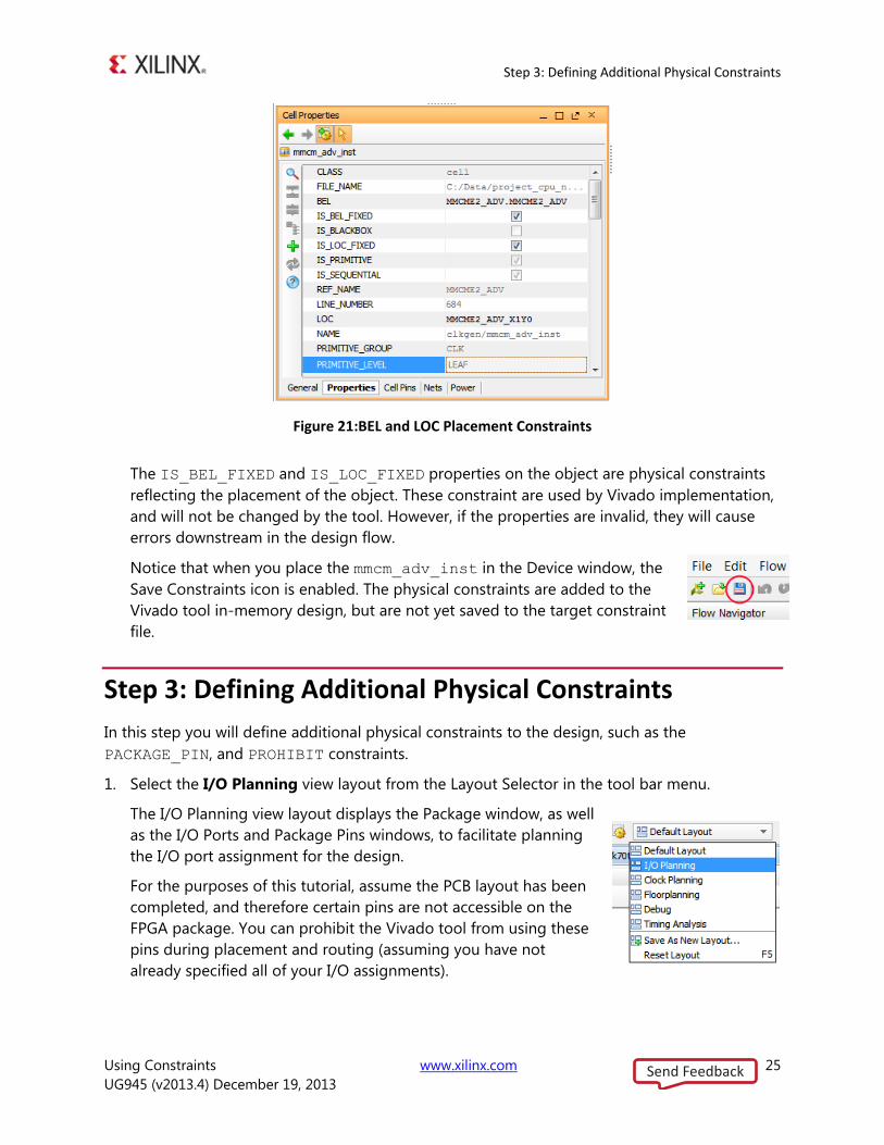
Figure 21:BEL and LOC Placement Constraints
The IS_BEL_FIXED and IS_LOC_FIXED properties on the object are physical constraints
reflecting the placement of the object. These constraint are used by Vivado implementation,
and will not be changed by the tool. However, if the properties are invalid, they will cause
errors downstream in the design flow.
Notice that when you place the mmcm_adv_inst in the Device window, the
Save Constraints icon is enabled. The physical constraints are added to the
Vivado tool in-memory design, but are not yet saved to the target constraint
file.
Step 3: Defining Additional Physical Constraints
In this step you will define additional physical constraints to the design, such as the
PACKAGE_PIN, and PROHIBIT constraints.
Select the I/O Planning view layout from the Layout Selector in the tool bar menu. 1.
The I/O Planning view layout displays the Package window, as well
as the I/O Ports and Package Pins windows, to facilitate planning
the I/O port assignment for the design.
For the purposes of this tutorial, assume the PCB layout has been
completed, and therefore certain pins are not accessible on the
FPGA package. You can prohibit the Vivado tool from using these
pins during placement and routing (assuming you have not
already specified all of your I/O assignments).
Send Feedback
Step 4: Defining Constraints with Object Properties
Using Constraints www.xilinx.com 26
UG945 (v2013.4) December 19, 2013
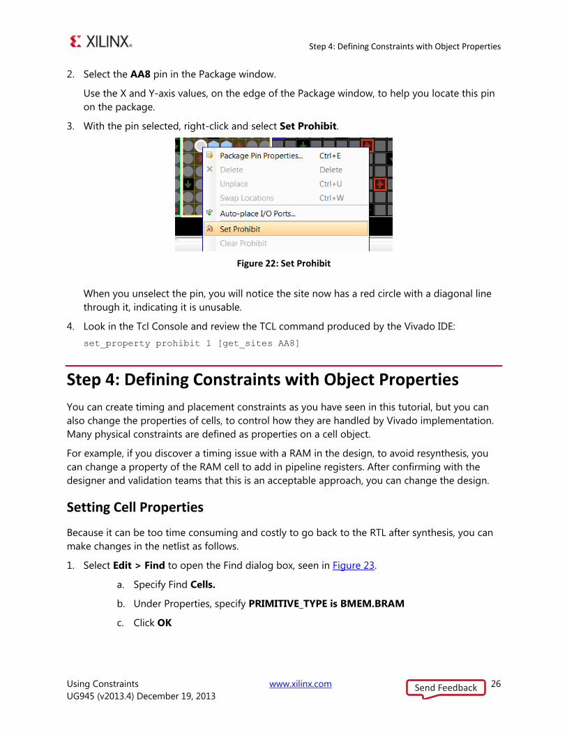
Select the AA8 pin in the Package window. 2.
Use the X and Y-axis values, on the edge of the Package window, to help you locate this pin
on the package.
With the pin selected, right-click and select Set Prohibit. 3.
Figure 22: Set Prohibit
When you unselect the pin, you will notice the site now has a red circle with a diagonal line
through it, indicating it is unusable.
Look in the Tcl Console and review the TCL command produced by the Vivado IDE: 4.
set_property prohibit 1 [get_sites AA8]
Step 4: Defining Constraints with Object Properties
You can create timing and placement constraints as you have seen in this tutorial, but you can
also change the properties of cells, to control how they are handled by Vivado implementation.
Many physical constraints are defined as properties on a cell object.
For example, if you discover a timing issue with a RAM in the design, to avoid resynthesis, you
can change a property of the RAM cell to add in pipeline registers. After confirming with the
designer and validation teams that this is an acceptable approach, you can change the design.
Setting Cell Properties
Because it can be too time consuming and costly to go back to the RTL after synthesis, you can
make changes in the netlist as follows.
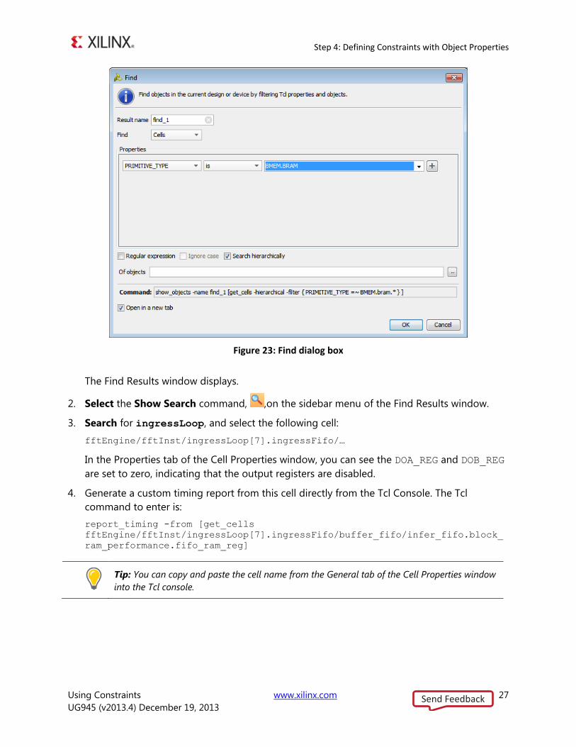
Select Edit > Find to open the Find dialog box, seen in Figure 23. 1.
a. Specify Find Cells.
b. Under Properties, specify PRIMITIVE_TYPE is BMEM.BRAM
c. Click OK
Send Feedback
Step 4: Defining Constraints with Object Properties
Using Constraints www.xilinx.com 27
UG945 (v2013.4) December 19, 2013
Figure 23: Find dialog box
The Find Results window displays.
Select the Show Search command, ,on the sidebar menu of the Find Results window. 2.
Search for ingressLoop, and select the following cell: 3.
fftEngine/fftInst/ingressLoop[7].ingressFifo/…
In the Properties tab of the Cell Properties window, you can see the DOA_REG and DOB_REG
are set to zero, indicating that the output registers are disabled.
Generate a custom timing report from this cell directly from the Tcl Console. The Tcl 4.
command to enter is:
report_timing -from [get_cells
fftEngine/fftInst/ingressLoop[7].ingressFifo/buffer_fifo/infer_fifo.block_
ram_performance.fifo_ram_reg]
Tip: You can copy and paste the cell name from the General tab of the Cell Properties window
into the Tcl console.
Send Feedback
Step 4: Defining Constraints with Object Properties
Using Constraints www.xilinx.com 28
UG945 (v2013.4) December 19, 2013
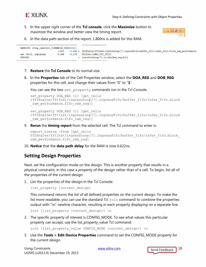
In the upper right corner of the Tcl console, click the Maximize button to 5.
maximize the window and better view the timing report.
In the data path section of the report, 1.800ns is added for this RAM. 6.
Restore the Tcl Console to its normal size. 7.
In the Properties tab of the Cell Properties window, select the DOA_REG and DOB_REG 8.
properties for this cell, and change their values from “0” to “1”.
You can see the two set_property commands run in the Tcl Console.
set_property DOA_REG {1} [get_cells
{fftEngine/fftInst/ingressLoop[7].ingressFifo/buffer_fifo/infer_fifo.block
_ram_performance.fifo_ram_reg}]
set_property DOB_REG {1} [get_cells
{fftEngine/fftInst/ingressLoop[7].ingressFifo/buffer_fifo/infer_fifo.block
_ram_performance.fifo_ram_reg}]
Rerun the timing report from the selected cell. The Tcl command to enter is: 9.
report_timing -from [get_cells
fftEngine/fftInst/ingressLoop[7].ingressFifo/buffer_fifo/infer_fifo.block_
ram_performance.fifo_ram_reg]
Notice that the data path delay for the RAM is now 0.622ns. 10.
Setting Design Properties
Next, set the configuration mode on the design. This is another property that results in a
physical constraint, in this case a property of the design rather than of a cell. To begin, list all of
the properties of the current design.
List the properties of the design in the Tcl Console: 1.
list_property [current_design]
This command returns the list of all defined properties on the current design. To make the
list more readable, you can use the standard Tcl join command to combine the properties
output with “\n” newline character, resulting in each property displaying on a separate line.
join [list_property [current_design]] \n
The specific property of interest is CONFIG_MODE. To see what values this particular 2.
property can accept, use the list_property_value Tcl command:
join [list_property_value CONFIG_MODE [current_design]] \n
Use the Tools > Edit Device Properties command to set the CONFIG_MODE property for 3.
the current design.
Send Feedback
Step 4: Defining Constraints with Object Properties
Using Constraints www.xilinx.com 29
UG945 (v2013.4) December 19, 2013
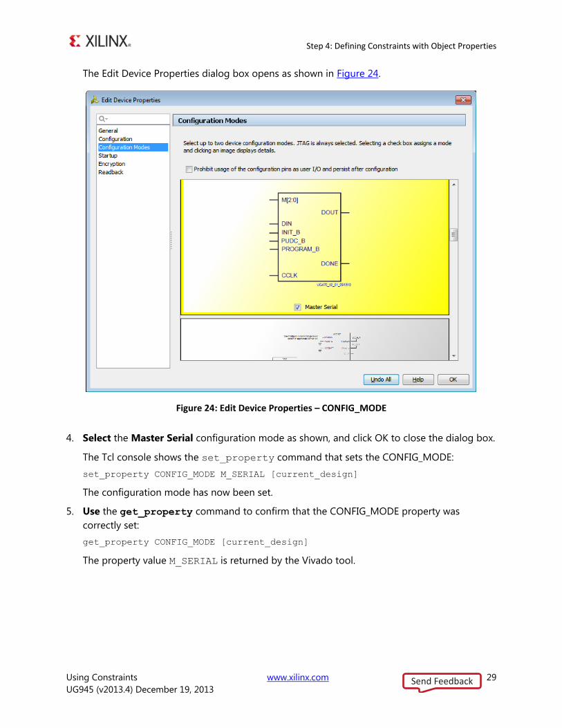
The Edit Device Properties dialog box opens as shown in Figure 24.
Figure 24: Edit Device Properties – CONFIG_MODE
Select the Master Serial configuration mode as shown, and click OK to close the dialog box. 4.
The Tcl console shows the set_property command that sets the CONFIG_MODE:
set_property CONFIG_MODE M_SERIAL [current_design]
The configuration mode has now been set.
Use the get_property command to confirm that the CONFIG_MODE property was 5.
correctly set:
get_property CONFIG_MODE [current_design]
The property value M_SERIAL is returned by the Vivado tool.
Send Feedback
Step 5: Saving Constraints
Using Constraints www.xilinx.com 30
UG945 (v2013.4) December 19, 2013
Step 5: Saving Constraints
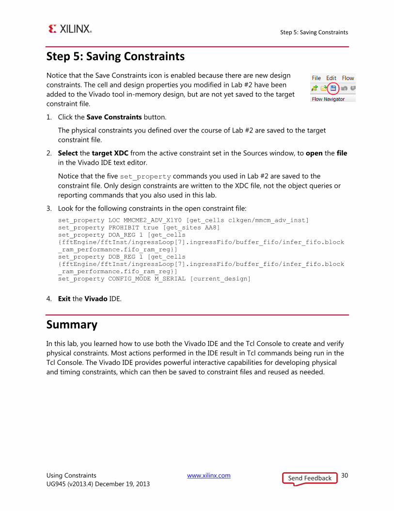
Notice that the Save Constraints icon is enabled because there are new design
constraints. The cell and design properties you modified in Lab #2 have been
added to the Vivado tool in-memory design, but are not yet saved to the target
constraint file.
Click the Save Constraints button. 1.
The physical constraints you defined over the course of Lab #2 are saved to the target
constraint file.
Select the target XDC from the active constraint set in the Sources window, to open the file 2.
in the Vivado IDE text editor.
Notice that the five set_property commands you used in Lab #2 are saved to the
constraint file. Only design constraints are written to the XDC file, not the object queries or
reporting commands that you also used in this lab.
Look for the following constraints in the open constraint file: 3.
set_property LOC MMCME2_ADV_X1Y0 [get_cells clkgen/mmcm_adv_inst]
set_property PROHIBIT true [get_sites AA8]
set_property DOA_REG 1 [get_cells
{fftEngine/fftInst/ingressLoop[7].ingressFifo/buffer_fifo/infer_fifo.block
_ram_performance.fifo_ram_reg}]
set_property DOB_REG 1 [get_cells
{fftEngine/fftInst/ingressLoop[7].ingressFifo/buffer_fifo/infer_fifo.block
_ram_performance.fifo_ram_reg}]
set_property CONFIG_MODE M_SERIAL [current_design]
Exit the Vivado IDE. 4.
Summary
In this lab, you learned how to use both the Vivado IDE and the Tcl Console to create and verify
physical constraints. Most actions performed in the IDE result in Tcl commands being run in the
Tcl Console. The Vivado IDE provides powerful interactive capabilities for developing physical
and timing constraints, which can then be saved to constraint files and reused as needed.
Send Feedback