Embed Size (px)
Citation preview
1
VK-PVC
LEGENDA
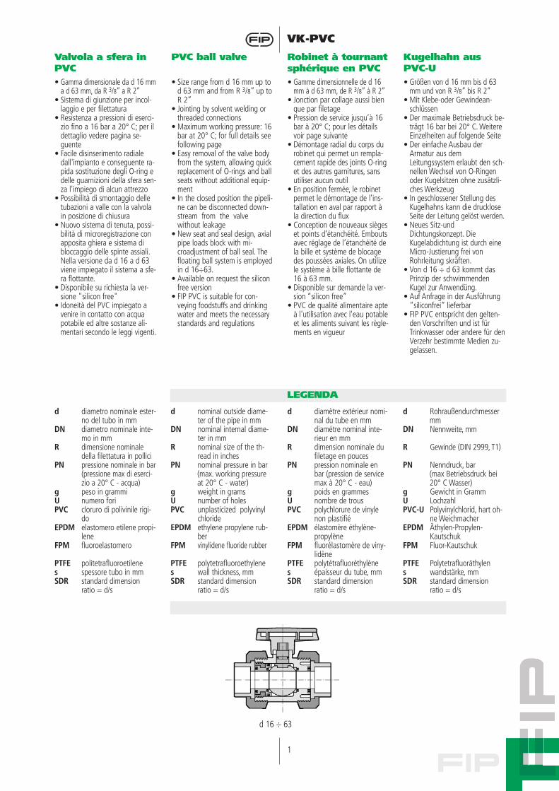
Valvola a sfera inPVC
PVC ball valve Robinet à tournantsphérique en PVC
Kugelhahn ausPVC-U
• Gamma dimensionale da d 16 mma d 63 mm, da R 3/8” a R 2”
• Sistema di giunzione per incol-laggio e per filettatura
• Resistenza a pressioni di eserci-zio fino a 16 bar a 20° C; per ildettaglio vedere pagina se-guente
• Facile disinserimento radialedall'impianto e conseguente ra-pida sostituzione degli O-ring edelle guarnizioni della sfera sen-za l'impiego di alcun attrezzo
• Possibilità di smontaggio delletubazioni a valle con la valvolain posizione di chiusura
• Nuovo sistema di tenuta, possi-bilità di microregistrazione conapposita ghiera e sistema dibloccaggio delle spinte assiali.Nella versione da d 16 a d 63viene impiegato il sistema a sfe-ra flottante.
• Disponibile su richiesta la ver-sione "silicon free"
• Idoneità del PVC impiegato avenire in contatto con acquapotabile ed altre sostanze ali-mentari secondo le leggi vigenti.
• Size range from d 16 mm up tod 63 mm and from R 3/8” up toR 2”
• Jointing by solvent welding orthreaded connections
• Maximum working pressure: 16bar at 20° C; for full details seefollowing page
• Easy removal of the valve bodyfrom the system, allowing quickreplacement of O-rings and ballseats without additional equip-ment
• In the closed position the pipeli-ne can be disconnected down-stream from the valvewithout leakage
• New seat and seal design, axialpipe loads block with mi-croadjustment of ball seal. Thefloating ball system is employedin d 16÷63.
• Available on request the siliconfree version
• FIP PVC is suitable for con-veying foodstuffs and drinkingwater and meets the necessarystandards and regulations
• Gamme dimensionnelle de d 16mm à d 63 mm, de R 3/8” à R 2”
• Jonction par collage aussi bienque par filetage
• Pression de service jusqu’à 16bar à 20° C; pour les détailsvoir page suivante
• Démontage radiaI du corps durobinet qui permet un rempla-cement rapide des joints O-ringet des autres garnitures, sansutiliser aucun outil
• En position fermée, le robinetpermet le démontage de l'ins-tallation en aval par rapport àla direction du flux
• Conception de nouveaux siègeset points d’étanchéité. Emboutsavec réglage de l’étanchéité dela bille et système de blocagedes poussées axiales. On utilizele système à bille flottante de16 à 63 mm.
• Disponible sur demande la ver-sion “silicon free”
• PVC de qualité alimentaire apteà l'utilisation avec l'eau potableet les aliments suivant les règle-ments en vigueur
• Größen von d 16 mm bis d 63mm und von R 3/8” bis R 2”
• Mit Klebe-oder Gewindean-schlüssen
• Der maximale Betriebsdruck be-trägt 16 bar bei 20° C. WeitereEinzelheiten auf folgende Seite
• Der einfache Ausbau derArmatur aus demLeitungssystem erlaubt den sch-nellen Wechsel von O-Ringenoder Kugelsitzen ohne zusätzli-ches Werkzeug
• In geschlossener Stellung desKugelhahns kann die druckloseSeite der Leitung gelöst werden.
• Neues Sitz-undDichtungskonzept. DieKugelabdichtung ist durch eineMicro-Justierung frei vonRohrleitung skräften.
• Von d 16 ÷ d 63 kommt dasPrinzip der schwimmendenKugel zur Anwendüng.
• Auf Anfrage in der Ausführung“siliconfrei” lieferbar
• FIP PVC entspricht den gelten-den Vorschriften und ist fürTrinkwasser oder andere für denVerzehr bestimmte Medien zu-gelassen.
d diametro nominale ester-no del tubo in mm
DN diametro nominale inte-mo in mm
R dimensione nominaledella filettatura in pollici
PN pressione nominale in bar(pressione max di eserci-zio a 20° C - acqua)
g peso in grammiU numero foriPVC cloruro di polivinile rigi-
doEPDM elastomero etilene propi-
leneFPM fluoroelastomero
PTFE politetrafluoroetilenes spessore tubo in mmSDR standard dimension
ratio = d/s
d nominaI outside diame-ter of the pipe in mm
DN nominal internal diame-ter in mm
R nominal size of the th-read in inches
PN nominal pressure in bar(max. working pressureat 20° C - water)
g weight in gramsU number of holesPVC unplasticized polyvinyl
chlorideEPDM ethylene propylene rub-
berFPM vinylidene fluoride rubber
PTFE polytetrafluoroethylenes wall thickness, mmSDR standard dimension
ratio = d/s
d diamètre extérieur nomi-nal du tube en mm
DN diamétre nominal inte-rieur en mm
R dimension nominale dufiletage en pouces
PN pression nominale enbar (pression de servicemax à 20° C - eau)
g poids en grammesU nombre de trousPVC polychlorure de vinyle
non plastifiéEPDM élastomère éthylène-
propylèneFPM fluorélastomère de viny-
lidènePTFE polytétrafluoréthylènes épaisseur du tube, mmSDR standard dimension
ratio = d/s
d Rohraußendurchmessermm
DN Nennweite, mm
R Gewinde (DIN 2999, T1)
PN Nenndruck, bar(max Betriebsdruck bei20° C Wasser)
g Gewicht in GrammU LochzahlPVC-U Polyvinylchlorid, hart oh-
ne WeichmacherEPDM Äthylen-Propylen-
KautschukFPM Fluor-Kautschuk
PTFE Polytetrafluoräthylens wandstärke, mmSDR standard dimension
ratio = d/s
d 16 ÷ 63
2
VK-PVCDati Tecnici
3
2
4
Technical Data
Données Techniques
Technische Daten
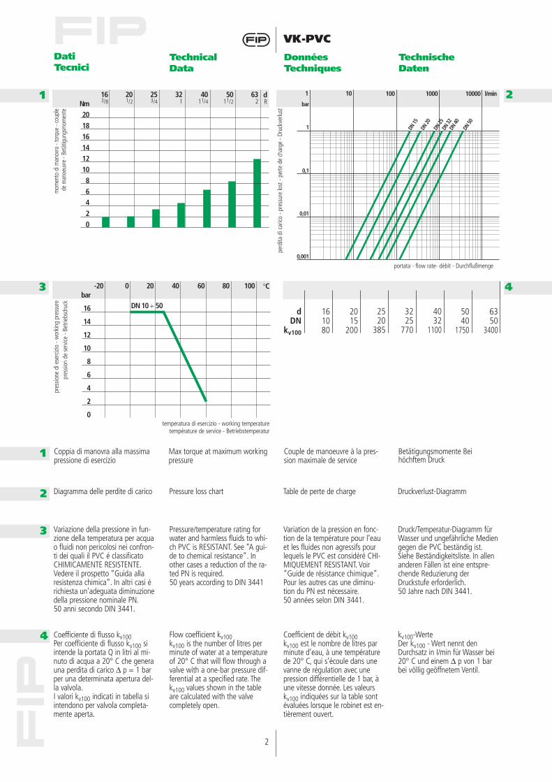
Coppia di manovra alla massimapressione di esercizio
Max torque at maximum workingpressure
Couple de manoeuvre à la pres-sion maximale de service
Betätigungsmomente Bei höchftem Druck
Diagramma delle perdite di carico Pressure loss chart Table de perte de charge Druckverlust-Diagramm
Variazione della pressione in fun-zione della temperatura per acquao fluidi non pericolosi nei confron-ti dei quali il PVC é classificatoCHIMICAMENTE RESISTENTE.Vedere il prospetto “Guida allaresistenza chimica”. In altri casi érichiesta un’adeguata diminuzionedella pressione nominale PN.50 anni secondo DIN 3441.
Pressure/temperature rating forwater and harmless fluids to whi-ch PVC is RESISTANT. See “A gui-de to chemical resistance”. Inother cases a reduction of the ra-ted PN is required.50 years according to DIN 3441
Variation de la pression en fonc-tion de la température pour l’eauet les fluides non agressifs pourlequels le PVC est considéré CHI-MIQUEMENT RESISTANT. Voir“Guide de résistance chimique”.Pour les autres cas une diminu-tion du PN est nécessaire.50 années selon DIN 3441.
Druck/Temperatur-Diagramm fürWasser und ungefährliche Mediengegen die PVC beständig ist.Siehe Beständigkeitsliste. In allenanderen Fällen ist eine entspre-chende Reduzierung derDruckstufe erforderlich.50 Jahre nach DIN 3441.
Coefficiente di flusso kv100Per coefficiente di flusso kv100 siintende la portata Q in litri al mi-nuto di acqua a 20° C che generauna perdita di carico ∆ p = 1 barper una determinata apertura del-la valvola.I valori kv100 indicati in tabella siintendono per valvola completa-mente aperta.
Flow coefficient kv100kv100 is the number of litres perminute of water at a temperatureof 20° C that will flow through avalve with a one-bar pressure dif-ferential at a specified rate. Thekv100 values shown in the tableare calculated with the valvecompletely open.
Coefficient de débit kv100kv100 est le nombre de litres parminute d’eau, à une températurede 20° C, qui s’écoule dans unevanne de régulation avec unepression différentielle de 1 bar, àune vitesse donnée. Les valeurskv100 indiquées sur la table sontévaluées lorsque le robinet est en-tièrement ouvert.
kv100-WerteDer kv100 - Wert nennt denDurchsatz in I/min für Wasser bei20° C und einem ∆ p von 1 barbei völlig geöffnetem Ventil.
4032
1100
3225
770
2520
385
5040
1750
2015
200
161080
dDN
kv100
6350
3400
Nm20181614121086420
163/8
201/2
253/4
321
dR
4011/4
632
5011/2
bar
16
14
12
10
8
6
4
2
0
-20 0 20 40 °C60 10080
DN 10 ÷ 50
bar
1
0,1
0,01
0,001
DN 15
DN 20
100 l/min1000 10000101
DN 25
DN 32
DN 40
DN 50
1
1
2
3
4
mom
ento
di m
anov
ra -
torq
ue -
coup
le de
man
oeuv
re -
Betä
tigun
gsm
omen
te
perd
ita d
i car
ico -
pres
sure
lost
- pe
rte d
e ch
arge
- Dr
uckv
erlu
st
portata - flow rate- débit - Durchflußmenge
pres
sione
di e
serc
izio
- wor
king
pre
ssur
epr
essio
n de
ser
vice
- Bet
riebs
druc
k
temperatura di esercizio - working temperaturetempérature de service - Betriebstemperatur
3
VK-PVC
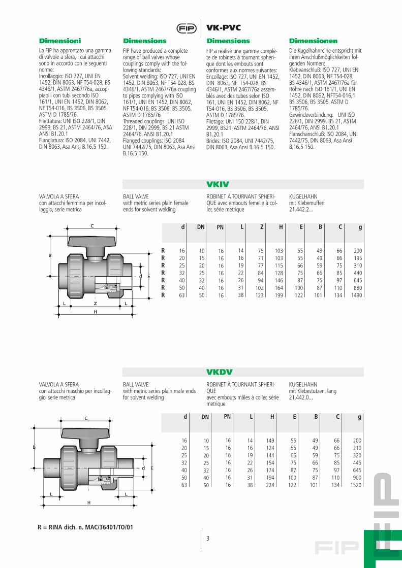
VALVOLA A SFERAcon attacchi femmina per incol-laggio, serie metrica
BALL VALVEwith metric series plain femaleends for solvent welding
ROBINET À TOURNANT SPHERI-QUE avec embouts femelle à col-ler, série metrique
KUGELHAHNmit Klebemuffen21.442.2...
Dimensioni Dimensions Dimensions Dimensionen
VKIV
VALVOLA A SFERAcon attacchi maschio per incollag-gio, serie metrica
BALL VALVEwith metric series plain male endsfor solvent welding
ROBINET À TOURNANT SPHERI-QUEavec embouts mâles à coller, sériemetrique
KUGELHAHNmit Klebestutzen, lang21.442.0...
VKDV
La FIP ha approntato una gammadi valvole a sfera, i cui attacchisono in accordo con le seguentinorme:Incollaggio: ISO 727, UNI EN1452, DIN 8063, NF T54-028, BS4346/1, ASTM 2467/76a, accop-piabili con tubi secondo ISO161/1, UNI EN 1452, DIN 8062,NF T54-016, BS 3506, BS 3505,ASTM D 1785/76.Filettatura: UNI ISO 228/1, DIN2999, BS 21, ASTM 2464/76, ASA ANSI B1.20.1 Flangiatura: ISO 2084, UNI 7442,DIN 8063, Asa Ansi B.16.5 150.
FIP have produced a completerange of ball valves whose couplings comply with the fol-lowing standards:Solvent welding: ISO 727, UNI EN1452, DIN 8063, NF T54-028, BS4346/1, ASTM 2467/76a couplingto pipes complying with ISO161/1, UNI EN 1452, DIN 8062,NF T54-016, BS 3506, BS 3505,ASTM D 1785/76Threaded couplings UNI ISO228/1, DIN 2999, BS 21 ASTM2464/76, ANSI B1.20.1Flanged couplings: ISO 2084UNI 7442/75, DIN 8063, Asa AnsiB.16.5 150.
FIP a réalisé une gamme complè-te de robinets à tournant sphéri-que dont les embouts sontconformes aux normes suivantes:Encollage: ISO 727, UNI EN 1452,DIN 8063, NF T54-028, BS4346/1, ASTM 2467/76a assem-blés avec des tubes selon ISO161, UNI EN 1452, DIN 8062, NFT54-016, BS 3506, BS 3505,ASTM D 1785/76.Filetage: UNI 150 228/1, DIN2999, BS21, ASTM 2464/76, ANSIB1.20.1Brides: ISO 2084, UNI 7442/75,DIN 8063, Asa Ansi B.16.5 150.
Die Kugelhahnreihe entspricht mitihren Anschlußmöglichkeiten fol-genden Normen:Klebeanschluß: ISO 727, UNI EN1452, DIN 8063, NF T54-028,BS 4346/1, ASTM 2467/76a fürRohre nach ISO 161/1, UNI EN1452, DIN 8062, NFT54-016,1BS 3506, BS 3505, ASTM D1785/76.Gewindeverbindung: UNI ISO228/1, DIN 2999, BS 21, ASTM2464/76, ANSI B1.20.1Flanschanschluß: ISO 2084, UNI7442/75, DIN 8063, Asa AnsiB.16.5 150.
DN
10152025324050
d
16202532405063
PN
16161616161616
Z
7571778494
102123
L
14161922263138
H
103103115128146164199
E
5555667587
100122
B
494959667587
101
C
6666758597
110134
g
200195310440645880
1490
d
16202532405063
DN
10152025324050
L
14161922263138
PN
16161616161616
H
149124144154174194224
E
5555667587
100122
B
494959667587
101
C
6666758597
110134
g
200210320445645900
1520
RRRRRRR
R = RINA dich. n. MAC/36401/TO/01
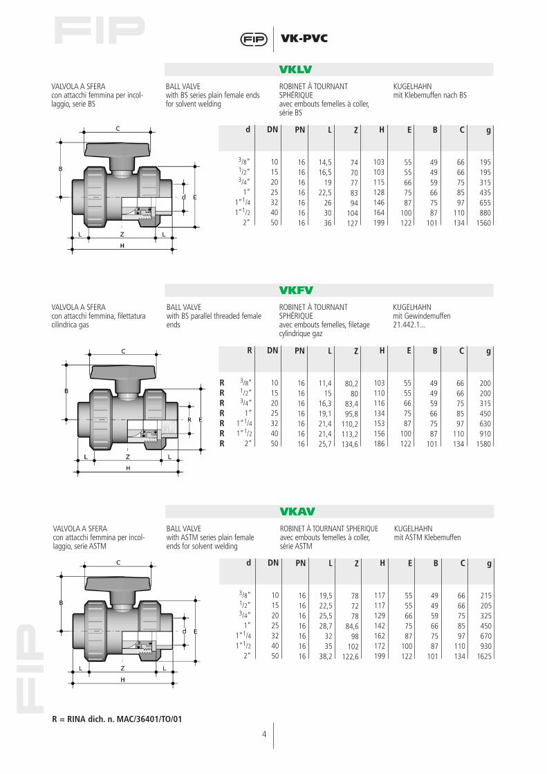
VALVOLA A SFERAcon attacchi femmina per incol-laggio, serie ASTM
BALL VALVEwith ASTM series plain femaleends for solvent welding
ROBINET À TOURNANT SPHERIQUEavec embouts femelles à coller,série ASTM
KUGELHAHNmit ASTM Klebemuffen
VKAV
d
3/8”1/2”3/4”
1”1”1/41”1/2
2”
DN
10152025324050
L
19,522,525,528,7
3235
38,2
PN
16161616161616
Z
787278
84,698
102122,6
E
5555667587
100122
H
117117129142162172199
B
494959667587
101
C
6666758597
110134
g
215205325450670930
1625
4
VK-PVC
VALVOLA A SFERAcon attacchi femmina per incol-laggio, serie BS
BALL VALVEwith BS series plain female endsfor solvent welding
ROBINET À TOURNANTSPHÉRIQUEavec embouts femelles à coller,série BS
KUGELHAHNmit Klebemuffen nach BS
VKLV
VALVOLA A SFERAcon attacchi femmina, filettaturacilindrica gas
BALL VALVEwith BS parallel threaded femaleends
ROBINET À TOURNANTSPHÉRIQUEavec embouts femelles, filetagecylindrique gaz
KUGELHAHNmit Gewindemuffen21.442.1...
VKFV
d
3/8”1/2”3/4”
1”1”1/41”1/2
2”
DN
10152025324050
L
14,516,5
1922,5
263036
PN
16161616161616
Z
7470778394
104127
E
5555667587
100122
H
103103115128146164199
B
494959667587
101
C
6666758597
110134
g
195195315435655880
1560
R
3/8”1/2”3/4”
1”1”1/41”1/2
2”
DN
10152025324050
L
11,415
16,319,121,421,425,7
PN
16161616161616
Z
80,280
83,495,8
110,2113,2134,6
B
494959667587
101
H
103110116134153156186
E
5555667587
100122
C
6666758597
110134
g
200200315450630910
1580
R = RINA dich. n. MAC/36401/TO/01
RRRRRRR
5
VK-PVC
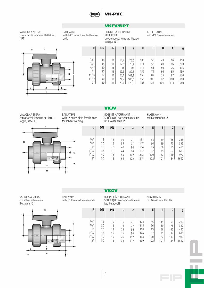
VALVOLA A SFERAcon attacchi femmina filettaturaNPT
BALL VALVEwith NPT taper threaded femaleends
ROBINET À TOURNANTSPHÉRIQUEavec embouts femelles, filetageconique NPT
KUGELHAHNmit NPT Gewindemuffen
VKFV/NPT
R
3/8”1/2”3/4”
1”1”1/41”1/2
2”
DN
10152025324050
L
13,717,8
1822,625,124,729,6
PN
16161616161616
Z
75.675,4
8189,8
102,8106,6126,8
B
494959667587
101
H
103111117135153156186
E
5555667587
100122
C
6666758597
110134
g
200200315450630910
1580
VALVOLA A SFERAcon attacchi femmina per incol-laggio, serie JIS
BALL VALVEwith JIS series plain female endsfor solvent welding
ROBINET À TOURNANTSPHÉRIQUE avec embouts femel-les à coller, serie JIS
KUGELHAHNmit Klebemuffen JIS
VKJV
VALVOLA A SFERAcon attacchi femmina,filettatura JIS
BALL VALVEwith JIS threaded female ends
ROBINET À TOURNANTSPHÉRIQUE avec embouts femel-les, filetage JIS
KUGELHAHNmit Gewindemuffen JIS
VKGV
d
1/2”3/4”
1”1”1/41”1/2
2”
DN
152025324050
L
303540445563
PN
161616161616
Z
71778494
102122
E
55667587
100122
H
131147164182212248
B
4959667587
101
C
66758597
110134
g
215315450680970
1640
R
1/2”3/4”
1”1”1/41”1/2
2”
DN
152025324050
L
161922252631
PN
161616161616
Z
71778496
112137
B
4959667587
101
H
103115128146164199
E
55667587
100122
C
66758597
110134
g
200310440630930
1540
6
VK-PVC
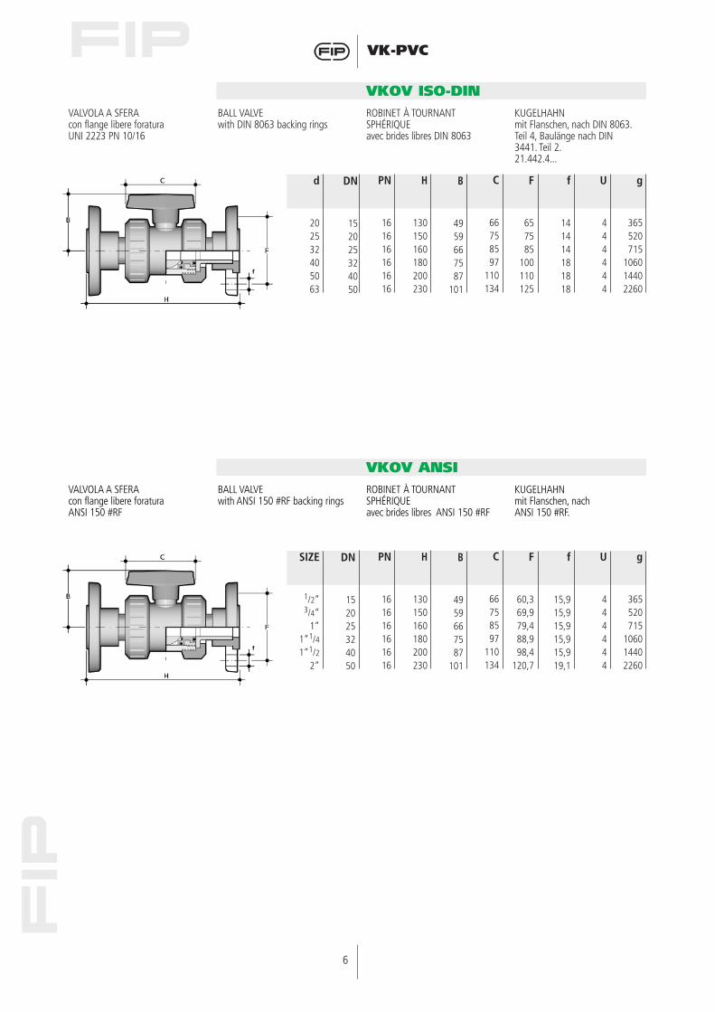
VALVOLA A SFERAcon flange libere foraturaUNI 2223 PN 10/16
BALL VALVEwith DIN 8063 backing rings
ROBINET À TOURNANTSPHÉRIQUEavec brides libres DIN 8063
KUGELHAHNmit Flanschen, nach DIN 8063.Teil 4, Baulänge nach DIN3441. Teil 2.21.442.4...
VKOV ISO-DIN
d
202532405063
DN
152025324050
H
130150160180200230
PN
161616161616
B
4959667587
101
F
657585
100110125
f
141414181818
C
66758597
110134
U
444444
g
365520715
106014402260
VALVOLA A SFERAcon flange libere foraturaANSI 150 #RF
BALL VALVEwith ANSI 150 #RF backing rings
ROBINET À TOURNANTSPHÉRIQUEavec brides libres ANSI 150 #RF
KUGELHAHNmit Flanschen, nach ANSI 150 #RF.
VKOV ANSI
SIZE
1/2”3/4”
1”1”1/41”1/2
2”
DN
152025324050
H
130150160180200230
PN
161616161616
B
4959667587
101
F
60,369,979,488,998,4
120,7
f
15,915,915,915,915,919,1
C
66758597
110134
U
444444
g
365520715
106014402260
7
VK-PVC
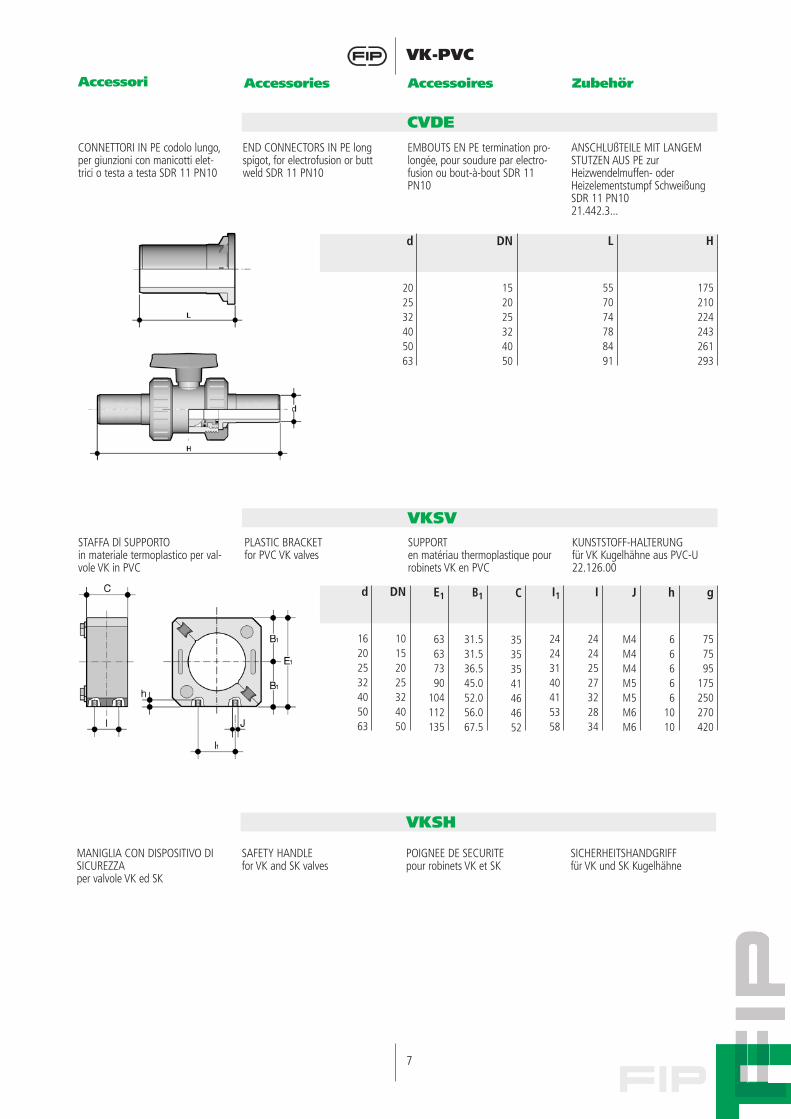
CONNETTORI IN PE codolo lungo,per giunzioni con manicotti elet-trici o testa a testa SDR 11 PN10
END CONNECTORS IN PE longspigot, for electrofusion or buttweld SDR 11 PN10
EMBOUTS EN PE termination pro-longée, pour soudure par electro-fusion ou bout-à-bout SDR 11PN10
ANSCHLUßTEILE MIT LANGEMSTUTZEN AUS PE zurHeizwendelmuffen- oderHeizelementstumpf SchweißungSDR 11 PN1021.442.3...
CVDE
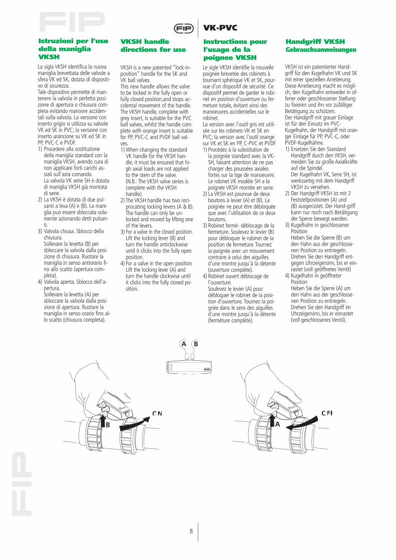
STAFFA Dl SUPPORTOin materiale termoplastico per val-vole VK in PVC
PLASTIC BRACKET for PVC VK valves
SUPPORTen matériau thermoplastique pourrobinets VK en PVC
KUNSTSTOFF-HALTERUNG für VK Kugelhähne aus PVC-U22.126.00
VKSV
d
202532405063
DN
152025324050
L
557074788491
H
175210224243261293
d
16202532405063
DN
10152025324050
B1
31.531.536.545.052.056.067.5
E1
63637390
104112135
C
35353541464652
J
M4M4M4M5M5M6M6
I1
24243140415358
I
24242527322834
h
66666
1010
g
757595
175250270420
Accessori Accessories Accessoires Zubehör
MANIGLIA CON DISPOSITIVO DISICUREZZAper valvole VK ed SK
SAFETY HANDLEfor VK and SK valves
POIGNEE DE SECURITEpour robinets VK et SK
SICHERHEITSHANDGRIFFfür VK und SK Kugelhähne
VKSH
8
VK-PVC
Istruzioni per l’usodella manigliaVKSH
VKSH handle directions for use
Instructions pourl’usage de la poignee VKSH
Handgriff VKSHGebrauchsanweisungen
La sigla VKSH identifica la nuovamaniglia brevettata delle valvole asfera VK ed SK, dotata di dispositi-vo di sicurezza.Tale dispositivo permette di man-tenere la valvola in perfetta posi-zione di apertura o chiusura com-pleta evitando manovre acciden-tali sulla valvola. La versione coninserto grigio si utilizza su valvoleVK ed SK in PVC; la versione coninserto arancione su VK ed SK inPP, PVC-C e PVDF.1) Procedere alla sostituzione
della maniglia standard con lamaniglia VKSH, avendo cura dinon applicare forti carichi as-siali sull'asta comando.La valvola VK serie SH è dotatadi maniglia VKSH già montatadi serie.
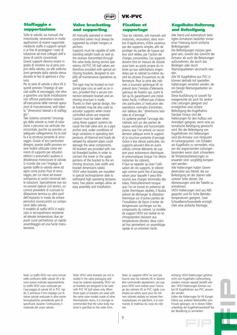
2) La VKSH è dotata di due pul-santi a leva (A) e (B). La mani-glia può essere sbloccata sola-mente azionando detti pulsan-ti.
3) Valvola chiusa. Sblocco dellachiusura.Sollevare la levetta (B) persbloccare la valvola dalla posi-zione di chiusura. Ruotare lamaniglia in senso antiorario fi-no allo scatto (apertura com-pleta).
4) Valvola aperta. Sblocco dell'a-pertura.Sollevare la levetta (A) persbloccare la valvola dalla posi-zione di apertura. Ruotare lamaniglia in senso orario fino al-lo scatto (chiusura completa).
VKSH is a new patented “lock-in-position” handle for the SK andVK ball valves.This new handle allows the valveto be locked in the fully open orfully closed position,and stops ac-cidental movement of the handle.The VKSH handle, complete withgrey insert, is suitable for the PVCball valves, whilst the handle com-plete with orange insert is suitablefor PP, PVC-C and PVDF ball val-ves.1) When changing the standard
VK handle for the VKSH han-dle, it must be ensured that hi-gh axial loads are not appliedto the stem of the valve.(N.B.: The VKSH valve series iscomplete with the VKSHhandle).
2) The VKSH handle has two reci-procating locking levers (A & B).The handle can only be un-locked and moved by lifting oneof the levers.
3) For a valve in the closed position.Lift the locking lever (B) andturn the handle anticlockwiseuntil it clicks into the fully openposition.
4) For a valve in the open positionLift the locking lever (A) andturn the handle clockwise untilit clicks into the fully closed po-sition.
Le sigle VKSH identifie la nouvellepoignée brevetée des robinets àtournant sphérique VK et SK, pour-vue d'un dispositif de sécurité. Cedispositif permet de garder le robi-net en position d’ouverture ou fer-meture totale, évitant ainsi desmanoeuvres accidentelles sur lerobinet.La version avec l’outil gris est utili-sée sur les robinets VK et SK enPVC; la version avec l'outil orangesur VK et SK en PP, C-PVC et PVDF1) Procédez à la substitution de
la poignée standard avec la VK-SH, faisant attention de ne pascharger des poussées axialesfortes sur la tige de manoeuvre.Le robinet VK modèle SH a lapoignée VKSH montée en serie.
2) La VKSH est pourvue de deuxboutons à levier (A) et (B). Lapoignée ne peut être débloquéeque avec l’utilisation de ce deuxboutons.
3) Robinet fermé- déblocage de lafermeture. Soulevez le levier (B)pour débloquer le robinet de laposition de fermeture. Tournezla poignée avec un mouvementcontraire à celui des aiguillesd’une montre jusqu’à la détente(ouverture complète).
4) Robinet ouvert déblocage del’ouverture.Soulevez le levier (A) pourdébloquer le robinet de la posi-tion d'ouverture. Tournez la poi-gnée dans le sens des aiguillesd'une montre jusqu’à la détente(ferméture complète).
VKSH ist ein patentierter Hand-griff für den Kugelhahn VK und SKmit einer speziellen Arretierung.Diese Arretierung macht es mögli-ch, den Kugelhahn entweder in of-fener oder geschlossener Stellungzu fixieren und ihn vor zufälligerBetätigung zu schützen.Der Handgriff mit grauer Einlageist für den Einsatz im PVC-Kugelhahn, der Handgriff mit oran-ger Einlage für PP, PVC-C, oderPVDF-Kugelhähne.1) Ersetzen Sie den Standard
Handgriff durch den VKSH, ver-meiden Sie zu große Axialkräfteauf die Spindel.Der Kugelhahn VK, Serie SH, istwerksseitig mit dem HandgriffVKSH zu versehen.
2) Der Handgriff VKSH ist mit 2Feststellpositionen (A) und(B) ausgerüstet. Der Hand-griffkann nur noch nach Betätigungder Sperre bewegt werden.
3) Kugelhahn in geschlossenerPositionHeben Sie die Sperre (B) umden Hahn aus der geschlosse-nen Position zu entriegeln.Drehen Sie den Handgriff ent-gegen Uhrzeigersinn, bis er ein-rastet (voll geöffnetes VentiI)
4) Kugelhahn in geöffneterPositionHeben Sie die Sperre (A) umden Hahn aus der geschlosse-nen Position zu entriegeln.Drehen Sie den Handgriff imUhrzeigersinn, bis er einrastet(voll geschlossenes Ventil).
A B
B
ON
A
OFF
9
VK-PVC
Staffaggio esupportazione
Valve bracketingand supporting
Fixation etsupportage
Kugelhahn-Halterungund Befestigung
Tutte le valvole, sia manuali chemotorizzate, necessitano in molteapplicazioni di essere supportatemediante staffe o supporti sempli-ci al fine di proteggere i tratti ditubazione ad esse collegati dall'a-zione di carichi concentrati.Questi supporti devono essere ingrado di resistere sia al peso pro-prio della valvola, sia alle sollecita-zioni generate dalla valvola stessadurante le fasi di apertura e chiu-sura.Per la serie di valvole a sfera VK èquindi previsto l'impiego di spe-ciali staffe di ancoraggio, che oltrea garantire una facile installazionenon offrono particolare ostacoloall'esecuzione delle normali opera-zioni di manutenzione, vedi tabel-la “dimensioni laterali e di staffag-gio”.Tale sistema consente l'ancorag-gio delle valvole su tratti di tuba-zione a percorso sia verticale cheorizzontale, purchè sia previsto unadeguato collegamento fra la staf-fa e la struttura portante di anco-raggio. Grazie al loro particolaredisegno, queste staffe possono es-sere inoltre utilizzate come ele-menti di supporto per attuatorielettrici e pneumatici qualora sidesiderasse motorizzare le valvole.Si ricorda che con l'impiego diqueste staffe la valvola viene adagire come punto fisso di anco-raggio, per cui viene ad esseresottoposta ai carichi terminali del-le tubazioni. Specialmente ove sia-no previsti ripetuti cicli termici, oc-correrà prevedere di scaricare ladilatazione termica su altre partidell'impianto in modo da evitarepericolosi sovraccarichi sui compo-nenti della valvola.Il modello di staffa VKSV è realiz-zato in tecnopolimero resistentead elevate temperature; due ap-positi cunei permettono un rapidoassemblaggio ed una facile manu-tenzione.
All manually operated or motorcontrolled valves must always besupported by simple hangers oranchors.Supports must be capable of with-standing weight loads as well asthe stresses transmitted throughthe valve body during service ope-rations. All PVC VK ball valves aretherefore provided with special an-choring brackets, designed to sim-plify all maintenance operations aswell.This type may be located on hori-zontal pipe runs as well as on ri-sers, provided that a secure con-nection between bracket and an-choring structure is made.Thanks to their special design, the-se brackets may be also used asactuator supports when motorcontrolled valves are required.Caution must be taken whenusing these support systems be-cause the ball valve acts as a pipeanchor and, under conditions oflarge variations in operating tem-perature, all thermal end loads de-veloped by adiacent pipes coulddamage the valve components.All brackets are provided with me-tal threaded bushes in order toconnect the lower or the upperportions of the bracket to the an-choring structure, (see width andbracket dimensions table).VKSV valve brackets are mouldedin special technopolymer able towithstand high operating tempera-tures. Two plastic wedges allow aneasy assembly and installation.
Tous les robinets, soit manuels soitmotorisés, nécessitent, dans nom-bre d'applications, d’être soutenuspar des supports simples, afin deprotéger les parties de tuyaux quileur sont reliées, par l'action decharges concentrées. Ces supportsdoivent être en mesure de résisteraussi bein au poids propre du ro-binet qu’aux sollicitations engen-drées par le robinet lui-même du-rant les phases d'ouverture ou defermeture. Pour la série des robi-nets à tournant sphérique VK onprévoit donc l'emploi d’élémentsspéciaux de fixation qui, outre lefait qu’ils garantissent une instal-lation facile, n'offrent pas d'obsta-cles particuliers à l’exécution desoperations normales d’entretien,voir tableau des “dimensions late-rales et d'ancrage”.Ce système permet l'ancrage desrobinets soit sur des parties detuyaux verticales soit horizontalespourvu que l’on prévoit un raccor-dement adéquat entre le supportet la structure portante d'ancrage.Grâce à leur dessin particulier, cessupports peuvent être en outreutilisés comme éléments de sup-port pour actionneurs électriqueset pneumatiques lorque l’on désiremotoriser les robinets.Il faut se rappeler qu’avec l'utili-sation de ces supports, le robinetagit comme point fixe d'ancrage,raison pour laquelle il peut êtresoumis aux charges terminales destubes. Particulièrement lorsqueque l’on se trouve en présence decycles thermiques répétés, il faudraprévoir de décharger la dilatationthermique sur d’autres parties del'installation de façon à éviter dedangereuses surcherges sur lescomposants du robinet. Le modèlede support VKSV est réalisé en te-chnopolymère résistant auxtempératures élevées; deux coinsad hoc permettent un assemblagerapide et un entretien facile.
Alle Hand-und automatisch betä-tigten Armaturen bedürfen immereiner Fixierung durch einfacheBefestigungen.Die Befestigungen müssen geei-gnet sein, sowohl das Gewicht derArmatur als auch die Belastungenaufzunehmen, die durch dasBetätigen oder durchWartungsarbeiten verursacht wer-den.Alle VK Kugelhähne aus PVC-Ukönnen deshalb mit speziellenHalterungen versehen werden, de-ren Design Wartungsarbeiten ve-reinfacht.Diese Ausführung ist sowohl fürwaagerechte als auch für senkre-chte Leitungen geeignet undermöglichen eine sichereBefestigung des Kugelhahns.Darüber hinaus sind dieHalterungen für den Aufbau vonAntrieben geeignet, wenn eine au-tomatische Betätigung gewüschtwird. Bei der Befestigung vonKugelhähnen mit Halterungenwird die Armatur zum Festpunktim Leitungssystem. Um Schädenam Kugelhahn zu vermeiden, müs-sen die angrenzenden Leitungen -besonders wenn stark schwanken-de Temperaturbelastungen zuerwarten sind- sorgfältig kompen-siert werden.Alle Halterungen haben Gewin-deeinsätze aus Metall, die zurBefestigung an der oberen oderunteren Seite dienen. DieAbmessungen sind der Tabelle zuentnehmen.VKSV-Halterungen sind aus ABSgespritzt und für hohe Betriebs-temperaturen geeignet. ZweiSchwalbenschwanzkeile ermögli-chen eine ainfache Montage.
Note: Le staffe VKSV non sono inclusenelle confezioni delle valvole VK e de-vono essere ordinate separatamente.Le staffe VKSV sono realizzate perl'ancoraggio di valvole VK in PVC rigi-do. È ammesso il loro impiego con lestesse valvole realizzate in altre resinetermoplastiche, prevedendo però dispecificare, durante l’ordinazione, ilmateriale del corpo valvola.
Note: VKSV valve brackets are not in-cluded in the valve packaging andmust be ordered separately. VKSV val-ve brackets are designed to be usedwith PVC VK ball valves only. Whenthese types of brackets are used withthe same valve models made of otherthermoplastic resins, it is strongly re-commended that the valve body ma-terial is specified on the order form.
Note: Le supports VKSV ne sont pasfournis avec les robinets VK et doiventêtre commandés séparément. Les sup-ports VKSV sont réalisés pour l’ancra-ge des robinets VK en PVC rigide. Leuremploi est admis aussi pour les mê-mes robinets réalisés en resines ther-moplastiques, en spécifiant, à la com-mande, le matériau du corps du robi-net.
Achtung: VKSV-Halterungen gehörennicht zum Kugelhahn-Lieferumfang,sondern müssen separat bestellt wer-den. VKSV-Halterungen können nurbei VK Kugelhähnen aus PVC verwen-det werden.Sollen die Halterungen für VK Kungel-hähne aus anderen Werkstoffen zumEinsatz gelangen, ist in diesen Fällenunbedingt der Kugelhahnwerkstoff beider Bestellung zu vermerken.
10
VK-PVC
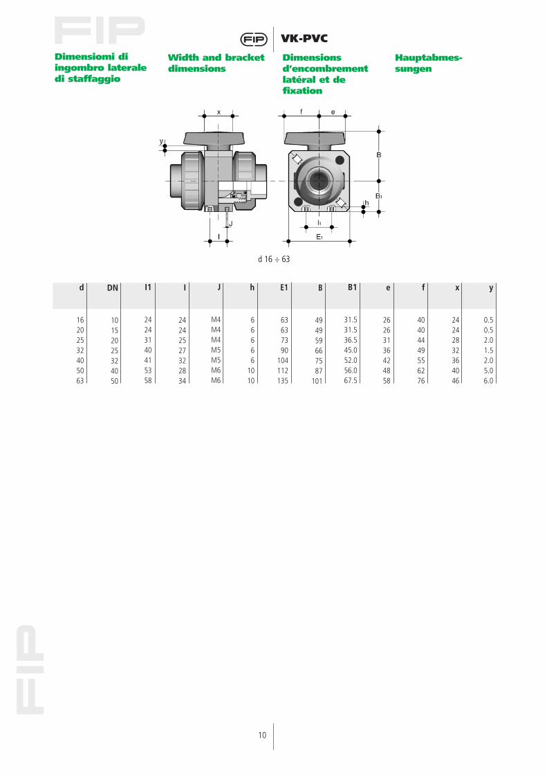
Dimensiomi di ingombro lateraledi staffaggio
Width and bracketdimensions
Dimensions d’encombrementlatéral et de fixation
Hauptabmes-sungen
J
M4M4M4M5M5M6M6
E1
63637390
104112135
h
66666
1010
I1
24243140415358
I
24242527322834
d
16202532405063
DN
10152025324050
B
494959667587
101
e
26263136424858
B1
31.531.536.545.052.056.067.5
f
40404449556276
x
24242832364046
y
0.50.52.01.52.05.06.0
d 16 ÷ 63
11
VK-PVC
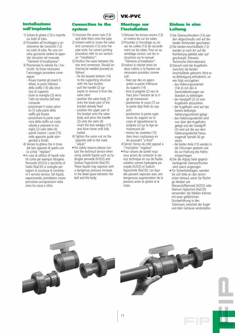
1) Svitare le ghiere (13) e inserirlesui tratti di tubo.
2) Procedere all'incollaggio o av-vitamento dei manicotti (12)sui tratti di tubo. Per una cor-retta giunzione vedere le appo-site istruzioni nel manuale“Elementi d'installazione”.
3) Posizionare la valvola fra i ma-nicotti. Se fosse necessariol'ancoraggio procedere comesegue:- fissare tramite gli inserti fi-
lettati, la parte inferiore della staffa (14) alla strut-tura di supporto
- tirare la maniglia (2) verso l'alto ed estrarla dall'asta comando
- posizionare il corpo valvo-la (7) sulla parte della staffa già fissata
- posizionare la parte supe-riore della staffa sul corpo valvola e pressare la ma-niglia (2) sullo stelo (4)
- quindi inserire i cunei (15) nelle apposite guide spin-gendoli a fondo.
4) Serrare la ghiera che si trovadal lato opposto di quello conla scritta "regolare"
• In caso di utilizzo di liquidi vola-tili come per esempio IdrogenoPerossido (H2O2) o Ipoclorito diSodio (NaClO) si consiglia perragioni di sicurezza di contatta-re il servizio tecnico. Tali liquidi,vaporizzando, potrebbero crearepericolose sovrapressioni nellazona tra cassa e sfera.
1) Unscrew the union nuts (13)and slide them onto the pipe.
2) Solvent weld or screw the valveend connectors (12) onto thepipe ends. For correct jointingprocedure refer to our sectionon “Installation”.
3) Position the valve between thetwo end connectors. Should an-choring be needed proceed asfollows:- fix the bracket bottom (14)
to the supporting structure with the four bushes
- pull the handle (2) up-wards to remove it from the valve stem
- position the valve body (7) onto the lower part of the bracket already fixed
- position the upper part of the bracket onto the valve body and press the handle (2) onto the stem (4)
- insert the two wedges (15) and drive home until fully locked
4) Tighten the union nut on theopposite side to the mark"adjust"
• For safety reasons please con-tact the technical service whenusing volatile liquids such as hy-drogen peroxide (H2O2) andSodium Hypoclorite (NaClO).These liquids may vaporize witha dangerous pressure increasein the dead space between theball and the body.
1) Dévissez les écrous-unions (13)et insérez-les sur les tubes.
2) Procédez à l’encollage ou vis-sez les collets (12) de raccorde-ment sur les tubes. Pour un as-semblage correct, voir les in-structions sur le manuel“Eléments d'installation”.
3) lnsérez le robinet entre lesdeux collets; si la fixation estnécessaire procédez commesuit:- fixez par des vis appro-
priées la partie inférieure du support (14)
- tirez la poignée (2) vers le haut pour l’extraire de la ti-ge de manoeuvre
- positionnez le corps (7) sur la partie dejà fixée du sup-port
- positionnez la partie supé-rieure du support sur le corps et repositionnez la poignée (2) sur la tige de manoeuvre (4)
- insérez les clavettes (15) dans leurs coulisseaux en les poussant “à fond”
4) Serrez l’écrou du côté opposé àl’inscription “regolare”
• Pour raisons de sûreté nousvous prions de contacter le ser-vice technique en cas de fluidesvolatiles comme hydrogène pe-roxyde (H2O2) et SodiumHypoclorite (NaClO). Les liqui-des peuvent vaporiser avec unedangereuse augmentation de lapression entre la sphère et lecorps.
1) Die Überwurfmuttern (13) wer-den abgeschraubt und auf diebeiden Rohrenden geschoben.
2) Die beiden Anschlußteile (12)werden je nach Art auf dieRohrleitung geklebt oder auf-geschraubt. (Hinweis:Technische Informationen).
3) Danach wird der Kugelhahnzwischen die beidenAnschlußteile gebracht. Wird ei-ne Befestigung erforderlich, istwie folgt vorzugehen:- das Halterungsunterteil
(14) ist mit den 4Gewindebohrungen amStandort zu befestigen
- der Handgriff (2) ist vom Kugelhahn abzuziehen
- der Kugelhahn wird auf das bereits befestigte HaIterungsunterteil gelegt
- das Halterungsoberteil wird nun über den Kugelhahn gelegt und der Handgriff (2) wird auf die aus dem Halterungsoberteil herau-sragende Spindel (4) ge-steckt
- die beiden Keile (15) werden indie Führungen gesteckt und bis zur Fixierung des Hahns eingeschlagen.
4) Die der Adjust-Seite gegenü-berliegende Überwurfmutterwird zuerst angezogen
• Für Sicherheitsfragen, wendenSie sich bitte an den techni-schen Verkauf, wenn Sie flüchti-ge Medien wieWasserstoffperoxid (H2O2) oderNatrium Hypoclorit (NaCIO)verwenden: die Medien könnenmit einer gefährlichenDruckerhöhung in denTotenraum zwischen der Kugelund dem Gehäuse verdampfen.
Installazione sull’impianto
Connection to thesystem
Montage sur l’installation
Einbau in eine Leitung
12
VK-PVC
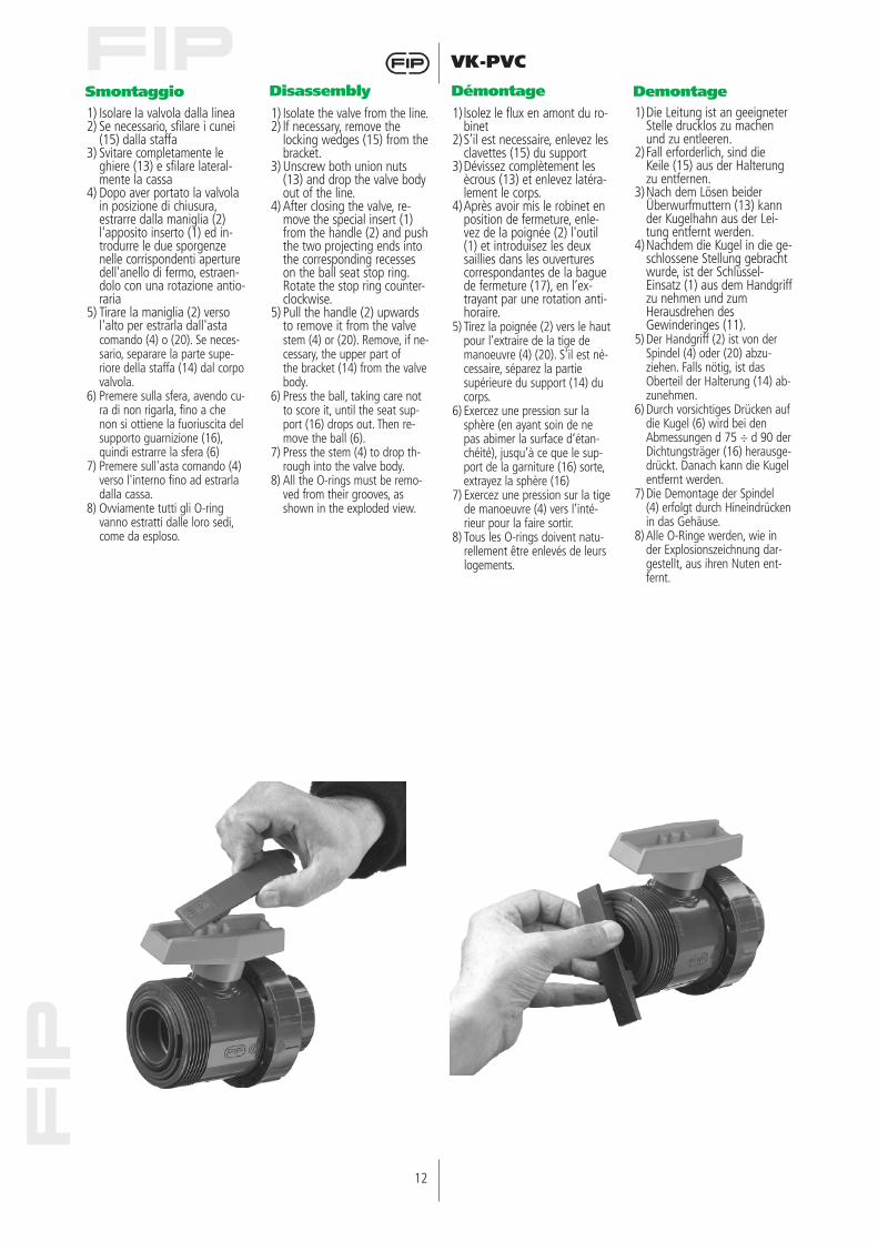
1) Isolare la valvola dalla linea2) Se necessario, sfilare i cunei
(15) dalla staffa3) Svitare completamente le
ghiere (13) e sfilare lateral-mente la cassa
4) Dopo aver portato la valvolain posizione di chiusura,estrarre dalla maniglia (2)l'apposito inserto (1) ed in-trodurre le due sporgenzenelle corrispondenti aperturedell'anello di fermo, estraen-dolo con una rotazione antio-raria
5) Tirare la maniglia (2) versol'alto per estrarla dall'asta comando (4) o (20). Se neces-sario, separare la parte supe-riore della staffa (14) dal corpovalvola.
6) Premere sulla sfera, avendo cu-ra di non rigarla, fino a chenon si ottiene la fuoriuscita delsupporto guarnizione (16),quindi estrarre la sfera (6)
7) Premere sull'asta comando (4)verso l'interno fino ad estrarladalla cassa.
8) Ovviamente tutti gli O-ringvanno estratti dalle loro sedi,come da esploso.
1) Isolate the valve from the line.2) lf necessary, remove the
locking wedges (15) from thebracket.
3) Unscrew both union nuts(13) and drop the valve bodyout of the line.
4) After closing the valve, re-move the special insert (1)from the handle (2) and pushthe two projecting ends intothe corresponding recesseson the ball seat stop ring.Rotate the stop ring counter-clockwise.
5) Pull the handle (2) upwardsto remove it from the valve stem (4) or (20). Remove, if ne-cessary, the upper part of the bracket (14) from the valvebody.
6) Press the ball, taking care notto score it, until the seat sup-port (16) drops out. Then re-move the ball (6).
7) Press the stem (4) to drop th-rough into the valve body.
8) All the O-rings must be remo-ved from their grooves, asshown in the exploded view.
1) lsolez le flux en amont du ro-binet
2)S’il est necessaire, enlevez lesclavettes (15) du support
3)Dévissez complètement lesècrous (13) et enlevez latéra-lement le corps.
4)Après avoir mis le robinet enposition de fermeture, enle-vez de la poignée (2) l'outil(1) et introduisez les deuxsaillies dans les ouverturescorrespondantes de la baguede fermeture (17), en l’ex-trayant par une rotation anti-horaire.
5) Tirez la poignée (2) vers le hautpour l’extraire de la tige demanoeuvre (4) (20). S’il est né-cessaire, séparez la partiesupérieure du support (14) ducorps.
6) Exercez une pression sur lasphère (en ayant soin de nepas abimer la surface d’étan-chéité), jusqu’à ce que le sup-port de la garniture (16) sorte,extrayez la sphère (16)
7) Exercez une pression sur la tigede manoeuvre (4) vers l’inté-rieur pour la faire sortir.
8) Tous les O-rings doivent natu-rellement être enlevés de leurslogements.
1)Die Leitung ist an geeigneterStelle drucklos zu machenund zu entleeren.
2)Fall erforderlich, sind dieKeile (15) aus der Halterungzu entfernen.
3)Nach dem Lösen beiderÜberwurfmuttern (13) kannder Kugelhahn aus der Lei-tung entfernt werden.
4)Nachdem die Kugel in die ge-schlossene Stellung gebrachtwurde, ist der Schlüssel-Einsatz (1) aus dem Handgriffzu nehmen und zumHerausdrehen desGewinderinges (11).
5) Der Handgriff (2) ist von derSpindel (4) oder (20) abzu-ziehen. Falls nötig, ist dasOberteil der Halterung (14) ab-zunehmen.
6) Durch vorsichtiges Drücken aufdie Kugel (6) wird bei denAbmessungen d 75 ÷ d 90 derDichtungsträger (16) herausge-drückt. Danach kann die Kugelentfernt werden.
7) Die Demontage der Spindel(4) erfolgt durch Hineindrückenin das Gehäuse.
8) Alle O-Ringe werden, wie inder Explosionszeichnung dar-gestellt, aus ihren Nuten ent-fernt.
Smontaggio Disassembly Démontage Demontage
13
VK-PVC
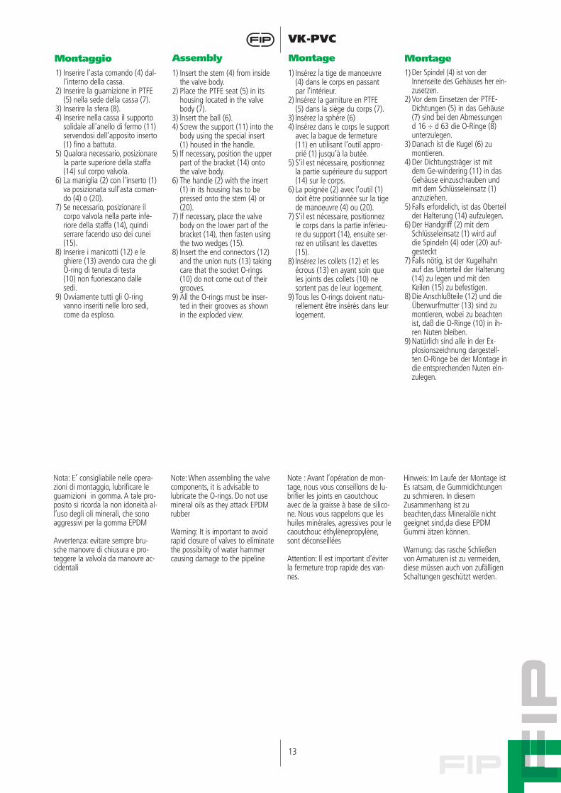
1) Inserire l’asta comando (4) dal-l'interno della cassa.
2) Inserire la guarnizione in PTFE(5) nella sede della cassa (7).
3) Inserire la sfera (8).4) Inserire nella cassa il supporto
solidale all'anello di fermo (11)servendosi dell'apposito inserto(1) fino a battuta.
5) Qualora necessario, posizionarela parte superiore della staffa(14) sul corpo valvola.
6) La maniglia (2) con l'inserto (1)va posizionata sull'asta coman-do (4) o (20).
7) Se necessario, posizionare ilcorpo valvola nella parte infe-riore della staffa (14), quindiserrare facendo uso dei cunei(15).
8) Inserire i manicotti (12) e leghiere (13) avendo cura che gliO-ring di tenuta di testa(10) non fuoriescano dallesedi.
9) Ovviamente tutti gli O-ringvanno inseriti nelle loro sedi,come da esploso.
1) Insert the stem (4) from insidethe valve body.
2) Place the PTFE seat (5) in itshousing Iocated in the valvebody (7).
3) lnsert the ball (6).4) Screw the support (11) into the
body using the special insert(1) housed in the handle.
5) lf necessary, position the upperpart of the bracket (14) ontothe valve body.
6) The handle (2) with the insert(1) in its housing has to bepressed onto the stem (4) or(20).
7) If necessary, pIace the valvebody on the lower part of thebracket (14), then fasten usingthe two wedges (15).
8) lnsert the end connectors (12)and the union nuts (13) takingcare that the socket O-rings(10) do not come out of theirgrooves.
9) All the O-rings must be inser-ted in their grooves as shownin the exploded view.
1) Insérez la tige de manoeuvre(4) dans le corps en passantpar l’intérieur.
2) lnsérez la garniture en PTFE(5) dans la siège du corps (7).
3) lnsérez la sphère (6)4) Insérez dans le corps le support
avec la bague de fermeture(11) en utilisant l’outil appro-prié (1) jusqu’à la butée.
5) S’il est nécessaire, positionnezla partie supérieure du support(14) sur le corps.
6) La poignée (2) avec l’outil (1)doit être positionnée sur la tigede manoeuvre (4) ou (20).
7) S’il est nécessaire, positionnezle corps dans la partie inférieu-re du support (14), ensuite ser-rez en utilisant les clavettes(15).
8) lnsérez les collets (12) et lesécrous (13) en ayant soin queles joints des collets (10) nesortent pas de leur logement.
9) Tous les O-rings doivent natu-rellement être insérés dans leurlogement.
1) Der Spindel (4) ist von derInnenseite des Gehäuses her ein-zusetzen.
2) Vor dem Einsetzen der PTFE-Dichtungen (5) in das Gehäuse(7) sind bei den Abmessungend 16 ÷ d 63 die O-Ringe (8)unterzulegen.
3) Danach ist die Kugel (6) zumontieren.
4) Der Dichtungsträger ist mitdem Ge-windering (11) in dasGehäuse einzuschrauben undmit dem Schlüsseleinsatz (1)anzuziehen.
5) Falls erfordelich, ist das Oberteilder Halterung (14) aufzulegen.
6) Der Handgriff (2) mit demSchlüsseleinsatz (1) wird aufdie Spindeln (4) oder (20) auf-gesteckt
7) Falls nötig, ist der Kugelhahnauf das Unterteil der Halterung(14) zu legen und mit denKeilen (15) zu befestigen.
8) Die Anschlußteile (12) und dieÜberwurfmutter (13) sind zumontieren, wobei zu beachtenist, daß die O-Ringe (10) in ih-ren Nuten bleiben.
9) Natürlich sind alle in der Ex-plosionszeichnung dargestell-ten O-Ringe bei der Montage indie entsprechenden Nuten ein-zulegen.
Montaggio Assembly Montage Montage
Nota: E’ consigliabile nelle opera-zioni di montaggio, lubrificare leguarnizioni in gomma. A tale pro-posito si ricorda la non idoneità al-l’uso degli oli minerali, che sonoaggressivi per la gomma EPDM
Avvertenza: evitare sempre bru-sche manovre di chiusura e pro-teggere la valvola da manovre ac-cidentali
Note: When assembling the valvecomponents, it is advisable tolubricate the O-rings. Do not usemineral oils as they attack EPDMrubber
Warning: It is important to avoidrapid closure of valves to eliminatethe possibility of water hammercausing damage to the pipeline
Note : Avant l’opération de mon-tage, nous vous conseillons de lu-brifier les joints en caoutchoucavec de la graisse à base de silico-ne. Nous vous rappelons que leshuiles minérales, agressives pour le caoutchouc éthylènepropylène,sont déconseillées
Attention: Il est important d’éviterla fermeture trop rapide des van-nes.
Hinweis: Im Laufe der Montage ist Es ratsam, die Gummidichtungenzu schmieren. In diesemZusammenhang ist zubeachten,dass Mineralöle nichtgeeignet sind,da diese EPDMGummi ätzen können.
Warnung: das rasche Schließenvon Armaturen ist zu vermeiden,diese müssen auch von zufälligenSchaltungen geschützt werden.
14
VK-PVC
d 16 ÷ 63
15
VK-PVC
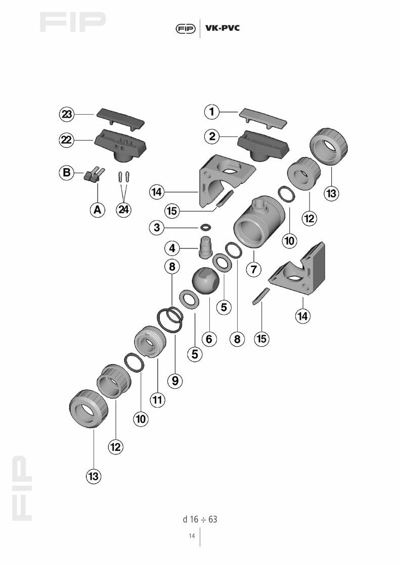
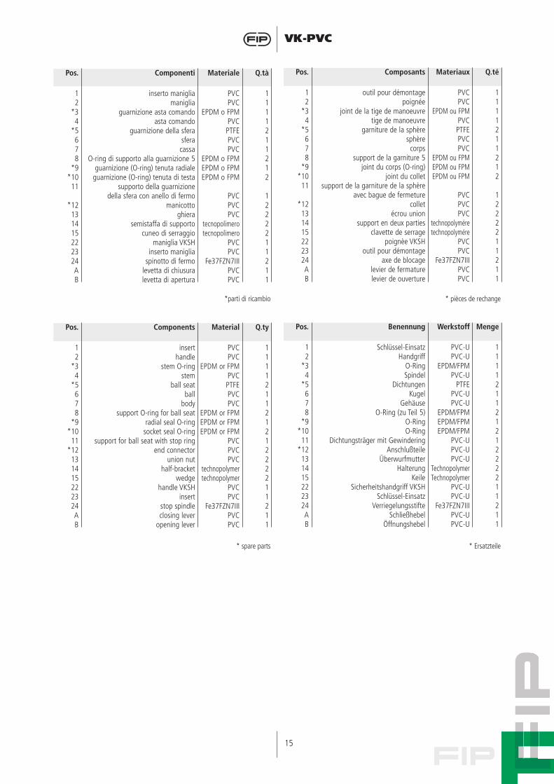
Pos.
12
*34
*5678
*9*10
11
*12131415222324AB
Componenti
inserto manigliamaniglia
guarnizione asta comandoasta comando
guarnizione della sferasferacassa
O-ring di supporto alla guarnizione 5guarnizione (O-ring) tenuta radiale
guarnizione (O-ring) tenuta di testasupporto della guarnizione
della sfera con anello di fermo manicotto
ghierasemistaffa di supporto
cuneo di serraggiomaniglia VKSH
inserto manigliaspinotto di fermo
levetta di chiusuralevetta di apertura
Q.tà
1111211212
1222211211
Materiale
PVCPVC
EPDM o FPMPVCPTFEPVCPVC
EPDM o FPMEPDM o FPMEPDM o FPM
PVCPVCPVC
tecnopolimerotecnopolimero
PVCPVC
Fe37FZN7IIIPVCPVC
Pos.
12
*34
*5678
*9*1011
*12131415222324AB
Composants
outil pour démontage poignée
joint de la tige de manoeuvre tige de manoeuvre
garniture de la sphère sphère
corpssupport de la garniture 5
joint du corps (O-ring)joint du collet
support de la garniture de la sphèreavec bague de fermeture
colletécrou union
support en deux parties clavette de serrage
poignèe VKSHoutil pour démontage
axe de blocagelevier de fermaturelevier de ouverture
Q.té
1111211212
1222211211
Materiaux
PVCPVC
EPDM ou FPMPVCPTFEPVCPVC
EPDM ou FPMEPDM ou FPMEPDM ou FPM
PVCPVCPVC
technopolyméretechnopolymére
PVCPVC
Fe37FZN7IIIPVCPVC
*parti di ricambio
Pos.
12
*34
*5678
*9*10
11*12
131415222324AB
Components
inserthandle
stem O-ringstem
ball seatball
bodysupport O-ring for ball seat
radial seal O-ringsocket seal O-ring
support for ball seat with stop ringend connector
union nut half-bracket
wedgehandle VKSH
insertstop spindleclosing lever
opening lever
Q.ty
11112112121222211211
Material
PVCPVC
EPDM or FPMPVCPTFEPVCPVC
EPDM or FPMEPDM or FPMEPDM or FPM
PVCPVCPVC
technopolymertechnopolymer
PVCPVC
Fe37FZN7IIIPVCPVC
Pos.
12
*34
*5678
*9*1011
*12131415222324AB
Benennung
Schlüssel-EinsatzHandgriff
O-RingSpindel
DichtungenKugel
GehäuseO-Ring (zu Teil 5)
O-RingO-Ring
Dichtungsträger mit GewinderingAnschlußteile
ÜberwurfmutterHalterung
KeileSicherheitshandgriff VKSH
Schlüssel-EinsatzVerriegelungsstifte
SchließhebelÖffnungshebel
Menge
11112112121222211211
Werkstoff
PVC-UPVC-U
EPDM/FPMPVC-U
PTFEPVC-UPVC-U
EPDM/FPMEPDM/FPMEPDM/FPM
PVC-UPVC-UPVC-U
TechnopolymerTechnopolymer
PVC-UPVC-U
Fe37FZN7IIIPVC-UPVC-U
* pièces de rechange
* spare parts * Ersatzteile


![· BS 6360, s.ngue core . SS 358, BS 6004, IEC 60227 Tye. TIT , TÇ3 3D 1 rtm" far mm C'iwr Power Cables '/ BS 6231 PVC (s"lgue core] PVC (SWITCHGEAR unres) e Standard cores Power](https://img.pdfslide.net/doc/110x75/5e7ae69424a1fb3975256952/bs-6360-sngue-core-ss-358-bs-6004-iec-60227-tye-tit-t3-3d-1-rtm.jpg)


![Unplasticized polyvinyl chloride [uPVC] Facts](https://img.pdfslide.net/doc/110x75/56812ba2550346895d8fceab/unplasticized-polyvinyl-chloride-upvc-facts.jpg)