Embed Size (px)
Citation preview
J Sign Process SystDOI 10.1007/s11265-012-0709-z
VLSI Architecture for MIMO Soft-Input Soft-OutputSphere Detection
Esther P. Adeva · Tobias Seifert · Gerhard Fettweis
Received: 20 April 2012 / Revised: 1 October 2012 / Accepted: 4 October 2012© The Author(s) 2012. This article is published with open access at SpringerLink.com
Abstract Achieving good detection performance whileincurring low complexity is known to be one ofthe major challenges in multiple-input multiple-output(MIMO) communications based on spatial multiplex-ing. The tuple search detector (TSD) was recently in-troduced, improving this trade-off with regard to othertree-search-based algorithms (e.g. single tree search orlist sphere detector). Motivated by the tremendous gainachievable through the turbo principle and based on apreviously developed soft-output (SO) TSD implemen-tation, this work presents the first soft-input soft-output(SISO) TSD realization, scalable in constellation sizeand number of antennas and mapped to a highly par-allel and pipelined VLSI architecture. The proposedSISO-TSD VLSI realization is instantiated for 4 × 4MIMO transmission and 64-QAM constellation in 65-nm CMOS technology. For a given BER↔complexitytrade-off, the throughput ranges from 57.3 Mbps (it-erative detection-decoding with 3 iterations) to 403.6Mbps (non-iterative detection-decoding) at a clock fre-quency of 454 MHz. The BER↔complexity trade-offcan be moreover adjusted according to transmissionconditions, reaching >1 Gbps in high SNR scenarios.A silicon area of 0.14 mm2 (97.7 kGEs) is occupiedby the SISO-TSD core, reporting low power dissipa-tion (58.2 mW – 73.9 mW) under typical case operat-
E. P. Adeva (B) · T. Seifert · G. FettweisVodafone Chair Mobile Communications Systems,Technische Universität Dresden, Dresden, Germanye-mail: [email protected]
T. Seiferte-mail: [email protected]
G. Fettweise-mail: [email protected]
ing conditions. The proposed detector implementationachieves hence high throughput with reasonable hard-ware complexity, representing a very competitive strat-egy with regard to relevant state-of-the-art realizations.
Keywords MIMO · Iterative detection-decoding ·Soft-input soft-output (SISO) detection · Spheredetection · Tuple search detector · SIMD ·Pipeline-interleaving · VLSI architecture
1 Introduction
Future mobile communication systems will make useof multiple-input multiple-output (MIMO) techniquesin combination with high constellation orders to en-hance spectral efficiency. The turbo principle (i.e. it-erative detection-decoding) is in this regard foreseenas a strategy to approach the full potential of MIMO.Additionally, transmission of spatially multiplexed datastreams allows increasing data rates as well as di-versity. As it is widely known, in such systems thepotential search space grows exponentially with in-creasing number of transmit antennas (NT) and con-stellation size (Q). As a consequence, the inherenthigh detection complexity of most tree-search-baseddetection strategies represents a limiting factor towardsefficient detector implementation. Low-complex detec-tion strategies provide poor bit error rate (BER) per-formance (e.g. linear detector, successive/parallel inter-ference cancelation—SIC/PIC detector, . . . ), whereasimplementations achieving high BER performancepresent unusable high complexity (e.g. search ap-proaches like unclipped single tree search sphere
J Sign Process Syst
detector—STS-SD). Besides the mentioned difficultiesconcerning complexity, most of today’s communicationstandards define several transmission modes (e.g. upto 8 × 8 MIMO and up to 64-QAM in Long TermEvolution Advanced—LTE-A [1, 2]), thus becomingflexibility and scalability of detection approaches anadditional challenge to be addressed. The tuple searchdetector (TSD) introduced in [17] has demonstrated tooutperform the complexity↔BER-performance trade-off of comparable tree search detection strategies likeSTS [25] or list sphere detection (LSD) [31]. Addition-ally, TSD’s search complexity presents a roughly lineartrend with NT and Q [4], hence becoming especiallywell suited for high-order transmission scenarios (NT ≥4, Q > 16). In contrast to breadth-f irst approachespresenting fixed search complexity, the complexity ofthe so-called depth-f irst detection algorithms (like STS,LSD and TSD) is variable. This fact represents an ad-ditional challenge towards practical realizations, sincethe inherent irregular and data-dependent control flowtypically frustrates efficient algorithm parallelization,thus considerably limitig the achievable throughput en-hancement. In this work, the first soft-input soft-output(SISO) TSD realization capable of reaching LTE-Adata rates is presented and compared to a previouslydeveloped soft-output (SO) TSD implementation [3].The turbo principle [10] allows significant further im-provement of BER performance, but it also generallyleads to further complexity increase resulting from themultiple detection-decoding runs per received symbol.Both benefit and cost of processing a-priori informationfrom channel decoder will be hence evinced throughoutthis work.
The considered communications system model is in-troduced in Section 2, followed by the description ofthe complexity-reduced SISO-TSD algorithm (Section3) representing the basis of our implementation. Inorder to minimize the required resources and speedup the computations, fixed-point arithmetic is utilized,as described in Section 4. Analysis of the computa-tional complexity and the critical path is presentedin Section 5. Considered parallelism approaches forfurther throughput enhancement are detailed in Sec-tion 6. In Section 7 the processor architecture is pre-sented and relevant implementation challenges are in-troduced. Corresponding VLSI implementation resultsare presented in Section 8 and discussed in Section 9.As summarized in Section 10, low-complexity, scalabil-ity and high throughput (up to 1 Gbps)1 characterize
1At 454 MHz, for 4 × 4 transmission and 64-QAM in high SNRscenarios, non-iterative case.
the proposed SISO-TSD implementation, resulting ina very competitive detection strategy with regard torelevant state-of-the-art realizations.
2 System Model
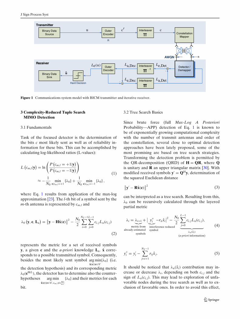
Throughout this paper, we consider a NT × NR MIMOsystem based on a bit-interleaved coded modulation(BICM) transmission strategy with NT transmit andNR receive antennas, as depicted in Fig. 1. A vectoru of i.i.d. information bits is encoded by the outerchannel encoder with rate R. The resulting stream ofvectors c′ is bit-interleaved with a random interleaverand portioned into blocks c of NT · L bits, where Ldenotes the number of bits per transmit symbol. Forthe transmission, the corresponding bits c ∈ C , coveredin the set of permitted bit vectors, are mapped (e.g.Gray mapping) onto complex constellation symbolsx(c) = [x0, ...xNT−1]T = map(c) with xi ∈ X , being Xthe set of valid transmit symbols xi with cardinality#X = #C = 2L = Q. The transmit energy is normal-ized so that E {xxH} = ES/NTI, where Es represents theaverage transmit energy of the transmitter.
Regarding the transmission, we consider an uncorre-lated, flat fading channel and an additive noise vectorn ∈ C
NR×1 at the receiver with complex components ofzero mean i.i.d. gaussian random variables of varianceN0/2 per real dimension (E {nnH} = N0I). The consid-ered passive channel is represented by H ∈ C
NR×NT andis assumed to be perfectly known at the receiver. Thereceived signal y is therefore given by
y = Hx + n
and the signal-to-noise-ratio (SNR = Es/N0) at thereceiver applied to the energy of one information bitcan be stated as Eb/N0 = Es NR/N0 NTLR.
At the receiver side, the detection process is carriedout by a complex-valued TSD algorithm in conjunctionwith a PCCC (Parallel Concatenated ConvolutionalCode) channel decoder, which can operate in iterativedetection-decoding fashion. In order to ensure compa-rability of results, a setup equivalent to the one used ine.g. [11, 32] has been used for our simulations.2
2Channel decoder is BCJR-based (Bahl, Cocke, Jelinek andRaviv) and uses (7R, 5) convolutional codes, 8 internal iterationsand rate 1/2. Information block size of 9216 bits (including tailbits) and Gray mapping are used.
J Sign Process Syst
Transmitter
Receiver
Outer Encoder
Interleaver
Interleaver
Binary Data Sink
+
Constellation Mapper
-1-
Detector / Demapper
+Outer
Decoder
Binary Data Source
Interleaver
+ +
Transmitter
Receiver
Outer Encoder
Interleaver
Interleaver
Binary Data Sink
+
Constellation Mapper
-1-
Detector / Demapper
+Outer
Decoder
Binary Data Source
Interleaver
+ +
u c c
Le,Det
La,Det
La,Dec
Le,Dec
Le(u)
u
n
H
-
Figure 1 Communications system model with BICM transmitter and iterative receiver.
3 Complexity-Reduced Tuple SearchMIMO Detection
3.1 Fundamentals
Task of the focused detector is the determination ofthe bits c most likely sent as well as of reliability in-formation for these bits. This can be accomplished bycalculating log-likelihood ratios (L-values):
L(cm,l|y
) = ln
(P
(cm,l = +1|y)
P(cm,l = −1|y)
)
≈ − 1
N0min
c|cm,l=+1{λ0} + 1
N0min
c|cm,l=−1{λ0} ,
(1)
where Eq. 1 results from application of the max-logapproximation [23]. The l-th bit of a symbol sent by them-th antenna is represented by cm,l and
λ0(y, c, La
) = ∥∥y − Hx(c)
∥∥2 − N0
2
NT−1∑
i=0
L−1∑
j=0
ci, jLa(ci, j)
(2)
represents the metric for a set of received symbolsy, a given c and the a-priori knowledge La. x corre-sponds to a possible transmitted symbol. Consequently,besides the most likely sent symbol arg min
x(c)|c∈C
{λ0} (i.e.
the detection hypothesis) and its corresponding metricλ0(cML), the detector has to determine also the counter-hypotheses arg min
x(c)|c∈C ,cm,l �=cMLm,l
{λ0} and their metrics for each
bit.
3.2 Tree Search Basics
Since brute force (full Max-Log A PosterioriProbability—APP) detection of Eq. 1 is known tobe of exponentially growing computational complexitywith the number of transmit antennas and order ofthe constellation, several close to optimal detectionapproaches have been lately proposed, some of themost promising are based on tree search strategies.Transforming the detection problem is permitted bythe QR-decomposition (QRD) of H = QR, where Qis unitary and R an upper triangular matrix [30]. Withmodified received symbols y′ = QHy, determination ofthe squared Euclidean distance
∥∥y′ − Rx(c)
∥∥2 (3)
can be interpreted as a tree search. Resulting from this,λ0 can be recursively calculated through the layeredpartial metric
λi = λi+1︸︷︷︸metric from
already estimatedsymbols
+ ∣∣ y′′
i︸︷︷︸interference reducedsymbol
−rii xi∣∣2 − N0
2
L−1∑
j=0
ci, jLa(ci, j)
︸ ︷︷ ︸λa(xi)
(a-priori information)
,
(4)
y′′i = y′
i −NT−1∑
j=i+1
rijx j. (5)
It should be noticed that λa(xi) contribution may in-crease or decrease λi, depending on both ci, j and thesign of La(ci, j). This may lead to exploration of unfa-vorable nodes during the tree search as well as to ex-clusion of favorable ones. In order to avoid this effect,
J Sign Process Syst
monotonously increasing λi is considered by redefiningλa [19] as
λa(xi) = −L−1∑
j=0
(∣∣La(ci, j)∣∣ − ci, jLa(ci, j)
)
= −2L−1∑
j=0
|La(ci, j)|.with ci, j �=sign(La(ci, j))
(6)
The search is carried out in depth-f irst fashion, succes-sively extending the selected nodes by analyzing theirchild nodes. As introduced in [20] and described inSection 3.5, a regularized control flow and the parallelcalculation of sibling parent nodes as well as of leafnodes permit a so called one-node-per-cycle implemen-tation [6]. Based on this, the average number of nodeextensions �n performed in the detection is taken assearch complexity measure throughout this paper.
3.3 Tuple Search and Bit-Specific CandidateDetermination
Computing the L-values in Eq. 1 requires the deter-mination of a detection hypothesis and all counter-hypotheses as described in Section 3.1. Explicit searchfor all the needed minimums leads to impractically high�n [12]. Therefore, instead of searching all possibleminima, TSD [17] searches a subset of T most likelyleaves, similarly to the LSD approach. The metricsλ0 of these leaves are stored in a search tuple T :={λ0 (c1) , λ0 (c2) , . . . , λ0 (cT)}, defining the sphere radiusas the maximum metric in the tuple:
R = maxct|ct∈T
{λ0,t
}. (7)
The tuple search is additionally combined with sepa-rated bit-specific storage of information for the L-valuecalculation [17]. The resulting TSD achieves muchbetter BER performance than LSD, at a significantlyreduced �n compared to STS detection. Additionally,adjustment of �n ↔BER-performance trade-off is en-abled by varying the size of the tuple T.
3.4 Complexity Reduction Approaches
Strategies like sorted QR decomposition (SQRD)[30], MMSE preprocessing [32] as well as sphere andL-values clipping [9] are widely applied approachestowards �n reduction. Novel approaches like search se-quence determination (SSD) [18] and metric estimation
(ME) [4] contribute to further reduce the computa-tional complexity, as described in the following.
3.4.1 Search Sequence Determination (SSD)
The SSD strategy introduced in [18] replaces the costlymetric calculations in Eq. 4 and sorting operationsrequired by SE enumeration by few inexpensive basicoperations. The SSD approach is based on geometricalposition analysis relative to reference nodes xr, deter-mined by
xr = �y′′′i = � y′′
i
rii (8)
(with �· representing a rounding operation to theclosest constellation symbol). Resulting enumeration isdefined by fixed sequences which are mapped to con-stellation symbols during the detection, based on therelative position between y′′′
i and xr. The computationalcomplexity of this strategy can be further decreasedby reducing the amount and length of the consideredsequences. As proposed in [18], in this work only m = 2sequences of n = 14 partially combined elements havebeen used.
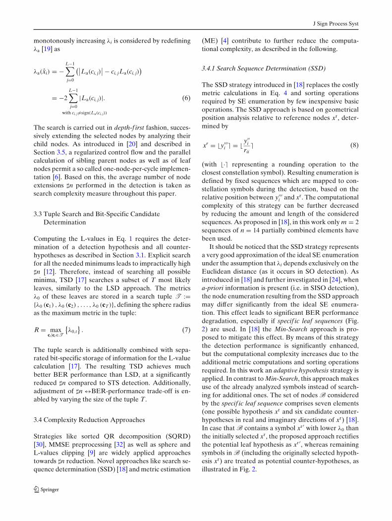
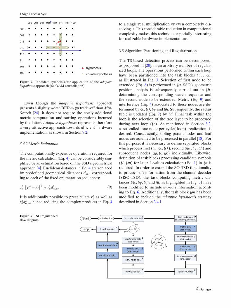
It should be noticed that the SSD strategy representsa very good approximation of the ideal SE enumerationunder the assumption that λi depends exclusively on theEuclidean distance (as it occurs in SO detection). Asintroduced in [18] and further investigated in [24], whena-priori information is present (i.e. in SISO detection),the node enumeration resulting from the SSD approachmay differ significantly from the ideal SE enumera-tion. This effect leads to significant BER performancedegradation, especially if specif ic leaf sequences (Fig.2) are used. In [18] the Min-Search approach is pro-posed to mitigate this effect. By means of this strategythe detection performance is significantly enhanced,but the computational complexity increases due to theadditional metric computations and sorting operationsrequired. In this work an adaptive hypothesis strategy isapplied. In contrast to Min-Search, this approach makesuse of the already analyzed symbols instead of search-ing for additional ones. The set of nodes B consideredby the specif ic leaf sequence comprises seven elements(one possible hypothesis xr and six candidate counter-hypotheses in real and imaginary directions of xr) [18].In case that B contains a symbol xr′ with lower λ0 thanthe initially selected xr, the proposed approach rectifiesthe potential leaf hypothesis as xr′, whereas remainingsymbols in B (including the originally selected hypoth-esis xr) are treated as potential counter-hypotheses, asillustrated in Fig. 2.
J Sign Process Syst
xr
xr
Figure 2 Candidate symbols after application of the adaptivehypothesis approach (64-QAM constellation).
Even though the adaptive hypothesis approachpresents a slightly worse BER↔ �n trade-off than Min-Search [24], it does not require the costly additionalmetric computation and sorting operations incurredby the latter. Adaptive hypothesis represents thereforea very attractive approach towards efficient hardwareimplementation, as shown in Section 7.2.
3.4.2 Metric Estimation
The computationally expensive operations required forthe metric calculation (Eq. 4) can be considerably sim-plified by an estimation based on the SSD’s geometricalapproach [4]. Euclidean distances in Eq. 4 are replacedby predefined geometrical distances dm,n correspond-ing to each of the fixed enumeration sequences:
r2ii
∥∥y′′′
i − xi∥∥2 ≈ r2
iid2m,n. (9)
It is additionally possible to precalculate r2ii as well as
r2iid
2m,n, hence reducing the complex products in Eq. 4
to a single real multiplication or even completely dis-solving it. This considerable reduction in computationalcomplexity makes this technique especially interestingfor realizable hardware implementations.
3.5 Algorithm Partitioning and Regularization
The TS-based detection process can be decomposed,as proposed in [20], in an arbitrary number of regular-ized loops. The operations performed within each loophave been partitioned into the task blocks §a . . . §n,as illustrated in Fig. 3. Selection of first node to beextended (Eq. 8) is performed in §a. SSD’s geometricposition analysis is subsequently carried out in §b ,determining the corresponding search sequence andthe second node to be extended. Metric (Eq. 9) andinterference (Eq. 4) associated to these nodes are de-termined by §c, § f, §g and §h. Subsequently, the radiustuple is updated (Eq. 7) by §d. Final task within theloop is the selection of the tree layer to be processedduring next loop (§e). As mentioned in Section 3.2,a so called one-node-per-cycle(-loop) realization isdesired. Consequently, sibling parent nodes and leafnodes are assumed to be processed in parallel [18]. Forthis purpose, it is necessary to define separated blockswhich process first (§a, §c, § f ), second (§b , §g, §h) andsubsequent nodes (§i, § j, §k) individually. Likewise,definition of task blocks processing candidate symbols(§l, §m) for later L-values calculation (Eq. 1) in §n isrequired. In order to extend the SO-TSD functionalityto process soft-information from the channel decoder(SISO-TSD), the task blocks computing metric dis-tances (§c, §g, § j and §l, as highlighted in Fig. 3) havebeen modified to include a-priori information accord-ing to Eq. 6. Additionally, the task block §m has beenmodified to include the adaptive hypothesis strategydescribed in Section 3.4.1.
Figure 3 TSD regularizedflow diagram.
candidate calc.
i == Nt?yes
Start
metric det.(1st. node)
no
Stop
initialization
interference calc.(1st. node)
metric det.(2nd. node)
interference calc.(2nd. node)
1st. node selection2nd. Node sel. /
search sequence det.
radius updatetree layer det.
Nth. node sel.
metric det.(Nth. node)
interference calc.(Nth. node)
candidate update
L-value calc.
a b
f
c
g
hi
j
k
l
m #n
de
n
J Sign Process Syst
4 Fixed-Point Representation
Fixed-point arithmetic is commonly applied in orderto limit the latency and hardware resources requiredin a practical implementation. However, overflow andquantization errors incurred due to the inherent limitedprecision typically lead to BER performance degrada-tion in the context of MIMO detection. It is there-fore necessary to define the bit-resolution appropri-ately, according to the trade-off between BER perfor-mance and hardware complexity. In [3] a maximumword width of 8 bits3 was proposed, whereas ∼ 0.3 dBSNR loss has to be accepted. In this work, suitablefixed-point representation of La(ci, j) has been addi-tionally investigated and required considerations takeninto account, as described throughout the followingsections.
4.1 Normalization
As investigated in [3], parameters involved in Eq. 1and hence in Eq. 4 (y′
i, R = {rii, rij}i �= j and La(ci, j), withi, j = {1, . . . , (NT − 1)}) possess a dynamic range fluctuatingwith the received energy Er. In order to define fixedranges, independent of transmission conditions, elim-ination of Er dependency is required. For this pur-pose, a scaling factor sf = f
√Er (with f represent-
ing a constant factor) is utilized to normalize pa-rameters rii = rii/sf and La(ci, j) = La(ci, j)/s2
f , leadingto λi = λi/s2
f and Eq. 1 is modified as L(cm,l|y
) =L
(cm,l|y
)/s2
f . Concerning y′i and rij, normalization with
sf is not necessary since application of the SSD strategy(Eq. 8) eliminates the energy dependency. A certainscaling factor f ′ is nevertheless required in order toaccommodate their dynamic range to the proposed8-bit quantization. Based on this, y = y′
i/ f ′ and rij =rij/ f ′ are additionally defined. To ensure flexibilityof the proposed detector implementation, fixed-pointrepresentation has to be additionally independent ofthe system configuration. For this purpose, adjust-ing f and f ′ according to the transmission schemeis proposed [3], as shown in Table 1.4 As a result,definition of different fixed-point representations de-
3Integer and fractional word lengths have been individually de-termined for each of the variables involved in the detection.Integer word lengths have been selected to cover the variablesrange, while fractional lengths have been determined based onBER performance analysis through simulations. Further detailscan be found in [16].4Values determined through simulation for the given systemmodel.
Table 1 Scaling factors f and f ′, to enable flexibility of theproposed fixed-point representation.
Q 4 16 64
f 12 6 3f ′ 8 16 32
pending on transmission characteristics (as e.g. in [27])is avoided. By applying the described normalization,8-bit fixed-point representation is enabled, indepen-dent of transmission conditions and adaptable to dif-ferent NT and Q by simple adjustment of f and f ′. Theresulting detector presents lower hardware complexityand higher flexibility than comparable sphere detector(SD) realizations [21, 27], typically requiring greaterprecision (10–16 bits) to achieve comparable BERperformance.
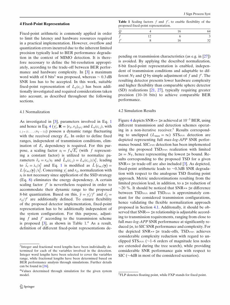
4.2 Simulation Results
Figure 4 depicts SNR↔ �n achieved at 10−5 BER, usingdifferent transmission and detection schemes operat-ing in a non-iterative receiver.5 Results correspond-ing to unclipped (Lmax = ∞) STS(FLP) detection aredepicted representing full max-log-APP SNR perfor-mance bound. SIC(FXP) detection has been implementedusing the proposed TSD(FXP) realization with limited�n = NT, hence representing the lowest �n bound. Re-sults corresponding to the proposed TSD for a givenSNR↔ �n trade-off are also included [3]. As depicted,fixed-point arithmetic leads to ∼0.3dB SNR degrada-tion with respect to the analogous TSD floating pointapproach. Metric underestimations resulting from thelimited precision lead, in addition, to a �n reduction of∼20 %. It should be noticed that SNR↔ �n differencebetween TSD(FLP) and TSD(FXP) is approximately con-stant for the considered transmission configurations,hence validating the flexible normalization approachproposed in Section 4.1. Additonally, it should be ob-served that SNR↔ �n relationship is adjustable accord-ing to transmission requirements, ranging from close tofull max-log-APP SNR performance at significantly re-duced �n, to SIC SNR performance and complexity. Forthe depicted SNR↔ �n trade-offs, TSD(FXP) achievesconsiderable complexity reduction with regard to un-clipped STS(FLP) (∼1–6 orders of magnitude less nodesare extended during the tree search), while providingconsiderable SNR performance gain with respect toSIC (∼4dB in most of the considered scenarios).
5FLP denotes floating point, while FXP stands for fixed point.
J Sign Process Syst
4 6 8 10 12 14 16 18 20100
101
102
103
104
105
106
107
108
109
Eb/N0 (dB)
#n
STS(uncl.), ZF − FLPTSD−SSD−ME, MMSE − FLPTSD−SSD−ME, MMSE − FXPSIC (TSD−based), MMSE − FXP
T=4
4x416QAM
4x464QAM
2x264QAM4x4
4QAM
T=8
8x864QAM
T=16
T=16
T=8
T
MM
T=1T
M
T=T=8T 8T 8
AMM
Figure 4 �n required for 10−5 BER, corresponding to differenttransmission and detection schemes (It = 1).
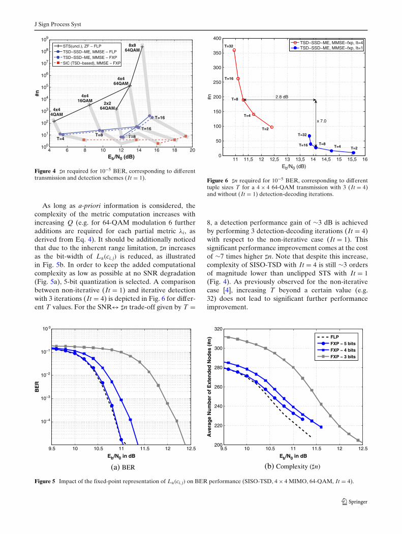
As long as a-priori information is considered, thecomplexity of the metric computation increases withincreasing Q (e.g. for 64-QAM modulation 6 furtheradditions are required for each partial metric λi, asderived from Eq. 4). It should be additionally noticedthat due to the inherent range limitation, �n increasesas the bit-width of La(ci, j) is reduced, as illustratedin Fig. 5b. In order to keep the added computationalcomplexity as low as possible at no SNR degradation(Fig. 5a), 5-bit quantization is selected. A comparisonbetween non-iterative (It = 1) and iterative detectionwith 3 iterations (It = 4) is depicted in Fig. 6 for differ-ent T values. For the SNR↔ �n trade-off given by T =
11 11,5 12 12,5 13 13,5 14 14,5 15 15,5 160
50
100
150
200
250
300
350
400
Eb/N0 (dB)
#n
TSD−SSD−ME, MMSE−fxp, It=4TSD−SSD−ME, MMSE−fxp, It=1T=32
T=16
T=8
T=4
T=2
T=32
T=16 T=8T=4 T=2
2.8 dB
x 7.0
Figure 6 �n required for 10−5 BER, corresponding to differenttuple sizes T for a 4 × 4 64-QAM transmission with 3 (It = 4)and without (It = 1) detection-decoding iterations.
8, a detection performance gain of ∼3 dB is achievedby performing 3 detection-decoding iterations (It = 4)with respect to the non-iterative case (It = 1). Thissignificant performance improvement comes at the costof ∼7 times higher �n. Note that despite this increase,complexity of SISO-TSD with It = 4 is still ∼3 ordersof magnitude lower than unclipped STS with It = 1(Fig. 4). As previously observed for the non-iterativecase [4], increasing T beyond a certain value (e.g.32) does not lead to significant further performanceimprovement.
9.5 10 10.5 11 11.5 12 12.5
10−4
10−3
10−2
10−1
10 0
BE
R
Eb/N0 in dB
9.5 10 10.5 11 11.5 12 12.5200
220
240
260
280
300
320
Eb/N0 in dB
Ave
rag
e N
um
ber
of
Ext
end
ed N
od
es (
#n)
FLP
FXP − 5 bitsFXP − 4 bits
FXP − 3 bits
(a) BER (b) Complexity ( n)
Figure 5 Impact of the fixed-point representation of La(ci, j) on BER performance (SISO-TSD, 4 × 4 MIMO, 64-QAM, It = 4).
J Sign Process Syst
5 Computational Complexity and Critical PathEstimation
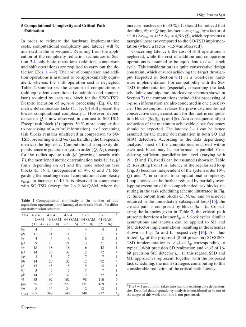
In order to estimate the hardware implementationcosts, computational complexity and latency will beanalyzed in the subsequent. Resulting from the appli-cation of the complexity reduction techniques in Sec-tion 3.4 only basic operations (addition, comparisonand shift operations) are required to carry out the de-tection (Eqs. 1, 4–9). The cost of comparison and addi-tion operations is assumed to be approximately equiv-alent, whereas the shift operation cost is neglegted.Table 2 summarizes the amount of computations c(add-equivalent operations, i.e. addition and compar-ison) required by each task block for the SISO-TSD.Despite inclusion of a-priori processing (Eq. 6), themetric determination tasks (§c, §g, § j) still present thelowest computational complexity c. However, depen-dance on Q is now observed, in contrast to SO-TSD.Except task block §l (approx. 50 % more complex dueto processing of a-priori information), c of remainingtask blocks remains unaffected in comparison to SO-TSD, presenting §l and §m (i.e. handling the bit-specificmetrics) the highest c. Computational complexity de-pends hence in general on system order (Q, NT), exceptfor the radius update task §d (growing linearly withT), the mentioned metric determination tasks §c, §g, § j(only depending on Q) and the node selection taskblocks §a, §b , §i (independent of NT, Q and T). Re-garding the resulting overall computational complexityctotal, an increase of 10 % is observed in comparisonwith SO-TSD (except for 2 × 2 64-QAM, where the
Table 2 Computational complexity c (in number of add-equivalent operations) and latency of each task block, for differ-ent transmission schemes.
Task 4 × 4 4 × 4 4 × 4 2 × 2 8 × 8 l4-QAM 16-QAM 64-QAM 64-QAM 64-QAM(T = 4) (T = 8) (T = 16) (T = 8) (T = 16)
§a 4 4 4 4 4 1§b 11 11 11 11 11 1§c 4 6 8 8 8 1§d 9 13 21 13 21 1§e 18 18 18 6 42 1§ f 14 20 32 12 72 4§g 3 5 7 7 7 1§h 14 20 32 12 72 4§i 15 15 15 15 15 1§ j 3 5 7 7 7 1§k 14 20 32 12 72 4§l 33 62 102 98 110 6§m 55 125 227 131 419 1§n 8 16 24 12 12 1ctotal 205 340 540 348 872 lcp
increase reaches up to 30 %). It should be noticed thatdoubling NT or Q implies increasing ctotal by a factor of∼1.6 (�ctotal ≈ 4/5�NT ≈ 4/5�Q), which represents amarginal increase compared to the SO-TSD implemen-tation (where a factor ∼1.5 was observed).
Concerning latency l, the cost of shift operations isneglected, while the cost of addition and comparisonoperations is assumed to be equivalent to l = 1 clockcycle. This consideration is a quite conservative designconstraint, which ensures achieving the target through-put (depicted in Section 8.1) in a worst-case hard-ware implementation. For compatibility with the SO-TSD implementation (especially concerning the taskscheduling and pipeline-interleaving schemes shown inSection 7) the computations included for processing ofa-priori information are also condensed in one clock cy-cle. This assumption relaxes the previously mentionedconservative design constraint for the metric computa-tion blocks (§c, §g, § j and §l). As a consequence, slightreduction of the maximum achievable clock frequencyshould be expected. The latency l = 1 can be henceassumed for the metric determination in both SO andSISO detectors. According to the data dependencyanalysis,6 most of the computations enclosed withineach task block may be performed in parallel. Con-sidering sufficient parallelization level (varying withNT, Q and T), fixed l can be assumed (shown in Table2). Resulting from this, latency of the regularized loop(Fig. 3) becomes independent of the system order (NT,Q) and T, in contrast to computational complexity.Loop latency can be further reduced by partially over-lapping execution of the comprehended task blocks, re-sulting in the task scheduling scheme illustrated in Fig.7c. Since output from blocks §h, §l, §m and §n is neverrequired in the immediately subsequent loop [16], thecritical path is comprised by blocks §a − §e. Consid-ering the latencies given in Table 2, the critical pathpresents therefore a latency lcp = 5 clock cycles. Similarassumptions and analysis can be applied to SD andSIC detector implementations, resulting in the schemesshown in Fig. 7a and b, respectively [16]. As illus-trated, lcp of the proposed (8-bit precision) SO/SISO-TSD implementation is <1/4 of lcp corresponding totypical 16-bit precision SD realization and <1/2 of 16-bit precision SIC detector lcp. In this regard, SSD andME approaches represent, together with the proposedtask scheduling, the main strategies contributing to thisconsiderable reduction of the critical path latency.
6The l = 1 assumption takes into account existing data dependen-cies. Detailed data dependency analysis is considered to be out ofthe scope of this work and thus is not presented.
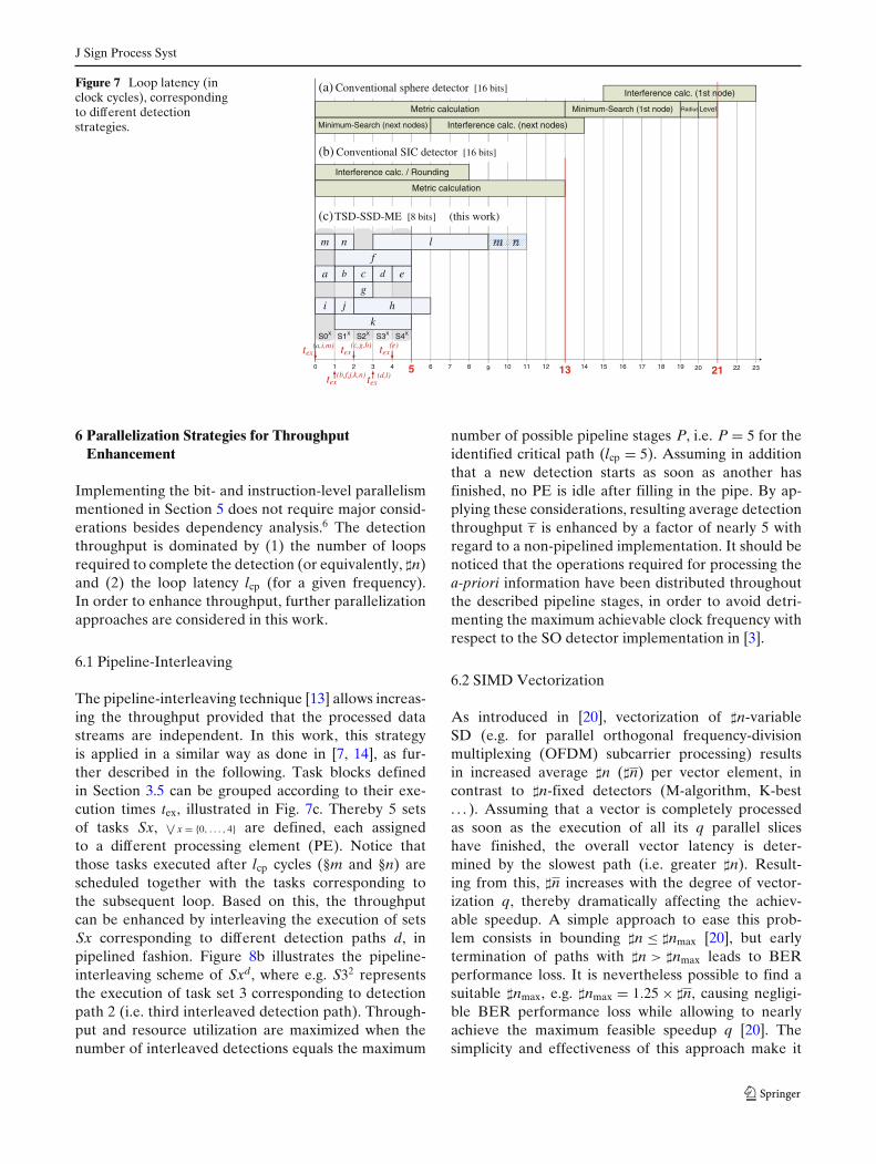
J Sign Process Syst
Figure 7 Loop latency (inclock cycles), correspondingto different detectionstrategies.
179
S4XS3XS2XS1XS0X
191816151411 121087643210
(a) Conventional sphere detector [16 bits]
(b) Conventional SIC detector [16 bits]
Interference calc. (next nodes)Minimum-Search (next nodes)
Metric calculation
Interference calc. / Rounding
Metric calculation
c d
j
g
k
i
ba e
h
f
lnm
Minimum-Search (1st node)
232220
Interference calc. (1st node)
tex(a,i,m)
tex(b,f,j,k,n)
tex(c,g,h)
tex(d,l)
tex(e)
RadiusLevel
21135
(c)TSD-SSD-ME [8 bits] (this work)
6 Parallelization Strategies for ThroughputEnhancement
Implementing the bit- and instruction-level parallelismmentioned in Section 5 does not require major consid-erations besides dependency analysis.6 The detectionthroughput is dominated by (1) the number of loopsrequired to complete the detection (or equivalently, �n)and (2) the loop latency lcp (for a given frequency).In order to enhance throughput, further parallelizationapproaches are considered in this work.
6.1 Pipeline-Interleaving
The pipeline-interleaving technique [13] allows increas-ing the throughput provided that the processed datastreams are independent. In this work, this strategyis applied in a similar way as done in [7, 14], as fur-ther described in the following. Task blocks definedin Section 3.5 can be grouped according to their exe-cution times tex, illustrated in Fig. 7c. Thereby 5 setsof tasks Sx, ∨
x = {0, . . . , 4} are defined, each assignedto a different processing element (PE). Notice thatthose tasks executed after lcp cycles (§m and §n) arescheduled together with the tasks corresponding tothe subsequent loop. Based on this, the throughputcan be enhanced by interleaving the execution of setsSx corresponding to different detection paths d, inpipelined fashion. Figure 8b illustrates the pipeline-interleaving scheme of Sxd, where e.g. S32 representsthe execution of task set 3 corresponding to detectionpath 2 (i.e. third interleaved detection path). Through-put and resource utilization are maximized when thenumber of interleaved detections equals the maximum
number of possible pipeline stages P, i.e. P = 5 for theidentified critical path (lcp = 5). Assuming in additionthat a new detection starts as soon as another hasfinished, no PE is idle after filling in the pipe. By ap-plying these considerations, resulting average detectionthroughput τ is enhanced by a factor of nearly 5 withregard to a non-pipelined implementation. It should benoticed that the operations required for processing thea-priori information have been distributed throughoutthe described pipeline stages, in order to avoid detri-menting the maximum achievable clock frequency withrespect to the SO detector implementation in [3].
6.2 SIMD Vectorization
As introduced in [20], vectorization of �n-variableSD (e.g. for parallel orthogonal frequency-divisionmultiplexing (OFDM) subcarrier processing) resultsin increased average �n (�n) per vector element, incontrast to �n-fixed detectors (M-algorithm, K-best. . . ). Assuming that a vector is completely processedas soon as the execution of all its q parallel sliceshave finished, the overall vector latency is deter-mined by the slowest path (i.e. greater �n). Result-ing from this, �n increases with the degree of vector-ization q, thereby dramatically affecting the achiev-able speedup. A simple approach to ease this prob-lem consists in bounding �n ≤ �nmax [20], but earlytermination of paths with �n > �nmax leads to BERperformance loss. It is nevertheless possible to find asuitable �nmax, e.g. �nmax = 1.25 × �n, causing negligi-ble BER performance loss while allowing to nearlyachieve the maximum feasible speedup q [20]. Thesimplicity and effectiveness of this approach make it
J Sign Process Syst
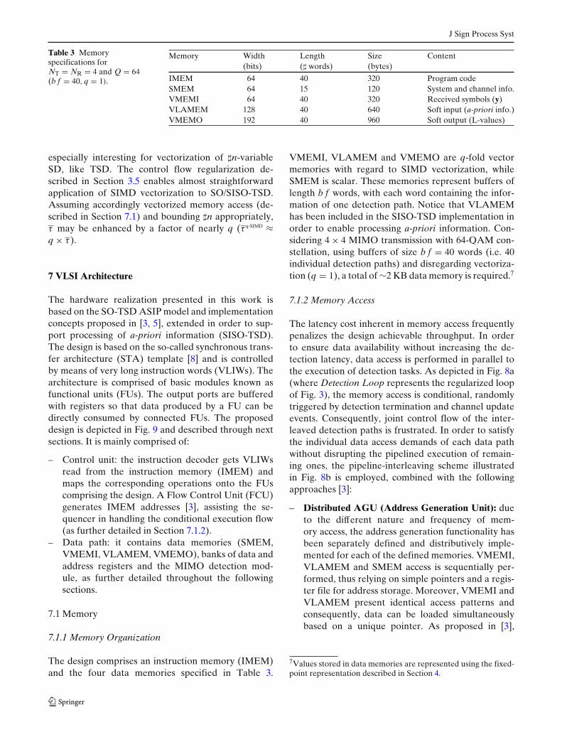
Table 3 Memoryspecifications forNT = NR = 4 and Q = 64(b f = 40, q = 1).
Memory Width Length Size Content(bits) (� words) (bytes)
IMEM 64 40 320 Program codeSMEM 64 15 120 System and channel info.VMEMI 64 40 320 Received symbols (y)VLAMEM 128 40 640 Soft input (a-priori info.)VMEMO 192 40 960 Soft output (L-values)
especially interesting for vectorization of �n-variableSD, like TSD. The control flow regularization de-scribed in Section 3.5 enables almost straightforwardapplication of SIMD vectorization to SO/SISO-TSD.Assuming accordingly vectorized memory access (de-scribed in Section 7.1) and bounding �n appropriately,τ may be enhanced by a factor of nearly q (τ q-SIMD ≈q × τ ).
7 VLSI Architecture
The hardware realization presented in this work isbased on the SO-TSD ASIP model and implementationconcepts proposed in [3, 5], extended in order to sup-port processing of a-priori information (SISO-TSD).The design is based on the so-called synchronous trans-fer architecture (STA) template [8] and is controlledby means of very long instruction words (VLIWs). Thearchitecture is comprised of basic modules known asfunctional units (FUs). The output ports are bufferedwith registers so that data produced by a FU can bedirectly consumed by connected FUs. The proposeddesign is depicted in Fig. 9 and described through nextsections. It is mainly comprised of:
– Control unit: the instruction decoder gets VLIWsread from the instruction memory (IMEM) andmaps the corresponding operations onto the FUscomprising the design. A Flow Control Unit (FCU)generates IMEM addresses [3], assisting the se-quencer in handling the conditional execution flow(as further detailed in Section 7.1.2).
– Data path: it contains data memories (SMEM,VMEMI, VLAMEM, VMEMO), banks of data andaddress registers and the MIMO detection mod-ule, as further detailed throughout the followingsections.
7.1 Memory
7.1.1 Memory Organization
The design comprises an instruction memory (IMEM)and the four data memories specified in Table 3.
VMEMI, VLAMEM and VMEMO are q-fold vectormemories with regard to SIMD vectorization, whileSMEM is scalar. These memories represent buffers oflength b f words, with each word containing the infor-mation of one detection path. Notice that VLAMEMhas been included in the SISO-TSD implementation inorder to enable processing a-priori information. Con-sidering 4 × 4 MIMO transmission with 64-QAM con-stellation, using buffers of size b f = 40 words (i.e. 40individual detection paths) and disregarding vectoriza-tion (q = 1), a total of ∼2 KB data memory is required.7
7.1.2 Memory Access
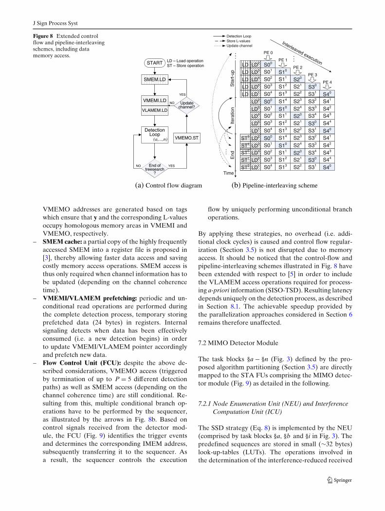
The latency cost inherent in memory access frequentlypenalizes the design achievable throughput. In orderto ensure data availability without increasing the de-tection latency, data access is performed in parallel tothe execution of detection tasks. As depicted in Fig. 8a(where Detection Loop represents the regularized loopof Fig. 3), the memory access is conditional, randomlytriggered by detection termination and channel updateevents. Consequently, joint control flow of the inter-leaved detection paths is frustrated. In order to satisfythe individual data access demands of each data pathwithout disrupting the pipelined execution of remain-ing ones, the pipeline-interleaving scheme illustratedin Fig. 8b is employed, combined with the followingapproaches [3]:
– Distributed AGU (Address Generation Unit): dueto the different nature and frequency of mem-ory access, the address generation functionality hasbeen separately defined and distributively imple-mented for each of the defined memories. VMEMI,VLAMEM and SMEM access is sequentially per-formed, thus relying on simple pointers and a regis-ter file for address storage. Moreover, VMEMI andVLAMEM present identical access patterns andconsequently, data can be loaded simultaneouslybased on a unique pointer. As proposed in [3],
7Values stored in data memories are represented using the fixed-point representation described in Section 4.
J Sign Process Syst
Figure 8 Extended controlflow and pipeline-interleavingschemes, including datamemory access.
(a) Control flow diagram (b) Pipeline-interleaving scheme
S30
S20
S21
S11
S32
S12
S02
S33
S23S13
S03
S40
S41
S42
S43
Sta
rt-u
pIte
ratio
n
Interleaved execution
Time
S23
S13
S03
S31S22
PE 0
PE 1
PE 2
PE 3
PE 4
...
S24
S14
S04
S34
S24
S14S04
S44
S43S34
S44
S10
S00
S01
End
...
S30S20
S40
S10
S00
S02
S03
S04
S01
S11
S12
S13
S21
S22 S31
LD0
LD1
LD2
LD4
LD3
LD0
LD1
LD2
LD4
LD3
LD0
LD
LD
LD LD4
ST3
ST0
ST4
ST1
ST2
S20
S21
S10
S30
S32
S31
S33
S40
S41
S42
S22
S11
S12
S02
S00
S01LD3LD
LD LD2
...
Update channelStore L-valuesDetection Loop
LD1
START
SMEM.LD
Detection Loop
(a,...,n)
NO YES
VMEMI.LD
VMEMO.ST
Update NO
YES
LD – Load operationST – Store operation
VLAMEM.LD
treesearch?
End of
channel?Update
VMEMO addresses are generated based on tagswhich ensure that y and the corresponding L-valuesoccupy homologous memory areas in VMEMI andVMEMO, respectively.
– SMEM cache: a partial copy of the highly frequentlyaccessed SMEM into a register file is proposed in[3], thereby allowing faster data access and savingcostly memory access operations. SMEM access isthus only required when channel information has tobe updated (depending on the channel coherencetime).
– VMEMI/VLAMEM prefetching: periodic and un-conditional read operations are performed duringthe complete detection process, temporary storingprefetched data (24 bytes) in registers. Internalsignaling detects when data has been effectivelyconsumed (i.e. a new detection begins) in orderto update VMEMI/VLAMEM pointer accordinglyand prefetch new data.
– Flow Control Unit (FCU): despite the above de-scribed considerations, VMEMO access (triggeredby termination of up to P = 5 different detectionpaths) as well as SMEM access (depending on thechannel coherence time) are still conditional. Re-sulting from this, multiple conditional branch op-erations have to be performed by the sequencer,as illustrated by the arrows in Fig. 8b. Based oncontrol signals received from the detector mod-ule, the FCU (Fig. 9) identifies the trigger eventsand determines the corresponding IMEM address,subsequently transferring it to the sequencer. Asa result, the sequencer controls the execution
flow by uniquely performing unconditional branchoperations.
By applying these strategies, no overhead (i.e. addi-tional clock cycles) is caused and control flow regular-ization (Section 3.5) is not disrupted due to memoryaccess. It should be noticed that the control-flow andpipeline-interleaving schemes illustrated in Fig. 8 havebeen extended with respect to [5] in order to includethe VLAMEM access operations required for process-ing a-priori information (SISO-TSD). Resulting latencydepends uniquely on the detection process, as describedin Section 8.1. The achievable speedup provided bythe parallelization approaches considered in Section 6remains therefore unaffected.
7.2 MIMO Detector Module
The task blocks §a − §n (Fig. 3) defined by the pro-posed algorithm partitioning (Section 3.5) are directlymapped to the STA FUs comprising the MIMO detec-tor module (Fig. 9) as detailed in the following.
7.2.1 Node Enumeration Unit (NEU) and InterferenceComputation Unit (ICU)
The SSD strategy (Eq. 8) is implemented by the NEU(comprised by task blocks §a, §b and §i in Fig. 3). Thepredefined sequences are stored in small (∼32 bytes)look-up-tables (LUTs). The operations involved inthe determination of the interference-reduced received
J Sign Process Syst
Figure 9 MIMO detectorarchitecture.
data path
No
de
En
um
erat
ion
Met
ric
Co
mp
uta
tio
n
Inte
rfer
ence
Co
mp
uta
tio
n
Rad
ius
Ad
min
.
Lev
elD
eter
min
atio
n
control path
Sequencer
IMEM
Instr.decoder
FlowControl
Unit (FCU)
Soft-output Admin. & L-value Comp.
Synchronous-Transfer Network
Syn
chro
no
us-T
ransfer
Netw
ork
data memory
SMEM
VMEMI
VLAMEM
VMEMO
Addr. reg. bank
Data reg. bank
signal y′′ (Eq. 5) are performed in the ICU (comprisedby task blocks § f , §h and §k).
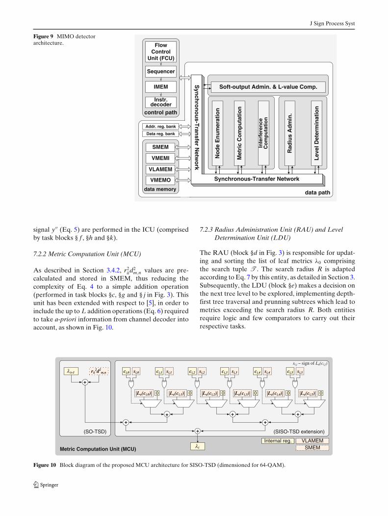
7.2.2 Metric Computation Unit (MCU)
As described in Section 3.4.2, r2iid
2m,n values are pre-
calculated and stored in SMEM, thus reducing thecomplexity of Eq. 4 to a simple addition operation(performed in task blocks §c, §g and § j in Fig. 3). Thisunit has been extended with respect to [5], in order toinclude the up to L addition operations (Eq. 6) requiredto take a-priori information from channel decoder intoaccount, as shown in Fig. 10.
7.2.3 Radius Administration Unit (RAU) and LevelDetermination Unit (LDU)
The RAU (block §d in Fig. 3) is responsible for updat-ing and sorting the list of leaf metrics λ0 comprisingthe search tuple T . The search radius R is adaptedaccording to Eq. 7 by this entity, as detailed in Section 3.Subsequently, the LDU (block §e) makes a decision onthe next tree level to be explored, implementing depth-first tree traversal and prunning subtrees which lead tometrics exceeding the search radius R. Both entitiesrequire logic and few comparators to carry out theirrespective tasks.
λ i+1 rii2d2
m,n
+
ci,0 si,0
|La(ci,0)| 0
ci,1 si,1
|La(ci,1)|
ci,2 si,2
|La(ci,2)|
ci,3 si,3
|La(ci,3)|
ci,4 si,4
|La(ci,4)|
ci,5 si,5
|La(ci,5)|
+ + +
++
+
λ i
Internal reg. VLAMEMSMEM
(SO-TSD) (SISO-TSD extension)
si,j sign of La(ci,j)
Metric Computation Unit (MCU)
0 0 0 0 0
Figure 10 Block diagram of the proposed MCU architecture for SISO-TSD (dimensioned for 64-QAM).
J Sign Process Syst
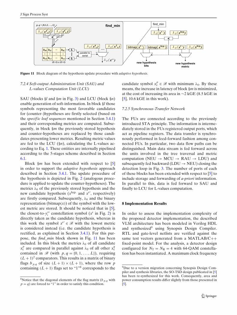
Figure 11 Block diagram of the hypothesis update procedure with adaptive hypothesis.
7.2.4 Soft-output Administration Unit (SAU) andL-values Computation Unit (LCU)
SAU (blocks §l and §m in Fig. 3) and LCU (block §n)enable generation of soft-information. In block §l thosesymbols representing the most favorable candidatesfor (counter-)hypotheses are firstly selected (based onthe specif ic leaf sequences mentioned in Section 3.4.1)and their corresponding metrics are computed. Subse-quently, in block §m the previously stored hypothesisand counter-hypotheses are replaced by those candi-dates presenting lower metrics. Resulting metric valuesare fed to the LCU (§n), calculating the L-values ac-cording to Eq. 1. These entities are internally pipelinedaccording to the 5-stages scheme described in Section6.1.
Block §m has been extended with respect to [5]in order to support the adaptive hypothesis approachdescribed in Section 3.4.1. The update procedure ofthe hypothesis is depicted in Fig. 2 (analogous proce-dure is applied to update the counter-hypotheses). Themetrics λ0 of the previously stored hypothesis and thenew candidate hypothesis (xhyp. and xr′, respectively)are firstly compared. Subsequently, λ0 and the binaryrepresentation (bitmap(x)) of the symbol with the low-est metric are stored. It should be noticed that in [5],the closest-to-y′′′
i constellation symbol (xr in Fig. 2) isdirectly taken as the candidate hypothesis, whereas inthis work the symbol xr′ ∈ B with the lowest metricis considered instead (i.e. the candidate hypothesis isrectified, as explained in Section 3.4.1). For this pur-pose, the find_min block shown in Fig. 11 has beenincluded. In this block the metrics λ0 of all candidatexp
c are compared in parallel against λ0 of all other xqc
contained in B (with p, q = {0, 1, . . . , L}), requiring(L + 1)2 comparators. This results in a matrix of binaryflags b p,q of size (L + 1) × (L + 1), where the row pcontaining (L + 1) flags set to “1”8 corresponds to the
8Notice that the diagonal elements of the flag matrix (b p,q withp = q) are forced to “1” in order to satisfy this condition.
candidate symbol xpc ∈ B with minimum λ0. By these
means, the increase in latency of block §m is minimized,at the cost of increasing its area in ∼2 kGE (8.5 kGE in[5], 10.6 kGE in this work).
7.2.5 Synchronous-Transfer Network
The FUs are connected according to the previouslyintroduced STA principle. The information is interme-diately stored in the FUs registered output ports, whichact as pipeline registers. The data transfer is synchro-nously performed in feed-forward fashion among con-nected FUs. In particular, two data flow paths can bedistinguished. Main data stream is fed forward acrossthe units involved in the tree traversal and metriccomputation (NEU → MCU → RAU → LDU) andsubsequently fed backward (LDU → NEU) closing thedetection loop in Fig. 3. The number of ports of eachof these blocks has been extended with respect to [5] toinclude storage and forwarding of a-priori information.In parallel to this, data is fed forward to SAU andfinally to LCU for L-values computation.
8 Implementation Results
In order to assess the implementation complexity ofthe proposed detector implementation, the describedVLSI architecture has been modeled in Verilog HDLand synthesized9 using Synopsis Design Compiler.RTL and gate-level netlists are verified against thesame test vectors generated from a MATLAB/C++fixed-point model. For the analysis, a detector designconfigured for NT = NR = 4 with 64-QAM constella-tion has been instantiated. A maximum clock frequency
9Due to a version migration concerning Synopsis Design Com-piler and synthesis libraries, the SO-TSD design publicated in [5]has been re-synthesized for this work. Consequently, area andpower consumption results differ slightly from those presented in[5].
J Sign Process Syst
10.5 11 11.5 12 12.5 13 13.5 14 14.5 15 15.5 160
200
400
600
800
1000
1200
Eb/N0 (dB)
Ave
rage
Thr
ough
put (
Mbp
s)4x4, 64−QAM, @ 454 MHz
SO−TSD (It = 1) SISO−TSD (It = 4) − overall throughputSISO−TSD (It = 4) − throughput per iteration
T=2(112.3 Mbps @ 12.4 dB)
T=32(162.2 Mbps @ 13.85 dB)
T=16(279.4 Mbps @ 13.9 dB)
T=32(30.3 Mbps @ 10.95 dB)
T=8(403.6 Mbps @ 14.1 dB)
T=2(1.1 Gbps @ 15.55 dB)
T=4(681 Mbps @ 14.7 dB)
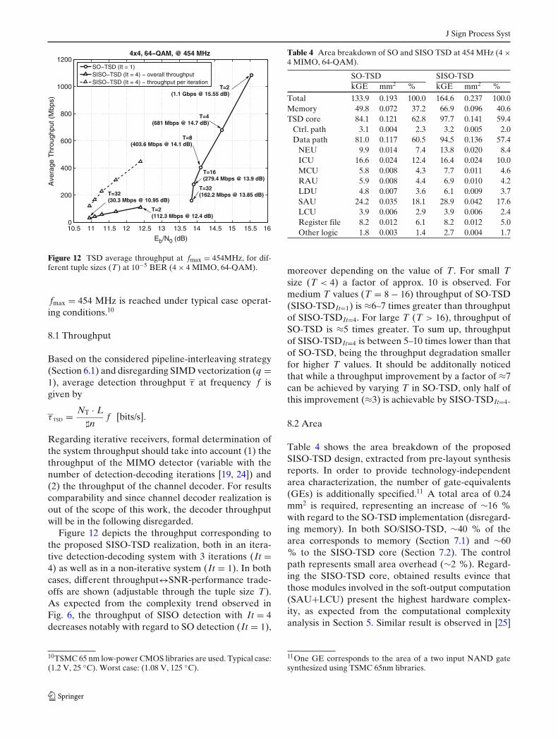
Figure 12 TSD average throughput at fmax = 454MHz, for dif-ferent tuple sizes (T) at 10−5 BER (4 × 4 MIMO, 64-QAM).
fmax = 454 MHz is reached under typical case operat-ing conditions.10
8.1 Throughput
Based on the considered pipeline-interleaving strategy(Section 6.1) and disregarding SIMD vectorization (q =1), average detection throughput τ at frequency f isgiven by
τ TSD = NT · L�n
f [bits/s].
Regarding iterative receivers, formal determination ofthe system throughput should take into account (1) thethroughput of the MIMO detector (variable with thenumber of detection-decoding iterations [19, 24]) and(2) the throughput of the channel decoder. For resultscomparability and since channel decoder realization isout of the scope of this work, the decoder throughputwill be in the following disregarded.
Figure 12 depicts the throughput corresponding tothe proposed SISO-TSD realization, both in an itera-tive detection-decoding system with 3 iterations (It =4) as well as in a non-iterative system (It = 1). In bothcases, different throughput↔SNR-performance trade-offs are shown (adjustable through the tuple size T).As expected from the complexity trend observed inFig. 6, the throughput of SISO detection with It = 4decreases notably with regard to SO detection (It = 1),
10TSMC 65 nm low-power CMOS libraries are used. Typical case:(1.2 V, 25 ◦C). Worst case: (1.08 V, 125 ◦C).
Table 4 Area breakdown of SO and SISO TSD at 454 MHz (4 ×4 MIMO, 64-QAM).
SO-TSD SISO-TSDkGE mm2 % kGE mm2 %
Total 133.9 0.193 100.0 164.6 0.237 100.0Memory 49.8 0.072 37.2 66.9 0.096 40.6TSD core 84.1 0.121 62.8 97.7 0.141 59.4
Ctrl. path 3.1 0.004 2.3 3.2 0.005 2.0Data path 81.0 0.117 60.5 94.5 0.136 57.4
NEU 9.9 0.014 7.4 13.8 0.020 8.4ICU 16.6 0.024 12.4 16.4 0.024 10.0MCU 5.8 0.008 4.3 7.7 0.011 4.6RAU 5.9 0.008 4.4 6.9 0.010 4.2LDU 4.8 0.007 3.6 6.1 0.009 3.7SAU 24.2 0.035 18.1 28.9 0.042 17.6LCU 3.9 0.006 2.9 3.9 0.006 2.4Register file 8.2 0.012 6.1 8.2 0.012 5.0Other logic 1.8 0.003 1.4 2.7 0.004 1.7
moreover depending on the value of T. For small Tsize (T < 4) a factor of approx. 10 is observed. Formedium T values (T = 8 − 16) throughput of SO-TSD(SISO-TSDIt=1) is ≈6–7 times greater than throughputof SISO-TSDIt=4. For large T (T > 16), throughput ofSO-TSD is ≈5 times greater. To sum up, throughputof SISO-TSDIt=4 is between 5–10 times lower than thatof SO-TSD, being the throughput degradation smallerfor higher T values. It should be additonally noticedthat while a throughput improvement by a factor of ≈7can be achieved by varying T in SO-TSD, only half ofthis improvement (≈3) is achievable by SISO-TSDIt=4.
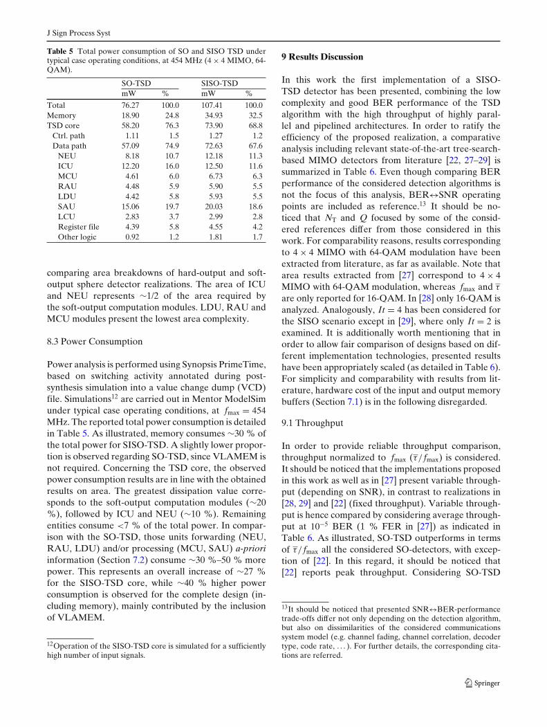
8.2 Area
Table 4 shows the area breakdown of the proposedSISO-TSD design, extracted from pre-layout synthesisreports. In order to provide technology-independentarea characterization, the number of gate-equivalents(GEs) is additionally specified.11 A total area of 0.24mm2 is required, representing an increase of ∼16 %with regard to the SO-TSD implementation (disregard-ing memory). In both SO/SISO-TSD, ∼40 % of thearea corresponds to memory (Section 7.1) and ∼60% to the SISO-TSD core (Section 7.2). The controlpath represents small area overhead (∼2 %). Regard-ing the SISO-TSD core, obtained results evince thatthose modules involved in the soft-output computation(SAU+LCU) present the highest hardware complex-ity, as expected from the computational complexityanalysis in Section 5. Similar result is observed in [25]
11One GE corresponds to the area of a two input NAND gatesynthesized using TSMC 65nm libraries.
J Sign Process Syst
Table 5 Total power consumption of SO and SISO TSD undertypical case operating conditions, at 454 MHz (4 × 4 MIMO, 64-QAM).
SO-TSD SISO-TSDmW % mW %
Total 76.27 100.0 107.41 100.0Memory 18.90 24.8 34.93 32.5TSD core 58.20 76.3 73.90 68.8
Ctrl. path 1.11 1.5 1.27 1.2Data path 57.09 74.9 72.63 67.6
NEU 8.18 10.7 12.18 11.3ICU 12.20 16.0 12.50 11.6MCU 4.61 6.0 6.73 6.3RAU 4.48 5.9 5.90 5.5LDU 4.42 5.8 5.93 5.5SAU 15.06 19.7 20.03 18.6LCU 2.83 3.7 2.99 2.8Register file 4.39 5.8 4.55 4.2Other logic 0.92 1.2 1.81 1.7
comparing area breakdowns of hard-output and soft-output sphere detector realizations. The area of ICUand NEU represents ∼1/2 of the area required bythe soft-output computation modules. LDU, RAU andMCU modules present the lowest area complexity.
8.3 Power Consumption
Power analysis is performed using Synopsis PrimeTime,based on switching activity annotated during post-synthesis simulation into a value change dump (VCD)file. Simulations12 are carried out in Mentor ModelSimunder typical case operating conditions, at fmax = 454MHz. The reported total power consumption is detailedin Table 5. As illustrated, memory consumes ∼30 % ofthe total power for SISO-TSD. A slightly lower propor-tion is observed regarding SO-TSD, since VLAMEM isnot required. Concerning the TSD core, the observedpower consumption results are in line with the obtainedresults on area. The greatest dissipation value corre-sponds to the soft-output computation modules (∼20%), followed by ICU and NEU (∼10 %). Remainingentities consume <7 % of the total power. In compar-ison with the SO-TSD, those units forwarding (NEU,RAU, LDU) and/or processing (MCU, SAU) a-prioriinformation (Section 7.2) consume ∼30 %–50 % morepower. This represents an overall increase of ∼27 %for the SISO-TSD core, while ∼40 % higher powerconsumption is observed for the complete design (in-cluding memory), mainly contributed by the inclusionof VLAMEM.
12Operation of the SISO-TSD core is simulated for a sufficientlyhigh number of input signals.
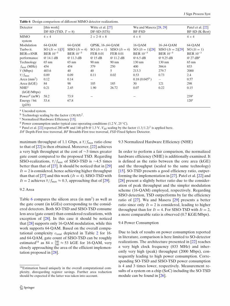
9 Results Discussion
In this work the first implementation of a SISO-TSD detector has been presented, combining the lowcomplexity and good BER performance of the TSDalgorithm with the high throughput of highly paral-lel and pipelined architectures. In order to ratify theefficiency of the proposed realization, a comparativeanalysis including relevant state-of-the-art tree-search-based MIMO detectors from literature [22, 27–29] issummarized in Table 6. Even though comparing BERperformance of the considered detection algorithms isnot the focus of this analysis, BER↔SNR operatingpoints are included as reference.13 It should be no-ticed that NT and Q focused by some of the consid-ered references differ from those considered in thiswork. For comparability reasons, results correspondingto 4 × 4 MIMO with 64-QAM modulation have beenextracted from literature, as far as available. Note thatarea results extracted from [27] correspond to 4 × 4MIMO with 64-QAM modulation, whereas fmax and τ
are only reported for 16-QAM. In [28] only 16-QAM isanalyzed. Analogously, It = 4 has been considered forthe SISO scenario except in [29], where only It = 2 isexamined. It is additionally worth mentioning that inorder to allow fair comparison of designs based on dif-ferent implementation technologies, presented resultshave been appropriately scaled (as detailed in Table 6).For simplicity and comparability with results from lit-erature, hardware cost of the input and output memorybuffers (Section 7.1) is in the following disregarded.
9.1 Throughput
In order to provide reliable throughput comparison,throughput normalized to fmax (τ/ fmax) is considered.It should be noticed that the implementations proposedin this work as well as in [27] present variable through-put (depending on SNR), in contrast to realizations in[28, 29] and [22] (fixed throughput). Variable through-put is hence compared by considering average through-put at 10−5 BER (1 % FER in [27]) as indicated inTable 6. As illustrated, SO-TSD outperforms in termsof τ/ fmax all the considered SO-detectors, with excep-tion of [22]. In this regard, it should be noticed that[22] reports peak throughput. Considering SO-TSD
13It should be noticed that presented SNR↔BER-performancetrade-offs differ not only depending on the detection algorithm,but also on dissimilarities of the considered communicationssystem model (e.g. channel fading, channel correlation, decodertype, code rate, . . . ). For further details, the corresponding cita-tions are referred.
J Sign Process Syst
Table 6 Design comparison of different MIMO detector realizations.
Detector [this work] Witte et al. [27] Wu and Masera [28, 29] Patel et al. [22]DF-SD (TSD, T = 8) DF-SD (STS) BF-FSD BF-SD (K-Best)
MIMO 4 × 4 2 × 2–8 × 8 4 × 4 4 × 4system
Modulation 64-QAM 64-QAM QPSK, 16-,64-QAM 16-QAM 16-,64-QAM 64-QAMTurbo it. SO (It = 1)[5] SISO (It = 4) SO (It = 1) SISO (It = 4) SO (It = 1)[28] SISO (It = 2)[29] SO (It = 1)BER↔SNR BER 10−5 BER 10−5 FER 0.01 FER 0.01 BER 10−5 BER 10−5 BER 10−3
performance @ 14.1 dB @ 11.3 dB @ 15 dB @ 11.2 dB @ 6.5 dB @ 9.25 dB @ 27 dBa
Technology 65 nm 65 nm 90 nm 90 nm 130 nm 130 nm 65 nmfmax (MHz) 454 454 379 250 400 384.6 833τ (Mbps) 403.6 40 40 5 213.3 279.7 2000τ/ fmax 0.89 0.09 0.11 0.02 0.53 0.73 2.4Area (mm2) 0.12 0.14 − 0.18 (0.045b ) − 0.57Area (kGE) 84 98 105 185 30 121 298NHEc 0.21 2.45 1.90 26.72 0.07 0.22 0.15
(kGE/Mbps)Powerd (mW) 58.2 73.9 − − 239e
Energy / bit 53.4 67.8 120e
(pJ/b)
a Uncoded system.b Technology scaling by the factor (130/65)2.c Normalized Hardware Efficiency [15].d Power consumption under typical case operating conditions (1.2 V, 25 ◦C).e Patel et al. [22] reported 280 mW and 140 pJ/b @ 1.3 V, Vdd scaling by the factor (1.3/1.2)2 is applied here.DF Depth-First tree traversal, BF Breadth-First tree traversal, FSD Fixed Sphere Detector.
maximum throughput of 1.1 Gbps, a τ/ fmax ratio closeto that of [22] is then obtained. Moreover, [22] achievesa very high throughput at the cost of ∼3 times greatergate count compared to the proposed TSD. RegardingSISO-realizations, τ/ fmax of SISO-TSD is ∼4.5 timesbetter than that of [27]. It should be noticed that in [29]It = 2 is considered, hence achieving higher throughputthan that of [27] and this work (It = 4). SISO-TSD withIt = 2 achieves τ/ fmax ≈ 0.3, approaching that of [29].
9.2 Area
Table 6 compares the silicon area (in mm2) as well asthe gate count (in kGEs) corresponding to the consid-ered detectors. Both SO-TSD and SISO-TSD consumeless area (gate count) than considered realizations, withexception of [28]. In this case it should be noticedthat [28] supports only 16-QAM modulation, while thiswork supports 64-QAM. Based on the overall compu-tational complexity ctotal depicted in Table 2 for 16-and 64-QAM, gate count of SISO-TSD can be roughlyestimated14 as 84 × 540
340 ≈ 53 kGE for 16-QAM, veryclosely approaching the area of the efficient implemen-tation proposed in [28].
14Estimation based uniquely in the overall computational com-plexity, disregarding register savings. Further area reductionshould be expected if the latter was taken into account.
9.3 Normalized Hardware Efficiency (NHE)
In order to perform a fair comparison, the normalizedhardware efficiency (NHE) is additionally examined. Itis defined as the ratio between the core area (kGE)and the throughput (scaled to the same technology)[15]. SO-TSD presents a good efficiency ratio, outper-forming the implementation in [27]. Patel et al. [22] and[28] present a slightly better ratio due to the consider-ation of peak throughput and the simpler modulationscheme (16-QAM) employed, respectively. RegardingSISO detection, TSD outperforms by far the efficiencyratio of [27]. Wu and Masera [29] presents a betterratio since only It = 2 is considered, leading to higherthroughput than for It = 4. For SISO-TSD with It = 2,a more comparable ratio is observed (0.7 KGE/Mbps).
9.4 Power Consumption
Due to lack of results on power consumption reportedin literature, comparison is here limited to SO-detectorrealizations. The architecture presented in [22] reachesa very high clock frequency (833 MHz) and inher-ently very high (peak) throughput (2000 Mbps), con-sequently leading to high power consumption. Corre-sponding SO-TSD and SISO-TSD power consumptionis 4 and 3 times lower, respectively. Measurement re-sults of a system on a chip (SoC) including the SO-TSDmodule can be found in [26].
J Sign Process Syst
9.5 SISO vs. SO Detectors
As explained in previous sections, the existing SO-TSDimplementation [5] has been extended in this work inorder to enable processing of a-priori information. Incontrast to comparable SISO-detectors ([27, 29]), fmax
of the proposed SISO-TSD realization is not degradedin comparison to the SO-TSD. Likewise, the area in-crease (14 kGE) due to processing of a-priori informa-tion is small (16 %) in comparison to the designs re-ported in literature (∼76 % in [27] and ∼50 % in [29]).Regarding the power consumption (and inherently theenergy per bit), an increase of ∼27 % is observed.As additionally depicted, SISO-TSD achieves 10 timeslower throughput than SO-TSD for the considered T =8. It is nevertheless possible to achieve beyond 100Mbps with It = 4 and more than 1 Gbps with It = 1,by adjusting T of SISO-TSD as described in Section8.1. Additionally, strategies further reducing �n (i.e.further enhancing the throughput) have been recentlyproposed for the SISO-TSD in [24].
10 Conclusion and Future Work
In this work key strategies enabling the first efficientimplementation of the SISO-TSD algorithm have beenpresented. A novel flexible 8-bit fixed-point represen-tation has been utilized, significantly reducing the com-plexity compared to state-of-the-art implementationsrequiring >10 bits (e.g. [27]). Presented regularizationand architectural concepts permit efficient applicationof pipelining and parallelization approaches. The costsof processing a-priori information have been addition-ally analyzed. Considering a 4 × 4 MIMO system with64-QAM, the SISO-TSD implementation presents only16 % larger area and 27 % higher power consump-tion than the previous SO-TSD realization, whereasa SNR gain of up to ∼3.2 dB is provided for It =4. The proposed VLSI design incorporates sophis-ticated concepts to reduce the algorithm computa-tional complexity as well as parallelization strategiesfor throughput enhancement. In combination with thedefinition of a suitable architecture, a high-throughput,low-hardware-complexity and low-power-consumptionimplementation is enabled. Resulting implementationhas been shown to be well suited for iterative receiverarchitectures, outperforming in most aspects similar ap-proaches (e.g. STS-SD) and achieving data rates com-parable to or even greater than less complex and moreparallelizable detection strategies (e.g. K-Best, FSD).The presented realization has in general demonstratedto reduce the hardware cost with regard to comparable
state-of-the-art realizations. The clearly outstandingimplementation results, together with scalability andparallelizability, make the proposed design a very fa-vorable candidate for MIMO detection in a wide rangeof applications.
Future work will target further throughput improve-ment by exploiting SIMD vectorization and possiblyincreasing frequency by optimizing the critical path. Inaddition to this, architecture optimization for furtherreduction of area and power consumption are planned.
Acknowledgements This work has been supported by the Ger-man Federal Ministry of Education and Research (BMBF) undergrant 13N11810.
Open Access This article is distributed under the terms ofthe Creative Commons Attribution License which permits anyuse, distribution, and reproduction in any medium, provided theoriginal author(s) and the source are credited.
References
1. 3GPP LTE, evolved universal terrestrial radio access(E-UTRA), base station (BS) radio transmission andreception. Technical Specification 36.104 Release 10.http://www.3gpp.org.
2. 3GPP LTE, Evolved universal terrestrial radio access(E-UTRA), user equipment (UE) radio transmission andreception. Technical Specification 36.101 Release 10.http://www.3gpp.org.
3. Adeva, E.P., Mennenga, B., Fettweis, G. (2011). ScalableASIP implementation and parallelization of a MIMO spheredetector. In Proceedings of the 11th international conferenceon embedded computer systems: architectures, modeling, andsimulation (SAMOS XI). Samos, Greece.
4. Adeva, E.P., Mennenga, B., Fettweis, G. (2011). Survey onan efficient, low-complex tuple search based sphere detector.In Proceedings of the ieee 34th sarnof f symposium. Princeton,USA.
5. Adeva, E.P., Shah, M.A., Mennenga, B., Fettweis, G. (2011).VLSI architecture for soft-output tuple search sphere decod-ing. In Proceedings of the IEEE workshop on signal process-ing systems (SIPS’11). Beirut, Lebanon.
6. Burg, A., Borgmann, M., Wenk, M., Zellweger, M., Fichtner,W., Bölcskei, H. (2005). VLSI implementation of MIMO de-tection using the sphere decoding algorithm. IEEE Journal ofSolid-State Circuits, 40, 1566–1577.
7. Burg, A., Wenk, M., Fichtner, W. (2006). VLSI implemen-tation of pipelined sphere decoding with early termination.In Proceedings of the 14th european signal processing confer-ence, 2006 (EUSIPCO 2006). Florence, Italy.
8. Cichon, G. (2004). A novel compiler-friendly micro-architecture for rapid development of high-performanceand low-power DSPs. Dissertation, Technische UniversitätDresden.
9. de Jong, Y., & Willink, T. (2005). Iterative tree search de-tection for MIMO wireless systems. IEEE Transactions onCommunications, 53(6), 930–935.
10. Hagenauer, J. (2002). The turbo principal in mobile com-munications. In Proceedings of the international symposiumon information theory and its applications (ISITA’02). Xi’an,China.
J Sign Process Syst
11. Hochwald, B., & ten Brink, S. (2003). Achieving near-capacity on a multiple-antenna channel. IEEE Transactionson Communications, 51, 389–399.
12. Jaldén, J., & Ottersten, B. (2005). Parallel implementationof a soft output sphere decoder. In Proceedings of asilomarconference on signals, systems, and computers.
13. Lee, E., & Messerschmitt, D. (1987). Pipeline interleavedprogrammable DSP’s: architecture. IEEE Transactionson Acoustics, Speech and Signal Processing, 35, 1320–1333.
14. Lee, J. (2006). Area efficient pipelined vlsi implementation oflist sphere decoder. In Proceedings of the Asia-Pacif ic Con-ference on Communications, 2006 (APCC ’06). Busan, Korea.
15. Mahdavi, M., & Shabany, M. (2012). Novel MIMO detec-tion algorithm for high-order constellations in the complexdomain. IEEE Transactions on Very Large Scale Integration(VLSI) Systems. doi:10.1109/TVLSI.2012.2196296.
16. Mennenga, B. (2010). Aufwandsgünstige Detektion inMehrantennensystemen mittels komplexitätsreduzierterBaumsuchverfahren. Dissertation, Technische UniversitätDresden.
17. Mennenga, B., von Borany, A., Fettweis, G. (2009). Complex-ity reduced soft-in soft-out sphere detection based on searchtuples. In Proceedings of the IEEE international conferenceon communications (ICC’09). Dresden, Germany.
18. Mennenga, B., & Fettweis, G. (2009). Search sequence de-termination for tree search based detection algorithms. InProceedings of the IEEE sarnof f symposium 2009. Princeton,USA.
19. Mennenga, B., Fritzsche, R., Fettweis, G. (2009). Iterativesoft-in soft-out sphere detection for MIMO systems. In Pro-ceedings of the IEEE 69th vehicular technology conference,(VTC’09-Spring). Barcelona, Spain.
20. Mennenga, B., Matus, E., Fettweis, G. (2009). Vectorizationof the sphere detection algorithm. In Proceedings of the IEEEinternational symposium on circuits and systems (ISCAS’09).Taipei, Taiwan.
21. Myllyla, M., Cavallaro, J.R., Juntti, M. (2010). Architecturedesign and implementation of the metric first list sphere de-tector algorithm. IEEE Transactions on Very Large ScaleIntegration (VLSI) Systems, 19, 895–899.
22. Patel, D., Smolyakov, V., Shabany, M., Gulak, P. (2010).VLSI iumplementation of a WiMAX/LTE Compliant low-complexity high-throughput soft-output K-best MIMO detec-tor. In Proceedings of the IEEE international symposium oncircuits and systems 2010, (ISCAS’10).
23. Robertson, P., Villebrun, E., Hoeher, P. (1995). A compar-ison of optimal and sub-optimal map decoding algorithmsoperating in the log domain. In Proceedings of the IEEEinternational conference on communications, 1995 (ICC ’95).
24. Seifert, T., Adeva, E.P., Fettweis, G. (2013). Towardscomplexity-reduced soft-input soft-output sphere detection.In Submitted to the 9th international itg conference on sys-tems, communications and coding 2013, (SCC’13). Munich,Germany.
25. Studer, C., Burg, A., Bölcskei, H. (2008). Soft-output spheredecoding: algorithms and VLSI implementation. IEEE Jour-nal on Selected Areas in Communications, 26, 290–300.
26. Winter, M., Kunze, S., Adeva, E.P., Mennenga, B.,Matus, E., Fettweis, G., Eisenreich, H., Ellguth, G., Höppner,S., Scholze, S., Schüffny, R., Kobori, T. (2012). A 335Mb/s3.9mm2 65nm CMOS flexible MIMO detection-decoding en-gine achieving 4g wireless data rates. In Proceedings of the59th international solid-state circuits conference (ISSCC’12).San Francisco, USA.
27. Witte, E.M., Borlenghi, F., Ascheid, G., Leupers, R., Meyr,H. (2010). A scalable VLSI architecture for soft-input soft-
output single tree-search sphere decoding. IEEE Transac-tions on Circuits and Systems II: Express Briefs, 57, 706–710.
28. Wu, B., & Masera, G. (2010). A novel VLSI architecture offixed-complexity sphere decoder. In 13th euromicro confer-ence on digital system design: architectures, methods and tools(DSD).
29. Wu, B., & Masera, G. (2012) Efficient VLSI implementationof soft-input soft-output fixed-complexity sphere decoder. In-stitution of Engineering and Technology (IET) Communica-tions, 6, 1111–1118.
30. Wübben, D., Böhnke, R., Rinas, J., Kühn, V., Kammeyer, K.(2001). Efficient algorithm for decoding layered space-timecodes. Electronics Letters, 37, 1348–1350.
31. Yee, M.S. (2005). Max-log-MAP sphere decoder. In Proceed-ings of the IEEE international conference on acoustics, speech,and signal processing (ICASSP ’05), (Vol. 3).
32. Zimmermann, E., & Fettweis, G. (2006). Unbiased MMSEtree search detection for multiple antenna systems. In Pro-ceedings of the International symposium on wireless personalmultimedia communications (WPMC’06). San Diego, USA.
Esther P. Adeva received her Dipl.-Ing. in Electrical Engineer-ing from the Miguel Hernández University (Spain) in June 2009.She developed her diploma thesis at the Technische UniversitätDresden, focusing on the analysis and implementation of tree-search-based MIMO detection algorithms. She is currently pursu-ing a PhD at the Vodafone Chair and she continues her researchon the exploration of efficient architectures for MIMO detection.
Tobias Seifert received his Dipl.-Ing. in Electrical Engineeringfrom the Technische Universität Dresden in January 2012. In hisdiploma thesis he dealt with implementation aspects of MIMOsphere-search-based detectors for iterative detection-decoding.He is currently pursuing a PhD at the Vodafone Chair andcontinues his research on strategies for efficient MIMO detectionimplementation.
J Sign Process Syst
Gerhard Fettweis earned his Ph.D. from RWTH Aachen in 1990.Thereafter he was at IBM Research and TCSI Inc., California.Since 1994 he is Vodafone Chair Professor at TU Dresden,Germany, with main research interest on wireless transmissionand chip design. He is IEEE Fellow and an honorary doctorateof TU Tampere.