Embed Size (px)
Citation preview
WALCHER GmbH & Co.KG Kraftwerks-, Automatisierungstechnik, Energiemanagement,TransformatorenbauZum Lingeshof 3 D 36124 Eichenzell Tel. +49 (0) 6659 98794-0 Fax. +49 (0) 6659 98794-44
[email protected] http://www.walcher.com
Aggravation with voltage?At photovoltaic plants, long linesor increasing energy consumption?
...then the voltage regulator can help
Regulation of each single phase
Higher capacities on request
Quick regulation from 300-700 ms
34 till 300 kVA
F:/P
rosp
ekt
e/N
etz
regle
r/englis
ch/2
011
Voltage Regulator
WALCHER GmbH & Co.KG Kraftwerks-, Automatisierungstechnik, Energiemanagement,TransformatorenbauZum Lingeshof 3 D 36124 Eichenzell Tel. +49 (0) 6659 98794-0 Fax. +49 (0) 6659 98794-44
[email protected] http://www.walcher.com
8V
230V
8V
230V
8V
230V
8V
230V
8V
230V
8V
230V
Input Output
L
N
230 5V
0,3 0,5 1 1,5 2 3 km
70
60
50
40
30
20
10
kW Three-phase four-wire system 400/231V
50mm
²35mm
²25mm
²16mm
²
Please request our materials,we will gladly assist you.
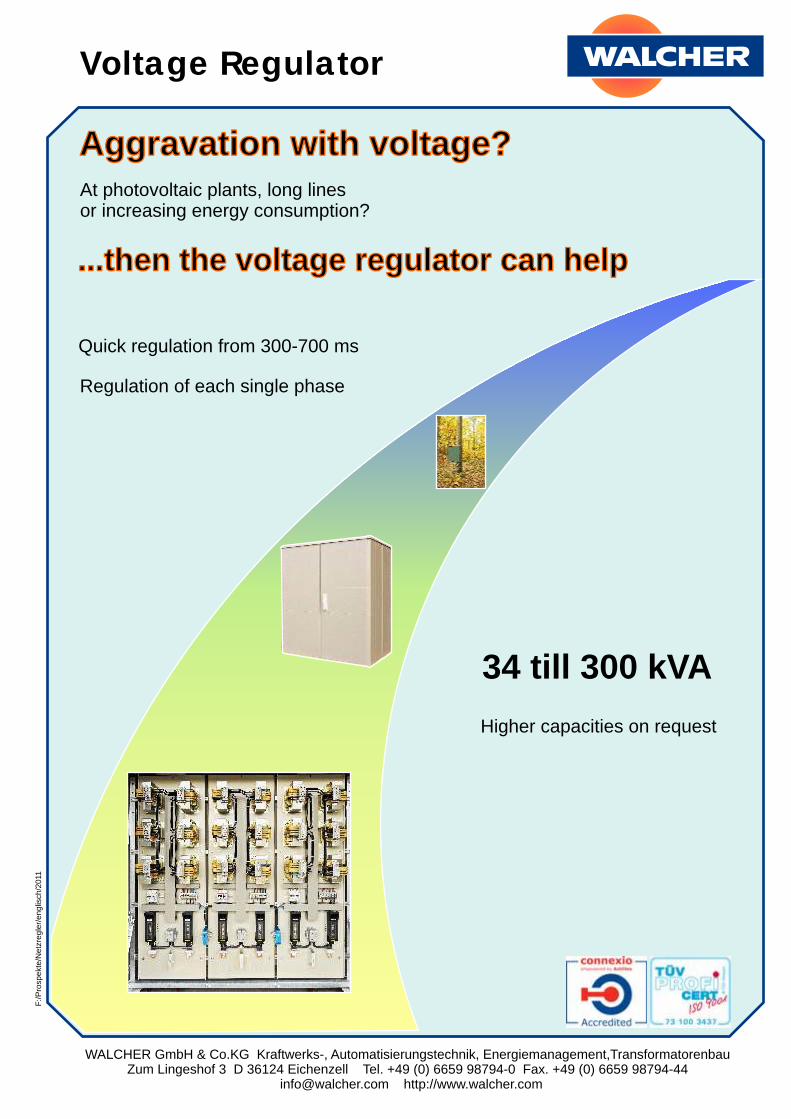
The Voltage Regulator measures and regulates the three phases individually, quickly and independent of one another.
When idle or with an unloaded Voltage Regulator, the transformer stages that are not needed are bypassed. If the output voltage of the Voltage Regulator sinks below 225 volts due to load in the power supply lines, the required number of transformer stages in the affected phase are calculated and activated via the switch protectors. The bypass of the transformer stages to be switched is cancelled and the 230 volt winding is switched to the regulated line voltage.
With excessive input voltage, which can occur due to starpoint shifts especially under load, the Voltage Regulator can regulate the voltage upwards by polarizing the windings, whereby a symmetrical output voltage between 235 and 225 V / phase is always guaranteed.
This diagram depicts four common copper cross sections. The intersection with the km line provides the greatest possible performance for a range of +- 36V / phase, with which a complete regulation of the line voltage still occurs.
Example: for voltage regulator +- 36V/ Phase
Copper cross section q = 25mm²
Line length l = 1 kmIntersection produces P = 31kW
WALCHER GmbH & Co.KG Kraftwerks-, Automatisierungstechnik, Energiemanagement,TransformatorenbauZum Lingeshof 3 D 36124 Eichenzell Tel. +49 (0) 6659 98794-0 Fax. +49 (0) 6659 98794-44
[email protected] http://www.walcher.com
20
kV
0,4
kV
240m NAYY 4*120mm² 180m NAYY 4*120mm² 1230m NAYY 4*185mm²
line voltageregulator
Imax 100A
150A
30A
20A
100A
180V250 500 750 1500
200V
190V
m
210V
240V
230V
220V
voltage characteristics without line voltage regulator
voltage characteristics with line voltage regulator
line voltage regulator control range +- 5 V
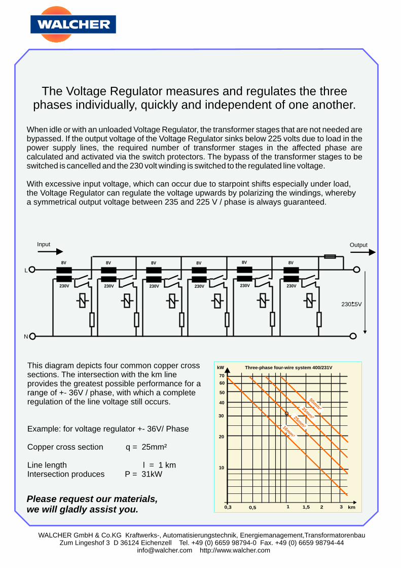
Adjustment of a spur linevia a 69 kVA line voltage regulator
Application of a line voltage regulator (blue curve).The voltage shape without line voltage regulator is shown in the red curve.Due to the voltage increase after the line voltage regulator, the current before the line voltage regulator has to be higher, according to the power balance chart before and after the line voltage regulator (P = constant = U*I), which results in a slight additional voltage drop in the line.
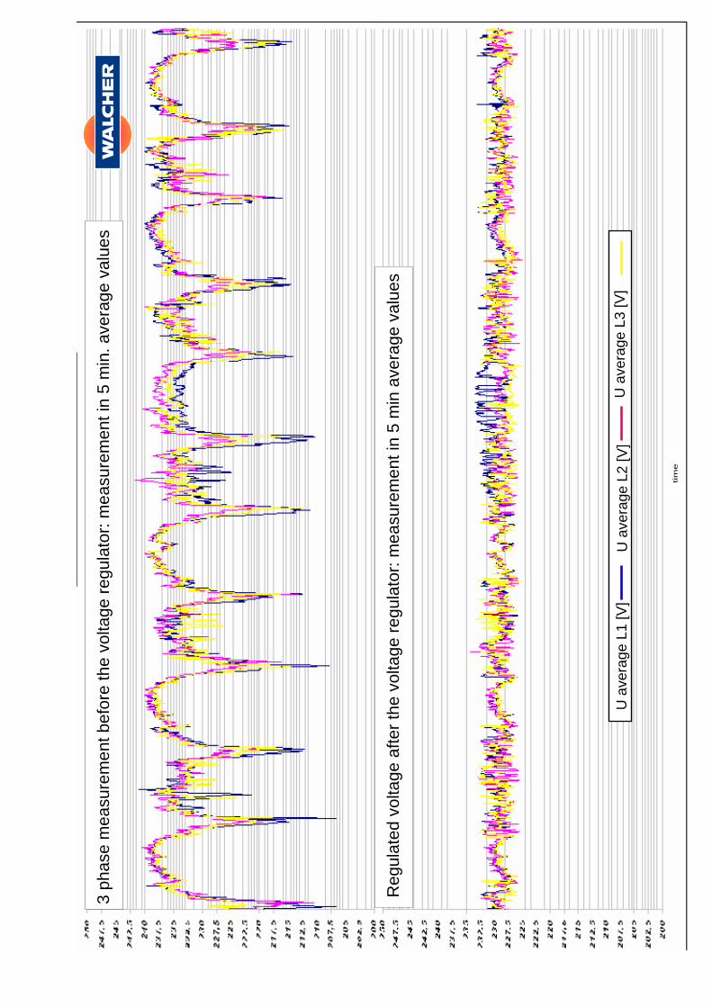
3 p
hase
measu
rem
ent befo
re the v
olta
ge r
egula
tor:
measu
rem
ent in
5 m
in.
ave
rage v
alu
es
Regula
ted v
olta
ge a
fter
the
volta
ge r
egula
tor:
measu
rem
ent in
5 m
in a
vera
ge v
alu
es
U a
vera
ge L
1 [V
]U
ave
rage L
2 [V
]U
ave
rage L
3 [V
]
tim
e
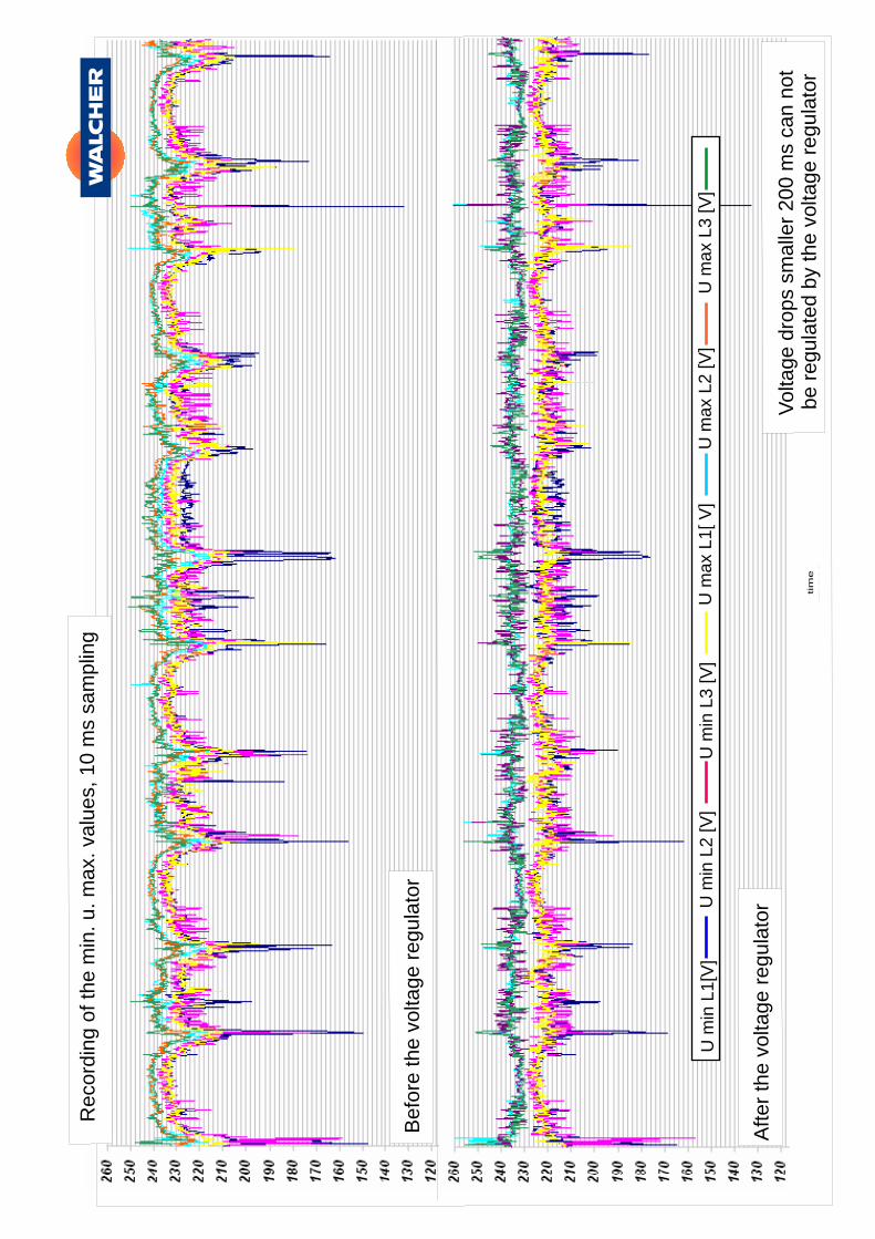
Reco
rdin
g o
f th
e m
in. u. m
ax.
valu
es,
10 m
s sa
mplin
g
Befo
re the v
olta
ge r
egula
tor
After
the v
olta
ge r
egula
tor
Volta
ge d
rops
smalle
r 200 m
s ca
n n
ot
be r
egula
ted b
y th
e v
olta
ge r
egula
tor
U m
in L
1[V
]U
max
L1[ V
]U
min
L2 [V
]U
max
L2 [V
]U
min
L3 [V
]U
max
L3 [V
]
tim
e
WALCHER GmbH & Co.KG Kraftwerks-, Automatisierungstechnik, Energiemanagement,TransformatorenbauZum Lingeshof 3 D 36124 Eichenzell Tel. +49 (0) 6659 98794-0 Fax. +49 (0) 6659 98794-44
[email protected] http://www.walcher.com
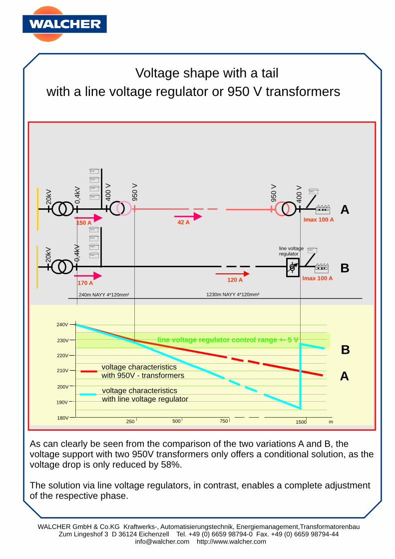
180V250 500 750 1500
200V
190V
m
210V
240V
230V
220V
voltage characteristicswith 950V - transformers
voltage characteristicswith line voltage regulator
line voltage regulator control range +- 5 V
20kV
20kV
0,4
kV0,4
kV
240m NAYY 4*120mm² 1230m NAYY 4*120mm²
line voltageregulator
Imax 100 A
Imax 100 A42 A
120 A170 A
150 A
400 V
400 V
950 V
950 V
A
A
B
B
Voltage shape with a tail
with a line voltage regulator or 950 V transformers
As can clearly be seen from the comparison of the two variations A and B, the voltage support with two 950V transformers only offers a conditional solution, as the voltage drop is only reduced by 58%.
The solution via line voltage regulators, in contrast, enables a complete adjustment of the respective phase.
WALCHER GmbH & Co.KG Kraftwerks-, Automatisierungstechnik, Energiemanagement,TransformatorenbauZum Lingeshof 3 D 36124 Eichenzell Tel. +49 (0) 6659 98794-0 Fax. +49 (0) 6659 98794-44
[email protected] http://www.walcher.com
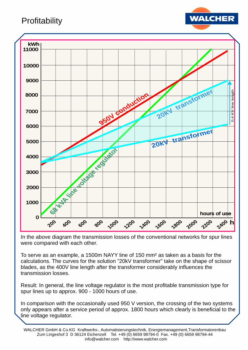
In the above diagram the transmission losses of the conventional networks for spur lines were compared with each other.
To serve as an example, a 1500m NAYY line of 150 mm² as taken as a basis for the calculations. The curves for the solution ”20kV transformer” take on the shape of scissor blades, as the 400V line length after the transformer considerably influences the transmission losses.
Result: In general, the line voltage regulator is the most profitable transmission type for spur lines up to approx. 900 - 1000 hours of use.
In comparison with the occasionally used 950 V version, the crossing of the two systems only appears after a service period of approx. 1800 hours which clearly is beneficial to the line voltage regulator.
Profitability
2000
0
5000
1000
6000
7000
8000
9000
4000
hours of use
10000
11000kWh
3000
200400
1400600
1600800
18001000
20002200
12002400 h
950V conduction
68 k
VA line
volta
ge re
gulato
r
20kV transformer
0,4
KV
lin
e length
20kV transform
er
WALCHER GmbH & Co.KG Kraftwerks-, Automatisierungstechnik, Energiemanagement,TransformatorenbauZum Lingeshof 3 D 36124 Eichenzell Tel. +49 (0) 6659 98794-0 Fax. +49 (0) 6659 98794-44
[email protected] http://www.walcher.com
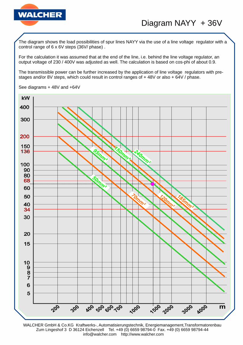
The diagram shows the load possibilities of spur lines NAYY via the use of a line voltage regulator with a control range of 6 x 6V steps (36V/ phase) .
For the calculation it was assumed that at the end of the line, i.e. behind the line voltage regulator, an output voltage of 230 / 400V was adjusted as well. The calculation is based on cos-phi of about 0.9.
The transmissible power can be further increased by the application of line voltage regulators with pre-stages and/or 8V steps, which could result in control ranges of + 48V or also + 64V / phase.
See diagrams + 48V and +64V
Diagram NAYY + 36V
WALCHER GmbH & Co.KG Kraftwerks-, Automatisierungstechnik, Energiemanagement,TransformatorenbauZum Lingeshof 3 D 36124 Eichenzell Tel. +49 (0) 6659 98794-0 Fax. +49 (0) 6659 98794-44
[email protected] http://www.walcher.com
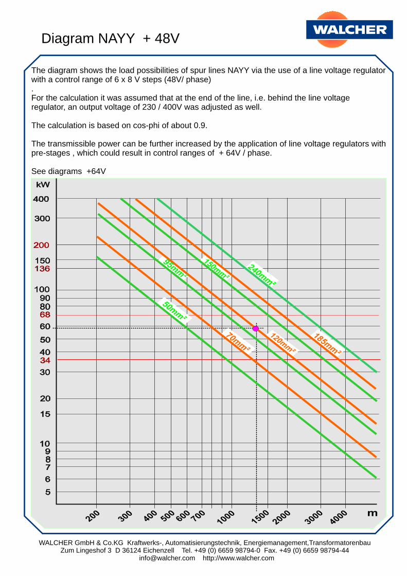
The diagram shows the load possibilities of spur lines NAYY via the use of a line voltage regulator with a control range of 6 x 8 V steps (48V/ phase) .For the calculation it was assumed that at the end of the line, i.e. behind the line voltage regulator, an output voltage of 230 / 400V was adjusted as well.
The calculation is based on cos-phi of about 0.9.
The transmissible power can be further increased by the application of line voltage regulators with pre-stages , which could result in control ranges of + 64V / phase.
See diagrams +64V
Diagram NAYY + 48V
WALCHER GmbH & Co.KG Kraftwerks-, Automatisierungstechnik, Energiemanagement,TransformatorenbauZum Lingeshof 3 D 36124 Eichenzell Tel. +49 (0) 6659 98794-0 Fax. +49 (0) 6659 98794-44
[email protected] http://www.walcher.com
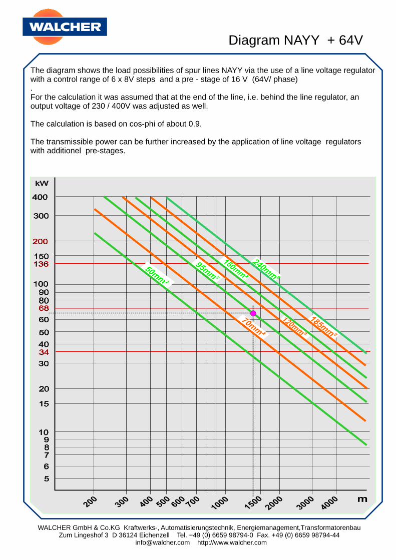
The diagram shows the load possibilities of spur lines NAYY via the use of a line voltage regulator with a control range of 6 x 8V steps and a pre - stage of 16 V (64V/ phase) .For the calculation it was assumed that at the end of the line, i.e. behind the line regulator, an output voltage of 230 / 400V was adjusted as well.
The calculation is based on cos-phi of about 0.9.
The transmissible power can be further increased by the application of line voltage regulators with additionel pre-stages.
Diagram NAYY + 64V
WALCHER GmbH & Co.KG Kraftwerks-, Automatisierungstechnik, Energiemanagement,TransformatorenbauZum Lingeshof 3 D 36124 Eichenzell Tel. +49 (0) 6659 98794-0 Fax. +49 (0) 6659 98794-44
[email protected] http://www.walcher.com
Design and mode of operation
The intention is to offset the voltage loss or the excessive voltages in the low-voltage networks (tail cabling!) through the automatic regulation. For this purpose, the line-voltage regulator is developed, which is created for installation outdoors as a result of its weatherproof design.
The most common models are built for continuity currents of 50 to 200 A. The control range usually amounts to ± 36 V and/or ± 48 V in stages of 6 x 6 and/or 6 x 8 V in each phase. Greater voltage pulses up to 12 V per stage are possible. In particular cases the whole control range can be fundamentally extended again by preselector stages. Contact us about system problems, we would be happy to advise you.
Design of the regulator
Every three-phase current network regulator consists of three regulated transformer cascades independent of each other. A stored-program controller for rough climatic conditions computes the required number of the transformer stages to be actuated, and in the event of voltage fluctuations, switches these on or off as required, within a range of 300 500 ms.
All the contactors are located in a collective casing, including the three reversing starter groups, which facilitate the input voltages to be regulated upwards or downwards with the same transformers.
Each of the 6 x 6 V (8 V) stage transformers possess a primary coil of 230 V and a secondary coil of 6 or 8 V, by which the secondary coil, depending on the size of the system, is rated for 50 - 300 A (greater currents upon request).
The contactors short-circuit the 230 V coils in the switched-off state. As a result, the individual transformer has no magnetisation losses at all in the no-load running. If required, the 230 V coil is connected to the voltage, by which the 6 V and/or 8 V coil is activated and this voltage is added to the incoming mains voltage (and/or subtracted from it).
The excess voltages occasionally occurring with the activation of the transformers are shunted via switch arcs. Through damping resistors, which are housed in a separate box, the arc is lowered to an amperage harmless for the contactors.
WALCHER GmbH & Co.KG Kraftwerks-, Automatisierungstechnik, Energiemanagement,TransformatorenbauZum Lingeshof 3 D 36124 Eichenzell Tel. +49 (0) 6659 98794-0 Fax. +49 (0) 6659 98794-44
[email protected] http://www.walcher.com
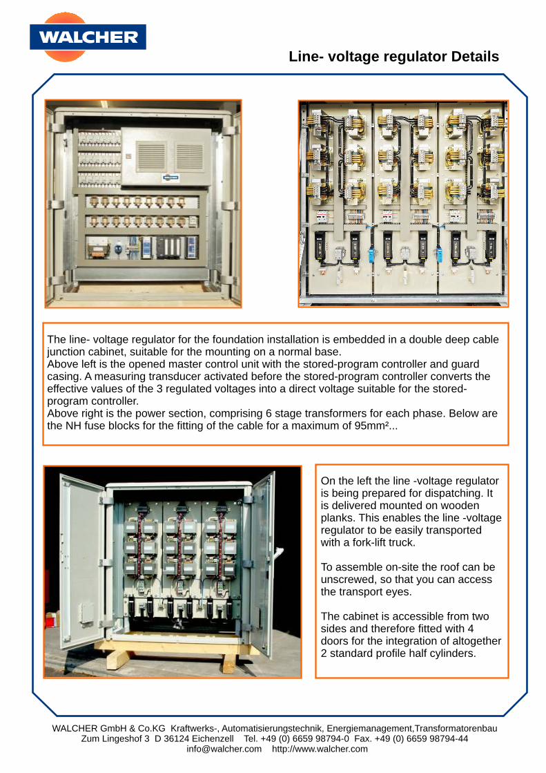
The line- voltage regulator for the foundation installation is embedded in a double deep cable junction cabinet, suitable for the mounting on a normal base. Above left is the opened master control unit with the stored-program controller and guard casing. A measuring transducer activated before the stored-program controller converts the effective values of the 3 regulated voltages into a direct voltage suitable for the stored-program controller.Above right is the power section, comprising 6 stage transformers for each phase. Below are the NH fuse blocks for the fitting of the cable for a maximum of 95mm²...
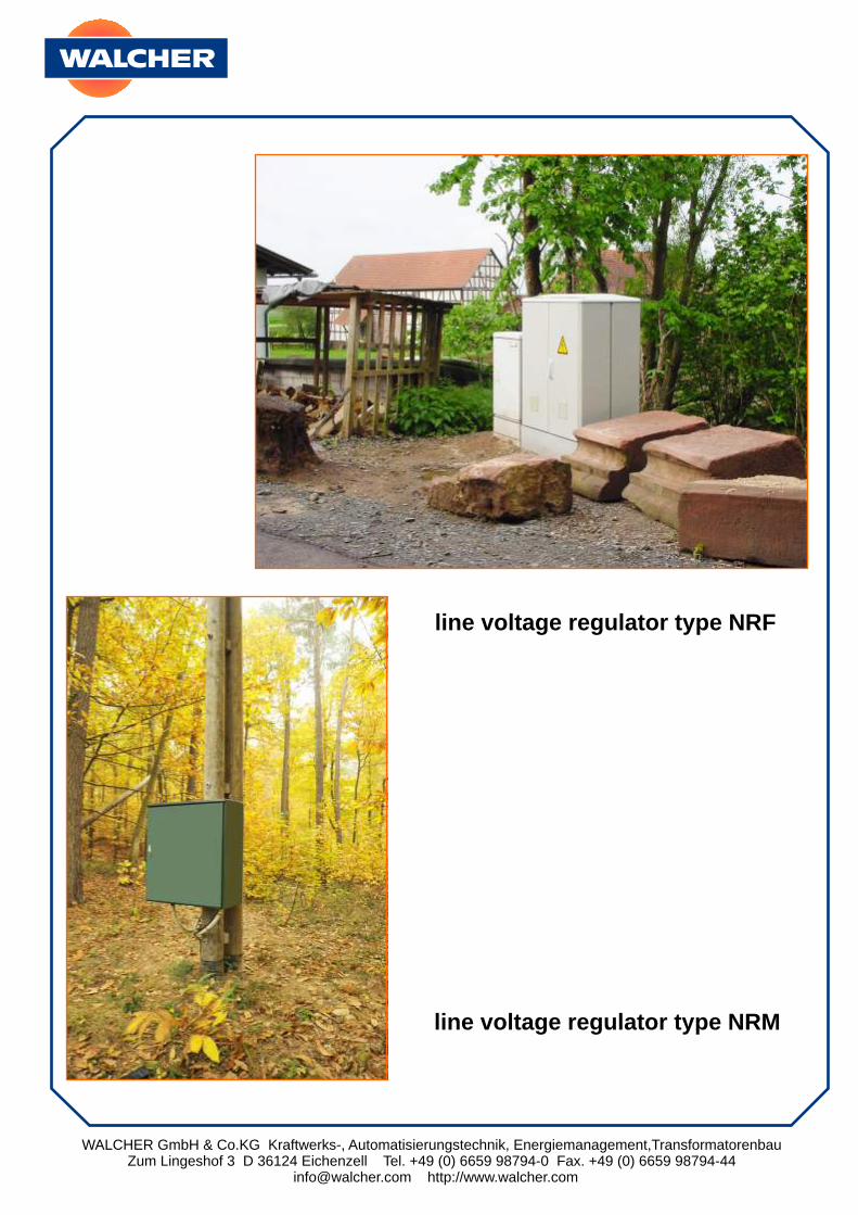
On the left the line -voltage regulator is being prepared for dispatching. It is delivered mounted on wooden planks. This enables the line -voltage regulator to be easily transported with a fork-lift truck.
To assemble on-site the roof can be unscrewed, so that you can access the transport eyes.
The cabinet is accessible from two sides and therefore fitted with 4 doors for the integration of altogether 2 standard profile half cylinders.
Line- voltage regulator Details
WALCHER GmbH & Co.KG Kraftwerks-, Automatisierungstechnik, Energiemanagement,TransformatorenbauZum Lingeshof 3 D 36124 Eichenzell Tel. +49 (0) 6659 98794-0 Fax. +49 (0) 6659 98794-44
[email protected] http://www.walcher.com
Design features:
Offsetting of the voltage losses up to 25%, with the use of a preselector stage over 40%. Because of this, a multiplication of the cable load capacity is attained with adherence to the constant voltage.
The high control rate, ca. 300 500 ms, for the whole control range. The start sequence with the heavy-running motors is normalised and/or once again possible.
Symmetrical balancing of the phase voltages with the asymmetric load by the individual activation of each phase.
Throughput rating: 34, 68, 136, 200 und 300 kVA.Control rate: 300 - 500ms.
Individual activation of each phase: Because of this the asymmetries, the neutral displacements and voltage increases, determined by the uneven loads in the three phases, are balanced.
Low-loss regulation: The efficiency factor lies at 98%. In the no-load running with all quantities the losses lie below 30 VA.
Weatherproof design: The line- voltage regulators for the pole installation (sheet steel) are equipped with pole straps. The polyester design is suitable only for mounting on a foundation base.
Maintenance-free operation: We recommend an inspection of the line -voltage regulator in intervals of one or two years.
Module principle: Easy replacement possibility of all structural components.
Economic efficiency:
The line -voltage regulators have been in use for over 40 years. They have become reliable components of the system construction. It has been proven that the line- voltage regulator is not only suitable for temporary application, but also often durable as a final solution because of the high total efficiency.
WALCHER GmbH & Co.KG Kraftwerks-, Automatisierungstechnik, Energiemanagement,TransformatorenbauZum Lingeshof 3 D 36124 Eichenzell Tel. +49 (0) 6659 98794-0 Fax. +49 (0) 6659 98794-44
[email protected] http://www.walcher.com
line voltage regulator type NRF
line voltage regulator type NRM

WALCHER GmbH & Co.KG Kraftwerks-, Automatisierungstechnik, Energiemanagement,TransformatorenbauZum Lingeshof 3 D 36124 Eichenzell Tel. +49 (0) 6659 98794-0 Fax. +49 (0) 6659 98794-44
[email protected] http://www.walcher.com
Line- voltage regulator in short-circuitZeroing condition
In the event of short-circuits behind the line -voltage regulator (K) the inherent resistance of the unit exerts only a low influence on the level of the short-circuit current.
Picture: Equivalent network diagram Line- voltage regulator
Through measurements on the various line -voltage regulators and in different systems with good approximation the intrinsic impedance of the 6-stage transformer series was measured with
Z = 0,06 bis 0,08 Ohms.
The ohmic resistance lies between the values R = 0.036 and 0.040 Ohms.
The reactive impedance lies between the values X = 0.05 and 0.07 Ohms.
Picture: Transformer series (switched-off)
Measurement results:
Depending on the momentary closed-circuit condition of the line-voltage regulator, before the occurrence of the short circuit, the impedance of the loop fluctuates between 0.08 and 1.22 Ohms. After the decrease in the transformer contactors, as a result of the breakdowns of the voltage, the final resistance of approximately 0.08 Ohm is set within 10 to 20 ms.
R
L1
N
R( K )
RR
X X
X
line-voltage-regulators
WALCHER GmbH & Co.KG Kraftwerks-, Automatisierungstechnik, Energiemanagement,TransformatorenbauZum Lingeshof 3 D 36124 Eichenzell Tel. +49 (0) 6659 98794-0 Fax. +49 (0) 6659 98794-44
[email protected] http://www.walcher.com
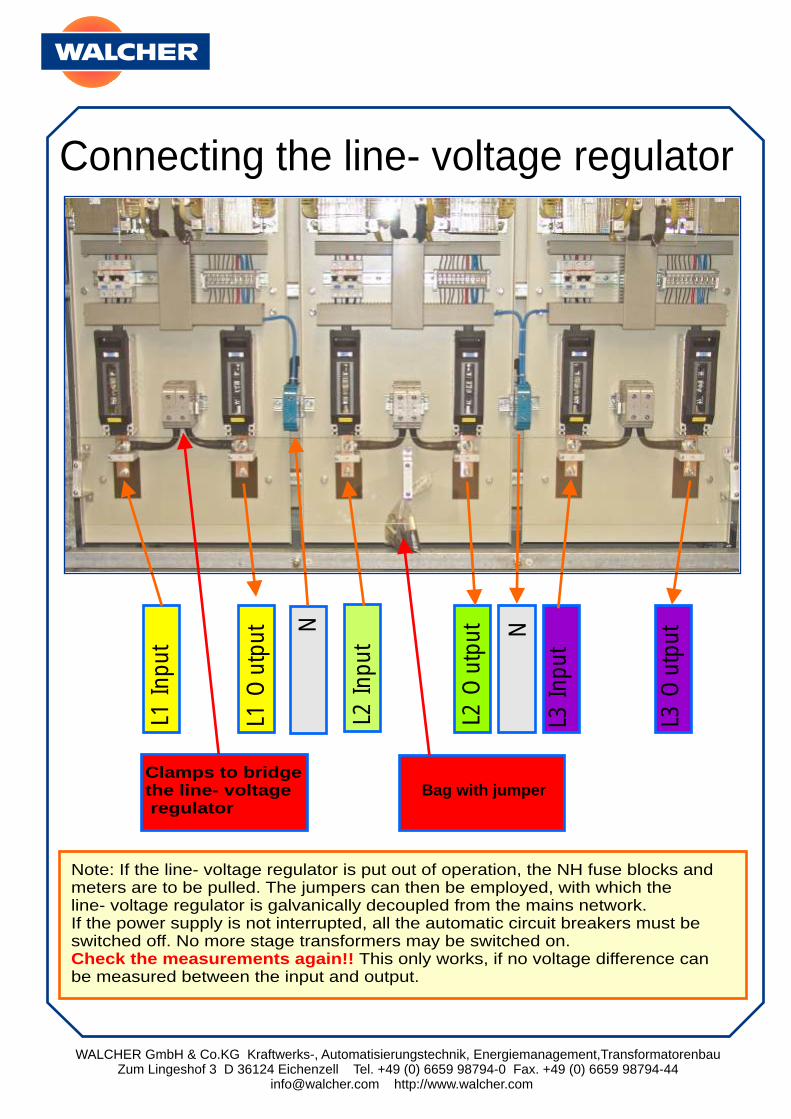
Connecting the line- voltage regulatorL1
Input
L1 O
utp
ut
L2 Input
L2 O
utp
ut
L3 Input
L3 O
utp
ut
Clamps to bridge the line- voltage regulator
N N
Note: If the line- voltage regulator is put out of operation, the NH fuse blocks andmeters are to be pulled. The jumpers can then be employed, with which theline- voltage regulator is galvanically decoupled from the mains network. If the power supply is not interrupted, all the automatic circuit breakers must beswitched off. No more stage transformers may be switched on.
This only works, if no voltage difference can be measured between the input and output.Check the measurements again!!
Bag with jumper
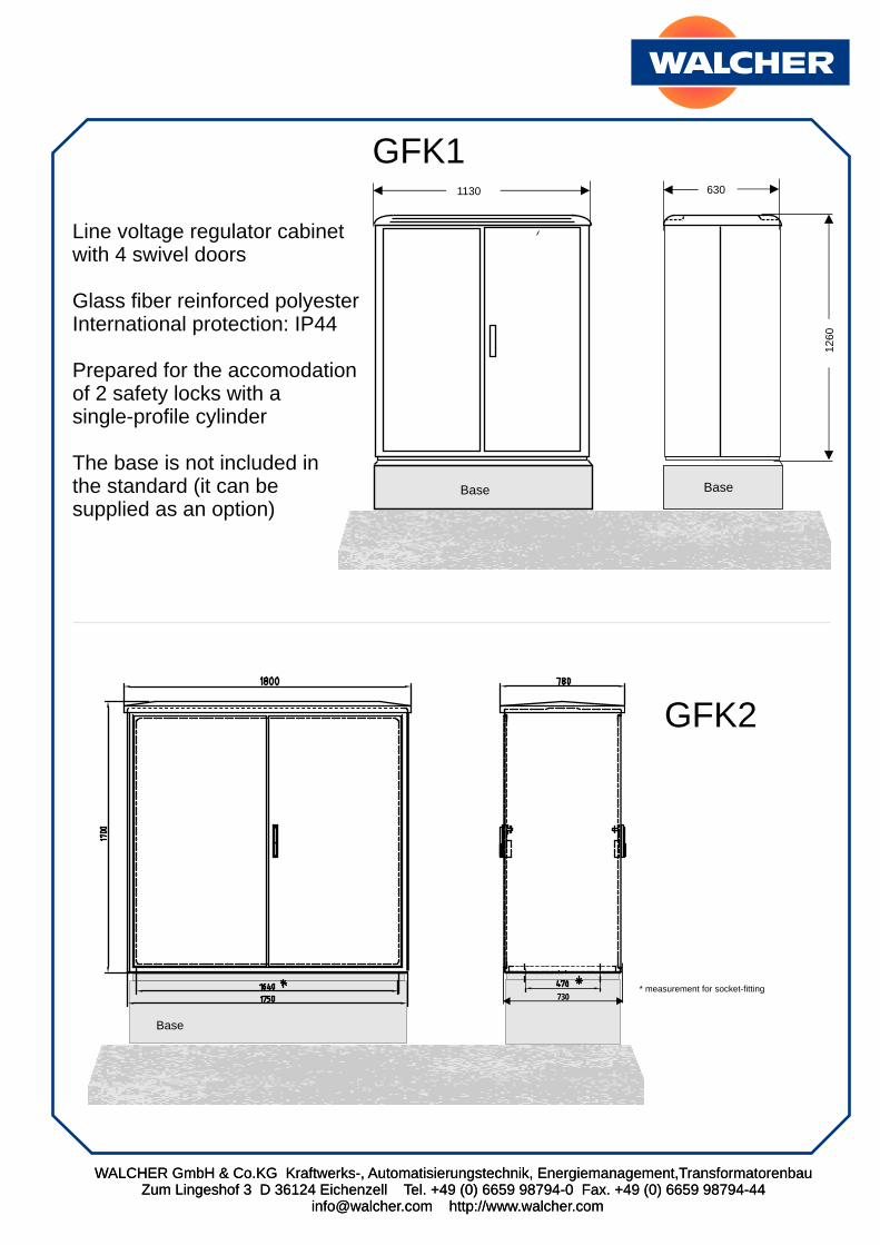
Base
730
GFK1
GFK2
WALCHER GmbH & Co.KG Kraftwerks-, Automatisierungstechnik, Energiemanagement,TransformatorenbauZum Lingeshof 3 D 36124 Eichenzell Tel. +49 (0) 6659 98794-0 Fax. +49 (0) 6659 98794-44
[email protected] http://www.walcher.com
1130 630
1260
Base Base
Line voltage regulator cabinetwith 4 swivel doors
Glass fiber reinforced polyesterInternational protection: IP44
Prepared for the accomodationof 2 safety locks with asingle-profile cylinder
The base is not included in the standard (it can besupplied as an option)
* measurement for socket-fitting
WALCHER GmbH & Co.KG Kraftwerks-, Automatisierungstechnik, Energiemanagement,TransformatorenbauZum Lingeshof 3 D 36124 Eichenzell Tel. +49 (0) 6659 98794-0 Fax. +49 (0) 6659 98794-44
[email protected] http://www.walcher.com
WALCHER GmbH & Co.KG Kraftwerks-, Automatisierungstechnik, Energiemanagement,TransformatorenbauZum Lingeshof 3 D 36124 Eichenzell Tel. +49 (0) 6659 98794-0 Fax. +49 (0) 6659 98794-44
[email protected] http://www.walcher.com
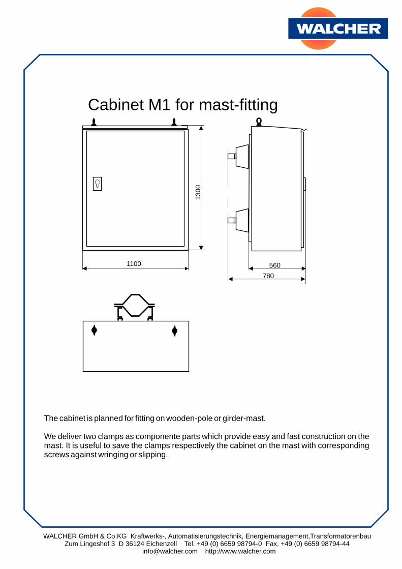
1300
560
780
1100
Cabinet M1 for mast-fitting
The cabinet is planned for fitting on wooden-pole or girder-mast.
We deliver two clamps as componente parts which provide easy and fast construction on the mast. It is useful to save the clamps respectively the cabinet on the mast with corresponding screws against wringing or slipping.
WALCHER GmbH & Co.KG Kraftwerks-, Automatisierungstechnik, Energiemanagement,TransformatorenbauZum Lingeshof 3 D 36124 Eichenzell Tel. +49 (0) 6659 98794-0 Fax. +49 (0) 6659 98794-44
[email protected] http://www.walcher.com
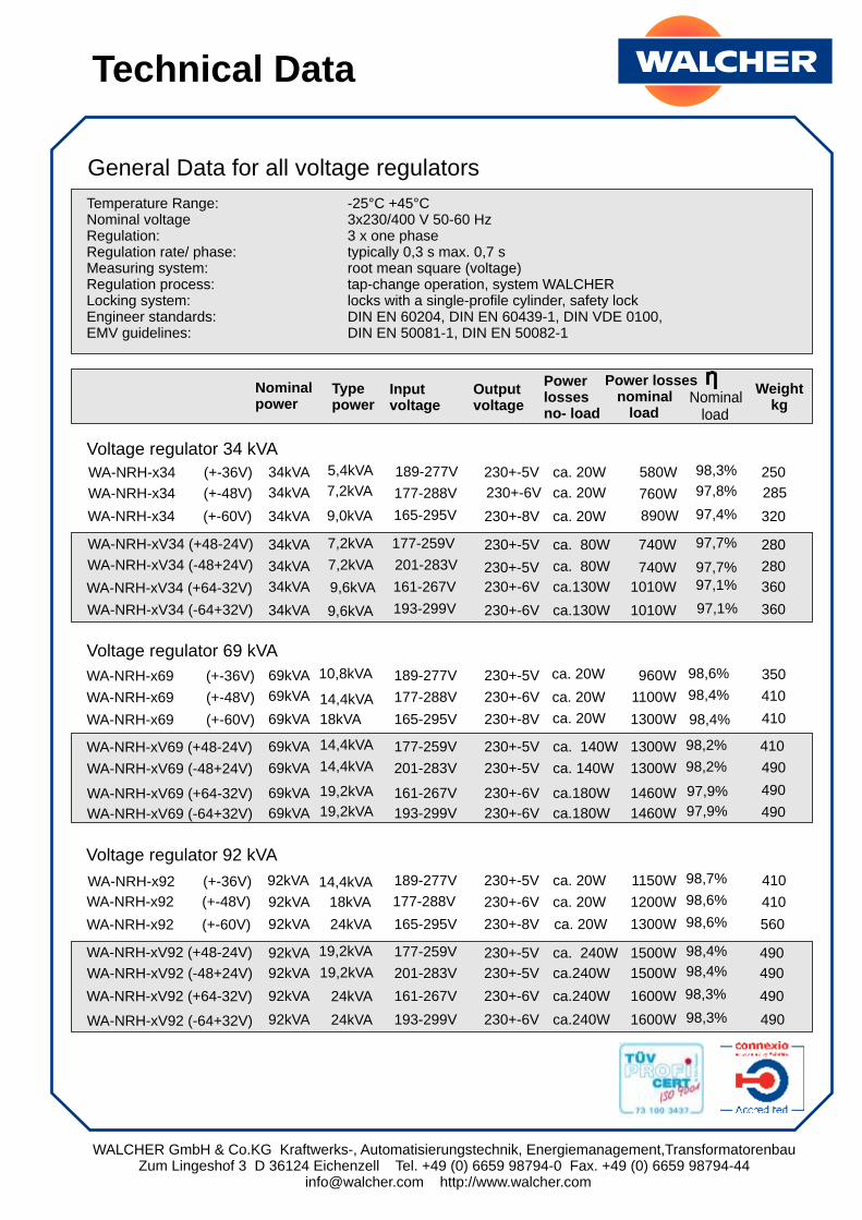
Technical Data
General Data for all voltage regulators
Temperature Range: -25°C +45°CNominal voltage 3x230/400 V 50-60 HzRegulation: 3 x one phaseRegulation rate/ phase: typically 0,3 s max. 0,7 sMeasuring system: root mean square (voltage)Regulation process: tap-change operation, system WALCHERLocking system: locks with a single-profile cylinder, safety lockEngineer standards: DIN EN 60204, DIN EN 60439-1, DIN VDE 0100,EMV guidelines: DIN EN 50081-1, DIN EN 50082-1
WA-NRH-x34 (+-36V)
WA-NRH-x69 (+-36V)
WA-NRH-x92 (+-36V)
WA-NRH-xV34 (+48-24V)
WA-NRH-xV69 (+48-24V)
WA-NRH-xV92 (+48-24V)
WA-NRH-x34 (+-48V)
WA-NRH-x69 (+-48V)
WA-NRH-x92 (+-48V)
WA-NRH-xV34 (-48+24V)
WA-NRH-xV69 (-48+24V)
WA-NRH-xV92 (-48+24V)
WA-NRH-x34 (+-60V)
WA-NRH-x69 (+-60V)
WA-NRH-x92 (+-60V)
WA-NRH-xV34 (+64-32V)
WA-NRH-xV69 (+64-32V)
WA-NRH-xV92 (+64-32V)
WA-NRH-xV34 (-64+32V)
WA-NRH-xV69 (-64+32V)
WA-NRH-xV92 (-64+32V)
34kVA
69kVA
92kVA
34kVA
69kVA
92kVA
34kVA
69kVA
92kVA
34kVA
69kVA
92kVA
34kVA
69kVA
92kVA
34kVA
69kVA
92kVA
34kVA
69kVA
92kVA
5,4kVA
10,8kVA
14,4kVA
7,2kVA
14,4kVA
19,2kVA
189-277V
189-277V
189-277V
177-259V
177-259V
177-259V
230+-5V
230+-5V
230+-5V
230+-5V
230+-5V
230+-5V
ca. 20W
ca. 20W
ca. 20W
ca. 80W
ca. 140W
ca. 240W
ca. 20W
ca. 20W
ca. 20W
ca.130W
ca.180W
ca.240W
ca.130W
ca.180W
ca.240W
ca. 20W
ca. 20W
ca. 20W
ca. 80W
ca. 140W
ca.240W
580W
960W
1150W
740W
1300W
1500W
Nominalpower
Typepower
Inputvoltage
Outputvoltage
Power losses no- load
Power losses nominal load
Weightkg
Nominal load
98,3%
98,6%
98,7%
97,7%
98,2%
98,4%
250
350
410
280
410
490
7,2kVA
14,4kVA
18kVA
7,2kVA
14,4kVA
19,2kVA
9,0kVA
18kVA
24kVA
9,6kVA
19,2kVA
24kVA
9,6kVA
19,2kVA
24kVA
177-288V
177-288V
177-288V
201-283V
201-283V
201-283V
165-295V
165-295V
165-295V
161-267V
161-267V
161-267V
230+-6V
230+-6V
230+-6V
230+-5V
230+-5V
230+-5V
230+-8V
230+-8V
230+-8V
230+-6V
230+-6V
230+-6V
230+-6V
230+-6V
230+-6V
760W
1100W
1200W
740W
1300W
1500W
97,8%
98,4%
98,6%
97,7%
98,2%
98,4%
890W
1300W
1300W
1010W
1460W
1600W
1010W
1460W
1600W
97,4%
98,4%
98,6%
97,1%
97,9%
98,3%
97,1%
97,9%
98,3%
285
410
410
280
490
490
320
410
560
360
490
490
360
490
490
193-299V
193-299V
193-299V
Voltage regulator 34 kVA
Voltage regulator 69 kVA
Voltage regulator 92 kVA
WALCHER GmbH & Co.KG Kraftwerks-, Automatisierungstechnik, Energiemanagement,TransformatorenbauZum Lingeshof 3 D 36124 Eichenzell Tel. +49 (0) 6659 98794-0 Fax. +49 (0) 6659 98794-44
[email protected] http://www.walcher.com
WA-NRH-F150 (+-36V)
WA-NRH-F207 (+-36V)
WA-NRH-F300 (+-36V)
WA-NRH-FV150 (+48-24V)
WA-NRH-FV207 (+48-24V)
WA-NRH-FV300 (+48-24V)
WA-NRH-F150 (+-48V)
WA-NRH-F207 (+-48V)
WA-NRH-F300 (+-48V)
WA-NRH-FV150 (-48+24V)
WA-NRH-FV207 (-48+24V)
WA-NRH-FV300 (-48+24V)
WA-NRH-F150 (+-60V)
WA-NRH-F207 (+-60V)
WA-NRH-F300 (+-60V)
WA-NRH-FV150 (+64-32V)
WA-NRH-FV207 (+64-32V)
WA-NRH-FV300 (+64-32V)
WA-NRH-FV150 (-64+32V)
WA-NRH-FV207 (-64+32V)
WA-NRH-FV300 (-64+32V)
150kVA
207kVA
300kVA
150kVA
207kVA
300kVA
150kVA
207kVA
300kVA
150kVA
207kVA
300kVA
150kVA
207kVA
300kVA
150kVA
207kVA
300kVA
150kVA
207kVA
300kVA
23,4kVA
32,4kVA
47kVA
31,2kVA
43,2kVA
62,5kVA
189-277V
189-277V
189-277V
177-259V
177-259V
177-259V
230+-5V
230+-5V
230+-5V
230+-5V
230+-5V
230+-5V
ca. 40W
ca. 50W
ca. 60W
ca. 220W
ca. 300W
ca. 240W
ca. 40W
ca. 50W
ca. 60W
ca.250W
ca.300W
ca. 240W
ca.250W
ca.300W
ca. 240W
ca. 40W
ca. 50W
ca. 60W
ca. 220W
ca. 300W
ca. 240W
1600W
1900W
2500W
1700W
2500W
3300W
98,9%
99,0%
99,1%
98,8%
98,8%
98,9%
540
715
735
640
865
903
31,1kVA
43,2kVA
62,5kVA
31,2kVA
43,2kVA
62,5kVA
39,6kVA
54kVA
78,2kVA
42kVA
57,6kVA
83,3kVA
42kVA
57,6kVA
83,3kVA
177-288V
177-288V
177-288V
201-283V
201-283V
201-283V
165-295V
165-295V
165-295V
161-267V
161-267V
161-267V
230+-6V
230+-6V
230+-6V
230+-5V
230+-5V
230+-5V
230+-8V
230+-8V
230+-8V
230+-6V
230+-6V
230+-6V
230+-6V
230+-6V
230+-6V
2050W
2250W
4100W
1700W
2500W
3300W
98,6%
98,9%
98,6%
98,8%
98,8%
98,9%
2150W
2800W
5500W
2700W
3000W
5400W
2700W
3000W
5400W
98,5%
98,6%
98,2%
98,2%
98,6%
98,2%
98,2%
98,6%
98,2%
570
770
860
640
865
903
610
770
1040
750
883
1070
750
883
1070
193-299V
193-299V
193-299V
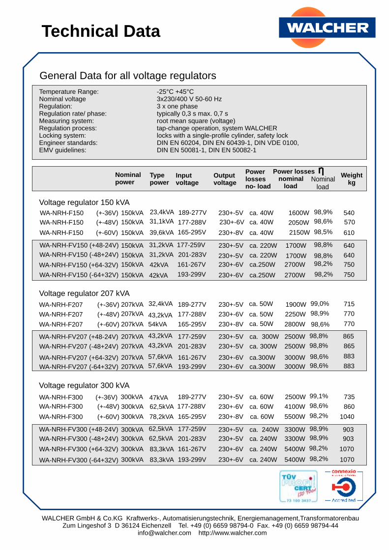
Voltage regulator 150 kVA
Voltage regulator 207 kVA
Voltage regulator 300 kVA
Temperature Range: -25°C +45°CNominal voltage 3x230/400 V 50-60 HzRegulation: 3 x one phaseRegulation rate/ phase: typically 0,3 s max. 0,7 sMeasuring system: root mean square (voltage)Regulation process: tap-change operation, system WALCHERLocking system: locks with a single-profile cylinder, safety lockEngineer standards: DIN EN 60204, DIN EN 60439-1, DIN VDE 0100,EMV guidelines: DIN EN 50081-1, DIN EN 50082-1
Technical Data
General Data for all voltage regulators
Nominalpower
Typepower
Inputvoltage
Outputvoltage
Power losses no- load
Power losses nominal load
Weightkg
Nominal load
WALCHER GmbH & Co.KG Kraftwerks-, Automatisierungstechnik, Energiemanagement,TransformatorenbauZum Lingeshof 3 D 36124 Eichenzell Tel. +49 (0) 6659 98794-0 Fax. +49 (0) 6659 98794-44
[email protected] http://www.walcher.com
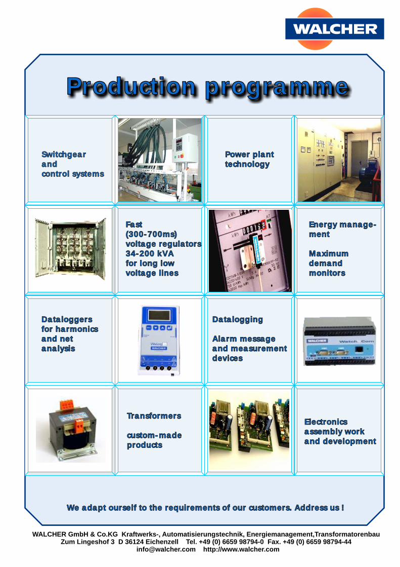
Production programme
Switchgearandcontrol systems
Power planttechnology
Fast(300-700ms)voltage regulators34-200 kVAfor long lowvoltage lines
Energy manage-ment
Maximumdemandmonitors
Dataloggersfor harmonicsand netanalysis
Datalogging
Alarm messageand measurementdevices
Transformers
custom-made products
Electronics assembly workand development
We adapt ourself to the requirements of our customers. Address us !