Embed Size (px)
Citation preview
AIR BAG RESTRAINT SYSTEM
�1995 Volvo 850
1995 ACCESSORIES/SAFETY EQUIPMENT Volvo Air Bag Restraint System
850
* PLEASE READ THIS FIRST *
WARNING: To avoid injury from accidental air bag deployment, read and carefully follow all WARNINGS and SERVICE PRECAUTIONS.
WARNING: If vehicle is equipped with SIPS system, exercise care when working around front seat and door area. During servicing which involves front seats, always install safety device in SIPS bag of seat being serviced. Never apply external force to side of seat. See SIPS under REMOVAL & INSTALLATION for safety device attachment procedures. Failure to observe precautions may result in SIPS deployment and personal injury. See SERVICE PRECAUTIONS.
IDENTIFICATION
SRS/SIPS (Side Impact Protection System) unit decals will befound on the windshield, on the end of the driver-side of theinstrument panel (visible with door open), on the sensor housing (sideof front seats), and on the driver-side "B" pillar.
DESCRIPTION & OPERATION
The Supplemental Restraint System (SRS) is designed tooperate when vehicle strikes a rigid or heavy object with enough forceto activate SRS. Activation impact area is directly in front ofvehicle and 30 degrees on either side of dead center. SRS is notdesigned to activate during a side or rear collision, a rollover, or afrontal collision at low speed or with soft objects. In addition, the850 is equipped with Side Impact Protection System (SIPS). SIPS areseat mounted air bags which deploy only in the event of a side impactintrusion in the front passenger compartment. Main SRS components include a driver-side air bag/gasgenerator module mounted to steering wheel, and passenger-side airbag/gas generator module mounted to instrument panel. System alsoincludes a contact reel (clockspring) mounted to steering column,under steering wheel, crash sensor, and standby power unit mountedunder center console and SRS warning light, mounted in instrumentgauge cluster light bar. See Fig. 1. All models have an On-BoardDiagnostic (OBD) system located within engine compartment. All modelshave pyrotechnical seat belt tensioners for driver and front passengerseats. Seat belt tensioners are mounted inside "B" pillars. For SRS tooperate properly, 3-point seat belts must be worn.
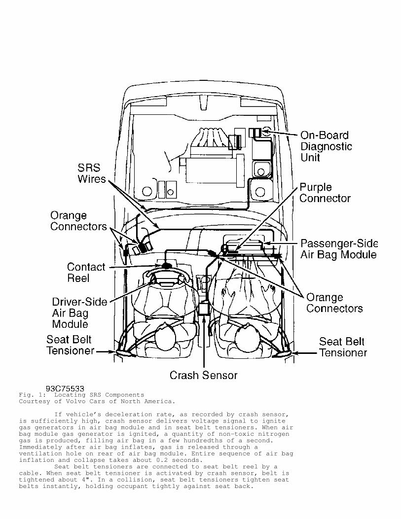
Fig. 1: Locating SRS ComponentsCourtesy of Volvo Cars of North America.
If vehicle’s deceleration rate, as recorded by crash sensor,is sufficiently high, crash sensor delivers voltage signal to ignitegas generators in air bag module and in seat belt tensioners. When airbag module gas generator is ignited, a quantity of non-toxic nitrogengas is produced, filling air bag in a few hundredths of a second.Immediately after air bag inflates, gas is released through aventilation hole on rear of air bag module. Entire sequence of air baginflation and collapse takes about 0.2 seconds. Seat belt tensioners are connected to seat belt reel by acable. When seat belt tensioner is activated by crash sensor, belt istightened about 4". In a collision, seat belt tensioners tighten seatbelts instantly, holding occupant tightly against seat back.
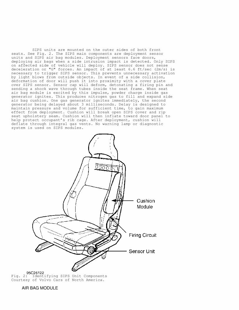
SIPS units are mounted on the outer sides of both frontseats. See Fig. 2. The SIPS main components are deployment sensorunits and SIPS air bag modules. Deployment sensors face doors,deploying air bags when a side intrusion impact is detected. Only SIPSon affected side of vehicle will deploy. SIPS sensor does not sensedeceleration or "G" forces. An impact of at least 6.6 ft/sec (2m/s) isnecessary to trigger SIPS sensor. This prevents unnecessary activationby light blows from outside objects. In event of a side collision,deformation of door will push it into proximity with a cover plateover SIPS sensor. Sensor cap will deform, detonating a firing pin andsending a shock wave through tubes inside the seat frame. When seatair bag module is excited by this impulse, powder charge inside gasgenerator ignites. This produces nitrogen gas to fill and expand sideair bag cushion. One gas generator ignites immediately, the secondgenerator being delayed about 3 milliseconds. Delay is designed tomaintain pressure and volume for sufficient time, to gain maximumeffect from deployment. Cushion will break open SIPS cover and ripseat upholstery seam. Cushion will then inflate toward door panel tohelp protect occupant’s rib cage. After deployment, cushion willdeflate through integral gas vents. No warning lamp or diagnosticsystem is used on SIPS modules.
Fig. 2: Identifying SIPS Unit ComponentsCourtesy of Volvo Cars of North America.
AIR BAG MODULE
NOTE: Volvo recommends air bag modules and seat belt tensioners be replaced every 10 years to maintain reliability.
Each air bag module consists of an inflatable air bag andinflator unit. Gas generator and ignitor make up the inflator unit,which is mounted to rear of air bag module. A 2-pin electricalconnector with gold-plated terminals is mounted to inflator unit. If2-pin connector is disconnected for any reason, a safety shortingspring inside 2-pin connector spreads open, touching both terminals.This prevents accidental air bag deployment by static electricity orcareless handling.
CONTACT REEL (CLOCKSPRING)
Contact reel is a spirally wound wire coil (not a slip ring)mounted to steering column. This single-wire type contact reel designensures most reliable contact possible between air bag module assemblyand crash sensor.
CRASH SENSOR
Crash sensor measures and records deceleration/collisionforce of vehicle to determine if air bag deployment is necessary.Crash sensor also functions as a diagnostic monitor, whichcontinuously monitors SRS operation and records any faults in SRS.Crash sensor incorporates a piezoelectric sensor (to detectdeceleration/collision force), microprocessors (to evaluate collisionsignal and control SRS deployment), a memory (to retain informationfor fault tracing if power supply fails) and a standby power unit (ifbattery power supply is lost). Electrical sensor records combination of "G" force and changein speed (deceleration). Both high "G" force and prolongeddeceleration are required to activate SRS. Consequently, crash sensorcannot be activated by a hammer blow or other similar influence, whichproduces a high "G" force for a short time. To ensure correct operation of crash sensor, crash sensormust be properly secured to floor and securely grounded. Crash sensoris grounded by a short Black wire connected to one of crash sensor’smounting screws. SRS is monitored continuously by microprocessors incrash sensor, regardless of ignition switch position or engineoperation. Crash sensor will illuminate instrument gauge cluster SRSwarning light until a fault is corrected, and crash sensor memory iscleared. Crash sensor incorporates a standby power unit if normalpower source (battery voltage) is interrupted. Standby power unitstores enough energy to deploy SRS within 100 milliseconds of batterypower loss during a collision.
ON-BOARD DIAGNOSTIC UNIT
On-Board Diagnostic (OBD) unit, located within enginecompartment, is a 2-part, interconnected unit with an "A" side and a"B" side. OBD unit is used to store fault codes, display fault codes,and monitor SRS continuously by self-diagnostics. Fault codes arestored in crash sensor and displayed through OBD unit and/or SRS lighton side "A" of OBD unit. See SELF-DIAGNOSTIC SYSTEM under DIAGNOSIS &TESTING. OBD unit is positioned on right front of engine compartmentand is controlled by crash sensor located under center console.
ELECTRICAL SYSTEM
SRS deployment harness connectors are Orange, except forpassenger-side air bag module connector, which is Violet. SRSconnectors between air bag module(s) and crash sensor have gold-platedterminals for maximum conductivity. These colored connectors contain asafety shorting spring in male half of connector. When connectors aredisconnected, safety shorting spring spreads open to touch bothterminals, preventing accidental deployment of air bag by staticelectricity or careless handling.
SRS WARNING LIGHT
When ignition switch is turned to ON position, SRS warninglight will glow. If SRS faults are not detected, SRS warning lightwill go out after about 10 seconds or immediately after engine isstarted. If SRS detects a fault, warning light will remain on untilfault is corrected and memory is cleared. If warning light fails toglow, bulb is faulty, and/or a short exists in wire to bulb.
SEAT BELT TENSIONER
All models are equipped with pyrotechnical seat belttensioners for driver and front passenger seats. If vehicle’sdeceleration rate, recorded by crash sensor, is sufficiently high,crash sensor delivers voltage charges to activate gas generators inseat belt tensioners. If seat belt tensioner gas generator isactivated by crash sensor, a quantity of non-toxic nitrogen gas isproduced. This gas pressure displaces plunger mounted in tensionertube and tightens seat belt by tensioning cable connected to seat beltreel. In a collision, seat belt tensioners tighten seat beltsinstantly, holding occupant tightly against seat back.
SIPS SENSOR UNIT
Driver and front passenger seats are equipped with SIPSimpact sensors to detect side intrusion impact, and excite gasgenerator detonators inside SIPS air bag modules.
SIPS AIR BAG MODULE
Driver and front passenger seats are equipped with SIPS airbag module which deploys a cushion to protect occupant’s ribs in sideimpact collisions.
SYSTEM OPERATION CHECK
Turn ignition switch to ON position (engine not running). Ifno fault codes are present, SRS warning light will go out after 10seconds. If SRS is malfunctioning, SRS fault code will be stored incrash sensor memory during following conditions:
* SRS warning light does not glow. * SRS warning light does not go out after 10 seconds. * SRS warning light does not go out after engine is started. * SRS warning light comes on while driving. If SRS warning light indicates a malfunction, enter self-diagnostics and retrieve fault codes. See SELF-DIAGNOSTIC SYSTEM under DIAGNOSIS & TESTING.
Seat Belt Tensioner Inspection There are 2 methods of determining seat belt tensioneractivation. Start by pulling seat belt out and releasing it. If beltnormally extends easily to full length, tensioner has not been
activated. If either belt sticks, jerks when reeling and unreeling, orfails to reel, both belts must be replaced. If seat belt tensioneractivation cannot be determined, turn ignition switch to OFF position.Remove "B" pillar inner panel. Insert a steel rod into tensioner tubeto establish position of plunger. If plunger position is near bottomof tensioner tube, seat belt tensioner has not deployed. If plungerposition is near top of tensioner tube, seat belt tensioner has beenactivated, and both belts must be replaced.
SIPS System Inspection No maintenance is necessary on SIPS units.
SERVICE PRECAUTIONS
Observe these precautions when working with air bag systems:
* Always disable SRS before performing any air bag repairs. See DISABLING & ACTIVATING AIR BAG SYSTEM. * Always ensure radio is off before disconnecting battery. This will prevent damage to radio microprocessor. * Always wear safety glasses and gloves when handling a deployed air bag module and/or seat belt tensioners. Air bag module and/or seat belt tensioners may contain sodium hydroxide deposits, which irritate skin. * Use caution when handling sensors. Never strike or jar sensors. All sensors and mounting bracket bolts must be tightened carefully to ensure proper sensor operation. See TORQUE SPECIFICATIONS. * Never apply power to SRS if any SRS crash sensor is not securely mounted to vehicle. * Never make any measurement directly on air bag module(s) or seat belt tensioners. A fault in these components is determined by a process of elimination using Special Test Resistor (998 8695). * To avoid accidental air bag deployment when trouble shooting SRS, DO NOT use self-powered electrical test equipment, such as battery-powered or AC-powered voltmeter, ohmmeter, etc. when air bag module(s) or seat belt tensioners are connected to SRS. * When called for during diagnostics, use a DVOM with ohmmeter ranges of 2000 ohms and 200,000 ohms with a one-percent error tolerance. * Wiring repairs should not be performed on any portion of SRS wiring harness. * Always handle air bag modules with trim cover away from your body. Always place air bag module on workbench with trim cover facing up, away from loose objects. * If equipped with SIPS, always use care when working near outer side of seat frame. SIPS sensor is located directly behind outer seat frame pocket. Never strike or apply pressure to side of seat.
DISABLING & ACTIVATING AIR BAG SYSTEM
WARNING: DO NOT disconnect crash sensor connector or standby power unit to disable system. This action could cause air bag to deploy.
Disabling System 1) Before proceeding, see SERVICE PRECAUTIONS. Beforeperforming any repairs, turn ignition switch to OFF position.Disconnect and shield negative battery cable.
2) Locate and disconnect Orange air bag module and seat belttensioner connectors and Violet passenger-side air bag moduleconnector. DO NOT disconnect crash sensor connector or standby powerunit to disable system. This action could cause air bags to deploy.See Fig. 1.
Activating System After repairs are performed, ensure all wiring and componentconnectors are connected. Turn ignition switch to ON position. Connectnegative battery cable. Ensure vehicle is not occupied when connectingbattery cable. Ensure system is functioning properly. See SYSTEMOPERATION CHECK.
DISPOSAL PROCEDURES
WARNING: An undeployed air bag module or seat belt tensioner should never be disposed of without first being deployed. See SCRAPPED VEHICLE. If deployment is not possible, contact vehicle manufacturer for further instructions.
Several situations may arise requiring some form of disposalaction, including:
* Scrapping a vehicle containing a deployed air bag module(s), seat belt tensioners or SIPS units. * Scrapping a vehicle with undeployed air bag module(s), seat belt tensioners or SIPS units. * Disposal of undeployed, but electrically faulty air bag module(s) or seat belt tensioners. * Disposal of a deployed air bag module or seat belt tensioner.
DEPLOYED AIR BAG OR SEAT BELT TENSIONER
Deployed air bag module or seat belt tensioner can bedisposed of as any other part. Handle air bag module(s) and/or seatbelt tensioners with gloves and wear safety glasses.
SCRAPPED VEHICLE
WARNING: An undeployed air bag module, seat belt tensioner and/or SIPS module cannot be disposed of without first deploying air bag, seat belt tensioner, and/or SIPS module. If this is not possible through procedures outlined below, contact vehicle manufacturer for further instructions. Perform remote deployment outdoors. To avoid personal injury when an air bag is deployed, keep all personnel at least 20 feet away. See SERVICE PRECAUTIONS.
Air Bag Module 1) Move vehicle outdoors to a remote area, away from workshopand other personnel. Disconnect negative battery cable. Open allvehicle windows and doors. Ensure air bag module is secured tosteering wheel or instrument panel (if equipped). Remove any loosearticles from front seat. Ensure no occupants are inside vehicle. 2) Disconnect driver-side air bag module Orange connector orpassenger-side Violet connector. See Fig. 1. Using two 20-foot longwires, splice one end of each wire to air bag side of Orange connectorOrange and Orange/White wires. On passenger-side, connect wires toViolet connector, Brown and Blue wires. While at least 20 feet fromvehicle, connect both wires to 12-volt power source. Air bag shoulddeploy. 3) If driver-side air bag does not deploy, disconnect 20-foot
wires from 12-volt power source. Remove air bag module from steeringwheel. See AIR BAG MODULE under REMOVAL & INSTALLATION. Carefully cutoff module connector bypassing contact reel. Splice both 20-foot wiresto air bag module wires, and tape spliced connections. 4) Reinstall air bag module to steering wheel. While at least20 feet from vehicle, connect both wires to 12-volt power source totrigger air bag inflator. Air bag should deploy.
Seat Belt Tensioner 1) Move vehicle outdoors to a remote area, away from workshopand other personnel. Disconnect negative battery cable. Open allvehicle windows and doors. Ensure seat belt tensioner is secured to"B" pillar. Remove any loose articles from front seat. Ensure nooccupants are inside vehicle. Connect seat belt latch coupling toposition shoulder harness across seat back. 2) Locate and disconnect Orange connectors. See Fig. 1. Using2 wires, each 20 feet long, splice one end of each wire to terminalsof male end of Orange connector. While at least 20 feet from vehicle,connect both wire ends to 12-volt power source to trigger seat belttensioner. Seat belt tensioner should deploy. Repeat procedure forother seat belt tensioner. 3) Ensure seat belt tensioner has deployed. See SEAT BELTTENSIONER INSPECTION under SYSTEM OPERATION CHECK. If seat belttensioner does not deploy, disconnect 20-foot wires from 12-volt powersource. Remove seat belt tensioner trim cover from "B" pillar. SeeSEAT BELT TENSIONER under REMOVAL & INSTALLATION. See Fig. 3.Carefully remove connector from seat belt tensioner module. Strip backabout 1" of insulation of two wires from seat belt tensioner harness.Splice both 20-foot wire ends to seat belt tensioner wires, and tapespliced connections.
Fig. 3: Removing Driver-Side Seat Belt Reel & TensionerCourtesy of Volvo Cars of North America.
4) While at least 20 feet from vehicle, connect both wires to12-volt power source to trigger seat belt tensioner.
WARNING: DO NOT handle SIPS sensor unit roughly with transport safety device removed. DO NOT exert external pressure on sensor unit. Aluminum cover on sensor must not be pressed in or dented. Safety glasses and hearing protection should be worn, as deployment of SIPS module will produce a loud explosion.
SIPS Modules 1) Move vehicle outdoors to a remote area, away from workshopand other personnel. Remove loose articles from front seat. Ensure nooccupants are inside vehicle. Lift seat pocket and remove SIPStransport safety device from holder inside seat pocket. See Fig. 4.Place safety device over SIPS sensor. See Fig. 5. Cut cable tiesholding firing tubes and free tubes from clips. See Fig. 6. RemoveTorx T-25 screw holding pressure plate and sensor. Remove sensor fromSIPS tube sensor housing.
Fig. 4: Removing Seat Pocket and SIPS Safety DeviceCourtesy of Volvo Cars of North America.
Fig. 5: Installing SIPS Transport Safety DeviceCourtesy of Volvo Cars of North America.
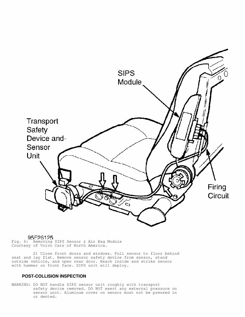
Fig. 6: Removing SIPS Sensor & Air Bag ModuleCourtesy of Volvo Cars of North America.
2) Close front doors and windows. Pull sensor to floor behindseat and lay flat. Remove sensor safety device from sensor, standoutside vehicle, and open rear door. Reach inside and strike sensorwith hammer on front face. SIPS unit will deploy.
POST-COLLISION INSPECTION
WARNING: DO NOT handle SIPS sensor unit roughly with transport safety device removed. DO NOT exert any external pressure on sensor unit. Aluminum cover on sensor must not be pressed in or dented.
After vehicle is involved in a collision in which SRS did notdeploy, perform a system operation check to ensure proper SRSoperation. See SYSTEM OPERATION CHECK. Repair as necessary. If SRSdeployed, replace air bag modules, crash sensor, contact reel, seatbelt tensioners, any seat belt in use at time of collision, andigniter leads to air bag modules. Inspect following items and replaceif damaged (even if deployment did not occur): knee bolster,instrumentpanel frame, instrument panel speakers, steering wheel, sunroof,instrument panel trim pieces, and windshield.
SIPS Inspection 1) Remove any loose articles from front seat and ensure nooccupants are inside vehicle. Lift up seat pocket and remove SIPStransport safety device from its holder inside seat pocket. SeeFig. 10. Place safety device over SIPS sensor. See Fig. 5. Remove TorxT-25 screw holding pressure plate and sensor and then remove sensorfrom SIPS tube sensor housing. See Fig. 6. 2) Inspect exposed portion of firing tubes for cuts orabrasions. Remove safety device from SIPS sensor and carefully inspectsensor for any dents or damage. Sensor should slide easily from tubesensor housing. If sensor is difficult to remove, it may be dented.Measure height of sensor from flat back plane to front face. Be surenot to apply pressure while measuring. Use a vernier caliper, ifavailable. Height must be not less than 1.06" (27mm). If less, replaceSIPS module. If okay, replace safety device on sensor then reverseremoval procedure. Be sure to remove safety device before installingseat pocket.
REMOVAL & INSTALLATION
WARNING: Failure to follow service precautions may result in air bag deployment and personal injury. See SERVICE PRECAUTIONS. After component replacement, always perform a system operation check to ensure proper SRS operation. See SYSTEM OPERATION CHECK.
WARNING: During servicing which involves front seats, always install safety device in SIPS bag of seat being serviced. Never apply external force to side of seat. See SIPS under REMOVAL & INSTALLATION for SAFETY DEVICE ATTACHMENT PROCEDURES.
AIR BAG MODULE
NOTE: Air bag module has a 10-digit identification number that must be used when ordering replacement module.
Removal & Installation (Driver-Side) 1) Before proceeding, follow air bag service precautions. SeeSERVICE PRECAUTIONS. Disable air bag system. See DISABLING &ACTIVATING AIR BAG SYSTEM. 2) Turn ignition switch to disengage steering column lock.Remove steering wheel tilt adjuster (if equipped), steering columnlower cover panel and knee bolster assembly. 3) Remove 2 Torx No. 30 screws from rear of steering wheel.See Fig. 7. Pull air bag module away from steering wheel just enoughto disconnect wiring connector. Install SRS (Special Test Resistor)(988 8695) in place of air bag module to prevent generation of faultcodes. See Fig. 8.
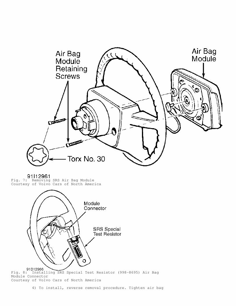
Fig. 7: Removing SRS Air Bag ModuleCourtesy of Volvo Cars of North America
Fig. 8: Installing SRS Special Test Resistor (998-8695) Air BagModule ConnectorCourtesy of Volvo Cars of North America
4) To install, reverse removal procedure. Tighten air bag

module bolts to specification. See TORQUE SPECIFICATIONS. Turnignition switch to ON position. Connect negative battery cable. Ensuresystem is functioning properly. See SYSTEM OPERATION CHECK. 5) If an air bag module fault code exists after replacing airbag module, clear codes, and perform SYSTEM OPERATION CHECK again. IfSRS warning light still indicates a malfunction, enter self-diagnostics and retrieve fault codes. See SELF-DIAGNOSTIC SYSTEM underDIAGNOSIS & TESTING.
Removal & Installation (Passenger-Side) 1) Before proceeding, follow air bag service precautions. SeeSERVICE PRECAUTIONS. Disable air bag system. See DISABLING &ACTIVATING AIR BAG SYSTEM. 2) Remove driver-side soundproofing panel and center console.Disconnect Violet connector and cut cable tie. Disconnect glove boxlid arms. Using a screwdriver between each arm and side of lid, pryout arms. Remove glove box screws and compartment. Remove 4 air bagmodule screws and disconnect air bag module connector. 3) Remove side defroster outlet screw caps and screws. Pivot4 vent nozzles downward and pull out. Remove both nozzles and air ductfrom right side. Remove speaker grilles and speakers. Disconnectspeaker connectors. Remove 11 instrument panel retaining screws anddisengage cover panel from upper part of frame above center console. 4) Using Torx bit TX 20, remove 8 air bag module retainingTorx screws. Remove 6 special nuts using locking pliers and remove airbag module. 5) Inspect for excessive foam under felt tape at positionsNo. 1 and 2. See Fig. 9. If there is excessive foam, remove tape, cutfoam so there will not be a bump in instrument panel cover. Reinstalltape over foam. Tightly support air bag module with electrical wire instraps, ensuring correct position of straps. See Fig. 9. Incorrectposition of straps will not allow instrument panel cover to laysmoothly.
Fig. 9: Installing Passenger-Side Air Bag ModuleCourtesy of Volvo Cars of North America.
6) Keeping support wire stretched tightly, put air bag moduleinto position. Install Torx screws into positions No. 1 and 2 to
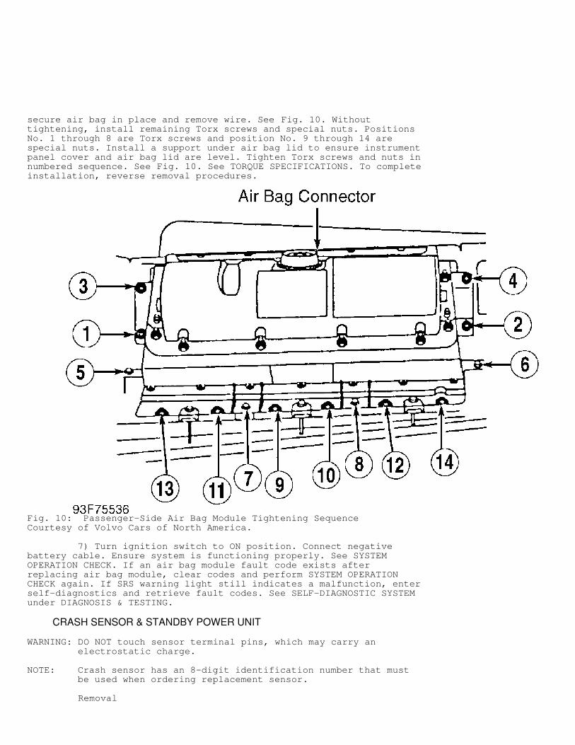
secure air bag in place and remove wire. See Fig. 10. Withouttightening, install remaining Torx screws and special nuts. PositionsNo. 1 through 8 are Torx screws and position No. 9 through 14 arespecial nuts. Install a support under air bag lid to ensure instrumentpanel cover and air bag lid are level. Tighten Torx screws and nuts innumbered sequence. See Fig. 10. See TORQUE SPECIFICATIONS. To completeinstallation, reverse removal procedures.
Fig. 10: Passenger-Side Air Bag Module Tightening SequenceCourtesy of Volvo Cars of North America.
7) Turn ignition switch to ON position. Connect negativebattery cable. Ensure system is functioning properly. See SYSTEMOPERATION CHECK. If an air bag module fault code exists afterreplacing air bag module, clear codes and perform SYSTEM OPERATIONCHECK again. If SRS warning light still indicates a malfunction, enterself-diagnostics and retrieve fault codes. See SELF-DIAGNOSTIC SYSTEMunder DIAGNOSIS & TESTING.
CRASH SENSOR & STANDBY POWER UNIT
WARNING: DO NOT touch sensor terminal pins, which may carry an electrostatic charge.
NOTE: Crash sensor has an 8-digit identification number that must be used when ordering replacement sensor.
Removal
1) Before proceeding, follow air bag service precautions. SeeSERVICE PRECAUTIONS. Disable system. See DISABLING & ACTIVATING AIRBAG SYSTEM. 2) Crash sensor is located under center console. Removeashtray and cigarette lighter holder. Remove center console mountingscrews, apply handbrake and shift transmission into Neutral. Removecenter console. Remove crash sensor, and disconnect connector. SeeFig. 1.
Installation 1) To install, reverse removal procedure. Install crashsensor using original bolts. Because ground terminal is secured by onemounting bolt, ensure ground terminal is not damaged when tighteningbolts. Tighten all bolts to specification. See TORQUE SPECIFICATIONS.Ensure all SRS connectors are connected. 2) Turn ignition switch to ON position and connect negativebattery cable. Check SRS warning light to ensure system is functioningproperly. See SYSTEM OPERATION CHECK. If fault code exists afterreplacing crash sensor, clear codes and perform SYSTEM OPERATION CHECKagain. If SRS warning light still indicates a malfunction, enter self-diagnostics and retrieve fault codes. See SELF-DIAGNOSTIC SYSTEM underDIAGNOSIS & TESTING.
SEAT BELT TENSIONER
NOTE: If air bag deployed, replace both seat belt tensioners (including belts) since seat belt tensioners are ignited at same time as air bag.
Removal 1) Before proceeding, follow air bag service precautions. SeeSERVICE PRECAUTIONS. Disable system. See DISABLING & ACTIVATING AIRBAG SYSTEM. 2) Push front seat as far forward as possible. Remove "B"pillar inner panel. Remove door sill molding and seat side pocket.Remove seat belt tensioner bolts and plunger tube Torx screw from "B"pillar. Disconnect tensioner connector. See Fig. 3.
Installation 1) To install, reverse removal procedure. Ensure SRS wire ispositioned so as not to become pinched or cut. Tighten all bolts tospecification. See TORQUE SPECIFICATIONS. Ensure all SRS connectorsare connected. 2) Activate system. Check SRS warning light to ensure systemis functioning properly. See SYSTEM OPERATION CHECK. If fault codeexists after replacing new seat belt reel assembly, clear codes, andperform SYSTEM OPERATION CHECK again. If SRS warning light stillindicates a malfunction, enter self-diagnostics and retrieve faultcodes. See SELF-DIAGNOSTIC SYSTEM under DIAGNOSIS & TESTING.
STEERING WHEEL & CONTACT REEL
NOTE: If air bag deployed during a collision, contact reel and steering wheel must be replaced.
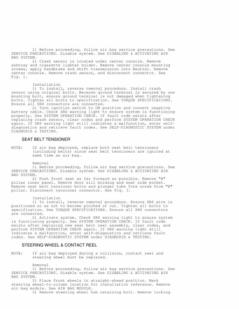
Removal 1) Before proceeding, follow air bag service precautions. SeeSERVICE PRECAUTIONS. Disable system. See DISABLING & ACTIVATING AIRBAG SYSTEM. 2) Place front wheels in straight-ahead position. Marksteering wheel-to-column location for installation reference. Removeair bag module. See AIR BAG MODULE. 3) Remove steering wheel hub retaining bolt. Remove locking
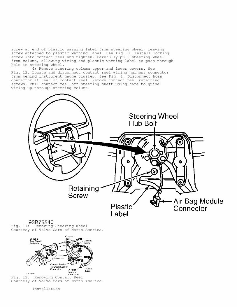
screw at end of plastic warning label from steering wheel, leavingscrew attached to plastic warning label. See Fig. 8. Install lockingscrew into contact reel and tighten. Carefully pull steering wheelfrom column, allowing wiring and plastic warning label to pass throughhole in steering wheel. 4) Remove steering column upper and lower covers. SeeFig. 12. Locate and disconnect contact reel wiring harness connectorfrom behind instrument gauge cluster. See Fig. 1. Disconnect hornconnector at rear of contact reel. Remove contact reel retainingscrews. Pull contact reel off steering shaft using care to guidewiring up through steering column.
Fig. 11: Removing Steering WheelCourtesy of Volvo Cars of North America.
Fig. 12: Removing Contact ReelCourtesy of Volvo Cars of North America.
Installation
1) Position new contact reel onto steering shaft. Connectcontact reel and horn connectors. Install retaining screws. Installturn signal and wiper switches. Install column covers. 2) Contact reel must be adjusted before installation. SeeCONTACT REEL CENTERING under ADJUSTMENTS. Reverse removal proceduresto complete installation.
SIPS AIR BAG MODULE ASSEMBLY
WARNING: During servicing which involves front seats, always install safety device in SIPS bag of seat being serviced. Never apply external force to side of seat.
Removal 1) Lift up front edge of seat pocket and push backward.Remove SIPS Transport Safety Device (9156562-2) from holder insideseat pocket. See Fig. 4. Attach safety device to sensor. See Fig. 5.Ensure ignition is off and remove negative battery cable. Unbolt seatbelt from outside of seat. Remove cover on front edge of outboard seatrail. Unbolt seat and then disconnect heating element electricalconnector, under seat. Remove connector to seat belt buckle switch andthen lift seat straight up. 2) Disconnect seat back from bottom by removing 3 screws oneach side. Remove seat back angle adjustment knob. Remove lumbar-support adjustment knob by unscrewing counterclockwise. Turn knobuntil it stops. Continue to turn while pulling out firmly. Removeupholstery clamps with a strong cutter and then pull upholstery offseat. 3) Note routing of firing tubes, and cut cable ties. RemoveSIPS module by unscrewing 2 Torx T-25 screws. Remove Torx T-25 screwthat holds sensor pressure plate and sensor and then slide sensor outof tube sensor housing. See Fig. 6. Remove entire assembly from seat,being careful not to snag firing tubes on any part of seat frame.
Installation 1) Verify transport safety device is in place on sensor unit.Supplied with all SIPS seats. Replacement # 9156562-2 Position newsensor in tube sensor housing and then reinstall pressure plate. Ifmaking a collision repair, use a new plate. Install Torx screw.Install SIPS module on seat frame and tighten 2 Torx screws. If SIPSunit deployed, new screws of same type and quality should be used.Torque Torx screws to 24 INCH lbs. (2.9 N.m). Place firing tubes backin retaining clips and install new wire ties. 2) Reinstall upholstery in reverse of removal, using Hog RingPliers (1158962-9) to install clamps. If seat is being reupholstered,be sure to use Volvo original or Volvo approved upholstery. Operationof SIPS unit could be adversely affected otherwise. 3) Reassemble seat back to bottom. Reconnect all electricalconnectors previously removed. Torque seat base bolts to 30 FT Lbs.(40 N.m). Torque seat belt bolt to 15 Ft. Lbs. (20 N.m.). Removetransport safety device from SIPS sensor and place back in holder.Reinstall seat pocket. Apply new SIPS sticker shipped with SIPSmodule. New sticker goes over old sticker on "B" pillar decal.
ADJUSTMENTS
CONTACT REEL CENTERING
1) Before performing contact reel centering procedures,ensure contact reel is properly installed and steering wheel isremoved. If installing new contact reel, remove shipping lock screw(with plastic label attached) from pin hole. See Fig. 12. Ensure that
front wheels are pointed straight ahead. 2) Loosen locking screw to permit contact reel to turnfreely. Turn contact reel clockwise to stop and then backcounterclockwise about 3 turns until pin hole is at one o’clockposition. Lock contact reel in proper position with lock screw that isconnected to plastic warning label. See Fig. 12. 3) To install steering wheel, carefully pull contact reelwiring with plastic warning label through hole in steering wheel.Position steering wheel so contact reel pin aligns with properalignment hole in steering wheel. Install steering wheel hub boltfinger tight to ensure steering wheel does not come off shaft whenremoving contact reel lock screw. 4) Remove lock screw, with plastic label attached, fromcontact reel pin. Install lock screw, with plastic warning labelattached, into retaining screw hole in steering wheel. See Fig. 12.Tighten steering wheel hub retaining bolt to specification. See TORQUESPECIFICATIONS. 5) To check contact reel wiring circuit, connect SRS SpecialTest Resistor (998 8695) to air bag module wiring connector in placeof air bag module. See Fig. 8. Activate system. 6) Turn ignition switch to ON position and ensure SRS warninglight goes out after 10 seconds. If warning light does not go out, afault code is set. See SELF-DIAGNOSTIC SYSTEM under DIAGNOSIS &TESTING. 7) If SRS warning light goes out after about 10 seconds, turnignition switch off. Disconnect negative battery cable. Remove SRSSpecial Test Resistor (998 8695) from air bag module connector.Position air bag module to steering wheel and install module wiringconnector. 8) Ensure module wiring connector clicks into position.Install air bag module Torx screws to rear of steering wheel andtighten to specification. See TORQUE SPECIFICATIONS. Install steeringcolumn undercover and steering wheel adjuster (if equipped). Connectnegative battery cable. Perform SYSTEM OPERATION CHECK.
WIRE REPAIR
DO NOT attempt to repair SRS wiring or harness connectors. IfSRS wiring or harness connectors are faulty, replace faulty wiringharness.
DIAGNOSIS & TESTING
WARNING: Failure to follow SERVICE PRECAUTIONS may result in air bag deployment and personal injury. See SERVICE PRECAUTIONS.
NOTE: After component replacement, ensure proper system operation. Perform SYSTEM OPERATION CHECK. DO NOT use ohmmeter or other self-powered meter to test resistance of air bag inflator/module or seat belt tensioner. Use SRS Special Test Resistor (998 8695) in place of air bag module(s) or seat belt tensioner when testing resistance of any SRS circuit. SRS Special Test Resistor (998 8695) specified resistance is 1.8-2.5 ohms, which is same as components it replaces. Test resistor can be "deployed" if deployment voltage is applied to it while connected to SRS. Ensure test resistor resistance is as specified after each use. If resistance is not as specified, replace test resistor.
WARNING: If vehicle is equipped with SIPS restraint system, DO NOT handle SIPS sensor unit roughly with transport safety device removed. DO NOT exert any external pressure on sensor unit.
Aluminum cover on sensor must not be pressed in or dented. Never apply pressure to side of seat frame, or handle seat assembly roughly. Failure to follow cautions may result in SIPS deployment and personal injury. SEE SERVICE PRECAUTIONS.
SELF-DIAGNOSTIC SYSTEM
On-Board Diagnostic (OBD) unit performs 2 tests: a start-uptest and a cyclical test. During start-up test, microprocessorsperform complete system diagnosis. Faults will not be recorded untilstart-up test has been repeated 1 or 2 more times. Cyclical test isperformed 4 times per second. Faults must be detected during 2successive measurements before they will be stored. After a fault hasbeen detected for 10 seconds, it will be stored, and SRS warning lightwill be turned on. When faults are detected, SRS warning light willremain on until they are corrected and cleared from OBD. A detected fault can occur internally within air bag module,seat belt tensioner, crash sensor, or SRS wiring harnesses. Storedfaults will be displayed by a series of flashes from SRS warning lightand/or LED light on side "A" of OBD unit located in enginecompartment. Flash codes consist of 3 digits or series of flashes. Forexample code 2-2-1 would be 2 flashes plus 2 flashes plus one flash.Only the first 5 fault codes detected will be stored. These faultcodes are stored in a non-volatile memory that will retain storedcodes even if battery voltage is lost.
NOTE: If SRS warning light does not come on, go to SRS WARNING LIGHT PROBLEMS.
RETRIEVING CODES
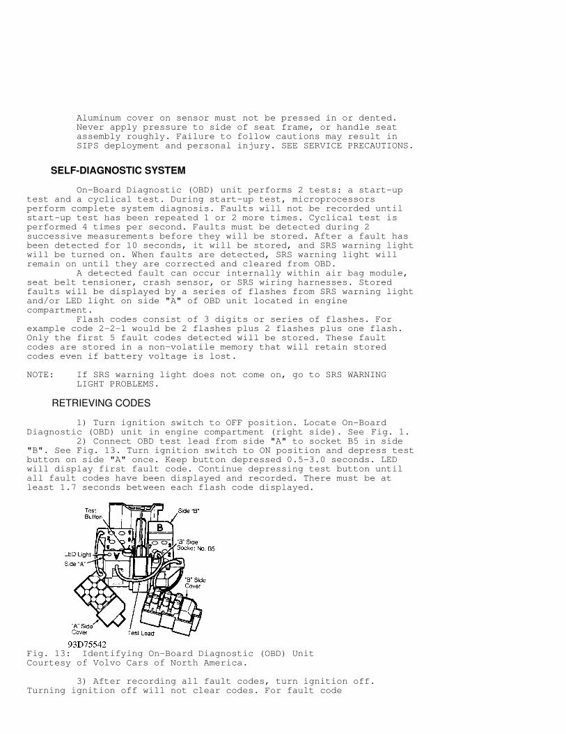
1) Turn ignition switch to OFF position. Locate On-BoardDiagnostic (OBD) unit in engine compartment (right side). See Fig. 1. 2) Connect OBD test lead from side "A" to socket B5 in side"B". See Fig. 13. Turn ignition switch to ON position and depress testbutton on side "A" once. Keep button depressed 0.5-3.0 seconds. LEDwill display first fault code. Continue depressing test button untilall fault codes have been displayed and recorded. There must be atleast 1.7 seconds between each flash code displayed.
Fig. 13: Identifying On-Board Diagnostic (OBD) UnitCourtesy of Volvo Cars of North America.
3) After recording all fault codes, turn ignition off.Turning ignition off will not clear codes. For fault code

descriptions, See SRS FAULT CODES table.
NOTE: Fault Code 1-1-2 indicates an interior crash sensor fault. Replace crash sensor and DO NOT clear this code.
CLEARING CODES
1) All fault codes must be displayed in order at least oncebefore they can be cleared. Display of first code displayed, a secondtime, indicates all codes in memory have been displayed. Fault codesmust be displayed during same ignition-on period before they can becleared. 2) Connect OBD test lead from side "A" to socket No. B5 inside "B". See Fig. 13. Turn ignition switch to ON position, anddepress test button on side "A" once. Keep button depressed for atleast 5 seconds. Release test button and LED will come on. While LEDis on, depress test button and hold it for at least 5 seconds. Faultcodes are now cleared. 3) Verify that fault codes have been cleared by repeatingretrieval steps. See RETRIEVING CODES. If fault codes have beenproperly cleared, fault code 1-1-1 will display. If more fault codesare displayed, record codes and repeat code retrieving procedure.Record these codes and repeat clearing procedure. See step 2). Iffault codes are still present, correct faults and repeat clearing codeprocedure. To ensure SRS fault codes are now cleared, perform SYSTEMOPERATION CHECK.
SRS FAULT CODES TABLE�����������������������������������������������������������������������������������������������������������������������Code (1) Fault
1-1-1 .................................. No Fault Detected1-1-2 ................................ Sensor Module Fault1-2-7 ............ SRS Lamp, Open Circuit Or Short Circuit2-1-1 ................. Driver-Side Air Bag, Short Circuit2-1-2 .................. Driver-Side Air Bag, Open Circuit2-1-3 ....... Driver-Side Air Bag, Short Circuit To Ground2-1-4 ....... Driver-Side Air Bag, Short Circuit To Supply2-2-1 .............. Passenger-Side Air Bag, Short Circuit2-2-2 ............... Passenger-Side Air Bag, Open Circuit2-2-3 .... Passenger-Side Air Bag, Short Circuit To Ground2-2-4 .... Passenger-Side Air Bag, Short Circuit To Supply2-3-1 ................. Left Belt Tensioner, Short Circuit2-3-2 .................. Left Belt Tensioner, Open Circuit2-3-3 ....... Left Belt Tensioner, Short Circuit To Ground2-3-4 ....... Left Belt Tensioner, Short Circuit To Supply2-4-1 ................ Right Belt Tensioner, Short circuit2-4-2 ................. Right Belt Tensioner, Open Circuit2-4-3 ...... Right Belt Tensioner, Short Circuit To Ground2-4-4 ...... Right Belt Tensioner, Short Circuit To Supply
(1) - For corrective action of faults, see FAULT CODE TESTING.�����������������������������������������������������������������������������������������������������������������������
FAULT CODE TESTING
WARNING: DO NOT use ohmmeter or other self-powered meter to test resistance of air bag module(s) or seat belt tensioners. Use SRS Special Test Resistor (998 8695) in place of air bag module(s) or seat belt tensioners when testing continuity or resistance of any SRS circuit.

FAULT CODE 1-1-2
Conditions For Fault Code Self-diagnostics has detected an internal crash sensor module fault.
Fault Symptom None, except illumination of SRS warning light.
Fault Source Internal crash sensor fault.
Corrective Action Replace crash sensor and ensure SRS fault codes are nowcleared, perform SYSTEM OPERATION CHECK. See CRASH SENSOR & STANDBYPOWER UNIT under REMOVAL & INSTALLATION.
FAULT CODE 1-2-7
Conditions For Fault Code SRS warning light is controlled by crash sensor. If SRSwarning light or warning light circuit is defective, crash sensorcannot detect it.
Fault Symptom SRS warning light is on, indicating a fault code is stored.Warning light does not come on when ignition is turned on.
Fault Source There is a short to battery voltage, short to ground, oropen in Green/Brown wire between crash sensor terminal No. 1 andinstrument gauge cluster indicator lights terminal B:3. See Fig. 14.
Fig. 14: Identifying Instrument Gauge Cluster TerminalsCourtesy of Volvo Cars of North America.
Corrective Action 1) Turn ignition switch to ON position. If SRS warning light
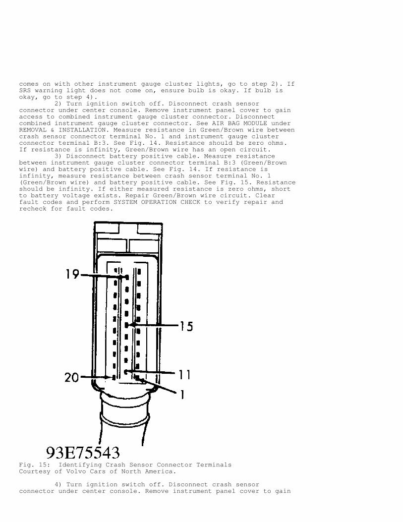
comes on with other instrument gauge cluster lights, go to step 2). IfSRS warning light does not come on, ensure bulb is okay. If bulb isokay, go to step 4). 2) Turn ignition switch off. Disconnect crash sensorconnector under center console. Remove instrument panel cover to gainaccess to combined instrument gauge cluster connector. Disconnectcombined instrument gauge cluster connector. See AIR BAG MODULE underREMOVAL & INSTALLATION. Measure resistance in Green/Brown wire betweencrash sensor connector terminal No. 1 and instrument gauge clusterconnector terminal B:3. See Fig. 14. Resistance should be zero ohms.If resistance is infinity, Green/Brown wire has an open circuit. 3) Disconnect battery positive cable. Measure resistancebetween instrument gauge cluster connector terminal B:3 (Green/Brownwire) and battery positive cable. See Fig. 14. If resistance isinfinity, measure resistance between crash sensor terminal No. 1(Green/Brown wire) and battery positive cable. See Fig. 15. Resistanceshould be infinity. If either measured resistance is zero ohms, shortto battery voltage exists. Repair Green/Brown wire circuit. Clearfault codes and perform SYSTEM OPERATION CHECK to verify repair andrecheck for fault codes.
Fig. 15: Identifying Crash Sensor Connector TerminalsCourtesy of Volvo Cars of North America.
4) Turn ignition switch off. Disconnect crash sensorconnector under center console. Remove instrument panel cover to gain
access to combined instrument gauge cluster connector. Disconnectcombined instrument gauge cluster connector. See AIR BAG MODULE underREMOVAL & INSTALLATION. Measure resistance between instrument gaugecluster connector terminal B:3 (Green/Brown wire) and ground. SeeFig. 14. 5) If resistance is infinity, measure resistance betweencrash sensor terminal No. 1 (Green/Brown wire) and ground. Resistanceshould be infinity. If either measured resistance is zero ohms, thereis a short to ground. Repair Green/Brown wire circuit. 6) Clear fault codes and perform SYSTEM OPERATION CHECK toverify repair and recheck for fault codes. If fault code does notclear, replace crash sensor. Clear fault codes and perform SYSTEMOPERATION CHECK to verify repair and recheck for fault codes. 7) If fault code again does not clear, inspect instrumentgauge cluster circuit board and replace if defective. Clear faultcodes. Perform SYSTEM OPERATION CHECK to verify repair. Recheck forfault codes.
WARNING: DO NOT attempt to measure resistance in any SRS wiring harness or circuit with air bag module(s) and seat belt tensioners connected. DO NOT attempt to measure resistance directly on air bag modules or seat belt tensioners. Use of an ohmmeter or other current-carrying measuring device may cause deployment of air bags and/or seat belts tensioners.
FAULT CODE 2-1-1, 2-2-1, 2-3-1 Or 2-4-1
Conditions For Fault Code If OBD unit measures a resistance lower than is normal (1.8-2.5 ohms) for air bag igniter(s) and seat belt tensioners, a faultcode will be set.
Fault Symptom None, except illumination of SRS warning light.
Fault Source There is a short in SRS harness to air bag module(s) and/orseat belt tensioners, connectors or igniter (igniter resistance is toolow).
Corrective Action 1) Turn ignition switch to OFF position. Disconnect batterynegative cable. Disconnect connector to suspect air bag module or seatbelt tensioner. Connect SRS Special Test Resistor (998 8695). SeeFig. 8. Clear fault codes. Try to retrieve fault codes. See SELF-DIAGNOSTIC SYSTEM. If fault code does not display within 15 seconds,replace suspect air bag module or belt tensioner. See REMOVAL &INSTALLATION. If fault code does display, go to next step. 2) Disconnect test resistor and measure resistance betweensuspect module or tensioner connector terminals. If resistance is high(40,000 ohms), circuit is okay. If resistance is zero ohms, there is ashort in circuit to module or tensioner. Inspect wiring and connectorsbetween crash sensor and suspect module/tensioner and replace asnecessary. If fault code 2-1-1 is displayed, also inspect contact reelfor short. Ensure steering wheel module is disconnected. Clear faultcodes and perform SYSTEM OPERATION CHECK to verify repair and recheckfor fault codes.
FAULT CODE 2-1-2, 2-2-2, 2-3-2, Or 2-4-2
Conditions For Fault Code If OBD unit measures a resistance higher than is normal (1.8-2.5 ohms) for air bag igniter(s) and seat belt tensioners, a fault
code will be set.
Fault Symptom None, except illumination of SRS warning light.
Fault Source There is an open in SRS harness, connector or air bag moduleor seat belt tensioner.
Corrective Action 1) Turn ignition off. Disconnect battery negative cable.Disconnect connector to suspect air bag module or seat belt tensioner.Connect SRS Special Test Resistor (998 8695). See Fig. 8. Clearfault codes and try to retrieve fault codes. See SELF-DIAGNOSTICSYSTEM. If fault code does not display within 15 seconds, replacesuspect air bag module or belt tensioner. See REMOVAL & INSTALLATION.If fault code does display, go to next step. 2) Carefully measure resistance between suspectmodule/tensioner connector and corresponding terminal in crash sensorconnector. See WIRING DIAGRAMS. Resistance should be zero ohms. Ifresistance is infinity, there is an open in wiring harness. Inspectwiring and connectors between crash sensor and suspectmodule/tensioner and replace as necessary. If fault code 2-1-2 isdisplayed, also check contact reel for short. Ensure steering wheelmodule is disconnected. Clear fault codes and perform SYSTEM OPERATIONCHECK to verify repair and recheck for fault codes.
FAULT CODE 2-1-3, 2-2-3, 2-3-3, Or 2-4-3
Conditions For Fault Code Fault code will be stored if a short to ground is detected.
Fault Symptom None, except illumination of SRS warning light.
Fault Source Short to ground exists in wiring harness, connectors, moduleor tensioners.
Corrective Action 1) Turn ignition to OFF position. Disconnect suspectmodule/tensioner. Connect Special Test Resistor (998 8695). SeeFig. 8. Clear fault codes and try to retrieve fault codes. See SELF- DIAGNOSTIC SYSTEM. If fault code does not display within 15seconds, replace suspect air bag module or belt tensioner. See REMOVAL& INSTALLATION. If fault code does display, go to next step. 2) Carefully measure resistance between suspectmodule/tensioner connector and ground. If resistance is infinity,wiring is not shorted to ground. If resistance is zero ohms, harnessis shorted to ground. Inspect wiring and connectors between crashsensor and suspect module/tensioner. If fault code 2-1-3 is displayed,also check contact reel for short. Ensure steering wheel module isdisconnected. Clear fault codes and perform SYSTEM OPERATION CHECK toverify repair and recheck for fault codes.
FAULT CODE 2-1-4, 2-2-4, 2-3-4 Or 2-4-4
Conditions For Fault Code Fault code will be stored if a short to supply is detected.
Fault Symptom None, except illumination of SRS warning light.
Fault Source Short to supply exists in wiring harness, connectors, moduleor tensioners.
Corrective Action 1) Turn ignition off. Disconnect battery negative cable.Disconnect connector to suspect module/tensioner. Connect SRS SpecialTest Resistor (998 8695). See Fig. 8. Clear fault codes. Try toretrieve fault codes. See SELF-DIAGNOSTIC SYSTEM. If fault code doesnot display within 15 seconds, replace suspect air bag module or belttensioner. See REMOVAL & INSTALLATION. If fault code displays, go tonext step. 2) Disconnect battery positive cable. Connect ohmmeterbetween suspect module/tensioner connector terminals (one at a time)and battery positive cable. When connecting battery, turn ignitionswitch to ON position. As ignition is turned on, measure resistance.If resistance is infinity, no short is present. If resistance is zeroohms, there is a short to supply. 3) Inspect wiring and connectors between crash sensor andsuspect module/tensioner. If fault code 2-1-4 is displayed, also checkcontact reel for short. Ensure steering wheel module is disconnected.Clear fault codes and perform SYSTEM OPERATION CHECK to verify repairand recheck for fault codes.
SRS WARNING LIGHT PROBLEMS
NOTE: Some faults do not set codes. These faults must be located by measurement, interpreting secondary fault codes and eliminating other faults.
SRS WARNING LIGHT WILL NOT COME ON
Conditions For Fault 1) Normally SRS warning light should come on when ignition isturned on. SRS warning light should go out after 10 seconds or whenengine starts. Incorporated into the instrument gauge cluster circuitboard is an indicating circuit that switches SRS warning light on andoff. Voltage supplied to indicating circuit is controlled by crashsensor. When self-diagnostics are completed, crash sensor lowerssupply voltage from 8.5 volts to 1.5 volts, causing SRS light to goout. 2) At this time voltage measured at alternator terminal "D+"will be zero volts with ignition off or in position "I", 0.8-2 voltswith ignition in position "II", and greater than 8 volts when engineis running.
Fault Symptom SRS light does not come on when ignition is on, but flashes when fault codes are displayed. Fault codes can be read onOBD LED. SRS warning light does not come on.
Fault Source Alternator (Red/White wire) terminal "D+" is shorted tosupply. Defective SRS light. Incorrect voltage in instrument gaugecluster. Circuit between crash sensor and instrument gauge cluster isshorted to ground. This will set fault code 1-2-7. See FAULT CODETESTING. Crash sensor SRS light output defective. This will set faultcodes 1-1-2 or 1-2-7. See FAULT CODE TESTING.
Corrective Action 1) Check circuit between alternator (Red/White wire) terminal"D+" and crash sensor connector terminal No. 19 for a short to battery
voltage. Measure voltage between crash sensor connector terminal No.19 and ground. SeeFig. 15. If voltage is less than 2 volts, short does not exist. Ifvoltage is greater than 8 volts, SRS light circuit is shorted tobattery voltage. Repair as necessary, clear fault codes and performSYSTEM OPERATION CHECK to verify repair and recheck for fault codes. 2) If fault code 1-1-2 is displayed, replace crash sensor,see FAULT CODE TESTING. Clear fault codes and perform SYSTEM OPERATIONCHECK to verify repair and recheck for fault codes. If fault code 1-2-7 is displayed, see FAULT CODE TESTING. If fault code 1-1-1 isdisplayed, remove instrument panel cover, raise instrument gaugecluster and replace SRS warning light bulb. If SRS warning light bulbstill not come on, replace printed circuit board in instrument gaugecluster. Clear fault codes and perform SYSTEM OPERATION CHECK toverify repair and recheck for fault codes.
SRS WARNING LIGHT COMES ON, BUT FAULT CODE(S) DO NOT DISPLAY
Conditions For Fault Code None.
Fault Symptom SRS warning light comes on, but only fault code 1-1-1 isdisplayed.
Fault Source Open or short to ground in circuit between alternatorterminal "D+" and crash sensor terminal No. 19. High/low supplyvoltage. Instrument gauge cluster fault. Open in circuit between crash sensor and instrument gauge cluster.
Corrective Action 1) Disconnect crash sensor connector. Start engine. Checkcircuit from alternator terminal "D+" to terminal No. 19 at crashsensor for an open or short. See Fig. 15. Ensure voltage is greaterthan 8 volts. If voltage is less than 8 volts, repair short or open incircuit. If voltage is greater than 8 volts, go to next step. 2) Start engine and measure voltage at terminal No. 15 ofcrash sensor connector. See Fig. 15. If voltage is greater than 9volts, go to next step. If voltage is less than 9 volts, replace SRSwarning light circuit in instrument gauge cluster. If voltage does notincrease to greater than 9 volts after circuit replacement, replacecrash sensor. 3) After repairs and/or component replacement, clear faultcodes and perform SYSTEM OPERATION CHECK to verify repair and recheckfor fault codes.
ON-BOARD DIAGNOSTIC UNIT PROBLEMS
LED DOES NOT COME ON
Conditions For Fault Code None.
Fault Symptom LED on diagnostic unit does not come on.
Fault Source Defective LED. No power supply to diagnostic unit. Diagnosticunit not grounded.
Corrective Action
1) Connect test lead from diagnostic unit side "A" to side"B" socket No. 5. See Fig. 13. Turn ignition switch to ON position.When test button on side "A" is depressed, LED should come on. If LEDdoes not come on, go to next step and check power supply. 2) Turn ignition switch to ON position. Disconnect connectorfrom underside of diagnostic unit side "A". Measure voltage betweensocket No. 4 and ground. If battery voltage is present, go to nextstep and check ground connection. If battery voltage is not present,check fuse No. 33 and associated wiring for an open circuit. 3) Turn ignition switch to OFF position. With diagnostic unitside "A" connector disconnected, measure resistance between socket No.8 and ground. If resistance is zero ohms, replace diagnostic unit andrepeat test. If resistance is greater than zero ohms, inspect groundterminal and circuit for an open.
LED COMES ON, BUT NO CODES ARE DISPLAYED
Conditions For Fault Code Fault code 1-1-1 does not display indicating that no faulthas been detected.
Fault Symptom None.
Fault Source Open or short between diagnostic unit test lead and crashsensor connector terminal No. 29. See Fig. 15. Crash sensor internalfault. Corrective Action Turn ignition switch to ON position. Disconnect diagnosticunit test lead from side "B" socket No. B5. See Fig. 13. Measurevoltage between socket No. B5 and ground. If voltage is approximately10 volts, replace diagnostic unit. If voltage is not approximately 10volts, inspect circuit between crash sensor connector No. 29 anddiagnostic unit side "B" socket No. B5 for an open or short to ground.
TORQUE SPECIFICATIONS
TORQUE SPECIFICATIONS TABLE�����������������������������������������������������������������������������������������������������������������������Application Ft. Lbs. (N.m)
Seat Rail-To-Floor Bolts ......................... 35 (48)Seat Belt Tensioner Mounting Bolts ............... 35 (48)Seat Rails-To-Floor Bolts ........................ 35 (48)Steering Wheel Bolt .............................. 24 (33)
INCH Lbs. (N.m)
Driver-Side Air Bag Module ....................... 89 (10)Crash Sensor Bracket Bolts ....................... 96 (11)Knee Bolster Bolts ................................ 62 (7)Passenger-Side Air Bag Module Hexagon Nuts ..................................... 53 (6) Torx Screws ...................................... 27 (3)�����������������������������������������������������������������������������������������������������������������������
POST-COLLISION AIR BAG SAFETY INSPECTION
POST-COLLISION AIR BAG SAFETY INSPECTION TABLE�������������������������������������������������������������������������������������������������������������������������������������
�Replace After Deployment
� * Air Bag Module(s)
��
� * Contact Reel
��
� * Initiation Wiring To Passenger
��
� Module
��
� * Seat Belt Units
��
� * Sensor Module (1)
��
� * Steering Wheel
��
� * SIPS (Sensor Module, Ignition
��
� Circuit & Bag Module)
�� �����������������������������������������������������������������������������������������������������������������������������������Inspect & If Damaged,
� * Dashboard & Frame
��Replace Component
� * Dashboard Speakers
��(Even If Air Bag Did
� * Knee Bolsters & Brackets
��Not Deploy)
� * Panels Under Dashboard
��
� * Windshield & Moulding
�� �����������������������������������������������������������������������������������������������������������������������������������Comments
� * DO NOT attempt SRS wiring repairs.
��
� * Visually inspect SIPS & seats in
��
� event of minor collisions without
��
� deployment.
��
�
��
� (1) - Replace if fault code cannot
��
� be erased or if there is
��
� damage in the area of the
��
� Sensor Module.
� �����������������������������������������������������������������������������������������������������������������������������������
WIRING DIAGRAMS
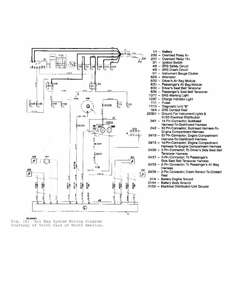
Fig. 16: Air Bag System Wiring DiagramCourtesy of Volvo Cars of North America.