Embed Size (px)
Citation preview
Building 511 Renovation & AdditionWalter Reed Army Institute of Research
USAG Fort Detrick Forest Glen AnnexSilver Spring, MD
Preliminary & Final Design SubmissionNCPC 7 July 2016
USAG Fort Detrick Directorate of Public WorksMedical Research Material Command
USACE Little Rock DistrictTurner + Jacobs
Submitted 8 April 2016
TABLE OF CONTENTS
1. PROJECT REPORT A. Agency B. Agency Point of Contact C. Site Area & Land Allocation D. Area of Building and Surface Parking E. Existing and Projected Employment F. Relation to Master Plan G. Coordination with Local Government & COG H. Schedule of Construction and Occupancy I. Project Cost & Funding Source
2. NARRATIVE DESCRIPTION A. Background B. Project Site C. Erosion Plan D. Landscape E. Building Design F. Interior Design G. Parking H. Utilities I. Fire & Sprinkler System J. Energy Conservation and LEED
3. DOCUMENTATION A. NEPA B. SHPO C. Vicinity Map D. Installation Map E. Site Plan F. Renderings G. First Floor Plan H. Second Floor Plan I. Roof Plan J. Elevations – North, East, South and West K. Building Sections – North-South, East-West L. Landscape, Grading and Drainage Plan M. Erosion and Sediment Control Plan N. Parking
1. PROJECT REPORT
A. AGENCY United States Army Garrison Fort Detrick Directorate of Public Works 201 Beasley Drive Frederick, MD
B. AGENCY POC Carl B. Pritchard, Director Directorate of Public Works United States Army Garrison Fort Detrick 201 Beasley Drive Frederick, MD (301) 619-2454
TENANT POCRandy Weishaar, MEDCOM - MRMC Director Facility Transformation 504 Scott St Ft Detrick, Maryland 21702 (301) 619-2750
C. TOTAL AREA OF SITE & LAND ALLOCATIONThe existing Building 511 site is approximately 2 acres. The limit of disturbance is approximately 5,000 gross square feet. Forest Glen Annex has 124 total acres.
D. AREA OF BUILDINGThe existing building footprint is approximately 35,155 gross square feet and has a total 67,518 gross square footage. The new addition is approximately 5,300 gross square feet total building area and 2,650 gross square feet of addition footprint.
E. EXISTING & PROJECTED EMPLOYMENTExisting staff in Building 511 is 56 full time and 9 part time employees. No new personnel are added due to the addition. Therefore employment is not changing with the construction of the project.
F. RELATION TO FOREST GLEN MASTER PLANBuilding 511 is on the NCPC approved 2003 Masterplan, and on the NCPC reviewed but not approved 2009 BRAC Master Plan. The building addition is not on the NCPC Master Plan but note that the addition is conforming to the existing approved use and the renovations are restoring, repairing and modernizing the existing conditions. In
keeping with the installation design guide standards, the exterior envelope of the existing building and new addition are designed to complement Building 503’s theme.
G. COORDINATION WITH LOCAL GOVERNMENT AND COUNCIL OF GOVERNMENTS A draft Forest Glen Annex Master Plan was informally presented and reviewed for comment with representatives of the Maryland National Capitol Planning Commission in 2012. The Building 511 project is a major interior renovation and a minor addition to an existing facility. Exterior envelope changes are being made to improve energy conservation requirements for the existing building. No new employees are added to the installation population, and it presents no adverse environmental or historic impacts. This project was not coordinated with the local government or Council of Government.
H. CONSTRUCTION SCHEDULE & OCCUPANCYNotice to proceed for construction is expected October of 2016 with completion December of 2018.
I. PROJECT COST & FUNDING SOURCE The authorized budget for this project for design and construction of the addition is $3.4M and for the existing building renovation is $48.36M. The funding source for the project is Defense Health Program (DHP) - O & M.
2. NARRATIVE DESCRIPTION
A. BACKGROUND
The Walter Reed Army Institute of Research (WRAIR), located on the Fort Detrick, Forest Glen Annex in Silver Spring, Maryland, has provided biomedical research to protect and sustain the warfighter and global medical solutions for many decades. Critical to supporting this function has been the Raymond Randall Building (Building 511), which is a 67,518 square foot, two-story concrete structure constructed in 1971. Operating continuously since construction, the building serves as a vivarium and research lab on site, housing non-human primates, large animal species and small animal species including specialty species such as snakes. In addition, the building houses several unique research functions used by both the Navy and Army involving specialized equipment. After over 40 years of continual operation, the Building 511 infrastructure is not in accordance with current building codes and standards, and inadequate to support vivarium best practices. In addition, the building does not have sufficient space for proper operation of the specialized equipment, which was added after the original structure was constructed; therefore, an addition to the structure has been designed. Since 2010, several conceptual designs to renew and reconfigure Building 511 to modern standards and better support of the current mission have occurred. The addition will house specialty equipment associated with research functions currently located within Building 511 and renovation of existing building. Space gained from this relocation will facilitate a better layout for the remaining vivarium functions, including right sizing animal rooms.
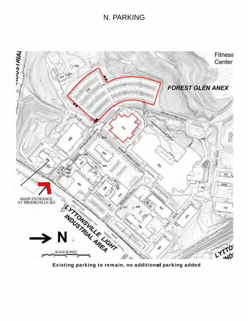
B. PROJECT SITE The site is bounded by two existing roads, Robert Grant Avenue to the south and Stephen Sitter Avenue to the west and north. Vehicular access into the site is provided off of both existing roads. All access drives are constructed of asphalt pavement with the appropriate base course thickness.A large parking lot is located across Stephen Sitter Ave from Building 511. A smaller parking lot is located across Grant Ave. No new parking will be provided in phase 1 or 3 of construction. A service vehicle entrance, consisting of asphalt pavement exists on the northwest corner of the building and is consistent with the surrounding roads.A contractor laydown area is located northwest of the site off of Stephen Sitter Ave. The staging site has an existing hardstand and a controlled perimeter marking an area of approximately 12,000 square feet. Emergency vehicle access will remain consistent with the layout of the current building. Emergency vehicles can access the building from either Stephen Sitter Ave, Robert Grant Ave, or in the drive aisle located between Building 511 and the Forest Glen Annex.Walkways will be constructed of concrete and will be designed to provide access from the northwest vehicle loading area to the western side entrance of the building. The
grading of the non-paved area around the addition and the concrete landing will have a minimum 2 percent slope. The grading of the ramp is in accordance with Americans with Disabilities Act regulations, with a maximum slope of 1:12. The slope of the concrete pavement between the ramp and existing asphalt is about 5%. No permanent irrigation is required for low maintenance, native vegetation. The ornamental fence on the site will remain throughout construction. No other fences will be constructed around the perimeter of the site.
C. STORMWATER MANAGEMENT
Although the total land disturbance does not exceed 5,000 square feet, the total volume of earthwork excavation will exceed 100 cubic yards. Therefore, stormwater management designed in accordance with the Maryland Department of the Environment (MDE) rules and regulations will be required. Low impact development practices have been utilized to the maximum extent practicable by providing two rain gardens, which are an MDE approved Environmental Site Design (ESD) measure. The two rain gardens are designed to capture and infiltrate runoff into the ground prior to discharging from the site into off-site tributaries.
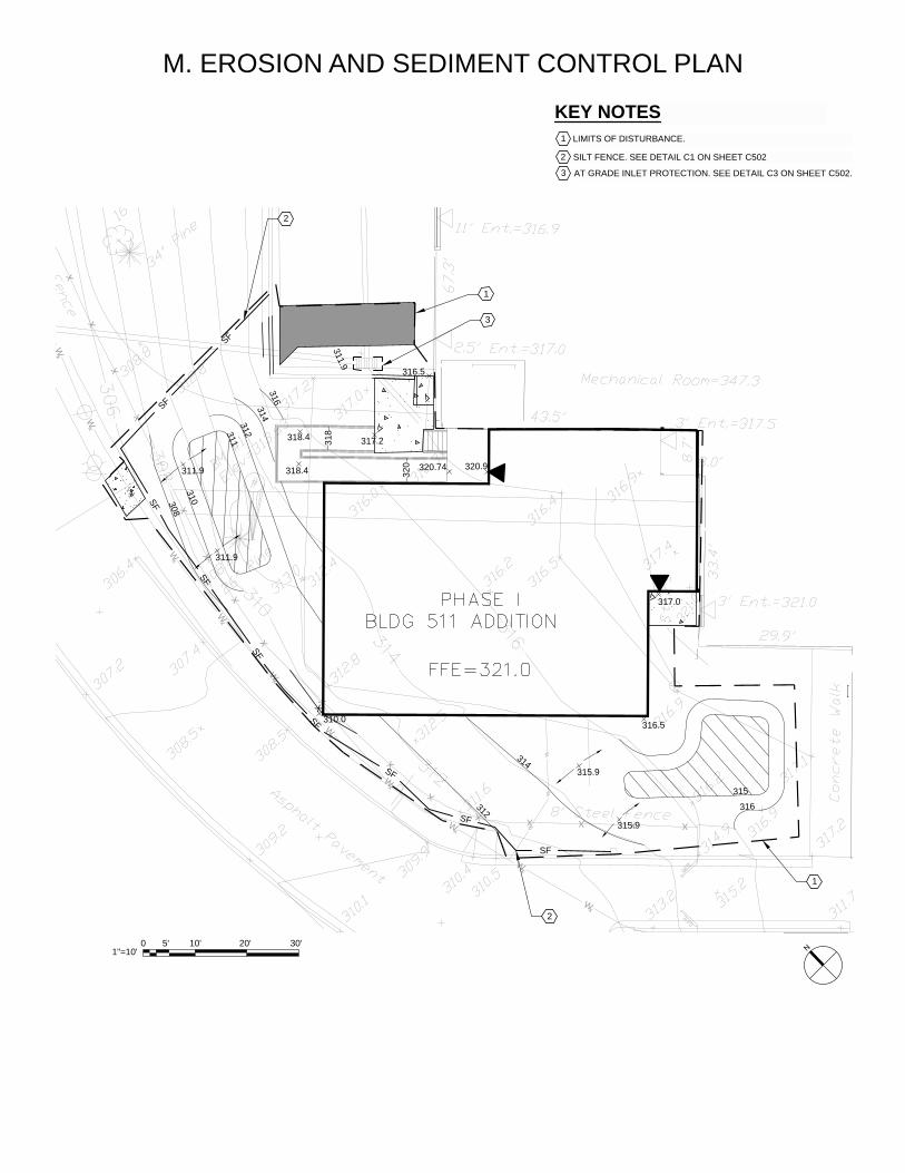
During construction, erosion and sediment control devices will be utilized to ensure sediment laden runoff does not discharge from the site, polluting nearby tributaries. The erosion and sediment control approach will employ a combination of silt fence, tree protection, inlet protection, and stabilized construction entrances.
D. LANDSCAPEA landscape plan will strive to meet all current jurisdictional agency requirements with regards to proposed planting, while also adhering to AT/FP measures that must be applied to this facility. Therefore, proposed planting adjacent to the building is limited to reseeding and establishing lawn areas disturbed by construction with a species of grass matching the existing lawn.Further from the proposed building, existing trees will be preserved. Tree protection will be installed where necessary and any excavation within drip lines will be limited and will require root pruning. No equipment will be stored within tree driplines, no access into tree protection areas will be allowed.
E. BUILDING DESIGN The design and construction of the project is divided into four construction and transition phases.Phase I, is the construction of an approximately 5,300 square feet addition. The first floor of the addition houses large testing equipment (shock tubes) and the second level is mechanical space only which will be integrated with the existing mechanical space. Existing egress stairwell will be demolished to construct a new egress stairwell which will access the roof. The shock-tube suite via a corridor will be directly connected to the vivarium. It will also have direct access to the exterior of the building with a ramp and stair leading to grade. The new addition will be separated from the existing building with
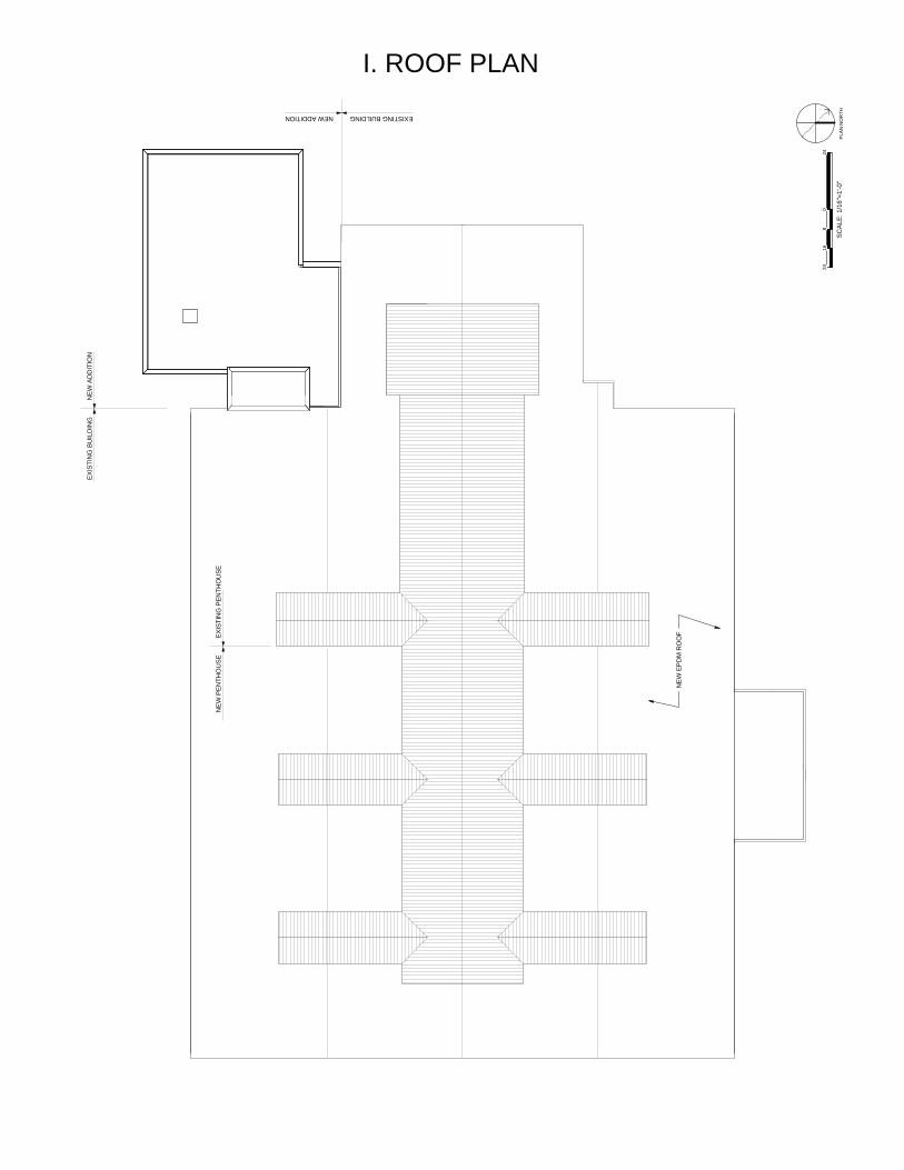
a building expansion joint. The exterior will be brick to match existing building with metal panel accents. See attached rendering and elevations. Phase II, Transition is the relocation of the equipment, laboratories and staff from the existing building into the new addition. Phase II will also relocate administration functions within the existing building and prepare the site to permit the implementation of Phase III. Phase III is the construction of the renovation of the existing facility to provide a vivarium, that will function efficiently, with built in flexibility and upgraded building envelope and finishes which address future needs, and environmental sustainability.Windows will be replaced to meet ATFP requirements and mullions will be blue to match the base theme. Exterior envelope and roof of the building will be replaced in kind in order to upgrade the insulation for the design parameters of the humidification of the Vivarium and weather-proofing. The exterior envelope will match the existing conditions as well as update to meet the Installation Guidelines with Guideline colors and thematic metal panel accents. In order to upgrade the mechanical system to meet the criteria, the penthouse on the roof will be enlarged in footprint to accommodate additional ductwork. The penthouse will not increase in height. See attached renderings and elevations. Phase IV is the initial outfitting and occupancy procedure of the occupancy of the building after construction has been completed.
F. INTERIOR DESIGN The interior upgrades to the entire building will be made to enhance the working experience, meet projected animal holding requirements and improve animal care. Renovation of office and conferencing areas will be designed to meet MEDCOM Interior Design Master Plan Guides. Recommendations from the most recent guide care and use of Laboratory Animals (the “Guide”) will be used as basis of design for the Vivarium portions of the building. The floors in the Vivarium will be epoxy flooring with CMU walls and where applicable gypsum wall board or Fiberglass ceilings.The interior finishes will be selected based on suitability of use, LEED properties, durability, and aesthetic character. The primary colors in the building will be neutral with accents of color to provide interest. The floor finishes offer durability and safety while providing complementary accents that pull the remainder of the room finishes together.The floor in the reception area, offices, conference/meeting rooms and study/library will be carpet tile, with ceramic/porcelain tile in restroom/locker rooms and rubber tile in break/kitchen, storage and mail/copy rooms. Wall colors will be painted a soothing neutral in the majority of the building. Special spaces such as break/kitchen area will have accent walls painted in complementary colors that will blend with the overall color palette yet add an extra point of interest to the space. Acrylic latex painted gypsum board will be the standard wall finish in the majority of spaces. Color options will be presented to the owner/users and selections will be made based on an approved design process.The restrooms will be finished with a ceramic porcelain through-color tile that will provide the areas with a pleasing look and ease of cleaning.
Acoustical ceiling tile will be used in offices, break/kitchen and administrative support spaces such as storage and mail/copy rooms. New furniture and furnishings will be selected and furnished throughout the administrative spaces.The building will reflect both users’ needs and functionality and will provide a comfortable yet durable facility in which to complete their operations.
G. PARKING No new employee or visitors will be added due to the increased area and there will be no changes to existing parking counts or configurations.
H. UTILITIESA water service line traverses through the Phase I project site and will be relocated to accommodate the planned Addition. A new water line will connect to the existing water main located within Stephen Sitter Avenue, and will be routed north of the addition and into the existing mechanical room. Prior to entering the building, the water line will split, providing separate dedicated lines for domestic and fire suppression service. All other utilities are existing to remain.
I. FIRE SPRINKLER SYSTEM The existing building is currently sprinklered and fully complicate with NFPA 13 and 72 for sprinkler and alarm systems. Addition will tie into existing building system. Sprinkler heads will be modified for new floor plan layout during the renovation of the existing building.
J. ENERGY CONSERVATION AND LEED The renovation and Addition to the Building 511 will comply with USGBC LEED v2009 NC requirements and be certifiable to a LEED Silver rating.
A. NEPA‐ ADDITION
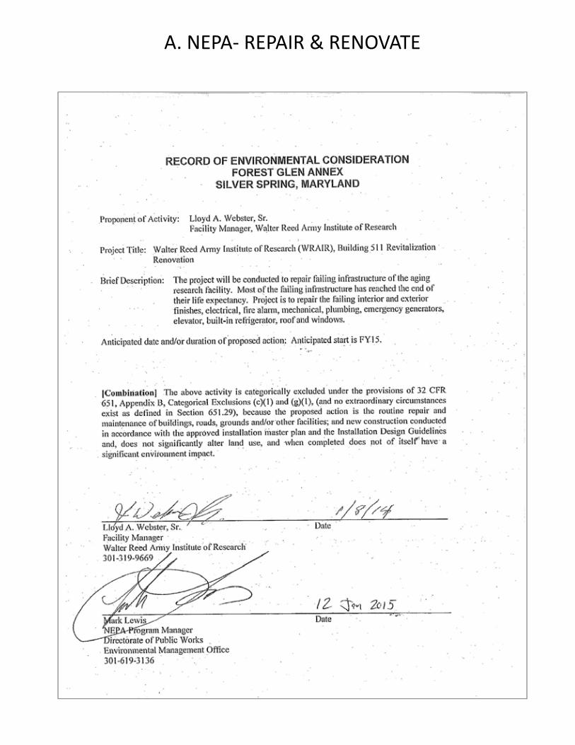
A. NEPA‐ REPAIR & RENOVATE
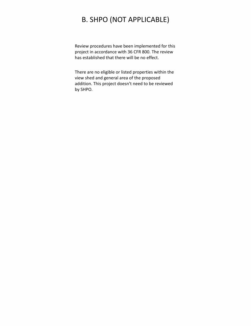
B. SHPO (NOT APPLICABLE)
Review procedures have been implemented for this project in accordance with 36 CFR 800. The review has established that there will be no effect.
There are no eligible or listed properties within the view shed and general area of the proposed addition. This project doesn't need to be reviewed by SHPO.
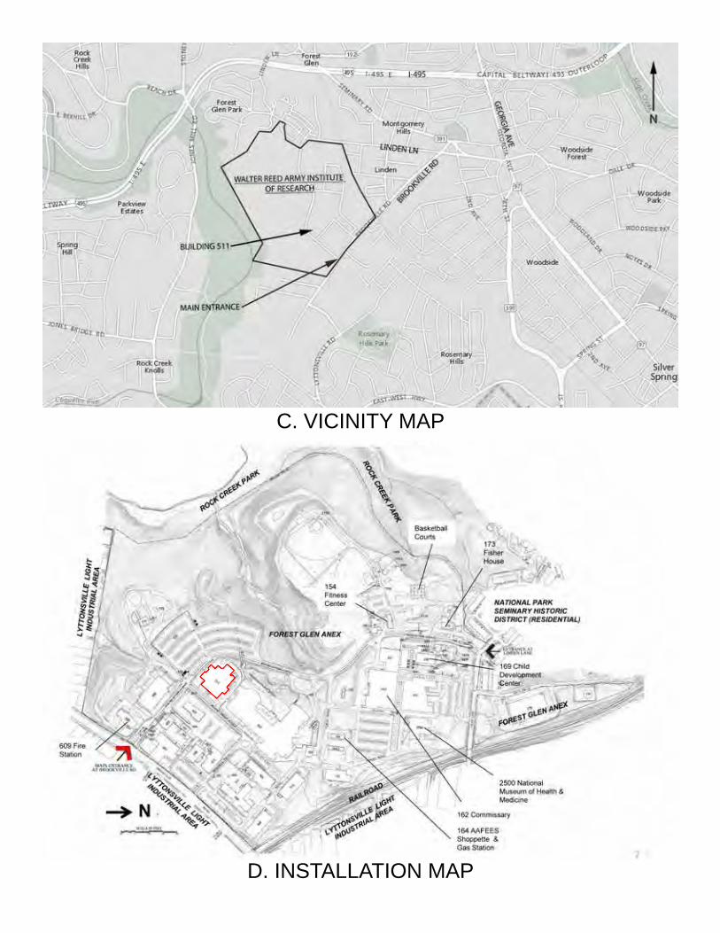
C. VICINITY MAP
D. INSTALLATION MAP
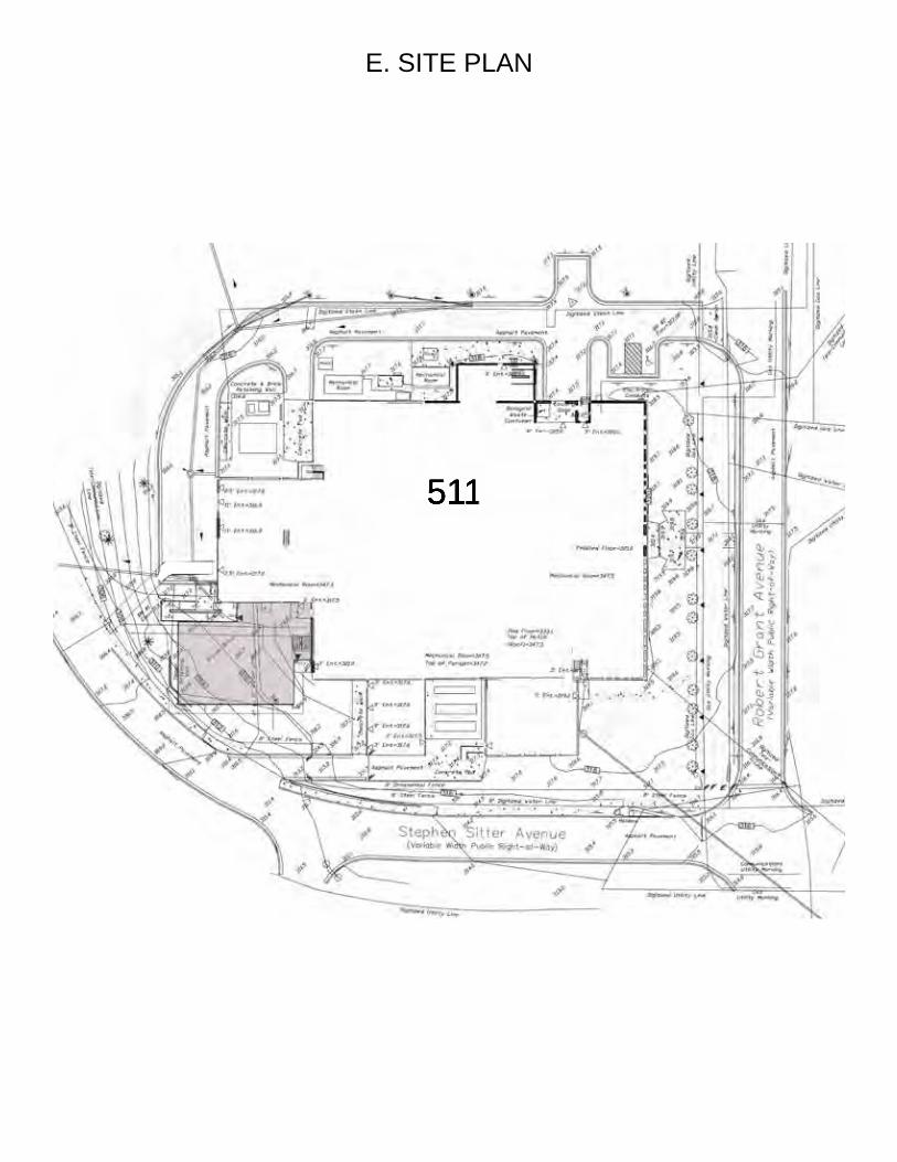
E. SITE PLAN
511
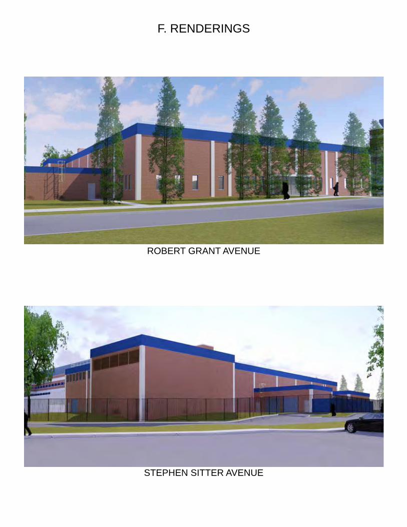
F. RENDERINGS
ROBERT GRANT AVENUE
STEPHEN SITTER AVENUE
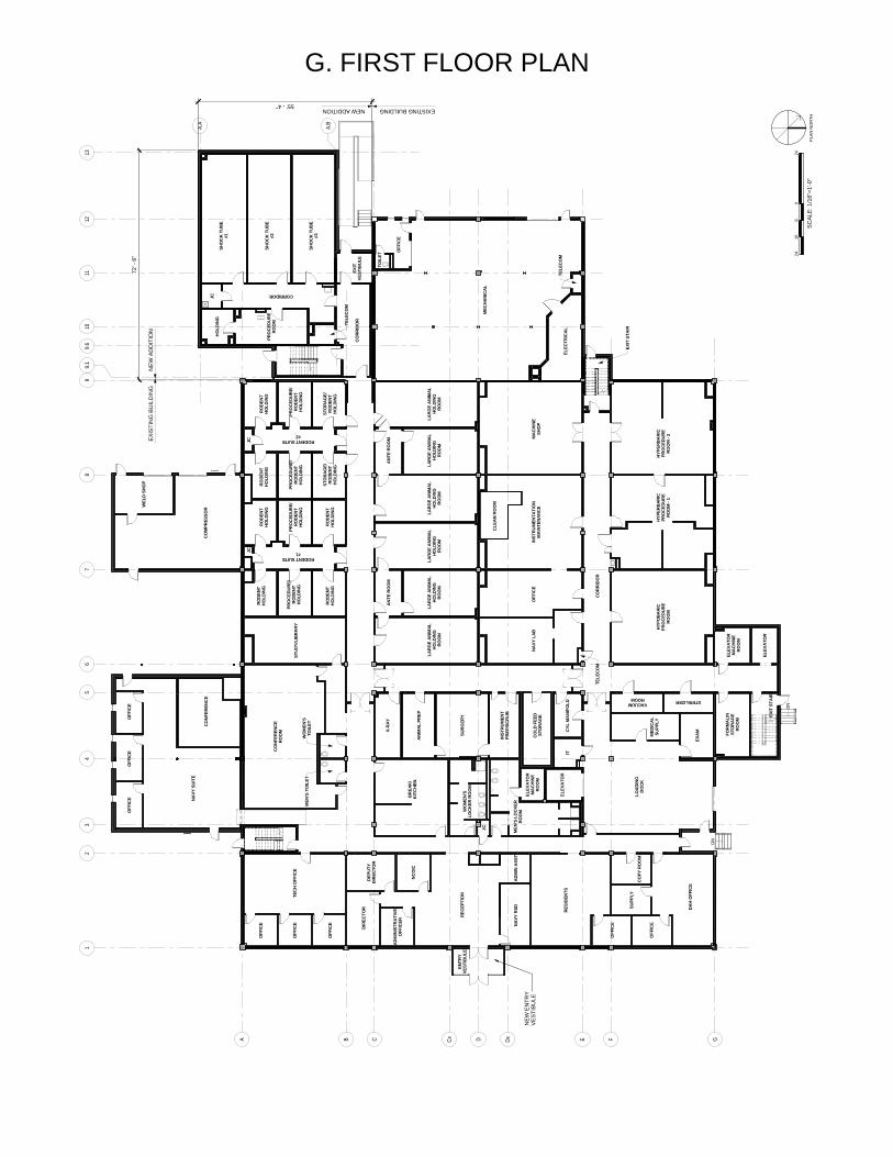
G. FIRST FLOOR PLAN
DN
DN
12
34
56
78
910
11
A B C D E F GCx Dx
12
A.A
A.B
9.6
139.
1
MAC
HINE
SHO
P
BR
EAK/
KIT
CHE
N
HYP
OB
ARIC
PRO
CED
URE
RO
OM
HYP
ERBA
RIC
PRO
CEDU
RER
OO
M -
1
HYP
ERBA
RIC
PRO
CEDU
RER
OO
M -
2
OFF
ICE
OFF
ICE
OFF
ICE
MEC
HANI
CAL
OFF
ICE
CLE
AN R
OO
M
OFF
ICE
OFF
ICE
OFF
ICE
TEC
H O
FFIC
E
DIR
ECTO
RD
EPU
TYD
IREC
TOR
NC
OIC
REC
EPTI
ON
ADM
INIS
TRA
TIVE
OFF
ICER NA
VY R
SDAD
MIN
ASS
T
RES
IDEN
TS
OFF
ICE
OFF
ICE
SUPP
LYC
OPY
RO
OM
DA
H O
FFIC
E
X-RA
Y
ANIM
AL P
REP
SUR
GER
Y
INST
RUM
ENT
PREP
/SC
RU
B
CO
LD F
EED
STO
RA
GE
IT
WO
MEN
'SLO
CKE
R R
OO
M
MEN
'S L
OC
KER
RO
OM
ELEV
ATO
RM
AC
HIN
ERO
OM
STU
DY/L
IBRA
RY
CO
NFER
ENCE
RO
OM
WEL
D SH
OP
CO
MPR
ESSO
R
MED
ICAL
SUPP
LY
STERILIZERVACUUMROOM
EXAM
LOA
DIN
GD
OCK
NAVY
LAB
RODENT SUITE#1
RODENT SUITE#2
FOR
MA
LIN
STO
RA
GE
ROO
M
NAV
Y SU
ITE
CO
RRID
OR
ELEV
ATO
RM
AC
HIN
ERO
OM
EXIT
STA
IR
EXIT
VEST
IBU
LE
CYL
MA
NIF
OLD
TELE
CO
M
JC
MEN
'S T
OIL
ETW
OM
EN'S
TOIL
ET
EXIT
STA
IR
ELEV
ATO
R
ELEV
ATO
R
OFF
ICE
TOIL
ET
INST
RU
MEN
TATI
ON
MAI
NTEN
ANCE
TELE
CO
M
SHO
CK
TU
BE
#2
SHO
CK
TU
BE
#1
PRO
CED
UR
ER
OO
M
SHO
CK
TU
BE
#3
HO
LDIN
GJC
CORRIDOR
TELE
CO
M
CO
NFER
ENCE
LARG
E AN
IMAL
HOLD
ING
ROO
M
LARG
E AN
IMAL
HOLD
ING
ROO
M
LARG
E AN
IMAL
HOLD
ING
ROO
M
ANT
E R
OO
MA
NTE
RO
OM
ELEC
TRIC
AL
LARG
E AN
IMAL
HOLD
ING
ROO
M
LARG
E AN
IMAL
HOLD
ING
ROO
M
LARG
E AN
IMAL
HOLD
ING
ROO
M
CO
RRID
OR
ENTR
YVE
STIB
ULE
NEW
AD
DIT
ION
EXIS
TIN
G B
UIL
DIN
G
EXISTING BUILDINGNEW ADDITION
RO
DEN
TH
OLD
ING
PRO
CED
URE/
RO
DEN
TH
OLD
ING
RO
DEN
TH
OLD
ING
RO
DEN
TH
OLD
ING
STO
RAG
E/R
ODE
NTH
OLD
ING
PRO
CED
URE/
RO
DEN
TH
OLD
ING
PRO
CED
URE/
RO
DEN
TH
OLD
ING
RO
DEN
TH
OLD
ING
RO
DEN
TH
OLD
ING
RO
DEN
TH
OLD
ING
PRO
CED
URE/
RO
DEN
TH
OLD
ING
STO
RAG
E/R
ODE
NTH
OLD
ING
JCJC
72' -
6"
55' - 4"
NEW
EN
TRY
VEST
IBU
LE
2424
SCAL
E: 1
/16"
=1'-0
"
016
8
PLAN
NO
RTH
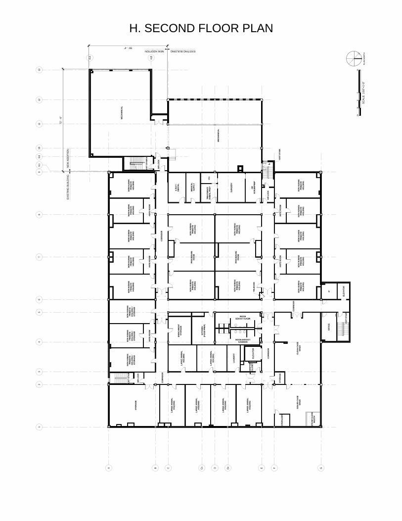
H. SECOND FLOOR PLAN1
23
45
67
89
1011
A B C D E F GCx Dx
12
A.A
A.B
9.6
139.
1
LARG
E AN
IMAL
HOLD
ING
LARG
E AN
IMAL
HOLD
ING
NO
N HU
MAN
PRIM
ATE
HO
LDIN
G
NO
N HU
MAN
PRIM
ATE
HO
LDIN
G
NO
N HU
MAN
PRIM
ATE
HO
LDIN
G
NO
N HU
MAN
PRIM
ATE
HO
LDIN
G
NO
N HU
MAN
PRIM
ATE
HO
LDIN
G
NO
N HU
MAN
PRIM
ATE
HO
LDIN
G
NO
N HU
MAN
PRIM
ATE
HO
LDIN
G /
STO
RAG
E
NO
N HU
MAN
PRIM
ATE
HO
LDIN
G /
STO
RAG
E
MEN'S LOCKERROOM
WOMEN'SLOCKER ROOM
LAUN
DRY
JANI
TOR
CLO
SET
ENR
ICH
MEN
TST
OR
AG
E
KIT
CH
EN(F
OO
D P
REP
)
X-R
AY /
DENT
AL
MED
ICA
LSU
PPLY
TREA
TMEN
T/AN
IMAL
PRE
P
SUR
GER
Y
OR
SCR
UB/P
REP
ICU
AIR
LO
CK
SOIL
ED C
AG
EW
ASH
CLEA
N CA
GE
WAS
H
STO
RAG
E
ITO
FFIC
E
MEC
HANI
CAL
MEC
HANI
CAL
EXIT
STA
IR
EXIT
STA
IR B
CO
RRID
OR
AIR
LO
CK
AIR
LO
CK
CO
RRID
OR
CO
RRID
OR
ELEV
ATO
R
STER
ILIZ
ER
STEA
M C
LEAN
BOO
TH
EXIT
STA
IR
ELEV
ATO
R
EXIT
STA
IR
CO
RRID
OR
PRO
CED
URE
RO
OM
NO
N HU
MAN
PRIM
ATE
HO
LDIN
G
NO
N HU
MAN
PRIM
ATE
HO
LDIN
G
NO
N HU
MAN
PRIM
ATE
HO
LDIN
G
NO
N HU
MAN
PRIM
ATE
HO
LDIN
G
TELE
CO
M
ANT
E R
OO
MA
NTE
RO
OM
LARG
E AN
IMAL
HO
LDIN
G
LARG
E AN
IMAL
HO
LDIN
G
STO
RAG
E
LARG
E AN
IMAL
HOLD
ING
PRO
CED
URE
RO
OM
ANT
E R
OO
MA
NTE
RO
OM
NO
N HU
MAN
PRIM
ATE
HO
LDIN
G
NO
N HU
MAN
PRIM
ATE
HO
LDIN
G
NO
N HU
MAN
PRIM
ATE
HO
LDIN
G
NO
N HU
MAN
PRIM
ATE
HO
LDIN
G /
STO
RAG
E
NO
N HU
MAN
PRIM
ATE
HO
LDIN
G
ANT
E R
OO
M
LARG
E AN
IMAL
HOLD
ING
NEW
AD
DIT
ION
EXIS
TIN
G B
UIL
DIN
G
EXISTING BUILDINGNEW ADDITION
72' -
6"
55' - 4"
2424
SCAL
E: 1
/16"
=1'-0
"
016
8
PLAN
NO
RTH
NEW
AD
DIT
ION
EXIS
TIN
G B
UIL
DIN
G
EXISTING BUILDINGNEW ADDITION
EXIS
TIN
G P
ENTH
OU
SEN
EW P
ENTH
OU
SE
NEW
EPD
M R
OO
F
2424
SCAL
E: 1
/16"
=1'-0
"
016
8
PLAN
NO
RTH
I. ROOF PLAN
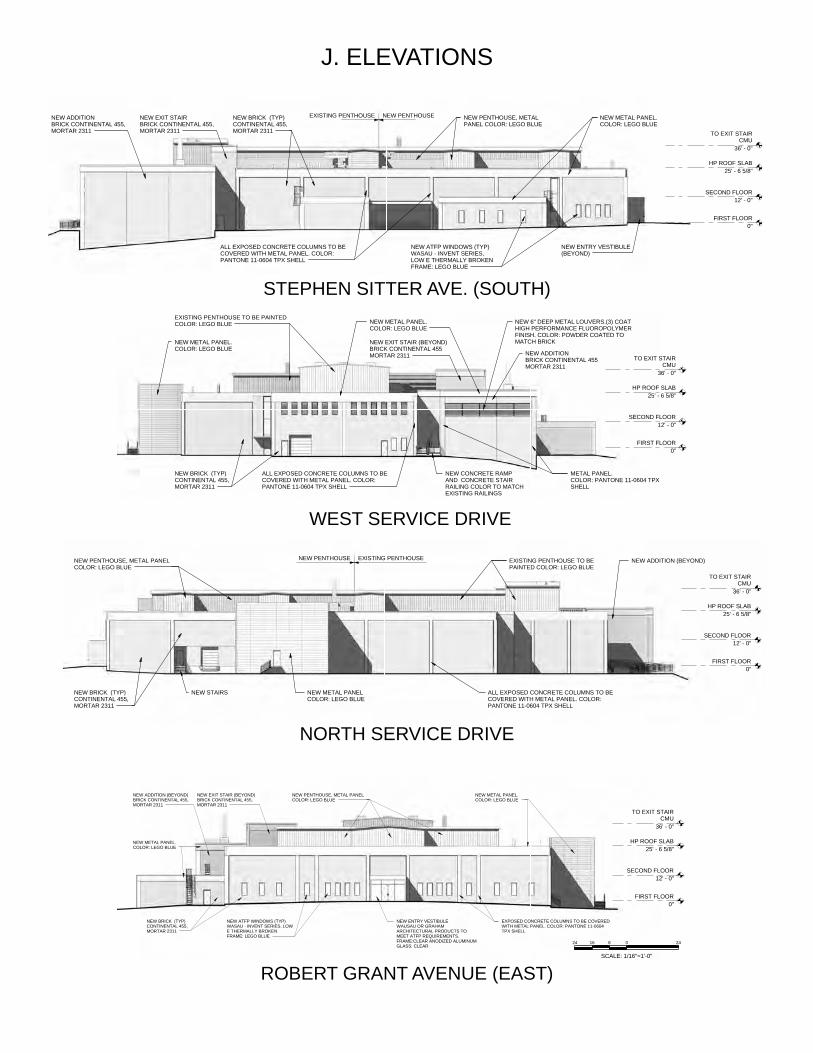
J. ELEVATIONS
WEST SERVICE DRIVE
STEPHEN SITTER AVE. (SOUTH)
NORTH SERVICE DRIVE
ROBERT GRANT AVENUE (EAST)
FIRST FLOOR0"
SECOND FLOOR12' - 0"
HP ROOF SLAB25' - 6 5/8"
TO EXIT STAIRCMU
36' - 0"
EXISTING PENTHOUSE TO BEPAINTED COLOR: LEGO BLUE
ALL EXPOSED CONCRETE COLUMNS TO BECOVERED WITH METAL PANEL. COLOR:PANTONE 11-0604 TPX SHELL
NEW METAL PANELCOLOR: LEGO BLUE
NEW BRICK (TYP)CONTINENTAL 455,MORTAR 2311
NEW STAIRS
NEW ADDITION (BEYOND)EXISTING PENTHOUSENEW PENTHOUSENEW PENTHOUSE, METAL PANELCOLOR: LEGO BLUE
FIRST FLOOR0"
SECOND FLOOR12' - 0"
HP ROOF SLAB25' - 6 5/8"
TO EXIT STAIRCMU
36' - 0"
NEW ADDITIONBRICK CONTINENTAL 455,MORTAR 2311
NEW EXIT STAIRBRICK CONTINENTAL 455,MORTAR 2311
NEW PENTHOUSE, METALPANEL COLOR: LEGO BLUE
NEW ENTRY VESTIBULE(BEYOND)
ALL EXPOSED CONCRETE COLUMNS TO BECOVERED WITH METAL PANEL. COLOR:PANTONE 11-0604 TPX SHELL
NEW BRICK (TYP)CONTINENTAL 455,MORTAR 2311
NEW ATFP WINDOWS (TYP)WASAU - INVENT SERIES,LOW E THERMALLY BROKENFRAME: LEGO BLUE
NEW PENTHOUSEEXISTING PENTHOUSE NEW METAL PANEL.COLOR: LEGO BLUE
FIRST FLOOR0"
SECOND FLOOR12' - 0"
HP ROOF SLAB25' - 6 5/8"
TO EXIT STAIRCMU
36' - 0"
NEW ADDITIONBRICK CONTINENTAL 455MORTAR 2311
NEW EXIT STAIR (BEYOND)BRICK CONTINENTAL 455MORTAR 2311
NEW METAL PANEL.COLOR: LEGO BLUE
NEW BRICK (TYP)CONTINENTAL 455,MORTAR 2311
NEW CONCRETE RAMPAND CONCRETE STAIRRAILING COLOR TO MATCHEXISTING RAILINGS
NEW 6" DEEP METAL LOUVERS.(3) COATHIGH PERFORMANCE FLUOROPOLYMERFINISH. COLOR: POWDER COATED TOMATCH BRICK
ALL EXPOSED CONCRETE COLUMNS TO BECOVERED WITH METAL PANEL. COLOR:PANTONE 11-0604 TPX SHELL
METAL PANEL.COLOR: PANTONE 11-0604 TPXSHELL
NEW METAL PANEL.COLOR: LEGO BLUE
EXISTING PENTHOUSE TO BE PAINTEDCOLOR: LEGO BLUE
FIRST FLOOR0"
SECOND FLOOR12' - 0"
HP ROOF SLAB25' - 6 5/8"
TO EXIT STAIRCMU
36' - 0"
NEW ADDITION (BEYOND)BRICK CONTINENTAL 455,MORTAR 2311
NEW EXIT STAIR (BEYOND)BRICK CONTINENTAL 455,MORTAR 2311
NEW PENTHOUSE, METAL PANELCOLOR: LEGO BLUE
NEW ENTRY VESTIBULEWAUSAU OR GRAHAMARCHITECTURAL PRODUCTS TOMEET ATFP REQUIREMENTS.FRAME:CLEAR ANODIZED ALUMINUMGLASS: CLEAR
EXPOSED CONCRETE COLUMNS TO BE COVEREDWITH METAL PANEL. COLOR: PANTONE 11-0604TPX SHELL
NEW METAL PANEL.COLOR: LEGO BLUE
NEW BRICK (TYP)CONTINENTAL 455,MORTAR 2311
NEW ATFP WINDOWS (TYP)WASAU - INVENT SERIES, LOWE THERMALLY BROKENFRAME: LEGO BLUE
NEW METAL PANEL.COLOR: LEGO BLUE
2424
SCALE: 1/16"=1'-0"
016 8
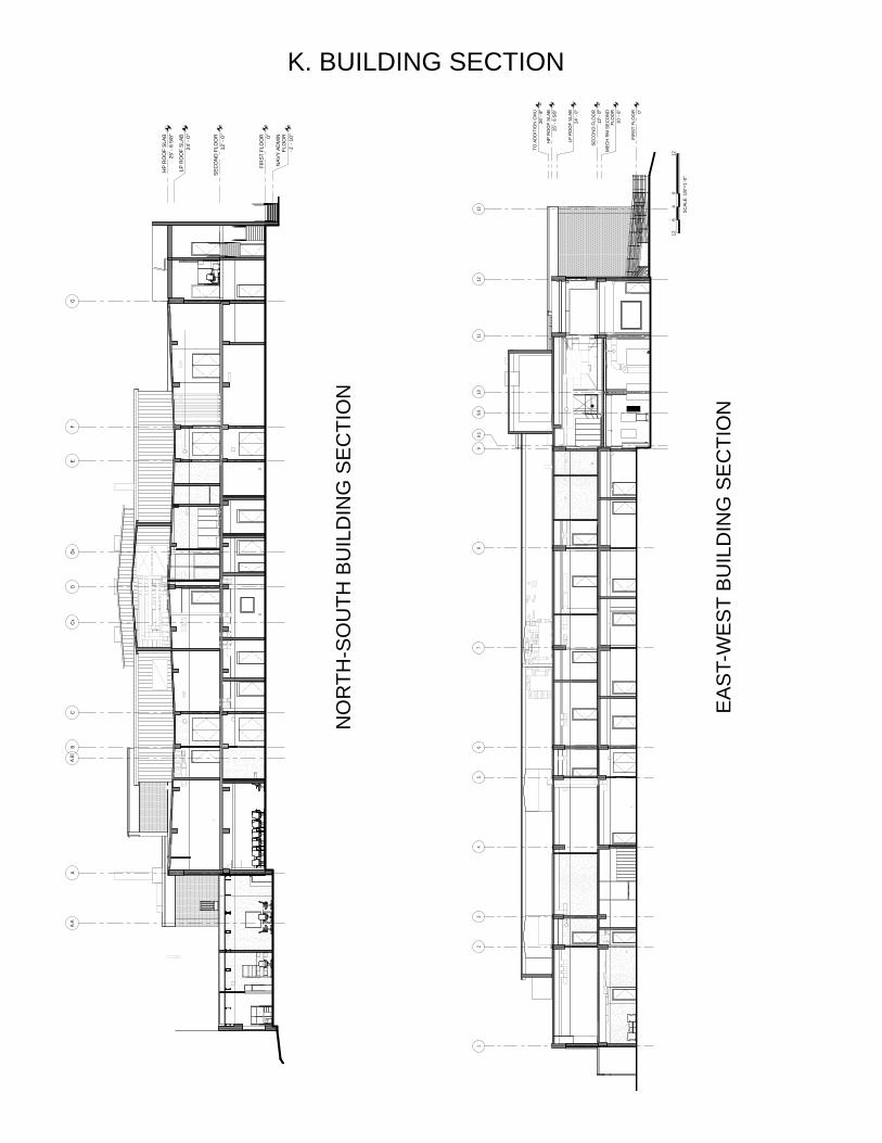
K. BUILDING SECTION
NO
RTH
-SO
UTH
BU
ILD
ING
SE
CTI
ON
EA
ST-
WE
ST
BU
ILD
ING
SE
CTI
ON
FIR
ST F
LOO
R 0"
SEC
ON
D F
LOO
R12
' - 0
"
HP
RO
OF
SLAB
25' -
6 5
/8"
12
34
56
78
910
11
LP R
OO
F SL
AB24
' - 0
"
12
MEC
H R
M S
ECO
ND
FLO
OR
10' -
6"
9.6
139.
1
TO A
DD
ITIO
N C
MU
26' -
8"
1212
SCAL
E: 1
/8"=
1'-0
"
08
4
FIR
ST F
LOO
R 0"
SEC
ON
D F
LOO
R12
' - 0
"
HP
RO
OF
SLAB
25' -
6 5
/8"
AB
CD
EF
GCx
Dx
LP R
OO
F SL
AB24
' - 0
"
NAV
Y AD
MIN
FLO
OR
-1' -
10"
A.A
A.B
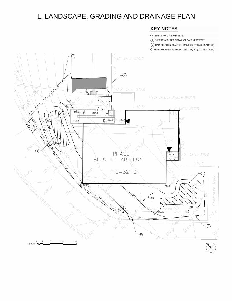
L. LANDSCAPE, GRADING AND DRAINAGE PLAN
XXXXX
X
X
X
X
X
X
X
X
X
X
X
X
X
X
XXXXXXXXXXXXXXX
XXXXXX
X
Wx
Wx
Wx
Wx
Wx
Wx
Wx
Wx
Wx
Wx
Wx
Wx
Wx
Wx
Wx
Wx
Wx
WxWx Wx Wx Wx Wx Wx Wx Wx
Wx
Wx
Wx
317.0
320.9320.74318.4
318.4 317.2
310.0
320
318
316.5
316.5
315
316
315.9
315.9
311.9
311.9
314316
312
311.9
310308
311
314
312
X
SF
SF
SF
SF
SF
SF
SF
SF
SF
1
1
2
4
3
2
CG-101
GR
AD
ING
AN
D D
RA
INA
GE
PLA
N
1
PROFESSIONAL CERTIFICATION. I HEREBYCERTIFY THAT THESE DOCUMENTSWERE PREPARED OR APPROVED BY ME,AND THAT I AM A DULY LICENSEDPROFESSIONAL ENGINEER UNDER THELAWS OF THE STATE OF MARYLAND,
MARYLAND LICENSE NO.: 45292
EXPIRATION DATE: 05-21-2016
SCALE: 1" = 10'CG-101A1 GRADING AND DRAINAGE PLAN
1 LIMITS OF DISTURBANCE.
KEY NOTES
N
5'1"=10'
0 10' 20' 30'
US Army Corpsof Engineers ®
SHEET ID
US
AR
MY
CO
RP
S O
F E
NG
INE
ER
S
DR
AW
N B
Y:
DE
SIG
NE
D B
Y:
SU
BM
ITTE
D B
Y:
SIZ
E:
CH
EC
KE
D B
Y:
AR
CH
E1
FILE
NA
ME
:
ISS
UE
DA
TE:
CO
NTR
AC
T N
O.:
SO
LIC
ITA
TIO
N N
O.:
FILE
NU
MB
ER
:
1
A
2 3 4 5 6
B
C
D
E
PHASE -
MA
RC
H 2
3, 2
015
W91
275-
15-R
-600
8-00
09
W91
275-
15-C
-600
5
WR
AIR
BU
ILD
ING
511
LITT
LE R
OC
K D
ISTR
ICTL
ITTL
ER
OC
K, A
RK
AN
SA
S
R. C
RO
WLE
Y
A. W
ILLI
AM
SO
N
J. S
TIP
E
D. D
EIB
LE
MA
RK
DE
SC
RIP
TIO
ND
ATE
35%
SU
BM
ISS
ION
03/2
3/16
2 SILT FENCE. SEE DETAIL C1 ON SHEET C502
3 RAIN GARDEN #1. AREA= 278.1 SQ FT (0.0064 ACRES)
4 RAIN GARDEN #2. AREA= 223.0 SQ FT (0.0051 ACRES)
XXXXX
X
X
X
X
X
X
X
X
X
X
X
X
X
X
XXXXXXXXXXXXXXX
XXXXXX
X
Wx
Wx
Wx
Wx
Wx
Wx
Wx
Wx
Wx
Wx
Wx
Wx
Wx
Wx
Wx
Wx
Wx
WxWx Wx Wx Wx Wx Wx Wx Wx
Wx
Wx
Wx
317.0
320.9320.74318.4
318.4 317.2
310.0
320
318
316.5
316.5
315
316
315.9
315.9
311.9
311.9
314316
312
311.9
310308
311
314
312
X
SF
SF
SF
SF
SF
SF
SF
SF
SF
1
1
2
2
3
CG-111
ER
OS
ION
AN
D S
ED
IME
NT
CO
NTR
OL
PLA
N
1
PROFESSIONAL CERTIFICATION. I HEREBYCERTIFY THAT THESE DOCUMENTSWERE PREPARED OR APPROVED BY ME,AND THAT I AM A DULY LICENSEDPROFESSIONAL ENGINEER UNDER THELAWS OF THE STATE OF MARYLAND,
MARYLAND LICENSE NO.: 45292
EXPIRATION DATE: 05-21-2016
SCALE: 1" = 10'CG-111A1
EROSION AND SEDIMENT CONTROL PLAN
1 LIMITS OF DISTURBANCE.
KEY NOTES
N
5'1"=10'
0 10' 20' 30'
US Army Corpsof Engineers ®
SHEET ID
US
AR
MY
CO
RP
S O
F E
NG
INE
ER
S
DR
AW
N B
Y:
DE
SIG
NE
D B
Y:
SU
BM
ITTE
D B
Y:
SIZ
E:
CH
EC
KE
D B
Y:
AR
CH
E1
FILE
NA
ME
:
ISS
UE
DA
TE:
CO
NTR
AC
T N
O.:
SO
LIC
ITA
TIO
N N
O.:
FILE
NU
MB
ER
:
1
A
2 3 4 5 6
B
C
D
E
PHASE -
MA
RC
H 2
3, 2
015
W91
275-
15-R
-600
8-00
09
W91
275-
15-C
-600
5
WR
AIR
BU
ILD
ING
511
LITT
LE R
OC
K D
ISTR
ICTL
ITTL
ER
OC
K, A
RK
AN
SA
S
R. C
RO
WLE
Y
A. W
ILLI
AM
SO
N
J. S
TIP
E
D. D
EIB
LE
MA
RK
DE
SC
RIP
TIO
ND
ATE
35%
SU
BM
ISS
ION
03/2
3/16
2 SILT FENCE. SEE DETAIL C1 ON SHEET C502
3 AT GRADE INLET PROTECTION. SEE DETAIL C3 ON SHEET C502.
XXXXX
X
X
X
X
X
X
X
X
X
X
X
X
X
X
XXXXXXXXXXXXXXX
XXXXXX
X
Wx
Wx
Wx
Wx
Wx
Wx
Wx
Wx
Wx
Wx
Wx
Wx
Wx
Wx
Wx
Wx
Wx
WxWx Wx Wx Wx Wx Wx Wx Wx
Wx
Wx
Wx
317.0
320.9320.74318.4
318.4 317.2
310.0
320
318
316.5
316.5
315
316
315.9
315.9
311.9
311.9
314316
312
311.9
310308
311
314
312
X
SF
SF
SF
SF
SF
SF
SF
SF
SF
1
1
2
4
3
2
CG-101
GR
AD
ING
AN
D D
RA
INA
GE
PLA
N
1
PROFESSIONAL CERTIFICATION. I HEREBYCERTIFY THAT THESE DOCUMENTSWERE PREPARED OR APPROVED BY ME,AND THAT I AM A DULY LICENSEDPROFESSIONAL ENGINEER UNDER THELAWS OF THE STATE OF MARYLAND,
MARYLAND LICENSE NO.: 45292
EXPIRATION DATE: 05-21-2016
SCALE: 1" = 10'CG-101A1 GRADING AND DRAINAGE PLAN
1 LIMITS OF DISTURBANCE.
KEY NOTES
N
5'1"=10'
0 10' 20' 30'
US Army Corpsof Engineers ®
SHEET ID
US
AR
MY
CO
RP
S O
F E
NG
INE
ER
S
DR
AW
N B
Y:
DE
SIG
NE
D B
Y:
SU
BM
ITTE
D B
Y:
SIZ
E:
CH
EC
KE
D B
Y:
AR
CH
E1
FILE
NA
ME
:
ISS
UE
DA
TE:
CO
NTR
AC
T N
O.:
SO
LIC
ITA
TIO
N N
O.:
FILE
NU
MB
ER
:
1
A
2 3 4 5 6
B
C
D
E
PHASE -
MA
RC
H 2
3, 2
015
W91
275-
15-R
-600
8-00
09
W91
275-
15-C
-600
5
WR
AIR
BU
ILD
ING
511
LITT
LE R
OC
K D
ISTR
ICTL
ITTL
ER
OC
K, A
RK
AN
SA
S
R. C
RO
WLE
Y
A. W
ILLI
AM
SO
N
J. S
TIP
E
D. D
EIB
LE
MA
RK
DE
SC
RIP
TIO
ND
ATE
35%
SU
BM
ISS
ION
03/2
3/16
2 SILT FENCE. SEE DETAIL C1 ON SHEET C502
3 RAIN GARDEN #1. AREA= 278.1 SQ FT (0.0064 ACRES)
4 RAIN GARDEN #2. AREA= 223.0 SQ FT (0.0051 ACRES)
XXXXX
X
X
X
X
X
X
X
X
X
X
X
X
X
X
XXXXXXXXXXXXXXX
XXXXXX
X
Wx
Wx
Wx
Wx
Wx
Wx
Wx
Wx
Wx
Wx
Wx
Wx
Wx
Wx
Wx
Wx
Wx
WxWx Wx Wx Wx Wx Wx Wx Wx
Wx
Wx
Wx
317.0
320.9320.74318.4
318.4 317.2
310.0
320
318
316.5
316.5
315
316
315.9
315.9
311.9
311.9
314316
312
311.9
310308
311
314
312
X
SF
SF
SF
SF
SF
SF
SF
SF
SF
1
1
2
2
3
CG-111
ER
OS
ION
AN
D S
ED
IME
NT
CO
NTR
OL
PLA
N
1
PROFESSIONAL CERTIFICATION. I HEREBYCERTIFY THAT THESE DOCUMENTSWERE PREPARED OR APPROVED BY ME,AND THAT I AM A DULY LICENSEDPROFESSIONAL ENGINEER UNDER THELAWS OF THE STATE OF MARYLAND,
MARYLAND LICENSE NO.: 45292
EXPIRATION DATE: 05-21-2016
SCALE: 1" = 10'CG-111A1
EROSION AND SEDIMENT CONTROL PLAN
1 LIMITS OF DISTURBANCE.
KEY NOTES
N
5'1"=10'
0 10' 20' 30'
US Army Corpsof Engineers ®
SHEET ID
US
AR
MY
CO
RP
S O
F E
NG
INE
ER
S
DR
AW
N B
Y:
DE
SIG
NE
D B
Y:
SU
BM
ITTE
D B
Y:
SIZ
E:
CH
EC
KE
D B
Y:
AR
CH
E1
FILE
NA
ME
:
ISS
UE
DA
TE:
CO
NTR
AC
T N
O.:
SO
LIC
ITA
TIO
N N
O.:
FILE
NU
MB
ER
:
1
A
2 3 4 5 6
B
C
D
E
PHASE -
MA
RC
H 2
3, 2
015
W91
275-
15-R
-600
8-00
09
W91
275-
15-C
-600
5
WR
AIR
BU
ILD
ING
511
LITT
LE R
OC
K D
ISTR
ICTL
ITTL
ER
OC
K, A
RK
AN
SA
S
R. C
RO
WLE
Y
A. W
ILLI
AM
SO
N
J. S
TIP
E
D. D
EIB
LE
MA
RK
DE
SC
RIP
TIO
ND
ATE
35%
SU
BM
ISS
ION
03/2
3/16
2 SILT FENCE. SEE DETAIL C1 ON SHEET C502
3 AT GRADE INLET PROTECTION. SEE DETAIL C3 ON SHEET C502.
M. EROSION AND SEDIMENT CONTROL PLAN
N. PARKING
Existing parking to remain, no additional parking added


![Phoenix Convention Center Phoenix, Arizona Fort Hunter Liggett Microgrid [Track Title][Session Title] Greg Vallery PE, CEM USAG FHL, Director Public Works](https://img.pdfslide.net/doc/110x75/56649e855503460f94b8774d/phoenix-convention-center-phoenix-arizona-fort-hunter-liggett-microgrid-track.jpg)